35 Theeffectoffinspacingandmaterialonthe ...web.iitd.ac.in/~adewan/Dewan_2009_IMechE.pdf · 35...
12
35 The effect of fin spacing and material on the performance of a heat sink with circular pin fins A Dewan ∗ , P Patro, I Khan, and P Mahanta Department of Mechanical Engineering, Indian Institute ofTechnology Guwahati, Guwahati, Assam, India The manuscript was received on 17 January 2009 and was accepted after revision for publication on 15 July 2009. DOI: 10.1243/09576509JPE750 Abstract: This article presents a computational study of the steady-state thermal and air-flow resistance characteristics and performance analysis through a rectangular channel with circular pin fins attached to a flat surface. The pin fins are arranged in staggered manner and the heat transfer is assumed to be conjugated in nature. The body forces and radiation effects are assumed to be negligible. The hydrodynamic and thermal behaviours are studied in detail for the Reynolds numbers varying from 200 to 1000. The heat transfer increases with an increase of the fin density along the streamwise direction. For the same surface area and pumping power, the fin materials with large thermal conductivity provide high heat transfer rate with no increase in the pressure drop. The emphasis of the present research work is not only to look into the traditional objective of maximum heat transfer in a heat exchanger, but also to obtain it with minimum pressure drop. Keywords: heat exchanger, computational fluid dynamics, turbulent flow, wall function, pressure drop 1 INTRODUCTION Heat exchangers are the equipment used to transfer thermal energy from a hot fluid to a cold fluid, in most cases through an intermediate metallic wall. Heat exchangers are basically heat convection equipment, because it is the convective transfer that governs their performance. Convection within a heat exchanger is always forced and may be with or without phase change of one or both fluids. Compact heat exchangers (CHEs) offer a high surface area-to-volume ratio typ- ically more than 700 m 2 /m 3 for gas–gas applications and more than 400 m 2 /m 3 for liquid–gas applications. This means that a CHE must contain a number of extended surfaces. Pin fins are commonly used as extended surfaces in CHEs to augment heat trans- fer and turbulence. CHEs are used in a wide variety of applications including air-conditioning condensers and evaporators and automotive radiators and many others. The pin-fin heat exchanger considered in the present article is the one that is widely used for the cooling of electronic appliances. During the past two ∗ Corresponding author: Department of Applied Mechanics, Indian Institute of Technology Delhi, Hauz Khas, New Delhi 110016, India. email: [email protected]; [email protected] decades, rapid advances in micro fabrication tech- niques have taken place. Some manufacturing tech- niques that are used for the fabrication of electronic circuits are being used for the fabrication of com- pact heat exchangers. An understanding of the effect of the fluid velocity on the performance of the heat exchanger is of paramount importance for the design and characterization of electronic systems. Extensive research on pin-fin CHEs has been going on for more than five decades. Kays [1] performed an extensive study of compact heat exchanger and derived several correlations for the heat exchanger’s thermal performance and flow behaviour. Dewan et al.[2] have presented a review of different meth- ods that can be adopted for the enhancement of heat transfer in heat exchangers. Maudgal and Sun- derland [3] performed an experimental investigation of forced convection heat transfer for inline pin- fin arrays. A comparison of performance of different pin-fin geometries in laminar forced convection was performed by Behnia et al.[4]. The performance of an array of staggered and inline cooling fins was compared by Leon et al.[5]. The results showed the advantages of the staggered model compared with the inline model, because for a given incoming velocity, the use of a staggered heat sink always leads to a maximization of the heat transfer flux. Short et al.[6] JPE750 Proc. IMechE Vol. 224 Part A: J. Power and Energy
Transcript of 35 Theeffectoffinspacingandmaterialonthe ...web.iitd.ac.in/~adewan/Dewan_2009_IMechE.pdf · 35...

35
The effect of fin spacing and material on theperformance of a heat sink with circular pin finsA Dewan∗, P Patro, I Khan, and P MahantaDepartment of Mechanical Engineering, Indian Institute of Technology Guwahati, Guwahati, Assam, India
The manuscript was received on 17 January 2009 and was accepted after revision for publication on 15 July 2009.
DOI: 10.1243/09576509JPE750
Abstract: This article presents a computational study of the steady-state thermal and air-flowresistance characteristics and performance analysis through a rectangular channel with circularpin fins attached to a flat surface. The pin fins are arranged in staggered manner and the heattransfer is assumed to be conjugated in nature. The body forces and radiation effects are assumedto be negligible. The hydrodynamic and thermal behaviours are studied in detail for the Reynoldsnumbers varying from 200 to 1000. The heat transfer increases with an increase of the fin densityalong the streamwise direction. For the same surface area and pumping power, the fin materialswith large thermal conductivity provide high heat transfer rate with no increase in the pressuredrop. The emphasis of the present research work is not only to look into the traditional objectiveof maximum heat transfer in a heat exchanger, but also to obtain it with minimum pressure drop.
Keywords: heat exchanger, computational fluid dynamics, turbulent flow, wall function, pressuredrop
1 INTRODUCTION
Heat exchangers are the equipment used to transferthermal energy from a hot fluid to a cold fluid, in mostcases through an intermediate metallic wall. Heatexchangers are basically heat convection equipment,because it is the convective transfer that governs theirperformance. Convection within a heat exchanger isalways forced and may be with or without phasechange of one or both fluids. Compact heat exchangers(CHEs) offer a high surface area-to-volume ratio typ-ically more than 700 m2/m3 for gas–gas applicationsand more than 400 m2/m3 for liquid–gas applications.This means that a CHE must contain a number ofextended surfaces. Pin fins are commonly used asextended surfaces in CHEs to augment heat trans-fer and turbulence. CHEs are used in a wide varietyof applications including air-conditioning condensersand evaporators and automotive radiators and manyothers. The pin-fin heat exchanger considered in thepresent article is the one that is widely used for thecooling of electronic appliances. During the past two
∗Corresponding author: Department of Applied Mechanics, Indian
Institute of Technology Delhi, Hauz Khas, New Delhi 110016, India.
email: [email protected]; [email protected]
decades, rapid advances in micro fabrication tech-niques have taken place. Some manufacturing tech-niques that are used for the fabrication of electroniccircuits are being used for the fabrication of com-pact heat exchangers. An understanding of the effectof the fluid velocity on the performance of the heatexchanger is of paramount importance for the designand characterization of electronic systems.
Extensive research on pin-fin CHEs has been goingon for more than five decades. Kays [1] performedan extensive study of compact heat exchanger andderived several correlations for the heat exchanger’sthermal performance and flow behaviour. Dewanet al. [2] have presented a review of different meth-ods that can be adopted for the enhancement ofheat transfer in heat exchangers. Maudgal and Sun-derland [3] performed an experimental investigationof forced convection heat transfer for inline pin-fin arrays. A comparison of performance of differentpin-fin geometries in laminar forced convection wasperformed by Behnia et al. [4]. The performance ofan array of staggered and inline cooling fins wascompared by Leon et al. [5]. The results showed theadvantages of the staggered model compared with theinline model, because for a given incoming velocity,the use of a staggered heat sink always leads to amaximization of the heat transfer flux. Short et al. [6]
JPE750 Proc. IMechE Vol. 224 Part A: J. Power and Energy

36 A Dewan, P Patro, I Khan, and P Mahanta
showed that at low to moderate Reynolds numbers,cast pin-fin cold walls provide the best performanceand also involve a low cost for electronic applica-tions. A comprehensive theoretical and experimentalstudy was carried out on the thermal performanceof a pin-fin heat sink by Kobus and Oshio [7]. Theyformulated a theoretical model that has the capabil-ity of predicting the influence of various geometrical,thermal, and flow parameters on the effective thermalresistance of the heat sink. The steady-state thermaland air-flow resistance performances of horizontallybased pin-fin assemblies were investigated experi-mentally by Tahat et al. [8]. They studied the effectsof varying the geometrical configurations of the pin-fin and the air-flow rates. Sahiti et al. [9] reviewedsome important methods proposed in the literaturefor comparison of different elements for heat-transferenhancement. Sahiti et al. [10] demonstrated that theuse of cylindrical pin fins in heat exchangers amountsto considerable enhancement in heat transfer. Some ofthe other researchers who investigated the cylindricalpin fins include Sparrow et al. [11], Metzer et al. [12],and Moshfegh and Nyiredy [13].
Dewan et al. [14] compared their numerical resultsusing three turbulence models, namely, the stan-dard k–ε model, the renormalization group (RNG) k–ε
model, and the realizable k–ε model, with the exper-imental data reported in the literature and a goodagreement was obtained using RNG k–ε model withthe standard wall functions. Experimental investiga-tion of the fluid dynamics of the pin-fin arrays inorder to clarify the physics of heat transfer enhance-ment was performed by Ames and Dvorak [15]. Theyobserved that in early rows where turbulence is low,the strength of shedding increases dramatically withReynolds number. The laminar velocity profiles off thesurface of pins show evidence of unsteady separationin early rows. In the third row and beyond, laminarboundary layers off pins are quite similar.
Advantages of the staggered array over inline arraywere shown by Dvinsky et al. [16]. An experimental,numerical, and analytical study of the optimal spac-ing between cylinders in cross-flow forced convectionwas carried out by Stanescu et al. [17]. The opti-mal cylinder-to-cylinder spacing was determined bymaximizing the overall thermal conductance betweenall the cylinders and the free stream. According toZukauskas and Ulinskas [18], at low Re < 103, themainstream flow within the bank of tubes is lam-inar with regions of circulating macroscale eddieswhose effect on the boundary layer over the frontpart of tubes is attained by viscous forces and thefavourable pressure gradient. This flow pattern overa tube bank that occurs at Re < 103 can be regardedas predominantly laminar with large-scale vorticesin the recirculation regions. With a further increasein Re, intertube flow becomes highly turbulent withintensity depending on the bank configuration. For
long tube arrays, Zukauskas [19] reported that reduc-ing the streamwise spacing increases heat transfer,and though less significantly, increasing the spanwisespacing increases the heat transfer.
Larson and Sparrow [20] compared the perfor-mance among geometrically different pin-fin arrayssituated in an oncoming longitudinal flow. An exper-imental investigation was conducted by Ames et al.[21] in a staggered-pin-fin array at Reynolds numbersof 3000, 10 000, and 30 000 based on the maximumvelocity between cylinders. Turbulence measurementsand velocity distributions were acquired at the inletand in between adjacent pins in rows using hot wireanemometry. Lu and Jiang [22] experimentally andnumerically investigated the heat transfer in a rectan-gular channel with angled ribs. The ribs were taken atvarious angles and the comparison between the exper-imental and numerical results showed that the shearstress transport (SST) k–ω turbulence model was suit-able for the convection heat transfer in such channels.
It has been observed experimentally by Incropera[23] that the flow around a cylinder can be approx-imated as the flow around a single pin in crossflow. Tahat et al. [24] investigated experimentally thesteady-state thermal and hydraulic performances ofhorizontally based pin-fin assemblies. They studiedthe effects of varying the geometrical configurationsof the pin-fins and the air-flow rates. Mon and Gross[25] numerically studied the fin-spacing effects inannular-finned tube heat exchangers. The study byYang et al. [26] examined the thermal–hydraulic per-formance of heat sinks. They performed a compari-son of the associated heat-transfer performance andthe effect of fin spacing. Sahin [27] investigated theeffect of inlet air velocity, thermal properties of theworking fluid and the pin fins, the relative pin-finheight, the cross-sectional shape of the pin fins byusing the Taguchi approach for a circular pin-fin heatexchanger. Babus’Haq et al. [28] experimentally inves-tigated steady-state forced-convective cooling of ahorizontally based pin-fin assembly. Goldstein et al.[29] have provided an excellent review of heat trans-fer enhancement, including numerical, analytical, andexperimental studies.
The literature survey shows that the effects of pin-fingeometry, inlet air velocity, and different turbulencemodels on the performance of a heat exchanger havebeen investigated by many researchers. In the presentarticle, the effects of streamwise fin spacing and pin-fin material on the thermal and fluid performancesof the heat exchanger are investigated numerically.The computations were performed using the com-mercial computational fluid dynamics (CFD) packageFLUENT 6.3. The effect of the streamwise fin spacingS is carried out for S/d = 2.3, 3.13, and 4.0 (whereS denotes the longitudinal fin spacing and d thefin diameter) and H /d = 10 (where H denotes thefin height). Three fin materials, namely, aluminium,
Proc. IMechE Vol. 224 Part A: J. Power and Energy JPE750

The effect of fin spacing and material on the performance of a heat sink 37
nickel, and steel, are used for studying the effect of finmaterial thermal conductivity.
2 COMPUTATIONAL DOMAIN AND GOVERNINGEQUATIONS
The computational domain considered in the presentstudy is a three-dimensional rectangular duct with astaggered array of circular pin fins mounted on theheated bottom wall maintained at a constant temper-ature. A schematic of the pin-fin heat sink model usedin the present study is shown in Fig. 1.
To simplify the analysis, two adjacent rows of finswere considered. Two planes along the middle ofthese two rows of fins were passed and the flowand thermal behaviours were assumed to be sym-metric across these planes (Fig. 2). With laminar flowthrough the heat exchanger, this symmetry bound-ary condition would perhaps be more reasonablethan that for the case of turbulent flow. Under tur-bulent flow conditions, possible vortex shedding inthe wake of pins may give rise to flow asymmetry andtherefore some inaccuracies may be introduced if thesymmetry conditions are applied. Nevertheless, thesymmetry boundary conditions were applied to savethe computational effort (for example, see references[4], [14], [15], and [30]).
Fig. 1 Pin-fin heat sink model
Fig. 2 Computational domain considered in the presentarticle
Fig. 3 Dimensions of unit cells for three configurations(all dimensions are in mm)
The computational domain as shown in Fig. 2 hasa width a = 3.6 mm, flow length L = 155.3 mm, andfin height H = 23.0 mm. The fins have the circularcross-sections. The diameter of the fins d is 2.3 mm.A hydraulic diameter Dh of 2.0 mm was used as thisvalue is commonly used for the pin fins used in elec-tronic appliances. The length of the flow developinginlet block was taken to be 5Dh, whereas the outletblock length was set equal to 15Dh in order to avoidany influence of the eventual back flow streams onbehaviour in the heat exchanger [30, 31].
To study the effect of streamwise fin spacing, threeconfigurations were selected. The corresponding unitcells are shown in Fig. 3. Table 1 provides number offins considered in three configurations. The volume ofthe computational domain considered was the samefor the three configurations.
2.1 Governing equations
For an incompressible steady flow and neglecting bodyforces, the governing mass continuity and momentum
Table 1 S/d ratio and number of fins considered inthree cases in the present study
Configuration S/d Number of fins
A 2.30 22B 3.13 16C 4.00 13
JPE750 Proc. IMechE Vol. 224 Part A: J. Power and Energy

38 A Dewan, P Patro, I Khan, and P Mahanta
equations can be written in the Cartesian tensor formas
∂(ρui)
∂xi= 0 (1)
ρuj∂ui
∂xj= − ∂p
∂xi− ∂(−u′
ju′i)
∂xj(2)
The Reynolds stress tensor is given by
−u′ju
′i = 2μt
(∂ui
∂xj+ ∂uj
∂xi
)− 2
3ρδijk (3)
here μt denotes the eddy viscosity and i, j = 1, 2, and 3.The governing equation for obtaining the tempera-
ture field is provided by
ρcpui∂T∂xi
= kf∂2T∂x2
i
− ∂
∂xi(ρcpu′
iT ′) (4)
where ui denotes the velocity components in theCartesian coordinate system with its coordinates xi,Tf the fluid temperature, p the pressure, and kf thethermal conductivity of the fluid.
The conjugate heat transfer from pin-fin arrays wasassumed in all cases considered in the present article.It implies the simultaneous solution of equations (1)to (4) and the energy equation in the solid, which reads
∂2Ts
∂x2i
= 0 (5)
The RNG k–ε model was used to model turbulence[14]. The transport equations for turbulence kineticenergy k and its rate of dissipation ε used in the RNGk–ε model are
∂
∂t(ρk) + ∂
∂xi(ρkui) = ∂
∂xj
(μeff
σk
∂k∂xj
)+ Gk − ρε (6)
∂
∂t(ρε) + ∂
∂xi(ρεui) = ∂
∂xj
(μeff
σε
∂ε
∂xj
)+ C1ε
ε
kGk
− C2ερε2
k− Rε (7)
Rε = cμρη3(1 − η/η0)
1 + βη3
ε2
kη = S
kε
(8)
The model constants are Cμ = 0.0845, C1ε = 1.42, C2ε =1.68, σk = σε = 0.7178, and β = 0.012.
Turbulent heat fluxes in the thermal energy equationare modelled as
−ρu′iT ′ = − μt
Prt
∂Tdxi
(9)
The eddy viscosity in equations (3) and (9) is computedas
μt = ρCμk2/ε (10)
The standard law of the wall was used to model theturbulence close to the wall. The law of the wall
for temperature used in the present work is of thefollowing form
T + = Pr[ln(EY +) + P] (11)
P = 9.24
[(PrPrt
)3/2
− 1
](1 + 0.28e−0.007Pr/Prt ) (12)
Here Prt is the turbulent Prandtl number and is takenas 0.85 and Pr = 0.71 for air. The physical proper-ties of air considered are ρ = 1.225 kg/m3, μ = 1.789 ×10⁻⁵ kg/(m s), and Cp = 1006.43 J/kg/K [32].
2.2 Boundary conditions
The inlet (velocity inlet), outlet (pressure outlet), walland symmetry boundary conditions were applied inthe computational domain. The boundary conditionsreferring to Fig. 2 are:
(a) For the inlet section 1–8–16–9
u(0, y, z) = uin, v(0, y, z) = 0, w(0, y, z) = 0
and
T (0, y, z) = Tin = 293 K (13)
(b) For the bottom heated wall 2–3–6–7
u(x, y, 0) = v(x, y, 0) = w(x, y, 0) = 0 and
T (x, y, 0) = Tw = 343 K (14)
(c) For the section 1–4–5–8
u(x, y, 0) = v(x, y, 0) = w(x, y, 0) = 0 and(∂T∂z
)x,y,0
= 0 (15)
(d) The top wall 9–12–13–16 was considered to be adi-abatic, where the no slip condition for the velocitycomponents was applied
u(x, y, z) = v(x, y, z) = w(x, y, z) = 0 and(∂T∂z
)= 0 (16)
(e) For sections 1–4–12–9 and 8–5–13–16, the symme-try boundary condition [4, 14, 15, 30] was appliedand in the outlet section 4–12–13–5 the pressureoutlet boundary condition was used.
3 NUMERICAL SIMULATION
The governing equations along with the boundaryconditions were solved numerically by the finite vol-ume method using a commercial CFD software FLU-ENT 6.3. The second-order upwind scheme was usedto discretize the governing equations. The preprocess-ing tool Gambit was used for the creation of geometry
Proc. IMechE Vol. 224 Part A: J. Power and Energy JPE750

The effect of fin spacing and material on the performance of a heat sink 39
and meshing. Based on the study by Dewan et al. [14]the RNG k–ε model with the standard wall functionswas used in the present study. The segregated solverwas employed to obtain the numerical solution of thegoverning equations for the conservation of the mass,momentum, and energy and other scalar variables,such as turbulence. The SIMPLE algorithm was usedto relate velocity and pressure corrections to enforcemass conservation and to obtain the pressure field.Sutherland’s correlation was used for the molecularviscosity of air [30, 32]
μ =(
T273.15
)3/2 273.15 + Cs
T + Csμ0 (17)
where μ0 denotes the dynamic viscosity at 273.15 Kand 1.013 25 bar, Cs is the Sutherland constant, and Tthe absolute temperature. The properties of the solidfins were considered to be constant.
3.1 Mesh and grid independence
A mesh of size 810 000 was used to carry out thecomputations. This size was based on the grid inde-pendence study performed by Dewan et al. [14]. Atetrahedral mesh was obtained from the triangularmeshes on the surfaces. Turbulence plays a dominantrole in the transport of mean momentum and otherproperties. Therefore turbulent quantities in complexturbulent flows should be properly resolved, and inthe present work we have resolved, with sufficientlyfine meshes, the regions where the mean flow changesrapidly and there are shear layers with a large meanrate of strain. We can assess the near-wall mesh fromthe values of non-dimensional distance from the wally+ = ρuτ y/μ. For the standard wall function, eachwall adjacent cell’s centroid should be located within
the log-law layer, 30 < y+ < 300. However, a value ofy+ close to 30 is desirable. A variation of y+ for thewall adjacent cell’s centroid along the computationaldomain for the present computation shows that y+
varies from 35 to 41, which means that the first gridpoint is located in the log layer (Fig. 4).
3.2 Validation
The validation of the code in the present study wasperformed by comparing the computations with theexperimental data of Kays [1] for the Nusselt numberand Colburn factor (Fig. 5). The present predictions by
Fig. 4 Non-dimensional distance from the wall alongthe computational domain for the present com-putation
0
5
10
15
20
25
30
Re
Nu
Present Computations
Experiments by Kays [1]
(a)
0
0.01
0.02
0.03
0.04
0.05
0.06
0.07
0.08
0.09
0.1
0 200 400 600 800 10000 200 400 600 800 1000
Re
j
Present Computations
Experiments by Kays [1]
(b)
Fig. 5 Validation of the present computations with experimental data by Kays [1]: (a) Nusseltnumber and (b) Colburn factor
JPE750 Proc. IMechE Vol. 224 Part A: J. Power and Energy
40 A Dewan, P Patro, I Khan, and P Mahanta
the RNG k–ε model using the standard wall functionare in reasonably good agreement with the experimen-tal data [1]. An average deviation of approximately20 per cent between the two can be attributed toexperimental uncertainties and limitation of mod-elling complex turbulent flow in this heat exchangerusing the Reynolds-averaged Navier–Stokes (RANS)equations. The amount of deviation obtained in thepresent article is similar to that obtained in the liter-ature for the validation of computational model forcircular pin-fin heat sink [30, 31].
4 RESULTS AND DISCUSSION
4.1 Flow behaviour in a pin-fin heat exchanger
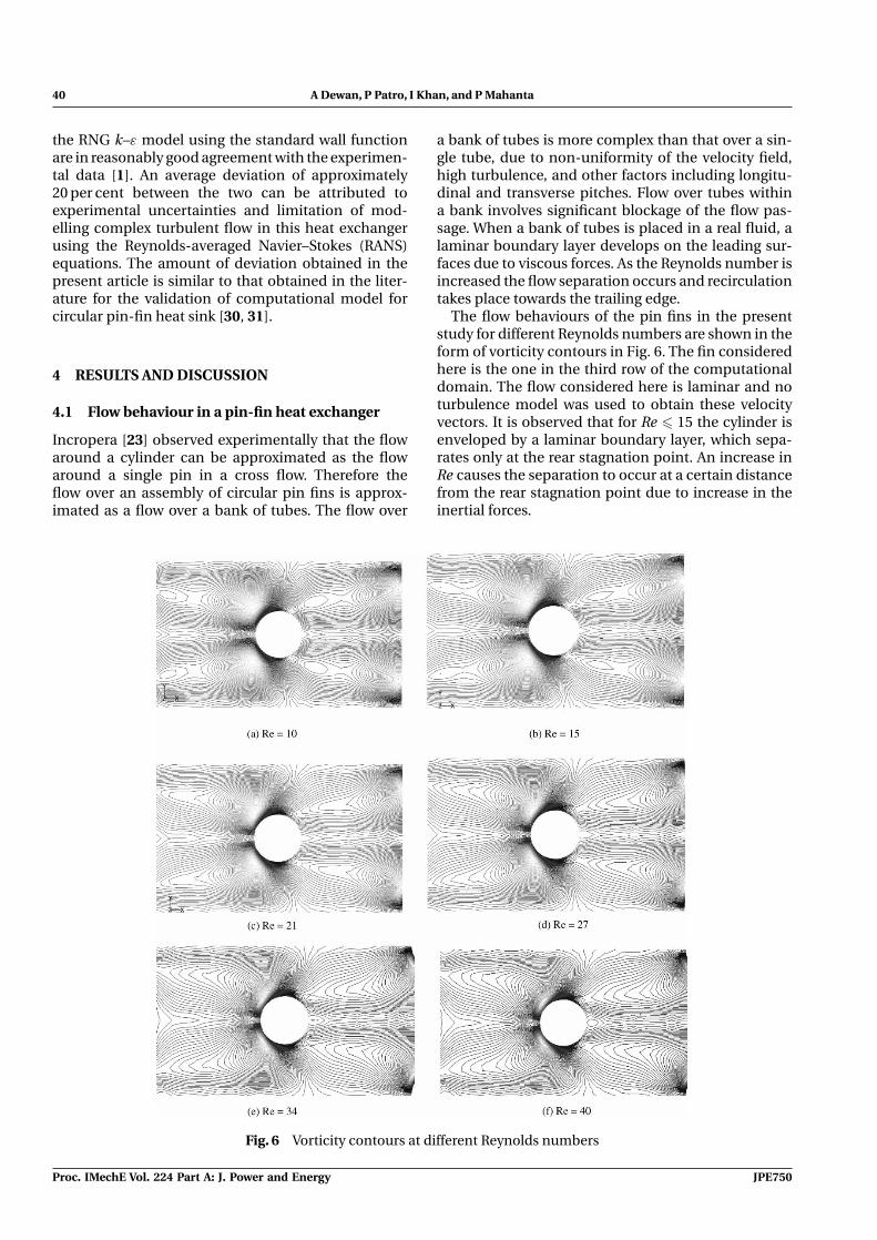
Incropera [23] observed experimentally that the flowaround a cylinder can be approximated as the flowaround a single pin in a cross flow. Therefore theflow over an assembly of circular pin fins is approx-imated as a flow over a bank of tubes. The flow over
a bank of tubes is more complex than that over a sin-gle tube, due to non-uniformity of the velocity field,high turbulence, and other factors including longitu-dinal and transverse pitches. Flow over tubes withina bank involves significant blockage of the flow pas-sage. When a bank of tubes is placed in a real fluid, alaminar boundary layer develops on the leading sur-faces due to viscous forces. As the Reynolds number isincreased the flow separation occurs and recirculationtakes place towards the trailing edge.
The flow behaviours of the pin fins in the presentstudy for different Reynolds numbers are shown in theform of vorticity contours in Fig. 6. The fin consideredhere is the one in the third row of the computationaldomain. The flow considered here is laminar and noturbulence model was used to obtain these velocityvectors. It is observed that for Re � 15 the cylinder isenveloped by a laminar boundary layer, which sepa-rates only at the rear stagnation point. An increase inRe causes the separation to occur at a certain distancefrom the rear stagnation point due to increase in theinertial forces.
Fig. 6 Vorticity contours at different Reynolds numbers
Proc. IMechE Vol. 224 Part A: J. Power and Energy JPE750

The effect of fin spacing and material on the performance of a heat sink 41
The flow behaviour changes at Reynolds number20–25. Flow separation occurs and recirculation offluid takes place towards the trailing edge of the fins.The turbulent eddies are formed and the intensity ofthe turbulent eddies and recirculation is significantwhen Re is higher than 40. The wake behind the cylin-der becomes unstable and vortex shedding is initiated.As Re increases further, the point of separation gradu-ally moves upstream. Therefore the Reynolds numbershould be more than 40 for proper mixing of the fluid toaugment the heat transfer in a heat exchanger. For thepresent computation, Reynolds number was variedfrom 200 to 1000.
4.2 Effect of fin material
Three fin materials namely, aluminium, nickel andsteel were considered to study the effect of pin fin’sthermal conductivity on the performance of the heatexchanger. As already stated in Section 3.1 conjugateheat transfer from pin-fin arrays was assumed whileconsidering the effect of the fin material. The charac-teristics of the convective heat transfer from pin arrayscan be understood from the temperature contours influid and solid parts of the computational domain(Fig. 7). It is seen that the fluid adjacent to the finsattain the maximum temperature. Heat is transferredfrom the bottom heated plate to the fins by conductionand from fins to the fluid by turbulent convection. Thetemperature difference between the fin and the fluiddecreases in the downstream direction. The fluid takesheat from the fins and hence the temperature of thefluid increases. It was observed that for the aluminiumfins, the exit temperature of the fluid is the maximum
and for steel fins it is the minimum. The tempera-ture difference between the fins and the surroundingfluid decreases along the computational domain. Theglobal Nusselt number is more for aluminium finscompared to that for the other two fins (Tables 2 to 4).It was also observed that as the inlet velocity increases,the outlet bulk temperature decreases for all cases dueto large convective heat transfer at high inlet velocity.
Table 2 Heat transfer and pressure drop for aluminiumfins
Reynolds number, Re 205.0 410.0 550.0 685.0 820.0Present Nusselt
number, Nu4.34 7.42 9.14 10.69 12.1
Nusselt number, Nu,from experimentaldata by Kays [1]
5.7 9.6 11.5 13.2 14.8
Total pressure drop,�p (Pa)
19.93 66.69 109.88 162.52 224.20
Table 3 Heat transfer and pressure drop for nickelfins
Reynoldsnumber, Re
205.0 410.0 550.0 685.0 820.0
Present Nusseltnumber, Nu
3.81 6.20 7.53 9.61 10.12
Total pressuredrop, �p (Pa)
19.89 66.56 109.66 162.25 223.88
Table 4 Heat transfer and pressure drop for steel fins
Reynoldsnumber, Re
205.0 410.0 550.0 685.0 820.0
Present Nusseltnumber, Nu
2.612 3.82 4.61 5.18 5.41
Total pressuredrop, �p (Pa)
19.75 65.10 108.81 161.05 222.36
Fig. 7 Temperature contours on the x–z plane ( y = 0) for the inlet velocity of 3.0 m/s
JPE750 Proc. IMechE Vol. 224 Part A: J. Power and Energy

42 A Dewan, P Patro, I Khan, and P Mahanta
Overall Nusselt numbers and total pressure dropat different Reynolds numbers for three fin materialsare presented in Tables 2–4. The total pressure dropis directly related to the input power required to drivethe fan of a compact heat exchanger. The Nusselt num-ber obtained experimentally by Kays [1] for aluminiumfins is also shown in Table 2. To the best of the authors’knowledge no experimental data for nickel and steelfins exist in the literature and therefore no comparisoncan be made. Table 2 shows that the present predic-tions of the aluminium fins are in reasonably goodagreement with the experimental data of Kay [1]. Pos-sible reasons for the deviation between the presentpredictions and experimental data have already beengiven in Section 3.2.
Tables 2 to 4 show that the Nusselt number increaseswith Reynolds number and simultaneously pressuredrop also increases. Up to Re = 685, which corre-sponds to an inlet velocity of 5.0 m/s, the pressure droprises slowly. However, for higher values of Re the risein pressure drop is high compared with a correspond-ing small rise in Nusselt number in all the three cases.Therefore a compact heat exchanger should be oper-ated at approximately 4.0–5.0 m/s inlet velocity. Thetotal heat transfer is the highest for the aluminium finsand the lowest for the steel fins at different Reynoldsnumbers.The pressure drop is approximately the samefor all the three cases indicating that there is hardly anychange in the hydrodynamic behaviour with a changein thermal conductivity. An extremely small change inthe pressure drop is probably due to a small change inthe hydrodynamic behaviour due to a change in theviscosity of air due to temperature.
4.3 Effect of streamwise fin spacing
The three geometries chosen for this purpose areshown in Fig. 3 and the corresponding values of S/dand number of fins considered are shown in Table 1.The computations were carried out for the Reynoldsnumbers from 200 to 1000.
The corresponding temperature contours are shownin Fig. 8. It has been seen that for streamwise spacingS/d = 2.3, the heat transfer from the fins to the bulk ofthe fluid is more compared with that for the other twocases. This is due to large heat transfer area availablein this case for the same volume of the heat exchanger.As the flow velocity increases, the bulk temperature ofthe fluid decreases.
Upstream of the pin fins, there is ordinary ductflow, which may be laminar or turbulent depend-ing on the duct Reynolds number. With a turbulentflow approaching the pin-fin row, the flow is acceler-ated between the pin fins. This increases the velocitybetween the pins (this is clearly observed from Fig. 9)and it increases the transfer of energy between the pin-fin row and the fluid. Turbulent wakes are shed fromthe pin fins and enhance the duct wall heat trans-fer downstream of the pin-fin row. The heat transferis higher within the pin wakes as opposed to thatbetween the pins. Downstream the individual wakesfrom the pins tend to disperse and the flow beginsto redevelop and become uniform in the transversedirection to the bulk flow. Heat transfer and pressuredrop characteristics for the three configurations areshown in Figs 10 and 11. As the number of fins in thecomputational domain is increased (i.e. by decreasing
Fig. 8 Temperature contours: (a) S/d = 2.3; (b) S/d = 3.13; and (c) S/d = 4.0 at 4.0 m/s (Re = 550)
Proc. IMechE Vol. 224 Part A: J. Power and Energy JPE750

The effect of fin spacing and material on the performance of a heat sink 43
Fig. 9 Velocity contours at 4.0 m/s (Re = 550): (a) S/d = 2.3; (b) S/d = 3.13; and (c) S/d = 4.0
Fig. 10 Variation of global Nusselt numbers withReynolds numbers
the row-to-row spacing) the heat transfer increasesand this is accompanied by a corresponding rise inthe pressure drop. The air flow around a pin-fin arrayencounters a significant resistance and hence an over-all pressure drop. A larger rate of heat transfer isachieved by increasing the inlet velocity. At high Re,the difference of heat transfer at different fin spacingsis large (Fig. 10).
Figure 12 shows the static temperature variationfor the three fin spacings. For all the three cases thetemperature increases towards the exit. The exit tem-perature is largest for S/d = 2.3 and therefore large
Fig. 11 Variation of pressure drop with Reynolds num-bers
heat transfer takes place. Static pressure behaves justopposite to the temperature and it decreases alongthe computational domain. We observe from Fig. 13that the pressure drop is also large for S/d = 2.3. Col-burn factor j represents non-dimensional form of heattransfer and it is a standard practice in the literatureto present this parameter as a function of Reynoldsnumber [33]. Figure 14 shows that the Colburn fac-tor j is the largest for the smallest fin spacing forthe entire range of Reynolds number and this is con-sistent with the static temperature data presentedin Fig. 12.
JPE750 Proc. IMechE Vol. 224 Part A: J. Power and Energy

44 A Dewan, P Patro, I Khan, and P Mahanta
Fig. 12 Static temperature variation
Fig. 13 Static pressure variation
5 CONCLUSIONS
A computational study to understand the thermo-fluid behaviour of a circular heat exchanger has beenpresented using the RNG k–ε turbulence model andstandard wall functions. The conclusions may besummarized as follows:
1. Considering different factors for a compact heatexchanger, such as heat transfer, pressure drop,density, etc., aluminium is found to be the best finmaterial.
2. Reynolds numbers from 550 to 685 are the best foroperating a compact heat exchanger. Although heat
0
0.005
0.01
0.015
0.02
0.025
0.03
0 200 400 600 800
Re
j
S/d=2.3S/d=3.13S/d=4
Fig. 14 Colburn factor for different fin spacings andReynolds number
transfer increases by increasing Re to more than685, the proportion by which the correspondingheat transfer increases is small compared with theproportion by which total pressure drop increases.
3. As far as the magnitude of heat transfer is con-cerned, the fin spacing with S/d = 2.3 providesmuch higher augmentation than that for S/d =3.13 and 4.0. The results show that the heat trans-fer decreases with an increased fin spacing. Thesedifferences are caused by decreased fin wake inter-actions with increased fin spacings.
ACKNOWLEDGEMENTS
The work reported here forms a part of the Depart-ment of Science and Technology, Government of India,New Delhi sponsored project ‘Modelling and Com-putation of Three-Dimensional Turbulent ConvectiveHeat Transfer for Design of Energy Efficient Pin FinHeat Exchanger’ (SR/S3/MERC-091/2007). A. Dewanand P. Mahanta acknowledge the financial supportreceived from DST.
© Authors 2010
REFERENCES
1 Kays,W. M. Pin fin heat exchanger surfaces. Trans. ASME,1955, 77, 471–483.
2 Dewan, A., Mahanta, P., Sumithra Raju, K., andSuresh Kumar, P. Review of passive heat transfer aug-mentation techniques. Proc. IMechE, Part A: J. Powerand Energy, 2004, 218(A7), 509–527. DOI: 10.1243/0957650042456953.
3 Maudgal, V. K. and Sunderland, J. E. An experimentalstudy of forced convection heat transfer from inline pinfin arrays. In Proceedings of the 13th IEEE Semi-ThermSymposium, Austin, Texas, USA, 1997, pp. 149–157.
Proc. IMechE Vol. 224 Part A: J. Power and Energy JPE750

The effect of fin spacing and material on the performance of a heat sink 45
4 Behnia, M., Copeland, D., and Soodphakdee, D. A com-parison of heat sink geometries for laminar forced con-vection: numerical simulation of periodically developedflow. In Proceedings of the InterSociety Conference onThermal phenomena, Seattle, Washington, USA, 1998,pp. 310–315.
5 Leon, O., Mey, G. D., Dick, E., and Vierendeels, J. Com-parison between the standard and staggered layout forcooling fins in forced convective cooling. J. Electron.Pack., 2003, 125, 442–446.
6 Short, Jr, B. E., Price, D. C., and Raad, P. E. Design ofcast pin fin coldwalls for air-cooled electronics systems.J. Electron. Pack., 2004, 126, 67–73.
7 Kobus, C. J. and Oshio, T. Development of a theoreticalmodel for predicting the thermal performance character-istics of a vertical pin-fin array heat sink under combinedforced and natural convection with impinging flow. Int.J. Heat Mass Transf., 2005, 48, 1053–1063.
8 Tahat, M., Kodah, Z. H., Jarrah, B. A., and Probert, S. D.Heat transfers from pin-fin arrays experiencing forcedconvection. Appl. Energy, 2000, 67, 419–442.
9 Sahiti, N., Durst, F., and Dewan, A. Strategy for selectionof elements for heat transfer enhancement. Int. J. HeatMass Transf., 2006, 49, 3392–3400.
10 Sahiti, N., Durst, F., and Dewan, A. Heat transferenhancement by pin elements. Int. J. Heat Mass Transf.,2005, 48, 4738–4747.
11 Sparrow, E. M., Ramsey, J. W., and Altemani, C. A. C.Experiments on inline-pin fin arrays and performancecomparison with staggered arrangement. ASME J. HeatTransf., 1980, 102, 44–50.
12 Metzger, D. E., Berry, R. A., and Bronson, J. P. Devel-oping heat transfer in rectangular ducts with staggeredarrays of short pin fin. ASME J. Heat Transf., 1982, 104,700–706.
13 Moshfegh, B. and Nyiredy, R. Comparing RANS mod-els for flow and thermal analysis of pin fin heat sinks.In Proceedings of the 15th Australasian Fluid MechanicsConference, University of Sydney, Sydney, 2004.
14 Dewan, A., Dayanand, L., and Patro, P. Mathematicalmodeling and computation of three-dimensional, tur-bulent, convective heat transfer in a heat exchangerwith circular pin fins. In Applied mathematical modeling(Ed. E. N. Virtanen), 2008, pp. 273–296 (Nova Publishers,New York).
15 Ames, F. E. and Dvorak, L. A. Turbulent transportin pin fin arrays: experimental data and predictions.J. Turbomach., 2006, 128, 71–81.
16 Dvinsky, A., Bar-Cohen, A., and Strelets, M. Thermo-fluid analysis of staggered and inline pin fin heat sinks. InProceedings of the Inter Society Conference on Thermalphenomena, 2000, pp. 157–164.
17 Stanescu, G., Fowler, A. J. and Bejan, A. The optimalspacing of cylinders in free-stream cross-flow forcedconvection. lnt. J. Heat Mass Transf., 1996, 39, 311–317.
18 Zukauskas, A. and Ulinskas, R. Efficiency parameters forheat transfer in tube banks. Heat Transf. Engng, 1983, 36,19–25.
19 Zukauskas, A. Heat transfer from tubes in cross flow,advances in heat transfer, vol. 8, 1972, pp. 93–160 (Aca-demic Press, New York).
20 Larson, E. D. and Sparrow, E. M. Performance com-parison among geometrically different pin fin arrays
situated in an oncoming longitudinal flow. Int. J. HeatMass Transf., 1982, 25, 723–725.
21 Ames, F. E., Dvorak, L. A., and Morrow, M. J. Tur-bulent augmentation of internal convection over pinsin staggered pin-fin arrays. J. Turbomach., 2005, 127,183–190.
22 Lu, B. and Jiang, P. X. Experimental and numerical inves-tigation of convection heat transfer in a rectangularchannel with angled ribs. Exp. Therm. Fluid Sci., 2006,30, 513–521.
23 Incropera, F. P. Liquid cooling of electronic devices bysingle phase convection, 1999 (John Wiley, New York).
24 Tahat, M. A., Babus’Haq, R. F., and Probert, S. D. Forcedsteady-state convections from pin-fin arrays. J. Appl.Energy, 1994, 48, 335–351.
25 Mon, M. S. and Gross, U. Numerical study of fin-spacingeffects in annular-finned tube heat exchangers. Int. J.Heat Mass Transf., 2004, 47, 1953–1964.
26 Yang, K. S., Chiang, C., Lin,Y., Chien, K., and Wang, C. Onthe heat transfer characteristics of heat sinks: influenceof fin spacing at low Reynolds number region. Int. J. HeatMass Transf., 2007, 50, 2667–2674.
27 Sahin, B. A Taguchi approach for determination of opti-mum design parameters for a heat exchanger havingcircular-cross sectional pin fins. Int. J. Heat Mass Transf.,2007, 43, 493–502.
28 Babus’Haq, R. F., Akintunde, K., and Probert, S. D. Ther-mal performance of a pin-fin assembly. Int. J. Heat FluidFlow, 1995, 16, 50–55.
29 Goldstein, R. J., Ibele, W. E., Patankar, S. V., Simon, T. W.,Kuehn, T. H., Strykowski, P. J., Tamma, K. K., Heberlein,J.V. R., Davidson, J. H., Bischof, J., Kulacki, F. A., Kortsha-gen, U., Garrick, S., and Srinivasan, V. Heat transfer – areview of 2003 literature. Int. J. Heat Mass Transf., 2006,49, 451–534.
30 Sahiti, N., Lemouedda, A., Stojkovic, D., Durst, F., andFranz, E. Performance comparison of pin fin in-ductflow arrays with various pin cross-sections. Appl. Therm.Engng, 2006, 26, 1176–1192.
31 Sahiti, N. Thermal and fluid dynamic performance ofpin fin heat transfer surfaces. PhD Thesis, University ofErlangen Nuremberg, Germany, 2006.
32 FLUENT 6.3 users guide, 2006 (Fluent Inc., Lebanon,USA).
33 Kwak, K. M., Torii, K., and Nishino, K. Simultaneousheat transfer enhancement and pressure loss reductionfor finned-tube bundles with the first or two transverserows of built-in winglets. Exp. Therm. Fluid Sci., 2005, 29,625–632.
APPENDIX
Notation
Cp specific heat at constant pressureCf friction coefficientd diameter of finsDh hydraulic diameterH fin heighth heat-transfer coefficientJ Colburn factork thermal conductivity
JPE750 Proc. IMechE Vol. 224 Part A: J. Power and Energy

46 A Dewan, P Patro, I Khan, and P Mahanta
k turbulent kinetic energyL lengthNu Nusselt numberp pressurePr Prandtl numberQ heat fluxRe Reynolds numberS longitudinal fin spacingSt Stanton numberT temperatureU inlet air velocityy+ non-dimensional distance from wall
δij Kronecker delta
� dropε dissipation rateμ dynamic viscosityρ densityτ shear stress
Subscripts
a airf fluidh hydraulict turbulentw wall
Proc. IMechE Vol. 224 Part A: J. Power and Energy JPE750