3.5 Telemetering Systems - twanclik.free.frtwanclik.free.fr/electricity/IEPOPDF/1081ch3_5.pdf ·...
13
507 3.5 Telemetering Systems C. H. HOEPPNER (1970) J. VENCZEL (1985) B. G. LIPTÁK (1995) H. EREN (2005) Types: Wire telemetry and wireless telemetry Sensors: Common sensors for both types; additionally, IC and intelligent sensors for digital instruments Components: Collection of many components: computers, microprocessor and micro-controller sys- tems, intelligent and common sensors and transducers, instruments, controllers, wire and wireless communication devices and components, communication protocols and software, repeaters, satellite systems, GPS systems Displays: Computer peripherals, numeric (LED or LCD) displays Communications: Wired base-band and multiplexed, RF, microwave, optical, sonic, satellite communica- tions Networking: Unlimited network capabilities Vendors (partial list): Acroamatics Telemetry Systems (www.acroam.com) Athena Controls, Inc. (www.athenacontrols.com) Automated Control Systems (www.testdevices.com) Barton Instrument Systems Ltd (www.barton-instruments.com) Bristol Babcock (www.bristolbabcock.com) Crompton Instruments Ltd (www.crompton-instruments.com) Data Flow Systems, Inc. (www.dataflowsys.com) Datatel Telemetry Electronik GmbH (www.datatel-telemetry.com) D&D Security Products, Inc. (www.ddsp.com) Devar, Inc. (www.devarinc.com) Dranetz Technologies, Inc. (www.dranetz.com) Dwyer Instruments, Inc. (www.dwyer-inst.com) Dynalco Controls (www.dynalco.com) EMI Technologies, Inc. (www.emitechnologies.com) Garmin, Ltd. (www.garmin.com) Geomation Measurement & Control Systems (www.controls-ez.com) Harris Corp., Government Aerospace Systems Div. (www.harris.com) Industrial Control Links, Inc. (www.iclinks.com) Industrial Instruments & Supplies, Inc. (www.iisusa.com) Internet Telemetry Corp.(www.itelemetry.net) IR Telemetrics Inc. (www.irtelemetrics.com) Kahn Instruments, Inc. (www.kahn.com) Keithley Instruments, Inc. (www.keithley.com) Koehler Inst. Co., Inc. (www.koehlerinstrument.com) Lockheed Martin Corp. (www.lockheedmartin.com) Microwave Data Systems, Inc. (www.microwavedata.com) Myers Engineering International, Inc. (www.myerseng.com) Nihon Kohden Corporation (www.nihonkohden.com) Ono Sokki Technology Inc. (www.onosokki.net) Philip Medical Systems (www.medical.philips.com) Precision Devices, Inc. (www.predev.com) © 2006 by Béla Lipták
Transcript of 3.5 Telemetering Systems - twanclik.free.frtwanclik.free.fr/electricity/IEPOPDF/1081ch3_5.pdf ·...
507
3.5 Telemetering Systems
C. H. HOEPPNER (1970) J. VENCZEL (1985) B. G. LIPTÁK (1995) H. EREN (2005)
Types: Wire telemetry and wireless telemetry
Sensors: Common sensors for both types; additionally, IC and intelligent sensors for digitalinstruments
Components: Collection of many components: computers, microprocessor and micro-controller sys-tems, intelligent and common sensors and transducers, instruments, controllers, wireand wireless communication devices and components, communication protocols andsoftware, repeaters, satellite systems, GPS systems
Displays: Computer peripherals, numeric (LED or LCD) displays
Communications: Wired base-band and multiplexed, RF, microwave, optical, sonic, satellite communica-tions
Networking: Unlimited network capabilities
Vendors (partial list): Acroamatics Telemetry Systems (www.acroam.com)Athena Controls, Inc. (www.athenacontrols.com)Automated Control Systems (www.testdevices.com) Barton Instrument Systems Ltd (www.barton-instruments.com)Bristol Babcock (www.bristolbabcock.com)Crompton Instruments Ltd (www.crompton-instruments.com)Data Flow Systems, Inc. (www.dataflowsys.com)Datatel Telemetry Electronik GmbH (www.datatel-telemetry.com)D&D Security Products, Inc. (www.ddsp.com)Devar, Inc. (www.devarinc.com)Dranetz Technologies, Inc. (www.dranetz.com)Dwyer Instruments, Inc. (www.dwyer-inst.com) Dynalco Controls (www.dynalco.com)EMI Technologies, Inc. (www.emitechnologies.com)Garmin, Ltd. (www.garmin.com)Geomation Measurement & Control Systems (www.controls-ez.com)Harris Corp., Government Aerospace Systems Div. (www.harris.com)Industrial Control Links, Inc. (www.iclinks.com)Industrial Instruments & Supplies, Inc. (www.iisusa.com)Internet Telemetry Corp.(www.itelemetry.net)IR Telemetrics Inc. (www.irtelemetrics.com)Kahn Instruments, Inc. (www.kahn.com)Keithley Instruments, Inc. (www.keithley.com)Koehler Inst. Co., Inc. (www.koehlerinstrument.com)Lockheed Martin Corp. (www.lockheedmartin.com)Microwave Data Systems, Inc. (www.microwavedata.com)Myers Engineering International, Inc. (www.myerseng.com)Nihon Kohden Corporation (www.nihonkohden.com)Ono Sokki Technology Inc. (www.onosokki.net)Philip Medical Systems (www.medical.philips.com)Precision Devices, Inc. (www.predev.com)
© 2006 by Béla Lipták
508 Transmitters and Local Controllers
Pribusin Inc. (www.pribusin.com)REMEC, Inc. (www.remec.com)Satellink, Inc. (www.satellink.com)SunTech Medical Instruments (www.suntechmed.com)Tateyama Electr. Corp (www5.ocn.ne.jp/~tateyama/telemetrysys/en/)Telescada, Inc. (www.telescada.com)Teletronics Technology Corporation (www.ttcdas.com)Texas Instruments (www.ti.com)Turner BioSystems (www.turnerbiosystems.com)Warren-Knight Instrument Co. (www.warrenknight.com)Weston Aerospace (www.westonaero.com)Wireless Data Corp. (www.ce-mag.com)Yokogawa Corp. (www.yokogawa.com)
INTRODUCTION
Telemetry is a process of gathering information from remotelocations. The data obtained from field instruments is trans-mitted to a convenient location for processing and recordingpurposes. Telemetry can be performed by different methods:electromagnetic, optical, electrical, sonic, Internet, etc.Recently, radio frequency (RF) and microwave telemetrymethods have been used extensively. This section largelyconcentrates on wireless telemetry systems. However, theuse of optical fiber systems allows the measurement ofbroad bandwidth and provides high immunity to noise andinterference. Here, telemetry and telemetry systems thatare based on electrical and electromagnetic principles arecovered.
Electrical telemetry methods can be divided into groupsdepending on the transmission methods that they use. Thereare two basic types: wire telemetry and wireless telemetry.Wire telemetry uses wire transmission utilizing coaxialcables, twisted wire pairs, telephone systems, commoncommunication buses, or similar communication means. Itoffers simple and inexpensive solutions for data flow andnetworking of devices. It is extensively used where thebasic infrastructure and wiring systems already exist, as inthe case of electric power lines that can be used as wiretelemetry carriers.
Wireless telemetry is somewhat more complex as itrequires radio frequency transmitters and receivers. Despitethe complexity, it is widely used because it can transmitinformation over longer distances without wires from nor-mally inaccessible areas. It can also operate at high speedsand can have the capacity to transmit several parallel chan-nels of information at the same time. The applications ofother wireless telemetry methods such as ultrasound andinfrared radiation are limited to certain environments, suchas marine telemetry.
Telemetry systems can operate repeatedly without anyadjustments and calibrations under widely ranging environmen-tal conditions, such as high-temperature and high-pressure sit-uations. Telemetry is extensively used in space exploration andmilitary applications for telemeasurements of distant variablesor telecommandment of actuators and controllers.
Some land-mobile vehicles, such as passenger and cargotrains, also use telemetry systems, either wireless or by usingsome of the existing power distribution networks to transmitdata to a central station. In medical applications, the use oftelemetry increases the quality of life of patients, giving themmobility while still being monitored. Several medical appli-cations are based on implanting a sensor in a patient andtransmitting the data to be further analyzed and processedeither by radio or by adapted telephone lines. In industrialapplications, fiber optic communications are used in hazard-ous and electrically noisy environments.
The design and methodology required for a fully func-tional telemetry system depends on the application require-ments and the environmental characteristics. From the appli-cations point of view, telemetry can be grouped into fourmain categories: telemetry in medical and life sciences,industrial telemetry, space telemetry, and others. Applicationexamples are provided at the end of this section.
BASIC TELEMETRY CONCEPTS
Classical Configuration
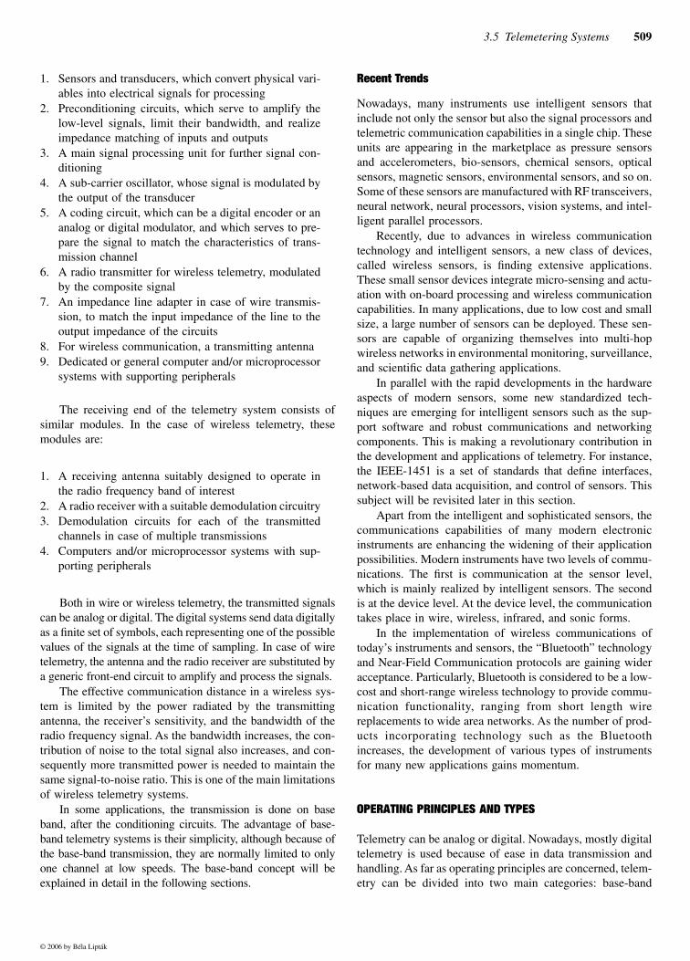
A telemetry system consists of many components, as illus-trated in Figure 3.5a. The main components are:
FIG. 3.5aBasic components of a telemetry system.
Transducer
Front-endprocessing
Signalconditioning Codifier Repeater
Modulator
RF power+Modulator
Lineamplifier
Wiretelemetry
Wirelesstelemetry
© 2006 by Béla Lipták
3.5 Telemetering Systems 509
1. Sensors and transducers, which convert physical vari-ables into electrical signals for processing
2. Preconditioning circuits, which serve to amplify thelow-level signals, limit their bandwidth, and realizeimpedance matching of inputs and outputs
3. A main signal processing unit for further signal con-ditioning
4. A sub-carrier oscillator, whose signal is modulated bythe output of the transducer
5. A coding circuit, which can be a digital encoder or ananalog or digital modulator, and which serves to pre-pare the signal to match the characteristics of trans-mission channel
6. A radio transmitter for wireless telemetry, modulatedby the composite signal
7. An impedance line adapter in case of wire transmis-sion, to match the input impedance of the line to theoutput impedance of the circuits
8. For wireless communication, a transmitting antenna9. Dedicated or general computer and/or microprocessor
systems with supporting peripherals
The receiving end of the telemetry system consists ofsimilar modules. In the case of wireless telemetry, thesemodules are:
1. A receiving antenna suitably designed to operate inthe radio frequency band of interest
2. A radio receiver with a suitable demodulation circuitry3. Demodulation circuits for each of the transmitted
channels in case of multiple transmissions4. Computers and/or microprocessor systems with sup-
porting peripherals
Both in wire or wireless telemetry, the transmitted signalscan be analog or digital. The digital systems send data digitallyas a finite set of symbols, each representing one of the possiblevalues of the signals at the time of sampling. In case of wiretelemetry, the antenna and the radio receiver are substituted bya generic front-end circuit to amplify and process the signals.
The effective communication distance in a wireless sys-tem is limited by the power radiated by the transmittingantenna, the receiver’s sensitivity, and the bandwidth of theradio frequency signal. As the bandwidth increases, the con-tribution of noise to the total signal also increases, and con-sequently more transmitted power is needed to maintain thesame signal-to-noise ratio. This is one of the main limitationsof wireless telemetry systems.
In some applications, the transmission is done on baseband, after the conditioning circuits. The advantage of base-band telemetry systems is their simplicity, although because ofthe base-band transmission, they are normally limited to onlyone channel at low speeds. The base-band concept will beexplained in detail in the following sections.
Recent Trends
Nowadays, many instruments use intelligent sensors thatinclude not only the sensor but also the signal processors andtelemetric communication capabilities in a single chip. Theseunits are appearing in the marketplace as pressure sensorsand accelerometers, bio-sensors, chemical sensors, opticalsensors, magnetic sensors, environmental sensors, and so on.Some of these sensors are manufactured with RF transceivers,neural network, neural processors, vision systems, and intel-ligent parallel processors.
Recently, due to advances in wireless communicationtechnology and intelligent sensors, a new class of devices,called wireless sensors, is finding extensive applications.These small sensor devices integrate micro-sensing and actu-ation with on-board processing and wireless communicationcapabilities. In many applications, due to low cost and smallsize, a large number of sensors can be deployed. These sen-sors are capable of organizing themselves into multi-hopwireless networks in environmental monitoring, surveillance,and scientific data gathering applications.
In parallel with the rapid developments in the hardwareaspects of modern sensors, some new standardized tech-niques are emerging for intelligent sensors such as the sup-port software and robust communications and networkingcomponents. This is making a revolutionary contribution inthe development and applications of telemetry. For instance,the IEEE-1451 is a set of standards that define interfaces,network-based data acquisition, and control of sensors. Thissubject will be revisited later in this section.
Apart from the intelligent and sophisticated sensors, thecommunications capabilities of many modern electronicinstruments are enhancing the widening of their applicationpossibilities. Modern instruments have two levels of commu-nications. The first is communication at the sensor level,which is mainly realized by intelligent sensors. The secondis at the device level. At the device level, the communicationtakes place in wire, wireless, infrared, and sonic forms.
In the implementation of wireless communications oftoday’s instruments and sensors, the “Bluetooth” technologyand Near-Field Communication protocols are gaining wideracceptance. Particularly, Bluetooth is considered to be a low-cost and short-range wireless technology to provide commu-nication functionality, ranging from short length wirereplacements to wide area networks. As the number of prod-ucts incorporating technology such as the Bluetoothincreases, the development of various types of instrumentsfor many new applications gains momentum.
OPERATING PRINCIPLES AND TYPES
Telemetry can be analog or digital. Nowadays, mostly digitaltelemetry is used because of ease in data transmission andhandling. As far as operating principles are concerned, telem-etry can be divided into two main categories: base-band
© 2006 by Béla Lipták
510 Transmitters and Local Controllers
telemetry and multiple-channel telemetry. These methodswill be explained next, and appropriate comments will bemade for their analog and digital applications.
Base-Band Telemetry
Base-band telemetry uses a wire line to communicate thesignals obtained from the sensors and transducer to someremote location. There are two basic types: amplitude-basedtelemetry and frequency-based telemetry.
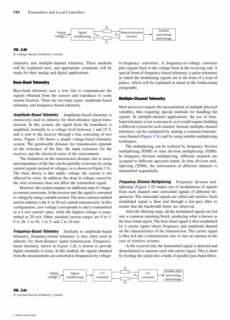
Amplitude-Based Telemetry Amplitude-based telemetry isextensively used in industry for short-distance signal trans-mission. In this system, the signal from the transducer isamplified, normally to a voltage level between 1 and 15 V,and is sent to the receiver through a line consisting of twowires. Figure 3.5b shows a simple voltage-based telemetrysystem. The permissible distance for transmission dependson the resistance of the line, the input resistance for thereceiver, and the electrical noise of the environment.
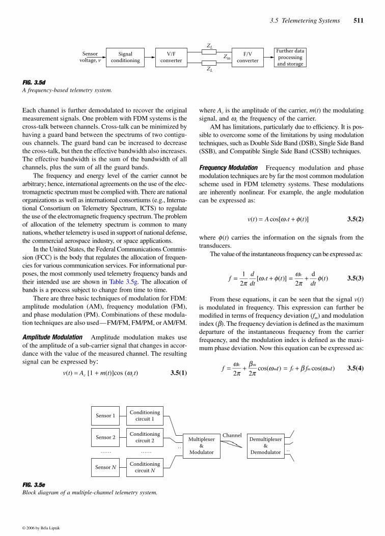
The limitation on the transmission distance due to noiseand impedance of the line can be partially overcome by usingcurrent signals instead of voltages, as is shown in Figure 3.5c.The basic theory is that unlike voltage, the current is notaffected by noise. In addition, the drop in voltage caused bythe wire resistance does not affect the transmitted signal.
However, this system requires an additional step of voltage-to-current conversion. At the receiver end, the signal is convertedto voltage by using a suitable resistor. The most common methodused in industry is the 4- to 20-mA current transmission. In thisconfiguration, zero voltage corresponds to and is transmittedas a 4 mA current value, while the highest voltage is trans-mitted as 20 mA. Other standard current ranges are 0 to 5,0 to 20, 1 to 50, 1 to 5, and 2 to 10 mA.
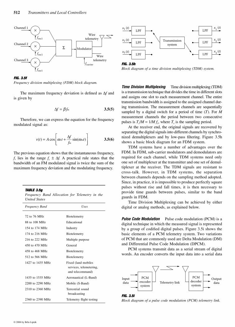
Frequency-Based Telemetry Similarly to amplitude-basedtelemetry, frequency-based telemetry is also often used inindustry for short-distance signal transmission. Frequency-based telemetry, shown in Figure 3.3d, is known to providehigher immunity to noise. In this method, the signals obtainedfrom the measurements are converted to frequencies by voltage-
to-frequency converters. A frequency-to-voltage converterputs signals back to the voltage form at the receiving end. Aspecial form of frequency-based telemetry is pulse telemetryin which the modulating signals are in the form of a train ofpulses, which will be explained in detail in the forthcomingparagraphs.
Multiple-Channel Telemetry
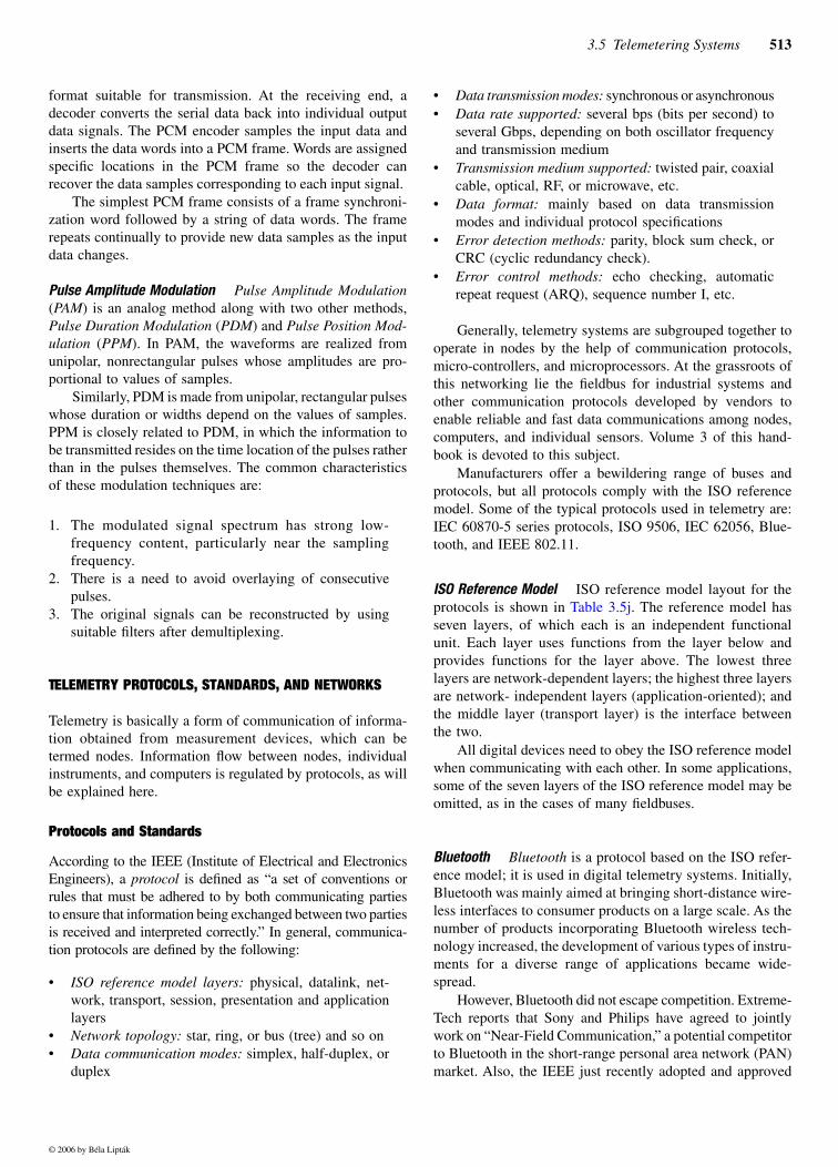
Most processes require the measurement of multiple physicalvariables, thus requiring special methods for handling thesignals. In multiple-channel applications, the use of base-band telemetry is not economical, as it would require buildinga different system for each channel. Instead, multiple-channeltelemetry can be configured by sharing a common transmis-sion channel (Figure 3.5e) and by using suitable multiplexingtechniques.
The multiplexing can be realized by frequency divisionmultiplexing (FDM) or time division multiplexing (TDM).In frequency division multiplexing, different channels areassigned to different spectrum bands. In time division mul-tiplexing (TDM), the information of different channels istransmitted sequentially.
Frequency Division Multiplexing Frequency division mul-tiplexing (Figure 3.5f) makes use of modulations of signalsfrom each channel onto sinusoidal signals of different fre-quencies. The sinusoidal signals are called sub-carriers. Eachmodulated signal is then sent through a low-pass filter toensure that the bandwidth limits are observed.
After the filtering stage, all the modulated signals are fedinto a common summing block, producing what is known asthe base-band signal. The base-band signal is then modulatedby a carrier signal whose frequency and amplitude dependon the characteristics of the transmission. The carrier signalis then fed into a transmission wire or into an antenna in thecase of wireless systems.
At the receiver end, the transmitted signal is detected anddemodulated to separate each sub-carrier signal. This is doneby feeding the signal into a bank of parallel pass-band filters.
FIG. 3.5bA voltage-based telemetry system.
Signalconditioning
Remote locationreceiver
Sensorvoltage, v vout
ZL
ZL
Zin
Furtherprocessingand storage
FIG. 3.5cA current-based telemetry system.
Signalconditioning
Sensorvoltage, v
ZL
ZL
ZinV/I
converterI/V
converter
Further dataprocessingand storage
© 2006 by Béla Lipták
3.5 Telemetering Systems 511
Each channel is further demodulated to recover the originalmeasurement signals. One problem with FDM systems is thecross-talk between channels. Cross-talk can be minimized byhaving a guard band between the spectrums of two contigu-ous channels. The guard band can be increased to decreasethe cross-talk, but then the effective bandwidth also increases.The effective bandwidth is the sum of the bandwidth of allchannels, plus the sum of all the guard bands.
The frequency and energy level of the carrier cannot bearbitrary; hence, international agreements on the use of the elec-tromagnetic spectrum must be complied with. There are nationalorganizations as well as international consortiums (e.g., Interna-tional Consortium on Telemetry Spectrum, ICTS) to regulatethe use of the electromagnetic frequency spectrum. The problemof allocation of the telemetry spectrum is common to manynations, whether telemetry is used in support of national defense,the commercial aerospace industry, or space applications.
In the United States, the Federal Communications Commis-sion (FCC) is the body that regulates the allocation of frequen-cies for various communication services. For informational pur-poses, the most commonly used telemetry frequency bands andtheir intended use are shown in Table 3.5g. The allocation ofbands is a process subject to change from time to time.
There are three basic techniques of modulation for FDM:amplitude modulation (AM), frequency modulation (FM),and phase modulation (PM). Combinations of these modula-tion techniques are also used—FM/FM, FM/PM, or AM/FM.
Amplitude Modulation Amplitude modulation makes useof the amplitude of a sub-carrier signal that changes in accor-dance with the value of the measured channel. The resultingsignal can be expressed by:
v(t) = Ac [1 + m(t)]cos (ωct) 3.5(1)
where Ac is the amplitude of the carrier, m(t) the modulatingsignal, and ωc the frequency of the carrier.
AM has limitations, particularly due to efficiency. It is pos-sible to overcome some of the limitations by using modulationtechniques, such as Double Side Band (DSB), Single Side Band(SSB), and Compatible Single Side Band (CSSB) techniques.
Frequency Modulation Frequency modulation and phasemodulation techniques are by far the most common modulationscheme used in FDM telemetry systems. These modulationsare inherently nonlinear. For example, the angle modulationcan be expressed as:
3.5(2)
where φ(t) carries the information on the signals from thetransducers.
The value of the instantaneous frequency can be expressed as:
3.5(3)
From these equations, it can be seen that the signal v(t)is modulated in frequency. This expression can further bemodified in terms of frequency deviation (fm) and modulationindex (β). The frequency deviation is defined as the maximumdeparture of the instantaneous frequency from the carrierfrequency, and the modulation index is defined as the maxi-mum phase deviation. Now this equation can be expressed as:
3.5(4)
FIG. 3.5dA frequency-based telemetry system.
Signalconditioning
Sensorvoltage, v
ZL
ZL
ZinV/F
converterF/V
converter
Further dataprocessingand storage
v t A t tc( ) cos[ ( )]= +ω φ
fd
dtt t
dttc
c= + = +12 2π
ω φ ωπ
φ[ ( )] ( )d
f t f f tc m
m c m m= + = +ωπ
βπ
ω β ω2 2
cos( ) cos( )
FIG. 3.5eBlock diagram of a multiple-channel telemetry system.
Sensor 1 Conditioningcircuit 1
Sensor 2 Conditioningcircuit 2
Sensor N Conditioningcircuit N
Multiplexer&
Modulator
Demultiplexer&
Demodulator
Channel
…… ……… …
© 2006 by Béla Lipták
512 Transmitters and Local Controllers
The maximum frequency deviation is defined as ∆f andis given by
3.5(5)
Therefore, we can express the equation for the frequencymodulated signal as:
3.5(6)
The previous equation shows that the instantaneous frequency,f, lies in the range fc ± ∆f. A practical rule states that thebandwidth of an FM modulated signal is twice the sum of themaximum frequency deviation and the modulating frequency.
Time Division Multiplexing Time division multiplexing (TDM)is a transmission technique that divides the time in different slotsand assigns one slot to each measurement channel. The entiretransmission bandwidth is assigned to the assigned channel dur-ing transmission. The measurement channels are sequentiallysampled by a digital switch for a period of time (T). For Mmeasurement channels the period between two consecutivepulses is Ts/M = 1/M fs, where Ts is the sampling period.
At the receiver end, the original signals are recovered byseparating the digital signals into different channels by synchro-nized demultiplexers and by low-pass filtering. Figure 3.5hshows a basic block diagram for an FDM system.
TDM systems have a number of advantages over theFDM. In FDM, sub-carrier modulators and demodulators arerequired for each channel, while TDM systems need onlyone set of multiplexer at the transmitter and one set of demul-tiplexer at the receiver. The TDM signals are resistant tocross-talk. However, in TDM systems, the separationbetween channels depends on the sampling method adopted.Since, in practice, it is impossible to produce perfectly squarepulses without rise and fall times, it is then necessary toprovide time guards between pulses, similar to the bandguards in FDM.
Time Division Multiplexing can be achieved by eitherdigital or analog methods, as explained below.
Pulse Code Modulation Pulse code modulation (PCM) is adigital technique in which the measured signal is representedby a group of codified digital pulses. Figure 3.5i shows thebasic elements of a PCM telemetry system. Two variationsof PCM that are commonly used are Delta Modulation (DM)and Differential Pulse Code Modulation (DPCM).
PCM systems transmit data as a serial stream of digitalwords. An encoder converts the input data into a serial data
FIG. 3.5f Frequency division multiplexing (FDM) block diagram.
TABLE 3.5g Frequency Band Allocation for Telemetry in theUnited States
Frequency Band Uses
72 to 76 MHz Biotelemetry
88 to 108 MHz Educational
154 to 174 MHz Industry
174 to 216 MHz Biotelemetry
216 to 222 MHz Multiple purpose
450 to 470 MHz General
458 to 468 MHz Biotelemetry
512 to 566 MHz Biotelemetry
1427 to 1435 MHz Fixed (land mobiles services, telemetering, and telecommand)
1435 to 1535 MHz Aeronautical (L-Band)
2200 to 2290 MHz Mobile (S-Band)
2310 to 2360 MHz Terrestrial sound broadcasting
2360 to 2390 MHz Telemetry flight testing
Channel 1
fosc1
Channel 2
fosc1
Channel 3
fosc1
fcarrier
Modulator
Wiretelemetry
Wiretelemetry
Σ
×
×
×
∆f fm= β
v t A tf
ftc
mm( ) cos sin( )= +
ω ω∆
FIG. 3.5hBlock diagram of a time division multiplexing (TDM) system.
FIG. 3.5i Block diagram of a pulse code modulation (PCM) telemetry link.
x1 (t)
x2 (t)
x3 (t)
LPF
LPF
LPF
x1 (t)
x2 (t)
x3 (t)
LPF
LPF
LPF
Transmissionsystem
Inputdata
Outputdata
PCMencodersystem
PCMdecodersystem
Telemetry link
© 2006 by Béla Lipták
3.5 Telemetering Systems 513
format suitable for transmission. At the receiving end, adecoder converts the serial data back into individual outputdata signals. The PCM encoder samples the input data andinserts the data words into a PCM frame. Words are assignedspecific locations in the PCM frame so the decoder canrecover the data samples corresponding to each input signal.
The simplest PCM frame consists of a frame synchroni-zation word followed by a string of data words. The framerepeats continually to provide new data samples as the inputdata changes.
Pulse Amplitude Modulation Pulse Amplitude Modulation(PAM) is an analog method along with two other methods,Pulse Duration Modulation (PDM) and Pulse Position Mod-ulation (PPM). In PAM, the waveforms are realized fromunipolar, nonrectangular pulses whose amplitudes are pro-portional to values of samples.
Similarly, PDM is made from unipolar, rectangular pulseswhose duration or widths depend on the values of samples.PPM is closely related to PDM, in which the information tobe transmitted resides on the time location of the pulses ratherthan in the pulses themselves. The common characteristicsof these modulation techniques are:
1. The modulated signal spectrum has strong low-frequency content, particularly near the samplingfrequency.
2. There is a need to avoid overlaying of consecutivepulses.
3. The original signals can be reconstructed by usingsuitable filters after demultiplexing.
TELEMETRY PROTOCOLS, STANDARDS, AND NETWORKS
Telemetry is basically a form of communication of informa-tion obtained from measurement devices, which can betermed nodes. Information flow between nodes, individualinstruments, and computers is regulated by protocols, as willbe explained here.
Protocols and Standards
According to the IEEE (Institute of Electrical and ElectronicsEngineers), a protocol is defined as “a set of conventions orrules that must be adhered to by both communicating partiesto ensure that information being exchanged between two partiesis received and interpreted correctly.” In general, communica-tion protocols are defined by the following:
• ISO reference model layers: physical, datalink, net-work, transport, session, presentation and applicationlayers
• Network topology: star, ring, or bus (tree) and so on• Data communication modes: simplex, half-duplex, or
duplex
• Data transmission modes: synchronous or asynchronous• Data rate supported: several bps (bits per second) to
several Gbps, depending on both oscillator frequencyand transmission medium
• Transmission medium supported: twisted pair, coaxialcable, optical, RF, or microwave, etc.
• Data format: mainly based on data transmissionmodes and individual protocol specifications
• Error detection methods: parity, block sum check, orCRC (cyclic redundancy check).
• Error control methods: echo checking, automaticrepeat request (ARQ), sequence number I, etc.
Generally, telemetry systems are subgrouped together tooperate in nodes by the help of communication protocols,micro-controllers, and microprocessors. At the grassroots ofthis networking lie the fieldbus for industrial systems andother communication protocols developed by vendors toenable reliable and fast data communications among nodes,computers, and individual sensors. Volume 3 of this hand-book is devoted to this subject.
Manufacturers offer a bewildering range of buses andprotocols, but all protocols comply with the ISO referencemodel. Some of the typical protocols used in telemetry are:IEC 60870-5 series protocols, ISO 9506, IEC 62056, Blue-tooth, and IEEE 802.11.
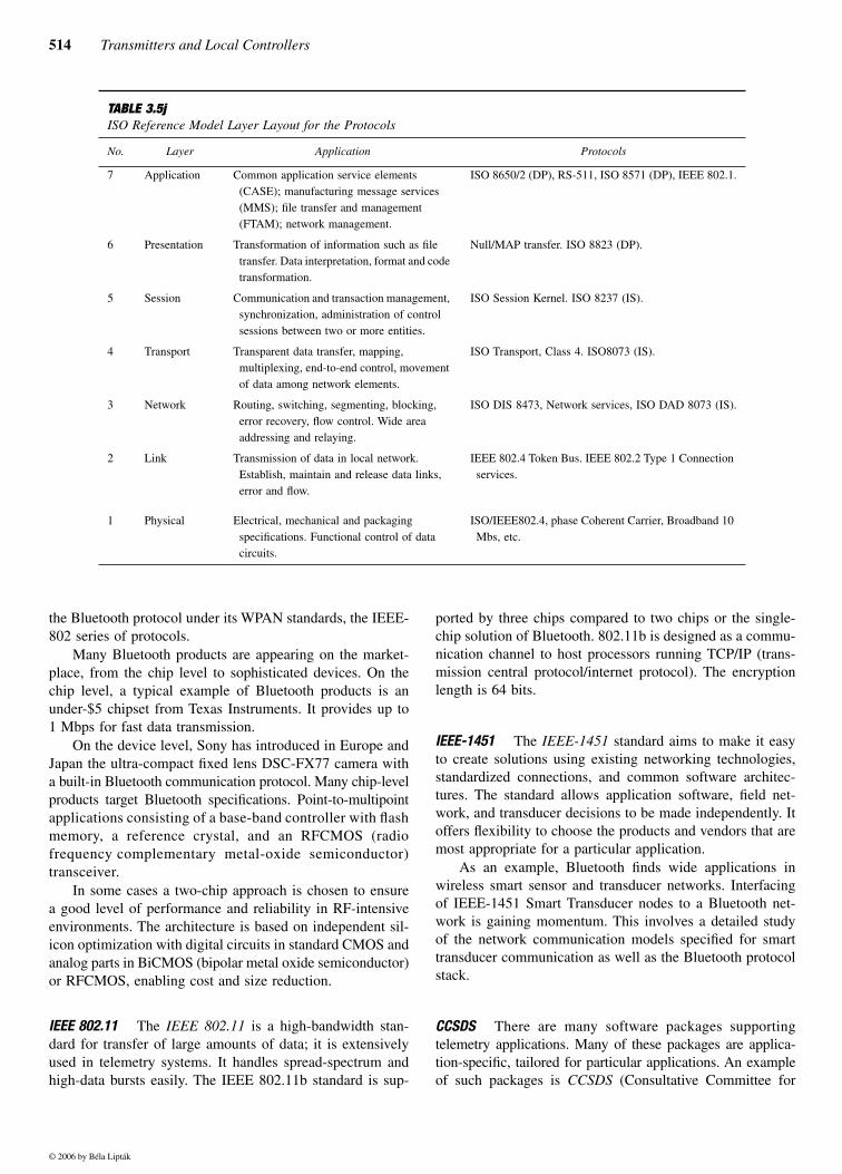
ISO Reference Model ISO reference model layout for theprotocols is shown in Table 3.5j. The reference model hasseven layers, of which each is an independent functionalunit. Each layer uses functions from the layer below andprovides functions for the layer above. The lowest threelayers are network-dependent layers; the highest three layersare network- independent layers (application-oriented); andthe middle layer (transport layer) is the interface betweenthe two.
All digital devices need to obey the ISO reference modelwhen communicating with each other. In some applications,some of the seven layers of the ISO reference model may beomitted, as in the cases of many fieldbuses.
Bluetooth Bluetooth is a protocol based on the ISO refer-ence model; it is used in digital telemetry systems. Initially,Bluetooth was mainly aimed at bringing short-distance wire-less interfaces to consumer products on a large scale. As thenumber of products incorporating Bluetooth wireless tech-nology increased, the development of various types of instru-ments for a diverse range of applications became wide-spread.
However, Bluetooth did not escape competition. Extreme-Tech reports that Sony and Philips have agreed to jointlywork on “Near-Field Communication,” a potential competitorto Bluetooth in the short-range personal area network (PAN)market. Also, the IEEE just recently adopted and approved
© 2006 by Béla Lipták
514 Transmitters and Local Controllers
the Bluetooth protocol under its WPAN standards, the IEEE-802 series of protocols.
Many Bluetooth products are appearing on the market-place, from the chip level to sophisticated devices. On thechip level, a typical example of Bluetooth products is anunder-$5 chipset from Texas Instruments. It provides up to1 Mbps for fast data transmission.
On the device level, Sony has introduced in Europe andJapan the ultra-compact fixed lens DSC-FX77 camera witha built-in Bluetooth communication protocol. Many chip-levelproducts target Bluetooth specifications. Point-to-multipointapplications consisting of a base-band controller with flashmemory, a reference crystal, and an RFCMOS (radiofrequency complementary metal-oxide semiconductor)transceiver.
In some cases a two-chip approach is chosen to ensurea good level of performance and reliability in RF-intensiveenvironments. The architecture is based on independent sil-icon optimization with digital circuits in standard CMOS andanalog parts in BiCMOS (bipolar metal oxide semiconductor)or RFCMOS, enabling cost and size reduction.
IEEE 802.11 The IEEE 802.11 is a high-bandwidth stan-dard for transfer of large amounts of data; it is extensivelyused in telemetry systems. It handles spread-spectrum andhigh-data bursts easily. The IEEE 802.11b standard is sup-
ported by three chips compared to two chips or the single-chip solution of Bluetooth. 802.11b is designed as a commu-nication channel to host processors running TCP/IP (trans-mission central protocol/internet protocol). The encryptionlength is 64 bits.
IEEE-1451 The IEEE-1451 standard aims to make it easyto create solutions using existing networking technologies,standardized connections, and common software architec-tures. The standard allows application software, field net-work, and transducer decisions to be made independently. Itoffers flexibility to choose the products and vendors that aremost appropriate for a particular application.
As an example, Bluetooth finds wide applications inwireless smart sensor and transducer networks. Interfacingof IEEE-1451 Smart Transducer nodes to a Bluetooth net-work is gaining momentum. This involves a detailed studyof the network communication models specified for smarttransducer communication as well as the Bluetooth protocolstack.
CCSDS There are many software packages supportingtelemetry applications. Many of these packages are applica-tion-specific, tailored for particular applications. An exampleof such packages is CCSDS (Consultative Committee for
TABLE 3.5jISO Reference Model Layer Layout for the Protocols
No. Layer Application Protocols
7 Application Common application service elements (CASE); manufacturing message services (MMS); file transfer and management (FTAM); network management.
ISO 8650/2 (DP), RS-511, ISO 8571 (DP), IEEE 802.1.
6 Presentation Transformation of information such as file transfer. Data interpretation, format and code transformation.
Null/MAP transfer. ISO 8823 (DP).
5 Session Communication and transaction management, synchronization, administration of control sessions between two or more entities.
ISO Session Kernel. ISO 8237 (IS).
4 Transport Transparent data transfer, mapping, multiplexing, end-to-end control, movement of data among network elements.
ISO Transport, Class 4. ISO8073 (IS).
3 Network Routing, switching, segmenting, blocking, error recovery, flow control. Wide area addressing and relaying.
ISO DIS 8473, Network services, ISO DAD 8073 (IS).
2 Link Transmission of data in local network. Establish, maintain and release data links, error and flow.
IEEE 802.4 Token Bus. IEEE 802.2 Type 1 Connection services.
1 Physical Electrical, mechanical and packaging specifications. Functional control of data circuits.
ISO/IEEE802.4, phase Coherent Carrier, Broadband 10 Mbs, etc.
© 2006 by Béla Lipták
3.5 Telemetering Systems 515
Space Data Systems). CCSDS is a telemetry and telecom soft-ware library that provides a reference implementation of theinternational protocol standard for the transmission and recep-tion of data in radio communications with spacecraft.
This library supports the full set of uplink and downlinkvirtual channels. It has a frame-acceptance and -reporting mech-anism (FARM) that supports a sliding window specified withinthe standard. The library has been written in the C programminglanguage for execution on various computers running theSunOS4, SunOS5, AIX, and VxWorks operating systems.
MLS-STD-1553 The MLS-STD-1553 standard addressesthe acquisition of all the traffic flowing on MIL-STD-1553–type data buses for telemetry and recording purposes.Up to eight data buses within a single system can be used.Constraints such as RF bandwidth and recording times aredefined.
As the application of telemetry widens, many forms ofsupporting hardware and software appear in the marketplaceoffered by different vendors and organizations. Althoughmost of these products are supported by the existing stan-dards, in some cases new standards appear in lieu of newdevelopments.
Networks
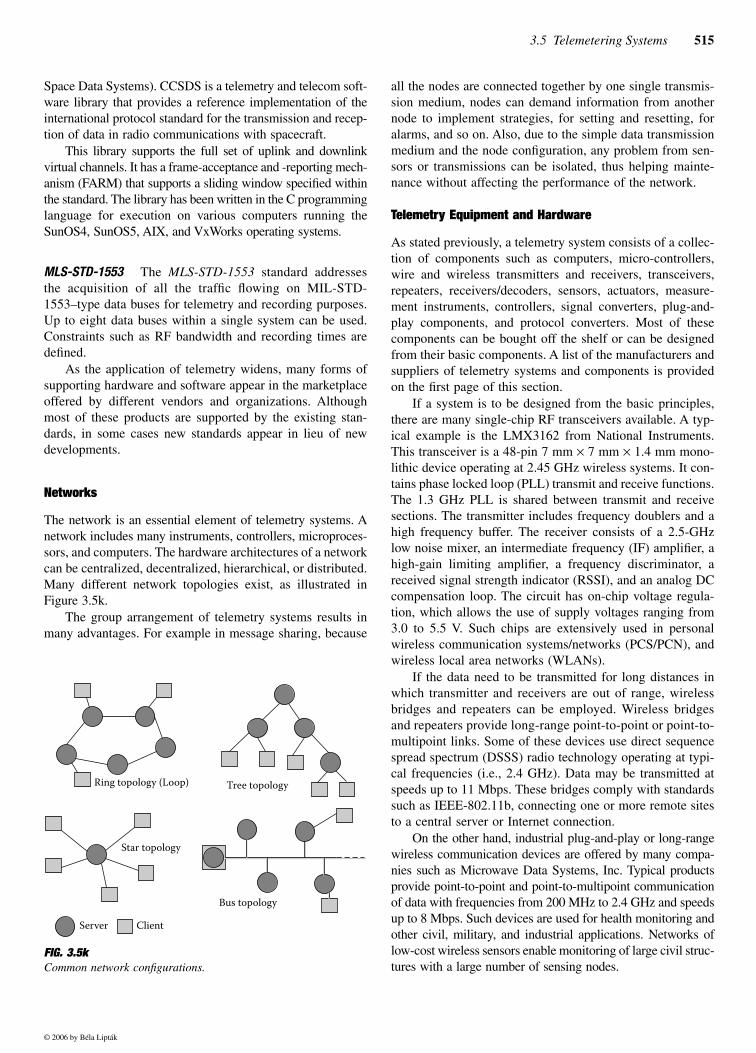
The network is an essential element of telemetry systems. Anetwork includes many instruments, controllers, microproces-sors, and computers. The hardware architectures of a networkcan be centralized, decentralized, hierarchical, or distributed.Many different network topologies exist, as illustrated inFigure 3.5k.
The group arrangement of telemetry systems results inmany advantages. For example in message sharing, because
all the nodes are connected together by one single transmis-sion medium, nodes can demand information from anothernode to implement strategies, for setting and resetting, foralarms, and so on. Also, due to the simple data transmissionmedium and the node configuration, any problem from sen-sors or transmissions can be isolated, thus helping mainte-nance without affecting the performance of the network.
Telemetry Equipment and Hardware
As stated previously, a telemetry system consists of a collec-tion of components such as computers, micro-controllers,wire and wireless transmitters and receivers, transceivers,repeaters, receivers/decoders, sensors, actuators, measure-ment instruments, controllers, signal converters, plug-and-play components, and protocol converters. Most of thesecomponents can be bought off the shelf or can be designedfrom their basic components. A list of the manufacturers andsuppliers of telemetry systems and components is providedon the first page of this section.
If a system is to be designed from the basic principles,there are many single-chip RF transceivers available. A typ-ical example is the LMX3162 from National Instruments.This transceiver is a 48-pin 7 mm × 7 mm × 1.4 mm mono-lithic device operating at 2.45 GHz wireless systems. It con-tains phase locked loop (PLL) transmit and receive functions.The 1.3 GHz PLL is shared between transmit and receivesections. The transmitter includes frequency doublers and ahigh frequency buffer. The receiver consists of a 2.5-GHzlow noise mixer, an intermediate frequency (IF) amplifier, ahigh-gain limiting amplifier, a frequency discriminator, areceived signal strength indicator (RSSI), and an analog DCcompensation loop. The circuit has on-chip voltage regula-tion, which allows the use of supply voltages ranging from3.0 to 5.5 V. Such chips are extensively used in personalwireless communication systems/networks (PCS/PCN), andwireless local area networks (WLANs).
If the data need to be transmitted for long distances inwhich transmitter and receivers are out of range, wirelessbridges and repeaters can be employed. Wireless bridgesand repeaters provide long-range point-to-point or point-to-multipoint links. Some of these devices use direct sequencespread spectrum (DSSS) radio technology operating at typi-cal frequencies (i.e., 2.4 GHz). Data may be transmitted atspeeds up to 11 Mbps. These bridges comply with standardssuch as IEEE-802.11b, connecting one or more remote sitesto a central server or Internet connection.
On the other hand, industrial plug-and-play or long-rangewireless communication devices are offered by many compa-nies such as Microwave Data Systems, Inc. Typical productsprovide point-to-point and point-to-multipoint communicationof data with frequencies from 200 MHz to 2.4 GHz and speedsup to 8 Mbps. Such devices are used for health monitoring andother civil, military, and industrial applications. Networks oflow-cost wireless sensors enable monitoring of large civil struc-tures with a large number of sensing nodes.
FIG. 3.5kCommon network configurations.
Ring topology (Loop)
Star topology
Server Client
Tree topology
Bus topology
© 2006 by Béla Lipták
516 Transmitters and Local Controllers
A typical single-unit data logging transceiver is a wirelessdata communications device that can serve multichannel sen-sor arrays to a remote data acquisition system hosted by acomputer or a microprocessor. The frequency of transmissionis 916 MHz, narrow-band. The RF communication link oper-ates with 19,200 baud, and the device is capable of triggeringa sample to be logged (typically from 30 m), or requesteddata to be transmitted.
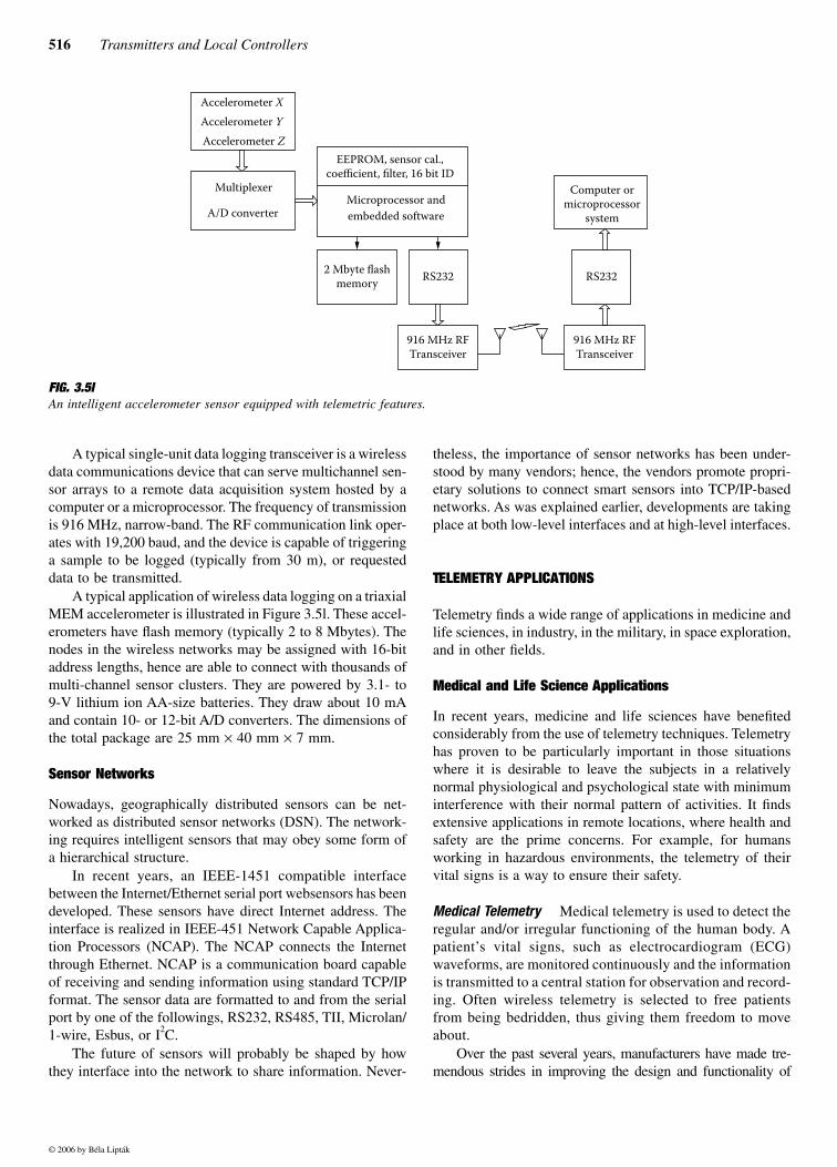
A typical application of wireless data logging on a triaxialMEM accelerometer is illustrated in Figure 3.5l. These accel-erometers have flash memory (typically 2 to 8 Mbytes). Thenodes in the wireless networks may be assigned with 16-bitaddress lengths, hence are able to connect with thousands ofmulti-channel sensor clusters. They are powered by 3.1- to9-V lithium ion AA-size batteries. They draw about 10 mAand contain 10- or 12-bit A/D converters. The dimensions ofthe total package are 25 mm × 40 mm × 7 mm.
Sensor Networks
Nowadays, geographically distributed sensors can be net-worked as distributed sensor networks (DSN). The network-ing requires intelligent sensors that may obey some form ofa hierarchical structure.
In recent years, an IEEE-1451 compatible interfacebetween the Internet/Ethernet serial port websensors has beendeveloped. These sensors have direct Internet address. Theinterface is realized in IEEE-451 Network Capable Applica-tion Processors (NCAP). The NCAP connects the Internetthrough Ethernet. NCAP is a communication board capableof receiving and sending information using standard TCP/IPformat. The sensor data are formatted to and from the serialport by one of the followings, RS232, RS485, TII, Microlan/1-wire, Esbus, or I2C.
The future of sensors will probably be shaped by howthey interface into the network to share information. Never-
theless, the importance of sensor networks has been under-stood by many vendors; hence, the vendors promote propri-etary solutions to connect smart sensors into TCP/IP-basednetworks. As was explained earlier, developments are takingplace at both low-level interfaces and at high-level interfaces.
TELEMETRY APPLICATIONS
Telemetry finds a wide range of applications in medicine andlife sciences, in industry, in the military, in space exploration,and in other fields.
Medical and Life Science Applications
In recent years, medicine and life sciences have benefitedconsiderably from the use of telemetry techniques. Telemetryhas proven to be particularly important in those situationswhere it is desirable to leave the subjects in a relativelynormal physiological and psychological state with minimuminterference with their normal pattern of activities. It findsextensive applications in remote locations, where health andsafety are the prime concerns. For example, for humansworking in hazardous environments, the telemetry of theirvital signs is a way to ensure their safety.
Medical Telemetry Medical telemetry is used to detect theregular and/or irregular functioning of the human body. Apatient’s vital signs, such as electrocardiogram (ECG)waveforms, are monitored continuously and the informationis transmitted to a central station for observation and record-ing. Often wireless telemetry is selected to free patientsfrom being bedridden, thus giving them freedom to moveabout.
Over the past several years, manufacturers have made tre-mendous strides in improving the design and functionality of
FIG. 3.5lAn intelligent accelerometer sensor equipped with telemetric features.
Accelerometer XAccelerometer YAccelerometer Z
Multiplexer
A/D converter
EEPROM, sensor cal.,coefficient, filter, 16 bit ID
Microprocessor andembedded software
2 Mbyte flashmemory RS232 RS232
916 MHz RFTransceiver
916 MHz RFTransceiver
Computer ormicroprocessor
system
© 2006 by Béla Lipták
3.5 Telemetering Systems 517
telemetry systems, allowing more acute patients to becomeambulatory during recovery. These systems are now capable ofmonitoring several different parameters, from ECG waveforms,arrhythmias, and heart rate to pulse oximetry and other vital signs.
Many medical telemetry systems consist of a small digitaltransmitter worn by the patient, a set of sensors for gatheringpatient vital signs, a distributed transmitter, and receivingsystems. Displays, controls, and recordings are often con-trolled from a central computer, which is located at the nurs-ing station, where telemetry units dedicated to the diagnosisand treatment of life-threatening illnesses are also located.
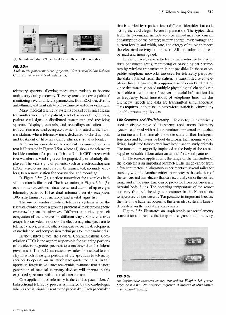
A telemetric nurse-based biomedical instrumentation sys-tem is illustrated in Figure 3.5m, where (1) shows the telemetrybedside monitor of a patient. It has a 7-inch CRT screen withtwo waveforms. Vital signs can be graphically or tabularly dis-played. The vital signs of patients, such as electrocardiogram(ECG) waveforms, and data can be transmitted, normally wire-less, to a remote station for observation and recording.
In Figure 3.5m (2), a patient transmitter for a wireless bed-side monitor is illustrated. The base station, in Figure 3.5m (3),can monitor waveforms, data, trends and alarms of up to eighttelemetry patients. It has dual-antenna diversity reception,100-arrhythmia event memory, and a vital signs list.
The use of wireless medical telemetry systems is on therise worldwide despite a growing problem with electromagneticovercrowding on the airwaves. Different countries approachcongestion of the airwaves in different ways. Some countriesassign less crowded regions of the electromagnetic spectrum totelemetry services while others concentrate on the developmentof modulation and compression techniques to limit bandwidths.
In the United States, the Federal Communications Com-mission (FCC) is the agency responsible for assigning portionsof the electromagnetic spectrum to users other than the federalgovernment. The FCC has issued new rules for medical telem-etry in which it assigns portions of the spectrum to telemetryservices to operate on an interference-protected basis. In thisapproach, hospitals will have reasonable assurance that the nextgeneration of medical telemetry devices will operate in thisexpanded spectrum with minimal interference.
One application of telemetry is the cardiac pacemaker. Abidirectional telemetry process is initiated by the cardiologistwhen a special signal is sent to the pacemaker. Each pacemaker
that is carried by a patient has a different identification codeset by the cardiologist before implantation. The typical datafrom the pacemaker include voltage, impedance, and currentconsumption of the battery; battery charge level; voltage andcurrent levels; and width, rate, and energy of pulses to recordthe electrical activity of the heart. All this information canbe read and interrogated.
In many cases, especially for patients who are located inrural or isolated areas, monitoring of physiological parame-ters by wireless transmission is not possible. In these cases,public telephone networks are used for telemetry purposes;the data obtained from the patient is transmitted over tele-phone lines. However, this approach needs careful attentionsince the transmission of multiple physiological channels canbe problematic in terms of recovering useful information dueto frequency band limitations of telephone lines. In thistelemetry, speech and data are transmitted simultaneously.This requires an increase in bandwidth, which is achieved bysuitable processing devices.
Life Sciences and Bio-Telemetry Telemetry is extensivelyused in diverse range of life science applications. Telemetrysystems equipped with radio transmitters implanted or attachedto marine and land animals allow the study of their biologicalfunctions and behavior without disturbing their normal way ofliving. Implanted transmitters have been used to study animals.The transmitter surgically implanted in the body of the animalsupplies valuable information on animals’ survival patterns.
In life science applications, the range of the transmitter ofthe telemeter is an important parameter. The range can be froma few centimeters in laboratory experiments to several miles fortracking wildlife. Another critical parameter is the selection ofthe sensors and transducers that can accurately sense the desiredrange and at the same time can be protected from corrosion andharmful body fluids. The operating temperature of the sensorcan vary from sub-freezing temperatures in the North to thetemperature of the deserts. Temperature is important becausethe life of the batteries powering the telemetry system is largelydependent on the operating temperature.
Figure 3.5n illustrates an implantable sensor/telemetrytransmitter to measure the temperature, gross motor activity,
FIG. 3.5mA telemetric patient monitoring system. (Courtesy of Nihon KohdenCorporation, www.nihonkohden.com)
(1) Bed side monitor (2) handheld transmitters (3) base station
FIG. 3.5n An implantable sensor/telemetry transmitter. Weight: 1.6 grams,Size: 22 × 8 mm. No batteries required. (Courtesy of Mini Mitter,www.minimitter.com)
© 2006 by Béla Lipták
518 Transmitters and Local Controllers
and heart rate of an animal. This sensor/transmitter arrange-ment does not require a battery.
Industrial Telemetry
Telemetry is extensively used in industrial applications.Industrial telemetry enables the automatic and remote mon-itoring and recording of process variables. By using teleme-try, operational efficiencies and safety can be improved.Some applications include oil and gas operations, medicalequipment, utilities production and consumption, and intel-ligent transportation systems.
There are many different types of industrial telemetrysystems, since they are offered by a diverse range of vendorscompeting for the same market. SCADA, which is discussedbelow, is an example of a well-established telemetry system.
Modern industrial systems use computers, remote termi-nal units (RTUs), programmable telemetry controllers(PTCs), and so on. PTCs consist of modular intelligent unitsthat can handle multiple inputs (typically 128 I/O) for net-working purposes. Remote terminal units can handle virtuallythousands of digital and analog inputs and outputs. SomeRTUs support local, public switched telephone networks(PSTN), private wire (PW) systems, leased lines (LL), andradio communications.
SCADA Systems SCADA stands for System Control andData Acquisition. SCADA consists of a collection of com-puters, sensors, and other equipment interfaced by telemetryto monitor and control processes. The uses of SCADA sys-tems are endless as they are only limited by the designer’simagination. Some typical applications include high- andlow-voltage power distributions, broadcasting stations, andenvironmental measurements.
An example of SCADA applications is in water manage-ment. Water conservation is critical not only in drought-stricken areas but everywhere, as water is becoming a limitedresource due to increases in consumption. Application ofSCADA systems enables the remote and effective monitoringand controlling of water levels.
Another application of SCADA in industry is digitalpager alarming systems. If an unusual situation occurs in aprocess, the SCADA system can alert key personnel by send-ing messages to their pagers. SCADA systems also archiveinformation and generate reports and graphs that are criticalto processes.
An important advantage of SCADA systems is that theexisting sensors in an application can be incorporated into theoverall SCADA system. In doing so, the SCADA system sim-ply adds a new level of intelligence and provides additionalcapabilities to the existing controls in the plant. In addition tolowering the cost of implementing new technological solutionsin existing plants, it can also help to centralize the controls toa central commanding post. SCADA systems can be equippedwith alarms so that if one of the subsystems fails, correctiveactions can be taken without delay.
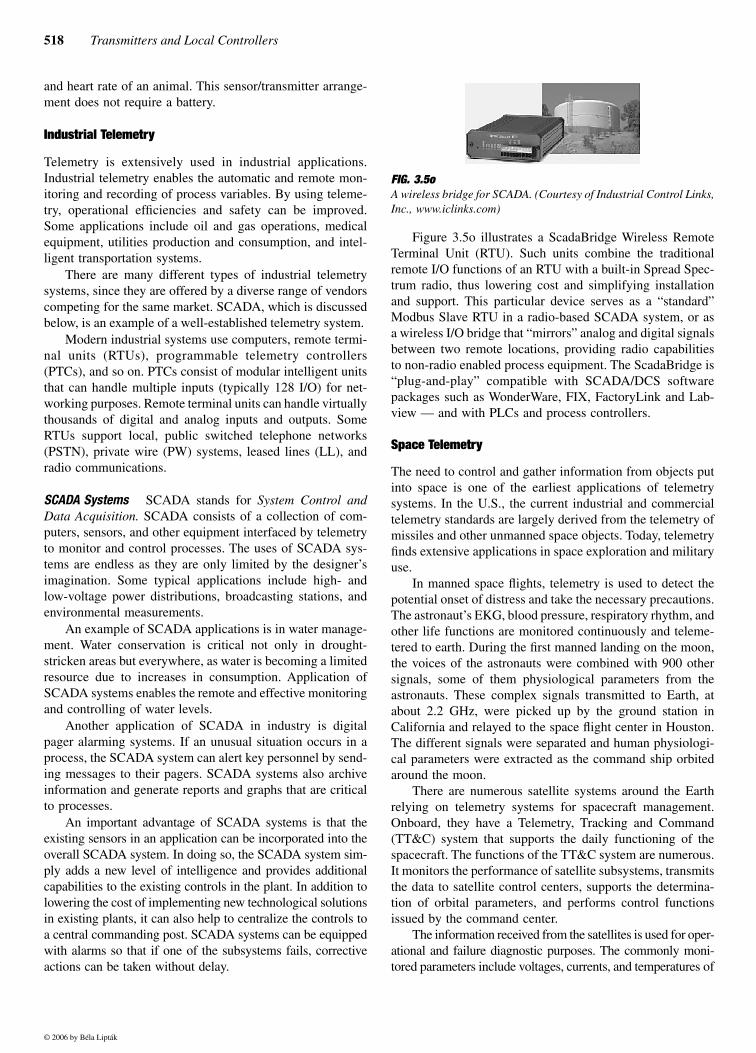
Figure 3.5o illustrates a ScadaBridge Wireless RemoteTerminal Unit (RTU). Such units combine the traditionalremote I/O functions of an RTU with a built-in Spread Spec-trum radio, thus lowering cost and simplifying installationand support. This particular device serves as a “standard”Modbus Slave RTU in a radio-based SCADA system, or asa wireless I/O bridge that “mirrors” analog and digital signalsbetween two remote locations, providing radio capabilitiesto non-radio enabled process equipment. The ScadaBridge is“plug-and-play” compatible with SCADA/DCS softwarepackages such as WonderWare, FIX, FactoryLink and Lab-view — and with PLCs and process controllers.
Space Telemetry
The need to control and gather information from objects putinto space is one of the earliest applications of telemetrysystems. In the U.S., the current industrial and commercialtelemetry standards are largely derived from the telemetry ofmissiles and other unmanned space objects. Today, telemetryfinds extensive applications in space exploration and militaryuse.
In manned space flights, telemetry is used to detect thepotential onset of distress and take the necessary precautions.The astronaut’s EKG, blood pressure, respiratory rhythm, andother life functions are monitored continuously and teleme-tered to earth. During the first manned landing on the moon,the voices of the astronauts were combined with 900 othersignals, some of them physiological parameters from theastronauts. These complex signals transmitted to Earth, atabout 2.2 GHz, were picked up by the ground station inCalifornia and relayed to the space flight center in Houston.The different signals were separated and human physiologi-cal parameters were extracted as the command ship orbitedaround the moon.
There are numerous satellite systems around the Earthrelying on telemetry systems for spacecraft management.Onboard, they have a Telemetry, Tracking and Command(TT&C) system that supports the daily functioning of thespacecraft. The functions of the TT&C system are numerous.It monitors the performance of satellite subsystems, transmitsthe data to satellite control centers, supports the determina-tion of orbital parameters, and performs control functionsissued by the command center.
The information received from the satellites is used for oper-ational and failure diagnostic purposes. The commonly moni-tored parameters include voltages, currents, and temperatures of
FIG. 3.5o A wireless bridge for SCADA. (Courtesy of Industrial Control Links,Inc., www.iclinks.com)
© 2006 by Béla Lipták
3.5 Telemetering Systems 519
all the major subsystems; the switch status of communicationtransponders; the pressure in propulsion tanks; and the out-puts from altitude sensors.
In modern satellite systems, distributed telemetry sys-tems in modular forms are favored. In this configuration,digital encoders are located in each satellite subsystem andthe data from each encoder are sent to a central encoder viaa common, time-shared bus. This method reduces the numberof wire connections and improves the reliability of the wholetelemetry system. Modular design also permits the easyexpansion of the initial design and facilitates easy testingduring the satellite assembly phase.
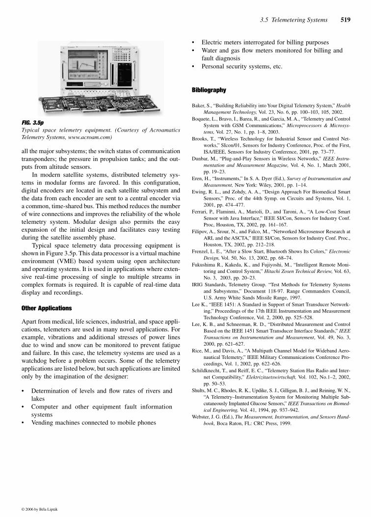
Typical space telemetry data processing equipment isshown in Figure 3.5p. This data processor is a virtual machineenvironment (VME) based system using open architectureand operating systems. It is used in applications where exten-sive real-time processing of single to multiple streams incomplex formats is required. It is capable of real-time datadisplay and recordings.
Other Applications
Apart from medical, life sciences, industrial, and space appli-cations, telemeters are used in many novel applications. Forexample, vibrations and additional stresses of power linesdue to wind and snow can be monitored to prevent fatigueand failure. In this case, the telemetry systems are used as awatchdog before a problem occurs. Some of the telemetryapplications are listed below, but such applications are limitedonly by the imagination of the designer:
• Determination of levels and flow rates of rivers andlakes
• Computer and other equipment fault informationsystems
• Vending machines connected to mobile phones
• Electric meters interrogated for billing purposes• Water and gas flow meters monitored for billing and
fault diagnosis• Personal security systems, etc.
Bibliography
Baker, S., “Building Reliability into Your Digital Telemetry System,” HealthManagement Technology, Vol. 23, No. 6, pp. 100–103, 105, 2002.
Boquete, L., Bravo, I., Barea, R., and Garcia, M. A., “Telemetry and ControlSystem with GSM Communications,” Microprocessors & Microsys-tems, Vol. 27, No. 1, pp. 1–8, 2003.
Brooks, T., “Wireless Technology for Industrial Sensor and Control Net-works,” SIcon/01, Sensors for Industry Conference, Proc. of the First,ISA/IEEE, Sensors for Industry Conference, 2001, pp. 73–77.
Dunbar, M., “Plug-and-Play Sensors in Wireless Networks,” IEEE Instru-mentation and Measurement Magazine, Vol. 4, No. 1, March 2001,pp. 19–23.
Eren, H., “Instruments,” In S. A. Dyer (Ed.), Survey of Instrumentation andMeasurement, New York: Wiley, 2001, pp. 1–14.
Ewing, R. L., and Zohdy, A. A., “Design Approach For Biomedical SmartSensors,” Proc. of the 44th Symp. on Circuits and Systems, Vol. 1,2001, pp. 474–477.
Ferrari, P., Flaminni, A., Marioli, D., and Taroni, A., “A Low-Cost SmartSensor with Java Interface,” IEEE SI/Con, Sensors for Industry Conf.Proc, Houston, TX, 2002, pp. 161–167.
Filipov, A., Srour, N., and Falco, M., “Networked Microsensor Research atARL and the ASCTA,” IEEE SI/Con, Sensors for Industry Conf. Proc.,Houston, TX, 2002, pp. 212–218.
Frenzel, L. E., “After a Slow Start, Bluetooth Shows Its Colors,” ElectronicDesign, Vol. 50, No. 13, 2002, pp. 68–74.
Fukushima R., Kakeda, K., and Fujiyoshi, M., “Intelligent Remote Moni-toring and Control System,” Hitachi Zosen Technical Review, Vol. 63,No. 3, 2003, pp. 20–23.
IRIG Standards, Telemetry Group. “Test Methods for Telemetry Systemsand Subsystems,” Document 118-97. Range Commanders Council,U.S. Army White Sands Missile Range, 1997.
Lee K., “IEEE 1451: A Standard in Support of Smart Transducer Network-ing,” Proceedings of the 17th IEEE Instrumentation and MeasurementTechnology Conference, Vol. 2, 2000, pp. 525–528.
Lee, K. B., and Schneeman, R. D., “Distributed Measurement and ControlBased on the IEEE 1451 Smart Transducer Interface Standards,” IEEETransactions on Instrumentation and Measurement, Vol. 49, No. 3,2000, pp. 621–627.
Rice, M., and Davis, A., “A Multipath Channel Model for Wideband Aero-nautical Telemetry,” IEEE Military Communications Conference Pro-ceedings, Vol. 1, 2002, pp. 622–626.
Schildknecht, T., and Reiff, E. C., “Telemetry Station Has Radio and Inter-net Compatibility,” Elektrizitaetswirtschaft, Vol. 102, No.1–2, 2002,pp. 50–53.
Shults, M. C., Rhodes, R. K., Updike, S. J., Gilligan, B. J., and Reining, W. N.,“A Telemetry–Instrumentation System for Monitoring Multiple Sub-cutaneously Implanted Glucose Sensors,” IEEE Transactions on Biomed-ical Engineering, Vol. 41, 1994, pp. 937–942.
Webster, J. G. (Ed.), The Measurement, Instrumentation, and Sensors Hand-book, Boca Raton, FL: CRC Press, 1999.
FIG. 3.5pTypical space telemetry equipment. (Courtesy of AcroamaticsTelemetry Systems, www.acroam.com)
© 2006 by Béla Lipták