341r Dynamic Modelling and Control of Divided Wall...
27
Dynamic Modeling and Control of Divided Wall Column Authors: László Szabó Sándor Németh Ferenc Szeifert A B C A B C 2010.02.18 8 th Meeting of Young Chemical Engineers Zagreb University of Pannonia Department of Process Engineering
Transcript of 341r Dynamic Modelling and Control of Divided Wall...
Dynamic Modeling and Control of Divided Wall Column
Authors:
László SzabóSándor NémethFerenc Szeifert
ABC
A
B
C
2010.02.18
8th Meeting of Young Chemical EngineersZagreb
University of Pannonia Department of Process Engineering
2
History of divided wall column
� Dividing-Wall Column (DWC) was introduced by Richard O.Wright in 1949 : Fractionation Apparatus
� However, lack of reliable design method and concerns about the operation and control of DWC have prevented the widespread application.
� People started to pay more attention to DWC after the Energy Crisis (1980).
� In 1985, BASF built the first commercial DWC.� More than 100 columns installed worldwide.
3
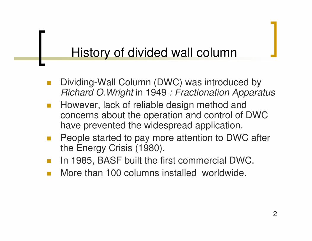
The number of the DWC
4
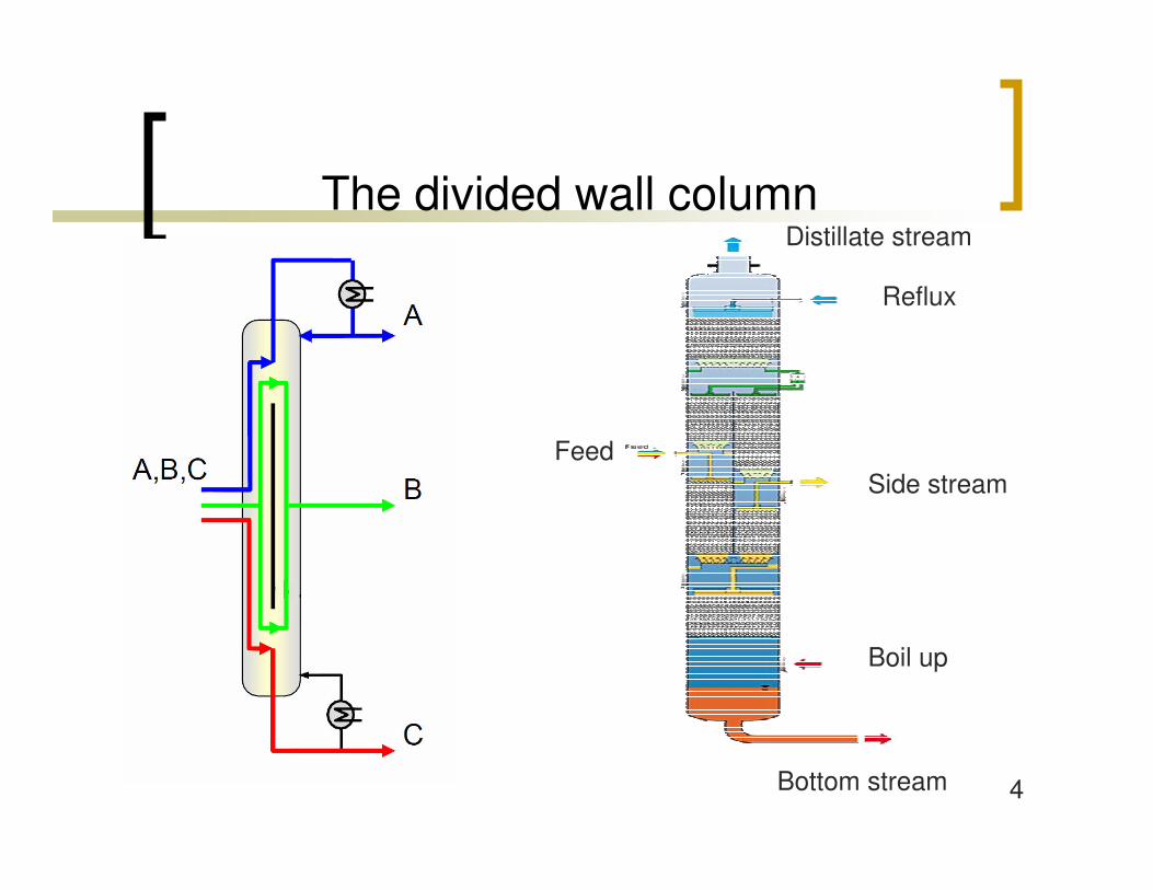
The divided wall column
Bottom stream
Boil up
Side stream
Reflux
Distillate stream
Feed

5
Concentration profile of the side product
0
0,1
0,2
0,3
0,4
0,5
0,6
0,7
0,8
0,9
1
0 5 10 15 20 25
Tray
Tol
uene
mas
sfra
c (m
/m)
Feed zoneProduct zone

6
Separation task
144,4
112,1
80,1
Boiling point(°C)
0,33o-Xylene
0,33Toluene
0,33Benzene
Feed concentration(kg/kg)
Feed90 kg/h
BenzenePurity: 0,99 kg/kg
Toluene
o-XylenePurity : 0,99 kg/kg
7
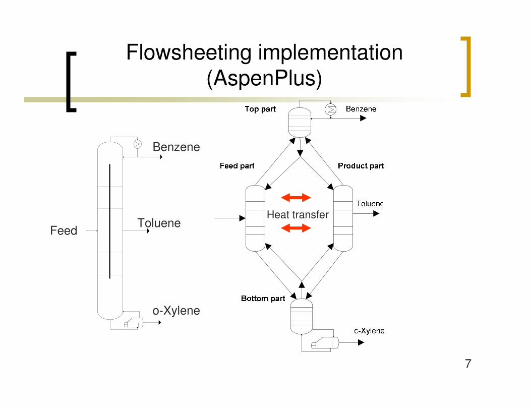
Flowsheeting implementation (AspenPlus)
Heat transferFeed
Benzene
Toluene
o-Xylene
8
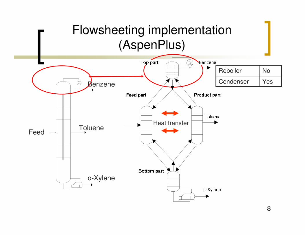
Flowsheeting implementation(AspenPlus)
YesCondenser
NoReboiler
Feed
Benzene
Toluene
o-Xylene
Heat transfer
9
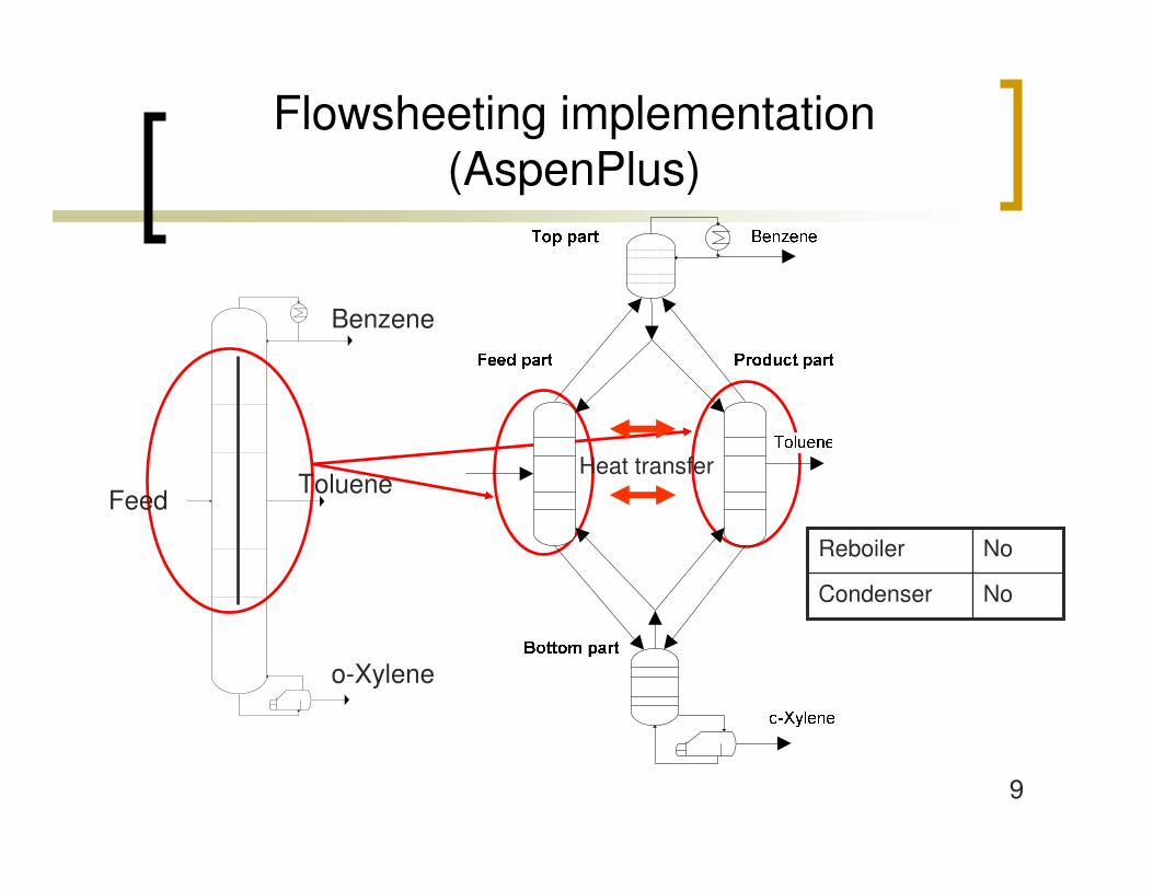
Flowsheeting implementation (AspenPlus)
NoCondenser
NoReboiler
Feed
Benzene
Toluene
o-Xylene
Heat transfer
10
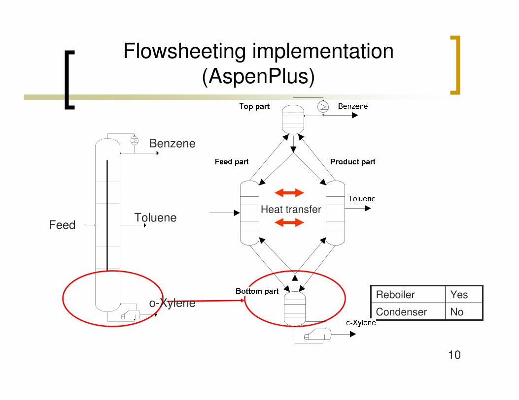
Flowsheeting implementation (AspenPlus)
NoCondenser
YesReboiler
Feed
Benzene
Toluene
o-Xylene
Heat transfer
11
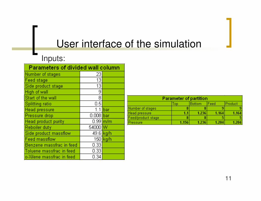
Inputs:
User interface of the simulation
12
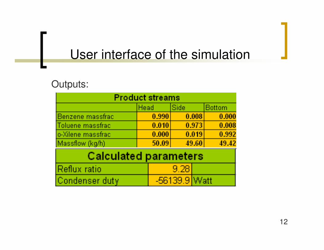
Outputs:
User interface of the simulation
13
Parametric study
� Height of the wall� Vertical position of the wall � Splitting ratio� Comparing divided wall column to side
stream column

14
20
25
30
35
40
45
50
55
60
5 6 7 8 9 10 11 12 13
Height of the wall (tray)
Reb
oile
r dut
y (k
W)
Effect of the height of the wall
50-50%
15
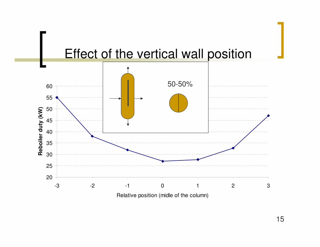
20
25
30
35
40
45
50
55
60
-3 -2 -1 0 1 2 3
Relative position (midle of the column)
Reb
oile
r du
ty (k
W)
Effect of the vertical wall position
50-50%

16
20
25
30
35
40
45
50
55
60
65
70
0 20 40 60 80 100
Splitting ratio (%)
Reb
oile
r du
ty (
kW)
Effect of splitting ratio
17
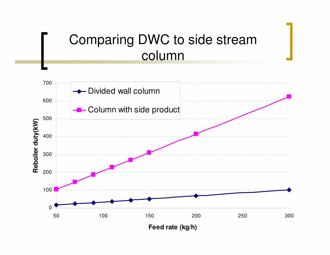
Comparing DWC to side stream column
0
100
200
300
400
500
600
700
50 100 150 200 250 300
Feed rate (kg/h)
Reb
oile
r du
ty(k
W)
Divided wall column
Column with side product

18
Dynamics simulation (Aspen Dynamics)
� The reboiler, the condenser and the reflux drum were implemented
� The column was implemented by two blocks
� Pressure changers (pipe, valve, pump) were applied
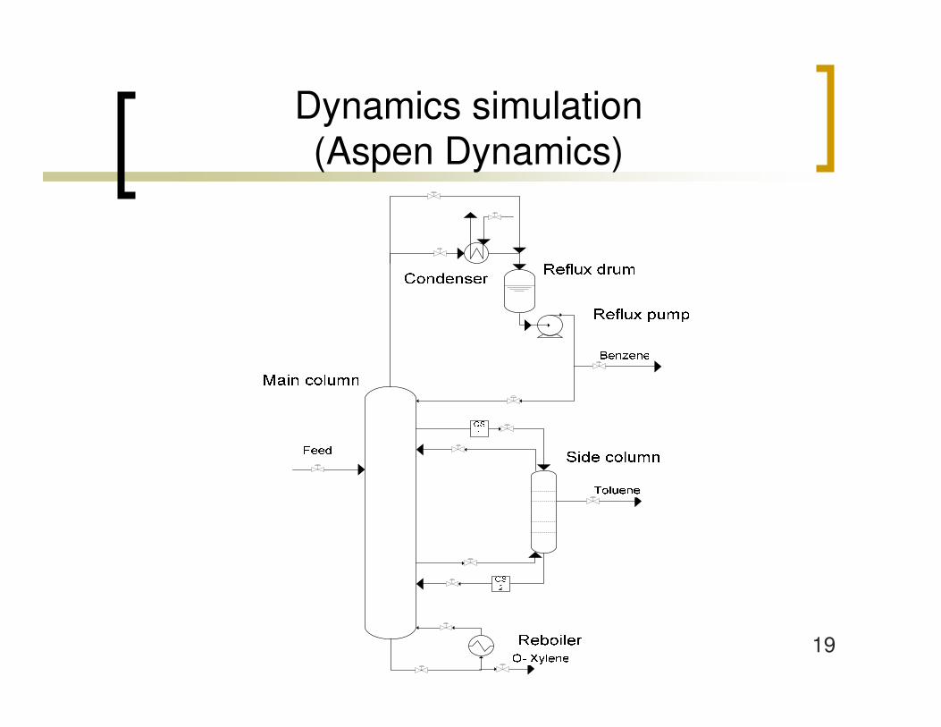
19
Dynamics simulation (Aspen Dynamics)
20
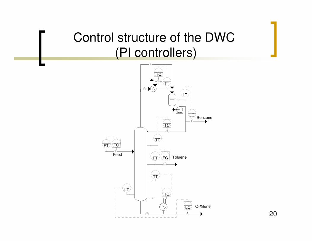
Control structure of the DWC(PI controllers)
�������
�������
���� ����
��
��
��
��
��
��
� �
� �
��
��
��
��
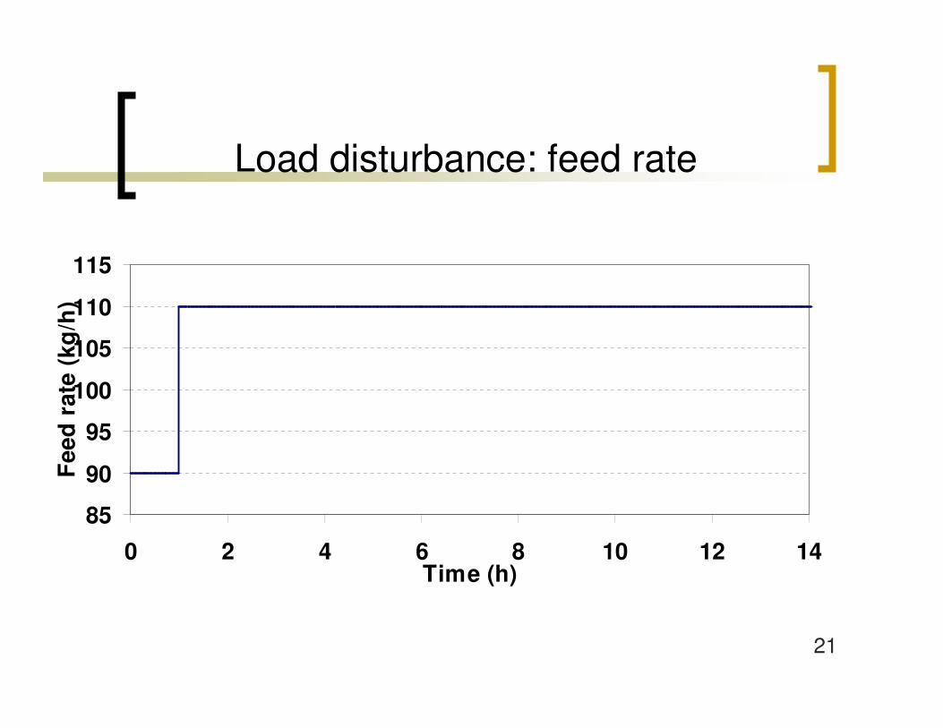
21
Load disturbance: feed rate
85
90
95
100
105
110
115
0 2 4 6 8 10 12 14Time (h)
Fee
d r
ate
(kg
/h)
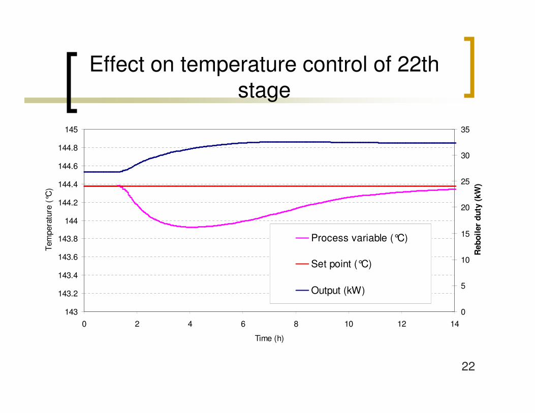
22
Effect on temperature control of 22th stage
143
143.2
143.4
143.6
143.8
144
144.2
144.4
144.6
144.8
145
0 2 4 6 8 10 12 14
Time (h)
Tem
pera
ture
(°C
)
0
5
10
15
20
25
30
35
Reb
oile
r du
ty (
kW)
Process variable (°C)
Set point (°C)
Output (kW)
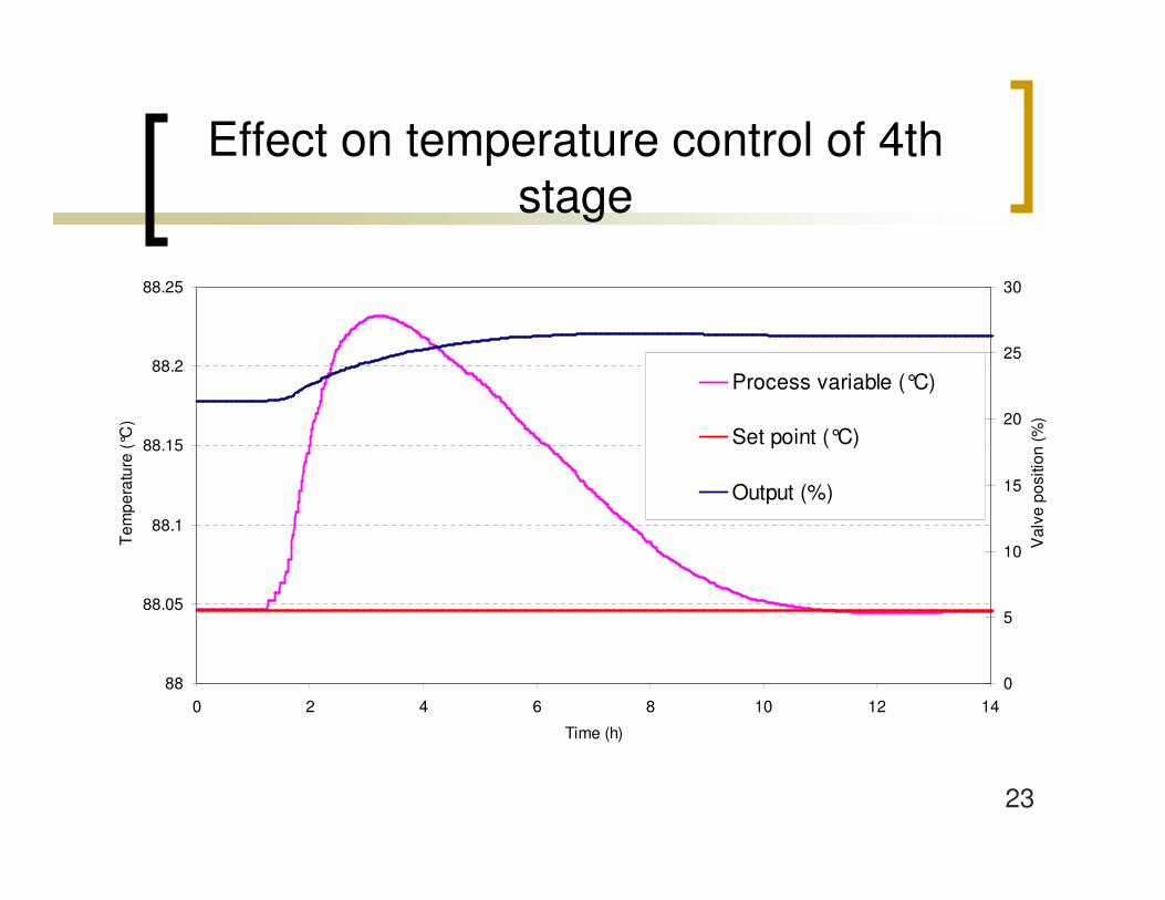
23
Effect on temperature control of 4thstage
88
88.05
88.1
88.15
88.2
88.25
0 2 4 6 8 10 12 14
Time (h)
Tem
pera
ture
(°C
)
0
5
10
15
20
25
30
Val
ve p
ositi
on (%
)
Process variable (°C)
Set point (°C)
Output (%)
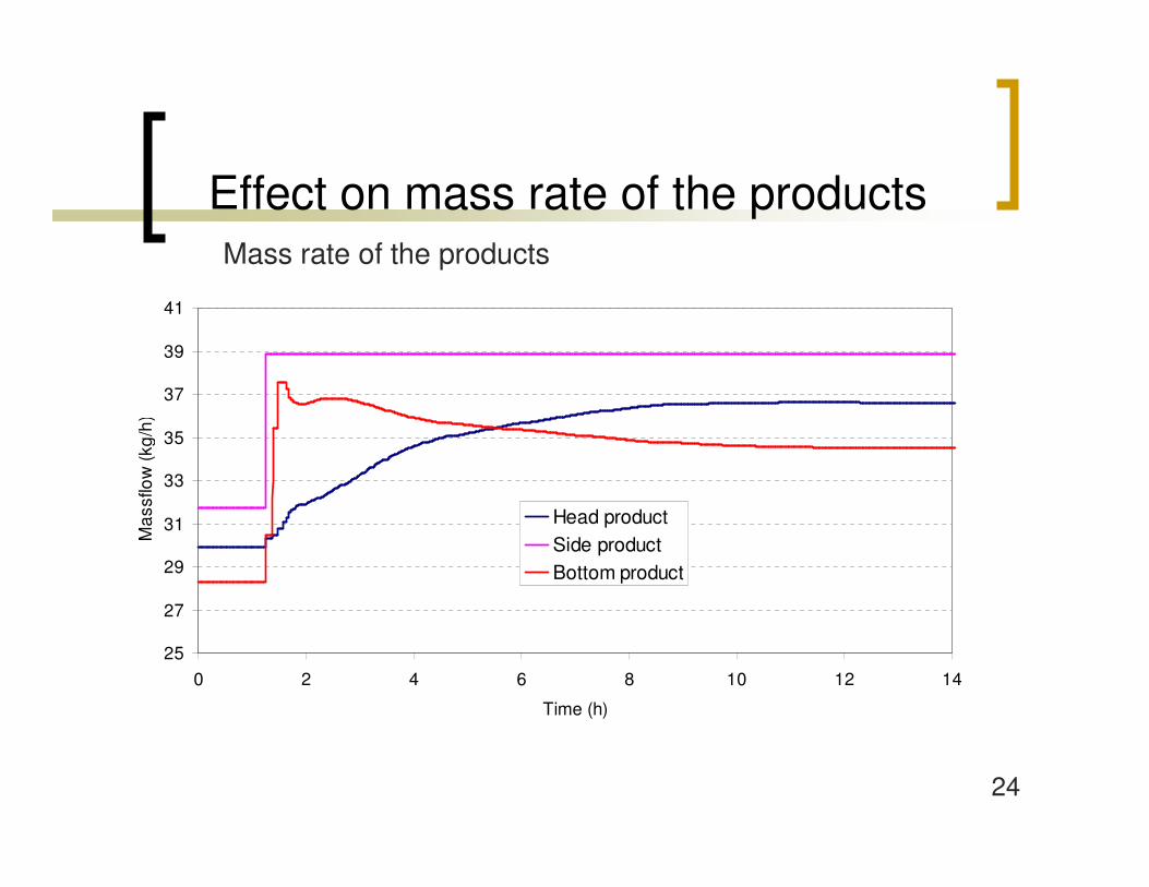
24
Effect on mass rate of the productsMass rate of the products
25
27
29
31
33
35
37
39
41
0 2 4 6 8 10 12 14
Time (h)
Mas
sflo
w (k
g/h)
Head productSide productBottom product
25
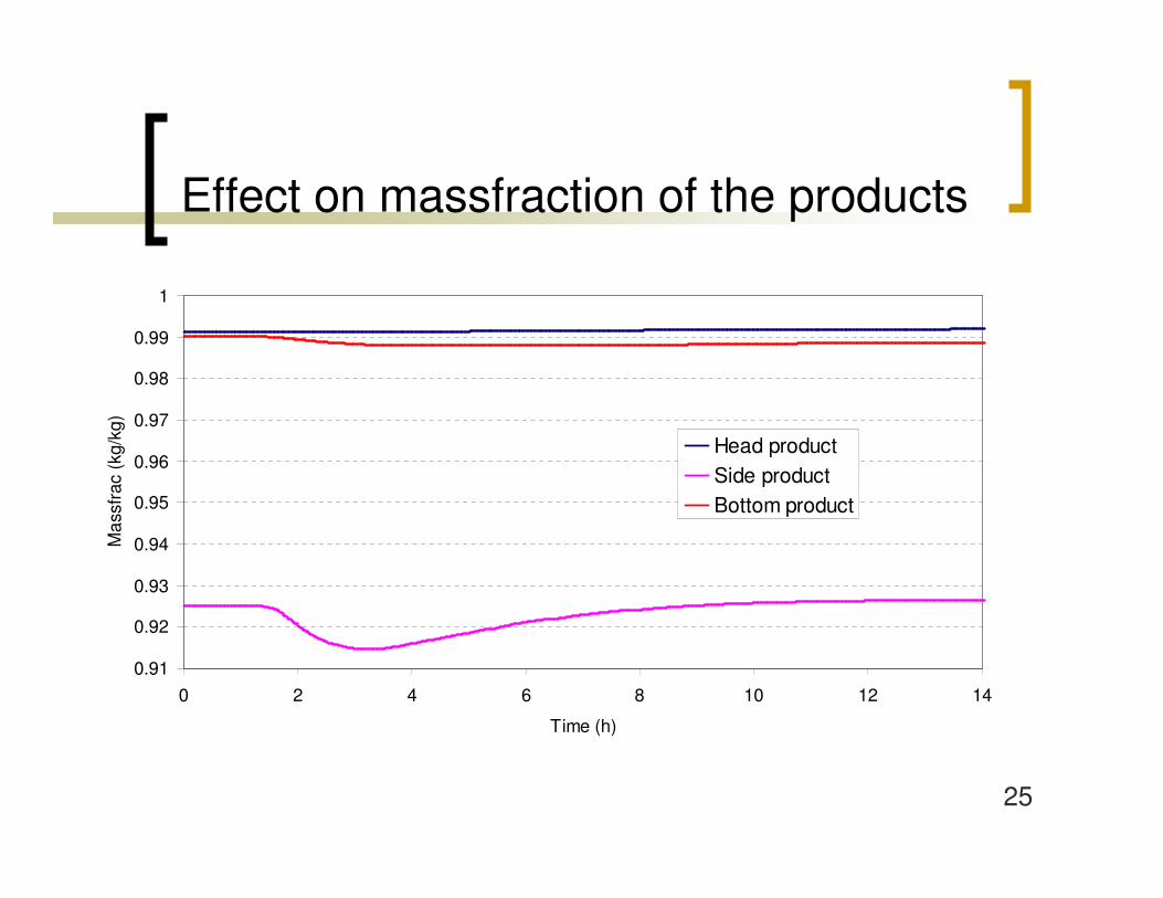
Effect on massfraction of the products
0.91
0.92
0.93
0.94
0.95
0.96
0.97
0.98
0.99
1
0 2 4 6 8 10 12 14
Time (h)
Mas
sfra
c (k
g/kg
)
Head productSide productBottom product

26
Summary
� The DWC was implemented in dynamic and steady-state simulator
� Main parameters of the column were analysed: optimum wall position is determinated
� Comparing DWC to side stream column: significant energy saving
� Controllability of the divided wall column was analysed: feasible control structure
27
Thank you for your attention!
� László Szabó is grateful for the support of the PhD Fellowship of the MOL Plc
� The financial support from the TAMOP-4.2.2-08/1/2008-0018 (Livable environment and healthier people – Bioinnovation and Green Technology research at the University of Pannonia) project is gratefully acknowledged.