
340 IEEE TRANSACTIONS ON BROADCASTING, VOL. 56,...
10
340 IEEE TRANSACTIONS ON BROADCASTING, VOL. 56, NO. 3, SEPTEMBER 2010 1K Element Antenna System for Mobile Direct Broadcasting Satellite Reception Pedram Mousavi, Member, IEEE, Mohammad Fakharzadeh, Member, IEEE, and Safieddin Safavi-Naeini, Member, IEEE Abstract—This paper describes the design methodology and low- cost solutions implemented in a low-cost 1K–element phased array system for mobile direct broadcasting satellite (DBS) reception. The techniques and configurations used to reduce the cost and com- plexity of the system are described in this paper. Moreover, the de- sign of a novel compact sub-array antenna to reduce the overall size of the system , the signal processing unit to suppress the noise on feedback channel and the mechanical structure to make the system agile, light and low cost are presented. Three efficient, model-free beamforming techniques are discussed and their performances in terms of convergence speed and steady state behavior are com- pared using several road tests. Results show that the developed in- telligent antenna can meet the stringent requirements of the highly dynamic mobile applications. Index Terms—Adaptive antenna, digital satellite broadcasting, mobile satellite communication, phased array antenna. I. INTRODUCTION D EMANDS for mobile reception of high quality video and data broadcasting services are rapidly increasing. Satellite broadcasting has a unique advantage of wide area coverage as compared to terrestrial broadcasting. However, reliable, robust, low profile and low cost antenna system that can receive and maintain weak satellite signal for all road conditions and vehicle maneuvers are not commercially available. Intelligent antennas can offer significant advantage in this field. Intelligent antennas refer to antenna system that adapts itself to users ever-changing requirements and the dynamic conditions of the environment by taking advantage of signal processing methods to adjust its radiation direction, frequency channel and polarization. They can reduce the size of the an- tenna which is an essential factor in market acceptability. Also by using electronic beamforming, the tracking speed substan- tially increases compared to the mechanical counterpart. The latter is important for compensating various road conditions and vehicle maneuvers. However, despite their impressive potentials and properties, intelligent antenna systems have Manuscript received July 30, 2009; revised March 22, 2010; accepted March 31, 2010. Date of publication June 10, 2010; date of current version August 20, 2010. P. Mousavi is with Intelligent Mechatronics Systems Inc., Waterloo, ON N2J 2Z5, Canada (e-mail: [email protected]). M. Fakharzadeh is with the Electrical and Computer Engineering Depart- ment, University of Waterloo, Waterloo, ON N2L 3G1, Canada, and also with the Intelwaves Technologies LTD, Waterloo, ON N2L 6J2, Canada. S. Safavi-Naeini is with the Electrical and Computer Engineering Depart- ment, University of Waterloo, Waterloo, ON N2L 3G1, Canada. Color versions of one or more of the figures in this paper are available online at http://ieeexplore.ieee.org. Digital Object Identifier 10.1109/TBC.2010.2049611 not become widespread commercial products in this field. Cost and complexity of intelligent antennas are beyond the scales of consumer electronics devices [1]. Calibration is an essential requirement of such complex systems, which is a fairly time-consuming process and requires skilled manpower. Moreover, the narrow bandwidth of microwave components degrades the broadband performance of a phased array system. Finally, a majority of the beamforming algorithms developed so far either have preconditions, or require considerable hardware resources, which make them unsuitable for a low-cost phased array system [2]–[19]. To design a low-cost intelligent antenna system, several pa- rameters, both at the component level and system level, must be noticed. At the component level, high gain antenna elements, low loss feed networks, low noise blocks, phase and amplitude linearity of active components and most importantly fabrication tolerances are among the factors that directly affect the cost. System integration and the issues arising from that have sig- nificant effects on the adaptability of the system to very cost sensitive applications such as vehicular communications. Some of those concerns are: mutual coupling, cross-talk between dif- ferent channels, system linearity, signal isolation, resonance, el- ement position error, element failure, weight, size, wind-loading and other mechanical constraints. In [20] the authors have presented an intelligent antenna system for on-road DBS reception, operating at 12.2–12.7 GHz, with a novel electronic beamforming algorithm [21], which in conjunction with a mechanical stabilization loop provides a robust tracking algorithm to compensate for vehicle maneuvers [22]. This paper discusses novel features and new mechanism which are added to the system in four areas that significantly reduce the cost and complexity and advance the performance of the unit in highly hostile environments in terms of noise, interference, extreme temperatures, various weather conditions and sharp maneuvers. These areas are: 1) A novel sub-array antenna and power combiner/phase shifter box, which have direct effects on the radiation gain, total loss and size of the system. 2) The signal processing and detection modules, which re- duce the noise and interference on the feed-back loop of the beamforming algorithm. 3) A light, agile and easily assembled mechanical platform with minimum vibration and noise transmission to the in- terior of the vehicles. 4) Three beamforming techniques, which are model-free (does not required the knowledge of phase-voltage, loca- tion of the target, and training sequence), converge fast, 0018-9316/$26.00 © 2010 IEEE
Transcript of 340 IEEE TRANSACTIONS ON BROADCASTING, VOL. 56,...
340 IEEE TRANSACTIONS ON BROADCASTING, VOL. 56, NO. 3, SEPTEMBER 2010
1K Element Antenna System for Mobile DirectBroadcasting Satellite Reception
Pedram Mousavi, Member, IEEE, Mohammad Fakharzadeh, Member, IEEE, andSafieddin Safavi-Naeini, Member, IEEE
Abstract—This paper describes the design methodology and low-cost solutions implemented in a low-cost 1K–element phased arraysystem for mobile direct broadcasting satellite (DBS) reception.The techniques and configurations used to reduce the cost and com-plexity of the system are described in this paper. Moreover, the de-sign of a novel compact sub-array antenna to reduce the overall sizeof the system , the signal processing unit to suppress the noise onfeedback channel and the mechanical structure to make the systemagile, light and low cost are presented. Three efficient, model-freebeamforming techniques are discussed and their performances interms of convergence speed and steady state behavior are com-pared using several road tests. Results show that the developed in-telligent antenna can meet the stringent requirements of the highlydynamic mobile applications.
Index Terms—Adaptive antenna, digital satellite broadcasting,mobile satellite communication, phased array antenna.
I. INTRODUCTION
D EMANDS for mobile reception of high quality video anddata broadcasting services are rapidly increasing. Satellite
broadcasting has a unique advantage of wide area coverage ascompared to terrestrial broadcasting. However, reliable, robust,low profile and low cost antenna system that can receive andmaintain weak satellite signal for all road conditions and vehiclemaneuvers are not commercially available.
Intelligent antennas can offer significant advantage in thisfield. Intelligent antennas refer to antenna system that adaptsitself to users ever-changing requirements and the dynamicconditions of the environment by taking advantage of signalprocessing methods to adjust its radiation direction, frequencychannel and polarization. They can reduce the size of the an-tenna which is an essential factor in market acceptability. Alsoby using electronic beamforming, the tracking speed substan-tially increases compared to the mechanical counterpart. Thelatter is important for compensating various road conditionsand vehicle maneuvers. However, despite their impressivepotentials and properties, intelligent antenna systems have
Manuscript received July 30, 2009; revised March 22, 2010; accepted March31, 2010. Date of publication June 10, 2010; date of current version August 20,2010.
P. Mousavi is with Intelligent Mechatronics Systems Inc., Waterloo, ON N2J2Z5, Canada (e-mail: [email protected]).
M. Fakharzadeh is with the Electrical and Computer Engineering Depart-ment, University of Waterloo, Waterloo, ON N2L 3G1, Canada, and also withthe Intelwaves Technologies LTD, Waterloo, ON N2L 6J2, Canada.
S. Safavi-Naeini is with the Electrical and Computer Engineering Depart-ment, University of Waterloo, Waterloo, ON N2L 3G1, Canada.
Color versions of one or more of the figures in this paper are available onlineat http://ieeexplore.ieee.org.
Digital Object Identifier 10.1109/TBC.2010.2049611
not become widespread commercial products in this field.Cost and complexity of intelligent antennas are beyond thescales of consumer electronics devices [1]. Calibration is anessential requirement of such complex systems, which is afairly time-consuming process and requires skilled manpower.Moreover, the narrow bandwidth of microwave componentsdegrades the broadband performance of a phased array system.Finally, a majority of the beamforming algorithms developed sofar either have preconditions, or require considerable hardwareresources, which make them unsuitable for a low-cost phasedarray system [2]–[19].
To design a low-cost intelligent antenna system, several pa-rameters, both at the component level and system level, must benoticed. At the component level, high gain antenna elements,low loss feed networks, low noise blocks, phase and amplitudelinearity of active components and most importantly fabricationtolerances are among the factors that directly affect the cost.System integration and the issues arising from that have sig-nificant effects on the adaptability of the system to very costsensitive applications such as vehicular communications. Someof those concerns are: mutual coupling, cross-talk between dif-ferent channels, system linearity, signal isolation, resonance, el-ement position error, element failure, weight, size, wind-loadingand other mechanical constraints.
In [20] the authors have presented an intelligent antennasystem for on-road DBS reception, operating at 12.2–12.7 GHz,with a novel electronic beamforming algorithm [21], which inconjunction with a mechanical stabilization loop provides arobust tracking algorithm to compensate for vehicle maneuvers[22]. This paper discusses novel features and new mechanismwhich are added to the system in four areas that significantlyreduce the cost and complexity and advance the performanceof the unit in highly hostile environments in terms of noise,interference, extreme temperatures, various weather conditionsand sharp maneuvers. These areas are:
1) A novel sub-array antenna and power combiner/phaseshifter box, which have direct effects on the radiation gain,total loss and size of the system.
2) The signal processing and detection modules, which re-duce the noise and interference on the feed-back loop ofthe beamforming algorithm.
3) A light, agile and easily assembled mechanical platformwith minimum vibration and noise transmission to the in-terior of the vehicles.
4) Three beamforming techniques, which are model-free(does not required the knowledge of phase-voltage, loca-tion of the target, and training sequence), converge fast,
0018-9316/$26.00 © 2010 IEEE

MOUSAVI et al.: 1K ELEMENT ANTENNA SYSTEM FOR MOBILE DIRECT BROADCASTING SATELLITE RECEPTION 341
Fig. 1. Intelligent antenna system configuration for mobile DBS.
and enable tracking the desired satellite on any drivingcondition and can compensate for the fabrication errors.
In the next section, we present the configuration of the intel-ligent antenna system. In Section III, the designed microwavecomponents, including the new sub-array antenna and powercombiner/ phase shifter will be described. Section IV is dealingwith the agile low-profile mechanical structure of the antennasystem. Section V elaborates on beamforming algorithms. Theeffectiveness of the proposed beamforming techniques is con-firmed through various tests in Section VI. Finally, Section VIIconcludes the paper.
II. SYSTEM DESCRIPTION
A. RF Section
Figs. 1 and 2 shows the system configuration and the photo-graph of the new version of the low-profile intelligent antennasystem designed for vehicular satellite communication. Twooperational modes have been designed for this system: Homing(acquisition of the desired satellite), and Tracking (maintainingthe array beam locked on the satellite direction) [20]. Thesystem consists of 17 high-gain sub-arrays for Right HandCircular Polarization (RHCP) and 17 sub-arrays for Left HandCircular Polarization (LHCP). Compared to the previous ver-sion [20], by introducing a novel design for the sub-array (seeSection III-A) the overall gain has increased to 31.8 dBi from31.5 dBi [20] and the axial ratio has decreased to 1.5 dB from1.8 dB [20], while its size has decreased. As a result, the overalldiameter and the height of system have reduced to 83 cm and5 cm compared to 86 cm and 6 cm of [20], which make the newversion more attractive for the consumer electronic market andeasier to install on vehicles.
The sub-array antennas for each polarization are placed in fiveconsecutive panels fitted in a half-circle. Three panels hold threesub-array antennas and the rest hold four sub-arrays. Each sub-array consists of 16 or 32 microstrip patch elements and a feednetwork. Totally, 992 patch elements are used in this system.
Fig. 2. Phased array antenna for land mobile satellite link (CB: control board;PS/PC: phase shifter power combiner; EL: elevation; AZ: azimuth).
Each sub-array is connected to a voltage controlled analogphase shifter [23] via an LNA and low-loss cable. For each po-larization the outputs of all 17 phase shifters are combined by apower combiner and then down converted to IF by a Low NoiseBlock (LNB) module. The control voltage of the phase shiftersare adjusted by the beamforming algorithm.
Since phase shifting devices are used instead of true-timedelay network, there is a possibility of beam squint at the edgeof the frequency band when the antenna is scanning. Due to thesmall scan angle in azimuth the beam-squint in azimuthis less than 0.05 from the beam direction related to the centerfrequency. However, for elevation scanning, due to the largerscan angle (20 –70 ) the beam-squint can be up to 4 from themain beam at center frequency. To alleviate this problem, dif-ferent RF cable lengths between panels (as shown in Fig. 2) areemployed in the new version. The required coaxial cable lengthbetween each sub-array and the corresponding phase shifter isgiven by
(1)
where is the number of panels for each polarization,is the minimum cable length used in the system , isthe relative permittivity of the coaxial cable (2.1 in this case)and is the average distance between panels when the panelsrotate in the elevation plane.
B. Signal Processing Unit
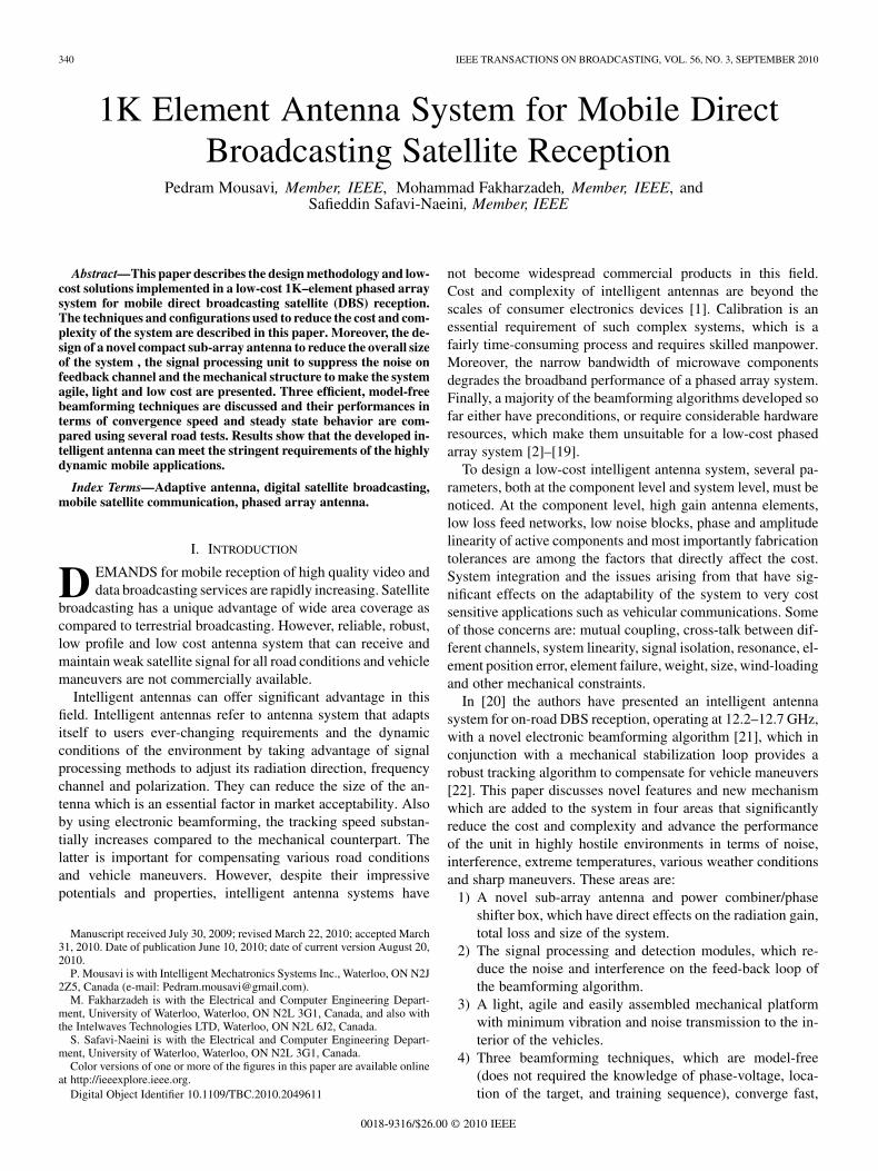
The block diagram of the signal processing unit is shown inFig. 3(a). The down-converted signal from the LNB (IF signal)transfers to the Digital Video Broadcasting (DVB) board de-veloped in house and shown in Fig. 3(b). The IF frequencyranges from 950 to 1450 MHz, and its power level varies be-tween 20 to 35 dBm. The IF signal is divided into two partsusing a compact Wilkinson power divider. One branch goes tothe Digital Satellite Tuner (ZL10037) and the Satellite Demod-ulator (ZL10313). The satellite ID, extracted from the MPEG2stream, is used to identify the desired satellite and expedite the
342 IEEE TRANSACTIONS ON BROADCASTING, VOL. 56, NO. 3, SEPTEMBER 2010
Fig. 3. (a) Block diagram of signal processing unit. (b) DVB and RF detectorboard.
initial homing of the phased array system. Also the amplifiedIF signal from the digital satellite tuner is transferred to thesatellite receiver inside the car through a rotary joint. The otherbranch of the Wilkinson power divider is connected to the RFpower detector via a band-pass hair pin filter. The power de-tector (LT5534) has a frequency range of 50 MHz to 3 GHz,and a dynamic range of 60 dB. The measured power is the onlyavailable input for the beamforming algorithms which will bediscussed in Section V. The amplitude fluctuations of the mea-sured power caused by noise or interference from other activesources can reduce the accuracy of the beamforming algorithm.Thus, three types of filters have been implemented in the signalprocessing unit to limit noise and interference.
A band-pass filter with 100 MHz bandwidth(1200–1300 MHz) is employed before the power de-tector. Additionally, a low-pass RC filter is implemented afterthe power detector to smooth the detected power level, whichideally must be a DC signal. The output is then digitized by a12-bits analog to digital converter (AD7887) with a maximumsymbol rate of 125 kS/s. Finally, a -point low-pass digitalfilter with Hamming window and a cutoff frequency equalto 0.01 of the sampling rate is used after the ADC. Digitalfiltering attenuates the high-frequency components of thesampled measured power and limits the energy of noise. The
size of Hamming window, , can vary from 8 to 30. Increasingdiminishes the instantaneous power fluctuations, while
decreasing speeds up the beamforming.The control algorithms, have been implemented in a Digital
Signal Processor (ADSP-BF537) on the main Control Board(CB). Using the measured RF power level and the gyro informa-tion, the beamforming algorithm adjusts the phase shifters andthe tracking algorithm sends the required commands to the az-imuth and elevation motors, via motor control and motor driverboards.
III. RF AND MICROWAVE COMPONENTS
In this section the design procedures for the new sub-arrayantenna and phase shifters–power combiner box are discussedand some measured data will be presented.
A. Sub-Array Antenna
The design criteria for the sub-array antenna are to achievehigh radiation gain ( 20 dBi), low feed-network loss, a goodreturn loss ( 15 dB) and a small axial ratio ( 2 dB) over a4% relative bandwidth. Additionally, the width and the length ofthe sub-array must be reduced, which directly affect the overallheight and diameter of the system.
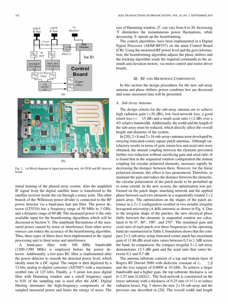
In [20], 2 8 and 2 16 sub-arrays antenna were developed byarraying truncated-corner square patch antennas. Although sat-isfactory results in terms of gain, return loss and axial ratio wereobtained, the mutual coupling between the elements preventedfurther size reduction without sacrificing gain and axial ratio. Itis found that in the sequential rotation configuration the mutualcoupling for circular polarized elements, increases rapidly bydecreasing the distance between them. However, for the linearpolarized element, this effect is less pronounced. Therefore, tomaintain the gain and reduce the distance between the elements,the circular polarization of the patch needs to be perturbed upto some extend. In the new system, the optimization was per-formed on the patch shape, matching network and the appliedphase between each two elements in a sequentially rotated 2 2patch array. The optimization on the shapes of the patch an-tennas in a 2 2 configuration resulted in two notable irregularhexagonal microstrip (A &B) antennas as shown in Fig. 4. Dueto the irregular shape of the patches, the new electrical phaseshifts between the elements in sequential rotation are calcu-lated to be 0 , 80 , 190 , and 270 . The simulated gain andaxial ratio of each patch over three frequencies in the operatingband are summarized in Table I. Simulation shows that the com-pact 2 2 sub-array using truncated corner patch has maximumgain of 11.86 dBi axial ratio varies between 0.3 to 1.3dB acrossthe band. In comparison, the compact irregular 2 2 sub-arraydemonstrates 12.3 dBi gain and the axial ratio that varies be-tween 0.2 and 0.7 dB.
The antenna substrate consists of a top and bottom layer ofRogers RT Duroid 5880 with dielectric constant ofand the loss tangent of 0.0009 at 10 GHz. To achieve a largerbandwidth and a higher gain, the top substrate thickness is setto 1.57 mm . The feed-network is constructed on thelower substrate with a thickness of 0.25 mm to reduceradiation losses. Fig. 5 shows the new 2 16 sub-array and theprevious one described in [20]. The overall width and length
MOUSAVI et al.: 1K ELEMENT ANTENNA SYSTEM FOR MOBILE DIRECT BROADCASTING SATELLITE RECEPTION 343
Fig. 4. Optimized patches, in a 2�2 sequentially rotated building block.
TABLE IOPTIMIZED PATCH ANTENNA PARAMETERS
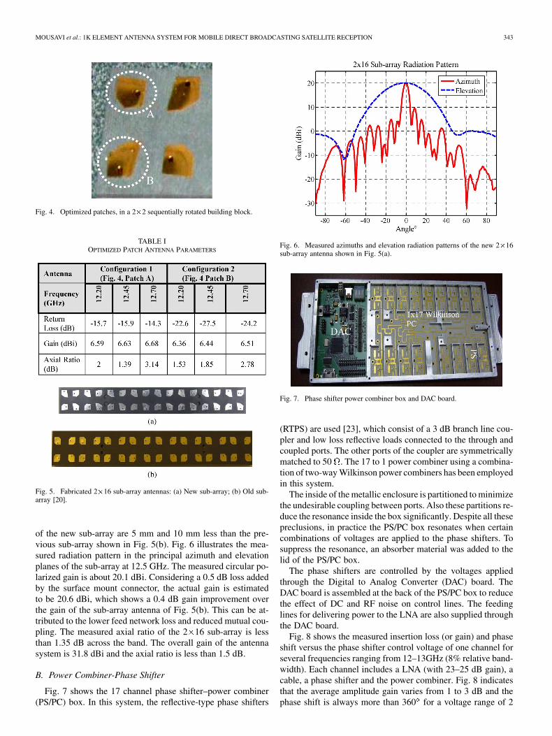
Fig. 5. Fabricated 2�16 sub-array antennas: (a) New sub-array; (b) Old sub-array [20].
of the new sub-array are 5 mm and 10 mm less than the pre-vious sub-array shown in Fig. 5(b). Fig. 6 illustrates the mea-sured radiation pattern in the principal azimuth and elevationplanes of the sub-array at 12.5 GHz. The measured circular po-larized gain is about 20.1 dBi. Considering a 0.5 dB loss addedby the surface mount connector, the actual gain is estimatedto be 20.6 dBi, which shows a 0.4 dB gain improvement overthe gain of the sub-array antenna of Fig. 5(b). This can be at-tributed to the lower feed network loss and reduced mutual cou-pling. The measured axial ratio of the 2 16 sub-array is lessthan 1.35 dB across the band. The overall gain of the antennasystem is 31.8 dBi and the axial ratio is less than 1.5 dB.
B. Power Combiner-Phase Shifter
Fig. 7 shows the 17 channel phase shifter–power combiner(PS/PC) box. In this system, the reflective-type phase shifters
Fig. 6. Measured azimuths and elevation radiation patterns of the new 2�16sub-array antenna shown in Fig. 5(a).
Fig. 7. Phase shifter power combiner box and DAC board.
(RTPS) are used [23], which consist of a 3 dB branch line cou-pler and low loss reflective loads connected to the through andcoupled ports. The other ports of the coupler are symmetricallymatched to 50 . The 17 to 1 power combiner using a combina-tion of two-way Wilkinson power combiners has been employedin this system.
The inside of the metallic enclosure is partitioned to minimizethe undesirable coupling between ports. Also these partitions re-duce the resonance inside the box significantly. Despite all thesepreclusions, in practice the PS/PC box resonates when certaincombinations of voltages are applied to the phase shifters. Tosuppress the resonance, an absorber material was added to thelid of the PS/PC box.
The phase shifters are controlled by the voltages appliedthrough the Digital to Analog Converter (DAC) board. TheDAC board is assembled at the back of the PS/PC box to reducethe effect of DC and RF noise on control lines. The feedinglines for delivering power to the LNA are also supplied throughthe DAC board.
Fig. 8 shows the measured insertion loss (or gain) and phaseshift versus the phase shifter control voltage of one channel forseveral frequencies ranging from 12–13GHz (8% relative band-width). Each channel includes a LNA (with 23–25 dB gain), acable, a phase shifter and the power combiner. Fig. 8 indicatesthat the average amplitude gain varies from 1 to 3 dB and thephase shift is always more than 360 for a voltage range of 2

344 IEEE TRANSACTIONS ON BROADCASTING, VOL. 56, NO. 3, SEPTEMBER 2010
Fig. 8. Amplitude and phase variation over control voltages of one RF channel(including phase shifter, power combiner, cable and LNA).
Fig. 9. An exploded isometric view showing the principal mechanical compo-nents of the low profile intelligent antenna system.
to 10 Volts. Therefore about 12 dB of ideal loss of the 17 to 1power combiner is included in the measurements.
IV. MECHANICAL STRUCTURE
The general purpose of the mechanical design is to providea light platform (less than 10 kg) for a low profile phased arraysatellite tracker system (5 cm height and 83 cm diameter), whichcan be fitted to small vehicles.
Fig. 9 shows a mechanical platform including a polymerbase and a stainless steel azimuth rotation drive ring affixedto the inner diameter of the polymer base. An azimuth rotorassembly engages the rotation ring with two fixed wheels andone spring-biased urethane coated drive wheel of a stepper drivemotor. One of the novel features of the mechanical structure isthe spring loaded wheel which provides both optimized torquetransmittal to the stainless steel drive ring, and, compensationfor the thermal expansion of the different materials containedwithin the structure at various temperatures and environmentalconditions. The other advantages of this structure are as follows:
Fig. 10. A detailed view of elevation mechanism showing the elevation controlarm and assembly of sub-array/LNA to array carrier.
1 By spring loading the drive assembly one can accuratelyprovide torque which is sufficient to drive the rotor as-sembly without slippage, but not so high as cause unnec-essarily high current demands on the entire drive system.
2 2) Spring loading compensates for the wide manufacturingtolerances required to produce the drive ring at an econom-ical cost. The drive ring can actually be as much asout of round or flatness and the system will still turn freely.
The urethane coating on all spring loaded and fixed wheelsreduces noise and vibration. The unit is mechanically capableof rotating at speeds of up to 120 , with acceleration valuesexceeding 100 , within the drive ring/chassis structure. Theelevation system enables the synchronous movement of ten an-tenna array panel assemblies by using the elevation control arms, shown in Fig. 10, from a position roughly 20 from the hori-zontal through to 90 i.e. a nominally 70 rotation.
By using the vertical transition between the LNA and thesub-array described in [20] it is possible to simply snap the in-tegrated LNA and sub-array into the array carrier by hand, com-pletely without any tools. This ability to position and attach 34sub-array/LNA assemblies to array carriers drastically reducesthe production cost. This new mechanical structure reduces theweight of the system by more than 30% compared to [22] (8 kgvs. 12 kg).
V. EFFICIENT BEAMFORMING ALGORITHM
In this section three beamforming algorithms designed forthis phased array application are described. These algorithmsdo not depend on any specific initial conditions and the RFchannel model. Their objective is to maximize the receivedpower from the desired satellite whose ID has been detected bythe DVB board and minimize the possibility and duration ofloosing signal in various road and driving conditions.
A. Beamforming for Satellite Communication
There is a substantial body of research addressing the beam-forming for phased array systems [24], [27]; however, efficientand low-complex algorithms are still needed to facilitate the uti-lization of phased arrays for commercial applications. An effi-cient beamforming algorithm is the one which compensates forthe hardware inaccuracies, converges fast, reduces the steady
MOUSAVI et al.: 1K ELEMENT ANTENNA SYSTEM FOR MOBILE DIRECT BROADCASTING SATELLITE RECEPTION 345
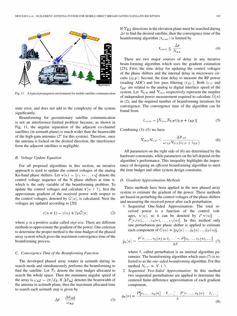
Fig. 11. A typical propagation environment for mobile satellite communication
state error, and does not add to the complexity of the systemsignificantly.
Beamforming for geostationary satellite communicationis not an interference-limited problem because, as shown inFig. 11, the angular separation of the adjacent co-channelsatellites (in azimuth plane) is much wider than the beamwidthof the high-gain antennas (2 for this system). Therefore, oncethe antenna is locked on the desired direction, the interferencefrom the adjacent satellites is negligible.
B. Voltage Update Equation
For all proposed algorithms in this section, an iterativeapproach is used to update the control voltages of the analogKu-band phase shifters. Let denote thecontrol voltage sequence of the N phase shifters at time ,which is the only variable of the beamforming problem. Toupdate the control voltages and calculate , first theapproximate gradient of the received power with respect tothe control voltages, denoted by , is calculated. Next thevoltages are updated according to [20]
(2)
where is a positive scalar called step size. There are differentmethods to approximate the gradient of the power. One criterionto determine the proper method is the time-budget of the phasedarray system which gives the maximum convergence time of thebeamforming process.
C. Convergence Time of the Beamforming Function
The developed phased array rotates in azimuth during itssearch mode and simultaneously performs the beamforming tofind the satellite. Let denote the time budget allocated tosearch the whole space. Then the minimum angular speed ofthe array is . If denotes the beamwidth ofthe antenna in azimuth plane, then the maximum allocated timeto search each azimuth step is given by
(3)
If directions in the elevation plane must be searched duringto find the desired satellite, then the convergence time of the
beamforming algorithm is limited by
(4)
There are two major sources of delay in any iterativebeam-forming algorithm which uses the gradient estimation[25]. First, the time delay for updating the control voltagesof the phase shifters and the internal delay in microwave cir-cuits . Second, the time delay to measure the RF power(reading ADC) and low pass filtering . Both and
are related to the analog to digital interface speed of thesystem. Let and respectively represent the numberof independent power measurement required to calculatein (2), and the required number of beamforming iterations forconvergence. The convergence time of the algorithm can befound from
(5)
Combining (3)–(5) we have
(6)
All parameters on the right side of (6) are determined by thehardware constraints, while parameters on the left depend on thealgorithm’s performance. This inequality highlights the impor-tance of designing an efficient beamforming algorithm to meetthe time budget and other system design constrains.
D. Gradient Approximation Methods
Three methods have been applied in the new phased arraysystem to estimate the gradient of the power. These methodsare based on perturbing the control voltages of the phase shiftersand measuring the received power after each perturbation.
1 Sequential One-Sided Approximation: The total re-ceived power is a function of the control volt-ages, , so it can be denoted by
. In this method onlyone perturbation per phase shifter is applied to estimateeach component of ,
(7)
where , called perturbation is an internal algorithm pa-rameter. The beamforming algorithm which uses (7) is re-ferred to as the one-sided beamforming algorithm. For thismethod .
2 Sequential Two-Sided Approximation: In this methodtwo sequential perturbations are applied to determine thecentered finite-difference approximation of each gradientcomponent,
(8)
346 IEEE TRANSACTIONS ON BROADCASTING, VOL. 56, NO. 3, SEPTEMBER 2010
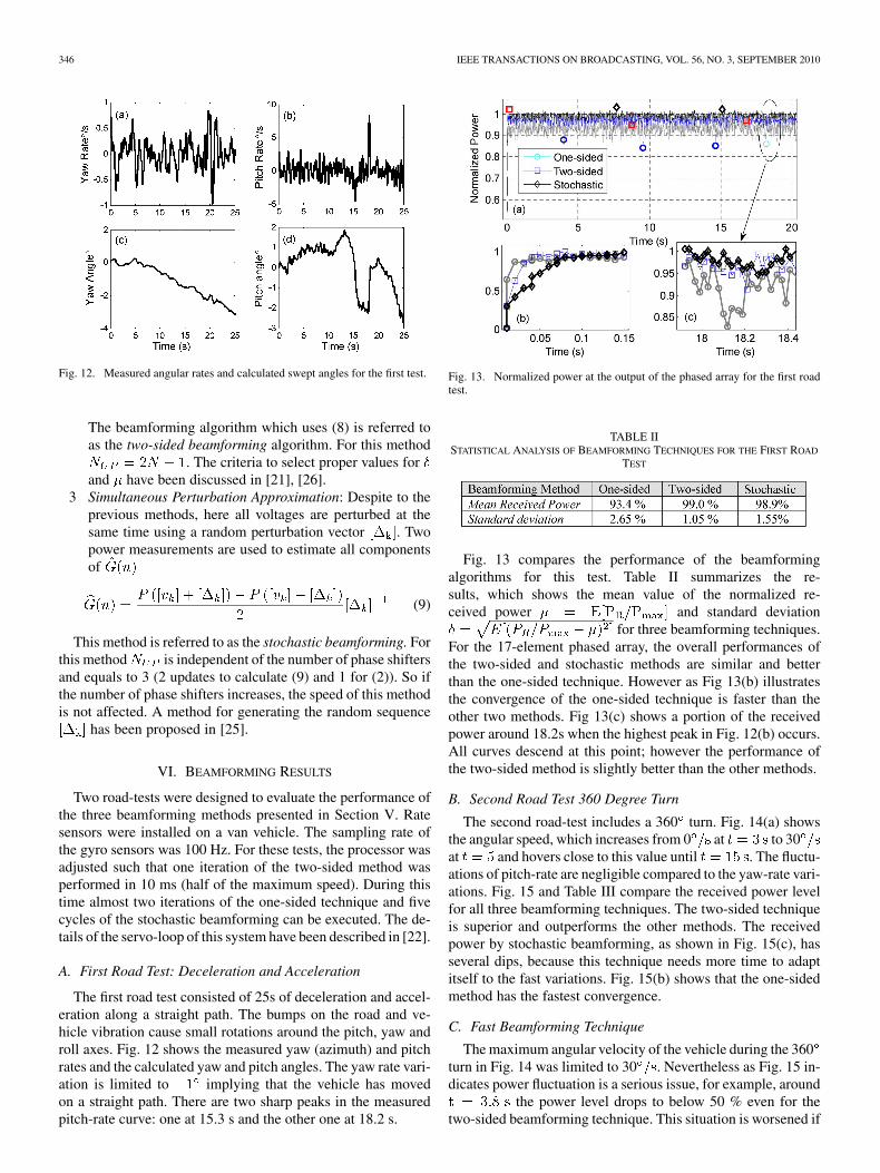
Fig. 12. Measured angular rates and calculated swept angles for the first test.
The beamforming algorithm which uses (8) is referred toas the two-sided beamforming algorithm. For this method
. The criteria to select proper values forand have been discussed in [21], [26].
3 Simultaneous Perturbation Approximation: Despite to theprevious methods, here all voltages are perturbed at thesame time using a random perturbation vector . Twopower measurements are used to estimate all componentsof
(9)
This method is referred to as the stochastic beamforming. Forthis method is independent of the number of phase shiftersand equals to 3 (2 updates to calculate (9) and 1 for (2)). So ifthe number of phase shifters increases, the speed of this methodis not affected. A method for generating the random sequence
has been proposed in [25].
VI. BEAMFORMING RESULTS
Two road-tests were designed to evaluate the performance ofthe three beamforming methods presented in Section V. Ratesensors were installed on a van vehicle. The sampling rate ofthe gyro sensors was 100 Hz. For these tests, the processor wasadjusted such that one iteration of the two-sided method wasperformed in 10 ms (half of the maximum speed). During thistime almost two iterations of the one-sided technique and fivecycles of the stochastic beamforming can be executed. The de-tails of the servo-loop of this system have been described in [22].
A. First Road Test: Deceleration and Acceleration
The first road test consisted of 25s of deceleration and accel-eration along a straight path. The bumps on the road and ve-hicle vibration cause small rotations around the pitch, yaw androll axes. Fig. 12 shows the measured yaw (azimuth) and pitchrates and the calculated yaw and pitch angles. The yaw rate vari-ation is limited to implying that the vehicle has movedon a straight path. There are two sharp peaks in the measuredpitch-rate curve: one at 15.3 s and the other one at 18.2 s.
Fig. 13. Normalized power at the output of the phased array for the first roadtest.
TABLE IISTATISTICAL ANALYSIS OF BEAMFORMING TECHNIQUES FOR THE FIRST ROAD
TEST
Fig. 13 compares the performance of the beamformingalgorithms for this test. Table II summarizes the re-sults, which shows the mean value of the normalized re-ceived power and standard deviation
for three beamforming techniques.For the 17-element phased array, the overall performances ofthe two-sided and stochastic methods are similar and betterthan the one-sided technique. However as Fig 13(b) illustratesthe convergence of the one-sided technique is faster than theother two methods. Fig 13(c) shows a portion of the receivedpower around 18.2s when the highest peak in Fig. 12(b) occurs.All curves descend at this point; however the performance ofthe two-sided method is slightly better than the other methods.
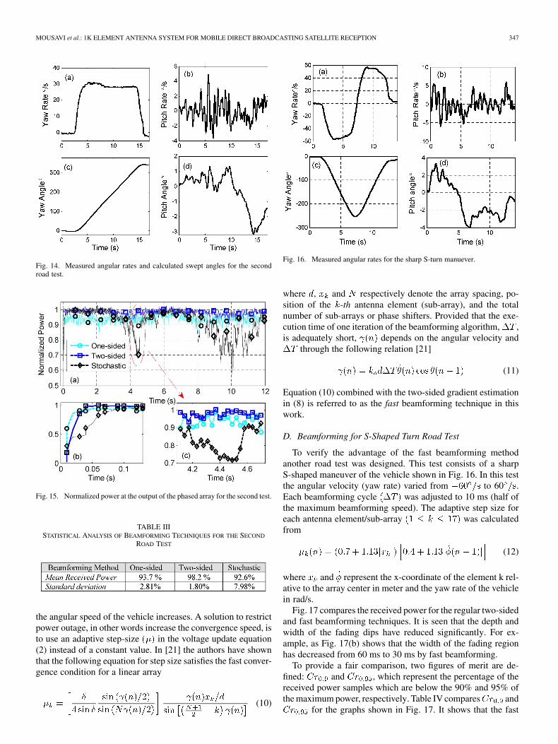
B. Second Road Test 360 Degree Turn
The second road-test includes a 360 turn. Fig. 14(a) showsthe angular speed, which increases from 0 at to 30at and hovers close to this value until . The fluctu-ations of pitch-rate are negligible compared to the yaw-rate vari-ations. Fig. 15 and Table III compare the received power levelfor all three beamforming techniques. The two-sided techniqueis superior and outperforms the other methods. The receivedpower by stochastic beamforming, as shown in Fig. 15(c), hasseveral dips, because this technique needs more time to adaptitself to the fast variations. Fig. 15(b) shows that the one-sidedmethod has the fastest convergence.
C. Fast Beamforming Technique
The maximum angular velocity of the vehicle during the 360turn in Fig. 14 was limited to 30 . Nevertheless as Fig. 15 in-dicates power fluctuation is a serious issue, for example, around
the power level drops to below 50 % even for thetwo-sided beamforming technique. This situation is worsened if
MOUSAVI et al.: 1K ELEMENT ANTENNA SYSTEM FOR MOBILE DIRECT BROADCASTING SATELLITE RECEPTION 347
Fig. 14. Measured angular rates and calculated swept angles for the secondroad test.
Fig. 15. Normalized power at the output of the phased array for the second test.
TABLE IIISTATISTICAL ANALYSIS OF BEAMFORMING TECHNIQUES FOR THE SECOND
ROAD TEST
the angular speed of the vehicle increases. A solution to restrictpower outage, in other words increase the convergence speed, isto use an adaptive step-size in the voltage update equation(2) instead of a constant value. In [21] the authors have shownthat the following equation for step size satisfies the fast conver-gence condition for a linear array
(10)
Fig. 16. Measured angular rates for the sharp S-turn manuever.
where , and respectively denote the array spacing, po-sition of the -th antenna element (sub-array), and the totalnumber of sub-arrays or phase shifters. Provided that the exe-cution time of one iteration of the beamforming algorithm, ,is adequately short, depends on the angular velocity and
through the following relation [21]
(11)
Equation (10) combined with the two-sided gradient estimationin (8) is referred to as the fast beamforming technique in thiswork.
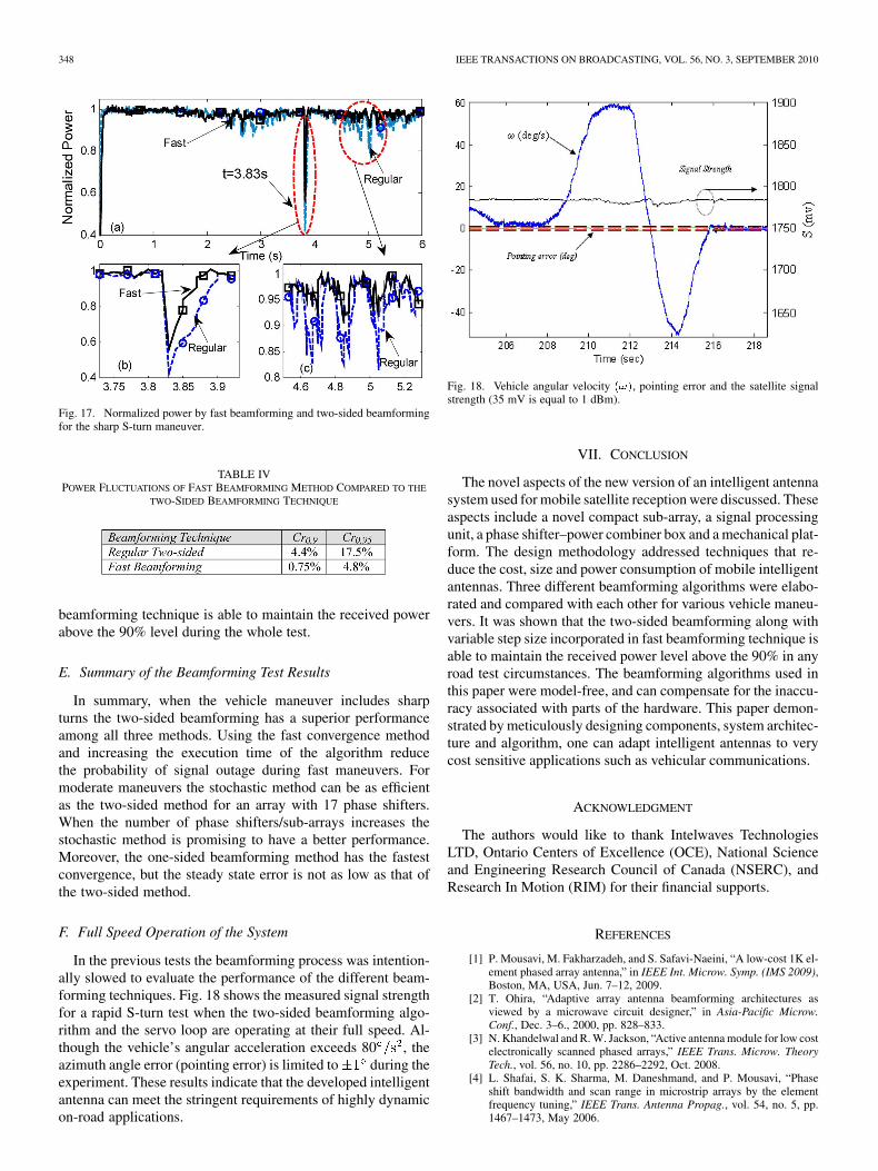
D. Beamforming for S-Shaped Turn Road Test
To verify the advantage of the fast beamforming methodanother road test was designed. This test consists of a sharpS-shaped maneuver of the vehicle shown in Fig. 16. In this testthe angular velocity (yaw rate) varied from to 60 .Each beamforming cycle was adjusted to 10 ms (half ofthe maximum beamforming speed). The adaptive step size foreach antenna element/sub-array was calculatedfrom
(12)
where and represent the x-coordinate of the element k rel-ative to the array center in meter and the yaw rate of the vehiclein rad/s.
Fig. 17 compares the received power for the regular two-sidedand fast beamforming techniques. It is seen that the depth andwidth of the fading dips have reduced significantly. For ex-ample, as Fig. 17(b) shows that the width of the fading regionhas decreased from 60 ms to 30 ms by fast beamforming.
To provide a fair comparison, two figures of merit are de-fined: and , which represent the percentage of thereceived power samples which are below the 90% and 95% ofthe maximum power, respectively. Table IV compares and
for the graphs shown in Fig. 17. It shows that the fast
348 IEEE TRANSACTIONS ON BROADCASTING, VOL. 56, NO. 3, SEPTEMBER 2010
Fig. 17. Normalized power by fast beamforming and two-sided beamformingfor the sharp S-turn maneuver.
TABLE IVPOWER FLUCTUATIONS OF FAST BEAMFORMING METHOD COMPARED TO THE
TWO-SIDED BEAMFORMING TECHNIQUE
beamforming technique is able to maintain the received powerabove the 90% level during the whole test.
E. Summary of the Beamforming Test Results
In summary, when the vehicle maneuver includes sharpturns the two-sided beamforming has a superior performanceamong all three methods. Using the fast convergence methodand increasing the execution time of the algorithm reducethe probability of signal outage during fast maneuvers. Formoderate maneuvers the stochastic method can be as efficientas the two-sided method for an array with 17 phase shifters.When the number of phase shifters/sub-arrays increases thestochastic method is promising to have a better performance.Moreover, the one-sided beamforming method has the fastestconvergence, but the steady state error is not as low as that ofthe two-sided method.
F. Full Speed Operation of the System
In the previous tests the beamforming process was intention-ally slowed to evaluate the performance of the different beam-forming techniques. Fig. 18 shows the measured signal strengthfor a rapid S-turn test when the two-sided beamforming algo-rithm and the servo loop are operating at their full speed. Al-though the vehicle’s angular acceleration exceeds 80 , theazimuth angle error (pointing error) is limited to during theexperiment. These results indicate that the developed intelligentantenna can meet the stringent requirements of highly dynamicon-road applications.
Fig. 18. Vehicle angular velocity ���, pointing error and the satellite signalstrength (35 mV is equal to 1 dBm).
VII. CONCLUSION
The novel aspects of the new version of an intelligent antennasystem used for mobile satellite reception were discussed. Theseaspects include a novel compact sub-array, a signal processingunit, a phase shifter–power combiner box and a mechanical plat-form. The design methodology addressed techniques that re-duce the cost, size and power consumption of mobile intelligentantennas. Three different beamforming algorithms were elabo-rated and compared with each other for various vehicle maneu-vers. It was shown that the two-sided beamforming along withvariable step size incorporated in fast beamforming technique isable to maintain the received power level above the 90% in anyroad test circumstances. The beamforming algorithms used inthis paper were model-free, and can compensate for the inaccu-racy associated with parts of the hardware. This paper demon-strated by meticulously designing components, system architec-ture and algorithm, one can adapt intelligent antennas to verycost sensitive applications such as vehicular communications.
ACKNOWLEDGMENT
The authors would like to thank Intelwaves TechnologiesLTD, Ontario Centers of Excellence (OCE), National Scienceand Engineering Research Council of Canada (NSERC), andResearch In Motion (RIM) for their financial supports.
REFERENCES
[1] P. Mousavi, M. Fakharzadeh, and S. Safavi-Naeini, “A low-cost 1K el-ement phased array antenna,” in IEEE Int. Microw. Symp. (IMS 2009),Boston, MA, USA, Jun. 7–12, 2009.
[2] T. Ohira, “Adaptive array antenna beamforming architectures asviewed by a microwave circuit designer,” in Asia-Pacific Microw.Conf., Dec. 3–6., 2000, pp. 828–833.
[3] N. Khandelwal and R. W. Jackson, “Active antenna module for low costelectronically scanned phased arrays,” IEEE Trans. Microw. TheoryTech., vol. 56, no. 10, pp. 2286–2292, Oct. 2008.
[4] L. Shafai, S. K. Sharma, M. Daneshmand, and P. Mousavi, “Phaseshift bandwidth and scan range in microstrip arrays by the elementfrequency tuning,” IEEE Trans. Antenna Propag., vol. 54, no. 5, pp.1467–1473, May 2006.
MOUSAVI et al.: 1K ELEMENT ANTENNA SYSTEM FOR MOBILE DIRECT BROADCASTING SATELLITE RECEPTION 349
[5] J. Litva et al., Digital Beamforming in Wireless Communications..Boston, London: Artech House, 1996, ~~28-34.
[6] F. Kira et al., “New design approach to multiple-beam forming net-work for beam-steerable phased array antennas,” IEICE Trans. Elec-tron., E82-C, vol. 7, p. 11951201, Jul. 1999.
[7] A. D. Monk and C. O. Adler, “Calibration and RF test of Connexionby Boeing airborne phased arrays,” in IEEE Int. Symp. Phased ArraySyst. Technol., Oct. 14–17, 2003, pp. 405–410.
[8] A. Agrawal and A. Jablon, “A calibration technique for active phasedarray antennas,” in IEEE Int. Symp. Phased Array Syst. Technol., Oct.14–17, 2003, pp. 223–228.
[9] R. Sorace, “Phased array calibration,” IEEE Trans. Antennas Propag.,vol. 49, no. 4, pp. 517–525, Apr. 2001.
[10] D. Goshi, K. Leong, B. Houshmand, and T. Itoh, “A Sparse Ka-banddigital beamforming integrated receiver array,” in IEEE MTT-S Int. Mi-crow. Symp. Digest, Jun. 11–16, 2006, pp. 461–464.
[11] D. D. Curtis, C. R. Thomas, and W. J. Payne, “32-channel X-banddigital beamforming plug-and-play receive array,” in IEEE Int. Symp.Phased Array Syst. Tech., Oct. 14–17, 2003, pp. 205–210.
[12] L. Kuehnke, J. Heminger, F. Klefenz, and A. Dreher, “A prototypedigital beamforming antenna for future satellite communications,” in29th Eur. Microw. Conf., Munich, 1999, pp. 141–144.
[13] A. Dreher, N. Niklasch, F. Klefenz, and A. Schroth, “Antenna and re-ceiver system with digital beamforming for satellite navigation andcommunication,” IEEE Trans. Microw. Theory Tech., vol. 51, no. 7,pp. 1815–1821, Jul. 2003.
[14] W. Li, X. Huang, and H. Leung, “Performance evaluation of digitalbeamforming strategies for satellite communications,” IEEE Trans.Aerosp. Electron. Syst., vol. 40, no. 1, pp. 12–26, Jan. 2004.
[15] J. D. Fredrick, Y. Wang, S. Jeon, and T. Itoh, “A smart antenna receiverarray using a single RF channel and digital beamforming,” in IEEEMTT-S Int. Microw. Symp. Digest, Jun. 11–16, 2002, pp. 313–316.
[16] D. S. Goshi, Y. Wang, and T. Itoh, “A compact digital beamformingSMILE array for mobile communications,” IEEE Trans. Microw.Theory Tech., vol. 52, no. 12, pp. 2732–2738, Dec. 2004.
[17] D. Spendley, L. J. Rosal, and D. D. Curtis, “Initial demonstration ofand X-band digital beamforming (DBF) receive array,” in IEEE Aerosp.Conf. 2006, pp. 1–10.
[18] S. Jeon, Y. Kim, and D. Oh, “A new active phased array antenna for mo-bile direct broadcasting satellite reception,” IEEE Trans. Broadcast.,vol. 46, no. 1, pp. 34–40, Mar. 2000.
[19] Y. Ito and S. Yamazaki, “A mobile 12 GHz DBS television receivingsystem,” IEEE Trans. Broadcast., vol. 35, no. 1, pp. 56–62, Mar. 1989.
[20] P. Mousavi, M. Fakharzadeh, S. H. Jamali, K. Narimani, M. Hossu, H.Bolandhemmat, G. Rafi, and S. Safavi-Naeini, “A low-cost ultra lowprofile phased array system for mobile satellite reception using zero-knowledge beamforming algorithm,” IEEE Trans. Antennas Propag.,vol. 56, no. 12, pp. 3667–3679, Dec. 2008.
[21] M. Fakharzadeh, S. H. Jamali, P. Mousavi, and S. Safavi-Naeini,“Fast beamforming for mobile satellite receiver phased arrays: theoryand experiment,” IEEE Trans. Antennas Propag., vol. 57, no. 6, pp.1645–1654, Jun. 2009.
[22] H. Bolandhemmat, M. Fakharzadeh, P. Mousavi, H. Jamali, Gh. Rafi,and S. Safavi- Naeini, “Active stabilization of a vehicle-mountedphased array antenna system,” IEEE Trans. on Veh. Technol., vol. 58,no. 6, pp. 2638–2650, Jul. 2009.
[23] P. Mousavi, I. Ehtezazi, S. Safavi-Naeini, and M. Kahrizi, “A new lowcost phase shifter for land mobile satellite transceiver,” in Proc. IEEEInt. Symp. Antennas Propag., Jul. 2005, pp. 229–232.
[24] M. Fakharzadeh, “Optical and microwave beamforming for phasedarray antennas,” Ph.D. dissertation, University of Waterloo, Waterloo,ON, Canada, Nov. 2008.
[25] M. Fakharzadeh, H. Jamali, S. Safavi-Naeini, P. Mousavi, and K. Nari-mani, “Fast stochastic beamforming for mobile phased array antennas,”in Proc. 2007 IEEE Int. Symp. Antennas Propag., Honolulu, Hawaii,USA, pp. 1945–1948.
[26] M. Fakharzadeh, S. H. Jamali, K. Narimani, P. Mousavi, and S.Safavi-Naeini, “Zero-knowledge beamforming for mobile satellitephased array antenna,” in 68th IEEE Veh. Technol. Conf. (VTC 2008),Calgary, AB, Canada.
[27] R. J. Mailloux, Phased Array Antenna Handbook. Norwood, MA:Artech House, 1994.
Pedram Mousavi (S’96-M’01) received the B.Sc.(Hons.) degree in telecommunication engineeringfrom Iran University of Science and Technology,Tehran, Iran, in 1995 and the M.Sc. and Ph.D.degrees in electrical engineering from the Universityof Manitoba, Winnipeg, MB, Canada, in 1997 and2001 respectively.
From 2001 TO 2003, he was a Senior MicrowaveEngineer with Sirific Wireless Corporation, where heworked on the development of multiband VCO forvarious wireless standards. From 2003 to 2004, he
was a Postdoctoral Fellow with the Department of ECE and the Centre for Inte-grated RF Engineering, University of Waterloo, Waterloo, ON, Canada, wherehe conducted research on low-cost low-profile phased array antenna system formobile satellite communication. Based on his research with the University ofWaterloo, he founded Intelwaves Technologies, wherein he was the CEO forfour years. He is currently a Senior Research Scientist with Intelligent Mecha-tronics Systems Inc., Waterloo. His research interest includes miniaturized in-telligent antennas and radios, microwave and millimeter-wave low-profile/inte-grated adaptive antenna structures, and emerging technologies for microwaveand millimeter wave in smart antennas.
Mohammad Fakharzadeh (S’05-M’09) receivedthe B.Sc. degree (honors) in electrical engineeringfrom Shiraz University, Shiraz, Iran, in 2000 and theM.Sc. degree in electrical engineering from SharifUniversity of Technology, Tehran, Iran, and 2002.
From 2004 to 2008, he was a Ph.D. studentwith the Intelligent Integrated Radio and PhotonicsGroup, University of Waterloo, Waterloo, ON,Canada, where he is currently a Postdoctoral Re-searcher and the Coordinator of the Millimeter-WaveGroup. From January 2003 to September 2004, he
was a faculty member with the Electrical Engineering Department, ShahidChamran University of Ahvaz, Ahvaz, Iran. Since June 2005, he has beena Consultant with the Intelwaves Technologies Ltd., Waterloo, ON, Canada,where he has been developing the beamforming, signal processing, and trackingalgorithms for Ku-band mobile satellite receiver-phased array antennas. Hisareas of interest include phased array design and beamforming, integratedantennas, millimeter-wave systems for short-range wireless networks, andminiaturized optical delay lines.
Dr. Fakharzadeh was the recipient of the University of Waterloo OutstandingGraduate Studies Award and the 2008 Khwarizimi International Award.
Safieddin Safavi-Naeini (M’79) was born in Gach-saran, Iran, in 1951. He received the B.Sc. degree inelectrical engineering from the University of Tehran,Tehran, Iran, in 1974 and the M.Sc. and Ph.D. de-grees in electrical engineering from the University ofIllinois at Urbana-Champaign, in 1975 and 1979, re-spectively.
He was previously with the Electrical EngineeringDepartment, University of Tehran, where he was anAssistant Professor in 1980 and an Associate Pro-fessor in 1988. Since 2002, he has bee a Full Pro-
fessor with the Electrical and Computer Engineering Department, University ofWaterloo, Waterloo, ON, Canada. He has been a scientific and technical consul-tant to a number of national and international telecommunication industrial andresearch organizations since 1980. His research interests and activities includenumerical electromagnetics applied to RF/microwave/millimeter wave systemsand circuits, antenna and propagation, wireless communication systems, veryhigh speed digital circuits, and optical communication systems.


![IEEE TRANSACTIONS ON WIRELESS …digital video broadcasting system for satellite broadcasting and unicasting (DVB-S2X) standard [1] introduces a number of improvements for the air](https://static.fdocuments.in/doc/165x107/5e8657065b18b3783f1ef841/ieee-transactions-on-wireless-digital-video-broadcasting-system-for-satellite-broadcasting.jpg)