332305G. G3 Max Pump - Auto-Lube Services · 332305G EN Instructions G3 Max Automatic Lubrication...
40
332305G EN Instructions G3 Max Automatic Lubrication Pump For dispensing of NLGI Grades #000 to #2 greases and oil with at least 40cSt. For Professional Use Only. Not approved for use in explosive atmospheres or hazardous locations. Part Nos., page 3 5100 psi (35.1 MPa, 351.6 bar) Pump Output Pressure 5000 psi (34.4 MPa, 344.7 bar) Maximum Working Pressure - Auto-Fill Shut Off Important Safety Instructions Read all warnings and instructions in this manual. Save all instructions. Conforms to ANSI/UL 73 Certified to CAN/CSA Std. 22.2 No 68-09 3132066
Transcript of 332305G. G3 Max Pump - Auto-Lube Services · 332305G EN Instructions G3 Max Automatic Lubrication...

332305GEN
Instructions
G3 Max Automatic Lubrication Pump
For dispensing of NLGI Grades #000 to #2 greases and oil with at least 40cSt. For Professional Use Only.
Not approved for use in explosive atmospheres or hazardous locations.
Part Nos., page 35100 psi (35.1 MPa, 351.6 bar) Pump Output Pressure 5000 psi (34.4 MPa, 344.7 bar) Maximum Working Pressure - Auto-Fill Shut Off
Important Safety InstructionsRead all warnings and instructions in this manual. Save all instructions.
Conforms to ANSI/UL 73 Certified to CAN/CSA Std. 22.2 No 68-09
3132066
2 332305G
ContentsPart / Model Numbers . . . . . . . . . . . . . . . . . . . . . . . 3
2 Liter Models . . . . . . . . . . . . . . . . . . . . . . . . . . . 34 Liter Models . . . . . . . . . . . . . . . . . . . . . . . . . . . 38 Liter Models . . . . . . . . . . . . . . . . . . . . . . . . . . . 412 Liter Models . . . . . . . . . . . . . . . . . . . . . . . . . . 416 Liter Models . . . . . . . . . . . . . . . . . . . . . . . . . . 4Understanding the Model Number . . . . . . . . . . . 5
Warnings . . . . . . . . . . . . . . . . . . . . . . . . . . . . . . . . . 6Installation . . . . . . . . . . . . . . . . . . . . . . . . . . . . . . . . 8
Unpacking . . . . . . . . . . . . . . . . . . . . . . . . . . . . . . 8Component Identification . . . . . . . . . . . . . . . . . . 9Typical Installation . . . . . . . . . . . . . . . . . . . . . . . 10Typical Installation -
With Remote Fill Manifold . . . . . . . . . . . . . . 11Optional Installation -
Without Remote Fill Manifold . . . . . . . . . . . 12System Configuration and Wiring . . . . . . . . . . . 13
Setup . . . . . . . . . . . . . . . . . . . . . . . . . . . . . . . . . . . . 21Connecting to Auxiliary Fittings . . . . . . . . . . . . . 21Setting Pump Outlet Volume . . . . . . . . . . . . . . . 22Loading Grease . . . . . . . . . . . . . . . . . . . . . . . . 22Auto-Fill Shut Off . . . . . . . . . . . . . . . . . . . . . . . . 24Filling Oil Unit . . . . . . . . . . . . . . . . . . . . . . . . . . 26Priming . . . . . . . . . . . . . . . . . . . . . . . . . . . . . . . 27
Quick Setup Guide . . . . . . . . . . . . . . . . . . . . . . . . 28Max Model Setup . . . . . . . . . . . . . . . . . . . . . . . . . . 29
Control Panel Overview . . . . . . . . . . . . . . . . . . 29Programming the Max Model . . . . . . . . . . . . . . 30Checking the Firmware Version . . . . . . . . . . . . 30PUMP OFF / REST Setup . . . . . . . . . . . . . . . . 35
DMS™ Models Only . . . . . . . . . . . . . . . . . . . . . 38Storing Pump Program Settings
to the Flash Drive . . . . . . . . . . . . . . . . . . . . 38Uploading Pump Program Settings
to the Pump . . . . . . . . . . . . . . . . . . . . . . . . 39Operation / Data Log . . . . . . . . . . . . . . . . . . . . . . . 40
System Event Log . . . . . . . . . . . . . . . . . . . . . . . 40Error Log . . . . . . . . . . . . . . . . . . . . . . . . . . . . . . 41Functional Summary . . . . . . . . . . . . . . . . . . . . . 43Technical Summary . . . . . . . . . . . . . . . . . . . . . . 45
Advanced Programming . . . . . . . . . . . . . . . . . . . . 46Run Mode . . . . . . . . . . . . . . . . . . . . . . . . . . . . . . . . 53
Time Control . . . . . . . . . . . . . . . . . . . . . . . . . . . 53Alarms: Firmware Versions 6.01 and Below . . . . 58
Fault / Warning Scenarios . . . . . . . . . . . . . . . . . 58
Alarms: Firmware Versions 6.02 and Above . . . . 63Fault / Warning Scenarios . . . . . . . . . . . . . . . . . 63
Troubleshooting . . . . . . . . . . . . . . . . . . . . . . . . . . . 69Maintenance . . . . . . . . . . . . . . . . . . . . . . . . . . . . . . 71Parts - 2 Liter Models . . . . . . . . . . . . . . . . . . . . . . . 72Parts - 4 Liter and Larger Models . . . . . . . . . . . . . 73Technical Data . . . . . . . . . . . . . . . . . . . . . . . . . . . . 77
Dimensions . . . . . . . . . . . . . . . . . . . . . . . . . . . . 78Mounting Pattern . . . . . . . . . . . . . . . . . . . . . . . . 79
Graco Standard Warranty . . . . . . . . . . . . . . . . . . . 80Graco Information . . . . . . . . . . . . . . . . . . . . . . . 80

Part / Model Numbers
332305G 3
Part / Model Numbers The Part Number is a six-digit unique number that is only used to order the G3 Pump. Directly related to this six digit Part Number is the configured Graco Model Number. This configured number identifies the distinct features of a spe-cific G3 Pump. To help you understand each component that makes up the Model Number see Understanding Your Model Number, page 5. The tables below shows the relationship between each Part Number and its related Model Number.
2 Liter Models 4 Liter Models
Part Model Numbers96G017 G3-G-24MX-2L0L00-10CV00R096G018 G3-G-24MX-2LFL00-10CV00R096G019 G3-G-ACMX-2L0L00-1D0V000096G020 G3-G-ACMX-2LFL00-1D0V000096G021 G3-G-12MX-2L0L00-1DMVA2R396G023 G3-G-24MX-2L0L00-1DMVA2R396G024 G3-G-24MX-2LFL00-1DMVA2R396G025 G3-G-ACMX-2L0L00-1DMVA2R396G026 G3-G-ACMX-2LFL00-1DMVA2R396G030 G3-G-12MX-2L0L00-10C0000096G031 G3-G-24MX-2L0L00-10C000R096G032 G3-G-ACMX-2L0L00-1D000000
96G035 G3-G-12MX-2L0L05-10CV0000
96G036 G3-G-24MX-2L0L05-10CV0000
96G037 G3-G-ACMX-2L0L00-1D00A00096G098 G3-G-12MX-2L0L00-UDMVA1R296G107 G3-A-24MX-2L0L00-1DMVA2R396G110 G3-G-24MX-2L0L00-UDMVA1R296G115 G3-G-24MX-2LFL00-UDMVA1R2
96G122 G3-A-ACMX-2L0L00-1DMVA2R3
96G125 G3-G-ACMX-2L0L00-UDMVA1R296G132 G3-G-ACMX-2LFL00-UDMVA1R2
96G174 G3-A-ACMX-2L0L00-UDMVA1R296G178 G3-G-24MX-2L0L00-0D00A10096G190 G3-A-24MX-2L0L00-UDMVA1R296G206 G3-G-24MX-24L0L07-0D00A000
Part Model Numbers96G088 G3-G-24MX-4L0L00-10CV00R0
96G090 G3-G-24MX-4LFL00-10CV00R0
96G092 G3-G-ACMX-4L0L00-1D0V0000
96G094 G3-G-ACMX-4LFL00-1D0V0000
96G096 G3-G-12MX-4L0L00-1DMVA2R396G099 G3-G-12MX-4L0L00-UDMVA1R2
96G103 G3-G-24MX-4L0L00-1DMVA2R396G108 G3-A-24MX-4L0L00-1DMVA2R396G111 G3-G-24MX-4L0L00-UDMVA1R2
96G113 G3-G-24MX-4LFL00-1DMVA2R3
96G116 G3-G-24MX-4LFL00-UDMVA1R2
96G118 G3-G-ACMX-4L0L00-1DMVA2R3
96G123 G3-A-ACMX-4L0L00-1DMVA2R3
96G126 G3-G-ACMX-4L0L00-UDMVA1R2
96G128 G3-G-ACMX-4LFL00-1DMVA2R3
96G133 G3-G-ACMX-4LFL00-UDMVA1R2
96G141 G3-G-12MX-4L0L00-10C00000
96G143 G3-G-24MX-4L0L00-10C00000
96G145 G3-G-ACMX-4L0L00-1D000000
96G151 G3-G-12MX-4L0L05-10CV0000
96G153 G3-G-12MX-4L0L05-U0CV0100
96G155 G3-G-24MX-4L0L05-10CV0000
96G157 G3-G-24MX-4L0L05-U0CV0100
96G159 G3-G-12MX-4L0L05-00C0010M
96G160 G3-G-24MX-4L0L05-00C0010M
96G161 G3-G-12MX-4L0L05-U0C0010M
96G162 G3-G-24MX-4L0L05-U0C0010M
96G175 G3-A-ACMX-4L0L00-UDMVA1R2
96G181 G3-G-24MX-4L0L03-00C00100
96G183 G3-G-ACMX-4L0L00-1D00A000
96G188 G3-A-24MX-4L0L05-U0C0010M
96G212 G3-G-24MX-4LAL05-10CV0000
96G218 G3-G-12MX-4LFL00-10MVA2R3

Part / Model Numbers
4 332305G
8 Liter Models 12 Liter Models
16 Liter Models
Part Model Numbers96G089 G3-G-24MX-8L0L00-10CV00R0
96G093 G3-G-ACMX-8L0L00-1D0V0000
96G097 G3-G-12MX-8L0L00-1DMVA2R3
96G100 G3-G-12MX-8L0L00-UDMVA1R2
96G104 G3-G-24MX-8L0L00-1DMVA2R3
96G109 G3-A-24MX-8L0L00-1DMVA2R396G112 G3-G-24MX-8L0L00-UDMVA1R296G119 G3-G-ACMX-8L0L00-1DMVA2R3
96G124 G3-A-ACMX-8L0L00-1DMVA2R3
96G127 G3-G-ACMX-8L0L00-UDMVA1R2
96G142 G3-G-12MX-8L0L00-10C00000
96G144 G3-G-24MX-8L0L00-10C00000
96G146 G3-G-ACMX-8L0L00-1D000000
96G152 G3-G-12MX-8L0L05-10CV0000
96G154 G3-G-12MX-8L0L05-U0CV0100
96G156 G3-G-24MX-8L0L05-10CV0000
96G158 G3-G-24MX-8L0L05-U0CV0100
96G176 G3-A-ACMX-8L0L00-UDMVA1R2
96G177 G3-G-24MX-8L0L05-00C0010M
96G186 G3-A-12MX-8L0L05-U0C0010M
96G216 G3-G-24MX-8L0L08-10CV0000
96G191 G3-G-24MX-8L0L05-10CV02M3
96G195 G3-A-24MX-8L0L05-U0C0010M
96G197 G3-G-ACMX-8LFL00-1DMVA2R3
96G209 G3-G-ACMX-8LAL00-1DV00000
96G215 G3-G-24MX-8LAL05-10CV0000
96G216 G3-G-24MX-8L0L08-10CV00000
Part Model Numbers96G105 G3-G-24MX-120L00-1DMVA2R396G120 G3-G-ACMX-120L00-1DMVA2R396G164 G3-G-24MX-120L05-10CV0000096G165 G3-G-24MX-120L05-U0CV0100
Part Model Numbers96G106 G3-G-24MX-160L00-1DMVA2R3
96G121 G3-G-ACMX-160L00-1DMVA2R3
96G166 G3-G-ACMX-160L00-1D0V0000
96G168 G3-G-24MX-160L05-10CV0000
96G169 G3-G-24MX-160L05-U0CV0100
96G185 G3-G-24MX-160L05-U0C0010M
96G201 G3-A-ACMX-160L00-UDMVA1R2
96G219 G3-G-24MX-160L08-10CV0000

Part / Model Numbers
332305G 5
Understanding the Model NumberUse the Code Sample provided below to identify each component’s location in the Model Number. The options for each component that make up the code are provided on the lists below.
NOTE: Some pump configurations are not available. Contact Graco Customer Service or your local Graco distributor for assistance.
G3 - G = Identifies pump as being a G3; G = Grease G3 - A = Identifies pump as being a G3; A = Oil
Code aa: Power Source
• 12 = 12 Volts DC• 24 = 24 Volts DC• AC = 100 - 240 Volts AC
Code bb: Operation Control
• MX = Max (Cycle) Control
Code cc: Reservoir Capacity (Liters)
• 2L = 2 Liters• 4L = 4 Liters• 8L = 8 Liters• 12 = 12 Liters• 16 = 16 Liters
Code d: Follower Plate Installed
• F = Follower Plate Installed• 0 = No Follower Plate• A = Auto-Fill Shut Off
Code e: Low Level Option
• L = Low Level with Controller• 0 = No Low Level monitoring
Code ff: Options
• 00 = No Options• 03 = Powered Alarm Contact• 05 = 5 Pin CPC power cable• 07 = No Power Cord• 08 = Normally open vent valve with alarm,
manual run, and low level in CPC
Code g, h, i, j, k, m, n, pNOTE: Codes g - p relate to a specific location on the G3 pump. See FIG. 1 for these locations.
• C = CPC• D = DIN• 1, 2, 3 = Sensor Number• R = Remote Manual Run• M = Machine Count• A = Alarm Output• V = Vent Valve• 0 = Not populated• U = USB Port
G 3 - G - M XCode Sample: a a b b - c c d e f f - g h i j k m n p
FIG. 1
k
m
np
h
ji
g
DMS™ Model

Warnings
6 332305G
WarningsThe following warnings are for the setup, use, grounding, maintenance, and repair of this equipment. The exclama-tion point symbol alerts you to a general warning and the hazard symbols refer to procedure-specific risks. When these symbols appear in the body of this manual or on warning labels, refer back to these Warnings. Product-specific hazard symbols and warnings not covered in this section may appear throughout the body of this manual where applicable.
WARNINGELECTRIC SHOCK HAZARD This equipment must be grounded. Improper grounding, setup, or usage of the system can cause electric shock.• Turn off and disconnect power at main switch before disconnecting any cables and before servicing
or installing equipment.• Connect only to grounded power source.• All electrical wiring must be done by a qualified electrician and comply with all local codes and reg-
ulations.
EQUIPMENT MISUSE HAZARD Misuse can cause death or serious injury.• Do not operate the unit when fatigued or under the influence of drugs or alcohol.• Do not exceed the maximum working pressure or temperature rating of the lowest rated system
component. See Technical Data in all equipment manuals.• Use fluids and solvents that are compatible with equipment wetted parts. See Technical Data in all
equipment manuals. Read fluid and solvent manufacturer’s warnings. For complete information about your material, request MSDS from distributor or retailer.
• Turn off all equipment and follow the Pressure Relief Procedure when equipment is not in use.• Check equipment daily. Repair or replace worn or damaged parts immediately with genuine man-
ufacturer’s replacement parts only.• Do not alter or modify equipment. Alterations or modifications may void agency approvals and cre-
ate safety hazards.• Make sure all equipment is rated and approved for the environment in which you are using it.• Use equipment only for its intended purpose. Call your distributor for information.• Route hoses and cables away from traffic areas, sharp edges, moving parts, and hot surfaces.• Do not kink or over bend hoses or use hoses to pull equipment.• Keep children and animals away from work area.• Comply with all applicable safety regulations.

Warnings
332305G 7
SKIN INJECTION HAZARDHigh-pressure fluid from dispensing device, hose leaks, or ruptured components will pierce skin. This may look like just a cut, but it is a serious injury that can result in amputation. Get immediate surgi-cal treatment.• Do not point dispensing device at anyone or at any part of the body.• Do not put your hand over the fluid outlet.• Do not stop or deflect leaks with your hand, body, glove, or rag.• Follow the Pressure Relief Procedure when you stop dispensing and before cleaning, checking,
or servicing equipment. • Tighten all fluid connections before operating the equipment.• Check hoses and couplings daily. Replace worn or damaged parts immediately.
PRESSURIZED EQUIPMENT HAZARD Over-pressurization can result in equipment rupture and serious injury.
• A pressure relief valve is required at each pump outlet.• Follow Pressure Relief Procedure in this manual before servicing.
PLASTIC PARTS CLEANING SOLVENT HAZARD Many solvents can degrade plastic parts and cause them to fail, which could cause serious injury or property damage. • Use only compatible water-based solvents to clean plastic structural or pressure-containing parts.• See Technical Data in this and all other equipment instruction manuals. Read fluid and solvent
manufacturer’s SDSs and recommendations.
MOVING PARTS HAZARDMoving parts can pinch, cut or amputate fingers and other body parts.• Keep clear of moving parts.• Do not operate equipment with protective guards or covers removed.• Pressurized equipment can start without warning. Before checking, moving, or servicing equip-
ment, follow the Pressure Relief Procedure and disconnect all power sources.
PERSONAL PROTECTIVE EQUIPMENTWear appropriate protective equipment when in the work area to help prevent serious injury, includ-ing eye injury, hearing loss, inhalation of toxic fumes, and burns. This protective equipment includes but is not limited to:• Protective eye wear, and hearing protection. • Respirators, protective clothing, and gloves as recommended by the fluid and solvent manufac-
turer
WARNING

Installation
8 332305G
Installation
Unpacking
The pump module was carefully packaged for shipmentby Graco. When the package arrives, perform the follow-ing procedure to unpack the units:
1. Inspect the shipping box carefully for shipping damage. Contact the carrier promptly if damage is discovered.
2. Unseal the box and inspect the contents carefully. There should not be any damaged parts.
3. Compare the packing slip against all items included in the box. Any shortages or other inspection problems should be reported immediately.
Choosing an Installation Loca-tion
• Select a location that will adequately support the weight of the G3 Pump and lubricant, as well as all plumbing and electrical connections.
• Refer to the mounting hole layouts provided in the Mounting Pattern section of this manual, page 79. No other installation configuration should be used.
• Use designated mounting holes and provided configurations only.
• Always mount the G3 oil models upright.
• If the G3 grease model is going to be operated in a tilted or inverted position for any period of time, you must use a model that includes a fol-lower plate, otherwise the G3 must be mounted upright. Refer to your model number to confirm if a follower plate was installed on your pump. See page 5, Understanding the Model Number to identify this character in your model number.
• Use the three fasteners (included) to secure the G3 to the mounting surface.
• Some installations may require an additional reservoir support bracket. See Table below for bracket information
NOTICEObserve precautions for handling electrostatic sensi-tive devices. Touch ground before handling pump.
AUTOMATIC SYSTEM ACTIVATION HAZARD
If the system is equipped with has an automatic timer (user supplied) that activates the pump lubrication system when power is connected or when exiting the programming function, unexpected activation of the system could result in serious injury, including skin injection and amputation.
Before you install or remove the lubrication pump from the system, disconnect and isolate all power supplies and relieve all pressure.
Part No Description
571159 Reservoir bracket and strap
125910 L-Bracket for pump
127665 USP to G-Series mounting bracket

Installation
332305G 9
Component Identification
Key:A ReservoirB Pump Element (1 included. Can accommodate 3 total)C Pressure Relief Valve (Not shown. Not included / required for
each outlet - Available from Graco. See Parts, page 75.)D Zerk Inlet Fill Fitting (1 included / grease models only)E Pump Outlet Plug (2 included)F Volume Control Spacers (2 included. More spacers = less
output volume per stroke) (also see FIG. 20, page 22)G Fuse (DC models only - Not included, not shown. Available
from Graco. See Parts, page 76.)H Control Panel I Power / Sensor Panel (both sides; only one side shown)J Part Number / Model Number example only shown, (see
pages 5, Understanding the Model Number, for details)K Power Cord (not shown)
L Follower Plate (grease models only / not available on all grease models)
M Vent Hole for Follower Plate (grease models only / not available on all grease models)
N Fill cap (oil models only)P USB Port (DMS™ Models only)R Auto-Fill Shut Off
FIG. 2:
A
D
H
I
B
E
F
J
G3-G-24NC-2L0A00-L0C00000
Grease Models with Follower Plate
L
M
96GXXX
Oil Models
N
Grease Models
DMSTM Models
P
R
Auto-Fill Shut Off Models
Installation
10 332305G
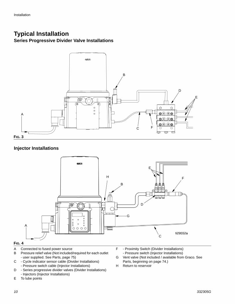
Typical InstallationSeries Progressive Divider Valve Installations
Injector Installations
A Connected to fused power sourceB Pressure relief valve (Not included/required for each outlet
- user supplied. See Parts, page 75)C - Cycle indicator sensor cable (Divider Installations)
- Pressure switch cable (Injector Installations)D - Series progressive divider valves (Divider Installations)
- Injectors (Injector Installations)E To lube points
F - Proximity Switch (Divider Installations)- Pressure switch (Injector Installations)
G Vent valve (Not included / available from Graco. See Parts, beginning on page 74.)
H Return to reservoir
FIG. 3
FIG. 4
A
B
C
D
E
F
A
B
D
E
C
FH
G

Installation
332305G 11
Typical Installation - With Remote Fill Manifold The installation shown is only a guide for selecting and installing system components. Contact your Graco distributorfor assistance in planning a system to suit your needs.
Key:A G3 PumpB Auto-Fill Shut Off ValveC Auto-Fill InletD G3 ReservoirE Remote Fill ReservoirF Remote Fill PumpG Supply Hose (user supplied)H Air Supply to Refill PumpJ Supply Hose (user supplied)K Pressure Relief ValveL Drain HoseM Fill Coupler/Inlet (quick disconnect)N Fill ManifoldP Fill Manifold OutletQ Fill Manifold Vent PortR Pressure GaugeS Pressure Regulator and GaugeT Pressure Relief Knob
To relieve the stall pressure in the fill line a fill manifold (N) must be installed in the system.
FIG. 5
E
D
C
F
P
N
K
H J
M
L
A
R
Q
B
ST

Installation
12 332305G
Optional Installation - Without Remote Fill ManifoldThe installation shown is only a guide for selecting and installing system components. Contact your Graco distributor for assistance in planning a system to suit your needs.
NOTE: The remote filling station pump stalls (dead-heads) when the reservoir is full. If the pump does not stall (dead-head) there is a leak in the system.
Key:A G3 PumpB Auto-Fill Shut Off ValveC Auto-Fill InletD G3 ReservoirE Remote Fill ReservoirF Remote Fill PumpH Relief ValveJ Supply Hose (user supplied)L Drain Tube
L1 Option - To reservoirL2 Option - To overflow container
S Pressure Regulator and GaugeU Pressure Relief ValveV Quick DisconnectW Overflow ContainerY Supply Hose Pressure Relief Valve
To relieve the stall pressure in the fill line a ball valve (Y) must be installed in the system.
FIG. 6
E
F
J
S
B
C
D
AL1
H U
V
L
L2
W
Y

Installation
332305G 13
System Configuration and Wiring
Grounding
If the product is permanently connected:
• it must be installed by a qualified electrician or ser-viceman.
• it must be connected to a grounded, permanent wir-ing system.
If an attachment plug is required in the end use application:
• it must be rated for the product electrical specifica-tions.
• it must be an approved, 3-wire grounding type attachment plug.
• it must be plugged into an outlet that is properly installed and grounded in accordance with all local codes and ordinances.
• when repair or replacement of the power cord or plug is required, do not connect the grounding wire to either flat blade terminal.
Fuses
Fuse Kits are available from Graco. The following Table identifies the correct fuse to use for your input voltage and the corresponding Graco Kit number.
Recommendations for Using Pump in Harsh Environments
• Use pump with CPC style power cable.
• If using a DIN style power or alarm harness with a right angle mating connector, make sure the con-nector does not exit the unit in the UP direction.
• Use a corrosion preventative electrical grease on all contacts.
The equipment must be grounded to reduce the risk of static sparking and electric shock. Electric or static sparking can cause fumes to ignite or explode. Improper grounding can cause electric shock. Grounding provides an escape wire for the electric current.
Improper installation of the grounding conductor may result in a risk of electric shock. This product must be installed by a qualified electrician in compliance with all state and local codes and regulations.
NOTICEFuses (user supplied) are required on all DC mod-els. To avoid equipment damage:
• Never operate G3 Pump DC models without a fuse installed.
• A fuse of the correct voltage must be installed in line with the power entry to the system.
Input Voltage Fuse Value Graco Kit No.
12 VDC 7.5 A 571039
24 VDC 4 A 571040

Installation
14 332305G
Alarm Output and Remote Illumination Response
The following tables include graphical representations of the connector as it appears on the unit, a pin-out associated with the connector and a typical installation wiring diagram. An internal representative wiring diagram is included where it is deemed useful.
Wire colors provided on these pages only refer to the power cable provided by Graco with this product.
Outputs (“08” option) (via 5 wire CPC)
Alarm Output(via DIN alarm relay
connector)
Standard Remote Illumination
(via 5 wire CPC power cable)
Tri-Color Remote Illumination
(via M12 Connector)
Unit in OFF Mode Deactivated (off) Off OffUnit in ON Mode Deactivated (off) On Green
Warning Condition Deactivated (off)Toggles On and Off once per second
Yellow
Low Level Indication (A9 OFF)
See Warning or Fault Con-dition
Toggles On and Off once per second
See Warning or Fault Con-dition
Fault Condition(Advanced Programming A7 OFF)
Toggles On and Off once per second
Toggles On and Off once per second
Red
Fault Condition (Advanced Programming A7 ON)
Activated (on)Toggles On and Off once per second
Red
Pin 4Alarm
Pin 7 Low Level
Low Level WarningFIRMWARE 6.02 and above(A7 OFF, A9 ON)
OffToggles On and Off once per second
Low Level Warning (A7 OFF, A9 OFF)
Off Activated (On)
Low Level Fault (A7 OFF, A9 OFF)
Toggles On and Off once per second
Activated (On)
Low Level Fault (A7 ON, A9 OFF)
Activated (On) Activated (On)

Installation
332305G 15
Alarm Relay Response
Wiring and Installation Diagrams
The following Table identifies the wiring and installation diagrams provided in this manual.
Output Tied to Common
No Faults or Warnings
Fault (Advanced
Programming A7 OFF)
Fault (Advanced
Programming Setting A7 ON)
N.O.
N.C.
N.O.
N.C.
1 second
N.O.
N.C.
Diagram Symbol Page #
Power DIN AC 16
Power DIN DC 16
Power CPC DC 17
Inputs (M12) 18
Vent Valve Outputs 19
Alarm Outputs 19
Illuminated Manual Run InputKits: 571030, 571031, 571032, 571033

Installation
16 332305G
Power DIN AC - 15 foot: Part No. 16U790
Pin and Related Wire Color (FIG. 7)
Power DIN DC - 15 foot
Pin and Related Wire Color (FIG. 8)
Pin Pin Name Color
1 Line Black2 Neutral White3 Not Used Not Used
4
Ground Green
FIG. 7
Pin Pin Name Color
1 -VDC Black2 +VDC White3 Not Used Not Used
4
Not Used Green
FIG. 8

Installation
332305G 17
Power CPC DC -15 foot
Pin and Related Wire Color (FIG. 9)Power CPC DC - 5 Wire
Part No.: 127780: 15 ft (4.5 m)Part No.: 127781: 20 ft (6.1 m)Part No.: 127782: 30 ft (9.1 m)
An Illuminated Remote Run Button Kit: 571030, 571031 for starting a manual run cycle if used in conjunction with a 5-wire CPC cable, is available from Graco. Con-tact your local Graco distributor or Graco Customer Ser-vice for additional information about these kits.
Pin and Related Wire Color (FIG. 10)
Pin Pin Name Color
1 Not Used Not Used2 -VDC Black3 +VDC White4 Not Used Not Used5 Not Used Not Used6 Not Used Not Used7 Not Used Green
FIG. 9
Pin Pin Name Color
1 Not Used Not Used2 -VDC Black3 +VDC Red4 LIGHT White
5Manual Run
SwitchOrange
6 Not Used Not Used7 Not Used Green
FIG. 10

Installation
18 332305G
Pin and Related Wire Color (FIG. 11)Wiring for “08” Option Inputs (M12)
See Technical Data, page 77 for ratings.CPC Pin Pin Name Wire Color
1 Not Used Not Used2 -VDC/Com Black3 +VDC Red4 Alarm White5 Manual Orange6 Not Used Not Used7 Low Level Warning Green
FIG. 11
FIG. 12
1 SW +
2 Not Used
3 SW -
4 Signal
(3)
(4)
(1)
(2)
Sink (NPN) 2 or 3 wire
1
2
3
4
Source (PNP) 2 or 3 wire
1
2
3
4
Dry Contacts
1
2
3
4
Example Wiring Diagram
Pin-outConnector on Housing

Installation
332305G 19
Vent Valve OutputsSee Technical Data, page 77 for ratings.
Alarm OutputsDC example shown. See Technical Data, page 77 for ratings.
1
FIG. 13
FIG. 14
1.

Installation
20 332305G
Part No. 124333: Cable Pin Out (M12)
Wire Colors (FIG. 15)
Part No. 124595: 5 Pin Eurofast Field Wireable Connector
Part No. 124300: Field Wireable Pin Out (M12)
Wire Colors (FIG. 17)
Part No. 124594: 4 Pin Eurofast Field Wireable Connector
Item No. Color
1 Brown
2 White
3 Blue
4 Black
FIG. 15
FIG. 16
Item No. Color1 Brown
2 White
3 Blue
4 Black
FIG. 17
FIG. 18

Setup
332305G 21
Setup
Pressure Relief
Follow the Pressure Relief Procedure whenever you see this symbol.
Relieve pressure in system using two wrenches working in opposite directions on pump element and pump element fitting to slowly loosen fitting only until fitting is loose and no more lubricant or air is leaking from fitting.
NOTE: When loosening pump element fitting, do NOT loosen pump element. Loosening pump element will change the output volume.
Connecting to Auxiliary Fittings
Pressure Relief Valves
NOTE: A pressure relief valve can be purchased from Graco. See Parts, page 75.
This equipment stays pressurized until pressure is manually relieved. To help prevent serious injury from pressurized fluid, such as skin injection, splashing fluid and moving parts, follow the Pressure Relief Procedure when you stop dispensing and before cleaning, checking, or servicing the equipment.
FIG. 19
NOTICEDo not attach unsupported equipment to auxiliary fit-tings such as fill ports and pump element. Attaching unsupported equipment to these fitting can result in irreparable housing damage.
• Always use two wrenches working in opposite directions when connecting anything to pump ele-ment or auxiliary fittings. See FIG. 19 for an exam-ple.
• Torque pump element fittings to 50 in. lbs (5.6 N•m).
• When connecting pump element into housing torque to 50 in. lbs (5.6 N•m).
To prevent over-pressurization, which can result in equipment rupture and serious injury, a pressure relief valve appropriate for the lubrication system must be installed close to every pump outlet to allevi-ate unintended pressure rises in the system and pro-tect the G3 pump from damage.
• Only use a pressure relief valve that is rated for no more than the working pressure of any com-ponent installed in the system. See Technical Data, page 73.
• Install a pressure relief valve close to every pump outlet; before any auxiliary fitting.

Setup
22 332305G
Setting Pump Outlet Volume
NOTE:
• Before making any adjustments to pump volume, Relieve Pressure following procedure on page 21.
• Only use Graco supplied spacers to control output volume.
1. Use a wrench to turn pump element counter-clock-wise to loosen. Do not remove entire pump element. Only back pump element out enough to allow spacer to be slid on or off.
2. If needed, remove or insert spacers to achieve required pump output volume. A tool may be needed to facilitate removal.
Pump volume control is set using either no (0) spac-ers, 1 or 2 spacers (FIG. 20).
Do not use more than 2 spacers to adjust output vol-ume.
NOTE:
• The amount of dispensed volume can vary depend-ing on external conditions such as lubricant tem-perature and back pressure from downstream connections.
• Use of these volume adjustment in conjunction with setting the ON time of the pump will allow for control of the output volume.
• Use these volume adjustments as a starting point and adjust as necessary to ensure desired lubrica-tion dispense.
3. Tighten pump element fitting. Torque fitting to 50 in. lbs (5.6 N•m).
Loading GreaseTo ensure optimal performance from the G3:
• Only use NLGI #000 - #2 greases appropriate for your application, automatic dispensing, and the equipment’s operating temperature. Consult with machine and lube manufacturer for details.
• The reservoir can be filled using a hand operated pump, pneumatic pump or electric transfer pump.
• Do not overfill (FIG. 23).
• Do not operate G3 without reservoir attached.
No. Spacers
Output Volume / Minute
cubic inches cubic cm
2 0.12 2
1 0.18 3
0 0.25 4
FIG. 20
NOTICE• Always clean inlet fitting (D) (FIG. 21) with a
clean dry cloth prior to filling reservoir. Dirt and/or debris can damage pump and/or lubrica-tion system.
• Care must be used when filling the reservoir using a pneumatic or electric transfer pump to not pressurize and break the reservoir.
FIG. 21
D
Setup
332305G 23
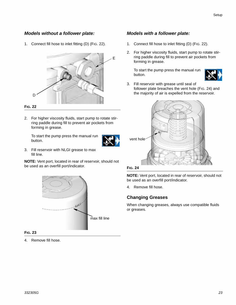
Models without a follower plate:
1. Connect fill hose to inlet fitting (D) (FIG. 22).
2. For higher viscosity fluids, start pump to rotate stir-ring paddle during fill to prevent air pockets from forming in grease.
To start the pump press the manual run button.
3. Fill reservoir with NLGI grease to max fill line.
NOTE: Vent port, located in rear of reservoir, should not be used as an overfill port/indicator.
4. Remove fill hose.
Models with a follower plate:
1. Connect fill hose to inlet fitting (D) (FIG. 22).
2. For higher viscosity fluids, start pump to rotate stir-ring paddle during fill to prevent air pockets from forming in grease.
To start the pump press the manual run button.
3. Fill reservoir with grease until seal of follower plate breaches the vent hole (FIG. 24) and the majority of air is expelled from the reservoir.
NOTE: Vent port, located in rear of reservoir, should not be used as an overfill port/indicator.
4. Remove fill hose.
Changing Greases
When changing greases, always use compatible fluids or greases.
FIG. 22
FIG. 23
D
E
max fill line
FIG. 24
vent hole

Setup
24 332305G
Auto-Fill Shut Off
Loading Grease
To ensure optimal performance from the G3:
• Only use NLGI #000 - #2 greases appropriate for your application, automatic dispensing, and the tem-perature. Consult with machine and lube manufac-turer for details.
• Do not overfill.
• Do not operate G3 without reservoir attached.
Changing Greases
When changing greases, always use compatible fluids or greases.
The Auto-Fill Shut Off is used for refilling the G3 reser-voir in an automatic lubrication system. As fluid is added to the reservoir, it pushes the plate valve up to the top of the reservoir. The plate valve then pushes the valve pin and closes the inlet fluid path.
When the fluid refilling path closes, the refilling line pres-surizes and brings the refilling pump to a pressurized stall condition.
NOTE: The operator must monitor system while filling the reservoir to prevent overfilling.
Remote Fill with Remote Fill Manifold
The reference letters used in the following instructions refer to the Typical Installation diagram, page 11.
The fill valve is used to relieve pressure in the refill line and to reset the Auto Fill Shut Off. See Fill Valve instruc-tion manual 333393. Graco fill valve, part no. 77X542 is available. Contact your local Graco distributor.
1. Pull out and hold the Pressure Relief Knob (T) long enough to relieve line pressure between Fill Mani-fold (N) and Auto-Fill Shut Off Valve (B).
2. Verify the Auto-Fill Shut Off (B) pin is down, indicat-ing it is reset (FIG. 25).
3. Remove yellow Dust Cover from Fill Coupler (M).
NOTICE
Care must be used when filling the reservoir using a pneumatic or electric transfer pump to not pressur-ize and break the reservoir.
The remote filling station pump stalls (dead-heads) when the reservoir is full, causing the supply system pressure to rise to the maximum output pressureof the filling station pump. To help prevent equipment damage or serious injury caused by pressurized fluid, such as skin injection or injury from splashing fluid, always use a remote filling station pump with a maxi-mum output pressure of 5100 psi (35.1 MPa, 351.6 bar) and use supply hoses with a minimumpressure rating of 5100 psi (35.1 MPa, 351.6 bar).
COMPONENT RUPTURE HAZARDThe maximum working pressure of each component in the system may not be the same. To reduce the risk of over-pressurizing any component in the sys-tem, be sure you know the maximum working pres-sure of each component. Never exceed the maximum working pressure of the lowest rated com-ponent in the system. Over-pressurizing any compo-nent can result in rupture, fire, explosion, property damage and serious injury.
Regulate input pressure to the remote fill pump so that no fluid line, component or accessory is over pressurized.
FIG. 25
pindown
Setup
332305G 25
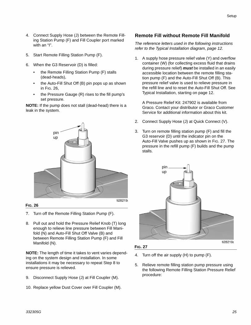
4. Connect Supply Hose (J) between the Remote Fill-ing Station Pump (F) and Fill Coupler port marked with an “I”.
5. Start Remote Filling Station Pump (F).
6. When the G3 Reservoir (D) is filled:
• the Remote Filling Station Pump (F) stalls (dead-heads),
• the Auto-Fill Shut Off (B) pin pops up as shown in FIG. 26,
• the Pressure Gauge (R) rises to the fill pump’s set pressure.
NOTE: If the pump does not stall (dead-head) there is a leak in the system.
NO7. Turn off the Remote Filling Station Pump (F).
8. Pull out and hold the Pressure Relief Knob (T) long enough to relieve line pressure between Fill Mani-fold (N) and Auto-Fill Shut Off Valve (B) and between Remote Filling Station Pump (F) and Fill Manifold (N).
NOTE: The length of time it takes to vent varies depend-ing on the system design and installation. In some installations it may be necessary to repeat Step 8 to ensure pressure is relieved.
9. Disconnect Supply Hose (J) at Fill Coupler (M).
10. Replace yellow Dust Cover over Fill Coupler (M).
Remote Fill without Remote Fill Manifold
The reference letters used in the following instructions refer to the Typical Installation diagram, page 12.
1. A supply hose pressure relief valve (Y) and overflow container (W) (for collecting excess fluid that drains during pressure relief) must be installed in an easily accessible location between the remote filling sta-tion pump (F) and the Auto-Fill Shut Off (B). This pressure relief valve is used to relieve pressure in the refill line and to reset the Auto-Fill Shut Off. See Typical Installation, starting on page 12.
A Pressure Relief Kit: 247902 is available from Graco. Contact your distributor or Graco Customer Service for additional information about this kit.
2. Connect Supply Hose (J) at Quick Connect (V).
3. Turn on remote filling station pump (F) and fill the G3 reservoir (D) until the indicator pin on the Auto-Fill Valve pushes up as shown in FIG. 27. The pressure in the refill pump (F) builds and the pump stalls.
4. Turn off the air supply (H) to pump (F).
5. Relieve remote filling station pump pressure using the following Remote Filling Station Pressure Relief procedure:
FIG. 26
pinup
FIG. 27
pinup

Setup
26 332305G
Remote Filling Station Pressure Relief
The reference letters used in the following instructions refer to the Typical Installation diagrams starting on page 10.
The following Pressure Relief Procedure is only used with the Auto-Fill Shut Off Valve to relieve remote filling station and lubricant supply line
pressure.
a. To relieve pressure between the Refill Pump (F) and Auto-Fill Shut Off (B), open ball valve (bv) (FIG. 28). Pressure will be released and excess fluid will drain out of the drain tube (L) and into the lubrication overflow container (W).
b. Close supply hose pressure relief valve (Y) when all pressure has been relieved.
6. Disconnect the supply hose (J) from Quick Connect (V).
Filling Oil Unit• Only use oil appropriate for your application, auto-
matic dispensing, and the equipment’s operating temperature. Consult with machine and lube manu-facturer for details.
• Do not overfill (FIG. 29).
• Do not operate G3 without reservoir attached.
• Only use oils with viscosity at least 40 cSt.
1. Remove fill cap (a).
2. Pour oil into reservoir to max fill line (b).
3. Replace fill cap. Hand tighten cap, securely.5
This equipment stays pressurized until pressure is manually relieved. To help prevent serious injury from pressurized fluid, such as skin injection, splashing fluid and moving parts, follow the Pressure Relief Procedure when you stop dispensing and before cleaning, checking, or servicing the equipment.
FIG. 28:
Y
L
W
FIG. 29
a
b

Setup
332305G 27
PrimingNOTE: It is not necessary to prime pump every time pump is filled with lubricant.
Pump only requires priming the first time it is used or if it is allowed to run dry.
1. Loosen pump element fitting (FIG. 30).
NOTE: When loosening pump element fitting, do NOT loosen pump element. Loosening pump element will change the output volume
2. Only run pump until air is no longer dispensed with the lubricant coming out of element fitting (FIG. 31).
3. Tighten pump element fitting using two wrenches working in opposite directions (FIG. 30).
FIG. 30
FIG. 31

Quick Setup Guide
28 332305G
Quick Setup Guide
����������� ���������� ����� ����� �����������������
����������� �������������������� ����� �����������������
�!
���������
������ ��������� ���
���������
������ ��������� ���
���������
���������
������
��
�������� ������!
������!"#$�%�
� �������
�����������&��$�
�����
������
'�
���*�������,����'�����
.������ �����������/'��0�
��������
� �������
�""
�!
�������� ������!
�����������&��$�
�����
��������
� �������
�""
������!"#$�%�
� �������

Max Model Setup
332305G 29
Max Model SetupControl Panel Overview (FIG. 32)NOTE: Programming instructions begin on page 30.
FIG. 32
DISPLAY• A blinking LED under HH, MM, SS
or ## identifies type of measurement unit you are setting; i.e., HH is hours.
• A blinking number on the display indicates the G3 is in SETUP MODE.
• In RUN MODE displayed numbers count up or down. See Time ON and Time OFF.
ON TIME/BACKUP TIME
• LED lights when ON Time/Backup Time is running.
• Display shows time as MM:SS (minutes and seconds).i.e., 08:30 is 8 minutes: 30 sec-onds.
• Sets the limits for the amount of time to complete a cycle or build up pressure before a warning is activated.
• Counts down from a set time to zero.
OFF TIME/BACKUP TIME
• LED lights when OFF Time/Backup Time is used to con-trol Pump OFF function.
• Value is entered in HH:M.
• Displays in HH:MM (hours and minutes) when > 1 hour.
• Times pump rest between cycles.
• Counts down from set time to zero.
• Can be set up to use as a backup for Machine Count control.
ALARM ICONSLED next to icon lights when a fault / warning event occurs during a run cycle. See page 58 for a complete description of these alarm scenarios.
PIN ICON• LED next to icon lights indi-
cating PIN is required to enter setup.
• In SETUP MODE LED lights when setting up the PIN.
PRELUBELED next to icon lights indicat-ing LED lights when Prelube function is enabled.
LEFT DIRECTION ARROW / RESET
• In SETUP MODE: moves cursor in display one field to the left.
• In RUN MODE: single press clears warning.
• In RUN MODE: pressing for one second ends run cycle if no warnings.
• In ALARM MODE: pressing and holding for 3 seconds clears fault / warning and switches cycle to OFF MODE.
RIGHT DIRECTION ARROW / MANUAL RUN / ENTER
• In SETUP MODE: saves entry, moves cursor in display one field to the right or to the next setup step.
• In RUN MODE: starts a man-ual run cycle.
UP and DOWN ARROW
• Hold both the UP and DOWN ARROW but-tons down together for 3 seconds to enter SETUP MODE.
• In SETUP MODE: increases or decreases number values shown in display.
CYCLE / PRESSURE SETUP
• Sets either Cycle (C) or Pressure (P) Monitoring limits for up to 3 sensors.
• Each sensor is set up and con-trolled independently.
MACHINE COUNT
• LED lights when Machine Count is used to control Pump OFF function.
• Counts independent machine operations with a sensor to con-trol Pump Off duration.
• Time OFF function can be used as a backup for Machine Count.

Max Model Setup
30 332305G
Programming the Max Model
Checking the Firmware VersionTo check the firmware version installed on the pump:
1. Remove power to the pump by disconnecting the power cable from the connection.
2. Reconnect the power cable to the power connec-tion.
This creates a power cycle and the firmware version displays on the screen during the first few seconds of power up. See FIG. 33.
Powering Units With Controllers
By default, units with controllers are set to operate in a timed mode with 1 minute of ON time and 8 hours of OFF time. The unit should be powered up in OFF mode, counting down from the 8 hours. If the unit powers up in ON mode and has not been primed, hold the reset but-ton located on the control panel (example shown on the right) for 1 second to move to the OFF mode.
NOTE:
• A blinking number on the display indicates the G3 is in SETUP MODE.
• In RUN MODE numbers on the display do not blink.
• After 60 seconds of no activity, the device returns to RUN MODE in the OFF Time cycle and the OFF Time restarts counting down the total programmed amount of time. It does not resume the countdown from the point where the cycle was interrupted when you entered SETUP MODE.
Entering Setup Mode
Press both the UP and DOWN ARROW buttons together for 3 seconds to enter the SETUP MODE.
NOTE: If the lock LED is lit after entering Setup Mode and four 0000’s are displayed, the unit has a PIN Code lock out enabled. See the follow-ing section: Entering a PIN Code to Access Setup Mode.
Entering a PIN Code to Access Setup Mode
The G3 controller does not require a user to provide a PIN code to access the programming features of the unit. However, Graco understands that some users may want to protect the programming settings and therefore, an option for adding PIN Code authorization is available. The instructions for setting up PIN Code Authorization are provided in the Advanced Programming section of this manual. See page 47.
To enter the PIN Code:
1. Press both the UP and DOWN ARROW buttons for 3 seconds.
2. The LED next to the LOCK ICON on the display lights and the 4 zeros appear on the display indicating the system requires a PIN Code entry to run the G3 in SETUP MODE.
FIG. 33

Max Model Setup
332305G 31
3. The cursor is automatically positioned to enter the first character of the PIN Code. Use the UP and DOWN ARROW buttons to move up and down through the numbers 0-9 until the first number in the PIN code is displayed in the field.
4. Press the ENTER button to set the num-ber. The cursor automatically moves to the next number field.
5. Repeat steps 3 and 4 for each PIN Code prompt field.
If the PIN Code you entered is correct, the first editable character on the display will flash.
NOTE: A blinking field on the display indicates the G3 is in SETUP MODE. In RUN MODE numbers on the dis-play will not blink.
Setting the Real Time ClockDMS™ Equipped Models Only
NOTE: Set the real time clock prior to plugging the USB flash drive into the pump.
Enter the Year:
• The year displays. The first programma-ble character, the decade, blinks indi-cating the device is ready to program the decade digit of the year.
• The LED under the # sign lights while setting the year.
1. Use the UP and DOWN arrow but-tons to move up and down through the number 0-9 until the number for the current decade is displayed in the field.
2. Press the ENTER button to set the decade number. The cursor auto-matically moves to the next field, the year number.
3. Use the UP and DOWN arrow but-tons to move up and down through the number 0-9 until the number for the current year is displayed in the field.
4. Press the ENTER button to set the year number.
The 3-character month displays indicating the G3 is now ready to program the month.
Enter the Month:
1. Set the 3 character month by using the UP and DOWN ARROW but-tons to move up and down through the list of months until the current month is displayed in the field.
2. Press the ENTER button to set the month.
The 2-digit date displays indicating the G3 is now ready to program the date.
Enter the 2-digit Date:
The first programmable character of the 2-digit date blinks indicating the device is ready to pro-gram the first digit of the date.
The LED under the # sign lights while setting the date.
1. Use the UP and DOWN ARROW buttons to move up and down through the numbers 0-3 until the first digit of the date is displayed in the field.
2. Press the ENTER button to accept the selection. The cursor automati-cally moves to the second digit of the date.

Max Model Setup
32 332305G
3. Use the UP and DOWN ARROW buttons to move up and down through the numbers 0-9 until the second digit of the date is dis-played in the field.
4. Press the ENTER button to set the date.
The time displays indicating the G3 is now ready to program the time.
Enter the Time:• The time displays in 24-Hour format. i.e., 2:45 PM
displays as 14:45.
• The clock is set in Hours and Minutes (HH:MM).
• The LED under the HH lights when set-ting hours and the LED under the MM lights when setting minutes.
• The first programmable number of the HH (hour) filed blinks, indicating the device is ready to program the first digit of the hour.
• When programming a time of less then 12 hours, you must program a leading zero in the first number field and press the ENTER button to save the zero.
1. Use the UP and DOWN ARROW buttons to move up and down through the numbers 0-2 until the desired number appears in the first hour (HH) field.
2. Press the ENTER button to set the number.
3. Use the UP and DOWN ARROW buttons to move up and down through the numbers 0-9 until the desired number for the second HH number field appears.
4. Press the ENTER button to set the number.
5. The next number field to the right blinks and the LED under the MM lights indicating the G3 is ready to program the minutes fields.
6. Repeat steps 1-4 to set the minutes (MM) fields.
7. After pressing the ENTER button to set the time, the programmed Time information is saved.
Programming ON Duration
• OFF, C1 (C2, C3) or P1 (P2, P3) displays, identifying the func-tion you are program-ming.
• Selection of OFF, C1 (C2, C3) or P1 (P2, P3) desig-nates the way pump run time is controlled:
• C1, C2, C3 - Completing a specific number of cycles measured by an external prox/cycle switch
• P1, P2, P3 - Reaching a specific pressure threshold measured by an external pressure switch - OR,
• OFF - A specific duration of time elapses.
• The LED next to C/P1 lights, indicat-ing which sensor of the pump control you are programming using either a specific number of cycles or by mon-itoring a pressure switch.
• C / P2 and C / P3 controls functions to the second and third sensors (when sensors are used).
• Only sensor inputs that are available on the unit can be programmed.
NOTE: Field cannot be left blank. If C / P2 and C / P3 are not used, OFF must be entered instead.
Cycle (C1, C2, C3) Setup
Cycle controls the number of lube cycles (as monitored by an external cycle monitor) completed before the pump rests.
NOTE:
• You must program at least one cycle. Zero is not an available option.
1. Use UP or DOWN arrow but-ton to toggle display between OFF / C1 / P1 on the display.
or
Max Model Setup
332305G 33
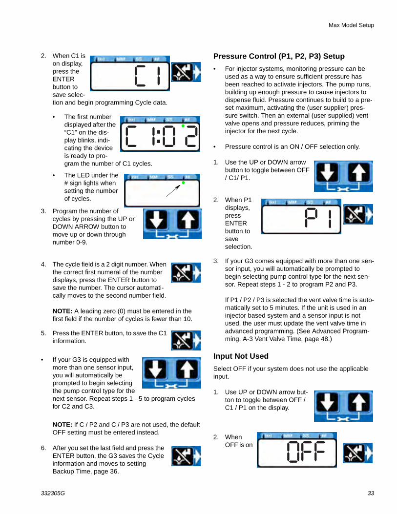
2. When C1 is on display, press the ENTER button to save selec-tion and begin programming Cycle data.
• The first number displayed after the “C1” on the dis-play blinks, indi-cating the device is ready to pro-gram the number of C1 cycles.
• The LED under the # sign lights when setting the number of cycles.
3. Program the number of cycles by pressing the UP or DOWN ARROW button to move up or down through number 0-9.
4. The cycle field is a 2 digit number. When the correct first numeral of the number displays, press the ENTER button to save the number. The cursor automati-cally moves to the second number field.
NOTE: A leading zero (0) must be entered in the first field if the number of cycles is fewer than 10.
5. Press the ENTER button, to save the C1 information.
• If your G3 is equipped with more than one sensor input, you will automatically be prompted to begin selecting the pump control type for the next sensor. Repeat steps 1 - 5 to program cycles for C2 and C3.
NOTE: If C / P2 and C / P3 are not used, the default OFF setting must be entered instead.
6. After you set the last field and press the ENTER button, the G3 saves the Cycle information and moves to setting Backup Time, page 36.
Pressure Control (P1, P2, P3) Setup
• For injector systems, monitoring pressure can be used as a way to ensure sufficient pressure has been reached to activate injectors. The pump runs, building up enough pressure to cause injectors to dispense fluid. Pressure continues to build to a pre-set maximum, activating the (user supplier) pres-sure switch. Then an external (user supplied) vent valve opens and pressure reduces, priming the injector for the next cycle.
• Pressure control is an ON / OFF selection only.
1. Use the UP or DOWN arrow button to toggle between OFF / C1/ P1.
2. When P1 displays, press ENTER button to save selection.
3. If your G3 comes equipped with more than one sen-sor input, you will automatically be prompted to begin selecting pump control type for the next sen-sor. Repeat steps 1 - 2 to program P2 and P3.
If P1 / P2 / P3 is selected the vent valve time is auto-matically set to 5 minutes. If the unit is used in an injector based system and a sensor input is not used, the user must update the vent valve time in advanced programming. (See Advanced Program-ming, A-3 Vent Valve Time, page 48.)
Input Not Used
Select OFF if your system does not use the applicable input.
1. Use UP or DOWN arrow but-ton to toggle between OFF / C1 / P1 on the display.
2. When OFF is on

Max Model Setup
34 332305G
the display, press the ENTER button to save selec-tion.
If the sensor inputs are available and none are used in the ON Mode, the definition of the entered time is ON TIME.
Examples:
Model G3-G-24MX-2LFL00-1DMVA2R3 has 4 sensors, so C/P1, C/P2, and C/P3 and Machine Count can all be programmed.
Model G3-G-24MX-2LFL00-10CV00R0 has 1 sensor, only C/P1 is available for programming.
Backup Time
In both Cycle and Pressure Modes, a maximum run Time (Backup Time) for the lubrication period must be set up. If this Time expires before the lubrication is com-pleted an alarm/warning is triggered and the pump stops.
To determine the Backup Time, Graco recommends the user verify the length of time it takes to complete a typi-cal cycle and double that value (to a maximum of 30 minutes).
Backup Time is setup after Cycle or Pressure Sensor Setup is complete.
NOTE:
• The LED next to the clock in the ON field lights, indi-cating the Backup Time is being programmed.
• BACKUP (ON) Time is set as minutes and seconds (MM:SS) only.
• The small flashing LED under the MM indicates you are setting minutes.
• The first field (left side of display) blinks indicating the device is ready for you to begin programming.
Programming Backup Time
NOTE: When programming a time of less than 10 min-utes you must program the leading zero in the first num-ber field and press the ENTER button to save the zero selection.
1. To set the ON Time use the UP or DOWN ARROW button to scroll through numerals 0 to 5 until the desired number appears in the first MM (min-utes) field.
2. Press the ENTER button to lock in the selection. The next MM number field to the right flashes indicating it is ready for programming.
3. Use the UP or DOWN ARROW button to scroll through numerals 0 to 9 until the desired number appears in the second MM number field.
4. Press the ENTER button to lock in the selection.
The next number field to the right flashes and the LED lights under SS; indicating it is ready to program the seconds fields.
5. Repeat steps 1 - 4 to set the SS (seconds) fields.
6. After pressing the ENTER button to set the last SS field, all the programmed ON Time information is saved.
The G3 automatically switches to the OFF Time SETUP MODE.
ON Time
• The LED next to the clock in the ON field lights, indicating you are setting the ON Time parameters.
• ON Time is set in Minutes and Seconds (MM: SS).
• An LED flashes under either MM when pro-gramming minutes OR SS when pro-gramming seconds.
OR

Max Model Setup
332305G 35
• In SETUP MODE, the number displayed in the first field, on the left side of display blinks, indicating the device is ready to program the ON Time minutes.
• The total amount of ON Time cannot exceed 30 minutes. If a value greater than 30 minutes is entered, the RED alarm LED lights and the value must be updated.
If this time does not meet the application needs, contact Graco Customer Support.
Programming ON Time
NOTE: When programming a time of less than 10 min-utes you must program a leading zero in the first num-ber field and press the ENTER button to save the zero selection.
1. To set the ON Time use the UP or DOWN ARROW button to scroll through numerals 0 to 5 until the desired number appears in the first MM (min-utes) field.
2. Press the ENTER button to lock in the selection. The next MM number field to the right flashes indicating it is ready for programming.
3. Use the UP or DOWN ARROW button to scroll through numerals 0 to 9 until the desired number appears in the second MM number field.
4. Press the ENTER button to lock in the selection.
The next number field to the right flashes and the LED lights under SS; indicating it is ready to program the seconds fields.
5. Repeat steps 1 - 4 to set the SS (seconds) fields.
6. After pressing the ENTER button to set the last SS field, all the programmed ON Time information is saved.
The G3 automatically switches to the OFF Time SETUP MODE.
PUMP OFF / REST SetupAfter setting the parameters for either Cycle (C1, C2 or C3) or Pressure (P1, P2, or P3) ON modes, the OFF or pump rest cycle must be set up. There are 3 ways to control this function:
• Machine Count switch activation, or
• Machine Count activations limited by a maxi-mum Time, or
• A specific set amount of Time (similar to Time Mode).
• If the machine count sensor input is available and not used in the OFF Mode, the definition of the entered time is OFF TIME.
Machine Count
1. After you set the last ON Time field and press the ENTER button, the G3 automatically switches to the Machine Count setup.
Notice the LED next to 123 on the G3 display lights indicating you are now in the Machine Count setup mode.
2. Press the UP or DOWN ARROW button to move up or down through number 0-9.
3. When the correct number displays, press the ENTER button to set the num-ber.
NOTE: If the machine count input is available on the unit and not used, the value MUST be set to zero (0).
4. Repeat 2 - 3 to set the remaining fields.
NOTE: After the Machine Count value is entered, the G3 can be programmed to backup the machine count input with time.
Backup Time Setup
1. The OFF Time LED lights.

Max Model Setup
36 332305G
OFF displays.
2. Press the UP or DOWN ARROW button to change OFF to ON on the display.
3. Press the ENTER button to set the selection.
Backup Time
• The LED next to the clock in the OFF field lights, indicating you are setting the Backup Time parameters.
• OFF Time is set in Hours and Minutes (HH: MM).
• An LED flashes under either HH when pro-gramming hours OR MM when program-ming minutes.
• In SETUP MODE the number displayed in the first field, on the left side of display blinks, indicating the device is ready to pro-gram the Backup Time hours.
• The total amount of Backup Time must be at least twice as long as the pro-grammed ON Time. If a value less than twice the ON Time is entered, the RED alarm LED lights and the value must be updated.
If this time does not meet the application needs, contact Graco Customer Support.
Programming Backup Time
NOTE: When programming a Backup Time of less than 10 hours you must program a leading zero in the first number field and press the ENTER button to save the zero selection.
1. To set the Backup Time use the UP or DOWN ARROW button to scroll through numerals 0 to 9 until the desired number appears in the first HH (hour) field.
2. Press the ENTER button to lock in the selection. The next HH number field to the right flashes indicating it is ready for programming.
3. Use the UP or DOWN ARROW button to scroll through numerals 0 to 9 until the desired number appears in the second HH number field.
4. Press the ENTER button to lock in the selection.
The next number field to the right flashes and the LED lights under MM; indicating it is ready to program the minutes fields.
5. Repeat steps 1 - 4 to set the next MM (minutes) fields.
6. After pressing the ENTER button to set the last MM field, the OFF Time informa-tion is saved.
7. After selecting ON, refer to page 33.
NOTE: Backup time can be set in HH:MM for the machine count input.
OFF Time
• The LED next to the clock in the OFF field lights, indicating you are setting the OFF Time parameters.
• OFF Time is set in Hours and Minutes (HH: MM).
• An LED flashes under either HH when pro-gramming hours OR MM when program-ming minutes.
OR
OR

Max Model Setup
332305G 37
• In SETUP MODE the number displayed in the first field, on the left side of display blinks, indicating the device is ready to pro-gram the OFF Time hours.
• The total amount of OFF Time must be at least twice as long as the pro-grammed ON Time. If a value less than twice the ON Time is entered, the RED alarm LED lights and the value must be updated.
If this time does not meet the application needs, contact Graco Customer Support.
Programming OFF Time
NOTE: When programming a time of less than 10 hours you must program a leading zero in the first num-ber field and press the ENTER button to save the zero selection.
1. To set the OFF Time use the UP or DOWN ARROW button to scroll through numerals 0 to 9 until the desired number appears in the first HH (hour) field.
2. Press the ENTER button to lock in the selection. The next HH number field to the right flashes indicating it is ready for programming.
3. Use the UP or DOWN ARROW button to scroll through numerals 0 to 9 until the desired number appears in the second HH number field.
4. Press the ENTER button to lock in the selection.
The next number field to the right
flashes and the LED lights under MM; indicating it is ready to program the minutes fields.
5. Repeat steps 1 - 4 to set the next MM (minutes) fields.
6. After pressing the ENTER button to set the last MM field, the OFF Time informa-tion is saved.
Prelube
The Prelube function determines operation of the pump when power is applied. It can be set to OFF or ON.
OFF (default) - The unit resumes its lubrication cycle at the point it was at when power was removed.
ON - The unit begins a pump cycle.
Setting Prelube
1. After you set the OFF Time information and press the ENTER button, the G3 automatically switches to the Prelube Delay setup.
Notice the LED next to the prelube icon on the G3 display lights indicat-ing you are now in the Prelube setup mode.
2. OFF displays. If you want the prelube cycle to begin imme-diately, leave this set to OFF.
3. Press the ENTER button to set the selection.
4. If you want to set a prelube delay time, press the DOWN ARROW button to change OFF to ON on the display.
Prelube Delay
Prelube Delay can be entered to delay the start of the pump’s cycle on power up. If prelube is set to ON, a pre-lube delay time in MM:SS must be entered. By default, the delay is set to 0 (begin an ON cycle immediately).

Max Model Setup
38 332305G
Delaying the prelube function may be desired if other critical functions or systems of your machine or vehicle are also coming on line during power up.
1. Prelube Delay is set in MM:SS (minutes and sec-onds). To set the time use the UP or DOWN ARROW button to scroll through numerals 0 to 5 until the desired number appears in the first MM (minutes) field.
The maximum length of time Prelube Delay can be set to is 59:59 (59 minutes:59 seconds).
2. Press the ENTER button to lock in the selection. The next MM number field to the right flashes indicating it is ready for programming.
3. Use the UP or DOWN ARROW button to scroll through numerals 0 to 9 until the desired number appears in the second MM number field.
4. Press the ENTER button to lock in the selection.
The next number field to the right flashes and the LED lights under SS; indicating it is ready to program the seconds fields.
5. Repeat steps 1 - 4 to set the SS (seconds) fields.
6. After pressing the ENTER button to set the last SS field the G3 automatically switches to the RUN MODE.
DMS™ Models Only
Downloading Data
1. Plug the USB flash drive into the USB port.
NOTE: The G3 pump stops pumping as soon as the USB flash drive is plugged into it.
2. The system automatically begins downloading data to the USB drive.
3. “data” is displayed while the system is downloading files.
4. When download is finished, “done” is displayed.
5. G3 pump restarts cycle in the OFF mode.
6. Remove the USB flash drive.
Storing Pump Program Settings to the Flash DriveThe pump program settings file is named:
GRACO/G3Config/g3config.bin. This file cannot be modified. Modification of the file or file name may cause it to be unusable.
1. Plug the USB flash drive into the USB port.
NOTE: The G3 pump stops pumping as soon as the USB flash drive is plugged into it.
2. The system automatically begins downloading data to the USB drive.
3. “data” is displayed while the system is downloading files.
4. When download is finished, “done” is displayed.
5. G3 pump restarts cycle in the OFF mode.
6. After the download is com-plete, press and hold the UP and DOWN ARROW button for 3 seconds to store the cur-rent setup to the USB flash drive.
7. “data” is displayed while the unit is downloading and storing the configu-ration on the USB drive.
8. When configuration is stored, “done” is displayed.
9. G3 pump restarts cycle in the OFF mode.
10. Remove the USB flash drive.
Max Model Setup
332305G 39
Uploading Pump Program Settings to the Pump1. Plug the USB flash drive into the USB port.
NOTE:
• The USB flash drive must contain file GRACO/G3Config/g3config.bin.
• The G3 pump stops pumping as soon as the USB flash drive is plugged into it.
2. The system automatically begins downloading data to the USB drive.
3. “data” is displayed while the system is downloading files.
4. When download is finished, “done” is displayed.
5. G3 pump restarts cycle in the OFF mode.
6. After the download is com-plete, press and hold the RESET button and UP ARROW button for 3 seconds to upload the setup stored in the USB flash drive.
7. “data” is displayed while the unit is uploading the configuration data.
8. When upload is finished, “done” is displayed.
9. G3 pump restarts cycle in the OFF mode.
10. Remove the USB flash drive.
11. After the USB flash drive is removed, press and hold the UP and DOWN ARROW but-tons for 3 seconds to enter the SETUP MODE (see Entering Setup Mode, page 30).
12. In SETUP MODE, set the YEAR, MONTH, DATE and TIME (see Setting the Real Time Clock, page 31).
13. After pressing the ENTER button to set the TIME, press the RESET button to exit the SETUP MODE.
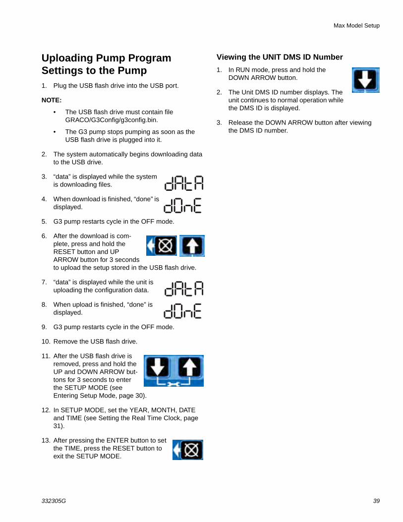
Viewing the UNIT DMS ID Number
1. In RUN mode, press and hold the DOWN ARROW button.
2. The Unit DMS ID number displays. The unit continues to normal operation while the DMS ID is displayed.
3. Release the DOWN ARROW button after viewing the DMS ID number.

Operation / Data Log
40 332305G
Operation / Data LogDuring operation the G3 Pump stores information as Log and Summary Files.
Logs contain the following information:
• Log Name
• DMS ID Number
• Current Software Graco Part Number
• Current Software Version
• Date and Time of Upload
System Event Log The System Event Log lists the date and time of the last 800 common system events such as pump cycles, man-ual run and setting changes. The most recent event is listed first.
The log file is stored in a folder structure created by the pump DMS ID and download date. If multiple downloads are done on the same date, the existing files will be writ-ten over.
The folder structure is as follows:
GRACO/G3_{DMS_id}/{download date - YYYYm-mDD}/EVENTLOG.CSV
Example: GRACO/G3_00025/20100911/EVENT-LOG.CSV.
Sample System Event Log
Example Event Log 1: Pump cycle of a divider valve system with a proximity switch set to detect 5 divider valve cycles.
G 3 Sy stem Event Lo gDMS ID Number: 0025 (see page 39)Software Part Number: 16F821Software Version: 101909/29/2010 14:1400
Date Time Description9/29/2010 14:13:02 Pump Run Off9/29/2010 14:13:02 C1 Cycle Completed9/29/2010 14:12:39 C1 Cycle Detected9/29/2010 14:12:34 C1 Cycle Detected9/29/2010 14:12:28 C1 Cycle Detected9/29/2010 14:12:23 C1 Cycle Detected9/29/2010 14:12:17 Pump Run On