
331 331E Operation 334
127
Operation & Maintenance Manual © Bobcat Europe 2004 6902612-EN (01-04) (1) 331 331E 334 Printed in Europe 331 - S/N 234311001 & Above 331E - S/N 234411001 & Above 334 - S/N 234511001 & Above (G Series) EN
Transcript of 331 331E Operation 334

Operation
&
Maintenance
Manual
SN
© Bobcat Europe 20046902612-EN (01-04) (1)
331331E334
Printed in Europe
331 - S/N 234311001 & Above
331E - S/N 234411001 & Above
334 - S/N 234511001 & Above
(G Series)
EN

331/331E/334 Excavator
Operation & Maintenance Manual
Never operate withoutinstructions.
Read machine signs andOperation & MaintenanceManual.
Do not grasp controlhandles when enteringcanopy or cab.
Be sure controls are inneutral before starting.
Sound horn and checkbehind machine beforestarting.
Never operate withoutapproved canopy or cab.
Never modify equipment.
Never use attachmentsnot approved by BobcatCompany.
Avoid steep areas orbanks that could breakaway.
WARNINGOperator must be instructed before running the machine. Untrained
operators can cause injury or death.
OPERATOR SAFETY WARNING
CORRECT
MS-1861
25° Maximum
Never exceed 25° whengoing down or backingup a slope.
OSW24-1003
To leave Excavator, lowerthe attachment.
Stop the engine.
This symbol with a warning statement, means: “Warning, be alert! your safety is involved!” Carefullyread the message that follows.
W-2001-1285
6808261A
CORRECT
MS-1853
B-21928
CORRECT SAFETY EQUIPMENT
1. Seat Belt
2. Swing Lock
3. ROPS/TOPS Canopy
or Cab
4. Machine Safety Signs
5. Safety Tread
6. Grab Handles
Fasten seat belt securely.
Operate controls only from operator’s seat.
Use caution to avoidtipping - do not swingheavy load over side oftrack.
Operate on flat, levelground.
Keep bystanders out ofmaximum reach area.
Do not travel or turn withbucket extended.
Never carry riders.
Never exceed a 15° slopeto the side.
Never travel up a slopethat exceeds 15°.
WRONG
MS-1858
WRONG
MS1859 B-19936
CORRECT
15° Maximum
CORRECT
MS-1786
15° Maximum
B-10731a
CORRECT WRONG
MS-1853
CORRECT WRONG
B19934B-19961

331/331E/334 Excavator
i Operation & Maintenance Manual
CONTENTS
FOREWORD . . . . . . . . . . . . . . . . . . . . . . . . . . . . . . . . . . . . . . . . . III
SAFETY INSTRUCTIONS . . . . . . . . . . . . . . . . . . . . . . . . . . . . . . . XI
OPERATING INSTRUCTIONS. . . . . . . . . . . . . . . . . . . . . . . . . . OI-1
PREVENTIVE MAINTENANCE . . . . . . . . . . . . . . . . . . . . . . . . PM-1
SYSTEM SET-UP AND ANALYSIS. . . . . . . . . . . . . . . . . . . . . . .SA-1
SPECIFICATIONS . . . . . . . . . . . . . . . . . . . . . . . . . . . . . . . . SPEC-1
REFERENCE INFORMATION
Write the correct information for YOUR Excavator in the spaces below. Always use
these numbers when referring to your Bobcat Excavator.
Bobcat Company Europe
J. Huysmanslaan 59
B-1651 LOT
Belgium
Bobcat Excavator
Serial Number
Engine Serial Number
NOTES
YOUR BOBCAT® EXCAVATOR DEALER:
ADDRESS:
PHONE:
FOREWORD
OPERATINGINSTRUCTIONS
MAINTENANCEPREVENTIVE
SPECIFICATIONS
& ANALYSISSYSTEM SET-UP
SAFETYINSTRUCTIONS

331/331E/334 Excavator
ii Operation & Maintenance Manual

331/331E/334 Excavator
iii Operation & Maintenance Manual
FOREWORD
This manual gives the owner/operator necessary operating and preventive maintenance
instructions for the Bobcat Excavator.
Read this manual completely and get to know the Bobcat Excavator before operating and
servicing it. All references to left or right on the Excavator are given in relation to the operator's
left or right hand while in the operator's seat.
For further information, see your Bobcat Excavator dealer. Parts Manuals, Service Manuals
and extra Operation & Maintenance Manuals are also available.
BOBCAT COMPANY IS ISO 9001:2000 CERTIFIED . . . . . . . . . . . . . . . V
BOBCAT EXCAVATOR IDENTIFICATION . . . . . . . . . . . . . . . . . . . . . . VIII
DELIVERY REPORT . . . . . . . . . . . . . . . . . . . . . . . . . . . . . . . . . . . . . . VII
FEATURES AND ACCESSORIES . . . . . . . . . . . . . . . . . . . . . . . . . . . . . IX
REGULAR MAINTENANCE ITEMS . . . . . . . . . . . . . . . . . . . . . . . . . . . . V
SERIAL NUMBER LOCATIONS . . . . . . . . . . . . . . . . . . . . . . . . . . . . . . VII
& ANALYSIS
TRANSLATIONS
SYSTEM SETUP
FOREWORD

331/331E/334 Excavator
iv Operation & Maintenance Manual

331/331E/334 Excavator
v Operation & Maintenance Manual
BOBCAT COMPANY IS ISO 9001:2000 CERTIFIED
ISO 9001:2000 is a set of international standards that control the processes and procedures which we use to design,
develop, manufacture, distribute, and service Bobcat products.
British Standards Institute (BSI) is the Certified Registrar Bobcat chose to assess the Company’s compliance with the
ISO 9001:2000 set of standards. The BSI registration certifies that the two Bobcat manufacturing plants and the Bobcat
corporate offices (Gwinner, Bismarck & West Fargo) in North Dakota are in compliance with ISO 9001:2000. Only
certified assessors, such as BSI, can grant registrations.
ISO 9001:2000 means that as a company we say what we do and do what we say. In other words, we have established
procedures and policies, and we provide evidence that the procedures and policies are followed.
REGULAR MAINTENANCE ITEMS
MOTOR OIL
ENGINE OIL FILTER
6675517
BATTERY 6670251
FUEL FILTER
6667352
FLUID, Hydraulic/Hydrostatic (15 litres)
6563328
AIR FILTER, Outer
6666333
RADIATOR CAP
6646678
AIR FILTER, Inner
6666334
PROPYLENE GLYCOL ANTI-FREEZE,
Premixed [-34 F] (-37C)
6724094
PRIMARY HYDRAULIC FILTER 6661248
CASE DRAIN HYDRAULIC
FILTER 6516722
PROPYLENE GLYCOL ANTI-FREEZE,
Concentrate
6724354
6667299 SAE 15W40 CE/SG (11 L) 6724558 SAE 15W40 CE/SG (4 L) 6674294 SAE 15W40 CE/SG (9.5 L)
6657301 SAE 10W30 CE/SG (11 L) 6724557 SAE 10W30 CE/SG (4 L) 6674205 SAE 10W30 CE/SG (9.5 L)
6657303 SAE 30W CE/SG (11 L) 6724559 SAE 30W CS/SG (4 L) 6674206 SAE 30W CS/SG (9.5 L)

331/331E/334 Excavator
vi Operation & Maintenance Manual

331/331E/334 Excavator
vii Operation & Maintenance Manual
SERIAL NUMBER LOCATIONS
Always use the serial number of the Excavator when
requesting service information or when ordering parts.
Early or later models (identification made by serial
number) may use different parts, or it may be necessary
to use a different procedure in doing a specific service
operation.
Excavator Serial Number
Figure 1
The Excavator serial number plate (Item 1) is located on
the frame of the machine in the location shown [Figure 1].
Explanation of Excavator Serial Number:
Engine Serial Number
Figure 2
Figure 3
The engine serial number (Item 1) [Figure 2] & [Figure 3]
is located on the engine in the locations shown.
DELIVERY REPORT
Figure 4
The delivery report must be filled in by the dealer and
signed by the owner or operator when the Bobcat
Excavator is delivered. An explanation of the form must be
given to the owner. Make sure it is filled in completely
[Figure 4].
P-49272
1
XXXX XXXXX
Module 2. - Production
Sequence (Series)
Module 1. - Model / Engine
Combination
1. The four digit Model/Engine Combination Module
number identifies the model number and engine
combination.
2. The five digit Production Sequence Number identifies
the order which the Excavator is produced.
P-49279
1
P-49280
1
B-16315

331/331E/334 Excavator
viii Operation & Maintenance Manual
BOBCAT EXCAVATOR IDENTIFICATION
*CANOPY/CAB
(ROPS/TOPS)
* FOGS (Falling Object Guards) is available from your Bobcat Excavator dealer.
B-19949
B-19948
AUXILIARY
QUICK
COUPLERS
ARM
CYLINDER LIFT
POINT
OPERATOR’S
HANDBOOKOPERATOR
SEAT With
SEAT BELT
CONTROL
LEVERS
(JOYSTICKS)
BOOM
CYLINDER
BOOM
ARM
BLADE
CYLINDER
TIE DOWNS/
LIFT POINTSBUCKET
X-CHANGE ™
BUCKET
CYLINDER
RIGHT SIDE
COVER
BLADE
TRACK FRAME
TIE
DOWN
TAILGATE
TRACK
TRACKSUPERSTRUCTURE
BUCKET
LINK

331/331E/334 Excavator
ix Operation & Maintenance Manual
FEATURES AND ACCESSORIES
Standard Items
Model 331, 331E & 334 Bobcat Excavators are equipped
with the following standard items:
• Canopy with ROPS/TOPS Approval
• 1524 mm Dozer Blade
• 400 mm Rubber Tracks
• Two-Speed Travel
• Auxiliary Hydraulics
• Hydraulic and Travel Control Lock-outs
• Blade Float
• Working Lights - Boom and Frame Mounted
• Engine and Hydraulic system Monitor with Shut Down
• Horn
• Hydraulic Joystick Controls
• Suspension Seat
• Spark Arrester Silencer
• Advanced Diagnostics
• Counterweight (331, 334, 331E)
• Hydraulic Extendable Arm (331E)
• Direct to Tank Auxiliary Hydraulics
Subject to change.
Options and Accessories
Below is a list of some equipment available from your
Bobcat Excavator dealer as Dealer and/or Factory-
Installed Accessories and Factory-Installed Options. See
your Bobcat dealer for other available options,
accessories and attachments.
• Enclosed Cab With Heater and A.C.
• Enclosed Cab With Heater
• Travel Motion Alarm
• Keyless Start
• Canopy/Cab Mounted Lights
• Catalytic Exhaust Purifier
• Top Guard Kit (FOGS)
• Steel Tracks
• Special Application Cab
• Counterweight (331)
• Long Arm (331)
• Extendable Arm (331, 334)
• X-Change ™
Attachments
These and other attachments are approved for use on this
model Bobcat Excavator. Do not use unapproved
attachments. Attachments not manufactured by Bobcat
may not be approved.
The versatile Bobcat Excavator quickly turns into a multi-
job machine with a variety of attachments.
See your Bobcat dealer for more details on these and
other attachments and field accessories.
• Heavy duty trenching bucket
• Trenching buckets
• Grading bucket
• Auger
• Breaker
• Hydraulic Clamp (331, 334)
• 3-Tined Grapple (331, 334)
• Compactor (Arm retracted and pinned 331E)
• Power Tilt (Arm retracted and pinned 331E)
• Ripper
• 130 mm Grading blade
• Hydro tilt
• Cutter crusher (331, 334)
Buckets
Increase the versatility of your Bobcat Excavator with a
variety of bucket sizes.
• 305 mm Trenching
• 406 mm Trenching
• 508 mm Trenching
• 610 mm Trenching
• 610 mm Heavy duty trenching
• 760 mm Trenching
• 914 mm Trenching
• 991 mm Grading

331/331E/334 Excavator
x Operation & Maintenance Manual

331/331E/334 Excavator
xi Operation & Maintenance Manual
SAFETY INSTRUCTIONS
MACHINE SIGNS (TRANSFERS) . . . . . . . . . . . . . . . . . . . . . . . .XVI
SAFETY INSTRUCTIONS . . . . . . . . . . . . . . . . . . . . . . . . . . . . . . XIIIBefore Operating the Bobcat Compact Excavator. . . . . . . . . . xivFire Prevention . . . . . . . . . . . . . . . . . . . . . . . . . . . . . . . . . . . . . xvSafe Operation Is The Operator’s Responsibility. . . . . . . . . . . xiii
& ANALYSIS
TRANSLATIONS
SYSTEM SETUP
SAFETYINSTRUCTIONS

331/331E/334 Excavator
xii Operation & Maintenance Manual

331/331E/334 Excavator
xiii Operation & Maintenance Manual
SAFETY INSTRUCTIONS
Safe Operation Is The Operator’s Responsibility
Carefully follow the operating and maintenance
instructions in this manual.
The Bobcat Excavator is highly manoeuvrable and
compact. It is rugged and useful under a wide variety of
conditions. This presents an operator with hazards
associated with off highway, rough terrain applications,
common with Bobcat Excavator usage.
The Bobcat Excavator has an internal combustion engine
with resultant heat and exhaust. All exhaust gases can kill
or cause illness, so use the Excavator with adequate
ventilation. The Excavator has a spark arrester exhaust
system or silencer which is required for operation in
certain areas.
The dealer explains the capabilities and restrictions of the
Bobcat Excavator and attachments for each application.
The dealer demonstrates the safe operation according to
Bobcat instructional materials, which are also available to
operators. The dealer can also identify unsafe
modifications or use of unapproved attachments. The
attachments and buckets are designed for a Rated Lift
Capacity and secure fastening to the Bobcat Excavator.
The user must check with the dealer or Bobcat literature
to determine safe loads of materials of specified densities
for the Excavator-attachment combination.
The following publications and training materials provide
information on the safe use and maintenance of the
Bobcat Excavator and attachments:
• The Delivery Report is used to assure that complete
instructions have been given to the new owner and
that the Bobcat Excavator and attachment are in safe
operating condition.
• The Operation & Maintenance Manual delivered with
the Bobcat Excavator or attachment gives operating
information as well as routine maintenance and
service procedures. It is a part of the machine and is
stored in a container provided inside the cab of the
Excavator. Replacement Operation & Maintenance
Manuals may be ordered from your Bobcat dealer.
• Machine signs (stickers) instruct on the safe operation
and care of your Bobcat Excavator or attachment. The
signs and their locations are shown in the Operation &
Maintenance Manual. Replacement signs are
available from your Bobcat dealer.
• An Operator’s Handbook is fastened to the cab of theExcavator. Its brief instructions are convenient to theoperator. The Handbook is available from your dealerin an English edition or one of many other languages.See your Bobcat dealer for more information ontranslated versions.
The dealer and owner/operator review the recommended
uses of the product when delivered. If the owner/operator
will be using the machine for a different application(s) he
should ask the dealer for recommendations on the new
use.
Sl22-0803

331/331E/334 Excavator
xiv Operation & Maintenance Manual
SAFETY INSTRUCTIONS (CONT’D)
Before Operating the Bobcat Compact Excavator
WARNINGWARNING
Operator must have instructions before operating the
machine. Untrained operators may cause injury or
death.W-2001-0502
IMPORTANTThis notice identifies procedures which must be
followed to avoid damage to the machine.I-2019-0284
WARNINGWARNING
Warnings on the machine and in the manuals are for
your safety. Failure to obey warnings may cause
injury or death.W-2044-1285
The Bobcat Excavator and attachment must be in good
operating condition before use.
Check all of the items on the Bobcat Service Schedule
Decal under the 8-10 hour column or as shown in the
Operation & Maintenance Manual.
SAFE OPERATION NEEDS A QUALIFIED OPERATOR
For an operator to be qualified, he must not use drugs or
alcoholic drinks which impair his alertness or co-
ordination while working. An operator who is taking
prescription drugs must get medical advice to determine if
he can safely operate a machine.
A Qualified Operator Must Do The Following:
Understand the Written Instructions, Rules andRegulations
• The written instructions from Bobcat company include
the Delivery Report, Operation & MaintenanceManual, Operator’s Handbook, and machine signs(transfers).
• Check the rules and regulations at your location. Therules may include your employer’s work safetyrequirements. Regulations may apply to local drivingrequirements or use of a Slow Moving Vehicle (SMV)emblem. Regulations may identify a hazard such as autility line.
Know the Work Conditions
• Know the weight of the materials being handled. Avoidexceeding the Rated Lifting Capacity of the machine.Material which is very dense will be heavier than thesame volume of less dense material. Reduce the sizeof load if handling dense material.
• The operator must know any prohibited uses or workareas: for example, he needs to know about excessiveslopes.
• Know the location of any underground lines.
• Wear tight-fitting clothing. Always wear safety glasseswhen doing maintenance or service. Safety glasses,hearing protection or special applications kit arerequired for some work. See your dealer about BobcatSafety equipment.
SI23-1003
This symbol with a warning statement means:
“Warning, be alert! Your safety is involved!”
Carefully read the message that follows.
Safety Alert Symbol

331/331E/334 Excavator
xv Operation & Maintenance Manual
SAFETY INSTRUCTIONS (CONT’D)
Fire Prevention
The machines and some attachments have components
that are at high temperatures under normal operating
conditions. The primary source of high temperatures is
the engine and exhaust system. The electrical system, if
damaged or incorrectly maintained, can be a source of
arcs or sparks.
Flammable debris (leaves, straw, etc) must be removed
regularly. If flammable debris is allowed to accumulate, it
can cause a fire hazard. Clean often to avoid this
accumulation. Flammable debris in the engine
compartment is a potential fire hazard.
The spark arrester exhaust system (if equipped) is
designed to control the emission of hot particles from the
engine and exhaust system, but the silencer and the
exhaust gases are still hot.
• Do not use the machine where exhaust, arcs, sparks
or hot components may contact flammable material,
explosive dust or gases.
• The operator cab, engine compartment and engine
cooling system must be inspected every day and
cleaned if necessary to prevent fire hazards and
overheating.
• Check all electrical wiring and connections for
damage. Keep the battery terminals clean and tight.
Repair or replace any damaged part.
• Check fuel and hydraulic tubes, hoses and fittings for
damage and leakage. Never use open flame or bare
skin to check for leaks. Tighten or replace any parts
that show leakage. Always clean fluid spills. Do not
use petrol or diesel fuel for cleaning parts. Use
commercial non-flammable solvents.
• Do not use ether or starting fluids on any engine
which has glow plugs. These starting aids may cause
explosion and injure you or bystanders.
• Always clean the machine, disconnect the battery,
and disconnect the wiring from the electronic
controllers before welding. Cover rubber hoses,
battery and all other flammable parts. Keep a fire
extinguisher near the machine when welding. Have
good ventilation when grinding or welding painted
parts. Wear dust mask when grinding painted parts.
Toxic dust or gas may be produced.
• Stop the engine and let it cool before refuelling. No
smoking!
• Use the procedure in the Operation & Maintenance
Manual for connecting the battery and for jump-lead
starting.
• Know where fire extinguishers and first aid kits are
located and how to use them. Fire extinguishers are
available from your Bobcat dealer.
SI24-0703

331/331E/334 Excavator
xvi Operation & Maintenance Manual
MACHINE SIGNS (TRANSFERS)
Follow the instructions on all the Machine Signs (Transfers) on the Excavator. Replace any damaged machine signs and
be sure they are in the correct locations. Machine signs are available from your Bobcat Excavator dealer.
6589129(2)
6804114(2)
6533899 (2)
6594897
6809829
6808872(2)
6808185
6808480
6902747
OPERATOR’S HANDBOOK
6808474
LEFT CONSOLE AREA
6808474
6808949
6808433
6577754(2)
6817815
6808261
RIGHT CONSOLE AREA
6808481
6815983

331/331E/334 Excavator
xvii Operation & Maintenance Manual
MACHINE SIGNS (TRANSFERS) (CONT’D)
Follow the instructions on all the Machine Signs (Transfers) on the Excavator. Replace any damaged machine signs and
be sure they are in the correct locations. Machine signs are available from your Bobcat Excavator dealer.
6817815
(Cab Option)
6815985
6815986
6810008 - 331
INSIDE REAR DOOR
6807776INSIDE CAB
6707971
6803760
6805416
681993(2)
6808879
6565990
6710829
IN ENGINE COMPARTMENT
6809263
6808602
6809832 6804233
6817082
6810010 - 331E
6810009 - 334

331/331E/334 Excavator
xviii Operation & Maintenance Manual

331/331E/334 Excavator
OI-1 Operation & Maintenance Manual
OPERATING INSTRUCTIONS
ATTACHMENTS . . . . . . . . . . . . . . . . . . . . . . . . . . . . . . . . . . . . . OI-29Auxiliary Hydraulics . . . . . . . . . . . . . . . . . . . . . . . . . . . . . . . . OI-33Quick Couplers . . . . . . . . . . . . . . . . . . . . . . . . . . . . . . . . . . . OI-32Relieving Hydraulic Pressure. . . . . . . . . . . . . . . . . . . . . . . . . OI-33Using The X-Change™ System. . . . . . . . . . . . . . . . . . . . . . . OI-29
Installing Bucket Or Attachment . . . . . . . . . . . . . . . . . . . . OI-30Removing Bucket Or Attachment . . . . . . . . . . . . . . . . . . . OI-29
BLADE CONTROL LEVER . . . . . . . . . . . . . . . . . . . . . . . . . . . . . OI-19
BOOM SWING PEDAL . . . . . . . . . . . . . . . . . . . . . . . . . . . . . . . . OI-19
DAILY INSPECTION . . . . . . . . . . . . . . . . . . . . . . . . . . . . . . . . . . OI-20Service Schedule . . . . . . . . . . . . . . . . . . . . . . . . . . . . . . . OI-21
FALLING OBJECT GUARDS (FOGS). . . . . . . . . . . . . . . . . . . . . . OI-8
HYDRAULIC CONTROLS. . . . . . . . . . . . . . . . . . . . . . . . . . . . . . OI-18ISO Control Pattern . . . . . . . . . . . . . . . . . . . . . . . . . . . . . . . . OI-18
Left Control Lever . . . . . . . . . . . . . . . . . . . . . . . . . . . . . . . OI-18Right Control Lever . . . . . . . . . . . . . . . . . . . . . . . . . . . . . OI-18
INSTRUMENTS AND CONSOLES. . . . . . . . . . . . . . . . . . . . . . . . OI-3Cab Interior Light (If Equipped) . . . . . . . . . . . . . . . . . . . . . . . . OI-3Function Icons . . . . . . . . . . . . . . . . . . . . . . . . . . . . . . . . . . . . . OI-5Left Console. . . . . . . . . . . . . . . . . . . . . . . . . . . . . . . . . . . . . . . OI-3Raising And Lowering The Console. . . . . . . . . . . . . . . . . . . . . OI-6Right Console . . . . . . . . . . . . . . . . . . . . . . . . . . . . . . . . . . . . . OI-4
LIFTING THE EXCAVATOR . . . . . . . . . . . . . . . . . . . . . . . . . . . . OI-44
CONT’D
OPERATINGINSTRUCTIONS

331/331E/334 Excavator
OI-2 Operation & Maintenance Manual
OPERATING INSTRUCTIONS (CONT’D)
OPERATING PROCEDURE . . . . . . . . . . . . . . . . . . . . . . . . . . . OI-34Backfilling . . . . . . . . . . . . . . . . . . . . . . . . . . . . . . . . . . . . . . OI-38Boom Swing . . . . . . . . . . . . . . . . . . . . . . . . . . . . . . . . . . . . OI-37Driving The Excavator . . . . . . . . . . . . . . . . . . . . . . . . . . . . . OI-38Excavating . . . . . . . . . . . . . . . . . . . . . . . . . . . . . . . . . . . . . . OI-35Extending The Arm (331E Only) . . . . . . . . . . . . . . . . . . . . . OI-41Lifting A Load. . . . . . . . . . . . . . . . . . . . . . . . . . . . . . . . . . . . OI-34Operating In Water . . . . . . . . . . . . . . . . . . . . . . . . . . . . . . . OI-41Operating On Public Roads. . . . . . . . . . . . . . . . . . . . . . . . . OI-34Operating On Slopes . . . . . . . . . . . . . . . . . . . . . . . . . . . . . . OI-39
OPERATOR CAB (ROPS/TOPS) . . . . . . . . . . . . . . . . . . . . . . . . OI-9Cab Door . . . . . . . . . . . . . . . . . . . . . . . . . . . . . . . . . . . . . . . OI-10Emergency Exit . . . . . . . . . . . . . . . . . . . . . . . . . . . . . . . . . . . OI-9Front Window. . . . . . . . . . . . . . . . . . . . . . . . . . . . . . . . . . . . OI-11
OPERATOR CANOPY (ROPS/TOPS) . . . . . . . . . . . . . . . . . . . . OI-7
PARKING THE EXCAVATOR . . . . . . . . . . . . . . . . . . . . . . . . . . OI-42
PRE-STARTING PROCEDURE . . . . . . . . . . . . . . . . . . . . . . . . OI-22
STARTING THE ENGINE . . . . . . . . . . . . . . . . . . . . . . . . . . . . . OI-24Key Switch . . . . . . . . . . . . . . . . . . . . . . . . . . . . . . . . . . . . . . OI-24Keyless Start . . . . . . . . . . . . . . . . . . . . . . . . . . . . . . . . . . . . OI-25Cold Temperature Starting Procedure . . . . . . . . . . . . . . . . . OI-26
STEERING LEVERS/FOOT PEDALS. . . . . . . . . . . . . . . . . . . . OI-16Forward And Reverse Travel . . . . . . . . . . . . . . . . . . . . . . . . OI-16Turning. . . . . . . . . . . . . . . . . . . . . . . . . . . . . . . . . . . . . . . . . OI-16
TRANSPORTING THE EXCAVATOR . . . . . . . . . . . . . . . . . . . . OI-43

331/331E/334 Excavator
OI-3 Operation & Maintenance Manual
INSTRUMENTS AND CONSOLES
Cab Interior Light (If Equipped)
Figure OI-1
Press the button (Item 1) [Figure OI-1] to turn the light
ON. Press again to turn OFF.
Left Console
Figure OI-2
Left Control Lever (Joystick) (Item 1) [Figure OI-2] -
(See HYDRAULIC CONTROLS on Page OI-18).
Horn - (Item 2) [Figure OI-2] Press the button on the
Control Lever to sound the horn.
Heater/Air Conditioner (with Cab Option Only)
Fan Motor - (Item 3) [Figure OI-2] Turn clockwise to
increase fan speed; anticlockwise to decrease. There are
four positions: OFF - 1 - 2 - 3.
Air Conditioner - (Item 4) [Figure OI-2] Press the top of
the switch to turn the Air Conditioner ON (light in switch
will be ON); press bottom to turn OFF,
Temperature Control - (Item 5) [Figure OI-2] Turn
clockwise to increase temperature; anticlockwise to
decrease.
Switches
Wiper/Washer Switch - (Item 6) [Figure OI-2] Press the
switch to the left to start the wiper. The switch will stay in
this position.
Press to the right to turn the wiper OFF.
Press and hold to the left to turn the washer ON to
help clean the window. The switch will return to the
ON position when released.
Future Use - (Item 7) [Figure OI-2]
Future Use - (Item 8) [Figure OI-2]
Future Use - (Item 9) [Figure OI-2]
P-42568
1
P-46187A
1
2
6
78
9
3 4 5

331/331E/334 Excavator
OI-4 Operation & Maintenance Manual
INSTRUMENTS AND CONSOLES (CONT’D)
Right Console
Figure OI-3
Right Control Lever (Joystick) - (Item 1) [Figure OI-3]
(See HYDRAULIC CONTROLS on Page OI-18).
Auxiliary Hydraulics Switch - (Item 2) [Figure OI-3]
Controls the fluid flow to the auxiliary quick couplers
(attachment). (See Auxiliary Hydraulics on Page OI-33).
Blade Control Lever - (Item 3) [Figure OI-3] Controls
raising and lowering the blade. Pushed all the way forward
puts blade in float position. (See BLADE CONTROL
LEVER on Page OI-19).
Two-Speed Button - (Item 4) [Figure OI-3] Engages and
disengages High Range Travel Speed, (See Two-Speed
Travel on Page OI-7).
Speed Control Lever - (Item 5) [Figure OI-3] Controls
the RPM of the engine.
Key Switch (STANDARD Panel Only) - (Item 6) [Figure
OI-3] Always perform the PRE-STARTING PROCEDURE,
(See PRE-STARTING PROCEDURE on Page OI-22).
Before starting the engine. (See STARTING THE ENGINE
on Page OI-24).
NOTE: Always turn key switch and all accessories to
OFF position when the engine is stopped the
battery will discharge if the key is left ON.
Audible alarm will sound if the key is in the ON
position with the engine stopped.
Auxiliary Power Outlet - (Item 7) [Figure OI-3] Provides
12 volt receptacle for accessories.
Auxiliary Hydraulic Button - (Item 8) [Figure OI-3]
Activates and deactivates auxiliary hydraulic function. (See
Auxiliary Hydraulics on Page OI-33).
HOURS/JOB/RPM - (Item 9) [Figure OI-3] Press to show
HOURS, JOB CLOCK or Engine RPM in LCD (Liquid
Crystal Display, Item 12.) [Figure OI-3] (See “Password
Lock-out Feature” on Page SA-5.)
LIGHTS/HOLD FOR CODES - (Item 10) [Figure OI-3]
Press once to turn lights ON; press again to turn lights
OFF, Press and hold two seconds for display of SERVICE
CODES in LCD (Item 12) [Figure OI-3].
TEMPerature - (Item 11) [Figure OI-3] Shows the engine
coolant temperature.
LCD (Liquid Crystal Display) - (Item 12) [Figure OI-3]
The LCD is the HOUR METER during normal operation of
the Excavator, When preheat is activated (Keyless Start),
the LCD will show remaining preheat time. Can also be
used to display JOB CLOCK or Engine RPM. (See “Job
Clock” on Page SA-5.)
FUEL Gauge - (Item 13) [Figure OI-3] Shows the amount
of fuel in the tank.
Keyless Start (DELUXE Panel Only) - (Item 14) [Figure
OI-3] (Always perform the PRE-STARTINGPROCEDURE, (See PRE-STARTING PROCEDURE on
Page OI-22). Before starting the engine. (See STARTING
THE ENGINE on Page OI-24).
Function Icons - (Item 15) [Figure OI-3] (See Function
Icons on Page OI-5).
JOB - (Item 16) [Figure OI-3] On when JOB CLOCK is
activated.
RPM - (Item 17) [Figure OI-3] On when Engine RPM is
activated.
P-49175A
8
9
10
1116 17
12
15
13 14
DELUXE Panel Shown
7
53
4
2
1 6
STOP ON
START
STOP - Key switch OFF; engine stopped
ON - Position when the engine is running.
START - Start engine.

331/331E/334 Excavator
OI-5 Operation & Maintenance Manual
INSTRUMENTS AND CONSOLES (CONT’D)
Function Icons
Figure OI-4
The right console contains the instrument panel with
Function Icons [Figure OI-4].
The table below shows the Icons, their function and other important information.
REF. FUNCTION ICON/LIGHT ALARMCONDITION/
CODEDESCRIPTION
1 Auxiliary Hydraulics
OFF CONTINUOUS
FLASHING
--- ---
3 Beeps
------
Error �Auxiliary Hydraulics Button pressed, hydraulic functions available.Error with Auxiliary Hydraulics.
2 Two-Speed Travel
OFF CONTINUOUS
FLASHING
--- ---
3 Beeps
------
Error �Two-Speed activated, High Range engaged Solenoid Error
3 Hydraulic/Traction Drive
CONTINUOUS OFF
FLASHING FLASHING
--- ---
3 Beeps CONTINUOUS
--- Error �
Error �
Left Console down. Hydraulic/Traction Drive functions activatedLeft Console up. Hydraulic/Traction Drive functions deactivatedError with console sensor or workgroup solenoidWorkgroup solenoid not connected
4 Glow Plugs
OFF CONTINUOUS
FLASHING
--- ---
3 Beeps ---
Error �
Glow Plugs energizedError with Glow Plugs
5 System Voltage
OFF FLASHING
--- 3 Beeps 3 Beeps
CONTINUOUS CONTINUOUS
Error �Warning �Warning �Shutdown �
Voltage out of range Voltage low or highVoltage extremely highVoltage extremely low - Engine will stop in 10 seconds.
6 Engine Oil Pressure
OFF CONTINUOUS CONTINUOUS
FLASHING
--- 3 Beeps 3 Beeps
CONTINUOUS
Error �Warning �
Shutdown �
Engine Oil Pressure sender out of range. Engine Oil level low. Engine Oil pressure very low, Engine will shutdown in 10 seconds.
7 Hydraulic Oil
Filter & Temperature
OFF FLASHING
CONTINUOUS CONTINUOUS
FLASHING
--- 3 Beeps 3 Beeps 3 Beeps
CONTINUOUS
Warning �Error �
Warning �Shutdown �
Error with Hydraulic Filter Hydraulic Oil Temperature out of range Hydraulic Filter plugged or temperature high Hydraulic Oil Temp. extremely high - Engine will stop in 10 seconds.
8 General Warning
OFF CONTINUOUS CONTINUOUS
FLASHING
--- 3 Beeps 3 Beeps
CONTINUOUS
Error � Warning � Shutdown �
Error with one or more engine, hydraulic, or fuel functions.Low fuel, engine speed high, coolant temperature high Coolant temperature or engine speed extremely high - Engine will stop in 10 seconds.
9 Keypad Unlocked
ONOFF
------
------
Panel is unlocked
10 Seat Belt
ON --- --- Light stays on for 45 seconds to remind operator to fasten seat belt.
11 Low Fuel
OFFCONTINUOUS
---3 Beeps
---Warning Light stays on
* This is the normal operating condition.
� These functions are monitored and have SERVICE CODES associated with them, See SYSTEM SET-UP & ANALYSIS Page SA-3 for
descriptions of SERVICE CODES.
*
*
*
*
*
*
P16616
DELUXE Panel Shown
1 3
2 4 5 6 7 8
911
10

331/331E/334 Excavator
OI-6 Operation & Maintenance Manual
INSTRUMENTS AND CONTROLS (CONT’D)
Superstructure Slewing Lock
Figure OI-5
Push the lever down (Item 1) [Figure OI-5] to engage the
superstructure slewing lock.
Pull the lever up (Item 2) [Figure OI-5] to disengage the
superstructure slewing lock.
NOTE: Superstructure must be in the straight forward
or straight backward position for
superstructure to lock.
Raising And Lowering The Console
Raise the console before exiting the cab.
Figure OI-6
Pull up on the release handle [Figure OI-6]. The lifting
spring will assist in raising the console.
Lower the console before operating the Excavator.
Push down on the console [Figure OI-6] until the latch is
engaged.
NOTE: When the console is raised, the hydraulic and
traction system functions are locked and will
not operate.
If the engine stops, the boom/bucket
(attachments) may be lowered to the ground
using hydraulic pressure in the accumulator.
The control console must be in the locked
down position, and the key switch in the ON
position.
P-49281
1
2
P-49126

331/331E/334 Excavator
OI-7 Operation & Maintenance Manual
INSTRUMENTS AND CONTROLS (CONT’D)
Two-Speed Travel
Figure OI-7
Push the button (Item 1) [Figure OI-7] to engage the
High Range.
Figure OI-8
When High Range is engaged, the two speed travel icon
(Item 1) [Figure OI-8] will illuminate.
Press the button again to disengage.
OPERATOR CANOPY (ROPS/TOPS)
Description
WARNINGNever modify operator cab by welding, grinding,
drilling holes or adding attachments unless
instructed to do so by Bobcat. Changes to the cab
can cause loss of operator protection from rollover
and falling objects, and result in injury or death.W-2069-1299
The Excavator has an operator canopy (ROPS/TOPS -
Roll Over Protective Structure/Tip Over Protective
Structure) as standard equipment. The ROPS/TOPS
meets ROPS ISO 3471 and TOPS ISO 12117.
An enclosed cab (ROPS/TOPS) is an Option or may be
installed as a Field Accessory.
Both the cab and canopy provide operator protection if
the Excavator is tipped over. The seat belt must be worn
for ROPS/TOPS protection.
P-49094
1
P16616
1

331/331E/334 Excavator
OI-8 Operation & Maintenance Manual
FALLING OBJECT GUARDS (FOGS)
Figure OI-9
A cab or canopy FOGS (Falling Object Guards) (Item 1)
[Figure OI-9] is available as a field-installed accessory.
The FOGS provides additional protection from heavier
objects falling on the cab/canopy.
For the cab or canopy to meet the FOGS (Falling Object
Guards) (ISO 10262-level 1), the Excavator must have the
overhead guard (Item 1) [Figure OI-9] and Special
Application Kit installed.
See your Excavator dealer to order these kits.
Not available at time of print

331/331E/334 Excavator
OI-9 Operation & Maintenance Manual
OPERATOR CAB (ROPS/TOPS)
Emergency Exit
The left door, front window and right rear window provide
exits.
Figure OI-10
Pull forward on the latch (Item 1) [Figure OI-10].
Figure OI-11
Pull the latch/handle (Item 1) [Figure OI-11] forward to
open the window.
Push the handle back to close the window.
Figure OI-12
Exit through the window [Figure OI-12]
Figure OI-13
Raise the front window and exit through the window
[Figure OI-13].
P-49176
1
P-49177
1
P-49118
P-49127

331/331E/334 Excavator
OI-10 Operation & Maintenance Manual
OPERATOR CAB (ROPS/TOPS) (CONT’D)
Cab Door
Figure OI-14
The cab door (Item 1) [Figure OI-14] can be locked with
the same key as the starter switch (if equipped).
Figure OI-15
Push the door all the way open until the latch engages to
hold the door in the open position.
Firmly pull the door away from the cab to disengage the
latch and close the door [Figure OI-15].
P-42570
1
P-49283

331/331E/334 Excavator
OI-11 Operation & Maintenance Manual
OPERATOR CAB (ROPS/TOPS) (CONT’D)
Front Window
Figure OI-16
The front window is equipped with a wiper (Item 1)
[Figure OI-16] and washer.
Opening The Front Window
Figure OI-17
Retract the two top window latch pins (Item 1)
[Figure OI-17].
Figure OI-18
Turn the two top latches (Item 1) [Figure OI-18] to the
unlocked position.
P-49095
1
P-49097
1
P-49098
1

331/331E/334 Excavator
OI-12 Operation & Maintenance Manual
OPERATOR CAB (ROPS/TOPS) (CONT’D)
Front Window (Cont’d)
Figure OI-19
Use both window grab handles to pull the top of the
window in [Figure OI-19].
Continue moving the window in and up over the operator’s
head until the window is fully raised.
Figure OI-20
When the window is fully raised, the latch (Item 1) will
close on the bracket. Turn the two top latches (Item 2)
[Figure OI-20] to the locked position.
Closing The Front Window
Support the window while releasing both window latch
pins and placing the pins in the unlocked position
[Figure OI-20].
Support the window using the left grab handle and pull
down on the latch (Item 1) [Figure OI-20] to release the
window.
Use both window grab handles to pull the window down
[Figure OI-19].
Rotate the top latches (Item 1) [Figure OI-18 on Page
OI-11] to the locked position (Item 1) [Figure OI-17 on
Page OI-11].
P-49127
P-49099
1
2

331/331E/334 Excavator
OI-13 Operation & Maintenance Manual
OPERATOR CAB (ROPS/TOPS) (CONT’D)
Right Side Windows
Opening the right rear window
Figure OI-21
Pull out on the latch (Item 1) [Figure OI-21].
Figure OI-22
Pull the latch/handle (Item 1) [Figure OI-22] forward to
open the window.
Push the handle back to close the window.
Opening the right front window
Figure OI-23
Pull back on the latch (Item 1) [Figure OI-23].
Figure OI-24
Pull the latch/handle (Item 1) [Figure OI-24] back to open
the window.
Push the handle forward to close the window.
P-49176
1
P-49177
1
P-49119
1
P-49120
1

331/331E/334 Excavator
OI-14 Operation & Maintenance Manual
OPERATOR CAB (ROPS/TOPS) (CONT’D)
Heating, Ventilation, and Air Conditioning Duct
There are two HVAC ducts which the operator may install.
Figure OI-25
The small duct (Item 1) [Figure OI-25] is standard for
heater use.
NOTE: The air conditioner duct may be ordered and
used on heater models.
Figure OI-26
The large duct (Item 1) [Figure OI-26] is standard for air
conditioner use.
NOTE: This duct is removable for improved operator
visibility.
Figure OI-27
Remove the screw and pull straight up to remove the duct
(Item 1) [Figure OI-27].
P-42587
1
P-42588
1
P-42587
1

331/331E/334 Excavator
OI-15 Operation & Maintenance Manual
OPERATOR CAB (ROPS/TOPS) (CONT’D)
Heating, Ventilation, and Air Conditioning Duct
(Cont’d)
Figure OI-28
Place the air conditioning duct (Item 1) on the housing
and over the locking stud (Item 2) [Figure OI-28].
Install the screw (Item 3) [Figure OI-28].
Figure OI-29
Fully seat the duct and rotate the lock (Item 1)
[Figure OI-29].
P-42588
2
1
3
P-42590
1

331/331E/334 Excavator
OI-16 Operation & Maintenance Manual
STEERING LEVERS/FOOT PEDALS
Forward And Reverse Travel
NOTE: The following procedures describe forward,
reverse, left and right as seated in the
operator’s seat.
Figure OI-30
Put the blade so that it is at the front of the machine (as
you sit in the operator’s seat). Slowly move both steering
levers* (Item 1) [Figure OI-30] forwards for forward travel;
backwards for reverse travel.
* Travel may also be controlled with foot pedals (Item 2)
[Figure OI-30]. Pivot the heel of the pedals forward for
additional space on the floor.
WARNINGAVOID INJURY OR DEATH
• Check the blade location before travelling. When
the blade is behind you, operate the steering
levers/foot pedals in the opposite direction to
when the blade is in the front.
• Move the steering levers/foot pedals slowly.
Abrupt lever motion will cause the machine to
jerk.W-2235-0396
Turning
Right Turn
Figure OI-31
Push the left steering lever forwards to turn right
[Figure OI-31] while travelling forward.
Figure OI-32
Pull the left steering lever backwards to turn right while
travelling backward [Figure OI-32]
P-49125
1
2
Forward
Reverse
Neutral
2
1
B-19992
Right Turn
(Forward)
B-19993
Right Turn
(Reverse)

331/331E/334 Excavator
OI-17 Operation & Maintenance Manual
STEERING LEVERS/FOOT PEDALS (CONT’D)
Turning (Cont’d)
Counter - Rotation Right Turn
Figure OI-33
Push the left steering lever forwards and pull the right
steering lever backwards [Figure OI-33].
Left Turn
Figure OI-34
Push the right steering lever forwards to turn left while
travelling forward [Figure OI-34].
Figure OI-35
Pull the right steering lever backwards to turn left while
travelling backward [Figure OI-35].
Counter-Rotation Left Turn
Figure OI-36
Push the right steering lever forwards and pull the left
steering lever backwards [Figure OI-36].
B-19988
Counter-Rotation
(Right Turn)
B-19989
Left Turn
(Forward)
B-19990
Left Turn
(Reverse)
B-19991
Counter-Rotation
(Left Turn)

331/331E/334 Excavator
OI-18 Operation & Maintenance Manual
HYDRAULIC CONTROLS
ISO Control Pattern
Left Control Lever
Figure OI-37
Figure OI-38
The work equipment (boom, arm, bucket, and
superstructure slew) is operated by using the left and right
control levers (joysticks). (See [Figure OI-37] & [Figure
OI-38] and [Figure OI-39] & [Figure OI-40])
The left lever is used to operate the arm and to slew the
superstructure [Figure OI-37] & [Figure OI-38].
1. Arm out.
2. Arm out and slew right.
3. Slew right.
4. Arm in and slew right.
5. Arm in.
6. Arm in and slew left.
7. Slew left.
8. Arm out and slew left.
Right Control Lever
Figure OI-39
Figure OI-40
The right lever is used to operate the boom and bucket
[Figure OI-39] & [Figure OI-40].
1. Boom lower.
2. Boom lower and bucket dump.
3. Bucket dump.
4. Boom raise and bucket dump.
5. Boom raise.
6. Boom raise and bucket curl.
7. Bucket curl.
8. Boom lower and bucket curl.
WARNINGAVOID INJURY OR DEATH
Before leaving the machine:
• Lower the work equipment to the ground.
• Lower the blade to the ground.
• Stop the engine and remove the key.W-2196-0595
P-16615
1
P-42159
B-21923
P-16615
1
P-49130
B-21924

331/331E/334 Excavator
OI-19 Operation & Maintenance Manual
BLADE CONTROL LEVER
Figure OI-41
Pull the lever backwards to raise the blade (Item 1)
[Figure OI-41].
Push the lever forwards to lower the blade (Item 2)
[Figure OI-41].
Push the lever (Item 3) [Figure OI-41] forwards until the
lever is in the locked position to put the blade in the floatposition.
Pull the lever backwards to unlock from the float position.
NOTE: Keep the blade lowered when digging to help
stabilise machine.
BOOM SWING PEDAL
Figure OI-42
Release the pedal lock and pivot the heel of the pedal to
the rear (Item 1) [Figure OI-42].
Push the toe of the pedal (Item 2) to swing the boom to
the right; push the heel (Item 1) [Figure OI-42] to swing
the boom to the left.
Figure OI-43
NOTE: The purpose of the boom swing pedal is to
offset the boom with respect to the
superstructure for digging close to a
structure [Figure OI-43].
P-49128
2 13
P-49129
1
2
B-19937

331/331E/334 Excavator
OI-20 Operation & Maintenance Manual
DAILY INSPECTION
Maintenance work must be done at regular intervals.
Failure to do so will result in excessive wear and early
failures. The Service Schedule is a guide for correct
maintenance of the Bobcat Excavator (See Service
Schedule on Page OI-21). It is located inside the rear door
of the Excavator.
Check the following items before each day of operation:
• Operator Canopy or Cab (ROPS/TOPS) and mounting
fixings.
• Seat belt and mounting fixings.
• Damaged signs; replace as needed.
• Check control console lock-out.
• Air cleaner and intake hoses/clamps.
• Engine oil level and engine for leaks.
• Hydraulic fluid level and system for leaks.
• Grease all pivot points.
• Cylinder and attachment pivot points.
• Track tension.
• Repair broken and loose parts.
WARNINGAVOID INJURY OR DEATH
Never service or adjust the machine when the engine
is running unless instructed to do so in the manual.W-2012-0497
Fluids such as engine oil, hydraulic fluid, coolants, etc
must be disposed of in an environmentally safe manner.
Some regulations require that certain spills and leaks on
the ground must be cleaned in a specific manner. Consult
local authority regulations for correct disposal.

331/331E/334 Excavator
OI-21 Operation & Maintenance Manual
DAILY INSPECTION (CONT’D)
Service Schedule
6817082

331/331E/334 Excavator
OI-22 Operation & Maintenance Manual
PRE-STARTING PROCEDURE
Figure OI-44
Read and understand the Operation & Maintenance
Manual (Item 1) and the Operator’s Handbook (Item 2)
[Figure OI-44] before operating.
Figure OI-45
Use the grab handles, tracks and safety treads to enter
the canopy/cab [Figure OI-45].
Figure OI-46
Release the seat lever (Item 1) [Figure OI-46] to adjust
the seat forwards or backwards.
Turn the handle (Item 2) to change the adjustment for
operator weight. Turn the handle until the operator’s
weight is shown in the window (Item 3) [Figure OI-46].
Release the lever (Item 4) [Figure OI-46] to change the
slope of the seat back.
Sit in the seat and turn the knob (Item 5) [Figure OI-46]
to adjust the height of the seat.
Figure OI-47
Fasten the seat belt [Figure OI-47].
P-49239
1
2
P-49240
P-42163
1
3
2
5
4
P-42245

331/331E/334 Excavator
OI-23 Operation & Maintenance Manual
PRE-STARTING PROCEDURE (CONT’D)
Figure OI-48
Lower the control console [Figure OI-48].
NOTE: There is a control lock switch in the left console
which deactivates the hydraulic control levers
(joysticks) and the traction drive system when
the control console is raised. The console
must be in the locked down position for the
hydraulic control levers (joysticks) and
traction system to operate.
NOTE: If the control lock switch does not deactivate
the control levers and traction system when
console is raised, see your Bobcat dealer for
service.
WARNINGAVOID INJURY OR DEATH
• Engines may have hot parts and hot exhaust gas.
Keep flammable material away.
• Do not use machines in atmosphere containing
explosive gas.W-2051-1086
WARNINGWhen an engine is running in an enclosed area, fresh
air must be added to avoid concentration of exhaust
fumes. If the engine is stationary, vent the exhaust
outside. Exhaust fumes contain odourless, invisible
gases which can kill without warning.W-2050-1285
Figure OI-49
Put control levers (Item 1) [Figure OI-49] in the neutral
position.
P-49126
P-42158
Forward
Reverse
Neutral
1

331/331E/334 Excavator
OI-24 Operation & Maintenance Manual
STARTING THE ENGINE
Key Switch
Perform the PRE-STARTING PROCEDURE (See PRE-
STARTING PROCEDURE on Page OI-22).
Figure OI-50
Move the engine speed control (Item 1) [Figure OI-50] to
low idle.
Figure OI-51
Turn the key (Item 1) [Figure OI-51] to the ON position. If
preheating is required, the glow plugs will automatically
cycle and the remaining preheat time (in seconds) will
show in the LCD. (Preheat icon will be ON).
Turn the key to START and release the key when the
engine starts. It will return to the ON position
[Figure OI-51].
Stop the engine if the warning lights and alarm do not go
OFF. Check for the cause before starting the engine
again.
Turn the key switch OFF to stop the engine.
IMPORTANTDo not engage the starter for longer than 15 seconds
at a time. Longer use can damage the starter by
overheating. Allow starter to cool for one minute
before using starter again.I-2034-0700
P-49093
1
P19199A
Stop On
Start
1

331/331E/334 Excavator
OI-25 Operation & Maintenance Manual
STARTING THE ENGINE (CONT’D)
Keyless Start
Perform the PRE-STARTING PROCEDURE (See PRE-
STARTING PROCEDURE on Page OI-22).
Figure OI-52
Move the engine speed control (Item 1) [Figure OI-52] to
low idle.
Figure OI-53
Press ENTER CODE Button (Item 1) [Figure OI-53]. The
display will become lit and there will be two short beeps,
CodE will appear on the LCD.
Use the keypad (Item 2) [Figure OI-53] to enter the
password. For each digit that you enter, a dash will appear
on the LCD. (You have 40 seconds to enter the password
or the process will abort and you will need to start again.)
If the password was entered correctly, there will be one
long beep.
NOTE: If the password was incorrect there will be
three short beeps and “Error” will appear on
the LCD. Press the ENTER CODE Button again
and start again. After three failed attempts, you
must wait three minutes to try again.
Press the START Button (Item 3) [Figure OI-53] and hold
it until the engine starts.
IMPORTANTDo not engage the starter for longer than 15 seconds
at a time. Longer use may damage the starter by
overheating. Allow starter to cool for one minute
before using starter again.I-2034-0700
Press the STOP button (Item 4) [Figure OI-53] to stop the
engine.
Stop the engine if the warning lights and alarm do not go
OFF.
Check for the cause before starting the engine again.
Password Lock-out Feature
See Password Lock-out Feature. (See “Password Lock-
out Feature” on Page SA-5.)
P-49175
1
P16616
1
34
2

331/331E/334 Excavator
OI-26 Operation & Maintenance Manual
STARTING THE ENGINE (CONT’D)
Cold Temperature Starting Procedure
If the temperature is below freezing, perform the following
to make starting the engine easier:
• Replace the engine oil with the correct type and
viscosity for the anticipated starting temperature. (See
“Fluid Specifications” on Page SPEC-18.)
• Make sure the battery is fully charged.
• Install an engine heater.
NOTE: If the battery is discharged (but not frozen) a
booster battery can be used to jump-start the
Excavator (See “Using A Booster Battery
(Jump-Starting)” on Page PM-21.)
Figure OI-54
Push the speed control lever (Item 1) [Figure OI-54] fully
forward.
Key Switch (Standard Panel)
Figure OI-55
Turn the key to the ON position [Figure OI-55].
Figure OI-56
The preheat icon (Item 1) [Figure OI-56] will come ON.
The glow plugs will automatically cycle. When the icon
goes off, turn the key to start.
Release the key when the engine starts. It will return to
the ON position.
Stop the engine if the warning lights and alarm do not go
off. Check for the cause before starting the engine again.
When the engine speed increases, move the speed
control lever to idle position until the engine warms up.
P-49175
1
6808261
STOP ON
START
P16616
1

331/331E/334 Excavator
OI-27 Operation & Maintenance Manual
STARTING THE ENGINE (CONT’D)
Cold Temperature Starting Procedure (Cont’d)
Keyless Start (Deluxe Panel)
Follow STARTING PROCEDURE See “Keyless Start” on
Page OI-25.
If the preheat icon comes ON, wait for it to disappear
before pressing the START Button [Figure OI-56 on Page
OI-26].
The remaining preheat time (in seconds) will count down
in the LCD.
IMPORTANTDo not engage the starter for longer than 15 seconds
at a time. Longer use may damage the starter by
overheating. Allow starter to cool for one minute
before using starter again.I-2034-0700
IMPORTANTMachines warmed up with moderate engine speed
and light load have longer life.I-2015-0284
WARNINGDo not use ether with glow plug (preheat) systems.
Explosion can result which may cause injury or
death, or severe engine damage.W-2071-0700

331/331E/334 Excavator
OI-28 Operation & Maintenance Manual
WARMING THE HYDRAULIC SYSTEM
IMPORTANTWhen the temperature is below -20°F (-30°C),
hydrostatic oil must be warmed before starting. The
hydrostatic system will not get enough oil at low
temperatures and will be damaged. Park the machine
in an area where the temperature will be above 0°F
(-18°C) if possible.I-2007-1285
Let the engine run at least 5 minutes to warm the engine
and hydraulic fluid before operating the Excavator.
Figure OI-57
If the Fluid Pressure Icon (Item 1) [Figure OI-57] comes
ON when operating the Excavator (cold), more warm-up
time is needed.
P16616
1

331/331E/334 Excavator
OI-29 Operation & Maintenance Manual
ATTACHMENTS
Using The X-Change™ System
Removing Bucket Or Attachment
The Excavator is equipped with the X-Change™ system.
The X-Change™ is used for fast changing of buckets and
attachments.
NOTE: Removal and installation of the bucket is
shown. The procedure is the same for other
attachments. Disconnect any hydraulic lines
operated by hydraulic power before removing
any attachments (breaker, auger, etc).
WARNINGNever use attachments or buckets which are not
approved by Bobcat Company. Buckets and
attachments for safe loads of specified densities are
approved for each model. Unapproved attachments
can cause injury or death.W-2052-0500
Stop the machine on a flat level surface. Put the bucket on
the ground.
Figure OI-58
Install the X-Change™ tool (Item 1) [Figure OI-58] in the
latch.
Pull the tool (Item 1) [Figure OI-58] to unlock the latch.
Remove the tool.
Figure OI-59
Start the engine, lift the boom approximately one foot and
extend the bucket cylinder until the X-Change™ pins
(Item 1) engage the hooks (Item 2) [Figure OI-59] on the
bucket.
Figure OI-60
Retract the bucket cylinder and lower the boom and arm
until the bucket is on the ground, and the X-Change™
pins (Item 1) are disengaged from the hooks (Item 2)
[Figure OI-60].
Move the arm toward the machine until the X-Change™
pins are clear of the bucket.P19382
1
P19392
2
1
P19393
2
1

331/331E/334 Excavator
OI-30 Operation & Maintenance Manual
ATTACHMENTS (CONT’D)
Using The X-Change™ System (Cont’d)
Installing Bucket Or Attachment
WARNINGNever use attachments or buckets which are not
approved by Bobcat Company. Buckets and
attachments for safe loads of specified densities are
approved for each model. Unapproved attachments
can cause injury or death.W-2052-0500
Figure OI-61
Fully retract the bucket cylinder to release the latch on the
X-Change™ [Figure OI-61].
Move the arm toward the bucket.
Figure OI-62
Raise the boom until the pins (Item 1) engage the hooks
(Item 2) [Figure OI-62] on the bucket.
Figure OI-63
Lift the boom and extend the bucket cylinder until the
bucket is in the position shown [Figure OI-63].
P19394
P19395
2
1
P19397

331/331E/334 Excavator
OI-31 Operation & Maintenance Manual
ATTACHMENTS (CONT’D)
Using The X-Change™ System (Cont’d)
Installing Bucket Or Attachment (Cont’d)
Figure OI-64
Lower the boom until the hooks (Item 1) of the bucket
disengage the pins (Item 2) of the X-Change™ and the
plate (Item 3) [Figure OI-64] engages in the bucket cross
member.
WARNINGKeep all bystanders 6 metres away from equipment
when operating. Contact with moving parts, a trench
cave-in or flying objects may cause injury or death.W-2119-0788
After installation of the bucket, lift the boom approximately
one metre and fully extend and retract the bucket cylinder
to ensure the bucket is securely attached to the X-
Change™.
P19396
3
2
1

331/331E/334 Excavator
OI-32 Operation & Maintenance Manual
ATTACHMENTS (CONT’D)
Using The X-Change™ System (Cont’d)
Quick Couplers
WARNINGAVOID BURNS
Hydraulic fluid, tubes, fittings and quick couplers can
get hot when running machine and attachments. Be
careful when connecting and disconnecting quick
couplers.W-2220-0396
Figure OI-65
Excavators and attachments have flush faced couplers
(Item 1) [Figure OI-65].
To Connect:
Remove any dirt or debris from the surface of both the
male and female couplers, and from the outside diameter
of the male coupler. Visually check the couplers for
corroding, cracking, damage, or excessive wear. If any of
these conditions exist, the coupler(s) (Item 1)
[Figure OI-65] must be replaced.
Figure OI-66
Install the male coupler into the female coupler
[Figure OI-66].
To Disconnect:
Hold the male coupler. Retract the sleeve on the female
coupler until the couplers disconnect [Figure OI-66].P-42160
1
1
P-44760

331/331E/334 Excavator
OI-33 Operation & Maintenance Manual
ATTACHMENTS (CONT’D)
Using The X-Change™ System (Cont’d)
Auxiliary Hydraulics
Figure OI-67
Press the Auxiliary Hydraulics button on the right console
(Item 1) [Figure OI-67].
Figure OI-68
Move the switch (Item 1) [Figure OI-68] on the right
control lever to the right or left to direct fluid flow to an
attachment such as a breaker or hydraulic clamp.
Press the switch (Item 2) [Figure OI-68] on the front of
the handle to provide constant flow to the female coupler.
NOTE: Pressing the switch (Item 1) [Figure OI-68] to
the left at the same time as pressing the switch
on the front of the handle will provide constant
flow to the male coupler.
Press the switch (Item 2) [Figure OI-68] a second time to
stop auxiliary flow to the quick couplers.
Relieving Hydraulic Pressure
Stop the engine and turn the key to ON (Standard) or
press ENTER CODE Button (Deluxe).
Press AUX HYD Button (Item 1) [Figure OI-67] and then
move the switch (Item 1) [Figure OI-68] to the right and
left several times.
Return To Tank Valve (If Equipped)
The return to tank valve is located under the right side
cover.
Figure OI-69
Remove the spool lock (Item 1) [Figure OI-69] and push
the spool in to direct auxiliary return hydraulic fluid to the
reservoir.
Pull the spool out and install the spool lock (Item 1)
[Figure OI-69] for two-way hydraulic auxiliary flow
operation.
P16616
1
1
P-49130
2
P-49178
1

331/331E/334 Excavator
OI-34 Operation & Maintenance Manual
OPERATING PROCEDURE
Lowering The Work Equipment With Engine Stopped
If the engine stops, the work equipment (boom/bucket,
attachments) can be lowered to the ground using
hydraulic pressure stored in the accumulator.
The console must be in the locked down position, and the
key switch in the ON position.
Use the control lever to lower the boom.
Operating On Public Roads
When operating on a public road or highway, always follow
local regulations. For example: A slow moving vehicle
(SMV) sign or direction signals may be required.
Check with utility companies for underground electrical,
water, gas lines, etc. Work slowly in areas with
underground utilities.
Lifting A Load
Do not exceed the rated lifting capacity. (See “LIFTing
CHART” on Page SPEC-12.)
WARNINGAVOID INJURY OR DEATH
Do not exceed rated lifting capacity. Excessive load
may cause tipping or loss of control.W-2476-1003
Extend the bucket cylinder completely and lower the
boom to the ground. Stop the engine.
Wrap the chain assembly around the bucket mounting
plate.
Figure OI-70
Make sure the load is evenly weighted and centred on the
lifting chain, and is secured to prevent the load from
shifting [Figure OI-70].
Lift and position the load. When the load is in position and
tension is removed from the lifting chain (secondary lifting
system), remove the secondary lifting system.
Figure OI-71
The optional lifting clamp attachment gives the Excavator
a wider range of use and mobility for debris removal
[Figure OI-71].
The lifting clamp cylinder is operated by the auxiliary
hydraulic system.
The lifting clamp cylinder must be fully retracted when the
machine is being used for excavating.
Lifting capacity is reduced by 122 Kg if the Excavator is
equipped with the optional lifting clamp.
B-19942
N-15513

331/331E/334 Excavator
OI-35 Operation & Maintenance Manual
OPERATING PROCEDURE (CONT’D)
Excavating
Lower the blade to provide stability.
Figure OI-72
Extend the arm, lower the boom, and open the bucket
[Figure OI-72].
Figure OI-73
Retract the arm, while lowering boom and curling the
bucket [Figure OI-73].
Figure OI-74
Raise the boom, retract the arm and curl the bucket
[Figure OI-74].
Rotate the superstructure.
NOTE: Do not allow the bucket teeth to contact the
ground when swinging the superstructure.
WARNINGKeep all bystanders 6 metres away from equipment
when operating. Contact with moving parts, a trench
cave-in or flying objects may cause injury or death.W-2119-0788
MS1855
MS1856
MS1854

331/331E/334 Excavator
OI-36 Operation & Maintenance Manual
OPERATING PROCEDURE (CONT’D)
Excavating (Cont’d)
Figure OI-75
Extend the arm and uncurl the bucket to dump the
material into a pile or truck [Figure OI-75].
IMPORTANTAvoid operating hydraulics over relief pressure as
this will overheat hydraulic components.W-2380-0700
Figure OI-76
Do not dig under the Excavator [Figure OI-76].
Do not use the bucket as a breaker or pile driver. It is
better to excavate hard or rocky ground after breaking it
with other equipment. This will reduce damage to the
Excavator.
Do not move the Excavator while the bucket is in the
ground.
Dig only by moving the boom and arm toward the
Excavator.
Do not back dig (digging by moving the boom and arm
away from the Excavator). Damage to the X-Change™
and attachments may occur.
B-19943
MS1857
WRONG

331/331E/334 Excavator
OI-37 Operation & Maintenance Manual
OPERATING PROCEDURE (CONT’D)
Boom Swing
Figure OI-77
Figure OI-78
Figure OI-79
Slew the superstructure, swing the boom to the right
[Figure OI-77], centre [Figure OI-78] and left
[Figure OI-79] to dig a square hole the width of the
machine without repositioning the Excavator.
Figure OI-80
The boom swing allows the operator to offset the boom
and dig close to buildings and other structures
[Figure OI-80].
B-19994
B-19995
B-19996
B-19937

331/331E/334 Excavator
OI-38 Operation & Maintenance Manual
OPERATING PROCEDURE (CONT’D)
Backfilling
Figure OI-81
Use the blade to backfill the trench or hole after
excavating [Figure OI-81].
Driving The Excavator
When operating on uneven ground, operate as slow as
possible and avoid sudden changes in direction.
Avoid traveling over objects such as rocks, trees,
stumps, etc.
When working on wet or soft ground, put planks on the
ground to provide a solid base to travel on and prevent the
Excavator from getting stuck.
Figure OI-82
If one or both tracks have become stuck in soft or wet
ground, raise one track at a time by turning the
upperstructure and pushing the bucket against the ground
[Figure OI-82].
Put planks under the tracks and drive the Excavator to dry
ground.
Figure OI-83
The bucket may also be used to pull the Excavator. Raise
the blade, extend the arm and lower the boom. Operate
the boom and arm in a digging manner [Figure OI-83].
B-19940
B-19963
Plank
B-19939

331/331E/334 Excavator
OI-39 Operation & Maintenance Manual
OPERATING PROCEDURE (CONT’D)
Operating On Slopes
When going down a slope, control the speed with the
steering levers and the speed control lever.
Figure OI-84
When going down slopes that exceed 15 degrees, put the
machine in the position shown, and run the engine slowly
[Figure OI-84].
Operate as slowly as possible and avoid sudden changes
in lever direction.
Avoid travelling over objects such as rocks, trees,
stumps, etc.
Stop the machine before moving the upper equipment
controls. Never allow the blade to strike a solid object.
Damage to the blade or hydraulic cylinder may result.
WARNINGAVOID INJURY OR DEATH
• Fasten seat belt, start and operate only from the
operator seat.
• Never wear loose clothing when working near
machine.W-2135-1188
Figure OI-85
Figure OI-86
When travelling up slopes or on side slopes that are
15 degrees or less, position the machine as shown and
run the engine slowly [Figure OI-85] & [Figure OI-86].
WARNINGAVOID INJURY OR DEATH
• Do not travel across or up slopes which are over
15 degrees to the side or back of machine or
25 degrees to the front. Keep boom centred while
travelling.
• Keep attachments as low as possible when
travelling on slopes or in rough conditions.W-2199-0595
12 in.
(304 mm)
Maximum
Travelling Down or Backing Up Slopes
MS-1861
25° Maximum
MS1860
Travelling Up Slopes
15° Maximum
Travelling On Side Slopes
B-19936
15° Maximum
331/331E/334 Excavator
OI-40 Operation & Maintenance Manual
OPERATING PROCEDURE (CONT’D)
Operating On Slopes (Cont’d)
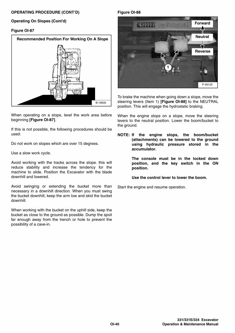
Figure OI-87
When operating on a slope, level the work area before
beginning [Figure OI-87].
If this is not possible, the following procedures should be
used:
Do not work on slopes which are over 15 degrees.
Use a slow work cycle.
Avoid working with the tracks across the slope. this will
reduce stability and increase the tendency for the
machine to slide. Position the Excavator with the blade
downhill and lowered.
Avoid swinging or extending the bucket more than
necessary in a downhill direction. When you must swing
the bucket downhill, keep the arm low and skid the bucket
downhill.
When working with the bucket on the uphill side, keep the
bucket as close to the ground as possible. Dump the spoil
far enough away from the trench or hole to prevent the
possibility of a cave-in.
Figure OI-88
To brake the machine when going down a slope, move the
steering levers (Item 1) [Figure OI-88] to the NEUTRAL
position. This will engage the hydrostatic braking.
When the engine stops on a slope, move the steering
levers to the neutral position. Lower the boom/bucket to
the ground.
NOTE: If the engine stops, the boom/bucket
(attachments) can be lowered to the ground
using hydraulic pressure stored in the
accumulator.
The console must be in the locked down
position, and the key switch in the ON
position.
Use the control lever to lower the boom.
Start the engine and resume operation.
B-19935
Recommended Position For Working On A Slope
P-49125
1
Forward
Reverse
Neutral

331/331E/334 Excavator
OI-41 Operation & Maintenance Manual
OPERATING PROCEDURE (CONT’D)
Operating In Water
Mud and water should be removed from the machine
before parking. In freezing temperatures, park the
machine on boards or concrete to prevent the track or
undercarriage from freezing to the ground and preventing
machine movement.
Figure OI-89
Do not operate or immerse the Excavator in water higher
than the bottom of the swing circle [Figure OI-89].
Grease the Excavator when it has been operated or
immersed in water for a period of time. Greasing forces
the water out of the lubrication areas.
Water must be removed from the cylinder rods. If water
freezes to the cylinder rod, the cylinder seals may be
damaged when the rod is retracted.
Extending The Arm (331E Only)
The arm can be extended to increase the reach of the
Excavator.
Figure OI-90
Remove quick couplers from the storage position (Item 1)
[Figure OI-90] and connect to the auxiliary couplers.
Move the lock pin (Item 2) [Figure OI-90] to the top holes
(storage position).
Figure OI-91
Operate the auxiliary control on the right joystick to extend
and retract the arm [Figure OI-91]. (See “HYDRAULIC
CONTROLS” on Page OI-18.)
NOTE: When transporting the Excavator or when
using hydraulically operated attachments, the
arm must be locked in the retracted position.
Fully retract the arm and install the pin (Item 2)
[Figure OI-90] through the lower holes of the
bracket. (Be sure the pin goes through the
mounting brackets and the extendable arm
bracket.)
MS1854
Maximum
Water
LevelN-18669
1
2
MS1882

331/331E/334 Excavator
OI-42 Operation & Maintenance Manual
PARKING THE EXCAVATOR
Stop the machine on level ground. Lower the work
equipment and the blade to the ground.
Figure OI-92
Move the speed control lever fully backwards (Item 1)
[Figure OI-92].
Run the engine at idle speed for about 5 minutes to allow
it to cool.
Figure OI-93
Figure OI-94
Turn the key switch to STOP (Standard Panel)
[Figure OI-93] or press the STOP Button (Deluxe Panel)
(Item 1) [Figure OI-94].
Disconnect the seat belt. Remove the key from the switch
to prevent operation of machine by unauthorised
personnel. Raise the control console and exit the
machine.
P-49179
16808261
STOP ON
START
P16616
1

331/331E/334 Excavator
OI-43 Operation & Maintenance Manual
TRANSPORTING THE EXCAVATOR
When transporting the machine, observe the rules, motor
vehicle laws, and vehicle limit ordinances. Use a transport
and towing vehicle of adequate length and capacity.
Secure the parking brakes and block the wheels of the
transport vehicle.
Align the ramps with the centre of the transport vehicle.
Secure the ramps to the truck bed and be sure ramp
angle does not exceed 15 degrees.
Use metal loading ramps with a slip-resistant surface.
Use ramps that are the correct length and width and can
support the weight of the machine.
The rear of the trailer must be blocked or supported when
loading or unloading the Excavator to prevent the front of
the transport vehicle from raising.
Determine the direction of the track movement before
moving the machine (blade forward).
Figure OI-95
Engage the slew lock.
Move the machine forward onto the transport vehicle
[Figure OI-95].
Do not change direction of the machine while it is on the
ramps.
Lower the boom, arm, bucket, and blade to the transport
vehicle.
Stop the engine and remove the key (if equipped).
Put blocks at the front and rear of the tracks.
Figure OI-96
Figure OI-97
Fasten chains to the front corners of the blade (Item 1)
[Figure OI-96] and to the tie-down loop at the rear of the
track frame (Item 1) [Figure OI-97] to prevent it from
moving when going up or down slopes or during sudden
stops.
Use chain binders to tighten the chains and then safely tie
the chain binder levers to prevent loosening.
WARNINGAdequately designed ramps of sufficient strength are
needed to support the weight of the machine when
loading onto a transport vehicle. Wooden ramps can
break and cause personal injury.W-2058-0494
P-49273
P-49274
1
1
P-49101
1

331/331E/334 Excavator
OI-44 Operation & Maintenance Manual
LIFTING THE EXCAVATOR
Figure OI-98
Fully extend the cylinders of the bucket, arm, and boom
so that the Excavator is in the position as shown
[Figure OI-98].
Raise the blade all the way.
Put all the control levers in neutral.
WARNINGAVOID INJURY OR DEATH
• Use a lifting fixture with sufficient capacity for the
weight of the Excavator plus any added
attachments.
• Maintain centre of gravity and balance when
lifting.
• Do not swing boom or superstructure. Engage the
swing locking lever.
• Never lift with operator on machine.W-2202-0595
Figure OI-99
Figure OI-100
Fasten chains to the ends of the blade (Item 1)
[Figure OI-98] and [Figure OI-99] and up to a lifting
fixture above the canopy/cab. The lifting fixture must
extend over the sides of the canopy/cab to prevent the
chains from hitting the ROPS/TOPS.
Install a 25 mm bolt and nut (Grade 5 or 8) through the
holes at the boom (Item 2) [Figure OI-98] and
[Figure OI-100]. Fasten a chain from the bolt to the lift
fixture.
P-49275
2
1
P-49277
1
1
P-49276
2

331/331E/334 Excavator
PM-1 Operation & Maintenance Manual
PREVENTIVE MAINTENANCE
AIR CLEANER. . . . . . . . . . . . . . . . . . . . . . . . . . . . . . . . . . . . . . . PM-8Daily Check . . . . . . . . . . . . . . . . . . . . . . . . . . . . . . . . . . . . . . PM-8Replacing The Filters . . . . . . . . . . . . . . . . . . . . . . . . . . . . . . . PM-9
COOLING SYSTEM. . . . . . . . . . . . . . . . . . . . . . . . . . . . . . . . . . PM-17Checking Coolant Level . . . . . . . . . . . . . . . . . . . . . . . . . . . . PM-18Cleaning The Cooling System . . . . . . . . . . . . . . . . . . . . . . . PM-17Replacing The Coolant . . . . . . . . . . . . . . . . . . . . . . . . . . . . . PM-19
ELECTRICAL SYSTEM. . . . . . . . . . . . . . . . . . . . . . . . . . . . . . . PM-20Description . . . . . . . . . . . . . . . . . . . . . . . . . . . . . . . . . . . . . . PM-20Fuse And Relay Location . . . . . . . . . . . . . . . . . . . . . . . . . . . PM-20Removing And Installing The Battery . . . . . . . . . . . . . . . . . . PM-22Using A Booster Battery (Jump-Starting) . . . . . . . . . . . . . . . PM-21
ENGINE ACCESSORY DRIVE BELT . . . . . . . . . . . . . . . . . . . . PM-30Belt Adjustment . . . . . . . . . . . . . . . . . . . . . . . . . . . . . . . . . . PM-30Belt Tension . . . . . . . . . . . . . . . . . . . . . . . . . . . . . . . . . . . . . PM-30
ENGINE LUBRICATION SYSTEM. . . . . . . . . . . . . . . . . . . . . . . PM-15Checking Engine Oil . . . . . . . . . . . . . . . . . . . . . . . . . . . . . . . PM-15Replacing Oil And Filter . . . . . . . . . . . . . . . . . . . . . . . . . . . . PM-16
FUEL SYSTEM . . . . . . . . . . . . . . . . . . . . . . . . . . . . . . . . . . . . . PM-12Draining The Fuel Tank . . . . . . . . . . . . . . . . . . . . . . . . . . . . PM-13Filling The Fuel Tank . . . . . . . . . . . . . . . . . . . . . . . . . . . . . . PM-12Fuel Filter . . . . . . . . . . . . . . . . . . . . . . . . . . . . . . . . . . . . . . . PM-14Fuel Specifications . . . . . . . . . . . . . . . . . . . . . . . . . . . . . . . . PM-12Removing Air From The Fuel System. . . . . . . . . . . . . . . . . . PM-14Removing Water From The Fuel Filter . . . . . . . . . . . . . . . . . PM-13
HEATER AIR FILTER (WITH CAB OPTION ONLY). . . . . . . . . . PM-11Removal And Installation . . . . . . . . . . . . . . . . . . . . . . . . . . . PM-11
HYDRAULIC SYSTEM. . . . . . . . . . . . . . . . . . . . . . . . . . . . . . . . PM-23Checking And Adding Hydraulic Oil . . . . . . . . . . . . . . . . . . . PM-23Diagnostic Couplers . . . . . . . . . . . . . . . . . . . . . . . . . . . . . . . PM-26Replacing The Case Drain Filter . . . . . . . . . . . . . . . . . . . . . PM-25Replacing The Hydraulic Filter . . . . . . . . . . . . . . . . . . . . . . . PM-25Replacing The Hydraulic Oil . . . . . . . . . . . . . . . . . . . . . . . . . PM-24
MAINTENANCEPREVENTIVE

331/331E/334 Excavator
PM-2 Operation & Maintenance Manual
PREVENTIVE MAINTENANCE (CONT’D)
LUBRICATION OF THE HYDRAULIC EXCAVATOR . . . . . . . PM-33
MAINTENANCE SAFETY. . . . . . . . . . . . . . . . . . . . . . . . . . . . . PM-3
SEAT BELT . . . . . . . . . . . . . . . . . . . . . . . . . . . . . . . . . . . . . . . PM-10Inspection And Maintenance . . . . . . . . . . . . . . . . . . . . . . . PM-10
RIGHT SIDE COVER . . . . . . . . . . . . . . . . . . . . . . . . . . . . . . . . PM-7Opening And Closing The Right Side Cover . . . . . . . . . . . . PM-7
SERVICE SCHEDULE . . . . . . . . . . . . . . . . . . . . . . . . . . . . . . . PM-5
SPARK ARRESTER SILENCER . . . . . . . . . . . . . . . . . . . . . . . PM-27
TAILGATE . . . . . . . . . . . . . . . . . . . . . . . . . . . . . . . . . . . . . . . . . PM-6Adjusting The Latch. . . . . . . . . . . . . . . . . . . . . . . . . . . . . . . PM-6Adjusting The Bumper . . . . . . . . . . . . . . . . . . . . . . . . . . . . . PM-6Opening And Closing The Tailgate . . . . . . . . . . . . . . . . . . . PM-6
TRACK TENSION. . . . . . . . . . . . . . . . . . . . . . . . . . . . . . . . . . PM-28Adjustment. . . . . . . . . . . . . . . . . . . . . . . . . . . . . . . . . . . . . PM-29
TRAVEL MOTOR . . . . . . . . . . . . . . . . . . . . . . . . . . . . . . . . . . PM-31Checking Oil Level . . . . . . . . . . . . . . . . . . . . . . . . . . . . . . . PM-31Draining The Travel Motor . . . . . . . . . . . . . . . . . . . . . . . . . PM-31
X-CHANGE ™ . . . . . . . . . . . . . . . . . . . . . . . . . . . . . . . . . . . . PM-32Inspection And Maintenance . . . . . . . . . . . . . . . . . . . . . . . PM-32

331/331E/334 Excavator
PM-3 Operation & Maintenance Manual
Cleaning and maintenance arerequired daily.
Use the correct procedure to liftand support the Excavator.
MAINTENANCE SAFETY
WARNING
Instructions are necessary before operating or servicing machine. Read and understand the
Operation & Maintenance Manual, Operator’s Handbook and signs (transfers) on machine.
Follow warnings and instructions in the manuals when making repairs, adjustments or
servicing. Check for correct function after adjustments, repairs or service. Untrained operators
and failure to follow instructions can cause injury or death.W-2003-0903
Never service the Bobcat CompactExcavator without instructions.
B-10731A
CORRECT
B-19965
WRONG
Have good ventilation whenwelding or grinding painted parts.Wear dust mask when grindingpainted parts. Toxic dust and gascan be produced.
WRONG
B-19962
Stop, cool and clean engine offlammable materials beforechecking fluids.Never service or adjust machinewith the engine running unlessinstructed to do so in themanual.Avoid contact with leakinghydraulic fluid or diesel fuelunder pressure. It can penetratethe skin or eyes.Never fill fuel tank with enginerunning, while smoking, or whennear open flame.
B-19966
WRONGWRONG
B-19960
B-19958
WRONG
Always lower the bucket andblade to the ground before doingany maintenance.Never modify equipment or addattachments not approved byBobcat Company.
Keep body, jewellery and clothing
away from moving parts, electrical
contact, hot parts and exhaust.
Wear eye protection to guard from
battery acid, compressed springs,
fluids under pressure and flying
debris when engines are running
or tools are used. Use eye
protectors approved for type of
welding.
Keep rear door closed except for
service. Close and latch door
before operating the Excavator.
Vent exhaust to outside whenengine must be run for service.Exhaust system must be tightlysealed. Exhaust fumes may killwithout warning.
Safety Alert Symbol: This symbol with a warning statement, means: “Warning, be alert! Your safety isinvolved!” Carefully read the message that follows.
CORRECT
B-19964
CORRECT CORRECT
B-19959
MSW28-1003
Maintenance procedures given in the Operation & Maintenance manual may be performed by the owner/operator without any
specific technical training. Maintenance procedures which are not in the Operation & Maintenance manual must be performed
ONLY BY QUALIFIED BOBCAT SERVICE PERSONNEL. Always use genuine Bobcat replacement parts. The Service Safety
Training course is available from your Bobcat dealer.
B-19798
WRONG
Lead-acid batteries produce
flammable and explosive gases.
Keep arcs, sparks, flames and
lighted tobacco away from
batteries.
Batteries contain acid which
burns eyes or skin on contact.
Wear protective clothing. If acid
contacts body, flush well with
water. For eye contact flush well
and get immediate medical
attention.

331/331E/334 Excavator
PM-4 Operation & Maintenance Manual

331/331E/334 Excavator
PM-5 Operation & Maintenance Manual
SERVICE SCHEDULE
Chart
Maintenance work must be done at regular intervals.
Failure to do so will result in excessive wear and early
failures. The service schedule is a guide for correct
maintenance of the Bobcat Excavator.
WARNINGInstructions are necessary before operating or
servicing machine. Read and understand the
Operation & Maintenance Manual, Operator’s
Handbook and signs (transfers) on machine. Follow
warnings and instructions in the manuals when
making repairs, adjustments or servicing. Check for
correct function after adjustments, repairs or
service. Untrained operators and failure to follow
instructions can cause injury or death.W-2003-0903
SERVICE SCHEDULE HOURS
ITEM SERVICE REQUIRED8-10 50 100 250 500
�
1000
Engine Coolant Check coolant level. Add premixed coolant as needed.
Engine Oil Check the engine oil level and add as needed.
Hydraulic Fluid, Hoses and
Tubelines, Reservoir Breather Cap
Check the hydraulic fluid level and add as needed. Check for damage and
leaks. Repair or replace as needed.
Engine Air Filter and Air System Check condition indicator and empty dust cup as needed. Check air system
for leaks.
Tracks Check and adjust track tension as needed.
Indicators and Lights Check for correct operation of all indicators and lights.
Operator Canopy/Cab Check condition. Check mounting hardware.
Seat Belt Check condition. Check mounting hardware.
Safety Signs and Safety Treads Check for damaged signs (transfers) and safety treads. Replace any signs or safety treads which are damaged or worn.
Pivot Points Grease all machinery pivot points.
Cab Heater Air Filter Clean the filter as needed.
Console Lock-out Check console lock-out for proper operation.
X-Change ™ Lubricate and inspect for damage or loose parts.
Swing Circle and Pinion Grease two fittings
Fuel Tank & Filter Drain water and sediment from fuel tank and fuel filter.
Battery Check battery, cables, connections and electrolyte level. Add distilled water
as needed.
Accessory Drive Belt Check condition of belt and adjust as needed. �
Spark Arrester Silencer Clean the spark chamber.
Fuel Filter Replace fuel filter.
Radiator, Oil Cooler, *A/C Clean debris from the radiator fins.
Engine Oil and Filter Replace oil and filter use CD or better grade oil and Bobcat filter. �
Primary Hydraulic Filter Replace the primary hydraulic filter. ^
Case Drain Filter Replace the case drain filter. ^
Alternator & Starter Check the alternator and starter connections.
Engine Valves Check and adjust the engine valve clearance.
Engine Cooling System Drain and flush the cooling system. Replace the coolant.
Hydraulic System Replace the hydraulic fluid and filters. Clean the reservoir.
Travel Motor Replace the lubricant in both travel motors.
* If Fitted� Also at first 50 Hours^ Also at first 100 Hours� Or every 6 months.

331/331E/334 Excavator
PM-6 Operation & Maintenance Manual
TAILGATE
Opening And Closing The Tailgate
WARNINGAVOID INJURY OR DEATH
Never service or adjust the machine when the engine
is running unless instructed to do so in the manual.W-2012-0497
WARNINGKeep the rear door closed when operating the
machine. Failure to do so could seriously injure a
bystander.W-2020-1285
Figure PM-1
Pull the latch (Item 1) [Figure PM-1] and pull the tailgate
open.
Push firmly to close the tailgate.
NOTE: The tailgate may be locked using the start key.
Adjusting The Bumper
Figure PM-2
The door bumper (Item 1) [Figure PM-2] may be adjusted
to align with the tailgate.
Close the tailgate before operating the Excavator.
Adjusting The Latch
Figure PM-3
The door catch (Item 1) [Figure PM-3] may be adjusted
for alignment.
Close the tailgate before operating the Excavator.
P-49241
1
P-49243
1
P-49242
1

331/331E/334 Excavator
PM-7 Operation & Maintenance Manual
RIGHT SIDE COVER
Opening And Closing The Right Side Cover
Figure PM-4
Pull the latch (Item 1) [Figure PM-4] and raise the right
side cover.
NOTE: The right side cover can be locked using the
start key.
P-49244
1

331/331E/334 Excavator
PM-8 Operation & Maintenance Manual
AIR CLEANER
See the SERVICE SCHEDULE (See “SERVICE
SCHEDULE” on Page PM-5.) for the correct service
interval.
Daily Check
Figure PM-5
Check the condition indicator (Item 1) [Figure PM-5]. If
the red ring shows in the condition indicator, the filter
needs to be replaced.
Replace the inner filter every third time the outer filter is
replaced or as indicated.
P-49245
1
23
2

331/331E/334 Excavator
PM-9 Operation & Maintenance Manual
AIR CLEANER (CONT’D)
Replacing The Filters
Outer Filter
Release the two fasteners (Item 2) [Figure PM-5].
Remove and clean the dust cup (Item 3) [Figure PM-5].
Figure PM-6
Pull the outer filter (Item 1) [Figure PM-6] from the air
cleaner housing.
Check the housing for damage.
Clean the housing and the seal surface. DO NOT use
compressed air.
Install a new filter.
Figure PM-7
Install the dust cup (Item 1) and engage the fasteners
(Item 2) [Figure PM-7].
Check the air intake hose and the air cleaner housing for
damage. Make sure all connections are tight.
Inner Filter
Only replace the inner filter under the following conditions:
• Replace the inner filter every third time the outer filter
is replaced.
• After the outer filter has been replaced, press the
button (Item 3) [Figure PM-7] on the top of the
condition indicator and start the engine. Run at full
RPM, then reduce engine speed and stop the engine.
If the red ring shows in the condition indicator, replace
the inner filter.
Figure PM-8
Remove the dust cup, outer filter and inner filter (Item 1)
[Figure PM-8].
NOTE: Make sure all sealing surfaces are free of dirt
and debris.
Install the new inner filter.
Install the outer filter and the dust cup.
Press the button on the condition indicator to remove the
red ring.
P-49246
1
P-49245
32
12
P-49247
1

331/331E/334 Excavator
PM-10 Operation & Maintenance Manual
SEAT BELT
Inspection And Maintenance
WARNINGFailure to properly inspect and maintain the seat belt
may cause lack of operator restraint resulting in
serious injury or death.W-2466-0703
Check the seat belt daily for correct function.
Inspect the seat belt system thoroughly yearly or more
often if the machine is exposed to severe environmental
conditions or applications.
The seat belt system should be repaired or replaced if it
shows cuts, fraying, extreme or unusual wear, significant
discoloration due to ultraviolet (UV) rays from the sun,
dusty/dirty conditions, abrasion to the seat belt webbing,
or damage to the buckle, latch plate, retractor (if fitted), or
fixings.
Figure PM-9
The items below are referenced in [Figure PM-9].
1. Check the seat belt webbing. If the system is fitted with
a retractor, pull the webbing completely out and
inspect the full length of the webbing. Look for cuts,
wear, fraying, dirt and stiffness.
2. Check the buckle and latch for proper function. Make
sure latch plate is not excessively worn, deformed or
buckle is not damaged.
3. Check the retractor web storage device (if fitted) by
extending the seat belt webbing to determine if it
extends and retracts the webbing correctly.
4. Check webbing in areas exposed to ultraviolet (UV)
rays from the sun or extreme dust or dirt. If the original
colour of the webbing in these areas is extremely
faded and / or the webbing is packed with dirt, the
webbing strength may have weakened.
See your Bobcat dealer for approved seat belt system
replacement parts for your machine.
B-22283

331/331E/334 Excavator
PM-11 Operation & Maintenance Manual
HEATER AIR FILTER (WITH CAB OPTION ONLY)
Removal And Installation
The heater filter must be cleaned regularly. The filter is
located at the left of the operator seat.
Figure PM-10
Remove the screw (Item 1) and cover (Item 2)
[Figure PM-10].
Figure PM-11
Pull the filter (Item 1) [Figure PM-11] away and out of the
heater/AC housing.
Use low air pressure to clean the filter. Replace the filter
when very dirty.
Figure PM-12
Installation: Install the filter with the arrows that indicate
air flow direction (Item 1) [Figure PM-12] pointing towards
the heater/AC housing.
P-42166
1
2
P-42167
1
P-42168
1

331/331E/334 Excavator
PM-12 Operation & Maintenance Manual
FUEL SYSTEM
Fuel Specifications
Use only clean, high quality diesel fuel, Grade No. 2 or
Grade No. 1.
The following is a suggested blending guideline which
should prevent fuel gelling problems during freezing
temperature
See your fuel supplier for local recommendations.
Filling The Fuel Tank
Figure PM-13
Open the right side cover and remove the fuel fill cap
(Item 1) [Figure PM-13].
Use a clean, approved safety container to add fuel. Add
fuel only in an area that has a free movement of air and no
flames or sparks. NO SMOKING!
Install and tighten the fuel fill cap.
Clean up any spilled fuel.
WARNINGAlways clean up spilled fuel or oil. Keep heat, flames,
sparks or lighted tobacco away from fuel and oil.
Failure to take care around combustibles may cause
explosion or fire which can result in injury or death.W-2103-1285
Temp. F° (C°) No. 2 No. 1
Above +15° (-9°) 100% 0%
Down to -20° (-29°) 50% 50%
Below -20° (-29°) 0% 100%
P-49248
1

331/331E/334 Excavator
PM-13 Operation & Maintenance Manual
FUEL SYSTEM (CONT’D)
Removing Water From The Fuel Filter
Open the tailgate.
Figure PM-14
Loosen the drain (Item 1) [Figure PM-14] at the bottom of
the filter to drain water from the filter.
See the SERVICE SCHEDULE (See “SERVICE
SCHEDULE” on Page PM-5.) for the service interval
when to remove the water from the fuel filter.
Draining The Fuel Tank
See the SERVICE SCHEDULE (See “SERVICE
SCHEDULE” on Page PM-5.) for the correct service
interval.
Figure PM-15
Remove the hose (Item 1) [Figure PM-15] from the fuel
injection pump. Route the hose to the bottom of the
engine compartment and out through the tailgate.
Drain the fuel into a container.
Reuse, recycle or dispose of fuel in an environmentally
safe manner.
WARNINGDiesel fuel or hydraulic fluid under pressure can
penetrate skin or eyes, causing serious injury or
death. Fluid leaks under pressure may not be visible.
Use a piece of cardboard or wood to find leaks. Do
not use your bare hand. Wear safety goggles. If fluid
enters skin or eyes, get immediate medical attention
from a doctor familiar with this injury.W-2072-0496
P-49259
1
P-49251
1

331/331E/334 Excavator
PM-14 Operation & Maintenance Manual
FUEL SYSTEM (CONT’D)
Fuel Filter
See the SERVICE SCHEDULE (See “SERVICE
SCHEDULE” on Page PM-5.) for the service interval
when to replace the fuel filter.
Figure PM-16
Remove the filter (Item 1) [Figure PM-16].
Clean the area around the filter housing.
Put oil on the seal of the new filter.
Install the fuel filter, and hand tighten.
Removing Air From The Fuel System
After replacing the fuel filter or when the fuel tank has run
out of fuel, air must be removed from the fuel system
before starting the engine.
Figure PM-17
Open the fuel filter vent (Item 1) and operate the hand
pump (priming bulb) (Item 2) [Figure PM-17] until the fuel
flows from the vent with no air bubbles.
Close the vent (Item 1) [Figure PM-17].
Start the engine. It may be necessary to open the vent
(Item 3) [Figure PM-17] (at the fuel injection pump) briefly
until the engine runs smoothly.
WARNINGDiesel fuel or hydraulic fluid under pressure can
penetrate skin or eyes, causing serious injury or
death. Fluid leaks under pressure may not be visible.
Use a piece of cardboard or wood to find leaks. Do
not use your bare hand. Wear safety goggles. If fluid
enters skin or eyes, get immediate medical attention
from a doctor familiar with this injury.W-2072-0496
P-49249
1
P-49251
3
2
1

331/331E/334 Excavator
PM-15 Operation & Maintenance Manual
ENGINE LUBRICATION SYSTEM
Checking Engine Oil
Check the engine oil after every 8-10 hours of operation
and before starting the engine.
Figure PM-18
Open the tailgate and remove the dipstick (Item 1)
[Figure PM-18].
Keep the oil level between the marks on the dipstick.
Use a good quality motor oil that meets the correct API
Service Classification.
Oil Chart
Figure PM-19
Use a good quality motor oil that meets the correct API
Service Classification. See oil chart [Figure PM-19].
P-49252
1

331/331E/334 Excavator
PM-16 Operation & Maintenance Manual
ENGINE LUBRICATION SYSTEM (CONT’D)
Replacing Oil And Filter
See the SERVICE SCHEDULE (See “SERVICE
SCHEDULE” on Page PM-5.) for the service interval for
replacing the engine oil and filter.
Run the engine until it is at operating temperature. Stop
the engine.
Figure PM-20
Remove the drain hose (Item 1) [Figure PM-20] from the
storage position.
Figure PM-21
Remove the cap (Item 1) [Figure PM-21]. Drain the oil
into a container.
Recycle or dispose of used oil in an environmentally safe
manner.
Figure PM-22
Remove the oil filter (Item 1) [Figure PM-22] and clean
the filter housing surface.
Use a genuine Bobcat replacement filter. Put clean oil on
the filter gasket. Install the filter and hand tighten.
Install and tighten the oil cap.
Figure PM-23
Remove the fill cap (Item 1) [Figure PM-23].
Put oil in the engine. (See “Electrical” on Page SPEC-15.)
Install the fill cap.
Start the engine and let it run for several minutes.
Stop the engine. Check for leaks at the oil filter. Check the
oil level.
Add oil as needed if it is not at the top mark on the
dipstick.
P-49253
1
P-49254
1
P-49255
1
P-49256
1

331/331E/334 Excavator
PM-17 Operation & Maintenance Manual
COOLING SYSTEM
Check the cooling system every day to prevent over-
heating, loss of performance or engine damage.
Cleaning The Cooling System
NOTE: Allow the cooling system and engine to cool
before servicing or cleaning the cooling
system.
Open the right side cover.
Figure PM-24
Use air pressure or water pressure to clean the radiator
and oil cooler (Item 1) [Figure PM-24]. Be careful not to
damage fins when cleaning.
P-49257
1

331/331E/334 Excavator
PM-18 Operation & Maintenance Manual
COOLING SYSTEM (CONT’D)
Checking Coolant Level
WARNINGDo not remove radiator cap when the engine is hot.
You may be seriously burned.
W-2070-1285
Open the tailgate.
Figure PM-25
Check the coolant level in the coolant recovery tank
(Item 1) [Figure PM-25].
The coolant level must be between the MIN and MAX
marks on the coolant recovery tank when the engine is
cold.
NOTE: The cooling system is factory filled with
propylene glycol (purple colour). DO NOT mix
propylene glycol with ethylene glycol.
IMPORTANTAVOID ENGINE DAMAGE
Always use the correct ratio of water to antifreeze.
Too much antifreeze reduces cooling system
efficiency and may cause serious premature engine
damage.
Too little antifreeze reduces the additives which
protect the internal engine components; reduces the
boiling point and freeze protection of the system.
Always add a premixed solution. Adding full strength
concentrated coolant can cause serious premature
engine damage.I-2124-0497
WARNINGWear safety glasses to prevent eye injury when any of
the following conditions exist:
When fluids are under pressure.
Flying debris or loose material is present.
Engine is running.
Tools are being used.W-2019-1285
P-49258
1

331/331E/334 Excavator
PM-19 Operation & Maintenance Manual
COOLING SYSTEM (CONT’D)
Replacing The Coolant
See the SERVICE SCHEDULE (See “SERVICE
SCHEDULE” on Page PM-5.) for correct service intervals.
WARNINGDo not remove radiator cap when the engine is hot.
You may be seriously burned.W-2070-1285
Figure PM-26
When the engine is cool, loosen and remove the radiator
cap (Item 1) [Figure PM-26].
Figure PM-27
Put a hose on the drain valve at the bottom of the radiator.
Open the drain valve (Item 1) [Figure PM-27] and drain
the coolant into a container.
Figure PM-28
Put a hose on the drain valve on the engine block. Open
the drain valve (Item 1) [Figure PM-28] and drain the
coolant into a container.
After all the coolant is removed, close both drain valves.
Recycle or dispose of the used coolant in an
environmentally safe manner.
Mix the coolant in a separate container. (See “Electrical”
on Page SPEC-15.)
NOTE: The cooling system is factory filled with
propylene glycol (purple colour). DO NOT mix
propylene glycol with ethylene glycol.
Add premixed coolant; 47% water and 53% propylene
glycol to the recovery tank if the coolant level is low.
4.25 L of propylene glycol mixed with 3.8 L of water is the
correct mixture of coolant to provide a -34°F (-37°C)
freeze protection.
Use a refractometer to check the condition of propylene
glycol in your cooling system.
Add premixed coolant until the level is correct.
Run the engine until it is at operating temperature. Stop
the engine. Check the coolant level and add as needed.
Be sure the radiator cap is tight.
Add coolant to the recovery tank as needed.
Close the tailgate.
P-49260
1
P-49259
1
P-49270
1

331/331E/334 Excavator
PM-20 Operation & Maintenance Manual
ELECTRICAL SYSTEM
Description
Figure PM-29
The Excavator has a 12 volt, negative earth electrical
system. The electrical system is protected by fuses
located under the right side cover of the Excavator
(Item 1) [Figure PM-29]. The fuses will protect the
electrical system when there is an electrical overload. The
reason for the overload must be found before starting the
engine again.
The battery cables must be clean and tight. Check the
electrolyte level in the battery. Add distilled water as
needed. Remove acid or corrosion from the battery and
cables with a sodium bicarbonate and water solution.
Put Battery Saver P/N 6664458 or grease on the battery
terminals and cable ends to prevent corrosion.
WARNINGBatteries contain acid which burns eyes and skin on
contact. Wear goggles, protective clothing and rubber
gloves to keep acid off body.
In case of acid contact, wash immediately with water.
In case of eye contact get prompt medical attention
and wash eye with clean, cool water for at least
15 minutes.
If electrolyte is taken internally drink large quantities
of water or milk! DO NOT induce vomiting. Get prompt
medical attention.W-2065-1296
Fuse And Relay Location
A notice is inside the cover to show location and amp
ratings.
Remove the cover to check or replace the fuses and
relays.
Figure PM-30
The location and sizes are shown below and
[Figure PM-30].
Always replace fuses using the same type and capacity.
P-49261
1
REF DESCRIPTION AMP REF DESCRIPTION AMP
1 Not Used - - 11 Lights 20
2 Heater 25 12 ACC Plug 15
3 Ignition 5
4 Fuel Solenoid 25
5 Wiper 5
6 Switch Power 20
7 Alternator/
Heater
25
8 ACD 25
9 Controller 25
10 ACD 25
REF DESCRIPTION
E Switch Power
F Fuel Solenoid
G Lights
H Glow Plug
J Starter
B-19812

331/331E/334 Excavator
PM-21 Operation & Maintenance Manual
ELECTRICAL SYSTEM (CONT’D)
Using A Booster Battery (Jump-Starting)
IMPORTANTWhen jump-starting the Excavator from a battery
installed in a second machine, make sure the second
machine is NOT running while using the glow plugs.
High voltage spikes from a running machine may burn
out the glow plugs.I-2060-0195
If it is necessary to use a booster battery to start the
engine, BE CAREFUL! There must be one person in the
operator’s seat and one person to connect and disconnect
the battery cables.
Be sure the key switch is OFF. The booster battery must
be 12 volt.
Open the tailgate.
Figure PM-31
Connect one end of the first cable to the positive (+)
terminal of the booster battery. Connect the other end of
the same cable to the positive (+) terminal (Item 1)
[Figure PM-31] of the Excavator starter.
Connect one end of the second cable to the negative (-)
terminal of the booster battery. Connect the other end of
the same cable to the negative Excavator cable (Item 2)
[Figure PM-31] where it is fastened to the frame.
NOTE: (See “Cold Temperature Starting Procedure”
on Page OI-26.)
Start the engine. After the engine has started, remove the
earth (-) cable first (Item 2) [Figure PM-31].
Disconnect the cable from the Excavator starter (Item 1)
[Figure PM-31].
WARNINGBatteries contain acid which burns eyes and skin on
contact. Wear goggles, protective clothing and rubber
gloves to keep acid off body.
In case of acid contact, wash immediately with water.
In case of eye contact get prompt medical attention
and wash eye with clean, cool water for at least
15 minutes.
If electrolyte is taken internally drink large quantities
of water or milk! DO NOT induce vomiting. Get prompt
medical attention.W-2065-1296
WARNINGKeep arcs, sparks flames and lighted tobacco away
from batteries. When jumping from booster battery
make final connection (negative) at engine frame.
Do not jump-start or charge a frozen or damaged
battery. Warm battery to 60°F (16°C) before
connecting to a charger. Unplug charger before
connecting or disconnecting cables to battery. Never
lean over battery while boosting, testing or charging.
Battery gas can explode and cause serious injury.W-2066-1296
IMPORTANTDamage to the alternator may occur if:
• Engine is operated with battery cables
disconnected.
• Battery cables are connected when using a fast
charger or when welding on the Excavator.
(Remove both cables from the battery.)
• Extra battery cables (booster cables) are
connected incorrectly.I-2222-0903
P-49262
1
2

331/331E/334 Excavator
PM-22 Operation & Maintenance Manual
ELECTRICAL SYSTEM (CONT’D)
Removing And Installing The Battery
Open the right side cover.
Figure PM-32
Disconnect the negative (-) cable (Item 1) [Figure PM-32]
first.
Disconnect the positive (+) cable (Item 2) [Figure PM-32].
Remove the bolts (Item 3) [Figure PM-32] and remove
the hold-down clamp.
Remove the battery.
Always clean the terminals and the cable ends, even
when installing a new battery.
Install the battery. Install the hold-down clamp and tighten
the bolts.
Connect the battery cables. Connect the negative (-)
cable (Item 1) [Figure PM-32] last to prevent sparks.
WARNINGBatteries contain acid which burns eyes and skin on
contact. Wear goggles, protective clothing and rubber
gloves to keep acid off body.
In case of acid contact, wash immediately with water.
In case of eye contact get prompt medical attention
and wash eye with clean, cool water for at least
15 minutes.
If electrolyte is taken internally drink large quantities
of water or milk! DO NOT induce vomiting. Get prompt
medical attention.W-2065-1296
P-21152
21
33

331/331E/334 Excavator
PM-23 Operation & Maintenance Manual
HYDRAULIC SYSTEM
Checking And Adding Hydraulic Oil
Put the machine on a flat level surface.
Retract the arm and bucket cylinders, put the bucket on
the ground and lower the blade. Stop the engine.
Open the tailgate.
Figure PM-33
Check the hydraulic fluid level: it must be visible in the
sight gauge (Item 1) [Figure PM-33].
Clean the surface around the reservoir (breather) cap and
remove the cap from the reservoir (Item 2)
[Figure PM-33].
Figure PM-34
Check the condition of the fill strainer screen (Item 1)
[Figure PM-34]. Clean or replace as necessary.
Be sure the screen is installed before adding fluid.
Add the correct fluid to the reservoir until it is visible in the
sight gauge. (See “Electrical” on Page SPEC-15.)
Check the cap and clean as necessary. Replace the cap if
damaged.
Install the cap.
Close the tailgate.
P-49263
1
2 P-49264
1

331/331E/334 Excavator
PM-24 Operation & Maintenance Manual
HYDRAULIC SYSTEM (CONT’D)
Replacing The Hydraulic Oil
See the SERVICE SCHEDULE (See “SERVICE
SCHEDULE” on Page PM-5.) for the correct service
interval.
WARNINGDiesel fuel or hydraulic fluid under pressure can
penetrate skin or eyes, causing serious injury or
death. Fluid leaks under pressure may not be visible.
Use a piece of cardboard or wood to find leaks. Do
not use your bare hand. Wear safety goggles. If fluid
enters skin or eyes, get immediate medical attention
from a doctor familiar with this injury.W-2072-0496
Retract the arm and bucket cylinders, lower the bucket to
the ground. Stop the engine.
Open the tailgate.
Figure PM-35
Remove the drain plug (Item 1) [Figure PM-35].
Drain the fluid into a container.
Recycle or dispose of the fluid in an environmentally safe
manner.
Install the drain plug (Item 1) [Figure PM-35].
Add fluid to the reservoir. (See “Electrical” on Page
SPEC-15.)
Figure PM-36
Open the bleed valve (Item 1) [Figure PM-36] on the
hydraulic pump. Close the valve after a steady stream of
hydraulic fluid free of any air bubbles drains from the
valve. Tighten the bleed valve. DO NOT RUN THE
MACHINE WITH THE BLEED VALVE OPEN.
Start the engine and operate the machine through the
hydraulic functions. Stop the engine. Check the fluid level
and add as needed.
P-49265
1
P-22626
1

331/331E/334 Excavator
PM-25 Operation & Maintenance Manual
HYDRAULIC SYSTEM (CONT’D)
Replacing The Hydraulic Filter
See the SERVICE SCHEDULE (See “SERVICE
SCHEDULE” on Page PM-5.) for the correct service
interval.
Open the right side cover.
Figure PM-37
Remove the hydraulic filter (Item 1) [Figure PM-37].
Clean the housing where the filter gasket makes contact.
Put clean hydraulic fluid on the gasket. Install the new
filter and hand tighten only.
WARNINGAlways clean up spilled fuel or oil. Keep heat, flames,
sparks or lighted tobacco away from fuel and oil.
Failure to take care around combustibles can cause
explosion or fire which may result in injury or death.W-2103-1285
Replacing The Case Drain Filter
Open the right side cover.
Remove the filter (Item 2) [Figure PM-37].
Clean the housing where the filter gasket makes contact.
Put clean hydraulic fluid on the gasket. Install the new
filter and hand tighten only.
P-49266
2
1

331/331E/334 Excavator
PM-26 Operation & Maintenance Manual
HYDRAULIC SYSTEM (CONT’D)
Diagnostic Couplers
Open the right side cover.
Figure PM-38
Diagnostic couplers (Item 1) [Figure PM-38] are located
on the hydraulic circuitry.
The couplers may be used to check circuit pressures.
P-49267
1
1 1

331/331E/334 Excavator
PM-27 Operation & Maintenance Manual
SPARK ARRESTER SILENCER
See the SERVICE SCHEDULE (See “SERVICE
SCHEDULE” on Page PM-5.) for the correct service
interval.
Do not operate the Excavator with a defective exhaust
system.
IMPORTANTThis Excavator is factory equipped with a US
Department of Agriculture Forestry Service approved
spark arrester silencer. It is necessary to do
maintenance on this spark arrester silencer to keep it
in working condition. The spark arrester silencer
must be serviced by dumping the spark chamber
every 100 hours of operation.
If this machine is operated on flammable forest, brush
or grass covered land, it must be equipped with a
spark arrester attached to the exhaust system and
maintained in working order.
Refer to local laws and regulations for spark arrester
requirements.I-2061-0195
WARNINGWhen the engine is running during service, the
steering levers must be in neutral.
Failure to do so can cause injury or death.W-2203-0595
Stop the engine. Open the tailgate.
Figure PM-39
Remove the plug (Item 1) [Figure PM-39] from the bottom
of the silencer.
Start the engine and run for about 10 seconds while a
second person, wearing safety glasses, holds a piece of
wood over the outlet of the silencer. The carbon deposits
will be forced out of the silencer plug hole (Item 1)
[Figure PM-39].
Stop the engine. Install and tighten the plug.
Close the tailgate.
P-49268
1

331/331E/334 Excavator
PM-28 Operation & Maintenance Manual
TRACK TENSION
NOTE: The wear of the pins and bushings on the
undercarriage will vary with the working
conditions and the different types of soil. It is
necessary to inspect track tension and
maintain the correct tension. (See ’SERVICESCHEDULE’ on Page PM-5) for the correct
service interval.
Figure PM-40
Raise one side of the machine (Approximately 100 mm)
using the boom and arm [Figure PM-40].
Raise the blade fully and install jacks under the blade and
track frame (Item 1) [Figure PM-40]. Lower the boom until
all machine weight is on the jacks.
Stop the engine.
WARNINGAVOID INJURY OR DEATH
Keep fingers and hands out of pinch points when
checking the track tension.W-2142-0189
Rubber Track Clearance
Figure PM-41
Figure PM-42
Measure the clearance at the middle track roller. Do not
get fingers into pinch points between the track and the
track roller. Use a bolt or a dowel of the appropriate size to
check the gap between the contact edge of the roller and
the top edge of the track guide [Figure PM-41] & [Figure
PM-42].
Rubber Track Clearance - 9.7-14.7 mm.
P-49234
1
1
P-49187
0.490-0.690”
(12.4-17.5mm)
B-14067
Track Frame
0.38-0.58”(9.7-14.7 mm)
Track
TrackRoller

331/331E/334 Excavator
PM-29 Operation & Maintenance Manual
TRACK TENSION (CONT’D)
Steel Track Clearance
Figure PM-43
Measure the track clearance at the middle track roller. Do
not get fingers into pinch points between the track and the
track roller. Us a bolt or dowel of the appropriate size to
check the gap between the contact edge of the roller and
the top edge of the track guide [Figure PM-43].
Steel Track Clearance - 17.3-30 mm.
Adjustment
Figure PM-44
Loosen the two bolts from the cover (Item 1)
[Figure PM-44]. Pivot the cover downward.
Figure PM-45
Add grease to the fitting (Item 1) [Figure PM-45] until the
track tension is correct.
Figure PM-46
Use tool MEL1560 (Item 1) [Figure PM-46] to loosen the
bleed fitting (Item 2) [Figure PM-45] to release tension
from the track.
NOTE: Do not loosen the grease fitting (Item 1)
[Figure PM-45].
Repeat the procedure for the other side.
B-15022
Track Frame
0.680-1.180” (17.3-30 mm)
Track
P-49116
11
P-42471
21
N-18490
1
6804114

331/331E/334 Excavator
PM-30 Operation & Maintenance Manual
ENGINE ACCESSORY DRIVE BELT
Belt Tension
Open the tailgate.
Figure PM-47
Using a belt tension gauge, measure the belt tension
midway between the crankshaft pulley and alternator
pulley [Figure PM-47].
Belt tension is as follows:
New belt 145-155 Nm
Used belt 125-134 Nm
Belt Adjustment
Figure PM-48
Loosen the nut (Item 1) on the belt idler pulley. Loosen the
nut (Item 2) and tighten the bolt (Item 3) [Figure PM-48]
until the belt tension is correct.
Tighten the nut (Item 1) to 40-50 Nm torque. Tighten the
nut (Item 2) [Figure PM-48] to 20-25 Nm torque.
P-49269
P-49236
12
3

331/331E/334 Excavator
PM-31 Operation & Maintenance Manual
TRAVEL MOTOR
Checking Oil Level
Figure PM-49
Park the Excavator on a level surface with the plugs (Item
1 & 2) [Figure PM-49] in the position as shown.
Remove the plug (Item 1) [Figure PM-49]. The oil level
must be at the bottom edge of the hole.
Add lubricant through the hole if the level is low. (See
“Electrical” on Page SPEC-15.)
Draining The Travel Motor
See the SERVICE SCHEDULE (See “SERVICE
SCHEDULE” on Page PM-5.) for the correct service
interval.
Park the Excavator on a level surface with plugs (Item 1 &
2) [Figure PM-49] in the position shown. Remove both
plugs and drain the lubricant into a container.
WARNINGAlways clean up spilled fuel or oil. Keep heat, flames,
sparks or lighted tobacco away from fuel and oil.
Failure to take care around combustibles can cause
explosion or fire which may result in injury or death.W-2103-1285
Install the bottom plug (Item 2 [Figure PM-49]). Add
lubricant through the top plug hole until the lubricant level
is at the bottom edge of the hole. (See “Electrical” on
Page SPEC-15.)
Install the plug (Item 1) [Figure PM-49].
P-49185
1
2

331/331E/334 Excavator
PM-32 Operation & Maintenance Manual
X-CHANGE ™
Inspection And Maintenance
Figure PM-50
Inspect the X-Change for wear or damage. Inspect the
X-Change pins (Item 1) and hooks (Item 2)
[Figure PM-50] (on the attachment) for wear or damage.
Repair or replace damaged parts.
P-49712
2
1
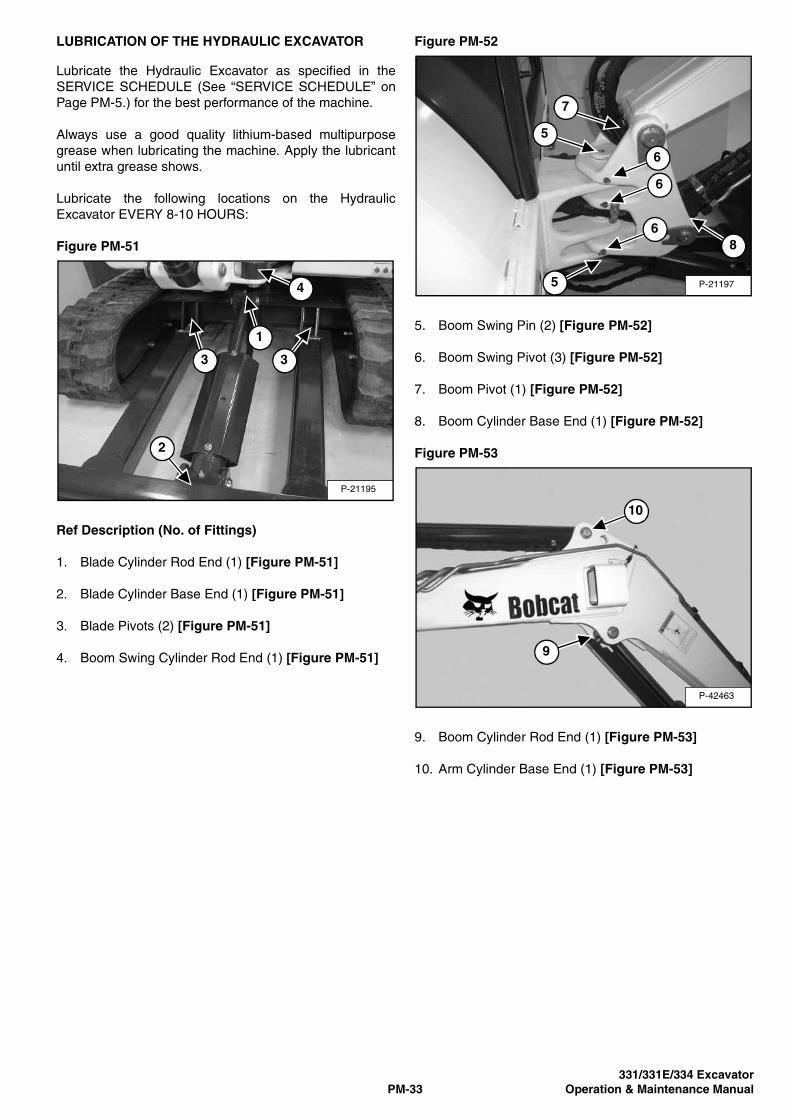
331/331E/334 Excavator
PM-33 Operation & Maintenance Manual
LUBRICATION OF THE HYDRAULIC EXCAVATOR
Lubricate the Hydraulic Excavator as specified in the
SERVICE SCHEDULE (See “SERVICE SCHEDULE” on
Page PM-5.) for the best performance of the machine.
Always use a good quality lithium-based multipurpose
grease when lubricating the machine. Apply the lubricant
until extra grease shows.
Lubricate the following locations on the Hydraulic
Excavator EVERY 8-10 HOURS:
Figure PM-51
Ref Description (No. of Fittings)
1. Blade Cylinder Rod End (1) [Figure PM-51]
2. Blade Cylinder Base End (1) [Figure PM-51]
3. Blade Pivots (2) [Figure PM-51]
4. Boom Swing Cylinder Rod End (1) [Figure PM-51]
Figure PM-52
5. Boom Swing Pin (2) [Figure PM-52]
6. Boom Swing Pivot (3) [Figure PM-52]
7. Boom Pivot (1) [Figure PM-52]
8. Boom Cylinder Base End (1) [Figure PM-52]
Figure PM-53
9. Boom Cylinder Rod End (1) [Figure PM-53]
10. Arm Cylinder Base End (1) [Figure PM-53]
P-21195
2
3 3
1
4 P-21197
7
5
5
6
6
6
8
P-42463
10
9

331/331E/334 Excavator
PM-34 Operation & Maintenance Manual
LUBRICATION OF THE HYDRAULIC EXCAVATOR (CONT’D)
Figure PM-54
11. Arm Cylinder Rod End (1) [Figure PM-54]
12. Arm Pivot (1) [Figure PM-54]
13. Bucket Cylinder Base End (1) [Figure PM-54]
Figure PM-55
14. Bucket Cylinder Rod End (1) [Figure PM-55]
15. Bucket Link Pin (1) [Figure PM-55]
16. Bucket Pivot (3) [Figure PM-55]
Figure PM-56
17. X-Change Latch (1) [Figure PM-56]
18. X-Change Pivot Pin (2) [Figure PM-56]
Figure PM-57
19. Boom Swing Cylinder Base End (1) [Figure PM-57]
Lubricate the following locations on the hydraulic
Excavator EVERY 50 HOURS:
20. Slew Circle (1) [Figure PM-57]
21. Slew Pinion (1) [Figure PM-57]
P-42464
11
13
12
P19384
14
15
16
16
16
P-19385
17
18 18
P-49272
2120
19

331/331E/334 Excavator
PM-35 Operation & Maintenance Manual
LUBRICATION OF THE HYDRAULIC EXCAVATOR (CONT’D)
Figure PM-58
22. Tailgate Hinge (2) [Figure PM-58].
P-49271
22
22

331/331E/334 Excavator
PM-36 Operation & Maintenance Manual

331/331E/334 Excavator
SA-1 Operation & Maintenance Manual
SYSTEM SET-UP AND ANALYSIS
DELUXE INSTRUMENT PANEL SET-UP . . . . . . . . . . . . . . . . . . SA-4Changing The Operator Password. . . . . . . . . . . . . . . . . . . . . SA-4Passwords . . . . . . . . . . . . . . . . . . . . . . . . . . . . . . . . . . . . . . . SA-4Job Clock . . . . . . . . . . . . . . . . . . . . . . . . . . . . . . . . . . . . . . . . SA-5Password Entry (For Starting and Operating the Machine) . . SA-4Password Lock-out Feature . . . . . . . . . . . . . . . . . . . . . . . . . . SA-5RPM. . . . . . . . . . . . . . . . . . . . . . . . . . . . . . . . . . . . . . . . . . . . SA-5
DIAGNOSTICS SERVICE CODE . . . . . . . . . . . . . . . . . . . . . . . . SA-3Number Codes List . . . . . . . . . . . . . . . . . . . . . . . . . . . . . . . . SA-3
& ANALYSISSYSTEM SET-UP

331/331E/334 Excavator
SA-2 Operation & Maintenance Manual

331/331E/334 Excavator
SA-3 Operation & Maintenance Manual
DIAGNOSTICS SERVICE CODE
Number Codes List
CODE CODE
02-16 Hydraulic charge filter not connected 20-02 Two speed output error ON
02-17 Hydraulic charge filter plugged 20-03 Two speed output error OFF
03-09 Battery voltage low 21-02 Glow plug output error ON
03-10 Battery voltage high 21-03 Glow plug output error OFF
03-11 Battery voltage extremely high
03-14 Battery voltage extremely low 22-02 Starter relay output error ON
03-22 Battery voltage out of range low 22-03 Starter relay output error OFF
04-14 Oil pressure extremely low 26-02 Front base output error ON
04-15 Oil pressure shutdown level 26-03 Front base output error OFF
05-09 Hydraulic charge pressure low 27-02 Front rod output error ON
05-14 Hydraulic charge pressure extremely low 27-03 Front rod output error OFF
05-15 Hydraulic charge pressure shutdown level
05-21 Hydraulic charge pressure out of range high 28-02 Diverter output error ON
05-22 Hydraulic charge pressure out of range low 28-03 Diverter output error OFF
06-10 Engine speed high 30-28 Watch dog failure
06-11 Engine speed extremely high
06-15 Engine speed shutdown level 31-28 Recovery mode failure
06-18 Engine speed out of range high
33-23 Controller not calibrated
07-10 Hydraulic oil temperature high
07-11 Hydraulic oil temperature extremely high
07-15 Hydraulic oil temperature shutdown level 60-21 Sec. aux. thumbswitch out of range high
07-21 Hydraulic oil temperature out of range high 60-22 Sec. aux. thumbswitch out of range low
07-22 Hydraulic oil temperature out of range low 60-23 Sec. aux. thumbswitch not calibrated
08-10 Engine coolant temperature high 62-04 Load moment monitoring in error
08-11 Engine coolant temperature extremely high
08-15 Engine coolant temperature shutdown level 63-05 Work group/travel console sensor
08-21 Engine coolant temperature out of range high 63-06 Work group/travel console sensor
08-22 Engine coolant temperature out of range low
64-05 Switched power/acc. relay short to battery
09-09 Fuel level low 64-06 Switched power/acc. relay short to ground
09-21 Fuel level out of range high 64-07 Switched power/acc. relay open circuit
09-22 Fuel level out of range low
65-02 Work group/travel lock-out solenoid error ON
12-21 Primary auxiliary PWM switch out of range high 65-03 Work group/travel lock-out solenoid error OFF
12-22 Primary auxiliary PWM switch out of range low 65-05 Work group/travel lock-out solenoid short to battery
12-23 primary auxiliary PWM switch not calibrated 65-06 Work group/travel lock-out solenoid short to ground
65-07 Work group/travel lock-out solenoid open circuit
13-05 Fuel shut-off hold solenoid short to battery
13-06 Fuel shut-off hold solenoid short to ground 66-05 Travel solenoid short to battery
66-06 Travel solenoid short to ground
14-02 Fuel shut-off hold solenoid short to batter
14-03 Fuel shut-off hold solenoid short to ground

331/331E/334 Excavator
SA-4 Operation & Maintenance Manual
DELUXE INSTRUMENT PANEL SET-UP
Passwords
All new machines with Deluxe Instrumentation arrive at
Bobcat Dealerships with the panel in locked mode. This
means that a password must be used to start the engine.
For security purposes, your dealer may change the
password and also set it in the locked mode. Your
dealer will provide you with the password.
Master Password:A permanent, randomly selected password is set at
the factory which cannot be changed. This password
is used for service by the Bobcat dealer if the Owner
Password is not known; or to change the Owner
Password.
Owner Password:There is only one Owner Password (CodE 0). It must
be used to change the owner or operator passwords.
See below for changing the Owner Password.
Operator Password:There can be up to three operator Passwords
(CodE 1, CodE 2, CodE 3). See below for changing
the Operator Password.
Password Entry (For Starting and Operating the
Machine)
Press ENTER CODE button (Item 1). The panel will
become lit and there will be two short beeps. CodE will
appear on the LCD (Item 2) [Figure SA-1].
NOTE: After you press ENTER CODE you have
40 seconds to use the keypad (Item 3)
[Figure SA-1] to enter the password. (If more
than 40 seconds is used, the process will abort
and you will need to start again.
Enter the password. For each digit that you enter, a dash
will appear on the LCD. If the password was entered
correctly, there will be one long beep.
NOTE: If the password was incorrect there will be
three short beeps and Error will appear on the
LCD. Press the ENTER CODE button again and
start again. After three failed attempts, you
must wait three minutes to try again.
You are now ready to start and operate the machine.
If you will be changing the operator password, do not start
the engine. (See “Changing The Operator Password” on
Page SA-4.)
Figure SA-1
Changing The Operator Password
Perform Password Entry at left, but do not start the
engine.
Press and hold the ENTER CODE button (Item 1) for
three seconds. CodE 1 will appear on the LCD (Item 2)
[Figure SA-1].
Press the ENTER CODE button until the desired operator
Code (CodE 1, CodE 2, CodE 3) appears. You now have
40 seconds to use the keypad (Item 3) [Figure SA-1] to
enter each digit of a new four digit password.
Enter the new four digit password. After the fourth digit is
entered, there will be two short beeps and rPEAt will
appear.
Re-enter the new four digit password to verify. If the new
passwords match, there will be two short beeps, Code will
appear for 1 second and then the LCD will return to
HOUR METER function.
NOTE: If the new passwords do not match, there will
be one long beep and Error will appear for
1 second and then the LCD will return to HOUR
METER function.
21
3
B-15819

331/331E/334 Excavator
SA-5 Operation & Maintenance Manual
DELUXE INSTRUMENT PANEL SET-UP (CONT’D)
Password Lock-out Feature
This allows the operator to Unlock the password feature
so that a password does not need to be used every time
you start the engine.
Perform Password Entry (See “Password Entry (For
Starting and Operating the Machine)” on Page SA-4.)
(the engine can be started or stopped.) The password
entry may be performed with the engine off or running.
Figure SA-2
Press the Lock/Unlock button (Item 1) [Figure SA-2].
The LCD will continuously alternate from UnLoc to CodE
for 1 second periods.
Perform Password Entry again.
UnLoc will appear in the LCD (Item 5), the Unlocked Icon
(Item 2) will appear in the Icon Display Area (Item 3)
[Figure SA-2] and there will be two short beeps.
To start an Unlocked system, press the ENTER CODE
button and press the START button.
When you stop the engine with the system unlocked, you
will hear one long beep every 3 seconds for 15 seconds.
To lock the system again, press the Lock/Unlock button
(Item 1) [Figure SA-2] and enter the password during
the 15 second period.
Job Clock
The JOB CLOCK can be set to record accumulated
hours for a particular job.
Press and release the HOURS/JOB/RPM button (Item 4)
until JOB light is ON at the top, centre of the LCD (Item 5)
[Figure SA-2].
While the JOB light is ON, press and hold the HOURS/
JOB/RPM button (Item 4) [Figure SA-2] until the LCD
returns to zero.
This process will clear the accumulated hours and will
begin recording JOB CLOCK time again. (This does not
affect the HOUR METER, which continues to record the
total operating hours of the Excavator.)
Pressing the HOURS/JOB/RPM button again or pressing
the START button will return the LCD to HOUR METER
function.
RPM
The LCD (Item 5) [Figure SA-2] can be set to display
engine RPM.
With the engine running, press and release the HOURS/
JOB/RPM button (Item 4) until RPM light is ON at the top,
centre of the LCD (Item 5) [Figure SA-2].
Engine RPM is now displayed in the LCD.
Press the HOURS/JOB/RPM button (Item 4)
[Figure SA-2] again the return to HOUR METER
function.
B-15819
42
1
3
5

331/331E/334 Excavator
SA-6 Operation & Maintenance Manual

331/331E/334 Excavator
SPEC-1 Operation & Maintenance Manual
SPECIFICATIONS
Attachments . . . . . . . . . . . . . . . . . . . . . . . . . . . . . . . . . . . . . . . . . . .SPEC-19Controls . . . . . . . . . . . . . . . . . . . . . . . . . . . . . . . . . . . . . . . . . . . . . .SPEC-15Dimensions 331 Excavator . . . . . . . . . . . . . . . . . . . . . . . . . . . . . . . . .SPEC-3Dimensions 331E Excavator . . . . . . . . . . . . . . . . . . . . . . . . . . . . . . .SPEC-4Dimensions 334 Excavator . . . . . . . . . . . . . . . . . . . . . . . . . . . . . . . . .SPEC-5Drive System . . . . . . . . . . . . . . . . . . . . . . . . . . . . . . . . . . . . . . . . . .SPEC-16Electrical . . . . . . . . . . . . . . . . . . . . . . . . . . . . . . . . . . . . . . . . . . . . . .SPEC-15Engine . . . . . . . . . . . . . . . . . . . . . . . . . . . . . . . . . . . . . . . . . . . . . . .SPEC-15Fluid Capacities . . . . . . . . . . . . . . . . . . . . . . . . . . . . . . . . . . . . . . . .SPEC-17Fluid Specifications . . . . . . . . . . . . . . . . . . . . . . . . . . . . . . . . . . . . .SPEC-18Function Time 331 Excavator . . . . . . . . . . . . . . . . . . . . . . . . . . . . . .SPEC-12Function Time 331E Excavator . . . . . . . . . . . . . . . . . . . . . . . . . . . .SPEC-13Function Time 334 Excavator . . . . . . . . . . . . . . . . . . . . . . . . . . . . . .SPEC-13Hydraulic Cylinders . . . . . . . . . . . . . . . . . . . . . . . . . . . . . . . . . . . . .SPEC-16Hydraulic System . . . . . . . . . . . . . . . . . . . . . . . . . . . . . . . . . . . . . . .SPEC-16Instrumentation . . . . . . . . . . . . . . . . . . . . . . . . . . . . . . . . . . . . . . . . .SPEC-17Lift Capacity 331 Excavator . . . . . . . . . . . . . . . . . . . . . . . . . . . . . . . .SPEC-9Lift Capacity 331E Excavator . . . . . . . . . . . . . . . . . . . . . . . . . . . . . .SPEC-10Lift Capacity 334 Excavator . . . . . . . . . . . . . . . . . . . . . . . . . . . . . . .SPEC-11Options . . . . . . . . . . . . . . . . . . . . . . . . . . . . . . . . . . . . . . . . . . . . . . .SPEC-19Performance 331 Excavator . . . . . . . . . . . . . . . . . . . . . . . . . . . . . . .SPEC-12Performance 331E Excavator . . . . . . . . . . . . . . . . . . . . . . . . . . . . . .SPEC-12Performance 334 Excavator . . . . . . . . . . . . . . . . . . . . . . . . . . . . . . .SPEC-12Standard Features . . . . . . . . . . . . . . . . . . . . . . . . . . . . . . . . . . . . . .SPEC-18Traction . . . . . . . . . . . . . . . . . . . . . . . . . . . . . . . . . . . . . . . . . . . . . . .SPEC-17Weights 331 Excavator . . . . . . . . . . . . . . . . . . . . . . . . . . . . . . . . . . .SPEC-14Weights 331E Excavator . . . . . . . . . . . . . . . . . . . . . . . . . . . . . . . . .SPEC-14Weights 334 Excavator . . . . . . . . . . . . . . . . . . . . . . . . . . . . . . . . . . .SPEC-14Working Range 331 Excavator . . . . . . . . . . . . . . . . . . . . . . . . . . . . . .SPEC-6Working Range 334 Excavator . . . . . . . . . . . . . . . . . . . . . . . . . . . . . .SPEC-8
SPECIFICATIONS

331/331E/334 Excavator
SPEC-2 Operation & Maintenance Manual

331/331E/334 Excavator
SPEC-3 Operation & Maintenance Manual
SPECIFICATIONS
Dimensions 331 Excavator
• All dimensions in mm.
MS1884

331/331E/334 Excavator
SPEC-4 Operation & Maintenance Manual
SPECIFICATIONS (CONT’D)
Dimensions 331E Excavator
• All dimensions in mm.
• Arrows show dimensions with dipperstick extension extended (h) and retracted (i).
MS1886

331/331E/334 Excavator
SPEC-5 Operation & Maintenance Manual
SPECIFICATIONS (CONT’D)
Dimensions 334 Excavator
• All dimensions in mm.
MS1885

331/331E/334 Excavator
SPEC-6 Operation & Maintenance Manual
SPECIFICATIONS (CONT’D)
Working Range 331 Excavator
• All dimensions in mm.
MS1887

331/331E/334 Excavator
SPEC-7 Operation & Maintenance Manual
SPECIFICATIONS (CONT’D)
Working Range 331E Excavator
• All dimensions in mm.
• Arrows show dimensions with dipperstick extension extended (h) and retracted (i).
MS1887

331/331E/334 Excavator
SPEC-8 Operation & Maintenance Manual
SPECIFICATIONS (CONT’D)
Working Range 334 Excavator
• All dimensions in mm.
MS1887

331/331E/334 Excavator
SPEC-9 Operation & Maintenance Manual
SPECIFICATIONS (CONT’D)
Lift Capacity 331 Excavator
Note: Lift point is bucket hinge pin with standard bucket attached and bucket cylinder fully extended.
* Rated hydraulic lift capacity
* Rated hydraulic lift capacity
Rated lift capacity over blade, blade down, 235 kg counterweight
Lift point
height [H] (mm)
Maximum radius
[R] (mm)
Lift at max.
radius (kg)
Lift at 2000 mm
radius
Lift at 3000 mm
radius
Lift at 4000 mm
radius
3000 3580 414 *
2000 4070 479 * 499 * 466 *
1000 4230 540 * 754 * 554 *
Ground 4090 610 * 1717 * 941 * 631 *
-1000 3620 703 * 1802 * 983 *
Rated lift capacity over blade, blade up, 235 kg counterweight
Lift point
height [H] (mm)
Maximum radius
[R] (mm)
Lift at max.
radius (kg)
Lift at 2000 mm
radius
Lift at 3000 mm
radius
Lift at 4000 mm
radius
3000 3580 400 *
2000 4070 458 * 487 * 458 *
1000 4230 379 723 * 423
Ground 4090 390 1209 656 408
-1000 3620 485 1241 665
Rated lift capacity over side, blade up, 235 kg counterweight
Lift point
height [H] (mm)
Maximum radius
[R] (mm)
Lift at max.
radius (kg)
Lift at 2000 mm
radius
Lift at 3000 mm
radius
Lift at 4000 mm
radius
3000 3580 400 *
2000 4070 360 498 * 366
1000 4230 334 570 364
Ground 4090 348 1008 564 357
-1000 3620 423 1056 558

331/331E/334 Excavator
SPEC-10 Operation & Maintenance Manual
SPECIFICATIONS (CONT’D)
Lift Capacity 331E Excavator
Note: Lift point is bucket hinge pin with standard bucket attached and bucket cylinder fully extended.
* Rated hydraulic lift capacity
* Rated hydraulic lift capacity
Rated lift capacity over blade, blade down, 235 kg counterweight
Lift point height
[H] (mm)
Maximum radius,
extendible dipperstick
retracted [R] (mm)
Maximum radius,
extendible dipperstick
extended [R] (mm)
Lift at max. radius,
extendible dipperstick retracted
(kg)
Lift at max. radius,
extendible dipperstick extended
(kg)
Lift at 2000 mm
radius
Lift at 3000 mm
radius
Lift at 4000 mm
radius
3000 3570 4430 782 * 491 *
2000 4060 4820 894 * 596 * 909 * 861 *
1000 4220 4950 1021 * 703 * 1389 * 1024 *
Ground 4080 4840 1148 * 831 * 3556 * 1782 * 1183 *
-1000 3615 4470 1345 * 999 * 3528 * 1810 *
Rated lift capacity over blade, blade up, 235 kg counterweight
Lift point height
[H] (mm)
Maximum radius,
extendible dipperstick
retracted [R] (mm)
Maximum radius,
extendible dipperstick
extended [R] (mm)
Lift at max. radius,
extendible dipperstick retracted
(kg)
Lift at max. radius,
extendible dipperstick extended
(kg)
Lift at 2000 mm
radius
Lift at 3000 mm
radius
Lift at 4000 mm
radius
3000 3570 4430 732 * 481 *
2000 4060 4820 847 * 572 * 881 * 840 *
1000 4220 4950 686 * 491 1328 * 764
Ground 4080 4840 710 * 513 2327 1136 737
-1000 3615 4470 896 * 599 2458 1196
Rated lift capacity over side, blade up, 235 kg counterweight
Lift point height
[H] (mm)
Maximum radius,
extendible dipperstick
retracted [R] (mm)
Maximum radius,
extendible dipperstick
extended [R] (mm)
Lift at max. radius,
extendible dipperstick retracted
(kg)
Lift at max. radius,
extendible dipperstick extended
(kg)
Lift at 2000 mm
radius
Lift at 3000 mm
radius
Lift at 4000 mm
radius
3000 3570 4430 774 * 490 *
2000 4060 4820 658 462 905 * 706
1000 4220 4950 572 415 1086 645
Ground 4080 4840 593 413 1927 978 600
-1000 3615 4470 759 524 2003 971

331/331E/334 Excavator
SPEC-11 Operation & Maintenance Manual
SPECIFICATIONS (CONT’D)
Lift Capacity 334 Excavator
Note: Lift point is bucket hinge pin with standard bucket attached and bucket cylinder fully extended.
* Rated hydraulic lift capacity
* Rated hydraulic lift capacity
Rated lift capacity over blade, blade down, 235 kg counterweight
Lift point
height [H] (mm)
Maximum radius
[R] (mm)
Lift at max.
radius (kg)
Lift at 2000 mm
radius
Lift at 3000 mm
radius
Lift at 4000 mm
radius
3000 3920 360 * 353 *
2000 4370 414 * 404 *
1000 4510 472 * 1262 * 662 * 499 *
Ground 4390 537 * 1729 * 886 * 612 *
-1000 3960 617 * 1833 * 969 *
Rated lift capacity over blade, blade up, 235 kg counterweight
Lift point
height [H] (mm)
Maximum radius
[R] (mm)
Lift at max.
radius (kg)
Lift at 2000 mm
radius
Lift at 3000 mm
radius
Lift at 4000 mm
radius
3000 3920 348 * 342 *
2000 4370 399 * 387 *
1000 4510 340 1220 * 640 * 428 *
Ground 4390 351 1170 653 415
-1000 3960 414 1276 643
Rated lift capacity over side, blade up, 235 kg counterweight
Lift point
height [H] (mm)
Maximum radius
[R] (mm)
Lift at max.
radius (kg)
Lift at 2000 mm
radius
Lift at 3000 mm
radius
Lift at 4000 mm
radius
3000 3920 358 * 347 *
2000 4370 310 * 401 *
1000 4510 298 1248 * 649 * 357
Ground 4390 298 1041 564 354
-1000 3960 358 1047 548

331/331E/334 Excavator
SPEC-12 Operation & Maintenance Manual
SPECIFICATIONS (CONT’D)
Performance 331 Excavator
Performance 331E Excavator
Performance 334 Excavator
Function Time 331 Excavator
Digging force, dipperstick (ISO 6015) 18794 N
Digging force, bucket (ISO 6015) 31136 N
Drawbar pull (theoretical at 78.5% efficiency) 31580 N
Ground pressure with ROPS canopy and rubber tracks 29,4 kPa
Ground pressure with ROPS cab and rubber tracks 30,5 kPa
Ground pressure with ROPS canopy and steel tracks 30,0 kPa
Digging force, dipperstick, with dipperstick extension fully
retracted (ISO 6015)
18794 N
Digging force, dipperstick, with dipperstick extension fully
extended (ISO 6015)
11083 N
Digging force, bucket (ISO 6015) 31136 N
Drawbar pull (theoretical at 78.5% efficiency) 31580 N
Ground pressure with rubber tracks 31,6 kPa
Ground pressure with steel tracks 32,3 kPa
Digging force, dipperstick (ISO 6015) 15035 N
Digging force, bucket (ISO 6015) 31136 N
Drawbar pull (theoretical at 78.5% efficiency) 31580 N
Ground pressure with rubber tracks 30,8 kPa
Ground pressure with steel tracks 31,3 kPa
Boom raise time 3,9 s
Boom lower time 5,1 s
Bucket curl time 2,6 s
Bucket dump time 1,6 s
Dipperstick retract time 3,1 s
Dipperstick extend time 2,2 s
Boom swing left time 5,7 s
Boom swing right time 5,3 s
Blade raise time 2,8 s
Blade lower time 3,1 s
Slew rate 9,2 RPM
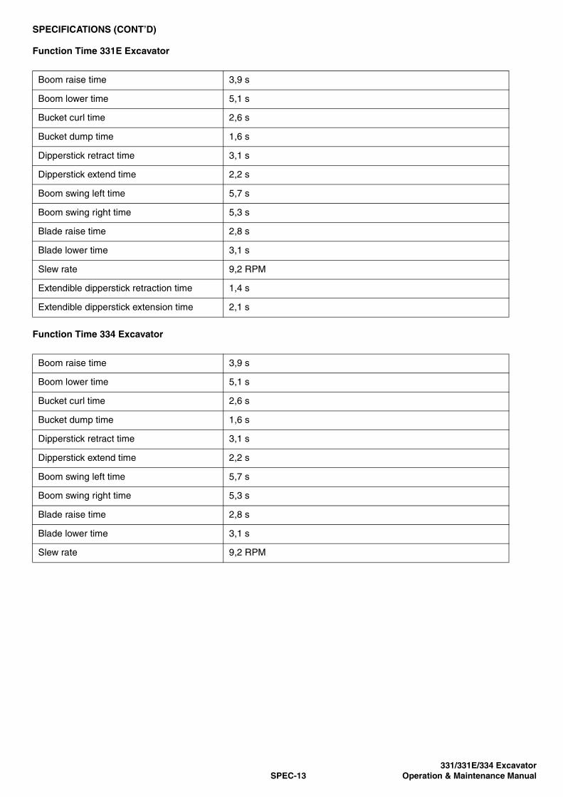
331/331E/334 Excavator
SPEC-13 Operation & Maintenance Manual
SPECIFICATIONS (CONT’D)
Function Time 331E Excavator
Function Time 334 Excavator
Boom raise time 3,9 s
Boom lower time 5,1 s
Bucket curl time 2,6 s
Bucket dump time 1,6 s
Dipperstick retract time 3,1 s
Dipperstick extend time 2,2 s
Boom swing left time 5,7 s
Boom swing right time 5,3 s
Blade raise time 2,8 s
Blade lower time 3,1 s
Slew rate 9,2 RPM
Extendible dipperstick retraction time 1,4 s
Extendible dipperstick extension time 2,1 s
Boom raise time 3,9 s
Boom lower time 5,1 s
Bucket curl time 2,6 s
Bucket dump time 1,6 s
Dipperstick retract time 3,1 s
Dipperstick extend time 2,2 s
Boom swing left time 5,7 s
Boom swing right time 5,3 s
Blade raise time 2,8 s
Blade lower time 3,1 s
Slew rate 9,2 RPM

331/331E/334 Excavator
SPEC-14 Operation & Maintenance Manual
SPECIFICATIONS (CONT’D)
Weights 331 Excavator
Weights 331E Excavator
Weights 334 Excavator
Operating weight with ROPS canopy, rubber tracks,
counterweight, 610 mm bucket
3273 kg
Additional weight for ROPS cab with heater 119 kg
Additional weight for ROPS cab with HVAC 141 kg
Additional weight for steel tracks 72 kg
Reduction for shipping weight Not available
Operating weight with ROPS canopy, rubber tracks,
counterweight, 610 mm bucket
3519 kg
Additional weight for ROPS cab with heater 119 kg
Additional weight for ROPS cab with HVAC 141 kg
Additional weight for steel tracks 72 kg
Reduction for shipping weight Not available
Operating weight with ROPS canopy, rubber tracks,
counterweight, 610 mm bucket
3433 kg
Additional weight for ROPS cab with heater 119 kg
Additional weight for ROPS cab with HVAC 141 kg
Additional weight for steel tracks 72 kg
Reduction for shipping weight Not available

331/331E/334 Excavator
SPEC-15 Operation & Maintenance Manual
SPECIFICATIONS (CONT’D)
Controls
Engine
Electrical
Engine Hand lever on right-hand side
Starting Key-type starter switch and shutdown
Blade Right hand lever
Boom swing Right foot pedal
Hydraulics Two joysticks control boom, bucket, dipperstick and upper
structure slew
Auxiliary hydraulics Electric switch in right joystick
Upper structure slew brake Hydraulic lock on motor
Holding brake for upper structure slew Pin lock
Steering Direction and speed controlled by two hand levers or foot pedals
Make / model Kubota / V2203-M-D1-E28-BC-4
Fuel Diesel
Cooling Liquid
Maximum power at 2400 RPM (SAE Net J1349) 30,3 kW
Maximum governed speed 2620 RPM
Torque at 2400 RPM (SAE Net J1349) 140,3 Nm
Number of cylinders 4
Displacement 2,20 l
Bore 87,0 mm
Stroke 92,4 mm
Lubrication Pressure system with full-flow filter
Crankcase ventilation Closed breathing
Air filter Dual dry replaceable paper cartridge
Ignition Diesel-compression
Starting aid Intake air heater
Alternator 12 V — 90 A — open frame with internal regulator
Battery 12 V — 530 cold cranking A at -18°C — 75 min reserve capacity at 25 A
Starter 12 V — gear reduction type — 2.0 kW

331/331E/334 Excavator
SPEC-16 Operation & Maintenance Manual
SPECIFICATIONS (CONT’D)
Hydraulic System
Hydraulic Cylinders
Drive System
Pump type Dual-outlet variable displacement piston pump with gear pump
Pump 1 capacity 33,3 l/min at 2400 RPM
Pump 2 and 3 capacity 28,8 l/min at 2400 RPM
System relief pressure for implement
circuits
172 Bar
System relief pressure for travel circuits 263 Bar
System relief pressure for slew circuits 117 Bar
System relief pressure for auxiliary circuits 172 Bar
Dipperstick port relief base and rod end 290 Bar
Boom port relief base and rod end 290 Bar
Bucket port relief base and rod end 290 Bar
Main hydraulic filter bypass 3,4 Bar
Case drain bypass 1,4 Bar
Control valve Ten-spool parallel series
Hydraulic filter Full-flow replaceable — 3 µm synthetic media element
Fluid lines SAE standard tubelines, hoses, and fittings
Boom cylinder Cushion up
Boom cylinder bore 82,6 mm
Boom cylinder rod 44,5 mm
Boom cylinder stroke 637,3 mm
Dipperstick cylinder Cushion extend
Dipperstick cylinder bore 82,6 mm
Dipperstick cylinder rod 44,5 mm
Dipperstick cylinder stroke 599,9 mm
Bucket cylinder No cushion
Bucket cylinder bore 82,6 mm
Bucket cylinder rod 50,8 mm
Bucket cylinder stroke 467,1 mm
Boom swing cylinder Cushion left and right
Boom swing cylinder bore 76,2 mm
Boom swing cylinder rod 38,1 mm
Boom swing cylinder stroke 524,5 mm
Blade cylinder No cushion
Blade cylinder bore 88,9 mm
Blade cylinder rod 44,5 mm
Blade cylinder stroke 184,9 mm
Travel motor Each track is driven by a hydrostatic axial piston motor
Drive reduction Two-stage planetary gear reduction 36.4:1

331/331E/334 Excavator
SPEC-17 Operation & Maintenance Manual
SPECIFICATIONS (CONT’D)
Traction
Instrumentation
Fluid Capacities
Track width, rubber, standard 320 mm
Track width, steel, optional 300 mm
Track adjusters Grease type with shock absorbing recoil springs
Track type, standard Half-pitch, rubber with 40 shoes
Track type, optional Steel with 41 shoes
Travel speed, low range 2,1 km/h
Travel speed, high range 5,6 km/h
Undercarriage Crawler-type tractor design with reinforced box-section track roller
frame and sealed track rollers
Number of track rollers per side 4
Gradeability 30°
• Air intake heater indicator
• Auxiliary mode indicator
• Console indicator
• Engine temperature gauge
• Engine/hydraulic service warning indicator
• Fuel gauge
• Hour meter
• Job clock
• Low fuel indicator
• Tachometer
• Two-speed range indicator
Cooling system 17,0 l
Engine lubrication plus oil filter 7,1 l
Fuel reservoir 53,3 l
Hydraulic reservoir 29,5 l
Hydraulic system with bucket and dipper cylinder retracted,
bucket on the ground, and blade down
44,0 l
Travel motor (each) 0,5 l

331/331E/334 Excavator
SPEC-18 Operation & Maintenance Manual
Fluid Specifications
Standard Features
Engine coolant Polypropylene glycol/water mix (53% – 47%) with freeze
protection to -37°C
Engine oil Oil must meet API Service Classification of CD, CE, CF4, CG4, or better.Recommended SAE viscosity number for anticipated temperature range.
* Can by used only when available with appropriate diesel rating.
For synthetic oil use the recommendation from the oil manufacturer.
Hydraulic fluid Bobcat Fluid (P/N 6563328). If fluid is not available use 10W-30/
10W Class SE motor oil for temperatures above -18°C or 5W-30
Class SE motor oil for temperatures below -18°C.
• * TOPS/ROPS canopy
• 1450 mm dozer blade
• 320 mm half-pitch rubber track
• Auxiliary hydraulics with Quick Couplers
• Control console locks
• Counterweight
• Engine shutdown system
• Fingertip auxiliary hydraulic control
• Horn
• Hydraulic joystick controls
• Retractable seat belt
• Spark arrester muffler
• Suspension seat with high back
• Two-speed travel
• Vandalism protection
• Warranty: 12 months, 2000 hours
• Working lights
* Roll Over Protective Structure (ROPS) – Meets requirements of SAE-J1040C
Tip Over Protective Structure (TOPS) – Meets requirements of ISO/DIS 12117

331/331E/334 Excavator
SPEC-19 Operation & Maintenance Manual
Options
Attachments
• 300 mm steel tracks
• AM/FM stereo radio
• Cab enclosure, vinyl
• Cab/canopy light kit
• Catalytic exhaust purifier kit
• Counterweight kit
• FOPS kit
• Keyless start
• Lifting chain kit
• Special applications kit
• TOPS/ROPS cab with heater
• Travel motion alarm
• X-Change™ attachment mounting system
• Auger
• Cutter crusher
• Grading bucket
• Grapple, three-tine
• Hydra-Tilt
• Hydraulic breaker
• Hydraulic clamp
• Plate compactor
• Power tilt
• Ripper
• Trenching bucket

331/331E/334 Excavator
SPEC-20 Operation & Maintenance Manual

WARRANTYBobcat Excavators
Bobcat Europe warrants to its authorised dealer, who in turn, warrants to theoriginal buyer (owner) that each Bobcat excavator will be free from provendefects in material and workmanship for twelve months or 2000 hours afterdelivery to the original buyer (owner), whichever occurs first.
During the warranty period, the authorised selling Bobcat dealer shall repair orreplace, at his option, without charge for parts, labour and travel time ofmechanics, any part of the Bobcat product which fails because of defects inmaterial and workmanship. The owner shall provide the authorised dealer withprompt written notice of the defect and allow reasonable time for replacement orrepair. Bobcat Europe may, at its option, request failed parts to be returned to thefactory Transportation of the Bobcat product to the authorised Bobcat Excavatordealer for warranty work is the responsibility of the owner.
Warranty does not cover replacement of scheduled service items such as oil,filters, tune-up parts, and other high-wear items. The warranty does not coverdamages resulting from abuse, accidents, alterations, use of the Bobcat productwith any bucket or attachment not approved by Bobcat Europe, air flowobstructions, or failure to maintain or use the Bobcat product according to theinstructions applicable to it.
THIS WARRANTY IS IN LIEU OF ALL OTHER WARRANTIES (EXCEPT THOSE OFTITLE), EXPRESSED OR IMPLIED, AND THERE ARE NO WARRANTIES OFMERCHANTABILITY OR FITNESS FOR A PARTICULAR PURPOSE. IN NO EVENTSHALL THE AUTHORISED SELLING DEALER OR BOBCAT EUROPE BE LIABLEFOR DOWNTIME EXPENSES, LOSS OF MACHINE USE OTHER INCIDENTAL,CONSEQUENTIAL OR SPECIAL DAMAGES.
Printed in Europe6902612-EN (01-04)


