330525 Velomitor XA Piezo-velocity Sensor …...Description The Velomitor XA (eXtended Application)...
8
Description The Velomitor XA (eXtended Application) Sensor is a ruggedized version of Bently Nevada's 330500 Velomitor Sensor. Its 316L stainless steel case and unique, weatherproof connector and cable assembly permit mounting without a housing. The Velomitor XA Sensor cable assembly is suitable for use in moist environments, and the Velomitor XA Sensor design meets the requirements of IP-65 and NEMA 4X dust ratings when properly installed with a mating extension cable. If you are monitoring rotor vibration using a transducer placed on a bearing housing or machine casing, carefully choose a location for each transducer. Common machine malfunctions like imbalance and misalignment originate in the rotor, causing a change in rotor vibration. To obtain meaningful measurements, install the transducer in a location that transmits significant rotor vibration. The location must also conduct rotor amplitude and frequency response that accurately reflect actual machine vibration. If needed, Bently Nevada provides engineering services that can help you identify the optimum locations for transducers on bearing housings or machine casings. To request assistance, visit Bently.com. Document: 141633 Rev. L 330525 Velomitor XA Piezo-velocity Sensor Datasheet Bently Nevada Machinery Condition Monitoring
Transcript of 330525 Velomitor XA Piezo-velocity Sensor …...Description The Velomitor XA (eXtended Application)...

DescriptionThe Velomitor XA (eXtended Application) Sensor is a ruggedized version of Bently Nevada's 330500 Velomitor Sensor. Its 316L stainless steel case and unique, weatherproof connector and cable assembly permit mounting without a housing. The Velomitor XA Sensor cable assembly is suitable for use in moist environments, and the Velomitor XA Sensor design meets the requirements of IP-65 and NEMA 4X dust ratings when properly installed with a mating extension cable.
If you are monitoring rotor vibration using a transducer placed on a bearing housing or machine casing, carefully choose a location for each transducer.
Common machine malfunctions like imbalance and misalignment originate in the rotor, causing a change in rotor vibration.
To obtain meaningful measurements, install the transducer in a location that transmits significant rotor vibration.
The location must also conduct rotor amplitude and frequency response that accurately reflect actual machine vibration.
If needed, Bently Nevada provides engineering services that can help you identify the optimum locations for transducers on bearing housings or machine casings. To request assistance, visit Bently.com.
Document: 141633Rev. L
330525 Velomitor XA Piezo-velocity SensorDatasheetBently Nevada Machinery Condition Monitoring
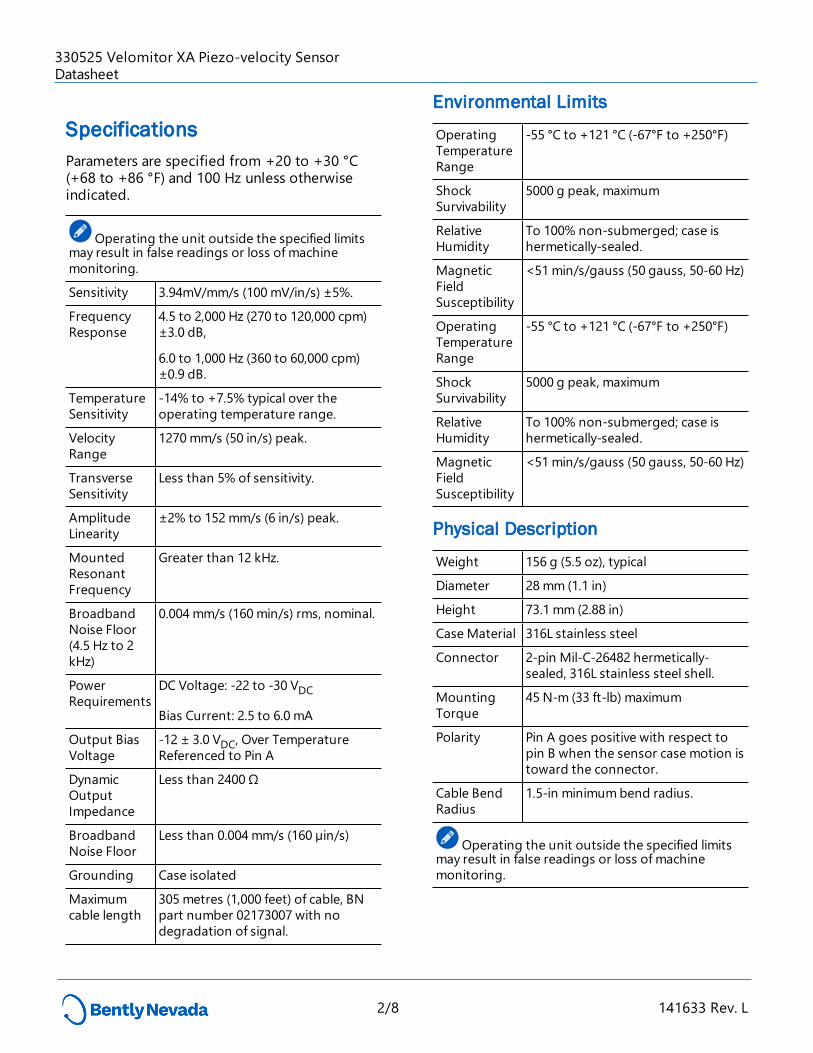
SpecificationsParameters are specified from +20 to +30 °C (+68 to +86 °F) and 100 Hz unless otherwise indicated.
Operating the unit outside the specified limits may result in false readings or loss of machine monitoring.
Sensitivity 3.94mV/mm/s (100 mV/in/s) ±5%.
Frequency Response
4.5 to 2,000 Hz (270 to 120,000 cpm) ±3.0 dB,
6.0 to 1,000 Hz (360 to 60,000 cpm) ±0.9 dB.
Temperature Sensitivity
-14% to +7.5% typical over the operating temperature range.
Velocity Range
1270 mm/s (50 in/s) peak.
Transverse Sensitivity
Less than 5% of sensitivity.
Amplitude Linearity
±2% to 152 mm/s (6 in/s) peak.
Mounted Resonant Frequency
Greater than 12 kHz.
Broadband Noise Floor (4.5 Hz to 2 kHz)
0.004 mm/s (160 min/s) rms, nominal.
Power Requirements
DC Voltage: -22 to -30 VDC
Bias Current: 2.5 to 6.0 mA
Output Bias Voltage
-12 ± 3.0 VDC, Over Temperature Referenced to Pin A
Dynamic Output Impedance
Less than 2400 Ω
Broadband Noise Floor
Less than 0.004 mm/s (160 µin/s)
Grounding Case isolated
Maximum cable length
305 metres (1,000 feet) of cable, BN part number 02173007 with no degradation of signal.
Environmental Limits
Operating Temperature Range
-55 °C to +121 °C (-67°F to +250°F)
Shock Survivability
5000 g peak, maximum
Relative Humidity
To 100% non-submerged; case is hermetically-sealed.
Magnetic Field Susceptibility
<51 min/s/gauss (50 gauss, 50-60 Hz)
Operating Temperature Range
-55 °C to +121 °C (-67°F to +250°F)
Shock Survivability
5000 g peak, maximum
Relative Humidity
To 100% non-submerged; case is hermetically-sealed.
Magnetic Field Susceptibility
<51 min/s/gauss (50 gauss, 50-60 Hz)
Physical Description
Weight 156 g (5.5 oz), typical
Diameter 28 mm (1.1 in)
Height 73.1 mm (2.88 in)
Case Material 316L stainless steel
Connector 2-pin Mil-C-26482 hermetically-sealed, 316L stainless steel shell.
Mounting Torque
45 N-m (33 ft-lb) maximum
Polarity Pin A goes positive with respect to pin B when the sensor case motion is toward the connector.
Cable Bend Radius
1.5-in minimum bend radius.
Operating the unit outside the specified limits may result in false readings or loss of machine monitoring.
330525 Velomitor XA Piezo-velocity SensorDatasheet
2/8 141633 Rev. L

Before installing and using this product, read the 330500, 330525, and 330530 Velomitor Sensors User Guide (document 100076).
330525 Velomitor XA Piezo-velocity SensorDatasheet
3/8 141633 Rev. L

Compliance and Certifications
FCCThis device complies with part 15 of the FCC Rules. Operation is subject to the following two conditions:
l This device may not cause harmful interference.
l This device must accept any interference received, including interference that may cause undesired operation.
EMC EMC Directive 2014/30/EU
RoHSRoHS Directive 2011/65/EU
Maritime
330400 and 330425 only
ABS 2009 Steel Vessels Rules
1-1-4/7.7,4-8-3/1.11.1,4-9-7/13
Hazardous Area ApprovalsCSA/NRTL/C
190501 (Agency Approval Options 01 through 04)
Intrinsically Safe
Ex ia IIC T4: Class I, Div 1, Groups A, B, C, D. Class II, Group E, F and G Class III AEx ia IIC T4:Class I, Div 1, Groups A, B, C, D; Class II, Groups E, F, GClass III
Install per drawing 167536
T4 @ -40 °C ≤ Ta ≤ +100 °C(-40 °F ≤ Ta ≤ +212 °F)
Intrinsically Safe and Non-Incendive
Ex nL IIC T4Class I, Division 2, Groups A, B, C and D AEx nA T4Class I, Division 2, Groups A, B, C and D
Install per drawing 167536
T4 @ -40 °C ≤ Ta ≤ +100 °C (-40 °F ≤ Ta ≤ +212 °F)
330400, 330425
Ex ia IIC T4 AEx ia IIC T4Class I, Div 1 Groups A, B, C and D Class II, Groups E, F, and G Class III T4 @ -40°C ≤ Ta ≤ 100°C Install per dwg 167538
330500 Ex ia IIC T4AEx ia IIC T4Class I, Division 1, Groups A, B, C and D Class II, Groups E, F, GClass III Install per dwg 167537T4 @ -40°C ≤ Ta ≤ 100°C Ex nL IIC T4AEx nA IIC T4Class I, Div 2, Groups A, B, C, D Install per dwg 167537T4 @ -40°C ≤ Ta ≤ 100°C
330525 Ex ia IIC T4AEx ia IIC T4Class I, Division 1, Groups A, B, C and D Class II, Groups E, F, GClass III T4 @ -40°C ≤ Ta ≤ 100°C Ex nL IIC T4AEx nA IIC T4Class I, Div 2, Groups A, B, C, D Install per dwg 167539T4 @ -40°C ≤ Ta ≤ 100°C
ATEX/IECEx
330525 Velomitor XA Piezo-velocity SensorDatasheet
4/8 141633 Rev. L

190501, 330400, 330425, 330500, 330525
190501
Entity Parameters
II 1 GEx ia IIC T4 Ga
II 3 DEx na IIC T4 GcEx tc III T130°C Dc
T4@ Ta = -55°C to 121°C Zone 0/1 Zone 2
Ui= 30V Ui= 30V
Ii= 200mA Ii= 200mA
Pi= 0.75W Pi= 1.14W
Ci-27.2nF
Li= 0
330400, 330425, 330500, 330525
Entity Parameters
II 1 GEx ia IIC T4 Ga
II 3 DEx na IIC T4 GcEx tc III T130°C Dc
T4@ Ta = -55°C to 121°C Zone 0/1 Zone 2
Ui= 28V Ui= 28V
Ii= 150mA Ii= 150mA
Pi= 0.84W Pi= 1.26W
Ci-10.8nF
Li= 0
Hazardous Area Conditions of Safe UseATEX/IECExZone 0/1:
Equipment must be connected to equipment, which meets the abovelisted entity parameters.
The cables type A or B (in compliance with EN 60079-25) must respect the cable parameters listed with the entity parameters.
Zone 2 :
The supply electrical parameters shall not exceed the values mentioned in the tables above.
330525 Velomitor XA Piezo-velocity SensorDatasheet
5/8 141633 Rev. L

Ordering InformationFor the detailed listing of country and product specific approvals, refer to the Approvals Quick Reference Guide, Document 108M1756, at Bently.com.
330525-AA
A: Agency Approval Option
0 0 None Required
0 1 CSA/NRTL/C
0 2 SIRA/CENELEC
106765-AA Interconnect Cable
A: Length (in meters)
Minimum length 1 meter(3.3 feet)
Maximum length 25 meters (82 feet)
Order in increments of 3 meters.
Terminal Housing
Terminal Housing for terminating Velomitor XA Sensor cable to bulk cable listed above. The Terminal Housing provides local connection of the Velomitor XA Sensor signal wires to the monitor field wiring. Each Terminal Housing can accommodate up to 2 Velomitor XA Sensor Cables.
106769-AA
A: Conduit Fitting Option
0 0 No fittings supplied
0 1 One ¾ NPT fitting
0 2 Two ¾ NPT fittings
Accessories
100076 330500/330525 Velomitor Sensor and Velomitor XA SensorUser Guide
02173007 Bulk cable; two-conductor twisted,
shielded. 22 AWG cable without connectors or terminal lugs. Specify length in feet.
103537-01 Terminal Mounting Block. Provides simple field wiring connection and can be mounted inside any standard Proximitor Sensor housing. One terminal mounting block is needed for each Velomitor XA Sensor connection.
03839144 Splash-resistant boot cover for interconnect cable assembly. The boot is made from fluorosilicone elastomer. Boot color is blue.
03839142 Bottom clamp used to secure the boot to the Velomitor XA Sensor case.
03839143 Top clamp used to secure the boot to the interconnect cable assembly.
330525 Velomitor XA Piezo-velocity SensorDatasheet
6/8 141633 Rev. L

Graphs and Figures
1. Splash-resistant boot with clamps 5. “A” (white)
2. Stainless steel armor over cable 6. “B” (black)
3. 0.382 mm2 (22 AWG) 7. “SHLD” (green)
4. Clear shrink tubing 8. Overall length ± 200 (7.8)
Figure 1: Dimensions for 106765 Cable
Dimensions are in millimeters (inches)
7/8 141633 Rev. L
330525 Velomitor XA Piezo-velocity SensorDatasheet

1. MIL-C-26482 receptacle
2. 25.4 (100) hexagonal
3. 1/4-18 NPT
Figure 2: Dimensions for 330525 Velomitor XA Piezo-Sensor
Dimensions are in millimeters (inches)
Copyright 2019 Baker Hughes, a GE company, LLC ("BHGE") All rights reserved.
Bently Nevada, Orbit Logo, Velomitor, Proximitor and System 1 are registered trademarks of BHGE in the United States and other countries. All product and company names are trademarks of their
respective holders. Use of the trademarks does not imply any affiliation with or endorsement by the respective holders.
This product may be covered by one or more patents, see Bently.com/legal for current status. The information contained in this document is subject to change without prior notice.
1631 Bently Parkway South, Minden, Nevada USA 89423Phone: 1.775.782.3611 Bently.com
8/8 141633 Rev. L
330525 Velomitor XA Piezo-velocity SensorDatasheet


![SM320F2812, SMJ320F2812 Digital Signal Processors Data Manual · 2020. 12. 12. · xa[12] xd[14] xf_xplldis xa[13] vss vdd xa[14] vddio emu1 xd[15] xa[15] xint1_xbio xnmi_xint13 xint2_adcsoc](https://static.fdocuments.in/doc/165x107/60ba62c666c9292a92496216/sm320f2812-smj320f2812-digital-signal-processors-data-manual-2020-12-12-xa12.jpg)