32703351D (6/05): Installing the Tracer ZN517 Unitary … Equipment damage! Complete input/output...
12
Installing the Tracer™ ZN517 Unitary Controller Ordering number: 4950 0496, 4950 0596 Product overview The Tracer ZN517 controller is a field-installed, application-specific controller that provides direct- digital zone temperature control. The controller can operate as a stand-alone device or as part of a building automation system (BAS). The Tracer ZN517 is designed to control the following types of equipment: • 2-heat/2-cool rooftop unit with optional economizer control • 4-cool rooftop unit with optional economizer control • 2-compressor heat pump with optional economizer and auxiliary heat control • Split system The Tracer ZN517 follows the guidelines of the LonMark ® Space Comfort Controller (SCC) profile. The Tracer ZN517 is available in two different versions: frame-mount (4950 0496) and metal enclosure (4950 0596). (See Figure 3 and Figure 4 on page 3.) The frame-mount package contains: • A Tracer ZN517 circuit board fastened to a metal back plate • A removable molded resin cover The metal-enclosure package contains: • A Tracer ZN517 circuit board fastened to the back piece of the metal enclosure • A removable metal cover Shipment Visually inspect all parts for obvious defects or damage. All components are thoroughly inspected before leaving the factory. Any claims for damage incurred in shipping should be filed with the carrier. Storage environment An indoor storage environment is recommended that meets the following requirements: • Temperature: –40°F to 185°F (–40°C to 85°C) • Relative humidity: 5–95%, noncondensing Operating environment Make sure that the operating environment conforms to the specifications listed in Table 1. Dimensions and clearances are illustrated in Figure 1 and Figure 2 on page 2: Table 1. Operating environment specifications Temperature From –40°F to 160°F (–40°C to 70°C) Humidity 5–90%, noncondensing Power 19–30 Vac (24 Vac nominal), 50–60 Hz 9 VA per controller and a maximum of 12 VA per output utilized Mounting Mounting surface must be able to weight (frame- support 2 lb (1 kg) mount) Mounting Mounting surface must be able to weight (metal support 8 lb (4 kg) enclosure) Altitude 6,500 ft (2,000 m) Installation Category 3 Pollution Degree 2 Location For most applications, the Tracer ZN517 can be installed within the unit it is controlling. It is suitable for extended ambient temperatures. If installed in an outdoor environment, it must be fully enclosed for protection from the elements. Trane also recommends locating the Tracer ZN517 unitary controller: • Where public access is restricted to minimize the possibility of tampering or vandalism • In or near the controlled piece of equipment to reduce wiring costs • Where it is easily accessible for service personnel Trane A Business of American Standard Companies www.trane.com © 2005 American Standard All rights reserved 3270 3351 D
Transcript of 32703351D (6/05): Installing the Tracer ZN517 Unitary … Equipment damage! Complete input/output...

Installing the Tracer™ ZN517 Unitary Controller Ordering number: 4950 0496, 4950 0596
Product overview The Tracer ZN517 controller is a field-installed, application-specific controller that provides direct-digital zone temperature control. The controller can operate as a stand-alone device or as part of a building automation system (BAS). The Tracer ZN517 is designed to control the following types of equipment: • 2-heat/2-cool rooftop unit with optional economizer
control • 4-cool rooftop unit with optional economizer control • 2-compressor heat pump with optional economizer
and auxiliary heat control • Split system The Tracer ZN517 follows the guidelines of the LonMark® Space Comfort Controller (SCC) profile.
The Tracer ZN517 is available in two different versions: frame-mount (4950 0496) and metal enclosure (4950 0596). (See Figure 3 and Figure 4 on page 3.)
The frame-mount package contains: • A Tracer ZN517 circuit board fastened to a metal
back plate • A removable molded resin cover The metal-enclosure package contains: • A Tracer ZN517 circuit board fastened to the back
piece of the metal enclosure • A removable metal cover
Shipment Visually inspect all parts for obvious defects or damage. All components are thoroughly inspected before leaving the factory. Any claims for damage incurred in shipping should be filed with the carrier.
Storage environment An indoor storage environment is recommended that meets the following requirements:
• Temperature: –40°F to 185°F (–40°C to 85°C) • Relative humidity: 5–95%, noncondensing
Operating environment Make sure that the operating environment conforms to the specifications listed in Table 1. Dimensions and clearances are illustrated in Figure 1 and Figure 2 on page 2:
Table 1. Operating environment specifications
Temperature From –40°F to 160°F (–40°C to 70°C)
Humidity 5–90%, noncondensing
Power
19–30 Vac (24 Vac nominal), 50–60 Hz
9 VA per controller and a maximum of 12 VA per output utilized
Mounting Mounting surface must be able to weight (frame- support 2 lb (1 kg) mount)
Mounting Mounting surface must be able to weight (metal support 8 lb (4 kg) enclosure)
Altitude 6,500 ft (2,000 m)
Installation Category 3
Pollution Degree 2
Location For most applications, the Tracer ZN517 can be installed within the unit it is controlling. It is suitable for extended ambient temperatures. If installed in an outdoor environment, it must be fully enclosed for protection from the elements. Trane also recommends locating the Tracer ZN517 unitary controller:
• Where public access is restricted to minimize the possibility of tampering or vandalism
• In or near the controlled piece of equipment to reduce wiring costs
• Where it is easily accessible for service personnel
Trane A Business of American Standard Companies www.trane.com © 2005 American Standard All rights reserved 3270 3351 D

3270 3351 D 2
Figure 1. Dimensions and clearances for the frame-mount controller
Figure 2. Dimensions and clearances for the metal-enclosure controller
LEDA BBA +20GND-BI2- SET-BI1- ZNLED GNDPIN
ZONE SENSORZONE SENSOR
SERVICE
ANALOG INPUTSANALOG INPUTSCOMM5
COMM5
24VGND
HVAC UNITHVAC UNIT
RhRc 1G 432 5NO5COM
LED
STATUS5NC
BINARY INPUTS
AI1 -DAT-
24VGND GND 24V OPN CLS
BINARY OUTPUTECONOMIZERAC OUTAC OUTAC POWERAC POWER
-AI --AI -2
2 in. (51 mm)
Clearances
Dimensions
6.875 in.(175 mm)
6.313 in.(160 mm)
5.375 in.(137 mm)
5.625 in. (143 mm)
1 in.(25 mm)
4 in.(102 mm)
4 in.(102 mm)
4 in.(102 mm)
1 in.(25 mm)
Clearances
Dimensions
9 in.(229 mm)
10.37 in.(263 mm)
width with cover
2.25 in.(58 mm)
7 in.(178 mm)
1 in.(25 mm)
1.875 in.(48 mm)
6.5 in.(165 mm)
9 in.(229 mm)
10.25 in.(260 mm)
width without cover
24 in.(610 mm)
1 in.(25 mm)
1 in.(25 mm)
2 in.(51 mm)
2 in.(51mm)

3 3270 3351 D
Mounting the frame-mount controller
IMPORTANTMount the Tracer ZN517 controller with the cover on
to avoid damaging the circuit board during
installation.
To mount the frame-mount controller:
1. Using the module as a template, mark the loca-tion of the two mounting holes on the mounting surface (Figure 3).
2. Set the module aside and drill holes for the screws at the marked locations.
Drill holes for #10 (5 mm) screws or #10 wall anchors. Use wall anchors if the mounting surface is dry wall or masonry.
3. Insert wall anchors if needed.
4. Secure the module to the mounting surface with #10 (5 mm) screws (not included).
Attach the frame-mount module securely so that it can withstand the vibrations of associated heating, ventilating, and air-conditioning (HVAC) equipment.
Figure 3. Mounting the frame-mount Tracer ZN517
zone controller
Mounting the metal-enclosure controllerTo mount the metal-enclosure controller:
1. Remove the two cover screws and then the cover.
2. Using the enclosure as a template, mark the location of the four mounting holes on the mounting surface (Figure 4).
3. Set the enclosure aside and drill holes for the screws at the marked locations.
Drill holes for #10 (5 mm) screws or #10 wall anchors. Use wall anchors if the mounting surface is dry wall or masonry.
4. Insert wall anchors if needed.
5. Secure the enclosure to the mounting surface with #10 (5 mm) screws (not included).
Figure 4. Mounting the metal-enclosure Tracer
ZN517 controller
Agency conformanceCE marked
UL and C-UL listed: 916, Energy management equipment
UL 94-5V (UL flammability rating for plenum use)
FCC Part 15, Class A, CFR 47
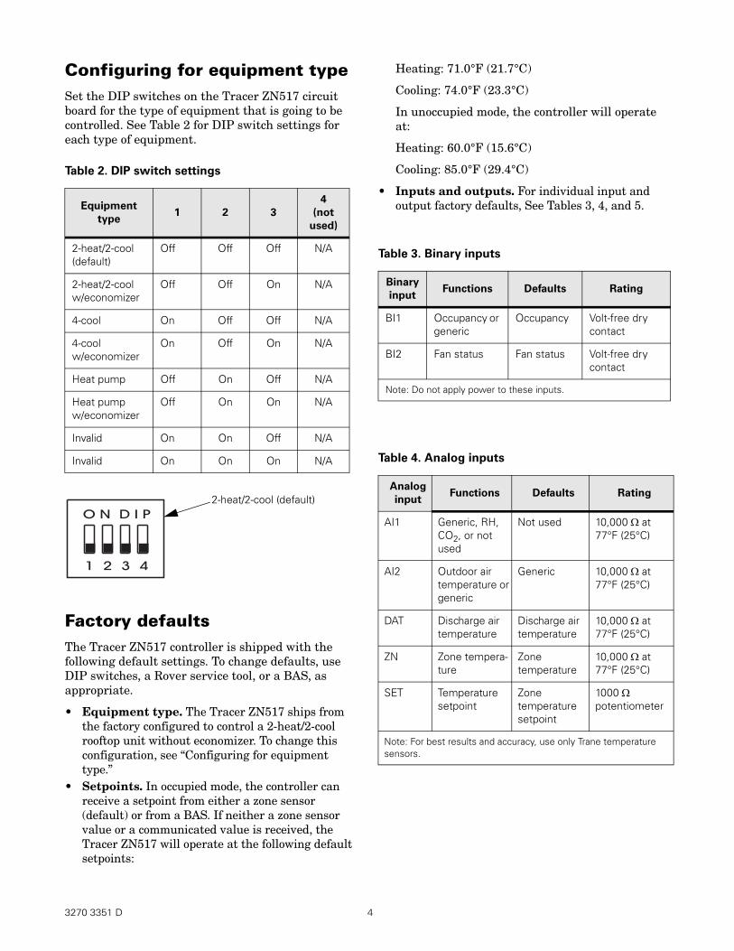
Configuring for equipment type Set the DIP switches on the Tracer ZN517 circuit board for the type of equipment that is going to be controlled. See Table 2 for DIP switch settings for each type of equipment.
Table 2. DIP switch settings
Heating: 71.0°F (21.7°C)
Cooling: 74.0°F (23.3°C)
In unoccupied mode, the controller will operate at:
Heating: 60.0°F (15.6°C)
Cooling: 85.0°F (29.4°C)
Equipment
type 1 2 3
4
(not
used)
2-heat/2-cool (default)
Off Off Off N/A
2-heat/2-cool w/economizer
Off Off On N/A
4-cool On Off Off N/A
4-cool w/economizer
On Off On N/A
Heat pump Off On Off N/A
Heat pump w/economizer
Off On On N/A
Invalid On On Off N/A
Invalid On On On N/A
• Inputs and outputs. For individual input and output factory defaults, See Tables 3, 4, and 5.
Table 3. Binary inputs
Binary
input Functions Defaults Rating
BI1 Occupancy or generic
Occupancy Volt-free dry contact
BI2 Fan status Fan status Volt-free dry contact
Note: Do not apply power to these inputs.
Table 4. Analog inputs
1 2 3 4
O N D I P
2-heat/2-cool (default)
Factory defaults The Tracer ZN517 controller is shipped with the following default settings. To change defaults, use DIP switches, a Rover service tool, or a BAS, as appropriate.
• Equipment type. The Tracer ZN517 ships from the factory configured to control a 2-heat/2-cool rooftop unit without economizer. To change this configuration, see “Configuring for equipment type.”
• Setpoints. In occupied mode, the controller can receive a setpoint from either a zone sensor (default) or from a BAS. If neither a zone sensor value or a communicated value is received, the Tracer ZN517 will operate at the following default setpoints:
Analog
input Functions Defaults Rating
AI1 Generic, RH, CO2, or not used
Not used 10,000 Ω at 77°F (25°C)
AI2 Outdoor air temperature or generic
Generic 10,000 Ω at 77°F (25°C)
DAT Discharge air temperature
Discharge air temperature
10,000 Ω at 77°F (25°C)
ZN Zone temperature
Zone temperature
10,000 Ω at 77°F (25°C)
SET Temperature setpoint
Zone temperature setpoint
1000 Ω potentiometer
Note: For best results and accuracy, use only Trane temperature sensors.
3270 3351 D 4

Table 5. Binary outputs
Binary
output
2-heat/
2-cool 4-cool Heat pump Rating
OPN Economizer, drive open Economizer, drive open Economizer, drive open Triac, 24 Vac, max 500 mA, min 50 mA
CLS Economizer, drive closed Economizer, drive closed Economizer, drive closed Triac, 24 Vac, max 500 mA, min 50 mA
Rc 24 Vac from HVAC system 24 Vac from HVAC system 24 Vac from HVAC system 24 Vac nominal
Rh 24 Vac from HVAC system 24 Vac from HVAC system 24 Vac from HVAC system 24 Vac nominal (optional) (optional) (optional)
G Supply fan Supply fan Supply fan Form A relay, powered contact, 24 Vac, 1 A max
1 Cool stage 1 (Y1) Cool stage 1(Y1) Compressor 1(Y1) Form A relay, powered contact, 24 Vac, 1 A max
2 Cool stage 2 (Y2) Cool stage 2 (Y2) Compressor 2 (Y2) Form A relay, powered contact, 24 Vac, 1 A max
3 Heat stage 1 (W1) Cool stage 3 (Y3) Reversing valve (O) Form A relay, powered contact, 24 Vac, 1 A max
4 Heat stage 2 (W2) Cool stage 4 (Y4) Auxiliary heat (W1) Form A relay, powered contact, 24 Vac, 1 A max
5NO/ Exhaust fan*/generic/ Exhaust fan*/generic/ Exhaust fan*/generic/ Form C relay, pow5COM/ occupancy occupancy occupancy ered contact, 24 Vac, 5NC 1 A max
*Factory default
AC-power wiring See Figure 5 on page 6 or Figure 6 on page 6 for the location of the ac-power connections.
IMPORTANT Make sure that the 24 Vac power supplies are
consistently grounded. Do not share 24 Vac between
controllers.
The recommended wire for ac power is 16 AWG copper wire. All wiring must comply with National Electrical Code® and local codes.
If you are providing a new transformer for power, use a UL-listed Class 2 power transformer supplying a nominal 24 Vac (19–30 Vac). The transformer must be sized to provide adequate power to the Tracer ZN521 zone controller (14 VA) and output devices, including relays and valve actuators (a maximum of 12 VA per output utilized).
Please read the warning and cautions before proceeding.
WARNING
Hazardous voltage!
Disconnect all electric power, including remote
disconnects before servicing. Follow proper lockout/
tagout procedures to ensure the power cannot be
inadvertently energized. Failure to disconnect power
before servicing could result in death or serious
injury.
CAUTION
Injury and equipment damage!
Make sure that the 24 Vac transformer is properly
grounded. Failure to do so may result in personal
injury and/or damage to equipment.
5 3270 3351 D

CAUTION
Equipment damage!
Complete input/output wiring before applying
power to the controller. Failure to do so may cause
damage to the controller or power transformer due
to inadvertent connections to power circuits. Do not
share 24 Vac between controllers. Failure to do so
may cause controller damage.
Wiring AC-power to the frame-mount controller Please read the preceding warning and cautions. To connect ac-power to the frame-mount controller:
1. Connect the ground wire from the 24 Vac transformer to the GND terminal shown in Figure 5.
2. Connect the power wire to the 24V terminal.
Figure 5. AC-power wiring for frame-mount
24 Vactransformer
24VGND 24VGND
AC OUTAC OUTAC POWERAC POWER
H N
Figure 6. AC-power wiring for metal enclosure
5C
OM
BIN
AR
Y O
UT
PU
T
LE
D
5N
C3
4
5N
O2
G
1
HV
AC
UN
IT
24V
AC
OU
T
OP
N
EC
ON
OM
IZE
R
Rh
CL
S
Rc
GN
D2
4V
GN
D
AC
PO
WE
R G
ND
24V
GN
D
ZO
NE
SE
NS
OR
CO
MM
5
LE
D
ZN
S
ET
GN
D
AN
AL
OG
INP
UT
S
-AI2
--D
AT
-+
20
A
I1B
CO
MM
5
-BI1
BIN
AR
Y IN
PU
TS
-BI2
B
A
SE
RV
ICE
A
P
INL
ED
24
V2
4V
GN
DG
ND
AC
PO
WE
RA
CP
OW
ER
Ground screw
Communication-link wiring The Tracer ZN517 communicates with the building automation system (BAS) and with other controllers by means of a Comm5 communication link. Comm5 is Trane’s implementation of LonTalk®. For instructions on Comm5 communication wiring and addressing, follow the Tracer Summit Hardware and Software Installation guide (BMTX-SVN01A), the Tracker Building Automation System Hardware Installation guide (BMTK-SVN01D), or another BAS installation manual.
Wiring AC-power to the metal-enclosure controller Please read the preceding warnings and cautions. To connect ac-power wiring to the enclosure:
1. Remove the cover of the enclosure.
2. Remove the knockout for the 0.5 in. (13 mm) conduit from the enclosure and attach the conduit.
3. Feed the power wire into the enclosure.
4. When mounting on dry wall or other non-conduc-tive surface, connect an earth ground to the earth-ground screw on the enclosure (Figure 6).
5. Connect the ground wire from the 24 Vac transformer to the GND terminal shown in Figure 6.
6. Connect the power wire to the 24V terminal.
7. Replace the cover of the enclosure.
HVAC unit electrical circuit wiring The terminals labeled Rc and Rh are provided as inputs for 24 Vac power from the transformer(s) of the HVAC system.
Note: The Tracer ZN517 is shipped from the factory with terminals Rc and Rh coupled with a jumper at J1 on the controller circuit board.
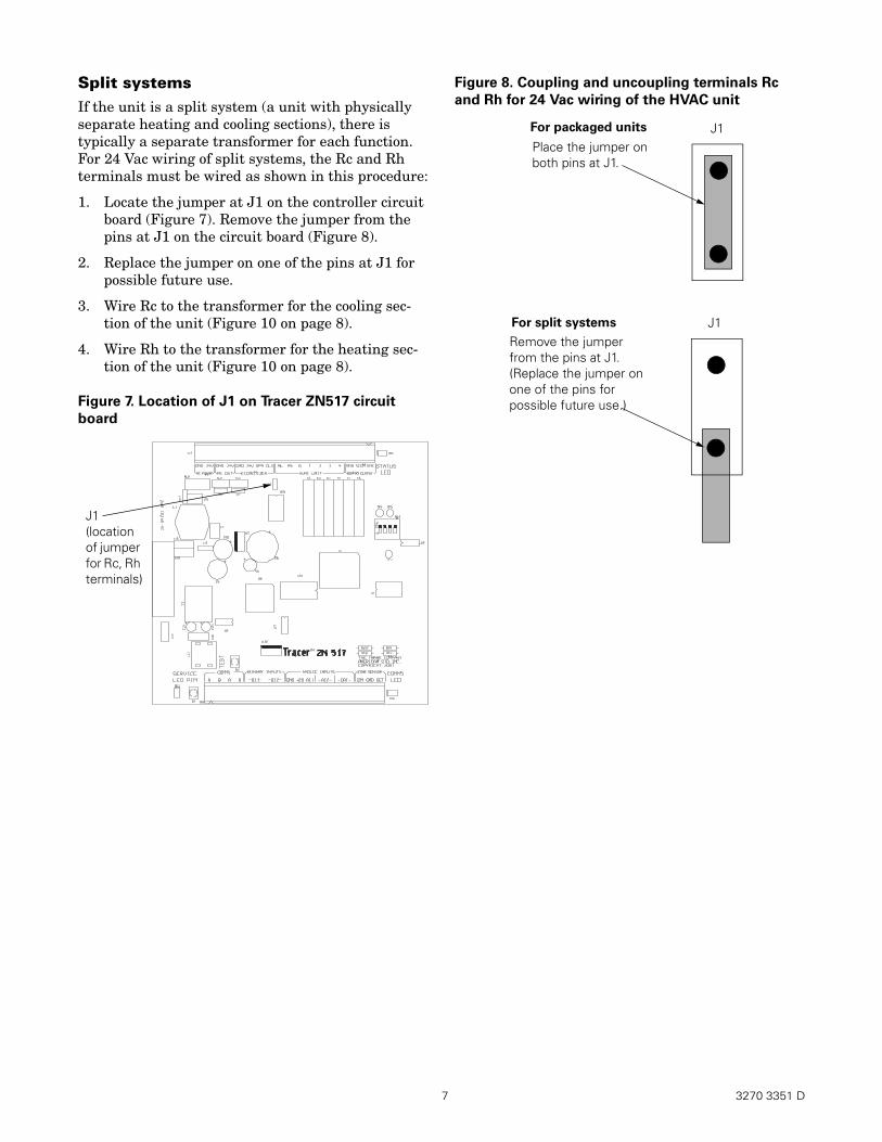
Packaged units If the HVAC unit combines heating and cooling (referred to as a “packaged” unit), it will typically have one “R” transformer. For 24 Vac wiring of packaged units, the Rc terminal must be wired as shown in this procedure:
1. Locate the jumper at J1 on the controller circuit board (Figure 7 on page 7). Place the jumper on both pins at J1 on the circuit board (Figure 8 on page 7).
2. Wire the Rc terminal to the transformer on the unit (Figure 9 on page 8).
3270 3351 D 6
7 3270 3351 D
Split systemsIf the unit is a split system (a unit with physically separate heating and cooling sections), there is typically a separate transformer for each function. For 24 Vac wiring of split systems, the Rc and Rh terminals must be wired as shown in this procedure:
1. Locate the jumper at J1 on the controller circuit board (Figure 7). Remove the jumper from the pins at J1 on the circuit board (Figure 8).
2. Replace the jumper on one of the pins at J1 for possible future use.
3. Wire Rc to the transformer for the cooling sec-tion of the unit (Figure 10 on page 8).
4. Wire Rh to the transformer for the heating sec-tion of the unit (Figure 10 on page 8).
Figure 7. Location of J1 on Tracer ZN517 circuit
board
Figure 8. Coupling and uncoupling terminals Rc
and Rh for 24 Vac wiring of the HVAC unit
J1 (location of jumper for Rc, Rh terminals)
Place the jumper on both pins at J1.
Remove the jumper from the pins at J1. (Replace the jumper on one of the pins for possible future use.)
J1
J1
For packaged units
For split systems
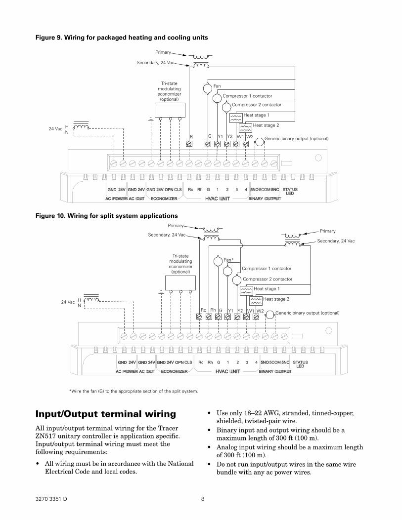
Figure 9. Wiring for packaged heating and cooling units
24V24VGNDGND
HVAC UNITHVAC UNIT
RhRc 1G 432 5NO5NO5COM
LEDLED
STATUS5NC5NC24V24VGNDGND GNDGND 24V24V OPNOPN CLS
BINARY OUTPUTBINARY OUTPUTECONOMIZERECONOMIZERAC OUTAC OUTAC POWERAC POWER
Compressor 1 contactor
Heat stage 1
Tri-state modulating economizer (optional)
Fan
H N
24 Vac
Generic binary output (optional)
Compressor 2 contactor
Heat stage 2
Primary
Secondary, 24 Vac
G Y1 Y2R W1 W2
Figure 10. Wiring for split system applications
*Wire the fan (G) to the appropriate section of the split system.
Input/Output terminal wiring All input/output terminal wiring for the Tracer ZN517 unitary controller is application specific. Input/output terminal wiring must meet the following requirements:
• All wiring must be in accordance with the National Electrical Code and local codes.
24V24VGNDGND
HVAC UNITHVAC UNIT
RhRc 1G 432 5NO5NO5COM
LEDLED
STATUS5NC5NC24V24VGNDGND GNDGND 24V24V OPNOPN CLS
BINARY OUTPUTBINARY OUTPUTECONOMIZERECONOMIZERAC OUTAC OUTAC POWERAC POWER
Compressor 1 contactor
Heat stage 1
Tri-state modulating economizer (optional)
Fan*
H N
24 Vac
Generic binary output (optional)
Compressor 2 contactor
Heat stage 2
Primary
Secondary, 24 Vac
G Y1 Y2Rc W1 W2
Primary
Secondary, 24 Vac
Rh
• Use only 18–22 AWG, stranded, tinned-copper, shielded, twisted-pair wire.
• Binary input and output wiring should be a maximum length of 300 ft (100 m).
• Analog input wiring should be a maximum length of 300 ft (100 m).
• Do not run input/output wires in the same wire bundle with any ac power wires.
3270 3351 D 8
9 3270 3351 D
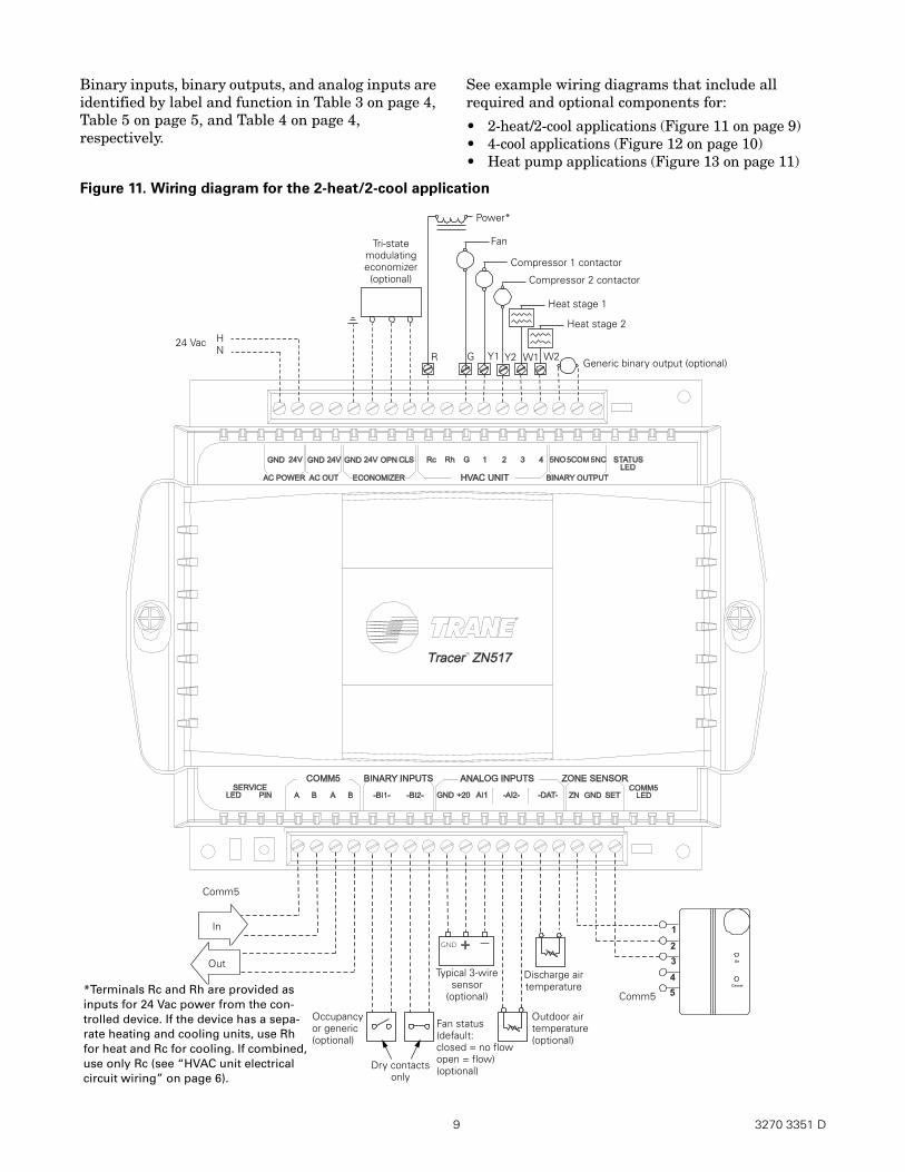
Binary inputs, binary outputs, and analog inputs are identified by label and function in Table 3 on page 4, Table 5 on page 5, and Table 4 on page 4, respectively.
See example wiring diagrams that include all required and optional components for:
• 2-heat/2-cool applications (Figure 11 on page 9)• 4-cool applications (Figure 12 on page 10)• Heat pump applications (Figure 13 on page 11)
Figure 11. Wiring diagram for the 2-heat/2-cool application
Compressor 1 contactor
Heat stage 1
Tri-state modulating economizer (optional)
Fan
HN
24 Vac
Generic binary output (optional)
Compressor 2 contactor
G Y2
Heat stage 2
Power*
R W2W1Y1
Comm5
Occupancyor generic(optional)
Typical 3-wire sensor
(optional)
Comm5
In
OutDischarge air temperature
Outdoor air temperature (optional)
*Terminals Rc and Rh are provided as inputs for 24 Vac power from the con-trolled device. If the device has a sepa-rate heating and cooling units, use Rh for heat and Rc for cooling. If combined, use only Rc (see “HVAC unit electrical circuit wiring” on page 6).
Dry contacts only
Fan status(default: closed = no flowopen = flow)(optional)

3270 3351 D 10
Figure 12. Wiring diagram for the 4-cool application
Comm5
In
Outdoor air temperature (optional)
Discharge airtemperature Comm5
Out
Compressor 1 contactor
Compressor 3 contactor
Tri-state modulating economizer (optional)
Fan
HN
24 Vac
Generic binary output (optional)
Compressor 2 contactor
G Y2
Compressor 4 contactor
Power*
R Y4
Typical 3-wire sensor
(optional)
Occupancy or generic (optional)
Y1 Y3
*Terminals Rc and Rh are provided as inputs for 24 Vac power from the con-trolled device. If the device has a sepa-rate heating and cooling units, use Rh for heat and Rc for cooling. If com-bined, use only Rc (see “HVAC unit electrical circuit wiring” on page 6).
Dry contacts only
Fan status(default: closed = no flowopen = flow)(optional)
11 3270 3351 D
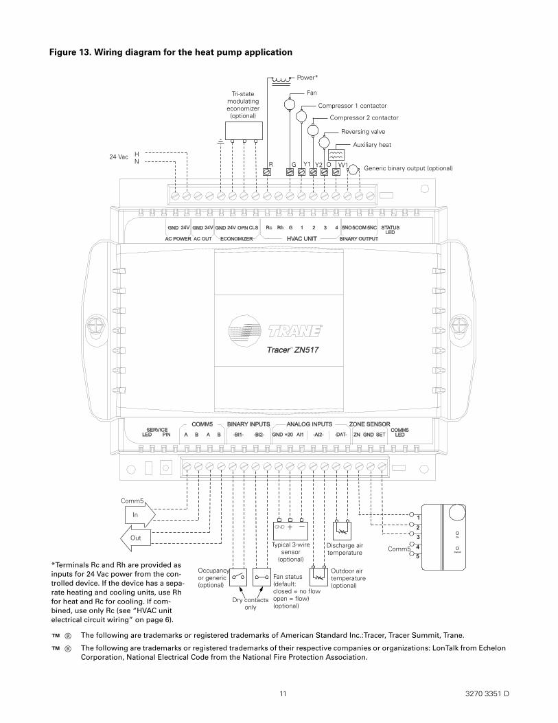
Figure 13. Wiring diagram for the heat pump application
*Terminals Rc and Rh are provided as inputs for 24 Vac power from the con-trolled device. If the device has a sepa-rate heating and cooling units, use Rh for heat and Rc for cooling. If com-bined, use only Rc (see “HVAC unit electrical circuit wiring” on page 6).
Comm5
In
Out
Occupancy or generic (optional)
Compressor 1 contactor
Reversing valve
Tri-state modulating economizer (optional)
Fan
HN
24 Vac
Generic binary output (optional)
Compressor 2 contactor
G
Auxiliary heat
Power*
R O W1Y2
Discharge airtemperature Comm5
Typical 3-wire sensor
(optional)
Outdoor air temperature (optional)
Y1
Dry contacts only
Fan status(default: closed = no flowopen = flow)(optional)
The following are trademarks or registered trademarks of American Standard Inc.:Tracer, Tracer Summit, Trane.
The following are trademarks or registered trademarks of their respective companies or organizations: LonTalk from Echelon Corporation, National Electrical Code from the National Fire Protection Association.
™ ®
™ ®
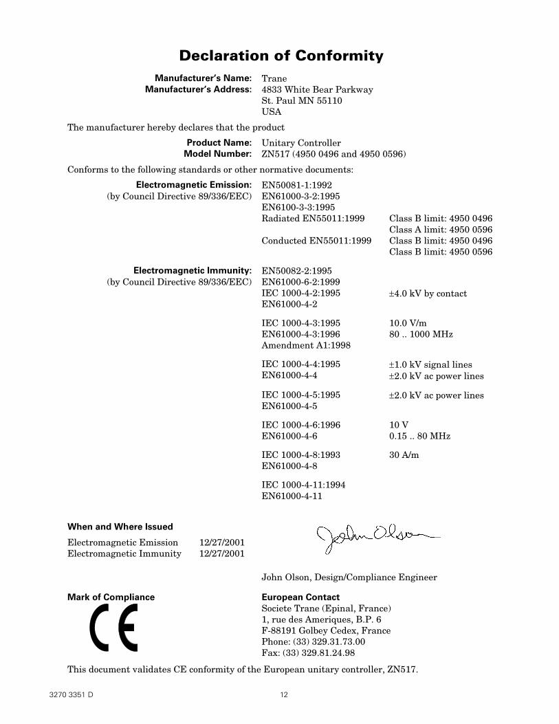
Declaration of Conformity Manufacturer’s Name:
Manufacturer’s Address:
The manufacturer hereby declares that the product
Product Name:
Model Number:
Conforms to the following standards or other normative documents:
Electromagnetic Emission:
(by Council Directive 89/336/EEC)
Electromagnetic Immunity:
(by Council Directive 89/336/EEC)
When and Where Issued
Electromagnetic Emission 12/27/2001 Electromagnetic Immunity 12/27/2001
Mark of Compliance
Trane 4833 White Bear Parkway St. Paul MN 55110 USA
Unitary Controller ZN517 (4950 0496 and 4950 0596)
EN50081-1:1992 EN61000-3-2:1995 EN6100-3-3:1995 Radiated EN55011:1999
Conducted EN55011:1999
EN50082-2:1995 EN61000-6-2:1999 IEC 1000-4-2:1995 EN61000-4-2
IEC 1000-4-3:1995 EN61000-4-3:1996 Amendment A1:1998
IEC 1000-4-4:1995 EN61000-4-4
IEC 1000-4-5:1995 EN61000-4-5
IEC 1000-4-6:1996 EN61000-4-6
IEC 1000-4-8:1993 EN61000-4-8
IEC 1000-4-11:1994 EN61000-4-11
Class B limit: 4950 0496 Class A limit: 4950 0596 Class B limit: 4950 0496 Class B limit: 4950 0596
±4.0 kV by contact
10.0 V/m80 .. 1000 MHz
±1.0 kV signal lines ±2.0 kV ac power lines
±2.0 kV ac power lines
10 V 0.15 .. 80 MHz
30 A/m
John Olson, Design/Compliance Engineer
European Contact
Societe Trane (Epinal, France) 1, rue des Ameriques, B.P. 6 F-88191 Golbey Cedex, France Phone: (33) 329.31.73.00 Fax: (33) 329.81.24.98
This document validates CE conformity of the European unitary controller, ZN517.
3270 3351 D 12