325E X-RAY GENERATOR - Frank's Hospital...
40
325E X-RAY GENERATOR USER AND ASSEMBLER INFORMATION For X-ray Control Model No.: F280 and X-ray High-voltage Generator Model No. A700 01496-000 Revision G AUGUST 2005 SUMMIT INDUSTRIES, INC. 2901 W. Lawrence Avenue Chicago, IL 60625 773-588-2444 www.Summitindustries.net
Transcript of 325E X-RAY GENERATOR - Frank's Hospital...

325E X-RAY GENERATOR
USER AND ASSEMBLER INFORMATION For X-ray Control Model No.: F280
and X-ray High-voltage Generator Model No. A700
01496-000 Revision G AUGUST 2005
SUMMIT INDUSTRIES, INC. 2901 W. Lawrence Avenue
Chicago, IL 60625 773-588-2444
www.Summitindustries.net

325E X-Ray Generator Summit Industries, Inc. Model Numbers F280 / A700
TEXT REVISION HISTORY FOR F285 MANUAL
REVISION ECR DESCRIPTION RELEASE DATE E 4196 UPDATED COVER SHEET AND
SCHEMATICS AUGUST 2004
F 4484 ADDED ERROR CODES AND TUBE PROTECT DIP SW. SETTINGS DUE
TO 02249-000 TIMER BOARD. ADDED TEXT REVISION HISTORY
PAGE, AND UPDATED TOC
FEBRUARY 2005
G 4727 UPDATED TOC TO INCLUDE 02581 SERVICE GUIDE
AUGUST 2005

325E X-Ray Generator Summit Industries, Inc. Model Numbers F280 / A700
TABLE OF CONTENTS
I. INTRODUCTION.................................................................................................. 2 II. USER INFORMATION ......................................................................................... 3
A. CONTROL FEATURES................................................................................ 3
B. RECOMMENDED OPERATING PROCEDURES ........................................ 6
C. MAINTENANCE ........................................................................................... 7
D. TECHNICAL INFORMATION ....................................................................... 9
III. ASSEMBLER INFORMATION............................................................................ 11
A. CERTIFICATION OF COMPATIBILITY...................................................... 11
B. RADIATION PROTECTION ....................................................................... 11
C. ELECTRICAL POWER SUPPLY REQUIREMENTS.................................. 11
D. UNPACKING AND OPENING CONTROL.................................................. 12
E. PRELIMINARY ASSEMBLY AND TUBE PROTECT SELECTIONS .......... 14
F. PRELIMINARY ELECTRICAL CHECKS AND ADJUSTMENTS ................ 18
G. CALIBRATION............................................................................................ 20
H. FINAL COMPLIANCE TESTS .................................................................... 26
I. ANCHORING CONTROL CABINET TO THE FLOOR ............................... 28
J. SCHEMATICS
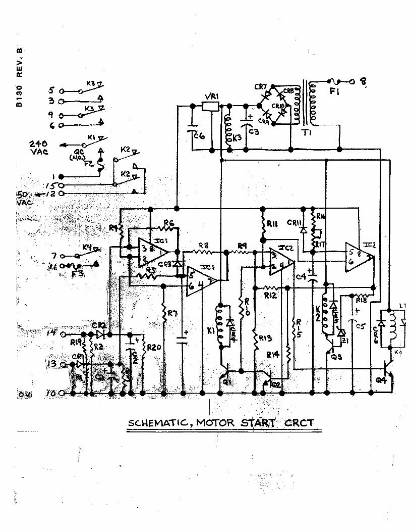
1. B127 --SCHEMATIC, 325 CONTROL CIRCUIT DIAGRAM .................. 29 2. 02249-002 -- COMPONENT LAYOUT FOR TIMER DRIVER PCBA ..... 30 3. B130-- SCHEMATIC, MOTOR START CRCT ...................................... 31
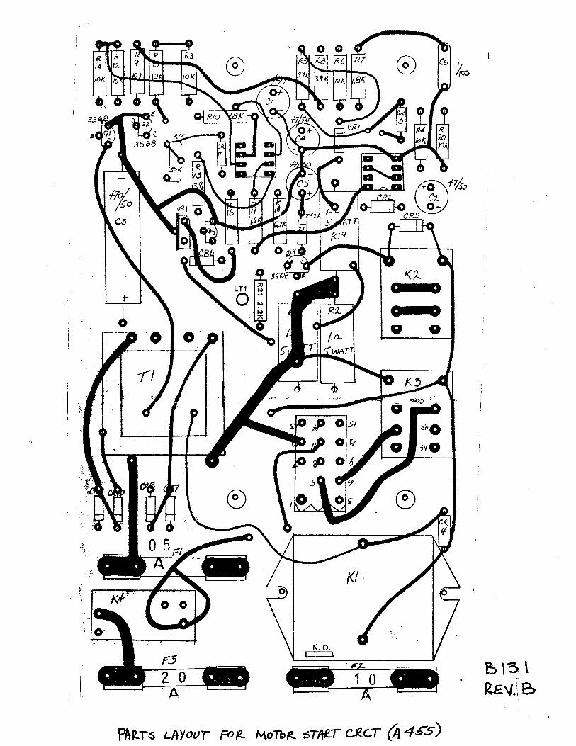
4. B131--PARTS LAYOUT FOR MOTOR START CRCT (A455) ............. 32
5. B132-- SCHEMATIC FOR KV COMP. PCB ASSY. (01204) ................. 33
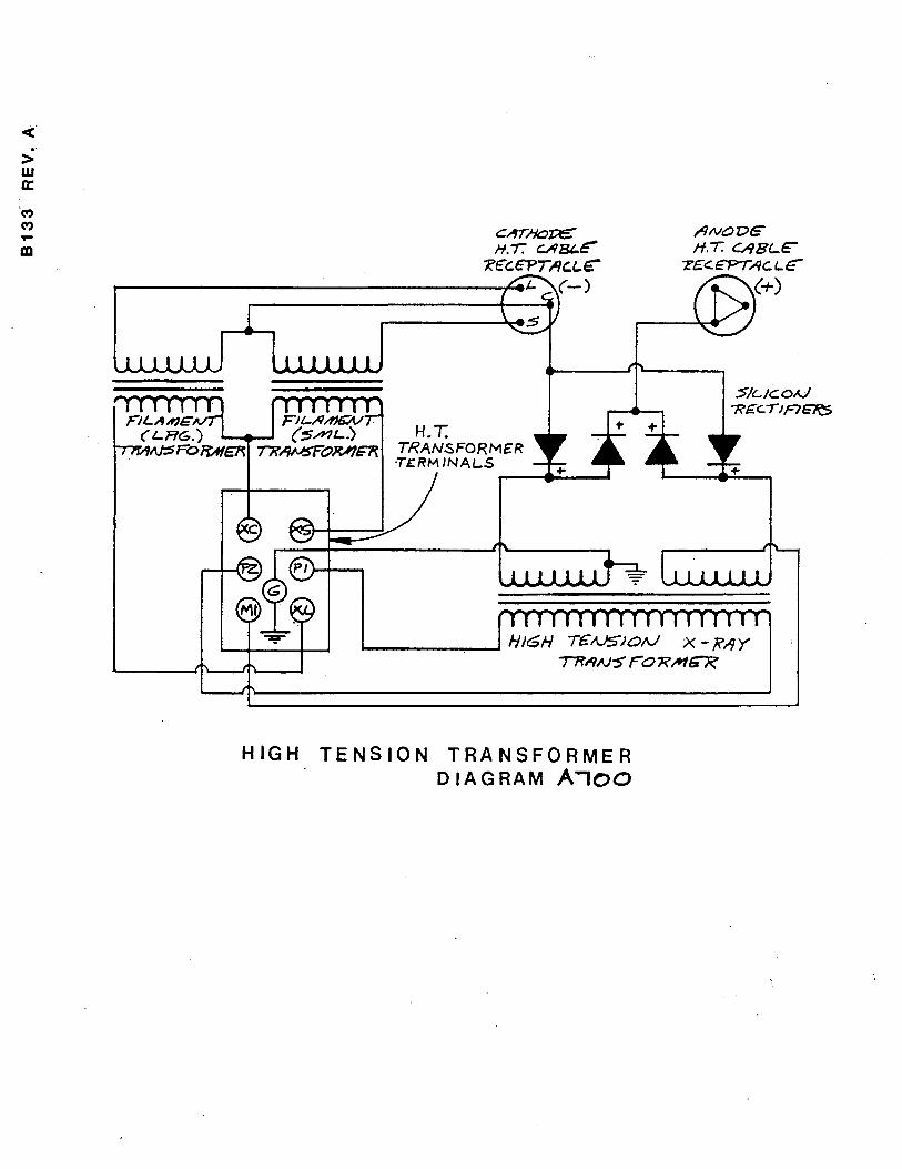
6. B133--HIGH TENSION TRANSFORMER DIAGRAM (A700) ............... 34
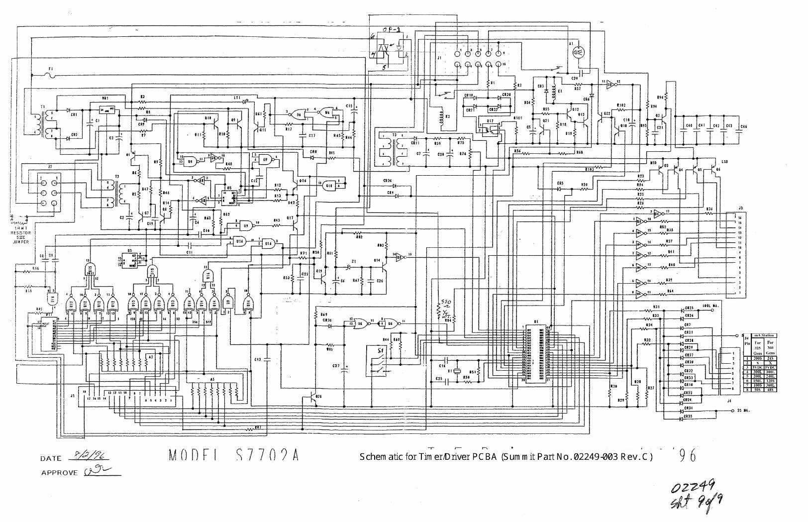
7. 02249-003--SCHEMATIC AND COMPONENT LAYOUTS …………….35
K. SERVICE GUIDE, SINGLE-PHASE GENERATORS (02581)................... 36
1

325E X-Ray Generator Summit Industries, Inc. Model Numbers F280 / A700
2
I. INTRODUCTION The equipment, which is described in this manual, will perform reliably when installed, operated, and maintained in accordance with the instructions of this manual. This equipment is sold with the understanding that the user assumes sole responsibility for radiation safety and that the manufacturer does not accept any responsibility for the following:
1. Equipment improperly installed. 2. Equipment improperly used. 3. Equipment improperly maintained or repaired. 4. Equipment, which has been modified or altered in any way. 5. Injury or damage to patient or other personnel for any of the above
causes. We are proud of our products and are confident they will provide many years of useful and enjoyable service. Summit Industries Inc.

325E X-Ray Generator Summit Industries, Inc. Model Numbers F280 / A700
II. USER INFORMATION This x-ray generator is both easy to use and very versatile. It consists of an x-ray control and a high voltage generator (H.V. generator).
A. CONTROL FEATURES
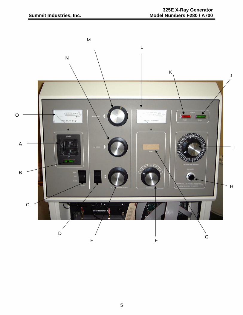
Refer to photo on page 6 for location of the following controls and indicators:
Note: Refer to Section B, “Recommended Operating Procedure” for detailed description of proper use of these controls and indicators.
A) Power “on” – “off” switch – Controls power to the system.
B) Power “on” light – Indicator light lights when power is “on”.
C) Bucky selector switch – Allows selection of either wall bucky, table bucky, or
no bucky.
D) Line check rocker switch – When depressed, this switch causes the kVp meter (O) to indicate if the line voltage compensator (E) is adjusted properly.
E) Line voltage compensator – Allows operator to adjust input circuit of x-ray
control to match the line voltage easily and effectively.
F) Tube current (mA) selector switch – Rotary switch allows operator to select the optimum tube current and focal spot for the desired technique.
G) Digital display – This display provides three very useful features:
1. Pre-exposure indication of mAs (the product of mA and exposure time). 2. Post-exposure indication of the number of x-ray pulses counted during
the previous exposure. 3. Error codes to indicate generator status or inappropriate selection.
Error Code Indicated Fault Corrective Action Required
E01 Tube Limits Exceeded Reduce kVp, mA or Time E02 kVp too high (>128 kVp) Select 125 kVp or less E03 kVp too low (<37 kVp) Select 40 kVp or more E04 Invalid mA setting Reselect mA station
E06 Invalid Time Selection or Leaking SCR
Reselect Time station, call for service if error won’t clear.
We recommend that the above chart be kept available for easy reference.
3

325E X-Ray Generator Summit Industries, Inc. Model Numbers F280 / A700
H) X-ray exposure switch – Two level switch: Partial depression (PREP) causes
anode rotation and filament current boost. Full depression (EXPOSE) initiates the production of x-rays.
I) Exposure time selector switch – Provides the operator capability to select any
one of 23 different exposure times.
J) Exposure interlock “ready” light – Indicator light lights when all exposure interlocks are closed. (Collimator interlock, tube thermal protection, misc. exposure interlock devices, etc.) When this light is “off”, exposures will not be allowed.
K) Tube ratings exceeded light – Indicator light lights when internal electronic
circuitry detects that selected technique factors exceed the single exposure ratings of the x-ray tube. Under these conditions, x-ray exposures are not allowed.
L) Milliampere meter – Indicates actual tube current during an x-ray exposure.
Meter deflection is the visual indication of x-ray production.
M) kVp minor selector – Provides fine adjustment of peak tube potential (kVp).
N) kVp major selector – Provides coarse adjustment of peak tube potential (kVp).
O) KILOVOLT meter – Pre-reading meter, which indicates selected peak tube
potential (kVp). This meter also serves as an indicator of line voltage adjustment in conjunction with item (D) above.
4
325E X-Ray Generator Summit Industries, Inc. Model Numbers F280 / A700
ML
N
KJ
O
A I
FG
B
H
C
DE
5

325E X-Ray Generator Summit Industries, Inc. Model Numbers F280 / A700
B. RECOMMENDED OPERATING PROCEDURES
Note: It is important to turn the generator “on” at least 15 minutes before making an exposure. This will provide sufficient “warm-up” time for the circuitry to stabilize.
1. Turn the system “on” by slowly snapping the power switch (A) to the right.
Power “on” light (B) should light.
2. Check the line voltage by depressing “line check rocker switch” (D) while observing the kVp meter (O). Rotate the knob of the “line voltage compensator” (E) as necessary until the needle of the kVp meter falls within darkened area of the scale marked “V”, (as near the center of the area as possible.)
Note: If you are unable to position the needle within this area, it is an indication that the line voltage is not correct and the equipment should not be used. Either wait for line voltage to change or call for service.
3. Determine the desired technique factors Note: Do not exceed the x-ray
tube ratings. Refer to x-ray tube rating charts provided with the x-ray tube. If the technique factors are set beyond the x-ray tube limits “E01” should appear in the digital display window, preventing exposure.
Note: Proper warm-up of the anode must be done on a cold unit prior to making exposures. The specific details may be found in “General Information for Installing and Operating X-Ray Tubes”, that is included with each tube shipped. The warm-up procedure tags are attached to each unit. Basically this procedure will reduce the chance of tube damage due to thermal shock.
4. Select the desired tube current. Selecting the 50 or 100 mA stations
automatically determine that the small Focal Spot will be used. The 150, 200, and 300 mA stations are internally connected to the large F.S.
Note: Select the desired tube current (mA) prior to selecting the desired peak tube potential (kVp).
If at any time, a different tube current is selected, it will be necessary to reset the kVp selector switches.
5. Rotate the exposure time selector switch (I) to the desired time setting.
6

325E X-Ray Generator Summit Industries, Inc. Model Numbers F280 / A700
6. Observe the digital display (G) to confirm that the correct mAs has been
selected.
7. Select the desired peak tube potential (kVp) by observing the kVp meter (O) while rotating the kVp selectors (M&N)
8. This generator is equipped with tube protect circuitry that compares the
selected technique factors to the “single exposure ratings” of the x-ray tube. Exposures will only be allowed if the selected values are less than or equal to the x-ray tube limits. Refer to the chart below for description of “E01” error.
9. If the x-ray system includes a bucky (wall or table or both) and it is desired to
use a bucky technique, select the appropriate bucky by depressing the bucky selector switch. If a non-bucky technique is desired select the center “off” position of the bucky selector switch.
10. This generator is also equipped with an indicator light identified as “exposure
interlocks ready” light, which monitors the status of all auxiliary exposure interlock circuitry. When all interlocks are ready the light will light. If the light is not “on”, x-ray exposures will not be allowed. Such interlocks might be SID interlock switches, tube thermal protectors, collimator interlock, etc.
11. Depress the exposure switch approximately halfway. This action will cause
the rotating anode of the x-ray tube to accelerate to full speed and the selected filament of the x-ray tube to heat up to its proper emission temperature. Depress the exposure switch fully and hold. A beep tone will indicate the termination of the exposure, and the mA meter deflection will provide a visual indication of x-ray production.
Note: It is permissible to depress the exposure switch fully in one motion. There will be however, a one second delay before x-ray production begins.
After the exposure terminates, but while the exposure switch is still depressed, the digital display will flash “on” and “off” indicating the number of x-ray pulses produced. This is primarily a service feature provided for the x-ray serviceman to verify proper operation.
12. Error codes and corrective action for digital display window.
Error Code Indicated Fault Corrective Action RequiredE01 Tube Limits Exceeded Reduce kVp, mA or Time E02 kVp too high (>128 kVp) Select 125 kVp or less E03 kVp too low (<37 kVp) Select 40 kVp or more E04 Invalid mA setting Reselect mA station
E06 Invalid Time Selection or Leaking SCR
Reselect Time station, call for service if error won’t clear.
7
325E X-Ray Generator Summit Industries, Inc. Model Numbers F280 / A700
C. MAINTENANCE Periodic inspection and preventative maintenance of this equipment is necessary to assure continued safe performance and compliance with applicable state and federal regulations. The following maintenance program must be closely followed.
Q: Who should perform the service? A: Service personnel specifically trained, experienced, and familiar with this type of
medical x-ray equipment.
Q: When and How often? A: Appropriate inspection and service should be performed 30 days after installation
and every 6 months thereafter.
Q: Specifically, what must be inspected, tested and/or serviced? A: Several things:
1. Verify that the knob on exposure time selector is mounted solidly and
indicates the proper value. 2. Verify that all push-button and rocker switches operate freely with no sticking
or hanging up. 3. Verify proper operation of all pilot lights. 4. Verify proper operation of audible and visual indicators of x-ray termination
and production respectively. 5. Verify the accuracy of exposure timer, tube current, and peak tube potential,
and adjust as necessary. 6. Perform reproducibility and linearity tests and verify compliance. 7. Inspect electro-mechanical contactor for pitting and/or burned contacts.
Replace if necessary. 8. Examine terminal connections of high voltage generator. All terminals should
be tight. 9. Examine oil level of H.V. generator and refill as necessary. There should be
approximately ½ to ¾” air space between the oil and the inside edge of the generator cover.
10. Examine the plugs of the high voltage cables. They should be clean with no signs of carbon tracking.
Note: This x-ray generator should not be altered or modified in any way as such action may invalidate its regulatory compliance and void the factory warranty.
8

325E X-Ray Generator Summit Industries, Inc. Model Numbers F280 / A700
D. TECHNICAL INFORMATION Rated line voltage – 240 VAC, 60 Hz., single phase.
Range of line voltage regulation at max. line current = 1-5%
Maximum line current based on input voltage of 240 VAC -140A.
Technique factors that constitute the maximum line current – 300 mA @ 125 kVp.
Generator rating-
Output Current = 50-300mA. Output Voltage = 40-125kVp.
Generator duty cycle-
100mA @ 125 kVp – 4% 200mA @ 125kVp – 2% 300mA @ 125kVp – 1%
Maximum Deviation The following maximum deviation statements are broad and considered “worst case” conditions. Typical performance will normally be significantly better. Peak Tube Potential (kVp) The Maximum Deviation of the Peak Tube Potential during an exposure from its pre-indicated value is + 20% of the kVp meter’s full-scale value. The measurement basis upon which the peak tube potential is defined is a calibrated high voltage divider unit such as the Machlett Dynalyzer. Tube Current The Maximum Deviation of the tube current during an exposure from its pre-indicated value is +10% of selected value within a kVp range of 50-125 kVp (inclusive), and +20% of selected value within a kVp range of 40-50 kVp (exclusive). The measurement basis upon which the tube current is defined is a calibrated D.C. milliammeter in series with the x-ray tube.
9

325E X-Ray Generator Summit Industries, Inc. Model Numbers F280 / A700
Exposure Time
The maximum deviation of the measured exposure time from its pre-indicated values is
+ 1 pulse for selected times within the range of 1/120 – 1/10 sec. + 15% of selected times within the range of 3/20-6 sec.
The measurement basis upon which the exposure time is defined as the number of half cycle impulses of the 60 Hz power line measured either at the primary of the high voltage generator with an oscilloscope or in the secondary of the high voltage generator by means of a high voltage divider unit and an oscilloscope.
Tube Current-Exposure Time Product The digital display of mAs provided is not a primary indication of technique factors. It is intended solely as an auxiliary indication to verify the product of the primary control settings: tube current and exposure time. As such, a statement of maximum deviation is not provided.
10

325E X-Ray Generator Summit Industries, Inc. Model Numbers F280 / A700
III. ASSEMBLER INFORMATION
A. CERTIFICATION OF COMPATIBILITY The manufacturer certifies that it’s certified x-ray controls and high voltage generators are compatible with all certified x-ray tubes concerning compliance with 21CFR, Chapter I, Sub-chapter J, only if the ratings of the controls, generators and tubes are strictly observed and the control is calibrated within the applicable published limits.
Our certified controls and generators, when combined with other certified components, will not affect the compliance of these components when these components are installed, connected and adjusted in accordance with the applicable manufacturer’s instructions and specifications.
Note: It is the assembler’s responsibility to verify compatibility of all components assembled as parts of the x-ray system. Refer to compatibility statements published by the component manufacturer for this specific information.
B. RADIATION PROTECTION
Most states and local governments have regulations, which specify minimum safety requirements for radiation protection. Consult your local regulations for specific requirements.
C. ELECTRICAL POWER SUPPLY REQUIREMENTS The information provided below is taken from NEMA standards, Minimum Power Supply Requirements for X-Ray Machines, and National Electric Code.
Equipment Category – 300mA at 125kVp, single phase.
Nominal Line Voltage – 240 VAC., 60 Hz., single phase.
Note: Alternate line voltages, which will provide normal operation, are 208-277
VAC.
Maximum Momentary Line Current – 140 amperes (at 240 VAC)
Note: Maximum momentary line current at alternate line voltages can be determined using the following formula:
140x240 I2 =
V2 where V2 represents the alternate line voltage, and I2 represents the maximum line current at the alternate line voltage, “V2”.
11

325E X-Ray Generator Summit Industries, Inc. Model Numbers F280 / A700
Line Voltage Regulation – Not to exceed 5% at maximum line current.
Percent line voltage regulation = VN – VL VL
X 100
where VN represents the line voltage under “no load” conditions, and VL represents line voltage under “full load” conditions.
Minimum Over Current Protection Rating – 50% of maximum line current rating or greater. Assuming maximum line current to be 140 amps, this value would be 70 amperes or greater.
Wire Size from Power Transformer to Disconnect Switch – for 50 feet use #2AWG; for 100 feet use #00AWG; for 200 feet use 250mcm
(mcm – thousand circular mils.)
Connection to Supply Circuit (taken from N.F.P.A. 70-1984) A disconnecting means of adequate capacity for at least 50% of the input required for the momentary rating shall be provided in the supply circuit. The disconnecting means shall be operable from a location readily accessible from the x-ray control. Underwriters Laboratories also requires that this disconnecting means be mounted on either the wall behind the x-ray control or the wall directly adjacent to it.
D. UNPACKING AND OPENING CONTROL 1. Open all cartons carefully and examine contents. If damage is found notify the
freight company immediately to file claim. Do not dispose of cartons or packing materials until installation is complete, and any damage claims have been settled.
2. Verify that the oil level in the H.V. generator is approximately ½” to ¾” below the
underside of the cover. Refill with “Shell Diala oil AX” or equivalent as necessary.
3. Once the H.V. generator is in its final location, loosen the screw on the vent plug
to allow for oil expansion. Cover the vent plug and flange with one of the loose fitting plastic covers provided with the H.V. generator to prevent contaminants from entering the oil.
4. To open control for service, loosen the lockdown screws (one on each side) and
tilt the control lid assembly forward.
12

325E X-Ray Generator Summit Industries, Inc. Model Numbers F280 / A700
5. From the inside of the control, remove the two thumbscrews and washers from front panel being careful not to drop them into the cabinet.
13
325E X-Ray Generator Summit Industries, Inc. Model Numbers F280 / A700
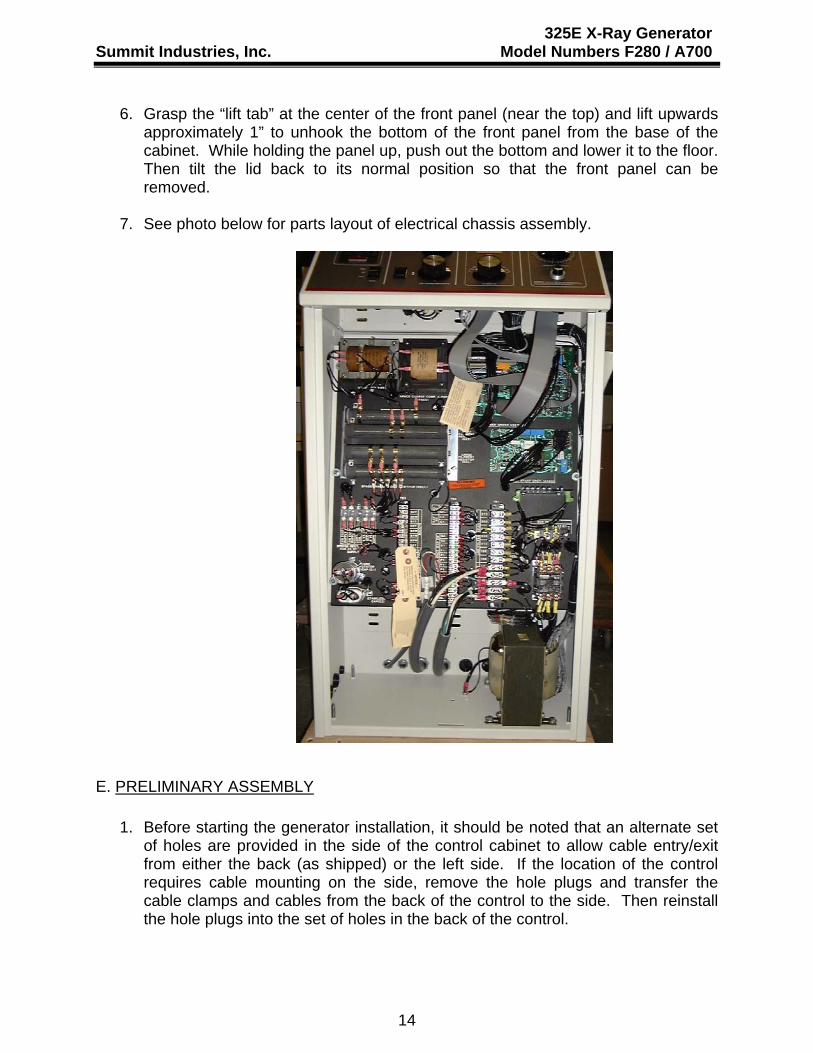
6. Grasp the “lift tab” at the center of the front panel (near the top) and lift upwards approximately 1” to unhook the bottom of the front panel from the base of the cabinet. While holding the panel up, push out the bottom and lower it to the floor. Then tilt the lid back to its normal position so that the front panel can be removed.
7. See photo below for parts layout of electrical chassis assembly.
E. PRELIMINARY ASSEMBLY 1. Before starting the generator installation, it should be noted that an alternate set
of holes are provided in the side of the control cabinet to allow cable entry/exit from either the back (as shipped) or the left side. If the location of the control requires cable mounting on the side, remove the hole plugs and transfer the cable clamps and cables from the back of the control to the side. Then reinstall the hole plugs into the set of holes in the back of the control.
14

325E X-Ray Generator Summit Industries, Inc. Model Numbers F280 / A700
2. Connect x-ray tube a) High voltage cables (HV cables) – The high voltage generator requires the
use of H.V. cables constructed with federal terminals. Note: Use extreme care when handling the H.V. cables to avoid damaging the plug or terminal pins.
Be sure that “Anode” of H.V. generator connects to “Anode” of x-ray tube, and “Cathode” to “”Cathode”. H.V. cable terminals must be thoroughly cleaned and then coated with a thick coating of Vapor Proofing Compount (normally provided with the x-ray tube) prior to insertion into the x-ray tube or H.V. generator receptacles.
Insert the H.V. cable terminals into the appropriate receptacle and screw the cable nut as tightly as possible by hand – do not use tools for tightening.
b) Stator cable – This x-ray control will accept either a 3 or 5 wire tube stator
cable. The terminals of the x-ray control are on TB3 and are marked 07, 08, 09, T5, and T6.
COLOR CODE FOR STATOR CABLE TERMINAL
MARKINGS OF (TB3)
CONNECTIONS EUREKA/VARIAN TUBES
MACHLETT TUBES
SUMMIT and TOSHIBA TUBES
07 RUN WDG. OF TUBE STATOR BLACK BLACK BLACK 08 START WDG. OF TUBE STATOR RED GREEN RED 09 COM. LEAD OF TUBE STATOR WHITE WHITE WHITE T5 *THERMAL CUTOUT SWITCH
(OPTIONAL) ORANGE/BROWN
---- YELLOW
T6 *THERMAL CUTOUT SWITCH (OPTIONAL)
BROWN/ORANGE
---- BLUE
*If tube has thermal cutout switch, remove jumper across T5 and T6 and connect leads as indicated. If tube does not have thermal cutout switch, terminals T5 and T6 must be jumpered together. (Control is shipped with this jumper installed.)
15

325E X-Ray Generator Summit Industries, Inc. Model Numbers F280 / A700
3. Connect high voltage generator to control –
a) The 25’ primary cable for the H.V. generator is connected to the control at the
factory. The loose end, marked P1, P2, and GND, should be connected to the corresponding terminals of the H.V. generator.
b) The 25’ filament supply cable for the H.V. generator is connected to the
control at the factory. The loose ends, marked XC, XS, XL, and MI are to be connected to the corresponding terminals of the H.V. generator.
4. Connect collimator and/or electric locks (if applicable) –
This x-ray control is provided with fused power supplies rated 24 VACm 10Amp max. (terminals “C1 and “C2” of TB2) and 24 VDC 8Amp max. (terminal “DC+” and “DC-“ of TB2).
5. Exposure interlock circuits –
This x-ray control provides pairs of terminals which can be used to connect auxiliary interlock circuitry which inhibit x-ray exposures. These terminal pairs are marked T6/T7, and T7/F2 of TB3. Removable jumper clips are connected across these terminals at the factory. If it is necessary to connect an interlock switch into the exposure circuit, remove one of these jumpers and connect the interlock leads across the opened terminals. Note: Any interlock switch to be used must be rated 125 VAC, 2 Amps minimum.
6. Bucky connections –
This control provides terminals which can be used to operate one or two buckys. The terminals are designated B1W, B2W, B3W, and B4W for “wall” buckys; and B1T, B2T, B3T, and B4T for “table” buckys. Since several types of buckys may be used, be sure to connect bucky to appropriate terminals as indicated below. All bucky’s must be configured for 115 VAC operation.
3B2BB 1
CONTROL TERM STRIP "TB3"GND23 B 1 B
BR
N.
BLU
E
4B
WH
ITERE
D
GR
N/Y
EL
B 3
BLA
CK
SUMMIT BUCKY "J500"
B 4B 3B 21B
CONTROL TB3B1B 2 B 3 4B
14 X 36MIDWEST
B
B8
LIEBEL-FLARSHIEM 8000
6BB B B2 3 4B 1B B B2 3 4B 1
CONTROL TB3B B1 2 3B B 4
CONTROL TB3B1B B 2 GROUND4
L-F PAR SPEED(PRE-1989) AND MIDWEST 7440
B86B4B
Note: Remove jumper clip across B1T and B2T on TB3 when connecting “table” bucky, or B1W and B2W on TB3 when connecting “wall” bucky.
16

325E X-Ray Generator Summit Industries, Inc. Model Numbers F280 / A700
7. Auxilary exposure switch –
Terminals have been provided in the control for connecting an auxilary exposure switch. They are on TB2 and are marked S1, s2, and S3. Refer to control circuit schematic for connection details.
8. Power supply –
A 13 ft. line cable marked L1, L2, and GND is provided. One end is connected to the control at the factory. The other end is to be connected to the disconnect switch to the appropriate terminals. The disconnect switch should be “off” before making connections. Be sure to connect the green “GND” lead to a “GOOD” ground.
9. Tube Protect DIP Switch Selection –
The 02249-000 timer board has a DIP switch (S1) to select the tube protect limits for the x-tube type used at this installation. The new U1 chip will be labeled with generator type (325 or 360), line frequency (50 or 60 Hz), and tube manufacturer (Summit/Toshiba or Varian/Eureka). Verify the chip type installed is appropriate for the generator, line frequency and tube type at this site. DIP SW1 positions will select the specific type of x-ray tube insert at this site (see table below). For the DIP switch “OFF” is to the left, “ON” is to the right. Any change to the DIP S1 settings must be done while the generator is turned OFF.
DIP SW (S1) Settings Tube Mfg, Insert, (Focal Spot) S1-1 S1-2 S1-3
Toshiba E7239 (1.0/2.0) OFF OFF inactive Toshiba E7242 (0.6/1.5) OFF ON inactive Toshiba E7252 (0.6/1.2) ON OFF inactive Toshiba E7813 (1.0/2.0) ON ON inactive Varian Rad 8 (1.0/2.0) OFF OFF inactive
Varian Rad 74 (0.6/1.5) OFF ON inactive Varian Rad 14 (0.6/1.2) ON OFF inactive Varian Rad 13 (1.0/2.0) ON ON inactive
17

325E X-Ray Generator Summit Industries, Inc. Model Numbers F280 / A700
F. Preliminary Electrical Checks and Adjustments
1. Line voltage adjustments –
Terminals in the control on TBI are provided for coarse adjustments of line voltage. Measure the line voltage at the disconnect switch and relocate wire marked LVA to the corresponding terminal. See below for details.
If line voltage measures 190-203V connect LVA lead to term “198”
If line voltage measures 204-219V connect LVA lead to term “212”
If line voltage measures 220-233V connect LVA lead to term “228”
If line voltage measures 234-249V connect LVA lead to term “242”
If line voltage measures 250-263V connect LVA lead to term “258”
If line voltage measures 264-280V connect LVA lead to term “272”
2. Preset all selector switches –
Prior to turning “on” power, set each selector switch as follows:
Power “on-off” - “off” Bucky switch - “off” kVp major and minor - fully counterclockwise Line voltage compensator - approximately halfway mA selector - 150L Time selector - 1/120 sec.
3. Disconnect leads marked P1 and P2 from H.V. generator and insulate with electrical tape. This will prevent accidental production of x-rays during initial check-out. Switch the disconnect switch “on” and then switch the control’s “on-off” switch “on”.
Observe the following:
-Power “on” light is lit. -kVp meter indicates approximately 20 kVp. -mA meter indicates zero. -Digital display indicates E03 (kVp too low). -Tube ratings exceeded light “lit”. -Exposure ready light lit.
18

325E X-Ray Generator Summit Industries, Inc. Model Numbers F280 / A700
Note that the 02249-000 timer board will display error codes per the table below. If more than one selection is invalid the highest number will take precedence. For example, an “invalid mA” and “kVp too low” would display as E04. Once the mA error is cleared the kVp low error E03 would then be displayed. Error Code Indicated Fault Corrective Action Required
E01 Tube Limits Exceeded Reduce kVp, mA or Time E02 kVp too high (>128 kVp) Select 125 kVp or less E03 kVp too low (<37 kVp) Select 40 kVp or more E04 Invalid mA setting Reselect mA station
E06 Invalid Time Selection or Leaking SCR
Reselect Time station, call for service if error won’t clear.
4. Depress and hold “line check rocker switch” and observe kVp meter. Rotate “line
voltage compensator” until kVp meter needle is in the black area of the scale marked “V”. Release line check rocker switch.
5. While observing the tube filaments through the port of the x-ray tube, verify that
the correct filament is lit for each mA station.
6. Depress the exposure switch to the 1st stage (prep.) and verify anode rotation and filament boost.
7. The kVp meter circuit is factory adjusted, but should be checked to verify
approximate calibration.
a) With power “off” connect an “AC” voltmeter capable of reading 0-250 VAC across the wipers (center terminals of tap switches) of the KV selector switches (major and minor). This will allow measurement of the “no-load” primary voltage.
b) Turn “on” power and adjust the kVp selector switches to result in 220 VAC
indicated on the voltmeter.
c) Compare the kVp meter indications for all mA stations with the values given below:
mA STATION kVp METER INDICATION (kVp)
50 115
100 114 150 110 200 103 300 87
19

325E X-Ray Generator Summit Industries, Inc. Model Numbers F280 / A700
Then reset kVp selectors to result in voltmeter indication of 160 VAC.
mA STATION kVp METER INDICATION (kVp)
50 81 100 80 150 76 200 69 300 53 If the kVp meter indication varies by more than 5 kVp from the values given above, proceed to the kVp calibration procedure (page 23).
8. Check proper operation of all auxiliary devices and interlocks (electric locks,
collimator, auxiliary exposure switch, bucky, etc.)
9. Switch the disconnect switch “off” and reconnect the leads P1 and P2 to the H.V. generator.
G. CALIBRATION
This x-ray generator has been fully tested and calibrated using a “production test” x-ray tube. Because the tube characteristics of this tube may vary from the tube characteristics of the specific tube being installed, the assembler must check the accuracy of the tube current, and make the appropriate adjustments. This equipment has been designed and calibrated based on proper connection to a power supply as described below: -Nominal line voltage – 190-280 VAC 60 Hz. single phase -Maximum line voltage regulation – 5% at full rated load (300 mA 125 kVp) Calibration will normally involve only slight adjustments of the tube current and verification of KV accuracy.
It is recommended that the assembler read and understand the information provided with the x-ray tube prior to making any x-ray exposures. Particular attention should be given to:
a) Pre-warming of the anode b) Initial seasoning of the x-ray tube c) One shot tube ratings d) Long time accumulated heat ratings
It is also recommended that measuring equipment be connected into the x-ray system and used to monitor mA and kVp throughout the calibration procedure. This reduces the chances of misleading test data and unnecessary backtracking.
20

325E X-Ray Generator Summit Industries, Inc. Model Numbers F280 / A700
1. Calibration of Tube Current
Achieving maximum accuracy of tube current involves two types of adjustments:
• •
Overall mA level (bands of filament resistors RXS and RXL), AND mA balance throughout the useful kVp range (bands of space charge
compensating resistor RSCC).
The leads connected to the resistor bands of RXS and RXL are marked with numbers, which correspond to the mA stations. Moving one of these bands to the right increases the tube current for the corresponding mA station.
The leads connected to the bands of RSCC are also marked with numbers, which correspond the mA stations. Moving one of these bands to the right causes a reduction of mA at high kVp levels as compared to low kVp levels for the corresponding mA station. This is commonly referred to as the balance adjustment.
Note: If a band of RXS or RXL is all the way to the right & the corresponding tube current is not up to the proper level, it may be necessary to reposition the right-most band of Boost Resistor, “RB”. Moving this band to the right causes tube current to increase for all mA stations.
a) Select 150 mA and 80kVp
b) Adjust the band of RXL marked 150 to produce approximately 156 mA
(moving the band to the right increases mA).
c) Select 50 kVp and note the mA produced.
d) Select 120 kVp and note the mA produced.
e) If the mA at 120 kVp is higher than the mA at 50kVp, move the band of RSCC marked 150 to the right. If lower, move the band to the left.
f) Repeat steps (a) through (f) until no further adjustments are necessary.
g) Check mA tracking from 50 to 120 kVp and fine tune as required. The unit is
capable by fine tuning to deviate no more than approximately 5% of selected value. Due to the method of space charge compensation utilized, normal tracking will result in mA values slightly higher than selected near 80 kVp and mA values equal to one another but slightly lower than selected levels at the high and low ends of the kVp range (125 and 50). See below for visual presentation of this effect.
21

325E X-Ray Generator Summit Industries, Inc. Model Numbers F280 / A700
50 80 125 140
mA
kVp0
+ 5%- 5%
SELECTED mA
h) Repeat steps (a) through (g) for the remaining mA stations:
Note: In step (b), use the following values in place of 156 mA.
MA STATION MA 50
100 200 300
52 105 210 315
2. Peak Tube Potential (kVp)
This x-ray generator comes equipped with an adjustable circuit used to compensate the kVp meter for loading effects. This circuit is identified as “kVp Meter Compensation Circuit”. Its adjustments consist of:
(5) Independent offset pots (marked to correspond to the appropriate mA
station)
(1) Common slope pots Rs
These adjustment pots are all mounted onto a small P.C.B., which clearly identified inside the control on the electric chassis.
a) Verify kVp meter movement accuracy.
1) Connect a 250 VAC voltmeter of + 1% accuracy directly across the kVp
meter terminals.
2) Turn “on” the unit and rotate the KV selector switches major and minor to vary the voltage across the meter. Compare readings to the values in the table below. If kVp meter indication deviates from the values given by more than 3 kVp, the kVp meter may have to be replaced.
22

325E X-Ray Generator Summit Industries, Inc. Model Numbers F280 / A700
METER VOLTAGE
(VAC) kVp METER INDICATION
86 138 172 207
50 kVp 80 kVp
100 kVp 120 kVp
b) Verify kVp METER COMP. CIRCUIT input voltage and write down factory kVp
METER offset calibration data.
1) Connect an AC voltmeter between TP-1 and Tp-2 of the kVp COMP. PCB. Verify that voltage is 100 VAC.
2) Turn unit power OFF. Disconnect connector J1 of kVp METER COMP.
PCBA. Turn power ON. Connect AC voltmeter between Tp-1 and Tp-3, measure the offset voltage for 50 mA station and enter result in the Table.
3) Repeat step 2 for all remaining mA stations using test points indicated in table below. Use results for future reference.
4) Turn power OFF. Reinstall connector J1, turn power ON.
mA STATION 50 mA 100 mA 150 mA 200 mA 300 mA TEST POINTS TP1-TP3 TP1-TP4 TP1-TP5 TP1-TP6 TP1-TP7 FACTORY CALIBRATION
FIELD CALIBRATION
23

Summit Industries, Inc.
325E X-Ray Generator Model Numbers F280 / A700
24
c) Verify and adjust kVp meter accuracy
1) Select 150 mA and 50 kVp. While monitoring mA and kVp output, compare the measured kVp to the kVp meter’s preread indication.
Note: In order to make a valid comparison between the measured
peak tube potential (kVp) and the kVp meter’s preread indication, the tube current must be calibrated accurately. Failure to do so will result in an erroneous determination of kVp accuracy.
2) Adjust the 150 mA offset pot until the kVp meter’s preread indication
matches the measured kVp output.
3) Select 120 kVp. Make an x-ray exposure and adjust the common slope pot until the kVp meter’s preread indication matches the measured kVp output. Repeat steps 1, 2 and 3 above until no further adjustments are necessary.
4) Select 50 mA and 90 kVp; Adjust the 50 mA offset pot until the kVp
meter’s preread indication matches the measured kVp output.
5) Repeat step 4 for each remaining mA station, adjusting the corresponding pot as necessary.
6) Check final kVp meter tracking over the entire kVp range. Under normal
conditions the kVp meter’s indication will not deviate from the measured kVp output by more than 5 kVp.
Summit Industries, Inc.
325E X-Ray Generator Model Numbers F280 / A700
25

325E X-Ray Generator Summit Industries, Inc. Model Numbers F280 / A700
H. FINAL COMPLIANCE TESTS
It is necessary for the assembler to perform tests on the newly-assembled x-ray system prior to release to the user. These tests must assure compliance with the applicable requirements of the FDA performance standard at the time of installation.
Perform these tests in accordance with NEMA publication #XR8-1979, Tests Methods for Diagnostic X-Ray Machines for Use During Initial Installation. It is necessary that the assembler document these tests to demonstrate at a later date that all tests were performed and that the x-ray system was left in full compliance with the standard. The test results obtained must verify that the following system specifications are met or the system must be removed from service until corrective action is completed.
SYSTEM SPECIFICATIONS
BEAM QUALITY
The half-value layer of the useful beam shall not be less than 3.5mm of aluminum.
REPRODUCTIBILITY AND LINEARTIY When the x-ray unit is operated on an adequate power supply (see section IIA): (1) the estimated coefficient of variation of radiation exposure shall not be greater than .048 for any specific combination of technique factors, and (2) the average ratios of exposure to the indicated tube current exposure time product (mAs) obtained at any two consecutive tube current settings shall not differ by more than .095 timed their sum, or
X1 – X2
X1 + X2
where X1 and X2 are the average mR/mAs values obtained at each of two consecutive tube current settings.
< 0.095
PEAK TUBE POTENTIAL The maximum deviation of the peak tube potential from its preindicated value, during an exposure, when the equipment is connected to an adequate power supply (see section IIA) shall not exceed + 19% of full scale value within the range of 40-125 kVp.
26

325E X-Ray Generator Summit Industries, Inc. Model Numbers F280 / A700
TUBE CURRENT The maximum deviation of the tube current from its preindicated value, during an exposure, when the equipment is connected to an adequate power supply (see section IIA) shall not exceed +9% of selected tube current within the range of 50-125 kVp (inclusive), and +19% of selected tube current within the range of 40-50 kVp (exclusive). EXPOSURE TIME The maximum deviation of the exposure time from its preindicated value, during an exposure, when the equipment is connected to an adequate power supply (see section IIA) shall not exceed +0 pulses within the range of 1/120-1/10 (inclusive) +14% of selected time within the range of 3/20-6 seconds (inclusive).
27
325E X-Ray Generator Summit Industries, Inc. Model Numbers F280 / A700
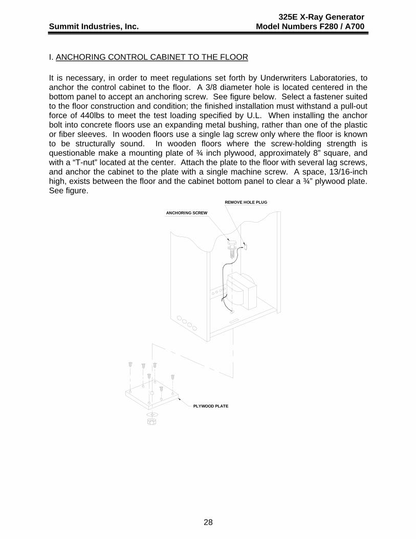
I. ANCHORING CONTROL CABINET TO THE FLOOR It is necessary, in order to meet regulations set forth by Underwriters Laboratories, to anchor the control cabinet to the floor. A 3/8 diameter hole is located centered in the bottom panel to accept an anchoring screw. See figure below. Select a fastener suited to the floor construction and condition; the finished installation must withstand a pull-out force of 440lbs to meet the test loading specified by U.L. When installing the anchor bolt into concrete floors use an expanding metal bushing, rather than one of the plastic or fiber sleeves. In wooden floors use a single lag screw only where the floor is known to be structurally sound. In wooden floors where the screw-holding strength is questionable make a mounting plate of ¾ inch plywood, approximately 8” square, and with a “T-nut” located at the center. Attach the plate to the floor with several lag screws, and anchor the cabinet to the plate with a single machine screw. A space, 13/16-inch high, exists between the floor and the cabinet bottom panel to clear a ¾” plywood plate. See figure.
REMOVE HOLE PLUG
ANCHORING SCREW
PLYWOOD PLATE
28

PART I.D. for 325 & 360 GENERATOR LID ASSEMBLY
1:02 PM 12/26/2006
02255-000: kV Tap Switch A367: Milliampre Meter 325 HE73: RED LIGHT, A312: Knob without Pointer 00312-000: mAs Display TUBE LIMIT (Same for Major and Minor) RED LED Replacement B697: Milliampre Meter 360 01376-000: Kit, Kilovolt Meter 01381-000: Replacement Instructions A365: ON/OFF Circuit Breaker HG11: GREEN Power Indicator (same as Ready) A364: SWITCH Bucky Selector
HG11: GREEN, Ready Light
A310: SWITCH, Time Select 325
C083: SWITCH, Time Select 360
A311: KNOB,
With Pointer
A361: SWITCH, Expsure, 2-Position
A363: SWITCH, A363: SWITCH, B642: SWITCH, mA Selector 325 Line Check Line Compensation B932: SWITCH, mA Selector 360

A323 ELECTRICAL CHASSIS for 325 generators filename: A323_ElecChassis 325.JPG
ROGERS C:/Pictures/GenerComponents/60Hz/Nova

subrinan
01204
subrinan
F280, B300, K240, 01200
subrinan
G
subrinan
subrinan
subrinan
subrinan
subrinan
8
subrinan
8
subrinan
J4 Pin
subrinan
7
subrinan
6
subrinan
5
subrinan
4
subrinan
3
subrinan
2
subrinan
1
subrinan
50S
subrinan
100S
subrinan
300L
subrinan
150L
subrinan
200L
subrinan
5VDC
subrinan
200S
subrinan
X
subrinan
120S
subrinan
48S
subrinan
360L
subrinan
240L
subrinan
300L
subrinan
5VDC
subrinan
X
subrinan
24S
subrinan
For 325 Gens
subrinan
For 360 Gens
subrinan
mA Station
subrinan
subrinan
subrinan
subrinan
Schematic for Timer/Driver PCBA (Summit Part No. 02249-003 Rev. C)
subrinan
subrinan
subrinan
1/4 WT RESISTOR SIZE JUMPER

subrinan
subrinan
subrinan
subrinan
subrinan
subrinan
subrinan
subrinan
subrinan
subrinan
subrinan
subrinan
subrinan
subrinan
subrinan
subrinan
Component Layout for Timer/Driver PCBA (Summit Part No. 02249-002 Rev. C)
subrinan
subrinan
subrinan
subrinan
subrinan
subrinan
subrinan
subrinan