3.2.4 HIT-RE 500-SD Epoxy Adhesive Anchoring System€¦ · 3.2.4 HIT-RE 500-SD Epoxy Adhesive...
32
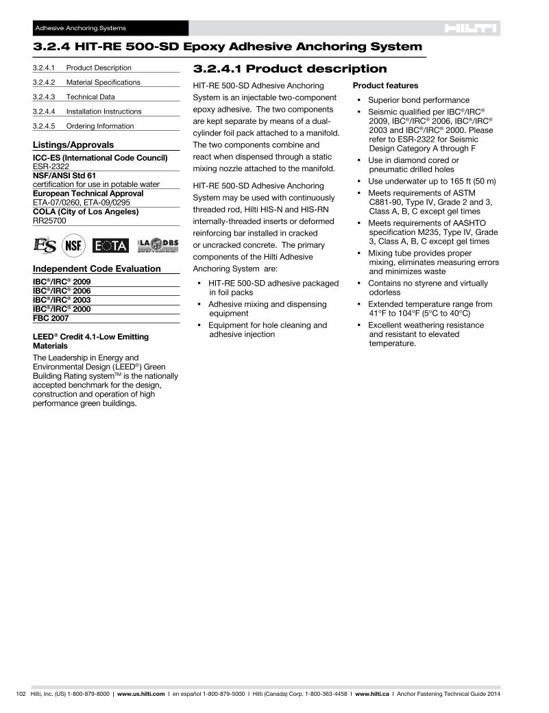
Adhesive Anchoring Systems 3.2.4 HIT-RE 500-SD Epoxy Adhesive Anchoring System 102 Hilti, Inc. (US) 1-800-879-8000 | www.us.hilti.com I en español 1-800-879-5000 I Hilti (Canada) Corp. 1-800-363-4458 I www.hilti.ca I Anchor Fastening Technical Guide 2014 3.2.4.1 Product description HIT-RE 500-SD Adhesive Anchoring System is an injectable two-component epoxy adhesive. The two components are kept separate by means of a dual- cylinder foil pack attached to a manifold. The two components combine and react when dispensed through a static mixing nozzle attached to the manifold. HIT-RE 500-SD Adhesive Anchoring System may be used with continuously threaded rod, Hilti HIS-N and HIS-RN internally-threaded inserts or deformed reinforcing bar installed in cracked or uncracked concrete. The primary components of the Hilti Adhesive Anchoring System are: • HIT-RE 500-SD adhesive packaged in foil packs • Adhesive mixing and dispensing equipment • Equipment for hole cleaning and adhesive injection Product features • Superior bond performance • Seismic qualified per IBC ® /IRC ® 2009, IBC ® /IRC ® 2006, IBC ® /IRC ® 2003 and IBC ® /IRC ® 2000. Please refer to ESR-2322 for Seismic Design Category A through F • Use in diamond cored or pneumatic drilled holes • Use underwater up to 165 ft (50 m) • Meets requirements of ASTM C881-90, Type IV, Grade 2 and 3, Class A, B, C except gel times • Meets requirements of AASHTO specification M235, Type IV, Grade 3, Class A, B, C except gel times • Mixing tube provides proper mixing, eliminates measuring errors and minimizes waste • Contains no styrene and virtually odorless • Extended temperature range from 41°F to 104°F (5°C to 40°C) • Excellent weathering resistance and resistant to elevated temperature. 3.2.4.1 Product Description 3.2.4.2 Material Specifications 3.2.4.3 Technical Data 3.2.4.4 Installation Instructions 3.2.4.5 Ordering Information Listings/Approvals ICC-ES (International Code Council) ESR-2322 NSF/ANSI Std 61 certification for use in potable water European Technical Approval ETA-07/0260, ETA-09/0295 COLA (City of Los Angeles) RR25700 Independent Code Evaluation IBC ® /IRC ® 2009 IBC ® /IRC ® 2006 IBC ® /IRC ® 2003 IBC ® /IRC ® 2000 FBC 2007 LEED ® Credit 4.1-Low Emitting Materials The Leadership in Energy and Environmental Design ( LEED ® ) Green Building Rating system TM is the nationally accepted benchmark for the design, construction and operation of high performance green buildings.
Transcript of 3.2.4 HIT-RE 500-SD Epoxy Adhesive Anchoring System€¦ · 3.2.4 HIT-RE 500-SD Epoxy Adhesive...
Adhesive Anchoring Systems
324 HIT-RE 500-SD Epoxy Adhesive Anchoring System
102 Hilti Inc (US) 1-800-879-8000 | wwwushilticom I en espantildeol 1-800-879-5000 I Hilti (Canada) Corp 1-800-363-4458 I wwwhiltica I Anchor Fastening Technical Guide 2014
3241 Product descriptionHIT-RE500-SDAdhesiveAnchoringSystem is an injectable two-component epoxy adhesive The two components are kept separate by means of a dual-cylinder foil pack attached to a manifold The two components combine and react when dispensed through a static mixing nozzle attached to the manifold
HIT-RE500-SDAdhesiveAnchoringSystem may be used with continuously threaded rod Hilti HIS-N and HIS-RN internally-threaded inserts or deformed reinforcing bar installed in cracked or uncracked concrete The primary components of the Hilti Adhesive Anchoring System are
bull HIT-RE500-SDadhesivepackagedin foil packs
bull Adhesivemixinganddispensingequipment
bull Equipmentforholecleaningandadhesive injection
Product features
bull Superiorbondperformancebull SeismicqualifiedperIBCregIRCreg
2009IBCregIRCreg2006IBCregIRCreg 2003andIBCregIRCreg 2000 Please refertoESR-2322forSeismicDesign Category A through F
bull Useindiamondcoredor pneumatic drilled holes
bull Useunderwaterupto165ft(50m)bull MeetsrequirementsofASTM
C881-90 Type IV Grade 2 and 3 ClassABCexceptgeltimes
bull MeetsrequirementsofAASHTOspecification M235 Type IV Grade 3ClassABCexceptgeltimes
bull Mixingtubeprovidesproper mixing eliminates measuring errors and minimizes waste
bull Containsnostyreneandvirtuallyodorless
bull Extendedtemperaturerangefrom41degF to 104degF (5degC to 40degC)
bull Excellentweatheringresistanceand resistant to elevated temperature
3241 Product Description
3242 Material Specifications
3243 Technical Data
3244 Installation Instructions
3245 Ordering Information
ListingsApprovalsICC-ES (International Code Council)ESR-2322NSFANSI Std 61certification for use in potable waterEuropean Technical Approval ETA-070260ETA-090295COLA (City of Los Angeles) RR25700
Independent Code EvaluationIBCregIRCreg 2009IBCregIRCreg 2006IBCregIRCreg 2003IBCregIRCreg 2000FBC 2007
LEEDreg Credit 41-Low Emitting MaterialsTheLeadershipinEnergyandEnvironmentalDesign(LEEDreg) Green BuildingRatingsystemTM is the nationally accepted benchmark for the design construction and operation of high performance green buildings
Adhesive Anchoring Systems
HIT-RE 500-SD Epoxy Adhesive Anchoring System 324
Hilti Inc (US) 1-800-879-8000 | wwwushilticom I en espantildeol 1-800-879-5000 I Hilti (Canada) Corp 1-800-363-4458 I wwwhiltica I Anchor Fastening Technical Guide 2014 103
328
325
326
327
324
325
325
323
Guide Specifications
Master Format Section
Previous 2004 Format
03250 03 16 00 Concrete anchors
Related Sections
03200 03 20 00 Concrete reinforcing 05050 05 50 00 Metal fabrications 05120 05 10 00 Structural metal framing
Injectable adhesive shall be used for installation of all reinforcing steel dowels or threaded anchor rods and inserts into existing concrete Adhesive shall be furnished in side-by-side refill packs which keep component A and componentBseparateSide-by-sidepacks shall be designed to compress
during use to minimize waste volume Side-by-side packs shall also be designed to accept static mixing nozzle which thoroughly blends component A andcomponentBandallowsinjectiondirectly into drilled hole Only injection tools and static mixing nozzles as recommended by manufacturer shall be used Manufacturerrsquos instructions shall be followed Injection adhesive shall be formulated to include resin and hardener to provide optimal curing speed as well as high strength and stiffness Typical curing time at 68degF (20degC) shall be approximately 12 hours
Injection adhesive shall be HIT-RE500-SDasfurnishedbyHilti
Anchor rods shall be end stamped to show the grade of steel and overall rod length Anchor rods shall be manufactured to meet the following requirements
1HAS-Ecarbonsteel
2ASTMA193GradeB7(highstrengthcarbon steel anchor)
3 AISI Type 304 or AISI Type 316 stainless steel meeting the requirementsofASTMF593(condition CW)
Special order length HAS Rods may vary from standard product
Nuts and washers of other grades and styles having specified proof load strength greater than the specified grade and style are also suitable Nuts must have specified proof load strength equaltoorgreaterthantheminimumtensile strength of the specified threaded rod
3243 Technical dataThe load values contained in this section are Hilti Simplified Design Tables The load tables in this section were developed using thestrengthdesignparametersandvariablesofESR-1917andtheequationswithinACI318-11AppendixDForadetailedexplanationoftheHiltiSimplifiedDesignTablesrefertoSection317DatatablesfromESR-1917arenotcontainedinthissection but can be found at wwwicc-esorg or at wwwushilticom
3242 Material specificationsTable 1 - Material properties of fully cured HIT-RE 500-SDBondStrengthASTMC882-912 day cure7 day cure
124 MPa124 MPa
1800 psi1800 psi
Compressive Strength ASTM D695-96 827 MPa 12000 psiCompressive Modulus ASTM D695-96 1493 MPa 022 x 106 psiTensile Strength 7 day ASTM D638-97 435 MPa 6310 psiElongationatbreakASTMD638-97 20 20Heat Deflection Temperature ASTM D648-95 63degC 146degFAbsorption ASTM D570-95 006 006Linear Coefficient of Shrinkage on Cure ASTM D2566-86 0004 0004ElectricalresistanceDINIEC93(1293) 66 x 1013 Ωm 17 x 1012 Ωin
MaterialSpecificationsforHASthreadedrodsarelistedinSection3242MaterialSpecificationsforHIS-NInternallyThreadedInsertsarelistedinSection3243
Adhesive Anchoring Systems
324 HIT-RE 500-SD Epoxy Adhesive Anchoring System
104 Hilti Inc (US) 1-800-879-8000 | wwwushilticom I en espantildeol 1-800-879-5000 I Hilti (Canada) Corp 1-800-363-4458 I wwwhiltica I Anchor Fastening Technical Guide 2014
32431 HIT-RE 500-SD with reinforcing steel (rebar)
Table 2 - Rebar installed HIT-RE 500-SD adhesive
Setting information Symbol UnitsRebar size
3 4 5 6 7 8 9 10Nominal bit diameter do in 12 58 34 78 1 1-18 1-38 1-12
Standard effective embedment hefstd
in 3-38 4-12 5-58 6-34 7-78 9 10-18 11-14(mm) (86) (114) (143) (171) (200) (229) (257) (286)
Effective embedment
minimum hefmin
in 2-38 2-34 3-18 3-12 3-12 4 4-12 5(mm) (60) (70) (79) (89) (89) (102) (114) (127)
maximum hefmax
in 7-12 10 12-12 15 17-12 20 22-12 25(mm) (191) (254) (318) (381) (445) (508) (572) (635)
Minimum concrete member thickness hmin
in hef + 1-14hef + 2do(mm) hef + 30
Figure 1 - Rebar installed with HIT-RE 500-SD adhesive
Adhesive Anchoring Systems
HIT-RE 500-SD Epoxy Adhesive Anchoring System 324
Hilti Inc (US) 1-800-879-8000 | wwwushilticom I en espantildeol 1-800-879-5000 I Hilti (Canada) Corp 1-800-363-4458 I wwwhiltica I Anchor Fastening Technical Guide 2014 105
328
325
326
327
324
325
325
323
Table 3 - Hilti HIT-RE 500-SD adhesive design strength (factored resistance) with concrete bond failure for rebar in uncracked concrete123456789
Rebar size
Effectiveembedment
in (mm)
TensionmdashϕNn or Nr ShearmdashϕVn or Vr
ƒ´c = 2500 psi (172 Mpa)
lb (kN)
ƒ´c = 3000 psi (207 Mpa)
lb (kN)
ƒ´c = 4000 psi (276 Mpa)
lb (kN)
ƒ´c = 6000 psi (414 Mpa)
lb (kN)
ƒ´c = 2500 psi (172 Mpa)
lb (kN)
ƒ´c = 3000 psi (207 Mpa)
lb (kN)
ƒ´c = 4000 psi (276 Mpa)
lb (kN)
ƒ´c = 6000 psi (414 Mpa)
lb (kN)
3
3-38 4835 5300 5855 6205 10415 11410 12610 13365(86) (215) (236) (260) (276) (463) (508) (561) (595)
4-12 7445 7805 7805 8275 16035 16810 16810 17820(114) (331) (347) (347) (368) (713) (748) (748) (793)7-12 13010 13010 13010 13790 28020 28020 28020 29700(191) (579) (579) (579) (613) (1246) (1246) (1246) (1321)
4
4-12 7445 8155 9420 10885 16035 17570 20285 23445(114) (331) (363) (419) (484) (713) (782) (902) (1043)
6 11465 12560 13690 14515 24690 27045 29490 31260(152) (510) (559) (609) (646) (1098) (1203) (1312) (1391)10 22820 22820 22820 24190 49150 49150 49150 52100
(254) (1015) (1015) (1015) (1076) (2186) (2186) (2186) (2318)
5
5-58 10405 11400 13165 16120 22415 24550 28350 34720(143) (463) (507) (586) (717) (997) (1092) (1261) (1544)7-12 16020 17550 20265 21765 34505 37800 43650 46875(191) (713) (781) (901) (968) (1535) (1681) (1942) (2085)
12-12 34220 34220 34220 36275 73705 73705 73705 78125(318) (1522) (1522) (1522) (1614) (3279) (3279) (3279) (3475)
6
6-34 13680 14985 17305 21190 29460 32275 37265 45645(171) (609) (667) (770) (943) (1310) (1436) (1658) (2030)
9 21060 23070 26640 30170 45360 49690 57375 64985(229) (937) (1026) (1185) (1342) (2018) (2210) (2552) (2891)15 45315 47440 47440 50285 97600 102175 102175 108305
(381) (2016) (2110) (2110) (2237) (4341) (4545) (4545) (4818)
7
7-78 17235 18885 21805 25240 37125 40670 46960 57515(200) (767) (840) (970) (1123) (1651) (1809) (2089) (2558)
10-12 26540 29070 31750 33655 57160 62615 72300 85665(267) (1181) (1293) (1412) (1497) (2543) (2785) (3216) (3811)
17-12 52915 52915 52915 56090 122990 134695 134695 142780(445) (2354) (2354) (2354) (2495) (5471) (5992) (5992) (6351)
8
9 21060 23070 26640 32060 45360 49690 57375 70270(229) (937) (1026) (1185) (1426) (2018) (2210) (2552) (3126)12 32425 35520 40330 42750 69835 76500 88335 108190
(305) (1442) (1580) (1794) (1902) (3106) (3403) (3929) (4813)20 67215 67215 67215 71245 150265 164605 171090 181355
(508) (2990) (2990) (2990) (3169) (6684) (7322) (7610) (8067)
9
10-18 25130 27530 31785 38930 54125 59290 68465 83850(257) (1118) (1225) (1414) (1732) (2408) (2637) (3045) (3730)
13-12 38690 42380 48940 52850 83330 91285 105405 129095(343) (1721) (1885) (2177) (2351) (3707) (4061) (4689) (5742)
22-12 83100 83100 83100 88085 179300 196415 211525 224220(572) (3696) (3696) (3696) (3918) (7976) (8737) (9409) (9974)
10
11-14 29430 32240 37230 45595 63395 69445 80185 98205(286) (1309) (1434) (1656) (2028) (2820) (3089) (3567) (4368)15 45315 49640 57320 63875 97600 106915 123455 151200
(381) (2016) (2208) (2550) (2841) (4341) (4756) (5492) (6726)25 97500 100435 100435 106460 210000 230045 255645 270985
(635) (4337) (4468) (4468) (4736) (9341) (10233) (11372) (12054)1 See Section 317 for explanation on development of load values2 See Section 3173 to convert design strength (factored resistance) value to ASD value3 Linear interpolation between embedment depths and concrete compressive strengths is not permitted4 Apply spacing edge distance and concrete thickness factors in Tables 6-21 as necessary Compare to the steel values in Table 5
The lesser of the values is to be used for the design5 Data is for temperature range A Max short term temperature = 110 F (43deg C) max long term temperature = 80deg F (26deg C)
FortemperaturerangeBMaxshorttermtemperature=162degF(72degC)maxlongtermtemperature=110degF(43degC)multiplyabovevalueby034 Short term elevated concrete temperatures are those that occur over brief intervals eg as a result of diurnal cycling Long term concrete temperatures are roughly constantoversignificantperiodsoftime
6 Tabular values are for dry concrete conditions For water saturated concrete multiply design strength (factored resistance) by 069 Forwater-filleddrilledholesmultiplydesignstrength(factoredresistance)by063 For submerged (under water) applications multiply design strength (factored resistance) by 064
7 Tabular values are for short term loads only For sustained loads including overhead use see Section 31758 TabularvaluesarefornormalweightconcreteonlyForlightweightconcretemultiplydesignstrength(factoredresistance)byλa as follows
Forsand-lightweightλa=051Forall-lightweightλa = 0459 Tabular values are for holes drilled in concrete with carbide tipped hammer drill bit For diamond core drilling multiply above value by 051
Diamondcoredrillingisnotpermittedforthewater-filledorunderwater(submerged)applications
Adhesive Anchoring Systems
324 HIT-RE 500-SD Epoxy Adhesive Anchoring System
106 Hilti Inc (US) 1-800-879-8000 | wwwushilticom I en espantildeol 1-800-879-5000 I Hilti (Canada) Corp 1-800-363-4458 I wwwhiltica I Anchor Fastening Technical Guide 2014
Table 4 - Hilti HIT-RE 500-SD adhesive design strength (factored resistance) with concrete bond failure for rebar in cracked concrete12345678910
Rebar size
Effectiveembedment
in (mm)
TensionmdashϕNn or Nr ShearmdashϕVn or Vr
ƒ´c = 2500 psi (172 Mpa)
lb (kN)
ƒ´c = 3000 psi (207 Mpa)
lb (kN)
ƒ´c = 4000 psi (276 Mpa)
lb (kN)
ƒ´c = 6000 psi (414 Mpa)
lb (kN)
ƒ´c = 2500 psi (172 Mpa)
lb (kN)
ƒ´c = 3000 psi (207 Mpa)
lb (kN)
ƒ´c = 4000 psi (276 Mpa)
lb (kN)
ƒ´c = 6000 psi (414 Mpa)
lb (kN)
3
3-38 2815 2815 2815 2985 6065 6065 6065 6430(86) (125) (125) (125) (133) (270) (270) (270) (286)
4-12 3755 3755 3755 3980 8090 8090 8090 8575(114) (167) (167) (167) (177) (360) (360) (360) (381)7-12 6260 6260 6260 6635 13485 13485 13485 14290(191) (278) (278) (278) (295) (600) (600) (600) (636)
4
4-12 4940 4940 4940 5235 10640 10640 10640 11275(114) (220) (220) (220) (233) (473) (473) (473) (502)
6 6585 6585 6585 6980 14185 14185 14185 15035(152) (293) (293) (293) (310) (631) (631) (631) (669)10 10975 10975 10975 11635 23640 23640 23640 25060
(254) (488) (488) (488) (518) (1052) (1052) (1052) (1115)
5
5-58 7370 7500 7500 7950 15875 16160 16160 17130(143) (328) (334) (334) (354) (706) (719) (719) (762)7-12 10005 10005 10005 10605 21545 21545 21545 22835(191) (445) (445) (445) (472) (958) (958) (958) (1016)
12-12 16670 16670 16670 17670 35905 35905 35905 38060(318) (742) (742) (742) (786) (1597) (1597) (1597) (1693)
6
6-34 9690 10340 10340 10960 20870 22265 22265 23600(171) (431) (460) (460) (488) (928) (990) (990) (1050)
9 13785 13785 13785 14610 29690 29690 29690 31470(229) (613) (613) (613) (650) (1321) (1321) (1321) (1400)15 22975 22975 22975 24350 49480 49480 49480 52450
(381) (1022) (1022) (1022) (1083) (2201) (2201) (2201) (2333)
7
7-78 10895 10895 10895 11550 26300 27730 27730 29395(200) (485) (485) (485) (514) (1170) (1233) (1233) (1308)
10-12 14525 14525 14525 15395 36975 36975 36975 39190(267) (646) (646) (646) (685) (1645) (1645) (1645) (1743)
17-12 24210 24210 24210 25660 61625 61625 61625 65320(445) (1077) (1077) (1077) (1141) (2741) (2741) (2741) (2906)
8
9 13295 13295 13295 14095 32130 33845 33845 35875(229) (591) (591) (591) (627) (1429) (1505) (1505) (1596)12 17730 17730 17730 18790 45125 45125 45125 47835
(305) (789) (789) (789) (836) (2007) (2007) (2007) (2128)20 29545 29545 29545 31320 75210 75210 75210 79720
(508) (1314) (1314) (1314) (1393) (3345) (3345) (3345) (3546)
9
10-18 15745 15745 15745 16690 38340 40080 40080 42485(257) (700) (700) (700) (742) (1705) (1783) (1783) (1890)
13-12 20995 20995 20995 22255 53440 53440 53440 56645(343) (934) (934) (934) (990) (2377) (2377) (2377) (2520)
22-12 34990 34990 34990 37090 89065 89065 89065 94410(572) (1556) (1556) (1556) (1650) (3962) (3962) (3962) (4200)
10
11-14 17740 17740 17740 18800 44905 45150 45150 47860(286) (789) (789) (789) (836) (1997) (2008) (2008) (2129)15 23650 23650 23650 25070 60200 60200 60200 63815
(381) (1052) (1052) (1052) (1115) (2678) (2678) (2678) (2839)25 39415 39415 39415 41780 100335 100335 100335 106355
(635) (1753) (1753) (1753) (1858) (4463) (4463) (4463) (4731)1 See Section 317 for explanation on development of load values2 See Section 3173 to convert design strength (factored resistance) value to ASD value3 Linear interpolation between embedment depths and concrete compressive strengths is not permitted4 Apply spacing edge distance and concrete thickness factors in Tables 6-21 as necessary Compare to the steel values in Table 5
The lesser of the values is to be used for the design5 Data is for temperature range A Max short term temperature = 110 F (43deg C) max long term temperature = 80deg F (26deg C)
FortemperaturerangeBMaxshorttermtemperature=162degF(72degC)maxlongtermtemperature=110degF(43degC)multiplyabovevalueby034 Short term elevated concrete temperatures are those that occur over brief intervals eg as a result of diurnal cycling Long term concrete temperatures are roughly constantoversignificantperiodsoftime
6 Tabular values are for dry concrete conditions For water saturated concrete multiply design strength (factored resistance) by 069 Forwater-filleddrilledholesmultiplydesignstrength(factoredresistance)by063 For submerged (under water) applications multiply design strength (factored resistance) by 064
7 Tabular values are for short term loads only For sustained loads including overhead use see Section 31758 TabularvaluesarefornormalweightconcreteonlyForlightweightconcretemultiplydesignstrength(factoredresistance)byλa as follows
Forsand-lightweightλa=051Forall-lightweightλa = 0459 TabularvaluesareforstaticloadsonlyForseismicloadsmultiplyabovevaluebyαseis = 049 See section 3174 for additional information on seismic applications10 Tabular values are for holes drilled in concrete with carbide tipped hammer drill bit Diamond core drilling is not permitted in cracked concrete conditions
Adhesive Anchoring Systems
HIT-RE 500-SD Epoxy Adhesive Anchoring System 324
Hilti Inc (US) 1-800-879-8000 | wwwushilticom I en espantildeol 1-800-879-5000 I Hilti (Canada) Corp 1-800-363-4458 I wwwhiltica I Anchor Fastening Technical Guide 2014 107
328
325
326
327
324
325
325
323
Table 5 - Steel design strength (ACI 318 Appendix D Based Design) for rebar1
Rebar size
ASTM A615 Grade 402 ASTM A615 Grade 602 ASTM A706 Grade 602
Tensile3
ϕNsalb (kN)
Shear4
ϕVsalb (kN)
Seismic Shear5
ϕVsalb (kN)
Tensile3
ϕNsalb (kN)
Shear4
ϕVsalb (kN)
Seismic Shear5
ϕVsalb (kN)
Tensile3
ϕNsalb (kN)
Shear4
ϕVsalb (kN)
Seismic Shear5
ϕVsalb (kN)
34290 2375 1663 6435 3565 2496 6600 3430 2401(191) (106) (74) (286) (159) (111) (294) (153) (107)
47800 4320 3024 11700 6480 4536 12000 6240 4368(347) (192) (135) (520) (288) (202) (534) (278) (194)
512090 6695 4687 18135 10045 7032 18600 9670 6769(538) (298) (208) (807) (447) (313) (827) (430) (301)
617160 9505 6654 25740 14255 9979 26400 13730 9611(763) (423) (296) (1145) (634) (444) (1174) (611) (428)
723400 12960 9072 35100 19440 13608 36000 18720 13104(1041) (576) (404) (1561) (865) (605) (1601) (833) (583)
830810 17065 11946 46215 25595 17917 47400 24650 17255(1370) (759) (531) (2056) (1139) (797) (2108) (1096) (768)
939000 21600 15120 58500 32400 22680 60000 31200 21840(1735) (961) (673) (2602) (1441) (1009) (2669) (1388) (971)
1049530 27430 19201 74295 41150 28805 76200 39625 27738(2203) (1220) (854) (3305) (1830) (1281) (3390) (1763) (1234)
1 See Section 3173 to convert design strength (factored resistance) value to ASD value2 ASTM A706 Grade 60 rebar are considered ductile steel elements ASTM A615 Grade 40 and 60 rebar are considered brittle steel elements3 Tensile = AseN futa as noted in ACI 318 Appendix D4 Shear = 060 AseN futa as noted in ACI 318 Appendix D5 Seismic shear values determined by multiplying VsaxαVseiswhereαVseis = 07 See Section 3174 for additional information on seismic applications
Adhesive Anchoring Systems
324 HIT-RE 500-SD Epoxy Adhesive Anchoring System
108 Hilti Inc (US) 1-800-879-8000 | wwwushilticom I en espantildeol 1-800-879-5000 I Hilti (Canada) Corp 1-800-363-4458 I wwwhiltica I Anchor Fastening Technical Guide 2014
Table 6 - Load adjustment factors for 3 rebar in uncracked concrete123
3uncracked concrete
Spacing factor in tension
ƒAN
Edgedistancefactor in tension
ƒRN
Spacing factor in shear4
ƒAV
Edgedistanceinshear
Concrete thickness factor in shear5
ƒHV
Toward edge
ƒRV
To edge
ƒRV
Embedment hef
in 3-38 4-12 7-12 3-38 4-12 7-12 3-38 4-12 7-12 3-38 4-12 7-12 3-38 4-12 7-12 3-38 4-12 7-12(mm) (86) (114) (191) (86) (114) (191) (86) (114) (191) (86) (114) (191) (86) (114) (191) (86) (114) (191)
Spacing(s)Edg
eDistance(c
a) C
oncr
ete
Thic
knes
s (h
) - i
n (m
m) 1-34 (44) na na na 028 022 013 na na na 007 005 003 014 009 005 na na na
1-78 (48) 058 057 054 029 022 013 053 052 052 008 005 003 016 010 006 na na na2 (51) 059 057 054 029 023 013 053 052 052 009 006 003 017 011 006 na na na3 (76) 063 061 057 036 028 016 055 054 053 016 010 006 032 021 012 na na na
3-58 (92) 066 063 058 041 031 018 056 054 053 021 014 008 041 027 016 na na na4 (102) 068 065 059 043 033 019 057 055 053 024 016 009 043 032 018 na na na
4-58 (117) 070 067 060 048 036 021 058 056 054 030 020 011 048 038 023 055 na na5 (127) 072 069 061 051 038 022 058 056 054 034 022 013 051 040 025 057 na na
5-34 (146) 075 071 063 059 043 025 059 057 055 042 027 016 059 044 031 061 053 na6 (152) 077 072 063 061 045 026 060 057 055 045 029 017 061 046 032 063 054 na7 (178) 081 076 066 071 052 030 061 059 056 057 037 021 071 052 035 068 058 na8 (203) 085 080 068 082 059 034 063 060 057 069 045 026 082 059 038 072 063 na
8-34 (222) 089 082 069 089 065 038 064 061 057 079 051 029 089 065 040 076 065 0549 (229) 090 083 070 092 067 039 065 061 058 083 054 031 092 067 041 077 066 05510 (254) 094 087 072 100 074 043 066 062 058 097 063 036 100 074 044 081 070 05811 (279) 099 091 074 082 047 068 063 059 100 072 041 082 048 085 073 06112 (305) 100 094 077 089 052 070 065 060 083 047 089 052 088 077 06414 (356) 100 081 100 060 073 067 062 100 060 100 060 096 083 06916 (406) 086 069 076 070 063 073 069 100 088 07318 (457) 090 077 079 072 065 087 077 094 07824 (610) 100 100 089 079 070 100 100 100 09030 (762) 099 087 075 10036 (914) 100 094 080
gt48 (1219) 100 090
Table 7 - Load adjustment factors for 3 rebar in cracked concrete123
3cracked concrete
Spacing factor in tension
ƒAN
Edgedistancefactor in tension
ƒRN
Spacing factor in shear4
ƒAV
Edgedistanceinshear
Concrete thickness factor in shear5
ƒHV
Toward edge
ƒRV
To edge
ƒRV
Embedment hef
in 3-38 4-12 7-12 3-38 4-12 7-12 3-38 4-12 7-12 3-38 4-12 7-12 3-38 4-12 7-12 3-38 4-12 7-12(mm) (86) (114) (191) (86) (114) (191) (86) (114) (191) (86) (114) (191) (86) (114) (191) (86) (114) (191)
Spacing(s)Edg
eDistance(c
a) C
oncr
ete
Thic
knes
s (h
) - i
n (m
m) 1-34 (44) na na na 052 049 043 na na na 009 007 004 017 013 008 na na na
1-78 (48) 058 057 054 053 050 044 053 053 052 010 007 004 019 014 009 na na na2 (51) 059 057 054 055 051 044 054 053 052 011 008 005 021 016 010 na na na3 (76) 063 061 057 066 060 049 056 055 053 019 015 009 039 029 018 na na na
3-58 (92) 066 063 058 073 066 053 057 056 054 026 019 012 052 039 023 na na na4 (102) 068 065 059 078 070 055 057 056 054 030 022 013 060 045 027 na na na
4-58 (117) 070 067 060 086 076 058 059 057 055 037 028 017 075 056 034 059 na na5 (127) 072 069 061 091 080 060 059 058 055 042 031 019 084 063 038 061 na na
5-34 (146) 075 071 063 100 088 064 061 059 056 052 039 023 100 078 047 066 060 na6 (152) 077 072 063 091 066 061 059 057 055 041 025 083 050 067 061 na7 (178) 081 076 066 100 072 063 061 058 069 052 031 100 062 072 066 na8 (203) 085 080 068 078 065 062 059 085 064 038 076 077 070 na
8-34 (222) 089 082 069 083 066 063 060 097 073 044 083 081 073 0629 (229) 090 083 070 085 067 064 060 100 076 046 085 082 074 06310 (254) 094 087 072 091 069 065 061 089 053 091 086 079 06611 (279) 099 091 074 098 071 067 062 100 062 098 091 082 06912 (305) 100 094 077 100 072 068 063 070 100 095 086 07314 (356) 100 081 076 072 065 088 100 093 07816 (406) 086 080 075 068 100 099 08418 (457) 090 084 078 070 100 08924 (610) 100 095 087 076 10030 (762) 100 096 08336 (914) 100 089
gt48 (1219) 1001 Linear interpolation not permitted2 Shadedareawithreducededgedistanceispermittedprovidedtheinstallationtorqueisreducedto030Tmax for 5d lt s lt 16-in and to 05 Tmax for s gt 16-in3 When combining multiple load adjustment factors (eg for a 4 anchor pattern in a corner with a thin concrete member) the design can become very conservative To
optimizethedesignuseHiltiPROFISAnchorDesignsoftwareorperformanchorcalculationusingthedesignequationsfromACI318AppendixD4 Spacing factor reduction in shear ƒAVassumesaninfluenceofanearbyedgeIfnoedgeexiststhenƒAV = ƒAN5 Concrete thickness reduction factor in shear ƒHVassumesaninfluenceofanearbyedgeIfnoedgeexiststhenƒHV = 10
Adhesive Anchoring Systems
HIT-RE 500-SD Epoxy Adhesive Anchoring System 324
Hilti Inc (US) 1-800-879-8000 | wwwushilticom I en espantildeol 1-800-879-5000 I Hilti (Canada) Corp 1-800-363-4458 I wwwhiltica I Anchor Fastening Technical Guide 2014 109
328
325
326
327
324
325
325
323
Table 8 - Load adjustment factors for 4 rebar in uncracked concrete123
4uncracked concrete
Spacing factor in tension
ƒAN
Edgedistancefactor in tension
ƒRN
Spacing factor in shear4
ƒAV
Edgedistanceinshear
Concrete thickness factor in shear5
ƒHV
Toward edge
ƒRV
To edge
ƒRV
Embedment hef
in 3-38 4-12 7-12 3-38 4-12 7-12 3-38 4-12 7-12 3-38 4-12 7-12 3-38 4-12 7-12 3-38 4-12 7-12(mm) (86) (114) (191) (86) (114) (191) (86) (114) (191) (86) (114) (191) (86) (114) (191) (86) (114) (191)
Spacing(s)Edg
eDistance(c
a) C
oncr
ete
Thic
knes
s (h
) - i
n (m
m) 1-34 (44) na na na 025 019 011 na na na 005 003 002 011 007 003 na na na
2-12 (64) 058 057 054 028 022 013 053 053 052 009 006 003 018 012 006 na na na3 (76) 060 058 055 030 024 014 054 053 052 012 008 004 024 015 008 na na na4 (102) 063 061 057 035 027 016 055 054 053 018 012 006 035 024 012 na na na5 (127) 067 064 058 040 031 018 057 055 053 026 017 008 040 033 017 na na na
5-34 (146) 069 066 060 045 034 020 058 056 054 032 021 010 045 036 021 056 na na6 (152) 070 067 060 046 035 020 058 056 054 034 022 011 046 037 022 057 na na7 (178) 073 069 062 052 039 023 059 057 054 042 028 014 052 041 028 061 na na
7-14 (184) 074 070 062 054 040 023 060 057 055 045 029 015 054 042 029 062 054 na8 (203) 077 072 063 060 044 026 061 058 055 052 034 017 060 045 032 066 057 na9 (229) 080 075 065 067 049 029 062 059 056 062 040 020 067 049 034 070 060 na
10 (254) 083 078 067 075 055 032 063 060 056 072 047 024 075 055 036 073 064 na11-14 (286) 088 081 069 084 062 036 065 061 057 086 056 028 084 062 039 078 067 054
12 (305) 090 083 070 090 066 038 066 062 058 095 062 031 090 066 041 080 070 05514 (356) 097 089 073 100 077 045 069 064 059 100 078 039 100 077 046 087 075 06016 (406) 100 094 077 088 051 072 066 060 095 048 088 051 093 080 06418 (457) 100 080 099 058 074 068 061 100 057 099 058 098 085 06820 (508) 083 100 064 077 070 063 067 100 064 100 090 07122 (559) 087 070 080 072 064 077 070 094 07524 (610) 090 077 082 074 065 088 077 098 07830 (762) 100 096 090 080 069 100 096 100 08736 (914) 100 098 086 073 100 096
gt 48 (1219) 100 098 081 100
Table 9 - Load adjustment factors for 4 rebar in cracked concrete123
4cracked concrete
Spacing factor in tension
ƒAN
Edgedistancefactor in tension
ƒRN
Spacing factor in shear4
ƒAV
Edgedistanceinshear
Concrete thickness factor in shear5
ƒHV
Toward edge
ƒRV
To edge
ƒRV
Embedment hef
in 3-38 4-12 7-12 3-38 4-12 7-12 3-38 4-12 7-12 3-38 4-12 7-12 3-38 4-12 7-12 3-38 4-12 7-12(mm) (86) (114) (191) (86) (114) (191) (86) (114) (191) (86) (114) (191) (86) (114) (191) (86) (114) (191)
Spacing(s)Edg
eDistance(c
a) C
oncr
ete
Thic
knes
s (h
) - i
n (m
m) 1-34 (44) na na na 048 045 041 na na na 006 004 003 011 009 005 na na na
2-12 (64) 058 057 054 053 050 044 054 053 052 010 007 004 020 015 009 na na na3 (76) 060 058 055 057 053 046 054 053 052 013 010 006 026 019 012 na na na4 (102) 063 061 057 066 060 049 056 055 053 020 015 009 039 030 018 na na na5 (127) 067 064 058 075 067 053 057 056 054 028 021 012 055 041 025 na na na
5-34 (146) 069 066 060 082 073 056 058 057 055 034 026 015 068 051 031 057 na na6 (152) 070 067 060 085 075 057 058 057 055 036 027 016 073 054 033 058 na na7 (178) 073 069 062 095 083 062 060 058 056 046 034 021 091 069 041 063 na na
7-14 (184) 074 070 062 098 085 063 060 058 056 048 036 022 096 072 043 064 058 na8 (203) 077 072 063 100 091 066 061 059 057 056 042 025 100 084 050 067 061 na9 (229) 080 075 065 100 070 063 060 057 067 050 030 100 060 071 065 na
10 (254) 083 078 067 075 064 062 058 078 059 035 070 075 068 na11-14 (286) 088 081 069 081 066 063 059 093 070 042 081 080 072 061
12 (305) 090 083 070 085 067 064 060 100 077 046 085 082 075 06314 (356) 097 089 073 095 070 066 062 097 058 095 089 081 06816 (406) 100 094 077 100 073 069 063 100 071 100 095 086 07318 (457) 100 080 075 071 065 085 100 092 07720 (508) 083 078 073 067 099 097 08122 (559) 087 081 076 068 100 100 08524 (610) 090 084 078 070 08930 (762) 100 092 085 075 10036 (914) 100 092 080
gt 48 (1219) 100 0901 Linear interpolation not permitted2 Shadedareawithreducededgedistanceispermittedprovidedtheinstallationtorqueisreducedto030Tmax for 5d lt s lt 16-in and to 05 Tmax for s gt 16-in3 When combining multiple load adjustment factors (eg for a 4 anchor pattern in a corner with a thin concrete member) the design can become very conservative To
optimizethedesignuseHiltiPROFISAnchorDesignsoftwareorperformanchorcalculationusingthedesignequationsfromACI318AppendixD4 Spacing factor reduction in shear ƒAVassumesaninfluenceofanearbyedgeIfnoedgeexiststhenƒAV = ƒAN5 Concrete thickness reduction factor in shear ƒHVassumesaninfluenceofanearbyedgeIfnoedgeexiststhenƒHV = 10
Adhesive Anchoring Systems
324 HIT-RE 500-SD Epoxy Adhesive Anchoring System
110 Hilti Inc (US) 1-800-879-8000 | wwwushilticom I en espantildeol 1-800-879-5000 I Hilti (Canada) Corp 1-800-363-4458 I wwwhiltica I Anchor Fastening Technical Guide 2014
Table 10 - Load adjustment factors for 5 rebar in uncracked concrete123
5uncracked concrete
Spacing factor in tension
ƒAN
Edgedistancefactor in tension
ƒRN
Spacing factor in shear4
ƒAV
Edgedistanceinshear
Concrete thickness factor in shear5
ƒHV
Toward edge
ƒRV
To edge
ƒRV
Embedment hef
in 5-58 7-12 12-12 5-58 7-12 12-12 5-58 7-12 12-12 5-58 7-12 12-12 5-58 7-12 12-12 5-58 7-12 12-12(mm) (143) (191) (318) (143) (191) (318) (143) (191) (318) (143) (191) (318) (143) (191) (318) (143) (191) (318)
Spacing(s)Edg
eDistance(c
a) C
oncr
ete
Thic
knes
s (h
) - i
n (m
m) 1-34 (44) na na na 023 018 011 na na na 004 003 001 008 006 003 na na na
3-18 (79) 059 057 054 028 022 013 054 053 052 010 007 003 020 013 006 na na na4 (102) 061 059 055 032 024 014 055 053 052 015 010 004 029 019 009 na na na
4-58 (117) 063 060 056 034 026 015 055 054 052 018 012 006 034 024 011 na na na5 (127) 064 061 057 036 027 016 056 054 053 021 013 006 036 027 012 na na na6 (152) 066 063 058 040 030 018 057 055 053 027 018 008 040 033 016 na na na7 (178) 069 066 059 044 033 020 058 056 054 034 022 010 044 036 021 na na na
7-18 (181) 069 066 060 045 034 020 058 056 054 035 023 011 045 036 021 057 na na8 (203) 072 068 061 049 037 021 059 057 054 041 027 013 049 039 025 061 na na9 (229) 075 070 062 054 040 023 060 058 055 050 032 015 054 042 030 065 056 na10 (254) 077 072 063 060 044 026 062 059 055 058 038 018 060 046 032 068 059 na11 (279) 080 074 065 067 049 029 063 060 056 067 043 020 067 049 034 071 062 na12 (305) 083 077 066 073 053 031 064 060 056 076 050 023 073 053 036 075 065 na14 (356) 088 081 069 085 062 036 066 062 057 096 062 029 085 062 039 081 070 05416 (406) 094 086 071 097 071 042 069 064 058 100 076 036 097 071 043 086 075 05818 (457) 099 090 074 100 080 047 071 066 059 091 043 100 080 047 091 079 06120 (508) 100 094 077 089 052 073 067 060 100 050 089 052 096 083 06522 (559) 099 079 098 057 075 069 062 058 098 057 100 087 06824 (610) 100 082 100 062 078 071 063 066 100 062 091 07126 (660) 085 068 080 073 064 074 068 095 07428 (711) 087 073 082 074 065 083 073 099 07730 (762) 090 078 085 076 066 092 078 100 07936 (914) 098 094 092 081 069 100 094 087
gt 48 (1219) 100 100 100 092 075 100 100
Table 11 - Load adjustment factors for 5 rebar in cracked concrete123
5cracked concrete
Spacing factor in tension
ƒAN
Edgedistancefactor in tension
ƒRN
Spacing factor in shear4
ƒAV
Edgedistanceinshear
Concrete thickness factor in shear5
ƒHV
Toward edge
ƒRV
To edge
ƒRV
Embedment hef
in 5-58 7-12 12-12 5-58 7-12 12-12 5-58 7-12 12-12 5-58 7-12 12-12 5-58 7-12 12-12 5-58 7-12 12-12(mm) (143) (191) (318) (143) (191) (318) (143) (191) (318) (143) (191) (318) (143) (191) (318) (143) (191) (318)
Spacing(s)Edg
eDistance(c
a) C
oncr
ete
Thic
knes
s (h
) - i
n (m
m) 1-34 (44) na na na 045 043 040 na na na 004 003 002 009 006 004 na na na
3-18 (79) 059 057 054 054 050 044 054 053 052 010 008 005 020 015 009 na na na4 (102) 061 059 055 060 055 046 055 054 053 015 011 007 030 022 013 na na na
4-58 (117) 063 060 056 064 058 048 055 054 053 018 014 008 037 027 016 na na na5 (127) 064 061 057 067 060 049 056 055 053 021 015 009 041 030 018 na na na6 (152) 066 063 058 074 066 053 057 056 054 027 020 012 054 040 024 na na na7 (178) 069 066 059 082 072 056 058 057 055 034 025 015 068 050 030 na na na
7-18 (181) 069 066 060 083 073 056 058 057 055 035 026 016 070 052 031 058 na na8 (203) 072 068 061 090 078 059 059 058 055 042 031 019 084 062 037 061 na na9 (229) 075 070 062 099 085 062 060 059 056 050 037 022 100 074 044 065 059 na10 (254) 077 072 063 100 091 066 062 060 057 058 043 026 086 052 068 062 na11 (279) 080 074 065 098 069 063 060 057 067 050 030 098 060 072 065 na12 (305) 083 077 066 100 073 064 061 058 077 057 034 100 068 075 068 na14 (356) 088 081 069 081 066 063 059 097 071 043 081 081 073 06216 (406) 094 086 071 089 069 065 061 100 087 052 089 086 078 06618 (457) 099 090 074 097 071 067 062 100 062 097 092 083 07020 (508) 100 094 077 100 073 069 064 073 100 097 087 07422 (559) 099 079 076 071 065 084 100 091 07724 (610) 100 082 078 073 066 096 096 08126 (660) 085 080 075 068 100 099 08428 (711) 087 083 077 069 100 08730 (762) 090 085 079 070 09036 (914) 098 092 084 074 099
gt 48 (1219) 100 100 096 082 1001 Linear interpolation not permitted2 Shadedareawithreducededgedistanceispermittedprovidedtheinstallationtorqueisreducedto030Tmax for 5d lt s lt 16-in and to 05 Tmax for s gt 16-in3 When combining multiple load adjustment factors (eg for a 4 anchor pattern in a corner with a thin concrete member) the design can become very conservative To
optimizethedesignuseHiltiPROFISAnchorDesignsoftwareorperformanchorcalculationusingthedesignequationsfromACI318AppendixD4 Spacing factor reduction in shear ƒAVassumesaninfluenceofanearbyedgeIfnoedgeexiststhenƒAV = ƒAN5 Concrete thickness reduction factor in shear ƒHVassumesaninfluenceofanearbyedgeIfnoedgeexiststhenƒHV = 10
Adhesive Anchoring Systems
HIT-RE 500-SD Epoxy Adhesive Anchoring System 324
Hilti Inc (US) 1-800-879-8000 | wwwushilticom I en espantildeol 1-800-879-5000 I Hilti (Canada) Corp 1-800-363-4458 I wwwhiltica I Anchor Fastening Technical Guide 2014 111
328
325
326
327
324
325
325
323
Table 12 - Load adjustment factors for 6 rebar in uncracked concrete123
6uncracked concrete
Spacing factor in tension
ƒAN
Edgedistancefactor in tension
ƒRN
Spacing factor in shear4
ƒAV
Edgedistanceinshear
Concrete thickness factor in shear5
ƒHV
Toward edge
ƒRV
To edge
ƒRV
Embedment hef
in 6-34 9 15 6-34 9 15 6-34 9 15 6-34 9 15 6-34 9 15 6-34 9 15(mm) (171) (229) (381) (171) (229) (381) (171) (229) (381) (171) (229) (381) (171) (229) (381) (171) (229) (381)
Spacing(s)Edg
eDistance(c
a) C
oncr
ete
Thic
knes
s (h
) - i
n (m
m)
1-34 (44) na na na 023 018 010 na na na 003 002 001 007 005 002 na na na3-34 (95) 059 057 054 029 022 013 054 053 052 011 007 003 022 014 007 na na na
4 (102) 059 057 054 030 022 013 054 053 052 012 008 004 024 016 007 na na na5 (127) 062 059 056 033 025 015 055 054 052 017 011 005 033 022 010 na na na
5-14 (133) 062 060 056 034 025 015 055 054 052 018 012 005 034 023 011 na na na6 (152) 064 061 057 036 027 016 056 055 053 022 014 007 036 029 013 na na na7 (178) 066 063 058 040 030 017 057 055 053 028 018 008 040 033 017 na na na8 (203) 069 065 059 043 032 019 058 056 054 034 022 010 043 035 020 na na na
8-12 (216) 070 066 059 045 034 020 059 056 054 037 024 011 045 037 022 059 na na9 (229) 071 067 060 047 035 021 059 057 054 040 026 012 047 038 024 060 na na10 (254) 073 069 061 051 038 022 060 058 055 047 031 014 051 041 029 064 na na
10-34 (273) 075 070 062 055 040 024 061 058 055 053 034 016 055 043 031 066 057 na12 (305) 078 072 063 061 045 026 062 059 055 062 040 019 061 046 033 070 060 na14 (356) 082 076 066 071 053 031 064 061 056 078 051 024 071 053 036 075 065 na16 (406) 087 080 068 082 060 035 066 062 057 096 062 029 082 060 039 080 070 na
16-34 (425) 089 081 069 085 063 037 067 063 058 100 067 031 085 063 040 082 071 05518 (457) 092 083 070 092 068 040 068 064 058 074 035 092 068 042 085 074 05720 (508) 096 087 072 100 075 044 070 065 059 087 040 100 075 045 090 078 06022 (559) 100 091 074 083 048 072 067 060 100 047 083 049 094 082 06324 (610) 094 077 090 053 074 068 061 053 090 053 099 085 06626 (660) 098 079 098 057 076 070 062 060 098 057 100 089 06928 (711) 100 081 100 062 078 071 063 067 100 062 092 07130 (762) 083 066 080 073 064 074 066 095 07436 (914) 090 079 086 077 066 098 079 100 081
gt 48 (1219) 100 100 099 086 072 100 100 094
Table 13 - Load adjustment factors for 6 rebar in cracked concrete123
6cracked concrete
Spacing factor in tension
ƒAN
Edgedistancefactor in tension
ƒRN
Spacing factor in shear4
ƒAV
Edgedistanceinshear
Concrete thickness factor in shear5
ƒHV
Toward edge
ƒRV
To edge
ƒRV
Embedment hef
in 6-34 9 15 6-34 9 15 6-34 9 15 6-34 9 15 6-34 9 15 6-34 9 15(mm) (171) (229) (381) (171) (229) (381) (171) (229) (381) (171) (229) (381) (171) (229) (381) (171) (229) (381)
Spacing(s)Edg
eDistance(c
a) C
oncr
ete
Thic
knes
s (h
) - i
n (m
m)
1-34 (44) na na na 044 042 039 na na na 003 002 001 007 005 003 na na na3-34 (95) 059 057 054 054 050 044 054 053 052 011 008 005 022 015 009 na na na
4 (102) 059 057 054 056 051 044 054 053 052 012 008 005 024 017 010 na na na5 (127) 062 059 056 061 056 047 055 054 053 017 012 007 034 024 014 na na na
5-14 (133) 062 060 056 063 057 047 055 054 053 018 013 008 036 026 015 na na na6 (152) 064 061 057 067 060 049 056 055 053 022 016 009 044 031 019 na na na7 (178) 066 063 058 074 065 052 057 056 054 028 020 012 056 039 024 na na na8 (203) 069 065 059 080 070 055 058 056 055 034 024 014 068 048 029 na na na
8-12 (216) 070 066 059 084 072 056 059 057 055 037 026 016 075 053 032 059 na na9 (229) 071 067 060 087 075 057 059 057 055 041 029 017 082 057 034 061 na na10 (254) 073 069 061 094 080 060 060 058 056 048 034 020 095 067 040 064 na na
10-34 (273) 075 070 062 100 084 062 061 059 056 053 037 022 100 075 045 066 059 na12 (305) 078 072 063 091 066 062 060 057 063 044 026 088 053 070 062 na14 (356) 082 076 066 100 072 064 061 058 079 056 033 100 067 076 067 na16 (406) 087 080 068 078 066 063 059 097 068 041 078 081 072 na
16-34 (425) 089 081 069 081 067 063 060 100 073 044 081 083 073 06218 (457) 092 083 070 085 068 064 060 081 049 085 086 076 06420 (508) 096 087 072 091 070 066 061 095 057 091 090 080 06822 (559) 100 091 074 098 072 068 063 100 066 098 095 084 07124 (610) 094 077 100 074 069 064 075 100 099 088 07426 (660) 098 079 076 071 065 084 100 091 07728 (711) 100 081 079 073 066 094 095 08030 (762) 083 081 074 067 100 098 08336 (914) 090 087 079 071 100 091
gt 48 (1219) 100 099 089 077 1001 Linear interpolation not permitted2 Shadedareawithreducededgedistanceispermittedprovidedtheinstallationtorqueisreducedto030Tmax for 5d lt s lt 16-in and to 05 Tmax for s gt 16-in3 When combining multiple load adjustment factors (eg for a 4 anchor pattern in a corner with a thin concrete member) the design can become very conservative To
optimizethedesignuseHiltiPROFISAnchorDesignsoftwareorperformanchorcalculationusingthedesignequationsfromACI318AppendixD4 Spacing factor reduction in shear ƒAVassumesaninfluenceofanearbyedgeIfnoedgeexiststhenƒAV = ƒAN5 Concrete thickness reduction factor in shear ƒHVassumesaninfluenceofanearbyedgeIfnoedgeexiststhenƒHV = 10
Adhesive Anchoring Systems
324 HIT-RE 500-SD Epoxy Adhesive Anchoring System
112 Hilti Inc (US) 1-800-879-8000 | wwwushilticom I en espantildeol 1-800-879-5000 I Hilti (Canada) Corp 1-800-363-4458 I wwwhiltica I Anchor Fastening Technical Guide 2014
Table 14 - Load adjustment factors for 7 Rebar in uncracked concrete123
7uncracked concrete
Spacing factor in tension
ƒAN
Edgedistancefactor in tension
ƒRN
Spacing factor in shear4
ƒAV
Edgedistanceinshear
Concrete thickness factor in shear5
ƒHV
Toward edge
ƒRV
To edge
ƒRV
Embedment hef
in 7-78 10-12 17-12 7-78 10-12 17-12 7-78 10-12 17-12 7-78 10-12 17-12 7-78 10-12 17-12 7-78 10-12 17-12(mm) (200) (267) (445) (200) (267) (445) (200) (267) (445) (200) (267) (445) (200) (267) (445) (200) (267) (445)
Spacing(s)Edg
eDistance(c
a) C
oncr
ete
Thic
knes
s (h
) - i
n (m
m)
1-34 (44) na na na 022 017 010 na na na 003 002 001 005 004 002 na na na4-38 (111) 059 057 054 029 022 013 054 053 052 011 007 003 022 014 007 na na na
5 (127) 060 058 055 031 023 014 054 053 052 013 009 004 027 017 008 na na na5-12 (140) 061 059 055 032 024 014 055 054 052 015 010 005 031 020 009 na na na
6 (152) 062 060 056 034 025 015 055 054 052 017 011 005 034 023 011 na na na7 (178) 064 061 057 037 027 016 056 055 053 022 014 007 037 029 013 na na na8 (203) 066 063 058 040 030 017 057 055 053 027 017 008 040 033 016 na na na9 (229) 068 064 059 043 032 019 058 056 054 032 021 010 043 035 019 na na na
9-78 (251) 070 066 059 046 034 020 059 056 054 037 024 011 046 037 022 059 na na10 (254) 070 066 060 046 034 020 059 057 054 038 024 011 046 037 023 059 na na11 (279) 072 067 060 049 037 022 060 057 054 043 028 013 049 040 026 062 na na12 (305) 074 069 061 053 039 023 060 058 055 049 032 015 053 042 030 065 na na
12-12 (318) 075 070 062 055 041 024 061 058 055 052 034 016 055 043 031 066 057 na14 (356) 078 072 063 062 046 027 062 059 055 062 040 019 062 047 033 070 060 na16 (406) 082 075 065 071 052 031 064 060 056 076 049 023 071 052 036 075 065 na18 (457) 086 079 067 080 059 034 066 062 057 091 059 027 080 059 038 079 068 na
19-12 (495) 089 081 069 086 063 037 067 063 058 100 066 031 086 063 040 082 071 05520 (508) 090 082 069 089 065 038 067 063 058 069 032 089 065 041 083 072 05622 (559) 094 085 071 097 072 042 069 064 059 080 037 097 072 044 087 076 05924 (610) 098 088 073 100 078 046 071 066 059 091 042 100 078 047 091 079 06126 (660) 100 091 075 085 050 073 067 060 100 048 085 050 095 082 06428 (711) 094 077 091 053 074 068 061 053 091 053 099 085 06630 (762) 098 079 098 057 076 070 062 059 098 057 100 088 06836 (914) 100 084 100 069 081 073 064 077 100 069 097 075
gt 48 (1219) 096 092 092 081 069 100 092 100 087
Table 15 - Load adjustment factors for 7 rebar in cracked concrete123
7cracked concrete
Spacing factor in tension
ƒAN
Edgedistancefactor in tension
ƒRN
Spacing factor in shear4
ƒAV
Edgedistanceinshear
Concrete thickness factor in shear5
ƒHV
Toward edge
ƒRV
To edge
ƒRV
Embedment hef
in 7-78 10-12 17-12 7-78 10-12 17-12 7-78 10-12 17-12 7-78 10-12 17-12 7-78 10-12 17-12 7-78 10-12 17-12(mm) (200) (267) (445) (200) (267) (445) (200) (267) (445) (200) (267) (445) (200) (267) (445) (200) (267) (445)
Spacing(s)Edg
eDistance(c
a) C
oncr
ete
Thic
knes
s (h
) - i
n (m
m)
1-34 (44) na na na 042 041 038 na na na 003 002 001 006 004 002 na na na4-38 (111) 059 057 054 055 050 044 054 053 052 011 008 005 022 016 009 na na na
5 (127) 060 058 055 058 052 045 054 053 052 013 010 006 027 019 011 na na na5-12 (140) 061 059 055 060 054 046 055 054 053 015 011 007 031 022 013 na na na
6 (152) 062 060 056 063 056 047 055 054 053 018 013 008 035 025 015 na na na7 (178) 064 061 057 068 060 049 056 055 053 022 016 009 044 032 019 na na na8 (203) 066 063 058 074 064 052 057 056 054 027 019 012 054 039 023 na na na9 (229) 068 064 059 079 068 054 058 056 054 032 023 014 065 046 028 na na na
9-78 (251) 070 066 059 084 072 056 059 057 055 037 026 016 074 053 032 059 na na10 (254) 070 066 060 085 073 056 059 057 055 038 027 016 076 054 032 059 na na11 (279) 072 067 060 091 077 059 060 058 055 044 031 019 087 062 037 062 na na12 (305) 074 069 061 098 082 061 060 058 056 050 035 021 100 071 042 065 na na
12-12 (318) 075 070 062 100 084 062 061 059 056 053 038 023 075 045 066 059 na14 (356) 078 072 063 091 066 062 060 057 063 045 027 089 054 070 062 na16 (406) 082 075 065 100 071 064 061 058 077 055 033 100 065 075 067 na18 (457) 086 079 067 076 066 063 059 091 065 039 076 079 071 na
19-12 (495) 089 081 069 080 067 064 060 100 073 044 080 082 074 06220 (508) 090 082 069 082 067 064 060 076 046 082 084 075 06322 (559) 094 085 071 087 069 065 061 088 053 087 088 078 06624 (610) 098 088 073 093 071 067 062 100 060 093 092 082 06926 (660) 100 091 075 099 073 068 063 068 099 095 085 07228 (711) 094 077 100 074 069 064 076 100 099 088 07430 (762) 098 079 076 071 065 084 100 091 07736 (914) 100 084 081 075 068 100 100 084
gt 48 (1219) 096 092 083 074 0971 Linear interpolation not permitted2 Shadedareawithreducededgedistanceispermittedprovidedtheinstallationtorqueisreducedto030Tmax for 5d lt s lt 16-in and to 05 Tmax for s gt 16-in3 When combining multiple load adjustment factors (eg for a 4 anchor pattern in a corner with a thin concrete member) the design can become very conservative To
optimizethedesignuseHiltiPROFISAnchorDesignsoftwareorperformanchorcalculationusingthedesignequationsfromACI318AppendixD4 Spacing factor reduction in shear ƒAVassumesaninfluenceofanearbyedgeIfnoedgeexiststhenƒAV = ƒAN5 Concrete thickness reduction factor in shear ƒHVassumesaninfluenceofanearbyedgeIfnoedgeexiststhenƒHV = 10
Adhesive Anchoring Systems
HIT-RE 500-SD Epoxy Adhesive Anchoring System 324
Hilti Inc (US) 1-800-879-8000 | wwwushilticom I en espantildeol 1-800-879-5000 I Hilti (Canada) Corp 1-800-363-4458 I wwwhiltica I Anchor Fastening Technical Guide 2014 113
328
325
326
327
324
325
325
323
Table 16 - Load adjustment factors for 8 rebar in uncracked concrete123
8uncracked concrete
Spacing factor in tension
ƒAN
Edgedistancefactor in tension
ƒRN
Spacing factor in shear4
ƒAV
Edgedistanceinshear
Concrete thickness factor in shear5
ƒHV
Toward edge
ƒRV
To edge
ƒRV
Embedment hef
in 9 12 20 9 12 20 9 12 20 9 12 20 9 12 20 9 12 20(mm) (229) (305) (508) (229) (305) (508) (229) (305) (508) (229) (305) (508) (229) (305) (508) (229) (305) (508)
Spacing(s)Edg
eDistance(c
a) C
oncr
ete
Thic
knes
s (h
) - i
n (m
m)
1-34 (44) na na na 022 017 010 na na na 002 001 001 005 003 001 na na na5 (127) 059 057 054 030 022 013 054 053 052 011 007 003 022 014 007 na na na6 (152) 061 058 055 032 024 014 055 053 052 014 009 004 029 019 009 na na na
6-14 (159) 061 059 055 033 024 014 055 054 052 015 010 005 030 020 009 na na na7 (178) 063 060 056 035 026 015 055 054 052 018 012 005 035 023 011 na na na8 (203) 064 061 057 038 028 016 056 055 053 022 014 007 038 029 013 na na na9 (229) 066 063 058 040 029 017 057 055 053 026 017 008 040 033 016 na na na10 (254) 068 064 058 043 032 018 058 056 053 031 020 009 043 035 019 na na na11 (279) 070 065 059 046 034 020 058 056 054 035 023 011 046 037 021 na na na
11-14 (286) 070 066 059 047 034 020 059 056 054 037 024 011 047 037 022 058 na na12 (305) 072 067 060 049 036 021 059 057 054 040 026 012 049 039 024 060 na na13 (330) 073 068 061 052 038 022 060 057 054 046 030 014 052 041 028 063 na na14 (356) 075 069 062 056 040 024 061 058 055 051 033 015 056 043 031 065 na na
14-14 (362) 076 070 062 057 041 024 061 058 055 052 034 016 057 043 031 066 057 na16 (406) 079 072 063 064 046 027 062 059 055 062 040 019 064 047 033 070 060 na18 (457) 082 075 065 072 052 030 064 060 056 074 048 022 072 052 036 074 064 na20 (508) 086 078 067 080 058 034 065 061 057 087 056 026 080 058 038 078 067 na22 (559) 089 081 068 087 063 037 067 063 058 100 065 030 087 063 040 082 071 na
22-14 (565) 090 081 069 088 064 038 067 063 058 066 031 088 064 041 082 071 05524 (610) 093 083 070 095 069 040 068 064 058 074 035 095 069 043 085 074 05726 (660) 097 086 072 100 075 044 070 065 059 084 039 100 075 045 089 077 06028 (711) 100 089 073 081 047 071 066 060 094 043 081 048 092 080 06230 (762) 092 075 086 051 073 067 060 100 048 086 051 095 083 06436 (914) 100 080 100 061 077 070 062 063 100 061 100 091 070
gt 48 (1219) 090 081 086 077 066 098 081 100 081
Table 17 - Load adjustment factors for 8 rebar in cracked concrete123
8cracked concrete
Spacing factor in tension
ƒAN
Edgedistancefactor in tension
ƒRN
Spacing factor in shear4
ƒAV
Edgedistanceinshear
Concrete thickness factor in shear5
ƒHV
Toward edge
ƒRV
To edge
ƒRV
Embedment hef
in 9 12 20 9 12 20 9 12 20 9 12 20 9 12 20 9 12 20(mm) (229) (305) (508) (229) (305) (508) (229) (305) (508) (229) (305) (508) (229) (305) (508) (229) (305) (508)
Spacing(s)Edg
eDistance(c
a) C
oncr
ete
Thic
knes
s (h
) - i
n (m
m)
1-34 (44) na na na 042 040 038 na na na 002 002 001 005 003 002 na na na5 (127) 059 057 054 055 050 044 054 053 052 011 008 005 022 016 009 na na na6 (152) 061 058 055 059 053 046 055 054 053 014 010 006 029 021 012 na na na
6-14 (159) 061 059 055 060 054 046 055 054 053 015 011 007 031 022 013 na na na7 (178) 063 060 056 064 057 047 055 054 053 018 013 008 036 026 016 na na na8 (203) 064 061 057 069 060 049 056 055 053 022 016 009 044 032 019 na na na9 (229) 066 063 058 074 064 051 057 055 054 026 019 011 053 038 023 na na na10 (254) 068 064 058 079 067 053 058 056 054 031 022 013 062 044 026 na na na11 (279) 070 065 059 084 071 055 058 057 055 036 025 015 072 051 031 na na na
11-14 (286) 070 066 059 085 072 056 059 057 055 037 026 016 074 053 032 059 na na12 (305) 072 067 060 089 075 057 059 057 055 041 029 017 082 058 035 061 na na13 (330) 073 068 061 095 079 059 060 058 056 046 033 020 092 065 039 063 na na14 (356) 075 069 062 100 083 062 061 059 056 051 037 022 100 073 044 065 na na
14-14 (362) 076 070 062 084 062 061 059 056 053 038 023 075 045 066 059 na16 (406) 079 072 063 091 066 062 060 057 063 045 027 089 054 070 062 na18 (457) 082 075 065 100 070 064 061 058 075 053 032 100 064 074 066 na20 (508) 086 078 067 075 065 062 059 088 062 037 075 078 070 na22 (559) 089 081 068 080 067 063 060 100 072 043 080 082 073 na
22-14 (565) 090 081 069 080 067 064 060 073 044 080 082 074 06224 (610) 093 083 070 085 068 065 060 082 049 085 086 076 06426 (660) 097 086 072 090 070 066 061 093 056 090 089 080 06728 (711) 100 089 073 095 071 067 062 100 062 095 092 083 07030 (762) 092 075 100 073 068 063 069 100 096 085 07236 (914) 100 080 077 072 066 090 100 094 079
gt 48 (1219) 090 087 079 071 100 100 0911 Linear interpolation not permitted2 Shadedareawithreducededgedistanceispermittedprovidedtheinstallationtorqueisreducedto030Tmax for 5d lt s lt 16-in and to 05 Tmax for s gt 16-in3 When combining multiple load adjustment factors (eg for a 4 anchor pattern in a corner with a thin concrete member) the design can become very conservative To
optimizethedesignuseHiltiPROFISAnchorDesignsoftwareorperformanchorcalculationusingthedesignequationsfromACI318AppendixD4 Spacing factor reduction in shear ƒAVassumesaninfluenceofanearbyedgeIfnoedgeexiststhenƒAV = ƒAN5 Concrete thickness reduction factor in shear ƒHVassumesaninfluenceofanearbyedgeIfnoedgeexiststhenƒHV = 10
Adhesive Anchoring Systems
324 HIT-RE 500-SD Epoxy Adhesive Anchoring System
114 Hilti Inc (US) 1-800-879-8000 | wwwushilticom I en espantildeol 1-800-879-5000 I Hilti (Canada) Corp 1-800-363-4458 I wwwhiltica I Anchor Fastening Technical Guide 2014
Table 18 - Load adjustment factors for 9 rebar in uncracked concrete123
9uncracked concrete
Spacing factor in tension
ƒAN
Edgedistancefactor in tension
ƒRN
Spacing factor in shear4
ƒAV
Edgedistanceinshear
Concrete thickness factor in shear5
ƒHV
Toward edge
ƒRV
To edge
ƒRV
Embedment hef
in 10-18 13-12 22-12 10-18 13-12 22-12 10-18 13-12 22-12 10-18 13-12 22-12 10-18 13-12 22-12 10-18 13-12 22-12(mm) (257) (343) (572) (257) (343) (572) (257) (343) (572) (257) (343) (572) (257) (343) (572) (257) (343) (572)
Spacing(s)Edg
eDistance(c
a) C
oncr
ete
Thic
knes
s (h
) - i
n (m
m)
1-34 (44) na na na 023 016 010 na na na 002 001 001 004 002 001 na na na5-58 (143) 059 057 054 031 022 013 054 053 052 011 007 003 022 014 007 na na na
6 (152) 060 057 054 032 023 013 054 053 052 012 008 004 024 016 007 na na na7 (178) 061 059 055 034 024 014 055 054 052 015 010 005 030 020 009 na na na
7-14 (184) 062 059 055 034 025 015 055 054 052 016 010 005 032 021 010 na na na8 (203) 063 060 056 036 026 015 055 054 052 018 012 006 036 024 011 na na na9 (229) 065 061 057 039 028 016 056 055 053 022 014 007 039 029 013 na na na10 (254) 066 062 057 041 030 017 057 055 053 026 017 008 041 033 016 na na na11 (279) 068 064 058 044 031 018 057 056 053 030 019 009 044 035 018 na na na12 (305) 069 065 059 046 033 019 058 056 054 034 022 010 046 037 020 na na na
12-78 (327) 071 066 060 049 035 020 059 057 054 038 024 011 049 038 023 059 na na13 (330) 071 066 060 049 035 021 059 057 054 038 025 012 049 038 023 059 na na14 (356) 073 067 060 052 037 022 059 057 054 043 028 013 052 040 026 061 na na16 (406) 076 070 062 058 041 024 061 058 055 052 034 016 058 044 031 066 na na
16-14 (413) 076 070 062 059 042 025 061 058 055 053 035 016 059 045 032 066 057 na18 (457) 079 072 063 066 047 027 062 059 055 062 040 019 066 048 034 070 060 na20 (508) 082 075 065 073 052 030 063 060 056 073 047 022 073 052 036 073 064 na22 (559) 085 077 066 080 057 033 065 061 057 084 055 025 080 057 038 077 067 na24 (610) 089 080 068 087 062 036 066 062 057 096 062 029 087 062 040 080 070 na
25-14 (641) 091 081 069 092 065 038 067 063 058 100 067 031 092 065 041 083 071 05526 (660) 092 082 069 095 067 039 068 063 058 070 033 095 067 042 084 073 05628 (711) 095 085 071 100 073 042 069 064 059 078 036 100 073 044 087 075 05830 (762) 098 087 072 078 046 070 065 059 087 040 078 047 090 078 06036 (914) 100 094 077 093 055 074 068 061 100 053 093 055 099 085 066
gt 48 (1219) 100 086 100 073 082 074 065 082 100 073 100 099 076
Table 19 - Load adjustment factors for 9 rebar in cracked concrete123
9cracked concrete
Spacing factor in tension
ƒAN
Edgedistancefactor in tension
ƒRN
Spacing factor in shear4
ƒAV
Edgedistanceinshear
Concrete thickness factor in shear5
ƒHV
Toward edge
ƒRV
To edge
ƒRV
Embedment hef
in 10-18 13-12 22-12 10-18 13-12 22-12 10-18 13-12 22-12 10-18 13-12 22-12 10-18 13-12 22-12 10-18 13-12 22-12(mm) (257) (343) (572) (257) (343) (572) (257) (343) (572) (257) (343) (572) (257) (343) (572) (257) (343) (572)
Spacing(s)Edg
eDistance(c
a) C
oncr
ete
Thic
knes
s (h
) - i
n (m
m)
1-34 (44) na na na 041 039 038 na na na 002 001 001 004 003 002 na na na5-58 (143) 059 057 054 055 050 044 054 053 052 011 008 005 022 016 009 na na na
6 (152) 060 057 054 057 051 044 054 053 052 012 009 005 024 017 010 na na na7 (178) 061 059 055 061 054 046 055 054 053 015 011 007 030 022 013 na na na
7-14 (184) 062 059 055 062 055 046 055 054 053 016 012 007 032 023 014 na na na8 (203) 063 060 056 065 057 048 055 054 053 019 013 008 037 027 016 na na na9 (229) 065 061 057 069 060 049 056 055 053 022 016 010 044 032 019 na na na10 (254) 066 062 057 073 063 051 057 055 054 026 019 011 052 037 022 na na na11 (279) 068 064 058 078 067 053 057 056 054 030 022 013 060 043 026 na na na12 (305) 069 065 059 083 070 055 058 057 055 034 025 015 068 049 029 na na na
12-78 (327) 071 066 060 087 073 056 059 057 055 038 027 016 076 054 033 059 na na13 (330) 071 066 060 087 073 056 059 057 055 039 028 017 077 055 033 059 na na14 (356) 073 067 060 092 077 058 060 058 055 043 031 019 086 062 037 062 na na16 (406) 076 070 062 100 084 062 061 059 056 053 038 023 100 075 045 066 na na
16-14 (413) 076 070 062 085 063 061 059 056 054 039 023 077 046 066 059 na18 (457) 079 072 063 091 066 062 060 057 063 045 027 090 054 070 063 na20 (508) 082 075 065 099 070 064 061 058 073 053 032 099 063 074 066 na22 (559) 085 077 066 100 074 065 062 059 085 061 036 100 073 077 069 na24 (610) 089 080 068 078 066 063 059 097 069 042 078 081 072 na
25-14 (641) 091 081 069 081 067 064 060 100 075 045 081 083 074 06326 (660) 092 082 069 082 068 064 060 078 047 082 084 075 06328 (711) 095 085 071 087 069 065 061 087 052 087 087 078 06630 (762) 098 087 072 091 070 066 062 097 058 091 090 081 06836 (914) 100 094 077 100 074 070 064 100 076 100 099 088 075
gt 48 (1219) 100 086 083 076 069 100 100 100 0861 Linear interpolation not permitted2 Shadedareawithreducededgedistanceispermittedprovidedtheinstallationtorqueisreducedto030Tmax for 5d lt s lt 16-in and to 05 Tmax for s gt 16-in3 When combining multiple load adjustment factors (eg for a 4 anchor pattern in a corner with a thin concrete member) the design can become very conservative To
optimizethedesignuseHiltiPROFISAnchorDesignsoftwareorperformanchorcalculationusingthedesignequationsfromACI318AppendixD4 Spacing factor reduction in shear ƒAVassumesaninfluenceofanearbyedgeIfnoedgeexiststhenƒAV = ƒAN5 Concrete thickness reduction factor in shear ƒHVassumesaninfluenceofanearbyedgeIfnoedgeexiststhenƒHV = 10
Adhesive Anchoring Systems
HIT-RE 500-SD Epoxy Adhesive Anchoring System 324
Hilti Inc (US) 1-800-879-8000 | wwwushilticom I en espantildeol 1-800-879-5000 I Hilti (Canada) Corp 1-800-363-4458 I wwwhiltica I Anchor Fastening Technical Guide 2014 115
328
325
326
327
324
325
325
323
Table 20 - Load adjustment factors for 10 rebar in uncracked concrete123
10uncracked concrete
Spacing factor in tension
ƒAN
Edgedistancefactor in tension
ƒRN
Spacing factor in shear4
ƒAV
Edgedistanceinshear
Concrete thickness factor in shear5
ƒHV
Toward edge
ƒRV
To edge
ƒRV
Embedment hef
in 11-14 15 25 11-14 15 25 11-14 15 25 11-14 15 25 11-14 15 25 11-14 15 25(mm) (286) (381) (635) (286) (381) (635) (286) (381) (635) (286) (381) (635) (286) (381) (635) (286) (381) (635)
Spacing(s)Edg
eDistance(c
a) C
oncr
ete
Thic
knes
s (h
) - i
n (m
m) 1-34 (44) na na na 023 016 009 na na na 002 001 000 003 002 001 na na na
6-14 (159) 059 057 054 031 022 013 054 053 052 011 007 003 022 014 007 na na na7 (178) 060 058 055 033 023 014 054 053 052 013 008 004 026 017 008 na na na8 (203) 062 059 055 035 025 014 055 054 052 016 010 005 031 020 010 na na na9 (229) 063 060 056 037 026 015 055 054 052 019 012 006 037 024 011 na na na10 (254) 065 061 057 039 028 016 056 055 053 022 014 007 039 029 013 na na na11 (279) 066 062 057 042 029 017 057 055 053 025 016 008 042 033 015 na na na12 (305) 068 063 058 044 031 018 057 055 053 029 019 009 044 035 017 na na na13 (330) 069 064 059 047 033 019 058 056 054 033 021 010 047 036 020 na na na14 (356) 071 066 059 049 035 020 059 056 054 036 024 011 049 038 022 na na na
14-14 (362) 071 066 060 050 035 020 059 056 054 037 024 011 050 038 023 059 na na15 (381) 072 067 060 052 036 021 059 057 054 040 026 012 052 040 024 060 na na16 (406) 073 068 061 054 038 022 060 057 054 045 029 013 054 041 027 062 na na17 (432) 075 069 061 057 040 023 060 058 055 049 032 015 057 043 029 064 na na18 (457) 076 070 062 060 042 025 061 058 055 053 035 016 060 045 032 066 057 na20 (508) 079 072 063 067 047 028 062 059 055 062 040 019 067 048 034 070 060 na22 (559) 082 074 065 074 052 030 063 060 056 072 047 022 074 052 036 073 063 na24 (610) 085 077 066 080 056 033 065 061 057 082 053 025 080 056 038 076 066 na26 (660) 088 079 067 087 061 036 066 062 057 092 060 028 087 061 040 079 069 na28 (711) 091 081 069 094 066 039 067 063 058 100 067 031 094 066 042 082 071 05530 (762) 094 083 070 100 071 041 068 064 058 074 035 100 071 044 085 074 05736 (914) 100 090 074 085 050 072 066 060 098 045 085 050 094 081 063
gt 48 (1219) 100 082 100 066 079 072 063 100 070 100 066 100 094 072
Table 21 - Load adjustment factors for 10 rebar in cracked concrete123
10cracked concrete
Spacing factor in tension
ƒAN
Edgedistancefactor in tension
ƒRN
Spacing factor in shear4
ƒAV
Edgedistanceinshear
Concrete thickness factor in shear5
ƒHV
Toward edge
ƒRV
To edge
ƒRV
Embedment hef
in 11-14 15 25 11-14 15 25 11-14 15 25 11-14 15 25 11-14 15 25 11-14 15 25(mm) (286) (381) (635) (286) (381) (635) (286) (381) (635) (286) (381) (635) (286) (381) (635) (286) (381) (635)
Spacing(s)Edg
eDistance(c
a) C
oncr
ete
Thic
knes
s (h
) - i
n (m
m) 1-34 (44) na na na 040 039 037 na na na 002 001 001 003 002 001 na na na
6-14 (159) 059 057 054 055 050 044 054 053 052 011 008 005 022 016 010 na na na7 (178) 060 058 055 058 052 045 054 054 053 013 010 006 026 019 012 na na na8 (203) 062 059 055 062 055 046 055 054 053 016 012 007 032 024 014 na na na9 (229) 063 060 056 066 057 048 055 055 053 019 014 008 038 028 017 na na na10 (254) 065 061 057 069 060 049 056 055 054 022 017 010 044 033 020 na na na11 (279) 066 062 057 074 063 051 057 056 054 026 019 011 051 038 023 na na na12 (305) 068 063 058 078 066 053 057 056 054 029 022 013 058 044 026 na na na13 (330) 069 064 059 082 069 054 058 057 055 033 025 015 066 049 029 na na na14 (356) 071 066 059 086 072 056 059 057 055 037 027 016 073 055 033 na na na
14-14 (362) 071 066 060 087 073 056 059 057 055 038 028 017 075 056 034 059 na na15 (381) 072 067 060 091 075 057 059 058 055 041 030 018 082 061 036 061 na na16 (406) 073 068 061 095 078 059 060 058 056 045 033 020 090 067 040 063 na na17 (432) 075 069 061 100 081 061 060 059 056 049 037 022 098 073 044 064 na na18 (457) 076 070 062 085 062 061 059 056 054 040 024 100 080 048 066 060 na20 (508) 079 072 063 091 066 062 060 057 063 047 028 091 056 070 063 na22 (559) 082 074 065 098 069 063 061 058 072 054 032 098 065 073 066 na24 (610) 085 077 066 100 073 065 062 059 082 062 037 100 073 077 069 na26 (660) 088 079 067 077 066 063 059 093 069 042 077 080 072 na28 (711) 091 081 069 081 067 064 060 100 078 047 081 083 075 06330 (762) 094 083 070 085 068 065 061 086 052 085 086 078 06536 (914) 100 090 074 097 072 068 063 100 068 097 094 085 072
gt 48 (1219) 100 082 100 079 074 067 100 100 100 098 0831 Linear interpolation not permitted2 Shadedareawithreducededgedistanceispermittedprovidedtheinstallationtorqueisreducedto030Tmax for 5d lt s lt 16-in and to 05 Tmax for s gt 16-in3 When combining multiple load adjustment factors (eg for a 4 anchor pattern in a corner with a thin concrete member) the design can become very conservative To
optimizethedesignuseHiltiPROFISAnchorDesignsoftwareorperformanchorcalculationusingthedesignequationsfromACI318AppendixD4 Spacing factor reduction in shear ƒAVassumesaninfluenceofanearbyedgeIfnoedgeexiststhenƒAV = ƒAN5 Concrete thickness reduction factor in shear ƒHVassumesaninfluenceofanearbyedgeIfnoedgeexiststhenƒHV = 10
Adhesive Anchoring Systems
324 HIT-RE 500-SD Epoxy Adhesive Anchoring System
116 Hilti Inc (US) 1-800-879-8000 | wwwushilticom I en espantildeol 1-800-879-5000 I Hilti (Canada) Corp 1-800-363-4458 I wwwhiltica I Anchor Fastening Technical Guide 2014
32432 HIT-RE 500-SD Adhesive with Hilti HAS threaded rods Table 22 - HAS carbon steel threaded rod specifications
Setting information Symbol UnitsNominal rod diameter
38 12 58 34 78 1 1-14Nominal bit diameter do in 716 916 34 78 1 1-18 1-38
Standard effective embedment hefstd
in 3-38 4-12 5-58 6-34 7-78 9 11-14(mm) (86) (114) (143) (171) (200) (229) (286)
Effective embedment
minimum hefmin
in 2-38 2-34 3-18 3-12 3-12 4 5(mm) (60) (70) (79) (89) (89) (102) (127)
maximum hefmax
in 7-12 10 12-12 15 17-12 20 25(mm) (191) (254) (318) (381) (445) (508) (635)
Minimum diameter of fixture hole through-set in 12 58 13161 15161 1-181 1-141 1-121
Minimum diameter of fixture hole preset in 716 916 1116 1316 1516 1-18 1-38
Installationtorque Tinst
ft-lb 15 30 60 100 125 150 200(Nm) (20) (40) (80) (136) (169) (203) (271)
1 Install using (2) washers See Figure 11
Figure 10 - HAS threaded rods
Figure 11 - Installation with (2) washers
HAS carbon steel threaded rod specificationsCarbon steel rods conform to ISO 898 class 58 with a minimum tensile strength of 725 ksi (500 MPa) and a minimum yield strength of 58 ksi (400 MPa)HAS-EnutsconformtoSAEJ995Grade5HAS-EwashersconformtoASTMF884HVandANSIB18221TypeAPlainHAS-ErodnutandwasherhasanelectroplatedzinccoatingconformingtoASTMB633SC1
HAS Super high strength threaded rod specificationsCarbonsteelrodsmanufacturedfromASTMA193GradeB7withaminimumtensilestrengthof125ksi(862MPa)and a minimum yield strength of 105 ksi (724 MPa)HASSupernutsconformtoSAEJ995Grade5HASSuperwashersconformtoASTMF884HVandANSIB18221TypeAPlainHAS Super rods nuts and washers except the 78-in diameter have an electroplated zinc coating conforming to ASTM B633 SC178-in HAS Super rods nuts and washers are hot-dip galvanized in accordance with ASTM A153
HAS-R 304 stainless steel38- 12- and 58-in rods manufactured from AISI Type 304 stainless steel with a minimum tensile strength of 100 ksi (689 MPa) and a minimum yield strength of 65 ksi (448 MPa)34- 1- and 1 14-in rods are manufactured from AISI Type 304 stainless steel conforming to ASTM F593 Condition CW or cold workedAISI Type 304 stainless steel nuts conform to ASTM F594AISI Type 304 stainless steel washers conform to ASTM A240 and ANSI B18221 Type A Plain
HAS-R 316 stainless steel38- 12- and 58-in rods manufactured from AISI Type 316 stainless steel with a minimum tensile strength of 100 ksi (689 MPa) and a minimum yield strength of 65 ksi (448 MPa)34- 1- and 1 14-in rods are manufactured from AISI Type 316 stainless steel conforming to ASTM F593 Condition CWAISI Type 316 stainless steel nuts conform to ASTM F594AISI Type 316 stainless steel washers conform to ASTM A240 and ANSI B18221 Type A Plain
Adhesive Anchoring Systems
HIT-RE 500-SD Epoxy Adhesive Anchoring System 324
Hilti Inc (US) 1-800-879-8000 | wwwushilticom I en espantildeol 1-800-879-5000 I Hilti (Canada) Corp 1-800-363-4458 I wwwhiltica I Anchor Fastening Technical Guide 2014 117
328
325
326
327
324
325
325
323
Table 23 - Hilti HIT-RE 500-SD adhesive design strength (factored resistance) with concrete bond failure for Hilti HAS threaded rod in uncracked concrete123456789
Nominal anchor
diameter in
Effectiveembedment
in (mm)
TensionmdashФNn or Nr ShearmdashФVn or Vr
ƒ´c = 2500 psi (172 Mpa)
lb (kN)
ƒ´c = 3000 psi (207 Mpa)
lb (kN)
ƒ´c = 4000 psi (276 Mpa)
lb (kN)
ƒ´c = 6000 psi(414 Mpa)
lb (kN)
ƒ´c = 2500 psi (172 Mpa)
lb (kN)
ƒ´c = 3000 psi (207 Mpa)
lb (kN)
ƒ´c = 4000 psi (276 Mpa)
lb (kN)
ƒ´c = 6000 psi(414 Mpa)
lb (kN)
38
2-38 2855 3125 3610 4405 3075 3370 3890 4745(60) (127) (139) (161) (196) (137) (150) (173) (211)
3-38 4835 5300 5905 6260 10415 11410 12720 13485(86) (215) (236) (263) (278) (463) (508) (566) (600)
4-12 7445 7875 7875 8345 16035 16960 16960 17975(114) (331) (350) (350) (371) (713) (754) (754) (800)7-12 13125 13125 13125 13910 28265 28265 28265 29960(191) (584) (584) (584) (619) (1257) (1257) (1257) (1333)
12
2-34 3555 3895 4500 5510 7660 8395 9690 11870(70) (158) (173) (200) (245) (341) (373) (431) (528)
4-12 7445 8155 9420 10885 16035 17570 20285 23445(114) (331) (363) (419) (484) (713) (782) (902) (1043)
6 11465 12560 13690 14515 24690 27045 29490 31260(152) (510) (559) (609) (646) (1098) (1203) (1312) (1391)10 22820 22820 22820 24190 49150 49150 49150 52100
(254) (1015) (1015) (1015) (1076) (2186) (2186) (2186) (2318)
58
3-18 4310 4720 5450 6675 9280 10165 11740 14380(79) (192) (210) (242) (297) (413) (452) (522) (640)
5-58 10405 11400 13165 16120 22415 24550 28350 34720(143) (463) (507) (586) (717) (997) (1092) (1261) (1544)7-12 16020 17550 20265 21715 34505 37800 43650 46765(191) (713) (781) (901) (966) (1535) (1681) (1942) (2080)
12-12 34140 34140 34140 36190 73535 73535 73535 77945(318) (1519) (1519) (1519) (1610) (3271) (3271) (3271) (3467)
34
3-12 5105 5595 6460 7910 11000 12050 13915 17040(89) (227) (249) (287) (352) (489) (536) (619) (758)
6-34 13680 14985 17305 21190 29460 32275 37265 45645(171) (609) (667) (770) (943) (1310) (1436) (1658) (2030)
9 21060 23070 26640 30170 45360 49690 57375 64985(229) (937) (1026) (1185) (1342) (2018) (2210) (2552) (2891)15 45315 47440 47440 50285 97600 102175 102175 108305
(381) (2016) (2110) (2110) (2237) (4341) (4545) (4545) (4818)
78
3-12 5105 5595 6460 7910 11000 12050 13915 17040(89) (227) (249) (287) (352) (489) (536) (619) (758)
7-78 17235 18885 21805 25240 37125 40670 46960 57515(200) (767) (840) (970) (1123) (1651) (1809) (2089) (2558)
10-12 26540 29070 31750 33655 57160 62615 72300 85665(267) (1181) (1293) (1412) (1497) (2543) (2785) (3216) (3811)
17-12 52915 52915 52915 56090 122990 134695 134695 142780(445) (2354) (2354) (2354) (2495) (5471) (5992) (5992) (6351)
1
4 6240 6835 7895 9665 13440 14725 17000 20820(102) (278) (304) (351) (430) (598) (655) (756) (926)
9 21060 23070 26640 32060 45360 49690 57375 70270(229) (937) (1026) (1185) (1426) (2018) (2210) (2552) (3126)12 32425 35520 40330 42750 69835 76500 88335 108190
(305) (1442) (1580) (1794) (1902) (3106) (3403) (3929) (4813)20 67215 67215 67215 71245 150265 164605 171090 181355
(508) (2990) (2990) (2990) (3169) (6684) (7322) (7610) (8067)
1-14
5 8720 9555 11030 13510 18785 20575 23760 29100(127) (388) (425) (491) (601) (836) (915) (1057) (1294)
11-14 29430 32240 37230 45595 63395 69445 80185 98205(286) (1309) (1434) (1656) (2028) (2820) (3089) (3567) (4368)15 45315 49640 57320 63875 97600 106915 123455 151200
(381) (2016) (2208) (2550) (2841) (4341) (4756) (5492) (6726)25 97500 100435 100435 106460 210000 230045 255645 270985
(635) (4337) (4468) (4468) (4736) (9341) (10233) (11372) (12054)1 See Section 317 for explanation on development of load values2 See Section 3173 to convert design strength (factored resistance) value to ASD value3 Linear interpolation between embedment depths and concrete compressive strengths is not permitted4 Apply spacing edge distance and concrete thickness factors in Tables 26-39 as necessary Compare to the steel values in Table 25
The lesser of the values is to be used for the design5 Data is for temperature range A Max short term temperature = 110degF (43degC) max long term temperature = 80degF (26degC)
FortemperaturerangeBMaxshorttermtemperature=162degF(72degC)maxlongtermtemperature=110degF(43degC)multiplyabovevalueby034 Short term elevated concrete temperatures are those that occur over brief intervals eg as a result of diurnal cycling Long term concrete temperatures are roughly constantoversignificantperiodsoftime
6 Tabular values are for dry concrete conditions For water saturated concrete multiply design strength (factored resistance) by 069 Forwater-filleddrilledholesmultiplydesignstrength(factoredresistance)by063 For submerged (under water) applications multiply design strength (factored resistance) by 064
7 Tabular values are for short term loads only For sustained loads including overhead use see Section 31758 TabularvaluesarefornormalweightconcreteonlyForlightweightconcretemultiplydesignstrength(factoredresistance)byλa as follows
Forsand-lightweightλa=051Forall-lightweightλa = 0459 Tabular values are for holes drilled in concrete with carbide tipped hammer drill bit For diamond core drilling multiply above value by 051
Diamondcoredrillingisnotpermittedforwater-filledorunderwater(submerged)applications
Adhesive Anchoring Systems
324 HIT-RE 500-SD Epoxy Adhesive Anchoring System
118 Hilti Inc (US) 1-800-879-8000 | wwwushilticom I en espantildeol 1-800-879-5000 I Hilti (Canada) Corp 1-800-363-4458 I wwwhiltica I Anchor Fastening Technical Guide 2014
Table 24 - Hilti HIT-RE 500-SD adhesive design strength (factored resistance) with concrete bond failure for Hilti HAS threaded rod in cracked concrete12345678910
Nominal anchor
diameter in
Effectiveembedment
depth in (mm)
TensionmdashФNn or Nr ShearmdashФVn or Vr
ƒ´c = 2500 psi (172 Mpa)
lb (kN)
ƒ´c = 3000 psi (207 Mpa)
lb (kN)
ƒ´c = 4000 psi (276 Mpa)
lb (kN)
ƒ´c = 6000 psi(414 Mpa)
lb (kN)
ƒ´c = 2500 psi (172 Mpa)
lb (kN)
ƒ´c = 3000 psi (207 Mpa)
lb (kN)
ƒ´c = 4000 psi (276 Mpa)
lb (kN)
ƒ´c = 6000 psi(414 Mpa)
lb (kN)
38
2-38 1980 1980 1980 2100 2135 2135 2135 2265(60) (88) (88) (88) (93) (95) (95) (95) (101)
3-38 2815 2815 2815 2985 6065 6065 6065 6430(86) (125) (125) (125) (133) (270) (270) (270) (286)
4-12 3755 3755 3755 3980 8090 8090 8090 8575(114) (167) (167) (167) (177) (360) (360) (360) (381)7-12 6260 6260 6260 6635 13485 13485 13485 14290(191) (278) (278) (278) (295) (600) (600) (600) (636)
12
2-34 2520 2760 3020 3200 5425 5945 6500 6890(70) (112) (123) (134) (142) (241) (264) (289) (306)
4-12 4940 4940 4940 5235 10640 10640 10640 11275(114) (220) (220) (220) (233) (473) (473) (473) (502)
6 6585 6585 6585 6980 14185 14185 14185 15035(152) (293) (293) (293) (310) (631) (631) (631) (669)10 10975 10975 10975 11635 23640 23640 23640 25060
(254) (488) (488) (488) (518) (1052) (1052) (1052) (1115)
58
3-18 3050 3345 3860 4420 6575 7200 8315 9515(79) (136) (149) (172) (197) (292) (320) (370) (423)
5-58 7370 7500 7500 7950 15875 16160 16160 17130(143) (328) (334) (334) (354) (706) (719) (719) (762)7-12 10005 10005 10005 10605 21545 21545 21545 22835(191) (445) (445) (445) (472) (958) (958) (958) (1016)
12-12 16670 16670 16670 17670 35905 35905 35905 38060(318) (742) (742) (742) (786) (1597) (1597) (1597) (1693)
34
3-12 3620 3965 4575 5605 7790 8535 9855 12070(89) (161) (176) (204) (249) (347) (380) (438) (537)
6-34 9690 10340 10340 10960 20870 22265 22265 23600(171) (431) (460) (460) (488) (928) (990) (990) (1050)
9 13785 13785 13785 14610 29690 29690 29690 31470(229) (613) (613) (613) (650) (1321) (1321) (1321) (1400)15 22975 22975 22975 24350 49480 49480 49480 52450
(381) (1022) (1022) (1022) (1083) (2201) (2201) (2201) (2333)
78
3-12 3620 3965 4575 5160 7790 8535 9855 12070(89) (161) (176) (204) (230) (347) (380) (438) (537)
7-78 10955 10955 10955 11610 26300 27880 27880 29555(200) (487) (487) (487) (516) (1170) (1240) (1240) (1315)
10-12 14605 14605 14605 15480 37175 37175 37175 39405(267) (650) (650) (650) (689) (1654) (1654) (1654) (1753)
17-12 24340 24340 24340 25800 61960 61960 61960 65680(445) (1083) (1083) (1083) (1148) (2756) (2756) (2756) (2922)
1
4 4420 4840 5590 6225 9520 10430 12040 14750(102) (197) (215) (249) (277) (423) (464) (536) (656)
9 13220 13220 13220 14010 32130 33645 33645 35665(229) (588) (588) (588) (623) (1429) (1497) (1497) (1586)12 17625 17625 17625 18680 44860 44860 44860 47555
(305) (784) (784) (784) (831) (1995) (1995) (1995) (2115)20 29375 29375 29375 31135 74770 74770 74770 79255
(508) (1307) (1307) (1307) (1385) (3326) (3326) (3326) (3525)
1-14
5 6175 6765 7815 8355 13305 14575 16830 20610(127) (275) (301) (348) (372) (592) (648) (749) (917)
11-14 17740 17740 17740 18800 44905 45150 45150 47860(286) (789) (789) (789) (836) (1997) (2008) (2008) (2129)15 23650 23650 23650 25070 60200 60200 60200 63815
(381) (1052) (1052) (1052) (1115) (2678) (2678) (2678) (2839)25 39415 39415 39415 41780 100335 100335 100335 106355
(635) (1753) (1753) (1753) (1858) (4463) (4463) (4463) (4731)1 See Section 317 for explanation on development of load values2 See Section 3173 to convert design strength (factored resistance) value to ASD value3 Linear interpolation between embedment depths and concrete compressive strengths is not permitted4 Apply spacing edge distance and concrete thickness factors in Tables 26-39 as necessary Compare to the steel values in Table 25
The lesser of the values is to be used for the design5 Data is for temperature range A Max short term temperature = 110degF (43degC) max long term temperature = 80degF (26degC)
FortemperaturerangeBMaxshorttermtemperature=162degF(72degC)maxlongtermtemperature=110degF(43degC)multiplyabovevalueby034 Short term elevated concrete temperatures are those that occur over brief intervals eg as a result of diurnal cycling Long term concrete temperatures are roughly constantoversignificantperiodsoftime
6 Tabular values are for dry concrete conditions For water saturated concrete multiply design strength (factored resistance) by 069 Forwater-filleddrilledholesmultiplydesignstrength(factoredresistance)by063 For submerged (under water) applications multiply design strength (factored resistance) by 064
7 Tabular values are for short term loads only For sustained loads including overhead use see Section 31758 TabularvaluesarefornormalweightconcreteonlyForlightweightconcretemultiplydesignstrength(factoredresistance)byλa as follows
Forsand-lightweightλa=051Forall-lightweightλa = 0459 TabularvaluesareforstaticloadsonlyForseismicloadsmultiplyabovevaluebyαseis = 049 See section 3174 for additional information on seismic applications10 Tabular values are for holes drilled in concrete with carbide tipped hammer drill bit Diamond core drilling is not permitted in cracked concrete conditions
Adhesive Anchoring Systems
HIT-RE 500-SD Epoxy Adhesive Anchoring System 324
Hilti Inc (US) 1-800-879-8000 | wwwushilticom I en espantildeol 1-800-879-5000 I Hilti (Canada) Corp 1-800-363-4458 I wwwhiltica I Anchor Fastening Technical Guide 2014 119
328
325
326
327
324
325
325
323
Table 25 - Steel design strength (ACI 318 Appendix D Based Design) for Hilti HAS threaded rods1
Nominal anchor
diameterin
HAS-E 2 HAS-SuperASTMA193B7 2 HAS SS AISI 304316 SS 2
Tensile3
ϕNsalb (kN)
Shear4
ϕVsalb (kN)
Seismic Shear5
ϕVsalb (kN)
Tensile3
ϕNsalb (kN)
Shear4
ϕVsalb (kN)
Seismic Shear5
ϕVsalb (kN)
Tensile3
ϕNsalb (kN)
Shear4
ϕVsalb (kN)
Seismic Shear5
ϕVsalb (kN)
383655 1685 1180 7265 3150 2205 5040 2325 1628(163) (75) (52) (323) (140) (98) (224) (103) (72)
126690 3705 2594 13300 6915 4841 9225 5110 3577(298) (165) (115) (592) (308) (215) (410) (227) (159)
5810650 5900 4130 21190 11020 7714 14690 8135 5695(474) (262) (184) (943) (490) (343) (653) (362) (253)
3415765 8730 6111 31360 16305 11414 18480 10235 7165(701) (388) (272) (1395) (725) (508) (822) (455) (319)
7821755 12050 8435 43285 22505 15754 25510 14125 9888(968) (536) (375) (1925) (1001) (701) (1135) (628) (440)
128540 15805 11064 56785 29525 20668 33465 18535 12975(1270) (703) (492) (2526) (1313) (919) (1489) (824) (577)
1-1445670 25295 17707 90850 47240 33068 53540 29655 20759(2031) (1125) (788) (4041) (2101) (1471) (2382) (1319) (923)
1 See Section 3173 to convert design strength (factored resistance) value to ASD value2 HASSuperrodsareconsideredductilesteelelementsHAS-EandHASSSrodsareconsideredbrittlesteelelements3 Tensile=фAseN futa as noted in ACI 318 Appendix D4 Shear=ф060AseN futa as noted in ACI 318 Appendix D5 SeismicshearvaluesdeterminedbymultiplyingфVsaxαVseiswhereαVseis = 07 for threaded rod See Section 3174 for additional information on seismic applications
Adhesive Anchoring Systems
324 HIT-RE 500-SD Epoxy Adhesive Anchoring System
120 Hilti Inc (US) 1-800-879-8000 | wwwushilticom I en espantildeol 1-800-879-5000 I Hilti (Canada) Corp 1-800-363-4458 I wwwhiltica I Anchor Fastening Technical Guide 2014
Table 26 - Load adjustment factors for 38-in diameter threaded rods in uncracked concrete123
38-inuncracked concrete
Spacing factor in tension
ƒAN
Edgedistancefactor in tension
ƒRN
Spacing factor in shear4
ƒAV
Edgedistanceinshear
Concrete thickness factor in shear5
ƒHV
Toward edge
ƒRV
To edge
ƒRV
Embedmenthef
in 2-38 3-38 4-12 7-12 2-38 3-38 4-12 7-12 2-38 3-38 4-12 7-12 2-38 3-38 4-12 7-12 2-38 3-38 4-12 7-12 2-38 3-38 4-12 7-12(mm) (60) (86) (114) (191) (60) (86) (114) (191) (60) (86) (114) (191) (60) (86) (114) (191) (60) (86) (114) (191) (60) (86) (114) (191)
Spacing(s)Edg
eDistance(c
a) C
oncr
ete
Thic
knes
s (h
) - i
n (m
m) 1-34 (44) na na na na 034 028 022 013 na na na na 023 007 005 003 041 014 009 005 na na na na
1-78 (48) 058 058 057 054 035 029 022 013 057 053 052 052 025 008 005 003 035 016 010 006 na na na na2 (51) 059 059 057 054 037 029 023 013 057 053 052 052 028 009 006 003 037 017 011 006 na na na na3 (76) 063 063 061 057 048 036 028 016 061 055 054 053 051 016 010 006 048 032 021 012 na na na na
3-58 (92) 066 066 063 058 055 040 031 018 063 056 054 053 068 021 014 008 055 040 027 016 072 na na na4 (102) 068 068 065 059 061 043 033 019 064 057 055 053 079 024 016 009 061 043 032 018 075 na na na
4-58 (117) 070 070 067 060 070 048 036 021 066 058 056 054 098 030 020 011 070 048 038 022 081 055 na na5 (127) 072 072 069 061 076 051 038 022 068 058 056 054 100 034 022 013 076 051 040 025 084 057 na na
5-34 (146) 075 075 071 063 087 058 043 025 070 059 057 055 042 027 016 087 058 044 031 091 061 053 na6 (152) 076 076 072 063 091 061 044 026 071 060 057 055 045 029 017 091 061 046 032 092 063 054 na7 (178) 081 081 076 066 100 071 052 030 075 061 059 056 057 037 021 100 071 052 035 100 068 058 na8 (203) 085 085 080 068 081 059 034 079 063 060 057 069 045 025 081 059 038 072 063 na
8-34 (222) 089 089 082 069 089 065 038 081 064 061 057 079 051 029 089 065 040 076 065 0549 (229) 090 090 083 070 091 067 039 082 065 061 058 083 054 030 091 067 041 077 066 055
10 (254) 094 094 087 072 100 074 043 086 066 062 058 097 063 036 100 074 044 081 070 05811 (279) 099 099 091 074 081 047 089 068 063 059 100 072 041 081 047 085 073 06112 (305) 100 100 094 077 089 051 093 070 065 060 083 047 089 051 088 077 06314 (356) 100 081 100 060 100 073 067 062 100 059 100 060 096 083 06816 (406) 086 069 076 070 063 072 069 100 088 07318 (457) 090 077 079 072 065 086 077 094 07824 (610) 100 100 089 079 070 100 100 100 09030 (762) 099 087 075 10036 (914) 100 094 080
gt 48 (1219) 100 090
Table 27 - Load adjustment factors for 38-in diameter threaded rods in cracked concrete123
38-incracked concrete
Spacing factor in tension
ƒAN
Edgedistancefactor in tension
ƒRN
Spacing factor in shear4
ƒAV
Edgedistanceinshear
Concrete thickness factor in shear5
ƒHV
Toward edge
ƒRV
To edge
ƒRV
Embedmenthef
in 2-38 3-38 4-12 7-12 2-38 3-38 4-12 7-12 2-38 3-38 4-12 7-12 2-38 3-38 4-12 7-12 2-38 3-38 4-12 7-12 2-38 3-38 4-12 7-12(mm) (60) (86) (114) (191) (60) (86) (114) (191) (60) (86) (114) (191) (60) (86) (114) (191) (60) (86) (114) (191) (60) (86) (114) (191)
Spacing(s)Edg
eDistance(c
a) C
oncr
ete
Thic
knes
s (h
) - i
n (m
m) 1-34 (44) na na na na 052 052 049 043 na na na na 024 009 007 004 047 017 013 008 na na na na
1-78 (48) 058 058 057 054 053 053 050 044 057 053 053 052 026 010 007 004 052 019 014 009 na na na na2 (51) 059 059 057 054 055 055 051 044 057 054 053 052 029 011 008 005 058 021 016 010 na na na na3 (76) 063 063 061 057 066 066 060 049 061 056 055 053 053 019 015 009 088 039 029 018 na na na na
3-58 (92) 066 066 063 058 073 073 066 053 063 057 056 054 070 026 019 012 100 052 039 023 073 na na na4 (102) 068 068 065 059 078 078 070 055 065 057 056 054 081 030 022 013 060 045 027 076 na na na
4-58 (117) 070 070 067 060 086 086 076 058 067 059 057 055 100 037 028 017 075 056 034 082 059 na na5 (127) 072 072 069 061 091 091 080 060 068 059 058 055 042 031 019 084 063 038 085 061 na na
5-34 (146) 075 075 071 063 100 100 088 064 071 061 059 056 052 039 023 100 078 047 091 066 060 na6 (152) 076 076 072 063 091 066 072 061 059 057 055 041 025 083 050 093 067 061 na7 (178) 081 081 076 066 100 072 075 063 061 058 069 052 031 100 062 100 072 066 na8 (203) 085 085 080 068 078 079 065 062 059 085 064 038 076 077 070 na
8-34 (222) 089 089 082 069 083 082 066 063 060 097 073 044 083 081 073 0629 (229) 090 090 083 070 085 083 067 064 060 100 076 046 085 082 074 063
10 (254) 094 094 087 072 091 086 069 065 061 089 053 091 086 079 06611 (279) 099 099 091 074 098 090 071 067 062 100 062 098 091 082 06912 (305) 100 100 094 077 100 094 072 068 063 070 100 095 086 07314 (356) 100 100 081 100 076 072 065 088 100 093 07816 (406) 086 080 075 068 100 099 08418 (457) 090 084 078 070 100 08924 (610) 100 095 087 076 10030 (762) 100 096 08336 (914) 100 089
gt 48 (1219) 1001 Linear interpolation not permitted2 Shadedareawithreducededgedistanceispermittedprovidedtheinstallationtorqueisreducedto030Tmax for 5d lt s lt 16-in and to 05 Tmax for s gt 16-in3 When combining multiple load adjustment factors (eg for a 4 anchor pattern in a corner with a thin concrete member) the design can become very conservative To
optimizethedesignuseHiltiPROFISAnchorDesignsoftwareorperformanchorcalculationusingthedesignequationsfromACI318AppendixD4 Spacing factor reduction in shear fAVassumesaninfluenceofanearbyedgeIfnoedgeexiststhenƒAV = ƒAN5 Concrete thickness reduction factor in shear ƒHVassumesaninfluenceofanearbyedgeIfnoedgeexiststhenƒHV = 10
Adhesive Anchoring Systems
HIT-RE 500-SD Epoxy Adhesive Anchoring System 324
Hilti Inc (US) 1-800-879-8000 | wwwushilticom I en espantildeol 1-800-879-5000 I Hilti (Canada) Corp 1-800-363-4458 I wwwhiltica I Anchor Fastening Technical Guide 2014 121
328
325
326
327
324
325
325
323
Table 28 - Load adjustment factors for 12-in diameter threaded rods in uncracked concrete123
12-inuncracked concrete
Spacing factor in tension
ƒAN
Edgedistancefactor in tension
ƒRN
Spacing factor in shear4
ƒAV
Edgedistanceinshear
Concrete thickness factor in shear5
ƒHV
Toward edge
ƒRV
To edge
ƒRV
Embedmenthef
in 2-34 4-12 6 10 2-34 4-12 6 10 2-34 4-12 6 10 2-34 4-12 6 10 2-34 4-12 6 10 2-34 4-12 6 10(mm) (70) (114) (152) (254) (70) (114) (152) (254) (70) (114) (152) (254) (70) (114) (152) (254) (70) (114) (152) (254) (70) (114) (152) (254)
Spacing(s)Edg
eDistance(c
a) C
oncr
ete
Thic
knes
s (h
) - i
n (m
m) 1-34 (44) na na na na 032 025 019 011 na na na na 010 005 003 002 021 011 007 003 na na na na
2-12 (64) 058 058 057 054 039 028 022 013 055 053 053 052 018 009 006 003 035 018 012 006 na na na na3 (76) 060 060 058 055 044 030 024 014 056 054 053 052 023 012 008 004 044 024 015 008 na na na na4 (102) 063 063 061 057 054 035 027 016 058 055 054 053 036 018 012 006 054 035 024 012 058 na na na5 (127) 067 067 064 058 067 040 031 018 060 057 055 053 050 026 017 008 067 040 033 017 065 na na na
5-34 (146) 069 069 066 060 077 045 034 020 062 058 056 054 061 032 021 010 077 045 036 021 069 056 na na6 (152) 070 070 067 060 080 046 035 020 063 058 056 054 065 034 022 011 080 046 037 022 071 057 na na7 (178) 073 073 069 062 094 052 039 023 065 059 057 054 082 042 028 014 094 052 041 028 077 061 na na
7-14 (184) 074 074 070 062 097 054 040 023 065 060 057 055 087 045 029 015 097 054 042 029 078 062 054 na8 (203) 077 077 072 063 100 060 044 026 067 061 058 055 100 052 034 017 100 060 045 032 082 066 057 na9 (229) 080 080 075 065 067 049 029 069 062 059 056 062 040 020 067 049 034 087 070 060 na
10 (254) 083 083 078 067 075 055 032 071 063 060 056 072 047 024 075 055 036 092 073 064 na11-14 (286) 088 088 081 069 084 062 036 074 065 061 057 086 056 028 084 062 039 097 078 067 054
12 (305) 090 090 083 070 090 066 038 075 066 062 058 095 062 031 090 066 041 100 080 070 05514 (356) 097 097 089 073 100 077 045 079 069 064 059 100 078 039 100 077 046 087 075 06016 (406) 100 100 094 077 088 051 083 072 066 060 095 048 088 051 093 080 06418 (457) 100 080 099 058 088 074 068 061 100 057 099 058 098 085 06820 (508) 083 100 064 092 077 070 063 067 100 064 100 090 07122 (559) 087 070 096 080 072 064 077 070 094 07524 (610) 090 077 100 082 074 065 088 077 098 07830 (762) 100 096 090 080 069 100 096 100 08736 (914) 100 098 086 073 100 096
gt 48 (1219) 100 098 081 100
Table 29 - Load adjustment factors for 12-in diameter threaded rods in cracked concrete123
12-incracked concrete
Spacing factor in tension
ƒAN
Edgedistancefactor in tension
ƒRN
Spacing factor in shear4
ƒAV
Edgedistanceinshear
Concrete thickness factor in shear5
ƒHV
Toward edge
ƒRV
To edge
ƒRV
Embedmenthef
in 2-34 4-12 6 10 2-34 4-12 6 10 2-34 4-12 6 10 2-34 4-12 6 10 2-34 4-12 6 10 2-34 4-12 6 10(mm) (70) (114) (152) (254) (70) (114) (152) (254) (70) (114) (152) (254) (70) (114) (152) (254) (70) (114) (152) (254) (70) (114) (152) (254)
Spacing(s)Edg
eDistance(c
a) C
oncr
ete
Thic
knes
s (h
) - i
n (m
m) 1-34 (44) na na na na 048 048 045 041 na na na na 010 006 004 003 021 011 009 005 na na na na
2-12 (64) 058 058 057 054 053 053 050 044 055 054 053 052 018 010 007 004 035 020 015 009 na na na na3 (76) 060 060 058 055 057 057 053 046 056 054 053 052 023 013 010 006 047 026 019 012 na na na na4 (102) 063 063 061 057 066 066 060 049 058 056 055 053 036 020 015 009 072 039 030 018 058 na na na5 (127) 067 067 064 058 075 075 067 053 061 057 056 054 050 028 021 012 100 055 041 025 065 na na na
5-34 (146) 069 069 066 060 082 082 073 056 062 058 057 055 062 034 026 015 068 051 031 070 057 na na6 (152) 070 070 067 060 085 085 075 057 063 058 057 055 066 036 027 016 073 054 033 071 058 na na7 (178) 073 073 069 062 095 095 083 062 065 060 058 056 083 046 034 021 091 069 041 077 063 na na
7-14 (184) 074 074 070 062 098 098 085 063 065 060 058 056 088 048 036 022 096 072 043 078 064 058 na8 (203) 077 077 072 063 100 100 091 066 067 061 059 057 100 056 042 025 100 084 050 082 067 061 na9 (229) 080 080 075 065 100 070 069 063 060 057 067 050 030 100 060 087 071 065 na
10 (254) 083 083 078 067 075 071 064 062 058 078 059 035 070 092 075 068 na11-14 (286) 088 088 081 069 081 074 066 063 059 093 070 042 081 097 080 072 061
12 (305) 090 090 083 070 085 075 067 064 060 100 077 046 085 100 082 075 06314 (356) 097 097 089 073 095 079 070 066 062 097 058 095 089 081 06816 (406) 100 100 094 077 100 084 073 069 063 100 071 100 095 086 07318 (457) 100 080 088 075 071 065 085 100 092 07720 (508) 083 092 078 073 067 099 097 08122 (559) 087 096 081 076 068 100 100 08524 (610) 090 100 084 078 070 08930 (762) 100 092 085 075 10036 (914) 100 092 080
gt 48 (1219) 1 100 0901 Linear interpolation not permitted2 Shadedareawithreducededgedistanceispermittedprovidedtheinstallationtorqueisreducedto030Tmax for 5d lt s lt 16-in and to 05 Tmax for s gt 16-in3 When combining multiple load adjustment factors (eg for a 4 anchor pattern in a corner with a thin concrete member) the design can become very conservative To
optimizethedesignuseHiltiPROFISAnchorDesignsoftwareorperformanchorcalculationusingthedesignequationsfromACI318AppendixD4 Spacing factor reduction in shear ƒAVassumesaninfluenceofanearbyedgeIfnoedgeexiststhenƒAV = ƒAN5 Concrete thickness reduction ƒactor in shear ƒHVassumesaninfluenceofanearbyedgeIfnoedgeexiststhenƒHV = 10
Adhesive Anchoring Systems
324 HIT-RE 500-SD Epoxy Adhesive Anchoring System
122 Hilti Inc (US) 1-800-879-8000 | wwwushilticom I en espantildeol 1-800-879-5000 I Hilti (Canada) Corp 1-800-363-4458 I wwwhiltica I Anchor Fastening Technical Guide 2014
Table 30 - Load adjustment factors for 58-in diameter threaded rods in uncracked concrete123
58-inuncracked concrete
Spacing factor in tension
ƒAN
Edgedistancefactor in tension
ƒRN
Spacing factor in shear4
ƒAV
Edgedistanceinshear
Concrete thickness factor in shear5
ƒHV
Toward edge
ƒRV
To edge
ƒRV
Embedmenthef
in 3-18 5-58 7-12 12-12 3-18 5-58 7-12 12-12 3-18 5-58 7-12 12-12 3-18 5-58 7-12 12-12 3-18 5-58 7-12 12-12 3-18 5-58 7-12 12-12(mm) (79) (143) (191) (318) (79) (143) (191) (318) (79) (143) (191) (318) (79) (143) (191) (318) (79) (143) (191) (318) (79) (143) (191) (318)
Spacing(s)Edg
eDistance(c
a) C
oncr
ete
Thic
knes
s (h
) - i
n (m
m) 1-34 (44) na na na na 033 023 018 011 na na na na 009 004 003 001 019 008 006 003 na na na na
3-18 (79) 059 059 057 054 044 028 022 013 056 054 053 052 022 010 007 003 044 020 013 006 na na na na4 (102) 061 061 059 055 052 032 024 014 058 055 053 052 032 015 010 004 052 029 019 009 na na na na
4-58 (117) 063 063 060 056 059 034 026 015 059 055 054 052 040 018 012 006 059 034 024 011 060 na na na5 (127) 064 064 061 057 063 036 027 016 060 056 054 053 045 021 013 006 063 036 027 012 063 na na na6 (152) 066 066 063 058 074 040 030 018 062 057 055 053 059 027 018 008 076 040 033 016 069 na na na7 (178) 069 069 066 059 082 044 033 020 064 058 056 054 075 034 022 010 088 044 036 021 074 na na na
7-18 (181) 069 069 066 060 083 045 034 020 064 058 056 054 077 035 023 011 090 045 036 021 075 057 na na8 (203) 072 072 068 061 090 049 037 021 066 059 057 054 091 041 027 013 100 049 039 025 079 061 na na9 (229) 075 075 070 062 099 054 040 023 068 060 058 055 100 050 032 015 054 042 030 084 065 056 na10 (254) 077 077 072 063 100 061 044 026 070 062 059 055 058 038 018 061 046 032 089 068 059 na11 (279) 080 080 074 065 067 049 029 072 063 060 056 067 043 020 067 049 034 093 071 062 na12 (305) 083 083 077 066 073 053 031 074 064 060 056 076 050 023 073 053 036 097 075 065 na14 (356) 088 088 081 069 085 062 036 077 066 062 057 096 062 029 085 062 039 100 081 070 05416 (406) 094 094 086 071 097 071 042 081 069 064 058 100 076 036 097 071 043 086 075 05818 (457) 099 099 090 074 100 080 047 085 071 066 059 091 043 100 080 047 091 079 06120 (508) 100 100 094 077 089 052 089 073 067 060 100 050 089 052 096 083 06522 (559) 099 079 098 057 093 075 069 062 058 098 057 100 087 06824 (610) 100 082 100 062 097 078 071 063 066 100 062 091 07126 (660) 085 068 100 080 073 064 074 068 095 07428 (711) 087 073 082 074 065 083 073 099 07730 (762) 090 078 085 076 066 092 078 100 07936 (914) 098 094 092 081 069 100 094 087
gt48 (1219) 100 100 100 092 075 100
Table 31 - Load adjustment factors for 58-in diameter threaded rods in cracked concrete123
58-incracked concrete
Spacing factor in tension
ƒAN
Edgedistancefactor in tension
ƒRN
Spacing factor in shear4
ƒAV
Edgedistanceinshear
Concrete thickness factor in shear5
ƒHV
Toward edge
ƒRV
To edge
ƒRV
Embedmenthef
in 3-18 5-58 7-12 12-12 3-18 5-58 7-12 12-12 3-18 5-58 7-12 12-12 3-18 5-58 7-12 12-12 3-18 5-58 7-12 12-12 3-18 5-58 7-12 12-12(mm) (79) (143) (191) (318) (79) (143) (191) (318) (79) (143) (191) (318) (79) (143) (191) (318) (79) (143) (191) (318) (79) (143) (191) (318)
Spacing(s)Edg
eDistance(c
a) C
oncr
ete
Thic
knes
s (h
) - i
n (m
m) 1-34 (44) na na na na 045 045 043 040 na na na na 009 004 003 002 019 009 006 004 na na na na
3-18 (79) 059 059 057 054 054 054 050 044 056 054 053 052 022 010 008 005 045 020 015 009 na na na na4 (102) 061 061 059 055 060 060 055 046 058 055 054 053 033 015 011 007 065 030 022 013 na na na na
4-58 (117) 063 063 060 056 064 064 058 048 059 055 054 053 040 018 014 008 081 037 027 016 060 na na na5 (127) 064 064 061 057 067 067 060 049 060 056 055 053 045 021 015 009 091 041 030 018 063 na na na6 (152) 066 066 063 058 074 074 066 053 062 057 056 054 060 027 020 012 100 054 040 024 069 na na na7 (178) 069 069 066 059 082 082 072 056 064 058 057 055 075 034 025 015 068 050 030 074 na na na
7-18 (181) 069 069 066 060 083 083 073 056 064 058 057 055 077 035 026 016 070 052 031 075 058 na na8 (203) 072 072 068 061 090 090 078 059 066 059 058 055 092 042 031 019 084 062 037 079 061 na na9 (229) 075 075 070 062 099 099 085 062 068 060 059 056 100 050 037 022 100 074 044 084 065 059 na10 (254) 077 077 072 063 100 100 091 066 070 062 060 057 058 043 026 086 052 089 068 062 na11 (279) 080 080 074 065 098 069 072 063 060 057 067 050 030 098 060 093 072 065 na12 (305) 083 083 077 066 100 073 074 064 061 058 077 057 034 100 068 097 075 068 na14 (356) 088 088 081 069 081 078 066 063 059 097 071 043 081 100 081 073 06216 (406) 094 094 086 071 089 082 069 065 061 100 087 052 089 086 078 06618 (457) 099 099 090 074 097 085 071 067 062 100 062 097 092 083 07020 (508) 100 100 094 077 100 089 073 069 064 073 100 097 087 07422 (559) 099 079 093 076 071 065 084 100 091 07724 (610) 100 082 097 078 073 066 096 096 08126 (660) 085 100 080 075 068 100 099 08428 (711) 087 083 077 069 100 08730 (762) 090 085 079 070 09036 (914) 098 092 084 074 099
gt48 (1219) 100 100 096 082 1001 Linear interpolation not permitted2 Shadedareawithreducededgedistanceispermittedprovidedtheinstallationtorqueisreducedto030Tmax for 5d lt s lt 16-in and to 05 Tmax for s gt 16-in3 When combining multiple load adjustment factors (eg for a 4 anchor pattern in a corner with a thin concrete member) the design can become very conservative To
optimizethedesignuseHiltiPROFISAnchorDesignsoftwareorperformanchorcalculationusingthedesignequationsfromACI318AppendixD4 Spacing factor reduction in shear ƒAVassumesaninfluenceofanearbyedgeIfnoedgeexiststhenƒAV = ƒAN5 Concrete thickness reduction factor in shear ƒHVassumesaninfluenceofanearbyedgeIfnoedgeexiststhenƒHV = 10
Adhesive Anchoring Systems
HIT-RE 500-SD Epoxy Adhesive Anchoring System 324
Hilti Inc (US) 1-800-879-8000 | wwwushilticom I en espantildeol 1-800-879-5000 I Hilti (Canada) Corp 1-800-363-4458 I wwwhiltica I Anchor Fastening Technical Guide 2014 123
328
325
326
327
324
325
325
323
Table 32 - Load adjustment factors for 34-in diameter threaded rods in uncracked concrete123
34-inuncracked concrete
Spacing factor in tension
ƒAN
Edgedistancefactor in tension
ƒRN
Spacing factor in shear4
ƒAV
Edgedistanceinshear
Concrete thickness factor in shear5
ƒHV
Toward edge
ƒRV
To edge
ƒRV
Embedmenthef
in 3-12 6-34 9 15 3-12 6-34 9 15 3-12 6-34 9 15 3-12 6-34 9 15 3-12 6-34 9 15 3-12 6-34 9 15(mm) (89) (171) (229) (381) (89) (171) (229) (381) (89) (171) (229) (381) (89) (171) (229) (381) (89) (171) (229) (381) (89) (171) (229) (381)
Spacing(s)Edg
eDistance(c
a) C
oncr
ete
Thic
knes
s (h
) - i
n (m
m)
1-34 (44) na na na na 033 023 018 010 na na na na 009 003 002 001 017 007 005 002 na na na na3-34 (95) 059 059 057 054 049 029 022 013 057 054 053 052 027 011 007 003 049 022 014 007 na na na na
4 (102) 059 059 057 054 051 030 022 013 057 054 053 052 029 012 008 004 051 024 016 007 na na na na5 (127) 062 062 059 056 060 033 025 015 059 055 054 052 041 017 011 005 060 033 022 010 na na na na
5-14 (133) 062 062 060 056 063 034 025 015 060 055 054 052 044 018 012 005 063 034 023 011 062 na na na6 (152) 064 064 061 057 067 036 027 016 061 056 055 053 054 022 014 007 072 036 029 013 066 na na na7 (178) 066 066 063 058 074 040 030 017 063 057 055 053 068 028 018 008 084 040 033 017 072 na na na8 (203) 069 069 065 059 080 043 032 019 065 058 056 054 083 034 022 010 096 043 035 020 077 na na na
8-12 (216) 070 070 066 059 084 045 034 020 066 059 056 054 091 037 024 011 100 045 037 022 079 059 na na9 (229) 071 071 067 060 087 047 035 021 067 059 057 054 099 040 026 012 047 038 024 081 060 na na
10 (254) 073 073 069 061 094 051 038 022 068 060 058 055 100 047 031 014 051 041 029 086 064 na na10-34 (273) 075 075 070 062 100 055 040 024 070 061 058 055 053 034 016 055 043 031 089 066 057 na
12 (305) 078 078 072 063 061 045 026 072 062 059 055 062 040 019 061 046 033 094 070 060 na14 (356) 082 082 076 066 071 053 031 076 064 061 056 078 051 024 071 053 036 100 075 065 na16 (406) 087 087 080 068 082 060 035 079 066 062 057 096 062 029 082 060 039 080 070 na
16-34 (425) 089 089 081 069 085 063 037 081 067 063 058 100 067 031 085 063 040 082 071 05518 (457) 092 092 083 070 092 068 040 083 068 064 058 074 035 092 068 042 085 074 05720 (508) 096 096 087 072 100 075 044 087 070 065 059 087 040 100 075 045 090 078 06022 (559) 100 100 091 074 083 048 091 072 067 060 100 047 083 049 094 082 06324 (610) 094 077 090 053 094 074 068 061 053 090 053 099 085 06626 (660) 098 079 098 057 098 076 070 062 060 098 057 100 089 06928 (711) 100 081 100 062 100 078 071 063 067 100 062 092 07130 (762) 083 066 080 073 064 074 066 095 07436 (914) 100 100 086 077 066 100 100 100 081
gt 48 (1219) 099 086 072 094
Table 33 - Load adjustment factors for 34-in diameter threaded rods in cracked concrete123
34-incracked concrete
Spacing factor in tension
ƒAN
Edgedistancefactor in tension
ƒRN
Spacing factor in shear4
ƒAV
Edgedistanceinshear
Concrete thickness factor in shear5
ƒHV
Toward edge
ƒRV
To edge
ƒRV
Embedmenthef
in 3-12 6-34 9 15 3-12 6-34 9 15 3-12 6-34 9 15 3-12 6-34 9 15 3-12 6-34 9 15 3-12 6-34 9 15(mm) (89) (171) (229) (381) (89) (171) (229) (381) (89) (171) (229) (381) (89) (171) (229) (381) (89) (171) (229) (381) (89) (171) (229) (381)
Spacing(s)Edg
eDistance(c
a) C
oncr
ete
Thic
knes
s (h
) - i
n (m
m)
1-34 (44) na na na na 044 044 042 039 na na na na 009 003 002 001 017 007 005 003 na na na na3-34 (95) 059 059 057 054 054 054 050 044 057 054 053 052 027 011 008 005 054 022 015 009 na na na na
4 (102) 059 059 057 054 056 056 051 044 057 054 053 052 030 012 008 005 059 024 017 010 na na na na5 (127) 062 062 059 056 061 061 056 047 059 055 054 053 041 017 012 007 083 034 024 014 na na na na
5-14 (133) 062 062 060 056 063 063 057 047 060 055 054 053 045 018 013 008 089 036 026 015 062 na na na6 (152) 064 064 061 057 067 067 060 049 061 056 055 053 054 022 016 009 100 044 031 019 067 na na na7 (178) 066 066 063 058 074 074 065 052 063 057 056 054 069 028 020 012 056 039 024 072 na na na8 (203) 069 069 065 059 080 080 070 055 065 058 056 055 084 034 024 014 068 048 029 077 na na na
8-12 (216) 070 070 066 059 084 084 072 056 066 059 057 055 092 037 026 016 075 053 032 079 059 na na9 (229) 071 071 067 060 087 087 075 057 067 059 057 055 100 041 029 017 082 057 034 082 061 na na
10 (254) 073 073 069 061 094 094 080 060 069 060 058 056 048 034 020 095 067 040 086 064 na na10-34 (273) 075 075 070 062 100 100 084 062 070 061 059 056 053 037 022 100 075 045 089 066 059 na
12 (305) 078 078 072 063 091 066 072 062 060 057 063 044 026 088 053 094 070 062 na14 (356) 082 082 076 066 100 072 076 064 061 058 079 056 033 100 067 100 076 067 na16 (406) 087 087 080 068 078 080 066 063 059 097 068 041 078 081 072 na
16-34 (425) 089 089 081 069 081 081 067 063 060 100 073 044 081 083 073 06218 (457) 092 092 083 070 085 083 068 064 060 081 049 085 086 076 06420 (508) 096 096 087 072 091 087 070 066 061 095 057 091 090 080 06822 (559) 100 100 091 074 098 091 072 068 063 100 066 098 095 084 07124 (610) 094 077 100 094 074 069 064 075 100 099 088 07426 (660) 098 079 098 076 071 065 084 100 091 07728 (711) 100 081 100 079 073 066 094 095 08030 (762) 083 081 074 067 100 098 08336 (914) 090 087 079 071 100 091
gt 48 (1219) 100 099 089 077 1001 Linear interpolation not permitted2 Shadedareawithreducededgedistanceispermittedprovidedtheinstallationtorqueisreducedto030Tmax for 5d lt s lt 16-in and to 05 Tmax for s gt 16-in3 When combining multiple load adjustment factors (eg for a 4 anchor pattern in a corner with a thin concrete member) the design can become very conservative To
optimizethedesignuseHiltiPROFISAnchorDesignsoftwareorperformanchorcalculationusingthedesignequationsfromACI318AppendixD4 Spacing factor reduction in shear ƒAVassumesaninfluenceofanearbyedgeIfnoedgeexiststhenƒAV = ƒAN5 Concrete thickness reduction factor in shear ƒHVassumesaninfluenceofanearbyedgeIfnoedgeexiststhenƒHV = 10
Adhesive Anchoring Systems
324 HIT-RE 500-SD Epoxy Adhesive Anchoring System
124 Hilti Inc (US) 1-800-879-8000 | wwwushilticom I en espantildeol 1-800-879-5000 I Hilti (Canada) Corp 1-800-363-4458 I wwwhiltica I Anchor Fastening Technical Guide 2014
Table 34 - Load adjustment factors for 78-in diameter threaded rods in uncracked concrete123
78-inuncracked concrete
Spacing factor in tension
ƒAN
Edgedistancefactor in tension
ƒRN
Spacing factor in shear4
ƒAV
Edgedistanceinshear
Concrete thickness factor in shear5
ƒHV
Toward edge
ƒRV
To edge
ƒRV
Embedmenthef
in 3-12 7-78 10-12 17-12 3-12 7-78 10-12 17-12 3-12 7-78 10-12 17-12 3-12 7-78 10-12 17-12 3-12 7-78 10-12 17-12 3-12 7-78 10-12 17-12(mm) (89) (200) (267) (445) (89) (200) (267) (445) (89) (200) (267) (445) (89) (200) (267) (445) (89) (200) (267) (445) (89) (200) (267) (445)
Spacing(s)Edg
eDistance(c
a) C
oncr
ete
Thic
knes
s (h
) - i
n (m
m)
1-34 (44) na na na na 036 022 017 010 na na na na 009 003 002 001 018 005 004 002 na na na na4-38 (111) 059 059 057 054 055 029 022 013 058 054 053 052 035 011 007 003 060 022 014 007 na na na na
5 (127) 060 060 058 055 058 031 023 014 059 054 053 052 043 013 009 004 066 027 017 008 na na na na5-12 (140) 061 061 059 055 060 032 024 014 060 055 054 052 050 015 010 005 072 031 020 009 065 na na na
6 (152) 062 062 060 056 063 034 025 015 061 055 054 052 057 017 011 005 078 034 023 011 068 na na na7 (178) 064 064 061 057 068 037 027 016 063 056 055 053 071 022 014 007 091 037 029 013 073 na na na8 (203) 066 066 063 058 074 040 030 017 065 057 055 053 087 027 017 008 100 040 033 016 078 na na na9 (229) 068 068 064 059 079 043 032 019 067 058 056 054 100 032 021 010 043 035 019 083 na na na
9-78 (251) 070 070 066 059 084 046 034 020 069 059 056 054 037 024 011 046 037 022 087 059 na na10 (254) 070 070 066 060 085 046 034 020 069 059 057 054 038 024 011 046 037 023 087 059 na na11 (279) 072 072 067 060 091 049 037 022 071 060 057 054 043 028 013 049 040 026 091 062 na na12 (305) 074 074 069 061 098 053 039 023 073 060 058 055 049 032 015 053 042 030 095 065 na na
12-12 (318) 075 075 070 062 100 055 041 024 074 061 058 055 052 034 016 055 043 031 097 066 057 na14 (356) 078 078 072 063 062 046 027 077 062 059 055 062 040 019 062 047 033 100 070 060 na16 (406) 082 082 075 065 071 052 031 080 064 060 056 076 049 023 071 052 036 075 065 na18 (457) 086 086 079 067 080 059 034 084 066 062 057 091 059 027 080 059 038 079 068 na
19-12 (495) 089 089 081 069 086 063 037 087 067 063 058 100 066 031 086 063 040 082 071 05520 (508) 090 090 082 069 089 065 038 088 067 063 058 069 032 089 065 041 083 072 05622 (559) 094 094 085 071 097 072 042 092 069 064 059 080 037 097 072 044 087 076 05924 (610) 098 098 088 073 100 078 046 096 071 066 059 091 042 100 078 047 091 079 06126 (660) 100 100 091 075 085 050 099 073 067 060 100 048 085 050 095 082 06428 (711) 094 077 091 053 100 074 068 061 053 091 053 099 085 06630 (762) 098 079 098 057 076 070 062 059 098 057 100 088 06836 (914) 100 084 100 069 081 073 064 077 100 069 097 075
gt 48 (1219) 096 092 092 081 069 100 092 100 087
Table 35 - Load adjustment factors for 78-in diameter threaded rods in cracked concrete123
78-incracked concrete
Spacing factor in tension
ƒAN
Edgedistancefactor in tension
ƒRN
Spacing factor in shear4
ƒAV
Edgedistanceinshear
Concrete thickness factor in shear5
ƒHV
Toward edge
ƒRV
To edge
ƒRV
Embedmenthef
in 3-12 7-78 10-12 17-12 3-12 7-78 10-12 17-12 3-12 7-78 10-12 17-12 3-12 7-78 10-12 17-12 3-12 7-78 10-12 17-12 3-12 7-78 10-12 17-12(mm) (89) (200) (267) (445) (89) (200) (267) (445) (89) (200) (267) (445) (89) (200) (267) (445) (89) (200) (267) (445) (89) (200) (267) (445)
Spacing(s)Edg
eDistance(c
a) C
oncr
ete
Thic
knes
s (h
) - i
n (m
m)
1-34 (44) na na na na 042 042 041 038 na na na na 009 003 002 001 018 006 004 002 na na na na4-38 (111) 059 059 057 054 055 055 050 044 058 054 053 052 036 011 008 005 071 022 016 009 na na na na
5 (127) 060 060 058 055 058 058 052 045 060 054 053 052 043 013 009 006 087 027 019 011 na na na na5-12 (140) 061 061 059 055 060 060 054 046 061 055 054 053 050 015 011 007 100 031 022 013 065 na na na
6 (152) 062 062 060 056 063 063 056 047 061 055 054 053 057 018 012 007 035 025 015 068 na na na7 (178) 064 064 061 057 068 068 060 049 063 056 055 053 072 022 016 009 044 031 019 073 na na na8 (203) 066 066 063 058 074 074 064 052 065 057 056 054 088 027 019 012 054 038 023 078 na na na9 (229) 068 068 064 059 079 079 068 054 067 058 056 054 100 032 023 014 065 046 027 083 na na na
9-78 (251) 070 070 066 059 084 084 072 056 069 059 057 055 037 026 016 074 053 032 087 059 na na10 (254) 070 070 066 060 085 085 073 056 069 059 057 055 038 027 016 076 054 032 087 059 na na11 (279) 072 072 067 060 091 091 077 059 071 060 058 055 044 031 019 087 062 037 092 062 na na12 (305) 074 074 069 061 098 098 082 061 073 060 058 056 050 035 021 100 070 042 096 065 na na
12-12 (318) 075 075 070 062 100 100 084 062 074 061 059 056 053 037 022 075 045 098 066 059 na14 (356) 078 078 072 063 091 066 077 062 060 057 063 044 027 089 053 100 070 062 na16 (406) 082 082 075 065 100 071 081 064 061 058 077 054 033 100 065 075 067 na18 (457) 086 086 079 067 076 084 066 062 059 091 065 039 076 079 071 na
19-12 (495) 089 089 081 069 080 087 067 064 060 100 073 044 080 082 074 06220 (508) 090 090 082 069 082 088 067 064 060 076 045 082 084 074 06322 (559) 094 094 085 071 087 092 069 065 061 087 052 087 088 078 06624 (610) 098 098 088 073 093 096 071 067 062 100 060 093 092 082 06926 (660) 100 100 091 075 099 100 073 068 063 067 099 095 085 07228 (711) 094 077 100 074 069 064 075 100 099 088 07430 (762) 098 079 076 071 065 084 100 091 07736 (914) 100 084 081 075 068 100 100 084
gt 48 (1219) 096 092 083 074 0971 Linear interpolation not permitted2 Shadedareawithreducededgedistanceispermittedprovidedtheinstallationtorqueisreducedto030Tmax for 5d lt s lt 16-in and to 05 Tmax for s gt 16-in3 When combining multiple load adjustment factors (eg for a 4 anchor pattern in a corner with a thin concrete member) the design can become very conservative To
optimizethedesignuseHiltiPROFISAnchorDesignsoftwareorperformanchorcalculationusingthedesignequationsfromACI318AppendixD4 Spacing factor reduction in shear ƒAVassumesaninfluenceofanearbyedgeIfnoedgeexiststhenƒAV = ƒAN5 Concrete thickness reduction factor in shear ƒHVassumesaninfluenceofanearbyedgeIfnoedgeexiststhenƒHV = 10
Adhesive Anchoring Systems
HIT-RE 500-SD Epoxy Adhesive Anchoring System 324
Hilti Inc (US) 1-800-879-8000 | wwwushilticom I en espantildeol 1-800-879-5000 I Hilti (Canada) Corp 1-800-363-4458 I wwwhiltica I Anchor Fastening Technical Guide 2014 125
328
325
326
327
324
325
325
323
Table 36 - Load adjustment factors for 1-in diameter threaded rods in uncracked concrete123
1-inuncracked concrete
Spacing factor in tension
ƒAN
Edgedistancefactor in tension
ƒRN
Spacing factor in shear4
ƒAV
Edgedistanceinshear
Concrete thickness factor in shear5
ƒHV
Toward edge
ƒRV
To edge
ƒRV
Embedmenthef
in 4 4 12 20 4 4 12 20 4 4 12 20 4 4 12 20 4 4 12 20 4 4 12 20(mm) (102) (229) (305) (508) (102) (229) (305) (508) (102) (229) (305) (508) (102) (229) (305) (508) (102) (229) (305) (508) (102) (229) (305) (508)
Spacing(s)Edg
eDistance(c
a) C
oncr
ete
Thic
knes
s (h
) - i
n (m
m)
1-34 (44) na na na na 036 022 017 010 na na na na 008 002 001 001 015 005 003 001 na na na na5 (127) 059 059 057 054 055 030 022 013 059 054 053 052 037 011 007 003 061 022 014 007 na na na na6 (152) 061 061 058 055 059 032 024 014 060 055 053 052 048 014 009 004 070 029 019 009 na na na na
6-14 (159) 061 061 059 055 060 033 024 014 061 055 054 052 051 015 010 005 073 030 020 009 065 na na na7 (178) 063 063 060 056 064 035 026 015 062 055 054 052 061 018 012 005 082 035 023 011 069 na na na8 (203) 064 064 061 057 069 038 028 016 064 056 055 053 074 022 014 007 093 038 029 013 074 na na na9 (229) 066 066 063 058 074 040 029 017 065 057 055 053 089 026 017 008 100 040 033 016 078 na na na
10 (254) 068 068 064 058 079 043 032 018 067 058 056 053 100 031 020 009 043 035 019 083 na na na11 (279) 070 070 065 059 084 046 034 020 069 058 056 054 035 023 011 046 037 021 087 na na na
11-14 (286) 070 070 066 059 085 047 034 020 069 059 056 054 037 024 011 047 037 022 088 058 na na12 (305) 072 072 067 060 089 049 036 021 070 059 057 054 040 026 012 049 039 024 091 060 na na13 (330) 073 073 068 061 095 052 038 022 072 060 057 054 046 030 014 052 041 028 094 063 na na14 (356) 075 075 069 062 100 056 040 024 074 061 058 055 051 033 015 056 043 031 098 065 na na
14-14 (362) 076 076 070 062 057 041 024 074 061 058 055 052 034 016 057 043 031 099 066 057 na16 (406) 079 079 072 063 064 046 027 077 062 059 055 062 040 019 064 047 033 100 070 060 na18 (457) 082 082 075 065 072 052 030 081 064 060 056 074 048 022 072 052 036 074 064 na20 (508) 086 086 078 067 080 058 034 084 065 061 057 087 056 026 080 058 038 078 067 na22 (559) 089 089 081 068 087 063 037 088 067 063 058 100 065 030 087 063 040 082 071 na
22-14 (565) 090 090 081 069 088 064 038 088 067 063 058 066 031 088 064 041 082 071 05524 (610) 093 093 083 070 095 069 040 091 068 064 058 074 035 095 069 043 085 074 05726 (660) 097 097 086 072 100 075 044 094 070 065 059 084 039 100 075 045 089 077 06028 (711) 100 100 089 073 081 047 098 071 066 060 094 043 081 048 092 080 06230 (762) 092 075 086 051 100 073 067 060 100 048 086 051 095 083 06436 (914) 100 080 100 061 077 070 062 063 100 061 100 091 070
gt 48 (1219) 090 081 086 077 066 098 081 100 081
Table 37 - Load adjustment factors for 1-in diameter threaded rods in cracked concrete123
1-incracked concrete
Spacing factor in tension
ƒAN
Edgedistancefactor in tension
ƒRN
Spacing factor in shear4
ƒAV
Edgedistanceinshear
Concrete thickness factor in shear5
ƒHV
Toward edge
ƒRV
To edge
ƒRV
Embedmenthef
in 4 4 12 20 4 4 12 20 4 4 12 20 4 4 12 20 4 4 12 20 4 4 12 20(mm) (102) (229) (305) (508) (102) (229) (305) (508) (102) (229) (305) (508) (102) (229) (305) (508) (102) (229) (305) (508) (102) (229) (305) (508)
Spacing(s)Edg
eDistance(c
a) C
oncr
ete
Thic
knes
s (h
) - i
n (m
m)
1-34 (44) na na na na 042 042 040 038 na na na na 008 002 002 001 015 005 003 002 na na na na5 (127) 059 059 057 054 055 055 050 044 059 054 053 052 037 011 008 005 074 022 016 009 na na na na6 (152) 061 061 058 055 059 059 053 046 060 055 054 053 049 014 010 006 097 029 021 012 na na na na
6-14 (159) 061 061 059 055 060 060 054 046 061 055 054 053 052 015 011 007 100 031 022 013 066 na na na7 (178) 063 063 060 056 064 064 057 047 062 055 054 053 061 018 013 008 036 026 016 069 na na na8 (203) 064 064 061 057 069 069 060 049 064 056 055 053 075 022 016 010 044 032 019 074 na na na9 (229) 066 066 063 058 074 074 064 051 065 057 056 054 089 026 019 011 053 038 023 079 na na na
10 (254) 068 068 064 058 079 079 067 053 067 058 056 054 100 031 022 013 062 044 027 083 na na na11 (279) 070 070 065 059 084 084 071 055 069 058 057 055 036 026 015 072 051 031 087 na na na
11-14 (286) 070 070 066 059 085 085 072 056 069 059 057 055 037 026 016 074 053 032 088 059 na na12 (305) 072 072 067 060 089 089 075 057 071 059 057 055 041 029 018 082 058 035 091 061 na na13 (330) 073 073 068 061 095 095 079 059 072 060 058 056 046 033 020 092 066 039 095 063 na na14 (356) 075 075 069 062 100 100 083 062 074 061 059 056 051 037 022 100 074 044 098 065 na na
14-14 (362) 076 076 070 062 084 062 074 061 059 056 053 038 023 076 045 099 066 059 na16 (406) 079 079 072 063 091 066 077 062 060 057 063 045 027 090 054 100 070 063 na18 (457) 082 082 075 065 100 070 081 064 061 058 075 054 032 100 064 074 066 na20 (508) 086 086 078 067 075 084 065 062 059 088 063 038 075 078 070 na22 (559) 089 089 081 068 080 088 067 063 060 100 072 043 080 082 073 na
22-14 (565) 090 090 081 069 080 088 067 064 060 074 044 080 082 074 06224 (610) 093 093 083 070 085 091 068 065 060 083 050 085 086 077 06526 (660) 097 097 086 072 090 095 070 066 061 093 056 090 089 080 06728 (711) 100 100 089 073 095 098 071 067 062 100 062 095 092 083 07030 (762) 092 075 100 100 073 068 063 069 100 096 086 07236 (914) 100 080 077 072 066 091 100 094 079
gt 48 (1219) 090 087 079 071 100 100 0911 Linear interpolation not permitted2 Shadedareawithreducededgedistanceispermittedprovidedtheinstallationtorqueisreducedto030Tmax for 5d lt s lt 16-in and to 05 Tmax for s gt 16-in3 When combining multiple load adjustment factors (eg for a 4 anchor pattern in a corner with a thin concrete member) the design can become very conservative To
optimizethedesignuseHiltiPROFISAnchorDesignsoftwareorperformanchorcalculationusingthedesignequationsfromACI318AppendixD4 Spacing factor reduction in shear ƒAVassumesaninfluenceofanearbyedgeIfnoedgeexiststhenƒAV = ƒAN5 Concrete thickness reduction factor in shear ƒHVassumesaninfluenceofanearbyedgeIfnoedgeexiststhenƒHV = 10
Adhesive Anchoring Systems
324 HIT-RE 500-SD Epoxy Adhesive Anchoring System
126 Hilti Inc (US) 1-800-879-8000 | wwwushilticom I en espantildeol 1-800-879-5000 I Hilti (Canada) Corp 1-800-363-4458 I wwwhiltica I Anchor Fastening Technical Guide 2014
Table 38 - Load adjustment factors for 1-14-in diameter threaded rods in uncracked concrete123
1-14-inuncracked concrete
Spacing factor in tension
ƒAN
Edgedistancefactor in tension
ƒRN
Spacing factor in shear4
ƒAV
Edgedistanceinshear
Concrete thickness factor in shear5
ƒHV
Toward edge
ƒRV
To edge
ƒRV
Embedmenthef
in 5 11-14 15 25 5 11-14 15 25 5 11-14 15 25 5 11-14 15 25 5 11-14 15 25 5 11-14 15 25(mm) (127) (286) (381) (635) (127) (286) (381) (635) (127) (286) (381) (635) (127) (286) (381) (635) (127) (286) (381) (635) (127) (286) (381) (635)
Spacing(s)Edg
eDistance(c
a) C
oncr
ete
Thic
knes
s (h
) - i
n (m
m) 1-34 (44) na na na na 035 023 016 009 na na na na 005 002 001 000 011 003 002 001 na na na na
6-14 (159) 059 059 057 054 055 031 022 013 059 054 053 052 037 011 007 003 063 022 014 007 na na na na7 (178) 060 060 058 055 058 033 023 014 060 054 053 052 043 013 008 004 069 026 017 008 na na na na8 (203) 062 062 059 055 062 035 025 014 061 055 054 052 053 016 010 005 078 031 020 010 066 na na na9 (229) 063 063 060 056 066 037 026 015 062 055 054 052 063 019 012 006 087 037 024 011 070 na na na10 (254) 065 065 061 057 069 039 028 016 064 056 055 053 074 022 014 007 097 039 029 013 074 na na na11 (279) 066 066 062 057 074 041 029 017 065 057 055 053 086 025 016 008 100 041 033 015 078 na na na12 (305) 068 068 063 058 078 044 031 018 066 057 055 053 098 029 019 009 044 035 017 081 na na na13 (330) 069 069 064 059 082 046 033 019 068 058 056 054 100 033 021 010 046 036 020 084 na na na14 (356) 071 071 066 059 086 049 034 020 069 059 056 054 036 024 011 049 038 022 087 058 na na
14-14 (362) 071 071 066 060 087 049 035 020 069 059 056 054 037 024 011 049 038 023 088 059 na na15 (381) 072 072 067 060 091 051 036 021 070 059 057 054 040 026 012 051 039 024 091 060 na na16 (406) 073 073 068 061 095 054 038 022 072 060 057 054 045 029 013 054 041 027 094 062 na na17 (432) 075 075 069 061 100 056 040 023 073 060 058 055 049 032 015 056 043 029 096 064 na na18 (457) 076 076 070 062 060 042 025 075 061 058 055 053 035 016 060 045 032 099 066 057 na20 (508) 079 079 072 063 066 047 027 077 062 059 055 062 040 019 066 048 034 100 070 060 na22 (559) 082 082 074 065 073 051 030 080 063 060 056 072 047 022 073 052 036 073 063 na24 (610) 085 085 077 066 080 056 033 083 065 061 057 082 053 025 080 056 038 076 066 na26 (660) 088 088 079 067 086 061 036 086 066 062 057 092 060 028 086 061 040 079 069 na28 (711) 091 091 081 069 093 065 038 088 067 063 058 100 067 031 093 065 042 082 071 05530 (762) 094 094 083 070 100 070 041 091 068 064 058 074 035 100 070 044 085 074 05736 (914) 100 100 090 074 084 049 099 072 066 060 098 045 084 050 094 081 063
gt 48 (1219) 100 082 100 066 100 079 072 063 100 070 100 066 100 094 072
Table 39 - Load adjustment factors for 1-14-in diameter threaded rods in cracked concrete123
1-14-incracked concrete
Spacing factor in tension
ƒAN
Edgedistancefactor in tension
ƒRN
Spacing factor in shear4
ƒAV
Edgedistanceinshear
Concrete thickness factor in shear5
ƒHV
Toward edge
ƒRV
To edge
ƒRV
Embedmenthef
in 5 11-14 15 25 5 11-14 15 25 5 11-14 15 25 5 11-14 15 25 5 11-14 15 25 5 11-14 15 25(mm) (127) (286) (381) (635) (127) (286) (381) (635) (127) (286) (381) (635) (127) (286) (381) (635) (127) (286) (381) (635) (127) (286) (381) (635)
Spacing(s)Edg
eDistance(c
a) C
oncr
ete
Thic
knes
s (h
) - i
n (m
m) 1-34 (44) na na na na 040 040 039 037 na na na na 005 002 001 001 011 003 002 001 na na na na
6-14 (159) 059 059 057 054 055 055 050 044 059 054 053 052 037 011 008 005 074 022 016 010 na na na na7 (178) 060 060 058 055 058 058 052 045 060 054 054 053 044 013 010 006 088 026 019 012 na na na na8 (203) 062 062 059 055 062 062 055 046 061 055 054 053 054 016 012 007 100 032 024 014 066 na na na9 (229) 063 063 060 056 066 066 057 048 062 055 055 053 064 019 014 008 038 028 017 070 na na na10 (254) 065 065 061 057 069 069 060 049 064 056 055 054 075 022 017 010 044 033 020 074 na na na11 (279) 066 066 062 057 074 074 063 051 065 057 056 054 086 026 019 011 051 038 023 078 na na na12 (305) 068 068 063 058 078 078 066 053 066 057 056 054 098 029 022 013 058 044 026 081 na na na13 (330) 069 069 064 059 082 082 069 054 068 058 057 055 100 033 025 015 066 049 029 085 na na na14 (356) 071 071 066 059 086 086 072 056 069 059 057 055 037 027 016 073 055 033 088 058 na na
14-14 (362) 071 071 066 060 087 087 073 056 070 059 057 055 038 028 017 075 056 034 089 059 na na15 (381) 072 072 067 060 091 091 075 057 071 059 058 055 041 030 018 082 061 036 091 061 na na16 (406) 073 073 068 061 095 095 078 059 072 060 058 056 045 033 020 090 067 040 094 063 na na17 (432) 075 075 069 061 100 100 081 061 073 060 059 056 049 037 022 098 073 044 097 064 na na18 (457) 076 076 070 062 085 062 075 061 059 056 054 040 024 100 080 048 099 066 060 na20 (508) 079 079 072 063 091 066 077 062 060 057 063 047 028 091 056 100 070 063 na22 (559) 082 082 074 065 098 069 080 063 061 058 072 054 032 098 065 073 066 na24 (610) 085 085 077 066 100 073 083 065 062 059 082 062 037 100 073 077 069 na26 (660) 088 088 079 067 077 086 066 063 059 093 069 042 077 080 072 na28 (711) 091 091 081 069 081 088 067 064 060 100 078 047 081 083 075 06330 (762) 094 094 083 070 085 091 068 065 061 086 052 085 086 078 06536 (914) 100 100 090 074 097 099 072 068 063 100 068 097 094 085 072
gt 48 (1219) 100 082 100 100 079 074 067 100 100 100 098 0831 Linear interpolation not permitted2 Shadedareawithreducededgedistanceispermittedprovidedtheinstallationtorqueisreducedto030Tmax for 5d lt s lt 16-in and to 05 Tmax for s gt 16-in3 When combining multiple load adjustment factors (eg for a 4 anchor pattern in a corner with a thin concrete member) the design can become very conservative To
optimizethedesignuseHiltiPROFISAnchorDesignsoftwareorperformanchorcalculationusingthedesignequationsfromACI318AppendixD4 Spacing factor reduction in shear ƒAVassumesaninfluenceofanearbyedgeIfnoedgeexiststhenƒAV = ƒAN5 Concrete thickness reduction factor in shear ƒHVassumesaninfluenceofanearbyedgeIfnoedgeexiststhenƒHV = 10
Adhesive Anchoring Systems
HIT-RE 500-SD Epoxy Adhesive Anchoring System 324
Hilti Inc (US) 1-800-879-8000 | wwwushilticom I en espantildeol 1-800-879-5000 I Hilti (Canada) Corp 1-800-363-4458 I wwwhiltica I Anchor Fastening Technical Guide 2014 127
328
325
326
327
324
325
325
323
32433 HIT-RE 500-SD with HIS-N Inserts
HIS-N internally threaded insert specifications38-in HIS-N is manufactured from 11MnPb30+C carbon steel conforming to DIN 10277-3 with a minimum tensile strength of 711 ksi (490 MPa) and a minimum yield strength of 595 ksi (410 MPa)12- 58- and 34-in HIS-N is manufactured from 11MnPb30+C carbon steel conforming to DIN 10277-3 with a minimum tensile strength of 667 ksi (460 MPa) and a minimum yield strength of 544 ksi (375 MPa)HIS-RNismanufacturedfromX5CrNiMo17122K700stainlesssteelconformingtoDINEN10088-3withaminimumtensilestrength of 1015 ksi (700 MPa) and a minimum yield strength of 508 ksi (350 MPa)
Figure 3 - HIS-N and HIS-RN specifications
Setting information Symbol UnitsThread size
38-16 UNC 12-13 UNC 58-11 UNC 34-10 UNCOutside diameter of insert in 065 081 100 109Nominal bit diameter do in 1116 78 1-18 1-14
Effectiveembedment hef
in 4-38 5 6-34 8-18(mm) (110) (125) (170) (205)
Thread engagementminimum
hs
in 38 12 58 34maximum in 1516 1-316 1-12 1-78
Installationtorque Tinst
ft-lb 15 30 60 100(Nm) (20) (40) (81) (136)
Concrete thickness hmin
in 59 67 91 106(mm) (150) (170) (230) (270)
Table 40 - HIS-N and HIS-RN specifications
Adhesive Anchoring Systems
324 HIT-RE 500-SD Epoxy Adhesive Anchoring System
128 Hilti Inc (US) 1-800-879-8000 | wwwushilticom I en espantildeol 1-800-879-5000 I Hilti (Canada) Corp 1-800-363-4458 I wwwhiltica I Anchor Fastening Technical Guide 2014
Table 41 - Hilti HIT-RE 500-SD adhesive design strength (factored resistance) with concrete bond failure for Hilti HIS-N and HIS-RN internally threaded inserts in uncracked concrete1234567810
Thread size
Effective embedment
in (mm)
TensionmdashФNn or Nr ShearmdashФVn or Vr
ƒ´c = 2500 psi (172 Mpa)
lb (kN)
ƒ´c = 3000 psi (207 Mpa)
lb (kN)
ƒ´c = 4000 psi (276 Mpa)
lb (kN)
ƒ´c = 6000 psi (414 Mpa)
lb (kN)
ƒ´c = 2500 psi(172 Mpa)
lb (kN)
ƒ´c = 3000 psi(207 Mpa)
lb (kN)
ƒ´c = 4000 psi(276 Mpa)
lb (kN)
ƒ´c = 6000 psi(414 Mpa)
lb (kN)
38-16 UNC
4-38 7140 7820 9030 11060 15375 16840 19445 23815(111) (318) (348) (402) (492) (684) (749) (865) (1059)
12-13 UNC
5 8720 9555 11030 13510 18785 20575 23760 29100(127) (388) (425) (491) (601) (836) (915) (1057) (1294)
58-11 UNC
6-34 13680 14985 17305 21190 29460 32275 37265 45645(171) (609) (667) (770) (943) (1310) (1436) (1658) (2030)
34-10 UNC
8-18 18065 19790 22850 27985 38910 42620 49215 60275(206) (804) (880) (1016) (1245) (1731) (1896) (2189) (2681)
Table 42 - Hilti HIT-RE 500-SD adhesive design strength (factored resistance) with concrete bond failure for Hilti HIS-N and HIS-RN internally threaded inserts in cracked concrete12345678910
Thread size
Effective embedment
in (mm)
TensionmdashФNn or Nr ShearmdashФVn or Vr
ƒ´c = 2500 psi (172 Mpa)
lb (kN)
ƒ´c = 3000 psi (207 Mpa)
lb (kN)
ƒ´c = 4000 psi (276 Mpa)
lb (kN)
ƒ´c = 6000 psi (414 Mpa)
lb (kN)
ƒ´c = 2500 psi(172 Mpa)
lb (kN)
ƒ´c = 3000 psi(207 Mpa)
lb (kN)
ƒ´c = 4000 psi(276 Mpa)
lb (kN)
ƒ´c = 6000 psi(414 Mpa)
lb (kN)
38-16 UNC
4-38 5055 5540 6040 6400 10890 11930 13010 13790(111) (225) (246) (269) (285) (484) (531) (579) (613)
12-13 UNC
5 6175 6765 7815 8370 13305 14575 16830 18030(127) (275) (301) (348) (372) (592) (648) (749) (802)
58-11 UNC
6-34 9690 9855 9855 10445 20870 22860 25085 26590(171) (431) (438) (438) (465) (928) (1017) (1116) (1183)
34-10 UNC
8-18 12320 12320 12320 13060 27560 30190 31355 33240(206) (548) (548) (548) (581) (1226) (1343) (1395) (1479)
1 See Section 317 for explanation on development of load values2 See Section 3173 to convert design strength (factored resistance) value to ASD value3 Linear interpolation between embedment depths and concrete compressive strengths is not permitted4 Apply spacing edge distance and concrete thickness factors in Tables 44-45 as necessary Compare to the steel values in Table 43
The lesser of the values is to be used for the design5 Data is for temperature range A Max short term temperature = 110deg F (43deg C) max long term temperature = 80deg F (26deg C)
FortemperaturerangeBMaxshorttermtemperature=162degF(72degC)maxlongtermtemperature=110degF(43degC)multiplyabovevalueby034 Short term elevated concrete temperatures are those that occur over brief intervals eg as a result of diurnal cycling Long term concrete temperatures are roughlyconstantoversignificantperiodsoftime
6 Tabular values are for dry concrete conditions For water saturated concrete multiply design strength (factored resistance) by 069 Forwater-filleddrilledholesmultiplydesignstrength(factoredresistance)by062 For submerged (under water) applications multiply design strength (factored resistance) by 064
7 Tabular values are for short term loads only For sustained loads including overhead use see Section 31758 TabularvaluesarefornormalweightconcreteonlyForlightweightconcretemultiplydesignstrength(factoredresistance)byλa as follows
Forsand-lightweightλa=051Forall-lightweightλa = 0459 TabularvaluesareforstaticloadsonlyForseismicloadsmultiplyabovevaluebyαseis = 049 See section 3174 for additional information on
seismic applications10 Tabular values are for holes drilled in concrete with carbide tipped hammer drill bit For diamond core drilling multiply above value by 053
Diamondcoredrillingisnotpermittedcrackedconcreteandisnotpermittedforthewater-filledorunderwater(submerged)applications
Adhesive Anchoring Systems
HIT-RE 500-SD Epoxy Adhesive Anchoring System 324
Hilti Inc (US) 1-800-879-8000 | wwwushilticom I en espantildeol 1-800-879-5000 I Hilti (Canada) Corp 1-800-363-4458 I wwwhiltica I Anchor Fastening Technical Guide 2014 129
328
325
326
327
324
325
325
323
Table 43 - Steel design strength (factored resistance) for steel bolt cap screw for Hilti HIS-N and HIS-RN internally threaded inserts1
Thread size
ACI318AppendixDBasedDesign
ASTMA193B72 ASTMA193GradeB8Mstainless steel2
Tensile3
ϕNsalb (kN)
Shear4
ϕVsalb (kN)
SeismicShear5
ϕVsalb (kN)
Tensile3
ϕNsalb (kN)
Shear4
ϕVsalb (kN)
SeismicShear5
ϕVsalb (kN)
38-16 UNC
6300 3490 2443 5540 3070 2149(280) (155) (109) (246) (137) (96)
12-13 UNC
11530 6385 4470 10145 5620 3934(513) (284) (199) (451) (250) (175)
58-11 UNC
18365 10170 7119 16160 8950 6265(817) (452) (317) (719) (398) (279)
34-10 UNC
27180 15055 10539 23915 13245 9272(1209) (670) (469) (1064) (589) (412)
1 See Section 3173 to convert design strength (factored resistance) value to ASD value2 Steel bolt cap screw for Hilti HIS-N and HIS-RN inserts are considered brittle steel elements3 Tensile=фAseN futa as noted in ACI 318 Appendix D4 Shear=ф060AseN futa as noted in ACI 318 Appendix D5 SeismicshearvaluesdeterminedbymultiplyingфVsaxαVseiswhereαVseis = 07 for steel bolt
See Section 3174 for additional information on seismic applications
Adhesive Anchoring Systems
324 HIT-RE 500-SD Epoxy Adhesive Anchoring System
130 Hilti Inc (US) 1-800-879-8000 | wwwushilticom I en espantildeol 1-800-879-5000 I Hilti (Canada) Corp 1-800-363-4458 I wwwhiltica I Anchor Fastening Technical Guide 2014
Table 44 - Load adjustment factors for Hilti HIS-N and HIS-RN internally threaded inserts in uncracked concrete123
HIS-N and HIS-RN all diameters uncracked concrete
Spacing factor in tension
ƒAN
Edgedistancefactor in tension
ƒRN
Spacing factor in shear4
ƒAV
EdgeDistanceinShear
Concrete thickness factor in shear5
ƒHV
Toward edge
ƒRV
To edge
ƒRV
Thread size in 38 12 58 34 38 12 58 34 38 12 58 34 38 12 58 34 38 12 58 34 38 12 58 34
Embedmenthef
in 4-38 5 6-34 8-18 4-38 5 6-34 8-18 4-38 5 6-34 8-18 4-38 5 6-34 8-18 4-38 5 6-34 8-18 4-38 5 6-34 8-18(mm) (111) (127) (171) (206) (111) (127) (171) (206) (111) (127) (171) (206) (111) (127) (171) (206) (111) (127) (171) (206) (111) (127) (171) (206)
Spacing
(s)Edg
eDistance(c
a) C
oncr
ete
Thick
ness
(h)
- in
(mm
) 3-14 (83) 059 na na na 034 na na na 055 na na na 015 na na na 031 na na na na na na na4 (102) 061 059 na na 038 038 na na 056 055 na na 021 019 na na 038 038 na na na na na na5 (127) 063 061 059 na 044 043 037 na 057 057 055 na 029 026 017 na 044 043 033 na na na na na
5-12 (140) 065 062 060 059 047 046 039 035 058 058 056 055 034 030 019 015 047 046 039 029 na na na na6 (152) 066 063 061 060 050 048 041 037 059 058 056 055 039 035 022 017 050 048 041 033 060 na na na7 (178) 068 065 063 062 057 054 045 040 060 060 057 056 049 043 028 021 057 054 045 040 064 062 na na8 (203) 071 067 064 063 066 061 049 043 062 061 058 057 060 053 034 026 066 061 049 043 069 066 na na9 (229) 074 069 066 065 074 069 054 046 063 062 059 058 071 063 040 031 074 069 054 046 073 070 na na10 (254) 076 072 068 067 082 076 058 050 065 064 060 058 083 074 047 036 082 076 058 050 077 074 064 na11 (279) 079 074 070 068 090 084 064 053 066 065 061 059 096 086 055 041 090 084 064 053 081 078 067 06112 (305) 082 076 072 070 099 091 070 057 068 066 062 060 100 098 062 047 099 091 070 057 084 081 070 06414 (356) 087 080 075 073 100 100 081 066 071 069 064 062 100 100 078 059 100 100 081 066 091 087 075 06916 (406) 092 085 079 077 100 100 093 076 074 072 066 063 100 100 096 073 100 100 093 076 097 094 080 07318 (457) 097 089 082 080 100 100 100 085 077 075 068 065 100 100 100 087 100 100 100 085 100 099 085 07824 (610) 100 100 093 090 100 100 100 100 085 083 074 070 100 100 100 100 100 100 100 100 100 100 099 09030 (762) 100 100 100 100 100 100 100 100 094 091 080 075 100 100 100 100 100 100 100 100 100 100 100 10036 (914) 100 100 100 100 100 100 100 100 100 099 086 080 100 100 100 100 100 100 100 100 100 100 100 100
gt 48 (1219) 100 100 100 100 100 100 100 100 100 100 099 090 100 100 100 100 100 100 100 100 100 100 100 100
Table 45 - Load adjustment factors for Hilti HIS-N and HIS-RN internally threaded inserts in cracked concrete123
HIS-N and HIS-RN all diameters
cracked concrete
Spacing factor in tension
ƒAN
Edgedistancefactor in tension
ƒRN
Spacing factor in shear4
ƒAV
EdgeDistanceinShear
Concrete thickness factor in shear5
ƒHV
Toward edge
ƒRV
To edge
ƒRV
Thread size in 38 12 58 34 38 12 58 34 38 12 58 34 38 12 58 34 38 12 58 34 38 12 58 34
Embedmenthef
in 4-38 5 6-34 8-18 4-38 5 6-34 8-18 4-38 5 6-34 8-18 4-38 5 6-34 8-18 4-38 5 6-34 8-18 4-38 5 6-34 8-18(mm) (111) (127) (171) (206) (111) (127) (171) (206) (111) (127) (171) (206) (111) (127) (171) (206) (111) (127) (171) (206) (111) (127) (171) (206)
Spacing
(s)Edg
eDistance(c
a) C
oncr
ete
Thick
ness
(h)
- in
(mm
) 3-14 (83) 059 na na na 054 na na na 055 na na na 016 na na na 031 na na na na na na na4 (102) 061 059 na na 059 054 na na 056 055 na na 021 019 na na 042 038 na na na na na na5 (127) 063 061 059 na 066 059 055 na 057 057 055 na 030 026 017 na 059 053 034 na na na na na
5-12 (140) 065 062 060 059 069 062 057 055 058 058 056 055 034 031 019 015 069 061 039 029 na na na na6 (152) 066 063 061 060 073 065 059 057 059 058 056 055 039 035 022 017 078 070 044 034 060 na na na7 (178) 068 065 063 062 080 071 064 061 060 060 057 056 049 044 028 021 098 088 056 042 064 062 na na8 (203) 071 067 064 063 088 077 069 066 062 061 058 057 060 054 034 026 100 100 068 052 069 066 na na9 (229) 074 069 066 065 096 083 074 070 063 062 059 058 072 064 041 031 100 100 082 062 073 070 na na10 (254) 076 072 068 067 100 090 079 075 065 064 060 058 084 075 048 036 100 100 095 072 077 074 064 na11 (279) 079 074 070 068 100 096 084 080 066 065 061 059 097 086 055 042 100 100 100 083 081 078 067 06112 (305) 082 076 072 070 100 100 089 084 068 066 062 060 100 098 063 048 100 100 100 095 084 081 070 06414 (356) 087 080 075 073 100 100 100 094 071 069 064 062 100 100 079 060 100 100 100 100 091 088 076 06916 (406) 092 085 079 077 100 100 100 100 074 072 066 064 100 100 097 073 100 100 100 100 097 094 081 07418 (457) 097 089 082 080 100 100 100 100 077 075 068 065 100 100 100 087 100 100 100 100 100 099 086 07824 (610) 100 100 093 090 100 100 100 100 086 083 074 070 100 100 100 100 100 100 100 100 100 100 099 09030 (762) 100 100 100 100 100 100 100 100 095 091 081 075 100 100 100 100 100 100 100 100 100 100 100 10036 (914) 100 100 100 100 100 100 100 100 100 099 087 080 100 100 100 100 100 100 100 100 100 100 100 100
gt 48 (1219) 100 100 100 100 100 100 100 100 100 100 099 091 100 100 100 100 100 100 100 100 100 100 100 1001 Linear interpolation not permitted2 Shadedareawithreducededgedistanceispermittedprovidedtheinstallationtorqueisreducedto030Tmax for 5d lt s lt 16-in and to 05 Tmax for s gt 16-in3 When combining multiple load adjustment factors (eg for a 4 anchor pattern in a corner with a thin concrete member) the design can become very conservative To
optimizethedesignuseHiltiPROFISAnchorDesignsoftwareorperformanchorcalculationusingthedesignequationsfromACI318AppendixD4 Spacing factor reduction in shear ƒAVassumesaninfluenceofanearbyedgeIfnoedgeexiststhenƒAV = ƒAN5 Concrete thickness reduction factor in shear ƒHVassumesaninfluenceofanearbyedgeIfnoedgeexiststhenƒHV = 10
Adhesive Anchoring Systems
HIT-RE 500-SD Epoxy Adhesive Anchoring System 324
Hilti Inc (US) 1-800-879-8000 | wwwushilticom I en espantildeol 1-800-879-5000 I Hilti (Canada) Corp 1-800-363-4458 I wwwhiltica I Anchor Fastening Technical Guide 2014 131
328
325
326
327
324
325
325
323
3244 Installation instructionsInstallation Instructions For Use (IFU) are included with each product package They can also be viewed or downloaded online atwwwushilticom(US)andwwwhiltica(Canada)BecauseofthepossibilityofchangesalwaysverifythatdownloadedIFUarecurrentwhenusedProperinstallationiscriticaltoachievefullperformanceTrainingisavailableonrequestContactHiltiTechnical Services for applications and conditions not addressed in the IFU
HIT-RE 500-SD volume chartsTable 46 - Threaded rod installation
Nominal anchor
diameterin
Nominal bit
diameter in
Adhesive volumerequired
per inch of embedment in 3
14 516 005538 716 009512 916 013358 34 026134 78 032678 1 03911 1-18 0478
1-14 1-38 0626
TheuseablevolumeofHIT-RE500-SDrefillcartridge is 165 in3 (270 ml)
TheuseablevolumeofHIT-RE500-SD mediumrefillis269in3 (440 ml)
TheuseablevolumeofHIT-RE500-SD mediumrefillis818in3 (1340 ml)
ExAMPLE
58-in diameter rod with an embedment of 10 inches
10 in x 026 in3 in = 26 in3fastening
165 in3cartridge divide 26 in3fasteningasymp 6 fasteningscartridge
818 in3cartridge divide 26 in3fasteningasymp 31 fasteningscartridge
Table 48 - HIT-RE 500-SD cure time
Basematerialtemperature
Gel Time Full CuredegF degC41 5 25 h 72 h50 10 2 h 48 h59 15 15 h 24 h68 20 30 min 12 h86 30 20 min 8 h104 40 12 min 4 h
Table 47 - Rebar installation1
Rebarsize
Nominal bit1diameter
in
Adhesive volumerequired
per Inch of embedment
in 3
3 12 01104 58 01465 34 01766 78 02187 1 02528 1-18 02999 1-38 060110 1-12 065911 1-34 1037
1 Rebar diameter may vary Use smallest drill bit which will accommodate rebar
Table 49 - Resistance of HIT-RE 500-SD to chemicals
Chemical Chemicals Tested ResistantNot
ResistantAlkaline Concrete drilling mud (10) pH=126
Concrete drilling mud (10) pH=132Concrete potash solution (10) pH=140
+++
Acids Acetic acid (10)1 Nitric acid (10)1 Hydrochloric acid (10) 3 month - Sulfuric acid (10)
ndashndash ndash ndash
Solvents Benzylalcohol Ethanol Ethylacetate Methylethylketone(MEK) Trichlorethylene Xylene (mixture)
+
ndashndash ndash ndash ndash
Chemicals used on job sites
Concrete plasticizer Diesel oilOil Petrol Oil for form work (forming oil)
++ + + +
Environmentalchemicals
Salt water de-mineralized water salt spraying test SO2
Environmentweather
++ + + +
1 Concrete was dissolved by acid
Adhesive Anchoring Systems
324 HIT-RE 500-SD Epoxy Adhesive Anchoring System
132 Hilti Inc (US) 1-800-879-8000 | wwwushilticom I en espantildeol 1-800-879-5000 I Hilti (Canada) Corp 1-800-363-4458 I wwwhiltica I Anchor Fastening Technical Guide 2014
3245 Ordering information1
HIT-RE 500-SD Epoxy AdhesiveOrder information
Description Package contentsQty of foil
packsHIT-RE 500-SD (111 fl oz330 ml) Includes(1)foilpackwith(1)mixerand38fillertubeperpack 1HIT-RE 500-SD Master Carton (111 fl oz330 ml) Includes (1) master carton containing (25) foil packs with (1) mixer and 38
fillertubeperpack25
HIT-RE 500-SD Combo (111 fl oz330 ml) Includes (1) master carton containing (25) foil packs with (1) mixer and 38 fillertubeperpackand(1)HDM500manualdispenser
25
HIT-RE 500-SD Master Carton (169 fl oz500 ml) Includes (1) master carton containing (20) foil packs with (1) mixer and 38 fillertubeperpack
20
HIT-RE 500-SD Combo (169 fl oz500 ml) Includes (2) master cartons containing (20) foil packs each with (1) mixer and38fillertubeperpackand(1)HDM500manualdispenser
40
HIT-RE 500-SD Jumbo (473 fl oz1400 ml) Includes(4)jumbofoilpackswith(1)mixerand38fillertubeperpack 4HIT-RE 500-SD Jumbo (473 fl oz1400 ml) Pallet Combo
Includes(64)jumbofoilpackswith(1)mixerand38fillertubeperpackand (1) P8000 pneumatic dispenser
64
HIT-RE-M Static Mixer ForusewithHIT-RE500-SDcartridges 11 For complete information about Hilti anchors adhesive anchoring dispensers drilled hole preparation and other adhesive anchoring accessories see HIT-HY 200
Anchoring System Section 3235 Ordering Information
HITREMixer
HIT-RE500-SDRefill Pack Refill Pack Holder
Refill Pack Holder
HIT-RE500-SDMedium Cartridge
HIT-RE500-SDJumboCartridge
HAS Threaded Rods
HIS-N Internally Threaded Inserts
Rebar (supplied by contractor)
Fastener Components
P8000DDispenser
HDE500 BatteryDispenser
P3500Dispenser
HDM 500 ManualDispenser
Adhesive Anchoring Systems
Notes
Hilti Inc (US) 1-800-879-8000 | wwwushilticom I en espantildeol 1-800-879-5000 I Hilti (Canada) Corp 1-800-363-4458 I wwwhiltica I Anchor Fastening Technical Guide 2014 133

Adhesive Anchoring Systems
HIT-RE 500-SD Epoxy Adhesive Anchoring System 324
Hilti Inc (US) 1-800-879-8000 | wwwushilticom I en espantildeol 1-800-879-5000 I Hilti (Canada) Corp 1-800-363-4458 I wwwhiltica I Anchor Fastening Technical Guide 2014 103
328
325
326
327
324
325
325
323
Guide Specifications
Master Format Section
Previous 2004 Format
03250 03 16 00 Concrete anchors
Related Sections
03200 03 20 00 Concrete reinforcing 05050 05 50 00 Metal fabrications 05120 05 10 00 Structural metal framing
Injectable adhesive shall be used for installation of all reinforcing steel dowels or threaded anchor rods and inserts into existing concrete Adhesive shall be furnished in side-by-side refill packs which keep component A and componentBseparateSide-by-sidepacks shall be designed to compress
during use to minimize waste volume Side-by-side packs shall also be designed to accept static mixing nozzle which thoroughly blends component A andcomponentBandallowsinjectiondirectly into drilled hole Only injection tools and static mixing nozzles as recommended by manufacturer shall be used Manufacturerrsquos instructions shall be followed Injection adhesive shall be formulated to include resin and hardener to provide optimal curing speed as well as high strength and stiffness Typical curing time at 68degF (20degC) shall be approximately 12 hours
Injection adhesive shall be HIT-RE500-SDasfurnishedbyHilti
Anchor rods shall be end stamped to show the grade of steel and overall rod length Anchor rods shall be manufactured to meet the following requirements
1HAS-Ecarbonsteel
2ASTMA193GradeB7(highstrengthcarbon steel anchor)
3 AISI Type 304 or AISI Type 316 stainless steel meeting the requirementsofASTMF593(condition CW)
Special order length HAS Rods may vary from standard product
Nuts and washers of other grades and styles having specified proof load strength greater than the specified grade and style are also suitable Nuts must have specified proof load strength equaltoorgreaterthantheminimumtensile strength of the specified threaded rod
3243 Technical dataThe load values contained in this section are Hilti Simplified Design Tables The load tables in this section were developed using thestrengthdesignparametersandvariablesofESR-1917andtheequationswithinACI318-11AppendixDForadetailedexplanationoftheHiltiSimplifiedDesignTablesrefertoSection317DatatablesfromESR-1917arenotcontainedinthissection but can be found at wwwicc-esorg or at wwwushilticom
3242 Material specificationsTable 1 - Material properties of fully cured HIT-RE 500-SDBondStrengthASTMC882-912 day cure7 day cure
124 MPa124 MPa
1800 psi1800 psi
Compressive Strength ASTM D695-96 827 MPa 12000 psiCompressive Modulus ASTM D695-96 1493 MPa 022 x 106 psiTensile Strength 7 day ASTM D638-97 435 MPa 6310 psiElongationatbreakASTMD638-97 20 20Heat Deflection Temperature ASTM D648-95 63degC 146degFAbsorption ASTM D570-95 006 006Linear Coefficient of Shrinkage on Cure ASTM D2566-86 0004 0004ElectricalresistanceDINIEC93(1293) 66 x 1013 Ωm 17 x 1012 Ωin
MaterialSpecificationsforHASthreadedrodsarelistedinSection3242MaterialSpecificationsforHIS-NInternallyThreadedInsertsarelistedinSection3243
Adhesive Anchoring Systems
324 HIT-RE 500-SD Epoxy Adhesive Anchoring System
104 Hilti Inc (US) 1-800-879-8000 | wwwushilticom I en espantildeol 1-800-879-5000 I Hilti (Canada) Corp 1-800-363-4458 I wwwhiltica I Anchor Fastening Technical Guide 2014
32431 HIT-RE 500-SD with reinforcing steel (rebar)
Table 2 - Rebar installed HIT-RE 500-SD adhesive
Setting information Symbol UnitsRebar size
3 4 5 6 7 8 9 10Nominal bit diameter do in 12 58 34 78 1 1-18 1-38 1-12
Standard effective embedment hefstd
in 3-38 4-12 5-58 6-34 7-78 9 10-18 11-14(mm) (86) (114) (143) (171) (200) (229) (257) (286)
Effective embedment
minimum hefmin
in 2-38 2-34 3-18 3-12 3-12 4 4-12 5(mm) (60) (70) (79) (89) (89) (102) (114) (127)
maximum hefmax
in 7-12 10 12-12 15 17-12 20 22-12 25(mm) (191) (254) (318) (381) (445) (508) (572) (635)
Minimum concrete member thickness hmin
in hef + 1-14hef + 2do(mm) hef + 30
Figure 1 - Rebar installed with HIT-RE 500-SD adhesive
Adhesive Anchoring Systems
HIT-RE 500-SD Epoxy Adhesive Anchoring System 324
Hilti Inc (US) 1-800-879-8000 | wwwushilticom I en espantildeol 1-800-879-5000 I Hilti (Canada) Corp 1-800-363-4458 I wwwhiltica I Anchor Fastening Technical Guide 2014 105
328
325
326
327
324
325
325
323
Table 3 - Hilti HIT-RE 500-SD adhesive design strength (factored resistance) with concrete bond failure for rebar in uncracked concrete123456789
Rebar size
Effectiveembedment
in (mm)
TensionmdashϕNn or Nr ShearmdashϕVn or Vr
ƒ´c = 2500 psi (172 Mpa)
lb (kN)
ƒ´c = 3000 psi (207 Mpa)
lb (kN)
ƒ´c = 4000 psi (276 Mpa)
lb (kN)
ƒ´c = 6000 psi (414 Mpa)
lb (kN)
ƒ´c = 2500 psi (172 Mpa)
lb (kN)
ƒ´c = 3000 psi (207 Mpa)
lb (kN)
ƒ´c = 4000 psi (276 Mpa)
lb (kN)
ƒ´c = 6000 psi (414 Mpa)
lb (kN)
3
3-38 4835 5300 5855 6205 10415 11410 12610 13365(86) (215) (236) (260) (276) (463) (508) (561) (595)
4-12 7445 7805 7805 8275 16035 16810 16810 17820(114) (331) (347) (347) (368) (713) (748) (748) (793)7-12 13010 13010 13010 13790 28020 28020 28020 29700(191) (579) (579) (579) (613) (1246) (1246) (1246) (1321)
4
4-12 7445 8155 9420 10885 16035 17570 20285 23445(114) (331) (363) (419) (484) (713) (782) (902) (1043)
6 11465 12560 13690 14515 24690 27045 29490 31260(152) (510) (559) (609) (646) (1098) (1203) (1312) (1391)10 22820 22820 22820 24190 49150 49150 49150 52100
(254) (1015) (1015) (1015) (1076) (2186) (2186) (2186) (2318)
5
5-58 10405 11400 13165 16120 22415 24550 28350 34720(143) (463) (507) (586) (717) (997) (1092) (1261) (1544)7-12 16020 17550 20265 21765 34505 37800 43650 46875(191) (713) (781) (901) (968) (1535) (1681) (1942) (2085)
12-12 34220 34220 34220 36275 73705 73705 73705 78125(318) (1522) (1522) (1522) (1614) (3279) (3279) (3279) (3475)
6
6-34 13680 14985 17305 21190 29460 32275 37265 45645(171) (609) (667) (770) (943) (1310) (1436) (1658) (2030)
9 21060 23070 26640 30170 45360 49690 57375 64985(229) (937) (1026) (1185) (1342) (2018) (2210) (2552) (2891)15 45315 47440 47440 50285 97600 102175 102175 108305
(381) (2016) (2110) (2110) (2237) (4341) (4545) (4545) (4818)
7
7-78 17235 18885 21805 25240 37125 40670 46960 57515(200) (767) (840) (970) (1123) (1651) (1809) (2089) (2558)
10-12 26540 29070 31750 33655 57160 62615 72300 85665(267) (1181) (1293) (1412) (1497) (2543) (2785) (3216) (3811)
17-12 52915 52915 52915 56090 122990 134695 134695 142780(445) (2354) (2354) (2354) (2495) (5471) (5992) (5992) (6351)
8
9 21060 23070 26640 32060 45360 49690 57375 70270(229) (937) (1026) (1185) (1426) (2018) (2210) (2552) (3126)12 32425 35520 40330 42750 69835 76500 88335 108190
(305) (1442) (1580) (1794) (1902) (3106) (3403) (3929) (4813)20 67215 67215 67215 71245 150265 164605 171090 181355
(508) (2990) (2990) (2990) (3169) (6684) (7322) (7610) (8067)
9
10-18 25130 27530 31785 38930 54125 59290 68465 83850(257) (1118) (1225) (1414) (1732) (2408) (2637) (3045) (3730)
13-12 38690 42380 48940 52850 83330 91285 105405 129095(343) (1721) (1885) (2177) (2351) (3707) (4061) (4689) (5742)
22-12 83100 83100 83100 88085 179300 196415 211525 224220(572) (3696) (3696) (3696) (3918) (7976) (8737) (9409) (9974)
10
11-14 29430 32240 37230 45595 63395 69445 80185 98205(286) (1309) (1434) (1656) (2028) (2820) (3089) (3567) (4368)15 45315 49640 57320 63875 97600 106915 123455 151200
(381) (2016) (2208) (2550) (2841) (4341) (4756) (5492) (6726)25 97500 100435 100435 106460 210000 230045 255645 270985
(635) (4337) (4468) (4468) (4736) (9341) (10233) (11372) (12054)1 See Section 317 for explanation on development of load values2 See Section 3173 to convert design strength (factored resistance) value to ASD value3 Linear interpolation between embedment depths and concrete compressive strengths is not permitted4 Apply spacing edge distance and concrete thickness factors in Tables 6-21 as necessary Compare to the steel values in Table 5
The lesser of the values is to be used for the design5 Data is for temperature range A Max short term temperature = 110 F (43deg C) max long term temperature = 80deg F (26deg C)
FortemperaturerangeBMaxshorttermtemperature=162degF(72degC)maxlongtermtemperature=110degF(43degC)multiplyabovevalueby034 Short term elevated concrete temperatures are those that occur over brief intervals eg as a result of diurnal cycling Long term concrete temperatures are roughly constantoversignificantperiodsoftime
6 Tabular values are for dry concrete conditions For water saturated concrete multiply design strength (factored resistance) by 069 Forwater-filleddrilledholesmultiplydesignstrength(factoredresistance)by063 For submerged (under water) applications multiply design strength (factored resistance) by 064
7 Tabular values are for short term loads only For sustained loads including overhead use see Section 31758 TabularvaluesarefornormalweightconcreteonlyForlightweightconcretemultiplydesignstrength(factoredresistance)byλa as follows
Forsand-lightweightλa=051Forall-lightweightλa = 0459 Tabular values are for holes drilled in concrete with carbide tipped hammer drill bit For diamond core drilling multiply above value by 051
Diamondcoredrillingisnotpermittedforthewater-filledorunderwater(submerged)applications
Adhesive Anchoring Systems
324 HIT-RE 500-SD Epoxy Adhesive Anchoring System
106 Hilti Inc (US) 1-800-879-8000 | wwwushilticom I en espantildeol 1-800-879-5000 I Hilti (Canada) Corp 1-800-363-4458 I wwwhiltica I Anchor Fastening Technical Guide 2014
Table 4 - Hilti HIT-RE 500-SD adhesive design strength (factored resistance) with concrete bond failure for rebar in cracked concrete12345678910
Rebar size
Effectiveembedment
in (mm)
TensionmdashϕNn or Nr ShearmdashϕVn or Vr
ƒ´c = 2500 psi (172 Mpa)
lb (kN)
ƒ´c = 3000 psi (207 Mpa)
lb (kN)
ƒ´c = 4000 psi (276 Mpa)
lb (kN)
ƒ´c = 6000 psi (414 Mpa)
lb (kN)
ƒ´c = 2500 psi (172 Mpa)
lb (kN)
ƒ´c = 3000 psi (207 Mpa)
lb (kN)
ƒ´c = 4000 psi (276 Mpa)
lb (kN)
ƒ´c = 6000 psi (414 Mpa)
lb (kN)
3
3-38 2815 2815 2815 2985 6065 6065 6065 6430(86) (125) (125) (125) (133) (270) (270) (270) (286)
4-12 3755 3755 3755 3980 8090 8090 8090 8575(114) (167) (167) (167) (177) (360) (360) (360) (381)7-12 6260 6260 6260 6635 13485 13485 13485 14290(191) (278) (278) (278) (295) (600) (600) (600) (636)
4
4-12 4940 4940 4940 5235 10640 10640 10640 11275(114) (220) (220) (220) (233) (473) (473) (473) (502)
6 6585 6585 6585 6980 14185 14185 14185 15035(152) (293) (293) (293) (310) (631) (631) (631) (669)10 10975 10975 10975 11635 23640 23640 23640 25060
(254) (488) (488) (488) (518) (1052) (1052) (1052) (1115)
5
5-58 7370 7500 7500 7950 15875 16160 16160 17130(143) (328) (334) (334) (354) (706) (719) (719) (762)7-12 10005 10005 10005 10605 21545 21545 21545 22835(191) (445) (445) (445) (472) (958) (958) (958) (1016)
12-12 16670 16670 16670 17670 35905 35905 35905 38060(318) (742) (742) (742) (786) (1597) (1597) (1597) (1693)
6
6-34 9690 10340 10340 10960 20870 22265 22265 23600(171) (431) (460) (460) (488) (928) (990) (990) (1050)
9 13785 13785 13785 14610 29690 29690 29690 31470(229) (613) (613) (613) (650) (1321) (1321) (1321) (1400)15 22975 22975 22975 24350 49480 49480 49480 52450
(381) (1022) (1022) (1022) (1083) (2201) (2201) (2201) (2333)
7
7-78 10895 10895 10895 11550 26300 27730 27730 29395(200) (485) (485) (485) (514) (1170) (1233) (1233) (1308)
10-12 14525 14525 14525 15395 36975 36975 36975 39190(267) (646) (646) (646) (685) (1645) (1645) (1645) (1743)
17-12 24210 24210 24210 25660 61625 61625 61625 65320(445) (1077) (1077) (1077) (1141) (2741) (2741) (2741) (2906)
8
9 13295 13295 13295 14095 32130 33845 33845 35875(229) (591) (591) (591) (627) (1429) (1505) (1505) (1596)12 17730 17730 17730 18790 45125 45125 45125 47835
(305) (789) (789) (789) (836) (2007) (2007) (2007) (2128)20 29545 29545 29545 31320 75210 75210 75210 79720
(508) (1314) (1314) (1314) (1393) (3345) (3345) (3345) (3546)
9
10-18 15745 15745 15745 16690 38340 40080 40080 42485(257) (700) (700) (700) (742) (1705) (1783) (1783) (1890)
13-12 20995 20995 20995 22255 53440 53440 53440 56645(343) (934) (934) (934) (990) (2377) (2377) (2377) (2520)
22-12 34990 34990 34990 37090 89065 89065 89065 94410(572) (1556) (1556) (1556) (1650) (3962) (3962) (3962) (4200)
10
11-14 17740 17740 17740 18800 44905 45150 45150 47860(286) (789) (789) (789) (836) (1997) (2008) (2008) (2129)15 23650 23650 23650 25070 60200 60200 60200 63815
(381) (1052) (1052) (1052) (1115) (2678) (2678) (2678) (2839)25 39415 39415 39415 41780 100335 100335 100335 106355
(635) (1753) (1753) (1753) (1858) (4463) (4463) (4463) (4731)1 See Section 317 for explanation on development of load values2 See Section 3173 to convert design strength (factored resistance) value to ASD value3 Linear interpolation between embedment depths and concrete compressive strengths is not permitted4 Apply spacing edge distance and concrete thickness factors in Tables 6-21 as necessary Compare to the steel values in Table 5
The lesser of the values is to be used for the design5 Data is for temperature range A Max short term temperature = 110 F (43deg C) max long term temperature = 80deg F (26deg C)
FortemperaturerangeBMaxshorttermtemperature=162degF(72degC)maxlongtermtemperature=110degF(43degC)multiplyabovevalueby034 Short term elevated concrete temperatures are those that occur over brief intervals eg as a result of diurnal cycling Long term concrete temperatures are roughly constantoversignificantperiodsoftime
6 Tabular values are for dry concrete conditions For water saturated concrete multiply design strength (factored resistance) by 069 Forwater-filleddrilledholesmultiplydesignstrength(factoredresistance)by063 For submerged (under water) applications multiply design strength (factored resistance) by 064
7 Tabular values are for short term loads only For sustained loads including overhead use see Section 31758 TabularvaluesarefornormalweightconcreteonlyForlightweightconcretemultiplydesignstrength(factoredresistance)byλa as follows
Forsand-lightweightλa=051Forall-lightweightλa = 0459 TabularvaluesareforstaticloadsonlyForseismicloadsmultiplyabovevaluebyαseis = 049 See section 3174 for additional information on seismic applications10 Tabular values are for holes drilled in concrete with carbide tipped hammer drill bit Diamond core drilling is not permitted in cracked concrete conditions
Adhesive Anchoring Systems
HIT-RE 500-SD Epoxy Adhesive Anchoring System 324
Hilti Inc (US) 1-800-879-8000 | wwwushilticom I en espantildeol 1-800-879-5000 I Hilti (Canada) Corp 1-800-363-4458 I wwwhiltica I Anchor Fastening Technical Guide 2014 107
328
325
326
327
324
325
325
323
Table 5 - Steel design strength (ACI 318 Appendix D Based Design) for rebar1
Rebar size
ASTM A615 Grade 402 ASTM A615 Grade 602 ASTM A706 Grade 602
Tensile3
ϕNsalb (kN)
Shear4
ϕVsalb (kN)
Seismic Shear5
ϕVsalb (kN)
Tensile3
ϕNsalb (kN)
Shear4
ϕVsalb (kN)
Seismic Shear5
ϕVsalb (kN)
Tensile3
ϕNsalb (kN)
Shear4
ϕVsalb (kN)
Seismic Shear5
ϕVsalb (kN)
34290 2375 1663 6435 3565 2496 6600 3430 2401(191) (106) (74) (286) (159) (111) (294) (153) (107)
47800 4320 3024 11700 6480 4536 12000 6240 4368(347) (192) (135) (520) (288) (202) (534) (278) (194)
512090 6695 4687 18135 10045 7032 18600 9670 6769(538) (298) (208) (807) (447) (313) (827) (430) (301)
617160 9505 6654 25740 14255 9979 26400 13730 9611(763) (423) (296) (1145) (634) (444) (1174) (611) (428)
723400 12960 9072 35100 19440 13608 36000 18720 13104(1041) (576) (404) (1561) (865) (605) (1601) (833) (583)
830810 17065 11946 46215 25595 17917 47400 24650 17255(1370) (759) (531) (2056) (1139) (797) (2108) (1096) (768)
939000 21600 15120 58500 32400 22680 60000 31200 21840(1735) (961) (673) (2602) (1441) (1009) (2669) (1388) (971)
1049530 27430 19201 74295 41150 28805 76200 39625 27738(2203) (1220) (854) (3305) (1830) (1281) (3390) (1763) (1234)
1 See Section 3173 to convert design strength (factored resistance) value to ASD value2 ASTM A706 Grade 60 rebar are considered ductile steel elements ASTM A615 Grade 40 and 60 rebar are considered brittle steel elements3 Tensile = AseN futa as noted in ACI 318 Appendix D4 Shear = 060 AseN futa as noted in ACI 318 Appendix D5 Seismic shear values determined by multiplying VsaxαVseiswhereαVseis = 07 See Section 3174 for additional information on seismic applications
Adhesive Anchoring Systems
324 HIT-RE 500-SD Epoxy Adhesive Anchoring System
108 Hilti Inc (US) 1-800-879-8000 | wwwushilticom I en espantildeol 1-800-879-5000 I Hilti (Canada) Corp 1-800-363-4458 I wwwhiltica I Anchor Fastening Technical Guide 2014
Table 6 - Load adjustment factors for 3 rebar in uncracked concrete123
3uncracked concrete
Spacing factor in tension
ƒAN
Edgedistancefactor in tension
ƒRN
Spacing factor in shear4
ƒAV
Edgedistanceinshear
Concrete thickness factor in shear5
ƒHV
Toward edge
ƒRV
To edge
ƒRV
Embedment hef
in 3-38 4-12 7-12 3-38 4-12 7-12 3-38 4-12 7-12 3-38 4-12 7-12 3-38 4-12 7-12 3-38 4-12 7-12(mm) (86) (114) (191) (86) (114) (191) (86) (114) (191) (86) (114) (191) (86) (114) (191) (86) (114) (191)
Spacing(s)Edg
eDistance(c
a) C
oncr
ete
Thic
knes
s (h
) - i
n (m
m) 1-34 (44) na na na 028 022 013 na na na 007 005 003 014 009 005 na na na
1-78 (48) 058 057 054 029 022 013 053 052 052 008 005 003 016 010 006 na na na2 (51) 059 057 054 029 023 013 053 052 052 009 006 003 017 011 006 na na na3 (76) 063 061 057 036 028 016 055 054 053 016 010 006 032 021 012 na na na
3-58 (92) 066 063 058 041 031 018 056 054 053 021 014 008 041 027 016 na na na4 (102) 068 065 059 043 033 019 057 055 053 024 016 009 043 032 018 na na na
4-58 (117) 070 067 060 048 036 021 058 056 054 030 020 011 048 038 023 055 na na5 (127) 072 069 061 051 038 022 058 056 054 034 022 013 051 040 025 057 na na
5-34 (146) 075 071 063 059 043 025 059 057 055 042 027 016 059 044 031 061 053 na6 (152) 077 072 063 061 045 026 060 057 055 045 029 017 061 046 032 063 054 na7 (178) 081 076 066 071 052 030 061 059 056 057 037 021 071 052 035 068 058 na8 (203) 085 080 068 082 059 034 063 060 057 069 045 026 082 059 038 072 063 na
8-34 (222) 089 082 069 089 065 038 064 061 057 079 051 029 089 065 040 076 065 0549 (229) 090 083 070 092 067 039 065 061 058 083 054 031 092 067 041 077 066 05510 (254) 094 087 072 100 074 043 066 062 058 097 063 036 100 074 044 081 070 05811 (279) 099 091 074 082 047 068 063 059 100 072 041 082 048 085 073 06112 (305) 100 094 077 089 052 070 065 060 083 047 089 052 088 077 06414 (356) 100 081 100 060 073 067 062 100 060 100 060 096 083 06916 (406) 086 069 076 070 063 073 069 100 088 07318 (457) 090 077 079 072 065 087 077 094 07824 (610) 100 100 089 079 070 100 100 100 09030 (762) 099 087 075 10036 (914) 100 094 080
gt48 (1219) 100 090
Table 7 - Load adjustment factors for 3 rebar in cracked concrete123
3cracked concrete
Spacing factor in tension
ƒAN
Edgedistancefactor in tension
ƒRN
Spacing factor in shear4
ƒAV
Edgedistanceinshear
Concrete thickness factor in shear5
ƒHV
Toward edge
ƒRV
To edge
ƒRV
Embedment hef
in 3-38 4-12 7-12 3-38 4-12 7-12 3-38 4-12 7-12 3-38 4-12 7-12 3-38 4-12 7-12 3-38 4-12 7-12(mm) (86) (114) (191) (86) (114) (191) (86) (114) (191) (86) (114) (191) (86) (114) (191) (86) (114) (191)
Spacing(s)Edg
eDistance(c
a) C
oncr
ete
Thic
knes
s (h
) - i
n (m
m) 1-34 (44) na na na 052 049 043 na na na 009 007 004 017 013 008 na na na
1-78 (48) 058 057 054 053 050 044 053 053 052 010 007 004 019 014 009 na na na2 (51) 059 057 054 055 051 044 054 053 052 011 008 005 021 016 010 na na na3 (76) 063 061 057 066 060 049 056 055 053 019 015 009 039 029 018 na na na
3-58 (92) 066 063 058 073 066 053 057 056 054 026 019 012 052 039 023 na na na4 (102) 068 065 059 078 070 055 057 056 054 030 022 013 060 045 027 na na na
4-58 (117) 070 067 060 086 076 058 059 057 055 037 028 017 075 056 034 059 na na5 (127) 072 069 061 091 080 060 059 058 055 042 031 019 084 063 038 061 na na
5-34 (146) 075 071 063 100 088 064 061 059 056 052 039 023 100 078 047 066 060 na6 (152) 077 072 063 091 066 061 059 057 055 041 025 083 050 067 061 na7 (178) 081 076 066 100 072 063 061 058 069 052 031 100 062 072 066 na8 (203) 085 080 068 078 065 062 059 085 064 038 076 077 070 na
8-34 (222) 089 082 069 083 066 063 060 097 073 044 083 081 073 0629 (229) 090 083 070 085 067 064 060 100 076 046 085 082 074 06310 (254) 094 087 072 091 069 065 061 089 053 091 086 079 06611 (279) 099 091 074 098 071 067 062 100 062 098 091 082 06912 (305) 100 094 077 100 072 068 063 070 100 095 086 07314 (356) 100 081 076 072 065 088 100 093 07816 (406) 086 080 075 068 100 099 08418 (457) 090 084 078 070 100 08924 (610) 100 095 087 076 10030 (762) 100 096 08336 (914) 100 089
gt48 (1219) 1001 Linear interpolation not permitted2 Shadedareawithreducededgedistanceispermittedprovidedtheinstallationtorqueisreducedto030Tmax for 5d lt s lt 16-in and to 05 Tmax for s gt 16-in3 When combining multiple load adjustment factors (eg for a 4 anchor pattern in a corner with a thin concrete member) the design can become very conservative To
optimizethedesignuseHiltiPROFISAnchorDesignsoftwareorperformanchorcalculationusingthedesignequationsfromACI318AppendixD4 Spacing factor reduction in shear ƒAVassumesaninfluenceofanearbyedgeIfnoedgeexiststhenƒAV = ƒAN5 Concrete thickness reduction factor in shear ƒHVassumesaninfluenceofanearbyedgeIfnoedgeexiststhenƒHV = 10
Adhesive Anchoring Systems
HIT-RE 500-SD Epoxy Adhesive Anchoring System 324
Hilti Inc (US) 1-800-879-8000 | wwwushilticom I en espantildeol 1-800-879-5000 I Hilti (Canada) Corp 1-800-363-4458 I wwwhiltica I Anchor Fastening Technical Guide 2014 109
328
325
326
327
324
325
325
323
Table 8 - Load adjustment factors for 4 rebar in uncracked concrete123
4uncracked concrete
Spacing factor in tension
ƒAN
Edgedistancefactor in tension
ƒRN
Spacing factor in shear4
ƒAV
Edgedistanceinshear
Concrete thickness factor in shear5
ƒHV
Toward edge
ƒRV
To edge
ƒRV
Embedment hef
in 3-38 4-12 7-12 3-38 4-12 7-12 3-38 4-12 7-12 3-38 4-12 7-12 3-38 4-12 7-12 3-38 4-12 7-12(mm) (86) (114) (191) (86) (114) (191) (86) (114) (191) (86) (114) (191) (86) (114) (191) (86) (114) (191)
Spacing(s)Edg
eDistance(c
a) C
oncr
ete
Thic
knes
s (h
) - i
n (m
m) 1-34 (44) na na na 025 019 011 na na na 005 003 002 011 007 003 na na na
2-12 (64) 058 057 054 028 022 013 053 053 052 009 006 003 018 012 006 na na na3 (76) 060 058 055 030 024 014 054 053 052 012 008 004 024 015 008 na na na4 (102) 063 061 057 035 027 016 055 054 053 018 012 006 035 024 012 na na na5 (127) 067 064 058 040 031 018 057 055 053 026 017 008 040 033 017 na na na
5-34 (146) 069 066 060 045 034 020 058 056 054 032 021 010 045 036 021 056 na na6 (152) 070 067 060 046 035 020 058 056 054 034 022 011 046 037 022 057 na na7 (178) 073 069 062 052 039 023 059 057 054 042 028 014 052 041 028 061 na na
7-14 (184) 074 070 062 054 040 023 060 057 055 045 029 015 054 042 029 062 054 na8 (203) 077 072 063 060 044 026 061 058 055 052 034 017 060 045 032 066 057 na9 (229) 080 075 065 067 049 029 062 059 056 062 040 020 067 049 034 070 060 na
10 (254) 083 078 067 075 055 032 063 060 056 072 047 024 075 055 036 073 064 na11-14 (286) 088 081 069 084 062 036 065 061 057 086 056 028 084 062 039 078 067 054
12 (305) 090 083 070 090 066 038 066 062 058 095 062 031 090 066 041 080 070 05514 (356) 097 089 073 100 077 045 069 064 059 100 078 039 100 077 046 087 075 06016 (406) 100 094 077 088 051 072 066 060 095 048 088 051 093 080 06418 (457) 100 080 099 058 074 068 061 100 057 099 058 098 085 06820 (508) 083 100 064 077 070 063 067 100 064 100 090 07122 (559) 087 070 080 072 064 077 070 094 07524 (610) 090 077 082 074 065 088 077 098 07830 (762) 100 096 090 080 069 100 096 100 08736 (914) 100 098 086 073 100 096
gt 48 (1219) 100 098 081 100
Table 9 - Load adjustment factors for 4 rebar in cracked concrete123
4cracked concrete
Spacing factor in tension
ƒAN
Edgedistancefactor in tension
ƒRN
Spacing factor in shear4
ƒAV
Edgedistanceinshear
Concrete thickness factor in shear5
ƒHV
Toward edge
ƒRV
To edge
ƒRV
Embedment hef
in 3-38 4-12 7-12 3-38 4-12 7-12 3-38 4-12 7-12 3-38 4-12 7-12 3-38 4-12 7-12 3-38 4-12 7-12(mm) (86) (114) (191) (86) (114) (191) (86) (114) (191) (86) (114) (191) (86) (114) (191) (86) (114) (191)
Spacing(s)Edg
eDistance(c
a) C
oncr
ete
Thic
knes
s (h
) - i
n (m
m) 1-34 (44) na na na 048 045 041 na na na 006 004 003 011 009 005 na na na
2-12 (64) 058 057 054 053 050 044 054 053 052 010 007 004 020 015 009 na na na3 (76) 060 058 055 057 053 046 054 053 052 013 010 006 026 019 012 na na na4 (102) 063 061 057 066 060 049 056 055 053 020 015 009 039 030 018 na na na5 (127) 067 064 058 075 067 053 057 056 054 028 021 012 055 041 025 na na na
5-34 (146) 069 066 060 082 073 056 058 057 055 034 026 015 068 051 031 057 na na6 (152) 070 067 060 085 075 057 058 057 055 036 027 016 073 054 033 058 na na7 (178) 073 069 062 095 083 062 060 058 056 046 034 021 091 069 041 063 na na
7-14 (184) 074 070 062 098 085 063 060 058 056 048 036 022 096 072 043 064 058 na8 (203) 077 072 063 100 091 066 061 059 057 056 042 025 100 084 050 067 061 na9 (229) 080 075 065 100 070 063 060 057 067 050 030 100 060 071 065 na
10 (254) 083 078 067 075 064 062 058 078 059 035 070 075 068 na11-14 (286) 088 081 069 081 066 063 059 093 070 042 081 080 072 061
12 (305) 090 083 070 085 067 064 060 100 077 046 085 082 075 06314 (356) 097 089 073 095 070 066 062 097 058 095 089 081 06816 (406) 100 094 077 100 073 069 063 100 071 100 095 086 07318 (457) 100 080 075 071 065 085 100 092 07720 (508) 083 078 073 067 099 097 08122 (559) 087 081 076 068 100 100 08524 (610) 090 084 078 070 08930 (762) 100 092 085 075 10036 (914) 100 092 080
gt 48 (1219) 100 0901 Linear interpolation not permitted2 Shadedareawithreducededgedistanceispermittedprovidedtheinstallationtorqueisreducedto030Tmax for 5d lt s lt 16-in and to 05 Tmax for s gt 16-in3 When combining multiple load adjustment factors (eg for a 4 anchor pattern in a corner with a thin concrete member) the design can become very conservative To
optimizethedesignuseHiltiPROFISAnchorDesignsoftwareorperformanchorcalculationusingthedesignequationsfromACI318AppendixD4 Spacing factor reduction in shear ƒAVassumesaninfluenceofanearbyedgeIfnoedgeexiststhenƒAV = ƒAN5 Concrete thickness reduction factor in shear ƒHVassumesaninfluenceofanearbyedgeIfnoedgeexiststhenƒHV = 10
Adhesive Anchoring Systems
324 HIT-RE 500-SD Epoxy Adhesive Anchoring System
110 Hilti Inc (US) 1-800-879-8000 | wwwushilticom I en espantildeol 1-800-879-5000 I Hilti (Canada) Corp 1-800-363-4458 I wwwhiltica I Anchor Fastening Technical Guide 2014
Table 10 - Load adjustment factors for 5 rebar in uncracked concrete123
5uncracked concrete
Spacing factor in tension
ƒAN
Edgedistancefactor in tension
ƒRN
Spacing factor in shear4
ƒAV
Edgedistanceinshear
Concrete thickness factor in shear5
ƒHV
Toward edge
ƒRV
To edge
ƒRV
Embedment hef
in 5-58 7-12 12-12 5-58 7-12 12-12 5-58 7-12 12-12 5-58 7-12 12-12 5-58 7-12 12-12 5-58 7-12 12-12(mm) (143) (191) (318) (143) (191) (318) (143) (191) (318) (143) (191) (318) (143) (191) (318) (143) (191) (318)
Spacing(s)Edg
eDistance(c
a) C
oncr
ete
Thic
knes
s (h
) - i
n (m
m) 1-34 (44) na na na 023 018 011 na na na 004 003 001 008 006 003 na na na
3-18 (79) 059 057 054 028 022 013 054 053 052 010 007 003 020 013 006 na na na4 (102) 061 059 055 032 024 014 055 053 052 015 010 004 029 019 009 na na na
4-58 (117) 063 060 056 034 026 015 055 054 052 018 012 006 034 024 011 na na na5 (127) 064 061 057 036 027 016 056 054 053 021 013 006 036 027 012 na na na6 (152) 066 063 058 040 030 018 057 055 053 027 018 008 040 033 016 na na na7 (178) 069 066 059 044 033 020 058 056 054 034 022 010 044 036 021 na na na
7-18 (181) 069 066 060 045 034 020 058 056 054 035 023 011 045 036 021 057 na na8 (203) 072 068 061 049 037 021 059 057 054 041 027 013 049 039 025 061 na na9 (229) 075 070 062 054 040 023 060 058 055 050 032 015 054 042 030 065 056 na10 (254) 077 072 063 060 044 026 062 059 055 058 038 018 060 046 032 068 059 na11 (279) 080 074 065 067 049 029 063 060 056 067 043 020 067 049 034 071 062 na12 (305) 083 077 066 073 053 031 064 060 056 076 050 023 073 053 036 075 065 na14 (356) 088 081 069 085 062 036 066 062 057 096 062 029 085 062 039 081 070 05416 (406) 094 086 071 097 071 042 069 064 058 100 076 036 097 071 043 086 075 05818 (457) 099 090 074 100 080 047 071 066 059 091 043 100 080 047 091 079 06120 (508) 100 094 077 089 052 073 067 060 100 050 089 052 096 083 06522 (559) 099 079 098 057 075 069 062 058 098 057 100 087 06824 (610) 100 082 100 062 078 071 063 066 100 062 091 07126 (660) 085 068 080 073 064 074 068 095 07428 (711) 087 073 082 074 065 083 073 099 07730 (762) 090 078 085 076 066 092 078 100 07936 (914) 098 094 092 081 069 100 094 087
gt 48 (1219) 100 100 100 092 075 100 100
Table 11 - Load adjustment factors for 5 rebar in cracked concrete123
5cracked concrete
Spacing factor in tension
ƒAN
Edgedistancefactor in tension
ƒRN
Spacing factor in shear4
ƒAV
Edgedistanceinshear
Concrete thickness factor in shear5
ƒHV
Toward edge
ƒRV
To edge
ƒRV
Embedment hef
in 5-58 7-12 12-12 5-58 7-12 12-12 5-58 7-12 12-12 5-58 7-12 12-12 5-58 7-12 12-12 5-58 7-12 12-12(mm) (143) (191) (318) (143) (191) (318) (143) (191) (318) (143) (191) (318) (143) (191) (318) (143) (191) (318)
Spacing(s)Edg
eDistance(c
a) C
oncr
ete
Thic
knes
s (h
) - i
n (m
m) 1-34 (44) na na na 045 043 040 na na na 004 003 002 009 006 004 na na na
3-18 (79) 059 057 054 054 050 044 054 053 052 010 008 005 020 015 009 na na na4 (102) 061 059 055 060 055 046 055 054 053 015 011 007 030 022 013 na na na
4-58 (117) 063 060 056 064 058 048 055 054 053 018 014 008 037 027 016 na na na5 (127) 064 061 057 067 060 049 056 055 053 021 015 009 041 030 018 na na na6 (152) 066 063 058 074 066 053 057 056 054 027 020 012 054 040 024 na na na7 (178) 069 066 059 082 072 056 058 057 055 034 025 015 068 050 030 na na na
7-18 (181) 069 066 060 083 073 056 058 057 055 035 026 016 070 052 031 058 na na8 (203) 072 068 061 090 078 059 059 058 055 042 031 019 084 062 037 061 na na9 (229) 075 070 062 099 085 062 060 059 056 050 037 022 100 074 044 065 059 na10 (254) 077 072 063 100 091 066 062 060 057 058 043 026 086 052 068 062 na11 (279) 080 074 065 098 069 063 060 057 067 050 030 098 060 072 065 na12 (305) 083 077 066 100 073 064 061 058 077 057 034 100 068 075 068 na14 (356) 088 081 069 081 066 063 059 097 071 043 081 081 073 06216 (406) 094 086 071 089 069 065 061 100 087 052 089 086 078 06618 (457) 099 090 074 097 071 067 062 100 062 097 092 083 07020 (508) 100 094 077 100 073 069 064 073 100 097 087 07422 (559) 099 079 076 071 065 084 100 091 07724 (610) 100 082 078 073 066 096 096 08126 (660) 085 080 075 068 100 099 08428 (711) 087 083 077 069 100 08730 (762) 090 085 079 070 09036 (914) 098 092 084 074 099
gt 48 (1219) 100 100 096 082 1001 Linear interpolation not permitted2 Shadedareawithreducededgedistanceispermittedprovidedtheinstallationtorqueisreducedto030Tmax for 5d lt s lt 16-in and to 05 Tmax for s gt 16-in3 When combining multiple load adjustment factors (eg for a 4 anchor pattern in a corner with a thin concrete member) the design can become very conservative To
optimizethedesignuseHiltiPROFISAnchorDesignsoftwareorperformanchorcalculationusingthedesignequationsfromACI318AppendixD4 Spacing factor reduction in shear ƒAVassumesaninfluenceofanearbyedgeIfnoedgeexiststhenƒAV = ƒAN5 Concrete thickness reduction factor in shear ƒHVassumesaninfluenceofanearbyedgeIfnoedgeexiststhenƒHV = 10
Adhesive Anchoring Systems
HIT-RE 500-SD Epoxy Adhesive Anchoring System 324
Hilti Inc (US) 1-800-879-8000 | wwwushilticom I en espantildeol 1-800-879-5000 I Hilti (Canada) Corp 1-800-363-4458 I wwwhiltica I Anchor Fastening Technical Guide 2014 111
328
325
326
327
324
325
325
323
Table 12 - Load adjustment factors for 6 rebar in uncracked concrete123
6uncracked concrete
Spacing factor in tension
ƒAN
Edgedistancefactor in tension
ƒRN
Spacing factor in shear4
ƒAV
Edgedistanceinshear
Concrete thickness factor in shear5
ƒHV
Toward edge
ƒRV
To edge
ƒRV
Embedment hef
in 6-34 9 15 6-34 9 15 6-34 9 15 6-34 9 15 6-34 9 15 6-34 9 15(mm) (171) (229) (381) (171) (229) (381) (171) (229) (381) (171) (229) (381) (171) (229) (381) (171) (229) (381)
Spacing(s)Edg
eDistance(c
a) C
oncr
ete
Thic
knes
s (h
) - i
n (m
m)
1-34 (44) na na na 023 018 010 na na na 003 002 001 007 005 002 na na na3-34 (95) 059 057 054 029 022 013 054 053 052 011 007 003 022 014 007 na na na
4 (102) 059 057 054 030 022 013 054 053 052 012 008 004 024 016 007 na na na5 (127) 062 059 056 033 025 015 055 054 052 017 011 005 033 022 010 na na na
5-14 (133) 062 060 056 034 025 015 055 054 052 018 012 005 034 023 011 na na na6 (152) 064 061 057 036 027 016 056 055 053 022 014 007 036 029 013 na na na7 (178) 066 063 058 040 030 017 057 055 053 028 018 008 040 033 017 na na na8 (203) 069 065 059 043 032 019 058 056 054 034 022 010 043 035 020 na na na
8-12 (216) 070 066 059 045 034 020 059 056 054 037 024 011 045 037 022 059 na na9 (229) 071 067 060 047 035 021 059 057 054 040 026 012 047 038 024 060 na na10 (254) 073 069 061 051 038 022 060 058 055 047 031 014 051 041 029 064 na na
10-34 (273) 075 070 062 055 040 024 061 058 055 053 034 016 055 043 031 066 057 na12 (305) 078 072 063 061 045 026 062 059 055 062 040 019 061 046 033 070 060 na14 (356) 082 076 066 071 053 031 064 061 056 078 051 024 071 053 036 075 065 na16 (406) 087 080 068 082 060 035 066 062 057 096 062 029 082 060 039 080 070 na
16-34 (425) 089 081 069 085 063 037 067 063 058 100 067 031 085 063 040 082 071 05518 (457) 092 083 070 092 068 040 068 064 058 074 035 092 068 042 085 074 05720 (508) 096 087 072 100 075 044 070 065 059 087 040 100 075 045 090 078 06022 (559) 100 091 074 083 048 072 067 060 100 047 083 049 094 082 06324 (610) 094 077 090 053 074 068 061 053 090 053 099 085 06626 (660) 098 079 098 057 076 070 062 060 098 057 100 089 06928 (711) 100 081 100 062 078 071 063 067 100 062 092 07130 (762) 083 066 080 073 064 074 066 095 07436 (914) 090 079 086 077 066 098 079 100 081
gt 48 (1219) 100 100 099 086 072 100 100 094
Table 13 - Load adjustment factors for 6 rebar in cracked concrete123
6cracked concrete
Spacing factor in tension
ƒAN
Edgedistancefactor in tension
ƒRN
Spacing factor in shear4
ƒAV
Edgedistanceinshear
Concrete thickness factor in shear5
ƒHV
Toward edge
ƒRV
To edge
ƒRV
Embedment hef
in 6-34 9 15 6-34 9 15 6-34 9 15 6-34 9 15 6-34 9 15 6-34 9 15(mm) (171) (229) (381) (171) (229) (381) (171) (229) (381) (171) (229) (381) (171) (229) (381) (171) (229) (381)
Spacing(s)Edg
eDistance(c
a) C
oncr
ete
Thic
knes
s (h
) - i
n (m
m)
1-34 (44) na na na 044 042 039 na na na 003 002 001 007 005 003 na na na3-34 (95) 059 057 054 054 050 044 054 053 052 011 008 005 022 015 009 na na na
4 (102) 059 057 054 056 051 044 054 053 052 012 008 005 024 017 010 na na na5 (127) 062 059 056 061 056 047 055 054 053 017 012 007 034 024 014 na na na
5-14 (133) 062 060 056 063 057 047 055 054 053 018 013 008 036 026 015 na na na6 (152) 064 061 057 067 060 049 056 055 053 022 016 009 044 031 019 na na na7 (178) 066 063 058 074 065 052 057 056 054 028 020 012 056 039 024 na na na8 (203) 069 065 059 080 070 055 058 056 055 034 024 014 068 048 029 na na na
8-12 (216) 070 066 059 084 072 056 059 057 055 037 026 016 075 053 032 059 na na9 (229) 071 067 060 087 075 057 059 057 055 041 029 017 082 057 034 061 na na10 (254) 073 069 061 094 080 060 060 058 056 048 034 020 095 067 040 064 na na
10-34 (273) 075 070 062 100 084 062 061 059 056 053 037 022 100 075 045 066 059 na12 (305) 078 072 063 091 066 062 060 057 063 044 026 088 053 070 062 na14 (356) 082 076 066 100 072 064 061 058 079 056 033 100 067 076 067 na16 (406) 087 080 068 078 066 063 059 097 068 041 078 081 072 na
16-34 (425) 089 081 069 081 067 063 060 100 073 044 081 083 073 06218 (457) 092 083 070 085 068 064 060 081 049 085 086 076 06420 (508) 096 087 072 091 070 066 061 095 057 091 090 080 06822 (559) 100 091 074 098 072 068 063 100 066 098 095 084 07124 (610) 094 077 100 074 069 064 075 100 099 088 07426 (660) 098 079 076 071 065 084 100 091 07728 (711) 100 081 079 073 066 094 095 08030 (762) 083 081 074 067 100 098 08336 (914) 090 087 079 071 100 091
gt 48 (1219) 100 099 089 077 1001 Linear interpolation not permitted2 Shadedareawithreducededgedistanceispermittedprovidedtheinstallationtorqueisreducedto030Tmax for 5d lt s lt 16-in and to 05 Tmax for s gt 16-in3 When combining multiple load adjustment factors (eg for a 4 anchor pattern in a corner with a thin concrete member) the design can become very conservative To
optimizethedesignuseHiltiPROFISAnchorDesignsoftwareorperformanchorcalculationusingthedesignequationsfromACI318AppendixD4 Spacing factor reduction in shear ƒAVassumesaninfluenceofanearbyedgeIfnoedgeexiststhenƒAV = ƒAN5 Concrete thickness reduction factor in shear ƒHVassumesaninfluenceofanearbyedgeIfnoedgeexiststhenƒHV = 10
Adhesive Anchoring Systems
324 HIT-RE 500-SD Epoxy Adhesive Anchoring System
112 Hilti Inc (US) 1-800-879-8000 | wwwushilticom I en espantildeol 1-800-879-5000 I Hilti (Canada) Corp 1-800-363-4458 I wwwhiltica I Anchor Fastening Technical Guide 2014
Table 14 - Load adjustment factors for 7 Rebar in uncracked concrete123
7uncracked concrete
Spacing factor in tension
ƒAN
Edgedistancefactor in tension
ƒRN
Spacing factor in shear4
ƒAV
Edgedistanceinshear
Concrete thickness factor in shear5
ƒHV
Toward edge
ƒRV
To edge
ƒRV
Embedment hef
in 7-78 10-12 17-12 7-78 10-12 17-12 7-78 10-12 17-12 7-78 10-12 17-12 7-78 10-12 17-12 7-78 10-12 17-12(mm) (200) (267) (445) (200) (267) (445) (200) (267) (445) (200) (267) (445) (200) (267) (445) (200) (267) (445)
Spacing(s)Edg
eDistance(c
a) C
oncr
ete
Thic
knes
s (h
) - i
n (m
m)
1-34 (44) na na na 022 017 010 na na na 003 002 001 005 004 002 na na na4-38 (111) 059 057 054 029 022 013 054 053 052 011 007 003 022 014 007 na na na
5 (127) 060 058 055 031 023 014 054 053 052 013 009 004 027 017 008 na na na5-12 (140) 061 059 055 032 024 014 055 054 052 015 010 005 031 020 009 na na na
6 (152) 062 060 056 034 025 015 055 054 052 017 011 005 034 023 011 na na na7 (178) 064 061 057 037 027 016 056 055 053 022 014 007 037 029 013 na na na8 (203) 066 063 058 040 030 017 057 055 053 027 017 008 040 033 016 na na na9 (229) 068 064 059 043 032 019 058 056 054 032 021 010 043 035 019 na na na
9-78 (251) 070 066 059 046 034 020 059 056 054 037 024 011 046 037 022 059 na na10 (254) 070 066 060 046 034 020 059 057 054 038 024 011 046 037 023 059 na na11 (279) 072 067 060 049 037 022 060 057 054 043 028 013 049 040 026 062 na na12 (305) 074 069 061 053 039 023 060 058 055 049 032 015 053 042 030 065 na na
12-12 (318) 075 070 062 055 041 024 061 058 055 052 034 016 055 043 031 066 057 na14 (356) 078 072 063 062 046 027 062 059 055 062 040 019 062 047 033 070 060 na16 (406) 082 075 065 071 052 031 064 060 056 076 049 023 071 052 036 075 065 na18 (457) 086 079 067 080 059 034 066 062 057 091 059 027 080 059 038 079 068 na
19-12 (495) 089 081 069 086 063 037 067 063 058 100 066 031 086 063 040 082 071 05520 (508) 090 082 069 089 065 038 067 063 058 069 032 089 065 041 083 072 05622 (559) 094 085 071 097 072 042 069 064 059 080 037 097 072 044 087 076 05924 (610) 098 088 073 100 078 046 071 066 059 091 042 100 078 047 091 079 06126 (660) 100 091 075 085 050 073 067 060 100 048 085 050 095 082 06428 (711) 094 077 091 053 074 068 061 053 091 053 099 085 06630 (762) 098 079 098 057 076 070 062 059 098 057 100 088 06836 (914) 100 084 100 069 081 073 064 077 100 069 097 075
gt 48 (1219) 096 092 092 081 069 100 092 100 087
Table 15 - Load adjustment factors for 7 rebar in cracked concrete123
7cracked concrete
Spacing factor in tension
ƒAN
Edgedistancefactor in tension
ƒRN
Spacing factor in shear4
ƒAV
Edgedistanceinshear
Concrete thickness factor in shear5
ƒHV
Toward edge
ƒRV
To edge
ƒRV
Embedment hef
in 7-78 10-12 17-12 7-78 10-12 17-12 7-78 10-12 17-12 7-78 10-12 17-12 7-78 10-12 17-12 7-78 10-12 17-12(mm) (200) (267) (445) (200) (267) (445) (200) (267) (445) (200) (267) (445) (200) (267) (445) (200) (267) (445)
Spacing(s)Edg
eDistance(c
a) C
oncr
ete
Thic
knes
s (h
) - i
n (m
m)
1-34 (44) na na na 042 041 038 na na na 003 002 001 006 004 002 na na na4-38 (111) 059 057 054 055 050 044 054 053 052 011 008 005 022 016 009 na na na
5 (127) 060 058 055 058 052 045 054 053 052 013 010 006 027 019 011 na na na5-12 (140) 061 059 055 060 054 046 055 054 053 015 011 007 031 022 013 na na na
6 (152) 062 060 056 063 056 047 055 054 053 018 013 008 035 025 015 na na na7 (178) 064 061 057 068 060 049 056 055 053 022 016 009 044 032 019 na na na8 (203) 066 063 058 074 064 052 057 056 054 027 019 012 054 039 023 na na na9 (229) 068 064 059 079 068 054 058 056 054 032 023 014 065 046 028 na na na
9-78 (251) 070 066 059 084 072 056 059 057 055 037 026 016 074 053 032 059 na na10 (254) 070 066 060 085 073 056 059 057 055 038 027 016 076 054 032 059 na na11 (279) 072 067 060 091 077 059 060 058 055 044 031 019 087 062 037 062 na na12 (305) 074 069 061 098 082 061 060 058 056 050 035 021 100 071 042 065 na na
12-12 (318) 075 070 062 100 084 062 061 059 056 053 038 023 075 045 066 059 na14 (356) 078 072 063 091 066 062 060 057 063 045 027 089 054 070 062 na16 (406) 082 075 065 100 071 064 061 058 077 055 033 100 065 075 067 na18 (457) 086 079 067 076 066 063 059 091 065 039 076 079 071 na
19-12 (495) 089 081 069 080 067 064 060 100 073 044 080 082 074 06220 (508) 090 082 069 082 067 064 060 076 046 082 084 075 06322 (559) 094 085 071 087 069 065 061 088 053 087 088 078 06624 (610) 098 088 073 093 071 067 062 100 060 093 092 082 06926 (660) 100 091 075 099 073 068 063 068 099 095 085 07228 (711) 094 077 100 074 069 064 076 100 099 088 07430 (762) 098 079 076 071 065 084 100 091 07736 (914) 100 084 081 075 068 100 100 084
gt 48 (1219) 096 092 083 074 0971 Linear interpolation not permitted2 Shadedareawithreducededgedistanceispermittedprovidedtheinstallationtorqueisreducedto030Tmax for 5d lt s lt 16-in and to 05 Tmax for s gt 16-in3 When combining multiple load adjustment factors (eg for a 4 anchor pattern in a corner with a thin concrete member) the design can become very conservative To
optimizethedesignuseHiltiPROFISAnchorDesignsoftwareorperformanchorcalculationusingthedesignequationsfromACI318AppendixD4 Spacing factor reduction in shear ƒAVassumesaninfluenceofanearbyedgeIfnoedgeexiststhenƒAV = ƒAN5 Concrete thickness reduction factor in shear ƒHVassumesaninfluenceofanearbyedgeIfnoedgeexiststhenƒHV = 10
Adhesive Anchoring Systems
HIT-RE 500-SD Epoxy Adhesive Anchoring System 324
Hilti Inc (US) 1-800-879-8000 | wwwushilticom I en espantildeol 1-800-879-5000 I Hilti (Canada) Corp 1-800-363-4458 I wwwhiltica I Anchor Fastening Technical Guide 2014 113
328
325
326
327
324
325
325
323
Table 16 - Load adjustment factors for 8 rebar in uncracked concrete123
8uncracked concrete
Spacing factor in tension
ƒAN
Edgedistancefactor in tension
ƒRN
Spacing factor in shear4
ƒAV
Edgedistanceinshear
Concrete thickness factor in shear5
ƒHV
Toward edge
ƒRV
To edge
ƒRV
Embedment hef
in 9 12 20 9 12 20 9 12 20 9 12 20 9 12 20 9 12 20(mm) (229) (305) (508) (229) (305) (508) (229) (305) (508) (229) (305) (508) (229) (305) (508) (229) (305) (508)
Spacing(s)Edg
eDistance(c
a) C
oncr
ete
Thic
knes
s (h
) - i
n (m
m)
1-34 (44) na na na 022 017 010 na na na 002 001 001 005 003 001 na na na5 (127) 059 057 054 030 022 013 054 053 052 011 007 003 022 014 007 na na na6 (152) 061 058 055 032 024 014 055 053 052 014 009 004 029 019 009 na na na
6-14 (159) 061 059 055 033 024 014 055 054 052 015 010 005 030 020 009 na na na7 (178) 063 060 056 035 026 015 055 054 052 018 012 005 035 023 011 na na na8 (203) 064 061 057 038 028 016 056 055 053 022 014 007 038 029 013 na na na9 (229) 066 063 058 040 029 017 057 055 053 026 017 008 040 033 016 na na na10 (254) 068 064 058 043 032 018 058 056 053 031 020 009 043 035 019 na na na11 (279) 070 065 059 046 034 020 058 056 054 035 023 011 046 037 021 na na na
11-14 (286) 070 066 059 047 034 020 059 056 054 037 024 011 047 037 022 058 na na12 (305) 072 067 060 049 036 021 059 057 054 040 026 012 049 039 024 060 na na13 (330) 073 068 061 052 038 022 060 057 054 046 030 014 052 041 028 063 na na14 (356) 075 069 062 056 040 024 061 058 055 051 033 015 056 043 031 065 na na
14-14 (362) 076 070 062 057 041 024 061 058 055 052 034 016 057 043 031 066 057 na16 (406) 079 072 063 064 046 027 062 059 055 062 040 019 064 047 033 070 060 na18 (457) 082 075 065 072 052 030 064 060 056 074 048 022 072 052 036 074 064 na20 (508) 086 078 067 080 058 034 065 061 057 087 056 026 080 058 038 078 067 na22 (559) 089 081 068 087 063 037 067 063 058 100 065 030 087 063 040 082 071 na
22-14 (565) 090 081 069 088 064 038 067 063 058 066 031 088 064 041 082 071 05524 (610) 093 083 070 095 069 040 068 064 058 074 035 095 069 043 085 074 05726 (660) 097 086 072 100 075 044 070 065 059 084 039 100 075 045 089 077 06028 (711) 100 089 073 081 047 071 066 060 094 043 081 048 092 080 06230 (762) 092 075 086 051 073 067 060 100 048 086 051 095 083 06436 (914) 100 080 100 061 077 070 062 063 100 061 100 091 070
gt 48 (1219) 090 081 086 077 066 098 081 100 081
Table 17 - Load adjustment factors for 8 rebar in cracked concrete123
8cracked concrete
Spacing factor in tension
ƒAN
Edgedistancefactor in tension
ƒRN
Spacing factor in shear4
ƒAV
Edgedistanceinshear
Concrete thickness factor in shear5
ƒHV
Toward edge
ƒRV
To edge
ƒRV
Embedment hef
in 9 12 20 9 12 20 9 12 20 9 12 20 9 12 20 9 12 20(mm) (229) (305) (508) (229) (305) (508) (229) (305) (508) (229) (305) (508) (229) (305) (508) (229) (305) (508)
Spacing(s)Edg
eDistance(c
a) C
oncr
ete
Thic
knes
s (h
) - i
n (m
m)
1-34 (44) na na na 042 040 038 na na na 002 002 001 005 003 002 na na na5 (127) 059 057 054 055 050 044 054 053 052 011 008 005 022 016 009 na na na6 (152) 061 058 055 059 053 046 055 054 053 014 010 006 029 021 012 na na na
6-14 (159) 061 059 055 060 054 046 055 054 053 015 011 007 031 022 013 na na na7 (178) 063 060 056 064 057 047 055 054 053 018 013 008 036 026 016 na na na8 (203) 064 061 057 069 060 049 056 055 053 022 016 009 044 032 019 na na na9 (229) 066 063 058 074 064 051 057 055 054 026 019 011 053 038 023 na na na10 (254) 068 064 058 079 067 053 058 056 054 031 022 013 062 044 026 na na na11 (279) 070 065 059 084 071 055 058 057 055 036 025 015 072 051 031 na na na
11-14 (286) 070 066 059 085 072 056 059 057 055 037 026 016 074 053 032 059 na na12 (305) 072 067 060 089 075 057 059 057 055 041 029 017 082 058 035 061 na na13 (330) 073 068 061 095 079 059 060 058 056 046 033 020 092 065 039 063 na na14 (356) 075 069 062 100 083 062 061 059 056 051 037 022 100 073 044 065 na na
14-14 (362) 076 070 062 084 062 061 059 056 053 038 023 075 045 066 059 na16 (406) 079 072 063 091 066 062 060 057 063 045 027 089 054 070 062 na18 (457) 082 075 065 100 070 064 061 058 075 053 032 100 064 074 066 na20 (508) 086 078 067 075 065 062 059 088 062 037 075 078 070 na22 (559) 089 081 068 080 067 063 060 100 072 043 080 082 073 na
22-14 (565) 090 081 069 080 067 064 060 073 044 080 082 074 06224 (610) 093 083 070 085 068 065 060 082 049 085 086 076 06426 (660) 097 086 072 090 070 066 061 093 056 090 089 080 06728 (711) 100 089 073 095 071 067 062 100 062 095 092 083 07030 (762) 092 075 100 073 068 063 069 100 096 085 07236 (914) 100 080 077 072 066 090 100 094 079
gt 48 (1219) 090 087 079 071 100 100 0911 Linear interpolation not permitted2 Shadedareawithreducededgedistanceispermittedprovidedtheinstallationtorqueisreducedto030Tmax for 5d lt s lt 16-in and to 05 Tmax for s gt 16-in3 When combining multiple load adjustment factors (eg for a 4 anchor pattern in a corner with a thin concrete member) the design can become very conservative To
optimizethedesignuseHiltiPROFISAnchorDesignsoftwareorperformanchorcalculationusingthedesignequationsfromACI318AppendixD4 Spacing factor reduction in shear ƒAVassumesaninfluenceofanearbyedgeIfnoedgeexiststhenƒAV = ƒAN5 Concrete thickness reduction factor in shear ƒHVassumesaninfluenceofanearbyedgeIfnoedgeexiststhenƒHV = 10
Adhesive Anchoring Systems
324 HIT-RE 500-SD Epoxy Adhesive Anchoring System
114 Hilti Inc (US) 1-800-879-8000 | wwwushilticom I en espantildeol 1-800-879-5000 I Hilti (Canada) Corp 1-800-363-4458 I wwwhiltica I Anchor Fastening Technical Guide 2014
Table 18 - Load adjustment factors for 9 rebar in uncracked concrete123
9uncracked concrete
Spacing factor in tension
ƒAN
Edgedistancefactor in tension
ƒRN
Spacing factor in shear4
ƒAV
Edgedistanceinshear
Concrete thickness factor in shear5
ƒHV
Toward edge
ƒRV
To edge
ƒRV
Embedment hef
in 10-18 13-12 22-12 10-18 13-12 22-12 10-18 13-12 22-12 10-18 13-12 22-12 10-18 13-12 22-12 10-18 13-12 22-12(mm) (257) (343) (572) (257) (343) (572) (257) (343) (572) (257) (343) (572) (257) (343) (572) (257) (343) (572)
Spacing(s)Edg
eDistance(c
a) C
oncr
ete
Thic
knes
s (h
) - i
n (m
m)
1-34 (44) na na na 023 016 010 na na na 002 001 001 004 002 001 na na na5-58 (143) 059 057 054 031 022 013 054 053 052 011 007 003 022 014 007 na na na
6 (152) 060 057 054 032 023 013 054 053 052 012 008 004 024 016 007 na na na7 (178) 061 059 055 034 024 014 055 054 052 015 010 005 030 020 009 na na na
7-14 (184) 062 059 055 034 025 015 055 054 052 016 010 005 032 021 010 na na na8 (203) 063 060 056 036 026 015 055 054 052 018 012 006 036 024 011 na na na9 (229) 065 061 057 039 028 016 056 055 053 022 014 007 039 029 013 na na na10 (254) 066 062 057 041 030 017 057 055 053 026 017 008 041 033 016 na na na11 (279) 068 064 058 044 031 018 057 056 053 030 019 009 044 035 018 na na na12 (305) 069 065 059 046 033 019 058 056 054 034 022 010 046 037 020 na na na
12-78 (327) 071 066 060 049 035 020 059 057 054 038 024 011 049 038 023 059 na na13 (330) 071 066 060 049 035 021 059 057 054 038 025 012 049 038 023 059 na na14 (356) 073 067 060 052 037 022 059 057 054 043 028 013 052 040 026 061 na na16 (406) 076 070 062 058 041 024 061 058 055 052 034 016 058 044 031 066 na na
16-14 (413) 076 070 062 059 042 025 061 058 055 053 035 016 059 045 032 066 057 na18 (457) 079 072 063 066 047 027 062 059 055 062 040 019 066 048 034 070 060 na20 (508) 082 075 065 073 052 030 063 060 056 073 047 022 073 052 036 073 064 na22 (559) 085 077 066 080 057 033 065 061 057 084 055 025 080 057 038 077 067 na24 (610) 089 080 068 087 062 036 066 062 057 096 062 029 087 062 040 080 070 na
25-14 (641) 091 081 069 092 065 038 067 063 058 100 067 031 092 065 041 083 071 05526 (660) 092 082 069 095 067 039 068 063 058 070 033 095 067 042 084 073 05628 (711) 095 085 071 100 073 042 069 064 059 078 036 100 073 044 087 075 05830 (762) 098 087 072 078 046 070 065 059 087 040 078 047 090 078 06036 (914) 100 094 077 093 055 074 068 061 100 053 093 055 099 085 066
gt 48 (1219) 100 086 100 073 082 074 065 082 100 073 100 099 076
Table 19 - Load adjustment factors for 9 rebar in cracked concrete123
9cracked concrete
Spacing factor in tension
ƒAN
Edgedistancefactor in tension
ƒRN
Spacing factor in shear4
ƒAV
Edgedistanceinshear
Concrete thickness factor in shear5
ƒHV
Toward edge
ƒRV
To edge
ƒRV
Embedment hef
in 10-18 13-12 22-12 10-18 13-12 22-12 10-18 13-12 22-12 10-18 13-12 22-12 10-18 13-12 22-12 10-18 13-12 22-12(mm) (257) (343) (572) (257) (343) (572) (257) (343) (572) (257) (343) (572) (257) (343) (572) (257) (343) (572)
Spacing(s)Edg
eDistance(c
a) C
oncr
ete
Thic
knes
s (h
) - i
n (m
m)
1-34 (44) na na na 041 039 038 na na na 002 001 001 004 003 002 na na na5-58 (143) 059 057 054 055 050 044 054 053 052 011 008 005 022 016 009 na na na
6 (152) 060 057 054 057 051 044 054 053 052 012 009 005 024 017 010 na na na7 (178) 061 059 055 061 054 046 055 054 053 015 011 007 030 022 013 na na na
7-14 (184) 062 059 055 062 055 046 055 054 053 016 012 007 032 023 014 na na na8 (203) 063 060 056 065 057 048 055 054 053 019 013 008 037 027 016 na na na9 (229) 065 061 057 069 060 049 056 055 053 022 016 010 044 032 019 na na na10 (254) 066 062 057 073 063 051 057 055 054 026 019 011 052 037 022 na na na11 (279) 068 064 058 078 067 053 057 056 054 030 022 013 060 043 026 na na na12 (305) 069 065 059 083 070 055 058 057 055 034 025 015 068 049 029 na na na
12-78 (327) 071 066 060 087 073 056 059 057 055 038 027 016 076 054 033 059 na na13 (330) 071 066 060 087 073 056 059 057 055 039 028 017 077 055 033 059 na na14 (356) 073 067 060 092 077 058 060 058 055 043 031 019 086 062 037 062 na na16 (406) 076 070 062 100 084 062 061 059 056 053 038 023 100 075 045 066 na na
16-14 (413) 076 070 062 085 063 061 059 056 054 039 023 077 046 066 059 na18 (457) 079 072 063 091 066 062 060 057 063 045 027 090 054 070 063 na20 (508) 082 075 065 099 070 064 061 058 073 053 032 099 063 074 066 na22 (559) 085 077 066 100 074 065 062 059 085 061 036 100 073 077 069 na24 (610) 089 080 068 078 066 063 059 097 069 042 078 081 072 na
25-14 (641) 091 081 069 081 067 064 060 100 075 045 081 083 074 06326 (660) 092 082 069 082 068 064 060 078 047 082 084 075 06328 (711) 095 085 071 087 069 065 061 087 052 087 087 078 06630 (762) 098 087 072 091 070 066 062 097 058 091 090 081 06836 (914) 100 094 077 100 074 070 064 100 076 100 099 088 075
gt 48 (1219) 100 086 083 076 069 100 100 100 0861 Linear interpolation not permitted2 Shadedareawithreducededgedistanceispermittedprovidedtheinstallationtorqueisreducedto030Tmax for 5d lt s lt 16-in and to 05 Tmax for s gt 16-in3 When combining multiple load adjustment factors (eg for a 4 anchor pattern in a corner with a thin concrete member) the design can become very conservative To
optimizethedesignuseHiltiPROFISAnchorDesignsoftwareorperformanchorcalculationusingthedesignequationsfromACI318AppendixD4 Spacing factor reduction in shear ƒAVassumesaninfluenceofanearbyedgeIfnoedgeexiststhenƒAV = ƒAN5 Concrete thickness reduction factor in shear ƒHVassumesaninfluenceofanearbyedgeIfnoedgeexiststhenƒHV = 10
Adhesive Anchoring Systems
HIT-RE 500-SD Epoxy Adhesive Anchoring System 324
Hilti Inc (US) 1-800-879-8000 | wwwushilticom I en espantildeol 1-800-879-5000 I Hilti (Canada) Corp 1-800-363-4458 I wwwhiltica I Anchor Fastening Technical Guide 2014 115
328
325
326
327
324
325
325
323
Table 20 - Load adjustment factors for 10 rebar in uncracked concrete123
10uncracked concrete
Spacing factor in tension
ƒAN
Edgedistancefactor in tension
ƒRN
Spacing factor in shear4
ƒAV
Edgedistanceinshear
Concrete thickness factor in shear5
ƒHV
Toward edge
ƒRV
To edge
ƒRV
Embedment hef
in 11-14 15 25 11-14 15 25 11-14 15 25 11-14 15 25 11-14 15 25 11-14 15 25(mm) (286) (381) (635) (286) (381) (635) (286) (381) (635) (286) (381) (635) (286) (381) (635) (286) (381) (635)
Spacing(s)Edg
eDistance(c
a) C
oncr
ete
Thic
knes
s (h
) - i
n (m
m) 1-34 (44) na na na 023 016 009 na na na 002 001 000 003 002 001 na na na
6-14 (159) 059 057 054 031 022 013 054 053 052 011 007 003 022 014 007 na na na7 (178) 060 058 055 033 023 014 054 053 052 013 008 004 026 017 008 na na na8 (203) 062 059 055 035 025 014 055 054 052 016 010 005 031 020 010 na na na9 (229) 063 060 056 037 026 015 055 054 052 019 012 006 037 024 011 na na na10 (254) 065 061 057 039 028 016 056 055 053 022 014 007 039 029 013 na na na11 (279) 066 062 057 042 029 017 057 055 053 025 016 008 042 033 015 na na na12 (305) 068 063 058 044 031 018 057 055 053 029 019 009 044 035 017 na na na13 (330) 069 064 059 047 033 019 058 056 054 033 021 010 047 036 020 na na na14 (356) 071 066 059 049 035 020 059 056 054 036 024 011 049 038 022 na na na
14-14 (362) 071 066 060 050 035 020 059 056 054 037 024 011 050 038 023 059 na na15 (381) 072 067 060 052 036 021 059 057 054 040 026 012 052 040 024 060 na na16 (406) 073 068 061 054 038 022 060 057 054 045 029 013 054 041 027 062 na na17 (432) 075 069 061 057 040 023 060 058 055 049 032 015 057 043 029 064 na na18 (457) 076 070 062 060 042 025 061 058 055 053 035 016 060 045 032 066 057 na20 (508) 079 072 063 067 047 028 062 059 055 062 040 019 067 048 034 070 060 na22 (559) 082 074 065 074 052 030 063 060 056 072 047 022 074 052 036 073 063 na24 (610) 085 077 066 080 056 033 065 061 057 082 053 025 080 056 038 076 066 na26 (660) 088 079 067 087 061 036 066 062 057 092 060 028 087 061 040 079 069 na28 (711) 091 081 069 094 066 039 067 063 058 100 067 031 094 066 042 082 071 05530 (762) 094 083 070 100 071 041 068 064 058 074 035 100 071 044 085 074 05736 (914) 100 090 074 085 050 072 066 060 098 045 085 050 094 081 063
gt 48 (1219) 100 082 100 066 079 072 063 100 070 100 066 100 094 072
Table 21 - Load adjustment factors for 10 rebar in cracked concrete123
10cracked concrete
Spacing factor in tension
ƒAN
Edgedistancefactor in tension
ƒRN
Spacing factor in shear4
ƒAV
Edgedistanceinshear
Concrete thickness factor in shear5
ƒHV
Toward edge
ƒRV
To edge
ƒRV
Embedment hef
in 11-14 15 25 11-14 15 25 11-14 15 25 11-14 15 25 11-14 15 25 11-14 15 25(mm) (286) (381) (635) (286) (381) (635) (286) (381) (635) (286) (381) (635) (286) (381) (635) (286) (381) (635)
Spacing(s)Edg
eDistance(c
a) C
oncr
ete
Thic
knes
s (h
) - i
n (m
m) 1-34 (44) na na na 040 039 037 na na na 002 001 001 003 002 001 na na na
6-14 (159) 059 057 054 055 050 044 054 053 052 011 008 005 022 016 010 na na na7 (178) 060 058 055 058 052 045 054 054 053 013 010 006 026 019 012 na na na8 (203) 062 059 055 062 055 046 055 054 053 016 012 007 032 024 014 na na na9 (229) 063 060 056 066 057 048 055 055 053 019 014 008 038 028 017 na na na10 (254) 065 061 057 069 060 049 056 055 054 022 017 010 044 033 020 na na na11 (279) 066 062 057 074 063 051 057 056 054 026 019 011 051 038 023 na na na12 (305) 068 063 058 078 066 053 057 056 054 029 022 013 058 044 026 na na na13 (330) 069 064 059 082 069 054 058 057 055 033 025 015 066 049 029 na na na14 (356) 071 066 059 086 072 056 059 057 055 037 027 016 073 055 033 na na na
14-14 (362) 071 066 060 087 073 056 059 057 055 038 028 017 075 056 034 059 na na15 (381) 072 067 060 091 075 057 059 058 055 041 030 018 082 061 036 061 na na16 (406) 073 068 061 095 078 059 060 058 056 045 033 020 090 067 040 063 na na17 (432) 075 069 061 100 081 061 060 059 056 049 037 022 098 073 044 064 na na18 (457) 076 070 062 085 062 061 059 056 054 040 024 100 080 048 066 060 na20 (508) 079 072 063 091 066 062 060 057 063 047 028 091 056 070 063 na22 (559) 082 074 065 098 069 063 061 058 072 054 032 098 065 073 066 na24 (610) 085 077 066 100 073 065 062 059 082 062 037 100 073 077 069 na26 (660) 088 079 067 077 066 063 059 093 069 042 077 080 072 na28 (711) 091 081 069 081 067 064 060 100 078 047 081 083 075 06330 (762) 094 083 070 085 068 065 061 086 052 085 086 078 06536 (914) 100 090 074 097 072 068 063 100 068 097 094 085 072
gt 48 (1219) 100 082 100 079 074 067 100 100 100 098 0831 Linear interpolation not permitted2 Shadedareawithreducededgedistanceispermittedprovidedtheinstallationtorqueisreducedto030Tmax for 5d lt s lt 16-in and to 05 Tmax for s gt 16-in3 When combining multiple load adjustment factors (eg for a 4 anchor pattern in a corner with a thin concrete member) the design can become very conservative To
optimizethedesignuseHiltiPROFISAnchorDesignsoftwareorperformanchorcalculationusingthedesignequationsfromACI318AppendixD4 Spacing factor reduction in shear ƒAVassumesaninfluenceofanearbyedgeIfnoedgeexiststhenƒAV = ƒAN5 Concrete thickness reduction factor in shear ƒHVassumesaninfluenceofanearbyedgeIfnoedgeexiststhenƒHV = 10
Adhesive Anchoring Systems
324 HIT-RE 500-SD Epoxy Adhesive Anchoring System
116 Hilti Inc (US) 1-800-879-8000 | wwwushilticom I en espantildeol 1-800-879-5000 I Hilti (Canada) Corp 1-800-363-4458 I wwwhiltica I Anchor Fastening Technical Guide 2014
32432 HIT-RE 500-SD Adhesive with Hilti HAS threaded rods Table 22 - HAS carbon steel threaded rod specifications
Setting information Symbol UnitsNominal rod diameter
38 12 58 34 78 1 1-14Nominal bit diameter do in 716 916 34 78 1 1-18 1-38
Standard effective embedment hefstd
in 3-38 4-12 5-58 6-34 7-78 9 11-14(mm) (86) (114) (143) (171) (200) (229) (286)
Effective embedment
minimum hefmin
in 2-38 2-34 3-18 3-12 3-12 4 5(mm) (60) (70) (79) (89) (89) (102) (127)
maximum hefmax
in 7-12 10 12-12 15 17-12 20 25(mm) (191) (254) (318) (381) (445) (508) (635)
Minimum diameter of fixture hole through-set in 12 58 13161 15161 1-181 1-141 1-121
Minimum diameter of fixture hole preset in 716 916 1116 1316 1516 1-18 1-38
Installationtorque Tinst
ft-lb 15 30 60 100 125 150 200(Nm) (20) (40) (80) (136) (169) (203) (271)
1 Install using (2) washers See Figure 11
Figure 10 - HAS threaded rods
Figure 11 - Installation with (2) washers
HAS carbon steel threaded rod specificationsCarbon steel rods conform to ISO 898 class 58 with a minimum tensile strength of 725 ksi (500 MPa) and a minimum yield strength of 58 ksi (400 MPa)HAS-EnutsconformtoSAEJ995Grade5HAS-EwashersconformtoASTMF884HVandANSIB18221TypeAPlainHAS-ErodnutandwasherhasanelectroplatedzinccoatingconformingtoASTMB633SC1
HAS Super high strength threaded rod specificationsCarbonsteelrodsmanufacturedfromASTMA193GradeB7withaminimumtensilestrengthof125ksi(862MPa)and a minimum yield strength of 105 ksi (724 MPa)HASSupernutsconformtoSAEJ995Grade5HASSuperwashersconformtoASTMF884HVandANSIB18221TypeAPlainHAS Super rods nuts and washers except the 78-in diameter have an electroplated zinc coating conforming to ASTM B633 SC178-in HAS Super rods nuts and washers are hot-dip galvanized in accordance with ASTM A153
HAS-R 304 stainless steel38- 12- and 58-in rods manufactured from AISI Type 304 stainless steel with a minimum tensile strength of 100 ksi (689 MPa) and a minimum yield strength of 65 ksi (448 MPa)34- 1- and 1 14-in rods are manufactured from AISI Type 304 stainless steel conforming to ASTM F593 Condition CW or cold workedAISI Type 304 stainless steel nuts conform to ASTM F594AISI Type 304 stainless steel washers conform to ASTM A240 and ANSI B18221 Type A Plain
HAS-R 316 stainless steel38- 12- and 58-in rods manufactured from AISI Type 316 stainless steel with a minimum tensile strength of 100 ksi (689 MPa) and a minimum yield strength of 65 ksi (448 MPa)34- 1- and 1 14-in rods are manufactured from AISI Type 316 stainless steel conforming to ASTM F593 Condition CWAISI Type 316 stainless steel nuts conform to ASTM F594AISI Type 316 stainless steel washers conform to ASTM A240 and ANSI B18221 Type A Plain
Adhesive Anchoring Systems
HIT-RE 500-SD Epoxy Adhesive Anchoring System 324
Hilti Inc (US) 1-800-879-8000 | wwwushilticom I en espantildeol 1-800-879-5000 I Hilti (Canada) Corp 1-800-363-4458 I wwwhiltica I Anchor Fastening Technical Guide 2014 117
328
325
326
327
324
325
325
323
Table 23 - Hilti HIT-RE 500-SD adhesive design strength (factored resistance) with concrete bond failure for Hilti HAS threaded rod in uncracked concrete123456789
Nominal anchor
diameter in
Effectiveembedment
in (mm)
TensionmdashФNn or Nr ShearmdashФVn or Vr
ƒ´c = 2500 psi (172 Mpa)
lb (kN)
ƒ´c = 3000 psi (207 Mpa)
lb (kN)
ƒ´c = 4000 psi (276 Mpa)
lb (kN)
ƒ´c = 6000 psi(414 Mpa)
lb (kN)
ƒ´c = 2500 psi (172 Mpa)
lb (kN)
ƒ´c = 3000 psi (207 Mpa)
lb (kN)
ƒ´c = 4000 psi (276 Mpa)
lb (kN)
ƒ´c = 6000 psi(414 Mpa)
lb (kN)
38
2-38 2855 3125 3610 4405 3075 3370 3890 4745(60) (127) (139) (161) (196) (137) (150) (173) (211)
3-38 4835 5300 5905 6260 10415 11410 12720 13485(86) (215) (236) (263) (278) (463) (508) (566) (600)
4-12 7445 7875 7875 8345 16035 16960 16960 17975(114) (331) (350) (350) (371) (713) (754) (754) (800)7-12 13125 13125 13125 13910 28265 28265 28265 29960(191) (584) (584) (584) (619) (1257) (1257) (1257) (1333)
12
2-34 3555 3895 4500 5510 7660 8395 9690 11870(70) (158) (173) (200) (245) (341) (373) (431) (528)
4-12 7445 8155 9420 10885 16035 17570 20285 23445(114) (331) (363) (419) (484) (713) (782) (902) (1043)
6 11465 12560 13690 14515 24690 27045 29490 31260(152) (510) (559) (609) (646) (1098) (1203) (1312) (1391)10 22820 22820 22820 24190 49150 49150 49150 52100
(254) (1015) (1015) (1015) (1076) (2186) (2186) (2186) (2318)
58
3-18 4310 4720 5450 6675 9280 10165 11740 14380(79) (192) (210) (242) (297) (413) (452) (522) (640)
5-58 10405 11400 13165 16120 22415 24550 28350 34720(143) (463) (507) (586) (717) (997) (1092) (1261) (1544)7-12 16020 17550 20265 21715 34505 37800 43650 46765(191) (713) (781) (901) (966) (1535) (1681) (1942) (2080)
12-12 34140 34140 34140 36190 73535 73535 73535 77945(318) (1519) (1519) (1519) (1610) (3271) (3271) (3271) (3467)
34
3-12 5105 5595 6460 7910 11000 12050 13915 17040(89) (227) (249) (287) (352) (489) (536) (619) (758)
6-34 13680 14985 17305 21190 29460 32275 37265 45645(171) (609) (667) (770) (943) (1310) (1436) (1658) (2030)
9 21060 23070 26640 30170 45360 49690 57375 64985(229) (937) (1026) (1185) (1342) (2018) (2210) (2552) (2891)15 45315 47440 47440 50285 97600 102175 102175 108305
(381) (2016) (2110) (2110) (2237) (4341) (4545) (4545) (4818)
78
3-12 5105 5595 6460 7910 11000 12050 13915 17040(89) (227) (249) (287) (352) (489) (536) (619) (758)
7-78 17235 18885 21805 25240 37125 40670 46960 57515(200) (767) (840) (970) (1123) (1651) (1809) (2089) (2558)
10-12 26540 29070 31750 33655 57160 62615 72300 85665(267) (1181) (1293) (1412) (1497) (2543) (2785) (3216) (3811)
17-12 52915 52915 52915 56090 122990 134695 134695 142780(445) (2354) (2354) (2354) (2495) (5471) (5992) (5992) (6351)
1
4 6240 6835 7895 9665 13440 14725 17000 20820(102) (278) (304) (351) (430) (598) (655) (756) (926)
9 21060 23070 26640 32060 45360 49690 57375 70270(229) (937) (1026) (1185) (1426) (2018) (2210) (2552) (3126)12 32425 35520 40330 42750 69835 76500 88335 108190
(305) (1442) (1580) (1794) (1902) (3106) (3403) (3929) (4813)20 67215 67215 67215 71245 150265 164605 171090 181355
(508) (2990) (2990) (2990) (3169) (6684) (7322) (7610) (8067)
1-14
5 8720 9555 11030 13510 18785 20575 23760 29100(127) (388) (425) (491) (601) (836) (915) (1057) (1294)
11-14 29430 32240 37230 45595 63395 69445 80185 98205(286) (1309) (1434) (1656) (2028) (2820) (3089) (3567) (4368)15 45315 49640 57320 63875 97600 106915 123455 151200
(381) (2016) (2208) (2550) (2841) (4341) (4756) (5492) (6726)25 97500 100435 100435 106460 210000 230045 255645 270985
(635) (4337) (4468) (4468) (4736) (9341) (10233) (11372) (12054)1 See Section 317 for explanation on development of load values2 See Section 3173 to convert design strength (factored resistance) value to ASD value3 Linear interpolation between embedment depths and concrete compressive strengths is not permitted4 Apply spacing edge distance and concrete thickness factors in Tables 26-39 as necessary Compare to the steel values in Table 25
The lesser of the values is to be used for the design5 Data is for temperature range A Max short term temperature = 110degF (43degC) max long term temperature = 80degF (26degC)
FortemperaturerangeBMaxshorttermtemperature=162degF(72degC)maxlongtermtemperature=110degF(43degC)multiplyabovevalueby034 Short term elevated concrete temperatures are those that occur over brief intervals eg as a result of diurnal cycling Long term concrete temperatures are roughly constantoversignificantperiodsoftime
6 Tabular values are for dry concrete conditions For water saturated concrete multiply design strength (factored resistance) by 069 Forwater-filleddrilledholesmultiplydesignstrength(factoredresistance)by063 For submerged (under water) applications multiply design strength (factored resistance) by 064
7 Tabular values are for short term loads only For sustained loads including overhead use see Section 31758 TabularvaluesarefornormalweightconcreteonlyForlightweightconcretemultiplydesignstrength(factoredresistance)byλa as follows
Forsand-lightweightλa=051Forall-lightweightλa = 0459 Tabular values are for holes drilled in concrete with carbide tipped hammer drill bit For diamond core drilling multiply above value by 051
Diamondcoredrillingisnotpermittedforwater-filledorunderwater(submerged)applications
Adhesive Anchoring Systems
324 HIT-RE 500-SD Epoxy Adhesive Anchoring System
118 Hilti Inc (US) 1-800-879-8000 | wwwushilticom I en espantildeol 1-800-879-5000 I Hilti (Canada) Corp 1-800-363-4458 I wwwhiltica I Anchor Fastening Technical Guide 2014
Table 24 - Hilti HIT-RE 500-SD adhesive design strength (factored resistance) with concrete bond failure for Hilti HAS threaded rod in cracked concrete12345678910
Nominal anchor
diameter in
Effectiveembedment
depth in (mm)
TensionmdashФNn or Nr ShearmdashФVn or Vr
ƒ´c = 2500 psi (172 Mpa)
lb (kN)
ƒ´c = 3000 psi (207 Mpa)
lb (kN)
ƒ´c = 4000 psi (276 Mpa)
lb (kN)
ƒ´c = 6000 psi(414 Mpa)
lb (kN)
ƒ´c = 2500 psi (172 Mpa)
lb (kN)
ƒ´c = 3000 psi (207 Mpa)
lb (kN)
ƒ´c = 4000 psi (276 Mpa)
lb (kN)
ƒ´c = 6000 psi(414 Mpa)
lb (kN)
38
2-38 1980 1980 1980 2100 2135 2135 2135 2265(60) (88) (88) (88) (93) (95) (95) (95) (101)
3-38 2815 2815 2815 2985 6065 6065 6065 6430(86) (125) (125) (125) (133) (270) (270) (270) (286)
4-12 3755 3755 3755 3980 8090 8090 8090 8575(114) (167) (167) (167) (177) (360) (360) (360) (381)7-12 6260 6260 6260 6635 13485 13485 13485 14290(191) (278) (278) (278) (295) (600) (600) (600) (636)
12
2-34 2520 2760 3020 3200 5425 5945 6500 6890(70) (112) (123) (134) (142) (241) (264) (289) (306)
4-12 4940 4940 4940 5235 10640 10640 10640 11275(114) (220) (220) (220) (233) (473) (473) (473) (502)
6 6585 6585 6585 6980 14185 14185 14185 15035(152) (293) (293) (293) (310) (631) (631) (631) (669)10 10975 10975 10975 11635 23640 23640 23640 25060
(254) (488) (488) (488) (518) (1052) (1052) (1052) (1115)
58
3-18 3050 3345 3860 4420 6575 7200 8315 9515(79) (136) (149) (172) (197) (292) (320) (370) (423)
5-58 7370 7500 7500 7950 15875 16160 16160 17130(143) (328) (334) (334) (354) (706) (719) (719) (762)7-12 10005 10005 10005 10605 21545 21545 21545 22835(191) (445) (445) (445) (472) (958) (958) (958) (1016)
12-12 16670 16670 16670 17670 35905 35905 35905 38060(318) (742) (742) (742) (786) (1597) (1597) (1597) (1693)
34
3-12 3620 3965 4575 5605 7790 8535 9855 12070(89) (161) (176) (204) (249) (347) (380) (438) (537)
6-34 9690 10340 10340 10960 20870 22265 22265 23600(171) (431) (460) (460) (488) (928) (990) (990) (1050)
9 13785 13785 13785 14610 29690 29690 29690 31470(229) (613) (613) (613) (650) (1321) (1321) (1321) (1400)15 22975 22975 22975 24350 49480 49480 49480 52450
(381) (1022) (1022) (1022) (1083) (2201) (2201) (2201) (2333)
78
3-12 3620 3965 4575 5160 7790 8535 9855 12070(89) (161) (176) (204) (230) (347) (380) (438) (537)
7-78 10955 10955 10955 11610 26300 27880 27880 29555(200) (487) (487) (487) (516) (1170) (1240) (1240) (1315)
10-12 14605 14605 14605 15480 37175 37175 37175 39405(267) (650) (650) (650) (689) (1654) (1654) (1654) (1753)
17-12 24340 24340 24340 25800 61960 61960 61960 65680(445) (1083) (1083) (1083) (1148) (2756) (2756) (2756) (2922)
1
4 4420 4840 5590 6225 9520 10430 12040 14750(102) (197) (215) (249) (277) (423) (464) (536) (656)
9 13220 13220 13220 14010 32130 33645 33645 35665(229) (588) (588) (588) (623) (1429) (1497) (1497) (1586)12 17625 17625 17625 18680 44860 44860 44860 47555
(305) (784) (784) (784) (831) (1995) (1995) (1995) (2115)20 29375 29375 29375 31135 74770 74770 74770 79255
(508) (1307) (1307) (1307) (1385) (3326) (3326) (3326) (3525)
1-14
5 6175 6765 7815 8355 13305 14575 16830 20610(127) (275) (301) (348) (372) (592) (648) (749) (917)
11-14 17740 17740 17740 18800 44905 45150 45150 47860(286) (789) (789) (789) (836) (1997) (2008) (2008) (2129)15 23650 23650 23650 25070 60200 60200 60200 63815
(381) (1052) (1052) (1052) (1115) (2678) (2678) (2678) (2839)25 39415 39415 39415 41780 100335 100335 100335 106355
(635) (1753) (1753) (1753) (1858) (4463) (4463) (4463) (4731)1 See Section 317 for explanation on development of load values2 See Section 3173 to convert design strength (factored resistance) value to ASD value3 Linear interpolation between embedment depths and concrete compressive strengths is not permitted4 Apply spacing edge distance and concrete thickness factors in Tables 26-39 as necessary Compare to the steel values in Table 25
The lesser of the values is to be used for the design5 Data is for temperature range A Max short term temperature = 110degF (43degC) max long term temperature = 80degF (26degC)
FortemperaturerangeBMaxshorttermtemperature=162degF(72degC)maxlongtermtemperature=110degF(43degC)multiplyabovevalueby034 Short term elevated concrete temperatures are those that occur over brief intervals eg as a result of diurnal cycling Long term concrete temperatures are roughly constantoversignificantperiodsoftime
6 Tabular values are for dry concrete conditions For water saturated concrete multiply design strength (factored resistance) by 069 Forwater-filleddrilledholesmultiplydesignstrength(factoredresistance)by063 For submerged (under water) applications multiply design strength (factored resistance) by 064
7 Tabular values are for short term loads only For sustained loads including overhead use see Section 31758 TabularvaluesarefornormalweightconcreteonlyForlightweightconcretemultiplydesignstrength(factoredresistance)byλa as follows
Forsand-lightweightλa=051Forall-lightweightλa = 0459 TabularvaluesareforstaticloadsonlyForseismicloadsmultiplyabovevaluebyαseis = 049 See section 3174 for additional information on seismic applications10 Tabular values are for holes drilled in concrete with carbide tipped hammer drill bit Diamond core drilling is not permitted in cracked concrete conditions
Adhesive Anchoring Systems
HIT-RE 500-SD Epoxy Adhesive Anchoring System 324
Hilti Inc (US) 1-800-879-8000 | wwwushilticom I en espantildeol 1-800-879-5000 I Hilti (Canada) Corp 1-800-363-4458 I wwwhiltica I Anchor Fastening Technical Guide 2014 119
328
325
326
327
324
325
325
323
Table 25 - Steel design strength (ACI 318 Appendix D Based Design) for Hilti HAS threaded rods1
Nominal anchor
diameterin
HAS-E 2 HAS-SuperASTMA193B7 2 HAS SS AISI 304316 SS 2
Tensile3
ϕNsalb (kN)
Shear4
ϕVsalb (kN)
Seismic Shear5
ϕVsalb (kN)
Tensile3
ϕNsalb (kN)
Shear4
ϕVsalb (kN)
Seismic Shear5
ϕVsalb (kN)
Tensile3
ϕNsalb (kN)
Shear4
ϕVsalb (kN)
Seismic Shear5
ϕVsalb (kN)
383655 1685 1180 7265 3150 2205 5040 2325 1628(163) (75) (52) (323) (140) (98) (224) (103) (72)
126690 3705 2594 13300 6915 4841 9225 5110 3577(298) (165) (115) (592) (308) (215) (410) (227) (159)
5810650 5900 4130 21190 11020 7714 14690 8135 5695(474) (262) (184) (943) (490) (343) (653) (362) (253)
3415765 8730 6111 31360 16305 11414 18480 10235 7165(701) (388) (272) (1395) (725) (508) (822) (455) (319)
7821755 12050 8435 43285 22505 15754 25510 14125 9888(968) (536) (375) (1925) (1001) (701) (1135) (628) (440)
128540 15805 11064 56785 29525 20668 33465 18535 12975(1270) (703) (492) (2526) (1313) (919) (1489) (824) (577)
1-1445670 25295 17707 90850 47240 33068 53540 29655 20759(2031) (1125) (788) (4041) (2101) (1471) (2382) (1319) (923)
1 See Section 3173 to convert design strength (factored resistance) value to ASD value2 HASSuperrodsareconsideredductilesteelelementsHAS-EandHASSSrodsareconsideredbrittlesteelelements3 Tensile=фAseN futa as noted in ACI 318 Appendix D4 Shear=ф060AseN futa as noted in ACI 318 Appendix D5 SeismicshearvaluesdeterminedbymultiplyingфVsaxαVseiswhereαVseis = 07 for threaded rod See Section 3174 for additional information on seismic applications
Adhesive Anchoring Systems
324 HIT-RE 500-SD Epoxy Adhesive Anchoring System
120 Hilti Inc (US) 1-800-879-8000 | wwwushilticom I en espantildeol 1-800-879-5000 I Hilti (Canada) Corp 1-800-363-4458 I wwwhiltica I Anchor Fastening Technical Guide 2014
Table 26 - Load adjustment factors for 38-in diameter threaded rods in uncracked concrete123
38-inuncracked concrete
Spacing factor in tension
ƒAN
Edgedistancefactor in tension
ƒRN
Spacing factor in shear4
ƒAV
Edgedistanceinshear
Concrete thickness factor in shear5
ƒHV
Toward edge
ƒRV
To edge
ƒRV
Embedmenthef
in 2-38 3-38 4-12 7-12 2-38 3-38 4-12 7-12 2-38 3-38 4-12 7-12 2-38 3-38 4-12 7-12 2-38 3-38 4-12 7-12 2-38 3-38 4-12 7-12(mm) (60) (86) (114) (191) (60) (86) (114) (191) (60) (86) (114) (191) (60) (86) (114) (191) (60) (86) (114) (191) (60) (86) (114) (191)
Spacing(s)Edg
eDistance(c
a) C
oncr
ete
Thic
knes
s (h
) - i
n (m
m) 1-34 (44) na na na na 034 028 022 013 na na na na 023 007 005 003 041 014 009 005 na na na na
1-78 (48) 058 058 057 054 035 029 022 013 057 053 052 052 025 008 005 003 035 016 010 006 na na na na2 (51) 059 059 057 054 037 029 023 013 057 053 052 052 028 009 006 003 037 017 011 006 na na na na3 (76) 063 063 061 057 048 036 028 016 061 055 054 053 051 016 010 006 048 032 021 012 na na na na
3-58 (92) 066 066 063 058 055 040 031 018 063 056 054 053 068 021 014 008 055 040 027 016 072 na na na4 (102) 068 068 065 059 061 043 033 019 064 057 055 053 079 024 016 009 061 043 032 018 075 na na na
4-58 (117) 070 070 067 060 070 048 036 021 066 058 056 054 098 030 020 011 070 048 038 022 081 055 na na5 (127) 072 072 069 061 076 051 038 022 068 058 056 054 100 034 022 013 076 051 040 025 084 057 na na
5-34 (146) 075 075 071 063 087 058 043 025 070 059 057 055 042 027 016 087 058 044 031 091 061 053 na6 (152) 076 076 072 063 091 061 044 026 071 060 057 055 045 029 017 091 061 046 032 092 063 054 na7 (178) 081 081 076 066 100 071 052 030 075 061 059 056 057 037 021 100 071 052 035 100 068 058 na8 (203) 085 085 080 068 081 059 034 079 063 060 057 069 045 025 081 059 038 072 063 na
8-34 (222) 089 089 082 069 089 065 038 081 064 061 057 079 051 029 089 065 040 076 065 0549 (229) 090 090 083 070 091 067 039 082 065 061 058 083 054 030 091 067 041 077 066 055
10 (254) 094 094 087 072 100 074 043 086 066 062 058 097 063 036 100 074 044 081 070 05811 (279) 099 099 091 074 081 047 089 068 063 059 100 072 041 081 047 085 073 06112 (305) 100 100 094 077 089 051 093 070 065 060 083 047 089 051 088 077 06314 (356) 100 081 100 060 100 073 067 062 100 059 100 060 096 083 06816 (406) 086 069 076 070 063 072 069 100 088 07318 (457) 090 077 079 072 065 086 077 094 07824 (610) 100 100 089 079 070 100 100 100 09030 (762) 099 087 075 10036 (914) 100 094 080
gt 48 (1219) 100 090
Table 27 - Load adjustment factors for 38-in diameter threaded rods in cracked concrete123
38-incracked concrete
Spacing factor in tension
ƒAN
Edgedistancefactor in tension
ƒRN
Spacing factor in shear4
ƒAV
Edgedistanceinshear
Concrete thickness factor in shear5
ƒHV
Toward edge
ƒRV
To edge
ƒRV
Embedmenthef
in 2-38 3-38 4-12 7-12 2-38 3-38 4-12 7-12 2-38 3-38 4-12 7-12 2-38 3-38 4-12 7-12 2-38 3-38 4-12 7-12 2-38 3-38 4-12 7-12(mm) (60) (86) (114) (191) (60) (86) (114) (191) (60) (86) (114) (191) (60) (86) (114) (191) (60) (86) (114) (191) (60) (86) (114) (191)
Spacing(s)Edg
eDistance(c
a) C
oncr
ete
Thic
knes
s (h
) - i
n (m
m) 1-34 (44) na na na na 052 052 049 043 na na na na 024 009 007 004 047 017 013 008 na na na na
1-78 (48) 058 058 057 054 053 053 050 044 057 053 053 052 026 010 007 004 052 019 014 009 na na na na2 (51) 059 059 057 054 055 055 051 044 057 054 053 052 029 011 008 005 058 021 016 010 na na na na3 (76) 063 063 061 057 066 066 060 049 061 056 055 053 053 019 015 009 088 039 029 018 na na na na
3-58 (92) 066 066 063 058 073 073 066 053 063 057 056 054 070 026 019 012 100 052 039 023 073 na na na4 (102) 068 068 065 059 078 078 070 055 065 057 056 054 081 030 022 013 060 045 027 076 na na na
4-58 (117) 070 070 067 060 086 086 076 058 067 059 057 055 100 037 028 017 075 056 034 082 059 na na5 (127) 072 072 069 061 091 091 080 060 068 059 058 055 042 031 019 084 063 038 085 061 na na
5-34 (146) 075 075 071 063 100 100 088 064 071 061 059 056 052 039 023 100 078 047 091 066 060 na6 (152) 076 076 072 063 091 066 072 061 059 057 055 041 025 083 050 093 067 061 na7 (178) 081 081 076 066 100 072 075 063 061 058 069 052 031 100 062 100 072 066 na8 (203) 085 085 080 068 078 079 065 062 059 085 064 038 076 077 070 na
8-34 (222) 089 089 082 069 083 082 066 063 060 097 073 044 083 081 073 0629 (229) 090 090 083 070 085 083 067 064 060 100 076 046 085 082 074 063
10 (254) 094 094 087 072 091 086 069 065 061 089 053 091 086 079 06611 (279) 099 099 091 074 098 090 071 067 062 100 062 098 091 082 06912 (305) 100 100 094 077 100 094 072 068 063 070 100 095 086 07314 (356) 100 100 081 100 076 072 065 088 100 093 07816 (406) 086 080 075 068 100 099 08418 (457) 090 084 078 070 100 08924 (610) 100 095 087 076 10030 (762) 100 096 08336 (914) 100 089
gt 48 (1219) 1001 Linear interpolation not permitted2 Shadedareawithreducededgedistanceispermittedprovidedtheinstallationtorqueisreducedto030Tmax for 5d lt s lt 16-in and to 05 Tmax for s gt 16-in3 When combining multiple load adjustment factors (eg for a 4 anchor pattern in a corner with a thin concrete member) the design can become very conservative To
optimizethedesignuseHiltiPROFISAnchorDesignsoftwareorperformanchorcalculationusingthedesignequationsfromACI318AppendixD4 Spacing factor reduction in shear fAVassumesaninfluenceofanearbyedgeIfnoedgeexiststhenƒAV = ƒAN5 Concrete thickness reduction factor in shear ƒHVassumesaninfluenceofanearbyedgeIfnoedgeexiststhenƒHV = 10
Adhesive Anchoring Systems
HIT-RE 500-SD Epoxy Adhesive Anchoring System 324
Hilti Inc (US) 1-800-879-8000 | wwwushilticom I en espantildeol 1-800-879-5000 I Hilti (Canada) Corp 1-800-363-4458 I wwwhiltica I Anchor Fastening Technical Guide 2014 121
328
325
326
327
324
325
325
323
Table 28 - Load adjustment factors for 12-in diameter threaded rods in uncracked concrete123
12-inuncracked concrete
Spacing factor in tension
ƒAN
Edgedistancefactor in tension
ƒRN
Spacing factor in shear4
ƒAV
Edgedistanceinshear
Concrete thickness factor in shear5
ƒHV
Toward edge
ƒRV
To edge
ƒRV
Embedmenthef
in 2-34 4-12 6 10 2-34 4-12 6 10 2-34 4-12 6 10 2-34 4-12 6 10 2-34 4-12 6 10 2-34 4-12 6 10(mm) (70) (114) (152) (254) (70) (114) (152) (254) (70) (114) (152) (254) (70) (114) (152) (254) (70) (114) (152) (254) (70) (114) (152) (254)
Spacing(s)Edg
eDistance(c
a) C
oncr
ete
Thic
knes
s (h
) - i
n (m
m) 1-34 (44) na na na na 032 025 019 011 na na na na 010 005 003 002 021 011 007 003 na na na na
2-12 (64) 058 058 057 054 039 028 022 013 055 053 053 052 018 009 006 003 035 018 012 006 na na na na3 (76) 060 060 058 055 044 030 024 014 056 054 053 052 023 012 008 004 044 024 015 008 na na na na4 (102) 063 063 061 057 054 035 027 016 058 055 054 053 036 018 012 006 054 035 024 012 058 na na na5 (127) 067 067 064 058 067 040 031 018 060 057 055 053 050 026 017 008 067 040 033 017 065 na na na
5-34 (146) 069 069 066 060 077 045 034 020 062 058 056 054 061 032 021 010 077 045 036 021 069 056 na na6 (152) 070 070 067 060 080 046 035 020 063 058 056 054 065 034 022 011 080 046 037 022 071 057 na na7 (178) 073 073 069 062 094 052 039 023 065 059 057 054 082 042 028 014 094 052 041 028 077 061 na na
7-14 (184) 074 074 070 062 097 054 040 023 065 060 057 055 087 045 029 015 097 054 042 029 078 062 054 na8 (203) 077 077 072 063 100 060 044 026 067 061 058 055 100 052 034 017 100 060 045 032 082 066 057 na9 (229) 080 080 075 065 067 049 029 069 062 059 056 062 040 020 067 049 034 087 070 060 na
10 (254) 083 083 078 067 075 055 032 071 063 060 056 072 047 024 075 055 036 092 073 064 na11-14 (286) 088 088 081 069 084 062 036 074 065 061 057 086 056 028 084 062 039 097 078 067 054
12 (305) 090 090 083 070 090 066 038 075 066 062 058 095 062 031 090 066 041 100 080 070 05514 (356) 097 097 089 073 100 077 045 079 069 064 059 100 078 039 100 077 046 087 075 06016 (406) 100 100 094 077 088 051 083 072 066 060 095 048 088 051 093 080 06418 (457) 100 080 099 058 088 074 068 061 100 057 099 058 098 085 06820 (508) 083 100 064 092 077 070 063 067 100 064 100 090 07122 (559) 087 070 096 080 072 064 077 070 094 07524 (610) 090 077 100 082 074 065 088 077 098 07830 (762) 100 096 090 080 069 100 096 100 08736 (914) 100 098 086 073 100 096
gt 48 (1219) 100 098 081 100
Table 29 - Load adjustment factors for 12-in diameter threaded rods in cracked concrete123
12-incracked concrete
Spacing factor in tension
ƒAN
Edgedistancefactor in tension
ƒRN
Spacing factor in shear4
ƒAV
Edgedistanceinshear
Concrete thickness factor in shear5
ƒHV
Toward edge
ƒRV
To edge
ƒRV
Embedmenthef
in 2-34 4-12 6 10 2-34 4-12 6 10 2-34 4-12 6 10 2-34 4-12 6 10 2-34 4-12 6 10 2-34 4-12 6 10(mm) (70) (114) (152) (254) (70) (114) (152) (254) (70) (114) (152) (254) (70) (114) (152) (254) (70) (114) (152) (254) (70) (114) (152) (254)
Spacing(s)Edg
eDistance(c
a) C
oncr
ete
Thic
knes
s (h
) - i
n (m
m) 1-34 (44) na na na na 048 048 045 041 na na na na 010 006 004 003 021 011 009 005 na na na na
2-12 (64) 058 058 057 054 053 053 050 044 055 054 053 052 018 010 007 004 035 020 015 009 na na na na3 (76) 060 060 058 055 057 057 053 046 056 054 053 052 023 013 010 006 047 026 019 012 na na na na4 (102) 063 063 061 057 066 066 060 049 058 056 055 053 036 020 015 009 072 039 030 018 058 na na na5 (127) 067 067 064 058 075 075 067 053 061 057 056 054 050 028 021 012 100 055 041 025 065 na na na
5-34 (146) 069 069 066 060 082 082 073 056 062 058 057 055 062 034 026 015 068 051 031 070 057 na na6 (152) 070 070 067 060 085 085 075 057 063 058 057 055 066 036 027 016 073 054 033 071 058 na na7 (178) 073 073 069 062 095 095 083 062 065 060 058 056 083 046 034 021 091 069 041 077 063 na na
7-14 (184) 074 074 070 062 098 098 085 063 065 060 058 056 088 048 036 022 096 072 043 078 064 058 na8 (203) 077 077 072 063 100 100 091 066 067 061 059 057 100 056 042 025 100 084 050 082 067 061 na9 (229) 080 080 075 065 100 070 069 063 060 057 067 050 030 100 060 087 071 065 na
10 (254) 083 083 078 067 075 071 064 062 058 078 059 035 070 092 075 068 na11-14 (286) 088 088 081 069 081 074 066 063 059 093 070 042 081 097 080 072 061
12 (305) 090 090 083 070 085 075 067 064 060 100 077 046 085 100 082 075 06314 (356) 097 097 089 073 095 079 070 066 062 097 058 095 089 081 06816 (406) 100 100 094 077 100 084 073 069 063 100 071 100 095 086 07318 (457) 100 080 088 075 071 065 085 100 092 07720 (508) 083 092 078 073 067 099 097 08122 (559) 087 096 081 076 068 100 100 08524 (610) 090 100 084 078 070 08930 (762) 100 092 085 075 10036 (914) 100 092 080
gt 48 (1219) 1 100 0901 Linear interpolation not permitted2 Shadedareawithreducededgedistanceispermittedprovidedtheinstallationtorqueisreducedto030Tmax for 5d lt s lt 16-in and to 05 Tmax for s gt 16-in3 When combining multiple load adjustment factors (eg for a 4 anchor pattern in a corner with a thin concrete member) the design can become very conservative To
optimizethedesignuseHiltiPROFISAnchorDesignsoftwareorperformanchorcalculationusingthedesignequationsfromACI318AppendixD4 Spacing factor reduction in shear ƒAVassumesaninfluenceofanearbyedgeIfnoedgeexiststhenƒAV = ƒAN5 Concrete thickness reduction ƒactor in shear ƒHVassumesaninfluenceofanearbyedgeIfnoedgeexiststhenƒHV = 10
Adhesive Anchoring Systems
324 HIT-RE 500-SD Epoxy Adhesive Anchoring System
122 Hilti Inc (US) 1-800-879-8000 | wwwushilticom I en espantildeol 1-800-879-5000 I Hilti (Canada) Corp 1-800-363-4458 I wwwhiltica I Anchor Fastening Technical Guide 2014
Table 30 - Load adjustment factors for 58-in diameter threaded rods in uncracked concrete123
58-inuncracked concrete
Spacing factor in tension
ƒAN
Edgedistancefactor in tension
ƒRN
Spacing factor in shear4
ƒAV
Edgedistanceinshear
Concrete thickness factor in shear5
ƒHV
Toward edge
ƒRV
To edge
ƒRV
Embedmenthef
in 3-18 5-58 7-12 12-12 3-18 5-58 7-12 12-12 3-18 5-58 7-12 12-12 3-18 5-58 7-12 12-12 3-18 5-58 7-12 12-12 3-18 5-58 7-12 12-12(mm) (79) (143) (191) (318) (79) (143) (191) (318) (79) (143) (191) (318) (79) (143) (191) (318) (79) (143) (191) (318) (79) (143) (191) (318)
Spacing(s)Edg
eDistance(c
a) C
oncr
ete
Thic
knes
s (h
) - i
n (m
m) 1-34 (44) na na na na 033 023 018 011 na na na na 009 004 003 001 019 008 006 003 na na na na
3-18 (79) 059 059 057 054 044 028 022 013 056 054 053 052 022 010 007 003 044 020 013 006 na na na na4 (102) 061 061 059 055 052 032 024 014 058 055 053 052 032 015 010 004 052 029 019 009 na na na na
4-58 (117) 063 063 060 056 059 034 026 015 059 055 054 052 040 018 012 006 059 034 024 011 060 na na na5 (127) 064 064 061 057 063 036 027 016 060 056 054 053 045 021 013 006 063 036 027 012 063 na na na6 (152) 066 066 063 058 074 040 030 018 062 057 055 053 059 027 018 008 076 040 033 016 069 na na na7 (178) 069 069 066 059 082 044 033 020 064 058 056 054 075 034 022 010 088 044 036 021 074 na na na
7-18 (181) 069 069 066 060 083 045 034 020 064 058 056 054 077 035 023 011 090 045 036 021 075 057 na na8 (203) 072 072 068 061 090 049 037 021 066 059 057 054 091 041 027 013 100 049 039 025 079 061 na na9 (229) 075 075 070 062 099 054 040 023 068 060 058 055 100 050 032 015 054 042 030 084 065 056 na10 (254) 077 077 072 063 100 061 044 026 070 062 059 055 058 038 018 061 046 032 089 068 059 na11 (279) 080 080 074 065 067 049 029 072 063 060 056 067 043 020 067 049 034 093 071 062 na12 (305) 083 083 077 066 073 053 031 074 064 060 056 076 050 023 073 053 036 097 075 065 na14 (356) 088 088 081 069 085 062 036 077 066 062 057 096 062 029 085 062 039 100 081 070 05416 (406) 094 094 086 071 097 071 042 081 069 064 058 100 076 036 097 071 043 086 075 05818 (457) 099 099 090 074 100 080 047 085 071 066 059 091 043 100 080 047 091 079 06120 (508) 100 100 094 077 089 052 089 073 067 060 100 050 089 052 096 083 06522 (559) 099 079 098 057 093 075 069 062 058 098 057 100 087 06824 (610) 100 082 100 062 097 078 071 063 066 100 062 091 07126 (660) 085 068 100 080 073 064 074 068 095 07428 (711) 087 073 082 074 065 083 073 099 07730 (762) 090 078 085 076 066 092 078 100 07936 (914) 098 094 092 081 069 100 094 087
gt48 (1219) 100 100 100 092 075 100
Table 31 - Load adjustment factors for 58-in diameter threaded rods in cracked concrete123
58-incracked concrete
Spacing factor in tension
ƒAN
Edgedistancefactor in tension
ƒRN
Spacing factor in shear4
ƒAV
Edgedistanceinshear
Concrete thickness factor in shear5
ƒHV
Toward edge
ƒRV
To edge
ƒRV
Embedmenthef
in 3-18 5-58 7-12 12-12 3-18 5-58 7-12 12-12 3-18 5-58 7-12 12-12 3-18 5-58 7-12 12-12 3-18 5-58 7-12 12-12 3-18 5-58 7-12 12-12(mm) (79) (143) (191) (318) (79) (143) (191) (318) (79) (143) (191) (318) (79) (143) (191) (318) (79) (143) (191) (318) (79) (143) (191) (318)
Spacing(s)Edg
eDistance(c
a) C
oncr
ete
Thic
knes
s (h
) - i
n (m
m) 1-34 (44) na na na na 045 045 043 040 na na na na 009 004 003 002 019 009 006 004 na na na na
3-18 (79) 059 059 057 054 054 054 050 044 056 054 053 052 022 010 008 005 045 020 015 009 na na na na4 (102) 061 061 059 055 060 060 055 046 058 055 054 053 033 015 011 007 065 030 022 013 na na na na
4-58 (117) 063 063 060 056 064 064 058 048 059 055 054 053 040 018 014 008 081 037 027 016 060 na na na5 (127) 064 064 061 057 067 067 060 049 060 056 055 053 045 021 015 009 091 041 030 018 063 na na na6 (152) 066 066 063 058 074 074 066 053 062 057 056 054 060 027 020 012 100 054 040 024 069 na na na7 (178) 069 069 066 059 082 082 072 056 064 058 057 055 075 034 025 015 068 050 030 074 na na na
7-18 (181) 069 069 066 060 083 083 073 056 064 058 057 055 077 035 026 016 070 052 031 075 058 na na8 (203) 072 072 068 061 090 090 078 059 066 059 058 055 092 042 031 019 084 062 037 079 061 na na9 (229) 075 075 070 062 099 099 085 062 068 060 059 056 100 050 037 022 100 074 044 084 065 059 na10 (254) 077 077 072 063 100 100 091 066 070 062 060 057 058 043 026 086 052 089 068 062 na11 (279) 080 080 074 065 098 069 072 063 060 057 067 050 030 098 060 093 072 065 na12 (305) 083 083 077 066 100 073 074 064 061 058 077 057 034 100 068 097 075 068 na14 (356) 088 088 081 069 081 078 066 063 059 097 071 043 081 100 081 073 06216 (406) 094 094 086 071 089 082 069 065 061 100 087 052 089 086 078 06618 (457) 099 099 090 074 097 085 071 067 062 100 062 097 092 083 07020 (508) 100 100 094 077 100 089 073 069 064 073 100 097 087 07422 (559) 099 079 093 076 071 065 084 100 091 07724 (610) 100 082 097 078 073 066 096 096 08126 (660) 085 100 080 075 068 100 099 08428 (711) 087 083 077 069 100 08730 (762) 090 085 079 070 09036 (914) 098 092 084 074 099
gt48 (1219) 100 100 096 082 1001 Linear interpolation not permitted2 Shadedareawithreducededgedistanceispermittedprovidedtheinstallationtorqueisreducedto030Tmax for 5d lt s lt 16-in and to 05 Tmax for s gt 16-in3 When combining multiple load adjustment factors (eg for a 4 anchor pattern in a corner with a thin concrete member) the design can become very conservative To
optimizethedesignuseHiltiPROFISAnchorDesignsoftwareorperformanchorcalculationusingthedesignequationsfromACI318AppendixD4 Spacing factor reduction in shear ƒAVassumesaninfluenceofanearbyedgeIfnoedgeexiststhenƒAV = ƒAN5 Concrete thickness reduction factor in shear ƒHVassumesaninfluenceofanearbyedgeIfnoedgeexiststhenƒHV = 10
Adhesive Anchoring Systems
HIT-RE 500-SD Epoxy Adhesive Anchoring System 324
Hilti Inc (US) 1-800-879-8000 | wwwushilticom I en espantildeol 1-800-879-5000 I Hilti (Canada) Corp 1-800-363-4458 I wwwhiltica I Anchor Fastening Technical Guide 2014 123
328
325
326
327
324
325
325
323
Table 32 - Load adjustment factors for 34-in diameter threaded rods in uncracked concrete123
34-inuncracked concrete
Spacing factor in tension
ƒAN
Edgedistancefactor in tension
ƒRN
Spacing factor in shear4
ƒAV
Edgedistanceinshear
Concrete thickness factor in shear5
ƒHV
Toward edge
ƒRV
To edge
ƒRV
Embedmenthef
in 3-12 6-34 9 15 3-12 6-34 9 15 3-12 6-34 9 15 3-12 6-34 9 15 3-12 6-34 9 15 3-12 6-34 9 15(mm) (89) (171) (229) (381) (89) (171) (229) (381) (89) (171) (229) (381) (89) (171) (229) (381) (89) (171) (229) (381) (89) (171) (229) (381)
Spacing(s)Edg
eDistance(c
a) C
oncr
ete
Thic
knes
s (h
) - i
n (m
m)
1-34 (44) na na na na 033 023 018 010 na na na na 009 003 002 001 017 007 005 002 na na na na3-34 (95) 059 059 057 054 049 029 022 013 057 054 053 052 027 011 007 003 049 022 014 007 na na na na
4 (102) 059 059 057 054 051 030 022 013 057 054 053 052 029 012 008 004 051 024 016 007 na na na na5 (127) 062 062 059 056 060 033 025 015 059 055 054 052 041 017 011 005 060 033 022 010 na na na na
5-14 (133) 062 062 060 056 063 034 025 015 060 055 054 052 044 018 012 005 063 034 023 011 062 na na na6 (152) 064 064 061 057 067 036 027 016 061 056 055 053 054 022 014 007 072 036 029 013 066 na na na7 (178) 066 066 063 058 074 040 030 017 063 057 055 053 068 028 018 008 084 040 033 017 072 na na na8 (203) 069 069 065 059 080 043 032 019 065 058 056 054 083 034 022 010 096 043 035 020 077 na na na
8-12 (216) 070 070 066 059 084 045 034 020 066 059 056 054 091 037 024 011 100 045 037 022 079 059 na na9 (229) 071 071 067 060 087 047 035 021 067 059 057 054 099 040 026 012 047 038 024 081 060 na na
10 (254) 073 073 069 061 094 051 038 022 068 060 058 055 100 047 031 014 051 041 029 086 064 na na10-34 (273) 075 075 070 062 100 055 040 024 070 061 058 055 053 034 016 055 043 031 089 066 057 na
12 (305) 078 078 072 063 061 045 026 072 062 059 055 062 040 019 061 046 033 094 070 060 na14 (356) 082 082 076 066 071 053 031 076 064 061 056 078 051 024 071 053 036 100 075 065 na16 (406) 087 087 080 068 082 060 035 079 066 062 057 096 062 029 082 060 039 080 070 na
16-34 (425) 089 089 081 069 085 063 037 081 067 063 058 100 067 031 085 063 040 082 071 05518 (457) 092 092 083 070 092 068 040 083 068 064 058 074 035 092 068 042 085 074 05720 (508) 096 096 087 072 100 075 044 087 070 065 059 087 040 100 075 045 090 078 06022 (559) 100 100 091 074 083 048 091 072 067 060 100 047 083 049 094 082 06324 (610) 094 077 090 053 094 074 068 061 053 090 053 099 085 06626 (660) 098 079 098 057 098 076 070 062 060 098 057 100 089 06928 (711) 100 081 100 062 100 078 071 063 067 100 062 092 07130 (762) 083 066 080 073 064 074 066 095 07436 (914) 100 100 086 077 066 100 100 100 081
gt 48 (1219) 099 086 072 094
Table 33 - Load adjustment factors for 34-in diameter threaded rods in cracked concrete123
34-incracked concrete
Spacing factor in tension
ƒAN
Edgedistancefactor in tension
ƒRN
Spacing factor in shear4
ƒAV
Edgedistanceinshear
Concrete thickness factor in shear5
ƒHV
Toward edge
ƒRV
To edge
ƒRV
Embedmenthef
in 3-12 6-34 9 15 3-12 6-34 9 15 3-12 6-34 9 15 3-12 6-34 9 15 3-12 6-34 9 15 3-12 6-34 9 15(mm) (89) (171) (229) (381) (89) (171) (229) (381) (89) (171) (229) (381) (89) (171) (229) (381) (89) (171) (229) (381) (89) (171) (229) (381)
Spacing(s)Edg
eDistance(c
a) C
oncr
ete
Thic
knes
s (h
) - i
n (m
m)
1-34 (44) na na na na 044 044 042 039 na na na na 009 003 002 001 017 007 005 003 na na na na3-34 (95) 059 059 057 054 054 054 050 044 057 054 053 052 027 011 008 005 054 022 015 009 na na na na
4 (102) 059 059 057 054 056 056 051 044 057 054 053 052 030 012 008 005 059 024 017 010 na na na na5 (127) 062 062 059 056 061 061 056 047 059 055 054 053 041 017 012 007 083 034 024 014 na na na na
5-14 (133) 062 062 060 056 063 063 057 047 060 055 054 053 045 018 013 008 089 036 026 015 062 na na na6 (152) 064 064 061 057 067 067 060 049 061 056 055 053 054 022 016 009 100 044 031 019 067 na na na7 (178) 066 066 063 058 074 074 065 052 063 057 056 054 069 028 020 012 056 039 024 072 na na na8 (203) 069 069 065 059 080 080 070 055 065 058 056 055 084 034 024 014 068 048 029 077 na na na
8-12 (216) 070 070 066 059 084 084 072 056 066 059 057 055 092 037 026 016 075 053 032 079 059 na na9 (229) 071 071 067 060 087 087 075 057 067 059 057 055 100 041 029 017 082 057 034 082 061 na na
10 (254) 073 073 069 061 094 094 080 060 069 060 058 056 048 034 020 095 067 040 086 064 na na10-34 (273) 075 075 070 062 100 100 084 062 070 061 059 056 053 037 022 100 075 045 089 066 059 na
12 (305) 078 078 072 063 091 066 072 062 060 057 063 044 026 088 053 094 070 062 na14 (356) 082 082 076 066 100 072 076 064 061 058 079 056 033 100 067 100 076 067 na16 (406) 087 087 080 068 078 080 066 063 059 097 068 041 078 081 072 na
16-34 (425) 089 089 081 069 081 081 067 063 060 100 073 044 081 083 073 06218 (457) 092 092 083 070 085 083 068 064 060 081 049 085 086 076 06420 (508) 096 096 087 072 091 087 070 066 061 095 057 091 090 080 06822 (559) 100 100 091 074 098 091 072 068 063 100 066 098 095 084 07124 (610) 094 077 100 094 074 069 064 075 100 099 088 07426 (660) 098 079 098 076 071 065 084 100 091 07728 (711) 100 081 100 079 073 066 094 095 08030 (762) 083 081 074 067 100 098 08336 (914) 090 087 079 071 100 091
gt 48 (1219) 100 099 089 077 1001 Linear interpolation not permitted2 Shadedareawithreducededgedistanceispermittedprovidedtheinstallationtorqueisreducedto030Tmax for 5d lt s lt 16-in and to 05 Tmax for s gt 16-in3 When combining multiple load adjustment factors (eg for a 4 anchor pattern in a corner with a thin concrete member) the design can become very conservative To
optimizethedesignuseHiltiPROFISAnchorDesignsoftwareorperformanchorcalculationusingthedesignequationsfromACI318AppendixD4 Spacing factor reduction in shear ƒAVassumesaninfluenceofanearbyedgeIfnoedgeexiststhenƒAV = ƒAN5 Concrete thickness reduction factor in shear ƒHVassumesaninfluenceofanearbyedgeIfnoedgeexiststhenƒHV = 10
Adhesive Anchoring Systems
324 HIT-RE 500-SD Epoxy Adhesive Anchoring System
124 Hilti Inc (US) 1-800-879-8000 | wwwushilticom I en espantildeol 1-800-879-5000 I Hilti (Canada) Corp 1-800-363-4458 I wwwhiltica I Anchor Fastening Technical Guide 2014
Table 34 - Load adjustment factors for 78-in diameter threaded rods in uncracked concrete123
78-inuncracked concrete
Spacing factor in tension
ƒAN
Edgedistancefactor in tension
ƒRN
Spacing factor in shear4
ƒAV
Edgedistanceinshear
Concrete thickness factor in shear5
ƒHV
Toward edge
ƒRV
To edge
ƒRV
Embedmenthef
in 3-12 7-78 10-12 17-12 3-12 7-78 10-12 17-12 3-12 7-78 10-12 17-12 3-12 7-78 10-12 17-12 3-12 7-78 10-12 17-12 3-12 7-78 10-12 17-12(mm) (89) (200) (267) (445) (89) (200) (267) (445) (89) (200) (267) (445) (89) (200) (267) (445) (89) (200) (267) (445) (89) (200) (267) (445)
Spacing(s)Edg
eDistance(c
a) C
oncr
ete
Thic
knes
s (h
) - i
n (m
m)
1-34 (44) na na na na 036 022 017 010 na na na na 009 003 002 001 018 005 004 002 na na na na4-38 (111) 059 059 057 054 055 029 022 013 058 054 053 052 035 011 007 003 060 022 014 007 na na na na
5 (127) 060 060 058 055 058 031 023 014 059 054 053 052 043 013 009 004 066 027 017 008 na na na na5-12 (140) 061 061 059 055 060 032 024 014 060 055 054 052 050 015 010 005 072 031 020 009 065 na na na
6 (152) 062 062 060 056 063 034 025 015 061 055 054 052 057 017 011 005 078 034 023 011 068 na na na7 (178) 064 064 061 057 068 037 027 016 063 056 055 053 071 022 014 007 091 037 029 013 073 na na na8 (203) 066 066 063 058 074 040 030 017 065 057 055 053 087 027 017 008 100 040 033 016 078 na na na9 (229) 068 068 064 059 079 043 032 019 067 058 056 054 100 032 021 010 043 035 019 083 na na na
9-78 (251) 070 070 066 059 084 046 034 020 069 059 056 054 037 024 011 046 037 022 087 059 na na10 (254) 070 070 066 060 085 046 034 020 069 059 057 054 038 024 011 046 037 023 087 059 na na11 (279) 072 072 067 060 091 049 037 022 071 060 057 054 043 028 013 049 040 026 091 062 na na12 (305) 074 074 069 061 098 053 039 023 073 060 058 055 049 032 015 053 042 030 095 065 na na
12-12 (318) 075 075 070 062 100 055 041 024 074 061 058 055 052 034 016 055 043 031 097 066 057 na14 (356) 078 078 072 063 062 046 027 077 062 059 055 062 040 019 062 047 033 100 070 060 na16 (406) 082 082 075 065 071 052 031 080 064 060 056 076 049 023 071 052 036 075 065 na18 (457) 086 086 079 067 080 059 034 084 066 062 057 091 059 027 080 059 038 079 068 na
19-12 (495) 089 089 081 069 086 063 037 087 067 063 058 100 066 031 086 063 040 082 071 05520 (508) 090 090 082 069 089 065 038 088 067 063 058 069 032 089 065 041 083 072 05622 (559) 094 094 085 071 097 072 042 092 069 064 059 080 037 097 072 044 087 076 05924 (610) 098 098 088 073 100 078 046 096 071 066 059 091 042 100 078 047 091 079 06126 (660) 100 100 091 075 085 050 099 073 067 060 100 048 085 050 095 082 06428 (711) 094 077 091 053 100 074 068 061 053 091 053 099 085 06630 (762) 098 079 098 057 076 070 062 059 098 057 100 088 06836 (914) 100 084 100 069 081 073 064 077 100 069 097 075
gt 48 (1219) 096 092 092 081 069 100 092 100 087
Table 35 - Load adjustment factors for 78-in diameter threaded rods in cracked concrete123
78-incracked concrete
Spacing factor in tension
ƒAN
Edgedistancefactor in tension
ƒRN
Spacing factor in shear4
ƒAV
Edgedistanceinshear
Concrete thickness factor in shear5
ƒHV
Toward edge
ƒRV
To edge
ƒRV
Embedmenthef
in 3-12 7-78 10-12 17-12 3-12 7-78 10-12 17-12 3-12 7-78 10-12 17-12 3-12 7-78 10-12 17-12 3-12 7-78 10-12 17-12 3-12 7-78 10-12 17-12(mm) (89) (200) (267) (445) (89) (200) (267) (445) (89) (200) (267) (445) (89) (200) (267) (445) (89) (200) (267) (445) (89) (200) (267) (445)
Spacing(s)Edg
eDistance(c
a) C
oncr
ete
Thic
knes
s (h
) - i
n (m
m)
1-34 (44) na na na na 042 042 041 038 na na na na 009 003 002 001 018 006 004 002 na na na na4-38 (111) 059 059 057 054 055 055 050 044 058 054 053 052 036 011 008 005 071 022 016 009 na na na na
5 (127) 060 060 058 055 058 058 052 045 060 054 053 052 043 013 009 006 087 027 019 011 na na na na5-12 (140) 061 061 059 055 060 060 054 046 061 055 054 053 050 015 011 007 100 031 022 013 065 na na na
6 (152) 062 062 060 056 063 063 056 047 061 055 054 053 057 018 012 007 035 025 015 068 na na na7 (178) 064 064 061 057 068 068 060 049 063 056 055 053 072 022 016 009 044 031 019 073 na na na8 (203) 066 066 063 058 074 074 064 052 065 057 056 054 088 027 019 012 054 038 023 078 na na na9 (229) 068 068 064 059 079 079 068 054 067 058 056 054 100 032 023 014 065 046 027 083 na na na
9-78 (251) 070 070 066 059 084 084 072 056 069 059 057 055 037 026 016 074 053 032 087 059 na na10 (254) 070 070 066 060 085 085 073 056 069 059 057 055 038 027 016 076 054 032 087 059 na na11 (279) 072 072 067 060 091 091 077 059 071 060 058 055 044 031 019 087 062 037 092 062 na na12 (305) 074 074 069 061 098 098 082 061 073 060 058 056 050 035 021 100 070 042 096 065 na na
12-12 (318) 075 075 070 062 100 100 084 062 074 061 059 056 053 037 022 075 045 098 066 059 na14 (356) 078 078 072 063 091 066 077 062 060 057 063 044 027 089 053 100 070 062 na16 (406) 082 082 075 065 100 071 081 064 061 058 077 054 033 100 065 075 067 na18 (457) 086 086 079 067 076 084 066 062 059 091 065 039 076 079 071 na
19-12 (495) 089 089 081 069 080 087 067 064 060 100 073 044 080 082 074 06220 (508) 090 090 082 069 082 088 067 064 060 076 045 082 084 074 06322 (559) 094 094 085 071 087 092 069 065 061 087 052 087 088 078 06624 (610) 098 098 088 073 093 096 071 067 062 100 060 093 092 082 06926 (660) 100 100 091 075 099 100 073 068 063 067 099 095 085 07228 (711) 094 077 100 074 069 064 075 100 099 088 07430 (762) 098 079 076 071 065 084 100 091 07736 (914) 100 084 081 075 068 100 100 084
gt 48 (1219) 096 092 083 074 0971 Linear interpolation not permitted2 Shadedareawithreducededgedistanceispermittedprovidedtheinstallationtorqueisreducedto030Tmax for 5d lt s lt 16-in and to 05 Tmax for s gt 16-in3 When combining multiple load adjustment factors (eg for a 4 anchor pattern in a corner with a thin concrete member) the design can become very conservative To
optimizethedesignuseHiltiPROFISAnchorDesignsoftwareorperformanchorcalculationusingthedesignequationsfromACI318AppendixD4 Spacing factor reduction in shear ƒAVassumesaninfluenceofanearbyedgeIfnoedgeexiststhenƒAV = ƒAN5 Concrete thickness reduction factor in shear ƒHVassumesaninfluenceofanearbyedgeIfnoedgeexiststhenƒHV = 10
Adhesive Anchoring Systems
HIT-RE 500-SD Epoxy Adhesive Anchoring System 324
Hilti Inc (US) 1-800-879-8000 | wwwushilticom I en espantildeol 1-800-879-5000 I Hilti (Canada) Corp 1-800-363-4458 I wwwhiltica I Anchor Fastening Technical Guide 2014 125
328
325
326
327
324
325
325
323
Table 36 - Load adjustment factors for 1-in diameter threaded rods in uncracked concrete123
1-inuncracked concrete
Spacing factor in tension
ƒAN
Edgedistancefactor in tension
ƒRN
Spacing factor in shear4
ƒAV
Edgedistanceinshear
Concrete thickness factor in shear5
ƒHV
Toward edge
ƒRV
To edge
ƒRV
Embedmenthef
in 4 4 12 20 4 4 12 20 4 4 12 20 4 4 12 20 4 4 12 20 4 4 12 20(mm) (102) (229) (305) (508) (102) (229) (305) (508) (102) (229) (305) (508) (102) (229) (305) (508) (102) (229) (305) (508) (102) (229) (305) (508)
Spacing(s)Edg
eDistance(c
a) C
oncr
ete
Thic
knes
s (h
) - i
n (m
m)
1-34 (44) na na na na 036 022 017 010 na na na na 008 002 001 001 015 005 003 001 na na na na5 (127) 059 059 057 054 055 030 022 013 059 054 053 052 037 011 007 003 061 022 014 007 na na na na6 (152) 061 061 058 055 059 032 024 014 060 055 053 052 048 014 009 004 070 029 019 009 na na na na
6-14 (159) 061 061 059 055 060 033 024 014 061 055 054 052 051 015 010 005 073 030 020 009 065 na na na7 (178) 063 063 060 056 064 035 026 015 062 055 054 052 061 018 012 005 082 035 023 011 069 na na na8 (203) 064 064 061 057 069 038 028 016 064 056 055 053 074 022 014 007 093 038 029 013 074 na na na9 (229) 066 066 063 058 074 040 029 017 065 057 055 053 089 026 017 008 100 040 033 016 078 na na na
10 (254) 068 068 064 058 079 043 032 018 067 058 056 053 100 031 020 009 043 035 019 083 na na na11 (279) 070 070 065 059 084 046 034 020 069 058 056 054 035 023 011 046 037 021 087 na na na
11-14 (286) 070 070 066 059 085 047 034 020 069 059 056 054 037 024 011 047 037 022 088 058 na na12 (305) 072 072 067 060 089 049 036 021 070 059 057 054 040 026 012 049 039 024 091 060 na na13 (330) 073 073 068 061 095 052 038 022 072 060 057 054 046 030 014 052 041 028 094 063 na na14 (356) 075 075 069 062 100 056 040 024 074 061 058 055 051 033 015 056 043 031 098 065 na na
14-14 (362) 076 076 070 062 057 041 024 074 061 058 055 052 034 016 057 043 031 099 066 057 na16 (406) 079 079 072 063 064 046 027 077 062 059 055 062 040 019 064 047 033 100 070 060 na18 (457) 082 082 075 065 072 052 030 081 064 060 056 074 048 022 072 052 036 074 064 na20 (508) 086 086 078 067 080 058 034 084 065 061 057 087 056 026 080 058 038 078 067 na22 (559) 089 089 081 068 087 063 037 088 067 063 058 100 065 030 087 063 040 082 071 na
22-14 (565) 090 090 081 069 088 064 038 088 067 063 058 066 031 088 064 041 082 071 05524 (610) 093 093 083 070 095 069 040 091 068 064 058 074 035 095 069 043 085 074 05726 (660) 097 097 086 072 100 075 044 094 070 065 059 084 039 100 075 045 089 077 06028 (711) 100 100 089 073 081 047 098 071 066 060 094 043 081 048 092 080 06230 (762) 092 075 086 051 100 073 067 060 100 048 086 051 095 083 06436 (914) 100 080 100 061 077 070 062 063 100 061 100 091 070
gt 48 (1219) 090 081 086 077 066 098 081 100 081
Table 37 - Load adjustment factors for 1-in diameter threaded rods in cracked concrete123
1-incracked concrete
Spacing factor in tension
ƒAN
Edgedistancefactor in tension
ƒRN
Spacing factor in shear4
ƒAV
Edgedistanceinshear
Concrete thickness factor in shear5
ƒHV
Toward edge
ƒRV
To edge
ƒRV
Embedmenthef
in 4 4 12 20 4 4 12 20 4 4 12 20 4 4 12 20 4 4 12 20 4 4 12 20(mm) (102) (229) (305) (508) (102) (229) (305) (508) (102) (229) (305) (508) (102) (229) (305) (508) (102) (229) (305) (508) (102) (229) (305) (508)
Spacing(s)Edg
eDistance(c
a) C
oncr
ete
Thic
knes
s (h
) - i
n (m
m)
1-34 (44) na na na na 042 042 040 038 na na na na 008 002 002 001 015 005 003 002 na na na na5 (127) 059 059 057 054 055 055 050 044 059 054 053 052 037 011 008 005 074 022 016 009 na na na na6 (152) 061 061 058 055 059 059 053 046 060 055 054 053 049 014 010 006 097 029 021 012 na na na na
6-14 (159) 061 061 059 055 060 060 054 046 061 055 054 053 052 015 011 007 100 031 022 013 066 na na na7 (178) 063 063 060 056 064 064 057 047 062 055 054 053 061 018 013 008 036 026 016 069 na na na8 (203) 064 064 061 057 069 069 060 049 064 056 055 053 075 022 016 010 044 032 019 074 na na na9 (229) 066 066 063 058 074 074 064 051 065 057 056 054 089 026 019 011 053 038 023 079 na na na
10 (254) 068 068 064 058 079 079 067 053 067 058 056 054 100 031 022 013 062 044 027 083 na na na11 (279) 070 070 065 059 084 084 071 055 069 058 057 055 036 026 015 072 051 031 087 na na na
11-14 (286) 070 070 066 059 085 085 072 056 069 059 057 055 037 026 016 074 053 032 088 059 na na12 (305) 072 072 067 060 089 089 075 057 071 059 057 055 041 029 018 082 058 035 091 061 na na13 (330) 073 073 068 061 095 095 079 059 072 060 058 056 046 033 020 092 066 039 095 063 na na14 (356) 075 075 069 062 100 100 083 062 074 061 059 056 051 037 022 100 074 044 098 065 na na
14-14 (362) 076 076 070 062 084 062 074 061 059 056 053 038 023 076 045 099 066 059 na16 (406) 079 079 072 063 091 066 077 062 060 057 063 045 027 090 054 100 070 063 na18 (457) 082 082 075 065 100 070 081 064 061 058 075 054 032 100 064 074 066 na20 (508) 086 086 078 067 075 084 065 062 059 088 063 038 075 078 070 na22 (559) 089 089 081 068 080 088 067 063 060 100 072 043 080 082 073 na
22-14 (565) 090 090 081 069 080 088 067 064 060 074 044 080 082 074 06224 (610) 093 093 083 070 085 091 068 065 060 083 050 085 086 077 06526 (660) 097 097 086 072 090 095 070 066 061 093 056 090 089 080 06728 (711) 100 100 089 073 095 098 071 067 062 100 062 095 092 083 07030 (762) 092 075 100 100 073 068 063 069 100 096 086 07236 (914) 100 080 077 072 066 091 100 094 079
gt 48 (1219) 090 087 079 071 100 100 0911 Linear interpolation not permitted2 Shadedareawithreducededgedistanceispermittedprovidedtheinstallationtorqueisreducedto030Tmax for 5d lt s lt 16-in and to 05 Tmax for s gt 16-in3 When combining multiple load adjustment factors (eg for a 4 anchor pattern in a corner with a thin concrete member) the design can become very conservative To
optimizethedesignuseHiltiPROFISAnchorDesignsoftwareorperformanchorcalculationusingthedesignequationsfromACI318AppendixD4 Spacing factor reduction in shear ƒAVassumesaninfluenceofanearbyedgeIfnoedgeexiststhenƒAV = ƒAN5 Concrete thickness reduction factor in shear ƒHVassumesaninfluenceofanearbyedgeIfnoedgeexiststhenƒHV = 10
Adhesive Anchoring Systems
324 HIT-RE 500-SD Epoxy Adhesive Anchoring System
126 Hilti Inc (US) 1-800-879-8000 | wwwushilticom I en espantildeol 1-800-879-5000 I Hilti (Canada) Corp 1-800-363-4458 I wwwhiltica I Anchor Fastening Technical Guide 2014
Table 38 - Load adjustment factors for 1-14-in diameter threaded rods in uncracked concrete123
1-14-inuncracked concrete
Spacing factor in tension
ƒAN
Edgedistancefactor in tension
ƒRN
Spacing factor in shear4
ƒAV
Edgedistanceinshear
Concrete thickness factor in shear5
ƒHV
Toward edge
ƒRV
To edge
ƒRV
Embedmenthef
in 5 11-14 15 25 5 11-14 15 25 5 11-14 15 25 5 11-14 15 25 5 11-14 15 25 5 11-14 15 25(mm) (127) (286) (381) (635) (127) (286) (381) (635) (127) (286) (381) (635) (127) (286) (381) (635) (127) (286) (381) (635) (127) (286) (381) (635)
Spacing(s)Edg
eDistance(c
a) C
oncr
ete
Thic
knes
s (h
) - i
n (m
m) 1-34 (44) na na na na 035 023 016 009 na na na na 005 002 001 000 011 003 002 001 na na na na
6-14 (159) 059 059 057 054 055 031 022 013 059 054 053 052 037 011 007 003 063 022 014 007 na na na na7 (178) 060 060 058 055 058 033 023 014 060 054 053 052 043 013 008 004 069 026 017 008 na na na na8 (203) 062 062 059 055 062 035 025 014 061 055 054 052 053 016 010 005 078 031 020 010 066 na na na9 (229) 063 063 060 056 066 037 026 015 062 055 054 052 063 019 012 006 087 037 024 011 070 na na na10 (254) 065 065 061 057 069 039 028 016 064 056 055 053 074 022 014 007 097 039 029 013 074 na na na11 (279) 066 066 062 057 074 041 029 017 065 057 055 053 086 025 016 008 100 041 033 015 078 na na na12 (305) 068 068 063 058 078 044 031 018 066 057 055 053 098 029 019 009 044 035 017 081 na na na13 (330) 069 069 064 059 082 046 033 019 068 058 056 054 100 033 021 010 046 036 020 084 na na na14 (356) 071 071 066 059 086 049 034 020 069 059 056 054 036 024 011 049 038 022 087 058 na na
14-14 (362) 071 071 066 060 087 049 035 020 069 059 056 054 037 024 011 049 038 023 088 059 na na15 (381) 072 072 067 060 091 051 036 021 070 059 057 054 040 026 012 051 039 024 091 060 na na16 (406) 073 073 068 061 095 054 038 022 072 060 057 054 045 029 013 054 041 027 094 062 na na17 (432) 075 075 069 061 100 056 040 023 073 060 058 055 049 032 015 056 043 029 096 064 na na18 (457) 076 076 070 062 060 042 025 075 061 058 055 053 035 016 060 045 032 099 066 057 na20 (508) 079 079 072 063 066 047 027 077 062 059 055 062 040 019 066 048 034 100 070 060 na22 (559) 082 082 074 065 073 051 030 080 063 060 056 072 047 022 073 052 036 073 063 na24 (610) 085 085 077 066 080 056 033 083 065 061 057 082 053 025 080 056 038 076 066 na26 (660) 088 088 079 067 086 061 036 086 066 062 057 092 060 028 086 061 040 079 069 na28 (711) 091 091 081 069 093 065 038 088 067 063 058 100 067 031 093 065 042 082 071 05530 (762) 094 094 083 070 100 070 041 091 068 064 058 074 035 100 070 044 085 074 05736 (914) 100 100 090 074 084 049 099 072 066 060 098 045 084 050 094 081 063
gt 48 (1219) 100 082 100 066 100 079 072 063 100 070 100 066 100 094 072
Table 39 - Load adjustment factors for 1-14-in diameter threaded rods in cracked concrete123
1-14-incracked concrete
Spacing factor in tension
ƒAN
Edgedistancefactor in tension
ƒRN
Spacing factor in shear4
ƒAV
Edgedistanceinshear
Concrete thickness factor in shear5
ƒHV
Toward edge
ƒRV
To edge
ƒRV
Embedmenthef
in 5 11-14 15 25 5 11-14 15 25 5 11-14 15 25 5 11-14 15 25 5 11-14 15 25 5 11-14 15 25(mm) (127) (286) (381) (635) (127) (286) (381) (635) (127) (286) (381) (635) (127) (286) (381) (635) (127) (286) (381) (635) (127) (286) (381) (635)
Spacing(s)Edg
eDistance(c
a) C
oncr
ete
Thic
knes
s (h
) - i
n (m
m) 1-34 (44) na na na na 040 040 039 037 na na na na 005 002 001 001 011 003 002 001 na na na na
6-14 (159) 059 059 057 054 055 055 050 044 059 054 053 052 037 011 008 005 074 022 016 010 na na na na7 (178) 060 060 058 055 058 058 052 045 060 054 054 053 044 013 010 006 088 026 019 012 na na na na8 (203) 062 062 059 055 062 062 055 046 061 055 054 053 054 016 012 007 100 032 024 014 066 na na na9 (229) 063 063 060 056 066 066 057 048 062 055 055 053 064 019 014 008 038 028 017 070 na na na10 (254) 065 065 061 057 069 069 060 049 064 056 055 054 075 022 017 010 044 033 020 074 na na na11 (279) 066 066 062 057 074 074 063 051 065 057 056 054 086 026 019 011 051 038 023 078 na na na12 (305) 068 068 063 058 078 078 066 053 066 057 056 054 098 029 022 013 058 044 026 081 na na na13 (330) 069 069 064 059 082 082 069 054 068 058 057 055 100 033 025 015 066 049 029 085 na na na14 (356) 071 071 066 059 086 086 072 056 069 059 057 055 037 027 016 073 055 033 088 058 na na
14-14 (362) 071 071 066 060 087 087 073 056 070 059 057 055 038 028 017 075 056 034 089 059 na na15 (381) 072 072 067 060 091 091 075 057 071 059 058 055 041 030 018 082 061 036 091 061 na na16 (406) 073 073 068 061 095 095 078 059 072 060 058 056 045 033 020 090 067 040 094 063 na na17 (432) 075 075 069 061 100 100 081 061 073 060 059 056 049 037 022 098 073 044 097 064 na na18 (457) 076 076 070 062 085 062 075 061 059 056 054 040 024 100 080 048 099 066 060 na20 (508) 079 079 072 063 091 066 077 062 060 057 063 047 028 091 056 100 070 063 na22 (559) 082 082 074 065 098 069 080 063 061 058 072 054 032 098 065 073 066 na24 (610) 085 085 077 066 100 073 083 065 062 059 082 062 037 100 073 077 069 na26 (660) 088 088 079 067 077 086 066 063 059 093 069 042 077 080 072 na28 (711) 091 091 081 069 081 088 067 064 060 100 078 047 081 083 075 06330 (762) 094 094 083 070 085 091 068 065 061 086 052 085 086 078 06536 (914) 100 100 090 074 097 099 072 068 063 100 068 097 094 085 072
gt 48 (1219) 100 082 100 100 079 074 067 100 100 100 098 0831 Linear interpolation not permitted2 Shadedareawithreducededgedistanceispermittedprovidedtheinstallationtorqueisreducedto030Tmax for 5d lt s lt 16-in and to 05 Tmax for s gt 16-in3 When combining multiple load adjustment factors (eg for a 4 anchor pattern in a corner with a thin concrete member) the design can become very conservative To
optimizethedesignuseHiltiPROFISAnchorDesignsoftwareorperformanchorcalculationusingthedesignequationsfromACI318AppendixD4 Spacing factor reduction in shear ƒAVassumesaninfluenceofanearbyedgeIfnoedgeexiststhenƒAV = ƒAN5 Concrete thickness reduction factor in shear ƒHVassumesaninfluenceofanearbyedgeIfnoedgeexiststhenƒHV = 10
Adhesive Anchoring Systems
HIT-RE 500-SD Epoxy Adhesive Anchoring System 324
Hilti Inc (US) 1-800-879-8000 | wwwushilticom I en espantildeol 1-800-879-5000 I Hilti (Canada) Corp 1-800-363-4458 I wwwhiltica I Anchor Fastening Technical Guide 2014 127
328
325
326
327
324
325
325
323
32433 HIT-RE 500-SD with HIS-N Inserts
HIS-N internally threaded insert specifications38-in HIS-N is manufactured from 11MnPb30+C carbon steel conforming to DIN 10277-3 with a minimum tensile strength of 711 ksi (490 MPa) and a minimum yield strength of 595 ksi (410 MPa)12- 58- and 34-in HIS-N is manufactured from 11MnPb30+C carbon steel conforming to DIN 10277-3 with a minimum tensile strength of 667 ksi (460 MPa) and a minimum yield strength of 544 ksi (375 MPa)HIS-RNismanufacturedfromX5CrNiMo17122K700stainlesssteelconformingtoDINEN10088-3withaminimumtensilestrength of 1015 ksi (700 MPa) and a minimum yield strength of 508 ksi (350 MPa)
Figure 3 - HIS-N and HIS-RN specifications
Setting information Symbol UnitsThread size
38-16 UNC 12-13 UNC 58-11 UNC 34-10 UNCOutside diameter of insert in 065 081 100 109Nominal bit diameter do in 1116 78 1-18 1-14
Effectiveembedment hef
in 4-38 5 6-34 8-18(mm) (110) (125) (170) (205)
Thread engagementminimum
hs
in 38 12 58 34maximum in 1516 1-316 1-12 1-78
Installationtorque Tinst
ft-lb 15 30 60 100(Nm) (20) (40) (81) (136)
Concrete thickness hmin
in 59 67 91 106(mm) (150) (170) (230) (270)
Table 40 - HIS-N and HIS-RN specifications
Adhesive Anchoring Systems
324 HIT-RE 500-SD Epoxy Adhesive Anchoring System
128 Hilti Inc (US) 1-800-879-8000 | wwwushilticom I en espantildeol 1-800-879-5000 I Hilti (Canada) Corp 1-800-363-4458 I wwwhiltica I Anchor Fastening Technical Guide 2014
Table 41 - Hilti HIT-RE 500-SD adhesive design strength (factored resistance) with concrete bond failure for Hilti HIS-N and HIS-RN internally threaded inserts in uncracked concrete1234567810
Thread size
Effective embedment
in (mm)
TensionmdashФNn or Nr ShearmdashФVn or Vr
ƒ´c = 2500 psi (172 Mpa)
lb (kN)
ƒ´c = 3000 psi (207 Mpa)
lb (kN)
ƒ´c = 4000 psi (276 Mpa)
lb (kN)
ƒ´c = 6000 psi (414 Mpa)
lb (kN)
ƒ´c = 2500 psi(172 Mpa)
lb (kN)
ƒ´c = 3000 psi(207 Mpa)
lb (kN)
ƒ´c = 4000 psi(276 Mpa)
lb (kN)
ƒ´c = 6000 psi(414 Mpa)
lb (kN)
38-16 UNC
4-38 7140 7820 9030 11060 15375 16840 19445 23815(111) (318) (348) (402) (492) (684) (749) (865) (1059)
12-13 UNC
5 8720 9555 11030 13510 18785 20575 23760 29100(127) (388) (425) (491) (601) (836) (915) (1057) (1294)
58-11 UNC
6-34 13680 14985 17305 21190 29460 32275 37265 45645(171) (609) (667) (770) (943) (1310) (1436) (1658) (2030)
34-10 UNC
8-18 18065 19790 22850 27985 38910 42620 49215 60275(206) (804) (880) (1016) (1245) (1731) (1896) (2189) (2681)
Table 42 - Hilti HIT-RE 500-SD adhesive design strength (factored resistance) with concrete bond failure for Hilti HIS-N and HIS-RN internally threaded inserts in cracked concrete12345678910
Thread size
Effective embedment
in (mm)
TensionmdashФNn or Nr ShearmdashФVn or Vr
ƒ´c = 2500 psi (172 Mpa)
lb (kN)
ƒ´c = 3000 psi (207 Mpa)
lb (kN)
ƒ´c = 4000 psi (276 Mpa)
lb (kN)
ƒ´c = 6000 psi (414 Mpa)
lb (kN)
ƒ´c = 2500 psi(172 Mpa)
lb (kN)
ƒ´c = 3000 psi(207 Mpa)
lb (kN)
ƒ´c = 4000 psi(276 Mpa)
lb (kN)
ƒ´c = 6000 psi(414 Mpa)
lb (kN)
38-16 UNC
4-38 5055 5540 6040 6400 10890 11930 13010 13790(111) (225) (246) (269) (285) (484) (531) (579) (613)
12-13 UNC
5 6175 6765 7815 8370 13305 14575 16830 18030(127) (275) (301) (348) (372) (592) (648) (749) (802)
58-11 UNC
6-34 9690 9855 9855 10445 20870 22860 25085 26590(171) (431) (438) (438) (465) (928) (1017) (1116) (1183)
34-10 UNC
8-18 12320 12320 12320 13060 27560 30190 31355 33240(206) (548) (548) (548) (581) (1226) (1343) (1395) (1479)
1 See Section 317 for explanation on development of load values2 See Section 3173 to convert design strength (factored resistance) value to ASD value3 Linear interpolation between embedment depths and concrete compressive strengths is not permitted4 Apply spacing edge distance and concrete thickness factors in Tables 44-45 as necessary Compare to the steel values in Table 43
The lesser of the values is to be used for the design5 Data is for temperature range A Max short term temperature = 110deg F (43deg C) max long term temperature = 80deg F (26deg C)
FortemperaturerangeBMaxshorttermtemperature=162degF(72degC)maxlongtermtemperature=110degF(43degC)multiplyabovevalueby034 Short term elevated concrete temperatures are those that occur over brief intervals eg as a result of diurnal cycling Long term concrete temperatures are roughlyconstantoversignificantperiodsoftime
6 Tabular values are for dry concrete conditions For water saturated concrete multiply design strength (factored resistance) by 069 Forwater-filleddrilledholesmultiplydesignstrength(factoredresistance)by062 For submerged (under water) applications multiply design strength (factored resistance) by 064
7 Tabular values are for short term loads only For sustained loads including overhead use see Section 31758 TabularvaluesarefornormalweightconcreteonlyForlightweightconcretemultiplydesignstrength(factoredresistance)byλa as follows
Forsand-lightweightλa=051Forall-lightweightλa = 0459 TabularvaluesareforstaticloadsonlyForseismicloadsmultiplyabovevaluebyαseis = 049 See section 3174 for additional information on
seismic applications10 Tabular values are for holes drilled in concrete with carbide tipped hammer drill bit For diamond core drilling multiply above value by 053
Diamondcoredrillingisnotpermittedcrackedconcreteandisnotpermittedforthewater-filledorunderwater(submerged)applications
Adhesive Anchoring Systems
HIT-RE 500-SD Epoxy Adhesive Anchoring System 324
Hilti Inc (US) 1-800-879-8000 | wwwushilticom I en espantildeol 1-800-879-5000 I Hilti (Canada) Corp 1-800-363-4458 I wwwhiltica I Anchor Fastening Technical Guide 2014 129
328
325
326
327
324
325
325
323
Table 43 - Steel design strength (factored resistance) for steel bolt cap screw for Hilti HIS-N and HIS-RN internally threaded inserts1
Thread size
ACI318AppendixDBasedDesign
ASTMA193B72 ASTMA193GradeB8Mstainless steel2
Tensile3
ϕNsalb (kN)
Shear4
ϕVsalb (kN)
SeismicShear5
ϕVsalb (kN)
Tensile3
ϕNsalb (kN)
Shear4
ϕVsalb (kN)
SeismicShear5
ϕVsalb (kN)
38-16 UNC
6300 3490 2443 5540 3070 2149(280) (155) (109) (246) (137) (96)
12-13 UNC
11530 6385 4470 10145 5620 3934(513) (284) (199) (451) (250) (175)
58-11 UNC
18365 10170 7119 16160 8950 6265(817) (452) (317) (719) (398) (279)
34-10 UNC
27180 15055 10539 23915 13245 9272(1209) (670) (469) (1064) (589) (412)
1 See Section 3173 to convert design strength (factored resistance) value to ASD value2 Steel bolt cap screw for Hilti HIS-N and HIS-RN inserts are considered brittle steel elements3 Tensile=фAseN futa as noted in ACI 318 Appendix D4 Shear=ф060AseN futa as noted in ACI 318 Appendix D5 SeismicshearvaluesdeterminedbymultiplyingфVsaxαVseiswhereαVseis = 07 for steel bolt
See Section 3174 for additional information on seismic applications
Adhesive Anchoring Systems
324 HIT-RE 500-SD Epoxy Adhesive Anchoring System
130 Hilti Inc (US) 1-800-879-8000 | wwwushilticom I en espantildeol 1-800-879-5000 I Hilti (Canada) Corp 1-800-363-4458 I wwwhiltica I Anchor Fastening Technical Guide 2014
Table 44 - Load adjustment factors for Hilti HIS-N and HIS-RN internally threaded inserts in uncracked concrete123
HIS-N and HIS-RN all diameters uncracked concrete
Spacing factor in tension
ƒAN
Edgedistancefactor in tension
ƒRN
Spacing factor in shear4
ƒAV
EdgeDistanceinShear
Concrete thickness factor in shear5
ƒHV
Toward edge
ƒRV
To edge
ƒRV
Thread size in 38 12 58 34 38 12 58 34 38 12 58 34 38 12 58 34 38 12 58 34 38 12 58 34
Embedmenthef
in 4-38 5 6-34 8-18 4-38 5 6-34 8-18 4-38 5 6-34 8-18 4-38 5 6-34 8-18 4-38 5 6-34 8-18 4-38 5 6-34 8-18(mm) (111) (127) (171) (206) (111) (127) (171) (206) (111) (127) (171) (206) (111) (127) (171) (206) (111) (127) (171) (206) (111) (127) (171) (206)
Spacing
(s)Edg
eDistance(c
a) C
oncr
ete
Thick
ness
(h)
- in
(mm
) 3-14 (83) 059 na na na 034 na na na 055 na na na 015 na na na 031 na na na na na na na4 (102) 061 059 na na 038 038 na na 056 055 na na 021 019 na na 038 038 na na na na na na5 (127) 063 061 059 na 044 043 037 na 057 057 055 na 029 026 017 na 044 043 033 na na na na na
5-12 (140) 065 062 060 059 047 046 039 035 058 058 056 055 034 030 019 015 047 046 039 029 na na na na6 (152) 066 063 061 060 050 048 041 037 059 058 056 055 039 035 022 017 050 048 041 033 060 na na na7 (178) 068 065 063 062 057 054 045 040 060 060 057 056 049 043 028 021 057 054 045 040 064 062 na na8 (203) 071 067 064 063 066 061 049 043 062 061 058 057 060 053 034 026 066 061 049 043 069 066 na na9 (229) 074 069 066 065 074 069 054 046 063 062 059 058 071 063 040 031 074 069 054 046 073 070 na na10 (254) 076 072 068 067 082 076 058 050 065 064 060 058 083 074 047 036 082 076 058 050 077 074 064 na11 (279) 079 074 070 068 090 084 064 053 066 065 061 059 096 086 055 041 090 084 064 053 081 078 067 06112 (305) 082 076 072 070 099 091 070 057 068 066 062 060 100 098 062 047 099 091 070 057 084 081 070 06414 (356) 087 080 075 073 100 100 081 066 071 069 064 062 100 100 078 059 100 100 081 066 091 087 075 06916 (406) 092 085 079 077 100 100 093 076 074 072 066 063 100 100 096 073 100 100 093 076 097 094 080 07318 (457) 097 089 082 080 100 100 100 085 077 075 068 065 100 100 100 087 100 100 100 085 100 099 085 07824 (610) 100 100 093 090 100 100 100 100 085 083 074 070 100 100 100 100 100 100 100 100 100 100 099 09030 (762) 100 100 100 100 100 100 100 100 094 091 080 075 100 100 100 100 100 100 100 100 100 100 100 10036 (914) 100 100 100 100 100 100 100 100 100 099 086 080 100 100 100 100 100 100 100 100 100 100 100 100
gt 48 (1219) 100 100 100 100 100 100 100 100 100 100 099 090 100 100 100 100 100 100 100 100 100 100 100 100
Table 45 - Load adjustment factors for Hilti HIS-N and HIS-RN internally threaded inserts in cracked concrete123
HIS-N and HIS-RN all diameters
cracked concrete
Spacing factor in tension
ƒAN
Edgedistancefactor in tension
ƒRN
Spacing factor in shear4
ƒAV
EdgeDistanceinShear
Concrete thickness factor in shear5
ƒHV
Toward edge
ƒRV
To edge
ƒRV
Thread size in 38 12 58 34 38 12 58 34 38 12 58 34 38 12 58 34 38 12 58 34 38 12 58 34
Embedmenthef
in 4-38 5 6-34 8-18 4-38 5 6-34 8-18 4-38 5 6-34 8-18 4-38 5 6-34 8-18 4-38 5 6-34 8-18 4-38 5 6-34 8-18(mm) (111) (127) (171) (206) (111) (127) (171) (206) (111) (127) (171) (206) (111) (127) (171) (206) (111) (127) (171) (206) (111) (127) (171) (206)
Spacing
(s)Edg
eDistance(c
a) C
oncr
ete
Thick
ness
(h)
- in
(mm
) 3-14 (83) 059 na na na 054 na na na 055 na na na 016 na na na 031 na na na na na na na4 (102) 061 059 na na 059 054 na na 056 055 na na 021 019 na na 042 038 na na na na na na5 (127) 063 061 059 na 066 059 055 na 057 057 055 na 030 026 017 na 059 053 034 na na na na na
5-12 (140) 065 062 060 059 069 062 057 055 058 058 056 055 034 031 019 015 069 061 039 029 na na na na6 (152) 066 063 061 060 073 065 059 057 059 058 056 055 039 035 022 017 078 070 044 034 060 na na na7 (178) 068 065 063 062 080 071 064 061 060 060 057 056 049 044 028 021 098 088 056 042 064 062 na na8 (203) 071 067 064 063 088 077 069 066 062 061 058 057 060 054 034 026 100 100 068 052 069 066 na na9 (229) 074 069 066 065 096 083 074 070 063 062 059 058 072 064 041 031 100 100 082 062 073 070 na na10 (254) 076 072 068 067 100 090 079 075 065 064 060 058 084 075 048 036 100 100 095 072 077 074 064 na11 (279) 079 074 070 068 100 096 084 080 066 065 061 059 097 086 055 042 100 100 100 083 081 078 067 06112 (305) 082 076 072 070 100 100 089 084 068 066 062 060 100 098 063 048 100 100 100 095 084 081 070 06414 (356) 087 080 075 073 100 100 100 094 071 069 064 062 100 100 079 060 100 100 100 100 091 088 076 06916 (406) 092 085 079 077 100 100 100 100 074 072 066 064 100 100 097 073 100 100 100 100 097 094 081 07418 (457) 097 089 082 080 100 100 100 100 077 075 068 065 100 100 100 087 100 100 100 100 100 099 086 07824 (610) 100 100 093 090 100 100 100 100 086 083 074 070 100 100 100 100 100 100 100 100 100 100 099 09030 (762) 100 100 100 100 100 100 100 100 095 091 081 075 100 100 100 100 100 100 100 100 100 100 100 10036 (914) 100 100 100 100 100 100 100 100 100 099 087 080 100 100 100 100 100 100 100 100 100 100 100 100
gt 48 (1219) 100 100 100 100 100 100 100 100 100 100 099 091 100 100 100 100 100 100 100 100 100 100 100 1001 Linear interpolation not permitted2 Shadedareawithreducededgedistanceispermittedprovidedtheinstallationtorqueisreducedto030Tmax for 5d lt s lt 16-in and to 05 Tmax for s gt 16-in3 When combining multiple load adjustment factors (eg for a 4 anchor pattern in a corner with a thin concrete member) the design can become very conservative To
optimizethedesignuseHiltiPROFISAnchorDesignsoftwareorperformanchorcalculationusingthedesignequationsfromACI318AppendixD4 Spacing factor reduction in shear ƒAVassumesaninfluenceofanearbyedgeIfnoedgeexiststhenƒAV = ƒAN5 Concrete thickness reduction factor in shear ƒHVassumesaninfluenceofanearbyedgeIfnoedgeexiststhenƒHV = 10
Adhesive Anchoring Systems
HIT-RE 500-SD Epoxy Adhesive Anchoring System 324
Hilti Inc (US) 1-800-879-8000 | wwwushilticom I en espantildeol 1-800-879-5000 I Hilti (Canada) Corp 1-800-363-4458 I wwwhiltica I Anchor Fastening Technical Guide 2014 131
328
325
326
327
324
325
325
323
3244 Installation instructionsInstallation Instructions For Use (IFU) are included with each product package They can also be viewed or downloaded online atwwwushilticom(US)andwwwhiltica(Canada)BecauseofthepossibilityofchangesalwaysverifythatdownloadedIFUarecurrentwhenusedProperinstallationiscriticaltoachievefullperformanceTrainingisavailableonrequestContactHiltiTechnical Services for applications and conditions not addressed in the IFU
HIT-RE 500-SD volume chartsTable 46 - Threaded rod installation
Nominal anchor
diameterin
Nominal bit
diameter in
Adhesive volumerequired
per inch of embedment in 3
14 516 005538 716 009512 916 013358 34 026134 78 032678 1 03911 1-18 0478
1-14 1-38 0626
TheuseablevolumeofHIT-RE500-SDrefillcartridge is 165 in3 (270 ml)
TheuseablevolumeofHIT-RE500-SD mediumrefillis269in3 (440 ml)
TheuseablevolumeofHIT-RE500-SD mediumrefillis818in3 (1340 ml)
ExAMPLE
58-in diameter rod with an embedment of 10 inches
10 in x 026 in3 in = 26 in3fastening
165 in3cartridge divide 26 in3fasteningasymp 6 fasteningscartridge
818 in3cartridge divide 26 in3fasteningasymp 31 fasteningscartridge
Table 48 - HIT-RE 500-SD cure time
Basematerialtemperature
Gel Time Full CuredegF degC41 5 25 h 72 h50 10 2 h 48 h59 15 15 h 24 h68 20 30 min 12 h86 30 20 min 8 h104 40 12 min 4 h
Table 47 - Rebar installation1
Rebarsize
Nominal bit1diameter
in
Adhesive volumerequired
per Inch of embedment
in 3
3 12 01104 58 01465 34 01766 78 02187 1 02528 1-18 02999 1-38 060110 1-12 065911 1-34 1037
1 Rebar diameter may vary Use smallest drill bit which will accommodate rebar
Table 49 - Resistance of HIT-RE 500-SD to chemicals
Chemical Chemicals Tested ResistantNot
ResistantAlkaline Concrete drilling mud (10) pH=126
Concrete drilling mud (10) pH=132Concrete potash solution (10) pH=140
+++
Acids Acetic acid (10)1 Nitric acid (10)1 Hydrochloric acid (10) 3 month - Sulfuric acid (10)
ndashndash ndash ndash
Solvents Benzylalcohol Ethanol Ethylacetate Methylethylketone(MEK) Trichlorethylene Xylene (mixture)
+
ndashndash ndash ndash ndash
Chemicals used on job sites
Concrete plasticizer Diesel oilOil Petrol Oil for form work (forming oil)
++ + + +
Environmentalchemicals
Salt water de-mineralized water salt spraying test SO2
Environmentweather
++ + + +
1 Concrete was dissolved by acid
Adhesive Anchoring Systems
324 HIT-RE 500-SD Epoxy Adhesive Anchoring System
132 Hilti Inc (US) 1-800-879-8000 | wwwushilticom I en espantildeol 1-800-879-5000 I Hilti (Canada) Corp 1-800-363-4458 I wwwhiltica I Anchor Fastening Technical Guide 2014
3245 Ordering information1
HIT-RE 500-SD Epoxy AdhesiveOrder information
Description Package contentsQty of foil
packsHIT-RE 500-SD (111 fl oz330 ml) Includes(1)foilpackwith(1)mixerand38fillertubeperpack 1HIT-RE 500-SD Master Carton (111 fl oz330 ml) Includes (1) master carton containing (25) foil packs with (1) mixer and 38
fillertubeperpack25
HIT-RE 500-SD Combo (111 fl oz330 ml) Includes (1) master carton containing (25) foil packs with (1) mixer and 38 fillertubeperpackand(1)HDM500manualdispenser
25
HIT-RE 500-SD Master Carton (169 fl oz500 ml) Includes (1) master carton containing (20) foil packs with (1) mixer and 38 fillertubeperpack
20
HIT-RE 500-SD Combo (169 fl oz500 ml) Includes (2) master cartons containing (20) foil packs each with (1) mixer and38fillertubeperpackand(1)HDM500manualdispenser
40
HIT-RE 500-SD Jumbo (473 fl oz1400 ml) Includes(4)jumbofoilpackswith(1)mixerand38fillertubeperpack 4HIT-RE 500-SD Jumbo (473 fl oz1400 ml) Pallet Combo
Includes(64)jumbofoilpackswith(1)mixerand38fillertubeperpackand (1) P8000 pneumatic dispenser
64
HIT-RE-M Static Mixer ForusewithHIT-RE500-SDcartridges 11 For complete information about Hilti anchors adhesive anchoring dispensers drilled hole preparation and other adhesive anchoring accessories see HIT-HY 200
Anchoring System Section 3235 Ordering Information
HITREMixer
HIT-RE500-SDRefill Pack Refill Pack Holder
Refill Pack Holder
HIT-RE500-SDMedium Cartridge
HIT-RE500-SDJumboCartridge
HAS Threaded Rods
HIS-N Internally Threaded Inserts
Rebar (supplied by contractor)
Fastener Components
P8000DDispenser
HDE500 BatteryDispenser
P3500Dispenser
HDM 500 ManualDispenser
Adhesive Anchoring Systems
Notes
Hilti Inc (US) 1-800-879-8000 | wwwushilticom I en espantildeol 1-800-879-5000 I Hilti (Canada) Corp 1-800-363-4458 I wwwhiltica I Anchor Fastening Technical Guide 2014 133

Adhesive Anchoring Systems
324 HIT-RE 500-SD Epoxy Adhesive Anchoring System
104 Hilti Inc (US) 1-800-879-8000 | wwwushilticom I en espantildeol 1-800-879-5000 I Hilti (Canada) Corp 1-800-363-4458 I wwwhiltica I Anchor Fastening Technical Guide 2014
32431 HIT-RE 500-SD with reinforcing steel (rebar)
Table 2 - Rebar installed HIT-RE 500-SD adhesive
Setting information Symbol UnitsRebar size
3 4 5 6 7 8 9 10Nominal bit diameter do in 12 58 34 78 1 1-18 1-38 1-12
Standard effective embedment hefstd
in 3-38 4-12 5-58 6-34 7-78 9 10-18 11-14(mm) (86) (114) (143) (171) (200) (229) (257) (286)
Effective embedment
minimum hefmin
in 2-38 2-34 3-18 3-12 3-12 4 4-12 5(mm) (60) (70) (79) (89) (89) (102) (114) (127)
maximum hefmax
in 7-12 10 12-12 15 17-12 20 22-12 25(mm) (191) (254) (318) (381) (445) (508) (572) (635)
Minimum concrete member thickness hmin
in hef + 1-14hef + 2do(mm) hef + 30
Figure 1 - Rebar installed with HIT-RE 500-SD adhesive
Adhesive Anchoring Systems
HIT-RE 500-SD Epoxy Adhesive Anchoring System 324
Hilti Inc (US) 1-800-879-8000 | wwwushilticom I en espantildeol 1-800-879-5000 I Hilti (Canada) Corp 1-800-363-4458 I wwwhiltica I Anchor Fastening Technical Guide 2014 105
328
325
326
327
324
325
325
323
Table 3 - Hilti HIT-RE 500-SD adhesive design strength (factored resistance) with concrete bond failure for rebar in uncracked concrete123456789
Rebar size
Effectiveembedment
in (mm)
TensionmdashϕNn or Nr ShearmdashϕVn or Vr
ƒ´c = 2500 psi (172 Mpa)
lb (kN)
ƒ´c = 3000 psi (207 Mpa)
lb (kN)
ƒ´c = 4000 psi (276 Mpa)
lb (kN)
ƒ´c = 6000 psi (414 Mpa)
lb (kN)
ƒ´c = 2500 psi (172 Mpa)
lb (kN)
ƒ´c = 3000 psi (207 Mpa)
lb (kN)
ƒ´c = 4000 psi (276 Mpa)
lb (kN)
ƒ´c = 6000 psi (414 Mpa)
lb (kN)
3
3-38 4835 5300 5855 6205 10415 11410 12610 13365(86) (215) (236) (260) (276) (463) (508) (561) (595)
4-12 7445 7805 7805 8275 16035 16810 16810 17820(114) (331) (347) (347) (368) (713) (748) (748) (793)7-12 13010 13010 13010 13790 28020 28020 28020 29700(191) (579) (579) (579) (613) (1246) (1246) (1246) (1321)
4
4-12 7445 8155 9420 10885 16035 17570 20285 23445(114) (331) (363) (419) (484) (713) (782) (902) (1043)
6 11465 12560 13690 14515 24690 27045 29490 31260(152) (510) (559) (609) (646) (1098) (1203) (1312) (1391)10 22820 22820 22820 24190 49150 49150 49150 52100
(254) (1015) (1015) (1015) (1076) (2186) (2186) (2186) (2318)
5
5-58 10405 11400 13165 16120 22415 24550 28350 34720(143) (463) (507) (586) (717) (997) (1092) (1261) (1544)7-12 16020 17550 20265 21765 34505 37800 43650 46875(191) (713) (781) (901) (968) (1535) (1681) (1942) (2085)
12-12 34220 34220 34220 36275 73705 73705 73705 78125(318) (1522) (1522) (1522) (1614) (3279) (3279) (3279) (3475)
6
6-34 13680 14985 17305 21190 29460 32275 37265 45645(171) (609) (667) (770) (943) (1310) (1436) (1658) (2030)
9 21060 23070 26640 30170 45360 49690 57375 64985(229) (937) (1026) (1185) (1342) (2018) (2210) (2552) (2891)15 45315 47440 47440 50285 97600 102175 102175 108305
(381) (2016) (2110) (2110) (2237) (4341) (4545) (4545) (4818)
7
7-78 17235 18885 21805 25240 37125 40670 46960 57515(200) (767) (840) (970) (1123) (1651) (1809) (2089) (2558)
10-12 26540 29070 31750 33655 57160 62615 72300 85665(267) (1181) (1293) (1412) (1497) (2543) (2785) (3216) (3811)
17-12 52915 52915 52915 56090 122990 134695 134695 142780(445) (2354) (2354) (2354) (2495) (5471) (5992) (5992) (6351)
8
9 21060 23070 26640 32060 45360 49690 57375 70270(229) (937) (1026) (1185) (1426) (2018) (2210) (2552) (3126)12 32425 35520 40330 42750 69835 76500 88335 108190
(305) (1442) (1580) (1794) (1902) (3106) (3403) (3929) (4813)20 67215 67215 67215 71245 150265 164605 171090 181355
(508) (2990) (2990) (2990) (3169) (6684) (7322) (7610) (8067)
9
10-18 25130 27530 31785 38930 54125 59290 68465 83850(257) (1118) (1225) (1414) (1732) (2408) (2637) (3045) (3730)
13-12 38690 42380 48940 52850 83330 91285 105405 129095(343) (1721) (1885) (2177) (2351) (3707) (4061) (4689) (5742)
22-12 83100 83100 83100 88085 179300 196415 211525 224220(572) (3696) (3696) (3696) (3918) (7976) (8737) (9409) (9974)
10
11-14 29430 32240 37230 45595 63395 69445 80185 98205(286) (1309) (1434) (1656) (2028) (2820) (3089) (3567) (4368)15 45315 49640 57320 63875 97600 106915 123455 151200
(381) (2016) (2208) (2550) (2841) (4341) (4756) (5492) (6726)25 97500 100435 100435 106460 210000 230045 255645 270985
(635) (4337) (4468) (4468) (4736) (9341) (10233) (11372) (12054)1 See Section 317 for explanation on development of load values2 See Section 3173 to convert design strength (factored resistance) value to ASD value3 Linear interpolation between embedment depths and concrete compressive strengths is not permitted4 Apply spacing edge distance and concrete thickness factors in Tables 6-21 as necessary Compare to the steel values in Table 5
The lesser of the values is to be used for the design5 Data is for temperature range A Max short term temperature = 110 F (43deg C) max long term temperature = 80deg F (26deg C)
FortemperaturerangeBMaxshorttermtemperature=162degF(72degC)maxlongtermtemperature=110degF(43degC)multiplyabovevalueby034 Short term elevated concrete temperatures are those that occur over brief intervals eg as a result of diurnal cycling Long term concrete temperatures are roughly constantoversignificantperiodsoftime
6 Tabular values are for dry concrete conditions For water saturated concrete multiply design strength (factored resistance) by 069 Forwater-filleddrilledholesmultiplydesignstrength(factoredresistance)by063 For submerged (under water) applications multiply design strength (factored resistance) by 064
7 Tabular values are for short term loads only For sustained loads including overhead use see Section 31758 TabularvaluesarefornormalweightconcreteonlyForlightweightconcretemultiplydesignstrength(factoredresistance)byλa as follows
Forsand-lightweightλa=051Forall-lightweightλa = 0459 Tabular values are for holes drilled in concrete with carbide tipped hammer drill bit For diamond core drilling multiply above value by 051
Diamondcoredrillingisnotpermittedforthewater-filledorunderwater(submerged)applications
Adhesive Anchoring Systems
324 HIT-RE 500-SD Epoxy Adhesive Anchoring System
106 Hilti Inc (US) 1-800-879-8000 | wwwushilticom I en espantildeol 1-800-879-5000 I Hilti (Canada) Corp 1-800-363-4458 I wwwhiltica I Anchor Fastening Technical Guide 2014
Table 4 - Hilti HIT-RE 500-SD adhesive design strength (factored resistance) with concrete bond failure for rebar in cracked concrete12345678910
Rebar size
Effectiveembedment
in (mm)
TensionmdashϕNn or Nr ShearmdashϕVn or Vr
ƒ´c = 2500 psi (172 Mpa)
lb (kN)
ƒ´c = 3000 psi (207 Mpa)
lb (kN)
ƒ´c = 4000 psi (276 Mpa)
lb (kN)
ƒ´c = 6000 psi (414 Mpa)
lb (kN)
ƒ´c = 2500 psi (172 Mpa)
lb (kN)
ƒ´c = 3000 psi (207 Mpa)
lb (kN)
ƒ´c = 4000 psi (276 Mpa)
lb (kN)
ƒ´c = 6000 psi (414 Mpa)
lb (kN)
3
3-38 2815 2815 2815 2985 6065 6065 6065 6430(86) (125) (125) (125) (133) (270) (270) (270) (286)
4-12 3755 3755 3755 3980 8090 8090 8090 8575(114) (167) (167) (167) (177) (360) (360) (360) (381)7-12 6260 6260 6260 6635 13485 13485 13485 14290(191) (278) (278) (278) (295) (600) (600) (600) (636)
4
4-12 4940 4940 4940 5235 10640 10640 10640 11275(114) (220) (220) (220) (233) (473) (473) (473) (502)
6 6585 6585 6585 6980 14185 14185 14185 15035(152) (293) (293) (293) (310) (631) (631) (631) (669)10 10975 10975 10975 11635 23640 23640 23640 25060
(254) (488) (488) (488) (518) (1052) (1052) (1052) (1115)
5
5-58 7370 7500 7500 7950 15875 16160 16160 17130(143) (328) (334) (334) (354) (706) (719) (719) (762)7-12 10005 10005 10005 10605 21545 21545 21545 22835(191) (445) (445) (445) (472) (958) (958) (958) (1016)
12-12 16670 16670 16670 17670 35905 35905 35905 38060(318) (742) (742) (742) (786) (1597) (1597) (1597) (1693)
6
6-34 9690 10340 10340 10960 20870 22265 22265 23600(171) (431) (460) (460) (488) (928) (990) (990) (1050)
9 13785 13785 13785 14610 29690 29690 29690 31470(229) (613) (613) (613) (650) (1321) (1321) (1321) (1400)15 22975 22975 22975 24350 49480 49480 49480 52450
(381) (1022) (1022) (1022) (1083) (2201) (2201) (2201) (2333)
7
7-78 10895 10895 10895 11550 26300 27730 27730 29395(200) (485) (485) (485) (514) (1170) (1233) (1233) (1308)
10-12 14525 14525 14525 15395 36975 36975 36975 39190(267) (646) (646) (646) (685) (1645) (1645) (1645) (1743)
17-12 24210 24210 24210 25660 61625 61625 61625 65320(445) (1077) (1077) (1077) (1141) (2741) (2741) (2741) (2906)
8
9 13295 13295 13295 14095 32130 33845 33845 35875(229) (591) (591) (591) (627) (1429) (1505) (1505) (1596)12 17730 17730 17730 18790 45125 45125 45125 47835
(305) (789) (789) (789) (836) (2007) (2007) (2007) (2128)20 29545 29545 29545 31320 75210 75210 75210 79720
(508) (1314) (1314) (1314) (1393) (3345) (3345) (3345) (3546)
9
10-18 15745 15745 15745 16690 38340 40080 40080 42485(257) (700) (700) (700) (742) (1705) (1783) (1783) (1890)
13-12 20995 20995 20995 22255 53440 53440 53440 56645(343) (934) (934) (934) (990) (2377) (2377) (2377) (2520)
22-12 34990 34990 34990 37090 89065 89065 89065 94410(572) (1556) (1556) (1556) (1650) (3962) (3962) (3962) (4200)
10
11-14 17740 17740 17740 18800 44905 45150 45150 47860(286) (789) (789) (789) (836) (1997) (2008) (2008) (2129)15 23650 23650 23650 25070 60200 60200 60200 63815
(381) (1052) (1052) (1052) (1115) (2678) (2678) (2678) (2839)25 39415 39415 39415 41780 100335 100335 100335 106355
(635) (1753) (1753) (1753) (1858) (4463) (4463) (4463) (4731)1 See Section 317 for explanation on development of load values2 See Section 3173 to convert design strength (factored resistance) value to ASD value3 Linear interpolation between embedment depths and concrete compressive strengths is not permitted4 Apply spacing edge distance and concrete thickness factors in Tables 6-21 as necessary Compare to the steel values in Table 5
The lesser of the values is to be used for the design5 Data is for temperature range A Max short term temperature = 110 F (43deg C) max long term temperature = 80deg F (26deg C)
FortemperaturerangeBMaxshorttermtemperature=162degF(72degC)maxlongtermtemperature=110degF(43degC)multiplyabovevalueby034 Short term elevated concrete temperatures are those that occur over brief intervals eg as a result of diurnal cycling Long term concrete temperatures are roughly constantoversignificantperiodsoftime
6 Tabular values are for dry concrete conditions For water saturated concrete multiply design strength (factored resistance) by 069 Forwater-filleddrilledholesmultiplydesignstrength(factoredresistance)by063 For submerged (under water) applications multiply design strength (factored resistance) by 064
7 Tabular values are for short term loads only For sustained loads including overhead use see Section 31758 TabularvaluesarefornormalweightconcreteonlyForlightweightconcretemultiplydesignstrength(factoredresistance)byλa as follows
Forsand-lightweightλa=051Forall-lightweightλa = 0459 TabularvaluesareforstaticloadsonlyForseismicloadsmultiplyabovevaluebyαseis = 049 See section 3174 for additional information on seismic applications10 Tabular values are for holes drilled in concrete with carbide tipped hammer drill bit Diamond core drilling is not permitted in cracked concrete conditions
Adhesive Anchoring Systems
HIT-RE 500-SD Epoxy Adhesive Anchoring System 324
Hilti Inc (US) 1-800-879-8000 | wwwushilticom I en espantildeol 1-800-879-5000 I Hilti (Canada) Corp 1-800-363-4458 I wwwhiltica I Anchor Fastening Technical Guide 2014 107
328
325
326
327
324
325
325
323
Table 5 - Steel design strength (ACI 318 Appendix D Based Design) for rebar1
Rebar size
ASTM A615 Grade 402 ASTM A615 Grade 602 ASTM A706 Grade 602
Tensile3
ϕNsalb (kN)
Shear4
ϕVsalb (kN)
Seismic Shear5
ϕVsalb (kN)
Tensile3
ϕNsalb (kN)
Shear4
ϕVsalb (kN)
Seismic Shear5
ϕVsalb (kN)
Tensile3
ϕNsalb (kN)
Shear4
ϕVsalb (kN)
Seismic Shear5
ϕVsalb (kN)
34290 2375 1663 6435 3565 2496 6600 3430 2401(191) (106) (74) (286) (159) (111) (294) (153) (107)
47800 4320 3024 11700 6480 4536 12000 6240 4368(347) (192) (135) (520) (288) (202) (534) (278) (194)
512090 6695 4687 18135 10045 7032 18600 9670 6769(538) (298) (208) (807) (447) (313) (827) (430) (301)
617160 9505 6654 25740 14255 9979 26400 13730 9611(763) (423) (296) (1145) (634) (444) (1174) (611) (428)
723400 12960 9072 35100 19440 13608 36000 18720 13104(1041) (576) (404) (1561) (865) (605) (1601) (833) (583)
830810 17065 11946 46215 25595 17917 47400 24650 17255(1370) (759) (531) (2056) (1139) (797) (2108) (1096) (768)
939000 21600 15120 58500 32400 22680 60000 31200 21840(1735) (961) (673) (2602) (1441) (1009) (2669) (1388) (971)
1049530 27430 19201 74295 41150 28805 76200 39625 27738(2203) (1220) (854) (3305) (1830) (1281) (3390) (1763) (1234)
1 See Section 3173 to convert design strength (factored resistance) value to ASD value2 ASTM A706 Grade 60 rebar are considered ductile steel elements ASTM A615 Grade 40 and 60 rebar are considered brittle steel elements3 Tensile = AseN futa as noted in ACI 318 Appendix D4 Shear = 060 AseN futa as noted in ACI 318 Appendix D5 Seismic shear values determined by multiplying VsaxαVseiswhereαVseis = 07 See Section 3174 for additional information on seismic applications
Adhesive Anchoring Systems
324 HIT-RE 500-SD Epoxy Adhesive Anchoring System
108 Hilti Inc (US) 1-800-879-8000 | wwwushilticom I en espantildeol 1-800-879-5000 I Hilti (Canada) Corp 1-800-363-4458 I wwwhiltica I Anchor Fastening Technical Guide 2014
Table 6 - Load adjustment factors for 3 rebar in uncracked concrete123
3uncracked concrete
Spacing factor in tension
ƒAN
Edgedistancefactor in tension
ƒRN
Spacing factor in shear4
ƒAV
Edgedistanceinshear
Concrete thickness factor in shear5
ƒHV
Toward edge
ƒRV
To edge
ƒRV
Embedment hef
in 3-38 4-12 7-12 3-38 4-12 7-12 3-38 4-12 7-12 3-38 4-12 7-12 3-38 4-12 7-12 3-38 4-12 7-12(mm) (86) (114) (191) (86) (114) (191) (86) (114) (191) (86) (114) (191) (86) (114) (191) (86) (114) (191)
Spacing(s)Edg
eDistance(c
a) C
oncr
ete
Thic
knes
s (h
) - i
n (m
m) 1-34 (44) na na na 028 022 013 na na na 007 005 003 014 009 005 na na na
1-78 (48) 058 057 054 029 022 013 053 052 052 008 005 003 016 010 006 na na na2 (51) 059 057 054 029 023 013 053 052 052 009 006 003 017 011 006 na na na3 (76) 063 061 057 036 028 016 055 054 053 016 010 006 032 021 012 na na na
3-58 (92) 066 063 058 041 031 018 056 054 053 021 014 008 041 027 016 na na na4 (102) 068 065 059 043 033 019 057 055 053 024 016 009 043 032 018 na na na
4-58 (117) 070 067 060 048 036 021 058 056 054 030 020 011 048 038 023 055 na na5 (127) 072 069 061 051 038 022 058 056 054 034 022 013 051 040 025 057 na na
5-34 (146) 075 071 063 059 043 025 059 057 055 042 027 016 059 044 031 061 053 na6 (152) 077 072 063 061 045 026 060 057 055 045 029 017 061 046 032 063 054 na7 (178) 081 076 066 071 052 030 061 059 056 057 037 021 071 052 035 068 058 na8 (203) 085 080 068 082 059 034 063 060 057 069 045 026 082 059 038 072 063 na
8-34 (222) 089 082 069 089 065 038 064 061 057 079 051 029 089 065 040 076 065 0549 (229) 090 083 070 092 067 039 065 061 058 083 054 031 092 067 041 077 066 05510 (254) 094 087 072 100 074 043 066 062 058 097 063 036 100 074 044 081 070 05811 (279) 099 091 074 082 047 068 063 059 100 072 041 082 048 085 073 06112 (305) 100 094 077 089 052 070 065 060 083 047 089 052 088 077 06414 (356) 100 081 100 060 073 067 062 100 060 100 060 096 083 06916 (406) 086 069 076 070 063 073 069 100 088 07318 (457) 090 077 079 072 065 087 077 094 07824 (610) 100 100 089 079 070 100 100 100 09030 (762) 099 087 075 10036 (914) 100 094 080
gt48 (1219) 100 090
Table 7 - Load adjustment factors for 3 rebar in cracked concrete123
3cracked concrete
Spacing factor in tension
ƒAN
Edgedistancefactor in tension
ƒRN
Spacing factor in shear4
ƒAV
Edgedistanceinshear
Concrete thickness factor in shear5
ƒHV
Toward edge
ƒRV
To edge
ƒRV
Embedment hef
in 3-38 4-12 7-12 3-38 4-12 7-12 3-38 4-12 7-12 3-38 4-12 7-12 3-38 4-12 7-12 3-38 4-12 7-12(mm) (86) (114) (191) (86) (114) (191) (86) (114) (191) (86) (114) (191) (86) (114) (191) (86) (114) (191)
Spacing(s)Edg
eDistance(c
a) C
oncr
ete
Thic
knes
s (h
) - i
n (m
m) 1-34 (44) na na na 052 049 043 na na na 009 007 004 017 013 008 na na na
1-78 (48) 058 057 054 053 050 044 053 053 052 010 007 004 019 014 009 na na na2 (51) 059 057 054 055 051 044 054 053 052 011 008 005 021 016 010 na na na3 (76) 063 061 057 066 060 049 056 055 053 019 015 009 039 029 018 na na na
3-58 (92) 066 063 058 073 066 053 057 056 054 026 019 012 052 039 023 na na na4 (102) 068 065 059 078 070 055 057 056 054 030 022 013 060 045 027 na na na
4-58 (117) 070 067 060 086 076 058 059 057 055 037 028 017 075 056 034 059 na na5 (127) 072 069 061 091 080 060 059 058 055 042 031 019 084 063 038 061 na na
5-34 (146) 075 071 063 100 088 064 061 059 056 052 039 023 100 078 047 066 060 na6 (152) 077 072 063 091 066 061 059 057 055 041 025 083 050 067 061 na7 (178) 081 076 066 100 072 063 061 058 069 052 031 100 062 072 066 na8 (203) 085 080 068 078 065 062 059 085 064 038 076 077 070 na
8-34 (222) 089 082 069 083 066 063 060 097 073 044 083 081 073 0629 (229) 090 083 070 085 067 064 060 100 076 046 085 082 074 06310 (254) 094 087 072 091 069 065 061 089 053 091 086 079 06611 (279) 099 091 074 098 071 067 062 100 062 098 091 082 06912 (305) 100 094 077 100 072 068 063 070 100 095 086 07314 (356) 100 081 076 072 065 088 100 093 07816 (406) 086 080 075 068 100 099 08418 (457) 090 084 078 070 100 08924 (610) 100 095 087 076 10030 (762) 100 096 08336 (914) 100 089
gt48 (1219) 1001 Linear interpolation not permitted2 Shadedareawithreducededgedistanceispermittedprovidedtheinstallationtorqueisreducedto030Tmax for 5d lt s lt 16-in and to 05 Tmax for s gt 16-in3 When combining multiple load adjustment factors (eg for a 4 anchor pattern in a corner with a thin concrete member) the design can become very conservative To
optimizethedesignuseHiltiPROFISAnchorDesignsoftwareorperformanchorcalculationusingthedesignequationsfromACI318AppendixD4 Spacing factor reduction in shear ƒAVassumesaninfluenceofanearbyedgeIfnoedgeexiststhenƒAV = ƒAN5 Concrete thickness reduction factor in shear ƒHVassumesaninfluenceofanearbyedgeIfnoedgeexiststhenƒHV = 10
Adhesive Anchoring Systems
HIT-RE 500-SD Epoxy Adhesive Anchoring System 324
Hilti Inc (US) 1-800-879-8000 | wwwushilticom I en espantildeol 1-800-879-5000 I Hilti (Canada) Corp 1-800-363-4458 I wwwhiltica I Anchor Fastening Technical Guide 2014 109
328
325
326
327
324
325
325
323
Table 8 - Load adjustment factors for 4 rebar in uncracked concrete123
4uncracked concrete
Spacing factor in tension
ƒAN
Edgedistancefactor in tension
ƒRN
Spacing factor in shear4
ƒAV
Edgedistanceinshear
Concrete thickness factor in shear5
ƒHV
Toward edge
ƒRV
To edge
ƒRV
Embedment hef
in 3-38 4-12 7-12 3-38 4-12 7-12 3-38 4-12 7-12 3-38 4-12 7-12 3-38 4-12 7-12 3-38 4-12 7-12(mm) (86) (114) (191) (86) (114) (191) (86) (114) (191) (86) (114) (191) (86) (114) (191) (86) (114) (191)
Spacing(s)Edg
eDistance(c
a) C
oncr
ete
Thic
knes
s (h
) - i
n (m
m) 1-34 (44) na na na 025 019 011 na na na 005 003 002 011 007 003 na na na
2-12 (64) 058 057 054 028 022 013 053 053 052 009 006 003 018 012 006 na na na3 (76) 060 058 055 030 024 014 054 053 052 012 008 004 024 015 008 na na na4 (102) 063 061 057 035 027 016 055 054 053 018 012 006 035 024 012 na na na5 (127) 067 064 058 040 031 018 057 055 053 026 017 008 040 033 017 na na na
5-34 (146) 069 066 060 045 034 020 058 056 054 032 021 010 045 036 021 056 na na6 (152) 070 067 060 046 035 020 058 056 054 034 022 011 046 037 022 057 na na7 (178) 073 069 062 052 039 023 059 057 054 042 028 014 052 041 028 061 na na
7-14 (184) 074 070 062 054 040 023 060 057 055 045 029 015 054 042 029 062 054 na8 (203) 077 072 063 060 044 026 061 058 055 052 034 017 060 045 032 066 057 na9 (229) 080 075 065 067 049 029 062 059 056 062 040 020 067 049 034 070 060 na
10 (254) 083 078 067 075 055 032 063 060 056 072 047 024 075 055 036 073 064 na11-14 (286) 088 081 069 084 062 036 065 061 057 086 056 028 084 062 039 078 067 054
12 (305) 090 083 070 090 066 038 066 062 058 095 062 031 090 066 041 080 070 05514 (356) 097 089 073 100 077 045 069 064 059 100 078 039 100 077 046 087 075 06016 (406) 100 094 077 088 051 072 066 060 095 048 088 051 093 080 06418 (457) 100 080 099 058 074 068 061 100 057 099 058 098 085 06820 (508) 083 100 064 077 070 063 067 100 064 100 090 07122 (559) 087 070 080 072 064 077 070 094 07524 (610) 090 077 082 074 065 088 077 098 07830 (762) 100 096 090 080 069 100 096 100 08736 (914) 100 098 086 073 100 096
gt 48 (1219) 100 098 081 100
Table 9 - Load adjustment factors for 4 rebar in cracked concrete123
4cracked concrete
Spacing factor in tension
ƒAN
Edgedistancefactor in tension
ƒRN
Spacing factor in shear4
ƒAV
Edgedistanceinshear
Concrete thickness factor in shear5
ƒHV
Toward edge
ƒRV
To edge
ƒRV
Embedment hef
in 3-38 4-12 7-12 3-38 4-12 7-12 3-38 4-12 7-12 3-38 4-12 7-12 3-38 4-12 7-12 3-38 4-12 7-12(mm) (86) (114) (191) (86) (114) (191) (86) (114) (191) (86) (114) (191) (86) (114) (191) (86) (114) (191)
Spacing(s)Edg
eDistance(c
a) C
oncr
ete
Thic
knes
s (h
) - i
n (m
m) 1-34 (44) na na na 048 045 041 na na na 006 004 003 011 009 005 na na na
2-12 (64) 058 057 054 053 050 044 054 053 052 010 007 004 020 015 009 na na na3 (76) 060 058 055 057 053 046 054 053 052 013 010 006 026 019 012 na na na4 (102) 063 061 057 066 060 049 056 055 053 020 015 009 039 030 018 na na na5 (127) 067 064 058 075 067 053 057 056 054 028 021 012 055 041 025 na na na
5-34 (146) 069 066 060 082 073 056 058 057 055 034 026 015 068 051 031 057 na na6 (152) 070 067 060 085 075 057 058 057 055 036 027 016 073 054 033 058 na na7 (178) 073 069 062 095 083 062 060 058 056 046 034 021 091 069 041 063 na na
7-14 (184) 074 070 062 098 085 063 060 058 056 048 036 022 096 072 043 064 058 na8 (203) 077 072 063 100 091 066 061 059 057 056 042 025 100 084 050 067 061 na9 (229) 080 075 065 100 070 063 060 057 067 050 030 100 060 071 065 na
10 (254) 083 078 067 075 064 062 058 078 059 035 070 075 068 na11-14 (286) 088 081 069 081 066 063 059 093 070 042 081 080 072 061
12 (305) 090 083 070 085 067 064 060 100 077 046 085 082 075 06314 (356) 097 089 073 095 070 066 062 097 058 095 089 081 06816 (406) 100 094 077 100 073 069 063 100 071 100 095 086 07318 (457) 100 080 075 071 065 085 100 092 07720 (508) 083 078 073 067 099 097 08122 (559) 087 081 076 068 100 100 08524 (610) 090 084 078 070 08930 (762) 100 092 085 075 10036 (914) 100 092 080
gt 48 (1219) 100 0901 Linear interpolation not permitted2 Shadedareawithreducededgedistanceispermittedprovidedtheinstallationtorqueisreducedto030Tmax for 5d lt s lt 16-in and to 05 Tmax for s gt 16-in3 When combining multiple load adjustment factors (eg for a 4 anchor pattern in a corner with a thin concrete member) the design can become very conservative To
optimizethedesignuseHiltiPROFISAnchorDesignsoftwareorperformanchorcalculationusingthedesignequationsfromACI318AppendixD4 Spacing factor reduction in shear ƒAVassumesaninfluenceofanearbyedgeIfnoedgeexiststhenƒAV = ƒAN5 Concrete thickness reduction factor in shear ƒHVassumesaninfluenceofanearbyedgeIfnoedgeexiststhenƒHV = 10
Adhesive Anchoring Systems
324 HIT-RE 500-SD Epoxy Adhesive Anchoring System
110 Hilti Inc (US) 1-800-879-8000 | wwwushilticom I en espantildeol 1-800-879-5000 I Hilti (Canada) Corp 1-800-363-4458 I wwwhiltica I Anchor Fastening Technical Guide 2014
Table 10 - Load adjustment factors for 5 rebar in uncracked concrete123
5uncracked concrete
Spacing factor in tension
ƒAN
Edgedistancefactor in tension
ƒRN
Spacing factor in shear4
ƒAV
Edgedistanceinshear
Concrete thickness factor in shear5
ƒHV
Toward edge
ƒRV
To edge
ƒRV
Embedment hef
in 5-58 7-12 12-12 5-58 7-12 12-12 5-58 7-12 12-12 5-58 7-12 12-12 5-58 7-12 12-12 5-58 7-12 12-12(mm) (143) (191) (318) (143) (191) (318) (143) (191) (318) (143) (191) (318) (143) (191) (318) (143) (191) (318)
Spacing(s)Edg
eDistance(c
a) C
oncr
ete
Thic
knes
s (h
) - i
n (m
m) 1-34 (44) na na na 023 018 011 na na na 004 003 001 008 006 003 na na na
3-18 (79) 059 057 054 028 022 013 054 053 052 010 007 003 020 013 006 na na na4 (102) 061 059 055 032 024 014 055 053 052 015 010 004 029 019 009 na na na
4-58 (117) 063 060 056 034 026 015 055 054 052 018 012 006 034 024 011 na na na5 (127) 064 061 057 036 027 016 056 054 053 021 013 006 036 027 012 na na na6 (152) 066 063 058 040 030 018 057 055 053 027 018 008 040 033 016 na na na7 (178) 069 066 059 044 033 020 058 056 054 034 022 010 044 036 021 na na na
7-18 (181) 069 066 060 045 034 020 058 056 054 035 023 011 045 036 021 057 na na8 (203) 072 068 061 049 037 021 059 057 054 041 027 013 049 039 025 061 na na9 (229) 075 070 062 054 040 023 060 058 055 050 032 015 054 042 030 065 056 na10 (254) 077 072 063 060 044 026 062 059 055 058 038 018 060 046 032 068 059 na11 (279) 080 074 065 067 049 029 063 060 056 067 043 020 067 049 034 071 062 na12 (305) 083 077 066 073 053 031 064 060 056 076 050 023 073 053 036 075 065 na14 (356) 088 081 069 085 062 036 066 062 057 096 062 029 085 062 039 081 070 05416 (406) 094 086 071 097 071 042 069 064 058 100 076 036 097 071 043 086 075 05818 (457) 099 090 074 100 080 047 071 066 059 091 043 100 080 047 091 079 06120 (508) 100 094 077 089 052 073 067 060 100 050 089 052 096 083 06522 (559) 099 079 098 057 075 069 062 058 098 057 100 087 06824 (610) 100 082 100 062 078 071 063 066 100 062 091 07126 (660) 085 068 080 073 064 074 068 095 07428 (711) 087 073 082 074 065 083 073 099 07730 (762) 090 078 085 076 066 092 078 100 07936 (914) 098 094 092 081 069 100 094 087
gt 48 (1219) 100 100 100 092 075 100 100
Table 11 - Load adjustment factors for 5 rebar in cracked concrete123
5cracked concrete
Spacing factor in tension
ƒAN
Edgedistancefactor in tension
ƒRN
Spacing factor in shear4
ƒAV
Edgedistanceinshear
Concrete thickness factor in shear5
ƒHV
Toward edge
ƒRV
To edge
ƒRV
Embedment hef
in 5-58 7-12 12-12 5-58 7-12 12-12 5-58 7-12 12-12 5-58 7-12 12-12 5-58 7-12 12-12 5-58 7-12 12-12(mm) (143) (191) (318) (143) (191) (318) (143) (191) (318) (143) (191) (318) (143) (191) (318) (143) (191) (318)
Spacing(s)Edg
eDistance(c
a) C
oncr
ete
Thic
knes
s (h
) - i
n (m
m) 1-34 (44) na na na 045 043 040 na na na 004 003 002 009 006 004 na na na
3-18 (79) 059 057 054 054 050 044 054 053 052 010 008 005 020 015 009 na na na4 (102) 061 059 055 060 055 046 055 054 053 015 011 007 030 022 013 na na na
4-58 (117) 063 060 056 064 058 048 055 054 053 018 014 008 037 027 016 na na na5 (127) 064 061 057 067 060 049 056 055 053 021 015 009 041 030 018 na na na6 (152) 066 063 058 074 066 053 057 056 054 027 020 012 054 040 024 na na na7 (178) 069 066 059 082 072 056 058 057 055 034 025 015 068 050 030 na na na
7-18 (181) 069 066 060 083 073 056 058 057 055 035 026 016 070 052 031 058 na na8 (203) 072 068 061 090 078 059 059 058 055 042 031 019 084 062 037 061 na na9 (229) 075 070 062 099 085 062 060 059 056 050 037 022 100 074 044 065 059 na10 (254) 077 072 063 100 091 066 062 060 057 058 043 026 086 052 068 062 na11 (279) 080 074 065 098 069 063 060 057 067 050 030 098 060 072 065 na12 (305) 083 077 066 100 073 064 061 058 077 057 034 100 068 075 068 na14 (356) 088 081 069 081 066 063 059 097 071 043 081 081 073 06216 (406) 094 086 071 089 069 065 061 100 087 052 089 086 078 06618 (457) 099 090 074 097 071 067 062 100 062 097 092 083 07020 (508) 100 094 077 100 073 069 064 073 100 097 087 07422 (559) 099 079 076 071 065 084 100 091 07724 (610) 100 082 078 073 066 096 096 08126 (660) 085 080 075 068 100 099 08428 (711) 087 083 077 069 100 08730 (762) 090 085 079 070 09036 (914) 098 092 084 074 099
gt 48 (1219) 100 100 096 082 1001 Linear interpolation not permitted2 Shadedareawithreducededgedistanceispermittedprovidedtheinstallationtorqueisreducedto030Tmax for 5d lt s lt 16-in and to 05 Tmax for s gt 16-in3 When combining multiple load adjustment factors (eg for a 4 anchor pattern in a corner with a thin concrete member) the design can become very conservative To
optimizethedesignuseHiltiPROFISAnchorDesignsoftwareorperformanchorcalculationusingthedesignequationsfromACI318AppendixD4 Spacing factor reduction in shear ƒAVassumesaninfluenceofanearbyedgeIfnoedgeexiststhenƒAV = ƒAN5 Concrete thickness reduction factor in shear ƒHVassumesaninfluenceofanearbyedgeIfnoedgeexiststhenƒHV = 10
Adhesive Anchoring Systems
HIT-RE 500-SD Epoxy Adhesive Anchoring System 324
Hilti Inc (US) 1-800-879-8000 | wwwushilticom I en espantildeol 1-800-879-5000 I Hilti (Canada) Corp 1-800-363-4458 I wwwhiltica I Anchor Fastening Technical Guide 2014 111
328
325
326
327
324
325
325
323
Table 12 - Load adjustment factors for 6 rebar in uncracked concrete123
6uncracked concrete
Spacing factor in tension
ƒAN
Edgedistancefactor in tension
ƒRN
Spacing factor in shear4
ƒAV
Edgedistanceinshear
Concrete thickness factor in shear5
ƒHV
Toward edge
ƒRV
To edge
ƒRV
Embedment hef
in 6-34 9 15 6-34 9 15 6-34 9 15 6-34 9 15 6-34 9 15 6-34 9 15(mm) (171) (229) (381) (171) (229) (381) (171) (229) (381) (171) (229) (381) (171) (229) (381) (171) (229) (381)
Spacing(s)Edg
eDistance(c
a) C
oncr
ete
Thic
knes
s (h
) - i
n (m
m)
1-34 (44) na na na 023 018 010 na na na 003 002 001 007 005 002 na na na3-34 (95) 059 057 054 029 022 013 054 053 052 011 007 003 022 014 007 na na na
4 (102) 059 057 054 030 022 013 054 053 052 012 008 004 024 016 007 na na na5 (127) 062 059 056 033 025 015 055 054 052 017 011 005 033 022 010 na na na
5-14 (133) 062 060 056 034 025 015 055 054 052 018 012 005 034 023 011 na na na6 (152) 064 061 057 036 027 016 056 055 053 022 014 007 036 029 013 na na na7 (178) 066 063 058 040 030 017 057 055 053 028 018 008 040 033 017 na na na8 (203) 069 065 059 043 032 019 058 056 054 034 022 010 043 035 020 na na na
8-12 (216) 070 066 059 045 034 020 059 056 054 037 024 011 045 037 022 059 na na9 (229) 071 067 060 047 035 021 059 057 054 040 026 012 047 038 024 060 na na10 (254) 073 069 061 051 038 022 060 058 055 047 031 014 051 041 029 064 na na
10-34 (273) 075 070 062 055 040 024 061 058 055 053 034 016 055 043 031 066 057 na12 (305) 078 072 063 061 045 026 062 059 055 062 040 019 061 046 033 070 060 na14 (356) 082 076 066 071 053 031 064 061 056 078 051 024 071 053 036 075 065 na16 (406) 087 080 068 082 060 035 066 062 057 096 062 029 082 060 039 080 070 na
16-34 (425) 089 081 069 085 063 037 067 063 058 100 067 031 085 063 040 082 071 05518 (457) 092 083 070 092 068 040 068 064 058 074 035 092 068 042 085 074 05720 (508) 096 087 072 100 075 044 070 065 059 087 040 100 075 045 090 078 06022 (559) 100 091 074 083 048 072 067 060 100 047 083 049 094 082 06324 (610) 094 077 090 053 074 068 061 053 090 053 099 085 06626 (660) 098 079 098 057 076 070 062 060 098 057 100 089 06928 (711) 100 081 100 062 078 071 063 067 100 062 092 07130 (762) 083 066 080 073 064 074 066 095 07436 (914) 090 079 086 077 066 098 079 100 081
gt 48 (1219) 100 100 099 086 072 100 100 094
Table 13 - Load adjustment factors for 6 rebar in cracked concrete123
6cracked concrete
Spacing factor in tension
ƒAN
Edgedistancefactor in tension
ƒRN
Spacing factor in shear4
ƒAV
Edgedistanceinshear
Concrete thickness factor in shear5
ƒHV
Toward edge
ƒRV
To edge
ƒRV
Embedment hef
in 6-34 9 15 6-34 9 15 6-34 9 15 6-34 9 15 6-34 9 15 6-34 9 15(mm) (171) (229) (381) (171) (229) (381) (171) (229) (381) (171) (229) (381) (171) (229) (381) (171) (229) (381)
Spacing(s)Edg
eDistance(c
a) C
oncr
ete
Thic
knes
s (h
) - i
n (m
m)
1-34 (44) na na na 044 042 039 na na na 003 002 001 007 005 003 na na na3-34 (95) 059 057 054 054 050 044 054 053 052 011 008 005 022 015 009 na na na
4 (102) 059 057 054 056 051 044 054 053 052 012 008 005 024 017 010 na na na5 (127) 062 059 056 061 056 047 055 054 053 017 012 007 034 024 014 na na na
5-14 (133) 062 060 056 063 057 047 055 054 053 018 013 008 036 026 015 na na na6 (152) 064 061 057 067 060 049 056 055 053 022 016 009 044 031 019 na na na7 (178) 066 063 058 074 065 052 057 056 054 028 020 012 056 039 024 na na na8 (203) 069 065 059 080 070 055 058 056 055 034 024 014 068 048 029 na na na
8-12 (216) 070 066 059 084 072 056 059 057 055 037 026 016 075 053 032 059 na na9 (229) 071 067 060 087 075 057 059 057 055 041 029 017 082 057 034 061 na na10 (254) 073 069 061 094 080 060 060 058 056 048 034 020 095 067 040 064 na na
10-34 (273) 075 070 062 100 084 062 061 059 056 053 037 022 100 075 045 066 059 na12 (305) 078 072 063 091 066 062 060 057 063 044 026 088 053 070 062 na14 (356) 082 076 066 100 072 064 061 058 079 056 033 100 067 076 067 na16 (406) 087 080 068 078 066 063 059 097 068 041 078 081 072 na
16-34 (425) 089 081 069 081 067 063 060 100 073 044 081 083 073 06218 (457) 092 083 070 085 068 064 060 081 049 085 086 076 06420 (508) 096 087 072 091 070 066 061 095 057 091 090 080 06822 (559) 100 091 074 098 072 068 063 100 066 098 095 084 07124 (610) 094 077 100 074 069 064 075 100 099 088 07426 (660) 098 079 076 071 065 084 100 091 07728 (711) 100 081 079 073 066 094 095 08030 (762) 083 081 074 067 100 098 08336 (914) 090 087 079 071 100 091
gt 48 (1219) 100 099 089 077 1001 Linear interpolation not permitted2 Shadedareawithreducededgedistanceispermittedprovidedtheinstallationtorqueisreducedto030Tmax for 5d lt s lt 16-in and to 05 Tmax for s gt 16-in3 When combining multiple load adjustment factors (eg for a 4 anchor pattern in a corner with a thin concrete member) the design can become very conservative To
optimizethedesignuseHiltiPROFISAnchorDesignsoftwareorperformanchorcalculationusingthedesignequationsfromACI318AppendixD4 Spacing factor reduction in shear ƒAVassumesaninfluenceofanearbyedgeIfnoedgeexiststhenƒAV = ƒAN5 Concrete thickness reduction factor in shear ƒHVassumesaninfluenceofanearbyedgeIfnoedgeexiststhenƒHV = 10
Adhesive Anchoring Systems
324 HIT-RE 500-SD Epoxy Adhesive Anchoring System
112 Hilti Inc (US) 1-800-879-8000 | wwwushilticom I en espantildeol 1-800-879-5000 I Hilti (Canada) Corp 1-800-363-4458 I wwwhiltica I Anchor Fastening Technical Guide 2014
Table 14 - Load adjustment factors for 7 Rebar in uncracked concrete123
7uncracked concrete
Spacing factor in tension
ƒAN
Edgedistancefactor in tension
ƒRN
Spacing factor in shear4
ƒAV
Edgedistanceinshear
Concrete thickness factor in shear5
ƒHV
Toward edge
ƒRV
To edge
ƒRV
Embedment hef
in 7-78 10-12 17-12 7-78 10-12 17-12 7-78 10-12 17-12 7-78 10-12 17-12 7-78 10-12 17-12 7-78 10-12 17-12(mm) (200) (267) (445) (200) (267) (445) (200) (267) (445) (200) (267) (445) (200) (267) (445) (200) (267) (445)
Spacing(s)Edg
eDistance(c
a) C
oncr
ete
Thic
knes
s (h
) - i
n (m
m)
1-34 (44) na na na 022 017 010 na na na 003 002 001 005 004 002 na na na4-38 (111) 059 057 054 029 022 013 054 053 052 011 007 003 022 014 007 na na na
5 (127) 060 058 055 031 023 014 054 053 052 013 009 004 027 017 008 na na na5-12 (140) 061 059 055 032 024 014 055 054 052 015 010 005 031 020 009 na na na
6 (152) 062 060 056 034 025 015 055 054 052 017 011 005 034 023 011 na na na7 (178) 064 061 057 037 027 016 056 055 053 022 014 007 037 029 013 na na na8 (203) 066 063 058 040 030 017 057 055 053 027 017 008 040 033 016 na na na9 (229) 068 064 059 043 032 019 058 056 054 032 021 010 043 035 019 na na na
9-78 (251) 070 066 059 046 034 020 059 056 054 037 024 011 046 037 022 059 na na10 (254) 070 066 060 046 034 020 059 057 054 038 024 011 046 037 023 059 na na11 (279) 072 067 060 049 037 022 060 057 054 043 028 013 049 040 026 062 na na12 (305) 074 069 061 053 039 023 060 058 055 049 032 015 053 042 030 065 na na
12-12 (318) 075 070 062 055 041 024 061 058 055 052 034 016 055 043 031 066 057 na14 (356) 078 072 063 062 046 027 062 059 055 062 040 019 062 047 033 070 060 na16 (406) 082 075 065 071 052 031 064 060 056 076 049 023 071 052 036 075 065 na18 (457) 086 079 067 080 059 034 066 062 057 091 059 027 080 059 038 079 068 na
19-12 (495) 089 081 069 086 063 037 067 063 058 100 066 031 086 063 040 082 071 05520 (508) 090 082 069 089 065 038 067 063 058 069 032 089 065 041 083 072 05622 (559) 094 085 071 097 072 042 069 064 059 080 037 097 072 044 087 076 05924 (610) 098 088 073 100 078 046 071 066 059 091 042 100 078 047 091 079 06126 (660) 100 091 075 085 050 073 067 060 100 048 085 050 095 082 06428 (711) 094 077 091 053 074 068 061 053 091 053 099 085 06630 (762) 098 079 098 057 076 070 062 059 098 057 100 088 06836 (914) 100 084 100 069 081 073 064 077 100 069 097 075
gt 48 (1219) 096 092 092 081 069 100 092 100 087
Table 15 - Load adjustment factors for 7 rebar in cracked concrete123
7cracked concrete
Spacing factor in tension
ƒAN
Edgedistancefactor in tension
ƒRN
Spacing factor in shear4
ƒAV
Edgedistanceinshear
Concrete thickness factor in shear5
ƒHV
Toward edge
ƒRV
To edge
ƒRV
Embedment hef
in 7-78 10-12 17-12 7-78 10-12 17-12 7-78 10-12 17-12 7-78 10-12 17-12 7-78 10-12 17-12 7-78 10-12 17-12(mm) (200) (267) (445) (200) (267) (445) (200) (267) (445) (200) (267) (445) (200) (267) (445) (200) (267) (445)
Spacing(s)Edg
eDistance(c
a) C
oncr
ete
Thic
knes
s (h
) - i
n (m
m)
1-34 (44) na na na 042 041 038 na na na 003 002 001 006 004 002 na na na4-38 (111) 059 057 054 055 050 044 054 053 052 011 008 005 022 016 009 na na na
5 (127) 060 058 055 058 052 045 054 053 052 013 010 006 027 019 011 na na na5-12 (140) 061 059 055 060 054 046 055 054 053 015 011 007 031 022 013 na na na
6 (152) 062 060 056 063 056 047 055 054 053 018 013 008 035 025 015 na na na7 (178) 064 061 057 068 060 049 056 055 053 022 016 009 044 032 019 na na na8 (203) 066 063 058 074 064 052 057 056 054 027 019 012 054 039 023 na na na9 (229) 068 064 059 079 068 054 058 056 054 032 023 014 065 046 028 na na na
9-78 (251) 070 066 059 084 072 056 059 057 055 037 026 016 074 053 032 059 na na10 (254) 070 066 060 085 073 056 059 057 055 038 027 016 076 054 032 059 na na11 (279) 072 067 060 091 077 059 060 058 055 044 031 019 087 062 037 062 na na12 (305) 074 069 061 098 082 061 060 058 056 050 035 021 100 071 042 065 na na
12-12 (318) 075 070 062 100 084 062 061 059 056 053 038 023 075 045 066 059 na14 (356) 078 072 063 091 066 062 060 057 063 045 027 089 054 070 062 na16 (406) 082 075 065 100 071 064 061 058 077 055 033 100 065 075 067 na18 (457) 086 079 067 076 066 063 059 091 065 039 076 079 071 na
19-12 (495) 089 081 069 080 067 064 060 100 073 044 080 082 074 06220 (508) 090 082 069 082 067 064 060 076 046 082 084 075 06322 (559) 094 085 071 087 069 065 061 088 053 087 088 078 06624 (610) 098 088 073 093 071 067 062 100 060 093 092 082 06926 (660) 100 091 075 099 073 068 063 068 099 095 085 07228 (711) 094 077 100 074 069 064 076 100 099 088 07430 (762) 098 079 076 071 065 084 100 091 07736 (914) 100 084 081 075 068 100 100 084
gt 48 (1219) 096 092 083 074 0971 Linear interpolation not permitted2 Shadedareawithreducededgedistanceispermittedprovidedtheinstallationtorqueisreducedto030Tmax for 5d lt s lt 16-in and to 05 Tmax for s gt 16-in3 When combining multiple load adjustment factors (eg for a 4 anchor pattern in a corner with a thin concrete member) the design can become very conservative To
optimizethedesignuseHiltiPROFISAnchorDesignsoftwareorperformanchorcalculationusingthedesignequationsfromACI318AppendixD4 Spacing factor reduction in shear ƒAVassumesaninfluenceofanearbyedgeIfnoedgeexiststhenƒAV = ƒAN5 Concrete thickness reduction factor in shear ƒHVassumesaninfluenceofanearbyedgeIfnoedgeexiststhenƒHV = 10
Adhesive Anchoring Systems
HIT-RE 500-SD Epoxy Adhesive Anchoring System 324
Hilti Inc (US) 1-800-879-8000 | wwwushilticom I en espantildeol 1-800-879-5000 I Hilti (Canada) Corp 1-800-363-4458 I wwwhiltica I Anchor Fastening Technical Guide 2014 113
328
325
326
327
324
325
325
323
Table 16 - Load adjustment factors for 8 rebar in uncracked concrete123
8uncracked concrete
Spacing factor in tension
ƒAN
Edgedistancefactor in tension
ƒRN
Spacing factor in shear4
ƒAV
Edgedistanceinshear
Concrete thickness factor in shear5
ƒHV
Toward edge
ƒRV
To edge
ƒRV
Embedment hef
in 9 12 20 9 12 20 9 12 20 9 12 20 9 12 20 9 12 20(mm) (229) (305) (508) (229) (305) (508) (229) (305) (508) (229) (305) (508) (229) (305) (508) (229) (305) (508)
Spacing(s)Edg
eDistance(c
a) C
oncr
ete
Thic
knes
s (h
) - i
n (m
m)
1-34 (44) na na na 022 017 010 na na na 002 001 001 005 003 001 na na na5 (127) 059 057 054 030 022 013 054 053 052 011 007 003 022 014 007 na na na6 (152) 061 058 055 032 024 014 055 053 052 014 009 004 029 019 009 na na na
6-14 (159) 061 059 055 033 024 014 055 054 052 015 010 005 030 020 009 na na na7 (178) 063 060 056 035 026 015 055 054 052 018 012 005 035 023 011 na na na8 (203) 064 061 057 038 028 016 056 055 053 022 014 007 038 029 013 na na na9 (229) 066 063 058 040 029 017 057 055 053 026 017 008 040 033 016 na na na10 (254) 068 064 058 043 032 018 058 056 053 031 020 009 043 035 019 na na na11 (279) 070 065 059 046 034 020 058 056 054 035 023 011 046 037 021 na na na
11-14 (286) 070 066 059 047 034 020 059 056 054 037 024 011 047 037 022 058 na na12 (305) 072 067 060 049 036 021 059 057 054 040 026 012 049 039 024 060 na na13 (330) 073 068 061 052 038 022 060 057 054 046 030 014 052 041 028 063 na na14 (356) 075 069 062 056 040 024 061 058 055 051 033 015 056 043 031 065 na na
14-14 (362) 076 070 062 057 041 024 061 058 055 052 034 016 057 043 031 066 057 na16 (406) 079 072 063 064 046 027 062 059 055 062 040 019 064 047 033 070 060 na18 (457) 082 075 065 072 052 030 064 060 056 074 048 022 072 052 036 074 064 na20 (508) 086 078 067 080 058 034 065 061 057 087 056 026 080 058 038 078 067 na22 (559) 089 081 068 087 063 037 067 063 058 100 065 030 087 063 040 082 071 na
22-14 (565) 090 081 069 088 064 038 067 063 058 066 031 088 064 041 082 071 05524 (610) 093 083 070 095 069 040 068 064 058 074 035 095 069 043 085 074 05726 (660) 097 086 072 100 075 044 070 065 059 084 039 100 075 045 089 077 06028 (711) 100 089 073 081 047 071 066 060 094 043 081 048 092 080 06230 (762) 092 075 086 051 073 067 060 100 048 086 051 095 083 06436 (914) 100 080 100 061 077 070 062 063 100 061 100 091 070
gt 48 (1219) 090 081 086 077 066 098 081 100 081
Table 17 - Load adjustment factors for 8 rebar in cracked concrete123
8cracked concrete
Spacing factor in tension
ƒAN
Edgedistancefactor in tension
ƒRN
Spacing factor in shear4
ƒAV
Edgedistanceinshear
Concrete thickness factor in shear5
ƒHV
Toward edge
ƒRV
To edge
ƒRV
Embedment hef
in 9 12 20 9 12 20 9 12 20 9 12 20 9 12 20 9 12 20(mm) (229) (305) (508) (229) (305) (508) (229) (305) (508) (229) (305) (508) (229) (305) (508) (229) (305) (508)
Spacing(s)Edg
eDistance(c
a) C
oncr
ete
Thic
knes
s (h
) - i
n (m
m)
1-34 (44) na na na 042 040 038 na na na 002 002 001 005 003 002 na na na5 (127) 059 057 054 055 050 044 054 053 052 011 008 005 022 016 009 na na na6 (152) 061 058 055 059 053 046 055 054 053 014 010 006 029 021 012 na na na
6-14 (159) 061 059 055 060 054 046 055 054 053 015 011 007 031 022 013 na na na7 (178) 063 060 056 064 057 047 055 054 053 018 013 008 036 026 016 na na na8 (203) 064 061 057 069 060 049 056 055 053 022 016 009 044 032 019 na na na9 (229) 066 063 058 074 064 051 057 055 054 026 019 011 053 038 023 na na na10 (254) 068 064 058 079 067 053 058 056 054 031 022 013 062 044 026 na na na11 (279) 070 065 059 084 071 055 058 057 055 036 025 015 072 051 031 na na na
11-14 (286) 070 066 059 085 072 056 059 057 055 037 026 016 074 053 032 059 na na12 (305) 072 067 060 089 075 057 059 057 055 041 029 017 082 058 035 061 na na13 (330) 073 068 061 095 079 059 060 058 056 046 033 020 092 065 039 063 na na14 (356) 075 069 062 100 083 062 061 059 056 051 037 022 100 073 044 065 na na
14-14 (362) 076 070 062 084 062 061 059 056 053 038 023 075 045 066 059 na16 (406) 079 072 063 091 066 062 060 057 063 045 027 089 054 070 062 na18 (457) 082 075 065 100 070 064 061 058 075 053 032 100 064 074 066 na20 (508) 086 078 067 075 065 062 059 088 062 037 075 078 070 na22 (559) 089 081 068 080 067 063 060 100 072 043 080 082 073 na
22-14 (565) 090 081 069 080 067 064 060 073 044 080 082 074 06224 (610) 093 083 070 085 068 065 060 082 049 085 086 076 06426 (660) 097 086 072 090 070 066 061 093 056 090 089 080 06728 (711) 100 089 073 095 071 067 062 100 062 095 092 083 07030 (762) 092 075 100 073 068 063 069 100 096 085 07236 (914) 100 080 077 072 066 090 100 094 079
gt 48 (1219) 090 087 079 071 100 100 0911 Linear interpolation not permitted2 Shadedareawithreducededgedistanceispermittedprovidedtheinstallationtorqueisreducedto030Tmax for 5d lt s lt 16-in and to 05 Tmax for s gt 16-in3 When combining multiple load adjustment factors (eg for a 4 anchor pattern in a corner with a thin concrete member) the design can become very conservative To
optimizethedesignuseHiltiPROFISAnchorDesignsoftwareorperformanchorcalculationusingthedesignequationsfromACI318AppendixD4 Spacing factor reduction in shear ƒAVassumesaninfluenceofanearbyedgeIfnoedgeexiststhenƒAV = ƒAN5 Concrete thickness reduction factor in shear ƒHVassumesaninfluenceofanearbyedgeIfnoedgeexiststhenƒHV = 10
Adhesive Anchoring Systems
324 HIT-RE 500-SD Epoxy Adhesive Anchoring System
114 Hilti Inc (US) 1-800-879-8000 | wwwushilticom I en espantildeol 1-800-879-5000 I Hilti (Canada) Corp 1-800-363-4458 I wwwhiltica I Anchor Fastening Technical Guide 2014
Table 18 - Load adjustment factors for 9 rebar in uncracked concrete123
9uncracked concrete
Spacing factor in tension
ƒAN
Edgedistancefactor in tension
ƒRN
Spacing factor in shear4
ƒAV
Edgedistanceinshear
Concrete thickness factor in shear5
ƒHV
Toward edge
ƒRV
To edge
ƒRV
Embedment hef
in 10-18 13-12 22-12 10-18 13-12 22-12 10-18 13-12 22-12 10-18 13-12 22-12 10-18 13-12 22-12 10-18 13-12 22-12(mm) (257) (343) (572) (257) (343) (572) (257) (343) (572) (257) (343) (572) (257) (343) (572) (257) (343) (572)
Spacing(s)Edg
eDistance(c
a) C
oncr
ete
Thic
knes
s (h
) - i
n (m
m)
1-34 (44) na na na 023 016 010 na na na 002 001 001 004 002 001 na na na5-58 (143) 059 057 054 031 022 013 054 053 052 011 007 003 022 014 007 na na na
6 (152) 060 057 054 032 023 013 054 053 052 012 008 004 024 016 007 na na na7 (178) 061 059 055 034 024 014 055 054 052 015 010 005 030 020 009 na na na
7-14 (184) 062 059 055 034 025 015 055 054 052 016 010 005 032 021 010 na na na8 (203) 063 060 056 036 026 015 055 054 052 018 012 006 036 024 011 na na na9 (229) 065 061 057 039 028 016 056 055 053 022 014 007 039 029 013 na na na10 (254) 066 062 057 041 030 017 057 055 053 026 017 008 041 033 016 na na na11 (279) 068 064 058 044 031 018 057 056 053 030 019 009 044 035 018 na na na12 (305) 069 065 059 046 033 019 058 056 054 034 022 010 046 037 020 na na na
12-78 (327) 071 066 060 049 035 020 059 057 054 038 024 011 049 038 023 059 na na13 (330) 071 066 060 049 035 021 059 057 054 038 025 012 049 038 023 059 na na14 (356) 073 067 060 052 037 022 059 057 054 043 028 013 052 040 026 061 na na16 (406) 076 070 062 058 041 024 061 058 055 052 034 016 058 044 031 066 na na
16-14 (413) 076 070 062 059 042 025 061 058 055 053 035 016 059 045 032 066 057 na18 (457) 079 072 063 066 047 027 062 059 055 062 040 019 066 048 034 070 060 na20 (508) 082 075 065 073 052 030 063 060 056 073 047 022 073 052 036 073 064 na22 (559) 085 077 066 080 057 033 065 061 057 084 055 025 080 057 038 077 067 na24 (610) 089 080 068 087 062 036 066 062 057 096 062 029 087 062 040 080 070 na
25-14 (641) 091 081 069 092 065 038 067 063 058 100 067 031 092 065 041 083 071 05526 (660) 092 082 069 095 067 039 068 063 058 070 033 095 067 042 084 073 05628 (711) 095 085 071 100 073 042 069 064 059 078 036 100 073 044 087 075 05830 (762) 098 087 072 078 046 070 065 059 087 040 078 047 090 078 06036 (914) 100 094 077 093 055 074 068 061 100 053 093 055 099 085 066
gt 48 (1219) 100 086 100 073 082 074 065 082 100 073 100 099 076
Table 19 - Load adjustment factors for 9 rebar in cracked concrete123
9cracked concrete
Spacing factor in tension
ƒAN
Edgedistancefactor in tension
ƒRN
Spacing factor in shear4
ƒAV
Edgedistanceinshear
Concrete thickness factor in shear5
ƒHV
Toward edge
ƒRV
To edge
ƒRV
Embedment hef
in 10-18 13-12 22-12 10-18 13-12 22-12 10-18 13-12 22-12 10-18 13-12 22-12 10-18 13-12 22-12 10-18 13-12 22-12(mm) (257) (343) (572) (257) (343) (572) (257) (343) (572) (257) (343) (572) (257) (343) (572) (257) (343) (572)
Spacing(s)Edg
eDistance(c
a) C
oncr
ete
Thic
knes
s (h
) - i
n (m
m)
1-34 (44) na na na 041 039 038 na na na 002 001 001 004 003 002 na na na5-58 (143) 059 057 054 055 050 044 054 053 052 011 008 005 022 016 009 na na na
6 (152) 060 057 054 057 051 044 054 053 052 012 009 005 024 017 010 na na na7 (178) 061 059 055 061 054 046 055 054 053 015 011 007 030 022 013 na na na
7-14 (184) 062 059 055 062 055 046 055 054 053 016 012 007 032 023 014 na na na8 (203) 063 060 056 065 057 048 055 054 053 019 013 008 037 027 016 na na na9 (229) 065 061 057 069 060 049 056 055 053 022 016 010 044 032 019 na na na10 (254) 066 062 057 073 063 051 057 055 054 026 019 011 052 037 022 na na na11 (279) 068 064 058 078 067 053 057 056 054 030 022 013 060 043 026 na na na12 (305) 069 065 059 083 070 055 058 057 055 034 025 015 068 049 029 na na na
12-78 (327) 071 066 060 087 073 056 059 057 055 038 027 016 076 054 033 059 na na13 (330) 071 066 060 087 073 056 059 057 055 039 028 017 077 055 033 059 na na14 (356) 073 067 060 092 077 058 060 058 055 043 031 019 086 062 037 062 na na16 (406) 076 070 062 100 084 062 061 059 056 053 038 023 100 075 045 066 na na
16-14 (413) 076 070 062 085 063 061 059 056 054 039 023 077 046 066 059 na18 (457) 079 072 063 091 066 062 060 057 063 045 027 090 054 070 063 na20 (508) 082 075 065 099 070 064 061 058 073 053 032 099 063 074 066 na22 (559) 085 077 066 100 074 065 062 059 085 061 036 100 073 077 069 na24 (610) 089 080 068 078 066 063 059 097 069 042 078 081 072 na
25-14 (641) 091 081 069 081 067 064 060 100 075 045 081 083 074 06326 (660) 092 082 069 082 068 064 060 078 047 082 084 075 06328 (711) 095 085 071 087 069 065 061 087 052 087 087 078 06630 (762) 098 087 072 091 070 066 062 097 058 091 090 081 06836 (914) 100 094 077 100 074 070 064 100 076 100 099 088 075
gt 48 (1219) 100 086 083 076 069 100 100 100 0861 Linear interpolation not permitted2 Shadedareawithreducededgedistanceispermittedprovidedtheinstallationtorqueisreducedto030Tmax for 5d lt s lt 16-in and to 05 Tmax for s gt 16-in3 When combining multiple load adjustment factors (eg for a 4 anchor pattern in a corner with a thin concrete member) the design can become very conservative To
optimizethedesignuseHiltiPROFISAnchorDesignsoftwareorperformanchorcalculationusingthedesignequationsfromACI318AppendixD4 Spacing factor reduction in shear ƒAVassumesaninfluenceofanearbyedgeIfnoedgeexiststhenƒAV = ƒAN5 Concrete thickness reduction factor in shear ƒHVassumesaninfluenceofanearbyedgeIfnoedgeexiststhenƒHV = 10
Adhesive Anchoring Systems
HIT-RE 500-SD Epoxy Adhesive Anchoring System 324
Hilti Inc (US) 1-800-879-8000 | wwwushilticom I en espantildeol 1-800-879-5000 I Hilti (Canada) Corp 1-800-363-4458 I wwwhiltica I Anchor Fastening Technical Guide 2014 115
328
325
326
327
324
325
325
323
Table 20 - Load adjustment factors for 10 rebar in uncracked concrete123
10uncracked concrete
Spacing factor in tension
ƒAN
Edgedistancefactor in tension
ƒRN
Spacing factor in shear4
ƒAV
Edgedistanceinshear
Concrete thickness factor in shear5
ƒHV
Toward edge
ƒRV
To edge
ƒRV
Embedment hef
in 11-14 15 25 11-14 15 25 11-14 15 25 11-14 15 25 11-14 15 25 11-14 15 25(mm) (286) (381) (635) (286) (381) (635) (286) (381) (635) (286) (381) (635) (286) (381) (635) (286) (381) (635)
Spacing(s)Edg
eDistance(c
a) C
oncr
ete
Thic
knes
s (h
) - i
n (m
m) 1-34 (44) na na na 023 016 009 na na na 002 001 000 003 002 001 na na na
6-14 (159) 059 057 054 031 022 013 054 053 052 011 007 003 022 014 007 na na na7 (178) 060 058 055 033 023 014 054 053 052 013 008 004 026 017 008 na na na8 (203) 062 059 055 035 025 014 055 054 052 016 010 005 031 020 010 na na na9 (229) 063 060 056 037 026 015 055 054 052 019 012 006 037 024 011 na na na10 (254) 065 061 057 039 028 016 056 055 053 022 014 007 039 029 013 na na na11 (279) 066 062 057 042 029 017 057 055 053 025 016 008 042 033 015 na na na12 (305) 068 063 058 044 031 018 057 055 053 029 019 009 044 035 017 na na na13 (330) 069 064 059 047 033 019 058 056 054 033 021 010 047 036 020 na na na14 (356) 071 066 059 049 035 020 059 056 054 036 024 011 049 038 022 na na na
14-14 (362) 071 066 060 050 035 020 059 056 054 037 024 011 050 038 023 059 na na15 (381) 072 067 060 052 036 021 059 057 054 040 026 012 052 040 024 060 na na16 (406) 073 068 061 054 038 022 060 057 054 045 029 013 054 041 027 062 na na17 (432) 075 069 061 057 040 023 060 058 055 049 032 015 057 043 029 064 na na18 (457) 076 070 062 060 042 025 061 058 055 053 035 016 060 045 032 066 057 na20 (508) 079 072 063 067 047 028 062 059 055 062 040 019 067 048 034 070 060 na22 (559) 082 074 065 074 052 030 063 060 056 072 047 022 074 052 036 073 063 na24 (610) 085 077 066 080 056 033 065 061 057 082 053 025 080 056 038 076 066 na26 (660) 088 079 067 087 061 036 066 062 057 092 060 028 087 061 040 079 069 na28 (711) 091 081 069 094 066 039 067 063 058 100 067 031 094 066 042 082 071 05530 (762) 094 083 070 100 071 041 068 064 058 074 035 100 071 044 085 074 05736 (914) 100 090 074 085 050 072 066 060 098 045 085 050 094 081 063
gt 48 (1219) 100 082 100 066 079 072 063 100 070 100 066 100 094 072
Table 21 - Load adjustment factors for 10 rebar in cracked concrete123
10cracked concrete
Spacing factor in tension
ƒAN
Edgedistancefactor in tension
ƒRN
Spacing factor in shear4
ƒAV
Edgedistanceinshear
Concrete thickness factor in shear5
ƒHV
Toward edge
ƒRV
To edge
ƒRV
Embedment hef
in 11-14 15 25 11-14 15 25 11-14 15 25 11-14 15 25 11-14 15 25 11-14 15 25(mm) (286) (381) (635) (286) (381) (635) (286) (381) (635) (286) (381) (635) (286) (381) (635) (286) (381) (635)
Spacing(s)Edg
eDistance(c
a) C
oncr
ete
Thic
knes
s (h
) - i
n (m
m) 1-34 (44) na na na 040 039 037 na na na 002 001 001 003 002 001 na na na
6-14 (159) 059 057 054 055 050 044 054 053 052 011 008 005 022 016 010 na na na7 (178) 060 058 055 058 052 045 054 054 053 013 010 006 026 019 012 na na na8 (203) 062 059 055 062 055 046 055 054 053 016 012 007 032 024 014 na na na9 (229) 063 060 056 066 057 048 055 055 053 019 014 008 038 028 017 na na na10 (254) 065 061 057 069 060 049 056 055 054 022 017 010 044 033 020 na na na11 (279) 066 062 057 074 063 051 057 056 054 026 019 011 051 038 023 na na na12 (305) 068 063 058 078 066 053 057 056 054 029 022 013 058 044 026 na na na13 (330) 069 064 059 082 069 054 058 057 055 033 025 015 066 049 029 na na na14 (356) 071 066 059 086 072 056 059 057 055 037 027 016 073 055 033 na na na
14-14 (362) 071 066 060 087 073 056 059 057 055 038 028 017 075 056 034 059 na na15 (381) 072 067 060 091 075 057 059 058 055 041 030 018 082 061 036 061 na na16 (406) 073 068 061 095 078 059 060 058 056 045 033 020 090 067 040 063 na na17 (432) 075 069 061 100 081 061 060 059 056 049 037 022 098 073 044 064 na na18 (457) 076 070 062 085 062 061 059 056 054 040 024 100 080 048 066 060 na20 (508) 079 072 063 091 066 062 060 057 063 047 028 091 056 070 063 na22 (559) 082 074 065 098 069 063 061 058 072 054 032 098 065 073 066 na24 (610) 085 077 066 100 073 065 062 059 082 062 037 100 073 077 069 na26 (660) 088 079 067 077 066 063 059 093 069 042 077 080 072 na28 (711) 091 081 069 081 067 064 060 100 078 047 081 083 075 06330 (762) 094 083 070 085 068 065 061 086 052 085 086 078 06536 (914) 100 090 074 097 072 068 063 100 068 097 094 085 072
gt 48 (1219) 100 082 100 079 074 067 100 100 100 098 0831 Linear interpolation not permitted2 Shadedareawithreducededgedistanceispermittedprovidedtheinstallationtorqueisreducedto030Tmax for 5d lt s lt 16-in and to 05 Tmax for s gt 16-in3 When combining multiple load adjustment factors (eg for a 4 anchor pattern in a corner with a thin concrete member) the design can become very conservative To
optimizethedesignuseHiltiPROFISAnchorDesignsoftwareorperformanchorcalculationusingthedesignequationsfromACI318AppendixD4 Spacing factor reduction in shear ƒAVassumesaninfluenceofanearbyedgeIfnoedgeexiststhenƒAV = ƒAN5 Concrete thickness reduction factor in shear ƒHVassumesaninfluenceofanearbyedgeIfnoedgeexiststhenƒHV = 10
Adhesive Anchoring Systems
324 HIT-RE 500-SD Epoxy Adhesive Anchoring System
116 Hilti Inc (US) 1-800-879-8000 | wwwushilticom I en espantildeol 1-800-879-5000 I Hilti (Canada) Corp 1-800-363-4458 I wwwhiltica I Anchor Fastening Technical Guide 2014
32432 HIT-RE 500-SD Adhesive with Hilti HAS threaded rods Table 22 - HAS carbon steel threaded rod specifications
Setting information Symbol UnitsNominal rod diameter
38 12 58 34 78 1 1-14Nominal bit diameter do in 716 916 34 78 1 1-18 1-38
Standard effective embedment hefstd
in 3-38 4-12 5-58 6-34 7-78 9 11-14(mm) (86) (114) (143) (171) (200) (229) (286)
Effective embedment
minimum hefmin
in 2-38 2-34 3-18 3-12 3-12 4 5(mm) (60) (70) (79) (89) (89) (102) (127)
maximum hefmax
in 7-12 10 12-12 15 17-12 20 25(mm) (191) (254) (318) (381) (445) (508) (635)
Minimum diameter of fixture hole through-set in 12 58 13161 15161 1-181 1-141 1-121
Minimum diameter of fixture hole preset in 716 916 1116 1316 1516 1-18 1-38
Installationtorque Tinst
ft-lb 15 30 60 100 125 150 200(Nm) (20) (40) (80) (136) (169) (203) (271)
1 Install using (2) washers See Figure 11
Figure 10 - HAS threaded rods
Figure 11 - Installation with (2) washers
HAS carbon steel threaded rod specificationsCarbon steel rods conform to ISO 898 class 58 with a minimum tensile strength of 725 ksi (500 MPa) and a minimum yield strength of 58 ksi (400 MPa)HAS-EnutsconformtoSAEJ995Grade5HAS-EwashersconformtoASTMF884HVandANSIB18221TypeAPlainHAS-ErodnutandwasherhasanelectroplatedzinccoatingconformingtoASTMB633SC1
HAS Super high strength threaded rod specificationsCarbonsteelrodsmanufacturedfromASTMA193GradeB7withaminimumtensilestrengthof125ksi(862MPa)and a minimum yield strength of 105 ksi (724 MPa)HASSupernutsconformtoSAEJ995Grade5HASSuperwashersconformtoASTMF884HVandANSIB18221TypeAPlainHAS Super rods nuts and washers except the 78-in diameter have an electroplated zinc coating conforming to ASTM B633 SC178-in HAS Super rods nuts and washers are hot-dip galvanized in accordance with ASTM A153
HAS-R 304 stainless steel38- 12- and 58-in rods manufactured from AISI Type 304 stainless steel with a minimum tensile strength of 100 ksi (689 MPa) and a minimum yield strength of 65 ksi (448 MPa)34- 1- and 1 14-in rods are manufactured from AISI Type 304 stainless steel conforming to ASTM F593 Condition CW or cold workedAISI Type 304 stainless steel nuts conform to ASTM F594AISI Type 304 stainless steel washers conform to ASTM A240 and ANSI B18221 Type A Plain
HAS-R 316 stainless steel38- 12- and 58-in rods manufactured from AISI Type 316 stainless steel with a minimum tensile strength of 100 ksi (689 MPa) and a minimum yield strength of 65 ksi (448 MPa)34- 1- and 1 14-in rods are manufactured from AISI Type 316 stainless steel conforming to ASTM F593 Condition CWAISI Type 316 stainless steel nuts conform to ASTM F594AISI Type 316 stainless steel washers conform to ASTM A240 and ANSI B18221 Type A Plain
Adhesive Anchoring Systems
HIT-RE 500-SD Epoxy Adhesive Anchoring System 324
Hilti Inc (US) 1-800-879-8000 | wwwushilticom I en espantildeol 1-800-879-5000 I Hilti (Canada) Corp 1-800-363-4458 I wwwhiltica I Anchor Fastening Technical Guide 2014 117
328
325
326
327
324
325
325
323
Table 23 - Hilti HIT-RE 500-SD adhesive design strength (factored resistance) with concrete bond failure for Hilti HAS threaded rod in uncracked concrete123456789
Nominal anchor
diameter in
Effectiveembedment
in (mm)
TensionmdashФNn or Nr ShearmdashФVn or Vr
ƒ´c = 2500 psi (172 Mpa)
lb (kN)
ƒ´c = 3000 psi (207 Mpa)
lb (kN)
ƒ´c = 4000 psi (276 Mpa)
lb (kN)
ƒ´c = 6000 psi(414 Mpa)
lb (kN)
ƒ´c = 2500 psi (172 Mpa)
lb (kN)
ƒ´c = 3000 psi (207 Mpa)
lb (kN)
ƒ´c = 4000 psi (276 Mpa)
lb (kN)
ƒ´c = 6000 psi(414 Mpa)
lb (kN)
38
2-38 2855 3125 3610 4405 3075 3370 3890 4745(60) (127) (139) (161) (196) (137) (150) (173) (211)
3-38 4835 5300 5905 6260 10415 11410 12720 13485(86) (215) (236) (263) (278) (463) (508) (566) (600)
4-12 7445 7875 7875 8345 16035 16960 16960 17975(114) (331) (350) (350) (371) (713) (754) (754) (800)7-12 13125 13125 13125 13910 28265 28265 28265 29960(191) (584) (584) (584) (619) (1257) (1257) (1257) (1333)
12
2-34 3555 3895 4500 5510 7660 8395 9690 11870(70) (158) (173) (200) (245) (341) (373) (431) (528)
4-12 7445 8155 9420 10885 16035 17570 20285 23445(114) (331) (363) (419) (484) (713) (782) (902) (1043)
6 11465 12560 13690 14515 24690 27045 29490 31260(152) (510) (559) (609) (646) (1098) (1203) (1312) (1391)10 22820 22820 22820 24190 49150 49150 49150 52100
(254) (1015) (1015) (1015) (1076) (2186) (2186) (2186) (2318)
58
3-18 4310 4720 5450 6675 9280 10165 11740 14380(79) (192) (210) (242) (297) (413) (452) (522) (640)
5-58 10405 11400 13165 16120 22415 24550 28350 34720(143) (463) (507) (586) (717) (997) (1092) (1261) (1544)7-12 16020 17550 20265 21715 34505 37800 43650 46765(191) (713) (781) (901) (966) (1535) (1681) (1942) (2080)
12-12 34140 34140 34140 36190 73535 73535 73535 77945(318) (1519) (1519) (1519) (1610) (3271) (3271) (3271) (3467)
34
3-12 5105 5595 6460 7910 11000 12050 13915 17040(89) (227) (249) (287) (352) (489) (536) (619) (758)
6-34 13680 14985 17305 21190 29460 32275 37265 45645(171) (609) (667) (770) (943) (1310) (1436) (1658) (2030)
9 21060 23070 26640 30170 45360 49690 57375 64985(229) (937) (1026) (1185) (1342) (2018) (2210) (2552) (2891)15 45315 47440 47440 50285 97600 102175 102175 108305
(381) (2016) (2110) (2110) (2237) (4341) (4545) (4545) (4818)
78
3-12 5105 5595 6460 7910 11000 12050 13915 17040(89) (227) (249) (287) (352) (489) (536) (619) (758)
7-78 17235 18885 21805 25240 37125 40670 46960 57515(200) (767) (840) (970) (1123) (1651) (1809) (2089) (2558)
10-12 26540 29070 31750 33655 57160 62615 72300 85665(267) (1181) (1293) (1412) (1497) (2543) (2785) (3216) (3811)
17-12 52915 52915 52915 56090 122990 134695 134695 142780(445) (2354) (2354) (2354) (2495) (5471) (5992) (5992) (6351)
1
4 6240 6835 7895 9665 13440 14725 17000 20820(102) (278) (304) (351) (430) (598) (655) (756) (926)
9 21060 23070 26640 32060 45360 49690 57375 70270(229) (937) (1026) (1185) (1426) (2018) (2210) (2552) (3126)12 32425 35520 40330 42750 69835 76500 88335 108190
(305) (1442) (1580) (1794) (1902) (3106) (3403) (3929) (4813)20 67215 67215 67215 71245 150265 164605 171090 181355
(508) (2990) (2990) (2990) (3169) (6684) (7322) (7610) (8067)
1-14
5 8720 9555 11030 13510 18785 20575 23760 29100(127) (388) (425) (491) (601) (836) (915) (1057) (1294)
11-14 29430 32240 37230 45595 63395 69445 80185 98205(286) (1309) (1434) (1656) (2028) (2820) (3089) (3567) (4368)15 45315 49640 57320 63875 97600 106915 123455 151200
(381) (2016) (2208) (2550) (2841) (4341) (4756) (5492) (6726)25 97500 100435 100435 106460 210000 230045 255645 270985
(635) (4337) (4468) (4468) (4736) (9341) (10233) (11372) (12054)1 See Section 317 for explanation on development of load values2 See Section 3173 to convert design strength (factored resistance) value to ASD value3 Linear interpolation between embedment depths and concrete compressive strengths is not permitted4 Apply spacing edge distance and concrete thickness factors in Tables 26-39 as necessary Compare to the steel values in Table 25
The lesser of the values is to be used for the design5 Data is for temperature range A Max short term temperature = 110degF (43degC) max long term temperature = 80degF (26degC)
FortemperaturerangeBMaxshorttermtemperature=162degF(72degC)maxlongtermtemperature=110degF(43degC)multiplyabovevalueby034 Short term elevated concrete temperatures are those that occur over brief intervals eg as a result of diurnal cycling Long term concrete temperatures are roughly constantoversignificantperiodsoftime
6 Tabular values are for dry concrete conditions For water saturated concrete multiply design strength (factored resistance) by 069 Forwater-filleddrilledholesmultiplydesignstrength(factoredresistance)by063 For submerged (under water) applications multiply design strength (factored resistance) by 064
7 Tabular values are for short term loads only For sustained loads including overhead use see Section 31758 TabularvaluesarefornormalweightconcreteonlyForlightweightconcretemultiplydesignstrength(factoredresistance)byλa as follows
Forsand-lightweightλa=051Forall-lightweightλa = 0459 Tabular values are for holes drilled in concrete with carbide tipped hammer drill bit For diamond core drilling multiply above value by 051
Diamondcoredrillingisnotpermittedforwater-filledorunderwater(submerged)applications
Adhesive Anchoring Systems
324 HIT-RE 500-SD Epoxy Adhesive Anchoring System
118 Hilti Inc (US) 1-800-879-8000 | wwwushilticom I en espantildeol 1-800-879-5000 I Hilti (Canada) Corp 1-800-363-4458 I wwwhiltica I Anchor Fastening Technical Guide 2014
Table 24 - Hilti HIT-RE 500-SD adhesive design strength (factored resistance) with concrete bond failure for Hilti HAS threaded rod in cracked concrete12345678910
Nominal anchor
diameter in
Effectiveembedment
depth in (mm)
TensionmdashФNn or Nr ShearmdashФVn or Vr
ƒ´c = 2500 psi (172 Mpa)
lb (kN)
ƒ´c = 3000 psi (207 Mpa)
lb (kN)
ƒ´c = 4000 psi (276 Mpa)
lb (kN)
ƒ´c = 6000 psi(414 Mpa)
lb (kN)
ƒ´c = 2500 psi (172 Mpa)
lb (kN)
ƒ´c = 3000 psi (207 Mpa)
lb (kN)
ƒ´c = 4000 psi (276 Mpa)
lb (kN)
ƒ´c = 6000 psi(414 Mpa)
lb (kN)
38
2-38 1980 1980 1980 2100 2135 2135 2135 2265(60) (88) (88) (88) (93) (95) (95) (95) (101)
3-38 2815 2815 2815 2985 6065 6065 6065 6430(86) (125) (125) (125) (133) (270) (270) (270) (286)
4-12 3755 3755 3755 3980 8090 8090 8090 8575(114) (167) (167) (167) (177) (360) (360) (360) (381)7-12 6260 6260 6260 6635 13485 13485 13485 14290(191) (278) (278) (278) (295) (600) (600) (600) (636)
12
2-34 2520 2760 3020 3200 5425 5945 6500 6890(70) (112) (123) (134) (142) (241) (264) (289) (306)
4-12 4940 4940 4940 5235 10640 10640 10640 11275(114) (220) (220) (220) (233) (473) (473) (473) (502)
6 6585 6585 6585 6980 14185 14185 14185 15035(152) (293) (293) (293) (310) (631) (631) (631) (669)10 10975 10975 10975 11635 23640 23640 23640 25060
(254) (488) (488) (488) (518) (1052) (1052) (1052) (1115)
58
3-18 3050 3345 3860 4420 6575 7200 8315 9515(79) (136) (149) (172) (197) (292) (320) (370) (423)
5-58 7370 7500 7500 7950 15875 16160 16160 17130(143) (328) (334) (334) (354) (706) (719) (719) (762)7-12 10005 10005 10005 10605 21545 21545 21545 22835(191) (445) (445) (445) (472) (958) (958) (958) (1016)
12-12 16670 16670 16670 17670 35905 35905 35905 38060(318) (742) (742) (742) (786) (1597) (1597) (1597) (1693)
34
3-12 3620 3965 4575 5605 7790 8535 9855 12070(89) (161) (176) (204) (249) (347) (380) (438) (537)
6-34 9690 10340 10340 10960 20870 22265 22265 23600(171) (431) (460) (460) (488) (928) (990) (990) (1050)
9 13785 13785 13785 14610 29690 29690 29690 31470(229) (613) (613) (613) (650) (1321) (1321) (1321) (1400)15 22975 22975 22975 24350 49480 49480 49480 52450
(381) (1022) (1022) (1022) (1083) (2201) (2201) (2201) (2333)
78
3-12 3620 3965 4575 5160 7790 8535 9855 12070(89) (161) (176) (204) (230) (347) (380) (438) (537)
7-78 10955 10955 10955 11610 26300 27880 27880 29555(200) (487) (487) (487) (516) (1170) (1240) (1240) (1315)
10-12 14605 14605 14605 15480 37175 37175 37175 39405(267) (650) (650) (650) (689) (1654) (1654) (1654) (1753)
17-12 24340 24340 24340 25800 61960 61960 61960 65680(445) (1083) (1083) (1083) (1148) (2756) (2756) (2756) (2922)
1
4 4420 4840 5590 6225 9520 10430 12040 14750(102) (197) (215) (249) (277) (423) (464) (536) (656)
9 13220 13220 13220 14010 32130 33645 33645 35665(229) (588) (588) (588) (623) (1429) (1497) (1497) (1586)12 17625 17625 17625 18680 44860 44860 44860 47555
(305) (784) (784) (784) (831) (1995) (1995) (1995) (2115)20 29375 29375 29375 31135 74770 74770 74770 79255
(508) (1307) (1307) (1307) (1385) (3326) (3326) (3326) (3525)
1-14
5 6175 6765 7815 8355 13305 14575 16830 20610(127) (275) (301) (348) (372) (592) (648) (749) (917)
11-14 17740 17740 17740 18800 44905 45150 45150 47860(286) (789) (789) (789) (836) (1997) (2008) (2008) (2129)15 23650 23650 23650 25070 60200 60200 60200 63815
(381) (1052) (1052) (1052) (1115) (2678) (2678) (2678) (2839)25 39415 39415 39415 41780 100335 100335 100335 106355
(635) (1753) (1753) (1753) (1858) (4463) (4463) (4463) (4731)1 See Section 317 for explanation on development of load values2 See Section 3173 to convert design strength (factored resistance) value to ASD value3 Linear interpolation between embedment depths and concrete compressive strengths is not permitted4 Apply spacing edge distance and concrete thickness factors in Tables 26-39 as necessary Compare to the steel values in Table 25
The lesser of the values is to be used for the design5 Data is for temperature range A Max short term temperature = 110degF (43degC) max long term temperature = 80degF (26degC)
FortemperaturerangeBMaxshorttermtemperature=162degF(72degC)maxlongtermtemperature=110degF(43degC)multiplyabovevalueby034 Short term elevated concrete temperatures are those that occur over brief intervals eg as a result of diurnal cycling Long term concrete temperatures are roughly constantoversignificantperiodsoftime
6 Tabular values are for dry concrete conditions For water saturated concrete multiply design strength (factored resistance) by 069 Forwater-filleddrilledholesmultiplydesignstrength(factoredresistance)by063 For submerged (under water) applications multiply design strength (factored resistance) by 064
7 Tabular values are for short term loads only For sustained loads including overhead use see Section 31758 TabularvaluesarefornormalweightconcreteonlyForlightweightconcretemultiplydesignstrength(factoredresistance)byλa as follows
Forsand-lightweightλa=051Forall-lightweightλa = 0459 TabularvaluesareforstaticloadsonlyForseismicloadsmultiplyabovevaluebyαseis = 049 See section 3174 for additional information on seismic applications10 Tabular values are for holes drilled in concrete with carbide tipped hammer drill bit Diamond core drilling is not permitted in cracked concrete conditions
Adhesive Anchoring Systems
HIT-RE 500-SD Epoxy Adhesive Anchoring System 324
Hilti Inc (US) 1-800-879-8000 | wwwushilticom I en espantildeol 1-800-879-5000 I Hilti (Canada) Corp 1-800-363-4458 I wwwhiltica I Anchor Fastening Technical Guide 2014 119
328
325
326
327
324
325
325
323
Table 25 - Steel design strength (ACI 318 Appendix D Based Design) for Hilti HAS threaded rods1
Nominal anchor
diameterin
HAS-E 2 HAS-SuperASTMA193B7 2 HAS SS AISI 304316 SS 2
Tensile3
ϕNsalb (kN)
Shear4
ϕVsalb (kN)
Seismic Shear5
ϕVsalb (kN)
Tensile3
ϕNsalb (kN)
Shear4
ϕVsalb (kN)
Seismic Shear5
ϕVsalb (kN)
Tensile3
ϕNsalb (kN)
Shear4
ϕVsalb (kN)
Seismic Shear5
ϕVsalb (kN)
383655 1685 1180 7265 3150 2205 5040 2325 1628(163) (75) (52) (323) (140) (98) (224) (103) (72)
126690 3705 2594 13300 6915 4841 9225 5110 3577(298) (165) (115) (592) (308) (215) (410) (227) (159)
5810650 5900 4130 21190 11020 7714 14690 8135 5695(474) (262) (184) (943) (490) (343) (653) (362) (253)
3415765 8730 6111 31360 16305 11414 18480 10235 7165(701) (388) (272) (1395) (725) (508) (822) (455) (319)
7821755 12050 8435 43285 22505 15754 25510 14125 9888(968) (536) (375) (1925) (1001) (701) (1135) (628) (440)
128540 15805 11064 56785 29525 20668 33465 18535 12975(1270) (703) (492) (2526) (1313) (919) (1489) (824) (577)
1-1445670 25295 17707 90850 47240 33068 53540 29655 20759(2031) (1125) (788) (4041) (2101) (1471) (2382) (1319) (923)
1 See Section 3173 to convert design strength (factored resistance) value to ASD value2 HASSuperrodsareconsideredductilesteelelementsHAS-EandHASSSrodsareconsideredbrittlesteelelements3 Tensile=фAseN futa as noted in ACI 318 Appendix D4 Shear=ф060AseN futa as noted in ACI 318 Appendix D5 SeismicshearvaluesdeterminedbymultiplyingфVsaxαVseiswhereαVseis = 07 for threaded rod See Section 3174 for additional information on seismic applications
Adhesive Anchoring Systems
324 HIT-RE 500-SD Epoxy Adhesive Anchoring System
120 Hilti Inc (US) 1-800-879-8000 | wwwushilticom I en espantildeol 1-800-879-5000 I Hilti (Canada) Corp 1-800-363-4458 I wwwhiltica I Anchor Fastening Technical Guide 2014
Table 26 - Load adjustment factors for 38-in diameter threaded rods in uncracked concrete123
38-inuncracked concrete
Spacing factor in tension
ƒAN
Edgedistancefactor in tension
ƒRN
Spacing factor in shear4
ƒAV
Edgedistanceinshear
Concrete thickness factor in shear5
ƒHV
Toward edge
ƒRV
To edge
ƒRV
Embedmenthef
in 2-38 3-38 4-12 7-12 2-38 3-38 4-12 7-12 2-38 3-38 4-12 7-12 2-38 3-38 4-12 7-12 2-38 3-38 4-12 7-12 2-38 3-38 4-12 7-12(mm) (60) (86) (114) (191) (60) (86) (114) (191) (60) (86) (114) (191) (60) (86) (114) (191) (60) (86) (114) (191) (60) (86) (114) (191)
Spacing(s)Edg
eDistance(c
a) C
oncr
ete
Thic
knes
s (h
) - i
n (m
m) 1-34 (44) na na na na 034 028 022 013 na na na na 023 007 005 003 041 014 009 005 na na na na
1-78 (48) 058 058 057 054 035 029 022 013 057 053 052 052 025 008 005 003 035 016 010 006 na na na na2 (51) 059 059 057 054 037 029 023 013 057 053 052 052 028 009 006 003 037 017 011 006 na na na na3 (76) 063 063 061 057 048 036 028 016 061 055 054 053 051 016 010 006 048 032 021 012 na na na na
3-58 (92) 066 066 063 058 055 040 031 018 063 056 054 053 068 021 014 008 055 040 027 016 072 na na na4 (102) 068 068 065 059 061 043 033 019 064 057 055 053 079 024 016 009 061 043 032 018 075 na na na
4-58 (117) 070 070 067 060 070 048 036 021 066 058 056 054 098 030 020 011 070 048 038 022 081 055 na na5 (127) 072 072 069 061 076 051 038 022 068 058 056 054 100 034 022 013 076 051 040 025 084 057 na na
5-34 (146) 075 075 071 063 087 058 043 025 070 059 057 055 042 027 016 087 058 044 031 091 061 053 na6 (152) 076 076 072 063 091 061 044 026 071 060 057 055 045 029 017 091 061 046 032 092 063 054 na7 (178) 081 081 076 066 100 071 052 030 075 061 059 056 057 037 021 100 071 052 035 100 068 058 na8 (203) 085 085 080 068 081 059 034 079 063 060 057 069 045 025 081 059 038 072 063 na
8-34 (222) 089 089 082 069 089 065 038 081 064 061 057 079 051 029 089 065 040 076 065 0549 (229) 090 090 083 070 091 067 039 082 065 061 058 083 054 030 091 067 041 077 066 055
10 (254) 094 094 087 072 100 074 043 086 066 062 058 097 063 036 100 074 044 081 070 05811 (279) 099 099 091 074 081 047 089 068 063 059 100 072 041 081 047 085 073 06112 (305) 100 100 094 077 089 051 093 070 065 060 083 047 089 051 088 077 06314 (356) 100 081 100 060 100 073 067 062 100 059 100 060 096 083 06816 (406) 086 069 076 070 063 072 069 100 088 07318 (457) 090 077 079 072 065 086 077 094 07824 (610) 100 100 089 079 070 100 100 100 09030 (762) 099 087 075 10036 (914) 100 094 080
gt 48 (1219) 100 090
Table 27 - Load adjustment factors for 38-in diameter threaded rods in cracked concrete123
38-incracked concrete
Spacing factor in tension
ƒAN
Edgedistancefactor in tension
ƒRN
Spacing factor in shear4
ƒAV
Edgedistanceinshear
Concrete thickness factor in shear5
ƒHV
Toward edge
ƒRV
To edge
ƒRV
Embedmenthef
in 2-38 3-38 4-12 7-12 2-38 3-38 4-12 7-12 2-38 3-38 4-12 7-12 2-38 3-38 4-12 7-12 2-38 3-38 4-12 7-12 2-38 3-38 4-12 7-12(mm) (60) (86) (114) (191) (60) (86) (114) (191) (60) (86) (114) (191) (60) (86) (114) (191) (60) (86) (114) (191) (60) (86) (114) (191)
Spacing(s)Edg
eDistance(c
a) C
oncr
ete
Thic
knes
s (h
) - i
n (m
m) 1-34 (44) na na na na 052 052 049 043 na na na na 024 009 007 004 047 017 013 008 na na na na
1-78 (48) 058 058 057 054 053 053 050 044 057 053 053 052 026 010 007 004 052 019 014 009 na na na na2 (51) 059 059 057 054 055 055 051 044 057 054 053 052 029 011 008 005 058 021 016 010 na na na na3 (76) 063 063 061 057 066 066 060 049 061 056 055 053 053 019 015 009 088 039 029 018 na na na na
3-58 (92) 066 066 063 058 073 073 066 053 063 057 056 054 070 026 019 012 100 052 039 023 073 na na na4 (102) 068 068 065 059 078 078 070 055 065 057 056 054 081 030 022 013 060 045 027 076 na na na
4-58 (117) 070 070 067 060 086 086 076 058 067 059 057 055 100 037 028 017 075 056 034 082 059 na na5 (127) 072 072 069 061 091 091 080 060 068 059 058 055 042 031 019 084 063 038 085 061 na na
5-34 (146) 075 075 071 063 100 100 088 064 071 061 059 056 052 039 023 100 078 047 091 066 060 na6 (152) 076 076 072 063 091 066 072 061 059 057 055 041 025 083 050 093 067 061 na7 (178) 081 081 076 066 100 072 075 063 061 058 069 052 031 100 062 100 072 066 na8 (203) 085 085 080 068 078 079 065 062 059 085 064 038 076 077 070 na
8-34 (222) 089 089 082 069 083 082 066 063 060 097 073 044 083 081 073 0629 (229) 090 090 083 070 085 083 067 064 060 100 076 046 085 082 074 063
10 (254) 094 094 087 072 091 086 069 065 061 089 053 091 086 079 06611 (279) 099 099 091 074 098 090 071 067 062 100 062 098 091 082 06912 (305) 100 100 094 077 100 094 072 068 063 070 100 095 086 07314 (356) 100 100 081 100 076 072 065 088 100 093 07816 (406) 086 080 075 068 100 099 08418 (457) 090 084 078 070 100 08924 (610) 100 095 087 076 10030 (762) 100 096 08336 (914) 100 089
gt 48 (1219) 1001 Linear interpolation not permitted2 Shadedareawithreducededgedistanceispermittedprovidedtheinstallationtorqueisreducedto030Tmax for 5d lt s lt 16-in and to 05 Tmax for s gt 16-in3 When combining multiple load adjustment factors (eg for a 4 anchor pattern in a corner with a thin concrete member) the design can become very conservative To
optimizethedesignuseHiltiPROFISAnchorDesignsoftwareorperformanchorcalculationusingthedesignequationsfromACI318AppendixD4 Spacing factor reduction in shear fAVassumesaninfluenceofanearbyedgeIfnoedgeexiststhenƒAV = ƒAN5 Concrete thickness reduction factor in shear ƒHVassumesaninfluenceofanearbyedgeIfnoedgeexiststhenƒHV = 10
Adhesive Anchoring Systems
HIT-RE 500-SD Epoxy Adhesive Anchoring System 324
Hilti Inc (US) 1-800-879-8000 | wwwushilticom I en espantildeol 1-800-879-5000 I Hilti (Canada) Corp 1-800-363-4458 I wwwhiltica I Anchor Fastening Technical Guide 2014 121
328
325
326
327
324
325
325
323
Table 28 - Load adjustment factors for 12-in diameter threaded rods in uncracked concrete123
12-inuncracked concrete
Spacing factor in tension
ƒAN
Edgedistancefactor in tension
ƒRN
Spacing factor in shear4
ƒAV
Edgedistanceinshear
Concrete thickness factor in shear5
ƒHV
Toward edge
ƒRV
To edge
ƒRV
Embedmenthef
in 2-34 4-12 6 10 2-34 4-12 6 10 2-34 4-12 6 10 2-34 4-12 6 10 2-34 4-12 6 10 2-34 4-12 6 10(mm) (70) (114) (152) (254) (70) (114) (152) (254) (70) (114) (152) (254) (70) (114) (152) (254) (70) (114) (152) (254) (70) (114) (152) (254)
Spacing(s)Edg
eDistance(c
a) C
oncr
ete
Thic
knes
s (h
) - i
n (m
m) 1-34 (44) na na na na 032 025 019 011 na na na na 010 005 003 002 021 011 007 003 na na na na
2-12 (64) 058 058 057 054 039 028 022 013 055 053 053 052 018 009 006 003 035 018 012 006 na na na na3 (76) 060 060 058 055 044 030 024 014 056 054 053 052 023 012 008 004 044 024 015 008 na na na na4 (102) 063 063 061 057 054 035 027 016 058 055 054 053 036 018 012 006 054 035 024 012 058 na na na5 (127) 067 067 064 058 067 040 031 018 060 057 055 053 050 026 017 008 067 040 033 017 065 na na na
5-34 (146) 069 069 066 060 077 045 034 020 062 058 056 054 061 032 021 010 077 045 036 021 069 056 na na6 (152) 070 070 067 060 080 046 035 020 063 058 056 054 065 034 022 011 080 046 037 022 071 057 na na7 (178) 073 073 069 062 094 052 039 023 065 059 057 054 082 042 028 014 094 052 041 028 077 061 na na
7-14 (184) 074 074 070 062 097 054 040 023 065 060 057 055 087 045 029 015 097 054 042 029 078 062 054 na8 (203) 077 077 072 063 100 060 044 026 067 061 058 055 100 052 034 017 100 060 045 032 082 066 057 na9 (229) 080 080 075 065 067 049 029 069 062 059 056 062 040 020 067 049 034 087 070 060 na
10 (254) 083 083 078 067 075 055 032 071 063 060 056 072 047 024 075 055 036 092 073 064 na11-14 (286) 088 088 081 069 084 062 036 074 065 061 057 086 056 028 084 062 039 097 078 067 054
12 (305) 090 090 083 070 090 066 038 075 066 062 058 095 062 031 090 066 041 100 080 070 05514 (356) 097 097 089 073 100 077 045 079 069 064 059 100 078 039 100 077 046 087 075 06016 (406) 100 100 094 077 088 051 083 072 066 060 095 048 088 051 093 080 06418 (457) 100 080 099 058 088 074 068 061 100 057 099 058 098 085 06820 (508) 083 100 064 092 077 070 063 067 100 064 100 090 07122 (559) 087 070 096 080 072 064 077 070 094 07524 (610) 090 077 100 082 074 065 088 077 098 07830 (762) 100 096 090 080 069 100 096 100 08736 (914) 100 098 086 073 100 096
gt 48 (1219) 100 098 081 100
Table 29 - Load adjustment factors for 12-in diameter threaded rods in cracked concrete123
12-incracked concrete
Spacing factor in tension
ƒAN
Edgedistancefactor in tension
ƒRN
Spacing factor in shear4
ƒAV
Edgedistanceinshear
Concrete thickness factor in shear5
ƒHV
Toward edge
ƒRV
To edge
ƒRV
Embedmenthef
in 2-34 4-12 6 10 2-34 4-12 6 10 2-34 4-12 6 10 2-34 4-12 6 10 2-34 4-12 6 10 2-34 4-12 6 10(mm) (70) (114) (152) (254) (70) (114) (152) (254) (70) (114) (152) (254) (70) (114) (152) (254) (70) (114) (152) (254) (70) (114) (152) (254)
Spacing(s)Edg
eDistance(c
a) C
oncr
ete
Thic
knes
s (h
) - i
n (m
m) 1-34 (44) na na na na 048 048 045 041 na na na na 010 006 004 003 021 011 009 005 na na na na
2-12 (64) 058 058 057 054 053 053 050 044 055 054 053 052 018 010 007 004 035 020 015 009 na na na na3 (76) 060 060 058 055 057 057 053 046 056 054 053 052 023 013 010 006 047 026 019 012 na na na na4 (102) 063 063 061 057 066 066 060 049 058 056 055 053 036 020 015 009 072 039 030 018 058 na na na5 (127) 067 067 064 058 075 075 067 053 061 057 056 054 050 028 021 012 100 055 041 025 065 na na na
5-34 (146) 069 069 066 060 082 082 073 056 062 058 057 055 062 034 026 015 068 051 031 070 057 na na6 (152) 070 070 067 060 085 085 075 057 063 058 057 055 066 036 027 016 073 054 033 071 058 na na7 (178) 073 073 069 062 095 095 083 062 065 060 058 056 083 046 034 021 091 069 041 077 063 na na
7-14 (184) 074 074 070 062 098 098 085 063 065 060 058 056 088 048 036 022 096 072 043 078 064 058 na8 (203) 077 077 072 063 100 100 091 066 067 061 059 057 100 056 042 025 100 084 050 082 067 061 na9 (229) 080 080 075 065 100 070 069 063 060 057 067 050 030 100 060 087 071 065 na
10 (254) 083 083 078 067 075 071 064 062 058 078 059 035 070 092 075 068 na11-14 (286) 088 088 081 069 081 074 066 063 059 093 070 042 081 097 080 072 061
12 (305) 090 090 083 070 085 075 067 064 060 100 077 046 085 100 082 075 06314 (356) 097 097 089 073 095 079 070 066 062 097 058 095 089 081 06816 (406) 100 100 094 077 100 084 073 069 063 100 071 100 095 086 07318 (457) 100 080 088 075 071 065 085 100 092 07720 (508) 083 092 078 073 067 099 097 08122 (559) 087 096 081 076 068 100 100 08524 (610) 090 100 084 078 070 08930 (762) 100 092 085 075 10036 (914) 100 092 080
gt 48 (1219) 1 100 0901 Linear interpolation not permitted2 Shadedareawithreducededgedistanceispermittedprovidedtheinstallationtorqueisreducedto030Tmax for 5d lt s lt 16-in and to 05 Tmax for s gt 16-in3 When combining multiple load adjustment factors (eg for a 4 anchor pattern in a corner with a thin concrete member) the design can become very conservative To
optimizethedesignuseHiltiPROFISAnchorDesignsoftwareorperformanchorcalculationusingthedesignequationsfromACI318AppendixD4 Spacing factor reduction in shear ƒAVassumesaninfluenceofanearbyedgeIfnoedgeexiststhenƒAV = ƒAN5 Concrete thickness reduction ƒactor in shear ƒHVassumesaninfluenceofanearbyedgeIfnoedgeexiststhenƒHV = 10
Adhesive Anchoring Systems
324 HIT-RE 500-SD Epoxy Adhesive Anchoring System
122 Hilti Inc (US) 1-800-879-8000 | wwwushilticom I en espantildeol 1-800-879-5000 I Hilti (Canada) Corp 1-800-363-4458 I wwwhiltica I Anchor Fastening Technical Guide 2014
Table 30 - Load adjustment factors for 58-in diameter threaded rods in uncracked concrete123
58-inuncracked concrete
Spacing factor in tension
ƒAN
Edgedistancefactor in tension
ƒRN
Spacing factor in shear4
ƒAV
Edgedistanceinshear
Concrete thickness factor in shear5
ƒHV
Toward edge
ƒRV
To edge
ƒRV
Embedmenthef
in 3-18 5-58 7-12 12-12 3-18 5-58 7-12 12-12 3-18 5-58 7-12 12-12 3-18 5-58 7-12 12-12 3-18 5-58 7-12 12-12 3-18 5-58 7-12 12-12(mm) (79) (143) (191) (318) (79) (143) (191) (318) (79) (143) (191) (318) (79) (143) (191) (318) (79) (143) (191) (318) (79) (143) (191) (318)
Spacing(s)Edg
eDistance(c
a) C
oncr
ete
Thic
knes
s (h
) - i
n (m
m) 1-34 (44) na na na na 033 023 018 011 na na na na 009 004 003 001 019 008 006 003 na na na na
3-18 (79) 059 059 057 054 044 028 022 013 056 054 053 052 022 010 007 003 044 020 013 006 na na na na4 (102) 061 061 059 055 052 032 024 014 058 055 053 052 032 015 010 004 052 029 019 009 na na na na
4-58 (117) 063 063 060 056 059 034 026 015 059 055 054 052 040 018 012 006 059 034 024 011 060 na na na5 (127) 064 064 061 057 063 036 027 016 060 056 054 053 045 021 013 006 063 036 027 012 063 na na na6 (152) 066 066 063 058 074 040 030 018 062 057 055 053 059 027 018 008 076 040 033 016 069 na na na7 (178) 069 069 066 059 082 044 033 020 064 058 056 054 075 034 022 010 088 044 036 021 074 na na na
7-18 (181) 069 069 066 060 083 045 034 020 064 058 056 054 077 035 023 011 090 045 036 021 075 057 na na8 (203) 072 072 068 061 090 049 037 021 066 059 057 054 091 041 027 013 100 049 039 025 079 061 na na9 (229) 075 075 070 062 099 054 040 023 068 060 058 055 100 050 032 015 054 042 030 084 065 056 na10 (254) 077 077 072 063 100 061 044 026 070 062 059 055 058 038 018 061 046 032 089 068 059 na11 (279) 080 080 074 065 067 049 029 072 063 060 056 067 043 020 067 049 034 093 071 062 na12 (305) 083 083 077 066 073 053 031 074 064 060 056 076 050 023 073 053 036 097 075 065 na14 (356) 088 088 081 069 085 062 036 077 066 062 057 096 062 029 085 062 039 100 081 070 05416 (406) 094 094 086 071 097 071 042 081 069 064 058 100 076 036 097 071 043 086 075 05818 (457) 099 099 090 074 100 080 047 085 071 066 059 091 043 100 080 047 091 079 06120 (508) 100 100 094 077 089 052 089 073 067 060 100 050 089 052 096 083 06522 (559) 099 079 098 057 093 075 069 062 058 098 057 100 087 06824 (610) 100 082 100 062 097 078 071 063 066 100 062 091 07126 (660) 085 068 100 080 073 064 074 068 095 07428 (711) 087 073 082 074 065 083 073 099 07730 (762) 090 078 085 076 066 092 078 100 07936 (914) 098 094 092 081 069 100 094 087
gt48 (1219) 100 100 100 092 075 100
Table 31 - Load adjustment factors for 58-in diameter threaded rods in cracked concrete123
58-incracked concrete
Spacing factor in tension
ƒAN
Edgedistancefactor in tension
ƒRN
Spacing factor in shear4
ƒAV
Edgedistanceinshear
Concrete thickness factor in shear5
ƒHV
Toward edge
ƒRV
To edge
ƒRV
Embedmenthef
in 3-18 5-58 7-12 12-12 3-18 5-58 7-12 12-12 3-18 5-58 7-12 12-12 3-18 5-58 7-12 12-12 3-18 5-58 7-12 12-12 3-18 5-58 7-12 12-12(mm) (79) (143) (191) (318) (79) (143) (191) (318) (79) (143) (191) (318) (79) (143) (191) (318) (79) (143) (191) (318) (79) (143) (191) (318)
Spacing(s)Edg
eDistance(c
a) C
oncr
ete
Thic
knes
s (h
) - i
n (m
m) 1-34 (44) na na na na 045 045 043 040 na na na na 009 004 003 002 019 009 006 004 na na na na
3-18 (79) 059 059 057 054 054 054 050 044 056 054 053 052 022 010 008 005 045 020 015 009 na na na na4 (102) 061 061 059 055 060 060 055 046 058 055 054 053 033 015 011 007 065 030 022 013 na na na na
4-58 (117) 063 063 060 056 064 064 058 048 059 055 054 053 040 018 014 008 081 037 027 016 060 na na na5 (127) 064 064 061 057 067 067 060 049 060 056 055 053 045 021 015 009 091 041 030 018 063 na na na6 (152) 066 066 063 058 074 074 066 053 062 057 056 054 060 027 020 012 100 054 040 024 069 na na na7 (178) 069 069 066 059 082 082 072 056 064 058 057 055 075 034 025 015 068 050 030 074 na na na
7-18 (181) 069 069 066 060 083 083 073 056 064 058 057 055 077 035 026 016 070 052 031 075 058 na na8 (203) 072 072 068 061 090 090 078 059 066 059 058 055 092 042 031 019 084 062 037 079 061 na na9 (229) 075 075 070 062 099 099 085 062 068 060 059 056 100 050 037 022 100 074 044 084 065 059 na10 (254) 077 077 072 063 100 100 091 066 070 062 060 057 058 043 026 086 052 089 068 062 na11 (279) 080 080 074 065 098 069 072 063 060 057 067 050 030 098 060 093 072 065 na12 (305) 083 083 077 066 100 073 074 064 061 058 077 057 034 100 068 097 075 068 na14 (356) 088 088 081 069 081 078 066 063 059 097 071 043 081 100 081 073 06216 (406) 094 094 086 071 089 082 069 065 061 100 087 052 089 086 078 06618 (457) 099 099 090 074 097 085 071 067 062 100 062 097 092 083 07020 (508) 100 100 094 077 100 089 073 069 064 073 100 097 087 07422 (559) 099 079 093 076 071 065 084 100 091 07724 (610) 100 082 097 078 073 066 096 096 08126 (660) 085 100 080 075 068 100 099 08428 (711) 087 083 077 069 100 08730 (762) 090 085 079 070 09036 (914) 098 092 084 074 099
gt48 (1219) 100 100 096 082 1001 Linear interpolation not permitted2 Shadedareawithreducededgedistanceispermittedprovidedtheinstallationtorqueisreducedto030Tmax for 5d lt s lt 16-in and to 05 Tmax for s gt 16-in3 When combining multiple load adjustment factors (eg for a 4 anchor pattern in a corner with a thin concrete member) the design can become very conservative To
optimizethedesignuseHiltiPROFISAnchorDesignsoftwareorperformanchorcalculationusingthedesignequationsfromACI318AppendixD4 Spacing factor reduction in shear ƒAVassumesaninfluenceofanearbyedgeIfnoedgeexiststhenƒAV = ƒAN5 Concrete thickness reduction factor in shear ƒHVassumesaninfluenceofanearbyedgeIfnoedgeexiststhenƒHV = 10
Adhesive Anchoring Systems
HIT-RE 500-SD Epoxy Adhesive Anchoring System 324
Hilti Inc (US) 1-800-879-8000 | wwwushilticom I en espantildeol 1-800-879-5000 I Hilti (Canada) Corp 1-800-363-4458 I wwwhiltica I Anchor Fastening Technical Guide 2014 123
328
325
326
327
324
325
325
323
Table 32 - Load adjustment factors for 34-in diameter threaded rods in uncracked concrete123
34-inuncracked concrete
Spacing factor in tension
ƒAN
Edgedistancefactor in tension
ƒRN
Spacing factor in shear4
ƒAV
Edgedistanceinshear
Concrete thickness factor in shear5
ƒHV
Toward edge
ƒRV
To edge
ƒRV
Embedmenthef
in 3-12 6-34 9 15 3-12 6-34 9 15 3-12 6-34 9 15 3-12 6-34 9 15 3-12 6-34 9 15 3-12 6-34 9 15(mm) (89) (171) (229) (381) (89) (171) (229) (381) (89) (171) (229) (381) (89) (171) (229) (381) (89) (171) (229) (381) (89) (171) (229) (381)
Spacing(s)Edg
eDistance(c
a) C
oncr
ete
Thic
knes
s (h
) - i
n (m
m)
1-34 (44) na na na na 033 023 018 010 na na na na 009 003 002 001 017 007 005 002 na na na na3-34 (95) 059 059 057 054 049 029 022 013 057 054 053 052 027 011 007 003 049 022 014 007 na na na na
4 (102) 059 059 057 054 051 030 022 013 057 054 053 052 029 012 008 004 051 024 016 007 na na na na5 (127) 062 062 059 056 060 033 025 015 059 055 054 052 041 017 011 005 060 033 022 010 na na na na
5-14 (133) 062 062 060 056 063 034 025 015 060 055 054 052 044 018 012 005 063 034 023 011 062 na na na6 (152) 064 064 061 057 067 036 027 016 061 056 055 053 054 022 014 007 072 036 029 013 066 na na na7 (178) 066 066 063 058 074 040 030 017 063 057 055 053 068 028 018 008 084 040 033 017 072 na na na8 (203) 069 069 065 059 080 043 032 019 065 058 056 054 083 034 022 010 096 043 035 020 077 na na na
8-12 (216) 070 070 066 059 084 045 034 020 066 059 056 054 091 037 024 011 100 045 037 022 079 059 na na9 (229) 071 071 067 060 087 047 035 021 067 059 057 054 099 040 026 012 047 038 024 081 060 na na
10 (254) 073 073 069 061 094 051 038 022 068 060 058 055 100 047 031 014 051 041 029 086 064 na na10-34 (273) 075 075 070 062 100 055 040 024 070 061 058 055 053 034 016 055 043 031 089 066 057 na
12 (305) 078 078 072 063 061 045 026 072 062 059 055 062 040 019 061 046 033 094 070 060 na14 (356) 082 082 076 066 071 053 031 076 064 061 056 078 051 024 071 053 036 100 075 065 na16 (406) 087 087 080 068 082 060 035 079 066 062 057 096 062 029 082 060 039 080 070 na
16-34 (425) 089 089 081 069 085 063 037 081 067 063 058 100 067 031 085 063 040 082 071 05518 (457) 092 092 083 070 092 068 040 083 068 064 058 074 035 092 068 042 085 074 05720 (508) 096 096 087 072 100 075 044 087 070 065 059 087 040 100 075 045 090 078 06022 (559) 100 100 091 074 083 048 091 072 067 060 100 047 083 049 094 082 06324 (610) 094 077 090 053 094 074 068 061 053 090 053 099 085 06626 (660) 098 079 098 057 098 076 070 062 060 098 057 100 089 06928 (711) 100 081 100 062 100 078 071 063 067 100 062 092 07130 (762) 083 066 080 073 064 074 066 095 07436 (914) 100 100 086 077 066 100 100 100 081
gt 48 (1219) 099 086 072 094
Table 33 - Load adjustment factors for 34-in diameter threaded rods in cracked concrete123
34-incracked concrete
Spacing factor in tension
ƒAN
Edgedistancefactor in tension
ƒRN
Spacing factor in shear4
ƒAV
Edgedistanceinshear
Concrete thickness factor in shear5
ƒHV
Toward edge
ƒRV
To edge
ƒRV
Embedmenthef
in 3-12 6-34 9 15 3-12 6-34 9 15 3-12 6-34 9 15 3-12 6-34 9 15 3-12 6-34 9 15 3-12 6-34 9 15(mm) (89) (171) (229) (381) (89) (171) (229) (381) (89) (171) (229) (381) (89) (171) (229) (381) (89) (171) (229) (381) (89) (171) (229) (381)
Spacing(s)Edg
eDistance(c
a) C
oncr
ete
Thic
knes
s (h
) - i
n (m
m)
1-34 (44) na na na na 044 044 042 039 na na na na 009 003 002 001 017 007 005 003 na na na na3-34 (95) 059 059 057 054 054 054 050 044 057 054 053 052 027 011 008 005 054 022 015 009 na na na na
4 (102) 059 059 057 054 056 056 051 044 057 054 053 052 030 012 008 005 059 024 017 010 na na na na5 (127) 062 062 059 056 061 061 056 047 059 055 054 053 041 017 012 007 083 034 024 014 na na na na
5-14 (133) 062 062 060 056 063 063 057 047 060 055 054 053 045 018 013 008 089 036 026 015 062 na na na6 (152) 064 064 061 057 067 067 060 049 061 056 055 053 054 022 016 009 100 044 031 019 067 na na na7 (178) 066 066 063 058 074 074 065 052 063 057 056 054 069 028 020 012 056 039 024 072 na na na8 (203) 069 069 065 059 080 080 070 055 065 058 056 055 084 034 024 014 068 048 029 077 na na na
8-12 (216) 070 070 066 059 084 084 072 056 066 059 057 055 092 037 026 016 075 053 032 079 059 na na9 (229) 071 071 067 060 087 087 075 057 067 059 057 055 100 041 029 017 082 057 034 082 061 na na
10 (254) 073 073 069 061 094 094 080 060 069 060 058 056 048 034 020 095 067 040 086 064 na na10-34 (273) 075 075 070 062 100 100 084 062 070 061 059 056 053 037 022 100 075 045 089 066 059 na
12 (305) 078 078 072 063 091 066 072 062 060 057 063 044 026 088 053 094 070 062 na14 (356) 082 082 076 066 100 072 076 064 061 058 079 056 033 100 067 100 076 067 na16 (406) 087 087 080 068 078 080 066 063 059 097 068 041 078 081 072 na
16-34 (425) 089 089 081 069 081 081 067 063 060 100 073 044 081 083 073 06218 (457) 092 092 083 070 085 083 068 064 060 081 049 085 086 076 06420 (508) 096 096 087 072 091 087 070 066 061 095 057 091 090 080 06822 (559) 100 100 091 074 098 091 072 068 063 100 066 098 095 084 07124 (610) 094 077 100 094 074 069 064 075 100 099 088 07426 (660) 098 079 098 076 071 065 084 100 091 07728 (711) 100 081 100 079 073 066 094 095 08030 (762) 083 081 074 067 100 098 08336 (914) 090 087 079 071 100 091
gt 48 (1219) 100 099 089 077 1001 Linear interpolation not permitted2 Shadedareawithreducededgedistanceispermittedprovidedtheinstallationtorqueisreducedto030Tmax for 5d lt s lt 16-in and to 05 Tmax for s gt 16-in3 When combining multiple load adjustment factors (eg for a 4 anchor pattern in a corner with a thin concrete member) the design can become very conservative To
optimizethedesignuseHiltiPROFISAnchorDesignsoftwareorperformanchorcalculationusingthedesignequationsfromACI318AppendixD4 Spacing factor reduction in shear ƒAVassumesaninfluenceofanearbyedgeIfnoedgeexiststhenƒAV = ƒAN5 Concrete thickness reduction factor in shear ƒHVassumesaninfluenceofanearbyedgeIfnoedgeexiststhenƒHV = 10
Adhesive Anchoring Systems
324 HIT-RE 500-SD Epoxy Adhesive Anchoring System
124 Hilti Inc (US) 1-800-879-8000 | wwwushilticom I en espantildeol 1-800-879-5000 I Hilti (Canada) Corp 1-800-363-4458 I wwwhiltica I Anchor Fastening Technical Guide 2014
Table 34 - Load adjustment factors for 78-in diameter threaded rods in uncracked concrete123
78-inuncracked concrete
Spacing factor in tension
ƒAN
Edgedistancefactor in tension
ƒRN
Spacing factor in shear4
ƒAV
Edgedistanceinshear
Concrete thickness factor in shear5
ƒHV
Toward edge
ƒRV
To edge
ƒRV
Embedmenthef
in 3-12 7-78 10-12 17-12 3-12 7-78 10-12 17-12 3-12 7-78 10-12 17-12 3-12 7-78 10-12 17-12 3-12 7-78 10-12 17-12 3-12 7-78 10-12 17-12(mm) (89) (200) (267) (445) (89) (200) (267) (445) (89) (200) (267) (445) (89) (200) (267) (445) (89) (200) (267) (445) (89) (200) (267) (445)
Spacing(s)Edg
eDistance(c
a) C
oncr
ete
Thic
knes
s (h
) - i
n (m
m)
1-34 (44) na na na na 036 022 017 010 na na na na 009 003 002 001 018 005 004 002 na na na na4-38 (111) 059 059 057 054 055 029 022 013 058 054 053 052 035 011 007 003 060 022 014 007 na na na na
5 (127) 060 060 058 055 058 031 023 014 059 054 053 052 043 013 009 004 066 027 017 008 na na na na5-12 (140) 061 061 059 055 060 032 024 014 060 055 054 052 050 015 010 005 072 031 020 009 065 na na na
6 (152) 062 062 060 056 063 034 025 015 061 055 054 052 057 017 011 005 078 034 023 011 068 na na na7 (178) 064 064 061 057 068 037 027 016 063 056 055 053 071 022 014 007 091 037 029 013 073 na na na8 (203) 066 066 063 058 074 040 030 017 065 057 055 053 087 027 017 008 100 040 033 016 078 na na na9 (229) 068 068 064 059 079 043 032 019 067 058 056 054 100 032 021 010 043 035 019 083 na na na
9-78 (251) 070 070 066 059 084 046 034 020 069 059 056 054 037 024 011 046 037 022 087 059 na na10 (254) 070 070 066 060 085 046 034 020 069 059 057 054 038 024 011 046 037 023 087 059 na na11 (279) 072 072 067 060 091 049 037 022 071 060 057 054 043 028 013 049 040 026 091 062 na na12 (305) 074 074 069 061 098 053 039 023 073 060 058 055 049 032 015 053 042 030 095 065 na na
12-12 (318) 075 075 070 062 100 055 041 024 074 061 058 055 052 034 016 055 043 031 097 066 057 na14 (356) 078 078 072 063 062 046 027 077 062 059 055 062 040 019 062 047 033 100 070 060 na16 (406) 082 082 075 065 071 052 031 080 064 060 056 076 049 023 071 052 036 075 065 na18 (457) 086 086 079 067 080 059 034 084 066 062 057 091 059 027 080 059 038 079 068 na
19-12 (495) 089 089 081 069 086 063 037 087 067 063 058 100 066 031 086 063 040 082 071 05520 (508) 090 090 082 069 089 065 038 088 067 063 058 069 032 089 065 041 083 072 05622 (559) 094 094 085 071 097 072 042 092 069 064 059 080 037 097 072 044 087 076 05924 (610) 098 098 088 073 100 078 046 096 071 066 059 091 042 100 078 047 091 079 06126 (660) 100 100 091 075 085 050 099 073 067 060 100 048 085 050 095 082 06428 (711) 094 077 091 053 100 074 068 061 053 091 053 099 085 06630 (762) 098 079 098 057 076 070 062 059 098 057 100 088 06836 (914) 100 084 100 069 081 073 064 077 100 069 097 075
gt 48 (1219) 096 092 092 081 069 100 092 100 087
Table 35 - Load adjustment factors for 78-in diameter threaded rods in cracked concrete123
78-incracked concrete
Spacing factor in tension
ƒAN
Edgedistancefactor in tension
ƒRN
Spacing factor in shear4
ƒAV
Edgedistanceinshear
Concrete thickness factor in shear5
ƒHV
Toward edge
ƒRV
To edge
ƒRV
Embedmenthef
in 3-12 7-78 10-12 17-12 3-12 7-78 10-12 17-12 3-12 7-78 10-12 17-12 3-12 7-78 10-12 17-12 3-12 7-78 10-12 17-12 3-12 7-78 10-12 17-12(mm) (89) (200) (267) (445) (89) (200) (267) (445) (89) (200) (267) (445) (89) (200) (267) (445) (89) (200) (267) (445) (89) (200) (267) (445)
Spacing(s)Edg
eDistance(c
a) C
oncr
ete
Thic
knes
s (h
) - i
n (m
m)
1-34 (44) na na na na 042 042 041 038 na na na na 009 003 002 001 018 006 004 002 na na na na4-38 (111) 059 059 057 054 055 055 050 044 058 054 053 052 036 011 008 005 071 022 016 009 na na na na
5 (127) 060 060 058 055 058 058 052 045 060 054 053 052 043 013 009 006 087 027 019 011 na na na na5-12 (140) 061 061 059 055 060 060 054 046 061 055 054 053 050 015 011 007 100 031 022 013 065 na na na
6 (152) 062 062 060 056 063 063 056 047 061 055 054 053 057 018 012 007 035 025 015 068 na na na7 (178) 064 064 061 057 068 068 060 049 063 056 055 053 072 022 016 009 044 031 019 073 na na na8 (203) 066 066 063 058 074 074 064 052 065 057 056 054 088 027 019 012 054 038 023 078 na na na9 (229) 068 068 064 059 079 079 068 054 067 058 056 054 100 032 023 014 065 046 027 083 na na na
9-78 (251) 070 070 066 059 084 084 072 056 069 059 057 055 037 026 016 074 053 032 087 059 na na10 (254) 070 070 066 060 085 085 073 056 069 059 057 055 038 027 016 076 054 032 087 059 na na11 (279) 072 072 067 060 091 091 077 059 071 060 058 055 044 031 019 087 062 037 092 062 na na12 (305) 074 074 069 061 098 098 082 061 073 060 058 056 050 035 021 100 070 042 096 065 na na
12-12 (318) 075 075 070 062 100 100 084 062 074 061 059 056 053 037 022 075 045 098 066 059 na14 (356) 078 078 072 063 091 066 077 062 060 057 063 044 027 089 053 100 070 062 na16 (406) 082 082 075 065 100 071 081 064 061 058 077 054 033 100 065 075 067 na18 (457) 086 086 079 067 076 084 066 062 059 091 065 039 076 079 071 na
19-12 (495) 089 089 081 069 080 087 067 064 060 100 073 044 080 082 074 06220 (508) 090 090 082 069 082 088 067 064 060 076 045 082 084 074 06322 (559) 094 094 085 071 087 092 069 065 061 087 052 087 088 078 06624 (610) 098 098 088 073 093 096 071 067 062 100 060 093 092 082 06926 (660) 100 100 091 075 099 100 073 068 063 067 099 095 085 07228 (711) 094 077 100 074 069 064 075 100 099 088 07430 (762) 098 079 076 071 065 084 100 091 07736 (914) 100 084 081 075 068 100 100 084
gt 48 (1219) 096 092 083 074 0971 Linear interpolation not permitted2 Shadedareawithreducededgedistanceispermittedprovidedtheinstallationtorqueisreducedto030Tmax for 5d lt s lt 16-in and to 05 Tmax for s gt 16-in3 When combining multiple load adjustment factors (eg for a 4 anchor pattern in a corner with a thin concrete member) the design can become very conservative To
optimizethedesignuseHiltiPROFISAnchorDesignsoftwareorperformanchorcalculationusingthedesignequationsfromACI318AppendixD4 Spacing factor reduction in shear ƒAVassumesaninfluenceofanearbyedgeIfnoedgeexiststhenƒAV = ƒAN5 Concrete thickness reduction factor in shear ƒHVassumesaninfluenceofanearbyedgeIfnoedgeexiststhenƒHV = 10
Adhesive Anchoring Systems
HIT-RE 500-SD Epoxy Adhesive Anchoring System 324
Hilti Inc (US) 1-800-879-8000 | wwwushilticom I en espantildeol 1-800-879-5000 I Hilti (Canada) Corp 1-800-363-4458 I wwwhiltica I Anchor Fastening Technical Guide 2014 125
328
325
326
327
324
325
325
323
Table 36 - Load adjustment factors for 1-in diameter threaded rods in uncracked concrete123
1-inuncracked concrete
Spacing factor in tension
ƒAN
Edgedistancefactor in tension
ƒRN
Spacing factor in shear4
ƒAV
Edgedistanceinshear
Concrete thickness factor in shear5
ƒHV
Toward edge
ƒRV
To edge
ƒRV
Embedmenthef
in 4 4 12 20 4 4 12 20 4 4 12 20 4 4 12 20 4 4 12 20 4 4 12 20(mm) (102) (229) (305) (508) (102) (229) (305) (508) (102) (229) (305) (508) (102) (229) (305) (508) (102) (229) (305) (508) (102) (229) (305) (508)
Spacing(s)Edg
eDistance(c
a) C
oncr
ete
Thic
knes
s (h
) - i
n (m
m)
1-34 (44) na na na na 036 022 017 010 na na na na 008 002 001 001 015 005 003 001 na na na na5 (127) 059 059 057 054 055 030 022 013 059 054 053 052 037 011 007 003 061 022 014 007 na na na na6 (152) 061 061 058 055 059 032 024 014 060 055 053 052 048 014 009 004 070 029 019 009 na na na na
6-14 (159) 061 061 059 055 060 033 024 014 061 055 054 052 051 015 010 005 073 030 020 009 065 na na na7 (178) 063 063 060 056 064 035 026 015 062 055 054 052 061 018 012 005 082 035 023 011 069 na na na8 (203) 064 064 061 057 069 038 028 016 064 056 055 053 074 022 014 007 093 038 029 013 074 na na na9 (229) 066 066 063 058 074 040 029 017 065 057 055 053 089 026 017 008 100 040 033 016 078 na na na
10 (254) 068 068 064 058 079 043 032 018 067 058 056 053 100 031 020 009 043 035 019 083 na na na11 (279) 070 070 065 059 084 046 034 020 069 058 056 054 035 023 011 046 037 021 087 na na na
11-14 (286) 070 070 066 059 085 047 034 020 069 059 056 054 037 024 011 047 037 022 088 058 na na12 (305) 072 072 067 060 089 049 036 021 070 059 057 054 040 026 012 049 039 024 091 060 na na13 (330) 073 073 068 061 095 052 038 022 072 060 057 054 046 030 014 052 041 028 094 063 na na14 (356) 075 075 069 062 100 056 040 024 074 061 058 055 051 033 015 056 043 031 098 065 na na
14-14 (362) 076 076 070 062 057 041 024 074 061 058 055 052 034 016 057 043 031 099 066 057 na16 (406) 079 079 072 063 064 046 027 077 062 059 055 062 040 019 064 047 033 100 070 060 na18 (457) 082 082 075 065 072 052 030 081 064 060 056 074 048 022 072 052 036 074 064 na20 (508) 086 086 078 067 080 058 034 084 065 061 057 087 056 026 080 058 038 078 067 na22 (559) 089 089 081 068 087 063 037 088 067 063 058 100 065 030 087 063 040 082 071 na
22-14 (565) 090 090 081 069 088 064 038 088 067 063 058 066 031 088 064 041 082 071 05524 (610) 093 093 083 070 095 069 040 091 068 064 058 074 035 095 069 043 085 074 05726 (660) 097 097 086 072 100 075 044 094 070 065 059 084 039 100 075 045 089 077 06028 (711) 100 100 089 073 081 047 098 071 066 060 094 043 081 048 092 080 06230 (762) 092 075 086 051 100 073 067 060 100 048 086 051 095 083 06436 (914) 100 080 100 061 077 070 062 063 100 061 100 091 070
gt 48 (1219) 090 081 086 077 066 098 081 100 081
Table 37 - Load adjustment factors for 1-in diameter threaded rods in cracked concrete123
1-incracked concrete
Spacing factor in tension
ƒAN
Edgedistancefactor in tension
ƒRN
Spacing factor in shear4
ƒAV
Edgedistanceinshear
Concrete thickness factor in shear5
ƒHV
Toward edge
ƒRV
To edge
ƒRV
Embedmenthef
in 4 4 12 20 4 4 12 20 4 4 12 20 4 4 12 20 4 4 12 20 4 4 12 20(mm) (102) (229) (305) (508) (102) (229) (305) (508) (102) (229) (305) (508) (102) (229) (305) (508) (102) (229) (305) (508) (102) (229) (305) (508)
Spacing(s)Edg
eDistance(c
a) C
oncr
ete
Thic
knes
s (h
) - i
n (m
m)
1-34 (44) na na na na 042 042 040 038 na na na na 008 002 002 001 015 005 003 002 na na na na5 (127) 059 059 057 054 055 055 050 044 059 054 053 052 037 011 008 005 074 022 016 009 na na na na6 (152) 061 061 058 055 059 059 053 046 060 055 054 053 049 014 010 006 097 029 021 012 na na na na
6-14 (159) 061 061 059 055 060 060 054 046 061 055 054 053 052 015 011 007 100 031 022 013 066 na na na7 (178) 063 063 060 056 064 064 057 047 062 055 054 053 061 018 013 008 036 026 016 069 na na na8 (203) 064 064 061 057 069 069 060 049 064 056 055 053 075 022 016 010 044 032 019 074 na na na9 (229) 066 066 063 058 074 074 064 051 065 057 056 054 089 026 019 011 053 038 023 079 na na na
10 (254) 068 068 064 058 079 079 067 053 067 058 056 054 100 031 022 013 062 044 027 083 na na na11 (279) 070 070 065 059 084 084 071 055 069 058 057 055 036 026 015 072 051 031 087 na na na
11-14 (286) 070 070 066 059 085 085 072 056 069 059 057 055 037 026 016 074 053 032 088 059 na na12 (305) 072 072 067 060 089 089 075 057 071 059 057 055 041 029 018 082 058 035 091 061 na na13 (330) 073 073 068 061 095 095 079 059 072 060 058 056 046 033 020 092 066 039 095 063 na na14 (356) 075 075 069 062 100 100 083 062 074 061 059 056 051 037 022 100 074 044 098 065 na na
14-14 (362) 076 076 070 062 084 062 074 061 059 056 053 038 023 076 045 099 066 059 na16 (406) 079 079 072 063 091 066 077 062 060 057 063 045 027 090 054 100 070 063 na18 (457) 082 082 075 065 100 070 081 064 061 058 075 054 032 100 064 074 066 na20 (508) 086 086 078 067 075 084 065 062 059 088 063 038 075 078 070 na22 (559) 089 089 081 068 080 088 067 063 060 100 072 043 080 082 073 na
22-14 (565) 090 090 081 069 080 088 067 064 060 074 044 080 082 074 06224 (610) 093 093 083 070 085 091 068 065 060 083 050 085 086 077 06526 (660) 097 097 086 072 090 095 070 066 061 093 056 090 089 080 06728 (711) 100 100 089 073 095 098 071 067 062 100 062 095 092 083 07030 (762) 092 075 100 100 073 068 063 069 100 096 086 07236 (914) 100 080 077 072 066 091 100 094 079
gt 48 (1219) 090 087 079 071 100 100 0911 Linear interpolation not permitted2 Shadedareawithreducededgedistanceispermittedprovidedtheinstallationtorqueisreducedto030Tmax for 5d lt s lt 16-in and to 05 Tmax for s gt 16-in3 When combining multiple load adjustment factors (eg for a 4 anchor pattern in a corner with a thin concrete member) the design can become very conservative To
optimizethedesignuseHiltiPROFISAnchorDesignsoftwareorperformanchorcalculationusingthedesignequationsfromACI318AppendixD4 Spacing factor reduction in shear ƒAVassumesaninfluenceofanearbyedgeIfnoedgeexiststhenƒAV = ƒAN5 Concrete thickness reduction factor in shear ƒHVassumesaninfluenceofanearbyedgeIfnoedgeexiststhenƒHV = 10
Adhesive Anchoring Systems
324 HIT-RE 500-SD Epoxy Adhesive Anchoring System
126 Hilti Inc (US) 1-800-879-8000 | wwwushilticom I en espantildeol 1-800-879-5000 I Hilti (Canada) Corp 1-800-363-4458 I wwwhiltica I Anchor Fastening Technical Guide 2014
Table 38 - Load adjustment factors for 1-14-in diameter threaded rods in uncracked concrete123
1-14-inuncracked concrete
Spacing factor in tension
ƒAN
Edgedistancefactor in tension
ƒRN
Spacing factor in shear4
ƒAV
Edgedistanceinshear
Concrete thickness factor in shear5
ƒHV
Toward edge
ƒRV
To edge
ƒRV
Embedmenthef
in 5 11-14 15 25 5 11-14 15 25 5 11-14 15 25 5 11-14 15 25 5 11-14 15 25 5 11-14 15 25(mm) (127) (286) (381) (635) (127) (286) (381) (635) (127) (286) (381) (635) (127) (286) (381) (635) (127) (286) (381) (635) (127) (286) (381) (635)
Spacing(s)Edg
eDistance(c
a) C
oncr
ete
Thic
knes
s (h
) - i
n (m
m) 1-34 (44) na na na na 035 023 016 009 na na na na 005 002 001 000 011 003 002 001 na na na na
6-14 (159) 059 059 057 054 055 031 022 013 059 054 053 052 037 011 007 003 063 022 014 007 na na na na7 (178) 060 060 058 055 058 033 023 014 060 054 053 052 043 013 008 004 069 026 017 008 na na na na8 (203) 062 062 059 055 062 035 025 014 061 055 054 052 053 016 010 005 078 031 020 010 066 na na na9 (229) 063 063 060 056 066 037 026 015 062 055 054 052 063 019 012 006 087 037 024 011 070 na na na10 (254) 065 065 061 057 069 039 028 016 064 056 055 053 074 022 014 007 097 039 029 013 074 na na na11 (279) 066 066 062 057 074 041 029 017 065 057 055 053 086 025 016 008 100 041 033 015 078 na na na12 (305) 068 068 063 058 078 044 031 018 066 057 055 053 098 029 019 009 044 035 017 081 na na na13 (330) 069 069 064 059 082 046 033 019 068 058 056 054 100 033 021 010 046 036 020 084 na na na14 (356) 071 071 066 059 086 049 034 020 069 059 056 054 036 024 011 049 038 022 087 058 na na
14-14 (362) 071 071 066 060 087 049 035 020 069 059 056 054 037 024 011 049 038 023 088 059 na na15 (381) 072 072 067 060 091 051 036 021 070 059 057 054 040 026 012 051 039 024 091 060 na na16 (406) 073 073 068 061 095 054 038 022 072 060 057 054 045 029 013 054 041 027 094 062 na na17 (432) 075 075 069 061 100 056 040 023 073 060 058 055 049 032 015 056 043 029 096 064 na na18 (457) 076 076 070 062 060 042 025 075 061 058 055 053 035 016 060 045 032 099 066 057 na20 (508) 079 079 072 063 066 047 027 077 062 059 055 062 040 019 066 048 034 100 070 060 na22 (559) 082 082 074 065 073 051 030 080 063 060 056 072 047 022 073 052 036 073 063 na24 (610) 085 085 077 066 080 056 033 083 065 061 057 082 053 025 080 056 038 076 066 na26 (660) 088 088 079 067 086 061 036 086 066 062 057 092 060 028 086 061 040 079 069 na28 (711) 091 091 081 069 093 065 038 088 067 063 058 100 067 031 093 065 042 082 071 05530 (762) 094 094 083 070 100 070 041 091 068 064 058 074 035 100 070 044 085 074 05736 (914) 100 100 090 074 084 049 099 072 066 060 098 045 084 050 094 081 063
gt 48 (1219) 100 082 100 066 100 079 072 063 100 070 100 066 100 094 072
Table 39 - Load adjustment factors for 1-14-in diameter threaded rods in cracked concrete123
1-14-incracked concrete
Spacing factor in tension
ƒAN
Edgedistancefactor in tension
ƒRN
Spacing factor in shear4
ƒAV
Edgedistanceinshear
Concrete thickness factor in shear5
ƒHV
Toward edge
ƒRV
To edge
ƒRV
Embedmenthef
in 5 11-14 15 25 5 11-14 15 25 5 11-14 15 25 5 11-14 15 25 5 11-14 15 25 5 11-14 15 25(mm) (127) (286) (381) (635) (127) (286) (381) (635) (127) (286) (381) (635) (127) (286) (381) (635) (127) (286) (381) (635) (127) (286) (381) (635)
Spacing(s)Edg
eDistance(c
a) C
oncr
ete
Thic
knes
s (h
) - i
n (m
m) 1-34 (44) na na na na 040 040 039 037 na na na na 005 002 001 001 011 003 002 001 na na na na
6-14 (159) 059 059 057 054 055 055 050 044 059 054 053 052 037 011 008 005 074 022 016 010 na na na na7 (178) 060 060 058 055 058 058 052 045 060 054 054 053 044 013 010 006 088 026 019 012 na na na na8 (203) 062 062 059 055 062 062 055 046 061 055 054 053 054 016 012 007 100 032 024 014 066 na na na9 (229) 063 063 060 056 066 066 057 048 062 055 055 053 064 019 014 008 038 028 017 070 na na na10 (254) 065 065 061 057 069 069 060 049 064 056 055 054 075 022 017 010 044 033 020 074 na na na11 (279) 066 066 062 057 074 074 063 051 065 057 056 054 086 026 019 011 051 038 023 078 na na na12 (305) 068 068 063 058 078 078 066 053 066 057 056 054 098 029 022 013 058 044 026 081 na na na13 (330) 069 069 064 059 082 082 069 054 068 058 057 055 100 033 025 015 066 049 029 085 na na na14 (356) 071 071 066 059 086 086 072 056 069 059 057 055 037 027 016 073 055 033 088 058 na na
14-14 (362) 071 071 066 060 087 087 073 056 070 059 057 055 038 028 017 075 056 034 089 059 na na15 (381) 072 072 067 060 091 091 075 057 071 059 058 055 041 030 018 082 061 036 091 061 na na16 (406) 073 073 068 061 095 095 078 059 072 060 058 056 045 033 020 090 067 040 094 063 na na17 (432) 075 075 069 061 100 100 081 061 073 060 059 056 049 037 022 098 073 044 097 064 na na18 (457) 076 076 070 062 085 062 075 061 059 056 054 040 024 100 080 048 099 066 060 na20 (508) 079 079 072 063 091 066 077 062 060 057 063 047 028 091 056 100 070 063 na22 (559) 082 082 074 065 098 069 080 063 061 058 072 054 032 098 065 073 066 na24 (610) 085 085 077 066 100 073 083 065 062 059 082 062 037 100 073 077 069 na26 (660) 088 088 079 067 077 086 066 063 059 093 069 042 077 080 072 na28 (711) 091 091 081 069 081 088 067 064 060 100 078 047 081 083 075 06330 (762) 094 094 083 070 085 091 068 065 061 086 052 085 086 078 06536 (914) 100 100 090 074 097 099 072 068 063 100 068 097 094 085 072
gt 48 (1219) 100 082 100 100 079 074 067 100 100 100 098 0831 Linear interpolation not permitted2 Shadedareawithreducededgedistanceispermittedprovidedtheinstallationtorqueisreducedto030Tmax for 5d lt s lt 16-in and to 05 Tmax for s gt 16-in3 When combining multiple load adjustment factors (eg for a 4 anchor pattern in a corner with a thin concrete member) the design can become very conservative To
optimizethedesignuseHiltiPROFISAnchorDesignsoftwareorperformanchorcalculationusingthedesignequationsfromACI318AppendixD4 Spacing factor reduction in shear ƒAVassumesaninfluenceofanearbyedgeIfnoedgeexiststhenƒAV = ƒAN5 Concrete thickness reduction factor in shear ƒHVassumesaninfluenceofanearbyedgeIfnoedgeexiststhenƒHV = 10
Adhesive Anchoring Systems
HIT-RE 500-SD Epoxy Adhesive Anchoring System 324
Hilti Inc (US) 1-800-879-8000 | wwwushilticom I en espantildeol 1-800-879-5000 I Hilti (Canada) Corp 1-800-363-4458 I wwwhiltica I Anchor Fastening Technical Guide 2014 127
328
325
326
327
324
325
325
323
32433 HIT-RE 500-SD with HIS-N Inserts
HIS-N internally threaded insert specifications38-in HIS-N is manufactured from 11MnPb30+C carbon steel conforming to DIN 10277-3 with a minimum tensile strength of 711 ksi (490 MPa) and a minimum yield strength of 595 ksi (410 MPa)12- 58- and 34-in HIS-N is manufactured from 11MnPb30+C carbon steel conforming to DIN 10277-3 with a minimum tensile strength of 667 ksi (460 MPa) and a minimum yield strength of 544 ksi (375 MPa)HIS-RNismanufacturedfromX5CrNiMo17122K700stainlesssteelconformingtoDINEN10088-3withaminimumtensilestrength of 1015 ksi (700 MPa) and a minimum yield strength of 508 ksi (350 MPa)
Figure 3 - HIS-N and HIS-RN specifications
Setting information Symbol UnitsThread size
38-16 UNC 12-13 UNC 58-11 UNC 34-10 UNCOutside diameter of insert in 065 081 100 109Nominal bit diameter do in 1116 78 1-18 1-14
Effectiveembedment hef
in 4-38 5 6-34 8-18(mm) (110) (125) (170) (205)
Thread engagementminimum
hs
in 38 12 58 34maximum in 1516 1-316 1-12 1-78
Installationtorque Tinst
ft-lb 15 30 60 100(Nm) (20) (40) (81) (136)
Concrete thickness hmin
in 59 67 91 106(mm) (150) (170) (230) (270)
Table 40 - HIS-N and HIS-RN specifications
Adhesive Anchoring Systems
324 HIT-RE 500-SD Epoxy Adhesive Anchoring System
128 Hilti Inc (US) 1-800-879-8000 | wwwushilticom I en espantildeol 1-800-879-5000 I Hilti (Canada) Corp 1-800-363-4458 I wwwhiltica I Anchor Fastening Technical Guide 2014
Table 41 - Hilti HIT-RE 500-SD adhesive design strength (factored resistance) with concrete bond failure for Hilti HIS-N and HIS-RN internally threaded inserts in uncracked concrete1234567810
Thread size
Effective embedment
in (mm)
TensionmdashФNn or Nr ShearmdashФVn or Vr
ƒ´c = 2500 psi (172 Mpa)
lb (kN)
ƒ´c = 3000 psi (207 Mpa)
lb (kN)
ƒ´c = 4000 psi (276 Mpa)
lb (kN)
ƒ´c = 6000 psi (414 Mpa)
lb (kN)
ƒ´c = 2500 psi(172 Mpa)
lb (kN)
ƒ´c = 3000 psi(207 Mpa)
lb (kN)
ƒ´c = 4000 psi(276 Mpa)
lb (kN)
ƒ´c = 6000 psi(414 Mpa)
lb (kN)
38-16 UNC
4-38 7140 7820 9030 11060 15375 16840 19445 23815(111) (318) (348) (402) (492) (684) (749) (865) (1059)
12-13 UNC
5 8720 9555 11030 13510 18785 20575 23760 29100(127) (388) (425) (491) (601) (836) (915) (1057) (1294)
58-11 UNC
6-34 13680 14985 17305 21190 29460 32275 37265 45645(171) (609) (667) (770) (943) (1310) (1436) (1658) (2030)
34-10 UNC
8-18 18065 19790 22850 27985 38910 42620 49215 60275(206) (804) (880) (1016) (1245) (1731) (1896) (2189) (2681)
Table 42 - Hilti HIT-RE 500-SD adhesive design strength (factored resistance) with concrete bond failure for Hilti HIS-N and HIS-RN internally threaded inserts in cracked concrete12345678910
Thread size
Effective embedment
in (mm)
TensionmdashФNn or Nr ShearmdashФVn or Vr
ƒ´c = 2500 psi (172 Mpa)
lb (kN)
ƒ´c = 3000 psi (207 Mpa)
lb (kN)
ƒ´c = 4000 psi (276 Mpa)
lb (kN)
ƒ´c = 6000 psi (414 Mpa)
lb (kN)
ƒ´c = 2500 psi(172 Mpa)
lb (kN)
ƒ´c = 3000 psi(207 Mpa)
lb (kN)
ƒ´c = 4000 psi(276 Mpa)
lb (kN)
ƒ´c = 6000 psi(414 Mpa)
lb (kN)
38-16 UNC
4-38 5055 5540 6040 6400 10890 11930 13010 13790(111) (225) (246) (269) (285) (484) (531) (579) (613)
12-13 UNC
5 6175 6765 7815 8370 13305 14575 16830 18030(127) (275) (301) (348) (372) (592) (648) (749) (802)
58-11 UNC
6-34 9690 9855 9855 10445 20870 22860 25085 26590(171) (431) (438) (438) (465) (928) (1017) (1116) (1183)
34-10 UNC
8-18 12320 12320 12320 13060 27560 30190 31355 33240(206) (548) (548) (548) (581) (1226) (1343) (1395) (1479)
1 See Section 317 for explanation on development of load values2 See Section 3173 to convert design strength (factored resistance) value to ASD value3 Linear interpolation between embedment depths and concrete compressive strengths is not permitted4 Apply spacing edge distance and concrete thickness factors in Tables 44-45 as necessary Compare to the steel values in Table 43
The lesser of the values is to be used for the design5 Data is for temperature range A Max short term temperature = 110deg F (43deg C) max long term temperature = 80deg F (26deg C)
FortemperaturerangeBMaxshorttermtemperature=162degF(72degC)maxlongtermtemperature=110degF(43degC)multiplyabovevalueby034 Short term elevated concrete temperatures are those that occur over brief intervals eg as a result of diurnal cycling Long term concrete temperatures are roughlyconstantoversignificantperiodsoftime
6 Tabular values are for dry concrete conditions For water saturated concrete multiply design strength (factored resistance) by 069 Forwater-filleddrilledholesmultiplydesignstrength(factoredresistance)by062 For submerged (under water) applications multiply design strength (factored resistance) by 064
7 Tabular values are for short term loads only For sustained loads including overhead use see Section 31758 TabularvaluesarefornormalweightconcreteonlyForlightweightconcretemultiplydesignstrength(factoredresistance)byλa as follows
Forsand-lightweightλa=051Forall-lightweightλa = 0459 TabularvaluesareforstaticloadsonlyForseismicloadsmultiplyabovevaluebyαseis = 049 See section 3174 for additional information on
seismic applications10 Tabular values are for holes drilled in concrete with carbide tipped hammer drill bit For diamond core drilling multiply above value by 053
Diamondcoredrillingisnotpermittedcrackedconcreteandisnotpermittedforthewater-filledorunderwater(submerged)applications
Adhesive Anchoring Systems
HIT-RE 500-SD Epoxy Adhesive Anchoring System 324
Hilti Inc (US) 1-800-879-8000 | wwwushilticom I en espantildeol 1-800-879-5000 I Hilti (Canada) Corp 1-800-363-4458 I wwwhiltica I Anchor Fastening Technical Guide 2014 129
328
325
326
327
324
325
325
323
Table 43 - Steel design strength (factored resistance) for steel bolt cap screw for Hilti HIS-N and HIS-RN internally threaded inserts1
Thread size
ACI318AppendixDBasedDesign
ASTMA193B72 ASTMA193GradeB8Mstainless steel2
Tensile3
ϕNsalb (kN)
Shear4
ϕVsalb (kN)
SeismicShear5
ϕVsalb (kN)
Tensile3
ϕNsalb (kN)
Shear4
ϕVsalb (kN)
SeismicShear5
ϕVsalb (kN)
38-16 UNC
6300 3490 2443 5540 3070 2149(280) (155) (109) (246) (137) (96)
12-13 UNC
11530 6385 4470 10145 5620 3934(513) (284) (199) (451) (250) (175)
58-11 UNC
18365 10170 7119 16160 8950 6265(817) (452) (317) (719) (398) (279)
34-10 UNC
27180 15055 10539 23915 13245 9272(1209) (670) (469) (1064) (589) (412)
1 See Section 3173 to convert design strength (factored resistance) value to ASD value2 Steel bolt cap screw for Hilti HIS-N and HIS-RN inserts are considered brittle steel elements3 Tensile=фAseN futa as noted in ACI 318 Appendix D4 Shear=ф060AseN futa as noted in ACI 318 Appendix D5 SeismicshearvaluesdeterminedbymultiplyingфVsaxαVseiswhereαVseis = 07 for steel bolt
See Section 3174 for additional information on seismic applications
Adhesive Anchoring Systems
324 HIT-RE 500-SD Epoxy Adhesive Anchoring System
130 Hilti Inc (US) 1-800-879-8000 | wwwushilticom I en espantildeol 1-800-879-5000 I Hilti (Canada) Corp 1-800-363-4458 I wwwhiltica I Anchor Fastening Technical Guide 2014
Table 44 - Load adjustment factors for Hilti HIS-N and HIS-RN internally threaded inserts in uncracked concrete123
HIS-N and HIS-RN all diameters uncracked concrete
Spacing factor in tension
ƒAN
Edgedistancefactor in tension
ƒRN
Spacing factor in shear4
ƒAV
EdgeDistanceinShear
Concrete thickness factor in shear5
ƒHV
Toward edge
ƒRV
To edge
ƒRV
Thread size in 38 12 58 34 38 12 58 34 38 12 58 34 38 12 58 34 38 12 58 34 38 12 58 34
Embedmenthef
in 4-38 5 6-34 8-18 4-38 5 6-34 8-18 4-38 5 6-34 8-18 4-38 5 6-34 8-18 4-38 5 6-34 8-18 4-38 5 6-34 8-18(mm) (111) (127) (171) (206) (111) (127) (171) (206) (111) (127) (171) (206) (111) (127) (171) (206) (111) (127) (171) (206) (111) (127) (171) (206)
Spacing
(s)Edg
eDistance(c
a) C
oncr
ete
Thick
ness
(h)
- in
(mm
) 3-14 (83) 059 na na na 034 na na na 055 na na na 015 na na na 031 na na na na na na na4 (102) 061 059 na na 038 038 na na 056 055 na na 021 019 na na 038 038 na na na na na na5 (127) 063 061 059 na 044 043 037 na 057 057 055 na 029 026 017 na 044 043 033 na na na na na
5-12 (140) 065 062 060 059 047 046 039 035 058 058 056 055 034 030 019 015 047 046 039 029 na na na na6 (152) 066 063 061 060 050 048 041 037 059 058 056 055 039 035 022 017 050 048 041 033 060 na na na7 (178) 068 065 063 062 057 054 045 040 060 060 057 056 049 043 028 021 057 054 045 040 064 062 na na8 (203) 071 067 064 063 066 061 049 043 062 061 058 057 060 053 034 026 066 061 049 043 069 066 na na9 (229) 074 069 066 065 074 069 054 046 063 062 059 058 071 063 040 031 074 069 054 046 073 070 na na10 (254) 076 072 068 067 082 076 058 050 065 064 060 058 083 074 047 036 082 076 058 050 077 074 064 na11 (279) 079 074 070 068 090 084 064 053 066 065 061 059 096 086 055 041 090 084 064 053 081 078 067 06112 (305) 082 076 072 070 099 091 070 057 068 066 062 060 100 098 062 047 099 091 070 057 084 081 070 06414 (356) 087 080 075 073 100 100 081 066 071 069 064 062 100 100 078 059 100 100 081 066 091 087 075 06916 (406) 092 085 079 077 100 100 093 076 074 072 066 063 100 100 096 073 100 100 093 076 097 094 080 07318 (457) 097 089 082 080 100 100 100 085 077 075 068 065 100 100 100 087 100 100 100 085 100 099 085 07824 (610) 100 100 093 090 100 100 100 100 085 083 074 070 100 100 100 100 100 100 100 100 100 100 099 09030 (762) 100 100 100 100 100 100 100 100 094 091 080 075 100 100 100 100 100 100 100 100 100 100 100 10036 (914) 100 100 100 100 100 100 100 100 100 099 086 080 100 100 100 100 100 100 100 100 100 100 100 100
gt 48 (1219) 100 100 100 100 100 100 100 100 100 100 099 090 100 100 100 100 100 100 100 100 100 100 100 100
Table 45 - Load adjustment factors for Hilti HIS-N and HIS-RN internally threaded inserts in cracked concrete123
HIS-N and HIS-RN all diameters
cracked concrete
Spacing factor in tension
ƒAN
Edgedistancefactor in tension
ƒRN
Spacing factor in shear4
ƒAV
EdgeDistanceinShear
Concrete thickness factor in shear5
ƒHV
Toward edge
ƒRV
To edge
ƒRV
Thread size in 38 12 58 34 38 12 58 34 38 12 58 34 38 12 58 34 38 12 58 34 38 12 58 34
Embedmenthef
in 4-38 5 6-34 8-18 4-38 5 6-34 8-18 4-38 5 6-34 8-18 4-38 5 6-34 8-18 4-38 5 6-34 8-18 4-38 5 6-34 8-18(mm) (111) (127) (171) (206) (111) (127) (171) (206) (111) (127) (171) (206) (111) (127) (171) (206) (111) (127) (171) (206) (111) (127) (171) (206)
Spacing
(s)Edg
eDistance(c
a) C
oncr
ete
Thick
ness
(h)
- in
(mm
) 3-14 (83) 059 na na na 054 na na na 055 na na na 016 na na na 031 na na na na na na na4 (102) 061 059 na na 059 054 na na 056 055 na na 021 019 na na 042 038 na na na na na na5 (127) 063 061 059 na 066 059 055 na 057 057 055 na 030 026 017 na 059 053 034 na na na na na
5-12 (140) 065 062 060 059 069 062 057 055 058 058 056 055 034 031 019 015 069 061 039 029 na na na na6 (152) 066 063 061 060 073 065 059 057 059 058 056 055 039 035 022 017 078 070 044 034 060 na na na7 (178) 068 065 063 062 080 071 064 061 060 060 057 056 049 044 028 021 098 088 056 042 064 062 na na8 (203) 071 067 064 063 088 077 069 066 062 061 058 057 060 054 034 026 100 100 068 052 069 066 na na9 (229) 074 069 066 065 096 083 074 070 063 062 059 058 072 064 041 031 100 100 082 062 073 070 na na10 (254) 076 072 068 067 100 090 079 075 065 064 060 058 084 075 048 036 100 100 095 072 077 074 064 na11 (279) 079 074 070 068 100 096 084 080 066 065 061 059 097 086 055 042 100 100 100 083 081 078 067 06112 (305) 082 076 072 070 100 100 089 084 068 066 062 060 100 098 063 048 100 100 100 095 084 081 070 06414 (356) 087 080 075 073 100 100 100 094 071 069 064 062 100 100 079 060 100 100 100 100 091 088 076 06916 (406) 092 085 079 077 100 100 100 100 074 072 066 064 100 100 097 073 100 100 100 100 097 094 081 07418 (457) 097 089 082 080 100 100 100 100 077 075 068 065 100 100 100 087 100 100 100 100 100 099 086 07824 (610) 100 100 093 090 100 100 100 100 086 083 074 070 100 100 100 100 100 100 100 100 100 100 099 09030 (762) 100 100 100 100 100 100 100 100 095 091 081 075 100 100 100 100 100 100 100 100 100 100 100 10036 (914) 100 100 100 100 100 100 100 100 100 099 087 080 100 100 100 100 100 100 100 100 100 100 100 100
gt 48 (1219) 100 100 100 100 100 100 100 100 100 100 099 091 100 100 100 100 100 100 100 100 100 100 100 1001 Linear interpolation not permitted2 Shadedareawithreducededgedistanceispermittedprovidedtheinstallationtorqueisreducedto030Tmax for 5d lt s lt 16-in and to 05 Tmax for s gt 16-in3 When combining multiple load adjustment factors (eg for a 4 anchor pattern in a corner with a thin concrete member) the design can become very conservative To
optimizethedesignuseHiltiPROFISAnchorDesignsoftwareorperformanchorcalculationusingthedesignequationsfromACI318AppendixD4 Spacing factor reduction in shear ƒAVassumesaninfluenceofanearbyedgeIfnoedgeexiststhenƒAV = ƒAN5 Concrete thickness reduction factor in shear ƒHVassumesaninfluenceofanearbyedgeIfnoedgeexiststhenƒHV = 10
Adhesive Anchoring Systems
HIT-RE 500-SD Epoxy Adhesive Anchoring System 324
Hilti Inc (US) 1-800-879-8000 | wwwushilticom I en espantildeol 1-800-879-5000 I Hilti (Canada) Corp 1-800-363-4458 I wwwhiltica I Anchor Fastening Technical Guide 2014 131
328
325
326
327
324
325
325
323
3244 Installation instructionsInstallation Instructions For Use (IFU) are included with each product package They can also be viewed or downloaded online atwwwushilticom(US)andwwwhiltica(Canada)BecauseofthepossibilityofchangesalwaysverifythatdownloadedIFUarecurrentwhenusedProperinstallationiscriticaltoachievefullperformanceTrainingisavailableonrequestContactHiltiTechnical Services for applications and conditions not addressed in the IFU
HIT-RE 500-SD volume chartsTable 46 - Threaded rod installation
Nominal anchor
diameterin
Nominal bit
diameter in
Adhesive volumerequired
per inch of embedment in 3
14 516 005538 716 009512 916 013358 34 026134 78 032678 1 03911 1-18 0478
1-14 1-38 0626
TheuseablevolumeofHIT-RE500-SDrefillcartridge is 165 in3 (270 ml)
TheuseablevolumeofHIT-RE500-SD mediumrefillis269in3 (440 ml)
TheuseablevolumeofHIT-RE500-SD mediumrefillis818in3 (1340 ml)
ExAMPLE
58-in diameter rod with an embedment of 10 inches
10 in x 026 in3 in = 26 in3fastening
165 in3cartridge divide 26 in3fasteningasymp 6 fasteningscartridge
818 in3cartridge divide 26 in3fasteningasymp 31 fasteningscartridge
Table 48 - HIT-RE 500-SD cure time
Basematerialtemperature
Gel Time Full CuredegF degC41 5 25 h 72 h50 10 2 h 48 h59 15 15 h 24 h68 20 30 min 12 h86 30 20 min 8 h104 40 12 min 4 h
Table 47 - Rebar installation1
Rebarsize
Nominal bit1diameter
in
Adhesive volumerequired
per Inch of embedment
in 3
3 12 01104 58 01465 34 01766 78 02187 1 02528 1-18 02999 1-38 060110 1-12 065911 1-34 1037
1 Rebar diameter may vary Use smallest drill bit which will accommodate rebar
Table 49 - Resistance of HIT-RE 500-SD to chemicals
Chemical Chemicals Tested ResistantNot
ResistantAlkaline Concrete drilling mud (10) pH=126
Concrete drilling mud (10) pH=132Concrete potash solution (10) pH=140
+++
Acids Acetic acid (10)1 Nitric acid (10)1 Hydrochloric acid (10) 3 month - Sulfuric acid (10)
ndashndash ndash ndash
Solvents Benzylalcohol Ethanol Ethylacetate Methylethylketone(MEK) Trichlorethylene Xylene (mixture)
+
ndashndash ndash ndash ndash
Chemicals used on job sites
Concrete plasticizer Diesel oilOil Petrol Oil for form work (forming oil)
++ + + +
Environmentalchemicals
Salt water de-mineralized water salt spraying test SO2
Environmentweather
++ + + +
1 Concrete was dissolved by acid
Adhesive Anchoring Systems
324 HIT-RE 500-SD Epoxy Adhesive Anchoring System
132 Hilti Inc (US) 1-800-879-8000 | wwwushilticom I en espantildeol 1-800-879-5000 I Hilti (Canada) Corp 1-800-363-4458 I wwwhiltica I Anchor Fastening Technical Guide 2014
3245 Ordering information1
HIT-RE 500-SD Epoxy AdhesiveOrder information
Description Package contentsQty of foil
packsHIT-RE 500-SD (111 fl oz330 ml) Includes(1)foilpackwith(1)mixerand38fillertubeperpack 1HIT-RE 500-SD Master Carton (111 fl oz330 ml) Includes (1) master carton containing (25) foil packs with (1) mixer and 38
fillertubeperpack25
HIT-RE 500-SD Combo (111 fl oz330 ml) Includes (1) master carton containing (25) foil packs with (1) mixer and 38 fillertubeperpackand(1)HDM500manualdispenser
25
HIT-RE 500-SD Master Carton (169 fl oz500 ml) Includes (1) master carton containing (20) foil packs with (1) mixer and 38 fillertubeperpack
20
HIT-RE 500-SD Combo (169 fl oz500 ml) Includes (2) master cartons containing (20) foil packs each with (1) mixer and38fillertubeperpackand(1)HDM500manualdispenser
40
HIT-RE 500-SD Jumbo (473 fl oz1400 ml) Includes(4)jumbofoilpackswith(1)mixerand38fillertubeperpack 4HIT-RE 500-SD Jumbo (473 fl oz1400 ml) Pallet Combo
Includes(64)jumbofoilpackswith(1)mixerand38fillertubeperpackand (1) P8000 pneumatic dispenser
64
HIT-RE-M Static Mixer ForusewithHIT-RE500-SDcartridges 11 For complete information about Hilti anchors adhesive anchoring dispensers drilled hole preparation and other adhesive anchoring accessories see HIT-HY 200
Anchoring System Section 3235 Ordering Information
HITREMixer
HIT-RE500-SDRefill Pack Refill Pack Holder
Refill Pack Holder
HIT-RE500-SDMedium Cartridge
HIT-RE500-SDJumboCartridge
HAS Threaded Rods
HIS-N Internally Threaded Inserts
Rebar (supplied by contractor)
Fastener Components
P8000DDispenser
HDE500 BatteryDispenser
P3500Dispenser
HDM 500 ManualDispenser
Adhesive Anchoring Systems
Notes
Hilti Inc (US) 1-800-879-8000 | wwwushilticom I en espantildeol 1-800-879-5000 I Hilti (Canada) Corp 1-800-363-4458 I wwwhiltica I Anchor Fastening Technical Guide 2014 133

Adhesive Anchoring Systems
HIT-RE 500-SD Epoxy Adhesive Anchoring System 324
Hilti Inc (US) 1-800-879-8000 | wwwushilticom I en espantildeol 1-800-879-5000 I Hilti (Canada) Corp 1-800-363-4458 I wwwhiltica I Anchor Fastening Technical Guide 2014 105
328
325
326
327
324
325
325
323
Table 3 - Hilti HIT-RE 500-SD adhesive design strength (factored resistance) with concrete bond failure for rebar in uncracked concrete123456789
Rebar size
Effectiveembedment
in (mm)
TensionmdashϕNn or Nr ShearmdashϕVn or Vr
ƒ´c = 2500 psi (172 Mpa)
lb (kN)
ƒ´c = 3000 psi (207 Mpa)
lb (kN)
ƒ´c = 4000 psi (276 Mpa)
lb (kN)
ƒ´c = 6000 psi (414 Mpa)
lb (kN)
ƒ´c = 2500 psi (172 Mpa)
lb (kN)
ƒ´c = 3000 psi (207 Mpa)
lb (kN)
ƒ´c = 4000 psi (276 Mpa)
lb (kN)
ƒ´c = 6000 psi (414 Mpa)
lb (kN)
3
3-38 4835 5300 5855 6205 10415 11410 12610 13365(86) (215) (236) (260) (276) (463) (508) (561) (595)
4-12 7445 7805 7805 8275 16035 16810 16810 17820(114) (331) (347) (347) (368) (713) (748) (748) (793)7-12 13010 13010 13010 13790 28020 28020 28020 29700(191) (579) (579) (579) (613) (1246) (1246) (1246) (1321)
4
4-12 7445 8155 9420 10885 16035 17570 20285 23445(114) (331) (363) (419) (484) (713) (782) (902) (1043)
6 11465 12560 13690 14515 24690 27045 29490 31260(152) (510) (559) (609) (646) (1098) (1203) (1312) (1391)10 22820 22820 22820 24190 49150 49150 49150 52100
(254) (1015) (1015) (1015) (1076) (2186) (2186) (2186) (2318)
5
5-58 10405 11400 13165 16120 22415 24550 28350 34720(143) (463) (507) (586) (717) (997) (1092) (1261) (1544)7-12 16020 17550 20265 21765 34505 37800 43650 46875(191) (713) (781) (901) (968) (1535) (1681) (1942) (2085)
12-12 34220 34220 34220 36275 73705 73705 73705 78125(318) (1522) (1522) (1522) (1614) (3279) (3279) (3279) (3475)
6
6-34 13680 14985 17305 21190 29460 32275 37265 45645(171) (609) (667) (770) (943) (1310) (1436) (1658) (2030)
9 21060 23070 26640 30170 45360 49690 57375 64985(229) (937) (1026) (1185) (1342) (2018) (2210) (2552) (2891)15 45315 47440 47440 50285 97600 102175 102175 108305
(381) (2016) (2110) (2110) (2237) (4341) (4545) (4545) (4818)
7
7-78 17235 18885 21805 25240 37125 40670 46960 57515(200) (767) (840) (970) (1123) (1651) (1809) (2089) (2558)
10-12 26540 29070 31750 33655 57160 62615 72300 85665(267) (1181) (1293) (1412) (1497) (2543) (2785) (3216) (3811)
17-12 52915 52915 52915 56090 122990 134695 134695 142780(445) (2354) (2354) (2354) (2495) (5471) (5992) (5992) (6351)
8
9 21060 23070 26640 32060 45360 49690 57375 70270(229) (937) (1026) (1185) (1426) (2018) (2210) (2552) (3126)12 32425 35520 40330 42750 69835 76500 88335 108190
(305) (1442) (1580) (1794) (1902) (3106) (3403) (3929) (4813)20 67215 67215 67215 71245 150265 164605 171090 181355
(508) (2990) (2990) (2990) (3169) (6684) (7322) (7610) (8067)
9
10-18 25130 27530 31785 38930 54125 59290 68465 83850(257) (1118) (1225) (1414) (1732) (2408) (2637) (3045) (3730)
13-12 38690 42380 48940 52850 83330 91285 105405 129095(343) (1721) (1885) (2177) (2351) (3707) (4061) (4689) (5742)
22-12 83100 83100 83100 88085 179300 196415 211525 224220(572) (3696) (3696) (3696) (3918) (7976) (8737) (9409) (9974)
10
11-14 29430 32240 37230 45595 63395 69445 80185 98205(286) (1309) (1434) (1656) (2028) (2820) (3089) (3567) (4368)15 45315 49640 57320 63875 97600 106915 123455 151200
(381) (2016) (2208) (2550) (2841) (4341) (4756) (5492) (6726)25 97500 100435 100435 106460 210000 230045 255645 270985
(635) (4337) (4468) (4468) (4736) (9341) (10233) (11372) (12054)1 See Section 317 for explanation on development of load values2 See Section 3173 to convert design strength (factored resistance) value to ASD value3 Linear interpolation between embedment depths and concrete compressive strengths is not permitted4 Apply spacing edge distance and concrete thickness factors in Tables 6-21 as necessary Compare to the steel values in Table 5
The lesser of the values is to be used for the design5 Data is for temperature range A Max short term temperature = 110 F (43deg C) max long term temperature = 80deg F (26deg C)
FortemperaturerangeBMaxshorttermtemperature=162degF(72degC)maxlongtermtemperature=110degF(43degC)multiplyabovevalueby034 Short term elevated concrete temperatures are those that occur over brief intervals eg as a result of diurnal cycling Long term concrete temperatures are roughly constantoversignificantperiodsoftime
6 Tabular values are for dry concrete conditions For water saturated concrete multiply design strength (factored resistance) by 069 Forwater-filleddrilledholesmultiplydesignstrength(factoredresistance)by063 For submerged (under water) applications multiply design strength (factored resistance) by 064
7 Tabular values are for short term loads only For sustained loads including overhead use see Section 31758 TabularvaluesarefornormalweightconcreteonlyForlightweightconcretemultiplydesignstrength(factoredresistance)byλa as follows
Forsand-lightweightλa=051Forall-lightweightλa = 0459 Tabular values are for holes drilled in concrete with carbide tipped hammer drill bit For diamond core drilling multiply above value by 051
Diamondcoredrillingisnotpermittedforthewater-filledorunderwater(submerged)applications
Adhesive Anchoring Systems
324 HIT-RE 500-SD Epoxy Adhesive Anchoring System
106 Hilti Inc (US) 1-800-879-8000 | wwwushilticom I en espantildeol 1-800-879-5000 I Hilti (Canada) Corp 1-800-363-4458 I wwwhiltica I Anchor Fastening Technical Guide 2014
Table 4 - Hilti HIT-RE 500-SD adhesive design strength (factored resistance) with concrete bond failure for rebar in cracked concrete12345678910
Rebar size
Effectiveembedment
in (mm)
TensionmdashϕNn or Nr ShearmdashϕVn or Vr
ƒ´c = 2500 psi (172 Mpa)
lb (kN)
ƒ´c = 3000 psi (207 Mpa)
lb (kN)
ƒ´c = 4000 psi (276 Mpa)
lb (kN)
ƒ´c = 6000 psi (414 Mpa)
lb (kN)
ƒ´c = 2500 psi (172 Mpa)
lb (kN)
ƒ´c = 3000 psi (207 Mpa)
lb (kN)
ƒ´c = 4000 psi (276 Mpa)
lb (kN)
ƒ´c = 6000 psi (414 Mpa)
lb (kN)
3
3-38 2815 2815 2815 2985 6065 6065 6065 6430(86) (125) (125) (125) (133) (270) (270) (270) (286)
4-12 3755 3755 3755 3980 8090 8090 8090 8575(114) (167) (167) (167) (177) (360) (360) (360) (381)7-12 6260 6260 6260 6635 13485 13485 13485 14290(191) (278) (278) (278) (295) (600) (600) (600) (636)
4
4-12 4940 4940 4940 5235 10640 10640 10640 11275(114) (220) (220) (220) (233) (473) (473) (473) (502)
6 6585 6585 6585 6980 14185 14185 14185 15035(152) (293) (293) (293) (310) (631) (631) (631) (669)10 10975 10975 10975 11635 23640 23640 23640 25060
(254) (488) (488) (488) (518) (1052) (1052) (1052) (1115)
5
5-58 7370 7500 7500 7950 15875 16160 16160 17130(143) (328) (334) (334) (354) (706) (719) (719) (762)7-12 10005 10005 10005 10605 21545 21545 21545 22835(191) (445) (445) (445) (472) (958) (958) (958) (1016)
12-12 16670 16670 16670 17670 35905 35905 35905 38060(318) (742) (742) (742) (786) (1597) (1597) (1597) (1693)
6
6-34 9690 10340 10340 10960 20870 22265 22265 23600(171) (431) (460) (460) (488) (928) (990) (990) (1050)
9 13785 13785 13785 14610 29690 29690 29690 31470(229) (613) (613) (613) (650) (1321) (1321) (1321) (1400)15 22975 22975 22975 24350 49480 49480 49480 52450
(381) (1022) (1022) (1022) (1083) (2201) (2201) (2201) (2333)
7
7-78 10895 10895 10895 11550 26300 27730 27730 29395(200) (485) (485) (485) (514) (1170) (1233) (1233) (1308)
10-12 14525 14525 14525 15395 36975 36975 36975 39190(267) (646) (646) (646) (685) (1645) (1645) (1645) (1743)
17-12 24210 24210 24210 25660 61625 61625 61625 65320(445) (1077) (1077) (1077) (1141) (2741) (2741) (2741) (2906)
8
9 13295 13295 13295 14095 32130 33845 33845 35875(229) (591) (591) (591) (627) (1429) (1505) (1505) (1596)12 17730 17730 17730 18790 45125 45125 45125 47835
(305) (789) (789) (789) (836) (2007) (2007) (2007) (2128)20 29545 29545 29545 31320 75210 75210 75210 79720
(508) (1314) (1314) (1314) (1393) (3345) (3345) (3345) (3546)
9
10-18 15745 15745 15745 16690 38340 40080 40080 42485(257) (700) (700) (700) (742) (1705) (1783) (1783) (1890)
13-12 20995 20995 20995 22255 53440 53440 53440 56645(343) (934) (934) (934) (990) (2377) (2377) (2377) (2520)
22-12 34990 34990 34990 37090 89065 89065 89065 94410(572) (1556) (1556) (1556) (1650) (3962) (3962) (3962) (4200)
10
11-14 17740 17740 17740 18800 44905 45150 45150 47860(286) (789) (789) (789) (836) (1997) (2008) (2008) (2129)15 23650 23650 23650 25070 60200 60200 60200 63815
(381) (1052) (1052) (1052) (1115) (2678) (2678) (2678) (2839)25 39415 39415 39415 41780 100335 100335 100335 106355
(635) (1753) (1753) (1753) (1858) (4463) (4463) (4463) (4731)1 See Section 317 for explanation on development of load values2 See Section 3173 to convert design strength (factored resistance) value to ASD value3 Linear interpolation between embedment depths and concrete compressive strengths is not permitted4 Apply spacing edge distance and concrete thickness factors in Tables 6-21 as necessary Compare to the steel values in Table 5
The lesser of the values is to be used for the design5 Data is for temperature range A Max short term temperature = 110 F (43deg C) max long term temperature = 80deg F (26deg C)
FortemperaturerangeBMaxshorttermtemperature=162degF(72degC)maxlongtermtemperature=110degF(43degC)multiplyabovevalueby034 Short term elevated concrete temperatures are those that occur over brief intervals eg as a result of diurnal cycling Long term concrete temperatures are roughly constantoversignificantperiodsoftime
6 Tabular values are for dry concrete conditions For water saturated concrete multiply design strength (factored resistance) by 069 Forwater-filleddrilledholesmultiplydesignstrength(factoredresistance)by063 For submerged (under water) applications multiply design strength (factored resistance) by 064
7 Tabular values are for short term loads only For sustained loads including overhead use see Section 31758 TabularvaluesarefornormalweightconcreteonlyForlightweightconcretemultiplydesignstrength(factoredresistance)byλa as follows
Forsand-lightweightλa=051Forall-lightweightλa = 0459 TabularvaluesareforstaticloadsonlyForseismicloadsmultiplyabovevaluebyαseis = 049 See section 3174 for additional information on seismic applications10 Tabular values are for holes drilled in concrete with carbide tipped hammer drill bit Diamond core drilling is not permitted in cracked concrete conditions
Adhesive Anchoring Systems
HIT-RE 500-SD Epoxy Adhesive Anchoring System 324
Hilti Inc (US) 1-800-879-8000 | wwwushilticom I en espantildeol 1-800-879-5000 I Hilti (Canada) Corp 1-800-363-4458 I wwwhiltica I Anchor Fastening Technical Guide 2014 107
328
325
326
327
324
325
325
323
Table 5 - Steel design strength (ACI 318 Appendix D Based Design) for rebar1
Rebar size
ASTM A615 Grade 402 ASTM A615 Grade 602 ASTM A706 Grade 602
Tensile3
ϕNsalb (kN)
Shear4
ϕVsalb (kN)
Seismic Shear5
ϕVsalb (kN)
Tensile3
ϕNsalb (kN)
Shear4
ϕVsalb (kN)
Seismic Shear5
ϕVsalb (kN)
Tensile3
ϕNsalb (kN)
Shear4
ϕVsalb (kN)
Seismic Shear5
ϕVsalb (kN)
34290 2375 1663 6435 3565 2496 6600 3430 2401(191) (106) (74) (286) (159) (111) (294) (153) (107)
47800 4320 3024 11700 6480 4536 12000 6240 4368(347) (192) (135) (520) (288) (202) (534) (278) (194)
512090 6695 4687 18135 10045 7032 18600 9670 6769(538) (298) (208) (807) (447) (313) (827) (430) (301)
617160 9505 6654 25740 14255 9979 26400 13730 9611(763) (423) (296) (1145) (634) (444) (1174) (611) (428)
723400 12960 9072 35100 19440 13608 36000 18720 13104(1041) (576) (404) (1561) (865) (605) (1601) (833) (583)
830810 17065 11946 46215 25595 17917 47400 24650 17255(1370) (759) (531) (2056) (1139) (797) (2108) (1096) (768)
939000 21600 15120 58500 32400 22680 60000 31200 21840(1735) (961) (673) (2602) (1441) (1009) (2669) (1388) (971)
1049530 27430 19201 74295 41150 28805 76200 39625 27738(2203) (1220) (854) (3305) (1830) (1281) (3390) (1763) (1234)
1 See Section 3173 to convert design strength (factored resistance) value to ASD value2 ASTM A706 Grade 60 rebar are considered ductile steel elements ASTM A615 Grade 40 and 60 rebar are considered brittle steel elements3 Tensile = AseN futa as noted in ACI 318 Appendix D4 Shear = 060 AseN futa as noted in ACI 318 Appendix D5 Seismic shear values determined by multiplying VsaxαVseiswhereαVseis = 07 See Section 3174 for additional information on seismic applications
Adhesive Anchoring Systems
324 HIT-RE 500-SD Epoxy Adhesive Anchoring System
108 Hilti Inc (US) 1-800-879-8000 | wwwushilticom I en espantildeol 1-800-879-5000 I Hilti (Canada) Corp 1-800-363-4458 I wwwhiltica I Anchor Fastening Technical Guide 2014
Table 6 - Load adjustment factors for 3 rebar in uncracked concrete123
3uncracked concrete
Spacing factor in tension
ƒAN
Edgedistancefactor in tension
ƒRN
Spacing factor in shear4
ƒAV
Edgedistanceinshear
Concrete thickness factor in shear5
ƒHV
Toward edge
ƒRV
To edge
ƒRV
Embedment hef
in 3-38 4-12 7-12 3-38 4-12 7-12 3-38 4-12 7-12 3-38 4-12 7-12 3-38 4-12 7-12 3-38 4-12 7-12(mm) (86) (114) (191) (86) (114) (191) (86) (114) (191) (86) (114) (191) (86) (114) (191) (86) (114) (191)
Spacing(s)Edg
eDistance(c
a) C
oncr
ete
Thic
knes
s (h
) - i
n (m
m) 1-34 (44) na na na 028 022 013 na na na 007 005 003 014 009 005 na na na
1-78 (48) 058 057 054 029 022 013 053 052 052 008 005 003 016 010 006 na na na2 (51) 059 057 054 029 023 013 053 052 052 009 006 003 017 011 006 na na na3 (76) 063 061 057 036 028 016 055 054 053 016 010 006 032 021 012 na na na
3-58 (92) 066 063 058 041 031 018 056 054 053 021 014 008 041 027 016 na na na4 (102) 068 065 059 043 033 019 057 055 053 024 016 009 043 032 018 na na na
4-58 (117) 070 067 060 048 036 021 058 056 054 030 020 011 048 038 023 055 na na5 (127) 072 069 061 051 038 022 058 056 054 034 022 013 051 040 025 057 na na
5-34 (146) 075 071 063 059 043 025 059 057 055 042 027 016 059 044 031 061 053 na6 (152) 077 072 063 061 045 026 060 057 055 045 029 017 061 046 032 063 054 na7 (178) 081 076 066 071 052 030 061 059 056 057 037 021 071 052 035 068 058 na8 (203) 085 080 068 082 059 034 063 060 057 069 045 026 082 059 038 072 063 na
8-34 (222) 089 082 069 089 065 038 064 061 057 079 051 029 089 065 040 076 065 0549 (229) 090 083 070 092 067 039 065 061 058 083 054 031 092 067 041 077 066 05510 (254) 094 087 072 100 074 043 066 062 058 097 063 036 100 074 044 081 070 05811 (279) 099 091 074 082 047 068 063 059 100 072 041 082 048 085 073 06112 (305) 100 094 077 089 052 070 065 060 083 047 089 052 088 077 06414 (356) 100 081 100 060 073 067 062 100 060 100 060 096 083 06916 (406) 086 069 076 070 063 073 069 100 088 07318 (457) 090 077 079 072 065 087 077 094 07824 (610) 100 100 089 079 070 100 100 100 09030 (762) 099 087 075 10036 (914) 100 094 080
gt48 (1219) 100 090
Table 7 - Load adjustment factors for 3 rebar in cracked concrete123
3cracked concrete
Spacing factor in tension
ƒAN
Edgedistancefactor in tension
ƒRN
Spacing factor in shear4
ƒAV
Edgedistanceinshear
Concrete thickness factor in shear5
ƒHV
Toward edge
ƒRV
To edge
ƒRV
Embedment hef
in 3-38 4-12 7-12 3-38 4-12 7-12 3-38 4-12 7-12 3-38 4-12 7-12 3-38 4-12 7-12 3-38 4-12 7-12(mm) (86) (114) (191) (86) (114) (191) (86) (114) (191) (86) (114) (191) (86) (114) (191) (86) (114) (191)
Spacing(s)Edg
eDistance(c
a) C
oncr
ete
Thic
knes
s (h
) - i
n (m
m) 1-34 (44) na na na 052 049 043 na na na 009 007 004 017 013 008 na na na
1-78 (48) 058 057 054 053 050 044 053 053 052 010 007 004 019 014 009 na na na2 (51) 059 057 054 055 051 044 054 053 052 011 008 005 021 016 010 na na na3 (76) 063 061 057 066 060 049 056 055 053 019 015 009 039 029 018 na na na
3-58 (92) 066 063 058 073 066 053 057 056 054 026 019 012 052 039 023 na na na4 (102) 068 065 059 078 070 055 057 056 054 030 022 013 060 045 027 na na na
4-58 (117) 070 067 060 086 076 058 059 057 055 037 028 017 075 056 034 059 na na5 (127) 072 069 061 091 080 060 059 058 055 042 031 019 084 063 038 061 na na
5-34 (146) 075 071 063 100 088 064 061 059 056 052 039 023 100 078 047 066 060 na6 (152) 077 072 063 091 066 061 059 057 055 041 025 083 050 067 061 na7 (178) 081 076 066 100 072 063 061 058 069 052 031 100 062 072 066 na8 (203) 085 080 068 078 065 062 059 085 064 038 076 077 070 na
8-34 (222) 089 082 069 083 066 063 060 097 073 044 083 081 073 0629 (229) 090 083 070 085 067 064 060 100 076 046 085 082 074 06310 (254) 094 087 072 091 069 065 061 089 053 091 086 079 06611 (279) 099 091 074 098 071 067 062 100 062 098 091 082 06912 (305) 100 094 077 100 072 068 063 070 100 095 086 07314 (356) 100 081 076 072 065 088 100 093 07816 (406) 086 080 075 068 100 099 08418 (457) 090 084 078 070 100 08924 (610) 100 095 087 076 10030 (762) 100 096 08336 (914) 100 089
gt48 (1219) 1001 Linear interpolation not permitted2 Shadedareawithreducededgedistanceispermittedprovidedtheinstallationtorqueisreducedto030Tmax for 5d lt s lt 16-in and to 05 Tmax for s gt 16-in3 When combining multiple load adjustment factors (eg for a 4 anchor pattern in a corner with a thin concrete member) the design can become very conservative To
optimizethedesignuseHiltiPROFISAnchorDesignsoftwareorperformanchorcalculationusingthedesignequationsfromACI318AppendixD4 Spacing factor reduction in shear ƒAVassumesaninfluenceofanearbyedgeIfnoedgeexiststhenƒAV = ƒAN5 Concrete thickness reduction factor in shear ƒHVassumesaninfluenceofanearbyedgeIfnoedgeexiststhenƒHV = 10
Adhesive Anchoring Systems
HIT-RE 500-SD Epoxy Adhesive Anchoring System 324
Hilti Inc (US) 1-800-879-8000 | wwwushilticom I en espantildeol 1-800-879-5000 I Hilti (Canada) Corp 1-800-363-4458 I wwwhiltica I Anchor Fastening Technical Guide 2014 109
328
325
326
327
324
325
325
323
Table 8 - Load adjustment factors for 4 rebar in uncracked concrete123
4uncracked concrete
Spacing factor in tension
ƒAN
Edgedistancefactor in tension
ƒRN
Spacing factor in shear4
ƒAV
Edgedistanceinshear
Concrete thickness factor in shear5
ƒHV
Toward edge
ƒRV
To edge
ƒRV
Embedment hef
in 3-38 4-12 7-12 3-38 4-12 7-12 3-38 4-12 7-12 3-38 4-12 7-12 3-38 4-12 7-12 3-38 4-12 7-12(mm) (86) (114) (191) (86) (114) (191) (86) (114) (191) (86) (114) (191) (86) (114) (191) (86) (114) (191)
Spacing(s)Edg
eDistance(c
a) C
oncr
ete
Thic
knes
s (h
) - i
n (m
m) 1-34 (44) na na na 025 019 011 na na na 005 003 002 011 007 003 na na na
2-12 (64) 058 057 054 028 022 013 053 053 052 009 006 003 018 012 006 na na na3 (76) 060 058 055 030 024 014 054 053 052 012 008 004 024 015 008 na na na4 (102) 063 061 057 035 027 016 055 054 053 018 012 006 035 024 012 na na na5 (127) 067 064 058 040 031 018 057 055 053 026 017 008 040 033 017 na na na
5-34 (146) 069 066 060 045 034 020 058 056 054 032 021 010 045 036 021 056 na na6 (152) 070 067 060 046 035 020 058 056 054 034 022 011 046 037 022 057 na na7 (178) 073 069 062 052 039 023 059 057 054 042 028 014 052 041 028 061 na na
7-14 (184) 074 070 062 054 040 023 060 057 055 045 029 015 054 042 029 062 054 na8 (203) 077 072 063 060 044 026 061 058 055 052 034 017 060 045 032 066 057 na9 (229) 080 075 065 067 049 029 062 059 056 062 040 020 067 049 034 070 060 na
10 (254) 083 078 067 075 055 032 063 060 056 072 047 024 075 055 036 073 064 na11-14 (286) 088 081 069 084 062 036 065 061 057 086 056 028 084 062 039 078 067 054
12 (305) 090 083 070 090 066 038 066 062 058 095 062 031 090 066 041 080 070 05514 (356) 097 089 073 100 077 045 069 064 059 100 078 039 100 077 046 087 075 06016 (406) 100 094 077 088 051 072 066 060 095 048 088 051 093 080 06418 (457) 100 080 099 058 074 068 061 100 057 099 058 098 085 06820 (508) 083 100 064 077 070 063 067 100 064 100 090 07122 (559) 087 070 080 072 064 077 070 094 07524 (610) 090 077 082 074 065 088 077 098 07830 (762) 100 096 090 080 069 100 096 100 08736 (914) 100 098 086 073 100 096
gt 48 (1219) 100 098 081 100
Table 9 - Load adjustment factors for 4 rebar in cracked concrete123
4cracked concrete
Spacing factor in tension
ƒAN
Edgedistancefactor in tension
ƒRN
Spacing factor in shear4
ƒAV
Edgedistanceinshear
Concrete thickness factor in shear5
ƒHV
Toward edge
ƒRV
To edge
ƒRV
Embedment hef
in 3-38 4-12 7-12 3-38 4-12 7-12 3-38 4-12 7-12 3-38 4-12 7-12 3-38 4-12 7-12 3-38 4-12 7-12(mm) (86) (114) (191) (86) (114) (191) (86) (114) (191) (86) (114) (191) (86) (114) (191) (86) (114) (191)
Spacing(s)Edg
eDistance(c
a) C
oncr
ete
Thic
knes
s (h
) - i
n (m
m) 1-34 (44) na na na 048 045 041 na na na 006 004 003 011 009 005 na na na
2-12 (64) 058 057 054 053 050 044 054 053 052 010 007 004 020 015 009 na na na3 (76) 060 058 055 057 053 046 054 053 052 013 010 006 026 019 012 na na na4 (102) 063 061 057 066 060 049 056 055 053 020 015 009 039 030 018 na na na5 (127) 067 064 058 075 067 053 057 056 054 028 021 012 055 041 025 na na na
5-34 (146) 069 066 060 082 073 056 058 057 055 034 026 015 068 051 031 057 na na6 (152) 070 067 060 085 075 057 058 057 055 036 027 016 073 054 033 058 na na7 (178) 073 069 062 095 083 062 060 058 056 046 034 021 091 069 041 063 na na
7-14 (184) 074 070 062 098 085 063 060 058 056 048 036 022 096 072 043 064 058 na8 (203) 077 072 063 100 091 066 061 059 057 056 042 025 100 084 050 067 061 na9 (229) 080 075 065 100 070 063 060 057 067 050 030 100 060 071 065 na
10 (254) 083 078 067 075 064 062 058 078 059 035 070 075 068 na11-14 (286) 088 081 069 081 066 063 059 093 070 042 081 080 072 061
12 (305) 090 083 070 085 067 064 060 100 077 046 085 082 075 06314 (356) 097 089 073 095 070 066 062 097 058 095 089 081 06816 (406) 100 094 077 100 073 069 063 100 071 100 095 086 07318 (457) 100 080 075 071 065 085 100 092 07720 (508) 083 078 073 067 099 097 08122 (559) 087 081 076 068 100 100 08524 (610) 090 084 078 070 08930 (762) 100 092 085 075 10036 (914) 100 092 080
gt 48 (1219) 100 0901 Linear interpolation not permitted2 Shadedareawithreducededgedistanceispermittedprovidedtheinstallationtorqueisreducedto030Tmax for 5d lt s lt 16-in and to 05 Tmax for s gt 16-in3 When combining multiple load adjustment factors (eg for a 4 anchor pattern in a corner with a thin concrete member) the design can become very conservative To
optimizethedesignuseHiltiPROFISAnchorDesignsoftwareorperformanchorcalculationusingthedesignequationsfromACI318AppendixD4 Spacing factor reduction in shear ƒAVassumesaninfluenceofanearbyedgeIfnoedgeexiststhenƒAV = ƒAN5 Concrete thickness reduction factor in shear ƒHVassumesaninfluenceofanearbyedgeIfnoedgeexiststhenƒHV = 10
Adhesive Anchoring Systems
324 HIT-RE 500-SD Epoxy Adhesive Anchoring System
110 Hilti Inc (US) 1-800-879-8000 | wwwushilticom I en espantildeol 1-800-879-5000 I Hilti (Canada) Corp 1-800-363-4458 I wwwhiltica I Anchor Fastening Technical Guide 2014
Table 10 - Load adjustment factors for 5 rebar in uncracked concrete123
5uncracked concrete
Spacing factor in tension
ƒAN
Edgedistancefactor in tension
ƒRN
Spacing factor in shear4
ƒAV
Edgedistanceinshear
Concrete thickness factor in shear5
ƒHV
Toward edge
ƒRV
To edge
ƒRV
Embedment hef
in 5-58 7-12 12-12 5-58 7-12 12-12 5-58 7-12 12-12 5-58 7-12 12-12 5-58 7-12 12-12 5-58 7-12 12-12(mm) (143) (191) (318) (143) (191) (318) (143) (191) (318) (143) (191) (318) (143) (191) (318) (143) (191) (318)
Spacing(s)Edg
eDistance(c
a) C
oncr
ete
Thic
knes
s (h
) - i
n (m
m) 1-34 (44) na na na 023 018 011 na na na 004 003 001 008 006 003 na na na
3-18 (79) 059 057 054 028 022 013 054 053 052 010 007 003 020 013 006 na na na4 (102) 061 059 055 032 024 014 055 053 052 015 010 004 029 019 009 na na na
4-58 (117) 063 060 056 034 026 015 055 054 052 018 012 006 034 024 011 na na na5 (127) 064 061 057 036 027 016 056 054 053 021 013 006 036 027 012 na na na6 (152) 066 063 058 040 030 018 057 055 053 027 018 008 040 033 016 na na na7 (178) 069 066 059 044 033 020 058 056 054 034 022 010 044 036 021 na na na
7-18 (181) 069 066 060 045 034 020 058 056 054 035 023 011 045 036 021 057 na na8 (203) 072 068 061 049 037 021 059 057 054 041 027 013 049 039 025 061 na na9 (229) 075 070 062 054 040 023 060 058 055 050 032 015 054 042 030 065 056 na10 (254) 077 072 063 060 044 026 062 059 055 058 038 018 060 046 032 068 059 na11 (279) 080 074 065 067 049 029 063 060 056 067 043 020 067 049 034 071 062 na12 (305) 083 077 066 073 053 031 064 060 056 076 050 023 073 053 036 075 065 na14 (356) 088 081 069 085 062 036 066 062 057 096 062 029 085 062 039 081 070 05416 (406) 094 086 071 097 071 042 069 064 058 100 076 036 097 071 043 086 075 05818 (457) 099 090 074 100 080 047 071 066 059 091 043 100 080 047 091 079 06120 (508) 100 094 077 089 052 073 067 060 100 050 089 052 096 083 06522 (559) 099 079 098 057 075 069 062 058 098 057 100 087 06824 (610) 100 082 100 062 078 071 063 066 100 062 091 07126 (660) 085 068 080 073 064 074 068 095 07428 (711) 087 073 082 074 065 083 073 099 07730 (762) 090 078 085 076 066 092 078 100 07936 (914) 098 094 092 081 069 100 094 087
gt 48 (1219) 100 100 100 092 075 100 100
Table 11 - Load adjustment factors for 5 rebar in cracked concrete123
5cracked concrete
Spacing factor in tension
ƒAN
Edgedistancefactor in tension
ƒRN
Spacing factor in shear4
ƒAV
Edgedistanceinshear
Concrete thickness factor in shear5
ƒHV
Toward edge
ƒRV
To edge
ƒRV
Embedment hef
in 5-58 7-12 12-12 5-58 7-12 12-12 5-58 7-12 12-12 5-58 7-12 12-12 5-58 7-12 12-12 5-58 7-12 12-12(mm) (143) (191) (318) (143) (191) (318) (143) (191) (318) (143) (191) (318) (143) (191) (318) (143) (191) (318)
Spacing(s)Edg
eDistance(c
a) C
oncr
ete
Thic
knes
s (h
) - i
n (m
m) 1-34 (44) na na na 045 043 040 na na na 004 003 002 009 006 004 na na na
3-18 (79) 059 057 054 054 050 044 054 053 052 010 008 005 020 015 009 na na na4 (102) 061 059 055 060 055 046 055 054 053 015 011 007 030 022 013 na na na
4-58 (117) 063 060 056 064 058 048 055 054 053 018 014 008 037 027 016 na na na5 (127) 064 061 057 067 060 049 056 055 053 021 015 009 041 030 018 na na na6 (152) 066 063 058 074 066 053 057 056 054 027 020 012 054 040 024 na na na7 (178) 069 066 059 082 072 056 058 057 055 034 025 015 068 050 030 na na na
7-18 (181) 069 066 060 083 073 056 058 057 055 035 026 016 070 052 031 058 na na8 (203) 072 068 061 090 078 059 059 058 055 042 031 019 084 062 037 061 na na9 (229) 075 070 062 099 085 062 060 059 056 050 037 022 100 074 044 065 059 na10 (254) 077 072 063 100 091 066 062 060 057 058 043 026 086 052 068 062 na11 (279) 080 074 065 098 069 063 060 057 067 050 030 098 060 072 065 na12 (305) 083 077 066 100 073 064 061 058 077 057 034 100 068 075 068 na14 (356) 088 081 069 081 066 063 059 097 071 043 081 081 073 06216 (406) 094 086 071 089 069 065 061 100 087 052 089 086 078 06618 (457) 099 090 074 097 071 067 062 100 062 097 092 083 07020 (508) 100 094 077 100 073 069 064 073 100 097 087 07422 (559) 099 079 076 071 065 084 100 091 07724 (610) 100 082 078 073 066 096 096 08126 (660) 085 080 075 068 100 099 08428 (711) 087 083 077 069 100 08730 (762) 090 085 079 070 09036 (914) 098 092 084 074 099
gt 48 (1219) 100 100 096 082 1001 Linear interpolation not permitted2 Shadedareawithreducededgedistanceispermittedprovidedtheinstallationtorqueisreducedto030Tmax for 5d lt s lt 16-in and to 05 Tmax for s gt 16-in3 When combining multiple load adjustment factors (eg for a 4 anchor pattern in a corner with a thin concrete member) the design can become very conservative To
optimizethedesignuseHiltiPROFISAnchorDesignsoftwareorperformanchorcalculationusingthedesignequationsfromACI318AppendixD4 Spacing factor reduction in shear ƒAVassumesaninfluenceofanearbyedgeIfnoedgeexiststhenƒAV = ƒAN5 Concrete thickness reduction factor in shear ƒHVassumesaninfluenceofanearbyedgeIfnoedgeexiststhenƒHV = 10
Adhesive Anchoring Systems
HIT-RE 500-SD Epoxy Adhesive Anchoring System 324
Hilti Inc (US) 1-800-879-8000 | wwwushilticom I en espantildeol 1-800-879-5000 I Hilti (Canada) Corp 1-800-363-4458 I wwwhiltica I Anchor Fastening Technical Guide 2014 111
328
325
326
327
324
325
325
323
Table 12 - Load adjustment factors for 6 rebar in uncracked concrete123
6uncracked concrete
Spacing factor in tension
ƒAN
Edgedistancefactor in tension
ƒRN
Spacing factor in shear4
ƒAV
Edgedistanceinshear
Concrete thickness factor in shear5
ƒHV
Toward edge
ƒRV
To edge
ƒRV
Embedment hef
in 6-34 9 15 6-34 9 15 6-34 9 15 6-34 9 15 6-34 9 15 6-34 9 15(mm) (171) (229) (381) (171) (229) (381) (171) (229) (381) (171) (229) (381) (171) (229) (381) (171) (229) (381)
Spacing(s)Edg
eDistance(c
a) C
oncr
ete
Thic
knes
s (h
) - i
n (m
m)
1-34 (44) na na na 023 018 010 na na na 003 002 001 007 005 002 na na na3-34 (95) 059 057 054 029 022 013 054 053 052 011 007 003 022 014 007 na na na
4 (102) 059 057 054 030 022 013 054 053 052 012 008 004 024 016 007 na na na5 (127) 062 059 056 033 025 015 055 054 052 017 011 005 033 022 010 na na na
5-14 (133) 062 060 056 034 025 015 055 054 052 018 012 005 034 023 011 na na na6 (152) 064 061 057 036 027 016 056 055 053 022 014 007 036 029 013 na na na7 (178) 066 063 058 040 030 017 057 055 053 028 018 008 040 033 017 na na na8 (203) 069 065 059 043 032 019 058 056 054 034 022 010 043 035 020 na na na
8-12 (216) 070 066 059 045 034 020 059 056 054 037 024 011 045 037 022 059 na na9 (229) 071 067 060 047 035 021 059 057 054 040 026 012 047 038 024 060 na na10 (254) 073 069 061 051 038 022 060 058 055 047 031 014 051 041 029 064 na na
10-34 (273) 075 070 062 055 040 024 061 058 055 053 034 016 055 043 031 066 057 na12 (305) 078 072 063 061 045 026 062 059 055 062 040 019 061 046 033 070 060 na14 (356) 082 076 066 071 053 031 064 061 056 078 051 024 071 053 036 075 065 na16 (406) 087 080 068 082 060 035 066 062 057 096 062 029 082 060 039 080 070 na
16-34 (425) 089 081 069 085 063 037 067 063 058 100 067 031 085 063 040 082 071 05518 (457) 092 083 070 092 068 040 068 064 058 074 035 092 068 042 085 074 05720 (508) 096 087 072 100 075 044 070 065 059 087 040 100 075 045 090 078 06022 (559) 100 091 074 083 048 072 067 060 100 047 083 049 094 082 06324 (610) 094 077 090 053 074 068 061 053 090 053 099 085 06626 (660) 098 079 098 057 076 070 062 060 098 057 100 089 06928 (711) 100 081 100 062 078 071 063 067 100 062 092 07130 (762) 083 066 080 073 064 074 066 095 07436 (914) 090 079 086 077 066 098 079 100 081
gt 48 (1219) 100 100 099 086 072 100 100 094
Table 13 - Load adjustment factors for 6 rebar in cracked concrete123
6cracked concrete
Spacing factor in tension
ƒAN
Edgedistancefactor in tension
ƒRN
Spacing factor in shear4
ƒAV
Edgedistanceinshear
Concrete thickness factor in shear5
ƒHV
Toward edge
ƒRV
To edge
ƒRV
Embedment hef
in 6-34 9 15 6-34 9 15 6-34 9 15 6-34 9 15 6-34 9 15 6-34 9 15(mm) (171) (229) (381) (171) (229) (381) (171) (229) (381) (171) (229) (381) (171) (229) (381) (171) (229) (381)
Spacing(s)Edg
eDistance(c
a) C
oncr
ete
Thic
knes
s (h
) - i
n (m
m)
1-34 (44) na na na 044 042 039 na na na 003 002 001 007 005 003 na na na3-34 (95) 059 057 054 054 050 044 054 053 052 011 008 005 022 015 009 na na na
4 (102) 059 057 054 056 051 044 054 053 052 012 008 005 024 017 010 na na na5 (127) 062 059 056 061 056 047 055 054 053 017 012 007 034 024 014 na na na
5-14 (133) 062 060 056 063 057 047 055 054 053 018 013 008 036 026 015 na na na6 (152) 064 061 057 067 060 049 056 055 053 022 016 009 044 031 019 na na na7 (178) 066 063 058 074 065 052 057 056 054 028 020 012 056 039 024 na na na8 (203) 069 065 059 080 070 055 058 056 055 034 024 014 068 048 029 na na na
8-12 (216) 070 066 059 084 072 056 059 057 055 037 026 016 075 053 032 059 na na9 (229) 071 067 060 087 075 057 059 057 055 041 029 017 082 057 034 061 na na10 (254) 073 069 061 094 080 060 060 058 056 048 034 020 095 067 040 064 na na
10-34 (273) 075 070 062 100 084 062 061 059 056 053 037 022 100 075 045 066 059 na12 (305) 078 072 063 091 066 062 060 057 063 044 026 088 053 070 062 na14 (356) 082 076 066 100 072 064 061 058 079 056 033 100 067 076 067 na16 (406) 087 080 068 078 066 063 059 097 068 041 078 081 072 na
16-34 (425) 089 081 069 081 067 063 060 100 073 044 081 083 073 06218 (457) 092 083 070 085 068 064 060 081 049 085 086 076 06420 (508) 096 087 072 091 070 066 061 095 057 091 090 080 06822 (559) 100 091 074 098 072 068 063 100 066 098 095 084 07124 (610) 094 077 100 074 069 064 075 100 099 088 07426 (660) 098 079 076 071 065 084 100 091 07728 (711) 100 081 079 073 066 094 095 08030 (762) 083 081 074 067 100 098 08336 (914) 090 087 079 071 100 091
gt 48 (1219) 100 099 089 077 1001 Linear interpolation not permitted2 Shadedareawithreducededgedistanceispermittedprovidedtheinstallationtorqueisreducedto030Tmax for 5d lt s lt 16-in and to 05 Tmax for s gt 16-in3 When combining multiple load adjustment factors (eg for a 4 anchor pattern in a corner with a thin concrete member) the design can become very conservative To
optimizethedesignuseHiltiPROFISAnchorDesignsoftwareorperformanchorcalculationusingthedesignequationsfromACI318AppendixD4 Spacing factor reduction in shear ƒAVassumesaninfluenceofanearbyedgeIfnoedgeexiststhenƒAV = ƒAN5 Concrete thickness reduction factor in shear ƒHVassumesaninfluenceofanearbyedgeIfnoedgeexiststhenƒHV = 10
Adhesive Anchoring Systems
324 HIT-RE 500-SD Epoxy Adhesive Anchoring System
112 Hilti Inc (US) 1-800-879-8000 | wwwushilticom I en espantildeol 1-800-879-5000 I Hilti (Canada) Corp 1-800-363-4458 I wwwhiltica I Anchor Fastening Technical Guide 2014
Table 14 - Load adjustment factors for 7 Rebar in uncracked concrete123
7uncracked concrete
Spacing factor in tension
ƒAN
Edgedistancefactor in tension
ƒRN
Spacing factor in shear4
ƒAV
Edgedistanceinshear
Concrete thickness factor in shear5
ƒHV
Toward edge
ƒRV
To edge
ƒRV
Embedment hef
in 7-78 10-12 17-12 7-78 10-12 17-12 7-78 10-12 17-12 7-78 10-12 17-12 7-78 10-12 17-12 7-78 10-12 17-12(mm) (200) (267) (445) (200) (267) (445) (200) (267) (445) (200) (267) (445) (200) (267) (445) (200) (267) (445)
Spacing(s)Edg
eDistance(c
a) C
oncr
ete
Thic
knes
s (h
) - i
n (m
m)
1-34 (44) na na na 022 017 010 na na na 003 002 001 005 004 002 na na na4-38 (111) 059 057 054 029 022 013 054 053 052 011 007 003 022 014 007 na na na
5 (127) 060 058 055 031 023 014 054 053 052 013 009 004 027 017 008 na na na5-12 (140) 061 059 055 032 024 014 055 054 052 015 010 005 031 020 009 na na na
6 (152) 062 060 056 034 025 015 055 054 052 017 011 005 034 023 011 na na na7 (178) 064 061 057 037 027 016 056 055 053 022 014 007 037 029 013 na na na8 (203) 066 063 058 040 030 017 057 055 053 027 017 008 040 033 016 na na na9 (229) 068 064 059 043 032 019 058 056 054 032 021 010 043 035 019 na na na
9-78 (251) 070 066 059 046 034 020 059 056 054 037 024 011 046 037 022 059 na na10 (254) 070 066 060 046 034 020 059 057 054 038 024 011 046 037 023 059 na na11 (279) 072 067 060 049 037 022 060 057 054 043 028 013 049 040 026 062 na na12 (305) 074 069 061 053 039 023 060 058 055 049 032 015 053 042 030 065 na na
12-12 (318) 075 070 062 055 041 024 061 058 055 052 034 016 055 043 031 066 057 na14 (356) 078 072 063 062 046 027 062 059 055 062 040 019 062 047 033 070 060 na16 (406) 082 075 065 071 052 031 064 060 056 076 049 023 071 052 036 075 065 na18 (457) 086 079 067 080 059 034 066 062 057 091 059 027 080 059 038 079 068 na
19-12 (495) 089 081 069 086 063 037 067 063 058 100 066 031 086 063 040 082 071 05520 (508) 090 082 069 089 065 038 067 063 058 069 032 089 065 041 083 072 05622 (559) 094 085 071 097 072 042 069 064 059 080 037 097 072 044 087 076 05924 (610) 098 088 073 100 078 046 071 066 059 091 042 100 078 047 091 079 06126 (660) 100 091 075 085 050 073 067 060 100 048 085 050 095 082 06428 (711) 094 077 091 053 074 068 061 053 091 053 099 085 06630 (762) 098 079 098 057 076 070 062 059 098 057 100 088 06836 (914) 100 084 100 069 081 073 064 077 100 069 097 075
gt 48 (1219) 096 092 092 081 069 100 092 100 087
Table 15 - Load adjustment factors for 7 rebar in cracked concrete123
7cracked concrete
Spacing factor in tension
ƒAN
Edgedistancefactor in tension
ƒRN
Spacing factor in shear4
ƒAV
Edgedistanceinshear
Concrete thickness factor in shear5
ƒHV
Toward edge
ƒRV
To edge
ƒRV
Embedment hef
in 7-78 10-12 17-12 7-78 10-12 17-12 7-78 10-12 17-12 7-78 10-12 17-12 7-78 10-12 17-12 7-78 10-12 17-12(mm) (200) (267) (445) (200) (267) (445) (200) (267) (445) (200) (267) (445) (200) (267) (445) (200) (267) (445)
Spacing(s)Edg
eDistance(c
a) C
oncr
ete
Thic
knes
s (h
) - i
n (m
m)
1-34 (44) na na na 042 041 038 na na na 003 002 001 006 004 002 na na na4-38 (111) 059 057 054 055 050 044 054 053 052 011 008 005 022 016 009 na na na
5 (127) 060 058 055 058 052 045 054 053 052 013 010 006 027 019 011 na na na5-12 (140) 061 059 055 060 054 046 055 054 053 015 011 007 031 022 013 na na na
6 (152) 062 060 056 063 056 047 055 054 053 018 013 008 035 025 015 na na na7 (178) 064 061 057 068 060 049 056 055 053 022 016 009 044 032 019 na na na8 (203) 066 063 058 074 064 052 057 056 054 027 019 012 054 039 023 na na na9 (229) 068 064 059 079 068 054 058 056 054 032 023 014 065 046 028 na na na
9-78 (251) 070 066 059 084 072 056 059 057 055 037 026 016 074 053 032 059 na na10 (254) 070 066 060 085 073 056 059 057 055 038 027 016 076 054 032 059 na na11 (279) 072 067 060 091 077 059 060 058 055 044 031 019 087 062 037 062 na na12 (305) 074 069 061 098 082 061 060 058 056 050 035 021 100 071 042 065 na na
12-12 (318) 075 070 062 100 084 062 061 059 056 053 038 023 075 045 066 059 na14 (356) 078 072 063 091 066 062 060 057 063 045 027 089 054 070 062 na16 (406) 082 075 065 100 071 064 061 058 077 055 033 100 065 075 067 na18 (457) 086 079 067 076 066 063 059 091 065 039 076 079 071 na
19-12 (495) 089 081 069 080 067 064 060 100 073 044 080 082 074 06220 (508) 090 082 069 082 067 064 060 076 046 082 084 075 06322 (559) 094 085 071 087 069 065 061 088 053 087 088 078 06624 (610) 098 088 073 093 071 067 062 100 060 093 092 082 06926 (660) 100 091 075 099 073 068 063 068 099 095 085 07228 (711) 094 077 100 074 069 064 076 100 099 088 07430 (762) 098 079 076 071 065 084 100 091 07736 (914) 100 084 081 075 068 100 100 084
gt 48 (1219) 096 092 083 074 0971 Linear interpolation not permitted2 Shadedareawithreducededgedistanceispermittedprovidedtheinstallationtorqueisreducedto030Tmax for 5d lt s lt 16-in and to 05 Tmax for s gt 16-in3 When combining multiple load adjustment factors (eg for a 4 anchor pattern in a corner with a thin concrete member) the design can become very conservative To
optimizethedesignuseHiltiPROFISAnchorDesignsoftwareorperformanchorcalculationusingthedesignequationsfromACI318AppendixD4 Spacing factor reduction in shear ƒAVassumesaninfluenceofanearbyedgeIfnoedgeexiststhenƒAV = ƒAN5 Concrete thickness reduction factor in shear ƒHVassumesaninfluenceofanearbyedgeIfnoedgeexiststhenƒHV = 10
Adhesive Anchoring Systems
HIT-RE 500-SD Epoxy Adhesive Anchoring System 324
Hilti Inc (US) 1-800-879-8000 | wwwushilticom I en espantildeol 1-800-879-5000 I Hilti (Canada) Corp 1-800-363-4458 I wwwhiltica I Anchor Fastening Technical Guide 2014 113
328
325
326
327
324
325
325
323
Table 16 - Load adjustment factors for 8 rebar in uncracked concrete123
8uncracked concrete
Spacing factor in tension
ƒAN
Edgedistancefactor in tension
ƒRN
Spacing factor in shear4
ƒAV
Edgedistanceinshear
Concrete thickness factor in shear5
ƒHV
Toward edge
ƒRV
To edge
ƒRV
Embedment hef
in 9 12 20 9 12 20 9 12 20 9 12 20 9 12 20 9 12 20(mm) (229) (305) (508) (229) (305) (508) (229) (305) (508) (229) (305) (508) (229) (305) (508) (229) (305) (508)
Spacing(s)Edg
eDistance(c
a) C
oncr
ete
Thic
knes
s (h
) - i
n (m
m)
1-34 (44) na na na 022 017 010 na na na 002 001 001 005 003 001 na na na5 (127) 059 057 054 030 022 013 054 053 052 011 007 003 022 014 007 na na na6 (152) 061 058 055 032 024 014 055 053 052 014 009 004 029 019 009 na na na
6-14 (159) 061 059 055 033 024 014 055 054 052 015 010 005 030 020 009 na na na7 (178) 063 060 056 035 026 015 055 054 052 018 012 005 035 023 011 na na na8 (203) 064 061 057 038 028 016 056 055 053 022 014 007 038 029 013 na na na9 (229) 066 063 058 040 029 017 057 055 053 026 017 008 040 033 016 na na na10 (254) 068 064 058 043 032 018 058 056 053 031 020 009 043 035 019 na na na11 (279) 070 065 059 046 034 020 058 056 054 035 023 011 046 037 021 na na na
11-14 (286) 070 066 059 047 034 020 059 056 054 037 024 011 047 037 022 058 na na12 (305) 072 067 060 049 036 021 059 057 054 040 026 012 049 039 024 060 na na13 (330) 073 068 061 052 038 022 060 057 054 046 030 014 052 041 028 063 na na14 (356) 075 069 062 056 040 024 061 058 055 051 033 015 056 043 031 065 na na
14-14 (362) 076 070 062 057 041 024 061 058 055 052 034 016 057 043 031 066 057 na16 (406) 079 072 063 064 046 027 062 059 055 062 040 019 064 047 033 070 060 na18 (457) 082 075 065 072 052 030 064 060 056 074 048 022 072 052 036 074 064 na20 (508) 086 078 067 080 058 034 065 061 057 087 056 026 080 058 038 078 067 na22 (559) 089 081 068 087 063 037 067 063 058 100 065 030 087 063 040 082 071 na
22-14 (565) 090 081 069 088 064 038 067 063 058 066 031 088 064 041 082 071 05524 (610) 093 083 070 095 069 040 068 064 058 074 035 095 069 043 085 074 05726 (660) 097 086 072 100 075 044 070 065 059 084 039 100 075 045 089 077 06028 (711) 100 089 073 081 047 071 066 060 094 043 081 048 092 080 06230 (762) 092 075 086 051 073 067 060 100 048 086 051 095 083 06436 (914) 100 080 100 061 077 070 062 063 100 061 100 091 070
gt 48 (1219) 090 081 086 077 066 098 081 100 081
Table 17 - Load adjustment factors for 8 rebar in cracked concrete123
8cracked concrete
Spacing factor in tension
ƒAN
Edgedistancefactor in tension
ƒRN
Spacing factor in shear4
ƒAV
Edgedistanceinshear
Concrete thickness factor in shear5
ƒHV
Toward edge
ƒRV
To edge
ƒRV
Embedment hef
in 9 12 20 9 12 20 9 12 20 9 12 20 9 12 20 9 12 20(mm) (229) (305) (508) (229) (305) (508) (229) (305) (508) (229) (305) (508) (229) (305) (508) (229) (305) (508)
Spacing(s)Edg
eDistance(c
a) C
oncr
ete
Thic
knes
s (h
) - i
n (m
m)
1-34 (44) na na na 042 040 038 na na na 002 002 001 005 003 002 na na na5 (127) 059 057 054 055 050 044 054 053 052 011 008 005 022 016 009 na na na6 (152) 061 058 055 059 053 046 055 054 053 014 010 006 029 021 012 na na na
6-14 (159) 061 059 055 060 054 046 055 054 053 015 011 007 031 022 013 na na na7 (178) 063 060 056 064 057 047 055 054 053 018 013 008 036 026 016 na na na8 (203) 064 061 057 069 060 049 056 055 053 022 016 009 044 032 019 na na na9 (229) 066 063 058 074 064 051 057 055 054 026 019 011 053 038 023 na na na10 (254) 068 064 058 079 067 053 058 056 054 031 022 013 062 044 026 na na na11 (279) 070 065 059 084 071 055 058 057 055 036 025 015 072 051 031 na na na
11-14 (286) 070 066 059 085 072 056 059 057 055 037 026 016 074 053 032 059 na na12 (305) 072 067 060 089 075 057 059 057 055 041 029 017 082 058 035 061 na na13 (330) 073 068 061 095 079 059 060 058 056 046 033 020 092 065 039 063 na na14 (356) 075 069 062 100 083 062 061 059 056 051 037 022 100 073 044 065 na na
14-14 (362) 076 070 062 084 062 061 059 056 053 038 023 075 045 066 059 na16 (406) 079 072 063 091 066 062 060 057 063 045 027 089 054 070 062 na18 (457) 082 075 065 100 070 064 061 058 075 053 032 100 064 074 066 na20 (508) 086 078 067 075 065 062 059 088 062 037 075 078 070 na22 (559) 089 081 068 080 067 063 060 100 072 043 080 082 073 na
22-14 (565) 090 081 069 080 067 064 060 073 044 080 082 074 06224 (610) 093 083 070 085 068 065 060 082 049 085 086 076 06426 (660) 097 086 072 090 070 066 061 093 056 090 089 080 06728 (711) 100 089 073 095 071 067 062 100 062 095 092 083 07030 (762) 092 075 100 073 068 063 069 100 096 085 07236 (914) 100 080 077 072 066 090 100 094 079
gt 48 (1219) 090 087 079 071 100 100 0911 Linear interpolation not permitted2 Shadedareawithreducededgedistanceispermittedprovidedtheinstallationtorqueisreducedto030Tmax for 5d lt s lt 16-in and to 05 Tmax for s gt 16-in3 When combining multiple load adjustment factors (eg for a 4 anchor pattern in a corner with a thin concrete member) the design can become very conservative To
optimizethedesignuseHiltiPROFISAnchorDesignsoftwareorperformanchorcalculationusingthedesignequationsfromACI318AppendixD4 Spacing factor reduction in shear ƒAVassumesaninfluenceofanearbyedgeIfnoedgeexiststhenƒAV = ƒAN5 Concrete thickness reduction factor in shear ƒHVassumesaninfluenceofanearbyedgeIfnoedgeexiststhenƒHV = 10
Adhesive Anchoring Systems
324 HIT-RE 500-SD Epoxy Adhesive Anchoring System
114 Hilti Inc (US) 1-800-879-8000 | wwwushilticom I en espantildeol 1-800-879-5000 I Hilti (Canada) Corp 1-800-363-4458 I wwwhiltica I Anchor Fastening Technical Guide 2014
Table 18 - Load adjustment factors for 9 rebar in uncracked concrete123
9uncracked concrete
Spacing factor in tension
ƒAN
Edgedistancefactor in tension
ƒRN
Spacing factor in shear4
ƒAV
Edgedistanceinshear
Concrete thickness factor in shear5
ƒHV
Toward edge
ƒRV
To edge
ƒRV
Embedment hef
in 10-18 13-12 22-12 10-18 13-12 22-12 10-18 13-12 22-12 10-18 13-12 22-12 10-18 13-12 22-12 10-18 13-12 22-12(mm) (257) (343) (572) (257) (343) (572) (257) (343) (572) (257) (343) (572) (257) (343) (572) (257) (343) (572)
Spacing(s)Edg
eDistance(c
a) C
oncr
ete
Thic
knes
s (h
) - i
n (m
m)
1-34 (44) na na na 023 016 010 na na na 002 001 001 004 002 001 na na na5-58 (143) 059 057 054 031 022 013 054 053 052 011 007 003 022 014 007 na na na
6 (152) 060 057 054 032 023 013 054 053 052 012 008 004 024 016 007 na na na7 (178) 061 059 055 034 024 014 055 054 052 015 010 005 030 020 009 na na na
7-14 (184) 062 059 055 034 025 015 055 054 052 016 010 005 032 021 010 na na na8 (203) 063 060 056 036 026 015 055 054 052 018 012 006 036 024 011 na na na9 (229) 065 061 057 039 028 016 056 055 053 022 014 007 039 029 013 na na na10 (254) 066 062 057 041 030 017 057 055 053 026 017 008 041 033 016 na na na11 (279) 068 064 058 044 031 018 057 056 053 030 019 009 044 035 018 na na na12 (305) 069 065 059 046 033 019 058 056 054 034 022 010 046 037 020 na na na
12-78 (327) 071 066 060 049 035 020 059 057 054 038 024 011 049 038 023 059 na na13 (330) 071 066 060 049 035 021 059 057 054 038 025 012 049 038 023 059 na na14 (356) 073 067 060 052 037 022 059 057 054 043 028 013 052 040 026 061 na na16 (406) 076 070 062 058 041 024 061 058 055 052 034 016 058 044 031 066 na na
16-14 (413) 076 070 062 059 042 025 061 058 055 053 035 016 059 045 032 066 057 na18 (457) 079 072 063 066 047 027 062 059 055 062 040 019 066 048 034 070 060 na20 (508) 082 075 065 073 052 030 063 060 056 073 047 022 073 052 036 073 064 na22 (559) 085 077 066 080 057 033 065 061 057 084 055 025 080 057 038 077 067 na24 (610) 089 080 068 087 062 036 066 062 057 096 062 029 087 062 040 080 070 na
25-14 (641) 091 081 069 092 065 038 067 063 058 100 067 031 092 065 041 083 071 05526 (660) 092 082 069 095 067 039 068 063 058 070 033 095 067 042 084 073 05628 (711) 095 085 071 100 073 042 069 064 059 078 036 100 073 044 087 075 05830 (762) 098 087 072 078 046 070 065 059 087 040 078 047 090 078 06036 (914) 100 094 077 093 055 074 068 061 100 053 093 055 099 085 066
gt 48 (1219) 100 086 100 073 082 074 065 082 100 073 100 099 076
Table 19 - Load adjustment factors for 9 rebar in cracked concrete123
9cracked concrete
Spacing factor in tension
ƒAN
Edgedistancefactor in tension
ƒRN
Spacing factor in shear4
ƒAV
Edgedistanceinshear
Concrete thickness factor in shear5
ƒHV
Toward edge
ƒRV
To edge
ƒRV
Embedment hef
in 10-18 13-12 22-12 10-18 13-12 22-12 10-18 13-12 22-12 10-18 13-12 22-12 10-18 13-12 22-12 10-18 13-12 22-12(mm) (257) (343) (572) (257) (343) (572) (257) (343) (572) (257) (343) (572) (257) (343) (572) (257) (343) (572)
Spacing(s)Edg
eDistance(c
a) C
oncr
ete
Thic
knes
s (h
) - i
n (m
m)
1-34 (44) na na na 041 039 038 na na na 002 001 001 004 003 002 na na na5-58 (143) 059 057 054 055 050 044 054 053 052 011 008 005 022 016 009 na na na
6 (152) 060 057 054 057 051 044 054 053 052 012 009 005 024 017 010 na na na7 (178) 061 059 055 061 054 046 055 054 053 015 011 007 030 022 013 na na na
7-14 (184) 062 059 055 062 055 046 055 054 053 016 012 007 032 023 014 na na na8 (203) 063 060 056 065 057 048 055 054 053 019 013 008 037 027 016 na na na9 (229) 065 061 057 069 060 049 056 055 053 022 016 010 044 032 019 na na na10 (254) 066 062 057 073 063 051 057 055 054 026 019 011 052 037 022 na na na11 (279) 068 064 058 078 067 053 057 056 054 030 022 013 060 043 026 na na na12 (305) 069 065 059 083 070 055 058 057 055 034 025 015 068 049 029 na na na
12-78 (327) 071 066 060 087 073 056 059 057 055 038 027 016 076 054 033 059 na na13 (330) 071 066 060 087 073 056 059 057 055 039 028 017 077 055 033 059 na na14 (356) 073 067 060 092 077 058 060 058 055 043 031 019 086 062 037 062 na na16 (406) 076 070 062 100 084 062 061 059 056 053 038 023 100 075 045 066 na na
16-14 (413) 076 070 062 085 063 061 059 056 054 039 023 077 046 066 059 na18 (457) 079 072 063 091 066 062 060 057 063 045 027 090 054 070 063 na20 (508) 082 075 065 099 070 064 061 058 073 053 032 099 063 074 066 na22 (559) 085 077 066 100 074 065 062 059 085 061 036 100 073 077 069 na24 (610) 089 080 068 078 066 063 059 097 069 042 078 081 072 na
25-14 (641) 091 081 069 081 067 064 060 100 075 045 081 083 074 06326 (660) 092 082 069 082 068 064 060 078 047 082 084 075 06328 (711) 095 085 071 087 069 065 061 087 052 087 087 078 06630 (762) 098 087 072 091 070 066 062 097 058 091 090 081 06836 (914) 100 094 077 100 074 070 064 100 076 100 099 088 075
gt 48 (1219) 100 086 083 076 069 100 100 100 0861 Linear interpolation not permitted2 Shadedareawithreducededgedistanceispermittedprovidedtheinstallationtorqueisreducedto030Tmax for 5d lt s lt 16-in and to 05 Tmax for s gt 16-in3 When combining multiple load adjustment factors (eg for a 4 anchor pattern in a corner with a thin concrete member) the design can become very conservative To
optimizethedesignuseHiltiPROFISAnchorDesignsoftwareorperformanchorcalculationusingthedesignequationsfromACI318AppendixD4 Spacing factor reduction in shear ƒAVassumesaninfluenceofanearbyedgeIfnoedgeexiststhenƒAV = ƒAN5 Concrete thickness reduction factor in shear ƒHVassumesaninfluenceofanearbyedgeIfnoedgeexiststhenƒHV = 10
Adhesive Anchoring Systems
HIT-RE 500-SD Epoxy Adhesive Anchoring System 324
Hilti Inc (US) 1-800-879-8000 | wwwushilticom I en espantildeol 1-800-879-5000 I Hilti (Canada) Corp 1-800-363-4458 I wwwhiltica I Anchor Fastening Technical Guide 2014 115
328
325
326
327
324
325
325
323
Table 20 - Load adjustment factors for 10 rebar in uncracked concrete123
10uncracked concrete
Spacing factor in tension
ƒAN
Edgedistancefactor in tension
ƒRN
Spacing factor in shear4
ƒAV
Edgedistanceinshear
Concrete thickness factor in shear5
ƒHV
Toward edge
ƒRV
To edge
ƒRV
Embedment hef
in 11-14 15 25 11-14 15 25 11-14 15 25 11-14 15 25 11-14 15 25 11-14 15 25(mm) (286) (381) (635) (286) (381) (635) (286) (381) (635) (286) (381) (635) (286) (381) (635) (286) (381) (635)
Spacing(s)Edg
eDistance(c
a) C
oncr
ete
Thic
knes
s (h
) - i
n (m
m) 1-34 (44) na na na 023 016 009 na na na 002 001 000 003 002 001 na na na
6-14 (159) 059 057 054 031 022 013 054 053 052 011 007 003 022 014 007 na na na7 (178) 060 058 055 033 023 014 054 053 052 013 008 004 026 017 008 na na na8 (203) 062 059 055 035 025 014 055 054 052 016 010 005 031 020 010 na na na9 (229) 063 060 056 037 026 015 055 054 052 019 012 006 037 024 011 na na na10 (254) 065 061 057 039 028 016 056 055 053 022 014 007 039 029 013 na na na11 (279) 066 062 057 042 029 017 057 055 053 025 016 008 042 033 015 na na na12 (305) 068 063 058 044 031 018 057 055 053 029 019 009 044 035 017 na na na13 (330) 069 064 059 047 033 019 058 056 054 033 021 010 047 036 020 na na na14 (356) 071 066 059 049 035 020 059 056 054 036 024 011 049 038 022 na na na
14-14 (362) 071 066 060 050 035 020 059 056 054 037 024 011 050 038 023 059 na na15 (381) 072 067 060 052 036 021 059 057 054 040 026 012 052 040 024 060 na na16 (406) 073 068 061 054 038 022 060 057 054 045 029 013 054 041 027 062 na na17 (432) 075 069 061 057 040 023 060 058 055 049 032 015 057 043 029 064 na na18 (457) 076 070 062 060 042 025 061 058 055 053 035 016 060 045 032 066 057 na20 (508) 079 072 063 067 047 028 062 059 055 062 040 019 067 048 034 070 060 na22 (559) 082 074 065 074 052 030 063 060 056 072 047 022 074 052 036 073 063 na24 (610) 085 077 066 080 056 033 065 061 057 082 053 025 080 056 038 076 066 na26 (660) 088 079 067 087 061 036 066 062 057 092 060 028 087 061 040 079 069 na28 (711) 091 081 069 094 066 039 067 063 058 100 067 031 094 066 042 082 071 05530 (762) 094 083 070 100 071 041 068 064 058 074 035 100 071 044 085 074 05736 (914) 100 090 074 085 050 072 066 060 098 045 085 050 094 081 063
gt 48 (1219) 100 082 100 066 079 072 063 100 070 100 066 100 094 072
Table 21 - Load adjustment factors for 10 rebar in cracked concrete123
10cracked concrete
Spacing factor in tension
ƒAN
Edgedistancefactor in tension
ƒRN
Spacing factor in shear4
ƒAV
Edgedistanceinshear
Concrete thickness factor in shear5
ƒHV
Toward edge
ƒRV
To edge
ƒRV
Embedment hef
in 11-14 15 25 11-14 15 25 11-14 15 25 11-14 15 25 11-14 15 25 11-14 15 25(mm) (286) (381) (635) (286) (381) (635) (286) (381) (635) (286) (381) (635) (286) (381) (635) (286) (381) (635)
Spacing(s)Edg
eDistance(c
a) C
oncr
ete
Thic
knes
s (h
) - i
n (m
m) 1-34 (44) na na na 040 039 037 na na na 002 001 001 003 002 001 na na na
6-14 (159) 059 057 054 055 050 044 054 053 052 011 008 005 022 016 010 na na na7 (178) 060 058 055 058 052 045 054 054 053 013 010 006 026 019 012 na na na8 (203) 062 059 055 062 055 046 055 054 053 016 012 007 032 024 014 na na na9 (229) 063 060 056 066 057 048 055 055 053 019 014 008 038 028 017 na na na10 (254) 065 061 057 069 060 049 056 055 054 022 017 010 044 033 020 na na na11 (279) 066 062 057 074 063 051 057 056 054 026 019 011 051 038 023 na na na12 (305) 068 063 058 078 066 053 057 056 054 029 022 013 058 044 026 na na na13 (330) 069 064 059 082 069 054 058 057 055 033 025 015 066 049 029 na na na14 (356) 071 066 059 086 072 056 059 057 055 037 027 016 073 055 033 na na na
14-14 (362) 071 066 060 087 073 056 059 057 055 038 028 017 075 056 034 059 na na15 (381) 072 067 060 091 075 057 059 058 055 041 030 018 082 061 036 061 na na16 (406) 073 068 061 095 078 059 060 058 056 045 033 020 090 067 040 063 na na17 (432) 075 069 061 100 081 061 060 059 056 049 037 022 098 073 044 064 na na18 (457) 076 070 062 085 062 061 059 056 054 040 024 100 080 048 066 060 na20 (508) 079 072 063 091 066 062 060 057 063 047 028 091 056 070 063 na22 (559) 082 074 065 098 069 063 061 058 072 054 032 098 065 073 066 na24 (610) 085 077 066 100 073 065 062 059 082 062 037 100 073 077 069 na26 (660) 088 079 067 077 066 063 059 093 069 042 077 080 072 na28 (711) 091 081 069 081 067 064 060 100 078 047 081 083 075 06330 (762) 094 083 070 085 068 065 061 086 052 085 086 078 06536 (914) 100 090 074 097 072 068 063 100 068 097 094 085 072
gt 48 (1219) 100 082 100 079 074 067 100 100 100 098 0831 Linear interpolation not permitted2 Shadedareawithreducededgedistanceispermittedprovidedtheinstallationtorqueisreducedto030Tmax for 5d lt s lt 16-in and to 05 Tmax for s gt 16-in3 When combining multiple load adjustment factors (eg for a 4 anchor pattern in a corner with a thin concrete member) the design can become very conservative To
optimizethedesignuseHiltiPROFISAnchorDesignsoftwareorperformanchorcalculationusingthedesignequationsfromACI318AppendixD4 Spacing factor reduction in shear ƒAVassumesaninfluenceofanearbyedgeIfnoedgeexiststhenƒAV = ƒAN5 Concrete thickness reduction factor in shear ƒHVassumesaninfluenceofanearbyedgeIfnoedgeexiststhenƒHV = 10
Adhesive Anchoring Systems
324 HIT-RE 500-SD Epoxy Adhesive Anchoring System
116 Hilti Inc (US) 1-800-879-8000 | wwwushilticom I en espantildeol 1-800-879-5000 I Hilti (Canada) Corp 1-800-363-4458 I wwwhiltica I Anchor Fastening Technical Guide 2014
32432 HIT-RE 500-SD Adhesive with Hilti HAS threaded rods Table 22 - HAS carbon steel threaded rod specifications
Setting information Symbol UnitsNominal rod diameter
38 12 58 34 78 1 1-14Nominal bit diameter do in 716 916 34 78 1 1-18 1-38
Standard effective embedment hefstd
in 3-38 4-12 5-58 6-34 7-78 9 11-14(mm) (86) (114) (143) (171) (200) (229) (286)
Effective embedment
minimum hefmin
in 2-38 2-34 3-18 3-12 3-12 4 5(mm) (60) (70) (79) (89) (89) (102) (127)
maximum hefmax
in 7-12 10 12-12 15 17-12 20 25(mm) (191) (254) (318) (381) (445) (508) (635)
Minimum diameter of fixture hole through-set in 12 58 13161 15161 1-181 1-141 1-121
Minimum diameter of fixture hole preset in 716 916 1116 1316 1516 1-18 1-38
Installationtorque Tinst
ft-lb 15 30 60 100 125 150 200(Nm) (20) (40) (80) (136) (169) (203) (271)
1 Install using (2) washers See Figure 11
Figure 10 - HAS threaded rods
Figure 11 - Installation with (2) washers
HAS carbon steel threaded rod specificationsCarbon steel rods conform to ISO 898 class 58 with a minimum tensile strength of 725 ksi (500 MPa) and a minimum yield strength of 58 ksi (400 MPa)HAS-EnutsconformtoSAEJ995Grade5HAS-EwashersconformtoASTMF884HVandANSIB18221TypeAPlainHAS-ErodnutandwasherhasanelectroplatedzinccoatingconformingtoASTMB633SC1
HAS Super high strength threaded rod specificationsCarbonsteelrodsmanufacturedfromASTMA193GradeB7withaminimumtensilestrengthof125ksi(862MPa)and a minimum yield strength of 105 ksi (724 MPa)HASSupernutsconformtoSAEJ995Grade5HASSuperwashersconformtoASTMF884HVandANSIB18221TypeAPlainHAS Super rods nuts and washers except the 78-in diameter have an electroplated zinc coating conforming to ASTM B633 SC178-in HAS Super rods nuts and washers are hot-dip galvanized in accordance with ASTM A153
HAS-R 304 stainless steel38- 12- and 58-in rods manufactured from AISI Type 304 stainless steel with a minimum tensile strength of 100 ksi (689 MPa) and a minimum yield strength of 65 ksi (448 MPa)34- 1- and 1 14-in rods are manufactured from AISI Type 304 stainless steel conforming to ASTM F593 Condition CW or cold workedAISI Type 304 stainless steel nuts conform to ASTM F594AISI Type 304 stainless steel washers conform to ASTM A240 and ANSI B18221 Type A Plain
HAS-R 316 stainless steel38- 12- and 58-in rods manufactured from AISI Type 316 stainless steel with a minimum tensile strength of 100 ksi (689 MPa) and a minimum yield strength of 65 ksi (448 MPa)34- 1- and 1 14-in rods are manufactured from AISI Type 316 stainless steel conforming to ASTM F593 Condition CWAISI Type 316 stainless steel nuts conform to ASTM F594AISI Type 316 stainless steel washers conform to ASTM A240 and ANSI B18221 Type A Plain
Adhesive Anchoring Systems
HIT-RE 500-SD Epoxy Adhesive Anchoring System 324
Hilti Inc (US) 1-800-879-8000 | wwwushilticom I en espantildeol 1-800-879-5000 I Hilti (Canada) Corp 1-800-363-4458 I wwwhiltica I Anchor Fastening Technical Guide 2014 117
328
325
326
327
324
325
325
323
Table 23 - Hilti HIT-RE 500-SD adhesive design strength (factored resistance) with concrete bond failure for Hilti HAS threaded rod in uncracked concrete123456789
Nominal anchor
diameter in
Effectiveembedment
in (mm)
TensionmdashФNn or Nr ShearmdashФVn or Vr
ƒ´c = 2500 psi (172 Mpa)
lb (kN)
ƒ´c = 3000 psi (207 Mpa)
lb (kN)
ƒ´c = 4000 psi (276 Mpa)
lb (kN)
ƒ´c = 6000 psi(414 Mpa)
lb (kN)
ƒ´c = 2500 psi (172 Mpa)
lb (kN)
ƒ´c = 3000 psi (207 Mpa)
lb (kN)
ƒ´c = 4000 psi (276 Mpa)
lb (kN)
ƒ´c = 6000 psi(414 Mpa)
lb (kN)
38
2-38 2855 3125 3610 4405 3075 3370 3890 4745(60) (127) (139) (161) (196) (137) (150) (173) (211)
3-38 4835 5300 5905 6260 10415 11410 12720 13485(86) (215) (236) (263) (278) (463) (508) (566) (600)
4-12 7445 7875 7875 8345 16035 16960 16960 17975(114) (331) (350) (350) (371) (713) (754) (754) (800)7-12 13125 13125 13125 13910 28265 28265 28265 29960(191) (584) (584) (584) (619) (1257) (1257) (1257) (1333)
12
2-34 3555 3895 4500 5510 7660 8395 9690 11870(70) (158) (173) (200) (245) (341) (373) (431) (528)
4-12 7445 8155 9420 10885 16035 17570 20285 23445(114) (331) (363) (419) (484) (713) (782) (902) (1043)
6 11465 12560 13690 14515 24690 27045 29490 31260(152) (510) (559) (609) (646) (1098) (1203) (1312) (1391)10 22820 22820 22820 24190 49150 49150 49150 52100
(254) (1015) (1015) (1015) (1076) (2186) (2186) (2186) (2318)
58
3-18 4310 4720 5450 6675 9280 10165 11740 14380(79) (192) (210) (242) (297) (413) (452) (522) (640)
5-58 10405 11400 13165 16120 22415 24550 28350 34720(143) (463) (507) (586) (717) (997) (1092) (1261) (1544)7-12 16020 17550 20265 21715 34505 37800 43650 46765(191) (713) (781) (901) (966) (1535) (1681) (1942) (2080)
12-12 34140 34140 34140 36190 73535 73535 73535 77945(318) (1519) (1519) (1519) (1610) (3271) (3271) (3271) (3467)
34
3-12 5105 5595 6460 7910 11000 12050 13915 17040(89) (227) (249) (287) (352) (489) (536) (619) (758)
6-34 13680 14985 17305 21190 29460 32275 37265 45645(171) (609) (667) (770) (943) (1310) (1436) (1658) (2030)
9 21060 23070 26640 30170 45360 49690 57375 64985(229) (937) (1026) (1185) (1342) (2018) (2210) (2552) (2891)15 45315 47440 47440 50285 97600 102175 102175 108305
(381) (2016) (2110) (2110) (2237) (4341) (4545) (4545) (4818)
78
3-12 5105 5595 6460 7910 11000 12050 13915 17040(89) (227) (249) (287) (352) (489) (536) (619) (758)
7-78 17235 18885 21805 25240 37125 40670 46960 57515(200) (767) (840) (970) (1123) (1651) (1809) (2089) (2558)
10-12 26540 29070 31750 33655 57160 62615 72300 85665(267) (1181) (1293) (1412) (1497) (2543) (2785) (3216) (3811)
17-12 52915 52915 52915 56090 122990 134695 134695 142780(445) (2354) (2354) (2354) (2495) (5471) (5992) (5992) (6351)
1
4 6240 6835 7895 9665 13440 14725 17000 20820(102) (278) (304) (351) (430) (598) (655) (756) (926)
9 21060 23070 26640 32060 45360 49690 57375 70270(229) (937) (1026) (1185) (1426) (2018) (2210) (2552) (3126)12 32425 35520 40330 42750 69835 76500 88335 108190
(305) (1442) (1580) (1794) (1902) (3106) (3403) (3929) (4813)20 67215 67215 67215 71245 150265 164605 171090 181355
(508) (2990) (2990) (2990) (3169) (6684) (7322) (7610) (8067)
1-14
5 8720 9555 11030 13510 18785 20575 23760 29100(127) (388) (425) (491) (601) (836) (915) (1057) (1294)
11-14 29430 32240 37230 45595 63395 69445 80185 98205(286) (1309) (1434) (1656) (2028) (2820) (3089) (3567) (4368)15 45315 49640 57320 63875 97600 106915 123455 151200
(381) (2016) (2208) (2550) (2841) (4341) (4756) (5492) (6726)25 97500 100435 100435 106460 210000 230045 255645 270985
(635) (4337) (4468) (4468) (4736) (9341) (10233) (11372) (12054)1 See Section 317 for explanation on development of load values2 See Section 3173 to convert design strength (factored resistance) value to ASD value3 Linear interpolation between embedment depths and concrete compressive strengths is not permitted4 Apply spacing edge distance and concrete thickness factors in Tables 26-39 as necessary Compare to the steel values in Table 25
The lesser of the values is to be used for the design5 Data is for temperature range A Max short term temperature = 110degF (43degC) max long term temperature = 80degF (26degC)
FortemperaturerangeBMaxshorttermtemperature=162degF(72degC)maxlongtermtemperature=110degF(43degC)multiplyabovevalueby034 Short term elevated concrete temperatures are those that occur over brief intervals eg as a result of diurnal cycling Long term concrete temperatures are roughly constantoversignificantperiodsoftime
6 Tabular values are for dry concrete conditions For water saturated concrete multiply design strength (factored resistance) by 069 Forwater-filleddrilledholesmultiplydesignstrength(factoredresistance)by063 For submerged (under water) applications multiply design strength (factored resistance) by 064
7 Tabular values are for short term loads only For sustained loads including overhead use see Section 31758 TabularvaluesarefornormalweightconcreteonlyForlightweightconcretemultiplydesignstrength(factoredresistance)byλa as follows
Forsand-lightweightλa=051Forall-lightweightλa = 0459 Tabular values are for holes drilled in concrete with carbide tipped hammer drill bit For diamond core drilling multiply above value by 051
Diamondcoredrillingisnotpermittedforwater-filledorunderwater(submerged)applications
Adhesive Anchoring Systems
324 HIT-RE 500-SD Epoxy Adhesive Anchoring System
118 Hilti Inc (US) 1-800-879-8000 | wwwushilticom I en espantildeol 1-800-879-5000 I Hilti (Canada) Corp 1-800-363-4458 I wwwhiltica I Anchor Fastening Technical Guide 2014
Table 24 - Hilti HIT-RE 500-SD adhesive design strength (factored resistance) with concrete bond failure for Hilti HAS threaded rod in cracked concrete12345678910
Nominal anchor
diameter in
Effectiveembedment
depth in (mm)
TensionmdashФNn or Nr ShearmdashФVn or Vr
ƒ´c = 2500 psi (172 Mpa)
lb (kN)
ƒ´c = 3000 psi (207 Mpa)
lb (kN)
ƒ´c = 4000 psi (276 Mpa)
lb (kN)
ƒ´c = 6000 psi(414 Mpa)
lb (kN)
ƒ´c = 2500 psi (172 Mpa)
lb (kN)
ƒ´c = 3000 psi (207 Mpa)
lb (kN)
ƒ´c = 4000 psi (276 Mpa)
lb (kN)
ƒ´c = 6000 psi(414 Mpa)
lb (kN)
38
2-38 1980 1980 1980 2100 2135 2135 2135 2265(60) (88) (88) (88) (93) (95) (95) (95) (101)
3-38 2815 2815 2815 2985 6065 6065 6065 6430(86) (125) (125) (125) (133) (270) (270) (270) (286)
4-12 3755 3755 3755 3980 8090 8090 8090 8575(114) (167) (167) (167) (177) (360) (360) (360) (381)7-12 6260 6260 6260 6635 13485 13485 13485 14290(191) (278) (278) (278) (295) (600) (600) (600) (636)
12
2-34 2520 2760 3020 3200 5425 5945 6500 6890(70) (112) (123) (134) (142) (241) (264) (289) (306)
4-12 4940 4940 4940 5235 10640 10640 10640 11275(114) (220) (220) (220) (233) (473) (473) (473) (502)
6 6585 6585 6585 6980 14185 14185 14185 15035(152) (293) (293) (293) (310) (631) (631) (631) (669)10 10975 10975 10975 11635 23640 23640 23640 25060
(254) (488) (488) (488) (518) (1052) (1052) (1052) (1115)
58
3-18 3050 3345 3860 4420 6575 7200 8315 9515(79) (136) (149) (172) (197) (292) (320) (370) (423)
5-58 7370 7500 7500 7950 15875 16160 16160 17130(143) (328) (334) (334) (354) (706) (719) (719) (762)7-12 10005 10005 10005 10605 21545 21545 21545 22835(191) (445) (445) (445) (472) (958) (958) (958) (1016)
12-12 16670 16670 16670 17670 35905 35905 35905 38060(318) (742) (742) (742) (786) (1597) (1597) (1597) (1693)
34
3-12 3620 3965 4575 5605 7790 8535 9855 12070(89) (161) (176) (204) (249) (347) (380) (438) (537)
6-34 9690 10340 10340 10960 20870 22265 22265 23600(171) (431) (460) (460) (488) (928) (990) (990) (1050)
9 13785 13785 13785 14610 29690 29690 29690 31470(229) (613) (613) (613) (650) (1321) (1321) (1321) (1400)15 22975 22975 22975 24350 49480 49480 49480 52450
(381) (1022) (1022) (1022) (1083) (2201) (2201) (2201) (2333)
78
3-12 3620 3965 4575 5160 7790 8535 9855 12070(89) (161) (176) (204) (230) (347) (380) (438) (537)
7-78 10955 10955 10955 11610 26300 27880 27880 29555(200) (487) (487) (487) (516) (1170) (1240) (1240) (1315)
10-12 14605 14605 14605 15480 37175 37175 37175 39405(267) (650) (650) (650) (689) (1654) (1654) (1654) (1753)
17-12 24340 24340 24340 25800 61960 61960 61960 65680(445) (1083) (1083) (1083) (1148) (2756) (2756) (2756) (2922)
1
4 4420 4840 5590 6225 9520 10430 12040 14750(102) (197) (215) (249) (277) (423) (464) (536) (656)
9 13220 13220 13220 14010 32130 33645 33645 35665(229) (588) (588) (588) (623) (1429) (1497) (1497) (1586)12 17625 17625 17625 18680 44860 44860 44860 47555
(305) (784) (784) (784) (831) (1995) (1995) (1995) (2115)20 29375 29375 29375 31135 74770 74770 74770 79255
(508) (1307) (1307) (1307) (1385) (3326) (3326) (3326) (3525)
1-14
5 6175 6765 7815 8355 13305 14575 16830 20610(127) (275) (301) (348) (372) (592) (648) (749) (917)
11-14 17740 17740 17740 18800 44905 45150 45150 47860(286) (789) (789) (789) (836) (1997) (2008) (2008) (2129)15 23650 23650 23650 25070 60200 60200 60200 63815
(381) (1052) (1052) (1052) (1115) (2678) (2678) (2678) (2839)25 39415 39415 39415 41780 100335 100335 100335 106355
(635) (1753) (1753) (1753) (1858) (4463) (4463) (4463) (4731)1 See Section 317 for explanation on development of load values2 See Section 3173 to convert design strength (factored resistance) value to ASD value3 Linear interpolation between embedment depths and concrete compressive strengths is not permitted4 Apply spacing edge distance and concrete thickness factors in Tables 26-39 as necessary Compare to the steel values in Table 25
The lesser of the values is to be used for the design5 Data is for temperature range A Max short term temperature = 110degF (43degC) max long term temperature = 80degF (26degC)
FortemperaturerangeBMaxshorttermtemperature=162degF(72degC)maxlongtermtemperature=110degF(43degC)multiplyabovevalueby034 Short term elevated concrete temperatures are those that occur over brief intervals eg as a result of diurnal cycling Long term concrete temperatures are roughly constantoversignificantperiodsoftime
6 Tabular values are for dry concrete conditions For water saturated concrete multiply design strength (factored resistance) by 069 Forwater-filleddrilledholesmultiplydesignstrength(factoredresistance)by063 For submerged (under water) applications multiply design strength (factored resistance) by 064
7 Tabular values are for short term loads only For sustained loads including overhead use see Section 31758 TabularvaluesarefornormalweightconcreteonlyForlightweightconcretemultiplydesignstrength(factoredresistance)byλa as follows
Forsand-lightweightλa=051Forall-lightweightλa = 0459 TabularvaluesareforstaticloadsonlyForseismicloadsmultiplyabovevaluebyαseis = 049 See section 3174 for additional information on seismic applications10 Tabular values are for holes drilled in concrete with carbide tipped hammer drill bit Diamond core drilling is not permitted in cracked concrete conditions
Adhesive Anchoring Systems
HIT-RE 500-SD Epoxy Adhesive Anchoring System 324
Hilti Inc (US) 1-800-879-8000 | wwwushilticom I en espantildeol 1-800-879-5000 I Hilti (Canada) Corp 1-800-363-4458 I wwwhiltica I Anchor Fastening Technical Guide 2014 119
328
325
326
327
324
325
325
323
Table 25 - Steel design strength (ACI 318 Appendix D Based Design) for Hilti HAS threaded rods1
Nominal anchor
diameterin
HAS-E 2 HAS-SuperASTMA193B7 2 HAS SS AISI 304316 SS 2
Tensile3
ϕNsalb (kN)
Shear4
ϕVsalb (kN)
Seismic Shear5
ϕVsalb (kN)
Tensile3
ϕNsalb (kN)
Shear4
ϕVsalb (kN)
Seismic Shear5
ϕVsalb (kN)
Tensile3
ϕNsalb (kN)
Shear4
ϕVsalb (kN)
Seismic Shear5
ϕVsalb (kN)
383655 1685 1180 7265 3150 2205 5040 2325 1628(163) (75) (52) (323) (140) (98) (224) (103) (72)
126690 3705 2594 13300 6915 4841 9225 5110 3577(298) (165) (115) (592) (308) (215) (410) (227) (159)
5810650 5900 4130 21190 11020 7714 14690 8135 5695(474) (262) (184) (943) (490) (343) (653) (362) (253)
3415765 8730 6111 31360 16305 11414 18480 10235 7165(701) (388) (272) (1395) (725) (508) (822) (455) (319)
7821755 12050 8435 43285 22505 15754 25510 14125 9888(968) (536) (375) (1925) (1001) (701) (1135) (628) (440)
128540 15805 11064 56785 29525 20668 33465 18535 12975(1270) (703) (492) (2526) (1313) (919) (1489) (824) (577)
1-1445670 25295 17707 90850 47240 33068 53540 29655 20759(2031) (1125) (788) (4041) (2101) (1471) (2382) (1319) (923)
1 See Section 3173 to convert design strength (factored resistance) value to ASD value2 HASSuperrodsareconsideredductilesteelelementsHAS-EandHASSSrodsareconsideredbrittlesteelelements3 Tensile=фAseN futa as noted in ACI 318 Appendix D4 Shear=ф060AseN futa as noted in ACI 318 Appendix D5 SeismicshearvaluesdeterminedbymultiplyingфVsaxαVseiswhereαVseis = 07 for threaded rod See Section 3174 for additional information on seismic applications
Adhesive Anchoring Systems
324 HIT-RE 500-SD Epoxy Adhesive Anchoring System
120 Hilti Inc (US) 1-800-879-8000 | wwwushilticom I en espantildeol 1-800-879-5000 I Hilti (Canada) Corp 1-800-363-4458 I wwwhiltica I Anchor Fastening Technical Guide 2014
Table 26 - Load adjustment factors for 38-in diameter threaded rods in uncracked concrete123
38-inuncracked concrete
Spacing factor in tension
ƒAN
Edgedistancefactor in tension
ƒRN
Spacing factor in shear4
ƒAV
Edgedistanceinshear
Concrete thickness factor in shear5
ƒHV
Toward edge
ƒRV
To edge
ƒRV
Embedmenthef
in 2-38 3-38 4-12 7-12 2-38 3-38 4-12 7-12 2-38 3-38 4-12 7-12 2-38 3-38 4-12 7-12 2-38 3-38 4-12 7-12 2-38 3-38 4-12 7-12(mm) (60) (86) (114) (191) (60) (86) (114) (191) (60) (86) (114) (191) (60) (86) (114) (191) (60) (86) (114) (191) (60) (86) (114) (191)
Spacing(s)Edg
eDistance(c
a) C
oncr
ete
Thic
knes
s (h
) - i
n (m
m) 1-34 (44) na na na na 034 028 022 013 na na na na 023 007 005 003 041 014 009 005 na na na na
1-78 (48) 058 058 057 054 035 029 022 013 057 053 052 052 025 008 005 003 035 016 010 006 na na na na2 (51) 059 059 057 054 037 029 023 013 057 053 052 052 028 009 006 003 037 017 011 006 na na na na3 (76) 063 063 061 057 048 036 028 016 061 055 054 053 051 016 010 006 048 032 021 012 na na na na
3-58 (92) 066 066 063 058 055 040 031 018 063 056 054 053 068 021 014 008 055 040 027 016 072 na na na4 (102) 068 068 065 059 061 043 033 019 064 057 055 053 079 024 016 009 061 043 032 018 075 na na na
4-58 (117) 070 070 067 060 070 048 036 021 066 058 056 054 098 030 020 011 070 048 038 022 081 055 na na5 (127) 072 072 069 061 076 051 038 022 068 058 056 054 100 034 022 013 076 051 040 025 084 057 na na
5-34 (146) 075 075 071 063 087 058 043 025 070 059 057 055 042 027 016 087 058 044 031 091 061 053 na6 (152) 076 076 072 063 091 061 044 026 071 060 057 055 045 029 017 091 061 046 032 092 063 054 na7 (178) 081 081 076 066 100 071 052 030 075 061 059 056 057 037 021 100 071 052 035 100 068 058 na8 (203) 085 085 080 068 081 059 034 079 063 060 057 069 045 025 081 059 038 072 063 na
8-34 (222) 089 089 082 069 089 065 038 081 064 061 057 079 051 029 089 065 040 076 065 0549 (229) 090 090 083 070 091 067 039 082 065 061 058 083 054 030 091 067 041 077 066 055
10 (254) 094 094 087 072 100 074 043 086 066 062 058 097 063 036 100 074 044 081 070 05811 (279) 099 099 091 074 081 047 089 068 063 059 100 072 041 081 047 085 073 06112 (305) 100 100 094 077 089 051 093 070 065 060 083 047 089 051 088 077 06314 (356) 100 081 100 060 100 073 067 062 100 059 100 060 096 083 06816 (406) 086 069 076 070 063 072 069 100 088 07318 (457) 090 077 079 072 065 086 077 094 07824 (610) 100 100 089 079 070 100 100 100 09030 (762) 099 087 075 10036 (914) 100 094 080
gt 48 (1219) 100 090
Table 27 - Load adjustment factors for 38-in diameter threaded rods in cracked concrete123
38-incracked concrete
Spacing factor in tension
ƒAN
Edgedistancefactor in tension
ƒRN
Spacing factor in shear4
ƒAV
Edgedistanceinshear
Concrete thickness factor in shear5
ƒHV
Toward edge
ƒRV
To edge
ƒRV
Embedmenthef
in 2-38 3-38 4-12 7-12 2-38 3-38 4-12 7-12 2-38 3-38 4-12 7-12 2-38 3-38 4-12 7-12 2-38 3-38 4-12 7-12 2-38 3-38 4-12 7-12(mm) (60) (86) (114) (191) (60) (86) (114) (191) (60) (86) (114) (191) (60) (86) (114) (191) (60) (86) (114) (191) (60) (86) (114) (191)
Spacing(s)Edg
eDistance(c
a) C
oncr
ete
Thic
knes
s (h
) - i
n (m
m) 1-34 (44) na na na na 052 052 049 043 na na na na 024 009 007 004 047 017 013 008 na na na na
1-78 (48) 058 058 057 054 053 053 050 044 057 053 053 052 026 010 007 004 052 019 014 009 na na na na2 (51) 059 059 057 054 055 055 051 044 057 054 053 052 029 011 008 005 058 021 016 010 na na na na3 (76) 063 063 061 057 066 066 060 049 061 056 055 053 053 019 015 009 088 039 029 018 na na na na
3-58 (92) 066 066 063 058 073 073 066 053 063 057 056 054 070 026 019 012 100 052 039 023 073 na na na4 (102) 068 068 065 059 078 078 070 055 065 057 056 054 081 030 022 013 060 045 027 076 na na na
4-58 (117) 070 070 067 060 086 086 076 058 067 059 057 055 100 037 028 017 075 056 034 082 059 na na5 (127) 072 072 069 061 091 091 080 060 068 059 058 055 042 031 019 084 063 038 085 061 na na
5-34 (146) 075 075 071 063 100 100 088 064 071 061 059 056 052 039 023 100 078 047 091 066 060 na6 (152) 076 076 072 063 091 066 072 061 059 057 055 041 025 083 050 093 067 061 na7 (178) 081 081 076 066 100 072 075 063 061 058 069 052 031 100 062 100 072 066 na8 (203) 085 085 080 068 078 079 065 062 059 085 064 038 076 077 070 na
8-34 (222) 089 089 082 069 083 082 066 063 060 097 073 044 083 081 073 0629 (229) 090 090 083 070 085 083 067 064 060 100 076 046 085 082 074 063
10 (254) 094 094 087 072 091 086 069 065 061 089 053 091 086 079 06611 (279) 099 099 091 074 098 090 071 067 062 100 062 098 091 082 06912 (305) 100 100 094 077 100 094 072 068 063 070 100 095 086 07314 (356) 100 100 081 100 076 072 065 088 100 093 07816 (406) 086 080 075 068 100 099 08418 (457) 090 084 078 070 100 08924 (610) 100 095 087 076 10030 (762) 100 096 08336 (914) 100 089
gt 48 (1219) 1001 Linear interpolation not permitted2 Shadedareawithreducededgedistanceispermittedprovidedtheinstallationtorqueisreducedto030Tmax for 5d lt s lt 16-in and to 05 Tmax for s gt 16-in3 When combining multiple load adjustment factors (eg for a 4 anchor pattern in a corner with a thin concrete member) the design can become very conservative To
optimizethedesignuseHiltiPROFISAnchorDesignsoftwareorperformanchorcalculationusingthedesignequationsfromACI318AppendixD4 Spacing factor reduction in shear fAVassumesaninfluenceofanearbyedgeIfnoedgeexiststhenƒAV = ƒAN5 Concrete thickness reduction factor in shear ƒHVassumesaninfluenceofanearbyedgeIfnoedgeexiststhenƒHV = 10
Adhesive Anchoring Systems
HIT-RE 500-SD Epoxy Adhesive Anchoring System 324
Hilti Inc (US) 1-800-879-8000 | wwwushilticom I en espantildeol 1-800-879-5000 I Hilti (Canada) Corp 1-800-363-4458 I wwwhiltica I Anchor Fastening Technical Guide 2014 121
328
325
326
327
324
325
325
323
Table 28 - Load adjustment factors for 12-in diameter threaded rods in uncracked concrete123
12-inuncracked concrete
Spacing factor in tension
ƒAN
Edgedistancefactor in tension
ƒRN
Spacing factor in shear4
ƒAV
Edgedistanceinshear
Concrete thickness factor in shear5
ƒHV
Toward edge
ƒRV
To edge
ƒRV
Embedmenthef
in 2-34 4-12 6 10 2-34 4-12 6 10 2-34 4-12 6 10 2-34 4-12 6 10 2-34 4-12 6 10 2-34 4-12 6 10(mm) (70) (114) (152) (254) (70) (114) (152) (254) (70) (114) (152) (254) (70) (114) (152) (254) (70) (114) (152) (254) (70) (114) (152) (254)
Spacing(s)Edg
eDistance(c
a) C
oncr
ete
Thic
knes
s (h
) - i
n (m
m) 1-34 (44) na na na na 032 025 019 011 na na na na 010 005 003 002 021 011 007 003 na na na na
2-12 (64) 058 058 057 054 039 028 022 013 055 053 053 052 018 009 006 003 035 018 012 006 na na na na3 (76) 060 060 058 055 044 030 024 014 056 054 053 052 023 012 008 004 044 024 015 008 na na na na4 (102) 063 063 061 057 054 035 027 016 058 055 054 053 036 018 012 006 054 035 024 012 058 na na na5 (127) 067 067 064 058 067 040 031 018 060 057 055 053 050 026 017 008 067 040 033 017 065 na na na
5-34 (146) 069 069 066 060 077 045 034 020 062 058 056 054 061 032 021 010 077 045 036 021 069 056 na na6 (152) 070 070 067 060 080 046 035 020 063 058 056 054 065 034 022 011 080 046 037 022 071 057 na na7 (178) 073 073 069 062 094 052 039 023 065 059 057 054 082 042 028 014 094 052 041 028 077 061 na na
7-14 (184) 074 074 070 062 097 054 040 023 065 060 057 055 087 045 029 015 097 054 042 029 078 062 054 na8 (203) 077 077 072 063 100 060 044 026 067 061 058 055 100 052 034 017 100 060 045 032 082 066 057 na9 (229) 080 080 075 065 067 049 029 069 062 059 056 062 040 020 067 049 034 087 070 060 na
10 (254) 083 083 078 067 075 055 032 071 063 060 056 072 047 024 075 055 036 092 073 064 na11-14 (286) 088 088 081 069 084 062 036 074 065 061 057 086 056 028 084 062 039 097 078 067 054
12 (305) 090 090 083 070 090 066 038 075 066 062 058 095 062 031 090 066 041 100 080 070 05514 (356) 097 097 089 073 100 077 045 079 069 064 059 100 078 039 100 077 046 087 075 06016 (406) 100 100 094 077 088 051 083 072 066 060 095 048 088 051 093 080 06418 (457) 100 080 099 058 088 074 068 061 100 057 099 058 098 085 06820 (508) 083 100 064 092 077 070 063 067 100 064 100 090 07122 (559) 087 070 096 080 072 064 077 070 094 07524 (610) 090 077 100 082 074 065 088 077 098 07830 (762) 100 096 090 080 069 100 096 100 08736 (914) 100 098 086 073 100 096
gt 48 (1219) 100 098 081 100
Table 29 - Load adjustment factors for 12-in diameter threaded rods in cracked concrete123
12-incracked concrete
Spacing factor in tension
ƒAN
Edgedistancefactor in tension
ƒRN
Spacing factor in shear4
ƒAV
Edgedistanceinshear
Concrete thickness factor in shear5
ƒHV
Toward edge
ƒRV
To edge
ƒRV
Embedmenthef
in 2-34 4-12 6 10 2-34 4-12 6 10 2-34 4-12 6 10 2-34 4-12 6 10 2-34 4-12 6 10 2-34 4-12 6 10(mm) (70) (114) (152) (254) (70) (114) (152) (254) (70) (114) (152) (254) (70) (114) (152) (254) (70) (114) (152) (254) (70) (114) (152) (254)
Spacing(s)Edg
eDistance(c
a) C
oncr
ete
Thic
knes
s (h
) - i
n (m
m) 1-34 (44) na na na na 048 048 045 041 na na na na 010 006 004 003 021 011 009 005 na na na na
2-12 (64) 058 058 057 054 053 053 050 044 055 054 053 052 018 010 007 004 035 020 015 009 na na na na3 (76) 060 060 058 055 057 057 053 046 056 054 053 052 023 013 010 006 047 026 019 012 na na na na4 (102) 063 063 061 057 066 066 060 049 058 056 055 053 036 020 015 009 072 039 030 018 058 na na na5 (127) 067 067 064 058 075 075 067 053 061 057 056 054 050 028 021 012 100 055 041 025 065 na na na
5-34 (146) 069 069 066 060 082 082 073 056 062 058 057 055 062 034 026 015 068 051 031 070 057 na na6 (152) 070 070 067 060 085 085 075 057 063 058 057 055 066 036 027 016 073 054 033 071 058 na na7 (178) 073 073 069 062 095 095 083 062 065 060 058 056 083 046 034 021 091 069 041 077 063 na na
7-14 (184) 074 074 070 062 098 098 085 063 065 060 058 056 088 048 036 022 096 072 043 078 064 058 na8 (203) 077 077 072 063 100 100 091 066 067 061 059 057 100 056 042 025 100 084 050 082 067 061 na9 (229) 080 080 075 065 100 070 069 063 060 057 067 050 030 100 060 087 071 065 na
10 (254) 083 083 078 067 075 071 064 062 058 078 059 035 070 092 075 068 na11-14 (286) 088 088 081 069 081 074 066 063 059 093 070 042 081 097 080 072 061
12 (305) 090 090 083 070 085 075 067 064 060 100 077 046 085 100 082 075 06314 (356) 097 097 089 073 095 079 070 066 062 097 058 095 089 081 06816 (406) 100 100 094 077 100 084 073 069 063 100 071 100 095 086 07318 (457) 100 080 088 075 071 065 085 100 092 07720 (508) 083 092 078 073 067 099 097 08122 (559) 087 096 081 076 068 100 100 08524 (610) 090 100 084 078 070 08930 (762) 100 092 085 075 10036 (914) 100 092 080
gt 48 (1219) 1 100 0901 Linear interpolation not permitted2 Shadedareawithreducededgedistanceispermittedprovidedtheinstallationtorqueisreducedto030Tmax for 5d lt s lt 16-in and to 05 Tmax for s gt 16-in3 When combining multiple load adjustment factors (eg for a 4 anchor pattern in a corner with a thin concrete member) the design can become very conservative To
optimizethedesignuseHiltiPROFISAnchorDesignsoftwareorperformanchorcalculationusingthedesignequationsfromACI318AppendixD4 Spacing factor reduction in shear ƒAVassumesaninfluenceofanearbyedgeIfnoedgeexiststhenƒAV = ƒAN5 Concrete thickness reduction ƒactor in shear ƒHVassumesaninfluenceofanearbyedgeIfnoedgeexiststhenƒHV = 10
Adhesive Anchoring Systems
324 HIT-RE 500-SD Epoxy Adhesive Anchoring System
122 Hilti Inc (US) 1-800-879-8000 | wwwushilticom I en espantildeol 1-800-879-5000 I Hilti (Canada) Corp 1-800-363-4458 I wwwhiltica I Anchor Fastening Technical Guide 2014
Table 30 - Load adjustment factors for 58-in diameter threaded rods in uncracked concrete123
58-inuncracked concrete
Spacing factor in tension
ƒAN
Edgedistancefactor in tension
ƒRN
Spacing factor in shear4
ƒAV
Edgedistanceinshear
Concrete thickness factor in shear5
ƒHV
Toward edge
ƒRV
To edge
ƒRV
Embedmenthef
in 3-18 5-58 7-12 12-12 3-18 5-58 7-12 12-12 3-18 5-58 7-12 12-12 3-18 5-58 7-12 12-12 3-18 5-58 7-12 12-12 3-18 5-58 7-12 12-12(mm) (79) (143) (191) (318) (79) (143) (191) (318) (79) (143) (191) (318) (79) (143) (191) (318) (79) (143) (191) (318) (79) (143) (191) (318)
Spacing(s)Edg
eDistance(c
a) C
oncr
ete
Thic
knes
s (h
) - i
n (m
m) 1-34 (44) na na na na 033 023 018 011 na na na na 009 004 003 001 019 008 006 003 na na na na
3-18 (79) 059 059 057 054 044 028 022 013 056 054 053 052 022 010 007 003 044 020 013 006 na na na na4 (102) 061 061 059 055 052 032 024 014 058 055 053 052 032 015 010 004 052 029 019 009 na na na na
4-58 (117) 063 063 060 056 059 034 026 015 059 055 054 052 040 018 012 006 059 034 024 011 060 na na na5 (127) 064 064 061 057 063 036 027 016 060 056 054 053 045 021 013 006 063 036 027 012 063 na na na6 (152) 066 066 063 058 074 040 030 018 062 057 055 053 059 027 018 008 076 040 033 016 069 na na na7 (178) 069 069 066 059 082 044 033 020 064 058 056 054 075 034 022 010 088 044 036 021 074 na na na
7-18 (181) 069 069 066 060 083 045 034 020 064 058 056 054 077 035 023 011 090 045 036 021 075 057 na na8 (203) 072 072 068 061 090 049 037 021 066 059 057 054 091 041 027 013 100 049 039 025 079 061 na na9 (229) 075 075 070 062 099 054 040 023 068 060 058 055 100 050 032 015 054 042 030 084 065 056 na10 (254) 077 077 072 063 100 061 044 026 070 062 059 055 058 038 018 061 046 032 089 068 059 na11 (279) 080 080 074 065 067 049 029 072 063 060 056 067 043 020 067 049 034 093 071 062 na12 (305) 083 083 077 066 073 053 031 074 064 060 056 076 050 023 073 053 036 097 075 065 na14 (356) 088 088 081 069 085 062 036 077 066 062 057 096 062 029 085 062 039 100 081 070 05416 (406) 094 094 086 071 097 071 042 081 069 064 058 100 076 036 097 071 043 086 075 05818 (457) 099 099 090 074 100 080 047 085 071 066 059 091 043 100 080 047 091 079 06120 (508) 100 100 094 077 089 052 089 073 067 060 100 050 089 052 096 083 06522 (559) 099 079 098 057 093 075 069 062 058 098 057 100 087 06824 (610) 100 082 100 062 097 078 071 063 066 100 062 091 07126 (660) 085 068 100 080 073 064 074 068 095 07428 (711) 087 073 082 074 065 083 073 099 07730 (762) 090 078 085 076 066 092 078 100 07936 (914) 098 094 092 081 069 100 094 087
gt48 (1219) 100 100 100 092 075 100
Table 31 - Load adjustment factors for 58-in diameter threaded rods in cracked concrete123
58-incracked concrete
Spacing factor in tension
ƒAN
Edgedistancefactor in tension
ƒRN
Spacing factor in shear4
ƒAV
Edgedistanceinshear
Concrete thickness factor in shear5
ƒHV
Toward edge
ƒRV
To edge
ƒRV
Embedmenthef
in 3-18 5-58 7-12 12-12 3-18 5-58 7-12 12-12 3-18 5-58 7-12 12-12 3-18 5-58 7-12 12-12 3-18 5-58 7-12 12-12 3-18 5-58 7-12 12-12(mm) (79) (143) (191) (318) (79) (143) (191) (318) (79) (143) (191) (318) (79) (143) (191) (318) (79) (143) (191) (318) (79) (143) (191) (318)
Spacing(s)Edg
eDistance(c
a) C
oncr
ete
Thic
knes
s (h
) - i
n (m
m) 1-34 (44) na na na na 045 045 043 040 na na na na 009 004 003 002 019 009 006 004 na na na na
3-18 (79) 059 059 057 054 054 054 050 044 056 054 053 052 022 010 008 005 045 020 015 009 na na na na4 (102) 061 061 059 055 060 060 055 046 058 055 054 053 033 015 011 007 065 030 022 013 na na na na
4-58 (117) 063 063 060 056 064 064 058 048 059 055 054 053 040 018 014 008 081 037 027 016 060 na na na5 (127) 064 064 061 057 067 067 060 049 060 056 055 053 045 021 015 009 091 041 030 018 063 na na na6 (152) 066 066 063 058 074 074 066 053 062 057 056 054 060 027 020 012 100 054 040 024 069 na na na7 (178) 069 069 066 059 082 082 072 056 064 058 057 055 075 034 025 015 068 050 030 074 na na na
7-18 (181) 069 069 066 060 083 083 073 056 064 058 057 055 077 035 026 016 070 052 031 075 058 na na8 (203) 072 072 068 061 090 090 078 059 066 059 058 055 092 042 031 019 084 062 037 079 061 na na9 (229) 075 075 070 062 099 099 085 062 068 060 059 056 100 050 037 022 100 074 044 084 065 059 na10 (254) 077 077 072 063 100 100 091 066 070 062 060 057 058 043 026 086 052 089 068 062 na11 (279) 080 080 074 065 098 069 072 063 060 057 067 050 030 098 060 093 072 065 na12 (305) 083 083 077 066 100 073 074 064 061 058 077 057 034 100 068 097 075 068 na14 (356) 088 088 081 069 081 078 066 063 059 097 071 043 081 100 081 073 06216 (406) 094 094 086 071 089 082 069 065 061 100 087 052 089 086 078 06618 (457) 099 099 090 074 097 085 071 067 062 100 062 097 092 083 07020 (508) 100 100 094 077 100 089 073 069 064 073 100 097 087 07422 (559) 099 079 093 076 071 065 084 100 091 07724 (610) 100 082 097 078 073 066 096 096 08126 (660) 085 100 080 075 068 100 099 08428 (711) 087 083 077 069 100 08730 (762) 090 085 079 070 09036 (914) 098 092 084 074 099
gt48 (1219) 100 100 096 082 1001 Linear interpolation not permitted2 Shadedareawithreducededgedistanceispermittedprovidedtheinstallationtorqueisreducedto030Tmax for 5d lt s lt 16-in and to 05 Tmax for s gt 16-in3 When combining multiple load adjustment factors (eg for a 4 anchor pattern in a corner with a thin concrete member) the design can become very conservative To
optimizethedesignuseHiltiPROFISAnchorDesignsoftwareorperformanchorcalculationusingthedesignequationsfromACI318AppendixD4 Spacing factor reduction in shear ƒAVassumesaninfluenceofanearbyedgeIfnoedgeexiststhenƒAV = ƒAN5 Concrete thickness reduction factor in shear ƒHVassumesaninfluenceofanearbyedgeIfnoedgeexiststhenƒHV = 10
Adhesive Anchoring Systems
HIT-RE 500-SD Epoxy Adhesive Anchoring System 324
Hilti Inc (US) 1-800-879-8000 | wwwushilticom I en espantildeol 1-800-879-5000 I Hilti (Canada) Corp 1-800-363-4458 I wwwhiltica I Anchor Fastening Technical Guide 2014 123
328
325
326
327
324
325
325
323
Table 32 - Load adjustment factors for 34-in diameter threaded rods in uncracked concrete123
34-inuncracked concrete
Spacing factor in tension
ƒAN
Edgedistancefactor in tension
ƒRN
Spacing factor in shear4
ƒAV
Edgedistanceinshear
Concrete thickness factor in shear5
ƒHV
Toward edge
ƒRV
To edge
ƒRV
Embedmenthef
in 3-12 6-34 9 15 3-12 6-34 9 15 3-12 6-34 9 15 3-12 6-34 9 15 3-12 6-34 9 15 3-12 6-34 9 15(mm) (89) (171) (229) (381) (89) (171) (229) (381) (89) (171) (229) (381) (89) (171) (229) (381) (89) (171) (229) (381) (89) (171) (229) (381)
Spacing(s)Edg
eDistance(c
a) C
oncr
ete
Thic
knes
s (h
) - i
n (m
m)
1-34 (44) na na na na 033 023 018 010 na na na na 009 003 002 001 017 007 005 002 na na na na3-34 (95) 059 059 057 054 049 029 022 013 057 054 053 052 027 011 007 003 049 022 014 007 na na na na
4 (102) 059 059 057 054 051 030 022 013 057 054 053 052 029 012 008 004 051 024 016 007 na na na na5 (127) 062 062 059 056 060 033 025 015 059 055 054 052 041 017 011 005 060 033 022 010 na na na na
5-14 (133) 062 062 060 056 063 034 025 015 060 055 054 052 044 018 012 005 063 034 023 011 062 na na na6 (152) 064 064 061 057 067 036 027 016 061 056 055 053 054 022 014 007 072 036 029 013 066 na na na7 (178) 066 066 063 058 074 040 030 017 063 057 055 053 068 028 018 008 084 040 033 017 072 na na na8 (203) 069 069 065 059 080 043 032 019 065 058 056 054 083 034 022 010 096 043 035 020 077 na na na
8-12 (216) 070 070 066 059 084 045 034 020 066 059 056 054 091 037 024 011 100 045 037 022 079 059 na na9 (229) 071 071 067 060 087 047 035 021 067 059 057 054 099 040 026 012 047 038 024 081 060 na na
10 (254) 073 073 069 061 094 051 038 022 068 060 058 055 100 047 031 014 051 041 029 086 064 na na10-34 (273) 075 075 070 062 100 055 040 024 070 061 058 055 053 034 016 055 043 031 089 066 057 na
12 (305) 078 078 072 063 061 045 026 072 062 059 055 062 040 019 061 046 033 094 070 060 na14 (356) 082 082 076 066 071 053 031 076 064 061 056 078 051 024 071 053 036 100 075 065 na16 (406) 087 087 080 068 082 060 035 079 066 062 057 096 062 029 082 060 039 080 070 na
16-34 (425) 089 089 081 069 085 063 037 081 067 063 058 100 067 031 085 063 040 082 071 05518 (457) 092 092 083 070 092 068 040 083 068 064 058 074 035 092 068 042 085 074 05720 (508) 096 096 087 072 100 075 044 087 070 065 059 087 040 100 075 045 090 078 06022 (559) 100 100 091 074 083 048 091 072 067 060 100 047 083 049 094 082 06324 (610) 094 077 090 053 094 074 068 061 053 090 053 099 085 06626 (660) 098 079 098 057 098 076 070 062 060 098 057 100 089 06928 (711) 100 081 100 062 100 078 071 063 067 100 062 092 07130 (762) 083 066 080 073 064 074 066 095 07436 (914) 100 100 086 077 066 100 100 100 081
gt 48 (1219) 099 086 072 094
Table 33 - Load adjustment factors for 34-in diameter threaded rods in cracked concrete123
34-incracked concrete
Spacing factor in tension
ƒAN
Edgedistancefactor in tension
ƒRN
Spacing factor in shear4
ƒAV
Edgedistanceinshear
Concrete thickness factor in shear5
ƒHV
Toward edge
ƒRV
To edge
ƒRV
Embedmenthef
in 3-12 6-34 9 15 3-12 6-34 9 15 3-12 6-34 9 15 3-12 6-34 9 15 3-12 6-34 9 15 3-12 6-34 9 15(mm) (89) (171) (229) (381) (89) (171) (229) (381) (89) (171) (229) (381) (89) (171) (229) (381) (89) (171) (229) (381) (89) (171) (229) (381)
Spacing(s)Edg
eDistance(c
a) C
oncr
ete
Thic
knes
s (h
) - i
n (m
m)
1-34 (44) na na na na 044 044 042 039 na na na na 009 003 002 001 017 007 005 003 na na na na3-34 (95) 059 059 057 054 054 054 050 044 057 054 053 052 027 011 008 005 054 022 015 009 na na na na
4 (102) 059 059 057 054 056 056 051 044 057 054 053 052 030 012 008 005 059 024 017 010 na na na na5 (127) 062 062 059 056 061 061 056 047 059 055 054 053 041 017 012 007 083 034 024 014 na na na na
5-14 (133) 062 062 060 056 063 063 057 047 060 055 054 053 045 018 013 008 089 036 026 015 062 na na na6 (152) 064 064 061 057 067 067 060 049 061 056 055 053 054 022 016 009 100 044 031 019 067 na na na7 (178) 066 066 063 058 074 074 065 052 063 057 056 054 069 028 020 012 056 039 024 072 na na na8 (203) 069 069 065 059 080 080 070 055 065 058 056 055 084 034 024 014 068 048 029 077 na na na
8-12 (216) 070 070 066 059 084 084 072 056 066 059 057 055 092 037 026 016 075 053 032 079 059 na na9 (229) 071 071 067 060 087 087 075 057 067 059 057 055 100 041 029 017 082 057 034 082 061 na na
10 (254) 073 073 069 061 094 094 080 060 069 060 058 056 048 034 020 095 067 040 086 064 na na10-34 (273) 075 075 070 062 100 100 084 062 070 061 059 056 053 037 022 100 075 045 089 066 059 na
12 (305) 078 078 072 063 091 066 072 062 060 057 063 044 026 088 053 094 070 062 na14 (356) 082 082 076 066 100 072 076 064 061 058 079 056 033 100 067 100 076 067 na16 (406) 087 087 080 068 078 080 066 063 059 097 068 041 078 081 072 na
16-34 (425) 089 089 081 069 081 081 067 063 060 100 073 044 081 083 073 06218 (457) 092 092 083 070 085 083 068 064 060 081 049 085 086 076 06420 (508) 096 096 087 072 091 087 070 066 061 095 057 091 090 080 06822 (559) 100 100 091 074 098 091 072 068 063 100 066 098 095 084 07124 (610) 094 077 100 094 074 069 064 075 100 099 088 07426 (660) 098 079 098 076 071 065 084 100 091 07728 (711) 100 081 100 079 073 066 094 095 08030 (762) 083 081 074 067 100 098 08336 (914) 090 087 079 071 100 091
gt 48 (1219) 100 099 089 077 1001 Linear interpolation not permitted2 Shadedareawithreducededgedistanceispermittedprovidedtheinstallationtorqueisreducedto030Tmax for 5d lt s lt 16-in and to 05 Tmax for s gt 16-in3 When combining multiple load adjustment factors (eg for a 4 anchor pattern in a corner with a thin concrete member) the design can become very conservative To
optimizethedesignuseHiltiPROFISAnchorDesignsoftwareorperformanchorcalculationusingthedesignequationsfromACI318AppendixD4 Spacing factor reduction in shear ƒAVassumesaninfluenceofanearbyedgeIfnoedgeexiststhenƒAV = ƒAN5 Concrete thickness reduction factor in shear ƒHVassumesaninfluenceofanearbyedgeIfnoedgeexiststhenƒHV = 10
Adhesive Anchoring Systems
324 HIT-RE 500-SD Epoxy Adhesive Anchoring System
124 Hilti Inc (US) 1-800-879-8000 | wwwushilticom I en espantildeol 1-800-879-5000 I Hilti (Canada) Corp 1-800-363-4458 I wwwhiltica I Anchor Fastening Technical Guide 2014
Table 34 - Load adjustment factors for 78-in diameter threaded rods in uncracked concrete123
78-inuncracked concrete
Spacing factor in tension
ƒAN
Edgedistancefactor in tension
ƒRN
Spacing factor in shear4
ƒAV
Edgedistanceinshear
Concrete thickness factor in shear5
ƒHV
Toward edge
ƒRV
To edge
ƒRV
Embedmenthef
in 3-12 7-78 10-12 17-12 3-12 7-78 10-12 17-12 3-12 7-78 10-12 17-12 3-12 7-78 10-12 17-12 3-12 7-78 10-12 17-12 3-12 7-78 10-12 17-12(mm) (89) (200) (267) (445) (89) (200) (267) (445) (89) (200) (267) (445) (89) (200) (267) (445) (89) (200) (267) (445) (89) (200) (267) (445)
Spacing(s)Edg
eDistance(c
a) C
oncr
ete
Thic
knes
s (h
) - i
n (m
m)
1-34 (44) na na na na 036 022 017 010 na na na na 009 003 002 001 018 005 004 002 na na na na4-38 (111) 059 059 057 054 055 029 022 013 058 054 053 052 035 011 007 003 060 022 014 007 na na na na
5 (127) 060 060 058 055 058 031 023 014 059 054 053 052 043 013 009 004 066 027 017 008 na na na na5-12 (140) 061 061 059 055 060 032 024 014 060 055 054 052 050 015 010 005 072 031 020 009 065 na na na
6 (152) 062 062 060 056 063 034 025 015 061 055 054 052 057 017 011 005 078 034 023 011 068 na na na7 (178) 064 064 061 057 068 037 027 016 063 056 055 053 071 022 014 007 091 037 029 013 073 na na na8 (203) 066 066 063 058 074 040 030 017 065 057 055 053 087 027 017 008 100 040 033 016 078 na na na9 (229) 068 068 064 059 079 043 032 019 067 058 056 054 100 032 021 010 043 035 019 083 na na na
9-78 (251) 070 070 066 059 084 046 034 020 069 059 056 054 037 024 011 046 037 022 087 059 na na10 (254) 070 070 066 060 085 046 034 020 069 059 057 054 038 024 011 046 037 023 087 059 na na11 (279) 072 072 067 060 091 049 037 022 071 060 057 054 043 028 013 049 040 026 091 062 na na12 (305) 074 074 069 061 098 053 039 023 073 060 058 055 049 032 015 053 042 030 095 065 na na
12-12 (318) 075 075 070 062 100 055 041 024 074 061 058 055 052 034 016 055 043 031 097 066 057 na14 (356) 078 078 072 063 062 046 027 077 062 059 055 062 040 019 062 047 033 100 070 060 na16 (406) 082 082 075 065 071 052 031 080 064 060 056 076 049 023 071 052 036 075 065 na18 (457) 086 086 079 067 080 059 034 084 066 062 057 091 059 027 080 059 038 079 068 na
19-12 (495) 089 089 081 069 086 063 037 087 067 063 058 100 066 031 086 063 040 082 071 05520 (508) 090 090 082 069 089 065 038 088 067 063 058 069 032 089 065 041 083 072 05622 (559) 094 094 085 071 097 072 042 092 069 064 059 080 037 097 072 044 087 076 05924 (610) 098 098 088 073 100 078 046 096 071 066 059 091 042 100 078 047 091 079 06126 (660) 100 100 091 075 085 050 099 073 067 060 100 048 085 050 095 082 06428 (711) 094 077 091 053 100 074 068 061 053 091 053 099 085 06630 (762) 098 079 098 057 076 070 062 059 098 057 100 088 06836 (914) 100 084 100 069 081 073 064 077 100 069 097 075
gt 48 (1219) 096 092 092 081 069 100 092 100 087
Table 35 - Load adjustment factors for 78-in diameter threaded rods in cracked concrete123
78-incracked concrete
Spacing factor in tension
ƒAN
Edgedistancefactor in tension
ƒRN
Spacing factor in shear4
ƒAV
Edgedistanceinshear
Concrete thickness factor in shear5
ƒHV
Toward edge
ƒRV
To edge
ƒRV
Embedmenthef
in 3-12 7-78 10-12 17-12 3-12 7-78 10-12 17-12 3-12 7-78 10-12 17-12 3-12 7-78 10-12 17-12 3-12 7-78 10-12 17-12 3-12 7-78 10-12 17-12(mm) (89) (200) (267) (445) (89) (200) (267) (445) (89) (200) (267) (445) (89) (200) (267) (445) (89) (200) (267) (445) (89) (200) (267) (445)
Spacing(s)Edg
eDistance(c
a) C
oncr
ete
Thic
knes
s (h
) - i
n (m
m)
1-34 (44) na na na na 042 042 041 038 na na na na 009 003 002 001 018 006 004 002 na na na na4-38 (111) 059 059 057 054 055 055 050 044 058 054 053 052 036 011 008 005 071 022 016 009 na na na na
5 (127) 060 060 058 055 058 058 052 045 060 054 053 052 043 013 009 006 087 027 019 011 na na na na5-12 (140) 061 061 059 055 060 060 054 046 061 055 054 053 050 015 011 007 100 031 022 013 065 na na na
6 (152) 062 062 060 056 063 063 056 047 061 055 054 053 057 018 012 007 035 025 015 068 na na na7 (178) 064 064 061 057 068 068 060 049 063 056 055 053 072 022 016 009 044 031 019 073 na na na8 (203) 066 066 063 058 074 074 064 052 065 057 056 054 088 027 019 012 054 038 023 078 na na na9 (229) 068 068 064 059 079 079 068 054 067 058 056 054 100 032 023 014 065 046 027 083 na na na
9-78 (251) 070 070 066 059 084 084 072 056 069 059 057 055 037 026 016 074 053 032 087 059 na na10 (254) 070 070 066 060 085 085 073 056 069 059 057 055 038 027 016 076 054 032 087 059 na na11 (279) 072 072 067 060 091 091 077 059 071 060 058 055 044 031 019 087 062 037 092 062 na na12 (305) 074 074 069 061 098 098 082 061 073 060 058 056 050 035 021 100 070 042 096 065 na na
12-12 (318) 075 075 070 062 100 100 084 062 074 061 059 056 053 037 022 075 045 098 066 059 na14 (356) 078 078 072 063 091 066 077 062 060 057 063 044 027 089 053 100 070 062 na16 (406) 082 082 075 065 100 071 081 064 061 058 077 054 033 100 065 075 067 na18 (457) 086 086 079 067 076 084 066 062 059 091 065 039 076 079 071 na
19-12 (495) 089 089 081 069 080 087 067 064 060 100 073 044 080 082 074 06220 (508) 090 090 082 069 082 088 067 064 060 076 045 082 084 074 06322 (559) 094 094 085 071 087 092 069 065 061 087 052 087 088 078 06624 (610) 098 098 088 073 093 096 071 067 062 100 060 093 092 082 06926 (660) 100 100 091 075 099 100 073 068 063 067 099 095 085 07228 (711) 094 077 100 074 069 064 075 100 099 088 07430 (762) 098 079 076 071 065 084 100 091 07736 (914) 100 084 081 075 068 100 100 084
gt 48 (1219) 096 092 083 074 0971 Linear interpolation not permitted2 Shadedareawithreducededgedistanceispermittedprovidedtheinstallationtorqueisreducedto030Tmax for 5d lt s lt 16-in and to 05 Tmax for s gt 16-in3 When combining multiple load adjustment factors (eg for a 4 anchor pattern in a corner with a thin concrete member) the design can become very conservative To
optimizethedesignuseHiltiPROFISAnchorDesignsoftwareorperformanchorcalculationusingthedesignequationsfromACI318AppendixD4 Spacing factor reduction in shear ƒAVassumesaninfluenceofanearbyedgeIfnoedgeexiststhenƒAV = ƒAN5 Concrete thickness reduction factor in shear ƒHVassumesaninfluenceofanearbyedgeIfnoedgeexiststhenƒHV = 10
Adhesive Anchoring Systems
HIT-RE 500-SD Epoxy Adhesive Anchoring System 324
Hilti Inc (US) 1-800-879-8000 | wwwushilticom I en espantildeol 1-800-879-5000 I Hilti (Canada) Corp 1-800-363-4458 I wwwhiltica I Anchor Fastening Technical Guide 2014 125
328
325
326
327
324
325
325
323
Table 36 - Load adjustment factors for 1-in diameter threaded rods in uncracked concrete123
1-inuncracked concrete
Spacing factor in tension
ƒAN
Edgedistancefactor in tension
ƒRN
Spacing factor in shear4
ƒAV
Edgedistanceinshear
Concrete thickness factor in shear5
ƒHV
Toward edge
ƒRV
To edge
ƒRV
Embedmenthef
in 4 4 12 20 4 4 12 20 4 4 12 20 4 4 12 20 4 4 12 20 4 4 12 20(mm) (102) (229) (305) (508) (102) (229) (305) (508) (102) (229) (305) (508) (102) (229) (305) (508) (102) (229) (305) (508) (102) (229) (305) (508)
Spacing(s)Edg
eDistance(c
a) C
oncr
ete
Thic
knes
s (h
) - i
n (m
m)
1-34 (44) na na na na 036 022 017 010 na na na na 008 002 001 001 015 005 003 001 na na na na5 (127) 059 059 057 054 055 030 022 013 059 054 053 052 037 011 007 003 061 022 014 007 na na na na6 (152) 061 061 058 055 059 032 024 014 060 055 053 052 048 014 009 004 070 029 019 009 na na na na
6-14 (159) 061 061 059 055 060 033 024 014 061 055 054 052 051 015 010 005 073 030 020 009 065 na na na7 (178) 063 063 060 056 064 035 026 015 062 055 054 052 061 018 012 005 082 035 023 011 069 na na na8 (203) 064 064 061 057 069 038 028 016 064 056 055 053 074 022 014 007 093 038 029 013 074 na na na9 (229) 066 066 063 058 074 040 029 017 065 057 055 053 089 026 017 008 100 040 033 016 078 na na na
10 (254) 068 068 064 058 079 043 032 018 067 058 056 053 100 031 020 009 043 035 019 083 na na na11 (279) 070 070 065 059 084 046 034 020 069 058 056 054 035 023 011 046 037 021 087 na na na
11-14 (286) 070 070 066 059 085 047 034 020 069 059 056 054 037 024 011 047 037 022 088 058 na na12 (305) 072 072 067 060 089 049 036 021 070 059 057 054 040 026 012 049 039 024 091 060 na na13 (330) 073 073 068 061 095 052 038 022 072 060 057 054 046 030 014 052 041 028 094 063 na na14 (356) 075 075 069 062 100 056 040 024 074 061 058 055 051 033 015 056 043 031 098 065 na na
14-14 (362) 076 076 070 062 057 041 024 074 061 058 055 052 034 016 057 043 031 099 066 057 na16 (406) 079 079 072 063 064 046 027 077 062 059 055 062 040 019 064 047 033 100 070 060 na18 (457) 082 082 075 065 072 052 030 081 064 060 056 074 048 022 072 052 036 074 064 na20 (508) 086 086 078 067 080 058 034 084 065 061 057 087 056 026 080 058 038 078 067 na22 (559) 089 089 081 068 087 063 037 088 067 063 058 100 065 030 087 063 040 082 071 na
22-14 (565) 090 090 081 069 088 064 038 088 067 063 058 066 031 088 064 041 082 071 05524 (610) 093 093 083 070 095 069 040 091 068 064 058 074 035 095 069 043 085 074 05726 (660) 097 097 086 072 100 075 044 094 070 065 059 084 039 100 075 045 089 077 06028 (711) 100 100 089 073 081 047 098 071 066 060 094 043 081 048 092 080 06230 (762) 092 075 086 051 100 073 067 060 100 048 086 051 095 083 06436 (914) 100 080 100 061 077 070 062 063 100 061 100 091 070
gt 48 (1219) 090 081 086 077 066 098 081 100 081
Table 37 - Load adjustment factors for 1-in diameter threaded rods in cracked concrete123
1-incracked concrete
Spacing factor in tension
ƒAN
Edgedistancefactor in tension
ƒRN
Spacing factor in shear4
ƒAV
Edgedistanceinshear
Concrete thickness factor in shear5
ƒHV
Toward edge
ƒRV
To edge
ƒRV
Embedmenthef
in 4 4 12 20 4 4 12 20 4 4 12 20 4 4 12 20 4 4 12 20 4 4 12 20(mm) (102) (229) (305) (508) (102) (229) (305) (508) (102) (229) (305) (508) (102) (229) (305) (508) (102) (229) (305) (508) (102) (229) (305) (508)
Spacing(s)Edg
eDistance(c
a) C
oncr
ete
Thic
knes
s (h
) - i
n (m
m)
1-34 (44) na na na na 042 042 040 038 na na na na 008 002 002 001 015 005 003 002 na na na na5 (127) 059 059 057 054 055 055 050 044 059 054 053 052 037 011 008 005 074 022 016 009 na na na na6 (152) 061 061 058 055 059 059 053 046 060 055 054 053 049 014 010 006 097 029 021 012 na na na na
6-14 (159) 061 061 059 055 060 060 054 046 061 055 054 053 052 015 011 007 100 031 022 013 066 na na na7 (178) 063 063 060 056 064 064 057 047 062 055 054 053 061 018 013 008 036 026 016 069 na na na8 (203) 064 064 061 057 069 069 060 049 064 056 055 053 075 022 016 010 044 032 019 074 na na na9 (229) 066 066 063 058 074 074 064 051 065 057 056 054 089 026 019 011 053 038 023 079 na na na
10 (254) 068 068 064 058 079 079 067 053 067 058 056 054 100 031 022 013 062 044 027 083 na na na11 (279) 070 070 065 059 084 084 071 055 069 058 057 055 036 026 015 072 051 031 087 na na na
11-14 (286) 070 070 066 059 085 085 072 056 069 059 057 055 037 026 016 074 053 032 088 059 na na12 (305) 072 072 067 060 089 089 075 057 071 059 057 055 041 029 018 082 058 035 091 061 na na13 (330) 073 073 068 061 095 095 079 059 072 060 058 056 046 033 020 092 066 039 095 063 na na14 (356) 075 075 069 062 100 100 083 062 074 061 059 056 051 037 022 100 074 044 098 065 na na
14-14 (362) 076 076 070 062 084 062 074 061 059 056 053 038 023 076 045 099 066 059 na16 (406) 079 079 072 063 091 066 077 062 060 057 063 045 027 090 054 100 070 063 na18 (457) 082 082 075 065 100 070 081 064 061 058 075 054 032 100 064 074 066 na20 (508) 086 086 078 067 075 084 065 062 059 088 063 038 075 078 070 na22 (559) 089 089 081 068 080 088 067 063 060 100 072 043 080 082 073 na
22-14 (565) 090 090 081 069 080 088 067 064 060 074 044 080 082 074 06224 (610) 093 093 083 070 085 091 068 065 060 083 050 085 086 077 06526 (660) 097 097 086 072 090 095 070 066 061 093 056 090 089 080 06728 (711) 100 100 089 073 095 098 071 067 062 100 062 095 092 083 07030 (762) 092 075 100 100 073 068 063 069 100 096 086 07236 (914) 100 080 077 072 066 091 100 094 079
gt 48 (1219) 090 087 079 071 100 100 0911 Linear interpolation not permitted2 Shadedareawithreducededgedistanceispermittedprovidedtheinstallationtorqueisreducedto030Tmax for 5d lt s lt 16-in and to 05 Tmax for s gt 16-in3 When combining multiple load adjustment factors (eg for a 4 anchor pattern in a corner with a thin concrete member) the design can become very conservative To
optimizethedesignuseHiltiPROFISAnchorDesignsoftwareorperformanchorcalculationusingthedesignequationsfromACI318AppendixD4 Spacing factor reduction in shear ƒAVassumesaninfluenceofanearbyedgeIfnoedgeexiststhenƒAV = ƒAN5 Concrete thickness reduction factor in shear ƒHVassumesaninfluenceofanearbyedgeIfnoedgeexiststhenƒHV = 10
Adhesive Anchoring Systems
324 HIT-RE 500-SD Epoxy Adhesive Anchoring System
126 Hilti Inc (US) 1-800-879-8000 | wwwushilticom I en espantildeol 1-800-879-5000 I Hilti (Canada) Corp 1-800-363-4458 I wwwhiltica I Anchor Fastening Technical Guide 2014
Table 38 - Load adjustment factors for 1-14-in diameter threaded rods in uncracked concrete123
1-14-inuncracked concrete
Spacing factor in tension
ƒAN
Edgedistancefactor in tension
ƒRN
Spacing factor in shear4
ƒAV
Edgedistanceinshear
Concrete thickness factor in shear5
ƒHV
Toward edge
ƒRV
To edge
ƒRV
Embedmenthef
in 5 11-14 15 25 5 11-14 15 25 5 11-14 15 25 5 11-14 15 25 5 11-14 15 25 5 11-14 15 25(mm) (127) (286) (381) (635) (127) (286) (381) (635) (127) (286) (381) (635) (127) (286) (381) (635) (127) (286) (381) (635) (127) (286) (381) (635)
Spacing(s)Edg
eDistance(c
a) C
oncr
ete
Thic
knes
s (h
) - i
n (m
m) 1-34 (44) na na na na 035 023 016 009 na na na na 005 002 001 000 011 003 002 001 na na na na
6-14 (159) 059 059 057 054 055 031 022 013 059 054 053 052 037 011 007 003 063 022 014 007 na na na na7 (178) 060 060 058 055 058 033 023 014 060 054 053 052 043 013 008 004 069 026 017 008 na na na na8 (203) 062 062 059 055 062 035 025 014 061 055 054 052 053 016 010 005 078 031 020 010 066 na na na9 (229) 063 063 060 056 066 037 026 015 062 055 054 052 063 019 012 006 087 037 024 011 070 na na na10 (254) 065 065 061 057 069 039 028 016 064 056 055 053 074 022 014 007 097 039 029 013 074 na na na11 (279) 066 066 062 057 074 041 029 017 065 057 055 053 086 025 016 008 100 041 033 015 078 na na na12 (305) 068 068 063 058 078 044 031 018 066 057 055 053 098 029 019 009 044 035 017 081 na na na13 (330) 069 069 064 059 082 046 033 019 068 058 056 054 100 033 021 010 046 036 020 084 na na na14 (356) 071 071 066 059 086 049 034 020 069 059 056 054 036 024 011 049 038 022 087 058 na na
14-14 (362) 071 071 066 060 087 049 035 020 069 059 056 054 037 024 011 049 038 023 088 059 na na15 (381) 072 072 067 060 091 051 036 021 070 059 057 054 040 026 012 051 039 024 091 060 na na16 (406) 073 073 068 061 095 054 038 022 072 060 057 054 045 029 013 054 041 027 094 062 na na17 (432) 075 075 069 061 100 056 040 023 073 060 058 055 049 032 015 056 043 029 096 064 na na18 (457) 076 076 070 062 060 042 025 075 061 058 055 053 035 016 060 045 032 099 066 057 na20 (508) 079 079 072 063 066 047 027 077 062 059 055 062 040 019 066 048 034 100 070 060 na22 (559) 082 082 074 065 073 051 030 080 063 060 056 072 047 022 073 052 036 073 063 na24 (610) 085 085 077 066 080 056 033 083 065 061 057 082 053 025 080 056 038 076 066 na26 (660) 088 088 079 067 086 061 036 086 066 062 057 092 060 028 086 061 040 079 069 na28 (711) 091 091 081 069 093 065 038 088 067 063 058 100 067 031 093 065 042 082 071 05530 (762) 094 094 083 070 100 070 041 091 068 064 058 074 035 100 070 044 085 074 05736 (914) 100 100 090 074 084 049 099 072 066 060 098 045 084 050 094 081 063
gt 48 (1219) 100 082 100 066 100 079 072 063 100 070 100 066 100 094 072
Table 39 - Load adjustment factors for 1-14-in diameter threaded rods in cracked concrete123
1-14-incracked concrete
Spacing factor in tension
ƒAN
Edgedistancefactor in tension
ƒRN
Spacing factor in shear4
ƒAV
Edgedistanceinshear
Concrete thickness factor in shear5
ƒHV
Toward edge
ƒRV
To edge
ƒRV
Embedmenthef
in 5 11-14 15 25 5 11-14 15 25 5 11-14 15 25 5 11-14 15 25 5 11-14 15 25 5 11-14 15 25(mm) (127) (286) (381) (635) (127) (286) (381) (635) (127) (286) (381) (635) (127) (286) (381) (635) (127) (286) (381) (635) (127) (286) (381) (635)
Spacing(s)Edg
eDistance(c
a) C
oncr
ete
Thic
knes
s (h
) - i
n (m
m) 1-34 (44) na na na na 040 040 039 037 na na na na 005 002 001 001 011 003 002 001 na na na na
6-14 (159) 059 059 057 054 055 055 050 044 059 054 053 052 037 011 008 005 074 022 016 010 na na na na7 (178) 060 060 058 055 058 058 052 045 060 054 054 053 044 013 010 006 088 026 019 012 na na na na8 (203) 062 062 059 055 062 062 055 046 061 055 054 053 054 016 012 007 100 032 024 014 066 na na na9 (229) 063 063 060 056 066 066 057 048 062 055 055 053 064 019 014 008 038 028 017 070 na na na10 (254) 065 065 061 057 069 069 060 049 064 056 055 054 075 022 017 010 044 033 020 074 na na na11 (279) 066 066 062 057 074 074 063 051 065 057 056 054 086 026 019 011 051 038 023 078 na na na12 (305) 068 068 063 058 078 078 066 053 066 057 056 054 098 029 022 013 058 044 026 081 na na na13 (330) 069 069 064 059 082 082 069 054 068 058 057 055 100 033 025 015 066 049 029 085 na na na14 (356) 071 071 066 059 086 086 072 056 069 059 057 055 037 027 016 073 055 033 088 058 na na
14-14 (362) 071 071 066 060 087 087 073 056 070 059 057 055 038 028 017 075 056 034 089 059 na na15 (381) 072 072 067 060 091 091 075 057 071 059 058 055 041 030 018 082 061 036 091 061 na na16 (406) 073 073 068 061 095 095 078 059 072 060 058 056 045 033 020 090 067 040 094 063 na na17 (432) 075 075 069 061 100 100 081 061 073 060 059 056 049 037 022 098 073 044 097 064 na na18 (457) 076 076 070 062 085 062 075 061 059 056 054 040 024 100 080 048 099 066 060 na20 (508) 079 079 072 063 091 066 077 062 060 057 063 047 028 091 056 100 070 063 na22 (559) 082 082 074 065 098 069 080 063 061 058 072 054 032 098 065 073 066 na24 (610) 085 085 077 066 100 073 083 065 062 059 082 062 037 100 073 077 069 na26 (660) 088 088 079 067 077 086 066 063 059 093 069 042 077 080 072 na28 (711) 091 091 081 069 081 088 067 064 060 100 078 047 081 083 075 06330 (762) 094 094 083 070 085 091 068 065 061 086 052 085 086 078 06536 (914) 100 100 090 074 097 099 072 068 063 100 068 097 094 085 072
gt 48 (1219) 100 082 100 100 079 074 067 100 100 100 098 0831 Linear interpolation not permitted2 Shadedareawithreducededgedistanceispermittedprovidedtheinstallationtorqueisreducedto030Tmax for 5d lt s lt 16-in and to 05 Tmax for s gt 16-in3 When combining multiple load adjustment factors (eg for a 4 anchor pattern in a corner with a thin concrete member) the design can become very conservative To
optimizethedesignuseHiltiPROFISAnchorDesignsoftwareorperformanchorcalculationusingthedesignequationsfromACI318AppendixD4 Spacing factor reduction in shear ƒAVassumesaninfluenceofanearbyedgeIfnoedgeexiststhenƒAV = ƒAN5 Concrete thickness reduction factor in shear ƒHVassumesaninfluenceofanearbyedgeIfnoedgeexiststhenƒHV = 10
Adhesive Anchoring Systems
HIT-RE 500-SD Epoxy Adhesive Anchoring System 324
Hilti Inc (US) 1-800-879-8000 | wwwushilticom I en espantildeol 1-800-879-5000 I Hilti (Canada) Corp 1-800-363-4458 I wwwhiltica I Anchor Fastening Technical Guide 2014 127
328
325
326
327
324
325
325
323
32433 HIT-RE 500-SD with HIS-N Inserts
HIS-N internally threaded insert specifications38-in HIS-N is manufactured from 11MnPb30+C carbon steel conforming to DIN 10277-3 with a minimum tensile strength of 711 ksi (490 MPa) and a minimum yield strength of 595 ksi (410 MPa)12- 58- and 34-in HIS-N is manufactured from 11MnPb30+C carbon steel conforming to DIN 10277-3 with a minimum tensile strength of 667 ksi (460 MPa) and a minimum yield strength of 544 ksi (375 MPa)HIS-RNismanufacturedfromX5CrNiMo17122K700stainlesssteelconformingtoDINEN10088-3withaminimumtensilestrength of 1015 ksi (700 MPa) and a minimum yield strength of 508 ksi (350 MPa)
Figure 3 - HIS-N and HIS-RN specifications
Setting information Symbol UnitsThread size
38-16 UNC 12-13 UNC 58-11 UNC 34-10 UNCOutside diameter of insert in 065 081 100 109Nominal bit diameter do in 1116 78 1-18 1-14
Effectiveembedment hef
in 4-38 5 6-34 8-18(mm) (110) (125) (170) (205)
Thread engagementminimum
hs
in 38 12 58 34maximum in 1516 1-316 1-12 1-78
Installationtorque Tinst
ft-lb 15 30 60 100(Nm) (20) (40) (81) (136)
Concrete thickness hmin
in 59 67 91 106(mm) (150) (170) (230) (270)
Table 40 - HIS-N and HIS-RN specifications
Adhesive Anchoring Systems
324 HIT-RE 500-SD Epoxy Adhesive Anchoring System
128 Hilti Inc (US) 1-800-879-8000 | wwwushilticom I en espantildeol 1-800-879-5000 I Hilti (Canada) Corp 1-800-363-4458 I wwwhiltica I Anchor Fastening Technical Guide 2014
Table 41 - Hilti HIT-RE 500-SD adhesive design strength (factored resistance) with concrete bond failure for Hilti HIS-N and HIS-RN internally threaded inserts in uncracked concrete1234567810
Thread size
Effective embedment
in (mm)
TensionmdashФNn or Nr ShearmdashФVn or Vr
ƒ´c = 2500 psi (172 Mpa)
lb (kN)
ƒ´c = 3000 psi (207 Mpa)
lb (kN)
ƒ´c = 4000 psi (276 Mpa)
lb (kN)
ƒ´c = 6000 psi (414 Mpa)
lb (kN)
ƒ´c = 2500 psi(172 Mpa)
lb (kN)
ƒ´c = 3000 psi(207 Mpa)
lb (kN)
ƒ´c = 4000 psi(276 Mpa)
lb (kN)
ƒ´c = 6000 psi(414 Mpa)
lb (kN)
38-16 UNC
4-38 7140 7820 9030 11060 15375 16840 19445 23815(111) (318) (348) (402) (492) (684) (749) (865) (1059)
12-13 UNC
5 8720 9555 11030 13510 18785 20575 23760 29100(127) (388) (425) (491) (601) (836) (915) (1057) (1294)
58-11 UNC
6-34 13680 14985 17305 21190 29460 32275 37265 45645(171) (609) (667) (770) (943) (1310) (1436) (1658) (2030)
34-10 UNC
8-18 18065 19790 22850 27985 38910 42620 49215 60275(206) (804) (880) (1016) (1245) (1731) (1896) (2189) (2681)
Table 42 - Hilti HIT-RE 500-SD adhesive design strength (factored resistance) with concrete bond failure for Hilti HIS-N and HIS-RN internally threaded inserts in cracked concrete12345678910
Thread size
Effective embedment
in (mm)
TensionmdashФNn or Nr ShearmdashФVn or Vr
ƒ´c = 2500 psi (172 Mpa)
lb (kN)
ƒ´c = 3000 psi (207 Mpa)
lb (kN)
ƒ´c = 4000 psi (276 Mpa)
lb (kN)
ƒ´c = 6000 psi (414 Mpa)
lb (kN)
ƒ´c = 2500 psi(172 Mpa)
lb (kN)
ƒ´c = 3000 psi(207 Mpa)
lb (kN)
ƒ´c = 4000 psi(276 Mpa)
lb (kN)
ƒ´c = 6000 psi(414 Mpa)
lb (kN)
38-16 UNC
4-38 5055 5540 6040 6400 10890 11930 13010 13790(111) (225) (246) (269) (285) (484) (531) (579) (613)
12-13 UNC
5 6175 6765 7815 8370 13305 14575 16830 18030(127) (275) (301) (348) (372) (592) (648) (749) (802)
58-11 UNC
6-34 9690 9855 9855 10445 20870 22860 25085 26590(171) (431) (438) (438) (465) (928) (1017) (1116) (1183)
34-10 UNC
8-18 12320 12320 12320 13060 27560 30190 31355 33240(206) (548) (548) (548) (581) (1226) (1343) (1395) (1479)
1 See Section 317 for explanation on development of load values2 See Section 3173 to convert design strength (factored resistance) value to ASD value3 Linear interpolation between embedment depths and concrete compressive strengths is not permitted4 Apply spacing edge distance and concrete thickness factors in Tables 44-45 as necessary Compare to the steel values in Table 43
The lesser of the values is to be used for the design5 Data is for temperature range A Max short term temperature = 110deg F (43deg C) max long term temperature = 80deg F (26deg C)
FortemperaturerangeBMaxshorttermtemperature=162degF(72degC)maxlongtermtemperature=110degF(43degC)multiplyabovevalueby034 Short term elevated concrete temperatures are those that occur over brief intervals eg as a result of diurnal cycling Long term concrete temperatures are roughlyconstantoversignificantperiodsoftime
6 Tabular values are for dry concrete conditions For water saturated concrete multiply design strength (factored resistance) by 069 Forwater-filleddrilledholesmultiplydesignstrength(factoredresistance)by062 For submerged (under water) applications multiply design strength (factored resistance) by 064
7 Tabular values are for short term loads only For sustained loads including overhead use see Section 31758 TabularvaluesarefornormalweightconcreteonlyForlightweightconcretemultiplydesignstrength(factoredresistance)byλa as follows
Forsand-lightweightλa=051Forall-lightweightλa = 0459 TabularvaluesareforstaticloadsonlyForseismicloadsmultiplyabovevaluebyαseis = 049 See section 3174 for additional information on
seismic applications10 Tabular values are for holes drilled in concrete with carbide tipped hammer drill bit For diamond core drilling multiply above value by 053
Diamondcoredrillingisnotpermittedcrackedconcreteandisnotpermittedforthewater-filledorunderwater(submerged)applications
Adhesive Anchoring Systems
HIT-RE 500-SD Epoxy Adhesive Anchoring System 324
Hilti Inc (US) 1-800-879-8000 | wwwushilticom I en espantildeol 1-800-879-5000 I Hilti (Canada) Corp 1-800-363-4458 I wwwhiltica I Anchor Fastening Technical Guide 2014 129
328
325
326
327
324
325
325
323
Table 43 - Steel design strength (factored resistance) for steel bolt cap screw for Hilti HIS-N and HIS-RN internally threaded inserts1
Thread size
ACI318AppendixDBasedDesign
ASTMA193B72 ASTMA193GradeB8Mstainless steel2
Tensile3
ϕNsalb (kN)
Shear4
ϕVsalb (kN)
SeismicShear5
ϕVsalb (kN)
Tensile3
ϕNsalb (kN)
Shear4
ϕVsalb (kN)
SeismicShear5
ϕVsalb (kN)
38-16 UNC
6300 3490 2443 5540 3070 2149(280) (155) (109) (246) (137) (96)
12-13 UNC
11530 6385 4470 10145 5620 3934(513) (284) (199) (451) (250) (175)
58-11 UNC
18365 10170 7119 16160 8950 6265(817) (452) (317) (719) (398) (279)
34-10 UNC
27180 15055 10539 23915 13245 9272(1209) (670) (469) (1064) (589) (412)
1 See Section 3173 to convert design strength (factored resistance) value to ASD value2 Steel bolt cap screw for Hilti HIS-N and HIS-RN inserts are considered brittle steel elements3 Tensile=фAseN futa as noted in ACI 318 Appendix D4 Shear=ф060AseN futa as noted in ACI 318 Appendix D5 SeismicshearvaluesdeterminedbymultiplyingфVsaxαVseiswhereαVseis = 07 for steel bolt
See Section 3174 for additional information on seismic applications
Adhesive Anchoring Systems
324 HIT-RE 500-SD Epoxy Adhesive Anchoring System
130 Hilti Inc (US) 1-800-879-8000 | wwwushilticom I en espantildeol 1-800-879-5000 I Hilti (Canada) Corp 1-800-363-4458 I wwwhiltica I Anchor Fastening Technical Guide 2014
Table 44 - Load adjustment factors for Hilti HIS-N and HIS-RN internally threaded inserts in uncracked concrete123
HIS-N and HIS-RN all diameters uncracked concrete
Spacing factor in tension
ƒAN
Edgedistancefactor in tension
ƒRN
Spacing factor in shear4
ƒAV
EdgeDistanceinShear
Concrete thickness factor in shear5
ƒHV
Toward edge
ƒRV
To edge
ƒRV
Thread size in 38 12 58 34 38 12 58 34 38 12 58 34 38 12 58 34 38 12 58 34 38 12 58 34
Embedmenthef
in 4-38 5 6-34 8-18 4-38 5 6-34 8-18 4-38 5 6-34 8-18 4-38 5 6-34 8-18 4-38 5 6-34 8-18 4-38 5 6-34 8-18(mm) (111) (127) (171) (206) (111) (127) (171) (206) (111) (127) (171) (206) (111) (127) (171) (206) (111) (127) (171) (206) (111) (127) (171) (206)
Spacing
(s)Edg
eDistance(c
a) C
oncr
ete
Thick
ness
(h)
- in
(mm
) 3-14 (83) 059 na na na 034 na na na 055 na na na 015 na na na 031 na na na na na na na4 (102) 061 059 na na 038 038 na na 056 055 na na 021 019 na na 038 038 na na na na na na5 (127) 063 061 059 na 044 043 037 na 057 057 055 na 029 026 017 na 044 043 033 na na na na na
5-12 (140) 065 062 060 059 047 046 039 035 058 058 056 055 034 030 019 015 047 046 039 029 na na na na6 (152) 066 063 061 060 050 048 041 037 059 058 056 055 039 035 022 017 050 048 041 033 060 na na na7 (178) 068 065 063 062 057 054 045 040 060 060 057 056 049 043 028 021 057 054 045 040 064 062 na na8 (203) 071 067 064 063 066 061 049 043 062 061 058 057 060 053 034 026 066 061 049 043 069 066 na na9 (229) 074 069 066 065 074 069 054 046 063 062 059 058 071 063 040 031 074 069 054 046 073 070 na na10 (254) 076 072 068 067 082 076 058 050 065 064 060 058 083 074 047 036 082 076 058 050 077 074 064 na11 (279) 079 074 070 068 090 084 064 053 066 065 061 059 096 086 055 041 090 084 064 053 081 078 067 06112 (305) 082 076 072 070 099 091 070 057 068 066 062 060 100 098 062 047 099 091 070 057 084 081 070 06414 (356) 087 080 075 073 100 100 081 066 071 069 064 062 100 100 078 059 100 100 081 066 091 087 075 06916 (406) 092 085 079 077 100 100 093 076 074 072 066 063 100 100 096 073 100 100 093 076 097 094 080 07318 (457) 097 089 082 080 100 100 100 085 077 075 068 065 100 100 100 087 100 100 100 085 100 099 085 07824 (610) 100 100 093 090 100 100 100 100 085 083 074 070 100 100 100 100 100 100 100 100 100 100 099 09030 (762) 100 100 100 100 100 100 100 100 094 091 080 075 100 100 100 100 100 100 100 100 100 100 100 10036 (914) 100 100 100 100 100 100 100 100 100 099 086 080 100 100 100 100 100 100 100 100 100 100 100 100
gt 48 (1219) 100 100 100 100 100 100 100 100 100 100 099 090 100 100 100 100 100 100 100 100 100 100 100 100
Table 45 - Load adjustment factors for Hilti HIS-N and HIS-RN internally threaded inserts in cracked concrete123
HIS-N and HIS-RN all diameters
cracked concrete
Spacing factor in tension
ƒAN
Edgedistancefactor in tension
ƒRN
Spacing factor in shear4
ƒAV
EdgeDistanceinShear
Concrete thickness factor in shear5
ƒHV
Toward edge
ƒRV
To edge
ƒRV
Thread size in 38 12 58 34 38 12 58 34 38 12 58 34 38 12 58 34 38 12 58 34 38 12 58 34
Embedmenthef
in 4-38 5 6-34 8-18 4-38 5 6-34 8-18 4-38 5 6-34 8-18 4-38 5 6-34 8-18 4-38 5 6-34 8-18 4-38 5 6-34 8-18(mm) (111) (127) (171) (206) (111) (127) (171) (206) (111) (127) (171) (206) (111) (127) (171) (206) (111) (127) (171) (206) (111) (127) (171) (206)
Spacing
(s)Edg
eDistance(c
a) C
oncr
ete
Thick
ness
(h)
- in
(mm
) 3-14 (83) 059 na na na 054 na na na 055 na na na 016 na na na 031 na na na na na na na4 (102) 061 059 na na 059 054 na na 056 055 na na 021 019 na na 042 038 na na na na na na5 (127) 063 061 059 na 066 059 055 na 057 057 055 na 030 026 017 na 059 053 034 na na na na na
5-12 (140) 065 062 060 059 069 062 057 055 058 058 056 055 034 031 019 015 069 061 039 029 na na na na6 (152) 066 063 061 060 073 065 059 057 059 058 056 055 039 035 022 017 078 070 044 034 060 na na na7 (178) 068 065 063 062 080 071 064 061 060 060 057 056 049 044 028 021 098 088 056 042 064 062 na na8 (203) 071 067 064 063 088 077 069 066 062 061 058 057 060 054 034 026 100 100 068 052 069 066 na na9 (229) 074 069 066 065 096 083 074 070 063 062 059 058 072 064 041 031 100 100 082 062 073 070 na na10 (254) 076 072 068 067 100 090 079 075 065 064 060 058 084 075 048 036 100 100 095 072 077 074 064 na11 (279) 079 074 070 068 100 096 084 080 066 065 061 059 097 086 055 042 100 100 100 083 081 078 067 06112 (305) 082 076 072 070 100 100 089 084 068 066 062 060 100 098 063 048 100 100 100 095 084 081 070 06414 (356) 087 080 075 073 100 100 100 094 071 069 064 062 100 100 079 060 100 100 100 100 091 088 076 06916 (406) 092 085 079 077 100 100 100 100 074 072 066 064 100 100 097 073 100 100 100 100 097 094 081 07418 (457) 097 089 082 080 100 100 100 100 077 075 068 065 100 100 100 087 100 100 100 100 100 099 086 07824 (610) 100 100 093 090 100 100 100 100 086 083 074 070 100 100 100 100 100 100 100 100 100 100 099 09030 (762) 100 100 100 100 100 100 100 100 095 091 081 075 100 100 100 100 100 100 100 100 100 100 100 10036 (914) 100 100 100 100 100 100 100 100 100 099 087 080 100 100 100 100 100 100 100 100 100 100 100 100
gt 48 (1219) 100 100 100 100 100 100 100 100 100 100 099 091 100 100 100 100 100 100 100 100 100 100 100 1001 Linear interpolation not permitted2 Shadedareawithreducededgedistanceispermittedprovidedtheinstallationtorqueisreducedto030Tmax for 5d lt s lt 16-in and to 05 Tmax for s gt 16-in3 When combining multiple load adjustment factors (eg for a 4 anchor pattern in a corner with a thin concrete member) the design can become very conservative To
optimizethedesignuseHiltiPROFISAnchorDesignsoftwareorperformanchorcalculationusingthedesignequationsfromACI318AppendixD4 Spacing factor reduction in shear ƒAVassumesaninfluenceofanearbyedgeIfnoedgeexiststhenƒAV = ƒAN5 Concrete thickness reduction factor in shear ƒHVassumesaninfluenceofanearbyedgeIfnoedgeexiststhenƒHV = 10
Adhesive Anchoring Systems
HIT-RE 500-SD Epoxy Adhesive Anchoring System 324
Hilti Inc (US) 1-800-879-8000 | wwwushilticom I en espantildeol 1-800-879-5000 I Hilti (Canada) Corp 1-800-363-4458 I wwwhiltica I Anchor Fastening Technical Guide 2014 131
328
325
326
327
324
325
325
323
3244 Installation instructionsInstallation Instructions For Use (IFU) are included with each product package They can also be viewed or downloaded online atwwwushilticom(US)andwwwhiltica(Canada)BecauseofthepossibilityofchangesalwaysverifythatdownloadedIFUarecurrentwhenusedProperinstallationiscriticaltoachievefullperformanceTrainingisavailableonrequestContactHiltiTechnical Services for applications and conditions not addressed in the IFU
HIT-RE 500-SD volume chartsTable 46 - Threaded rod installation
Nominal anchor
diameterin
Nominal bit
diameter in
Adhesive volumerequired
per inch of embedment in 3
14 516 005538 716 009512 916 013358 34 026134 78 032678 1 03911 1-18 0478
1-14 1-38 0626
TheuseablevolumeofHIT-RE500-SDrefillcartridge is 165 in3 (270 ml)
TheuseablevolumeofHIT-RE500-SD mediumrefillis269in3 (440 ml)
TheuseablevolumeofHIT-RE500-SD mediumrefillis818in3 (1340 ml)
ExAMPLE
58-in diameter rod with an embedment of 10 inches
10 in x 026 in3 in = 26 in3fastening
165 in3cartridge divide 26 in3fasteningasymp 6 fasteningscartridge
818 in3cartridge divide 26 in3fasteningasymp 31 fasteningscartridge
Table 48 - HIT-RE 500-SD cure time
Basematerialtemperature
Gel Time Full CuredegF degC41 5 25 h 72 h50 10 2 h 48 h59 15 15 h 24 h68 20 30 min 12 h86 30 20 min 8 h104 40 12 min 4 h
Table 47 - Rebar installation1
Rebarsize
Nominal bit1diameter
in
Adhesive volumerequired
per Inch of embedment
in 3
3 12 01104 58 01465 34 01766 78 02187 1 02528 1-18 02999 1-38 060110 1-12 065911 1-34 1037
1 Rebar diameter may vary Use smallest drill bit which will accommodate rebar
Table 49 - Resistance of HIT-RE 500-SD to chemicals
Chemical Chemicals Tested ResistantNot
ResistantAlkaline Concrete drilling mud (10) pH=126
Concrete drilling mud (10) pH=132Concrete potash solution (10) pH=140
+++
Acids Acetic acid (10)1 Nitric acid (10)1 Hydrochloric acid (10) 3 month - Sulfuric acid (10)
ndashndash ndash ndash
Solvents Benzylalcohol Ethanol Ethylacetate Methylethylketone(MEK) Trichlorethylene Xylene (mixture)
+
ndashndash ndash ndash ndash
Chemicals used on job sites
Concrete plasticizer Diesel oilOil Petrol Oil for form work (forming oil)
++ + + +
Environmentalchemicals
Salt water de-mineralized water salt spraying test SO2
Environmentweather
++ + + +
1 Concrete was dissolved by acid
Adhesive Anchoring Systems
324 HIT-RE 500-SD Epoxy Adhesive Anchoring System
132 Hilti Inc (US) 1-800-879-8000 | wwwushilticom I en espantildeol 1-800-879-5000 I Hilti (Canada) Corp 1-800-363-4458 I wwwhiltica I Anchor Fastening Technical Guide 2014
3245 Ordering information1
HIT-RE 500-SD Epoxy AdhesiveOrder information
Description Package contentsQty of foil
packsHIT-RE 500-SD (111 fl oz330 ml) Includes(1)foilpackwith(1)mixerand38fillertubeperpack 1HIT-RE 500-SD Master Carton (111 fl oz330 ml) Includes (1) master carton containing (25) foil packs with (1) mixer and 38
fillertubeperpack25
HIT-RE 500-SD Combo (111 fl oz330 ml) Includes (1) master carton containing (25) foil packs with (1) mixer and 38 fillertubeperpackand(1)HDM500manualdispenser
25
HIT-RE 500-SD Master Carton (169 fl oz500 ml) Includes (1) master carton containing (20) foil packs with (1) mixer and 38 fillertubeperpack
20
HIT-RE 500-SD Combo (169 fl oz500 ml) Includes (2) master cartons containing (20) foil packs each with (1) mixer and38fillertubeperpackand(1)HDM500manualdispenser
40
HIT-RE 500-SD Jumbo (473 fl oz1400 ml) Includes(4)jumbofoilpackswith(1)mixerand38fillertubeperpack 4HIT-RE 500-SD Jumbo (473 fl oz1400 ml) Pallet Combo
Includes(64)jumbofoilpackswith(1)mixerand38fillertubeperpackand (1) P8000 pneumatic dispenser
64
HIT-RE-M Static Mixer ForusewithHIT-RE500-SDcartridges 11 For complete information about Hilti anchors adhesive anchoring dispensers drilled hole preparation and other adhesive anchoring accessories see HIT-HY 200
Anchoring System Section 3235 Ordering Information
HITREMixer
HIT-RE500-SDRefill Pack Refill Pack Holder
Refill Pack Holder
HIT-RE500-SDMedium Cartridge
HIT-RE500-SDJumboCartridge
HAS Threaded Rods
HIS-N Internally Threaded Inserts
Rebar (supplied by contractor)
Fastener Components
P8000DDispenser
HDE500 BatteryDispenser
P3500Dispenser
HDM 500 ManualDispenser
Adhesive Anchoring Systems
Notes
Hilti Inc (US) 1-800-879-8000 | wwwushilticom I en espantildeol 1-800-879-5000 I Hilti (Canada) Corp 1-800-363-4458 I wwwhiltica I Anchor Fastening Technical Guide 2014 133
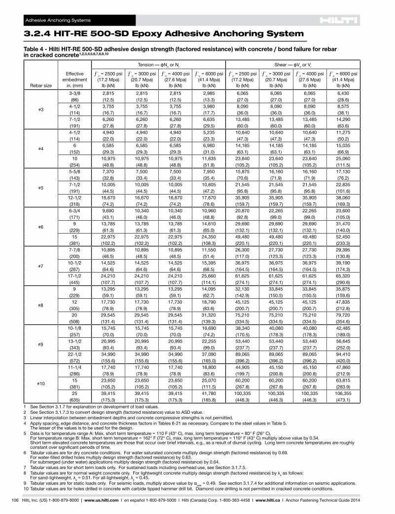
Adhesive Anchoring Systems
324 HIT-RE 500-SD Epoxy Adhesive Anchoring System
106 Hilti Inc (US) 1-800-879-8000 | wwwushilticom I en espantildeol 1-800-879-5000 I Hilti (Canada) Corp 1-800-363-4458 I wwwhiltica I Anchor Fastening Technical Guide 2014
Table 4 - Hilti HIT-RE 500-SD adhesive design strength (factored resistance) with concrete bond failure for rebar in cracked concrete12345678910
Rebar size
Effectiveembedment
in (mm)
TensionmdashϕNn or Nr ShearmdashϕVn or Vr
ƒ´c = 2500 psi (172 Mpa)
lb (kN)
ƒ´c = 3000 psi (207 Mpa)
lb (kN)
ƒ´c = 4000 psi (276 Mpa)
lb (kN)
ƒ´c = 6000 psi (414 Mpa)
lb (kN)
ƒ´c = 2500 psi (172 Mpa)
lb (kN)
ƒ´c = 3000 psi (207 Mpa)
lb (kN)
ƒ´c = 4000 psi (276 Mpa)
lb (kN)
ƒ´c = 6000 psi (414 Mpa)
lb (kN)
3
3-38 2815 2815 2815 2985 6065 6065 6065 6430(86) (125) (125) (125) (133) (270) (270) (270) (286)
4-12 3755 3755 3755 3980 8090 8090 8090 8575(114) (167) (167) (167) (177) (360) (360) (360) (381)7-12 6260 6260 6260 6635 13485 13485 13485 14290(191) (278) (278) (278) (295) (600) (600) (600) (636)
4
4-12 4940 4940 4940 5235 10640 10640 10640 11275(114) (220) (220) (220) (233) (473) (473) (473) (502)
6 6585 6585 6585 6980 14185 14185 14185 15035(152) (293) (293) (293) (310) (631) (631) (631) (669)10 10975 10975 10975 11635 23640 23640 23640 25060
(254) (488) (488) (488) (518) (1052) (1052) (1052) (1115)
5
5-58 7370 7500 7500 7950 15875 16160 16160 17130(143) (328) (334) (334) (354) (706) (719) (719) (762)7-12 10005 10005 10005 10605 21545 21545 21545 22835(191) (445) (445) (445) (472) (958) (958) (958) (1016)
12-12 16670 16670 16670 17670 35905 35905 35905 38060(318) (742) (742) (742) (786) (1597) (1597) (1597) (1693)
6
6-34 9690 10340 10340 10960 20870 22265 22265 23600(171) (431) (460) (460) (488) (928) (990) (990) (1050)
9 13785 13785 13785 14610 29690 29690 29690 31470(229) (613) (613) (613) (650) (1321) (1321) (1321) (1400)15 22975 22975 22975 24350 49480 49480 49480 52450
(381) (1022) (1022) (1022) (1083) (2201) (2201) (2201) (2333)
7
7-78 10895 10895 10895 11550 26300 27730 27730 29395(200) (485) (485) (485) (514) (1170) (1233) (1233) (1308)
10-12 14525 14525 14525 15395 36975 36975 36975 39190(267) (646) (646) (646) (685) (1645) (1645) (1645) (1743)
17-12 24210 24210 24210 25660 61625 61625 61625 65320(445) (1077) (1077) (1077) (1141) (2741) (2741) (2741) (2906)
8
9 13295 13295 13295 14095 32130 33845 33845 35875(229) (591) (591) (591) (627) (1429) (1505) (1505) (1596)12 17730 17730 17730 18790 45125 45125 45125 47835
(305) (789) (789) (789) (836) (2007) (2007) (2007) (2128)20 29545 29545 29545 31320 75210 75210 75210 79720
(508) (1314) (1314) (1314) (1393) (3345) (3345) (3345) (3546)
9
10-18 15745 15745 15745 16690 38340 40080 40080 42485(257) (700) (700) (700) (742) (1705) (1783) (1783) (1890)
13-12 20995 20995 20995 22255 53440 53440 53440 56645(343) (934) (934) (934) (990) (2377) (2377) (2377) (2520)
22-12 34990 34990 34990 37090 89065 89065 89065 94410(572) (1556) (1556) (1556) (1650) (3962) (3962) (3962) (4200)
10
11-14 17740 17740 17740 18800 44905 45150 45150 47860(286) (789) (789) (789) (836) (1997) (2008) (2008) (2129)15 23650 23650 23650 25070 60200 60200 60200 63815
(381) (1052) (1052) (1052) (1115) (2678) (2678) (2678) (2839)25 39415 39415 39415 41780 100335 100335 100335 106355
(635) (1753) (1753) (1753) (1858) (4463) (4463) (4463) (4731)1 See Section 317 for explanation on development of load values2 See Section 3173 to convert design strength (factored resistance) value to ASD value3 Linear interpolation between embedment depths and concrete compressive strengths is not permitted4 Apply spacing edge distance and concrete thickness factors in Tables 6-21 as necessary Compare to the steel values in Table 5
The lesser of the values is to be used for the design5 Data is for temperature range A Max short term temperature = 110 F (43deg C) max long term temperature = 80deg F (26deg C)
FortemperaturerangeBMaxshorttermtemperature=162degF(72degC)maxlongtermtemperature=110degF(43degC)multiplyabovevalueby034 Short term elevated concrete temperatures are those that occur over brief intervals eg as a result of diurnal cycling Long term concrete temperatures are roughly constantoversignificantperiodsoftime
6 Tabular values are for dry concrete conditions For water saturated concrete multiply design strength (factored resistance) by 069 Forwater-filleddrilledholesmultiplydesignstrength(factoredresistance)by063 For submerged (under water) applications multiply design strength (factored resistance) by 064
7 Tabular values are for short term loads only For sustained loads including overhead use see Section 31758 TabularvaluesarefornormalweightconcreteonlyForlightweightconcretemultiplydesignstrength(factoredresistance)byλa as follows
Forsand-lightweightλa=051Forall-lightweightλa = 0459 TabularvaluesareforstaticloadsonlyForseismicloadsmultiplyabovevaluebyαseis = 049 See section 3174 for additional information on seismic applications10 Tabular values are for holes drilled in concrete with carbide tipped hammer drill bit Diamond core drilling is not permitted in cracked concrete conditions
Adhesive Anchoring Systems
HIT-RE 500-SD Epoxy Adhesive Anchoring System 324
Hilti Inc (US) 1-800-879-8000 | wwwushilticom I en espantildeol 1-800-879-5000 I Hilti (Canada) Corp 1-800-363-4458 I wwwhiltica I Anchor Fastening Technical Guide 2014 107
328
325
326
327
324
325
325
323
Table 5 - Steel design strength (ACI 318 Appendix D Based Design) for rebar1
Rebar size
ASTM A615 Grade 402 ASTM A615 Grade 602 ASTM A706 Grade 602
Tensile3
ϕNsalb (kN)
Shear4
ϕVsalb (kN)
Seismic Shear5
ϕVsalb (kN)
Tensile3
ϕNsalb (kN)
Shear4
ϕVsalb (kN)
Seismic Shear5
ϕVsalb (kN)
Tensile3
ϕNsalb (kN)
Shear4
ϕVsalb (kN)
Seismic Shear5
ϕVsalb (kN)
34290 2375 1663 6435 3565 2496 6600 3430 2401(191) (106) (74) (286) (159) (111) (294) (153) (107)
47800 4320 3024 11700 6480 4536 12000 6240 4368(347) (192) (135) (520) (288) (202) (534) (278) (194)
512090 6695 4687 18135 10045 7032 18600 9670 6769(538) (298) (208) (807) (447) (313) (827) (430) (301)
617160 9505 6654 25740 14255 9979 26400 13730 9611(763) (423) (296) (1145) (634) (444) (1174) (611) (428)
723400 12960 9072 35100 19440 13608 36000 18720 13104(1041) (576) (404) (1561) (865) (605) (1601) (833) (583)
830810 17065 11946 46215 25595 17917 47400 24650 17255(1370) (759) (531) (2056) (1139) (797) (2108) (1096) (768)
939000 21600 15120 58500 32400 22680 60000 31200 21840(1735) (961) (673) (2602) (1441) (1009) (2669) (1388) (971)
1049530 27430 19201 74295 41150 28805 76200 39625 27738(2203) (1220) (854) (3305) (1830) (1281) (3390) (1763) (1234)
1 See Section 3173 to convert design strength (factored resistance) value to ASD value2 ASTM A706 Grade 60 rebar are considered ductile steel elements ASTM A615 Grade 40 and 60 rebar are considered brittle steel elements3 Tensile = AseN futa as noted in ACI 318 Appendix D4 Shear = 060 AseN futa as noted in ACI 318 Appendix D5 Seismic shear values determined by multiplying VsaxαVseiswhereαVseis = 07 See Section 3174 for additional information on seismic applications
Adhesive Anchoring Systems
324 HIT-RE 500-SD Epoxy Adhesive Anchoring System
108 Hilti Inc (US) 1-800-879-8000 | wwwushilticom I en espantildeol 1-800-879-5000 I Hilti (Canada) Corp 1-800-363-4458 I wwwhiltica I Anchor Fastening Technical Guide 2014
Table 6 - Load adjustment factors for 3 rebar in uncracked concrete123
3uncracked concrete
Spacing factor in tension
ƒAN
Edgedistancefactor in tension
ƒRN
Spacing factor in shear4
ƒAV
Edgedistanceinshear
Concrete thickness factor in shear5
ƒHV
Toward edge
ƒRV
To edge
ƒRV
Embedment hef
in 3-38 4-12 7-12 3-38 4-12 7-12 3-38 4-12 7-12 3-38 4-12 7-12 3-38 4-12 7-12 3-38 4-12 7-12(mm) (86) (114) (191) (86) (114) (191) (86) (114) (191) (86) (114) (191) (86) (114) (191) (86) (114) (191)
Spacing(s)Edg
eDistance(c
a) C
oncr
ete
Thic
knes
s (h
) - i
n (m
m) 1-34 (44) na na na 028 022 013 na na na 007 005 003 014 009 005 na na na
1-78 (48) 058 057 054 029 022 013 053 052 052 008 005 003 016 010 006 na na na2 (51) 059 057 054 029 023 013 053 052 052 009 006 003 017 011 006 na na na3 (76) 063 061 057 036 028 016 055 054 053 016 010 006 032 021 012 na na na
3-58 (92) 066 063 058 041 031 018 056 054 053 021 014 008 041 027 016 na na na4 (102) 068 065 059 043 033 019 057 055 053 024 016 009 043 032 018 na na na
4-58 (117) 070 067 060 048 036 021 058 056 054 030 020 011 048 038 023 055 na na5 (127) 072 069 061 051 038 022 058 056 054 034 022 013 051 040 025 057 na na
5-34 (146) 075 071 063 059 043 025 059 057 055 042 027 016 059 044 031 061 053 na6 (152) 077 072 063 061 045 026 060 057 055 045 029 017 061 046 032 063 054 na7 (178) 081 076 066 071 052 030 061 059 056 057 037 021 071 052 035 068 058 na8 (203) 085 080 068 082 059 034 063 060 057 069 045 026 082 059 038 072 063 na
8-34 (222) 089 082 069 089 065 038 064 061 057 079 051 029 089 065 040 076 065 0549 (229) 090 083 070 092 067 039 065 061 058 083 054 031 092 067 041 077 066 05510 (254) 094 087 072 100 074 043 066 062 058 097 063 036 100 074 044 081 070 05811 (279) 099 091 074 082 047 068 063 059 100 072 041 082 048 085 073 06112 (305) 100 094 077 089 052 070 065 060 083 047 089 052 088 077 06414 (356) 100 081 100 060 073 067 062 100 060 100 060 096 083 06916 (406) 086 069 076 070 063 073 069 100 088 07318 (457) 090 077 079 072 065 087 077 094 07824 (610) 100 100 089 079 070 100 100 100 09030 (762) 099 087 075 10036 (914) 100 094 080
gt48 (1219) 100 090
Table 7 - Load adjustment factors for 3 rebar in cracked concrete123
3cracked concrete
Spacing factor in tension
ƒAN
Edgedistancefactor in tension
ƒRN
Spacing factor in shear4
ƒAV
Edgedistanceinshear
Concrete thickness factor in shear5
ƒHV
Toward edge
ƒRV
To edge
ƒRV
Embedment hef
in 3-38 4-12 7-12 3-38 4-12 7-12 3-38 4-12 7-12 3-38 4-12 7-12 3-38 4-12 7-12 3-38 4-12 7-12(mm) (86) (114) (191) (86) (114) (191) (86) (114) (191) (86) (114) (191) (86) (114) (191) (86) (114) (191)
Spacing(s)Edg
eDistance(c
a) C
oncr
ete
Thic
knes
s (h
) - i
n (m
m) 1-34 (44) na na na 052 049 043 na na na 009 007 004 017 013 008 na na na
1-78 (48) 058 057 054 053 050 044 053 053 052 010 007 004 019 014 009 na na na2 (51) 059 057 054 055 051 044 054 053 052 011 008 005 021 016 010 na na na3 (76) 063 061 057 066 060 049 056 055 053 019 015 009 039 029 018 na na na
3-58 (92) 066 063 058 073 066 053 057 056 054 026 019 012 052 039 023 na na na4 (102) 068 065 059 078 070 055 057 056 054 030 022 013 060 045 027 na na na
4-58 (117) 070 067 060 086 076 058 059 057 055 037 028 017 075 056 034 059 na na5 (127) 072 069 061 091 080 060 059 058 055 042 031 019 084 063 038 061 na na
5-34 (146) 075 071 063 100 088 064 061 059 056 052 039 023 100 078 047 066 060 na6 (152) 077 072 063 091 066 061 059 057 055 041 025 083 050 067 061 na7 (178) 081 076 066 100 072 063 061 058 069 052 031 100 062 072 066 na8 (203) 085 080 068 078 065 062 059 085 064 038 076 077 070 na
8-34 (222) 089 082 069 083 066 063 060 097 073 044 083 081 073 0629 (229) 090 083 070 085 067 064 060 100 076 046 085 082 074 06310 (254) 094 087 072 091 069 065 061 089 053 091 086 079 06611 (279) 099 091 074 098 071 067 062 100 062 098 091 082 06912 (305) 100 094 077 100 072 068 063 070 100 095 086 07314 (356) 100 081 076 072 065 088 100 093 07816 (406) 086 080 075 068 100 099 08418 (457) 090 084 078 070 100 08924 (610) 100 095 087 076 10030 (762) 100 096 08336 (914) 100 089
gt48 (1219) 1001 Linear interpolation not permitted2 Shadedareawithreducededgedistanceispermittedprovidedtheinstallationtorqueisreducedto030Tmax for 5d lt s lt 16-in and to 05 Tmax for s gt 16-in3 When combining multiple load adjustment factors (eg for a 4 anchor pattern in a corner with a thin concrete member) the design can become very conservative To
optimizethedesignuseHiltiPROFISAnchorDesignsoftwareorperformanchorcalculationusingthedesignequationsfromACI318AppendixD4 Spacing factor reduction in shear ƒAVassumesaninfluenceofanearbyedgeIfnoedgeexiststhenƒAV = ƒAN5 Concrete thickness reduction factor in shear ƒHVassumesaninfluenceofanearbyedgeIfnoedgeexiststhenƒHV = 10
Adhesive Anchoring Systems
HIT-RE 500-SD Epoxy Adhesive Anchoring System 324
Hilti Inc (US) 1-800-879-8000 | wwwushilticom I en espantildeol 1-800-879-5000 I Hilti (Canada) Corp 1-800-363-4458 I wwwhiltica I Anchor Fastening Technical Guide 2014 109
328
325
326
327
324
325
325
323
Table 8 - Load adjustment factors for 4 rebar in uncracked concrete123
4uncracked concrete
Spacing factor in tension
ƒAN
Edgedistancefactor in tension
ƒRN
Spacing factor in shear4
ƒAV
Edgedistanceinshear
Concrete thickness factor in shear5
ƒHV
Toward edge
ƒRV
To edge
ƒRV
Embedment hef
in 3-38 4-12 7-12 3-38 4-12 7-12 3-38 4-12 7-12 3-38 4-12 7-12 3-38 4-12 7-12 3-38 4-12 7-12(mm) (86) (114) (191) (86) (114) (191) (86) (114) (191) (86) (114) (191) (86) (114) (191) (86) (114) (191)
Spacing(s)Edg
eDistance(c
a) C
oncr
ete
Thic
knes
s (h
) - i
n (m
m) 1-34 (44) na na na 025 019 011 na na na 005 003 002 011 007 003 na na na
2-12 (64) 058 057 054 028 022 013 053 053 052 009 006 003 018 012 006 na na na3 (76) 060 058 055 030 024 014 054 053 052 012 008 004 024 015 008 na na na4 (102) 063 061 057 035 027 016 055 054 053 018 012 006 035 024 012 na na na5 (127) 067 064 058 040 031 018 057 055 053 026 017 008 040 033 017 na na na
5-34 (146) 069 066 060 045 034 020 058 056 054 032 021 010 045 036 021 056 na na6 (152) 070 067 060 046 035 020 058 056 054 034 022 011 046 037 022 057 na na7 (178) 073 069 062 052 039 023 059 057 054 042 028 014 052 041 028 061 na na
7-14 (184) 074 070 062 054 040 023 060 057 055 045 029 015 054 042 029 062 054 na8 (203) 077 072 063 060 044 026 061 058 055 052 034 017 060 045 032 066 057 na9 (229) 080 075 065 067 049 029 062 059 056 062 040 020 067 049 034 070 060 na
10 (254) 083 078 067 075 055 032 063 060 056 072 047 024 075 055 036 073 064 na11-14 (286) 088 081 069 084 062 036 065 061 057 086 056 028 084 062 039 078 067 054
12 (305) 090 083 070 090 066 038 066 062 058 095 062 031 090 066 041 080 070 05514 (356) 097 089 073 100 077 045 069 064 059 100 078 039 100 077 046 087 075 06016 (406) 100 094 077 088 051 072 066 060 095 048 088 051 093 080 06418 (457) 100 080 099 058 074 068 061 100 057 099 058 098 085 06820 (508) 083 100 064 077 070 063 067 100 064 100 090 07122 (559) 087 070 080 072 064 077 070 094 07524 (610) 090 077 082 074 065 088 077 098 07830 (762) 100 096 090 080 069 100 096 100 08736 (914) 100 098 086 073 100 096
gt 48 (1219) 100 098 081 100
Table 9 - Load adjustment factors for 4 rebar in cracked concrete123
4cracked concrete
Spacing factor in tension
ƒAN
Edgedistancefactor in tension
ƒRN
Spacing factor in shear4
ƒAV
Edgedistanceinshear
Concrete thickness factor in shear5
ƒHV
Toward edge
ƒRV
To edge
ƒRV
Embedment hef
in 3-38 4-12 7-12 3-38 4-12 7-12 3-38 4-12 7-12 3-38 4-12 7-12 3-38 4-12 7-12 3-38 4-12 7-12(mm) (86) (114) (191) (86) (114) (191) (86) (114) (191) (86) (114) (191) (86) (114) (191) (86) (114) (191)
Spacing(s)Edg
eDistance(c
a) C
oncr
ete
Thic
knes
s (h
) - i
n (m
m) 1-34 (44) na na na 048 045 041 na na na 006 004 003 011 009 005 na na na
2-12 (64) 058 057 054 053 050 044 054 053 052 010 007 004 020 015 009 na na na3 (76) 060 058 055 057 053 046 054 053 052 013 010 006 026 019 012 na na na4 (102) 063 061 057 066 060 049 056 055 053 020 015 009 039 030 018 na na na5 (127) 067 064 058 075 067 053 057 056 054 028 021 012 055 041 025 na na na
5-34 (146) 069 066 060 082 073 056 058 057 055 034 026 015 068 051 031 057 na na6 (152) 070 067 060 085 075 057 058 057 055 036 027 016 073 054 033 058 na na7 (178) 073 069 062 095 083 062 060 058 056 046 034 021 091 069 041 063 na na
7-14 (184) 074 070 062 098 085 063 060 058 056 048 036 022 096 072 043 064 058 na8 (203) 077 072 063 100 091 066 061 059 057 056 042 025 100 084 050 067 061 na9 (229) 080 075 065 100 070 063 060 057 067 050 030 100 060 071 065 na
10 (254) 083 078 067 075 064 062 058 078 059 035 070 075 068 na11-14 (286) 088 081 069 081 066 063 059 093 070 042 081 080 072 061
12 (305) 090 083 070 085 067 064 060 100 077 046 085 082 075 06314 (356) 097 089 073 095 070 066 062 097 058 095 089 081 06816 (406) 100 094 077 100 073 069 063 100 071 100 095 086 07318 (457) 100 080 075 071 065 085 100 092 07720 (508) 083 078 073 067 099 097 08122 (559) 087 081 076 068 100 100 08524 (610) 090 084 078 070 08930 (762) 100 092 085 075 10036 (914) 100 092 080
gt 48 (1219) 100 0901 Linear interpolation not permitted2 Shadedareawithreducededgedistanceispermittedprovidedtheinstallationtorqueisreducedto030Tmax for 5d lt s lt 16-in and to 05 Tmax for s gt 16-in3 When combining multiple load adjustment factors (eg for a 4 anchor pattern in a corner with a thin concrete member) the design can become very conservative To
optimizethedesignuseHiltiPROFISAnchorDesignsoftwareorperformanchorcalculationusingthedesignequationsfromACI318AppendixD4 Spacing factor reduction in shear ƒAVassumesaninfluenceofanearbyedgeIfnoedgeexiststhenƒAV = ƒAN5 Concrete thickness reduction factor in shear ƒHVassumesaninfluenceofanearbyedgeIfnoedgeexiststhenƒHV = 10
Adhesive Anchoring Systems
324 HIT-RE 500-SD Epoxy Adhesive Anchoring System
110 Hilti Inc (US) 1-800-879-8000 | wwwushilticom I en espantildeol 1-800-879-5000 I Hilti (Canada) Corp 1-800-363-4458 I wwwhiltica I Anchor Fastening Technical Guide 2014
Table 10 - Load adjustment factors for 5 rebar in uncracked concrete123
5uncracked concrete
Spacing factor in tension
ƒAN
Edgedistancefactor in tension
ƒRN
Spacing factor in shear4
ƒAV
Edgedistanceinshear
Concrete thickness factor in shear5
ƒHV
Toward edge
ƒRV
To edge
ƒRV
Embedment hef
in 5-58 7-12 12-12 5-58 7-12 12-12 5-58 7-12 12-12 5-58 7-12 12-12 5-58 7-12 12-12 5-58 7-12 12-12(mm) (143) (191) (318) (143) (191) (318) (143) (191) (318) (143) (191) (318) (143) (191) (318) (143) (191) (318)
Spacing(s)Edg
eDistance(c
a) C
oncr
ete
Thic
knes
s (h
) - i
n (m
m) 1-34 (44) na na na 023 018 011 na na na 004 003 001 008 006 003 na na na
3-18 (79) 059 057 054 028 022 013 054 053 052 010 007 003 020 013 006 na na na4 (102) 061 059 055 032 024 014 055 053 052 015 010 004 029 019 009 na na na
4-58 (117) 063 060 056 034 026 015 055 054 052 018 012 006 034 024 011 na na na5 (127) 064 061 057 036 027 016 056 054 053 021 013 006 036 027 012 na na na6 (152) 066 063 058 040 030 018 057 055 053 027 018 008 040 033 016 na na na7 (178) 069 066 059 044 033 020 058 056 054 034 022 010 044 036 021 na na na
7-18 (181) 069 066 060 045 034 020 058 056 054 035 023 011 045 036 021 057 na na8 (203) 072 068 061 049 037 021 059 057 054 041 027 013 049 039 025 061 na na9 (229) 075 070 062 054 040 023 060 058 055 050 032 015 054 042 030 065 056 na10 (254) 077 072 063 060 044 026 062 059 055 058 038 018 060 046 032 068 059 na11 (279) 080 074 065 067 049 029 063 060 056 067 043 020 067 049 034 071 062 na12 (305) 083 077 066 073 053 031 064 060 056 076 050 023 073 053 036 075 065 na14 (356) 088 081 069 085 062 036 066 062 057 096 062 029 085 062 039 081 070 05416 (406) 094 086 071 097 071 042 069 064 058 100 076 036 097 071 043 086 075 05818 (457) 099 090 074 100 080 047 071 066 059 091 043 100 080 047 091 079 06120 (508) 100 094 077 089 052 073 067 060 100 050 089 052 096 083 06522 (559) 099 079 098 057 075 069 062 058 098 057 100 087 06824 (610) 100 082 100 062 078 071 063 066 100 062 091 07126 (660) 085 068 080 073 064 074 068 095 07428 (711) 087 073 082 074 065 083 073 099 07730 (762) 090 078 085 076 066 092 078 100 07936 (914) 098 094 092 081 069 100 094 087
gt 48 (1219) 100 100 100 092 075 100 100
Table 11 - Load adjustment factors for 5 rebar in cracked concrete123
5cracked concrete
Spacing factor in tension
ƒAN
Edgedistancefactor in tension
ƒRN
Spacing factor in shear4
ƒAV
Edgedistanceinshear
Concrete thickness factor in shear5
ƒHV
Toward edge
ƒRV
To edge
ƒRV
Embedment hef
in 5-58 7-12 12-12 5-58 7-12 12-12 5-58 7-12 12-12 5-58 7-12 12-12 5-58 7-12 12-12 5-58 7-12 12-12(mm) (143) (191) (318) (143) (191) (318) (143) (191) (318) (143) (191) (318) (143) (191) (318) (143) (191) (318)
Spacing(s)Edg
eDistance(c
a) C
oncr
ete
Thic
knes
s (h
) - i
n (m
m) 1-34 (44) na na na 045 043 040 na na na 004 003 002 009 006 004 na na na
3-18 (79) 059 057 054 054 050 044 054 053 052 010 008 005 020 015 009 na na na4 (102) 061 059 055 060 055 046 055 054 053 015 011 007 030 022 013 na na na
4-58 (117) 063 060 056 064 058 048 055 054 053 018 014 008 037 027 016 na na na5 (127) 064 061 057 067 060 049 056 055 053 021 015 009 041 030 018 na na na6 (152) 066 063 058 074 066 053 057 056 054 027 020 012 054 040 024 na na na7 (178) 069 066 059 082 072 056 058 057 055 034 025 015 068 050 030 na na na
7-18 (181) 069 066 060 083 073 056 058 057 055 035 026 016 070 052 031 058 na na8 (203) 072 068 061 090 078 059 059 058 055 042 031 019 084 062 037 061 na na9 (229) 075 070 062 099 085 062 060 059 056 050 037 022 100 074 044 065 059 na10 (254) 077 072 063 100 091 066 062 060 057 058 043 026 086 052 068 062 na11 (279) 080 074 065 098 069 063 060 057 067 050 030 098 060 072 065 na12 (305) 083 077 066 100 073 064 061 058 077 057 034 100 068 075 068 na14 (356) 088 081 069 081 066 063 059 097 071 043 081 081 073 06216 (406) 094 086 071 089 069 065 061 100 087 052 089 086 078 06618 (457) 099 090 074 097 071 067 062 100 062 097 092 083 07020 (508) 100 094 077 100 073 069 064 073 100 097 087 07422 (559) 099 079 076 071 065 084 100 091 07724 (610) 100 082 078 073 066 096 096 08126 (660) 085 080 075 068 100 099 08428 (711) 087 083 077 069 100 08730 (762) 090 085 079 070 09036 (914) 098 092 084 074 099
gt 48 (1219) 100 100 096 082 1001 Linear interpolation not permitted2 Shadedareawithreducededgedistanceispermittedprovidedtheinstallationtorqueisreducedto030Tmax for 5d lt s lt 16-in and to 05 Tmax for s gt 16-in3 When combining multiple load adjustment factors (eg for a 4 anchor pattern in a corner with a thin concrete member) the design can become very conservative To
optimizethedesignuseHiltiPROFISAnchorDesignsoftwareorperformanchorcalculationusingthedesignequationsfromACI318AppendixD4 Spacing factor reduction in shear ƒAVassumesaninfluenceofanearbyedgeIfnoedgeexiststhenƒAV = ƒAN5 Concrete thickness reduction factor in shear ƒHVassumesaninfluenceofanearbyedgeIfnoedgeexiststhenƒHV = 10
Adhesive Anchoring Systems
HIT-RE 500-SD Epoxy Adhesive Anchoring System 324
Hilti Inc (US) 1-800-879-8000 | wwwushilticom I en espantildeol 1-800-879-5000 I Hilti (Canada) Corp 1-800-363-4458 I wwwhiltica I Anchor Fastening Technical Guide 2014 111
328
325
326
327
324
325
325
323
Table 12 - Load adjustment factors for 6 rebar in uncracked concrete123
6uncracked concrete
Spacing factor in tension
ƒAN
Edgedistancefactor in tension
ƒRN
Spacing factor in shear4
ƒAV
Edgedistanceinshear
Concrete thickness factor in shear5
ƒHV
Toward edge
ƒRV
To edge
ƒRV
Embedment hef
in 6-34 9 15 6-34 9 15 6-34 9 15 6-34 9 15 6-34 9 15 6-34 9 15(mm) (171) (229) (381) (171) (229) (381) (171) (229) (381) (171) (229) (381) (171) (229) (381) (171) (229) (381)
Spacing(s)Edg
eDistance(c
a) C
oncr
ete
Thic
knes
s (h
) - i
n (m
m)
1-34 (44) na na na 023 018 010 na na na 003 002 001 007 005 002 na na na3-34 (95) 059 057 054 029 022 013 054 053 052 011 007 003 022 014 007 na na na
4 (102) 059 057 054 030 022 013 054 053 052 012 008 004 024 016 007 na na na5 (127) 062 059 056 033 025 015 055 054 052 017 011 005 033 022 010 na na na
5-14 (133) 062 060 056 034 025 015 055 054 052 018 012 005 034 023 011 na na na6 (152) 064 061 057 036 027 016 056 055 053 022 014 007 036 029 013 na na na7 (178) 066 063 058 040 030 017 057 055 053 028 018 008 040 033 017 na na na8 (203) 069 065 059 043 032 019 058 056 054 034 022 010 043 035 020 na na na
8-12 (216) 070 066 059 045 034 020 059 056 054 037 024 011 045 037 022 059 na na9 (229) 071 067 060 047 035 021 059 057 054 040 026 012 047 038 024 060 na na10 (254) 073 069 061 051 038 022 060 058 055 047 031 014 051 041 029 064 na na
10-34 (273) 075 070 062 055 040 024 061 058 055 053 034 016 055 043 031 066 057 na12 (305) 078 072 063 061 045 026 062 059 055 062 040 019 061 046 033 070 060 na14 (356) 082 076 066 071 053 031 064 061 056 078 051 024 071 053 036 075 065 na16 (406) 087 080 068 082 060 035 066 062 057 096 062 029 082 060 039 080 070 na
16-34 (425) 089 081 069 085 063 037 067 063 058 100 067 031 085 063 040 082 071 05518 (457) 092 083 070 092 068 040 068 064 058 074 035 092 068 042 085 074 05720 (508) 096 087 072 100 075 044 070 065 059 087 040 100 075 045 090 078 06022 (559) 100 091 074 083 048 072 067 060 100 047 083 049 094 082 06324 (610) 094 077 090 053 074 068 061 053 090 053 099 085 06626 (660) 098 079 098 057 076 070 062 060 098 057 100 089 06928 (711) 100 081 100 062 078 071 063 067 100 062 092 07130 (762) 083 066 080 073 064 074 066 095 07436 (914) 090 079 086 077 066 098 079 100 081
gt 48 (1219) 100 100 099 086 072 100 100 094
Table 13 - Load adjustment factors for 6 rebar in cracked concrete123
6cracked concrete
Spacing factor in tension
ƒAN
Edgedistancefactor in tension
ƒRN
Spacing factor in shear4
ƒAV
Edgedistanceinshear
Concrete thickness factor in shear5
ƒHV
Toward edge
ƒRV
To edge
ƒRV
Embedment hef
in 6-34 9 15 6-34 9 15 6-34 9 15 6-34 9 15 6-34 9 15 6-34 9 15(mm) (171) (229) (381) (171) (229) (381) (171) (229) (381) (171) (229) (381) (171) (229) (381) (171) (229) (381)
Spacing(s)Edg
eDistance(c
a) C
oncr
ete
Thic
knes
s (h
) - i
n (m
m)
1-34 (44) na na na 044 042 039 na na na 003 002 001 007 005 003 na na na3-34 (95) 059 057 054 054 050 044 054 053 052 011 008 005 022 015 009 na na na
4 (102) 059 057 054 056 051 044 054 053 052 012 008 005 024 017 010 na na na5 (127) 062 059 056 061 056 047 055 054 053 017 012 007 034 024 014 na na na
5-14 (133) 062 060 056 063 057 047 055 054 053 018 013 008 036 026 015 na na na6 (152) 064 061 057 067 060 049 056 055 053 022 016 009 044 031 019 na na na7 (178) 066 063 058 074 065 052 057 056 054 028 020 012 056 039 024 na na na8 (203) 069 065 059 080 070 055 058 056 055 034 024 014 068 048 029 na na na
8-12 (216) 070 066 059 084 072 056 059 057 055 037 026 016 075 053 032 059 na na9 (229) 071 067 060 087 075 057 059 057 055 041 029 017 082 057 034 061 na na10 (254) 073 069 061 094 080 060 060 058 056 048 034 020 095 067 040 064 na na
10-34 (273) 075 070 062 100 084 062 061 059 056 053 037 022 100 075 045 066 059 na12 (305) 078 072 063 091 066 062 060 057 063 044 026 088 053 070 062 na14 (356) 082 076 066 100 072 064 061 058 079 056 033 100 067 076 067 na16 (406) 087 080 068 078 066 063 059 097 068 041 078 081 072 na
16-34 (425) 089 081 069 081 067 063 060 100 073 044 081 083 073 06218 (457) 092 083 070 085 068 064 060 081 049 085 086 076 06420 (508) 096 087 072 091 070 066 061 095 057 091 090 080 06822 (559) 100 091 074 098 072 068 063 100 066 098 095 084 07124 (610) 094 077 100 074 069 064 075 100 099 088 07426 (660) 098 079 076 071 065 084 100 091 07728 (711) 100 081 079 073 066 094 095 08030 (762) 083 081 074 067 100 098 08336 (914) 090 087 079 071 100 091
gt 48 (1219) 100 099 089 077 1001 Linear interpolation not permitted2 Shadedareawithreducededgedistanceispermittedprovidedtheinstallationtorqueisreducedto030Tmax for 5d lt s lt 16-in and to 05 Tmax for s gt 16-in3 When combining multiple load adjustment factors (eg for a 4 anchor pattern in a corner with a thin concrete member) the design can become very conservative To
optimizethedesignuseHiltiPROFISAnchorDesignsoftwareorperformanchorcalculationusingthedesignequationsfromACI318AppendixD4 Spacing factor reduction in shear ƒAVassumesaninfluenceofanearbyedgeIfnoedgeexiststhenƒAV = ƒAN5 Concrete thickness reduction factor in shear ƒHVassumesaninfluenceofanearbyedgeIfnoedgeexiststhenƒHV = 10
Adhesive Anchoring Systems
324 HIT-RE 500-SD Epoxy Adhesive Anchoring System
112 Hilti Inc (US) 1-800-879-8000 | wwwushilticom I en espantildeol 1-800-879-5000 I Hilti (Canada) Corp 1-800-363-4458 I wwwhiltica I Anchor Fastening Technical Guide 2014
Table 14 - Load adjustment factors for 7 Rebar in uncracked concrete123
7uncracked concrete
Spacing factor in tension
ƒAN
Edgedistancefactor in tension
ƒRN
Spacing factor in shear4
ƒAV
Edgedistanceinshear
Concrete thickness factor in shear5
ƒHV
Toward edge
ƒRV
To edge
ƒRV
Embedment hef
in 7-78 10-12 17-12 7-78 10-12 17-12 7-78 10-12 17-12 7-78 10-12 17-12 7-78 10-12 17-12 7-78 10-12 17-12(mm) (200) (267) (445) (200) (267) (445) (200) (267) (445) (200) (267) (445) (200) (267) (445) (200) (267) (445)
Spacing(s)Edg
eDistance(c
a) C
oncr
ete
Thic
knes
s (h
) - i
n (m
m)
1-34 (44) na na na 022 017 010 na na na 003 002 001 005 004 002 na na na4-38 (111) 059 057 054 029 022 013 054 053 052 011 007 003 022 014 007 na na na
5 (127) 060 058 055 031 023 014 054 053 052 013 009 004 027 017 008 na na na5-12 (140) 061 059 055 032 024 014 055 054 052 015 010 005 031 020 009 na na na
6 (152) 062 060 056 034 025 015 055 054 052 017 011 005 034 023 011 na na na7 (178) 064 061 057 037 027 016 056 055 053 022 014 007 037 029 013 na na na8 (203) 066 063 058 040 030 017 057 055 053 027 017 008 040 033 016 na na na9 (229) 068 064 059 043 032 019 058 056 054 032 021 010 043 035 019 na na na
9-78 (251) 070 066 059 046 034 020 059 056 054 037 024 011 046 037 022 059 na na10 (254) 070 066 060 046 034 020 059 057 054 038 024 011 046 037 023 059 na na11 (279) 072 067 060 049 037 022 060 057 054 043 028 013 049 040 026 062 na na12 (305) 074 069 061 053 039 023 060 058 055 049 032 015 053 042 030 065 na na
12-12 (318) 075 070 062 055 041 024 061 058 055 052 034 016 055 043 031 066 057 na14 (356) 078 072 063 062 046 027 062 059 055 062 040 019 062 047 033 070 060 na16 (406) 082 075 065 071 052 031 064 060 056 076 049 023 071 052 036 075 065 na18 (457) 086 079 067 080 059 034 066 062 057 091 059 027 080 059 038 079 068 na
19-12 (495) 089 081 069 086 063 037 067 063 058 100 066 031 086 063 040 082 071 05520 (508) 090 082 069 089 065 038 067 063 058 069 032 089 065 041 083 072 05622 (559) 094 085 071 097 072 042 069 064 059 080 037 097 072 044 087 076 05924 (610) 098 088 073 100 078 046 071 066 059 091 042 100 078 047 091 079 06126 (660) 100 091 075 085 050 073 067 060 100 048 085 050 095 082 06428 (711) 094 077 091 053 074 068 061 053 091 053 099 085 06630 (762) 098 079 098 057 076 070 062 059 098 057 100 088 06836 (914) 100 084 100 069 081 073 064 077 100 069 097 075
gt 48 (1219) 096 092 092 081 069 100 092 100 087
Table 15 - Load adjustment factors for 7 rebar in cracked concrete123
7cracked concrete
Spacing factor in tension
ƒAN
Edgedistancefactor in tension
ƒRN
Spacing factor in shear4
ƒAV
Edgedistanceinshear
Concrete thickness factor in shear5
ƒHV
Toward edge
ƒRV
To edge
ƒRV
Embedment hef
in 7-78 10-12 17-12 7-78 10-12 17-12 7-78 10-12 17-12 7-78 10-12 17-12 7-78 10-12 17-12 7-78 10-12 17-12(mm) (200) (267) (445) (200) (267) (445) (200) (267) (445) (200) (267) (445) (200) (267) (445) (200) (267) (445)
Spacing(s)Edg
eDistance(c
a) C
oncr
ete
Thic
knes
s (h
) - i
n (m
m)
1-34 (44) na na na 042 041 038 na na na 003 002 001 006 004 002 na na na4-38 (111) 059 057 054 055 050 044 054 053 052 011 008 005 022 016 009 na na na
5 (127) 060 058 055 058 052 045 054 053 052 013 010 006 027 019 011 na na na5-12 (140) 061 059 055 060 054 046 055 054 053 015 011 007 031 022 013 na na na
6 (152) 062 060 056 063 056 047 055 054 053 018 013 008 035 025 015 na na na7 (178) 064 061 057 068 060 049 056 055 053 022 016 009 044 032 019 na na na8 (203) 066 063 058 074 064 052 057 056 054 027 019 012 054 039 023 na na na9 (229) 068 064 059 079 068 054 058 056 054 032 023 014 065 046 028 na na na
9-78 (251) 070 066 059 084 072 056 059 057 055 037 026 016 074 053 032 059 na na10 (254) 070 066 060 085 073 056 059 057 055 038 027 016 076 054 032 059 na na11 (279) 072 067 060 091 077 059 060 058 055 044 031 019 087 062 037 062 na na12 (305) 074 069 061 098 082 061 060 058 056 050 035 021 100 071 042 065 na na
12-12 (318) 075 070 062 100 084 062 061 059 056 053 038 023 075 045 066 059 na14 (356) 078 072 063 091 066 062 060 057 063 045 027 089 054 070 062 na16 (406) 082 075 065 100 071 064 061 058 077 055 033 100 065 075 067 na18 (457) 086 079 067 076 066 063 059 091 065 039 076 079 071 na
19-12 (495) 089 081 069 080 067 064 060 100 073 044 080 082 074 06220 (508) 090 082 069 082 067 064 060 076 046 082 084 075 06322 (559) 094 085 071 087 069 065 061 088 053 087 088 078 06624 (610) 098 088 073 093 071 067 062 100 060 093 092 082 06926 (660) 100 091 075 099 073 068 063 068 099 095 085 07228 (711) 094 077 100 074 069 064 076 100 099 088 07430 (762) 098 079 076 071 065 084 100 091 07736 (914) 100 084 081 075 068 100 100 084
gt 48 (1219) 096 092 083 074 0971 Linear interpolation not permitted2 Shadedareawithreducededgedistanceispermittedprovidedtheinstallationtorqueisreducedto030Tmax for 5d lt s lt 16-in and to 05 Tmax for s gt 16-in3 When combining multiple load adjustment factors (eg for a 4 anchor pattern in a corner with a thin concrete member) the design can become very conservative To
optimizethedesignuseHiltiPROFISAnchorDesignsoftwareorperformanchorcalculationusingthedesignequationsfromACI318AppendixD4 Spacing factor reduction in shear ƒAVassumesaninfluenceofanearbyedgeIfnoedgeexiststhenƒAV = ƒAN5 Concrete thickness reduction factor in shear ƒHVassumesaninfluenceofanearbyedgeIfnoedgeexiststhenƒHV = 10
Adhesive Anchoring Systems
HIT-RE 500-SD Epoxy Adhesive Anchoring System 324
Hilti Inc (US) 1-800-879-8000 | wwwushilticom I en espantildeol 1-800-879-5000 I Hilti (Canada) Corp 1-800-363-4458 I wwwhiltica I Anchor Fastening Technical Guide 2014 113
328
325
326
327
324
325
325
323
Table 16 - Load adjustment factors for 8 rebar in uncracked concrete123
8uncracked concrete
Spacing factor in tension
ƒAN
Edgedistancefactor in tension
ƒRN
Spacing factor in shear4
ƒAV
Edgedistanceinshear
Concrete thickness factor in shear5
ƒHV
Toward edge
ƒRV
To edge
ƒRV
Embedment hef
in 9 12 20 9 12 20 9 12 20 9 12 20 9 12 20 9 12 20(mm) (229) (305) (508) (229) (305) (508) (229) (305) (508) (229) (305) (508) (229) (305) (508) (229) (305) (508)
Spacing(s)Edg
eDistance(c
a) C
oncr
ete
Thic
knes
s (h
) - i
n (m
m)
1-34 (44) na na na 022 017 010 na na na 002 001 001 005 003 001 na na na5 (127) 059 057 054 030 022 013 054 053 052 011 007 003 022 014 007 na na na6 (152) 061 058 055 032 024 014 055 053 052 014 009 004 029 019 009 na na na
6-14 (159) 061 059 055 033 024 014 055 054 052 015 010 005 030 020 009 na na na7 (178) 063 060 056 035 026 015 055 054 052 018 012 005 035 023 011 na na na8 (203) 064 061 057 038 028 016 056 055 053 022 014 007 038 029 013 na na na9 (229) 066 063 058 040 029 017 057 055 053 026 017 008 040 033 016 na na na10 (254) 068 064 058 043 032 018 058 056 053 031 020 009 043 035 019 na na na11 (279) 070 065 059 046 034 020 058 056 054 035 023 011 046 037 021 na na na
11-14 (286) 070 066 059 047 034 020 059 056 054 037 024 011 047 037 022 058 na na12 (305) 072 067 060 049 036 021 059 057 054 040 026 012 049 039 024 060 na na13 (330) 073 068 061 052 038 022 060 057 054 046 030 014 052 041 028 063 na na14 (356) 075 069 062 056 040 024 061 058 055 051 033 015 056 043 031 065 na na
14-14 (362) 076 070 062 057 041 024 061 058 055 052 034 016 057 043 031 066 057 na16 (406) 079 072 063 064 046 027 062 059 055 062 040 019 064 047 033 070 060 na18 (457) 082 075 065 072 052 030 064 060 056 074 048 022 072 052 036 074 064 na20 (508) 086 078 067 080 058 034 065 061 057 087 056 026 080 058 038 078 067 na22 (559) 089 081 068 087 063 037 067 063 058 100 065 030 087 063 040 082 071 na
22-14 (565) 090 081 069 088 064 038 067 063 058 066 031 088 064 041 082 071 05524 (610) 093 083 070 095 069 040 068 064 058 074 035 095 069 043 085 074 05726 (660) 097 086 072 100 075 044 070 065 059 084 039 100 075 045 089 077 06028 (711) 100 089 073 081 047 071 066 060 094 043 081 048 092 080 06230 (762) 092 075 086 051 073 067 060 100 048 086 051 095 083 06436 (914) 100 080 100 061 077 070 062 063 100 061 100 091 070
gt 48 (1219) 090 081 086 077 066 098 081 100 081
Table 17 - Load adjustment factors for 8 rebar in cracked concrete123
8cracked concrete
Spacing factor in tension
ƒAN
Edgedistancefactor in tension
ƒRN
Spacing factor in shear4
ƒAV
Edgedistanceinshear
Concrete thickness factor in shear5
ƒHV
Toward edge
ƒRV
To edge
ƒRV
Embedment hef
in 9 12 20 9 12 20 9 12 20 9 12 20 9 12 20 9 12 20(mm) (229) (305) (508) (229) (305) (508) (229) (305) (508) (229) (305) (508) (229) (305) (508) (229) (305) (508)
Spacing(s)Edg
eDistance(c
a) C
oncr
ete
Thic
knes
s (h
) - i
n (m
m)
1-34 (44) na na na 042 040 038 na na na 002 002 001 005 003 002 na na na5 (127) 059 057 054 055 050 044 054 053 052 011 008 005 022 016 009 na na na6 (152) 061 058 055 059 053 046 055 054 053 014 010 006 029 021 012 na na na
6-14 (159) 061 059 055 060 054 046 055 054 053 015 011 007 031 022 013 na na na7 (178) 063 060 056 064 057 047 055 054 053 018 013 008 036 026 016 na na na8 (203) 064 061 057 069 060 049 056 055 053 022 016 009 044 032 019 na na na9 (229) 066 063 058 074 064 051 057 055 054 026 019 011 053 038 023 na na na10 (254) 068 064 058 079 067 053 058 056 054 031 022 013 062 044 026 na na na11 (279) 070 065 059 084 071 055 058 057 055 036 025 015 072 051 031 na na na
11-14 (286) 070 066 059 085 072 056 059 057 055 037 026 016 074 053 032 059 na na12 (305) 072 067 060 089 075 057 059 057 055 041 029 017 082 058 035 061 na na13 (330) 073 068 061 095 079 059 060 058 056 046 033 020 092 065 039 063 na na14 (356) 075 069 062 100 083 062 061 059 056 051 037 022 100 073 044 065 na na
14-14 (362) 076 070 062 084 062 061 059 056 053 038 023 075 045 066 059 na16 (406) 079 072 063 091 066 062 060 057 063 045 027 089 054 070 062 na18 (457) 082 075 065 100 070 064 061 058 075 053 032 100 064 074 066 na20 (508) 086 078 067 075 065 062 059 088 062 037 075 078 070 na22 (559) 089 081 068 080 067 063 060 100 072 043 080 082 073 na
22-14 (565) 090 081 069 080 067 064 060 073 044 080 082 074 06224 (610) 093 083 070 085 068 065 060 082 049 085 086 076 06426 (660) 097 086 072 090 070 066 061 093 056 090 089 080 06728 (711) 100 089 073 095 071 067 062 100 062 095 092 083 07030 (762) 092 075 100 073 068 063 069 100 096 085 07236 (914) 100 080 077 072 066 090 100 094 079
gt 48 (1219) 090 087 079 071 100 100 0911 Linear interpolation not permitted2 Shadedareawithreducededgedistanceispermittedprovidedtheinstallationtorqueisreducedto030Tmax for 5d lt s lt 16-in and to 05 Tmax for s gt 16-in3 When combining multiple load adjustment factors (eg for a 4 anchor pattern in a corner with a thin concrete member) the design can become very conservative To
optimizethedesignuseHiltiPROFISAnchorDesignsoftwareorperformanchorcalculationusingthedesignequationsfromACI318AppendixD4 Spacing factor reduction in shear ƒAVassumesaninfluenceofanearbyedgeIfnoedgeexiststhenƒAV = ƒAN5 Concrete thickness reduction factor in shear ƒHVassumesaninfluenceofanearbyedgeIfnoedgeexiststhenƒHV = 10
Adhesive Anchoring Systems
324 HIT-RE 500-SD Epoxy Adhesive Anchoring System
114 Hilti Inc (US) 1-800-879-8000 | wwwushilticom I en espantildeol 1-800-879-5000 I Hilti (Canada) Corp 1-800-363-4458 I wwwhiltica I Anchor Fastening Technical Guide 2014
Table 18 - Load adjustment factors for 9 rebar in uncracked concrete123
9uncracked concrete
Spacing factor in tension
ƒAN
Edgedistancefactor in tension
ƒRN
Spacing factor in shear4
ƒAV
Edgedistanceinshear
Concrete thickness factor in shear5
ƒHV
Toward edge
ƒRV
To edge
ƒRV
Embedment hef
in 10-18 13-12 22-12 10-18 13-12 22-12 10-18 13-12 22-12 10-18 13-12 22-12 10-18 13-12 22-12 10-18 13-12 22-12(mm) (257) (343) (572) (257) (343) (572) (257) (343) (572) (257) (343) (572) (257) (343) (572) (257) (343) (572)
Spacing(s)Edg
eDistance(c
a) C
oncr
ete
Thic
knes
s (h
) - i
n (m
m)
1-34 (44) na na na 023 016 010 na na na 002 001 001 004 002 001 na na na5-58 (143) 059 057 054 031 022 013 054 053 052 011 007 003 022 014 007 na na na
6 (152) 060 057 054 032 023 013 054 053 052 012 008 004 024 016 007 na na na7 (178) 061 059 055 034 024 014 055 054 052 015 010 005 030 020 009 na na na
7-14 (184) 062 059 055 034 025 015 055 054 052 016 010 005 032 021 010 na na na8 (203) 063 060 056 036 026 015 055 054 052 018 012 006 036 024 011 na na na9 (229) 065 061 057 039 028 016 056 055 053 022 014 007 039 029 013 na na na10 (254) 066 062 057 041 030 017 057 055 053 026 017 008 041 033 016 na na na11 (279) 068 064 058 044 031 018 057 056 053 030 019 009 044 035 018 na na na12 (305) 069 065 059 046 033 019 058 056 054 034 022 010 046 037 020 na na na
12-78 (327) 071 066 060 049 035 020 059 057 054 038 024 011 049 038 023 059 na na13 (330) 071 066 060 049 035 021 059 057 054 038 025 012 049 038 023 059 na na14 (356) 073 067 060 052 037 022 059 057 054 043 028 013 052 040 026 061 na na16 (406) 076 070 062 058 041 024 061 058 055 052 034 016 058 044 031 066 na na
16-14 (413) 076 070 062 059 042 025 061 058 055 053 035 016 059 045 032 066 057 na18 (457) 079 072 063 066 047 027 062 059 055 062 040 019 066 048 034 070 060 na20 (508) 082 075 065 073 052 030 063 060 056 073 047 022 073 052 036 073 064 na22 (559) 085 077 066 080 057 033 065 061 057 084 055 025 080 057 038 077 067 na24 (610) 089 080 068 087 062 036 066 062 057 096 062 029 087 062 040 080 070 na
25-14 (641) 091 081 069 092 065 038 067 063 058 100 067 031 092 065 041 083 071 05526 (660) 092 082 069 095 067 039 068 063 058 070 033 095 067 042 084 073 05628 (711) 095 085 071 100 073 042 069 064 059 078 036 100 073 044 087 075 05830 (762) 098 087 072 078 046 070 065 059 087 040 078 047 090 078 06036 (914) 100 094 077 093 055 074 068 061 100 053 093 055 099 085 066
gt 48 (1219) 100 086 100 073 082 074 065 082 100 073 100 099 076
Table 19 - Load adjustment factors for 9 rebar in cracked concrete123
9cracked concrete
Spacing factor in tension
ƒAN
Edgedistancefactor in tension
ƒRN
Spacing factor in shear4
ƒAV
Edgedistanceinshear
Concrete thickness factor in shear5
ƒHV
Toward edge
ƒRV
To edge
ƒRV
Embedment hef
in 10-18 13-12 22-12 10-18 13-12 22-12 10-18 13-12 22-12 10-18 13-12 22-12 10-18 13-12 22-12 10-18 13-12 22-12(mm) (257) (343) (572) (257) (343) (572) (257) (343) (572) (257) (343) (572) (257) (343) (572) (257) (343) (572)
Spacing(s)Edg
eDistance(c
a) C
oncr
ete
Thic
knes
s (h
) - i
n (m
m)
1-34 (44) na na na 041 039 038 na na na 002 001 001 004 003 002 na na na5-58 (143) 059 057 054 055 050 044 054 053 052 011 008 005 022 016 009 na na na
6 (152) 060 057 054 057 051 044 054 053 052 012 009 005 024 017 010 na na na7 (178) 061 059 055 061 054 046 055 054 053 015 011 007 030 022 013 na na na
7-14 (184) 062 059 055 062 055 046 055 054 053 016 012 007 032 023 014 na na na8 (203) 063 060 056 065 057 048 055 054 053 019 013 008 037 027 016 na na na9 (229) 065 061 057 069 060 049 056 055 053 022 016 010 044 032 019 na na na10 (254) 066 062 057 073 063 051 057 055 054 026 019 011 052 037 022 na na na11 (279) 068 064 058 078 067 053 057 056 054 030 022 013 060 043 026 na na na12 (305) 069 065 059 083 070 055 058 057 055 034 025 015 068 049 029 na na na
12-78 (327) 071 066 060 087 073 056 059 057 055 038 027 016 076 054 033 059 na na13 (330) 071 066 060 087 073 056 059 057 055 039 028 017 077 055 033 059 na na14 (356) 073 067 060 092 077 058 060 058 055 043 031 019 086 062 037 062 na na16 (406) 076 070 062 100 084 062 061 059 056 053 038 023 100 075 045 066 na na
16-14 (413) 076 070 062 085 063 061 059 056 054 039 023 077 046 066 059 na18 (457) 079 072 063 091 066 062 060 057 063 045 027 090 054 070 063 na20 (508) 082 075 065 099 070 064 061 058 073 053 032 099 063 074 066 na22 (559) 085 077 066 100 074 065 062 059 085 061 036 100 073 077 069 na24 (610) 089 080 068 078 066 063 059 097 069 042 078 081 072 na
25-14 (641) 091 081 069 081 067 064 060 100 075 045 081 083 074 06326 (660) 092 082 069 082 068 064 060 078 047 082 084 075 06328 (711) 095 085 071 087 069 065 061 087 052 087 087 078 06630 (762) 098 087 072 091 070 066 062 097 058 091 090 081 06836 (914) 100 094 077 100 074 070 064 100 076 100 099 088 075
gt 48 (1219) 100 086 083 076 069 100 100 100 0861 Linear interpolation not permitted2 Shadedareawithreducededgedistanceispermittedprovidedtheinstallationtorqueisreducedto030Tmax for 5d lt s lt 16-in and to 05 Tmax for s gt 16-in3 When combining multiple load adjustment factors (eg for a 4 anchor pattern in a corner with a thin concrete member) the design can become very conservative To
optimizethedesignuseHiltiPROFISAnchorDesignsoftwareorperformanchorcalculationusingthedesignequationsfromACI318AppendixD4 Spacing factor reduction in shear ƒAVassumesaninfluenceofanearbyedgeIfnoedgeexiststhenƒAV = ƒAN5 Concrete thickness reduction factor in shear ƒHVassumesaninfluenceofanearbyedgeIfnoedgeexiststhenƒHV = 10
Adhesive Anchoring Systems
HIT-RE 500-SD Epoxy Adhesive Anchoring System 324
Hilti Inc (US) 1-800-879-8000 | wwwushilticom I en espantildeol 1-800-879-5000 I Hilti (Canada) Corp 1-800-363-4458 I wwwhiltica I Anchor Fastening Technical Guide 2014 115
328
325
326
327
324
325
325
323
Table 20 - Load adjustment factors for 10 rebar in uncracked concrete123
10uncracked concrete
Spacing factor in tension
ƒAN
Edgedistancefactor in tension
ƒRN
Spacing factor in shear4
ƒAV
Edgedistanceinshear
Concrete thickness factor in shear5
ƒHV
Toward edge
ƒRV
To edge
ƒRV
Embedment hef
in 11-14 15 25 11-14 15 25 11-14 15 25 11-14 15 25 11-14 15 25 11-14 15 25(mm) (286) (381) (635) (286) (381) (635) (286) (381) (635) (286) (381) (635) (286) (381) (635) (286) (381) (635)
Spacing(s)Edg
eDistance(c
a) C
oncr
ete
Thic
knes
s (h
) - i
n (m
m) 1-34 (44) na na na 023 016 009 na na na 002 001 000 003 002 001 na na na
6-14 (159) 059 057 054 031 022 013 054 053 052 011 007 003 022 014 007 na na na7 (178) 060 058 055 033 023 014 054 053 052 013 008 004 026 017 008 na na na8 (203) 062 059 055 035 025 014 055 054 052 016 010 005 031 020 010 na na na9 (229) 063 060 056 037 026 015 055 054 052 019 012 006 037 024 011 na na na10 (254) 065 061 057 039 028 016 056 055 053 022 014 007 039 029 013 na na na11 (279) 066 062 057 042 029 017 057 055 053 025 016 008 042 033 015 na na na12 (305) 068 063 058 044 031 018 057 055 053 029 019 009 044 035 017 na na na13 (330) 069 064 059 047 033 019 058 056 054 033 021 010 047 036 020 na na na14 (356) 071 066 059 049 035 020 059 056 054 036 024 011 049 038 022 na na na
14-14 (362) 071 066 060 050 035 020 059 056 054 037 024 011 050 038 023 059 na na15 (381) 072 067 060 052 036 021 059 057 054 040 026 012 052 040 024 060 na na16 (406) 073 068 061 054 038 022 060 057 054 045 029 013 054 041 027 062 na na17 (432) 075 069 061 057 040 023 060 058 055 049 032 015 057 043 029 064 na na18 (457) 076 070 062 060 042 025 061 058 055 053 035 016 060 045 032 066 057 na20 (508) 079 072 063 067 047 028 062 059 055 062 040 019 067 048 034 070 060 na22 (559) 082 074 065 074 052 030 063 060 056 072 047 022 074 052 036 073 063 na24 (610) 085 077 066 080 056 033 065 061 057 082 053 025 080 056 038 076 066 na26 (660) 088 079 067 087 061 036 066 062 057 092 060 028 087 061 040 079 069 na28 (711) 091 081 069 094 066 039 067 063 058 100 067 031 094 066 042 082 071 05530 (762) 094 083 070 100 071 041 068 064 058 074 035 100 071 044 085 074 05736 (914) 100 090 074 085 050 072 066 060 098 045 085 050 094 081 063
gt 48 (1219) 100 082 100 066 079 072 063 100 070 100 066 100 094 072
Table 21 - Load adjustment factors for 10 rebar in cracked concrete123
10cracked concrete
Spacing factor in tension
ƒAN
Edgedistancefactor in tension
ƒRN
Spacing factor in shear4
ƒAV
Edgedistanceinshear
Concrete thickness factor in shear5
ƒHV
Toward edge
ƒRV
To edge
ƒRV
Embedment hef
in 11-14 15 25 11-14 15 25 11-14 15 25 11-14 15 25 11-14 15 25 11-14 15 25(mm) (286) (381) (635) (286) (381) (635) (286) (381) (635) (286) (381) (635) (286) (381) (635) (286) (381) (635)
Spacing(s)Edg
eDistance(c
a) C
oncr
ete
Thic
knes
s (h
) - i
n (m
m) 1-34 (44) na na na 040 039 037 na na na 002 001 001 003 002 001 na na na
6-14 (159) 059 057 054 055 050 044 054 053 052 011 008 005 022 016 010 na na na7 (178) 060 058 055 058 052 045 054 054 053 013 010 006 026 019 012 na na na8 (203) 062 059 055 062 055 046 055 054 053 016 012 007 032 024 014 na na na9 (229) 063 060 056 066 057 048 055 055 053 019 014 008 038 028 017 na na na10 (254) 065 061 057 069 060 049 056 055 054 022 017 010 044 033 020 na na na11 (279) 066 062 057 074 063 051 057 056 054 026 019 011 051 038 023 na na na12 (305) 068 063 058 078 066 053 057 056 054 029 022 013 058 044 026 na na na13 (330) 069 064 059 082 069 054 058 057 055 033 025 015 066 049 029 na na na14 (356) 071 066 059 086 072 056 059 057 055 037 027 016 073 055 033 na na na
14-14 (362) 071 066 060 087 073 056 059 057 055 038 028 017 075 056 034 059 na na15 (381) 072 067 060 091 075 057 059 058 055 041 030 018 082 061 036 061 na na16 (406) 073 068 061 095 078 059 060 058 056 045 033 020 090 067 040 063 na na17 (432) 075 069 061 100 081 061 060 059 056 049 037 022 098 073 044 064 na na18 (457) 076 070 062 085 062 061 059 056 054 040 024 100 080 048 066 060 na20 (508) 079 072 063 091 066 062 060 057 063 047 028 091 056 070 063 na22 (559) 082 074 065 098 069 063 061 058 072 054 032 098 065 073 066 na24 (610) 085 077 066 100 073 065 062 059 082 062 037 100 073 077 069 na26 (660) 088 079 067 077 066 063 059 093 069 042 077 080 072 na28 (711) 091 081 069 081 067 064 060 100 078 047 081 083 075 06330 (762) 094 083 070 085 068 065 061 086 052 085 086 078 06536 (914) 100 090 074 097 072 068 063 100 068 097 094 085 072
gt 48 (1219) 100 082 100 079 074 067 100 100 100 098 0831 Linear interpolation not permitted2 Shadedareawithreducededgedistanceispermittedprovidedtheinstallationtorqueisreducedto030Tmax for 5d lt s lt 16-in and to 05 Tmax for s gt 16-in3 When combining multiple load adjustment factors (eg for a 4 anchor pattern in a corner with a thin concrete member) the design can become very conservative To
optimizethedesignuseHiltiPROFISAnchorDesignsoftwareorperformanchorcalculationusingthedesignequationsfromACI318AppendixD4 Spacing factor reduction in shear ƒAVassumesaninfluenceofanearbyedgeIfnoedgeexiststhenƒAV = ƒAN5 Concrete thickness reduction factor in shear ƒHVassumesaninfluenceofanearbyedgeIfnoedgeexiststhenƒHV = 10
Adhesive Anchoring Systems
324 HIT-RE 500-SD Epoxy Adhesive Anchoring System
116 Hilti Inc (US) 1-800-879-8000 | wwwushilticom I en espantildeol 1-800-879-5000 I Hilti (Canada) Corp 1-800-363-4458 I wwwhiltica I Anchor Fastening Technical Guide 2014
32432 HIT-RE 500-SD Adhesive with Hilti HAS threaded rods Table 22 - HAS carbon steel threaded rod specifications
Setting information Symbol UnitsNominal rod diameter
38 12 58 34 78 1 1-14Nominal bit diameter do in 716 916 34 78 1 1-18 1-38
Standard effective embedment hefstd
in 3-38 4-12 5-58 6-34 7-78 9 11-14(mm) (86) (114) (143) (171) (200) (229) (286)
Effective embedment
minimum hefmin
in 2-38 2-34 3-18 3-12 3-12 4 5(mm) (60) (70) (79) (89) (89) (102) (127)
maximum hefmax
in 7-12 10 12-12 15 17-12 20 25(mm) (191) (254) (318) (381) (445) (508) (635)
Minimum diameter of fixture hole through-set in 12 58 13161 15161 1-181 1-141 1-121
Minimum diameter of fixture hole preset in 716 916 1116 1316 1516 1-18 1-38
Installationtorque Tinst
ft-lb 15 30 60 100 125 150 200(Nm) (20) (40) (80) (136) (169) (203) (271)
1 Install using (2) washers See Figure 11
Figure 10 - HAS threaded rods
Figure 11 - Installation with (2) washers
HAS carbon steel threaded rod specificationsCarbon steel rods conform to ISO 898 class 58 with a minimum tensile strength of 725 ksi (500 MPa) and a minimum yield strength of 58 ksi (400 MPa)HAS-EnutsconformtoSAEJ995Grade5HAS-EwashersconformtoASTMF884HVandANSIB18221TypeAPlainHAS-ErodnutandwasherhasanelectroplatedzinccoatingconformingtoASTMB633SC1
HAS Super high strength threaded rod specificationsCarbonsteelrodsmanufacturedfromASTMA193GradeB7withaminimumtensilestrengthof125ksi(862MPa)and a minimum yield strength of 105 ksi (724 MPa)HASSupernutsconformtoSAEJ995Grade5HASSuperwashersconformtoASTMF884HVandANSIB18221TypeAPlainHAS Super rods nuts and washers except the 78-in diameter have an electroplated zinc coating conforming to ASTM B633 SC178-in HAS Super rods nuts and washers are hot-dip galvanized in accordance with ASTM A153
HAS-R 304 stainless steel38- 12- and 58-in rods manufactured from AISI Type 304 stainless steel with a minimum tensile strength of 100 ksi (689 MPa) and a minimum yield strength of 65 ksi (448 MPa)34- 1- and 1 14-in rods are manufactured from AISI Type 304 stainless steel conforming to ASTM F593 Condition CW or cold workedAISI Type 304 stainless steel nuts conform to ASTM F594AISI Type 304 stainless steel washers conform to ASTM A240 and ANSI B18221 Type A Plain
HAS-R 316 stainless steel38- 12- and 58-in rods manufactured from AISI Type 316 stainless steel with a minimum tensile strength of 100 ksi (689 MPa) and a minimum yield strength of 65 ksi (448 MPa)34- 1- and 1 14-in rods are manufactured from AISI Type 316 stainless steel conforming to ASTM F593 Condition CWAISI Type 316 stainless steel nuts conform to ASTM F594AISI Type 316 stainless steel washers conform to ASTM A240 and ANSI B18221 Type A Plain
Adhesive Anchoring Systems
HIT-RE 500-SD Epoxy Adhesive Anchoring System 324
Hilti Inc (US) 1-800-879-8000 | wwwushilticom I en espantildeol 1-800-879-5000 I Hilti (Canada) Corp 1-800-363-4458 I wwwhiltica I Anchor Fastening Technical Guide 2014 117
328
325
326
327
324
325
325
323
Table 23 - Hilti HIT-RE 500-SD adhesive design strength (factored resistance) with concrete bond failure for Hilti HAS threaded rod in uncracked concrete123456789
Nominal anchor
diameter in
Effectiveembedment
in (mm)
TensionmdashФNn or Nr ShearmdashФVn or Vr
ƒ´c = 2500 psi (172 Mpa)
lb (kN)
ƒ´c = 3000 psi (207 Mpa)
lb (kN)
ƒ´c = 4000 psi (276 Mpa)
lb (kN)
ƒ´c = 6000 psi(414 Mpa)
lb (kN)
ƒ´c = 2500 psi (172 Mpa)
lb (kN)
ƒ´c = 3000 psi (207 Mpa)
lb (kN)
ƒ´c = 4000 psi (276 Mpa)
lb (kN)
ƒ´c = 6000 psi(414 Mpa)
lb (kN)
38
2-38 2855 3125 3610 4405 3075 3370 3890 4745(60) (127) (139) (161) (196) (137) (150) (173) (211)
3-38 4835 5300 5905 6260 10415 11410 12720 13485(86) (215) (236) (263) (278) (463) (508) (566) (600)
4-12 7445 7875 7875 8345 16035 16960 16960 17975(114) (331) (350) (350) (371) (713) (754) (754) (800)7-12 13125 13125 13125 13910 28265 28265 28265 29960(191) (584) (584) (584) (619) (1257) (1257) (1257) (1333)
12
2-34 3555 3895 4500 5510 7660 8395 9690 11870(70) (158) (173) (200) (245) (341) (373) (431) (528)
4-12 7445 8155 9420 10885 16035 17570 20285 23445(114) (331) (363) (419) (484) (713) (782) (902) (1043)
6 11465 12560 13690 14515 24690 27045 29490 31260(152) (510) (559) (609) (646) (1098) (1203) (1312) (1391)10 22820 22820 22820 24190 49150 49150 49150 52100
(254) (1015) (1015) (1015) (1076) (2186) (2186) (2186) (2318)
58
3-18 4310 4720 5450 6675 9280 10165 11740 14380(79) (192) (210) (242) (297) (413) (452) (522) (640)
5-58 10405 11400 13165 16120 22415 24550 28350 34720(143) (463) (507) (586) (717) (997) (1092) (1261) (1544)7-12 16020 17550 20265 21715 34505 37800 43650 46765(191) (713) (781) (901) (966) (1535) (1681) (1942) (2080)
12-12 34140 34140 34140 36190 73535 73535 73535 77945(318) (1519) (1519) (1519) (1610) (3271) (3271) (3271) (3467)
34
3-12 5105 5595 6460 7910 11000 12050 13915 17040(89) (227) (249) (287) (352) (489) (536) (619) (758)
6-34 13680 14985 17305 21190 29460 32275 37265 45645(171) (609) (667) (770) (943) (1310) (1436) (1658) (2030)
9 21060 23070 26640 30170 45360 49690 57375 64985(229) (937) (1026) (1185) (1342) (2018) (2210) (2552) (2891)15 45315 47440 47440 50285 97600 102175 102175 108305
(381) (2016) (2110) (2110) (2237) (4341) (4545) (4545) (4818)
78
3-12 5105 5595 6460 7910 11000 12050 13915 17040(89) (227) (249) (287) (352) (489) (536) (619) (758)
7-78 17235 18885 21805 25240 37125 40670 46960 57515(200) (767) (840) (970) (1123) (1651) (1809) (2089) (2558)
10-12 26540 29070 31750 33655 57160 62615 72300 85665(267) (1181) (1293) (1412) (1497) (2543) (2785) (3216) (3811)
17-12 52915 52915 52915 56090 122990 134695 134695 142780(445) (2354) (2354) (2354) (2495) (5471) (5992) (5992) (6351)
1
4 6240 6835 7895 9665 13440 14725 17000 20820(102) (278) (304) (351) (430) (598) (655) (756) (926)
9 21060 23070 26640 32060 45360 49690 57375 70270(229) (937) (1026) (1185) (1426) (2018) (2210) (2552) (3126)12 32425 35520 40330 42750 69835 76500 88335 108190
(305) (1442) (1580) (1794) (1902) (3106) (3403) (3929) (4813)20 67215 67215 67215 71245 150265 164605 171090 181355
(508) (2990) (2990) (2990) (3169) (6684) (7322) (7610) (8067)
1-14
5 8720 9555 11030 13510 18785 20575 23760 29100(127) (388) (425) (491) (601) (836) (915) (1057) (1294)
11-14 29430 32240 37230 45595 63395 69445 80185 98205(286) (1309) (1434) (1656) (2028) (2820) (3089) (3567) (4368)15 45315 49640 57320 63875 97600 106915 123455 151200
(381) (2016) (2208) (2550) (2841) (4341) (4756) (5492) (6726)25 97500 100435 100435 106460 210000 230045 255645 270985
(635) (4337) (4468) (4468) (4736) (9341) (10233) (11372) (12054)1 See Section 317 for explanation on development of load values2 See Section 3173 to convert design strength (factored resistance) value to ASD value3 Linear interpolation between embedment depths and concrete compressive strengths is not permitted4 Apply spacing edge distance and concrete thickness factors in Tables 26-39 as necessary Compare to the steel values in Table 25
The lesser of the values is to be used for the design5 Data is for temperature range A Max short term temperature = 110degF (43degC) max long term temperature = 80degF (26degC)
FortemperaturerangeBMaxshorttermtemperature=162degF(72degC)maxlongtermtemperature=110degF(43degC)multiplyabovevalueby034 Short term elevated concrete temperatures are those that occur over brief intervals eg as a result of diurnal cycling Long term concrete temperatures are roughly constantoversignificantperiodsoftime
6 Tabular values are for dry concrete conditions For water saturated concrete multiply design strength (factored resistance) by 069 Forwater-filleddrilledholesmultiplydesignstrength(factoredresistance)by063 For submerged (under water) applications multiply design strength (factored resistance) by 064
7 Tabular values are for short term loads only For sustained loads including overhead use see Section 31758 TabularvaluesarefornormalweightconcreteonlyForlightweightconcretemultiplydesignstrength(factoredresistance)byλa as follows
Forsand-lightweightλa=051Forall-lightweightλa = 0459 Tabular values are for holes drilled in concrete with carbide tipped hammer drill bit For diamond core drilling multiply above value by 051
Diamondcoredrillingisnotpermittedforwater-filledorunderwater(submerged)applications
Adhesive Anchoring Systems
324 HIT-RE 500-SD Epoxy Adhesive Anchoring System
118 Hilti Inc (US) 1-800-879-8000 | wwwushilticom I en espantildeol 1-800-879-5000 I Hilti (Canada) Corp 1-800-363-4458 I wwwhiltica I Anchor Fastening Technical Guide 2014
Table 24 - Hilti HIT-RE 500-SD adhesive design strength (factored resistance) with concrete bond failure for Hilti HAS threaded rod in cracked concrete12345678910
Nominal anchor
diameter in
Effectiveembedment
depth in (mm)
TensionmdashФNn or Nr ShearmdashФVn or Vr
ƒ´c = 2500 psi (172 Mpa)
lb (kN)
ƒ´c = 3000 psi (207 Mpa)
lb (kN)
ƒ´c = 4000 psi (276 Mpa)
lb (kN)
ƒ´c = 6000 psi(414 Mpa)
lb (kN)
ƒ´c = 2500 psi (172 Mpa)
lb (kN)
ƒ´c = 3000 psi (207 Mpa)
lb (kN)
ƒ´c = 4000 psi (276 Mpa)
lb (kN)
ƒ´c = 6000 psi(414 Mpa)
lb (kN)
38
2-38 1980 1980 1980 2100 2135 2135 2135 2265(60) (88) (88) (88) (93) (95) (95) (95) (101)
3-38 2815 2815 2815 2985 6065 6065 6065 6430(86) (125) (125) (125) (133) (270) (270) (270) (286)
4-12 3755 3755 3755 3980 8090 8090 8090 8575(114) (167) (167) (167) (177) (360) (360) (360) (381)7-12 6260 6260 6260 6635 13485 13485 13485 14290(191) (278) (278) (278) (295) (600) (600) (600) (636)
12
2-34 2520 2760 3020 3200 5425 5945 6500 6890(70) (112) (123) (134) (142) (241) (264) (289) (306)
4-12 4940 4940 4940 5235 10640 10640 10640 11275(114) (220) (220) (220) (233) (473) (473) (473) (502)
6 6585 6585 6585 6980 14185 14185 14185 15035(152) (293) (293) (293) (310) (631) (631) (631) (669)10 10975 10975 10975 11635 23640 23640 23640 25060
(254) (488) (488) (488) (518) (1052) (1052) (1052) (1115)
58
3-18 3050 3345 3860 4420 6575 7200 8315 9515(79) (136) (149) (172) (197) (292) (320) (370) (423)
5-58 7370 7500 7500 7950 15875 16160 16160 17130(143) (328) (334) (334) (354) (706) (719) (719) (762)7-12 10005 10005 10005 10605 21545 21545 21545 22835(191) (445) (445) (445) (472) (958) (958) (958) (1016)
12-12 16670 16670 16670 17670 35905 35905 35905 38060(318) (742) (742) (742) (786) (1597) (1597) (1597) (1693)
34
3-12 3620 3965 4575 5605 7790 8535 9855 12070(89) (161) (176) (204) (249) (347) (380) (438) (537)
6-34 9690 10340 10340 10960 20870 22265 22265 23600(171) (431) (460) (460) (488) (928) (990) (990) (1050)
9 13785 13785 13785 14610 29690 29690 29690 31470(229) (613) (613) (613) (650) (1321) (1321) (1321) (1400)15 22975 22975 22975 24350 49480 49480 49480 52450
(381) (1022) (1022) (1022) (1083) (2201) (2201) (2201) (2333)
78
3-12 3620 3965 4575 5160 7790 8535 9855 12070(89) (161) (176) (204) (230) (347) (380) (438) (537)
7-78 10955 10955 10955 11610 26300 27880 27880 29555(200) (487) (487) (487) (516) (1170) (1240) (1240) (1315)
10-12 14605 14605 14605 15480 37175 37175 37175 39405(267) (650) (650) (650) (689) (1654) (1654) (1654) (1753)
17-12 24340 24340 24340 25800 61960 61960 61960 65680(445) (1083) (1083) (1083) (1148) (2756) (2756) (2756) (2922)
1
4 4420 4840 5590 6225 9520 10430 12040 14750(102) (197) (215) (249) (277) (423) (464) (536) (656)
9 13220 13220 13220 14010 32130 33645 33645 35665(229) (588) (588) (588) (623) (1429) (1497) (1497) (1586)12 17625 17625 17625 18680 44860 44860 44860 47555
(305) (784) (784) (784) (831) (1995) (1995) (1995) (2115)20 29375 29375 29375 31135 74770 74770 74770 79255
(508) (1307) (1307) (1307) (1385) (3326) (3326) (3326) (3525)
1-14
5 6175 6765 7815 8355 13305 14575 16830 20610(127) (275) (301) (348) (372) (592) (648) (749) (917)
11-14 17740 17740 17740 18800 44905 45150 45150 47860(286) (789) (789) (789) (836) (1997) (2008) (2008) (2129)15 23650 23650 23650 25070 60200 60200 60200 63815
(381) (1052) (1052) (1052) (1115) (2678) (2678) (2678) (2839)25 39415 39415 39415 41780 100335 100335 100335 106355
(635) (1753) (1753) (1753) (1858) (4463) (4463) (4463) (4731)1 See Section 317 for explanation on development of load values2 See Section 3173 to convert design strength (factored resistance) value to ASD value3 Linear interpolation between embedment depths and concrete compressive strengths is not permitted4 Apply spacing edge distance and concrete thickness factors in Tables 26-39 as necessary Compare to the steel values in Table 25
The lesser of the values is to be used for the design5 Data is for temperature range A Max short term temperature = 110degF (43degC) max long term temperature = 80degF (26degC)
FortemperaturerangeBMaxshorttermtemperature=162degF(72degC)maxlongtermtemperature=110degF(43degC)multiplyabovevalueby034 Short term elevated concrete temperatures are those that occur over brief intervals eg as a result of diurnal cycling Long term concrete temperatures are roughly constantoversignificantperiodsoftime
6 Tabular values are for dry concrete conditions For water saturated concrete multiply design strength (factored resistance) by 069 Forwater-filleddrilledholesmultiplydesignstrength(factoredresistance)by063 For submerged (under water) applications multiply design strength (factored resistance) by 064
7 Tabular values are for short term loads only For sustained loads including overhead use see Section 31758 TabularvaluesarefornormalweightconcreteonlyForlightweightconcretemultiplydesignstrength(factoredresistance)byλa as follows
Forsand-lightweightλa=051Forall-lightweightλa = 0459 TabularvaluesareforstaticloadsonlyForseismicloadsmultiplyabovevaluebyαseis = 049 See section 3174 for additional information on seismic applications10 Tabular values are for holes drilled in concrete with carbide tipped hammer drill bit Diamond core drilling is not permitted in cracked concrete conditions
Adhesive Anchoring Systems
HIT-RE 500-SD Epoxy Adhesive Anchoring System 324
Hilti Inc (US) 1-800-879-8000 | wwwushilticom I en espantildeol 1-800-879-5000 I Hilti (Canada) Corp 1-800-363-4458 I wwwhiltica I Anchor Fastening Technical Guide 2014 119
328
325
326
327
324
325
325
323
Table 25 - Steel design strength (ACI 318 Appendix D Based Design) for Hilti HAS threaded rods1
Nominal anchor
diameterin
HAS-E 2 HAS-SuperASTMA193B7 2 HAS SS AISI 304316 SS 2
Tensile3
ϕNsalb (kN)
Shear4
ϕVsalb (kN)
Seismic Shear5
ϕVsalb (kN)
Tensile3
ϕNsalb (kN)
Shear4
ϕVsalb (kN)
Seismic Shear5
ϕVsalb (kN)
Tensile3
ϕNsalb (kN)
Shear4
ϕVsalb (kN)
Seismic Shear5
ϕVsalb (kN)
383655 1685 1180 7265 3150 2205 5040 2325 1628(163) (75) (52) (323) (140) (98) (224) (103) (72)
126690 3705 2594 13300 6915 4841 9225 5110 3577(298) (165) (115) (592) (308) (215) (410) (227) (159)
5810650 5900 4130 21190 11020 7714 14690 8135 5695(474) (262) (184) (943) (490) (343) (653) (362) (253)
3415765 8730 6111 31360 16305 11414 18480 10235 7165(701) (388) (272) (1395) (725) (508) (822) (455) (319)
7821755 12050 8435 43285 22505 15754 25510 14125 9888(968) (536) (375) (1925) (1001) (701) (1135) (628) (440)
128540 15805 11064 56785 29525 20668 33465 18535 12975(1270) (703) (492) (2526) (1313) (919) (1489) (824) (577)
1-1445670 25295 17707 90850 47240 33068 53540 29655 20759(2031) (1125) (788) (4041) (2101) (1471) (2382) (1319) (923)
1 See Section 3173 to convert design strength (factored resistance) value to ASD value2 HASSuperrodsareconsideredductilesteelelementsHAS-EandHASSSrodsareconsideredbrittlesteelelements3 Tensile=фAseN futa as noted in ACI 318 Appendix D4 Shear=ф060AseN futa as noted in ACI 318 Appendix D5 SeismicshearvaluesdeterminedbymultiplyingфVsaxαVseiswhereαVseis = 07 for threaded rod See Section 3174 for additional information on seismic applications
Adhesive Anchoring Systems
324 HIT-RE 500-SD Epoxy Adhesive Anchoring System
120 Hilti Inc (US) 1-800-879-8000 | wwwushilticom I en espantildeol 1-800-879-5000 I Hilti (Canada) Corp 1-800-363-4458 I wwwhiltica I Anchor Fastening Technical Guide 2014
Table 26 - Load adjustment factors for 38-in diameter threaded rods in uncracked concrete123
38-inuncracked concrete
Spacing factor in tension
ƒAN
Edgedistancefactor in tension
ƒRN
Spacing factor in shear4
ƒAV
Edgedistanceinshear
Concrete thickness factor in shear5
ƒHV
Toward edge
ƒRV
To edge
ƒRV
Embedmenthef
in 2-38 3-38 4-12 7-12 2-38 3-38 4-12 7-12 2-38 3-38 4-12 7-12 2-38 3-38 4-12 7-12 2-38 3-38 4-12 7-12 2-38 3-38 4-12 7-12(mm) (60) (86) (114) (191) (60) (86) (114) (191) (60) (86) (114) (191) (60) (86) (114) (191) (60) (86) (114) (191) (60) (86) (114) (191)
Spacing(s)Edg
eDistance(c
a) C
oncr
ete
Thic
knes
s (h
) - i
n (m
m) 1-34 (44) na na na na 034 028 022 013 na na na na 023 007 005 003 041 014 009 005 na na na na
1-78 (48) 058 058 057 054 035 029 022 013 057 053 052 052 025 008 005 003 035 016 010 006 na na na na2 (51) 059 059 057 054 037 029 023 013 057 053 052 052 028 009 006 003 037 017 011 006 na na na na3 (76) 063 063 061 057 048 036 028 016 061 055 054 053 051 016 010 006 048 032 021 012 na na na na
3-58 (92) 066 066 063 058 055 040 031 018 063 056 054 053 068 021 014 008 055 040 027 016 072 na na na4 (102) 068 068 065 059 061 043 033 019 064 057 055 053 079 024 016 009 061 043 032 018 075 na na na
4-58 (117) 070 070 067 060 070 048 036 021 066 058 056 054 098 030 020 011 070 048 038 022 081 055 na na5 (127) 072 072 069 061 076 051 038 022 068 058 056 054 100 034 022 013 076 051 040 025 084 057 na na
5-34 (146) 075 075 071 063 087 058 043 025 070 059 057 055 042 027 016 087 058 044 031 091 061 053 na6 (152) 076 076 072 063 091 061 044 026 071 060 057 055 045 029 017 091 061 046 032 092 063 054 na7 (178) 081 081 076 066 100 071 052 030 075 061 059 056 057 037 021 100 071 052 035 100 068 058 na8 (203) 085 085 080 068 081 059 034 079 063 060 057 069 045 025 081 059 038 072 063 na
8-34 (222) 089 089 082 069 089 065 038 081 064 061 057 079 051 029 089 065 040 076 065 0549 (229) 090 090 083 070 091 067 039 082 065 061 058 083 054 030 091 067 041 077 066 055
10 (254) 094 094 087 072 100 074 043 086 066 062 058 097 063 036 100 074 044 081 070 05811 (279) 099 099 091 074 081 047 089 068 063 059 100 072 041 081 047 085 073 06112 (305) 100 100 094 077 089 051 093 070 065 060 083 047 089 051 088 077 06314 (356) 100 081 100 060 100 073 067 062 100 059 100 060 096 083 06816 (406) 086 069 076 070 063 072 069 100 088 07318 (457) 090 077 079 072 065 086 077 094 07824 (610) 100 100 089 079 070 100 100 100 09030 (762) 099 087 075 10036 (914) 100 094 080
gt 48 (1219) 100 090
Table 27 - Load adjustment factors for 38-in diameter threaded rods in cracked concrete123
38-incracked concrete
Spacing factor in tension
ƒAN
Edgedistancefactor in tension
ƒRN
Spacing factor in shear4
ƒAV
Edgedistanceinshear
Concrete thickness factor in shear5
ƒHV
Toward edge
ƒRV
To edge
ƒRV
Embedmenthef
in 2-38 3-38 4-12 7-12 2-38 3-38 4-12 7-12 2-38 3-38 4-12 7-12 2-38 3-38 4-12 7-12 2-38 3-38 4-12 7-12 2-38 3-38 4-12 7-12(mm) (60) (86) (114) (191) (60) (86) (114) (191) (60) (86) (114) (191) (60) (86) (114) (191) (60) (86) (114) (191) (60) (86) (114) (191)
Spacing(s)Edg
eDistance(c
a) C
oncr
ete
Thic
knes
s (h
) - i
n (m
m) 1-34 (44) na na na na 052 052 049 043 na na na na 024 009 007 004 047 017 013 008 na na na na
1-78 (48) 058 058 057 054 053 053 050 044 057 053 053 052 026 010 007 004 052 019 014 009 na na na na2 (51) 059 059 057 054 055 055 051 044 057 054 053 052 029 011 008 005 058 021 016 010 na na na na3 (76) 063 063 061 057 066 066 060 049 061 056 055 053 053 019 015 009 088 039 029 018 na na na na
3-58 (92) 066 066 063 058 073 073 066 053 063 057 056 054 070 026 019 012 100 052 039 023 073 na na na4 (102) 068 068 065 059 078 078 070 055 065 057 056 054 081 030 022 013 060 045 027 076 na na na
4-58 (117) 070 070 067 060 086 086 076 058 067 059 057 055 100 037 028 017 075 056 034 082 059 na na5 (127) 072 072 069 061 091 091 080 060 068 059 058 055 042 031 019 084 063 038 085 061 na na
5-34 (146) 075 075 071 063 100 100 088 064 071 061 059 056 052 039 023 100 078 047 091 066 060 na6 (152) 076 076 072 063 091 066 072 061 059 057 055 041 025 083 050 093 067 061 na7 (178) 081 081 076 066 100 072 075 063 061 058 069 052 031 100 062 100 072 066 na8 (203) 085 085 080 068 078 079 065 062 059 085 064 038 076 077 070 na
8-34 (222) 089 089 082 069 083 082 066 063 060 097 073 044 083 081 073 0629 (229) 090 090 083 070 085 083 067 064 060 100 076 046 085 082 074 063
10 (254) 094 094 087 072 091 086 069 065 061 089 053 091 086 079 06611 (279) 099 099 091 074 098 090 071 067 062 100 062 098 091 082 06912 (305) 100 100 094 077 100 094 072 068 063 070 100 095 086 07314 (356) 100 100 081 100 076 072 065 088 100 093 07816 (406) 086 080 075 068 100 099 08418 (457) 090 084 078 070 100 08924 (610) 100 095 087 076 10030 (762) 100 096 08336 (914) 100 089
gt 48 (1219) 1001 Linear interpolation not permitted2 Shadedareawithreducededgedistanceispermittedprovidedtheinstallationtorqueisreducedto030Tmax for 5d lt s lt 16-in and to 05 Tmax for s gt 16-in3 When combining multiple load adjustment factors (eg for a 4 anchor pattern in a corner with a thin concrete member) the design can become very conservative To
optimizethedesignuseHiltiPROFISAnchorDesignsoftwareorperformanchorcalculationusingthedesignequationsfromACI318AppendixD4 Spacing factor reduction in shear fAVassumesaninfluenceofanearbyedgeIfnoedgeexiststhenƒAV = ƒAN5 Concrete thickness reduction factor in shear ƒHVassumesaninfluenceofanearbyedgeIfnoedgeexiststhenƒHV = 10
Adhesive Anchoring Systems
HIT-RE 500-SD Epoxy Adhesive Anchoring System 324
Hilti Inc (US) 1-800-879-8000 | wwwushilticom I en espantildeol 1-800-879-5000 I Hilti (Canada) Corp 1-800-363-4458 I wwwhiltica I Anchor Fastening Technical Guide 2014 121
328
325
326
327
324
325
325
323
Table 28 - Load adjustment factors for 12-in diameter threaded rods in uncracked concrete123
12-inuncracked concrete
Spacing factor in tension
ƒAN
Edgedistancefactor in tension
ƒRN
Spacing factor in shear4
ƒAV
Edgedistanceinshear
Concrete thickness factor in shear5
ƒHV
Toward edge
ƒRV
To edge
ƒRV
Embedmenthef
in 2-34 4-12 6 10 2-34 4-12 6 10 2-34 4-12 6 10 2-34 4-12 6 10 2-34 4-12 6 10 2-34 4-12 6 10(mm) (70) (114) (152) (254) (70) (114) (152) (254) (70) (114) (152) (254) (70) (114) (152) (254) (70) (114) (152) (254) (70) (114) (152) (254)
Spacing(s)Edg
eDistance(c
a) C
oncr
ete
Thic
knes
s (h
) - i
n (m
m) 1-34 (44) na na na na 032 025 019 011 na na na na 010 005 003 002 021 011 007 003 na na na na
2-12 (64) 058 058 057 054 039 028 022 013 055 053 053 052 018 009 006 003 035 018 012 006 na na na na3 (76) 060 060 058 055 044 030 024 014 056 054 053 052 023 012 008 004 044 024 015 008 na na na na4 (102) 063 063 061 057 054 035 027 016 058 055 054 053 036 018 012 006 054 035 024 012 058 na na na5 (127) 067 067 064 058 067 040 031 018 060 057 055 053 050 026 017 008 067 040 033 017 065 na na na
5-34 (146) 069 069 066 060 077 045 034 020 062 058 056 054 061 032 021 010 077 045 036 021 069 056 na na6 (152) 070 070 067 060 080 046 035 020 063 058 056 054 065 034 022 011 080 046 037 022 071 057 na na7 (178) 073 073 069 062 094 052 039 023 065 059 057 054 082 042 028 014 094 052 041 028 077 061 na na
7-14 (184) 074 074 070 062 097 054 040 023 065 060 057 055 087 045 029 015 097 054 042 029 078 062 054 na8 (203) 077 077 072 063 100 060 044 026 067 061 058 055 100 052 034 017 100 060 045 032 082 066 057 na9 (229) 080 080 075 065 067 049 029 069 062 059 056 062 040 020 067 049 034 087 070 060 na
10 (254) 083 083 078 067 075 055 032 071 063 060 056 072 047 024 075 055 036 092 073 064 na11-14 (286) 088 088 081 069 084 062 036 074 065 061 057 086 056 028 084 062 039 097 078 067 054
12 (305) 090 090 083 070 090 066 038 075 066 062 058 095 062 031 090 066 041 100 080 070 05514 (356) 097 097 089 073 100 077 045 079 069 064 059 100 078 039 100 077 046 087 075 06016 (406) 100 100 094 077 088 051 083 072 066 060 095 048 088 051 093 080 06418 (457) 100 080 099 058 088 074 068 061 100 057 099 058 098 085 06820 (508) 083 100 064 092 077 070 063 067 100 064 100 090 07122 (559) 087 070 096 080 072 064 077 070 094 07524 (610) 090 077 100 082 074 065 088 077 098 07830 (762) 100 096 090 080 069 100 096 100 08736 (914) 100 098 086 073 100 096
gt 48 (1219) 100 098 081 100
Table 29 - Load adjustment factors for 12-in diameter threaded rods in cracked concrete123
12-incracked concrete
Spacing factor in tension
ƒAN
Edgedistancefactor in tension
ƒRN
Spacing factor in shear4
ƒAV
Edgedistanceinshear
Concrete thickness factor in shear5
ƒHV
Toward edge
ƒRV
To edge
ƒRV
Embedmenthef
in 2-34 4-12 6 10 2-34 4-12 6 10 2-34 4-12 6 10 2-34 4-12 6 10 2-34 4-12 6 10 2-34 4-12 6 10(mm) (70) (114) (152) (254) (70) (114) (152) (254) (70) (114) (152) (254) (70) (114) (152) (254) (70) (114) (152) (254) (70) (114) (152) (254)
Spacing(s)Edg
eDistance(c
a) C
oncr
ete
Thic
knes
s (h
) - i
n (m
m) 1-34 (44) na na na na 048 048 045 041 na na na na 010 006 004 003 021 011 009 005 na na na na
2-12 (64) 058 058 057 054 053 053 050 044 055 054 053 052 018 010 007 004 035 020 015 009 na na na na3 (76) 060 060 058 055 057 057 053 046 056 054 053 052 023 013 010 006 047 026 019 012 na na na na4 (102) 063 063 061 057 066 066 060 049 058 056 055 053 036 020 015 009 072 039 030 018 058 na na na5 (127) 067 067 064 058 075 075 067 053 061 057 056 054 050 028 021 012 100 055 041 025 065 na na na
5-34 (146) 069 069 066 060 082 082 073 056 062 058 057 055 062 034 026 015 068 051 031 070 057 na na6 (152) 070 070 067 060 085 085 075 057 063 058 057 055 066 036 027 016 073 054 033 071 058 na na7 (178) 073 073 069 062 095 095 083 062 065 060 058 056 083 046 034 021 091 069 041 077 063 na na
7-14 (184) 074 074 070 062 098 098 085 063 065 060 058 056 088 048 036 022 096 072 043 078 064 058 na8 (203) 077 077 072 063 100 100 091 066 067 061 059 057 100 056 042 025 100 084 050 082 067 061 na9 (229) 080 080 075 065 100 070 069 063 060 057 067 050 030 100 060 087 071 065 na
10 (254) 083 083 078 067 075 071 064 062 058 078 059 035 070 092 075 068 na11-14 (286) 088 088 081 069 081 074 066 063 059 093 070 042 081 097 080 072 061
12 (305) 090 090 083 070 085 075 067 064 060 100 077 046 085 100 082 075 06314 (356) 097 097 089 073 095 079 070 066 062 097 058 095 089 081 06816 (406) 100 100 094 077 100 084 073 069 063 100 071 100 095 086 07318 (457) 100 080 088 075 071 065 085 100 092 07720 (508) 083 092 078 073 067 099 097 08122 (559) 087 096 081 076 068 100 100 08524 (610) 090 100 084 078 070 08930 (762) 100 092 085 075 10036 (914) 100 092 080
gt 48 (1219) 1 100 0901 Linear interpolation not permitted2 Shadedareawithreducededgedistanceispermittedprovidedtheinstallationtorqueisreducedto030Tmax for 5d lt s lt 16-in and to 05 Tmax for s gt 16-in3 When combining multiple load adjustment factors (eg for a 4 anchor pattern in a corner with a thin concrete member) the design can become very conservative To
optimizethedesignuseHiltiPROFISAnchorDesignsoftwareorperformanchorcalculationusingthedesignequationsfromACI318AppendixD4 Spacing factor reduction in shear ƒAVassumesaninfluenceofanearbyedgeIfnoedgeexiststhenƒAV = ƒAN5 Concrete thickness reduction ƒactor in shear ƒHVassumesaninfluenceofanearbyedgeIfnoedgeexiststhenƒHV = 10
Adhesive Anchoring Systems
324 HIT-RE 500-SD Epoxy Adhesive Anchoring System
122 Hilti Inc (US) 1-800-879-8000 | wwwushilticom I en espantildeol 1-800-879-5000 I Hilti (Canada) Corp 1-800-363-4458 I wwwhiltica I Anchor Fastening Technical Guide 2014
Table 30 - Load adjustment factors for 58-in diameter threaded rods in uncracked concrete123
58-inuncracked concrete
Spacing factor in tension
ƒAN
Edgedistancefactor in tension
ƒRN
Spacing factor in shear4
ƒAV
Edgedistanceinshear
Concrete thickness factor in shear5
ƒHV
Toward edge
ƒRV
To edge
ƒRV
Embedmenthef
in 3-18 5-58 7-12 12-12 3-18 5-58 7-12 12-12 3-18 5-58 7-12 12-12 3-18 5-58 7-12 12-12 3-18 5-58 7-12 12-12 3-18 5-58 7-12 12-12(mm) (79) (143) (191) (318) (79) (143) (191) (318) (79) (143) (191) (318) (79) (143) (191) (318) (79) (143) (191) (318) (79) (143) (191) (318)
Spacing(s)Edg
eDistance(c
a) C
oncr
ete
Thic
knes
s (h
) - i
n (m
m) 1-34 (44) na na na na 033 023 018 011 na na na na 009 004 003 001 019 008 006 003 na na na na
3-18 (79) 059 059 057 054 044 028 022 013 056 054 053 052 022 010 007 003 044 020 013 006 na na na na4 (102) 061 061 059 055 052 032 024 014 058 055 053 052 032 015 010 004 052 029 019 009 na na na na
4-58 (117) 063 063 060 056 059 034 026 015 059 055 054 052 040 018 012 006 059 034 024 011 060 na na na5 (127) 064 064 061 057 063 036 027 016 060 056 054 053 045 021 013 006 063 036 027 012 063 na na na6 (152) 066 066 063 058 074 040 030 018 062 057 055 053 059 027 018 008 076 040 033 016 069 na na na7 (178) 069 069 066 059 082 044 033 020 064 058 056 054 075 034 022 010 088 044 036 021 074 na na na
7-18 (181) 069 069 066 060 083 045 034 020 064 058 056 054 077 035 023 011 090 045 036 021 075 057 na na8 (203) 072 072 068 061 090 049 037 021 066 059 057 054 091 041 027 013 100 049 039 025 079 061 na na9 (229) 075 075 070 062 099 054 040 023 068 060 058 055 100 050 032 015 054 042 030 084 065 056 na10 (254) 077 077 072 063 100 061 044 026 070 062 059 055 058 038 018 061 046 032 089 068 059 na11 (279) 080 080 074 065 067 049 029 072 063 060 056 067 043 020 067 049 034 093 071 062 na12 (305) 083 083 077 066 073 053 031 074 064 060 056 076 050 023 073 053 036 097 075 065 na14 (356) 088 088 081 069 085 062 036 077 066 062 057 096 062 029 085 062 039 100 081 070 05416 (406) 094 094 086 071 097 071 042 081 069 064 058 100 076 036 097 071 043 086 075 05818 (457) 099 099 090 074 100 080 047 085 071 066 059 091 043 100 080 047 091 079 06120 (508) 100 100 094 077 089 052 089 073 067 060 100 050 089 052 096 083 06522 (559) 099 079 098 057 093 075 069 062 058 098 057 100 087 06824 (610) 100 082 100 062 097 078 071 063 066 100 062 091 07126 (660) 085 068 100 080 073 064 074 068 095 07428 (711) 087 073 082 074 065 083 073 099 07730 (762) 090 078 085 076 066 092 078 100 07936 (914) 098 094 092 081 069 100 094 087
gt48 (1219) 100 100 100 092 075 100
Table 31 - Load adjustment factors for 58-in diameter threaded rods in cracked concrete123
58-incracked concrete
Spacing factor in tension
ƒAN
Edgedistancefactor in tension
ƒRN
Spacing factor in shear4
ƒAV
Edgedistanceinshear
Concrete thickness factor in shear5
ƒHV
Toward edge
ƒRV
To edge
ƒRV
Embedmenthef
in 3-18 5-58 7-12 12-12 3-18 5-58 7-12 12-12 3-18 5-58 7-12 12-12 3-18 5-58 7-12 12-12 3-18 5-58 7-12 12-12 3-18 5-58 7-12 12-12(mm) (79) (143) (191) (318) (79) (143) (191) (318) (79) (143) (191) (318) (79) (143) (191) (318) (79) (143) (191) (318) (79) (143) (191) (318)
Spacing(s)Edg
eDistance(c
a) C
oncr
ete
Thic
knes
s (h
) - i
n (m
m) 1-34 (44) na na na na 045 045 043 040 na na na na 009 004 003 002 019 009 006 004 na na na na
3-18 (79) 059 059 057 054 054 054 050 044 056 054 053 052 022 010 008 005 045 020 015 009 na na na na4 (102) 061 061 059 055 060 060 055 046 058 055 054 053 033 015 011 007 065 030 022 013 na na na na
4-58 (117) 063 063 060 056 064 064 058 048 059 055 054 053 040 018 014 008 081 037 027 016 060 na na na5 (127) 064 064 061 057 067 067 060 049 060 056 055 053 045 021 015 009 091 041 030 018 063 na na na6 (152) 066 066 063 058 074 074 066 053 062 057 056 054 060 027 020 012 100 054 040 024 069 na na na7 (178) 069 069 066 059 082 082 072 056 064 058 057 055 075 034 025 015 068 050 030 074 na na na
7-18 (181) 069 069 066 060 083 083 073 056 064 058 057 055 077 035 026 016 070 052 031 075 058 na na8 (203) 072 072 068 061 090 090 078 059 066 059 058 055 092 042 031 019 084 062 037 079 061 na na9 (229) 075 075 070 062 099 099 085 062 068 060 059 056 100 050 037 022 100 074 044 084 065 059 na10 (254) 077 077 072 063 100 100 091 066 070 062 060 057 058 043 026 086 052 089 068 062 na11 (279) 080 080 074 065 098 069 072 063 060 057 067 050 030 098 060 093 072 065 na12 (305) 083 083 077 066 100 073 074 064 061 058 077 057 034 100 068 097 075 068 na14 (356) 088 088 081 069 081 078 066 063 059 097 071 043 081 100 081 073 06216 (406) 094 094 086 071 089 082 069 065 061 100 087 052 089 086 078 06618 (457) 099 099 090 074 097 085 071 067 062 100 062 097 092 083 07020 (508) 100 100 094 077 100 089 073 069 064 073 100 097 087 07422 (559) 099 079 093 076 071 065 084 100 091 07724 (610) 100 082 097 078 073 066 096 096 08126 (660) 085 100 080 075 068 100 099 08428 (711) 087 083 077 069 100 08730 (762) 090 085 079 070 09036 (914) 098 092 084 074 099
gt48 (1219) 100 100 096 082 1001 Linear interpolation not permitted2 Shadedareawithreducededgedistanceispermittedprovidedtheinstallationtorqueisreducedto030Tmax for 5d lt s lt 16-in and to 05 Tmax for s gt 16-in3 When combining multiple load adjustment factors (eg for a 4 anchor pattern in a corner with a thin concrete member) the design can become very conservative To
optimizethedesignuseHiltiPROFISAnchorDesignsoftwareorperformanchorcalculationusingthedesignequationsfromACI318AppendixD4 Spacing factor reduction in shear ƒAVassumesaninfluenceofanearbyedgeIfnoedgeexiststhenƒAV = ƒAN5 Concrete thickness reduction factor in shear ƒHVassumesaninfluenceofanearbyedgeIfnoedgeexiststhenƒHV = 10
Adhesive Anchoring Systems
HIT-RE 500-SD Epoxy Adhesive Anchoring System 324
Hilti Inc (US) 1-800-879-8000 | wwwushilticom I en espantildeol 1-800-879-5000 I Hilti (Canada) Corp 1-800-363-4458 I wwwhiltica I Anchor Fastening Technical Guide 2014 123
328
325
326
327
324
325
325
323
Table 32 - Load adjustment factors for 34-in diameter threaded rods in uncracked concrete123
34-inuncracked concrete
Spacing factor in tension
ƒAN
Edgedistancefactor in tension
ƒRN
Spacing factor in shear4
ƒAV
Edgedistanceinshear
Concrete thickness factor in shear5
ƒHV
Toward edge
ƒRV
To edge
ƒRV
Embedmenthef
in 3-12 6-34 9 15 3-12 6-34 9 15 3-12 6-34 9 15 3-12 6-34 9 15 3-12 6-34 9 15 3-12 6-34 9 15(mm) (89) (171) (229) (381) (89) (171) (229) (381) (89) (171) (229) (381) (89) (171) (229) (381) (89) (171) (229) (381) (89) (171) (229) (381)
Spacing(s)Edg
eDistance(c
a) C
oncr
ete
Thic
knes
s (h
) - i
n (m
m)
1-34 (44) na na na na 033 023 018 010 na na na na 009 003 002 001 017 007 005 002 na na na na3-34 (95) 059 059 057 054 049 029 022 013 057 054 053 052 027 011 007 003 049 022 014 007 na na na na
4 (102) 059 059 057 054 051 030 022 013 057 054 053 052 029 012 008 004 051 024 016 007 na na na na5 (127) 062 062 059 056 060 033 025 015 059 055 054 052 041 017 011 005 060 033 022 010 na na na na
5-14 (133) 062 062 060 056 063 034 025 015 060 055 054 052 044 018 012 005 063 034 023 011 062 na na na6 (152) 064 064 061 057 067 036 027 016 061 056 055 053 054 022 014 007 072 036 029 013 066 na na na7 (178) 066 066 063 058 074 040 030 017 063 057 055 053 068 028 018 008 084 040 033 017 072 na na na8 (203) 069 069 065 059 080 043 032 019 065 058 056 054 083 034 022 010 096 043 035 020 077 na na na
8-12 (216) 070 070 066 059 084 045 034 020 066 059 056 054 091 037 024 011 100 045 037 022 079 059 na na9 (229) 071 071 067 060 087 047 035 021 067 059 057 054 099 040 026 012 047 038 024 081 060 na na
10 (254) 073 073 069 061 094 051 038 022 068 060 058 055 100 047 031 014 051 041 029 086 064 na na10-34 (273) 075 075 070 062 100 055 040 024 070 061 058 055 053 034 016 055 043 031 089 066 057 na
12 (305) 078 078 072 063 061 045 026 072 062 059 055 062 040 019 061 046 033 094 070 060 na14 (356) 082 082 076 066 071 053 031 076 064 061 056 078 051 024 071 053 036 100 075 065 na16 (406) 087 087 080 068 082 060 035 079 066 062 057 096 062 029 082 060 039 080 070 na
16-34 (425) 089 089 081 069 085 063 037 081 067 063 058 100 067 031 085 063 040 082 071 05518 (457) 092 092 083 070 092 068 040 083 068 064 058 074 035 092 068 042 085 074 05720 (508) 096 096 087 072 100 075 044 087 070 065 059 087 040 100 075 045 090 078 06022 (559) 100 100 091 074 083 048 091 072 067 060 100 047 083 049 094 082 06324 (610) 094 077 090 053 094 074 068 061 053 090 053 099 085 06626 (660) 098 079 098 057 098 076 070 062 060 098 057 100 089 06928 (711) 100 081 100 062 100 078 071 063 067 100 062 092 07130 (762) 083 066 080 073 064 074 066 095 07436 (914) 100 100 086 077 066 100 100 100 081
gt 48 (1219) 099 086 072 094
Table 33 - Load adjustment factors for 34-in diameter threaded rods in cracked concrete123
34-incracked concrete
Spacing factor in tension
ƒAN
Edgedistancefactor in tension
ƒRN
Spacing factor in shear4
ƒAV
Edgedistanceinshear
Concrete thickness factor in shear5
ƒHV
Toward edge
ƒRV
To edge
ƒRV
Embedmenthef
in 3-12 6-34 9 15 3-12 6-34 9 15 3-12 6-34 9 15 3-12 6-34 9 15 3-12 6-34 9 15 3-12 6-34 9 15(mm) (89) (171) (229) (381) (89) (171) (229) (381) (89) (171) (229) (381) (89) (171) (229) (381) (89) (171) (229) (381) (89) (171) (229) (381)
Spacing(s)Edg
eDistance(c
a) C
oncr
ete
Thic
knes
s (h
) - i
n (m
m)
1-34 (44) na na na na 044 044 042 039 na na na na 009 003 002 001 017 007 005 003 na na na na3-34 (95) 059 059 057 054 054 054 050 044 057 054 053 052 027 011 008 005 054 022 015 009 na na na na
4 (102) 059 059 057 054 056 056 051 044 057 054 053 052 030 012 008 005 059 024 017 010 na na na na5 (127) 062 062 059 056 061 061 056 047 059 055 054 053 041 017 012 007 083 034 024 014 na na na na
5-14 (133) 062 062 060 056 063 063 057 047 060 055 054 053 045 018 013 008 089 036 026 015 062 na na na6 (152) 064 064 061 057 067 067 060 049 061 056 055 053 054 022 016 009 100 044 031 019 067 na na na7 (178) 066 066 063 058 074 074 065 052 063 057 056 054 069 028 020 012 056 039 024 072 na na na8 (203) 069 069 065 059 080 080 070 055 065 058 056 055 084 034 024 014 068 048 029 077 na na na
8-12 (216) 070 070 066 059 084 084 072 056 066 059 057 055 092 037 026 016 075 053 032 079 059 na na9 (229) 071 071 067 060 087 087 075 057 067 059 057 055 100 041 029 017 082 057 034 082 061 na na
10 (254) 073 073 069 061 094 094 080 060 069 060 058 056 048 034 020 095 067 040 086 064 na na10-34 (273) 075 075 070 062 100 100 084 062 070 061 059 056 053 037 022 100 075 045 089 066 059 na
12 (305) 078 078 072 063 091 066 072 062 060 057 063 044 026 088 053 094 070 062 na14 (356) 082 082 076 066 100 072 076 064 061 058 079 056 033 100 067 100 076 067 na16 (406) 087 087 080 068 078 080 066 063 059 097 068 041 078 081 072 na
16-34 (425) 089 089 081 069 081 081 067 063 060 100 073 044 081 083 073 06218 (457) 092 092 083 070 085 083 068 064 060 081 049 085 086 076 06420 (508) 096 096 087 072 091 087 070 066 061 095 057 091 090 080 06822 (559) 100 100 091 074 098 091 072 068 063 100 066 098 095 084 07124 (610) 094 077 100 094 074 069 064 075 100 099 088 07426 (660) 098 079 098 076 071 065 084 100 091 07728 (711) 100 081 100 079 073 066 094 095 08030 (762) 083 081 074 067 100 098 08336 (914) 090 087 079 071 100 091
gt 48 (1219) 100 099 089 077 1001 Linear interpolation not permitted2 Shadedareawithreducededgedistanceispermittedprovidedtheinstallationtorqueisreducedto030Tmax for 5d lt s lt 16-in and to 05 Tmax for s gt 16-in3 When combining multiple load adjustment factors (eg for a 4 anchor pattern in a corner with a thin concrete member) the design can become very conservative To
optimizethedesignuseHiltiPROFISAnchorDesignsoftwareorperformanchorcalculationusingthedesignequationsfromACI318AppendixD4 Spacing factor reduction in shear ƒAVassumesaninfluenceofanearbyedgeIfnoedgeexiststhenƒAV = ƒAN5 Concrete thickness reduction factor in shear ƒHVassumesaninfluenceofanearbyedgeIfnoedgeexiststhenƒHV = 10
Adhesive Anchoring Systems
324 HIT-RE 500-SD Epoxy Adhesive Anchoring System
124 Hilti Inc (US) 1-800-879-8000 | wwwushilticom I en espantildeol 1-800-879-5000 I Hilti (Canada) Corp 1-800-363-4458 I wwwhiltica I Anchor Fastening Technical Guide 2014
Table 34 - Load adjustment factors for 78-in diameter threaded rods in uncracked concrete123
78-inuncracked concrete
Spacing factor in tension
ƒAN
Edgedistancefactor in tension
ƒRN
Spacing factor in shear4
ƒAV
Edgedistanceinshear
Concrete thickness factor in shear5
ƒHV
Toward edge
ƒRV
To edge
ƒRV
Embedmenthef
in 3-12 7-78 10-12 17-12 3-12 7-78 10-12 17-12 3-12 7-78 10-12 17-12 3-12 7-78 10-12 17-12 3-12 7-78 10-12 17-12 3-12 7-78 10-12 17-12(mm) (89) (200) (267) (445) (89) (200) (267) (445) (89) (200) (267) (445) (89) (200) (267) (445) (89) (200) (267) (445) (89) (200) (267) (445)
Spacing(s)Edg
eDistance(c
a) C
oncr
ete
Thic
knes
s (h
) - i
n (m
m)
1-34 (44) na na na na 036 022 017 010 na na na na 009 003 002 001 018 005 004 002 na na na na4-38 (111) 059 059 057 054 055 029 022 013 058 054 053 052 035 011 007 003 060 022 014 007 na na na na
5 (127) 060 060 058 055 058 031 023 014 059 054 053 052 043 013 009 004 066 027 017 008 na na na na5-12 (140) 061 061 059 055 060 032 024 014 060 055 054 052 050 015 010 005 072 031 020 009 065 na na na
6 (152) 062 062 060 056 063 034 025 015 061 055 054 052 057 017 011 005 078 034 023 011 068 na na na7 (178) 064 064 061 057 068 037 027 016 063 056 055 053 071 022 014 007 091 037 029 013 073 na na na8 (203) 066 066 063 058 074 040 030 017 065 057 055 053 087 027 017 008 100 040 033 016 078 na na na9 (229) 068 068 064 059 079 043 032 019 067 058 056 054 100 032 021 010 043 035 019 083 na na na
9-78 (251) 070 070 066 059 084 046 034 020 069 059 056 054 037 024 011 046 037 022 087 059 na na10 (254) 070 070 066 060 085 046 034 020 069 059 057 054 038 024 011 046 037 023 087 059 na na11 (279) 072 072 067 060 091 049 037 022 071 060 057 054 043 028 013 049 040 026 091 062 na na12 (305) 074 074 069 061 098 053 039 023 073 060 058 055 049 032 015 053 042 030 095 065 na na
12-12 (318) 075 075 070 062 100 055 041 024 074 061 058 055 052 034 016 055 043 031 097 066 057 na14 (356) 078 078 072 063 062 046 027 077 062 059 055 062 040 019 062 047 033 100 070 060 na16 (406) 082 082 075 065 071 052 031 080 064 060 056 076 049 023 071 052 036 075 065 na18 (457) 086 086 079 067 080 059 034 084 066 062 057 091 059 027 080 059 038 079 068 na
19-12 (495) 089 089 081 069 086 063 037 087 067 063 058 100 066 031 086 063 040 082 071 05520 (508) 090 090 082 069 089 065 038 088 067 063 058 069 032 089 065 041 083 072 05622 (559) 094 094 085 071 097 072 042 092 069 064 059 080 037 097 072 044 087 076 05924 (610) 098 098 088 073 100 078 046 096 071 066 059 091 042 100 078 047 091 079 06126 (660) 100 100 091 075 085 050 099 073 067 060 100 048 085 050 095 082 06428 (711) 094 077 091 053 100 074 068 061 053 091 053 099 085 06630 (762) 098 079 098 057 076 070 062 059 098 057 100 088 06836 (914) 100 084 100 069 081 073 064 077 100 069 097 075
gt 48 (1219) 096 092 092 081 069 100 092 100 087
Table 35 - Load adjustment factors for 78-in diameter threaded rods in cracked concrete123
78-incracked concrete
Spacing factor in tension
ƒAN
Edgedistancefactor in tension
ƒRN
Spacing factor in shear4
ƒAV
Edgedistanceinshear
Concrete thickness factor in shear5
ƒHV
Toward edge
ƒRV
To edge
ƒRV
Embedmenthef
in 3-12 7-78 10-12 17-12 3-12 7-78 10-12 17-12 3-12 7-78 10-12 17-12 3-12 7-78 10-12 17-12 3-12 7-78 10-12 17-12 3-12 7-78 10-12 17-12(mm) (89) (200) (267) (445) (89) (200) (267) (445) (89) (200) (267) (445) (89) (200) (267) (445) (89) (200) (267) (445) (89) (200) (267) (445)
Spacing(s)Edg
eDistance(c
a) C
oncr
ete
Thic
knes
s (h
) - i
n (m
m)
1-34 (44) na na na na 042 042 041 038 na na na na 009 003 002 001 018 006 004 002 na na na na4-38 (111) 059 059 057 054 055 055 050 044 058 054 053 052 036 011 008 005 071 022 016 009 na na na na
5 (127) 060 060 058 055 058 058 052 045 060 054 053 052 043 013 009 006 087 027 019 011 na na na na5-12 (140) 061 061 059 055 060 060 054 046 061 055 054 053 050 015 011 007 100 031 022 013 065 na na na
6 (152) 062 062 060 056 063 063 056 047 061 055 054 053 057 018 012 007 035 025 015 068 na na na7 (178) 064 064 061 057 068 068 060 049 063 056 055 053 072 022 016 009 044 031 019 073 na na na8 (203) 066 066 063 058 074 074 064 052 065 057 056 054 088 027 019 012 054 038 023 078 na na na9 (229) 068 068 064 059 079 079 068 054 067 058 056 054 100 032 023 014 065 046 027 083 na na na
9-78 (251) 070 070 066 059 084 084 072 056 069 059 057 055 037 026 016 074 053 032 087 059 na na10 (254) 070 070 066 060 085 085 073 056 069 059 057 055 038 027 016 076 054 032 087 059 na na11 (279) 072 072 067 060 091 091 077 059 071 060 058 055 044 031 019 087 062 037 092 062 na na12 (305) 074 074 069 061 098 098 082 061 073 060 058 056 050 035 021 100 070 042 096 065 na na
12-12 (318) 075 075 070 062 100 100 084 062 074 061 059 056 053 037 022 075 045 098 066 059 na14 (356) 078 078 072 063 091 066 077 062 060 057 063 044 027 089 053 100 070 062 na16 (406) 082 082 075 065 100 071 081 064 061 058 077 054 033 100 065 075 067 na18 (457) 086 086 079 067 076 084 066 062 059 091 065 039 076 079 071 na
19-12 (495) 089 089 081 069 080 087 067 064 060 100 073 044 080 082 074 06220 (508) 090 090 082 069 082 088 067 064 060 076 045 082 084 074 06322 (559) 094 094 085 071 087 092 069 065 061 087 052 087 088 078 06624 (610) 098 098 088 073 093 096 071 067 062 100 060 093 092 082 06926 (660) 100 100 091 075 099 100 073 068 063 067 099 095 085 07228 (711) 094 077 100 074 069 064 075 100 099 088 07430 (762) 098 079 076 071 065 084 100 091 07736 (914) 100 084 081 075 068 100 100 084
gt 48 (1219) 096 092 083 074 0971 Linear interpolation not permitted2 Shadedareawithreducededgedistanceispermittedprovidedtheinstallationtorqueisreducedto030Tmax for 5d lt s lt 16-in and to 05 Tmax for s gt 16-in3 When combining multiple load adjustment factors (eg for a 4 anchor pattern in a corner with a thin concrete member) the design can become very conservative To
optimizethedesignuseHiltiPROFISAnchorDesignsoftwareorperformanchorcalculationusingthedesignequationsfromACI318AppendixD4 Spacing factor reduction in shear ƒAVassumesaninfluenceofanearbyedgeIfnoedgeexiststhenƒAV = ƒAN5 Concrete thickness reduction factor in shear ƒHVassumesaninfluenceofanearbyedgeIfnoedgeexiststhenƒHV = 10
Adhesive Anchoring Systems
HIT-RE 500-SD Epoxy Adhesive Anchoring System 324
Hilti Inc (US) 1-800-879-8000 | wwwushilticom I en espantildeol 1-800-879-5000 I Hilti (Canada) Corp 1-800-363-4458 I wwwhiltica I Anchor Fastening Technical Guide 2014 125
328
325
326
327
324
325
325
323
Table 36 - Load adjustment factors for 1-in diameter threaded rods in uncracked concrete123
1-inuncracked concrete
Spacing factor in tension
ƒAN
Edgedistancefactor in tension
ƒRN
Spacing factor in shear4
ƒAV
Edgedistanceinshear
Concrete thickness factor in shear5
ƒHV
Toward edge
ƒRV
To edge
ƒRV
Embedmenthef
in 4 4 12 20 4 4 12 20 4 4 12 20 4 4 12 20 4 4 12 20 4 4 12 20(mm) (102) (229) (305) (508) (102) (229) (305) (508) (102) (229) (305) (508) (102) (229) (305) (508) (102) (229) (305) (508) (102) (229) (305) (508)
Spacing(s)Edg
eDistance(c
a) C
oncr
ete
Thic
knes
s (h
) - i
n (m
m)
1-34 (44) na na na na 036 022 017 010 na na na na 008 002 001 001 015 005 003 001 na na na na5 (127) 059 059 057 054 055 030 022 013 059 054 053 052 037 011 007 003 061 022 014 007 na na na na6 (152) 061 061 058 055 059 032 024 014 060 055 053 052 048 014 009 004 070 029 019 009 na na na na
6-14 (159) 061 061 059 055 060 033 024 014 061 055 054 052 051 015 010 005 073 030 020 009 065 na na na7 (178) 063 063 060 056 064 035 026 015 062 055 054 052 061 018 012 005 082 035 023 011 069 na na na8 (203) 064 064 061 057 069 038 028 016 064 056 055 053 074 022 014 007 093 038 029 013 074 na na na9 (229) 066 066 063 058 074 040 029 017 065 057 055 053 089 026 017 008 100 040 033 016 078 na na na
10 (254) 068 068 064 058 079 043 032 018 067 058 056 053 100 031 020 009 043 035 019 083 na na na11 (279) 070 070 065 059 084 046 034 020 069 058 056 054 035 023 011 046 037 021 087 na na na
11-14 (286) 070 070 066 059 085 047 034 020 069 059 056 054 037 024 011 047 037 022 088 058 na na12 (305) 072 072 067 060 089 049 036 021 070 059 057 054 040 026 012 049 039 024 091 060 na na13 (330) 073 073 068 061 095 052 038 022 072 060 057 054 046 030 014 052 041 028 094 063 na na14 (356) 075 075 069 062 100 056 040 024 074 061 058 055 051 033 015 056 043 031 098 065 na na
14-14 (362) 076 076 070 062 057 041 024 074 061 058 055 052 034 016 057 043 031 099 066 057 na16 (406) 079 079 072 063 064 046 027 077 062 059 055 062 040 019 064 047 033 100 070 060 na18 (457) 082 082 075 065 072 052 030 081 064 060 056 074 048 022 072 052 036 074 064 na20 (508) 086 086 078 067 080 058 034 084 065 061 057 087 056 026 080 058 038 078 067 na22 (559) 089 089 081 068 087 063 037 088 067 063 058 100 065 030 087 063 040 082 071 na
22-14 (565) 090 090 081 069 088 064 038 088 067 063 058 066 031 088 064 041 082 071 05524 (610) 093 093 083 070 095 069 040 091 068 064 058 074 035 095 069 043 085 074 05726 (660) 097 097 086 072 100 075 044 094 070 065 059 084 039 100 075 045 089 077 06028 (711) 100 100 089 073 081 047 098 071 066 060 094 043 081 048 092 080 06230 (762) 092 075 086 051 100 073 067 060 100 048 086 051 095 083 06436 (914) 100 080 100 061 077 070 062 063 100 061 100 091 070
gt 48 (1219) 090 081 086 077 066 098 081 100 081
Table 37 - Load adjustment factors for 1-in diameter threaded rods in cracked concrete123
1-incracked concrete
Spacing factor in tension
ƒAN
Edgedistancefactor in tension
ƒRN
Spacing factor in shear4
ƒAV
Edgedistanceinshear
Concrete thickness factor in shear5
ƒHV
Toward edge
ƒRV
To edge
ƒRV
Embedmenthef
in 4 4 12 20 4 4 12 20 4 4 12 20 4 4 12 20 4 4 12 20 4 4 12 20(mm) (102) (229) (305) (508) (102) (229) (305) (508) (102) (229) (305) (508) (102) (229) (305) (508) (102) (229) (305) (508) (102) (229) (305) (508)
Spacing(s)Edg
eDistance(c
a) C
oncr
ete
Thic
knes
s (h
) - i
n (m
m)
1-34 (44) na na na na 042 042 040 038 na na na na 008 002 002 001 015 005 003 002 na na na na5 (127) 059 059 057 054 055 055 050 044 059 054 053 052 037 011 008 005 074 022 016 009 na na na na6 (152) 061 061 058 055 059 059 053 046 060 055 054 053 049 014 010 006 097 029 021 012 na na na na
6-14 (159) 061 061 059 055 060 060 054 046 061 055 054 053 052 015 011 007 100 031 022 013 066 na na na7 (178) 063 063 060 056 064 064 057 047 062 055 054 053 061 018 013 008 036 026 016 069 na na na8 (203) 064 064 061 057 069 069 060 049 064 056 055 053 075 022 016 010 044 032 019 074 na na na9 (229) 066 066 063 058 074 074 064 051 065 057 056 054 089 026 019 011 053 038 023 079 na na na
10 (254) 068 068 064 058 079 079 067 053 067 058 056 054 100 031 022 013 062 044 027 083 na na na11 (279) 070 070 065 059 084 084 071 055 069 058 057 055 036 026 015 072 051 031 087 na na na
11-14 (286) 070 070 066 059 085 085 072 056 069 059 057 055 037 026 016 074 053 032 088 059 na na12 (305) 072 072 067 060 089 089 075 057 071 059 057 055 041 029 018 082 058 035 091 061 na na13 (330) 073 073 068 061 095 095 079 059 072 060 058 056 046 033 020 092 066 039 095 063 na na14 (356) 075 075 069 062 100 100 083 062 074 061 059 056 051 037 022 100 074 044 098 065 na na
14-14 (362) 076 076 070 062 084 062 074 061 059 056 053 038 023 076 045 099 066 059 na16 (406) 079 079 072 063 091 066 077 062 060 057 063 045 027 090 054 100 070 063 na18 (457) 082 082 075 065 100 070 081 064 061 058 075 054 032 100 064 074 066 na20 (508) 086 086 078 067 075 084 065 062 059 088 063 038 075 078 070 na22 (559) 089 089 081 068 080 088 067 063 060 100 072 043 080 082 073 na
22-14 (565) 090 090 081 069 080 088 067 064 060 074 044 080 082 074 06224 (610) 093 093 083 070 085 091 068 065 060 083 050 085 086 077 06526 (660) 097 097 086 072 090 095 070 066 061 093 056 090 089 080 06728 (711) 100 100 089 073 095 098 071 067 062 100 062 095 092 083 07030 (762) 092 075 100 100 073 068 063 069 100 096 086 07236 (914) 100 080 077 072 066 091 100 094 079
gt 48 (1219) 090 087 079 071 100 100 0911 Linear interpolation not permitted2 Shadedareawithreducededgedistanceispermittedprovidedtheinstallationtorqueisreducedto030Tmax for 5d lt s lt 16-in and to 05 Tmax for s gt 16-in3 When combining multiple load adjustment factors (eg for a 4 anchor pattern in a corner with a thin concrete member) the design can become very conservative To
optimizethedesignuseHiltiPROFISAnchorDesignsoftwareorperformanchorcalculationusingthedesignequationsfromACI318AppendixD4 Spacing factor reduction in shear ƒAVassumesaninfluenceofanearbyedgeIfnoedgeexiststhenƒAV = ƒAN5 Concrete thickness reduction factor in shear ƒHVassumesaninfluenceofanearbyedgeIfnoedgeexiststhenƒHV = 10
Adhesive Anchoring Systems
324 HIT-RE 500-SD Epoxy Adhesive Anchoring System
126 Hilti Inc (US) 1-800-879-8000 | wwwushilticom I en espantildeol 1-800-879-5000 I Hilti (Canada) Corp 1-800-363-4458 I wwwhiltica I Anchor Fastening Technical Guide 2014
Table 38 - Load adjustment factors for 1-14-in diameter threaded rods in uncracked concrete123
1-14-inuncracked concrete
Spacing factor in tension
ƒAN
Edgedistancefactor in tension
ƒRN
Spacing factor in shear4
ƒAV
Edgedistanceinshear
Concrete thickness factor in shear5
ƒHV
Toward edge
ƒRV
To edge
ƒRV
Embedmenthef
in 5 11-14 15 25 5 11-14 15 25 5 11-14 15 25 5 11-14 15 25 5 11-14 15 25 5 11-14 15 25(mm) (127) (286) (381) (635) (127) (286) (381) (635) (127) (286) (381) (635) (127) (286) (381) (635) (127) (286) (381) (635) (127) (286) (381) (635)
Spacing(s)Edg
eDistance(c
a) C
oncr
ete
Thic
knes
s (h
) - i
n (m
m) 1-34 (44) na na na na 035 023 016 009 na na na na 005 002 001 000 011 003 002 001 na na na na
6-14 (159) 059 059 057 054 055 031 022 013 059 054 053 052 037 011 007 003 063 022 014 007 na na na na7 (178) 060 060 058 055 058 033 023 014 060 054 053 052 043 013 008 004 069 026 017 008 na na na na8 (203) 062 062 059 055 062 035 025 014 061 055 054 052 053 016 010 005 078 031 020 010 066 na na na9 (229) 063 063 060 056 066 037 026 015 062 055 054 052 063 019 012 006 087 037 024 011 070 na na na10 (254) 065 065 061 057 069 039 028 016 064 056 055 053 074 022 014 007 097 039 029 013 074 na na na11 (279) 066 066 062 057 074 041 029 017 065 057 055 053 086 025 016 008 100 041 033 015 078 na na na12 (305) 068 068 063 058 078 044 031 018 066 057 055 053 098 029 019 009 044 035 017 081 na na na13 (330) 069 069 064 059 082 046 033 019 068 058 056 054 100 033 021 010 046 036 020 084 na na na14 (356) 071 071 066 059 086 049 034 020 069 059 056 054 036 024 011 049 038 022 087 058 na na
14-14 (362) 071 071 066 060 087 049 035 020 069 059 056 054 037 024 011 049 038 023 088 059 na na15 (381) 072 072 067 060 091 051 036 021 070 059 057 054 040 026 012 051 039 024 091 060 na na16 (406) 073 073 068 061 095 054 038 022 072 060 057 054 045 029 013 054 041 027 094 062 na na17 (432) 075 075 069 061 100 056 040 023 073 060 058 055 049 032 015 056 043 029 096 064 na na18 (457) 076 076 070 062 060 042 025 075 061 058 055 053 035 016 060 045 032 099 066 057 na20 (508) 079 079 072 063 066 047 027 077 062 059 055 062 040 019 066 048 034 100 070 060 na22 (559) 082 082 074 065 073 051 030 080 063 060 056 072 047 022 073 052 036 073 063 na24 (610) 085 085 077 066 080 056 033 083 065 061 057 082 053 025 080 056 038 076 066 na26 (660) 088 088 079 067 086 061 036 086 066 062 057 092 060 028 086 061 040 079 069 na28 (711) 091 091 081 069 093 065 038 088 067 063 058 100 067 031 093 065 042 082 071 05530 (762) 094 094 083 070 100 070 041 091 068 064 058 074 035 100 070 044 085 074 05736 (914) 100 100 090 074 084 049 099 072 066 060 098 045 084 050 094 081 063
gt 48 (1219) 100 082 100 066 100 079 072 063 100 070 100 066 100 094 072
Table 39 - Load adjustment factors for 1-14-in diameter threaded rods in cracked concrete123
1-14-incracked concrete
Spacing factor in tension
ƒAN
Edgedistancefactor in tension
ƒRN
Spacing factor in shear4
ƒAV
Edgedistanceinshear
Concrete thickness factor in shear5
ƒHV
Toward edge
ƒRV
To edge
ƒRV
Embedmenthef
in 5 11-14 15 25 5 11-14 15 25 5 11-14 15 25 5 11-14 15 25 5 11-14 15 25 5 11-14 15 25(mm) (127) (286) (381) (635) (127) (286) (381) (635) (127) (286) (381) (635) (127) (286) (381) (635) (127) (286) (381) (635) (127) (286) (381) (635)
Spacing(s)Edg
eDistance(c
a) C
oncr
ete
Thic
knes
s (h
) - i
n (m
m) 1-34 (44) na na na na 040 040 039 037 na na na na 005 002 001 001 011 003 002 001 na na na na
6-14 (159) 059 059 057 054 055 055 050 044 059 054 053 052 037 011 008 005 074 022 016 010 na na na na7 (178) 060 060 058 055 058 058 052 045 060 054 054 053 044 013 010 006 088 026 019 012 na na na na8 (203) 062 062 059 055 062 062 055 046 061 055 054 053 054 016 012 007 100 032 024 014 066 na na na9 (229) 063 063 060 056 066 066 057 048 062 055 055 053 064 019 014 008 038 028 017 070 na na na10 (254) 065 065 061 057 069 069 060 049 064 056 055 054 075 022 017 010 044 033 020 074 na na na11 (279) 066 066 062 057 074 074 063 051 065 057 056 054 086 026 019 011 051 038 023 078 na na na12 (305) 068 068 063 058 078 078 066 053 066 057 056 054 098 029 022 013 058 044 026 081 na na na13 (330) 069 069 064 059 082 082 069 054 068 058 057 055 100 033 025 015 066 049 029 085 na na na14 (356) 071 071 066 059 086 086 072 056 069 059 057 055 037 027 016 073 055 033 088 058 na na
14-14 (362) 071 071 066 060 087 087 073 056 070 059 057 055 038 028 017 075 056 034 089 059 na na15 (381) 072 072 067 060 091 091 075 057 071 059 058 055 041 030 018 082 061 036 091 061 na na16 (406) 073 073 068 061 095 095 078 059 072 060 058 056 045 033 020 090 067 040 094 063 na na17 (432) 075 075 069 061 100 100 081 061 073 060 059 056 049 037 022 098 073 044 097 064 na na18 (457) 076 076 070 062 085 062 075 061 059 056 054 040 024 100 080 048 099 066 060 na20 (508) 079 079 072 063 091 066 077 062 060 057 063 047 028 091 056 100 070 063 na22 (559) 082 082 074 065 098 069 080 063 061 058 072 054 032 098 065 073 066 na24 (610) 085 085 077 066 100 073 083 065 062 059 082 062 037 100 073 077 069 na26 (660) 088 088 079 067 077 086 066 063 059 093 069 042 077 080 072 na28 (711) 091 091 081 069 081 088 067 064 060 100 078 047 081 083 075 06330 (762) 094 094 083 070 085 091 068 065 061 086 052 085 086 078 06536 (914) 100 100 090 074 097 099 072 068 063 100 068 097 094 085 072
gt 48 (1219) 100 082 100 100 079 074 067 100 100 100 098 0831 Linear interpolation not permitted2 Shadedareawithreducededgedistanceispermittedprovidedtheinstallationtorqueisreducedto030Tmax for 5d lt s lt 16-in and to 05 Tmax for s gt 16-in3 When combining multiple load adjustment factors (eg for a 4 anchor pattern in a corner with a thin concrete member) the design can become very conservative To
optimizethedesignuseHiltiPROFISAnchorDesignsoftwareorperformanchorcalculationusingthedesignequationsfromACI318AppendixD4 Spacing factor reduction in shear ƒAVassumesaninfluenceofanearbyedgeIfnoedgeexiststhenƒAV = ƒAN5 Concrete thickness reduction factor in shear ƒHVassumesaninfluenceofanearbyedgeIfnoedgeexiststhenƒHV = 10
Adhesive Anchoring Systems
HIT-RE 500-SD Epoxy Adhesive Anchoring System 324
Hilti Inc (US) 1-800-879-8000 | wwwushilticom I en espantildeol 1-800-879-5000 I Hilti (Canada) Corp 1-800-363-4458 I wwwhiltica I Anchor Fastening Technical Guide 2014 127
328
325
326
327
324
325
325
323
32433 HIT-RE 500-SD with HIS-N Inserts
HIS-N internally threaded insert specifications38-in HIS-N is manufactured from 11MnPb30+C carbon steel conforming to DIN 10277-3 with a minimum tensile strength of 711 ksi (490 MPa) and a minimum yield strength of 595 ksi (410 MPa)12- 58- and 34-in HIS-N is manufactured from 11MnPb30+C carbon steel conforming to DIN 10277-3 with a minimum tensile strength of 667 ksi (460 MPa) and a minimum yield strength of 544 ksi (375 MPa)HIS-RNismanufacturedfromX5CrNiMo17122K700stainlesssteelconformingtoDINEN10088-3withaminimumtensilestrength of 1015 ksi (700 MPa) and a minimum yield strength of 508 ksi (350 MPa)
Figure 3 - HIS-N and HIS-RN specifications
Setting information Symbol UnitsThread size
38-16 UNC 12-13 UNC 58-11 UNC 34-10 UNCOutside diameter of insert in 065 081 100 109Nominal bit diameter do in 1116 78 1-18 1-14
Effectiveembedment hef
in 4-38 5 6-34 8-18(mm) (110) (125) (170) (205)
Thread engagementminimum
hs
in 38 12 58 34maximum in 1516 1-316 1-12 1-78
Installationtorque Tinst
ft-lb 15 30 60 100(Nm) (20) (40) (81) (136)
Concrete thickness hmin
in 59 67 91 106(mm) (150) (170) (230) (270)
Table 40 - HIS-N and HIS-RN specifications
Adhesive Anchoring Systems
324 HIT-RE 500-SD Epoxy Adhesive Anchoring System
128 Hilti Inc (US) 1-800-879-8000 | wwwushilticom I en espantildeol 1-800-879-5000 I Hilti (Canada) Corp 1-800-363-4458 I wwwhiltica I Anchor Fastening Technical Guide 2014
Table 41 - Hilti HIT-RE 500-SD adhesive design strength (factored resistance) with concrete bond failure for Hilti HIS-N and HIS-RN internally threaded inserts in uncracked concrete1234567810
Thread size
Effective embedment
in (mm)
TensionmdashФNn or Nr ShearmdashФVn or Vr
ƒ´c = 2500 psi (172 Mpa)
lb (kN)
ƒ´c = 3000 psi (207 Mpa)
lb (kN)
ƒ´c = 4000 psi (276 Mpa)
lb (kN)
ƒ´c = 6000 psi (414 Mpa)
lb (kN)
ƒ´c = 2500 psi(172 Mpa)
lb (kN)
ƒ´c = 3000 psi(207 Mpa)
lb (kN)
ƒ´c = 4000 psi(276 Mpa)
lb (kN)
ƒ´c = 6000 psi(414 Mpa)
lb (kN)
38-16 UNC
4-38 7140 7820 9030 11060 15375 16840 19445 23815(111) (318) (348) (402) (492) (684) (749) (865) (1059)
12-13 UNC
5 8720 9555 11030 13510 18785 20575 23760 29100(127) (388) (425) (491) (601) (836) (915) (1057) (1294)
58-11 UNC
6-34 13680 14985 17305 21190 29460 32275 37265 45645(171) (609) (667) (770) (943) (1310) (1436) (1658) (2030)
34-10 UNC
8-18 18065 19790 22850 27985 38910 42620 49215 60275(206) (804) (880) (1016) (1245) (1731) (1896) (2189) (2681)
Table 42 - Hilti HIT-RE 500-SD adhesive design strength (factored resistance) with concrete bond failure for Hilti HIS-N and HIS-RN internally threaded inserts in cracked concrete12345678910
Thread size
Effective embedment
in (mm)
TensionmdashФNn or Nr ShearmdashФVn or Vr
ƒ´c = 2500 psi (172 Mpa)
lb (kN)
ƒ´c = 3000 psi (207 Mpa)
lb (kN)
ƒ´c = 4000 psi (276 Mpa)
lb (kN)
ƒ´c = 6000 psi (414 Mpa)
lb (kN)
ƒ´c = 2500 psi(172 Mpa)
lb (kN)
ƒ´c = 3000 psi(207 Mpa)
lb (kN)
ƒ´c = 4000 psi(276 Mpa)
lb (kN)
ƒ´c = 6000 psi(414 Mpa)
lb (kN)
38-16 UNC
4-38 5055 5540 6040 6400 10890 11930 13010 13790(111) (225) (246) (269) (285) (484) (531) (579) (613)
12-13 UNC
5 6175 6765 7815 8370 13305 14575 16830 18030(127) (275) (301) (348) (372) (592) (648) (749) (802)
58-11 UNC
6-34 9690 9855 9855 10445 20870 22860 25085 26590(171) (431) (438) (438) (465) (928) (1017) (1116) (1183)
34-10 UNC
8-18 12320 12320 12320 13060 27560 30190 31355 33240(206) (548) (548) (548) (581) (1226) (1343) (1395) (1479)
1 See Section 317 for explanation on development of load values2 See Section 3173 to convert design strength (factored resistance) value to ASD value3 Linear interpolation between embedment depths and concrete compressive strengths is not permitted4 Apply spacing edge distance and concrete thickness factors in Tables 44-45 as necessary Compare to the steel values in Table 43
The lesser of the values is to be used for the design5 Data is for temperature range A Max short term temperature = 110deg F (43deg C) max long term temperature = 80deg F (26deg C)
FortemperaturerangeBMaxshorttermtemperature=162degF(72degC)maxlongtermtemperature=110degF(43degC)multiplyabovevalueby034 Short term elevated concrete temperatures are those that occur over brief intervals eg as a result of diurnal cycling Long term concrete temperatures are roughlyconstantoversignificantperiodsoftime
6 Tabular values are for dry concrete conditions For water saturated concrete multiply design strength (factored resistance) by 069 Forwater-filleddrilledholesmultiplydesignstrength(factoredresistance)by062 For submerged (under water) applications multiply design strength (factored resistance) by 064
7 Tabular values are for short term loads only For sustained loads including overhead use see Section 31758 TabularvaluesarefornormalweightconcreteonlyForlightweightconcretemultiplydesignstrength(factoredresistance)byλa as follows
Forsand-lightweightλa=051Forall-lightweightλa = 0459 TabularvaluesareforstaticloadsonlyForseismicloadsmultiplyabovevaluebyαseis = 049 See section 3174 for additional information on
seismic applications10 Tabular values are for holes drilled in concrete with carbide tipped hammer drill bit For diamond core drilling multiply above value by 053
Diamondcoredrillingisnotpermittedcrackedconcreteandisnotpermittedforthewater-filledorunderwater(submerged)applications
Adhesive Anchoring Systems
HIT-RE 500-SD Epoxy Adhesive Anchoring System 324
Hilti Inc (US) 1-800-879-8000 | wwwushilticom I en espantildeol 1-800-879-5000 I Hilti (Canada) Corp 1-800-363-4458 I wwwhiltica I Anchor Fastening Technical Guide 2014 129
328
325
326
327
324
325
325
323
Table 43 - Steel design strength (factored resistance) for steel bolt cap screw for Hilti HIS-N and HIS-RN internally threaded inserts1
Thread size
ACI318AppendixDBasedDesign
ASTMA193B72 ASTMA193GradeB8Mstainless steel2
Tensile3
ϕNsalb (kN)
Shear4
ϕVsalb (kN)
SeismicShear5
ϕVsalb (kN)
Tensile3
ϕNsalb (kN)
Shear4
ϕVsalb (kN)
SeismicShear5
ϕVsalb (kN)
38-16 UNC
6300 3490 2443 5540 3070 2149(280) (155) (109) (246) (137) (96)
12-13 UNC
11530 6385 4470 10145 5620 3934(513) (284) (199) (451) (250) (175)
58-11 UNC
18365 10170 7119 16160 8950 6265(817) (452) (317) (719) (398) (279)
34-10 UNC
27180 15055 10539 23915 13245 9272(1209) (670) (469) (1064) (589) (412)
1 See Section 3173 to convert design strength (factored resistance) value to ASD value2 Steel bolt cap screw for Hilti HIS-N and HIS-RN inserts are considered brittle steel elements3 Tensile=фAseN futa as noted in ACI 318 Appendix D4 Shear=ф060AseN futa as noted in ACI 318 Appendix D5 SeismicshearvaluesdeterminedbymultiplyingфVsaxαVseiswhereαVseis = 07 for steel bolt
See Section 3174 for additional information on seismic applications
Adhesive Anchoring Systems
324 HIT-RE 500-SD Epoxy Adhesive Anchoring System
130 Hilti Inc (US) 1-800-879-8000 | wwwushilticom I en espantildeol 1-800-879-5000 I Hilti (Canada) Corp 1-800-363-4458 I wwwhiltica I Anchor Fastening Technical Guide 2014
Table 44 - Load adjustment factors for Hilti HIS-N and HIS-RN internally threaded inserts in uncracked concrete123
HIS-N and HIS-RN all diameters uncracked concrete
Spacing factor in tension
ƒAN
Edgedistancefactor in tension
ƒRN
Spacing factor in shear4
ƒAV
EdgeDistanceinShear
Concrete thickness factor in shear5
ƒHV
Toward edge
ƒRV
To edge
ƒRV
Thread size in 38 12 58 34 38 12 58 34 38 12 58 34 38 12 58 34 38 12 58 34 38 12 58 34
Embedmenthef
in 4-38 5 6-34 8-18 4-38 5 6-34 8-18 4-38 5 6-34 8-18 4-38 5 6-34 8-18 4-38 5 6-34 8-18 4-38 5 6-34 8-18(mm) (111) (127) (171) (206) (111) (127) (171) (206) (111) (127) (171) (206) (111) (127) (171) (206) (111) (127) (171) (206) (111) (127) (171) (206)
Spacing
(s)Edg
eDistance(c
a) C
oncr
ete
Thick
ness
(h)
- in
(mm
) 3-14 (83) 059 na na na 034 na na na 055 na na na 015 na na na 031 na na na na na na na4 (102) 061 059 na na 038 038 na na 056 055 na na 021 019 na na 038 038 na na na na na na5 (127) 063 061 059 na 044 043 037 na 057 057 055 na 029 026 017 na 044 043 033 na na na na na
5-12 (140) 065 062 060 059 047 046 039 035 058 058 056 055 034 030 019 015 047 046 039 029 na na na na6 (152) 066 063 061 060 050 048 041 037 059 058 056 055 039 035 022 017 050 048 041 033 060 na na na7 (178) 068 065 063 062 057 054 045 040 060 060 057 056 049 043 028 021 057 054 045 040 064 062 na na8 (203) 071 067 064 063 066 061 049 043 062 061 058 057 060 053 034 026 066 061 049 043 069 066 na na9 (229) 074 069 066 065 074 069 054 046 063 062 059 058 071 063 040 031 074 069 054 046 073 070 na na10 (254) 076 072 068 067 082 076 058 050 065 064 060 058 083 074 047 036 082 076 058 050 077 074 064 na11 (279) 079 074 070 068 090 084 064 053 066 065 061 059 096 086 055 041 090 084 064 053 081 078 067 06112 (305) 082 076 072 070 099 091 070 057 068 066 062 060 100 098 062 047 099 091 070 057 084 081 070 06414 (356) 087 080 075 073 100 100 081 066 071 069 064 062 100 100 078 059 100 100 081 066 091 087 075 06916 (406) 092 085 079 077 100 100 093 076 074 072 066 063 100 100 096 073 100 100 093 076 097 094 080 07318 (457) 097 089 082 080 100 100 100 085 077 075 068 065 100 100 100 087 100 100 100 085 100 099 085 07824 (610) 100 100 093 090 100 100 100 100 085 083 074 070 100 100 100 100 100 100 100 100 100 100 099 09030 (762) 100 100 100 100 100 100 100 100 094 091 080 075 100 100 100 100 100 100 100 100 100 100 100 10036 (914) 100 100 100 100 100 100 100 100 100 099 086 080 100 100 100 100 100 100 100 100 100 100 100 100
gt 48 (1219) 100 100 100 100 100 100 100 100 100 100 099 090 100 100 100 100 100 100 100 100 100 100 100 100
Table 45 - Load adjustment factors for Hilti HIS-N and HIS-RN internally threaded inserts in cracked concrete123
HIS-N and HIS-RN all diameters
cracked concrete
Spacing factor in tension
ƒAN
Edgedistancefactor in tension
ƒRN
Spacing factor in shear4
ƒAV
EdgeDistanceinShear
Concrete thickness factor in shear5
ƒHV
Toward edge
ƒRV
To edge
ƒRV
Thread size in 38 12 58 34 38 12 58 34 38 12 58 34 38 12 58 34 38 12 58 34 38 12 58 34
Embedmenthef
in 4-38 5 6-34 8-18 4-38 5 6-34 8-18 4-38 5 6-34 8-18 4-38 5 6-34 8-18 4-38 5 6-34 8-18 4-38 5 6-34 8-18(mm) (111) (127) (171) (206) (111) (127) (171) (206) (111) (127) (171) (206) (111) (127) (171) (206) (111) (127) (171) (206) (111) (127) (171) (206)
Spacing
(s)Edg
eDistance(c
a) C
oncr
ete
Thick
ness
(h)
- in
(mm
) 3-14 (83) 059 na na na 054 na na na 055 na na na 016 na na na 031 na na na na na na na4 (102) 061 059 na na 059 054 na na 056 055 na na 021 019 na na 042 038 na na na na na na5 (127) 063 061 059 na 066 059 055 na 057 057 055 na 030 026 017 na 059 053 034 na na na na na
5-12 (140) 065 062 060 059 069 062 057 055 058 058 056 055 034 031 019 015 069 061 039 029 na na na na6 (152) 066 063 061 060 073 065 059 057 059 058 056 055 039 035 022 017 078 070 044 034 060 na na na7 (178) 068 065 063 062 080 071 064 061 060 060 057 056 049 044 028 021 098 088 056 042 064 062 na na8 (203) 071 067 064 063 088 077 069 066 062 061 058 057 060 054 034 026 100 100 068 052 069 066 na na9 (229) 074 069 066 065 096 083 074 070 063 062 059 058 072 064 041 031 100 100 082 062 073 070 na na10 (254) 076 072 068 067 100 090 079 075 065 064 060 058 084 075 048 036 100 100 095 072 077 074 064 na11 (279) 079 074 070 068 100 096 084 080 066 065 061 059 097 086 055 042 100 100 100 083 081 078 067 06112 (305) 082 076 072 070 100 100 089 084 068 066 062 060 100 098 063 048 100 100 100 095 084 081 070 06414 (356) 087 080 075 073 100 100 100 094 071 069 064 062 100 100 079 060 100 100 100 100 091 088 076 06916 (406) 092 085 079 077 100 100 100 100 074 072 066 064 100 100 097 073 100 100 100 100 097 094 081 07418 (457) 097 089 082 080 100 100 100 100 077 075 068 065 100 100 100 087 100 100 100 100 100 099 086 07824 (610) 100 100 093 090 100 100 100 100 086 083 074 070 100 100 100 100 100 100 100 100 100 100 099 09030 (762) 100 100 100 100 100 100 100 100 095 091 081 075 100 100 100 100 100 100 100 100 100 100 100 10036 (914) 100 100 100 100 100 100 100 100 100 099 087 080 100 100 100 100 100 100 100 100 100 100 100 100
gt 48 (1219) 100 100 100 100 100 100 100 100 100 100 099 091 100 100 100 100 100 100 100 100 100 100 100 1001 Linear interpolation not permitted2 Shadedareawithreducededgedistanceispermittedprovidedtheinstallationtorqueisreducedto030Tmax for 5d lt s lt 16-in and to 05 Tmax for s gt 16-in3 When combining multiple load adjustment factors (eg for a 4 anchor pattern in a corner with a thin concrete member) the design can become very conservative To
optimizethedesignuseHiltiPROFISAnchorDesignsoftwareorperformanchorcalculationusingthedesignequationsfromACI318AppendixD4 Spacing factor reduction in shear ƒAVassumesaninfluenceofanearbyedgeIfnoedgeexiststhenƒAV = ƒAN5 Concrete thickness reduction factor in shear ƒHVassumesaninfluenceofanearbyedgeIfnoedgeexiststhenƒHV = 10
Adhesive Anchoring Systems
HIT-RE 500-SD Epoxy Adhesive Anchoring System 324
Hilti Inc (US) 1-800-879-8000 | wwwushilticom I en espantildeol 1-800-879-5000 I Hilti (Canada) Corp 1-800-363-4458 I wwwhiltica I Anchor Fastening Technical Guide 2014 131
328
325
326
327
324
325
325
323
3244 Installation instructionsInstallation Instructions For Use (IFU) are included with each product package They can also be viewed or downloaded online atwwwushilticom(US)andwwwhiltica(Canada)BecauseofthepossibilityofchangesalwaysverifythatdownloadedIFUarecurrentwhenusedProperinstallationiscriticaltoachievefullperformanceTrainingisavailableonrequestContactHiltiTechnical Services for applications and conditions not addressed in the IFU
HIT-RE 500-SD volume chartsTable 46 - Threaded rod installation
Nominal anchor
diameterin
Nominal bit
diameter in
Adhesive volumerequired
per inch of embedment in 3
14 516 005538 716 009512 916 013358 34 026134 78 032678 1 03911 1-18 0478
1-14 1-38 0626
TheuseablevolumeofHIT-RE500-SDrefillcartridge is 165 in3 (270 ml)
TheuseablevolumeofHIT-RE500-SD mediumrefillis269in3 (440 ml)
TheuseablevolumeofHIT-RE500-SD mediumrefillis818in3 (1340 ml)
ExAMPLE
58-in diameter rod with an embedment of 10 inches
10 in x 026 in3 in = 26 in3fastening
165 in3cartridge divide 26 in3fasteningasymp 6 fasteningscartridge
818 in3cartridge divide 26 in3fasteningasymp 31 fasteningscartridge
Table 48 - HIT-RE 500-SD cure time
Basematerialtemperature
Gel Time Full CuredegF degC41 5 25 h 72 h50 10 2 h 48 h59 15 15 h 24 h68 20 30 min 12 h86 30 20 min 8 h104 40 12 min 4 h
Table 47 - Rebar installation1
Rebarsize
Nominal bit1diameter
in
Adhesive volumerequired
per Inch of embedment
in 3
3 12 01104 58 01465 34 01766 78 02187 1 02528 1-18 02999 1-38 060110 1-12 065911 1-34 1037
1 Rebar diameter may vary Use smallest drill bit which will accommodate rebar
Table 49 - Resistance of HIT-RE 500-SD to chemicals
Chemical Chemicals Tested ResistantNot
ResistantAlkaline Concrete drilling mud (10) pH=126
Concrete drilling mud (10) pH=132Concrete potash solution (10) pH=140
+++
Acids Acetic acid (10)1 Nitric acid (10)1 Hydrochloric acid (10) 3 month - Sulfuric acid (10)
ndashndash ndash ndash
Solvents Benzylalcohol Ethanol Ethylacetate Methylethylketone(MEK) Trichlorethylene Xylene (mixture)
+
ndashndash ndash ndash ndash
Chemicals used on job sites
Concrete plasticizer Diesel oilOil Petrol Oil for form work (forming oil)
++ + + +
Environmentalchemicals
Salt water de-mineralized water salt spraying test SO2
Environmentweather
++ + + +
1 Concrete was dissolved by acid
Adhesive Anchoring Systems
324 HIT-RE 500-SD Epoxy Adhesive Anchoring System
132 Hilti Inc (US) 1-800-879-8000 | wwwushilticom I en espantildeol 1-800-879-5000 I Hilti (Canada) Corp 1-800-363-4458 I wwwhiltica I Anchor Fastening Technical Guide 2014
3245 Ordering information1
HIT-RE 500-SD Epoxy AdhesiveOrder information
Description Package contentsQty of foil
packsHIT-RE 500-SD (111 fl oz330 ml) Includes(1)foilpackwith(1)mixerand38fillertubeperpack 1HIT-RE 500-SD Master Carton (111 fl oz330 ml) Includes (1) master carton containing (25) foil packs with (1) mixer and 38
fillertubeperpack25
HIT-RE 500-SD Combo (111 fl oz330 ml) Includes (1) master carton containing (25) foil packs with (1) mixer and 38 fillertubeperpackand(1)HDM500manualdispenser
25
HIT-RE 500-SD Master Carton (169 fl oz500 ml) Includes (1) master carton containing (20) foil packs with (1) mixer and 38 fillertubeperpack
20
HIT-RE 500-SD Combo (169 fl oz500 ml) Includes (2) master cartons containing (20) foil packs each with (1) mixer and38fillertubeperpackand(1)HDM500manualdispenser
40
HIT-RE 500-SD Jumbo (473 fl oz1400 ml) Includes(4)jumbofoilpackswith(1)mixerand38fillertubeperpack 4HIT-RE 500-SD Jumbo (473 fl oz1400 ml) Pallet Combo
Includes(64)jumbofoilpackswith(1)mixerand38fillertubeperpackand (1) P8000 pneumatic dispenser
64
HIT-RE-M Static Mixer ForusewithHIT-RE500-SDcartridges 11 For complete information about Hilti anchors adhesive anchoring dispensers drilled hole preparation and other adhesive anchoring accessories see HIT-HY 200
Anchoring System Section 3235 Ordering Information
HITREMixer
HIT-RE500-SDRefill Pack Refill Pack Holder
Refill Pack Holder
HIT-RE500-SDMedium Cartridge
HIT-RE500-SDJumboCartridge
HAS Threaded Rods
HIS-N Internally Threaded Inserts
Rebar (supplied by contractor)
Fastener Components
P8000DDispenser
HDE500 BatteryDispenser
P3500Dispenser
HDM 500 ManualDispenser
Adhesive Anchoring Systems
Notes
Hilti Inc (US) 1-800-879-8000 | wwwushilticom I en espantildeol 1-800-879-5000 I Hilti (Canada) Corp 1-800-363-4458 I wwwhiltica I Anchor Fastening Technical Guide 2014 133

Adhesive Anchoring Systems
HIT-RE 500-SD Epoxy Adhesive Anchoring System 324
Hilti Inc (US) 1-800-879-8000 | wwwushilticom I en espantildeol 1-800-879-5000 I Hilti (Canada) Corp 1-800-363-4458 I wwwhiltica I Anchor Fastening Technical Guide 2014 107
328
325
326
327
324
325
325
323
Table 5 - Steel design strength (ACI 318 Appendix D Based Design) for rebar1
Rebar size
ASTM A615 Grade 402 ASTM A615 Grade 602 ASTM A706 Grade 602
Tensile3
ϕNsalb (kN)
Shear4
ϕVsalb (kN)
Seismic Shear5
ϕVsalb (kN)
Tensile3
ϕNsalb (kN)
Shear4
ϕVsalb (kN)
Seismic Shear5
ϕVsalb (kN)
Tensile3
ϕNsalb (kN)
Shear4
ϕVsalb (kN)
Seismic Shear5
ϕVsalb (kN)
34290 2375 1663 6435 3565 2496 6600 3430 2401(191) (106) (74) (286) (159) (111) (294) (153) (107)
47800 4320 3024 11700 6480 4536 12000 6240 4368(347) (192) (135) (520) (288) (202) (534) (278) (194)
512090 6695 4687 18135 10045 7032 18600 9670 6769(538) (298) (208) (807) (447) (313) (827) (430) (301)
617160 9505 6654 25740 14255 9979 26400 13730 9611(763) (423) (296) (1145) (634) (444) (1174) (611) (428)
723400 12960 9072 35100 19440 13608 36000 18720 13104(1041) (576) (404) (1561) (865) (605) (1601) (833) (583)
830810 17065 11946 46215 25595 17917 47400 24650 17255(1370) (759) (531) (2056) (1139) (797) (2108) (1096) (768)
939000 21600 15120 58500 32400 22680 60000 31200 21840(1735) (961) (673) (2602) (1441) (1009) (2669) (1388) (971)
1049530 27430 19201 74295 41150 28805 76200 39625 27738(2203) (1220) (854) (3305) (1830) (1281) (3390) (1763) (1234)
1 See Section 3173 to convert design strength (factored resistance) value to ASD value2 ASTM A706 Grade 60 rebar are considered ductile steel elements ASTM A615 Grade 40 and 60 rebar are considered brittle steel elements3 Tensile = AseN futa as noted in ACI 318 Appendix D4 Shear = 060 AseN futa as noted in ACI 318 Appendix D5 Seismic shear values determined by multiplying VsaxαVseiswhereαVseis = 07 See Section 3174 for additional information on seismic applications
Adhesive Anchoring Systems
324 HIT-RE 500-SD Epoxy Adhesive Anchoring System
108 Hilti Inc (US) 1-800-879-8000 | wwwushilticom I en espantildeol 1-800-879-5000 I Hilti (Canada) Corp 1-800-363-4458 I wwwhiltica I Anchor Fastening Technical Guide 2014
Table 6 - Load adjustment factors for 3 rebar in uncracked concrete123
3uncracked concrete
Spacing factor in tension
ƒAN
Edgedistancefactor in tension
ƒRN
Spacing factor in shear4
ƒAV
Edgedistanceinshear
Concrete thickness factor in shear5
ƒHV
Toward edge
ƒRV
To edge
ƒRV
Embedment hef
in 3-38 4-12 7-12 3-38 4-12 7-12 3-38 4-12 7-12 3-38 4-12 7-12 3-38 4-12 7-12 3-38 4-12 7-12(mm) (86) (114) (191) (86) (114) (191) (86) (114) (191) (86) (114) (191) (86) (114) (191) (86) (114) (191)
Spacing(s)Edg
eDistance(c
a) C
oncr
ete
Thic
knes
s (h
) - i
n (m
m) 1-34 (44) na na na 028 022 013 na na na 007 005 003 014 009 005 na na na
1-78 (48) 058 057 054 029 022 013 053 052 052 008 005 003 016 010 006 na na na2 (51) 059 057 054 029 023 013 053 052 052 009 006 003 017 011 006 na na na3 (76) 063 061 057 036 028 016 055 054 053 016 010 006 032 021 012 na na na
3-58 (92) 066 063 058 041 031 018 056 054 053 021 014 008 041 027 016 na na na4 (102) 068 065 059 043 033 019 057 055 053 024 016 009 043 032 018 na na na
4-58 (117) 070 067 060 048 036 021 058 056 054 030 020 011 048 038 023 055 na na5 (127) 072 069 061 051 038 022 058 056 054 034 022 013 051 040 025 057 na na
5-34 (146) 075 071 063 059 043 025 059 057 055 042 027 016 059 044 031 061 053 na6 (152) 077 072 063 061 045 026 060 057 055 045 029 017 061 046 032 063 054 na7 (178) 081 076 066 071 052 030 061 059 056 057 037 021 071 052 035 068 058 na8 (203) 085 080 068 082 059 034 063 060 057 069 045 026 082 059 038 072 063 na
8-34 (222) 089 082 069 089 065 038 064 061 057 079 051 029 089 065 040 076 065 0549 (229) 090 083 070 092 067 039 065 061 058 083 054 031 092 067 041 077 066 05510 (254) 094 087 072 100 074 043 066 062 058 097 063 036 100 074 044 081 070 05811 (279) 099 091 074 082 047 068 063 059 100 072 041 082 048 085 073 06112 (305) 100 094 077 089 052 070 065 060 083 047 089 052 088 077 06414 (356) 100 081 100 060 073 067 062 100 060 100 060 096 083 06916 (406) 086 069 076 070 063 073 069 100 088 07318 (457) 090 077 079 072 065 087 077 094 07824 (610) 100 100 089 079 070 100 100 100 09030 (762) 099 087 075 10036 (914) 100 094 080
gt48 (1219) 100 090
Table 7 - Load adjustment factors for 3 rebar in cracked concrete123
3cracked concrete
Spacing factor in tension
ƒAN
Edgedistancefactor in tension
ƒRN
Spacing factor in shear4
ƒAV
Edgedistanceinshear
Concrete thickness factor in shear5
ƒHV
Toward edge
ƒRV
To edge
ƒRV
Embedment hef
in 3-38 4-12 7-12 3-38 4-12 7-12 3-38 4-12 7-12 3-38 4-12 7-12 3-38 4-12 7-12 3-38 4-12 7-12(mm) (86) (114) (191) (86) (114) (191) (86) (114) (191) (86) (114) (191) (86) (114) (191) (86) (114) (191)
Spacing(s)Edg
eDistance(c
a) C
oncr
ete
Thic
knes
s (h
) - i
n (m
m) 1-34 (44) na na na 052 049 043 na na na 009 007 004 017 013 008 na na na
1-78 (48) 058 057 054 053 050 044 053 053 052 010 007 004 019 014 009 na na na2 (51) 059 057 054 055 051 044 054 053 052 011 008 005 021 016 010 na na na3 (76) 063 061 057 066 060 049 056 055 053 019 015 009 039 029 018 na na na
3-58 (92) 066 063 058 073 066 053 057 056 054 026 019 012 052 039 023 na na na4 (102) 068 065 059 078 070 055 057 056 054 030 022 013 060 045 027 na na na
4-58 (117) 070 067 060 086 076 058 059 057 055 037 028 017 075 056 034 059 na na5 (127) 072 069 061 091 080 060 059 058 055 042 031 019 084 063 038 061 na na
5-34 (146) 075 071 063 100 088 064 061 059 056 052 039 023 100 078 047 066 060 na6 (152) 077 072 063 091 066 061 059 057 055 041 025 083 050 067 061 na7 (178) 081 076 066 100 072 063 061 058 069 052 031 100 062 072 066 na8 (203) 085 080 068 078 065 062 059 085 064 038 076 077 070 na
8-34 (222) 089 082 069 083 066 063 060 097 073 044 083 081 073 0629 (229) 090 083 070 085 067 064 060 100 076 046 085 082 074 06310 (254) 094 087 072 091 069 065 061 089 053 091 086 079 06611 (279) 099 091 074 098 071 067 062 100 062 098 091 082 06912 (305) 100 094 077 100 072 068 063 070 100 095 086 07314 (356) 100 081 076 072 065 088 100 093 07816 (406) 086 080 075 068 100 099 08418 (457) 090 084 078 070 100 08924 (610) 100 095 087 076 10030 (762) 100 096 08336 (914) 100 089
gt48 (1219) 1001 Linear interpolation not permitted2 Shadedareawithreducededgedistanceispermittedprovidedtheinstallationtorqueisreducedto030Tmax for 5d lt s lt 16-in and to 05 Tmax for s gt 16-in3 When combining multiple load adjustment factors (eg for a 4 anchor pattern in a corner with a thin concrete member) the design can become very conservative To
optimizethedesignuseHiltiPROFISAnchorDesignsoftwareorperformanchorcalculationusingthedesignequationsfromACI318AppendixD4 Spacing factor reduction in shear ƒAVassumesaninfluenceofanearbyedgeIfnoedgeexiststhenƒAV = ƒAN5 Concrete thickness reduction factor in shear ƒHVassumesaninfluenceofanearbyedgeIfnoedgeexiststhenƒHV = 10
Adhesive Anchoring Systems
HIT-RE 500-SD Epoxy Adhesive Anchoring System 324
Hilti Inc (US) 1-800-879-8000 | wwwushilticom I en espantildeol 1-800-879-5000 I Hilti (Canada) Corp 1-800-363-4458 I wwwhiltica I Anchor Fastening Technical Guide 2014 109
328
325
326
327
324
325
325
323
Table 8 - Load adjustment factors for 4 rebar in uncracked concrete123
4uncracked concrete
Spacing factor in tension
ƒAN
Edgedistancefactor in tension
ƒRN
Spacing factor in shear4
ƒAV
Edgedistanceinshear
Concrete thickness factor in shear5
ƒHV
Toward edge
ƒRV
To edge
ƒRV
Embedment hef
in 3-38 4-12 7-12 3-38 4-12 7-12 3-38 4-12 7-12 3-38 4-12 7-12 3-38 4-12 7-12 3-38 4-12 7-12(mm) (86) (114) (191) (86) (114) (191) (86) (114) (191) (86) (114) (191) (86) (114) (191) (86) (114) (191)
Spacing(s)Edg
eDistance(c
a) C
oncr
ete
Thic
knes
s (h
) - i
n (m
m) 1-34 (44) na na na 025 019 011 na na na 005 003 002 011 007 003 na na na
2-12 (64) 058 057 054 028 022 013 053 053 052 009 006 003 018 012 006 na na na3 (76) 060 058 055 030 024 014 054 053 052 012 008 004 024 015 008 na na na4 (102) 063 061 057 035 027 016 055 054 053 018 012 006 035 024 012 na na na5 (127) 067 064 058 040 031 018 057 055 053 026 017 008 040 033 017 na na na
5-34 (146) 069 066 060 045 034 020 058 056 054 032 021 010 045 036 021 056 na na6 (152) 070 067 060 046 035 020 058 056 054 034 022 011 046 037 022 057 na na7 (178) 073 069 062 052 039 023 059 057 054 042 028 014 052 041 028 061 na na
7-14 (184) 074 070 062 054 040 023 060 057 055 045 029 015 054 042 029 062 054 na8 (203) 077 072 063 060 044 026 061 058 055 052 034 017 060 045 032 066 057 na9 (229) 080 075 065 067 049 029 062 059 056 062 040 020 067 049 034 070 060 na
10 (254) 083 078 067 075 055 032 063 060 056 072 047 024 075 055 036 073 064 na11-14 (286) 088 081 069 084 062 036 065 061 057 086 056 028 084 062 039 078 067 054
12 (305) 090 083 070 090 066 038 066 062 058 095 062 031 090 066 041 080 070 05514 (356) 097 089 073 100 077 045 069 064 059 100 078 039 100 077 046 087 075 06016 (406) 100 094 077 088 051 072 066 060 095 048 088 051 093 080 06418 (457) 100 080 099 058 074 068 061 100 057 099 058 098 085 06820 (508) 083 100 064 077 070 063 067 100 064 100 090 07122 (559) 087 070 080 072 064 077 070 094 07524 (610) 090 077 082 074 065 088 077 098 07830 (762) 100 096 090 080 069 100 096 100 08736 (914) 100 098 086 073 100 096
gt 48 (1219) 100 098 081 100
Table 9 - Load adjustment factors for 4 rebar in cracked concrete123
4cracked concrete
Spacing factor in tension
ƒAN
Edgedistancefactor in tension
ƒRN
Spacing factor in shear4
ƒAV
Edgedistanceinshear
Concrete thickness factor in shear5
ƒHV
Toward edge
ƒRV
To edge
ƒRV
Embedment hef
in 3-38 4-12 7-12 3-38 4-12 7-12 3-38 4-12 7-12 3-38 4-12 7-12 3-38 4-12 7-12 3-38 4-12 7-12(mm) (86) (114) (191) (86) (114) (191) (86) (114) (191) (86) (114) (191) (86) (114) (191) (86) (114) (191)
Spacing(s)Edg
eDistance(c
a) C
oncr
ete
Thic
knes
s (h
) - i
n (m
m) 1-34 (44) na na na 048 045 041 na na na 006 004 003 011 009 005 na na na
2-12 (64) 058 057 054 053 050 044 054 053 052 010 007 004 020 015 009 na na na3 (76) 060 058 055 057 053 046 054 053 052 013 010 006 026 019 012 na na na4 (102) 063 061 057 066 060 049 056 055 053 020 015 009 039 030 018 na na na5 (127) 067 064 058 075 067 053 057 056 054 028 021 012 055 041 025 na na na
5-34 (146) 069 066 060 082 073 056 058 057 055 034 026 015 068 051 031 057 na na6 (152) 070 067 060 085 075 057 058 057 055 036 027 016 073 054 033 058 na na7 (178) 073 069 062 095 083 062 060 058 056 046 034 021 091 069 041 063 na na
7-14 (184) 074 070 062 098 085 063 060 058 056 048 036 022 096 072 043 064 058 na8 (203) 077 072 063 100 091 066 061 059 057 056 042 025 100 084 050 067 061 na9 (229) 080 075 065 100 070 063 060 057 067 050 030 100 060 071 065 na
10 (254) 083 078 067 075 064 062 058 078 059 035 070 075 068 na11-14 (286) 088 081 069 081 066 063 059 093 070 042 081 080 072 061
12 (305) 090 083 070 085 067 064 060 100 077 046 085 082 075 06314 (356) 097 089 073 095 070 066 062 097 058 095 089 081 06816 (406) 100 094 077 100 073 069 063 100 071 100 095 086 07318 (457) 100 080 075 071 065 085 100 092 07720 (508) 083 078 073 067 099 097 08122 (559) 087 081 076 068 100 100 08524 (610) 090 084 078 070 08930 (762) 100 092 085 075 10036 (914) 100 092 080
gt 48 (1219) 100 0901 Linear interpolation not permitted2 Shadedareawithreducededgedistanceispermittedprovidedtheinstallationtorqueisreducedto030Tmax for 5d lt s lt 16-in and to 05 Tmax for s gt 16-in3 When combining multiple load adjustment factors (eg for a 4 anchor pattern in a corner with a thin concrete member) the design can become very conservative To
optimizethedesignuseHiltiPROFISAnchorDesignsoftwareorperformanchorcalculationusingthedesignequationsfromACI318AppendixD4 Spacing factor reduction in shear ƒAVassumesaninfluenceofanearbyedgeIfnoedgeexiststhenƒAV = ƒAN5 Concrete thickness reduction factor in shear ƒHVassumesaninfluenceofanearbyedgeIfnoedgeexiststhenƒHV = 10
Adhesive Anchoring Systems
324 HIT-RE 500-SD Epoxy Adhesive Anchoring System
110 Hilti Inc (US) 1-800-879-8000 | wwwushilticom I en espantildeol 1-800-879-5000 I Hilti (Canada) Corp 1-800-363-4458 I wwwhiltica I Anchor Fastening Technical Guide 2014
Table 10 - Load adjustment factors for 5 rebar in uncracked concrete123
5uncracked concrete
Spacing factor in tension
ƒAN
Edgedistancefactor in tension
ƒRN
Spacing factor in shear4
ƒAV
Edgedistanceinshear
Concrete thickness factor in shear5
ƒHV
Toward edge
ƒRV
To edge
ƒRV
Embedment hef
in 5-58 7-12 12-12 5-58 7-12 12-12 5-58 7-12 12-12 5-58 7-12 12-12 5-58 7-12 12-12 5-58 7-12 12-12(mm) (143) (191) (318) (143) (191) (318) (143) (191) (318) (143) (191) (318) (143) (191) (318) (143) (191) (318)
Spacing(s)Edg
eDistance(c
a) C
oncr
ete
Thic
knes
s (h
) - i
n (m
m) 1-34 (44) na na na 023 018 011 na na na 004 003 001 008 006 003 na na na
3-18 (79) 059 057 054 028 022 013 054 053 052 010 007 003 020 013 006 na na na4 (102) 061 059 055 032 024 014 055 053 052 015 010 004 029 019 009 na na na
4-58 (117) 063 060 056 034 026 015 055 054 052 018 012 006 034 024 011 na na na5 (127) 064 061 057 036 027 016 056 054 053 021 013 006 036 027 012 na na na6 (152) 066 063 058 040 030 018 057 055 053 027 018 008 040 033 016 na na na7 (178) 069 066 059 044 033 020 058 056 054 034 022 010 044 036 021 na na na
7-18 (181) 069 066 060 045 034 020 058 056 054 035 023 011 045 036 021 057 na na8 (203) 072 068 061 049 037 021 059 057 054 041 027 013 049 039 025 061 na na9 (229) 075 070 062 054 040 023 060 058 055 050 032 015 054 042 030 065 056 na10 (254) 077 072 063 060 044 026 062 059 055 058 038 018 060 046 032 068 059 na11 (279) 080 074 065 067 049 029 063 060 056 067 043 020 067 049 034 071 062 na12 (305) 083 077 066 073 053 031 064 060 056 076 050 023 073 053 036 075 065 na14 (356) 088 081 069 085 062 036 066 062 057 096 062 029 085 062 039 081 070 05416 (406) 094 086 071 097 071 042 069 064 058 100 076 036 097 071 043 086 075 05818 (457) 099 090 074 100 080 047 071 066 059 091 043 100 080 047 091 079 06120 (508) 100 094 077 089 052 073 067 060 100 050 089 052 096 083 06522 (559) 099 079 098 057 075 069 062 058 098 057 100 087 06824 (610) 100 082 100 062 078 071 063 066 100 062 091 07126 (660) 085 068 080 073 064 074 068 095 07428 (711) 087 073 082 074 065 083 073 099 07730 (762) 090 078 085 076 066 092 078 100 07936 (914) 098 094 092 081 069 100 094 087
gt 48 (1219) 100 100 100 092 075 100 100
Table 11 - Load adjustment factors for 5 rebar in cracked concrete123
5cracked concrete
Spacing factor in tension
ƒAN
Edgedistancefactor in tension
ƒRN
Spacing factor in shear4
ƒAV
Edgedistanceinshear
Concrete thickness factor in shear5
ƒHV
Toward edge
ƒRV
To edge
ƒRV
Embedment hef
in 5-58 7-12 12-12 5-58 7-12 12-12 5-58 7-12 12-12 5-58 7-12 12-12 5-58 7-12 12-12 5-58 7-12 12-12(mm) (143) (191) (318) (143) (191) (318) (143) (191) (318) (143) (191) (318) (143) (191) (318) (143) (191) (318)
Spacing(s)Edg
eDistance(c
a) C
oncr
ete
Thic
knes
s (h
) - i
n (m
m) 1-34 (44) na na na 045 043 040 na na na 004 003 002 009 006 004 na na na
3-18 (79) 059 057 054 054 050 044 054 053 052 010 008 005 020 015 009 na na na4 (102) 061 059 055 060 055 046 055 054 053 015 011 007 030 022 013 na na na
4-58 (117) 063 060 056 064 058 048 055 054 053 018 014 008 037 027 016 na na na5 (127) 064 061 057 067 060 049 056 055 053 021 015 009 041 030 018 na na na6 (152) 066 063 058 074 066 053 057 056 054 027 020 012 054 040 024 na na na7 (178) 069 066 059 082 072 056 058 057 055 034 025 015 068 050 030 na na na
7-18 (181) 069 066 060 083 073 056 058 057 055 035 026 016 070 052 031 058 na na8 (203) 072 068 061 090 078 059 059 058 055 042 031 019 084 062 037 061 na na9 (229) 075 070 062 099 085 062 060 059 056 050 037 022 100 074 044 065 059 na10 (254) 077 072 063 100 091 066 062 060 057 058 043 026 086 052 068 062 na11 (279) 080 074 065 098 069 063 060 057 067 050 030 098 060 072 065 na12 (305) 083 077 066 100 073 064 061 058 077 057 034 100 068 075 068 na14 (356) 088 081 069 081 066 063 059 097 071 043 081 081 073 06216 (406) 094 086 071 089 069 065 061 100 087 052 089 086 078 06618 (457) 099 090 074 097 071 067 062 100 062 097 092 083 07020 (508) 100 094 077 100 073 069 064 073 100 097 087 07422 (559) 099 079 076 071 065 084 100 091 07724 (610) 100 082 078 073 066 096 096 08126 (660) 085 080 075 068 100 099 08428 (711) 087 083 077 069 100 08730 (762) 090 085 079 070 09036 (914) 098 092 084 074 099
gt 48 (1219) 100 100 096 082 1001 Linear interpolation not permitted2 Shadedareawithreducededgedistanceispermittedprovidedtheinstallationtorqueisreducedto030Tmax for 5d lt s lt 16-in and to 05 Tmax for s gt 16-in3 When combining multiple load adjustment factors (eg for a 4 anchor pattern in a corner with a thin concrete member) the design can become very conservative To
optimizethedesignuseHiltiPROFISAnchorDesignsoftwareorperformanchorcalculationusingthedesignequationsfromACI318AppendixD4 Spacing factor reduction in shear ƒAVassumesaninfluenceofanearbyedgeIfnoedgeexiststhenƒAV = ƒAN5 Concrete thickness reduction factor in shear ƒHVassumesaninfluenceofanearbyedgeIfnoedgeexiststhenƒHV = 10
Adhesive Anchoring Systems
HIT-RE 500-SD Epoxy Adhesive Anchoring System 324
Hilti Inc (US) 1-800-879-8000 | wwwushilticom I en espantildeol 1-800-879-5000 I Hilti (Canada) Corp 1-800-363-4458 I wwwhiltica I Anchor Fastening Technical Guide 2014 111
328
325
326
327
324
325
325
323
Table 12 - Load adjustment factors for 6 rebar in uncracked concrete123
6uncracked concrete
Spacing factor in tension
ƒAN
Edgedistancefactor in tension
ƒRN
Spacing factor in shear4
ƒAV
Edgedistanceinshear
Concrete thickness factor in shear5
ƒHV
Toward edge
ƒRV
To edge
ƒRV
Embedment hef
in 6-34 9 15 6-34 9 15 6-34 9 15 6-34 9 15 6-34 9 15 6-34 9 15(mm) (171) (229) (381) (171) (229) (381) (171) (229) (381) (171) (229) (381) (171) (229) (381) (171) (229) (381)
Spacing(s)Edg
eDistance(c
a) C
oncr
ete
Thic
knes
s (h
) - i
n (m
m)
1-34 (44) na na na 023 018 010 na na na 003 002 001 007 005 002 na na na3-34 (95) 059 057 054 029 022 013 054 053 052 011 007 003 022 014 007 na na na
4 (102) 059 057 054 030 022 013 054 053 052 012 008 004 024 016 007 na na na5 (127) 062 059 056 033 025 015 055 054 052 017 011 005 033 022 010 na na na
5-14 (133) 062 060 056 034 025 015 055 054 052 018 012 005 034 023 011 na na na6 (152) 064 061 057 036 027 016 056 055 053 022 014 007 036 029 013 na na na7 (178) 066 063 058 040 030 017 057 055 053 028 018 008 040 033 017 na na na8 (203) 069 065 059 043 032 019 058 056 054 034 022 010 043 035 020 na na na
8-12 (216) 070 066 059 045 034 020 059 056 054 037 024 011 045 037 022 059 na na9 (229) 071 067 060 047 035 021 059 057 054 040 026 012 047 038 024 060 na na10 (254) 073 069 061 051 038 022 060 058 055 047 031 014 051 041 029 064 na na
10-34 (273) 075 070 062 055 040 024 061 058 055 053 034 016 055 043 031 066 057 na12 (305) 078 072 063 061 045 026 062 059 055 062 040 019 061 046 033 070 060 na14 (356) 082 076 066 071 053 031 064 061 056 078 051 024 071 053 036 075 065 na16 (406) 087 080 068 082 060 035 066 062 057 096 062 029 082 060 039 080 070 na
16-34 (425) 089 081 069 085 063 037 067 063 058 100 067 031 085 063 040 082 071 05518 (457) 092 083 070 092 068 040 068 064 058 074 035 092 068 042 085 074 05720 (508) 096 087 072 100 075 044 070 065 059 087 040 100 075 045 090 078 06022 (559) 100 091 074 083 048 072 067 060 100 047 083 049 094 082 06324 (610) 094 077 090 053 074 068 061 053 090 053 099 085 06626 (660) 098 079 098 057 076 070 062 060 098 057 100 089 06928 (711) 100 081 100 062 078 071 063 067 100 062 092 07130 (762) 083 066 080 073 064 074 066 095 07436 (914) 090 079 086 077 066 098 079 100 081
gt 48 (1219) 100 100 099 086 072 100 100 094
Table 13 - Load adjustment factors for 6 rebar in cracked concrete123
6cracked concrete
Spacing factor in tension
ƒAN
Edgedistancefactor in tension
ƒRN
Spacing factor in shear4
ƒAV
Edgedistanceinshear
Concrete thickness factor in shear5
ƒHV
Toward edge
ƒRV
To edge
ƒRV
Embedment hef
in 6-34 9 15 6-34 9 15 6-34 9 15 6-34 9 15 6-34 9 15 6-34 9 15(mm) (171) (229) (381) (171) (229) (381) (171) (229) (381) (171) (229) (381) (171) (229) (381) (171) (229) (381)
Spacing(s)Edg
eDistance(c
a) C
oncr
ete
Thic
knes
s (h
) - i
n (m
m)
1-34 (44) na na na 044 042 039 na na na 003 002 001 007 005 003 na na na3-34 (95) 059 057 054 054 050 044 054 053 052 011 008 005 022 015 009 na na na
4 (102) 059 057 054 056 051 044 054 053 052 012 008 005 024 017 010 na na na5 (127) 062 059 056 061 056 047 055 054 053 017 012 007 034 024 014 na na na
5-14 (133) 062 060 056 063 057 047 055 054 053 018 013 008 036 026 015 na na na6 (152) 064 061 057 067 060 049 056 055 053 022 016 009 044 031 019 na na na7 (178) 066 063 058 074 065 052 057 056 054 028 020 012 056 039 024 na na na8 (203) 069 065 059 080 070 055 058 056 055 034 024 014 068 048 029 na na na
8-12 (216) 070 066 059 084 072 056 059 057 055 037 026 016 075 053 032 059 na na9 (229) 071 067 060 087 075 057 059 057 055 041 029 017 082 057 034 061 na na10 (254) 073 069 061 094 080 060 060 058 056 048 034 020 095 067 040 064 na na
10-34 (273) 075 070 062 100 084 062 061 059 056 053 037 022 100 075 045 066 059 na12 (305) 078 072 063 091 066 062 060 057 063 044 026 088 053 070 062 na14 (356) 082 076 066 100 072 064 061 058 079 056 033 100 067 076 067 na16 (406) 087 080 068 078 066 063 059 097 068 041 078 081 072 na
16-34 (425) 089 081 069 081 067 063 060 100 073 044 081 083 073 06218 (457) 092 083 070 085 068 064 060 081 049 085 086 076 06420 (508) 096 087 072 091 070 066 061 095 057 091 090 080 06822 (559) 100 091 074 098 072 068 063 100 066 098 095 084 07124 (610) 094 077 100 074 069 064 075 100 099 088 07426 (660) 098 079 076 071 065 084 100 091 07728 (711) 100 081 079 073 066 094 095 08030 (762) 083 081 074 067 100 098 08336 (914) 090 087 079 071 100 091
gt 48 (1219) 100 099 089 077 1001 Linear interpolation not permitted2 Shadedareawithreducededgedistanceispermittedprovidedtheinstallationtorqueisreducedto030Tmax for 5d lt s lt 16-in and to 05 Tmax for s gt 16-in3 When combining multiple load adjustment factors (eg for a 4 anchor pattern in a corner with a thin concrete member) the design can become very conservative To
optimizethedesignuseHiltiPROFISAnchorDesignsoftwareorperformanchorcalculationusingthedesignequationsfromACI318AppendixD4 Spacing factor reduction in shear ƒAVassumesaninfluenceofanearbyedgeIfnoedgeexiststhenƒAV = ƒAN5 Concrete thickness reduction factor in shear ƒHVassumesaninfluenceofanearbyedgeIfnoedgeexiststhenƒHV = 10
Adhesive Anchoring Systems
324 HIT-RE 500-SD Epoxy Adhesive Anchoring System
112 Hilti Inc (US) 1-800-879-8000 | wwwushilticom I en espantildeol 1-800-879-5000 I Hilti (Canada) Corp 1-800-363-4458 I wwwhiltica I Anchor Fastening Technical Guide 2014
Table 14 - Load adjustment factors for 7 Rebar in uncracked concrete123
7uncracked concrete
Spacing factor in tension
ƒAN
Edgedistancefactor in tension
ƒRN
Spacing factor in shear4
ƒAV
Edgedistanceinshear
Concrete thickness factor in shear5
ƒHV
Toward edge
ƒRV
To edge
ƒRV
Embedment hef
in 7-78 10-12 17-12 7-78 10-12 17-12 7-78 10-12 17-12 7-78 10-12 17-12 7-78 10-12 17-12 7-78 10-12 17-12(mm) (200) (267) (445) (200) (267) (445) (200) (267) (445) (200) (267) (445) (200) (267) (445) (200) (267) (445)
Spacing(s)Edg
eDistance(c
a) C
oncr
ete
Thic
knes
s (h
) - i
n (m
m)
1-34 (44) na na na 022 017 010 na na na 003 002 001 005 004 002 na na na4-38 (111) 059 057 054 029 022 013 054 053 052 011 007 003 022 014 007 na na na
5 (127) 060 058 055 031 023 014 054 053 052 013 009 004 027 017 008 na na na5-12 (140) 061 059 055 032 024 014 055 054 052 015 010 005 031 020 009 na na na
6 (152) 062 060 056 034 025 015 055 054 052 017 011 005 034 023 011 na na na7 (178) 064 061 057 037 027 016 056 055 053 022 014 007 037 029 013 na na na8 (203) 066 063 058 040 030 017 057 055 053 027 017 008 040 033 016 na na na9 (229) 068 064 059 043 032 019 058 056 054 032 021 010 043 035 019 na na na
9-78 (251) 070 066 059 046 034 020 059 056 054 037 024 011 046 037 022 059 na na10 (254) 070 066 060 046 034 020 059 057 054 038 024 011 046 037 023 059 na na11 (279) 072 067 060 049 037 022 060 057 054 043 028 013 049 040 026 062 na na12 (305) 074 069 061 053 039 023 060 058 055 049 032 015 053 042 030 065 na na
12-12 (318) 075 070 062 055 041 024 061 058 055 052 034 016 055 043 031 066 057 na14 (356) 078 072 063 062 046 027 062 059 055 062 040 019 062 047 033 070 060 na16 (406) 082 075 065 071 052 031 064 060 056 076 049 023 071 052 036 075 065 na18 (457) 086 079 067 080 059 034 066 062 057 091 059 027 080 059 038 079 068 na
19-12 (495) 089 081 069 086 063 037 067 063 058 100 066 031 086 063 040 082 071 05520 (508) 090 082 069 089 065 038 067 063 058 069 032 089 065 041 083 072 05622 (559) 094 085 071 097 072 042 069 064 059 080 037 097 072 044 087 076 05924 (610) 098 088 073 100 078 046 071 066 059 091 042 100 078 047 091 079 06126 (660) 100 091 075 085 050 073 067 060 100 048 085 050 095 082 06428 (711) 094 077 091 053 074 068 061 053 091 053 099 085 06630 (762) 098 079 098 057 076 070 062 059 098 057 100 088 06836 (914) 100 084 100 069 081 073 064 077 100 069 097 075
gt 48 (1219) 096 092 092 081 069 100 092 100 087
Table 15 - Load adjustment factors for 7 rebar in cracked concrete123
7cracked concrete
Spacing factor in tension
ƒAN
Edgedistancefactor in tension
ƒRN
Spacing factor in shear4
ƒAV
Edgedistanceinshear
Concrete thickness factor in shear5
ƒHV
Toward edge
ƒRV
To edge
ƒRV
Embedment hef
in 7-78 10-12 17-12 7-78 10-12 17-12 7-78 10-12 17-12 7-78 10-12 17-12 7-78 10-12 17-12 7-78 10-12 17-12(mm) (200) (267) (445) (200) (267) (445) (200) (267) (445) (200) (267) (445) (200) (267) (445) (200) (267) (445)
Spacing(s)Edg
eDistance(c
a) C
oncr
ete
Thic
knes
s (h
) - i
n (m
m)
1-34 (44) na na na 042 041 038 na na na 003 002 001 006 004 002 na na na4-38 (111) 059 057 054 055 050 044 054 053 052 011 008 005 022 016 009 na na na
5 (127) 060 058 055 058 052 045 054 053 052 013 010 006 027 019 011 na na na5-12 (140) 061 059 055 060 054 046 055 054 053 015 011 007 031 022 013 na na na
6 (152) 062 060 056 063 056 047 055 054 053 018 013 008 035 025 015 na na na7 (178) 064 061 057 068 060 049 056 055 053 022 016 009 044 032 019 na na na8 (203) 066 063 058 074 064 052 057 056 054 027 019 012 054 039 023 na na na9 (229) 068 064 059 079 068 054 058 056 054 032 023 014 065 046 028 na na na
9-78 (251) 070 066 059 084 072 056 059 057 055 037 026 016 074 053 032 059 na na10 (254) 070 066 060 085 073 056 059 057 055 038 027 016 076 054 032 059 na na11 (279) 072 067 060 091 077 059 060 058 055 044 031 019 087 062 037 062 na na12 (305) 074 069 061 098 082 061 060 058 056 050 035 021 100 071 042 065 na na
12-12 (318) 075 070 062 100 084 062 061 059 056 053 038 023 075 045 066 059 na14 (356) 078 072 063 091 066 062 060 057 063 045 027 089 054 070 062 na16 (406) 082 075 065 100 071 064 061 058 077 055 033 100 065 075 067 na18 (457) 086 079 067 076 066 063 059 091 065 039 076 079 071 na
19-12 (495) 089 081 069 080 067 064 060 100 073 044 080 082 074 06220 (508) 090 082 069 082 067 064 060 076 046 082 084 075 06322 (559) 094 085 071 087 069 065 061 088 053 087 088 078 06624 (610) 098 088 073 093 071 067 062 100 060 093 092 082 06926 (660) 100 091 075 099 073 068 063 068 099 095 085 07228 (711) 094 077 100 074 069 064 076 100 099 088 07430 (762) 098 079 076 071 065 084 100 091 07736 (914) 100 084 081 075 068 100 100 084
gt 48 (1219) 096 092 083 074 0971 Linear interpolation not permitted2 Shadedareawithreducededgedistanceispermittedprovidedtheinstallationtorqueisreducedto030Tmax for 5d lt s lt 16-in and to 05 Tmax for s gt 16-in3 When combining multiple load adjustment factors (eg for a 4 anchor pattern in a corner with a thin concrete member) the design can become very conservative To
optimizethedesignuseHiltiPROFISAnchorDesignsoftwareorperformanchorcalculationusingthedesignequationsfromACI318AppendixD4 Spacing factor reduction in shear ƒAVassumesaninfluenceofanearbyedgeIfnoedgeexiststhenƒAV = ƒAN5 Concrete thickness reduction factor in shear ƒHVassumesaninfluenceofanearbyedgeIfnoedgeexiststhenƒHV = 10
Adhesive Anchoring Systems
HIT-RE 500-SD Epoxy Adhesive Anchoring System 324
Hilti Inc (US) 1-800-879-8000 | wwwushilticom I en espantildeol 1-800-879-5000 I Hilti (Canada) Corp 1-800-363-4458 I wwwhiltica I Anchor Fastening Technical Guide 2014 113
328
325
326
327
324
325
325
323
Table 16 - Load adjustment factors for 8 rebar in uncracked concrete123
8uncracked concrete
Spacing factor in tension
ƒAN
Edgedistancefactor in tension
ƒRN
Spacing factor in shear4
ƒAV
Edgedistanceinshear
Concrete thickness factor in shear5
ƒHV
Toward edge
ƒRV
To edge
ƒRV
Embedment hef
in 9 12 20 9 12 20 9 12 20 9 12 20 9 12 20 9 12 20(mm) (229) (305) (508) (229) (305) (508) (229) (305) (508) (229) (305) (508) (229) (305) (508) (229) (305) (508)
Spacing(s)Edg
eDistance(c
a) C
oncr
ete
Thic
knes
s (h
) - i
n (m
m)
1-34 (44) na na na 022 017 010 na na na 002 001 001 005 003 001 na na na5 (127) 059 057 054 030 022 013 054 053 052 011 007 003 022 014 007 na na na6 (152) 061 058 055 032 024 014 055 053 052 014 009 004 029 019 009 na na na
6-14 (159) 061 059 055 033 024 014 055 054 052 015 010 005 030 020 009 na na na7 (178) 063 060 056 035 026 015 055 054 052 018 012 005 035 023 011 na na na8 (203) 064 061 057 038 028 016 056 055 053 022 014 007 038 029 013 na na na9 (229) 066 063 058 040 029 017 057 055 053 026 017 008 040 033 016 na na na10 (254) 068 064 058 043 032 018 058 056 053 031 020 009 043 035 019 na na na11 (279) 070 065 059 046 034 020 058 056 054 035 023 011 046 037 021 na na na
11-14 (286) 070 066 059 047 034 020 059 056 054 037 024 011 047 037 022 058 na na12 (305) 072 067 060 049 036 021 059 057 054 040 026 012 049 039 024 060 na na13 (330) 073 068 061 052 038 022 060 057 054 046 030 014 052 041 028 063 na na14 (356) 075 069 062 056 040 024 061 058 055 051 033 015 056 043 031 065 na na
14-14 (362) 076 070 062 057 041 024 061 058 055 052 034 016 057 043 031 066 057 na16 (406) 079 072 063 064 046 027 062 059 055 062 040 019 064 047 033 070 060 na18 (457) 082 075 065 072 052 030 064 060 056 074 048 022 072 052 036 074 064 na20 (508) 086 078 067 080 058 034 065 061 057 087 056 026 080 058 038 078 067 na22 (559) 089 081 068 087 063 037 067 063 058 100 065 030 087 063 040 082 071 na
22-14 (565) 090 081 069 088 064 038 067 063 058 066 031 088 064 041 082 071 05524 (610) 093 083 070 095 069 040 068 064 058 074 035 095 069 043 085 074 05726 (660) 097 086 072 100 075 044 070 065 059 084 039 100 075 045 089 077 06028 (711) 100 089 073 081 047 071 066 060 094 043 081 048 092 080 06230 (762) 092 075 086 051 073 067 060 100 048 086 051 095 083 06436 (914) 100 080 100 061 077 070 062 063 100 061 100 091 070
gt 48 (1219) 090 081 086 077 066 098 081 100 081
Table 17 - Load adjustment factors for 8 rebar in cracked concrete123
8cracked concrete
Spacing factor in tension
ƒAN
Edgedistancefactor in tension
ƒRN
Spacing factor in shear4
ƒAV
Edgedistanceinshear
Concrete thickness factor in shear5
ƒHV
Toward edge
ƒRV
To edge
ƒRV
Embedment hef
in 9 12 20 9 12 20 9 12 20 9 12 20 9 12 20 9 12 20(mm) (229) (305) (508) (229) (305) (508) (229) (305) (508) (229) (305) (508) (229) (305) (508) (229) (305) (508)
Spacing(s)Edg
eDistance(c
a) C
oncr
ete
Thic
knes
s (h
) - i
n (m
m)
1-34 (44) na na na 042 040 038 na na na 002 002 001 005 003 002 na na na5 (127) 059 057 054 055 050 044 054 053 052 011 008 005 022 016 009 na na na6 (152) 061 058 055 059 053 046 055 054 053 014 010 006 029 021 012 na na na
6-14 (159) 061 059 055 060 054 046 055 054 053 015 011 007 031 022 013 na na na7 (178) 063 060 056 064 057 047 055 054 053 018 013 008 036 026 016 na na na8 (203) 064 061 057 069 060 049 056 055 053 022 016 009 044 032 019 na na na9 (229) 066 063 058 074 064 051 057 055 054 026 019 011 053 038 023 na na na10 (254) 068 064 058 079 067 053 058 056 054 031 022 013 062 044 026 na na na11 (279) 070 065 059 084 071 055 058 057 055 036 025 015 072 051 031 na na na
11-14 (286) 070 066 059 085 072 056 059 057 055 037 026 016 074 053 032 059 na na12 (305) 072 067 060 089 075 057 059 057 055 041 029 017 082 058 035 061 na na13 (330) 073 068 061 095 079 059 060 058 056 046 033 020 092 065 039 063 na na14 (356) 075 069 062 100 083 062 061 059 056 051 037 022 100 073 044 065 na na
14-14 (362) 076 070 062 084 062 061 059 056 053 038 023 075 045 066 059 na16 (406) 079 072 063 091 066 062 060 057 063 045 027 089 054 070 062 na18 (457) 082 075 065 100 070 064 061 058 075 053 032 100 064 074 066 na20 (508) 086 078 067 075 065 062 059 088 062 037 075 078 070 na22 (559) 089 081 068 080 067 063 060 100 072 043 080 082 073 na
22-14 (565) 090 081 069 080 067 064 060 073 044 080 082 074 06224 (610) 093 083 070 085 068 065 060 082 049 085 086 076 06426 (660) 097 086 072 090 070 066 061 093 056 090 089 080 06728 (711) 100 089 073 095 071 067 062 100 062 095 092 083 07030 (762) 092 075 100 073 068 063 069 100 096 085 07236 (914) 100 080 077 072 066 090 100 094 079
gt 48 (1219) 090 087 079 071 100 100 0911 Linear interpolation not permitted2 Shadedareawithreducededgedistanceispermittedprovidedtheinstallationtorqueisreducedto030Tmax for 5d lt s lt 16-in and to 05 Tmax for s gt 16-in3 When combining multiple load adjustment factors (eg for a 4 anchor pattern in a corner with a thin concrete member) the design can become very conservative To
optimizethedesignuseHiltiPROFISAnchorDesignsoftwareorperformanchorcalculationusingthedesignequationsfromACI318AppendixD4 Spacing factor reduction in shear ƒAVassumesaninfluenceofanearbyedgeIfnoedgeexiststhenƒAV = ƒAN5 Concrete thickness reduction factor in shear ƒHVassumesaninfluenceofanearbyedgeIfnoedgeexiststhenƒHV = 10
Adhesive Anchoring Systems
324 HIT-RE 500-SD Epoxy Adhesive Anchoring System
114 Hilti Inc (US) 1-800-879-8000 | wwwushilticom I en espantildeol 1-800-879-5000 I Hilti (Canada) Corp 1-800-363-4458 I wwwhiltica I Anchor Fastening Technical Guide 2014
Table 18 - Load adjustment factors for 9 rebar in uncracked concrete123
9uncracked concrete
Spacing factor in tension
ƒAN
Edgedistancefactor in tension
ƒRN
Spacing factor in shear4
ƒAV
Edgedistanceinshear
Concrete thickness factor in shear5
ƒHV
Toward edge
ƒRV
To edge
ƒRV
Embedment hef
in 10-18 13-12 22-12 10-18 13-12 22-12 10-18 13-12 22-12 10-18 13-12 22-12 10-18 13-12 22-12 10-18 13-12 22-12(mm) (257) (343) (572) (257) (343) (572) (257) (343) (572) (257) (343) (572) (257) (343) (572) (257) (343) (572)
Spacing(s)Edg
eDistance(c
a) C
oncr
ete
Thic
knes
s (h
) - i
n (m
m)
1-34 (44) na na na 023 016 010 na na na 002 001 001 004 002 001 na na na5-58 (143) 059 057 054 031 022 013 054 053 052 011 007 003 022 014 007 na na na
6 (152) 060 057 054 032 023 013 054 053 052 012 008 004 024 016 007 na na na7 (178) 061 059 055 034 024 014 055 054 052 015 010 005 030 020 009 na na na
7-14 (184) 062 059 055 034 025 015 055 054 052 016 010 005 032 021 010 na na na8 (203) 063 060 056 036 026 015 055 054 052 018 012 006 036 024 011 na na na9 (229) 065 061 057 039 028 016 056 055 053 022 014 007 039 029 013 na na na10 (254) 066 062 057 041 030 017 057 055 053 026 017 008 041 033 016 na na na11 (279) 068 064 058 044 031 018 057 056 053 030 019 009 044 035 018 na na na12 (305) 069 065 059 046 033 019 058 056 054 034 022 010 046 037 020 na na na
12-78 (327) 071 066 060 049 035 020 059 057 054 038 024 011 049 038 023 059 na na13 (330) 071 066 060 049 035 021 059 057 054 038 025 012 049 038 023 059 na na14 (356) 073 067 060 052 037 022 059 057 054 043 028 013 052 040 026 061 na na16 (406) 076 070 062 058 041 024 061 058 055 052 034 016 058 044 031 066 na na
16-14 (413) 076 070 062 059 042 025 061 058 055 053 035 016 059 045 032 066 057 na18 (457) 079 072 063 066 047 027 062 059 055 062 040 019 066 048 034 070 060 na20 (508) 082 075 065 073 052 030 063 060 056 073 047 022 073 052 036 073 064 na22 (559) 085 077 066 080 057 033 065 061 057 084 055 025 080 057 038 077 067 na24 (610) 089 080 068 087 062 036 066 062 057 096 062 029 087 062 040 080 070 na
25-14 (641) 091 081 069 092 065 038 067 063 058 100 067 031 092 065 041 083 071 05526 (660) 092 082 069 095 067 039 068 063 058 070 033 095 067 042 084 073 05628 (711) 095 085 071 100 073 042 069 064 059 078 036 100 073 044 087 075 05830 (762) 098 087 072 078 046 070 065 059 087 040 078 047 090 078 06036 (914) 100 094 077 093 055 074 068 061 100 053 093 055 099 085 066
gt 48 (1219) 100 086 100 073 082 074 065 082 100 073 100 099 076
Table 19 - Load adjustment factors for 9 rebar in cracked concrete123
9cracked concrete
Spacing factor in tension
ƒAN
Edgedistancefactor in tension
ƒRN
Spacing factor in shear4
ƒAV
Edgedistanceinshear
Concrete thickness factor in shear5
ƒHV
Toward edge
ƒRV
To edge
ƒRV
Embedment hef
in 10-18 13-12 22-12 10-18 13-12 22-12 10-18 13-12 22-12 10-18 13-12 22-12 10-18 13-12 22-12 10-18 13-12 22-12(mm) (257) (343) (572) (257) (343) (572) (257) (343) (572) (257) (343) (572) (257) (343) (572) (257) (343) (572)
Spacing(s)Edg
eDistance(c
a) C
oncr
ete
Thic
knes
s (h
) - i
n (m
m)
1-34 (44) na na na 041 039 038 na na na 002 001 001 004 003 002 na na na5-58 (143) 059 057 054 055 050 044 054 053 052 011 008 005 022 016 009 na na na
6 (152) 060 057 054 057 051 044 054 053 052 012 009 005 024 017 010 na na na7 (178) 061 059 055 061 054 046 055 054 053 015 011 007 030 022 013 na na na
7-14 (184) 062 059 055 062 055 046 055 054 053 016 012 007 032 023 014 na na na8 (203) 063 060 056 065 057 048 055 054 053 019 013 008 037 027 016 na na na9 (229) 065 061 057 069 060 049 056 055 053 022 016 010 044 032 019 na na na10 (254) 066 062 057 073 063 051 057 055 054 026 019 011 052 037 022 na na na11 (279) 068 064 058 078 067 053 057 056 054 030 022 013 060 043 026 na na na12 (305) 069 065 059 083 070 055 058 057 055 034 025 015 068 049 029 na na na
12-78 (327) 071 066 060 087 073 056 059 057 055 038 027 016 076 054 033 059 na na13 (330) 071 066 060 087 073 056 059 057 055 039 028 017 077 055 033 059 na na14 (356) 073 067 060 092 077 058 060 058 055 043 031 019 086 062 037 062 na na16 (406) 076 070 062 100 084 062 061 059 056 053 038 023 100 075 045 066 na na
16-14 (413) 076 070 062 085 063 061 059 056 054 039 023 077 046 066 059 na18 (457) 079 072 063 091 066 062 060 057 063 045 027 090 054 070 063 na20 (508) 082 075 065 099 070 064 061 058 073 053 032 099 063 074 066 na22 (559) 085 077 066 100 074 065 062 059 085 061 036 100 073 077 069 na24 (610) 089 080 068 078 066 063 059 097 069 042 078 081 072 na
25-14 (641) 091 081 069 081 067 064 060 100 075 045 081 083 074 06326 (660) 092 082 069 082 068 064 060 078 047 082 084 075 06328 (711) 095 085 071 087 069 065 061 087 052 087 087 078 06630 (762) 098 087 072 091 070 066 062 097 058 091 090 081 06836 (914) 100 094 077 100 074 070 064 100 076 100 099 088 075
gt 48 (1219) 100 086 083 076 069 100 100 100 0861 Linear interpolation not permitted2 Shadedareawithreducededgedistanceispermittedprovidedtheinstallationtorqueisreducedto030Tmax for 5d lt s lt 16-in and to 05 Tmax for s gt 16-in3 When combining multiple load adjustment factors (eg for a 4 anchor pattern in a corner with a thin concrete member) the design can become very conservative To
optimizethedesignuseHiltiPROFISAnchorDesignsoftwareorperformanchorcalculationusingthedesignequationsfromACI318AppendixD4 Spacing factor reduction in shear ƒAVassumesaninfluenceofanearbyedgeIfnoedgeexiststhenƒAV = ƒAN5 Concrete thickness reduction factor in shear ƒHVassumesaninfluenceofanearbyedgeIfnoedgeexiststhenƒHV = 10
Adhesive Anchoring Systems
HIT-RE 500-SD Epoxy Adhesive Anchoring System 324
Hilti Inc (US) 1-800-879-8000 | wwwushilticom I en espantildeol 1-800-879-5000 I Hilti (Canada) Corp 1-800-363-4458 I wwwhiltica I Anchor Fastening Technical Guide 2014 115
328
325
326
327
324
325
325
323
Table 20 - Load adjustment factors for 10 rebar in uncracked concrete123
10uncracked concrete
Spacing factor in tension
ƒAN
Edgedistancefactor in tension
ƒRN
Spacing factor in shear4
ƒAV
Edgedistanceinshear
Concrete thickness factor in shear5
ƒHV
Toward edge
ƒRV
To edge
ƒRV
Embedment hef
in 11-14 15 25 11-14 15 25 11-14 15 25 11-14 15 25 11-14 15 25 11-14 15 25(mm) (286) (381) (635) (286) (381) (635) (286) (381) (635) (286) (381) (635) (286) (381) (635) (286) (381) (635)
Spacing(s)Edg
eDistance(c
a) C
oncr
ete
Thic
knes
s (h
) - i
n (m
m) 1-34 (44) na na na 023 016 009 na na na 002 001 000 003 002 001 na na na
6-14 (159) 059 057 054 031 022 013 054 053 052 011 007 003 022 014 007 na na na7 (178) 060 058 055 033 023 014 054 053 052 013 008 004 026 017 008 na na na8 (203) 062 059 055 035 025 014 055 054 052 016 010 005 031 020 010 na na na9 (229) 063 060 056 037 026 015 055 054 052 019 012 006 037 024 011 na na na10 (254) 065 061 057 039 028 016 056 055 053 022 014 007 039 029 013 na na na11 (279) 066 062 057 042 029 017 057 055 053 025 016 008 042 033 015 na na na12 (305) 068 063 058 044 031 018 057 055 053 029 019 009 044 035 017 na na na13 (330) 069 064 059 047 033 019 058 056 054 033 021 010 047 036 020 na na na14 (356) 071 066 059 049 035 020 059 056 054 036 024 011 049 038 022 na na na
14-14 (362) 071 066 060 050 035 020 059 056 054 037 024 011 050 038 023 059 na na15 (381) 072 067 060 052 036 021 059 057 054 040 026 012 052 040 024 060 na na16 (406) 073 068 061 054 038 022 060 057 054 045 029 013 054 041 027 062 na na17 (432) 075 069 061 057 040 023 060 058 055 049 032 015 057 043 029 064 na na18 (457) 076 070 062 060 042 025 061 058 055 053 035 016 060 045 032 066 057 na20 (508) 079 072 063 067 047 028 062 059 055 062 040 019 067 048 034 070 060 na22 (559) 082 074 065 074 052 030 063 060 056 072 047 022 074 052 036 073 063 na24 (610) 085 077 066 080 056 033 065 061 057 082 053 025 080 056 038 076 066 na26 (660) 088 079 067 087 061 036 066 062 057 092 060 028 087 061 040 079 069 na28 (711) 091 081 069 094 066 039 067 063 058 100 067 031 094 066 042 082 071 05530 (762) 094 083 070 100 071 041 068 064 058 074 035 100 071 044 085 074 05736 (914) 100 090 074 085 050 072 066 060 098 045 085 050 094 081 063
gt 48 (1219) 100 082 100 066 079 072 063 100 070 100 066 100 094 072
Table 21 - Load adjustment factors for 10 rebar in cracked concrete123
10cracked concrete
Spacing factor in tension
ƒAN
Edgedistancefactor in tension
ƒRN
Spacing factor in shear4
ƒAV
Edgedistanceinshear
Concrete thickness factor in shear5
ƒHV
Toward edge
ƒRV
To edge
ƒRV
Embedment hef
in 11-14 15 25 11-14 15 25 11-14 15 25 11-14 15 25 11-14 15 25 11-14 15 25(mm) (286) (381) (635) (286) (381) (635) (286) (381) (635) (286) (381) (635) (286) (381) (635) (286) (381) (635)
Spacing(s)Edg
eDistance(c
a) C
oncr
ete
Thic
knes
s (h
) - i
n (m
m) 1-34 (44) na na na 040 039 037 na na na 002 001 001 003 002 001 na na na
6-14 (159) 059 057 054 055 050 044 054 053 052 011 008 005 022 016 010 na na na7 (178) 060 058 055 058 052 045 054 054 053 013 010 006 026 019 012 na na na8 (203) 062 059 055 062 055 046 055 054 053 016 012 007 032 024 014 na na na9 (229) 063 060 056 066 057 048 055 055 053 019 014 008 038 028 017 na na na10 (254) 065 061 057 069 060 049 056 055 054 022 017 010 044 033 020 na na na11 (279) 066 062 057 074 063 051 057 056 054 026 019 011 051 038 023 na na na12 (305) 068 063 058 078 066 053 057 056 054 029 022 013 058 044 026 na na na13 (330) 069 064 059 082 069 054 058 057 055 033 025 015 066 049 029 na na na14 (356) 071 066 059 086 072 056 059 057 055 037 027 016 073 055 033 na na na
14-14 (362) 071 066 060 087 073 056 059 057 055 038 028 017 075 056 034 059 na na15 (381) 072 067 060 091 075 057 059 058 055 041 030 018 082 061 036 061 na na16 (406) 073 068 061 095 078 059 060 058 056 045 033 020 090 067 040 063 na na17 (432) 075 069 061 100 081 061 060 059 056 049 037 022 098 073 044 064 na na18 (457) 076 070 062 085 062 061 059 056 054 040 024 100 080 048 066 060 na20 (508) 079 072 063 091 066 062 060 057 063 047 028 091 056 070 063 na22 (559) 082 074 065 098 069 063 061 058 072 054 032 098 065 073 066 na24 (610) 085 077 066 100 073 065 062 059 082 062 037 100 073 077 069 na26 (660) 088 079 067 077 066 063 059 093 069 042 077 080 072 na28 (711) 091 081 069 081 067 064 060 100 078 047 081 083 075 06330 (762) 094 083 070 085 068 065 061 086 052 085 086 078 06536 (914) 100 090 074 097 072 068 063 100 068 097 094 085 072
gt 48 (1219) 100 082 100 079 074 067 100 100 100 098 0831 Linear interpolation not permitted2 Shadedareawithreducededgedistanceispermittedprovidedtheinstallationtorqueisreducedto030Tmax for 5d lt s lt 16-in and to 05 Tmax for s gt 16-in3 When combining multiple load adjustment factors (eg for a 4 anchor pattern in a corner with a thin concrete member) the design can become very conservative To
optimizethedesignuseHiltiPROFISAnchorDesignsoftwareorperformanchorcalculationusingthedesignequationsfromACI318AppendixD4 Spacing factor reduction in shear ƒAVassumesaninfluenceofanearbyedgeIfnoedgeexiststhenƒAV = ƒAN5 Concrete thickness reduction factor in shear ƒHVassumesaninfluenceofanearbyedgeIfnoedgeexiststhenƒHV = 10
Adhesive Anchoring Systems
324 HIT-RE 500-SD Epoxy Adhesive Anchoring System
116 Hilti Inc (US) 1-800-879-8000 | wwwushilticom I en espantildeol 1-800-879-5000 I Hilti (Canada) Corp 1-800-363-4458 I wwwhiltica I Anchor Fastening Technical Guide 2014
32432 HIT-RE 500-SD Adhesive with Hilti HAS threaded rods Table 22 - HAS carbon steel threaded rod specifications
Setting information Symbol UnitsNominal rod diameter
38 12 58 34 78 1 1-14Nominal bit diameter do in 716 916 34 78 1 1-18 1-38
Standard effective embedment hefstd
in 3-38 4-12 5-58 6-34 7-78 9 11-14(mm) (86) (114) (143) (171) (200) (229) (286)
Effective embedment
minimum hefmin
in 2-38 2-34 3-18 3-12 3-12 4 5(mm) (60) (70) (79) (89) (89) (102) (127)
maximum hefmax
in 7-12 10 12-12 15 17-12 20 25(mm) (191) (254) (318) (381) (445) (508) (635)
Minimum diameter of fixture hole through-set in 12 58 13161 15161 1-181 1-141 1-121
Minimum diameter of fixture hole preset in 716 916 1116 1316 1516 1-18 1-38
Installationtorque Tinst
ft-lb 15 30 60 100 125 150 200(Nm) (20) (40) (80) (136) (169) (203) (271)
1 Install using (2) washers See Figure 11
Figure 10 - HAS threaded rods
Figure 11 - Installation with (2) washers
HAS carbon steel threaded rod specificationsCarbon steel rods conform to ISO 898 class 58 with a minimum tensile strength of 725 ksi (500 MPa) and a minimum yield strength of 58 ksi (400 MPa)HAS-EnutsconformtoSAEJ995Grade5HAS-EwashersconformtoASTMF884HVandANSIB18221TypeAPlainHAS-ErodnutandwasherhasanelectroplatedzinccoatingconformingtoASTMB633SC1
HAS Super high strength threaded rod specificationsCarbonsteelrodsmanufacturedfromASTMA193GradeB7withaminimumtensilestrengthof125ksi(862MPa)and a minimum yield strength of 105 ksi (724 MPa)HASSupernutsconformtoSAEJ995Grade5HASSuperwashersconformtoASTMF884HVandANSIB18221TypeAPlainHAS Super rods nuts and washers except the 78-in diameter have an electroplated zinc coating conforming to ASTM B633 SC178-in HAS Super rods nuts and washers are hot-dip galvanized in accordance with ASTM A153
HAS-R 304 stainless steel38- 12- and 58-in rods manufactured from AISI Type 304 stainless steel with a minimum tensile strength of 100 ksi (689 MPa) and a minimum yield strength of 65 ksi (448 MPa)34- 1- and 1 14-in rods are manufactured from AISI Type 304 stainless steel conforming to ASTM F593 Condition CW or cold workedAISI Type 304 stainless steel nuts conform to ASTM F594AISI Type 304 stainless steel washers conform to ASTM A240 and ANSI B18221 Type A Plain
HAS-R 316 stainless steel38- 12- and 58-in rods manufactured from AISI Type 316 stainless steel with a minimum tensile strength of 100 ksi (689 MPa) and a minimum yield strength of 65 ksi (448 MPa)34- 1- and 1 14-in rods are manufactured from AISI Type 316 stainless steel conforming to ASTM F593 Condition CWAISI Type 316 stainless steel nuts conform to ASTM F594AISI Type 316 stainless steel washers conform to ASTM A240 and ANSI B18221 Type A Plain
Adhesive Anchoring Systems
HIT-RE 500-SD Epoxy Adhesive Anchoring System 324
Hilti Inc (US) 1-800-879-8000 | wwwushilticom I en espantildeol 1-800-879-5000 I Hilti (Canada) Corp 1-800-363-4458 I wwwhiltica I Anchor Fastening Technical Guide 2014 117
328
325
326
327
324
325
325
323
Table 23 - Hilti HIT-RE 500-SD adhesive design strength (factored resistance) with concrete bond failure for Hilti HAS threaded rod in uncracked concrete123456789
Nominal anchor
diameter in
Effectiveembedment
in (mm)
TensionmdashФNn or Nr ShearmdashФVn or Vr
ƒ´c = 2500 psi (172 Mpa)
lb (kN)
ƒ´c = 3000 psi (207 Mpa)
lb (kN)
ƒ´c = 4000 psi (276 Mpa)
lb (kN)
ƒ´c = 6000 psi(414 Mpa)
lb (kN)
ƒ´c = 2500 psi (172 Mpa)
lb (kN)
ƒ´c = 3000 psi (207 Mpa)
lb (kN)
ƒ´c = 4000 psi (276 Mpa)
lb (kN)
ƒ´c = 6000 psi(414 Mpa)
lb (kN)
38
2-38 2855 3125 3610 4405 3075 3370 3890 4745(60) (127) (139) (161) (196) (137) (150) (173) (211)
3-38 4835 5300 5905 6260 10415 11410 12720 13485(86) (215) (236) (263) (278) (463) (508) (566) (600)
4-12 7445 7875 7875 8345 16035 16960 16960 17975(114) (331) (350) (350) (371) (713) (754) (754) (800)7-12 13125 13125 13125 13910 28265 28265 28265 29960(191) (584) (584) (584) (619) (1257) (1257) (1257) (1333)
12
2-34 3555 3895 4500 5510 7660 8395 9690 11870(70) (158) (173) (200) (245) (341) (373) (431) (528)
4-12 7445 8155 9420 10885 16035 17570 20285 23445(114) (331) (363) (419) (484) (713) (782) (902) (1043)
6 11465 12560 13690 14515 24690 27045 29490 31260(152) (510) (559) (609) (646) (1098) (1203) (1312) (1391)10 22820 22820 22820 24190 49150 49150 49150 52100
(254) (1015) (1015) (1015) (1076) (2186) (2186) (2186) (2318)
58
3-18 4310 4720 5450 6675 9280 10165 11740 14380(79) (192) (210) (242) (297) (413) (452) (522) (640)
5-58 10405 11400 13165 16120 22415 24550 28350 34720(143) (463) (507) (586) (717) (997) (1092) (1261) (1544)7-12 16020 17550 20265 21715 34505 37800 43650 46765(191) (713) (781) (901) (966) (1535) (1681) (1942) (2080)
12-12 34140 34140 34140 36190 73535 73535 73535 77945(318) (1519) (1519) (1519) (1610) (3271) (3271) (3271) (3467)
34
3-12 5105 5595 6460 7910 11000 12050 13915 17040(89) (227) (249) (287) (352) (489) (536) (619) (758)
6-34 13680 14985 17305 21190 29460 32275 37265 45645(171) (609) (667) (770) (943) (1310) (1436) (1658) (2030)
9 21060 23070 26640 30170 45360 49690 57375 64985(229) (937) (1026) (1185) (1342) (2018) (2210) (2552) (2891)15 45315 47440 47440 50285 97600 102175 102175 108305
(381) (2016) (2110) (2110) (2237) (4341) (4545) (4545) (4818)
78
3-12 5105 5595 6460 7910 11000 12050 13915 17040(89) (227) (249) (287) (352) (489) (536) (619) (758)
7-78 17235 18885 21805 25240 37125 40670 46960 57515(200) (767) (840) (970) (1123) (1651) (1809) (2089) (2558)
10-12 26540 29070 31750 33655 57160 62615 72300 85665(267) (1181) (1293) (1412) (1497) (2543) (2785) (3216) (3811)
17-12 52915 52915 52915 56090 122990 134695 134695 142780(445) (2354) (2354) (2354) (2495) (5471) (5992) (5992) (6351)
1
4 6240 6835 7895 9665 13440 14725 17000 20820(102) (278) (304) (351) (430) (598) (655) (756) (926)
9 21060 23070 26640 32060 45360 49690 57375 70270(229) (937) (1026) (1185) (1426) (2018) (2210) (2552) (3126)12 32425 35520 40330 42750 69835 76500 88335 108190
(305) (1442) (1580) (1794) (1902) (3106) (3403) (3929) (4813)20 67215 67215 67215 71245 150265 164605 171090 181355
(508) (2990) (2990) (2990) (3169) (6684) (7322) (7610) (8067)
1-14
5 8720 9555 11030 13510 18785 20575 23760 29100(127) (388) (425) (491) (601) (836) (915) (1057) (1294)
11-14 29430 32240 37230 45595 63395 69445 80185 98205(286) (1309) (1434) (1656) (2028) (2820) (3089) (3567) (4368)15 45315 49640 57320 63875 97600 106915 123455 151200
(381) (2016) (2208) (2550) (2841) (4341) (4756) (5492) (6726)25 97500 100435 100435 106460 210000 230045 255645 270985
(635) (4337) (4468) (4468) (4736) (9341) (10233) (11372) (12054)1 See Section 317 for explanation on development of load values2 See Section 3173 to convert design strength (factored resistance) value to ASD value3 Linear interpolation between embedment depths and concrete compressive strengths is not permitted4 Apply spacing edge distance and concrete thickness factors in Tables 26-39 as necessary Compare to the steel values in Table 25
The lesser of the values is to be used for the design5 Data is for temperature range A Max short term temperature = 110degF (43degC) max long term temperature = 80degF (26degC)
FortemperaturerangeBMaxshorttermtemperature=162degF(72degC)maxlongtermtemperature=110degF(43degC)multiplyabovevalueby034 Short term elevated concrete temperatures are those that occur over brief intervals eg as a result of diurnal cycling Long term concrete temperatures are roughly constantoversignificantperiodsoftime
6 Tabular values are for dry concrete conditions For water saturated concrete multiply design strength (factored resistance) by 069 Forwater-filleddrilledholesmultiplydesignstrength(factoredresistance)by063 For submerged (under water) applications multiply design strength (factored resistance) by 064
7 Tabular values are for short term loads only For sustained loads including overhead use see Section 31758 TabularvaluesarefornormalweightconcreteonlyForlightweightconcretemultiplydesignstrength(factoredresistance)byλa as follows
Forsand-lightweightλa=051Forall-lightweightλa = 0459 Tabular values are for holes drilled in concrete with carbide tipped hammer drill bit For diamond core drilling multiply above value by 051
Diamondcoredrillingisnotpermittedforwater-filledorunderwater(submerged)applications
Adhesive Anchoring Systems
324 HIT-RE 500-SD Epoxy Adhesive Anchoring System
118 Hilti Inc (US) 1-800-879-8000 | wwwushilticom I en espantildeol 1-800-879-5000 I Hilti (Canada) Corp 1-800-363-4458 I wwwhiltica I Anchor Fastening Technical Guide 2014
Table 24 - Hilti HIT-RE 500-SD adhesive design strength (factored resistance) with concrete bond failure for Hilti HAS threaded rod in cracked concrete12345678910
Nominal anchor
diameter in
Effectiveembedment
depth in (mm)
TensionmdashФNn or Nr ShearmdashФVn or Vr
ƒ´c = 2500 psi (172 Mpa)
lb (kN)
ƒ´c = 3000 psi (207 Mpa)
lb (kN)
ƒ´c = 4000 psi (276 Mpa)
lb (kN)
ƒ´c = 6000 psi(414 Mpa)
lb (kN)
ƒ´c = 2500 psi (172 Mpa)
lb (kN)
ƒ´c = 3000 psi (207 Mpa)
lb (kN)
ƒ´c = 4000 psi (276 Mpa)
lb (kN)
ƒ´c = 6000 psi(414 Mpa)
lb (kN)
38
2-38 1980 1980 1980 2100 2135 2135 2135 2265(60) (88) (88) (88) (93) (95) (95) (95) (101)
3-38 2815 2815 2815 2985 6065 6065 6065 6430(86) (125) (125) (125) (133) (270) (270) (270) (286)
4-12 3755 3755 3755 3980 8090 8090 8090 8575(114) (167) (167) (167) (177) (360) (360) (360) (381)7-12 6260 6260 6260 6635 13485 13485 13485 14290(191) (278) (278) (278) (295) (600) (600) (600) (636)
12
2-34 2520 2760 3020 3200 5425 5945 6500 6890(70) (112) (123) (134) (142) (241) (264) (289) (306)
4-12 4940 4940 4940 5235 10640 10640 10640 11275(114) (220) (220) (220) (233) (473) (473) (473) (502)
6 6585 6585 6585 6980 14185 14185 14185 15035(152) (293) (293) (293) (310) (631) (631) (631) (669)10 10975 10975 10975 11635 23640 23640 23640 25060
(254) (488) (488) (488) (518) (1052) (1052) (1052) (1115)
58
3-18 3050 3345 3860 4420 6575 7200 8315 9515(79) (136) (149) (172) (197) (292) (320) (370) (423)
5-58 7370 7500 7500 7950 15875 16160 16160 17130(143) (328) (334) (334) (354) (706) (719) (719) (762)7-12 10005 10005 10005 10605 21545 21545 21545 22835(191) (445) (445) (445) (472) (958) (958) (958) (1016)
12-12 16670 16670 16670 17670 35905 35905 35905 38060(318) (742) (742) (742) (786) (1597) (1597) (1597) (1693)
34
3-12 3620 3965 4575 5605 7790 8535 9855 12070(89) (161) (176) (204) (249) (347) (380) (438) (537)
6-34 9690 10340 10340 10960 20870 22265 22265 23600(171) (431) (460) (460) (488) (928) (990) (990) (1050)
9 13785 13785 13785 14610 29690 29690 29690 31470(229) (613) (613) (613) (650) (1321) (1321) (1321) (1400)15 22975 22975 22975 24350 49480 49480 49480 52450
(381) (1022) (1022) (1022) (1083) (2201) (2201) (2201) (2333)
78
3-12 3620 3965 4575 5160 7790 8535 9855 12070(89) (161) (176) (204) (230) (347) (380) (438) (537)
7-78 10955 10955 10955 11610 26300 27880 27880 29555(200) (487) (487) (487) (516) (1170) (1240) (1240) (1315)
10-12 14605 14605 14605 15480 37175 37175 37175 39405(267) (650) (650) (650) (689) (1654) (1654) (1654) (1753)
17-12 24340 24340 24340 25800 61960 61960 61960 65680(445) (1083) (1083) (1083) (1148) (2756) (2756) (2756) (2922)
1
4 4420 4840 5590 6225 9520 10430 12040 14750(102) (197) (215) (249) (277) (423) (464) (536) (656)
9 13220 13220 13220 14010 32130 33645 33645 35665(229) (588) (588) (588) (623) (1429) (1497) (1497) (1586)12 17625 17625 17625 18680 44860 44860 44860 47555
(305) (784) (784) (784) (831) (1995) (1995) (1995) (2115)20 29375 29375 29375 31135 74770 74770 74770 79255
(508) (1307) (1307) (1307) (1385) (3326) (3326) (3326) (3525)
1-14
5 6175 6765 7815 8355 13305 14575 16830 20610(127) (275) (301) (348) (372) (592) (648) (749) (917)
11-14 17740 17740 17740 18800 44905 45150 45150 47860(286) (789) (789) (789) (836) (1997) (2008) (2008) (2129)15 23650 23650 23650 25070 60200 60200 60200 63815
(381) (1052) (1052) (1052) (1115) (2678) (2678) (2678) (2839)25 39415 39415 39415 41780 100335 100335 100335 106355
(635) (1753) (1753) (1753) (1858) (4463) (4463) (4463) (4731)1 See Section 317 for explanation on development of load values2 See Section 3173 to convert design strength (factored resistance) value to ASD value3 Linear interpolation between embedment depths and concrete compressive strengths is not permitted4 Apply spacing edge distance and concrete thickness factors in Tables 26-39 as necessary Compare to the steel values in Table 25
The lesser of the values is to be used for the design5 Data is for temperature range A Max short term temperature = 110degF (43degC) max long term temperature = 80degF (26degC)
FortemperaturerangeBMaxshorttermtemperature=162degF(72degC)maxlongtermtemperature=110degF(43degC)multiplyabovevalueby034 Short term elevated concrete temperatures are those that occur over brief intervals eg as a result of diurnal cycling Long term concrete temperatures are roughly constantoversignificantperiodsoftime
6 Tabular values are for dry concrete conditions For water saturated concrete multiply design strength (factored resistance) by 069 Forwater-filleddrilledholesmultiplydesignstrength(factoredresistance)by063 For submerged (under water) applications multiply design strength (factored resistance) by 064
7 Tabular values are for short term loads only For sustained loads including overhead use see Section 31758 TabularvaluesarefornormalweightconcreteonlyForlightweightconcretemultiplydesignstrength(factoredresistance)byλa as follows
Forsand-lightweightλa=051Forall-lightweightλa = 0459 TabularvaluesareforstaticloadsonlyForseismicloadsmultiplyabovevaluebyαseis = 049 See section 3174 for additional information on seismic applications10 Tabular values are for holes drilled in concrete with carbide tipped hammer drill bit Diamond core drilling is not permitted in cracked concrete conditions
Adhesive Anchoring Systems
HIT-RE 500-SD Epoxy Adhesive Anchoring System 324
Hilti Inc (US) 1-800-879-8000 | wwwushilticom I en espantildeol 1-800-879-5000 I Hilti (Canada) Corp 1-800-363-4458 I wwwhiltica I Anchor Fastening Technical Guide 2014 119
328
325
326
327
324
325
325
323
Table 25 - Steel design strength (ACI 318 Appendix D Based Design) for Hilti HAS threaded rods1
Nominal anchor
diameterin
HAS-E 2 HAS-SuperASTMA193B7 2 HAS SS AISI 304316 SS 2
Tensile3
ϕNsalb (kN)
Shear4
ϕVsalb (kN)
Seismic Shear5
ϕVsalb (kN)
Tensile3
ϕNsalb (kN)
Shear4
ϕVsalb (kN)
Seismic Shear5
ϕVsalb (kN)
Tensile3
ϕNsalb (kN)
Shear4
ϕVsalb (kN)
Seismic Shear5
ϕVsalb (kN)
383655 1685 1180 7265 3150 2205 5040 2325 1628(163) (75) (52) (323) (140) (98) (224) (103) (72)
126690 3705 2594 13300 6915 4841 9225 5110 3577(298) (165) (115) (592) (308) (215) (410) (227) (159)
5810650 5900 4130 21190 11020 7714 14690 8135 5695(474) (262) (184) (943) (490) (343) (653) (362) (253)
3415765 8730 6111 31360 16305 11414 18480 10235 7165(701) (388) (272) (1395) (725) (508) (822) (455) (319)
7821755 12050 8435 43285 22505 15754 25510 14125 9888(968) (536) (375) (1925) (1001) (701) (1135) (628) (440)
128540 15805 11064 56785 29525 20668 33465 18535 12975(1270) (703) (492) (2526) (1313) (919) (1489) (824) (577)
1-1445670 25295 17707 90850 47240 33068 53540 29655 20759(2031) (1125) (788) (4041) (2101) (1471) (2382) (1319) (923)
1 See Section 3173 to convert design strength (factored resistance) value to ASD value2 HASSuperrodsareconsideredductilesteelelementsHAS-EandHASSSrodsareconsideredbrittlesteelelements3 Tensile=фAseN futa as noted in ACI 318 Appendix D4 Shear=ф060AseN futa as noted in ACI 318 Appendix D5 SeismicshearvaluesdeterminedbymultiplyingфVsaxαVseiswhereαVseis = 07 for threaded rod See Section 3174 for additional information on seismic applications
Adhesive Anchoring Systems
324 HIT-RE 500-SD Epoxy Adhesive Anchoring System
120 Hilti Inc (US) 1-800-879-8000 | wwwushilticom I en espantildeol 1-800-879-5000 I Hilti (Canada) Corp 1-800-363-4458 I wwwhiltica I Anchor Fastening Technical Guide 2014
Table 26 - Load adjustment factors for 38-in diameter threaded rods in uncracked concrete123
38-inuncracked concrete
Spacing factor in tension
ƒAN
Edgedistancefactor in tension
ƒRN
Spacing factor in shear4
ƒAV
Edgedistanceinshear
Concrete thickness factor in shear5
ƒHV
Toward edge
ƒRV
To edge
ƒRV
Embedmenthef
in 2-38 3-38 4-12 7-12 2-38 3-38 4-12 7-12 2-38 3-38 4-12 7-12 2-38 3-38 4-12 7-12 2-38 3-38 4-12 7-12 2-38 3-38 4-12 7-12(mm) (60) (86) (114) (191) (60) (86) (114) (191) (60) (86) (114) (191) (60) (86) (114) (191) (60) (86) (114) (191) (60) (86) (114) (191)
Spacing(s)Edg
eDistance(c
a) C
oncr
ete
Thic
knes
s (h
) - i
n (m
m) 1-34 (44) na na na na 034 028 022 013 na na na na 023 007 005 003 041 014 009 005 na na na na
1-78 (48) 058 058 057 054 035 029 022 013 057 053 052 052 025 008 005 003 035 016 010 006 na na na na2 (51) 059 059 057 054 037 029 023 013 057 053 052 052 028 009 006 003 037 017 011 006 na na na na3 (76) 063 063 061 057 048 036 028 016 061 055 054 053 051 016 010 006 048 032 021 012 na na na na
3-58 (92) 066 066 063 058 055 040 031 018 063 056 054 053 068 021 014 008 055 040 027 016 072 na na na4 (102) 068 068 065 059 061 043 033 019 064 057 055 053 079 024 016 009 061 043 032 018 075 na na na
4-58 (117) 070 070 067 060 070 048 036 021 066 058 056 054 098 030 020 011 070 048 038 022 081 055 na na5 (127) 072 072 069 061 076 051 038 022 068 058 056 054 100 034 022 013 076 051 040 025 084 057 na na
5-34 (146) 075 075 071 063 087 058 043 025 070 059 057 055 042 027 016 087 058 044 031 091 061 053 na6 (152) 076 076 072 063 091 061 044 026 071 060 057 055 045 029 017 091 061 046 032 092 063 054 na7 (178) 081 081 076 066 100 071 052 030 075 061 059 056 057 037 021 100 071 052 035 100 068 058 na8 (203) 085 085 080 068 081 059 034 079 063 060 057 069 045 025 081 059 038 072 063 na
8-34 (222) 089 089 082 069 089 065 038 081 064 061 057 079 051 029 089 065 040 076 065 0549 (229) 090 090 083 070 091 067 039 082 065 061 058 083 054 030 091 067 041 077 066 055
10 (254) 094 094 087 072 100 074 043 086 066 062 058 097 063 036 100 074 044 081 070 05811 (279) 099 099 091 074 081 047 089 068 063 059 100 072 041 081 047 085 073 06112 (305) 100 100 094 077 089 051 093 070 065 060 083 047 089 051 088 077 06314 (356) 100 081 100 060 100 073 067 062 100 059 100 060 096 083 06816 (406) 086 069 076 070 063 072 069 100 088 07318 (457) 090 077 079 072 065 086 077 094 07824 (610) 100 100 089 079 070 100 100 100 09030 (762) 099 087 075 10036 (914) 100 094 080
gt 48 (1219) 100 090
Table 27 - Load adjustment factors for 38-in diameter threaded rods in cracked concrete123
38-incracked concrete
Spacing factor in tension
ƒAN
Edgedistancefactor in tension
ƒRN
Spacing factor in shear4
ƒAV
Edgedistanceinshear
Concrete thickness factor in shear5
ƒHV
Toward edge
ƒRV
To edge
ƒRV
Embedmenthef
in 2-38 3-38 4-12 7-12 2-38 3-38 4-12 7-12 2-38 3-38 4-12 7-12 2-38 3-38 4-12 7-12 2-38 3-38 4-12 7-12 2-38 3-38 4-12 7-12(mm) (60) (86) (114) (191) (60) (86) (114) (191) (60) (86) (114) (191) (60) (86) (114) (191) (60) (86) (114) (191) (60) (86) (114) (191)
Spacing(s)Edg
eDistance(c
a) C
oncr
ete
Thic
knes
s (h
) - i
n (m
m) 1-34 (44) na na na na 052 052 049 043 na na na na 024 009 007 004 047 017 013 008 na na na na
1-78 (48) 058 058 057 054 053 053 050 044 057 053 053 052 026 010 007 004 052 019 014 009 na na na na2 (51) 059 059 057 054 055 055 051 044 057 054 053 052 029 011 008 005 058 021 016 010 na na na na3 (76) 063 063 061 057 066 066 060 049 061 056 055 053 053 019 015 009 088 039 029 018 na na na na
3-58 (92) 066 066 063 058 073 073 066 053 063 057 056 054 070 026 019 012 100 052 039 023 073 na na na4 (102) 068 068 065 059 078 078 070 055 065 057 056 054 081 030 022 013 060 045 027 076 na na na
4-58 (117) 070 070 067 060 086 086 076 058 067 059 057 055 100 037 028 017 075 056 034 082 059 na na5 (127) 072 072 069 061 091 091 080 060 068 059 058 055 042 031 019 084 063 038 085 061 na na
5-34 (146) 075 075 071 063 100 100 088 064 071 061 059 056 052 039 023 100 078 047 091 066 060 na6 (152) 076 076 072 063 091 066 072 061 059 057 055 041 025 083 050 093 067 061 na7 (178) 081 081 076 066 100 072 075 063 061 058 069 052 031 100 062 100 072 066 na8 (203) 085 085 080 068 078 079 065 062 059 085 064 038 076 077 070 na
8-34 (222) 089 089 082 069 083 082 066 063 060 097 073 044 083 081 073 0629 (229) 090 090 083 070 085 083 067 064 060 100 076 046 085 082 074 063
10 (254) 094 094 087 072 091 086 069 065 061 089 053 091 086 079 06611 (279) 099 099 091 074 098 090 071 067 062 100 062 098 091 082 06912 (305) 100 100 094 077 100 094 072 068 063 070 100 095 086 07314 (356) 100 100 081 100 076 072 065 088 100 093 07816 (406) 086 080 075 068 100 099 08418 (457) 090 084 078 070 100 08924 (610) 100 095 087 076 10030 (762) 100 096 08336 (914) 100 089
gt 48 (1219) 1001 Linear interpolation not permitted2 Shadedareawithreducededgedistanceispermittedprovidedtheinstallationtorqueisreducedto030Tmax for 5d lt s lt 16-in and to 05 Tmax for s gt 16-in3 When combining multiple load adjustment factors (eg for a 4 anchor pattern in a corner with a thin concrete member) the design can become very conservative To
optimizethedesignuseHiltiPROFISAnchorDesignsoftwareorperformanchorcalculationusingthedesignequationsfromACI318AppendixD4 Spacing factor reduction in shear fAVassumesaninfluenceofanearbyedgeIfnoedgeexiststhenƒAV = ƒAN5 Concrete thickness reduction factor in shear ƒHVassumesaninfluenceofanearbyedgeIfnoedgeexiststhenƒHV = 10
Adhesive Anchoring Systems
HIT-RE 500-SD Epoxy Adhesive Anchoring System 324
Hilti Inc (US) 1-800-879-8000 | wwwushilticom I en espantildeol 1-800-879-5000 I Hilti (Canada) Corp 1-800-363-4458 I wwwhiltica I Anchor Fastening Technical Guide 2014 121
328
325
326
327
324
325
325
323
Table 28 - Load adjustment factors for 12-in diameter threaded rods in uncracked concrete123
12-inuncracked concrete
Spacing factor in tension
ƒAN
Edgedistancefactor in tension
ƒRN
Spacing factor in shear4
ƒAV
Edgedistanceinshear
Concrete thickness factor in shear5
ƒHV
Toward edge
ƒRV
To edge
ƒRV
Embedmenthef
in 2-34 4-12 6 10 2-34 4-12 6 10 2-34 4-12 6 10 2-34 4-12 6 10 2-34 4-12 6 10 2-34 4-12 6 10(mm) (70) (114) (152) (254) (70) (114) (152) (254) (70) (114) (152) (254) (70) (114) (152) (254) (70) (114) (152) (254) (70) (114) (152) (254)
Spacing(s)Edg
eDistance(c
a) C
oncr
ete
Thic
knes
s (h
) - i
n (m
m) 1-34 (44) na na na na 032 025 019 011 na na na na 010 005 003 002 021 011 007 003 na na na na
2-12 (64) 058 058 057 054 039 028 022 013 055 053 053 052 018 009 006 003 035 018 012 006 na na na na3 (76) 060 060 058 055 044 030 024 014 056 054 053 052 023 012 008 004 044 024 015 008 na na na na4 (102) 063 063 061 057 054 035 027 016 058 055 054 053 036 018 012 006 054 035 024 012 058 na na na5 (127) 067 067 064 058 067 040 031 018 060 057 055 053 050 026 017 008 067 040 033 017 065 na na na
5-34 (146) 069 069 066 060 077 045 034 020 062 058 056 054 061 032 021 010 077 045 036 021 069 056 na na6 (152) 070 070 067 060 080 046 035 020 063 058 056 054 065 034 022 011 080 046 037 022 071 057 na na7 (178) 073 073 069 062 094 052 039 023 065 059 057 054 082 042 028 014 094 052 041 028 077 061 na na
7-14 (184) 074 074 070 062 097 054 040 023 065 060 057 055 087 045 029 015 097 054 042 029 078 062 054 na8 (203) 077 077 072 063 100 060 044 026 067 061 058 055 100 052 034 017 100 060 045 032 082 066 057 na9 (229) 080 080 075 065 067 049 029 069 062 059 056 062 040 020 067 049 034 087 070 060 na
10 (254) 083 083 078 067 075 055 032 071 063 060 056 072 047 024 075 055 036 092 073 064 na11-14 (286) 088 088 081 069 084 062 036 074 065 061 057 086 056 028 084 062 039 097 078 067 054
12 (305) 090 090 083 070 090 066 038 075 066 062 058 095 062 031 090 066 041 100 080 070 05514 (356) 097 097 089 073 100 077 045 079 069 064 059 100 078 039 100 077 046 087 075 06016 (406) 100 100 094 077 088 051 083 072 066 060 095 048 088 051 093 080 06418 (457) 100 080 099 058 088 074 068 061 100 057 099 058 098 085 06820 (508) 083 100 064 092 077 070 063 067 100 064 100 090 07122 (559) 087 070 096 080 072 064 077 070 094 07524 (610) 090 077 100 082 074 065 088 077 098 07830 (762) 100 096 090 080 069 100 096 100 08736 (914) 100 098 086 073 100 096
gt 48 (1219) 100 098 081 100
Table 29 - Load adjustment factors for 12-in diameter threaded rods in cracked concrete123
12-incracked concrete
Spacing factor in tension
ƒAN
Edgedistancefactor in tension
ƒRN
Spacing factor in shear4
ƒAV
Edgedistanceinshear
Concrete thickness factor in shear5
ƒHV
Toward edge
ƒRV
To edge
ƒRV
Embedmenthef
in 2-34 4-12 6 10 2-34 4-12 6 10 2-34 4-12 6 10 2-34 4-12 6 10 2-34 4-12 6 10 2-34 4-12 6 10(mm) (70) (114) (152) (254) (70) (114) (152) (254) (70) (114) (152) (254) (70) (114) (152) (254) (70) (114) (152) (254) (70) (114) (152) (254)
Spacing(s)Edg
eDistance(c
a) C
oncr
ete
Thic
knes
s (h
) - i
n (m
m) 1-34 (44) na na na na 048 048 045 041 na na na na 010 006 004 003 021 011 009 005 na na na na
2-12 (64) 058 058 057 054 053 053 050 044 055 054 053 052 018 010 007 004 035 020 015 009 na na na na3 (76) 060 060 058 055 057 057 053 046 056 054 053 052 023 013 010 006 047 026 019 012 na na na na4 (102) 063 063 061 057 066 066 060 049 058 056 055 053 036 020 015 009 072 039 030 018 058 na na na5 (127) 067 067 064 058 075 075 067 053 061 057 056 054 050 028 021 012 100 055 041 025 065 na na na
5-34 (146) 069 069 066 060 082 082 073 056 062 058 057 055 062 034 026 015 068 051 031 070 057 na na6 (152) 070 070 067 060 085 085 075 057 063 058 057 055 066 036 027 016 073 054 033 071 058 na na7 (178) 073 073 069 062 095 095 083 062 065 060 058 056 083 046 034 021 091 069 041 077 063 na na
7-14 (184) 074 074 070 062 098 098 085 063 065 060 058 056 088 048 036 022 096 072 043 078 064 058 na8 (203) 077 077 072 063 100 100 091 066 067 061 059 057 100 056 042 025 100 084 050 082 067 061 na9 (229) 080 080 075 065 100 070 069 063 060 057 067 050 030 100 060 087 071 065 na
10 (254) 083 083 078 067 075 071 064 062 058 078 059 035 070 092 075 068 na11-14 (286) 088 088 081 069 081 074 066 063 059 093 070 042 081 097 080 072 061
12 (305) 090 090 083 070 085 075 067 064 060 100 077 046 085 100 082 075 06314 (356) 097 097 089 073 095 079 070 066 062 097 058 095 089 081 06816 (406) 100 100 094 077 100 084 073 069 063 100 071 100 095 086 07318 (457) 100 080 088 075 071 065 085 100 092 07720 (508) 083 092 078 073 067 099 097 08122 (559) 087 096 081 076 068 100 100 08524 (610) 090 100 084 078 070 08930 (762) 100 092 085 075 10036 (914) 100 092 080
gt 48 (1219) 1 100 0901 Linear interpolation not permitted2 Shadedareawithreducededgedistanceispermittedprovidedtheinstallationtorqueisreducedto030Tmax for 5d lt s lt 16-in and to 05 Tmax for s gt 16-in3 When combining multiple load adjustment factors (eg for a 4 anchor pattern in a corner with a thin concrete member) the design can become very conservative To
optimizethedesignuseHiltiPROFISAnchorDesignsoftwareorperformanchorcalculationusingthedesignequationsfromACI318AppendixD4 Spacing factor reduction in shear ƒAVassumesaninfluenceofanearbyedgeIfnoedgeexiststhenƒAV = ƒAN5 Concrete thickness reduction ƒactor in shear ƒHVassumesaninfluenceofanearbyedgeIfnoedgeexiststhenƒHV = 10
Adhesive Anchoring Systems
324 HIT-RE 500-SD Epoxy Adhesive Anchoring System
122 Hilti Inc (US) 1-800-879-8000 | wwwushilticom I en espantildeol 1-800-879-5000 I Hilti (Canada) Corp 1-800-363-4458 I wwwhiltica I Anchor Fastening Technical Guide 2014
Table 30 - Load adjustment factors for 58-in diameter threaded rods in uncracked concrete123
58-inuncracked concrete
Spacing factor in tension
ƒAN
Edgedistancefactor in tension
ƒRN
Spacing factor in shear4
ƒAV
Edgedistanceinshear
Concrete thickness factor in shear5
ƒHV
Toward edge
ƒRV
To edge
ƒRV
Embedmenthef
in 3-18 5-58 7-12 12-12 3-18 5-58 7-12 12-12 3-18 5-58 7-12 12-12 3-18 5-58 7-12 12-12 3-18 5-58 7-12 12-12 3-18 5-58 7-12 12-12(mm) (79) (143) (191) (318) (79) (143) (191) (318) (79) (143) (191) (318) (79) (143) (191) (318) (79) (143) (191) (318) (79) (143) (191) (318)
Spacing(s)Edg
eDistance(c
a) C
oncr
ete
Thic
knes
s (h
) - i
n (m
m) 1-34 (44) na na na na 033 023 018 011 na na na na 009 004 003 001 019 008 006 003 na na na na
3-18 (79) 059 059 057 054 044 028 022 013 056 054 053 052 022 010 007 003 044 020 013 006 na na na na4 (102) 061 061 059 055 052 032 024 014 058 055 053 052 032 015 010 004 052 029 019 009 na na na na
4-58 (117) 063 063 060 056 059 034 026 015 059 055 054 052 040 018 012 006 059 034 024 011 060 na na na5 (127) 064 064 061 057 063 036 027 016 060 056 054 053 045 021 013 006 063 036 027 012 063 na na na6 (152) 066 066 063 058 074 040 030 018 062 057 055 053 059 027 018 008 076 040 033 016 069 na na na7 (178) 069 069 066 059 082 044 033 020 064 058 056 054 075 034 022 010 088 044 036 021 074 na na na
7-18 (181) 069 069 066 060 083 045 034 020 064 058 056 054 077 035 023 011 090 045 036 021 075 057 na na8 (203) 072 072 068 061 090 049 037 021 066 059 057 054 091 041 027 013 100 049 039 025 079 061 na na9 (229) 075 075 070 062 099 054 040 023 068 060 058 055 100 050 032 015 054 042 030 084 065 056 na10 (254) 077 077 072 063 100 061 044 026 070 062 059 055 058 038 018 061 046 032 089 068 059 na11 (279) 080 080 074 065 067 049 029 072 063 060 056 067 043 020 067 049 034 093 071 062 na12 (305) 083 083 077 066 073 053 031 074 064 060 056 076 050 023 073 053 036 097 075 065 na14 (356) 088 088 081 069 085 062 036 077 066 062 057 096 062 029 085 062 039 100 081 070 05416 (406) 094 094 086 071 097 071 042 081 069 064 058 100 076 036 097 071 043 086 075 05818 (457) 099 099 090 074 100 080 047 085 071 066 059 091 043 100 080 047 091 079 06120 (508) 100 100 094 077 089 052 089 073 067 060 100 050 089 052 096 083 06522 (559) 099 079 098 057 093 075 069 062 058 098 057 100 087 06824 (610) 100 082 100 062 097 078 071 063 066 100 062 091 07126 (660) 085 068 100 080 073 064 074 068 095 07428 (711) 087 073 082 074 065 083 073 099 07730 (762) 090 078 085 076 066 092 078 100 07936 (914) 098 094 092 081 069 100 094 087
gt48 (1219) 100 100 100 092 075 100
Table 31 - Load adjustment factors for 58-in diameter threaded rods in cracked concrete123
58-incracked concrete
Spacing factor in tension
ƒAN
Edgedistancefactor in tension
ƒRN
Spacing factor in shear4
ƒAV
Edgedistanceinshear
Concrete thickness factor in shear5
ƒHV
Toward edge
ƒRV
To edge
ƒRV
Embedmenthef
in 3-18 5-58 7-12 12-12 3-18 5-58 7-12 12-12 3-18 5-58 7-12 12-12 3-18 5-58 7-12 12-12 3-18 5-58 7-12 12-12 3-18 5-58 7-12 12-12(mm) (79) (143) (191) (318) (79) (143) (191) (318) (79) (143) (191) (318) (79) (143) (191) (318) (79) (143) (191) (318) (79) (143) (191) (318)
Spacing(s)Edg
eDistance(c
a) C
oncr
ete
Thic
knes
s (h
) - i
n (m
m) 1-34 (44) na na na na 045 045 043 040 na na na na 009 004 003 002 019 009 006 004 na na na na
3-18 (79) 059 059 057 054 054 054 050 044 056 054 053 052 022 010 008 005 045 020 015 009 na na na na4 (102) 061 061 059 055 060 060 055 046 058 055 054 053 033 015 011 007 065 030 022 013 na na na na
4-58 (117) 063 063 060 056 064 064 058 048 059 055 054 053 040 018 014 008 081 037 027 016 060 na na na5 (127) 064 064 061 057 067 067 060 049 060 056 055 053 045 021 015 009 091 041 030 018 063 na na na6 (152) 066 066 063 058 074 074 066 053 062 057 056 054 060 027 020 012 100 054 040 024 069 na na na7 (178) 069 069 066 059 082 082 072 056 064 058 057 055 075 034 025 015 068 050 030 074 na na na
7-18 (181) 069 069 066 060 083 083 073 056 064 058 057 055 077 035 026 016 070 052 031 075 058 na na8 (203) 072 072 068 061 090 090 078 059 066 059 058 055 092 042 031 019 084 062 037 079 061 na na9 (229) 075 075 070 062 099 099 085 062 068 060 059 056 100 050 037 022 100 074 044 084 065 059 na10 (254) 077 077 072 063 100 100 091 066 070 062 060 057 058 043 026 086 052 089 068 062 na11 (279) 080 080 074 065 098 069 072 063 060 057 067 050 030 098 060 093 072 065 na12 (305) 083 083 077 066 100 073 074 064 061 058 077 057 034 100 068 097 075 068 na14 (356) 088 088 081 069 081 078 066 063 059 097 071 043 081 100 081 073 06216 (406) 094 094 086 071 089 082 069 065 061 100 087 052 089 086 078 06618 (457) 099 099 090 074 097 085 071 067 062 100 062 097 092 083 07020 (508) 100 100 094 077 100 089 073 069 064 073 100 097 087 07422 (559) 099 079 093 076 071 065 084 100 091 07724 (610) 100 082 097 078 073 066 096 096 08126 (660) 085 100 080 075 068 100 099 08428 (711) 087 083 077 069 100 08730 (762) 090 085 079 070 09036 (914) 098 092 084 074 099
gt48 (1219) 100 100 096 082 1001 Linear interpolation not permitted2 Shadedareawithreducededgedistanceispermittedprovidedtheinstallationtorqueisreducedto030Tmax for 5d lt s lt 16-in and to 05 Tmax for s gt 16-in3 When combining multiple load adjustment factors (eg for a 4 anchor pattern in a corner with a thin concrete member) the design can become very conservative To
optimizethedesignuseHiltiPROFISAnchorDesignsoftwareorperformanchorcalculationusingthedesignequationsfromACI318AppendixD4 Spacing factor reduction in shear ƒAVassumesaninfluenceofanearbyedgeIfnoedgeexiststhenƒAV = ƒAN5 Concrete thickness reduction factor in shear ƒHVassumesaninfluenceofanearbyedgeIfnoedgeexiststhenƒHV = 10
Adhesive Anchoring Systems
HIT-RE 500-SD Epoxy Adhesive Anchoring System 324
Hilti Inc (US) 1-800-879-8000 | wwwushilticom I en espantildeol 1-800-879-5000 I Hilti (Canada) Corp 1-800-363-4458 I wwwhiltica I Anchor Fastening Technical Guide 2014 123
328
325
326
327
324
325
325
323
Table 32 - Load adjustment factors for 34-in diameter threaded rods in uncracked concrete123
34-inuncracked concrete
Spacing factor in tension
ƒAN
Edgedistancefactor in tension
ƒRN
Spacing factor in shear4
ƒAV
Edgedistanceinshear
Concrete thickness factor in shear5
ƒHV
Toward edge
ƒRV
To edge
ƒRV
Embedmenthef
in 3-12 6-34 9 15 3-12 6-34 9 15 3-12 6-34 9 15 3-12 6-34 9 15 3-12 6-34 9 15 3-12 6-34 9 15(mm) (89) (171) (229) (381) (89) (171) (229) (381) (89) (171) (229) (381) (89) (171) (229) (381) (89) (171) (229) (381) (89) (171) (229) (381)
Spacing(s)Edg
eDistance(c
a) C
oncr
ete
Thic
knes
s (h
) - i
n (m
m)
1-34 (44) na na na na 033 023 018 010 na na na na 009 003 002 001 017 007 005 002 na na na na3-34 (95) 059 059 057 054 049 029 022 013 057 054 053 052 027 011 007 003 049 022 014 007 na na na na
4 (102) 059 059 057 054 051 030 022 013 057 054 053 052 029 012 008 004 051 024 016 007 na na na na5 (127) 062 062 059 056 060 033 025 015 059 055 054 052 041 017 011 005 060 033 022 010 na na na na
5-14 (133) 062 062 060 056 063 034 025 015 060 055 054 052 044 018 012 005 063 034 023 011 062 na na na6 (152) 064 064 061 057 067 036 027 016 061 056 055 053 054 022 014 007 072 036 029 013 066 na na na7 (178) 066 066 063 058 074 040 030 017 063 057 055 053 068 028 018 008 084 040 033 017 072 na na na8 (203) 069 069 065 059 080 043 032 019 065 058 056 054 083 034 022 010 096 043 035 020 077 na na na
8-12 (216) 070 070 066 059 084 045 034 020 066 059 056 054 091 037 024 011 100 045 037 022 079 059 na na9 (229) 071 071 067 060 087 047 035 021 067 059 057 054 099 040 026 012 047 038 024 081 060 na na
10 (254) 073 073 069 061 094 051 038 022 068 060 058 055 100 047 031 014 051 041 029 086 064 na na10-34 (273) 075 075 070 062 100 055 040 024 070 061 058 055 053 034 016 055 043 031 089 066 057 na
12 (305) 078 078 072 063 061 045 026 072 062 059 055 062 040 019 061 046 033 094 070 060 na14 (356) 082 082 076 066 071 053 031 076 064 061 056 078 051 024 071 053 036 100 075 065 na16 (406) 087 087 080 068 082 060 035 079 066 062 057 096 062 029 082 060 039 080 070 na
16-34 (425) 089 089 081 069 085 063 037 081 067 063 058 100 067 031 085 063 040 082 071 05518 (457) 092 092 083 070 092 068 040 083 068 064 058 074 035 092 068 042 085 074 05720 (508) 096 096 087 072 100 075 044 087 070 065 059 087 040 100 075 045 090 078 06022 (559) 100 100 091 074 083 048 091 072 067 060 100 047 083 049 094 082 06324 (610) 094 077 090 053 094 074 068 061 053 090 053 099 085 06626 (660) 098 079 098 057 098 076 070 062 060 098 057 100 089 06928 (711) 100 081 100 062 100 078 071 063 067 100 062 092 07130 (762) 083 066 080 073 064 074 066 095 07436 (914) 100 100 086 077 066 100 100 100 081
gt 48 (1219) 099 086 072 094
Table 33 - Load adjustment factors for 34-in diameter threaded rods in cracked concrete123
34-incracked concrete
Spacing factor in tension
ƒAN
Edgedistancefactor in tension
ƒRN
Spacing factor in shear4
ƒAV
Edgedistanceinshear
Concrete thickness factor in shear5
ƒHV
Toward edge
ƒRV
To edge
ƒRV
Embedmenthef
in 3-12 6-34 9 15 3-12 6-34 9 15 3-12 6-34 9 15 3-12 6-34 9 15 3-12 6-34 9 15 3-12 6-34 9 15(mm) (89) (171) (229) (381) (89) (171) (229) (381) (89) (171) (229) (381) (89) (171) (229) (381) (89) (171) (229) (381) (89) (171) (229) (381)
Spacing(s)Edg
eDistance(c
a) C
oncr
ete
Thic
knes
s (h
) - i
n (m
m)
1-34 (44) na na na na 044 044 042 039 na na na na 009 003 002 001 017 007 005 003 na na na na3-34 (95) 059 059 057 054 054 054 050 044 057 054 053 052 027 011 008 005 054 022 015 009 na na na na
4 (102) 059 059 057 054 056 056 051 044 057 054 053 052 030 012 008 005 059 024 017 010 na na na na5 (127) 062 062 059 056 061 061 056 047 059 055 054 053 041 017 012 007 083 034 024 014 na na na na
5-14 (133) 062 062 060 056 063 063 057 047 060 055 054 053 045 018 013 008 089 036 026 015 062 na na na6 (152) 064 064 061 057 067 067 060 049 061 056 055 053 054 022 016 009 100 044 031 019 067 na na na7 (178) 066 066 063 058 074 074 065 052 063 057 056 054 069 028 020 012 056 039 024 072 na na na8 (203) 069 069 065 059 080 080 070 055 065 058 056 055 084 034 024 014 068 048 029 077 na na na
8-12 (216) 070 070 066 059 084 084 072 056 066 059 057 055 092 037 026 016 075 053 032 079 059 na na9 (229) 071 071 067 060 087 087 075 057 067 059 057 055 100 041 029 017 082 057 034 082 061 na na
10 (254) 073 073 069 061 094 094 080 060 069 060 058 056 048 034 020 095 067 040 086 064 na na10-34 (273) 075 075 070 062 100 100 084 062 070 061 059 056 053 037 022 100 075 045 089 066 059 na
12 (305) 078 078 072 063 091 066 072 062 060 057 063 044 026 088 053 094 070 062 na14 (356) 082 082 076 066 100 072 076 064 061 058 079 056 033 100 067 100 076 067 na16 (406) 087 087 080 068 078 080 066 063 059 097 068 041 078 081 072 na
16-34 (425) 089 089 081 069 081 081 067 063 060 100 073 044 081 083 073 06218 (457) 092 092 083 070 085 083 068 064 060 081 049 085 086 076 06420 (508) 096 096 087 072 091 087 070 066 061 095 057 091 090 080 06822 (559) 100 100 091 074 098 091 072 068 063 100 066 098 095 084 07124 (610) 094 077 100 094 074 069 064 075 100 099 088 07426 (660) 098 079 098 076 071 065 084 100 091 07728 (711) 100 081 100 079 073 066 094 095 08030 (762) 083 081 074 067 100 098 08336 (914) 090 087 079 071 100 091
gt 48 (1219) 100 099 089 077 1001 Linear interpolation not permitted2 Shadedareawithreducededgedistanceispermittedprovidedtheinstallationtorqueisreducedto030Tmax for 5d lt s lt 16-in and to 05 Tmax for s gt 16-in3 When combining multiple load adjustment factors (eg for a 4 anchor pattern in a corner with a thin concrete member) the design can become very conservative To
optimizethedesignuseHiltiPROFISAnchorDesignsoftwareorperformanchorcalculationusingthedesignequationsfromACI318AppendixD4 Spacing factor reduction in shear ƒAVassumesaninfluenceofanearbyedgeIfnoedgeexiststhenƒAV = ƒAN5 Concrete thickness reduction factor in shear ƒHVassumesaninfluenceofanearbyedgeIfnoedgeexiststhenƒHV = 10
Adhesive Anchoring Systems
324 HIT-RE 500-SD Epoxy Adhesive Anchoring System
124 Hilti Inc (US) 1-800-879-8000 | wwwushilticom I en espantildeol 1-800-879-5000 I Hilti (Canada) Corp 1-800-363-4458 I wwwhiltica I Anchor Fastening Technical Guide 2014
Table 34 - Load adjustment factors for 78-in diameter threaded rods in uncracked concrete123
78-inuncracked concrete
Spacing factor in tension
ƒAN
Edgedistancefactor in tension
ƒRN
Spacing factor in shear4
ƒAV
Edgedistanceinshear
Concrete thickness factor in shear5
ƒHV
Toward edge
ƒRV
To edge
ƒRV
Embedmenthef
in 3-12 7-78 10-12 17-12 3-12 7-78 10-12 17-12 3-12 7-78 10-12 17-12 3-12 7-78 10-12 17-12 3-12 7-78 10-12 17-12 3-12 7-78 10-12 17-12(mm) (89) (200) (267) (445) (89) (200) (267) (445) (89) (200) (267) (445) (89) (200) (267) (445) (89) (200) (267) (445) (89) (200) (267) (445)
Spacing(s)Edg
eDistance(c
a) C
oncr
ete
Thic
knes
s (h
) - i
n (m
m)
1-34 (44) na na na na 036 022 017 010 na na na na 009 003 002 001 018 005 004 002 na na na na4-38 (111) 059 059 057 054 055 029 022 013 058 054 053 052 035 011 007 003 060 022 014 007 na na na na
5 (127) 060 060 058 055 058 031 023 014 059 054 053 052 043 013 009 004 066 027 017 008 na na na na5-12 (140) 061 061 059 055 060 032 024 014 060 055 054 052 050 015 010 005 072 031 020 009 065 na na na
6 (152) 062 062 060 056 063 034 025 015 061 055 054 052 057 017 011 005 078 034 023 011 068 na na na7 (178) 064 064 061 057 068 037 027 016 063 056 055 053 071 022 014 007 091 037 029 013 073 na na na8 (203) 066 066 063 058 074 040 030 017 065 057 055 053 087 027 017 008 100 040 033 016 078 na na na9 (229) 068 068 064 059 079 043 032 019 067 058 056 054 100 032 021 010 043 035 019 083 na na na
9-78 (251) 070 070 066 059 084 046 034 020 069 059 056 054 037 024 011 046 037 022 087 059 na na10 (254) 070 070 066 060 085 046 034 020 069 059 057 054 038 024 011 046 037 023 087 059 na na11 (279) 072 072 067 060 091 049 037 022 071 060 057 054 043 028 013 049 040 026 091 062 na na12 (305) 074 074 069 061 098 053 039 023 073 060 058 055 049 032 015 053 042 030 095 065 na na
12-12 (318) 075 075 070 062 100 055 041 024 074 061 058 055 052 034 016 055 043 031 097 066 057 na14 (356) 078 078 072 063 062 046 027 077 062 059 055 062 040 019 062 047 033 100 070 060 na16 (406) 082 082 075 065 071 052 031 080 064 060 056 076 049 023 071 052 036 075 065 na18 (457) 086 086 079 067 080 059 034 084 066 062 057 091 059 027 080 059 038 079 068 na
19-12 (495) 089 089 081 069 086 063 037 087 067 063 058 100 066 031 086 063 040 082 071 05520 (508) 090 090 082 069 089 065 038 088 067 063 058 069 032 089 065 041 083 072 05622 (559) 094 094 085 071 097 072 042 092 069 064 059 080 037 097 072 044 087 076 05924 (610) 098 098 088 073 100 078 046 096 071 066 059 091 042 100 078 047 091 079 06126 (660) 100 100 091 075 085 050 099 073 067 060 100 048 085 050 095 082 06428 (711) 094 077 091 053 100 074 068 061 053 091 053 099 085 06630 (762) 098 079 098 057 076 070 062 059 098 057 100 088 06836 (914) 100 084 100 069 081 073 064 077 100 069 097 075
gt 48 (1219) 096 092 092 081 069 100 092 100 087
Table 35 - Load adjustment factors for 78-in diameter threaded rods in cracked concrete123
78-incracked concrete
Spacing factor in tension
ƒAN
Edgedistancefactor in tension
ƒRN
Spacing factor in shear4
ƒAV
Edgedistanceinshear
Concrete thickness factor in shear5
ƒHV
Toward edge
ƒRV
To edge
ƒRV
Embedmenthef
in 3-12 7-78 10-12 17-12 3-12 7-78 10-12 17-12 3-12 7-78 10-12 17-12 3-12 7-78 10-12 17-12 3-12 7-78 10-12 17-12 3-12 7-78 10-12 17-12(mm) (89) (200) (267) (445) (89) (200) (267) (445) (89) (200) (267) (445) (89) (200) (267) (445) (89) (200) (267) (445) (89) (200) (267) (445)
Spacing(s)Edg
eDistance(c
a) C
oncr
ete
Thic
knes
s (h
) - i
n (m
m)
1-34 (44) na na na na 042 042 041 038 na na na na 009 003 002 001 018 006 004 002 na na na na4-38 (111) 059 059 057 054 055 055 050 044 058 054 053 052 036 011 008 005 071 022 016 009 na na na na
5 (127) 060 060 058 055 058 058 052 045 060 054 053 052 043 013 009 006 087 027 019 011 na na na na5-12 (140) 061 061 059 055 060 060 054 046 061 055 054 053 050 015 011 007 100 031 022 013 065 na na na
6 (152) 062 062 060 056 063 063 056 047 061 055 054 053 057 018 012 007 035 025 015 068 na na na7 (178) 064 064 061 057 068 068 060 049 063 056 055 053 072 022 016 009 044 031 019 073 na na na8 (203) 066 066 063 058 074 074 064 052 065 057 056 054 088 027 019 012 054 038 023 078 na na na9 (229) 068 068 064 059 079 079 068 054 067 058 056 054 100 032 023 014 065 046 027 083 na na na
9-78 (251) 070 070 066 059 084 084 072 056 069 059 057 055 037 026 016 074 053 032 087 059 na na10 (254) 070 070 066 060 085 085 073 056 069 059 057 055 038 027 016 076 054 032 087 059 na na11 (279) 072 072 067 060 091 091 077 059 071 060 058 055 044 031 019 087 062 037 092 062 na na12 (305) 074 074 069 061 098 098 082 061 073 060 058 056 050 035 021 100 070 042 096 065 na na
12-12 (318) 075 075 070 062 100 100 084 062 074 061 059 056 053 037 022 075 045 098 066 059 na14 (356) 078 078 072 063 091 066 077 062 060 057 063 044 027 089 053 100 070 062 na16 (406) 082 082 075 065 100 071 081 064 061 058 077 054 033 100 065 075 067 na18 (457) 086 086 079 067 076 084 066 062 059 091 065 039 076 079 071 na
19-12 (495) 089 089 081 069 080 087 067 064 060 100 073 044 080 082 074 06220 (508) 090 090 082 069 082 088 067 064 060 076 045 082 084 074 06322 (559) 094 094 085 071 087 092 069 065 061 087 052 087 088 078 06624 (610) 098 098 088 073 093 096 071 067 062 100 060 093 092 082 06926 (660) 100 100 091 075 099 100 073 068 063 067 099 095 085 07228 (711) 094 077 100 074 069 064 075 100 099 088 07430 (762) 098 079 076 071 065 084 100 091 07736 (914) 100 084 081 075 068 100 100 084
gt 48 (1219) 096 092 083 074 0971 Linear interpolation not permitted2 Shadedareawithreducededgedistanceispermittedprovidedtheinstallationtorqueisreducedto030Tmax for 5d lt s lt 16-in and to 05 Tmax for s gt 16-in3 When combining multiple load adjustment factors (eg for a 4 anchor pattern in a corner with a thin concrete member) the design can become very conservative To
optimizethedesignuseHiltiPROFISAnchorDesignsoftwareorperformanchorcalculationusingthedesignequationsfromACI318AppendixD4 Spacing factor reduction in shear ƒAVassumesaninfluenceofanearbyedgeIfnoedgeexiststhenƒAV = ƒAN5 Concrete thickness reduction factor in shear ƒHVassumesaninfluenceofanearbyedgeIfnoedgeexiststhenƒHV = 10
Adhesive Anchoring Systems
HIT-RE 500-SD Epoxy Adhesive Anchoring System 324
Hilti Inc (US) 1-800-879-8000 | wwwushilticom I en espantildeol 1-800-879-5000 I Hilti (Canada) Corp 1-800-363-4458 I wwwhiltica I Anchor Fastening Technical Guide 2014 125
328
325
326
327
324
325
325
323
Table 36 - Load adjustment factors for 1-in diameter threaded rods in uncracked concrete123
1-inuncracked concrete
Spacing factor in tension
ƒAN
Edgedistancefactor in tension
ƒRN
Spacing factor in shear4
ƒAV
Edgedistanceinshear
Concrete thickness factor in shear5
ƒHV
Toward edge
ƒRV
To edge
ƒRV
Embedmenthef
in 4 4 12 20 4 4 12 20 4 4 12 20 4 4 12 20 4 4 12 20 4 4 12 20(mm) (102) (229) (305) (508) (102) (229) (305) (508) (102) (229) (305) (508) (102) (229) (305) (508) (102) (229) (305) (508) (102) (229) (305) (508)
Spacing(s)Edg
eDistance(c
a) C
oncr
ete
Thic
knes
s (h
) - i
n (m
m)
1-34 (44) na na na na 036 022 017 010 na na na na 008 002 001 001 015 005 003 001 na na na na5 (127) 059 059 057 054 055 030 022 013 059 054 053 052 037 011 007 003 061 022 014 007 na na na na6 (152) 061 061 058 055 059 032 024 014 060 055 053 052 048 014 009 004 070 029 019 009 na na na na
6-14 (159) 061 061 059 055 060 033 024 014 061 055 054 052 051 015 010 005 073 030 020 009 065 na na na7 (178) 063 063 060 056 064 035 026 015 062 055 054 052 061 018 012 005 082 035 023 011 069 na na na8 (203) 064 064 061 057 069 038 028 016 064 056 055 053 074 022 014 007 093 038 029 013 074 na na na9 (229) 066 066 063 058 074 040 029 017 065 057 055 053 089 026 017 008 100 040 033 016 078 na na na
10 (254) 068 068 064 058 079 043 032 018 067 058 056 053 100 031 020 009 043 035 019 083 na na na11 (279) 070 070 065 059 084 046 034 020 069 058 056 054 035 023 011 046 037 021 087 na na na
11-14 (286) 070 070 066 059 085 047 034 020 069 059 056 054 037 024 011 047 037 022 088 058 na na12 (305) 072 072 067 060 089 049 036 021 070 059 057 054 040 026 012 049 039 024 091 060 na na13 (330) 073 073 068 061 095 052 038 022 072 060 057 054 046 030 014 052 041 028 094 063 na na14 (356) 075 075 069 062 100 056 040 024 074 061 058 055 051 033 015 056 043 031 098 065 na na
14-14 (362) 076 076 070 062 057 041 024 074 061 058 055 052 034 016 057 043 031 099 066 057 na16 (406) 079 079 072 063 064 046 027 077 062 059 055 062 040 019 064 047 033 100 070 060 na18 (457) 082 082 075 065 072 052 030 081 064 060 056 074 048 022 072 052 036 074 064 na20 (508) 086 086 078 067 080 058 034 084 065 061 057 087 056 026 080 058 038 078 067 na22 (559) 089 089 081 068 087 063 037 088 067 063 058 100 065 030 087 063 040 082 071 na
22-14 (565) 090 090 081 069 088 064 038 088 067 063 058 066 031 088 064 041 082 071 05524 (610) 093 093 083 070 095 069 040 091 068 064 058 074 035 095 069 043 085 074 05726 (660) 097 097 086 072 100 075 044 094 070 065 059 084 039 100 075 045 089 077 06028 (711) 100 100 089 073 081 047 098 071 066 060 094 043 081 048 092 080 06230 (762) 092 075 086 051 100 073 067 060 100 048 086 051 095 083 06436 (914) 100 080 100 061 077 070 062 063 100 061 100 091 070
gt 48 (1219) 090 081 086 077 066 098 081 100 081
Table 37 - Load adjustment factors for 1-in diameter threaded rods in cracked concrete123
1-incracked concrete
Spacing factor in tension
ƒAN
Edgedistancefactor in tension
ƒRN
Spacing factor in shear4
ƒAV
Edgedistanceinshear
Concrete thickness factor in shear5
ƒHV
Toward edge
ƒRV
To edge
ƒRV
Embedmenthef
in 4 4 12 20 4 4 12 20 4 4 12 20 4 4 12 20 4 4 12 20 4 4 12 20(mm) (102) (229) (305) (508) (102) (229) (305) (508) (102) (229) (305) (508) (102) (229) (305) (508) (102) (229) (305) (508) (102) (229) (305) (508)
Spacing(s)Edg
eDistance(c
a) C
oncr
ete
Thic
knes
s (h
) - i
n (m
m)
1-34 (44) na na na na 042 042 040 038 na na na na 008 002 002 001 015 005 003 002 na na na na5 (127) 059 059 057 054 055 055 050 044 059 054 053 052 037 011 008 005 074 022 016 009 na na na na6 (152) 061 061 058 055 059 059 053 046 060 055 054 053 049 014 010 006 097 029 021 012 na na na na
6-14 (159) 061 061 059 055 060 060 054 046 061 055 054 053 052 015 011 007 100 031 022 013 066 na na na7 (178) 063 063 060 056 064 064 057 047 062 055 054 053 061 018 013 008 036 026 016 069 na na na8 (203) 064 064 061 057 069 069 060 049 064 056 055 053 075 022 016 010 044 032 019 074 na na na9 (229) 066 066 063 058 074 074 064 051 065 057 056 054 089 026 019 011 053 038 023 079 na na na
10 (254) 068 068 064 058 079 079 067 053 067 058 056 054 100 031 022 013 062 044 027 083 na na na11 (279) 070 070 065 059 084 084 071 055 069 058 057 055 036 026 015 072 051 031 087 na na na
11-14 (286) 070 070 066 059 085 085 072 056 069 059 057 055 037 026 016 074 053 032 088 059 na na12 (305) 072 072 067 060 089 089 075 057 071 059 057 055 041 029 018 082 058 035 091 061 na na13 (330) 073 073 068 061 095 095 079 059 072 060 058 056 046 033 020 092 066 039 095 063 na na14 (356) 075 075 069 062 100 100 083 062 074 061 059 056 051 037 022 100 074 044 098 065 na na
14-14 (362) 076 076 070 062 084 062 074 061 059 056 053 038 023 076 045 099 066 059 na16 (406) 079 079 072 063 091 066 077 062 060 057 063 045 027 090 054 100 070 063 na18 (457) 082 082 075 065 100 070 081 064 061 058 075 054 032 100 064 074 066 na20 (508) 086 086 078 067 075 084 065 062 059 088 063 038 075 078 070 na22 (559) 089 089 081 068 080 088 067 063 060 100 072 043 080 082 073 na
22-14 (565) 090 090 081 069 080 088 067 064 060 074 044 080 082 074 06224 (610) 093 093 083 070 085 091 068 065 060 083 050 085 086 077 06526 (660) 097 097 086 072 090 095 070 066 061 093 056 090 089 080 06728 (711) 100 100 089 073 095 098 071 067 062 100 062 095 092 083 07030 (762) 092 075 100 100 073 068 063 069 100 096 086 07236 (914) 100 080 077 072 066 091 100 094 079
gt 48 (1219) 090 087 079 071 100 100 0911 Linear interpolation not permitted2 Shadedareawithreducededgedistanceispermittedprovidedtheinstallationtorqueisreducedto030Tmax for 5d lt s lt 16-in and to 05 Tmax for s gt 16-in3 When combining multiple load adjustment factors (eg for a 4 anchor pattern in a corner with a thin concrete member) the design can become very conservative To
optimizethedesignuseHiltiPROFISAnchorDesignsoftwareorperformanchorcalculationusingthedesignequationsfromACI318AppendixD4 Spacing factor reduction in shear ƒAVassumesaninfluenceofanearbyedgeIfnoedgeexiststhenƒAV = ƒAN5 Concrete thickness reduction factor in shear ƒHVassumesaninfluenceofanearbyedgeIfnoedgeexiststhenƒHV = 10
Adhesive Anchoring Systems
324 HIT-RE 500-SD Epoxy Adhesive Anchoring System
126 Hilti Inc (US) 1-800-879-8000 | wwwushilticom I en espantildeol 1-800-879-5000 I Hilti (Canada) Corp 1-800-363-4458 I wwwhiltica I Anchor Fastening Technical Guide 2014
Table 38 - Load adjustment factors for 1-14-in diameter threaded rods in uncracked concrete123
1-14-inuncracked concrete
Spacing factor in tension
ƒAN
Edgedistancefactor in tension
ƒRN
Spacing factor in shear4
ƒAV
Edgedistanceinshear
Concrete thickness factor in shear5
ƒHV
Toward edge
ƒRV
To edge
ƒRV
Embedmenthef
in 5 11-14 15 25 5 11-14 15 25 5 11-14 15 25 5 11-14 15 25 5 11-14 15 25 5 11-14 15 25(mm) (127) (286) (381) (635) (127) (286) (381) (635) (127) (286) (381) (635) (127) (286) (381) (635) (127) (286) (381) (635) (127) (286) (381) (635)
Spacing(s)Edg
eDistance(c
a) C
oncr
ete
Thic
knes
s (h
) - i
n (m
m) 1-34 (44) na na na na 035 023 016 009 na na na na 005 002 001 000 011 003 002 001 na na na na
6-14 (159) 059 059 057 054 055 031 022 013 059 054 053 052 037 011 007 003 063 022 014 007 na na na na7 (178) 060 060 058 055 058 033 023 014 060 054 053 052 043 013 008 004 069 026 017 008 na na na na8 (203) 062 062 059 055 062 035 025 014 061 055 054 052 053 016 010 005 078 031 020 010 066 na na na9 (229) 063 063 060 056 066 037 026 015 062 055 054 052 063 019 012 006 087 037 024 011 070 na na na10 (254) 065 065 061 057 069 039 028 016 064 056 055 053 074 022 014 007 097 039 029 013 074 na na na11 (279) 066 066 062 057 074 041 029 017 065 057 055 053 086 025 016 008 100 041 033 015 078 na na na12 (305) 068 068 063 058 078 044 031 018 066 057 055 053 098 029 019 009 044 035 017 081 na na na13 (330) 069 069 064 059 082 046 033 019 068 058 056 054 100 033 021 010 046 036 020 084 na na na14 (356) 071 071 066 059 086 049 034 020 069 059 056 054 036 024 011 049 038 022 087 058 na na
14-14 (362) 071 071 066 060 087 049 035 020 069 059 056 054 037 024 011 049 038 023 088 059 na na15 (381) 072 072 067 060 091 051 036 021 070 059 057 054 040 026 012 051 039 024 091 060 na na16 (406) 073 073 068 061 095 054 038 022 072 060 057 054 045 029 013 054 041 027 094 062 na na17 (432) 075 075 069 061 100 056 040 023 073 060 058 055 049 032 015 056 043 029 096 064 na na18 (457) 076 076 070 062 060 042 025 075 061 058 055 053 035 016 060 045 032 099 066 057 na20 (508) 079 079 072 063 066 047 027 077 062 059 055 062 040 019 066 048 034 100 070 060 na22 (559) 082 082 074 065 073 051 030 080 063 060 056 072 047 022 073 052 036 073 063 na24 (610) 085 085 077 066 080 056 033 083 065 061 057 082 053 025 080 056 038 076 066 na26 (660) 088 088 079 067 086 061 036 086 066 062 057 092 060 028 086 061 040 079 069 na28 (711) 091 091 081 069 093 065 038 088 067 063 058 100 067 031 093 065 042 082 071 05530 (762) 094 094 083 070 100 070 041 091 068 064 058 074 035 100 070 044 085 074 05736 (914) 100 100 090 074 084 049 099 072 066 060 098 045 084 050 094 081 063
gt 48 (1219) 100 082 100 066 100 079 072 063 100 070 100 066 100 094 072
Table 39 - Load adjustment factors for 1-14-in diameter threaded rods in cracked concrete123
1-14-incracked concrete
Spacing factor in tension
ƒAN
Edgedistancefactor in tension
ƒRN
Spacing factor in shear4
ƒAV
Edgedistanceinshear
Concrete thickness factor in shear5
ƒHV
Toward edge
ƒRV
To edge
ƒRV
Embedmenthef
in 5 11-14 15 25 5 11-14 15 25 5 11-14 15 25 5 11-14 15 25 5 11-14 15 25 5 11-14 15 25(mm) (127) (286) (381) (635) (127) (286) (381) (635) (127) (286) (381) (635) (127) (286) (381) (635) (127) (286) (381) (635) (127) (286) (381) (635)
Spacing(s)Edg
eDistance(c
a) C
oncr
ete
Thic
knes
s (h
) - i
n (m
m) 1-34 (44) na na na na 040 040 039 037 na na na na 005 002 001 001 011 003 002 001 na na na na
6-14 (159) 059 059 057 054 055 055 050 044 059 054 053 052 037 011 008 005 074 022 016 010 na na na na7 (178) 060 060 058 055 058 058 052 045 060 054 054 053 044 013 010 006 088 026 019 012 na na na na8 (203) 062 062 059 055 062 062 055 046 061 055 054 053 054 016 012 007 100 032 024 014 066 na na na9 (229) 063 063 060 056 066 066 057 048 062 055 055 053 064 019 014 008 038 028 017 070 na na na10 (254) 065 065 061 057 069 069 060 049 064 056 055 054 075 022 017 010 044 033 020 074 na na na11 (279) 066 066 062 057 074 074 063 051 065 057 056 054 086 026 019 011 051 038 023 078 na na na12 (305) 068 068 063 058 078 078 066 053 066 057 056 054 098 029 022 013 058 044 026 081 na na na13 (330) 069 069 064 059 082 082 069 054 068 058 057 055 100 033 025 015 066 049 029 085 na na na14 (356) 071 071 066 059 086 086 072 056 069 059 057 055 037 027 016 073 055 033 088 058 na na
14-14 (362) 071 071 066 060 087 087 073 056 070 059 057 055 038 028 017 075 056 034 089 059 na na15 (381) 072 072 067 060 091 091 075 057 071 059 058 055 041 030 018 082 061 036 091 061 na na16 (406) 073 073 068 061 095 095 078 059 072 060 058 056 045 033 020 090 067 040 094 063 na na17 (432) 075 075 069 061 100 100 081 061 073 060 059 056 049 037 022 098 073 044 097 064 na na18 (457) 076 076 070 062 085 062 075 061 059 056 054 040 024 100 080 048 099 066 060 na20 (508) 079 079 072 063 091 066 077 062 060 057 063 047 028 091 056 100 070 063 na22 (559) 082 082 074 065 098 069 080 063 061 058 072 054 032 098 065 073 066 na24 (610) 085 085 077 066 100 073 083 065 062 059 082 062 037 100 073 077 069 na26 (660) 088 088 079 067 077 086 066 063 059 093 069 042 077 080 072 na28 (711) 091 091 081 069 081 088 067 064 060 100 078 047 081 083 075 06330 (762) 094 094 083 070 085 091 068 065 061 086 052 085 086 078 06536 (914) 100 100 090 074 097 099 072 068 063 100 068 097 094 085 072
gt 48 (1219) 100 082 100 100 079 074 067 100 100 100 098 0831 Linear interpolation not permitted2 Shadedareawithreducededgedistanceispermittedprovidedtheinstallationtorqueisreducedto030Tmax for 5d lt s lt 16-in and to 05 Tmax for s gt 16-in3 When combining multiple load adjustment factors (eg for a 4 anchor pattern in a corner with a thin concrete member) the design can become very conservative To
optimizethedesignuseHiltiPROFISAnchorDesignsoftwareorperformanchorcalculationusingthedesignequationsfromACI318AppendixD4 Spacing factor reduction in shear ƒAVassumesaninfluenceofanearbyedgeIfnoedgeexiststhenƒAV = ƒAN5 Concrete thickness reduction factor in shear ƒHVassumesaninfluenceofanearbyedgeIfnoedgeexiststhenƒHV = 10
Adhesive Anchoring Systems
HIT-RE 500-SD Epoxy Adhesive Anchoring System 324
Hilti Inc (US) 1-800-879-8000 | wwwushilticom I en espantildeol 1-800-879-5000 I Hilti (Canada) Corp 1-800-363-4458 I wwwhiltica I Anchor Fastening Technical Guide 2014 127
328
325
326
327
324
325
325
323
32433 HIT-RE 500-SD with HIS-N Inserts
HIS-N internally threaded insert specifications38-in HIS-N is manufactured from 11MnPb30+C carbon steel conforming to DIN 10277-3 with a minimum tensile strength of 711 ksi (490 MPa) and a minimum yield strength of 595 ksi (410 MPa)12- 58- and 34-in HIS-N is manufactured from 11MnPb30+C carbon steel conforming to DIN 10277-3 with a minimum tensile strength of 667 ksi (460 MPa) and a minimum yield strength of 544 ksi (375 MPa)HIS-RNismanufacturedfromX5CrNiMo17122K700stainlesssteelconformingtoDINEN10088-3withaminimumtensilestrength of 1015 ksi (700 MPa) and a minimum yield strength of 508 ksi (350 MPa)
Figure 3 - HIS-N and HIS-RN specifications
Setting information Symbol UnitsThread size
38-16 UNC 12-13 UNC 58-11 UNC 34-10 UNCOutside diameter of insert in 065 081 100 109Nominal bit diameter do in 1116 78 1-18 1-14
Effectiveembedment hef
in 4-38 5 6-34 8-18(mm) (110) (125) (170) (205)
Thread engagementminimum
hs
in 38 12 58 34maximum in 1516 1-316 1-12 1-78
Installationtorque Tinst
ft-lb 15 30 60 100(Nm) (20) (40) (81) (136)
Concrete thickness hmin
in 59 67 91 106(mm) (150) (170) (230) (270)
Table 40 - HIS-N and HIS-RN specifications
Adhesive Anchoring Systems
324 HIT-RE 500-SD Epoxy Adhesive Anchoring System
128 Hilti Inc (US) 1-800-879-8000 | wwwushilticom I en espantildeol 1-800-879-5000 I Hilti (Canada) Corp 1-800-363-4458 I wwwhiltica I Anchor Fastening Technical Guide 2014
Table 41 - Hilti HIT-RE 500-SD adhesive design strength (factored resistance) with concrete bond failure for Hilti HIS-N and HIS-RN internally threaded inserts in uncracked concrete1234567810
Thread size
Effective embedment
in (mm)
TensionmdashФNn or Nr ShearmdashФVn or Vr
ƒ´c = 2500 psi (172 Mpa)
lb (kN)
ƒ´c = 3000 psi (207 Mpa)
lb (kN)
ƒ´c = 4000 psi (276 Mpa)
lb (kN)
ƒ´c = 6000 psi (414 Mpa)
lb (kN)
ƒ´c = 2500 psi(172 Mpa)
lb (kN)
ƒ´c = 3000 psi(207 Mpa)
lb (kN)
ƒ´c = 4000 psi(276 Mpa)
lb (kN)
ƒ´c = 6000 psi(414 Mpa)
lb (kN)
38-16 UNC
4-38 7140 7820 9030 11060 15375 16840 19445 23815(111) (318) (348) (402) (492) (684) (749) (865) (1059)
12-13 UNC
5 8720 9555 11030 13510 18785 20575 23760 29100(127) (388) (425) (491) (601) (836) (915) (1057) (1294)
58-11 UNC
6-34 13680 14985 17305 21190 29460 32275 37265 45645(171) (609) (667) (770) (943) (1310) (1436) (1658) (2030)
34-10 UNC
8-18 18065 19790 22850 27985 38910 42620 49215 60275(206) (804) (880) (1016) (1245) (1731) (1896) (2189) (2681)
Table 42 - Hilti HIT-RE 500-SD adhesive design strength (factored resistance) with concrete bond failure for Hilti HIS-N and HIS-RN internally threaded inserts in cracked concrete12345678910
Thread size
Effective embedment
in (mm)
TensionmdashФNn or Nr ShearmdashФVn or Vr
ƒ´c = 2500 psi (172 Mpa)
lb (kN)
ƒ´c = 3000 psi (207 Mpa)
lb (kN)
ƒ´c = 4000 psi (276 Mpa)
lb (kN)
ƒ´c = 6000 psi (414 Mpa)
lb (kN)
ƒ´c = 2500 psi(172 Mpa)
lb (kN)
ƒ´c = 3000 psi(207 Mpa)
lb (kN)
ƒ´c = 4000 psi(276 Mpa)
lb (kN)
ƒ´c = 6000 psi(414 Mpa)
lb (kN)
38-16 UNC
4-38 5055 5540 6040 6400 10890 11930 13010 13790(111) (225) (246) (269) (285) (484) (531) (579) (613)
12-13 UNC
5 6175 6765 7815 8370 13305 14575 16830 18030(127) (275) (301) (348) (372) (592) (648) (749) (802)
58-11 UNC
6-34 9690 9855 9855 10445 20870 22860 25085 26590(171) (431) (438) (438) (465) (928) (1017) (1116) (1183)
34-10 UNC
8-18 12320 12320 12320 13060 27560 30190 31355 33240(206) (548) (548) (548) (581) (1226) (1343) (1395) (1479)
1 See Section 317 for explanation on development of load values2 See Section 3173 to convert design strength (factored resistance) value to ASD value3 Linear interpolation between embedment depths and concrete compressive strengths is not permitted4 Apply spacing edge distance and concrete thickness factors in Tables 44-45 as necessary Compare to the steel values in Table 43
The lesser of the values is to be used for the design5 Data is for temperature range A Max short term temperature = 110deg F (43deg C) max long term temperature = 80deg F (26deg C)
FortemperaturerangeBMaxshorttermtemperature=162degF(72degC)maxlongtermtemperature=110degF(43degC)multiplyabovevalueby034 Short term elevated concrete temperatures are those that occur over brief intervals eg as a result of diurnal cycling Long term concrete temperatures are roughlyconstantoversignificantperiodsoftime
6 Tabular values are for dry concrete conditions For water saturated concrete multiply design strength (factored resistance) by 069 Forwater-filleddrilledholesmultiplydesignstrength(factoredresistance)by062 For submerged (under water) applications multiply design strength (factored resistance) by 064
7 Tabular values are for short term loads only For sustained loads including overhead use see Section 31758 TabularvaluesarefornormalweightconcreteonlyForlightweightconcretemultiplydesignstrength(factoredresistance)byλa as follows
Forsand-lightweightλa=051Forall-lightweightλa = 0459 TabularvaluesareforstaticloadsonlyForseismicloadsmultiplyabovevaluebyαseis = 049 See section 3174 for additional information on
seismic applications10 Tabular values are for holes drilled in concrete with carbide tipped hammer drill bit For diamond core drilling multiply above value by 053
Diamondcoredrillingisnotpermittedcrackedconcreteandisnotpermittedforthewater-filledorunderwater(submerged)applications
Adhesive Anchoring Systems
HIT-RE 500-SD Epoxy Adhesive Anchoring System 324
Hilti Inc (US) 1-800-879-8000 | wwwushilticom I en espantildeol 1-800-879-5000 I Hilti (Canada) Corp 1-800-363-4458 I wwwhiltica I Anchor Fastening Technical Guide 2014 129
328
325
326
327
324
325
325
323
Table 43 - Steel design strength (factored resistance) for steel bolt cap screw for Hilti HIS-N and HIS-RN internally threaded inserts1
Thread size
ACI318AppendixDBasedDesign
ASTMA193B72 ASTMA193GradeB8Mstainless steel2
Tensile3
ϕNsalb (kN)
Shear4
ϕVsalb (kN)
SeismicShear5
ϕVsalb (kN)
Tensile3
ϕNsalb (kN)
Shear4
ϕVsalb (kN)
SeismicShear5
ϕVsalb (kN)
38-16 UNC
6300 3490 2443 5540 3070 2149(280) (155) (109) (246) (137) (96)
12-13 UNC
11530 6385 4470 10145 5620 3934(513) (284) (199) (451) (250) (175)
58-11 UNC
18365 10170 7119 16160 8950 6265(817) (452) (317) (719) (398) (279)
34-10 UNC
27180 15055 10539 23915 13245 9272(1209) (670) (469) (1064) (589) (412)
1 See Section 3173 to convert design strength (factored resistance) value to ASD value2 Steel bolt cap screw for Hilti HIS-N and HIS-RN inserts are considered brittle steel elements3 Tensile=фAseN futa as noted in ACI 318 Appendix D4 Shear=ф060AseN futa as noted in ACI 318 Appendix D5 SeismicshearvaluesdeterminedbymultiplyingфVsaxαVseiswhereαVseis = 07 for steel bolt
See Section 3174 for additional information on seismic applications
Adhesive Anchoring Systems
324 HIT-RE 500-SD Epoxy Adhesive Anchoring System
130 Hilti Inc (US) 1-800-879-8000 | wwwushilticom I en espantildeol 1-800-879-5000 I Hilti (Canada) Corp 1-800-363-4458 I wwwhiltica I Anchor Fastening Technical Guide 2014
Table 44 - Load adjustment factors for Hilti HIS-N and HIS-RN internally threaded inserts in uncracked concrete123
HIS-N and HIS-RN all diameters uncracked concrete
Spacing factor in tension
ƒAN
Edgedistancefactor in tension
ƒRN
Spacing factor in shear4
ƒAV
EdgeDistanceinShear
Concrete thickness factor in shear5
ƒHV
Toward edge
ƒRV
To edge
ƒRV
Thread size in 38 12 58 34 38 12 58 34 38 12 58 34 38 12 58 34 38 12 58 34 38 12 58 34
Embedmenthef
in 4-38 5 6-34 8-18 4-38 5 6-34 8-18 4-38 5 6-34 8-18 4-38 5 6-34 8-18 4-38 5 6-34 8-18 4-38 5 6-34 8-18(mm) (111) (127) (171) (206) (111) (127) (171) (206) (111) (127) (171) (206) (111) (127) (171) (206) (111) (127) (171) (206) (111) (127) (171) (206)
Spacing
(s)Edg
eDistance(c
a) C
oncr
ete
Thick
ness
(h)
- in
(mm
) 3-14 (83) 059 na na na 034 na na na 055 na na na 015 na na na 031 na na na na na na na4 (102) 061 059 na na 038 038 na na 056 055 na na 021 019 na na 038 038 na na na na na na5 (127) 063 061 059 na 044 043 037 na 057 057 055 na 029 026 017 na 044 043 033 na na na na na
5-12 (140) 065 062 060 059 047 046 039 035 058 058 056 055 034 030 019 015 047 046 039 029 na na na na6 (152) 066 063 061 060 050 048 041 037 059 058 056 055 039 035 022 017 050 048 041 033 060 na na na7 (178) 068 065 063 062 057 054 045 040 060 060 057 056 049 043 028 021 057 054 045 040 064 062 na na8 (203) 071 067 064 063 066 061 049 043 062 061 058 057 060 053 034 026 066 061 049 043 069 066 na na9 (229) 074 069 066 065 074 069 054 046 063 062 059 058 071 063 040 031 074 069 054 046 073 070 na na10 (254) 076 072 068 067 082 076 058 050 065 064 060 058 083 074 047 036 082 076 058 050 077 074 064 na11 (279) 079 074 070 068 090 084 064 053 066 065 061 059 096 086 055 041 090 084 064 053 081 078 067 06112 (305) 082 076 072 070 099 091 070 057 068 066 062 060 100 098 062 047 099 091 070 057 084 081 070 06414 (356) 087 080 075 073 100 100 081 066 071 069 064 062 100 100 078 059 100 100 081 066 091 087 075 06916 (406) 092 085 079 077 100 100 093 076 074 072 066 063 100 100 096 073 100 100 093 076 097 094 080 07318 (457) 097 089 082 080 100 100 100 085 077 075 068 065 100 100 100 087 100 100 100 085 100 099 085 07824 (610) 100 100 093 090 100 100 100 100 085 083 074 070 100 100 100 100 100 100 100 100 100 100 099 09030 (762) 100 100 100 100 100 100 100 100 094 091 080 075 100 100 100 100 100 100 100 100 100 100 100 10036 (914) 100 100 100 100 100 100 100 100 100 099 086 080 100 100 100 100 100 100 100 100 100 100 100 100
gt 48 (1219) 100 100 100 100 100 100 100 100 100 100 099 090 100 100 100 100 100 100 100 100 100 100 100 100
Table 45 - Load adjustment factors for Hilti HIS-N and HIS-RN internally threaded inserts in cracked concrete123
HIS-N and HIS-RN all diameters
cracked concrete
Spacing factor in tension
ƒAN
Edgedistancefactor in tension
ƒRN
Spacing factor in shear4
ƒAV
EdgeDistanceinShear
Concrete thickness factor in shear5
ƒHV
Toward edge
ƒRV
To edge
ƒRV
Thread size in 38 12 58 34 38 12 58 34 38 12 58 34 38 12 58 34 38 12 58 34 38 12 58 34
Embedmenthef
in 4-38 5 6-34 8-18 4-38 5 6-34 8-18 4-38 5 6-34 8-18 4-38 5 6-34 8-18 4-38 5 6-34 8-18 4-38 5 6-34 8-18(mm) (111) (127) (171) (206) (111) (127) (171) (206) (111) (127) (171) (206) (111) (127) (171) (206) (111) (127) (171) (206) (111) (127) (171) (206)
Spacing
(s)Edg
eDistance(c
a) C
oncr
ete
Thick
ness
(h)
- in
(mm
) 3-14 (83) 059 na na na 054 na na na 055 na na na 016 na na na 031 na na na na na na na4 (102) 061 059 na na 059 054 na na 056 055 na na 021 019 na na 042 038 na na na na na na5 (127) 063 061 059 na 066 059 055 na 057 057 055 na 030 026 017 na 059 053 034 na na na na na
5-12 (140) 065 062 060 059 069 062 057 055 058 058 056 055 034 031 019 015 069 061 039 029 na na na na6 (152) 066 063 061 060 073 065 059 057 059 058 056 055 039 035 022 017 078 070 044 034 060 na na na7 (178) 068 065 063 062 080 071 064 061 060 060 057 056 049 044 028 021 098 088 056 042 064 062 na na8 (203) 071 067 064 063 088 077 069 066 062 061 058 057 060 054 034 026 100 100 068 052 069 066 na na9 (229) 074 069 066 065 096 083 074 070 063 062 059 058 072 064 041 031 100 100 082 062 073 070 na na10 (254) 076 072 068 067 100 090 079 075 065 064 060 058 084 075 048 036 100 100 095 072 077 074 064 na11 (279) 079 074 070 068 100 096 084 080 066 065 061 059 097 086 055 042 100 100 100 083 081 078 067 06112 (305) 082 076 072 070 100 100 089 084 068 066 062 060 100 098 063 048 100 100 100 095 084 081 070 06414 (356) 087 080 075 073 100 100 100 094 071 069 064 062 100 100 079 060 100 100 100 100 091 088 076 06916 (406) 092 085 079 077 100 100 100 100 074 072 066 064 100 100 097 073 100 100 100 100 097 094 081 07418 (457) 097 089 082 080 100 100 100 100 077 075 068 065 100 100 100 087 100 100 100 100 100 099 086 07824 (610) 100 100 093 090 100 100 100 100 086 083 074 070 100 100 100 100 100 100 100 100 100 100 099 09030 (762) 100 100 100 100 100 100 100 100 095 091 081 075 100 100 100 100 100 100 100 100 100 100 100 10036 (914) 100 100 100 100 100 100 100 100 100 099 087 080 100 100 100 100 100 100 100 100 100 100 100 100
gt 48 (1219) 100 100 100 100 100 100 100 100 100 100 099 091 100 100 100 100 100 100 100 100 100 100 100 1001 Linear interpolation not permitted2 Shadedareawithreducededgedistanceispermittedprovidedtheinstallationtorqueisreducedto030Tmax for 5d lt s lt 16-in and to 05 Tmax for s gt 16-in3 When combining multiple load adjustment factors (eg for a 4 anchor pattern in a corner with a thin concrete member) the design can become very conservative To
optimizethedesignuseHiltiPROFISAnchorDesignsoftwareorperformanchorcalculationusingthedesignequationsfromACI318AppendixD4 Spacing factor reduction in shear ƒAVassumesaninfluenceofanearbyedgeIfnoedgeexiststhenƒAV = ƒAN5 Concrete thickness reduction factor in shear ƒHVassumesaninfluenceofanearbyedgeIfnoedgeexiststhenƒHV = 10
Adhesive Anchoring Systems
HIT-RE 500-SD Epoxy Adhesive Anchoring System 324
Hilti Inc (US) 1-800-879-8000 | wwwushilticom I en espantildeol 1-800-879-5000 I Hilti (Canada) Corp 1-800-363-4458 I wwwhiltica I Anchor Fastening Technical Guide 2014 131
328
325
326
327
324
325
325
323
3244 Installation instructionsInstallation Instructions For Use (IFU) are included with each product package They can also be viewed or downloaded online atwwwushilticom(US)andwwwhiltica(Canada)BecauseofthepossibilityofchangesalwaysverifythatdownloadedIFUarecurrentwhenusedProperinstallationiscriticaltoachievefullperformanceTrainingisavailableonrequestContactHiltiTechnical Services for applications and conditions not addressed in the IFU
HIT-RE 500-SD volume chartsTable 46 - Threaded rod installation
Nominal anchor
diameterin
Nominal bit
diameter in
Adhesive volumerequired
per inch of embedment in 3
14 516 005538 716 009512 916 013358 34 026134 78 032678 1 03911 1-18 0478
1-14 1-38 0626
TheuseablevolumeofHIT-RE500-SDrefillcartridge is 165 in3 (270 ml)
TheuseablevolumeofHIT-RE500-SD mediumrefillis269in3 (440 ml)
TheuseablevolumeofHIT-RE500-SD mediumrefillis818in3 (1340 ml)
ExAMPLE
58-in diameter rod with an embedment of 10 inches
10 in x 026 in3 in = 26 in3fastening
165 in3cartridge divide 26 in3fasteningasymp 6 fasteningscartridge
818 in3cartridge divide 26 in3fasteningasymp 31 fasteningscartridge
Table 48 - HIT-RE 500-SD cure time
Basematerialtemperature
Gel Time Full CuredegF degC41 5 25 h 72 h50 10 2 h 48 h59 15 15 h 24 h68 20 30 min 12 h86 30 20 min 8 h104 40 12 min 4 h
Table 47 - Rebar installation1
Rebarsize
Nominal bit1diameter
in
Adhesive volumerequired
per Inch of embedment
in 3
3 12 01104 58 01465 34 01766 78 02187 1 02528 1-18 02999 1-38 060110 1-12 065911 1-34 1037
1 Rebar diameter may vary Use smallest drill bit which will accommodate rebar
Table 49 - Resistance of HIT-RE 500-SD to chemicals
Chemical Chemicals Tested ResistantNot
ResistantAlkaline Concrete drilling mud (10) pH=126
Concrete drilling mud (10) pH=132Concrete potash solution (10) pH=140
+++
Acids Acetic acid (10)1 Nitric acid (10)1 Hydrochloric acid (10) 3 month - Sulfuric acid (10)
ndashndash ndash ndash
Solvents Benzylalcohol Ethanol Ethylacetate Methylethylketone(MEK) Trichlorethylene Xylene (mixture)
+
ndashndash ndash ndash ndash
Chemicals used on job sites
Concrete plasticizer Diesel oilOil Petrol Oil for form work (forming oil)
++ + + +
Environmentalchemicals
Salt water de-mineralized water salt spraying test SO2
Environmentweather
++ + + +
1 Concrete was dissolved by acid
Adhesive Anchoring Systems
324 HIT-RE 500-SD Epoxy Adhesive Anchoring System
132 Hilti Inc (US) 1-800-879-8000 | wwwushilticom I en espantildeol 1-800-879-5000 I Hilti (Canada) Corp 1-800-363-4458 I wwwhiltica I Anchor Fastening Technical Guide 2014
3245 Ordering information1
HIT-RE 500-SD Epoxy AdhesiveOrder information
Description Package contentsQty of foil
packsHIT-RE 500-SD (111 fl oz330 ml) Includes(1)foilpackwith(1)mixerand38fillertubeperpack 1HIT-RE 500-SD Master Carton (111 fl oz330 ml) Includes (1) master carton containing (25) foil packs with (1) mixer and 38
fillertubeperpack25
HIT-RE 500-SD Combo (111 fl oz330 ml) Includes (1) master carton containing (25) foil packs with (1) mixer and 38 fillertubeperpackand(1)HDM500manualdispenser
25
HIT-RE 500-SD Master Carton (169 fl oz500 ml) Includes (1) master carton containing (20) foil packs with (1) mixer and 38 fillertubeperpack
20
HIT-RE 500-SD Combo (169 fl oz500 ml) Includes (2) master cartons containing (20) foil packs each with (1) mixer and38fillertubeperpackand(1)HDM500manualdispenser
40
HIT-RE 500-SD Jumbo (473 fl oz1400 ml) Includes(4)jumbofoilpackswith(1)mixerand38fillertubeperpack 4HIT-RE 500-SD Jumbo (473 fl oz1400 ml) Pallet Combo
Includes(64)jumbofoilpackswith(1)mixerand38fillertubeperpackand (1) P8000 pneumatic dispenser
64
HIT-RE-M Static Mixer ForusewithHIT-RE500-SDcartridges 11 For complete information about Hilti anchors adhesive anchoring dispensers drilled hole preparation and other adhesive anchoring accessories see HIT-HY 200
Anchoring System Section 3235 Ordering Information
HITREMixer
HIT-RE500-SDRefill Pack Refill Pack Holder
Refill Pack Holder
HIT-RE500-SDMedium Cartridge
HIT-RE500-SDJumboCartridge
HAS Threaded Rods
HIS-N Internally Threaded Inserts
Rebar (supplied by contractor)
Fastener Components
P8000DDispenser
HDE500 BatteryDispenser
P3500Dispenser
HDM 500 ManualDispenser
Adhesive Anchoring Systems
Notes
Hilti Inc (US) 1-800-879-8000 | wwwushilticom I en espantildeol 1-800-879-5000 I Hilti (Canada) Corp 1-800-363-4458 I wwwhiltica I Anchor Fastening Technical Guide 2014 133

Adhesive Anchoring Systems
324 HIT-RE 500-SD Epoxy Adhesive Anchoring System
108 Hilti Inc (US) 1-800-879-8000 | wwwushilticom I en espantildeol 1-800-879-5000 I Hilti (Canada) Corp 1-800-363-4458 I wwwhiltica I Anchor Fastening Technical Guide 2014
Table 6 - Load adjustment factors for 3 rebar in uncracked concrete123
3uncracked concrete
Spacing factor in tension
ƒAN
Edgedistancefactor in tension
ƒRN
Spacing factor in shear4
ƒAV
Edgedistanceinshear
Concrete thickness factor in shear5
ƒHV
Toward edge
ƒRV
To edge
ƒRV
Embedment hef
in 3-38 4-12 7-12 3-38 4-12 7-12 3-38 4-12 7-12 3-38 4-12 7-12 3-38 4-12 7-12 3-38 4-12 7-12(mm) (86) (114) (191) (86) (114) (191) (86) (114) (191) (86) (114) (191) (86) (114) (191) (86) (114) (191)
Spacing(s)Edg
eDistance(c
a) C
oncr
ete
Thic
knes
s (h
) - i
n (m
m) 1-34 (44) na na na 028 022 013 na na na 007 005 003 014 009 005 na na na
1-78 (48) 058 057 054 029 022 013 053 052 052 008 005 003 016 010 006 na na na2 (51) 059 057 054 029 023 013 053 052 052 009 006 003 017 011 006 na na na3 (76) 063 061 057 036 028 016 055 054 053 016 010 006 032 021 012 na na na
3-58 (92) 066 063 058 041 031 018 056 054 053 021 014 008 041 027 016 na na na4 (102) 068 065 059 043 033 019 057 055 053 024 016 009 043 032 018 na na na
4-58 (117) 070 067 060 048 036 021 058 056 054 030 020 011 048 038 023 055 na na5 (127) 072 069 061 051 038 022 058 056 054 034 022 013 051 040 025 057 na na
5-34 (146) 075 071 063 059 043 025 059 057 055 042 027 016 059 044 031 061 053 na6 (152) 077 072 063 061 045 026 060 057 055 045 029 017 061 046 032 063 054 na7 (178) 081 076 066 071 052 030 061 059 056 057 037 021 071 052 035 068 058 na8 (203) 085 080 068 082 059 034 063 060 057 069 045 026 082 059 038 072 063 na
8-34 (222) 089 082 069 089 065 038 064 061 057 079 051 029 089 065 040 076 065 0549 (229) 090 083 070 092 067 039 065 061 058 083 054 031 092 067 041 077 066 05510 (254) 094 087 072 100 074 043 066 062 058 097 063 036 100 074 044 081 070 05811 (279) 099 091 074 082 047 068 063 059 100 072 041 082 048 085 073 06112 (305) 100 094 077 089 052 070 065 060 083 047 089 052 088 077 06414 (356) 100 081 100 060 073 067 062 100 060 100 060 096 083 06916 (406) 086 069 076 070 063 073 069 100 088 07318 (457) 090 077 079 072 065 087 077 094 07824 (610) 100 100 089 079 070 100 100 100 09030 (762) 099 087 075 10036 (914) 100 094 080
gt48 (1219) 100 090
Table 7 - Load adjustment factors for 3 rebar in cracked concrete123
3cracked concrete
Spacing factor in tension
ƒAN
Edgedistancefactor in tension
ƒRN
Spacing factor in shear4
ƒAV
Edgedistanceinshear
Concrete thickness factor in shear5
ƒHV
Toward edge
ƒRV
To edge
ƒRV
Embedment hef
in 3-38 4-12 7-12 3-38 4-12 7-12 3-38 4-12 7-12 3-38 4-12 7-12 3-38 4-12 7-12 3-38 4-12 7-12(mm) (86) (114) (191) (86) (114) (191) (86) (114) (191) (86) (114) (191) (86) (114) (191) (86) (114) (191)
Spacing(s)Edg
eDistance(c
a) C
oncr
ete
Thic
knes
s (h
) - i
n (m
m) 1-34 (44) na na na 052 049 043 na na na 009 007 004 017 013 008 na na na
1-78 (48) 058 057 054 053 050 044 053 053 052 010 007 004 019 014 009 na na na2 (51) 059 057 054 055 051 044 054 053 052 011 008 005 021 016 010 na na na3 (76) 063 061 057 066 060 049 056 055 053 019 015 009 039 029 018 na na na
3-58 (92) 066 063 058 073 066 053 057 056 054 026 019 012 052 039 023 na na na4 (102) 068 065 059 078 070 055 057 056 054 030 022 013 060 045 027 na na na
4-58 (117) 070 067 060 086 076 058 059 057 055 037 028 017 075 056 034 059 na na5 (127) 072 069 061 091 080 060 059 058 055 042 031 019 084 063 038 061 na na
5-34 (146) 075 071 063 100 088 064 061 059 056 052 039 023 100 078 047 066 060 na6 (152) 077 072 063 091 066 061 059 057 055 041 025 083 050 067 061 na7 (178) 081 076 066 100 072 063 061 058 069 052 031 100 062 072 066 na8 (203) 085 080 068 078 065 062 059 085 064 038 076 077 070 na
8-34 (222) 089 082 069 083 066 063 060 097 073 044 083 081 073 0629 (229) 090 083 070 085 067 064 060 100 076 046 085 082 074 06310 (254) 094 087 072 091 069 065 061 089 053 091 086 079 06611 (279) 099 091 074 098 071 067 062 100 062 098 091 082 06912 (305) 100 094 077 100 072 068 063 070 100 095 086 07314 (356) 100 081 076 072 065 088 100 093 07816 (406) 086 080 075 068 100 099 08418 (457) 090 084 078 070 100 08924 (610) 100 095 087 076 10030 (762) 100 096 08336 (914) 100 089
gt48 (1219) 1001 Linear interpolation not permitted2 Shadedareawithreducededgedistanceispermittedprovidedtheinstallationtorqueisreducedto030Tmax for 5d lt s lt 16-in and to 05 Tmax for s gt 16-in3 When combining multiple load adjustment factors (eg for a 4 anchor pattern in a corner with a thin concrete member) the design can become very conservative To
optimizethedesignuseHiltiPROFISAnchorDesignsoftwareorperformanchorcalculationusingthedesignequationsfromACI318AppendixD4 Spacing factor reduction in shear ƒAVassumesaninfluenceofanearbyedgeIfnoedgeexiststhenƒAV = ƒAN5 Concrete thickness reduction factor in shear ƒHVassumesaninfluenceofanearbyedgeIfnoedgeexiststhenƒHV = 10
Adhesive Anchoring Systems
HIT-RE 500-SD Epoxy Adhesive Anchoring System 324
Hilti Inc (US) 1-800-879-8000 | wwwushilticom I en espantildeol 1-800-879-5000 I Hilti (Canada) Corp 1-800-363-4458 I wwwhiltica I Anchor Fastening Technical Guide 2014 109
328
325
326
327
324
325
325
323
Table 8 - Load adjustment factors for 4 rebar in uncracked concrete123
4uncracked concrete
Spacing factor in tension
ƒAN
Edgedistancefactor in tension
ƒRN
Spacing factor in shear4
ƒAV
Edgedistanceinshear
Concrete thickness factor in shear5
ƒHV
Toward edge
ƒRV
To edge
ƒRV
Embedment hef
in 3-38 4-12 7-12 3-38 4-12 7-12 3-38 4-12 7-12 3-38 4-12 7-12 3-38 4-12 7-12 3-38 4-12 7-12(mm) (86) (114) (191) (86) (114) (191) (86) (114) (191) (86) (114) (191) (86) (114) (191) (86) (114) (191)
Spacing(s)Edg
eDistance(c
a) C
oncr
ete
Thic
knes
s (h
) - i
n (m
m) 1-34 (44) na na na 025 019 011 na na na 005 003 002 011 007 003 na na na
2-12 (64) 058 057 054 028 022 013 053 053 052 009 006 003 018 012 006 na na na3 (76) 060 058 055 030 024 014 054 053 052 012 008 004 024 015 008 na na na4 (102) 063 061 057 035 027 016 055 054 053 018 012 006 035 024 012 na na na5 (127) 067 064 058 040 031 018 057 055 053 026 017 008 040 033 017 na na na
5-34 (146) 069 066 060 045 034 020 058 056 054 032 021 010 045 036 021 056 na na6 (152) 070 067 060 046 035 020 058 056 054 034 022 011 046 037 022 057 na na7 (178) 073 069 062 052 039 023 059 057 054 042 028 014 052 041 028 061 na na
7-14 (184) 074 070 062 054 040 023 060 057 055 045 029 015 054 042 029 062 054 na8 (203) 077 072 063 060 044 026 061 058 055 052 034 017 060 045 032 066 057 na9 (229) 080 075 065 067 049 029 062 059 056 062 040 020 067 049 034 070 060 na
10 (254) 083 078 067 075 055 032 063 060 056 072 047 024 075 055 036 073 064 na11-14 (286) 088 081 069 084 062 036 065 061 057 086 056 028 084 062 039 078 067 054
12 (305) 090 083 070 090 066 038 066 062 058 095 062 031 090 066 041 080 070 05514 (356) 097 089 073 100 077 045 069 064 059 100 078 039 100 077 046 087 075 06016 (406) 100 094 077 088 051 072 066 060 095 048 088 051 093 080 06418 (457) 100 080 099 058 074 068 061 100 057 099 058 098 085 06820 (508) 083 100 064 077 070 063 067 100 064 100 090 07122 (559) 087 070 080 072 064 077 070 094 07524 (610) 090 077 082 074 065 088 077 098 07830 (762) 100 096 090 080 069 100 096 100 08736 (914) 100 098 086 073 100 096
gt 48 (1219) 100 098 081 100
Table 9 - Load adjustment factors for 4 rebar in cracked concrete123
4cracked concrete
Spacing factor in tension
ƒAN
Edgedistancefactor in tension
ƒRN
Spacing factor in shear4
ƒAV
Edgedistanceinshear
Concrete thickness factor in shear5
ƒHV
Toward edge
ƒRV
To edge
ƒRV
Embedment hef
in 3-38 4-12 7-12 3-38 4-12 7-12 3-38 4-12 7-12 3-38 4-12 7-12 3-38 4-12 7-12 3-38 4-12 7-12(mm) (86) (114) (191) (86) (114) (191) (86) (114) (191) (86) (114) (191) (86) (114) (191) (86) (114) (191)
Spacing(s)Edg
eDistance(c
a) C
oncr
ete
Thic
knes
s (h
) - i
n (m
m) 1-34 (44) na na na 048 045 041 na na na 006 004 003 011 009 005 na na na
2-12 (64) 058 057 054 053 050 044 054 053 052 010 007 004 020 015 009 na na na3 (76) 060 058 055 057 053 046 054 053 052 013 010 006 026 019 012 na na na4 (102) 063 061 057 066 060 049 056 055 053 020 015 009 039 030 018 na na na5 (127) 067 064 058 075 067 053 057 056 054 028 021 012 055 041 025 na na na
5-34 (146) 069 066 060 082 073 056 058 057 055 034 026 015 068 051 031 057 na na6 (152) 070 067 060 085 075 057 058 057 055 036 027 016 073 054 033 058 na na7 (178) 073 069 062 095 083 062 060 058 056 046 034 021 091 069 041 063 na na
7-14 (184) 074 070 062 098 085 063 060 058 056 048 036 022 096 072 043 064 058 na8 (203) 077 072 063 100 091 066 061 059 057 056 042 025 100 084 050 067 061 na9 (229) 080 075 065 100 070 063 060 057 067 050 030 100 060 071 065 na
10 (254) 083 078 067 075 064 062 058 078 059 035 070 075 068 na11-14 (286) 088 081 069 081 066 063 059 093 070 042 081 080 072 061
12 (305) 090 083 070 085 067 064 060 100 077 046 085 082 075 06314 (356) 097 089 073 095 070 066 062 097 058 095 089 081 06816 (406) 100 094 077 100 073 069 063 100 071 100 095 086 07318 (457) 100 080 075 071 065 085 100 092 07720 (508) 083 078 073 067 099 097 08122 (559) 087 081 076 068 100 100 08524 (610) 090 084 078 070 08930 (762) 100 092 085 075 10036 (914) 100 092 080
gt 48 (1219) 100 0901 Linear interpolation not permitted2 Shadedareawithreducededgedistanceispermittedprovidedtheinstallationtorqueisreducedto030Tmax for 5d lt s lt 16-in and to 05 Tmax for s gt 16-in3 When combining multiple load adjustment factors (eg for a 4 anchor pattern in a corner with a thin concrete member) the design can become very conservative To
optimizethedesignuseHiltiPROFISAnchorDesignsoftwareorperformanchorcalculationusingthedesignequationsfromACI318AppendixD4 Spacing factor reduction in shear ƒAVassumesaninfluenceofanearbyedgeIfnoedgeexiststhenƒAV = ƒAN5 Concrete thickness reduction factor in shear ƒHVassumesaninfluenceofanearbyedgeIfnoedgeexiststhenƒHV = 10
Adhesive Anchoring Systems
324 HIT-RE 500-SD Epoxy Adhesive Anchoring System
110 Hilti Inc (US) 1-800-879-8000 | wwwushilticom I en espantildeol 1-800-879-5000 I Hilti (Canada) Corp 1-800-363-4458 I wwwhiltica I Anchor Fastening Technical Guide 2014
Table 10 - Load adjustment factors for 5 rebar in uncracked concrete123
5uncracked concrete
Spacing factor in tension
ƒAN
Edgedistancefactor in tension
ƒRN
Spacing factor in shear4
ƒAV
Edgedistanceinshear
Concrete thickness factor in shear5
ƒHV
Toward edge
ƒRV
To edge
ƒRV
Embedment hef
in 5-58 7-12 12-12 5-58 7-12 12-12 5-58 7-12 12-12 5-58 7-12 12-12 5-58 7-12 12-12 5-58 7-12 12-12(mm) (143) (191) (318) (143) (191) (318) (143) (191) (318) (143) (191) (318) (143) (191) (318) (143) (191) (318)
Spacing(s)Edg
eDistance(c
a) C
oncr
ete
Thic
knes
s (h
) - i
n (m
m) 1-34 (44) na na na 023 018 011 na na na 004 003 001 008 006 003 na na na
3-18 (79) 059 057 054 028 022 013 054 053 052 010 007 003 020 013 006 na na na4 (102) 061 059 055 032 024 014 055 053 052 015 010 004 029 019 009 na na na
4-58 (117) 063 060 056 034 026 015 055 054 052 018 012 006 034 024 011 na na na5 (127) 064 061 057 036 027 016 056 054 053 021 013 006 036 027 012 na na na6 (152) 066 063 058 040 030 018 057 055 053 027 018 008 040 033 016 na na na7 (178) 069 066 059 044 033 020 058 056 054 034 022 010 044 036 021 na na na
7-18 (181) 069 066 060 045 034 020 058 056 054 035 023 011 045 036 021 057 na na8 (203) 072 068 061 049 037 021 059 057 054 041 027 013 049 039 025 061 na na9 (229) 075 070 062 054 040 023 060 058 055 050 032 015 054 042 030 065 056 na10 (254) 077 072 063 060 044 026 062 059 055 058 038 018 060 046 032 068 059 na11 (279) 080 074 065 067 049 029 063 060 056 067 043 020 067 049 034 071 062 na12 (305) 083 077 066 073 053 031 064 060 056 076 050 023 073 053 036 075 065 na14 (356) 088 081 069 085 062 036 066 062 057 096 062 029 085 062 039 081 070 05416 (406) 094 086 071 097 071 042 069 064 058 100 076 036 097 071 043 086 075 05818 (457) 099 090 074 100 080 047 071 066 059 091 043 100 080 047 091 079 06120 (508) 100 094 077 089 052 073 067 060 100 050 089 052 096 083 06522 (559) 099 079 098 057 075 069 062 058 098 057 100 087 06824 (610) 100 082 100 062 078 071 063 066 100 062 091 07126 (660) 085 068 080 073 064 074 068 095 07428 (711) 087 073 082 074 065 083 073 099 07730 (762) 090 078 085 076 066 092 078 100 07936 (914) 098 094 092 081 069 100 094 087
gt 48 (1219) 100 100 100 092 075 100 100
Table 11 - Load adjustment factors for 5 rebar in cracked concrete123
5cracked concrete
Spacing factor in tension
ƒAN
Edgedistancefactor in tension
ƒRN
Spacing factor in shear4
ƒAV
Edgedistanceinshear
Concrete thickness factor in shear5
ƒHV
Toward edge
ƒRV
To edge
ƒRV
Embedment hef
in 5-58 7-12 12-12 5-58 7-12 12-12 5-58 7-12 12-12 5-58 7-12 12-12 5-58 7-12 12-12 5-58 7-12 12-12(mm) (143) (191) (318) (143) (191) (318) (143) (191) (318) (143) (191) (318) (143) (191) (318) (143) (191) (318)
Spacing(s)Edg
eDistance(c
a) C
oncr
ete
Thic
knes
s (h
) - i
n (m
m) 1-34 (44) na na na 045 043 040 na na na 004 003 002 009 006 004 na na na
3-18 (79) 059 057 054 054 050 044 054 053 052 010 008 005 020 015 009 na na na4 (102) 061 059 055 060 055 046 055 054 053 015 011 007 030 022 013 na na na
4-58 (117) 063 060 056 064 058 048 055 054 053 018 014 008 037 027 016 na na na5 (127) 064 061 057 067 060 049 056 055 053 021 015 009 041 030 018 na na na6 (152) 066 063 058 074 066 053 057 056 054 027 020 012 054 040 024 na na na7 (178) 069 066 059 082 072 056 058 057 055 034 025 015 068 050 030 na na na
7-18 (181) 069 066 060 083 073 056 058 057 055 035 026 016 070 052 031 058 na na8 (203) 072 068 061 090 078 059 059 058 055 042 031 019 084 062 037 061 na na9 (229) 075 070 062 099 085 062 060 059 056 050 037 022 100 074 044 065 059 na10 (254) 077 072 063 100 091 066 062 060 057 058 043 026 086 052 068 062 na11 (279) 080 074 065 098 069 063 060 057 067 050 030 098 060 072 065 na12 (305) 083 077 066 100 073 064 061 058 077 057 034 100 068 075 068 na14 (356) 088 081 069 081 066 063 059 097 071 043 081 081 073 06216 (406) 094 086 071 089 069 065 061 100 087 052 089 086 078 06618 (457) 099 090 074 097 071 067 062 100 062 097 092 083 07020 (508) 100 094 077 100 073 069 064 073 100 097 087 07422 (559) 099 079 076 071 065 084 100 091 07724 (610) 100 082 078 073 066 096 096 08126 (660) 085 080 075 068 100 099 08428 (711) 087 083 077 069 100 08730 (762) 090 085 079 070 09036 (914) 098 092 084 074 099
gt 48 (1219) 100 100 096 082 1001 Linear interpolation not permitted2 Shadedareawithreducededgedistanceispermittedprovidedtheinstallationtorqueisreducedto030Tmax for 5d lt s lt 16-in and to 05 Tmax for s gt 16-in3 When combining multiple load adjustment factors (eg for a 4 anchor pattern in a corner with a thin concrete member) the design can become very conservative To
optimizethedesignuseHiltiPROFISAnchorDesignsoftwareorperformanchorcalculationusingthedesignequationsfromACI318AppendixD4 Spacing factor reduction in shear ƒAVassumesaninfluenceofanearbyedgeIfnoedgeexiststhenƒAV = ƒAN5 Concrete thickness reduction factor in shear ƒHVassumesaninfluenceofanearbyedgeIfnoedgeexiststhenƒHV = 10
Adhesive Anchoring Systems
HIT-RE 500-SD Epoxy Adhesive Anchoring System 324
Hilti Inc (US) 1-800-879-8000 | wwwushilticom I en espantildeol 1-800-879-5000 I Hilti (Canada) Corp 1-800-363-4458 I wwwhiltica I Anchor Fastening Technical Guide 2014 111
328
325
326
327
324
325
325
323
Table 12 - Load adjustment factors for 6 rebar in uncracked concrete123
6uncracked concrete
Spacing factor in tension
ƒAN
Edgedistancefactor in tension
ƒRN
Spacing factor in shear4
ƒAV
Edgedistanceinshear
Concrete thickness factor in shear5
ƒHV
Toward edge
ƒRV
To edge
ƒRV
Embedment hef
in 6-34 9 15 6-34 9 15 6-34 9 15 6-34 9 15 6-34 9 15 6-34 9 15(mm) (171) (229) (381) (171) (229) (381) (171) (229) (381) (171) (229) (381) (171) (229) (381) (171) (229) (381)
Spacing(s)Edg
eDistance(c
a) C
oncr
ete
Thic
knes
s (h
) - i
n (m
m)
1-34 (44) na na na 023 018 010 na na na 003 002 001 007 005 002 na na na3-34 (95) 059 057 054 029 022 013 054 053 052 011 007 003 022 014 007 na na na
4 (102) 059 057 054 030 022 013 054 053 052 012 008 004 024 016 007 na na na5 (127) 062 059 056 033 025 015 055 054 052 017 011 005 033 022 010 na na na
5-14 (133) 062 060 056 034 025 015 055 054 052 018 012 005 034 023 011 na na na6 (152) 064 061 057 036 027 016 056 055 053 022 014 007 036 029 013 na na na7 (178) 066 063 058 040 030 017 057 055 053 028 018 008 040 033 017 na na na8 (203) 069 065 059 043 032 019 058 056 054 034 022 010 043 035 020 na na na
8-12 (216) 070 066 059 045 034 020 059 056 054 037 024 011 045 037 022 059 na na9 (229) 071 067 060 047 035 021 059 057 054 040 026 012 047 038 024 060 na na10 (254) 073 069 061 051 038 022 060 058 055 047 031 014 051 041 029 064 na na
10-34 (273) 075 070 062 055 040 024 061 058 055 053 034 016 055 043 031 066 057 na12 (305) 078 072 063 061 045 026 062 059 055 062 040 019 061 046 033 070 060 na14 (356) 082 076 066 071 053 031 064 061 056 078 051 024 071 053 036 075 065 na16 (406) 087 080 068 082 060 035 066 062 057 096 062 029 082 060 039 080 070 na
16-34 (425) 089 081 069 085 063 037 067 063 058 100 067 031 085 063 040 082 071 05518 (457) 092 083 070 092 068 040 068 064 058 074 035 092 068 042 085 074 05720 (508) 096 087 072 100 075 044 070 065 059 087 040 100 075 045 090 078 06022 (559) 100 091 074 083 048 072 067 060 100 047 083 049 094 082 06324 (610) 094 077 090 053 074 068 061 053 090 053 099 085 06626 (660) 098 079 098 057 076 070 062 060 098 057 100 089 06928 (711) 100 081 100 062 078 071 063 067 100 062 092 07130 (762) 083 066 080 073 064 074 066 095 07436 (914) 090 079 086 077 066 098 079 100 081
gt 48 (1219) 100 100 099 086 072 100 100 094
Table 13 - Load adjustment factors for 6 rebar in cracked concrete123
6cracked concrete
Spacing factor in tension
ƒAN
Edgedistancefactor in tension
ƒRN
Spacing factor in shear4
ƒAV
Edgedistanceinshear
Concrete thickness factor in shear5
ƒHV
Toward edge
ƒRV
To edge
ƒRV
Embedment hef
in 6-34 9 15 6-34 9 15 6-34 9 15 6-34 9 15 6-34 9 15 6-34 9 15(mm) (171) (229) (381) (171) (229) (381) (171) (229) (381) (171) (229) (381) (171) (229) (381) (171) (229) (381)
Spacing(s)Edg
eDistance(c
a) C
oncr
ete
Thic
knes
s (h
) - i
n (m
m)
1-34 (44) na na na 044 042 039 na na na 003 002 001 007 005 003 na na na3-34 (95) 059 057 054 054 050 044 054 053 052 011 008 005 022 015 009 na na na
4 (102) 059 057 054 056 051 044 054 053 052 012 008 005 024 017 010 na na na5 (127) 062 059 056 061 056 047 055 054 053 017 012 007 034 024 014 na na na
5-14 (133) 062 060 056 063 057 047 055 054 053 018 013 008 036 026 015 na na na6 (152) 064 061 057 067 060 049 056 055 053 022 016 009 044 031 019 na na na7 (178) 066 063 058 074 065 052 057 056 054 028 020 012 056 039 024 na na na8 (203) 069 065 059 080 070 055 058 056 055 034 024 014 068 048 029 na na na
8-12 (216) 070 066 059 084 072 056 059 057 055 037 026 016 075 053 032 059 na na9 (229) 071 067 060 087 075 057 059 057 055 041 029 017 082 057 034 061 na na10 (254) 073 069 061 094 080 060 060 058 056 048 034 020 095 067 040 064 na na
10-34 (273) 075 070 062 100 084 062 061 059 056 053 037 022 100 075 045 066 059 na12 (305) 078 072 063 091 066 062 060 057 063 044 026 088 053 070 062 na14 (356) 082 076 066 100 072 064 061 058 079 056 033 100 067 076 067 na16 (406) 087 080 068 078 066 063 059 097 068 041 078 081 072 na
16-34 (425) 089 081 069 081 067 063 060 100 073 044 081 083 073 06218 (457) 092 083 070 085 068 064 060 081 049 085 086 076 06420 (508) 096 087 072 091 070 066 061 095 057 091 090 080 06822 (559) 100 091 074 098 072 068 063 100 066 098 095 084 07124 (610) 094 077 100 074 069 064 075 100 099 088 07426 (660) 098 079 076 071 065 084 100 091 07728 (711) 100 081 079 073 066 094 095 08030 (762) 083 081 074 067 100 098 08336 (914) 090 087 079 071 100 091
gt 48 (1219) 100 099 089 077 1001 Linear interpolation not permitted2 Shadedareawithreducededgedistanceispermittedprovidedtheinstallationtorqueisreducedto030Tmax for 5d lt s lt 16-in and to 05 Tmax for s gt 16-in3 When combining multiple load adjustment factors (eg for a 4 anchor pattern in a corner with a thin concrete member) the design can become very conservative To
optimizethedesignuseHiltiPROFISAnchorDesignsoftwareorperformanchorcalculationusingthedesignequationsfromACI318AppendixD4 Spacing factor reduction in shear ƒAVassumesaninfluenceofanearbyedgeIfnoedgeexiststhenƒAV = ƒAN5 Concrete thickness reduction factor in shear ƒHVassumesaninfluenceofanearbyedgeIfnoedgeexiststhenƒHV = 10
Adhesive Anchoring Systems
324 HIT-RE 500-SD Epoxy Adhesive Anchoring System
112 Hilti Inc (US) 1-800-879-8000 | wwwushilticom I en espantildeol 1-800-879-5000 I Hilti (Canada) Corp 1-800-363-4458 I wwwhiltica I Anchor Fastening Technical Guide 2014
Table 14 - Load adjustment factors for 7 Rebar in uncracked concrete123
7uncracked concrete
Spacing factor in tension
ƒAN
Edgedistancefactor in tension
ƒRN
Spacing factor in shear4
ƒAV
Edgedistanceinshear
Concrete thickness factor in shear5
ƒHV
Toward edge
ƒRV
To edge
ƒRV
Embedment hef
in 7-78 10-12 17-12 7-78 10-12 17-12 7-78 10-12 17-12 7-78 10-12 17-12 7-78 10-12 17-12 7-78 10-12 17-12(mm) (200) (267) (445) (200) (267) (445) (200) (267) (445) (200) (267) (445) (200) (267) (445) (200) (267) (445)
Spacing(s)Edg
eDistance(c
a) C
oncr
ete
Thic
knes
s (h
) - i
n (m
m)
1-34 (44) na na na 022 017 010 na na na 003 002 001 005 004 002 na na na4-38 (111) 059 057 054 029 022 013 054 053 052 011 007 003 022 014 007 na na na
5 (127) 060 058 055 031 023 014 054 053 052 013 009 004 027 017 008 na na na5-12 (140) 061 059 055 032 024 014 055 054 052 015 010 005 031 020 009 na na na
6 (152) 062 060 056 034 025 015 055 054 052 017 011 005 034 023 011 na na na7 (178) 064 061 057 037 027 016 056 055 053 022 014 007 037 029 013 na na na8 (203) 066 063 058 040 030 017 057 055 053 027 017 008 040 033 016 na na na9 (229) 068 064 059 043 032 019 058 056 054 032 021 010 043 035 019 na na na
9-78 (251) 070 066 059 046 034 020 059 056 054 037 024 011 046 037 022 059 na na10 (254) 070 066 060 046 034 020 059 057 054 038 024 011 046 037 023 059 na na11 (279) 072 067 060 049 037 022 060 057 054 043 028 013 049 040 026 062 na na12 (305) 074 069 061 053 039 023 060 058 055 049 032 015 053 042 030 065 na na
12-12 (318) 075 070 062 055 041 024 061 058 055 052 034 016 055 043 031 066 057 na14 (356) 078 072 063 062 046 027 062 059 055 062 040 019 062 047 033 070 060 na16 (406) 082 075 065 071 052 031 064 060 056 076 049 023 071 052 036 075 065 na18 (457) 086 079 067 080 059 034 066 062 057 091 059 027 080 059 038 079 068 na
19-12 (495) 089 081 069 086 063 037 067 063 058 100 066 031 086 063 040 082 071 05520 (508) 090 082 069 089 065 038 067 063 058 069 032 089 065 041 083 072 05622 (559) 094 085 071 097 072 042 069 064 059 080 037 097 072 044 087 076 05924 (610) 098 088 073 100 078 046 071 066 059 091 042 100 078 047 091 079 06126 (660) 100 091 075 085 050 073 067 060 100 048 085 050 095 082 06428 (711) 094 077 091 053 074 068 061 053 091 053 099 085 06630 (762) 098 079 098 057 076 070 062 059 098 057 100 088 06836 (914) 100 084 100 069 081 073 064 077 100 069 097 075
gt 48 (1219) 096 092 092 081 069 100 092 100 087
Table 15 - Load adjustment factors for 7 rebar in cracked concrete123
7cracked concrete
Spacing factor in tension
ƒAN
Edgedistancefactor in tension
ƒRN
Spacing factor in shear4
ƒAV
Edgedistanceinshear
Concrete thickness factor in shear5
ƒHV
Toward edge
ƒRV
To edge
ƒRV
Embedment hef
in 7-78 10-12 17-12 7-78 10-12 17-12 7-78 10-12 17-12 7-78 10-12 17-12 7-78 10-12 17-12 7-78 10-12 17-12(mm) (200) (267) (445) (200) (267) (445) (200) (267) (445) (200) (267) (445) (200) (267) (445) (200) (267) (445)
Spacing(s)Edg
eDistance(c
a) C
oncr
ete
Thic
knes
s (h
) - i
n (m
m)
1-34 (44) na na na 042 041 038 na na na 003 002 001 006 004 002 na na na4-38 (111) 059 057 054 055 050 044 054 053 052 011 008 005 022 016 009 na na na
5 (127) 060 058 055 058 052 045 054 053 052 013 010 006 027 019 011 na na na5-12 (140) 061 059 055 060 054 046 055 054 053 015 011 007 031 022 013 na na na
6 (152) 062 060 056 063 056 047 055 054 053 018 013 008 035 025 015 na na na7 (178) 064 061 057 068 060 049 056 055 053 022 016 009 044 032 019 na na na8 (203) 066 063 058 074 064 052 057 056 054 027 019 012 054 039 023 na na na9 (229) 068 064 059 079 068 054 058 056 054 032 023 014 065 046 028 na na na
9-78 (251) 070 066 059 084 072 056 059 057 055 037 026 016 074 053 032 059 na na10 (254) 070 066 060 085 073 056 059 057 055 038 027 016 076 054 032 059 na na11 (279) 072 067 060 091 077 059 060 058 055 044 031 019 087 062 037 062 na na12 (305) 074 069 061 098 082 061 060 058 056 050 035 021 100 071 042 065 na na
12-12 (318) 075 070 062 100 084 062 061 059 056 053 038 023 075 045 066 059 na14 (356) 078 072 063 091 066 062 060 057 063 045 027 089 054 070 062 na16 (406) 082 075 065 100 071 064 061 058 077 055 033 100 065 075 067 na18 (457) 086 079 067 076 066 063 059 091 065 039 076 079 071 na
19-12 (495) 089 081 069 080 067 064 060 100 073 044 080 082 074 06220 (508) 090 082 069 082 067 064 060 076 046 082 084 075 06322 (559) 094 085 071 087 069 065 061 088 053 087 088 078 06624 (610) 098 088 073 093 071 067 062 100 060 093 092 082 06926 (660) 100 091 075 099 073 068 063 068 099 095 085 07228 (711) 094 077 100 074 069 064 076 100 099 088 07430 (762) 098 079 076 071 065 084 100 091 07736 (914) 100 084 081 075 068 100 100 084
gt 48 (1219) 096 092 083 074 0971 Linear interpolation not permitted2 Shadedareawithreducededgedistanceispermittedprovidedtheinstallationtorqueisreducedto030Tmax for 5d lt s lt 16-in and to 05 Tmax for s gt 16-in3 When combining multiple load adjustment factors (eg for a 4 anchor pattern in a corner with a thin concrete member) the design can become very conservative To
optimizethedesignuseHiltiPROFISAnchorDesignsoftwareorperformanchorcalculationusingthedesignequationsfromACI318AppendixD4 Spacing factor reduction in shear ƒAVassumesaninfluenceofanearbyedgeIfnoedgeexiststhenƒAV = ƒAN5 Concrete thickness reduction factor in shear ƒHVassumesaninfluenceofanearbyedgeIfnoedgeexiststhenƒHV = 10
Adhesive Anchoring Systems
HIT-RE 500-SD Epoxy Adhesive Anchoring System 324
Hilti Inc (US) 1-800-879-8000 | wwwushilticom I en espantildeol 1-800-879-5000 I Hilti (Canada) Corp 1-800-363-4458 I wwwhiltica I Anchor Fastening Technical Guide 2014 113
328
325
326
327
324
325
325
323
Table 16 - Load adjustment factors for 8 rebar in uncracked concrete123
8uncracked concrete
Spacing factor in tension
ƒAN
Edgedistancefactor in tension
ƒRN
Spacing factor in shear4
ƒAV
Edgedistanceinshear
Concrete thickness factor in shear5
ƒHV
Toward edge
ƒRV
To edge
ƒRV
Embedment hef
in 9 12 20 9 12 20 9 12 20 9 12 20 9 12 20 9 12 20(mm) (229) (305) (508) (229) (305) (508) (229) (305) (508) (229) (305) (508) (229) (305) (508) (229) (305) (508)
Spacing(s)Edg
eDistance(c
a) C
oncr
ete
Thic
knes
s (h
) - i
n (m
m)
1-34 (44) na na na 022 017 010 na na na 002 001 001 005 003 001 na na na5 (127) 059 057 054 030 022 013 054 053 052 011 007 003 022 014 007 na na na6 (152) 061 058 055 032 024 014 055 053 052 014 009 004 029 019 009 na na na
6-14 (159) 061 059 055 033 024 014 055 054 052 015 010 005 030 020 009 na na na7 (178) 063 060 056 035 026 015 055 054 052 018 012 005 035 023 011 na na na8 (203) 064 061 057 038 028 016 056 055 053 022 014 007 038 029 013 na na na9 (229) 066 063 058 040 029 017 057 055 053 026 017 008 040 033 016 na na na10 (254) 068 064 058 043 032 018 058 056 053 031 020 009 043 035 019 na na na11 (279) 070 065 059 046 034 020 058 056 054 035 023 011 046 037 021 na na na
11-14 (286) 070 066 059 047 034 020 059 056 054 037 024 011 047 037 022 058 na na12 (305) 072 067 060 049 036 021 059 057 054 040 026 012 049 039 024 060 na na13 (330) 073 068 061 052 038 022 060 057 054 046 030 014 052 041 028 063 na na14 (356) 075 069 062 056 040 024 061 058 055 051 033 015 056 043 031 065 na na
14-14 (362) 076 070 062 057 041 024 061 058 055 052 034 016 057 043 031 066 057 na16 (406) 079 072 063 064 046 027 062 059 055 062 040 019 064 047 033 070 060 na18 (457) 082 075 065 072 052 030 064 060 056 074 048 022 072 052 036 074 064 na20 (508) 086 078 067 080 058 034 065 061 057 087 056 026 080 058 038 078 067 na22 (559) 089 081 068 087 063 037 067 063 058 100 065 030 087 063 040 082 071 na
22-14 (565) 090 081 069 088 064 038 067 063 058 066 031 088 064 041 082 071 05524 (610) 093 083 070 095 069 040 068 064 058 074 035 095 069 043 085 074 05726 (660) 097 086 072 100 075 044 070 065 059 084 039 100 075 045 089 077 06028 (711) 100 089 073 081 047 071 066 060 094 043 081 048 092 080 06230 (762) 092 075 086 051 073 067 060 100 048 086 051 095 083 06436 (914) 100 080 100 061 077 070 062 063 100 061 100 091 070
gt 48 (1219) 090 081 086 077 066 098 081 100 081
Table 17 - Load adjustment factors for 8 rebar in cracked concrete123
8cracked concrete
Spacing factor in tension
ƒAN
Edgedistancefactor in tension
ƒRN
Spacing factor in shear4
ƒAV
Edgedistanceinshear
Concrete thickness factor in shear5
ƒHV
Toward edge
ƒRV
To edge
ƒRV
Embedment hef
in 9 12 20 9 12 20 9 12 20 9 12 20 9 12 20 9 12 20(mm) (229) (305) (508) (229) (305) (508) (229) (305) (508) (229) (305) (508) (229) (305) (508) (229) (305) (508)
Spacing(s)Edg
eDistance(c
a) C
oncr
ete
Thic
knes
s (h
) - i
n (m
m)
1-34 (44) na na na 042 040 038 na na na 002 002 001 005 003 002 na na na5 (127) 059 057 054 055 050 044 054 053 052 011 008 005 022 016 009 na na na6 (152) 061 058 055 059 053 046 055 054 053 014 010 006 029 021 012 na na na
6-14 (159) 061 059 055 060 054 046 055 054 053 015 011 007 031 022 013 na na na7 (178) 063 060 056 064 057 047 055 054 053 018 013 008 036 026 016 na na na8 (203) 064 061 057 069 060 049 056 055 053 022 016 009 044 032 019 na na na9 (229) 066 063 058 074 064 051 057 055 054 026 019 011 053 038 023 na na na10 (254) 068 064 058 079 067 053 058 056 054 031 022 013 062 044 026 na na na11 (279) 070 065 059 084 071 055 058 057 055 036 025 015 072 051 031 na na na
11-14 (286) 070 066 059 085 072 056 059 057 055 037 026 016 074 053 032 059 na na12 (305) 072 067 060 089 075 057 059 057 055 041 029 017 082 058 035 061 na na13 (330) 073 068 061 095 079 059 060 058 056 046 033 020 092 065 039 063 na na14 (356) 075 069 062 100 083 062 061 059 056 051 037 022 100 073 044 065 na na
14-14 (362) 076 070 062 084 062 061 059 056 053 038 023 075 045 066 059 na16 (406) 079 072 063 091 066 062 060 057 063 045 027 089 054 070 062 na18 (457) 082 075 065 100 070 064 061 058 075 053 032 100 064 074 066 na20 (508) 086 078 067 075 065 062 059 088 062 037 075 078 070 na22 (559) 089 081 068 080 067 063 060 100 072 043 080 082 073 na
22-14 (565) 090 081 069 080 067 064 060 073 044 080 082 074 06224 (610) 093 083 070 085 068 065 060 082 049 085 086 076 06426 (660) 097 086 072 090 070 066 061 093 056 090 089 080 06728 (711) 100 089 073 095 071 067 062 100 062 095 092 083 07030 (762) 092 075 100 073 068 063 069 100 096 085 07236 (914) 100 080 077 072 066 090 100 094 079
gt 48 (1219) 090 087 079 071 100 100 0911 Linear interpolation not permitted2 Shadedareawithreducededgedistanceispermittedprovidedtheinstallationtorqueisreducedto030Tmax for 5d lt s lt 16-in and to 05 Tmax for s gt 16-in3 When combining multiple load adjustment factors (eg for a 4 anchor pattern in a corner with a thin concrete member) the design can become very conservative To
optimizethedesignuseHiltiPROFISAnchorDesignsoftwareorperformanchorcalculationusingthedesignequationsfromACI318AppendixD4 Spacing factor reduction in shear ƒAVassumesaninfluenceofanearbyedgeIfnoedgeexiststhenƒAV = ƒAN5 Concrete thickness reduction factor in shear ƒHVassumesaninfluenceofanearbyedgeIfnoedgeexiststhenƒHV = 10
Adhesive Anchoring Systems
324 HIT-RE 500-SD Epoxy Adhesive Anchoring System
114 Hilti Inc (US) 1-800-879-8000 | wwwushilticom I en espantildeol 1-800-879-5000 I Hilti (Canada) Corp 1-800-363-4458 I wwwhiltica I Anchor Fastening Technical Guide 2014
Table 18 - Load adjustment factors for 9 rebar in uncracked concrete123
9uncracked concrete
Spacing factor in tension
ƒAN
Edgedistancefactor in tension
ƒRN
Spacing factor in shear4
ƒAV
Edgedistanceinshear
Concrete thickness factor in shear5
ƒHV
Toward edge
ƒRV
To edge
ƒRV
Embedment hef
in 10-18 13-12 22-12 10-18 13-12 22-12 10-18 13-12 22-12 10-18 13-12 22-12 10-18 13-12 22-12 10-18 13-12 22-12(mm) (257) (343) (572) (257) (343) (572) (257) (343) (572) (257) (343) (572) (257) (343) (572) (257) (343) (572)
Spacing(s)Edg
eDistance(c
a) C
oncr
ete
Thic
knes
s (h
) - i
n (m
m)
1-34 (44) na na na 023 016 010 na na na 002 001 001 004 002 001 na na na5-58 (143) 059 057 054 031 022 013 054 053 052 011 007 003 022 014 007 na na na
6 (152) 060 057 054 032 023 013 054 053 052 012 008 004 024 016 007 na na na7 (178) 061 059 055 034 024 014 055 054 052 015 010 005 030 020 009 na na na
7-14 (184) 062 059 055 034 025 015 055 054 052 016 010 005 032 021 010 na na na8 (203) 063 060 056 036 026 015 055 054 052 018 012 006 036 024 011 na na na9 (229) 065 061 057 039 028 016 056 055 053 022 014 007 039 029 013 na na na10 (254) 066 062 057 041 030 017 057 055 053 026 017 008 041 033 016 na na na11 (279) 068 064 058 044 031 018 057 056 053 030 019 009 044 035 018 na na na12 (305) 069 065 059 046 033 019 058 056 054 034 022 010 046 037 020 na na na
12-78 (327) 071 066 060 049 035 020 059 057 054 038 024 011 049 038 023 059 na na13 (330) 071 066 060 049 035 021 059 057 054 038 025 012 049 038 023 059 na na14 (356) 073 067 060 052 037 022 059 057 054 043 028 013 052 040 026 061 na na16 (406) 076 070 062 058 041 024 061 058 055 052 034 016 058 044 031 066 na na
16-14 (413) 076 070 062 059 042 025 061 058 055 053 035 016 059 045 032 066 057 na18 (457) 079 072 063 066 047 027 062 059 055 062 040 019 066 048 034 070 060 na20 (508) 082 075 065 073 052 030 063 060 056 073 047 022 073 052 036 073 064 na22 (559) 085 077 066 080 057 033 065 061 057 084 055 025 080 057 038 077 067 na24 (610) 089 080 068 087 062 036 066 062 057 096 062 029 087 062 040 080 070 na
25-14 (641) 091 081 069 092 065 038 067 063 058 100 067 031 092 065 041 083 071 05526 (660) 092 082 069 095 067 039 068 063 058 070 033 095 067 042 084 073 05628 (711) 095 085 071 100 073 042 069 064 059 078 036 100 073 044 087 075 05830 (762) 098 087 072 078 046 070 065 059 087 040 078 047 090 078 06036 (914) 100 094 077 093 055 074 068 061 100 053 093 055 099 085 066
gt 48 (1219) 100 086 100 073 082 074 065 082 100 073 100 099 076
Table 19 - Load adjustment factors for 9 rebar in cracked concrete123
9cracked concrete
Spacing factor in tension
ƒAN
Edgedistancefactor in tension
ƒRN
Spacing factor in shear4
ƒAV
Edgedistanceinshear
Concrete thickness factor in shear5
ƒHV
Toward edge
ƒRV
To edge
ƒRV
Embedment hef
in 10-18 13-12 22-12 10-18 13-12 22-12 10-18 13-12 22-12 10-18 13-12 22-12 10-18 13-12 22-12 10-18 13-12 22-12(mm) (257) (343) (572) (257) (343) (572) (257) (343) (572) (257) (343) (572) (257) (343) (572) (257) (343) (572)
Spacing(s)Edg
eDistance(c
a) C
oncr
ete
Thic
knes
s (h
) - i
n (m
m)
1-34 (44) na na na 041 039 038 na na na 002 001 001 004 003 002 na na na5-58 (143) 059 057 054 055 050 044 054 053 052 011 008 005 022 016 009 na na na
6 (152) 060 057 054 057 051 044 054 053 052 012 009 005 024 017 010 na na na7 (178) 061 059 055 061 054 046 055 054 053 015 011 007 030 022 013 na na na
7-14 (184) 062 059 055 062 055 046 055 054 053 016 012 007 032 023 014 na na na8 (203) 063 060 056 065 057 048 055 054 053 019 013 008 037 027 016 na na na9 (229) 065 061 057 069 060 049 056 055 053 022 016 010 044 032 019 na na na10 (254) 066 062 057 073 063 051 057 055 054 026 019 011 052 037 022 na na na11 (279) 068 064 058 078 067 053 057 056 054 030 022 013 060 043 026 na na na12 (305) 069 065 059 083 070 055 058 057 055 034 025 015 068 049 029 na na na
12-78 (327) 071 066 060 087 073 056 059 057 055 038 027 016 076 054 033 059 na na13 (330) 071 066 060 087 073 056 059 057 055 039 028 017 077 055 033 059 na na14 (356) 073 067 060 092 077 058 060 058 055 043 031 019 086 062 037 062 na na16 (406) 076 070 062 100 084 062 061 059 056 053 038 023 100 075 045 066 na na
16-14 (413) 076 070 062 085 063 061 059 056 054 039 023 077 046 066 059 na18 (457) 079 072 063 091 066 062 060 057 063 045 027 090 054 070 063 na20 (508) 082 075 065 099 070 064 061 058 073 053 032 099 063 074 066 na22 (559) 085 077 066 100 074 065 062 059 085 061 036 100 073 077 069 na24 (610) 089 080 068 078 066 063 059 097 069 042 078 081 072 na
25-14 (641) 091 081 069 081 067 064 060 100 075 045 081 083 074 06326 (660) 092 082 069 082 068 064 060 078 047 082 084 075 06328 (711) 095 085 071 087 069 065 061 087 052 087 087 078 06630 (762) 098 087 072 091 070 066 062 097 058 091 090 081 06836 (914) 100 094 077 100 074 070 064 100 076 100 099 088 075
gt 48 (1219) 100 086 083 076 069 100 100 100 0861 Linear interpolation not permitted2 Shadedareawithreducededgedistanceispermittedprovidedtheinstallationtorqueisreducedto030Tmax for 5d lt s lt 16-in and to 05 Tmax for s gt 16-in3 When combining multiple load adjustment factors (eg for a 4 anchor pattern in a corner with a thin concrete member) the design can become very conservative To
optimizethedesignuseHiltiPROFISAnchorDesignsoftwareorperformanchorcalculationusingthedesignequationsfromACI318AppendixD4 Spacing factor reduction in shear ƒAVassumesaninfluenceofanearbyedgeIfnoedgeexiststhenƒAV = ƒAN5 Concrete thickness reduction factor in shear ƒHVassumesaninfluenceofanearbyedgeIfnoedgeexiststhenƒHV = 10
Adhesive Anchoring Systems
HIT-RE 500-SD Epoxy Adhesive Anchoring System 324
Hilti Inc (US) 1-800-879-8000 | wwwushilticom I en espantildeol 1-800-879-5000 I Hilti (Canada) Corp 1-800-363-4458 I wwwhiltica I Anchor Fastening Technical Guide 2014 115
328
325
326
327
324
325
325
323
Table 20 - Load adjustment factors for 10 rebar in uncracked concrete123
10uncracked concrete
Spacing factor in tension
ƒAN
Edgedistancefactor in tension
ƒRN
Spacing factor in shear4
ƒAV
Edgedistanceinshear
Concrete thickness factor in shear5
ƒHV
Toward edge
ƒRV
To edge
ƒRV
Embedment hef
in 11-14 15 25 11-14 15 25 11-14 15 25 11-14 15 25 11-14 15 25 11-14 15 25(mm) (286) (381) (635) (286) (381) (635) (286) (381) (635) (286) (381) (635) (286) (381) (635) (286) (381) (635)
Spacing(s)Edg
eDistance(c
a) C
oncr
ete
Thic
knes
s (h
) - i
n (m
m) 1-34 (44) na na na 023 016 009 na na na 002 001 000 003 002 001 na na na
6-14 (159) 059 057 054 031 022 013 054 053 052 011 007 003 022 014 007 na na na7 (178) 060 058 055 033 023 014 054 053 052 013 008 004 026 017 008 na na na8 (203) 062 059 055 035 025 014 055 054 052 016 010 005 031 020 010 na na na9 (229) 063 060 056 037 026 015 055 054 052 019 012 006 037 024 011 na na na10 (254) 065 061 057 039 028 016 056 055 053 022 014 007 039 029 013 na na na11 (279) 066 062 057 042 029 017 057 055 053 025 016 008 042 033 015 na na na12 (305) 068 063 058 044 031 018 057 055 053 029 019 009 044 035 017 na na na13 (330) 069 064 059 047 033 019 058 056 054 033 021 010 047 036 020 na na na14 (356) 071 066 059 049 035 020 059 056 054 036 024 011 049 038 022 na na na
14-14 (362) 071 066 060 050 035 020 059 056 054 037 024 011 050 038 023 059 na na15 (381) 072 067 060 052 036 021 059 057 054 040 026 012 052 040 024 060 na na16 (406) 073 068 061 054 038 022 060 057 054 045 029 013 054 041 027 062 na na17 (432) 075 069 061 057 040 023 060 058 055 049 032 015 057 043 029 064 na na18 (457) 076 070 062 060 042 025 061 058 055 053 035 016 060 045 032 066 057 na20 (508) 079 072 063 067 047 028 062 059 055 062 040 019 067 048 034 070 060 na22 (559) 082 074 065 074 052 030 063 060 056 072 047 022 074 052 036 073 063 na24 (610) 085 077 066 080 056 033 065 061 057 082 053 025 080 056 038 076 066 na26 (660) 088 079 067 087 061 036 066 062 057 092 060 028 087 061 040 079 069 na28 (711) 091 081 069 094 066 039 067 063 058 100 067 031 094 066 042 082 071 05530 (762) 094 083 070 100 071 041 068 064 058 074 035 100 071 044 085 074 05736 (914) 100 090 074 085 050 072 066 060 098 045 085 050 094 081 063
gt 48 (1219) 100 082 100 066 079 072 063 100 070 100 066 100 094 072
Table 21 - Load adjustment factors for 10 rebar in cracked concrete123
10cracked concrete
Spacing factor in tension
ƒAN
Edgedistancefactor in tension
ƒRN
Spacing factor in shear4
ƒAV
Edgedistanceinshear
Concrete thickness factor in shear5
ƒHV
Toward edge
ƒRV
To edge
ƒRV
Embedment hef
in 11-14 15 25 11-14 15 25 11-14 15 25 11-14 15 25 11-14 15 25 11-14 15 25(mm) (286) (381) (635) (286) (381) (635) (286) (381) (635) (286) (381) (635) (286) (381) (635) (286) (381) (635)
Spacing(s)Edg
eDistance(c
a) C
oncr
ete
Thic
knes
s (h
) - i
n (m
m) 1-34 (44) na na na 040 039 037 na na na 002 001 001 003 002 001 na na na
6-14 (159) 059 057 054 055 050 044 054 053 052 011 008 005 022 016 010 na na na7 (178) 060 058 055 058 052 045 054 054 053 013 010 006 026 019 012 na na na8 (203) 062 059 055 062 055 046 055 054 053 016 012 007 032 024 014 na na na9 (229) 063 060 056 066 057 048 055 055 053 019 014 008 038 028 017 na na na10 (254) 065 061 057 069 060 049 056 055 054 022 017 010 044 033 020 na na na11 (279) 066 062 057 074 063 051 057 056 054 026 019 011 051 038 023 na na na12 (305) 068 063 058 078 066 053 057 056 054 029 022 013 058 044 026 na na na13 (330) 069 064 059 082 069 054 058 057 055 033 025 015 066 049 029 na na na14 (356) 071 066 059 086 072 056 059 057 055 037 027 016 073 055 033 na na na
14-14 (362) 071 066 060 087 073 056 059 057 055 038 028 017 075 056 034 059 na na15 (381) 072 067 060 091 075 057 059 058 055 041 030 018 082 061 036 061 na na16 (406) 073 068 061 095 078 059 060 058 056 045 033 020 090 067 040 063 na na17 (432) 075 069 061 100 081 061 060 059 056 049 037 022 098 073 044 064 na na18 (457) 076 070 062 085 062 061 059 056 054 040 024 100 080 048 066 060 na20 (508) 079 072 063 091 066 062 060 057 063 047 028 091 056 070 063 na22 (559) 082 074 065 098 069 063 061 058 072 054 032 098 065 073 066 na24 (610) 085 077 066 100 073 065 062 059 082 062 037 100 073 077 069 na26 (660) 088 079 067 077 066 063 059 093 069 042 077 080 072 na28 (711) 091 081 069 081 067 064 060 100 078 047 081 083 075 06330 (762) 094 083 070 085 068 065 061 086 052 085 086 078 06536 (914) 100 090 074 097 072 068 063 100 068 097 094 085 072
gt 48 (1219) 100 082 100 079 074 067 100 100 100 098 0831 Linear interpolation not permitted2 Shadedareawithreducededgedistanceispermittedprovidedtheinstallationtorqueisreducedto030Tmax for 5d lt s lt 16-in and to 05 Tmax for s gt 16-in3 When combining multiple load adjustment factors (eg for a 4 anchor pattern in a corner with a thin concrete member) the design can become very conservative To
optimizethedesignuseHiltiPROFISAnchorDesignsoftwareorperformanchorcalculationusingthedesignequationsfromACI318AppendixD4 Spacing factor reduction in shear ƒAVassumesaninfluenceofanearbyedgeIfnoedgeexiststhenƒAV = ƒAN5 Concrete thickness reduction factor in shear ƒHVassumesaninfluenceofanearbyedgeIfnoedgeexiststhenƒHV = 10
Adhesive Anchoring Systems
324 HIT-RE 500-SD Epoxy Adhesive Anchoring System
116 Hilti Inc (US) 1-800-879-8000 | wwwushilticom I en espantildeol 1-800-879-5000 I Hilti (Canada) Corp 1-800-363-4458 I wwwhiltica I Anchor Fastening Technical Guide 2014
32432 HIT-RE 500-SD Adhesive with Hilti HAS threaded rods Table 22 - HAS carbon steel threaded rod specifications
Setting information Symbol UnitsNominal rod diameter
38 12 58 34 78 1 1-14Nominal bit diameter do in 716 916 34 78 1 1-18 1-38
Standard effective embedment hefstd
in 3-38 4-12 5-58 6-34 7-78 9 11-14(mm) (86) (114) (143) (171) (200) (229) (286)
Effective embedment
minimum hefmin
in 2-38 2-34 3-18 3-12 3-12 4 5(mm) (60) (70) (79) (89) (89) (102) (127)
maximum hefmax
in 7-12 10 12-12 15 17-12 20 25(mm) (191) (254) (318) (381) (445) (508) (635)
Minimum diameter of fixture hole through-set in 12 58 13161 15161 1-181 1-141 1-121
Minimum diameter of fixture hole preset in 716 916 1116 1316 1516 1-18 1-38
Installationtorque Tinst
ft-lb 15 30 60 100 125 150 200(Nm) (20) (40) (80) (136) (169) (203) (271)
1 Install using (2) washers See Figure 11
Figure 10 - HAS threaded rods
Figure 11 - Installation with (2) washers
HAS carbon steel threaded rod specificationsCarbon steel rods conform to ISO 898 class 58 with a minimum tensile strength of 725 ksi (500 MPa) and a minimum yield strength of 58 ksi (400 MPa)HAS-EnutsconformtoSAEJ995Grade5HAS-EwashersconformtoASTMF884HVandANSIB18221TypeAPlainHAS-ErodnutandwasherhasanelectroplatedzinccoatingconformingtoASTMB633SC1
HAS Super high strength threaded rod specificationsCarbonsteelrodsmanufacturedfromASTMA193GradeB7withaminimumtensilestrengthof125ksi(862MPa)and a minimum yield strength of 105 ksi (724 MPa)HASSupernutsconformtoSAEJ995Grade5HASSuperwashersconformtoASTMF884HVandANSIB18221TypeAPlainHAS Super rods nuts and washers except the 78-in diameter have an electroplated zinc coating conforming to ASTM B633 SC178-in HAS Super rods nuts and washers are hot-dip galvanized in accordance with ASTM A153
HAS-R 304 stainless steel38- 12- and 58-in rods manufactured from AISI Type 304 stainless steel with a minimum tensile strength of 100 ksi (689 MPa) and a minimum yield strength of 65 ksi (448 MPa)34- 1- and 1 14-in rods are manufactured from AISI Type 304 stainless steel conforming to ASTM F593 Condition CW or cold workedAISI Type 304 stainless steel nuts conform to ASTM F594AISI Type 304 stainless steel washers conform to ASTM A240 and ANSI B18221 Type A Plain
HAS-R 316 stainless steel38- 12- and 58-in rods manufactured from AISI Type 316 stainless steel with a minimum tensile strength of 100 ksi (689 MPa) and a minimum yield strength of 65 ksi (448 MPa)34- 1- and 1 14-in rods are manufactured from AISI Type 316 stainless steel conforming to ASTM F593 Condition CWAISI Type 316 stainless steel nuts conform to ASTM F594AISI Type 316 stainless steel washers conform to ASTM A240 and ANSI B18221 Type A Plain
Adhesive Anchoring Systems
HIT-RE 500-SD Epoxy Adhesive Anchoring System 324
Hilti Inc (US) 1-800-879-8000 | wwwushilticom I en espantildeol 1-800-879-5000 I Hilti (Canada) Corp 1-800-363-4458 I wwwhiltica I Anchor Fastening Technical Guide 2014 117
328
325
326
327
324
325
325
323
Table 23 - Hilti HIT-RE 500-SD adhesive design strength (factored resistance) with concrete bond failure for Hilti HAS threaded rod in uncracked concrete123456789
Nominal anchor
diameter in
Effectiveembedment
in (mm)
TensionmdashФNn or Nr ShearmdashФVn or Vr
ƒ´c = 2500 psi (172 Mpa)
lb (kN)
ƒ´c = 3000 psi (207 Mpa)
lb (kN)
ƒ´c = 4000 psi (276 Mpa)
lb (kN)
ƒ´c = 6000 psi(414 Mpa)
lb (kN)
ƒ´c = 2500 psi (172 Mpa)
lb (kN)
ƒ´c = 3000 psi (207 Mpa)
lb (kN)
ƒ´c = 4000 psi (276 Mpa)
lb (kN)
ƒ´c = 6000 psi(414 Mpa)
lb (kN)
38
2-38 2855 3125 3610 4405 3075 3370 3890 4745(60) (127) (139) (161) (196) (137) (150) (173) (211)
3-38 4835 5300 5905 6260 10415 11410 12720 13485(86) (215) (236) (263) (278) (463) (508) (566) (600)
4-12 7445 7875 7875 8345 16035 16960 16960 17975(114) (331) (350) (350) (371) (713) (754) (754) (800)7-12 13125 13125 13125 13910 28265 28265 28265 29960(191) (584) (584) (584) (619) (1257) (1257) (1257) (1333)
12
2-34 3555 3895 4500 5510 7660 8395 9690 11870(70) (158) (173) (200) (245) (341) (373) (431) (528)
4-12 7445 8155 9420 10885 16035 17570 20285 23445(114) (331) (363) (419) (484) (713) (782) (902) (1043)
6 11465 12560 13690 14515 24690 27045 29490 31260(152) (510) (559) (609) (646) (1098) (1203) (1312) (1391)10 22820 22820 22820 24190 49150 49150 49150 52100
(254) (1015) (1015) (1015) (1076) (2186) (2186) (2186) (2318)
58
3-18 4310 4720 5450 6675 9280 10165 11740 14380(79) (192) (210) (242) (297) (413) (452) (522) (640)
5-58 10405 11400 13165 16120 22415 24550 28350 34720(143) (463) (507) (586) (717) (997) (1092) (1261) (1544)7-12 16020 17550 20265 21715 34505 37800 43650 46765(191) (713) (781) (901) (966) (1535) (1681) (1942) (2080)
12-12 34140 34140 34140 36190 73535 73535 73535 77945(318) (1519) (1519) (1519) (1610) (3271) (3271) (3271) (3467)
34
3-12 5105 5595 6460 7910 11000 12050 13915 17040(89) (227) (249) (287) (352) (489) (536) (619) (758)
6-34 13680 14985 17305 21190 29460 32275 37265 45645(171) (609) (667) (770) (943) (1310) (1436) (1658) (2030)
9 21060 23070 26640 30170 45360 49690 57375 64985(229) (937) (1026) (1185) (1342) (2018) (2210) (2552) (2891)15 45315 47440 47440 50285 97600 102175 102175 108305
(381) (2016) (2110) (2110) (2237) (4341) (4545) (4545) (4818)
78
3-12 5105 5595 6460 7910 11000 12050 13915 17040(89) (227) (249) (287) (352) (489) (536) (619) (758)
7-78 17235 18885 21805 25240 37125 40670 46960 57515(200) (767) (840) (970) (1123) (1651) (1809) (2089) (2558)
10-12 26540 29070 31750 33655 57160 62615 72300 85665(267) (1181) (1293) (1412) (1497) (2543) (2785) (3216) (3811)
17-12 52915 52915 52915 56090 122990 134695 134695 142780(445) (2354) (2354) (2354) (2495) (5471) (5992) (5992) (6351)
1
4 6240 6835 7895 9665 13440 14725 17000 20820(102) (278) (304) (351) (430) (598) (655) (756) (926)
9 21060 23070 26640 32060 45360 49690 57375 70270(229) (937) (1026) (1185) (1426) (2018) (2210) (2552) (3126)12 32425 35520 40330 42750 69835 76500 88335 108190
(305) (1442) (1580) (1794) (1902) (3106) (3403) (3929) (4813)20 67215 67215 67215 71245 150265 164605 171090 181355
(508) (2990) (2990) (2990) (3169) (6684) (7322) (7610) (8067)
1-14
5 8720 9555 11030 13510 18785 20575 23760 29100(127) (388) (425) (491) (601) (836) (915) (1057) (1294)
11-14 29430 32240 37230 45595 63395 69445 80185 98205(286) (1309) (1434) (1656) (2028) (2820) (3089) (3567) (4368)15 45315 49640 57320 63875 97600 106915 123455 151200
(381) (2016) (2208) (2550) (2841) (4341) (4756) (5492) (6726)25 97500 100435 100435 106460 210000 230045 255645 270985
(635) (4337) (4468) (4468) (4736) (9341) (10233) (11372) (12054)1 See Section 317 for explanation on development of load values2 See Section 3173 to convert design strength (factored resistance) value to ASD value3 Linear interpolation between embedment depths and concrete compressive strengths is not permitted4 Apply spacing edge distance and concrete thickness factors in Tables 26-39 as necessary Compare to the steel values in Table 25
The lesser of the values is to be used for the design5 Data is for temperature range A Max short term temperature = 110degF (43degC) max long term temperature = 80degF (26degC)
FortemperaturerangeBMaxshorttermtemperature=162degF(72degC)maxlongtermtemperature=110degF(43degC)multiplyabovevalueby034 Short term elevated concrete temperatures are those that occur over brief intervals eg as a result of diurnal cycling Long term concrete temperatures are roughly constantoversignificantperiodsoftime
6 Tabular values are for dry concrete conditions For water saturated concrete multiply design strength (factored resistance) by 069 Forwater-filleddrilledholesmultiplydesignstrength(factoredresistance)by063 For submerged (under water) applications multiply design strength (factored resistance) by 064
7 Tabular values are for short term loads only For sustained loads including overhead use see Section 31758 TabularvaluesarefornormalweightconcreteonlyForlightweightconcretemultiplydesignstrength(factoredresistance)byλa as follows
Forsand-lightweightλa=051Forall-lightweightλa = 0459 Tabular values are for holes drilled in concrete with carbide tipped hammer drill bit For diamond core drilling multiply above value by 051
Diamondcoredrillingisnotpermittedforwater-filledorunderwater(submerged)applications
Adhesive Anchoring Systems
324 HIT-RE 500-SD Epoxy Adhesive Anchoring System
118 Hilti Inc (US) 1-800-879-8000 | wwwushilticom I en espantildeol 1-800-879-5000 I Hilti (Canada) Corp 1-800-363-4458 I wwwhiltica I Anchor Fastening Technical Guide 2014
Table 24 - Hilti HIT-RE 500-SD adhesive design strength (factored resistance) with concrete bond failure for Hilti HAS threaded rod in cracked concrete12345678910
Nominal anchor
diameter in
Effectiveembedment
depth in (mm)
TensionmdashФNn or Nr ShearmdashФVn or Vr
ƒ´c = 2500 psi (172 Mpa)
lb (kN)
ƒ´c = 3000 psi (207 Mpa)
lb (kN)
ƒ´c = 4000 psi (276 Mpa)
lb (kN)
ƒ´c = 6000 psi(414 Mpa)
lb (kN)
ƒ´c = 2500 psi (172 Mpa)
lb (kN)
ƒ´c = 3000 psi (207 Mpa)
lb (kN)
ƒ´c = 4000 psi (276 Mpa)
lb (kN)
ƒ´c = 6000 psi(414 Mpa)
lb (kN)
38
2-38 1980 1980 1980 2100 2135 2135 2135 2265(60) (88) (88) (88) (93) (95) (95) (95) (101)
3-38 2815 2815 2815 2985 6065 6065 6065 6430(86) (125) (125) (125) (133) (270) (270) (270) (286)
4-12 3755 3755 3755 3980 8090 8090 8090 8575(114) (167) (167) (167) (177) (360) (360) (360) (381)7-12 6260 6260 6260 6635 13485 13485 13485 14290(191) (278) (278) (278) (295) (600) (600) (600) (636)
12
2-34 2520 2760 3020 3200 5425 5945 6500 6890(70) (112) (123) (134) (142) (241) (264) (289) (306)
4-12 4940 4940 4940 5235 10640 10640 10640 11275(114) (220) (220) (220) (233) (473) (473) (473) (502)
6 6585 6585 6585 6980 14185 14185 14185 15035(152) (293) (293) (293) (310) (631) (631) (631) (669)10 10975 10975 10975 11635 23640 23640 23640 25060
(254) (488) (488) (488) (518) (1052) (1052) (1052) (1115)
58
3-18 3050 3345 3860 4420 6575 7200 8315 9515(79) (136) (149) (172) (197) (292) (320) (370) (423)
5-58 7370 7500 7500 7950 15875 16160 16160 17130(143) (328) (334) (334) (354) (706) (719) (719) (762)7-12 10005 10005 10005 10605 21545 21545 21545 22835(191) (445) (445) (445) (472) (958) (958) (958) (1016)
12-12 16670 16670 16670 17670 35905 35905 35905 38060(318) (742) (742) (742) (786) (1597) (1597) (1597) (1693)
34
3-12 3620 3965 4575 5605 7790 8535 9855 12070(89) (161) (176) (204) (249) (347) (380) (438) (537)
6-34 9690 10340 10340 10960 20870 22265 22265 23600(171) (431) (460) (460) (488) (928) (990) (990) (1050)
9 13785 13785 13785 14610 29690 29690 29690 31470(229) (613) (613) (613) (650) (1321) (1321) (1321) (1400)15 22975 22975 22975 24350 49480 49480 49480 52450
(381) (1022) (1022) (1022) (1083) (2201) (2201) (2201) (2333)
78
3-12 3620 3965 4575 5160 7790 8535 9855 12070(89) (161) (176) (204) (230) (347) (380) (438) (537)
7-78 10955 10955 10955 11610 26300 27880 27880 29555(200) (487) (487) (487) (516) (1170) (1240) (1240) (1315)
10-12 14605 14605 14605 15480 37175 37175 37175 39405(267) (650) (650) (650) (689) (1654) (1654) (1654) (1753)
17-12 24340 24340 24340 25800 61960 61960 61960 65680(445) (1083) (1083) (1083) (1148) (2756) (2756) (2756) (2922)
1
4 4420 4840 5590 6225 9520 10430 12040 14750(102) (197) (215) (249) (277) (423) (464) (536) (656)
9 13220 13220 13220 14010 32130 33645 33645 35665(229) (588) (588) (588) (623) (1429) (1497) (1497) (1586)12 17625 17625 17625 18680 44860 44860 44860 47555
(305) (784) (784) (784) (831) (1995) (1995) (1995) (2115)20 29375 29375 29375 31135 74770 74770 74770 79255
(508) (1307) (1307) (1307) (1385) (3326) (3326) (3326) (3525)
1-14
5 6175 6765 7815 8355 13305 14575 16830 20610(127) (275) (301) (348) (372) (592) (648) (749) (917)
11-14 17740 17740 17740 18800 44905 45150 45150 47860(286) (789) (789) (789) (836) (1997) (2008) (2008) (2129)15 23650 23650 23650 25070 60200 60200 60200 63815
(381) (1052) (1052) (1052) (1115) (2678) (2678) (2678) (2839)25 39415 39415 39415 41780 100335 100335 100335 106355
(635) (1753) (1753) (1753) (1858) (4463) (4463) (4463) (4731)1 See Section 317 for explanation on development of load values2 See Section 3173 to convert design strength (factored resistance) value to ASD value3 Linear interpolation between embedment depths and concrete compressive strengths is not permitted4 Apply spacing edge distance and concrete thickness factors in Tables 26-39 as necessary Compare to the steel values in Table 25
The lesser of the values is to be used for the design5 Data is for temperature range A Max short term temperature = 110degF (43degC) max long term temperature = 80degF (26degC)
FortemperaturerangeBMaxshorttermtemperature=162degF(72degC)maxlongtermtemperature=110degF(43degC)multiplyabovevalueby034 Short term elevated concrete temperatures are those that occur over brief intervals eg as a result of diurnal cycling Long term concrete temperatures are roughly constantoversignificantperiodsoftime
6 Tabular values are for dry concrete conditions For water saturated concrete multiply design strength (factored resistance) by 069 Forwater-filleddrilledholesmultiplydesignstrength(factoredresistance)by063 For submerged (under water) applications multiply design strength (factored resistance) by 064
7 Tabular values are for short term loads only For sustained loads including overhead use see Section 31758 TabularvaluesarefornormalweightconcreteonlyForlightweightconcretemultiplydesignstrength(factoredresistance)byλa as follows
Forsand-lightweightλa=051Forall-lightweightλa = 0459 TabularvaluesareforstaticloadsonlyForseismicloadsmultiplyabovevaluebyαseis = 049 See section 3174 for additional information on seismic applications10 Tabular values are for holes drilled in concrete with carbide tipped hammer drill bit Diamond core drilling is not permitted in cracked concrete conditions
Adhesive Anchoring Systems
HIT-RE 500-SD Epoxy Adhesive Anchoring System 324
Hilti Inc (US) 1-800-879-8000 | wwwushilticom I en espantildeol 1-800-879-5000 I Hilti (Canada) Corp 1-800-363-4458 I wwwhiltica I Anchor Fastening Technical Guide 2014 119
328
325
326
327
324
325
325
323
Table 25 - Steel design strength (ACI 318 Appendix D Based Design) for Hilti HAS threaded rods1
Nominal anchor
diameterin
HAS-E 2 HAS-SuperASTMA193B7 2 HAS SS AISI 304316 SS 2
Tensile3
ϕNsalb (kN)
Shear4
ϕVsalb (kN)
Seismic Shear5
ϕVsalb (kN)
Tensile3
ϕNsalb (kN)
Shear4
ϕVsalb (kN)
Seismic Shear5
ϕVsalb (kN)
Tensile3
ϕNsalb (kN)
Shear4
ϕVsalb (kN)
Seismic Shear5
ϕVsalb (kN)
383655 1685 1180 7265 3150 2205 5040 2325 1628(163) (75) (52) (323) (140) (98) (224) (103) (72)
126690 3705 2594 13300 6915 4841 9225 5110 3577(298) (165) (115) (592) (308) (215) (410) (227) (159)
5810650 5900 4130 21190 11020 7714 14690 8135 5695(474) (262) (184) (943) (490) (343) (653) (362) (253)
3415765 8730 6111 31360 16305 11414 18480 10235 7165(701) (388) (272) (1395) (725) (508) (822) (455) (319)
7821755 12050 8435 43285 22505 15754 25510 14125 9888(968) (536) (375) (1925) (1001) (701) (1135) (628) (440)
128540 15805 11064 56785 29525 20668 33465 18535 12975(1270) (703) (492) (2526) (1313) (919) (1489) (824) (577)
1-1445670 25295 17707 90850 47240 33068 53540 29655 20759(2031) (1125) (788) (4041) (2101) (1471) (2382) (1319) (923)
1 See Section 3173 to convert design strength (factored resistance) value to ASD value2 HASSuperrodsareconsideredductilesteelelementsHAS-EandHASSSrodsareconsideredbrittlesteelelements3 Tensile=фAseN futa as noted in ACI 318 Appendix D4 Shear=ф060AseN futa as noted in ACI 318 Appendix D5 SeismicshearvaluesdeterminedbymultiplyingфVsaxαVseiswhereαVseis = 07 for threaded rod See Section 3174 for additional information on seismic applications
Adhesive Anchoring Systems
324 HIT-RE 500-SD Epoxy Adhesive Anchoring System
120 Hilti Inc (US) 1-800-879-8000 | wwwushilticom I en espantildeol 1-800-879-5000 I Hilti (Canada) Corp 1-800-363-4458 I wwwhiltica I Anchor Fastening Technical Guide 2014
Table 26 - Load adjustment factors for 38-in diameter threaded rods in uncracked concrete123
38-inuncracked concrete
Spacing factor in tension
ƒAN
Edgedistancefactor in tension
ƒRN
Spacing factor in shear4
ƒAV
Edgedistanceinshear
Concrete thickness factor in shear5
ƒHV
Toward edge
ƒRV
To edge
ƒRV
Embedmenthef
in 2-38 3-38 4-12 7-12 2-38 3-38 4-12 7-12 2-38 3-38 4-12 7-12 2-38 3-38 4-12 7-12 2-38 3-38 4-12 7-12 2-38 3-38 4-12 7-12(mm) (60) (86) (114) (191) (60) (86) (114) (191) (60) (86) (114) (191) (60) (86) (114) (191) (60) (86) (114) (191) (60) (86) (114) (191)
Spacing(s)Edg
eDistance(c
a) C
oncr
ete
Thic
knes
s (h
) - i
n (m
m) 1-34 (44) na na na na 034 028 022 013 na na na na 023 007 005 003 041 014 009 005 na na na na
1-78 (48) 058 058 057 054 035 029 022 013 057 053 052 052 025 008 005 003 035 016 010 006 na na na na2 (51) 059 059 057 054 037 029 023 013 057 053 052 052 028 009 006 003 037 017 011 006 na na na na3 (76) 063 063 061 057 048 036 028 016 061 055 054 053 051 016 010 006 048 032 021 012 na na na na
3-58 (92) 066 066 063 058 055 040 031 018 063 056 054 053 068 021 014 008 055 040 027 016 072 na na na4 (102) 068 068 065 059 061 043 033 019 064 057 055 053 079 024 016 009 061 043 032 018 075 na na na
4-58 (117) 070 070 067 060 070 048 036 021 066 058 056 054 098 030 020 011 070 048 038 022 081 055 na na5 (127) 072 072 069 061 076 051 038 022 068 058 056 054 100 034 022 013 076 051 040 025 084 057 na na
5-34 (146) 075 075 071 063 087 058 043 025 070 059 057 055 042 027 016 087 058 044 031 091 061 053 na6 (152) 076 076 072 063 091 061 044 026 071 060 057 055 045 029 017 091 061 046 032 092 063 054 na7 (178) 081 081 076 066 100 071 052 030 075 061 059 056 057 037 021 100 071 052 035 100 068 058 na8 (203) 085 085 080 068 081 059 034 079 063 060 057 069 045 025 081 059 038 072 063 na
8-34 (222) 089 089 082 069 089 065 038 081 064 061 057 079 051 029 089 065 040 076 065 0549 (229) 090 090 083 070 091 067 039 082 065 061 058 083 054 030 091 067 041 077 066 055
10 (254) 094 094 087 072 100 074 043 086 066 062 058 097 063 036 100 074 044 081 070 05811 (279) 099 099 091 074 081 047 089 068 063 059 100 072 041 081 047 085 073 06112 (305) 100 100 094 077 089 051 093 070 065 060 083 047 089 051 088 077 06314 (356) 100 081 100 060 100 073 067 062 100 059 100 060 096 083 06816 (406) 086 069 076 070 063 072 069 100 088 07318 (457) 090 077 079 072 065 086 077 094 07824 (610) 100 100 089 079 070 100 100 100 09030 (762) 099 087 075 10036 (914) 100 094 080
gt 48 (1219) 100 090
Table 27 - Load adjustment factors for 38-in diameter threaded rods in cracked concrete123
38-incracked concrete
Spacing factor in tension
ƒAN
Edgedistancefactor in tension
ƒRN
Spacing factor in shear4
ƒAV
Edgedistanceinshear
Concrete thickness factor in shear5
ƒHV
Toward edge
ƒRV
To edge
ƒRV
Embedmenthef
in 2-38 3-38 4-12 7-12 2-38 3-38 4-12 7-12 2-38 3-38 4-12 7-12 2-38 3-38 4-12 7-12 2-38 3-38 4-12 7-12 2-38 3-38 4-12 7-12(mm) (60) (86) (114) (191) (60) (86) (114) (191) (60) (86) (114) (191) (60) (86) (114) (191) (60) (86) (114) (191) (60) (86) (114) (191)
Spacing(s)Edg
eDistance(c
a) C
oncr
ete
Thic
knes
s (h
) - i
n (m
m) 1-34 (44) na na na na 052 052 049 043 na na na na 024 009 007 004 047 017 013 008 na na na na
1-78 (48) 058 058 057 054 053 053 050 044 057 053 053 052 026 010 007 004 052 019 014 009 na na na na2 (51) 059 059 057 054 055 055 051 044 057 054 053 052 029 011 008 005 058 021 016 010 na na na na3 (76) 063 063 061 057 066 066 060 049 061 056 055 053 053 019 015 009 088 039 029 018 na na na na
3-58 (92) 066 066 063 058 073 073 066 053 063 057 056 054 070 026 019 012 100 052 039 023 073 na na na4 (102) 068 068 065 059 078 078 070 055 065 057 056 054 081 030 022 013 060 045 027 076 na na na
4-58 (117) 070 070 067 060 086 086 076 058 067 059 057 055 100 037 028 017 075 056 034 082 059 na na5 (127) 072 072 069 061 091 091 080 060 068 059 058 055 042 031 019 084 063 038 085 061 na na
5-34 (146) 075 075 071 063 100 100 088 064 071 061 059 056 052 039 023 100 078 047 091 066 060 na6 (152) 076 076 072 063 091 066 072 061 059 057 055 041 025 083 050 093 067 061 na7 (178) 081 081 076 066 100 072 075 063 061 058 069 052 031 100 062 100 072 066 na8 (203) 085 085 080 068 078 079 065 062 059 085 064 038 076 077 070 na
8-34 (222) 089 089 082 069 083 082 066 063 060 097 073 044 083 081 073 0629 (229) 090 090 083 070 085 083 067 064 060 100 076 046 085 082 074 063
10 (254) 094 094 087 072 091 086 069 065 061 089 053 091 086 079 06611 (279) 099 099 091 074 098 090 071 067 062 100 062 098 091 082 06912 (305) 100 100 094 077 100 094 072 068 063 070 100 095 086 07314 (356) 100 100 081 100 076 072 065 088 100 093 07816 (406) 086 080 075 068 100 099 08418 (457) 090 084 078 070 100 08924 (610) 100 095 087 076 10030 (762) 100 096 08336 (914) 100 089
gt 48 (1219) 1001 Linear interpolation not permitted2 Shadedareawithreducededgedistanceispermittedprovidedtheinstallationtorqueisreducedto030Tmax for 5d lt s lt 16-in and to 05 Tmax for s gt 16-in3 When combining multiple load adjustment factors (eg for a 4 anchor pattern in a corner with a thin concrete member) the design can become very conservative To
optimizethedesignuseHiltiPROFISAnchorDesignsoftwareorperformanchorcalculationusingthedesignequationsfromACI318AppendixD4 Spacing factor reduction in shear fAVassumesaninfluenceofanearbyedgeIfnoedgeexiststhenƒAV = ƒAN5 Concrete thickness reduction factor in shear ƒHVassumesaninfluenceofanearbyedgeIfnoedgeexiststhenƒHV = 10
Adhesive Anchoring Systems
HIT-RE 500-SD Epoxy Adhesive Anchoring System 324
Hilti Inc (US) 1-800-879-8000 | wwwushilticom I en espantildeol 1-800-879-5000 I Hilti (Canada) Corp 1-800-363-4458 I wwwhiltica I Anchor Fastening Technical Guide 2014 121
328
325
326
327
324
325
325
323
Table 28 - Load adjustment factors for 12-in diameter threaded rods in uncracked concrete123
12-inuncracked concrete
Spacing factor in tension
ƒAN
Edgedistancefactor in tension
ƒRN
Spacing factor in shear4
ƒAV
Edgedistanceinshear
Concrete thickness factor in shear5
ƒHV
Toward edge
ƒRV
To edge
ƒRV
Embedmenthef
in 2-34 4-12 6 10 2-34 4-12 6 10 2-34 4-12 6 10 2-34 4-12 6 10 2-34 4-12 6 10 2-34 4-12 6 10(mm) (70) (114) (152) (254) (70) (114) (152) (254) (70) (114) (152) (254) (70) (114) (152) (254) (70) (114) (152) (254) (70) (114) (152) (254)
Spacing(s)Edg
eDistance(c
a) C
oncr
ete
Thic
knes
s (h
) - i
n (m
m) 1-34 (44) na na na na 032 025 019 011 na na na na 010 005 003 002 021 011 007 003 na na na na
2-12 (64) 058 058 057 054 039 028 022 013 055 053 053 052 018 009 006 003 035 018 012 006 na na na na3 (76) 060 060 058 055 044 030 024 014 056 054 053 052 023 012 008 004 044 024 015 008 na na na na4 (102) 063 063 061 057 054 035 027 016 058 055 054 053 036 018 012 006 054 035 024 012 058 na na na5 (127) 067 067 064 058 067 040 031 018 060 057 055 053 050 026 017 008 067 040 033 017 065 na na na
5-34 (146) 069 069 066 060 077 045 034 020 062 058 056 054 061 032 021 010 077 045 036 021 069 056 na na6 (152) 070 070 067 060 080 046 035 020 063 058 056 054 065 034 022 011 080 046 037 022 071 057 na na7 (178) 073 073 069 062 094 052 039 023 065 059 057 054 082 042 028 014 094 052 041 028 077 061 na na
7-14 (184) 074 074 070 062 097 054 040 023 065 060 057 055 087 045 029 015 097 054 042 029 078 062 054 na8 (203) 077 077 072 063 100 060 044 026 067 061 058 055 100 052 034 017 100 060 045 032 082 066 057 na9 (229) 080 080 075 065 067 049 029 069 062 059 056 062 040 020 067 049 034 087 070 060 na
10 (254) 083 083 078 067 075 055 032 071 063 060 056 072 047 024 075 055 036 092 073 064 na11-14 (286) 088 088 081 069 084 062 036 074 065 061 057 086 056 028 084 062 039 097 078 067 054
12 (305) 090 090 083 070 090 066 038 075 066 062 058 095 062 031 090 066 041 100 080 070 05514 (356) 097 097 089 073 100 077 045 079 069 064 059 100 078 039 100 077 046 087 075 06016 (406) 100 100 094 077 088 051 083 072 066 060 095 048 088 051 093 080 06418 (457) 100 080 099 058 088 074 068 061 100 057 099 058 098 085 06820 (508) 083 100 064 092 077 070 063 067 100 064 100 090 07122 (559) 087 070 096 080 072 064 077 070 094 07524 (610) 090 077 100 082 074 065 088 077 098 07830 (762) 100 096 090 080 069 100 096 100 08736 (914) 100 098 086 073 100 096
gt 48 (1219) 100 098 081 100
Table 29 - Load adjustment factors for 12-in diameter threaded rods in cracked concrete123
12-incracked concrete
Spacing factor in tension
ƒAN
Edgedistancefactor in tension
ƒRN
Spacing factor in shear4
ƒAV
Edgedistanceinshear
Concrete thickness factor in shear5
ƒHV
Toward edge
ƒRV
To edge
ƒRV
Embedmenthef
in 2-34 4-12 6 10 2-34 4-12 6 10 2-34 4-12 6 10 2-34 4-12 6 10 2-34 4-12 6 10 2-34 4-12 6 10(mm) (70) (114) (152) (254) (70) (114) (152) (254) (70) (114) (152) (254) (70) (114) (152) (254) (70) (114) (152) (254) (70) (114) (152) (254)
Spacing(s)Edg
eDistance(c
a) C
oncr
ete
Thic
knes
s (h
) - i
n (m
m) 1-34 (44) na na na na 048 048 045 041 na na na na 010 006 004 003 021 011 009 005 na na na na
2-12 (64) 058 058 057 054 053 053 050 044 055 054 053 052 018 010 007 004 035 020 015 009 na na na na3 (76) 060 060 058 055 057 057 053 046 056 054 053 052 023 013 010 006 047 026 019 012 na na na na4 (102) 063 063 061 057 066 066 060 049 058 056 055 053 036 020 015 009 072 039 030 018 058 na na na5 (127) 067 067 064 058 075 075 067 053 061 057 056 054 050 028 021 012 100 055 041 025 065 na na na
5-34 (146) 069 069 066 060 082 082 073 056 062 058 057 055 062 034 026 015 068 051 031 070 057 na na6 (152) 070 070 067 060 085 085 075 057 063 058 057 055 066 036 027 016 073 054 033 071 058 na na7 (178) 073 073 069 062 095 095 083 062 065 060 058 056 083 046 034 021 091 069 041 077 063 na na
7-14 (184) 074 074 070 062 098 098 085 063 065 060 058 056 088 048 036 022 096 072 043 078 064 058 na8 (203) 077 077 072 063 100 100 091 066 067 061 059 057 100 056 042 025 100 084 050 082 067 061 na9 (229) 080 080 075 065 100 070 069 063 060 057 067 050 030 100 060 087 071 065 na
10 (254) 083 083 078 067 075 071 064 062 058 078 059 035 070 092 075 068 na11-14 (286) 088 088 081 069 081 074 066 063 059 093 070 042 081 097 080 072 061
12 (305) 090 090 083 070 085 075 067 064 060 100 077 046 085 100 082 075 06314 (356) 097 097 089 073 095 079 070 066 062 097 058 095 089 081 06816 (406) 100 100 094 077 100 084 073 069 063 100 071 100 095 086 07318 (457) 100 080 088 075 071 065 085 100 092 07720 (508) 083 092 078 073 067 099 097 08122 (559) 087 096 081 076 068 100 100 08524 (610) 090 100 084 078 070 08930 (762) 100 092 085 075 10036 (914) 100 092 080
gt 48 (1219) 1 100 0901 Linear interpolation not permitted2 Shadedareawithreducededgedistanceispermittedprovidedtheinstallationtorqueisreducedto030Tmax for 5d lt s lt 16-in and to 05 Tmax for s gt 16-in3 When combining multiple load adjustment factors (eg for a 4 anchor pattern in a corner with a thin concrete member) the design can become very conservative To
optimizethedesignuseHiltiPROFISAnchorDesignsoftwareorperformanchorcalculationusingthedesignequationsfromACI318AppendixD4 Spacing factor reduction in shear ƒAVassumesaninfluenceofanearbyedgeIfnoedgeexiststhenƒAV = ƒAN5 Concrete thickness reduction ƒactor in shear ƒHVassumesaninfluenceofanearbyedgeIfnoedgeexiststhenƒHV = 10
Adhesive Anchoring Systems
324 HIT-RE 500-SD Epoxy Adhesive Anchoring System
122 Hilti Inc (US) 1-800-879-8000 | wwwushilticom I en espantildeol 1-800-879-5000 I Hilti (Canada) Corp 1-800-363-4458 I wwwhiltica I Anchor Fastening Technical Guide 2014
Table 30 - Load adjustment factors for 58-in diameter threaded rods in uncracked concrete123
58-inuncracked concrete
Spacing factor in tension
ƒAN
Edgedistancefactor in tension
ƒRN
Spacing factor in shear4
ƒAV
Edgedistanceinshear
Concrete thickness factor in shear5
ƒHV
Toward edge
ƒRV
To edge
ƒRV
Embedmenthef
in 3-18 5-58 7-12 12-12 3-18 5-58 7-12 12-12 3-18 5-58 7-12 12-12 3-18 5-58 7-12 12-12 3-18 5-58 7-12 12-12 3-18 5-58 7-12 12-12(mm) (79) (143) (191) (318) (79) (143) (191) (318) (79) (143) (191) (318) (79) (143) (191) (318) (79) (143) (191) (318) (79) (143) (191) (318)
Spacing(s)Edg
eDistance(c
a) C
oncr
ete
Thic
knes
s (h
) - i
n (m
m) 1-34 (44) na na na na 033 023 018 011 na na na na 009 004 003 001 019 008 006 003 na na na na
3-18 (79) 059 059 057 054 044 028 022 013 056 054 053 052 022 010 007 003 044 020 013 006 na na na na4 (102) 061 061 059 055 052 032 024 014 058 055 053 052 032 015 010 004 052 029 019 009 na na na na
4-58 (117) 063 063 060 056 059 034 026 015 059 055 054 052 040 018 012 006 059 034 024 011 060 na na na5 (127) 064 064 061 057 063 036 027 016 060 056 054 053 045 021 013 006 063 036 027 012 063 na na na6 (152) 066 066 063 058 074 040 030 018 062 057 055 053 059 027 018 008 076 040 033 016 069 na na na7 (178) 069 069 066 059 082 044 033 020 064 058 056 054 075 034 022 010 088 044 036 021 074 na na na
7-18 (181) 069 069 066 060 083 045 034 020 064 058 056 054 077 035 023 011 090 045 036 021 075 057 na na8 (203) 072 072 068 061 090 049 037 021 066 059 057 054 091 041 027 013 100 049 039 025 079 061 na na9 (229) 075 075 070 062 099 054 040 023 068 060 058 055 100 050 032 015 054 042 030 084 065 056 na10 (254) 077 077 072 063 100 061 044 026 070 062 059 055 058 038 018 061 046 032 089 068 059 na11 (279) 080 080 074 065 067 049 029 072 063 060 056 067 043 020 067 049 034 093 071 062 na12 (305) 083 083 077 066 073 053 031 074 064 060 056 076 050 023 073 053 036 097 075 065 na14 (356) 088 088 081 069 085 062 036 077 066 062 057 096 062 029 085 062 039 100 081 070 05416 (406) 094 094 086 071 097 071 042 081 069 064 058 100 076 036 097 071 043 086 075 05818 (457) 099 099 090 074 100 080 047 085 071 066 059 091 043 100 080 047 091 079 06120 (508) 100 100 094 077 089 052 089 073 067 060 100 050 089 052 096 083 06522 (559) 099 079 098 057 093 075 069 062 058 098 057 100 087 06824 (610) 100 082 100 062 097 078 071 063 066 100 062 091 07126 (660) 085 068 100 080 073 064 074 068 095 07428 (711) 087 073 082 074 065 083 073 099 07730 (762) 090 078 085 076 066 092 078 100 07936 (914) 098 094 092 081 069 100 094 087
gt48 (1219) 100 100 100 092 075 100
Table 31 - Load adjustment factors for 58-in diameter threaded rods in cracked concrete123
58-incracked concrete
Spacing factor in tension
ƒAN
Edgedistancefactor in tension
ƒRN
Spacing factor in shear4
ƒAV
Edgedistanceinshear
Concrete thickness factor in shear5
ƒHV
Toward edge
ƒRV
To edge
ƒRV
Embedmenthef
in 3-18 5-58 7-12 12-12 3-18 5-58 7-12 12-12 3-18 5-58 7-12 12-12 3-18 5-58 7-12 12-12 3-18 5-58 7-12 12-12 3-18 5-58 7-12 12-12(mm) (79) (143) (191) (318) (79) (143) (191) (318) (79) (143) (191) (318) (79) (143) (191) (318) (79) (143) (191) (318) (79) (143) (191) (318)
Spacing(s)Edg
eDistance(c
a) C
oncr
ete
Thic
knes
s (h
) - i
n (m
m) 1-34 (44) na na na na 045 045 043 040 na na na na 009 004 003 002 019 009 006 004 na na na na
3-18 (79) 059 059 057 054 054 054 050 044 056 054 053 052 022 010 008 005 045 020 015 009 na na na na4 (102) 061 061 059 055 060 060 055 046 058 055 054 053 033 015 011 007 065 030 022 013 na na na na
4-58 (117) 063 063 060 056 064 064 058 048 059 055 054 053 040 018 014 008 081 037 027 016 060 na na na5 (127) 064 064 061 057 067 067 060 049 060 056 055 053 045 021 015 009 091 041 030 018 063 na na na6 (152) 066 066 063 058 074 074 066 053 062 057 056 054 060 027 020 012 100 054 040 024 069 na na na7 (178) 069 069 066 059 082 082 072 056 064 058 057 055 075 034 025 015 068 050 030 074 na na na
7-18 (181) 069 069 066 060 083 083 073 056 064 058 057 055 077 035 026 016 070 052 031 075 058 na na8 (203) 072 072 068 061 090 090 078 059 066 059 058 055 092 042 031 019 084 062 037 079 061 na na9 (229) 075 075 070 062 099 099 085 062 068 060 059 056 100 050 037 022 100 074 044 084 065 059 na10 (254) 077 077 072 063 100 100 091 066 070 062 060 057 058 043 026 086 052 089 068 062 na11 (279) 080 080 074 065 098 069 072 063 060 057 067 050 030 098 060 093 072 065 na12 (305) 083 083 077 066 100 073 074 064 061 058 077 057 034 100 068 097 075 068 na14 (356) 088 088 081 069 081 078 066 063 059 097 071 043 081 100 081 073 06216 (406) 094 094 086 071 089 082 069 065 061 100 087 052 089 086 078 06618 (457) 099 099 090 074 097 085 071 067 062 100 062 097 092 083 07020 (508) 100 100 094 077 100 089 073 069 064 073 100 097 087 07422 (559) 099 079 093 076 071 065 084 100 091 07724 (610) 100 082 097 078 073 066 096 096 08126 (660) 085 100 080 075 068 100 099 08428 (711) 087 083 077 069 100 08730 (762) 090 085 079 070 09036 (914) 098 092 084 074 099
gt48 (1219) 100 100 096 082 1001 Linear interpolation not permitted2 Shadedareawithreducededgedistanceispermittedprovidedtheinstallationtorqueisreducedto030Tmax for 5d lt s lt 16-in and to 05 Tmax for s gt 16-in3 When combining multiple load adjustment factors (eg for a 4 anchor pattern in a corner with a thin concrete member) the design can become very conservative To
optimizethedesignuseHiltiPROFISAnchorDesignsoftwareorperformanchorcalculationusingthedesignequationsfromACI318AppendixD4 Spacing factor reduction in shear ƒAVassumesaninfluenceofanearbyedgeIfnoedgeexiststhenƒAV = ƒAN5 Concrete thickness reduction factor in shear ƒHVassumesaninfluenceofanearbyedgeIfnoedgeexiststhenƒHV = 10
Adhesive Anchoring Systems
HIT-RE 500-SD Epoxy Adhesive Anchoring System 324
Hilti Inc (US) 1-800-879-8000 | wwwushilticom I en espantildeol 1-800-879-5000 I Hilti (Canada) Corp 1-800-363-4458 I wwwhiltica I Anchor Fastening Technical Guide 2014 123
328
325
326
327
324
325
325
323
Table 32 - Load adjustment factors for 34-in diameter threaded rods in uncracked concrete123
34-inuncracked concrete
Spacing factor in tension
ƒAN
Edgedistancefactor in tension
ƒRN
Spacing factor in shear4
ƒAV
Edgedistanceinshear
Concrete thickness factor in shear5
ƒHV
Toward edge
ƒRV
To edge
ƒRV
Embedmenthef
in 3-12 6-34 9 15 3-12 6-34 9 15 3-12 6-34 9 15 3-12 6-34 9 15 3-12 6-34 9 15 3-12 6-34 9 15(mm) (89) (171) (229) (381) (89) (171) (229) (381) (89) (171) (229) (381) (89) (171) (229) (381) (89) (171) (229) (381) (89) (171) (229) (381)
Spacing(s)Edg
eDistance(c
a) C
oncr
ete
Thic
knes
s (h
) - i
n (m
m)
1-34 (44) na na na na 033 023 018 010 na na na na 009 003 002 001 017 007 005 002 na na na na3-34 (95) 059 059 057 054 049 029 022 013 057 054 053 052 027 011 007 003 049 022 014 007 na na na na
4 (102) 059 059 057 054 051 030 022 013 057 054 053 052 029 012 008 004 051 024 016 007 na na na na5 (127) 062 062 059 056 060 033 025 015 059 055 054 052 041 017 011 005 060 033 022 010 na na na na
5-14 (133) 062 062 060 056 063 034 025 015 060 055 054 052 044 018 012 005 063 034 023 011 062 na na na6 (152) 064 064 061 057 067 036 027 016 061 056 055 053 054 022 014 007 072 036 029 013 066 na na na7 (178) 066 066 063 058 074 040 030 017 063 057 055 053 068 028 018 008 084 040 033 017 072 na na na8 (203) 069 069 065 059 080 043 032 019 065 058 056 054 083 034 022 010 096 043 035 020 077 na na na
8-12 (216) 070 070 066 059 084 045 034 020 066 059 056 054 091 037 024 011 100 045 037 022 079 059 na na9 (229) 071 071 067 060 087 047 035 021 067 059 057 054 099 040 026 012 047 038 024 081 060 na na
10 (254) 073 073 069 061 094 051 038 022 068 060 058 055 100 047 031 014 051 041 029 086 064 na na10-34 (273) 075 075 070 062 100 055 040 024 070 061 058 055 053 034 016 055 043 031 089 066 057 na
12 (305) 078 078 072 063 061 045 026 072 062 059 055 062 040 019 061 046 033 094 070 060 na14 (356) 082 082 076 066 071 053 031 076 064 061 056 078 051 024 071 053 036 100 075 065 na16 (406) 087 087 080 068 082 060 035 079 066 062 057 096 062 029 082 060 039 080 070 na
16-34 (425) 089 089 081 069 085 063 037 081 067 063 058 100 067 031 085 063 040 082 071 05518 (457) 092 092 083 070 092 068 040 083 068 064 058 074 035 092 068 042 085 074 05720 (508) 096 096 087 072 100 075 044 087 070 065 059 087 040 100 075 045 090 078 06022 (559) 100 100 091 074 083 048 091 072 067 060 100 047 083 049 094 082 06324 (610) 094 077 090 053 094 074 068 061 053 090 053 099 085 06626 (660) 098 079 098 057 098 076 070 062 060 098 057 100 089 06928 (711) 100 081 100 062 100 078 071 063 067 100 062 092 07130 (762) 083 066 080 073 064 074 066 095 07436 (914) 100 100 086 077 066 100 100 100 081
gt 48 (1219) 099 086 072 094
Table 33 - Load adjustment factors for 34-in diameter threaded rods in cracked concrete123
34-incracked concrete
Spacing factor in tension
ƒAN
Edgedistancefactor in tension
ƒRN
Spacing factor in shear4
ƒAV
Edgedistanceinshear
Concrete thickness factor in shear5
ƒHV
Toward edge
ƒRV
To edge
ƒRV
Embedmenthef
in 3-12 6-34 9 15 3-12 6-34 9 15 3-12 6-34 9 15 3-12 6-34 9 15 3-12 6-34 9 15 3-12 6-34 9 15(mm) (89) (171) (229) (381) (89) (171) (229) (381) (89) (171) (229) (381) (89) (171) (229) (381) (89) (171) (229) (381) (89) (171) (229) (381)
Spacing(s)Edg
eDistance(c
a) C
oncr
ete
Thic
knes
s (h
) - i
n (m
m)
1-34 (44) na na na na 044 044 042 039 na na na na 009 003 002 001 017 007 005 003 na na na na3-34 (95) 059 059 057 054 054 054 050 044 057 054 053 052 027 011 008 005 054 022 015 009 na na na na
4 (102) 059 059 057 054 056 056 051 044 057 054 053 052 030 012 008 005 059 024 017 010 na na na na5 (127) 062 062 059 056 061 061 056 047 059 055 054 053 041 017 012 007 083 034 024 014 na na na na
5-14 (133) 062 062 060 056 063 063 057 047 060 055 054 053 045 018 013 008 089 036 026 015 062 na na na6 (152) 064 064 061 057 067 067 060 049 061 056 055 053 054 022 016 009 100 044 031 019 067 na na na7 (178) 066 066 063 058 074 074 065 052 063 057 056 054 069 028 020 012 056 039 024 072 na na na8 (203) 069 069 065 059 080 080 070 055 065 058 056 055 084 034 024 014 068 048 029 077 na na na
8-12 (216) 070 070 066 059 084 084 072 056 066 059 057 055 092 037 026 016 075 053 032 079 059 na na9 (229) 071 071 067 060 087 087 075 057 067 059 057 055 100 041 029 017 082 057 034 082 061 na na
10 (254) 073 073 069 061 094 094 080 060 069 060 058 056 048 034 020 095 067 040 086 064 na na10-34 (273) 075 075 070 062 100 100 084 062 070 061 059 056 053 037 022 100 075 045 089 066 059 na
12 (305) 078 078 072 063 091 066 072 062 060 057 063 044 026 088 053 094 070 062 na14 (356) 082 082 076 066 100 072 076 064 061 058 079 056 033 100 067 100 076 067 na16 (406) 087 087 080 068 078 080 066 063 059 097 068 041 078 081 072 na
16-34 (425) 089 089 081 069 081 081 067 063 060 100 073 044 081 083 073 06218 (457) 092 092 083 070 085 083 068 064 060 081 049 085 086 076 06420 (508) 096 096 087 072 091 087 070 066 061 095 057 091 090 080 06822 (559) 100 100 091 074 098 091 072 068 063 100 066 098 095 084 07124 (610) 094 077 100 094 074 069 064 075 100 099 088 07426 (660) 098 079 098 076 071 065 084 100 091 07728 (711) 100 081 100 079 073 066 094 095 08030 (762) 083 081 074 067 100 098 08336 (914) 090 087 079 071 100 091
gt 48 (1219) 100 099 089 077 1001 Linear interpolation not permitted2 Shadedareawithreducededgedistanceispermittedprovidedtheinstallationtorqueisreducedto030Tmax for 5d lt s lt 16-in and to 05 Tmax for s gt 16-in3 When combining multiple load adjustment factors (eg for a 4 anchor pattern in a corner with a thin concrete member) the design can become very conservative To
optimizethedesignuseHiltiPROFISAnchorDesignsoftwareorperformanchorcalculationusingthedesignequationsfromACI318AppendixD4 Spacing factor reduction in shear ƒAVassumesaninfluenceofanearbyedgeIfnoedgeexiststhenƒAV = ƒAN5 Concrete thickness reduction factor in shear ƒHVassumesaninfluenceofanearbyedgeIfnoedgeexiststhenƒHV = 10
Adhesive Anchoring Systems
324 HIT-RE 500-SD Epoxy Adhesive Anchoring System
124 Hilti Inc (US) 1-800-879-8000 | wwwushilticom I en espantildeol 1-800-879-5000 I Hilti (Canada) Corp 1-800-363-4458 I wwwhiltica I Anchor Fastening Technical Guide 2014
Table 34 - Load adjustment factors for 78-in diameter threaded rods in uncracked concrete123
78-inuncracked concrete
Spacing factor in tension
ƒAN
Edgedistancefactor in tension
ƒRN
Spacing factor in shear4
ƒAV
Edgedistanceinshear
Concrete thickness factor in shear5
ƒHV
Toward edge
ƒRV
To edge
ƒRV
Embedmenthef
in 3-12 7-78 10-12 17-12 3-12 7-78 10-12 17-12 3-12 7-78 10-12 17-12 3-12 7-78 10-12 17-12 3-12 7-78 10-12 17-12 3-12 7-78 10-12 17-12(mm) (89) (200) (267) (445) (89) (200) (267) (445) (89) (200) (267) (445) (89) (200) (267) (445) (89) (200) (267) (445) (89) (200) (267) (445)
Spacing(s)Edg
eDistance(c
a) C
oncr
ete
Thic
knes
s (h
) - i
n (m
m)
1-34 (44) na na na na 036 022 017 010 na na na na 009 003 002 001 018 005 004 002 na na na na4-38 (111) 059 059 057 054 055 029 022 013 058 054 053 052 035 011 007 003 060 022 014 007 na na na na
5 (127) 060 060 058 055 058 031 023 014 059 054 053 052 043 013 009 004 066 027 017 008 na na na na5-12 (140) 061 061 059 055 060 032 024 014 060 055 054 052 050 015 010 005 072 031 020 009 065 na na na
6 (152) 062 062 060 056 063 034 025 015 061 055 054 052 057 017 011 005 078 034 023 011 068 na na na7 (178) 064 064 061 057 068 037 027 016 063 056 055 053 071 022 014 007 091 037 029 013 073 na na na8 (203) 066 066 063 058 074 040 030 017 065 057 055 053 087 027 017 008 100 040 033 016 078 na na na9 (229) 068 068 064 059 079 043 032 019 067 058 056 054 100 032 021 010 043 035 019 083 na na na
9-78 (251) 070 070 066 059 084 046 034 020 069 059 056 054 037 024 011 046 037 022 087 059 na na10 (254) 070 070 066 060 085 046 034 020 069 059 057 054 038 024 011 046 037 023 087 059 na na11 (279) 072 072 067 060 091 049 037 022 071 060 057 054 043 028 013 049 040 026 091 062 na na12 (305) 074 074 069 061 098 053 039 023 073 060 058 055 049 032 015 053 042 030 095 065 na na
12-12 (318) 075 075 070 062 100 055 041 024 074 061 058 055 052 034 016 055 043 031 097 066 057 na14 (356) 078 078 072 063 062 046 027 077 062 059 055 062 040 019 062 047 033 100 070 060 na16 (406) 082 082 075 065 071 052 031 080 064 060 056 076 049 023 071 052 036 075 065 na18 (457) 086 086 079 067 080 059 034 084 066 062 057 091 059 027 080 059 038 079 068 na
19-12 (495) 089 089 081 069 086 063 037 087 067 063 058 100 066 031 086 063 040 082 071 05520 (508) 090 090 082 069 089 065 038 088 067 063 058 069 032 089 065 041 083 072 05622 (559) 094 094 085 071 097 072 042 092 069 064 059 080 037 097 072 044 087 076 05924 (610) 098 098 088 073 100 078 046 096 071 066 059 091 042 100 078 047 091 079 06126 (660) 100 100 091 075 085 050 099 073 067 060 100 048 085 050 095 082 06428 (711) 094 077 091 053 100 074 068 061 053 091 053 099 085 06630 (762) 098 079 098 057 076 070 062 059 098 057 100 088 06836 (914) 100 084 100 069 081 073 064 077 100 069 097 075
gt 48 (1219) 096 092 092 081 069 100 092 100 087
Table 35 - Load adjustment factors for 78-in diameter threaded rods in cracked concrete123
78-incracked concrete
Spacing factor in tension
ƒAN
Edgedistancefactor in tension
ƒRN
Spacing factor in shear4
ƒAV
Edgedistanceinshear
Concrete thickness factor in shear5
ƒHV
Toward edge
ƒRV
To edge
ƒRV
Embedmenthef
in 3-12 7-78 10-12 17-12 3-12 7-78 10-12 17-12 3-12 7-78 10-12 17-12 3-12 7-78 10-12 17-12 3-12 7-78 10-12 17-12 3-12 7-78 10-12 17-12(mm) (89) (200) (267) (445) (89) (200) (267) (445) (89) (200) (267) (445) (89) (200) (267) (445) (89) (200) (267) (445) (89) (200) (267) (445)
Spacing(s)Edg
eDistance(c
a) C
oncr
ete
Thic
knes
s (h
) - i
n (m
m)
1-34 (44) na na na na 042 042 041 038 na na na na 009 003 002 001 018 006 004 002 na na na na4-38 (111) 059 059 057 054 055 055 050 044 058 054 053 052 036 011 008 005 071 022 016 009 na na na na
5 (127) 060 060 058 055 058 058 052 045 060 054 053 052 043 013 009 006 087 027 019 011 na na na na5-12 (140) 061 061 059 055 060 060 054 046 061 055 054 053 050 015 011 007 100 031 022 013 065 na na na
6 (152) 062 062 060 056 063 063 056 047 061 055 054 053 057 018 012 007 035 025 015 068 na na na7 (178) 064 064 061 057 068 068 060 049 063 056 055 053 072 022 016 009 044 031 019 073 na na na8 (203) 066 066 063 058 074 074 064 052 065 057 056 054 088 027 019 012 054 038 023 078 na na na9 (229) 068 068 064 059 079 079 068 054 067 058 056 054 100 032 023 014 065 046 027 083 na na na
9-78 (251) 070 070 066 059 084 084 072 056 069 059 057 055 037 026 016 074 053 032 087 059 na na10 (254) 070 070 066 060 085 085 073 056 069 059 057 055 038 027 016 076 054 032 087 059 na na11 (279) 072 072 067 060 091 091 077 059 071 060 058 055 044 031 019 087 062 037 092 062 na na12 (305) 074 074 069 061 098 098 082 061 073 060 058 056 050 035 021 100 070 042 096 065 na na
12-12 (318) 075 075 070 062 100 100 084 062 074 061 059 056 053 037 022 075 045 098 066 059 na14 (356) 078 078 072 063 091 066 077 062 060 057 063 044 027 089 053 100 070 062 na16 (406) 082 082 075 065 100 071 081 064 061 058 077 054 033 100 065 075 067 na18 (457) 086 086 079 067 076 084 066 062 059 091 065 039 076 079 071 na
19-12 (495) 089 089 081 069 080 087 067 064 060 100 073 044 080 082 074 06220 (508) 090 090 082 069 082 088 067 064 060 076 045 082 084 074 06322 (559) 094 094 085 071 087 092 069 065 061 087 052 087 088 078 06624 (610) 098 098 088 073 093 096 071 067 062 100 060 093 092 082 06926 (660) 100 100 091 075 099 100 073 068 063 067 099 095 085 07228 (711) 094 077 100 074 069 064 075 100 099 088 07430 (762) 098 079 076 071 065 084 100 091 07736 (914) 100 084 081 075 068 100 100 084
gt 48 (1219) 096 092 083 074 0971 Linear interpolation not permitted2 Shadedareawithreducededgedistanceispermittedprovidedtheinstallationtorqueisreducedto030Tmax for 5d lt s lt 16-in and to 05 Tmax for s gt 16-in3 When combining multiple load adjustment factors (eg for a 4 anchor pattern in a corner with a thin concrete member) the design can become very conservative To
optimizethedesignuseHiltiPROFISAnchorDesignsoftwareorperformanchorcalculationusingthedesignequationsfromACI318AppendixD4 Spacing factor reduction in shear ƒAVassumesaninfluenceofanearbyedgeIfnoedgeexiststhenƒAV = ƒAN5 Concrete thickness reduction factor in shear ƒHVassumesaninfluenceofanearbyedgeIfnoedgeexiststhenƒHV = 10
Adhesive Anchoring Systems
HIT-RE 500-SD Epoxy Adhesive Anchoring System 324
Hilti Inc (US) 1-800-879-8000 | wwwushilticom I en espantildeol 1-800-879-5000 I Hilti (Canada) Corp 1-800-363-4458 I wwwhiltica I Anchor Fastening Technical Guide 2014 125
328
325
326
327
324
325
325
323
Table 36 - Load adjustment factors for 1-in diameter threaded rods in uncracked concrete123
1-inuncracked concrete
Spacing factor in tension
ƒAN
Edgedistancefactor in tension
ƒRN
Spacing factor in shear4
ƒAV
Edgedistanceinshear
Concrete thickness factor in shear5
ƒHV
Toward edge
ƒRV
To edge
ƒRV
Embedmenthef
in 4 4 12 20 4 4 12 20 4 4 12 20 4 4 12 20 4 4 12 20 4 4 12 20(mm) (102) (229) (305) (508) (102) (229) (305) (508) (102) (229) (305) (508) (102) (229) (305) (508) (102) (229) (305) (508) (102) (229) (305) (508)
Spacing(s)Edg
eDistance(c
a) C
oncr
ete
Thic
knes
s (h
) - i
n (m
m)
1-34 (44) na na na na 036 022 017 010 na na na na 008 002 001 001 015 005 003 001 na na na na5 (127) 059 059 057 054 055 030 022 013 059 054 053 052 037 011 007 003 061 022 014 007 na na na na6 (152) 061 061 058 055 059 032 024 014 060 055 053 052 048 014 009 004 070 029 019 009 na na na na
6-14 (159) 061 061 059 055 060 033 024 014 061 055 054 052 051 015 010 005 073 030 020 009 065 na na na7 (178) 063 063 060 056 064 035 026 015 062 055 054 052 061 018 012 005 082 035 023 011 069 na na na8 (203) 064 064 061 057 069 038 028 016 064 056 055 053 074 022 014 007 093 038 029 013 074 na na na9 (229) 066 066 063 058 074 040 029 017 065 057 055 053 089 026 017 008 100 040 033 016 078 na na na
10 (254) 068 068 064 058 079 043 032 018 067 058 056 053 100 031 020 009 043 035 019 083 na na na11 (279) 070 070 065 059 084 046 034 020 069 058 056 054 035 023 011 046 037 021 087 na na na
11-14 (286) 070 070 066 059 085 047 034 020 069 059 056 054 037 024 011 047 037 022 088 058 na na12 (305) 072 072 067 060 089 049 036 021 070 059 057 054 040 026 012 049 039 024 091 060 na na13 (330) 073 073 068 061 095 052 038 022 072 060 057 054 046 030 014 052 041 028 094 063 na na14 (356) 075 075 069 062 100 056 040 024 074 061 058 055 051 033 015 056 043 031 098 065 na na
14-14 (362) 076 076 070 062 057 041 024 074 061 058 055 052 034 016 057 043 031 099 066 057 na16 (406) 079 079 072 063 064 046 027 077 062 059 055 062 040 019 064 047 033 100 070 060 na18 (457) 082 082 075 065 072 052 030 081 064 060 056 074 048 022 072 052 036 074 064 na20 (508) 086 086 078 067 080 058 034 084 065 061 057 087 056 026 080 058 038 078 067 na22 (559) 089 089 081 068 087 063 037 088 067 063 058 100 065 030 087 063 040 082 071 na
22-14 (565) 090 090 081 069 088 064 038 088 067 063 058 066 031 088 064 041 082 071 05524 (610) 093 093 083 070 095 069 040 091 068 064 058 074 035 095 069 043 085 074 05726 (660) 097 097 086 072 100 075 044 094 070 065 059 084 039 100 075 045 089 077 06028 (711) 100 100 089 073 081 047 098 071 066 060 094 043 081 048 092 080 06230 (762) 092 075 086 051 100 073 067 060 100 048 086 051 095 083 06436 (914) 100 080 100 061 077 070 062 063 100 061 100 091 070
gt 48 (1219) 090 081 086 077 066 098 081 100 081
Table 37 - Load adjustment factors for 1-in diameter threaded rods in cracked concrete123
1-incracked concrete
Spacing factor in tension
ƒAN
Edgedistancefactor in tension
ƒRN
Spacing factor in shear4
ƒAV
Edgedistanceinshear
Concrete thickness factor in shear5
ƒHV
Toward edge
ƒRV
To edge
ƒRV
Embedmenthef
in 4 4 12 20 4 4 12 20 4 4 12 20 4 4 12 20 4 4 12 20 4 4 12 20(mm) (102) (229) (305) (508) (102) (229) (305) (508) (102) (229) (305) (508) (102) (229) (305) (508) (102) (229) (305) (508) (102) (229) (305) (508)
Spacing(s)Edg
eDistance(c
a) C
oncr
ete
Thic
knes
s (h
) - i
n (m
m)
1-34 (44) na na na na 042 042 040 038 na na na na 008 002 002 001 015 005 003 002 na na na na5 (127) 059 059 057 054 055 055 050 044 059 054 053 052 037 011 008 005 074 022 016 009 na na na na6 (152) 061 061 058 055 059 059 053 046 060 055 054 053 049 014 010 006 097 029 021 012 na na na na
6-14 (159) 061 061 059 055 060 060 054 046 061 055 054 053 052 015 011 007 100 031 022 013 066 na na na7 (178) 063 063 060 056 064 064 057 047 062 055 054 053 061 018 013 008 036 026 016 069 na na na8 (203) 064 064 061 057 069 069 060 049 064 056 055 053 075 022 016 010 044 032 019 074 na na na9 (229) 066 066 063 058 074 074 064 051 065 057 056 054 089 026 019 011 053 038 023 079 na na na
10 (254) 068 068 064 058 079 079 067 053 067 058 056 054 100 031 022 013 062 044 027 083 na na na11 (279) 070 070 065 059 084 084 071 055 069 058 057 055 036 026 015 072 051 031 087 na na na
11-14 (286) 070 070 066 059 085 085 072 056 069 059 057 055 037 026 016 074 053 032 088 059 na na12 (305) 072 072 067 060 089 089 075 057 071 059 057 055 041 029 018 082 058 035 091 061 na na13 (330) 073 073 068 061 095 095 079 059 072 060 058 056 046 033 020 092 066 039 095 063 na na14 (356) 075 075 069 062 100 100 083 062 074 061 059 056 051 037 022 100 074 044 098 065 na na
14-14 (362) 076 076 070 062 084 062 074 061 059 056 053 038 023 076 045 099 066 059 na16 (406) 079 079 072 063 091 066 077 062 060 057 063 045 027 090 054 100 070 063 na18 (457) 082 082 075 065 100 070 081 064 061 058 075 054 032 100 064 074 066 na20 (508) 086 086 078 067 075 084 065 062 059 088 063 038 075 078 070 na22 (559) 089 089 081 068 080 088 067 063 060 100 072 043 080 082 073 na
22-14 (565) 090 090 081 069 080 088 067 064 060 074 044 080 082 074 06224 (610) 093 093 083 070 085 091 068 065 060 083 050 085 086 077 06526 (660) 097 097 086 072 090 095 070 066 061 093 056 090 089 080 06728 (711) 100 100 089 073 095 098 071 067 062 100 062 095 092 083 07030 (762) 092 075 100 100 073 068 063 069 100 096 086 07236 (914) 100 080 077 072 066 091 100 094 079
gt 48 (1219) 090 087 079 071 100 100 0911 Linear interpolation not permitted2 Shadedareawithreducededgedistanceispermittedprovidedtheinstallationtorqueisreducedto030Tmax for 5d lt s lt 16-in and to 05 Tmax for s gt 16-in3 When combining multiple load adjustment factors (eg for a 4 anchor pattern in a corner with a thin concrete member) the design can become very conservative To
optimizethedesignuseHiltiPROFISAnchorDesignsoftwareorperformanchorcalculationusingthedesignequationsfromACI318AppendixD4 Spacing factor reduction in shear ƒAVassumesaninfluenceofanearbyedgeIfnoedgeexiststhenƒAV = ƒAN5 Concrete thickness reduction factor in shear ƒHVassumesaninfluenceofanearbyedgeIfnoedgeexiststhenƒHV = 10
Adhesive Anchoring Systems
324 HIT-RE 500-SD Epoxy Adhesive Anchoring System
126 Hilti Inc (US) 1-800-879-8000 | wwwushilticom I en espantildeol 1-800-879-5000 I Hilti (Canada) Corp 1-800-363-4458 I wwwhiltica I Anchor Fastening Technical Guide 2014
Table 38 - Load adjustment factors for 1-14-in diameter threaded rods in uncracked concrete123
1-14-inuncracked concrete
Spacing factor in tension
ƒAN
Edgedistancefactor in tension
ƒRN
Spacing factor in shear4
ƒAV
Edgedistanceinshear
Concrete thickness factor in shear5
ƒHV
Toward edge
ƒRV
To edge
ƒRV
Embedmenthef
in 5 11-14 15 25 5 11-14 15 25 5 11-14 15 25 5 11-14 15 25 5 11-14 15 25 5 11-14 15 25(mm) (127) (286) (381) (635) (127) (286) (381) (635) (127) (286) (381) (635) (127) (286) (381) (635) (127) (286) (381) (635) (127) (286) (381) (635)
Spacing(s)Edg
eDistance(c
a) C
oncr
ete
Thic
knes
s (h
) - i
n (m
m) 1-34 (44) na na na na 035 023 016 009 na na na na 005 002 001 000 011 003 002 001 na na na na
6-14 (159) 059 059 057 054 055 031 022 013 059 054 053 052 037 011 007 003 063 022 014 007 na na na na7 (178) 060 060 058 055 058 033 023 014 060 054 053 052 043 013 008 004 069 026 017 008 na na na na8 (203) 062 062 059 055 062 035 025 014 061 055 054 052 053 016 010 005 078 031 020 010 066 na na na9 (229) 063 063 060 056 066 037 026 015 062 055 054 052 063 019 012 006 087 037 024 011 070 na na na10 (254) 065 065 061 057 069 039 028 016 064 056 055 053 074 022 014 007 097 039 029 013 074 na na na11 (279) 066 066 062 057 074 041 029 017 065 057 055 053 086 025 016 008 100 041 033 015 078 na na na12 (305) 068 068 063 058 078 044 031 018 066 057 055 053 098 029 019 009 044 035 017 081 na na na13 (330) 069 069 064 059 082 046 033 019 068 058 056 054 100 033 021 010 046 036 020 084 na na na14 (356) 071 071 066 059 086 049 034 020 069 059 056 054 036 024 011 049 038 022 087 058 na na
14-14 (362) 071 071 066 060 087 049 035 020 069 059 056 054 037 024 011 049 038 023 088 059 na na15 (381) 072 072 067 060 091 051 036 021 070 059 057 054 040 026 012 051 039 024 091 060 na na16 (406) 073 073 068 061 095 054 038 022 072 060 057 054 045 029 013 054 041 027 094 062 na na17 (432) 075 075 069 061 100 056 040 023 073 060 058 055 049 032 015 056 043 029 096 064 na na18 (457) 076 076 070 062 060 042 025 075 061 058 055 053 035 016 060 045 032 099 066 057 na20 (508) 079 079 072 063 066 047 027 077 062 059 055 062 040 019 066 048 034 100 070 060 na22 (559) 082 082 074 065 073 051 030 080 063 060 056 072 047 022 073 052 036 073 063 na24 (610) 085 085 077 066 080 056 033 083 065 061 057 082 053 025 080 056 038 076 066 na26 (660) 088 088 079 067 086 061 036 086 066 062 057 092 060 028 086 061 040 079 069 na28 (711) 091 091 081 069 093 065 038 088 067 063 058 100 067 031 093 065 042 082 071 05530 (762) 094 094 083 070 100 070 041 091 068 064 058 074 035 100 070 044 085 074 05736 (914) 100 100 090 074 084 049 099 072 066 060 098 045 084 050 094 081 063
gt 48 (1219) 100 082 100 066 100 079 072 063 100 070 100 066 100 094 072
Table 39 - Load adjustment factors for 1-14-in diameter threaded rods in cracked concrete123
1-14-incracked concrete
Spacing factor in tension
ƒAN
Edgedistancefactor in tension
ƒRN
Spacing factor in shear4
ƒAV
Edgedistanceinshear
Concrete thickness factor in shear5
ƒHV
Toward edge
ƒRV
To edge
ƒRV
Embedmenthef
in 5 11-14 15 25 5 11-14 15 25 5 11-14 15 25 5 11-14 15 25 5 11-14 15 25 5 11-14 15 25(mm) (127) (286) (381) (635) (127) (286) (381) (635) (127) (286) (381) (635) (127) (286) (381) (635) (127) (286) (381) (635) (127) (286) (381) (635)
Spacing(s)Edg
eDistance(c
a) C
oncr
ete
Thic
knes
s (h
) - i
n (m
m) 1-34 (44) na na na na 040 040 039 037 na na na na 005 002 001 001 011 003 002 001 na na na na
6-14 (159) 059 059 057 054 055 055 050 044 059 054 053 052 037 011 008 005 074 022 016 010 na na na na7 (178) 060 060 058 055 058 058 052 045 060 054 054 053 044 013 010 006 088 026 019 012 na na na na8 (203) 062 062 059 055 062 062 055 046 061 055 054 053 054 016 012 007 100 032 024 014 066 na na na9 (229) 063 063 060 056 066 066 057 048 062 055 055 053 064 019 014 008 038 028 017 070 na na na10 (254) 065 065 061 057 069 069 060 049 064 056 055 054 075 022 017 010 044 033 020 074 na na na11 (279) 066 066 062 057 074 074 063 051 065 057 056 054 086 026 019 011 051 038 023 078 na na na12 (305) 068 068 063 058 078 078 066 053 066 057 056 054 098 029 022 013 058 044 026 081 na na na13 (330) 069 069 064 059 082 082 069 054 068 058 057 055 100 033 025 015 066 049 029 085 na na na14 (356) 071 071 066 059 086 086 072 056 069 059 057 055 037 027 016 073 055 033 088 058 na na
14-14 (362) 071 071 066 060 087 087 073 056 070 059 057 055 038 028 017 075 056 034 089 059 na na15 (381) 072 072 067 060 091 091 075 057 071 059 058 055 041 030 018 082 061 036 091 061 na na16 (406) 073 073 068 061 095 095 078 059 072 060 058 056 045 033 020 090 067 040 094 063 na na17 (432) 075 075 069 061 100 100 081 061 073 060 059 056 049 037 022 098 073 044 097 064 na na18 (457) 076 076 070 062 085 062 075 061 059 056 054 040 024 100 080 048 099 066 060 na20 (508) 079 079 072 063 091 066 077 062 060 057 063 047 028 091 056 100 070 063 na22 (559) 082 082 074 065 098 069 080 063 061 058 072 054 032 098 065 073 066 na24 (610) 085 085 077 066 100 073 083 065 062 059 082 062 037 100 073 077 069 na26 (660) 088 088 079 067 077 086 066 063 059 093 069 042 077 080 072 na28 (711) 091 091 081 069 081 088 067 064 060 100 078 047 081 083 075 06330 (762) 094 094 083 070 085 091 068 065 061 086 052 085 086 078 06536 (914) 100 100 090 074 097 099 072 068 063 100 068 097 094 085 072
gt 48 (1219) 100 082 100 100 079 074 067 100 100 100 098 0831 Linear interpolation not permitted2 Shadedareawithreducededgedistanceispermittedprovidedtheinstallationtorqueisreducedto030Tmax for 5d lt s lt 16-in and to 05 Tmax for s gt 16-in3 When combining multiple load adjustment factors (eg for a 4 anchor pattern in a corner with a thin concrete member) the design can become very conservative To
optimizethedesignuseHiltiPROFISAnchorDesignsoftwareorperformanchorcalculationusingthedesignequationsfromACI318AppendixD4 Spacing factor reduction in shear ƒAVassumesaninfluenceofanearbyedgeIfnoedgeexiststhenƒAV = ƒAN5 Concrete thickness reduction factor in shear ƒHVassumesaninfluenceofanearbyedgeIfnoedgeexiststhenƒHV = 10
Adhesive Anchoring Systems
HIT-RE 500-SD Epoxy Adhesive Anchoring System 324
Hilti Inc (US) 1-800-879-8000 | wwwushilticom I en espantildeol 1-800-879-5000 I Hilti (Canada) Corp 1-800-363-4458 I wwwhiltica I Anchor Fastening Technical Guide 2014 127
328
325
326
327
324
325
325
323
32433 HIT-RE 500-SD with HIS-N Inserts
HIS-N internally threaded insert specifications38-in HIS-N is manufactured from 11MnPb30+C carbon steel conforming to DIN 10277-3 with a minimum tensile strength of 711 ksi (490 MPa) and a minimum yield strength of 595 ksi (410 MPa)12- 58- and 34-in HIS-N is manufactured from 11MnPb30+C carbon steel conforming to DIN 10277-3 with a minimum tensile strength of 667 ksi (460 MPa) and a minimum yield strength of 544 ksi (375 MPa)HIS-RNismanufacturedfromX5CrNiMo17122K700stainlesssteelconformingtoDINEN10088-3withaminimumtensilestrength of 1015 ksi (700 MPa) and a minimum yield strength of 508 ksi (350 MPa)
Figure 3 - HIS-N and HIS-RN specifications
Setting information Symbol UnitsThread size
38-16 UNC 12-13 UNC 58-11 UNC 34-10 UNCOutside diameter of insert in 065 081 100 109Nominal bit diameter do in 1116 78 1-18 1-14
Effectiveembedment hef
in 4-38 5 6-34 8-18(mm) (110) (125) (170) (205)
Thread engagementminimum
hs
in 38 12 58 34maximum in 1516 1-316 1-12 1-78
Installationtorque Tinst
ft-lb 15 30 60 100(Nm) (20) (40) (81) (136)
Concrete thickness hmin
in 59 67 91 106(mm) (150) (170) (230) (270)
Table 40 - HIS-N and HIS-RN specifications
Adhesive Anchoring Systems
324 HIT-RE 500-SD Epoxy Adhesive Anchoring System
128 Hilti Inc (US) 1-800-879-8000 | wwwushilticom I en espantildeol 1-800-879-5000 I Hilti (Canada) Corp 1-800-363-4458 I wwwhiltica I Anchor Fastening Technical Guide 2014
Table 41 - Hilti HIT-RE 500-SD adhesive design strength (factored resistance) with concrete bond failure for Hilti HIS-N and HIS-RN internally threaded inserts in uncracked concrete1234567810
Thread size
Effective embedment
in (mm)
TensionmdashФNn or Nr ShearmdashФVn or Vr
ƒ´c = 2500 psi (172 Mpa)
lb (kN)
ƒ´c = 3000 psi (207 Mpa)
lb (kN)
ƒ´c = 4000 psi (276 Mpa)
lb (kN)
ƒ´c = 6000 psi (414 Mpa)
lb (kN)
ƒ´c = 2500 psi(172 Mpa)
lb (kN)
ƒ´c = 3000 psi(207 Mpa)
lb (kN)
ƒ´c = 4000 psi(276 Mpa)
lb (kN)
ƒ´c = 6000 psi(414 Mpa)
lb (kN)
38-16 UNC
4-38 7140 7820 9030 11060 15375 16840 19445 23815(111) (318) (348) (402) (492) (684) (749) (865) (1059)
12-13 UNC
5 8720 9555 11030 13510 18785 20575 23760 29100(127) (388) (425) (491) (601) (836) (915) (1057) (1294)
58-11 UNC
6-34 13680 14985 17305 21190 29460 32275 37265 45645(171) (609) (667) (770) (943) (1310) (1436) (1658) (2030)
34-10 UNC
8-18 18065 19790 22850 27985 38910 42620 49215 60275(206) (804) (880) (1016) (1245) (1731) (1896) (2189) (2681)
Table 42 - Hilti HIT-RE 500-SD adhesive design strength (factored resistance) with concrete bond failure for Hilti HIS-N and HIS-RN internally threaded inserts in cracked concrete12345678910
Thread size
Effective embedment
in (mm)
TensionmdashФNn or Nr ShearmdashФVn or Vr
ƒ´c = 2500 psi (172 Mpa)
lb (kN)
ƒ´c = 3000 psi (207 Mpa)
lb (kN)
ƒ´c = 4000 psi (276 Mpa)
lb (kN)
ƒ´c = 6000 psi (414 Mpa)
lb (kN)
ƒ´c = 2500 psi(172 Mpa)
lb (kN)
ƒ´c = 3000 psi(207 Mpa)
lb (kN)
ƒ´c = 4000 psi(276 Mpa)
lb (kN)
ƒ´c = 6000 psi(414 Mpa)
lb (kN)
38-16 UNC
4-38 5055 5540 6040 6400 10890 11930 13010 13790(111) (225) (246) (269) (285) (484) (531) (579) (613)
12-13 UNC
5 6175 6765 7815 8370 13305 14575 16830 18030(127) (275) (301) (348) (372) (592) (648) (749) (802)
58-11 UNC
6-34 9690 9855 9855 10445 20870 22860 25085 26590(171) (431) (438) (438) (465) (928) (1017) (1116) (1183)
34-10 UNC
8-18 12320 12320 12320 13060 27560 30190 31355 33240(206) (548) (548) (548) (581) (1226) (1343) (1395) (1479)
1 See Section 317 for explanation on development of load values2 See Section 3173 to convert design strength (factored resistance) value to ASD value3 Linear interpolation between embedment depths and concrete compressive strengths is not permitted4 Apply spacing edge distance and concrete thickness factors in Tables 44-45 as necessary Compare to the steel values in Table 43
The lesser of the values is to be used for the design5 Data is for temperature range A Max short term temperature = 110deg F (43deg C) max long term temperature = 80deg F (26deg C)
FortemperaturerangeBMaxshorttermtemperature=162degF(72degC)maxlongtermtemperature=110degF(43degC)multiplyabovevalueby034 Short term elevated concrete temperatures are those that occur over brief intervals eg as a result of diurnal cycling Long term concrete temperatures are roughlyconstantoversignificantperiodsoftime
6 Tabular values are for dry concrete conditions For water saturated concrete multiply design strength (factored resistance) by 069 Forwater-filleddrilledholesmultiplydesignstrength(factoredresistance)by062 For submerged (under water) applications multiply design strength (factored resistance) by 064
7 Tabular values are for short term loads only For sustained loads including overhead use see Section 31758 TabularvaluesarefornormalweightconcreteonlyForlightweightconcretemultiplydesignstrength(factoredresistance)byλa as follows
Forsand-lightweightλa=051Forall-lightweightλa = 0459 TabularvaluesareforstaticloadsonlyForseismicloadsmultiplyabovevaluebyαseis = 049 See section 3174 for additional information on
seismic applications10 Tabular values are for holes drilled in concrete with carbide tipped hammer drill bit For diamond core drilling multiply above value by 053
Diamondcoredrillingisnotpermittedcrackedconcreteandisnotpermittedforthewater-filledorunderwater(submerged)applications
Adhesive Anchoring Systems
HIT-RE 500-SD Epoxy Adhesive Anchoring System 324
Hilti Inc (US) 1-800-879-8000 | wwwushilticom I en espantildeol 1-800-879-5000 I Hilti (Canada) Corp 1-800-363-4458 I wwwhiltica I Anchor Fastening Technical Guide 2014 129
328
325
326
327
324
325
325
323
Table 43 - Steel design strength (factored resistance) for steel bolt cap screw for Hilti HIS-N and HIS-RN internally threaded inserts1
Thread size
ACI318AppendixDBasedDesign
ASTMA193B72 ASTMA193GradeB8Mstainless steel2
Tensile3
ϕNsalb (kN)
Shear4
ϕVsalb (kN)
SeismicShear5
ϕVsalb (kN)
Tensile3
ϕNsalb (kN)
Shear4
ϕVsalb (kN)
SeismicShear5
ϕVsalb (kN)
38-16 UNC
6300 3490 2443 5540 3070 2149(280) (155) (109) (246) (137) (96)
12-13 UNC
11530 6385 4470 10145 5620 3934(513) (284) (199) (451) (250) (175)
58-11 UNC
18365 10170 7119 16160 8950 6265(817) (452) (317) (719) (398) (279)
34-10 UNC
27180 15055 10539 23915 13245 9272(1209) (670) (469) (1064) (589) (412)
1 See Section 3173 to convert design strength (factored resistance) value to ASD value2 Steel bolt cap screw for Hilti HIS-N and HIS-RN inserts are considered brittle steel elements3 Tensile=фAseN futa as noted in ACI 318 Appendix D4 Shear=ф060AseN futa as noted in ACI 318 Appendix D5 SeismicshearvaluesdeterminedbymultiplyingфVsaxαVseiswhereαVseis = 07 for steel bolt
See Section 3174 for additional information on seismic applications
Adhesive Anchoring Systems
324 HIT-RE 500-SD Epoxy Adhesive Anchoring System
130 Hilti Inc (US) 1-800-879-8000 | wwwushilticom I en espantildeol 1-800-879-5000 I Hilti (Canada) Corp 1-800-363-4458 I wwwhiltica I Anchor Fastening Technical Guide 2014
Table 44 - Load adjustment factors for Hilti HIS-N and HIS-RN internally threaded inserts in uncracked concrete123
HIS-N and HIS-RN all diameters uncracked concrete
Spacing factor in tension
ƒAN
Edgedistancefactor in tension
ƒRN
Spacing factor in shear4
ƒAV
EdgeDistanceinShear
Concrete thickness factor in shear5
ƒHV
Toward edge
ƒRV
To edge
ƒRV
Thread size in 38 12 58 34 38 12 58 34 38 12 58 34 38 12 58 34 38 12 58 34 38 12 58 34
Embedmenthef
in 4-38 5 6-34 8-18 4-38 5 6-34 8-18 4-38 5 6-34 8-18 4-38 5 6-34 8-18 4-38 5 6-34 8-18 4-38 5 6-34 8-18(mm) (111) (127) (171) (206) (111) (127) (171) (206) (111) (127) (171) (206) (111) (127) (171) (206) (111) (127) (171) (206) (111) (127) (171) (206)
Spacing
(s)Edg
eDistance(c
a) C
oncr
ete
Thick
ness
(h)
- in
(mm
) 3-14 (83) 059 na na na 034 na na na 055 na na na 015 na na na 031 na na na na na na na4 (102) 061 059 na na 038 038 na na 056 055 na na 021 019 na na 038 038 na na na na na na5 (127) 063 061 059 na 044 043 037 na 057 057 055 na 029 026 017 na 044 043 033 na na na na na
5-12 (140) 065 062 060 059 047 046 039 035 058 058 056 055 034 030 019 015 047 046 039 029 na na na na6 (152) 066 063 061 060 050 048 041 037 059 058 056 055 039 035 022 017 050 048 041 033 060 na na na7 (178) 068 065 063 062 057 054 045 040 060 060 057 056 049 043 028 021 057 054 045 040 064 062 na na8 (203) 071 067 064 063 066 061 049 043 062 061 058 057 060 053 034 026 066 061 049 043 069 066 na na9 (229) 074 069 066 065 074 069 054 046 063 062 059 058 071 063 040 031 074 069 054 046 073 070 na na10 (254) 076 072 068 067 082 076 058 050 065 064 060 058 083 074 047 036 082 076 058 050 077 074 064 na11 (279) 079 074 070 068 090 084 064 053 066 065 061 059 096 086 055 041 090 084 064 053 081 078 067 06112 (305) 082 076 072 070 099 091 070 057 068 066 062 060 100 098 062 047 099 091 070 057 084 081 070 06414 (356) 087 080 075 073 100 100 081 066 071 069 064 062 100 100 078 059 100 100 081 066 091 087 075 06916 (406) 092 085 079 077 100 100 093 076 074 072 066 063 100 100 096 073 100 100 093 076 097 094 080 07318 (457) 097 089 082 080 100 100 100 085 077 075 068 065 100 100 100 087 100 100 100 085 100 099 085 07824 (610) 100 100 093 090 100 100 100 100 085 083 074 070 100 100 100 100 100 100 100 100 100 100 099 09030 (762) 100 100 100 100 100 100 100 100 094 091 080 075 100 100 100 100 100 100 100 100 100 100 100 10036 (914) 100 100 100 100 100 100 100 100 100 099 086 080 100 100 100 100 100 100 100 100 100 100 100 100
gt 48 (1219) 100 100 100 100 100 100 100 100 100 100 099 090 100 100 100 100 100 100 100 100 100 100 100 100
Table 45 - Load adjustment factors for Hilti HIS-N and HIS-RN internally threaded inserts in cracked concrete123
HIS-N and HIS-RN all diameters
cracked concrete
Spacing factor in tension
ƒAN
Edgedistancefactor in tension
ƒRN
Spacing factor in shear4
ƒAV
EdgeDistanceinShear
Concrete thickness factor in shear5
ƒHV
Toward edge
ƒRV
To edge
ƒRV
Thread size in 38 12 58 34 38 12 58 34 38 12 58 34 38 12 58 34 38 12 58 34 38 12 58 34
Embedmenthef
in 4-38 5 6-34 8-18 4-38 5 6-34 8-18 4-38 5 6-34 8-18 4-38 5 6-34 8-18 4-38 5 6-34 8-18 4-38 5 6-34 8-18(mm) (111) (127) (171) (206) (111) (127) (171) (206) (111) (127) (171) (206) (111) (127) (171) (206) (111) (127) (171) (206) (111) (127) (171) (206)
Spacing
(s)Edg
eDistance(c
a) C
oncr
ete
Thick
ness
(h)
- in
(mm
) 3-14 (83) 059 na na na 054 na na na 055 na na na 016 na na na 031 na na na na na na na4 (102) 061 059 na na 059 054 na na 056 055 na na 021 019 na na 042 038 na na na na na na5 (127) 063 061 059 na 066 059 055 na 057 057 055 na 030 026 017 na 059 053 034 na na na na na
5-12 (140) 065 062 060 059 069 062 057 055 058 058 056 055 034 031 019 015 069 061 039 029 na na na na6 (152) 066 063 061 060 073 065 059 057 059 058 056 055 039 035 022 017 078 070 044 034 060 na na na7 (178) 068 065 063 062 080 071 064 061 060 060 057 056 049 044 028 021 098 088 056 042 064 062 na na8 (203) 071 067 064 063 088 077 069 066 062 061 058 057 060 054 034 026 100 100 068 052 069 066 na na9 (229) 074 069 066 065 096 083 074 070 063 062 059 058 072 064 041 031 100 100 082 062 073 070 na na10 (254) 076 072 068 067 100 090 079 075 065 064 060 058 084 075 048 036 100 100 095 072 077 074 064 na11 (279) 079 074 070 068 100 096 084 080 066 065 061 059 097 086 055 042 100 100 100 083 081 078 067 06112 (305) 082 076 072 070 100 100 089 084 068 066 062 060 100 098 063 048 100 100 100 095 084 081 070 06414 (356) 087 080 075 073 100 100 100 094 071 069 064 062 100 100 079 060 100 100 100 100 091 088 076 06916 (406) 092 085 079 077 100 100 100 100 074 072 066 064 100 100 097 073 100 100 100 100 097 094 081 07418 (457) 097 089 082 080 100 100 100 100 077 075 068 065 100 100 100 087 100 100 100 100 100 099 086 07824 (610) 100 100 093 090 100 100 100 100 086 083 074 070 100 100 100 100 100 100 100 100 100 100 099 09030 (762) 100 100 100 100 100 100 100 100 095 091 081 075 100 100 100 100 100 100 100 100 100 100 100 10036 (914) 100 100 100 100 100 100 100 100 100 099 087 080 100 100 100 100 100 100 100 100 100 100 100 100
gt 48 (1219) 100 100 100 100 100 100 100 100 100 100 099 091 100 100 100 100 100 100 100 100 100 100 100 1001 Linear interpolation not permitted2 Shadedareawithreducededgedistanceispermittedprovidedtheinstallationtorqueisreducedto030Tmax for 5d lt s lt 16-in and to 05 Tmax for s gt 16-in3 When combining multiple load adjustment factors (eg for a 4 anchor pattern in a corner with a thin concrete member) the design can become very conservative To
optimizethedesignuseHiltiPROFISAnchorDesignsoftwareorperformanchorcalculationusingthedesignequationsfromACI318AppendixD4 Spacing factor reduction in shear ƒAVassumesaninfluenceofanearbyedgeIfnoedgeexiststhenƒAV = ƒAN5 Concrete thickness reduction factor in shear ƒHVassumesaninfluenceofanearbyedgeIfnoedgeexiststhenƒHV = 10
Adhesive Anchoring Systems
HIT-RE 500-SD Epoxy Adhesive Anchoring System 324
Hilti Inc (US) 1-800-879-8000 | wwwushilticom I en espantildeol 1-800-879-5000 I Hilti (Canada) Corp 1-800-363-4458 I wwwhiltica I Anchor Fastening Technical Guide 2014 131
328
325
326
327
324
325
325
323
3244 Installation instructionsInstallation Instructions For Use (IFU) are included with each product package They can also be viewed or downloaded online atwwwushilticom(US)andwwwhiltica(Canada)BecauseofthepossibilityofchangesalwaysverifythatdownloadedIFUarecurrentwhenusedProperinstallationiscriticaltoachievefullperformanceTrainingisavailableonrequestContactHiltiTechnical Services for applications and conditions not addressed in the IFU
HIT-RE 500-SD volume chartsTable 46 - Threaded rod installation
Nominal anchor
diameterin
Nominal bit
diameter in
Adhesive volumerequired
per inch of embedment in 3
14 516 005538 716 009512 916 013358 34 026134 78 032678 1 03911 1-18 0478
1-14 1-38 0626
TheuseablevolumeofHIT-RE500-SDrefillcartridge is 165 in3 (270 ml)
TheuseablevolumeofHIT-RE500-SD mediumrefillis269in3 (440 ml)
TheuseablevolumeofHIT-RE500-SD mediumrefillis818in3 (1340 ml)
ExAMPLE
58-in diameter rod with an embedment of 10 inches
10 in x 026 in3 in = 26 in3fastening
165 in3cartridge divide 26 in3fasteningasymp 6 fasteningscartridge
818 in3cartridge divide 26 in3fasteningasymp 31 fasteningscartridge
Table 48 - HIT-RE 500-SD cure time
Basematerialtemperature
Gel Time Full CuredegF degC41 5 25 h 72 h50 10 2 h 48 h59 15 15 h 24 h68 20 30 min 12 h86 30 20 min 8 h104 40 12 min 4 h
Table 47 - Rebar installation1
Rebarsize
Nominal bit1diameter
in
Adhesive volumerequired
per Inch of embedment
in 3
3 12 01104 58 01465 34 01766 78 02187 1 02528 1-18 02999 1-38 060110 1-12 065911 1-34 1037
1 Rebar diameter may vary Use smallest drill bit which will accommodate rebar
Table 49 - Resistance of HIT-RE 500-SD to chemicals
Chemical Chemicals Tested ResistantNot
ResistantAlkaline Concrete drilling mud (10) pH=126
Concrete drilling mud (10) pH=132Concrete potash solution (10) pH=140
+++
Acids Acetic acid (10)1 Nitric acid (10)1 Hydrochloric acid (10) 3 month - Sulfuric acid (10)
ndashndash ndash ndash
Solvents Benzylalcohol Ethanol Ethylacetate Methylethylketone(MEK) Trichlorethylene Xylene (mixture)
+
ndashndash ndash ndash ndash
Chemicals used on job sites
Concrete plasticizer Diesel oilOil Petrol Oil for form work (forming oil)
++ + + +
Environmentalchemicals
Salt water de-mineralized water salt spraying test SO2
Environmentweather
++ + + +
1 Concrete was dissolved by acid
Adhesive Anchoring Systems
324 HIT-RE 500-SD Epoxy Adhesive Anchoring System
132 Hilti Inc (US) 1-800-879-8000 | wwwushilticom I en espantildeol 1-800-879-5000 I Hilti (Canada) Corp 1-800-363-4458 I wwwhiltica I Anchor Fastening Technical Guide 2014
3245 Ordering information1
HIT-RE 500-SD Epoxy AdhesiveOrder information
Description Package contentsQty of foil
packsHIT-RE 500-SD (111 fl oz330 ml) Includes(1)foilpackwith(1)mixerand38fillertubeperpack 1HIT-RE 500-SD Master Carton (111 fl oz330 ml) Includes (1) master carton containing (25) foil packs with (1) mixer and 38
fillertubeperpack25
HIT-RE 500-SD Combo (111 fl oz330 ml) Includes (1) master carton containing (25) foil packs with (1) mixer and 38 fillertubeperpackand(1)HDM500manualdispenser
25
HIT-RE 500-SD Master Carton (169 fl oz500 ml) Includes (1) master carton containing (20) foil packs with (1) mixer and 38 fillertubeperpack
20
HIT-RE 500-SD Combo (169 fl oz500 ml) Includes (2) master cartons containing (20) foil packs each with (1) mixer and38fillertubeperpackand(1)HDM500manualdispenser
40
HIT-RE 500-SD Jumbo (473 fl oz1400 ml) Includes(4)jumbofoilpackswith(1)mixerand38fillertubeperpack 4HIT-RE 500-SD Jumbo (473 fl oz1400 ml) Pallet Combo
Includes(64)jumbofoilpackswith(1)mixerand38fillertubeperpackand (1) P8000 pneumatic dispenser
64
HIT-RE-M Static Mixer ForusewithHIT-RE500-SDcartridges 11 For complete information about Hilti anchors adhesive anchoring dispensers drilled hole preparation and other adhesive anchoring accessories see HIT-HY 200
Anchoring System Section 3235 Ordering Information
HITREMixer
HIT-RE500-SDRefill Pack Refill Pack Holder
Refill Pack Holder
HIT-RE500-SDMedium Cartridge
HIT-RE500-SDJumboCartridge
HAS Threaded Rods
HIS-N Internally Threaded Inserts
Rebar (supplied by contractor)
Fastener Components
P8000DDispenser
HDE500 BatteryDispenser
P3500Dispenser
HDM 500 ManualDispenser
Adhesive Anchoring Systems
Notes
Hilti Inc (US) 1-800-879-8000 | wwwushilticom I en espantildeol 1-800-879-5000 I Hilti (Canada) Corp 1-800-363-4458 I wwwhiltica I Anchor Fastening Technical Guide 2014 133

Adhesive Anchoring Systems
HIT-RE 500-SD Epoxy Adhesive Anchoring System 324
Hilti Inc (US) 1-800-879-8000 | wwwushilticom I en espantildeol 1-800-879-5000 I Hilti (Canada) Corp 1-800-363-4458 I wwwhiltica I Anchor Fastening Technical Guide 2014 109
328
325
326
327
324
325
325
323
Table 8 - Load adjustment factors for 4 rebar in uncracked concrete123
4uncracked concrete
Spacing factor in tension
ƒAN
Edgedistancefactor in tension
ƒRN
Spacing factor in shear4
ƒAV
Edgedistanceinshear
Concrete thickness factor in shear5
ƒHV
Toward edge
ƒRV
To edge
ƒRV
Embedment hef
in 3-38 4-12 7-12 3-38 4-12 7-12 3-38 4-12 7-12 3-38 4-12 7-12 3-38 4-12 7-12 3-38 4-12 7-12(mm) (86) (114) (191) (86) (114) (191) (86) (114) (191) (86) (114) (191) (86) (114) (191) (86) (114) (191)
Spacing(s)Edg
eDistance(c
a) C
oncr
ete
Thic
knes
s (h
) - i
n (m
m) 1-34 (44) na na na 025 019 011 na na na 005 003 002 011 007 003 na na na
2-12 (64) 058 057 054 028 022 013 053 053 052 009 006 003 018 012 006 na na na3 (76) 060 058 055 030 024 014 054 053 052 012 008 004 024 015 008 na na na4 (102) 063 061 057 035 027 016 055 054 053 018 012 006 035 024 012 na na na5 (127) 067 064 058 040 031 018 057 055 053 026 017 008 040 033 017 na na na
5-34 (146) 069 066 060 045 034 020 058 056 054 032 021 010 045 036 021 056 na na6 (152) 070 067 060 046 035 020 058 056 054 034 022 011 046 037 022 057 na na7 (178) 073 069 062 052 039 023 059 057 054 042 028 014 052 041 028 061 na na
7-14 (184) 074 070 062 054 040 023 060 057 055 045 029 015 054 042 029 062 054 na8 (203) 077 072 063 060 044 026 061 058 055 052 034 017 060 045 032 066 057 na9 (229) 080 075 065 067 049 029 062 059 056 062 040 020 067 049 034 070 060 na
10 (254) 083 078 067 075 055 032 063 060 056 072 047 024 075 055 036 073 064 na11-14 (286) 088 081 069 084 062 036 065 061 057 086 056 028 084 062 039 078 067 054
12 (305) 090 083 070 090 066 038 066 062 058 095 062 031 090 066 041 080 070 05514 (356) 097 089 073 100 077 045 069 064 059 100 078 039 100 077 046 087 075 06016 (406) 100 094 077 088 051 072 066 060 095 048 088 051 093 080 06418 (457) 100 080 099 058 074 068 061 100 057 099 058 098 085 06820 (508) 083 100 064 077 070 063 067 100 064 100 090 07122 (559) 087 070 080 072 064 077 070 094 07524 (610) 090 077 082 074 065 088 077 098 07830 (762) 100 096 090 080 069 100 096 100 08736 (914) 100 098 086 073 100 096
gt 48 (1219) 100 098 081 100
Table 9 - Load adjustment factors for 4 rebar in cracked concrete123
4cracked concrete
Spacing factor in tension
ƒAN
Edgedistancefactor in tension
ƒRN
Spacing factor in shear4
ƒAV
Edgedistanceinshear
Concrete thickness factor in shear5
ƒHV
Toward edge
ƒRV
To edge
ƒRV
Embedment hef
in 3-38 4-12 7-12 3-38 4-12 7-12 3-38 4-12 7-12 3-38 4-12 7-12 3-38 4-12 7-12 3-38 4-12 7-12(mm) (86) (114) (191) (86) (114) (191) (86) (114) (191) (86) (114) (191) (86) (114) (191) (86) (114) (191)
Spacing(s)Edg
eDistance(c
a) C
oncr
ete
Thic
knes
s (h
) - i
n (m
m) 1-34 (44) na na na 048 045 041 na na na 006 004 003 011 009 005 na na na
2-12 (64) 058 057 054 053 050 044 054 053 052 010 007 004 020 015 009 na na na3 (76) 060 058 055 057 053 046 054 053 052 013 010 006 026 019 012 na na na4 (102) 063 061 057 066 060 049 056 055 053 020 015 009 039 030 018 na na na5 (127) 067 064 058 075 067 053 057 056 054 028 021 012 055 041 025 na na na
5-34 (146) 069 066 060 082 073 056 058 057 055 034 026 015 068 051 031 057 na na6 (152) 070 067 060 085 075 057 058 057 055 036 027 016 073 054 033 058 na na7 (178) 073 069 062 095 083 062 060 058 056 046 034 021 091 069 041 063 na na
7-14 (184) 074 070 062 098 085 063 060 058 056 048 036 022 096 072 043 064 058 na8 (203) 077 072 063 100 091 066 061 059 057 056 042 025 100 084 050 067 061 na9 (229) 080 075 065 100 070 063 060 057 067 050 030 100 060 071 065 na
10 (254) 083 078 067 075 064 062 058 078 059 035 070 075 068 na11-14 (286) 088 081 069 081 066 063 059 093 070 042 081 080 072 061
12 (305) 090 083 070 085 067 064 060 100 077 046 085 082 075 06314 (356) 097 089 073 095 070 066 062 097 058 095 089 081 06816 (406) 100 094 077 100 073 069 063 100 071 100 095 086 07318 (457) 100 080 075 071 065 085 100 092 07720 (508) 083 078 073 067 099 097 08122 (559) 087 081 076 068 100 100 08524 (610) 090 084 078 070 08930 (762) 100 092 085 075 10036 (914) 100 092 080
gt 48 (1219) 100 0901 Linear interpolation not permitted2 Shadedareawithreducededgedistanceispermittedprovidedtheinstallationtorqueisreducedto030Tmax for 5d lt s lt 16-in and to 05 Tmax for s gt 16-in3 When combining multiple load adjustment factors (eg for a 4 anchor pattern in a corner with a thin concrete member) the design can become very conservative To
optimizethedesignuseHiltiPROFISAnchorDesignsoftwareorperformanchorcalculationusingthedesignequationsfromACI318AppendixD4 Spacing factor reduction in shear ƒAVassumesaninfluenceofanearbyedgeIfnoedgeexiststhenƒAV = ƒAN5 Concrete thickness reduction factor in shear ƒHVassumesaninfluenceofanearbyedgeIfnoedgeexiststhenƒHV = 10
Adhesive Anchoring Systems
324 HIT-RE 500-SD Epoxy Adhesive Anchoring System
110 Hilti Inc (US) 1-800-879-8000 | wwwushilticom I en espantildeol 1-800-879-5000 I Hilti (Canada) Corp 1-800-363-4458 I wwwhiltica I Anchor Fastening Technical Guide 2014
Table 10 - Load adjustment factors for 5 rebar in uncracked concrete123
5uncracked concrete
Spacing factor in tension
ƒAN
Edgedistancefactor in tension
ƒRN
Spacing factor in shear4
ƒAV
Edgedistanceinshear
Concrete thickness factor in shear5
ƒHV
Toward edge
ƒRV
To edge
ƒRV
Embedment hef
in 5-58 7-12 12-12 5-58 7-12 12-12 5-58 7-12 12-12 5-58 7-12 12-12 5-58 7-12 12-12 5-58 7-12 12-12(mm) (143) (191) (318) (143) (191) (318) (143) (191) (318) (143) (191) (318) (143) (191) (318) (143) (191) (318)
Spacing(s)Edg
eDistance(c
a) C
oncr
ete
Thic
knes
s (h
) - i
n (m
m) 1-34 (44) na na na 023 018 011 na na na 004 003 001 008 006 003 na na na
3-18 (79) 059 057 054 028 022 013 054 053 052 010 007 003 020 013 006 na na na4 (102) 061 059 055 032 024 014 055 053 052 015 010 004 029 019 009 na na na
4-58 (117) 063 060 056 034 026 015 055 054 052 018 012 006 034 024 011 na na na5 (127) 064 061 057 036 027 016 056 054 053 021 013 006 036 027 012 na na na6 (152) 066 063 058 040 030 018 057 055 053 027 018 008 040 033 016 na na na7 (178) 069 066 059 044 033 020 058 056 054 034 022 010 044 036 021 na na na
7-18 (181) 069 066 060 045 034 020 058 056 054 035 023 011 045 036 021 057 na na8 (203) 072 068 061 049 037 021 059 057 054 041 027 013 049 039 025 061 na na9 (229) 075 070 062 054 040 023 060 058 055 050 032 015 054 042 030 065 056 na10 (254) 077 072 063 060 044 026 062 059 055 058 038 018 060 046 032 068 059 na11 (279) 080 074 065 067 049 029 063 060 056 067 043 020 067 049 034 071 062 na12 (305) 083 077 066 073 053 031 064 060 056 076 050 023 073 053 036 075 065 na14 (356) 088 081 069 085 062 036 066 062 057 096 062 029 085 062 039 081 070 05416 (406) 094 086 071 097 071 042 069 064 058 100 076 036 097 071 043 086 075 05818 (457) 099 090 074 100 080 047 071 066 059 091 043 100 080 047 091 079 06120 (508) 100 094 077 089 052 073 067 060 100 050 089 052 096 083 06522 (559) 099 079 098 057 075 069 062 058 098 057 100 087 06824 (610) 100 082 100 062 078 071 063 066 100 062 091 07126 (660) 085 068 080 073 064 074 068 095 07428 (711) 087 073 082 074 065 083 073 099 07730 (762) 090 078 085 076 066 092 078 100 07936 (914) 098 094 092 081 069 100 094 087
gt 48 (1219) 100 100 100 092 075 100 100
Table 11 - Load adjustment factors for 5 rebar in cracked concrete123
5cracked concrete
Spacing factor in tension
ƒAN
Edgedistancefactor in tension
ƒRN
Spacing factor in shear4
ƒAV
Edgedistanceinshear
Concrete thickness factor in shear5
ƒHV
Toward edge
ƒRV
To edge
ƒRV
Embedment hef
in 5-58 7-12 12-12 5-58 7-12 12-12 5-58 7-12 12-12 5-58 7-12 12-12 5-58 7-12 12-12 5-58 7-12 12-12(mm) (143) (191) (318) (143) (191) (318) (143) (191) (318) (143) (191) (318) (143) (191) (318) (143) (191) (318)
Spacing(s)Edg
eDistance(c
a) C
oncr
ete
Thic
knes
s (h
) - i
n (m
m) 1-34 (44) na na na 045 043 040 na na na 004 003 002 009 006 004 na na na
3-18 (79) 059 057 054 054 050 044 054 053 052 010 008 005 020 015 009 na na na4 (102) 061 059 055 060 055 046 055 054 053 015 011 007 030 022 013 na na na
4-58 (117) 063 060 056 064 058 048 055 054 053 018 014 008 037 027 016 na na na5 (127) 064 061 057 067 060 049 056 055 053 021 015 009 041 030 018 na na na6 (152) 066 063 058 074 066 053 057 056 054 027 020 012 054 040 024 na na na7 (178) 069 066 059 082 072 056 058 057 055 034 025 015 068 050 030 na na na
7-18 (181) 069 066 060 083 073 056 058 057 055 035 026 016 070 052 031 058 na na8 (203) 072 068 061 090 078 059 059 058 055 042 031 019 084 062 037 061 na na9 (229) 075 070 062 099 085 062 060 059 056 050 037 022 100 074 044 065 059 na10 (254) 077 072 063 100 091 066 062 060 057 058 043 026 086 052 068 062 na11 (279) 080 074 065 098 069 063 060 057 067 050 030 098 060 072 065 na12 (305) 083 077 066 100 073 064 061 058 077 057 034 100 068 075 068 na14 (356) 088 081 069 081 066 063 059 097 071 043 081 081 073 06216 (406) 094 086 071 089 069 065 061 100 087 052 089 086 078 06618 (457) 099 090 074 097 071 067 062 100 062 097 092 083 07020 (508) 100 094 077 100 073 069 064 073 100 097 087 07422 (559) 099 079 076 071 065 084 100 091 07724 (610) 100 082 078 073 066 096 096 08126 (660) 085 080 075 068 100 099 08428 (711) 087 083 077 069 100 08730 (762) 090 085 079 070 09036 (914) 098 092 084 074 099
gt 48 (1219) 100 100 096 082 1001 Linear interpolation not permitted2 Shadedareawithreducededgedistanceispermittedprovidedtheinstallationtorqueisreducedto030Tmax for 5d lt s lt 16-in and to 05 Tmax for s gt 16-in3 When combining multiple load adjustment factors (eg for a 4 anchor pattern in a corner with a thin concrete member) the design can become very conservative To
optimizethedesignuseHiltiPROFISAnchorDesignsoftwareorperformanchorcalculationusingthedesignequationsfromACI318AppendixD4 Spacing factor reduction in shear ƒAVassumesaninfluenceofanearbyedgeIfnoedgeexiststhenƒAV = ƒAN5 Concrete thickness reduction factor in shear ƒHVassumesaninfluenceofanearbyedgeIfnoedgeexiststhenƒHV = 10
Adhesive Anchoring Systems
HIT-RE 500-SD Epoxy Adhesive Anchoring System 324
Hilti Inc (US) 1-800-879-8000 | wwwushilticom I en espantildeol 1-800-879-5000 I Hilti (Canada) Corp 1-800-363-4458 I wwwhiltica I Anchor Fastening Technical Guide 2014 111
328
325
326
327
324
325
325
323
Table 12 - Load adjustment factors for 6 rebar in uncracked concrete123
6uncracked concrete
Spacing factor in tension
ƒAN
Edgedistancefactor in tension
ƒRN
Spacing factor in shear4
ƒAV
Edgedistanceinshear
Concrete thickness factor in shear5
ƒHV
Toward edge
ƒRV
To edge
ƒRV
Embedment hef
in 6-34 9 15 6-34 9 15 6-34 9 15 6-34 9 15 6-34 9 15 6-34 9 15(mm) (171) (229) (381) (171) (229) (381) (171) (229) (381) (171) (229) (381) (171) (229) (381) (171) (229) (381)
Spacing(s)Edg
eDistance(c
a) C
oncr
ete
Thic
knes
s (h
) - i
n (m
m)
1-34 (44) na na na 023 018 010 na na na 003 002 001 007 005 002 na na na3-34 (95) 059 057 054 029 022 013 054 053 052 011 007 003 022 014 007 na na na
4 (102) 059 057 054 030 022 013 054 053 052 012 008 004 024 016 007 na na na5 (127) 062 059 056 033 025 015 055 054 052 017 011 005 033 022 010 na na na
5-14 (133) 062 060 056 034 025 015 055 054 052 018 012 005 034 023 011 na na na6 (152) 064 061 057 036 027 016 056 055 053 022 014 007 036 029 013 na na na7 (178) 066 063 058 040 030 017 057 055 053 028 018 008 040 033 017 na na na8 (203) 069 065 059 043 032 019 058 056 054 034 022 010 043 035 020 na na na
8-12 (216) 070 066 059 045 034 020 059 056 054 037 024 011 045 037 022 059 na na9 (229) 071 067 060 047 035 021 059 057 054 040 026 012 047 038 024 060 na na10 (254) 073 069 061 051 038 022 060 058 055 047 031 014 051 041 029 064 na na
10-34 (273) 075 070 062 055 040 024 061 058 055 053 034 016 055 043 031 066 057 na12 (305) 078 072 063 061 045 026 062 059 055 062 040 019 061 046 033 070 060 na14 (356) 082 076 066 071 053 031 064 061 056 078 051 024 071 053 036 075 065 na16 (406) 087 080 068 082 060 035 066 062 057 096 062 029 082 060 039 080 070 na
16-34 (425) 089 081 069 085 063 037 067 063 058 100 067 031 085 063 040 082 071 05518 (457) 092 083 070 092 068 040 068 064 058 074 035 092 068 042 085 074 05720 (508) 096 087 072 100 075 044 070 065 059 087 040 100 075 045 090 078 06022 (559) 100 091 074 083 048 072 067 060 100 047 083 049 094 082 06324 (610) 094 077 090 053 074 068 061 053 090 053 099 085 06626 (660) 098 079 098 057 076 070 062 060 098 057 100 089 06928 (711) 100 081 100 062 078 071 063 067 100 062 092 07130 (762) 083 066 080 073 064 074 066 095 07436 (914) 090 079 086 077 066 098 079 100 081
gt 48 (1219) 100 100 099 086 072 100 100 094
Table 13 - Load adjustment factors for 6 rebar in cracked concrete123
6cracked concrete
Spacing factor in tension
ƒAN
Edgedistancefactor in tension
ƒRN
Spacing factor in shear4
ƒAV
Edgedistanceinshear
Concrete thickness factor in shear5
ƒHV
Toward edge
ƒRV
To edge
ƒRV
Embedment hef
in 6-34 9 15 6-34 9 15 6-34 9 15 6-34 9 15 6-34 9 15 6-34 9 15(mm) (171) (229) (381) (171) (229) (381) (171) (229) (381) (171) (229) (381) (171) (229) (381) (171) (229) (381)
Spacing(s)Edg
eDistance(c
a) C
oncr
ete
Thic
knes
s (h
) - i
n (m
m)
1-34 (44) na na na 044 042 039 na na na 003 002 001 007 005 003 na na na3-34 (95) 059 057 054 054 050 044 054 053 052 011 008 005 022 015 009 na na na
4 (102) 059 057 054 056 051 044 054 053 052 012 008 005 024 017 010 na na na5 (127) 062 059 056 061 056 047 055 054 053 017 012 007 034 024 014 na na na
5-14 (133) 062 060 056 063 057 047 055 054 053 018 013 008 036 026 015 na na na6 (152) 064 061 057 067 060 049 056 055 053 022 016 009 044 031 019 na na na7 (178) 066 063 058 074 065 052 057 056 054 028 020 012 056 039 024 na na na8 (203) 069 065 059 080 070 055 058 056 055 034 024 014 068 048 029 na na na
8-12 (216) 070 066 059 084 072 056 059 057 055 037 026 016 075 053 032 059 na na9 (229) 071 067 060 087 075 057 059 057 055 041 029 017 082 057 034 061 na na10 (254) 073 069 061 094 080 060 060 058 056 048 034 020 095 067 040 064 na na
10-34 (273) 075 070 062 100 084 062 061 059 056 053 037 022 100 075 045 066 059 na12 (305) 078 072 063 091 066 062 060 057 063 044 026 088 053 070 062 na14 (356) 082 076 066 100 072 064 061 058 079 056 033 100 067 076 067 na16 (406) 087 080 068 078 066 063 059 097 068 041 078 081 072 na
16-34 (425) 089 081 069 081 067 063 060 100 073 044 081 083 073 06218 (457) 092 083 070 085 068 064 060 081 049 085 086 076 06420 (508) 096 087 072 091 070 066 061 095 057 091 090 080 06822 (559) 100 091 074 098 072 068 063 100 066 098 095 084 07124 (610) 094 077 100 074 069 064 075 100 099 088 07426 (660) 098 079 076 071 065 084 100 091 07728 (711) 100 081 079 073 066 094 095 08030 (762) 083 081 074 067 100 098 08336 (914) 090 087 079 071 100 091
gt 48 (1219) 100 099 089 077 1001 Linear interpolation not permitted2 Shadedareawithreducededgedistanceispermittedprovidedtheinstallationtorqueisreducedto030Tmax for 5d lt s lt 16-in and to 05 Tmax for s gt 16-in3 When combining multiple load adjustment factors (eg for a 4 anchor pattern in a corner with a thin concrete member) the design can become very conservative To
optimizethedesignuseHiltiPROFISAnchorDesignsoftwareorperformanchorcalculationusingthedesignequationsfromACI318AppendixD4 Spacing factor reduction in shear ƒAVassumesaninfluenceofanearbyedgeIfnoedgeexiststhenƒAV = ƒAN5 Concrete thickness reduction factor in shear ƒHVassumesaninfluenceofanearbyedgeIfnoedgeexiststhenƒHV = 10
Adhesive Anchoring Systems
324 HIT-RE 500-SD Epoxy Adhesive Anchoring System
112 Hilti Inc (US) 1-800-879-8000 | wwwushilticom I en espantildeol 1-800-879-5000 I Hilti (Canada) Corp 1-800-363-4458 I wwwhiltica I Anchor Fastening Technical Guide 2014
Table 14 - Load adjustment factors for 7 Rebar in uncracked concrete123
7uncracked concrete
Spacing factor in tension
ƒAN
Edgedistancefactor in tension
ƒRN
Spacing factor in shear4
ƒAV
Edgedistanceinshear
Concrete thickness factor in shear5
ƒHV
Toward edge
ƒRV
To edge
ƒRV
Embedment hef
in 7-78 10-12 17-12 7-78 10-12 17-12 7-78 10-12 17-12 7-78 10-12 17-12 7-78 10-12 17-12 7-78 10-12 17-12(mm) (200) (267) (445) (200) (267) (445) (200) (267) (445) (200) (267) (445) (200) (267) (445) (200) (267) (445)
Spacing(s)Edg
eDistance(c
a) C
oncr
ete
Thic
knes
s (h
) - i
n (m
m)
1-34 (44) na na na 022 017 010 na na na 003 002 001 005 004 002 na na na4-38 (111) 059 057 054 029 022 013 054 053 052 011 007 003 022 014 007 na na na
5 (127) 060 058 055 031 023 014 054 053 052 013 009 004 027 017 008 na na na5-12 (140) 061 059 055 032 024 014 055 054 052 015 010 005 031 020 009 na na na
6 (152) 062 060 056 034 025 015 055 054 052 017 011 005 034 023 011 na na na7 (178) 064 061 057 037 027 016 056 055 053 022 014 007 037 029 013 na na na8 (203) 066 063 058 040 030 017 057 055 053 027 017 008 040 033 016 na na na9 (229) 068 064 059 043 032 019 058 056 054 032 021 010 043 035 019 na na na
9-78 (251) 070 066 059 046 034 020 059 056 054 037 024 011 046 037 022 059 na na10 (254) 070 066 060 046 034 020 059 057 054 038 024 011 046 037 023 059 na na11 (279) 072 067 060 049 037 022 060 057 054 043 028 013 049 040 026 062 na na12 (305) 074 069 061 053 039 023 060 058 055 049 032 015 053 042 030 065 na na
12-12 (318) 075 070 062 055 041 024 061 058 055 052 034 016 055 043 031 066 057 na14 (356) 078 072 063 062 046 027 062 059 055 062 040 019 062 047 033 070 060 na16 (406) 082 075 065 071 052 031 064 060 056 076 049 023 071 052 036 075 065 na18 (457) 086 079 067 080 059 034 066 062 057 091 059 027 080 059 038 079 068 na
19-12 (495) 089 081 069 086 063 037 067 063 058 100 066 031 086 063 040 082 071 05520 (508) 090 082 069 089 065 038 067 063 058 069 032 089 065 041 083 072 05622 (559) 094 085 071 097 072 042 069 064 059 080 037 097 072 044 087 076 05924 (610) 098 088 073 100 078 046 071 066 059 091 042 100 078 047 091 079 06126 (660) 100 091 075 085 050 073 067 060 100 048 085 050 095 082 06428 (711) 094 077 091 053 074 068 061 053 091 053 099 085 06630 (762) 098 079 098 057 076 070 062 059 098 057 100 088 06836 (914) 100 084 100 069 081 073 064 077 100 069 097 075
gt 48 (1219) 096 092 092 081 069 100 092 100 087
Table 15 - Load adjustment factors for 7 rebar in cracked concrete123
7cracked concrete
Spacing factor in tension
ƒAN
Edgedistancefactor in tension
ƒRN
Spacing factor in shear4
ƒAV
Edgedistanceinshear
Concrete thickness factor in shear5
ƒHV
Toward edge
ƒRV
To edge
ƒRV
Embedment hef
in 7-78 10-12 17-12 7-78 10-12 17-12 7-78 10-12 17-12 7-78 10-12 17-12 7-78 10-12 17-12 7-78 10-12 17-12(mm) (200) (267) (445) (200) (267) (445) (200) (267) (445) (200) (267) (445) (200) (267) (445) (200) (267) (445)
Spacing(s)Edg
eDistance(c
a) C
oncr
ete
Thic
knes
s (h
) - i
n (m
m)
1-34 (44) na na na 042 041 038 na na na 003 002 001 006 004 002 na na na4-38 (111) 059 057 054 055 050 044 054 053 052 011 008 005 022 016 009 na na na
5 (127) 060 058 055 058 052 045 054 053 052 013 010 006 027 019 011 na na na5-12 (140) 061 059 055 060 054 046 055 054 053 015 011 007 031 022 013 na na na
6 (152) 062 060 056 063 056 047 055 054 053 018 013 008 035 025 015 na na na7 (178) 064 061 057 068 060 049 056 055 053 022 016 009 044 032 019 na na na8 (203) 066 063 058 074 064 052 057 056 054 027 019 012 054 039 023 na na na9 (229) 068 064 059 079 068 054 058 056 054 032 023 014 065 046 028 na na na
9-78 (251) 070 066 059 084 072 056 059 057 055 037 026 016 074 053 032 059 na na10 (254) 070 066 060 085 073 056 059 057 055 038 027 016 076 054 032 059 na na11 (279) 072 067 060 091 077 059 060 058 055 044 031 019 087 062 037 062 na na12 (305) 074 069 061 098 082 061 060 058 056 050 035 021 100 071 042 065 na na
12-12 (318) 075 070 062 100 084 062 061 059 056 053 038 023 075 045 066 059 na14 (356) 078 072 063 091 066 062 060 057 063 045 027 089 054 070 062 na16 (406) 082 075 065 100 071 064 061 058 077 055 033 100 065 075 067 na18 (457) 086 079 067 076 066 063 059 091 065 039 076 079 071 na
19-12 (495) 089 081 069 080 067 064 060 100 073 044 080 082 074 06220 (508) 090 082 069 082 067 064 060 076 046 082 084 075 06322 (559) 094 085 071 087 069 065 061 088 053 087 088 078 06624 (610) 098 088 073 093 071 067 062 100 060 093 092 082 06926 (660) 100 091 075 099 073 068 063 068 099 095 085 07228 (711) 094 077 100 074 069 064 076 100 099 088 07430 (762) 098 079 076 071 065 084 100 091 07736 (914) 100 084 081 075 068 100 100 084
gt 48 (1219) 096 092 083 074 0971 Linear interpolation not permitted2 Shadedareawithreducededgedistanceispermittedprovidedtheinstallationtorqueisreducedto030Tmax for 5d lt s lt 16-in and to 05 Tmax for s gt 16-in3 When combining multiple load adjustment factors (eg for a 4 anchor pattern in a corner with a thin concrete member) the design can become very conservative To
optimizethedesignuseHiltiPROFISAnchorDesignsoftwareorperformanchorcalculationusingthedesignequationsfromACI318AppendixD4 Spacing factor reduction in shear ƒAVassumesaninfluenceofanearbyedgeIfnoedgeexiststhenƒAV = ƒAN5 Concrete thickness reduction factor in shear ƒHVassumesaninfluenceofanearbyedgeIfnoedgeexiststhenƒHV = 10
Adhesive Anchoring Systems
HIT-RE 500-SD Epoxy Adhesive Anchoring System 324
Hilti Inc (US) 1-800-879-8000 | wwwushilticom I en espantildeol 1-800-879-5000 I Hilti (Canada) Corp 1-800-363-4458 I wwwhiltica I Anchor Fastening Technical Guide 2014 113
328
325
326
327
324
325
325
323
Table 16 - Load adjustment factors for 8 rebar in uncracked concrete123
8uncracked concrete
Spacing factor in tension
ƒAN
Edgedistancefactor in tension
ƒRN
Spacing factor in shear4
ƒAV
Edgedistanceinshear
Concrete thickness factor in shear5
ƒHV
Toward edge
ƒRV
To edge
ƒRV
Embedment hef
in 9 12 20 9 12 20 9 12 20 9 12 20 9 12 20 9 12 20(mm) (229) (305) (508) (229) (305) (508) (229) (305) (508) (229) (305) (508) (229) (305) (508) (229) (305) (508)
Spacing(s)Edg
eDistance(c
a) C
oncr
ete
Thic
knes
s (h
) - i
n (m
m)
1-34 (44) na na na 022 017 010 na na na 002 001 001 005 003 001 na na na5 (127) 059 057 054 030 022 013 054 053 052 011 007 003 022 014 007 na na na6 (152) 061 058 055 032 024 014 055 053 052 014 009 004 029 019 009 na na na
6-14 (159) 061 059 055 033 024 014 055 054 052 015 010 005 030 020 009 na na na7 (178) 063 060 056 035 026 015 055 054 052 018 012 005 035 023 011 na na na8 (203) 064 061 057 038 028 016 056 055 053 022 014 007 038 029 013 na na na9 (229) 066 063 058 040 029 017 057 055 053 026 017 008 040 033 016 na na na10 (254) 068 064 058 043 032 018 058 056 053 031 020 009 043 035 019 na na na11 (279) 070 065 059 046 034 020 058 056 054 035 023 011 046 037 021 na na na
11-14 (286) 070 066 059 047 034 020 059 056 054 037 024 011 047 037 022 058 na na12 (305) 072 067 060 049 036 021 059 057 054 040 026 012 049 039 024 060 na na13 (330) 073 068 061 052 038 022 060 057 054 046 030 014 052 041 028 063 na na14 (356) 075 069 062 056 040 024 061 058 055 051 033 015 056 043 031 065 na na
14-14 (362) 076 070 062 057 041 024 061 058 055 052 034 016 057 043 031 066 057 na16 (406) 079 072 063 064 046 027 062 059 055 062 040 019 064 047 033 070 060 na18 (457) 082 075 065 072 052 030 064 060 056 074 048 022 072 052 036 074 064 na20 (508) 086 078 067 080 058 034 065 061 057 087 056 026 080 058 038 078 067 na22 (559) 089 081 068 087 063 037 067 063 058 100 065 030 087 063 040 082 071 na
22-14 (565) 090 081 069 088 064 038 067 063 058 066 031 088 064 041 082 071 05524 (610) 093 083 070 095 069 040 068 064 058 074 035 095 069 043 085 074 05726 (660) 097 086 072 100 075 044 070 065 059 084 039 100 075 045 089 077 06028 (711) 100 089 073 081 047 071 066 060 094 043 081 048 092 080 06230 (762) 092 075 086 051 073 067 060 100 048 086 051 095 083 06436 (914) 100 080 100 061 077 070 062 063 100 061 100 091 070
gt 48 (1219) 090 081 086 077 066 098 081 100 081
Table 17 - Load adjustment factors for 8 rebar in cracked concrete123
8cracked concrete
Spacing factor in tension
ƒAN
Edgedistancefactor in tension
ƒRN
Spacing factor in shear4
ƒAV
Edgedistanceinshear
Concrete thickness factor in shear5
ƒHV
Toward edge
ƒRV
To edge
ƒRV
Embedment hef
in 9 12 20 9 12 20 9 12 20 9 12 20 9 12 20 9 12 20(mm) (229) (305) (508) (229) (305) (508) (229) (305) (508) (229) (305) (508) (229) (305) (508) (229) (305) (508)
Spacing(s)Edg
eDistance(c
a) C
oncr
ete
Thic
knes
s (h
) - i
n (m
m)
1-34 (44) na na na 042 040 038 na na na 002 002 001 005 003 002 na na na5 (127) 059 057 054 055 050 044 054 053 052 011 008 005 022 016 009 na na na6 (152) 061 058 055 059 053 046 055 054 053 014 010 006 029 021 012 na na na
6-14 (159) 061 059 055 060 054 046 055 054 053 015 011 007 031 022 013 na na na7 (178) 063 060 056 064 057 047 055 054 053 018 013 008 036 026 016 na na na8 (203) 064 061 057 069 060 049 056 055 053 022 016 009 044 032 019 na na na9 (229) 066 063 058 074 064 051 057 055 054 026 019 011 053 038 023 na na na10 (254) 068 064 058 079 067 053 058 056 054 031 022 013 062 044 026 na na na11 (279) 070 065 059 084 071 055 058 057 055 036 025 015 072 051 031 na na na
11-14 (286) 070 066 059 085 072 056 059 057 055 037 026 016 074 053 032 059 na na12 (305) 072 067 060 089 075 057 059 057 055 041 029 017 082 058 035 061 na na13 (330) 073 068 061 095 079 059 060 058 056 046 033 020 092 065 039 063 na na14 (356) 075 069 062 100 083 062 061 059 056 051 037 022 100 073 044 065 na na
14-14 (362) 076 070 062 084 062 061 059 056 053 038 023 075 045 066 059 na16 (406) 079 072 063 091 066 062 060 057 063 045 027 089 054 070 062 na18 (457) 082 075 065 100 070 064 061 058 075 053 032 100 064 074 066 na20 (508) 086 078 067 075 065 062 059 088 062 037 075 078 070 na22 (559) 089 081 068 080 067 063 060 100 072 043 080 082 073 na
22-14 (565) 090 081 069 080 067 064 060 073 044 080 082 074 06224 (610) 093 083 070 085 068 065 060 082 049 085 086 076 06426 (660) 097 086 072 090 070 066 061 093 056 090 089 080 06728 (711) 100 089 073 095 071 067 062 100 062 095 092 083 07030 (762) 092 075 100 073 068 063 069 100 096 085 07236 (914) 100 080 077 072 066 090 100 094 079
gt 48 (1219) 090 087 079 071 100 100 0911 Linear interpolation not permitted2 Shadedareawithreducededgedistanceispermittedprovidedtheinstallationtorqueisreducedto030Tmax for 5d lt s lt 16-in and to 05 Tmax for s gt 16-in3 When combining multiple load adjustment factors (eg for a 4 anchor pattern in a corner with a thin concrete member) the design can become very conservative To
optimizethedesignuseHiltiPROFISAnchorDesignsoftwareorperformanchorcalculationusingthedesignequationsfromACI318AppendixD4 Spacing factor reduction in shear ƒAVassumesaninfluenceofanearbyedgeIfnoedgeexiststhenƒAV = ƒAN5 Concrete thickness reduction factor in shear ƒHVassumesaninfluenceofanearbyedgeIfnoedgeexiststhenƒHV = 10
Adhesive Anchoring Systems
324 HIT-RE 500-SD Epoxy Adhesive Anchoring System
114 Hilti Inc (US) 1-800-879-8000 | wwwushilticom I en espantildeol 1-800-879-5000 I Hilti (Canada) Corp 1-800-363-4458 I wwwhiltica I Anchor Fastening Technical Guide 2014
Table 18 - Load adjustment factors for 9 rebar in uncracked concrete123
9uncracked concrete
Spacing factor in tension
ƒAN
Edgedistancefactor in tension
ƒRN
Spacing factor in shear4
ƒAV
Edgedistanceinshear
Concrete thickness factor in shear5
ƒHV
Toward edge
ƒRV
To edge
ƒRV
Embedment hef
in 10-18 13-12 22-12 10-18 13-12 22-12 10-18 13-12 22-12 10-18 13-12 22-12 10-18 13-12 22-12 10-18 13-12 22-12(mm) (257) (343) (572) (257) (343) (572) (257) (343) (572) (257) (343) (572) (257) (343) (572) (257) (343) (572)
Spacing(s)Edg
eDistance(c
a) C
oncr
ete
Thic
knes
s (h
) - i
n (m
m)
1-34 (44) na na na 023 016 010 na na na 002 001 001 004 002 001 na na na5-58 (143) 059 057 054 031 022 013 054 053 052 011 007 003 022 014 007 na na na
6 (152) 060 057 054 032 023 013 054 053 052 012 008 004 024 016 007 na na na7 (178) 061 059 055 034 024 014 055 054 052 015 010 005 030 020 009 na na na
7-14 (184) 062 059 055 034 025 015 055 054 052 016 010 005 032 021 010 na na na8 (203) 063 060 056 036 026 015 055 054 052 018 012 006 036 024 011 na na na9 (229) 065 061 057 039 028 016 056 055 053 022 014 007 039 029 013 na na na10 (254) 066 062 057 041 030 017 057 055 053 026 017 008 041 033 016 na na na11 (279) 068 064 058 044 031 018 057 056 053 030 019 009 044 035 018 na na na12 (305) 069 065 059 046 033 019 058 056 054 034 022 010 046 037 020 na na na
12-78 (327) 071 066 060 049 035 020 059 057 054 038 024 011 049 038 023 059 na na13 (330) 071 066 060 049 035 021 059 057 054 038 025 012 049 038 023 059 na na14 (356) 073 067 060 052 037 022 059 057 054 043 028 013 052 040 026 061 na na16 (406) 076 070 062 058 041 024 061 058 055 052 034 016 058 044 031 066 na na
16-14 (413) 076 070 062 059 042 025 061 058 055 053 035 016 059 045 032 066 057 na18 (457) 079 072 063 066 047 027 062 059 055 062 040 019 066 048 034 070 060 na20 (508) 082 075 065 073 052 030 063 060 056 073 047 022 073 052 036 073 064 na22 (559) 085 077 066 080 057 033 065 061 057 084 055 025 080 057 038 077 067 na24 (610) 089 080 068 087 062 036 066 062 057 096 062 029 087 062 040 080 070 na
25-14 (641) 091 081 069 092 065 038 067 063 058 100 067 031 092 065 041 083 071 05526 (660) 092 082 069 095 067 039 068 063 058 070 033 095 067 042 084 073 05628 (711) 095 085 071 100 073 042 069 064 059 078 036 100 073 044 087 075 05830 (762) 098 087 072 078 046 070 065 059 087 040 078 047 090 078 06036 (914) 100 094 077 093 055 074 068 061 100 053 093 055 099 085 066
gt 48 (1219) 100 086 100 073 082 074 065 082 100 073 100 099 076
Table 19 - Load adjustment factors for 9 rebar in cracked concrete123
9cracked concrete
Spacing factor in tension
ƒAN
Edgedistancefactor in tension
ƒRN
Spacing factor in shear4
ƒAV
Edgedistanceinshear
Concrete thickness factor in shear5
ƒHV
Toward edge
ƒRV
To edge
ƒRV
Embedment hef
in 10-18 13-12 22-12 10-18 13-12 22-12 10-18 13-12 22-12 10-18 13-12 22-12 10-18 13-12 22-12 10-18 13-12 22-12(mm) (257) (343) (572) (257) (343) (572) (257) (343) (572) (257) (343) (572) (257) (343) (572) (257) (343) (572)
Spacing(s)Edg
eDistance(c
a) C
oncr
ete
Thic
knes
s (h
) - i
n (m
m)
1-34 (44) na na na 041 039 038 na na na 002 001 001 004 003 002 na na na5-58 (143) 059 057 054 055 050 044 054 053 052 011 008 005 022 016 009 na na na
6 (152) 060 057 054 057 051 044 054 053 052 012 009 005 024 017 010 na na na7 (178) 061 059 055 061 054 046 055 054 053 015 011 007 030 022 013 na na na
7-14 (184) 062 059 055 062 055 046 055 054 053 016 012 007 032 023 014 na na na8 (203) 063 060 056 065 057 048 055 054 053 019 013 008 037 027 016 na na na9 (229) 065 061 057 069 060 049 056 055 053 022 016 010 044 032 019 na na na10 (254) 066 062 057 073 063 051 057 055 054 026 019 011 052 037 022 na na na11 (279) 068 064 058 078 067 053 057 056 054 030 022 013 060 043 026 na na na12 (305) 069 065 059 083 070 055 058 057 055 034 025 015 068 049 029 na na na
12-78 (327) 071 066 060 087 073 056 059 057 055 038 027 016 076 054 033 059 na na13 (330) 071 066 060 087 073 056 059 057 055 039 028 017 077 055 033 059 na na14 (356) 073 067 060 092 077 058 060 058 055 043 031 019 086 062 037 062 na na16 (406) 076 070 062 100 084 062 061 059 056 053 038 023 100 075 045 066 na na
16-14 (413) 076 070 062 085 063 061 059 056 054 039 023 077 046 066 059 na18 (457) 079 072 063 091 066 062 060 057 063 045 027 090 054 070 063 na20 (508) 082 075 065 099 070 064 061 058 073 053 032 099 063 074 066 na22 (559) 085 077 066 100 074 065 062 059 085 061 036 100 073 077 069 na24 (610) 089 080 068 078 066 063 059 097 069 042 078 081 072 na
25-14 (641) 091 081 069 081 067 064 060 100 075 045 081 083 074 06326 (660) 092 082 069 082 068 064 060 078 047 082 084 075 06328 (711) 095 085 071 087 069 065 061 087 052 087 087 078 06630 (762) 098 087 072 091 070 066 062 097 058 091 090 081 06836 (914) 100 094 077 100 074 070 064 100 076 100 099 088 075
gt 48 (1219) 100 086 083 076 069 100 100 100 0861 Linear interpolation not permitted2 Shadedareawithreducededgedistanceispermittedprovidedtheinstallationtorqueisreducedto030Tmax for 5d lt s lt 16-in and to 05 Tmax for s gt 16-in3 When combining multiple load adjustment factors (eg for a 4 anchor pattern in a corner with a thin concrete member) the design can become very conservative To
optimizethedesignuseHiltiPROFISAnchorDesignsoftwareorperformanchorcalculationusingthedesignequationsfromACI318AppendixD4 Spacing factor reduction in shear ƒAVassumesaninfluenceofanearbyedgeIfnoedgeexiststhenƒAV = ƒAN5 Concrete thickness reduction factor in shear ƒHVassumesaninfluenceofanearbyedgeIfnoedgeexiststhenƒHV = 10
Adhesive Anchoring Systems
HIT-RE 500-SD Epoxy Adhesive Anchoring System 324
Hilti Inc (US) 1-800-879-8000 | wwwushilticom I en espantildeol 1-800-879-5000 I Hilti (Canada) Corp 1-800-363-4458 I wwwhiltica I Anchor Fastening Technical Guide 2014 115
328
325
326
327
324
325
325
323
Table 20 - Load adjustment factors for 10 rebar in uncracked concrete123
10uncracked concrete
Spacing factor in tension
ƒAN
Edgedistancefactor in tension
ƒRN
Spacing factor in shear4
ƒAV
Edgedistanceinshear
Concrete thickness factor in shear5
ƒHV
Toward edge
ƒRV
To edge
ƒRV
Embedment hef
in 11-14 15 25 11-14 15 25 11-14 15 25 11-14 15 25 11-14 15 25 11-14 15 25(mm) (286) (381) (635) (286) (381) (635) (286) (381) (635) (286) (381) (635) (286) (381) (635) (286) (381) (635)
Spacing(s)Edg
eDistance(c
a) C
oncr
ete
Thic
knes
s (h
) - i
n (m
m) 1-34 (44) na na na 023 016 009 na na na 002 001 000 003 002 001 na na na
6-14 (159) 059 057 054 031 022 013 054 053 052 011 007 003 022 014 007 na na na7 (178) 060 058 055 033 023 014 054 053 052 013 008 004 026 017 008 na na na8 (203) 062 059 055 035 025 014 055 054 052 016 010 005 031 020 010 na na na9 (229) 063 060 056 037 026 015 055 054 052 019 012 006 037 024 011 na na na10 (254) 065 061 057 039 028 016 056 055 053 022 014 007 039 029 013 na na na11 (279) 066 062 057 042 029 017 057 055 053 025 016 008 042 033 015 na na na12 (305) 068 063 058 044 031 018 057 055 053 029 019 009 044 035 017 na na na13 (330) 069 064 059 047 033 019 058 056 054 033 021 010 047 036 020 na na na14 (356) 071 066 059 049 035 020 059 056 054 036 024 011 049 038 022 na na na
14-14 (362) 071 066 060 050 035 020 059 056 054 037 024 011 050 038 023 059 na na15 (381) 072 067 060 052 036 021 059 057 054 040 026 012 052 040 024 060 na na16 (406) 073 068 061 054 038 022 060 057 054 045 029 013 054 041 027 062 na na17 (432) 075 069 061 057 040 023 060 058 055 049 032 015 057 043 029 064 na na18 (457) 076 070 062 060 042 025 061 058 055 053 035 016 060 045 032 066 057 na20 (508) 079 072 063 067 047 028 062 059 055 062 040 019 067 048 034 070 060 na22 (559) 082 074 065 074 052 030 063 060 056 072 047 022 074 052 036 073 063 na24 (610) 085 077 066 080 056 033 065 061 057 082 053 025 080 056 038 076 066 na26 (660) 088 079 067 087 061 036 066 062 057 092 060 028 087 061 040 079 069 na28 (711) 091 081 069 094 066 039 067 063 058 100 067 031 094 066 042 082 071 05530 (762) 094 083 070 100 071 041 068 064 058 074 035 100 071 044 085 074 05736 (914) 100 090 074 085 050 072 066 060 098 045 085 050 094 081 063
gt 48 (1219) 100 082 100 066 079 072 063 100 070 100 066 100 094 072
Table 21 - Load adjustment factors for 10 rebar in cracked concrete123
10cracked concrete
Spacing factor in tension
ƒAN
Edgedistancefactor in tension
ƒRN
Spacing factor in shear4
ƒAV
Edgedistanceinshear
Concrete thickness factor in shear5
ƒHV
Toward edge
ƒRV
To edge
ƒRV
Embedment hef
in 11-14 15 25 11-14 15 25 11-14 15 25 11-14 15 25 11-14 15 25 11-14 15 25(mm) (286) (381) (635) (286) (381) (635) (286) (381) (635) (286) (381) (635) (286) (381) (635) (286) (381) (635)
Spacing(s)Edg
eDistance(c
a) C
oncr
ete
Thic
knes
s (h
) - i
n (m
m) 1-34 (44) na na na 040 039 037 na na na 002 001 001 003 002 001 na na na
6-14 (159) 059 057 054 055 050 044 054 053 052 011 008 005 022 016 010 na na na7 (178) 060 058 055 058 052 045 054 054 053 013 010 006 026 019 012 na na na8 (203) 062 059 055 062 055 046 055 054 053 016 012 007 032 024 014 na na na9 (229) 063 060 056 066 057 048 055 055 053 019 014 008 038 028 017 na na na10 (254) 065 061 057 069 060 049 056 055 054 022 017 010 044 033 020 na na na11 (279) 066 062 057 074 063 051 057 056 054 026 019 011 051 038 023 na na na12 (305) 068 063 058 078 066 053 057 056 054 029 022 013 058 044 026 na na na13 (330) 069 064 059 082 069 054 058 057 055 033 025 015 066 049 029 na na na14 (356) 071 066 059 086 072 056 059 057 055 037 027 016 073 055 033 na na na
14-14 (362) 071 066 060 087 073 056 059 057 055 038 028 017 075 056 034 059 na na15 (381) 072 067 060 091 075 057 059 058 055 041 030 018 082 061 036 061 na na16 (406) 073 068 061 095 078 059 060 058 056 045 033 020 090 067 040 063 na na17 (432) 075 069 061 100 081 061 060 059 056 049 037 022 098 073 044 064 na na18 (457) 076 070 062 085 062 061 059 056 054 040 024 100 080 048 066 060 na20 (508) 079 072 063 091 066 062 060 057 063 047 028 091 056 070 063 na22 (559) 082 074 065 098 069 063 061 058 072 054 032 098 065 073 066 na24 (610) 085 077 066 100 073 065 062 059 082 062 037 100 073 077 069 na26 (660) 088 079 067 077 066 063 059 093 069 042 077 080 072 na28 (711) 091 081 069 081 067 064 060 100 078 047 081 083 075 06330 (762) 094 083 070 085 068 065 061 086 052 085 086 078 06536 (914) 100 090 074 097 072 068 063 100 068 097 094 085 072
gt 48 (1219) 100 082 100 079 074 067 100 100 100 098 0831 Linear interpolation not permitted2 Shadedareawithreducededgedistanceispermittedprovidedtheinstallationtorqueisreducedto030Tmax for 5d lt s lt 16-in and to 05 Tmax for s gt 16-in3 When combining multiple load adjustment factors (eg for a 4 anchor pattern in a corner with a thin concrete member) the design can become very conservative To
optimizethedesignuseHiltiPROFISAnchorDesignsoftwareorperformanchorcalculationusingthedesignequationsfromACI318AppendixD4 Spacing factor reduction in shear ƒAVassumesaninfluenceofanearbyedgeIfnoedgeexiststhenƒAV = ƒAN5 Concrete thickness reduction factor in shear ƒHVassumesaninfluenceofanearbyedgeIfnoedgeexiststhenƒHV = 10
Adhesive Anchoring Systems
324 HIT-RE 500-SD Epoxy Adhesive Anchoring System
116 Hilti Inc (US) 1-800-879-8000 | wwwushilticom I en espantildeol 1-800-879-5000 I Hilti (Canada) Corp 1-800-363-4458 I wwwhiltica I Anchor Fastening Technical Guide 2014
32432 HIT-RE 500-SD Adhesive with Hilti HAS threaded rods Table 22 - HAS carbon steel threaded rod specifications
Setting information Symbol UnitsNominal rod diameter
38 12 58 34 78 1 1-14Nominal bit diameter do in 716 916 34 78 1 1-18 1-38
Standard effective embedment hefstd
in 3-38 4-12 5-58 6-34 7-78 9 11-14(mm) (86) (114) (143) (171) (200) (229) (286)
Effective embedment
minimum hefmin
in 2-38 2-34 3-18 3-12 3-12 4 5(mm) (60) (70) (79) (89) (89) (102) (127)
maximum hefmax
in 7-12 10 12-12 15 17-12 20 25(mm) (191) (254) (318) (381) (445) (508) (635)
Minimum diameter of fixture hole through-set in 12 58 13161 15161 1-181 1-141 1-121
Minimum diameter of fixture hole preset in 716 916 1116 1316 1516 1-18 1-38
Installationtorque Tinst
ft-lb 15 30 60 100 125 150 200(Nm) (20) (40) (80) (136) (169) (203) (271)
1 Install using (2) washers See Figure 11
Figure 10 - HAS threaded rods
Figure 11 - Installation with (2) washers
HAS carbon steel threaded rod specificationsCarbon steel rods conform to ISO 898 class 58 with a minimum tensile strength of 725 ksi (500 MPa) and a minimum yield strength of 58 ksi (400 MPa)HAS-EnutsconformtoSAEJ995Grade5HAS-EwashersconformtoASTMF884HVandANSIB18221TypeAPlainHAS-ErodnutandwasherhasanelectroplatedzinccoatingconformingtoASTMB633SC1
HAS Super high strength threaded rod specificationsCarbonsteelrodsmanufacturedfromASTMA193GradeB7withaminimumtensilestrengthof125ksi(862MPa)and a minimum yield strength of 105 ksi (724 MPa)HASSupernutsconformtoSAEJ995Grade5HASSuperwashersconformtoASTMF884HVandANSIB18221TypeAPlainHAS Super rods nuts and washers except the 78-in diameter have an electroplated zinc coating conforming to ASTM B633 SC178-in HAS Super rods nuts and washers are hot-dip galvanized in accordance with ASTM A153
HAS-R 304 stainless steel38- 12- and 58-in rods manufactured from AISI Type 304 stainless steel with a minimum tensile strength of 100 ksi (689 MPa) and a minimum yield strength of 65 ksi (448 MPa)34- 1- and 1 14-in rods are manufactured from AISI Type 304 stainless steel conforming to ASTM F593 Condition CW or cold workedAISI Type 304 stainless steel nuts conform to ASTM F594AISI Type 304 stainless steel washers conform to ASTM A240 and ANSI B18221 Type A Plain
HAS-R 316 stainless steel38- 12- and 58-in rods manufactured from AISI Type 316 stainless steel with a minimum tensile strength of 100 ksi (689 MPa) and a minimum yield strength of 65 ksi (448 MPa)34- 1- and 1 14-in rods are manufactured from AISI Type 316 stainless steel conforming to ASTM F593 Condition CWAISI Type 316 stainless steel nuts conform to ASTM F594AISI Type 316 stainless steel washers conform to ASTM A240 and ANSI B18221 Type A Plain
Adhesive Anchoring Systems
HIT-RE 500-SD Epoxy Adhesive Anchoring System 324
Hilti Inc (US) 1-800-879-8000 | wwwushilticom I en espantildeol 1-800-879-5000 I Hilti (Canada) Corp 1-800-363-4458 I wwwhiltica I Anchor Fastening Technical Guide 2014 117
328
325
326
327
324
325
325
323
Table 23 - Hilti HIT-RE 500-SD adhesive design strength (factored resistance) with concrete bond failure for Hilti HAS threaded rod in uncracked concrete123456789
Nominal anchor
diameter in
Effectiveembedment
in (mm)
TensionmdashФNn or Nr ShearmdashФVn or Vr
ƒ´c = 2500 psi (172 Mpa)
lb (kN)
ƒ´c = 3000 psi (207 Mpa)
lb (kN)
ƒ´c = 4000 psi (276 Mpa)
lb (kN)
ƒ´c = 6000 psi(414 Mpa)
lb (kN)
ƒ´c = 2500 psi (172 Mpa)
lb (kN)
ƒ´c = 3000 psi (207 Mpa)
lb (kN)
ƒ´c = 4000 psi (276 Mpa)
lb (kN)
ƒ´c = 6000 psi(414 Mpa)
lb (kN)
38
2-38 2855 3125 3610 4405 3075 3370 3890 4745(60) (127) (139) (161) (196) (137) (150) (173) (211)
3-38 4835 5300 5905 6260 10415 11410 12720 13485(86) (215) (236) (263) (278) (463) (508) (566) (600)
4-12 7445 7875 7875 8345 16035 16960 16960 17975(114) (331) (350) (350) (371) (713) (754) (754) (800)7-12 13125 13125 13125 13910 28265 28265 28265 29960(191) (584) (584) (584) (619) (1257) (1257) (1257) (1333)
12
2-34 3555 3895 4500 5510 7660 8395 9690 11870(70) (158) (173) (200) (245) (341) (373) (431) (528)
4-12 7445 8155 9420 10885 16035 17570 20285 23445(114) (331) (363) (419) (484) (713) (782) (902) (1043)
6 11465 12560 13690 14515 24690 27045 29490 31260(152) (510) (559) (609) (646) (1098) (1203) (1312) (1391)10 22820 22820 22820 24190 49150 49150 49150 52100
(254) (1015) (1015) (1015) (1076) (2186) (2186) (2186) (2318)
58
3-18 4310 4720 5450 6675 9280 10165 11740 14380(79) (192) (210) (242) (297) (413) (452) (522) (640)
5-58 10405 11400 13165 16120 22415 24550 28350 34720(143) (463) (507) (586) (717) (997) (1092) (1261) (1544)7-12 16020 17550 20265 21715 34505 37800 43650 46765(191) (713) (781) (901) (966) (1535) (1681) (1942) (2080)
12-12 34140 34140 34140 36190 73535 73535 73535 77945(318) (1519) (1519) (1519) (1610) (3271) (3271) (3271) (3467)
34
3-12 5105 5595 6460 7910 11000 12050 13915 17040(89) (227) (249) (287) (352) (489) (536) (619) (758)
6-34 13680 14985 17305 21190 29460 32275 37265 45645(171) (609) (667) (770) (943) (1310) (1436) (1658) (2030)
9 21060 23070 26640 30170 45360 49690 57375 64985(229) (937) (1026) (1185) (1342) (2018) (2210) (2552) (2891)15 45315 47440 47440 50285 97600 102175 102175 108305
(381) (2016) (2110) (2110) (2237) (4341) (4545) (4545) (4818)
78
3-12 5105 5595 6460 7910 11000 12050 13915 17040(89) (227) (249) (287) (352) (489) (536) (619) (758)
7-78 17235 18885 21805 25240 37125 40670 46960 57515(200) (767) (840) (970) (1123) (1651) (1809) (2089) (2558)
10-12 26540 29070 31750 33655 57160 62615 72300 85665(267) (1181) (1293) (1412) (1497) (2543) (2785) (3216) (3811)
17-12 52915 52915 52915 56090 122990 134695 134695 142780(445) (2354) (2354) (2354) (2495) (5471) (5992) (5992) (6351)
1
4 6240 6835 7895 9665 13440 14725 17000 20820(102) (278) (304) (351) (430) (598) (655) (756) (926)
9 21060 23070 26640 32060 45360 49690 57375 70270(229) (937) (1026) (1185) (1426) (2018) (2210) (2552) (3126)12 32425 35520 40330 42750 69835 76500 88335 108190
(305) (1442) (1580) (1794) (1902) (3106) (3403) (3929) (4813)20 67215 67215 67215 71245 150265 164605 171090 181355
(508) (2990) (2990) (2990) (3169) (6684) (7322) (7610) (8067)
1-14
5 8720 9555 11030 13510 18785 20575 23760 29100(127) (388) (425) (491) (601) (836) (915) (1057) (1294)
11-14 29430 32240 37230 45595 63395 69445 80185 98205(286) (1309) (1434) (1656) (2028) (2820) (3089) (3567) (4368)15 45315 49640 57320 63875 97600 106915 123455 151200
(381) (2016) (2208) (2550) (2841) (4341) (4756) (5492) (6726)25 97500 100435 100435 106460 210000 230045 255645 270985
(635) (4337) (4468) (4468) (4736) (9341) (10233) (11372) (12054)1 See Section 317 for explanation on development of load values2 See Section 3173 to convert design strength (factored resistance) value to ASD value3 Linear interpolation between embedment depths and concrete compressive strengths is not permitted4 Apply spacing edge distance and concrete thickness factors in Tables 26-39 as necessary Compare to the steel values in Table 25
The lesser of the values is to be used for the design5 Data is for temperature range A Max short term temperature = 110degF (43degC) max long term temperature = 80degF (26degC)
FortemperaturerangeBMaxshorttermtemperature=162degF(72degC)maxlongtermtemperature=110degF(43degC)multiplyabovevalueby034 Short term elevated concrete temperatures are those that occur over brief intervals eg as a result of diurnal cycling Long term concrete temperatures are roughly constantoversignificantperiodsoftime
6 Tabular values are for dry concrete conditions For water saturated concrete multiply design strength (factored resistance) by 069 Forwater-filleddrilledholesmultiplydesignstrength(factoredresistance)by063 For submerged (under water) applications multiply design strength (factored resistance) by 064
7 Tabular values are for short term loads only For sustained loads including overhead use see Section 31758 TabularvaluesarefornormalweightconcreteonlyForlightweightconcretemultiplydesignstrength(factoredresistance)byλa as follows
Forsand-lightweightλa=051Forall-lightweightλa = 0459 Tabular values are for holes drilled in concrete with carbide tipped hammer drill bit For diamond core drilling multiply above value by 051
Diamondcoredrillingisnotpermittedforwater-filledorunderwater(submerged)applications
Adhesive Anchoring Systems
324 HIT-RE 500-SD Epoxy Adhesive Anchoring System
118 Hilti Inc (US) 1-800-879-8000 | wwwushilticom I en espantildeol 1-800-879-5000 I Hilti (Canada) Corp 1-800-363-4458 I wwwhiltica I Anchor Fastening Technical Guide 2014
Table 24 - Hilti HIT-RE 500-SD adhesive design strength (factored resistance) with concrete bond failure for Hilti HAS threaded rod in cracked concrete12345678910
Nominal anchor
diameter in
Effectiveembedment
depth in (mm)
TensionmdashФNn or Nr ShearmdashФVn or Vr
ƒ´c = 2500 psi (172 Mpa)
lb (kN)
ƒ´c = 3000 psi (207 Mpa)
lb (kN)
ƒ´c = 4000 psi (276 Mpa)
lb (kN)
ƒ´c = 6000 psi(414 Mpa)
lb (kN)
ƒ´c = 2500 psi (172 Mpa)
lb (kN)
ƒ´c = 3000 psi (207 Mpa)
lb (kN)
ƒ´c = 4000 psi (276 Mpa)
lb (kN)
ƒ´c = 6000 psi(414 Mpa)
lb (kN)
38
2-38 1980 1980 1980 2100 2135 2135 2135 2265(60) (88) (88) (88) (93) (95) (95) (95) (101)
3-38 2815 2815 2815 2985 6065 6065 6065 6430(86) (125) (125) (125) (133) (270) (270) (270) (286)
4-12 3755 3755 3755 3980 8090 8090 8090 8575(114) (167) (167) (167) (177) (360) (360) (360) (381)7-12 6260 6260 6260 6635 13485 13485 13485 14290(191) (278) (278) (278) (295) (600) (600) (600) (636)
12
2-34 2520 2760 3020 3200 5425 5945 6500 6890(70) (112) (123) (134) (142) (241) (264) (289) (306)
4-12 4940 4940 4940 5235 10640 10640 10640 11275(114) (220) (220) (220) (233) (473) (473) (473) (502)
6 6585 6585 6585 6980 14185 14185 14185 15035(152) (293) (293) (293) (310) (631) (631) (631) (669)10 10975 10975 10975 11635 23640 23640 23640 25060
(254) (488) (488) (488) (518) (1052) (1052) (1052) (1115)
58
3-18 3050 3345 3860 4420 6575 7200 8315 9515(79) (136) (149) (172) (197) (292) (320) (370) (423)
5-58 7370 7500 7500 7950 15875 16160 16160 17130(143) (328) (334) (334) (354) (706) (719) (719) (762)7-12 10005 10005 10005 10605 21545 21545 21545 22835(191) (445) (445) (445) (472) (958) (958) (958) (1016)
12-12 16670 16670 16670 17670 35905 35905 35905 38060(318) (742) (742) (742) (786) (1597) (1597) (1597) (1693)
34
3-12 3620 3965 4575 5605 7790 8535 9855 12070(89) (161) (176) (204) (249) (347) (380) (438) (537)
6-34 9690 10340 10340 10960 20870 22265 22265 23600(171) (431) (460) (460) (488) (928) (990) (990) (1050)
9 13785 13785 13785 14610 29690 29690 29690 31470(229) (613) (613) (613) (650) (1321) (1321) (1321) (1400)15 22975 22975 22975 24350 49480 49480 49480 52450
(381) (1022) (1022) (1022) (1083) (2201) (2201) (2201) (2333)
78
3-12 3620 3965 4575 5160 7790 8535 9855 12070(89) (161) (176) (204) (230) (347) (380) (438) (537)
7-78 10955 10955 10955 11610 26300 27880 27880 29555(200) (487) (487) (487) (516) (1170) (1240) (1240) (1315)
10-12 14605 14605 14605 15480 37175 37175 37175 39405(267) (650) (650) (650) (689) (1654) (1654) (1654) (1753)
17-12 24340 24340 24340 25800 61960 61960 61960 65680(445) (1083) (1083) (1083) (1148) (2756) (2756) (2756) (2922)
1
4 4420 4840 5590 6225 9520 10430 12040 14750(102) (197) (215) (249) (277) (423) (464) (536) (656)
9 13220 13220 13220 14010 32130 33645 33645 35665(229) (588) (588) (588) (623) (1429) (1497) (1497) (1586)12 17625 17625 17625 18680 44860 44860 44860 47555
(305) (784) (784) (784) (831) (1995) (1995) (1995) (2115)20 29375 29375 29375 31135 74770 74770 74770 79255
(508) (1307) (1307) (1307) (1385) (3326) (3326) (3326) (3525)
1-14
5 6175 6765 7815 8355 13305 14575 16830 20610(127) (275) (301) (348) (372) (592) (648) (749) (917)
11-14 17740 17740 17740 18800 44905 45150 45150 47860(286) (789) (789) (789) (836) (1997) (2008) (2008) (2129)15 23650 23650 23650 25070 60200 60200 60200 63815
(381) (1052) (1052) (1052) (1115) (2678) (2678) (2678) (2839)25 39415 39415 39415 41780 100335 100335 100335 106355
(635) (1753) (1753) (1753) (1858) (4463) (4463) (4463) (4731)1 See Section 317 for explanation on development of load values2 See Section 3173 to convert design strength (factored resistance) value to ASD value3 Linear interpolation between embedment depths and concrete compressive strengths is not permitted4 Apply spacing edge distance and concrete thickness factors in Tables 26-39 as necessary Compare to the steel values in Table 25
The lesser of the values is to be used for the design5 Data is for temperature range A Max short term temperature = 110degF (43degC) max long term temperature = 80degF (26degC)
FortemperaturerangeBMaxshorttermtemperature=162degF(72degC)maxlongtermtemperature=110degF(43degC)multiplyabovevalueby034 Short term elevated concrete temperatures are those that occur over brief intervals eg as a result of diurnal cycling Long term concrete temperatures are roughly constantoversignificantperiodsoftime
6 Tabular values are for dry concrete conditions For water saturated concrete multiply design strength (factored resistance) by 069 Forwater-filleddrilledholesmultiplydesignstrength(factoredresistance)by063 For submerged (under water) applications multiply design strength (factored resistance) by 064
7 Tabular values are for short term loads only For sustained loads including overhead use see Section 31758 TabularvaluesarefornormalweightconcreteonlyForlightweightconcretemultiplydesignstrength(factoredresistance)byλa as follows
Forsand-lightweightλa=051Forall-lightweightλa = 0459 TabularvaluesareforstaticloadsonlyForseismicloadsmultiplyabovevaluebyαseis = 049 See section 3174 for additional information on seismic applications10 Tabular values are for holes drilled in concrete with carbide tipped hammer drill bit Diamond core drilling is not permitted in cracked concrete conditions
Adhesive Anchoring Systems
HIT-RE 500-SD Epoxy Adhesive Anchoring System 324
Hilti Inc (US) 1-800-879-8000 | wwwushilticom I en espantildeol 1-800-879-5000 I Hilti (Canada) Corp 1-800-363-4458 I wwwhiltica I Anchor Fastening Technical Guide 2014 119
328
325
326
327
324
325
325
323
Table 25 - Steel design strength (ACI 318 Appendix D Based Design) for Hilti HAS threaded rods1
Nominal anchor
diameterin
HAS-E 2 HAS-SuperASTMA193B7 2 HAS SS AISI 304316 SS 2
Tensile3
ϕNsalb (kN)
Shear4
ϕVsalb (kN)
Seismic Shear5
ϕVsalb (kN)
Tensile3
ϕNsalb (kN)
Shear4
ϕVsalb (kN)
Seismic Shear5
ϕVsalb (kN)
Tensile3
ϕNsalb (kN)
Shear4
ϕVsalb (kN)
Seismic Shear5
ϕVsalb (kN)
383655 1685 1180 7265 3150 2205 5040 2325 1628(163) (75) (52) (323) (140) (98) (224) (103) (72)
126690 3705 2594 13300 6915 4841 9225 5110 3577(298) (165) (115) (592) (308) (215) (410) (227) (159)
5810650 5900 4130 21190 11020 7714 14690 8135 5695(474) (262) (184) (943) (490) (343) (653) (362) (253)
3415765 8730 6111 31360 16305 11414 18480 10235 7165(701) (388) (272) (1395) (725) (508) (822) (455) (319)
7821755 12050 8435 43285 22505 15754 25510 14125 9888(968) (536) (375) (1925) (1001) (701) (1135) (628) (440)
128540 15805 11064 56785 29525 20668 33465 18535 12975(1270) (703) (492) (2526) (1313) (919) (1489) (824) (577)
1-1445670 25295 17707 90850 47240 33068 53540 29655 20759(2031) (1125) (788) (4041) (2101) (1471) (2382) (1319) (923)
1 See Section 3173 to convert design strength (factored resistance) value to ASD value2 HASSuperrodsareconsideredductilesteelelementsHAS-EandHASSSrodsareconsideredbrittlesteelelements3 Tensile=фAseN futa as noted in ACI 318 Appendix D4 Shear=ф060AseN futa as noted in ACI 318 Appendix D5 SeismicshearvaluesdeterminedbymultiplyingфVsaxαVseiswhereαVseis = 07 for threaded rod See Section 3174 for additional information on seismic applications
Adhesive Anchoring Systems
324 HIT-RE 500-SD Epoxy Adhesive Anchoring System
120 Hilti Inc (US) 1-800-879-8000 | wwwushilticom I en espantildeol 1-800-879-5000 I Hilti (Canada) Corp 1-800-363-4458 I wwwhiltica I Anchor Fastening Technical Guide 2014
Table 26 - Load adjustment factors for 38-in diameter threaded rods in uncracked concrete123
38-inuncracked concrete
Spacing factor in tension
ƒAN
Edgedistancefactor in tension
ƒRN
Spacing factor in shear4
ƒAV
Edgedistanceinshear
Concrete thickness factor in shear5
ƒHV
Toward edge
ƒRV
To edge
ƒRV
Embedmenthef
in 2-38 3-38 4-12 7-12 2-38 3-38 4-12 7-12 2-38 3-38 4-12 7-12 2-38 3-38 4-12 7-12 2-38 3-38 4-12 7-12 2-38 3-38 4-12 7-12(mm) (60) (86) (114) (191) (60) (86) (114) (191) (60) (86) (114) (191) (60) (86) (114) (191) (60) (86) (114) (191) (60) (86) (114) (191)
Spacing(s)Edg
eDistance(c
a) C
oncr
ete
Thic
knes
s (h
) - i
n (m
m) 1-34 (44) na na na na 034 028 022 013 na na na na 023 007 005 003 041 014 009 005 na na na na
1-78 (48) 058 058 057 054 035 029 022 013 057 053 052 052 025 008 005 003 035 016 010 006 na na na na2 (51) 059 059 057 054 037 029 023 013 057 053 052 052 028 009 006 003 037 017 011 006 na na na na3 (76) 063 063 061 057 048 036 028 016 061 055 054 053 051 016 010 006 048 032 021 012 na na na na
3-58 (92) 066 066 063 058 055 040 031 018 063 056 054 053 068 021 014 008 055 040 027 016 072 na na na4 (102) 068 068 065 059 061 043 033 019 064 057 055 053 079 024 016 009 061 043 032 018 075 na na na
4-58 (117) 070 070 067 060 070 048 036 021 066 058 056 054 098 030 020 011 070 048 038 022 081 055 na na5 (127) 072 072 069 061 076 051 038 022 068 058 056 054 100 034 022 013 076 051 040 025 084 057 na na
5-34 (146) 075 075 071 063 087 058 043 025 070 059 057 055 042 027 016 087 058 044 031 091 061 053 na6 (152) 076 076 072 063 091 061 044 026 071 060 057 055 045 029 017 091 061 046 032 092 063 054 na7 (178) 081 081 076 066 100 071 052 030 075 061 059 056 057 037 021 100 071 052 035 100 068 058 na8 (203) 085 085 080 068 081 059 034 079 063 060 057 069 045 025 081 059 038 072 063 na
8-34 (222) 089 089 082 069 089 065 038 081 064 061 057 079 051 029 089 065 040 076 065 0549 (229) 090 090 083 070 091 067 039 082 065 061 058 083 054 030 091 067 041 077 066 055
10 (254) 094 094 087 072 100 074 043 086 066 062 058 097 063 036 100 074 044 081 070 05811 (279) 099 099 091 074 081 047 089 068 063 059 100 072 041 081 047 085 073 06112 (305) 100 100 094 077 089 051 093 070 065 060 083 047 089 051 088 077 06314 (356) 100 081 100 060 100 073 067 062 100 059 100 060 096 083 06816 (406) 086 069 076 070 063 072 069 100 088 07318 (457) 090 077 079 072 065 086 077 094 07824 (610) 100 100 089 079 070 100 100 100 09030 (762) 099 087 075 10036 (914) 100 094 080
gt 48 (1219) 100 090
Table 27 - Load adjustment factors for 38-in diameter threaded rods in cracked concrete123
38-incracked concrete
Spacing factor in tension
ƒAN
Edgedistancefactor in tension
ƒRN
Spacing factor in shear4
ƒAV
Edgedistanceinshear
Concrete thickness factor in shear5
ƒHV
Toward edge
ƒRV
To edge
ƒRV
Embedmenthef
in 2-38 3-38 4-12 7-12 2-38 3-38 4-12 7-12 2-38 3-38 4-12 7-12 2-38 3-38 4-12 7-12 2-38 3-38 4-12 7-12 2-38 3-38 4-12 7-12(mm) (60) (86) (114) (191) (60) (86) (114) (191) (60) (86) (114) (191) (60) (86) (114) (191) (60) (86) (114) (191) (60) (86) (114) (191)
Spacing(s)Edg
eDistance(c
a) C
oncr
ete
Thic
knes
s (h
) - i
n (m
m) 1-34 (44) na na na na 052 052 049 043 na na na na 024 009 007 004 047 017 013 008 na na na na
1-78 (48) 058 058 057 054 053 053 050 044 057 053 053 052 026 010 007 004 052 019 014 009 na na na na2 (51) 059 059 057 054 055 055 051 044 057 054 053 052 029 011 008 005 058 021 016 010 na na na na3 (76) 063 063 061 057 066 066 060 049 061 056 055 053 053 019 015 009 088 039 029 018 na na na na
3-58 (92) 066 066 063 058 073 073 066 053 063 057 056 054 070 026 019 012 100 052 039 023 073 na na na4 (102) 068 068 065 059 078 078 070 055 065 057 056 054 081 030 022 013 060 045 027 076 na na na
4-58 (117) 070 070 067 060 086 086 076 058 067 059 057 055 100 037 028 017 075 056 034 082 059 na na5 (127) 072 072 069 061 091 091 080 060 068 059 058 055 042 031 019 084 063 038 085 061 na na
5-34 (146) 075 075 071 063 100 100 088 064 071 061 059 056 052 039 023 100 078 047 091 066 060 na6 (152) 076 076 072 063 091 066 072 061 059 057 055 041 025 083 050 093 067 061 na7 (178) 081 081 076 066 100 072 075 063 061 058 069 052 031 100 062 100 072 066 na8 (203) 085 085 080 068 078 079 065 062 059 085 064 038 076 077 070 na
8-34 (222) 089 089 082 069 083 082 066 063 060 097 073 044 083 081 073 0629 (229) 090 090 083 070 085 083 067 064 060 100 076 046 085 082 074 063
10 (254) 094 094 087 072 091 086 069 065 061 089 053 091 086 079 06611 (279) 099 099 091 074 098 090 071 067 062 100 062 098 091 082 06912 (305) 100 100 094 077 100 094 072 068 063 070 100 095 086 07314 (356) 100 100 081 100 076 072 065 088 100 093 07816 (406) 086 080 075 068 100 099 08418 (457) 090 084 078 070 100 08924 (610) 100 095 087 076 10030 (762) 100 096 08336 (914) 100 089
gt 48 (1219) 1001 Linear interpolation not permitted2 Shadedareawithreducededgedistanceispermittedprovidedtheinstallationtorqueisreducedto030Tmax for 5d lt s lt 16-in and to 05 Tmax for s gt 16-in3 When combining multiple load adjustment factors (eg for a 4 anchor pattern in a corner with a thin concrete member) the design can become very conservative To
optimizethedesignuseHiltiPROFISAnchorDesignsoftwareorperformanchorcalculationusingthedesignequationsfromACI318AppendixD4 Spacing factor reduction in shear fAVassumesaninfluenceofanearbyedgeIfnoedgeexiststhenƒAV = ƒAN5 Concrete thickness reduction factor in shear ƒHVassumesaninfluenceofanearbyedgeIfnoedgeexiststhenƒHV = 10
Adhesive Anchoring Systems
HIT-RE 500-SD Epoxy Adhesive Anchoring System 324
Hilti Inc (US) 1-800-879-8000 | wwwushilticom I en espantildeol 1-800-879-5000 I Hilti (Canada) Corp 1-800-363-4458 I wwwhiltica I Anchor Fastening Technical Guide 2014 121
328
325
326
327
324
325
325
323
Table 28 - Load adjustment factors for 12-in diameter threaded rods in uncracked concrete123
12-inuncracked concrete
Spacing factor in tension
ƒAN
Edgedistancefactor in tension
ƒRN
Spacing factor in shear4
ƒAV
Edgedistanceinshear
Concrete thickness factor in shear5
ƒHV
Toward edge
ƒRV
To edge
ƒRV
Embedmenthef
in 2-34 4-12 6 10 2-34 4-12 6 10 2-34 4-12 6 10 2-34 4-12 6 10 2-34 4-12 6 10 2-34 4-12 6 10(mm) (70) (114) (152) (254) (70) (114) (152) (254) (70) (114) (152) (254) (70) (114) (152) (254) (70) (114) (152) (254) (70) (114) (152) (254)
Spacing(s)Edg
eDistance(c
a) C
oncr
ete
Thic
knes
s (h
) - i
n (m
m) 1-34 (44) na na na na 032 025 019 011 na na na na 010 005 003 002 021 011 007 003 na na na na
2-12 (64) 058 058 057 054 039 028 022 013 055 053 053 052 018 009 006 003 035 018 012 006 na na na na3 (76) 060 060 058 055 044 030 024 014 056 054 053 052 023 012 008 004 044 024 015 008 na na na na4 (102) 063 063 061 057 054 035 027 016 058 055 054 053 036 018 012 006 054 035 024 012 058 na na na5 (127) 067 067 064 058 067 040 031 018 060 057 055 053 050 026 017 008 067 040 033 017 065 na na na
5-34 (146) 069 069 066 060 077 045 034 020 062 058 056 054 061 032 021 010 077 045 036 021 069 056 na na6 (152) 070 070 067 060 080 046 035 020 063 058 056 054 065 034 022 011 080 046 037 022 071 057 na na7 (178) 073 073 069 062 094 052 039 023 065 059 057 054 082 042 028 014 094 052 041 028 077 061 na na
7-14 (184) 074 074 070 062 097 054 040 023 065 060 057 055 087 045 029 015 097 054 042 029 078 062 054 na8 (203) 077 077 072 063 100 060 044 026 067 061 058 055 100 052 034 017 100 060 045 032 082 066 057 na9 (229) 080 080 075 065 067 049 029 069 062 059 056 062 040 020 067 049 034 087 070 060 na
10 (254) 083 083 078 067 075 055 032 071 063 060 056 072 047 024 075 055 036 092 073 064 na11-14 (286) 088 088 081 069 084 062 036 074 065 061 057 086 056 028 084 062 039 097 078 067 054
12 (305) 090 090 083 070 090 066 038 075 066 062 058 095 062 031 090 066 041 100 080 070 05514 (356) 097 097 089 073 100 077 045 079 069 064 059 100 078 039 100 077 046 087 075 06016 (406) 100 100 094 077 088 051 083 072 066 060 095 048 088 051 093 080 06418 (457) 100 080 099 058 088 074 068 061 100 057 099 058 098 085 06820 (508) 083 100 064 092 077 070 063 067 100 064 100 090 07122 (559) 087 070 096 080 072 064 077 070 094 07524 (610) 090 077 100 082 074 065 088 077 098 07830 (762) 100 096 090 080 069 100 096 100 08736 (914) 100 098 086 073 100 096
gt 48 (1219) 100 098 081 100
Table 29 - Load adjustment factors for 12-in diameter threaded rods in cracked concrete123
12-incracked concrete
Spacing factor in tension
ƒAN
Edgedistancefactor in tension
ƒRN
Spacing factor in shear4
ƒAV
Edgedistanceinshear
Concrete thickness factor in shear5
ƒHV
Toward edge
ƒRV
To edge
ƒRV
Embedmenthef
in 2-34 4-12 6 10 2-34 4-12 6 10 2-34 4-12 6 10 2-34 4-12 6 10 2-34 4-12 6 10 2-34 4-12 6 10(mm) (70) (114) (152) (254) (70) (114) (152) (254) (70) (114) (152) (254) (70) (114) (152) (254) (70) (114) (152) (254) (70) (114) (152) (254)
Spacing(s)Edg
eDistance(c
a) C
oncr
ete
Thic
knes
s (h
) - i
n (m
m) 1-34 (44) na na na na 048 048 045 041 na na na na 010 006 004 003 021 011 009 005 na na na na
2-12 (64) 058 058 057 054 053 053 050 044 055 054 053 052 018 010 007 004 035 020 015 009 na na na na3 (76) 060 060 058 055 057 057 053 046 056 054 053 052 023 013 010 006 047 026 019 012 na na na na4 (102) 063 063 061 057 066 066 060 049 058 056 055 053 036 020 015 009 072 039 030 018 058 na na na5 (127) 067 067 064 058 075 075 067 053 061 057 056 054 050 028 021 012 100 055 041 025 065 na na na
5-34 (146) 069 069 066 060 082 082 073 056 062 058 057 055 062 034 026 015 068 051 031 070 057 na na6 (152) 070 070 067 060 085 085 075 057 063 058 057 055 066 036 027 016 073 054 033 071 058 na na7 (178) 073 073 069 062 095 095 083 062 065 060 058 056 083 046 034 021 091 069 041 077 063 na na
7-14 (184) 074 074 070 062 098 098 085 063 065 060 058 056 088 048 036 022 096 072 043 078 064 058 na8 (203) 077 077 072 063 100 100 091 066 067 061 059 057 100 056 042 025 100 084 050 082 067 061 na9 (229) 080 080 075 065 100 070 069 063 060 057 067 050 030 100 060 087 071 065 na
10 (254) 083 083 078 067 075 071 064 062 058 078 059 035 070 092 075 068 na11-14 (286) 088 088 081 069 081 074 066 063 059 093 070 042 081 097 080 072 061
12 (305) 090 090 083 070 085 075 067 064 060 100 077 046 085 100 082 075 06314 (356) 097 097 089 073 095 079 070 066 062 097 058 095 089 081 06816 (406) 100 100 094 077 100 084 073 069 063 100 071 100 095 086 07318 (457) 100 080 088 075 071 065 085 100 092 07720 (508) 083 092 078 073 067 099 097 08122 (559) 087 096 081 076 068 100 100 08524 (610) 090 100 084 078 070 08930 (762) 100 092 085 075 10036 (914) 100 092 080
gt 48 (1219) 1 100 0901 Linear interpolation not permitted2 Shadedareawithreducededgedistanceispermittedprovidedtheinstallationtorqueisreducedto030Tmax for 5d lt s lt 16-in and to 05 Tmax for s gt 16-in3 When combining multiple load adjustment factors (eg for a 4 anchor pattern in a corner with a thin concrete member) the design can become very conservative To
optimizethedesignuseHiltiPROFISAnchorDesignsoftwareorperformanchorcalculationusingthedesignequationsfromACI318AppendixD4 Spacing factor reduction in shear ƒAVassumesaninfluenceofanearbyedgeIfnoedgeexiststhenƒAV = ƒAN5 Concrete thickness reduction ƒactor in shear ƒHVassumesaninfluenceofanearbyedgeIfnoedgeexiststhenƒHV = 10
Adhesive Anchoring Systems
324 HIT-RE 500-SD Epoxy Adhesive Anchoring System
122 Hilti Inc (US) 1-800-879-8000 | wwwushilticom I en espantildeol 1-800-879-5000 I Hilti (Canada) Corp 1-800-363-4458 I wwwhiltica I Anchor Fastening Technical Guide 2014
Table 30 - Load adjustment factors for 58-in diameter threaded rods in uncracked concrete123
58-inuncracked concrete
Spacing factor in tension
ƒAN
Edgedistancefactor in tension
ƒRN
Spacing factor in shear4
ƒAV
Edgedistanceinshear
Concrete thickness factor in shear5
ƒHV
Toward edge
ƒRV
To edge
ƒRV
Embedmenthef
in 3-18 5-58 7-12 12-12 3-18 5-58 7-12 12-12 3-18 5-58 7-12 12-12 3-18 5-58 7-12 12-12 3-18 5-58 7-12 12-12 3-18 5-58 7-12 12-12(mm) (79) (143) (191) (318) (79) (143) (191) (318) (79) (143) (191) (318) (79) (143) (191) (318) (79) (143) (191) (318) (79) (143) (191) (318)
Spacing(s)Edg
eDistance(c
a) C
oncr
ete
Thic
knes
s (h
) - i
n (m
m) 1-34 (44) na na na na 033 023 018 011 na na na na 009 004 003 001 019 008 006 003 na na na na
3-18 (79) 059 059 057 054 044 028 022 013 056 054 053 052 022 010 007 003 044 020 013 006 na na na na4 (102) 061 061 059 055 052 032 024 014 058 055 053 052 032 015 010 004 052 029 019 009 na na na na
4-58 (117) 063 063 060 056 059 034 026 015 059 055 054 052 040 018 012 006 059 034 024 011 060 na na na5 (127) 064 064 061 057 063 036 027 016 060 056 054 053 045 021 013 006 063 036 027 012 063 na na na6 (152) 066 066 063 058 074 040 030 018 062 057 055 053 059 027 018 008 076 040 033 016 069 na na na7 (178) 069 069 066 059 082 044 033 020 064 058 056 054 075 034 022 010 088 044 036 021 074 na na na
7-18 (181) 069 069 066 060 083 045 034 020 064 058 056 054 077 035 023 011 090 045 036 021 075 057 na na8 (203) 072 072 068 061 090 049 037 021 066 059 057 054 091 041 027 013 100 049 039 025 079 061 na na9 (229) 075 075 070 062 099 054 040 023 068 060 058 055 100 050 032 015 054 042 030 084 065 056 na10 (254) 077 077 072 063 100 061 044 026 070 062 059 055 058 038 018 061 046 032 089 068 059 na11 (279) 080 080 074 065 067 049 029 072 063 060 056 067 043 020 067 049 034 093 071 062 na12 (305) 083 083 077 066 073 053 031 074 064 060 056 076 050 023 073 053 036 097 075 065 na14 (356) 088 088 081 069 085 062 036 077 066 062 057 096 062 029 085 062 039 100 081 070 05416 (406) 094 094 086 071 097 071 042 081 069 064 058 100 076 036 097 071 043 086 075 05818 (457) 099 099 090 074 100 080 047 085 071 066 059 091 043 100 080 047 091 079 06120 (508) 100 100 094 077 089 052 089 073 067 060 100 050 089 052 096 083 06522 (559) 099 079 098 057 093 075 069 062 058 098 057 100 087 06824 (610) 100 082 100 062 097 078 071 063 066 100 062 091 07126 (660) 085 068 100 080 073 064 074 068 095 07428 (711) 087 073 082 074 065 083 073 099 07730 (762) 090 078 085 076 066 092 078 100 07936 (914) 098 094 092 081 069 100 094 087
gt48 (1219) 100 100 100 092 075 100
Table 31 - Load adjustment factors for 58-in diameter threaded rods in cracked concrete123
58-incracked concrete
Spacing factor in tension
ƒAN
Edgedistancefactor in tension
ƒRN
Spacing factor in shear4
ƒAV
Edgedistanceinshear
Concrete thickness factor in shear5
ƒHV
Toward edge
ƒRV
To edge
ƒRV
Embedmenthef
in 3-18 5-58 7-12 12-12 3-18 5-58 7-12 12-12 3-18 5-58 7-12 12-12 3-18 5-58 7-12 12-12 3-18 5-58 7-12 12-12 3-18 5-58 7-12 12-12(mm) (79) (143) (191) (318) (79) (143) (191) (318) (79) (143) (191) (318) (79) (143) (191) (318) (79) (143) (191) (318) (79) (143) (191) (318)
Spacing(s)Edg
eDistance(c
a) C
oncr
ete
Thic
knes
s (h
) - i
n (m
m) 1-34 (44) na na na na 045 045 043 040 na na na na 009 004 003 002 019 009 006 004 na na na na
3-18 (79) 059 059 057 054 054 054 050 044 056 054 053 052 022 010 008 005 045 020 015 009 na na na na4 (102) 061 061 059 055 060 060 055 046 058 055 054 053 033 015 011 007 065 030 022 013 na na na na
4-58 (117) 063 063 060 056 064 064 058 048 059 055 054 053 040 018 014 008 081 037 027 016 060 na na na5 (127) 064 064 061 057 067 067 060 049 060 056 055 053 045 021 015 009 091 041 030 018 063 na na na6 (152) 066 066 063 058 074 074 066 053 062 057 056 054 060 027 020 012 100 054 040 024 069 na na na7 (178) 069 069 066 059 082 082 072 056 064 058 057 055 075 034 025 015 068 050 030 074 na na na
7-18 (181) 069 069 066 060 083 083 073 056 064 058 057 055 077 035 026 016 070 052 031 075 058 na na8 (203) 072 072 068 061 090 090 078 059 066 059 058 055 092 042 031 019 084 062 037 079 061 na na9 (229) 075 075 070 062 099 099 085 062 068 060 059 056 100 050 037 022 100 074 044 084 065 059 na10 (254) 077 077 072 063 100 100 091 066 070 062 060 057 058 043 026 086 052 089 068 062 na11 (279) 080 080 074 065 098 069 072 063 060 057 067 050 030 098 060 093 072 065 na12 (305) 083 083 077 066 100 073 074 064 061 058 077 057 034 100 068 097 075 068 na14 (356) 088 088 081 069 081 078 066 063 059 097 071 043 081 100 081 073 06216 (406) 094 094 086 071 089 082 069 065 061 100 087 052 089 086 078 06618 (457) 099 099 090 074 097 085 071 067 062 100 062 097 092 083 07020 (508) 100 100 094 077 100 089 073 069 064 073 100 097 087 07422 (559) 099 079 093 076 071 065 084 100 091 07724 (610) 100 082 097 078 073 066 096 096 08126 (660) 085 100 080 075 068 100 099 08428 (711) 087 083 077 069 100 08730 (762) 090 085 079 070 09036 (914) 098 092 084 074 099
gt48 (1219) 100 100 096 082 1001 Linear interpolation not permitted2 Shadedareawithreducededgedistanceispermittedprovidedtheinstallationtorqueisreducedto030Tmax for 5d lt s lt 16-in and to 05 Tmax for s gt 16-in3 When combining multiple load adjustment factors (eg for a 4 anchor pattern in a corner with a thin concrete member) the design can become very conservative To
optimizethedesignuseHiltiPROFISAnchorDesignsoftwareorperformanchorcalculationusingthedesignequationsfromACI318AppendixD4 Spacing factor reduction in shear ƒAVassumesaninfluenceofanearbyedgeIfnoedgeexiststhenƒAV = ƒAN5 Concrete thickness reduction factor in shear ƒHVassumesaninfluenceofanearbyedgeIfnoedgeexiststhenƒHV = 10
Adhesive Anchoring Systems
HIT-RE 500-SD Epoxy Adhesive Anchoring System 324
Hilti Inc (US) 1-800-879-8000 | wwwushilticom I en espantildeol 1-800-879-5000 I Hilti (Canada) Corp 1-800-363-4458 I wwwhiltica I Anchor Fastening Technical Guide 2014 123
328
325
326
327
324
325
325
323
Table 32 - Load adjustment factors for 34-in diameter threaded rods in uncracked concrete123
34-inuncracked concrete
Spacing factor in tension
ƒAN
Edgedistancefactor in tension
ƒRN
Spacing factor in shear4
ƒAV
Edgedistanceinshear
Concrete thickness factor in shear5
ƒHV
Toward edge
ƒRV
To edge
ƒRV
Embedmenthef
in 3-12 6-34 9 15 3-12 6-34 9 15 3-12 6-34 9 15 3-12 6-34 9 15 3-12 6-34 9 15 3-12 6-34 9 15(mm) (89) (171) (229) (381) (89) (171) (229) (381) (89) (171) (229) (381) (89) (171) (229) (381) (89) (171) (229) (381) (89) (171) (229) (381)
Spacing(s)Edg
eDistance(c
a) C
oncr
ete
Thic
knes
s (h
) - i
n (m
m)
1-34 (44) na na na na 033 023 018 010 na na na na 009 003 002 001 017 007 005 002 na na na na3-34 (95) 059 059 057 054 049 029 022 013 057 054 053 052 027 011 007 003 049 022 014 007 na na na na
4 (102) 059 059 057 054 051 030 022 013 057 054 053 052 029 012 008 004 051 024 016 007 na na na na5 (127) 062 062 059 056 060 033 025 015 059 055 054 052 041 017 011 005 060 033 022 010 na na na na
5-14 (133) 062 062 060 056 063 034 025 015 060 055 054 052 044 018 012 005 063 034 023 011 062 na na na6 (152) 064 064 061 057 067 036 027 016 061 056 055 053 054 022 014 007 072 036 029 013 066 na na na7 (178) 066 066 063 058 074 040 030 017 063 057 055 053 068 028 018 008 084 040 033 017 072 na na na8 (203) 069 069 065 059 080 043 032 019 065 058 056 054 083 034 022 010 096 043 035 020 077 na na na
8-12 (216) 070 070 066 059 084 045 034 020 066 059 056 054 091 037 024 011 100 045 037 022 079 059 na na9 (229) 071 071 067 060 087 047 035 021 067 059 057 054 099 040 026 012 047 038 024 081 060 na na
10 (254) 073 073 069 061 094 051 038 022 068 060 058 055 100 047 031 014 051 041 029 086 064 na na10-34 (273) 075 075 070 062 100 055 040 024 070 061 058 055 053 034 016 055 043 031 089 066 057 na
12 (305) 078 078 072 063 061 045 026 072 062 059 055 062 040 019 061 046 033 094 070 060 na14 (356) 082 082 076 066 071 053 031 076 064 061 056 078 051 024 071 053 036 100 075 065 na16 (406) 087 087 080 068 082 060 035 079 066 062 057 096 062 029 082 060 039 080 070 na
16-34 (425) 089 089 081 069 085 063 037 081 067 063 058 100 067 031 085 063 040 082 071 05518 (457) 092 092 083 070 092 068 040 083 068 064 058 074 035 092 068 042 085 074 05720 (508) 096 096 087 072 100 075 044 087 070 065 059 087 040 100 075 045 090 078 06022 (559) 100 100 091 074 083 048 091 072 067 060 100 047 083 049 094 082 06324 (610) 094 077 090 053 094 074 068 061 053 090 053 099 085 06626 (660) 098 079 098 057 098 076 070 062 060 098 057 100 089 06928 (711) 100 081 100 062 100 078 071 063 067 100 062 092 07130 (762) 083 066 080 073 064 074 066 095 07436 (914) 100 100 086 077 066 100 100 100 081
gt 48 (1219) 099 086 072 094
Table 33 - Load adjustment factors for 34-in diameter threaded rods in cracked concrete123
34-incracked concrete
Spacing factor in tension
ƒAN
Edgedistancefactor in tension
ƒRN
Spacing factor in shear4
ƒAV
Edgedistanceinshear
Concrete thickness factor in shear5
ƒHV
Toward edge
ƒRV
To edge
ƒRV
Embedmenthef
in 3-12 6-34 9 15 3-12 6-34 9 15 3-12 6-34 9 15 3-12 6-34 9 15 3-12 6-34 9 15 3-12 6-34 9 15(mm) (89) (171) (229) (381) (89) (171) (229) (381) (89) (171) (229) (381) (89) (171) (229) (381) (89) (171) (229) (381) (89) (171) (229) (381)
Spacing(s)Edg
eDistance(c
a) C
oncr
ete
Thic
knes
s (h
) - i
n (m
m)
1-34 (44) na na na na 044 044 042 039 na na na na 009 003 002 001 017 007 005 003 na na na na3-34 (95) 059 059 057 054 054 054 050 044 057 054 053 052 027 011 008 005 054 022 015 009 na na na na
4 (102) 059 059 057 054 056 056 051 044 057 054 053 052 030 012 008 005 059 024 017 010 na na na na5 (127) 062 062 059 056 061 061 056 047 059 055 054 053 041 017 012 007 083 034 024 014 na na na na
5-14 (133) 062 062 060 056 063 063 057 047 060 055 054 053 045 018 013 008 089 036 026 015 062 na na na6 (152) 064 064 061 057 067 067 060 049 061 056 055 053 054 022 016 009 100 044 031 019 067 na na na7 (178) 066 066 063 058 074 074 065 052 063 057 056 054 069 028 020 012 056 039 024 072 na na na8 (203) 069 069 065 059 080 080 070 055 065 058 056 055 084 034 024 014 068 048 029 077 na na na
8-12 (216) 070 070 066 059 084 084 072 056 066 059 057 055 092 037 026 016 075 053 032 079 059 na na9 (229) 071 071 067 060 087 087 075 057 067 059 057 055 100 041 029 017 082 057 034 082 061 na na
10 (254) 073 073 069 061 094 094 080 060 069 060 058 056 048 034 020 095 067 040 086 064 na na10-34 (273) 075 075 070 062 100 100 084 062 070 061 059 056 053 037 022 100 075 045 089 066 059 na
12 (305) 078 078 072 063 091 066 072 062 060 057 063 044 026 088 053 094 070 062 na14 (356) 082 082 076 066 100 072 076 064 061 058 079 056 033 100 067 100 076 067 na16 (406) 087 087 080 068 078 080 066 063 059 097 068 041 078 081 072 na
16-34 (425) 089 089 081 069 081 081 067 063 060 100 073 044 081 083 073 06218 (457) 092 092 083 070 085 083 068 064 060 081 049 085 086 076 06420 (508) 096 096 087 072 091 087 070 066 061 095 057 091 090 080 06822 (559) 100 100 091 074 098 091 072 068 063 100 066 098 095 084 07124 (610) 094 077 100 094 074 069 064 075 100 099 088 07426 (660) 098 079 098 076 071 065 084 100 091 07728 (711) 100 081 100 079 073 066 094 095 08030 (762) 083 081 074 067 100 098 08336 (914) 090 087 079 071 100 091
gt 48 (1219) 100 099 089 077 1001 Linear interpolation not permitted2 Shadedareawithreducededgedistanceispermittedprovidedtheinstallationtorqueisreducedto030Tmax for 5d lt s lt 16-in and to 05 Tmax for s gt 16-in3 When combining multiple load adjustment factors (eg for a 4 anchor pattern in a corner with a thin concrete member) the design can become very conservative To
optimizethedesignuseHiltiPROFISAnchorDesignsoftwareorperformanchorcalculationusingthedesignequationsfromACI318AppendixD4 Spacing factor reduction in shear ƒAVassumesaninfluenceofanearbyedgeIfnoedgeexiststhenƒAV = ƒAN5 Concrete thickness reduction factor in shear ƒHVassumesaninfluenceofanearbyedgeIfnoedgeexiststhenƒHV = 10
Adhesive Anchoring Systems
324 HIT-RE 500-SD Epoxy Adhesive Anchoring System
124 Hilti Inc (US) 1-800-879-8000 | wwwushilticom I en espantildeol 1-800-879-5000 I Hilti (Canada) Corp 1-800-363-4458 I wwwhiltica I Anchor Fastening Technical Guide 2014
Table 34 - Load adjustment factors for 78-in diameter threaded rods in uncracked concrete123
78-inuncracked concrete
Spacing factor in tension
ƒAN
Edgedistancefactor in tension
ƒRN
Spacing factor in shear4
ƒAV
Edgedistanceinshear
Concrete thickness factor in shear5
ƒHV
Toward edge
ƒRV
To edge
ƒRV
Embedmenthef
in 3-12 7-78 10-12 17-12 3-12 7-78 10-12 17-12 3-12 7-78 10-12 17-12 3-12 7-78 10-12 17-12 3-12 7-78 10-12 17-12 3-12 7-78 10-12 17-12(mm) (89) (200) (267) (445) (89) (200) (267) (445) (89) (200) (267) (445) (89) (200) (267) (445) (89) (200) (267) (445) (89) (200) (267) (445)
Spacing(s)Edg
eDistance(c
a) C
oncr
ete
Thic
knes
s (h
) - i
n (m
m)
1-34 (44) na na na na 036 022 017 010 na na na na 009 003 002 001 018 005 004 002 na na na na4-38 (111) 059 059 057 054 055 029 022 013 058 054 053 052 035 011 007 003 060 022 014 007 na na na na
5 (127) 060 060 058 055 058 031 023 014 059 054 053 052 043 013 009 004 066 027 017 008 na na na na5-12 (140) 061 061 059 055 060 032 024 014 060 055 054 052 050 015 010 005 072 031 020 009 065 na na na
6 (152) 062 062 060 056 063 034 025 015 061 055 054 052 057 017 011 005 078 034 023 011 068 na na na7 (178) 064 064 061 057 068 037 027 016 063 056 055 053 071 022 014 007 091 037 029 013 073 na na na8 (203) 066 066 063 058 074 040 030 017 065 057 055 053 087 027 017 008 100 040 033 016 078 na na na9 (229) 068 068 064 059 079 043 032 019 067 058 056 054 100 032 021 010 043 035 019 083 na na na
9-78 (251) 070 070 066 059 084 046 034 020 069 059 056 054 037 024 011 046 037 022 087 059 na na10 (254) 070 070 066 060 085 046 034 020 069 059 057 054 038 024 011 046 037 023 087 059 na na11 (279) 072 072 067 060 091 049 037 022 071 060 057 054 043 028 013 049 040 026 091 062 na na12 (305) 074 074 069 061 098 053 039 023 073 060 058 055 049 032 015 053 042 030 095 065 na na
12-12 (318) 075 075 070 062 100 055 041 024 074 061 058 055 052 034 016 055 043 031 097 066 057 na14 (356) 078 078 072 063 062 046 027 077 062 059 055 062 040 019 062 047 033 100 070 060 na16 (406) 082 082 075 065 071 052 031 080 064 060 056 076 049 023 071 052 036 075 065 na18 (457) 086 086 079 067 080 059 034 084 066 062 057 091 059 027 080 059 038 079 068 na
19-12 (495) 089 089 081 069 086 063 037 087 067 063 058 100 066 031 086 063 040 082 071 05520 (508) 090 090 082 069 089 065 038 088 067 063 058 069 032 089 065 041 083 072 05622 (559) 094 094 085 071 097 072 042 092 069 064 059 080 037 097 072 044 087 076 05924 (610) 098 098 088 073 100 078 046 096 071 066 059 091 042 100 078 047 091 079 06126 (660) 100 100 091 075 085 050 099 073 067 060 100 048 085 050 095 082 06428 (711) 094 077 091 053 100 074 068 061 053 091 053 099 085 06630 (762) 098 079 098 057 076 070 062 059 098 057 100 088 06836 (914) 100 084 100 069 081 073 064 077 100 069 097 075
gt 48 (1219) 096 092 092 081 069 100 092 100 087
Table 35 - Load adjustment factors for 78-in diameter threaded rods in cracked concrete123
78-incracked concrete
Spacing factor in tension
ƒAN
Edgedistancefactor in tension
ƒRN
Spacing factor in shear4
ƒAV
Edgedistanceinshear
Concrete thickness factor in shear5
ƒHV
Toward edge
ƒRV
To edge
ƒRV
Embedmenthef
in 3-12 7-78 10-12 17-12 3-12 7-78 10-12 17-12 3-12 7-78 10-12 17-12 3-12 7-78 10-12 17-12 3-12 7-78 10-12 17-12 3-12 7-78 10-12 17-12(mm) (89) (200) (267) (445) (89) (200) (267) (445) (89) (200) (267) (445) (89) (200) (267) (445) (89) (200) (267) (445) (89) (200) (267) (445)
Spacing(s)Edg
eDistance(c
a) C
oncr
ete
Thic
knes
s (h
) - i
n (m
m)
1-34 (44) na na na na 042 042 041 038 na na na na 009 003 002 001 018 006 004 002 na na na na4-38 (111) 059 059 057 054 055 055 050 044 058 054 053 052 036 011 008 005 071 022 016 009 na na na na
5 (127) 060 060 058 055 058 058 052 045 060 054 053 052 043 013 009 006 087 027 019 011 na na na na5-12 (140) 061 061 059 055 060 060 054 046 061 055 054 053 050 015 011 007 100 031 022 013 065 na na na
6 (152) 062 062 060 056 063 063 056 047 061 055 054 053 057 018 012 007 035 025 015 068 na na na7 (178) 064 064 061 057 068 068 060 049 063 056 055 053 072 022 016 009 044 031 019 073 na na na8 (203) 066 066 063 058 074 074 064 052 065 057 056 054 088 027 019 012 054 038 023 078 na na na9 (229) 068 068 064 059 079 079 068 054 067 058 056 054 100 032 023 014 065 046 027 083 na na na
9-78 (251) 070 070 066 059 084 084 072 056 069 059 057 055 037 026 016 074 053 032 087 059 na na10 (254) 070 070 066 060 085 085 073 056 069 059 057 055 038 027 016 076 054 032 087 059 na na11 (279) 072 072 067 060 091 091 077 059 071 060 058 055 044 031 019 087 062 037 092 062 na na12 (305) 074 074 069 061 098 098 082 061 073 060 058 056 050 035 021 100 070 042 096 065 na na
12-12 (318) 075 075 070 062 100 100 084 062 074 061 059 056 053 037 022 075 045 098 066 059 na14 (356) 078 078 072 063 091 066 077 062 060 057 063 044 027 089 053 100 070 062 na16 (406) 082 082 075 065 100 071 081 064 061 058 077 054 033 100 065 075 067 na18 (457) 086 086 079 067 076 084 066 062 059 091 065 039 076 079 071 na
19-12 (495) 089 089 081 069 080 087 067 064 060 100 073 044 080 082 074 06220 (508) 090 090 082 069 082 088 067 064 060 076 045 082 084 074 06322 (559) 094 094 085 071 087 092 069 065 061 087 052 087 088 078 06624 (610) 098 098 088 073 093 096 071 067 062 100 060 093 092 082 06926 (660) 100 100 091 075 099 100 073 068 063 067 099 095 085 07228 (711) 094 077 100 074 069 064 075 100 099 088 07430 (762) 098 079 076 071 065 084 100 091 07736 (914) 100 084 081 075 068 100 100 084
gt 48 (1219) 096 092 083 074 0971 Linear interpolation not permitted2 Shadedareawithreducededgedistanceispermittedprovidedtheinstallationtorqueisreducedto030Tmax for 5d lt s lt 16-in and to 05 Tmax for s gt 16-in3 When combining multiple load adjustment factors (eg for a 4 anchor pattern in a corner with a thin concrete member) the design can become very conservative To
optimizethedesignuseHiltiPROFISAnchorDesignsoftwareorperformanchorcalculationusingthedesignequationsfromACI318AppendixD4 Spacing factor reduction in shear ƒAVassumesaninfluenceofanearbyedgeIfnoedgeexiststhenƒAV = ƒAN5 Concrete thickness reduction factor in shear ƒHVassumesaninfluenceofanearbyedgeIfnoedgeexiststhenƒHV = 10
Adhesive Anchoring Systems
HIT-RE 500-SD Epoxy Adhesive Anchoring System 324
Hilti Inc (US) 1-800-879-8000 | wwwushilticom I en espantildeol 1-800-879-5000 I Hilti (Canada) Corp 1-800-363-4458 I wwwhiltica I Anchor Fastening Technical Guide 2014 125
328
325
326
327
324
325
325
323
Table 36 - Load adjustment factors for 1-in diameter threaded rods in uncracked concrete123
1-inuncracked concrete
Spacing factor in tension
ƒAN
Edgedistancefactor in tension
ƒRN
Spacing factor in shear4
ƒAV
Edgedistanceinshear
Concrete thickness factor in shear5
ƒHV
Toward edge
ƒRV
To edge
ƒRV
Embedmenthef
in 4 4 12 20 4 4 12 20 4 4 12 20 4 4 12 20 4 4 12 20 4 4 12 20(mm) (102) (229) (305) (508) (102) (229) (305) (508) (102) (229) (305) (508) (102) (229) (305) (508) (102) (229) (305) (508) (102) (229) (305) (508)
Spacing(s)Edg
eDistance(c
a) C
oncr
ete
Thic
knes
s (h
) - i
n (m
m)
1-34 (44) na na na na 036 022 017 010 na na na na 008 002 001 001 015 005 003 001 na na na na5 (127) 059 059 057 054 055 030 022 013 059 054 053 052 037 011 007 003 061 022 014 007 na na na na6 (152) 061 061 058 055 059 032 024 014 060 055 053 052 048 014 009 004 070 029 019 009 na na na na
6-14 (159) 061 061 059 055 060 033 024 014 061 055 054 052 051 015 010 005 073 030 020 009 065 na na na7 (178) 063 063 060 056 064 035 026 015 062 055 054 052 061 018 012 005 082 035 023 011 069 na na na8 (203) 064 064 061 057 069 038 028 016 064 056 055 053 074 022 014 007 093 038 029 013 074 na na na9 (229) 066 066 063 058 074 040 029 017 065 057 055 053 089 026 017 008 100 040 033 016 078 na na na
10 (254) 068 068 064 058 079 043 032 018 067 058 056 053 100 031 020 009 043 035 019 083 na na na11 (279) 070 070 065 059 084 046 034 020 069 058 056 054 035 023 011 046 037 021 087 na na na
11-14 (286) 070 070 066 059 085 047 034 020 069 059 056 054 037 024 011 047 037 022 088 058 na na12 (305) 072 072 067 060 089 049 036 021 070 059 057 054 040 026 012 049 039 024 091 060 na na13 (330) 073 073 068 061 095 052 038 022 072 060 057 054 046 030 014 052 041 028 094 063 na na14 (356) 075 075 069 062 100 056 040 024 074 061 058 055 051 033 015 056 043 031 098 065 na na
14-14 (362) 076 076 070 062 057 041 024 074 061 058 055 052 034 016 057 043 031 099 066 057 na16 (406) 079 079 072 063 064 046 027 077 062 059 055 062 040 019 064 047 033 100 070 060 na18 (457) 082 082 075 065 072 052 030 081 064 060 056 074 048 022 072 052 036 074 064 na20 (508) 086 086 078 067 080 058 034 084 065 061 057 087 056 026 080 058 038 078 067 na22 (559) 089 089 081 068 087 063 037 088 067 063 058 100 065 030 087 063 040 082 071 na
22-14 (565) 090 090 081 069 088 064 038 088 067 063 058 066 031 088 064 041 082 071 05524 (610) 093 093 083 070 095 069 040 091 068 064 058 074 035 095 069 043 085 074 05726 (660) 097 097 086 072 100 075 044 094 070 065 059 084 039 100 075 045 089 077 06028 (711) 100 100 089 073 081 047 098 071 066 060 094 043 081 048 092 080 06230 (762) 092 075 086 051 100 073 067 060 100 048 086 051 095 083 06436 (914) 100 080 100 061 077 070 062 063 100 061 100 091 070
gt 48 (1219) 090 081 086 077 066 098 081 100 081
Table 37 - Load adjustment factors for 1-in diameter threaded rods in cracked concrete123
1-incracked concrete
Spacing factor in tension
ƒAN
Edgedistancefactor in tension
ƒRN
Spacing factor in shear4
ƒAV
Edgedistanceinshear
Concrete thickness factor in shear5
ƒHV
Toward edge
ƒRV
To edge
ƒRV
Embedmenthef
in 4 4 12 20 4 4 12 20 4 4 12 20 4 4 12 20 4 4 12 20 4 4 12 20(mm) (102) (229) (305) (508) (102) (229) (305) (508) (102) (229) (305) (508) (102) (229) (305) (508) (102) (229) (305) (508) (102) (229) (305) (508)
Spacing(s)Edg
eDistance(c
a) C
oncr
ete
Thic
knes
s (h
) - i
n (m
m)
1-34 (44) na na na na 042 042 040 038 na na na na 008 002 002 001 015 005 003 002 na na na na5 (127) 059 059 057 054 055 055 050 044 059 054 053 052 037 011 008 005 074 022 016 009 na na na na6 (152) 061 061 058 055 059 059 053 046 060 055 054 053 049 014 010 006 097 029 021 012 na na na na
6-14 (159) 061 061 059 055 060 060 054 046 061 055 054 053 052 015 011 007 100 031 022 013 066 na na na7 (178) 063 063 060 056 064 064 057 047 062 055 054 053 061 018 013 008 036 026 016 069 na na na8 (203) 064 064 061 057 069 069 060 049 064 056 055 053 075 022 016 010 044 032 019 074 na na na9 (229) 066 066 063 058 074 074 064 051 065 057 056 054 089 026 019 011 053 038 023 079 na na na
10 (254) 068 068 064 058 079 079 067 053 067 058 056 054 100 031 022 013 062 044 027 083 na na na11 (279) 070 070 065 059 084 084 071 055 069 058 057 055 036 026 015 072 051 031 087 na na na
11-14 (286) 070 070 066 059 085 085 072 056 069 059 057 055 037 026 016 074 053 032 088 059 na na12 (305) 072 072 067 060 089 089 075 057 071 059 057 055 041 029 018 082 058 035 091 061 na na13 (330) 073 073 068 061 095 095 079 059 072 060 058 056 046 033 020 092 066 039 095 063 na na14 (356) 075 075 069 062 100 100 083 062 074 061 059 056 051 037 022 100 074 044 098 065 na na
14-14 (362) 076 076 070 062 084 062 074 061 059 056 053 038 023 076 045 099 066 059 na16 (406) 079 079 072 063 091 066 077 062 060 057 063 045 027 090 054 100 070 063 na18 (457) 082 082 075 065 100 070 081 064 061 058 075 054 032 100 064 074 066 na20 (508) 086 086 078 067 075 084 065 062 059 088 063 038 075 078 070 na22 (559) 089 089 081 068 080 088 067 063 060 100 072 043 080 082 073 na
22-14 (565) 090 090 081 069 080 088 067 064 060 074 044 080 082 074 06224 (610) 093 093 083 070 085 091 068 065 060 083 050 085 086 077 06526 (660) 097 097 086 072 090 095 070 066 061 093 056 090 089 080 06728 (711) 100 100 089 073 095 098 071 067 062 100 062 095 092 083 07030 (762) 092 075 100 100 073 068 063 069 100 096 086 07236 (914) 100 080 077 072 066 091 100 094 079
gt 48 (1219) 090 087 079 071 100 100 0911 Linear interpolation not permitted2 Shadedareawithreducededgedistanceispermittedprovidedtheinstallationtorqueisreducedto030Tmax for 5d lt s lt 16-in and to 05 Tmax for s gt 16-in3 When combining multiple load adjustment factors (eg for a 4 anchor pattern in a corner with a thin concrete member) the design can become very conservative To
optimizethedesignuseHiltiPROFISAnchorDesignsoftwareorperformanchorcalculationusingthedesignequationsfromACI318AppendixD4 Spacing factor reduction in shear ƒAVassumesaninfluenceofanearbyedgeIfnoedgeexiststhenƒAV = ƒAN5 Concrete thickness reduction factor in shear ƒHVassumesaninfluenceofanearbyedgeIfnoedgeexiststhenƒHV = 10
Adhesive Anchoring Systems
324 HIT-RE 500-SD Epoxy Adhesive Anchoring System
126 Hilti Inc (US) 1-800-879-8000 | wwwushilticom I en espantildeol 1-800-879-5000 I Hilti (Canada) Corp 1-800-363-4458 I wwwhiltica I Anchor Fastening Technical Guide 2014
Table 38 - Load adjustment factors for 1-14-in diameter threaded rods in uncracked concrete123
1-14-inuncracked concrete
Spacing factor in tension
ƒAN
Edgedistancefactor in tension
ƒRN
Spacing factor in shear4
ƒAV
Edgedistanceinshear
Concrete thickness factor in shear5
ƒHV
Toward edge
ƒRV
To edge
ƒRV
Embedmenthef
in 5 11-14 15 25 5 11-14 15 25 5 11-14 15 25 5 11-14 15 25 5 11-14 15 25 5 11-14 15 25(mm) (127) (286) (381) (635) (127) (286) (381) (635) (127) (286) (381) (635) (127) (286) (381) (635) (127) (286) (381) (635) (127) (286) (381) (635)
Spacing(s)Edg
eDistance(c
a) C
oncr
ete
Thic
knes
s (h
) - i
n (m
m) 1-34 (44) na na na na 035 023 016 009 na na na na 005 002 001 000 011 003 002 001 na na na na
6-14 (159) 059 059 057 054 055 031 022 013 059 054 053 052 037 011 007 003 063 022 014 007 na na na na7 (178) 060 060 058 055 058 033 023 014 060 054 053 052 043 013 008 004 069 026 017 008 na na na na8 (203) 062 062 059 055 062 035 025 014 061 055 054 052 053 016 010 005 078 031 020 010 066 na na na9 (229) 063 063 060 056 066 037 026 015 062 055 054 052 063 019 012 006 087 037 024 011 070 na na na10 (254) 065 065 061 057 069 039 028 016 064 056 055 053 074 022 014 007 097 039 029 013 074 na na na11 (279) 066 066 062 057 074 041 029 017 065 057 055 053 086 025 016 008 100 041 033 015 078 na na na12 (305) 068 068 063 058 078 044 031 018 066 057 055 053 098 029 019 009 044 035 017 081 na na na13 (330) 069 069 064 059 082 046 033 019 068 058 056 054 100 033 021 010 046 036 020 084 na na na14 (356) 071 071 066 059 086 049 034 020 069 059 056 054 036 024 011 049 038 022 087 058 na na
14-14 (362) 071 071 066 060 087 049 035 020 069 059 056 054 037 024 011 049 038 023 088 059 na na15 (381) 072 072 067 060 091 051 036 021 070 059 057 054 040 026 012 051 039 024 091 060 na na16 (406) 073 073 068 061 095 054 038 022 072 060 057 054 045 029 013 054 041 027 094 062 na na17 (432) 075 075 069 061 100 056 040 023 073 060 058 055 049 032 015 056 043 029 096 064 na na18 (457) 076 076 070 062 060 042 025 075 061 058 055 053 035 016 060 045 032 099 066 057 na20 (508) 079 079 072 063 066 047 027 077 062 059 055 062 040 019 066 048 034 100 070 060 na22 (559) 082 082 074 065 073 051 030 080 063 060 056 072 047 022 073 052 036 073 063 na24 (610) 085 085 077 066 080 056 033 083 065 061 057 082 053 025 080 056 038 076 066 na26 (660) 088 088 079 067 086 061 036 086 066 062 057 092 060 028 086 061 040 079 069 na28 (711) 091 091 081 069 093 065 038 088 067 063 058 100 067 031 093 065 042 082 071 05530 (762) 094 094 083 070 100 070 041 091 068 064 058 074 035 100 070 044 085 074 05736 (914) 100 100 090 074 084 049 099 072 066 060 098 045 084 050 094 081 063
gt 48 (1219) 100 082 100 066 100 079 072 063 100 070 100 066 100 094 072
Table 39 - Load adjustment factors for 1-14-in diameter threaded rods in cracked concrete123
1-14-incracked concrete
Spacing factor in tension
ƒAN
Edgedistancefactor in tension
ƒRN
Spacing factor in shear4
ƒAV
Edgedistanceinshear
Concrete thickness factor in shear5
ƒHV
Toward edge
ƒRV
To edge
ƒRV
Embedmenthef
in 5 11-14 15 25 5 11-14 15 25 5 11-14 15 25 5 11-14 15 25 5 11-14 15 25 5 11-14 15 25(mm) (127) (286) (381) (635) (127) (286) (381) (635) (127) (286) (381) (635) (127) (286) (381) (635) (127) (286) (381) (635) (127) (286) (381) (635)
Spacing(s)Edg
eDistance(c
a) C
oncr
ete
Thic
knes
s (h
) - i
n (m
m) 1-34 (44) na na na na 040 040 039 037 na na na na 005 002 001 001 011 003 002 001 na na na na
6-14 (159) 059 059 057 054 055 055 050 044 059 054 053 052 037 011 008 005 074 022 016 010 na na na na7 (178) 060 060 058 055 058 058 052 045 060 054 054 053 044 013 010 006 088 026 019 012 na na na na8 (203) 062 062 059 055 062 062 055 046 061 055 054 053 054 016 012 007 100 032 024 014 066 na na na9 (229) 063 063 060 056 066 066 057 048 062 055 055 053 064 019 014 008 038 028 017 070 na na na10 (254) 065 065 061 057 069 069 060 049 064 056 055 054 075 022 017 010 044 033 020 074 na na na11 (279) 066 066 062 057 074 074 063 051 065 057 056 054 086 026 019 011 051 038 023 078 na na na12 (305) 068 068 063 058 078 078 066 053 066 057 056 054 098 029 022 013 058 044 026 081 na na na13 (330) 069 069 064 059 082 082 069 054 068 058 057 055 100 033 025 015 066 049 029 085 na na na14 (356) 071 071 066 059 086 086 072 056 069 059 057 055 037 027 016 073 055 033 088 058 na na
14-14 (362) 071 071 066 060 087 087 073 056 070 059 057 055 038 028 017 075 056 034 089 059 na na15 (381) 072 072 067 060 091 091 075 057 071 059 058 055 041 030 018 082 061 036 091 061 na na16 (406) 073 073 068 061 095 095 078 059 072 060 058 056 045 033 020 090 067 040 094 063 na na17 (432) 075 075 069 061 100 100 081 061 073 060 059 056 049 037 022 098 073 044 097 064 na na18 (457) 076 076 070 062 085 062 075 061 059 056 054 040 024 100 080 048 099 066 060 na20 (508) 079 079 072 063 091 066 077 062 060 057 063 047 028 091 056 100 070 063 na22 (559) 082 082 074 065 098 069 080 063 061 058 072 054 032 098 065 073 066 na24 (610) 085 085 077 066 100 073 083 065 062 059 082 062 037 100 073 077 069 na26 (660) 088 088 079 067 077 086 066 063 059 093 069 042 077 080 072 na28 (711) 091 091 081 069 081 088 067 064 060 100 078 047 081 083 075 06330 (762) 094 094 083 070 085 091 068 065 061 086 052 085 086 078 06536 (914) 100 100 090 074 097 099 072 068 063 100 068 097 094 085 072
gt 48 (1219) 100 082 100 100 079 074 067 100 100 100 098 0831 Linear interpolation not permitted2 Shadedareawithreducededgedistanceispermittedprovidedtheinstallationtorqueisreducedto030Tmax for 5d lt s lt 16-in and to 05 Tmax for s gt 16-in3 When combining multiple load adjustment factors (eg for a 4 anchor pattern in a corner with a thin concrete member) the design can become very conservative To
optimizethedesignuseHiltiPROFISAnchorDesignsoftwareorperformanchorcalculationusingthedesignequationsfromACI318AppendixD4 Spacing factor reduction in shear ƒAVassumesaninfluenceofanearbyedgeIfnoedgeexiststhenƒAV = ƒAN5 Concrete thickness reduction factor in shear ƒHVassumesaninfluenceofanearbyedgeIfnoedgeexiststhenƒHV = 10
Adhesive Anchoring Systems
HIT-RE 500-SD Epoxy Adhesive Anchoring System 324
Hilti Inc (US) 1-800-879-8000 | wwwushilticom I en espantildeol 1-800-879-5000 I Hilti (Canada) Corp 1-800-363-4458 I wwwhiltica I Anchor Fastening Technical Guide 2014 127
328
325
326
327
324
325
325
323
32433 HIT-RE 500-SD with HIS-N Inserts
HIS-N internally threaded insert specifications38-in HIS-N is manufactured from 11MnPb30+C carbon steel conforming to DIN 10277-3 with a minimum tensile strength of 711 ksi (490 MPa) and a minimum yield strength of 595 ksi (410 MPa)12- 58- and 34-in HIS-N is manufactured from 11MnPb30+C carbon steel conforming to DIN 10277-3 with a minimum tensile strength of 667 ksi (460 MPa) and a minimum yield strength of 544 ksi (375 MPa)HIS-RNismanufacturedfromX5CrNiMo17122K700stainlesssteelconformingtoDINEN10088-3withaminimumtensilestrength of 1015 ksi (700 MPa) and a minimum yield strength of 508 ksi (350 MPa)
Figure 3 - HIS-N and HIS-RN specifications
Setting information Symbol UnitsThread size
38-16 UNC 12-13 UNC 58-11 UNC 34-10 UNCOutside diameter of insert in 065 081 100 109Nominal bit diameter do in 1116 78 1-18 1-14
Effectiveembedment hef
in 4-38 5 6-34 8-18(mm) (110) (125) (170) (205)
Thread engagementminimum
hs
in 38 12 58 34maximum in 1516 1-316 1-12 1-78
Installationtorque Tinst
ft-lb 15 30 60 100(Nm) (20) (40) (81) (136)
Concrete thickness hmin
in 59 67 91 106(mm) (150) (170) (230) (270)
Table 40 - HIS-N and HIS-RN specifications
Adhesive Anchoring Systems
324 HIT-RE 500-SD Epoxy Adhesive Anchoring System
128 Hilti Inc (US) 1-800-879-8000 | wwwushilticom I en espantildeol 1-800-879-5000 I Hilti (Canada) Corp 1-800-363-4458 I wwwhiltica I Anchor Fastening Technical Guide 2014
Table 41 - Hilti HIT-RE 500-SD adhesive design strength (factored resistance) with concrete bond failure for Hilti HIS-N and HIS-RN internally threaded inserts in uncracked concrete1234567810
Thread size
Effective embedment
in (mm)
TensionmdashФNn or Nr ShearmdashФVn or Vr
ƒ´c = 2500 psi (172 Mpa)
lb (kN)
ƒ´c = 3000 psi (207 Mpa)
lb (kN)
ƒ´c = 4000 psi (276 Mpa)
lb (kN)
ƒ´c = 6000 psi (414 Mpa)
lb (kN)
ƒ´c = 2500 psi(172 Mpa)
lb (kN)
ƒ´c = 3000 psi(207 Mpa)
lb (kN)
ƒ´c = 4000 psi(276 Mpa)
lb (kN)
ƒ´c = 6000 psi(414 Mpa)
lb (kN)
38-16 UNC
4-38 7140 7820 9030 11060 15375 16840 19445 23815(111) (318) (348) (402) (492) (684) (749) (865) (1059)
12-13 UNC
5 8720 9555 11030 13510 18785 20575 23760 29100(127) (388) (425) (491) (601) (836) (915) (1057) (1294)
58-11 UNC
6-34 13680 14985 17305 21190 29460 32275 37265 45645(171) (609) (667) (770) (943) (1310) (1436) (1658) (2030)
34-10 UNC
8-18 18065 19790 22850 27985 38910 42620 49215 60275(206) (804) (880) (1016) (1245) (1731) (1896) (2189) (2681)
Table 42 - Hilti HIT-RE 500-SD adhesive design strength (factored resistance) with concrete bond failure for Hilti HIS-N and HIS-RN internally threaded inserts in cracked concrete12345678910
Thread size
Effective embedment
in (mm)
TensionmdashФNn or Nr ShearmdashФVn or Vr
ƒ´c = 2500 psi (172 Mpa)
lb (kN)
ƒ´c = 3000 psi (207 Mpa)
lb (kN)
ƒ´c = 4000 psi (276 Mpa)
lb (kN)
ƒ´c = 6000 psi (414 Mpa)
lb (kN)
ƒ´c = 2500 psi(172 Mpa)
lb (kN)
ƒ´c = 3000 psi(207 Mpa)
lb (kN)
ƒ´c = 4000 psi(276 Mpa)
lb (kN)
ƒ´c = 6000 psi(414 Mpa)
lb (kN)
38-16 UNC
4-38 5055 5540 6040 6400 10890 11930 13010 13790(111) (225) (246) (269) (285) (484) (531) (579) (613)
12-13 UNC
5 6175 6765 7815 8370 13305 14575 16830 18030(127) (275) (301) (348) (372) (592) (648) (749) (802)
58-11 UNC
6-34 9690 9855 9855 10445 20870 22860 25085 26590(171) (431) (438) (438) (465) (928) (1017) (1116) (1183)
34-10 UNC
8-18 12320 12320 12320 13060 27560 30190 31355 33240(206) (548) (548) (548) (581) (1226) (1343) (1395) (1479)
1 See Section 317 for explanation on development of load values2 See Section 3173 to convert design strength (factored resistance) value to ASD value3 Linear interpolation between embedment depths and concrete compressive strengths is not permitted4 Apply spacing edge distance and concrete thickness factors in Tables 44-45 as necessary Compare to the steel values in Table 43
The lesser of the values is to be used for the design5 Data is for temperature range A Max short term temperature = 110deg F (43deg C) max long term temperature = 80deg F (26deg C)
FortemperaturerangeBMaxshorttermtemperature=162degF(72degC)maxlongtermtemperature=110degF(43degC)multiplyabovevalueby034 Short term elevated concrete temperatures are those that occur over brief intervals eg as a result of diurnal cycling Long term concrete temperatures are roughlyconstantoversignificantperiodsoftime
6 Tabular values are for dry concrete conditions For water saturated concrete multiply design strength (factored resistance) by 069 Forwater-filleddrilledholesmultiplydesignstrength(factoredresistance)by062 For submerged (under water) applications multiply design strength (factored resistance) by 064
7 Tabular values are for short term loads only For sustained loads including overhead use see Section 31758 TabularvaluesarefornormalweightconcreteonlyForlightweightconcretemultiplydesignstrength(factoredresistance)byλa as follows
Forsand-lightweightλa=051Forall-lightweightλa = 0459 TabularvaluesareforstaticloadsonlyForseismicloadsmultiplyabovevaluebyαseis = 049 See section 3174 for additional information on
seismic applications10 Tabular values are for holes drilled in concrete with carbide tipped hammer drill bit For diamond core drilling multiply above value by 053
Diamondcoredrillingisnotpermittedcrackedconcreteandisnotpermittedforthewater-filledorunderwater(submerged)applications
Adhesive Anchoring Systems
HIT-RE 500-SD Epoxy Adhesive Anchoring System 324
Hilti Inc (US) 1-800-879-8000 | wwwushilticom I en espantildeol 1-800-879-5000 I Hilti (Canada) Corp 1-800-363-4458 I wwwhiltica I Anchor Fastening Technical Guide 2014 129
328
325
326
327
324
325
325
323
Table 43 - Steel design strength (factored resistance) for steel bolt cap screw for Hilti HIS-N and HIS-RN internally threaded inserts1
Thread size
ACI318AppendixDBasedDesign
ASTMA193B72 ASTMA193GradeB8Mstainless steel2
Tensile3
ϕNsalb (kN)
Shear4
ϕVsalb (kN)
SeismicShear5
ϕVsalb (kN)
Tensile3
ϕNsalb (kN)
Shear4
ϕVsalb (kN)
SeismicShear5
ϕVsalb (kN)
38-16 UNC
6300 3490 2443 5540 3070 2149(280) (155) (109) (246) (137) (96)
12-13 UNC
11530 6385 4470 10145 5620 3934(513) (284) (199) (451) (250) (175)
58-11 UNC
18365 10170 7119 16160 8950 6265(817) (452) (317) (719) (398) (279)
34-10 UNC
27180 15055 10539 23915 13245 9272(1209) (670) (469) (1064) (589) (412)
1 See Section 3173 to convert design strength (factored resistance) value to ASD value2 Steel bolt cap screw for Hilti HIS-N and HIS-RN inserts are considered brittle steel elements3 Tensile=фAseN futa as noted in ACI 318 Appendix D4 Shear=ф060AseN futa as noted in ACI 318 Appendix D5 SeismicshearvaluesdeterminedbymultiplyingфVsaxαVseiswhereαVseis = 07 for steel bolt
See Section 3174 for additional information on seismic applications
Adhesive Anchoring Systems
324 HIT-RE 500-SD Epoxy Adhesive Anchoring System
130 Hilti Inc (US) 1-800-879-8000 | wwwushilticom I en espantildeol 1-800-879-5000 I Hilti (Canada) Corp 1-800-363-4458 I wwwhiltica I Anchor Fastening Technical Guide 2014
Table 44 - Load adjustment factors for Hilti HIS-N and HIS-RN internally threaded inserts in uncracked concrete123
HIS-N and HIS-RN all diameters uncracked concrete
Spacing factor in tension
ƒAN
Edgedistancefactor in tension
ƒRN
Spacing factor in shear4
ƒAV
EdgeDistanceinShear
Concrete thickness factor in shear5
ƒHV
Toward edge
ƒRV
To edge
ƒRV
Thread size in 38 12 58 34 38 12 58 34 38 12 58 34 38 12 58 34 38 12 58 34 38 12 58 34
Embedmenthef
in 4-38 5 6-34 8-18 4-38 5 6-34 8-18 4-38 5 6-34 8-18 4-38 5 6-34 8-18 4-38 5 6-34 8-18 4-38 5 6-34 8-18(mm) (111) (127) (171) (206) (111) (127) (171) (206) (111) (127) (171) (206) (111) (127) (171) (206) (111) (127) (171) (206) (111) (127) (171) (206)
Spacing
(s)Edg
eDistance(c
a) C
oncr
ete
Thick
ness
(h)
- in
(mm
) 3-14 (83) 059 na na na 034 na na na 055 na na na 015 na na na 031 na na na na na na na4 (102) 061 059 na na 038 038 na na 056 055 na na 021 019 na na 038 038 na na na na na na5 (127) 063 061 059 na 044 043 037 na 057 057 055 na 029 026 017 na 044 043 033 na na na na na
5-12 (140) 065 062 060 059 047 046 039 035 058 058 056 055 034 030 019 015 047 046 039 029 na na na na6 (152) 066 063 061 060 050 048 041 037 059 058 056 055 039 035 022 017 050 048 041 033 060 na na na7 (178) 068 065 063 062 057 054 045 040 060 060 057 056 049 043 028 021 057 054 045 040 064 062 na na8 (203) 071 067 064 063 066 061 049 043 062 061 058 057 060 053 034 026 066 061 049 043 069 066 na na9 (229) 074 069 066 065 074 069 054 046 063 062 059 058 071 063 040 031 074 069 054 046 073 070 na na10 (254) 076 072 068 067 082 076 058 050 065 064 060 058 083 074 047 036 082 076 058 050 077 074 064 na11 (279) 079 074 070 068 090 084 064 053 066 065 061 059 096 086 055 041 090 084 064 053 081 078 067 06112 (305) 082 076 072 070 099 091 070 057 068 066 062 060 100 098 062 047 099 091 070 057 084 081 070 06414 (356) 087 080 075 073 100 100 081 066 071 069 064 062 100 100 078 059 100 100 081 066 091 087 075 06916 (406) 092 085 079 077 100 100 093 076 074 072 066 063 100 100 096 073 100 100 093 076 097 094 080 07318 (457) 097 089 082 080 100 100 100 085 077 075 068 065 100 100 100 087 100 100 100 085 100 099 085 07824 (610) 100 100 093 090 100 100 100 100 085 083 074 070 100 100 100 100 100 100 100 100 100 100 099 09030 (762) 100 100 100 100 100 100 100 100 094 091 080 075 100 100 100 100 100 100 100 100 100 100 100 10036 (914) 100 100 100 100 100 100 100 100 100 099 086 080 100 100 100 100 100 100 100 100 100 100 100 100
gt 48 (1219) 100 100 100 100 100 100 100 100 100 100 099 090 100 100 100 100 100 100 100 100 100 100 100 100
Table 45 - Load adjustment factors for Hilti HIS-N and HIS-RN internally threaded inserts in cracked concrete123
HIS-N and HIS-RN all diameters
cracked concrete
Spacing factor in tension
ƒAN
Edgedistancefactor in tension
ƒRN
Spacing factor in shear4
ƒAV
EdgeDistanceinShear
Concrete thickness factor in shear5
ƒHV
Toward edge
ƒRV
To edge
ƒRV
Thread size in 38 12 58 34 38 12 58 34 38 12 58 34 38 12 58 34 38 12 58 34 38 12 58 34
Embedmenthef
in 4-38 5 6-34 8-18 4-38 5 6-34 8-18 4-38 5 6-34 8-18 4-38 5 6-34 8-18 4-38 5 6-34 8-18 4-38 5 6-34 8-18(mm) (111) (127) (171) (206) (111) (127) (171) (206) (111) (127) (171) (206) (111) (127) (171) (206) (111) (127) (171) (206) (111) (127) (171) (206)
Spacing
(s)Edg
eDistance(c
a) C
oncr
ete
Thick
ness
(h)
- in
(mm
) 3-14 (83) 059 na na na 054 na na na 055 na na na 016 na na na 031 na na na na na na na4 (102) 061 059 na na 059 054 na na 056 055 na na 021 019 na na 042 038 na na na na na na5 (127) 063 061 059 na 066 059 055 na 057 057 055 na 030 026 017 na 059 053 034 na na na na na
5-12 (140) 065 062 060 059 069 062 057 055 058 058 056 055 034 031 019 015 069 061 039 029 na na na na6 (152) 066 063 061 060 073 065 059 057 059 058 056 055 039 035 022 017 078 070 044 034 060 na na na7 (178) 068 065 063 062 080 071 064 061 060 060 057 056 049 044 028 021 098 088 056 042 064 062 na na8 (203) 071 067 064 063 088 077 069 066 062 061 058 057 060 054 034 026 100 100 068 052 069 066 na na9 (229) 074 069 066 065 096 083 074 070 063 062 059 058 072 064 041 031 100 100 082 062 073 070 na na10 (254) 076 072 068 067 100 090 079 075 065 064 060 058 084 075 048 036 100 100 095 072 077 074 064 na11 (279) 079 074 070 068 100 096 084 080 066 065 061 059 097 086 055 042 100 100 100 083 081 078 067 06112 (305) 082 076 072 070 100 100 089 084 068 066 062 060 100 098 063 048 100 100 100 095 084 081 070 06414 (356) 087 080 075 073 100 100 100 094 071 069 064 062 100 100 079 060 100 100 100 100 091 088 076 06916 (406) 092 085 079 077 100 100 100 100 074 072 066 064 100 100 097 073 100 100 100 100 097 094 081 07418 (457) 097 089 082 080 100 100 100 100 077 075 068 065 100 100 100 087 100 100 100 100 100 099 086 07824 (610) 100 100 093 090 100 100 100 100 086 083 074 070 100 100 100 100 100 100 100 100 100 100 099 09030 (762) 100 100 100 100 100 100 100 100 095 091 081 075 100 100 100 100 100 100 100 100 100 100 100 10036 (914) 100 100 100 100 100 100 100 100 100 099 087 080 100 100 100 100 100 100 100 100 100 100 100 100
gt 48 (1219) 100 100 100 100 100 100 100 100 100 100 099 091 100 100 100 100 100 100 100 100 100 100 100 1001 Linear interpolation not permitted2 Shadedareawithreducededgedistanceispermittedprovidedtheinstallationtorqueisreducedto030Tmax for 5d lt s lt 16-in and to 05 Tmax for s gt 16-in3 When combining multiple load adjustment factors (eg for a 4 anchor pattern in a corner with a thin concrete member) the design can become very conservative To
optimizethedesignuseHiltiPROFISAnchorDesignsoftwareorperformanchorcalculationusingthedesignequationsfromACI318AppendixD4 Spacing factor reduction in shear ƒAVassumesaninfluenceofanearbyedgeIfnoedgeexiststhenƒAV = ƒAN5 Concrete thickness reduction factor in shear ƒHVassumesaninfluenceofanearbyedgeIfnoedgeexiststhenƒHV = 10
Adhesive Anchoring Systems
HIT-RE 500-SD Epoxy Adhesive Anchoring System 324
Hilti Inc (US) 1-800-879-8000 | wwwushilticom I en espantildeol 1-800-879-5000 I Hilti (Canada) Corp 1-800-363-4458 I wwwhiltica I Anchor Fastening Technical Guide 2014 131
328
325
326
327
324
325
325
323
3244 Installation instructionsInstallation Instructions For Use (IFU) are included with each product package They can also be viewed or downloaded online atwwwushilticom(US)andwwwhiltica(Canada)BecauseofthepossibilityofchangesalwaysverifythatdownloadedIFUarecurrentwhenusedProperinstallationiscriticaltoachievefullperformanceTrainingisavailableonrequestContactHiltiTechnical Services for applications and conditions not addressed in the IFU
HIT-RE 500-SD volume chartsTable 46 - Threaded rod installation
Nominal anchor
diameterin
Nominal bit
diameter in
Adhesive volumerequired
per inch of embedment in 3
14 516 005538 716 009512 916 013358 34 026134 78 032678 1 03911 1-18 0478
1-14 1-38 0626
TheuseablevolumeofHIT-RE500-SDrefillcartridge is 165 in3 (270 ml)
TheuseablevolumeofHIT-RE500-SD mediumrefillis269in3 (440 ml)
TheuseablevolumeofHIT-RE500-SD mediumrefillis818in3 (1340 ml)
ExAMPLE
58-in diameter rod with an embedment of 10 inches
10 in x 026 in3 in = 26 in3fastening
165 in3cartridge divide 26 in3fasteningasymp 6 fasteningscartridge
818 in3cartridge divide 26 in3fasteningasymp 31 fasteningscartridge
Table 48 - HIT-RE 500-SD cure time
Basematerialtemperature
Gel Time Full CuredegF degC41 5 25 h 72 h50 10 2 h 48 h59 15 15 h 24 h68 20 30 min 12 h86 30 20 min 8 h104 40 12 min 4 h
Table 47 - Rebar installation1
Rebarsize
Nominal bit1diameter
in
Adhesive volumerequired
per Inch of embedment
in 3
3 12 01104 58 01465 34 01766 78 02187 1 02528 1-18 02999 1-38 060110 1-12 065911 1-34 1037
1 Rebar diameter may vary Use smallest drill bit which will accommodate rebar
Table 49 - Resistance of HIT-RE 500-SD to chemicals
Chemical Chemicals Tested ResistantNot
ResistantAlkaline Concrete drilling mud (10) pH=126
Concrete drilling mud (10) pH=132Concrete potash solution (10) pH=140
+++
Acids Acetic acid (10)1 Nitric acid (10)1 Hydrochloric acid (10) 3 month - Sulfuric acid (10)
ndashndash ndash ndash
Solvents Benzylalcohol Ethanol Ethylacetate Methylethylketone(MEK) Trichlorethylene Xylene (mixture)
+
ndashndash ndash ndash ndash
Chemicals used on job sites
Concrete plasticizer Diesel oilOil Petrol Oil for form work (forming oil)
++ + + +
Environmentalchemicals
Salt water de-mineralized water salt spraying test SO2
Environmentweather
++ + + +
1 Concrete was dissolved by acid
Adhesive Anchoring Systems
324 HIT-RE 500-SD Epoxy Adhesive Anchoring System
132 Hilti Inc (US) 1-800-879-8000 | wwwushilticom I en espantildeol 1-800-879-5000 I Hilti (Canada) Corp 1-800-363-4458 I wwwhiltica I Anchor Fastening Technical Guide 2014
3245 Ordering information1
HIT-RE 500-SD Epoxy AdhesiveOrder information
Description Package contentsQty of foil
packsHIT-RE 500-SD (111 fl oz330 ml) Includes(1)foilpackwith(1)mixerand38fillertubeperpack 1HIT-RE 500-SD Master Carton (111 fl oz330 ml) Includes (1) master carton containing (25) foil packs with (1) mixer and 38
fillertubeperpack25
HIT-RE 500-SD Combo (111 fl oz330 ml) Includes (1) master carton containing (25) foil packs with (1) mixer and 38 fillertubeperpackand(1)HDM500manualdispenser
25
HIT-RE 500-SD Master Carton (169 fl oz500 ml) Includes (1) master carton containing (20) foil packs with (1) mixer and 38 fillertubeperpack
20
HIT-RE 500-SD Combo (169 fl oz500 ml) Includes (2) master cartons containing (20) foil packs each with (1) mixer and38fillertubeperpackand(1)HDM500manualdispenser
40
HIT-RE 500-SD Jumbo (473 fl oz1400 ml) Includes(4)jumbofoilpackswith(1)mixerand38fillertubeperpack 4HIT-RE 500-SD Jumbo (473 fl oz1400 ml) Pallet Combo
Includes(64)jumbofoilpackswith(1)mixerand38fillertubeperpackand (1) P8000 pneumatic dispenser
64
HIT-RE-M Static Mixer ForusewithHIT-RE500-SDcartridges 11 For complete information about Hilti anchors adhesive anchoring dispensers drilled hole preparation and other adhesive anchoring accessories see HIT-HY 200
Anchoring System Section 3235 Ordering Information
HITREMixer
HIT-RE500-SDRefill Pack Refill Pack Holder
Refill Pack Holder
HIT-RE500-SDMedium Cartridge
HIT-RE500-SDJumboCartridge
HAS Threaded Rods
HIS-N Internally Threaded Inserts
Rebar (supplied by contractor)
Fastener Components
P8000DDispenser
HDE500 BatteryDispenser
P3500Dispenser
HDM 500 ManualDispenser
Adhesive Anchoring Systems
Notes
Hilti Inc (US) 1-800-879-8000 | wwwushilticom I en espantildeol 1-800-879-5000 I Hilti (Canada) Corp 1-800-363-4458 I wwwhiltica I Anchor Fastening Technical Guide 2014 133

Adhesive Anchoring Systems
324 HIT-RE 500-SD Epoxy Adhesive Anchoring System
110 Hilti Inc (US) 1-800-879-8000 | wwwushilticom I en espantildeol 1-800-879-5000 I Hilti (Canada) Corp 1-800-363-4458 I wwwhiltica I Anchor Fastening Technical Guide 2014
Table 10 - Load adjustment factors for 5 rebar in uncracked concrete123
5uncracked concrete
Spacing factor in tension
ƒAN
Edgedistancefactor in tension
ƒRN
Spacing factor in shear4
ƒAV
Edgedistanceinshear
Concrete thickness factor in shear5
ƒHV
Toward edge
ƒRV
To edge
ƒRV
Embedment hef
in 5-58 7-12 12-12 5-58 7-12 12-12 5-58 7-12 12-12 5-58 7-12 12-12 5-58 7-12 12-12 5-58 7-12 12-12(mm) (143) (191) (318) (143) (191) (318) (143) (191) (318) (143) (191) (318) (143) (191) (318) (143) (191) (318)
Spacing(s)Edg
eDistance(c
a) C
oncr
ete
Thic
knes
s (h
) - i
n (m
m) 1-34 (44) na na na 023 018 011 na na na 004 003 001 008 006 003 na na na
3-18 (79) 059 057 054 028 022 013 054 053 052 010 007 003 020 013 006 na na na4 (102) 061 059 055 032 024 014 055 053 052 015 010 004 029 019 009 na na na
4-58 (117) 063 060 056 034 026 015 055 054 052 018 012 006 034 024 011 na na na5 (127) 064 061 057 036 027 016 056 054 053 021 013 006 036 027 012 na na na6 (152) 066 063 058 040 030 018 057 055 053 027 018 008 040 033 016 na na na7 (178) 069 066 059 044 033 020 058 056 054 034 022 010 044 036 021 na na na
7-18 (181) 069 066 060 045 034 020 058 056 054 035 023 011 045 036 021 057 na na8 (203) 072 068 061 049 037 021 059 057 054 041 027 013 049 039 025 061 na na9 (229) 075 070 062 054 040 023 060 058 055 050 032 015 054 042 030 065 056 na10 (254) 077 072 063 060 044 026 062 059 055 058 038 018 060 046 032 068 059 na11 (279) 080 074 065 067 049 029 063 060 056 067 043 020 067 049 034 071 062 na12 (305) 083 077 066 073 053 031 064 060 056 076 050 023 073 053 036 075 065 na14 (356) 088 081 069 085 062 036 066 062 057 096 062 029 085 062 039 081 070 05416 (406) 094 086 071 097 071 042 069 064 058 100 076 036 097 071 043 086 075 05818 (457) 099 090 074 100 080 047 071 066 059 091 043 100 080 047 091 079 06120 (508) 100 094 077 089 052 073 067 060 100 050 089 052 096 083 06522 (559) 099 079 098 057 075 069 062 058 098 057 100 087 06824 (610) 100 082 100 062 078 071 063 066 100 062 091 07126 (660) 085 068 080 073 064 074 068 095 07428 (711) 087 073 082 074 065 083 073 099 07730 (762) 090 078 085 076 066 092 078 100 07936 (914) 098 094 092 081 069 100 094 087
gt 48 (1219) 100 100 100 092 075 100 100
Table 11 - Load adjustment factors for 5 rebar in cracked concrete123
5cracked concrete
Spacing factor in tension
ƒAN
Edgedistancefactor in tension
ƒRN
Spacing factor in shear4
ƒAV
Edgedistanceinshear
Concrete thickness factor in shear5
ƒHV
Toward edge
ƒRV
To edge
ƒRV
Embedment hef
in 5-58 7-12 12-12 5-58 7-12 12-12 5-58 7-12 12-12 5-58 7-12 12-12 5-58 7-12 12-12 5-58 7-12 12-12(mm) (143) (191) (318) (143) (191) (318) (143) (191) (318) (143) (191) (318) (143) (191) (318) (143) (191) (318)
Spacing(s)Edg
eDistance(c
a) C
oncr
ete
Thic
knes
s (h
) - i
n (m
m) 1-34 (44) na na na 045 043 040 na na na 004 003 002 009 006 004 na na na
3-18 (79) 059 057 054 054 050 044 054 053 052 010 008 005 020 015 009 na na na4 (102) 061 059 055 060 055 046 055 054 053 015 011 007 030 022 013 na na na
4-58 (117) 063 060 056 064 058 048 055 054 053 018 014 008 037 027 016 na na na5 (127) 064 061 057 067 060 049 056 055 053 021 015 009 041 030 018 na na na6 (152) 066 063 058 074 066 053 057 056 054 027 020 012 054 040 024 na na na7 (178) 069 066 059 082 072 056 058 057 055 034 025 015 068 050 030 na na na
7-18 (181) 069 066 060 083 073 056 058 057 055 035 026 016 070 052 031 058 na na8 (203) 072 068 061 090 078 059 059 058 055 042 031 019 084 062 037 061 na na9 (229) 075 070 062 099 085 062 060 059 056 050 037 022 100 074 044 065 059 na10 (254) 077 072 063 100 091 066 062 060 057 058 043 026 086 052 068 062 na11 (279) 080 074 065 098 069 063 060 057 067 050 030 098 060 072 065 na12 (305) 083 077 066 100 073 064 061 058 077 057 034 100 068 075 068 na14 (356) 088 081 069 081 066 063 059 097 071 043 081 081 073 06216 (406) 094 086 071 089 069 065 061 100 087 052 089 086 078 06618 (457) 099 090 074 097 071 067 062 100 062 097 092 083 07020 (508) 100 094 077 100 073 069 064 073 100 097 087 07422 (559) 099 079 076 071 065 084 100 091 07724 (610) 100 082 078 073 066 096 096 08126 (660) 085 080 075 068 100 099 08428 (711) 087 083 077 069 100 08730 (762) 090 085 079 070 09036 (914) 098 092 084 074 099
gt 48 (1219) 100 100 096 082 1001 Linear interpolation not permitted2 Shadedareawithreducededgedistanceispermittedprovidedtheinstallationtorqueisreducedto030Tmax for 5d lt s lt 16-in and to 05 Tmax for s gt 16-in3 When combining multiple load adjustment factors (eg for a 4 anchor pattern in a corner with a thin concrete member) the design can become very conservative To
optimizethedesignuseHiltiPROFISAnchorDesignsoftwareorperformanchorcalculationusingthedesignequationsfromACI318AppendixD4 Spacing factor reduction in shear ƒAVassumesaninfluenceofanearbyedgeIfnoedgeexiststhenƒAV = ƒAN5 Concrete thickness reduction factor in shear ƒHVassumesaninfluenceofanearbyedgeIfnoedgeexiststhenƒHV = 10
Adhesive Anchoring Systems
HIT-RE 500-SD Epoxy Adhesive Anchoring System 324
Hilti Inc (US) 1-800-879-8000 | wwwushilticom I en espantildeol 1-800-879-5000 I Hilti (Canada) Corp 1-800-363-4458 I wwwhiltica I Anchor Fastening Technical Guide 2014 111
328
325
326
327
324
325
325
323
Table 12 - Load adjustment factors for 6 rebar in uncracked concrete123
6uncracked concrete
Spacing factor in tension
ƒAN
Edgedistancefactor in tension
ƒRN
Spacing factor in shear4
ƒAV
Edgedistanceinshear
Concrete thickness factor in shear5
ƒHV
Toward edge
ƒRV
To edge
ƒRV
Embedment hef
in 6-34 9 15 6-34 9 15 6-34 9 15 6-34 9 15 6-34 9 15 6-34 9 15(mm) (171) (229) (381) (171) (229) (381) (171) (229) (381) (171) (229) (381) (171) (229) (381) (171) (229) (381)
Spacing(s)Edg
eDistance(c
a) C
oncr
ete
Thic
knes
s (h
) - i
n (m
m)
1-34 (44) na na na 023 018 010 na na na 003 002 001 007 005 002 na na na3-34 (95) 059 057 054 029 022 013 054 053 052 011 007 003 022 014 007 na na na
4 (102) 059 057 054 030 022 013 054 053 052 012 008 004 024 016 007 na na na5 (127) 062 059 056 033 025 015 055 054 052 017 011 005 033 022 010 na na na
5-14 (133) 062 060 056 034 025 015 055 054 052 018 012 005 034 023 011 na na na6 (152) 064 061 057 036 027 016 056 055 053 022 014 007 036 029 013 na na na7 (178) 066 063 058 040 030 017 057 055 053 028 018 008 040 033 017 na na na8 (203) 069 065 059 043 032 019 058 056 054 034 022 010 043 035 020 na na na
8-12 (216) 070 066 059 045 034 020 059 056 054 037 024 011 045 037 022 059 na na9 (229) 071 067 060 047 035 021 059 057 054 040 026 012 047 038 024 060 na na10 (254) 073 069 061 051 038 022 060 058 055 047 031 014 051 041 029 064 na na
10-34 (273) 075 070 062 055 040 024 061 058 055 053 034 016 055 043 031 066 057 na12 (305) 078 072 063 061 045 026 062 059 055 062 040 019 061 046 033 070 060 na14 (356) 082 076 066 071 053 031 064 061 056 078 051 024 071 053 036 075 065 na16 (406) 087 080 068 082 060 035 066 062 057 096 062 029 082 060 039 080 070 na
16-34 (425) 089 081 069 085 063 037 067 063 058 100 067 031 085 063 040 082 071 05518 (457) 092 083 070 092 068 040 068 064 058 074 035 092 068 042 085 074 05720 (508) 096 087 072 100 075 044 070 065 059 087 040 100 075 045 090 078 06022 (559) 100 091 074 083 048 072 067 060 100 047 083 049 094 082 06324 (610) 094 077 090 053 074 068 061 053 090 053 099 085 06626 (660) 098 079 098 057 076 070 062 060 098 057 100 089 06928 (711) 100 081 100 062 078 071 063 067 100 062 092 07130 (762) 083 066 080 073 064 074 066 095 07436 (914) 090 079 086 077 066 098 079 100 081
gt 48 (1219) 100 100 099 086 072 100 100 094
Table 13 - Load adjustment factors for 6 rebar in cracked concrete123
6cracked concrete
Spacing factor in tension
ƒAN
Edgedistancefactor in tension
ƒRN
Spacing factor in shear4
ƒAV
Edgedistanceinshear
Concrete thickness factor in shear5
ƒHV
Toward edge
ƒRV
To edge
ƒRV
Embedment hef
in 6-34 9 15 6-34 9 15 6-34 9 15 6-34 9 15 6-34 9 15 6-34 9 15(mm) (171) (229) (381) (171) (229) (381) (171) (229) (381) (171) (229) (381) (171) (229) (381) (171) (229) (381)
Spacing(s)Edg
eDistance(c
a) C
oncr
ete
Thic
knes
s (h
) - i
n (m
m)
1-34 (44) na na na 044 042 039 na na na 003 002 001 007 005 003 na na na3-34 (95) 059 057 054 054 050 044 054 053 052 011 008 005 022 015 009 na na na
4 (102) 059 057 054 056 051 044 054 053 052 012 008 005 024 017 010 na na na5 (127) 062 059 056 061 056 047 055 054 053 017 012 007 034 024 014 na na na
5-14 (133) 062 060 056 063 057 047 055 054 053 018 013 008 036 026 015 na na na6 (152) 064 061 057 067 060 049 056 055 053 022 016 009 044 031 019 na na na7 (178) 066 063 058 074 065 052 057 056 054 028 020 012 056 039 024 na na na8 (203) 069 065 059 080 070 055 058 056 055 034 024 014 068 048 029 na na na
8-12 (216) 070 066 059 084 072 056 059 057 055 037 026 016 075 053 032 059 na na9 (229) 071 067 060 087 075 057 059 057 055 041 029 017 082 057 034 061 na na10 (254) 073 069 061 094 080 060 060 058 056 048 034 020 095 067 040 064 na na
10-34 (273) 075 070 062 100 084 062 061 059 056 053 037 022 100 075 045 066 059 na12 (305) 078 072 063 091 066 062 060 057 063 044 026 088 053 070 062 na14 (356) 082 076 066 100 072 064 061 058 079 056 033 100 067 076 067 na16 (406) 087 080 068 078 066 063 059 097 068 041 078 081 072 na
16-34 (425) 089 081 069 081 067 063 060 100 073 044 081 083 073 06218 (457) 092 083 070 085 068 064 060 081 049 085 086 076 06420 (508) 096 087 072 091 070 066 061 095 057 091 090 080 06822 (559) 100 091 074 098 072 068 063 100 066 098 095 084 07124 (610) 094 077 100 074 069 064 075 100 099 088 07426 (660) 098 079 076 071 065 084 100 091 07728 (711) 100 081 079 073 066 094 095 08030 (762) 083 081 074 067 100 098 08336 (914) 090 087 079 071 100 091
gt 48 (1219) 100 099 089 077 1001 Linear interpolation not permitted2 Shadedareawithreducededgedistanceispermittedprovidedtheinstallationtorqueisreducedto030Tmax for 5d lt s lt 16-in and to 05 Tmax for s gt 16-in3 When combining multiple load adjustment factors (eg for a 4 anchor pattern in a corner with a thin concrete member) the design can become very conservative To
optimizethedesignuseHiltiPROFISAnchorDesignsoftwareorperformanchorcalculationusingthedesignequationsfromACI318AppendixD4 Spacing factor reduction in shear ƒAVassumesaninfluenceofanearbyedgeIfnoedgeexiststhenƒAV = ƒAN5 Concrete thickness reduction factor in shear ƒHVassumesaninfluenceofanearbyedgeIfnoedgeexiststhenƒHV = 10
Adhesive Anchoring Systems
324 HIT-RE 500-SD Epoxy Adhesive Anchoring System
112 Hilti Inc (US) 1-800-879-8000 | wwwushilticom I en espantildeol 1-800-879-5000 I Hilti (Canada) Corp 1-800-363-4458 I wwwhiltica I Anchor Fastening Technical Guide 2014
Table 14 - Load adjustment factors for 7 Rebar in uncracked concrete123
7uncracked concrete
Spacing factor in tension
ƒAN
Edgedistancefactor in tension
ƒRN
Spacing factor in shear4
ƒAV
Edgedistanceinshear
Concrete thickness factor in shear5
ƒHV
Toward edge
ƒRV
To edge
ƒRV
Embedment hef
in 7-78 10-12 17-12 7-78 10-12 17-12 7-78 10-12 17-12 7-78 10-12 17-12 7-78 10-12 17-12 7-78 10-12 17-12(mm) (200) (267) (445) (200) (267) (445) (200) (267) (445) (200) (267) (445) (200) (267) (445) (200) (267) (445)
Spacing(s)Edg
eDistance(c
a) C
oncr
ete
Thic
knes
s (h
) - i
n (m
m)
1-34 (44) na na na 022 017 010 na na na 003 002 001 005 004 002 na na na4-38 (111) 059 057 054 029 022 013 054 053 052 011 007 003 022 014 007 na na na
5 (127) 060 058 055 031 023 014 054 053 052 013 009 004 027 017 008 na na na5-12 (140) 061 059 055 032 024 014 055 054 052 015 010 005 031 020 009 na na na
6 (152) 062 060 056 034 025 015 055 054 052 017 011 005 034 023 011 na na na7 (178) 064 061 057 037 027 016 056 055 053 022 014 007 037 029 013 na na na8 (203) 066 063 058 040 030 017 057 055 053 027 017 008 040 033 016 na na na9 (229) 068 064 059 043 032 019 058 056 054 032 021 010 043 035 019 na na na
9-78 (251) 070 066 059 046 034 020 059 056 054 037 024 011 046 037 022 059 na na10 (254) 070 066 060 046 034 020 059 057 054 038 024 011 046 037 023 059 na na11 (279) 072 067 060 049 037 022 060 057 054 043 028 013 049 040 026 062 na na12 (305) 074 069 061 053 039 023 060 058 055 049 032 015 053 042 030 065 na na
12-12 (318) 075 070 062 055 041 024 061 058 055 052 034 016 055 043 031 066 057 na14 (356) 078 072 063 062 046 027 062 059 055 062 040 019 062 047 033 070 060 na16 (406) 082 075 065 071 052 031 064 060 056 076 049 023 071 052 036 075 065 na18 (457) 086 079 067 080 059 034 066 062 057 091 059 027 080 059 038 079 068 na
19-12 (495) 089 081 069 086 063 037 067 063 058 100 066 031 086 063 040 082 071 05520 (508) 090 082 069 089 065 038 067 063 058 069 032 089 065 041 083 072 05622 (559) 094 085 071 097 072 042 069 064 059 080 037 097 072 044 087 076 05924 (610) 098 088 073 100 078 046 071 066 059 091 042 100 078 047 091 079 06126 (660) 100 091 075 085 050 073 067 060 100 048 085 050 095 082 06428 (711) 094 077 091 053 074 068 061 053 091 053 099 085 06630 (762) 098 079 098 057 076 070 062 059 098 057 100 088 06836 (914) 100 084 100 069 081 073 064 077 100 069 097 075
gt 48 (1219) 096 092 092 081 069 100 092 100 087
Table 15 - Load adjustment factors for 7 rebar in cracked concrete123
7cracked concrete
Spacing factor in tension
ƒAN
Edgedistancefactor in tension
ƒRN
Spacing factor in shear4
ƒAV
Edgedistanceinshear
Concrete thickness factor in shear5
ƒHV
Toward edge
ƒRV
To edge
ƒRV
Embedment hef
in 7-78 10-12 17-12 7-78 10-12 17-12 7-78 10-12 17-12 7-78 10-12 17-12 7-78 10-12 17-12 7-78 10-12 17-12(mm) (200) (267) (445) (200) (267) (445) (200) (267) (445) (200) (267) (445) (200) (267) (445) (200) (267) (445)
Spacing(s)Edg
eDistance(c
a) C
oncr
ete
Thic
knes
s (h
) - i
n (m
m)
1-34 (44) na na na 042 041 038 na na na 003 002 001 006 004 002 na na na4-38 (111) 059 057 054 055 050 044 054 053 052 011 008 005 022 016 009 na na na
5 (127) 060 058 055 058 052 045 054 053 052 013 010 006 027 019 011 na na na5-12 (140) 061 059 055 060 054 046 055 054 053 015 011 007 031 022 013 na na na
6 (152) 062 060 056 063 056 047 055 054 053 018 013 008 035 025 015 na na na7 (178) 064 061 057 068 060 049 056 055 053 022 016 009 044 032 019 na na na8 (203) 066 063 058 074 064 052 057 056 054 027 019 012 054 039 023 na na na9 (229) 068 064 059 079 068 054 058 056 054 032 023 014 065 046 028 na na na
9-78 (251) 070 066 059 084 072 056 059 057 055 037 026 016 074 053 032 059 na na10 (254) 070 066 060 085 073 056 059 057 055 038 027 016 076 054 032 059 na na11 (279) 072 067 060 091 077 059 060 058 055 044 031 019 087 062 037 062 na na12 (305) 074 069 061 098 082 061 060 058 056 050 035 021 100 071 042 065 na na
12-12 (318) 075 070 062 100 084 062 061 059 056 053 038 023 075 045 066 059 na14 (356) 078 072 063 091 066 062 060 057 063 045 027 089 054 070 062 na16 (406) 082 075 065 100 071 064 061 058 077 055 033 100 065 075 067 na18 (457) 086 079 067 076 066 063 059 091 065 039 076 079 071 na
19-12 (495) 089 081 069 080 067 064 060 100 073 044 080 082 074 06220 (508) 090 082 069 082 067 064 060 076 046 082 084 075 06322 (559) 094 085 071 087 069 065 061 088 053 087 088 078 06624 (610) 098 088 073 093 071 067 062 100 060 093 092 082 06926 (660) 100 091 075 099 073 068 063 068 099 095 085 07228 (711) 094 077 100 074 069 064 076 100 099 088 07430 (762) 098 079 076 071 065 084 100 091 07736 (914) 100 084 081 075 068 100 100 084
gt 48 (1219) 096 092 083 074 0971 Linear interpolation not permitted2 Shadedareawithreducededgedistanceispermittedprovidedtheinstallationtorqueisreducedto030Tmax for 5d lt s lt 16-in and to 05 Tmax for s gt 16-in3 When combining multiple load adjustment factors (eg for a 4 anchor pattern in a corner with a thin concrete member) the design can become very conservative To
optimizethedesignuseHiltiPROFISAnchorDesignsoftwareorperformanchorcalculationusingthedesignequationsfromACI318AppendixD4 Spacing factor reduction in shear ƒAVassumesaninfluenceofanearbyedgeIfnoedgeexiststhenƒAV = ƒAN5 Concrete thickness reduction factor in shear ƒHVassumesaninfluenceofanearbyedgeIfnoedgeexiststhenƒHV = 10
Adhesive Anchoring Systems
HIT-RE 500-SD Epoxy Adhesive Anchoring System 324
Hilti Inc (US) 1-800-879-8000 | wwwushilticom I en espantildeol 1-800-879-5000 I Hilti (Canada) Corp 1-800-363-4458 I wwwhiltica I Anchor Fastening Technical Guide 2014 113
328
325
326
327
324
325
325
323
Table 16 - Load adjustment factors for 8 rebar in uncracked concrete123
8uncracked concrete
Spacing factor in tension
ƒAN
Edgedistancefactor in tension
ƒRN
Spacing factor in shear4
ƒAV
Edgedistanceinshear
Concrete thickness factor in shear5
ƒHV
Toward edge
ƒRV
To edge
ƒRV
Embedment hef
in 9 12 20 9 12 20 9 12 20 9 12 20 9 12 20 9 12 20(mm) (229) (305) (508) (229) (305) (508) (229) (305) (508) (229) (305) (508) (229) (305) (508) (229) (305) (508)
Spacing(s)Edg
eDistance(c
a) C
oncr
ete
Thic
knes
s (h
) - i
n (m
m)
1-34 (44) na na na 022 017 010 na na na 002 001 001 005 003 001 na na na5 (127) 059 057 054 030 022 013 054 053 052 011 007 003 022 014 007 na na na6 (152) 061 058 055 032 024 014 055 053 052 014 009 004 029 019 009 na na na
6-14 (159) 061 059 055 033 024 014 055 054 052 015 010 005 030 020 009 na na na7 (178) 063 060 056 035 026 015 055 054 052 018 012 005 035 023 011 na na na8 (203) 064 061 057 038 028 016 056 055 053 022 014 007 038 029 013 na na na9 (229) 066 063 058 040 029 017 057 055 053 026 017 008 040 033 016 na na na10 (254) 068 064 058 043 032 018 058 056 053 031 020 009 043 035 019 na na na11 (279) 070 065 059 046 034 020 058 056 054 035 023 011 046 037 021 na na na
11-14 (286) 070 066 059 047 034 020 059 056 054 037 024 011 047 037 022 058 na na12 (305) 072 067 060 049 036 021 059 057 054 040 026 012 049 039 024 060 na na13 (330) 073 068 061 052 038 022 060 057 054 046 030 014 052 041 028 063 na na14 (356) 075 069 062 056 040 024 061 058 055 051 033 015 056 043 031 065 na na
14-14 (362) 076 070 062 057 041 024 061 058 055 052 034 016 057 043 031 066 057 na16 (406) 079 072 063 064 046 027 062 059 055 062 040 019 064 047 033 070 060 na18 (457) 082 075 065 072 052 030 064 060 056 074 048 022 072 052 036 074 064 na20 (508) 086 078 067 080 058 034 065 061 057 087 056 026 080 058 038 078 067 na22 (559) 089 081 068 087 063 037 067 063 058 100 065 030 087 063 040 082 071 na
22-14 (565) 090 081 069 088 064 038 067 063 058 066 031 088 064 041 082 071 05524 (610) 093 083 070 095 069 040 068 064 058 074 035 095 069 043 085 074 05726 (660) 097 086 072 100 075 044 070 065 059 084 039 100 075 045 089 077 06028 (711) 100 089 073 081 047 071 066 060 094 043 081 048 092 080 06230 (762) 092 075 086 051 073 067 060 100 048 086 051 095 083 06436 (914) 100 080 100 061 077 070 062 063 100 061 100 091 070
gt 48 (1219) 090 081 086 077 066 098 081 100 081
Table 17 - Load adjustment factors for 8 rebar in cracked concrete123
8cracked concrete
Spacing factor in tension
ƒAN
Edgedistancefactor in tension
ƒRN
Spacing factor in shear4
ƒAV
Edgedistanceinshear
Concrete thickness factor in shear5
ƒHV
Toward edge
ƒRV
To edge
ƒRV
Embedment hef
in 9 12 20 9 12 20 9 12 20 9 12 20 9 12 20 9 12 20(mm) (229) (305) (508) (229) (305) (508) (229) (305) (508) (229) (305) (508) (229) (305) (508) (229) (305) (508)
Spacing(s)Edg
eDistance(c
a) C
oncr
ete
Thic
knes
s (h
) - i
n (m
m)
1-34 (44) na na na 042 040 038 na na na 002 002 001 005 003 002 na na na5 (127) 059 057 054 055 050 044 054 053 052 011 008 005 022 016 009 na na na6 (152) 061 058 055 059 053 046 055 054 053 014 010 006 029 021 012 na na na
6-14 (159) 061 059 055 060 054 046 055 054 053 015 011 007 031 022 013 na na na7 (178) 063 060 056 064 057 047 055 054 053 018 013 008 036 026 016 na na na8 (203) 064 061 057 069 060 049 056 055 053 022 016 009 044 032 019 na na na9 (229) 066 063 058 074 064 051 057 055 054 026 019 011 053 038 023 na na na10 (254) 068 064 058 079 067 053 058 056 054 031 022 013 062 044 026 na na na11 (279) 070 065 059 084 071 055 058 057 055 036 025 015 072 051 031 na na na
11-14 (286) 070 066 059 085 072 056 059 057 055 037 026 016 074 053 032 059 na na12 (305) 072 067 060 089 075 057 059 057 055 041 029 017 082 058 035 061 na na13 (330) 073 068 061 095 079 059 060 058 056 046 033 020 092 065 039 063 na na14 (356) 075 069 062 100 083 062 061 059 056 051 037 022 100 073 044 065 na na
14-14 (362) 076 070 062 084 062 061 059 056 053 038 023 075 045 066 059 na16 (406) 079 072 063 091 066 062 060 057 063 045 027 089 054 070 062 na18 (457) 082 075 065 100 070 064 061 058 075 053 032 100 064 074 066 na20 (508) 086 078 067 075 065 062 059 088 062 037 075 078 070 na22 (559) 089 081 068 080 067 063 060 100 072 043 080 082 073 na
22-14 (565) 090 081 069 080 067 064 060 073 044 080 082 074 06224 (610) 093 083 070 085 068 065 060 082 049 085 086 076 06426 (660) 097 086 072 090 070 066 061 093 056 090 089 080 06728 (711) 100 089 073 095 071 067 062 100 062 095 092 083 07030 (762) 092 075 100 073 068 063 069 100 096 085 07236 (914) 100 080 077 072 066 090 100 094 079
gt 48 (1219) 090 087 079 071 100 100 0911 Linear interpolation not permitted2 Shadedareawithreducededgedistanceispermittedprovidedtheinstallationtorqueisreducedto030Tmax for 5d lt s lt 16-in and to 05 Tmax for s gt 16-in3 When combining multiple load adjustment factors (eg for a 4 anchor pattern in a corner with a thin concrete member) the design can become very conservative To
optimizethedesignuseHiltiPROFISAnchorDesignsoftwareorperformanchorcalculationusingthedesignequationsfromACI318AppendixD4 Spacing factor reduction in shear ƒAVassumesaninfluenceofanearbyedgeIfnoedgeexiststhenƒAV = ƒAN5 Concrete thickness reduction factor in shear ƒHVassumesaninfluenceofanearbyedgeIfnoedgeexiststhenƒHV = 10
Adhesive Anchoring Systems
324 HIT-RE 500-SD Epoxy Adhesive Anchoring System
114 Hilti Inc (US) 1-800-879-8000 | wwwushilticom I en espantildeol 1-800-879-5000 I Hilti (Canada) Corp 1-800-363-4458 I wwwhiltica I Anchor Fastening Technical Guide 2014
Table 18 - Load adjustment factors for 9 rebar in uncracked concrete123
9uncracked concrete
Spacing factor in tension
ƒAN
Edgedistancefactor in tension
ƒRN
Spacing factor in shear4
ƒAV
Edgedistanceinshear
Concrete thickness factor in shear5
ƒHV
Toward edge
ƒRV
To edge
ƒRV
Embedment hef
in 10-18 13-12 22-12 10-18 13-12 22-12 10-18 13-12 22-12 10-18 13-12 22-12 10-18 13-12 22-12 10-18 13-12 22-12(mm) (257) (343) (572) (257) (343) (572) (257) (343) (572) (257) (343) (572) (257) (343) (572) (257) (343) (572)
Spacing(s)Edg
eDistance(c
a) C
oncr
ete
Thic
knes
s (h
) - i
n (m
m)
1-34 (44) na na na 023 016 010 na na na 002 001 001 004 002 001 na na na5-58 (143) 059 057 054 031 022 013 054 053 052 011 007 003 022 014 007 na na na
6 (152) 060 057 054 032 023 013 054 053 052 012 008 004 024 016 007 na na na7 (178) 061 059 055 034 024 014 055 054 052 015 010 005 030 020 009 na na na
7-14 (184) 062 059 055 034 025 015 055 054 052 016 010 005 032 021 010 na na na8 (203) 063 060 056 036 026 015 055 054 052 018 012 006 036 024 011 na na na9 (229) 065 061 057 039 028 016 056 055 053 022 014 007 039 029 013 na na na10 (254) 066 062 057 041 030 017 057 055 053 026 017 008 041 033 016 na na na11 (279) 068 064 058 044 031 018 057 056 053 030 019 009 044 035 018 na na na12 (305) 069 065 059 046 033 019 058 056 054 034 022 010 046 037 020 na na na
12-78 (327) 071 066 060 049 035 020 059 057 054 038 024 011 049 038 023 059 na na13 (330) 071 066 060 049 035 021 059 057 054 038 025 012 049 038 023 059 na na14 (356) 073 067 060 052 037 022 059 057 054 043 028 013 052 040 026 061 na na16 (406) 076 070 062 058 041 024 061 058 055 052 034 016 058 044 031 066 na na
16-14 (413) 076 070 062 059 042 025 061 058 055 053 035 016 059 045 032 066 057 na18 (457) 079 072 063 066 047 027 062 059 055 062 040 019 066 048 034 070 060 na20 (508) 082 075 065 073 052 030 063 060 056 073 047 022 073 052 036 073 064 na22 (559) 085 077 066 080 057 033 065 061 057 084 055 025 080 057 038 077 067 na24 (610) 089 080 068 087 062 036 066 062 057 096 062 029 087 062 040 080 070 na
25-14 (641) 091 081 069 092 065 038 067 063 058 100 067 031 092 065 041 083 071 05526 (660) 092 082 069 095 067 039 068 063 058 070 033 095 067 042 084 073 05628 (711) 095 085 071 100 073 042 069 064 059 078 036 100 073 044 087 075 05830 (762) 098 087 072 078 046 070 065 059 087 040 078 047 090 078 06036 (914) 100 094 077 093 055 074 068 061 100 053 093 055 099 085 066
gt 48 (1219) 100 086 100 073 082 074 065 082 100 073 100 099 076
Table 19 - Load adjustment factors for 9 rebar in cracked concrete123
9cracked concrete
Spacing factor in tension
ƒAN
Edgedistancefactor in tension
ƒRN
Spacing factor in shear4
ƒAV
Edgedistanceinshear
Concrete thickness factor in shear5
ƒHV
Toward edge
ƒRV
To edge
ƒRV
Embedment hef
in 10-18 13-12 22-12 10-18 13-12 22-12 10-18 13-12 22-12 10-18 13-12 22-12 10-18 13-12 22-12 10-18 13-12 22-12(mm) (257) (343) (572) (257) (343) (572) (257) (343) (572) (257) (343) (572) (257) (343) (572) (257) (343) (572)
Spacing(s)Edg
eDistance(c
a) C
oncr
ete
Thic
knes
s (h
) - i
n (m
m)
1-34 (44) na na na 041 039 038 na na na 002 001 001 004 003 002 na na na5-58 (143) 059 057 054 055 050 044 054 053 052 011 008 005 022 016 009 na na na
6 (152) 060 057 054 057 051 044 054 053 052 012 009 005 024 017 010 na na na7 (178) 061 059 055 061 054 046 055 054 053 015 011 007 030 022 013 na na na
7-14 (184) 062 059 055 062 055 046 055 054 053 016 012 007 032 023 014 na na na8 (203) 063 060 056 065 057 048 055 054 053 019 013 008 037 027 016 na na na9 (229) 065 061 057 069 060 049 056 055 053 022 016 010 044 032 019 na na na10 (254) 066 062 057 073 063 051 057 055 054 026 019 011 052 037 022 na na na11 (279) 068 064 058 078 067 053 057 056 054 030 022 013 060 043 026 na na na12 (305) 069 065 059 083 070 055 058 057 055 034 025 015 068 049 029 na na na
12-78 (327) 071 066 060 087 073 056 059 057 055 038 027 016 076 054 033 059 na na13 (330) 071 066 060 087 073 056 059 057 055 039 028 017 077 055 033 059 na na14 (356) 073 067 060 092 077 058 060 058 055 043 031 019 086 062 037 062 na na16 (406) 076 070 062 100 084 062 061 059 056 053 038 023 100 075 045 066 na na
16-14 (413) 076 070 062 085 063 061 059 056 054 039 023 077 046 066 059 na18 (457) 079 072 063 091 066 062 060 057 063 045 027 090 054 070 063 na20 (508) 082 075 065 099 070 064 061 058 073 053 032 099 063 074 066 na22 (559) 085 077 066 100 074 065 062 059 085 061 036 100 073 077 069 na24 (610) 089 080 068 078 066 063 059 097 069 042 078 081 072 na
25-14 (641) 091 081 069 081 067 064 060 100 075 045 081 083 074 06326 (660) 092 082 069 082 068 064 060 078 047 082 084 075 06328 (711) 095 085 071 087 069 065 061 087 052 087 087 078 06630 (762) 098 087 072 091 070 066 062 097 058 091 090 081 06836 (914) 100 094 077 100 074 070 064 100 076 100 099 088 075
gt 48 (1219) 100 086 083 076 069 100 100 100 0861 Linear interpolation not permitted2 Shadedareawithreducededgedistanceispermittedprovidedtheinstallationtorqueisreducedto030Tmax for 5d lt s lt 16-in and to 05 Tmax for s gt 16-in3 When combining multiple load adjustment factors (eg for a 4 anchor pattern in a corner with a thin concrete member) the design can become very conservative To
optimizethedesignuseHiltiPROFISAnchorDesignsoftwareorperformanchorcalculationusingthedesignequationsfromACI318AppendixD4 Spacing factor reduction in shear ƒAVassumesaninfluenceofanearbyedgeIfnoedgeexiststhenƒAV = ƒAN5 Concrete thickness reduction factor in shear ƒHVassumesaninfluenceofanearbyedgeIfnoedgeexiststhenƒHV = 10
Adhesive Anchoring Systems
HIT-RE 500-SD Epoxy Adhesive Anchoring System 324
Hilti Inc (US) 1-800-879-8000 | wwwushilticom I en espantildeol 1-800-879-5000 I Hilti (Canada) Corp 1-800-363-4458 I wwwhiltica I Anchor Fastening Technical Guide 2014 115
328
325
326
327
324
325
325
323
Table 20 - Load adjustment factors for 10 rebar in uncracked concrete123
10uncracked concrete
Spacing factor in tension
ƒAN
Edgedistancefactor in tension
ƒRN
Spacing factor in shear4
ƒAV
Edgedistanceinshear
Concrete thickness factor in shear5
ƒHV
Toward edge
ƒRV
To edge
ƒRV
Embedment hef
in 11-14 15 25 11-14 15 25 11-14 15 25 11-14 15 25 11-14 15 25 11-14 15 25(mm) (286) (381) (635) (286) (381) (635) (286) (381) (635) (286) (381) (635) (286) (381) (635) (286) (381) (635)
Spacing(s)Edg
eDistance(c
a) C
oncr
ete
Thic
knes
s (h
) - i
n (m
m) 1-34 (44) na na na 023 016 009 na na na 002 001 000 003 002 001 na na na
6-14 (159) 059 057 054 031 022 013 054 053 052 011 007 003 022 014 007 na na na7 (178) 060 058 055 033 023 014 054 053 052 013 008 004 026 017 008 na na na8 (203) 062 059 055 035 025 014 055 054 052 016 010 005 031 020 010 na na na9 (229) 063 060 056 037 026 015 055 054 052 019 012 006 037 024 011 na na na10 (254) 065 061 057 039 028 016 056 055 053 022 014 007 039 029 013 na na na11 (279) 066 062 057 042 029 017 057 055 053 025 016 008 042 033 015 na na na12 (305) 068 063 058 044 031 018 057 055 053 029 019 009 044 035 017 na na na13 (330) 069 064 059 047 033 019 058 056 054 033 021 010 047 036 020 na na na14 (356) 071 066 059 049 035 020 059 056 054 036 024 011 049 038 022 na na na
14-14 (362) 071 066 060 050 035 020 059 056 054 037 024 011 050 038 023 059 na na15 (381) 072 067 060 052 036 021 059 057 054 040 026 012 052 040 024 060 na na16 (406) 073 068 061 054 038 022 060 057 054 045 029 013 054 041 027 062 na na17 (432) 075 069 061 057 040 023 060 058 055 049 032 015 057 043 029 064 na na18 (457) 076 070 062 060 042 025 061 058 055 053 035 016 060 045 032 066 057 na20 (508) 079 072 063 067 047 028 062 059 055 062 040 019 067 048 034 070 060 na22 (559) 082 074 065 074 052 030 063 060 056 072 047 022 074 052 036 073 063 na24 (610) 085 077 066 080 056 033 065 061 057 082 053 025 080 056 038 076 066 na26 (660) 088 079 067 087 061 036 066 062 057 092 060 028 087 061 040 079 069 na28 (711) 091 081 069 094 066 039 067 063 058 100 067 031 094 066 042 082 071 05530 (762) 094 083 070 100 071 041 068 064 058 074 035 100 071 044 085 074 05736 (914) 100 090 074 085 050 072 066 060 098 045 085 050 094 081 063
gt 48 (1219) 100 082 100 066 079 072 063 100 070 100 066 100 094 072
Table 21 - Load adjustment factors for 10 rebar in cracked concrete123
10cracked concrete
Spacing factor in tension
ƒAN
Edgedistancefactor in tension
ƒRN
Spacing factor in shear4
ƒAV
Edgedistanceinshear
Concrete thickness factor in shear5
ƒHV
Toward edge
ƒRV
To edge
ƒRV
Embedment hef
in 11-14 15 25 11-14 15 25 11-14 15 25 11-14 15 25 11-14 15 25 11-14 15 25(mm) (286) (381) (635) (286) (381) (635) (286) (381) (635) (286) (381) (635) (286) (381) (635) (286) (381) (635)
Spacing(s)Edg
eDistance(c
a) C
oncr
ete
Thic
knes
s (h
) - i
n (m
m) 1-34 (44) na na na 040 039 037 na na na 002 001 001 003 002 001 na na na
6-14 (159) 059 057 054 055 050 044 054 053 052 011 008 005 022 016 010 na na na7 (178) 060 058 055 058 052 045 054 054 053 013 010 006 026 019 012 na na na8 (203) 062 059 055 062 055 046 055 054 053 016 012 007 032 024 014 na na na9 (229) 063 060 056 066 057 048 055 055 053 019 014 008 038 028 017 na na na10 (254) 065 061 057 069 060 049 056 055 054 022 017 010 044 033 020 na na na11 (279) 066 062 057 074 063 051 057 056 054 026 019 011 051 038 023 na na na12 (305) 068 063 058 078 066 053 057 056 054 029 022 013 058 044 026 na na na13 (330) 069 064 059 082 069 054 058 057 055 033 025 015 066 049 029 na na na14 (356) 071 066 059 086 072 056 059 057 055 037 027 016 073 055 033 na na na
14-14 (362) 071 066 060 087 073 056 059 057 055 038 028 017 075 056 034 059 na na15 (381) 072 067 060 091 075 057 059 058 055 041 030 018 082 061 036 061 na na16 (406) 073 068 061 095 078 059 060 058 056 045 033 020 090 067 040 063 na na17 (432) 075 069 061 100 081 061 060 059 056 049 037 022 098 073 044 064 na na18 (457) 076 070 062 085 062 061 059 056 054 040 024 100 080 048 066 060 na20 (508) 079 072 063 091 066 062 060 057 063 047 028 091 056 070 063 na22 (559) 082 074 065 098 069 063 061 058 072 054 032 098 065 073 066 na24 (610) 085 077 066 100 073 065 062 059 082 062 037 100 073 077 069 na26 (660) 088 079 067 077 066 063 059 093 069 042 077 080 072 na28 (711) 091 081 069 081 067 064 060 100 078 047 081 083 075 06330 (762) 094 083 070 085 068 065 061 086 052 085 086 078 06536 (914) 100 090 074 097 072 068 063 100 068 097 094 085 072
gt 48 (1219) 100 082 100 079 074 067 100 100 100 098 0831 Linear interpolation not permitted2 Shadedareawithreducededgedistanceispermittedprovidedtheinstallationtorqueisreducedto030Tmax for 5d lt s lt 16-in and to 05 Tmax for s gt 16-in3 When combining multiple load adjustment factors (eg for a 4 anchor pattern in a corner with a thin concrete member) the design can become very conservative To
optimizethedesignuseHiltiPROFISAnchorDesignsoftwareorperformanchorcalculationusingthedesignequationsfromACI318AppendixD4 Spacing factor reduction in shear ƒAVassumesaninfluenceofanearbyedgeIfnoedgeexiststhenƒAV = ƒAN5 Concrete thickness reduction factor in shear ƒHVassumesaninfluenceofanearbyedgeIfnoedgeexiststhenƒHV = 10
Adhesive Anchoring Systems
324 HIT-RE 500-SD Epoxy Adhesive Anchoring System
116 Hilti Inc (US) 1-800-879-8000 | wwwushilticom I en espantildeol 1-800-879-5000 I Hilti (Canada) Corp 1-800-363-4458 I wwwhiltica I Anchor Fastening Technical Guide 2014
32432 HIT-RE 500-SD Adhesive with Hilti HAS threaded rods Table 22 - HAS carbon steel threaded rod specifications
Setting information Symbol UnitsNominal rod diameter
38 12 58 34 78 1 1-14Nominal bit diameter do in 716 916 34 78 1 1-18 1-38
Standard effective embedment hefstd
in 3-38 4-12 5-58 6-34 7-78 9 11-14(mm) (86) (114) (143) (171) (200) (229) (286)
Effective embedment
minimum hefmin
in 2-38 2-34 3-18 3-12 3-12 4 5(mm) (60) (70) (79) (89) (89) (102) (127)
maximum hefmax
in 7-12 10 12-12 15 17-12 20 25(mm) (191) (254) (318) (381) (445) (508) (635)
Minimum diameter of fixture hole through-set in 12 58 13161 15161 1-181 1-141 1-121
Minimum diameter of fixture hole preset in 716 916 1116 1316 1516 1-18 1-38
Installationtorque Tinst
ft-lb 15 30 60 100 125 150 200(Nm) (20) (40) (80) (136) (169) (203) (271)
1 Install using (2) washers See Figure 11
Figure 10 - HAS threaded rods
Figure 11 - Installation with (2) washers
HAS carbon steel threaded rod specificationsCarbon steel rods conform to ISO 898 class 58 with a minimum tensile strength of 725 ksi (500 MPa) and a minimum yield strength of 58 ksi (400 MPa)HAS-EnutsconformtoSAEJ995Grade5HAS-EwashersconformtoASTMF884HVandANSIB18221TypeAPlainHAS-ErodnutandwasherhasanelectroplatedzinccoatingconformingtoASTMB633SC1
HAS Super high strength threaded rod specificationsCarbonsteelrodsmanufacturedfromASTMA193GradeB7withaminimumtensilestrengthof125ksi(862MPa)and a minimum yield strength of 105 ksi (724 MPa)HASSupernutsconformtoSAEJ995Grade5HASSuperwashersconformtoASTMF884HVandANSIB18221TypeAPlainHAS Super rods nuts and washers except the 78-in diameter have an electroplated zinc coating conforming to ASTM B633 SC178-in HAS Super rods nuts and washers are hot-dip galvanized in accordance with ASTM A153
HAS-R 304 stainless steel38- 12- and 58-in rods manufactured from AISI Type 304 stainless steel with a minimum tensile strength of 100 ksi (689 MPa) and a minimum yield strength of 65 ksi (448 MPa)34- 1- and 1 14-in rods are manufactured from AISI Type 304 stainless steel conforming to ASTM F593 Condition CW or cold workedAISI Type 304 stainless steel nuts conform to ASTM F594AISI Type 304 stainless steel washers conform to ASTM A240 and ANSI B18221 Type A Plain
HAS-R 316 stainless steel38- 12- and 58-in rods manufactured from AISI Type 316 stainless steel with a minimum tensile strength of 100 ksi (689 MPa) and a minimum yield strength of 65 ksi (448 MPa)34- 1- and 1 14-in rods are manufactured from AISI Type 316 stainless steel conforming to ASTM F593 Condition CWAISI Type 316 stainless steel nuts conform to ASTM F594AISI Type 316 stainless steel washers conform to ASTM A240 and ANSI B18221 Type A Plain
Adhesive Anchoring Systems
HIT-RE 500-SD Epoxy Adhesive Anchoring System 324
Hilti Inc (US) 1-800-879-8000 | wwwushilticom I en espantildeol 1-800-879-5000 I Hilti (Canada) Corp 1-800-363-4458 I wwwhiltica I Anchor Fastening Technical Guide 2014 117
328
325
326
327
324
325
325
323
Table 23 - Hilti HIT-RE 500-SD adhesive design strength (factored resistance) with concrete bond failure for Hilti HAS threaded rod in uncracked concrete123456789
Nominal anchor
diameter in
Effectiveembedment
in (mm)
TensionmdashФNn or Nr ShearmdashФVn or Vr
ƒ´c = 2500 psi (172 Mpa)
lb (kN)
ƒ´c = 3000 psi (207 Mpa)
lb (kN)
ƒ´c = 4000 psi (276 Mpa)
lb (kN)
ƒ´c = 6000 psi(414 Mpa)
lb (kN)
ƒ´c = 2500 psi (172 Mpa)
lb (kN)
ƒ´c = 3000 psi (207 Mpa)
lb (kN)
ƒ´c = 4000 psi (276 Mpa)
lb (kN)
ƒ´c = 6000 psi(414 Mpa)
lb (kN)
38
2-38 2855 3125 3610 4405 3075 3370 3890 4745(60) (127) (139) (161) (196) (137) (150) (173) (211)
3-38 4835 5300 5905 6260 10415 11410 12720 13485(86) (215) (236) (263) (278) (463) (508) (566) (600)
4-12 7445 7875 7875 8345 16035 16960 16960 17975(114) (331) (350) (350) (371) (713) (754) (754) (800)7-12 13125 13125 13125 13910 28265 28265 28265 29960(191) (584) (584) (584) (619) (1257) (1257) (1257) (1333)
12
2-34 3555 3895 4500 5510 7660 8395 9690 11870(70) (158) (173) (200) (245) (341) (373) (431) (528)
4-12 7445 8155 9420 10885 16035 17570 20285 23445(114) (331) (363) (419) (484) (713) (782) (902) (1043)
6 11465 12560 13690 14515 24690 27045 29490 31260(152) (510) (559) (609) (646) (1098) (1203) (1312) (1391)10 22820 22820 22820 24190 49150 49150 49150 52100
(254) (1015) (1015) (1015) (1076) (2186) (2186) (2186) (2318)
58
3-18 4310 4720 5450 6675 9280 10165 11740 14380(79) (192) (210) (242) (297) (413) (452) (522) (640)
5-58 10405 11400 13165 16120 22415 24550 28350 34720(143) (463) (507) (586) (717) (997) (1092) (1261) (1544)7-12 16020 17550 20265 21715 34505 37800 43650 46765(191) (713) (781) (901) (966) (1535) (1681) (1942) (2080)
12-12 34140 34140 34140 36190 73535 73535 73535 77945(318) (1519) (1519) (1519) (1610) (3271) (3271) (3271) (3467)
34
3-12 5105 5595 6460 7910 11000 12050 13915 17040(89) (227) (249) (287) (352) (489) (536) (619) (758)
6-34 13680 14985 17305 21190 29460 32275 37265 45645(171) (609) (667) (770) (943) (1310) (1436) (1658) (2030)
9 21060 23070 26640 30170 45360 49690 57375 64985(229) (937) (1026) (1185) (1342) (2018) (2210) (2552) (2891)15 45315 47440 47440 50285 97600 102175 102175 108305
(381) (2016) (2110) (2110) (2237) (4341) (4545) (4545) (4818)
78
3-12 5105 5595 6460 7910 11000 12050 13915 17040(89) (227) (249) (287) (352) (489) (536) (619) (758)
7-78 17235 18885 21805 25240 37125 40670 46960 57515(200) (767) (840) (970) (1123) (1651) (1809) (2089) (2558)
10-12 26540 29070 31750 33655 57160 62615 72300 85665(267) (1181) (1293) (1412) (1497) (2543) (2785) (3216) (3811)
17-12 52915 52915 52915 56090 122990 134695 134695 142780(445) (2354) (2354) (2354) (2495) (5471) (5992) (5992) (6351)
1
4 6240 6835 7895 9665 13440 14725 17000 20820(102) (278) (304) (351) (430) (598) (655) (756) (926)
9 21060 23070 26640 32060 45360 49690 57375 70270(229) (937) (1026) (1185) (1426) (2018) (2210) (2552) (3126)12 32425 35520 40330 42750 69835 76500 88335 108190
(305) (1442) (1580) (1794) (1902) (3106) (3403) (3929) (4813)20 67215 67215 67215 71245 150265 164605 171090 181355
(508) (2990) (2990) (2990) (3169) (6684) (7322) (7610) (8067)
1-14
5 8720 9555 11030 13510 18785 20575 23760 29100(127) (388) (425) (491) (601) (836) (915) (1057) (1294)
11-14 29430 32240 37230 45595 63395 69445 80185 98205(286) (1309) (1434) (1656) (2028) (2820) (3089) (3567) (4368)15 45315 49640 57320 63875 97600 106915 123455 151200
(381) (2016) (2208) (2550) (2841) (4341) (4756) (5492) (6726)25 97500 100435 100435 106460 210000 230045 255645 270985
(635) (4337) (4468) (4468) (4736) (9341) (10233) (11372) (12054)1 See Section 317 for explanation on development of load values2 See Section 3173 to convert design strength (factored resistance) value to ASD value3 Linear interpolation between embedment depths and concrete compressive strengths is not permitted4 Apply spacing edge distance and concrete thickness factors in Tables 26-39 as necessary Compare to the steel values in Table 25
The lesser of the values is to be used for the design5 Data is for temperature range A Max short term temperature = 110degF (43degC) max long term temperature = 80degF (26degC)
FortemperaturerangeBMaxshorttermtemperature=162degF(72degC)maxlongtermtemperature=110degF(43degC)multiplyabovevalueby034 Short term elevated concrete temperatures are those that occur over brief intervals eg as a result of diurnal cycling Long term concrete temperatures are roughly constantoversignificantperiodsoftime
6 Tabular values are for dry concrete conditions For water saturated concrete multiply design strength (factored resistance) by 069 Forwater-filleddrilledholesmultiplydesignstrength(factoredresistance)by063 For submerged (under water) applications multiply design strength (factored resistance) by 064
7 Tabular values are for short term loads only For sustained loads including overhead use see Section 31758 TabularvaluesarefornormalweightconcreteonlyForlightweightconcretemultiplydesignstrength(factoredresistance)byλa as follows
Forsand-lightweightλa=051Forall-lightweightλa = 0459 Tabular values are for holes drilled in concrete with carbide tipped hammer drill bit For diamond core drilling multiply above value by 051
Diamondcoredrillingisnotpermittedforwater-filledorunderwater(submerged)applications
Adhesive Anchoring Systems
324 HIT-RE 500-SD Epoxy Adhesive Anchoring System
118 Hilti Inc (US) 1-800-879-8000 | wwwushilticom I en espantildeol 1-800-879-5000 I Hilti (Canada) Corp 1-800-363-4458 I wwwhiltica I Anchor Fastening Technical Guide 2014
Table 24 - Hilti HIT-RE 500-SD adhesive design strength (factored resistance) with concrete bond failure for Hilti HAS threaded rod in cracked concrete12345678910
Nominal anchor
diameter in
Effectiveembedment
depth in (mm)
TensionmdashФNn or Nr ShearmdashФVn or Vr
ƒ´c = 2500 psi (172 Mpa)
lb (kN)
ƒ´c = 3000 psi (207 Mpa)
lb (kN)
ƒ´c = 4000 psi (276 Mpa)
lb (kN)
ƒ´c = 6000 psi(414 Mpa)
lb (kN)
ƒ´c = 2500 psi (172 Mpa)
lb (kN)
ƒ´c = 3000 psi (207 Mpa)
lb (kN)
ƒ´c = 4000 psi (276 Mpa)
lb (kN)
ƒ´c = 6000 psi(414 Mpa)
lb (kN)
38
2-38 1980 1980 1980 2100 2135 2135 2135 2265(60) (88) (88) (88) (93) (95) (95) (95) (101)
3-38 2815 2815 2815 2985 6065 6065 6065 6430(86) (125) (125) (125) (133) (270) (270) (270) (286)
4-12 3755 3755 3755 3980 8090 8090 8090 8575(114) (167) (167) (167) (177) (360) (360) (360) (381)7-12 6260 6260 6260 6635 13485 13485 13485 14290(191) (278) (278) (278) (295) (600) (600) (600) (636)
12
2-34 2520 2760 3020 3200 5425 5945 6500 6890(70) (112) (123) (134) (142) (241) (264) (289) (306)
4-12 4940 4940 4940 5235 10640 10640 10640 11275(114) (220) (220) (220) (233) (473) (473) (473) (502)
6 6585 6585 6585 6980 14185 14185 14185 15035(152) (293) (293) (293) (310) (631) (631) (631) (669)10 10975 10975 10975 11635 23640 23640 23640 25060
(254) (488) (488) (488) (518) (1052) (1052) (1052) (1115)
58
3-18 3050 3345 3860 4420 6575 7200 8315 9515(79) (136) (149) (172) (197) (292) (320) (370) (423)
5-58 7370 7500 7500 7950 15875 16160 16160 17130(143) (328) (334) (334) (354) (706) (719) (719) (762)7-12 10005 10005 10005 10605 21545 21545 21545 22835(191) (445) (445) (445) (472) (958) (958) (958) (1016)
12-12 16670 16670 16670 17670 35905 35905 35905 38060(318) (742) (742) (742) (786) (1597) (1597) (1597) (1693)
34
3-12 3620 3965 4575 5605 7790 8535 9855 12070(89) (161) (176) (204) (249) (347) (380) (438) (537)
6-34 9690 10340 10340 10960 20870 22265 22265 23600(171) (431) (460) (460) (488) (928) (990) (990) (1050)
9 13785 13785 13785 14610 29690 29690 29690 31470(229) (613) (613) (613) (650) (1321) (1321) (1321) (1400)15 22975 22975 22975 24350 49480 49480 49480 52450
(381) (1022) (1022) (1022) (1083) (2201) (2201) (2201) (2333)
78
3-12 3620 3965 4575 5160 7790 8535 9855 12070(89) (161) (176) (204) (230) (347) (380) (438) (537)
7-78 10955 10955 10955 11610 26300 27880 27880 29555(200) (487) (487) (487) (516) (1170) (1240) (1240) (1315)
10-12 14605 14605 14605 15480 37175 37175 37175 39405(267) (650) (650) (650) (689) (1654) (1654) (1654) (1753)
17-12 24340 24340 24340 25800 61960 61960 61960 65680(445) (1083) (1083) (1083) (1148) (2756) (2756) (2756) (2922)
1
4 4420 4840 5590 6225 9520 10430 12040 14750(102) (197) (215) (249) (277) (423) (464) (536) (656)
9 13220 13220 13220 14010 32130 33645 33645 35665(229) (588) (588) (588) (623) (1429) (1497) (1497) (1586)12 17625 17625 17625 18680 44860 44860 44860 47555
(305) (784) (784) (784) (831) (1995) (1995) (1995) (2115)20 29375 29375 29375 31135 74770 74770 74770 79255
(508) (1307) (1307) (1307) (1385) (3326) (3326) (3326) (3525)
1-14
5 6175 6765 7815 8355 13305 14575 16830 20610(127) (275) (301) (348) (372) (592) (648) (749) (917)
11-14 17740 17740 17740 18800 44905 45150 45150 47860(286) (789) (789) (789) (836) (1997) (2008) (2008) (2129)15 23650 23650 23650 25070 60200 60200 60200 63815
(381) (1052) (1052) (1052) (1115) (2678) (2678) (2678) (2839)25 39415 39415 39415 41780 100335 100335 100335 106355
(635) (1753) (1753) (1753) (1858) (4463) (4463) (4463) (4731)1 See Section 317 for explanation on development of load values2 See Section 3173 to convert design strength (factored resistance) value to ASD value3 Linear interpolation between embedment depths and concrete compressive strengths is not permitted4 Apply spacing edge distance and concrete thickness factors in Tables 26-39 as necessary Compare to the steel values in Table 25
The lesser of the values is to be used for the design5 Data is for temperature range A Max short term temperature = 110degF (43degC) max long term temperature = 80degF (26degC)
FortemperaturerangeBMaxshorttermtemperature=162degF(72degC)maxlongtermtemperature=110degF(43degC)multiplyabovevalueby034 Short term elevated concrete temperatures are those that occur over brief intervals eg as a result of diurnal cycling Long term concrete temperatures are roughly constantoversignificantperiodsoftime
6 Tabular values are for dry concrete conditions For water saturated concrete multiply design strength (factored resistance) by 069 Forwater-filleddrilledholesmultiplydesignstrength(factoredresistance)by063 For submerged (under water) applications multiply design strength (factored resistance) by 064
7 Tabular values are for short term loads only For sustained loads including overhead use see Section 31758 TabularvaluesarefornormalweightconcreteonlyForlightweightconcretemultiplydesignstrength(factoredresistance)byλa as follows
Forsand-lightweightλa=051Forall-lightweightλa = 0459 TabularvaluesareforstaticloadsonlyForseismicloadsmultiplyabovevaluebyαseis = 049 See section 3174 for additional information on seismic applications10 Tabular values are for holes drilled in concrete with carbide tipped hammer drill bit Diamond core drilling is not permitted in cracked concrete conditions
Adhesive Anchoring Systems
HIT-RE 500-SD Epoxy Adhesive Anchoring System 324
Hilti Inc (US) 1-800-879-8000 | wwwushilticom I en espantildeol 1-800-879-5000 I Hilti (Canada) Corp 1-800-363-4458 I wwwhiltica I Anchor Fastening Technical Guide 2014 119
328
325
326
327
324
325
325
323
Table 25 - Steel design strength (ACI 318 Appendix D Based Design) for Hilti HAS threaded rods1
Nominal anchor
diameterin
HAS-E 2 HAS-SuperASTMA193B7 2 HAS SS AISI 304316 SS 2
Tensile3
ϕNsalb (kN)
Shear4
ϕVsalb (kN)
Seismic Shear5
ϕVsalb (kN)
Tensile3
ϕNsalb (kN)
Shear4
ϕVsalb (kN)
Seismic Shear5
ϕVsalb (kN)
Tensile3
ϕNsalb (kN)
Shear4
ϕVsalb (kN)
Seismic Shear5
ϕVsalb (kN)
383655 1685 1180 7265 3150 2205 5040 2325 1628(163) (75) (52) (323) (140) (98) (224) (103) (72)
126690 3705 2594 13300 6915 4841 9225 5110 3577(298) (165) (115) (592) (308) (215) (410) (227) (159)
5810650 5900 4130 21190 11020 7714 14690 8135 5695(474) (262) (184) (943) (490) (343) (653) (362) (253)
3415765 8730 6111 31360 16305 11414 18480 10235 7165(701) (388) (272) (1395) (725) (508) (822) (455) (319)
7821755 12050 8435 43285 22505 15754 25510 14125 9888(968) (536) (375) (1925) (1001) (701) (1135) (628) (440)
128540 15805 11064 56785 29525 20668 33465 18535 12975(1270) (703) (492) (2526) (1313) (919) (1489) (824) (577)
1-1445670 25295 17707 90850 47240 33068 53540 29655 20759(2031) (1125) (788) (4041) (2101) (1471) (2382) (1319) (923)
1 See Section 3173 to convert design strength (factored resistance) value to ASD value2 HASSuperrodsareconsideredductilesteelelementsHAS-EandHASSSrodsareconsideredbrittlesteelelements3 Tensile=фAseN futa as noted in ACI 318 Appendix D4 Shear=ф060AseN futa as noted in ACI 318 Appendix D5 SeismicshearvaluesdeterminedbymultiplyingфVsaxαVseiswhereαVseis = 07 for threaded rod See Section 3174 for additional information on seismic applications
Adhesive Anchoring Systems
324 HIT-RE 500-SD Epoxy Adhesive Anchoring System
120 Hilti Inc (US) 1-800-879-8000 | wwwushilticom I en espantildeol 1-800-879-5000 I Hilti (Canada) Corp 1-800-363-4458 I wwwhiltica I Anchor Fastening Technical Guide 2014
Table 26 - Load adjustment factors for 38-in diameter threaded rods in uncracked concrete123
38-inuncracked concrete
Spacing factor in tension
ƒAN
Edgedistancefactor in tension
ƒRN
Spacing factor in shear4
ƒAV
Edgedistanceinshear
Concrete thickness factor in shear5
ƒHV
Toward edge
ƒRV
To edge
ƒRV
Embedmenthef
in 2-38 3-38 4-12 7-12 2-38 3-38 4-12 7-12 2-38 3-38 4-12 7-12 2-38 3-38 4-12 7-12 2-38 3-38 4-12 7-12 2-38 3-38 4-12 7-12(mm) (60) (86) (114) (191) (60) (86) (114) (191) (60) (86) (114) (191) (60) (86) (114) (191) (60) (86) (114) (191) (60) (86) (114) (191)
Spacing(s)Edg
eDistance(c
a) C
oncr
ete
Thic
knes
s (h
) - i
n (m
m) 1-34 (44) na na na na 034 028 022 013 na na na na 023 007 005 003 041 014 009 005 na na na na
1-78 (48) 058 058 057 054 035 029 022 013 057 053 052 052 025 008 005 003 035 016 010 006 na na na na2 (51) 059 059 057 054 037 029 023 013 057 053 052 052 028 009 006 003 037 017 011 006 na na na na3 (76) 063 063 061 057 048 036 028 016 061 055 054 053 051 016 010 006 048 032 021 012 na na na na
3-58 (92) 066 066 063 058 055 040 031 018 063 056 054 053 068 021 014 008 055 040 027 016 072 na na na4 (102) 068 068 065 059 061 043 033 019 064 057 055 053 079 024 016 009 061 043 032 018 075 na na na
4-58 (117) 070 070 067 060 070 048 036 021 066 058 056 054 098 030 020 011 070 048 038 022 081 055 na na5 (127) 072 072 069 061 076 051 038 022 068 058 056 054 100 034 022 013 076 051 040 025 084 057 na na
5-34 (146) 075 075 071 063 087 058 043 025 070 059 057 055 042 027 016 087 058 044 031 091 061 053 na6 (152) 076 076 072 063 091 061 044 026 071 060 057 055 045 029 017 091 061 046 032 092 063 054 na7 (178) 081 081 076 066 100 071 052 030 075 061 059 056 057 037 021 100 071 052 035 100 068 058 na8 (203) 085 085 080 068 081 059 034 079 063 060 057 069 045 025 081 059 038 072 063 na
8-34 (222) 089 089 082 069 089 065 038 081 064 061 057 079 051 029 089 065 040 076 065 0549 (229) 090 090 083 070 091 067 039 082 065 061 058 083 054 030 091 067 041 077 066 055
10 (254) 094 094 087 072 100 074 043 086 066 062 058 097 063 036 100 074 044 081 070 05811 (279) 099 099 091 074 081 047 089 068 063 059 100 072 041 081 047 085 073 06112 (305) 100 100 094 077 089 051 093 070 065 060 083 047 089 051 088 077 06314 (356) 100 081 100 060 100 073 067 062 100 059 100 060 096 083 06816 (406) 086 069 076 070 063 072 069 100 088 07318 (457) 090 077 079 072 065 086 077 094 07824 (610) 100 100 089 079 070 100 100 100 09030 (762) 099 087 075 10036 (914) 100 094 080
gt 48 (1219) 100 090
Table 27 - Load adjustment factors for 38-in diameter threaded rods in cracked concrete123
38-incracked concrete
Spacing factor in tension
ƒAN
Edgedistancefactor in tension
ƒRN
Spacing factor in shear4
ƒAV
Edgedistanceinshear
Concrete thickness factor in shear5
ƒHV
Toward edge
ƒRV
To edge
ƒRV
Embedmenthef
in 2-38 3-38 4-12 7-12 2-38 3-38 4-12 7-12 2-38 3-38 4-12 7-12 2-38 3-38 4-12 7-12 2-38 3-38 4-12 7-12 2-38 3-38 4-12 7-12(mm) (60) (86) (114) (191) (60) (86) (114) (191) (60) (86) (114) (191) (60) (86) (114) (191) (60) (86) (114) (191) (60) (86) (114) (191)
Spacing(s)Edg
eDistance(c
a) C
oncr
ete
Thic
knes
s (h
) - i
n (m
m) 1-34 (44) na na na na 052 052 049 043 na na na na 024 009 007 004 047 017 013 008 na na na na
1-78 (48) 058 058 057 054 053 053 050 044 057 053 053 052 026 010 007 004 052 019 014 009 na na na na2 (51) 059 059 057 054 055 055 051 044 057 054 053 052 029 011 008 005 058 021 016 010 na na na na3 (76) 063 063 061 057 066 066 060 049 061 056 055 053 053 019 015 009 088 039 029 018 na na na na
3-58 (92) 066 066 063 058 073 073 066 053 063 057 056 054 070 026 019 012 100 052 039 023 073 na na na4 (102) 068 068 065 059 078 078 070 055 065 057 056 054 081 030 022 013 060 045 027 076 na na na
4-58 (117) 070 070 067 060 086 086 076 058 067 059 057 055 100 037 028 017 075 056 034 082 059 na na5 (127) 072 072 069 061 091 091 080 060 068 059 058 055 042 031 019 084 063 038 085 061 na na
5-34 (146) 075 075 071 063 100 100 088 064 071 061 059 056 052 039 023 100 078 047 091 066 060 na6 (152) 076 076 072 063 091 066 072 061 059 057 055 041 025 083 050 093 067 061 na7 (178) 081 081 076 066 100 072 075 063 061 058 069 052 031 100 062 100 072 066 na8 (203) 085 085 080 068 078 079 065 062 059 085 064 038 076 077 070 na
8-34 (222) 089 089 082 069 083 082 066 063 060 097 073 044 083 081 073 0629 (229) 090 090 083 070 085 083 067 064 060 100 076 046 085 082 074 063
10 (254) 094 094 087 072 091 086 069 065 061 089 053 091 086 079 06611 (279) 099 099 091 074 098 090 071 067 062 100 062 098 091 082 06912 (305) 100 100 094 077 100 094 072 068 063 070 100 095 086 07314 (356) 100 100 081 100 076 072 065 088 100 093 07816 (406) 086 080 075 068 100 099 08418 (457) 090 084 078 070 100 08924 (610) 100 095 087 076 10030 (762) 100 096 08336 (914) 100 089
gt 48 (1219) 1001 Linear interpolation not permitted2 Shadedareawithreducededgedistanceispermittedprovidedtheinstallationtorqueisreducedto030Tmax for 5d lt s lt 16-in and to 05 Tmax for s gt 16-in3 When combining multiple load adjustment factors (eg for a 4 anchor pattern in a corner with a thin concrete member) the design can become very conservative To
optimizethedesignuseHiltiPROFISAnchorDesignsoftwareorperformanchorcalculationusingthedesignequationsfromACI318AppendixD4 Spacing factor reduction in shear fAVassumesaninfluenceofanearbyedgeIfnoedgeexiststhenƒAV = ƒAN5 Concrete thickness reduction factor in shear ƒHVassumesaninfluenceofanearbyedgeIfnoedgeexiststhenƒHV = 10
Adhesive Anchoring Systems
HIT-RE 500-SD Epoxy Adhesive Anchoring System 324
Hilti Inc (US) 1-800-879-8000 | wwwushilticom I en espantildeol 1-800-879-5000 I Hilti (Canada) Corp 1-800-363-4458 I wwwhiltica I Anchor Fastening Technical Guide 2014 121
328
325
326
327
324
325
325
323
Table 28 - Load adjustment factors for 12-in diameter threaded rods in uncracked concrete123
12-inuncracked concrete
Spacing factor in tension
ƒAN
Edgedistancefactor in tension
ƒRN
Spacing factor in shear4
ƒAV
Edgedistanceinshear
Concrete thickness factor in shear5
ƒHV
Toward edge
ƒRV
To edge
ƒRV
Embedmenthef
in 2-34 4-12 6 10 2-34 4-12 6 10 2-34 4-12 6 10 2-34 4-12 6 10 2-34 4-12 6 10 2-34 4-12 6 10(mm) (70) (114) (152) (254) (70) (114) (152) (254) (70) (114) (152) (254) (70) (114) (152) (254) (70) (114) (152) (254) (70) (114) (152) (254)
Spacing(s)Edg
eDistance(c
a) C
oncr
ete
Thic
knes
s (h
) - i
n (m
m) 1-34 (44) na na na na 032 025 019 011 na na na na 010 005 003 002 021 011 007 003 na na na na
2-12 (64) 058 058 057 054 039 028 022 013 055 053 053 052 018 009 006 003 035 018 012 006 na na na na3 (76) 060 060 058 055 044 030 024 014 056 054 053 052 023 012 008 004 044 024 015 008 na na na na4 (102) 063 063 061 057 054 035 027 016 058 055 054 053 036 018 012 006 054 035 024 012 058 na na na5 (127) 067 067 064 058 067 040 031 018 060 057 055 053 050 026 017 008 067 040 033 017 065 na na na
5-34 (146) 069 069 066 060 077 045 034 020 062 058 056 054 061 032 021 010 077 045 036 021 069 056 na na6 (152) 070 070 067 060 080 046 035 020 063 058 056 054 065 034 022 011 080 046 037 022 071 057 na na7 (178) 073 073 069 062 094 052 039 023 065 059 057 054 082 042 028 014 094 052 041 028 077 061 na na
7-14 (184) 074 074 070 062 097 054 040 023 065 060 057 055 087 045 029 015 097 054 042 029 078 062 054 na8 (203) 077 077 072 063 100 060 044 026 067 061 058 055 100 052 034 017 100 060 045 032 082 066 057 na9 (229) 080 080 075 065 067 049 029 069 062 059 056 062 040 020 067 049 034 087 070 060 na
10 (254) 083 083 078 067 075 055 032 071 063 060 056 072 047 024 075 055 036 092 073 064 na11-14 (286) 088 088 081 069 084 062 036 074 065 061 057 086 056 028 084 062 039 097 078 067 054
12 (305) 090 090 083 070 090 066 038 075 066 062 058 095 062 031 090 066 041 100 080 070 05514 (356) 097 097 089 073 100 077 045 079 069 064 059 100 078 039 100 077 046 087 075 06016 (406) 100 100 094 077 088 051 083 072 066 060 095 048 088 051 093 080 06418 (457) 100 080 099 058 088 074 068 061 100 057 099 058 098 085 06820 (508) 083 100 064 092 077 070 063 067 100 064 100 090 07122 (559) 087 070 096 080 072 064 077 070 094 07524 (610) 090 077 100 082 074 065 088 077 098 07830 (762) 100 096 090 080 069 100 096 100 08736 (914) 100 098 086 073 100 096
gt 48 (1219) 100 098 081 100
Table 29 - Load adjustment factors for 12-in diameter threaded rods in cracked concrete123
12-incracked concrete
Spacing factor in tension
ƒAN
Edgedistancefactor in tension
ƒRN
Spacing factor in shear4
ƒAV
Edgedistanceinshear
Concrete thickness factor in shear5
ƒHV
Toward edge
ƒRV
To edge
ƒRV
Embedmenthef
in 2-34 4-12 6 10 2-34 4-12 6 10 2-34 4-12 6 10 2-34 4-12 6 10 2-34 4-12 6 10 2-34 4-12 6 10(mm) (70) (114) (152) (254) (70) (114) (152) (254) (70) (114) (152) (254) (70) (114) (152) (254) (70) (114) (152) (254) (70) (114) (152) (254)
Spacing(s)Edg
eDistance(c
a) C
oncr
ete
Thic
knes
s (h
) - i
n (m
m) 1-34 (44) na na na na 048 048 045 041 na na na na 010 006 004 003 021 011 009 005 na na na na
2-12 (64) 058 058 057 054 053 053 050 044 055 054 053 052 018 010 007 004 035 020 015 009 na na na na3 (76) 060 060 058 055 057 057 053 046 056 054 053 052 023 013 010 006 047 026 019 012 na na na na4 (102) 063 063 061 057 066 066 060 049 058 056 055 053 036 020 015 009 072 039 030 018 058 na na na5 (127) 067 067 064 058 075 075 067 053 061 057 056 054 050 028 021 012 100 055 041 025 065 na na na
5-34 (146) 069 069 066 060 082 082 073 056 062 058 057 055 062 034 026 015 068 051 031 070 057 na na6 (152) 070 070 067 060 085 085 075 057 063 058 057 055 066 036 027 016 073 054 033 071 058 na na7 (178) 073 073 069 062 095 095 083 062 065 060 058 056 083 046 034 021 091 069 041 077 063 na na
7-14 (184) 074 074 070 062 098 098 085 063 065 060 058 056 088 048 036 022 096 072 043 078 064 058 na8 (203) 077 077 072 063 100 100 091 066 067 061 059 057 100 056 042 025 100 084 050 082 067 061 na9 (229) 080 080 075 065 100 070 069 063 060 057 067 050 030 100 060 087 071 065 na
10 (254) 083 083 078 067 075 071 064 062 058 078 059 035 070 092 075 068 na11-14 (286) 088 088 081 069 081 074 066 063 059 093 070 042 081 097 080 072 061
12 (305) 090 090 083 070 085 075 067 064 060 100 077 046 085 100 082 075 06314 (356) 097 097 089 073 095 079 070 066 062 097 058 095 089 081 06816 (406) 100 100 094 077 100 084 073 069 063 100 071 100 095 086 07318 (457) 100 080 088 075 071 065 085 100 092 07720 (508) 083 092 078 073 067 099 097 08122 (559) 087 096 081 076 068 100 100 08524 (610) 090 100 084 078 070 08930 (762) 100 092 085 075 10036 (914) 100 092 080
gt 48 (1219) 1 100 0901 Linear interpolation not permitted2 Shadedareawithreducededgedistanceispermittedprovidedtheinstallationtorqueisreducedto030Tmax for 5d lt s lt 16-in and to 05 Tmax for s gt 16-in3 When combining multiple load adjustment factors (eg for a 4 anchor pattern in a corner with a thin concrete member) the design can become very conservative To
optimizethedesignuseHiltiPROFISAnchorDesignsoftwareorperformanchorcalculationusingthedesignequationsfromACI318AppendixD4 Spacing factor reduction in shear ƒAVassumesaninfluenceofanearbyedgeIfnoedgeexiststhenƒAV = ƒAN5 Concrete thickness reduction ƒactor in shear ƒHVassumesaninfluenceofanearbyedgeIfnoedgeexiststhenƒHV = 10
Adhesive Anchoring Systems
324 HIT-RE 500-SD Epoxy Adhesive Anchoring System
122 Hilti Inc (US) 1-800-879-8000 | wwwushilticom I en espantildeol 1-800-879-5000 I Hilti (Canada) Corp 1-800-363-4458 I wwwhiltica I Anchor Fastening Technical Guide 2014
Table 30 - Load adjustment factors for 58-in diameter threaded rods in uncracked concrete123
58-inuncracked concrete
Spacing factor in tension
ƒAN
Edgedistancefactor in tension
ƒRN
Spacing factor in shear4
ƒAV
Edgedistanceinshear
Concrete thickness factor in shear5
ƒHV
Toward edge
ƒRV
To edge
ƒRV
Embedmenthef
in 3-18 5-58 7-12 12-12 3-18 5-58 7-12 12-12 3-18 5-58 7-12 12-12 3-18 5-58 7-12 12-12 3-18 5-58 7-12 12-12 3-18 5-58 7-12 12-12(mm) (79) (143) (191) (318) (79) (143) (191) (318) (79) (143) (191) (318) (79) (143) (191) (318) (79) (143) (191) (318) (79) (143) (191) (318)
Spacing(s)Edg
eDistance(c
a) C
oncr
ete
Thic
knes
s (h
) - i
n (m
m) 1-34 (44) na na na na 033 023 018 011 na na na na 009 004 003 001 019 008 006 003 na na na na
3-18 (79) 059 059 057 054 044 028 022 013 056 054 053 052 022 010 007 003 044 020 013 006 na na na na4 (102) 061 061 059 055 052 032 024 014 058 055 053 052 032 015 010 004 052 029 019 009 na na na na
4-58 (117) 063 063 060 056 059 034 026 015 059 055 054 052 040 018 012 006 059 034 024 011 060 na na na5 (127) 064 064 061 057 063 036 027 016 060 056 054 053 045 021 013 006 063 036 027 012 063 na na na6 (152) 066 066 063 058 074 040 030 018 062 057 055 053 059 027 018 008 076 040 033 016 069 na na na7 (178) 069 069 066 059 082 044 033 020 064 058 056 054 075 034 022 010 088 044 036 021 074 na na na
7-18 (181) 069 069 066 060 083 045 034 020 064 058 056 054 077 035 023 011 090 045 036 021 075 057 na na8 (203) 072 072 068 061 090 049 037 021 066 059 057 054 091 041 027 013 100 049 039 025 079 061 na na9 (229) 075 075 070 062 099 054 040 023 068 060 058 055 100 050 032 015 054 042 030 084 065 056 na10 (254) 077 077 072 063 100 061 044 026 070 062 059 055 058 038 018 061 046 032 089 068 059 na11 (279) 080 080 074 065 067 049 029 072 063 060 056 067 043 020 067 049 034 093 071 062 na12 (305) 083 083 077 066 073 053 031 074 064 060 056 076 050 023 073 053 036 097 075 065 na14 (356) 088 088 081 069 085 062 036 077 066 062 057 096 062 029 085 062 039 100 081 070 05416 (406) 094 094 086 071 097 071 042 081 069 064 058 100 076 036 097 071 043 086 075 05818 (457) 099 099 090 074 100 080 047 085 071 066 059 091 043 100 080 047 091 079 06120 (508) 100 100 094 077 089 052 089 073 067 060 100 050 089 052 096 083 06522 (559) 099 079 098 057 093 075 069 062 058 098 057 100 087 06824 (610) 100 082 100 062 097 078 071 063 066 100 062 091 07126 (660) 085 068 100 080 073 064 074 068 095 07428 (711) 087 073 082 074 065 083 073 099 07730 (762) 090 078 085 076 066 092 078 100 07936 (914) 098 094 092 081 069 100 094 087
gt48 (1219) 100 100 100 092 075 100
Table 31 - Load adjustment factors for 58-in diameter threaded rods in cracked concrete123
58-incracked concrete
Spacing factor in tension
ƒAN
Edgedistancefactor in tension
ƒRN
Spacing factor in shear4
ƒAV
Edgedistanceinshear
Concrete thickness factor in shear5
ƒHV
Toward edge
ƒRV
To edge
ƒRV
Embedmenthef
in 3-18 5-58 7-12 12-12 3-18 5-58 7-12 12-12 3-18 5-58 7-12 12-12 3-18 5-58 7-12 12-12 3-18 5-58 7-12 12-12 3-18 5-58 7-12 12-12(mm) (79) (143) (191) (318) (79) (143) (191) (318) (79) (143) (191) (318) (79) (143) (191) (318) (79) (143) (191) (318) (79) (143) (191) (318)
Spacing(s)Edg
eDistance(c
a) C
oncr
ete
Thic
knes
s (h
) - i
n (m
m) 1-34 (44) na na na na 045 045 043 040 na na na na 009 004 003 002 019 009 006 004 na na na na
3-18 (79) 059 059 057 054 054 054 050 044 056 054 053 052 022 010 008 005 045 020 015 009 na na na na4 (102) 061 061 059 055 060 060 055 046 058 055 054 053 033 015 011 007 065 030 022 013 na na na na
4-58 (117) 063 063 060 056 064 064 058 048 059 055 054 053 040 018 014 008 081 037 027 016 060 na na na5 (127) 064 064 061 057 067 067 060 049 060 056 055 053 045 021 015 009 091 041 030 018 063 na na na6 (152) 066 066 063 058 074 074 066 053 062 057 056 054 060 027 020 012 100 054 040 024 069 na na na7 (178) 069 069 066 059 082 082 072 056 064 058 057 055 075 034 025 015 068 050 030 074 na na na
7-18 (181) 069 069 066 060 083 083 073 056 064 058 057 055 077 035 026 016 070 052 031 075 058 na na8 (203) 072 072 068 061 090 090 078 059 066 059 058 055 092 042 031 019 084 062 037 079 061 na na9 (229) 075 075 070 062 099 099 085 062 068 060 059 056 100 050 037 022 100 074 044 084 065 059 na10 (254) 077 077 072 063 100 100 091 066 070 062 060 057 058 043 026 086 052 089 068 062 na11 (279) 080 080 074 065 098 069 072 063 060 057 067 050 030 098 060 093 072 065 na12 (305) 083 083 077 066 100 073 074 064 061 058 077 057 034 100 068 097 075 068 na14 (356) 088 088 081 069 081 078 066 063 059 097 071 043 081 100 081 073 06216 (406) 094 094 086 071 089 082 069 065 061 100 087 052 089 086 078 06618 (457) 099 099 090 074 097 085 071 067 062 100 062 097 092 083 07020 (508) 100 100 094 077 100 089 073 069 064 073 100 097 087 07422 (559) 099 079 093 076 071 065 084 100 091 07724 (610) 100 082 097 078 073 066 096 096 08126 (660) 085 100 080 075 068 100 099 08428 (711) 087 083 077 069 100 08730 (762) 090 085 079 070 09036 (914) 098 092 084 074 099
gt48 (1219) 100 100 096 082 1001 Linear interpolation not permitted2 Shadedareawithreducededgedistanceispermittedprovidedtheinstallationtorqueisreducedto030Tmax for 5d lt s lt 16-in and to 05 Tmax for s gt 16-in3 When combining multiple load adjustment factors (eg for a 4 anchor pattern in a corner with a thin concrete member) the design can become very conservative To
optimizethedesignuseHiltiPROFISAnchorDesignsoftwareorperformanchorcalculationusingthedesignequationsfromACI318AppendixD4 Spacing factor reduction in shear ƒAVassumesaninfluenceofanearbyedgeIfnoedgeexiststhenƒAV = ƒAN5 Concrete thickness reduction factor in shear ƒHVassumesaninfluenceofanearbyedgeIfnoedgeexiststhenƒHV = 10
Adhesive Anchoring Systems
HIT-RE 500-SD Epoxy Adhesive Anchoring System 324
Hilti Inc (US) 1-800-879-8000 | wwwushilticom I en espantildeol 1-800-879-5000 I Hilti (Canada) Corp 1-800-363-4458 I wwwhiltica I Anchor Fastening Technical Guide 2014 123
328
325
326
327
324
325
325
323
Table 32 - Load adjustment factors for 34-in diameter threaded rods in uncracked concrete123
34-inuncracked concrete
Spacing factor in tension
ƒAN
Edgedistancefactor in tension
ƒRN
Spacing factor in shear4
ƒAV
Edgedistanceinshear
Concrete thickness factor in shear5
ƒHV
Toward edge
ƒRV
To edge
ƒRV
Embedmenthef
in 3-12 6-34 9 15 3-12 6-34 9 15 3-12 6-34 9 15 3-12 6-34 9 15 3-12 6-34 9 15 3-12 6-34 9 15(mm) (89) (171) (229) (381) (89) (171) (229) (381) (89) (171) (229) (381) (89) (171) (229) (381) (89) (171) (229) (381) (89) (171) (229) (381)
Spacing(s)Edg
eDistance(c
a) C
oncr
ete
Thic
knes
s (h
) - i
n (m
m)
1-34 (44) na na na na 033 023 018 010 na na na na 009 003 002 001 017 007 005 002 na na na na3-34 (95) 059 059 057 054 049 029 022 013 057 054 053 052 027 011 007 003 049 022 014 007 na na na na
4 (102) 059 059 057 054 051 030 022 013 057 054 053 052 029 012 008 004 051 024 016 007 na na na na5 (127) 062 062 059 056 060 033 025 015 059 055 054 052 041 017 011 005 060 033 022 010 na na na na
5-14 (133) 062 062 060 056 063 034 025 015 060 055 054 052 044 018 012 005 063 034 023 011 062 na na na6 (152) 064 064 061 057 067 036 027 016 061 056 055 053 054 022 014 007 072 036 029 013 066 na na na7 (178) 066 066 063 058 074 040 030 017 063 057 055 053 068 028 018 008 084 040 033 017 072 na na na8 (203) 069 069 065 059 080 043 032 019 065 058 056 054 083 034 022 010 096 043 035 020 077 na na na
8-12 (216) 070 070 066 059 084 045 034 020 066 059 056 054 091 037 024 011 100 045 037 022 079 059 na na9 (229) 071 071 067 060 087 047 035 021 067 059 057 054 099 040 026 012 047 038 024 081 060 na na
10 (254) 073 073 069 061 094 051 038 022 068 060 058 055 100 047 031 014 051 041 029 086 064 na na10-34 (273) 075 075 070 062 100 055 040 024 070 061 058 055 053 034 016 055 043 031 089 066 057 na
12 (305) 078 078 072 063 061 045 026 072 062 059 055 062 040 019 061 046 033 094 070 060 na14 (356) 082 082 076 066 071 053 031 076 064 061 056 078 051 024 071 053 036 100 075 065 na16 (406) 087 087 080 068 082 060 035 079 066 062 057 096 062 029 082 060 039 080 070 na
16-34 (425) 089 089 081 069 085 063 037 081 067 063 058 100 067 031 085 063 040 082 071 05518 (457) 092 092 083 070 092 068 040 083 068 064 058 074 035 092 068 042 085 074 05720 (508) 096 096 087 072 100 075 044 087 070 065 059 087 040 100 075 045 090 078 06022 (559) 100 100 091 074 083 048 091 072 067 060 100 047 083 049 094 082 06324 (610) 094 077 090 053 094 074 068 061 053 090 053 099 085 06626 (660) 098 079 098 057 098 076 070 062 060 098 057 100 089 06928 (711) 100 081 100 062 100 078 071 063 067 100 062 092 07130 (762) 083 066 080 073 064 074 066 095 07436 (914) 100 100 086 077 066 100 100 100 081
gt 48 (1219) 099 086 072 094
Table 33 - Load adjustment factors for 34-in diameter threaded rods in cracked concrete123
34-incracked concrete
Spacing factor in tension
ƒAN
Edgedistancefactor in tension
ƒRN
Spacing factor in shear4
ƒAV
Edgedistanceinshear
Concrete thickness factor in shear5
ƒHV
Toward edge
ƒRV
To edge
ƒRV
Embedmenthef
in 3-12 6-34 9 15 3-12 6-34 9 15 3-12 6-34 9 15 3-12 6-34 9 15 3-12 6-34 9 15 3-12 6-34 9 15(mm) (89) (171) (229) (381) (89) (171) (229) (381) (89) (171) (229) (381) (89) (171) (229) (381) (89) (171) (229) (381) (89) (171) (229) (381)
Spacing(s)Edg
eDistance(c
a) C
oncr
ete
Thic
knes
s (h
) - i
n (m
m)
1-34 (44) na na na na 044 044 042 039 na na na na 009 003 002 001 017 007 005 003 na na na na3-34 (95) 059 059 057 054 054 054 050 044 057 054 053 052 027 011 008 005 054 022 015 009 na na na na
4 (102) 059 059 057 054 056 056 051 044 057 054 053 052 030 012 008 005 059 024 017 010 na na na na5 (127) 062 062 059 056 061 061 056 047 059 055 054 053 041 017 012 007 083 034 024 014 na na na na
5-14 (133) 062 062 060 056 063 063 057 047 060 055 054 053 045 018 013 008 089 036 026 015 062 na na na6 (152) 064 064 061 057 067 067 060 049 061 056 055 053 054 022 016 009 100 044 031 019 067 na na na7 (178) 066 066 063 058 074 074 065 052 063 057 056 054 069 028 020 012 056 039 024 072 na na na8 (203) 069 069 065 059 080 080 070 055 065 058 056 055 084 034 024 014 068 048 029 077 na na na
8-12 (216) 070 070 066 059 084 084 072 056 066 059 057 055 092 037 026 016 075 053 032 079 059 na na9 (229) 071 071 067 060 087 087 075 057 067 059 057 055 100 041 029 017 082 057 034 082 061 na na
10 (254) 073 073 069 061 094 094 080 060 069 060 058 056 048 034 020 095 067 040 086 064 na na10-34 (273) 075 075 070 062 100 100 084 062 070 061 059 056 053 037 022 100 075 045 089 066 059 na
12 (305) 078 078 072 063 091 066 072 062 060 057 063 044 026 088 053 094 070 062 na14 (356) 082 082 076 066 100 072 076 064 061 058 079 056 033 100 067 100 076 067 na16 (406) 087 087 080 068 078 080 066 063 059 097 068 041 078 081 072 na
16-34 (425) 089 089 081 069 081 081 067 063 060 100 073 044 081 083 073 06218 (457) 092 092 083 070 085 083 068 064 060 081 049 085 086 076 06420 (508) 096 096 087 072 091 087 070 066 061 095 057 091 090 080 06822 (559) 100 100 091 074 098 091 072 068 063 100 066 098 095 084 07124 (610) 094 077 100 094 074 069 064 075 100 099 088 07426 (660) 098 079 098 076 071 065 084 100 091 07728 (711) 100 081 100 079 073 066 094 095 08030 (762) 083 081 074 067 100 098 08336 (914) 090 087 079 071 100 091
gt 48 (1219) 100 099 089 077 1001 Linear interpolation not permitted2 Shadedareawithreducededgedistanceispermittedprovidedtheinstallationtorqueisreducedto030Tmax for 5d lt s lt 16-in and to 05 Tmax for s gt 16-in3 When combining multiple load adjustment factors (eg for a 4 anchor pattern in a corner with a thin concrete member) the design can become very conservative To
optimizethedesignuseHiltiPROFISAnchorDesignsoftwareorperformanchorcalculationusingthedesignequationsfromACI318AppendixD4 Spacing factor reduction in shear ƒAVassumesaninfluenceofanearbyedgeIfnoedgeexiststhenƒAV = ƒAN5 Concrete thickness reduction factor in shear ƒHVassumesaninfluenceofanearbyedgeIfnoedgeexiststhenƒHV = 10
Adhesive Anchoring Systems
324 HIT-RE 500-SD Epoxy Adhesive Anchoring System
124 Hilti Inc (US) 1-800-879-8000 | wwwushilticom I en espantildeol 1-800-879-5000 I Hilti (Canada) Corp 1-800-363-4458 I wwwhiltica I Anchor Fastening Technical Guide 2014
Table 34 - Load adjustment factors for 78-in diameter threaded rods in uncracked concrete123
78-inuncracked concrete
Spacing factor in tension
ƒAN
Edgedistancefactor in tension
ƒRN
Spacing factor in shear4
ƒAV
Edgedistanceinshear
Concrete thickness factor in shear5
ƒHV
Toward edge
ƒRV
To edge
ƒRV
Embedmenthef
in 3-12 7-78 10-12 17-12 3-12 7-78 10-12 17-12 3-12 7-78 10-12 17-12 3-12 7-78 10-12 17-12 3-12 7-78 10-12 17-12 3-12 7-78 10-12 17-12(mm) (89) (200) (267) (445) (89) (200) (267) (445) (89) (200) (267) (445) (89) (200) (267) (445) (89) (200) (267) (445) (89) (200) (267) (445)
Spacing(s)Edg
eDistance(c
a) C
oncr
ete
Thic
knes
s (h
) - i
n (m
m)
1-34 (44) na na na na 036 022 017 010 na na na na 009 003 002 001 018 005 004 002 na na na na4-38 (111) 059 059 057 054 055 029 022 013 058 054 053 052 035 011 007 003 060 022 014 007 na na na na
5 (127) 060 060 058 055 058 031 023 014 059 054 053 052 043 013 009 004 066 027 017 008 na na na na5-12 (140) 061 061 059 055 060 032 024 014 060 055 054 052 050 015 010 005 072 031 020 009 065 na na na
6 (152) 062 062 060 056 063 034 025 015 061 055 054 052 057 017 011 005 078 034 023 011 068 na na na7 (178) 064 064 061 057 068 037 027 016 063 056 055 053 071 022 014 007 091 037 029 013 073 na na na8 (203) 066 066 063 058 074 040 030 017 065 057 055 053 087 027 017 008 100 040 033 016 078 na na na9 (229) 068 068 064 059 079 043 032 019 067 058 056 054 100 032 021 010 043 035 019 083 na na na
9-78 (251) 070 070 066 059 084 046 034 020 069 059 056 054 037 024 011 046 037 022 087 059 na na10 (254) 070 070 066 060 085 046 034 020 069 059 057 054 038 024 011 046 037 023 087 059 na na11 (279) 072 072 067 060 091 049 037 022 071 060 057 054 043 028 013 049 040 026 091 062 na na12 (305) 074 074 069 061 098 053 039 023 073 060 058 055 049 032 015 053 042 030 095 065 na na
12-12 (318) 075 075 070 062 100 055 041 024 074 061 058 055 052 034 016 055 043 031 097 066 057 na14 (356) 078 078 072 063 062 046 027 077 062 059 055 062 040 019 062 047 033 100 070 060 na16 (406) 082 082 075 065 071 052 031 080 064 060 056 076 049 023 071 052 036 075 065 na18 (457) 086 086 079 067 080 059 034 084 066 062 057 091 059 027 080 059 038 079 068 na
19-12 (495) 089 089 081 069 086 063 037 087 067 063 058 100 066 031 086 063 040 082 071 05520 (508) 090 090 082 069 089 065 038 088 067 063 058 069 032 089 065 041 083 072 05622 (559) 094 094 085 071 097 072 042 092 069 064 059 080 037 097 072 044 087 076 05924 (610) 098 098 088 073 100 078 046 096 071 066 059 091 042 100 078 047 091 079 06126 (660) 100 100 091 075 085 050 099 073 067 060 100 048 085 050 095 082 06428 (711) 094 077 091 053 100 074 068 061 053 091 053 099 085 06630 (762) 098 079 098 057 076 070 062 059 098 057 100 088 06836 (914) 100 084 100 069 081 073 064 077 100 069 097 075
gt 48 (1219) 096 092 092 081 069 100 092 100 087
Table 35 - Load adjustment factors for 78-in diameter threaded rods in cracked concrete123
78-incracked concrete
Spacing factor in tension
ƒAN
Edgedistancefactor in tension
ƒRN
Spacing factor in shear4
ƒAV
Edgedistanceinshear
Concrete thickness factor in shear5
ƒHV
Toward edge
ƒRV
To edge
ƒRV
Embedmenthef
in 3-12 7-78 10-12 17-12 3-12 7-78 10-12 17-12 3-12 7-78 10-12 17-12 3-12 7-78 10-12 17-12 3-12 7-78 10-12 17-12 3-12 7-78 10-12 17-12(mm) (89) (200) (267) (445) (89) (200) (267) (445) (89) (200) (267) (445) (89) (200) (267) (445) (89) (200) (267) (445) (89) (200) (267) (445)
Spacing(s)Edg
eDistance(c
a) C
oncr
ete
Thic
knes
s (h
) - i
n (m
m)
1-34 (44) na na na na 042 042 041 038 na na na na 009 003 002 001 018 006 004 002 na na na na4-38 (111) 059 059 057 054 055 055 050 044 058 054 053 052 036 011 008 005 071 022 016 009 na na na na
5 (127) 060 060 058 055 058 058 052 045 060 054 053 052 043 013 009 006 087 027 019 011 na na na na5-12 (140) 061 061 059 055 060 060 054 046 061 055 054 053 050 015 011 007 100 031 022 013 065 na na na
6 (152) 062 062 060 056 063 063 056 047 061 055 054 053 057 018 012 007 035 025 015 068 na na na7 (178) 064 064 061 057 068 068 060 049 063 056 055 053 072 022 016 009 044 031 019 073 na na na8 (203) 066 066 063 058 074 074 064 052 065 057 056 054 088 027 019 012 054 038 023 078 na na na9 (229) 068 068 064 059 079 079 068 054 067 058 056 054 100 032 023 014 065 046 027 083 na na na
9-78 (251) 070 070 066 059 084 084 072 056 069 059 057 055 037 026 016 074 053 032 087 059 na na10 (254) 070 070 066 060 085 085 073 056 069 059 057 055 038 027 016 076 054 032 087 059 na na11 (279) 072 072 067 060 091 091 077 059 071 060 058 055 044 031 019 087 062 037 092 062 na na12 (305) 074 074 069 061 098 098 082 061 073 060 058 056 050 035 021 100 070 042 096 065 na na
12-12 (318) 075 075 070 062 100 100 084 062 074 061 059 056 053 037 022 075 045 098 066 059 na14 (356) 078 078 072 063 091 066 077 062 060 057 063 044 027 089 053 100 070 062 na16 (406) 082 082 075 065 100 071 081 064 061 058 077 054 033 100 065 075 067 na18 (457) 086 086 079 067 076 084 066 062 059 091 065 039 076 079 071 na
19-12 (495) 089 089 081 069 080 087 067 064 060 100 073 044 080 082 074 06220 (508) 090 090 082 069 082 088 067 064 060 076 045 082 084 074 06322 (559) 094 094 085 071 087 092 069 065 061 087 052 087 088 078 06624 (610) 098 098 088 073 093 096 071 067 062 100 060 093 092 082 06926 (660) 100 100 091 075 099 100 073 068 063 067 099 095 085 07228 (711) 094 077 100 074 069 064 075 100 099 088 07430 (762) 098 079 076 071 065 084 100 091 07736 (914) 100 084 081 075 068 100 100 084
gt 48 (1219) 096 092 083 074 0971 Linear interpolation not permitted2 Shadedareawithreducededgedistanceispermittedprovidedtheinstallationtorqueisreducedto030Tmax for 5d lt s lt 16-in and to 05 Tmax for s gt 16-in3 When combining multiple load adjustment factors (eg for a 4 anchor pattern in a corner with a thin concrete member) the design can become very conservative To
optimizethedesignuseHiltiPROFISAnchorDesignsoftwareorperformanchorcalculationusingthedesignequationsfromACI318AppendixD4 Spacing factor reduction in shear ƒAVassumesaninfluenceofanearbyedgeIfnoedgeexiststhenƒAV = ƒAN5 Concrete thickness reduction factor in shear ƒHVassumesaninfluenceofanearbyedgeIfnoedgeexiststhenƒHV = 10
Adhesive Anchoring Systems
HIT-RE 500-SD Epoxy Adhesive Anchoring System 324
Hilti Inc (US) 1-800-879-8000 | wwwushilticom I en espantildeol 1-800-879-5000 I Hilti (Canada) Corp 1-800-363-4458 I wwwhiltica I Anchor Fastening Technical Guide 2014 125
328
325
326
327
324
325
325
323
Table 36 - Load adjustment factors for 1-in diameter threaded rods in uncracked concrete123
1-inuncracked concrete
Spacing factor in tension
ƒAN
Edgedistancefactor in tension
ƒRN
Spacing factor in shear4
ƒAV
Edgedistanceinshear
Concrete thickness factor in shear5
ƒHV
Toward edge
ƒRV
To edge
ƒRV
Embedmenthef
in 4 4 12 20 4 4 12 20 4 4 12 20 4 4 12 20 4 4 12 20 4 4 12 20(mm) (102) (229) (305) (508) (102) (229) (305) (508) (102) (229) (305) (508) (102) (229) (305) (508) (102) (229) (305) (508) (102) (229) (305) (508)
Spacing(s)Edg
eDistance(c
a) C
oncr
ete
Thic
knes
s (h
) - i
n (m
m)
1-34 (44) na na na na 036 022 017 010 na na na na 008 002 001 001 015 005 003 001 na na na na5 (127) 059 059 057 054 055 030 022 013 059 054 053 052 037 011 007 003 061 022 014 007 na na na na6 (152) 061 061 058 055 059 032 024 014 060 055 053 052 048 014 009 004 070 029 019 009 na na na na
6-14 (159) 061 061 059 055 060 033 024 014 061 055 054 052 051 015 010 005 073 030 020 009 065 na na na7 (178) 063 063 060 056 064 035 026 015 062 055 054 052 061 018 012 005 082 035 023 011 069 na na na8 (203) 064 064 061 057 069 038 028 016 064 056 055 053 074 022 014 007 093 038 029 013 074 na na na9 (229) 066 066 063 058 074 040 029 017 065 057 055 053 089 026 017 008 100 040 033 016 078 na na na
10 (254) 068 068 064 058 079 043 032 018 067 058 056 053 100 031 020 009 043 035 019 083 na na na11 (279) 070 070 065 059 084 046 034 020 069 058 056 054 035 023 011 046 037 021 087 na na na
11-14 (286) 070 070 066 059 085 047 034 020 069 059 056 054 037 024 011 047 037 022 088 058 na na12 (305) 072 072 067 060 089 049 036 021 070 059 057 054 040 026 012 049 039 024 091 060 na na13 (330) 073 073 068 061 095 052 038 022 072 060 057 054 046 030 014 052 041 028 094 063 na na14 (356) 075 075 069 062 100 056 040 024 074 061 058 055 051 033 015 056 043 031 098 065 na na
14-14 (362) 076 076 070 062 057 041 024 074 061 058 055 052 034 016 057 043 031 099 066 057 na16 (406) 079 079 072 063 064 046 027 077 062 059 055 062 040 019 064 047 033 100 070 060 na18 (457) 082 082 075 065 072 052 030 081 064 060 056 074 048 022 072 052 036 074 064 na20 (508) 086 086 078 067 080 058 034 084 065 061 057 087 056 026 080 058 038 078 067 na22 (559) 089 089 081 068 087 063 037 088 067 063 058 100 065 030 087 063 040 082 071 na
22-14 (565) 090 090 081 069 088 064 038 088 067 063 058 066 031 088 064 041 082 071 05524 (610) 093 093 083 070 095 069 040 091 068 064 058 074 035 095 069 043 085 074 05726 (660) 097 097 086 072 100 075 044 094 070 065 059 084 039 100 075 045 089 077 06028 (711) 100 100 089 073 081 047 098 071 066 060 094 043 081 048 092 080 06230 (762) 092 075 086 051 100 073 067 060 100 048 086 051 095 083 06436 (914) 100 080 100 061 077 070 062 063 100 061 100 091 070
gt 48 (1219) 090 081 086 077 066 098 081 100 081
Table 37 - Load adjustment factors for 1-in diameter threaded rods in cracked concrete123
1-incracked concrete
Spacing factor in tension
ƒAN
Edgedistancefactor in tension
ƒRN
Spacing factor in shear4
ƒAV
Edgedistanceinshear
Concrete thickness factor in shear5
ƒHV
Toward edge
ƒRV
To edge
ƒRV
Embedmenthef
in 4 4 12 20 4 4 12 20 4 4 12 20 4 4 12 20 4 4 12 20 4 4 12 20(mm) (102) (229) (305) (508) (102) (229) (305) (508) (102) (229) (305) (508) (102) (229) (305) (508) (102) (229) (305) (508) (102) (229) (305) (508)
Spacing(s)Edg
eDistance(c
a) C
oncr
ete
Thic
knes
s (h
) - i
n (m
m)
1-34 (44) na na na na 042 042 040 038 na na na na 008 002 002 001 015 005 003 002 na na na na5 (127) 059 059 057 054 055 055 050 044 059 054 053 052 037 011 008 005 074 022 016 009 na na na na6 (152) 061 061 058 055 059 059 053 046 060 055 054 053 049 014 010 006 097 029 021 012 na na na na
6-14 (159) 061 061 059 055 060 060 054 046 061 055 054 053 052 015 011 007 100 031 022 013 066 na na na7 (178) 063 063 060 056 064 064 057 047 062 055 054 053 061 018 013 008 036 026 016 069 na na na8 (203) 064 064 061 057 069 069 060 049 064 056 055 053 075 022 016 010 044 032 019 074 na na na9 (229) 066 066 063 058 074 074 064 051 065 057 056 054 089 026 019 011 053 038 023 079 na na na
10 (254) 068 068 064 058 079 079 067 053 067 058 056 054 100 031 022 013 062 044 027 083 na na na11 (279) 070 070 065 059 084 084 071 055 069 058 057 055 036 026 015 072 051 031 087 na na na
11-14 (286) 070 070 066 059 085 085 072 056 069 059 057 055 037 026 016 074 053 032 088 059 na na12 (305) 072 072 067 060 089 089 075 057 071 059 057 055 041 029 018 082 058 035 091 061 na na13 (330) 073 073 068 061 095 095 079 059 072 060 058 056 046 033 020 092 066 039 095 063 na na14 (356) 075 075 069 062 100 100 083 062 074 061 059 056 051 037 022 100 074 044 098 065 na na
14-14 (362) 076 076 070 062 084 062 074 061 059 056 053 038 023 076 045 099 066 059 na16 (406) 079 079 072 063 091 066 077 062 060 057 063 045 027 090 054 100 070 063 na18 (457) 082 082 075 065 100 070 081 064 061 058 075 054 032 100 064 074 066 na20 (508) 086 086 078 067 075 084 065 062 059 088 063 038 075 078 070 na22 (559) 089 089 081 068 080 088 067 063 060 100 072 043 080 082 073 na
22-14 (565) 090 090 081 069 080 088 067 064 060 074 044 080 082 074 06224 (610) 093 093 083 070 085 091 068 065 060 083 050 085 086 077 06526 (660) 097 097 086 072 090 095 070 066 061 093 056 090 089 080 06728 (711) 100 100 089 073 095 098 071 067 062 100 062 095 092 083 07030 (762) 092 075 100 100 073 068 063 069 100 096 086 07236 (914) 100 080 077 072 066 091 100 094 079
gt 48 (1219) 090 087 079 071 100 100 0911 Linear interpolation not permitted2 Shadedareawithreducededgedistanceispermittedprovidedtheinstallationtorqueisreducedto030Tmax for 5d lt s lt 16-in and to 05 Tmax for s gt 16-in3 When combining multiple load adjustment factors (eg for a 4 anchor pattern in a corner with a thin concrete member) the design can become very conservative To
optimizethedesignuseHiltiPROFISAnchorDesignsoftwareorperformanchorcalculationusingthedesignequationsfromACI318AppendixD4 Spacing factor reduction in shear ƒAVassumesaninfluenceofanearbyedgeIfnoedgeexiststhenƒAV = ƒAN5 Concrete thickness reduction factor in shear ƒHVassumesaninfluenceofanearbyedgeIfnoedgeexiststhenƒHV = 10
Adhesive Anchoring Systems
324 HIT-RE 500-SD Epoxy Adhesive Anchoring System
126 Hilti Inc (US) 1-800-879-8000 | wwwushilticom I en espantildeol 1-800-879-5000 I Hilti (Canada) Corp 1-800-363-4458 I wwwhiltica I Anchor Fastening Technical Guide 2014
Table 38 - Load adjustment factors for 1-14-in diameter threaded rods in uncracked concrete123
1-14-inuncracked concrete
Spacing factor in tension
ƒAN
Edgedistancefactor in tension
ƒRN
Spacing factor in shear4
ƒAV
Edgedistanceinshear
Concrete thickness factor in shear5
ƒHV
Toward edge
ƒRV
To edge
ƒRV
Embedmenthef
in 5 11-14 15 25 5 11-14 15 25 5 11-14 15 25 5 11-14 15 25 5 11-14 15 25 5 11-14 15 25(mm) (127) (286) (381) (635) (127) (286) (381) (635) (127) (286) (381) (635) (127) (286) (381) (635) (127) (286) (381) (635) (127) (286) (381) (635)
Spacing(s)Edg
eDistance(c
a) C
oncr
ete
Thic
knes
s (h
) - i
n (m
m) 1-34 (44) na na na na 035 023 016 009 na na na na 005 002 001 000 011 003 002 001 na na na na
6-14 (159) 059 059 057 054 055 031 022 013 059 054 053 052 037 011 007 003 063 022 014 007 na na na na7 (178) 060 060 058 055 058 033 023 014 060 054 053 052 043 013 008 004 069 026 017 008 na na na na8 (203) 062 062 059 055 062 035 025 014 061 055 054 052 053 016 010 005 078 031 020 010 066 na na na9 (229) 063 063 060 056 066 037 026 015 062 055 054 052 063 019 012 006 087 037 024 011 070 na na na10 (254) 065 065 061 057 069 039 028 016 064 056 055 053 074 022 014 007 097 039 029 013 074 na na na11 (279) 066 066 062 057 074 041 029 017 065 057 055 053 086 025 016 008 100 041 033 015 078 na na na12 (305) 068 068 063 058 078 044 031 018 066 057 055 053 098 029 019 009 044 035 017 081 na na na13 (330) 069 069 064 059 082 046 033 019 068 058 056 054 100 033 021 010 046 036 020 084 na na na14 (356) 071 071 066 059 086 049 034 020 069 059 056 054 036 024 011 049 038 022 087 058 na na
14-14 (362) 071 071 066 060 087 049 035 020 069 059 056 054 037 024 011 049 038 023 088 059 na na15 (381) 072 072 067 060 091 051 036 021 070 059 057 054 040 026 012 051 039 024 091 060 na na16 (406) 073 073 068 061 095 054 038 022 072 060 057 054 045 029 013 054 041 027 094 062 na na17 (432) 075 075 069 061 100 056 040 023 073 060 058 055 049 032 015 056 043 029 096 064 na na18 (457) 076 076 070 062 060 042 025 075 061 058 055 053 035 016 060 045 032 099 066 057 na20 (508) 079 079 072 063 066 047 027 077 062 059 055 062 040 019 066 048 034 100 070 060 na22 (559) 082 082 074 065 073 051 030 080 063 060 056 072 047 022 073 052 036 073 063 na24 (610) 085 085 077 066 080 056 033 083 065 061 057 082 053 025 080 056 038 076 066 na26 (660) 088 088 079 067 086 061 036 086 066 062 057 092 060 028 086 061 040 079 069 na28 (711) 091 091 081 069 093 065 038 088 067 063 058 100 067 031 093 065 042 082 071 05530 (762) 094 094 083 070 100 070 041 091 068 064 058 074 035 100 070 044 085 074 05736 (914) 100 100 090 074 084 049 099 072 066 060 098 045 084 050 094 081 063
gt 48 (1219) 100 082 100 066 100 079 072 063 100 070 100 066 100 094 072
Table 39 - Load adjustment factors for 1-14-in diameter threaded rods in cracked concrete123
1-14-incracked concrete
Spacing factor in tension
ƒAN
Edgedistancefactor in tension
ƒRN
Spacing factor in shear4
ƒAV
Edgedistanceinshear
Concrete thickness factor in shear5
ƒHV
Toward edge
ƒRV
To edge
ƒRV
Embedmenthef
in 5 11-14 15 25 5 11-14 15 25 5 11-14 15 25 5 11-14 15 25 5 11-14 15 25 5 11-14 15 25(mm) (127) (286) (381) (635) (127) (286) (381) (635) (127) (286) (381) (635) (127) (286) (381) (635) (127) (286) (381) (635) (127) (286) (381) (635)
Spacing(s)Edg
eDistance(c
a) C
oncr
ete
Thic
knes
s (h
) - i
n (m
m) 1-34 (44) na na na na 040 040 039 037 na na na na 005 002 001 001 011 003 002 001 na na na na
6-14 (159) 059 059 057 054 055 055 050 044 059 054 053 052 037 011 008 005 074 022 016 010 na na na na7 (178) 060 060 058 055 058 058 052 045 060 054 054 053 044 013 010 006 088 026 019 012 na na na na8 (203) 062 062 059 055 062 062 055 046 061 055 054 053 054 016 012 007 100 032 024 014 066 na na na9 (229) 063 063 060 056 066 066 057 048 062 055 055 053 064 019 014 008 038 028 017 070 na na na10 (254) 065 065 061 057 069 069 060 049 064 056 055 054 075 022 017 010 044 033 020 074 na na na11 (279) 066 066 062 057 074 074 063 051 065 057 056 054 086 026 019 011 051 038 023 078 na na na12 (305) 068 068 063 058 078 078 066 053 066 057 056 054 098 029 022 013 058 044 026 081 na na na13 (330) 069 069 064 059 082 082 069 054 068 058 057 055 100 033 025 015 066 049 029 085 na na na14 (356) 071 071 066 059 086 086 072 056 069 059 057 055 037 027 016 073 055 033 088 058 na na
14-14 (362) 071 071 066 060 087 087 073 056 070 059 057 055 038 028 017 075 056 034 089 059 na na15 (381) 072 072 067 060 091 091 075 057 071 059 058 055 041 030 018 082 061 036 091 061 na na16 (406) 073 073 068 061 095 095 078 059 072 060 058 056 045 033 020 090 067 040 094 063 na na17 (432) 075 075 069 061 100 100 081 061 073 060 059 056 049 037 022 098 073 044 097 064 na na18 (457) 076 076 070 062 085 062 075 061 059 056 054 040 024 100 080 048 099 066 060 na20 (508) 079 079 072 063 091 066 077 062 060 057 063 047 028 091 056 100 070 063 na22 (559) 082 082 074 065 098 069 080 063 061 058 072 054 032 098 065 073 066 na24 (610) 085 085 077 066 100 073 083 065 062 059 082 062 037 100 073 077 069 na26 (660) 088 088 079 067 077 086 066 063 059 093 069 042 077 080 072 na28 (711) 091 091 081 069 081 088 067 064 060 100 078 047 081 083 075 06330 (762) 094 094 083 070 085 091 068 065 061 086 052 085 086 078 06536 (914) 100 100 090 074 097 099 072 068 063 100 068 097 094 085 072
gt 48 (1219) 100 082 100 100 079 074 067 100 100 100 098 0831 Linear interpolation not permitted2 Shadedareawithreducededgedistanceispermittedprovidedtheinstallationtorqueisreducedto030Tmax for 5d lt s lt 16-in and to 05 Tmax for s gt 16-in3 When combining multiple load adjustment factors (eg for a 4 anchor pattern in a corner with a thin concrete member) the design can become very conservative To
optimizethedesignuseHiltiPROFISAnchorDesignsoftwareorperformanchorcalculationusingthedesignequationsfromACI318AppendixD4 Spacing factor reduction in shear ƒAVassumesaninfluenceofanearbyedgeIfnoedgeexiststhenƒAV = ƒAN5 Concrete thickness reduction factor in shear ƒHVassumesaninfluenceofanearbyedgeIfnoedgeexiststhenƒHV = 10
Adhesive Anchoring Systems
HIT-RE 500-SD Epoxy Adhesive Anchoring System 324
Hilti Inc (US) 1-800-879-8000 | wwwushilticom I en espantildeol 1-800-879-5000 I Hilti (Canada) Corp 1-800-363-4458 I wwwhiltica I Anchor Fastening Technical Guide 2014 127
328
325
326
327
324
325
325
323
32433 HIT-RE 500-SD with HIS-N Inserts
HIS-N internally threaded insert specifications38-in HIS-N is manufactured from 11MnPb30+C carbon steel conforming to DIN 10277-3 with a minimum tensile strength of 711 ksi (490 MPa) and a minimum yield strength of 595 ksi (410 MPa)12- 58- and 34-in HIS-N is manufactured from 11MnPb30+C carbon steel conforming to DIN 10277-3 with a minimum tensile strength of 667 ksi (460 MPa) and a minimum yield strength of 544 ksi (375 MPa)HIS-RNismanufacturedfromX5CrNiMo17122K700stainlesssteelconformingtoDINEN10088-3withaminimumtensilestrength of 1015 ksi (700 MPa) and a minimum yield strength of 508 ksi (350 MPa)
Figure 3 - HIS-N and HIS-RN specifications
Setting information Symbol UnitsThread size
38-16 UNC 12-13 UNC 58-11 UNC 34-10 UNCOutside diameter of insert in 065 081 100 109Nominal bit diameter do in 1116 78 1-18 1-14
Effectiveembedment hef
in 4-38 5 6-34 8-18(mm) (110) (125) (170) (205)
Thread engagementminimum
hs
in 38 12 58 34maximum in 1516 1-316 1-12 1-78
Installationtorque Tinst
ft-lb 15 30 60 100(Nm) (20) (40) (81) (136)
Concrete thickness hmin
in 59 67 91 106(mm) (150) (170) (230) (270)
Table 40 - HIS-N and HIS-RN specifications
Adhesive Anchoring Systems
324 HIT-RE 500-SD Epoxy Adhesive Anchoring System
128 Hilti Inc (US) 1-800-879-8000 | wwwushilticom I en espantildeol 1-800-879-5000 I Hilti (Canada) Corp 1-800-363-4458 I wwwhiltica I Anchor Fastening Technical Guide 2014
Table 41 - Hilti HIT-RE 500-SD adhesive design strength (factored resistance) with concrete bond failure for Hilti HIS-N and HIS-RN internally threaded inserts in uncracked concrete1234567810
Thread size
Effective embedment
in (mm)
TensionmdashФNn or Nr ShearmdashФVn or Vr
ƒ´c = 2500 psi (172 Mpa)
lb (kN)
ƒ´c = 3000 psi (207 Mpa)
lb (kN)
ƒ´c = 4000 psi (276 Mpa)
lb (kN)
ƒ´c = 6000 psi (414 Mpa)
lb (kN)
ƒ´c = 2500 psi(172 Mpa)
lb (kN)
ƒ´c = 3000 psi(207 Mpa)
lb (kN)
ƒ´c = 4000 psi(276 Mpa)
lb (kN)
ƒ´c = 6000 psi(414 Mpa)
lb (kN)
38-16 UNC
4-38 7140 7820 9030 11060 15375 16840 19445 23815(111) (318) (348) (402) (492) (684) (749) (865) (1059)
12-13 UNC
5 8720 9555 11030 13510 18785 20575 23760 29100(127) (388) (425) (491) (601) (836) (915) (1057) (1294)
58-11 UNC
6-34 13680 14985 17305 21190 29460 32275 37265 45645(171) (609) (667) (770) (943) (1310) (1436) (1658) (2030)
34-10 UNC
8-18 18065 19790 22850 27985 38910 42620 49215 60275(206) (804) (880) (1016) (1245) (1731) (1896) (2189) (2681)
Table 42 - Hilti HIT-RE 500-SD adhesive design strength (factored resistance) with concrete bond failure for Hilti HIS-N and HIS-RN internally threaded inserts in cracked concrete12345678910
Thread size
Effective embedment
in (mm)
TensionmdashФNn or Nr ShearmdashФVn or Vr
ƒ´c = 2500 psi (172 Mpa)
lb (kN)
ƒ´c = 3000 psi (207 Mpa)
lb (kN)
ƒ´c = 4000 psi (276 Mpa)
lb (kN)
ƒ´c = 6000 psi (414 Mpa)
lb (kN)
ƒ´c = 2500 psi(172 Mpa)
lb (kN)
ƒ´c = 3000 psi(207 Mpa)
lb (kN)
ƒ´c = 4000 psi(276 Mpa)
lb (kN)
ƒ´c = 6000 psi(414 Mpa)
lb (kN)
38-16 UNC
4-38 5055 5540 6040 6400 10890 11930 13010 13790(111) (225) (246) (269) (285) (484) (531) (579) (613)
12-13 UNC
5 6175 6765 7815 8370 13305 14575 16830 18030(127) (275) (301) (348) (372) (592) (648) (749) (802)
58-11 UNC
6-34 9690 9855 9855 10445 20870 22860 25085 26590(171) (431) (438) (438) (465) (928) (1017) (1116) (1183)
34-10 UNC
8-18 12320 12320 12320 13060 27560 30190 31355 33240(206) (548) (548) (548) (581) (1226) (1343) (1395) (1479)
1 See Section 317 for explanation on development of load values2 See Section 3173 to convert design strength (factored resistance) value to ASD value3 Linear interpolation between embedment depths and concrete compressive strengths is not permitted4 Apply spacing edge distance and concrete thickness factors in Tables 44-45 as necessary Compare to the steel values in Table 43
The lesser of the values is to be used for the design5 Data is for temperature range A Max short term temperature = 110deg F (43deg C) max long term temperature = 80deg F (26deg C)
FortemperaturerangeBMaxshorttermtemperature=162degF(72degC)maxlongtermtemperature=110degF(43degC)multiplyabovevalueby034 Short term elevated concrete temperatures are those that occur over brief intervals eg as a result of diurnal cycling Long term concrete temperatures are roughlyconstantoversignificantperiodsoftime
6 Tabular values are for dry concrete conditions For water saturated concrete multiply design strength (factored resistance) by 069 Forwater-filleddrilledholesmultiplydesignstrength(factoredresistance)by062 For submerged (under water) applications multiply design strength (factored resistance) by 064
7 Tabular values are for short term loads only For sustained loads including overhead use see Section 31758 TabularvaluesarefornormalweightconcreteonlyForlightweightconcretemultiplydesignstrength(factoredresistance)byλa as follows
Forsand-lightweightλa=051Forall-lightweightλa = 0459 TabularvaluesareforstaticloadsonlyForseismicloadsmultiplyabovevaluebyαseis = 049 See section 3174 for additional information on
seismic applications10 Tabular values are for holes drilled in concrete with carbide tipped hammer drill bit For diamond core drilling multiply above value by 053
Diamondcoredrillingisnotpermittedcrackedconcreteandisnotpermittedforthewater-filledorunderwater(submerged)applications
Adhesive Anchoring Systems
HIT-RE 500-SD Epoxy Adhesive Anchoring System 324
Hilti Inc (US) 1-800-879-8000 | wwwushilticom I en espantildeol 1-800-879-5000 I Hilti (Canada) Corp 1-800-363-4458 I wwwhiltica I Anchor Fastening Technical Guide 2014 129
328
325
326
327
324
325
325
323
Table 43 - Steel design strength (factored resistance) for steel bolt cap screw for Hilti HIS-N and HIS-RN internally threaded inserts1
Thread size
ACI318AppendixDBasedDesign
ASTMA193B72 ASTMA193GradeB8Mstainless steel2
Tensile3
ϕNsalb (kN)
Shear4
ϕVsalb (kN)
SeismicShear5
ϕVsalb (kN)
Tensile3
ϕNsalb (kN)
Shear4
ϕVsalb (kN)
SeismicShear5
ϕVsalb (kN)
38-16 UNC
6300 3490 2443 5540 3070 2149(280) (155) (109) (246) (137) (96)
12-13 UNC
11530 6385 4470 10145 5620 3934(513) (284) (199) (451) (250) (175)
58-11 UNC
18365 10170 7119 16160 8950 6265(817) (452) (317) (719) (398) (279)
34-10 UNC
27180 15055 10539 23915 13245 9272(1209) (670) (469) (1064) (589) (412)
1 See Section 3173 to convert design strength (factored resistance) value to ASD value2 Steel bolt cap screw for Hilti HIS-N and HIS-RN inserts are considered brittle steel elements3 Tensile=фAseN futa as noted in ACI 318 Appendix D4 Shear=ф060AseN futa as noted in ACI 318 Appendix D5 SeismicshearvaluesdeterminedbymultiplyingфVsaxαVseiswhereαVseis = 07 for steel bolt
See Section 3174 for additional information on seismic applications
Adhesive Anchoring Systems
324 HIT-RE 500-SD Epoxy Adhesive Anchoring System
130 Hilti Inc (US) 1-800-879-8000 | wwwushilticom I en espantildeol 1-800-879-5000 I Hilti (Canada) Corp 1-800-363-4458 I wwwhiltica I Anchor Fastening Technical Guide 2014
Table 44 - Load adjustment factors for Hilti HIS-N and HIS-RN internally threaded inserts in uncracked concrete123
HIS-N and HIS-RN all diameters uncracked concrete
Spacing factor in tension
ƒAN
Edgedistancefactor in tension
ƒRN
Spacing factor in shear4
ƒAV
EdgeDistanceinShear
Concrete thickness factor in shear5
ƒHV
Toward edge
ƒRV
To edge
ƒRV
Thread size in 38 12 58 34 38 12 58 34 38 12 58 34 38 12 58 34 38 12 58 34 38 12 58 34
Embedmenthef
in 4-38 5 6-34 8-18 4-38 5 6-34 8-18 4-38 5 6-34 8-18 4-38 5 6-34 8-18 4-38 5 6-34 8-18 4-38 5 6-34 8-18(mm) (111) (127) (171) (206) (111) (127) (171) (206) (111) (127) (171) (206) (111) (127) (171) (206) (111) (127) (171) (206) (111) (127) (171) (206)
Spacing
(s)Edg
eDistance(c
a) C
oncr
ete
Thick
ness
(h)
- in
(mm
) 3-14 (83) 059 na na na 034 na na na 055 na na na 015 na na na 031 na na na na na na na4 (102) 061 059 na na 038 038 na na 056 055 na na 021 019 na na 038 038 na na na na na na5 (127) 063 061 059 na 044 043 037 na 057 057 055 na 029 026 017 na 044 043 033 na na na na na
5-12 (140) 065 062 060 059 047 046 039 035 058 058 056 055 034 030 019 015 047 046 039 029 na na na na6 (152) 066 063 061 060 050 048 041 037 059 058 056 055 039 035 022 017 050 048 041 033 060 na na na7 (178) 068 065 063 062 057 054 045 040 060 060 057 056 049 043 028 021 057 054 045 040 064 062 na na8 (203) 071 067 064 063 066 061 049 043 062 061 058 057 060 053 034 026 066 061 049 043 069 066 na na9 (229) 074 069 066 065 074 069 054 046 063 062 059 058 071 063 040 031 074 069 054 046 073 070 na na10 (254) 076 072 068 067 082 076 058 050 065 064 060 058 083 074 047 036 082 076 058 050 077 074 064 na11 (279) 079 074 070 068 090 084 064 053 066 065 061 059 096 086 055 041 090 084 064 053 081 078 067 06112 (305) 082 076 072 070 099 091 070 057 068 066 062 060 100 098 062 047 099 091 070 057 084 081 070 06414 (356) 087 080 075 073 100 100 081 066 071 069 064 062 100 100 078 059 100 100 081 066 091 087 075 06916 (406) 092 085 079 077 100 100 093 076 074 072 066 063 100 100 096 073 100 100 093 076 097 094 080 07318 (457) 097 089 082 080 100 100 100 085 077 075 068 065 100 100 100 087 100 100 100 085 100 099 085 07824 (610) 100 100 093 090 100 100 100 100 085 083 074 070 100 100 100 100 100 100 100 100 100 100 099 09030 (762) 100 100 100 100 100 100 100 100 094 091 080 075 100 100 100 100 100 100 100 100 100 100 100 10036 (914) 100 100 100 100 100 100 100 100 100 099 086 080 100 100 100 100 100 100 100 100 100 100 100 100
gt 48 (1219) 100 100 100 100 100 100 100 100 100 100 099 090 100 100 100 100 100 100 100 100 100 100 100 100
Table 45 - Load adjustment factors for Hilti HIS-N and HIS-RN internally threaded inserts in cracked concrete123
HIS-N and HIS-RN all diameters
cracked concrete
Spacing factor in tension
ƒAN
Edgedistancefactor in tension
ƒRN
Spacing factor in shear4
ƒAV
EdgeDistanceinShear
Concrete thickness factor in shear5
ƒHV
Toward edge
ƒRV
To edge
ƒRV
Thread size in 38 12 58 34 38 12 58 34 38 12 58 34 38 12 58 34 38 12 58 34 38 12 58 34
Embedmenthef
in 4-38 5 6-34 8-18 4-38 5 6-34 8-18 4-38 5 6-34 8-18 4-38 5 6-34 8-18 4-38 5 6-34 8-18 4-38 5 6-34 8-18(mm) (111) (127) (171) (206) (111) (127) (171) (206) (111) (127) (171) (206) (111) (127) (171) (206) (111) (127) (171) (206) (111) (127) (171) (206)
Spacing
(s)Edg
eDistance(c
a) C
oncr
ete
Thick
ness
(h)
- in
(mm
) 3-14 (83) 059 na na na 054 na na na 055 na na na 016 na na na 031 na na na na na na na4 (102) 061 059 na na 059 054 na na 056 055 na na 021 019 na na 042 038 na na na na na na5 (127) 063 061 059 na 066 059 055 na 057 057 055 na 030 026 017 na 059 053 034 na na na na na
5-12 (140) 065 062 060 059 069 062 057 055 058 058 056 055 034 031 019 015 069 061 039 029 na na na na6 (152) 066 063 061 060 073 065 059 057 059 058 056 055 039 035 022 017 078 070 044 034 060 na na na7 (178) 068 065 063 062 080 071 064 061 060 060 057 056 049 044 028 021 098 088 056 042 064 062 na na8 (203) 071 067 064 063 088 077 069 066 062 061 058 057 060 054 034 026 100 100 068 052 069 066 na na9 (229) 074 069 066 065 096 083 074 070 063 062 059 058 072 064 041 031 100 100 082 062 073 070 na na10 (254) 076 072 068 067 100 090 079 075 065 064 060 058 084 075 048 036 100 100 095 072 077 074 064 na11 (279) 079 074 070 068 100 096 084 080 066 065 061 059 097 086 055 042 100 100 100 083 081 078 067 06112 (305) 082 076 072 070 100 100 089 084 068 066 062 060 100 098 063 048 100 100 100 095 084 081 070 06414 (356) 087 080 075 073 100 100 100 094 071 069 064 062 100 100 079 060 100 100 100 100 091 088 076 06916 (406) 092 085 079 077 100 100 100 100 074 072 066 064 100 100 097 073 100 100 100 100 097 094 081 07418 (457) 097 089 082 080 100 100 100 100 077 075 068 065 100 100 100 087 100 100 100 100 100 099 086 07824 (610) 100 100 093 090 100 100 100 100 086 083 074 070 100 100 100 100 100 100 100 100 100 100 099 09030 (762) 100 100 100 100 100 100 100 100 095 091 081 075 100 100 100 100 100 100 100 100 100 100 100 10036 (914) 100 100 100 100 100 100 100 100 100 099 087 080 100 100 100 100 100 100 100 100 100 100 100 100
gt 48 (1219) 100 100 100 100 100 100 100 100 100 100 099 091 100 100 100 100 100 100 100 100 100 100 100 1001 Linear interpolation not permitted2 Shadedareawithreducededgedistanceispermittedprovidedtheinstallationtorqueisreducedto030Tmax for 5d lt s lt 16-in and to 05 Tmax for s gt 16-in3 When combining multiple load adjustment factors (eg for a 4 anchor pattern in a corner with a thin concrete member) the design can become very conservative To
optimizethedesignuseHiltiPROFISAnchorDesignsoftwareorperformanchorcalculationusingthedesignequationsfromACI318AppendixD4 Spacing factor reduction in shear ƒAVassumesaninfluenceofanearbyedgeIfnoedgeexiststhenƒAV = ƒAN5 Concrete thickness reduction factor in shear ƒHVassumesaninfluenceofanearbyedgeIfnoedgeexiststhenƒHV = 10
Adhesive Anchoring Systems
HIT-RE 500-SD Epoxy Adhesive Anchoring System 324
Hilti Inc (US) 1-800-879-8000 | wwwushilticom I en espantildeol 1-800-879-5000 I Hilti (Canada) Corp 1-800-363-4458 I wwwhiltica I Anchor Fastening Technical Guide 2014 131
328
325
326
327
324
325
325
323
3244 Installation instructionsInstallation Instructions For Use (IFU) are included with each product package They can also be viewed or downloaded online atwwwushilticom(US)andwwwhiltica(Canada)BecauseofthepossibilityofchangesalwaysverifythatdownloadedIFUarecurrentwhenusedProperinstallationiscriticaltoachievefullperformanceTrainingisavailableonrequestContactHiltiTechnical Services for applications and conditions not addressed in the IFU
HIT-RE 500-SD volume chartsTable 46 - Threaded rod installation
Nominal anchor
diameterin
Nominal bit
diameter in
Adhesive volumerequired
per inch of embedment in 3
14 516 005538 716 009512 916 013358 34 026134 78 032678 1 03911 1-18 0478
1-14 1-38 0626
TheuseablevolumeofHIT-RE500-SDrefillcartridge is 165 in3 (270 ml)
TheuseablevolumeofHIT-RE500-SD mediumrefillis269in3 (440 ml)
TheuseablevolumeofHIT-RE500-SD mediumrefillis818in3 (1340 ml)
ExAMPLE
58-in diameter rod with an embedment of 10 inches
10 in x 026 in3 in = 26 in3fastening
165 in3cartridge divide 26 in3fasteningasymp 6 fasteningscartridge
818 in3cartridge divide 26 in3fasteningasymp 31 fasteningscartridge
Table 48 - HIT-RE 500-SD cure time
Basematerialtemperature
Gel Time Full CuredegF degC41 5 25 h 72 h50 10 2 h 48 h59 15 15 h 24 h68 20 30 min 12 h86 30 20 min 8 h104 40 12 min 4 h
Table 47 - Rebar installation1
Rebarsize
Nominal bit1diameter
in
Adhesive volumerequired
per Inch of embedment
in 3
3 12 01104 58 01465 34 01766 78 02187 1 02528 1-18 02999 1-38 060110 1-12 065911 1-34 1037
1 Rebar diameter may vary Use smallest drill bit which will accommodate rebar
Table 49 - Resistance of HIT-RE 500-SD to chemicals
Chemical Chemicals Tested ResistantNot
ResistantAlkaline Concrete drilling mud (10) pH=126
Concrete drilling mud (10) pH=132Concrete potash solution (10) pH=140
+++
Acids Acetic acid (10)1 Nitric acid (10)1 Hydrochloric acid (10) 3 month - Sulfuric acid (10)
ndashndash ndash ndash
Solvents Benzylalcohol Ethanol Ethylacetate Methylethylketone(MEK) Trichlorethylene Xylene (mixture)
+
ndashndash ndash ndash ndash
Chemicals used on job sites
Concrete plasticizer Diesel oilOil Petrol Oil for form work (forming oil)
++ + + +
Environmentalchemicals
Salt water de-mineralized water salt spraying test SO2
Environmentweather
++ + + +
1 Concrete was dissolved by acid
Adhesive Anchoring Systems
324 HIT-RE 500-SD Epoxy Adhesive Anchoring System
132 Hilti Inc (US) 1-800-879-8000 | wwwushilticom I en espantildeol 1-800-879-5000 I Hilti (Canada) Corp 1-800-363-4458 I wwwhiltica I Anchor Fastening Technical Guide 2014
3245 Ordering information1
HIT-RE 500-SD Epoxy AdhesiveOrder information
Description Package contentsQty of foil
packsHIT-RE 500-SD (111 fl oz330 ml) Includes(1)foilpackwith(1)mixerand38fillertubeperpack 1HIT-RE 500-SD Master Carton (111 fl oz330 ml) Includes (1) master carton containing (25) foil packs with (1) mixer and 38
fillertubeperpack25
HIT-RE 500-SD Combo (111 fl oz330 ml) Includes (1) master carton containing (25) foil packs with (1) mixer and 38 fillertubeperpackand(1)HDM500manualdispenser
25
HIT-RE 500-SD Master Carton (169 fl oz500 ml) Includes (1) master carton containing (20) foil packs with (1) mixer and 38 fillertubeperpack
20
HIT-RE 500-SD Combo (169 fl oz500 ml) Includes (2) master cartons containing (20) foil packs each with (1) mixer and38fillertubeperpackand(1)HDM500manualdispenser
40
HIT-RE 500-SD Jumbo (473 fl oz1400 ml) Includes(4)jumbofoilpackswith(1)mixerand38fillertubeperpack 4HIT-RE 500-SD Jumbo (473 fl oz1400 ml) Pallet Combo
Includes(64)jumbofoilpackswith(1)mixerand38fillertubeperpackand (1) P8000 pneumatic dispenser
64
HIT-RE-M Static Mixer ForusewithHIT-RE500-SDcartridges 11 For complete information about Hilti anchors adhesive anchoring dispensers drilled hole preparation and other adhesive anchoring accessories see HIT-HY 200
Anchoring System Section 3235 Ordering Information
HITREMixer
HIT-RE500-SDRefill Pack Refill Pack Holder
Refill Pack Holder
HIT-RE500-SDMedium Cartridge
HIT-RE500-SDJumboCartridge
HAS Threaded Rods
HIS-N Internally Threaded Inserts
Rebar (supplied by contractor)
Fastener Components
P8000DDispenser
HDE500 BatteryDispenser
P3500Dispenser
HDM 500 ManualDispenser
Adhesive Anchoring Systems
Notes
Hilti Inc (US) 1-800-879-8000 | wwwushilticom I en espantildeol 1-800-879-5000 I Hilti (Canada) Corp 1-800-363-4458 I wwwhiltica I Anchor Fastening Technical Guide 2014 133

Adhesive Anchoring Systems
HIT-RE 500-SD Epoxy Adhesive Anchoring System 324
Hilti Inc (US) 1-800-879-8000 | wwwushilticom I en espantildeol 1-800-879-5000 I Hilti (Canada) Corp 1-800-363-4458 I wwwhiltica I Anchor Fastening Technical Guide 2014 111
328
325
326
327
324
325
325
323
Table 12 - Load adjustment factors for 6 rebar in uncracked concrete123
6uncracked concrete
Spacing factor in tension
ƒAN
Edgedistancefactor in tension
ƒRN
Spacing factor in shear4
ƒAV
Edgedistanceinshear
Concrete thickness factor in shear5
ƒHV
Toward edge
ƒRV
To edge
ƒRV
Embedment hef
in 6-34 9 15 6-34 9 15 6-34 9 15 6-34 9 15 6-34 9 15 6-34 9 15(mm) (171) (229) (381) (171) (229) (381) (171) (229) (381) (171) (229) (381) (171) (229) (381) (171) (229) (381)
Spacing(s)Edg
eDistance(c
a) C
oncr
ete
Thic
knes
s (h
) - i
n (m
m)
1-34 (44) na na na 023 018 010 na na na 003 002 001 007 005 002 na na na3-34 (95) 059 057 054 029 022 013 054 053 052 011 007 003 022 014 007 na na na
4 (102) 059 057 054 030 022 013 054 053 052 012 008 004 024 016 007 na na na5 (127) 062 059 056 033 025 015 055 054 052 017 011 005 033 022 010 na na na
5-14 (133) 062 060 056 034 025 015 055 054 052 018 012 005 034 023 011 na na na6 (152) 064 061 057 036 027 016 056 055 053 022 014 007 036 029 013 na na na7 (178) 066 063 058 040 030 017 057 055 053 028 018 008 040 033 017 na na na8 (203) 069 065 059 043 032 019 058 056 054 034 022 010 043 035 020 na na na
8-12 (216) 070 066 059 045 034 020 059 056 054 037 024 011 045 037 022 059 na na9 (229) 071 067 060 047 035 021 059 057 054 040 026 012 047 038 024 060 na na10 (254) 073 069 061 051 038 022 060 058 055 047 031 014 051 041 029 064 na na
10-34 (273) 075 070 062 055 040 024 061 058 055 053 034 016 055 043 031 066 057 na12 (305) 078 072 063 061 045 026 062 059 055 062 040 019 061 046 033 070 060 na14 (356) 082 076 066 071 053 031 064 061 056 078 051 024 071 053 036 075 065 na16 (406) 087 080 068 082 060 035 066 062 057 096 062 029 082 060 039 080 070 na
16-34 (425) 089 081 069 085 063 037 067 063 058 100 067 031 085 063 040 082 071 05518 (457) 092 083 070 092 068 040 068 064 058 074 035 092 068 042 085 074 05720 (508) 096 087 072 100 075 044 070 065 059 087 040 100 075 045 090 078 06022 (559) 100 091 074 083 048 072 067 060 100 047 083 049 094 082 06324 (610) 094 077 090 053 074 068 061 053 090 053 099 085 06626 (660) 098 079 098 057 076 070 062 060 098 057 100 089 06928 (711) 100 081 100 062 078 071 063 067 100 062 092 07130 (762) 083 066 080 073 064 074 066 095 07436 (914) 090 079 086 077 066 098 079 100 081
gt 48 (1219) 100 100 099 086 072 100 100 094
Table 13 - Load adjustment factors for 6 rebar in cracked concrete123
6cracked concrete
Spacing factor in tension
ƒAN
Edgedistancefactor in tension
ƒRN
Spacing factor in shear4
ƒAV
Edgedistanceinshear
Concrete thickness factor in shear5
ƒHV
Toward edge
ƒRV
To edge
ƒRV
Embedment hef
in 6-34 9 15 6-34 9 15 6-34 9 15 6-34 9 15 6-34 9 15 6-34 9 15(mm) (171) (229) (381) (171) (229) (381) (171) (229) (381) (171) (229) (381) (171) (229) (381) (171) (229) (381)
Spacing(s)Edg
eDistance(c
a) C
oncr
ete
Thic
knes
s (h
) - i
n (m
m)
1-34 (44) na na na 044 042 039 na na na 003 002 001 007 005 003 na na na3-34 (95) 059 057 054 054 050 044 054 053 052 011 008 005 022 015 009 na na na
4 (102) 059 057 054 056 051 044 054 053 052 012 008 005 024 017 010 na na na5 (127) 062 059 056 061 056 047 055 054 053 017 012 007 034 024 014 na na na
5-14 (133) 062 060 056 063 057 047 055 054 053 018 013 008 036 026 015 na na na6 (152) 064 061 057 067 060 049 056 055 053 022 016 009 044 031 019 na na na7 (178) 066 063 058 074 065 052 057 056 054 028 020 012 056 039 024 na na na8 (203) 069 065 059 080 070 055 058 056 055 034 024 014 068 048 029 na na na
8-12 (216) 070 066 059 084 072 056 059 057 055 037 026 016 075 053 032 059 na na9 (229) 071 067 060 087 075 057 059 057 055 041 029 017 082 057 034 061 na na10 (254) 073 069 061 094 080 060 060 058 056 048 034 020 095 067 040 064 na na
10-34 (273) 075 070 062 100 084 062 061 059 056 053 037 022 100 075 045 066 059 na12 (305) 078 072 063 091 066 062 060 057 063 044 026 088 053 070 062 na14 (356) 082 076 066 100 072 064 061 058 079 056 033 100 067 076 067 na16 (406) 087 080 068 078 066 063 059 097 068 041 078 081 072 na
16-34 (425) 089 081 069 081 067 063 060 100 073 044 081 083 073 06218 (457) 092 083 070 085 068 064 060 081 049 085 086 076 06420 (508) 096 087 072 091 070 066 061 095 057 091 090 080 06822 (559) 100 091 074 098 072 068 063 100 066 098 095 084 07124 (610) 094 077 100 074 069 064 075 100 099 088 07426 (660) 098 079 076 071 065 084 100 091 07728 (711) 100 081 079 073 066 094 095 08030 (762) 083 081 074 067 100 098 08336 (914) 090 087 079 071 100 091
gt 48 (1219) 100 099 089 077 1001 Linear interpolation not permitted2 Shadedareawithreducededgedistanceispermittedprovidedtheinstallationtorqueisreducedto030Tmax for 5d lt s lt 16-in and to 05 Tmax for s gt 16-in3 When combining multiple load adjustment factors (eg for a 4 anchor pattern in a corner with a thin concrete member) the design can become very conservative To
optimizethedesignuseHiltiPROFISAnchorDesignsoftwareorperformanchorcalculationusingthedesignequationsfromACI318AppendixD4 Spacing factor reduction in shear ƒAVassumesaninfluenceofanearbyedgeIfnoedgeexiststhenƒAV = ƒAN5 Concrete thickness reduction factor in shear ƒHVassumesaninfluenceofanearbyedgeIfnoedgeexiststhenƒHV = 10
Adhesive Anchoring Systems
324 HIT-RE 500-SD Epoxy Adhesive Anchoring System
112 Hilti Inc (US) 1-800-879-8000 | wwwushilticom I en espantildeol 1-800-879-5000 I Hilti (Canada) Corp 1-800-363-4458 I wwwhiltica I Anchor Fastening Technical Guide 2014
Table 14 - Load adjustment factors for 7 Rebar in uncracked concrete123
7uncracked concrete
Spacing factor in tension
ƒAN
Edgedistancefactor in tension
ƒRN
Spacing factor in shear4
ƒAV
Edgedistanceinshear
Concrete thickness factor in shear5
ƒHV
Toward edge
ƒRV
To edge
ƒRV
Embedment hef
in 7-78 10-12 17-12 7-78 10-12 17-12 7-78 10-12 17-12 7-78 10-12 17-12 7-78 10-12 17-12 7-78 10-12 17-12(mm) (200) (267) (445) (200) (267) (445) (200) (267) (445) (200) (267) (445) (200) (267) (445) (200) (267) (445)
Spacing(s)Edg
eDistance(c
a) C
oncr
ete
Thic
knes
s (h
) - i
n (m
m)
1-34 (44) na na na 022 017 010 na na na 003 002 001 005 004 002 na na na4-38 (111) 059 057 054 029 022 013 054 053 052 011 007 003 022 014 007 na na na
5 (127) 060 058 055 031 023 014 054 053 052 013 009 004 027 017 008 na na na5-12 (140) 061 059 055 032 024 014 055 054 052 015 010 005 031 020 009 na na na
6 (152) 062 060 056 034 025 015 055 054 052 017 011 005 034 023 011 na na na7 (178) 064 061 057 037 027 016 056 055 053 022 014 007 037 029 013 na na na8 (203) 066 063 058 040 030 017 057 055 053 027 017 008 040 033 016 na na na9 (229) 068 064 059 043 032 019 058 056 054 032 021 010 043 035 019 na na na
9-78 (251) 070 066 059 046 034 020 059 056 054 037 024 011 046 037 022 059 na na10 (254) 070 066 060 046 034 020 059 057 054 038 024 011 046 037 023 059 na na11 (279) 072 067 060 049 037 022 060 057 054 043 028 013 049 040 026 062 na na12 (305) 074 069 061 053 039 023 060 058 055 049 032 015 053 042 030 065 na na
12-12 (318) 075 070 062 055 041 024 061 058 055 052 034 016 055 043 031 066 057 na14 (356) 078 072 063 062 046 027 062 059 055 062 040 019 062 047 033 070 060 na16 (406) 082 075 065 071 052 031 064 060 056 076 049 023 071 052 036 075 065 na18 (457) 086 079 067 080 059 034 066 062 057 091 059 027 080 059 038 079 068 na
19-12 (495) 089 081 069 086 063 037 067 063 058 100 066 031 086 063 040 082 071 05520 (508) 090 082 069 089 065 038 067 063 058 069 032 089 065 041 083 072 05622 (559) 094 085 071 097 072 042 069 064 059 080 037 097 072 044 087 076 05924 (610) 098 088 073 100 078 046 071 066 059 091 042 100 078 047 091 079 06126 (660) 100 091 075 085 050 073 067 060 100 048 085 050 095 082 06428 (711) 094 077 091 053 074 068 061 053 091 053 099 085 06630 (762) 098 079 098 057 076 070 062 059 098 057 100 088 06836 (914) 100 084 100 069 081 073 064 077 100 069 097 075
gt 48 (1219) 096 092 092 081 069 100 092 100 087
Table 15 - Load adjustment factors for 7 rebar in cracked concrete123
7cracked concrete
Spacing factor in tension
ƒAN
Edgedistancefactor in tension
ƒRN
Spacing factor in shear4
ƒAV
Edgedistanceinshear
Concrete thickness factor in shear5
ƒHV
Toward edge
ƒRV
To edge
ƒRV
Embedment hef
in 7-78 10-12 17-12 7-78 10-12 17-12 7-78 10-12 17-12 7-78 10-12 17-12 7-78 10-12 17-12 7-78 10-12 17-12(mm) (200) (267) (445) (200) (267) (445) (200) (267) (445) (200) (267) (445) (200) (267) (445) (200) (267) (445)
Spacing(s)Edg
eDistance(c
a) C
oncr
ete
Thic
knes
s (h
) - i
n (m
m)
1-34 (44) na na na 042 041 038 na na na 003 002 001 006 004 002 na na na4-38 (111) 059 057 054 055 050 044 054 053 052 011 008 005 022 016 009 na na na
5 (127) 060 058 055 058 052 045 054 053 052 013 010 006 027 019 011 na na na5-12 (140) 061 059 055 060 054 046 055 054 053 015 011 007 031 022 013 na na na
6 (152) 062 060 056 063 056 047 055 054 053 018 013 008 035 025 015 na na na7 (178) 064 061 057 068 060 049 056 055 053 022 016 009 044 032 019 na na na8 (203) 066 063 058 074 064 052 057 056 054 027 019 012 054 039 023 na na na9 (229) 068 064 059 079 068 054 058 056 054 032 023 014 065 046 028 na na na
9-78 (251) 070 066 059 084 072 056 059 057 055 037 026 016 074 053 032 059 na na10 (254) 070 066 060 085 073 056 059 057 055 038 027 016 076 054 032 059 na na11 (279) 072 067 060 091 077 059 060 058 055 044 031 019 087 062 037 062 na na12 (305) 074 069 061 098 082 061 060 058 056 050 035 021 100 071 042 065 na na
12-12 (318) 075 070 062 100 084 062 061 059 056 053 038 023 075 045 066 059 na14 (356) 078 072 063 091 066 062 060 057 063 045 027 089 054 070 062 na16 (406) 082 075 065 100 071 064 061 058 077 055 033 100 065 075 067 na18 (457) 086 079 067 076 066 063 059 091 065 039 076 079 071 na
19-12 (495) 089 081 069 080 067 064 060 100 073 044 080 082 074 06220 (508) 090 082 069 082 067 064 060 076 046 082 084 075 06322 (559) 094 085 071 087 069 065 061 088 053 087 088 078 06624 (610) 098 088 073 093 071 067 062 100 060 093 092 082 06926 (660) 100 091 075 099 073 068 063 068 099 095 085 07228 (711) 094 077 100 074 069 064 076 100 099 088 07430 (762) 098 079 076 071 065 084 100 091 07736 (914) 100 084 081 075 068 100 100 084
gt 48 (1219) 096 092 083 074 0971 Linear interpolation not permitted2 Shadedareawithreducededgedistanceispermittedprovidedtheinstallationtorqueisreducedto030Tmax for 5d lt s lt 16-in and to 05 Tmax for s gt 16-in3 When combining multiple load adjustment factors (eg for a 4 anchor pattern in a corner with a thin concrete member) the design can become very conservative To
optimizethedesignuseHiltiPROFISAnchorDesignsoftwareorperformanchorcalculationusingthedesignequationsfromACI318AppendixD4 Spacing factor reduction in shear ƒAVassumesaninfluenceofanearbyedgeIfnoedgeexiststhenƒAV = ƒAN5 Concrete thickness reduction factor in shear ƒHVassumesaninfluenceofanearbyedgeIfnoedgeexiststhenƒHV = 10
Adhesive Anchoring Systems
HIT-RE 500-SD Epoxy Adhesive Anchoring System 324
Hilti Inc (US) 1-800-879-8000 | wwwushilticom I en espantildeol 1-800-879-5000 I Hilti (Canada) Corp 1-800-363-4458 I wwwhiltica I Anchor Fastening Technical Guide 2014 113
328
325
326
327
324
325
325
323
Table 16 - Load adjustment factors for 8 rebar in uncracked concrete123
8uncracked concrete
Spacing factor in tension
ƒAN
Edgedistancefactor in tension
ƒRN
Spacing factor in shear4
ƒAV
Edgedistanceinshear
Concrete thickness factor in shear5
ƒHV
Toward edge
ƒRV
To edge
ƒRV
Embedment hef
in 9 12 20 9 12 20 9 12 20 9 12 20 9 12 20 9 12 20(mm) (229) (305) (508) (229) (305) (508) (229) (305) (508) (229) (305) (508) (229) (305) (508) (229) (305) (508)
Spacing(s)Edg
eDistance(c
a) C
oncr
ete
Thic
knes
s (h
) - i
n (m
m)
1-34 (44) na na na 022 017 010 na na na 002 001 001 005 003 001 na na na5 (127) 059 057 054 030 022 013 054 053 052 011 007 003 022 014 007 na na na6 (152) 061 058 055 032 024 014 055 053 052 014 009 004 029 019 009 na na na
6-14 (159) 061 059 055 033 024 014 055 054 052 015 010 005 030 020 009 na na na7 (178) 063 060 056 035 026 015 055 054 052 018 012 005 035 023 011 na na na8 (203) 064 061 057 038 028 016 056 055 053 022 014 007 038 029 013 na na na9 (229) 066 063 058 040 029 017 057 055 053 026 017 008 040 033 016 na na na10 (254) 068 064 058 043 032 018 058 056 053 031 020 009 043 035 019 na na na11 (279) 070 065 059 046 034 020 058 056 054 035 023 011 046 037 021 na na na
11-14 (286) 070 066 059 047 034 020 059 056 054 037 024 011 047 037 022 058 na na12 (305) 072 067 060 049 036 021 059 057 054 040 026 012 049 039 024 060 na na13 (330) 073 068 061 052 038 022 060 057 054 046 030 014 052 041 028 063 na na14 (356) 075 069 062 056 040 024 061 058 055 051 033 015 056 043 031 065 na na
14-14 (362) 076 070 062 057 041 024 061 058 055 052 034 016 057 043 031 066 057 na16 (406) 079 072 063 064 046 027 062 059 055 062 040 019 064 047 033 070 060 na18 (457) 082 075 065 072 052 030 064 060 056 074 048 022 072 052 036 074 064 na20 (508) 086 078 067 080 058 034 065 061 057 087 056 026 080 058 038 078 067 na22 (559) 089 081 068 087 063 037 067 063 058 100 065 030 087 063 040 082 071 na
22-14 (565) 090 081 069 088 064 038 067 063 058 066 031 088 064 041 082 071 05524 (610) 093 083 070 095 069 040 068 064 058 074 035 095 069 043 085 074 05726 (660) 097 086 072 100 075 044 070 065 059 084 039 100 075 045 089 077 06028 (711) 100 089 073 081 047 071 066 060 094 043 081 048 092 080 06230 (762) 092 075 086 051 073 067 060 100 048 086 051 095 083 06436 (914) 100 080 100 061 077 070 062 063 100 061 100 091 070
gt 48 (1219) 090 081 086 077 066 098 081 100 081
Table 17 - Load adjustment factors for 8 rebar in cracked concrete123
8cracked concrete
Spacing factor in tension
ƒAN
Edgedistancefactor in tension
ƒRN
Spacing factor in shear4
ƒAV
Edgedistanceinshear
Concrete thickness factor in shear5
ƒHV
Toward edge
ƒRV
To edge
ƒRV
Embedment hef
in 9 12 20 9 12 20 9 12 20 9 12 20 9 12 20 9 12 20(mm) (229) (305) (508) (229) (305) (508) (229) (305) (508) (229) (305) (508) (229) (305) (508) (229) (305) (508)
Spacing(s)Edg
eDistance(c
a) C
oncr
ete
Thic
knes
s (h
) - i
n (m
m)
1-34 (44) na na na 042 040 038 na na na 002 002 001 005 003 002 na na na5 (127) 059 057 054 055 050 044 054 053 052 011 008 005 022 016 009 na na na6 (152) 061 058 055 059 053 046 055 054 053 014 010 006 029 021 012 na na na
6-14 (159) 061 059 055 060 054 046 055 054 053 015 011 007 031 022 013 na na na7 (178) 063 060 056 064 057 047 055 054 053 018 013 008 036 026 016 na na na8 (203) 064 061 057 069 060 049 056 055 053 022 016 009 044 032 019 na na na9 (229) 066 063 058 074 064 051 057 055 054 026 019 011 053 038 023 na na na10 (254) 068 064 058 079 067 053 058 056 054 031 022 013 062 044 026 na na na11 (279) 070 065 059 084 071 055 058 057 055 036 025 015 072 051 031 na na na
11-14 (286) 070 066 059 085 072 056 059 057 055 037 026 016 074 053 032 059 na na12 (305) 072 067 060 089 075 057 059 057 055 041 029 017 082 058 035 061 na na13 (330) 073 068 061 095 079 059 060 058 056 046 033 020 092 065 039 063 na na14 (356) 075 069 062 100 083 062 061 059 056 051 037 022 100 073 044 065 na na
14-14 (362) 076 070 062 084 062 061 059 056 053 038 023 075 045 066 059 na16 (406) 079 072 063 091 066 062 060 057 063 045 027 089 054 070 062 na18 (457) 082 075 065 100 070 064 061 058 075 053 032 100 064 074 066 na20 (508) 086 078 067 075 065 062 059 088 062 037 075 078 070 na22 (559) 089 081 068 080 067 063 060 100 072 043 080 082 073 na
22-14 (565) 090 081 069 080 067 064 060 073 044 080 082 074 06224 (610) 093 083 070 085 068 065 060 082 049 085 086 076 06426 (660) 097 086 072 090 070 066 061 093 056 090 089 080 06728 (711) 100 089 073 095 071 067 062 100 062 095 092 083 07030 (762) 092 075 100 073 068 063 069 100 096 085 07236 (914) 100 080 077 072 066 090 100 094 079
gt 48 (1219) 090 087 079 071 100 100 0911 Linear interpolation not permitted2 Shadedareawithreducededgedistanceispermittedprovidedtheinstallationtorqueisreducedto030Tmax for 5d lt s lt 16-in and to 05 Tmax for s gt 16-in3 When combining multiple load adjustment factors (eg for a 4 anchor pattern in a corner with a thin concrete member) the design can become very conservative To
optimizethedesignuseHiltiPROFISAnchorDesignsoftwareorperformanchorcalculationusingthedesignequationsfromACI318AppendixD4 Spacing factor reduction in shear ƒAVassumesaninfluenceofanearbyedgeIfnoedgeexiststhenƒAV = ƒAN5 Concrete thickness reduction factor in shear ƒHVassumesaninfluenceofanearbyedgeIfnoedgeexiststhenƒHV = 10
Adhesive Anchoring Systems
324 HIT-RE 500-SD Epoxy Adhesive Anchoring System
114 Hilti Inc (US) 1-800-879-8000 | wwwushilticom I en espantildeol 1-800-879-5000 I Hilti (Canada) Corp 1-800-363-4458 I wwwhiltica I Anchor Fastening Technical Guide 2014
Table 18 - Load adjustment factors for 9 rebar in uncracked concrete123
9uncracked concrete
Spacing factor in tension
ƒAN
Edgedistancefactor in tension
ƒRN
Spacing factor in shear4
ƒAV
Edgedistanceinshear
Concrete thickness factor in shear5
ƒHV
Toward edge
ƒRV
To edge
ƒRV
Embedment hef
in 10-18 13-12 22-12 10-18 13-12 22-12 10-18 13-12 22-12 10-18 13-12 22-12 10-18 13-12 22-12 10-18 13-12 22-12(mm) (257) (343) (572) (257) (343) (572) (257) (343) (572) (257) (343) (572) (257) (343) (572) (257) (343) (572)
Spacing(s)Edg
eDistance(c
a) C
oncr
ete
Thic
knes
s (h
) - i
n (m
m)
1-34 (44) na na na 023 016 010 na na na 002 001 001 004 002 001 na na na5-58 (143) 059 057 054 031 022 013 054 053 052 011 007 003 022 014 007 na na na
6 (152) 060 057 054 032 023 013 054 053 052 012 008 004 024 016 007 na na na7 (178) 061 059 055 034 024 014 055 054 052 015 010 005 030 020 009 na na na
7-14 (184) 062 059 055 034 025 015 055 054 052 016 010 005 032 021 010 na na na8 (203) 063 060 056 036 026 015 055 054 052 018 012 006 036 024 011 na na na9 (229) 065 061 057 039 028 016 056 055 053 022 014 007 039 029 013 na na na10 (254) 066 062 057 041 030 017 057 055 053 026 017 008 041 033 016 na na na11 (279) 068 064 058 044 031 018 057 056 053 030 019 009 044 035 018 na na na12 (305) 069 065 059 046 033 019 058 056 054 034 022 010 046 037 020 na na na
12-78 (327) 071 066 060 049 035 020 059 057 054 038 024 011 049 038 023 059 na na13 (330) 071 066 060 049 035 021 059 057 054 038 025 012 049 038 023 059 na na14 (356) 073 067 060 052 037 022 059 057 054 043 028 013 052 040 026 061 na na16 (406) 076 070 062 058 041 024 061 058 055 052 034 016 058 044 031 066 na na
16-14 (413) 076 070 062 059 042 025 061 058 055 053 035 016 059 045 032 066 057 na18 (457) 079 072 063 066 047 027 062 059 055 062 040 019 066 048 034 070 060 na20 (508) 082 075 065 073 052 030 063 060 056 073 047 022 073 052 036 073 064 na22 (559) 085 077 066 080 057 033 065 061 057 084 055 025 080 057 038 077 067 na24 (610) 089 080 068 087 062 036 066 062 057 096 062 029 087 062 040 080 070 na
25-14 (641) 091 081 069 092 065 038 067 063 058 100 067 031 092 065 041 083 071 05526 (660) 092 082 069 095 067 039 068 063 058 070 033 095 067 042 084 073 05628 (711) 095 085 071 100 073 042 069 064 059 078 036 100 073 044 087 075 05830 (762) 098 087 072 078 046 070 065 059 087 040 078 047 090 078 06036 (914) 100 094 077 093 055 074 068 061 100 053 093 055 099 085 066
gt 48 (1219) 100 086 100 073 082 074 065 082 100 073 100 099 076
Table 19 - Load adjustment factors for 9 rebar in cracked concrete123
9cracked concrete
Spacing factor in tension
ƒAN
Edgedistancefactor in tension
ƒRN
Spacing factor in shear4
ƒAV
Edgedistanceinshear
Concrete thickness factor in shear5
ƒHV
Toward edge
ƒRV
To edge
ƒRV
Embedment hef
in 10-18 13-12 22-12 10-18 13-12 22-12 10-18 13-12 22-12 10-18 13-12 22-12 10-18 13-12 22-12 10-18 13-12 22-12(mm) (257) (343) (572) (257) (343) (572) (257) (343) (572) (257) (343) (572) (257) (343) (572) (257) (343) (572)
Spacing(s)Edg
eDistance(c
a) C
oncr
ete
Thic
knes
s (h
) - i
n (m
m)
1-34 (44) na na na 041 039 038 na na na 002 001 001 004 003 002 na na na5-58 (143) 059 057 054 055 050 044 054 053 052 011 008 005 022 016 009 na na na
6 (152) 060 057 054 057 051 044 054 053 052 012 009 005 024 017 010 na na na7 (178) 061 059 055 061 054 046 055 054 053 015 011 007 030 022 013 na na na
7-14 (184) 062 059 055 062 055 046 055 054 053 016 012 007 032 023 014 na na na8 (203) 063 060 056 065 057 048 055 054 053 019 013 008 037 027 016 na na na9 (229) 065 061 057 069 060 049 056 055 053 022 016 010 044 032 019 na na na10 (254) 066 062 057 073 063 051 057 055 054 026 019 011 052 037 022 na na na11 (279) 068 064 058 078 067 053 057 056 054 030 022 013 060 043 026 na na na12 (305) 069 065 059 083 070 055 058 057 055 034 025 015 068 049 029 na na na
12-78 (327) 071 066 060 087 073 056 059 057 055 038 027 016 076 054 033 059 na na13 (330) 071 066 060 087 073 056 059 057 055 039 028 017 077 055 033 059 na na14 (356) 073 067 060 092 077 058 060 058 055 043 031 019 086 062 037 062 na na16 (406) 076 070 062 100 084 062 061 059 056 053 038 023 100 075 045 066 na na
16-14 (413) 076 070 062 085 063 061 059 056 054 039 023 077 046 066 059 na18 (457) 079 072 063 091 066 062 060 057 063 045 027 090 054 070 063 na20 (508) 082 075 065 099 070 064 061 058 073 053 032 099 063 074 066 na22 (559) 085 077 066 100 074 065 062 059 085 061 036 100 073 077 069 na24 (610) 089 080 068 078 066 063 059 097 069 042 078 081 072 na
25-14 (641) 091 081 069 081 067 064 060 100 075 045 081 083 074 06326 (660) 092 082 069 082 068 064 060 078 047 082 084 075 06328 (711) 095 085 071 087 069 065 061 087 052 087 087 078 06630 (762) 098 087 072 091 070 066 062 097 058 091 090 081 06836 (914) 100 094 077 100 074 070 064 100 076 100 099 088 075
gt 48 (1219) 100 086 083 076 069 100 100 100 0861 Linear interpolation not permitted2 Shadedareawithreducededgedistanceispermittedprovidedtheinstallationtorqueisreducedto030Tmax for 5d lt s lt 16-in and to 05 Tmax for s gt 16-in3 When combining multiple load adjustment factors (eg for a 4 anchor pattern in a corner with a thin concrete member) the design can become very conservative To
optimizethedesignuseHiltiPROFISAnchorDesignsoftwareorperformanchorcalculationusingthedesignequationsfromACI318AppendixD4 Spacing factor reduction in shear ƒAVassumesaninfluenceofanearbyedgeIfnoedgeexiststhenƒAV = ƒAN5 Concrete thickness reduction factor in shear ƒHVassumesaninfluenceofanearbyedgeIfnoedgeexiststhenƒHV = 10
Adhesive Anchoring Systems
HIT-RE 500-SD Epoxy Adhesive Anchoring System 324
Hilti Inc (US) 1-800-879-8000 | wwwushilticom I en espantildeol 1-800-879-5000 I Hilti (Canada) Corp 1-800-363-4458 I wwwhiltica I Anchor Fastening Technical Guide 2014 115
328
325
326
327
324
325
325
323
Table 20 - Load adjustment factors for 10 rebar in uncracked concrete123
10uncracked concrete
Spacing factor in tension
ƒAN
Edgedistancefactor in tension
ƒRN
Spacing factor in shear4
ƒAV
Edgedistanceinshear
Concrete thickness factor in shear5
ƒHV
Toward edge
ƒRV
To edge
ƒRV
Embedment hef
in 11-14 15 25 11-14 15 25 11-14 15 25 11-14 15 25 11-14 15 25 11-14 15 25(mm) (286) (381) (635) (286) (381) (635) (286) (381) (635) (286) (381) (635) (286) (381) (635) (286) (381) (635)
Spacing(s)Edg
eDistance(c
a) C
oncr
ete
Thic
knes
s (h
) - i
n (m
m) 1-34 (44) na na na 023 016 009 na na na 002 001 000 003 002 001 na na na
6-14 (159) 059 057 054 031 022 013 054 053 052 011 007 003 022 014 007 na na na7 (178) 060 058 055 033 023 014 054 053 052 013 008 004 026 017 008 na na na8 (203) 062 059 055 035 025 014 055 054 052 016 010 005 031 020 010 na na na9 (229) 063 060 056 037 026 015 055 054 052 019 012 006 037 024 011 na na na10 (254) 065 061 057 039 028 016 056 055 053 022 014 007 039 029 013 na na na11 (279) 066 062 057 042 029 017 057 055 053 025 016 008 042 033 015 na na na12 (305) 068 063 058 044 031 018 057 055 053 029 019 009 044 035 017 na na na13 (330) 069 064 059 047 033 019 058 056 054 033 021 010 047 036 020 na na na14 (356) 071 066 059 049 035 020 059 056 054 036 024 011 049 038 022 na na na
14-14 (362) 071 066 060 050 035 020 059 056 054 037 024 011 050 038 023 059 na na15 (381) 072 067 060 052 036 021 059 057 054 040 026 012 052 040 024 060 na na16 (406) 073 068 061 054 038 022 060 057 054 045 029 013 054 041 027 062 na na17 (432) 075 069 061 057 040 023 060 058 055 049 032 015 057 043 029 064 na na18 (457) 076 070 062 060 042 025 061 058 055 053 035 016 060 045 032 066 057 na20 (508) 079 072 063 067 047 028 062 059 055 062 040 019 067 048 034 070 060 na22 (559) 082 074 065 074 052 030 063 060 056 072 047 022 074 052 036 073 063 na24 (610) 085 077 066 080 056 033 065 061 057 082 053 025 080 056 038 076 066 na26 (660) 088 079 067 087 061 036 066 062 057 092 060 028 087 061 040 079 069 na28 (711) 091 081 069 094 066 039 067 063 058 100 067 031 094 066 042 082 071 05530 (762) 094 083 070 100 071 041 068 064 058 074 035 100 071 044 085 074 05736 (914) 100 090 074 085 050 072 066 060 098 045 085 050 094 081 063
gt 48 (1219) 100 082 100 066 079 072 063 100 070 100 066 100 094 072
Table 21 - Load adjustment factors for 10 rebar in cracked concrete123
10cracked concrete
Spacing factor in tension
ƒAN
Edgedistancefactor in tension
ƒRN
Spacing factor in shear4
ƒAV
Edgedistanceinshear
Concrete thickness factor in shear5
ƒHV
Toward edge
ƒRV
To edge
ƒRV
Embedment hef
in 11-14 15 25 11-14 15 25 11-14 15 25 11-14 15 25 11-14 15 25 11-14 15 25(mm) (286) (381) (635) (286) (381) (635) (286) (381) (635) (286) (381) (635) (286) (381) (635) (286) (381) (635)
Spacing(s)Edg
eDistance(c
a) C
oncr
ete
Thic
knes
s (h
) - i
n (m
m) 1-34 (44) na na na 040 039 037 na na na 002 001 001 003 002 001 na na na
6-14 (159) 059 057 054 055 050 044 054 053 052 011 008 005 022 016 010 na na na7 (178) 060 058 055 058 052 045 054 054 053 013 010 006 026 019 012 na na na8 (203) 062 059 055 062 055 046 055 054 053 016 012 007 032 024 014 na na na9 (229) 063 060 056 066 057 048 055 055 053 019 014 008 038 028 017 na na na10 (254) 065 061 057 069 060 049 056 055 054 022 017 010 044 033 020 na na na11 (279) 066 062 057 074 063 051 057 056 054 026 019 011 051 038 023 na na na12 (305) 068 063 058 078 066 053 057 056 054 029 022 013 058 044 026 na na na13 (330) 069 064 059 082 069 054 058 057 055 033 025 015 066 049 029 na na na14 (356) 071 066 059 086 072 056 059 057 055 037 027 016 073 055 033 na na na
14-14 (362) 071 066 060 087 073 056 059 057 055 038 028 017 075 056 034 059 na na15 (381) 072 067 060 091 075 057 059 058 055 041 030 018 082 061 036 061 na na16 (406) 073 068 061 095 078 059 060 058 056 045 033 020 090 067 040 063 na na17 (432) 075 069 061 100 081 061 060 059 056 049 037 022 098 073 044 064 na na18 (457) 076 070 062 085 062 061 059 056 054 040 024 100 080 048 066 060 na20 (508) 079 072 063 091 066 062 060 057 063 047 028 091 056 070 063 na22 (559) 082 074 065 098 069 063 061 058 072 054 032 098 065 073 066 na24 (610) 085 077 066 100 073 065 062 059 082 062 037 100 073 077 069 na26 (660) 088 079 067 077 066 063 059 093 069 042 077 080 072 na28 (711) 091 081 069 081 067 064 060 100 078 047 081 083 075 06330 (762) 094 083 070 085 068 065 061 086 052 085 086 078 06536 (914) 100 090 074 097 072 068 063 100 068 097 094 085 072
gt 48 (1219) 100 082 100 079 074 067 100 100 100 098 0831 Linear interpolation not permitted2 Shadedareawithreducededgedistanceispermittedprovidedtheinstallationtorqueisreducedto030Tmax for 5d lt s lt 16-in and to 05 Tmax for s gt 16-in3 When combining multiple load adjustment factors (eg for a 4 anchor pattern in a corner with a thin concrete member) the design can become very conservative To
optimizethedesignuseHiltiPROFISAnchorDesignsoftwareorperformanchorcalculationusingthedesignequationsfromACI318AppendixD4 Spacing factor reduction in shear ƒAVassumesaninfluenceofanearbyedgeIfnoedgeexiststhenƒAV = ƒAN5 Concrete thickness reduction factor in shear ƒHVassumesaninfluenceofanearbyedgeIfnoedgeexiststhenƒHV = 10
Adhesive Anchoring Systems
324 HIT-RE 500-SD Epoxy Adhesive Anchoring System
116 Hilti Inc (US) 1-800-879-8000 | wwwushilticom I en espantildeol 1-800-879-5000 I Hilti (Canada) Corp 1-800-363-4458 I wwwhiltica I Anchor Fastening Technical Guide 2014
32432 HIT-RE 500-SD Adhesive with Hilti HAS threaded rods Table 22 - HAS carbon steel threaded rod specifications
Setting information Symbol UnitsNominal rod diameter
38 12 58 34 78 1 1-14Nominal bit diameter do in 716 916 34 78 1 1-18 1-38
Standard effective embedment hefstd
in 3-38 4-12 5-58 6-34 7-78 9 11-14(mm) (86) (114) (143) (171) (200) (229) (286)
Effective embedment
minimum hefmin
in 2-38 2-34 3-18 3-12 3-12 4 5(mm) (60) (70) (79) (89) (89) (102) (127)
maximum hefmax
in 7-12 10 12-12 15 17-12 20 25(mm) (191) (254) (318) (381) (445) (508) (635)
Minimum diameter of fixture hole through-set in 12 58 13161 15161 1-181 1-141 1-121
Minimum diameter of fixture hole preset in 716 916 1116 1316 1516 1-18 1-38
Installationtorque Tinst
ft-lb 15 30 60 100 125 150 200(Nm) (20) (40) (80) (136) (169) (203) (271)
1 Install using (2) washers See Figure 11
Figure 10 - HAS threaded rods
Figure 11 - Installation with (2) washers
HAS carbon steel threaded rod specificationsCarbon steel rods conform to ISO 898 class 58 with a minimum tensile strength of 725 ksi (500 MPa) and a minimum yield strength of 58 ksi (400 MPa)HAS-EnutsconformtoSAEJ995Grade5HAS-EwashersconformtoASTMF884HVandANSIB18221TypeAPlainHAS-ErodnutandwasherhasanelectroplatedzinccoatingconformingtoASTMB633SC1
HAS Super high strength threaded rod specificationsCarbonsteelrodsmanufacturedfromASTMA193GradeB7withaminimumtensilestrengthof125ksi(862MPa)and a minimum yield strength of 105 ksi (724 MPa)HASSupernutsconformtoSAEJ995Grade5HASSuperwashersconformtoASTMF884HVandANSIB18221TypeAPlainHAS Super rods nuts and washers except the 78-in diameter have an electroplated zinc coating conforming to ASTM B633 SC178-in HAS Super rods nuts and washers are hot-dip galvanized in accordance with ASTM A153
HAS-R 304 stainless steel38- 12- and 58-in rods manufactured from AISI Type 304 stainless steel with a minimum tensile strength of 100 ksi (689 MPa) and a minimum yield strength of 65 ksi (448 MPa)34- 1- and 1 14-in rods are manufactured from AISI Type 304 stainless steel conforming to ASTM F593 Condition CW or cold workedAISI Type 304 stainless steel nuts conform to ASTM F594AISI Type 304 stainless steel washers conform to ASTM A240 and ANSI B18221 Type A Plain
HAS-R 316 stainless steel38- 12- and 58-in rods manufactured from AISI Type 316 stainless steel with a minimum tensile strength of 100 ksi (689 MPa) and a minimum yield strength of 65 ksi (448 MPa)34- 1- and 1 14-in rods are manufactured from AISI Type 316 stainless steel conforming to ASTM F593 Condition CWAISI Type 316 stainless steel nuts conform to ASTM F594AISI Type 316 stainless steel washers conform to ASTM A240 and ANSI B18221 Type A Plain
Adhesive Anchoring Systems
HIT-RE 500-SD Epoxy Adhesive Anchoring System 324
Hilti Inc (US) 1-800-879-8000 | wwwushilticom I en espantildeol 1-800-879-5000 I Hilti (Canada) Corp 1-800-363-4458 I wwwhiltica I Anchor Fastening Technical Guide 2014 117
328
325
326
327
324
325
325
323
Table 23 - Hilti HIT-RE 500-SD adhesive design strength (factored resistance) with concrete bond failure for Hilti HAS threaded rod in uncracked concrete123456789
Nominal anchor
diameter in
Effectiveembedment
in (mm)
TensionmdashФNn or Nr ShearmdashФVn or Vr
ƒ´c = 2500 psi (172 Mpa)
lb (kN)
ƒ´c = 3000 psi (207 Mpa)
lb (kN)
ƒ´c = 4000 psi (276 Mpa)
lb (kN)
ƒ´c = 6000 psi(414 Mpa)
lb (kN)
ƒ´c = 2500 psi (172 Mpa)
lb (kN)
ƒ´c = 3000 psi (207 Mpa)
lb (kN)
ƒ´c = 4000 psi (276 Mpa)
lb (kN)
ƒ´c = 6000 psi(414 Mpa)
lb (kN)
38
2-38 2855 3125 3610 4405 3075 3370 3890 4745(60) (127) (139) (161) (196) (137) (150) (173) (211)
3-38 4835 5300 5905 6260 10415 11410 12720 13485(86) (215) (236) (263) (278) (463) (508) (566) (600)
4-12 7445 7875 7875 8345 16035 16960 16960 17975(114) (331) (350) (350) (371) (713) (754) (754) (800)7-12 13125 13125 13125 13910 28265 28265 28265 29960(191) (584) (584) (584) (619) (1257) (1257) (1257) (1333)
12
2-34 3555 3895 4500 5510 7660 8395 9690 11870(70) (158) (173) (200) (245) (341) (373) (431) (528)
4-12 7445 8155 9420 10885 16035 17570 20285 23445(114) (331) (363) (419) (484) (713) (782) (902) (1043)
6 11465 12560 13690 14515 24690 27045 29490 31260(152) (510) (559) (609) (646) (1098) (1203) (1312) (1391)10 22820 22820 22820 24190 49150 49150 49150 52100
(254) (1015) (1015) (1015) (1076) (2186) (2186) (2186) (2318)
58
3-18 4310 4720 5450 6675 9280 10165 11740 14380(79) (192) (210) (242) (297) (413) (452) (522) (640)
5-58 10405 11400 13165 16120 22415 24550 28350 34720(143) (463) (507) (586) (717) (997) (1092) (1261) (1544)7-12 16020 17550 20265 21715 34505 37800 43650 46765(191) (713) (781) (901) (966) (1535) (1681) (1942) (2080)
12-12 34140 34140 34140 36190 73535 73535 73535 77945(318) (1519) (1519) (1519) (1610) (3271) (3271) (3271) (3467)
34
3-12 5105 5595 6460 7910 11000 12050 13915 17040(89) (227) (249) (287) (352) (489) (536) (619) (758)
6-34 13680 14985 17305 21190 29460 32275 37265 45645(171) (609) (667) (770) (943) (1310) (1436) (1658) (2030)
9 21060 23070 26640 30170 45360 49690 57375 64985(229) (937) (1026) (1185) (1342) (2018) (2210) (2552) (2891)15 45315 47440 47440 50285 97600 102175 102175 108305
(381) (2016) (2110) (2110) (2237) (4341) (4545) (4545) (4818)
78
3-12 5105 5595 6460 7910 11000 12050 13915 17040(89) (227) (249) (287) (352) (489) (536) (619) (758)
7-78 17235 18885 21805 25240 37125 40670 46960 57515(200) (767) (840) (970) (1123) (1651) (1809) (2089) (2558)
10-12 26540 29070 31750 33655 57160 62615 72300 85665(267) (1181) (1293) (1412) (1497) (2543) (2785) (3216) (3811)
17-12 52915 52915 52915 56090 122990 134695 134695 142780(445) (2354) (2354) (2354) (2495) (5471) (5992) (5992) (6351)
1
4 6240 6835 7895 9665 13440 14725 17000 20820(102) (278) (304) (351) (430) (598) (655) (756) (926)
9 21060 23070 26640 32060 45360 49690 57375 70270(229) (937) (1026) (1185) (1426) (2018) (2210) (2552) (3126)12 32425 35520 40330 42750 69835 76500 88335 108190
(305) (1442) (1580) (1794) (1902) (3106) (3403) (3929) (4813)20 67215 67215 67215 71245 150265 164605 171090 181355
(508) (2990) (2990) (2990) (3169) (6684) (7322) (7610) (8067)
1-14
5 8720 9555 11030 13510 18785 20575 23760 29100(127) (388) (425) (491) (601) (836) (915) (1057) (1294)
11-14 29430 32240 37230 45595 63395 69445 80185 98205(286) (1309) (1434) (1656) (2028) (2820) (3089) (3567) (4368)15 45315 49640 57320 63875 97600 106915 123455 151200
(381) (2016) (2208) (2550) (2841) (4341) (4756) (5492) (6726)25 97500 100435 100435 106460 210000 230045 255645 270985
(635) (4337) (4468) (4468) (4736) (9341) (10233) (11372) (12054)1 See Section 317 for explanation on development of load values2 See Section 3173 to convert design strength (factored resistance) value to ASD value3 Linear interpolation between embedment depths and concrete compressive strengths is not permitted4 Apply spacing edge distance and concrete thickness factors in Tables 26-39 as necessary Compare to the steel values in Table 25
The lesser of the values is to be used for the design5 Data is for temperature range A Max short term temperature = 110degF (43degC) max long term temperature = 80degF (26degC)
FortemperaturerangeBMaxshorttermtemperature=162degF(72degC)maxlongtermtemperature=110degF(43degC)multiplyabovevalueby034 Short term elevated concrete temperatures are those that occur over brief intervals eg as a result of diurnal cycling Long term concrete temperatures are roughly constantoversignificantperiodsoftime
6 Tabular values are for dry concrete conditions For water saturated concrete multiply design strength (factored resistance) by 069 Forwater-filleddrilledholesmultiplydesignstrength(factoredresistance)by063 For submerged (under water) applications multiply design strength (factored resistance) by 064
7 Tabular values are for short term loads only For sustained loads including overhead use see Section 31758 TabularvaluesarefornormalweightconcreteonlyForlightweightconcretemultiplydesignstrength(factoredresistance)byλa as follows
Forsand-lightweightλa=051Forall-lightweightλa = 0459 Tabular values are for holes drilled in concrete with carbide tipped hammer drill bit For diamond core drilling multiply above value by 051
Diamondcoredrillingisnotpermittedforwater-filledorunderwater(submerged)applications
Adhesive Anchoring Systems
324 HIT-RE 500-SD Epoxy Adhesive Anchoring System
118 Hilti Inc (US) 1-800-879-8000 | wwwushilticom I en espantildeol 1-800-879-5000 I Hilti (Canada) Corp 1-800-363-4458 I wwwhiltica I Anchor Fastening Technical Guide 2014
Table 24 - Hilti HIT-RE 500-SD adhesive design strength (factored resistance) with concrete bond failure for Hilti HAS threaded rod in cracked concrete12345678910
Nominal anchor
diameter in
Effectiveembedment
depth in (mm)
TensionmdashФNn or Nr ShearmdashФVn or Vr
ƒ´c = 2500 psi (172 Mpa)
lb (kN)
ƒ´c = 3000 psi (207 Mpa)
lb (kN)
ƒ´c = 4000 psi (276 Mpa)
lb (kN)
ƒ´c = 6000 psi(414 Mpa)
lb (kN)
ƒ´c = 2500 psi (172 Mpa)
lb (kN)
ƒ´c = 3000 psi (207 Mpa)
lb (kN)
ƒ´c = 4000 psi (276 Mpa)
lb (kN)
ƒ´c = 6000 psi(414 Mpa)
lb (kN)
38
2-38 1980 1980 1980 2100 2135 2135 2135 2265(60) (88) (88) (88) (93) (95) (95) (95) (101)
3-38 2815 2815 2815 2985 6065 6065 6065 6430(86) (125) (125) (125) (133) (270) (270) (270) (286)
4-12 3755 3755 3755 3980 8090 8090 8090 8575(114) (167) (167) (167) (177) (360) (360) (360) (381)7-12 6260 6260 6260 6635 13485 13485 13485 14290(191) (278) (278) (278) (295) (600) (600) (600) (636)
12
2-34 2520 2760 3020 3200 5425 5945 6500 6890(70) (112) (123) (134) (142) (241) (264) (289) (306)
4-12 4940 4940 4940 5235 10640 10640 10640 11275(114) (220) (220) (220) (233) (473) (473) (473) (502)
6 6585 6585 6585 6980 14185 14185 14185 15035(152) (293) (293) (293) (310) (631) (631) (631) (669)10 10975 10975 10975 11635 23640 23640 23640 25060
(254) (488) (488) (488) (518) (1052) (1052) (1052) (1115)
58
3-18 3050 3345 3860 4420 6575 7200 8315 9515(79) (136) (149) (172) (197) (292) (320) (370) (423)
5-58 7370 7500 7500 7950 15875 16160 16160 17130(143) (328) (334) (334) (354) (706) (719) (719) (762)7-12 10005 10005 10005 10605 21545 21545 21545 22835(191) (445) (445) (445) (472) (958) (958) (958) (1016)
12-12 16670 16670 16670 17670 35905 35905 35905 38060(318) (742) (742) (742) (786) (1597) (1597) (1597) (1693)
34
3-12 3620 3965 4575 5605 7790 8535 9855 12070(89) (161) (176) (204) (249) (347) (380) (438) (537)
6-34 9690 10340 10340 10960 20870 22265 22265 23600(171) (431) (460) (460) (488) (928) (990) (990) (1050)
9 13785 13785 13785 14610 29690 29690 29690 31470(229) (613) (613) (613) (650) (1321) (1321) (1321) (1400)15 22975 22975 22975 24350 49480 49480 49480 52450
(381) (1022) (1022) (1022) (1083) (2201) (2201) (2201) (2333)
78
3-12 3620 3965 4575 5160 7790 8535 9855 12070(89) (161) (176) (204) (230) (347) (380) (438) (537)
7-78 10955 10955 10955 11610 26300 27880 27880 29555(200) (487) (487) (487) (516) (1170) (1240) (1240) (1315)
10-12 14605 14605 14605 15480 37175 37175 37175 39405(267) (650) (650) (650) (689) (1654) (1654) (1654) (1753)
17-12 24340 24340 24340 25800 61960 61960 61960 65680(445) (1083) (1083) (1083) (1148) (2756) (2756) (2756) (2922)
1
4 4420 4840 5590 6225 9520 10430 12040 14750(102) (197) (215) (249) (277) (423) (464) (536) (656)
9 13220 13220 13220 14010 32130 33645 33645 35665(229) (588) (588) (588) (623) (1429) (1497) (1497) (1586)12 17625 17625 17625 18680 44860 44860 44860 47555
(305) (784) (784) (784) (831) (1995) (1995) (1995) (2115)20 29375 29375 29375 31135 74770 74770 74770 79255
(508) (1307) (1307) (1307) (1385) (3326) (3326) (3326) (3525)
1-14
5 6175 6765 7815 8355 13305 14575 16830 20610(127) (275) (301) (348) (372) (592) (648) (749) (917)
11-14 17740 17740 17740 18800 44905 45150 45150 47860(286) (789) (789) (789) (836) (1997) (2008) (2008) (2129)15 23650 23650 23650 25070 60200 60200 60200 63815
(381) (1052) (1052) (1052) (1115) (2678) (2678) (2678) (2839)25 39415 39415 39415 41780 100335 100335 100335 106355
(635) (1753) (1753) (1753) (1858) (4463) (4463) (4463) (4731)1 See Section 317 for explanation on development of load values2 See Section 3173 to convert design strength (factored resistance) value to ASD value3 Linear interpolation between embedment depths and concrete compressive strengths is not permitted4 Apply spacing edge distance and concrete thickness factors in Tables 26-39 as necessary Compare to the steel values in Table 25
The lesser of the values is to be used for the design5 Data is for temperature range A Max short term temperature = 110degF (43degC) max long term temperature = 80degF (26degC)
FortemperaturerangeBMaxshorttermtemperature=162degF(72degC)maxlongtermtemperature=110degF(43degC)multiplyabovevalueby034 Short term elevated concrete temperatures are those that occur over brief intervals eg as a result of diurnal cycling Long term concrete temperatures are roughly constantoversignificantperiodsoftime
6 Tabular values are for dry concrete conditions For water saturated concrete multiply design strength (factored resistance) by 069 Forwater-filleddrilledholesmultiplydesignstrength(factoredresistance)by063 For submerged (under water) applications multiply design strength (factored resistance) by 064
7 Tabular values are for short term loads only For sustained loads including overhead use see Section 31758 TabularvaluesarefornormalweightconcreteonlyForlightweightconcretemultiplydesignstrength(factoredresistance)byλa as follows
Forsand-lightweightλa=051Forall-lightweightλa = 0459 TabularvaluesareforstaticloadsonlyForseismicloadsmultiplyabovevaluebyαseis = 049 See section 3174 for additional information on seismic applications10 Tabular values are for holes drilled in concrete with carbide tipped hammer drill bit Diamond core drilling is not permitted in cracked concrete conditions
Adhesive Anchoring Systems
HIT-RE 500-SD Epoxy Adhesive Anchoring System 324
Hilti Inc (US) 1-800-879-8000 | wwwushilticom I en espantildeol 1-800-879-5000 I Hilti (Canada) Corp 1-800-363-4458 I wwwhiltica I Anchor Fastening Technical Guide 2014 119
328
325
326
327
324
325
325
323
Table 25 - Steel design strength (ACI 318 Appendix D Based Design) for Hilti HAS threaded rods1
Nominal anchor
diameterin
HAS-E 2 HAS-SuperASTMA193B7 2 HAS SS AISI 304316 SS 2
Tensile3
ϕNsalb (kN)
Shear4
ϕVsalb (kN)
Seismic Shear5
ϕVsalb (kN)
Tensile3
ϕNsalb (kN)
Shear4
ϕVsalb (kN)
Seismic Shear5
ϕVsalb (kN)
Tensile3
ϕNsalb (kN)
Shear4
ϕVsalb (kN)
Seismic Shear5
ϕVsalb (kN)
383655 1685 1180 7265 3150 2205 5040 2325 1628(163) (75) (52) (323) (140) (98) (224) (103) (72)
126690 3705 2594 13300 6915 4841 9225 5110 3577(298) (165) (115) (592) (308) (215) (410) (227) (159)
5810650 5900 4130 21190 11020 7714 14690 8135 5695(474) (262) (184) (943) (490) (343) (653) (362) (253)
3415765 8730 6111 31360 16305 11414 18480 10235 7165(701) (388) (272) (1395) (725) (508) (822) (455) (319)
7821755 12050 8435 43285 22505 15754 25510 14125 9888(968) (536) (375) (1925) (1001) (701) (1135) (628) (440)
128540 15805 11064 56785 29525 20668 33465 18535 12975(1270) (703) (492) (2526) (1313) (919) (1489) (824) (577)
1-1445670 25295 17707 90850 47240 33068 53540 29655 20759(2031) (1125) (788) (4041) (2101) (1471) (2382) (1319) (923)
1 See Section 3173 to convert design strength (factored resistance) value to ASD value2 HASSuperrodsareconsideredductilesteelelementsHAS-EandHASSSrodsareconsideredbrittlesteelelements3 Tensile=фAseN futa as noted in ACI 318 Appendix D4 Shear=ф060AseN futa as noted in ACI 318 Appendix D5 SeismicshearvaluesdeterminedbymultiplyingфVsaxαVseiswhereαVseis = 07 for threaded rod See Section 3174 for additional information on seismic applications
Adhesive Anchoring Systems
324 HIT-RE 500-SD Epoxy Adhesive Anchoring System
120 Hilti Inc (US) 1-800-879-8000 | wwwushilticom I en espantildeol 1-800-879-5000 I Hilti (Canada) Corp 1-800-363-4458 I wwwhiltica I Anchor Fastening Technical Guide 2014
Table 26 - Load adjustment factors for 38-in diameter threaded rods in uncracked concrete123
38-inuncracked concrete
Spacing factor in tension
ƒAN
Edgedistancefactor in tension
ƒRN
Spacing factor in shear4
ƒAV
Edgedistanceinshear
Concrete thickness factor in shear5
ƒHV
Toward edge
ƒRV
To edge
ƒRV
Embedmenthef
in 2-38 3-38 4-12 7-12 2-38 3-38 4-12 7-12 2-38 3-38 4-12 7-12 2-38 3-38 4-12 7-12 2-38 3-38 4-12 7-12 2-38 3-38 4-12 7-12(mm) (60) (86) (114) (191) (60) (86) (114) (191) (60) (86) (114) (191) (60) (86) (114) (191) (60) (86) (114) (191) (60) (86) (114) (191)
Spacing(s)Edg
eDistance(c
a) C
oncr
ete
Thic
knes
s (h
) - i
n (m
m) 1-34 (44) na na na na 034 028 022 013 na na na na 023 007 005 003 041 014 009 005 na na na na
1-78 (48) 058 058 057 054 035 029 022 013 057 053 052 052 025 008 005 003 035 016 010 006 na na na na2 (51) 059 059 057 054 037 029 023 013 057 053 052 052 028 009 006 003 037 017 011 006 na na na na3 (76) 063 063 061 057 048 036 028 016 061 055 054 053 051 016 010 006 048 032 021 012 na na na na
3-58 (92) 066 066 063 058 055 040 031 018 063 056 054 053 068 021 014 008 055 040 027 016 072 na na na4 (102) 068 068 065 059 061 043 033 019 064 057 055 053 079 024 016 009 061 043 032 018 075 na na na
4-58 (117) 070 070 067 060 070 048 036 021 066 058 056 054 098 030 020 011 070 048 038 022 081 055 na na5 (127) 072 072 069 061 076 051 038 022 068 058 056 054 100 034 022 013 076 051 040 025 084 057 na na
5-34 (146) 075 075 071 063 087 058 043 025 070 059 057 055 042 027 016 087 058 044 031 091 061 053 na6 (152) 076 076 072 063 091 061 044 026 071 060 057 055 045 029 017 091 061 046 032 092 063 054 na7 (178) 081 081 076 066 100 071 052 030 075 061 059 056 057 037 021 100 071 052 035 100 068 058 na8 (203) 085 085 080 068 081 059 034 079 063 060 057 069 045 025 081 059 038 072 063 na
8-34 (222) 089 089 082 069 089 065 038 081 064 061 057 079 051 029 089 065 040 076 065 0549 (229) 090 090 083 070 091 067 039 082 065 061 058 083 054 030 091 067 041 077 066 055
10 (254) 094 094 087 072 100 074 043 086 066 062 058 097 063 036 100 074 044 081 070 05811 (279) 099 099 091 074 081 047 089 068 063 059 100 072 041 081 047 085 073 06112 (305) 100 100 094 077 089 051 093 070 065 060 083 047 089 051 088 077 06314 (356) 100 081 100 060 100 073 067 062 100 059 100 060 096 083 06816 (406) 086 069 076 070 063 072 069 100 088 07318 (457) 090 077 079 072 065 086 077 094 07824 (610) 100 100 089 079 070 100 100 100 09030 (762) 099 087 075 10036 (914) 100 094 080
gt 48 (1219) 100 090
Table 27 - Load adjustment factors for 38-in diameter threaded rods in cracked concrete123
38-incracked concrete
Spacing factor in tension
ƒAN
Edgedistancefactor in tension
ƒRN
Spacing factor in shear4
ƒAV
Edgedistanceinshear
Concrete thickness factor in shear5
ƒHV
Toward edge
ƒRV
To edge
ƒRV
Embedmenthef
in 2-38 3-38 4-12 7-12 2-38 3-38 4-12 7-12 2-38 3-38 4-12 7-12 2-38 3-38 4-12 7-12 2-38 3-38 4-12 7-12 2-38 3-38 4-12 7-12(mm) (60) (86) (114) (191) (60) (86) (114) (191) (60) (86) (114) (191) (60) (86) (114) (191) (60) (86) (114) (191) (60) (86) (114) (191)
Spacing(s)Edg
eDistance(c
a) C
oncr
ete
Thic
knes
s (h
) - i
n (m
m) 1-34 (44) na na na na 052 052 049 043 na na na na 024 009 007 004 047 017 013 008 na na na na
1-78 (48) 058 058 057 054 053 053 050 044 057 053 053 052 026 010 007 004 052 019 014 009 na na na na2 (51) 059 059 057 054 055 055 051 044 057 054 053 052 029 011 008 005 058 021 016 010 na na na na3 (76) 063 063 061 057 066 066 060 049 061 056 055 053 053 019 015 009 088 039 029 018 na na na na
3-58 (92) 066 066 063 058 073 073 066 053 063 057 056 054 070 026 019 012 100 052 039 023 073 na na na4 (102) 068 068 065 059 078 078 070 055 065 057 056 054 081 030 022 013 060 045 027 076 na na na
4-58 (117) 070 070 067 060 086 086 076 058 067 059 057 055 100 037 028 017 075 056 034 082 059 na na5 (127) 072 072 069 061 091 091 080 060 068 059 058 055 042 031 019 084 063 038 085 061 na na
5-34 (146) 075 075 071 063 100 100 088 064 071 061 059 056 052 039 023 100 078 047 091 066 060 na6 (152) 076 076 072 063 091 066 072 061 059 057 055 041 025 083 050 093 067 061 na7 (178) 081 081 076 066 100 072 075 063 061 058 069 052 031 100 062 100 072 066 na8 (203) 085 085 080 068 078 079 065 062 059 085 064 038 076 077 070 na
8-34 (222) 089 089 082 069 083 082 066 063 060 097 073 044 083 081 073 0629 (229) 090 090 083 070 085 083 067 064 060 100 076 046 085 082 074 063
10 (254) 094 094 087 072 091 086 069 065 061 089 053 091 086 079 06611 (279) 099 099 091 074 098 090 071 067 062 100 062 098 091 082 06912 (305) 100 100 094 077 100 094 072 068 063 070 100 095 086 07314 (356) 100 100 081 100 076 072 065 088 100 093 07816 (406) 086 080 075 068 100 099 08418 (457) 090 084 078 070 100 08924 (610) 100 095 087 076 10030 (762) 100 096 08336 (914) 100 089
gt 48 (1219) 1001 Linear interpolation not permitted2 Shadedareawithreducededgedistanceispermittedprovidedtheinstallationtorqueisreducedto030Tmax for 5d lt s lt 16-in and to 05 Tmax for s gt 16-in3 When combining multiple load adjustment factors (eg for a 4 anchor pattern in a corner with a thin concrete member) the design can become very conservative To
optimizethedesignuseHiltiPROFISAnchorDesignsoftwareorperformanchorcalculationusingthedesignequationsfromACI318AppendixD4 Spacing factor reduction in shear fAVassumesaninfluenceofanearbyedgeIfnoedgeexiststhenƒAV = ƒAN5 Concrete thickness reduction factor in shear ƒHVassumesaninfluenceofanearbyedgeIfnoedgeexiststhenƒHV = 10
Adhesive Anchoring Systems
HIT-RE 500-SD Epoxy Adhesive Anchoring System 324
Hilti Inc (US) 1-800-879-8000 | wwwushilticom I en espantildeol 1-800-879-5000 I Hilti (Canada) Corp 1-800-363-4458 I wwwhiltica I Anchor Fastening Technical Guide 2014 121
328
325
326
327
324
325
325
323
Table 28 - Load adjustment factors for 12-in diameter threaded rods in uncracked concrete123
12-inuncracked concrete
Spacing factor in tension
ƒAN
Edgedistancefactor in tension
ƒRN
Spacing factor in shear4
ƒAV
Edgedistanceinshear
Concrete thickness factor in shear5
ƒHV
Toward edge
ƒRV
To edge
ƒRV
Embedmenthef
in 2-34 4-12 6 10 2-34 4-12 6 10 2-34 4-12 6 10 2-34 4-12 6 10 2-34 4-12 6 10 2-34 4-12 6 10(mm) (70) (114) (152) (254) (70) (114) (152) (254) (70) (114) (152) (254) (70) (114) (152) (254) (70) (114) (152) (254) (70) (114) (152) (254)
Spacing(s)Edg
eDistance(c
a) C
oncr
ete
Thic
knes
s (h
) - i
n (m
m) 1-34 (44) na na na na 032 025 019 011 na na na na 010 005 003 002 021 011 007 003 na na na na
2-12 (64) 058 058 057 054 039 028 022 013 055 053 053 052 018 009 006 003 035 018 012 006 na na na na3 (76) 060 060 058 055 044 030 024 014 056 054 053 052 023 012 008 004 044 024 015 008 na na na na4 (102) 063 063 061 057 054 035 027 016 058 055 054 053 036 018 012 006 054 035 024 012 058 na na na5 (127) 067 067 064 058 067 040 031 018 060 057 055 053 050 026 017 008 067 040 033 017 065 na na na
5-34 (146) 069 069 066 060 077 045 034 020 062 058 056 054 061 032 021 010 077 045 036 021 069 056 na na6 (152) 070 070 067 060 080 046 035 020 063 058 056 054 065 034 022 011 080 046 037 022 071 057 na na7 (178) 073 073 069 062 094 052 039 023 065 059 057 054 082 042 028 014 094 052 041 028 077 061 na na
7-14 (184) 074 074 070 062 097 054 040 023 065 060 057 055 087 045 029 015 097 054 042 029 078 062 054 na8 (203) 077 077 072 063 100 060 044 026 067 061 058 055 100 052 034 017 100 060 045 032 082 066 057 na9 (229) 080 080 075 065 067 049 029 069 062 059 056 062 040 020 067 049 034 087 070 060 na
10 (254) 083 083 078 067 075 055 032 071 063 060 056 072 047 024 075 055 036 092 073 064 na11-14 (286) 088 088 081 069 084 062 036 074 065 061 057 086 056 028 084 062 039 097 078 067 054
12 (305) 090 090 083 070 090 066 038 075 066 062 058 095 062 031 090 066 041 100 080 070 05514 (356) 097 097 089 073 100 077 045 079 069 064 059 100 078 039 100 077 046 087 075 06016 (406) 100 100 094 077 088 051 083 072 066 060 095 048 088 051 093 080 06418 (457) 100 080 099 058 088 074 068 061 100 057 099 058 098 085 06820 (508) 083 100 064 092 077 070 063 067 100 064 100 090 07122 (559) 087 070 096 080 072 064 077 070 094 07524 (610) 090 077 100 082 074 065 088 077 098 07830 (762) 100 096 090 080 069 100 096 100 08736 (914) 100 098 086 073 100 096
gt 48 (1219) 100 098 081 100
Table 29 - Load adjustment factors for 12-in diameter threaded rods in cracked concrete123
12-incracked concrete
Spacing factor in tension
ƒAN
Edgedistancefactor in tension
ƒRN
Spacing factor in shear4
ƒAV
Edgedistanceinshear
Concrete thickness factor in shear5
ƒHV
Toward edge
ƒRV
To edge
ƒRV
Embedmenthef
in 2-34 4-12 6 10 2-34 4-12 6 10 2-34 4-12 6 10 2-34 4-12 6 10 2-34 4-12 6 10 2-34 4-12 6 10(mm) (70) (114) (152) (254) (70) (114) (152) (254) (70) (114) (152) (254) (70) (114) (152) (254) (70) (114) (152) (254) (70) (114) (152) (254)
Spacing(s)Edg
eDistance(c
a) C
oncr
ete
Thic
knes
s (h
) - i
n (m
m) 1-34 (44) na na na na 048 048 045 041 na na na na 010 006 004 003 021 011 009 005 na na na na
2-12 (64) 058 058 057 054 053 053 050 044 055 054 053 052 018 010 007 004 035 020 015 009 na na na na3 (76) 060 060 058 055 057 057 053 046 056 054 053 052 023 013 010 006 047 026 019 012 na na na na4 (102) 063 063 061 057 066 066 060 049 058 056 055 053 036 020 015 009 072 039 030 018 058 na na na5 (127) 067 067 064 058 075 075 067 053 061 057 056 054 050 028 021 012 100 055 041 025 065 na na na
5-34 (146) 069 069 066 060 082 082 073 056 062 058 057 055 062 034 026 015 068 051 031 070 057 na na6 (152) 070 070 067 060 085 085 075 057 063 058 057 055 066 036 027 016 073 054 033 071 058 na na7 (178) 073 073 069 062 095 095 083 062 065 060 058 056 083 046 034 021 091 069 041 077 063 na na
7-14 (184) 074 074 070 062 098 098 085 063 065 060 058 056 088 048 036 022 096 072 043 078 064 058 na8 (203) 077 077 072 063 100 100 091 066 067 061 059 057 100 056 042 025 100 084 050 082 067 061 na9 (229) 080 080 075 065 100 070 069 063 060 057 067 050 030 100 060 087 071 065 na
10 (254) 083 083 078 067 075 071 064 062 058 078 059 035 070 092 075 068 na11-14 (286) 088 088 081 069 081 074 066 063 059 093 070 042 081 097 080 072 061
12 (305) 090 090 083 070 085 075 067 064 060 100 077 046 085 100 082 075 06314 (356) 097 097 089 073 095 079 070 066 062 097 058 095 089 081 06816 (406) 100 100 094 077 100 084 073 069 063 100 071 100 095 086 07318 (457) 100 080 088 075 071 065 085 100 092 07720 (508) 083 092 078 073 067 099 097 08122 (559) 087 096 081 076 068 100 100 08524 (610) 090 100 084 078 070 08930 (762) 100 092 085 075 10036 (914) 100 092 080
gt 48 (1219) 1 100 0901 Linear interpolation not permitted2 Shadedareawithreducededgedistanceispermittedprovidedtheinstallationtorqueisreducedto030Tmax for 5d lt s lt 16-in and to 05 Tmax for s gt 16-in3 When combining multiple load adjustment factors (eg for a 4 anchor pattern in a corner with a thin concrete member) the design can become very conservative To
optimizethedesignuseHiltiPROFISAnchorDesignsoftwareorperformanchorcalculationusingthedesignequationsfromACI318AppendixD4 Spacing factor reduction in shear ƒAVassumesaninfluenceofanearbyedgeIfnoedgeexiststhenƒAV = ƒAN5 Concrete thickness reduction ƒactor in shear ƒHVassumesaninfluenceofanearbyedgeIfnoedgeexiststhenƒHV = 10
Adhesive Anchoring Systems
324 HIT-RE 500-SD Epoxy Adhesive Anchoring System
122 Hilti Inc (US) 1-800-879-8000 | wwwushilticom I en espantildeol 1-800-879-5000 I Hilti (Canada) Corp 1-800-363-4458 I wwwhiltica I Anchor Fastening Technical Guide 2014
Table 30 - Load adjustment factors for 58-in diameter threaded rods in uncracked concrete123
58-inuncracked concrete
Spacing factor in tension
ƒAN
Edgedistancefactor in tension
ƒRN
Spacing factor in shear4
ƒAV
Edgedistanceinshear
Concrete thickness factor in shear5
ƒHV
Toward edge
ƒRV
To edge
ƒRV
Embedmenthef
in 3-18 5-58 7-12 12-12 3-18 5-58 7-12 12-12 3-18 5-58 7-12 12-12 3-18 5-58 7-12 12-12 3-18 5-58 7-12 12-12 3-18 5-58 7-12 12-12(mm) (79) (143) (191) (318) (79) (143) (191) (318) (79) (143) (191) (318) (79) (143) (191) (318) (79) (143) (191) (318) (79) (143) (191) (318)
Spacing(s)Edg
eDistance(c
a) C
oncr
ete
Thic
knes
s (h
) - i
n (m
m) 1-34 (44) na na na na 033 023 018 011 na na na na 009 004 003 001 019 008 006 003 na na na na
3-18 (79) 059 059 057 054 044 028 022 013 056 054 053 052 022 010 007 003 044 020 013 006 na na na na4 (102) 061 061 059 055 052 032 024 014 058 055 053 052 032 015 010 004 052 029 019 009 na na na na
4-58 (117) 063 063 060 056 059 034 026 015 059 055 054 052 040 018 012 006 059 034 024 011 060 na na na5 (127) 064 064 061 057 063 036 027 016 060 056 054 053 045 021 013 006 063 036 027 012 063 na na na6 (152) 066 066 063 058 074 040 030 018 062 057 055 053 059 027 018 008 076 040 033 016 069 na na na7 (178) 069 069 066 059 082 044 033 020 064 058 056 054 075 034 022 010 088 044 036 021 074 na na na
7-18 (181) 069 069 066 060 083 045 034 020 064 058 056 054 077 035 023 011 090 045 036 021 075 057 na na8 (203) 072 072 068 061 090 049 037 021 066 059 057 054 091 041 027 013 100 049 039 025 079 061 na na9 (229) 075 075 070 062 099 054 040 023 068 060 058 055 100 050 032 015 054 042 030 084 065 056 na10 (254) 077 077 072 063 100 061 044 026 070 062 059 055 058 038 018 061 046 032 089 068 059 na11 (279) 080 080 074 065 067 049 029 072 063 060 056 067 043 020 067 049 034 093 071 062 na12 (305) 083 083 077 066 073 053 031 074 064 060 056 076 050 023 073 053 036 097 075 065 na14 (356) 088 088 081 069 085 062 036 077 066 062 057 096 062 029 085 062 039 100 081 070 05416 (406) 094 094 086 071 097 071 042 081 069 064 058 100 076 036 097 071 043 086 075 05818 (457) 099 099 090 074 100 080 047 085 071 066 059 091 043 100 080 047 091 079 06120 (508) 100 100 094 077 089 052 089 073 067 060 100 050 089 052 096 083 06522 (559) 099 079 098 057 093 075 069 062 058 098 057 100 087 06824 (610) 100 082 100 062 097 078 071 063 066 100 062 091 07126 (660) 085 068 100 080 073 064 074 068 095 07428 (711) 087 073 082 074 065 083 073 099 07730 (762) 090 078 085 076 066 092 078 100 07936 (914) 098 094 092 081 069 100 094 087
gt48 (1219) 100 100 100 092 075 100
Table 31 - Load adjustment factors for 58-in diameter threaded rods in cracked concrete123
58-incracked concrete
Spacing factor in tension
ƒAN
Edgedistancefactor in tension
ƒRN
Spacing factor in shear4
ƒAV
Edgedistanceinshear
Concrete thickness factor in shear5
ƒHV
Toward edge
ƒRV
To edge
ƒRV
Embedmenthef
in 3-18 5-58 7-12 12-12 3-18 5-58 7-12 12-12 3-18 5-58 7-12 12-12 3-18 5-58 7-12 12-12 3-18 5-58 7-12 12-12 3-18 5-58 7-12 12-12(mm) (79) (143) (191) (318) (79) (143) (191) (318) (79) (143) (191) (318) (79) (143) (191) (318) (79) (143) (191) (318) (79) (143) (191) (318)
Spacing(s)Edg
eDistance(c
a) C
oncr
ete
Thic
knes
s (h
) - i
n (m
m) 1-34 (44) na na na na 045 045 043 040 na na na na 009 004 003 002 019 009 006 004 na na na na
3-18 (79) 059 059 057 054 054 054 050 044 056 054 053 052 022 010 008 005 045 020 015 009 na na na na4 (102) 061 061 059 055 060 060 055 046 058 055 054 053 033 015 011 007 065 030 022 013 na na na na
4-58 (117) 063 063 060 056 064 064 058 048 059 055 054 053 040 018 014 008 081 037 027 016 060 na na na5 (127) 064 064 061 057 067 067 060 049 060 056 055 053 045 021 015 009 091 041 030 018 063 na na na6 (152) 066 066 063 058 074 074 066 053 062 057 056 054 060 027 020 012 100 054 040 024 069 na na na7 (178) 069 069 066 059 082 082 072 056 064 058 057 055 075 034 025 015 068 050 030 074 na na na
7-18 (181) 069 069 066 060 083 083 073 056 064 058 057 055 077 035 026 016 070 052 031 075 058 na na8 (203) 072 072 068 061 090 090 078 059 066 059 058 055 092 042 031 019 084 062 037 079 061 na na9 (229) 075 075 070 062 099 099 085 062 068 060 059 056 100 050 037 022 100 074 044 084 065 059 na10 (254) 077 077 072 063 100 100 091 066 070 062 060 057 058 043 026 086 052 089 068 062 na11 (279) 080 080 074 065 098 069 072 063 060 057 067 050 030 098 060 093 072 065 na12 (305) 083 083 077 066 100 073 074 064 061 058 077 057 034 100 068 097 075 068 na14 (356) 088 088 081 069 081 078 066 063 059 097 071 043 081 100 081 073 06216 (406) 094 094 086 071 089 082 069 065 061 100 087 052 089 086 078 06618 (457) 099 099 090 074 097 085 071 067 062 100 062 097 092 083 07020 (508) 100 100 094 077 100 089 073 069 064 073 100 097 087 07422 (559) 099 079 093 076 071 065 084 100 091 07724 (610) 100 082 097 078 073 066 096 096 08126 (660) 085 100 080 075 068 100 099 08428 (711) 087 083 077 069 100 08730 (762) 090 085 079 070 09036 (914) 098 092 084 074 099
gt48 (1219) 100 100 096 082 1001 Linear interpolation not permitted2 Shadedareawithreducededgedistanceispermittedprovidedtheinstallationtorqueisreducedto030Tmax for 5d lt s lt 16-in and to 05 Tmax for s gt 16-in3 When combining multiple load adjustment factors (eg for a 4 anchor pattern in a corner with a thin concrete member) the design can become very conservative To
optimizethedesignuseHiltiPROFISAnchorDesignsoftwareorperformanchorcalculationusingthedesignequationsfromACI318AppendixD4 Spacing factor reduction in shear ƒAVassumesaninfluenceofanearbyedgeIfnoedgeexiststhenƒAV = ƒAN5 Concrete thickness reduction factor in shear ƒHVassumesaninfluenceofanearbyedgeIfnoedgeexiststhenƒHV = 10
Adhesive Anchoring Systems
HIT-RE 500-SD Epoxy Adhesive Anchoring System 324
Hilti Inc (US) 1-800-879-8000 | wwwushilticom I en espantildeol 1-800-879-5000 I Hilti (Canada) Corp 1-800-363-4458 I wwwhiltica I Anchor Fastening Technical Guide 2014 123
328
325
326
327
324
325
325
323
Table 32 - Load adjustment factors for 34-in diameter threaded rods in uncracked concrete123
34-inuncracked concrete
Spacing factor in tension
ƒAN
Edgedistancefactor in tension
ƒRN
Spacing factor in shear4
ƒAV
Edgedistanceinshear
Concrete thickness factor in shear5
ƒHV
Toward edge
ƒRV
To edge
ƒRV
Embedmenthef
in 3-12 6-34 9 15 3-12 6-34 9 15 3-12 6-34 9 15 3-12 6-34 9 15 3-12 6-34 9 15 3-12 6-34 9 15(mm) (89) (171) (229) (381) (89) (171) (229) (381) (89) (171) (229) (381) (89) (171) (229) (381) (89) (171) (229) (381) (89) (171) (229) (381)
Spacing(s)Edg
eDistance(c
a) C
oncr
ete
Thic
knes
s (h
) - i
n (m
m)
1-34 (44) na na na na 033 023 018 010 na na na na 009 003 002 001 017 007 005 002 na na na na3-34 (95) 059 059 057 054 049 029 022 013 057 054 053 052 027 011 007 003 049 022 014 007 na na na na
4 (102) 059 059 057 054 051 030 022 013 057 054 053 052 029 012 008 004 051 024 016 007 na na na na5 (127) 062 062 059 056 060 033 025 015 059 055 054 052 041 017 011 005 060 033 022 010 na na na na
5-14 (133) 062 062 060 056 063 034 025 015 060 055 054 052 044 018 012 005 063 034 023 011 062 na na na6 (152) 064 064 061 057 067 036 027 016 061 056 055 053 054 022 014 007 072 036 029 013 066 na na na7 (178) 066 066 063 058 074 040 030 017 063 057 055 053 068 028 018 008 084 040 033 017 072 na na na8 (203) 069 069 065 059 080 043 032 019 065 058 056 054 083 034 022 010 096 043 035 020 077 na na na
8-12 (216) 070 070 066 059 084 045 034 020 066 059 056 054 091 037 024 011 100 045 037 022 079 059 na na9 (229) 071 071 067 060 087 047 035 021 067 059 057 054 099 040 026 012 047 038 024 081 060 na na
10 (254) 073 073 069 061 094 051 038 022 068 060 058 055 100 047 031 014 051 041 029 086 064 na na10-34 (273) 075 075 070 062 100 055 040 024 070 061 058 055 053 034 016 055 043 031 089 066 057 na
12 (305) 078 078 072 063 061 045 026 072 062 059 055 062 040 019 061 046 033 094 070 060 na14 (356) 082 082 076 066 071 053 031 076 064 061 056 078 051 024 071 053 036 100 075 065 na16 (406) 087 087 080 068 082 060 035 079 066 062 057 096 062 029 082 060 039 080 070 na
16-34 (425) 089 089 081 069 085 063 037 081 067 063 058 100 067 031 085 063 040 082 071 05518 (457) 092 092 083 070 092 068 040 083 068 064 058 074 035 092 068 042 085 074 05720 (508) 096 096 087 072 100 075 044 087 070 065 059 087 040 100 075 045 090 078 06022 (559) 100 100 091 074 083 048 091 072 067 060 100 047 083 049 094 082 06324 (610) 094 077 090 053 094 074 068 061 053 090 053 099 085 06626 (660) 098 079 098 057 098 076 070 062 060 098 057 100 089 06928 (711) 100 081 100 062 100 078 071 063 067 100 062 092 07130 (762) 083 066 080 073 064 074 066 095 07436 (914) 100 100 086 077 066 100 100 100 081
gt 48 (1219) 099 086 072 094
Table 33 - Load adjustment factors for 34-in diameter threaded rods in cracked concrete123
34-incracked concrete
Spacing factor in tension
ƒAN
Edgedistancefactor in tension
ƒRN
Spacing factor in shear4
ƒAV
Edgedistanceinshear
Concrete thickness factor in shear5
ƒHV
Toward edge
ƒRV
To edge
ƒRV
Embedmenthef
in 3-12 6-34 9 15 3-12 6-34 9 15 3-12 6-34 9 15 3-12 6-34 9 15 3-12 6-34 9 15 3-12 6-34 9 15(mm) (89) (171) (229) (381) (89) (171) (229) (381) (89) (171) (229) (381) (89) (171) (229) (381) (89) (171) (229) (381) (89) (171) (229) (381)
Spacing(s)Edg
eDistance(c
a) C
oncr
ete
Thic
knes
s (h
) - i
n (m
m)
1-34 (44) na na na na 044 044 042 039 na na na na 009 003 002 001 017 007 005 003 na na na na3-34 (95) 059 059 057 054 054 054 050 044 057 054 053 052 027 011 008 005 054 022 015 009 na na na na
4 (102) 059 059 057 054 056 056 051 044 057 054 053 052 030 012 008 005 059 024 017 010 na na na na5 (127) 062 062 059 056 061 061 056 047 059 055 054 053 041 017 012 007 083 034 024 014 na na na na
5-14 (133) 062 062 060 056 063 063 057 047 060 055 054 053 045 018 013 008 089 036 026 015 062 na na na6 (152) 064 064 061 057 067 067 060 049 061 056 055 053 054 022 016 009 100 044 031 019 067 na na na7 (178) 066 066 063 058 074 074 065 052 063 057 056 054 069 028 020 012 056 039 024 072 na na na8 (203) 069 069 065 059 080 080 070 055 065 058 056 055 084 034 024 014 068 048 029 077 na na na
8-12 (216) 070 070 066 059 084 084 072 056 066 059 057 055 092 037 026 016 075 053 032 079 059 na na9 (229) 071 071 067 060 087 087 075 057 067 059 057 055 100 041 029 017 082 057 034 082 061 na na
10 (254) 073 073 069 061 094 094 080 060 069 060 058 056 048 034 020 095 067 040 086 064 na na10-34 (273) 075 075 070 062 100 100 084 062 070 061 059 056 053 037 022 100 075 045 089 066 059 na
12 (305) 078 078 072 063 091 066 072 062 060 057 063 044 026 088 053 094 070 062 na14 (356) 082 082 076 066 100 072 076 064 061 058 079 056 033 100 067 100 076 067 na16 (406) 087 087 080 068 078 080 066 063 059 097 068 041 078 081 072 na
16-34 (425) 089 089 081 069 081 081 067 063 060 100 073 044 081 083 073 06218 (457) 092 092 083 070 085 083 068 064 060 081 049 085 086 076 06420 (508) 096 096 087 072 091 087 070 066 061 095 057 091 090 080 06822 (559) 100 100 091 074 098 091 072 068 063 100 066 098 095 084 07124 (610) 094 077 100 094 074 069 064 075 100 099 088 07426 (660) 098 079 098 076 071 065 084 100 091 07728 (711) 100 081 100 079 073 066 094 095 08030 (762) 083 081 074 067 100 098 08336 (914) 090 087 079 071 100 091
gt 48 (1219) 100 099 089 077 1001 Linear interpolation not permitted2 Shadedareawithreducededgedistanceispermittedprovidedtheinstallationtorqueisreducedto030Tmax for 5d lt s lt 16-in and to 05 Tmax for s gt 16-in3 When combining multiple load adjustment factors (eg for a 4 anchor pattern in a corner with a thin concrete member) the design can become very conservative To
optimizethedesignuseHiltiPROFISAnchorDesignsoftwareorperformanchorcalculationusingthedesignequationsfromACI318AppendixD4 Spacing factor reduction in shear ƒAVassumesaninfluenceofanearbyedgeIfnoedgeexiststhenƒAV = ƒAN5 Concrete thickness reduction factor in shear ƒHVassumesaninfluenceofanearbyedgeIfnoedgeexiststhenƒHV = 10
Adhesive Anchoring Systems
324 HIT-RE 500-SD Epoxy Adhesive Anchoring System
124 Hilti Inc (US) 1-800-879-8000 | wwwushilticom I en espantildeol 1-800-879-5000 I Hilti (Canada) Corp 1-800-363-4458 I wwwhiltica I Anchor Fastening Technical Guide 2014
Table 34 - Load adjustment factors for 78-in diameter threaded rods in uncracked concrete123
78-inuncracked concrete
Spacing factor in tension
ƒAN
Edgedistancefactor in tension
ƒRN
Spacing factor in shear4
ƒAV
Edgedistanceinshear
Concrete thickness factor in shear5
ƒHV
Toward edge
ƒRV
To edge
ƒRV
Embedmenthef
in 3-12 7-78 10-12 17-12 3-12 7-78 10-12 17-12 3-12 7-78 10-12 17-12 3-12 7-78 10-12 17-12 3-12 7-78 10-12 17-12 3-12 7-78 10-12 17-12(mm) (89) (200) (267) (445) (89) (200) (267) (445) (89) (200) (267) (445) (89) (200) (267) (445) (89) (200) (267) (445) (89) (200) (267) (445)
Spacing(s)Edg
eDistance(c
a) C
oncr
ete
Thic
knes
s (h
) - i
n (m
m)
1-34 (44) na na na na 036 022 017 010 na na na na 009 003 002 001 018 005 004 002 na na na na4-38 (111) 059 059 057 054 055 029 022 013 058 054 053 052 035 011 007 003 060 022 014 007 na na na na
5 (127) 060 060 058 055 058 031 023 014 059 054 053 052 043 013 009 004 066 027 017 008 na na na na5-12 (140) 061 061 059 055 060 032 024 014 060 055 054 052 050 015 010 005 072 031 020 009 065 na na na
6 (152) 062 062 060 056 063 034 025 015 061 055 054 052 057 017 011 005 078 034 023 011 068 na na na7 (178) 064 064 061 057 068 037 027 016 063 056 055 053 071 022 014 007 091 037 029 013 073 na na na8 (203) 066 066 063 058 074 040 030 017 065 057 055 053 087 027 017 008 100 040 033 016 078 na na na9 (229) 068 068 064 059 079 043 032 019 067 058 056 054 100 032 021 010 043 035 019 083 na na na
9-78 (251) 070 070 066 059 084 046 034 020 069 059 056 054 037 024 011 046 037 022 087 059 na na10 (254) 070 070 066 060 085 046 034 020 069 059 057 054 038 024 011 046 037 023 087 059 na na11 (279) 072 072 067 060 091 049 037 022 071 060 057 054 043 028 013 049 040 026 091 062 na na12 (305) 074 074 069 061 098 053 039 023 073 060 058 055 049 032 015 053 042 030 095 065 na na
12-12 (318) 075 075 070 062 100 055 041 024 074 061 058 055 052 034 016 055 043 031 097 066 057 na14 (356) 078 078 072 063 062 046 027 077 062 059 055 062 040 019 062 047 033 100 070 060 na16 (406) 082 082 075 065 071 052 031 080 064 060 056 076 049 023 071 052 036 075 065 na18 (457) 086 086 079 067 080 059 034 084 066 062 057 091 059 027 080 059 038 079 068 na
19-12 (495) 089 089 081 069 086 063 037 087 067 063 058 100 066 031 086 063 040 082 071 05520 (508) 090 090 082 069 089 065 038 088 067 063 058 069 032 089 065 041 083 072 05622 (559) 094 094 085 071 097 072 042 092 069 064 059 080 037 097 072 044 087 076 05924 (610) 098 098 088 073 100 078 046 096 071 066 059 091 042 100 078 047 091 079 06126 (660) 100 100 091 075 085 050 099 073 067 060 100 048 085 050 095 082 06428 (711) 094 077 091 053 100 074 068 061 053 091 053 099 085 06630 (762) 098 079 098 057 076 070 062 059 098 057 100 088 06836 (914) 100 084 100 069 081 073 064 077 100 069 097 075
gt 48 (1219) 096 092 092 081 069 100 092 100 087
Table 35 - Load adjustment factors for 78-in diameter threaded rods in cracked concrete123
78-incracked concrete
Spacing factor in tension
ƒAN
Edgedistancefactor in tension
ƒRN
Spacing factor in shear4
ƒAV
Edgedistanceinshear
Concrete thickness factor in shear5
ƒHV
Toward edge
ƒRV
To edge
ƒRV
Embedmenthef
in 3-12 7-78 10-12 17-12 3-12 7-78 10-12 17-12 3-12 7-78 10-12 17-12 3-12 7-78 10-12 17-12 3-12 7-78 10-12 17-12 3-12 7-78 10-12 17-12(mm) (89) (200) (267) (445) (89) (200) (267) (445) (89) (200) (267) (445) (89) (200) (267) (445) (89) (200) (267) (445) (89) (200) (267) (445)
Spacing(s)Edg
eDistance(c
a) C
oncr
ete
Thic
knes
s (h
) - i
n (m
m)
1-34 (44) na na na na 042 042 041 038 na na na na 009 003 002 001 018 006 004 002 na na na na4-38 (111) 059 059 057 054 055 055 050 044 058 054 053 052 036 011 008 005 071 022 016 009 na na na na
5 (127) 060 060 058 055 058 058 052 045 060 054 053 052 043 013 009 006 087 027 019 011 na na na na5-12 (140) 061 061 059 055 060 060 054 046 061 055 054 053 050 015 011 007 100 031 022 013 065 na na na
6 (152) 062 062 060 056 063 063 056 047 061 055 054 053 057 018 012 007 035 025 015 068 na na na7 (178) 064 064 061 057 068 068 060 049 063 056 055 053 072 022 016 009 044 031 019 073 na na na8 (203) 066 066 063 058 074 074 064 052 065 057 056 054 088 027 019 012 054 038 023 078 na na na9 (229) 068 068 064 059 079 079 068 054 067 058 056 054 100 032 023 014 065 046 027 083 na na na
9-78 (251) 070 070 066 059 084 084 072 056 069 059 057 055 037 026 016 074 053 032 087 059 na na10 (254) 070 070 066 060 085 085 073 056 069 059 057 055 038 027 016 076 054 032 087 059 na na11 (279) 072 072 067 060 091 091 077 059 071 060 058 055 044 031 019 087 062 037 092 062 na na12 (305) 074 074 069 061 098 098 082 061 073 060 058 056 050 035 021 100 070 042 096 065 na na
12-12 (318) 075 075 070 062 100 100 084 062 074 061 059 056 053 037 022 075 045 098 066 059 na14 (356) 078 078 072 063 091 066 077 062 060 057 063 044 027 089 053 100 070 062 na16 (406) 082 082 075 065 100 071 081 064 061 058 077 054 033 100 065 075 067 na18 (457) 086 086 079 067 076 084 066 062 059 091 065 039 076 079 071 na
19-12 (495) 089 089 081 069 080 087 067 064 060 100 073 044 080 082 074 06220 (508) 090 090 082 069 082 088 067 064 060 076 045 082 084 074 06322 (559) 094 094 085 071 087 092 069 065 061 087 052 087 088 078 06624 (610) 098 098 088 073 093 096 071 067 062 100 060 093 092 082 06926 (660) 100 100 091 075 099 100 073 068 063 067 099 095 085 07228 (711) 094 077 100 074 069 064 075 100 099 088 07430 (762) 098 079 076 071 065 084 100 091 07736 (914) 100 084 081 075 068 100 100 084
gt 48 (1219) 096 092 083 074 0971 Linear interpolation not permitted2 Shadedareawithreducededgedistanceispermittedprovidedtheinstallationtorqueisreducedto030Tmax for 5d lt s lt 16-in and to 05 Tmax for s gt 16-in3 When combining multiple load adjustment factors (eg for a 4 anchor pattern in a corner with a thin concrete member) the design can become very conservative To
optimizethedesignuseHiltiPROFISAnchorDesignsoftwareorperformanchorcalculationusingthedesignequationsfromACI318AppendixD4 Spacing factor reduction in shear ƒAVassumesaninfluenceofanearbyedgeIfnoedgeexiststhenƒAV = ƒAN5 Concrete thickness reduction factor in shear ƒHVassumesaninfluenceofanearbyedgeIfnoedgeexiststhenƒHV = 10
Adhesive Anchoring Systems
HIT-RE 500-SD Epoxy Adhesive Anchoring System 324
Hilti Inc (US) 1-800-879-8000 | wwwushilticom I en espantildeol 1-800-879-5000 I Hilti (Canada) Corp 1-800-363-4458 I wwwhiltica I Anchor Fastening Technical Guide 2014 125
328
325
326
327
324
325
325
323
Table 36 - Load adjustment factors for 1-in diameter threaded rods in uncracked concrete123
1-inuncracked concrete
Spacing factor in tension
ƒAN
Edgedistancefactor in tension
ƒRN
Spacing factor in shear4
ƒAV
Edgedistanceinshear
Concrete thickness factor in shear5
ƒHV
Toward edge
ƒRV
To edge
ƒRV
Embedmenthef
in 4 4 12 20 4 4 12 20 4 4 12 20 4 4 12 20 4 4 12 20 4 4 12 20(mm) (102) (229) (305) (508) (102) (229) (305) (508) (102) (229) (305) (508) (102) (229) (305) (508) (102) (229) (305) (508) (102) (229) (305) (508)
Spacing(s)Edg
eDistance(c
a) C
oncr
ete
Thic
knes
s (h
) - i
n (m
m)
1-34 (44) na na na na 036 022 017 010 na na na na 008 002 001 001 015 005 003 001 na na na na5 (127) 059 059 057 054 055 030 022 013 059 054 053 052 037 011 007 003 061 022 014 007 na na na na6 (152) 061 061 058 055 059 032 024 014 060 055 053 052 048 014 009 004 070 029 019 009 na na na na
6-14 (159) 061 061 059 055 060 033 024 014 061 055 054 052 051 015 010 005 073 030 020 009 065 na na na7 (178) 063 063 060 056 064 035 026 015 062 055 054 052 061 018 012 005 082 035 023 011 069 na na na8 (203) 064 064 061 057 069 038 028 016 064 056 055 053 074 022 014 007 093 038 029 013 074 na na na9 (229) 066 066 063 058 074 040 029 017 065 057 055 053 089 026 017 008 100 040 033 016 078 na na na
10 (254) 068 068 064 058 079 043 032 018 067 058 056 053 100 031 020 009 043 035 019 083 na na na11 (279) 070 070 065 059 084 046 034 020 069 058 056 054 035 023 011 046 037 021 087 na na na
11-14 (286) 070 070 066 059 085 047 034 020 069 059 056 054 037 024 011 047 037 022 088 058 na na12 (305) 072 072 067 060 089 049 036 021 070 059 057 054 040 026 012 049 039 024 091 060 na na13 (330) 073 073 068 061 095 052 038 022 072 060 057 054 046 030 014 052 041 028 094 063 na na14 (356) 075 075 069 062 100 056 040 024 074 061 058 055 051 033 015 056 043 031 098 065 na na
14-14 (362) 076 076 070 062 057 041 024 074 061 058 055 052 034 016 057 043 031 099 066 057 na16 (406) 079 079 072 063 064 046 027 077 062 059 055 062 040 019 064 047 033 100 070 060 na18 (457) 082 082 075 065 072 052 030 081 064 060 056 074 048 022 072 052 036 074 064 na20 (508) 086 086 078 067 080 058 034 084 065 061 057 087 056 026 080 058 038 078 067 na22 (559) 089 089 081 068 087 063 037 088 067 063 058 100 065 030 087 063 040 082 071 na
22-14 (565) 090 090 081 069 088 064 038 088 067 063 058 066 031 088 064 041 082 071 05524 (610) 093 093 083 070 095 069 040 091 068 064 058 074 035 095 069 043 085 074 05726 (660) 097 097 086 072 100 075 044 094 070 065 059 084 039 100 075 045 089 077 06028 (711) 100 100 089 073 081 047 098 071 066 060 094 043 081 048 092 080 06230 (762) 092 075 086 051 100 073 067 060 100 048 086 051 095 083 06436 (914) 100 080 100 061 077 070 062 063 100 061 100 091 070
gt 48 (1219) 090 081 086 077 066 098 081 100 081
Table 37 - Load adjustment factors for 1-in diameter threaded rods in cracked concrete123
1-incracked concrete
Spacing factor in tension
ƒAN
Edgedistancefactor in tension
ƒRN
Spacing factor in shear4
ƒAV
Edgedistanceinshear
Concrete thickness factor in shear5
ƒHV
Toward edge
ƒRV
To edge
ƒRV
Embedmenthef
in 4 4 12 20 4 4 12 20 4 4 12 20 4 4 12 20 4 4 12 20 4 4 12 20(mm) (102) (229) (305) (508) (102) (229) (305) (508) (102) (229) (305) (508) (102) (229) (305) (508) (102) (229) (305) (508) (102) (229) (305) (508)
Spacing(s)Edg
eDistance(c
a) C
oncr
ete
Thic
knes
s (h
) - i
n (m
m)
1-34 (44) na na na na 042 042 040 038 na na na na 008 002 002 001 015 005 003 002 na na na na5 (127) 059 059 057 054 055 055 050 044 059 054 053 052 037 011 008 005 074 022 016 009 na na na na6 (152) 061 061 058 055 059 059 053 046 060 055 054 053 049 014 010 006 097 029 021 012 na na na na
6-14 (159) 061 061 059 055 060 060 054 046 061 055 054 053 052 015 011 007 100 031 022 013 066 na na na7 (178) 063 063 060 056 064 064 057 047 062 055 054 053 061 018 013 008 036 026 016 069 na na na8 (203) 064 064 061 057 069 069 060 049 064 056 055 053 075 022 016 010 044 032 019 074 na na na9 (229) 066 066 063 058 074 074 064 051 065 057 056 054 089 026 019 011 053 038 023 079 na na na
10 (254) 068 068 064 058 079 079 067 053 067 058 056 054 100 031 022 013 062 044 027 083 na na na11 (279) 070 070 065 059 084 084 071 055 069 058 057 055 036 026 015 072 051 031 087 na na na
11-14 (286) 070 070 066 059 085 085 072 056 069 059 057 055 037 026 016 074 053 032 088 059 na na12 (305) 072 072 067 060 089 089 075 057 071 059 057 055 041 029 018 082 058 035 091 061 na na13 (330) 073 073 068 061 095 095 079 059 072 060 058 056 046 033 020 092 066 039 095 063 na na14 (356) 075 075 069 062 100 100 083 062 074 061 059 056 051 037 022 100 074 044 098 065 na na
14-14 (362) 076 076 070 062 084 062 074 061 059 056 053 038 023 076 045 099 066 059 na16 (406) 079 079 072 063 091 066 077 062 060 057 063 045 027 090 054 100 070 063 na18 (457) 082 082 075 065 100 070 081 064 061 058 075 054 032 100 064 074 066 na20 (508) 086 086 078 067 075 084 065 062 059 088 063 038 075 078 070 na22 (559) 089 089 081 068 080 088 067 063 060 100 072 043 080 082 073 na
22-14 (565) 090 090 081 069 080 088 067 064 060 074 044 080 082 074 06224 (610) 093 093 083 070 085 091 068 065 060 083 050 085 086 077 06526 (660) 097 097 086 072 090 095 070 066 061 093 056 090 089 080 06728 (711) 100 100 089 073 095 098 071 067 062 100 062 095 092 083 07030 (762) 092 075 100 100 073 068 063 069 100 096 086 07236 (914) 100 080 077 072 066 091 100 094 079
gt 48 (1219) 090 087 079 071 100 100 0911 Linear interpolation not permitted2 Shadedareawithreducededgedistanceispermittedprovidedtheinstallationtorqueisreducedto030Tmax for 5d lt s lt 16-in and to 05 Tmax for s gt 16-in3 When combining multiple load adjustment factors (eg for a 4 anchor pattern in a corner with a thin concrete member) the design can become very conservative To
optimizethedesignuseHiltiPROFISAnchorDesignsoftwareorperformanchorcalculationusingthedesignequationsfromACI318AppendixD4 Spacing factor reduction in shear ƒAVassumesaninfluenceofanearbyedgeIfnoedgeexiststhenƒAV = ƒAN5 Concrete thickness reduction factor in shear ƒHVassumesaninfluenceofanearbyedgeIfnoedgeexiststhenƒHV = 10
Adhesive Anchoring Systems
324 HIT-RE 500-SD Epoxy Adhesive Anchoring System
126 Hilti Inc (US) 1-800-879-8000 | wwwushilticom I en espantildeol 1-800-879-5000 I Hilti (Canada) Corp 1-800-363-4458 I wwwhiltica I Anchor Fastening Technical Guide 2014
Table 38 - Load adjustment factors for 1-14-in diameter threaded rods in uncracked concrete123
1-14-inuncracked concrete
Spacing factor in tension
ƒAN
Edgedistancefactor in tension
ƒRN
Spacing factor in shear4
ƒAV
Edgedistanceinshear
Concrete thickness factor in shear5
ƒHV
Toward edge
ƒRV
To edge
ƒRV
Embedmenthef
in 5 11-14 15 25 5 11-14 15 25 5 11-14 15 25 5 11-14 15 25 5 11-14 15 25 5 11-14 15 25(mm) (127) (286) (381) (635) (127) (286) (381) (635) (127) (286) (381) (635) (127) (286) (381) (635) (127) (286) (381) (635) (127) (286) (381) (635)
Spacing(s)Edg
eDistance(c
a) C
oncr
ete
Thic
knes
s (h
) - i
n (m
m) 1-34 (44) na na na na 035 023 016 009 na na na na 005 002 001 000 011 003 002 001 na na na na
6-14 (159) 059 059 057 054 055 031 022 013 059 054 053 052 037 011 007 003 063 022 014 007 na na na na7 (178) 060 060 058 055 058 033 023 014 060 054 053 052 043 013 008 004 069 026 017 008 na na na na8 (203) 062 062 059 055 062 035 025 014 061 055 054 052 053 016 010 005 078 031 020 010 066 na na na9 (229) 063 063 060 056 066 037 026 015 062 055 054 052 063 019 012 006 087 037 024 011 070 na na na10 (254) 065 065 061 057 069 039 028 016 064 056 055 053 074 022 014 007 097 039 029 013 074 na na na11 (279) 066 066 062 057 074 041 029 017 065 057 055 053 086 025 016 008 100 041 033 015 078 na na na12 (305) 068 068 063 058 078 044 031 018 066 057 055 053 098 029 019 009 044 035 017 081 na na na13 (330) 069 069 064 059 082 046 033 019 068 058 056 054 100 033 021 010 046 036 020 084 na na na14 (356) 071 071 066 059 086 049 034 020 069 059 056 054 036 024 011 049 038 022 087 058 na na
14-14 (362) 071 071 066 060 087 049 035 020 069 059 056 054 037 024 011 049 038 023 088 059 na na15 (381) 072 072 067 060 091 051 036 021 070 059 057 054 040 026 012 051 039 024 091 060 na na16 (406) 073 073 068 061 095 054 038 022 072 060 057 054 045 029 013 054 041 027 094 062 na na17 (432) 075 075 069 061 100 056 040 023 073 060 058 055 049 032 015 056 043 029 096 064 na na18 (457) 076 076 070 062 060 042 025 075 061 058 055 053 035 016 060 045 032 099 066 057 na20 (508) 079 079 072 063 066 047 027 077 062 059 055 062 040 019 066 048 034 100 070 060 na22 (559) 082 082 074 065 073 051 030 080 063 060 056 072 047 022 073 052 036 073 063 na24 (610) 085 085 077 066 080 056 033 083 065 061 057 082 053 025 080 056 038 076 066 na26 (660) 088 088 079 067 086 061 036 086 066 062 057 092 060 028 086 061 040 079 069 na28 (711) 091 091 081 069 093 065 038 088 067 063 058 100 067 031 093 065 042 082 071 05530 (762) 094 094 083 070 100 070 041 091 068 064 058 074 035 100 070 044 085 074 05736 (914) 100 100 090 074 084 049 099 072 066 060 098 045 084 050 094 081 063
gt 48 (1219) 100 082 100 066 100 079 072 063 100 070 100 066 100 094 072
Table 39 - Load adjustment factors for 1-14-in diameter threaded rods in cracked concrete123
1-14-incracked concrete
Spacing factor in tension
ƒAN
Edgedistancefactor in tension
ƒRN
Spacing factor in shear4
ƒAV
Edgedistanceinshear
Concrete thickness factor in shear5
ƒHV
Toward edge
ƒRV
To edge
ƒRV
Embedmenthef
in 5 11-14 15 25 5 11-14 15 25 5 11-14 15 25 5 11-14 15 25 5 11-14 15 25 5 11-14 15 25(mm) (127) (286) (381) (635) (127) (286) (381) (635) (127) (286) (381) (635) (127) (286) (381) (635) (127) (286) (381) (635) (127) (286) (381) (635)
Spacing(s)Edg
eDistance(c
a) C
oncr
ete
Thic
knes
s (h
) - i
n (m
m) 1-34 (44) na na na na 040 040 039 037 na na na na 005 002 001 001 011 003 002 001 na na na na
6-14 (159) 059 059 057 054 055 055 050 044 059 054 053 052 037 011 008 005 074 022 016 010 na na na na7 (178) 060 060 058 055 058 058 052 045 060 054 054 053 044 013 010 006 088 026 019 012 na na na na8 (203) 062 062 059 055 062 062 055 046 061 055 054 053 054 016 012 007 100 032 024 014 066 na na na9 (229) 063 063 060 056 066 066 057 048 062 055 055 053 064 019 014 008 038 028 017 070 na na na10 (254) 065 065 061 057 069 069 060 049 064 056 055 054 075 022 017 010 044 033 020 074 na na na11 (279) 066 066 062 057 074 074 063 051 065 057 056 054 086 026 019 011 051 038 023 078 na na na12 (305) 068 068 063 058 078 078 066 053 066 057 056 054 098 029 022 013 058 044 026 081 na na na13 (330) 069 069 064 059 082 082 069 054 068 058 057 055 100 033 025 015 066 049 029 085 na na na14 (356) 071 071 066 059 086 086 072 056 069 059 057 055 037 027 016 073 055 033 088 058 na na
14-14 (362) 071 071 066 060 087 087 073 056 070 059 057 055 038 028 017 075 056 034 089 059 na na15 (381) 072 072 067 060 091 091 075 057 071 059 058 055 041 030 018 082 061 036 091 061 na na16 (406) 073 073 068 061 095 095 078 059 072 060 058 056 045 033 020 090 067 040 094 063 na na17 (432) 075 075 069 061 100 100 081 061 073 060 059 056 049 037 022 098 073 044 097 064 na na18 (457) 076 076 070 062 085 062 075 061 059 056 054 040 024 100 080 048 099 066 060 na20 (508) 079 079 072 063 091 066 077 062 060 057 063 047 028 091 056 100 070 063 na22 (559) 082 082 074 065 098 069 080 063 061 058 072 054 032 098 065 073 066 na24 (610) 085 085 077 066 100 073 083 065 062 059 082 062 037 100 073 077 069 na26 (660) 088 088 079 067 077 086 066 063 059 093 069 042 077 080 072 na28 (711) 091 091 081 069 081 088 067 064 060 100 078 047 081 083 075 06330 (762) 094 094 083 070 085 091 068 065 061 086 052 085 086 078 06536 (914) 100 100 090 074 097 099 072 068 063 100 068 097 094 085 072
gt 48 (1219) 100 082 100 100 079 074 067 100 100 100 098 0831 Linear interpolation not permitted2 Shadedareawithreducededgedistanceispermittedprovidedtheinstallationtorqueisreducedto030Tmax for 5d lt s lt 16-in and to 05 Tmax for s gt 16-in3 When combining multiple load adjustment factors (eg for a 4 anchor pattern in a corner with a thin concrete member) the design can become very conservative To
optimizethedesignuseHiltiPROFISAnchorDesignsoftwareorperformanchorcalculationusingthedesignequationsfromACI318AppendixD4 Spacing factor reduction in shear ƒAVassumesaninfluenceofanearbyedgeIfnoedgeexiststhenƒAV = ƒAN5 Concrete thickness reduction factor in shear ƒHVassumesaninfluenceofanearbyedgeIfnoedgeexiststhenƒHV = 10
Adhesive Anchoring Systems
HIT-RE 500-SD Epoxy Adhesive Anchoring System 324
Hilti Inc (US) 1-800-879-8000 | wwwushilticom I en espantildeol 1-800-879-5000 I Hilti (Canada) Corp 1-800-363-4458 I wwwhiltica I Anchor Fastening Technical Guide 2014 127
328
325
326
327
324
325
325
323
32433 HIT-RE 500-SD with HIS-N Inserts
HIS-N internally threaded insert specifications38-in HIS-N is manufactured from 11MnPb30+C carbon steel conforming to DIN 10277-3 with a minimum tensile strength of 711 ksi (490 MPa) and a minimum yield strength of 595 ksi (410 MPa)12- 58- and 34-in HIS-N is manufactured from 11MnPb30+C carbon steel conforming to DIN 10277-3 with a minimum tensile strength of 667 ksi (460 MPa) and a minimum yield strength of 544 ksi (375 MPa)HIS-RNismanufacturedfromX5CrNiMo17122K700stainlesssteelconformingtoDINEN10088-3withaminimumtensilestrength of 1015 ksi (700 MPa) and a minimum yield strength of 508 ksi (350 MPa)
Figure 3 - HIS-N and HIS-RN specifications
Setting information Symbol UnitsThread size
38-16 UNC 12-13 UNC 58-11 UNC 34-10 UNCOutside diameter of insert in 065 081 100 109Nominal bit diameter do in 1116 78 1-18 1-14
Effectiveembedment hef
in 4-38 5 6-34 8-18(mm) (110) (125) (170) (205)
Thread engagementminimum
hs
in 38 12 58 34maximum in 1516 1-316 1-12 1-78
Installationtorque Tinst
ft-lb 15 30 60 100(Nm) (20) (40) (81) (136)
Concrete thickness hmin
in 59 67 91 106(mm) (150) (170) (230) (270)
Table 40 - HIS-N and HIS-RN specifications
Adhesive Anchoring Systems
324 HIT-RE 500-SD Epoxy Adhesive Anchoring System
128 Hilti Inc (US) 1-800-879-8000 | wwwushilticom I en espantildeol 1-800-879-5000 I Hilti (Canada) Corp 1-800-363-4458 I wwwhiltica I Anchor Fastening Technical Guide 2014
Table 41 - Hilti HIT-RE 500-SD adhesive design strength (factored resistance) with concrete bond failure for Hilti HIS-N and HIS-RN internally threaded inserts in uncracked concrete1234567810
Thread size
Effective embedment
in (mm)
TensionmdashФNn or Nr ShearmdashФVn or Vr
ƒ´c = 2500 psi (172 Mpa)
lb (kN)
ƒ´c = 3000 psi (207 Mpa)
lb (kN)
ƒ´c = 4000 psi (276 Mpa)
lb (kN)
ƒ´c = 6000 psi (414 Mpa)
lb (kN)
ƒ´c = 2500 psi(172 Mpa)
lb (kN)
ƒ´c = 3000 psi(207 Mpa)
lb (kN)
ƒ´c = 4000 psi(276 Mpa)
lb (kN)
ƒ´c = 6000 psi(414 Mpa)
lb (kN)
38-16 UNC
4-38 7140 7820 9030 11060 15375 16840 19445 23815(111) (318) (348) (402) (492) (684) (749) (865) (1059)
12-13 UNC
5 8720 9555 11030 13510 18785 20575 23760 29100(127) (388) (425) (491) (601) (836) (915) (1057) (1294)
58-11 UNC
6-34 13680 14985 17305 21190 29460 32275 37265 45645(171) (609) (667) (770) (943) (1310) (1436) (1658) (2030)
34-10 UNC
8-18 18065 19790 22850 27985 38910 42620 49215 60275(206) (804) (880) (1016) (1245) (1731) (1896) (2189) (2681)
Table 42 - Hilti HIT-RE 500-SD adhesive design strength (factored resistance) with concrete bond failure for Hilti HIS-N and HIS-RN internally threaded inserts in cracked concrete12345678910
Thread size
Effective embedment
in (mm)
TensionmdashФNn or Nr ShearmdashФVn or Vr
ƒ´c = 2500 psi (172 Mpa)
lb (kN)
ƒ´c = 3000 psi (207 Mpa)
lb (kN)
ƒ´c = 4000 psi (276 Mpa)
lb (kN)
ƒ´c = 6000 psi (414 Mpa)
lb (kN)
ƒ´c = 2500 psi(172 Mpa)
lb (kN)
ƒ´c = 3000 psi(207 Mpa)
lb (kN)
ƒ´c = 4000 psi(276 Mpa)
lb (kN)
ƒ´c = 6000 psi(414 Mpa)
lb (kN)
38-16 UNC
4-38 5055 5540 6040 6400 10890 11930 13010 13790(111) (225) (246) (269) (285) (484) (531) (579) (613)
12-13 UNC
5 6175 6765 7815 8370 13305 14575 16830 18030(127) (275) (301) (348) (372) (592) (648) (749) (802)
58-11 UNC
6-34 9690 9855 9855 10445 20870 22860 25085 26590(171) (431) (438) (438) (465) (928) (1017) (1116) (1183)
34-10 UNC
8-18 12320 12320 12320 13060 27560 30190 31355 33240(206) (548) (548) (548) (581) (1226) (1343) (1395) (1479)
1 See Section 317 for explanation on development of load values2 See Section 3173 to convert design strength (factored resistance) value to ASD value3 Linear interpolation between embedment depths and concrete compressive strengths is not permitted4 Apply spacing edge distance and concrete thickness factors in Tables 44-45 as necessary Compare to the steel values in Table 43
The lesser of the values is to be used for the design5 Data is for temperature range A Max short term temperature = 110deg F (43deg C) max long term temperature = 80deg F (26deg C)
FortemperaturerangeBMaxshorttermtemperature=162degF(72degC)maxlongtermtemperature=110degF(43degC)multiplyabovevalueby034 Short term elevated concrete temperatures are those that occur over brief intervals eg as a result of diurnal cycling Long term concrete temperatures are roughlyconstantoversignificantperiodsoftime
6 Tabular values are for dry concrete conditions For water saturated concrete multiply design strength (factored resistance) by 069 Forwater-filleddrilledholesmultiplydesignstrength(factoredresistance)by062 For submerged (under water) applications multiply design strength (factored resistance) by 064
7 Tabular values are for short term loads only For sustained loads including overhead use see Section 31758 TabularvaluesarefornormalweightconcreteonlyForlightweightconcretemultiplydesignstrength(factoredresistance)byλa as follows
Forsand-lightweightλa=051Forall-lightweightλa = 0459 TabularvaluesareforstaticloadsonlyForseismicloadsmultiplyabovevaluebyαseis = 049 See section 3174 for additional information on
seismic applications10 Tabular values are for holes drilled in concrete with carbide tipped hammer drill bit For diamond core drilling multiply above value by 053
Diamondcoredrillingisnotpermittedcrackedconcreteandisnotpermittedforthewater-filledorunderwater(submerged)applications
Adhesive Anchoring Systems
HIT-RE 500-SD Epoxy Adhesive Anchoring System 324
Hilti Inc (US) 1-800-879-8000 | wwwushilticom I en espantildeol 1-800-879-5000 I Hilti (Canada) Corp 1-800-363-4458 I wwwhiltica I Anchor Fastening Technical Guide 2014 129
328
325
326
327
324
325
325
323
Table 43 - Steel design strength (factored resistance) for steel bolt cap screw for Hilti HIS-N and HIS-RN internally threaded inserts1
Thread size
ACI318AppendixDBasedDesign
ASTMA193B72 ASTMA193GradeB8Mstainless steel2
Tensile3
ϕNsalb (kN)
Shear4
ϕVsalb (kN)
SeismicShear5
ϕVsalb (kN)
Tensile3
ϕNsalb (kN)
Shear4
ϕVsalb (kN)
SeismicShear5
ϕVsalb (kN)
38-16 UNC
6300 3490 2443 5540 3070 2149(280) (155) (109) (246) (137) (96)
12-13 UNC
11530 6385 4470 10145 5620 3934(513) (284) (199) (451) (250) (175)
58-11 UNC
18365 10170 7119 16160 8950 6265(817) (452) (317) (719) (398) (279)
34-10 UNC
27180 15055 10539 23915 13245 9272(1209) (670) (469) (1064) (589) (412)
1 See Section 3173 to convert design strength (factored resistance) value to ASD value2 Steel bolt cap screw for Hilti HIS-N and HIS-RN inserts are considered brittle steel elements3 Tensile=фAseN futa as noted in ACI 318 Appendix D4 Shear=ф060AseN futa as noted in ACI 318 Appendix D5 SeismicshearvaluesdeterminedbymultiplyingфVsaxαVseiswhereαVseis = 07 for steel bolt
See Section 3174 for additional information on seismic applications
Adhesive Anchoring Systems
324 HIT-RE 500-SD Epoxy Adhesive Anchoring System
130 Hilti Inc (US) 1-800-879-8000 | wwwushilticom I en espantildeol 1-800-879-5000 I Hilti (Canada) Corp 1-800-363-4458 I wwwhiltica I Anchor Fastening Technical Guide 2014
Table 44 - Load adjustment factors for Hilti HIS-N and HIS-RN internally threaded inserts in uncracked concrete123
HIS-N and HIS-RN all diameters uncracked concrete
Spacing factor in tension
ƒAN
Edgedistancefactor in tension
ƒRN
Spacing factor in shear4
ƒAV
EdgeDistanceinShear
Concrete thickness factor in shear5
ƒHV
Toward edge
ƒRV
To edge
ƒRV
Thread size in 38 12 58 34 38 12 58 34 38 12 58 34 38 12 58 34 38 12 58 34 38 12 58 34
Embedmenthef
in 4-38 5 6-34 8-18 4-38 5 6-34 8-18 4-38 5 6-34 8-18 4-38 5 6-34 8-18 4-38 5 6-34 8-18 4-38 5 6-34 8-18(mm) (111) (127) (171) (206) (111) (127) (171) (206) (111) (127) (171) (206) (111) (127) (171) (206) (111) (127) (171) (206) (111) (127) (171) (206)
Spacing
(s)Edg
eDistance(c
a) C
oncr
ete
Thick
ness
(h)
- in
(mm
) 3-14 (83) 059 na na na 034 na na na 055 na na na 015 na na na 031 na na na na na na na4 (102) 061 059 na na 038 038 na na 056 055 na na 021 019 na na 038 038 na na na na na na5 (127) 063 061 059 na 044 043 037 na 057 057 055 na 029 026 017 na 044 043 033 na na na na na
5-12 (140) 065 062 060 059 047 046 039 035 058 058 056 055 034 030 019 015 047 046 039 029 na na na na6 (152) 066 063 061 060 050 048 041 037 059 058 056 055 039 035 022 017 050 048 041 033 060 na na na7 (178) 068 065 063 062 057 054 045 040 060 060 057 056 049 043 028 021 057 054 045 040 064 062 na na8 (203) 071 067 064 063 066 061 049 043 062 061 058 057 060 053 034 026 066 061 049 043 069 066 na na9 (229) 074 069 066 065 074 069 054 046 063 062 059 058 071 063 040 031 074 069 054 046 073 070 na na10 (254) 076 072 068 067 082 076 058 050 065 064 060 058 083 074 047 036 082 076 058 050 077 074 064 na11 (279) 079 074 070 068 090 084 064 053 066 065 061 059 096 086 055 041 090 084 064 053 081 078 067 06112 (305) 082 076 072 070 099 091 070 057 068 066 062 060 100 098 062 047 099 091 070 057 084 081 070 06414 (356) 087 080 075 073 100 100 081 066 071 069 064 062 100 100 078 059 100 100 081 066 091 087 075 06916 (406) 092 085 079 077 100 100 093 076 074 072 066 063 100 100 096 073 100 100 093 076 097 094 080 07318 (457) 097 089 082 080 100 100 100 085 077 075 068 065 100 100 100 087 100 100 100 085 100 099 085 07824 (610) 100 100 093 090 100 100 100 100 085 083 074 070 100 100 100 100 100 100 100 100 100 100 099 09030 (762) 100 100 100 100 100 100 100 100 094 091 080 075 100 100 100 100 100 100 100 100 100 100 100 10036 (914) 100 100 100 100 100 100 100 100 100 099 086 080 100 100 100 100 100 100 100 100 100 100 100 100
gt 48 (1219) 100 100 100 100 100 100 100 100 100 100 099 090 100 100 100 100 100 100 100 100 100 100 100 100
Table 45 - Load adjustment factors for Hilti HIS-N and HIS-RN internally threaded inserts in cracked concrete123
HIS-N and HIS-RN all diameters
cracked concrete
Spacing factor in tension
ƒAN
Edgedistancefactor in tension
ƒRN
Spacing factor in shear4
ƒAV
EdgeDistanceinShear
Concrete thickness factor in shear5
ƒHV
Toward edge
ƒRV
To edge
ƒRV
Thread size in 38 12 58 34 38 12 58 34 38 12 58 34 38 12 58 34 38 12 58 34 38 12 58 34
Embedmenthef
in 4-38 5 6-34 8-18 4-38 5 6-34 8-18 4-38 5 6-34 8-18 4-38 5 6-34 8-18 4-38 5 6-34 8-18 4-38 5 6-34 8-18(mm) (111) (127) (171) (206) (111) (127) (171) (206) (111) (127) (171) (206) (111) (127) (171) (206) (111) (127) (171) (206) (111) (127) (171) (206)
Spacing
(s)Edg
eDistance(c
a) C
oncr
ete
Thick
ness
(h)
- in
(mm
) 3-14 (83) 059 na na na 054 na na na 055 na na na 016 na na na 031 na na na na na na na4 (102) 061 059 na na 059 054 na na 056 055 na na 021 019 na na 042 038 na na na na na na5 (127) 063 061 059 na 066 059 055 na 057 057 055 na 030 026 017 na 059 053 034 na na na na na
5-12 (140) 065 062 060 059 069 062 057 055 058 058 056 055 034 031 019 015 069 061 039 029 na na na na6 (152) 066 063 061 060 073 065 059 057 059 058 056 055 039 035 022 017 078 070 044 034 060 na na na7 (178) 068 065 063 062 080 071 064 061 060 060 057 056 049 044 028 021 098 088 056 042 064 062 na na8 (203) 071 067 064 063 088 077 069 066 062 061 058 057 060 054 034 026 100 100 068 052 069 066 na na9 (229) 074 069 066 065 096 083 074 070 063 062 059 058 072 064 041 031 100 100 082 062 073 070 na na10 (254) 076 072 068 067 100 090 079 075 065 064 060 058 084 075 048 036 100 100 095 072 077 074 064 na11 (279) 079 074 070 068 100 096 084 080 066 065 061 059 097 086 055 042 100 100 100 083 081 078 067 06112 (305) 082 076 072 070 100 100 089 084 068 066 062 060 100 098 063 048 100 100 100 095 084 081 070 06414 (356) 087 080 075 073 100 100 100 094 071 069 064 062 100 100 079 060 100 100 100 100 091 088 076 06916 (406) 092 085 079 077 100 100 100 100 074 072 066 064 100 100 097 073 100 100 100 100 097 094 081 07418 (457) 097 089 082 080 100 100 100 100 077 075 068 065 100 100 100 087 100 100 100 100 100 099 086 07824 (610) 100 100 093 090 100 100 100 100 086 083 074 070 100 100 100 100 100 100 100 100 100 100 099 09030 (762) 100 100 100 100 100 100 100 100 095 091 081 075 100 100 100 100 100 100 100 100 100 100 100 10036 (914) 100 100 100 100 100 100 100 100 100 099 087 080 100 100 100 100 100 100 100 100 100 100 100 100
gt 48 (1219) 100 100 100 100 100 100 100 100 100 100 099 091 100 100 100 100 100 100 100 100 100 100 100 1001 Linear interpolation not permitted2 Shadedareawithreducededgedistanceispermittedprovidedtheinstallationtorqueisreducedto030Tmax for 5d lt s lt 16-in and to 05 Tmax for s gt 16-in3 When combining multiple load adjustment factors (eg for a 4 anchor pattern in a corner with a thin concrete member) the design can become very conservative To
optimizethedesignuseHiltiPROFISAnchorDesignsoftwareorperformanchorcalculationusingthedesignequationsfromACI318AppendixD4 Spacing factor reduction in shear ƒAVassumesaninfluenceofanearbyedgeIfnoedgeexiststhenƒAV = ƒAN5 Concrete thickness reduction factor in shear ƒHVassumesaninfluenceofanearbyedgeIfnoedgeexiststhenƒHV = 10
Adhesive Anchoring Systems
HIT-RE 500-SD Epoxy Adhesive Anchoring System 324
Hilti Inc (US) 1-800-879-8000 | wwwushilticom I en espantildeol 1-800-879-5000 I Hilti (Canada) Corp 1-800-363-4458 I wwwhiltica I Anchor Fastening Technical Guide 2014 131
328
325
326
327
324
325
325
323
3244 Installation instructionsInstallation Instructions For Use (IFU) are included with each product package They can also be viewed or downloaded online atwwwushilticom(US)andwwwhiltica(Canada)BecauseofthepossibilityofchangesalwaysverifythatdownloadedIFUarecurrentwhenusedProperinstallationiscriticaltoachievefullperformanceTrainingisavailableonrequestContactHiltiTechnical Services for applications and conditions not addressed in the IFU
HIT-RE 500-SD volume chartsTable 46 - Threaded rod installation
Nominal anchor
diameterin
Nominal bit
diameter in
Adhesive volumerequired
per inch of embedment in 3
14 516 005538 716 009512 916 013358 34 026134 78 032678 1 03911 1-18 0478
1-14 1-38 0626
TheuseablevolumeofHIT-RE500-SDrefillcartridge is 165 in3 (270 ml)
TheuseablevolumeofHIT-RE500-SD mediumrefillis269in3 (440 ml)
TheuseablevolumeofHIT-RE500-SD mediumrefillis818in3 (1340 ml)
ExAMPLE
58-in diameter rod with an embedment of 10 inches
10 in x 026 in3 in = 26 in3fastening
165 in3cartridge divide 26 in3fasteningasymp 6 fasteningscartridge
818 in3cartridge divide 26 in3fasteningasymp 31 fasteningscartridge
Table 48 - HIT-RE 500-SD cure time
Basematerialtemperature
Gel Time Full CuredegF degC41 5 25 h 72 h50 10 2 h 48 h59 15 15 h 24 h68 20 30 min 12 h86 30 20 min 8 h104 40 12 min 4 h
Table 47 - Rebar installation1
Rebarsize
Nominal bit1diameter
in
Adhesive volumerequired
per Inch of embedment
in 3
3 12 01104 58 01465 34 01766 78 02187 1 02528 1-18 02999 1-38 060110 1-12 065911 1-34 1037
1 Rebar diameter may vary Use smallest drill bit which will accommodate rebar
Table 49 - Resistance of HIT-RE 500-SD to chemicals
Chemical Chemicals Tested ResistantNot
ResistantAlkaline Concrete drilling mud (10) pH=126
Concrete drilling mud (10) pH=132Concrete potash solution (10) pH=140
+++
Acids Acetic acid (10)1 Nitric acid (10)1 Hydrochloric acid (10) 3 month - Sulfuric acid (10)
ndashndash ndash ndash
Solvents Benzylalcohol Ethanol Ethylacetate Methylethylketone(MEK) Trichlorethylene Xylene (mixture)
+
ndashndash ndash ndash ndash
Chemicals used on job sites
Concrete plasticizer Diesel oilOil Petrol Oil for form work (forming oil)
++ + + +
Environmentalchemicals
Salt water de-mineralized water salt spraying test SO2
Environmentweather
++ + + +
1 Concrete was dissolved by acid
Adhesive Anchoring Systems
324 HIT-RE 500-SD Epoxy Adhesive Anchoring System
132 Hilti Inc (US) 1-800-879-8000 | wwwushilticom I en espantildeol 1-800-879-5000 I Hilti (Canada) Corp 1-800-363-4458 I wwwhiltica I Anchor Fastening Technical Guide 2014
3245 Ordering information1
HIT-RE 500-SD Epoxy AdhesiveOrder information
Description Package contentsQty of foil
packsHIT-RE 500-SD (111 fl oz330 ml) Includes(1)foilpackwith(1)mixerand38fillertubeperpack 1HIT-RE 500-SD Master Carton (111 fl oz330 ml) Includes (1) master carton containing (25) foil packs with (1) mixer and 38
fillertubeperpack25
HIT-RE 500-SD Combo (111 fl oz330 ml) Includes (1) master carton containing (25) foil packs with (1) mixer and 38 fillertubeperpackand(1)HDM500manualdispenser
25
HIT-RE 500-SD Master Carton (169 fl oz500 ml) Includes (1) master carton containing (20) foil packs with (1) mixer and 38 fillertubeperpack
20
HIT-RE 500-SD Combo (169 fl oz500 ml) Includes (2) master cartons containing (20) foil packs each with (1) mixer and38fillertubeperpackand(1)HDM500manualdispenser
40
HIT-RE 500-SD Jumbo (473 fl oz1400 ml) Includes(4)jumbofoilpackswith(1)mixerand38fillertubeperpack 4HIT-RE 500-SD Jumbo (473 fl oz1400 ml) Pallet Combo
Includes(64)jumbofoilpackswith(1)mixerand38fillertubeperpackand (1) P8000 pneumatic dispenser
64
HIT-RE-M Static Mixer ForusewithHIT-RE500-SDcartridges 11 For complete information about Hilti anchors adhesive anchoring dispensers drilled hole preparation and other adhesive anchoring accessories see HIT-HY 200
Anchoring System Section 3235 Ordering Information
HITREMixer
HIT-RE500-SDRefill Pack Refill Pack Holder
Refill Pack Holder
HIT-RE500-SDMedium Cartridge
HIT-RE500-SDJumboCartridge
HAS Threaded Rods
HIS-N Internally Threaded Inserts
Rebar (supplied by contractor)
Fastener Components
P8000DDispenser
HDE500 BatteryDispenser
P3500Dispenser
HDM 500 ManualDispenser
Adhesive Anchoring Systems
Notes
Hilti Inc (US) 1-800-879-8000 | wwwushilticom I en espantildeol 1-800-879-5000 I Hilti (Canada) Corp 1-800-363-4458 I wwwhiltica I Anchor Fastening Technical Guide 2014 133
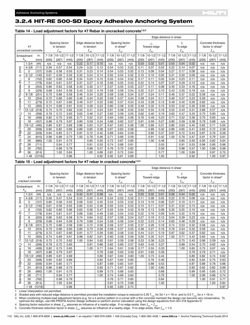
Adhesive Anchoring Systems
324 HIT-RE 500-SD Epoxy Adhesive Anchoring System
112 Hilti Inc (US) 1-800-879-8000 | wwwushilticom I en espantildeol 1-800-879-5000 I Hilti (Canada) Corp 1-800-363-4458 I wwwhiltica I Anchor Fastening Technical Guide 2014
Table 14 - Load adjustment factors for 7 Rebar in uncracked concrete123
7uncracked concrete
Spacing factor in tension
ƒAN
Edgedistancefactor in tension
ƒRN
Spacing factor in shear4
ƒAV
Edgedistanceinshear
Concrete thickness factor in shear5
ƒHV
Toward edge
ƒRV
To edge
ƒRV
Embedment hef
in 7-78 10-12 17-12 7-78 10-12 17-12 7-78 10-12 17-12 7-78 10-12 17-12 7-78 10-12 17-12 7-78 10-12 17-12(mm) (200) (267) (445) (200) (267) (445) (200) (267) (445) (200) (267) (445) (200) (267) (445) (200) (267) (445)
Spacing(s)Edg
eDistance(c
a) C
oncr
ete
Thic
knes
s (h
) - i
n (m
m)
1-34 (44) na na na 022 017 010 na na na 003 002 001 005 004 002 na na na4-38 (111) 059 057 054 029 022 013 054 053 052 011 007 003 022 014 007 na na na
5 (127) 060 058 055 031 023 014 054 053 052 013 009 004 027 017 008 na na na5-12 (140) 061 059 055 032 024 014 055 054 052 015 010 005 031 020 009 na na na
6 (152) 062 060 056 034 025 015 055 054 052 017 011 005 034 023 011 na na na7 (178) 064 061 057 037 027 016 056 055 053 022 014 007 037 029 013 na na na8 (203) 066 063 058 040 030 017 057 055 053 027 017 008 040 033 016 na na na9 (229) 068 064 059 043 032 019 058 056 054 032 021 010 043 035 019 na na na
9-78 (251) 070 066 059 046 034 020 059 056 054 037 024 011 046 037 022 059 na na10 (254) 070 066 060 046 034 020 059 057 054 038 024 011 046 037 023 059 na na11 (279) 072 067 060 049 037 022 060 057 054 043 028 013 049 040 026 062 na na12 (305) 074 069 061 053 039 023 060 058 055 049 032 015 053 042 030 065 na na
12-12 (318) 075 070 062 055 041 024 061 058 055 052 034 016 055 043 031 066 057 na14 (356) 078 072 063 062 046 027 062 059 055 062 040 019 062 047 033 070 060 na16 (406) 082 075 065 071 052 031 064 060 056 076 049 023 071 052 036 075 065 na18 (457) 086 079 067 080 059 034 066 062 057 091 059 027 080 059 038 079 068 na
19-12 (495) 089 081 069 086 063 037 067 063 058 100 066 031 086 063 040 082 071 05520 (508) 090 082 069 089 065 038 067 063 058 069 032 089 065 041 083 072 05622 (559) 094 085 071 097 072 042 069 064 059 080 037 097 072 044 087 076 05924 (610) 098 088 073 100 078 046 071 066 059 091 042 100 078 047 091 079 06126 (660) 100 091 075 085 050 073 067 060 100 048 085 050 095 082 06428 (711) 094 077 091 053 074 068 061 053 091 053 099 085 06630 (762) 098 079 098 057 076 070 062 059 098 057 100 088 06836 (914) 100 084 100 069 081 073 064 077 100 069 097 075
gt 48 (1219) 096 092 092 081 069 100 092 100 087
Table 15 - Load adjustment factors for 7 rebar in cracked concrete123
7cracked concrete
Spacing factor in tension
ƒAN
Edgedistancefactor in tension
ƒRN
Spacing factor in shear4
ƒAV
Edgedistanceinshear
Concrete thickness factor in shear5
ƒHV
Toward edge
ƒRV
To edge
ƒRV
Embedment hef
in 7-78 10-12 17-12 7-78 10-12 17-12 7-78 10-12 17-12 7-78 10-12 17-12 7-78 10-12 17-12 7-78 10-12 17-12(mm) (200) (267) (445) (200) (267) (445) (200) (267) (445) (200) (267) (445) (200) (267) (445) (200) (267) (445)
Spacing(s)Edg
eDistance(c
a) C
oncr
ete
Thic
knes
s (h
) - i
n (m
m)
1-34 (44) na na na 042 041 038 na na na 003 002 001 006 004 002 na na na4-38 (111) 059 057 054 055 050 044 054 053 052 011 008 005 022 016 009 na na na
5 (127) 060 058 055 058 052 045 054 053 052 013 010 006 027 019 011 na na na5-12 (140) 061 059 055 060 054 046 055 054 053 015 011 007 031 022 013 na na na
6 (152) 062 060 056 063 056 047 055 054 053 018 013 008 035 025 015 na na na7 (178) 064 061 057 068 060 049 056 055 053 022 016 009 044 032 019 na na na8 (203) 066 063 058 074 064 052 057 056 054 027 019 012 054 039 023 na na na9 (229) 068 064 059 079 068 054 058 056 054 032 023 014 065 046 028 na na na
9-78 (251) 070 066 059 084 072 056 059 057 055 037 026 016 074 053 032 059 na na10 (254) 070 066 060 085 073 056 059 057 055 038 027 016 076 054 032 059 na na11 (279) 072 067 060 091 077 059 060 058 055 044 031 019 087 062 037 062 na na12 (305) 074 069 061 098 082 061 060 058 056 050 035 021 100 071 042 065 na na
12-12 (318) 075 070 062 100 084 062 061 059 056 053 038 023 075 045 066 059 na14 (356) 078 072 063 091 066 062 060 057 063 045 027 089 054 070 062 na16 (406) 082 075 065 100 071 064 061 058 077 055 033 100 065 075 067 na18 (457) 086 079 067 076 066 063 059 091 065 039 076 079 071 na
19-12 (495) 089 081 069 080 067 064 060 100 073 044 080 082 074 06220 (508) 090 082 069 082 067 064 060 076 046 082 084 075 06322 (559) 094 085 071 087 069 065 061 088 053 087 088 078 06624 (610) 098 088 073 093 071 067 062 100 060 093 092 082 06926 (660) 100 091 075 099 073 068 063 068 099 095 085 07228 (711) 094 077 100 074 069 064 076 100 099 088 07430 (762) 098 079 076 071 065 084 100 091 07736 (914) 100 084 081 075 068 100 100 084
gt 48 (1219) 096 092 083 074 0971 Linear interpolation not permitted2 Shadedareawithreducededgedistanceispermittedprovidedtheinstallationtorqueisreducedto030Tmax for 5d lt s lt 16-in and to 05 Tmax for s gt 16-in3 When combining multiple load adjustment factors (eg for a 4 anchor pattern in a corner with a thin concrete member) the design can become very conservative To
optimizethedesignuseHiltiPROFISAnchorDesignsoftwareorperformanchorcalculationusingthedesignequationsfromACI318AppendixD4 Spacing factor reduction in shear ƒAVassumesaninfluenceofanearbyedgeIfnoedgeexiststhenƒAV = ƒAN5 Concrete thickness reduction factor in shear ƒHVassumesaninfluenceofanearbyedgeIfnoedgeexiststhenƒHV = 10
Adhesive Anchoring Systems
HIT-RE 500-SD Epoxy Adhesive Anchoring System 324
Hilti Inc (US) 1-800-879-8000 | wwwushilticom I en espantildeol 1-800-879-5000 I Hilti (Canada) Corp 1-800-363-4458 I wwwhiltica I Anchor Fastening Technical Guide 2014 113
328
325
326
327
324
325
325
323
Table 16 - Load adjustment factors for 8 rebar in uncracked concrete123
8uncracked concrete
Spacing factor in tension
ƒAN
Edgedistancefactor in tension
ƒRN
Spacing factor in shear4
ƒAV
Edgedistanceinshear
Concrete thickness factor in shear5
ƒHV
Toward edge
ƒRV
To edge
ƒRV
Embedment hef
in 9 12 20 9 12 20 9 12 20 9 12 20 9 12 20 9 12 20(mm) (229) (305) (508) (229) (305) (508) (229) (305) (508) (229) (305) (508) (229) (305) (508) (229) (305) (508)
Spacing(s)Edg
eDistance(c
a) C
oncr
ete
Thic
knes
s (h
) - i
n (m
m)
1-34 (44) na na na 022 017 010 na na na 002 001 001 005 003 001 na na na5 (127) 059 057 054 030 022 013 054 053 052 011 007 003 022 014 007 na na na6 (152) 061 058 055 032 024 014 055 053 052 014 009 004 029 019 009 na na na
6-14 (159) 061 059 055 033 024 014 055 054 052 015 010 005 030 020 009 na na na7 (178) 063 060 056 035 026 015 055 054 052 018 012 005 035 023 011 na na na8 (203) 064 061 057 038 028 016 056 055 053 022 014 007 038 029 013 na na na9 (229) 066 063 058 040 029 017 057 055 053 026 017 008 040 033 016 na na na10 (254) 068 064 058 043 032 018 058 056 053 031 020 009 043 035 019 na na na11 (279) 070 065 059 046 034 020 058 056 054 035 023 011 046 037 021 na na na
11-14 (286) 070 066 059 047 034 020 059 056 054 037 024 011 047 037 022 058 na na12 (305) 072 067 060 049 036 021 059 057 054 040 026 012 049 039 024 060 na na13 (330) 073 068 061 052 038 022 060 057 054 046 030 014 052 041 028 063 na na14 (356) 075 069 062 056 040 024 061 058 055 051 033 015 056 043 031 065 na na
14-14 (362) 076 070 062 057 041 024 061 058 055 052 034 016 057 043 031 066 057 na16 (406) 079 072 063 064 046 027 062 059 055 062 040 019 064 047 033 070 060 na18 (457) 082 075 065 072 052 030 064 060 056 074 048 022 072 052 036 074 064 na20 (508) 086 078 067 080 058 034 065 061 057 087 056 026 080 058 038 078 067 na22 (559) 089 081 068 087 063 037 067 063 058 100 065 030 087 063 040 082 071 na
22-14 (565) 090 081 069 088 064 038 067 063 058 066 031 088 064 041 082 071 05524 (610) 093 083 070 095 069 040 068 064 058 074 035 095 069 043 085 074 05726 (660) 097 086 072 100 075 044 070 065 059 084 039 100 075 045 089 077 06028 (711) 100 089 073 081 047 071 066 060 094 043 081 048 092 080 06230 (762) 092 075 086 051 073 067 060 100 048 086 051 095 083 06436 (914) 100 080 100 061 077 070 062 063 100 061 100 091 070
gt 48 (1219) 090 081 086 077 066 098 081 100 081
Table 17 - Load adjustment factors for 8 rebar in cracked concrete123
8cracked concrete
Spacing factor in tension
ƒAN
Edgedistancefactor in tension
ƒRN
Spacing factor in shear4
ƒAV
Edgedistanceinshear
Concrete thickness factor in shear5
ƒHV
Toward edge
ƒRV
To edge
ƒRV
Embedment hef
in 9 12 20 9 12 20 9 12 20 9 12 20 9 12 20 9 12 20(mm) (229) (305) (508) (229) (305) (508) (229) (305) (508) (229) (305) (508) (229) (305) (508) (229) (305) (508)
Spacing(s)Edg
eDistance(c
a) C
oncr
ete
Thic
knes
s (h
) - i
n (m
m)
1-34 (44) na na na 042 040 038 na na na 002 002 001 005 003 002 na na na5 (127) 059 057 054 055 050 044 054 053 052 011 008 005 022 016 009 na na na6 (152) 061 058 055 059 053 046 055 054 053 014 010 006 029 021 012 na na na
6-14 (159) 061 059 055 060 054 046 055 054 053 015 011 007 031 022 013 na na na7 (178) 063 060 056 064 057 047 055 054 053 018 013 008 036 026 016 na na na8 (203) 064 061 057 069 060 049 056 055 053 022 016 009 044 032 019 na na na9 (229) 066 063 058 074 064 051 057 055 054 026 019 011 053 038 023 na na na10 (254) 068 064 058 079 067 053 058 056 054 031 022 013 062 044 026 na na na11 (279) 070 065 059 084 071 055 058 057 055 036 025 015 072 051 031 na na na
11-14 (286) 070 066 059 085 072 056 059 057 055 037 026 016 074 053 032 059 na na12 (305) 072 067 060 089 075 057 059 057 055 041 029 017 082 058 035 061 na na13 (330) 073 068 061 095 079 059 060 058 056 046 033 020 092 065 039 063 na na14 (356) 075 069 062 100 083 062 061 059 056 051 037 022 100 073 044 065 na na
14-14 (362) 076 070 062 084 062 061 059 056 053 038 023 075 045 066 059 na16 (406) 079 072 063 091 066 062 060 057 063 045 027 089 054 070 062 na18 (457) 082 075 065 100 070 064 061 058 075 053 032 100 064 074 066 na20 (508) 086 078 067 075 065 062 059 088 062 037 075 078 070 na22 (559) 089 081 068 080 067 063 060 100 072 043 080 082 073 na
22-14 (565) 090 081 069 080 067 064 060 073 044 080 082 074 06224 (610) 093 083 070 085 068 065 060 082 049 085 086 076 06426 (660) 097 086 072 090 070 066 061 093 056 090 089 080 06728 (711) 100 089 073 095 071 067 062 100 062 095 092 083 07030 (762) 092 075 100 073 068 063 069 100 096 085 07236 (914) 100 080 077 072 066 090 100 094 079
gt 48 (1219) 090 087 079 071 100 100 0911 Linear interpolation not permitted2 Shadedareawithreducededgedistanceispermittedprovidedtheinstallationtorqueisreducedto030Tmax for 5d lt s lt 16-in and to 05 Tmax for s gt 16-in3 When combining multiple load adjustment factors (eg for a 4 anchor pattern in a corner with a thin concrete member) the design can become very conservative To
optimizethedesignuseHiltiPROFISAnchorDesignsoftwareorperformanchorcalculationusingthedesignequationsfromACI318AppendixD4 Spacing factor reduction in shear ƒAVassumesaninfluenceofanearbyedgeIfnoedgeexiststhenƒAV = ƒAN5 Concrete thickness reduction factor in shear ƒHVassumesaninfluenceofanearbyedgeIfnoedgeexiststhenƒHV = 10
Adhesive Anchoring Systems
324 HIT-RE 500-SD Epoxy Adhesive Anchoring System
114 Hilti Inc (US) 1-800-879-8000 | wwwushilticom I en espantildeol 1-800-879-5000 I Hilti (Canada) Corp 1-800-363-4458 I wwwhiltica I Anchor Fastening Technical Guide 2014
Table 18 - Load adjustment factors for 9 rebar in uncracked concrete123
9uncracked concrete
Spacing factor in tension
ƒAN
Edgedistancefactor in tension
ƒRN
Spacing factor in shear4
ƒAV
Edgedistanceinshear
Concrete thickness factor in shear5
ƒHV
Toward edge
ƒRV
To edge
ƒRV
Embedment hef
in 10-18 13-12 22-12 10-18 13-12 22-12 10-18 13-12 22-12 10-18 13-12 22-12 10-18 13-12 22-12 10-18 13-12 22-12(mm) (257) (343) (572) (257) (343) (572) (257) (343) (572) (257) (343) (572) (257) (343) (572) (257) (343) (572)
Spacing(s)Edg
eDistance(c
a) C
oncr
ete
Thic
knes
s (h
) - i
n (m
m)
1-34 (44) na na na 023 016 010 na na na 002 001 001 004 002 001 na na na5-58 (143) 059 057 054 031 022 013 054 053 052 011 007 003 022 014 007 na na na
6 (152) 060 057 054 032 023 013 054 053 052 012 008 004 024 016 007 na na na7 (178) 061 059 055 034 024 014 055 054 052 015 010 005 030 020 009 na na na
7-14 (184) 062 059 055 034 025 015 055 054 052 016 010 005 032 021 010 na na na8 (203) 063 060 056 036 026 015 055 054 052 018 012 006 036 024 011 na na na9 (229) 065 061 057 039 028 016 056 055 053 022 014 007 039 029 013 na na na10 (254) 066 062 057 041 030 017 057 055 053 026 017 008 041 033 016 na na na11 (279) 068 064 058 044 031 018 057 056 053 030 019 009 044 035 018 na na na12 (305) 069 065 059 046 033 019 058 056 054 034 022 010 046 037 020 na na na
12-78 (327) 071 066 060 049 035 020 059 057 054 038 024 011 049 038 023 059 na na13 (330) 071 066 060 049 035 021 059 057 054 038 025 012 049 038 023 059 na na14 (356) 073 067 060 052 037 022 059 057 054 043 028 013 052 040 026 061 na na16 (406) 076 070 062 058 041 024 061 058 055 052 034 016 058 044 031 066 na na
16-14 (413) 076 070 062 059 042 025 061 058 055 053 035 016 059 045 032 066 057 na18 (457) 079 072 063 066 047 027 062 059 055 062 040 019 066 048 034 070 060 na20 (508) 082 075 065 073 052 030 063 060 056 073 047 022 073 052 036 073 064 na22 (559) 085 077 066 080 057 033 065 061 057 084 055 025 080 057 038 077 067 na24 (610) 089 080 068 087 062 036 066 062 057 096 062 029 087 062 040 080 070 na
25-14 (641) 091 081 069 092 065 038 067 063 058 100 067 031 092 065 041 083 071 05526 (660) 092 082 069 095 067 039 068 063 058 070 033 095 067 042 084 073 05628 (711) 095 085 071 100 073 042 069 064 059 078 036 100 073 044 087 075 05830 (762) 098 087 072 078 046 070 065 059 087 040 078 047 090 078 06036 (914) 100 094 077 093 055 074 068 061 100 053 093 055 099 085 066
gt 48 (1219) 100 086 100 073 082 074 065 082 100 073 100 099 076
Table 19 - Load adjustment factors for 9 rebar in cracked concrete123
9cracked concrete
Spacing factor in tension
ƒAN
Edgedistancefactor in tension
ƒRN
Spacing factor in shear4
ƒAV
Edgedistanceinshear
Concrete thickness factor in shear5
ƒHV
Toward edge
ƒRV
To edge
ƒRV
Embedment hef
in 10-18 13-12 22-12 10-18 13-12 22-12 10-18 13-12 22-12 10-18 13-12 22-12 10-18 13-12 22-12 10-18 13-12 22-12(mm) (257) (343) (572) (257) (343) (572) (257) (343) (572) (257) (343) (572) (257) (343) (572) (257) (343) (572)
Spacing(s)Edg
eDistance(c
a) C
oncr
ete
Thic
knes
s (h
) - i
n (m
m)
1-34 (44) na na na 041 039 038 na na na 002 001 001 004 003 002 na na na5-58 (143) 059 057 054 055 050 044 054 053 052 011 008 005 022 016 009 na na na
6 (152) 060 057 054 057 051 044 054 053 052 012 009 005 024 017 010 na na na7 (178) 061 059 055 061 054 046 055 054 053 015 011 007 030 022 013 na na na
7-14 (184) 062 059 055 062 055 046 055 054 053 016 012 007 032 023 014 na na na8 (203) 063 060 056 065 057 048 055 054 053 019 013 008 037 027 016 na na na9 (229) 065 061 057 069 060 049 056 055 053 022 016 010 044 032 019 na na na10 (254) 066 062 057 073 063 051 057 055 054 026 019 011 052 037 022 na na na11 (279) 068 064 058 078 067 053 057 056 054 030 022 013 060 043 026 na na na12 (305) 069 065 059 083 070 055 058 057 055 034 025 015 068 049 029 na na na
12-78 (327) 071 066 060 087 073 056 059 057 055 038 027 016 076 054 033 059 na na13 (330) 071 066 060 087 073 056 059 057 055 039 028 017 077 055 033 059 na na14 (356) 073 067 060 092 077 058 060 058 055 043 031 019 086 062 037 062 na na16 (406) 076 070 062 100 084 062 061 059 056 053 038 023 100 075 045 066 na na
16-14 (413) 076 070 062 085 063 061 059 056 054 039 023 077 046 066 059 na18 (457) 079 072 063 091 066 062 060 057 063 045 027 090 054 070 063 na20 (508) 082 075 065 099 070 064 061 058 073 053 032 099 063 074 066 na22 (559) 085 077 066 100 074 065 062 059 085 061 036 100 073 077 069 na24 (610) 089 080 068 078 066 063 059 097 069 042 078 081 072 na
25-14 (641) 091 081 069 081 067 064 060 100 075 045 081 083 074 06326 (660) 092 082 069 082 068 064 060 078 047 082 084 075 06328 (711) 095 085 071 087 069 065 061 087 052 087 087 078 06630 (762) 098 087 072 091 070 066 062 097 058 091 090 081 06836 (914) 100 094 077 100 074 070 064 100 076 100 099 088 075
gt 48 (1219) 100 086 083 076 069 100 100 100 0861 Linear interpolation not permitted2 Shadedareawithreducededgedistanceispermittedprovidedtheinstallationtorqueisreducedto030Tmax for 5d lt s lt 16-in and to 05 Tmax for s gt 16-in3 When combining multiple load adjustment factors (eg for a 4 anchor pattern in a corner with a thin concrete member) the design can become very conservative To
optimizethedesignuseHiltiPROFISAnchorDesignsoftwareorperformanchorcalculationusingthedesignequationsfromACI318AppendixD4 Spacing factor reduction in shear ƒAVassumesaninfluenceofanearbyedgeIfnoedgeexiststhenƒAV = ƒAN5 Concrete thickness reduction factor in shear ƒHVassumesaninfluenceofanearbyedgeIfnoedgeexiststhenƒHV = 10
Adhesive Anchoring Systems
HIT-RE 500-SD Epoxy Adhesive Anchoring System 324
Hilti Inc (US) 1-800-879-8000 | wwwushilticom I en espantildeol 1-800-879-5000 I Hilti (Canada) Corp 1-800-363-4458 I wwwhiltica I Anchor Fastening Technical Guide 2014 115
328
325
326
327
324
325
325
323
Table 20 - Load adjustment factors for 10 rebar in uncracked concrete123
10uncracked concrete
Spacing factor in tension
ƒAN
Edgedistancefactor in tension
ƒRN
Spacing factor in shear4
ƒAV
Edgedistanceinshear
Concrete thickness factor in shear5
ƒHV
Toward edge
ƒRV
To edge
ƒRV
Embedment hef
in 11-14 15 25 11-14 15 25 11-14 15 25 11-14 15 25 11-14 15 25 11-14 15 25(mm) (286) (381) (635) (286) (381) (635) (286) (381) (635) (286) (381) (635) (286) (381) (635) (286) (381) (635)
Spacing(s)Edg
eDistance(c
a) C
oncr
ete
Thic
knes
s (h
) - i
n (m
m) 1-34 (44) na na na 023 016 009 na na na 002 001 000 003 002 001 na na na
6-14 (159) 059 057 054 031 022 013 054 053 052 011 007 003 022 014 007 na na na7 (178) 060 058 055 033 023 014 054 053 052 013 008 004 026 017 008 na na na8 (203) 062 059 055 035 025 014 055 054 052 016 010 005 031 020 010 na na na9 (229) 063 060 056 037 026 015 055 054 052 019 012 006 037 024 011 na na na10 (254) 065 061 057 039 028 016 056 055 053 022 014 007 039 029 013 na na na11 (279) 066 062 057 042 029 017 057 055 053 025 016 008 042 033 015 na na na12 (305) 068 063 058 044 031 018 057 055 053 029 019 009 044 035 017 na na na13 (330) 069 064 059 047 033 019 058 056 054 033 021 010 047 036 020 na na na14 (356) 071 066 059 049 035 020 059 056 054 036 024 011 049 038 022 na na na
14-14 (362) 071 066 060 050 035 020 059 056 054 037 024 011 050 038 023 059 na na15 (381) 072 067 060 052 036 021 059 057 054 040 026 012 052 040 024 060 na na16 (406) 073 068 061 054 038 022 060 057 054 045 029 013 054 041 027 062 na na17 (432) 075 069 061 057 040 023 060 058 055 049 032 015 057 043 029 064 na na18 (457) 076 070 062 060 042 025 061 058 055 053 035 016 060 045 032 066 057 na20 (508) 079 072 063 067 047 028 062 059 055 062 040 019 067 048 034 070 060 na22 (559) 082 074 065 074 052 030 063 060 056 072 047 022 074 052 036 073 063 na24 (610) 085 077 066 080 056 033 065 061 057 082 053 025 080 056 038 076 066 na26 (660) 088 079 067 087 061 036 066 062 057 092 060 028 087 061 040 079 069 na28 (711) 091 081 069 094 066 039 067 063 058 100 067 031 094 066 042 082 071 05530 (762) 094 083 070 100 071 041 068 064 058 074 035 100 071 044 085 074 05736 (914) 100 090 074 085 050 072 066 060 098 045 085 050 094 081 063
gt 48 (1219) 100 082 100 066 079 072 063 100 070 100 066 100 094 072
Table 21 - Load adjustment factors for 10 rebar in cracked concrete123
10cracked concrete
Spacing factor in tension
ƒAN
Edgedistancefactor in tension
ƒRN
Spacing factor in shear4
ƒAV
Edgedistanceinshear
Concrete thickness factor in shear5
ƒHV
Toward edge
ƒRV
To edge
ƒRV
Embedment hef
in 11-14 15 25 11-14 15 25 11-14 15 25 11-14 15 25 11-14 15 25 11-14 15 25(mm) (286) (381) (635) (286) (381) (635) (286) (381) (635) (286) (381) (635) (286) (381) (635) (286) (381) (635)
Spacing(s)Edg
eDistance(c
a) C
oncr
ete
Thic
knes
s (h
) - i
n (m
m) 1-34 (44) na na na 040 039 037 na na na 002 001 001 003 002 001 na na na
6-14 (159) 059 057 054 055 050 044 054 053 052 011 008 005 022 016 010 na na na7 (178) 060 058 055 058 052 045 054 054 053 013 010 006 026 019 012 na na na8 (203) 062 059 055 062 055 046 055 054 053 016 012 007 032 024 014 na na na9 (229) 063 060 056 066 057 048 055 055 053 019 014 008 038 028 017 na na na10 (254) 065 061 057 069 060 049 056 055 054 022 017 010 044 033 020 na na na11 (279) 066 062 057 074 063 051 057 056 054 026 019 011 051 038 023 na na na12 (305) 068 063 058 078 066 053 057 056 054 029 022 013 058 044 026 na na na13 (330) 069 064 059 082 069 054 058 057 055 033 025 015 066 049 029 na na na14 (356) 071 066 059 086 072 056 059 057 055 037 027 016 073 055 033 na na na
14-14 (362) 071 066 060 087 073 056 059 057 055 038 028 017 075 056 034 059 na na15 (381) 072 067 060 091 075 057 059 058 055 041 030 018 082 061 036 061 na na16 (406) 073 068 061 095 078 059 060 058 056 045 033 020 090 067 040 063 na na17 (432) 075 069 061 100 081 061 060 059 056 049 037 022 098 073 044 064 na na18 (457) 076 070 062 085 062 061 059 056 054 040 024 100 080 048 066 060 na20 (508) 079 072 063 091 066 062 060 057 063 047 028 091 056 070 063 na22 (559) 082 074 065 098 069 063 061 058 072 054 032 098 065 073 066 na24 (610) 085 077 066 100 073 065 062 059 082 062 037 100 073 077 069 na26 (660) 088 079 067 077 066 063 059 093 069 042 077 080 072 na28 (711) 091 081 069 081 067 064 060 100 078 047 081 083 075 06330 (762) 094 083 070 085 068 065 061 086 052 085 086 078 06536 (914) 100 090 074 097 072 068 063 100 068 097 094 085 072
gt 48 (1219) 100 082 100 079 074 067 100 100 100 098 0831 Linear interpolation not permitted2 Shadedareawithreducededgedistanceispermittedprovidedtheinstallationtorqueisreducedto030Tmax for 5d lt s lt 16-in and to 05 Tmax for s gt 16-in3 When combining multiple load adjustment factors (eg for a 4 anchor pattern in a corner with a thin concrete member) the design can become very conservative To
optimizethedesignuseHiltiPROFISAnchorDesignsoftwareorperformanchorcalculationusingthedesignequationsfromACI318AppendixD4 Spacing factor reduction in shear ƒAVassumesaninfluenceofanearbyedgeIfnoedgeexiststhenƒAV = ƒAN5 Concrete thickness reduction factor in shear ƒHVassumesaninfluenceofanearbyedgeIfnoedgeexiststhenƒHV = 10
Adhesive Anchoring Systems
324 HIT-RE 500-SD Epoxy Adhesive Anchoring System
116 Hilti Inc (US) 1-800-879-8000 | wwwushilticom I en espantildeol 1-800-879-5000 I Hilti (Canada) Corp 1-800-363-4458 I wwwhiltica I Anchor Fastening Technical Guide 2014
32432 HIT-RE 500-SD Adhesive with Hilti HAS threaded rods Table 22 - HAS carbon steel threaded rod specifications
Setting information Symbol UnitsNominal rod diameter
38 12 58 34 78 1 1-14Nominal bit diameter do in 716 916 34 78 1 1-18 1-38
Standard effective embedment hefstd
in 3-38 4-12 5-58 6-34 7-78 9 11-14(mm) (86) (114) (143) (171) (200) (229) (286)
Effective embedment
minimum hefmin
in 2-38 2-34 3-18 3-12 3-12 4 5(mm) (60) (70) (79) (89) (89) (102) (127)
maximum hefmax
in 7-12 10 12-12 15 17-12 20 25(mm) (191) (254) (318) (381) (445) (508) (635)
Minimum diameter of fixture hole through-set in 12 58 13161 15161 1-181 1-141 1-121
Minimum diameter of fixture hole preset in 716 916 1116 1316 1516 1-18 1-38
Installationtorque Tinst
ft-lb 15 30 60 100 125 150 200(Nm) (20) (40) (80) (136) (169) (203) (271)
1 Install using (2) washers See Figure 11
Figure 10 - HAS threaded rods
Figure 11 - Installation with (2) washers
HAS carbon steel threaded rod specificationsCarbon steel rods conform to ISO 898 class 58 with a minimum tensile strength of 725 ksi (500 MPa) and a minimum yield strength of 58 ksi (400 MPa)HAS-EnutsconformtoSAEJ995Grade5HAS-EwashersconformtoASTMF884HVandANSIB18221TypeAPlainHAS-ErodnutandwasherhasanelectroplatedzinccoatingconformingtoASTMB633SC1
HAS Super high strength threaded rod specificationsCarbonsteelrodsmanufacturedfromASTMA193GradeB7withaminimumtensilestrengthof125ksi(862MPa)and a minimum yield strength of 105 ksi (724 MPa)HASSupernutsconformtoSAEJ995Grade5HASSuperwashersconformtoASTMF884HVandANSIB18221TypeAPlainHAS Super rods nuts and washers except the 78-in diameter have an electroplated zinc coating conforming to ASTM B633 SC178-in HAS Super rods nuts and washers are hot-dip galvanized in accordance with ASTM A153
HAS-R 304 stainless steel38- 12- and 58-in rods manufactured from AISI Type 304 stainless steel with a minimum tensile strength of 100 ksi (689 MPa) and a minimum yield strength of 65 ksi (448 MPa)34- 1- and 1 14-in rods are manufactured from AISI Type 304 stainless steel conforming to ASTM F593 Condition CW or cold workedAISI Type 304 stainless steel nuts conform to ASTM F594AISI Type 304 stainless steel washers conform to ASTM A240 and ANSI B18221 Type A Plain
HAS-R 316 stainless steel38- 12- and 58-in rods manufactured from AISI Type 316 stainless steel with a minimum tensile strength of 100 ksi (689 MPa) and a minimum yield strength of 65 ksi (448 MPa)34- 1- and 1 14-in rods are manufactured from AISI Type 316 stainless steel conforming to ASTM F593 Condition CWAISI Type 316 stainless steel nuts conform to ASTM F594AISI Type 316 stainless steel washers conform to ASTM A240 and ANSI B18221 Type A Plain
Adhesive Anchoring Systems
HIT-RE 500-SD Epoxy Adhesive Anchoring System 324
Hilti Inc (US) 1-800-879-8000 | wwwushilticom I en espantildeol 1-800-879-5000 I Hilti (Canada) Corp 1-800-363-4458 I wwwhiltica I Anchor Fastening Technical Guide 2014 117
328
325
326
327
324
325
325
323
Table 23 - Hilti HIT-RE 500-SD adhesive design strength (factored resistance) with concrete bond failure for Hilti HAS threaded rod in uncracked concrete123456789
Nominal anchor
diameter in
Effectiveembedment
in (mm)
TensionmdashФNn or Nr ShearmdashФVn or Vr
ƒ´c = 2500 psi (172 Mpa)
lb (kN)
ƒ´c = 3000 psi (207 Mpa)
lb (kN)
ƒ´c = 4000 psi (276 Mpa)
lb (kN)
ƒ´c = 6000 psi(414 Mpa)
lb (kN)
ƒ´c = 2500 psi (172 Mpa)
lb (kN)
ƒ´c = 3000 psi (207 Mpa)
lb (kN)
ƒ´c = 4000 psi (276 Mpa)
lb (kN)
ƒ´c = 6000 psi(414 Mpa)
lb (kN)
38
2-38 2855 3125 3610 4405 3075 3370 3890 4745(60) (127) (139) (161) (196) (137) (150) (173) (211)
3-38 4835 5300 5905 6260 10415 11410 12720 13485(86) (215) (236) (263) (278) (463) (508) (566) (600)
4-12 7445 7875 7875 8345 16035 16960 16960 17975(114) (331) (350) (350) (371) (713) (754) (754) (800)7-12 13125 13125 13125 13910 28265 28265 28265 29960(191) (584) (584) (584) (619) (1257) (1257) (1257) (1333)
12
2-34 3555 3895 4500 5510 7660 8395 9690 11870(70) (158) (173) (200) (245) (341) (373) (431) (528)
4-12 7445 8155 9420 10885 16035 17570 20285 23445(114) (331) (363) (419) (484) (713) (782) (902) (1043)
6 11465 12560 13690 14515 24690 27045 29490 31260(152) (510) (559) (609) (646) (1098) (1203) (1312) (1391)10 22820 22820 22820 24190 49150 49150 49150 52100
(254) (1015) (1015) (1015) (1076) (2186) (2186) (2186) (2318)
58
3-18 4310 4720 5450 6675 9280 10165 11740 14380(79) (192) (210) (242) (297) (413) (452) (522) (640)
5-58 10405 11400 13165 16120 22415 24550 28350 34720(143) (463) (507) (586) (717) (997) (1092) (1261) (1544)7-12 16020 17550 20265 21715 34505 37800 43650 46765(191) (713) (781) (901) (966) (1535) (1681) (1942) (2080)
12-12 34140 34140 34140 36190 73535 73535 73535 77945(318) (1519) (1519) (1519) (1610) (3271) (3271) (3271) (3467)
34
3-12 5105 5595 6460 7910 11000 12050 13915 17040(89) (227) (249) (287) (352) (489) (536) (619) (758)
6-34 13680 14985 17305 21190 29460 32275 37265 45645(171) (609) (667) (770) (943) (1310) (1436) (1658) (2030)
9 21060 23070 26640 30170 45360 49690 57375 64985(229) (937) (1026) (1185) (1342) (2018) (2210) (2552) (2891)15 45315 47440 47440 50285 97600 102175 102175 108305
(381) (2016) (2110) (2110) (2237) (4341) (4545) (4545) (4818)
78
3-12 5105 5595 6460 7910 11000 12050 13915 17040(89) (227) (249) (287) (352) (489) (536) (619) (758)
7-78 17235 18885 21805 25240 37125 40670 46960 57515(200) (767) (840) (970) (1123) (1651) (1809) (2089) (2558)
10-12 26540 29070 31750 33655 57160 62615 72300 85665(267) (1181) (1293) (1412) (1497) (2543) (2785) (3216) (3811)
17-12 52915 52915 52915 56090 122990 134695 134695 142780(445) (2354) (2354) (2354) (2495) (5471) (5992) (5992) (6351)
1
4 6240 6835 7895 9665 13440 14725 17000 20820(102) (278) (304) (351) (430) (598) (655) (756) (926)
9 21060 23070 26640 32060 45360 49690 57375 70270(229) (937) (1026) (1185) (1426) (2018) (2210) (2552) (3126)12 32425 35520 40330 42750 69835 76500 88335 108190
(305) (1442) (1580) (1794) (1902) (3106) (3403) (3929) (4813)20 67215 67215 67215 71245 150265 164605 171090 181355
(508) (2990) (2990) (2990) (3169) (6684) (7322) (7610) (8067)
1-14
5 8720 9555 11030 13510 18785 20575 23760 29100(127) (388) (425) (491) (601) (836) (915) (1057) (1294)
11-14 29430 32240 37230 45595 63395 69445 80185 98205(286) (1309) (1434) (1656) (2028) (2820) (3089) (3567) (4368)15 45315 49640 57320 63875 97600 106915 123455 151200
(381) (2016) (2208) (2550) (2841) (4341) (4756) (5492) (6726)25 97500 100435 100435 106460 210000 230045 255645 270985
(635) (4337) (4468) (4468) (4736) (9341) (10233) (11372) (12054)1 See Section 317 for explanation on development of load values2 See Section 3173 to convert design strength (factored resistance) value to ASD value3 Linear interpolation between embedment depths and concrete compressive strengths is not permitted4 Apply spacing edge distance and concrete thickness factors in Tables 26-39 as necessary Compare to the steel values in Table 25
The lesser of the values is to be used for the design5 Data is for temperature range A Max short term temperature = 110degF (43degC) max long term temperature = 80degF (26degC)
FortemperaturerangeBMaxshorttermtemperature=162degF(72degC)maxlongtermtemperature=110degF(43degC)multiplyabovevalueby034 Short term elevated concrete temperatures are those that occur over brief intervals eg as a result of diurnal cycling Long term concrete temperatures are roughly constantoversignificantperiodsoftime
6 Tabular values are for dry concrete conditions For water saturated concrete multiply design strength (factored resistance) by 069 Forwater-filleddrilledholesmultiplydesignstrength(factoredresistance)by063 For submerged (under water) applications multiply design strength (factored resistance) by 064
7 Tabular values are for short term loads only For sustained loads including overhead use see Section 31758 TabularvaluesarefornormalweightconcreteonlyForlightweightconcretemultiplydesignstrength(factoredresistance)byλa as follows
Forsand-lightweightλa=051Forall-lightweightλa = 0459 Tabular values are for holes drilled in concrete with carbide tipped hammer drill bit For diamond core drilling multiply above value by 051
Diamondcoredrillingisnotpermittedforwater-filledorunderwater(submerged)applications
Adhesive Anchoring Systems
324 HIT-RE 500-SD Epoxy Adhesive Anchoring System
118 Hilti Inc (US) 1-800-879-8000 | wwwushilticom I en espantildeol 1-800-879-5000 I Hilti (Canada) Corp 1-800-363-4458 I wwwhiltica I Anchor Fastening Technical Guide 2014
Table 24 - Hilti HIT-RE 500-SD adhesive design strength (factored resistance) with concrete bond failure for Hilti HAS threaded rod in cracked concrete12345678910
Nominal anchor
diameter in
Effectiveembedment
depth in (mm)
TensionmdashФNn or Nr ShearmdashФVn or Vr
ƒ´c = 2500 psi (172 Mpa)
lb (kN)
ƒ´c = 3000 psi (207 Mpa)
lb (kN)
ƒ´c = 4000 psi (276 Mpa)
lb (kN)
ƒ´c = 6000 psi(414 Mpa)
lb (kN)
ƒ´c = 2500 psi (172 Mpa)
lb (kN)
ƒ´c = 3000 psi (207 Mpa)
lb (kN)
ƒ´c = 4000 psi (276 Mpa)
lb (kN)
ƒ´c = 6000 psi(414 Mpa)
lb (kN)
38
2-38 1980 1980 1980 2100 2135 2135 2135 2265(60) (88) (88) (88) (93) (95) (95) (95) (101)
3-38 2815 2815 2815 2985 6065 6065 6065 6430(86) (125) (125) (125) (133) (270) (270) (270) (286)
4-12 3755 3755 3755 3980 8090 8090 8090 8575(114) (167) (167) (167) (177) (360) (360) (360) (381)7-12 6260 6260 6260 6635 13485 13485 13485 14290(191) (278) (278) (278) (295) (600) (600) (600) (636)
12
2-34 2520 2760 3020 3200 5425 5945 6500 6890(70) (112) (123) (134) (142) (241) (264) (289) (306)
4-12 4940 4940 4940 5235 10640 10640 10640 11275(114) (220) (220) (220) (233) (473) (473) (473) (502)
6 6585 6585 6585 6980 14185 14185 14185 15035(152) (293) (293) (293) (310) (631) (631) (631) (669)10 10975 10975 10975 11635 23640 23640 23640 25060
(254) (488) (488) (488) (518) (1052) (1052) (1052) (1115)
58
3-18 3050 3345 3860 4420 6575 7200 8315 9515(79) (136) (149) (172) (197) (292) (320) (370) (423)
5-58 7370 7500 7500 7950 15875 16160 16160 17130(143) (328) (334) (334) (354) (706) (719) (719) (762)7-12 10005 10005 10005 10605 21545 21545 21545 22835(191) (445) (445) (445) (472) (958) (958) (958) (1016)
12-12 16670 16670 16670 17670 35905 35905 35905 38060(318) (742) (742) (742) (786) (1597) (1597) (1597) (1693)
34
3-12 3620 3965 4575 5605 7790 8535 9855 12070(89) (161) (176) (204) (249) (347) (380) (438) (537)
6-34 9690 10340 10340 10960 20870 22265 22265 23600(171) (431) (460) (460) (488) (928) (990) (990) (1050)
9 13785 13785 13785 14610 29690 29690 29690 31470(229) (613) (613) (613) (650) (1321) (1321) (1321) (1400)15 22975 22975 22975 24350 49480 49480 49480 52450
(381) (1022) (1022) (1022) (1083) (2201) (2201) (2201) (2333)
78
3-12 3620 3965 4575 5160 7790 8535 9855 12070(89) (161) (176) (204) (230) (347) (380) (438) (537)
7-78 10955 10955 10955 11610 26300 27880 27880 29555(200) (487) (487) (487) (516) (1170) (1240) (1240) (1315)
10-12 14605 14605 14605 15480 37175 37175 37175 39405(267) (650) (650) (650) (689) (1654) (1654) (1654) (1753)
17-12 24340 24340 24340 25800 61960 61960 61960 65680(445) (1083) (1083) (1083) (1148) (2756) (2756) (2756) (2922)
1
4 4420 4840 5590 6225 9520 10430 12040 14750(102) (197) (215) (249) (277) (423) (464) (536) (656)
9 13220 13220 13220 14010 32130 33645 33645 35665(229) (588) (588) (588) (623) (1429) (1497) (1497) (1586)12 17625 17625 17625 18680 44860 44860 44860 47555
(305) (784) (784) (784) (831) (1995) (1995) (1995) (2115)20 29375 29375 29375 31135 74770 74770 74770 79255
(508) (1307) (1307) (1307) (1385) (3326) (3326) (3326) (3525)
1-14
5 6175 6765 7815 8355 13305 14575 16830 20610(127) (275) (301) (348) (372) (592) (648) (749) (917)
11-14 17740 17740 17740 18800 44905 45150 45150 47860(286) (789) (789) (789) (836) (1997) (2008) (2008) (2129)15 23650 23650 23650 25070 60200 60200 60200 63815
(381) (1052) (1052) (1052) (1115) (2678) (2678) (2678) (2839)25 39415 39415 39415 41780 100335 100335 100335 106355
(635) (1753) (1753) (1753) (1858) (4463) (4463) (4463) (4731)1 See Section 317 for explanation on development of load values2 See Section 3173 to convert design strength (factored resistance) value to ASD value3 Linear interpolation between embedment depths and concrete compressive strengths is not permitted4 Apply spacing edge distance and concrete thickness factors in Tables 26-39 as necessary Compare to the steel values in Table 25
The lesser of the values is to be used for the design5 Data is for temperature range A Max short term temperature = 110degF (43degC) max long term temperature = 80degF (26degC)
FortemperaturerangeBMaxshorttermtemperature=162degF(72degC)maxlongtermtemperature=110degF(43degC)multiplyabovevalueby034 Short term elevated concrete temperatures are those that occur over brief intervals eg as a result of diurnal cycling Long term concrete temperatures are roughly constantoversignificantperiodsoftime
6 Tabular values are for dry concrete conditions For water saturated concrete multiply design strength (factored resistance) by 069 Forwater-filleddrilledholesmultiplydesignstrength(factoredresistance)by063 For submerged (under water) applications multiply design strength (factored resistance) by 064
7 Tabular values are for short term loads only For sustained loads including overhead use see Section 31758 TabularvaluesarefornormalweightconcreteonlyForlightweightconcretemultiplydesignstrength(factoredresistance)byλa as follows
Forsand-lightweightλa=051Forall-lightweightλa = 0459 TabularvaluesareforstaticloadsonlyForseismicloadsmultiplyabovevaluebyαseis = 049 See section 3174 for additional information on seismic applications10 Tabular values are for holes drilled in concrete with carbide tipped hammer drill bit Diamond core drilling is not permitted in cracked concrete conditions
Adhesive Anchoring Systems
HIT-RE 500-SD Epoxy Adhesive Anchoring System 324
Hilti Inc (US) 1-800-879-8000 | wwwushilticom I en espantildeol 1-800-879-5000 I Hilti (Canada) Corp 1-800-363-4458 I wwwhiltica I Anchor Fastening Technical Guide 2014 119
328
325
326
327
324
325
325
323
Table 25 - Steel design strength (ACI 318 Appendix D Based Design) for Hilti HAS threaded rods1
Nominal anchor
diameterin
HAS-E 2 HAS-SuperASTMA193B7 2 HAS SS AISI 304316 SS 2
Tensile3
ϕNsalb (kN)
Shear4
ϕVsalb (kN)
Seismic Shear5
ϕVsalb (kN)
Tensile3
ϕNsalb (kN)
Shear4
ϕVsalb (kN)
Seismic Shear5
ϕVsalb (kN)
Tensile3
ϕNsalb (kN)
Shear4
ϕVsalb (kN)
Seismic Shear5
ϕVsalb (kN)
383655 1685 1180 7265 3150 2205 5040 2325 1628(163) (75) (52) (323) (140) (98) (224) (103) (72)
126690 3705 2594 13300 6915 4841 9225 5110 3577(298) (165) (115) (592) (308) (215) (410) (227) (159)
5810650 5900 4130 21190 11020 7714 14690 8135 5695(474) (262) (184) (943) (490) (343) (653) (362) (253)
3415765 8730 6111 31360 16305 11414 18480 10235 7165(701) (388) (272) (1395) (725) (508) (822) (455) (319)
7821755 12050 8435 43285 22505 15754 25510 14125 9888(968) (536) (375) (1925) (1001) (701) (1135) (628) (440)
128540 15805 11064 56785 29525 20668 33465 18535 12975(1270) (703) (492) (2526) (1313) (919) (1489) (824) (577)
1-1445670 25295 17707 90850 47240 33068 53540 29655 20759(2031) (1125) (788) (4041) (2101) (1471) (2382) (1319) (923)
1 See Section 3173 to convert design strength (factored resistance) value to ASD value2 HASSuperrodsareconsideredductilesteelelementsHAS-EandHASSSrodsareconsideredbrittlesteelelements3 Tensile=фAseN futa as noted in ACI 318 Appendix D4 Shear=ф060AseN futa as noted in ACI 318 Appendix D5 SeismicshearvaluesdeterminedbymultiplyingфVsaxαVseiswhereαVseis = 07 for threaded rod See Section 3174 for additional information on seismic applications
Adhesive Anchoring Systems
324 HIT-RE 500-SD Epoxy Adhesive Anchoring System
120 Hilti Inc (US) 1-800-879-8000 | wwwushilticom I en espantildeol 1-800-879-5000 I Hilti (Canada) Corp 1-800-363-4458 I wwwhiltica I Anchor Fastening Technical Guide 2014
Table 26 - Load adjustment factors for 38-in diameter threaded rods in uncracked concrete123
38-inuncracked concrete
Spacing factor in tension
ƒAN
Edgedistancefactor in tension
ƒRN
Spacing factor in shear4
ƒAV
Edgedistanceinshear
Concrete thickness factor in shear5
ƒHV
Toward edge
ƒRV
To edge
ƒRV
Embedmenthef
in 2-38 3-38 4-12 7-12 2-38 3-38 4-12 7-12 2-38 3-38 4-12 7-12 2-38 3-38 4-12 7-12 2-38 3-38 4-12 7-12 2-38 3-38 4-12 7-12(mm) (60) (86) (114) (191) (60) (86) (114) (191) (60) (86) (114) (191) (60) (86) (114) (191) (60) (86) (114) (191) (60) (86) (114) (191)
Spacing(s)Edg
eDistance(c
a) C
oncr
ete
Thic
knes
s (h
) - i
n (m
m) 1-34 (44) na na na na 034 028 022 013 na na na na 023 007 005 003 041 014 009 005 na na na na
1-78 (48) 058 058 057 054 035 029 022 013 057 053 052 052 025 008 005 003 035 016 010 006 na na na na2 (51) 059 059 057 054 037 029 023 013 057 053 052 052 028 009 006 003 037 017 011 006 na na na na3 (76) 063 063 061 057 048 036 028 016 061 055 054 053 051 016 010 006 048 032 021 012 na na na na
3-58 (92) 066 066 063 058 055 040 031 018 063 056 054 053 068 021 014 008 055 040 027 016 072 na na na4 (102) 068 068 065 059 061 043 033 019 064 057 055 053 079 024 016 009 061 043 032 018 075 na na na
4-58 (117) 070 070 067 060 070 048 036 021 066 058 056 054 098 030 020 011 070 048 038 022 081 055 na na5 (127) 072 072 069 061 076 051 038 022 068 058 056 054 100 034 022 013 076 051 040 025 084 057 na na
5-34 (146) 075 075 071 063 087 058 043 025 070 059 057 055 042 027 016 087 058 044 031 091 061 053 na6 (152) 076 076 072 063 091 061 044 026 071 060 057 055 045 029 017 091 061 046 032 092 063 054 na7 (178) 081 081 076 066 100 071 052 030 075 061 059 056 057 037 021 100 071 052 035 100 068 058 na8 (203) 085 085 080 068 081 059 034 079 063 060 057 069 045 025 081 059 038 072 063 na
8-34 (222) 089 089 082 069 089 065 038 081 064 061 057 079 051 029 089 065 040 076 065 0549 (229) 090 090 083 070 091 067 039 082 065 061 058 083 054 030 091 067 041 077 066 055
10 (254) 094 094 087 072 100 074 043 086 066 062 058 097 063 036 100 074 044 081 070 05811 (279) 099 099 091 074 081 047 089 068 063 059 100 072 041 081 047 085 073 06112 (305) 100 100 094 077 089 051 093 070 065 060 083 047 089 051 088 077 06314 (356) 100 081 100 060 100 073 067 062 100 059 100 060 096 083 06816 (406) 086 069 076 070 063 072 069 100 088 07318 (457) 090 077 079 072 065 086 077 094 07824 (610) 100 100 089 079 070 100 100 100 09030 (762) 099 087 075 10036 (914) 100 094 080
gt 48 (1219) 100 090
Table 27 - Load adjustment factors for 38-in diameter threaded rods in cracked concrete123
38-incracked concrete
Spacing factor in tension
ƒAN
Edgedistancefactor in tension
ƒRN
Spacing factor in shear4
ƒAV
Edgedistanceinshear
Concrete thickness factor in shear5
ƒHV
Toward edge
ƒRV
To edge
ƒRV
Embedmenthef
in 2-38 3-38 4-12 7-12 2-38 3-38 4-12 7-12 2-38 3-38 4-12 7-12 2-38 3-38 4-12 7-12 2-38 3-38 4-12 7-12 2-38 3-38 4-12 7-12(mm) (60) (86) (114) (191) (60) (86) (114) (191) (60) (86) (114) (191) (60) (86) (114) (191) (60) (86) (114) (191) (60) (86) (114) (191)
Spacing(s)Edg
eDistance(c
a) C
oncr
ete
Thic
knes
s (h
) - i
n (m
m) 1-34 (44) na na na na 052 052 049 043 na na na na 024 009 007 004 047 017 013 008 na na na na
1-78 (48) 058 058 057 054 053 053 050 044 057 053 053 052 026 010 007 004 052 019 014 009 na na na na2 (51) 059 059 057 054 055 055 051 044 057 054 053 052 029 011 008 005 058 021 016 010 na na na na3 (76) 063 063 061 057 066 066 060 049 061 056 055 053 053 019 015 009 088 039 029 018 na na na na
3-58 (92) 066 066 063 058 073 073 066 053 063 057 056 054 070 026 019 012 100 052 039 023 073 na na na4 (102) 068 068 065 059 078 078 070 055 065 057 056 054 081 030 022 013 060 045 027 076 na na na
4-58 (117) 070 070 067 060 086 086 076 058 067 059 057 055 100 037 028 017 075 056 034 082 059 na na5 (127) 072 072 069 061 091 091 080 060 068 059 058 055 042 031 019 084 063 038 085 061 na na
5-34 (146) 075 075 071 063 100 100 088 064 071 061 059 056 052 039 023 100 078 047 091 066 060 na6 (152) 076 076 072 063 091 066 072 061 059 057 055 041 025 083 050 093 067 061 na7 (178) 081 081 076 066 100 072 075 063 061 058 069 052 031 100 062 100 072 066 na8 (203) 085 085 080 068 078 079 065 062 059 085 064 038 076 077 070 na
8-34 (222) 089 089 082 069 083 082 066 063 060 097 073 044 083 081 073 0629 (229) 090 090 083 070 085 083 067 064 060 100 076 046 085 082 074 063
10 (254) 094 094 087 072 091 086 069 065 061 089 053 091 086 079 06611 (279) 099 099 091 074 098 090 071 067 062 100 062 098 091 082 06912 (305) 100 100 094 077 100 094 072 068 063 070 100 095 086 07314 (356) 100 100 081 100 076 072 065 088 100 093 07816 (406) 086 080 075 068 100 099 08418 (457) 090 084 078 070 100 08924 (610) 100 095 087 076 10030 (762) 100 096 08336 (914) 100 089
gt 48 (1219) 1001 Linear interpolation not permitted2 Shadedareawithreducededgedistanceispermittedprovidedtheinstallationtorqueisreducedto030Tmax for 5d lt s lt 16-in and to 05 Tmax for s gt 16-in3 When combining multiple load adjustment factors (eg for a 4 anchor pattern in a corner with a thin concrete member) the design can become very conservative To
optimizethedesignuseHiltiPROFISAnchorDesignsoftwareorperformanchorcalculationusingthedesignequationsfromACI318AppendixD4 Spacing factor reduction in shear fAVassumesaninfluenceofanearbyedgeIfnoedgeexiststhenƒAV = ƒAN5 Concrete thickness reduction factor in shear ƒHVassumesaninfluenceofanearbyedgeIfnoedgeexiststhenƒHV = 10
Adhesive Anchoring Systems
HIT-RE 500-SD Epoxy Adhesive Anchoring System 324
Hilti Inc (US) 1-800-879-8000 | wwwushilticom I en espantildeol 1-800-879-5000 I Hilti (Canada) Corp 1-800-363-4458 I wwwhiltica I Anchor Fastening Technical Guide 2014 121
328
325
326
327
324
325
325
323
Table 28 - Load adjustment factors for 12-in diameter threaded rods in uncracked concrete123
12-inuncracked concrete
Spacing factor in tension
ƒAN
Edgedistancefactor in tension
ƒRN
Spacing factor in shear4
ƒAV
Edgedistanceinshear
Concrete thickness factor in shear5
ƒHV
Toward edge
ƒRV
To edge
ƒRV
Embedmenthef
in 2-34 4-12 6 10 2-34 4-12 6 10 2-34 4-12 6 10 2-34 4-12 6 10 2-34 4-12 6 10 2-34 4-12 6 10(mm) (70) (114) (152) (254) (70) (114) (152) (254) (70) (114) (152) (254) (70) (114) (152) (254) (70) (114) (152) (254) (70) (114) (152) (254)
Spacing(s)Edg
eDistance(c
a) C
oncr
ete
Thic
knes
s (h
) - i
n (m
m) 1-34 (44) na na na na 032 025 019 011 na na na na 010 005 003 002 021 011 007 003 na na na na
2-12 (64) 058 058 057 054 039 028 022 013 055 053 053 052 018 009 006 003 035 018 012 006 na na na na3 (76) 060 060 058 055 044 030 024 014 056 054 053 052 023 012 008 004 044 024 015 008 na na na na4 (102) 063 063 061 057 054 035 027 016 058 055 054 053 036 018 012 006 054 035 024 012 058 na na na5 (127) 067 067 064 058 067 040 031 018 060 057 055 053 050 026 017 008 067 040 033 017 065 na na na
5-34 (146) 069 069 066 060 077 045 034 020 062 058 056 054 061 032 021 010 077 045 036 021 069 056 na na6 (152) 070 070 067 060 080 046 035 020 063 058 056 054 065 034 022 011 080 046 037 022 071 057 na na7 (178) 073 073 069 062 094 052 039 023 065 059 057 054 082 042 028 014 094 052 041 028 077 061 na na
7-14 (184) 074 074 070 062 097 054 040 023 065 060 057 055 087 045 029 015 097 054 042 029 078 062 054 na8 (203) 077 077 072 063 100 060 044 026 067 061 058 055 100 052 034 017 100 060 045 032 082 066 057 na9 (229) 080 080 075 065 067 049 029 069 062 059 056 062 040 020 067 049 034 087 070 060 na
10 (254) 083 083 078 067 075 055 032 071 063 060 056 072 047 024 075 055 036 092 073 064 na11-14 (286) 088 088 081 069 084 062 036 074 065 061 057 086 056 028 084 062 039 097 078 067 054
12 (305) 090 090 083 070 090 066 038 075 066 062 058 095 062 031 090 066 041 100 080 070 05514 (356) 097 097 089 073 100 077 045 079 069 064 059 100 078 039 100 077 046 087 075 06016 (406) 100 100 094 077 088 051 083 072 066 060 095 048 088 051 093 080 06418 (457) 100 080 099 058 088 074 068 061 100 057 099 058 098 085 06820 (508) 083 100 064 092 077 070 063 067 100 064 100 090 07122 (559) 087 070 096 080 072 064 077 070 094 07524 (610) 090 077 100 082 074 065 088 077 098 07830 (762) 100 096 090 080 069 100 096 100 08736 (914) 100 098 086 073 100 096
gt 48 (1219) 100 098 081 100
Table 29 - Load adjustment factors for 12-in diameter threaded rods in cracked concrete123
12-incracked concrete
Spacing factor in tension
ƒAN
Edgedistancefactor in tension
ƒRN
Spacing factor in shear4
ƒAV
Edgedistanceinshear
Concrete thickness factor in shear5
ƒHV
Toward edge
ƒRV
To edge
ƒRV
Embedmenthef
in 2-34 4-12 6 10 2-34 4-12 6 10 2-34 4-12 6 10 2-34 4-12 6 10 2-34 4-12 6 10 2-34 4-12 6 10(mm) (70) (114) (152) (254) (70) (114) (152) (254) (70) (114) (152) (254) (70) (114) (152) (254) (70) (114) (152) (254) (70) (114) (152) (254)
Spacing(s)Edg
eDistance(c
a) C
oncr
ete
Thic
knes
s (h
) - i
n (m
m) 1-34 (44) na na na na 048 048 045 041 na na na na 010 006 004 003 021 011 009 005 na na na na
2-12 (64) 058 058 057 054 053 053 050 044 055 054 053 052 018 010 007 004 035 020 015 009 na na na na3 (76) 060 060 058 055 057 057 053 046 056 054 053 052 023 013 010 006 047 026 019 012 na na na na4 (102) 063 063 061 057 066 066 060 049 058 056 055 053 036 020 015 009 072 039 030 018 058 na na na5 (127) 067 067 064 058 075 075 067 053 061 057 056 054 050 028 021 012 100 055 041 025 065 na na na
5-34 (146) 069 069 066 060 082 082 073 056 062 058 057 055 062 034 026 015 068 051 031 070 057 na na6 (152) 070 070 067 060 085 085 075 057 063 058 057 055 066 036 027 016 073 054 033 071 058 na na7 (178) 073 073 069 062 095 095 083 062 065 060 058 056 083 046 034 021 091 069 041 077 063 na na
7-14 (184) 074 074 070 062 098 098 085 063 065 060 058 056 088 048 036 022 096 072 043 078 064 058 na8 (203) 077 077 072 063 100 100 091 066 067 061 059 057 100 056 042 025 100 084 050 082 067 061 na9 (229) 080 080 075 065 100 070 069 063 060 057 067 050 030 100 060 087 071 065 na
10 (254) 083 083 078 067 075 071 064 062 058 078 059 035 070 092 075 068 na11-14 (286) 088 088 081 069 081 074 066 063 059 093 070 042 081 097 080 072 061
12 (305) 090 090 083 070 085 075 067 064 060 100 077 046 085 100 082 075 06314 (356) 097 097 089 073 095 079 070 066 062 097 058 095 089 081 06816 (406) 100 100 094 077 100 084 073 069 063 100 071 100 095 086 07318 (457) 100 080 088 075 071 065 085 100 092 07720 (508) 083 092 078 073 067 099 097 08122 (559) 087 096 081 076 068 100 100 08524 (610) 090 100 084 078 070 08930 (762) 100 092 085 075 10036 (914) 100 092 080
gt 48 (1219) 1 100 0901 Linear interpolation not permitted2 Shadedareawithreducededgedistanceispermittedprovidedtheinstallationtorqueisreducedto030Tmax for 5d lt s lt 16-in and to 05 Tmax for s gt 16-in3 When combining multiple load adjustment factors (eg for a 4 anchor pattern in a corner with a thin concrete member) the design can become very conservative To
optimizethedesignuseHiltiPROFISAnchorDesignsoftwareorperformanchorcalculationusingthedesignequationsfromACI318AppendixD4 Spacing factor reduction in shear ƒAVassumesaninfluenceofanearbyedgeIfnoedgeexiststhenƒAV = ƒAN5 Concrete thickness reduction ƒactor in shear ƒHVassumesaninfluenceofanearbyedgeIfnoedgeexiststhenƒHV = 10
Adhesive Anchoring Systems
324 HIT-RE 500-SD Epoxy Adhesive Anchoring System
122 Hilti Inc (US) 1-800-879-8000 | wwwushilticom I en espantildeol 1-800-879-5000 I Hilti (Canada) Corp 1-800-363-4458 I wwwhiltica I Anchor Fastening Technical Guide 2014
Table 30 - Load adjustment factors for 58-in diameter threaded rods in uncracked concrete123
58-inuncracked concrete
Spacing factor in tension
ƒAN
Edgedistancefactor in tension
ƒRN
Spacing factor in shear4
ƒAV
Edgedistanceinshear
Concrete thickness factor in shear5
ƒHV
Toward edge
ƒRV
To edge
ƒRV
Embedmenthef
in 3-18 5-58 7-12 12-12 3-18 5-58 7-12 12-12 3-18 5-58 7-12 12-12 3-18 5-58 7-12 12-12 3-18 5-58 7-12 12-12 3-18 5-58 7-12 12-12(mm) (79) (143) (191) (318) (79) (143) (191) (318) (79) (143) (191) (318) (79) (143) (191) (318) (79) (143) (191) (318) (79) (143) (191) (318)
Spacing(s)Edg
eDistance(c
a) C
oncr
ete
Thic
knes
s (h
) - i
n (m
m) 1-34 (44) na na na na 033 023 018 011 na na na na 009 004 003 001 019 008 006 003 na na na na
3-18 (79) 059 059 057 054 044 028 022 013 056 054 053 052 022 010 007 003 044 020 013 006 na na na na4 (102) 061 061 059 055 052 032 024 014 058 055 053 052 032 015 010 004 052 029 019 009 na na na na
4-58 (117) 063 063 060 056 059 034 026 015 059 055 054 052 040 018 012 006 059 034 024 011 060 na na na5 (127) 064 064 061 057 063 036 027 016 060 056 054 053 045 021 013 006 063 036 027 012 063 na na na6 (152) 066 066 063 058 074 040 030 018 062 057 055 053 059 027 018 008 076 040 033 016 069 na na na7 (178) 069 069 066 059 082 044 033 020 064 058 056 054 075 034 022 010 088 044 036 021 074 na na na
7-18 (181) 069 069 066 060 083 045 034 020 064 058 056 054 077 035 023 011 090 045 036 021 075 057 na na8 (203) 072 072 068 061 090 049 037 021 066 059 057 054 091 041 027 013 100 049 039 025 079 061 na na9 (229) 075 075 070 062 099 054 040 023 068 060 058 055 100 050 032 015 054 042 030 084 065 056 na10 (254) 077 077 072 063 100 061 044 026 070 062 059 055 058 038 018 061 046 032 089 068 059 na11 (279) 080 080 074 065 067 049 029 072 063 060 056 067 043 020 067 049 034 093 071 062 na12 (305) 083 083 077 066 073 053 031 074 064 060 056 076 050 023 073 053 036 097 075 065 na14 (356) 088 088 081 069 085 062 036 077 066 062 057 096 062 029 085 062 039 100 081 070 05416 (406) 094 094 086 071 097 071 042 081 069 064 058 100 076 036 097 071 043 086 075 05818 (457) 099 099 090 074 100 080 047 085 071 066 059 091 043 100 080 047 091 079 06120 (508) 100 100 094 077 089 052 089 073 067 060 100 050 089 052 096 083 06522 (559) 099 079 098 057 093 075 069 062 058 098 057 100 087 06824 (610) 100 082 100 062 097 078 071 063 066 100 062 091 07126 (660) 085 068 100 080 073 064 074 068 095 07428 (711) 087 073 082 074 065 083 073 099 07730 (762) 090 078 085 076 066 092 078 100 07936 (914) 098 094 092 081 069 100 094 087
gt48 (1219) 100 100 100 092 075 100
Table 31 - Load adjustment factors for 58-in diameter threaded rods in cracked concrete123
58-incracked concrete
Spacing factor in tension
ƒAN
Edgedistancefactor in tension
ƒRN
Spacing factor in shear4
ƒAV
Edgedistanceinshear
Concrete thickness factor in shear5
ƒHV
Toward edge
ƒRV
To edge
ƒRV
Embedmenthef
in 3-18 5-58 7-12 12-12 3-18 5-58 7-12 12-12 3-18 5-58 7-12 12-12 3-18 5-58 7-12 12-12 3-18 5-58 7-12 12-12 3-18 5-58 7-12 12-12(mm) (79) (143) (191) (318) (79) (143) (191) (318) (79) (143) (191) (318) (79) (143) (191) (318) (79) (143) (191) (318) (79) (143) (191) (318)
Spacing(s)Edg
eDistance(c
a) C
oncr
ete
Thic
knes
s (h
) - i
n (m
m) 1-34 (44) na na na na 045 045 043 040 na na na na 009 004 003 002 019 009 006 004 na na na na
3-18 (79) 059 059 057 054 054 054 050 044 056 054 053 052 022 010 008 005 045 020 015 009 na na na na4 (102) 061 061 059 055 060 060 055 046 058 055 054 053 033 015 011 007 065 030 022 013 na na na na
4-58 (117) 063 063 060 056 064 064 058 048 059 055 054 053 040 018 014 008 081 037 027 016 060 na na na5 (127) 064 064 061 057 067 067 060 049 060 056 055 053 045 021 015 009 091 041 030 018 063 na na na6 (152) 066 066 063 058 074 074 066 053 062 057 056 054 060 027 020 012 100 054 040 024 069 na na na7 (178) 069 069 066 059 082 082 072 056 064 058 057 055 075 034 025 015 068 050 030 074 na na na
7-18 (181) 069 069 066 060 083 083 073 056 064 058 057 055 077 035 026 016 070 052 031 075 058 na na8 (203) 072 072 068 061 090 090 078 059 066 059 058 055 092 042 031 019 084 062 037 079 061 na na9 (229) 075 075 070 062 099 099 085 062 068 060 059 056 100 050 037 022 100 074 044 084 065 059 na10 (254) 077 077 072 063 100 100 091 066 070 062 060 057 058 043 026 086 052 089 068 062 na11 (279) 080 080 074 065 098 069 072 063 060 057 067 050 030 098 060 093 072 065 na12 (305) 083 083 077 066 100 073 074 064 061 058 077 057 034 100 068 097 075 068 na14 (356) 088 088 081 069 081 078 066 063 059 097 071 043 081 100 081 073 06216 (406) 094 094 086 071 089 082 069 065 061 100 087 052 089 086 078 06618 (457) 099 099 090 074 097 085 071 067 062 100 062 097 092 083 07020 (508) 100 100 094 077 100 089 073 069 064 073 100 097 087 07422 (559) 099 079 093 076 071 065 084 100 091 07724 (610) 100 082 097 078 073 066 096 096 08126 (660) 085 100 080 075 068 100 099 08428 (711) 087 083 077 069 100 08730 (762) 090 085 079 070 09036 (914) 098 092 084 074 099
gt48 (1219) 100 100 096 082 1001 Linear interpolation not permitted2 Shadedareawithreducededgedistanceispermittedprovidedtheinstallationtorqueisreducedto030Tmax for 5d lt s lt 16-in and to 05 Tmax for s gt 16-in3 When combining multiple load adjustment factors (eg for a 4 anchor pattern in a corner with a thin concrete member) the design can become very conservative To
optimizethedesignuseHiltiPROFISAnchorDesignsoftwareorperformanchorcalculationusingthedesignequationsfromACI318AppendixD4 Spacing factor reduction in shear ƒAVassumesaninfluenceofanearbyedgeIfnoedgeexiststhenƒAV = ƒAN5 Concrete thickness reduction factor in shear ƒHVassumesaninfluenceofanearbyedgeIfnoedgeexiststhenƒHV = 10
Adhesive Anchoring Systems
HIT-RE 500-SD Epoxy Adhesive Anchoring System 324
Hilti Inc (US) 1-800-879-8000 | wwwushilticom I en espantildeol 1-800-879-5000 I Hilti (Canada) Corp 1-800-363-4458 I wwwhiltica I Anchor Fastening Technical Guide 2014 123
328
325
326
327
324
325
325
323
Table 32 - Load adjustment factors for 34-in diameter threaded rods in uncracked concrete123
34-inuncracked concrete
Spacing factor in tension
ƒAN
Edgedistancefactor in tension
ƒRN
Spacing factor in shear4
ƒAV
Edgedistanceinshear
Concrete thickness factor in shear5
ƒHV
Toward edge
ƒRV
To edge
ƒRV
Embedmenthef
in 3-12 6-34 9 15 3-12 6-34 9 15 3-12 6-34 9 15 3-12 6-34 9 15 3-12 6-34 9 15 3-12 6-34 9 15(mm) (89) (171) (229) (381) (89) (171) (229) (381) (89) (171) (229) (381) (89) (171) (229) (381) (89) (171) (229) (381) (89) (171) (229) (381)
Spacing(s)Edg
eDistance(c
a) C
oncr
ete
Thic
knes
s (h
) - i
n (m
m)
1-34 (44) na na na na 033 023 018 010 na na na na 009 003 002 001 017 007 005 002 na na na na3-34 (95) 059 059 057 054 049 029 022 013 057 054 053 052 027 011 007 003 049 022 014 007 na na na na
4 (102) 059 059 057 054 051 030 022 013 057 054 053 052 029 012 008 004 051 024 016 007 na na na na5 (127) 062 062 059 056 060 033 025 015 059 055 054 052 041 017 011 005 060 033 022 010 na na na na
5-14 (133) 062 062 060 056 063 034 025 015 060 055 054 052 044 018 012 005 063 034 023 011 062 na na na6 (152) 064 064 061 057 067 036 027 016 061 056 055 053 054 022 014 007 072 036 029 013 066 na na na7 (178) 066 066 063 058 074 040 030 017 063 057 055 053 068 028 018 008 084 040 033 017 072 na na na8 (203) 069 069 065 059 080 043 032 019 065 058 056 054 083 034 022 010 096 043 035 020 077 na na na
8-12 (216) 070 070 066 059 084 045 034 020 066 059 056 054 091 037 024 011 100 045 037 022 079 059 na na9 (229) 071 071 067 060 087 047 035 021 067 059 057 054 099 040 026 012 047 038 024 081 060 na na
10 (254) 073 073 069 061 094 051 038 022 068 060 058 055 100 047 031 014 051 041 029 086 064 na na10-34 (273) 075 075 070 062 100 055 040 024 070 061 058 055 053 034 016 055 043 031 089 066 057 na
12 (305) 078 078 072 063 061 045 026 072 062 059 055 062 040 019 061 046 033 094 070 060 na14 (356) 082 082 076 066 071 053 031 076 064 061 056 078 051 024 071 053 036 100 075 065 na16 (406) 087 087 080 068 082 060 035 079 066 062 057 096 062 029 082 060 039 080 070 na
16-34 (425) 089 089 081 069 085 063 037 081 067 063 058 100 067 031 085 063 040 082 071 05518 (457) 092 092 083 070 092 068 040 083 068 064 058 074 035 092 068 042 085 074 05720 (508) 096 096 087 072 100 075 044 087 070 065 059 087 040 100 075 045 090 078 06022 (559) 100 100 091 074 083 048 091 072 067 060 100 047 083 049 094 082 06324 (610) 094 077 090 053 094 074 068 061 053 090 053 099 085 06626 (660) 098 079 098 057 098 076 070 062 060 098 057 100 089 06928 (711) 100 081 100 062 100 078 071 063 067 100 062 092 07130 (762) 083 066 080 073 064 074 066 095 07436 (914) 100 100 086 077 066 100 100 100 081
gt 48 (1219) 099 086 072 094
Table 33 - Load adjustment factors for 34-in diameter threaded rods in cracked concrete123
34-incracked concrete
Spacing factor in tension
ƒAN
Edgedistancefactor in tension
ƒRN
Spacing factor in shear4
ƒAV
Edgedistanceinshear
Concrete thickness factor in shear5
ƒHV
Toward edge
ƒRV
To edge
ƒRV
Embedmenthef
in 3-12 6-34 9 15 3-12 6-34 9 15 3-12 6-34 9 15 3-12 6-34 9 15 3-12 6-34 9 15 3-12 6-34 9 15(mm) (89) (171) (229) (381) (89) (171) (229) (381) (89) (171) (229) (381) (89) (171) (229) (381) (89) (171) (229) (381) (89) (171) (229) (381)
Spacing(s)Edg
eDistance(c
a) C
oncr
ete
Thic
knes
s (h
) - i
n (m
m)
1-34 (44) na na na na 044 044 042 039 na na na na 009 003 002 001 017 007 005 003 na na na na3-34 (95) 059 059 057 054 054 054 050 044 057 054 053 052 027 011 008 005 054 022 015 009 na na na na
4 (102) 059 059 057 054 056 056 051 044 057 054 053 052 030 012 008 005 059 024 017 010 na na na na5 (127) 062 062 059 056 061 061 056 047 059 055 054 053 041 017 012 007 083 034 024 014 na na na na
5-14 (133) 062 062 060 056 063 063 057 047 060 055 054 053 045 018 013 008 089 036 026 015 062 na na na6 (152) 064 064 061 057 067 067 060 049 061 056 055 053 054 022 016 009 100 044 031 019 067 na na na7 (178) 066 066 063 058 074 074 065 052 063 057 056 054 069 028 020 012 056 039 024 072 na na na8 (203) 069 069 065 059 080 080 070 055 065 058 056 055 084 034 024 014 068 048 029 077 na na na
8-12 (216) 070 070 066 059 084 084 072 056 066 059 057 055 092 037 026 016 075 053 032 079 059 na na9 (229) 071 071 067 060 087 087 075 057 067 059 057 055 100 041 029 017 082 057 034 082 061 na na
10 (254) 073 073 069 061 094 094 080 060 069 060 058 056 048 034 020 095 067 040 086 064 na na10-34 (273) 075 075 070 062 100 100 084 062 070 061 059 056 053 037 022 100 075 045 089 066 059 na
12 (305) 078 078 072 063 091 066 072 062 060 057 063 044 026 088 053 094 070 062 na14 (356) 082 082 076 066 100 072 076 064 061 058 079 056 033 100 067 100 076 067 na16 (406) 087 087 080 068 078 080 066 063 059 097 068 041 078 081 072 na
16-34 (425) 089 089 081 069 081 081 067 063 060 100 073 044 081 083 073 06218 (457) 092 092 083 070 085 083 068 064 060 081 049 085 086 076 06420 (508) 096 096 087 072 091 087 070 066 061 095 057 091 090 080 06822 (559) 100 100 091 074 098 091 072 068 063 100 066 098 095 084 07124 (610) 094 077 100 094 074 069 064 075 100 099 088 07426 (660) 098 079 098 076 071 065 084 100 091 07728 (711) 100 081 100 079 073 066 094 095 08030 (762) 083 081 074 067 100 098 08336 (914) 090 087 079 071 100 091
gt 48 (1219) 100 099 089 077 1001 Linear interpolation not permitted2 Shadedareawithreducededgedistanceispermittedprovidedtheinstallationtorqueisreducedto030Tmax for 5d lt s lt 16-in and to 05 Tmax for s gt 16-in3 When combining multiple load adjustment factors (eg for a 4 anchor pattern in a corner with a thin concrete member) the design can become very conservative To
optimizethedesignuseHiltiPROFISAnchorDesignsoftwareorperformanchorcalculationusingthedesignequationsfromACI318AppendixD4 Spacing factor reduction in shear ƒAVassumesaninfluenceofanearbyedgeIfnoedgeexiststhenƒAV = ƒAN5 Concrete thickness reduction factor in shear ƒHVassumesaninfluenceofanearbyedgeIfnoedgeexiststhenƒHV = 10
Adhesive Anchoring Systems
324 HIT-RE 500-SD Epoxy Adhesive Anchoring System
124 Hilti Inc (US) 1-800-879-8000 | wwwushilticom I en espantildeol 1-800-879-5000 I Hilti (Canada) Corp 1-800-363-4458 I wwwhiltica I Anchor Fastening Technical Guide 2014
Table 34 - Load adjustment factors for 78-in diameter threaded rods in uncracked concrete123
78-inuncracked concrete
Spacing factor in tension
ƒAN
Edgedistancefactor in tension
ƒRN
Spacing factor in shear4
ƒAV
Edgedistanceinshear
Concrete thickness factor in shear5
ƒHV
Toward edge
ƒRV
To edge
ƒRV
Embedmenthef
in 3-12 7-78 10-12 17-12 3-12 7-78 10-12 17-12 3-12 7-78 10-12 17-12 3-12 7-78 10-12 17-12 3-12 7-78 10-12 17-12 3-12 7-78 10-12 17-12(mm) (89) (200) (267) (445) (89) (200) (267) (445) (89) (200) (267) (445) (89) (200) (267) (445) (89) (200) (267) (445) (89) (200) (267) (445)
Spacing(s)Edg
eDistance(c
a) C
oncr
ete
Thic
knes
s (h
) - i
n (m
m)
1-34 (44) na na na na 036 022 017 010 na na na na 009 003 002 001 018 005 004 002 na na na na4-38 (111) 059 059 057 054 055 029 022 013 058 054 053 052 035 011 007 003 060 022 014 007 na na na na
5 (127) 060 060 058 055 058 031 023 014 059 054 053 052 043 013 009 004 066 027 017 008 na na na na5-12 (140) 061 061 059 055 060 032 024 014 060 055 054 052 050 015 010 005 072 031 020 009 065 na na na
6 (152) 062 062 060 056 063 034 025 015 061 055 054 052 057 017 011 005 078 034 023 011 068 na na na7 (178) 064 064 061 057 068 037 027 016 063 056 055 053 071 022 014 007 091 037 029 013 073 na na na8 (203) 066 066 063 058 074 040 030 017 065 057 055 053 087 027 017 008 100 040 033 016 078 na na na9 (229) 068 068 064 059 079 043 032 019 067 058 056 054 100 032 021 010 043 035 019 083 na na na
9-78 (251) 070 070 066 059 084 046 034 020 069 059 056 054 037 024 011 046 037 022 087 059 na na10 (254) 070 070 066 060 085 046 034 020 069 059 057 054 038 024 011 046 037 023 087 059 na na11 (279) 072 072 067 060 091 049 037 022 071 060 057 054 043 028 013 049 040 026 091 062 na na12 (305) 074 074 069 061 098 053 039 023 073 060 058 055 049 032 015 053 042 030 095 065 na na
12-12 (318) 075 075 070 062 100 055 041 024 074 061 058 055 052 034 016 055 043 031 097 066 057 na14 (356) 078 078 072 063 062 046 027 077 062 059 055 062 040 019 062 047 033 100 070 060 na16 (406) 082 082 075 065 071 052 031 080 064 060 056 076 049 023 071 052 036 075 065 na18 (457) 086 086 079 067 080 059 034 084 066 062 057 091 059 027 080 059 038 079 068 na
19-12 (495) 089 089 081 069 086 063 037 087 067 063 058 100 066 031 086 063 040 082 071 05520 (508) 090 090 082 069 089 065 038 088 067 063 058 069 032 089 065 041 083 072 05622 (559) 094 094 085 071 097 072 042 092 069 064 059 080 037 097 072 044 087 076 05924 (610) 098 098 088 073 100 078 046 096 071 066 059 091 042 100 078 047 091 079 06126 (660) 100 100 091 075 085 050 099 073 067 060 100 048 085 050 095 082 06428 (711) 094 077 091 053 100 074 068 061 053 091 053 099 085 06630 (762) 098 079 098 057 076 070 062 059 098 057 100 088 06836 (914) 100 084 100 069 081 073 064 077 100 069 097 075
gt 48 (1219) 096 092 092 081 069 100 092 100 087
Table 35 - Load adjustment factors for 78-in diameter threaded rods in cracked concrete123
78-incracked concrete
Spacing factor in tension
ƒAN
Edgedistancefactor in tension
ƒRN
Spacing factor in shear4
ƒAV
Edgedistanceinshear
Concrete thickness factor in shear5
ƒHV
Toward edge
ƒRV
To edge
ƒRV
Embedmenthef
in 3-12 7-78 10-12 17-12 3-12 7-78 10-12 17-12 3-12 7-78 10-12 17-12 3-12 7-78 10-12 17-12 3-12 7-78 10-12 17-12 3-12 7-78 10-12 17-12(mm) (89) (200) (267) (445) (89) (200) (267) (445) (89) (200) (267) (445) (89) (200) (267) (445) (89) (200) (267) (445) (89) (200) (267) (445)
Spacing(s)Edg
eDistance(c
a) C
oncr
ete
Thic
knes
s (h
) - i
n (m
m)
1-34 (44) na na na na 042 042 041 038 na na na na 009 003 002 001 018 006 004 002 na na na na4-38 (111) 059 059 057 054 055 055 050 044 058 054 053 052 036 011 008 005 071 022 016 009 na na na na
5 (127) 060 060 058 055 058 058 052 045 060 054 053 052 043 013 009 006 087 027 019 011 na na na na5-12 (140) 061 061 059 055 060 060 054 046 061 055 054 053 050 015 011 007 100 031 022 013 065 na na na
6 (152) 062 062 060 056 063 063 056 047 061 055 054 053 057 018 012 007 035 025 015 068 na na na7 (178) 064 064 061 057 068 068 060 049 063 056 055 053 072 022 016 009 044 031 019 073 na na na8 (203) 066 066 063 058 074 074 064 052 065 057 056 054 088 027 019 012 054 038 023 078 na na na9 (229) 068 068 064 059 079 079 068 054 067 058 056 054 100 032 023 014 065 046 027 083 na na na
9-78 (251) 070 070 066 059 084 084 072 056 069 059 057 055 037 026 016 074 053 032 087 059 na na10 (254) 070 070 066 060 085 085 073 056 069 059 057 055 038 027 016 076 054 032 087 059 na na11 (279) 072 072 067 060 091 091 077 059 071 060 058 055 044 031 019 087 062 037 092 062 na na12 (305) 074 074 069 061 098 098 082 061 073 060 058 056 050 035 021 100 070 042 096 065 na na
12-12 (318) 075 075 070 062 100 100 084 062 074 061 059 056 053 037 022 075 045 098 066 059 na14 (356) 078 078 072 063 091 066 077 062 060 057 063 044 027 089 053 100 070 062 na16 (406) 082 082 075 065 100 071 081 064 061 058 077 054 033 100 065 075 067 na18 (457) 086 086 079 067 076 084 066 062 059 091 065 039 076 079 071 na
19-12 (495) 089 089 081 069 080 087 067 064 060 100 073 044 080 082 074 06220 (508) 090 090 082 069 082 088 067 064 060 076 045 082 084 074 06322 (559) 094 094 085 071 087 092 069 065 061 087 052 087 088 078 06624 (610) 098 098 088 073 093 096 071 067 062 100 060 093 092 082 06926 (660) 100 100 091 075 099 100 073 068 063 067 099 095 085 07228 (711) 094 077 100 074 069 064 075 100 099 088 07430 (762) 098 079 076 071 065 084 100 091 07736 (914) 100 084 081 075 068 100 100 084
gt 48 (1219) 096 092 083 074 0971 Linear interpolation not permitted2 Shadedareawithreducededgedistanceispermittedprovidedtheinstallationtorqueisreducedto030Tmax for 5d lt s lt 16-in and to 05 Tmax for s gt 16-in3 When combining multiple load adjustment factors (eg for a 4 anchor pattern in a corner with a thin concrete member) the design can become very conservative To
optimizethedesignuseHiltiPROFISAnchorDesignsoftwareorperformanchorcalculationusingthedesignequationsfromACI318AppendixD4 Spacing factor reduction in shear ƒAVassumesaninfluenceofanearbyedgeIfnoedgeexiststhenƒAV = ƒAN5 Concrete thickness reduction factor in shear ƒHVassumesaninfluenceofanearbyedgeIfnoedgeexiststhenƒHV = 10
Adhesive Anchoring Systems
HIT-RE 500-SD Epoxy Adhesive Anchoring System 324
Hilti Inc (US) 1-800-879-8000 | wwwushilticom I en espantildeol 1-800-879-5000 I Hilti (Canada) Corp 1-800-363-4458 I wwwhiltica I Anchor Fastening Technical Guide 2014 125
328
325
326
327
324
325
325
323
Table 36 - Load adjustment factors for 1-in diameter threaded rods in uncracked concrete123
1-inuncracked concrete
Spacing factor in tension
ƒAN
Edgedistancefactor in tension
ƒRN
Spacing factor in shear4
ƒAV
Edgedistanceinshear
Concrete thickness factor in shear5
ƒHV
Toward edge
ƒRV
To edge
ƒRV
Embedmenthef
in 4 4 12 20 4 4 12 20 4 4 12 20 4 4 12 20 4 4 12 20 4 4 12 20(mm) (102) (229) (305) (508) (102) (229) (305) (508) (102) (229) (305) (508) (102) (229) (305) (508) (102) (229) (305) (508) (102) (229) (305) (508)
Spacing(s)Edg
eDistance(c
a) C
oncr
ete
Thic
knes
s (h
) - i
n (m
m)
1-34 (44) na na na na 036 022 017 010 na na na na 008 002 001 001 015 005 003 001 na na na na5 (127) 059 059 057 054 055 030 022 013 059 054 053 052 037 011 007 003 061 022 014 007 na na na na6 (152) 061 061 058 055 059 032 024 014 060 055 053 052 048 014 009 004 070 029 019 009 na na na na
6-14 (159) 061 061 059 055 060 033 024 014 061 055 054 052 051 015 010 005 073 030 020 009 065 na na na7 (178) 063 063 060 056 064 035 026 015 062 055 054 052 061 018 012 005 082 035 023 011 069 na na na8 (203) 064 064 061 057 069 038 028 016 064 056 055 053 074 022 014 007 093 038 029 013 074 na na na9 (229) 066 066 063 058 074 040 029 017 065 057 055 053 089 026 017 008 100 040 033 016 078 na na na
10 (254) 068 068 064 058 079 043 032 018 067 058 056 053 100 031 020 009 043 035 019 083 na na na11 (279) 070 070 065 059 084 046 034 020 069 058 056 054 035 023 011 046 037 021 087 na na na
11-14 (286) 070 070 066 059 085 047 034 020 069 059 056 054 037 024 011 047 037 022 088 058 na na12 (305) 072 072 067 060 089 049 036 021 070 059 057 054 040 026 012 049 039 024 091 060 na na13 (330) 073 073 068 061 095 052 038 022 072 060 057 054 046 030 014 052 041 028 094 063 na na14 (356) 075 075 069 062 100 056 040 024 074 061 058 055 051 033 015 056 043 031 098 065 na na
14-14 (362) 076 076 070 062 057 041 024 074 061 058 055 052 034 016 057 043 031 099 066 057 na16 (406) 079 079 072 063 064 046 027 077 062 059 055 062 040 019 064 047 033 100 070 060 na18 (457) 082 082 075 065 072 052 030 081 064 060 056 074 048 022 072 052 036 074 064 na20 (508) 086 086 078 067 080 058 034 084 065 061 057 087 056 026 080 058 038 078 067 na22 (559) 089 089 081 068 087 063 037 088 067 063 058 100 065 030 087 063 040 082 071 na
22-14 (565) 090 090 081 069 088 064 038 088 067 063 058 066 031 088 064 041 082 071 05524 (610) 093 093 083 070 095 069 040 091 068 064 058 074 035 095 069 043 085 074 05726 (660) 097 097 086 072 100 075 044 094 070 065 059 084 039 100 075 045 089 077 06028 (711) 100 100 089 073 081 047 098 071 066 060 094 043 081 048 092 080 06230 (762) 092 075 086 051 100 073 067 060 100 048 086 051 095 083 06436 (914) 100 080 100 061 077 070 062 063 100 061 100 091 070
gt 48 (1219) 090 081 086 077 066 098 081 100 081
Table 37 - Load adjustment factors for 1-in diameter threaded rods in cracked concrete123
1-incracked concrete
Spacing factor in tension
ƒAN
Edgedistancefactor in tension
ƒRN
Spacing factor in shear4
ƒAV
Edgedistanceinshear
Concrete thickness factor in shear5
ƒHV
Toward edge
ƒRV
To edge
ƒRV
Embedmenthef
in 4 4 12 20 4 4 12 20 4 4 12 20 4 4 12 20 4 4 12 20 4 4 12 20(mm) (102) (229) (305) (508) (102) (229) (305) (508) (102) (229) (305) (508) (102) (229) (305) (508) (102) (229) (305) (508) (102) (229) (305) (508)
Spacing(s)Edg
eDistance(c
a) C
oncr
ete
Thic
knes
s (h
) - i
n (m
m)
1-34 (44) na na na na 042 042 040 038 na na na na 008 002 002 001 015 005 003 002 na na na na5 (127) 059 059 057 054 055 055 050 044 059 054 053 052 037 011 008 005 074 022 016 009 na na na na6 (152) 061 061 058 055 059 059 053 046 060 055 054 053 049 014 010 006 097 029 021 012 na na na na
6-14 (159) 061 061 059 055 060 060 054 046 061 055 054 053 052 015 011 007 100 031 022 013 066 na na na7 (178) 063 063 060 056 064 064 057 047 062 055 054 053 061 018 013 008 036 026 016 069 na na na8 (203) 064 064 061 057 069 069 060 049 064 056 055 053 075 022 016 010 044 032 019 074 na na na9 (229) 066 066 063 058 074 074 064 051 065 057 056 054 089 026 019 011 053 038 023 079 na na na
10 (254) 068 068 064 058 079 079 067 053 067 058 056 054 100 031 022 013 062 044 027 083 na na na11 (279) 070 070 065 059 084 084 071 055 069 058 057 055 036 026 015 072 051 031 087 na na na
11-14 (286) 070 070 066 059 085 085 072 056 069 059 057 055 037 026 016 074 053 032 088 059 na na12 (305) 072 072 067 060 089 089 075 057 071 059 057 055 041 029 018 082 058 035 091 061 na na13 (330) 073 073 068 061 095 095 079 059 072 060 058 056 046 033 020 092 066 039 095 063 na na14 (356) 075 075 069 062 100 100 083 062 074 061 059 056 051 037 022 100 074 044 098 065 na na
14-14 (362) 076 076 070 062 084 062 074 061 059 056 053 038 023 076 045 099 066 059 na16 (406) 079 079 072 063 091 066 077 062 060 057 063 045 027 090 054 100 070 063 na18 (457) 082 082 075 065 100 070 081 064 061 058 075 054 032 100 064 074 066 na20 (508) 086 086 078 067 075 084 065 062 059 088 063 038 075 078 070 na22 (559) 089 089 081 068 080 088 067 063 060 100 072 043 080 082 073 na
22-14 (565) 090 090 081 069 080 088 067 064 060 074 044 080 082 074 06224 (610) 093 093 083 070 085 091 068 065 060 083 050 085 086 077 06526 (660) 097 097 086 072 090 095 070 066 061 093 056 090 089 080 06728 (711) 100 100 089 073 095 098 071 067 062 100 062 095 092 083 07030 (762) 092 075 100 100 073 068 063 069 100 096 086 07236 (914) 100 080 077 072 066 091 100 094 079
gt 48 (1219) 090 087 079 071 100 100 0911 Linear interpolation not permitted2 Shadedareawithreducededgedistanceispermittedprovidedtheinstallationtorqueisreducedto030Tmax for 5d lt s lt 16-in and to 05 Tmax for s gt 16-in3 When combining multiple load adjustment factors (eg for a 4 anchor pattern in a corner with a thin concrete member) the design can become very conservative To
optimizethedesignuseHiltiPROFISAnchorDesignsoftwareorperformanchorcalculationusingthedesignequationsfromACI318AppendixD4 Spacing factor reduction in shear ƒAVassumesaninfluenceofanearbyedgeIfnoedgeexiststhenƒAV = ƒAN5 Concrete thickness reduction factor in shear ƒHVassumesaninfluenceofanearbyedgeIfnoedgeexiststhenƒHV = 10
Adhesive Anchoring Systems
324 HIT-RE 500-SD Epoxy Adhesive Anchoring System
126 Hilti Inc (US) 1-800-879-8000 | wwwushilticom I en espantildeol 1-800-879-5000 I Hilti (Canada) Corp 1-800-363-4458 I wwwhiltica I Anchor Fastening Technical Guide 2014
Table 38 - Load adjustment factors for 1-14-in diameter threaded rods in uncracked concrete123
1-14-inuncracked concrete
Spacing factor in tension
ƒAN
Edgedistancefactor in tension
ƒRN
Spacing factor in shear4
ƒAV
Edgedistanceinshear
Concrete thickness factor in shear5
ƒHV
Toward edge
ƒRV
To edge
ƒRV
Embedmenthef
in 5 11-14 15 25 5 11-14 15 25 5 11-14 15 25 5 11-14 15 25 5 11-14 15 25 5 11-14 15 25(mm) (127) (286) (381) (635) (127) (286) (381) (635) (127) (286) (381) (635) (127) (286) (381) (635) (127) (286) (381) (635) (127) (286) (381) (635)
Spacing(s)Edg
eDistance(c
a) C
oncr
ete
Thic
knes
s (h
) - i
n (m
m) 1-34 (44) na na na na 035 023 016 009 na na na na 005 002 001 000 011 003 002 001 na na na na
6-14 (159) 059 059 057 054 055 031 022 013 059 054 053 052 037 011 007 003 063 022 014 007 na na na na7 (178) 060 060 058 055 058 033 023 014 060 054 053 052 043 013 008 004 069 026 017 008 na na na na8 (203) 062 062 059 055 062 035 025 014 061 055 054 052 053 016 010 005 078 031 020 010 066 na na na9 (229) 063 063 060 056 066 037 026 015 062 055 054 052 063 019 012 006 087 037 024 011 070 na na na10 (254) 065 065 061 057 069 039 028 016 064 056 055 053 074 022 014 007 097 039 029 013 074 na na na11 (279) 066 066 062 057 074 041 029 017 065 057 055 053 086 025 016 008 100 041 033 015 078 na na na12 (305) 068 068 063 058 078 044 031 018 066 057 055 053 098 029 019 009 044 035 017 081 na na na13 (330) 069 069 064 059 082 046 033 019 068 058 056 054 100 033 021 010 046 036 020 084 na na na14 (356) 071 071 066 059 086 049 034 020 069 059 056 054 036 024 011 049 038 022 087 058 na na
14-14 (362) 071 071 066 060 087 049 035 020 069 059 056 054 037 024 011 049 038 023 088 059 na na15 (381) 072 072 067 060 091 051 036 021 070 059 057 054 040 026 012 051 039 024 091 060 na na16 (406) 073 073 068 061 095 054 038 022 072 060 057 054 045 029 013 054 041 027 094 062 na na17 (432) 075 075 069 061 100 056 040 023 073 060 058 055 049 032 015 056 043 029 096 064 na na18 (457) 076 076 070 062 060 042 025 075 061 058 055 053 035 016 060 045 032 099 066 057 na20 (508) 079 079 072 063 066 047 027 077 062 059 055 062 040 019 066 048 034 100 070 060 na22 (559) 082 082 074 065 073 051 030 080 063 060 056 072 047 022 073 052 036 073 063 na24 (610) 085 085 077 066 080 056 033 083 065 061 057 082 053 025 080 056 038 076 066 na26 (660) 088 088 079 067 086 061 036 086 066 062 057 092 060 028 086 061 040 079 069 na28 (711) 091 091 081 069 093 065 038 088 067 063 058 100 067 031 093 065 042 082 071 05530 (762) 094 094 083 070 100 070 041 091 068 064 058 074 035 100 070 044 085 074 05736 (914) 100 100 090 074 084 049 099 072 066 060 098 045 084 050 094 081 063
gt 48 (1219) 100 082 100 066 100 079 072 063 100 070 100 066 100 094 072
Table 39 - Load adjustment factors for 1-14-in diameter threaded rods in cracked concrete123
1-14-incracked concrete
Spacing factor in tension
ƒAN
Edgedistancefactor in tension
ƒRN
Spacing factor in shear4
ƒAV
Edgedistanceinshear
Concrete thickness factor in shear5
ƒHV
Toward edge
ƒRV
To edge
ƒRV
Embedmenthef
in 5 11-14 15 25 5 11-14 15 25 5 11-14 15 25 5 11-14 15 25 5 11-14 15 25 5 11-14 15 25(mm) (127) (286) (381) (635) (127) (286) (381) (635) (127) (286) (381) (635) (127) (286) (381) (635) (127) (286) (381) (635) (127) (286) (381) (635)
Spacing(s)Edg
eDistance(c
a) C
oncr
ete
Thic
knes
s (h
) - i
n (m
m) 1-34 (44) na na na na 040 040 039 037 na na na na 005 002 001 001 011 003 002 001 na na na na
6-14 (159) 059 059 057 054 055 055 050 044 059 054 053 052 037 011 008 005 074 022 016 010 na na na na7 (178) 060 060 058 055 058 058 052 045 060 054 054 053 044 013 010 006 088 026 019 012 na na na na8 (203) 062 062 059 055 062 062 055 046 061 055 054 053 054 016 012 007 100 032 024 014 066 na na na9 (229) 063 063 060 056 066 066 057 048 062 055 055 053 064 019 014 008 038 028 017 070 na na na10 (254) 065 065 061 057 069 069 060 049 064 056 055 054 075 022 017 010 044 033 020 074 na na na11 (279) 066 066 062 057 074 074 063 051 065 057 056 054 086 026 019 011 051 038 023 078 na na na12 (305) 068 068 063 058 078 078 066 053 066 057 056 054 098 029 022 013 058 044 026 081 na na na13 (330) 069 069 064 059 082 082 069 054 068 058 057 055 100 033 025 015 066 049 029 085 na na na14 (356) 071 071 066 059 086 086 072 056 069 059 057 055 037 027 016 073 055 033 088 058 na na
14-14 (362) 071 071 066 060 087 087 073 056 070 059 057 055 038 028 017 075 056 034 089 059 na na15 (381) 072 072 067 060 091 091 075 057 071 059 058 055 041 030 018 082 061 036 091 061 na na16 (406) 073 073 068 061 095 095 078 059 072 060 058 056 045 033 020 090 067 040 094 063 na na17 (432) 075 075 069 061 100 100 081 061 073 060 059 056 049 037 022 098 073 044 097 064 na na18 (457) 076 076 070 062 085 062 075 061 059 056 054 040 024 100 080 048 099 066 060 na20 (508) 079 079 072 063 091 066 077 062 060 057 063 047 028 091 056 100 070 063 na22 (559) 082 082 074 065 098 069 080 063 061 058 072 054 032 098 065 073 066 na24 (610) 085 085 077 066 100 073 083 065 062 059 082 062 037 100 073 077 069 na26 (660) 088 088 079 067 077 086 066 063 059 093 069 042 077 080 072 na28 (711) 091 091 081 069 081 088 067 064 060 100 078 047 081 083 075 06330 (762) 094 094 083 070 085 091 068 065 061 086 052 085 086 078 06536 (914) 100 100 090 074 097 099 072 068 063 100 068 097 094 085 072
gt 48 (1219) 100 082 100 100 079 074 067 100 100 100 098 0831 Linear interpolation not permitted2 Shadedareawithreducededgedistanceispermittedprovidedtheinstallationtorqueisreducedto030Tmax for 5d lt s lt 16-in and to 05 Tmax for s gt 16-in3 When combining multiple load adjustment factors (eg for a 4 anchor pattern in a corner with a thin concrete member) the design can become very conservative To
optimizethedesignuseHiltiPROFISAnchorDesignsoftwareorperformanchorcalculationusingthedesignequationsfromACI318AppendixD4 Spacing factor reduction in shear ƒAVassumesaninfluenceofanearbyedgeIfnoedgeexiststhenƒAV = ƒAN5 Concrete thickness reduction factor in shear ƒHVassumesaninfluenceofanearbyedgeIfnoedgeexiststhenƒHV = 10
Adhesive Anchoring Systems
HIT-RE 500-SD Epoxy Adhesive Anchoring System 324
Hilti Inc (US) 1-800-879-8000 | wwwushilticom I en espantildeol 1-800-879-5000 I Hilti (Canada) Corp 1-800-363-4458 I wwwhiltica I Anchor Fastening Technical Guide 2014 127
328
325
326
327
324
325
325
323
32433 HIT-RE 500-SD with HIS-N Inserts
HIS-N internally threaded insert specifications38-in HIS-N is manufactured from 11MnPb30+C carbon steel conforming to DIN 10277-3 with a minimum tensile strength of 711 ksi (490 MPa) and a minimum yield strength of 595 ksi (410 MPa)12- 58- and 34-in HIS-N is manufactured from 11MnPb30+C carbon steel conforming to DIN 10277-3 with a minimum tensile strength of 667 ksi (460 MPa) and a minimum yield strength of 544 ksi (375 MPa)HIS-RNismanufacturedfromX5CrNiMo17122K700stainlesssteelconformingtoDINEN10088-3withaminimumtensilestrength of 1015 ksi (700 MPa) and a minimum yield strength of 508 ksi (350 MPa)
Figure 3 - HIS-N and HIS-RN specifications
Setting information Symbol UnitsThread size
38-16 UNC 12-13 UNC 58-11 UNC 34-10 UNCOutside diameter of insert in 065 081 100 109Nominal bit diameter do in 1116 78 1-18 1-14
Effectiveembedment hef
in 4-38 5 6-34 8-18(mm) (110) (125) (170) (205)
Thread engagementminimum
hs
in 38 12 58 34maximum in 1516 1-316 1-12 1-78
Installationtorque Tinst
ft-lb 15 30 60 100(Nm) (20) (40) (81) (136)
Concrete thickness hmin
in 59 67 91 106(mm) (150) (170) (230) (270)
Table 40 - HIS-N and HIS-RN specifications
Adhesive Anchoring Systems
324 HIT-RE 500-SD Epoxy Adhesive Anchoring System
128 Hilti Inc (US) 1-800-879-8000 | wwwushilticom I en espantildeol 1-800-879-5000 I Hilti (Canada) Corp 1-800-363-4458 I wwwhiltica I Anchor Fastening Technical Guide 2014
Table 41 - Hilti HIT-RE 500-SD adhesive design strength (factored resistance) with concrete bond failure for Hilti HIS-N and HIS-RN internally threaded inserts in uncracked concrete1234567810
Thread size
Effective embedment
in (mm)
TensionmdashФNn or Nr ShearmdashФVn or Vr
ƒ´c = 2500 psi (172 Mpa)
lb (kN)
ƒ´c = 3000 psi (207 Mpa)
lb (kN)
ƒ´c = 4000 psi (276 Mpa)
lb (kN)
ƒ´c = 6000 psi (414 Mpa)
lb (kN)
ƒ´c = 2500 psi(172 Mpa)
lb (kN)
ƒ´c = 3000 psi(207 Mpa)
lb (kN)
ƒ´c = 4000 psi(276 Mpa)
lb (kN)
ƒ´c = 6000 psi(414 Mpa)
lb (kN)
38-16 UNC
4-38 7140 7820 9030 11060 15375 16840 19445 23815(111) (318) (348) (402) (492) (684) (749) (865) (1059)
12-13 UNC
5 8720 9555 11030 13510 18785 20575 23760 29100(127) (388) (425) (491) (601) (836) (915) (1057) (1294)
58-11 UNC
6-34 13680 14985 17305 21190 29460 32275 37265 45645(171) (609) (667) (770) (943) (1310) (1436) (1658) (2030)
34-10 UNC
8-18 18065 19790 22850 27985 38910 42620 49215 60275(206) (804) (880) (1016) (1245) (1731) (1896) (2189) (2681)
Table 42 - Hilti HIT-RE 500-SD adhesive design strength (factored resistance) with concrete bond failure for Hilti HIS-N and HIS-RN internally threaded inserts in cracked concrete12345678910
Thread size
Effective embedment
in (mm)
TensionmdashФNn or Nr ShearmdashФVn or Vr
ƒ´c = 2500 psi (172 Mpa)
lb (kN)
ƒ´c = 3000 psi (207 Mpa)
lb (kN)
ƒ´c = 4000 psi (276 Mpa)
lb (kN)
ƒ´c = 6000 psi (414 Mpa)
lb (kN)
ƒ´c = 2500 psi(172 Mpa)
lb (kN)
ƒ´c = 3000 psi(207 Mpa)
lb (kN)
ƒ´c = 4000 psi(276 Mpa)
lb (kN)
ƒ´c = 6000 psi(414 Mpa)
lb (kN)
38-16 UNC
4-38 5055 5540 6040 6400 10890 11930 13010 13790(111) (225) (246) (269) (285) (484) (531) (579) (613)
12-13 UNC
5 6175 6765 7815 8370 13305 14575 16830 18030(127) (275) (301) (348) (372) (592) (648) (749) (802)
58-11 UNC
6-34 9690 9855 9855 10445 20870 22860 25085 26590(171) (431) (438) (438) (465) (928) (1017) (1116) (1183)
34-10 UNC
8-18 12320 12320 12320 13060 27560 30190 31355 33240(206) (548) (548) (548) (581) (1226) (1343) (1395) (1479)
1 See Section 317 for explanation on development of load values2 See Section 3173 to convert design strength (factored resistance) value to ASD value3 Linear interpolation between embedment depths and concrete compressive strengths is not permitted4 Apply spacing edge distance and concrete thickness factors in Tables 44-45 as necessary Compare to the steel values in Table 43
The lesser of the values is to be used for the design5 Data is for temperature range A Max short term temperature = 110deg F (43deg C) max long term temperature = 80deg F (26deg C)
FortemperaturerangeBMaxshorttermtemperature=162degF(72degC)maxlongtermtemperature=110degF(43degC)multiplyabovevalueby034 Short term elevated concrete temperatures are those that occur over brief intervals eg as a result of diurnal cycling Long term concrete temperatures are roughlyconstantoversignificantperiodsoftime
6 Tabular values are for dry concrete conditions For water saturated concrete multiply design strength (factored resistance) by 069 Forwater-filleddrilledholesmultiplydesignstrength(factoredresistance)by062 For submerged (under water) applications multiply design strength (factored resistance) by 064
7 Tabular values are for short term loads only For sustained loads including overhead use see Section 31758 TabularvaluesarefornormalweightconcreteonlyForlightweightconcretemultiplydesignstrength(factoredresistance)byλa as follows
Forsand-lightweightλa=051Forall-lightweightλa = 0459 TabularvaluesareforstaticloadsonlyForseismicloadsmultiplyabovevaluebyαseis = 049 See section 3174 for additional information on
seismic applications10 Tabular values are for holes drilled in concrete with carbide tipped hammer drill bit For diamond core drilling multiply above value by 053
Diamondcoredrillingisnotpermittedcrackedconcreteandisnotpermittedforthewater-filledorunderwater(submerged)applications
Adhesive Anchoring Systems
HIT-RE 500-SD Epoxy Adhesive Anchoring System 324
Hilti Inc (US) 1-800-879-8000 | wwwushilticom I en espantildeol 1-800-879-5000 I Hilti (Canada) Corp 1-800-363-4458 I wwwhiltica I Anchor Fastening Technical Guide 2014 129
328
325
326
327
324
325
325
323
Table 43 - Steel design strength (factored resistance) for steel bolt cap screw for Hilti HIS-N and HIS-RN internally threaded inserts1
Thread size
ACI318AppendixDBasedDesign
ASTMA193B72 ASTMA193GradeB8Mstainless steel2
Tensile3
ϕNsalb (kN)
Shear4
ϕVsalb (kN)
SeismicShear5
ϕVsalb (kN)
Tensile3
ϕNsalb (kN)
Shear4
ϕVsalb (kN)
SeismicShear5
ϕVsalb (kN)
38-16 UNC
6300 3490 2443 5540 3070 2149(280) (155) (109) (246) (137) (96)
12-13 UNC
11530 6385 4470 10145 5620 3934(513) (284) (199) (451) (250) (175)
58-11 UNC
18365 10170 7119 16160 8950 6265(817) (452) (317) (719) (398) (279)
34-10 UNC
27180 15055 10539 23915 13245 9272(1209) (670) (469) (1064) (589) (412)
1 See Section 3173 to convert design strength (factored resistance) value to ASD value2 Steel bolt cap screw for Hilti HIS-N and HIS-RN inserts are considered brittle steel elements3 Tensile=фAseN futa as noted in ACI 318 Appendix D4 Shear=ф060AseN futa as noted in ACI 318 Appendix D5 SeismicshearvaluesdeterminedbymultiplyingфVsaxαVseiswhereαVseis = 07 for steel bolt
See Section 3174 for additional information on seismic applications
Adhesive Anchoring Systems
324 HIT-RE 500-SD Epoxy Adhesive Anchoring System
130 Hilti Inc (US) 1-800-879-8000 | wwwushilticom I en espantildeol 1-800-879-5000 I Hilti (Canada) Corp 1-800-363-4458 I wwwhiltica I Anchor Fastening Technical Guide 2014
Table 44 - Load adjustment factors for Hilti HIS-N and HIS-RN internally threaded inserts in uncracked concrete123
HIS-N and HIS-RN all diameters uncracked concrete
Spacing factor in tension
ƒAN
Edgedistancefactor in tension
ƒRN
Spacing factor in shear4
ƒAV
EdgeDistanceinShear
Concrete thickness factor in shear5
ƒHV
Toward edge
ƒRV
To edge
ƒRV
Thread size in 38 12 58 34 38 12 58 34 38 12 58 34 38 12 58 34 38 12 58 34 38 12 58 34
Embedmenthef
in 4-38 5 6-34 8-18 4-38 5 6-34 8-18 4-38 5 6-34 8-18 4-38 5 6-34 8-18 4-38 5 6-34 8-18 4-38 5 6-34 8-18(mm) (111) (127) (171) (206) (111) (127) (171) (206) (111) (127) (171) (206) (111) (127) (171) (206) (111) (127) (171) (206) (111) (127) (171) (206)
Spacing
(s)Edg
eDistance(c
a) C
oncr
ete
Thick
ness
(h)
- in
(mm
) 3-14 (83) 059 na na na 034 na na na 055 na na na 015 na na na 031 na na na na na na na4 (102) 061 059 na na 038 038 na na 056 055 na na 021 019 na na 038 038 na na na na na na5 (127) 063 061 059 na 044 043 037 na 057 057 055 na 029 026 017 na 044 043 033 na na na na na
5-12 (140) 065 062 060 059 047 046 039 035 058 058 056 055 034 030 019 015 047 046 039 029 na na na na6 (152) 066 063 061 060 050 048 041 037 059 058 056 055 039 035 022 017 050 048 041 033 060 na na na7 (178) 068 065 063 062 057 054 045 040 060 060 057 056 049 043 028 021 057 054 045 040 064 062 na na8 (203) 071 067 064 063 066 061 049 043 062 061 058 057 060 053 034 026 066 061 049 043 069 066 na na9 (229) 074 069 066 065 074 069 054 046 063 062 059 058 071 063 040 031 074 069 054 046 073 070 na na10 (254) 076 072 068 067 082 076 058 050 065 064 060 058 083 074 047 036 082 076 058 050 077 074 064 na11 (279) 079 074 070 068 090 084 064 053 066 065 061 059 096 086 055 041 090 084 064 053 081 078 067 06112 (305) 082 076 072 070 099 091 070 057 068 066 062 060 100 098 062 047 099 091 070 057 084 081 070 06414 (356) 087 080 075 073 100 100 081 066 071 069 064 062 100 100 078 059 100 100 081 066 091 087 075 06916 (406) 092 085 079 077 100 100 093 076 074 072 066 063 100 100 096 073 100 100 093 076 097 094 080 07318 (457) 097 089 082 080 100 100 100 085 077 075 068 065 100 100 100 087 100 100 100 085 100 099 085 07824 (610) 100 100 093 090 100 100 100 100 085 083 074 070 100 100 100 100 100 100 100 100 100 100 099 09030 (762) 100 100 100 100 100 100 100 100 094 091 080 075 100 100 100 100 100 100 100 100 100 100 100 10036 (914) 100 100 100 100 100 100 100 100 100 099 086 080 100 100 100 100 100 100 100 100 100 100 100 100
gt 48 (1219) 100 100 100 100 100 100 100 100 100 100 099 090 100 100 100 100 100 100 100 100 100 100 100 100
Table 45 - Load adjustment factors for Hilti HIS-N and HIS-RN internally threaded inserts in cracked concrete123
HIS-N and HIS-RN all diameters
cracked concrete
Spacing factor in tension
ƒAN
Edgedistancefactor in tension
ƒRN
Spacing factor in shear4
ƒAV
EdgeDistanceinShear
Concrete thickness factor in shear5
ƒHV
Toward edge
ƒRV
To edge
ƒRV
Thread size in 38 12 58 34 38 12 58 34 38 12 58 34 38 12 58 34 38 12 58 34 38 12 58 34
Embedmenthef
in 4-38 5 6-34 8-18 4-38 5 6-34 8-18 4-38 5 6-34 8-18 4-38 5 6-34 8-18 4-38 5 6-34 8-18 4-38 5 6-34 8-18(mm) (111) (127) (171) (206) (111) (127) (171) (206) (111) (127) (171) (206) (111) (127) (171) (206) (111) (127) (171) (206) (111) (127) (171) (206)
Spacing
(s)Edg
eDistance(c
a) C
oncr
ete
Thick
ness
(h)
- in
(mm
) 3-14 (83) 059 na na na 054 na na na 055 na na na 016 na na na 031 na na na na na na na4 (102) 061 059 na na 059 054 na na 056 055 na na 021 019 na na 042 038 na na na na na na5 (127) 063 061 059 na 066 059 055 na 057 057 055 na 030 026 017 na 059 053 034 na na na na na
5-12 (140) 065 062 060 059 069 062 057 055 058 058 056 055 034 031 019 015 069 061 039 029 na na na na6 (152) 066 063 061 060 073 065 059 057 059 058 056 055 039 035 022 017 078 070 044 034 060 na na na7 (178) 068 065 063 062 080 071 064 061 060 060 057 056 049 044 028 021 098 088 056 042 064 062 na na8 (203) 071 067 064 063 088 077 069 066 062 061 058 057 060 054 034 026 100 100 068 052 069 066 na na9 (229) 074 069 066 065 096 083 074 070 063 062 059 058 072 064 041 031 100 100 082 062 073 070 na na10 (254) 076 072 068 067 100 090 079 075 065 064 060 058 084 075 048 036 100 100 095 072 077 074 064 na11 (279) 079 074 070 068 100 096 084 080 066 065 061 059 097 086 055 042 100 100 100 083 081 078 067 06112 (305) 082 076 072 070 100 100 089 084 068 066 062 060 100 098 063 048 100 100 100 095 084 081 070 06414 (356) 087 080 075 073 100 100 100 094 071 069 064 062 100 100 079 060 100 100 100 100 091 088 076 06916 (406) 092 085 079 077 100 100 100 100 074 072 066 064 100 100 097 073 100 100 100 100 097 094 081 07418 (457) 097 089 082 080 100 100 100 100 077 075 068 065 100 100 100 087 100 100 100 100 100 099 086 07824 (610) 100 100 093 090 100 100 100 100 086 083 074 070 100 100 100 100 100 100 100 100 100 100 099 09030 (762) 100 100 100 100 100 100 100 100 095 091 081 075 100 100 100 100 100 100 100 100 100 100 100 10036 (914) 100 100 100 100 100 100 100 100 100 099 087 080 100 100 100 100 100 100 100 100 100 100 100 100
gt 48 (1219) 100 100 100 100 100 100 100 100 100 100 099 091 100 100 100 100 100 100 100 100 100 100 100 1001 Linear interpolation not permitted2 Shadedareawithreducededgedistanceispermittedprovidedtheinstallationtorqueisreducedto030Tmax for 5d lt s lt 16-in and to 05 Tmax for s gt 16-in3 When combining multiple load adjustment factors (eg for a 4 anchor pattern in a corner with a thin concrete member) the design can become very conservative To
optimizethedesignuseHiltiPROFISAnchorDesignsoftwareorperformanchorcalculationusingthedesignequationsfromACI318AppendixD4 Spacing factor reduction in shear ƒAVassumesaninfluenceofanearbyedgeIfnoedgeexiststhenƒAV = ƒAN5 Concrete thickness reduction factor in shear ƒHVassumesaninfluenceofanearbyedgeIfnoedgeexiststhenƒHV = 10
Adhesive Anchoring Systems
HIT-RE 500-SD Epoxy Adhesive Anchoring System 324
Hilti Inc (US) 1-800-879-8000 | wwwushilticom I en espantildeol 1-800-879-5000 I Hilti (Canada) Corp 1-800-363-4458 I wwwhiltica I Anchor Fastening Technical Guide 2014 131
328
325
326
327
324
325
325
323
3244 Installation instructionsInstallation Instructions For Use (IFU) are included with each product package They can also be viewed or downloaded online atwwwushilticom(US)andwwwhiltica(Canada)BecauseofthepossibilityofchangesalwaysverifythatdownloadedIFUarecurrentwhenusedProperinstallationiscriticaltoachievefullperformanceTrainingisavailableonrequestContactHiltiTechnical Services for applications and conditions not addressed in the IFU
HIT-RE 500-SD volume chartsTable 46 - Threaded rod installation
Nominal anchor
diameterin
Nominal bit
diameter in
Adhesive volumerequired
per inch of embedment in 3
14 516 005538 716 009512 916 013358 34 026134 78 032678 1 03911 1-18 0478
1-14 1-38 0626
TheuseablevolumeofHIT-RE500-SDrefillcartridge is 165 in3 (270 ml)
TheuseablevolumeofHIT-RE500-SD mediumrefillis269in3 (440 ml)
TheuseablevolumeofHIT-RE500-SD mediumrefillis818in3 (1340 ml)
ExAMPLE
58-in diameter rod with an embedment of 10 inches
10 in x 026 in3 in = 26 in3fastening
165 in3cartridge divide 26 in3fasteningasymp 6 fasteningscartridge
818 in3cartridge divide 26 in3fasteningasymp 31 fasteningscartridge
Table 48 - HIT-RE 500-SD cure time
Basematerialtemperature
Gel Time Full CuredegF degC41 5 25 h 72 h50 10 2 h 48 h59 15 15 h 24 h68 20 30 min 12 h86 30 20 min 8 h104 40 12 min 4 h
Table 47 - Rebar installation1
Rebarsize
Nominal bit1diameter
in
Adhesive volumerequired
per Inch of embedment
in 3
3 12 01104 58 01465 34 01766 78 02187 1 02528 1-18 02999 1-38 060110 1-12 065911 1-34 1037
1 Rebar diameter may vary Use smallest drill bit which will accommodate rebar
Table 49 - Resistance of HIT-RE 500-SD to chemicals
Chemical Chemicals Tested ResistantNot
ResistantAlkaline Concrete drilling mud (10) pH=126
Concrete drilling mud (10) pH=132Concrete potash solution (10) pH=140
+++
Acids Acetic acid (10)1 Nitric acid (10)1 Hydrochloric acid (10) 3 month - Sulfuric acid (10)
ndashndash ndash ndash
Solvents Benzylalcohol Ethanol Ethylacetate Methylethylketone(MEK) Trichlorethylene Xylene (mixture)
+
ndashndash ndash ndash ndash
Chemicals used on job sites
Concrete plasticizer Diesel oilOil Petrol Oil for form work (forming oil)
++ + + +
Environmentalchemicals
Salt water de-mineralized water salt spraying test SO2
Environmentweather
++ + + +
1 Concrete was dissolved by acid
Adhesive Anchoring Systems
324 HIT-RE 500-SD Epoxy Adhesive Anchoring System
132 Hilti Inc (US) 1-800-879-8000 | wwwushilticom I en espantildeol 1-800-879-5000 I Hilti (Canada) Corp 1-800-363-4458 I wwwhiltica I Anchor Fastening Technical Guide 2014
3245 Ordering information1
HIT-RE 500-SD Epoxy AdhesiveOrder information
Description Package contentsQty of foil
packsHIT-RE 500-SD (111 fl oz330 ml) Includes(1)foilpackwith(1)mixerand38fillertubeperpack 1HIT-RE 500-SD Master Carton (111 fl oz330 ml) Includes (1) master carton containing (25) foil packs with (1) mixer and 38
fillertubeperpack25
HIT-RE 500-SD Combo (111 fl oz330 ml) Includes (1) master carton containing (25) foil packs with (1) mixer and 38 fillertubeperpackand(1)HDM500manualdispenser
25
HIT-RE 500-SD Master Carton (169 fl oz500 ml) Includes (1) master carton containing (20) foil packs with (1) mixer and 38 fillertubeperpack
20
HIT-RE 500-SD Combo (169 fl oz500 ml) Includes (2) master cartons containing (20) foil packs each with (1) mixer and38fillertubeperpackand(1)HDM500manualdispenser
40
HIT-RE 500-SD Jumbo (473 fl oz1400 ml) Includes(4)jumbofoilpackswith(1)mixerand38fillertubeperpack 4HIT-RE 500-SD Jumbo (473 fl oz1400 ml) Pallet Combo
Includes(64)jumbofoilpackswith(1)mixerand38fillertubeperpackand (1) P8000 pneumatic dispenser
64
HIT-RE-M Static Mixer ForusewithHIT-RE500-SDcartridges 11 For complete information about Hilti anchors adhesive anchoring dispensers drilled hole preparation and other adhesive anchoring accessories see HIT-HY 200
Anchoring System Section 3235 Ordering Information
HITREMixer
HIT-RE500-SDRefill Pack Refill Pack Holder
Refill Pack Holder
HIT-RE500-SDMedium Cartridge
HIT-RE500-SDJumboCartridge
HAS Threaded Rods
HIS-N Internally Threaded Inserts
Rebar (supplied by contractor)
Fastener Components
P8000DDispenser
HDE500 BatteryDispenser
P3500Dispenser
HDM 500 ManualDispenser
Adhesive Anchoring Systems
Notes
Hilti Inc (US) 1-800-879-8000 | wwwushilticom I en espantildeol 1-800-879-5000 I Hilti (Canada) Corp 1-800-363-4458 I wwwhiltica I Anchor Fastening Technical Guide 2014 133

Adhesive Anchoring Systems
HIT-RE 500-SD Epoxy Adhesive Anchoring System 324
Hilti Inc (US) 1-800-879-8000 | wwwushilticom I en espantildeol 1-800-879-5000 I Hilti (Canada) Corp 1-800-363-4458 I wwwhiltica I Anchor Fastening Technical Guide 2014 113
328
325
326
327
324
325
325
323
Table 16 - Load adjustment factors for 8 rebar in uncracked concrete123
8uncracked concrete
Spacing factor in tension
ƒAN
Edgedistancefactor in tension
ƒRN
Spacing factor in shear4
ƒAV
Edgedistanceinshear
Concrete thickness factor in shear5
ƒHV
Toward edge
ƒRV
To edge
ƒRV
Embedment hef
in 9 12 20 9 12 20 9 12 20 9 12 20 9 12 20 9 12 20(mm) (229) (305) (508) (229) (305) (508) (229) (305) (508) (229) (305) (508) (229) (305) (508) (229) (305) (508)
Spacing(s)Edg
eDistance(c
a) C
oncr
ete
Thic
knes
s (h
) - i
n (m
m)
1-34 (44) na na na 022 017 010 na na na 002 001 001 005 003 001 na na na5 (127) 059 057 054 030 022 013 054 053 052 011 007 003 022 014 007 na na na6 (152) 061 058 055 032 024 014 055 053 052 014 009 004 029 019 009 na na na
6-14 (159) 061 059 055 033 024 014 055 054 052 015 010 005 030 020 009 na na na7 (178) 063 060 056 035 026 015 055 054 052 018 012 005 035 023 011 na na na8 (203) 064 061 057 038 028 016 056 055 053 022 014 007 038 029 013 na na na9 (229) 066 063 058 040 029 017 057 055 053 026 017 008 040 033 016 na na na10 (254) 068 064 058 043 032 018 058 056 053 031 020 009 043 035 019 na na na11 (279) 070 065 059 046 034 020 058 056 054 035 023 011 046 037 021 na na na
11-14 (286) 070 066 059 047 034 020 059 056 054 037 024 011 047 037 022 058 na na12 (305) 072 067 060 049 036 021 059 057 054 040 026 012 049 039 024 060 na na13 (330) 073 068 061 052 038 022 060 057 054 046 030 014 052 041 028 063 na na14 (356) 075 069 062 056 040 024 061 058 055 051 033 015 056 043 031 065 na na
14-14 (362) 076 070 062 057 041 024 061 058 055 052 034 016 057 043 031 066 057 na16 (406) 079 072 063 064 046 027 062 059 055 062 040 019 064 047 033 070 060 na18 (457) 082 075 065 072 052 030 064 060 056 074 048 022 072 052 036 074 064 na20 (508) 086 078 067 080 058 034 065 061 057 087 056 026 080 058 038 078 067 na22 (559) 089 081 068 087 063 037 067 063 058 100 065 030 087 063 040 082 071 na
22-14 (565) 090 081 069 088 064 038 067 063 058 066 031 088 064 041 082 071 05524 (610) 093 083 070 095 069 040 068 064 058 074 035 095 069 043 085 074 05726 (660) 097 086 072 100 075 044 070 065 059 084 039 100 075 045 089 077 06028 (711) 100 089 073 081 047 071 066 060 094 043 081 048 092 080 06230 (762) 092 075 086 051 073 067 060 100 048 086 051 095 083 06436 (914) 100 080 100 061 077 070 062 063 100 061 100 091 070
gt 48 (1219) 090 081 086 077 066 098 081 100 081
Table 17 - Load adjustment factors for 8 rebar in cracked concrete123
8cracked concrete
Spacing factor in tension
ƒAN
Edgedistancefactor in tension
ƒRN
Spacing factor in shear4
ƒAV
Edgedistanceinshear
Concrete thickness factor in shear5
ƒHV
Toward edge
ƒRV
To edge
ƒRV
Embedment hef
in 9 12 20 9 12 20 9 12 20 9 12 20 9 12 20 9 12 20(mm) (229) (305) (508) (229) (305) (508) (229) (305) (508) (229) (305) (508) (229) (305) (508) (229) (305) (508)
Spacing(s)Edg
eDistance(c
a) C
oncr
ete
Thic
knes
s (h
) - i
n (m
m)
1-34 (44) na na na 042 040 038 na na na 002 002 001 005 003 002 na na na5 (127) 059 057 054 055 050 044 054 053 052 011 008 005 022 016 009 na na na6 (152) 061 058 055 059 053 046 055 054 053 014 010 006 029 021 012 na na na
6-14 (159) 061 059 055 060 054 046 055 054 053 015 011 007 031 022 013 na na na7 (178) 063 060 056 064 057 047 055 054 053 018 013 008 036 026 016 na na na8 (203) 064 061 057 069 060 049 056 055 053 022 016 009 044 032 019 na na na9 (229) 066 063 058 074 064 051 057 055 054 026 019 011 053 038 023 na na na10 (254) 068 064 058 079 067 053 058 056 054 031 022 013 062 044 026 na na na11 (279) 070 065 059 084 071 055 058 057 055 036 025 015 072 051 031 na na na
11-14 (286) 070 066 059 085 072 056 059 057 055 037 026 016 074 053 032 059 na na12 (305) 072 067 060 089 075 057 059 057 055 041 029 017 082 058 035 061 na na13 (330) 073 068 061 095 079 059 060 058 056 046 033 020 092 065 039 063 na na14 (356) 075 069 062 100 083 062 061 059 056 051 037 022 100 073 044 065 na na
14-14 (362) 076 070 062 084 062 061 059 056 053 038 023 075 045 066 059 na16 (406) 079 072 063 091 066 062 060 057 063 045 027 089 054 070 062 na18 (457) 082 075 065 100 070 064 061 058 075 053 032 100 064 074 066 na20 (508) 086 078 067 075 065 062 059 088 062 037 075 078 070 na22 (559) 089 081 068 080 067 063 060 100 072 043 080 082 073 na
22-14 (565) 090 081 069 080 067 064 060 073 044 080 082 074 06224 (610) 093 083 070 085 068 065 060 082 049 085 086 076 06426 (660) 097 086 072 090 070 066 061 093 056 090 089 080 06728 (711) 100 089 073 095 071 067 062 100 062 095 092 083 07030 (762) 092 075 100 073 068 063 069 100 096 085 07236 (914) 100 080 077 072 066 090 100 094 079
gt 48 (1219) 090 087 079 071 100 100 0911 Linear interpolation not permitted2 Shadedareawithreducededgedistanceispermittedprovidedtheinstallationtorqueisreducedto030Tmax for 5d lt s lt 16-in and to 05 Tmax for s gt 16-in3 When combining multiple load adjustment factors (eg for a 4 anchor pattern in a corner with a thin concrete member) the design can become very conservative To
optimizethedesignuseHiltiPROFISAnchorDesignsoftwareorperformanchorcalculationusingthedesignequationsfromACI318AppendixD4 Spacing factor reduction in shear ƒAVassumesaninfluenceofanearbyedgeIfnoedgeexiststhenƒAV = ƒAN5 Concrete thickness reduction factor in shear ƒHVassumesaninfluenceofanearbyedgeIfnoedgeexiststhenƒHV = 10
Adhesive Anchoring Systems
324 HIT-RE 500-SD Epoxy Adhesive Anchoring System
114 Hilti Inc (US) 1-800-879-8000 | wwwushilticom I en espantildeol 1-800-879-5000 I Hilti (Canada) Corp 1-800-363-4458 I wwwhiltica I Anchor Fastening Technical Guide 2014
Table 18 - Load adjustment factors for 9 rebar in uncracked concrete123
9uncracked concrete
Spacing factor in tension
ƒAN
Edgedistancefactor in tension
ƒRN
Spacing factor in shear4
ƒAV
Edgedistanceinshear
Concrete thickness factor in shear5
ƒHV
Toward edge
ƒRV
To edge
ƒRV
Embedment hef
in 10-18 13-12 22-12 10-18 13-12 22-12 10-18 13-12 22-12 10-18 13-12 22-12 10-18 13-12 22-12 10-18 13-12 22-12(mm) (257) (343) (572) (257) (343) (572) (257) (343) (572) (257) (343) (572) (257) (343) (572) (257) (343) (572)
Spacing(s)Edg
eDistance(c
a) C
oncr
ete
Thic
knes
s (h
) - i
n (m
m)
1-34 (44) na na na 023 016 010 na na na 002 001 001 004 002 001 na na na5-58 (143) 059 057 054 031 022 013 054 053 052 011 007 003 022 014 007 na na na
6 (152) 060 057 054 032 023 013 054 053 052 012 008 004 024 016 007 na na na7 (178) 061 059 055 034 024 014 055 054 052 015 010 005 030 020 009 na na na
7-14 (184) 062 059 055 034 025 015 055 054 052 016 010 005 032 021 010 na na na8 (203) 063 060 056 036 026 015 055 054 052 018 012 006 036 024 011 na na na9 (229) 065 061 057 039 028 016 056 055 053 022 014 007 039 029 013 na na na10 (254) 066 062 057 041 030 017 057 055 053 026 017 008 041 033 016 na na na11 (279) 068 064 058 044 031 018 057 056 053 030 019 009 044 035 018 na na na12 (305) 069 065 059 046 033 019 058 056 054 034 022 010 046 037 020 na na na
12-78 (327) 071 066 060 049 035 020 059 057 054 038 024 011 049 038 023 059 na na13 (330) 071 066 060 049 035 021 059 057 054 038 025 012 049 038 023 059 na na14 (356) 073 067 060 052 037 022 059 057 054 043 028 013 052 040 026 061 na na16 (406) 076 070 062 058 041 024 061 058 055 052 034 016 058 044 031 066 na na
16-14 (413) 076 070 062 059 042 025 061 058 055 053 035 016 059 045 032 066 057 na18 (457) 079 072 063 066 047 027 062 059 055 062 040 019 066 048 034 070 060 na20 (508) 082 075 065 073 052 030 063 060 056 073 047 022 073 052 036 073 064 na22 (559) 085 077 066 080 057 033 065 061 057 084 055 025 080 057 038 077 067 na24 (610) 089 080 068 087 062 036 066 062 057 096 062 029 087 062 040 080 070 na
25-14 (641) 091 081 069 092 065 038 067 063 058 100 067 031 092 065 041 083 071 05526 (660) 092 082 069 095 067 039 068 063 058 070 033 095 067 042 084 073 05628 (711) 095 085 071 100 073 042 069 064 059 078 036 100 073 044 087 075 05830 (762) 098 087 072 078 046 070 065 059 087 040 078 047 090 078 06036 (914) 100 094 077 093 055 074 068 061 100 053 093 055 099 085 066
gt 48 (1219) 100 086 100 073 082 074 065 082 100 073 100 099 076
Table 19 - Load adjustment factors for 9 rebar in cracked concrete123
9cracked concrete
Spacing factor in tension
ƒAN
Edgedistancefactor in tension
ƒRN
Spacing factor in shear4
ƒAV
Edgedistanceinshear
Concrete thickness factor in shear5
ƒHV
Toward edge
ƒRV
To edge
ƒRV
Embedment hef
in 10-18 13-12 22-12 10-18 13-12 22-12 10-18 13-12 22-12 10-18 13-12 22-12 10-18 13-12 22-12 10-18 13-12 22-12(mm) (257) (343) (572) (257) (343) (572) (257) (343) (572) (257) (343) (572) (257) (343) (572) (257) (343) (572)
Spacing(s)Edg
eDistance(c
a) C
oncr
ete
Thic
knes
s (h
) - i
n (m
m)
1-34 (44) na na na 041 039 038 na na na 002 001 001 004 003 002 na na na5-58 (143) 059 057 054 055 050 044 054 053 052 011 008 005 022 016 009 na na na
6 (152) 060 057 054 057 051 044 054 053 052 012 009 005 024 017 010 na na na7 (178) 061 059 055 061 054 046 055 054 053 015 011 007 030 022 013 na na na
7-14 (184) 062 059 055 062 055 046 055 054 053 016 012 007 032 023 014 na na na8 (203) 063 060 056 065 057 048 055 054 053 019 013 008 037 027 016 na na na9 (229) 065 061 057 069 060 049 056 055 053 022 016 010 044 032 019 na na na10 (254) 066 062 057 073 063 051 057 055 054 026 019 011 052 037 022 na na na11 (279) 068 064 058 078 067 053 057 056 054 030 022 013 060 043 026 na na na12 (305) 069 065 059 083 070 055 058 057 055 034 025 015 068 049 029 na na na
12-78 (327) 071 066 060 087 073 056 059 057 055 038 027 016 076 054 033 059 na na13 (330) 071 066 060 087 073 056 059 057 055 039 028 017 077 055 033 059 na na14 (356) 073 067 060 092 077 058 060 058 055 043 031 019 086 062 037 062 na na16 (406) 076 070 062 100 084 062 061 059 056 053 038 023 100 075 045 066 na na
16-14 (413) 076 070 062 085 063 061 059 056 054 039 023 077 046 066 059 na18 (457) 079 072 063 091 066 062 060 057 063 045 027 090 054 070 063 na20 (508) 082 075 065 099 070 064 061 058 073 053 032 099 063 074 066 na22 (559) 085 077 066 100 074 065 062 059 085 061 036 100 073 077 069 na24 (610) 089 080 068 078 066 063 059 097 069 042 078 081 072 na
25-14 (641) 091 081 069 081 067 064 060 100 075 045 081 083 074 06326 (660) 092 082 069 082 068 064 060 078 047 082 084 075 06328 (711) 095 085 071 087 069 065 061 087 052 087 087 078 06630 (762) 098 087 072 091 070 066 062 097 058 091 090 081 06836 (914) 100 094 077 100 074 070 064 100 076 100 099 088 075
gt 48 (1219) 100 086 083 076 069 100 100 100 0861 Linear interpolation not permitted2 Shadedareawithreducededgedistanceispermittedprovidedtheinstallationtorqueisreducedto030Tmax for 5d lt s lt 16-in and to 05 Tmax for s gt 16-in3 When combining multiple load adjustment factors (eg for a 4 anchor pattern in a corner with a thin concrete member) the design can become very conservative To
optimizethedesignuseHiltiPROFISAnchorDesignsoftwareorperformanchorcalculationusingthedesignequationsfromACI318AppendixD4 Spacing factor reduction in shear ƒAVassumesaninfluenceofanearbyedgeIfnoedgeexiststhenƒAV = ƒAN5 Concrete thickness reduction factor in shear ƒHVassumesaninfluenceofanearbyedgeIfnoedgeexiststhenƒHV = 10
Adhesive Anchoring Systems
HIT-RE 500-SD Epoxy Adhesive Anchoring System 324
Hilti Inc (US) 1-800-879-8000 | wwwushilticom I en espantildeol 1-800-879-5000 I Hilti (Canada) Corp 1-800-363-4458 I wwwhiltica I Anchor Fastening Technical Guide 2014 115
328
325
326
327
324
325
325
323
Table 20 - Load adjustment factors for 10 rebar in uncracked concrete123
10uncracked concrete
Spacing factor in tension
ƒAN
Edgedistancefactor in tension
ƒRN
Spacing factor in shear4
ƒAV
Edgedistanceinshear
Concrete thickness factor in shear5
ƒHV
Toward edge
ƒRV
To edge
ƒRV
Embedment hef
in 11-14 15 25 11-14 15 25 11-14 15 25 11-14 15 25 11-14 15 25 11-14 15 25(mm) (286) (381) (635) (286) (381) (635) (286) (381) (635) (286) (381) (635) (286) (381) (635) (286) (381) (635)
Spacing(s)Edg
eDistance(c
a) C
oncr
ete
Thic
knes
s (h
) - i
n (m
m) 1-34 (44) na na na 023 016 009 na na na 002 001 000 003 002 001 na na na
6-14 (159) 059 057 054 031 022 013 054 053 052 011 007 003 022 014 007 na na na7 (178) 060 058 055 033 023 014 054 053 052 013 008 004 026 017 008 na na na8 (203) 062 059 055 035 025 014 055 054 052 016 010 005 031 020 010 na na na9 (229) 063 060 056 037 026 015 055 054 052 019 012 006 037 024 011 na na na10 (254) 065 061 057 039 028 016 056 055 053 022 014 007 039 029 013 na na na11 (279) 066 062 057 042 029 017 057 055 053 025 016 008 042 033 015 na na na12 (305) 068 063 058 044 031 018 057 055 053 029 019 009 044 035 017 na na na13 (330) 069 064 059 047 033 019 058 056 054 033 021 010 047 036 020 na na na14 (356) 071 066 059 049 035 020 059 056 054 036 024 011 049 038 022 na na na
14-14 (362) 071 066 060 050 035 020 059 056 054 037 024 011 050 038 023 059 na na15 (381) 072 067 060 052 036 021 059 057 054 040 026 012 052 040 024 060 na na16 (406) 073 068 061 054 038 022 060 057 054 045 029 013 054 041 027 062 na na17 (432) 075 069 061 057 040 023 060 058 055 049 032 015 057 043 029 064 na na18 (457) 076 070 062 060 042 025 061 058 055 053 035 016 060 045 032 066 057 na20 (508) 079 072 063 067 047 028 062 059 055 062 040 019 067 048 034 070 060 na22 (559) 082 074 065 074 052 030 063 060 056 072 047 022 074 052 036 073 063 na24 (610) 085 077 066 080 056 033 065 061 057 082 053 025 080 056 038 076 066 na26 (660) 088 079 067 087 061 036 066 062 057 092 060 028 087 061 040 079 069 na28 (711) 091 081 069 094 066 039 067 063 058 100 067 031 094 066 042 082 071 05530 (762) 094 083 070 100 071 041 068 064 058 074 035 100 071 044 085 074 05736 (914) 100 090 074 085 050 072 066 060 098 045 085 050 094 081 063
gt 48 (1219) 100 082 100 066 079 072 063 100 070 100 066 100 094 072
Table 21 - Load adjustment factors for 10 rebar in cracked concrete123
10cracked concrete
Spacing factor in tension
ƒAN
Edgedistancefactor in tension
ƒRN
Spacing factor in shear4
ƒAV
Edgedistanceinshear
Concrete thickness factor in shear5
ƒHV
Toward edge
ƒRV
To edge
ƒRV
Embedment hef
in 11-14 15 25 11-14 15 25 11-14 15 25 11-14 15 25 11-14 15 25 11-14 15 25(mm) (286) (381) (635) (286) (381) (635) (286) (381) (635) (286) (381) (635) (286) (381) (635) (286) (381) (635)
Spacing(s)Edg
eDistance(c
a) C
oncr
ete
Thic
knes
s (h
) - i
n (m
m) 1-34 (44) na na na 040 039 037 na na na 002 001 001 003 002 001 na na na
6-14 (159) 059 057 054 055 050 044 054 053 052 011 008 005 022 016 010 na na na7 (178) 060 058 055 058 052 045 054 054 053 013 010 006 026 019 012 na na na8 (203) 062 059 055 062 055 046 055 054 053 016 012 007 032 024 014 na na na9 (229) 063 060 056 066 057 048 055 055 053 019 014 008 038 028 017 na na na10 (254) 065 061 057 069 060 049 056 055 054 022 017 010 044 033 020 na na na11 (279) 066 062 057 074 063 051 057 056 054 026 019 011 051 038 023 na na na12 (305) 068 063 058 078 066 053 057 056 054 029 022 013 058 044 026 na na na13 (330) 069 064 059 082 069 054 058 057 055 033 025 015 066 049 029 na na na14 (356) 071 066 059 086 072 056 059 057 055 037 027 016 073 055 033 na na na
14-14 (362) 071 066 060 087 073 056 059 057 055 038 028 017 075 056 034 059 na na15 (381) 072 067 060 091 075 057 059 058 055 041 030 018 082 061 036 061 na na16 (406) 073 068 061 095 078 059 060 058 056 045 033 020 090 067 040 063 na na17 (432) 075 069 061 100 081 061 060 059 056 049 037 022 098 073 044 064 na na18 (457) 076 070 062 085 062 061 059 056 054 040 024 100 080 048 066 060 na20 (508) 079 072 063 091 066 062 060 057 063 047 028 091 056 070 063 na22 (559) 082 074 065 098 069 063 061 058 072 054 032 098 065 073 066 na24 (610) 085 077 066 100 073 065 062 059 082 062 037 100 073 077 069 na26 (660) 088 079 067 077 066 063 059 093 069 042 077 080 072 na28 (711) 091 081 069 081 067 064 060 100 078 047 081 083 075 06330 (762) 094 083 070 085 068 065 061 086 052 085 086 078 06536 (914) 100 090 074 097 072 068 063 100 068 097 094 085 072
gt 48 (1219) 100 082 100 079 074 067 100 100 100 098 0831 Linear interpolation not permitted2 Shadedareawithreducededgedistanceispermittedprovidedtheinstallationtorqueisreducedto030Tmax for 5d lt s lt 16-in and to 05 Tmax for s gt 16-in3 When combining multiple load adjustment factors (eg for a 4 anchor pattern in a corner with a thin concrete member) the design can become very conservative To
optimizethedesignuseHiltiPROFISAnchorDesignsoftwareorperformanchorcalculationusingthedesignequationsfromACI318AppendixD4 Spacing factor reduction in shear ƒAVassumesaninfluenceofanearbyedgeIfnoedgeexiststhenƒAV = ƒAN5 Concrete thickness reduction factor in shear ƒHVassumesaninfluenceofanearbyedgeIfnoedgeexiststhenƒHV = 10
Adhesive Anchoring Systems
324 HIT-RE 500-SD Epoxy Adhesive Anchoring System
116 Hilti Inc (US) 1-800-879-8000 | wwwushilticom I en espantildeol 1-800-879-5000 I Hilti (Canada) Corp 1-800-363-4458 I wwwhiltica I Anchor Fastening Technical Guide 2014
32432 HIT-RE 500-SD Adhesive with Hilti HAS threaded rods Table 22 - HAS carbon steel threaded rod specifications
Setting information Symbol UnitsNominal rod diameter
38 12 58 34 78 1 1-14Nominal bit diameter do in 716 916 34 78 1 1-18 1-38
Standard effective embedment hefstd
in 3-38 4-12 5-58 6-34 7-78 9 11-14(mm) (86) (114) (143) (171) (200) (229) (286)
Effective embedment
minimum hefmin
in 2-38 2-34 3-18 3-12 3-12 4 5(mm) (60) (70) (79) (89) (89) (102) (127)
maximum hefmax
in 7-12 10 12-12 15 17-12 20 25(mm) (191) (254) (318) (381) (445) (508) (635)
Minimum diameter of fixture hole through-set in 12 58 13161 15161 1-181 1-141 1-121
Minimum diameter of fixture hole preset in 716 916 1116 1316 1516 1-18 1-38
Installationtorque Tinst
ft-lb 15 30 60 100 125 150 200(Nm) (20) (40) (80) (136) (169) (203) (271)
1 Install using (2) washers See Figure 11
Figure 10 - HAS threaded rods
Figure 11 - Installation with (2) washers
HAS carbon steel threaded rod specificationsCarbon steel rods conform to ISO 898 class 58 with a minimum tensile strength of 725 ksi (500 MPa) and a minimum yield strength of 58 ksi (400 MPa)HAS-EnutsconformtoSAEJ995Grade5HAS-EwashersconformtoASTMF884HVandANSIB18221TypeAPlainHAS-ErodnutandwasherhasanelectroplatedzinccoatingconformingtoASTMB633SC1
HAS Super high strength threaded rod specificationsCarbonsteelrodsmanufacturedfromASTMA193GradeB7withaminimumtensilestrengthof125ksi(862MPa)and a minimum yield strength of 105 ksi (724 MPa)HASSupernutsconformtoSAEJ995Grade5HASSuperwashersconformtoASTMF884HVandANSIB18221TypeAPlainHAS Super rods nuts and washers except the 78-in diameter have an electroplated zinc coating conforming to ASTM B633 SC178-in HAS Super rods nuts and washers are hot-dip galvanized in accordance with ASTM A153
HAS-R 304 stainless steel38- 12- and 58-in rods manufactured from AISI Type 304 stainless steel with a minimum tensile strength of 100 ksi (689 MPa) and a minimum yield strength of 65 ksi (448 MPa)34- 1- and 1 14-in rods are manufactured from AISI Type 304 stainless steel conforming to ASTM F593 Condition CW or cold workedAISI Type 304 stainless steel nuts conform to ASTM F594AISI Type 304 stainless steel washers conform to ASTM A240 and ANSI B18221 Type A Plain
HAS-R 316 stainless steel38- 12- and 58-in rods manufactured from AISI Type 316 stainless steel with a minimum tensile strength of 100 ksi (689 MPa) and a minimum yield strength of 65 ksi (448 MPa)34- 1- and 1 14-in rods are manufactured from AISI Type 316 stainless steel conforming to ASTM F593 Condition CWAISI Type 316 stainless steel nuts conform to ASTM F594AISI Type 316 stainless steel washers conform to ASTM A240 and ANSI B18221 Type A Plain
Adhesive Anchoring Systems
HIT-RE 500-SD Epoxy Adhesive Anchoring System 324
Hilti Inc (US) 1-800-879-8000 | wwwushilticom I en espantildeol 1-800-879-5000 I Hilti (Canada) Corp 1-800-363-4458 I wwwhiltica I Anchor Fastening Technical Guide 2014 117
328
325
326
327
324
325
325
323
Table 23 - Hilti HIT-RE 500-SD adhesive design strength (factored resistance) with concrete bond failure for Hilti HAS threaded rod in uncracked concrete123456789
Nominal anchor
diameter in
Effectiveembedment
in (mm)
TensionmdashФNn or Nr ShearmdashФVn or Vr
ƒ´c = 2500 psi (172 Mpa)
lb (kN)
ƒ´c = 3000 psi (207 Mpa)
lb (kN)
ƒ´c = 4000 psi (276 Mpa)
lb (kN)
ƒ´c = 6000 psi(414 Mpa)
lb (kN)
ƒ´c = 2500 psi (172 Mpa)
lb (kN)
ƒ´c = 3000 psi (207 Mpa)
lb (kN)
ƒ´c = 4000 psi (276 Mpa)
lb (kN)
ƒ´c = 6000 psi(414 Mpa)
lb (kN)
38
2-38 2855 3125 3610 4405 3075 3370 3890 4745(60) (127) (139) (161) (196) (137) (150) (173) (211)
3-38 4835 5300 5905 6260 10415 11410 12720 13485(86) (215) (236) (263) (278) (463) (508) (566) (600)
4-12 7445 7875 7875 8345 16035 16960 16960 17975(114) (331) (350) (350) (371) (713) (754) (754) (800)7-12 13125 13125 13125 13910 28265 28265 28265 29960(191) (584) (584) (584) (619) (1257) (1257) (1257) (1333)
12
2-34 3555 3895 4500 5510 7660 8395 9690 11870(70) (158) (173) (200) (245) (341) (373) (431) (528)
4-12 7445 8155 9420 10885 16035 17570 20285 23445(114) (331) (363) (419) (484) (713) (782) (902) (1043)
6 11465 12560 13690 14515 24690 27045 29490 31260(152) (510) (559) (609) (646) (1098) (1203) (1312) (1391)10 22820 22820 22820 24190 49150 49150 49150 52100
(254) (1015) (1015) (1015) (1076) (2186) (2186) (2186) (2318)
58
3-18 4310 4720 5450 6675 9280 10165 11740 14380(79) (192) (210) (242) (297) (413) (452) (522) (640)
5-58 10405 11400 13165 16120 22415 24550 28350 34720(143) (463) (507) (586) (717) (997) (1092) (1261) (1544)7-12 16020 17550 20265 21715 34505 37800 43650 46765(191) (713) (781) (901) (966) (1535) (1681) (1942) (2080)
12-12 34140 34140 34140 36190 73535 73535 73535 77945(318) (1519) (1519) (1519) (1610) (3271) (3271) (3271) (3467)
34
3-12 5105 5595 6460 7910 11000 12050 13915 17040(89) (227) (249) (287) (352) (489) (536) (619) (758)
6-34 13680 14985 17305 21190 29460 32275 37265 45645(171) (609) (667) (770) (943) (1310) (1436) (1658) (2030)
9 21060 23070 26640 30170 45360 49690 57375 64985(229) (937) (1026) (1185) (1342) (2018) (2210) (2552) (2891)15 45315 47440 47440 50285 97600 102175 102175 108305
(381) (2016) (2110) (2110) (2237) (4341) (4545) (4545) (4818)
78
3-12 5105 5595 6460 7910 11000 12050 13915 17040(89) (227) (249) (287) (352) (489) (536) (619) (758)
7-78 17235 18885 21805 25240 37125 40670 46960 57515(200) (767) (840) (970) (1123) (1651) (1809) (2089) (2558)
10-12 26540 29070 31750 33655 57160 62615 72300 85665(267) (1181) (1293) (1412) (1497) (2543) (2785) (3216) (3811)
17-12 52915 52915 52915 56090 122990 134695 134695 142780(445) (2354) (2354) (2354) (2495) (5471) (5992) (5992) (6351)
1
4 6240 6835 7895 9665 13440 14725 17000 20820(102) (278) (304) (351) (430) (598) (655) (756) (926)
9 21060 23070 26640 32060 45360 49690 57375 70270(229) (937) (1026) (1185) (1426) (2018) (2210) (2552) (3126)12 32425 35520 40330 42750 69835 76500 88335 108190
(305) (1442) (1580) (1794) (1902) (3106) (3403) (3929) (4813)20 67215 67215 67215 71245 150265 164605 171090 181355
(508) (2990) (2990) (2990) (3169) (6684) (7322) (7610) (8067)
1-14
5 8720 9555 11030 13510 18785 20575 23760 29100(127) (388) (425) (491) (601) (836) (915) (1057) (1294)
11-14 29430 32240 37230 45595 63395 69445 80185 98205(286) (1309) (1434) (1656) (2028) (2820) (3089) (3567) (4368)15 45315 49640 57320 63875 97600 106915 123455 151200
(381) (2016) (2208) (2550) (2841) (4341) (4756) (5492) (6726)25 97500 100435 100435 106460 210000 230045 255645 270985
(635) (4337) (4468) (4468) (4736) (9341) (10233) (11372) (12054)1 See Section 317 for explanation on development of load values2 See Section 3173 to convert design strength (factored resistance) value to ASD value3 Linear interpolation between embedment depths and concrete compressive strengths is not permitted4 Apply spacing edge distance and concrete thickness factors in Tables 26-39 as necessary Compare to the steel values in Table 25
The lesser of the values is to be used for the design5 Data is for temperature range A Max short term temperature = 110degF (43degC) max long term temperature = 80degF (26degC)
FortemperaturerangeBMaxshorttermtemperature=162degF(72degC)maxlongtermtemperature=110degF(43degC)multiplyabovevalueby034 Short term elevated concrete temperatures are those that occur over brief intervals eg as a result of diurnal cycling Long term concrete temperatures are roughly constantoversignificantperiodsoftime
6 Tabular values are for dry concrete conditions For water saturated concrete multiply design strength (factored resistance) by 069 Forwater-filleddrilledholesmultiplydesignstrength(factoredresistance)by063 For submerged (under water) applications multiply design strength (factored resistance) by 064
7 Tabular values are for short term loads only For sustained loads including overhead use see Section 31758 TabularvaluesarefornormalweightconcreteonlyForlightweightconcretemultiplydesignstrength(factoredresistance)byλa as follows
Forsand-lightweightλa=051Forall-lightweightλa = 0459 Tabular values are for holes drilled in concrete with carbide tipped hammer drill bit For diamond core drilling multiply above value by 051
Diamondcoredrillingisnotpermittedforwater-filledorunderwater(submerged)applications
Adhesive Anchoring Systems
324 HIT-RE 500-SD Epoxy Adhesive Anchoring System
118 Hilti Inc (US) 1-800-879-8000 | wwwushilticom I en espantildeol 1-800-879-5000 I Hilti (Canada) Corp 1-800-363-4458 I wwwhiltica I Anchor Fastening Technical Guide 2014
Table 24 - Hilti HIT-RE 500-SD adhesive design strength (factored resistance) with concrete bond failure for Hilti HAS threaded rod in cracked concrete12345678910
Nominal anchor
diameter in
Effectiveembedment
depth in (mm)
TensionmdashФNn or Nr ShearmdashФVn or Vr
ƒ´c = 2500 psi (172 Mpa)
lb (kN)
ƒ´c = 3000 psi (207 Mpa)
lb (kN)
ƒ´c = 4000 psi (276 Mpa)
lb (kN)
ƒ´c = 6000 psi(414 Mpa)
lb (kN)
ƒ´c = 2500 psi (172 Mpa)
lb (kN)
ƒ´c = 3000 psi (207 Mpa)
lb (kN)
ƒ´c = 4000 psi (276 Mpa)
lb (kN)
ƒ´c = 6000 psi(414 Mpa)
lb (kN)
38
2-38 1980 1980 1980 2100 2135 2135 2135 2265(60) (88) (88) (88) (93) (95) (95) (95) (101)
3-38 2815 2815 2815 2985 6065 6065 6065 6430(86) (125) (125) (125) (133) (270) (270) (270) (286)
4-12 3755 3755 3755 3980 8090 8090 8090 8575(114) (167) (167) (167) (177) (360) (360) (360) (381)7-12 6260 6260 6260 6635 13485 13485 13485 14290(191) (278) (278) (278) (295) (600) (600) (600) (636)
12
2-34 2520 2760 3020 3200 5425 5945 6500 6890(70) (112) (123) (134) (142) (241) (264) (289) (306)
4-12 4940 4940 4940 5235 10640 10640 10640 11275(114) (220) (220) (220) (233) (473) (473) (473) (502)
6 6585 6585 6585 6980 14185 14185 14185 15035(152) (293) (293) (293) (310) (631) (631) (631) (669)10 10975 10975 10975 11635 23640 23640 23640 25060
(254) (488) (488) (488) (518) (1052) (1052) (1052) (1115)
58
3-18 3050 3345 3860 4420 6575 7200 8315 9515(79) (136) (149) (172) (197) (292) (320) (370) (423)
5-58 7370 7500 7500 7950 15875 16160 16160 17130(143) (328) (334) (334) (354) (706) (719) (719) (762)7-12 10005 10005 10005 10605 21545 21545 21545 22835(191) (445) (445) (445) (472) (958) (958) (958) (1016)
12-12 16670 16670 16670 17670 35905 35905 35905 38060(318) (742) (742) (742) (786) (1597) (1597) (1597) (1693)
34
3-12 3620 3965 4575 5605 7790 8535 9855 12070(89) (161) (176) (204) (249) (347) (380) (438) (537)
6-34 9690 10340 10340 10960 20870 22265 22265 23600(171) (431) (460) (460) (488) (928) (990) (990) (1050)
9 13785 13785 13785 14610 29690 29690 29690 31470(229) (613) (613) (613) (650) (1321) (1321) (1321) (1400)15 22975 22975 22975 24350 49480 49480 49480 52450
(381) (1022) (1022) (1022) (1083) (2201) (2201) (2201) (2333)
78
3-12 3620 3965 4575 5160 7790 8535 9855 12070(89) (161) (176) (204) (230) (347) (380) (438) (537)
7-78 10955 10955 10955 11610 26300 27880 27880 29555(200) (487) (487) (487) (516) (1170) (1240) (1240) (1315)
10-12 14605 14605 14605 15480 37175 37175 37175 39405(267) (650) (650) (650) (689) (1654) (1654) (1654) (1753)
17-12 24340 24340 24340 25800 61960 61960 61960 65680(445) (1083) (1083) (1083) (1148) (2756) (2756) (2756) (2922)
1
4 4420 4840 5590 6225 9520 10430 12040 14750(102) (197) (215) (249) (277) (423) (464) (536) (656)
9 13220 13220 13220 14010 32130 33645 33645 35665(229) (588) (588) (588) (623) (1429) (1497) (1497) (1586)12 17625 17625 17625 18680 44860 44860 44860 47555
(305) (784) (784) (784) (831) (1995) (1995) (1995) (2115)20 29375 29375 29375 31135 74770 74770 74770 79255
(508) (1307) (1307) (1307) (1385) (3326) (3326) (3326) (3525)
1-14
5 6175 6765 7815 8355 13305 14575 16830 20610(127) (275) (301) (348) (372) (592) (648) (749) (917)
11-14 17740 17740 17740 18800 44905 45150 45150 47860(286) (789) (789) (789) (836) (1997) (2008) (2008) (2129)15 23650 23650 23650 25070 60200 60200 60200 63815
(381) (1052) (1052) (1052) (1115) (2678) (2678) (2678) (2839)25 39415 39415 39415 41780 100335 100335 100335 106355
(635) (1753) (1753) (1753) (1858) (4463) (4463) (4463) (4731)1 See Section 317 for explanation on development of load values2 See Section 3173 to convert design strength (factored resistance) value to ASD value3 Linear interpolation between embedment depths and concrete compressive strengths is not permitted4 Apply spacing edge distance and concrete thickness factors in Tables 26-39 as necessary Compare to the steel values in Table 25
The lesser of the values is to be used for the design5 Data is for temperature range A Max short term temperature = 110degF (43degC) max long term temperature = 80degF (26degC)
FortemperaturerangeBMaxshorttermtemperature=162degF(72degC)maxlongtermtemperature=110degF(43degC)multiplyabovevalueby034 Short term elevated concrete temperatures are those that occur over brief intervals eg as a result of diurnal cycling Long term concrete temperatures are roughly constantoversignificantperiodsoftime
6 Tabular values are for dry concrete conditions For water saturated concrete multiply design strength (factored resistance) by 069 Forwater-filleddrilledholesmultiplydesignstrength(factoredresistance)by063 For submerged (under water) applications multiply design strength (factored resistance) by 064
7 Tabular values are for short term loads only For sustained loads including overhead use see Section 31758 TabularvaluesarefornormalweightconcreteonlyForlightweightconcretemultiplydesignstrength(factoredresistance)byλa as follows
Forsand-lightweightλa=051Forall-lightweightλa = 0459 TabularvaluesareforstaticloadsonlyForseismicloadsmultiplyabovevaluebyαseis = 049 See section 3174 for additional information on seismic applications10 Tabular values are for holes drilled in concrete with carbide tipped hammer drill bit Diamond core drilling is not permitted in cracked concrete conditions
Adhesive Anchoring Systems
HIT-RE 500-SD Epoxy Adhesive Anchoring System 324
Hilti Inc (US) 1-800-879-8000 | wwwushilticom I en espantildeol 1-800-879-5000 I Hilti (Canada) Corp 1-800-363-4458 I wwwhiltica I Anchor Fastening Technical Guide 2014 119
328
325
326
327
324
325
325
323
Table 25 - Steel design strength (ACI 318 Appendix D Based Design) for Hilti HAS threaded rods1
Nominal anchor
diameterin
HAS-E 2 HAS-SuperASTMA193B7 2 HAS SS AISI 304316 SS 2
Tensile3
ϕNsalb (kN)
Shear4
ϕVsalb (kN)
Seismic Shear5
ϕVsalb (kN)
Tensile3
ϕNsalb (kN)
Shear4
ϕVsalb (kN)
Seismic Shear5
ϕVsalb (kN)
Tensile3
ϕNsalb (kN)
Shear4
ϕVsalb (kN)
Seismic Shear5
ϕVsalb (kN)
383655 1685 1180 7265 3150 2205 5040 2325 1628(163) (75) (52) (323) (140) (98) (224) (103) (72)
126690 3705 2594 13300 6915 4841 9225 5110 3577(298) (165) (115) (592) (308) (215) (410) (227) (159)
5810650 5900 4130 21190 11020 7714 14690 8135 5695(474) (262) (184) (943) (490) (343) (653) (362) (253)
3415765 8730 6111 31360 16305 11414 18480 10235 7165(701) (388) (272) (1395) (725) (508) (822) (455) (319)
7821755 12050 8435 43285 22505 15754 25510 14125 9888(968) (536) (375) (1925) (1001) (701) (1135) (628) (440)
128540 15805 11064 56785 29525 20668 33465 18535 12975(1270) (703) (492) (2526) (1313) (919) (1489) (824) (577)
1-1445670 25295 17707 90850 47240 33068 53540 29655 20759(2031) (1125) (788) (4041) (2101) (1471) (2382) (1319) (923)
1 See Section 3173 to convert design strength (factored resistance) value to ASD value2 HASSuperrodsareconsideredductilesteelelementsHAS-EandHASSSrodsareconsideredbrittlesteelelements3 Tensile=фAseN futa as noted in ACI 318 Appendix D4 Shear=ф060AseN futa as noted in ACI 318 Appendix D5 SeismicshearvaluesdeterminedbymultiplyingфVsaxαVseiswhereαVseis = 07 for threaded rod See Section 3174 for additional information on seismic applications
Adhesive Anchoring Systems
324 HIT-RE 500-SD Epoxy Adhesive Anchoring System
120 Hilti Inc (US) 1-800-879-8000 | wwwushilticom I en espantildeol 1-800-879-5000 I Hilti (Canada) Corp 1-800-363-4458 I wwwhiltica I Anchor Fastening Technical Guide 2014
Table 26 - Load adjustment factors for 38-in diameter threaded rods in uncracked concrete123
38-inuncracked concrete
Spacing factor in tension
ƒAN
Edgedistancefactor in tension
ƒRN
Spacing factor in shear4
ƒAV
Edgedistanceinshear
Concrete thickness factor in shear5
ƒHV
Toward edge
ƒRV
To edge
ƒRV
Embedmenthef
in 2-38 3-38 4-12 7-12 2-38 3-38 4-12 7-12 2-38 3-38 4-12 7-12 2-38 3-38 4-12 7-12 2-38 3-38 4-12 7-12 2-38 3-38 4-12 7-12(mm) (60) (86) (114) (191) (60) (86) (114) (191) (60) (86) (114) (191) (60) (86) (114) (191) (60) (86) (114) (191) (60) (86) (114) (191)
Spacing(s)Edg
eDistance(c
a) C
oncr
ete
Thic
knes
s (h
) - i
n (m
m) 1-34 (44) na na na na 034 028 022 013 na na na na 023 007 005 003 041 014 009 005 na na na na
1-78 (48) 058 058 057 054 035 029 022 013 057 053 052 052 025 008 005 003 035 016 010 006 na na na na2 (51) 059 059 057 054 037 029 023 013 057 053 052 052 028 009 006 003 037 017 011 006 na na na na3 (76) 063 063 061 057 048 036 028 016 061 055 054 053 051 016 010 006 048 032 021 012 na na na na
3-58 (92) 066 066 063 058 055 040 031 018 063 056 054 053 068 021 014 008 055 040 027 016 072 na na na4 (102) 068 068 065 059 061 043 033 019 064 057 055 053 079 024 016 009 061 043 032 018 075 na na na
4-58 (117) 070 070 067 060 070 048 036 021 066 058 056 054 098 030 020 011 070 048 038 022 081 055 na na5 (127) 072 072 069 061 076 051 038 022 068 058 056 054 100 034 022 013 076 051 040 025 084 057 na na
5-34 (146) 075 075 071 063 087 058 043 025 070 059 057 055 042 027 016 087 058 044 031 091 061 053 na6 (152) 076 076 072 063 091 061 044 026 071 060 057 055 045 029 017 091 061 046 032 092 063 054 na7 (178) 081 081 076 066 100 071 052 030 075 061 059 056 057 037 021 100 071 052 035 100 068 058 na8 (203) 085 085 080 068 081 059 034 079 063 060 057 069 045 025 081 059 038 072 063 na
8-34 (222) 089 089 082 069 089 065 038 081 064 061 057 079 051 029 089 065 040 076 065 0549 (229) 090 090 083 070 091 067 039 082 065 061 058 083 054 030 091 067 041 077 066 055
10 (254) 094 094 087 072 100 074 043 086 066 062 058 097 063 036 100 074 044 081 070 05811 (279) 099 099 091 074 081 047 089 068 063 059 100 072 041 081 047 085 073 06112 (305) 100 100 094 077 089 051 093 070 065 060 083 047 089 051 088 077 06314 (356) 100 081 100 060 100 073 067 062 100 059 100 060 096 083 06816 (406) 086 069 076 070 063 072 069 100 088 07318 (457) 090 077 079 072 065 086 077 094 07824 (610) 100 100 089 079 070 100 100 100 09030 (762) 099 087 075 10036 (914) 100 094 080
gt 48 (1219) 100 090
Table 27 - Load adjustment factors for 38-in diameter threaded rods in cracked concrete123
38-incracked concrete
Spacing factor in tension
ƒAN
Edgedistancefactor in tension
ƒRN
Spacing factor in shear4
ƒAV
Edgedistanceinshear
Concrete thickness factor in shear5
ƒHV
Toward edge
ƒRV
To edge
ƒRV
Embedmenthef
in 2-38 3-38 4-12 7-12 2-38 3-38 4-12 7-12 2-38 3-38 4-12 7-12 2-38 3-38 4-12 7-12 2-38 3-38 4-12 7-12 2-38 3-38 4-12 7-12(mm) (60) (86) (114) (191) (60) (86) (114) (191) (60) (86) (114) (191) (60) (86) (114) (191) (60) (86) (114) (191) (60) (86) (114) (191)
Spacing(s)Edg
eDistance(c
a) C
oncr
ete
Thic
knes
s (h
) - i
n (m
m) 1-34 (44) na na na na 052 052 049 043 na na na na 024 009 007 004 047 017 013 008 na na na na
1-78 (48) 058 058 057 054 053 053 050 044 057 053 053 052 026 010 007 004 052 019 014 009 na na na na2 (51) 059 059 057 054 055 055 051 044 057 054 053 052 029 011 008 005 058 021 016 010 na na na na3 (76) 063 063 061 057 066 066 060 049 061 056 055 053 053 019 015 009 088 039 029 018 na na na na
3-58 (92) 066 066 063 058 073 073 066 053 063 057 056 054 070 026 019 012 100 052 039 023 073 na na na4 (102) 068 068 065 059 078 078 070 055 065 057 056 054 081 030 022 013 060 045 027 076 na na na
4-58 (117) 070 070 067 060 086 086 076 058 067 059 057 055 100 037 028 017 075 056 034 082 059 na na5 (127) 072 072 069 061 091 091 080 060 068 059 058 055 042 031 019 084 063 038 085 061 na na
5-34 (146) 075 075 071 063 100 100 088 064 071 061 059 056 052 039 023 100 078 047 091 066 060 na6 (152) 076 076 072 063 091 066 072 061 059 057 055 041 025 083 050 093 067 061 na7 (178) 081 081 076 066 100 072 075 063 061 058 069 052 031 100 062 100 072 066 na8 (203) 085 085 080 068 078 079 065 062 059 085 064 038 076 077 070 na
8-34 (222) 089 089 082 069 083 082 066 063 060 097 073 044 083 081 073 0629 (229) 090 090 083 070 085 083 067 064 060 100 076 046 085 082 074 063
10 (254) 094 094 087 072 091 086 069 065 061 089 053 091 086 079 06611 (279) 099 099 091 074 098 090 071 067 062 100 062 098 091 082 06912 (305) 100 100 094 077 100 094 072 068 063 070 100 095 086 07314 (356) 100 100 081 100 076 072 065 088 100 093 07816 (406) 086 080 075 068 100 099 08418 (457) 090 084 078 070 100 08924 (610) 100 095 087 076 10030 (762) 100 096 08336 (914) 100 089
gt 48 (1219) 1001 Linear interpolation not permitted2 Shadedareawithreducededgedistanceispermittedprovidedtheinstallationtorqueisreducedto030Tmax for 5d lt s lt 16-in and to 05 Tmax for s gt 16-in3 When combining multiple load adjustment factors (eg for a 4 anchor pattern in a corner with a thin concrete member) the design can become very conservative To
optimizethedesignuseHiltiPROFISAnchorDesignsoftwareorperformanchorcalculationusingthedesignequationsfromACI318AppendixD4 Spacing factor reduction in shear fAVassumesaninfluenceofanearbyedgeIfnoedgeexiststhenƒAV = ƒAN5 Concrete thickness reduction factor in shear ƒHVassumesaninfluenceofanearbyedgeIfnoedgeexiststhenƒHV = 10
Adhesive Anchoring Systems
HIT-RE 500-SD Epoxy Adhesive Anchoring System 324
Hilti Inc (US) 1-800-879-8000 | wwwushilticom I en espantildeol 1-800-879-5000 I Hilti (Canada) Corp 1-800-363-4458 I wwwhiltica I Anchor Fastening Technical Guide 2014 121
328
325
326
327
324
325
325
323
Table 28 - Load adjustment factors for 12-in diameter threaded rods in uncracked concrete123
12-inuncracked concrete
Spacing factor in tension
ƒAN
Edgedistancefactor in tension
ƒRN
Spacing factor in shear4
ƒAV
Edgedistanceinshear
Concrete thickness factor in shear5
ƒHV
Toward edge
ƒRV
To edge
ƒRV
Embedmenthef
in 2-34 4-12 6 10 2-34 4-12 6 10 2-34 4-12 6 10 2-34 4-12 6 10 2-34 4-12 6 10 2-34 4-12 6 10(mm) (70) (114) (152) (254) (70) (114) (152) (254) (70) (114) (152) (254) (70) (114) (152) (254) (70) (114) (152) (254) (70) (114) (152) (254)
Spacing(s)Edg
eDistance(c
a) C
oncr
ete
Thic
knes
s (h
) - i
n (m
m) 1-34 (44) na na na na 032 025 019 011 na na na na 010 005 003 002 021 011 007 003 na na na na
2-12 (64) 058 058 057 054 039 028 022 013 055 053 053 052 018 009 006 003 035 018 012 006 na na na na3 (76) 060 060 058 055 044 030 024 014 056 054 053 052 023 012 008 004 044 024 015 008 na na na na4 (102) 063 063 061 057 054 035 027 016 058 055 054 053 036 018 012 006 054 035 024 012 058 na na na5 (127) 067 067 064 058 067 040 031 018 060 057 055 053 050 026 017 008 067 040 033 017 065 na na na
5-34 (146) 069 069 066 060 077 045 034 020 062 058 056 054 061 032 021 010 077 045 036 021 069 056 na na6 (152) 070 070 067 060 080 046 035 020 063 058 056 054 065 034 022 011 080 046 037 022 071 057 na na7 (178) 073 073 069 062 094 052 039 023 065 059 057 054 082 042 028 014 094 052 041 028 077 061 na na
7-14 (184) 074 074 070 062 097 054 040 023 065 060 057 055 087 045 029 015 097 054 042 029 078 062 054 na8 (203) 077 077 072 063 100 060 044 026 067 061 058 055 100 052 034 017 100 060 045 032 082 066 057 na9 (229) 080 080 075 065 067 049 029 069 062 059 056 062 040 020 067 049 034 087 070 060 na
10 (254) 083 083 078 067 075 055 032 071 063 060 056 072 047 024 075 055 036 092 073 064 na11-14 (286) 088 088 081 069 084 062 036 074 065 061 057 086 056 028 084 062 039 097 078 067 054
12 (305) 090 090 083 070 090 066 038 075 066 062 058 095 062 031 090 066 041 100 080 070 05514 (356) 097 097 089 073 100 077 045 079 069 064 059 100 078 039 100 077 046 087 075 06016 (406) 100 100 094 077 088 051 083 072 066 060 095 048 088 051 093 080 06418 (457) 100 080 099 058 088 074 068 061 100 057 099 058 098 085 06820 (508) 083 100 064 092 077 070 063 067 100 064 100 090 07122 (559) 087 070 096 080 072 064 077 070 094 07524 (610) 090 077 100 082 074 065 088 077 098 07830 (762) 100 096 090 080 069 100 096 100 08736 (914) 100 098 086 073 100 096
gt 48 (1219) 100 098 081 100
Table 29 - Load adjustment factors for 12-in diameter threaded rods in cracked concrete123
12-incracked concrete
Spacing factor in tension
ƒAN
Edgedistancefactor in tension
ƒRN
Spacing factor in shear4
ƒAV
Edgedistanceinshear
Concrete thickness factor in shear5
ƒHV
Toward edge
ƒRV
To edge
ƒRV
Embedmenthef
in 2-34 4-12 6 10 2-34 4-12 6 10 2-34 4-12 6 10 2-34 4-12 6 10 2-34 4-12 6 10 2-34 4-12 6 10(mm) (70) (114) (152) (254) (70) (114) (152) (254) (70) (114) (152) (254) (70) (114) (152) (254) (70) (114) (152) (254) (70) (114) (152) (254)
Spacing(s)Edg
eDistance(c
a) C
oncr
ete
Thic
knes
s (h
) - i
n (m
m) 1-34 (44) na na na na 048 048 045 041 na na na na 010 006 004 003 021 011 009 005 na na na na
2-12 (64) 058 058 057 054 053 053 050 044 055 054 053 052 018 010 007 004 035 020 015 009 na na na na3 (76) 060 060 058 055 057 057 053 046 056 054 053 052 023 013 010 006 047 026 019 012 na na na na4 (102) 063 063 061 057 066 066 060 049 058 056 055 053 036 020 015 009 072 039 030 018 058 na na na5 (127) 067 067 064 058 075 075 067 053 061 057 056 054 050 028 021 012 100 055 041 025 065 na na na
5-34 (146) 069 069 066 060 082 082 073 056 062 058 057 055 062 034 026 015 068 051 031 070 057 na na6 (152) 070 070 067 060 085 085 075 057 063 058 057 055 066 036 027 016 073 054 033 071 058 na na7 (178) 073 073 069 062 095 095 083 062 065 060 058 056 083 046 034 021 091 069 041 077 063 na na
7-14 (184) 074 074 070 062 098 098 085 063 065 060 058 056 088 048 036 022 096 072 043 078 064 058 na8 (203) 077 077 072 063 100 100 091 066 067 061 059 057 100 056 042 025 100 084 050 082 067 061 na9 (229) 080 080 075 065 100 070 069 063 060 057 067 050 030 100 060 087 071 065 na
10 (254) 083 083 078 067 075 071 064 062 058 078 059 035 070 092 075 068 na11-14 (286) 088 088 081 069 081 074 066 063 059 093 070 042 081 097 080 072 061
12 (305) 090 090 083 070 085 075 067 064 060 100 077 046 085 100 082 075 06314 (356) 097 097 089 073 095 079 070 066 062 097 058 095 089 081 06816 (406) 100 100 094 077 100 084 073 069 063 100 071 100 095 086 07318 (457) 100 080 088 075 071 065 085 100 092 07720 (508) 083 092 078 073 067 099 097 08122 (559) 087 096 081 076 068 100 100 08524 (610) 090 100 084 078 070 08930 (762) 100 092 085 075 10036 (914) 100 092 080
gt 48 (1219) 1 100 0901 Linear interpolation not permitted2 Shadedareawithreducededgedistanceispermittedprovidedtheinstallationtorqueisreducedto030Tmax for 5d lt s lt 16-in and to 05 Tmax for s gt 16-in3 When combining multiple load adjustment factors (eg for a 4 anchor pattern in a corner with a thin concrete member) the design can become very conservative To
optimizethedesignuseHiltiPROFISAnchorDesignsoftwareorperformanchorcalculationusingthedesignequationsfromACI318AppendixD4 Spacing factor reduction in shear ƒAVassumesaninfluenceofanearbyedgeIfnoedgeexiststhenƒAV = ƒAN5 Concrete thickness reduction ƒactor in shear ƒHVassumesaninfluenceofanearbyedgeIfnoedgeexiststhenƒHV = 10
Adhesive Anchoring Systems
324 HIT-RE 500-SD Epoxy Adhesive Anchoring System
122 Hilti Inc (US) 1-800-879-8000 | wwwushilticom I en espantildeol 1-800-879-5000 I Hilti (Canada) Corp 1-800-363-4458 I wwwhiltica I Anchor Fastening Technical Guide 2014
Table 30 - Load adjustment factors for 58-in diameter threaded rods in uncracked concrete123
58-inuncracked concrete
Spacing factor in tension
ƒAN
Edgedistancefactor in tension
ƒRN
Spacing factor in shear4
ƒAV
Edgedistanceinshear
Concrete thickness factor in shear5
ƒHV
Toward edge
ƒRV
To edge
ƒRV
Embedmenthef
in 3-18 5-58 7-12 12-12 3-18 5-58 7-12 12-12 3-18 5-58 7-12 12-12 3-18 5-58 7-12 12-12 3-18 5-58 7-12 12-12 3-18 5-58 7-12 12-12(mm) (79) (143) (191) (318) (79) (143) (191) (318) (79) (143) (191) (318) (79) (143) (191) (318) (79) (143) (191) (318) (79) (143) (191) (318)
Spacing(s)Edg
eDistance(c
a) C
oncr
ete
Thic
knes
s (h
) - i
n (m
m) 1-34 (44) na na na na 033 023 018 011 na na na na 009 004 003 001 019 008 006 003 na na na na
3-18 (79) 059 059 057 054 044 028 022 013 056 054 053 052 022 010 007 003 044 020 013 006 na na na na4 (102) 061 061 059 055 052 032 024 014 058 055 053 052 032 015 010 004 052 029 019 009 na na na na
4-58 (117) 063 063 060 056 059 034 026 015 059 055 054 052 040 018 012 006 059 034 024 011 060 na na na5 (127) 064 064 061 057 063 036 027 016 060 056 054 053 045 021 013 006 063 036 027 012 063 na na na6 (152) 066 066 063 058 074 040 030 018 062 057 055 053 059 027 018 008 076 040 033 016 069 na na na7 (178) 069 069 066 059 082 044 033 020 064 058 056 054 075 034 022 010 088 044 036 021 074 na na na
7-18 (181) 069 069 066 060 083 045 034 020 064 058 056 054 077 035 023 011 090 045 036 021 075 057 na na8 (203) 072 072 068 061 090 049 037 021 066 059 057 054 091 041 027 013 100 049 039 025 079 061 na na9 (229) 075 075 070 062 099 054 040 023 068 060 058 055 100 050 032 015 054 042 030 084 065 056 na10 (254) 077 077 072 063 100 061 044 026 070 062 059 055 058 038 018 061 046 032 089 068 059 na11 (279) 080 080 074 065 067 049 029 072 063 060 056 067 043 020 067 049 034 093 071 062 na12 (305) 083 083 077 066 073 053 031 074 064 060 056 076 050 023 073 053 036 097 075 065 na14 (356) 088 088 081 069 085 062 036 077 066 062 057 096 062 029 085 062 039 100 081 070 05416 (406) 094 094 086 071 097 071 042 081 069 064 058 100 076 036 097 071 043 086 075 05818 (457) 099 099 090 074 100 080 047 085 071 066 059 091 043 100 080 047 091 079 06120 (508) 100 100 094 077 089 052 089 073 067 060 100 050 089 052 096 083 06522 (559) 099 079 098 057 093 075 069 062 058 098 057 100 087 06824 (610) 100 082 100 062 097 078 071 063 066 100 062 091 07126 (660) 085 068 100 080 073 064 074 068 095 07428 (711) 087 073 082 074 065 083 073 099 07730 (762) 090 078 085 076 066 092 078 100 07936 (914) 098 094 092 081 069 100 094 087
gt48 (1219) 100 100 100 092 075 100
Table 31 - Load adjustment factors for 58-in diameter threaded rods in cracked concrete123
58-incracked concrete
Spacing factor in tension
ƒAN
Edgedistancefactor in tension
ƒRN
Spacing factor in shear4
ƒAV
Edgedistanceinshear
Concrete thickness factor in shear5
ƒHV
Toward edge
ƒRV
To edge
ƒRV
Embedmenthef
in 3-18 5-58 7-12 12-12 3-18 5-58 7-12 12-12 3-18 5-58 7-12 12-12 3-18 5-58 7-12 12-12 3-18 5-58 7-12 12-12 3-18 5-58 7-12 12-12(mm) (79) (143) (191) (318) (79) (143) (191) (318) (79) (143) (191) (318) (79) (143) (191) (318) (79) (143) (191) (318) (79) (143) (191) (318)
Spacing(s)Edg
eDistance(c
a) C
oncr
ete
Thic
knes
s (h
) - i
n (m
m) 1-34 (44) na na na na 045 045 043 040 na na na na 009 004 003 002 019 009 006 004 na na na na
3-18 (79) 059 059 057 054 054 054 050 044 056 054 053 052 022 010 008 005 045 020 015 009 na na na na4 (102) 061 061 059 055 060 060 055 046 058 055 054 053 033 015 011 007 065 030 022 013 na na na na
4-58 (117) 063 063 060 056 064 064 058 048 059 055 054 053 040 018 014 008 081 037 027 016 060 na na na5 (127) 064 064 061 057 067 067 060 049 060 056 055 053 045 021 015 009 091 041 030 018 063 na na na6 (152) 066 066 063 058 074 074 066 053 062 057 056 054 060 027 020 012 100 054 040 024 069 na na na7 (178) 069 069 066 059 082 082 072 056 064 058 057 055 075 034 025 015 068 050 030 074 na na na
7-18 (181) 069 069 066 060 083 083 073 056 064 058 057 055 077 035 026 016 070 052 031 075 058 na na8 (203) 072 072 068 061 090 090 078 059 066 059 058 055 092 042 031 019 084 062 037 079 061 na na9 (229) 075 075 070 062 099 099 085 062 068 060 059 056 100 050 037 022 100 074 044 084 065 059 na10 (254) 077 077 072 063 100 100 091 066 070 062 060 057 058 043 026 086 052 089 068 062 na11 (279) 080 080 074 065 098 069 072 063 060 057 067 050 030 098 060 093 072 065 na12 (305) 083 083 077 066 100 073 074 064 061 058 077 057 034 100 068 097 075 068 na14 (356) 088 088 081 069 081 078 066 063 059 097 071 043 081 100 081 073 06216 (406) 094 094 086 071 089 082 069 065 061 100 087 052 089 086 078 06618 (457) 099 099 090 074 097 085 071 067 062 100 062 097 092 083 07020 (508) 100 100 094 077 100 089 073 069 064 073 100 097 087 07422 (559) 099 079 093 076 071 065 084 100 091 07724 (610) 100 082 097 078 073 066 096 096 08126 (660) 085 100 080 075 068 100 099 08428 (711) 087 083 077 069 100 08730 (762) 090 085 079 070 09036 (914) 098 092 084 074 099
gt48 (1219) 100 100 096 082 1001 Linear interpolation not permitted2 Shadedareawithreducededgedistanceispermittedprovidedtheinstallationtorqueisreducedto030Tmax for 5d lt s lt 16-in and to 05 Tmax for s gt 16-in3 When combining multiple load adjustment factors (eg for a 4 anchor pattern in a corner with a thin concrete member) the design can become very conservative To
optimizethedesignuseHiltiPROFISAnchorDesignsoftwareorperformanchorcalculationusingthedesignequationsfromACI318AppendixD4 Spacing factor reduction in shear ƒAVassumesaninfluenceofanearbyedgeIfnoedgeexiststhenƒAV = ƒAN5 Concrete thickness reduction factor in shear ƒHVassumesaninfluenceofanearbyedgeIfnoedgeexiststhenƒHV = 10
Adhesive Anchoring Systems
HIT-RE 500-SD Epoxy Adhesive Anchoring System 324
Hilti Inc (US) 1-800-879-8000 | wwwushilticom I en espantildeol 1-800-879-5000 I Hilti (Canada) Corp 1-800-363-4458 I wwwhiltica I Anchor Fastening Technical Guide 2014 123
328
325
326
327
324
325
325
323
Table 32 - Load adjustment factors for 34-in diameter threaded rods in uncracked concrete123
34-inuncracked concrete
Spacing factor in tension
ƒAN
Edgedistancefactor in tension
ƒRN
Spacing factor in shear4
ƒAV
Edgedistanceinshear
Concrete thickness factor in shear5
ƒHV
Toward edge
ƒRV
To edge
ƒRV
Embedmenthef
in 3-12 6-34 9 15 3-12 6-34 9 15 3-12 6-34 9 15 3-12 6-34 9 15 3-12 6-34 9 15 3-12 6-34 9 15(mm) (89) (171) (229) (381) (89) (171) (229) (381) (89) (171) (229) (381) (89) (171) (229) (381) (89) (171) (229) (381) (89) (171) (229) (381)
Spacing(s)Edg
eDistance(c
a) C
oncr
ete
Thic
knes
s (h
) - i
n (m
m)
1-34 (44) na na na na 033 023 018 010 na na na na 009 003 002 001 017 007 005 002 na na na na3-34 (95) 059 059 057 054 049 029 022 013 057 054 053 052 027 011 007 003 049 022 014 007 na na na na
4 (102) 059 059 057 054 051 030 022 013 057 054 053 052 029 012 008 004 051 024 016 007 na na na na5 (127) 062 062 059 056 060 033 025 015 059 055 054 052 041 017 011 005 060 033 022 010 na na na na
5-14 (133) 062 062 060 056 063 034 025 015 060 055 054 052 044 018 012 005 063 034 023 011 062 na na na6 (152) 064 064 061 057 067 036 027 016 061 056 055 053 054 022 014 007 072 036 029 013 066 na na na7 (178) 066 066 063 058 074 040 030 017 063 057 055 053 068 028 018 008 084 040 033 017 072 na na na8 (203) 069 069 065 059 080 043 032 019 065 058 056 054 083 034 022 010 096 043 035 020 077 na na na
8-12 (216) 070 070 066 059 084 045 034 020 066 059 056 054 091 037 024 011 100 045 037 022 079 059 na na9 (229) 071 071 067 060 087 047 035 021 067 059 057 054 099 040 026 012 047 038 024 081 060 na na
10 (254) 073 073 069 061 094 051 038 022 068 060 058 055 100 047 031 014 051 041 029 086 064 na na10-34 (273) 075 075 070 062 100 055 040 024 070 061 058 055 053 034 016 055 043 031 089 066 057 na
12 (305) 078 078 072 063 061 045 026 072 062 059 055 062 040 019 061 046 033 094 070 060 na14 (356) 082 082 076 066 071 053 031 076 064 061 056 078 051 024 071 053 036 100 075 065 na16 (406) 087 087 080 068 082 060 035 079 066 062 057 096 062 029 082 060 039 080 070 na
16-34 (425) 089 089 081 069 085 063 037 081 067 063 058 100 067 031 085 063 040 082 071 05518 (457) 092 092 083 070 092 068 040 083 068 064 058 074 035 092 068 042 085 074 05720 (508) 096 096 087 072 100 075 044 087 070 065 059 087 040 100 075 045 090 078 06022 (559) 100 100 091 074 083 048 091 072 067 060 100 047 083 049 094 082 06324 (610) 094 077 090 053 094 074 068 061 053 090 053 099 085 06626 (660) 098 079 098 057 098 076 070 062 060 098 057 100 089 06928 (711) 100 081 100 062 100 078 071 063 067 100 062 092 07130 (762) 083 066 080 073 064 074 066 095 07436 (914) 100 100 086 077 066 100 100 100 081
gt 48 (1219) 099 086 072 094
Table 33 - Load adjustment factors for 34-in diameter threaded rods in cracked concrete123
34-incracked concrete
Spacing factor in tension
ƒAN
Edgedistancefactor in tension
ƒRN
Spacing factor in shear4
ƒAV
Edgedistanceinshear
Concrete thickness factor in shear5
ƒHV
Toward edge
ƒRV
To edge
ƒRV
Embedmenthef
in 3-12 6-34 9 15 3-12 6-34 9 15 3-12 6-34 9 15 3-12 6-34 9 15 3-12 6-34 9 15 3-12 6-34 9 15(mm) (89) (171) (229) (381) (89) (171) (229) (381) (89) (171) (229) (381) (89) (171) (229) (381) (89) (171) (229) (381) (89) (171) (229) (381)
Spacing(s)Edg
eDistance(c
a) C
oncr
ete
Thic
knes
s (h
) - i
n (m
m)
1-34 (44) na na na na 044 044 042 039 na na na na 009 003 002 001 017 007 005 003 na na na na3-34 (95) 059 059 057 054 054 054 050 044 057 054 053 052 027 011 008 005 054 022 015 009 na na na na
4 (102) 059 059 057 054 056 056 051 044 057 054 053 052 030 012 008 005 059 024 017 010 na na na na5 (127) 062 062 059 056 061 061 056 047 059 055 054 053 041 017 012 007 083 034 024 014 na na na na
5-14 (133) 062 062 060 056 063 063 057 047 060 055 054 053 045 018 013 008 089 036 026 015 062 na na na6 (152) 064 064 061 057 067 067 060 049 061 056 055 053 054 022 016 009 100 044 031 019 067 na na na7 (178) 066 066 063 058 074 074 065 052 063 057 056 054 069 028 020 012 056 039 024 072 na na na8 (203) 069 069 065 059 080 080 070 055 065 058 056 055 084 034 024 014 068 048 029 077 na na na
8-12 (216) 070 070 066 059 084 084 072 056 066 059 057 055 092 037 026 016 075 053 032 079 059 na na9 (229) 071 071 067 060 087 087 075 057 067 059 057 055 100 041 029 017 082 057 034 082 061 na na
10 (254) 073 073 069 061 094 094 080 060 069 060 058 056 048 034 020 095 067 040 086 064 na na10-34 (273) 075 075 070 062 100 100 084 062 070 061 059 056 053 037 022 100 075 045 089 066 059 na
12 (305) 078 078 072 063 091 066 072 062 060 057 063 044 026 088 053 094 070 062 na14 (356) 082 082 076 066 100 072 076 064 061 058 079 056 033 100 067 100 076 067 na16 (406) 087 087 080 068 078 080 066 063 059 097 068 041 078 081 072 na
16-34 (425) 089 089 081 069 081 081 067 063 060 100 073 044 081 083 073 06218 (457) 092 092 083 070 085 083 068 064 060 081 049 085 086 076 06420 (508) 096 096 087 072 091 087 070 066 061 095 057 091 090 080 06822 (559) 100 100 091 074 098 091 072 068 063 100 066 098 095 084 07124 (610) 094 077 100 094 074 069 064 075 100 099 088 07426 (660) 098 079 098 076 071 065 084 100 091 07728 (711) 100 081 100 079 073 066 094 095 08030 (762) 083 081 074 067 100 098 08336 (914) 090 087 079 071 100 091
gt 48 (1219) 100 099 089 077 1001 Linear interpolation not permitted2 Shadedareawithreducededgedistanceispermittedprovidedtheinstallationtorqueisreducedto030Tmax for 5d lt s lt 16-in and to 05 Tmax for s gt 16-in3 When combining multiple load adjustment factors (eg for a 4 anchor pattern in a corner with a thin concrete member) the design can become very conservative To
optimizethedesignuseHiltiPROFISAnchorDesignsoftwareorperformanchorcalculationusingthedesignequationsfromACI318AppendixD4 Spacing factor reduction in shear ƒAVassumesaninfluenceofanearbyedgeIfnoedgeexiststhenƒAV = ƒAN5 Concrete thickness reduction factor in shear ƒHVassumesaninfluenceofanearbyedgeIfnoedgeexiststhenƒHV = 10
Adhesive Anchoring Systems
324 HIT-RE 500-SD Epoxy Adhesive Anchoring System
124 Hilti Inc (US) 1-800-879-8000 | wwwushilticom I en espantildeol 1-800-879-5000 I Hilti (Canada) Corp 1-800-363-4458 I wwwhiltica I Anchor Fastening Technical Guide 2014
Table 34 - Load adjustment factors for 78-in diameter threaded rods in uncracked concrete123
78-inuncracked concrete
Spacing factor in tension
ƒAN
Edgedistancefactor in tension
ƒRN
Spacing factor in shear4
ƒAV
Edgedistanceinshear
Concrete thickness factor in shear5
ƒHV
Toward edge
ƒRV
To edge
ƒRV
Embedmenthef
in 3-12 7-78 10-12 17-12 3-12 7-78 10-12 17-12 3-12 7-78 10-12 17-12 3-12 7-78 10-12 17-12 3-12 7-78 10-12 17-12 3-12 7-78 10-12 17-12(mm) (89) (200) (267) (445) (89) (200) (267) (445) (89) (200) (267) (445) (89) (200) (267) (445) (89) (200) (267) (445) (89) (200) (267) (445)
Spacing(s)Edg
eDistance(c
a) C
oncr
ete
Thic
knes
s (h
) - i
n (m
m)
1-34 (44) na na na na 036 022 017 010 na na na na 009 003 002 001 018 005 004 002 na na na na4-38 (111) 059 059 057 054 055 029 022 013 058 054 053 052 035 011 007 003 060 022 014 007 na na na na
5 (127) 060 060 058 055 058 031 023 014 059 054 053 052 043 013 009 004 066 027 017 008 na na na na5-12 (140) 061 061 059 055 060 032 024 014 060 055 054 052 050 015 010 005 072 031 020 009 065 na na na
6 (152) 062 062 060 056 063 034 025 015 061 055 054 052 057 017 011 005 078 034 023 011 068 na na na7 (178) 064 064 061 057 068 037 027 016 063 056 055 053 071 022 014 007 091 037 029 013 073 na na na8 (203) 066 066 063 058 074 040 030 017 065 057 055 053 087 027 017 008 100 040 033 016 078 na na na9 (229) 068 068 064 059 079 043 032 019 067 058 056 054 100 032 021 010 043 035 019 083 na na na
9-78 (251) 070 070 066 059 084 046 034 020 069 059 056 054 037 024 011 046 037 022 087 059 na na10 (254) 070 070 066 060 085 046 034 020 069 059 057 054 038 024 011 046 037 023 087 059 na na11 (279) 072 072 067 060 091 049 037 022 071 060 057 054 043 028 013 049 040 026 091 062 na na12 (305) 074 074 069 061 098 053 039 023 073 060 058 055 049 032 015 053 042 030 095 065 na na
12-12 (318) 075 075 070 062 100 055 041 024 074 061 058 055 052 034 016 055 043 031 097 066 057 na14 (356) 078 078 072 063 062 046 027 077 062 059 055 062 040 019 062 047 033 100 070 060 na16 (406) 082 082 075 065 071 052 031 080 064 060 056 076 049 023 071 052 036 075 065 na18 (457) 086 086 079 067 080 059 034 084 066 062 057 091 059 027 080 059 038 079 068 na
19-12 (495) 089 089 081 069 086 063 037 087 067 063 058 100 066 031 086 063 040 082 071 05520 (508) 090 090 082 069 089 065 038 088 067 063 058 069 032 089 065 041 083 072 05622 (559) 094 094 085 071 097 072 042 092 069 064 059 080 037 097 072 044 087 076 05924 (610) 098 098 088 073 100 078 046 096 071 066 059 091 042 100 078 047 091 079 06126 (660) 100 100 091 075 085 050 099 073 067 060 100 048 085 050 095 082 06428 (711) 094 077 091 053 100 074 068 061 053 091 053 099 085 06630 (762) 098 079 098 057 076 070 062 059 098 057 100 088 06836 (914) 100 084 100 069 081 073 064 077 100 069 097 075
gt 48 (1219) 096 092 092 081 069 100 092 100 087
Table 35 - Load adjustment factors for 78-in diameter threaded rods in cracked concrete123
78-incracked concrete
Spacing factor in tension
ƒAN
Edgedistancefactor in tension
ƒRN
Spacing factor in shear4
ƒAV
Edgedistanceinshear
Concrete thickness factor in shear5
ƒHV
Toward edge
ƒRV
To edge
ƒRV
Embedmenthef
in 3-12 7-78 10-12 17-12 3-12 7-78 10-12 17-12 3-12 7-78 10-12 17-12 3-12 7-78 10-12 17-12 3-12 7-78 10-12 17-12 3-12 7-78 10-12 17-12(mm) (89) (200) (267) (445) (89) (200) (267) (445) (89) (200) (267) (445) (89) (200) (267) (445) (89) (200) (267) (445) (89) (200) (267) (445)
Spacing(s)Edg
eDistance(c
a) C
oncr
ete
Thic
knes
s (h
) - i
n (m
m)
1-34 (44) na na na na 042 042 041 038 na na na na 009 003 002 001 018 006 004 002 na na na na4-38 (111) 059 059 057 054 055 055 050 044 058 054 053 052 036 011 008 005 071 022 016 009 na na na na
5 (127) 060 060 058 055 058 058 052 045 060 054 053 052 043 013 009 006 087 027 019 011 na na na na5-12 (140) 061 061 059 055 060 060 054 046 061 055 054 053 050 015 011 007 100 031 022 013 065 na na na
6 (152) 062 062 060 056 063 063 056 047 061 055 054 053 057 018 012 007 035 025 015 068 na na na7 (178) 064 064 061 057 068 068 060 049 063 056 055 053 072 022 016 009 044 031 019 073 na na na8 (203) 066 066 063 058 074 074 064 052 065 057 056 054 088 027 019 012 054 038 023 078 na na na9 (229) 068 068 064 059 079 079 068 054 067 058 056 054 100 032 023 014 065 046 027 083 na na na
9-78 (251) 070 070 066 059 084 084 072 056 069 059 057 055 037 026 016 074 053 032 087 059 na na10 (254) 070 070 066 060 085 085 073 056 069 059 057 055 038 027 016 076 054 032 087 059 na na11 (279) 072 072 067 060 091 091 077 059 071 060 058 055 044 031 019 087 062 037 092 062 na na12 (305) 074 074 069 061 098 098 082 061 073 060 058 056 050 035 021 100 070 042 096 065 na na
12-12 (318) 075 075 070 062 100 100 084 062 074 061 059 056 053 037 022 075 045 098 066 059 na14 (356) 078 078 072 063 091 066 077 062 060 057 063 044 027 089 053 100 070 062 na16 (406) 082 082 075 065 100 071 081 064 061 058 077 054 033 100 065 075 067 na18 (457) 086 086 079 067 076 084 066 062 059 091 065 039 076 079 071 na
19-12 (495) 089 089 081 069 080 087 067 064 060 100 073 044 080 082 074 06220 (508) 090 090 082 069 082 088 067 064 060 076 045 082 084 074 06322 (559) 094 094 085 071 087 092 069 065 061 087 052 087 088 078 06624 (610) 098 098 088 073 093 096 071 067 062 100 060 093 092 082 06926 (660) 100 100 091 075 099 100 073 068 063 067 099 095 085 07228 (711) 094 077 100 074 069 064 075 100 099 088 07430 (762) 098 079 076 071 065 084 100 091 07736 (914) 100 084 081 075 068 100 100 084
gt 48 (1219) 096 092 083 074 0971 Linear interpolation not permitted2 Shadedareawithreducededgedistanceispermittedprovidedtheinstallationtorqueisreducedto030Tmax for 5d lt s lt 16-in and to 05 Tmax for s gt 16-in3 When combining multiple load adjustment factors (eg for a 4 anchor pattern in a corner with a thin concrete member) the design can become very conservative To
optimizethedesignuseHiltiPROFISAnchorDesignsoftwareorperformanchorcalculationusingthedesignequationsfromACI318AppendixD4 Spacing factor reduction in shear ƒAVassumesaninfluenceofanearbyedgeIfnoedgeexiststhenƒAV = ƒAN5 Concrete thickness reduction factor in shear ƒHVassumesaninfluenceofanearbyedgeIfnoedgeexiststhenƒHV = 10
Adhesive Anchoring Systems
HIT-RE 500-SD Epoxy Adhesive Anchoring System 324
Hilti Inc (US) 1-800-879-8000 | wwwushilticom I en espantildeol 1-800-879-5000 I Hilti (Canada) Corp 1-800-363-4458 I wwwhiltica I Anchor Fastening Technical Guide 2014 125
328
325
326
327
324
325
325
323
Table 36 - Load adjustment factors for 1-in diameter threaded rods in uncracked concrete123
1-inuncracked concrete
Spacing factor in tension
ƒAN
Edgedistancefactor in tension
ƒRN
Spacing factor in shear4
ƒAV
Edgedistanceinshear
Concrete thickness factor in shear5
ƒHV
Toward edge
ƒRV
To edge
ƒRV
Embedmenthef
in 4 4 12 20 4 4 12 20 4 4 12 20 4 4 12 20 4 4 12 20 4 4 12 20(mm) (102) (229) (305) (508) (102) (229) (305) (508) (102) (229) (305) (508) (102) (229) (305) (508) (102) (229) (305) (508) (102) (229) (305) (508)
Spacing(s)Edg
eDistance(c
a) C
oncr
ete
Thic
knes
s (h
) - i
n (m
m)
1-34 (44) na na na na 036 022 017 010 na na na na 008 002 001 001 015 005 003 001 na na na na5 (127) 059 059 057 054 055 030 022 013 059 054 053 052 037 011 007 003 061 022 014 007 na na na na6 (152) 061 061 058 055 059 032 024 014 060 055 053 052 048 014 009 004 070 029 019 009 na na na na
6-14 (159) 061 061 059 055 060 033 024 014 061 055 054 052 051 015 010 005 073 030 020 009 065 na na na7 (178) 063 063 060 056 064 035 026 015 062 055 054 052 061 018 012 005 082 035 023 011 069 na na na8 (203) 064 064 061 057 069 038 028 016 064 056 055 053 074 022 014 007 093 038 029 013 074 na na na9 (229) 066 066 063 058 074 040 029 017 065 057 055 053 089 026 017 008 100 040 033 016 078 na na na
10 (254) 068 068 064 058 079 043 032 018 067 058 056 053 100 031 020 009 043 035 019 083 na na na11 (279) 070 070 065 059 084 046 034 020 069 058 056 054 035 023 011 046 037 021 087 na na na
11-14 (286) 070 070 066 059 085 047 034 020 069 059 056 054 037 024 011 047 037 022 088 058 na na12 (305) 072 072 067 060 089 049 036 021 070 059 057 054 040 026 012 049 039 024 091 060 na na13 (330) 073 073 068 061 095 052 038 022 072 060 057 054 046 030 014 052 041 028 094 063 na na14 (356) 075 075 069 062 100 056 040 024 074 061 058 055 051 033 015 056 043 031 098 065 na na
14-14 (362) 076 076 070 062 057 041 024 074 061 058 055 052 034 016 057 043 031 099 066 057 na16 (406) 079 079 072 063 064 046 027 077 062 059 055 062 040 019 064 047 033 100 070 060 na18 (457) 082 082 075 065 072 052 030 081 064 060 056 074 048 022 072 052 036 074 064 na20 (508) 086 086 078 067 080 058 034 084 065 061 057 087 056 026 080 058 038 078 067 na22 (559) 089 089 081 068 087 063 037 088 067 063 058 100 065 030 087 063 040 082 071 na
22-14 (565) 090 090 081 069 088 064 038 088 067 063 058 066 031 088 064 041 082 071 05524 (610) 093 093 083 070 095 069 040 091 068 064 058 074 035 095 069 043 085 074 05726 (660) 097 097 086 072 100 075 044 094 070 065 059 084 039 100 075 045 089 077 06028 (711) 100 100 089 073 081 047 098 071 066 060 094 043 081 048 092 080 06230 (762) 092 075 086 051 100 073 067 060 100 048 086 051 095 083 06436 (914) 100 080 100 061 077 070 062 063 100 061 100 091 070
gt 48 (1219) 090 081 086 077 066 098 081 100 081
Table 37 - Load adjustment factors for 1-in diameter threaded rods in cracked concrete123
1-incracked concrete
Spacing factor in tension
ƒAN
Edgedistancefactor in tension
ƒRN
Spacing factor in shear4
ƒAV
Edgedistanceinshear
Concrete thickness factor in shear5
ƒHV
Toward edge
ƒRV
To edge
ƒRV
Embedmenthef
in 4 4 12 20 4 4 12 20 4 4 12 20 4 4 12 20 4 4 12 20 4 4 12 20(mm) (102) (229) (305) (508) (102) (229) (305) (508) (102) (229) (305) (508) (102) (229) (305) (508) (102) (229) (305) (508) (102) (229) (305) (508)
Spacing(s)Edg
eDistance(c
a) C
oncr
ete
Thic
knes
s (h
) - i
n (m
m)
1-34 (44) na na na na 042 042 040 038 na na na na 008 002 002 001 015 005 003 002 na na na na5 (127) 059 059 057 054 055 055 050 044 059 054 053 052 037 011 008 005 074 022 016 009 na na na na6 (152) 061 061 058 055 059 059 053 046 060 055 054 053 049 014 010 006 097 029 021 012 na na na na
6-14 (159) 061 061 059 055 060 060 054 046 061 055 054 053 052 015 011 007 100 031 022 013 066 na na na7 (178) 063 063 060 056 064 064 057 047 062 055 054 053 061 018 013 008 036 026 016 069 na na na8 (203) 064 064 061 057 069 069 060 049 064 056 055 053 075 022 016 010 044 032 019 074 na na na9 (229) 066 066 063 058 074 074 064 051 065 057 056 054 089 026 019 011 053 038 023 079 na na na
10 (254) 068 068 064 058 079 079 067 053 067 058 056 054 100 031 022 013 062 044 027 083 na na na11 (279) 070 070 065 059 084 084 071 055 069 058 057 055 036 026 015 072 051 031 087 na na na
11-14 (286) 070 070 066 059 085 085 072 056 069 059 057 055 037 026 016 074 053 032 088 059 na na12 (305) 072 072 067 060 089 089 075 057 071 059 057 055 041 029 018 082 058 035 091 061 na na13 (330) 073 073 068 061 095 095 079 059 072 060 058 056 046 033 020 092 066 039 095 063 na na14 (356) 075 075 069 062 100 100 083 062 074 061 059 056 051 037 022 100 074 044 098 065 na na
14-14 (362) 076 076 070 062 084 062 074 061 059 056 053 038 023 076 045 099 066 059 na16 (406) 079 079 072 063 091 066 077 062 060 057 063 045 027 090 054 100 070 063 na18 (457) 082 082 075 065 100 070 081 064 061 058 075 054 032 100 064 074 066 na20 (508) 086 086 078 067 075 084 065 062 059 088 063 038 075 078 070 na22 (559) 089 089 081 068 080 088 067 063 060 100 072 043 080 082 073 na
22-14 (565) 090 090 081 069 080 088 067 064 060 074 044 080 082 074 06224 (610) 093 093 083 070 085 091 068 065 060 083 050 085 086 077 06526 (660) 097 097 086 072 090 095 070 066 061 093 056 090 089 080 06728 (711) 100 100 089 073 095 098 071 067 062 100 062 095 092 083 07030 (762) 092 075 100 100 073 068 063 069 100 096 086 07236 (914) 100 080 077 072 066 091 100 094 079
gt 48 (1219) 090 087 079 071 100 100 0911 Linear interpolation not permitted2 Shadedareawithreducededgedistanceispermittedprovidedtheinstallationtorqueisreducedto030Tmax for 5d lt s lt 16-in and to 05 Tmax for s gt 16-in3 When combining multiple load adjustment factors (eg for a 4 anchor pattern in a corner with a thin concrete member) the design can become very conservative To
optimizethedesignuseHiltiPROFISAnchorDesignsoftwareorperformanchorcalculationusingthedesignequationsfromACI318AppendixD4 Spacing factor reduction in shear ƒAVassumesaninfluenceofanearbyedgeIfnoedgeexiststhenƒAV = ƒAN5 Concrete thickness reduction factor in shear ƒHVassumesaninfluenceofanearbyedgeIfnoedgeexiststhenƒHV = 10
Adhesive Anchoring Systems
324 HIT-RE 500-SD Epoxy Adhesive Anchoring System
126 Hilti Inc (US) 1-800-879-8000 | wwwushilticom I en espantildeol 1-800-879-5000 I Hilti (Canada) Corp 1-800-363-4458 I wwwhiltica I Anchor Fastening Technical Guide 2014
Table 38 - Load adjustment factors for 1-14-in diameter threaded rods in uncracked concrete123
1-14-inuncracked concrete
Spacing factor in tension
ƒAN
Edgedistancefactor in tension
ƒRN
Spacing factor in shear4
ƒAV
Edgedistanceinshear
Concrete thickness factor in shear5
ƒHV
Toward edge
ƒRV
To edge
ƒRV
Embedmenthef
in 5 11-14 15 25 5 11-14 15 25 5 11-14 15 25 5 11-14 15 25 5 11-14 15 25 5 11-14 15 25(mm) (127) (286) (381) (635) (127) (286) (381) (635) (127) (286) (381) (635) (127) (286) (381) (635) (127) (286) (381) (635) (127) (286) (381) (635)
Spacing(s)Edg
eDistance(c
a) C
oncr
ete
Thic
knes
s (h
) - i
n (m
m) 1-34 (44) na na na na 035 023 016 009 na na na na 005 002 001 000 011 003 002 001 na na na na
6-14 (159) 059 059 057 054 055 031 022 013 059 054 053 052 037 011 007 003 063 022 014 007 na na na na7 (178) 060 060 058 055 058 033 023 014 060 054 053 052 043 013 008 004 069 026 017 008 na na na na8 (203) 062 062 059 055 062 035 025 014 061 055 054 052 053 016 010 005 078 031 020 010 066 na na na9 (229) 063 063 060 056 066 037 026 015 062 055 054 052 063 019 012 006 087 037 024 011 070 na na na10 (254) 065 065 061 057 069 039 028 016 064 056 055 053 074 022 014 007 097 039 029 013 074 na na na11 (279) 066 066 062 057 074 041 029 017 065 057 055 053 086 025 016 008 100 041 033 015 078 na na na12 (305) 068 068 063 058 078 044 031 018 066 057 055 053 098 029 019 009 044 035 017 081 na na na13 (330) 069 069 064 059 082 046 033 019 068 058 056 054 100 033 021 010 046 036 020 084 na na na14 (356) 071 071 066 059 086 049 034 020 069 059 056 054 036 024 011 049 038 022 087 058 na na
14-14 (362) 071 071 066 060 087 049 035 020 069 059 056 054 037 024 011 049 038 023 088 059 na na15 (381) 072 072 067 060 091 051 036 021 070 059 057 054 040 026 012 051 039 024 091 060 na na16 (406) 073 073 068 061 095 054 038 022 072 060 057 054 045 029 013 054 041 027 094 062 na na17 (432) 075 075 069 061 100 056 040 023 073 060 058 055 049 032 015 056 043 029 096 064 na na18 (457) 076 076 070 062 060 042 025 075 061 058 055 053 035 016 060 045 032 099 066 057 na20 (508) 079 079 072 063 066 047 027 077 062 059 055 062 040 019 066 048 034 100 070 060 na22 (559) 082 082 074 065 073 051 030 080 063 060 056 072 047 022 073 052 036 073 063 na24 (610) 085 085 077 066 080 056 033 083 065 061 057 082 053 025 080 056 038 076 066 na26 (660) 088 088 079 067 086 061 036 086 066 062 057 092 060 028 086 061 040 079 069 na28 (711) 091 091 081 069 093 065 038 088 067 063 058 100 067 031 093 065 042 082 071 05530 (762) 094 094 083 070 100 070 041 091 068 064 058 074 035 100 070 044 085 074 05736 (914) 100 100 090 074 084 049 099 072 066 060 098 045 084 050 094 081 063
gt 48 (1219) 100 082 100 066 100 079 072 063 100 070 100 066 100 094 072
Table 39 - Load adjustment factors for 1-14-in diameter threaded rods in cracked concrete123
1-14-incracked concrete
Spacing factor in tension
ƒAN
Edgedistancefactor in tension
ƒRN
Spacing factor in shear4
ƒAV
Edgedistanceinshear
Concrete thickness factor in shear5
ƒHV
Toward edge
ƒRV
To edge
ƒRV
Embedmenthef
in 5 11-14 15 25 5 11-14 15 25 5 11-14 15 25 5 11-14 15 25 5 11-14 15 25 5 11-14 15 25(mm) (127) (286) (381) (635) (127) (286) (381) (635) (127) (286) (381) (635) (127) (286) (381) (635) (127) (286) (381) (635) (127) (286) (381) (635)
Spacing(s)Edg
eDistance(c
a) C
oncr
ete
Thic
knes
s (h
) - i
n (m
m) 1-34 (44) na na na na 040 040 039 037 na na na na 005 002 001 001 011 003 002 001 na na na na
6-14 (159) 059 059 057 054 055 055 050 044 059 054 053 052 037 011 008 005 074 022 016 010 na na na na7 (178) 060 060 058 055 058 058 052 045 060 054 054 053 044 013 010 006 088 026 019 012 na na na na8 (203) 062 062 059 055 062 062 055 046 061 055 054 053 054 016 012 007 100 032 024 014 066 na na na9 (229) 063 063 060 056 066 066 057 048 062 055 055 053 064 019 014 008 038 028 017 070 na na na10 (254) 065 065 061 057 069 069 060 049 064 056 055 054 075 022 017 010 044 033 020 074 na na na11 (279) 066 066 062 057 074 074 063 051 065 057 056 054 086 026 019 011 051 038 023 078 na na na12 (305) 068 068 063 058 078 078 066 053 066 057 056 054 098 029 022 013 058 044 026 081 na na na13 (330) 069 069 064 059 082 082 069 054 068 058 057 055 100 033 025 015 066 049 029 085 na na na14 (356) 071 071 066 059 086 086 072 056 069 059 057 055 037 027 016 073 055 033 088 058 na na
14-14 (362) 071 071 066 060 087 087 073 056 070 059 057 055 038 028 017 075 056 034 089 059 na na15 (381) 072 072 067 060 091 091 075 057 071 059 058 055 041 030 018 082 061 036 091 061 na na16 (406) 073 073 068 061 095 095 078 059 072 060 058 056 045 033 020 090 067 040 094 063 na na17 (432) 075 075 069 061 100 100 081 061 073 060 059 056 049 037 022 098 073 044 097 064 na na18 (457) 076 076 070 062 085 062 075 061 059 056 054 040 024 100 080 048 099 066 060 na20 (508) 079 079 072 063 091 066 077 062 060 057 063 047 028 091 056 100 070 063 na22 (559) 082 082 074 065 098 069 080 063 061 058 072 054 032 098 065 073 066 na24 (610) 085 085 077 066 100 073 083 065 062 059 082 062 037 100 073 077 069 na26 (660) 088 088 079 067 077 086 066 063 059 093 069 042 077 080 072 na28 (711) 091 091 081 069 081 088 067 064 060 100 078 047 081 083 075 06330 (762) 094 094 083 070 085 091 068 065 061 086 052 085 086 078 06536 (914) 100 100 090 074 097 099 072 068 063 100 068 097 094 085 072
gt 48 (1219) 100 082 100 100 079 074 067 100 100 100 098 0831 Linear interpolation not permitted2 Shadedareawithreducededgedistanceispermittedprovidedtheinstallationtorqueisreducedto030Tmax for 5d lt s lt 16-in and to 05 Tmax for s gt 16-in3 When combining multiple load adjustment factors (eg for a 4 anchor pattern in a corner with a thin concrete member) the design can become very conservative To
optimizethedesignuseHiltiPROFISAnchorDesignsoftwareorperformanchorcalculationusingthedesignequationsfromACI318AppendixD4 Spacing factor reduction in shear ƒAVassumesaninfluenceofanearbyedgeIfnoedgeexiststhenƒAV = ƒAN5 Concrete thickness reduction factor in shear ƒHVassumesaninfluenceofanearbyedgeIfnoedgeexiststhenƒHV = 10
Adhesive Anchoring Systems
HIT-RE 500-SD Epoxy Adhesive Anchoring System 324
Hilti Inc (US) 1-800-879-8000 | wwwushilticom I en espantildeol 1-800-879-5000 I Hilti (Canada) Corp 1-800-363-4458 I wwwhiltica I Anchor Fastening Technical Guide 2014 127
328
325
326
327
324
325
325
323
32433 HIT-RE 500-SD with HIS-N Inserts
HIS-N internally threaded insert specifications38-in HIS-N is manufactured from 11MnPb30+C carbon steel conforming to DIN 10277-3 with a minimum tensile strength of 711 ksi (490 MPa) and a minimum yield strength of 595 ksi (410 MPa)12- 58- and 34-in HIS-N is manufactured from 11MnPb30+C carbon steel conforming to DIN 10277-3 with a minimum tensile strength of 667 ksi (460 MPa) and a minimum yield strength of 544 ksi (375 MPa)HIS-RNismanufacturedfromX5CrNiMo17122K700stainlesssteelconformingtoDINEN10088-3withaminimumtensilestrength of 1015 ksi (700 MPa) and a minimum yield strength of 508 ksi (350 MPa)
Figure 3 - HIS-N and HIS-RN specifications
Setting information Symbol UnitsThread size
38-16 UNC 12-13 UNC 58-11 UNC 34-10 UNCOutside diameter of insert in 065 081 100 109Nominal bit diameter do in 1116 78 1-18 1-14
Effectiveembedment hef
in 4-38 5 6-34 8-18(mm) (110) (125) (170) (205)
Thread engagementminimum
hs
in 38 12 58 34maximum in 1516 1-316 1-12 1-78
Installationtorque Tinst
ft-lb 15 30 60 100(Nm) (20) (40) (81) (136)
Concrete thickness hmin
in 59 67 91 106(mm) (150) (170) (230) (270)
Table 40 - HIS-N and HIS-RN specifications
Adhesive Anchoring Systems
324 HIT-RE 500-SD Epoxy Adhesive Anchoring System
128 Hilti Inc (US) 1-800-879-8000 | wwwushilticom I en espantildeol 1-800-879-5000 I Hilti (Canada) Corp 1-800-363-4458 I wwwhiltica I Anchor Fastening Technical Guide 2014
Table 41 - Hilti HIT-RE 500-SD adhesive design strength (factored resistance) with concrete bond failure for Hilti HIS-N and HIS-RN internally threaded inserts in uncracked concrete1234567810
Thread size
Effective embedment
in (mm)
TensionmdashФNn or Nr ShearmdashФVn or Vr
ƒ´c = 2500 psi (172 Mpa)
lb (kN)
ƒ´c = 3000 psi (207 Mpa)
lb (kN)
ƒ´c = 4000 psi (276 Mpa)
lb (kN)
ƒ´c = 6000 psi (414 Mpa)
lb (kN)
ƒ´c = 2500 psi(172 Mpa)
lb (kN)
ƒ´c = 3000 psi(207 Mpa)
lb (kN)
ƒ´c = 4000 psi(276 Mpa)
lb (kN)
ƒ´c = 6000 psi(414 Mpa)
lb (kN)
38-16 UNC
4-38 7140 7820 9030 11060 15375 16840 19445 23815(111) (318) (348) (402) (492) (684) (749) (865) (1059)
12-13 UNC
5 8720 9555 11030 13510 18785 20575 23760 29100(127) (388) (425) (491) (601) (836) (915) (1057) (1294)
58-11 UNC
6-34 13680 14985 17305 21190 29460 32275 37265 45645(171) (609) (667) (770) (943) (1310) (1436) (1658) (2030)
34-10 UNC
8-18 18065 19790 22850 27985 38910 42620 49215 60275(206) (804) (880) (1016) (1245) (1731) (1896) (2189) (2681)
Table 42 - Hilti HIT-RE 500-SD adhesive design strength (factored resistance) with concrete bond failure for Hilti HIS-N and HIS-RN internally threaded inserts in cracked concrete12345678910
Thread size
Effective embedment
in (mm)
TensionmdashФNn or Nr ShearmdashФVn or Vr
ƒ´c = 2500 psi (172 Mpa)
lb (kN)
ƒ´c = 3000 psi (207 Mpa)
lb (kN)
ƒ´c = 4000 psi (276 Mpa)
lb (kN)
ƒ´c = 6000 psi (414 Mpa)
lb (kN)
ƒ´c = 2500 psi(172 Mpa)
lb (kN)
ƒ´c = 3000 psi(207 Mpa)
lb (kN)
ƒ´c = 4000 psi(276 Mpa)
lb (kN)
ƒ´c = 6000 psi(414 Mpa)
lb (kN)
38-16 UNC
4-38 5055 5540 6040 6400 10890 11930 13010 13790(111) (225) (246) (269) (285) (484) (531) (579) (613)
12-13 UNC
5 6175 6765 7815 8370 13305 14575 16830 18030(127) (275) (301) (348) (372) (592) (648) (749) (802)
58-11 UNC
6-34 9690 9855 9855 10445 20870 22860 25085 26590(171) (431) (438) (438) (465) (928) (1017) (1116) (1183)
34-10 UNC
8-18 12320 12320 12320 13060 27560 30190 31355 33240(206) (548) (548) (548) (581) (1226) (1343) (1395) (1479)
1 See Section 317 for explanation on development of load values2 See Section 3173 to convert design strength (factored resistance) value to ASD value3 Linear interpolation between embedment depths and concrete compressive strengths is not permitted4 Apply spacing edge distance and concrete thickness factors in Tables 44-45 as necessary Compare to the steel values in Table 43
The lesser of the values is to be used for the design5 Data is for temperature range A Max short term temperature = 110deg F (43deg C) max long term temperature = 80deg F (26deg C)
FortemperaturerangeBMaxshorttermtemperature=162degF(72degC)maxlongtermtemperature=110degF(43degC)multiplyabovevalueby034 Short term elevated concrete temperatures are those that occur over brief intervals eg as a result of diurnal cycling Long term concrete temperatures are roughlyconstantoversignificantperiodsoftime
6 Tabular values are for dry concrete conditions For water saturated concrete multiply design strength (factored resistance) by 069 Forwater-filleddrilledholesmultiplydesignstrength(factoredresistance)by062 For submerged (under water) applications multiply design strength (factored resistance) by 064
7 Tabular values are for short term loads only For sustained loads including overhead use see Section 31758 TabularvaluesarefornormalweightconcreteonlyForlightweightconcretemultiplydesignstrength(factoredresistance)byλa as follows
Forsand-lightweightλa=051Forall-lightweightλa = 0459 TabularvaluesareforstaticloadsonlyForseismicloadsmultiplyabovevaluebyαseis = 049 See section 3174 for additional information on
seismic applications10 Tabular values are for holes drilled in concrete with carbide tipped hammer drill bit For diamond core drilling multiply above value by 053
Diamondcoredrillingisnotpermittedcrackedconcreteandisnotpermittedforthewater-filledorunderwater(submerged)applications
Adhesive Anchoring Systems
HIT-RE 500-SD Epoxy Adhesive Anchoring System 324
Hilti Inc (US) 1-800-879-8000 | wwwushilticom I en espantildeol 1-800-879-5000 I Hilti (Canada) Corp 1-800-363-4458 I wwwhiltica I Anchor Fastening Technical Guide 2014 129
328
325
326
327
324
325
325
323
Table 43 - Steel design strength (factored resistance) for steel bolt cap screw for Hilti HIS-N and HIS-RN internally threaded inserts1
Thread size
ACI318AppendixDBasedDesign
ASTMA193B72 ASTMA193GradeB8Mstainless steel2
Tensile3
ϕNsalb (kN)
Shear4
ϕVsalb (kN)
SeismicShear5
ϕVsalb (kN)
Tensile3
ϕNsalb (kN)
Shear4
ϕVsalb (kN)
SeismicShear5
ϕVsalb (kN)
38-16 UNC
6300 3490 2443 5540 3070 2149(280) (155) (109) (246) (137) (96)
12-13 UNC
11530 6385 4470 10145 5620 3934(513) (284) (199) (451) (250) (175)
58-11 UNC
18365 10170 7119 16160 8950 6265(817) (452) (317) (719) (398) (279)
34-10 UNC
27180 15055 10539 23915 13245 9272(1209) (670) (469) (1064) (589) (412)
1 See Section 3173 to convert design strength (factored resistance) value to ASD value2 Steel bolt cap screw for Hilti HIS-N and HIS-RN inserts are considered brittle steel elements3 Tensile=фAseN futa as noted in ACI 318 Appendix D4 Shear=ф060AseN futa as noted in ACI 318 Appendix D5 SeismicshearvaluesdeterminedbymultiplyingфVsaxαVseiswhereαVseis = 07 for steel bolt
See Section 3174 for additional information on seismic applications
Adhesive Anchoring Systems
324 HIT-RE 500-SD Epoxy Adhesive Anchoring System
130 Hilti Inc (US) 1-800-879-8000 | wwwushilticom I en espantildeol 1-800-879-5000 I Hilti (Canada) Corp 1-800-363-4458 I wwwhiltica I Anchor Fastening Technical Guide 2014
Table 44 - Load adjustment factors for Hilti HIS-N and HIS-RN internally threaded inserts in uncracked concrete123
HIS-N and HIS-RN all diameters uncracked concrete
Spacing factor in tension
ƒAN
Edgedistancefactor in tension
ƒRN
Spacing factor in shear4
ƒAV
EdgeDistanceinShear
Concrete thickness factor in shear5
ƒHV
Toward edge
ƒRV
To edge
ƒRV
Thread size in 38 12 58 34 38 12 58 34 38 12 58 34 38 12 58 34 38 12 58 34 38 12 58 34
Embedmenthef
in 4-38 5 6-34 8-18 4-38 5 6-34 8-18 4-38 5 6-34 8-18 4-38 5 6-34 8-18 4-38 5 6-34 8-18 4-38 5 6-34 8-18(mm) (111) (127) (171) (206) (111) (127) (171) (206) (111) (127) (171) (206) (111) (127) (171) (206) (111) (127) (171) (206) (111) (127) (171) (206)
Spacing
(s)Edg
eDistance(c
a) C
oncr
ete
Thick
ness
(h)
- in
(mm
) 3-14 (83) 059 na na na 034 na na na 055 na na na 015 na na na 031 na na na na na na na4 (102) 061 059 na na 038 038 na na 056 055 na na 021 019 na na 038 038 na na na na na na5 (127) 063 061 059 na 044 043 037 na 057 057 055 na 029 026 017 na 044 043 033 na na na na na
5-12 (140) 065 062 060 059 047 046 039 035 058 058 056 055 034 030 019 015 047 046 039 029 na na na na6 (152) 066 063 061 060 050 048 041 037 059 058 056 055 039 035 022 017 050 048 041 033 060 na na na7 (178) 068 065 063 062 057 054 045 040 060 060 057 056 049 043 028 021 057 054 045 040 064 062 na na8 (203) 071 067 064 063 066 061 049 043 062 061 058 057 060 053 034 026 066 061 049 043 069 066 na na9 (229) 074 069 066 065 074 069 054 046 063 062 059 058 071 063 040 031 074 069 054 046 073 070 na na10 (254) 076 072 068 067 082 076 058 050 065 064 060 058 083 074 047 036 082 076 058 050 077 074 064 na11 (279) 079 074 070 068 090 084 064 053 066 065 061 059 096 086 055 041 090 084 064 053 081 078 067 06112 (305) 082 076 072 070 099 091 070 057 068 066 062 060 100 098 062 047 099 091 070 057 084 081 070 06414 (356) 087 080 075 073 100 100 081 066 071 069 064 062 100 100 078 059 100 100 081 066 091 087 075 06916 (406) 092 085 079 077 100 100 093 076 074 072 066 063 100 100 096 073 100 100 093 076 097 094 080 07318 (457) 097 089 082 080 100 100 100 085 077 075 068 065 100 100 100 087 100 100 100 085 100 099 085 07824 (610) 100 100 093 090 100 100 100 100 085 083 074 070 100 100 100 100 100 100 100 100 100 100 099 09030 (762) 100 100 100 100 100 100 100 100 094 091 080 075 100 100 100 100 100 100 100 100 100 100 100 10036 (914) 100 100 100 100 100 100 100 100 100 099 086 080 100 100 100 100 100 100 100 100 100 100 100 100
gt 48 (1219) 100 100 100 100 100 100 100 100 100 100 099 090 100 100 100 100 100 100 100 100 100 100 100 100
Table 45 - Load adjustment factors for Hilti HIS-N and HIS-RN internally threaded inserts in cracked concrete123
HIS-N and HIS-RN all diameters
cracked concrete
Spacing factor in tension
ƒAN
Edgedistancefactor in tension
ƒRN
Spacing factor in shear4
ƒAV
EdgeDistanceinShear
Concrete thickness factor in shear5
ƒHV
Toward edge
ƒRV
To edge
ƒRV
Thread size in 38 12 58 34 38 12 58 34 38 12 58 34 38 12 58 34 38 12 58 34 38 12 58 34
Embedmenthef
in 4-38 5 6-34 8-18 4-38 5 6-34 8-18 4-38 5 6-34 8-18 4-38 5 6-34 8-18 4-38 5 6-34 8-18 4-38 5 6-34 8-18(mm) (111) (127) (171) (206) (111) (127) (171) (206) (111) (127) (171) (206) (111) (127) (171) (206) (111) (127) (171) (206) (111) (127) (171) (206)
Spacing
(s)Edg
eDistance(c
a) C
oncr
ete
Thick
ness
(h)
- in
(mm
) 3-14 (83) 059 na na na 054 na na na 055 na na na 016 na na na 031 na na na na na na na4 (102) 061 059 na na 059 054 na na 056 055 na na 021 019 na na 042 038 na na na na na na5 (127) 063 061 059 na 066 059 055 na 057 057 055 na 030 026 017 na 059 053 034 na na na na na
5-12 (140) 065 062 060 059 069 062 057 055 058 058 056 055 034 031 019 015 069 061 039 029 na na na na6 (152) 066 063 061 060 073 065 059 057 059 058 056 055 039 035 022 017 078 070 044 034 060 na na na7 (178) 068 065 063 062 080 071 064 061 060 060 057 056 049 044 028 021 098 088 056 042 064 062 na na8 (203) 071 067 064 063 088 077 069 066 062 061 058 057 060 054 034 026 100 100 068 052 069 066 na na9 (229) 074 069 066 065 096 083 074 070 063 062 059 058 072 064 041 031 100 100 082 062 073 070 na na10 (254) 076 072 068 067 100 090 079 075 065 064 060 058 084 075 048 036 100 100 095 072 077 074 064 na11 (279) 079 074 070 068 100 096 084 080 066 065 061 059 097 086 055 042 100 100 100 083 081 078 067 06112 (305) 082 076 072 070 100 100 089 084 068 066 062 060 100 098 063 048 100 100 100 095 084 081 070 06414 (356) 087 080 075 073 100 100 100 094 071 069 064 062 100 100 079 060 100 100 100 100 091 088 076 06916 (406) 092 085 079 077 100 100 100 100 074 072 066 064 100 100 097 073 100 100 100 100 097 094 081 07418 (457) 097 089 082 080 100 100 100 100 077 075 068 065 100 100 100 087 100 100 100 100 100 099 086 07824 (610) 100 100 093 090 100 100 100 100 086 083 074 070 100 100 100 100 100 100 100 100 100 100 099 09030 (762) 100 100 100 100 100 100 100 100 095 091 081 075 100 100 100 100 100 100 100 100 100 100 100 10036 (914) 100 100 100 100 100 100 100 100 100 099 087 080 100 100 100 100 100 100 100 100 100 100 100 100
gt 48 (1219) 100 100 100 100 100 100 100 100 100 100 099 091 100 100 100 100 100 100 100 100 100 100 100 1001 Linear interpolation not permitted2 Shadedareawithreducededgedistanceispermittedprovidedtheinstallationtorqueisreducedto030Tmax for 5d lt s lt 16-in and to 05 Tmax for s gt 16-in3 When combining multiple load adjustment factors (eg for a 4 anchor pattern in a corner with a thin concrete member) the design can become very conservative To
optimizethedesignuseHiltiPROFISAnchorDesignsoftwareorperformanchorcalculationusingthedesignequationsfromACI318AppendixD4 Spacing factor reduction in shear ƒAVassumesaninfluenceofanearbyedgeIfnoedgeexiststhenƒAV = ƒAN5 Concrete thickness reduction factor in shear ƒHVassumesaninfluenceofanearbyedgeIfnoedgeexiststhenƒHV = 10
Adhesive Anchoring Systems
HIT-RE 500-SD Epoxy Adhesive Anchoring System 324
Hilti Inc (US) 1-800-879-8000 | wwwushilticom I en espantildeol 1-800-879-5000 I Hilti (Canada) Corp 1-800-363-4458 I wwwhiltica I Anchor Fastening Technical Guide 2014 131
328
325
326
327
324
325
325
323
3244 Installation instructionsInstallation Instructions For Use (IFU) are included with each product package They can also be viewed or downloaded online atwwwushilticom(US)andwwwhiltica(Canada)BecauseofthepossibilityofchangesalwaysverifythatdownloadedIFUarecurrentwhenusedProperinstallationiscriticaltoachievefullperformanceTrainingisavailableonrequestContactHiltiTechnical Services for applications and conditions not addressed in the IFU
HIT-RE 500-SD volume chartsTable 46 - Threaded rod installation
Nominal anchor
diameterin
Nominal bit
diameter in
Adhesive volumerequired
per inch of embedment in 3
14 516 005538 716 009512 916 013358 34 026134 78 032678 1 03911 1-18 0478
1-14 1-38 0626
TheuseablevolumeofHIT-RE500-SDrefillcartridge is 165 in3 (270 ml)
TheuseablevolumeofHIT-RE500-SD mediumrefillis269in3 (440 ml)
TheuseablevolumeofHIT-RE500-SD mediumrefillis818in3 (1340 ml)
ExAMPLE
58-in diameter rod with an embedment of 10 inches
10 in x 026 in3 in = 26 in3fastening
165 in3cartridge divide 26 in3fasteningasymp 6 fasteningscartridge
818 in3cartridge divide 26 in3fasteningasymp 31 fasteningscartridge
Table 48 - HIT-RE 500-SD cure time
Basematerialtemperature
Gel Time Full CuredegF degC41 5 25 h 72 h50 10 2 h 48 h59 15 15 h 24 h68 20 30 min 12 h86 30 20 min 8 h104 40 12 min 4 h
Table 47 - Rebar installation1
Rebarsize
Nominal bit1diameter
in
Adhesive volumerequired
per Inch of embedment
in 3
3 12 01104 58 01465 34 01766 78 02187 1 02528 1-18 02999 1-38 060110 1-12 065911 1-34 1037
1 Rebar diameter may vary Use smallest drill bit which will accommodate rebar
Table 49 - Resistance of HIT-RE 500-SD to chemicals
Chemical Chemicals Tested ResistantNot
ResistantAlkaline Concrete drilling mud (10) pH=126
Concrete drilling mud (10) pH=132Concrete potash solution (10) pH=140
+++
Acids Acetic acid (10)1 Nitric acid (10)1 Hydrochloric acid (10) 3 month - Sulfuric acid (10)
ndashndash ndash ndash
Solvents Benzylalcohol Ethanol Ethylacetate Methylethylketone(MEK) Trichlorethylene Xylene (mixture)
+
ndashndash ndash ndash ndash
Chemicals used on job sites
Concrete plasticizer Diesel oilOil Petrol Oil for form work (forming oil)
++ + + +
Environmentalchemicals
Salt water de-mineralized water salt spraying test SO2
Environmentweather
++ + + +
1 Concrete was dissolved by acid
Adhesive Anchoring Systems
324 HIT-RE 500-SD Epoxy Adhesive Anchoring System
132 Hilti Inc (US) 1-800-879-8000 | wwwushilticom I en espantildeol 1-800-879-5000 I Hilti (Canada) Corp 1-800-363-4458 I wwwhiltica I Anchor Fastening Technical Guide 2014
3245 Ordering information1
HIT-RE 500-SD Epoxy AdhesiveOrder information
Description Package contentsQty of foil
packsHIT-RE 500-SD (111 fl oz330 ml) Includes(1)foilpackwith(1)mixerand38fillertubeperpack 1HIT-RE 500-SD Master Carton (111 fl oz330 ml) Includes (1) master carton containing (25) foil packs with (1) mixer and 38
fillertubeperpack25
HIT-RE 500-SD Combo (111 fl oz330 ml) Includes (1) master carton containing (25) foil packs with (1) mixer and 38 fillertubeperpackand(1)HDM500manualdispenser
25
HIT-RE 500-SD Master Carton (169 fl oz500 ml) Includes (1) master carton containing (20) foil packs with (1) mixer and 38 fillertubeperpack
20
HIT-RE 500-SD Combo (169 fl oz500 ml) Includes (2) master cartons containing (20) foil packs each with (1) mixer and38fillertubeperpackand(1)HDM500manualdispenser
40
HIT-RE 500-SD Jumbo (473 fl oz1400 ml) Includes(4)jumbofoilpackswith(1)mixerand38fillertubeperpack 4HIT-RE 500-SD Jumbo (473 fl oz1400 ml) Pallet Combo
Includes(64)jumbofoilpackswith(1)mixerand38fillertubeperpackand (1) P8000 pneumatic dispenser
64
HIT-RE-M Static Mixer ForusewithHIT-RE500-SDcartridges 11 For complete information about Hilti anchors adhesive anchoring dispensers drilled hole preparation and other adhesive anchoring accessories see HIT-HY 200
Anchoring System Section 3235 Ordering Information
HITREMixer
HIT-RE500-SDRefill Pack Refill Pack Holder
Refill Pack Holder
HIT-RE500-SDMedium Cartridge
HIT-RE500-SDJumboCartridge
HAS Threaded Rods
HIS-N Internally Threaded Inserts
Rebar (supplied by contractor)
Fastener Components
P8000DDispenser
HDE500 BatteryDispenser
P3500Dispenser
HDM 500 ManualDispenser
Adhesive Anchoring Systems
Notes
Hilti Inc (US) 1-800-879-8000 | wwwushilticom I en espantildeol 1-800-879-5000 I Hilti (Canada) Corp 1-800-363-4458 I wwwhiltica I Anchor Fastening Technical Guide 2014 133

Adhesive Anchoring Systems
324 HIT-RE 500-SD Epoxy Adhesive Anchoring System
114 Hilti Inc (US) 1-800-879-8000 | wwwushilticom I en espantildeol 1-800-879-5000 I Hilti (Canada) Corp 1-800-363-4458 I wwwhiltica I Anchor Fastening Technical Guide 2014
Table 18 - Load adjustment factors for 9 rebar in uncracked concrete123
9uncracked concrete
Spacing factor in tension
ƒAN
Edgedistancefactor in tension
ƒRN
Spacing factor in shear4
ƒAV
Edgedistanceinshear
Concrete thickness factor in shear5
ƒHV
Toward edge
ƒRV
To edge
ƒRV
Embedment hef
in 10-18 13-12 22-12 10-18 13-12 22-12 10-18 13-12 22-12 10-18 13-12 22-12 10-18 13-12 22-12 10-18 13-12 22-12(mm) (257) (343) (572) (257) (343) (572) (257) (343) (572) (257) (343) (572) (257) (343) (572) (257) (343) (572)
Spacing(s)Edg
eDistance(c
a) C
oncr
ete
Thic
knes
s (h
) - i
n (m
m)
1-34 (44) na na na 023 016 010 na na na 002 001 001 004 002 001 na na na5-58 (143) 059 057 054 031 022 013 054 053 052 011 007 003 022 014 007 na na na
6 (152) 060 057 054 032 023 013 054 053 052 012 008 004 024 016 007 na na na7 (178) 061 059 055 034 024 014 055 054 052 015 010 005 030 020 009 na na na
7-14 (184) 062 059 055 034 025 015 055 054 052 016 010 005 032 021 010 na na na8 (203) 063 060 056 036 026 015 055 054 052 018 012 006 036 024 011 na na na9 (229) 065 061 057 039 028 016 056 055 053 022 014 007 039 029 013 na na na10 (254) 066 062 057 041 030 017 057 055 053 026 017 008 041 033 016 na na na11 (279) 068 064 058 044 031 018 057 056 053 030 019 009 044 035 018 na na na12 (305) 069 065 059 046 033 019 058 056 054 034 022 010 046 037 020 na na na
12-78 (327) 071 066 060 049 035 020 059 057 054 038 024 011 049 038 023 059 na na13 (330) 071 066 060 049 035 021 059 057 054 038 025 012 049 038 023 059 na na14 (356) 073 067 060 052 037 022 059 057 054 043 028 013 052 040 026 061 na na16 (406) 076 070 062 058 041 024 061 058 055 052 034 016 058 044 031 066 na na
16-14 (413) 076 070 062 059 042 025 061 058 055 053 035 016 059 045 032 066 057 na18 (457) 079 072 063 066 047 027 062 059 055 062 040 019 066 048 034 070 060 na20 (508) 082 075 065 073 052 030 063 060 056 073 047 022 073 052 036 073 064 na22 (559) 085 077 066 080 057 033 065 061 057 084 055 025 080 057 038 077 067 na24 (610) 089 080 068 087 062 036 066 062 057 096 062 029 087 062 040 080 070 na
25-14 (641) 091 081 069 092 065 038 067 063 058 100 067 031 092 065 041 083 071 05526 (660) 092 082 069 095 067 039 068 063 058 070 033 095 067 042 084 073 05628 (711) 095 085 071 100 073 042 069 064 059 078 036 100 073 044 087 075 05830 (762) 098 087 072 078 046 070 065 059 087 040 078 047 090 078 06036 (914) 100 094 077 093 055 074 068 061 100 053 093 055 099 085 066
gt 48 (1219) 100 086 100 073 082 074 065 082 100 073 100 099 076
Table 19 - Load adjustment factors for 9 rebar in cracked concrete123
9cracked concrete
Spacing factor in tension
ƒAN
Edgedistancefactor in tension
ƒRN
Spacing factor in shear4
ƒAV
Edgedistanceinshear
Concrete thickness factor in shear5
ƒHV
Toward edge
ƒRV
To edge
ƒRV
Embedment hef
in 10-18 13-12 22-12 10-18 13-12 22-12 10-18 13-12 22-12 10-18 13-12 22-12 10-18 13-12 22-12 10-18 13-12 22-12(mm) (257) (343) (572) (257) (343) (572) (257) (343) (572) (257) (343) (572) (257) (343) (572) (257) (343) (572)
Spacing(s)Edg
eDistance(c
a) C
oncr
ete
Thic
knes
s (h
) - i
n (m
m)
1-34 (44) na na na 041 039 038 na na na 002 001 001 004 003 002 na na na5-58 (143) 059 057 054 055 050 044 054 053 052 011 008 005 022 016 009 na na na
6 (152) 060 057 054 057 051 044 054 053 052 012 009 005 024 017 010 na na na7 (178) 061 059 055 061 054 046 055 054 053 015 011 007 030 022 013 na na na
7-14 (184) 062 059 055 062 055 046 055 054 053 016 012 007 032 023 014 na na na8 (203) 063 060 056 065 057 048 055 054 053 019 013 008 037 027 016 na na na9 (229) 065 061 057 069 060 049 056 055 053 022 016 010 044 032 019 na na na10 (254) 066 062 057 073 063 051 057 055 054 026 019 011 052 037 022 na na na11 (279) 068 064 058 078 067 053 057 056 054 030 022 013 060 043 026 na na na12 (305) 069 065 059 083 070 055 058 057 055 034 025 015 068 049 029 na na na
12-78 (327) 071 066 060 087 073 056 059 057 055 038 027 016 076 054 033 059 na na13 (330) 071 066 060 087 073 056 059 057 055 039 028 017 077 055 033 059 na na14 (356) 073 067 060 092 077 058 060 058 055 043 031 019 086 062 037 062 na na16 (406) 076 070 062 100 084 062 061 059 056 053 038 023 100 075 045 066 na na
16-14 (413) 076 070 062 085 063 061 059 056 054 039 023 077 046 066 059 na18 (457) 079 072 063 091 066 062 060 057 063 045 027 090 054 070 063 na20 (508) 082 075 065 099 070 064 061 058 073 053 032 099 063 074 066 na22 (559) 085 077 066 100 074 065 062 059 085 061 036 100 073 077 069 na24 (610) 089 080 068 078 066 063 059 097 069 042 078 081 072 na
25-14 (641) 091 081 069 081 067 064 060 100 075 045 081 083 074 06326 (660) 092 082 069 082 068 064 060 078 047 082 084 075 06328 (711) 095 085 071 087 069 065 061 087 052 087 087 078 06630 (762) 098 087 072 091 070 066 062 097 058 091 090 081 06836 (914) 100 094 077 100 074 070 064 100 076 100 099 088 075
gt 48 (1219) 100 086 083 076 069 100 100 100 0861 Linear interpolation not permitted2 Shadedareawithreducededgedistanceispermittedprovidedtheinstallationtorqueisreducedto030Tmax for 5d lt s lt 16-in and to 05 Tmax for s gt 16-in3 When combining multiple load adjustment factors (eg for a 4 anchor pattern in a corner with a thin concrete member) the design can become very conservative To
optimizethedesignuseHiltiPROFISAnchorDesignsoftwareorperformanchorcalculationusingthedesignequationsfromACI318AppendixD4 Spacing factor reduction in shear ƒAVassumesaninfluenceofanearbyedgeIfnoedgeexiststhenƒAV = ƒAN5 Concrete thickness reduction factor in shear ƒHVassumesaninfluenceofanearbyedgeIfnoedgeexiststhenƒHV = 10
Adhesive Anchoring Systems
HIT-RE 500-SD Epoxy Adhesive Anchoring System 324
Hilti Inc (US) 1-800-879-8000 | wwwushilticom I en espantildeol 1-800-879-5000 I Hilti (Canada) Corp 1-800-363-4458 I wwwhiltica I Anchor Fastening Technical Guide 2014 115
328
325
326
327
324
325
325
323
Table 20 - Load adjustment factors for 10 rebar in uncracked concrete123
10uncracked concrete
Spacing factor in tension
ƒAN
Edgedistancefactor in tension
ƒRN
Spacing factor in shear4
ƒAV
Edgedistanceinshear
Concrete thickness factor in shear5
ƒHV
Toward edge
ƒRV
To edge
ƒRV
Embedment hef
in 11-14 15 25 11-14 15 25 11-14 15 25 11-14 15 25 11-14 15 25 11-14 15 25(mm) (286) (381) (635) (286) (381) (635) (286) (381) (635) (286) (381) (635) (286) (381) (635) (286) (381) (635)
Spacing(s)Edg
eDistance(c
a) C
oncr
ete
Thic
knes
s (h
) - i
n (m
m) 1-34 (44) na na na 023 016 009 na na na 002 001 000 003 002 001 na na na
6-14 (159) 059 057 054 031 022 013 054 053 052 011 007 003 022 014 007 na na na7 (178) 060 058 055 033 023 014 054 053 052 013 008 004 026 017 008 na na na8 (203) 062 059 055 035 025 014 055 054 052 016 010 005 031 020 010 na na na9 (229) 063 060 056 037 026 015 055 054 052 019 012 006 037 024 011 na na na10 (254) 065 061 057 039 028 016 056 055 053 022 014 007 039 029 013 na na na11 (279) 066 062 057 042 029 017 057 055 053 025 016 008 042 033 015 na na na12 (305) 068 063 058 044 031 018 057 055 053 029 019 009 044 035 017 na na na13 (330) 069 064 059 047 033 019 058 056 054 033 021 010 047 036 020 na na na14 (356) 071 066 059 049 035 020 059 056 054 036 024 011 049 038 022 na na na
14-14 (362) 071 066 060 050 035 020 059 056 054 037 024 011 050 038 023 059 na na15 (381) 072 067 060 052 036 021 059 057 054 040 026 012 052 040 024 060 na na16 (406) 073 068 061 054 038 022 060 057 054 045 029 013 054 041 027 062 na na17 (432) 075 069 061 057 040 023 060 058 055 049 032 015 057 043 029 064 na na18 (457) 076 070 062 060 042 025 061 058 055 053 035 016 060 045 032 066 057 na20 (508) 079 072 063 067 047 028 062 059 055 062 040 019 067 048 034 070 060 na22 (559) 082 074 065 074 052 030 063 060 056 072 047 022 074 052 036 073 063 na24 (610) 085 077 066 080 056 033 065 061 057 082 053 025 080 056 038 076 066 na26 (660) 088 079 067 087 061 036 066 062 057 092 060 028 087 061 040 079 069 na28 (711) 091 081 069 094 066 039 067 063 058 100 067 031 094 066 042 082 071 05530 (762) 094 083 070 100 071 041 068 064 058 074 035 100 071 044 085 074 05736 (914) 100 090 074 085 050 072 066 060 098 045 085 050 094 081 063
gt 48 (1219) 100 082 100 066 079 072 063 100 070 100 066 100 094 072
Table 21 - Load adjustment factors for 10 rebar in cracked concrete123
10cracked concrete
Spacing factor in tension
ƒAN
Edgedistancefactor in tension
ƒRN
Spacing factor in shear4
ƒAV
Edgedistanceinshear
Concrete thickness factor in shear5
ƒHV
Toward edge
ƒRV
To edge
ƒRV
Embedment hef
in 11-14 15 25 11-14 15 25 11-14 15 25 11-14 15 25 11-14 15 25 11-14 15 25(mm) (286) (381) (635) (286) (381) (635) (286) (381) (635) (286) (381) (635) (286) (381) (635) (286) (381) (635)
Spacing(s)Edg
eDistance(c
a) C
oncr
ete
Thic
knes
s (h
) - i
n (m
m) 1-34 (44) na na na 040 039 037 na na na 002 001 001 003 002 001 na na na
6-14 (159) 059 057 054 055 050 044 054 053 052 011 008 005 022 016 010 na na na7 (178) 060 058 055 058 052 045 054 054 053 013 010 006 026 019 012 na na na8 (203) 062 059 055 062 055 046 055 054 053 016 012 007 032 024 014 na na na9 (229) 063 060 056 066 057 048 055 055 053 019 014 008 038 028 017 na na na10 (254) 065 061 057 069 060 049 056 055 054 022 017 010 044 033 020 na na na11 (279) 066 062 057 074 063 051 057 056 054 026 019 011 051 038 023 na na na12 (305) 068 063 058 078 066 053 057 056 054 029 022 013 058 044 026 na na na13 (330) 069 064 059 082 069 054 058 057 055 033 025 015 066 049 029 na na na14 (356) 071 066 059 086 072 056 059 057 055 037 027 016 073 055 033 na na na
14-14 (362) 071 066 060 087 073 056 059 057 055 038 028 017 075 056 034 059 na na15 (381) 072 067 060 091 075 057 059 058 055 041 030 018 082 061 036 061 na na16 (406) 073 068 061 095 078 059 060 058 056 045 033 020 090 067 040 063 na na17 (432) 075 069 061 100 081 061 060 059 056 049 037 022 098 073 044 064 na na18 (457) 076 070 062 085 062 061 059 056 054 040 024 100 080 048 066 060 na20 (508) 079 072 063 091 066 062 060 057 063 047 028 091 056 070 063 na22 (559) 082 074 065 098 069 063 061 058 072 054 032 098 065 073 066 na24 (610) 085 077 066 100 073 065 062 059 082 062 037 100 073 077 069 na26 (660) 088 079 067 077 066 063 059 093 069 042 077 080 072 na28 (711) 091 081 069 081 067 064 060 100 078 047 081 083 075 06330 (762) 094 083 070 085 068 065 061 086 052 085 086 078 06536 (914) 100 090 074 097 072 068 063 100 068 097 094 085 072
gt 48 (1219) 100 082 100 079 074 067 100 100 100 098 0831 Linear interpolation not permitted2 Shadedareawithreducededgedistanceispermittedprovidedtheinstallationtorqueisreducedto030Tmax for 5d lt s lt 16-in and to 05 Tmax for s gt 16-in3 When combining multiple load adjustment factors (eg for a 4 anchor pattern in a corner with a thin concrete member) the design can become very conservative To
optimizethedesignuseHiltiPROFISAnchorDesignsoftwareorperformanchorcalculationusingthedesignequationsfromACI318AppendixD4 Spacing factor reduction in shear ƒAVassumesaninfluenceofanearbyedgeIfnoedgeexiststhenƒAV = ƒAN5 Concrete thickness reduction factor in shear ƒHVassumesaninfluenceofanearbyedgeIfnoedgeexiststhenƒHV = 10
Adhesive Anchoring Systems
324 HIT-RE 500-SD Epoxy Adhesive Anchoring System
116 Hilti Inc (US) 1-800-879-8000 | wwwushilticom I en espantildeol 1-800-879-5000 I Hilti (Canada) Corp 1-800-363-4458 I wwwhiltica I Anchor Fastening Technical Guide 2014
32432 HIT-RE 500-SD Adhesive with Hilti HAS threaded rods Table 22 - HAS carbon steel threaded rod specifications
Setting information Symbol UnitsNominal rod diameter
38 12 58 34 78 1 1-14Nominal bit diameter do in 716 916 34 78 1 1-18 1-38
Standard effective embedment hefstd
in 3-38 4-12 5-58 6-34 7-78 9 11-14(mm) (86) (114) (143) (171) (200) (229) (286)
Effective embedment
minimum hefmin
in 2-38 2-34 3-18 3-12 3-12 4 5(mm) (60) (70) (79) (89) (89) (102) (127)
maximum hefmax
in 7-12 10 12-12 15 17-12 20 25(mm) (191) (254) (318) (381) (445) (508) (635)
Minimum diameter of fixture hole through-set in 12 58 13161 15161 1-181 1-141 1-121
Minimum diameter of fixture hole preset in 716 916 1116 1316 1516 1-18 1-38
Installationtorque Tinst
ft-lb 15 30 60 100 125 150 200(Nm) (20) (40) (80) (136) (169) (203) (271)
1 Install using (2) washers See Figure 11
Figure 10 - HAS threaded rods
Figure 11 - Installation with (2) washers
HAS carbon steel threaded rod specificationsCarbon steel rods conform to ISO 898 class 58 with a minimum tensile strength of 725 ksi (500 MPa) and a minimum yield strength of 58 ksi (400 MPa)HAS-EnutsconformtoSAEJ995Grade5HAS-EwashersconformtoASTMF884HVandANSIB18221TypeAPlainHAS-ErodnutandwasherhasanelectroplatedzinccoatingconformingtoASTMB633SC1
HAS Super high strength threaded rod specificationsCarbonsteelrodsmanufacturedfromASTMA193GradeB7withaminimumtensilestrengthof125ksi(862MPa)and a minimum yield strength of 105 ksi (724 MPa)HASSupernutsconformtoSAEJ995Grade5HASSuperwashersconformtoASTMF884HVandANSIB18221TypeAPlainHAS Super rods nuts and washers except the 78-in diameter have an electroplated zinc coating conforming to ASTM B633 SC178-in HAS Super rods nuts and washers are hot-dip galvanized in accordance with ASTM A153
HAS-R 304 stainless steel38- 12- and 58-in rods manufactured from AISI Type 304 stainless steel with a minimum tensile strength of 100 ksi (689 MPa) and a minimum yield strength of 65 ksi (448 MPa)34- 1- and 1 14-in rods are manufactured from AISI Type 304 stainless steel conforming to ASTM F593 Condition CW or cold workedAISI Type 304 stainless steel nuts conform to ASTM F594AISI Type 304 stainless steel washers conform to ASTM A240 and ANSI B18221 Type A Plain
HAS-R 316 stainless steel38- 12- and 58-in rods manufactured from AISI Type 316 stainless steel with a minimum tensile strength of 100 ksi (689 MPa) and a minimum yield strength of 65 ksi (448 MPa)34- 1- and 1 14-in rods are manufactured from AISI Type 316 stainless steel conforming to ASTM F593 Condition CWAISI Type 316 stainless steel nuts conform to ASTM F594AISI Type 316 stainless steel washers conform to ASTM A240 and ANSI B18221 Type A Plain
Adhesive Anchoring Systems
HIT-RE 500-SD Epoxy Adhesive Anchoring System 324
Hilti Inc (US) 1-800-879-8000 | wwwushilticom I en espantildeol 1-800-879-5000 I Hilti (Canada) Corp 1-800-363-4458 I wwwhiltica I Anchor Fastening Technical Guide 2014 117
328
325
326
327
324
325
325
323
Table 23 - Hilti HIT-RE 500-SD adhesive design strength (factored resistance) with concrete bond failure for Hilti HAS threaded rod in uncracked concrete123456789
Nominal anchor
diameter in
Effectiveembedment
in (mm)
TensionmdashФNn or Nr ShearmdashФVn or Vr
ƒ´c = 2500 psi (172 Mpa)
lb (kN)
ƒ´c = 3000 psi (207 Mpa)
lb (kN)
ƒ´c = 4000 psi (276 Mpa)
lb (kN)
ƒ´c = 6000 psi(414 Mpa)
lb (kN)
ƒ´c = 2500 psi (172 Mpa)
lb (kN)
ƒ´c = 3000 psi (207 Mpa)
lb (kN)
ƒ´c = 4000 psi (276 Mpa)
lb (kN)
ƒ´c = 6000 psi(414 Mpa)
lb (kN)
38
2-38 2855 3125 3610 4405 3075 3370 3890 4745(60) (127) (139) (161) (196) (137) (150) (173) (211)
3-38 4835 5300 5905 6260 10415 11410 12720 13485(86) (215) (236) (263) (278) (463) (508) (566) (600)
4-12 7445 7875 7875 8345 16035 16960 16960 17975(114) (331) (350) (350) (371) (713) (754) (754) (800)7-12 13125 13125 13125 13910 28265 28265 28265 29960(191) (584) (584) (584) (619) (1257) (1257) (1257) (1333)
12
2-34 3555 3895 4500 5510 7660 8395 9690 11870(70) (158) (173) (200) (245) (341) (373) (431) (528)
4-12 7445 8155 9420 10885 16035 17570 20285 23445(114) (331) (363) (419) (484) (713) (782) (902) (1043)
6 11465 12560 13690 14515 24690 27045 29490 31260(152) (510) (559) (609) (646) (1098) (1203) (1312) (1391)10 22820 22820 22820 24190 49150 49150 49150 52100
(254) (1015) (1015) (1015) (1076) (2186) (2186) (2186) (2318)
58
3-18 4310 4720 5450 6675 9280 10165 11740 14380(79) (192) (210) (242) (297) (413) (452) (522) (640)
5-58 10405 11400 13165 16120 22415 24550 28350 34720(143) (463) (507) (586) (717) (997) (1092) (1261) (1544)7-12 16020 17550 20265 21715 34505 37800 43650 46765(191) (713) (781) (901) (966) (1535) (1681) (1942) (2080)
12-12 34140 34140 34140 36190 73535 73535 73535 77945(318) (1519) (1519) (1519) (1610) (3271) (3271) (3271) (3467)
34
3-12 5105 5595 6460 7910 11000 12050 13915 17040(89) (227) (249) (287) (352) (489) (536) (619) (758)
6-34 13680 14985 17305 21190 29460 32275 37265 45645(171) (609) (667) (770) (943) (1310) (1436) (1658) (2030)
9 21060 23070 26640 30170 45360 49690 57375 64985(229) (937) (1026) (1185) (1342) (2018) (2210) (2552) (2891)15 45315 47440 47440 50285 97600 102175 102175 108305
(381) (2016) (2110) (2110) (2237) (4341) (4545) (4545) (4818)
78
3-12 5105 5595 6460 7910 11000 12050 13915 17040(89) (227) (249) (287) (352) (489) (536) (619) (758)
7-78 17235 18885 21805 25240 37125 40670 46960 57515(200) (767) (840) (970) (1123) (1651) (1809) (2089) (2558)
10-12 26540 29070 31750 33655 57160 62615 72300 85665(267) (1181) (1293) (1412) (1497) (2543) (2785) (3216) (3811)
17-12 52915 52915 52915 56090 122990 134695 134695 142780(445) (2354) (2354) (2354) (2495) (5471) (5992) (5992) (6351)
1
4 6240 6835 7895 9665 13440 14725 17000 20820(102) (278) (304) (351) (430) (598) (655) (756) (926)
9 21060 23070 26640 32060 45360 49690 57375 70270(229) (937) (1026) (1185) (1426) (2018) (2210) (2552) (3126)12 32425 35520 40330 42750 69835 76500 88335 108190
(305) (1442) (1580) (1794) (1902) (3106) (3403) (3929) (4813)20 67215 67215 67215 71245 150265 164605 171090 181355
(508) (2990) (2990) (2990) (3169) (6684) (7322) (7610) (8067)
1-14
5 8720 9555 11030 13510 18785 20575 23760 29100(127) (388) (425) (491) (601) (836) (915) (1057) (1294)
11-14 29430 32240 37230 45595 63395 69445 80185 98205(286) (1309) (1434) (1656) (2028) (2820) (3089) (3567) (4368)15 45315 49640 57320 63875 97600 106915 123455 151200
(381) (2016) (2208) (2550) (2841) (4341) (4756) (5492) (6726)25 97500 100435 100435 106460 210000 230045 255645 270985
(635) (4337) (4468) (4468) (4736) (9341) (10233) (11372) (12054)1 See Section 317 for explanation on development of load values2 See Section 3173 to convert design strength (factored resistance) value to ASD value3 Linear interpolation between embedment depths and concrete compressive strengths is not permitted4 Apply spacing edge distance and concrete thickness factors in Tables 26-39 as necessary Compare to the steel values in Table 25
The lesser of the values is to be used for the design5 Data is for temperature range A Max short term temperature = 110degF (43degC) max long term temperature = 80degF (26degC)
FortemperaturerangeBMaxshorttermtemperature=162degF(72degC)maxlongtermtemperature=110degF(43degC)multiplyabovevalueby034 Short term elevated concrete temperatures are those that occur over brief intervals eg as a result of diurnal cycling Long term concrete temperatures are roughly constantoversignificantperiodsoftime
6 Tabular values are for dry concrete conditions For water saturated concrete multiply design strength (factored resistance) by 069 Forwater-filleddrilledholesmultiplydesignstrength(factoredresistance)by063 For submerged (under water) applications multiply design strength (factored resistance) by 064
7 Tabular values are for short term loads only For sustained loads including overhead use see Section 31758 TabularvaluesarefornormalweightconcreteonlyForlightweightconcretemultiplydesignstrength(factoredresistance)byλa as follows
Forsand-lightweightλa=051Forall-lightweightλa = 0459 Tabular values are for holes drilled in concrete with carbide tipped hammer drill bit For diamond core drilling multiply above value by 051
Diamondcoredrillingisnotpermittedforwater-filledorunderwater(submerged)applications
Adhesive Anchoring Systems
324 HIT-RE 500-SD Epoxy Adhesive Anchoring System
118 Hilti Inc (US) 1-800-879-8000 | wwwushilticom I en espantildeol 1-800-879-5000 I Hilti (Canada) Corp 1-800-363-4458 I wwwhiltica I Anchor Fastening Technical Guide 2014
Table 24 - Hilti HIT-RE 500-SD adhesive design strength (factored resistance) with concrete bond failure for Hilti HAS threaded rod in cracked concrete12345678910
Nominal anchor
diameter in
Effectiveembedment
depth in (mm)
TensionmdashФNn or Nr ShearmdashФVn or Vr
ƒ´c = 2500 psi (172 Mpa)
lb (kN)
ƒ´c = 3000 psi (207 Mpa)
lb (kN)
ƒ´c = 4000 psi (276 Mpa)
lb (kN)
ƒ´c = 6000 psi(414 Mpa)
lb (kN)
ƒ´c = 2500 psi (172 Mpa)
lb (kN)
ƒ´c = 3000 psi (207 Mpa)
lb (kN)
ƒ´c = 4000 psi (276 Mpa)
lb (kN)
ƒ´c = 6000 psi(414 Mpa)
lb (kN)
38
2-38 1980 1980 1980 2100 2135 2135 2135 2265(60) (88) (88) (88) (93) (95) (95) (95) (101)
3-38 2815 2815 2815 2985 6065 6065 6065 6430(86) (125) (125) (125) (133) (270) (270) (270) (286)
4-12 3755 3755 3755 3980 8090 8090 8090 8575(114) (167) (167) (167) (177) (360) (360) (360) (381)7-12 6260 6260 6260 6635 13485 13485 13485 14290(191) (278) (278) (278) (295) (600) (600) (600) (636)
12
2-34 2520 2760 3020 3200 5425 5945 6500 6890(70) (112) (123) (134) (142) (241) (264) (289) (306)
4-12 4940 4940 4940 5235 10640 10640 10640 11275(114) (220) (220) (220) (233) (473) (473) (473) (502)
6 6585 6585 6585 6980 14185 14185 14185 15035(152) (293) (293) (293) (310) (631) (631) (631) (669)10 10975 10975 10975 11635 23640 23640 23640 25060
(254) (488) (488) (488) (518) (1052) (1052) (1052) (1115)
58
3-18 3050 3345 3860 4420 6575 7200 8315 9515(79) (136) (149) (172) (197) (292) (320) (370) (423)
5-58 7370 7500 7500 7950 15875 16160 16160 17130(143) (328) (334) (334) (354) (706) (719) (719) (762)7-12 10005 10005 10005 10605 21545 21545 21545 22835(191) (445) (445) (445) (472) (958) (958) (958) (1016)
12-12 16670 16670 16670 17670 35905 35905 35905 38060(318) (742) (742) (742) (786) (1597) (1597) (1597) (1693)
34
3-12 3620 3965 4575 5605 7790 8535 9855 12070(89) (161) (176) (204) (249) (347) (380) (438) (537)
6-34 9690 10340 10340 10960 20870 22265 22265 23600(171) (431) (460) (460) (488) (928) (990) (990) (1050)
9 13785 13785 13785 14610 29690 29690 29690 31470(229) (613) (613) (613) (650) (1321) (1321) (1321) (1400)15 22975 22975 22975 24350 49480 49480 49480 52450
(381) (1022) (1022) (1022) (1083) (2201) (2201) (2201) (2333)
78
3-12 3620 3965 4575 5160 7790 8535 9855 12070(89) (161) (176) (204) (230) (347) (380) (438) (537)
7-78 10955 10955 10955 11610 26300 27880 27880 29555(200) (487) (487) (487) (516) (1170) (1240) (1240) (1315)
10-12 14605 14605 14605 15480 37175 37175 37175 39405(267) (650) (650) (650) (689) (1654) (1654) (1654) (1753)
17-12 24340 24340 24340 25800 61960 61960 61960 65680(445) (1083) (1083) (1083) (1148) (2756) (2756) (2756) (2922)
1
4 4420 4840 5590 6225 9520 10430 12040 14750(102) (197) (215) (249) (277) (423) (464) (536) (656)
9 13220 13220 13220 14010 32130 33645 33645 35665(229) (588) (588) (588) (623) (1429) (1497) (1497) (1586)12 17625 17625 17625 18680 44860 44860 44860 47555
(305) (784) (784) (784) (831) (1995) (1995) (1995) (2115)20 29375 29375 29375 31135 74770 74770 74770 79255
(508) (1307) (1307) (1307) (1385) (3326) (3326) (3326) (3525)
1-14
5 6175 6765 7815 8355 13305 14575 16830 20610(127) (275) (301) (348) (372) (592) (648) (749) (917)
11-14 17740 17740 17740 18800 44905 45150 45150 47860(286) (789) (789) (789) (836) (1997) (2008) (2008) (2129)15 23650 23650 23650 25070 60200 60200 60200 63815
(381) (1052) (1052) (1052) (1115) (2678) (2678) (2678) (2839)25 39415 39415 39415 41780 100335 100335 100335 106355
(635) (1753) (1753) (1753) (1858) (4463) (4463) (4463) (4731)1 See Section 317 for explanation on development of load values2 See Section 3173 to convert design strength (factored resistance) value to ASD value3 Linear interpolation between embedment depths and concrete compressive strengths is not permitted4 Apply spacing edge distance and concrete thickness factors in Tables 26-39 as necessary Compare to the steel values in Table 25
The lesser of the values is to be used for the design5 Data is for temperature range A Max short term temperature = 110degF (43degC) max long term temperature = 80degF (26degC)
FortemperaturerangeBMaxshorttermtemperature=162degF(72degC)maxlongtermtemperature=110degF(43degC)multiplyabovevalueby034 Short term elevated concrete temperatures are those that occur over brief intervals eg as a result of diurnal cycling Long term concrete temperatures are roughly constantoversignificantperiodsoftime
6 Tabular values are for dry concrete conditions For water saturated concrete multiply design strength (factored resistance) by 069 Forwater-filleddrilledholesmultiplydesignstrength(factoredresistance)by063 For submerged (under water) applications multiply design strength (factored resistance) by 064
7 Tabular values are for short term loads only For sustained loads including overhead use see Section 31758 TabularvaluesarefornormalweightconcreteonlyForlightweightconcretemultiplydesignstrength(factoredresistance)byλa as follows
Forsand-lightweightλa=051Forall-lightweightλa = 0459 TabularvaluesareforstaticloadsonlyForseismicloadsmultiplyabovevaluebyαseis = 049 See section 3174 for additional information on seismic applications10 Tabular values are for holes drilled in concrete with carbide tipped hammer drill bit Diamond core drilling is not permitted in cracked concrete conditions
Adhesive Anchoring Systems
HIT-RE 500-SD Epoxy Adhesive Anchoring System 324
Hilti Inc (US) 1-800-879-8000 | wwwushilticom I en espantildeol 1-800-879-5000 I Hilti (Canada) Corp 1-800-363-4458 I wwwhiltica I Anchor Fastening Technical Guide 2014 119
328
325
326
327
324
325
325
323
Table 25 - Steel design strength (ACI 318 Appendix D Based Design) for Hilti HAS threaded rods1
Nominal anchor
diameterin
HAS-E 2 HAS-SuperASTMA193B7 2 HAS SS AISI 304316 SS 2
Tensile3
ϕNsalb (kN)
Shear4
ϕVsalb (kN)
Seismic Shear5
ϕVsalb (kN)
Tensile3
ϕNsalb (kN)
Shear4
ϕVsalb (kN)
Seismic Shear5
ϕVsalb (kN)
Tensile3
ϕNsalb (kN)
Shear4
ϕVsalb (kN)
Seismic Shear5
ϕVsalb (kN)
383655 1685 1180 7265 3150 2205 5040 2325 1628(163) (75) (52) (323) (140) (98) (224) (103) (72)
126690 3705 2594 13300 6915 4841 9225 5110 3577(298) (165) (115) (592) (308) (215) (410) (227) (159)
5810650 5900 4130 21190 11020 7714 14690 8135 5695(474) (262) (184) (943) (490) (343) (653) (362) (253)
3415765 8730 6111 31360 16305 11414 18480 10235 7165(701) (388) (272) (1395) (725) (508) (822) (455) (319)
7821755 12050 8435 43285 22505 15754 25510 14125 9888(968) (536) (375) (1925) (1001) (701) (1135) (628) (440)
128540 15805 11064 56785 29525 20668 33465 18535 12975(1270) (703) (492) (2526) (1313) (919) (1489) (824) (577)
1-1445670 25295 17707 90850 47240 33068 53540 29655 20759(2031) (1125) (788) (4041) (2101) (1471) (2382) (1319) (923)
1 See Section 3173 to convert design strength (factored resistance) value to ASD value2 HASSuperrodsareconsideredductilesteelelementsHAS-EandHASSSrodsareconsideredbrittlesteelelements3 Tensile=фAseN futa as noted in ACI 318 Appendix D4 Shear=ф060AseN futa as noted in ACI 318 Appendix D5 SeismicshearvaluesdeterminedbymultiplyingфVsaxαVseiswhereαVseis = 07 for threaded rod See Section 3174 for additional information on seismic applications
Adhesive Anchoring Systems
324 HIT-RE 500-SD Epoxy Adhesive Anchoring System
120 Hilti Inc (US) 1-800-879-8000 | wwwushilticom I en espantildeol 1-800-879-5000 I Hilti (Canada) Corp 1-800-363-4458 I wwwhiltica I Anchor Fastening Technical Guide 2014
Table 26 - Load adjustment factors for 38-in diameter threaded rods in uncracked concrete123
38-inuncracked concrete
Spacing factor in tension
ƒAN
Edgedistancefactor in tension
ƒRN
Spacing factor in shear4
ƒAV
Edgedistanceinshear
Concrete thickness factor in shear5
ƒHV
Toward edge
ƒRV
To edge
ƒRV
Embedmenthef
in 2-38 3-38 4-12 7-12 2-38 3-38 4-12 7-12 2-38 3-38 4-12 7-12 2-38 3-38 4-12 7-12 2-38 3-38 4-12 7-12 2-38 3-38 4-12 7-12(mm) (60) (86) (114) (191) (60) (86) (114) (191) (60) (86) (114) (191) (60) (86) (114) (191) (60) (86) (114) (191) (60) (86) (114) (191)
Spacing(s)Edg
eDistance(c
a) C
oncr
ete
Thic
knes
s (h
) - i
n (m
m) 1-34 (44) na na na na 034 028 022 013 na na na na 023 007 005 003 041 014 009 005 na na na na
1-78 (48) 058 058 057 054 035 029 022 013 057 053 052 052 025 008 005 003 035 016 010 006 na na na na2 (51) 059 059 057 054 037 029 023 013 057 053 052 052 028 009 006 003 037 017 011 006 na na na na3 (76) 063 063 061 057 048 036 028 016 061 055 054 053 051 016 010 006 048 032 021 012 na na na na
3-58 (92) 066 066 063 058 055 040 031 018 063 056 054 053 068 021 014 008 055 040 027 016 072 na na na4 (102) 068 068 065 059 061 043 033 019 064 057 055 053 079 024 016 009 061 043 032 018 075 na na na
4-58 (117) 070 070 067 060 070 048 036 021 066 058 056 054 098 030 020 011 070 048 038 022 081 055 na na5 (127) 072 072 069 061 076 051 038 022 068 058 056 054 100 034 022 013 076 051 040 025 084 057 na na
5-34 (146) 075 075 071 063 087 058 043 025 070 059 057 055 042 027 016 087 058 044 031 091 061 053 na6 (152) 076 076 072 063 091 061 044 026 071 060 057 055 045 029 017 091 061 046 032 092 063 054 na7 (178) 081 081 076 066 100 071 052 030 075 061 059 056 057 037 021 100 071 052 035 100 068 058 na8 (203) 085 085 080 068 081 059 034 079 063 060 057 069 045 025 081 059 038 072 063 na
8-34 (222) 089 089 082 069 089 065 038 081 064 061 057 079 051 029 089 065 040 076 065 0549 (229) 090 090 083 070 091 067 039 082 065 061 058 083 054 030 091 067 041 077 066 055
10 (254) 094 094 087 072 100 074 043 086 066 062 058 097 063 036 100 074 044 081 070 05811 (279) 099 099 091 074 081 047 089 068 063 059 100 072 041 081 047 085 073 06112 (305) 100 100 094 077 089 051 093 070 065 060 083 047 089 051 088 077 06314 (356) 100 081 100 060 100 073 067 062 100 059 100 060 096 083 06816 (406) 086 069 076 070 063 072 069 100 088 07318 (457) 090 077 079 072 065 086 077 094 07824 (610) 100 100 089 079 070 100 100 100 09030 (762) 099 087 075 10036 (914) 100 094 080
gt 48 (1219) 100 090
Table 27 - Load adjustment factors for 38-in diameter threaded rods in cracked concrete123
38-incracked concrete
Spacing factor in tension
ƒAN
Edgedistancefactor in tension
ƒRN
Spacing factor in shear4
ƒAV
Edgedistanceinshear
Concrete thickness factor in shear5
ƒHV
Toward edge
ƒRV
To edge
ƒRV
Embedmenthef
in 2-38 3-38 4-12 7-12 2-38 3-38 4-12 7-12 2-38 3-38 4-12 7-12 2-38 3-38 4-12 7-12 2-38 3-38 4-12 7-12 2-38 3-38 4-12 7-12(mm) (60) (86) (114) (191) (60) (86) (114) (191) (60) (86) (114) (191) (60) (86) (114) (191) (60) (86) (114) (191) (60) (86) (114) (191)
Spacing(s)Edg
eDistance(c
a) C
oncr
ete
Thic
knes
s (h
) - i
n (m
m) 1-34 (44) na na na na 052 052 049 043 na na na na 024 009 007 004 047 017 013 008 na na na na
1-78 (48) 058 058 057 054 053 053 050 044 057 053 053 052 026 010 007 004 052 019 014 009 na na na na2 (51) 059 059 057 054 055 055 051 044 057 054 053 052 029 011 008 005 058 021 016 010 na na na na3 (76) 063 063 061 057 066 066 060 049 061 056 055 053 053 019 015 009 088 039 029 018 na na na na
3-58 (92) 066 066 063 058 073 073 066 053 063 057 056 054 070 026 019 012 100 052 039 023 073 na na na4 (102) 068 068 065 059 078 078 070 055 065 057 056 054 081 030 022 013 060 045 027 076 na na na
4-58 (117) 070 070 067 060 086 086 076 058 067 059 057 055 100 037 028 017 075 056 034 082 059 na na5 (127) 072 072 069 061 091 091 080 060 068 059 058 055 042 031 019 084 063 038 085 061 na na
5-34 (146) 075 075 071 063 100 100 088 064 071 061 059 056 052 039 023 100 078 047 091 066 060 na6 (152) 076 076 072 063 091 066 072 061 059 057 055 041 025 083 050 093 067 061 na7 (178) 081 081 076 066 100 072 075 063 061 058 069 052 031 100 062 100 072 066 na8 (203) 085 085 080 068 078 079 065 062 059 085 064 038 076 077 070 na
8-34 (222) 089 089 082 069 083 082 066 063 060 097 073 044 083 081 073 0629 (229) 090 090 083 070 085 083 067 064 060 100 076 046 085 082 074 063
10 (254) 094 094 087 072 091 086 069 065 061 089 053 091 086 079 06611 (279) 099 099 091 074 098 090 071 067 062 100 062 098 091 082 06912 (305) 100 100 094 077 100 094 072 068 063 070 100 095 086 07314 (356) 100 100 081 100 076 072 065 088 100 093 07816 (406) 086 080 075 068 100 099 08418 (457) 090 084 078 070 100 08924 (610) 100 095 087 076 10030 (762) 100 096 08336 (914) 100 089
gt 48 (1219) 1001 Linear interpolation not permitted2 Shadedareawithreducededgedistanceispermittedprovidedtheinstallationtorqueisreducedto030Tmax for 5d lt s lt 16-in and to 05 Tmax for s gt 16-in3 When combining multiple load adjustment factors (eg for a 4 anchor pattern in a corner with a thin concrete member) the design can become very conservative To
optimizethedesignuseHiltiPROFISAnchorDesignsoftwareorperformanchorcalculationusingthedesignequationsfromACI318AppendixD4 Spacing factor reduction in shear fAVassumesaninfluenceofanearbyedgeIfnoedgeexiststhenƒAV = ƒAN5 Concrete thickness reduction factor in shear ƒHVassumesaninfluenceofanearbyedgeIfnoedgeexiststhenƒHV = 10
Adhesive Anchoring Systems
HIT-RE 500-SD Epoxy Adhesive Anchoring System 324
Hilti Inc (US) 1-800-879-8000 | wwwushilticom I en espantildeol 1-800-879-5000 I Hilti (Canada) Corp 1-800-363-4458 I wwwhiltica I Anchor Fastening Technical Guide 2014 121
328
325
326
327
324
325
325
323
Table 28 - Load adjustment factors for 12-in diameter threaded rods in uncracked concrete123
12-inuncracked concrete
Spacing factor in tension
ƒAN
Edgedistancefactor in tension
ƒRN
Spacing factor in shear4
ƒAV
Edgedistanceinshear
Concrete thickness factor in shear5
ƒHV
Toward edge
ƒRV
To edge
ƒRV
Embedmenthef
in 2-34 4-12 6 10 2-34 4-12 6 10 2-34 4-12 6 10 2-34 4-12 6 10 2-34 4-12 6 10 2-34 4-12 6 10(mm) (70) (114) (152) (254) (70) (114) (152) (254) (70) (114) (152) (254) (70) (114) (152) (254) (70) (114) (152) (254) (70) (114) (152) (254)
Spacing(s)Edg
eDistance(c
a) C
oncr
ete
Thic
knes
s (h
) - i
n (m
m) 1-34 (44) na na na na 032 025 019 011 na na na na 010 005 003 002 021 011 007 003 na na na na
2-12 (64) 058 058 057 054 039 028 022 013 055 053 053 052 018 009 006 003 035 018 012 006 na na na na3 (76) 060 060 058 055 044 030 024 014 056 054 053 052 023 012 008 004 044 024 015 008 na na na na4 (102) 063 063 061 057 054 035 027 016 058 055 054 053 036 018 012 006 054 035 024 012 058 na na na5 (127) 067 067 064 058 067 040 031 018 060 057 055 053 050 026 017 008 067 040 033 017 065 na na na
5-34 (146) 069 069 066 060 077 045 034 020 062 058 056 054 061 032 021 010 077 045 036 021 069 056 na na6 (152) 070 070 067 060 080 046 035 020 063 058 056 054 065 034 022 011 080 046 037 022 071 057 na na7 (178) 073 073 069 062 094 052 039 023 065 059 057 054 082 042 028 014 094 052 041 028 077 061 na na
7-14 (184) 074 074 070 062 097 054 040 023 065 060 057 055 087 045 029 015 097 054 042 029 078 062 054 na8 (203) 077 077 072 063 100 060 044 026 067 061 058 055 100 052 034 017 100 060 045 032 082 066 057 na9 (229) 080 080 075 065 067 049 029 069 062 059 056 062 040 020 067 049 034 087 070 060 na
10 (254) 083 083 078 067 075 055 032 071 063 060 056 072 047 024 075 055 036 092 073 064 na11-14 (286) 088 088 081 069 084 062 036 074 065 061 057 086 056 028 084 062 039 097 078 067 054
12 (305) 090 090 083 070 090 066 038 075 066 062 058 095 062 031 090 066 041 100 080 070 05514 (356) 097 097 089 073 100 077 045 079 069 064 059 100 078 039 100 077 046 087 075 06016 (406) 100 100 094 077 088 051 083 072 066 060 095 048 088 051 093 080 06418 (457) 100 080 099 058 088 074 068 061 100 057 099 058 098 085 06820 (508) 083 100 064 092 077 070 063 067 100 064 100 090 07122 (559) 087 070 096 080 072 064 077 070 094 07524 (610) 090 077 100 082 074 065 088 077 098 07830 (762) 100 096 090 080 069 100 096 100 08736 (914) 100 098 086 073 100 096
gt 48 (1219) 100 098 081 100
Table 29 - Load adjustment factors for 12-in diameter threaded rods in cracked concrete123
12-incracked concrete
Spacing factor in tension
ƒAN
Edgedistancefactor in tension
ƒRN
Spacing factor in shear4
ƒAV
Edgedistanceinshear
Concrete thickness factor in shear5
ƒHV
Toward edge
ƒRV
To edge
ƒRV
Embedmenthef
in 2-34 4-12 6 10 2-34 4-12 6 10 2-34 4-12 6 10 2-34 4-12 6 10 2-34 4-12 6 10 2-34 4-12 6 10(mm) (70) (114) (152) (254) (70) (114) (152) (254) (70) (114) (152) (254) (70) (114) (152) (254) (70) (114) (152) (254) (70) (114) (152) (254)
Spacing(s)Edg
eDistance(c
a) C
oncr
ete
Thic
knes
s (h
) - i
n (m
m) 1-34 (44) na na na na 048 048 045 041 na na na na 010 006 004 003 021 011 009 005 na na na na
2-12 (64) 058 058 057 054 053 053 050 044 055 054 053 052 018 010 007 004 035 020 015 009 na na na na3 (76) 060 060 058 055 057 057 053 046 056 054 053 052 023 013 010 006 047 026 019 012 na na na na4 (102) 063 063 061 057 066 066 060 049 058 056 055 053 036 020 015 009 072 039 030 018 058 na na na5 (127) 067 067 064 058 075 075 067 053 061 057 056 054 050 028 021 012 100 055 041 025 065 na na na
5-34 (146) 069 069 066 060 082 082 073 056 062 058 057 055 062 034 026 015 068 051 031 070 057 na na6 (152) 070 070 067 060 085 085 075 057 063 058 057 055 066 036 027 016 073 054 033 071 058 na na7 (178) 073 073 069 062 095 095 083 062 065 060 058 056 083 046 034 021 091 069 041 077 063 na na
7-14 (184) 074 074 070 062 098 098 085 063 065 060 058 056 088 048 036 022 096 072 043 078 064 058 na8 (203) 077 077 072 063 100 100 091 066 067 061 059 057 100 056 042 025 100 084 050 082 067 061 na9 (229) 080 080 075 065 100 070 069 063 060 057 067 050 030 100 060 087 071 065 na
10 (254) 083 083 078 067 075 071 064 062 058 078 059 035 070 092 075 068 na11-14 (286) 088 088 081 069 081 074 066 063 059 093 070 042 081 097 080 072 061
12 (305) 090 090 083 070 085 075 067 064 060 100 077 046 085 100 082 075 06314 (356) 097 097 089 073 095 079 070 066 062 097 058 095 089 081 06816 (406) 100 100 094 077 100 084 073 069 063 100 071 100 095 086 07318 (457) 100 080 088 075 071 065 085 100 092 07720 (508) 083 092 078 073 067 099 097 08122 (559) 087 096 081 076 068 100 100 08524 (610) 090 100 084 078 070 08930 (762) 100 092 085 075 10036 (914) 100 092 080
gt 48 (1219) 1 100 0901 Linear interpolation not permitted2 Shadedareawithreducededgedistanceispermittedprovidedtheinstallationtorqueisreducedto030Tmax for 5d lt s lt 16-in and to 05 Tmax for s gt 16-in3 When combining multiple load adjustment factors (eg for a 4 anchor pattern in a corner with a thin concrete member) the design can become very conservative To
optimizethedesignuseHiltiPROFISAnchorDesignsoftwareorperformanchorcalculationusingthedesignequationsfromACI318AppendixD4 Spacing factor reduction in shear ƒAVassumesaninfluenceofanearbyedgeIfnoedgeexiststhenƒAV = ƒAN5 Concrete thickness reduction ƒactor in shear ƒHVassumesaninfluenceofanearbyedgeIfnoedgeexiststhenƒHV = 10
Adhesive Anchoring Systems
324 HIT-RE 500-SD Epoxy Adhesive Anchoring System
122 Hilti Inc (US) 1-800-879-8000 | wwwushilticom I en espantildeol 1-800-879-5000 I Hilti (Canada) Corp 1-800-363-4458 I wwwhiltica I Anchor Fastening Technical Guide 2014
Table 30 - Load adjustment factors for 58-in diameter threaded rods in uncracked concrete123
58-inuncracked concrete
Spacing factor in tension
ƒAN
Edgedistancefactor in tension
ƒRN
Spacing factor in shear4
ƒAV
Edgedistanceinshear
Concrete thickness factor in shear5
ƒHV
Toward edge
ƒRV
To edge
ƒRV
Embedmenthef
in 3-18 5-58 7-12 12-12 3-18 5-58 7-12 12-12 3-18 5-58 7-12 12-12 3-18 5-58 7-12 12-12 3-18 5-58 7-12 12-12 3-18 5-58 7-12 12-12(mm) (79) (143) (191) (318) (79) (143) (191) (318) (79) (143) (191) (318) (79) (143) (191) (318) (79) (143) (191) (318) (79) (143) (191) (318)
Spacing(s)Edg
eDistance(c
a) C
oncr
ete
Thic
knes
s (h
) - i
n (m
m) 1-34 (44) na na na na 033 023 018 011 na na na na 009 004 003 001 019 008 006 003 na na na na
3-18 (79) 059 059 057 054 044 028 022 013 056 054 053 052 022 010 007 003 044 020 013 006 na na na na4 (102) 061 061 059 055 052 032 024 014 058 055 053 052 032 015 010 004 052 029 019 009 na na na na
4-58 (117) 063 063 060 056 059 034 026 015 059 055 054 052 040 018 012 006 059 034 024 011 060 na na na5 (127) 064 064 061 057 063 036 027 016 060 056 054 053 045 021 013 006 063 036 027 012 063 na na na6 (152) 066 066 063 058 074 040 030 018 062 057 055 053 059 027 018 008 076 040 033 016 069 na na na7 (178) 069 069 066 059 082 044 033 020 064 058 056 054 075 034 022 010 088 044 036 021 074 na na na
7-18 (181) 069 069 066 060 083 045 034 020 064 058 056 054 077 035 023 011 090 045 036 021 075 057 na na8 (203) 072 072 068 061 090 049 037 021 066 059 057 054 091 041 027 013 100 049 039 025 079 061 na na9 (229) 075 075 070 062 099 054 040 023 068 060 058 055 100 050 032 015 054 042 030 084 065 056 na10 (254) 077 077 072 063 100 061 044 026 070 062 059 055 058 038 018 061 046 032 089 068 059 na11 (279) 080 080 074 065 067 049 029 072 063 060 056 067 043 020 067 049 034 093 071 062 na12 (305) 083 083 077 066 073 053 031 074 064 060 056 076 050 023 073 053 036 097 075 065 na14 (356) 088 088 081 069 085 062 036 077 066 062 057 096 062 029 085 062 039 100 081 070 05416 (406) 094 094 086 071 097 071 042 081 069 064 058 100 076 036 097 071 043 086 075 05818 (457) 099 099 090 074 100 080 047 085 071 066 059 091 043 100 080 047 091 079 06120 (508) 100 100 094 077 089 052 089 073 067 060 100 050 089 052 096 083 06522 (559) 099 079 098 057 093 075 069 062 058 098 057 100 087 06824 (610) 100 082 100 062 097 078 071 063 066 100 062 091 07126 (660) 085 068 100 080 073 064 074 068 095 07428 (711) 087 073 082 074 065 083 073 099 07730 (762) 090 078 085 076 066 092 078 100 07936 (914) 098 094 092 081 069 100 094 087
gt48 (1219) 100 100 100 092 075 100
Table 31 - Load adjustment factors for 58-in diameter threaded rods in cracked concrete123
58-incracked concrete
Spacing factor in tension
ƒAN
Edgedistancefactor in tension
ƒRN
Spacing factor in shear4
ƒAV
Edgedistanceinshear
Concrete thickness factor in shear5
ƒHV
Toward edge
ƒRV
To edge
ƒRV
Embedmenthef
in 3-18 5-58 7-12 12-12 3-18 5-58 7-12 12-12 3-18 5-58 7-12 12-12 3-18 5-58 7-12 12-12 3-18 5-58 7-12 12-12 3-18 5-58 7-12 12-12(mm) (79) (143) (191) (318) (79) (143) (191) (318) (79) (143) (191) (318) (79) (143) (191) (318) (79) (143) (191) (318) (79) (143) (191) (318)
Spacing(s)Edg
eDistance(c
a) C
oncr
ete
Thic
knes
s (h
) - i
n (m
m) 1-34 (44) na na na na 045 045 043 040 na na na na 009 004 003 002 019 009 006 004 na na na na
3-18 (79) 059 059 057 054 054 054 050 044 056 054 053 052 022 010 008 005 045 020 015 009 na na na na4 (102) 061 061 059 055 060 060 055 046 058 055 054 053 033 015 011 007 065 030 022 013 na na na na
4-58 (117) 063 063 060 056 064 064 058 048 059 055 054 053 040 018 014 008 081 037 027 016 060 na na na5 (127) 064 064 061 057 067 067 060 049 060 056 055 053 045 021 015 009 091 041 030 018 063 na na na6 (152) 066 066 063 058 074 074 066 053 062 057 056 054 060 027 020 012 100 054 040 024 069 na na na7 (178) 069 069 066 059 082 082 072 056 064 058 057 055 075 034 025 015 068 050 030 074 na na na
7-18 (181) 069 069 066 060 083 083 073 056 064 058 057 055 077 035 026 016 070 052 031 075 058 na na8 (203) 072 072 068 061 090 090 078 059 066 059 058 055 092 042 031 019 084 062 037 079 061 na na9 (229) 075 075 070 062 099 099 085 062 068 060 059 056 100 050 037 022 100 074 044 084 065 059 na10 (254) 077 077 072 063 100 100 091 066 070 062 060 057 058 043 026 086 052 089 068 062 na11 (279) 080 080 074 065 098 069 072 063 060 057 067 050 030 098 060 093 072 065 na12 (305) 083 083 077 066 100 073 074 064 061 058 077 057 034 100 068 097 075 068 na14 (356) 088 088 081 069 081 078 066 063 059 097 071 043 081 100 081 073 06216 (406) 094 094 086 071 089 082 069 065 061 100 087 052 089 086 078 06618 (457) 099 099 090 074 097 085 071 067 062 100 062 097 092 083 07020 (508) 100 100 094 077 100 089 073 069 064 073 100 097 087 07422 (559) 099 079 093 076 071 065 084 100 091 07724 (610) 100 082 097 078 073 066 096 096 08126 (660) 085 100 080 075 068 100 099 08428 (711) 087 083 077 069 100 08730 (762) 090 085 079 070 09036 (914) 098 092 084 074 099
gt48 (1219) 100 100 096 082 1001 Linear interpolation not permitted2 Shadedareawithreducededgedistanceispermittedprovidedtheinstallationtorqueisreducedto030Tmax for 5d lt s lt 16-in and to 05 Tmax for s gt 16-in3 When combining multiple load adjustment factors (eg for a 4 anchor pattern in a corner with a thin concrete member) the design can become very conservative To
optimizethedesignuseHiltiPROFISAnchorDesignsoftwareorperformanchorcalculationusingthedesignequationsfromACI318AppendixD4 Spacing factor reduction in shear ƒAVassumesaninfluenceofanearbyedgeIfnoedgeexiststhenƒAV = ƒAN5 Concrete thickness reduction factor in shear ƒHVassumesaninfluenceofanearbyedgeIfnoedgeexiststhenƒHV = 10
Adhesive Anchoring Systems
HIT-RE 500-SD Epoxy Adhesive Anchoring System 324
Hilti Inc (US) 1-800-879-8000 | wwwushilticom I en espantildeol 1-800-879-5000 I Hilti (Canada) Corp 1-800-363-4458 I wwwhiltica I Anchor Fastening Technical Guide 2014 123
328
325
326
327
324
325
325
323
Table 32 - Load adjustment factors for 34-in diameter threaded rods in uncracked concrete123
34-inuncracked concrete
Spacing factor in tension
ƒAN
Edgedistancefactor in tension
ƒRN
Spacing factor in shear4
ƒAV
Edgedistanceinshear
Concrete thickness factor in shear5
ƒHV
Toward edge
ƒRV
To edge
ƒRV
Embedmenthef
in 3-12 6-34 9 15 3-12 6-34 9 15 3-12 6-34 9 15 3-12 6-34 9 15 3-12 6-34 9 15 3-12 6-34 9 15(mm) (89) (171) (229) (381) (89) (171) (229) (381) (89) (171) (229) (381) (89) (171) (229) (381) (89) (171) (229) (381) (89) (171) (229) (381)
Spacing(s)Edg
eDistance(c
a) C
oncr
ete
Thic
knes
s (h
) - i
n (m
m)
1-34 (44) na na na na 033 023 018 010 na na na na 009 003 002 001 017 007 005 002 na na na na3-34 (95) 059 059 057 054 049 029 022 013 057 054 053 052 027 011 007 003 049 022 014 007 na na na na
4 (102) 059 059 057 054 051 030 022 013 057 054 053 052 029 012 008 004 051 024 016 007 na na na na5 (127) 062 062 059 056 060 033 025 015 059 055 054 052 041 017 011 005 060 033 022 010 na na na na
5-14 (133) 062 062 060 056 063 034 025 015 060 055 054 052 044 018 012 005 063 034 023 011 062 na na na6 (152) 064 064 061 057 067 036 027 016 061 056 055 053 054 022 014 007 072 036 029 013 066 na na na7 (178) 066 066 063 058 074 040 030 017 063 057 055 053 068 028 018 008 084 040 033 017 072 na na na8 (203) 069 069 065 059 080 043 032 019 065 058 056 054 083 034 022 010 096 043 035 020 077 na na na
8-12 (216) 070 070 066 059 084 045 034 020 066 059 056 054 091 037 024 011 100 045 037 022 079 059 na na9 (229) 071 071 067 060 087 047 035 021 067 059 057 054 099 040 026 012 047 038 024 081 060 na na
10 (254) 073 073 069 061 094 051 038 022 068 060 058 055 100 047 031 014 051 041 029 086 064 na na10-34 (273) 075 075 070 062 100 055 040 024 070 061 058 055 053 034 016 055 043 031 089 066 057 na
12 (305) 078 078 072 063 061 045 026 072 062 059 055 062 040 019 061 046 033 094 070 060 na14 (356) 082 082 076 066 071 053 031 076 064 061 056 078 051 024 071 053 036 100 075 065 na16 (406) 087 087 080 068 082 060 035 079 066 062 057 096 062 029 082 060 039 080 070 na
16-34 (425) 089 089 081 069 085 063 037 081 067 063 058 100 067 031 085 063 040 082 071 05518 (457) 092 092 083 070 092 068 040 083 068 064 058 074 035 092 068 042 085 074 05720 (508) 096 096 087 072 100 075 044 087 070 065 059 087 040 100 075 045 090 078 06022 (559) 100 100 091 074 083 048 091 072 067 060 100 047 083 049 094 082 06324 (610) 094 077 090 053 094 074 068 061 053 090 053 099 085 06626 (660) 098 079 098 057 098 076 070 062 060 098 057 100 089 06928 (711) 100 081 100 062 100 078 071 063 067 100 062 092 07130 (762) 083 066 080 073 064 074 066 095 07436 (914) 100 100 086 077 066 100 100 100 081
gt 48 (1219) 099 086 072 094
Table 33 - Load adjustment factors for 34-in diameter threaded rods in cracked concrete123
34-incracked concrete
Spacing factor in tension
ƒAN
Edgedistancefactor in tension
ƒRN
Spacing factor in shear4
ƒAV
Edgedistanceinshear
Concrete thickness factor in shear5
ƒHV
Toward edge
ƒRV
To edge
ƒRV
Embedmenthef
in 3-12 6-34 9 15 3-12 6-34 9 15 3-12 6-34 9 15 3-12 6-34 9 15 3-12 6-34 9 15 3-12 6-34 9 15(mm) (89) (171) (229) (381) (89) (171) (229) (381) (89) (171) (229) (381) (89) (171) (229) (381) (89) (171) (229) (381) (89) (171) (229) (381)
Spacing(s)Edg
eDistance(c
a) C
oncr
ete
Thic
knes
s (h
) - i
n (m
m)
1-34 (44) na na na na 044 044 042 039 na na na na 009 003 002 001 017 007 005 003 na na na na3-34 (95) 059 059 057 054 054 054 050 044 057 054 053 052 027 011 008 005 054 022 015 009 na na na na
4 (102) 059 059 057 054 056 056 051 044 057 054 053 052 030 012 008 005 059 024 017 010 na na na na5 (127) 062 062 059 056 061 061 056 047 059 055 054 053 041 017 012 007 083 034 024 014 na na na na
5-14 (133) 062 062 060 056 063 063 057 047 060 055 054 053 045 018 013 008 089 036 026 015 062 na na na6 (152) 064 064 061 057 067 067 060 049 061 056 055 053 054 022 016 009 100 044 031 019 067 na na na7 (178) 066 066 063 058 074 074 065 052 063 057 056 054 069 028 020 012 056 039 024 072 na na na8 (203) 069 069 065 059 080 080 070 055 065 058 056 055 084 034 024 014 068 048 029 077 na na na
8-12 (216) 070 070 066 059 084 084 072 056 066 059 057 055 092 037 026 016 075 053 032 079 059 na na9 (229) 071 071 067 060 087 087 075 057 067 059 057 055 100 041 029 017 082 057 034 082 061 na na
10 (254) 073 073 069 061 094 094 080 060 069 060 058 056 048 034 020 095 067 040 086 064 na na10-34 (273) 075 075 070 062 100 100 084 062 070 061 059 056 053 037 022 100 075 045 089 066 059 na
12 (305) 078 078 072 063 091 066 072 062 060 057 063 044 026 088 053 094 070 062 na14 (356) 082 082 076 066 100 072 076 064 061 058 079 056 033 100 067 100 076 067 na16 (406) 087 087 080 068 078 080 066 063 059 097 068 041 078 081 072 na
16-34 (425) 089 089 081 069 081 081 067 063 060 100 073 044 081 083 073 06218 (457) 092 092 083 070 085 083 068 064 060 081 049 085 086 076 06420 (508) 096 096 087 072 091 087 070 066 061 095 057 091 090 080 06822 (559) 100 100 091 074 098 091 072 068 063 100 066 098 095 084 07124 (610) 094 077 100 094 074 069 064 075 100 099 088 07426 (660) 098 079 098 076 071 065 084 100 091 07728 (711) 100 081 100 079 073 066 094 095 08030 (762) 083 081 074 067 100 098 08336 (914) 090 087 079 071 100 091
gt 48 (1219) 100 099 089 077 1001 Linear interpolation not permitted2 Shadedareawithreducededgedistanceispermittedprovidedtheinstallationtorqueisreducedto030Tmax for 5d lt s lt 16-in and to 05 Tmax for s gt 16-in3 When combining multiple load adjustment factors (eg for a 4 anchor pattern in a corner with a thin concrete member) the design can become very conservative To
optimizethedesignuseHiltiPROFISAnchorDesignsoftwareorperformanchorcalculationusingthedesignequationsfromACI318AppendixD4 Spacing factor reduction in shear ƒAVassumesaninfluenceofanearbyedgeIfnoedgeexiststhenƒAV = ƒAN5 Concrete thickness reduction factor in shear ƒHVassumesaninfluenceofanearbyedgeIfnoedgeexiststhenƒHV = 10
Adhesive Anchoring Systems
324 HIT-RE 500-SD Epoxy Adhesive Anchoring System
124 Hilti Inc (US) 1-800-879-8000 | wwwushilticom I en espantildeol 1-800-879-5000 I Hilti (Canada) Corp 1-800-363-4458 I wwwhiltica I Anchor Fastening Technical Guide 2014
Table 34 - Load adjustment factors for 78-in diameter threaded rods in uncracked concrete123
78-inuncracked concrete
Spacing factor in tension
ƒAN
Edgedistancefactor in tension
ƒRN
Spacing factor in shear4
ƒAV
Edgedistanceinshear
Concrete thickness factor in shear5
ƒHV
Toward edge
ƒRV
To edge
ƒRV
Embedmenthef
in 3-12 7-78 10-12 17-12 3-12 7-78 10-12 17-12 3-12 7-78 10-12 17-12 3-12 7-78 10-12 17-12 3-12 7-78 10-12 17-12 3-12 7-78 10-12 17-12(mm) (89) (200) (267) (445) (89) (200) (267) (445) (89) (200) (267) (445) (89) (200) (267) (445) (89) (200) (267) (445) (89) (200) (267) (445)
Spacing(s)Edg
eDistance(c
a) C
oncr
ete
Thic
knes
s (h
) - i
n (m
m)
1-34 (44) na na na na 036 022 017 010 na na na na 009 003 002 001 018 005 004 002 na na na na4-38 (111) 059 059 057 054 055 029 022 013 058 054 053 052 035 011 007 003 060 022 014 007 na na na na
5 (127) 060 060 058 055 058 031 023 014 059 054 053 052 043 013 009 004 066 027 017 008 na na na na5-12 (140) 061 061 059 055 060 032 024 014 060 055 054 052 050 015 010 005 072 031 020 009 065 na na na
6 (152) 062 062 060 056 063 034 025 015 061 055 054 052 057 017 011 005 078 034 023 011 068 na na na7 (178) 064 064 061 057 068 037 027 016 063 056 055 053 071 022 014 007 091 037 029 013 073 na na na8 (203) 066 066 063 058 074 040 030 017 065 057 055 053 087 027 017 008 100 040 033 016 078 na na na9 (229) 068 068 064 059 079 043 032 019 067 058 056 054 100 032 021 010 043 035 019 083 na na na
9-78 (251) 070 070 066 059 084 046 034 020 069 059 056 054 037 024 011 046 037 022 087 059 na na10 (254) 070 070 066 060 085 046 034 020 069 059 057 054 038 024 011 046 037 023 087 059 na na11 (279) 072 072 067 060 091 049 037 022 071 060 057 054 043 028 013 049 040 026 091 062 na na12 (305) 074 074 069 061 098 053 039 023 073 060 058 055 049 032 015 053 042 030 095 065 na na
12-12 (318) 075 075 070 062 100 055 041 024 074 061 058 055 052 034 016 055 043 031 097 066 057 na14 (356) 078 078 072 063 062 046 027 077 062 059 055 062 040 019 062 047 033 100 070 060 na16 (406) 082 082 075 065 071 052 031 080 064 060 056 076 049 023 071 052 036 075 065 na18 (457) 086 086 079 067 080 059 034 084 066 062 057 091 059 027 080 059 038 079 068 na
19-12 (495) 089 089 081 069 086 063 037 087 067 063 058 100 066 031 086 063 040 082 071 05520 (508) 090 090 082 069 089 065 038 088 067 063 058 069 032 089 065 041 083 072 05622 (559) 094 094 085 071 097 072 042 092 069 064 059 080 037 097 072 044 087 076 05924 (610) 098 098 088 073 100 078 046 096 071 066 059 091 042 100 078 047 091 079 06126 (660) 100 100 091 075 085 050 099 073 067 060 100 048 085 050 095 082 06428 (711) 094 077 091 053 100 074 068 061 053 091 053 099 085 06630 (762) 098 079 098 057 076 070 062 059 098 057 100 088 06836 (914) 100 084 100 069 081 073 064 077 100 069 097 075
gt 48 (1219) 096 092 092 081 069 100 092 100 087
Table 35 - Load adjustment factors for 78-in diameter threaded rods in cracked concrete123
78-incracked concrete
Spacing factor in tension
ƒAN
Edgedistancefactor in tension
ƒRN
Spacing factor in shear4
ƒAV
Edgedistanceinshear
Concrete thickness factor in shear5
ƒHV
Toward edge
ƒRV
To edge
ƒRV
Embedmenthef
in 3-12 7-78 10-12 17-12 3-12 7-78 10-12 17-12 3-12 7-78 10-12 17-12 3-12 7-78 10-12 17-12 3-12 7-78 10-12 17-12 3-12 7-78 10-12 17-12(mm) (89) (200) (267) (445) (89) (200) (267) (445) (89) (200) (267) (445) (89) (200) (267) (445) (89) (200) (267) (445) (89) (200) (267) (445)
Spacing(s)Edg
eDistance(c
a) C
oncr
ete
Thic
knes
s (h
) - i
n (m
m)
1-34 (44) na na na na 042 042 041 038 na na na na 009 003 002 001 018 006 004 002 na na na na4-38 (111) 059 059 057 054 055 055 050 044 058 054 053 052 036 011 008 005 071 022 016 009 na na na na
5 (127) 060 060 058 055 058 058 052 045 060 054 053 052 043 013 009 006 087 027 019 011 na na na na5-12 (140) 061 061 059 055 060 060 054 046 061 055 054 053 050 015 011 007 100 031 022 013 065 na na na
6 (152) 062 062 060 056 063 063 056 047 061 055 054 053 057 018 012 007 035 025 015 068 na na na7 (178) 064 064 061 057 068 068 060 049 063 056 055 053 072 022 016 009 044 031 019 073 na na na8 (203) 066 066 063 058 074 074 064 052 065 057 056 054 088 027 019 012 054 038 023 078 na na na9 (229) 068 068 064 059 079 079 068 054 067 058 056 054 100 032 023 014 065 046 027 083 na na na
9-78 (251) 070 070 066 059 084 084 072 056 069 059 057 055 037 026 016 074 053 032 087 059 na na10 (254) 070 070 066 060 085 085 073 056 069 059 057 055 038 027 016 076 054 032 087 059 na na11 (279) 072 072 067 060 091 091 077 059 071 060 058 055 044 031 019 087 062 037 092 062 na na12 (305) 074 074 069 061 098 098 082 061 073 060 058 056 050 035 021 100 070 042 096 065 na na
12-12 (318) 075 075 070 062 100 100 084 062 074 061 059 056 053 037 022 075 045 098 066 059 na14 (356) 078 078 072 063 091 066 077 062 060 057 063 044 027 089 053 100 070 062 na16 (406) 082 082 075 065 100 071 081 064 061 058 077 054 033 100 065 075 067 na18 (457) 086 086 079 067 076 084 066 062 059 091 065 039 076 079 071 na
19-12 (495) 089 089 081 069 080 087 067 064 060 100 073 044 080 082 074 06220 (508) 090 090 082 069 082 088 067 064 060 076 045 082 084 074 06322 (559) 094 094 085 071 087 092 069 065 061 087 052 087 088 078 06624 (610) 098 098 088 073 093 096 071 067 062 100 060 093 092 082 06926 (660) 100 100 091 075 099 100 073 068 063 067 099 095 085 07228 (711) 094 077 100 074 069 064 075 100 099 088 07430 (762) 098 079 076 071 065 084 100 091 07736 (914) 100 084 081 075 068 100 100 084
gt 48 (1219) 096 092 083 074 0971 Linear interpolation not permitted2 Shadedareawithreducededgedistanceispermittedprovidedtheinstallationtorqueisreducedto030Tmax for 5d lt s lt 16-in and to 05 Tmax for s gt 16-in3 When combining multiple load adjustment factors (eg for a 4 anchor pattern in a corner with a thin concrete member) the design can become very conservative To
optimizethedesignuseHiltiPROFISAnchorDesignsoftwareorperformanchorcalculationusingthedesignequationsfromACI318AppendixD4 Spacing factor reduction in shear ƒAVassumesaninfluenceofanearbyedgeIfnoedgeexiststhenƒAV = ƒAN5 Concrete thickness reduction factor in shear ƒHVassumesaninfluenceofanearbyedgeIfnoedgeexiststhenƒHV = 10
Adhesive Anchoring Systems
HIT-RE 500-SD Epoxy Adhesive Anchoring System 324
Hilti Inc (US) 1-800-879-8000 | wwwushilticom I en espantildeol 1-800-879-5000 I Hilti (Canada) Corp 1-800-363-4458 I wwwhiltica I Anchor Fastening Technical Guide 2014 125
328
325
326
327
324
325
325
323
Table 36 - Load adjustment factors for 1-in diameter threaded rods in uncracked concrete123
1-inuncracked concrete
Spacing factor in tension
ƒAN
Edgedistancefactor in tension
ƒRN
Spacing factor in shear4
ƒAV
Edgedistanceinshear
Concrete thickness factor in shear5
ƒHV
Toward edge
ƒRV
To edge
ƒRV
Embedmenthef
in 4 4 12 20 4 4 12 20 4 4 12 20 4 4 12 20 4 4 12 20 4 4 12 20(mm) (102) (229) (305) (508) (102) (229) (305) (508) (102) (229) (305) (508) (102) (229) (305) (508) (102) (229) (305) (508) (102) (229) (305) (508)
Spacing(s)Edg
eDistance(c
a) C
oncr
ete
Thic
knes
s (h
) - i
n (m
m)
1-34 (44) na na na na 036 022 017 010 na na na na 008 002 001 001 015 005 003 001 na na na na5 (127) 059 059 057 054 055 030 022 013 059 054 053 052 037 011 007 003 061 022 014 007 na na na na6 (152) 061 061 058 055 059 032 024 014 060 055 053 052 048 014 009 004 070 029 019 009 na na na na
6-14 (159) 061 061 059 055 060 033 024 014 061 055 054 052 051 015 010 005 073 030 020 009 065 na na na7 (178) 063 063 060 056 064 035 026 015 062 055 054 052 061 018 012 005 082 035 023 011 069 na na na8 (203) 064 064 061 057 069 038 028 016 064 056 055 053 074 022 014 007 093 038 029 013 074 na na na9 (229) 066 066 063 058 074 040 029 017 065 057 055 053 089 026 017 008 100 040 033 016 078 na na na
10 (254) 068 068 064 058 079 043 032 018 067 058 056 053 100 031 020 009 043 035 019 083 na na na11 (279) 070 070 065 059 084 046 034 020 069 058 056 054 035 023 011 046 037 021 087 na na na
11-14 (286) 070 070 066 059 085 047 034 020 069 059 056 054 037 024 011 047 037 022 088 058 na na12 (305) 072 072 067 060 089 049 036 021 070 059 057 054 040 026 012 049 039 024 091 060 na na13 (330) 073 073 068 061 095 052 038 022 072 060 057 054 046 030 014 052 041 028 094 063 na na14 (356) 075 075 069 062 100 056 040 024 074 061 058 055 051 033 015 056 043 031 098 065 na na
14-14 (362) 076 076 070 062 057 041 024 074 061 058 055 052 034 016 057 043 031 099 066 057 na16 (406) 079 079 072 063 064 046 027 077 062 059 055 062 040 019 064 047 033 100 070 060 na18 (457) 082 082 075 065 072 052 030 081 064 060 056 074 048 022 072 052 036 074 064 na20 (508) 086 086 078 067 080 058 034 084 065 061 057 087 056 026 080 058 038 078 067 na22 (559) 089 089 081 068 087 063 037 088 067 063 058 100 065 030 087 063 040 082 071 na
22-14 (565) 090 090 081 069 088 064 038 088 067 063 058 066 031 088 064 041 082 071 05524 (610) 093 093 083 070 095 069 040 091 068 064 058 074 035 095 069 043 085 074 05726 (660) 097 097 086 072 100 075 044 094 070 065 059 084 039 100 075 045 089 077 06028 (711) 100 100 089 073 081 047 098 071 066 060 094 043 081 048 092 080 06230 (762) 092 075 086 051 100 073 067 060 100 048 086 051 095 083 06436 (914) 100 080 100 061 077 070 062 063 100 061 100 091 070
gt 48 (1219) 090 081 086 077 066 098 081 100 081
Table 37 - Load adjustment factors for 1-in diameter threaded rods in cracked concrete123
1-incracked concrete
Spacing factor in tension
ƒAN
Edgedistancefactor in tension
ƒRN
Spacing factor in shear4
ƒAV
Edgedistanceinshear
Concrete thickness factor in shear5
ƒHV
Toward edge
ƒRV
To edge
ƒRV
Embedmenthef
in 4 4 12 20 4 4 12 20 4 4 12 20 4 4 12 20 4 4 12 20 4 4 12 20(mm) (102) (229) (305) (508) (102) (229) (305) (508) (102) (229) (305) (508) (102) (229) (305) (508) (102) (229) (305) (508) (102) (229) (305) (508)
Spacing(s)Edg
eDistance(c
a) C
oncr
ete
Thic
knes
s (h
) - i
n (m
m)
1-34 (44) na na na na 042 042 040 038 na na na na 008 002 002 001 015 005 003 002 na na na na5 (127) 059 059 057 054 055 055 050 044 059 054 053 052 037 011 008 005 074 022 016 009 na na na na6 (152) 061 061 058 055 059 059 053 046 060 055 054 053 049 014 010 006 097 029 021 012 na na na na
6-14 (159) 061 061 059 055 060 060 054 046 061 055 054 053 052 015 011 007 100 031 022 013 066 na na na7 (178) 063 063 060 056 064 064 057 047 062 055 054 053 061 018 013 008 036 026 016 069 na na na8 (203) 064 064 061 057 069 069 060 049 064 056 055 053 075 022 016 010 044 032 019 074 na na na9 (229) 066 066 063 058 074 074 064 051 065 057 056 054 089 026 019 011 053 038 023 079 na na na
10 (254) 068 068 064 058 079 079 067 053 067 058 056 054 100 031 022 013 062 044 027 083 na na na11 (279) 070 070 065 059 084 084 071 055 069 058 057 055 036 026 015 072 051 031 087 na na na
11-14 (286) 070 070 066 059 085 085 072 056 069 059 057 055 037 026 016 074 053 032 088 059 na na12 (305) 072 072 067 060 089 089 075 057 071 059 057 055 041 029 018 082 058 035 091 061 na na13 (330) 073 073 068 061 095 095 079 059 072 060 058 056 046 033 020 092 066 039 095 063 na na14 (356) 075 075 069 062 100 100 083 062 074 061 059 056 051 037 022 100 074 044 098 065 na na
14-14 (362) 076 076 070 062 084 062 074 061 059 056 053 038 023 076 045 099 066 059 na16 (406) 079 079 072 063 091 066 077 062 060 057 063 045 027 090 054 100 070 063 na18 (457) 082 082 075 065 100 070 081 064 061 058 075 054 032 100 064 074 066 na20 (508) 086 086 078 067 075 084 065 062 059 088 063 038 075 078 070 na22 (559) 089 089 081 068 080 088 067 063 060 100 072 043 080 082 073 na
22-14 (565) 090 090 081 069 080 088 067 064 060 074 044 080 082 074 06224 (610) 093 093 083 070 085 091 068 065 060 083 050 085 086 077 06526 (660) 097 097 086 072 090 095 070 066 061 093 056 090 089 080 06728 (711) 100 100 089 073 095 098 071 067 062 100 062 095 092 083 07030 (762) 092 075 100 100 073 068 063 069 100 096 086 07236 (914) 100 080 077 072 066 091 100 094 079
gt 48 (1219) 090 087 079 071 100 100 0911 Linear interpolation not permitted2 Shadedareawithreducededgedistanceispermittedprovidedtheinstallationtorqueisreducedto030Tmax for 5d lt s lt 16-in and to 05 Tmax for s gt 16-in3 When combining multiple load adjustment factors (eg for a 4 anchor pattern in a corner with a thin concrete member) the design can become very conservative To
optimizethedesignuseHiltiPROFISAnchorDesignsoftwareorperformanchorcalculationusingthedesignequationsfromACI318AppendixD4 Spacing factor reduction in shear ƒAVassumesaninfluenceofanearbyedgeIfnoedgeexiststhenƒAV = ƒAN5 Concrete thickness reduction factor in shear ƒHVassumesaninfluenceofanearbyedgeIfnoedgeexiststhenƒHV = 10
Adhesive Anchoring Systems
324 HIT-RE 500-SD Epoxy Adhesive Anchoring System
126 Hilti Inc (US) 1-800-879-8000 | wwwushilticom I en espantildeol 1-800-879-5000 I Hilti (Canada) Corp 1-800-363-4458 I wwwhiltica I Anchor Fastening Technical Guide 2014
Table 38 - Load adjustment factors for 1-14-in diameter threaded rods in uncracked concrete123
1-14-inuncracked concrete
Spacing factor in tension
ƒAN
Edgedistancefactor in tension
ƒRN
Spacing factor in shear4
ƒAV
Edgedistanceinshear
Concrete thickness factor in shear5
ƒHV
Toward edge
ƒRV
To edge
ƒRV
Embedmenthef
in 5 11-14 15 25 5 11-14 15 25 5 11-14 15 25 5 11-14 15 25 5 11-14 15 25 5 11-14 15 25(mm) (127) (286) (381) (635) (127) (286) (381) (635) (127) (286) (381) (635) (127) (286) (381) (635) (127) (286) (381) (635) (127) (286) (381) (635)
Spacing(s)Edg
eDistance(c
a) C
oncr
ete
Thic
knes
s (h
) - i
n (m
m) 1-34 (44) na na na na 035 023 016 009 na na na na 005 002 001 000 011 003 002 001 na na na na
6-14 (159) 059 059 057 054 055 031 022 013 059 054 053 052 037 011 007 003 063 022 014 007 na na na na7 (178) 060 060 058 055 058 033 023 014 060 054 053 052 043 013 008 004 069 026 017 008 na na na na8 (203) 062 062 059 055 062 035 025 014 061 055 054 052 053 016 010 005 078 031 020 010 066 na na na9 (229) 063 063 060 056 066 037 026 015 062 055 054 052 063 019 012 006 087 037 024 011 070 na na na10 (254) 065 065 061 057 069 039 028 016 064 056 055 053 074 022 014 007 097 039 029 013 074 na na na11 (279) 066 066 062 057 074 041 029 017 065 057 055 053 086 025 016 008 100 041 033 015 078 na na na12 (305) 068 068 063 058 078 044 031 018 066 057 055 053 098 029 019 009 044 035 017 081 na na na13 (330) 069 069 064 059 082 046 033 019 068 058 056 054 100 033 021 010 046 036 020 084 na na na14 (356) 071 071 066 059 086 049 034 020 069 059 056 054 036 024 011 049 038 022 087 058 na na
14-14 (362) 071 071 066 060 087 049 035 020 069 059 056 054 037 024 011 049 038 023 088 059 na na15 (381) 072 072 067 060 091 051 036 021 070 059 057 054 040 026 012 051 039 024 091 060 na na16 (406) 073 073 068 061 095 054 038 022 072 060 057 054 045 029 013 054 041 027 094 062 na na17 (432) 075 075 069 061 100 056 040 023 073 060 058 055 049 032 015 056 043 029 096 064 na na18 (457) 076 076 070 062 060 042 025 075 061 058 055 053 035 016 060 045 032 099 066 057 na20 (508) 079 079 072 063 066 047 027 077 062 059 055 062 040 019 066 048 034 100 070 060 na22 (559) 082 082 074 065 073 051 030 080 063 060 056 072 047 022 073 052 036 073 063 na24 (610) 085 085 077 066 080 056 033 083 065 061 057 082 053 025 080 056 038 076 066 na26 (660) 088 088 079 067 086 061 036 086 066 062 057 092 060 028 086 061 040 079 069 na28 (711) 091 091 081 069 093 065 038 088 067 063 058 100 067 031 093 065 042 082 071 05530 (762) 094 094 083 070 100 070 041 091 068 064 058 074 035 100 070 044 085 074 05736 (914) 100 100 090 074 084 049 099 072 066 060 098 045 084 050 094 081 063
gt 48 (1219) 100 082 100 066 100 079 072 063 100 070 100 066 100 094 072
Table 39 - Load adjustment factors for 1-14-in diameter threaded rods in cracked concrete123
1-14-incracked concrete
Spacing factor in tension
ƒAN
Edgedistancefactor in tension
ƒRN
Spacing factor in shear4
ƒAV
Edgedistanceinshear
Concrete thickness factor in shear5
ƒHV
Toward edge
ƒRV
To edge
ƒRV
Embedmenthef
in 5 11-14 15 25 5 11-14 15 25 5 11-14 15 25 5 11-14 15 25 5 11-14 15 25 5 11-14 15 25(mm) (127) (286) (381) (635) (127) (286) (381) (635) (127) (286) (381) (635) (127) (286) (381) (635) (127) (286) (381) (635) (127) (286) (381) (635)
Spacing(s)Edg
eDistance(c
a) C
oncr
ete
Thic
knes
s (h
) - i
n (m
m) 1-34 (44) na na na na 040 040 039 037 na na na na 005 002 001 001 011 003 002 001 na na na na
6-14 (159) 059 059 057 054 055 055 050 044 059 054 053 052 037 011 008 005 074 022 016 010 na na na na7 (178) 060 060 058 055 058 058 052 045 060 054 054 053 044 013 010 006 088 026 019 012 na na na na8 (203) 062 062 059 055 062 062 055 046 061 055 054 053 054 016 012 007 100 032 024 014 066 na na na9 (229) 063 063 060 056 066 066 057 048 062 055 055 053 064 019 014 008 038 028 017 070 na na na10 (254) 065 065 061 057 069 069 060 049 064 056 055 054 075 022 017 010 044 033 020 074 na na na11 (279) 066 066 062 057 074 074 063 051 065 057 056 054 086 026 019 011 051 038 023 078 na na na12 (305) 068 068 063 058 078 078 066 053 066 057 056 054 098 029 022 013 058 044 026 081 na na na13 (330) 069 069 064 059 082 082 069 054 068 058 057 055 100 033 025 015 066 049 029 085 na na na14 (356) 071 071 066 059 086 086 072 056 069 059 057 055 037 027 016 073 055 033 088 058 na na
14-14 (362) 071 071 066 060 087 087 073 056 070 059 057 055 038 028 017 075 056 034 089 059 na na15 (381) 072 072 067 060 091 091 075 057 071 059 058 055 041 030 018 082 061 036 091 061 na na16 (406) 073 073 068 061 095 095 078 059 072 060 058 056 045 033 020 090 067 040 094 063 na na17 (432) 075 075 069 061 100 100 081 061 073 060 059 056 049 037 022 098 073 044 097 064 na na18 (457) 076 076 070 062 085 062 075 061 059 056 054 040 024 100 080 048 099 066 060 na20 (508) 079 079 072 063 091 066 077 062 060 057 063 047 028 091 056 100 070 063 na22 (559) 082 082 074 065 098 069 080 063 061 058 072 054 032 098 065 073 066 na24 (610) 085 085 077 066 100 073 083 065 062 059 082 062 037 100 073 077 069 na26 (660) 088 088 079 067 077 086 066 063 059 093 069 042 077 080 072 na28 (711) 091 091 081 069 081 088 067 064 060 100 078 047 081 083 075 06330 (762) 094 094 083 070 085 091 068 065 061 086 052 085 086 078 06536 (914) 100 100 090 074 097 099 072 068 063 100 068 097 094 085 072
gt 48 (1219) 100 082 100 100 079 074 067 100 100 100 098 0831 Linear interpolation not permitted2 Shadedareawithreducededgedistanceispermittedprovidedtheinstallationtorqueisreducedto030Tmax for 5d lt s lt 16-in and to 05 Tmax for s gt 16-in3 When combining multiple load adjustment factors (eg for a 4 anchor pattern in a corner with a thin concrete member) the design can become very conservative To
optimizethedesignuseHiltiPROFISAnchorDesignsoftwareorperformanchorcalculationusingthedesignequationsfromACI318AppendixD4 Spacing factor reduction in shear ƒAVassumesaninfluenceofanearbyedgeIfnoedgeexiststhenƒAV = ƒAN5 Concrete thickness reduction factor in shear ƒHVassumesaninfluenceofanearbyedgeIfnoedgeexiststhenƒHV = 10
Adhesive Anchoring Systems
HIT-RE 500-SD Epoxy Adhesive Anchoring System 324
Hilti Inc (US) 1-800-879-8000 | wwwushilticom I en espantildeol 1-800-879-5000 I Hilti (Canada) Corp 1-800-363-4458 I wwwhiltica I Anchor Fastening Technical Guide 2014 127
328
325
326
327
324
325
325
323
32433 HIT-RE 500-SD with HIS-N Inserts
HIS-N internally threaded insert specifications38-in HIS-N is manufactured from 11MnPb30+C carbon steel conforming to DIN 10277-3 with a minimum tensile strength of 711 ksi (490 MPa) and a minimum yield strength of 595 ksi (410 MPa)12- 58- and 34-in HIS-N is manufactured from 11MnPb30+C carbon steel conforming to DIN 10277-3 with a minimum tensile strength of 667 ksi (460 MPa) and a minimum yield strength of 544 ksi (375 MPa)HIS-RNismanufacturedfromX5CrNiMo17122K700stainlesssteelconformingtoDINEN10088-3withaminimumtensilestrength of 1015 ksi (700 MPa) and a minimum yield strength of 508 ksi (350 MPa)
Figure 3 - HIS-N and HIS-RN specifications
Setting information Symbol UnitsThread size
38-16 UNC 12-13 UNC 58-11 UNC 34-10 UNCOutside diameter of insert in 065 081 100 109Nominal bit diameter do in 1116 78 1-18 1-14
Effectiveembedment hef
in 4-38 5 6-34 8-18(mm) (110) (125) (170) (205)
Thread engagementminimum
hs
in 38 12 58 34maximum in 1516 1-316 1-12 1-78
Installationtorque Tinst
ft-lb 15 30 60 100(Nm) (20) (40) (81) (136)
Concrete thickness hmin
in 59 67 91 106(mm) (150) (170) (230) (270)
Table 40 - HIS-N and HIS-RN specifications
Adhesive Anchoring Systems
324 HIT-RE 500-SD Epoxy Adhesive Anchoring System
128 Hilti Inc (US) 1-800-879-8000 | wwwushilticom I en espantildeol 1-800-879-5000 I Hilti (Canada) Corp 1-800-363-4458 I wwwhiltica I Anchor Fastening Technical Guide 2014
Table 41 - Hilti HIT-RE 500-SD adhesive design strength (factored resistance) with concrete bond failure for Hilti HIS-N and HIS-RN internally threaded inserts in uncracked concrete1234567810
Thread size
Effective embedment
in (mm)
TensionmdashФNn or Nr ShearmdashФVn or Vr
ƒ´c = 2500 psi (172 Mpa)
lb (kN)
ƒ´c = 3000 psi (207 Mpa)
lb (kN)
ƒ´c = 4000 psi (276 Mpa)
lb (kN)
ƒ´c = 6000 psi (414 Mpa)
lb (kN)
ƒ´c = 2500 psi(172 Mpa)
lb (kN)
ƒ´c = 3000 psi(207 Mpa)
lb (kN)
ƒ´c = 4000 psi(276 Mpa)
lb (kN)
ƒ´c = 6000 psi(414 Mpa)
lb (kN)
38-16 UNC
4-38 7140 7820 9030 11060 15375 16840 19445 23815(111) (318) (348) (402) (492) (684) (749) (865) (1059)
12-13 UNC
5 8720 9555 11030 13510 18785 20575 23760 29100(127) (388) (425) (491) (601) (836) (915) (1057) (1294)
58-11 UNC
6-34 13680 14985 17305 21190 29460 32275 37265 45645(171) (609) (667) (770) (943) (1310) (1436) (1658) (2030)
34-10 UNC
8-18 18065 19790 22850 27985 38910 42620 49215 60275(206) (804) (880) (1016) (1245) (1731) (1896) (2189) (2681)
Table 42 - Hilti HIT-RE 500-SD adhesive design strength (factored resistance) with concrete bond failure for Hilti HIS-N and HIS-RN internally threaded inserts in cracked concrete12345678910
Thread size
Effective embedment
in (mm)
TensionmdashФNn or Nr ShearmdashФVn or Vr
ƒ´c = 2500 psi (172 Mpa)
lb (kN)
ƒ´c = 3000 psi (207 Mpa)
lb (kN)
ƒ´c = 4000 psi (276 Mpa)
lb (kN)
ƒ´c = 6000 psi (414 Mpa)
lb (kN)
ƒ´c = 2500 psi(172 Mpa)
lb (kN)
ƒ´c = 3000 psi(207 Mpa)
lb (kN)
ƒ´c = 4000 psi(276 Mpa)
lb (kN)
ƒ´c = 6000 psi(414 Mpa)
lb (kN)
38-16 UNC
4-38 5055 5540 6040 6400 10890 11930 13010 13790(111) (225) (246) (269) (285) (484) (531) (579) (613)
12-13 UNC
5 6175 6765 7815 8370 13305 14575 16830 18030(127) (275) (301) (348) (372) (592) (648) (749) (802)
58-11 UNC
6-34 9690 9855 9855 10445 20870 22860 25085 26590(171) (431) (438) (438) (465) (928) (1017) (1116) (1183)
34-10 UNC
8-18 12320 12320 12320 13060 27560 30190 31355 33240(206) (548) (548) (548) (581) (1226) (1343) (1395) (1479)
1 See Section 317 for explanation on development of load values2 See Section 3173 to convert design strength (factored resistance) value to ASD value3 Linear interpolation between embedment depths and concrete compressive strengths is not permitted4 Apply spacing edge distance and concrete thickness factors in Tables 44-45 as necessary Compare to the steel values in Table 43
The lesser of the values is to be used for the design5 Data is for temperature range A Max short term temperature = 110deg F (43deg C) max long term temperature = 80deg F (26deg C)
FortemperaturerangeBMaxshorttermtemperature=162degF(72degC)maxlongtermtemperature=110degF(43degC)multiplyabovevalueby034 Short term elevated concrete temperatures are those that occur over brief intervals eg as a result of diurnal cycling Long term concrete temperatures are roughlyconstantoversignificantperiodsoftime
6 Tabular values are for dry concrete conditions For water saturated concrete multiply design strength (factored resistance) by 069 Forwater-filleddrilledholesmultiplydesignstrength(factoredresistance)by062 For submerged (under water) applications multiply design strength (factored resistance) by 064
7 Tabular values are for short term loads only For sustained loads including overhead use see Section 31758 TabularvaluesarefornormalweightconcreteonlyForlightweightconcretemultiplydesignstrength(factoredresistance)byλa as follows
Forsand-lightweightλa=051Forall-lightweightλa = 0459 TabularvaluesareforstaticloadsonlyForseismicloadsmultiplyabovevaluebyαseis = 049 See section 3174 for additional information on
seismic applications10 Tabular values are for holes drilled in concrete with carbide tipped hammer drill bit For diamond core drilling multiply above value by 053
Diamondcoredrillingisnotpermittedcrackedconcreteandisnotpermittedforthewater-filledorunderwater(submerged)applications
Adhesive Anchoring Systems
HIT-RE 500-SD Epoxy Adhesive Anchoring System 324
Hilti Inc (US) 1-800-879-8000 | wwwushilticom I en espantildeol 1-800-879-5000 I Hilti (Canada) Corp 1-800-363-4458 I wwwhiltica I Anchor Fastening Technical Guide 2014 129
328
325
326
327
324
325
325
323
Table 43 - Steel design strength (factored resistance) for steel bolt cap screw for Hilti HIS-N and HIS-RN internally threaded inserts1
Thread size
ACI318AppendixDBasedDesign
ASTMA193B72 ASTMA193GradeB8Mstainless steel2
Tensile3
ϕNsalb (kN)
Shear4
ϕVsalb (kN)
SeismicShear5
ϕVsalb (kN)
Tensile3
ϕNsalb (kN)
Shear4
ϕVsalb (kN)
SeismicShear5
ϕVsalb (kN)
38-16 UNC
6300 3490 2443 5540 3070 2149(280) (155) (109) (246) (137) (96)
12-13 UNC
11530 6385 4470 10145 5620 3934(513) (284) (199) (451) (250) (175)
58-11 UNC
18365 10170 7119 16160 8950 6265(817) (452) (317) (719) (398) (279)
34-10 UNC
27180 15055 10539 23915 13245 9272(1209) (670) (469) (1064) (589) (412)
1 See Section 3173 to convert design strength (factored resistance) value to ASD value2 Steel bolt cap screw for Hilti HIS-N and HIS-RN inserts are considered brittle steel elements3 Tensile=фAseN futa as noted in ACI 318 Appendix D4 Shear=ф060AseN futa as noted in ACI 318 Appendix D5 SeismicshearvaluesdeterminedbymultiplyingфVsaxαVseiswhereαVseis = 07 for steel bolt
See Section 3174 for additional information on seismic applications
Adhesive Anchoring Systems
324 HIT-RE 500-SD Epoxy Adhesive Anchoring System
130 Hilti Inc (US) 1-800-879-8000 | wwwushilticom I en espantildeol 1-800-879-5000 I Hilti (Canada) Corp 1-800-363-4458 I wwwhiltica I Anchor Fastening Technical Guide 2014
Table 44 - Load adjustment factors for Hilti HIS-N and HIS-RN internally threaded inserts in uncracked concrete123
HIS-N and HIS-RN all diameters uncracked concrete
Spacing factor in tension
ƒAN
Edgedistancefactor in tension
ƒRN
Spacing factor in shear4
ƒAV
EdgeDistanceinShear
Concrete thickness factor in shear5
ƒHV
Toward edge
ƒRV
To edge
ƒRV
Thread size in 38 12 58 34 38 12 58 34 38 12 58 34 38 12 58 34 38 12 58 34 38 12 58 34
Embedmenthef
in 4-38 5 6-34 8-18 4-38 5 6-34 8-18 4-38 5 6-34 8-18 4-38 5 6-34 8-18 4-38 5 6-34 8-18 4-38 5 6-34 8-18(mm) (111) (127) (171) (206) (111) (127) (171) (206) (111) (127) (171) (206) (111) (127) (171) (206) (111) (127) (171) (206) (111) (127) (171) (206)
Spacing
(s)Edg
eDistance(c
a) C
oncr
ete
Thick
ness
(h)
- in
(mm
) 3-14 (83) 059 na na na 034 na na na 055 na na na 015 na na na 031 na na na na na na na4 (102) 061 059 na na 038 038 na na 056 055 na na 021 019 na na 038 038 na na na na na na5 (127) 063 061 059 na 044 043 037 na 057 057 055 na 029 026 017 na 044 043 033 na na na na na
5-12 (140) 065 062 060 059 047 046 039 035 058 058 056 055 034 030 019 015 047 046 039 029 na na na na6 (152) 066 063 061 060 050 048 041 037 059 058 056 055 039 035 022 017 050 048 041 033 060 na na na7 (178) 068 065 063 062 057 054 045 040 060 060 057 056 049 043 028 021 057 054 045 040 064 062 na na8 (203) 071 067 064 063 066 061 049 043 062 061 058 057 060 053 034 026 066 061 049 043 069 066 na na9 (229) 074 069 066 065 074 069 054 046 063 062 059 058 071 063 040 031 074 069 054 046 073 070 na na10 (254) 076 072 068 067 082 076 058 050 065 064 060 058 083 074 047 036 082 076 058 050 077 074 064 na11 (279) 079 074 070 068 090 084 064 053 066 065 061 059 096 086 055 041 090 084 064 053 081 078 067 06112 (305) 082 076 072 070 099 091 070 057 068 066 062 060 100 098 062 047 099 091 070 057 084 081 070 06414 (356) 087 080 075 073 100 100 081 066 071 069 064 062 100 100 078 059 100 100 081 066 091 087 075 06916 (406) 092 085 079 077 100 100 093 076 074 072 066 063 100 100 096 073 100 100 093 076 097 094 080 07318 (457) 097 089 082 080 100 100 100 085 077 075 068 065 100 100 100 087 100 100 100 085 100 099 085 07824 (610) 100 100 093 090 100 100 100 100 085 083 074 070 100 100 100 100 100 100 100 100 100 100 099 09030 (762) 100 100 100 100 100 100 100 100 094 091 080 075 100 100 100 100 100 100 100 100 100 100 100 10036 (914) 100 100 100 100 100 100 100 100 100 099 086 080 100 100 100 100 100 100 100 100 100 100 100 100
gt 48 (1219) 100 100 100 100 100 100 100 100 100 100 099 090 100 100 100 100 100 100 100 100 100 100 100 100
Table 45 - Load adjustment factors for Hilti HIS-N and HIS-RN internally threaded inserts in cracked concrete123
HIS-N and HIS-RN all diameters
cracked concrete
Spacing factor in tension
ƒAN
Edgedistancefactor in tension
ƒRN
Spacing factor in shear4
ƒAV
EdgeDistanceinShear
Concrete thickness factor in shear5
ƒHV
Toward edge
ƒRV
To edge
ƒRV
Thread size in 38 12 58 34 38 12 58 34 38 12 58 34 38 12 58 34 38 12 58 34 38 12 58 34
Embedmenthef
in 4-38 5 6-34 8-18 4-38 5 6-34 8-18 4-38 5 6-34 8-18 4-38 5 6-34 8-18 4-38 5 6-34 8-18 4-38 5 6-34 8-18(mm) (111) (127) (171) (206) (111) (127) (171) (206) (111) (127) (171) (206) (111) (127) (171) (206) (111) (127) (171) (206) (111) (127) (171) (206)
Spacing
(s)Edg
eDistance(c
a) C
oncr
ete
Thick
ness
(h)
- in
(mm
) 3-14 (83) 059 na na na 054 na na na 055 na na na 016 na na na 031 na na na na na na na4 (102) 061 059 na na 059 054 na na 056 055 na na 021 019 na na 042 038 na na na na na na5 (127) 063 061 059 na 066 059 055 na 057 057 055 na 030 026 017 na 059 053 034 na na na na na
5-12 (140) 065 062 060 059 069 062 057 055 058 058 056 055 034 031 019 015 069 061 039 029 na na na na6 (152) 066 063 061 060 073 065 059 057 059 058 056 055 039 035 022 017 078 070 044 034 060 na na na7 (178) 068 065 063 062 080 071 064 061 060 060 057 056 049 044 028 021 098 088 056 042 064 062 na na8 (203) 071 067 064 063 088 077 069 066 062 061 058 057 060 054 034 026 100 100 068 052 069 066 na na9 (229) 074 069 066 065 096 083 074 070 063 062 059 058 072 064 041 031 100 100 082 062 073 070 na na10 (254) 076 072 068 067 100 090 079 075 065 064 060 058 084 075 048 036 100 100 095 072 077 074 064 na11 (279) 079 074 070 068 100 096 084 080 066 065 061 059 097 086 055 042 100 100 100 083 081 078 067 06112 (305) 082 076 072 070 100 100 089 084 068 066 062 060 100 098 063 048 100 100 100 095 084 081 070 06414 (356) 087 080 075 073 100 100 100 094 071 069 064 062 100 100 079 060 100 100 100 100 091 088 076 06916 (406) 092 085 079 077 100 100 100 100 074 072 066 064 100 100 097 073 100 100 100 100 097 094 081 07418 (457) 097 089 082 080 100 100 100 100 077 075 068 065 100 100 100 087 100 100 100 100 100 099 086 07824 (610) 100 100 093 090 100 100 100 100 086 083 074 070 100 100 100 100 100 100 100 100 100 100 099 09030 (762) 100 100 100 100 100 100 100 100 095 091 081 075 100 100 100 100 100 100 100 100 100 100 100 10036 (914) 100 100 100 100 100 100 100 100 100 099 087 080 100 100 100 100 100 100 100 100 100 100 100 100
gt 48 (1219) 100 100 100 100 100 100 100 100 100 100 099 091 100 100 100 100 100 100 100 100 100 100 100 1001 Linear interpolation not permitted2 Shadedareawithreducededgedistanceispermittedprovidedtheinstallationtorqueisreducedto030Tmax for 5d lt s lt 16-in and to 05 Tmax for s gt 16-in3 When combining multiple load adjustment factors (eg for a 4 anchor pattern in a corner with a thin concrete member) the design can become very conservative To
optimizethedesignuseHiltiPROFISAnchorDesignsoftwareorperformanchorcalculationusingthedesignequationsfromACI318AppendixD4 Spacing factor reduction in shear ƒAVassumesaninfluenceofanearbyedgeIfnoedgeexiststhenƒAV = ƒAN5 Concrete thickness reduction factor in shear ƒHVassumesaninfluenceofanearbyedgeIfnoedgeexiststhenƒHV = 10
Adhesive Anchoring Systems
HIT-RE 500-SD Epoxy Adhesive Anchoring System 324
Hilti Inc (US) 1-800-879-8000 | wwwushilticom I en espantildeol 1-800-879-5000 I Hilti (Canada) Corp 1-800-363-4458 I wwwhiltica I Anchor Fastening Technical Guide 2014 131
328
325
326
327
324
325
325
323
3244 Installation instructionsInstallation Instructions For Use (IFU) are included with each product package They can also be viewed or downloaded online atwwwushilticom(US)andwwwhiltica(Canada)BecauseofthepossibilityofchangesalwaysverifythatdownloadedIFUarecurrentwhenusedProperinstallationiscriticaltoachievefullperformanceTrainingisavailableonrequestContactHiltiTechnical Services for applications and conditions not addressed in the IFU
HIT-RE 500-SD volume chartsTable 46 - Threaded rod installation
Nominal anchor
diameterin
Nominal bit
diameter in
Adhesive volumerequired
per inch of embedment in 3
14 516 005538 716 009512 916 013358 34 026134 78 032678 1 03911 1-18 0478
1-14 1-38 0626
TheuseablevolumeofHIT-RE500-SDrefillcartridge is 165 in3 (270 ml)
TheuseablevolumeofHIT-RE500-SD mediumrefillis269in3 (440 ml)
TheuseablevolumeofHIT-RE500-SD mediumrefillis818in3 (1340 ml)
ExAMPLE
58-in diameter rod with an embedment of 10 inches
10 in x 026 in3 in = 26 in3fastening
165 in3cartridge divide 26 in3fasteningasymp 6 fasteningscartridge
818 in3cartridge divide 26 in3fasteningasymp 31 fasteningscartridge
Table 48 - HIT-RE 500-SD cure time
Basematerialtemperature
Gel Time Full CuredegF degC41 5 25 h 72 h50 10 2 h 48 h59 15 15 h 24 h68 20 30 min 12 h86 30 20 min 8 h104 40 12 min 4 h
Table 47 - Rebar installation1
Rebarsize
Nominal bit1diameter
in
Adhesive volumerequired
per Inch of embedment
in 3
3 12 01104 58 01465 34 01766 78 02187 1 02528 1-18 02999 1-38 060110 1-12 065911 1-34 1037
1 Rebar diameter may vary Use smallest drill bit which will accommodate rebar
Table 49 - Resistance of HIT-RE 500-SD to chemicals
Chemical Chemicals Tested ResistantNot
ResistantAlkaline Concrete drilling mud (10) pH=126
Concrete drilling mud (10) pH=132Concrete potash solution (10) pH=140
+++
Acids Acetic acid (10)1 Nitric acid (10)1 Hydrochloric acid (10) 3 month - Sulfuric acid (10)
ndashndash ndash ndash
Solvents Benzylalcohol Ethanol Ethylacetate Methylethylketone(MEK) Trichlorethylene Xylene (mixture)
+
ndashndash ndash ndash ndash
Chemicals used on job sites
Concrete plasticizer Diesel oilOil Petrol Oil for form work (forming oil)
++ + + +
Environmentalchemicals
Salt water de-mineralized water salt spraying test SO2
Environmentweather
++ + + +
1 Concrete was dissolved by acid
Adhesive Anchoring Systems
324 HIT-RE 500-SD Epoxy Adhesive Anchoring System
132 Hilti Inc (US) 1-800-879-8000 | wwwushilticom I en espantildeol 1-800-879-5000 I Hilti (Canada) Corp 1-800-363-4458 I wwwhiltica I Anchor Fastening Technical Guide 2014
3245 Ordering information1
HIT-RE 500-SD Epoxy AdhesiveOrder information
Description Package contentsQty of foil
packsHIT-RE 500-SD (111 fl oz330 ml) Includes(1)foilpackwith(1)mixerand38fillertubeperpack 1HIT-RE 500-SD Master Carton (111 fl oz330 ml) Includes (1) master carton containing (25) foil packs with (1) mixer and 38
fillertubeperpack25
HIT-RE 500-SD Combo (111 fl oz330 ml) Includes (1) master carton containing (25) foil packs with (1) mixer and 38 fillertubeperpackand(1)HDM500manualdispenser
25
HIT-RE 500-SD Master Carton (169 fl oz500 ml) Includes (1) master carton containing (20) foil packs with (1) mixer and 38 fillertubeperpack
20
HIT-RE 500-SD Combo (169 fl oz500 ml) Includes (2) master cartons containing (20) foil packs each with (1) mixer and38fillertubeperpackand(1)HDM500manualdispenser
40
HIT-RE 500-SD Jumbo (473 fl oz1400 ml) Includes(4)jumbofoilpackswith(1)mixerand38fillertubeperpack 4HIT-RE 500-SD Jumbo (473 fl oz1400 ml) Pallet Combo
Includes(64)jumbofoilpackswith(1)mixerand38fillertubeperpackand (1) P8000 pneumatic dispenser
64
HIT-RE-M Static Mixer ForusewithHIT-RE500-SDcartridges 11 For complete information about Hilti anchors adhesive anchoring dispensers drilled hole preparation and other adhesive anchoring accessories see HIT-HY 200
Anchoring System Section 3235 Ordering Information
HITREMixer
HIT-RE500-SDRefill Pack Refill Pack Holder
Refill Pack Holder
HIT-RE500-SDMedium Cartridge
HIT-RE500-SDJumboCartridge
HAS Threaded Rods
HIS-N Internally Threaded Inserts
Rebar (supplied by contractor)
Fastener Components
P8000DDispenser
HDE500 BatteryDispenser
P3500Dispenser
HDM 500 ManualDispenser
Adhesive Anchoring Systems
Notes
Hilti Inc (US) 1-800-879-8000 | wwwushilticom I en espantildeol 1-800-879-5000 I Hilti (Canada) Corp 1-800-363-4458 I wwwhiltica I Anchor Fastening Technical Guide 2014 133

Adhesive Anchoring Systems
HIT-RE 500-SD Epoxy Adhesive Anchoring System 324
Hilti Inc (US) 1-800-879-8000 | wwwushilticom I en espantildeol 1-800-879-5000 I Hilti (Canada) Corp 1-800-363-4458 I wwwhiltica I Anchor Fastening Technical Guide 2014 115
328
325
326
327
324
325
325
323
Table 20 - Load adjustment factors for 10 rebar in uncracked concrete123
10uncracked concrete
Spacing factor in tension
ƒAN
Edgedistancefactor in tension
ƒRN
Spacing factor in shear4
ƒAV
Edgedistanceinshear
Concrete thickness factor in shear5
ƒHV
Toward edge
ƒRV
To edge
ƒRV
Embedment hef
in 11-14 15 25 11-14 15 25 11-14 15 25 11-14 15 25 11-14 15 25 11-14 15 25(mm) (286) (381) (635) (286) (381) (635) (286) (381) (635) (286) (381) (635) (286) (381) (635) (286) (381) (635)
Spacing(s)Edg
eDistance(c
a) C
oncr
ete
Thic
knes
s (h
) - i
n (m
m) 1-34 (44) na na na 023 016 009 na na na 002 001 000 003 002 001 na na na
6-14 (159) 059 057 054 031 022 013 054 053 052 011 007 003 022 014 007 na na na7 (178) 060 058 055 033 023 014 054 053 052 013 008 004 026 017 008 na na na8 (203) 062 059 055 035 025 014 055 054 052 016 010 005 031 020 010 na na na9 (229) 063 060 056 037 026 015 055 054 052 019 012 006 037 024 011 na na na10 (254) 065 061 057 039 028 016 056 055 053 022 014 007 039 029 013 na na na11 (279) 066 062 057 042 029 017 057 055 053 025 016 008 042 033 015 na na na12 (305) 068 063 058 044 031 018 057 055 053 029 019 009 044 035 017 na na na13 (330) 069 064 059 047 033 019 058 056 054 033 021 010 047 036 020 na na na14 (356) 071 066 059 049 035 020 059 056 054 036 024 011 049 038 022 na na na
14-14 (362) 071 066 060 050 035 020 059 056 054 037 024 011 050 038 023 059 na na15 (381) 072 067 060 052 036 021 059 057 054 040 026 012 052 040 024 060 na na16 (406) 073 068 061 054 038 022 060 057 054 045 029 013 054 041 027 062 na na17 (432) 075 069 061 057 040 023 060 058 055 049 032 015 057 043 029 064 na na18 (457) 076 070 062 060 042 025 061 058 055 053 035 016 060 045 032 066 057 na20 (508) 079 072 063 067 047 028 062 059 055 062 040 019 067 048 034 070 060 na22 (559) 082 074 065 074 052 030 063 060 056 072 047 022 074 052 036 073 063 na24 (610) 085 077 066 080 056 033 065 061 057 082 053 025 080 056 038 076 066 na26 (660) 088 079 067 087 061 036 066 062 057 092 060 028 087 061 040 079 069 na28 (711) 091 081 069 094 066 039 067 063 058 100 067 031 094 066 042 082 071 05530 (762) 094 083 070 100 071 041 068 064 058 074 035 100 071 044 085 074 05736 (914) 100 090 074 085 050 072 066 060 098 045 085 050 094 081 063
gt 48 (1219) 100 082 100 066 079 072 063 100 070 100 066 100 094 072
Table 21 - Load adjustment factors for 10 rebar in cracked concrete123
10cracked concrete
Spacing factor in tension
ƒAN
Edgedistancefactor in tension
ƒRN
Spacing factor in shear4
ƒAV
Edgedistanceinshear
Concrete thickness factor in shear5
ƒHV
Toward edge
ƒRV
To edge
ƒRV
Embedment hef
in 11-14 15 25 11-14 15 25 11-14 15 25 11-14 15 25 11-14 15 25 11-14 15 25(mm) (286) (381) (635) (286) (381) (635) (286) (381) (635) (286) (381) (635) (286) (381) (635) (286) (381) (635)
Spacing(s)Edg
eDistance(c
a) C
oncr
ete
Thic
knes
s (h
) - i
n (m
m) 1-34 (44) na na na 040 039 037 na na na 002 001 001 003 002 001 na na na
6-14 (159) 059 057 054 055 050 044 054 053 052 011 008 005 022 016 010 na na na7 (178) 060 058 055 058 052 045 054 054 053 013 010 006 026 019 012 na na na8 (203) 062 059 055 062 055 046 055 054 053 016 012 007 032 024 014 na na na9 (229) 063 060 056 066 057 048 055 055 053 019 014 008 038 028 017 na na na10 (254) 065 061 057 069 060 049 056 055 054 022 017 010 044 033 020 na na na11 (279) 066 062 057 074 063 051 057 056 054 026 019 011 051 038 023 na na na12 (305) 068 063 058 078 066 053 057 056 054 029 022 013 058 044 026 na na na13 (330) 069 064 059 082 069 054 058 057 055 033 025 015 066 049 029 na na na14 (356) 071 066 059 086 072 056 059 057 055 037 027 016 073 055 033 na na na
14-14 (362) 071 066 060 087 073 056 059 057 055 038 028 017 075 056 034 059 na na15 (381) 072 067 060 091 075 057 059 058 055 041 030 018 082 061 036 061 na na16 (406) 073 068 061 095 078 059 060 058 056 045 033 020 090 067 040 063 na na17 (432) 075 069 061 100 081 061 060 059 056 049 037 022 098 073 044 064 na na18 (457) 076 070 062 085 062 061 059 056 054 040 024 100 080 048 066 060 na20 (508) 079 072 063 091 066 062 060 057 063 047 028 091 056 070 063 na22 (559) 082 074 065 098 069 063 061 058 072 054 032 098 065 073 066 na24 (610) 085 077 066 100 073 065 062 059 082 062 037 100 073 077 069 na26 (660) 088 079 067 077 066 063 059 093 069 042 077 080 072 na28 (711) 091 081 069 081 067 064 060 100 078 047 081 083 075 06330 (762) 094 083 070 085 068 065 061 086 052 085 086 078 06536 (914) 100 090 074 097 072 068 063 100 068 097 094 085 072
gt 48 (1219) 100 082 100 079 074 067 100 100 100 098 0831 Linear interpolation not permitted2 Shadedareawithreducededgedistanceispermittedprovidedtheinstallationtorqueisreducedto030Tmax for 5d lt s lt 16-in and to 05 Tmax for s gt 16-in3 When combining multiple load adjustment factors (eg for a 4 anchor pattern in a corner with a thin concrete member) the design can become very conservative To
optimizethedesignuseHiltiPROFISAnchorDesignsoftwareorperformanchorcalculationusingthedesignequationsfromACI318AppendixD4 Spacing factor reduction in shear ƒAVassumesaninfluenceofanearbyedgeIfnoedgeexiststhenƒAV = ƒAN5 Concrete thickness reduction factor in shear ƒHVassumesaninfluenceofanearbyedgeIfnoedgeexiststhenƒHV = 10
Adhesive Anchoring Systems
324 HIT-RE 500-SD Epoxy Adhesive Anchoring System
116 Hilti Inc (US) 1-800-879-8000 | wwwushilticom I en espantildeol 1-800-879-5000 I Hilti (Canada) Corp 1-800-363-4458 I wwwhiltica I Anchor Fastening Technical Guide 2014
32432 HIT-RE 500-SD Adhesive with Hilti HAS threaded rods Table 22 - HAS carbon steel threaded rod specifications
Setting information Symbol UnitsNominal rod diameter
38 12 58 34 78 1 1-14Nominal bit diameter do in 716 916 34 78 1 1-18 1-38
Standard effective embedment hefstd
in 3-38 4-12 5-58 6-34 7-78 9 11-14(mm) (86) (114) (143) (171) (200) (229) (286)
Effective embedment
minimum hefmin
in 2-38 2-34 3-18 3-12 3-12 4 5(mm) (60) (70) (79) (89) (89) (102) (127)
maximum hefmax
in 7-12 10 12-12 15 17-12 20 25(mm) (191) (254) (318) (381) (445) (508) (635)
Minimum diameter of fixture hole through-set in 12 58 13161 15161 1-181 1-141 1-121
Minimum diameter of fixture hole preset in 716 916 1116 1316 1516 1-18 1-38
Installationtorque Tinst
ft-lb 15 30 60 100 125 150 200(Nm) (20) (40) (80) (136) (169) (203) (271)
1 Install using (2) washers See Figure 11
Figure 10 - HAS threaded rods
Figure 11 - Installation with (2) washers
HAS carbon steel threaded rod specificationsCarbon steel rods conform to ISO 898 class 58 with a minimum tensile strength of 725 ksi (500 MPa) and a minimum yield strength of 58 ksi (400 MPa)HAS-EnutsconformtoSAEJ995Grade5HAS-EwashersconformtoASTMF884HVandANSIB18221TypeAPlainHAS-ErodnutandwasherhasanelectroplatedzinccoatingconformingtoASTMB633SC1
HAS Super high strength threaded rod specificationsCarbonsteelrodsmanufacturedfromASTMA193GradeB7withaminimumtensilestrengthof125ksi(862MPa)and a minimum yield strength of 105 ksi (724 MPa)HASSupernutsconformtoSAEJ995Grade5HASSuperwashersconformtoASTMF884HVandANSIB18221TypeAPlainHAS Super rods nuts and washers except the 78-in diameter have an electroplated zinc coating conforming to ASTM B633 SC178-in HAS Super rods nuts and washers are hot-dip galvanized in accordance with ASTM A153
HAS-R 304 stainless steel38- 12- and 58-in rods manufactured from AISI Type 304 stainless steel with a minimum tensile strength of 100 ksi (689 MPa) and a minimum yield strength of 65 ksi (448 MPa)34- 1- and 1 14-in rods are manufactured from AISI Type 304 stainless steel conforming to ASTM F593 Condition CW or cold workedAISI Type 304 stainless steel nuts conform to ASTM F594AISI Type 304 stainless steel washers conform to ASTM A240 and ANSI B18221 Type A Plain
HAS-R 316 stainless steel38- 12- and 58-in rods manufactured from AISI Type 316 stainless steel with a minimum tensile strength of 100 ksi (689 MPa) and a minimum yield strength of 65 ksi (448 MPa)34- 1- and 1 14-in rods are manufactured from AISI Type 316 stainless steel conforming to ASTM F593 Condition CWAISI Type 316 stainless steel nuts conform to ASTM F594AISI Type 316 stainless steel washers conform to ASTM A240 and ANSI B18221 Type A Plain
Adhesive Anchoring Systems
HIT-RE 500-SD Epoxy Adhesive Anchoring System 324
Hilti Inc (US) 1-800-879-8000 | wwwushilticom I en espantildeol 1-800-879-5000 I Hilti (Canada) Corp 1-800-363-4458 I wwwhiltica I Anchor Fastening Technical Guide 2014 117
328
325
326
327
324
325
325
323
Table 23 - Hilti HIT-RE 500-SD adhesive design strength (factored resistance) with concrete bond failure for Hilti HAS threaded rod in uncracked concrete123456789
Nominal anchor
diameter in
Effectiveembedment
in (mm)
TensionmdashФNn or Nr ShearmdashФVn or Vr
ƒ´c = 2500 psi (172 Mpa)
lb (kN)
ƒ´c = 3000 psi (207 Mpa)
lb (kN)
ƒ´c = 4000 psi (276 Mpa)
lb (kN)
ƒ´c = 6000 psi(414 Mpa)
lb (kN)
ƒ´c = 2500 psi (172 Mpa)
lb (kN)
ƒ´c = 3000 psi (207 Mpa)
lb (kN)
ƒ´c = 4000 psi (276 Mpa)
lb (kN)
ƒ´c = 6000 psi(414 Mpa)
lb (kN)
38
2-38 2855 3125 3610 4405 3075 3370 3890 4745(60) (127) (139) (161) (196) (137) (150) (173) (211)
3-38 4835 5300 5905 6260 10415 11410 12720 13485(86) (215) (236) (263) (278) (463) (508) (566) (600)
4-12 7445 7875 7875 8345 16035 16960 16960 17975(114) (331) (350) (350) (371) (713) (754) (754) (800)7-12 13125 13125 13125 13910 28265 28265 28265 29960(191) (584) (584) (584) (619) (1257) (1257) (1257) (1333)
12
2-34 3555 3895 4500 5510 7660 8395 9690 11870(70) (158) (173) (200) (245) (341) (373) (431) (528)
4-12 7445 8155 9420 10885 16035 17570 20285 23445(114) (331) (363) (419) (484) (713) (782) (902) (1043)
6 11465 12560 13690 14515 24690 27045 29490 31260(152) (510) (559) (609) (646) (1098) (1203) (1312) (1391)10 22820 22820 22820 24190 49150 49150 49150 52100
(254) (1015) (1015) (1015) (1076) (2186) (2186) (2186) (2318)
58
3-18 4310 4720 5450 6675 9280 10165 11740 14380(79) (192) (210) (242) (297) (413) (452) (522) (640)
5-58 10405 11400 13165 16120 22415 24550 28350 34720(143) (463) (507) (586) (717) (997) (1092) (1261) (1544)7-12 16020 17550 20265 21715 34505 37800 43650 46765(191) (713) (781) (901) (966) (1535) (1681) (1942) (2080)
12-12 34140 34140 34140 36190 73535 73535 73535 77945(318) (1519) (1519) (1519) (1610) (3271) (3271) (3271) (3467)
34
3-12 5105 5595 6460 7910 11000 12050 13915 17040(89) (227) (249) (287) (352) (489) (536) (619) (758)
6-34 13680 14985 17305 21190 29460 32275 37265 45645(171) (609) (667) (770) (943) (1310) (1436) (1658) (2030)
9 21060 23070 26640 30170 45360 49690 57375 64985(229) (937) (1026) (1185) (1342) (2018) (2210) (2552) (2891)15 45315 47440 47440 50285 97600 102175 102175 108305
(381) (2016) (2110) (2110) (2237) (4341) (4545) (4545) (4818)
78
3-12 5105 5595 6460 7910 11000 12050 13915 17040(89) (227) (249) (287) (352) (489) (536) (619) (758)
7-78 17235 18885 21805 25240 37125 40670 46960 57515(200) (767) (840) (970) (1123) (1651) (1809) (2089) (2558)
10-12 26540 29070 31750 33655 57160 62615 72300 85665(267) (1181) (1293) (1412) (1497) (2543) (2785) (3216) (3811)
17-12 52915 52915 52915 56090 122990 134695 134695 142780(445) (2354) (2354) (2354) (2495) (5471) (5992) (5992) (6351)
1
4 6240 6835 7895 9665 13440 14725 17000 20820(102) (278) (304) (351) (430) (598) (655) (756) (926)
9 21060 23070 26640 32060 45360 49690 57375 70270(229) (937) (1026) (1185) (1426) (2018) (2210) (2552) (3126)12 32425 35520 40330 42750 69835 76500 88335 108190
(305) (1442) (1580) (1794) (1902) (3106) (3403) (3929) (4813)20 67215 67215 67215 71245 150265 164605 171090 181355
(508) (2990) (2990) (2990) (3169) (6684) (7322) (7610) (8067)
1-14
5 8720 9555 11030 13510 18785 20575 23760 29100(127) (388) (425) (491) (601) (836) (915) (1057) (1294)
11-14 29430 32240 37230 45595 63395 69445 80185 98205(286) (1309) (1434) (1656) (2028) (2820) (3089) (3567) (4368)15 45315 49640 57320 63875 97600 106915 123455 151200
(381) (2016) (2208) (2550) (2841) (4341) (4756) (5492) (6726)25 97500 100435 100435 106460 210000 230045 255645 270985
(635) (4337) (4468) (4468) (4736) (9341) (10233) (11372) (12054)1 See Section 317 for explanation on development of load values2 See Section 3173 to convert design strength (factored resistance) value to ASD value3 Linear interpolation between embedment depths and concrete compressive strengths is not permitted4 Apply spacing edge distance and concrete thickness factors in Tables 26-39 as necessary Compare to the steel values in Table 25
The lesser of the values is to be used for the design5 Data is for temperature range A Max short term temperature = 110degF (43degC) max long term temperature = 80degF (26degC)
FortemperaturerangeBMaxshorttermtemperature=162degF(72degC)maxlongtermtemperature=110degF(43degC)multiplyabovevalueby034 Short term elevated concrete temperatures are those that occur over brief intervals eg as a result of diurnal cycling Long term concrete temperatures are roughly constantoversignificantperiodsoftime
6 Tabular values are for dry concrete conditions For water saturated concrete multiply design strength (factored resistance) by 069 Forwater-filleddrilledholesmultiplydesignstrength(factoredresistance)by063 For submerged (under water) applications multiply design strength (factored resistance) by 064
7 Tabular values are for short term loads only For sustained loads including overhead use see Section 31758 TabularvaluesarefornormalweightconcreteonlyForlightweightconcretemultiplydesignstrength(factoredresistance)byλa as follows
Forsand-lightweightλa=051Forall-lightweightλa = 0459 Tabular values are for holes drilled in concrete with carbide tipped hammer drill bit For diamond core drilling multiply above value by 051
Diamondcoredrillingisnotpermittedforwater-filledorunderwater(submerged)applications
Adhesive Anchoring Systems
324 HIT-RE 500-SD Epoxy Adhesive Anchoring System
118 Hilti Inc (US) 1-800-879-8000 | wwwushilticom I en espantildeol 1-800-879-5000 I Hilti (Canada) Corp 1-800-363-4458 I wwwhiltica I Anchor Fastening Technical Guide 2014
Table 24 - Hilti HIT-RE 500-SD adhesive design strength (factored resistance) with concrete bond failure for Hilti HAS threaded rod in cracked concrete12345678910
Nominal anchor
diameter in
Effectiveembedment
depth in (mm)
TensionmdashФNn or Nr ShearmdashФVn or Vr
ƒ´c = 2500 psi (172 Mpa)
lb (kN)
ƒ´c = 3000 psi (207 Mpa)
lb (kN)
ƒ´c = 4000 psi (276 Mpa)
lb (kN)
ƒ´c = 6000 psi(414 Mpa)
lb (kN)
ƒ´c = 2500 psi (172 Mpa)
lb (kN)
ƒ´c = 3000 psi (207 Mpa)
lb (kN)
ƒ´c = 4000 psi (276 Mpa)
lb (kN)
ƒ´c = 6000 psi(414 Mpa)
lb (kN)
38
2-38 1980 1980 1980 2100 2135 2135 2135 2265(60) (88) (88) (88) (93) (95) (95) (95) (101)
3-38 2815 2815 2815 2985 6065 6065 6065 6430(86) (125) (125) (125) (133) (270) (270) (270) (286)
4-12 3755 3755 3755 3980 8090 8090 8090 8575(114) (167) (167) (167) (177) (360) (360) (360) (381)7-12 6260 6260 6260 6635 13485 13485 13485 14290(191) (278) (278) (278) (295) (600) (600) (600) (636)
12
2-34 2520 2760 3020 3200 5425 5945 6500 6890(70) (112) (123) (134) (142) (241) (264) (289) (306)
4-12 4940 4940 4940 5235 10640 10640 10640 11275(114) (220) (220) (220) (233) (473) (473) (473) (502)
6 6585 6585 6585 6980 14185 14185 14185 15035(152) (293) (293) (293) (310) (631) (631) (631) (669)10 10975 10975 10975 11635 23640 23640 23640 25060
(254) (488) (488) (488) (518) (1052) (1052) (1052) (1115)
58
3-18 3050 3345 3860 4420 6575 7200 8315 9515(79) (136) (149) (172) (197) (292) (320) (370) (423)
5-58 7370 7500 7500 7950 15875 16160 16160 17130(143) (328) (334) (334) (354) (706) (719) (719) (762)7-12 10005 10005 10005 10605 21545 21545 21545 22835(191) (445) (445) (445) (472) (958) (958) (958) (1016)
12-12 16670 16670 16670 17670 35905 35905 35905 38060(318) (742) (742) (742) (786) (1597) (1597) (1597) (1693)
34
3-12 3620 3965 4575 5605 7790 8535 9855 12070(89) (161) (176) (204) (249) (347) (380) (438) (537)
6-34 9690 10340 10340 10960 20870 22265 22265 23600(171) (431) (460) (460) (488) (928) (990) (990) (1050)
9 13785 13785 13785 14610 29690 29690 29690 31470(229) (613) (613) (613) (650) (1321) (1321) (1321) (1400)15 22975 22975 22975 24350 49480 49480 49480 52450
(381) (1022) (1022) (1022) (1083) (2201) (2201) (2201) (2333)
78
3-12 3620 3965 4575 5160 7790 8535 9855 12070(89) (161) (176) (204) (230) (347) (380) (438) (537)
7-78 10955 10955 10955 11610 26300 27880 27880 29555(200) (487) (487) (487) (516) (1170) (1240) (1240) (1315)
10-12 14605 14605 14605 15480 37175 37175 37175 39405(267) (650) (650) (650) (689) (1654) (1654) (1654) (1753)
17-12 24340 24340 24340 25800 61960 61960 61960 65680(445) (1083) (1083) (1083) (1148) (2756) (2756) (2756) (2922)
1
4 4420 4840 5590 6225 9520 10430 12040 14750(102) (197) (215) (249) (277) (423) (464) (536) (656)
9 13220 13220 13220 14010 32130 33645 33645 35665(229) (588) (588) (588) (623) (1429) (1497) (1497) (1586)12 17625 17625 17625 18680 44860 44860 44860 47555
(305) (784) (784) (784) (831) (1995) (1995) (1995) (2115)20 29375 29375 29375 31135 74770 74770 74770 79255
(508) (1307) (1307) (1307) (1385) (3326) (3326) (3326) (3525)
1-14
5 6175 6765 7815 8355 13305 14575 16830 20610(127) (275) (301) (348) (372) (592) (648) (749) (917)
11-14 17740 17740 17740 18800 44905 45150 45150 47860(286) (789) (789) (789) (836) (1997) (2008) (2008) (2129)15 23650 23650 23650 25070 60200 60200 60200 63815
(381) (1052) (1052) (1052) (1115) (2678) (2678) (2678) (2839)25 39415 39415 39415 41780 100335 100335 100335 106355
(635) (1753) (1753) (1753) (1858) (4463) (4463) (4463) (4731)1 See Section 317 for explanation on development of load values2 See Section 3173 to convert design strength (factored resistance) value to ASD value3 Linear interpolation between embedment depths and concrete compressive strengths is not permitted4 Apply spacing edge distance and concrete thickness factors in Tables 26-39 as necessary Compare to the steel values in Table 25
The lesser of the values is to be used for the design5 Data is for temperature range A Max short term temperature = 110degF (43degC) max long term temperature = 80degF (26degC)
FortemperaturerangeBMaxshorttermtemperature=162degF(72degC)maxlongtermtemperature=110degF(43degC)multiplyabovevalueby034 Short term elevated concrete temperatures are those that occur over brief intervals eg as a result of diurnal cycling Long term concrete temperatures are roughly constantoversignificantperiodsoftime
6 Tabular values are for dry concrete conditions For water saturated concrete multiply design strength (factored resistance) by 069 Forwater-filleddrilledholesmultiplydesignstrength(factoredresistance)by063 For submerged (under water) applications multiply design strength (factored resistance) by 064
7 Tabular values are for short term loads only For sustained loads including overhead use see Section 31758 TabularvaluesarefornormalweightconcreteonlyForlightweightconcretemultiplydesignstrength(factoredresistance)byλa as follows
Forsand-lightweightλa=051Forall-lightweightλa = 0459 TabularvaluesareforstaticloadsonlyForseismicloadsmultiplyabovevaluebyαseis = 049 See section 3174 for additional information on seismic applications10 Tabular values are for holes drilled in concrete with carbide tipped hammer drill bit Diamond core drilling is not permitted in cracked concrete conditions
Adhesive Anchoring Systems
HIT-RE 500-SD Epoxy Adhesive Anchoring System 324
Hilti Inc (US) 1-800-879-8000 | wwwushilticom I en espantildeol 1-800-879-5000 I Hilti (Canada) Corp 1-800-363-4458 I wwwhiltica I Anchor Fastening Technical Guide 2014 119
328
325
326
327
324
325
325
323
Table 25 - Steel design strength (ACI 318 Appendix D Based Design) for Hilti HAS threaded rods1
Nominal anchor
diameterin
HAS-E 2 HAS-SuperASTMA193B7 2 HAS SS AISI 304316 SS 2
Tensile3
ϕNsalb (kN)
Shear4
ϕVsalb (kN)
Seismic Shear5
ϕVsalb (kN)
Tensile3
ϕNsalb (kN)
Shear4
ϕVsalb (kN)
Seismic Shear5
ϕVsalb (kN)
Tensile3
ϕNsalb (kN)
Shear4
ϕVsalb (kN)
Seismic Shear5
ϕVsalb (kN)
383655 1685 1180 7265 3150 2205 5040 2325 1628(163) (75) (52) (323) (140) (98) (224) (103) (72)
126690 3705 2594 13300 6915 4841 9225 5110 3577(298) (165) (115) (592) (308) (215) (410) (227) (159)
5810650 5900 4130 21190 11020 7714 14690 8135 5695(474) (262) (184) (943) (490) (343) (653) (362) (253)
3415765 8730 6111 31360 16305 11414 18480 10235 7165(701) (388) (272) (1395) (725) (508) (822) (455) (319)
7821755 12050 8435 43285 22505 15754 25510 14125 9888(968) (536) (375) (1925) (1001) (701) (1135) (628) (440)
128540 15805 11064 56785 29525 20668 33465 18535 12975(1270) (703) (492) (2526) (1313) (919) (1489) (824) (577)
1-1445670 25295 17707 90850 47240 33068 53540 29655 20759(2031) (1125) (788) (4041) (2101) (1471) (2382) (1319) (923)
1 See Section 3173 to convert design strength (factored resistance) value to ASD value2 HASSuperrodsareconsideredductilesteelelementsHAS-EandHASSSrodsareconsideredbrittlesteelelements3 Tensile=фAseN futa as noted in ACI 318 Appendix D4 Shear=ф060AseN futa as noted in ACI 318 Appendix D5 SeismicshearvaluesdeterminedbymultiplyingфVsaxαVseiswhereαVseis = 07 for threaded rod See Section 3174 for additional information on seismic applications
Adhesive Anchoring Systems
324 HIT-RE 500-SD Epoxy Adhesive Anchoring System
120 Hilti Inc (US) 1-800-879-8000 | wwwushilticom I en espantildeol 1-800-879-5000 I Hilti (Canada) Corp 1-800-363-4458 I wwwhiltica I Anchor Fastening Technical Guide 2014
Table 26 - Load adjustment factors for 38-in diameter threaded rods in uncracked concrete123
38-inuncracked concrete
Spacing factor in tension
ƒAN
Edgedistancefactor in tension
ƒRN
Spacing factor in shear4
ƒAV
Edgedistanceinshear
Concrete thickness factor in shear5
ƒHV
Toward edge
ƒRV
To edge
ƒRV
Embedmenthef
in 2-38 3-38 4-12 7-12 2-38 3-38 4-12 7-12 2-38 3-38 4-12 7-12 2-38 3-38 4-12 7-12 2-38 3-38 4-12 7-12 2-38 3-38 4-12 7-12(mm) (60) (86) (114) (191) (60) (86) (114) (191) (60) (86) (114) (191) (60) (86) (114) (191) (60) (86) (114) (191) (60) (86) (114) (191)
Spacing(s)Edg
eDistance(c
a) C
oncr
ete
Thic
knes
s (h
) - i
n (m
m) 1-34 (44) na na na na 034 028 022 013 na na na na 023 007 005 003 041 014 009 005 na na na na
1-78 (48) 058 058 057 054 035 029 022 013 057 053 052 052 025 008 005 003 035 016 010 006 na na na na2 (51) 059 059 057 054 037 029 023 013 057 053 052 052 028 009 006 003 037 017 011 006 na na na na3 (76) 063 063 061 057 048 036 028 016 061 055 054 053 051 016 010 006 048 032 021 012 na na na na
3-58 (92) 066 066 063 058 055 040 031 018 063 056 054 053 068 021 014 008 055 040 027 016 072 na na na4 (102) 068 068 065 059 061 043 033 019 064 057 055 053 079 024 016 009 061 043 032 018 075 na na na
4-58 (117) 070 070 067 060 070 048 036 021 066 058 056 054 098 030 020 011 070 048 038 022 081 055 na na5 (127) 072 072 069 061 076 051 038 022 068 058 056 054 100 034 022 013 076 051 040 025 084 057 na na
5-34 (146) 075 075 071 063 087 058 043 025 070 059 057 055 042 027 016 087 058 044 031 091 061 053 na6 (152) 076 076 072 063 091 061 044 026 071 060 057 055 045 029 017 091 061 046 032 092 063 054 na7 (178) 081 081 076 066 100 071 052 030 075 061 059 056 057 037 021 100 071 052 035 100 068 058 na8 (203) 085 085 080 068 081 059 034 079 063 060 057 069 045 025 081 059 038 072 063 na
8-34 (222) 089 089 082 069 089 065 038 081 064 061 057 079 051 029 089 065 040 076 065 0549 (229) 090 090 083 070 091 067 039 082 065 061 058 083 054 030 091 067 041 077 066 055
10 (254) 094 094 087 072 100 074 043 086 066 062 058 097 063 036 100 074 044 081 070 05811 (279) 099 099 091 074 081 047 089 068 063 059 100 072 041 081 047 085 073 06112 (305) 100 100 094 077 089 051 093 070 065 060 083 047 089 051 088 077 06314 (356) 100 081 100 060 100 073 067 062 100 059 100 060 096 083 06816 (406) 086 069 076 070 063 072 069 100 088 07318 (457) 090 077 079 072 065 086 077 094 07824 (610) 100 100 089 079 070 100 100 100 09030 (762) 099 087 075 10036 (914) 100 094 080
gt 48 (1219) 100 090
Table 27 - Load adjustment factors for 38-in diameter threaded rods in cracked concrete123
38-incracked concrete
Spacing factor in tension
ƒAN
Edgedistancefactor in tension
ƒRN
Spacing factor in shear4
ƒAV
Edgedistanceinshear
Concrete thickness factor in shear5
ƒHV
Toward edge
ƒRV
To edge
ƒRV
Embedmenthef
in 2-38 3-38 4-12 7-12 2-38 3-38 4-12 7-12 2-38 3-38 4-12 7-12 2-38 3-38 4-12 7-12 2-38 3-38 4-12 7-12 2-38 3-38 4-12 7-12(mm) (60) (86) (114) (191) (60) (86) (114) (191) (60) (86) (114) (191) (60) (86) (114) (191) (60) (86) (114) (191) (60) (86) (114) (191)
Spacing(s)Edg
eDistance(c
a) C
oncr
ete
Thic
knes
s (h
) - i
n (m
m) 1-34 (44) na na na na 052 052 049 043 na na na na 024 009 007 004 047 017 013 008 na na na na
1-78 (48) 058 058 057 054 053 053 050 044 057 053 053 052 026 010 007 004 052 019 014 009 na na na na2 (51) 059 059 057 054 055 055 051 044 057 054 053 052 029 011 008 005 058 021 016 010 na na na na3 (76) 063 063 061 057 066 066 060 049 061 056 055 053 053 019 015 009 088 039 029 018 na na na na
3-58 (92) 066 066 063 058 073 073 066 053 063 057 056 054 070 026 019 012 100 052 039 023 073 na na na4 (102) 068 068 065 059 078 078 070 055 065 057 056 054 081 030 022 013 060 045 027 076 na na na
4-58 (117) 070 070 067 060 086 086 076 058 067 059 057 055 100 037 028 017 075 056 034 082 059 na na5 (127) 072 072 069 061 091 091 080 060 068 059 058 055 042 031 019 084 063 038 085 061 na na
5-34 (146) 075 075 071 063 100 100 088 064 071 061 059 056 052 039 023 100 078 047 091 066 060 na6 (152) 076 076 072 063 091 066 072 061 059 057 055 041 025 083 050 093 067 061 na7 (178) 081 081 076 066 100 072 075 063 061 058 069 052 031 100 062 100 072 066 na8 (203) 085 085 080 068 078 079 065 062 059 085 064 038 076 077 070 na
8-34 (222) 089 089 082 069 083 082 066 063 060 097 073 044 083 081 073 0629 (229) 090 090 083 070 085 083 067 064 060 100 076 046 085 082 074 063
10 (254) 094 094 087 072 091 086 069 065 061 089 053 091 086 079 06611 (279) 099 099 091 074 098 090 071 067 062 100 062 098 091 082 06912 (305) 100 100 094 077 100 094 072 068 063 070 100 095 086 07314 (356) 100 100 081 100 076 072 065 088 100 093 07816 (406) 086 080 075 068 100 099 08418 (457) 090 084 078 070 100 08924 (610) 100 095 087 076 10030 (762) 100 096 08336 (914) 100 089
gt 48 (1219) 1001 Linear interpolation not permitted2 Shadedareawithreducededgedistanceispermittedprovidedtheinstallationtorqueisreducedto030Tmax for 5d lt s lt 16-in and to 05 Tmax for s gt 16-in3 When combining multiple load adjustment factors (eg for a 4 anchor pattern in a corner with a thin concrete member) the design can become very conservative To
optimizethedesignuseHiltiPROFISAnchorDesignsoftwareorperformanchorcalculationusingthedesignequationsfromACI318AppendixD4 Spacing factor reduction in shear fAVassumesaninfluenceofanearbyedgeIfnoedgeexiststhenƒAV = ƒAN5 Concrete thickness reduction factor in shear ƒHVassumesaninfluenceofanearbyedgeIfnoedgeexiststhenƒHV = 10
Adhesive Anchoring Systems
HIT-RE 500-SD Epoxy Adhesive Anchoring System 324
Hilti Inc (US) 1-800-879-8000 | wwwushilticom I en espantildeol 1-800-879-5000 I Hilti (Canada) Corp 1-800-363-4458 I wwwhiltica I Anchor Fastening Technical Guide 2014 121
328
325
326
327
324
325
325
323
Table 28 - Load adjustment factors for 12-in diameter threaded rods in uncracked concrete123
12-inuncracked concrete
Spacing factor in tension
ƒAN
Edgedistancefactor in tension
ƒRN
Spacing factor in shear4
ƒAV
Edgedistanceinshear
Concrete thickness factor in shear5
ƒHV
Toward edge
ƒRV
To edge
ƒRV
Embedmenthef
in 2-34 4-12 6 10 2-34 4-12 6 10 2-34 4-12 6 10 2-34 4-12 6 10 2-34 4-12 6 10 2-34 4-12 6 10(mm) (70) (114) (152) (254) (70) (114) (152) (254) (70) (114) (152) (254) (70) (114) (152) (254) (70) (114) (152) (254) (70) (114) (152) (254)
Spacing(s)Edg
eDistance(c
a) C
oncr
ete
Thic
knes
s (h
) - i
n (m
m) 1-34 (44) na na na na 032 025 019 011 na na na na 010 005 003 002 021 011 007 003 na na na na
2-12 (64) 058 058 057 054 039 028 022 013 055 053 053 052 018 009 006 003 035 018 012 006 na na na na3 (76) 060 060 058 055 044 030 024 014 056 054 053 052 023 012 008 004 044 024 015 008 na na na na4 (102) 063 063 061 057 054 035 027 016 058 055 054 053 036 018 012 006 054 035 024 012 058 na na na5 (127) 067 067 064 058 067 040 031 018 060 057 055 053 050 026 017 008 067 040 033 017 065 na na na
5-34 (146) 069 069 066 060 077 045 034 020 062 058 056 054 061 032 021 010 077 045 036 021 069 056 na na6 (152) 070 070 067 060 080 046 035 020 063 058 056 054 065 034 022 011 080 046 037 022 071 057 na na7 (178) 073 073 069 062 094 052 039 023 065 059 057 054 082 042 028 014 094 052 041 028 077 061 na na
7-14 (184) 074 074 070 062 097 054 040 023 065 060 057 055 087 045 029 015 097 054 042 029 078 062 054 na8 (203) 077 077 072 063 100 060 044 026 067 061 058 055 100 052 034 017 100 060 045 032 082 066 057 na9 (229) 080 080 075 065 067 049 029 069 062 059 056 062 040 020 067 049 034 087 070 060 na
10 (254) 083 083 078 067 075 055 032 071 063 060 056 072 047 024 075 055 036 092 073 064 na11-14 (286) 088 088 081 069 084 062 036 074 065 061 057 086 056 028 084 062 039 097 078 067 054
12 (305) 090 090 083 070 090 066 038 075 066 062 058 095 062 031 090 066 041 100 080 070 05514 (356) 097 097 089 073 100 077 045 079 069 064 059 100 078 039 100 077 046 087 075 06016 (406) 100 100 094 077 088 051 083 072 066 060 095 048 088 051 093 080 06418 (457) 100 080 099 058 088 074 068 061 100 057 099 058 098 085 06820 (508) 083 100 064 092 077 070 063 067 100 064 100 090 07122 (559) 087 070 096 080 072 064 077 070 094 07524 (610) 090 077 100 082 074 065 088 077 098 07830 (762) 100 096 090 080 069 100 096 100 08736 (914) 100 098 086 073 100 096
gt 48 (1219) 100 098 081 100
Table 29 - Load adjustment factors for 12-in diameter threaded rods in cracked concrete123
12-incracked concrete
Spacing factor in tension
ƒAN
Edgedistancefactor in tension
ƒRN
Spacing factor in shear4
ƒAV
Edgedistanceinshear
Concrete thickness factor in shear5
ƒHV
Toward edge
ƒRV
To edge
ƒRV
Embedmenthef
in 2-34 4-12 6 10 2-34 4-12 6 10 2-34 4-12 6 10 2-34 4-12 6 10 2-34 4-12 6 10 2-34 4-12 6 10(mm) (70) (114) (152) (254) (70) (114) (152) (254) (70) (114) (152) (254) (70) (114) (152) (254) (70) (114) (152) (254) (70) (114) (152) (254)
Spacing(s)Edg
eDistance(c
a) C
oncr
ete
Thic
knes
s (h
) - i
n (m
m) 1-34 (44) na na na na 048 048 045 041 na na na na 010 006 004 003 021 011 009 005 na na na na
2-12 (64) 058 058 057 054 053 053 050 044 055 054 053 052 018 010 007 004 035 020 015 009 na na na na3 (76) 060 060 058 055 057 057 053 046 056 054 053 052 023 013 010 006 047 026 019 012 na na na na4 (102) 063 063 061 057 066 066 060 049 058 056 055 053 036 020 015 009 072 039 030 018 058 na na na5 (127) 067 067 064 058 075 075 067 053 061 057 056 054 050 028 021 012 100 055 041 025 065 na na na
5-34 (146) 069 069 066 060 082 082 073 056 062 058 057 055 062 034 026 015 068 051 031 070 057 na na6 (152) 070 070 067 060 085 085 075 057 063 058 057 055 066 036 027 016 073 054 033 071 058 na na7 (178) 073 073 069 062 095 095 083 062 065 060 058 056 083 046 034 021 091 069 041 077 063 na na
7-14 (184) 074 074 070 062 098 098 085 063 065 060 058 056 088 048 036 022 096 072 043 078 064 058 na8 (203) 077 077 072 063 100 100 091 066 067 061 059 057 100 056 042 025 100 084 050 082 067 061 na9 (229) 080 080 075 065 100 070 069 063 060 057 067 050 030 100 060 087 071 065 na
10 (254) 083 083 078 067 075 071 064 062 058 078 059 035 070 092 075 068 na11-14 (286) 088 088 081 069 081 074 066 063 059 093 070 042 081 097 080 072 061
12 (305) 090 090 083 070 085 075 067 064 060 100 077 046 085 100 082 075 06314 (356) 097 097 089 073 095 079 070 066 062 097 058 095 089 081 06816 (406) 100 100 094 077 100 084 073 069 063 100 071 100 095 086 07318 (457) 100 080 088 075 071 065 085 100 092 07720 (508) 083 092 078 073 067 099 097 08122 (559) 087 096 081 076 068 100 100 08524 (610) 090 100 084 078 070 08930 (762) 100 092 085 075 10036 (914) 100 092 080
gt 48 (1219) 1 100 0901 Linear interpolation not permitted2 Shadedareawithreducededgedistanceispermittedprovidedtheinstallationtorqueisreducedto030Tmax for 5d lt s lt 16-in and to 05 Tmax for s gt 16-in3 When combining multiple load adjustment factors (eg for a 4 anchor pattern in a corner with a thin concrete member) the design can become very conservative To
optimizethedesignuseHiltiPROFISAnchorDesignsoftwareorperformanchorcalculationusingthedesignequationsfromACI318AppendixD4 Spacing factor reduction in shear ƒAVassumesaninfluenceofanearbyedgeIfnoedgeexiststhenƒAV = ƒAN5 Concrete thickness reduction ƒactor in shear ƒHVassumesaninfluenceofanearbyedgeIfnoedgeexiststhenƒHV = 10
Adhesive Anchoring Systems
324 HIT-RE 500-SD Epoxy Adhesive Anchoring System
122 Hilti Inc (US) 1-800-879-8000 | wwwushilticom I en espantildeol 1-800-879-5000 I Hilti (Canada) Corp 1-800-363-4458 I wwwhiltica I Anchor Fastening Technical Guide 2014
Table 30 - Load adjustment factors for 58-in diameter threaded rods in uncracked concrete123
58-inuncracked concrete
Spacing factor in tension
ƒAN
Edgedistancefactor in tension
ƒRN
Spacing factor in shear4
ƒAV
Edgedistanceinshear
Concrete thickness factor in shear5
ƒHV
Toward edge
ƒRV
To edge
ƒRV
Embedmenthef
in 3-18 5-58 7-12 12-12 3-18 5-58 7-12 12-12 3-18 5-58 7-12 12-12 3-18 5-58 7-12 12-12 3-18 5-58 7-12 12-12 3-18 5-58 7-12 12-12(mm) (79) (143) (191) (318) (79) (143) (191) (318) (79) (143) (191) (318) (79) (143) (191) (318) (79) (143) (191) (318) (79) (143) (191) (318)
Spacing(s)Edg
eDistance(c
a) C
oncr
ete
Thic
knes
s (h
) - i
n (m
m) 1-34 (44) na na na na 033 023 018 011 na na na na 009 004 003 001 019 008 006 003 na na na na
3-18 (79) 059 059 057 054 044 028 022 013 056 054 053 052 022 010 007 003 044 020 013 006 na na na na4 (102) 061 061 059 055 052 032 024 014 058 055 053 052 032 015 010 004 052 029 019 009 na na na na
4-58 (117) 063 063 060 056 059 034 026 015 059 055 054 052 040 018 012 006 059 034 024 011 060 na na na5 (127) 064 064 061 057 063 036 027 016 060 056 054 053 045 021 013 006 063 036 027 012 063 na na na6 (152) 066 066 063 058 074 040 030 018 062 057 055 053 059 027 018 008 076 040 033 016 069 na na na7 (178) 069 069 066 059 082 044 033 020 064 058 056 054 075 034 022 010 088 044 036 021 074 na na na
7-18 (181) 069 069 066 060 083 045 034 020 064 058 056 054 077 035 023 011 090 045 036 021 075 057 na na8 (203) 072 072 068 061 090 049 037 021 066 059 057 054 091 041 027 013 100 049 039 025 079 061 na na9 (229) 075 075 070 062 099 054 040 023 068 060 058 055 100 050 032 015 054 042 030 084 065 056 na10 (254) 077 077 072 063 100 061 044 026 070 062 059 055 058 038 018 061 046 032 089 068 059 na11 (279) 080 080 074 065 067 049 029 072 063 060 056 067 043 020 067 049 034 093 071 062 na12 (305) 083 083 077 066 073 053 031 074 064 060 056 076 050 023 073 053 036 097 075 065 na14 (356) 088 088 081 069 085 062 036 077 066 062 057 096 062 029 085 062 039 100 081 070 05416 (406) 094 094 086 071 097 071 042 081 069 064 058 100 076 036 097 071 043 086 075 05818 (457) 099 099 090 074 100 080 047 085 071 066 059 091 043 100 080 047 091 079 06120 (508) 100 100 094 077 089 052 089 073 067 060 100 050 089 052 096 083 06522 (559) 099 079 098 057 093 075 069 062 058 098 057 100 087 06824 (610) 100 082 100 062 097 078 071 063 066 100 062 091 07126 (660) 085 068 100 080 073 064 074 068 095 07428 (711) 087 073 082 074 065 083 073 099 07730 (762) 090 078 085 076 066 092 078 100 07936 (914) 098 094 092 081 069 100 094 087
gt48 (1219) 100 100 100 092 075 100
Table 31 - Load adjustment factors for 58-in diameter threaded rods in cracked concrete123
58-incracked concrete
Spacing factor in tension
ƒAN
Edgedistancefactor in tension
ƒRN
Spacing factor in shear4
ƒAV
Edgedistanceinshear
Concrete thickness factor in shear5
ƒHV
Toward edge
ƒRV
To edge
ƒRV
Embedmenthef
in 3-18 5-58 7-12 12-12 3-18 5-58 7-12 12-12 3-18 5-58 7-12 12-12 3-18 5-58 7-12 12-12 3-18 5-58 7-12 12-12 3-18 5-58 7-12 12-12(mm) (79) (143) (191) (318) (79) (143) (191) (318) (79) (143) (191) (318) (79) (143) (191) (318) (79) (143) (191) (318) (79) (143) (191) (318)
Spacing(s)Edg
eDistance(c
a) C
oncr
ete
Thic
knes
s (h
) - i
n (m
m) 1-34 (44) na na na na 045 045 043 040 na na na na 009 004 003 002 019 009 006 004 na na na na
3-18 (79) 059 059 057 054 054 054 050 044 056 054 053 052 022 010 008 005 045 020 015 009 na na na na4 (102) 061 061 059 055 060 060 055 046 058 055 054 053 033 015 011 007 065 030 022 013 na na na na
4-58 (117) 063 063 060 056 064 064 058 048 059 055 054 053 040 018 014 008 081 037 027 016 060 na na na5 (127) 064 064 061 057 067 067 060 049 060 056 055 053 045 021 015 009 091 041 030 018 063 na na na6 (152) 066 066 063 058 074 074 066 053 062 057 056 054 060 027 020 012 100 054 040 024 069 na na na7 (178) 069 069 066 059 082 082 072 056 064 058 057 055 075 034 025 015 068 050 030 074 na na na
7-18 (181) 069 069 066 060 083 083 073 056 064 058 057 055 077 035 026 016 070 052 031 075 058 na na8 (203) 072 072 068 061 090 090 078 059 066 059 058 055 092 042 031 019 084 062 037 079 061 na na9 (229) 075 075 070 062 099 099 085 062 068 060 059 056 100 050 037 022 100 074 044 084 065 059 na10 (254) 077 077 072 063 100 100 091 066 070 062 060 057 058 043 026 086 052 089 068 062 na11 (279) 080 080 074 065 098 069 072 063 060 057 067 050 030 098 060 093 072 065 na12 (305) 083 083 077 066 100 073 074 064 061 058 077 057 034 100 068 097 075 068 na14 (356) 088 088 081 069 081 078 066 063 059 097 071 043 081 100 081 073 06216 (406) 094 094 086 071 089 082 069 065 061 100 087 052 089 086 078 06618 (457) 099 099 090 074 097 085 071 067 062 100 062 097 092 083 07020 (508) 100 100 094 077 100 089 073 069 064 073 100 097 087 07422 (559) 099 079 093 076 071 065 084 100 091 07724 (610) 100 082 097 078 073 066 096 096 08126 (660) 085 100 080 075 068 100 099 08428 (711) 087 083 077 069 100 08730 (762) 090 085 079 070 09036 (914) 098 092 084 074 099
gt48 (1219) 100 100 096 082 1001 Linear interpolation not permitted2 Shadedareawithreducededgedistanceispermittedprovidedtheinstallationtorqueisreducedto030Tmax for 5d lt s lt 16-in and to 05 Tmax for s gt 16-in3 When combining multiple load adjustment factors (eg for a 4 anchor pattern in a corner with a thin concrete member) the design can become very conservative To
optimizethedesignuseHiltiPROFISAnchorDesignsoftwareorperformanchorcalculationusingthedesignequationsfromACI318AppendixD4 Spacing factor reduction in shear ƒAVassumesaninfluenceofanearbyedgeIfnoedgeexiststhenƒAV = ƒAN5 Concrete thickness reduction factor in shear ƒHVassumesaninfluenceofanearbyedgeIfnoedgeexiststhenƒHV = 10
Adhesive Anchoring Systems
HIT-RE 500-SD Epoxy Adhesive Anchoring System 324
Hilti Inc (US) 1-800-879-8000 | wwwushilticom I en espantildeol 1-800-879-5000 I Hilti (Canada) Corp 1-800-363-4458 I wwwhiltica I Anchor Fastening Technical Guide 2014 123
328
325
326
327
324
325
325
323
Table 32 - Load adjustment factors for 34-in diameter threaded rods in uncracked concrete123
34-inuncracked concrete
Spacing factor in tension
ƒAN
Edgedistancefactor in tension
ƒRN
Spacing factor in shear4
ƒAV
Edgedistanceinshear
Concrete thickness factor in shear5
ƒHV
Toward edge
ƒRV
To edge
ƒRV
Embedmenthef
in 3-12 6-34 9 15 3-12 6-34 9 15 3-12 6-34 9 15 3-12 6-34 9 15 3-12 6-34 9 15 3-12 6-34 9 15(mm) (89) (171) (229) (381) (89) (171) (229) (381) (89) (171) (229) (381) (89) (171) (229) (381) (89) (171) (229) (381) (89) (171) (229) (381)
Spacing(s)Edg
eDistance(c
a) C
oncr
ete
Thic
knes
s (h
) - i
n (m
m)
1-34 (44) na na na na 033 023 018 010 na na na na 009 003 002 001 017 007 005 002 na na na na3-34 (95) 059 059 057 054 049 029 022 013 057 054 053 052 027 011 007 003 049 022 014 007 na na na na
4 (102) 059 059 057 054 051 030 022 013 057 054 053 052 029 012 008 004 051 024 016 007 na na na na5 (127) 062 062 059 056 060 033 025 015 059 055 054 052 041 017 011 005 060 033 022 010 na na na na
5-14 (133) 062 062 060 056 063 034 025 015 060 055 054 052 044 018 012 005 063 034 023 011 062 na na na6 (152) 064 064 061 057 067 036 027 016 061 056 055 053 054 022 014 007 072 036 029 013 066 na na na7 (178) 066 066 063 058 074 040 030 017 063 057 055 053 068 028 018 008 084 040 033 017 072 na na na8 (203) 069 069 065 059 080 043 032 019 065 058 056 054 083 034 022 010 096 043 035 020 077 na na na
8-12 (216) 070 070 066 059 084 045 034 020 066 059 056 054 091 037 024 011 100 045 037 022 079 059 na na9 (229) 071 071 067 060 087 047 035 021 067 059 057 054 099 040 026 012 047 038 024 081 060 na na
10 (254) 073 073 069 061 094 051 038 022 068 060 058 055 100 047 031 014 051 041 029 086 064 na na10-34 (273) 075 075 070 062 100 055 040 024 070 061 058 055 053 034 016 055 043 031 089 066 057 na
12 (305) 078 078 072 063 061 045 026 072 062 059 055 062 040 019 061 046 033 094 070 060 na14 (356) 082 082 076 066 071 053 031 076 064 061 056 078 051 024 071 053 036 100 075 065 na16 (406) 087 087 080 068 082 060 035 079 066 062 057 096 062 029 082 060 039 080 070 na
16-34 (425) 089 089 081 069 085 063 037 081 067 063 058 100 067 031 085 063 040 082 071 05518 (457) 092 092 083 070 092 068 040 083 068 064 058 074 035 092 068 042 085 074 05720 (508) 096 096 087 072 100 075 044 087 070 065 059 087 040 100 075 045 090 078 06022 (559) 100 100 091 074 083 048 091 072 067 060 100 047 083 049 094 082 06324 (610) 094 077 090 053 094 074 068 061 053 090 053 099 085 06626 (660) 098 079 098 057 098 076 070 062 060 098 057 100 089 06928 (711) 100 081 100 062 100 078 071 063 067 100 062 092 07130 (762) 083 066 080 073 064 074 066 095 07436 (914) 100 100 086 077 066 100 100 100 081
gt 48 (1219) 099 086 072 094
Table 33 - Load adjustment factors for 34-in diameter threaded rods in cracked concrete123
34-incracked concrete
Spacing factor in tension
ƒAN
Edgedistancefactor in tension
ƒRN
Spacing factor in shear4
ƒAV
Edgedistanceinshear
Concrete thickness factor in shear5
ƒHV
Toward edge
ƒRV
To edge
ƒRV
Embedmenthef
in 3-12 6-34 9 15 3-12 6-34 9 15 3-12 6-34 9 15 3-12 6-34 9 15 3-12 6-34 9 15 3-12 6-34 9 15(mm) (89) (171) (229) (381) (89) (171) (229) (381) (89) (171) (229) (381) (89) (171) (229) (381) (89) (171) (229) (381) (89) (171) (229) (381)
Spacing(s)Edg
eDistance(c
a) C
oncr
ete
Thic
knes
s (h
) - i
n (m
m)
1-34 (44) na na na na 044 044 042 039 na na na na 009 003 002 001 017 007 005 003 na na na na3-34 (95) 059 059 057 054 054 054 050 044 057 054 053 052 027 011 008 005 054 022 015 009 na na na na
4 (102) 059 059 057 054 056 056 051 044 057 054 053 052 030 012 008 005 059 024 017 010 na na na na5 (127) 062 062 059 056 061 061 056 047 059 055 054 053 041 017 012 007 083 034 024 014 na na na na
5-14 (133) 062 062 060 056 063 063 057 047 060 055 054 053 045 018 013 008 089 036 026 015 062 na na na6 (152) 064 064 061 057 067 067 060 049 061 056 055 053 054 022 016 009 100 044 031 019 067 na na na7 (178) 066 066 063 058 074 074 065 052 063 057 056 054 069 028 020 012 056 039 024 072 na na na8 (203) 069 069 065 059 080 080 070 055 065 058 056 055 084 034 024 014 068 048 029 077 na na na
8-12 (216) 070 070 066 059 084 084 072 056 066 059 057 055 092 037 026 016 075 053 032 079 059 na na9 (229) 071 071 067 060 087 087 075 057 067 059 057 055 100 041 029 017 082 057 034 082 061 na na
10 (254) 073 073 069 061 094 094 080 060 069 060 058 056 048 034 020 095 067 040 086 064 na na10-34 (273) 075 075 070 062 100 100 084 062 070 061 059 056 053 037 022 100 075 045 089 066 059 na
12 (305) 078 078 072 063 091 066 072 062 060 057 063 044 026 088 053 094 070 062 na14 (356) 082 082 076 066 100 072 076 064 061 058 079 056 033 100 067 100 076 067 na16 (406) 087 087 080 068 078 080 066 063 059 097 068 041 078 081 072 na
16-34 (425) 089 089 081 069 081 081 067 063 060 100 073 044 081 083 073 06218 (457) 092 092 083 070 085 083 068 064 060 081 049 085 086 076 06420 (508) 096 096 087 072 091 087 070 066 061 095 057 091 090 080 06822 (559) 100 100 091 074 098 091 072 068 063 100 066 098 095 084 07124 (610) 094 077 100 094 074 069 064 075 100 099 088 07426 (660) 098 079 098 076 071 065 084 100 091 07728 (711) 100 081 100 079 073 066 094 095 08030 (762) 083 081 074 067 100 098 08336 (914) 090 087 079 071 100 091
gt 48 (1219) 100 099 089 077 1001 Linear interpolation not permitted2 Shadedareawithreducededgedistanceispermittedprovidedtheinstallationtorqueisreducedto030Tmax for 5d lt s lt 16-in and to 05 Tmax for s gt 16-in3 When combining multiple load adjustment factors (eg for a 4 anchor pattern in a corner with a thin concrete member) the design can become very conservative To
optimizethedesignuseHiltiPROFISAnchorDesignsoftwareorperformanchorcalculationusingthedesignequationsfromACI318AppendixD4 Spacing factor reduction in shear ƒAVassumesaninfluenceofanearbyedgeIfnoedgeexiststhenƒAV = ƒAN5 Concrete thickness reduction factor in shear ƒHVassumesaninfluenceofanearbyedgeIfnoedgeexiststhenƒHV = 10
Adhesive Anchoring Systems
324 HIT-RE 500-SD Epoxy Adhesive Anchoring System
124 Hilti Inc (US) 1-800-879-8000 | wwwushilticom I en espantildeol 1-800-879-5000 I Hilti (Canada) Corp 1-800-363-4458 I wwwhiltica I Anchor Fastening Technical Guide 2014
Table 34 - Load adjustment factors for 78-in diameter threaded rods in uncracked concrete123
78-inuncracked concrete
Spacing factor in tension
ƒAN
Edgedistancefactor in tension
ƒRN
Spacing factor in shear4
ƒAV
Edgedistanceinshear
Concrete thickness factor in shear5
ƒHV
Toward edge
ƒRV
To edge
ƒRV
Embedmenthef
in 3-12 7-78 10-12 17-12 3-12 7-78 10-12 17-12 3-12 7-78 10-12 17-12 3-12 7-78 10-12 17-12 3-12 7-78 10-12 17-12 3-12 7-78 10-12 17-12(mm) (89) (200) (267) (445) (89) (200) (267) (445) (89) (200) (267) (445) (89) (200) (267) (445) (89) (200) (267) (445) (89) (200) (267) (445)
Spacing(s)Edg
eDistance(c
a) C
oncr
ete
Thic
knes
s (h
) - i
n (m
m)
1-34 (44) na na na na 036 022 017 010 na na na na 009 003 002 001 018 005 004 002 na na na na4-38 (111) 059 059 057 054 055 029 022 013 058 054 053 052 035 011 007 003 060 022 014 007 na na na na
5 (127) 060 060 058 055 058 031 023 014 059 054 053 052 043 013 009 004 066 027 017 008 na na na na5-12 (140) 061 061 059 055 060 032 024 014 060 055 054 052 050 015 010 005 072 031 020 009 065 na na na
6 (152) 062 062 060 056 063 034 025 015 061 055 054 052 057 017 011 005 078 034 023 011 068 na na na7 (178) 064 064 061 057 068 037 027 016 063 056 055 053 071 022 014 007 091 037 029 013 073 na na na8 (203) 066 066 063 058 074 040 030 017 065 057 055 053 087 027 017 008 100 040 033 016 078 na na na9 (229) 068 068 064 059 079 043 032 019 067 058 056 054 100 032 021 010 043 035 019 083 na na na
9-78 (251) 070 070 066 059 084 046 034 020 069 059 056 054 037 024 011 046 037 022 087 059 na na10 (254) 070 070 066 060 085 046 034 020 069 059 057 054 038 024 011 046 037 023 087 059 na na11 (279) 072 072 067 060 091 049 037 022 071 060 057 054 043 028 013 049 040 026 091 062 na na12 (305) 074 074 069 061 098 053 039 023 073 060 058 055 049 032 015 053 042 030 095 065 na na
12-12 (318) 075 075 070 062 100 055 041 024 074 061 058 055 052 034 016 055 043 031 097 066 057 na14 (356) 078 078 072 063 062 046 027 077 062 059 055 062 040 019 062 047 033 100 070 060 na16 (406) 082 082 075 065 071 052 031 080 064 060 056 076 049 023 071 052 036 075 065 na18 (457) 086 086 079 067 080 059 034 084 066 062 057 091 059 027 080 059 038 079 068 na
19-12 (495) 089 089 081 069 086 063 037 087 067 063 058 100 066 031 086 063 040 082 071 05520 (508) 090 090 082 069 089 065 038 088 067 063 058 069 032 089 065 041 083 072 05622 (559) 094 094 085 071 097 072 042 092 069 064 059 080 037 097 072 044 087 076 05924 (610) 098 098 088 073 100 078 046 096 071 066 059 091 042 100 078 047 091 079 06126 (660) 100 100 091 075 085 050 099 073 067 060 100 048 085 050 095 082 06428 (711) 094 077 091 053 100 074 068 061 053 091 053 099 085 06630 (762) 098 079 098 057 076 070 062 059 098 057 100 088 06836 (914) 100 084 100 069 081 073 064 077 100 069 097 075
gt 48 (1219) 096 092 092 081 069 100 092 100 087
Table 35 - Load adjustment factors for 78-in diameter threaded rods in cracked concrete123
78-incracked concrete
Spacing factor in tension
ƒAN
Edgedistancefactor in tension
ƒRN
Spacing factor in shear4
ƒAV
Edgedistanceinshear
Concrete thickness factor in shear5
ƒHV
Toward edge
ƒRV
To edge
ƒRV
Embedmenthef
in 3-12 7-78 10-12 17-12 3-12 7-78 10-12 17-12 3-12 7-78 10-12 17-12 3-12 7-78 10-12 17-12 3-12 7-78 10-12 17-12 3-12 7-78 10-12 17-12(mm) (89) (200) (267) (445) (89) (200) (267) (445) (89) (200) (267) (445) (89) (200) (267) (445) (89) (200) (267) (445) (89) (200) (267) (445)
Spacing(s)Edg
eDistance(c
a) C
oncr
ete
Thic
knes
s (h
) - i
n (m
m)
1-34 (44) na na na na 042 042 041 038 na na na na 009 003 002 001 018 006 004 002 na na na na4-38 (111) 059 059 057 054 055 055 050 044 058 054 053 052 036 011 008 005 071 022 016 009 na na na na
5 (127) 060 060 058 055 058 058 052 045 060 054 053 052 043 013 009 006 087 027 019 011 na na na na5-12 (140) 061 061 059 055 060 060 054 046 061 055 054 053 050 015 011 007 100 031 022 013 065 na na na
6 (152) 062 062 060 056 063 063 056 047 061 055 054 053 057 018 012 007 035 025 015 068 na na na7 (178) 064 064 061 057 068 068 060 049 063 056 055 053 072 022 016 009 044 031 019 073 na na na8 (203) 066 066 063 058 074 074 064 052 065 057 056 054 088 027 019 012 054 038 023 078 na na na9 (229) 068 068 064 059 079 079 068 054 067 058 056 054 100 032 023 014 065 046 027 083 na na na
9-78 (251) 070 070 066 059 084 084 072 056 069 059 057 055 037 026 016 074 053 032 087 059 na na10 (254) 070 070 066 060 085 085 073 056 069 059 057 055 038 027 016 076 054 032 087 059 na na11 (279) 072 072 067 060 091 091 077 059 071 060 058 055 044 031 019 087 062 037 092 062 na na12 (305) 074 074 069 061 098 098 082 061 073 060 058 056 050 035 021 100 070 042 096 065 na na
12-12 (318) 075 075 070 062 100 100 084 062 074 061 059 056 053 037 022 075 045 098 066 059 na14 (356) 078 078 072 063 091 066 077 062 060 057 063 044 027 089 053 100 070 062 na16 (406) 082 082 075 065 100 071 081 064 061 058 077 054 033 100 065 075 067 na18 (457) 086 086 079 067 076 084 066 062 059 091 065 039 076 079 071 na
19-12 (495) 089 089 081 069 080 087 067 064 060 100 073 044 080 082 074 06220 (508) 090 090 082 069 082 088 067 064 060 076 045 082 084 074 06322 (559) 094 094 085 071 087 092 069 065 061 087 052 087 088 078 06624 (610) 098 098 088 073 093 096 071 067 062 100 060 093 092 082 06926 (660) 100 100 091 075 099 100 073 068 063 067 099 095 085 07228 (711) 094 077 100 074 069 064 075 100 099 088 07430 (762) 098 079 076 071 065 084 100 091 07736 (914) 100 084 081 075 068 100 100 084
gt 48 (1219) 096 092 083 074 0971 Linear interpolation not permitted2 Shadedareawithreducededgedistanceispermittedprovidedtheinstallationtorqueisreducedto030Tmax for 5d lt s lt 16-in and to 05 Tmax for s gt 16-in3 When combining multiple load adjustment factors (eg for a 4 anchor pattern in a corner with a thin concrete member) the design can become very conservative To
optimizethedesignuseHiltiPROFISAnchorDesignsoftwareorperformanchorcalculationusingthedesignequationsfromACI318AppendixD4 Spacing factor reduction in shear ƒAVassumesaninfluenceofanearbyedgeIfnoedgeexiststhenƒAV = ƒAN5 Concrete thickness reduction factor in shear ƒHVassumesaninfluenceofanearbyedgeIfnoedgeexiststhenƒHV = 10
Adhesive Anchoring Systems
HIT-RE 500-SD Epoxy Adhesive Anchoring System 324
Hilti Inc (US) 1-800-879-8000 | wwwushilticom I en espantildeol 1-800-879-5000 I Hilti (Canada) Corp 1-800-363-4458 I wwwhiltica I Anchor Fastening Technical Guide 2014 125
328
325
326
327
324
325
325
323
Table 36 - Load adjustment factors for 1-in diameter threaded rods in uncracked concrete123
1-inuncracked concrete
Spacing factor in tension
ƒAN
Edgedistancefactor in tension
ƒRN
Spacing factor in shear4
ƒAV
Edgedistanceinshear
Concrete thickness factor in shear5
ƒHV
Toward edge
ƒRV
To edge
ƒRV
Embedmenthef
in 4 4 12 20 4 4 12 20 4 4 12 20 4 4 12 20 4 4 12 20 4 4 12 20(mm) (102) (229) (305) (508) (102) (229) (305) (508) (102) (229) (305) (508) (102) (229) (305) (508) (102) (229) (305) (508) (102) (229) (305) (508)
Spacing(s)Edg
eDistance(c
a) C
oncr
ete
Thic
knes
s (h
) - i
n (m
m)
1-34 (44) na na na na 036 022 017 010 na na na na 008 002 001 001 015 005 003 001 na na na na5 (127) 059 059 057 054 055 030 022 013 059 054 053 052 037 011 007 003 061 022 014 007 na na na na6 (152) 061 061 058 055 059 032 024 014 060 055 053 052 048 014 009 004 070 029 019 009 na na na na
6-14 (159) 061 061 059 055 060 033 024 014 061 055 054 052 051 015 010 005 073 030 020 009 065 na na na7 (178) 063 063 060 056 064 035 026 015 062 055 054 052 061 018 012 005 082 035 023 011 069 na na na8 (203) 064 064 061 057 069 038 028 016 064 056 055 053 074 022 014 007 093 038 029 013 074 na na na9 (229) 066 066 063 058 074 040 029 017 065 057 055 053 089 026 017 008 100 040 033 016 078 na na na
10 (254) 068 068 064 058 079 043 032 018 067 058 056 053 100 031 020 009 043 035 019 083 na na na11 (279) 070 070 065 059 084 046 034 020 069 058 056 054 035 023 011 046 037 021 087 na na na
11-14 (286) 070 070 066 059 085 047 034 020 069 059 056 054 037 024 011 047 037 022 088 058 na na12 (305) 072 072 067 060 089 049 036 021 070 059 057 054 040 026 012 049 039 024 091 060 na na13 (330) 073 073 068 061 095 052 038 022 072 060 057 054 046 030 014 052 041 028 094 063 na na14 (356) 075 075 069 062 100 056 040 024 074 061 058 055 051 033 015 056 043 031 098 065 na na
14-14 (362) 076 076 070 062 057 041 024 074 061 058 055 052 034 016 057 043 031 099 066 057 na16 (406) 079 079 072 063 064 046 027 077 062 059 055 062 040 019 064 047 033 100 070 060 na18 (457) 082 082 075 065 072 052 030 081 064 060 056 074 048 022 072 052 036 074 064 na20 (508) 086 086 078 067 080 058 034 084 065 061 057 087 056 026 080 058 038 078 067 na22 (559) 089 089 081 068 087 063 037 088 067 063 058 100 065 030 087 063 040 082 071 na
22-14 (565) 090 090 081 069 088 064 038 088 067 063 058 066 031 088 064 041 082 071 05524 (610) 093 093 083 070 095 069 040 091 068 064 058 074 035 095 069 043 085 074 05726 (660) 097 097 086 072 100 075 044 094 070 065 059 084 039 100 075 045 089 077 06028 (711) 100 100 089 073 081 047 098 071 066 060 094 043 081 048 092 080 06230 (762) 092 075 086 051 100 073 067 060 100 048 086 051 095 083 06436 (914) 100 080 100 061 077 070 062 063 100 061 100 091 070
gt 48 (1219) 090 081 086 077 066 098 081 100 081
Table 37 - Load adjustment factors for 1-in diameter threaded rods in cracked concrete123
1-incracked concrete
Spacing factor in tension
ƒAN
Edgedistancefactor in tension
ƒRN
Spacing factor in shear4
ƒAV
Edgedistanceinshear
Concrete thickness factor in shear5
ƒHV
Toward edge
ƒRV
To edge
ƒRV
Embedmenthef
in 4 4 12 20 4 4 12 20 4 4 12 20 4 4 12 20 4 4 12 20 4 4 12 20(mm) (102) (229) (305) (508) (102) (229) (305) (508) (102) (229) (305) (508) (102) (229) (305) (508) (102) (229) (305) (508) (102) (229) (305) (508)
Spacing(s)Edg
eDistance(c
a) C
oncr
ete
Thic
knes
s (h
) - i
n (m
m)
1-34 (44) na na na na 042 042 040 038 na na na na 008 002 002 001 015 005 003 002 na na na na5 (127) 059 059 057 054 055 055 050 044 059 054 053 052 037 011 008 005 074 022 016 009 na na na na6 (152) 061 061 058 055 059 059 053 046 060 055 054 053 049 014 010 006 097 029 021 012 na na na na
6-14 (159) 061 061 059 055 060 060 054 046 061 055 054 053 052 015 011 007 100 031 022 013 066 na na na7 (178) 063 063 060 056 064 064 057 047 062 055 054 053 061 018 013 008 036 026 016 069 na na na8 (203) 064 064 061 057 069 069 060 049 064 056 055 053 075 022 016 010 044 032 019 074 na na na9 (229) 066 066 063 058 074 074 064 051 065 057 056 054 089 026 019 011 053 038 023 079 na na na
10 (254) 068 068 064 058 079 079 067 053 067 058 056 054 100 031 022 013 062 044 027 083 na na na11 (279) 070 070 065 059 084 084 071 055 069 058 057 055 036 026 015 072 051 031 087 na na na
11-14 (286) 070 070 066 059 085 085 072 056 069 059 057 055 037 026 016 074 053 032 088 059 na na12 (305) 072 072 067 060 089 089 075 057 071 059 057 055 041 029 018 082 058 035 091 061 na na13 (330) 073 073 068 061 095 095 079 059 072 060 058 056 046 033 020 092 066 039 095 063 na na14 (356) 075 075 069 062 100 100 083 062 074 061 059 056 051 037 022 100 074 044 098 065 na na
14-14 (362) 076 076 070 062 084 062 074 061 059 056 053 038 023 076 045 099 066 059 na16 (406) 079 079 072 063 091 066 077 062 060 057 063 045 027 090 054 100 070 063 na18 (457) 082 082 075 065 100 070 081 064 061 058 075 054 032 100 064 074 066 na20 (508) 086 086 078 067 075 084 065 062 059 088 063 038 075 078 070 na22 (559) 089 089 081 068 080 088 067 063 060 100 072 043 080 082 073 na
22-14 (565) 090 090 081 069 080 088 067 064 060 074 044 080 082 074 06224 (610) 093 093 083 070 085 091 068 065 060 083 050 085 086 077 06526 (660) 097 097 086 072 090 095 070 066 061 093 056 090 089 080 06728 (711) 100 100 089 073 095 098 071 067 062 100 062 095 092 083 07030 (762) 092 075 100 100 073 068 063 069 100 096 086 07236 (914) 100 080 077 072 066 091 100 094 079
gt 48 (1219) 090 087 079 071 100 100 0911 Linear interpolation not permitted2 Shadedareawithreducededgedistanceispermittedprovidedtheinstallationtorqueisreducedto030Tmax for 5d lt s lt 16-in and to 05 Tmax for s gt 16-in3 When combining multiple load adjustment factors (eg for a 4 anchor pattern in a corner with a thin concrete member) the design can become very conservative To
optimizethedesignuseHiltiPROFISAnchorDesignsoftwareorperformanchorcalculationusingthedesignequationsfromACI318AppendixD4 Spacing factor reduction in shear ƒAVassumesaninfluenceofanearbyedgeIfnoedgeexiststhenƒAV = ƒAN5 Concrete thickness reduction factor in shear ƒHVassumesaninfluenceofanearbyedgeIfnoedgeexiststhenƒHV = 10
Adhesive Anchoring Systems
324 HIT-RE 500-SD Epoxy Adhesive Anchoring System
126 Hilti Inc (US) 1-800-879-8000 | wwwushilticom I en espantildeol 1-800-879-5000 I Hilti (Canada) Corp 1-800-363-4458 I wwwhiltica I Anchor Fastening Technical Guide 2014
Table 38 - Load adjustment factors for 1-14-in diameter threaded rods in uncracked concrete123
1-14-inuncracked concrete
Spacing factor in tension
ƒAN
Edgedistancefactor in tension
ƒRN
Spacing factor in shear4
ƒAV
Edgedistanceinshear
Concrete thickness factor in shear5
ƒHV
Toward edge
ƒRV
To edge
ƒRV
Embedmenthef
in 5 11-14 15 25 5 11-14 15 25 5 11-14 15 25 5 11-14 15 25 5 11-14 15 25 5 11-14 15 25(mm) (127) (286) (381) (635) (127) (286) (381) (635) (127) (286) (381) (635) (127) (286) (381) (635) (127) (286) (381) (635) (127) (286) (381) (635)
Spacing(s)Edg
eDistance(c
a) C
oncr
ete
Thic
knes
s (h
) - i
n (m
m) 1-34 (44) na na na na 035 023 016 009 na na na na 005 002 001 000 011 003 002 001 na na na na
6-14 (159) 059 059 057 054 055 031 022 013 059 054 053 052 037 011 007 003 063 022 014 007 na na na na7 (178) 060 060 058 055 058 033 023 014 060 054 053 052 043 013 008 004 069 026 017 008 na na na na8 (203) 062 062 059 055 062 035 025 014 061 055 054 052 053 016 010 005 078 031 020 010 066 na na na9 (229) 063 063 060 056 066 037 026 015 062 055 054 052 063 019 012 006 087 037 024 011 070 na na na10 (254) 065 065 061 057 069 039 028 016 064 056 055 053 074 022 014 007 097 039 029 013 074 na na na11 (279) 066 066 062 057 074 041 029 017 065 057 055 053 086 025 016 008 100 041 033 015 078 na na na12 (305) 068 068 063 058 078 044 031 018 066 057 055 053 098 029 019 009 044 035 017 081 na na na13 (330) 069 069 064 059 082 046 033 019 068 058 056 054 100 033 021 010 046 036 020 084 na na na14 (356) 071 071 066 059 086 049 034 020 069 059 056 054 036 024 011 049 038 022 087 058 na na
14-14 (362) 071 071 066 060 087 049 035 020 069 059 056 054 037 024 011 049 038 023 088 059 na na15 (381) 072 072 067 060 091 051 036 021 070 059 057 054 040 026 012 051 039 024 091 060 na na16 (406) 073 073 068 061 095 054 038 022 072 060 057 054 045 029 013 054 041 027 094 062 na na17 (432) 075 075 069 061 100 056 040 023 073 060 058 055 049 032 015 056 043 029 096 064 na na18 (457) 076 076 070 062 060 042 025 075 061 058 055 053 035 016 060 045 032 099 066 057 na20 (508) 079 079 072 063 066 047 027 077 062 059 055 062 040 019 066 048 034 100 070 060 na22 (559) 082 082 074 065 073 051 030 080 063 060 056 072 047 022 073 052 036 073 063 na24 (610) 085 085 077 066 080 056 033 083 065 061 057 082 053 025 080 056 038 076 066 na26 (660) 088 088 079 067 086 061 036 086 066 062 057 092 060 028 086 061 040 079 069 na28 (711) 091 091 081 069 093 065 038 088 067 063 058 100 067 031 093 065 042 082 071 05530 (762) 094 094 083 070 100 070 041 091 068 064 058 074 035 100 070 044 085 074 05736 (914) 100 100 090 074 084 049 099 072 066 060 098 045 084 050 094 081 063
gt 48 (1219) 100 082 100 066 100 079 072 063 100 070 100 066 100 094 072
Table 39 - Load adjustment factors for 1-14-in diameter threaded rods in cracked concrete123
1-14-incracked concrete
Spacing factor in tension
ƒAN
Edgedistancefactor in tension
ƒRN
Spacing factor in shear4
ƒAV
Edgedistanceinshear
Concrete thickness factor in shear5
ƒHV
Toward edge
ƒRV
To edge
ƒRV
Embedmenthef
in 5 11-14 15 25 5 11-14 15 25 5 11-14 15 25 5 11-14 15 25 5 11-14 15 25 5 11-14 15 25(mm) (127) (286) (381) (635) (127) (286) (381) (635) (127) (286) (381) (635) (127) (286) (381) (635) (127) (286) (381) (635) (127) (286) (381) (635)
Spacing(s)Edg
eDistance(c
a) C
oncr
ete
Thic
knes
s (h
) - i
n (m
m) 1-34 (44) na na na na 040 040 039 037 na na na na 005 002 001 001 011 003 002 001 na na na na
6-14 (159) 059 059 057 054 055 055 050 044 059 054 053 052 037 011 008 005 074 022 016 010 na na na na7 (178) 060 060 058 055 058 058 052 045 060 054 054 053 044 013 010 006 088 026 019 012 na na na na8 (203) 062 062 059 055 062 062 055 046 061 055 054 053 054 016 012 007 100 032 024 014 066 na na na9 (229) 063 063 060 056 066 066 057 048 062 055 055 053 064 019 014 008 038 028 017 070 na na na10 (254) 065 065 061 057 069 069 060 049 064 056 055 054 075 022 017 010 044 033 020 074 na na na11 (279) 066 066 062 057 074 074 063 051 065 057 056 054 086 026 019 011 051 038 023 078 na na na12 (305) 068 068 063 058 078 078 066 053 066 057 056 054 098 029 022 013 058 044 026 081 na na na13 (330) 069 069 064 059 082 082 069 054 068 058 057 055 100 033 025 015 066 049 029 085 na na na14 (356) 071 071 066 059 086 086 072 056 069 059 057 055 037 027 016 073 055 033 088 058 na na
14-14 (362) 071 071 066 060 087 087 073 056 070 059 057 055 038 028 017 075 056 034 089 059 na na15 (381) 072 072 067 060 091 091 075 057 071 059 058 055 041 030 018 082 061 036 091 061 na na16 (406) 073 073 068 061 095 095 078 059 072 060 058 056 045 033 020 090 067 040 094 063 na na17 (432) 075 075 069 061 100 100 081 061 073 060 059 056 049 037 022 098 073 044 097 064 na na18 (457) 076 076 070 062 085 062 075 061 059 056 054 040 024 100 080 048 099 066 060 na20 (508) 079 079 072 063 091 066 077 062 060 057 063 047 028 091 056 100 070 063 na22 (559) 082 082 074 065 098 069 080 063 061 058 072 054 032 098 065 073 066 na24 (610) 085 085 077 066 100 073 083 065 062 059 082 062 037 100 073 077 069 na26 (660) 088 088 079 067 077 086 066 063 059 093 069 042 077 080 072 na28 (711) 091 091 081 069 081 088 067 064 060 100 078 047 081 083 075 06330 (762) 094 094 083 070 085 091 068 065 061 086 052 085 086 078 06536 (914) 100 100 090 074 097 099 072 068 063 100 068 097 094 085 072
gt 48 (1219) 100 082 100 100 079 074 067 100 100 100 098 0831 Linear interpolation not permitted2 Shadedareawithreducededgedistanceispermittedprovidedtheinstallationtorqueisreducedto030Tmax for 5d lt s lt 16-in and to 05 Tmax for s gt 16-in3 When combining multiple load adjustment factors (eg for a 4 anchor pattern in a corner with a thin concrete member) the design can become very conservative To
optimizethedesignuseHiltiPROFISAnchorDesignsoftwareorperformanchorcalculationusingthedesignequationsfromACI318AppendixD4 Spacing factor reduction in shear ƒAVassumesaninfluenceofanearbyedgeIfnoedgeexiststhenƒAV = ƒAN5 Concrete thickness reduction factor in shear ƒHVassumesaninfluenceofanearbyedgeIfnoedgeexiststhenƒHV = 10
Adhesive Anchoring Systems
HIT-RE 500-SD Epoxy Adhesive Anchoring System 324
Hilti Inc (US) 1-800-879-8000 | wwwushilticom I en espantildeol 1-800-879-5000 I Hilti (Canada) Corp 1-800-363-4458 I wwwhiltica I Anchor Fastening Technical Guide 2014 127
328
325
326
327
324
325
325
323
32433 HIT-RE 500-SD with HIS-N Inserts
HIS-N internally threaded insert specifications38-in HIS-N is manufactured from 11MnPb30+C carbon steel conforming to DIN 10277-3 with a minimum tensile strength of 711 ksi (490 MPa) and a minimum yield strength of 595 ksi (410 MPa)12- 58- and 34-in HIS-N is manufactured from 11MnPb30+C carbon steel conforming to DIN 10277-3 with a minimum tensile strength of 667 ksi (460 MPa) and a minimum yield strength of 544 ksi (375 MPa)HIS-RNismanufacturedfromX5CrNiMo17122K700stainlesssteelconformingtoDINEN10088-3withaminimumtensilestrength of 1015 ksi (700 MPa) and a minimum yield strength of 508 ksi (350 MPa)
Figure 3 - HIS-N and HIS-RN specifications
Setting information Symbol UnitsThread size
38-16 UNC 12-13 UNC 58-11 UNC 34-10 UNCOutside diameter of insert in 065 081 100 109Nominal bit diameter do in 1116 78 1-18 1-14
Effectiveembedment hef
in 4-38 5 6-34 8-18(mm) (110) (125) (170) (205)
Thread engagementminimum
hs
in 38 12 58 34maximum in 1516 1-316 1-12 1-78
Installationtorque Tinst
ft-lb 15 30 60 100(Nm) (20) (40) (81) (136)
Concrete thickness hmin
in 59 67 91 106(mm) (150) (170) (230) (270)
Table 40 - HIS-N and HIS-RN specifications
Adhesive Anchoring Systems
324 HIT-RE 500-SD Epoxy Adhesive Anchoring System
128 Hilti Inc (US) 1-800-879-8000 | wwwushilticom I en espantildeol 1-800-879-5000 I Hilti (Canada) Corp 1-800-363-4458 I wwwhiltica I Anchor Fastening Technical Guide 2014
Table 41 - Hilti HIT-RE 500-SD adhesive design strength (factored resistance) with concrete bond failure for Hilti HIS-N and HIS-RN internally threaded inserts in uncracked concrete1234567810
Thread size
Effective embedment
in (mm)
TensionmdashФNn or Nr ShearmdashФVn or Vr
ƒ´c = 2500 psi (172 Mpa)
lb (kN)
ƒ´c = 3000 psi (207 Mpa)
lb (kN)
ƒ´c = 4000 psi (276 Mpa)
lb (kN)
ƒ´c = 6000 psi (414 Mpa)
lb (kN)
ƒ´c = 2500 psi(172 Mpa)
lb (kN)
ƒ´c = 3000 psi(207 Mpa)
lb (kN)
ƒ´c = 4000 psi(276 Mpa)
lb (kN)
ƒ´c = 6000 psi(414 Mpa)
lb (kN)
38-16 UNC
4-38 7140 7820 9030 11060 15375 16840 19445 23815(111) (318) (348) (402) (492) (684) (749) (865) (1059)
12-13 UNC
5 8720 9555 11030 13510 18785 20575 23760 29100(127) (388) (425) (491) (601) (836) (915) (1057) (1294)
58-11 UNC
6-34 13680 14985 17305 21190 29460 32275 37265 45645(171) (609) (667) (770) (943) (1310) (1436) (1658) (2030)
34-10 UNC
8-18 18065 19790 22850 27985 38910 42620 49215 60275(206) (804) (880) (1016) (1245) (1731) (1896) (2189) (2681)
Table 42 - Hilti HIT-RE 500-SD adhesive design strength (factored resistance) with concrete bond failure for Hilti HIS-N and HIS-RN internally threaded inserts in cracked concrete12345678910
Thread size
Effective embedment
in (mm)
TensionmdashФNn or Nr ShearmdashФVn or Vr
ƒ´c = 2500 psi (172 Mpa)
lb (kN)
ƒ´c = 3000 psi (207 Mpa)
lb (kN)
ƒ´c = 4000 psi (276 Mpa)
lb (kN)
ƒ´c = 6000 psi (414 Mpa)
lb (kN)
ƒ´c = 2500 psi(172 Mpa)
lb (kN)
ƒ´c = 3000 psi(207 Mpa)
lb (kN)
ƒ´c = 4000 psi(276 Mpa)
lb (kN)
ƒ´c = 6000 psi(414 Mpa)
lb (kN)
38-16 UNC
4-38 5055 5540 6040 6400 10890 11930 13010 13790(111) (225) (246) (269) (285) (484) (531) (579) (613)
12-13 UNC
5 6175 6765 7815 8370 13305 14575 16830 18030(127) (275) (301) (348) (372) (592) (648) (749) (802)
58-11 UNC
6-34 9690 9855 9855 10445 20870 22860 25085 26590(171) (431) (438) (438) (465) (928) (1017) (1116) (1183)
34-10 UNC
8-18 12320 12320 12320 13060 27560 30190 31355 33240(206) (548) (548) (548) (581) (1226) (1343) (1395) (1479)
1 See Section 317 for explanation on development of load values2 See Section 3173 to convert design strength (factored resistance) value to ASD value3 Linear interpolation between embedment depths and concrete compressive strengths is not permitted4 Apply spacing edge distance and concrete thickness factors in Tables 44-45 as necessary Compare to the steel values in Table 43
The lesser of the values is to be used for the design5 Data is for temperature range A Max short term temperature = 110deg F (43deg C) max long term temperature = 80deg F (26deg C)
FortemperaturerangeBMaxshorttermtemperature=162degF(72degC)maxlongtermtemperature=110degF(43degC)multiplyabovevalueby034 Short term elevated concrete temperatures are those that occur over brief intervals eg as a result of diurnal cycling Long term concrete temperatures are roughlyconstantoversignificantperiodsoftime
6 Tabular values are for dry concrete conditions For water saturated concrete multiply design strength (factored resistance) by 069 Forwater-filleddrilledholesmultiplydesignstrength(factoredresistance)by062 For submerged (under water) applications multiply design strength (factored resistance) by 064
7 Tabular values are for short term loads only For sustained loads including overhead use see Section 31758 TabularvaluesarefornormalweightconcreteonlyForlightweightconcretemultiplydesignstrength(factoredresistance)byλa as follows
Forsand-lightweightλa=051Forall-lightweightλa = 0459 TabularvaluesareforstaticloadsonlyForseismicloadsmultiplyabovevaluebyαseis = 049 See section 3174 for additional information on
seismic applications10 Tabular values are for holes drilled in concrete with carbide tipped hammer drill bit For diamond core drilling multiply above value by 053
Diamondcoredrillingisnotpermittedcrackedconcreteandisnotpermittedforthewater-filledorunderwater(submerged)applications
Adhesive Anchoring Systems
HIT-RE 500-SD Epoxy Adhesive Anchoring System 324
Hilti Inc (US) 1-800-879-8000 | wwwushilticom I en espantildeol 1-800-879-5000 I Hilti (Canada) Corp 1-800-363-4458 I wwwhiltica I Anchor Fastening Technical Guide 2014 129
328
325
326
327
324
325
325
323
Table 43 - Steel design strength (factored resistance) for steel bolt cap screw for Hilti HIS-N and HIS-RN internally threaded inserts1
Thread size
ACI318AppendixDBasedDesign
ASTMA193B72 ASTMA193GradeB8Mstainless steel2
Tensile3
ϕNsalb (kN)
Shear4
ϕVsalb (kN)
SeismicShear5
ϕVsalb (kN)
Tensile3
ϕNsalb (kN)
Shear4
ϕVsalb (kN)
SeismicShear5
ϕVsalb (kN)
38-16 UNC
6300 3490 2443 5540 3070 2149(280) (155) (109) (246) (137) (96)
12-13 UNC
11530 6385 4470 10145 5620 3934(513) (284) (199) (451) (250) (175)
58-11 UNC
18365 10170 7119 16160 8950 6265(817) (452) (317) (719) (398) (279)
34-10 UNC
27180 15055 10539 23915 13245 9272(1209) (670) (469) (1064) (589) (412)
1 See Section 3173 to convert design strength (factored resistance) value to ASD value2 Steel bolt cap screw for Hilti HIS-N and HIS-RN inserts are considered brittle steel elements3 Tensile=фAseN futa as noted in ACI 318 Appendix D4 Shear=ф060AseN futa as noted in ACI 318 Appendix D5 SeismicshearvaluesdeterminedbymultiplyingфVsaxαVseiswhereαVseis = 07 for steel bolt
See Section 3174 for additional information on seismic applications
Adhesive Anchoring Systems
324 HIT-RE 500-SD Epoxy Adhesive Anchoring System
130 Hilti Inc (US) 1-800-879-8000 | wwwushilticom I en espantildeol 1-800-879-5000 I Hilti (Canada) Corp 1-800-363-4458 I wwwhiltica I Anchor Fastening Technical Guide 2014
Table 44 - Load adjustment factors for Hilti HIS-N and HIS-RN internally threaded inserts in uncracked concrete123
HIS-N and HIS-RN all diameters uncracked concrete
Spacing factor in tension
ƒAN
Edgedistancefactor in tension
ƒRN
Spacing factor in shear4
ƒAV
EdgeDistanceinShear
Concrete thickness factor in shear5
ƒHV
Toward edge
ƒRV
To edge
ƒRV
Thread size in 38 12 58 34 38 12 58 34 38 12 58 34 38 12 58 34 38 12 58 34 38 12 58 34
Embedmenthef
in 4-38 5 6-34 8-18 4-38 5 6-34 8-18 4-38 5 6-34 8-18 4-38 5 6-34 8-18 4-38 5 6-34 8-18 4-38 5 6-34 8-18(mm) (111) (127) (171) (206) (111) (127) (171) (206) (111) (127) (171) (206) (111) (127) (171) (206) (111) (127) (171) (206) (111) (127) (171) (206)
Spacing
(s)Edg
eDistance(c
a) C
oncr
ete
Thick
ness
(h)
- in
(mm
) 3-14 (83) 059 na na na 034 na na na 055 na na na 015 na na na 031 na na na na na na na4 (102) 061 059 na na 038 038 na na 056 055 na na 021 019 na na 038 038 na na na na na na5 (127) 063 061 059 na 044 043 037 na 057 057 055 na 029 026 017 na 044 043 033 na na na na na
5-12 (140) 065 062 060 059 047 046 039 035 058 058 056 055 034 030 019 015 047 046 039 029 na na na na6 (152) 066 063 061 060 050 048 041 037 059 058 056 055 039 035 022 017 050 048 041 033 060 na na na7 (178) 068 065 063 062 057 054 045 040 060 060 057 056 049 043 028 021 057 054 045 040 064 062 na na8 (203) 071 067 064 063 066 061 049 043 062 061 058 057 060 053 034 026 066 061 049 043 069 066 na na9 (229) 074 069 066 065 074 069 054 046 063 062 059 058 071 063 040 031 074 069 054 046 073 070 na na10 (254) 076 072 068 067 082 076 058 050 065 064 060 058 083 074 047 036 082 076 058 050 077 074 064 na11 (279) 079 074 070 068 090 084 064 053 066 065 061 059 096 086 055 041 090 084 064 053 081 078 067 06112 (305) 082 076 072 070 099 091 070 057 068 066 062 060 100 098 062 047 099 091 070 057 084 081 070 06414 (356) 087 080 075 073 100 100 081 066 071 069 064 062 100 100 078 059 100 100 081 066 091 087 075 06916 (406) 092 085 079 077 100 100 093 076 074 072 066 063 100 100 096 073 100 100 093 076 097 094 080 07318 (457) 097 089 082 080 100 100 100 085 077 075 068 065 100 100 100 087 100 100 100 085 100 099 085 07824 (610) 100 100 093 090 100 100 100 100 085 083 074 070 100 100 100 100 100 100 100 100 100 100 099 09030 (762) 100 100 100 100 100 100 100 100 094 091 080 075 100 100 100 100 100 100 100 100 100 100 100 10036 (914) 100 100 100 100 100 100 100 100 100 099 086 080 100 100 100 100 100 100 100 100 100 100 100 100
gt 48 (1219) 100 100 100 100 100 100 100 100 100 100 099 090 100 100 100 100 100 100 100 100 100 100 100 100
Table 45 - Load adjustment factors for Hilti HIS-N and HIS-RN internally threaded inserts in cracked concrete123
HIS-N and HIS-RN all diameters
cracked concrete
Spacing factor in tension
ƒAN
Edgedistancefactor in tension
ƒRN
Spacing factor in shear4
ƒAV
EdgeDistanceinShear
Concrete thickness factor in shear5
ƒHV
Toward edge
ƒRV
To edge
ƒRV
Thread size in 38 12 58 34 38 12 58 34 38 12 58 34 38 12 58 34 38 12 58 34 38 12 58 34
Embedmenthef
in 4-38 5 6-34 8-18 4-38 5 6-34 8-18 4-38 5 6-34 8-18 4-38 5 6-34 8-18 4-38 5 6-34 8-18 4-38 5 6-34 8-18(mm) (111) (127) (171) (206) (111) (127) (171) (206) (111) (127) (171) (206) (111) (127) (171) (206) (111) (127) (171) (206) (111) (127) (171) (206)
Spacing
(s)Edg
eDistance(c
a) C
oncr
ete
Thick
ness
(h)
- in
(mm
) 3-14 (83) 059 na na na 054 na na na 055 na na na 016 na na na 031 na na na na na na na4 (102) 061 059 na na 059 054 na na 056 055 na na 021 019 na na 042 038 na na na na na na5 (127) 063 061 059 na 066 059 055 na 057 057 055 na 030 026 017 na 059 053 034 na na na na na
5-12 (140) 065 062 060 059 069 062 057 055 058 058 056 055 034 031 019 015 069 061 039 029 na na na na6 (152) 066 063 061 060 073 065 059 057 059 058 056 055 039 035 022 017 078 070 044 034 060 na na na7 (178) 068 065 063 062 080 071 064 061 060 060 057 056 049 044 028 021 098 088 056 042 064 062 na na8 (203) 071 067 064 063 088 077 069 066 062 061 058 057 060 054 034 026 100 100 068 052 069 066 na na9 (229) 074 069 066 065 096 083 074 070 063 062 059 058 072 064 041 031 100 100 082 062 073 070 na na10 (254) 076 072 068 067 100 090 079 075 065 064 060 058 084 075 048 036 100 100 095 072 077 074 064 na11 (279) 079 074 070 068 100 096 084 080 066 065 061 059 097 086 055 042 100 100 100 083 081 078 067 06112 (305) 082 076 072 070 100 100 089 084 068 066 062 060 100 098 063 048 100 100 100 095 084 081 070 06414 (356) 087 080 075 073 100 100 100 094 071 069 064 062 100 100 079 060 100 100 100 100 091 088 076 06916 (406) 092 085 079 077 100 100 100 100 074 072 066 064 100 100 097 073 100 100 100 100 097 094 081 07418 (457) 097 089 082 080 100 100 100 100 077 075 068 065 100 100 100 087 100 100 100 100 100 099 086 07824 (610) 100 100 093 090 100 100 100 100 086 083 074 070 100 100 100 100 100 100 100 100 100 100 099 09030 (762) 100 100 100 100 100 100 100 100 095 091 081 075 100 100 100 100 100 100 100 100 100 100 100 10036 (914) 100 100 100 100 100 100 100 100 100 099 087 080 100 100 100 100 100 100 100 100 100 100 100 100
gt 48 (1219) 100 100 100 100 100 100 100 100 100 100 099 091 100 100 100 100 100 100 100 100 100 100 100 1001 Linear interpolation not permitted2 Shadedareawithreducededgedistanceispermittedprovidedtheinstallationtorqueisreducedto030Tmax for 5d lt s lt 16-in and to 05 Tmax for s gt 16-in3 When combining multiple load adjustment factors (eg for a 4 anchor pattern in a corner with a thin concrete member) the design can become very conservative To
optimizethedesignuseHiltiPROFISAnchorDesignsoftwareorperformanchorcalculationusingthedesignequationsfromACI318AppendixD4 Spacing factor reduction in shear ƒAVassumesaninfluenceofanearbyedgeIfnoedgeexiststhenƒAV = ƒAN5 Concrete thickness reduction factor in shear ƒHVassumesaninfluenceofanearbyedgeIfnoedgeexiststhenƒHV = 10
Adhesive Anchoring Systems
HIT-RE 500-SD Epoxy Adhesive Anchoring System 324
Hilti Inc (US) 1-800-879-8000 | wwwushilticom I en espantildeol 1-800-879-5000 I Hilti (Canada) Corp 1-800-363-4458 I wwwhiltica I Anchor Fastening Technical Guide 2014 131
328
325
326
327
324
325
325
323
3244 Installation instructionsInstallation Instructions For Use (IFU) are included with each product package They can also be viewed or downloaded online atwwwushilticom(US)andwwwhiltica(Canada)BecauseofthepossibilityofchangesalwaysverifythatdownloadedIFUarecurrentwhenusedProperinstallationiscriticaltoachievefullperformanceTrainingisavailableonrequestContactHiltiTechnical Services for applications and conditions not addressed in the IFU
HIT-RE 500-SD volume chartsTable 46 - Threaded rod installation
Nominal anchor
diameterin
Nominal bit
diameter in
Adhesive volumerequired
per inch of embedment in 3
14 516 005538 716 009512 916 013358 34 026134 78 032678 1 03911 1-18 0478
1-14 1-38 0626
TheuseablevolumeofHIT-RE500-SDrefillcartridge is 165 in3 (270 ml)
TheuseablevolumeofHIT-RE500-SD mediumrefillis269in3 (440 ml)
TheuseablevolumeofHIT-RE500-SD mediumrefillis818in3 (1340 ml)
ExAMPLE
58-in diameter rod with an embedment of 10 inches
10 in x 026 in3 in = 26 in3fastening
165 in3cartridge divide 26 in3fasteningasymp 6 fasteningscartridge
818 in3cartridge divide 26 in3fasteningasymp 31 fasteningscartridge
Table 48 - HIT-RE 500-SD cure time
Basematerialtemperature
Gel Time Full CuredegF degC41 5 25 h 72 h50 10 2 h 48 h59 15 15 h 24 h68 20 30 min 12 h86 30 20 min 8 h104 40 12 min 4 h
Table 47 - Rebar installation1
Rebarsize
Nominal bit1diameter
in
Adhesive volumerequired
per Inch of embedment
in 3
3 12 01104 58 01465 34 01766 78 02187 1 02528 1-18 02999 1-38 060110 1-12 065911 1-34 1037
1 Rebar diameter may vary Use smallest drill bit which will accommodate rebar
Table 49 - Resistance of HIT-RE 500-SD to chemicals
Chemical Chemicals Tested ResistantNot
ResistantAlkaline Concrete drilling mud (10) pH=126
Concrete drilling mud (10) pH=132Concrete potash solution (10) pH=140
+++
Acids Acetic acid (10)1 Nitric acid (10)1 Hydrochloric acid (10) 3 month - Sulfuric acid (10)
ndashndash ndash ndash
Solvents Benzylalcohol Ethanol Ethylacetate Methylethylketone(MEK) Trichlorethylene Xylene (mixture)
+
ndashndash ndash ndash ndash
Chemicals used on job sites
Concrete plasticizer Diesel oilOil Petrol Oil for form work (forming oil)
++ + + +
Environmentalchemicals
Salt water de-mineralized water salt spraying test SO2
Environmentweather
++ + + +
1 Concrete was dissolved by acid
Adhesive Anchoring Systems
324 HIT-RE 500-SD Epoxy Adhesive Anchoring System
132 Hilti Inc (US) 1-800-879-8000 | wwwushilticom I en espantildeol 1-800-879-5000 I Hilti (Canada) Corp 1-800-363-4458 I wwwhiltica I Anchor Fastening Technical Guide 2014
3245 Ordering information1
HIT-RE 500-SD Epoxy AdhesiveOrder information
Description Package contentsQty of foil
packsHIT-RE 500-SD (111 fl oz330 ml) Includes(1)foilpackwith(1)mixerand38fillertubeperpack 1HIT-RE 500-SD Master Carton (111 fl oz330 ml) Includes (1) master carton containing (25) foil packs with (1) mixer and 38
fillertubeperpack25
HIT-RE 500-SD Combo (111 fl oz330 ml) Includes (1) master carton containing (25) foil packs with (1) mixer and 38 fillertubeperpackand(1)HDM500manualdispenser
25
HIT-RE 500-SD Master Carton (169 fl oz500 ml) Includes (1) master carton containing (20) foil packs with (1) mixer and 38 fillertubeperpack
20
HIT-RE 500-SD Combo (169 fl oz500 ml) Includes (2) master cartons containing (20) foil packs each with (1) mixer and38fillertubeperpackand(1)HDM500manualdispenser
40
HIT-RE 500-SD Jumbo (473 fl oz1400 ml) Includes(4)jumbofoilpackswith(1)mixerand38fillertubeperpack 4HIT-RE 500-SD Jumbo (473 fl oz1400 ml) Pallet Combo
Includes(64)jumbofoilpackswith(1)mixerand38fillertubeperpackand (1) P8000 pneumatic dispenser
64
HIT-RE-M Static Mixer ForusewithHIT-RE500-SDcartridges 11 For complete information about Hilti anchors adhesive anchoring dispensers drilled hole preparation and other adhesive anchoring accessories see HIT-HY 200
Anchoring System Section 3235 Ordering Information
HITREMixer
HIT-RE500-SDRefill Pack Refill Pack Holder
Refill Pack Holder
HIT-RE500-SDMedium Cartridge
HIT-RE500-SDJumboCartridge
HAS Threaded Rods
HIS-N Internally Threaded Inserts
Rebar (supplied by contractor)
Fastener Components
P8000DDispenser
HDE500 BatteryDispenser
P3500Dispenser
HDM 500 ManualDispenser
Adhesive Anchoring Systems
Notes
Hilti Inc (US) 1-800-879-8000 | wwwushilticom I en espantildeol 1-800-879-5000 I Hilti (Canada) Corp 1-800-363-4458 I wwwhiltica I Anchor Fastening Technical Guide 2014 133

Adhesive Anchoring Systems
324 HIT-RE 500-SD Epoxy Adhesive Anchoring System
116 Hilti Inc (US) 1-800-879-8000 | wwwushilticom I en espantildeol 1-800-879-5000 I Hilti (Canada) Corp 1-800-363-4458 I wwwhiltica I Anchor Fastening Technical Guide 2014
32432 HIT-RE 500-SD Adhesive with Hilti HAS threaded rods Table 22 - HAS carbon steel threaded rod specifications
Setting information Symbol UnitsNominal rod diameter
38 12 58 34 78 1 1-14Nominal bit diameter do in 716 916 34 78 1 1-18 1-38
Standard effective embedment hefstd
in 3-38 4-12 5-58 6-34 7-78 9 11-14(mm) (86) (114) (143) (171) (200) (229) (286)
Effective embedment
minimum hefmin
in 2-38 2-34 3-18 3-12 3-12 4 5(mm) (60) (70) (79) (89) (89) (102) (127)
maximum hefmax
in 7-12 10 12-12 15 17-12 20 25(mm) (191) (254) (318) (381) (445) (508) (635)
Minimum diameter of fixture hole through-set in 12 58 13161 15161 1-181 1-141 1-121
Minimum diameter of fixture hole preset in 716 916 1116 1316 1516 1-18 1-38
Installationtorque Tinst
ft-lb 15 30 60 100 125 150 200(Nm) (20) (40) (80) (136) (169) (203) (271)
1 Install using (2) washers See Figure 11
Figure 10 - HAS threaded rods
Figure 11 - Installation with (2) washers
HAS carbon steel threaded rod specificationsCarbon steel rods conform to ISO 898 class 58 with a minimum tensile strength of 725 ksi (500 MPa) and a minimum yield strength of 58 ksi (400 MPa)HAS-EnutsconformtoSAEJ995Grade5HAS-EwashersconformtoASTMF884HVandANSIB18221TypeAPlainHAS-ErodnutandwasherhasanelectroplatedzinccoatingconformingtoASTMB633SC1
HAS Super high strength threaded rod specificationsCarbonsteelrodsmanufacturedfromASTMA193GradeB7withaminimumtensilestrengthof125ksi(862MPa)and a minimum yield strength of 105 ksi (724 MPa)HASSupernutsconformtoSAEJ995Grade5HASSuperwashersconformtoASTMF884HVandANSIB18221TypeAPlainHAS Super rods nuts and washers except the 78-in diameter have an electroplated zinc coating conforming to ASTM B633 SC178-in HAS Super rods nuts and washers are hot-dip galvanized in accordance with ASTM A153
HAS-R 304 stainless steel38- 12- and 58-in rods manufactured from AISI Type 304 stainless steel with a minimum tensile strength of 100 ksi (689 MPa) and a minimum yield strength of 65 ksi (448 MPa)34- 1- and 1 14-in rods are manufactured from AISI Type 304 stainless steel conforming to ASTM F593 Condition CW or cold workedAISI Type 304 stainless steel nuts conform to ASTM F594AISI Type 304 stainless steel washers conform to ASTM A240 and ANSI B18221 Type A Plain
HAS-R 316 stainless steel38- 12- and 58-in rods manufactured from AISI Type 316 stainless steel with a minimum tensile strength of 100 ksi (689 MPa) and a minimum yield strength of 65 ksi (448 MPa)34- 1- and 1 14-in rods are manufactured from AISI Type 316 stainless steel conforming to ASTM F593 Condition CWAISI Type 316 stainless steel nuts conform to ASTM F594AISI Type 316 stainless steel washers conform to ASTM A240 and ANSI B18221 Type A Plain
Adhesive Anchoring Systems
HIT-RE 500-SD Epoxy Adhesive Anchoring System 324
Hilti Inc (US) 1-800-879-8000 | wwwushilticom I en espantildeol 1-800-879-5000 I Hilti (Canada) Corp 1-800-363-4458 I wwwhiltica I Anchor Fastening Technical Guide 2014 117
328
325
326
327
324
325
325
323
Table 23 - Hilti HIT-RE 500-SD adhesive design strength (factored resistance) with concrete bond failure for Hilti HAS threaded rod in uncracked concrete123456789
Nominal anchor
diameter in
Effectiveembedment
in (mm)
TensionmdashФNn or Nr ShearmdashФVn or Vr
ƒ´c = 2500 psi (172 Mpa)
lb (kN)
ƒ´c = 3000 psi (207 Mpa)
lb (kN)
ƒ´c = 4000 psi (276 Mpa)
lb (kN)
ƒ´c = 6000 psi(414 Mpa)
lb (kN)
ƒ´c = 2500 psi (172 Mpa)
lb (kN)
ƒ´c = 3000 psi (207 Mpa)
lb (kN)
ƒ´c = 4000 psi (276 Mpa)
lb (kN)
ƒ´c = 6000 psi(414 Mpa)
lb (kN)
38
2-38 2855 3125 3610 4405 3075 3370 3890 4745(60) (127) (139) (161) (196) (137) (150) (173) (211)
3-38 4835 5300 5905 6260 10415 11410 12720 13485(86) (215) (236) (263) (278) (463) (508) (566) (600)
4-12 7445 7875 7875 8345 16035 16960 16960 17975(114) (331) (350) (350) (371) (713) (754) (754) (800)7-12 13125 13125 13125 13910 28265 28265 28265 29960(191) (584) (584) (584) (619) (1257) (1257) (1257) (1333)
12
2-34 3555 3895 4500 5510 7660 8395 9690 11870(70) (158) (173) (200) (245) (341) (373) (431) (528)
4-12 7445 8155 9420 10885 16035 17570 20285 23445(114) (331) (363) (419) (484) (713) (782) (902) (1043)
6 11465 12560 13690 14515 24690 27045 29490 31260(152) (510) (559) (609) (646) (1098) (1203) (1312) (1391)10 22820 22820 22820 24190 49150 49150 49150 52100
(254) (1015) (1015) (1015) (1076) (2186) (2186) (2186) (2318)
58
3-18 4310 4720 5450 6675 9280 10165 11740 14380(79) (192) (210) (242) (297) (413) (452) (522) (640)
5-58 10405 11400 13165 16120 22415 24550 28350 34720(143) (463) (507) (586) (717) (997) (1092) (1261) (1544)7-12 16020 17550 20265 21715 34505 37800 43650 46765(191) (713) (781) (901) (966) (1535) (1681) (1942) (2080)
12-12 34140 34140 34140 36190 73535 73535 73535 77945(318) (1519) (1519) (1519) (1610) (3271) (3271) (3271) (3467)
34
3-12 5105 5595 6460 7910 11000 12050 13915 17040(89) (227) (249) (287) (352) (489) (536) (619) (758)
6-34 13680 14985 17305 21190 29460 32275 37265 45645(171) (609) (667) (770) (943) (1310) (1436) (1658) (2030)
9 21060 23070 26640 30170 45360 49690 57375 64985(229) (937) (1026) (1185) (1342) (2018) (2210) (2552) (2891)15 45315 47440 47440 50285 97600 102175 102175 108305
(381) (2016) (2110) (2110) (2237) (4341) (4545) (4545) (4818)
78
3-12 5105 5595 6460 7910 11000 12050 13915 17040(89) (227) (249) (287) (352) (489) (536) (619) (758)
7-78 17235 18885 21805 25240 37125 40670 46960 57515(200) (767) (840) (970) (1123) (1651) (1809) (2089) (2558)
10-12 26540 29070 31750 33655 57160 62615 72300 85665(267) (1181) (1293) (1412) (1497) (2543) (2785) (3216) (3811)
17-12 52915 52915 52915 56090 122990 134695 134695 142780(445) (2354) (2354) (2354) (2495) (5471) (5992) (5992) (6351)
1
4 6240 6835 7895 9665 13440 14725 17000 20820(102) (278) (304) (351) (430) (598) (655) (756) (926)
9 21060 23070 26640 32060 45360 49690 57375 70270(229) (937) (1026) (1185) (1426) (2018) (2210) (2552) (3126)12 32425 35520 40330 42750 69835 76500 88335 108190
(305) (1442) (1580) (1794) (1902) (3106) (3403) (3929) (4813)20 67215 67215 67215 71245 150265 164605 171090 181355
(508) (2990) (2990) (2990) (3169) (6684) (7322) (7610) (8067)
1-14
5 8720 9555 11030 13510 18785 20575 23760 29100(127) (388) (425) (491) (601) (836) (915) (1057) (1294)
11-14 29430 32240 37230 45595 63395 69445 80185 98205(286) (1309) (1434) (1656) (2028) (2820) (3089) (3567) (4368)15 45315 49640 57320 63875 97600 106915 123455 151200
(381) (2016) (2208) (2550) (2841) (4341) (4756) (5492) (6726)25 97500 100435 100435 106460 210000 230045 255645 270985
(635) (4337) (4468) (4468) (4736) (9341) (10233) (11372) (12054)1 See Section 317 for explanation on development of load values2 See Section 3173 to convert design strength (factored resistance) value to ASD value3 Linear interpolation between embedment depths and concrete compressive strengths is not permitted4 Apply spacing edge distance and concrete thickness factors in Tables 26-39 as necessary Compare to the steel values in Table 25
The lesser of the values is to be used for the design5 Data is for temperature range A Max short term temperature = 110degF (43degC) max long term temperature = 80degF (26degC)
FortemperaturerangeBMaxshorttermtemperature=162degF(72degC)maxlongtermtemperature=110degF(43degC)multiplyabovevalueby034 Short term elevated concrete temperatures are those that occur over brief intervals eg as a result of diurnal cycling Long term concrete temperatures are roughly constantoversignificantperiodsoftime
6 Tabular values are for dry concrete conditions For water saturated concrete multiply design strength (factored resistance) by 069 Forwater-filleddrilledholesmultiplydesignstrength(factoredresistance)by063 For submerged (under water) applications multiply design strength (factored resistance) by 064
7 Tabular values are for short term loads only For sustained loads including overhead use see Section 31758 TabularvaluesarefornormalweightconcreteonlyForlightweightconcretemultiplydesignstrength(factoredresistance)byλa as follows
Forsand-lightweightλa=051Forall-lightweightλa = 0459 Tabular values are for holes drilled in concrete with carbide tipped hammer drill bit For diamond core drilling multiply above value by 051
Diamondcoredrillingisnotpermittedforwater-filledorunderwater(submerged)applications
Adhesive Anchoring Systems
324 HIT-RE 500-SD Epoxy Adhesive Anchoring System
118 Hilti Inc (US) 1-800-879-8000 | wwwushilticom I en espantildeol 1-800-879-5000 I Hilti (Canada) Corp 1-800-363-4458 I wwwhiltica I Anchor Fastening Technical Guide 2014
Table 24 - Hilti HIT-RE 500-SD adhesive design strength (factored resistance) with concrete bond failure for Hilti HAS threaded rod in cracked concrete12345678910
Nominal anchor
diameter in
Effectiveembedment
depth in (mm)
TensionmdashФNn or Nr ShearmdashФVn or Vr
ƒ´c = 2500 psi (172 Mpa)
lb (kN)
ƒ´c = 3000 psi (207 Mpa)
lb (kN)
ƒ´c = 4000 psi (276 Mpa)
lb (kN)
ƒ´c = 6000 psi(414 Mpa)
lb (kN)
ƒ´c = 2500 psi (172 Mpa)
lb (kN)
ƒ´c = 3000 psi (207 Mpa)
lb (kN)
ƒ´c = 4000 psi (276 Mpa)
lb (kN)
ƒ´c = 6000 psi(414 Mpa)
lb (kN)
38
2-38 1980 1980 1980 2100 2135 2135 2135 2265(60) (88) (88) (88) (93) (95) (95) (95) (101)
3-38 2815 2815 2815 2985 6065 6065 6065 6430(86) (125) (125) (125) (133) (270) (270) (270) (286)
4-12 3755 3755 3755 3980 8090 8090 8090 8575(114) (167) (167) (167) (177) (360) (360) (360) (381)7-12 6260 6260 6260 6635 13485 13485 13485 14290(191) (278) (278) (278) (295) (600) (600) (600) (636)
12
2-34 2520 2760 3020 3200 5425 5945 6500 6890(70) (112) (123) (134) (142) (241) (264) (289) (306)
4-12 4940 4940 4940 5235 10640 10640 10640 11275(114) (220) (220) (220) (233) (473) (473) (473) (502)
6 6585 6585 6585 6980 14185 14185 14185 15035(152) (293) (293) (293) (310) (631) (631) (631) (669)10 10975 10975 10975 11635 23640 23640 23640 25060
(254) (488) (488) (488) (518) (1052) (1052) (1052) (1115)
58
3-18 3050 3345 3860 4420 6575 7200 8315 9515(79) (136) (149) (172) (197) (292) (320) (370) (423)
5-58 7370 7500 7500 7950 15875 16160 16160 17130(143) (328) (334) (334) (354) (706) (719) (719) (762)7-12 10005 10005 10005 10605 21545 21545 21545 22835(191) (445) (445) (445) (472) (958) (958) (958) (1016)
12-12 16670 16670 16670 17670 35905 35905 35905 38060(318) (742) (742) (742) (786) (1597) (1597) (1597) (1693)
34
3-12 3620 3965 4575 5605 7790 8535 9855 12070(89) (161) (176) (204) (249) (347) (380) (438) (537)
6-34 9690 10340 10340 10960 20870 22265 22265 23600(171) (431) (460) (460) (488) (928) (990) (990) (1050)
9 13785 13785 13785 14610 29690 29690 29690 31470(229) (613) (613) (613) (650) (1321) (1321) (1321) (1400)15 22975 22975 22975 24350 49480 49480 49480 52450
(381) (1022) (1022) (1022) (1083) (2201) (2201) (2201) (2333)
78
3-12 3620 3965 4575 5160 7790 8535 9855 12070(89) (161) (176) (204) (230) (347) (380) (438) (537)
7-78 10955 10955 10955 11610 26300 27880 27880 29555(200) (487) (487) (487) (516) (1170) (1240) (1240) (1315)
10-12 14605 14605 14605 15480 37175 37175 37175 39405(267) (650) (650) (650) (689) (1654) (1654) (1654) (1753)
17-12 24340 24340 24340 25800 61960 61960 61960 65680(445) (1083) (1083) (1083) (1148) (2756) (2756) (2756) (2922)
1
4 4420 4840 5590 6225 9520 10430 12040 14750(102) (197) (215) (249) (277) (423) (464) (536) (656)
9 13220 13220 13220 14010 32130 33645 33645 35665(229) (588) (588) (588) (623) (1429) (1497) (1497) (1586)12 17625 17625 17625 18680 44860 44860 44860 47555
(305) (784) (784) (784) (831) (1995) (1995) (1995) (2115)20 29375 29375 29375 31135 74770 74770 74770 79255
(508) (1307) (1307) (1307) (1385) (3326) (3326) (3326) (3525)
1-14
5 6175 6765 7815 8355 13305 14575 16830 20610(127) (275) (301) (348) (372) (592) (648) (749) (917)
11-14 17740 17740 17740 18800 44905 45150 45150 47860(286) (789) (789) (789) (836) (1997) (2008) (2008) (2129)15 23650 23650 23650 25070 60200 60200 60200 63815
(381) (1052) (1052) (1052) (1115) (2678) (2678) (2678) (2839)25 39415 39415 39415 41780 100335 100335 100335 106355
(635) (1753) (1753) (1753) (1858) (4463) (4463) (4463) (4731)1 See Section 317 for explanation on development of load values2 See Section 3173 to convert design strength (factored resistance) value to ASD value3 Linear interpolation between embedment depths and concrete compressive strengths is not permitted4 Apply spacing edge distance and concrete thickness factors in Tables 26-39 as necessary Compare to the steel values in Table 25
The lesser of the values is to be used for the design5 Data is for temperature range A Max short term temperature = 110degF (43degC) max long term temperature = 80degF (26degC)
FortemperaturerangeBMaxshorttermtemperature=162degF(72degC)maxlongtermtemperature=110degF(43degC)multiplyabovevalueby034 Short term elevated concrete temperatures are those that occur over brief intervals eg as a result of diurnal cycling Long term concrete temperatures are roughly constantoversignificantperiodsoftime
6 Tabular values are for dry concrete conditions For water saturated concrete multiply design strength (factored resistance) by 069 Forwater-filleddrilledholesmultiplydesignstrength(factoredresistance)by063 For submerged (under water) applications multiply design strength (factored resistance) by 064
7 Tabular values are for short term loads only For sustained loads including overhead use see Section 31758 TabularvaluesarefornormalweightconcreteonlyForlightweightconcretemultiplydesignstrength(factoredresistance)byλa as follows
Forsand-lightweightλa=051Forall-lightweightλa = 0459 TabularvaluesareforstaticloadsonlyForseismicloadsmultiplyabovevaluebyαseis = 049 See section 3174 for additional information on seismic applications10 Tabular values are for holes drilled in concrete with carbide tipped hammer drill bit Diamond core drilling is not permitted in cracked concrete conditions
Adhesive Anchoring Systems
HIT-RE 500-SD Epoxy Adhesive Anchoring System 324
Hilti Inc (US) 1-800-879-8000 | wwwushilticom I en espantildeol 1-800-879-5000 I Hilti (Canada) Corp 1-800-363-4458 I wwwhiltica I Anchor Fastening Technical Guide 2014 119
328
325
326
327
324
325
325
323
Table 25 - Steel design strength (ACI 318 Appendix D Based Design) for Hilti HAS threaded rods1
Nominal anchor
diameterin
HAS-E 2 HAS-SuperASTMA193B7 2 HAS SS AISI 304316 SS 2
Tensile3
ϕNsalb (kN)
Shear4
ϕVsalb (kN)
Seismic Shear5
ϕVsalb (kN)
Tensile3
ϕNsalb (kN)
Shear4
ϕVsalb (kN)
Seismic Shear5
ϕVsalb (kN)
Tensile3
ϕNsalb (kN)
Shear4
ϕVsalb (kN)
Seismic Shear5
ϕVsalb (kN)
383655 1685 1180 7265 3150 2205 5040 2325 1628(163) (75) (52) (323) (140) (98) (224) (103) (72)
126690 3705 2594 13300 6915 4841 9225 5110 3577(298) (165) (115) (592) (308) (215) (410) (227) (159)
5810650 5900 4130 21190 11020 7714 14690 8135 5695(474) (262) (184) (943) (490) (343) (653) (362) (253)
3415765 8730 6111 31360 16305 11414 18480 10235 7165(701) (388) (272) (1395) (725) (508) (822) (455) (319)
7821755 12050 8435 43285 22505 15754 25510 14125 9888(968) (536) (375) (1925) (1001) (701) (1135) (628) (440)
128540 15805 11064 56785 29525 20668 33465 18535 12975(1270) (703) (492) (2526) (1313) (919) (1489) (824) (577)
1-1445670 25295 17707 90850 47240 33068 53540 29655 20759(2031) (1125) (788) (4041) (2101) (1471) (2382) (1319) (923)
1 See Section 3173 to convert design strength (factored resistance) value to ASD value2 HASSuperrodsareconsideredductilesteelelementsHAS-EandHASSSrodsareconsideredbrittlesteelelements3 Tensile=фAseN futa as noted in ACI 318 Appendix D4 Shear=ф060AseN futa as noted in ACI 318 Appendix D5 SeismicshearvaluesdeterminedbymultiplyingфVsaxαVseiswhereαVseis = 07 for threaded rod See Section 3174 for additional information on seismic applications
Adhesive Anchoring Systems
324 HIT-RE 500-SD Epoxy Adhesive Anchoring System
120 Hilti Inc (US) 1-800-879-8000 | wwwushilticom I en espantildeol 1-800-879-5000 I Hilti (Canada) Corp 1-800-363-4458 I wwwhiltica I Anchor Fastening Technical Guide 2014
Table 26 - Load adjustment factors for 38-in diameter threaded rods in uncracked concrete123
38-inuncracked concrete
Spacing factor in tension
ƒAN
Edgedistancefactor in tension
ƒRN
Spacing factor in shear4
ƒAV
Edgedistanceinshear
Concrete thickness factor in shear5
ƒHV
Toward edge
ƒRV
To edge
ƒRV
Embedmenthef
in 2-38 3-38 4-12 7-12 2-38 3-38 4-12 7-12 2-38 3-38 4-12 7-12 2-38 3-38 4-12 7-12 2-38 3-38 4-12 7-12 2-38 3-38 4-12 7-12(mm) (60) (86) (114) (191) (60) (86) (114) (191) (60) (86) (114) (191) (60) (86) (114) (191) (60) (86) (114) (191) (60) (86) (114) (191)
Spacing(s)Edg
eDistance(c
a) C
oncr
ete
Thic
knes
s (h
) - i
n (m
m) 1-34 (44) na na na na 034 028 022 013 na na na na 023 007 005 003 041 014 009 005 na na na na
1-78 (48) 058 058 057 054 035 029 022 013 057 053 052 052 025 008 005 003 035 016 010 006 na na na na2 (51) 059 059 057 054 037 029 023 013 057 053 052 052 028 009 006 003 037 017 011 006 na na na na3 (76) 063 063 061 057 048 036 028 016 061 055 054 053 051 016 010 006 048 032 021 012 na na na na
3-58 (92) 066 066 063 058 055 040 031 018 063 056 054 053 068 021 014 008 055 040 027 016 072 na na na4 (102) 068 068 065 059 061 043 033 019 064 057 055 053 079 024 016 009 061 043 032 018 075 na na na
4-58 (117) 070 070 067 060 070 048 036 021 066 058 056 054 098 030 020 011 070 048 038 022 081 055 na na5 (127) 072 072 069 061 076 051 038 022 068 058 056 054 100 034 022 013 076 051 040 025 084 057 na na
5-34 (146) 075 075 071 063 087 058 043 025 070 059 057 055 042 027 016 087 058 044 031 091 061 053 na6 (152) 076 076 072 063 091 061 044 026 071 060 057 055 045 029 017 091 061 046 032 092 063 054 na7 (178) 081 081 076 066 100 071 052 030 075 061 059 056 057 037 021 100 071 052 035 100 068 058 na8 (203) 085 085 080 068 081 059 034 079 063 060 057 069 045 025 081 059 038 072 063 na
8-34 (222) 089 089 082 069 089 065 038 081 064 061 057 079 051 029 089 065 040 076 065 0549 (229) 090 090 083 070 091 067 039 082 065 061 058 083 054 030 091 067 041 077 066 055
10 (254) 094 094 087 072 100 074 043 086 066 062 058 097 063 036 100 074 044 081 070 05811 (279) 099 099 091 074 081 047 089 068 063 059 100 072 041 081 047 085 073 06112 (305) 100 100 094 077 089 051 093 070 065 060 083 047 089 051 088 077 06314 (356) 100 081 100 060 100 073 067 062 100 059 100 060 096 083 06816 (406) 086 069 076 070 063 072 069 100 088 07318 (457) 090 077 079 072 065 086 077 094 07824 (610) 100 100 089 079 070 100 100 100 09030 (762) 099 087 075 10036 (914) 100 094 080
gt 48 (1219) 100 090
Table 27 - Load adjustment factors for 38-in diameter threaded rods in cracked concrete123
38-incracked concrete
Spacing factor in tension
ƒAN
Edgedistancefactor in tension
ƒRN
Spacing factor in shear4
ƒAV
Edgedistanceinshear
Concrete thickness factor in shear5
ƒHV
Toward edge
ƒRV
To edge
ƒRV
Embedmenthef
in 2-38 3-38 4-12 7-12 2-38 3-38 4-12 7-12 2-38 3-38 4-12 7-12 2-38 3-38 4-12 7-12 2-38 3-38 4-12 7-12 2-38 3-38 4-12 7-12(mm) (60) (86) (114) (191) (60) (86) (114) (191) (60) (86) (114) (191) (60) (86) (114) (191) (60) (86) (114) (191) (60) (86) (114) (191)
Spacing(s)Edg
eDistance(c
a) C
oncr
ete
Thic
knes
s (h
) - i
n (m
m) 1-34 (44) na na na na 052 052 049 043 na na na na 024 009 007 004 047 017 013 008 na na na na
1-78 (48) 058 058 057 054 053 053 050 044 057 053 053 052 026 010 007 004 052 019 014 009 na na na na2 (51) 059 059 057 054 055 055 051 044 057 054 053 052 029 011 008 005 058 021 016 010 na na na na3 (76) 063 063 061 057 066 066 060 049 061 056 055 053 053 019 015 009 088 039 029 018 na na na na
3-58 (92) 066 066 063 058 073 073 066 053 063 057 056 054 070 026 019 012 100 052 039 023 073 na na na4 (102) 068 068 065 059 078 078 070 055 065 057 056 054 081 030 022 013 060 045 027 076 na na na
4-58 (117) 070 070 067 060 086 086 076 058 067 059 057 055 100 037 028 017 075 056 034 082 059 na na5 (127) 072 072 069 061 091 091 080 060 068 059 058 055 042 031 019 084 063 038 085 061 na na
5-34 (146) 075 075 071 063 100 100 088 064 071 061 059 056 052 039 023 100 078 047 091 066 060 na6 (152) 076 076 072 063 091 066 072 061 059 057 055 041 025 083 050 093 067 061 na7 (178) 081 081 076 066 100 072 075 063 061 058 069 052 031 100 062 100 072 066 na8 (203) 085 085 080 068 078 079 065 062 059 085 064 038 076 077 070 na
8-34 (222) 089 089 082 069 083 082 066 063 060 097 073 044 083 081 073 0629 (229) 090 090 083 070 085 083 067 064 060 100 076 046 085 082 074 063
10 (254) 094 094 087 072 091 086 069 065 061 089 053 091 086 079 06611 (279) 099 099 091 074 098 090 071 067 062 100 062 098 091 082 06912 (305) 100 100 094 077 100 094 072 068 063 070 100 095 086 07314 (356) 100 100 081 100 076 072 065 088 100 093 07816 (406) 086 080 075 068 100 099 08418 (457) 090 084 078 070 100 08924 (610) 100 095 087 076 10030 (762) 100 096 08336 (914) 100 089
gt 48 (1219) 1001 Linear interpolation not permitted2 Shadedareawithreducededgedistanceispermittedprovidedtheinstallationtorqueisreducedto030Tmax for 5d lt s lt 16-in and to 05 Tmax for s gt 16-in3 When combining multiple load adjustment factors (eg for a 4 anchor pattern in a corner with a thin concrete member) the design can become very conservative To
optimizethedesignuseHiltiPROFISAnchorDesignsoftwareorperformanchorcalculationusingthedesignequationsfromACI318AppendixD4 Spacing factor reduction in shear fAVassumesaninfluenceofanearbyedgeIfnoedgeexiststhenƒAV = ƒAN5 Concrete thickness reduction factor in shear ƒHVassumesaninfluenceofanearbyedgeIfnoedgeexiststhenƒHV = 10
Adhesive Anchoring Systems
HIT-RE 500-SD Epoxy Adhesive Anchoring System 324
Hilti Inc (US) 1-800-879-8000 | wwwushilticom I en espantildeol 1-800-879-5000 I Hilti (Canada) Corp 1-800-363-4458 I wwwhiltica I Anchor Fastening Technical Guide 2014 121
328
325
326
327
324
325
325
323
Table 28 - Load adjustment factors for 12-in diameter threaded rods in uncracked concrete123
12-inuncracked concrete
Spacing factor in tension
ƒAN
Edgedistancefactor in tension
ƒRN
Spacing factor in shear4
ƒAV
Edgedistanceinshear
Concrete thickness factor in shear5
ƒHV
Toward edge
ƒRV
To edge
ƒRV
Embedmenthef
in 2-34 4-12 6 10 2-34 4-12 6 10 2-34 4-12 6 10 2-34 4-12 6 10 2-34 4-12 6 10 2-34 4-12 6 10(mm) (70) (114) (152) (254) (70) (114) (152) (254) (70) (114) (152) (254) (70) (114) (152) (254) (70) (114) (152) (254) (70) (114) (152) (254)
Spacing(s)Edg
eDistance(c
a) C
oncr
ete
Thic
knes
s (h
) - i
n (m
m) 1-34 (44) na na na na 032 025 019 011 na na na na 010 005 003 002 021 011 007 003 na na na na
2-12 (64) 058 058 057 054 039 028 022 013 055 053 053 052 018 009 006 003 035 018 012 006 na na na na3 (76) 060 060 058 055 044 030 024 014 056 054 053 052 023 012 008 004 044 024 015 008 na na na na4 (102) 063 063 061 057 054 035 027 016 058 055 054 053 036 018 012 006 054 035 024 012 058 na na na5 (127) 067 067 064 058 067 040 031 018 060 057 055 053 050 026 017 008 067 040 033 017 065 na na na
5-34 (146) 069 069 066 060 077 045 034 020 062 058 056 054 061 032 021 010 077 045 036 021 069 056 na na6 (152) 070 070 067 060 080 046 035 020 063 058 056 054 065 034 022 011 080 046 037 022 071 057 na na7 (178) 073 073 069 062 094 052 039 023 065 059 057 054 082 042 028 014 094 052 041 028 077 061 na na
7-14 (184) 074 074 070 062 097 054 040 023 065 060 057 055 087 045 029 015 097 054 042 029 078 062 054 na8 (203) 077 077 072 063 100 060 044 026 067 061 058 055 100 052 034 017 100 060 045 032 082 066 057 na9 (229) 080 080 075 065 067 049 029 069 062 059 056 062 040 020 067 049 034 087 070 060 na
10 (254) 083 083 078 067 075 055 032 071 063 060 056 072 047 024 075 055 036 092 073 064 na11-14 (286) 088 088 081 069 084 062 036 074 065 061 057 086 056 028 084 062 039 097 078 067 054
12 (305) 090 090 083 070 090 066 038 075 066 062 058 095 062 031 090 066 041 100 080 070 05514 (356) 097 097 089 073 100 077 045 079 069 064 059 100 078 039 100 077 046 087 075 06016 (406) 100 100 094 077 088 051 083 072 066 060 095 048 088 051 093 080 06418 (457) 100 080 099 058 088 074 068 061 100 057 099 058 098 085 06820 (508) 083 100 064 092 077 070 063 067 100 064 100 090 07122 (559) 087 070 096 080 072 064 077 070 094 07524 (610) 090 077 100 082 074 065 088 077 098 07830 (762) 100 096 090 080 069 100 096 100 08736 (914) 100 098 086 073 100 096
gt 48 (1219) 100 098 081 100
Table 29 - Load adjustment factors for 12-in diameter threaded rods in cracked concrete123
12-incracked concrete
Spacing factor in tension
ƒAN
Edgedistancefactor in tension
ƒRN
Spacing factor in shear4
ƒAV
Edgedistanceinshear
Concrete thickness factor in shear5
ƒHV
Toward edge
ƒRV
To edge
ƒRV
Embedmenthef
in 2-34 4-12 6 10 2-34 4-12 6 10 2-34 4-12 6 10 2-34 4-12 6 10 2-34 4-12 6 10 2-34 4-12 6 10(mm) (70) (114) (152) (254) (70) (114) (152) (254) (70) (114) (152) (254) (70) (114) (152) (254) (70) (114) (152) (254) (70) (114) (152) (254)
Spacing(s)Edg
eDistance(c
a) C
oncr
ete
Thic
knes
s (h
) - i
n (m
m) 1-34 (44) na na na na 048 048 045 041 na na na na 010 006 004 003 021 011 009 005 na na na na
2-12 (64) 058 058 057 054 053 053 050 044 055 054 053 052 018 010 007 004 035 020 015 009 na na na na3 (76) 060 060 058 055 057 057 053 046 056 054 053 052 023 013 010 006 047 026 019 012 na na na na4 (102) 063 063 061 057 066 066 060 049 058 056 055 053 036 020 015 009 072 039 030 018 058 na na na5 (127) 067 067 064 058 075 075 067 053 061 057 056 054 050 028 021 012 100 055 041 025 065 na na na
5-34 (146) 069 069 066 060 082 082 073 056 062 058 057 055 062 034 026 015 068 051 031 070 057 na na6 (152) 070 070 067 060 085 085 075 057 063 058 057 055 066 036 027 016 073 054 033 071 058 na na7 (178) 073 073 069 062 095 095 083 062 065 060 058 056 083 046 034 021 091 069 041 077 063 na na
7-14 (184) 074 074 070 062 098 098 085 063 065 060 058 056 088 048 036 022 096 072 043 078 064 058 na8 (203) 077 077 072 063 100 100 091 066 067 061 059 057 100 056 042 025 100 084 050 082 067 061 na9 (229) 080 080 075 065 100 070 069 063 060 057 067 050 030 100 060 087 071 065 na
10 (254) 083 083 078 067 075 071 064 062 058 078 059 035 070 092 075 068 na11-14 (286) 088 088 081 069 081 074 066 063 059 093 070 042 081 097 080 072 061
12 (305) 090 090 083 070 085 075 067 064 060 100 077 046 085 100 082 075 06314 (356) 097 097 089 073 095 079 070 066 062 097 058 095 089 081 06816 (406) 100 100 094 077 100 084 073 069 063 100 071 100 095 086 07318 (457) 100 080 088 075 071 065 085 100 092 07720 (508) 083 092 078 073 067 099 097 08122 (559) 087 096 081 076 068 100 100 08524 (610) 090 100 084 078 070 08930 (762) 100 092 085 075 10036 (914) 100 092 080
gt 48 (1219) 1 100 0901 Linear interpolation not permitted2 Shadedareawithreducededgedistanceispermittedprovidedtheinstallationtorqueisreducedto030Tmax for 5d lt s lt 16-in and to 05 Tmax for s gt 16-in3 When combining multiple load adjustment factors (eg for a 4 anchor pattern in a corner with a thin concrete member) the design can become very conservative To
optimizethedesignuseHiltiPROFISAnchorDesignsoftwareorperformanchorcalculationusingthedesignequationsfromACI318AppendixD4 Spacing factor reduction in shear ƒAVassumesaninfluenceofanearbyedgeIfnoedgeexiststhenƒAV = ƒAN5 Concrete thickness reduction ƒactor in shear ƒHVassumesaninfluenceofanearbyedgeIfnoedgeexiststhenƒHV = 10
Adhesive Anchoring Systems
324 HIT-RE 500-SD Epoxy Adhesive Anchoring System
122 Hilti Inc (US) 1-800-879-8000 | wwwushilticom I en espantildeol 1-800-879-5000 I Hilti (Canada) Corp 1-800-363-4458 I wwwhiltica I Anchor Fastening Technical Guide 2014
Table 30 - Load adjustment factors for 58-in diameter threaded rods in uncracked concrete123
58-inuncracked concrete
Spacing factor in tension
ƒAN
Edgedistancefactor in tension
ƒRN
Spacing factor in shear4
ƒAV
Edgedistanceinshear
Concrete thickness factor in shear5
ƒHV
Toward edge
ƒRV
To edge
ƒRV
Embedmenthef
in 3-18 5-58 7-12 12-12 3-18 5-58 7-12 12-12 3-18 5-58 7-12 12-12 3-18 5-58 7-12 12-12 3-18 5-58 7-12 12-12 3-18 5-58 7-12 12-12(mm) (79) (143) (191) (318) (79) (143) (191) (318) (79) (143) (191) (318) (79) (143) (191) (318) (79) (143) (191) (318) (79) (143) (191) (318)
Spacing(s)Edg
eDistance(c
a) C
oncr
ete
Thic
knes
s (h
) - i
n (m
m) 1-34 (44) na na na na 033 023 018 011 na na na na 009 004 003 001 019 008 006 003 na na na na
3-18 (79) 059 059 057 054 044 028 022 013 056 054 053 052 022 010 007 003 044 020 013 006 na na na na4 (102) 061 061 059 055 052 032 024 014 058 055 053 052 032 015 010 004 052 029 019 009 na na na na
4-58 (117) 063 063 060 056 059 034 026 015 059 055 054 052 040 018 012 006 059 034 024 011 060 na na na5 (127) 064 064 061 057 063 036 027 016 060 056 054 053 045 021 013 006 063 036 027 012 063 na na na6 (152) 066 066 063 058 074 040 030 018 062 057 055 053 059 027 018 008 076 040 033 016 069 na na na7 (178) 069 069 066 059 082 044 033 020 064 058 056 054 075 034 022 010 088 044 036 021 074 na na na
7-18 (181) 069 069 066 060 083 045 034 020 064 058 056 054 077 035 023 011 090 045 036 021 075 057 na na8 (203) 072 072 068 061 090 049 037 021 066 059 057 054 091 041 027 013 100 049 039 025 079 061 na na9 (229) 075 075 070 062 099 054 040 023 068 060 058 055 100 050 032 015 054 042 030 084 065 056 na10 (254) 077 077 072 063 100 061 044 026 070 062 059 055 058 038 018 061 046 032 089 068 059 na11 (279) 080 080 074 065 067 049 029 072 063 060 056 067 043 020 067 049 034 093 071 062 na12 (305) 083 083 077 066 073 053 031 074 064 060 056 076 050 023 073 053 036 097 075 065 na14 (356) 088 088 081 069 085 062 036 077 066 062 057 096 062 029 085 062 039 100 081 070 05416 (406) 094 094 086 071 097 071 042 081 069 064 058 100 076 036 097 071 043 086 075 05818 (457) 099 099 090 074 100 080 047 085 071 066 059 091 043 100 080 047 091 079 06120 (508) 100 100 094 077 089 052 089 073 067 060 100 050 089 052 096 083 06522 (559) 099 079 098 057 093 075 069 062 058 098 057 100 087 06824 (610) 100 082 100 062 097 078 071 063 066 100 062 091 07126 (660) 085 068 100 080 073 064 074 068 095 07428 (711) 087 073 082 074 065 083 073 099 07730 (762) 090 078 085 076 066 092 078 100 07936 (914) 098 094 092 081 069 100 094 087
gt48 (1219) 100 100 100 092 075 100
Table 31 - Load adjustment factors for 58-in diameter threaded rods in cracked concrete123
58-incracked concrete
Spacing factor in tension
ƒAN
Edgedistancefactor in tension
ƒRN
Spacing factor in shear4
ƒAV
Edgedistanceinshear
Concrete thickness factor in shear5
ƒHV
Toward edge
ƒRV
To edge
ƒRV
Embedmenthef
in 3-18 5-58 7-12 12-12 3-18 5-58 7-12 12-12 3-18 5-58 7-12 12-12 3-18 5-58 7-12 12-12 3-18 5-58 7-12 12-12 3-18 5-58 7-12 12-12(mm) (79) (143) (191) (318) (79) (143) (191) (318) (79) (143) (191) (318) (79) (143) (191) (318) (79) (143) (191) (318) (79) (143) (191) (318)
Spacing(s)Edg
eDistance(c
a) C
oncr
ete
Thic
knes
s (h
) - i
n (m
m) 1-34 (44) na na na na 045 045 043 040 na na na na 009 004 003 002 019 009 006 004 na na na na
3-18 (79) 059 059 057 054 054 054 050 044 056 054 053 052 022 010 008 005 045 020 015 009 na na na na4 (102) 061 061 059 055 060 060 055 046 058 055 054 053 033 015 011 007 065 030 022 013 na na na na
4-58 (117) 063 063 060 056 064 064 058 048 059 055 054 053 040 018 014 008 081 037 027 016 060 na na na5 (127) 064 064 061 057 067 067 060 049 060 056 055 053 045 021 015 009 091 041 030 018 063 na na na6 (152) 066 066 063 058 074 074 066 053 062 057 056 054 060 027 020 012 100 054 040 024 069 na na na7 (178) 069 069 066 059 082 082 072 056 064 058 057 055 075 034 025 015 068 050 030 074 na na na
7-18 (181) 069 069 066 060 083 083 073 056 064 058 057 055 077 035 026 016 070 052 031 075 058 na na8 (203) 072 072 068 061 090 090 078 059 066 059 058 055 092 042 031 019 084 062 037 079 061 na na9 (229) 075 075 070 062 099 099 085 062 068 060 059 056 100 050 037 022 100 074 044 084 065 059 na10 (254) 077 077 072 063 100 100 091 066 070 062 060 057 058 043 026 086 052 089 068 062 na11 (279) 080 080 074 065 098 069 072 063 060 057 067 050 030 098 060 093 072 065 na12 (305) 083 083 077 066 100 073 074 064 061 058 077 057 034 100 068 097 075 068 na14 (356) 088 088 081 069 081 078 066 063 059 097 071 043 081 100 081 073 06216 (406) 094 094 086 071 089 082 069 065 061 100 087 052 089 086 078 06618 (457) 099 099 090 074 097 085 071 067 062 100 062 097 092 083 07020 (508) 100 100 094 077 100 089 073 069 064 073 100 097 087 07422 (559) 099 079 093 076 071 065 084 100 091 07724 (610) 100 082 097 078 073 066 096 096 08126 (660) 085 100 080 075 068 100 099 08428 (711) 087 083 077 069 100 08730 (762) 090 085 079 070 09036 (914) 098 092 084 074 099
gt48 (1219) 100 100 096 082 1001 Linear interpolation not permitted2 Shadedareawithreducededgedistanceispermittedprovidedtheinstallationtorqueisreducedto030Tmax for 5d lt s lt 16-in and to 05 Tmax for s gt 16-in3 When combining multiple load adjustment factors (eg for a 4 anchor pattern in a corner with a thin concrete member) the design can become very conservative To
optimizethedesignuseHiltiPROFISAnchorDesignsoftwareorperformanchorcalculationusingthedesignequationsfromACI318AppendixD4 Spacing factor reduction in shear ƒAVassumesaninfluenceofanearbyedgeIfnoedgeexiststhenƒAV = ƒAN5 Concrete thickness reduction factor in shear ƒHVassumesaninfluenceofanearbyedgeIfnoedgeexiststhenƒHV = 10
Adhesive Anchoring Systems
HIT-RE 500-SD Epoxy Adhesive Anchoring System 324
Hilti Inc (US) 1-800-879-8000 | wwwushilticom I en espantildeol 1-800-879-5000 I Hilti (Canada) Corp 1-800-363-4458 I wwwhiltica I Anchor Fastening Technical Guide 2014 123
328
325
326
327
324
325
325
323
Table 32 - Load adjustment factors for 34-in diameter threaded rods in uncracked concrete123
34-inuncracked concrete
Spacing factor in tension
ƒAN
Edgedistancefactor in tension
ƒRN
Spacing factor in shear4
ƒAV
Edgedistanceinshear
Concrete thickness factor in shear5
ƒHV
Toward edge
ƒRV
To edge
ƒRV
Embedmenthef
in 3-12 6-34 9 15 3-12 6-34 9 15 3-12 6-34 9 15 3-12 6-34 9 15 3-12 6-34 9 15 3-12 6-34 9 15(mm) (89) (171) (229) (381) (89) (171) (229) (381) (89) (171) (229) (381) (89) (171) (229) (381) (89) (171) (229) (381) (89) (171) (229) (381)
Spacing(s)Edg
eDistance(c
a) C
oncr
ete
Thic
knes
s (h
) - i
n (m
m)
1-34 (44) na na na na 033 023 018 010 na na na na 009 003 002 001 017 007 005 002 na na na na3-34 (95) 059 059 057 054 049 029 022 013 057 054 053 052 027 011 007 003 049 022 014 007 na na na na
4 (102) 059 059 057 054 051 030 022 013 057 054 053 052 029 012 008 004 051 024 016 007 na na na na5 (127) 062 062 059 056 060 033 025 015 059 055 054 052 041 017 011 005 060 033 022 010 na na na na
5-14 (133) 062 062 060 056 063 034 025 015 060 055 054 052 044 018 012 005 063 034 023 011 062 na na na6 (152) 064 064 061 057 067 036 027 016 061 056 055 053 054 022 014 007 072 036 029 013 066 na na na7 (178) 066 066 063 058 074 040 030 017 063 057 055 053 068 028 018 008 084 040 033 017 072 na na na8 (203) 069 069 065 059 080 043 032 019 065 058 056 054 083 034 022 010 096 043 035 020 077 na na na
8-12 (216) 070 070 066 059 084 045 034 020 066 059 056 054 091 037 024 011 100 045 037 022 079 059 na na9 (229) 071 071 067 060 087 047 035 021 067 059 057 054 099 040 026 012 047 038 024 081 060 na na
10 (254) 073 073 069 061 094 051 038 022 068 060 058 055 100 047 031 014 051 041 029 086 064 na na10-34 (273) 075 075 070 062 100 055 040 024 070 061 058 055 053 034 016 055 043 031 089 066 057 na
12 (305) 078 078 072 063 061 045 026 072 062 059 055 062 040 019 061 046 033 094 070 060 na14 (356) 082 082 076 066 071 053 031 076 064 061 056 078 051 024 071 053 036 100 075 065 na16 (406) 087 087 080 068 082 060 035 079 066 062 057 096 062 029 082 060 039 080 070 na
16-34 (425) 089 089 081 069 085 063 037 081 067 063 058 100 067 031 085 063 040 082 071 05518 (457) 092 092 083 070 092 068 040 083 068 064 058 074 035 092 068 042 085 074 05720 (508) 096 096 087 072 100 075 044 087 070 065 059 087 040 100 075 045 090 078 06022 (559) 100 100 091 074 083 048 091 072 067 060 100 047 083 049 094 082 06324 (610) 094 077 090 053 094 074 068 061 053 090 053 099 085 06626 (660) 098 079 098 057 098 076 070 062 060 098 057 100 089 06928 (711) 100 081 100 062 100 078 071 063 067 100 062 092 07130 (762) 083 066 080 073 064 074 066 095 07436 (914) 100 100 086 077 066 100 100 100 081
gt 48 (1219) 099 086 072 094
Table 33 - Load adjustment factors for 34-in diameter threaded rods in cracked concrete123
34-incracked concrete
Spacing factor in tension
ƒAN
Edgedistancefactor in tension
ƒRN
Spacing factor in shear4
ƒAV
Edgedistanceinshear
Concrete thickness factor in shear5
ƒHV
Toward edge
ƒRV
To edge
ƒRV
Embedmenthef
in 3-12 6-34 9 15 3-12 6-34 9 15 3-12 6-34 9 15 3-12 6-34 9 15 3-12 6-34 9 15 3-12 6-34 9 15(mm) (89) (171) (229) (381) (89) (171) (229) (381) (89) (171) (229) (381) (89) (171) (229) (381) (89) (171) (229) (381) (89) (171) (229) (381)
Spacing(s)Edg
eDistance(c
a) C
oncr
ete
Thic
knes
s (h
) - i
n (m
m)
1-34 (44) na na na na 044 044 042 039 na na na na 009 003 002 001 017 007 005 003 na na na na3-34 (95) 059 059 057 054 054 054 050 044 057 054 053 052 027 011 008 005 054 022 015 009 na na na na
4 (102) 059 059 057 054 056 056 051 044 057 054 053 052 030 012 008 005 059 024 017 010 na na na na5 (127) 062 062 059 056 061 061 056 047 059 055 054 053 041 017 012 007 083 034 024 014 na na na na
5-14 (133) 062 062 060 056 063 063 057 047 060 055 054 053 045 018 013 008 089 036 026 015 062 na na na6 (152) 064 064 061 057 067 067 060 049 061 056 055 053 054 022 016 009 100 044 031 019 067 na na na7 (178) 066 066 063 058 074 074 065 052 063 057 056 054 069 028 020 012 056 039 024 072 na na na8 (203) 069 069 065 059 080 080 070 055 065 058 056 055 084 034 024 014 068 048 029 077 na na na
8-12 (216) 070 070 066 059 084 084 072 056 066 059 057 055 092 037 026 016 075 053 032 079 059 na na9 (229) 071 071 067 060 087 087 075 057 067 059 057 055 100 041 029 017 082 057 034 082 061 na na
10 (254) 073 073 069 061 094 094 080 060 069 060 058 056 048 034 020 095 067 040 086 064 na na10-34 (273) 075 075 070 062 100 100 084 062 070 061 059 056 053 037 022 100 075 045 089 066 059 na
12 (305) 078 078 072 063 091 066 072 062 060 057 063 044 026 088 053 094 070 062 na14 (356) 082 082 076 066 100 072 076 064 061 058 079 056 033 100 067 100 076 067 na16 (406) 087 087 080 068 078 080 066 063 059 097 068 041 078 081 072 na
16-34 (425) 089 089 081 069 081 081 067 063 060 100 073 044 081 083 073 06218 (457) 092 092 083 070 085 083 068 064 060 081 049 085 086 076 06420 (508) 096 096 087 072 091 087 070 066 061 095 057 091 090 080 06822 (559) 100 100 091 074 098 091 072 068 063 100 066 098 095 084 07124 (610) 094 077 100 094 074 069 064 075 100 099 088 07426 (660) 098 079 098 076 071 065 084 100 091 07728 (711) 100 081 100 079 073 066 094 095 08030 (762) 083 081 074 067 100 098 08336 (914) 090 087 079 071 100 091
gt 48 (1219) 100 099 089 077 1001 Linear interpolation not permitted2 Shadedareawithreducededgedistanceispermittedprovidedtheinstallationtorqueisreducedto030Tmax for 5d lt s lt 16-in and to 05 Tmax for s gt 16-in3 When combining multiple load adjustment factors (eg for a 4 anchor pattern in a corner with a thin concrete member) the design can become very conservative To
optimizethedesignuseHiltiPROFISAnchorDesignsoftwareorperformanchorcalculationusingthedesignequationsfromACI318AppendixD4 Spacing factor reduction in shear ƒAVassumesaninfluenceofanearbyedgeIfnoedgeexiststhenƒAV = ƒAN5 Concrete thickness reduction factor in shear ƒHVassumesaninfluenceofanearbyedgeIfnoedgeexiststhenƒHV = 10
Adhesive Anchoring Systems
324 HIT-RE 500-SD Epoxy Adhesive Anchoring System
124 Hilti Inc (US) 1-800-879-8000 | wwwushilticom I en espantildeol 1-800-879-5000 I Hilti (Canada) Corp 1-800-363-4458 I wwwhiltica I Anchor Fastening Technical Guide 2014
Table 34 - Load adjustment factors for 78-in diameter threaded rods in uncracked concrete123
78-inuncracked concrete
Spacing factor in tension
ƒAN
Edgedistancefactor in tension
ƒRN
Spacing factor in shear4
ƒAV
Edgedistanceinshear
Concrete thickness factor in shear5
ƒHV
Toward edge
ƒRV
To edge
ƒRV
Embedmenthef
in 3-12 7-78 10-12 17-12 3-12 7-78 10-12 17-12 3-12 7-78 10-12 17-12 3-12 7-78 10-12 17-12 3-12 7-78 10-12 17-12 3-12 7-78 10-12 17-12(mm) (89) (200) (267) (445) (89) (200) (267) (445) (89) (200) (267) (445) (89) (200) (267) (445) (89) (200) (267) (445) (89) (200) (267) (445)
Spacing(s)Edg
eDistance(c
a) C
oncr
ete
Thic
knes
s (h
) - i
n (m
m)
1-34 (44) na na na na 036 022 017 010 na na na na 009 003 002 001 018 005 004 002 na na na na4-38 (111) 059 059 057 054 055 029 022 013 058 054 053 052 035 011 007 003 060 022 014 007 na na na na
5 (127) 060 060 058 055 058 031 023 014 059 054 053 052 043 013 009 004 066 027 017 008 na na na na5-12 (140) 061 061 059 055 060 032 024 014 060 055 054 052 050 015 010 005 072 031 020 009 065 na na na
6 (152) 062 062 060 056 063 034 025 015 061 055 054 052 057 017 011 005 078 034 023 011 068 na na na7 (178) 064 064 061 057 068 037 027 016 063 056 055 053 071 022 014 007 091 037 029 013 073 na na na8 (203) 066 066 063 058 074 040 030 017 065 057 055 053 087 027 017 008 100 040 033 016 078 na na na9 (229) 068 068 064 059 079 043 032 019 067 058 056 054 100 032 021 010 043 035 019 083 na na na
9-78 (251) 070 070 066 059 084 046 034 020 069 059 056 054 037 024 011 046 037 022 087 059 na na10 (254) 070 070 066 060 085 046 034 020 069 059 057 054 038 024 011 046 037 023 087 059 na na11 (279) 072 072 067 060 091 049 037 022 071 060 057 054 043 028 013 049 040 026 091 062 na na12 (305) 074 074 069 061 098 053 039 023 073 060 058 055 049 032 015 053 042 030 095 065 na na
12-12 (318) 075 075 070 062 100 055 041 024 074 061 058 055 052 034 016 055 043 031 097 066 057 na14 (356) 078 078 072 063 062 046 027 077 062 059 055 062 040 019 062 047 033 100 070 060 na16 (406) 082 082 075 065 071 052 031 080 064 060 056 076 049 023 071 052 036 075 065 na18 (457) 086 086 079 067 080 059 034 084 066 062 057 091 059 027 080 059 038 079 068 na
19-12 (495) 089 089 081 069 086 063 037 087 067 063 058 100 066 031 086 063 040 082 071 05520 (508) 090 090 082 069 089 065 038 088 067 063 058 069 032 089 065 041 083 072 05622 (559) 094 094 085 071 097 072 042 092 069 064 059 080 037 097 072 044 087 076 05924 (610) 098 098 088 073 100 078 046 096 071 066 059 091 042 100 078 047 091 079 06126 (660) 100 100 091 075 085 050 099 073 067 060 100 048 085 050 095 082 06428 (711) 094 077 091 053 100 074 068 061 053 091 053 099 085 06630 (762) 098 079 098 057 076 070 062 059 098 057 100 088 06836 (914) 100 084 100 069 081 073 064 077 100 069 097 075
gt 48 (1219) 096 092 092 081 069 100 092 100 087
Table 35 - Load adjustment factors for 78-in diameter threaded rods in cracked concrete123
78-incracked concrete
Spacing factor in tension
ƒAN
Edgedistancefactor in tension
ƒRN
Spacing factor in shear4
ƒAV
Edgedistanceinshear
Concrete thickness factor in shear5
ƒHV
Toward edge
ƒRV
To edge
ƒRV
Embedmenthef
in 3-12 7-78 10-12 17-12 3-12 7-78 10-12 17-12 3-12 7-78 10-12 17-12 3-12 7-78 10-12 17-12 3-12 7-78 10-12 17-12 3-12 7-78 10-12 17-12(mm) (89) (200) (267) (445) (89) (200) (267) (445) (89) (200) (267) (445) (89) (200) (267) (445) (89) (200) (267) (445) (89) (200) (267) (445)
Spacing(s)Edg
eDistance(c
a) C
oncr
ete
Thic
knes
s (h
) - i
n (m
m)
1-34 (44) na na na na 042 042 041 038 na na na na 009 003 002 001 018 006 004 002 na na na na4-38 (111) 059 059 057 054 055 055 050 044 058 054 053 052 036 011 008 005 071 022 016 009 na na na na
5 (127) 060 060 058 055 058 058 052 045 060 054 053 052 043 013 009 006 087 027 019 011 na na na na5-12 (140) 061 061 059 055 060 060 054 046 061 055 054 053 050 015 011 007 100 031 022 013 065 na na na
6 (152) 062 062 060 056 063 063 056 047 061 055 054 053 057 018 012 007 035 025 015 068 na na na7 (178) 064 064 061 057 068 068 060 049 063 056 055 053 072 022 016 009 044 031 019 073 na na na8 (203) 066 066 063 058 074 074 064 052 065 057 056 054 088 027 019 012 054 038 023 078 na na na9 (229) 068 068 064 059 079 079 068 054 067 058 056 054 100 032 023 014 065 046 027 083 na na na
9-78 (251) 070 070 066 059 084 084 072 056 069 059 057 055 037 026 016 074 053 032 087 059 na na10 (254) 070 070 066 060 085 085 073 056 069 059 057 055 038 027 016 076 054 032 087 059 na na11 (279) 072 072 067 060 091 091 077 059 071 060 058 055 044 031 019 087 062 037 092 062 na na12 (305) 074 074 069 061 098 098 082 061 073 060 058 056 050 035 021 100 070 042 096 065 na na
12-12 (318) 075 075 070 062 100 100 084 062 074 061 059 056 053 037 022 075 045 098 066 059 na14 (356) 078 078 072 063 091 066 077 062 060 057 063 044 027 089 053 100 070 062 na16 (406) 082 082 075 065 100 071 081 064 061 058 077 054 033 100 065 075 067 na18 (457) 086 086 079 067 076 084 066 062 059 091 065 039 076 079 071 na
19-12 (495) 089 089 081 069 080 087 067 064 060 100 073 044 080 082 074 06220 (508) 090 090 082 069 082 088 067 064 060 076 045 082 084 074 06322 (559) 094 094 085 071 087 092 069 065 061 087 052 087 088 078 06624 (610) 098 098 088 073 093 096 071 067 062 100 060 093 092 082 06926 (660) 100 100 091 075 099 100 073 068 063 067 099 095 085 07228 (711) 094 077 100 074 069 064 075 100 099 088 07430 (762) 098 079 076 071 065 084 100 091 07736 (914) 100 084 081 075 068 100 100 084
gt 48 (1219) 096 092 083 074 0971 Linear interpolation not permitted2 Shadedareawithreducededgedistanceispermittedprovidedtheinstallationtorqueisreducedto030Tmax for 5d lt s lt 16-in and to 05 Tmax for s gt 16-in3 When combining multiple load adjustment factors (eg for a 4 anchor pattern in a corner with a thin concrete member) the design can become very conservative To
optimizethedesignuseHiltiPROFISAnchorDesignsoftwareorperformanchorcalculationusingthedesignequationsfromACI318AppendixD4 Spacing factor reduction in shear ƒAVassumesaninfluenceofanearbyedgeIfnoedgeexiststhenƒAV = ƒAN5 Concrete thickness reduction factor in shear ƒHVassumesaninfluenceofanearbyedgeIfnoedgeexiststhenƒHV = 10
Adhesive Anchoring Systems
HIT-RE 500-SD Epoxy Adhesive Anchoring System 324
Hilti Inc (US) 1-800-879-8000 | wwwushilticom I en espantildeol 1-800-879-5000 I Hilti (Canada) Corp 1-800-363-4458 I wwwhiltica I Anchor Fastening Technical Guide 2014 125
328
325
326
327
324
325
325
323
Table 36 - Load adjustment factors for 1-in diameter threaded rods in uncracked concrete123
1-inuncracked concrete
Spacing factor in tension
ƒAN
Edgedistancefactor in tension
ƒRN
Spacing factor in shear4
ƒAV
Edgedistanceinshear
Concrete thickness factor in shear5
ƒHV
Toward edge
ƒRV
To edge
ƒRV
Embedmenthef
in 4 4 12 20 4 4 12 20 4 4 12 20 4 4 12 20 4 4 12 20 4 4 12 20(mm) (102) (229) (305) (508) (102) (229) (305) (508) (102) (229) (305) (508) (102) (229) (305) (508) (102) (229) (305) (508) (102) (229) (305) (508)
Spacing(s)Edg
eDistance(c
a) C
oncr
ete
Thic
knes
s (h
) - i
n (m
m)
1-34 (44) na na na na 036 022 017 010 na na na na 008 002 001 001 015 005 003 001 na na na na5 (127) 059 059 057 054 055 030 022 013 059 054 053 052 037 011 007 003 061 022 014 007 na na na na6 (152) 061 061 058 055 059 032 024 014 060 055 053 052 048 014 009 004 070 029 019 009 na na na na
6-14 (159) 061 061 059 055 060 033 024 014 061 055 054 052 051 015 010 005 073 030 020 009 065 na na na7 (178) 063 063 060 056 064 035 026 015 062 055 054 052 061 018 012 005 082 035 023 011 069 na na na8 (203) 064 064 061 057 069 038 028 016 064 056 055 053 074 022 014 007 093 038 029 013 074 na na na9 (229) 066 066 063 058 074 040 029 017 065 057 055 053 089 026 017 008 100 040 033 016 078 na na na
10 (254) 068 068 064 058 079 043 032 018 067 058 056 053 100 031 020 009 043 035 019 083 na na na11 (279) 070 070 065 059 084 046 034 020 069 058 056 054 035 023 011 046 037 021 087 na na na
11-14 (286) 070 070 066 059 085 047 034 020 069 059 056 054 037 024 011 047 037 022 088 058 na na12 (305) 072 072 067 060 089 049 036 021 070 059 057 054 040 026 012 049 039 024 091 060 na na13 (330) 073 073 068 061 095 052 038 022 072 060 057 054 046 030 014 052 041 028 094 063 na na14 (356) 075 075 069 062 100 056 040 024 074 061 058 055 051 033 015 056 043 031 098 065 na na
14-14 (362) 076 076 070 062 057 041 024 074 061 058 055 052 034 016 057 043 031 099 066 057 na16 (406) 079 079 072 063 064 046 027 077 062 059 055 062 040 019 064 047 033 100 070 060 na18 (457) 082 082 075 065 072 052 030 081 064 060 056 074 048 022 072 052 036 074 064 na20 (508) 086 086 078 067 080 058 034 084 065 061 057 087 056 026 080 058 038 078 067 na22 (559) 089 089 081 068 087 063 037 088 067 063 058 100 065 030 087 063 040 082 071 na
22-14 (565) 090 090 081 069 088 064 038 088 067 063 058 066 031 088 064 041 082 071 05524 (610) 093 093 083 070 095 069 040 091 068 064 058 074 035 095 069 043 085 074 05726 (660) 097 097 086 072 100 075 044 094 070 065 059 084 039 100 075 045 089 077 06028 (711) 100 100 089 073 081 047 098 071 066 060 094 043 081 048 092 080 06230 (762) 092 075 086 051 100 073 067 060 100 048 086 051 095 083 06436 (914) 100 080 100 061 077 070 062 063 100 061 100 091 070
gt 48 (1219) 090 081 086 077 066 098 081 100 081
Table 37 - Load adjustment factors for 1-in diameter threaded rods in cracked concrete123
1-incracked concrete
Spacing factor in tension
ƒAN
Edgedistancefactor in tension
ƒRN
Spacing factor in shear4
ƒAV
Edgedistanceinshear
Concrete thickness factor in shear5
ƒHV
Toward edge
ƒRV
To edge
ƒRV
Embedmenthef
in 4 4 12 20 4 4 12 20 4 4 12 20 4 4 12 20 4 4 12 20 4 4 12 20(mm) (102) (229) (305) (508) (102) (229) (305) (508) (102) (229) (305) (508) (102) (229) (305) (508) (102) (229) (305) (508) (102) (229) (305) (508)
Spacing(s)Edg
eDistance(c
a) C
oncr
ete
Thic
knes
s (h
) - i
n (m
m)
1-34 (44) na na na na 042 042 040 038 na na na na 008 002 002 001 015 005 003 002 na na na na5 (127) 059 059 057 054 055 055 050 044 059 054 053 052 037 011 008 005 074 022 016 009 na na na na6 (152) 061 061 058 055 059 059 053 046 060 055 054 053 049 014 010 006 097 029 021 012 na na na na
6-14 (159) 061 061 059 055 060 060 054 046 061 055 054 053 052 015 011 007 100 031 022 013 066 na na na7 (178) 063 063 060 056 064 064 057 047 062 055 054 053 061 018 013 008 036 026 016 069 na na na8 (203) 064 064 061 057 069 069 060 049 064 056 055 053 075 022 016 010 044 032 019 074 na na na9 (229) 066 066 063 058 074 074 064 051 065 057 056 054 089 026 019 011 053 038 023 079 na na na
10 (254) 068 068 064 058 079 079 067 053 067 058 056 054 100 031 022 013 062 044 027 083 na na na11 (279) 070 070 065 059 084 084 071 055 069 058 057 055 036 026 015 072 051 031 087 na na na
11-14 (286) 070 070 066 059 085 085 072 056 069 059 057 055 037 026 016 074 053 032 088 059 na na12 (305) 072 072 067 060 089 089 075 057 071 059 057 055 041 029 018 082 058 035 091 061 na na13 (330) 073 073 068 061 095 095 079 059 072 060 058 056 046 033 020 092 066 039 095 063 na na14 (356) 075 075 069 062 100 100 083 062 074 061 059 056 051 037 022 100 074 044 098 065 na na
14-14 (362) 076 076 070 062 084 062 074 061 059 056 053 038 023 076 045 099 066 059 na16 (406) 079 079 072 063 091 066 077 062 060 057 063 045 027 090 054 100 070 063 na18 (457) 082 082 075 065 100 070 081 064 061 058 075 054 032 100 064 074 066 na20 (508) 086 086 078 067 075 084 065 062 059 088 063 038 075 078 070 na22 (559) 089 089 081 068 080 088 067 063 060 100 072 043 080 082 073 na
22-14 (565) 090 090 081 069 080 088 067 064 060 074 044 080 082 074 06224 (610) 093 093 083 070 085 091 068 065 060 083 050 085 086 077 06526 (660) 097 097 086 072 090 095 070 066 061 093 056 090 089 080 06728 (711) 100 100 089 073 095 098 071 067 062 100 062 095 092 083 07030 (762) 092 075 100 100 073 068 063 069 100 096 086 07236 (914) 100 080 077 072 066 091 100 094 079
gt 48 (1219) 090 087 079 071 100 100 0911 Linear interpolation not permitted2 Shadedareawithreducededgedistanceispermittedprovidedtheinstallationtorqueisreducedto030Tmax for 5d lt s lt 16-in and to 05 Tmax for s gt 16-in3 When combining multiple load adjustment factors (eg for a 4 anchor pattern in a corner with a thin concrete member) the design can become very conservative To
optimizethedesignuseHiltiPROFISAnchorDesignsoftwareorperformanchorcalculationusingthedesignequationsfromACI318AppendixD4 Spacing factor reduction in shear ƒAVassumesaninfluenceofanearbyedgeIfnoedgeexiststhenƒAV = ƒAN5 Concrete thickness reduction factor in shear ƒHVassumesaninfluenceofanearbyedgeIfnoedgeexiststhenƒHV = 10
Adhesive Anchoring Systems
324 HIT-RE 500-SD Epoxy Adhesive Anchoring System
126 Hilti Inc (US) 1-800-879-8000 | wwwushilticom I en espantildeol 1-800-879-5000 I Hilti (Canada) Corp 1-800-363-4458 I wwwhiltica I Anchor Fastening Technical Guide 2014
Table 38 - Load adjustment factors for 1-14-in diameter threaded rods in uncracked concrete123
1-14-inuncracked concrete
Spacing factor in tension
ƒAN
Edgedistancefactor in tension
ƒRN
Spacing factor in shear4
ƒAV
Edgedistanceinshear
Concrete thickness factor in shear5
ƒHV
Toward edge
ƒRV
To edge
ƒRV
Embedmenthef
in 5 11-14 15 25 5 11-14 15 25 5 11-14 15 25 5 11-14 15 25 5 11-14 15 25 5 11-14 15 25(mm) (127) (286) (381) (635) (127) (286) (381) (635) (127) (286) (381) (635) (127) (286) (381) (635) (127) (286) (381) (635) (127) (286) (381) (635)
Spacing(s)Edg
eDistance(c
a) C
oncr
ete
Thic
knes
s (h
) - i
n (m
m) 1-34 (44) na na na na 035 023 016 009 na na na na 005 002 001 000 011 003 002 001 na na na na
6-14 (159) 059 059 057 054 055 031 022 013 059 054 053 052 037 011 007 003 063 022 014 007 na na na na7 (178) 060 060 058 055 058 033 023 014 060 054 053 052 043 013 008 004 069 026 017 008 na na na na8 (203) 062 062 059 055 062 035 025 014 061 055 054 052 053 016 010 005 078 031 020 010 066 na na na9 (229) 063 063 060 056 066 037 026 015 062 055 054 052 063 019 012 006 087 037 024 011 070 na na na10 (254) 065 065 061 057 069 039 028 016 064 056 055 053 074 022 014 007 097 039 029 013 074 na na na11 (279) 066 066 062 057 074 041 029 017 065 057 055 053 086 025 016 008 100 041 033 015 078 na na na12 (305) 068 068 063 058 078 044 031 018 066 057 055 053 098 029 019 009 044 035 017 081 na na na13 (330) 069 069 064 059 082 046 033 019 068 058 056 054 100 033 021 010 046 036 020 084 na na na14 (356) 071 071 066 059 086 049 034 020 069 059 056 054 036 024 011 049 038 022 087 058 na na
14-14 (362) 071 071 066 060 087 049 035 020 069 059 056 054 037 024 011 049 038 023 088 059 na na15 (381) 072 072 067 060 091 051 036 021 070 059 057 054 040 026 012 051 039 024 091 060 na na16 (406) 073 073 068 061 095 054 038 022 072 060 057 054 045 029 013 054 041 027 094 062 na na17 (432) 075 075 069 061 100 056 040 023 073 060 058 055 049 032 015 056 043 029 096 064 na na18 (457) 076 076 070 062 060 042 025 075 061 058 055 053 035 016 060 045 032 099 066 057 na20 (508) 079 079 072 063 066 047 027 077 062 059 055 062 040 019 066 048 034 100 070 060 na22 (559) 082 082 074 065 073 051 030 080 063 060 056 072 047 022 073 052 036 073 063 na24 (610) 085 085 077 066 080 056 033 083 065 061 057 082 053 025 080 056 038 076 066 na26 (660) 088 088 079 067 086 061 036 086 066 062 057 092 060 028 086 061 040 079 069 na28 (711) 091 091 081 069 093 065 038 088 067 063 058 100 067 031 093 065 042 082 071 05530 (762) 094 094 083 070 100 070 041 091 068 064 058 074 035 100 070 044 085 074 05736 (914) 100 100 090 074 084 049 099 072 066 060 098 045 084 050 094 081 063
gt 48 (1219) 100 082 100 066 100 079 072 063 100 070 100 066 100 094 072
Table 39 - Load adjustment factors for 1-14-in diameter threaded rods in cracked concrete123
1-14-incracked concrete
Spacing factor in tension
ƒAN
Edgedistancefactor in tension
ƒRN
Spacing factor in shear4
ƒAV
Edgedistanceinshear
Concrete thickness factor in shear5
ƒHV
Toward edge
ƒRV
To edge
ƒRV
Embedmenthef
in 5 11-14 15 25 5 11-14 15 25 5 11-14 15 25 5 11-14 15 25 5 11-14 15 25 5 11-14 15 25(mm) (127) (286) (381) (635) (127) (286) (381) (635) (127) (286) (381) (635) (127) (286) (381) (635) (127) (286) (381) (635) (127) (286) (381) (635)
Spacing(s)Edg
eDistance(c
a) C
oncr
ete
Thic
knes
s (h
) - i
n (m
m) 1-34 (44) na na na na 040 040 039 037 na na na na 005 002 001 001 011 003 002 001 na na na na
6-14 (159) 059 059 057 054 055 055 050 044 059 054 053 052 037 011 008 005 074 022 016 010 na na na na7 (178) 060 060 058 055 058 058 052 045 060 054 054 053 044 013 010 006 088 026 019 012 na na na na8 (203) 062 062 059 055 062 062 055 046 061 055 054 053 054 016 012 007 100 032 024 014 066 na na na9 (229) 063 063 060 056 066 066 057 048 062 055 055 053 064 019 014 008 038 028 017 070 na na na10 (254) 065 065 061 057 069 069 060 049 064 056 055 054 075 022 017 010 044 033 020 074 na na na11 (279) 066 066 062 057 074 074 063 051 065 057 056 054 086 026 019 011 051 038 023 078 na na na12 (305) 068 068 063 058 078 078 066 053 066 057 056 054 098 029 022 013 058 044 026 081 na na na13 (330) 069 069 064 059 082 082 069 054 068 058 057 055 100 033 025 015 066 049 029 085 na na na14 (356) 071 071 066 059 086 086 072 056 069 059 057 055 037 027 016 073 055 033 088 058 na na
14-14 (362) 071 071 066 060 087 087 073 056 070 059 057 055 038 028 017 075 056 034 089 059 na na15 (381) 072 072 067 060 091 091 075 057 071 059 058 055 041 030 018 082 061 036 091 061 na na16 (406) 073 073 068 061 095 095 078 059 072 060 058 056 045 033 020 090 067 040 094 063 na na17 (432) 075 075 069 061 100 100 081 061 073 060 059 056 049 037 022 098 073 044 097 064 na na18 (457) 076 076 070 062 085 062 075 061 059 056 054 040 024 100 080 048 099 066 060 na20 (508) 079 079 072 063 091 066 077 062 060 057 063 047 028 091 056 100 070 063 na22 (559) 082 082 074 065 098 069 080 063 061 058 072 054 032 098 065 073 066 na24 (610) 085 085 077 066 100 073 083 065 062 059 082 062 037 100 073 077 069 na26 (660) 088 088 079 067 077 086 066 063 059 093 069 042 077 080 072 na28 (711) 091 091 081 069 081 088 067 064 060 100 078 047 081 083 075 06330 (762) 094 094 083 070 085 091 068 065 061 086 052 085 086 078 06536 (914) 100 100 090 074 097 099 072 068 063 100 068 097 094 085 072
gt 48 (1219) 100 082 100 100 079 074 067 100 100 100 098 0831 Linear interpolation not permitted2 Shadedareawithreducededgedistanceispermittedprovidedtheinstallationtorqueisreducedto030Tmax for 5d lt s lt 16-in and to 05 Tmax for s gt 16-in3 When combining multiple load adjustment factors (eg for a 4 anchor pattern in a corner with a thin concrete member) the design can become very conservative To
optimizethedesignuseHiltiPROFISAnchorDesignsoftwareorperformanchorcalculationusingthedesignequationsfromACI318AppendixD4 Spacing factor reduction in shear ƒAVassumesaninfluenceofanearbyedgeIfnoedgeexiststhenƒAV = ƒAN5 Concrete thickness reduction factor in shear ƒHVassumesaninfluenceofanearbyedgeIfnoedgeexiststhenƒHV = 10
Adhesive Anchoring Systems
HIT-RE 500-SD Epoxy Adhesive Anchoring System 324
Hilti Inc (US) 1-800-879-8000 | wwwushilticom I en espantildeol 1-800-879-5000 I Hilti (Canada) Corp 1-800-363-4458 I wwwhiltica I Anchor Fastening Technical Guide 2014 127
328
325
326
327
324
325
325
323
32433 HIT-RE 500-SD with HIS-N Inserts
HIS-N internally threaded insert specifications38-in HIS-N is manufactured from 11MnPb30+C carbon steel conforming to DIN 10277-3 with a minimum tensile strength of 711 ksi (490 MPa) and a minimum yield strength of 595 ksi (410 MPa)12- 58- and 34-in HIS-N is manufactured from 11MnPb30+C carbon steel conforming to DIN 10277-3 with a minimum tensile strength of 667 ksi (460 MPa) and a minimum yield strength of 544 ksi (375 MPa)HIS-RNismanufacturedfromX5CrNiMo17122K700stainlesssteelconformingtoDINEN10088-3withaminimumtensilestrength of 1015 ksi (700 MPa) and a minimum yield strength of 508 ksi (350 MPa)
Figure 3 - HIS-N and HIS-RN specifications
Setting information Symbol UnitsThread size
38-16 UNC 12-13 UNC 58-11 UNC 34-10 UNCOutside diameter of insert in 065 081 100 109Nominal bit diameter do in 1116 78 1-18 1-14
Effectiveembedment hef
in 4-38 5 6-34 8-18(mm) (110) (125) (170) (205)
Thread engagementminimum
hs
in 38 12 58 34maximum in 1516 1-316 1-12 1-78
Installationtorque Tinst
ft-lb 15 30 60 100(Nm) (20) (40) (81) (136)
Concrete thickness hmin
in 59 67 91 106(mm) (150) (170) (230) (270)
Table 40 - HIS-N and HIS-RN specifications
Adhesive Anchoring Systems
324 HIT-RE 500-SD Epoxy Adhesive Anchoring System
128 Hilti Inc (US) 1-800-879-8000 | wwwushilticom I en espantildeol 1-800-879-5000 I Hilti (Canada) Corp 1-800-363-4458 I wwwhiltica I Anchor Fastening Technical Guide 2014
Table 41 - Hilti HIT-RE 500-SD adhesive design strength (factored resistance) with concrete bond failure for Hilti HIS-N and HIS-RN internally threaded inserts in uncracked concrete1234567810
Thread size
Effective embedment
in (mm)
TensionmdashФNn or Nr ShearmdashФVn or Vr
ƒ´c = 2500 psi (172 Mpa)
lb (kN)
ƒ´c = 3000 psi (207 Mpa)
lb (kN)
ƒ´c = 4000 psi (276 Mpa)
lb (kN)
ƒ´c = 6000 psi (414 Mpa)
lb (kN)
ƒ´c = 2500 psi(172 Mpa)
lb (kN)
ƒ´c = 3000 psi(207 Mpa)
lb (kN)
ƒ´c = 4000 psi(276 Mpa)
lb (kN)
ƒ´c = 6000 psi(414 Mpa)
lb (kN)
38-16 UNC
4-38 7140 7820 9030 11060 15375 16840 19445 23815(111) (318) (348) (402) (492) (684) (749) (865) (1059)
12-13 UNC
5 8720 9555 11030 13510 18785 20575 23760 29100(127) (388) (425) (491) (601) (836) (915) (1057) (1294)
58-11 UNC
6-34 13680 14985 17305 21190 29460 32275 37265 45645(171) (609) (667) (770) (943) (1310) (1436) (1658) (2030)
34-10 UNC
8-18 18065 19790 22850 27985 38910 42620 49215 60275(206) (804) (880) (1016) (1245) (1731) (1896) (2189) (2681)
Table 42 - Hilti HIT-RE 500-SD adhesive design strength (factored resistance) with concrete bond failure for Hilti HIS-N and HIS-RN internally threaded inserts in cracked concrete12345678910
Thread size
Effective embedment
in (mm)
TensionmdashФNn or Nr ShearmdashФVn or Vr
ƒ´c = 2500 psi (172 Mpa)
lb (kN)
ƒ´c = 3000 psi (207 Mpa)
lb (kN)
ƒ´c = 4000 psi (276 Mpa)
lb (kN)
ƒ´c = 6000 psi (414 Mpa)
lb (kN)
ƒ´c = 2500 psi(172 Mpa)
lb (kN)
ƒ´c = 3000 psi(207 Mpa)
lb (kN)
ƒ´c = 4000 psi(276 Mpa)
lb (kN)
ƒ´c = 6000 psi(414 Mpa)
lb (kN)
38-16 UNC
4-38 5055 5540 6040 6400 10890 11930 13010 13790(111) (225) (246) (269) (285) (484) (531) (579) (613)
12-13 UNC
5 6175 6765 7815 8370 13305 14575 16830 18030(127) (275) (301) (348) (372) (592) (648) (749) (802)
58-11 UNC
6-34 9690 9855 9855 10445 20870 22860 25085 26590(171) (431) (438) (438) (465) (928) (1017) (1116) (1183)
34-10 UNC
8-18 12320 12320 12320 13060 27560 30190 31355 33240(206) (548) (548) (548) (581) (1226) (1343) (1395) (1479)
1 See Section 317 for explanation on development of load values2 See Section 3173 to convert design strength (factored resistance) value to ASD value3 Linear interpolation between embedment depths and concrete compressive strengths is not permitted4 Apply spacing edge distance and concrete thickness factors in Tables 44-45 as necessary Compare to the steel values in Table 43
The lesser of the values is to be used for the design5 Data is for temperature range A Max short term temperature = 110deg F (43deg C) max long term temperature = 80deg F (26deg C)
FortemperaturerangeBMaxshorttermtemperature=162degF(72degC)maxlongtermtemperature=110degF(43degC)multiplyabovevalueby034 Short term elevated concrete temperatures are those that occur over brief intervals eg as a result of diurnal cycling Long term concrete temperatures are roughlyconstantoversignificantperiodsoftime
6 Tabular values are for dry concrete conditions For water saturated concrete multiply design strength (factored resistance) by 069 Forwater-filleddrilledholesmultiplydesignstrength(factoredresistance)by062 For submerged (under water) applications multiply design strength (factored resistance) by 064
7 Tabular values are for short term loads only For sustained loads including overhead use see Section 31758 TabularvaluesarefornormalweightconcreteonlyForlightweightconcretemultiplydesignstrength(factoredresistance)byλa as follows
Forsand-lightweightλa=051Forall-lightweightλa = 0459 TabularvaluesareforstaticloadsonlyForseismicloadsmultiplyabovevaluebyαseis = 049 See section 3174 for additional information on
seismic applications10 Tabular values are for holes drilled in concrete with carbide tipped hammer drill bit For diamond core drilling multiply above value by 053
Diamondcoredrillingisnotpermittedcrackedconcreteandisnotpermittedforthewater-filledorunderwater(submerged)applications
Adhesive Anchoring Systems
HIT-RE 500-SD Epoxy Adhesive Anchoring System 324
Hilti Inc (US) 1-800-879-8000 | wwwushilticom I en espantildeol 1-800-879-5000 I Hilti (Canada) Corp 1-800-363-4458 I wwwhiltica I Anchor Fastening Technical Guide 2014 129
328
325
326
327
324
325
325
323
Table 43 - Steel design strength (factored resistance) for steel bolt cap screw for Hilti HIS-N and HIS-RN internally threaded inserts1
Thread size
ACI318AppendixDBasedDesign
ASTMA193B72 ASTMA193GradeB8Mstainless steel2
Tensile3
ϕNsalb (kN)
Shear4
ϕVsalb (kN)
SeismicShear5
ϕVsalb (kN)
Tensile3
ϕNsalb (kN)
Shear4
ϕVsalb (kN)
SeismicShear5
ϕVsalb (kN)
38-16 UNC
6300 3490 2443 5540 3070 2149(280) (155) (109) (246) (137) (96)
12-13 UNC
11530 6385 4470 10145 5620 3934(513) (284) (199) (451) (250) (175)
58-11 UNC
18365 10170 7119 16160 8950 6265(817) (452) (317) (719) (398) (279)
34-10 UNC
27180 15055 10539 23915 13245 9272(1209) (670) (469) (1064) (589) (412)
1 See Section 3173 to convert design strength (factored resistance) value to ASD value2 Steel bolt cap screw for Hilti HIS-N and HIS-RN inserts are considered brittle steel elements3 Tensile=фAseN futa as noted in ACI 318 Appendix D4 Shear=ф060AseN futa as noted in ACI 318 Appendix D5 SeismicshearvaluesdeterminedbymultiplyingфVsaxαVseiswhereαVseis = 07 for steel bolt
See Section 3174 for additional information on seismic applications
Adhesive Anchoring Systems
324 HIT-RE 500-SD Epoxy Adhesive Anchoring System
130 Hilti Inc (US) 1-800-879-8000 | wwwushilticom I en espantildeol 1-800-879-5000 I Hilti (Canada) Corp 1-800-363-4458 I wwwhiltica I Anchor Fastening Technical Guide 2014
Table 44 - Load adjustment factors for Hilti HIS-N and HIS-RN internally threaded inserts in uncracked concrete123
HIS-N and HIS-RN all diameters uncracked concrete
Spacing factor in tension
ƒAN
Edgedistancefactor in tension
ƒRN
Spacing factor in shear4
ƒAV
EdgeDistanceinShear
Concrete thickness factor in shear5
ƒHV
Toward edge
ƒRV
To edge
ƒRV
Thread size in 38 12 58 34 38 12 58 34 38 12 58 34 38 12 58 34 38 12 58 34 38 12 58 34
Embedmenthef
in 4-38 5 6-34 8-18 4-38 5 6-34 8-18 4-38 5 6-34 8-18 4-38 5 6-34 8-18 4-38 5 6-34 8-18 4-38 5 6-34 8-18(mm) (111) (127) (171) (206) (111) (127) (171) (206) (111) (127) (171) (206) (111) (127) (171) (206) (111) (127) (171) (206) (111) (127) (171) (206)
Spacing
(s)Edg
eDistance(c
a) C
oncr
ete
Thick
ness
(h)
- in
(mm
) 3-14 (83) 059 na na na 034 na na na 055 na na na 015 na na na 031 na na na na na na na4 (102) 061 059 na na 038 038 na na 056 055 na na 021 019 na na 038 038 na na na na na na5 (127) 063 061 059 na 044 043 037 na 057 057 055 na 029 026 017 na 044 043 033 na na na na na
5-12 (140) 065 062 060 059 047 046 039 035 058 058 056 055 034 030 019 015 047 046 039 029 na na na na6 (152) 066 063 061 060 050 048 041 037 059 058 056 055 039 035 022 017 050 048 041 033 060 na na na7 (178) 068 065 063 062 057 054 045 040 060 060 057 056 049 043 028 021 057 054 045 040 064 062 na na8 (203) 071 067 064 063 066 061 049 043 062 061 058 057 060 053 034 026 066 061 049 043 069 066 na na9 (229) 074 069 066 065 074 069 054 046 063 062 059 058 071 063 040 031 074 069 054 046 073 070 na na10 (254) 076 072 068 067 082 076 058 050 065 064 060 058 083 074 047 036 082 076 058 050 077 074 064 na11 (279) 079 074 070 068 090 084 064 053 066 065 061 059 096 086 055 041 090 084 064 053 081 078 067 06112 (305) 082 076 072 070 099 091 070 057 068 066 062 060 100 098 062 047 099 091 070 057 084 081 070 06414 (356) 087 080 075 073 100 100 081 066 071 069 064 062 100 100 078 059 100 100 081 066 091 087 075 06916 (406) 092 085 079 077 100 100 093 076 074 072 066 063 100 100 096 073 100 100 093 076 097 094 080 07318 (457) 097 089 082 080 100 100 100 085 077 075 068 065 100 100 100 087 100 100 100 085 100 099 085 07824 (610) 100 100 093 090 100 100 100 100 085 083 074 070 100 100 100 100 100 100 100 100 100 100 099 09030 (762) 100 100 100 100 100 100 100 100 094 091 080 075 100 100 100 100 100 100 100 100 100 100 100 10036 (914) 100 100 100 100 100 100 100 100 100 099 086 080 100 100 100 100 100 100 100 100 100 100 100 100
gt 48 (1219) 100 100 100 100 100 100 100 100 100 100 099 090 100 100 100 100 100 100 100 100 100 100 100 100
Table 45 - Load adjustment factors for Hilti HIS-N and HIS-RN internally threaded inserts in cracked concrete123
HIS-N and HIS-RN all diameters
cracked concrete
Spacing factor in tension
ƒAN
Edgedistancefactor in tension
ƒRN
Spacing factor in shear4
ƒAV
EdgeDistanceinShear
Concrete thickness factor in shear5
ƒHV
Toward edge
ƒRV
To edge
ƒRV
Thread size in 38 12 58 34 38 12 58 34 38 12 58 34 38 12 58 34 38 12 58 34 38 12 58 34
Embedmenthef
in 4-38 5 6-34 8-18 4-38 5 6-34 8-18 4-38 5 6-34 8-18 4-38 5 6-34 8-18 4-38 5 6-34 8-18 4-38 5 6-34 8-18(mm) (111) (127) (171) (206) (111) (127) (171) (206) (111) (127) (171) (206) (111) (127) (171) (206) (111) (127) (171) (206) (111) (127) (171) (206)
Spacing
(s)Edg
eDistance(c
a) C
oncr
ete
Thick
ness
(h)
- in
(mm
) 3-14 (83) 059 na na na 054 na na na 055 na na na 016 na na na 031 na na na na na na na4 (102) 061 059 na na 059 054 na na 056 055 na na 021 019 na na 042 038 na na na na na na5 (127) 063 061 059 na 066 059 055 na 057 057 055 na 030 026 017 na 059 053 034 na na na na na
5-12 (140) 065 062 060 059 069 062 057 055 058 058 056 055 034 031 019 015 069 061 039 029 na na na na6 (152) 066 063 061 060 073 065 059 057 059 058 056 055 039 035 022 017 078 070 044 034 060 na na na7 (178) 068 065 063 062 080 071 064 061 060 060 057 056 049 044 028 021 098 088 056 042 064 062 na na8 (203) 071 067 064 063 088 077 069 066 062 061 058 057 060 054 034 026 100 100 068 052 069 066 na na9 (229) 074 069 066 065 096 083 074 070 063 062 059 058 072 064 041 031 100 100 082 062 073 070 na na10 (254) 076 072 068 067 100 090 079 075 065 064 060 058 084 075 048 036 100 100 095 072 077 074 064 na11 (279) 079 074 070 068 100 096 084 080 066 065 061 059 097 086 055 042 100 100 100 083 081 078 067 06112 (305) 082 076 072 070 100 100 089 084 068 066 062 060 100 098 063 048 100 100 100 095 084 081 070 06414 (356) 087 080 075 073 100 100 100 094 071 069 064 062 100 100 079 060 100 100 100 100 091 088 076 06916 (406) 092 085 079 077 100 100 100 100 074 072 066 064 100 100 097 073 100 100 100 100 097 094 081 07418 (457) 097 089 082 080 100 100 100 100 077 075 068 065 100 100 100 087 100 100 100 100 100 099 086 07824 (610) 100 100 093 090 100 100 100 100 086 083 074 070 100 100 100 100 100 100 100 100 100 100 099 09030 (762) 100 100 100 100 100 100 100 100 095 091 081 075 100 100 100 100 100 100 100 100 100 100 100 10036 (914) 100 100 100 100 100 100 100 100 100 099 087 080 100 100 100 100 100 100 100 100 100 100 100 100
gt 48 (1219) 100 100 100 100 100 100 100 100 100 100 099 091 100 100 100 100 100 100 100 100 100 100 100 1001 Linear interpolation not permitted2 Shadedareawithreducededgedistanceispermittedprovidedtheinstallationtorqueisreducedto030Tmax for 5d lt s lt 16-in and to 05 Tmax for s gt 16-in3 When combining multiple load adjustment factors (eg for a 4 anchor pattern in a corner with a thin concrete member) the design can become very conservative To
optimizethedesignuseHiltiPROFISAnchorDesignsoftwareorperformanchorcalculationusingthedesignequationsfromACI318AppendixD4 Spacing factor reduction in shear ƒAVassumesaninfluenceofanearbyedgeIfnoedgeexiststhenƒAV = ƒAN5 Concrete thickness reduction factor in shear ƒHVassumesaninfluenceofanearbyedgeIfnoedgeexiststhenƒHV = 10
Adhesive Anchoring Systems
HIT-RE 500-SD Epoxy Adhesive Anchoring System 324
Hilti Inc (US) 1-800-879-8000 | wwwushilticom I en espantildeol 1-800-879-5000 I Hilti (Canada) Corp 1-800-363-4458 I wwwhiltica I Anchor Fastening Technical Guide 2014 131
328
325
326
327
324
325
325
323
3244 Installation instructionsInstallation Instructions For Use (IFU) are included with each product package They can also be viewed or downloaded online atwwwushilticom(US)andwwwhiltica(Canada)BecauseofthepossibilityofchangesalwaysverifythatdownloadedIFUarecurrentwhenusedProperinstallationiscriticaltoachievefullperformanceTrainingisavailableonrequestContactHiltiTechnical Services for applications and conditions not addressed in the IFU
HIT-RE 500-SD volume chartsTable 46 - Threaded rod installation
Nominal anchor
diameterin
Nominal bit
diameter in
Adhesive volumerequired
per inch of embedment in 3
14 516 005538 716 009512 916 013358 34 026134 78 032678 1 03911 1-18 0478
1-14 1-38 0626
TheuseablevolumeofHIT-RE500-SDrefillcartridge is 165 in3 (270 ml)
TheuseablevolumeofHIT-RE500-SD mediumrefillis269in3 (440 ml)
TheuseablevolumeofHIT-RE500-SD mediumrefillis818in3 (1340 ml)
ExAMPLE
58-in diameter rod with an embedment of 10 inches
10 in x 026 in3 in = 26 in3fastening
165 in3cartridge divide 26 in3fasteningasymp 6 fasteningscartridge
818 in3cartridge divide 26 in3fasteningasymp 31 fasteningscartridge
Table 48 - HIT-RE 500-SD cure time
Basematerialtemperature
Gel Time Full CuredegF degC41 5 25 h 72 h50 10 2 h 48 h59 15 15 h 24 h68 20 30 min 12 h86 30 20 min 8 h104 40 12 min 4 h
Table 47 - Rebar installation1
Rebarsize
Nominal bit1diameter
in
Adhesive volumerequired
per Inch of embedment
in 3
3 12 01104 58 01465 34 01766 78 02187 1 02528 1-18 02999 1-38 060110 1-12 065911 1-34 1037
1 Rebar diameter may vary Use smallest drill bit which will accommodate rebar
Table 49 - Resistance of HIT-RE 500-SD to chemicals
Chemical Chemicals Tested ResistantNot
ResistantAlkaline Concrete drilling mud (10) pH=126
Concrete drilling mud (10) pH=132Concrete potash solution (10) pH=140
+++
Acids Acetic acid (10)1 Nitric acid (10)1 Hydrochloric acid (10) 3 month - Sulfuric acid (10)
ndashndash ndash ndash
Solvents Benzylalcohol Ethanol Ethylacetate Methylethylketone(MEK) Trichlorethylene Xylene (mixture)
+
ndashndash ndash ndash ndash
Chemicals used on job sites
Concrete plasticizer Diesel oilOil Petrol Oil for form work (forming oil)
++ + + +
Environmentalchemicals
Salt water de-mineralized water salt spraying test SO2
Environmentweather
++ + + +
1 Concrete was dissolved by acid
Adhesive Anchoring Systems
324 HIT-RE 500-SD Epoxy Adhesive Anchoring System
132 Hilti Inc (US) 1-800-879-8000 | wwwushilticom I en espantildeol 1-800-879-5000 I Hilti (Canada) Corp 1-800-363-4458 I wwwhiltica I Anchor Fastening Technical Guide 2014
3245 Ordering information1
HIT-RE 500-SD Epoxy AdhesiveOrder information
Description Package contentsQty of foil
packsHIT-RE 500-SD (111 fl oz330 ml) Includes(1)foilpackwith(1)mixerand38fillertubeperpack 1HIT-RE 500-SD Master Carton (111 fl oz330 ml) Includes (1) master carton containing (25) foil packs with (1) mixer and 38
fillertubeperpack25
HIT-RE 500-SD Combo (111 fl oz330 ml) Includes (1) master carton containing (25) foil packs with (1) mixer and 38 fillertubeperpackand(1)HDM500manualdispenser
25
HIT-RE 500-SD Master Carton (169 fl oz500 ml) Includes (1) master carton containing (20) foil packs with (1) mixer and 38 fillertubeperpack
20
HIT-RE 500-SD Combo (169 fl oz500 ml) Includes (2) master cartons containing (20) foil packs each with (1) mixer and38fillertubeperpackand(1)HDM500manualdispenser
40
HIT-RE 500-SD Jumbo (473 fl oz1400 ml) Includes(4)jumbofoilpackswith(1)mixerand38fillertubeperpack 4HIT-RE 500-SD Jumbo (473 fl oz1400 ml) Pallet Combo
Includes(64)jumbofoilpackswith(1)mixerand38fillertubeperpackand (1) P8000 pneumatic dispenser
64
HIT-RE-M Static Mixer ForusewithHIT-RE500-SDcartridges 11 For complete information about Hilti anchors adhesive anchoring dispensers drilled hole preparation and other adhesive anchoring accessories see HIT-HY 200
Anchoring System Section 3235 Ordering Information
HITREMixer
HIT-RE500-SDRefill Pack Refill Pack Holder
Refill Pack Holder
HIT-RE500-SDMedium Cartridge
HIT-RE500-SDJumboCartridge
HAS Threaded Rods
HIS-N Internally Threaded Inserts
Rebar (supplied by contractor)
Fastener Components
P8000DDispenser
HDE500 BatteryDispenser
P3500Dispenser
HDM 500 ManualDispenser
Adhesive Anchoring Systems
Notes
Hilti Inc (US) 1-800-879-8000 | wwwushilticom I en espantildeol 1-800-879-5000 I Hilti (Canada) Corp 1-800-363-4458 I wwwhiltica I Anchor Fastening Technical Guide 2014 133

Adhesive Anchoring Systems
HIT-RE 500-SD Epoxy Adhesive Anchoring System 324
Hilti Inc (US) 1-800-879-8000 | wwwushilticom I en espantildeol 1-800-879-5000 I Hilti (Canada) Corp 1-800-363-4458 I wwwhiltica I Anchor Fastening Technical Guide 2014 117
328
325
326
327
324
325
325
323
Table 23 - Hilti HIT-RE 500-SD adhesive design strength (factored resistance) with concrete bond failure for Hilti HAS threaded rod in uncracked concrete123456789
Nominal anchor
diameter in
Effectiveembedment
in (mm)
TensionmdashФNn or Nr ShearmdashФVn or Vr
ƒ´c = 2500 psi (172 Mpa)
lb (kN)
ƒ´c = 3000 psi (207 Mpa)
lb (kN)
ƒ´c = 4000 psi (276 Mpa)
lb (kN)
ƒ´c = 6000 psi(414 Mpa)
lb (kN)
ƒ´c = 2500 psi (172 Mpa)
lb (kN)
ƒ´c = 3000 psi (207 Mpa)
lb (kN)
ƒ´c = 4000 psi (276 Mpa)
lb (kN)
ƒ´c = 6000 psi(414 Mpa)
lb (kN)
38
2-38 2855 3125 3610 4405 3075 3370 3890 4745(60) (127) (139) (161) (196) (137) (150) (173) (211)
3-38 4835 5300 5905 6260 10415 11410 12720 13485(86) (215) (236) (263) (278) (463) (508) (566) (600)
4-12 7445 7875 7875 8345 16035 16960 16960 17975(114) (331) (350) (350) (371) (713) (754) (754) (800)7-12 13125 13125 13125 13910 28265 28265 28265 29960(191) (584) (584) (584) (619) (1257) (1257) (1257) (1333)
12
2-34 3555 3895 4500 5510 7660 8395 9690 11870(70) (158) (173) (200) (245) (341) (373) (431) (528)
4-12 7445 8155 9420 10885 16035 17570 20285 23445(114) (331) (363) (419) (484) (713) (782) (902) (1043)
6 11465 12560 13690 14515 24690 27045 29490 31260(152) (510) (559) (609) (646) (1098) (1203) (1312) (1391)10 22820 22820 22820 24190 49150 49150 49150 52100
(254) (1015) (1015) (1015) (1076) (2186) (2186) (2186) (2318)
58
3-18 4310 4720 5450 6675 9280 10165 11740 14380(79) (192) (210) (242) (297) (413) (452) (522) (640)
5-58 10405 11400 13165 16120 22415 24550 28350 34720(143) (463) (507) (586) (717) (997) (1092) (1261) (1544)7-12 16020 17550 20265 21715 34505 37800 43650 46765(191) (713) (781) (901) (966) (1535) (1681) (1942) (2080)
12-12 34140 34140 34140 36190 73535 73535 73535 77945(318) (1519) (1519) (1519) (1610) (3271) (3271) (3271) (3467)
34
3-12 5105 5595 6460 7910 11000 12050 13915 17040(89) (227) (249) (287) (352) (489) (536) (619) (758)
6-34 13680 14985 17305 21190 29460 32275 37265 45645(171) (609) (667) (770) (943) (1310) (1436) (1658) (2030)
9 21060 23070 26640 30170 45360 49690 57375 64985(229) (937) (1026) (1185) (1342) (2018) (2210) (2552) (2891)15 45315 47440 47440 50285 97600 102175 102175 108305
(381) (2016) (2110) (2110) (2237) (4341) (4545) (4545) (4818)
78
3-12 5105 5595 6460 7910 11000 12050 13915 17040(89) (227) (249) (287) (352) (489) (536) (619) (758)
7-78 17235 18885 21805 25240 37125 40670 46960 57515(200) (767) (840) (970) (1123) (1651) (1809) (2089) (2558)
10-12 26540 29070 31750 33655 57160 62615 72300 85665(267) (1181) (1293) (1412) (1497) (2543) (2785) (3216) (3811)
17-12 52915 52915 52915 56090 122990 134695 134695 142780(445) (2354) (2354) (2354) (2495) (5471) (5992) (5992) (6351)
1
4 6240 6835 7895 9665 13440 14725 17000 20820(102) (278) (304) (351) (430) (598) (655) (756) (926)
9 21060 23070 26640 32060 45360 49690 57375 70270(229) (937) (1026) (1185) (1426) (2018) (2210) (2552) (3126)12 32425 35520 40330 42750 69835 76500 88335 108190
(305) (1442) (1580) (1794) (1902) (3106) (3403) (3929) (4813)20 67215 67215 67215 71245 150265 164605 171090 181355
(508) (2990) (2990) (2990) (3169) (6684) (7322) (7610) (8067)
1-14
5 8720 9555 11030 13510 18785 20575 23760 29100(127) (388) (425) (491) (601) (836) (915) (1057) (1294)
11-14 29430 32240 37230 45595 63395 69445 80185 98205(286) (1309) (1434) (1656) (2028) (2820) (3089) (3567) (4368)15 45315 49640 57320 63875 97600 106915 123455 151200
(381) (2016) (2208) (2550) (2841) (4341) (4756) (5492) (6726)25 97500 100435 100435 106460 210000 230045 255645 270985
(635) (4337) (4468) (4468) (4736) (9341) (10233) (11372) (12054)1 See Section 317 for explanation on development of load values2 See Section 3173 to convert design strength (factored resistance) value to ASD value3 Linear interpolation between embedment depths and concrete compressive strengths is not permitted4 Apply spacing edge distance and concrete thickness factors in Tables 26-39 as necessary Compare to the steel values in Table 25
The lesser of the values is to be used for the design5 Data is for temperature range A Max short term temperature = 110degF (43degC) max long term temperature = 80degF (26degC)
FortemperaturerangeBMaxshorttermtemperature=162degF(72degC)maxlongtermtemperature=110degF(43degC)multiplyabovevalueby034 Short term elevated concrete temperatures are those that occur over brief intervals eg as a result of diurnal cycling Long term concrete temperatures are roughly constantoversignificantperiodsoftime
6 Tabular values are for dry concrete conditions For water saturated concrete multiply design strength (factored resistance) by 069 Forwater-filleddrilledholesmultiplydesignstrength(factoredresistance)by063 For submerged (under water) applications multiply design strength (factored resistance) by 064
7 Tabular values are for short term loads only For sustained loads including overhead use see Section 31758 TabularvaluesarefornormalweightconcreteonlyForlightweightconcretemultiplydesignstrength(factoredresistance)byλa as follows
Forsand-lightweightλa=051Forall-lightweightλa = 0459 Tabular values are for holes drilled in concrete with carbide tipped hammer drill bit For diamond core drilling multiply above value by 051
Diamondcoredrillingisnotpermittedforwater-filledorunderwater(submerged)applications
Adhesive Anchoring Systems
324 HIT-RE 500-SD Epoxy Adhesive Anchoring System
118 Hilti Inc (US) 1-800-879-8000 | wwwushilticom I en espantildeol 1-800-879-5000 I Hilti (Canada) Corp 1-800-363-4458 I wwwhiltica I Anchor Fastening Technical Guide 2014
Table 24 - Hilti HIT-RE 500-SD adhesive design strength (factored resistance) with concrete bond failure for Hilti HAS threaded rod in cracked concrete12345678910
Nominal anchor
diameter in
Effectiveembedment
depth in (mm)
TensionmdashФNn or Nr ShearmdashФVn or Vr
ƒ´c = 2500 psi (172 Mpa)
lb (kN)
ƒ´c = 3000 psi (207 Mpa)
lb (kN)
ƒ´c = 4000 psi (276 Mpa)
lb (kN)
ƒ´c = 6000 psi(414 Mpa)
lb (kN)
ƒ´c = 2500 psi (172 Mpa)
lb (kN)
ƒ´c = 3000 psi (207 Mpa)
lb (kN)
ƒ´c = 4000 psi (276 Mpa)
lb (kN)
ƒ´c = 6000 psi(414 Mpa)
lb (kN)
38
2-38 1980 1980 1980 2100 2135 2135 2135 2265(60) (88) (88) (88) (93) (95) (95) (95) (101)
3-38 2815 2815 2815 2985 6065 6065 6065 6430(86) (125) (125) (125) (133) (270) (270) (270) (286)
4-12 3755 3755 3755 3980 8090 8090 8090 8575(114) (167) (167) (167) (177) (360) (360) (360) (381)7-12 6260 6260 6260 6635 13485 13485 13485 14290(191) (278) (278) (278) (295) (600) (600) (600) (636)
12
2-34 2520 2760 3020 3200 5425 5945 6500 6890(70) (112) (123) (134) (142) (241) (264) (289) (306)
4-12 4940 4940 4940 5235 10640 10640 10640 11275(114) (220) (220) (220) (233) (473) (473) (473) (502)
6 6585 6585 6585 6980 14185 14185 14185 15035(152) (293) (293) (293) (310) (631) (631) (631) (669)10 10975 10975 10975 11635 23640 23640 23640 25060
(254) (488) (488) (488) (518) (1052) (1052) (1052) (1115)
58
3-18 3050 3345 3860 4420 6575 7200 8315 9515(79) (136) (149) (172) (197) (292) (320) (370) (423)
5-58 7370 7500 7500 7950 15875 16160 16160 17130(143) (328) (334) (334) (354) (706) (719) (719) (762)7-12 10005 10005 10005 10605 21545 21545 21545 22835(191) (445) (445) (445) (472) (958) (958) (958) (1016)
12-12 16670 16670 16670 17670 35905 35905 35905 38060(318) (742) (742) (742) (786) (1597) (1597) (1597) (1693)
34
3-12 3620 3965 4575 5605 7790 8535 9855 12070(89) (161) (176) (204) (249) (347) (380) (438) (537)
6-34 9690 10340 10340 10960 20870 22265 22265 23600(171) (431) (460) (460) (488) (928) (990) (990) (1050)
9 13785 13785 13785 14610 29690 29690 29690 31470(229) (613) (613) (613) (650) (1321) (1321) (1321) (1400)15 22975 22975 22975 24350 49480 49480 49480 52450
(381) (1022) (1022) (1022) (1083) (2201) (2201) (2201) (2333)
78
3-12 3620 3965 4575 5160 7790 8535 9855 12070(89) (161) (176) (204) (230) (347) (380) (438) (537)
7-78 10955 10955 10955 11610 26300 27880 27880 29555(200) (487) (487) (487) (516) (1170) (1240) (1240) (1315)
10-12 14605 14605 14605 15480 37175 37175 37175 39405(267) (650) (650) (650) (689) (1654) (1654) (1654) (1753)
17-12 24340 24340 24340 25800 61960 61960 61960 65680(445) (1083) (1083) (1083) (1148) (2756) (2756) (2756) (2922)
1
4 4420 4840 5590 6225 9520 10430 12040 14750(102) (197) (215) (249) (277) (423) (464) (536) (656)
9 13220 13220 13220 14010 32130 33645 33645 35665(229) (588) (588) (588) (623) (1429) (1497) (1497) (1586)12 17625 17625 17625 18680 44860 44860 44860 47555
(305) (784) (784) (784) (831) (1995) (1995) (1995) (2115)20 29375 29375 29375 31135 74770 74770 74770 79255
(508) (1307) (1307) (1307) (1385) (3326) (3326) (3326) (3525)
1-14
5 6175 6765 7815 8355 13305 14575 16830 20610(127) (275) (301) (348) (372) (592) (648) (749) (917)
11-14 17740 17740 17740 18800 44905 45150 45150 47860(286) (789) (789) (789) (836) (1997) (2008) (2008) (2129)15 23650 23650 23650 25070 60200 60200 60200 63815
(381) (1052) (1052) (1052) (1115) (2678) (2678) (2678) (2839)25 39415 39415 39415 41780 100335 100335 100335 106355
(635) (1753) (1753) (1753) (1858) (4463) (4463) (4463) (4731)1 See Section 317 for explanation on development of load values2 See Section 3173 to convert design strength (factored resistance) value to ASD value3 Linear interpolation between embedment depths and concrete compressive strengths is not permitted4 Apply spacing edge distance and concrete thickness factors in Tables 26-39 as necessary Compare to the steel values in Table 25
The lesser of the values is to be used for the design5 Data is for temperature range A Max short term temperature = 110degF (43degC) max long term temperature = 80degF (26degC)
FortemperaturerangeBMaxshorttermtemperature=162degF(72degC)maxlongtermtemperature=110degF(43degC)multiplyabovevalueby034 Short term elevated concrete temperatures are those that occur over brief intervals eg as a result of diurnal cycling Long term concrete temperatures are roughly constantoversignificantperiodsoftime
6 Tabular values are for dry concrete conditions For water saturated concrete multiply design strength (factored resistance) by 069 Forwater-filleddrilledholesmultiplydesignstrength(factoredresistance)by063 For submerged (under water) applications multiply design strength (factored resistance) by 064
7 Tabular values are for short term loads only For sustained loads including overhead use see Section 31758 TabularvaluesarefornormalweightconcreteonlyForlightweightconcretemultiplydesignstrength(factoredresistance)byλa as follows
Forsand-lightweightλa=051Forall-lightweightλa = 0459 TabularvaluesareforstaticloadsonlyForseismicloadsmultiplyabovevaluebyαseis = 049 See section 3174 for additional information on seismic applications10 Tabular values are for holes drilled in concrete with carbide tipped hammer drill bit Diamond core drilling is not permitted in cracked concrete conditions
Adhesive Anchoring Systems
HIT-RE 500-SD Epoxy Adhesive Anchoring System 324
Hilti Inc (US) 1-800-879-8000 | wwwushilticom I en espantildeol 1-800-879-5000 I Hilti (Canada) Corp 1-800-363-4458 I wwwhiltica I Anchor Fastening Technical Guide 2014 119
328
325
326
327
324
325
325
323
Table 25 - Steel design strength (ACI 318 Appendix D Based Design) for Hilti HAS threaded rods1
Nominal anchor
diameterin
HAS-E 2 HAS-SuperASTMA193B7 2 HAS SS AISI 304316 SS 2
Tensile3
ϕNsalb (kN)
Shear4
ϕVsalb (kN)
Seismic Shear5
ϕVsalb (kN)
Tensile3
ϕNsalb (kN)
Shear4
ϕVsalb (kN)
Seismic Shear5
ϕVsalb (kN)
Tensile3
ϕNsalb (kN)
Shear4
ϕVsalb (kN)
Seismic Shear5
ϕVsalb (kN)
383655 1685 1180 7265 3150 2205 5040 2325 1628(163) (75) (52) (323) (140) (98) (224) (103) (72)
126690 3705 2594 13300 6915 4841 9225 5110 3577(298) (165) (115) (592) (308) (215) (410) (227) (159)
5810650 5900 4130 21190 11020 7714 14690 8135 5695(474) (262) (184) (943) (490) (343) (653) (362) (253)
3415765 8730 6111 31360 16305 11414 18480 10235 7165(701) (388) (272) (1395) (725) (508) (822) (455) (319)
7821755 12050 8435 43285 22505 15754 25510 14125 9888(968) (536) (375) (1925) (1001) (701) (1135) (628) (440)
128540 15805 11064 56785 29525 20668 33465 18535 12975(1270) (703) (492) (2526) (1313) (919) (1489) (824) (577)
1-1445670 25295 17707 90850 47240 33068 53540 29655 20759(2031) (1125) (788) (4041) (2101) (1471) (2382) (1319) (923)
1 See Section 3173 to convert design strength (factored resistance) value to ASD value2 HASSuperrodsareconsideredductilesteelelementsHAS-EandHASSSrodsareconsideredbrittlesteelelements3 Tensile=фAseN futa as noted in ACI 318 Appendix D4 Shear=ф060AseN futa as noted in ACI 318 Appendix D5 SeismicshearvaluesdeterminedbymultiplyingфVsaxαVseiswhereαVseis = 07 for threaded rod See Section 3174 for additional information on seismic applications
Adhesive Anchoring Systems
324 HIT-RE 500-SD Epoxy Adhesive Anchoring System
120 Hilti Inc (US) 1-800-879-8000 | wwwushilticom I en espantildeol 1-800-879-5000 I Hilti (Canada) Corp 1-800-363-4458 I wwwhiltica I Anchor Fastening Technical Guide 2014
Table 26 - Load adjustment factors for 38-in diameter threaded rods in uncracked concrete123
38-inuncracked concrete
Spacing factor in tension
ƒAN
Edgedistancefactor in tension
ƒRN
Spacing factor in shear4
ƒAV
Edgedistanceinshear
Concrete thickness factor in shear5
ƒHV
Toward edge
ƒRV
To edge
ƒRV
Embedmenthef
in 2-38 3-38 4-12 7-12 2-38 3-38 4-12 7-12 2-38 3-38 4-12 7-12 2-38 3-38 4-12 7-12 2-38 3-38 4-12 7-12 2-38 3-38 4-12 7-12(mm) (60) (86) (114) (191) (60) (86) (114) (191) (60) (86) (114) (191) (60) (86) (114) (191) (60) (86) (114) (191) (60) (86) (114) (191)
Spacing(s)Edg
eDistance(c
a) C
oncr
ete
Thic
knes
s (h
) - i
n (m
m) 1-34 (44) na na na na 034 028 022 013 na na na na 023 007 005 003 041 014 009 005 na na na na
1-78 (48) 058 058 057 054 035 029 022 013 057 053 052 052 025 008 005 003 035 016 010 006 na na na na2 (51) 059 059 057 054 037 029 023 013 057 053 052 052 028 009 006 003 037 017 011 006 na na na na3 (76) 063 063 061 057 048 036 028 016 061 055 054 053 051 016 010 006 048 032 021 012 na na na na
3-58 (92) 066 066 063 058 055 040 031 018 063 056 054 053 068 021 014 008 055 040 027 016 072 na na na4 (102) 068 068 065 059 061 043 033 019 064 057 055 053 079 024 016 009 061 043 032 018 075 na na na
4-58 (117) 070 070 067 060 070 048 036 021 066 058 056 054 098 030 020 011 070 048 038 022 081 055 na na5 (127) 072 072 069 061 076 051 038 022 068 058 056 054 100 034 022 013 076 051 040 025 084 057 na na
5-34 (146) 075 075 071 063 087 058 043 025 070 059 057 055 042 027 016 087 058 044 031 091 061 053 na6 (152) 076 076 072 063 091 061 044 026 071 060 057 055 045 029 017 091 061 046 032 092 063 054 na7 (178) 081 081 076 066 100 071 052 030 075 061 059 056 057 037 021 100 071 052 035 100 068 058 na8 (203) 085 085 080 068 081 059 034 079 063 060 057 069 045 025 081 059 038 072 063 na
8-34 (222) 089 089 082 069 089 065 038 081 064 061 057 079 051 029 089 065 040 076 065 0549 (229) 090 090 083 070 091 067 039 082 065 061 058 083 054 030 091 067 041 077 066 055
10 (254) 094 094 087 072 100 074 043 086 066 062 058 097 063 036 100 074 044 081 070 05811 (279) 099 099 091 074 081 047 089 068 063 059 100 072 041 081 047 085 073 06112 (305) 100 100 094 077 089 051 093 070 065 060 083 047 089 051 088 077 06314 (356) 100 081 100 060 100 073 067 062 100 059 100 060 096 083 06816 (406) 086 069 076 070 063 072 069 100 088 07318 (457) 090 077 079 072 065 086 077 094 07824 (610) 100 100 089 079 070 100 100 100 09030 (762) 099 087 075 10036 (914) 100 094 080
gt 48 (1219) 100 090
Table 27 - Load adjustment factors for 38-in diameter threaded rods in cracked concrete123
38-incracked concrete
Spacing factor in tension
ƒAN
Edgedistancefactor in tension
ƒRN
Spacing factor in shear4
ƒAV
Edgedistanceinshear
Concrete thickness factor in shear5
ƒHV
Toward edge
ƒRV
To edge
ƒRV
Embedmenthef
in 2-38 3-38 4-12 7-12 2-38 3-38 4-12 7-12 2-38 3-38 4-12 7-12 2-38 3-38 4-12 7-12 2-38 3-38 4-12 7-12 2-38 3-38 4-12 7-12(mm) (60) (86) (114) (191) (60) (86) (114) (191) (60) (86) (114) (191) (60) (86) (114) (191) (60) (86) (114) (191) (60) (86) (114) (191)
Spacing(s)Edg
eDistance(c
a) C
oncr
ete
Thic
knes
s (h
) - i
n (m
m) 1-34 (44) na na na na 052 052 049 043 na na na na 024 009 007 004 047 017 013 008 na na na na
1-78 (48) 058 058 057 054 053 053 050 044 057 053 053 052 026 010 007 004 052 019 014 009 na na na na2 (51) 059 059 057 054 055 055 051 044 057 054 053 052 029 011 008 005 058 021 016 010 na na na na3 (76) 063 063 061 057 066 066 060 049 061 056 055 053 053 019 015 009 088 039 029 018 na na na na
3-58 (92) 066 066 063 058 073 073 066 053 063 057 056 054 070 026 019 012 100 052 039 023 073 na na na4 (102) 068 068 065 059 078 078 070 055 065 057 056 054 081 030 022 013 060 045 027 076 na na na
4-58 (117) 070 070 067 060 086 086 076 058 067 059 057 055 100 037 028 017 075 056 034 082 059 na na5 (127) 072 072 069 061 091 091 080 060 068 059 058 055 042 031 019 084 063 038 085 061 na na
5-34 (146) 075 075 071 063 100 100 088 064 071 061 059 056 052 039 023 100 078 047 091 066 060 na6 (152) 076 076 072 063 091 066 072 061 059 057 055 041 025 083 050 093 067 061 na7 (178) 081 081 076 066 100 072 075 063 061 058 069 052 031 100 062 100 072 066 na8 (203) 085 085 080 068 078 079 065 062 059 085 064 038 076 077 070 na
8-34 (222) 089 089 082 069 083 082 066 063 060 097 073 044 083 081 073 0629 (229) 090 090 083 070 085 083 067 064 060 100 076 046 085 082 074 063
10 (254) 094 094 087 072 091 086 069 065 061 089 053 091 086 079 06611 (279) 099 099 091 074 098 090 071 067 062 100 062 098 091 082 06912 (305) 100 100 094 077 100 094 072 068 063 070 100 095 086 07314 (356) 100 100 081 100 076 072 065 088 100 093 07816 (406) 086 080 075 068 100 099 08418 (457) 090 084 078 070 100 08924 (610) 100 095 087 076 10030 (762) 100 096 08336 (914) 100 089
gt 48 (1219) 1001 Linear interpolation not permitted2 Shadedareawithreducededgedistanceispermittedprovidedtheinstallationtorqueisreducedto030Tmax for 5d lt s lt 16-in and to 05 Tmax for s gt 16-in3 When combining multiple load adjustment factors (eg for a 4 anchor pattern in a corner with a thin concrete member) the design can become very conservative To
optimizethedesignuseHiltiPROFISAnchorDesignsoftwareorperformanchorcalculationusingthedesignequationsfromACI318AppendixD4 Spacing factor reduction in shear fAVassumesaninfluenceofanearbyedgeIfnoedgeexiststhenƒAV = ƒAN5 Concrete thickness reduction factor in shear ƒHVassumesaninfluenceofanearbyedgeIfnoedgeexiststhenƒHV = 10
Adhesive Anchoring Systems
HIT-RE 500-SD Epoxy Adhesive Anchoring System 324
Hilti Inc (US) 1-800-879-8000 | wwwushilticom I en espantildeol 1-800-879-5000 I Hilti (Canada) Corp 1-800-363-4458 I wwwhiltica I Anchor Fastening Technical Guide 2014 121
328
325
326
327
324
325
325
323
Table 28 - Load adjustment factors for 12-in diameter threaded rods in uncracked concrete123
12-inuncracked concrete
Spacing factor in tension
ƒAN
Edgedistancefactor in tension
ƒRN
Spacing factor in shear4
ƒAV
Edgedistanceinshear
Concrete thickness factor in shear5
ƒHV
Toward edge
ƒRV
To edge
ƒRV
Embedmenthef
in 2-34 4-12 6 10 2-34 4-12 6 10 2-34 4-12 6 10 2-34 4-12 6 10 2-34 4-12 6 10 2-34 4-12 6 10(mm) (70) (114) (152) (254) (70) (114) (152) (254) (70) (114) (152) (254) (70) (114) (152) (254) (70) (114) (152) (254) (70) (114) (152) (254)
Spacing(s)Edg
eDistance(c
a) C
oncr
ete
Thic
knes
s (h
) - i
n (m
m) 1-34 (44) na na na na 032 025 019 011 na na na na 010 005 003 002 021 011 007 003 na na na na
2-12 (64) 058 058 057 054 039 028 022 013 055 053 053 052 018 009 006 003 035 018 012 006 na na na na3 (76) 060 060 058 055 044 030 024 014 056 054 053 052 023 012 008 004 044 024 015 008 na na na na4 (102) 063 063 061 057 054 035 027 016 058 055 054 053 036 018 012 006 054 035 024 012 058 na na na5 (127) 067 067 064 058 067 040 031 018 060 057 055 053 050 026 017 008 067 040 033 017 065 na na na
5-34 (146) 069 069 066 060 077 045 034 020 062 058 056 054 061 032 021 010 077 045 036 021 069 056 na na6 (152) 070 070 067 060 080 046 035 020 063 058 056 054 065 034 022 011 080 046 037 022 071 057 na na7 (178) 073 073 069 062 094 052 039 023 065 059 057 054 082 042 028 014 094 052 041 028 077 061 na na
7-14 (184) 074 074 070 062 097 054 040 023 065 060 057 055 087 045 029 015 097 054 042 029 078 062 054 na8 (203) 077 077 072 063 100 060 044 026 067 061 058 055 100 052 034 017 100 060 045 032 082 066 057 na9 (229) 080 080 075 065 067 049 029 069 062 059 056 062 040 020 067 049 034 087 070 060 na
10 (254) 083 083 078 067 075 055 032 071 063 060 056 072 047 024 075 055 036 092 073 064 na11-14 (286) 088 088 081 069 084 062 036 074 065 061 057 086 056 028 084 062 039 097 078 067 054
12 (305) 090 090 083 070 090 066 038 075 066 062 058 095 062 031 090 066 041 100 080 070 05514 (356) 097 097 089 073 100 077 045 079 069 064 059 100 078 039 100 077 046 087 075 06016 (406) 100 100 094 077 088 051 083 072 066 060 095 048 088 051 093 080 06418 (457) 100 080 099 058 088 074 068 061 100 057 099 058 098 085 06820 (508) 083 100 064 092 077 070 063 067 100 064 100 090 07122 (559) 087 070 096 080 072 064 077 070 094 07524 (610) 090 077 100 082 074 065 088 077 098 07830 (762) 100 096 090 080 069 100 096 100 08736 (914) 100 098 086 073 100 096
gt 48 (1219) 100 098 081 100
Table 29 - Load adjustment factors for 12-in diameter threaded rods in cracked concrete123
12-incracked concrete
Spacing factor in tension
ƒAN
Edgedistancefactor in tension
ƒRN
Spacing factor in shear4
ƒAV
Edgedistanceinshear
Concrete thickness factor in shear5
ƒHV
Toward edge
ƒRV
To edge
ƒRV
Embedmenthef
in 2-34 4-12 6 10 2-34 4-12 6 10 2-34 4-12 6 10 2-34 4-12 6 10 2-34 4-12 6 10 2-34 4-12 6 10(mm) (70) (114) (152) (254) (70) (114) (152) (254) (70) (114) (152) (254) (70) (114) (152) (254) (70) (114) (152) (254) (70) (114) (152) (254)
Spacing(s)Edg
eDistance(c
a) C
oncr
ete
Thic
knes
s (h
) - i
n (m
m) 1-34 (44) na na na na 048 048 045 041 na na na na 010 006 004 003 021 011 009 005 na na na na
2-12 (64) 058 058 057 054 053 053 050 044 055 054 053 052 018 010 007 004 035 020 015 009 na na na na3 (76) 060 060 058 055 057 057 053 046 056 054 053 052 023 013 010 006 047 026 019 012 na na na na4 (102) 063 063 061 057 066 066 060 049 058 056 055 053 036 020 015 009 072 039 030 018 058 na na na5 (127) 067 067 064 058 075 075 067 053 061 057 056 054 050 028 021 012 100 055 041 025 065 na na na
5-34 (146) 069 069 066 060 082 082 073 056 062 058 057 055 062 034 026 015 068 051 031 070 057 na na6 (152) 070 070 067 060 085 085 075 057 063 058 057 055 066 036 027 016 073 054 033 071 058 na na7 (178) 073 073 069 062 095 095 083 062 065 060 058 056 083 046 034 021 091 069 041 077 063 na na
7-14 (184) 074 074 070 062 098 098 085 063 065 060 058 056 088 048 036 022 096 072 043 078 064 058 na8 (203) 077 077 072 063 100 100 091 066 067 061 059 057 100 056 042 025 100 084 050 082 067 061 na9 (229) 080 080 075 065 100 070 069 063 060 057 067 050 030 100 060 087 071 065 na
10 (254) 083 083 078 067 075 071 064 062 058 078 059 035 070 092 075 068 na11-14 (286) 088 088 081 069 081 074 066 063 059 093 070 042 081 097 080 072 061
12 (305) 090 090 083 070 085 075 067 064 060 100 077 046 085 100 082 075 06314 (356) 097 097 089 073 095 079 070 066 062 097 058 095 089 081 06816 (406) 100 100 094 077 100 084 073 069 063 100 071 100 095 086 07318 (457) 100 080 088 075 071 065 085 100 092 07720 (508) 083 092 078 073 067 099 097 08122 (559) 087 096 081 076 068 100 100 08524 (610) 090 100 084 078 070 08930 (762) 100 092 085 075 10036 (914) 100 092 080
gt 48 (1219) 1 100 0901 Linear interpolation not permitted2 Shadedareawithreducededgedistanceispermittedprovidedtheinstallationtorqueisreducedto030Tmax for 5d lt s lt 16-in and to 05 Tmax for s gt 16-in3 When combining multiple load adjustment factors (eg for a 4 anchor pattern in a corner with a thin concrete member) the design can become very conservative To
optimizethedesignuseHiltiPROFISAnchorDesignsoftwareorperformanchorcalculationusingthedesignequationsfromACI318AppendixD4 Spacing factor reduction in shear ƒAVassumesaninfluenceofanearbyedgeIfnoedgeexiststhenƒAV = ƒAN5 Concrete thickness reduction ƒactor in shear ƒHVassumesaninfluenceofanearbyedgeIfnoedgeexiststhenƒHV = 10
Adhesive Anchoring Systems
324 HIT-RE 500-SD Epoxy Adhesive Anchoring System
122 Hilti Inc (US) 1-800-879-8000 | wwwushilticom I en espantildeol 1-800-879-5000 I Hilti (Canada) Corp 1-800-363-4458 I wwwhiltica I Anchor Fastening Technical Guide 2014
Table 30 - Load adjustment factors for 58-in diameter threaded rods in uncracked concrete123
58-inuncracked concrete
Spacing factor in tension
ƒAN
Edgedistancefactor in tension
ƒRN
Spacing factor in shear4
ƒAV
Edgedistanceinshear
Concrete thickness factor in shear5
ƒHV
Toward edge
ƒRV
To edge
ƒRV
Embedmenthef
in 3-18 5-58 7-12 12-12 3-18 5-58 7-12 12-12 3-18 5-58 7-12 12-12 3-18 5-58 7-12 12-12 3-18 5-58 7-12 12-12 3-18 5-58 7-12 12-12(mm) (79) (143) (191) (318) (79) (143) (191) (318) (79) (143) (191) (318) (79) (143) (191) (318) (79) (143) (191) (318) (79) (143) (191) (318)
Spacing(s)Edg
eDistance(c
a) C
oncr
ete
Thic
knes
s (h
) - i
n (m
m) 1-34 (44) na na na na 033 023 018 011 na na na na 009 004 003 001 019 008 006 003 na na na na
3-18 (79) 059 059 057 054 044 028 022 013 056 054 053 052 022 010 007 003 044 020 013 006 na na na na4 (102) 061 061 059 055 052 032 024 014 058 055 053 052 032 015 010 004 052 029 019 009 na na na na
4-58 (117) 063 063 060 056 059 034 026 015 059 055 054 052 040 018 012 006 059 034 024 011 060 na na na5 (127) 064 064 061 057 063 036 027 016 060 056 054 053 045 021 013 006 063 036 027 012 063 na na na6 (152) 066 066 063 058 074 040 030 018 062 057 055 053 059 027 018 008 076 040 033 016 069 na na na7 (178) 069 069 066 059 082 044 033 020 064 058 056 054 075 034 022 010 088 044 036 021 074 na na na
7-18 (181) 069 069 066 060 083 045 034 020 064 058 056 054 077 035 023 011 090 045 036 021 075 057 na na8 (203) 072 072 068 061 090 049 037 021 066 059 057 054 091 041 027 013 100 049 039 025 079 061 na na9 (229) 075 075 070 062 099 054 040 023 068 060 058 055 100 050 032 015 054 042 030 084 065 056 na10 (254) 077 077 072 063 100 061 044 026 070 062 059 055 058 038 018 061 046 032 089 068 059 na11 (279) 080 080 074 065 067 049 029 072 063 060 056 067 043 020 067 049 034 093 071 062 na12 (305) 083 083 077 066 073 053 031 074 064 060 056 076 050 023 073 053 036 097 075 065 na14 (356) 088 088 081 069 085 062 036 077 066 062 057 096 062 029 085 062 039 100 081 070 05416 (406) 094 094 086 071 097 071 042 081 069 064 058 100 076 036 097 071 043 086 075 05818 (457) 099 099 090 074 100 080 047 085 071 066 059 091 043 100 080 047 091 079 06120 (508) 100 100 094 077 089 052 089 073 067 060 100 050 089 052 096 083 06522 (559) 099 079 098 057 093 075 069 062 058 098 057 100 087 06824 (610) 100 082 100 062 097 078 071 063 066 100 062 091 07126 (660) 085 068 100 080 073 064 074 068 095 07428 (711) 087 073 082 074 065 083 073 099 07730 (762) 090 078 085 076 066 092 078 100 07936 (914) 098 094 092 081 069 100 094 087
gt48 (1219) 100 100 100 092 075 100
Table 31 - Load adjustment factors for 58-in diameter threaded rods in cracked concrete123
58-incracked concrete
Spacing factor in tension
ƒAN
Edgedistancefactor in tension
ƒRN
Spacing factor in shear4
ƒAV
Edgedistanceinshear
Concrete thickness factor in shear5
ƒHV
Toward edge
ƒRV
To edge
ƒRV
Embedmenthef
in 3-18 5-58 7-12 12-12 3-18 5-58 7-12 12-12 3-18 5-58 7-12 12-12 3-18 5-58 7-12 12-12 3-18 5-58 7-12 12-12 3-18 5-58 7-12 12-12(mm) (79) (143) (191) (318) (79) (143) (191) (318) (79) (143) (191) (318) (79) (143) (191) (318) (79) (143) (191) (318) (79) (143) (191) (318)
Spacing(s)Edg
eDistance(c
a) C
oncr
ete
Thic
knes
s (h
) - i
n (m
m) 1-34 (44) na na na na 045 045 043 040 na na na na 009 004 003 002 019 009 006 004 na na na na
3-18 (79) 059 059 057 054 054 054 050 044 056 054 053 052 022 010 008 005 045 020 015 009 na na na na4 (102) 061 061 059 055 060 060 055 046 058 055 054 053 033 015 011 007 065 030 022 013 na na na na
4-58 (117) 063 063 060 056 064 064 058 048 059 055 054 053 040 018 014 008 081 037 027 016 060 na na na5 (127) 064 064 061 057 067 067 060 049 060 056 055 053 045 021 015 009 091 041 030 018 063 na na na6 (152) 066 066 063 058 074 074 066 053 062 057 056 054 060 027 020 012 100 054 040 024 069 na na na7 (178) 069 069 066 059 082 082 072 056 064 058 057 055 075 034 025 015 068 050 030 074 na na na
7-18 (181) 069 069 066 060 083 083 073 056 064 058 057 055 077 035 026 016 070 052 031 075 058 na na8 (203) 072 072 068 061 090 090 078 059 066 059 058 055 092 042 031 019 084 062 037 079 061 na na9 (229) 075 075 070 062 099 099 085 062 068 060 059 056 100 050 037 022 100 074 044 084 065 059 na10 (254) 077 077 072 063 100 100 091 066 070 062 060 057 058 043 026 086 052 089 068 062 na11 (279) 080 080 074 065 098 069 072 063 060 057 067 050 030 098 060 093 072 065 na12 (305) 083 083 077 066 100 073 074 064 061 058 077 057 034 100 068 097 075 068 na14 (356) 088 088 081 069 081 078 066 063 059 097 071 043 081 100 081 073 06216 (406) 094 094 086 071 089 082 069 065 061 100 087 052 089 086 078 06618 (457) 099 099 090 074 097 085 071 067 062 100 062 097 092 083 07020 (508) 100 100 094 077 100 089 073 069 064 073 100 097 087 07422 (559) 099 079 093 076 071 065 084 100 091 07724 (610) 100 082 097 078 073 066 096 096 08126 (660) 085 100 080 075 068 100 099 08428 (711) 087 083 077 069 100 08730 (762) 090 085 079 070 09036 (914) 098 092 084 074 099
gt48 (1219) 100 100 096 082 1001 Linear interpolation not permitted2 Shadedareawithreducededgedistanceispermittedprovidedtheinstallationtorqueisreducedto030Tmax for 5d lt s lt 16-in and to 05 Tmax for s gt 16-in3 When combining multiple load adjustment factors (eg for a 4 anchor pattern in a corner with a thin concrete member) the design can become very conservative To
optimizethedesignuseHiltiPROFISAnchorDesignsoftwareorperformanchorcalculationusingthedesignequationsfromACI318AppendixD4 Spacing factor reduction in shear ƒAVassumesaninfluenceofanearbyedgeIfnoedgeexiststhenƒAV = ƒAN5 Concrete thickness reduction factor in shear ƒHVassumesaninfluenceofanearbyedgeIfnoedgeexiststhenƒHV = 10
Adhesive Anchoring Systems
HIT-RE 500-SD Epoxy Adhesive Anchoring System 324
Hilti Inc (US) 1-800-879-8000 | wwwushilticom I en espantildeol 1-800-879-5000 I Hilti (Canada) Corp 1-800-363-4458 I wwwhiltica I Anchor Fastening Technical Guide 2014 123
328
325
326
327
324
325
325
323
Table 32 - Load adjustment factors for 34-in diameter threaded rods in uncracked concrete123
34-inuncracked concrete
Spacing factor in tension
ƒAN
Edgedistancefactor in tension
ƒRN
Spacing factor in shear4
ƒAV
Edgedistanceinshear
Concrete thickness factor in shear5
ƒHV
Toward edge
ƒRV
To edge
ƒRV
Embedmenthef
in 3-12 6-34 9 15 3-12 6-34 9 15 3-12 6-34 9 15 3-12 6-34 9 15 3-12 6-34 9 15 3-12 6-34 9 15(mm) (89) (171) (229) (381) (89) (171) (229) (381) (89) (171) (229) (381) (89) (171) (229) (381) (89) (171) (229) (381) (89) (171) (229) (381)
Spacing(s)Edg
eDistance(c
a) C
oncr
ete
Thic
knes
s (h
) - i
n (m
m)
1-34 (44) na na na na 033 023 018 010 na na na na 009 003 002 001 017 007 005 002 na na na na3-34 (95) 059 059 057 054 049 029 022 013 057 054 053 052 027 011 007 003 049 022 014 007 na na na na
4 (102) 059 059 057 054 051 030 022 013 057 054 053 052 029 012 008 004 051 024 016 007 na na na na5 (127) 062 062 059 056 060 033 025 015 059 055 054 052 041 017 011 005 060 033 022 010 na na na na
5-14 (133) 062 062 060 056 063 034 025 015 060 055 054 052 044 018 012 005 063 034 023 011 062 na na na6 (152) 064 064 061 057 067 036 027 016 061 056 055 053 054 022 014 007 072 036 029 013 066 na na na7 (178) 066 066 063 058 074 040 030 017 063 057 055 053 068 028 018 008 084 040 033 017 072 na na na8 (203) 069 069 065 059 080 043 032 019 065 058 056 054 083 034 022 010 096 043 035 020 077 na na na
8-12 (216) 070 070 066 059 084 045 034 020 066 059 056 054 091 037 024 011 100 045 037 022 079 059 na na9 (229) 071 071 067 060 087 047 035 021 067 059 057 054 099 040 026 012 047 038 024 081 060 na na
10 (254) 073 073 069 061 094 051 038 022 068 060 058 055 100 047 031 014 051 041 029 086 064 na na10-34 (273) 075 075 070 062 100 055 040 024 070 061 058 055 053 034 016 055 043 031 089 066 057 na
12 (305) 078 078 072 063 061 045 026 072 062 059 055 062 040 019 061 046 033 094 070 060 na14 (356) 082 082 076 066 071 053 031 076 064 061 056 078 051 024 071 053 036 100 075 065 na16 (406) 087 087 080 068 082 060 035 079 066 062 057 096 062 029 082 060 039 080 070 na
16-34 (425) 089 089 081 069 085 063 037 081 067 063 058 100 067 031 085 063 040 082 071 05518 (457) 092 092 083 070 092 068 040 083 068 064 058 074 035 092 068 042 085 074 05720 (508) 096 096 087 072 100 075 044 087 070 065 059 087 040 100 075 045 090 078 06022 (559) 100 100 091 074 083 048 091 072 067 060 100 047 083 049 094 082 06324 (610) 094 077 090 053 094 074 068 061 053 090 053 099 085 06626 (660) 098 079 098 057 098 076 070 062 060 098 057 100 089 06928 (711) 100 081 100 062 100 078 071 063 067 100 062 092 07130 (762) 083 066 080 073 064 074 066 095 07436 (914) 100 100 086 077 066 100 100 100 081
gt 48 (1219) 099 086 072 094
Table 33 - Load adjustment factors for 34-in diameter threaded rods in cracked concrete123
34-incracked concrete
Spacing factor in tension
ƒAN
Edgedistancefactor in tension
ƒRN
Spacing factor in shear4
ƒAV
Edgedistanceinshear
Concrete thickness factor in shear5
ƒHV
Toward edge
ƒRV
To edge
ƒRV
Embedmenthef
in 3-12 6-34 9 15 3-12 6-34 9 15 3-12 6-34 9 15 3-12 6-34 9 15 3-12 6-34 9 15 3-12 6-34 9 15(mm) (89) (171) (229) (381) (89) (171) (229) (381) (89) (171) (229) (381) (89) (171) (229) (381) (89) (171) (229) (381) (89) (171) (229) (381)
Spacing(s)Edg
eDistance(c
a) C
oncr
ete
Thic
knes
s (h
) - i
n (m
m)
1-34 (44) na na na na 044 044 042 039 na na na na 009 003 002 001 017 007 005 003 na na na na3-34 (95) 059 059 057 054 054 054 050 044 057 054 053 052 027 011 008 005 054 022 015 009 na na na na
4 (102) 059 059 057 054 056 056 051 044 057 054 053 052 030 012 008 005 059 024 017 010 na na na na5 (127) 062 062 059 056 061 061 056 047 059 055 054 053 041 017 012 007 083 034 024 014 na na na na
5-14 (133) 062 062 060 056 063 063 057 047 060 055 054 053 045 018 013 008 089 036 026 015 062 na na na6 (152) 064 064 061 057 067 067 060 049 061 056 055 053 054 022 016 009 100 044 031 019 067 na na na7 (178) 066 066 063 058 074 074 065 052 063 057 056 054 069 028 020 012 056 039 024 072 na na na8 (203) 069 069 065 059 080 080 070 055 065 058 056 055 084 034 024 014 068 048 029 077 na na na
8-12 (216) 070 070 066 059 084 084 072 056 066 059 057 055 092 037 026 016 075 053 032 079 059 na na9 (229) 071 071 067 060 087 087 075 057 067 059 057 055 100 041 029 017 082 057 034 082 061 na na
10 (254) 073 073 069 061 094 094 080 060 069 060 058 056 048 034 020 095 067 040 086 064 na na10-34 (273) 075 075 070 062 100 100 084 062 070 061 059 056 053 037 022 100 075 045 089 066 059 na
12 (305) 078 078 072 063 091 066 072 062 060 057 063 044 026 088 053 094 070 062 na14 (356) 082 082 076 066 100 072 076 064 061 058 079 056 033 100 067 100 076 067 na16 (406) 087 087 080 068 078 080 066 063 059 097 068 041 078 081 072 na
16-34 (425) 089 089 081 069 081 081 067 063 060 100 073 044 081 083 073 06218 (457) 092 092 083 070 085 083 068 064 060 081 049 085 086 076 06420 (508) 096 096 087 072 091 087 070 066 061 095 057 091 090 080 06822 (559) 100 100 091 074 098 091 072 068 063 100 066 098 095 084 07124 (610) 094 077 100 094 074 069 064 075 100 099 088 07426 (660) 098 079 098 076 071 065 084 100 091 07728 (711) 100 081 100 079 073 066 094 095 08030 (762) 083 081 074 067 100 098 08336 (914) 090 087 079 071 100 091
gt 48 (1219) 100 099 089 077 1001 Linear interpolation not permitted2 Shadedareawithreducededgedistanceispermittedprovidedtheinstallationtorqueisreducedto030Tmax for 5d lt s lt 16-in and to 05 Tmax for s gt 16-in3 When combining multiple load adjustment factors (eg for a 4 anchor pattern in a corner with a thin concrete member) the design can become very conservative To
optimizethedesignuseHiltiPROFISAnchorDesignsoftwareorperformanchorcalculationusingthedesignequationsfromACI318AppendixD4 Spacing factor reduction in shear ƒAVassumesaninfluenceofanearbyedgeIfnoedgeexiststhenƒAV = ƒAN5 Concrete thickness reduction factor in shear ƒHVassumesaninfluenceofanearbyedgeIfnoedgeexiststhenƒHV = 10
Adhesive Anchoring Systems
324 HIT-RE 500-SD Epoxy Adhesive Anchoring System
124 Hilti Inc (US) 1-800-879-8000 | wwwushilticom I en espantildeol 1-800-879-5000 I Hilti (Canada) Corp 1-800-363-4458 I wwwhiltica I Anchor Fastening Technical Guide 2014
Table 34 - Load adjustment factors for 78-in diameter threaded rods in uncracked concrete123
78-inuncracked concrete
Spacing factor in tension
ƒAN
Edgedistancefactor in tension
ƒRN
Spacing factor in shear4
ƒAV
Edgedistanceinshear
Concrete thickness factor in shear5
ƒHV
Toward edge
ƒRV
To edge
ƒRV
Embedmenthef
in 3-12 7-78 10-12 17-12 3-12 7-78 10-12 17-12 3-12 7-78 10-12 17-12 3-12 7-78 10-12 17-12 3-12 7-78 10-12 17-12 3-12 7-78 10-12 17-12(mm) (89) (200) (267) (445) (89) (200) (267) (445) (89) (200) (267) (445) (89) (200) (267) (445) (89) (200) (267) (445) (89) (200) (267) (445)
Spacing(s)Edg
eDistance(c
a) C
oncr
ete
Thic
knes
s (h
) - i
n (m
m)
1-34 (44) na na na na 036 022 017 010 na na na na 009 003 002 001 018 005 004 002 na na na na4-38 (111) 059 059 057 054 055 029 022 013 058 054 053 052 035 011 007 003 060 022 014 007 na na na na
5 (127) 060 060 058 055 058 031 023 014 059 054 053 052 043 013 009 004 066 027 017 008 na na na na5-12 (140) 061 061 059 055 060 032 024 014 060 055 054 052 050 015 010 005 072 031 020 009 065 na na na
6 (152) 062 062 060 056 063 034 025 015 061 055 054 052 057 017 011 005 078 034 023 011 068 na na na7 (178) 064 064 061 057 068 037 027 016 063 056 055 053 071 022 014 007 091 037 029 013 073 na na na8 (203) 066 066 063 058 074 040 030 017 065 057 055 053 087 027 017 008 100 040 033 016 078 na na na9 (229) 068 068 064 059 079 043 032 019 067 058 056 054 100 032 021 010 043 035 019 083 na na na
9-78 (251) 070 070 066 059 084 046 034 020 069 059 056 054 037 024 011 046 037 022 087 059 na na10 (254) 070 070 066 060 085 046 034 020 069 059 057 054 038 024 011 046 037 023 087 059 na na11 (279) 072 072 067 060 091 049 037 022 071 060 057 054 043 028 013 049 040 026 091 062 na na12 (305) 074 074 069 061 098 053 039 023 073 060 058 055 049 032 015 053 042 030 095 065 na na
12-12 (318) 075 075 070 062 100 055 041 024 074 061 058 055 052 034 016 055 043 031 097 066 057 na14 (356) 078 078 072 063 062 046 027 077 062 059 055 062 040 019 062 047 033 100 070 060 na16 (406) 082 082 075 065 071 052 031 080 064 060 056 076 049 023 071 052 036 075 065 na18 (457) 086 086 079 067 080 059 034 084 066 062 057 091 059 027 080 059 038 079 068 na
19-12 (495) 089 089 081 069 086 063 037 087 067 063 058 100 066 031 086 063 040 082 071 05520 (508) 090 090 082 069 089 065 038 088 067 063 058 069 032 089 065 041 083 072 05622 (559) 094 094 085 071 097 072 042 092 069 064 059 080 037 097 072 044 087 076 05924 (610) 098 098 088 073 100 078 046 096 071 066 059 091 042 100 078 047 091 079 06126 (660) 100 100 091 075 085 050 099 073 067 060 100 048 085 050 095 082 06428 (711) 094 077 091 053 100 074 068 061 053 091 053 099 085 06630 (762) 098 079 098 057 076 070 062 059 098 057 100 088 06836 (914) 100 084 100 069 081 073 064 077 100 069 097 075
gt 48 (1219) 096 092 092 081 069 100 092 100 087
Table 35 - Load adjustment factors for 78-in diameter threaded rods in cracked concrete123
78-incracked concrete
Spacing factor in tension
ƒAN
Edgedistancefactor in tension
ƒRN
Spacing factor in shear4
ƒAV
Edgedistanceinshear
Concrete thickness factor in shear5
ƒHV
Toward edge
ƒRV
To edge
ƒRV
Embedmenthef
in 3-12 7-78 10-12 17-12 3-12 7-78 10-12 17-12 3-12 7-78 10-12 17-12 3-12 7-78 10-12 17-12 3-12 7-78 10-12 17-12 3-12 7-78 10-12 17-12(mm) (89) (200) (267) (445) (89) (200) (267) (445) (89) (200) (267) (445) (89) (200) (267) (445) (89) (200) (267) (445) (89) (200) (267) (445)
Spacing(s)Edg
eDistance(c
a) C
oncr
ete
Thic
knes
s (h
) - i
n (m
m)
1-34 (44) na na na na 042 042 041 038 na na na na 009 003 002 001 018 006 004 002 na na na na4-38 (111) 059 059 057 054 055 055 050 044 058 054 053 052 036 011 008 005 071 022 016 009 na na na na
5 (127) 060 060 058 055 058 058 052 045 060 054 053 052 043 013 009 006 087 027 019 011 na na na na5-12 (140) 061 061 059 055 060 060 054 046 061 055 054 053 050 015 011 007 100 031 022 013 065 na na na
6 (152) 062 062 060 056 063 063 056 047 061 055 054 053 057 018 012 007 035 025 015 068 na na na7 (178) 064 064 061 057 068 068 060 049 063 056 055 053 072 022 016 009 044 031 019 073 na na na8 (203) 066 066 063 058 074 074 064 052 065 057 056 054 088 027 019 012 054 038 023 078 na na na9 (229) 068 068 064 059 079 079 068 054 067 058 056 054 100 032 023 014 065 046 027 083 na na na
9-78 (251) 070 070 066 059 084 084 072 056 069 059 057 055 037 026 016 074 053 032 087 059 na na10 (254) 070 070 066 060 085 085 073 056 069 059 057 055 038 027 016 076 054 032 087 059 na na11 (279) 072 072 067 060 091 091 077 059 071 060 058 055 044 031 019 087 062 037 092 062 na na12 (305) 074 074 069 061 098 098 082 061 073 060 058 056 050 035 021 100 070 042 096 065 na na
12-12 (318) 075 075 070 062 100 100 084 062 074 061 059 056 053 037 022 075 045 098 066 059 na14 (356) 078 078 072 063 091 066 077 062 060 057 063 044 027 089 053 100 070 062 na16 (406) 082 082 075 065 100 071 081 064 061 058 077 054 033 100 065 075 067 na18 (457) 086 086 079 067 076 084 066 062 059 091 065 039 076 079 071 na
19-12 (495) 089 089 081 069 080 087 067 064 060 100 073 044 080 082 074 06220 (508) 090 090 082 069 082 088 067 064 060 076 045 082 084 074 06322 (559) 094 094 085 071 087 092 069 065 061 087 052 087 088 078 06624 (610) 098 098 088 073 093 096 071 067 062 100 060 093 092 082 06926 (660) 100 100 091 075 099 100 073 068 063 067 099 095 085 07228 (711) 094 077 100 074 069 064 075 100 099 088 07430 (762) 098 079 076 071 065 084 100 091 07736 (914) 100 084 081 075 068 100 100 084
gt 48 (1219) 096 092 083 074 0971 Linear interpolation not permitted2 Shadedareawithreducededgedistanceispermittedprovidedtheinstallationtorqueisreducedto030Tmax for 5d lt s lt 16-in and to 05 Tmax for s gt 16-in3 When combining multiple load adjustment factors (eg for a 4 anchor pattern in a corner with a thin concrete member) the design can become very conservative To
optimizethedesignuseHiltiPROFISAnchorDesignsoftwareorperformanchorcalculationusingthedesignequationsfromACI318AppendixD4 Spacing factor reduction in shear ƒAVassumesaninfluenceofanearbyedgeIfnoedgeexiststhenƒAV = ƒAN5 Concrete thickness reduction factor in shear ƒHVassumesaninfluenceofanearbyedgeIfnoedgeexiststhenƒHV = 10
Adhesive Anchoring Systems
HIT-RE 500-SD Epoxy Adhesive Anchoring System 324
Hilti Inc (US) 1-800-879-8000 | wwwushilticom I en espantildeol 1-800-879-5000 I Hilti (Canada) Corp 1-800-363-4458 I wwwhiltica I Anchor Fastening Technical Guide 2014 125
328
325
326
327
324
325
325
323
Table 36 - Load adjustment factors for 1-in diameter threaded rods in uncracked concrete123
1-inuncracked concrete
Spacing factor in tension
ƒAN
Edgedistancefactor in tension
ƒRN
Spacing factor in shear4
ƒAV
Edgedistanceinshear
Concrete thickness factor in shear5
ƒHV
Toward edge
ƒRV
To edge
ƒRV
Embedmenthef
in 4 4 12 20 4 4 12 20 4 4 12 20 4 4 12 20 4 4 12 20 4 4 12 20(mm) (102) (229) (305) (508) (102) (229) (305) (508) (102) (229) (305) (508) (102) (229) (305) (508) (102) (229) (305) (508) (102) (229) (305) (508)
Spacing(s)Edg
eDistance(c
a) C
oncr
ete
Thic
knes
s (h
) - i
n (m
m)
1-34 (44) na na na na 036 022 017 010 na na na na 008 002 001 001 015 005 003 001 na na na na5 (127) 059 059 057 054 055 030 022 013 059 054 053 052 037 011 007 003 061 022 014 007 na na na na6 (152) 061 061 058 055 059 032 024 014 060 055 053 052 048 014 009 004 070 029 019 009 na na na na
6-14 (159) 061 061 059 055 060 033 024 014 061 055 054 052 051 015 010 005 073 030 020 009 065 na na na7 (178) 063 063 060 056 064 035 026 015 062 055 054 052 061 018 012 005 082 035 023 011 069 na na na8 (203) 064 064 061 057 069 038 028 016 064 056 055 053 074 022 014 007 093 038 029 013 074 na na na9 (229) 066 066 063 058 074 040 029 017 065 057 055 053 089 026 017 008 100 040 033 016 078 na na na
10 (254) 068 068 064 058 079 043 032 018 067 058 056 053 100 031 020 009 043 035 019 083 na na na11 (279) 070 070 065 059 084 046 034 020 069 058 056 054 035 023 011 046 037 021 087 na na na
11-14 (286) 070 070 066 059 085 047 034 020 069 059 056 054 037 024 011 047 037 022 088 058 na na12 (305) 072 072 067 060 089 049 036 021 070 059 057 054 040 026 012 049 039 024 091 060 na na13 (330) 073 073 068 061 095 052 038 022 072 060 057 054 046 030 014 052 041 028 094 063 na na14 (356) 075 075 069 062 100 056 040 024 074 061 058 055 051 033 015 056 043 031 098 065 na na
14-14 (362) 076 076 070 062 057 041 024 074 061 058 055 052 034 016 057 043 031 099 066 057 na16 (406) 079 079 072 063 064 046 027 077 062 059 055 062 040 019 064 047 033 100 070 060 na18 (457) 082 082 075 065 072 052 030 081 064 060 056 074 048 022 072 052 036 074 064 na20 (508) 086 086 078 067 080 058 034 084 065 061 057 087 056 026 080 058 038 078 067 na22 (559) 089 089 081 068 087 063 037 088 067 063 058 100 065 030 087 063 040 082 071 na
22-14 (565) 090 090 081 069 088 064 038 088 067 063 058 066 031 088 064 041 082 071 05524 (610) 093 093 083 070 095 069 040 091 068 064 058 074 035 095 069 043 085 074 05726 (660) 097 097 086 072 100 075 044 094 070 065 059 084 039 100 075 045 089 077 06028 (711) 100 100 089 073 081 047 098 071 066 060 094 043 081 048 092 080 06230 (762) 092 075 086 051 100 073 067 060 100 048 086 051 095 083 06436 (914) 100 080 100 061 077 070 062 063 100 061 100 091 070
gt 48 (1219) 090 081 086 077 066 098 081 100 081
Table 37 - Load adjustment factors for 1-in diameter threaded rods in cracked concrete123
1-incracked concrete
Spacing factor in tension
ƒAN
Edgedistancefactor in tension
ƒRN
Spacing factor in shear4
ƒAV
Edgedistanceinshear
Concrete thickness factor in shear5
ƒHV
Toward edge
ƒRV
To edge
ƒRV
Embedmenthef
in 4 4 12 20 4 4 12 20 4 4 12 20 4 4 12 20 4 4 12 20 4 4 12 20(mm) (102) (229) (305) (508) (102) (229) (305) (508) (102) (229) (305) (508) (102) (229) (305) (508) (102) (229) (305) (508) (102) (229) (305) (508)
Spacing(s)Edg
eDistance(c
a) C
oncr
ete
Thic
knes
s (h
) - i
n (m
m)
1-34 (44) na na na na 042 042 040 038 na na na na 008 002 002 001 015 005 003 002 na na na na5 (127) 059 059 057 054 055 055 050 044 059 054 053 052 037 011 008 005 074 022 016 009 na na na na6 (152) 061 061 058 055 059 059 053 046 060 055 054 053 049 014 010 006 097 029 021 012 na na na na
6-14 (159) 061 061 059 055 060 060 054 046 061 055 054 053 052 015 011 007 100 031 022 013 066 na na na7 (178) 063 063 060 056 064 064 057 047 062 055 054 053 061 018 013 008 036 026 016 069 na na na8 (203) 064 064 061 057 069 069 060 049 064 056 055 053 075 022 016 010 044 032 019 074 na na na9 (229) 066 066 063 058 074 074 064 051 065 057 056 054 089 026 019 011 053 038 023 079 na na na
10 (254) 068 068 064 058 079 079 067 053 067 058 056 054 100 031 022 013 062 044 027 083 na na na11 (279) 070 070 065 059 084 084 071 055 069 058 057 055 036 026 015 072 051 031 087 na na na
11-14 (286) 070 070 066 059 085 085 072 056 069 059 057 055 037 026 016 074 053 032 088 059 na na12 (305) 072 072 067 060 089 089 075 057 071 059 057 055 041 029 018 082 058 035 091 061 na na13 (330) 073 073 068 061 095 095 079 059 072 060 058 056 046 033 020 092 066 039 095 063 na na14 (356) 075 075 069 062 100 100 083 062 074 061 059 056 051 037 022 100 074 044 098 065 na na
14-14 (362) 076 076 070 062 084 062 074 061 059 056 053 038 023 076 045 099 066 059 na16 (406) 079 079 072 063 091 066 077 062 060 057 063 045 027 090 054 100 070 063 na18 (457) 082 082 075 065 100 070 081 064 061 058 075 054 032 100 064 074 066 na20 (508) 086 086 078 067 075 084 065 062 059 088 063 038 075 078 070 na22 (559) 089 089 081 068 080 088 067 063 060 100 072 043 080 082 073 na
22-14 (565) 090 090 081 069 080 088 067 064 060 074 044 080 082 074 06224 (610) 093 093 083 070 085 091 068 065 060 083 050 085 086 077 06526 (660) 097 097 086 072 090 095 070 066 061 093 056 090 089 080 06728 (711) 100 100 089 073 095 098 071 067 062 100 062 095 092 083 07030 (762) 092 075 100 100 073 068 063 069 100 096 086 07236 (914) 100 080 077 072 066 091 100 094 079
gt 48 (1219) 090 087 079 071 100 100 0911 Linear interpolation not permitted2 Shadedareawithreducededgedistanceispermittedprovidedtheinstallationtorqueisreducedto030Tmax for 5d lt s lt 16-in and to 05 Tmax for s gt 16-in3 When combining multiple load adjustment factors (eg for a 4 anchor pattern in a corner with a thin concrete member) the design can become very conservative To
optimizethedesignuseHiltiPROFISAnchorDesignsoftwareorperformanchorcalculationusingthedesignequationsfromACI318AppendixD4 Spacing factor reduction in shear ƒAVassumesaninfluenceofanearbyedgeIfnoedgeexiststhenƒAV = ƒAN5 Concrete thickness reduction factor in shear ƒHVassumesaninfluenceofanearbyedgeIfnoedgeexiststhenƒHV = 10
Adhesive Anchoring Systems
324 HIT-RE 500-SD Epoxy Adhesive Anchoring System
126 Hilti Inc (US) 1-800-879-8000 | wwwushilticom I en espantildeol 1-800-879-5000 I Hilti (Canada) Corp 1-800-363-4458 I wwwhiltica I Anchor Fastening Technical Guide 2014
Table 38 - Load adjustment factors for 1-14-in diameter threaded rods in uncracked concrete123
1-14-inuncracked concrete
Spacing factor in tension
ƒAN
Edgedistancefactor in tension
ƒRN
Spacing factor in shear4
ƒAV
Edgedistanceinshear
Concrete thickness factor in shear5
ƒHV
Toward edge
ƒRV
To edge
ƒRV
Embedmenthef
in 5 11-14 15 25 5 11-14 15 25 5 11-14 15 25 5 11-14 15 25 5 11-14 15 25 5 11-14 15 25(mm) (127) (286) (381) (635) (127) (286) (381) (635) (127) (286) (381) (635) (127) (286) (381) (635) (127) (286) (381) (635) (127) (286) (381) (635)
Spacing(s)Edg
eDistance(c
a) C
oncr
ete
Thic
knes
s (h
) - i
n (m
m) 1-34 (44) na na na na 035 023 016 009 na na na na 005 002 001 000 011 003 002 001 na na na na
6-14 (159) 059 059 057 054 055 031 022 013 059 054 053 052 037 011 007 003 063 022 014 007 na na na na7 (178) 060 060 058 055 058 033 023 014 060 054 053 052 043 013 008 004 069 026 017 008 na na na na8 (203) 062 062 059 055 062 035 025 014 061 055 054 052 053 016 010 005 078 031 020 010 066 na na na9 (229) 063 063 060 056 066 037 026 015 062 055 054 052 063 019 012 006 087 037 024 011 070 na na na10 (254) 065 065 061 057 069 039 028 016 064 056 055 053 074 022 014 007 097 039 029 013 074 na na na11 (279) 066 066 062 057 074 041 029 017 065 057 055 053 086 025 016 008 100 041 033 015 078 na na na12 (305) 068 068 063 058 078 044 031 018 066 057 055 053 098 029 019 009 044 035 017 081 na na na13 (330) 069 069 064 059 082 046 033 019 068 058 056 054 100 033 021 010 046 036 020 084 na na na14 (356) 071 071 066 059 086 049 034 020 069 059 056 054 036 024 011 049 038 022 087 058 na na
14-14 (362) 071 071 066 060 087 049 035 020 069 059 056 054 037 024 011 049 038 023 088 059 na na15 (381) 072 072 067 060 091 051 036 021 070 059 057 054 040 026 012 051 039 024 091 060 na na16 (406) 073 073 068 061 095 054 038 022 072 060 057 054 045 029 013 054 041 027 094 062 na na17 (432) 075 075 069 061 100 056 040 023 073 060 058 055 049 032 015 056 043 029 096 064 na na18 (457) 076 076 070 062 060 042 025 075 061 058 055 053 035 016 060 045 032 099 066 057 na20 (508) 079 079 072 063 066 047 027 077 062 059 055 062 040 019 066 048 034 100 070 060 na22 (559) 082 082 074 065 073 051 030 080 063 060 056 072 047 022 073 052 036 073 063 na24 (610) 085 085 077 066 080 056 033 083 065 061 057 082 053 025 080 056 038 076 066 na26 (660) 088 088 079 067 086 061 036 086 066 062 057 092 060 028 086 061 040 079 069 na28 (711) 091 091 081 069 093 065 038 088 067 063 058 100 067 031 093 065 042 082 071 05530 (762) 094 094 083 070 100 070 041 091 068 064 058 074 035 100 070 044 085 074 05736 (914) 100 100 090 074 084 049 099 072 066 060 098 045 084 050 094 081 063
gt 48 (1219) 100 082 100 066 100 079 072 063 100 070 100 066 100 094 072
Table 39 - Load adjustment factors for 1-14-in diameter threaded rods in cracked concrete123
1-14-incracked concrete
Spacing factor in tension
ƒAN
Edgedistancefactor in tension
ƒRN
Spacing factor in shear4
ƒAV
Edgedistanceinshear
Concrete thickness factor in shear5
ƒHV
Toward edge
ƒRV
To edge
ƒRV
Embedmenthef
in 5 11-14 15 25 5 11-14 15 25 5 11-14 15 25 5 11-14 15 25 5 11-14 15 25 5 11-14 15 25(mm) (127) (286) (381) (635) (127) (286) (381) (635) (127) (286) (381) (635) (127) (286) (381) (635) (127) (286) (381) (635) (127) (286) (381) (635)
Spacing(s)Edg
eDistance(c
a) C
oncr
ete
Thic
knes
s (h
) - i
n (m
m) 1-34 (44) na na na na 040 040 039 037 na na na na 005 002 001 001 011 003 002 001 na na na na
6-14 (159) 059 059 057 054 055 055 050 044 059 054 053 052 037 011 008 005 074 022 016 010 na na na na7 (178) 060 060 058 055 058 058 052 045 060 054 054 053 044 013 010 006 088 026 019 012 na na na na8 (203) 062 062 059 055 062 062 055 046 061 055 054 053 054 016 012 007 100 032 024 014 066 na na na9 (229) 063 063 060 056 066 066 057 048 062 055 055 053 064 019 014 008 038 028 017 070 na na na10 (254) 065 065 061 057 069 069 060 049 064 056 055 054 075 022 017 010 044 033 020 074 na na na11 (279) 066 066 062 057 074 074 063 051 065 057 056 054 086 026 019 011 051 038 023 078 na na na12 (305) 068 068 063 058 078 078 066 053 066 057 056 054 098 029 022 013 058 044 026 081 na na na13 (330) 069 069 064 059 082 082 069 054 068 058 057 055 100 033 025 015 066 049 029 085 na na na14 (356) 071 071 066 059 086 086 072 056 069 059 057 055 037 027 016 073 055 033 088 058 na na
14-14 (362) 071 071 066 060 087 087 073 056 070 059 057 055 038 028 017 075 056 034 089 059 na na15 (381) 072 072 067 060 091 091 075 057 071 059 058 055 041 030 018 082 061 036 091 061 na na16 (406) 073 073 068 061 095 095 078 059 072 060 058 056 045 033 020 090 067 040 094 063 na na17 (432) 075 075 069 061 100 100 081 061 073 060 059 056 049 037 022 098 073 044 097 064 na na18 (457) 076 076 070 062 085 062 075 061 059 056 054 040 024 100 080 048 099 066 060 na20 (508) 079 079 072 063 091 066 077 062 060 057 063 047 028 091 056 100 070 063 na22 (559) 082 082 074 065 098 069 080 063 061 058 072 054 032 098 065 073 066 na24 (610) 085 085 077 066 100 073 083 065 062 059 082 062 037 100 073 077 069 na26 (660) 088 088 079 067 077 086 066 063 059 093 069 042 077 080 072 na28 (711) 091 091 081 069 081 088 067 064 060 100 078 047 081 083 075 06330 (762) 094 094 083 070 085 091 068 065 061 086 052 085 086 078 06536 (914) 100 100 090 074 097 099 072 068 063 100 068 097 094 085 072
gt 48 (1219) 100 082 100 100 079 074 067 100 100 100 098 0831 Linear interpolation not permitted2 Shadedareawithreducededgedistanceispermittedprovidedtheinstallationtorqueisreducedto030Tmax for 5d lt s lt 16-in and to 05 Tmax for s gt 16-in3 When combining multiple load adjustment factors (eg for a 4 anchor pattern in a corner with a thin concrete member) the design can become very conservative To
optimizethedesignuseHiltiPROFISAnchorDesignsoftwareorperformanchorcalculationusingthedesignequationsfromACI318AppendixD4 Spacing factor reduction in shear ƒAVassumesaninfluenceofanearbyedgeIfnoedgeexiststhenƒAV = ƒAN5 Concrete thickness reduction factor in shear ƒHVassumesaninfluenceofanearbyedgeIfnoedgeexiststhenƒHV = 10
Adhesive Anchoring Systems
HIT-RE 500-SD Epoxy Adhesive Anchoring System 324
Hilti Inc (US) 1-800-879-8000 | wwwushilticom I en espantildeol 1-800-879-5000 I Hilti (Canada) Corp 1-800-363-4458 I wwwhiltica I Anchor Fastening Technical Guide 2014 127
328
325
326
327
324
325
325
323
32433 HIT-RE 500-SD with HIS-N Inserts
HIS-N internally threaded insert specifications38-in HIS-N is manufactured from 11MnPb30+C carbon steel conforming to DIN 10277-3 with a minimum tensile strength of 711 ksi (490 MPa) and a minimum yield strength of 595 ksi (410 MPa)12- 58- and 34-in HIS-N is manufactured from 11MnPb30+C carbon steel conforming to DIN 10277-3 with a minimum tensile strength of 667 ksi (460 MPa) and a minimum yield strength of 544 ksi (375 MPa)HIS-RNismanufacturedfromX5CrNiMo17122K700stainlesssteelconformingtoDINEN10088-3withaminimumtensilestrength of 1015 ksi (700 MPa) and a minimum yield strength of 508 ksi (350 MPa)
Figure 3 - HIS-N and HIS-RN specifications
Setting information Symbol UnitsThread size
38-16 UNC 12-13 UNC 58-11 UNC 34-10 UNCOutside diameter of insert in 065 081 100 109Nominal bit diameter do in 1116 78 1-18 1-14
Effectiveembedment hef
in 4-38 5 6-34 8-18(mm) (110) (125) (170) (205)
Thread engagementminimum
hs
in 38 12 58 34maximum in 1516 1-316 1-12 1-78
Installationtorque Tinst
ft-lb 15 30 60 100(Nm) (20) (40) (81) (136)
Concrete thickness hmin
in 59 67 91 106(mm) (150) (170) (230) (270)
Table 40 - HIS-N and HIS-RN specifications
Adhesive Anchoring Systems
324 HIT-RE 500-SD Epoxy Adhesive Anchoring System
128 Hilti Inc (US) 1-800-879-8000 | wwwushilticom I en espantildeol 1-800-879-5000 I Hilti (Canada) Corp 1-800-363-4458 I wwwhiltica I Anchor Fastening Technical Guide 2014
Table 41 - Hilti HIT-RE 500-SD adhesive design strength (factored resistance) with concrete bond failure for Hilti HIS-N and HIS-RN internally threaded inserts in uncracked concrete1234567810
Thread size
Effective embedment
in (mm)
TensionmdashФNn or Nr ShearmdashФVn or Vr
ƒ´c = 2500 psi (172 Mpa)
lb (kN)
ƒ´c = 3000 psi (207 Mpa)
lb (kN)
ƒ´c = 4000 psi (276 Mpa)
lb (kN)
ƒ´c = 6000 psi (414 Mpa)
lb (kN)
ƒ´c = 2500 psi(172 Mpa)
lb (kN)
ƒ´c = 3000 psi(207 Mpa)
lb (kN)
ƒ´c = 4000 psi(276 Mpa)
lb (kN)
ƒ´c = 6000 psi(414 Mpa)
lb (kN)
38-16 UNC
4-38 7140 7820 9030 11060 15375 16840 19445 23815(111) (318) (348) (402) (492) (684) (749) (865) (1059)
12-13 UNC
5 8720 9555 11030 13510 18785 20575 23760 29100(127) (388) (425) (491) (601) (836) (915) (1057) (1294)
58-11 UNC
6-34 13680 14985 17305 21190 29460 32275 37265 45645(171) (609) (667) (770) (943) (1310) (1436) (1658) (2030)
34-10 UNC
8-18 18065 19790 22850 27985 38910 42620 49215 60275(206) (804) (880) (1016) (1245) (1731) (1896) (2189) (2681)
Table 42 - Hilti HIT-RE 500-SD adhesive design strength (factored resistance) with concrete bond failure for Hilti HIS-N and HIS-RN internally threaded inserts in cracked concrete12345678910
Thread size
Effective embedment
in (mm)
TensionmdashФNn or Nr ShearmdashФVn or Vr
ƒ´c = 2500 psi (172 Mpa)
lb (kN)
ƒ´c = 3000 psi (207 Mpa)
lb (kN)
ƒ´c = 4000 psi (276 Mpa)
lb (kN)
ƒ´c = 6000 psi (414 Mpa)
lb (kN)
ƒ´c = 2500 psi(172 Mpa)
lb (kN)
ƒ´c = 3000 psi(207 Mpa)
lb (kN)
ƒ´c = 4000 psi(276 Mpa)
lb (kN)
ƒ´c = 6000 psi(414 Mpa)
lb (kN)
38-16 UNC
4-38 5055 5540 6040 6400 10890 11930 13010 13790(111) (225) (246) (269) (285) (484) (531) (579) (613)
12-13 UNC
5 6175 6765 7815 8370 13305 14575 16830 18030(127) (275) (301) (348) (372) (592) (648) (749) (802)
58-11 UNC
6-34 9690 9855 9855 10445 20870 22860 25085 26590(171) (431) (438) (438) (465) (928) (1017) (1116) (1183)
34-10 UNC
8-18 12320 12320 12320 13060 27560 30190 31355 33240(206) (548) (548) (548) (581) (1226) (1343) (1395) (1479)
1 See Section 317 for explanation on development of load values2 See Section 3173 to convert design strength (factored resistance) value to ASD value3 Linear interpolation between embedment depths and concrete compressive strengths is not permitted4 Apply spacing edge distance and concrete thickness factors in Tables 44-45 as necessary Compare to the steel values in Table 43
The lesser of the values is to be used for the design5 Data is for temperature range A Max short term temperature = 110deg F (43deg C) max long term temperature = 80deg F (26deg C)
FortemperaturerangeBMaxshorttermtemperature=162degF(72degC)maxlongtermtemperature=110degF(43degC)multiplyabovevalueby034 Short term elevated concrete temperatures are those that occur over brief intervals eg as a result of diurnal cycling Long term concrete temperatures are roughlyconstantoversignificantperiodsoftime
6 Tabular values are for dry concrete conditions For water saturated concrete multiply design strength (factored resistance) by 069 Forwater-filleddrilledholesmultiplydesignstrength(factoredresistance)by062 For submerged (under water) applications multiply design strength (factored resistance) by 064
7 Tabular values are for short term loads only For sustained loads including overhead use see Section 31758 TabularvaluesarefornormalweightconcreteonlyForlightweightconcretemultiplydesignstrength(factoredresistance)byλa as follows
Forsand-lightweightλa=051Forall-lightweightλa = 0459 TabularvaluesareforstaticloadsonlyForseismicloadsmultiplyabovevaluebyαseis = 049 See section 3174 for additional information on
seismic applications10 Tabular values are for holes drilled in concrete with carbide tipped hammer drill bit For diamond core drilling multiply above value by 053
Diamondcoredrillingisnotpermittedcrackedconcreteandisnotpermittedforthewater-filledorunderwater(submerged)applications
Adhesive Anchoring Systems
HIT-RE 500-SD Epoxy Adhesive Anchoring System 324
Hilti Inc (US) 1-800-879-8000 | wwwushilticom I en espantildeol 1-800-879-5000 I Hilti (Canada) Corp 1-800-363-4458 I wwwhiltica I Anchor Fastening Technical Guide 2014 129
328
325
326
327
324
325
325
323
Table 43 - Steel design strength (factored resistance) for steel bolt cap screw for Hilti HIS-N and HIS-RN internally threaded inserts1
Thread size
ACI318AppendixDBasedDesign
ASTMA193B72 ASTMA193GradeB8Mstainless steel2
Tensile3
ϕNsalb (kN)
Shear4
ϕVsalb (kN)
SeismicShear5
ϕVsalb (kN)
Tensile3
ϕNsalb (kN)
Shear4
ϕVsalb (kN)
SeismicShear5
ϕVsalb (kN)
38-16 UNC
6300 3490 2443 5540 3070 2149(280) (155) (109) (246) (137) (96)
12-13 UNC
11530 6385 4470 10145 5620 3934(513) (284) (199) (451) (250) (175)
58-11 UNC
18365 10170 7119 16160 8950 6265(817) (452) (317) (719) (398) (279)
34-10 UNC
27180 15055 10539 23915 13245 9272(1209) (670) (469) (1064) (589) (412)
1 See Section 3173 to convert design strength (factored resistance) value to ASD value2 Steel bolt cap screw for Hilti HIS-N and HIS-RN inserts are considered brittle steel elements3 Tensile=фAseN futa as noted in ACI 318 Appendix D4 Shear=ф060AseN futa as noted in ACI 318 Appendix D5 SeismicshearvaluesdeterminedbymultiplyingфVsaxαVseiswhereαVseis = 07 for steel bolt
See Section 3174 for additional information on seismic applications
Adhesive Anchoring Systems
324 HIT-RE 500-SD Epoxy Adhesive Anchoring System
130 Hilti Inc (US) 1-800-879-8000 | wwwushilticom I en espantildeol 1-800-879-5000 I Hilti (Canada) Corp 1-800-363-4458 I wwwhiltica I Anchor Fastening Technical Guide 2014
Table 44 - Load adjustment factors for Hilti HIS-N and HIS-RN internally threaded inserts in uncracked concrete123
HIS-N and HIS-RN all diameters uncracked concrete
Spacing factor in tension
ƒAN
Edgedistancefactor in tension
ƒRN
Spacing factor in shear4
ƒAV
EdgeDistanceinShear
Concrete thickness factor in shear5
ƒHV
Toward edge
ƒRV
To edge
ƒRV
Thread size in 38 12 58 34 38 12 58 34 38 12 58 34 38 12 58 34 38 12 58 34 38 12 58 34
Embedmenthef
in 4-38 5 6-34 8-18 4-38 5 6-34 8-18 4-38 5 6-34 8-18 4-38 5 6-34 8-18 4-38 5 6-34 8-18 4-38 5 6-34 8-18(mm) (111) (127) (171) (206) (111) (127) (171) (206) (111) (127) (171) (206) (111) (127) (171) (206) (111) (127) (171) (206) (111) (127) (171) (206)
Spacing
(s)Edg
eDistance(c
a) C
oncr
ete
Thick
ness
(h)
- in
(mm
) 3-14 (83) 059 na na na 034 na na na 055 na na na 015 na na na 031 na na na na na na na4 (102) 061 059 na na 038 038 na na 056 055 na na 021 019 na na 038 038 na na na na na na5 (127) 063 061 059 na 044 043 037 na 057 057 055 na 029 026 017 na 044 043 033 na na na na na
5-12 (140) 065 062 060 059 047 046 039 035 058 058 056 055 034 030 019 015 047 046 039 029 na na na na6 (152) 066 063 061 060 050 048 041 037 059 058 056 055 039 035 022 017 050 048 041 033 060 na na na7 (178) 068 065 063 062 057 054 045 040 060 060 057 056 049 043 028 021 057 054 045 040 064 062 na na8 (203) 071 067 064 063 066 061 049 043 062 061 058 057 060 053 034 026 066 061 049 043 069 066 na na9 (229) 074 069 066 065 074 069 054 046 063 062 059 058 071 063 040 031 074 069 054 046 073 070 na na10 (254) 076 072 068 067 082 076 058 050 065 064 060 058 083 074 047 036 082 076 058 050 077 074 064 na11 (279) 079 074 070 068 090 084 064 053 066 065 061 059 096 086 055 041 090 084 064 053 081 078 067 06112 (305) 082 076 072 070 099 091 070 057 068 066 062 060 100 098 062 047 099 091 070 057 084 081 070 06414 (356) 087 080 075 073 100 100 081 066 071 069 064 062 100 100 078 059 100 100 081 066 091 087 075 06916 (406) 092 085 079 077 100 100 093 076 074 072 066 063 100 100 096 073 100 100 093 076 097 094 080 07318 (457) 097 089 082 080 100 100 100 085 077 075 068 065 100 100 100 087 100 100 100 085 100 099 085 07824 (610) 100 100 093 090 100 100 100 100 085 083 074 070 100 100 100 100 100 100 100 100 100 100 099 09030 (762) 100 100 100 100 100 100 100 100 094 091 080 075 100 100 100 100 100 100 100 100 100 100 100 10036 (914) 100 100 100 100 100 100 100 100 100 099 086 080 100 100 100 100 100 100 100 100 100 100 100 100
gt 48 (1219) 100 100 100 100 100 100 100 100 100 100 099 090 100 100 100 100 100 100 100 100 100 100 100 100
Table 45 - Load adjustment factors for Hilti HIS-N and HIS-RN internally threaded inserts in cracked concrete123
HIS-N and HIS-RN all diameters
cracked concrete
Spacing factor in tension
ƒAN
Edgedistancefactor in tension
ƒRN
Spacing factor in shear4
ƒAV
EdgeDistanceinShear
Concrete thickness factor in shear5
ƒHV
Toward edge
ƒRV
To edge
ƒRV
Thread size in 38 12 58 34 38 12 58 34 38 12 58 34 38 12 58 34 38 12 58 34 38 12 58 34
Embedmenthef
in 4-38 5 6-34 8-18 4-38 5 6-34 8-18 4-38 5 6-34 8-18 4-38 5 6-34 8-18 4-38 5 6-34 8-18 4-38 5 6-34 8-18(mm) (111) (127) (171) (206) (111) (127) (171) (206) (111) (127) (171) (206) (111) (127) (171) (206) (111) (127) (171) (206) (111) (127) (171) (206)
Spacing
(s)Edg
eDistance(c
a) C
oncr
ete
Thick
ness
(h)
- in
(mm
) 3-14 (83) 059 na na na 054 na na na 055 na na na 016 na na na 031 na na na na na na na4 (102) 061 059 na na 059 054 na na 056 055 na na 021 019 na na 042 038 na na na na na na5 (127) 063 061 059 na 066 059 055 na 057 057 055 na 030 026 017 na 059 053 034 na na na na na
5-12 (140) 065 062 060 059 069 062 057 055 058 058 056 055 034 031 019 015 069 061 039 029 na na na na6 (152) 066 063 061 060 073 065 059 057 059 058 056 055 039 035 022 017 078 070 044 034 060 na na na7 (178) 068 065 063 062 080 071 064 061 060 060 057 056 049 044 028 021 098 088 056 042 064 062 na na8 (203) 071 067 064 063 088 077 069 066 062 061 058 057 060 054 034 026 100 100 068 052 069 066 na na9 (229) 074 069 066 065 096 083 074 070 063 062 059 058 072 064 041 031 100 100 082 062 073 070 na na10 (254) 076 072 068 067 100 090 079 075 065 064 060 058 084 075 048 036 100 100 095 072 077 074 064 na11 (279) 079 074 070 068 100 096 084 080 066 065 061 059 097 086 055 042 100 100 100 083 081 078 067 06112 (305) 082 076 072 070 100 100 089 084 068 066 062 060 100 098 063 048 100 100 100 095 084 081 070 06414 (356) 087 080 075 073 100 100 100 094 071 069 064 062 100 100 079 060 100 100 100 100 091 088 076 06916 (406) 092 085 079 077 100 100 100 100 074 072 066 064 100 100 097 073 100 100 100 100 097 094 081 07418 (457) 097 089 082 080 100 100 100 100 077 075 068 065 100 100 100 087 100 100 100 100 100 099 086 07824 (610) 100 100 093 090 100 100 100 100 086 083 074 070 100 100 100 100 100 100 100 100 100 100 099 09030 (762) 100 100 100 100 100 100 100 100 095 091 081 075 100 100 100 100 100 100 100 100 100 100 100 10036 (914) 100 100 100 100 100 100 100 100 100 099 087 080 100 100 100 100 100 100 100 100 100 100 100 100
gt 48 (1219) 100 100 100 100 100 100 100 100 100 100 099 091 100 100 100 100 100 100 100 100 100 100 100 1001 Linear interpolation not permitted2 Shadedareawithreducededgedistanceispermittedprovidedtheinstallationtorqueisreducedto030Tmax for 5d lt s lt 16-in and to 05 Tmax for s gt 16-in3 When combining multiple load adjustment factors (eg for a 4 anchor pattern in a corner with a thin concrete member) the design can become very conservative To
optimizethedesignuseHiltiPROFISAnchorDesignsoftwareorperformanchorcalculationusingthedesignequationsfromACI318AppendixD4 Spacing factor reduction in shear ƒAVassumesaninfluenceofanearbyedgeIfnoedgeexiststhenƒAV = ƒAN5 Concrete thickness reduction factor in shear ƒHVassumesaninfluenceofanearbyedgeIfnoedgeexiststhenƒHV = 10
Adhesive Anchoring Systems
HIT-RE 500-SD Epoxy Adhesive Anchoring System 324
Hilti Inc (US) 1-800-879-8000 | wwwushilticom I en espantildeol 1-800-879-5000 I Hilti (Canada) Corp 1-800-363-4458 I wwwhiltica I Anchor Fastening Technical Guide 2014 131
328
325
326
327
324
325
325
323
3244 Installation instructionsInstallation Instructions For Use (IFU) are included with each product package They can also be viewed or downloaded online atwwwushilticom(US)andwwwhiltica(Canada)BecauseofthepossibilityofchangesalwaysverifythatdownloadedIFUarecurrentwhenusedProperinstallationiscriticaltoachievefullperformanceTrainingisavailableonrequestContactHiltiTechnical Services for applications and conditions not addressed in the IFU
HIT-RE 500-SD volume chartsTable 46 - Threaded rod installation
Nominal anchor
diameterin
Nominal bit
diameter in
Adhesive volumerequired
per inch of embedment in 3
14 516 005538 716 009512 916 013358 34 026134 78 032678 1 03911 1-18 0478
1-14 1-38 0626
TheuseablevolumeofHIT-RE500-SDrefillcartridge is 165 in3 (270 ml)
TheuseablevolumeofHIT-RE500-SD mediumrefillis269in3 (440 ml)
TheuseablevolumeofHIT-RE500-SD mediumrefillis818in3 (1340 ml)
ExAMPLE
58-in diameter rod with an embedment of 10 inches
10 in x 026 in3 in = 26 in3fastening
165 in3cartridge divide 26 in3fasteningasymp 6 fasteningscartridge
818 in3cartridge divide 26 in3fasteningasymp 31 fasteningscartridge
Table 48 - HIT-RE 500-SD cure time
Basematerialtemperature
Gel Time Full CuredegF degC41 5 25 h 72 h50 10 2 h 48 h59 15 15 h 24 h68 20 30 min 12 h86 30 20 min 8 h104 40 12 min 4 h
Table 47 - Rebar installation1
Rebarsize
Nominal bit1diameter
in
Adhesive volumerequired
per Inch of embedment
in 3
3 12 01104 58 01465 34 01766 78 02187 1 02528 1-18 02999 1-38 060110 1-12 065911 1-34 1037
1 Rebar diameter may vary Use smallest drill bit which will accommodate rebar
Table 49 - Resistance of HIT-RE 500-SD to chemicals
Chemical Chemicals Tested ResistantNot
ResistantAlkaline Concrete drilling mud (10) pH=126
Concrete drilling mud (10) pH=132Concrete potash solution (10) pH=140
+++
Acids Acetic acid (10)1 Nitric acid (10)1 Hydrochloric acid (10) 3 month - Sulfuric acid (10)
ndashndash ndash ndash
Solvents Benzylalcohol Ethanol Ethylacetate Methylethylketone(MEK) Trichlorethylene Xylene (mixture)
+
ndashndash ndash ndash ndash
Chemicals used on job sites
Concrete plasticizer Diesel oilOil Petrol Oil for form work (forming oil)
++ + + +
Environmentalchemicals
Salt water de-mineralized water salt spraying test SO2
Environmentweather
++ + + +
1 Concrete was dissolved by acid
Adhesive Anchoring Systems
324 HIT-RE 500-SD Epoxy Adhesive Anchoring System
132 Hilti Inc (US) 1-800-879-8000 | wwwushilticom I en espantildeol 1-800-879-5000 I Hilti (Canada) Corp 1-800-363-4458 I wwwhiltica I Anchor Fastening Technical Guide 2014
3245 Ordering information1
HIT-RE 500-SD Epoxy AdhesiveOrder information
Description Package contentsQty of foil
packsHIT-RE 500-SD (111 fl oz330 ml) Includes(1)foilpackwith(1)mixerand38fillertubeperpack 1HIT-RE 500-SD Master Carton (111 fl oz330 ml) Includes (1) master carton containing (25) foil packs with (1) mixer and 38
fillertubeperpack25
HIT-RE 500-SD Combo (111 fl oz330 ml) Includes (1) master carton containing (25) foil packs with (1) mixer and 38 fillertubeperpackand(1)HDM500manualdispenser
25
HIT-RE 500-SD Master Carton (169 fl oz500 ml) Includes (1) master carton containing (20) foil packs with (1) mixer and 38 fillertubeperpack
20
HIT-RE 500-SD Combo (169 fl oz500 ml) Includes (2) master cartons containing (20) foil packs each with (1) mixer and38fillertubeperpackand(1)HDM500manualdispenser
40
HIT-RE 500-SD Jumbo (473 fl oz1400 ml) Includes(4)jumbofoilpackswith(1)mixerand38fillertubeperpack 4HIT-RE 500-SD Jumbo (473 fl oz1400 ml) Pallet Combo
Includes(64)jumbofoilpackswith(1)mixerand38fillertubeperpackand (1) P8000 pneumatic dispenser
64
HIT-RE-M Static Mixer ForusewithHIT-RE500-SDcartridges 11 For complete information about Hilti anchors adhesive anchoring dispensers drilled hole preparation and other adhesive anchoring accessories see HIT-HY 200
Anchoring System Section 3235 Ordering Information
HITREMixer
HIT-RE500-SDRefill Pack Refill Pack Holder
Refill Pack Holder
HIT-RE500-SDMedium Cartridge
HIT-RE500-SDJumboCartridge
HAS Threaded Rods
HIS-N Internally Threaded Inserts
Rebar (supplied by contractor)
Fastener Components
P8000DDispenser
HDE500 BatteryDispenser
P3500Dispenser
HDM 500 ManualDispenser
Adhesive Anchoring Systems
Notes
Hilti Inc (US) 1-800-879-8000 | wwwushilticom I en espantildeol 1-800-879-5000 I Hilti (Canada) Corp 1-800-363-4458 I wwwhiltica I Anchor Fastening Technical Guide 2014 133

Adhesive Anchoring Systems
324 HIT-RE 500-SD Epoxy Adhesive Anchoring System
118 Hilti Inc (US) 1-800-879-8000 | wwwushilticom I en espantildeol 1-800-879-5000 I Hilti (Canada) Corp 1-800-363-4458 I wwwhiltica I Anchor Fastening Technical Guide 2014
Table 24 - Hilti HIT-RE 500-SD adhesive design strength (factored resistance) with concrete bond failure for Hilti HAS threaded rod in cracked concrete12345678910
Nominal anchor
diameter in
Effectiveembedment
depth in (mm)
TensionmdashФNn or Nr ShearmdashФVn or Vr
ƒ´c = 2500 psi (172 Mpa)
lb (kN)
ƒ´c = 3000 psi (207 Mpa)
lb (kN)
ƒ´c = 4000 psi (276 Mpa)
lb (kN)
ƒ´c = 6000 psi(414 Mpa)
lb (kN)
ƒ´c = 2500 psi (172 Mpa)
lb (kN)
ƒ´c = 3000 psi (207 Mpa)
lb (kN)
ƒ´c = 4000 psi (276 Mpa)
lb (kN)
ƒ´c = 6000 psi(414 Mpa)
lb (kN)
38
2-38 1980 1980 1980 2100 2135 2135 2135 2265(60) (88) (88) (88) (93) (95) (95) (95) (101)
3-38 2815 2815 2815 2985 6065 6065 6065 6430(86) (125) (125) (125) (133) (270) (270) (270) (286)
4-12 3755 3755 3755 3980 8090 8090 8090 8575(114) (167) (167) (167) (177) (360) (360) (360) (381)7-12 6260 6260 6260 6635 13485 13485 13485 14290(191) (278) (278) (278) (295) (600) (600) (600) (636)
12
2-34 2520 2760 3020 3200 5425 5945 6500 6890(70) (112) (123) (134) (142) (241) (264) (289) (306)
4-12 4940 4940 4940 5235 10640 10640 10640 11275(114) (220) (220) (220) (233) (473) (473) (473) (502)
6 6585 6585 6585 6980 14185 14185 14185 15035(152) (293) (293) (293) (310) (631) (631) (631) (669)10 10975 10975 10975 11635 23640 23640 23640 25060
(254) (488) (488) (488) (518) (1052) (1052) (1052) (1115)
58
3-18 3050 3345 3860 4420 6575 7200 8315 9515(79) (136) (149) (172) (197) (292) (320) (370) (423)
5-58 7370 7500 7500 7950 15875 16160 16160 17130(143) (328) (334) (334) (354) (706) (719) (719) (762)7-12 10005 10005 10005 10605 21545 21545 21545 22835(191) (445) (445) (445) (472) (958) (958) (958) (1016)
12-12 16670 16670 16670 17670 35905 35905 35905 38060(318) (742) (742) (742) (786) (1597) (1597) (1597) (1693)
34
3-12 3620 3965 4575 5605 7790 8535 9855 12070(89) (161) (176) (204) (249) (347) (380) (438) (537)
6-34 9690 10340 10340 10960 20870 22265 22265 23600(171) (431) (460) (460) (488) (928) (990) (990) (1050)
9 13785 13785 13785 14610 29690 29690 29690 31470(229) (613) (613) (613) (650) (1321) (1321) (1321) (1400)15 22975 22975 22975 24350 49480 49480 49480 52450
(381) (1022) (1022) (1022) (1083) (2201) (2201) (2201) (2333)
78
3-12 3620 3965 4575 5160 7790 8535 9855 12070(89) (161) (176) (204) (230) (347) (380) (438) (537)
7-78 10955 10955 10955 11610 26300 27880 27880 29555(200) (487) (487) (487) (516) (1170) (1240) (1240) (1315)
10-12 14605 14605 14605 15480 37175 37175 37175 39405(267) (650) (650) (650) (689) (1654) (1654) (1654) (1753)
17-12 24340 24340 24340 25800 61960 61960 61960 65680(445) (1083) (1083) (1083) (1148) (2756) (2756) (2756) (2922)
1
4 4420 4840 5590 6225 9520 10430 12040 14750(102) (197) (215) (249) (277) (423) (464) (536) (656)
9 13220 13220 13220 14010 32130 33645 33645 35665(229) (588) (588) (588) (623) (1429) (1497) (1497) (1586)12 17625 17625 17625 18680 44860 44860 44860 47555
(305) (784) (784) (784) (831) (1995) (1995) (1995) (2115)20 29375 29375 29375 31135 74770 74770 74770 79255
(508) (1307) (1307) (1307) (1385) (3326) (3326) (3326) (3525)
1-14
5 6175 6765 7815 8355 13305 14575 16830 20610(127) (275) (301) (348) (372) (592) (648) (749) (917)
11-14 17740 17740 17740 18800 44905 45150 45150 47860(286) (789) (789) (789) (836) (1997) (2008) (2008) (2129)15 23650 23650 23650 25070 60200 60200 60200 63815
(381) (1052) (1052) (1052) (1115) (2678) (2678) (2678) (2839)25 39415 39415 39415 41780 100335 100335 100335 106355
(635) (1753) (1753) (1753) (1858) (4463) (4463) (4463) (4731)1 See Section 317 for explanation on development of load values2 See Section 3173 to convert design strength (factored resistance) value to ASD value3 Linear interpolation between embedment depths and concrete compressive strengths is not permitted4 Apply spacing edge distance and concrete thickness factors in Tables 26-39 as necessary Compare to the steel values in Table 25
The lesser of the values is to be used for the design5 Data is for temperature range A Max short term temperature = 110degF (43degC) max long term temperature = 80degF (26degC)
FortemperaturerangeBMaxshorttermtemperature=162degF(72degC)maxlongtermtemperature=110degF(43degC)multiplyabovevalueby034 Short term elevated concrete temperatures are those that occur over brief intervals eg as a result of diurnal cycling Long term concrete temperatures are roughly constantoversignificantperiodsoftime
6 Tabular values are for dry concrete conditions For water saturated concrete multiply design strength (factored resistance) by 069 Forwater-filleddrilledholesmultiplydesignstrength(factoredresistance)by063 For submerged (under water) applications multiply design strength (factored resistance) by 064
7 Tabular values are for short term loads only For sustained loads including overhead use see Section 31758 TabularvaluesarefornormalweightconcreteonlyForlightweightconcretemultiplydesignstrength(factoredresistance)byλa as follows
Forsand-lightweightλa=051Forall-lightweightλa = 0459 TabularvaluesareforstaticloadsonlyForseismicloadsmultiplyabovevaluebyαseis = 049 See section 3174 for additional information on seismic applications10 Tabular values are for holes drilled in concrete with carbide tipped hammer drill bit Diamond core drilling is not permitted in cracked concrete conditions
Adhesive Anchoring Systems
HIT-RE 500-SD Epoxy Adhesive Anchoring System 324
Hilti Inc (US) 1-800-879-8000 | wwwushilticom I en espantildeol 1-800-879-5000 I Hilti (Canada) Corp 1-800-363-4458 I wwwhiltica I Anchor Fastening Technical Guide 2014 119
328
325
326
327
324
325
325
323
Table 25 - Steel design strength (ACI 318 Appendix D Based Design) for Hilti HAS threaded rods1
Nominal anchor
diameterin
HAS-E 2 HAS-SuperASTMA193B7 2 HAS SS AISI 304316 SS 2
Tensile3
ϕNsalb (kN)
Shear4
ϕVsalb (kN)
Seismic Shear5
ϕVsalb (kN)
Tensile3
ϕNsalb (kN)
Shear4
ϕVsalb (kN)
Seismic Shear5
ϕVsalb (kN)
Tensile3
ϕNsalb (kN)
Shear4
ϕVsalb (kN)
Seismic Shear5
ϕVsalb (kN)
383655 1685 1180 7265 3150 2205 5040 2325 1628(163) (75) (52) (323) (140) (98) (224) (103) (72)
126690 3705 2594 13300 6915 4841 9225 5110 3577(298) (165) (115) (592) (308) (215) (410) (227) (159)
5810650 5900 4130 21190 11020 7714 14690 8135 5695(474) (262) (184) (943) (490) (343) (653) (362) (253)
3415765 8730 6111 31360 16305 11414 18480 10235 7165(701) (388) (272) (1395) (725) (508) (822) (455) (319)
7821755 12050 8435 43285 22505 15754 25510 14125 9888(968) (536) (375) (1925) (1001) (701) (1135) (628) (440)
128540 15805 11064 56785 29525 20668 33465 18535 12975(1270) (703) (492) (2526) (1313) (919) (1489) (824) (577)
1-1445670 25295 17707 90850 47240 33068 53540 29655 20759(2031) (1125) (788) (4041) (2101) (1471) (2382) (1319) (923)
1 See Section 3173 to convert design strength (factored resistance) value to ASD value2 HASSuperrodsareconsideredductilesteelelementsHAS-EandHASSSrodsareconsideredbrittlesteelelements3 Tensile=фAseN futa as noted in ACI 318 Appendix D4 Shear=ф060AseN futa as noted in ACI 318 Appendix D5 SeismicshearvaluesdeterminedbymultiplyingфVsaxαVseiswhereαVseis = 07 for threaded rod See Section 3174 for additional information on seismic applications
Adhesive Anchoring Systems
324 HIT-RE 500-SD Epoxy Adhesive Anchoring System
120 Hilti Inc (US) 1-800-879-8000 | wwwushilticom I en espantildeol 1-800-879-5000 I Hilti (Canada) Corp 1-800-363-4458 I wwwhiltica I Anchor Fastening Technical Guide 2014
Table 26 - Load adjustment factors for 38-in diameter threaded rods in uncracked concrete123
38-inuncracked concrete
Spacing factor in tension
ƒAN
Edgedistancefactor in tension
ƒRN
Spacing factor in shear4
ƒAV
Edgedistanceinshear
Concrete thickness factor in shear5
ƒHV
Toward edge
ƒRV
To edge
ƒRV
Embedmenthef
in 2-38 3-38 4-12 7-12 2-38 3-38 4-12 7-12 2-38 3-38 4-12 7-12 2-38 3-38 4-12 7-12 2-38 3-38 4-12 7-12 2-38 3-38 4-12 7-12(mm) (60) (86) (114) (191) (60) (86) (114) (191) (60) (86) (114) (191) (60) (86) (114) (191) (60) (86) (114) (191) (60) (86) (114) (191)
Spacing(s)Edg
eDistance(c
a) C
oncr
ete
Thic
knes
s (h
) - i
n (m
m) 1-34 (44) na na na na 034 028 022 013 na na na na 023 007 005 003 041 014 009 005 na na na na
1-78 (48) 058 058 057 054 035 029 022 013 057 053 052 052 025 008 005 003 035 016 010 006 na na na na2 (51) 059 059 057 054 037 029 023 013 057 053 052 052 028 009 006 003 037 017 011 006 na na na na3 (76) 063 063 061 057 048 036 028 016 061 055 054 053 051 016 010 006 048 032 021 012 na na na na
3-58 (92) 066 066 063 058 055 040 031 018 063 056 054 053 068 021 014 008 055 040 027 016 072 na na na4 (102) 068 068 065 059 061 043 033 019 064 057 055 053 079 024 016 009 061 043 032 018 075 na na na
4-58 (117) 070 070 067 060 070 048 036 021 066 058 056 054 098 030 020 011 070 048 038 022 081 055 na na5 (127) 072 072 069 061 076 051 038 022 068 058 056 054 100 034 022 013 076 051 040 025 084 057 na na
5-34 (146) 075 075 071 063 087 058 043 025 070 059 057 055 042 027 016 087 058 044 031 091 061 053 na6 (152) 076 076 072 063 091 061 044 026 071 060 057 055 045 029 017 091 061 046 032 092 063 054 na7 (178) 081 081 076 066 100 071 052 030 075 061 059 056 057 037 021 100 071 052 035 100 068 058 na8 (203) 085 085 080 068 081 059 034 079 063 060 057 069 045 025 081 059 038 072 063 na
8-34 (222) 089 089 082 069 089 065 038 081 064 061 057 079 051 029 089 065 040 076 065 0549 (229) 090 090 083 070 091 067 039 082 065 061 058 083 054 030 091 067 041 077 066 055
10 (254) 094 094 087 072 100 074 043 086 066 062 058 097 063 036 100 074 044 081 070 05811 (279) 099 099 091 074 081 047 089 068 063 059 100 072 041 081 047 085 073 06112 (305) 100 100 094 077 089 051 093 070 065 060 083 047 089 051 088 077 06314 (356) 100 081 100 060 100 073 067 062 100 059 100 060 096 083 06816 (406) 086 069 076 070 063 072 069 100 088 07318 (457) 090 077 079 072 065 086 077 094 07824 (610) 100 100 089 079 070 100 100 100 09030 (762) 099 087 075 10036 (914) 100 094 080
gt 48 (1219) 100 090
Table 27 - Load adjustment factors for 38-in diameter threaded rods in cracked concrete123
38-incracked concrete
Spacing factor in tension
ƒAN
Edgedistancefactor in tension
ƒRN
Spacing factor in shear4
ƒAV
Edgedistanceinshear
Concrete thickness factor in shear5
ƒHV
Toward edge
ƒRV
To edge
ƒRV
Embedmenthef
in 2-38 3-38 4-12 7-12 2-38 3-38 4-12 7-12 2-38 3-38 4-12 7-12 2-38 3-38 4-12 7-12 2-38 3-38 4-12 7-12 2-38 3-38 4-12 7-12(mm) (60) (86) (114) (191) (60) (86) (114) (191) (60) (86) (114) (191) (60) (86) (114) (191) (60) (86) (114) (191) (60) (86) (114) (191)
Spacing(s)Edg
eDistance(c
a) C
oncr
ete
Thic
knes
s (h
) - i
n (m
m) 1-34 (44) na na na na 052 052 049 043 na na na na 024 009 007 004 047 017 013 008 na na na na
1-78 (48) 058 058 057 054 053 053 050 044 057 053 053 052 026 010 007 004 052 019 014 009 na na na na2 (51) 059 059 057 054 055 055 051 044 057 054 053 052 029 011 008 005 058 021 016 010 na na na na3 (76) 063 063 061 057 066 066 060 049 061 056 055 053 053 019 015 009 088 039 029 018 na na na na
3-58 (92) 066 066 063 058 073 073 066 053 063 057 056 054 070 026 019 012 100 052 039 023 073 na na na4 (102) 068 068 065 059 078 078 070 055 065 057 056 054 081 030 022 013 060 045 027 076 na na na
4-58 (117) 070 070 067 060 086 086 076 058 067 059 057 055 100 037 028 017 075 056 034 082 059 na na5 (127) 072 072 069 061 091 091 080 060 068 059 058 055 042 031 019 084 063 038 085 061 na na
5-34 (146) 075 075 071 063 100 100 088 064 071 061 059 056 052 039 023 100 078 047 091 066 060 na6 (152) 076 076 072 063 091 066 072 061 059 057 055 041 025 083 050 093 067 061 na7 (178) 081 081 076 066 100 072 075 063 061 058 069 052 031 100 062 100 072 066 na8 (203) 085 085 080 068 078 079 065 062 059 085 064 038 076 077 070 na
8-34 (222) 089 089 082 069 083 082 066 063 060 097 073 044 083 081 073 0629 (229) 090 090 083 070 085 083 067 064 060 100 076 046 085 082 074 063
10 (254) 094 094 087 072 091 086 069 065 061 089 053 091 086 079 06611 (279) 099 099 091 074 098 090 071 067 062 100 062 098 091 082 06912 (305) 100 100 094 077 100 094 072 068 063 070 100 095 086 07314 (356) 100 100 081 100 076 072 065 088 100 093 07816 (406) 086 080 075 068 100 099 08418 (457) 090 084 078 070 100 08924 (610) 100 095 087 076 10030 (762) 100 096 08336 (914) 100 089
gt 48 (1219) 1001 Linear interpolation not permitted2 Shadedareawithreducededgedistanceispermittedprovidedtheinstallationtorqueisreducedto030Tmax for 5d lt s lt 16-in and to 05 Tmax for s gt 16-in3 When combining multiple load adjustment factors (eg for a 4 anchor pattern in a corner with a thin concrete member) the design can become very conservative To
optimizethedesignuseHiltiPROFISAnchorDesignsoftwareorperformanchorcalculationusingthedesignequationsfromACI318AppendixD4 Spacing factor reduction in shear fAVassumesaninfluenceofanearbyedgeIfnoedgeexiststhenƒAV = ƒAN5 Concrete thickness reduction factor in shear ƒHVassumesaninfluenceofanearbyedgeIfnoedgeexiststhenƒHV = 10
Adhesive Anchoring Systems
HIT-RE 500-SD Epoxy Adhesive Anchoring System 324
Hilti Inc (US) 1-800-879-8000 | wwwushilticom I en espantildeol 1-800-879-5000 I Hilti (Canada) Corp 1-800-363-4458 I wwwhiltica I Anchor Fastening Technical Guide 2014 121
328
325
326
327
324
325
325
323
Table 28 - Load adjustment factors for 12-in diameter threaded rods in uncracked concrete123
12-inuncracked concrete
Spacing factor in tension
ƒAN
Edgedistancefactor in tension
ƒRN
Spacing factor in shear4
ƒAV
Edgedistanceinshear
Concrete thickness factor in shear5
ƒHV
Toward edge
ƒRV
To edge
ƒRV
Embedmenthef
in 2-34 4-12 6 10 2-34 4-12 6 10 2-34 4-12 6 10 2-34 4-12 6 10 2-34 4-12 6 10 2-34 4-12 6 10(mm) (70) (114) (152) (254) (70) (114) (152) (254) (70) (114) (152) (254) (70) (114) (152) (254) (70) (114) (152) (254) (70) (114) (152) (254)
Spacing(s)Edg
eDistance(c
a) C
oncr
ete
Thic
knes
s (h
) - i
n (m
m) 1-34 (44) na na na na 032 025 019 011 na na na na 010 005 003 002 021 011 007 003 na na na na
2-12 (64) 058 058 057 054 039 028 022 013 055 053 053 052 018 009 006 003 035 018 012 006 na na na na3 (76) 060 060 058 055 044 030 024 014 056 054 053 052 023 012 008 004 044 024 015 008 na na na na4 (102) 063 063 061 057 054 035 027 016 058 055 054 053 036 018 012 006 054 035 024 012 058 na na na5 (127) 067 067 064 058 067 040 031 018 060 057 055 053 050 026 017 008 067 040 033 017 065 na na na
5-34 (146) 069 069 066 060 077 045 034 020 062 058 056 054 061 032 021 010 077 045 036 021 069 056 na na6 (152) 070 070 067 060 080 046 035 020 063 058 056 054 065 034 022 011 080 046 037 022 071 057 na na7 (178) 073 073 069 062 094 052 039 023 065 059 057 054 082 042 028 014 094 052 041 028 077 061 na na
7-14 (184) 074 074 070 062 097 054 040 023 065 060 057 055 087 045 029 015 097 054 042 029 078 062 054 na8 (203) 077 077 072 063 100 060 044 026 067 061 058 055 100 052 034 017 100 060 045 032 082 066 057 na9 (229) 080 080 075 065 067 049 029 069 062 059 056 062 040 020 067 049 034 087 070 060 na
10 (254) 083 083 078 067 075 055 032 071 063 060 056 072 047 024 075 055 036 092 073 064 na11-14 (286) 088 088 081 069 084 062 036 074 065 061 057 086 056 028 084 062 039 097 078 067 054
12 (305) 090 090 083 070 090 066 038 075 066 062 058 095 062 031 090 066 041 100 080 070 05514 (356) 097 097 089 073 100 077 045 079 069 064 059 100 078 039 100 077 046 087 075 06016 (406) 100 100 094 077 088 051 083 072 066 060 095 048 088 051 093 080 06418 (457) 100 080 099 058 088 074 068 061 100 057 099 058 098 085 06820 (508) 083 100 064 092 077 070 063 067 100 064 100 090 07122 (559) 087 070 096 080 072 064 077 070 094 07524 (610) 090 077 100 082 074 065 088 077 098 07830 (762) 100 096 090 080 069 100 096 100 08736 (914) 100 098 086 073 100 096
gt 48 (1219) 100 098 081 100
Table 29 - Load adjustment factors for 12-in diameter threaded rods in cracked concrete123
12-incracked concrete
Spacing factor in tension
ƒAN
Edgedistancefactor in tension
ƒRN
Spacing factor in shear4
ƒAV
Edgedistanceinshear
Concrete thickness factor in shear5
ƒHV
Toward edge
ƒRV
To edge
ƒRV
Embedmenthef
in 2-34 4-12 6 10 2-34 4-12 6 10 2-34 4-12 6 10 2-34 4-12 6 10 2-34 4-12 6 10 2-34 4-12 6 10(mm) (70) (114) (152) (254) (70) (114) (152) (254) (70) (114) (152) (254) (70) (114) (152) (254) (70) (114) (152) (254) (70) (114) (152) (254)
Spacing(s)Edg
eDistance(c
a) C
oncr
ete
Thic
knes
s (h
) - i
n (m
m) 1-34 (44) na na na na 048 048 045 041 na na na na 010 006 004 003 021 011 009 005 na na na na
2-12 (64) 058 058 057 054 053 053 050 044 055 054 053 052 018 010 007 004 035 020 015 009 na na na na3 (76) 060 060 058 055 057 057 053 046 056 054 053 052 023 013 010 006 047 026 019 012 na na na na4 (102) 063 063 061 057 066 066 060 049 058 056 055 053 036 020 015 009 072 039 030 018 058 na na na5 (127) 067 067 064 058 075 075 067 053 061 057 056 054 050 028 021 012 100 055 041 025 065 na na na
5-34 (146) 069 069 066 060 082 082 073 056 062 058 057 055 062 034 026 015 068 051 031 070 057 na na6 (152) 070 070 067 060 085 085 075 057 063 058 057 055 066 036 027 016 073 054 033 071 058 na na7 (178) 073 073 069 062 095 095 083 062 065 060 058 056 083 046 034 021 091 069 041 077 063 na na
7-14 (184) 074 074 070 062 098 098 085 063 065 060 058 056 088 048 036 022 096 072 043 078 064 058 na8 (203) 077 077 072 063 100 100 091 066 067 061 059 057 100 056 042 025 100 084 050 082 067 061 na9 (229) 080 080 075 065 100 070 069 063 060 057 067 050 030 100 060 087 071 065 na
10 (254) 083 083 078 067 075 071 064 062 058 078 059 035 070 092 075 068 na11-14 (286) 088 088 081 069 081 074 066 063 059 093 070 042 081 097 080 072 061
12 (305) 090 090 083 070 085 075 067 064 060 100 077 046 085 100 082 075 06314 (356) 097 097 089 073 095 079 070 066 062 097 058 095 089 081 06816 (406) 100 100 094 077 100 084 073 069 063 100 071 100 095 086 07318 (457) 100 080 088 075 071 065 085 100 092 07720 (508) 083 092 078 073 067 099 097 08122 (559) 087 096 081 076 068 100 100 08524 (610) 090 100 084 078 070 08930 (762) 100 092 085 075 10036 (914) 100 092 080
gt 48 (1219) 1 100 0901 Linear interpolation not permitted2 Shadedareawithreducededgedistanceispermittedprovidedtheinstallationtorqueisreducedto030Tmax for 5d lt s lt 16-in and to 05 Tmax for s gt 16-in3 When combining multiple load adjustment factors (eg for a 4 anchor pattern in a corner with a thin concrete member) the design can become very conservative To
optimizethedesignuseHiltiPROFISAnchorDesignsoftwareorperformanchorcalculationusingthedesignequationsfromACI318AppendixD4 Spacing factor reduction in shear ƒAVassumesaninfluenceofanearbyedgeIfnoedgeexiststhenƒAV = ƒAN5 Concrete thickness reduction ƒactor in shear ƒHVassumesaninfluenceofanearbyedgeIfnoedgeexiststhenƒHV = 10
Adhesive Anchoring Systems
324 HIT-RE 500-SD Epoxy Adhesive Anchoring System
122 Hilti Inc (US) 1-800-879-8000 | wwwushilticom I en espantildeol 1-800-879-5000 I Hilti (Canada) Corp 1-800-363-4458 I wwwhiltica I Anchor Fastening Technical Guide 2014
Table 30 - Load adjustment factors for 58-in diameter threaded rods in uncracked concrete123
58-inuncracked concrete
Spacing factor in tension
ƒAN
Edgedistancefactor in tension
ƒRN
Spacing factor in shear4
ƒAV
Edgedistanceinshear
Concrete thickness factor in shear5
ƒHV
Toward edge
ƒRV
To edge
ƒRV
Embedmenthef
in 3-18 5-58 7-12 12-12 3-18 5-58 7-12 12-12 3-18 5-58 7-12 12-12 3-18 5-58 7-12 12-12 3-18 5-58 7-12 12-12 3-18 5-58 7-12 12-12(mm) (79) (143) (191) (318) (79) (143) (191) (318) (79) (143) (191) (318) (79) (143) (191) (318) (79) (143) (191) (318) (79) (143) (191) (318)
Spacing(s)Edg
eDistance(c
a) C
oncr
ete
Thic
knes
s (h
) - i
n (m
m) 1-34 (44) na na na na 033 023 018 011 na na na na 009 004 003 001 019 008 006 003 na na na na
3-18 (79) 059 059 057 054 044 028 022 013 056 054 053 052 022 010 007 003 044 020 013 006 na na na na4 (102) 061 061 059 055 052 032 024 014 058 055 053 052 032 015 010 004 052 029 019 009 na na na na
4-58 (117) 063 063 060 056 059 034 026 015 059 055 054 052 040 018 012 006 059 034 024 011 060 na na na5 (127) 064 064 061 057 063 036 027 016 060 056 054 053 045 021 013 006 063 036 027 012 063 na na na6 (152) 066 066 063 058 074 040 030 018 062 057 055 053 059 027 018 008 076 040 033 016 069 na na na7 (178) 069 069 066 059 082 044 033 020 064 058 056 054 075 034 022 010 088 044 036 021 074 na na na
7-18 (181) 069 069 066 060 083 045 034 020 064 058 056 054 077 035 023 011 090 045 036 021 075 057 na na8 (203) 072 072 068 061 090 049 037 021 066 059 057 054 091 041 027 013 100 049 039 025 079 061 na na9 (229) 075 075 070 062 099 054 040 023 068 060 058 055 100 050 032 015 054 042 030 084 065 056 na10 (254) 077 077 072 063 100 061 044 026 070 062 059 055 058 038 018 061 046 032 089 068 059 na11 (279) 080 080 074 065 067 049 029 072 063 060 056 067 043 020 067 049 034 093 071 062 na12 (305) 083 083 077 066 073 053 031 074 064 060 056 076 050 023 073 053 036 097 075 065 na14 (356) 088 088 081 069 085 062 036 077 066 062 057 096 062 029 085 062 039 100 081 070 05416 (406) 094 094 086 071 097 071 042 081 069 064 058 100 076 036 097 071 043 086 075 05818 (457) 099 099 090 074 100 080 047 085 071 066 059 091 043 100 080 047 091 079 06120 (508) 100 100 094 077 089 052 089 073 067 060 100 050 089 052 096 083 06522 (559) 099 079 098 057 093 075 069 062 058 098 057 100 087 06824 (610) 100 082 100 062 097 078 071 063 066 100 062 091 07126 (660) 085 068 100 080 073 064 074 068 095 07428 (711) 087 073 082 074 065 083 073 099 07730 (762) 090 078 085 076 066 092 078 100 07936 (914) 098 094 092 081 069 100 094 087
gt48 (1219) 100 100 100 092 075 100
Table 31 - Load adjustment factors for 58-in diameter threaded rods in cracked concrete123
58-incracked concrete
Spacing factor in tension
ƒAN
Edgedistancefactor in tension
ƒRN
Spacing factor in shear4
ƒAV
Edgedistanceinshear
Concrete thickness factor in shear5
ƒHV
Toward edge
ƒRV
To edge
ƒRV
Embedmenthef
in 3-18 5-58 7-12 12-12 3-18 5-58 7-12 12-12 3-18 5-58 7-12 12-12 3-18 5-58 7-12 12-12 3-18 5-58 7-12 12-12 3-18 5-58 7-12 12-12(mm) (79) (143) (191) (318) (79) (143) (191) (318) (79) (143) (191) (318) (79) (143) (191) (318) (79) (143) (191) (318) (79) (143) (191) (318)
Spacing(s)Edg
eDistance(c
a) C
oncr
ete
Thic
knes
s (h
) - i
n (m
m) 1-34 (44) na na na na 045 045 043 040 na na na na 009 004 003 002 019 009 006 004 na na na na
3-18 (79) 059 059 057 054 054 054 050 044 056 054 053 052 022 010 008 005 045 020 015 009 na na na na4 (102) 061 061 059 055 060 060 055 046 058 055 054 053 033 015 011 007 065 030 022 013 na na na na
4-58 (117) 063 063 060 056 064 064 058 048 059 055 054 053 040 018 014 008 081 037 027 016 060 na na na5 (127) 064 064 061 057 067 067 060 049 060 056 055 053 045 021 015 009 091 041 030 018 063 na na na6 (152) 066 066 063 058 074 074 066 053 062 057 056 054 060 027 020 012 100 054 040 024 069 na na na7 (178) 069 069 066 059 082 082 072 056 064 058 057 055 075 034 025 015 068 050 030 074 na na na
7-18 (181) 069 069 066 060 083 083 073 056 064 058 057 055 077 035 026 016 070 052 031 075 058 na na8 (203) 072 072 068 061 090 090 078 059 066 059 058 055 092 042 031 019 084 062 037 079 061 na na9 (229) 075 075 070 062 099 099 085 062 068 060 059 056 100 050 037 022 100 074 044 084 065 059 na10 (254) 077 077 072 063 100 100 091 066 070 062 060 057 058 043 026 086 052 089 068 062 na11 (279) 080 080 074 065 098 069 072 063 060 057 067 050 030 098 060 093 072 065 na12 (305) 083 083 077 066 100 073 074 064 061 058 077 057 034 100 068 097 075 068 na14 (356) 088 088 081 069 081 078 066 063 059 097 071 043 081 100 081 073 06216 (406) 094 094 086 071 089 082 069 065 061 100 087 052 089 086 078 06618 (457) 099 099 090 074 097 085 071 067 062 100 062 097 092 083 07020 (508) 100 100 094 077 100 089 073 069 064 073 100 097 087 07422 (559) 099 079 093 076 071 065 084 100 091 07724 (610) 100 082 097 078 073 066 096 096 08126 (660) 085 100 080 075 068 100 099 08428 (711) 087 083 077 069 100 08730 (762) 090 085 079 070 09036 (914) 098 092 084 074 099
gt48 (1219) 100 100 096 082 1001 Linear interpolation not permitted2 Shadedareawithreducededgedistanceispermittedprovidedtheinstallationtorqueisreducedto030Tmax for 5d lt s lt 16-in and to 05 Tmax for s gt 16-in3 When combining multiple load adjustment factors (eg for a 4 anchor pattern in a corner with a thin concrete member) the design can become very conservative To
optimizethedesignuseHiltiPROFISAnchorDesignsoftwareorperformanchorcalculationusingthedesignequationsfromACI318AppendixD4 Spacing factor reduction in shear ƒAVassumesaninfluenceofanearbyedgeIfnoedgeexiststhenƒAV = ƒAN5 Concrete thickness reduction factor in shear ƒHVassumesaninfluenceofanearbyedgeIfnoedgeexiststhenƒHV = 10
Adhesive Anchoring Systems
HIT-RE 500-SD Epoxy Adhesive Anchoring System 324
Hilti Inc (US) 1-800-879-8000 | wwwushilticom I en espantildeol 1-800-879-5000 I Hilti (Canada) Corp 1-800-363-4458 I wwwhiltica I Anchor Fastening Technical Guide 2014 123
328
325
326
327
324
325
325
323
Table 32 - Load adjustment factors for 34-in diameter threaded rods in uncracked concrete123
34-inuncracked concrete
Spacing factor in tension
ƒAN
Edgedistancefactor in tension
ƒRN
Spacing factor in shear4
ƒAV
Edgedistanceinshear
Concrete thickness factor in shear5
ƒHV
Toward edge
ƒRV
To edge
ƒRV
Embedmenthef
in 3-12 6-34 9 15 3-12 6-34 9 15 3-12 6-34 9 15 3-12 6-34 9 15 3-12 6-34 9 15 3-12 6-34 9 15(mm) (89) (171) (229) (381) (89) (171) (229) (381) (89) (171) (229) (381) (89) (171) (229) (381) (89) (171) (229) (381) (89) (171) (229) (381)
Spacing(s)Edg
eDistance(c
a) C
oncr
ete
Thic
knes
s (h
) - i
n (m
m)
1-34 (44) na na na na 033 023 018 010 na na na na 009 003 002 001 017 007 005 002 na na na na3-34 (95) 059 059 057 054 049 029 022 013 057 054 053 052 027 011 007 003 049 022 014 007 na na na na
4 (102) 059 059 057 054 051 030 022 013 057 054 053 052 029 012 008 004 051 024 016 007 na na na na5 (127) 062 062 059 056 060 033 025 015 059 055 054 052 041 017 011 005 060 033 022 010 na na na na
5-14 (133) 062 062 060 056 063 034 025 015 060 055 054 052 044 018 012 005 063 034 023 011 062 na na na6 (152) 064 064 061 057 067 036 027 016 061 056 055 053 054 022 014 007 072 036 029 013 066 na na na7 (178) 066 066 063 058 074 040 030 017 063 057 055 053 068 028 018 008 084 040 033 017 072 na na na8 (203) 069 069 065 059 080 043 032 019 065 058 056 054 083 034 022 010 096 043 035 020 077 na na na
8-12 (216) 070 070 066 059 084 045 034 020 066 059 056 054 091 037 024 011 100 045 037 022 079 059 na na9 (229) 071 071 067 060 087 047 035 021 067 059 057 054 099 040 026 012 047 038 024 081 060 na na
10 (254) 073 073 069 061 094 051 038 022 068 060 058 055 100 047 031 014 051 041 029 086 064 na na10-34 (273) 075 075 070 062 100 055 040 024 070 061 058 055 053 034 016 055 043 031 089 066 057 na
12 (305) 078 078 072 063 061 045 026 072 062 059 055 062 040 019 061 046 033 094 070 060 na14 (356) 082 082 076 066 071 053 031 076 064 061 056 078 051 024 071 053 036 100 075 065 na16 (406) 087 087 080 068 082 060 035 079 066 062 057 096 062 029 082 060 039 080 070 na
16-34 (425) 089 089 081 069 085 063 037 081 067 063 058 100 067 031 085 063 040 082 071 05518 (457) 092 092 083 070 092 068 040 083 068 064 058 074 035 092 068 042 085 074 05720 (508) 096 096 087 072 100 075 044 087 070 065 059 087 040 100 075 045 090 078 06022 (559) 100 100 091 074 083 048 091 072 067 060 100 047 083 049 094 082 06324 (610) 094 077 090 053 094 074 068 061 053 090 053 099 085 06626 (660) 098 079 098 057 098 076 070 062 060 098 057 100 089 06928 (711) 100 081 100 062 100 078 071 063 067 100 062 092 07130 (762) 083 066 080 073 064 074 066 095 07436 (914) 100 100 086 077 066 100 100 100 081
gt 48 (1219) 099 086 072 094
Table 33 - Load adjustment factors for 34-in diameter threaded rods in cracked concrete123
34-incracked concrete
Spacing factor in tension
ƒAN
Edgedistancefactor in tension
ƒRN
Spacing factor in shear4
ƒAV
Edgedistanceinshear
Concrete thickness factor in shear5
ƒHV
Toward edge
ƒRV
To edge
ƒRV
Embedmenthef
in 3-12 6-34 9 15 3-12 6-34 9 15 3-12 6-34 9 15 3-12 6-34 9 15 3-12 6-34 9 15 3-12 6-34 9 15(mm) (89) (171) (229) (381) (89) (171) (229) (381) (89) (171) (229) (381) (89) (171) (229) (381) (89) (171) (229) (381) (89) (171) (229) (381)
Spacing(s)Edg
eDistance(c
a) C
oncr
ete
Thic
knes
s (h
) - i
n (m
m)
1-34 (44) na na na na 044 044 042 039 na na na na 009 003 002 001 017 007 005 003 na na na na3-34 (95) 059 059 057 054 054 054 050 044 057 054 053 052 027 011 008 005 054 022 015 009 na na na na
4 (102) 059 059 057 054 056 056 051 044 057 054 053 052 030 012 008 005 059 024 017 010 na na na na5 (127) 062 062 059 056 061 061 056 047 059 055 054 053 041 017 012 007 083 034 024 014 na na na na
5-14 (133) 062 062 060 056 063 063 057 047 060 055 054 053 045 018 013 008 089 036 026 015 062 na na na6 (152) 064 064 061 057 067 067 060 049 061 056 055 053 054 022 016 009 100 044 031 019 067 na na na7 (178) 066 066 063 058 074 074 065 052 063 057 056 054 069 028 020 012 056 039 024 072 na na na8 (203) 069 069 065 059 080 080 070 055 065 058 056 055 084 034 024 014 068 048 029 077 na na na
8-12 (216) 070 070 066 059 084 084 072 056 066 059 057 055 092 037 026 016 075 053 032 079 059 na na9 (229) 071 071 067 060 087 087 075 057 067 059 057 055 100 041 029 017 082 057 034 082 061 na na
10 (254) 073 073 069 061 094 094 080 060 069 060 058 056 048 034 020 095 067 040 086 064 na na10-34 (273) 075 075 070 062 100 100 084 062 070 061 059 056 053 037 022 100 075 045 089 066 059 na
12 (305) 078 078 072 063 091 066 072 062 060 057 063 044 026 088 053 094 070 062 na14 (356) 082 082 076 066 100 072 076 064 061 058 079 056 033 100 067 100 076 067 na16 (406) 087 087 080 068 078 080 066 063 059 097 068 041 078 081 072 na
16-34 (425) 089 089 081 069 081 081 067 063 060 100 073 044 081 083 073 06218 (457) 092 092 083 070 085 083 068 064 060 081 049 085 086 076 06420 (508) 096 096 087 072 091 087 070 066 061 095 057 091 090 080 06822 (559) 100 100 091 074 098 091 072 068 063 100 066 098 095 084 07124 (610) 094 077 100 094 074 069 064 075 100 099 088 07426 (660) 098 079 098 076 071 065 084 100 091 07728 (711) 100 081 100 079 073 066 094 095 08030 (762) 083 081 074 067 100 098 08336 (914) 090 087 079 071 100 091
gt 48 (1219) 100 099 089 077 1001 Linear interpolation not permitted2 Shadedareawithreducededgedistanceispermittedprovidedtheinstallationtorqueisreducedto030Tmax for 5d lt s lt 16-in and to 05 Tmax for s gt 16-in3 When combining multiple load adjustment factors (eg for a 4 anchor pattern in a corner with a thin concrete member) the design can become very conservative To
optimizethedesignuseHiltiPROFISAnchorDesignsoftwareorperformanchorcalculationusingthedesignequationsfromACI318AppendixD4 Spacing factor reduction in shear ƒAVassumesaninfluenceofanearbyedgeIfnoedgeexiststhenƒAV = ƒAN5 Concrete thickness reduction factor in shear ƒHVassumesaninfluenceofanearbyedgeIfnoedgeexiststhenƒHV = 10
Adhesive Anchoring Systems
324 HIT-RE 500-SD Epoxy Adhesive Anchoring System
124 Hilti Inc (US) 1-800-879-8000 | wwwushilticom I en espantildeol 1-800-879-5000 I Hilti (Canada) Corp 1-800-363-4458 I wwwhiltica I Anchor Fastening Technical Guide 2014
Table 34 - Load adjustment factors for 78-in diameter threaded rods in uncracked concrete123
78-inuncracked concrete
Spacing factor in tension
ƒAN
Edgedistancefactor in tension
ƒRN
Spacing factor in shear4
ƒAV
Edgedistanceinshear
Concrete thickness factor in shear5
ƒHV
Toward edge
ƒRV
To edge
ƒRV
Embedmenthef
in 3-12 7-78 10-12 17-12 3-12 7-78 10-12 17-12 3-12 7-78 10-12 17-12 3-12 7-78 10-12 17-12 3-12 7-78 10-12 17-12 3-12 7-78 10-12 17-12(mm) (89) (200) (267) (445) (89) (200) (267) (445) (89) (200) (267) (445) (89) (200) (267) (445) (89) (200) (267) (445) (89) (200) (267) (445)
Spacing(s)Edg
eDistance(c
a) C
oncr
ete
Thic
knes
s (h
) - i
n (m
m)
1-34 (44) na na na na 036 022 017 010 na na na na 009 003 002 001 018 005 004 002 na na na na4-38 (111) 059 059 057 054 055 029 022 013 058 054 053 052 035 011 007 003 060 022 014 007 na na na na
5 (127) 060 060 058 055 058 031 023 014 059 054 053 052 043 013 009 004 066 027 017 008 na na na na5-12 (140) 061 061 059 055 060 032 024 014 060 055 054 052 050 015 010 005 072 031 020 009 065 na na na
6 (152) 062 062 060 056 063 034 025 015 061 055 054 052 057 017 011 005 078 034 023 011 068 na na na7 (178) 064 064 061 057 068 037 027 016 063 056 055 053 071 022 014 007 091 037 029 013 073 na na na8 (203) 066 066 063 058 074 040 030 017 065 057 055 053 087 027 017 008 100 040 033 016 078 na na na9 (229) 068 068 064 059 079 043 032 019 067 058 056 054 100 032 021 010 043 035 019 083 na na na
9-78 (251) 070 070 066 059 084 046 034 020 069 059 056 054 037 024 011 046 037 022 087 059 na na10 (254) 070 070 066 060 085 046 034 020 069 059 057 054 038 024 011 046 037 023 087 059 na na11 (279) 072 072 067 060 091 049 037 022 071 060 057 054 043 028 013 049 040 026 091 062 na na12 (305) 074 074 069 061 098 053 039 023 073 060 058 055 049 032 015 053 042 030 095 065 na na
12-12 (318) 075 075 070 062 100 055 041 024 074 061 058 055 052 034 016 055 043 031 097 066 057 na14 (356) 078 078 072 063 062 046 027 077 062 059 055 062 040 019 062 047 033 100 070 060 na16 (406) 082 082 075 065 071 052 031 080 064 060 056 076 049 023 071 052 036 075 065 na18 (457) 086 086 079 067 080 059 034 084 066 062 057 091 059 027 080 059 038 079 068 na
19-12 (495) 089 089 081 069 086 063 037 087 067 063 058 100 066 031 086 063 040 082 071 05520 (508) 090 090 082 069 089 065 038 088 067 063 058 069 032 089 065 041 083 072 05622 (559) 094 094 085 071 097 072 042 092 069 064 059 080 037 097 072 044 087 076 05924 (610) 098 098 088 073 100 078 046 096 071 066 059 091 042 100 078 047 091 079 06126 (660) 100 100 091 075 085 050 099 073 067 060 100 048 085 050 095 082 06428 (711) 094 077 091 053 100 074 068 061 053 091 053 099 085 06630 (762) 098 079 098 057 076 070 062 059 098 057 100 088 06836 (914) 100 084 100 069 081 073 064 077 100 069 097 075
gt 48 (1219) 096 092 092 081 069 100 092 100 087
Table 35 - Load adjustment factors for 78-in diameter threaded rods in cracked concrete123
78-incracked concrete
Spacing factor in tension
ƒAN
Edgedistancefactor in tension
ƒRN
Spacing factor in shear4
ƒAV
Edgedistanceinshear
Concrete thickness factor in shear5
ƒHV
Toward edge
ƒRV
To edge
ƒRV
Embedmenthef
in 3-12 7-78 10-12 17-12 3-12 7-78 10-12 17-12 3-12 7-78 10-12 17-12 3-12 7-78 10-12 17-12 3-12 7-78 10-12 17-12 3-12 7-78 10-12 17-12(mm) (89) (200) (267) (445) (89) (200) (267) (445) (89) (200) (267) (445) (89) (200) (267) (445) (89) (200) (267) (445) (89) (200) (267) (445)
Spacing(s)Edg
eDistance(c
a) C
oncr
ete
Thic
knes
s (h
) - i
n (m
m)
1-34 (44) na na na na 042 042 041 038 na na na na 009 003 002 001 018 006 004 002 na na na na4-38 (111) 059 059 057 054 055 055 050 044 058 054 053 052 036 011 008 005 071 022 016 009 na na na na
5 (127) 060 060 058 055 058 058 052 045 060 054 053 052 043 013 009 006 087 027 019 011 na na na na5-12 (140) 061 061 059 055 060 060 054 046 061 055 054 053 050 015 011 007 100 031 022 013 065 na na na
6 (152) 062 062 060 056 063 063 056 047 061 055 054 053 057 018 012 007 035 025 015 068 na na na7 (178) 064 064 061 057 068 068 060 049 063 056 055 053 072 022 016 009 044 031 019 073 na na na8 (203) 066 066 063 058 074 074 064 052 065 057 056 054 088 027 019 012 054 038 023 078 na na na9 (229) 068 068 064 059 079 079 068 054 067 058 056 054 100 032 023 014 065 046 027 083 na na na
9-78 (251) 070 070 066 059 084 084 072 056 069 059 057 055 037 026 016 074 053 032 087 059 na na10 (254) 070 070 066 060 085 085 073 056 069 059 057 055 038 027 016 076 054 032 087 059 na na11 (279) 072 072 067 060 091 091 077 059 071 060 058 055 044 031 019 087 062 037 092 062 na na12 (305) 074 074 069 061 098 098 082 061 073 060 058 056 050 035 021 100 070 042 096 065 na na
12-12 (318) 075 075 070 062 100 100 084 062 074 061 059 056 053 037 022 075 045 098 066 059 na14 (356) 078 078 072 063 091 066 077 062 060 057 063 044 027 089 053 100 070 062 na16 (406) 082 082 075 065 100 071 081 064 061 058 077 054 033 100 065 075 067 na18 (457) 086 086 079 067 076 084 066 062 059 091 065 039 076 079 071 na
19-12 (495) 089 089 081 069 080 087 067 064 060 100 073 044 080 082 074 06220 (508) 090 090 082 069 082 088 067 064 060 076 045 082 084 074 06322 (559) 094 094 085 071 087 092 069 065 061 087 052 087 088 078 06624 (610) 098 098 088 073 093 096 071 067 062 100 060 093 092 082 06926 (660) 100 100 091 075 099 100 073 068 063 067 099 095 085 07228 (711) 094 077 100 074 069 064 075 100 099 088 07430 (762) 098 079 076 071 065 084 100 091 07736 (914) 100 084 081 075 068 100 100 084
gt 48 (1219) 096 092 083 074 0971 Linear interpolation not permitted2 Shadedareawithreducededgedistanceispermittedprovidedtheinstallationtorqueisreducedto030Tmax for 5d lt s lt 16-in and to 05 Tmax for s gt 16-in3 When combining multiple load adjustment factors (eg for a 4 anchor pattern in a corner with a thin concrete member) the design can become very conservative To
optimizethedesignuseHiltiPROFISAnchorDesignsoftwareorperformanchorcalculationusingthedesignequationsfromACI318AppendixD4 Spacing factor reduction in shear ƒAVassumesaninfluenceofanearbyedgeIfnoedgeexiststhenƒAV = ƒAN5 Concrete thickness reduction factor in shear ƒHVassumesaninfluenceofanearbyedgeIfnoedgeexiststhenƒHV = 10
Adhesive Anchoring Systems
HIT-RE 500-SD Epoxy Adhesive Anchoring System 324
Hilti Inc (US) 1-800-879-8000 | wwwushilticom I en espantildeol 1-800-879-5000 I Hilti (Canada) Corp 1-800-363-4458 I wwwhiltica I Anchor Fastening Technical Guide 2014 125
328
325
326
327
324
325
325
323
Table 36 - Load adjustment factors for 1-in diameter threaded rods in uncracked concrete123
1-inuncracked concrete
Spacing factor in tension
ƒAN
Edgedistancefactor in tension
ƒRN
Spacing factor in shear4
ƒAV
Edgedistanceinshear
Concrete thickness factor in shear5
ƒHV
Toward edge
ƒRV
To edge
ƒRV
Embedmenthef
in 4 4 12 20 4 4 12 20 4 4 12 20 4 4 12 20 4 4 12 20 4 4 12 20(mm) (102) (229) (305) (508) (102) (229) (305) (508) (102) (229) (305) (508) (102) (229) (305) (508) (102) (229) (305) (508) (102) (229) (305) (508)
Spacing(s)Edg
eDistance(c
a) C
oncr
ete
Thic
knes
s (h
) - i
n (m
m)
1-34 (44) na na na na 036 022 017 010 na na na na 008 002 001 001 015 005 003 001 na na na na5 (127) 059 059 057 054 055 030 022 013 059 054 053 052 037 011 007 003 061 022 014 007 na na na na6 (152) 061 061 058 055 059 032 024 014 060 055 053 052 048 014 009 004 070 029 019 009 na na na na
6-14 (159) 061 061 059 055 060 033 024 014 061 055 054 052 051 015 010 005 073 030 020 009 065 na na na7 (178) 063 063 060 056 064 035 026 015 062 055 054 052 061 018 012 005 082 035 023 011 069 na na na8 (203) 064 064 061 057 069 038 028 016 064 056 055 053 074 022 014 007 093 038 029 013 074 na na na9 (229) 066 066 063 058 074 040 029 017 065 057 055 053 089 026 017 008 100 040 033 016 078 na na na
10 (254) 068 068 064 058 079 043 032 018 067 058 056 053 100 031 020 009 043 035 019 083 na na na11 (279) 070 070 065 059 084 046 034 020 069 058 056 054 035 023 011 046 037 021 087 na na na
11-14 (286) 070 070 066 059 085 047 034 020 069 059 056 054 037 024 011 047 037 022 088 058 na na12 (305) 072 072 067 060 089 049 036 021 070 059 057 054 040 026 012 049 039 024 091 060 na na13 (330) 073 073 068 061 095 052 038 022 072 060 057 054 046 030 014 052 041 028 094 063 na na14 (356) 075 075 069 062 100 056 040 024 074 061 058 055 051 033 015 056 043 031 098 065 na na
14-14 (362) 076 076 070 062 057 041 024 074 061 058 055 052 034 016 057 043 031 099 066 057 na16 (406) 079 079 072 063 064 046 027 077 062 059 055 062 040 019 064 047 033 100 070 060 na18 (457) 082 082 075 065 072 052 030 081 064 060 056 074 048 022 072 052 036 074 064 na20 (508) 086 086 078 067 080 058 034 084 065 061 057 087 056 026 080 058 038 078 067 na22 (559) 089 089 081 068 087 063 037 088 067 063 058 100 065 030 087 063 040 082 071 na
22-14 (565) 090 090 081 069 088 064 038 088 067 063 058 066 031 088 064 041 082 071 05524 (610) 093 093 083 070 095 069 040 091 068 064 058 074 035 095 069 043 085 074 05726 (660) 097 097 086 072 100 075 044 094 070 065 059 084 039 100 075 045 089 077 06028 (711) 100 100 089 073 081 047 098 071 066 060 094 043 081 048 092 080 06230 (762) 092 075 086 051 100 073 067 060 100 048 086 051 095 083 06436 (914) 100 080 100 061 077 070 062 063 100 061 100 091 070
gt 48 (1219) 090 081 086 077 066 098 081 100 081
Table 37 - Load adjustment factors for 1-in diameter threaded rods in cracked concrete123
1-incracked concrete
Spacing factor in tension
ƒAN
Edgedistancefactor in tension
ƒRN
Spacing factor in shear4
ƒAV
Edgedistanceinshear
Concrete thickness factor in shear5
ƒHV
Toward edge
ƒRV
To edge
ƒRV
Embedmenthef
in 4 4 12 20 4 4 12 20 4 4 12 20 4 4 12 20 4 4 12 20 4 4 12 20(mm) (102) (229) (305) (508) (102) (229) (305) (508) (102) (229) (305) (508) (102) (229) (305) (508) (102) (229) (305) (508) (102) (229) (305) (508)
Spacing(s)Edg
eDistance(c
a) C
oncr
ete
Thic
knes
s (h
) - i
n (m
m)
1-34 (44) na na na na 042 042 040 038 na na na na 008 002 002 001 015 005 003 002 na na na na5 (127) 059 059 057 054 055 055 050 044 059 054 053 052 037 011 008 005 074 022 016 009 na na na na6 (152) 061 061 058 055 059 059 053 046 060 055 054 053 049 014 010 006 097 029 021 012 na na na na
6-14 (159) 061 061 059 055 060 060 054 046 061 055 054 053 052 015 011 007 100 031 022 013 066 na na na7 (178) 063 063 060 056 064 064 057 047 062 055 054 053 061 018 013 008 036 026 016 069 na na na8 (203) 064 064 061 057 069 069 060 049 064 056 055 053 075 022 016 010 044 032 019 074 na na na9 (229) 066 066 063 058 074 074 064 051 065 057 056 054 089 026 019 011 053 038 023 079 na na na
10 (254) 068 068 064 058 079 079 067 053 067 058 056 054 100 031 022 013 062 044 027 083 na na na11 (279) 070 070 065 059 084 084 071 055 069 058 057 055 036 026 015 072 051 031 087 na na na
11-14 (286) 070 070 066 059 085 085 072 056 069 059 057 055 037 026 016 074 053 032 088 059 na na12 (305) 072 072 067 060 089 089 075 057 071 059 057 055 041 029 018 082 058 035 091 061 na na13 (330) 073 073 068 061 095 095 079 059 072 060 058 056 046 033 020 092 066 039 095 063 na na14 (356) 075 075 069 062 100 100 083 062 074 061 059 056 051 037 022 100 074 044 098 065 na na
14-14 (362) 076 076 070 062 084 062 074 061 059 056 053 038 023 076 045 099 066 059 na16 (406) 079 079 072 063 091 066 077 062 060 057 063 045 027 090 054 100 070 063 na18 (457) 082 082 075 065 100 070 081 064 061 058 075 054 032 100 064 074 066 na20 (508) 086 086 078 067 075 084 065 062 059 088 063 038 075 078 070 na22 (559) 089 089 081 068 080 088 067 063 060 100 072 043 080 082 073 na
22-14 (565) 090 090 081 069 080 088 067 064 060 074 044 080 082 074 06224 (610) 093 093 083 070 085 091 068 065 060 083 050 085 086 077 06526 (660) 097 097 086 072 090 095 070 066 061 093 056 090 089 080 06728 (711) 100 100 089 073 095 098 071 067 062 100 062 095 092 083 07030 (762) 092 075 100 100 073 068 063 069 100 096 086 07236 (914) 100 080 077 072 066 091 100 094 079
gt 48 (1219) 090 087 079 071 100 100 0911 Linear interpolation not permitted2 Shadedareawithreducededgedistanceispermittedprovidedtheinstallationtorqueisreducedto030Tmax for 5d lt s lt 16-in and to 05 Tmax for s gt 16-in3 When combining multiple load adjustment factors (eg for a 4 anchor pattern in a corner with a thin concrete member) the design can become very conservative To
optimizethedesignuseHiltiPROFISAnchorDesignsoftwareorperformanchorcalculationusingthedesignequationsfromACI318AppendixD4 Spacing factor reduction in shear ƒAVassumesaninfluenceofanearbyedgeIfnoedgeexiststhenƒAV = ƒAN5 Concrete thickness reduction factor in shear ƒHVassumesaninfluenceofanearbyedgeIfnoedgeexiststhenƒHV = 10
Adhesive Anchoring Systems
324 HIT-RE 500-SD Epoxy Adhesive Anchoring System
126 Hilti Inc (US) 1-800-879-8000 | wwwushilticom I en espantildeol 1-800-879-5000 I Hilti (Canada) Corp 1-800-363-4458 I wwwhiltica I Anchor Fastening Technical Guide 2014
Table 38 - Load adjustment factors for 1-14-in diameter threaded rods in uncracked concrete123
1-14-inuncracked concrete
Spacing factor in tension
ƒAN
Edgedistancefactor in tension
ƒRN
Spacing factor in shear4
ƒAV
Edgedistanceinshear
Concrete thickness factor in shear5
ƒHV
Toward edge
ƒRV
To edge
ƒRV
Embedmenthef
in 5 11-14 15 25 5 11-14 15 25 5 11-14 15 25 5 11-14 15 25 5 11-14 15 25 5 11-14 15 25(mm) (127) (286) (381) (635) (127) (286) (381) (635) (127) (286) (381) (635) (127) (286) (381) (635) (127) (286) (381) (635) (127) (286) (381) (635)
Spacing(s)Edg
eDistance(c
a) C
oncr
ete
Thic
knes
s (h
) - i
n (m
m) 1-34 (44) na na na na 035 023 016 009 na na na na 005 002 001 000 011 003 002 001 na na na na
6-14 (159) 059 059 057 054 055 031 022 013 059 054 053 052 037 011 007 003 063 022 014 007 na na na na7 (178) 060 060 058 055 058 033 023 014 060 054 053 052 043 013 008 004 069 026 017 008 na na na na8 (203) 062 062 059 055 062 035 025 014 061 055 054 052 053 016 010 005 078 031 020 010 066 na na na9 (229) 063 063 060 056 066 037 026 015 062 055 054 052 063 019 012 006 087 037 024 011 070 na na na10 (254) 065 065 061 057 069 039 028 016 064 056 055 053 074 022 014 007 097 039 029 013 074 na na na11 (279) 066 066 062 057 074 041 029 017 065 057 055 053 086 025 016 008 100 041 033 015 078 na na na12 (305) 068 068 063 058 078 044 031 018 066 057 055 053 098 029 019 009 044 035 017 081 na na na13 (330) 069 069 064 059 082 046 033 019 068 058 056 054 100 033 021 010 046 036 020 084 na na na14 (356) 071 071 066 059 086 049 034 020 069 059 056 054 036 024 011 049 038 022 087 058 na na
14-14 (362) 071 071 066 060 087 049 035 020 069 059 056 054 037 024 011 049 038 023 088 059 na na15 (381) 072 072 067 060 091 051 036 021 070 059 057 054 040 026 012 051 039 024 091 060 na na16 (406) 073 073 068 061 095 054 038 022 072 060 057 054 045 029 013 054 041 027 094 062 na na17 (432) 075 075 069 061 100 056 040 023 073 060 058 055 049 032 015 056 043 029 096 064 na na18 (457) 076 076 070 062 060 042 025 075 061 058 055 053 035 016 060 045 032 099 066 057 na20 (508) 079 079 072 063 066 047 027 077 062 059 055 062 040 019 066 048 034 100 070 060 na22 (559) 082 082 074 065 073 051 030 080 063 060 056 072 047 022 073 052 036 073 063 na24 (610) 085 085 077 066 080 056 033 083 065 061 057 082 053 025 080 056 038 076 066 na26 (660) 088 088 079 067 086 061 036 086 066 062 057 092 060 028 086 061 040 079 069 na28 (711) 091 091 081 069 093 065 038 088 067 063 058 100 067 031 093 065 042 082 071 05530 (762) 094 094 083 070 100 070 041 091 068 064 058 074 035 100 070 044 085 074 05736 (914) 100 100 090 074 084 049 099 072 066 060 098 045 084 050 094 081 063
gt 48 (1219) 100 082 100 066 100 079 072 063 100 070 100 066 100 094 072
Table 39 - Load adjustment factors for 1-14-in diameter threaded rods in cracked concrete123
1-14-incracked concrete
Spacing factor in tension
ƒAN
Edgedistancefactor in tension
ƒRN
Spacing factor in shear4
ƒAV
Edgedistanceinshear
Concrete thickness factor in shear5
ƒHV
Toward edge
ƒRV
To edge
ƒRV
Embedmenthef
in 5 11-14 15 25 5 11-14 15 25 5 11-14 15 25 5 11-14 15 25 5 11-14 15 25 5 11-14 15 25(mm) (127) (286) (381) (635) (127) (286) (381) (635) (127) (286) (381) (635) (127) (286) (381) (635) (127) (286) (381) (635) (127) (286) (381) (635)
Spacing(s)Edg
eDistance(c
a) C
oncr
ete
Thic
knes
s (h
) - i
n (m
m) 1-34 (44) na na na na 040 040 039 037 na na na na 005 002 001 001 011 003 002 001 na na na na
6-14 (159) 059 059 057 054 055 055 050 044 059 054 053 052 037 011 008 005 074 022 016 010 na na na na7 (178) 060 060 058 055 058 058 052 045 060 054 054 053 044 013 010 006 088 026 019 012 na na na na8 (203) 062 062 059 055 062 062 055 046 061 055 054 053 054 016 012 007 100 032 024 014 066 na na na9 (229) 063 063 060 056 066 066 057 048 062 055 055 053 064 019 014 008 038 028 017 070 na na na10 (254) 065 065 061 057 069 069 060 049 064 056 055 054 075 022 017 010 044 033 020 074 na na na11 (279) 066 066 062 057 074 074 063 051 065 057 056 054 086 026 019 011 051 038 023 078 na na na12 (305) 068 068 063 058 078 078 066 053 066 057 056 054 098 029 022 013 058 044 026 081 na na na13 (330) 069 069 064 059 082 082 069 054 068 058 057 055 100 033 025 015 066 049 029 085 na na na14 (356) 071 071 066 059 086 086 072 056 069 059 057 055 037 027 016 073 055 033 088 058 na na
14-14 (362) 071 071 066 060 087 087 073 056 070 059 057 055 038 028 017 075 056 034 089 059 na na15 (381) 072 072 067 060 091 091 075 057 071 059 058 055 041 030 018 082 061 036 091 061 na na16 (406) 073 073 068 061 095 095 078 059 072 060 058 056 045 033 020 090 067 040 094 063 na na17 (432) 075 075 069 061 100 100 081 061 073 060 059 056 049 037 022 098 073 044 097 064 na na18 (457) 076 076 070 062 085 062 075 061 059 056 054 040 024 100 080 048 099 066 060 na20 (508) 079 079 072 063 091 066 077 062 060 057 063 047 028 091 056 100 070 063 na22 (559) 082 082 074 065 098 069 080 063 061 058 072 054 032 098 065 073 066 na24 (610) 085 085 077 066 100 073 083 065 062 059 082 062 037 100 073 077 069 na26 (660) 088 088 079 067 077 086 066 063 059 093 069 042 077 080 072 na28 (711) 091 091 081 069 081 088 067 064 060 100 078 047 081 083 075 06330 (762) 094 094 083 070 085 091 068 065 061 086 052 085 086 078 06536 (914) 100 100 090 074 097 099 072 068 063 100 068 097 094 085 072
gt 48 (1219) 100 082 100 100 079 074 067 100 100 100 098 0831 Linear interpolation not permitted2 Shadedareawithreducededgedistanceispermittedprovidedtheinstallationtorqueisreducedto030Tmax for 5d lt s lt 16-in and to 05 Tmax for s gt 16-in3 When combining multiple load adjustment factors (eg for a 4 anchor pattern in a corner with a thin concrete member) the design can become very conservative To
optimizethedesignuseHiltiPROFISAnchorDesignsoftwareorperformanchorcalculationusingthedesignequationsfromACI318AppendixD4 Spacing factor reduction in shear ƒAVassumesaninfluenceofanearbyedgeIfnoedgeexiststhenƒAV = ƒAN5 Concrete thickness reduction factor in shear ƒHVassumesaninfluenceofanearbyedgeIfnoedgeexiststhenƒHV = 10
Adhesive Anchoring Systems
HIT-RE 500-SD Epoxy Adhesive Anchoring System 324
Hilti Inc (US) 1-800-879-8000 | wwwushilticom I en espantildeol 1-800-879-5000 I Hilti (Canada) Corp 1-800-363-4458 I wwwhiltica I Anchor Fastening Technical Guide 2014 127
328
325
326
327
324
325
325
323
32433 HIT-RE 500-SD with HIS-N Inserts
HIS-N internally threaded insert specifications38-in HIS-N is manufactured from 11MnPb30+C carbon steel conforming to DIN 10277-3 with a minimum tensile strength of 711 ksi (490 MPa) and a minimum yield strength of 595 ksi (410 MPa)12- 58- and 34-in HIS-N is manufactured from 11MnPb30+C carbon steel conforming to DIN 10277-3 with a minimum tensile strength of 667 ksi (460 MPa) and a minimum yield strength of 544 ksi (375 MPa)HIS-RNismanufacturedfromX5CrNiMo17122K700stainlesssteelconformingtoDINEN10088-3withaminimumtensilestrength of 1015 ksi (700 MPa) and a minimum yield strength of 508 ksi (350 MPa)
Figure 3 - HIS-N and HIS-RN specifications
Setting information Symbol UnitsThread size
38-16 UNC 12-13 UNC 58-11 UNC 34-10 UNCOutside diameter of insert in 065 081 100 109Nominal bit diameter do in 1116 78 1-18 1-14
Effectiveembedment hef
in 4-38 5 6-34 8-18(mm) (110) (125) (170) (205)
Thread engagementminimum
hs
in 38 12 58 34maximum in 1516 1-316 1-12 1-78
Installationtorque Tinst
ft-lb 15 30 60 100(Nm) (20) (40) (81) (136)
Concrete thickness hmin
in 59 67 91 106(mm) (150) (170) (230) (270)
Table 40 - HIS-N and HIS-RN specifications
Adhesive Anchoring Systems
324 HIT-RE 500-SD Epoxy Adhesive Anchoring System
128 Hilti Inc (US) 1-800-879-8000 | wwwushilticom I en espantildeol 1-800-879-5000 I Hilti (Canada) Corp 1-800-363-4458 I wwwhiltica I Anchor Fastening Technical Guide 2014
Table 41 - Hilti HIT-RE 500-SD adhesive design strength (factored resistance) with concrete bond failure for Hilti HIS-N and HIS-RN internally threaded inserts in uncracked concrete1234567810
Thread size
Effective embedment
in (mm)
TensionmdashФNn or Nr ShearmdashФVn or Vr
ƒ´c = 2500 psi (172 Mpa)
lb (kN)
ƒ´c = 3000 psi (207 Mpa)
lb (kN)
ƒ´c = 4000 psi (276 Mpa)
lb (kN)
ƒ´c = 6000 psi (414 Mpa)
lb (kN)
ƒ´c = 2500 psi(172 Mpa)
lb (kN)
ƒ´c = 3000 psi(207 Mpa)
lb (kN)
ƒ´c = 4000 psi(276 Mpa)
lb (kN)
ƒ´c = 6000 psi(414 Mpa)
lb (kN)
38-16 UNC
4-38 7140 7820 9030 11060 15375 16840 19445 23815(111) (318) (348) (402) (492) (684) (749) (865) (1059)
12-13 UNC
5 8720 9555 11030 13510 18785 20575 23760 29100(127) (388) (425) (491) (601) (836) (915) (1057) (1294)
58-11 UNC
6-34 13680 14985 17305 21190 29460 32275 37265 45645(171) (609) (667) (770) (943) (1310) (1436) (1658) (2030)
34-10 UNC
8-18 18065 19790 22850 27985 38910 42620 49215 60275(206) (804) (880) (1016) (1245) (1731) (1896) (2189) (2681)
Table 42 - Hilti HIT-RE 500-SD adhesive design strength (factored resistance) with concrete bond failure for Hilti HIS-N and HIS-RN internally threaded inserts in cracked concrete12345678910
Thread size
Effective embedment
in (mm)
TensionmdashФNn or Nr ShearmdashФVn or Vr
ƒ´c = 2500 psi (172 Mpa)
lb (kN)
ƒ´c = 3000 psi (207 Mpa)
lb (kN)
ƒ´c = 4000 psi (276 Mpa)
lb (kN)
ƒ´c = 6000 psi (414 Mpa)
lb (kN)
ƒ´c = 2500 psi(172 Mpa)
lb (kN)
ƒ´c = 3000 psi(207 Mpa)
lb (kN)
ƒ´c = 4000 psi(276 Mpa)
lb (kN)
ƒ´c = 6000 psi(414 Mpa)
lb (kN)
38-16 UNC
4-38 5055 5540 6040 6400 10890 11930 13010 13790(111) (225) (246) (269) (285) (484) (531) (579) (613)
12-13 UNC
5 6175 6765 7815 8370 13305 14575 16830 18030(127) (275) (301) (348) (372) (592) (648) (749) (802)
58-11 UNC
6-34 9690 9855 9855 10445 20870 22860 25085 26590(171) (431) (438) (438) (465) (928) (1017) (1116) (1183)
34-10 UNC
8-18 12320 12320 12320 13060 27560 30190 31355 33240(206) (548) (548) (548) (581) (1226) (1343) (1395) (1479)
1 See Section 317 for explanation on development of load values2 See Section 3173 to convert design strength (factored resistance) value to ASD value3 Linear interpolation between embedment depths and concrete compressive strengths is not permitted4 Apply spacing edge distance and concrete thickness factors in Tables 44-45 as necessary Compare to the steel values in Table 43
The lesser of the values is to be used for the design5 Data is for temperature range A Max short term temperature = 110deg F (43deg C) max long term temperature = 80deg F (26deg C)
FortemperaturerangeBMaxshorttermtemperature=162degF(72degC)maxlongtermtemperature=110degF(43degC)multiplyabovevalueby034 Short term elevated concrete temperatures are those that occur over brief intervals eg as a result of diurnal cycling Long term concrete temperatures are roughlyconstantoversignificantperiodsoftime
6 Tabular values are for dry concrete conditions For water saturated concrete multiply design strength (factored resistance) by 069 Forwater-filleddrilledholesmultiplydesignstrength(factoredresistance)by062 For submerged (under water) applications multiply design strength (factored resistance) by 064
7 Tabular values are for short term loads only For sustained loads including overhead use see Section 31758 TabularvaluesarefornormalweightconcreteonlyForlightweightconcretemultiplydesignstrength(factoredresistance)byλa as follows
Forsand-lightweightλa=051Forall-lightweightλa = 0459 TabularvaluesareforstaticloadsonlyForseismicloadsmultiplyabovevaluebyαseis = 049 See section 3174 for additional information on
seismic applications10 Tabular values are for holes drilled in concrete with carbide tipped hammer drill bit For diamond core drilling multiply above value by 053
Diamondcoredrillingisnotpermittedcrackedconcreteandisnotpermittedforthewater-filledorunderwater(submerged)applications
Adhesive Anchoring Systems
HIT-RE 500-SD Epoxy Adhesive Anchoring System 324
Hilti Inc (US) 1-800-879-8000 | wwwushilticom I en espantildeol 1-800-879-5000 I Hilti (Canada) Corp 1-800-363-4458 I wwwhiltica I Anchor Fastening Technical Guide 2014 129
328
325
326
327
324
325
325
323
Table 43 - Steel design strength (factored resistance) for steel bolt cap screw for Hilti HIS-N and HIS-RN internally threaded inserts1
Thread size
ACI318AppendixDBasedDesign
ASTMA193B72 ASTMA193GradeB8Mstainless steel2
Tensile3
ϕNsalb (kN)
Shear4
ϕVsalb (kN)
SeismicShear5
ϕVsalb (kN)
Tensile3
ϕNsalb (kN)
Shear4
ϕVsalb (kN)
SeismicShear5
ϕVsalb (kN)
38-16 UNC
6300 3490 2443 5540 3070 2149(280) (155) (109) (246) (137) (96)
12-13 UNC
11530 6385 4470 10145 5620 3934(513) (284) (199) (451) (250) (175)
58-11 UNC
18365 10170 7119 16160 8950 6265(817) (452) (317) (719) (398) (279)
34-10 UNC
27180 15055 10539 23915 13245 9272(1209) (670) (469) (1064) (589) (412)
1 See Section 3173 to convert design strength (factored resistance) value to ASD value2 Steel bolt cap screw for Hilti HIS-N and HIS-RN inserts are considered brittle steel elements3 Tensile=фAseN futa as noted in ACI 318 Appendix D4 Shear=ф060AseN futa as noted in ACI 318 Appendix D5 SeismicshearvaluesdeterminedbymultiplyingфVsaxαVseiswhereαVseis = 07 for steel bolt
See Section 3174 for additional information on seismic applications
Adhesive Anchoring Systems
324 HIT-RE 500-SD Epoxy Adhesive Anchoring System
130 Hilti Inc (US) 1-800-879-8000 | wwwushilticom I en espantildeol 1-800-879-5000 I Hilti (Canada) Corp 1-800-363-4458 I wwwhiltica I Anchor Fastening Technical Guide 2014
Table 44 - Load adjustment factors for Hilti HIS-N and HIS-RN internally threaded inserts in uncracked concrete123
HIS-N and HIS-RN all diameters uncracked concrete
Spacing factor in tension
ƒAN
Edgedistancefactor in tension
ƒRN
Spacing factor in shear4
ƒAV
EdgeDistanceinShear
Concrete thickness factor in shear5
ƒHV
Toward edge
ƒRV
To edge
ƒRV
Thread size in 38 12 58 34 38 12 58 34 38 12 58 34 38 12 58 34 38 12 58 34 38 12 58 34
Embedmenthef
in 4-38 5 6-34 8-18 4-38 5 6-34 8-18 4-38 5 6-34 8-18 4-38 5 6-34 8-18 4-38 5 6-34 8-18 4-38 5 6-34 8-18(mm) (111) (127) (171) (206) (111) (127) (171) (206) (111) (127) (171) (206) (111) (127) (171) (206) (111) (127) (171) (206) (111) (127) (171) (206)
Spacing
(s)Edg
eDistance(c
a) C
oncr
ete
Thick
ness
(h)
- in
(mm
) 3-14 (83) 059 na na na 034 na na na 055 na na na 015 na na na 031 na na na na na na na4 (102) 061 059 na na 038 038 na na 056 055 na na 021 019 na na 038 038 na na na na na na5 (127) 063 061 059 na 044 043 037 na 057 057 055 na 029 026 017 na 044 043 033 na na na na na
5-12 (140) 065 062 060 059 047 046 039 035 058 058 056 055 034 030 019 015 047 046 039 029 na na na na6 (152) 066 063 061 060 050 048 041 037 059 058 056 055 039 035 022 017 050 048 041 033 060 na na na7 (178) 068 065 063 062 057 054 045 040 060 060 057 056 049 043 028 021 057 054 045 040 064 062 na na8 (203) 071 067 064 063 066 061 049 043 062 061 058 057 060 053 034 026 066 061 049 043 069 066 na na9 (229) 074 069 066 065 074 069 054 046 063 062 059 058 071 063 040 031 074 069 054 046 073 070 na na10 (254) 076 072 068 067 082 076 058 050 065 064 060 058 083 074 047 036 082 076 058 050 077 074 064 na11 (279) 079 074 070 068 090 084 064 053 066 065 061 059 096 086 055 041 090 084 064 053 081 078 067 06112 (305) 082 076 072 070 099 091 070 057 068 066 062 060 100 098 062 047 099 091 070 057 084 081 070 06414 (356) 087 080 075 073 100 100 081 066 071 069 064 062 100 100 078 059 100 100 081 066 091 087 075 06916 (406) 092 085 079 077 100 100 093 076 074 072 066 063 100 100 096 073 100 100 093 076 097 094 080 07318 (457) 097 089 082 080 100 100 100 085 077 075 068 065 100 100 100 087 100 100 100 085 100 099 085 07824 (610) 100 100 093 090 100 100 100 100 085 083 074 070 100 100 100 100 100 100 100 100 100 100 099 09030 (762) 100 100 100 100 100 100 100 100 094 091 080 075 100 100 100 100 100 100 100 100 100 100 100 10036 (914) 100 100 100 100 100 100 100 100 100 099 086 080 100 100 100 100 100 100 100 100 100 100 100 100
gt 48 (1219) 100 100 100 100 100 100 100 100 100 100 099 090 100 100 100 100 100 100 100 100 100 100 100 100
Table 45 - Load adjustment factors for Hilti HIS-N and HIS-RN internally threaded inserts in cracked concrete123
HIS-N and HIS-RN all diameters
cracked concrete
Spacing factor in tension
ƒAN
Edgedistancefactor in tension
ƒRN
Spacing factor in shear4
ƒAV
EdgeDistanceinShear
Concrete thickness factor in shear5
ƒHV
Toward edge
ƒRV
To edge
ƒRV
Thread size in 38 12 58 34 38 12 58 34 38 12 58 34 38 12 58 34 38 12 58 34 38 12 58 34
Embedmenthef
in 4-38 5 6-34 8-18 4-38 5 6-34 8-18 4-38 5 6-34 8-18 4-38 5 6-34 8-18 4-38 5 6-34 8-18 4-38 5 6-34 8-18(mm) (111) (127) (171) (206) (111) (127) (171) (206) (111) (127) (171) (206) (111) (127) (171) (206) (111) (127) (171) (206) (111) (127) (171) (206)
Spacing
(s)Edg
eDistance(c
a) C
oncr
ete
Thick
ness
(h)
- in
(mm
) 3-14 (83) 059 na na na 054 na na na 055 na na na 016 na na na 031 na na na na na na na4 (102) 061 059 na na 059 054 na na 056 055 na na 021 019 na na 042 038 na na na na na na5 (127) 063 061 059 na 066 059 055 na 057 057 055 na 030 026 017 na 059 053 034 na na na na na
5-12 (140) 065 062 060 059 069 062 057 055 058 058 056 055 034 031 019 015 069 061 039 029 na na na na6 (152) 066 063 061 060 073 065 059 057 059 058 056 055 039 035 022 017 078 070 044 034 060 na na na7 (178) 068 065 063 062 080 071 064 061 060 060 057 056 049 044 028 021 098 088 056 042 064 062 na na8 (203) 071 067 064 063 088 077 069 066 062 061 058 057 060 054 034 026 100 100 068 052 069 066 na na9 (229) 074 069 066 065 096 083 074 070 063 062 059 058 072 064 041 031 100 100 082 062 073 070 na na10 (254) 076 072 068 067 100 090 079 075 065 064 060 058 084 075 048 036 100 100 095 072 077 074 064 na11 (279) 079 074 070 068 100 096 084 080 066 065 061 059 097 086 055 042 100 100 100 083 081 078 067 06112 (305) 082 076 072 070 100 100 089 084 068 066 062 060 100 098 063 048 100 100 100 095 084 081 070 06414 (356) 087 080 075 073 100 100 100 094 071 069 064 062 100 100 079 060 100 100 100 100 091 088 076 06916 (406) 092 085 079 077 100 100 100 100 074 072 066 064 100 100 097 073 100 100 100 100 097 094 081 07418 (457) 097 089 082 080 100 100 100 100 077 075 068 065 100 100 100 087 100 100 100 100 100 099 086 07824 (610) 100 100 093 090 100 100 100 100 086 083 074 070 100 100 100 100 100 100 100 100 100 100 099 09030 (762) 100 100 100 100 100 100 100 100 095 091 081 075 100 100 100 100 100 100 100 100 100 100 100 10036 (914) 100 100 100 100 100 100 100 100 100 099 087 080 100 100 100 100 100 100 100 100 100 100 100 100
gt 48 (1219) 100 100 100 100 100 100 100 100 100 100 099 091 100 100 100 100 100 100 100 100 100 100 100 1001 Linear interpolation not permitted2 Shadedareawithreducededgedistanceispermittedprovidedtheinstallationtorqueisreducedto030Tmax for 5d lt s lt 16-in and to 05 Tmax for s gt 16-in3 When combining multiple load adjustment factors (eg for a 4 anchor pattern in a corner with a thin concrete member) the design can become very conservative To
optimizethedesignuseHiltiPROFISAnchorDesignsoftwareorperformanchorcalculationusingthedesignequationsfromACI318AppendixD4 Spacing factor reduction in shear ƒAVassumesaninfluenceofanearbyedgeIfnoedgeexiststhenƒAV = ƒAN5 Concrete thickness reduction factor in shear ƒHVassumesaninfluenceofanearbyedgeIfnoedgeexiststhenƒHV = 10
Adhesive Anchoring Systems
HIT-RE 500-SD Epoxy Adhesive Anchoring System 324
Hilti Inc (US) 1-800-879-8000 | wwwushilticom I en espantildeol 1-800-879-5000 I Hilti (Canada) Corp 1-800-363-4458 I wwwhiltica I Anchor Fastening Technical Guide 2014 131
328
325
326
327
324
325
325
323
3244 Installation instructionsInstallation Instructions For Use (IFU) are included with each product package They can also be viewed or downloaded online atwwwushilticom(US)andwwwhiltica(Canada)BecauseofthepossibilityofchangesalwaysverifythatdownloadedIFUarecurrentwhenusedProperinstallationiscriticaltoachievefullperformanceTrainingisavailableonrequestContactHiltiTechnical Services for applications and conditions not addressed in the IFU
HIT-RE 500-SD volume chartsTable 46 - Threaded rod installation
Nominal anchor
diameterin
Nominal bit
diameter in
Adhesive volumerequired
per inch of embedment in 3
14 516 005538 716 009512 916 013358 34 026134 78 032678 1 03911 1-18 0478
1-14 1-38 0626
TheuseablevolumeofHIT-RE500-SDrefillcartridge is 165 in3 (270 ml)
TheuseablevolumeofHIT-RE500-SD mediumrefillis269in3 (440 ml)
TheuseablevolumeofHIT-RE500-SD mediumrefillis818in3 (1340 ml)
ExAMPLE
58-in diameter rod with an embedment of 10 inches
10 in x 026 in3 in = 26 in3fastening
165 in3cartridge divide 26 in3fasteningasymp 6 fasteningscartridge
818 in3cartridge divide 26 in3fasteningasymp 31 fasteningscartridge
Table 48 - HIT-RE 500-SD cure time
Basematerialtemperature
Gel Time Full CuredegF degC41 5 25 h 72 h50 10 2 h 48 h59 15 15 h 24 h68 20 30 min 12 h86 30 20 min 8 h104 40 12 min 4 h
Table 47 - Rebar installation1
Rebarsize
Nominal bit1diameter
in
Adhesive volumerequired
per Inch of embedment
in 3
3 12 01104 58 01465 34 01766 78 02187 1 02528 1-18 02999 1-38 060110 1-12 065911 1-34 1037
1 Rebar diameter may vary Use smallest drill bit which will accommodate rebar
Table 49 - Resistance of HIT-RE 500-SD to chemicals
Chemical Chemicals Tested ResistantNot
ResistantAlkaline Concrete drilling mud (10) pH=126
Concrete drilling mud (10) pH=132Concrete potash solution (10) pH=140
+++
Acids Acetic acid (10)1 Nitric acid (10)1 Hydrochloric acid (10) 3 month - Sulfuric acid (10)
ndashndash ndash ndash
Solvents Benzylalcohol Ethanol Ethylacetate Methylethylketone(MEK) Trichlorethylene Xylene (mixture)
+
ndashndash ndash ndash ndash
Chemicals used on job sites
Concrete plasticizer Diesel oilOil Petrol Oil for form work (forming oil)
++ + + +
Environmentalchemicals
Salt water de-mineralized water salt spraying test SO2
Environmentweather
++ + + +
1 Concrete was dissolved by acid
Adhesive Anchoring Systems
324 HIT-RE 500-SD Epoxy Adhesive Anchoring System
132 Hilti Inc (US) 1-800-879-8000 | wwwushilticom I en espantildeol 1-800-879-5000 I Hilti (Canada) Corp 1-800-363-4458 I wwwhiltica I Anchor Fastening Technical Guide 2014
3245 Ordering information1
HIT-RE 500-SD Epoxy AdhesiveOrder information
Description Package contentsQty of foil
packsHIT-RE 500-SD (111 fl oz330 ml) Includes(1)foilpackwith(1)mixerand38fillertubeperpack 1HIT-RE 500-SD Master Carton (111 fl oz330 ml) Includes (1) master carton containing (25) foil packs with (1) mixer and 38
fillertubeperpack25
HIT-RE 500-SD Combo (111 fl oz330 ml) Includes (1) master carton containing (25) foil packs with (1) mixer and 38 fillertubeperpackand(1)HDM500manualdispenser
25
HIT-RE 500-SD Master Carton (169 fl oz500 ml) Includes (1) master carton containing (20) foil packs with (1) mixer and 38 fillertubeperpack
20
HIT-RE 500-SD Combo (169 fl oz500 ml) Includes (2) master cartons containing (20) foil packs each with (1) mixer and38fillertubeperpackand(1)HDM500manualdispenser
40
HIT-RE 500-SD Jumbo (473 fl oz1400 ml) Includes(4)jumbofoilpackswith(1)mixerand38fillertubeperpack 4HIT-RE 500-SD Jumbo (473 fl oz1400 ml) Pallet Combo
Includes(64)jumbofoilpackswith(1)mixerand38fillertubeperpackand (1) P8000 pneumatic dispenser
64
HIT-RE-M Static Mixer ForusewithHIT-RE500-SDcartridges 11 For complete information about Hilti anchors adhesive anchoring dispensers drilled hole preparation and other adhesive anchoring accessories see HIT-HY 200
Anchoring System Section 3235 Ordering Information
HITREMixer
HIT-RE500-SDRefill Pack Refill Pack Holder
Refill Pack Holder
HIT-RE500-SDMedium Cartridge
HIT-RE500-SDJumboCartridge
HAS Threaded Rods
HIS-N Internally Threaded Inserts
Rebar (supplied by contractor)
Fastener Components
P8000DDispenser
HDE500 BatteryDispenser
P3500Dispenser
HDM 500 ManualDispenser
Adhesive Anchoring Systems
Notes
Hilti Inc (US) 1-800-879-8000 | wwwushilticom I en espantildeol 1-800-879-5000 I Hilti (Canada) Corp 1-800-363-4458 I wwwhiltica I Anchor Fastening Technical Guide 2014 133

Adhesive Anchoring Systems
HIT-RE 500-SD Epoxy Adhesive Anchoring System 324
Hilti Inc (US) 1-800-879-8000 | wwwushilticom I en espantildeol 1-800-879-5000 I Hilti (Canada) Corp 1-800-363-4458 I wwwhiltica I Anchor Fastening Technical Guide 2014 119
328
325
326
327
324
325
325
323
Table 25 - Steel design strength (ACI 318 Appendix D Based Design) for Hilti HAS threaded rods1
Nominal anchor
diameterin
HAS-E 2 HAS-SuperASTMA193B7 2 HAS SS AISI 304316 SS 2
Tensile3
ϕNsalb (kN)
Shear4
ϕVsalb (kN)
Seismic Shear5
ϕVsalb (kN)
Tensile3
ϕNsalb (kN)
Shear4
ϕVsalb (kN)
Seismic Shear5
ϕVsalb (kN)
Tensile3
ϕNsalb (kN)
Shear4
ϕVsalb (kN)
Seismic Shear5
ϕVsalb (kN)
383655 1685 1180 7265 3150 2205 5040 2325 1628(163) (75) (52) (323) (140) (98) (224) (103) (72)
126690 3705 2594 13300 6915 4841 9225 5110 3577(298) (165) (115) (592) (308) (215) (410) (227) (159)
5810650 5900 4130 21190 11020 7714 14690 8135 5695(474) (262) (184) (943) (490) (343) (653) (362) (253)
3415765 8730 6111 31360 16305 11414 18480 10235 7165(701) (388) (272) (1395) (725) (508) (822) (455) (319)
7821755 12050 8435 43285 22505 15754 25510 14125 9888(968) (536) (375) (1925) (1001) (701) (1135) (628) (440)
128540 15805 11064 56785 29525 20668 33465 18535 12975(1270) (703) (492) (2526) (1313) (919) (1489) (824) (577)
1-1445670 25295 17707 90850 47240 33068 53540 29655 20759(2031) (1125) (788) (4041) (2101) (1471) (2382) (1319) (923)
1 See Section 3173 to convert design strength (factored resistance) value to ASD value2 HASSuperrodsareconsideredductilesteelelementsHAS-EandHASSSrodsareconsideredbrittlesteelelements3 Tensile=фAseN futa as noted in ACI 318 Appendix D4 Shear=ф060AseN futa as noted in ACI 318 Appendix D5 SeismicshearvaluesdeterminedbymultiplyingфVsaxαVseiswhereαVseis = 07 for threaded rod See Section 3174 for additional information on seismic applications
Adhesive Anchoring Systems
324 HIT-RE 500-SD Epoxy Adhesive Anchoring System
120 Hilti Inc (US) 1-800-879-8000 | wwwushilticom I en espantildeol 1-800-879-5000 I Hilti (Canada) Corp 1-800-363-4458 I wwwhiltica I Anchor Fastening Technical Guide 2014
Table 26 - Load adjustment factors for 38-in diameter threaded rods in uncracked concrete123
38-inuncracked concrete
Spacing factor in tension
ƒAN
Edgedistancefactor in tension
ƒRN
Spacing factor in shear4
ƒAV
Edgedistanceinshear
Concrete thickness factor in shear5
ƒHV
Toward edge
ƒRV
To edge
ƒRV
Embedmenthef
in 2-38 3-38 4-12 7-12 2-38 3-38 4-12 7-12 2-38 3-38 4-12 7-12 2-38 3-38 4-12 7-12 2-38 3-38 4-12 7-12 2-38 3-38 4-12 7-12(mm) (60) (86) (114) (191) (60) (86) (114) (191) (60) (86) (114) (191) (60) (86) (114) (191) (60) (86) (114) (191) (60) (86) (114) (191)
Spacing(s)Edg
eDistance(c
a) C
oncr
ete
Thic
knes
s (h
) - i
n (m
m) 1-34 (44) na na na na 034 028 022 013 na na na na 023 007 005 003 041 014 009 005 na na na na
1-78 (48) 058 058 057 054 035 029 022 013 057 053 052 052 025 008 005 003 035 016 010 006 na na na na2 (51) 059 059 057 054 037 029 023 013 057 053 052 052 028 009 006 003 037 017 011 006 na na na na3 (76) 063 063 061 057 048 036 028 016 061 055 054 053 051 016 010 006 048 032 021 012 na na na na
3-58 (92) 066 066 063 058 055 040 031 018 063 056 054 053 068 021 014 008 055 040 027 016 072 na na na4 (102) 068 068 065 059 061 043 033 019 064 057 055 053 079 024 016 009 061 043 032 018 075 na na na
4-58 (117) 070 070 067 060 070 048 036 021 066 058 056 054 098 030 020 011 070 048 038 022 081 055 na na5 (127) 072 072 069 061 076 051 038 022 068 058 056 054 100 034 022 013 076 051 040 025 084 057 na na
5-34 (146) 075 075 071 063 087 058 043 025 070 059 057 055 042 027 016 087 058 044 031 091 061 053 na6 (152) 076 076 072 063 091 061 044 026 071 060 057 055 045 029 017 091 061 046 032 092 063 054 na7 (178) 081 081 076 066 100 071 052 030 075 061 059 056 057 037 021 100 071 052 035 100 068 058 na8 (203) 085 085 080 068 081 059 034 079 063 060 057 069 045 025 081 059 038 072 063 na
8-34 (222) 089 089 082 069 089 065 038 081 064 061 057 079 051 029 089 065 040 076 065 0549 (229) 090 090 083 070 091 067 039 082 065 061 058 083 054 030 091 067 041 077 066 055
10 (254) 094 094 087 072 100 074 043 086 066 062 058 097 063 036 100 074 044 081 070 05811 (279) 099 099 091 074 081 047 089 068 063 059 100 072 041 081 047 085 073 06112 (305) 100 100 094 077 089 051 093 070 065 060 083 047 089 051 088 077 06314 (356) 100 081 100 060 100 073 067 062 100 059 100 060 096 083 06816 (406) 086 069 076 070 063 072 069 100 088 07318 (457) 090 077 079 072 065 086 077 094 07824 (610) 100 100 089 079 070 100 100 100 09030 (762) 099 087 075 10036 (914) 100 094 080
gt 48 (1219) 100 090
Table 27 - Load adjustment factors for 38-in diameter threaded rods in cracked concrete123
38-incracked concrete
Spacing factor in tension
ƒAN
Edgedistancefactor in tension
ƒRN
Spacing factor in shear4
ƒAV
Edgedistanceinshear
Concrete thickness factor in shear5
ƒHV
Toward edge
ƒRV
To edge
ƒRV
Embedmenthef
in 2-38 3-38 4-12 7-12 2-38 3-38 4-12 7-12 2-38 3-38 4-12 7-12 2-38 3-38 4-12 7-12 2-38 3-38 4-12 7-12 2-38 3-38 4-12 7-12(mm) (60) (86) (114) (191) (60) (86) (114) (191) (60) (86) (114) (191) (60) (86) (114) (191) (60) (86) (114) (191) (60) (86) (114) (191)
Spacing(s)Edg
eDistance(c
a) C
oncr
ete
Thic
knes
s (h
) - i
n (m
m) 1-34 (44) na na na na 052 052 049 043 na na na na 024 009 007 004 047 017 013 008 na na na na
1-78 (48) 058 058 057 054 053 053 050 044 057 053 053 052 026 010 007 004 052 019 014 009 na na na na2 (51) 059 059 057 054 055 055 051 044 057 054 053 052 029 011 008 005 058 021 016 010 na na na na3 (76) 063 063 061 057 066 066 060 049 061 056 055 053 053 019 015 009 088 039 029 018 na na na na
3-58 (92) 066 066 063 058 073 073 066 053 063 057 056 054 070 026 019 012 100 052 039 023 073 na na na4 (102) 068 068 065 059 078 078 070 055 065 057 056 054 081 030 022 013 060 045 027 076 na na na
4-58 (117) 070 070 067 060 086 086 076 058 067 059 057 055 100 037 028 017 075 056 034 082 059 na na5 (127) 072 072 069 061 091 091 080 060 068 059 058 055 042 031 019 084 063 038 085 061 na na
5-34 (146) 075 075 071 063 100 100 088 064 071 061 059 056 052 039 023 100 078 047 091 066 060 na6 (152) 076 076 072 063 091 066 072 061 059 057 055 041 025 083 050 093 067 061 na7 (178) 081 081 076 066 100 072 075 063 061 058 069 052 031 100 062 100 072 066 na8 (203) 085 085 080 068 078 079 065 062 059 085 064 038 076 077 070 na
8-34 (222) 089 089 082 069 083 082 066 063 060 097 073 044 083 081 073 0629 (229) 090 090 083 070 085 083 067 064 060 100 076 046 085 082 074 063
10 (254) 094 094 087 072 091 086 069 065 061 089 053 091 086 079 06611 (279) 099 099 091 074 098 090 071 067 062 100 062 098 091 082 06912 (305) 100 100 094 077 100 094 072 068 063 070 100 095 086 07314 (356) 100 100 081 100 076 072 065 088 100 093 07816 (406) 086 080 075 068 100 099 08418 (457) 090 084 078 070 100 08924 (610) 100 095 087 076 10030 (762) 100 096 08336 (914) 100 089
gt 48 (1219) 1001 Linear interpolation not permitted2 Shadedareawithreducededgedistanceispermittedprovidedtheinstallationtorqueisreducedto030Tmax for 5d lt s lt 16-in and to 05 Tmax for s gt 16-in3 When combining multiple load adjustment factors (eg for a 4 anchor pattern in a corner with a thin concrete member) the design can become very conservative To
optimizethedesignuseHiltiPROFISAnchorDesignsoftwareorperformanchorcalculationusingthedesignequationsfromACI318AppendixD4 Spacing factor reduction in shear fAVassumesaninfluenceofanearbyedgeIfnoedgeexiststhenƒAV = ƒAN5 Concrete thickness reduction factor in shear ƒHVassumesaninfluenceofanearbyedgeIfnoedgeexiststhenƒHV = 10
Adhesive Anchoring Systems
HIT-RE 500-SD Epoxy Adhesive Anchoring System 324
Hilti Inc (US) 1-800-879-8000 | wwwushilticom I en espantildeol 1-800-879-5000 I Hilti (Canada) Corp 1-800-363-4458 I wwwhiltica I Anchor Fastening Technical Guide 2014 121
328
325
326
327
324
325
325
323
Table 28 - Load adjustment factors for 12-in diameter threaded rods in uncracked concrete123
12-inuncracked concrete
Spacing factor in tension
ƒAN
Edgedistancefactor in tension
ƒRN
Spacing factor in shear4
ƒAV
Edgedistanceinshear
Concrete thickness factor in shear5
ƒHV
Toward edge
ƒRV
To edge
ƒRV
Embedmenthef
in 2-34 4-12 6 10 2-34 4-12 6 10 2-34 4-12 6 10 2-34 4-12 6 10 2-34 4-12 6 10 2-34 4-12 6 10(mm) (70) (114) (152) (254) (70) (114) (152) (254) (70) (114) (152) (254) (70) (114) (152) (254) (70) (114) (152) (254) (70) (114) (152) (254)
Spacing(s)Edg
eDistance(c
a) C
oncr
ete
Thic
knes
s (h
) - i
n (m
m) 1-34 (44) na na na na 032 025 019 011 na na na na 010 005 003 002 021 011 007 003 na na na na
2-12 (64) 058 058 057 054 039 028 022 013 055 053 053 052 018 009 006 003 035 018 012 006 na na na na3 (76) 060 060 058 055 044 030 024 014 056 054 053 052 023 012 008 004 044 024 015 008 na na na na4 (102) 063 063 061 057 054 035 027 016 058 055 054 053 036 018 012 006 054 035 024 012 058 na na na5 (127) 067 067 064 058 067 040 031 018 060 057 055 053 050 026 017 008 067 040 033 017 065 na na na
5-34 (146) 069 069 066 060 077 045 034 020 062 058 056 054 061 032 021 010 077 045 036 021 069 056 na na6 (152) 070 070 067 060 080 046 035 020 063 058 056 054 065 034 022 011 080 046 037 022 071 057 na na7 (178) 073 073 069 062 094 052 039 023 065 059 057 054 082 042 028 014 094 052 041 028 077 061 na na
7-14 (184) 074 074 070 062 097 054 040 023 065 060 057 055 087 045 029 015 097 054 042 029 078 062 054 na8 (203) 077 077 072 063 100 060 044 026 067 061 058 055 100 052 034 017 100 060 045 032 082 066 057 na9 (229) 080 080 075 065 067 049 029 069 062 059 056 062 040 020 067 049 034 087 070 060 na
10 (254) 083 083 078 067 075 055 032 071 063 060 056 072 047 024 075 055 036 092 073 064 na11-14 (286) 088 088 081 069 084 062 036 074 065 061 057 086 056 028 084 062 039 097 078 067 054
12 (305) 090 090 083 070 090 066 038 075 066 062 058 095 062 031 090 066 041 100 080 070 05514 (356) 097 097 089 073 100 077 045 079 069 064 059 100 078 039 100 077 046 087 075 06016 (406) 100 100 094 077 088 051 083 072 066 060 095 048 088 051 093 080 06418 (457) 100 080 099 058 088 074 068 061 100 057 099 058 098 085 06820 (508) 083 100 064 092 077 070 063 067 100 064 100 090 07122 (559) 087 070 096 080 072 064 077 070 094 07524 (610) 090 077 100 082 074 065 088 077 098 07830 (762) 100 096 090 080 069 100 096 100 08736 (914) 100 098 086 073 100 096
gt 48 (1219) 100 098 081 100
Table 29 - Load adjustment factors for 12-in diameter threaded rods in cracked concrete123
12-incracked concrete
Spacing factor in tension
ƒAN
Edgedistancefactor in tension
ƒRN
Spacing factor in shear4
ƒAV
Edgedistanceinshear
Concrete thickness factor in shear5
ƒHV
Toward edge
ƒRV
To edge
ƒRV
Embedmenthef
in 2-34 4-12 6 10 2-34 4-12 6 10 2-34 4-12 6 10 2-34 4-12 6 10 2-34 4-12 6 10 2-34 4-12 6 10(mm) (70) (114) (152) (254) (70) (114) (152) (254) (70) (114) (152) (254) (70) (114) (152) (254) (70) (114) (152) (254) (70) (114) (152) (254)
Spacing(s)Edg
eDistance(c
a) C
oncr
ete
Thic
knes
s (h
) - i
n (m
m) 1-34 (44) na na na na 048 048 045 041 na na na na 010 006 004 003 021 011 009 005 na na na na
2-12 (64) 058 058 057 054 053 053 050 044 055 054 053 052 018 010 007 004 035 020 015 009 na na na na3 (76) 060 060 058 055 057 057 053 046 056 054 053 052 023 013 010 006 047 026 019 012 na na na na4 (102) 063 063 061 057 066 066 060 049 058 056 055 053 036 020 015 009 072 039 030 018 058 na na na5 (127) 067 067 064 058 075 075 067 053 061 057 056 054 050 028 021 012 100 055 041 025 065 na na na
5-34 (146) 069 069 066 060 082 082 073 056 062 058 057 055 062 034 026 015 068 051 031 070 057 na na6 (152) 070 070 067 060 085 085 075 057 063 058 057 055 066 036 027 016 073 054 033 071 058 na na7 (178) 073 073 069 062 095 095 083 062 065 060 058 056 083 046 034 021 091 069 041 077 063 na na
7-14 (184) 074 074 070 062 098 098 085 063 065 060 058 056 088 048 036 022 096 072 043 078 064 058 na8 (203) 077 077 072 063 100 100 091 066 067 061 059 057 100 056 042 025 100 084 050 082 067 061 na9 (229) 080 080 075 065 100 070 069 063 060 057 067 050 030 100 060 087 071 065 na
10 (254) 083 083 078 067 075 071 064 062 058 078 059 035 070 092 075 068 na11-14 (286) 088 088 081 069 081 074 066 063 059 093 070 042 081 097 080 072 061
12 (305) 090 090 083 070 085 075 067 064 060 100 077 046 085 100 082 075 06314 (356) 097 097 089 073 095 079 070 066 062 097 058 095 089 081 06816 (406) 100 100 094 077 100 084 073 069 063 100 071 100 095 086 07318 (457) 100 080 088 075 071 065 085 100 092 07720 (508) 083 092 078 073 067 099 097 08122 (559) 087 096 081 076 068 100 100 08524 (610) 090 100 084 078 070 08930 (762) 100 092 085 075 10036 (914) 100 092 080
gt 48 (1219) 1 100 0901 Linear interpolation not permitted2 Shadedareawithreducededgedistanceispermittedprovidedtheinstallationtorqueisreducedto030Tmax for 5d lt s lt 16-in and to 05 Tmax for s gt 16-in3 When combining multiple load adjustment factors (eg for a 4 anchor pattern in a corner with a thin concrete member) the design can become very conservative To
optimizethedesignuseHiltiPROFISAnchorDesignsoftwareorperformanchorcalculationusingthedesignequationsfromACI318AppendixD4 Spacing factor reduction in shear ƒAVassumesaninfluenceofanearbyedgeIfnoedgeexiststhenƒAV = ƒAN5 Concrete thickness reduction ƒactor in shear ƒHVassumesaninfluenceofanearbyedgeIfnoedgeexiststhenƒHV = 10
Adhesive Anchoring Systems
324 HIT-RE 500-SD Epoxy Adhesive Anchoring System
122 Hilti Inc (US) 1-800-879-8000 | wwwushilticom I en espantildeol 1-800-879-5000 I Hilti (Canada) Corp 1-800-363-4458 I wwwhiltica I Anchor Fastening Technical Guide 2014
Table 30 - Load adjustment factors for 58-in diameter threaded rods in uncracked concrete123
58-inuncracked concrete
Spacing factor in tension
ƒAN
Edgedistancefactor in tension
ƒRN
Spacing factor in shear4
ƒAV
Edgedistanceinshear
Concrete thickness factor in shear5
ƒHV
Toward edge
ƒRV
To edge
ƒRV
Embedmenthef
in 3-18 5-58 7-12 12-12 3-18 5-58 7-12 12-12 3-18 5-58 7-12 12-12 3-18 5-58 7-12 12-12 3-18 5-58 7-12 12-12 3-18 5-58 7-12 12-12(mm) (79) (143) (191) (318) (79) (143) (191) (318) (79) (143) (191) (318) (79) (143) (191) (318) (79) (143) (191) (318) (79) (143) (191) (318)
Spacing(s)Edg
eDistance(c
a) C
oncr
ete
Thic
knes
s (h
) - i
n (m
m) 1-34 (44) na na na na 033 023 018 011 na na na na 009 004 003 001 019 008 006 003 na na na na
3-18 (79) 059 059 057 054 044 028 022 013 056 054 053 052 022 010 007 003 044 020 013 006 na na na na4 (102) 061 061 059 055 052 032 024 014 058 055 053 052 032 015 010 004 052 029 019 009 na na na na
4-58 (117) 063 063 060 056 059 034 026 015 059 055 054 052 040 018 012 006 059 034 024 011 060 na na na5 (127) 064 064 061 057 063 036 027 016 060 056 054 053 045 021 013 006 063 036 027 012 063 na na na6 (152) 066 066 063 058 074 040 030 018 062 057 055 053 059 027 018 008 076 040 033 016 069 na na na7 (178) 069 069 066 059 082 044 033 020 064 058 056 054 075 034 022 010 088 044 036 021 074 na na na
7-18 (181) 069 069 066 060 083 045 034 020 064 058 056 054 077 035 023 011 090 045 036 021 075 057 na na8 (203) 072 072 068 061 090 049 037 021 066 059 057 054 091 041 027 013 100 049 039 025 079 061 na na9 (229) 075 075 070 062 099 054 040 023 068 060 058 055 100 050 032 015 054 042 030 084 065 056 na10 (254) 077 077 072 063 100 061 044 026 070 062 059 055 058 038 018 061 046 032 089 068 059 na11 (279) 080 080 074 065 067 049 029 072 063 060 056 067 043 020 067 049 034 093 071 062 na12 (305) 083 083 077 066 073 053 031 074 064 060 056 076 050 023 073 053 036 097 075 065 na14 (356) 088 088 081 069 085 062 036 077 066 062 057 096 062 029 085 062 039 100 081 070 05416 (406) 094 094 086 071 097 071 042 081 069 064 058 100 076 036 097 071 043 086 075 05818 (457) 099 099 090 074 100 080 047 085 071 066 059 091 043 100 080 047 091 079 06120 (508) 100 100 094 077 089 052 089 073 067 060 100 050 089 052 096 083 06522 (559) 099 079 098 057 093 075 069 062 058 098 057 100 087 06824 (610) 100 082 100 062 097 078 071 063 066 100 062 091 07126 (660) 085 068 100 080 073 064 074 068 095 07428 (711) 087 073 082 074 065 083 073 099 07730 (762) 090 078 085 076 066 092 078 100 07936 (914) 098 094 092 081 069 100 094 087
gt48 (1219) 100 100 100 092 075 100
Table 31 - Load adjustment factors for 58-in diameter threaded rods in cracked concrete123
58-incracked concrete
Spacing factor in tension
ƒAN
Edgedistancefactor in tension
ƒRN
Spacing factor in shear4
ƒAV
Edgedistanceinshear
Concrete thickness factor in shear5
ƒHV
Toward edge
ƒRV
To edge
ƒRV
Embedmenthef
in 3-18 5-58 7-12 12-12 3-18 5-58 7-12 12-12 3-18 5-58 7-12 12-12 3-18 5-58 7-12 12-12 3-18 5-58 7-12 12-12 3-18 5-58 7-12 12-12(mm) (79) (143) (191) (318) (79) (143) (191) (318) (79) (143) (191) (318) (79) (143) (191) (318) (79) (143) (191) (318) (79) (143) (191) (318)
Spacing(s)Edg
eDistance(c
a) C
oncr
ete
Thic
knes
s (h
) - i
n (m
m) 1-34 (44) na na na na 045 045 043 040 na na na na 009 004 003 002 019 009 006 004 na na na na
3-18 (79) 059 059 057 054 054 054 050 044 056 054 053 052 022 010 008 005 045 020 015 009 na na na na4 (102) 061 061 059 055 060 060 055 046 058 055 054 053 033 015 011 007 065 030 022 013 na na na na
4-58 (117) 063 063 060 056 064 064 058 048 059 055 054 053 040 018 014 008 081 037 027 016 060 na na na5 (127) 064 064 061 057 067 067 060 049 060 056 055 053 045 021 015 009 091 041 030 018 063 na na na6 (152) 066 066 063 058 074 074 066 053 062 057 056 054 060 027 020 012 100 054 040 024 069 na na na7 (178) 069 069 066 059 082 082 072 056 064 058 057 055 075 034 025 015 068 050 030 074 na na na
7-18 (181) 069 069 066 060 083 083 073 056 064 058 057 055 077 035 026 016 070 052 031 075 058 na na8 (203) 072 072 068 061 090 090 078 059 066 059 058 055 092 042 031 019 084 062 037 079 061 na na9 (229) 075 075 070 062 099 099 085 062 068 060 059 056 100 050 037 022 100 074 044 084 065 059 na10 (254) 077 077 072 063 100 100 091 066 070 062 060 057 058 043 026 086 052 089 068 062 na11 (279) 080 080 074 065 098 069 072 063 060 057 067 050 030 098 060 093 072 065 na12 (305) 083 083 077 066 100 073 074 064 061 058 077 057 034 100 068 097 075 068 na14 (356) 088 088 081 069 081 078 066 063 059 097 071 043 081 100 081 073 06216 (406) 094 094 086 071 089 082 069 065 061 100 087 052 089 086 078 06618 (457) 099 099 090 074 097 085 071 067 062 100 062 097 092 083 07020 (508) 100 100 094 077 100 089 073 069 064 073 100 097 087 07422 (559) 099 079 093 076 071 065 084 100 091 07724 (610) 100 082 097 078 073 066 096 096 08126 (660) 085 100 080 075 068 100 099 08428 (711) 087 083 077 069 100 08730 (762) 090 085 079 070 09036 (914) 098 092 084 074 099
gt48 (1219) 100 100 096 082 1001 Linear interpolation not permitted2 Shadedareawithreducededgedistanceispermittedprovidedtheinstallationtorqueisreducedto030Tmax for 5d lt s lt 16-in and to 05 Tmax for s gt 16-in3 When combining multiple load adjustment factors (eg for a 4 anchor pattern in a corner with a thin concrete member) the design can become very conservative To
optimizethedesignuseHiltiPROFISAnchorDesignsoftwareorperformanchorcalculationusingthedesignequationsfromACI318AppendixD4 Spacing factor reduction in shear ƒAVassumesaninfluenceofanearbyedgeIfnoedgeexiststhenƒAV = ƒAN5 Concrete thickness reduction factor in shear ƒHVassumesaninfluenceofanearbyedgeIfnoedgeexiststhenƒHV = 10
Adhesive Anchoring Systems
HIT-RE 500-SD Epoxy Adhesive Anchoring System 324
Hilti Inc (US) 1-800-879-8000 | wwwushilticom I en espantildeol 1-800-879-5000 I Hilti (Canada) Corp 1-800-363-4458 I wwwhiltica I Anchor Fastening Technical Guide 2014 123
328
325
326
327
324
325
325
323
Table 32 - Load adjustment factors for 34-in diameter threaded rods in uncracked concrete123
34-inuncracked concrete
Spacing factor in tension
ƒAN
Edgedistancefactor in tension
ƒRN
Spacing factor in shear4
ƒAV
Edgedistanceinshear
Concrete thickness factor in shear5
ƒHV
Toward edge
ƒRV
To edge
ƒRV
Embedmenthef
in 3-12 6-34 9 15 3-12 6-34 9 15 3-12 6-34 9 15 3-12 6-34 9 15 3-12 6-34 9 15 3-12 6-34 9 15(mm) (89) (171) (229) (381) (89) (171) (229) (381) (89) (171) (229) (381) (89) (171) (229) (381) (89) (171) (229) (381) (89) (171) (229) (381)
Spacing(s)Edg
eDistance(c
a) C
oncr
ete
Thic
knes
s (h
) - i
n (m
m)
1-34 (44) na na na na 033 023 018 010 na na na na 009 003 002 001 017 007 005 002 na na na na3-34 (95) 059 059 057 054 049 029 022 013 057 054 053 052 027 011 007 003 049 022 014 007 na na na na
4 (102) 059 059 057 054 051 030 022 013 057 054 053 052 029 012 008 004 051 024 016 007 na na na na5 (127) 062 062 059 056 060 033 025 015 059 055 054 052 041 017 011 005 060 033 022 010 na na na na
5-14 (133) 062 062 060 056 063 034 025 015 060 055 054 052 044 018 012 005 063 034 023 011 062 na na na6 (152) 064 064 061 057 067 036 027 016 061 056 055 053 054 022 014 007 072 036 029 013 066 na na na7 (178) 066 066 063 058 074 040 030 017 063 057 055 053 068 028 018 008 084 040 033 017 072 na na na8 (203) 069 069 065 059 080 043 032 019 065 058 056 054 083 034 022 010 096 043 035 020 077 na na na
8-12 (216) 070 070 066 059 084 045 034 020 066 059 056 054 091 037 024 011 100 045 037 022 079 059 na na9 (229) 071 071 067 060 087 047 035 021 067 059 057 054 099 040 026 012 047 038 024 081 060 na na
10 (254) 073 073 069 061 094 051 038 022 068 060 058 055 100 047 031 014 051 041 029 086 064 na na10-34 (273) 075 075 070 062 100 055 040 024 070 061 058 055 053 034 016 055 043 031 089 066 057 na
12 (305) 078 078 072 063 061 045 026 072 062 059 055 062 040 019 061 046 033 094 070 060 na14 (356) 082 082 076 066 071 053 031 076 064 061 056 078 051 024 071 053 036 100 075 065 na16 (406) 087 087 080 068 082 060 035 079 066 062 057 096 062 029 082 060 039 080 070 na
16-34 (425) 089 089 081 069 085 063 037 081 067 063 058 100 067 031 085 063 040 082 071 05518 (457) 092 092 083 070 092 068 040 083 068 064 058 074 035 092 068 042 085 074 05720 (508) 096 096 087 072 100 075 044 087 070 065 059 087 040 100 075 045 090 078 06022 (559) 100 100 091 074 083 048 091 072 067 060 100 047 083 049 094 082 06324 (610) 094 077 090 053 094 074 068 061 053 090 053 099 085 06626 (660) 098 079 098 057 098 076 070 062 060 098 057 100 089 06928 (711) 100 081 100 062 100 078 071 063 067 100 062 092 07130 (762) 083 066 080 073 064 074 066 095 07436 (914) 100 100 086 077 066 100 100 100 081
gt 48 (1219) 099 086 072 094
Table 33 - Load adjustment factors for 34-in diameter threaded rods in cracked concrete123
34-incracked concrete
Spacing factor in tension
ƒAN
Edgedistancefactor in tension
ƒRN
Spacing factor in shear4
ƒAV
Edgedistanceinshear
Concrete thickness factor in shear5
ƒHV
Toward edge
ƒRV
To edge
ƒRV
Embedmenthef
in 3-12 6-34 9 15 3-12 6-34 9 15 3-12 6-34 9 15 3-12 6-34 9 15 3-12 6-34 9 15 3-12 6-34 9 15(mm) (89) (171) (229) (381) (89) (171) (229) (381) (89) (171) (229) (381) (89) (171) (229) (381) (89) (171) (229) (381) (89) (171) (229) (381)
Spacing(s)Edg
eDistance(c
a) C
oncr
ete
Thic
knes
s (h
) - i
n (m
m)
1-34 (44) na na na na 044 044 042 039 na na na na 009 003 002 001 017 007 005 003 na na na na3-34 (95) 059 059 057 054 054 054 050 044 057 054 053 052 027 011 008 005 054 022 015 009 na na na na
4 (102) 059 059 057 054 056 056 051 044 057 054 053 052 030 012 008 005 059 024 017 010 na na na na5 (127) 062 062 059 056 061 061 056 047 059 055 054 053 041 017 012 007 083 034 024 014 na na na na
5-14 (133) 062 062 060 056 063 063 057 047 060 055 054 053 045 018 013 008 089 036 026 015 062 na na na6 (152) 064 064 061 057 067 067 060 049 061 056 055 053 054 022 016 009 100 044 031 019 067 na na na7 (178) 066 066 063 058 074 074 065 052 063 057 056 054 069 028 020 012 056 039 024 072 na na na8 (203) 069 069 065 059 080 080 070 055 065 058 056 055 084 034 024 014 068 048 029 077 na na na
8-12 (216) 070 070 066 059 084 084 072 056 066 059 057 055 092 037 026 016 075 053 032 079 059 na na9 (229) 071 071 067 060 087 087 075 057 067 059 057 055 100 041 029 017 082 057 034 082 061 na na
10 (254) 073 073 069 061 094 094 080 060 069 060 058 056 048 034 020 095 067 040 086 064 na na10-34 (273) 075 075 070 062 100 100 084 062 070 061 059 056 053 037 022 100 075 045 089 066 059 na
12 (305) 078 078 072 063 091 066 072 062 060 057 063 044 026 088 053 094 070 062 na14 (356) 082 082 076 066 100 072 076 064 061 058 079 056 033 100 067 100 076 067 na16 (406) 087 087 080 068 078 080 066 063 059 097 068 041 078 081 072 na
16-34 (425) 089 089 081 069 081 081 067 063 060 100 073 044 081 083 073 06218 (457) 092 092 083 070 085 083 068 064 060 081 049 085 086 076 06420 (508) 096 096 087 072 091 087 070 066 061 095 057 091 090 080 06822 (559) 100 100 091 074 098 091 072 068 063 100 066 098 095 084 07124 (610) 094 077 100 094 074 069 064 075 100 099 088 07426 (660) 098 079 098 076 071 065 084 100 091 07728 (711) 100 081 100 079 073 066 094 095 08030 (762) 083 081 074 067 100 098 08336 (914) 090 087 079 071 100 091
gt 48 (1219) 100 099 089 077 1001 Linear interpolation not permitted2 Shadedareawithreducededgedistanceispermittedprovidedtheinstallationtorqueisreducedto030Tmax for 5d lt s lt 16-in and to 05 Tmax for s gt 16-in3 When combining multiple load adjustment factors (eg for a 4 anchor pattern in a corner with a thin concrete member) the design can become very conservative To
optimizethedesignuseHiltiPROFISAnchorDesignsoftwareorperformanchorcalculationusingthedesignequationsfromACI318AppendixD4 Spacing factor reduction in shear ƒAVassumesaninfluenceofanearbyedgeIfnoedgeexiststhenƒAV = ƒAN5 Concrete thickness reduction factor in shear ƒHVassumesaninfluenceofanearbyedgeIfnoedgeexiststhenƒHV = 10
Adhesive Anchoring Systems
324 HIT-RE 500-SD Epoxy Adhesive Anchoring System
124 Hilti Inc (US) 1-800-879-8000 | wwwushilticom I en espantildeol 1-800-879-5000 I Hilti (Canada) Corp 1-800-363-4458 I wwwhiltica I Anchor Fastening Technical Guide 2014
Table 34 - Load adjustment factors for 78-in diameter threaded rods in uncracked concrete123
78-inuncracked concrete
Spacing factor in tension
ƒAN
Edgedistancefactor in tension
ƒRN
Spacing factor in shear4
ƒAV
Edgedistanceinshear
Concrete thickness factor in shear5
ƒHV
Toward edge
ƒRV
To edge
ƒRV
Embedmenthef
in 3-12 7-78 10-12 17-12 3-12 7-78 10-12 17-12 3-12 7-78 10-12 17-12 3-12 7-78 10-12 17-12 3-12 7-78 10-12 17-12 3-12 7-78 10-12 17-12(mm) (89) (200) (267) (445) (89) (200) (267) (445) (89) (200) (267) (445) (89) (200) (267) (445) (89) (200) (267) (445) (89) (200) (267) (445)
Spacing(s)Edg
eDistance(c
a) C
oncr
ete
Thic
knes
s (h
) - i
n (m
m)
1-34 (44) na na na na 036 022 017 010 na na na na 009 003 002 001 018 005 004 002 na na na na4-38 (111) 059 059 057 054 055 029 022 013 058 054 053 052 035 011 007 003 060 022 014 007 na na na na
5 (127) 060 060 058 055 058 031 023 014 059 054 053 052 043 013 009 004 066 027 017 008 na na na na5-12 (140) 061 061 059 055 060 032 024 014 060 055 054 052 050 015 010 005 072 031 020 009 065 na na na
6 (152) 062 062 060 056 063 034 025 015 061 055 054 052 057 017 011 005 078 034 023 011 068 na na na7 (178) 064 064 061 057 068 037 027 016 063 056 055 053 071 022 014 007 091 037 029 013 073 na na na8 (203) 066 066 063 058 074 040 030 017 065 057 055 053 087 027 017 008 100 040 033 016 078 na na na9 (229) 068 068 064 059 079 043 032 019 067 058 056 054 100 032 021 010 043 035 019 083 na na na
9-78 (251) 070 070 066 059 084 046 034 020 069 059 056 054 037 024 011 046 037 022 087 059 na na10 (254) 070 070 066 060 085 046 034 020 069 059 057 054 038 024 011 046 037 023 087 059 na na11 (279) 072 072 067 060 091 049 037 022 071 060 057 054 043 028 013 049 040 026 091 062 na na12 (305) 074 074 069 061 098 053 039 023 073 060 058 055 049 032 015 053 042 030 095 065 na na
12-12 (318) 075 075 070 062 100 055 041 024 074 061 058 055 052 034 016 055 043 031 097 066 057 na14 (356) 078 078 072 063 062 046 027 077 062 059 055 062 040 019 062 047 033 100 070 060 na16 (406) 082 082 075 065 071 052 031 080 064 060 056 076 049 023 071 052 036 075 065 na18 (457) 086 086 079 067 080 059 034 084 066 062 057 091 059 027 080 059 038 079 068 na
19-12 (495) 089 089 081 069 086 063 037 087 067 063 058 100 066 031 086 063 040 082 071 05520 (508) 090 090 082 069 089 065 038 088 067 063 058 069 032 089 065 041 083 072 05622 (559) 094 094 085 071 097 072 042 092 069 064 059 080 037 097 072 044 087 076 05924 (610) 098 098 088 073 100 078 046 096 071 066 059 091 042 100 078 047 091 079 06126 (660) 100 100 091 075 085 050 099 073 067 060 100 048 085 050 095 082 06428 (711) 094 077 091 053 100 074 068 061 053 091 053 099 085 06630 (762) 098 079 098 057 076 070 062 059 098 057 100 088 06836 (914) 100 084 100 069 081 073 064 077 100 069 097 075
gt 48 (1219) 096 092 092 081 069 100 092 100 087
Table 35 - Load adjustment factors for 78-in diameter threaded rods in cracked concrete123
78-incracked concrete
Spacing factor in tension
ƒAN
Edgedistancefactor in tension
ƒRN
Spacing factor in shear4
ƒAV
Edgedistanceinshear
Concrete thickness factor in shear5
ƒHV
Toward edge
ƒRV
To edge
ƒRV
Embedmenthef
in 3-12 7-78 10-12 17-12 3-12 7-78 10-12 17-12 3-12 7-78 10-12 17-12 3-12 7-78 10-12 17-12 3-12 7-78 10-12 17-12 3-12 7-78 10-12 17-12(mm) (89) (200) (267) (445) (89) (200) (267) (445) (89) (200) (267) (445) (89) (200) (267) (445) (89) (200) (267) (445) (89) (200) (267) (445)
Spacing(s)Edg
eDistance(c
a) C
oncr
ete
Thic
knes
s (h
) - i
n (m
m)
1-34 (44) na na na na 042 042 041 038 na na na na 009 003 002 001 018 006 004 002 na na na na4-38 (111) 059 059 057 054 055 055 050 044 058 054 053 052 036 011 008 005 071 022 016 009 na na na na
5 (127) 060 060 058 055 058 058 052 045 060 054 053 052 043 013 009 006 087 027 019 011 na na na na5-12 (140) 061 061 059 055 060 060 054 046 061 055 054 053 050 015 011 007 100 031 022 013 065 na na na
6 (152) 062 062 060 056 063 063 056 047 061 055 054 053 057 018 012 007 035 025 015 068 na na na7 (178) 064 064 061 057 068 068 060 049 063 056 055 053 072 022 016 009 044 031 019 073 na na na8 (203) 066 066 063 058 074 074 064 052 065 057 056 054 088 027 019 012 054 038 023 078 na na na9 (229) 068 068 064 059 079 079 068 054 067 058 056 054 100 032 023 014 065 046 027 083 na na na
9-78 (251) 070 070 066 059 084 084 072 056 069 059 057 055 037 026 016 074 053 032 087 059 na na10 (254) 070 070 066 060 085 085 073 056 069 059 057 055 038 027 016 076 054 032 087 059 na na11 (279) 072 072 067 060 091 091 077 059 071 060 058 055 044 031 019 087 062 037 092 062 na na12 (305) 074 074 069 061 098 098 082 061 073 060 058 056 050 035 021 100 070 042 096 065 na na
12-12 (318) 075 075 070 062 100 100 084 062 074 061 059 056 053 037 022 075 045 098 066 059 na14 (356) 078 078 072 063 091 066 077 062 060 057 063 044 027 089 053 100 070 062 na16 (406) 082 082 075 065 100 071 081 064 061 058 077 054 033 100 065 075 067 na18 (457) 086 086 079 067 076 084 066 062 059 091 065 039 076 079 071 na
19-12 (495) 089 089 081 069 080 087 067 064 060 100 073 044 080 082 074 06220 (508) 090 090 082 069 082 088 067 064 060 076 045 082 084 074 06322 (559) 094 094 085 071 087 092 069 065 061 087 052 087 088 078 06624 (610) 098 098 088 073 093 096 071 067 062 100 060 093 092 082 06926 (660) 100 100 091 075 099 100 073 068 063 067 099 095 085 07228 (711) 094 077 100 074 069 064 075 100 099 088 07430 (762) 098 079 076 071 065 084 100 091 07736 (914) 100 084 081 075 068 100 100 084
gt 48 (1219) 096 092 083 074 0971 Linear interpolation not permitted2 Shadedareawithreducededgedistanceispermittedprovidedtheinstallationtorqueisreducedto030Tmax for 5d lt s lt 16-in and to 05 Tmax for s gt 16-in3 When combining multiple load adjustment factors (eg for a 4 anchor pattern in a corner with a thin concrete member) the design can become very conservative To
optimizethedesignuseHiltiPROFISAnchorDesignsoftwareorperformanchorcalculationusingthedesignequationsfromACI318AppendixD4 Spacing factor reduction in shear ƒAVassumesaninfluenceofanearbyedgeIfnoedgeexiststhenƒAV = ƒAN5 Concrete thickness reduction factor in shear ƒHVassumesaninfluenceofanearbyedgeIfnoedgeexiststhenƒHV = 10
Adhesive Anchoring Systems
HIT-RE 500-SD Epoxy Adhesive Anchoring System 324
Hilti Inc (US) 1-800-879-8000 | wwwushilticom I en espantildeol 1-800-879-5000 I Hilti (Canada) Corp 1-800-363-4458 I wwwhiltica I Anchor Fastening Technical Guide 2014 125
328
325
326
327
324
325
325
323
Table 36 - Load adjustment factors for 1-in diameter threaded rods in uncracked concrete123
1-inuncracked concrete
Spacing factor in tension
ƒAN
Edgedistancefactor in tension
ƒRN
Spacing factor in shear4
ƒAV
Edgedistanceinshear
Concrete thickness factor in shear5
ƒHV
Toward edge
ƒRV
To edge
ƒRV
Embedmenthef
in 4 4 12 20 4 4 12 20 4 4 12 20 4 4 12 20 4 4 12 20 4 4 12 20(mm) (102) (229) (305) (508) (102) (229) (305) (508) (102) (229) (305) (508) (102) (229) (305) (508) (102) (229) (305) (508) (102) (229) (305) (508)
Spacing(s)Edg
eDistance(c
a) C
oncr
ete
Thic
knes
s (h
) - i
n (m
m)
1-34 (44) na na na na 036 022 017 010 na na na na 008 002 001 001 015 005 003 001 na na na na5 (127) 059 059 057 054 055 030 022 013 059 054 053 052 037 011 007 003 061 022 014 007 na na na na6 (152) 061 061 058 055 059 032 024 014 060 055 053 052 048 014 009 004 070 029 019 009 na na na na
6-14 (159) 061 061 059 055 060 033 024 014 061 055 054 052 051 015 010 005 073 030 020 009 065 na na na7 (178) 063 063 060 056 064 035 026 015 062 055 054 052 061 018 012 005 082 035 023 011 069 na na na8 (203) 064 064 061 057 069 038 028 016 064 056 055 053 074 022 014 007 093 038 029 013 074 na na na9 (229) 066 066 063 058 074 040 029 017 065 057 055 053 089 026 017 008 100 040 033 016 078 na na na
10 (254) 068 068 064 058 079 043 032 018 067 058 056 053 100 031 020 009 043 035 019 083 na na na11 (279) 070 070 065 059 084 046 034 020 069 058 056 054 035 023 011 046 037 021 087 na na na
11-14 (286) 070 070 066 059 085 047 034 020 069 059 056 054 037 024 011 047 037 022 088 058 na na12 (305) 072 072 067 060 089 049 036 021 070 059 057 054 040 026 012 049 039 024 091 060 na na13 (330) 073 073 068 061 095 052 038 022 072 060 057 054 046 030 014 052 041 028 094 063 na na14 (356) 075 075 069 062 100 056 040 024 074 061 058 055 051 033 015 056 043 031 098 065 na na
14-14 (362) 076 076 070 062 057 041 024 074 061 058 055 052 034 016 057 043 031 099 066 057 na16 (406) 079 079 072 063 064 046 027 077 062 059 055 062 040 019 064 047 033 100 070 060 na18 (457) 082 082 075 065 072 052 030 081 064 060 056 074 048 022 072 052 036 074 064 na20 (508) 086 086 078 067 080 058 034 084 065 061 057 087 056 026 080 058 038 078 067 na22 (559) 089 089 081 068 087 063 037 088 067 063 058 100 065 030 087 063 040 082 071 na
22-14 (565) 090 090 081 069 088 064 038 088 067 063 058 066 031 088 064 041 082 071 05524 (610) 093 093 083 070 095 069 040 091 068 064 058 074 035 095 069 043 085 074 05726 (660) 097 097 086 072 100 075 044 094 070 065 059 084 039 100 075 045 089 077 06028 (711) 100 100 089 073 081 047 098 071 066 060 094 043 081 048 092 080 06230 (762) 092 075 086 051 100 073 067 060 100 048 086 051 095 083 06436 (914) 100 080 100 061 077 070 062 063 100 061 100 091 070
gt 48 (1219) 090 081 086 077 066 098 081 100 081
Table 37 - Load adjustment factors for 1-in diameter threaded rods in cracked concrete123
1-incracked concrete
Spacing factor in tension
ƒAN
Edgedistancefactor in tension
ƒRN
Spacing factor in shear4
ƒAV
Edgedistanceinshear
Concrete thickness factor in shear5
ƒHV
Toward edge
ƒRV
To edge
ƒRV
Embedmenthef
in 4 4 12 20 4 4 12 20 4 4 12 20 4 4 12 20 4 4 12 20 4 4 12 20(mm) (102) (229) (305) (508) (102) (229) (305) (508) (102) (229) (305) (508) (102) (229) (305) (508) (102) (229) (305) (508) (102) (229) (305) (508)
Spacing(s)Edg
eDistance(c
a) C
oncr
ete
Thic
knes
s (h
) - i
n (m
m)
1-34 (44) na na na na 042 042 040 038 na na na na 008 002 002 001 015 005 003 002 na na na na5 (127) 059 059 057 054 055 055 050 044 059 054 053 052 037 011 008 005 074 022 016 009 na na na na6 (152) 061 061 058 055 059 059 053 046 060 055 054 053 049 014 010 006 097 029 021 012 na na na na
6-14 (159) 061 061 059 055 060 060 054 046 061 055 054 053 052 015 011 007 100 031 022 013 066 na na na7 (178) 063 063 060 056 064 064 057 047 062 055 054 053 061 018 013 008 036 026 016 069 na na na8 (203) 064 064 061 057 069 069 060 049 064 056 055 053 075 022 016 010 044 032 019 074 na na na9 (229) 066 066 063 058 074 074 064 051 065 057 056 054 089 026 019 011 053 038 023 079 na na na
10 (254) 068 068 064 058 079 079 067 053 067 058 056 054 100 031 022 013 062 044 027 083 na na na11 (279) 070 070 065 059 084 084 071 055 069 058 057 055 036 026 015 072 051 031 087 na na na
11-14 (286) 070 070 066 059 085 085 072 056 069 059 057 055 037 026 016 074 053 032 088 059 na na12 (305) 072 072 067 060 089 089 075 057 071 059 057 055 041 029 018 082 058 035 091 061 na na13 (330) 073 073 068 061 095 095 079 059 072 060 058 056 046 033 020 092 066 039 095 063 na na14 (356) 075 075 069 062 100 100 083 062 074 061 059 056 051 037 022 100 074 044 098 065 na na
14-14 (362) 076 076 070 062 084 062 074 061 059 056 053 038 023 076 045 099 066 059 na16 (406) 079 079 072 063 091 066 077 062 060 057 063 045 027 090 054 100 070 063 na18 (457) 082 082 075 065 100 070 081 064 061 058 075 054 032 100 064 074 066 na20 (508) 086 086 078 067 075 084 065 062 059 088 063 038 075 078 070 na22 (559) 089 089 081 068 080 088 067 063 060 100 072 043 080 082 073 na
22-14 (565) 090 090 081 069 080 088 067 064 060 074 044 080 082 074 06224 (610) 093 093 083 070 085 091 068 065 060 083 050 085 086 077 06526 (660) 097 097 086 072 090 095 070 066 061 093 056 090 089 080 06728 (711) 100 100 089 073 095 098 071 067 062 100 062 095 092 083 07030 (762) 092 075 100 100 073 068 063 069 100 096 086 07236 (914) 100 080 077 072 066 091 100 094 079
gt 48 (1219) 090 087 079 071 100 100 0911 Linear interpolation not permitted2 Shadedareawithreducededgedistanceispermittedprovidedtheinstallationtorqueisreducedto030Tmax for 5d lt s lt 16-in and to 05 Tmax for s gt 16-in3 When combining multiple load adjustment factors (eg for a 4 anchor pattern in a corner with a thin concrete member) the design can become very conservative To
optimizethedesignuseHiltiPROFISAnchorDesignsoftwareorperformanchorcalculationusingthedesignequationsfromACI318AppendixD4 Spacing factor reduction in shear ƒAVassumesaninfluenceofanearbyedgeIfnoedgeexiststhenƒAV = ƒAN5 Concrete thickness reduction factor in shear ƒHVassumesaninfluenceofanearbyedgeIfnoedgeexiststhenƒHV = 10
Adhesive Anchoring Systems
324 HIT-RE 500-SD Epoxy Adhesive Anchoring System
126 Hilti Inc (US) 1-800-879-8000 | wwwushilticom I en espantildeol 1-800-879-5000 I Hilti (Canada) Corp 1-800-363-4458 I wwwhiltica I Anchor Fastening Technical Guide 2014
Table 38 - Load adjustment factors for 1-14-in diameter threaded rods in uncracked concrete123
1-14-inuncracked concrete
Spacing factor in tension
ƒAN
Edgedistancefactor in tension
ƒRN
Spacing factor in shear4
ƒAV
Edgedistanceinshear
Concrete thickness factor in shear5
ƒHV
Toward edge
ƒRV
To edge
ƒRV
Embedmenthef
in 5 11-14 15 25 5 11-14 15 25 5 11-14 15 25 5 11-14 15 25 5 11-14 15 25 5 11-14 15 25(mm) (127) (286) (381) (635) (127) (286) (381) (635) (127) (286) (381) (635) (127) (286) (381) (635) (127) (286) (381) (635) (127) (286) (381) (635)
Spacing(s)Edg
eDistance(c
a) C
oncr
ete
Thic
knes
s (h
) - i
n (m
m) 1-34 (44) na na na na 035 023 016 009 na na na na 005 002 001 000 011 003 002 001 na na na na
6-14 (159) 059 059 057 054 055 031 022 013 059 054 053 052 037 011 007 003 063 022 014 007 na na na na7 (178) 060 060 058 055 058 033 023 014 060 054 053 052 043 013 008 004 069 026 017 008 na na na na8 (203) 062 062 059 055 062 035 025 014 061 055 054 052 053 016 010 005 078 031 020 010 066 na na na9 (229) 063 063 060 056 066 037 026 015 062 055 054 052 063 019 012 006 087 037 024 011 070 na na na10 (254) 065 065 061 057 069 039 028 016 064 056 055 053 074 022 014 007 097 039 029 013 074 na na na11 (279) 066 066 062 057 074 041 029 017 065 057 055 053 086 025 016 008 100 041 033 015 078 na na na12 (305) 068 068 063 058 078 044 031 018 066 057 055 053 098 029 019 009 044 035 017 081 na na na13 (330) 069 069 064 059 082 046 033 019 068 058 056 054 100 033 021 010 046 036 020 084 na na na14 (356) 071 071 066 059 086 049 034 020 069 059 056 054 036 024 011 049 038 022 087 058 na na
14-14 (362) 071 071 066 060 087 049 035 020 069 059 056 054 037 024 011 049 038 023 088 059 na na15 (381) 072 072 067 060 091 051 036 021 070 059 057 054 040 026 012 051 039 024 091 060 na na16 (406) 073 073 068 061 095 054 038 022 072 060 057 054 045 029 013 054 041 027 094 062 na na17 (432) 075 075 069 061 100 056 040 023 073 060 058 055 049 032 015 056 043 029 096 064 na na18 (457) 076 076 070 062 060 042 025 075 061 058 055 053 035 016 060 045 032 099 066 057 na20 (508) 079 079 072 063 066 047 027 077 062 059 055 062 040 019 066 048 034 100 070 060 na22 (559) 082 082 074 065 073 051 030 080 063 060 056 072 047 022 073 052 036 073 063 na24 (610) 085 085 077 066 080 056 033 083 065 061 057 082 053 025 080 056 038 076 066 na26 (660) 088 088 079 067 086 061 036 086 066 062 057 092 060 028 086 061 040 079 069 na28 (711) 091 091 081 069 093 065 038 088 067 063 058 100 067 031 093 065 042 082 071 05530 (762) 094 094 083 070 100 070 041 091 068 064 058 074 035 100 070 044 085 074 05736 (914) 100 100 090 074 084 049 099 072 066 060 098 045 084 050 094 081 063
gt 48 (1219) 100 082 100 066 100 079 072 063 100 070 100 066 100 094 072
Table 39 - Load adjustment factors for 1-14-in diameter threaded rods in cracked concrete123
1-14-incracked concrete
Spacing factor in tension
ƒAN
Edgedistancefactor in tension
ƒRN
Spacing factor in shear4
ƒAV
Edgedistanceinshear
Concrete thickness factor in shear5
ƒHV
Toward edge
ƒRV
To edge
ƒRV
Embedmenthef
in 5 11-14 15 25 5 11-14 15 25 5 11-14 15 25 5 11-14 15 25 5 11-14 15 25 5 11-14 15 25(mm) (127) (286) (381) (635) (127) (286) (381) (635) (127) (286) (381) (635) (127) (286) (381) (635) (127) (286) (381) (635) (127) (286) (381) (635)
Spacing(s)Edg
eDistance(c
a) C
oncr
ete
Thic
knes
s (h
) - i
n (m
m) 1-34 (44) na na na na 040 040 039 037 na na na na 005 002 001 001 011 003 002 001 na na na na
6-14 (159) 059 059 057 054 055 055 050 044 059 054 053 052 037 011 008 005 074 022 016 010 na na na na7 (178) 060 060 058 055 058 058 052 045 060 054 054 053 044 013 010 006 088 026 019 012 na na na na8 (203) 062 062 059 055 062 062 055 046 061 055 054 053 054 016 012 007 100 032 024 014 066 na na na9 (229) 063 063 060 056 066 066 057 048 062 055 055 053 064 019 014 008 038 028 017 070 na na na10 (254) 065 065 061 057 069 069 060 049 064 056 055 054 075 022 017 010 044 033 020 074 na na na11 (279) 066 066 062 057 074 074 063 051 065 057 056 054 086 026 019 011 051 038 023 078 na na na12 (305) 068 068 063 058 078 078 066 053 066 057 056 054 098 029 022 013 058 044 026 081 na na na13 (330) 069 069 064 059 082 082 069 054 068 058 057 055 100 033 025 015 066 049 029 085 na na na14 (356) 071 071 066 059 086 086 072 056 069 059 057 055 037 027 016 073 055 033 088 058 na na
14-14 (362) 071 071 066 060 087 087 073 056 070 059 057 055 038 028 017 075 056 034 089 059 na na15 (381) 072 072 067 060 091 091 075 057 071 059 058 055 041 030 018 082 061 036 091 061 na na16 (406) 073 073 068 061 095 095 078 059 072 060 058 056 045 033 020 090 067 040 094 063 na na17 (432) 075 075 069 061 100 100 081 061 073 060 059 056 049 037 022 098 073 044 097 064 na na18 (457) 076 076 070 062 085 062 075 061 059 056 054 040 024 100 080 048 099 066 060 na20 (508) 079 079 072 063 091 066 077 062 060 057 063 047 028 091 056 100 070 063 na22 (559) 082 082 074 065 098 069 080 063 061 058 072 054 032 098 065 073 066 na24 (610) 085 085 077 066 100 073 083 065 062 059 082 062 037 100 073 077 069 na26 (660) 088 088 079 067 077 086 066 063 059 093 069 042 077 080 072 na28 (711) 091 091 081 069 081 088 067 064 060 100 078 047 081 083 075 06330 (762) 094 094 083 070 085 091 068 065 061 086 052 085 086 078 06536 (914) 100 100 090 074 097 099 072 068 063 100 068 097 094 085 072
gt 48 (1219) 100 082 100 100 079 074 067 100 100 100 098 0831 Linear interpolation not permitted2 Shadedareawithreducededgedistanceispermittedprovidedtheinstallationtorqueisreducedto030Tmax for 5d lt s lt 16-in and to 05 Tmax for s gt 16-in3 When combining multiple load adjustment factors (eg for a 4 anchor pattern in a corner with a thin concrete member) the design can become very conservative To
optimizethedesignuseHiltiPROFISAnchorDesignsoftwareorperformanchorcalculationusingthedesignequationsfromACI318AppendixD4 Spacing factor reduction in shear ƒAVassumesaninfluenceofanearbyedgeIfnoedgeexiststhenƒAV = ƒAN5 Concrete thickness reduction factor in shear ƒHVassumesaninfluenceofanearbyedgeIfnoedgeexiststhenƒHV = 10
Adhesive Anchoring Systems
HIT-RE 500-SD Epoxy Adhesive Anchoring System 324
Hilti Inc (US) 1-800-879-8000 | wwwushilticom I en espantildeol 1-800-879-5000 I Hilti (Canada) Corp 1-800-363-4458 I wwwhiltica I Anchor Fastening Technical Guide 2014 127
328
325
326
327
324
325
325
323
32433 HIT-RE 500-SD with HIS-N Inserts
HIS-N internally threaded insert specifications38-in HIS-N is manufactured from 11MnPb30+C carbon steel conforming to DIN 10277-3 with a minimum tensile strength of 711 ksi (490 MPa) and a minimum yield strength of 595 ksi (410 MPa)12- 58- and 34-in HIS-N is manufactured from 11MnPb30+C carbon steel conforming to DIN 10277-3 with a minimum tensile strength of 667 ksi (460 MPa) and a minimum yield strength of 544 ksi (375 MPa)HIS-RNismanufacturedfromX5CrNiMo17122K700stainlesssteelconformingtoDINEN10088-3withaminimumtensilestrength of 1015 ksi (700 MPa) and a minimum yield strength of 508 ksi (350 MPa)
Figure 3 - HIS-N and HIS-RN specifications
Setting information Symbol UnitsThread size
38-16 UNC 12-13 UNC 58-11 UNC 34-10 UNCOutside diameter of insert in 065 081 100 109Nominal bit diameter do in 1116 78 1-18 1-14
Effectiveembedment hef
in 4-38 5 6-34 8-18(mm) (110) (125) (170) (205)
Thread engagementminimum
hs
in 38 12 58 34maximum in 1516 1-316 1-12 1-78
Installationtorque Tinst
ft-lb 15 30 60 100(Nm) (20) (40) (81) (136)
Concrete thickness hmin
in 59 67 91 106(mm) (150) (170) (230) (270)
Table 40 - HIS-N and HIS-RN specifications
Adhesive Anchoring Systems
324 HIT-RE 500-SD Epoxy Adhesive Anchoring System
128 Hilti Inc (US) 1-800-879-8000 | wwwushilticom I en espantildeol 1-800-879-5000 I Hilti (Canada) Corp 1-800-363-4458 I wwwhiltica I Anchor Fastening Technical Guide 2014
Table 41 - Hilti HIT-RE 500-SD adhesive design strength (factored resistance) with concrete bond failure for Hilti HIS-N and HIS-RN internally threaded inserts in uncracked concrete1234567810
Thread size
Effective embedment
in (mm)
TensionmdashФNn or Nr ShearmdashФVn or Vr
ƒ´c = 2500 psi (172 Mpa)
lb (kN)
ƒ´c = 3000 psi (207 Mpa)
lb (kN)
ƒ´c = 4000 psi (276 Mpa)
lb (kN)
ƒ´c = 6000 psi (414 Mpa)
lb (kN)
ƒ´c = 2500 psi(172 Mpa)
lb (kN)
ƒ´c = 3000 psi(207 Mpa)
lb (kN)
ƒ´c = 4000 psi(276 Mpa)
lb (kN)
ƒ´c = 6000 psi(414 Mpa)
lb (kN)
38-16 UNC
4-38 7140 7820 9030 11060 15375 16840 19445 23815(111) (318) (348) (402) (492) (684) (749) (865) (1059)
12-13 UNC
5 8720 9555 11030 13510 18785 20575 23760 29100(127) (388) (425) (491) (601) (836) (915) (1057) (1294)
58-11 UNC
6-34 13680 14985 17305 21190 29460 32275 37265 45645(171) (609) (667) (770) (943) (1310) (1436) (1658) (2030)
34-10 UNC
8-18 18065 19790 22850 27985 38910 42620 49215 60275(206) (804) (880) (1016) (1245) (1731) (1896) (2189) (2681)
Table 42 - Hilti HIT-RE 500-SD adhesive design strength (factored resistance) with concrete bond failure for Hilti HIS-N and HIS-RN internally threaded inserts in cracked concrete12345678910
Thread size
Effective embedment
in (mm)
TensionmdashФNn or Nr ShearmdashФVn or Vr
ƒ´c = 2500 psi (172 Mpa)
lb (kN)
ƒ´c = 3000 psi (207 Mpa)
lb (kN)
ƒ´c = 4000 psi (276 Mpa)
lb (kN)
ƒ´c = 6000 psi (414 Mpa)
lb (kN)
ƒ´c = 2500 psi(172 Mpa)
lb (kN)
ƒ´c = 3000 psi(207 Mpa)
lb (kN)
ƒ´c = 4000 psi(276 Mpa)
lb (kN)
ƒ´c = 6000 psi(414 Mpa)
lb (kN)
38-16 UNC
4-38 5055 5540 6040 6400 10890 11930 13010 13790(111) (225) (246) (269) (285) (484) (531) (579) (613)
12-13 UNC
5 6175 6765 7815 8370 13305 14575 16830 18030(127) (275) (301) (348) (372) (592) (648) (749) (802)
58-11 UNC
6-34 9690 9855 9855 10445 20870 22860 25085 26590(171) (431) (438) (438) (465) (928) (1017) (1116) (1183)
34-10 UNC
8-18 12320 12320 12320 13060 27560 30190 31355 33240(206) (548) (548) (548) (581) (1226) (1343) (1395) (1479)
1 See Section 317 for explanation on development of load values2 See Section 3173 to convert design strength (factored resistance) value to ASD value3 Linear interpolation between embedment depths and concrete compressive strengths is not permitted4 Apply spacing edge distance and concrete thickness factors in Tables 44-45 as necessary Compare to the steel values in Table 43
The lesser of the values is to be used for the design5 Data is for temperature range A Max short term temperature = 110deg F (43deg C) max long term temperature = 80deg F (26deg C)
FortemperaturerangeBMaxshorttermtemperature=162degF(72degC)maxlongtermtemperature=110degF(43degC)multiplyabovevalueby034 Short term elevated concrete temperatures are those that occur over brief intervals eg as a result of diurnal cycling Long term concrete temperatures are roughlyconstantoversignificantperiodsoftime
6 Tabular values are for dry concrete conditions For water saturated concrete multiply design strength (factored resistance) by 069 Forwater-filleddrilledholesmultiplydesignstrength(factoredresistance)by062 For submerged (under water) applications multiply design strength (factored resistance) by 064
7 Tabular values are for short term loads only For sustained loads including overhead use see Section 31758 TabularvaluesarefornormalweightconcreteonlyForlightweightconcretemultiplydesignstrength(factoredresistance)byλa as follows
Forsand-lightweightλa=051Forall-lightweightλa = 0459 TabularvaluesareforstaticloadsonlyForseismicloadsmultiplyabovevaluebyαseis = 049 See section 3174 for additional information on
seismic applications10 Tabular values are for holes drilled in concrete with carbide tipped hammer drill bit For diamond core drilling multiply above value by 053
Diamondcoredrillingisnotpermittedcrackedconcreteandisnotpermittedforthewater-filledorunderwater(submerged)applications
Adhesive Anchoring Systems
HIT-RE 500-SD Epoxy Adhesive Anchoring System 324
Hilti Inc (US) 1-800-879-8000 | wwwushilticom I en espantildeol 1-800-879-5000 I Hilti (Canada) Corp 1-800-363-4458 I wwwhiltica I Anchor Fastening Technical Guide 2014 129
328
325
326
327
324
325
325
323
Table 43 - Steel design strength (factored resistance) for steel bolt cap screw for Hilti HIS-N and HIS-RN internally threaded inserts1
Thread size
ACI318AppendixDBasedDesign
ASTMA193B72 ASTMA193GradeB8Mstainless steel2
Tensile3
ϕNsalb (kN)
Shear4
ϕVsalb (kN)
SeismicShear5
ϕVsalb (kN)
Tensile3
ϕNsalb (kN)
Shear4
ϕVsalb (kN)
SeismicShear5
ϕVsalb (kN)
38-16 UNC
6300 3490 2443 5540 3070 2149(280) (155) (109) (246) (137) (96)
12-13 UNC
11530 6385 4470 10145 5620 3934(513) (284) (199) (451) (250) (175)
58-11 UNC
18365 10170 7119 16160 8950 6265(817) (452) (317) (719) (398) (279)
34-10 UNC
27180 15055 10539 23915 13245 9272(1209) (670) (469) (1064) (589) (412)
1 See Section 3173 to convert design strength (factored resistance) value to ASD value2 Steel bolt cap screw for Hilti HIS-N and HIS-RN inserts are considered brittle steel elements3 Tensile=фAseN futa as noted in ACI 318 Appendix D4 Shear=ф060AseN futa as noted in ACI 318 Appendix D5 SeismicshearvaluesdeterminedbymultiplyingфVsaxαVseiswhereαVseis = 07 for steel bolt
See Section 3174 for additional information on seismic applications
Adhesive Anchoring Systems
324 HIT-RE 500-SD Epoxy Adhesive Anchoring System
130 Hilti Inc (US) 1-800-879-8000 | wwwushilticom I en espantildeol 1-800-879-5000 I Hilti (Canada) Corp 1-800-363-4458 I wwwhiltica I Anchor Fastening Technical Guide 2014
Table 44 - Load adjustment factors for Hilti HIS-N and HIS-RN internally threaded inserts in uncracked concrete123
HIS-N and HIS-RN all diameters uncracked concrete
Spacing factor in tension
ƒAN
Edgedistancefactor in tension
ƒRN
Spacing factor in shear4
ƒAV
EdgeDistanceinShear
Concrete thickness factor in shear5
ƒHV
Toward edge
ƒRV
To edge
ƒRV
Thread size in 38 12 58 34 38 12 58 34 38 12 58 34 38 12 58 34 38 12 58 34 38 12 58 34
Embedmenthef
in 4-38 5 6-34 8-18 4-38 5 6-34 8-18 4-38 5 6-34 8-18 4-38 5 6-34 8-18 4-38 5 6-34 8-18 4-38 5 6-34 8-18(mm) (111) (127) (171) (206) (111) (127) (171) (206) (111) (127) (171) (206) (111) (127) (171) (206) (111) (127) (171) (206) (111) (127) (171) (206)
Spacing
(s)Edg
eDistance(c
a) C
oncr
ete
Thick
ness
(h)
- in
(mm
) 3-14 (83) 059 na na na 034 na na na 055 na na na 015 na na na 031 na na na na na na na4 (102) 061 059 na na 038 038 na na 056 055 na na 021 019 na na 038 038 na na na na na na5 (127) 063 061 059 na 044 043 037 na 057 057 055 na 029 026 017 na 044 043 033 na na na na na
5-12 (140) 065 062 060 059 047 046 039 035 058 058 056 055 034 030 019 015 047 046 039 029 na na na na6 (152) 066 063 061 060 050 048 041 037 059 058 056 055 039 035 022 017 050 048 041 033 060 na na na7 (178) 068 065 063 062 057 054 045 040 060 060 057 056 049 043 028 021 057 054 045 040 064 062 na na8 (203) 071 067 064 063 066 061 049 043 062 061 058 057 060 053 034 026 066 061 049 043 069 066 na na9 (229) 074 069 066 065 074 069 054 046 063 062 059 058 071 063 040 031 074 069 054 046 073 070 na na10 (254) 076 072 068 067 082 076 058 050 065 064 060 058 083 074 047 036 082 076 058 050 077 074 064 na11 (279) 079 074 070 068 090 084 064 053 066 065 061 059 096 086 055 041 090 084 064 053 081 078 067 06112 (305) 082 076 072 070 099 091 070 057 068 066 062 060 100 098 062 047 099 091 070 057 084 081 070 06414 (356) 087 080 075 073 100 100 081 066 071 069 064 062 100 100 078 059 100 100 081 066 091 087 075 06916 (406) 092 085 079 077 100 100 093 076 074 072 066 063 100 100 096 073 100 100 093 076 097 094 080 07318 (457) 097 089 082 080 100 100 100 085 077 075 068 065 100 100 100 087 100 100 100 085 100 099 085 07824 (610) 100 100 093 090 100 100 100 100 085 083 074 070 100 100 100 100 100 100 100 100 100 100 099 09030 (762) 100 100 100 100 100 100 100 100 094 091 080 075 100 100 100 100 100 100 100 100 100 100 100 10036 (914) 100 100 100 100 100 100 100 100 100 099 086 080 100 100 100 100 100 100 100 100 100 100 100 100
gt 48 (1219) 100 100 100 100 100 100 100 100 100 100 099 090 100 100 100 100 100 100 100 100 100 100 100 100
Table 45 - Load adjustment factors for Hilti HIS-N and HIS-RN internally threaded inserts in cracked concrete123
HIS-N and HIS-RN all diameters
cracked concrete
Spacing factor in tension
ƒAN
Edgedistancefactor in tension
ƒRN
Spacing factor in shear4
ƒAV
EdgeDistanceinShear
Concrete thickness factor in shear5
ƒHV
Toward edge
ƒRV
To edge
ƒRV
Thread size in 38 12 58 34 38 12 58 34 38 12 58 34 38 12 58 34 38 12 58 34 38 12 58 34
Embedmenthef
in 4-38 5 6-34 8-18 4-38 5 6-34 8-18 4-38 5 6-34 8-18 4-38 5 6-34 8-18 4-38 5 6-34 8-18 4-38 5 6-34 8-18(mm) (111) (127) (171) (206) (111) (127) (171) (206) (111) (127) (171) (206) (111) (127) (171) (206) (111) (127) (171) (206) (111) (127) (171) (206)
Spacing
(s)Edg
eDistance(c
a) C
oncr
ete
Thick
ness
(h)
- in
(mm
) 3-14 (83) 059 na na na 054 na na na 055 na na na 016 na na na 031 na na na na na na na4 (102) 061 059 na na 059 054 na na 056 055 na na 021 019 na na 042 038 na na na na na na5 (127) 063 061 059 na 066 059 055 na 057 057 055 na 030 026 017 na 059 053 034 na na na na na
5-12 (140) 065 062 060 059 069 062 057 055 058 058 056 055 034 031 019 015 069 061 039 029 na na na na6 (152) 066 063 061 060 073 065 059 057 059 058 056 055 039 035 022 017 078 070 044 034 060 na na na7 (178) 068 065 063 062 080 071 064 061 060 060 057 056 049 044 028 021 098 088 056 042 064 062 na na8 (203) 071 067 064 063 088 077 069 066 062 061 058 057 060 054 034 026 100 100 068 052 069 066 na na9 (229) 074 069 066 065 096 083 074 070 063 062 059 058 072 064 041 031 100 100 082 062 073 070 na na10 (254) 076 072 068 067 100 090 079 075 065 064 060 058 084 075 048 036 100 100 095 072 077 074 064 na11 (279) 079 074 070 068 100 096 084 080 066 065 061 059 097 086 055 042 100 100 100 083 081 078 067 06112 (305) 082 076 072 070 100 100 089 084 068 066 062 060 100 098 063 048 100 100 100 095 084 081 070 06414 (356) 087 080 075 073 100 100 100 094 071 069 064 062 100 100 079 060 100 100 100 100 091 088 076 06916 (406) 092 085 079 077 100 100 100 100 074 072 066 064 100 100 097 073 100 100 100 100 097 094 081 07418 (457) 097 089 082 080 100 100 100 100 077 075 068 065 100 100 100 087 100 100 100 100 100 099 086 07824 (610) 100 100 093 090 100 100 100 100 086 083 074 070 100 100 100 100 100 100 100 100 100 100 099 09030 (762) 100 100 100 100 100 100 100 100 095 091 081 075 100 100 100 100 100 100 100 100 100 100 100 10036 (914) 100 100 100 100 100 100 100 100 100 099 087 080 100 100 100 100 100 100 100 100 100 100 100 100
gt 48 (1219) 100 100 100 100 100 100 100 100 100 100 099 091 100 100 100 100 100 100 100 100 100 100 100 1001 Linear interpolation not permitted2 Shadedareawithreducededgedistanceispermittedprovidedtheinstallationtorqueisreducedto030Tmax for 5d lt s lt 16-in and to 05 Tmax for s gt 16-in3 When combining multiple load adjustment factors (eg for a 4 anchor pattern in a corner with a thin concrete member) the design can become very conservative To
optimizethedesignuseHiltiPROFISAnchorDesignsoftwareorperformanchorcalculationusingthedesignequationsfromACI318AppendixD4 Spacing factor reduction in shear ƒAVassumesaninfluenceofanearbyedgeIfnoedgeexiststhenƒAV = ƒAN5 Concrete thickness reduction factor in shear ƒHVassumesaninfluenceofanearbyedgeIfnoedgeexiststhenƒHV = 10
Adhesive Anchoring Systems
HIT-RE 500-SD Epoxy Adhesive Anchoring System 324
Hilti Inc (US) 1-800-879-8000 | wwwushilticom I en espantildeol 1-800-879-5000 I Hilti (Canada) Corp 1-800-363-4458 I wwwhiltica I Anchor Fastening Technical Guide 2014 131
328
325
326
327
324
325
325
323
3244 Installation instructionsInstallation Instructions For Use (IFU) are included with each product package They can also be viewed or downloaded online atwwwushilticom(US)andwwwhiltica(Canada)BecauseofthepossibilityofchangesalwaysverifythatdownloadedIFUarecurrentwhenusedProperinstallationiscriticaltoachievefullperformanceTrainingisavailableonrequestContactHiltiTechnical Services for applications and conditions not addressed in the IFU
HIT-RE 500-SD volume chartsTable 46 - Threaded rod installation
Nominal anchor
diameterin
Nominal bit
diameter in
Adhesive volumerequired
per inch of embedment in 3
14 516 005538 716 009512 916 013358 34 026134 78 032678 1 03911 1-18 0478
1-14 1-38 0626
TheuseablevolumeofHIT-RE500-SDrefillcartridge is 165 in3 (270 ml)
TheuseablevolumeofHIT-RE500-SD mediumrefillis269in3 (440 ml)
TheuseablevolumeofHIT-RE500-SD mediumrefillis818in3 (1340 ml)
ExAMPLE
58-in diameter rod with an embedment of 10 inches
10 in x 026 in3 in = 26 in3fastening
165 in3cartridge divide 26 in3fasteningasymp 6 fasteningscartridge
818 in3cartridge divide 26 in3fasteningasymp 31 fasteningscartridge
Table 48 - HIT-RE 500-SD cure time
Basematerialtemperature
Gel Time Full CuredegF degC41 5 25 h 72 h50 10 2 h 48 h59 15 15 h 24 h68 20 30 min 12 h86 30 20 min 8 h104 40 12 min 4 h
Table 47 - Rebar installation1
Rebarsize
Nominal bit1diameter
in
Adhesive volumerequired
per Inch of embedment
in 3
3 12 01104 58 01465 34 01766 78 02187 1 02528 1-18 02999 1-38 060110 1-12 065911 1-34 1037
1 Rebar diameter may vary Use smallest drill bit which will accommodate rebar
Table 49 - Resistance of HIT-RE 500-SD to chemicals
Chemical Chemicals Tested ResistantNot
ResistantAlkaline Concrete drilling mud (10) pH=126
Concrete drilling mud (10) pH=132Concrete potash solution (10) pH=140
+++
Acids Acetic acid (10)1 Nitric acid (10)1 Hydrochloric acid (10) 3 month - Sulfuric acid (10)
ndashndash ndash ndash
Solvents Benzylalcohol Ethanol Ethylacetate Methylethylketone(MEK) Trichlorethylene Xylene (mixture)
+
ndashndash ndash ndash ndash
Chemicals used on job sites
Concrete plasticizer Diesel oilOil Petrol Oil for form work (forming oil)
++ + + +
Environmentalchemicals
Salt water de-mineralized water salt spraying test SO2
Environmentweather
++ + + +
1 Concrete was dissolved by acid
Adhesive Anchoring Systems
324 HIT-RE 500-SD Epoxy Adhesive Anchoring System
132 Hilti Inc (US) 1-800-879-8000 | wwwushilticom I en espantildeol 1-800-879-5000 I Hilti (Canada) Corp 1-800-363-4458 I wwwhiltica I Anchor Fastening Technical Guide 2014
3245 Ordering information1
HIT-RE 500-SD Epoxy AdhesiveOrder information
Description Package contentsQty of foil
packsHIT-RE 500-SD (111 fl oz330 ml) Includes(1)foilpackwith(1)mixerand38fillertubeperpack 1HIT-RE 500-SD Master Carton (111 fl oz330 ml) Includes (1) master carton containing (25) foil packs with (1) mixer and 38
fillertubeperpack25
HIT-RE 500-SD Combo (111 fl oz330 ml) Includes (1) master carton containing (25) foil packs with (1) mixer and 38 fillertubeperpackand(1)HDM500manualdispenser
25
HIT-RE 500-SD Master Carton (169 fl oz500 ml) Includes (1) master carton containing (20) foil packs with (1) mixer and 38 fillertubeperpack
20
HIT-RE 500-SD Combo (169 fl oz500 ml) Includes (2) master cartons containing (20) foil packs each with (1) mixer and38fillertubeperpackand(1)HDM500manualdispenser
40
HIT-RE 500-SD Jumbo (473 fl oz1400 ml) Includes(4)jumbofoilpackswith(1)mixerand38fillertubeperpack 4HIT-RE 500-SD Jumbo (473 fl oz1400 ml) Pallet Combo
Includes(64)jumbofoilpackswith(1)mixerand38fillertubeperpackand (1) P8000 pneumatic dispenser
64
HIT-RE-M Static Mixer ForusewithHIT-RE500-SDcartridges 11 For complete information about Hilti anchors adhesive anchoring dispensers drilled hole preparation and other adhesive anchoring accessories see HIT-HY 200
Anchoring System Section 3235 Ordering Information
HITREMixer
HIT-RE500-SDRefill Pack Refill Pack Holder
Refill Pack Holder
HIT-RE500-SDMedium Cartridge
HIT-RE500-SDJumboCartridge
HAS Threaded Rods
HIS-N Internally Threaded Inserts
Rebar (supplied by contractor)
Fastener Components
P8000DDispenser
HDE500 BatteryDispenser
P3500Dispenser
HDM 500 ManualDispenser
Adhesive Anchoring Systems
Notes
Hilti Inc (US) 1-800-879-8000 | wwwushilticom I en espantildeol 1-800-879-5000 I Hilti (Canada) Corp 1-800-363-4458 I wwwhiltica I Anchor Fastening Technical Guide 2014 133

Adhesive Anchoring Systems
324 HIT-RE 500-SD Epoxy Adhesive Anchoring System
120 Hilti Inc (US) 1-800-879-8000 | wwwushilticom I en espantildeol 1-800-879-5000 I Hilti (Canada) Corp 1-800-363-4458 I wwwhiltica I Anchor Fastening Technical Guide 2014
Table 26 - Load adjustment factors for 38-in diameter threaded rods in uncracked concrete123
38-inuncracked concrete
Spacing factor in tension
ƒAN
Edgedistancefactor in tension
ƒRN
Spacing factor in shear4
ƒAV
Edgedistanceinshear
Concrete thickness factor in shear5
ƒHV
Toward edge
ƒRV
To edge
ƒRV
Embedmenthef
in 2-38 3-38 4-12 7-12 2-38 3-38 4-12 7-12 2-38 3-38 4-12 7-12 2-38 3-38 4-12 7-12 2-38 3-38 4-12 7-12 2-38 3-38 4-12 7-12(mm) (60) (86) (114) (191) (60) (86) (114) (191) (60) (86) (114) (191) (60) (86) (114) (191) (60) (86) (114) (191) (60) (86) (114) (191)
Spacing(s)Edg
eDistance(c
a) C
oncr
ete
Thic
knes
s (h
) - i
n (m
m) 1-34 (44) na na na na 034 028 022 013 na na na na 023 007 005 003 041 014 009 005 na na na na
1-78 (48) 058 058 057 054 035 029 022 013 057 053 052 052 025 008 005 003 035 016 010 006 na na na na2 (51) 059 059 057 054 037 029 023 013 057 053 052 052 028 009 006 003 037 017 011 006 na na na na3 (76) 063 063 061 057 048 036 028 016 061 055 054 053 051 016 010 006 048 032 021 012 na na na na
3-58 (92) 066 066 063 058 055 040 031 018 063 056 054 053 068 021 014 008 055 040 027 016 072 na na na4 (102) 068 068 065 059 061 043 033 019 064 057 055 053 079 024 016 009 061 043 032 018 075 na na na
4-58 (117) 070 070 067 060 070 048 036 021 066 058 056 054 098 030 020 011 070 048 038 022 081 055 na na5 (127) 072 072 069 061 076 051 038 022 068 058 056 054 100 034 022 013 076 051 040 025 084 057 na na
5-34 (146) 075 075 071 063 087 058 043 025 070 059 057 055 042 027 016 087 058 044 031 091 061 053 na6 (152) 076 076 072 063 091 061 044 026 071 060 057 055 045 029 017 091 061 046 032 092 063 054 na7 (178) 081 081 076 066 100 071 052 030 075 061 059 056 057 037 021 100 071 052 035 100 068 058 na8 (203) 085 085 080 068 081 059 034 079 063 060 057 069 045 025 081 059 038 072 063 na
8-34 (222) 089 089 082 069 089 065 038 081 064 061 057 079 051 029 089 065 040 076 065 0549 (229) 090 090 083 070 091 067 039 082 065 061 058 083 054 030 091 067 041 077 066 055
10 (254) 094 094 087 072 100 074 043 086 066 062 058 097 063 036 100 074 044 081 070 05811 (279) 099 099 091 074 081 047 089 068 063 059 100 072 041 081 047 085 073 06112 (305) 100 100 094 077 089 051 093 070 065 060 083 047 089 051 088 077 06314 (356) 100 081 100 060 100 073 067 062 100 059 100 060 096 083 06816 (406) 086 069 076 070 063 072 069 100 088 07318 (457) 090 077 079 072 065 086 077 094 07824 (610) 100 100 089 079 070 100 100 100 09030 (762) 099 087 075 10036 (914) 100 094 080
gt 48 (1219) 100 090
Table 27 - Load adjustment factors for 38-in diameter threaded rods in cracked concrete123
38-incracked concrete
Spacing factor in tension
ƒAN
Edgedistancefactor in tension
ƒRN
Spacing factor in shear4
ƒAV
Edgedistanceinshear
Concrete thickness factor in shear5
ƒHV
Toward edge
ƒRV
To edge
ƒRV
Embedmenthef
in 2-38 3-38 4-12 7-12 2-38 3-38 4-12 7-12 2-38 3-38 4-12 7-12 2-38 3-38 4-12 7-12 2-38 3-38 4-12 7-12 2-38 3-38 4-12 7-12(mm) (60) (86) (114) (191) (60) (86) (114) (191) (60) (86) (114) (191) (60) (86) (114) (191) (60) (86) (114) (191) (60) (86) (114) (191)
Spacing(s)Edg
eDistance(c
a) C
oncr
ete
Thic
knes
s (h
) - i
n (m
m) 1-34 (44) na na na na 052 052 049 043 na na na na 024 009 007 004 047 017 013 008 na na na na
1-78 (48) 058 058 057 054 053 053 050 044 057 053 053 052 026 010 007 004 052 019 014 009 na na na na2 (51) 059 059 057 054 055 055 051 044 057 054 053 052 029 011 008 005 058 021 016 010 na na na na3 (76) 063 063 061 057 066 066 060 049 061 056 055 053 053 019 015 009 088 039 029 018 na na na na
3-58 (92) 066 066 063 058 073 073 066 053 063 057 056 054 070 026 019 012 100 052 039 023 073 na na na4 (102) 068 068 065 059 078 078 070 055 065 057 056 054 081 030 022 013 060 045 027 076 na na na
4-58 (117) 070 070 067 060 086 086 076 058 067 059 057 055 100 037 028 017 075 056 034 082 059 na na5 (127) 072 072 069 061 091 091 080 060 068 059 058 055 042 031 019 084 063 038 085 061 na na
5-34 (146) 075 075 071 063 100 100 088 064 071 061 059 056 052 039 023 100 078 047 091 066 060 na6 (152) 076 076 072 063 091 066 072 061 059 057 055 041 025 083 050 093 067 061 na7 (178) 081 081 076 066 100 072 075 063 061 058 069 052 031 100 062 100 072 066 na8 (203) 085 085 080 068 078 079 065 062 059 085 064 038 076 077 070 na
8-34 (222) 089 089 082 069 083 082 066 063 060 097 073 044 083 081 073 0629 (229) 090 090 083 070 085 083 067 064 060 100 076 046 085 082 074 063
10 (254) 094 094 087 072 091 086 069 065 061 089 053 091 086 079 06611 (279) 099 099 091 074 098 090 071 067 062 100 062 098 091 082 06912 (305) 100 100 094 077 100 094 072 068 063 070 100 095 086 07314 (356) 100 100 081 100 076 072 065 088 100 093 07816 (406) 086 080 075 068 100 099 08418 (457) 090 084 078 070 100 08924 (610) 100 095 087 076 10030 (762) 100 096 08336 (914) 100 089
gt 48 (1219) 1001 Linear interpolation not permitted2 Shadedareawithreducededgedistanceispermittedprovidedtheinstallationtorqueisreducedto030Tmax for 5d lt s lt 16-in and to 05 Tmax for s gt 16-in3 When combining multiple load adjustment factors (eg for a 4 anchor pattern in a corner with a thin concrete member) the design can become very conservative To
optimizethedesignuseHiltiPROFISAnchorDesignsoftwareorperformanchorcalculationusingthedesignequationsfromACI318AppendixD4 Spacing factor reduction in shear fAVassumesaninfluenceofanearbyedgeIfnoedgeexiststhenƒAV = ƒAN5 Concrete thickness reduction factor in shear ƒHVassumesaninfluenceofanearbyedgeIfnoedgeexiststhenƒHV = 10
Adhesive Anchoring Systems
HIT-RE 500-SD Epoxy Adhesive Anchoring System 324
Hilti Inc (US) 1-800-879-8000 | wwwushilticom I en espantildeol 1-800-879-5000 I Hilti (Canada) Corp 1-800-363-4458 I wwwhiltica I Anchor Fastening Technical Guide 2014 121
328
325
326
327
324
325
325
323
Table 28 - Load adjustment factors for 12-in diameter threaded rods in uncracked concrete123
12-inuncracked concrete
Spacing factor in tension
ƒAN
Edgedistancefactor in tension
ƒRN
Spacing factor in shear4
ƒAV
Edgedistanceinshear
Concrete thickness factor in shear5
ƒHV
Toward edge
ƒRV
To edge
ƒRV
Embedmenthef
in 2-34 4-12 6 10 2-34 4-12 6 10 2-34 4-12 6 10 2-34 4-12 6 10 2-34 4-12 6 10 2-34 4-12 6 10(mm) (70) (114) (152) (254) (70) (114) (152) (254) (70) (114) (152) (254) (70) (114) (152) (254) (70) (114) (152) (254) (70) (114) (152) (254)
Spacing(s)Edg
eDistance(c
a) C
oncr
ete
Thic
knes
s (h
) - i
n (m
m) 1-34 (44) na na na na 032 025 019 011 na na na na 010 005 003 002 021 011 007 003 na na na na
2-12 (64) 058 058 057 054 039 028 022 013 055 053 053 052 018 009 006 003 035 018 012 006 na na na na3 (76) 060 060 058 055 044 030 024 014 056 054 053 052 023 012 008 004 044 024 015 008 na na na na4 (102) 063 063 061 057 054 035 027 016 058 055 054 053 036 018 012 006 054 035 024 012 058 na na na5 (127) 067 067 064 058 067 040 031 018 060 057 055 053 050 026 017 008 067 040 033 017 065 na na na
5-34 (146) 069 069 066 060 077 045 034 020 062 058 056 054 061 032 021 010 077 045 036 021 069 056 na na6 (152) 070 070 067 060 080 046 035 020 063 058 056 054 065 034 022 011 080 046 037 022 071 057 na na7 (178) 073 073 069 062 094 052 039 023 065 059 057 054 082 042 028 014 094 052 041 028 077 061 na na
7-14 (184) 074 074 070 062 097 054 040 023 065 060 057 055 087 045 029 015 097 054 042 029 078 062 054 na8 (203) 077 077 072 063 100 060 044 026 067 061 058 055 100 052 034 017 100 060 045 032 082 066 057 na9 (229) 080 080 075 065 067 049 029 069 062 059 056 062 040 020 067 049 034 087 070 060 na
10 (254) 083 083 078 067 075 055 032 071 063 060 056 072 047 024 075 055 036 092 073 064 na11-14 (286) 088 088 081 069 084 062 036 074 065 061 057 086 056 028 084 062 039 097 078 067 054
12 (305) 090 090 083 070 090 066 038 075 066 062 058 095 062 031 090 066 041 100 080 070 05514 (356) 097 097 089 073 100 077 045 079 069 064 059 100 078 039 100 077 046 087 075 06016 (406) 100 100 094 077 088 051 083 072 066 060 095 048 088 051 093 080 06418 (457) 100 080 099 058 088 074 068 061 100 057 099 058 098 085 06820 (508) 083 100 064 092 077 070 063 067 100 064 100 090 07122 (559) 087 070 096 080 072 064 077 070 094 07524 (610) 090 077 100 082 074 065 088 077 098 07830 (762) 100 096 090 080 069 100 096 100 08736 (914) 100 098 086 073 100 096
gt 48 (1219) 100 098 081 100
Table 29 - Load adjustment factors for 12-in diameter threaded rods in cracked concrete123
12-incracked concrete
Spacing factor in tension
ƒAN
Edgedistancefactor in tension
ƒRN
Spacing factor in shear4
ƒAV
Edgedistanceinshear
Concrete thickness factor in shear5
ƒHV
Toward edge
ƒRV
To edge
ƒRV
Embedmenthef
in 2-34 4-12 6 10 2-34 4-12 6 10 2-34 4-12 6 10 2-34 4-12 6 10 2-34 4-12 6 10 2-34 4-12 6 10(mm) (70) (114) (152) (254) (70) (114) (152) (254) (70) (114) (152) (254) (70) (114) (152) (254) (70) (114) (152) (254) (70) (114) (152) (254)
Spacing(s)Edg
eDistance(c
a) C
oncr
ete
Thic
knes
s (h
) - i
n (m
m) 1-34 (44) na na na na 048 048 045 041 na na na na 010 006 004 003 021 011 009 005 na na na na
2-12 (64) 058 058 057 054 053 053 050 044 055 054 053 052 018 010 007 004 035 020 015 009 na na na na3 (76) 060 060 058 055 057 057 053 046 056 054 053 052 023 013 010 006 047 026 019 012 na na na na4 (102) 063 063 061 057 066 066 060 049 058 056 055 053 036 020 015 009 072 039 030 018 058 na na na5 (127) 067 067 064 058 075 075 067 053 061 057 056 054 050 028 021 012 100 055 041 025 065 na na na
5-34 (146) 069 069 066 060 082 082 073 056 062 058 057 055 062 034 026 015 068 051 031 070 057 na na6 (152) 070 070 067 060 085 085 075 057 063 058 057 055 066 036 027 016 073 054 033 071 058 na na7 (178) 073 073 069 062 095 095 083 062 065 060 058 056 083 046 034 021 091 069 041 077 063 na na
7-14 (184) 074 074 070 062 098 098 085 063 065 060 058 056 088 048 036 022 096 072 043 078 064 058 na8 (203) 077 077 072 063 100 100 091 066 067 061 059 057 100 056 042 025 100 084 050 082 067 061 na9 (229) 080 080 075 065 100 070 069 063 060 057 067 050 030 100 060 087 071 065 na
10 (254) 083 083 078 067 075 071 064 062 058 078 059 035 070 092 075 068 na11-14 (286) 088 088 081 069 081 074 066 063 059 093 070 042 081 097 080 072 061
12 (305) 090 090 083 070 085 075 067 064 060 100 077 046 085 100 082 075 06314 (356) 097 097 089 073 095 079 070 066 062 097 058 095 089 081 06816 (406) 100 100 094 077 100 084 073 069 063 100 071 100 095 086 07318 (457) 100 080 088 075 071 065 085 100 092 07720 (508) 083 092 078 073 067 099 097 08122 (559) 087 096 081 076 068 100 100 08524 (610) 090 100 084 078 070 08930 (762) 100 092 085 075 10036 (914) 100 092 080
gt 48 (1219) 1 100 0901 Linear interpolation not permitted2 Shadedareawithreducededgedistanceispermittedprovidedtheinstallationtorqueisreducedto030Tmax for 5d lt s lt 16-in and to 05 Tmax for s gt 16-in3 When combining multiple load adjustment factors (eg for a 4 anchor pattern in a corner with a thin concrete member) the design can become very conservative To
optimizethedesignuseHiltiPROFISAnchorDesignsoftwareorperformanchorcalculationusingthedesignequationsfromACI318AppendixD4 Spacing factor reduction in shear ƒAVassumesaninfluenceofanearbyedgeIfnoedgeexiststhenƒAV = ƒAN5 Concrete thickness reduction ƒactor in shear ƒHVassumesaninfluenceofanearbyedgeIfnoedgeexiststhenƒHV = 10
Adhesive Anchoring Systems
324 HIT-RE 500-SD Epoxy Adhesive Anchoring System
122 Hilti Inc (US) 1-800-879-8000 | wwwushilticom I en espantildeol 1-800-879-5000 I Hilti (Canada) Corp 1-800-363-4458 I wwwhiltica I Anchor Fastening Technical Guide 2014
Table 30 - Load adjustment factors for 58-in diameter threaded rods in uncracked concrete123
58-inuncracked concrete
Spacing factor in tension
ƒAN
Edgedistancefactor in tension
ƒRN
Spacing factor in shear4
ƒAV
Edgedistanceinshear
Concrete thickness factor in shear5
ƒHV
Toward edge
ƒRV
To edge
ƒRV
Embedmenthef
in 3-18 5-58 7-12 12-12 3-18 5-58 7-12 12-12 3-18 5-58 7-12 12-12 3-18 5-58 7-12 12-12 3-18 5-58 7-12 12-12 3-18 5-58 7-12 12-12(mm) (79) (143) (191) (318) (79) (143) (191) (318) (79) (143) (191) (318) (79) (143) (191) (318) (79) (143) (191) (318) (79) (143) (191) (318)
Spacing(s)Edg
eDistance(c
a) C
oncr
ete
Thic
knes
s (h
) - i
n (m
m) 1-34 (44) na na na na 033 023 018 011 na na na na 009 004 003 001 019 008 006 003 na na na na
3-18 (79) 059 059 057 054 044 028 022 013 056 054 053 052 022 010 007 003 044 020 013 006 na na na na4 (102) 061 061 059 055 052 032 024 014 058 055 053 052 032 015 010 004 052 029 019 009 na na na na
4-58 (117) 063 063 060 056 059 034 026 015 059 055 054 052 040 018 012 006 059 034 024 011 060 na na na5 (127) 064 064 061 057 063 036 027 016 060 056 054 053 045 021 013 006 063 036 027 012 063 na na na6 (152) 066 066 063 058 074 040 030 018 062 057 055 053 059 027 018 008 076 040 033 016 069 na na na7 (178) 069 069 066 059 082 044 033 020 064 058 056 054 075 034 022 010 088 044 036 021 074 na na na
7-18 (181) 069 069 066 060 083 045 034 020 064 058 056 054 077 035 023 011 090 045 036 021 075 057 na na8 (203) 072 072 068 061 090 049 037 021 066 059 057 054 091 041 027 013 100 049 039 025 079 061 na na9 (229) 075 075 070 062 099 054 040 023 068 060 058 055 100 050 032 015 054 042 030 084 065 056 na10 (254) 077 077 072 063 100 061 044 026 070 062 059 055 058 038 018 061 046 032 089 068 059 na11 (279) 080 080 074 065 067 049 029 072 063 060 056 067 043 020 067 049 034 093 071 062 na12 (305) 083 083 077 066 073 053 031 074 064 060 056 076 050 023 073 053 036 097 075 065 na14 (356) 088 088 081 069 085 062 036 077 066 062 057 096 062 029 085 062 039 100 081 070 05416 (406) 094 094 086 071 097 071 042 081 069 064 058 100 076 036 097 071 043 086 075 05818 (457) 099 099 090 074 100 080 047 085 071 066 059 091 043 100 080 047 091 079 06120 (508) 100 100 094 077 089 052 089 073 067 060 100 050 089 052 096 083 06522 (559) 099 079 098 057 093 075 069 062 058 098 057 100 087 06824 (610) 100 082 100 062 097 078 071 063 066 100 062 091 07126 (660) 085 068 100 080 073 064 074 068 095 07428 (711) 087 073 082 074 065 083 073 099 07730 (762) 090 078 085 076 066 092 078 100 07936 (914) 098 094 092 081 069 100 094 087
gt48 (1219) 100 100 100 092 075 100
Table 31 - Load adjustment factors for 58-in diameter threaded rods in cracked concrete123
58-incracked concrete
Spacing factor in tension
ƒAN
Edgedistancefactor in tension
ƒRN
Spacing factor in shear4
ƒAV
Edgedistanceinshear
Concrete thickness factor in shear5
ƒHV
Toward edge
ƒRV
To edge
ƒRV
Embedmenthef
in 3-18 5-58 7-12 12-12 3-18 5-58 7-12 12-12 3-18 5-58 7-12 12-12 3-18 5-58 7-12 12-12 3-18 5-58 7-12 12-12 3-18 5-58 7-12 12-12(mm) (79) (143) (191) (318) (79) (143) (191) (318) (79) (143) (191) (318) (79) (143) (191) (318) (79) (143) (191) (318) (79) (143) (191) (318)
Spacing(s)Edg
eDistance(c
a) C
oncr
ete
Thic
knes
s (h
) - i
n (m
m) 1-34 (44) na na na na 045 045 043 040 na na na na 009 004 003 002 019 009 006 004 na na na na
3-18 (79) 059 059 057 054 054 054 050 044 056 054 053 052 022 010 008 005 045 020 015 009 na na na na4 (102) 061 061 059 055 060 060 055 046 058 055 054 053 033 015 011 007 065 030 022 013 na na na na
4-58 (117) 063 063 060 056 064 064 058 048 059 055 054 053 040 018 014 008 081 037 027 016 060 na na na5 (127) 064 064 061 057 067 067 060 049 060 056 055 053 045 021 015 009 091 041 030 018 063 na na na6 (152) 066 066 063 058 074 074 066 053 062 057 056 054 060 027 020 012 100 054 040 024 069 na na na7 (178) 069 069 066 059 082 082 072 056 064 058 057 055 075 034 025 015 068 050 030 074 na na na
7-18 (181) 069 069 066 060 083 083 073 056 064 058 057 055 077 035 026 016 070 052 031 075 058 na na8 (203) 072 072 068 061 090 090 078 059 066 059 058 055 092 042 031 019 084 062 037 079 061 na na9 (229) 075 075 070 062 099 099 085 062 068 060 059 056 100 050 037 022 100 074 044 084 065 059 na10 (254) 077 077 072 063 100 100 091 066 070 062 060 057 058 043 026 086 052 089 068 062 na11 (279) 080 080 074 065 098 069 072 063 060 057 067 050 030 098 060 093 072 065 na12 (305) 083 083 077 066 100 073 074 064 061 058 077 057 034 100 068 097 075 068 na14 (356) 088 088 081 069 081 078 066 063 059 097 071 043 081 100 081 073 06216 (406) 094 094 086 071 089 082 069 065 061 100 087 052 089 086 078 06618 (457) 099 099 090 074 097 085 071 067 062 100 062 097 092 083 07020 (508) 100 100 094 077 100 089 073 069 064 073 100 097 087 07422 (559) 099 079 093 076 071 065 084 100 091 07724 (610) 100 082 097 078 073 066 096 096 08126 (660) 085 100 080 075 068 100 099 08428 (711) 087 083 077 069 100 08730 (762) 090 085 079 070 09036 (914) 098 092 084 074 099
gt48 (1219) 100 100 096 082 1001 Linear interpolation not permitted2 Shadedareawithreducededgedistanceispermittedprovidedtheinstallationtorqueisreducedto030Tmax for 5d lt s lt 16-in and to 05 Tmax for s gt 16-in3 When combining multiple load adjustment factors (eg for a 4 anchor pattern in a corner with a thin concrete member) the design can become very conservative To
optimizethedesignuseHiltiPROFISAnchorDesignsoftwareorperformanchorcalculationusingthedesignequationsfromACI318AppendixD4 Spacing factor reduction in shear ƒAVassumesaninfluenceofanearbyedgeIfnoedgeexiststhenƒAV = ƒAN5 Concrete thickness reduction factor in shear ƒHVassumesaninfluenceofanearbyedgeIfnoedgeexiststhenƒHV = 10
Adhesive Anchoring Systems
HIT-RE 500-SD Epoxy Adhesive Anchoring System 324
Hilti Inc (US) 1-800-879-8000 | wwwushilticom I en espantildeol 1-800-879-5000 I Hilti (Canada) Corp 1-800-363-4458 I wwwhiltica I Anchor Fastening Technical Guide 2014 123
328
325
326
327
324
325
325
323
Table 32 - Load adjustment factors for 34-in diameter threaded rods in uncracked concrete123
34-inuncracked concrete
Spacing factor in tension
ƒAN
Edgedistancefactor in tension
ƒRN
Spacing factor in shear4
ƒAV
Edgedistanceinshear
Concrete thickness factor in shear5
ƒHV
Toward edge
ƒRV
To edge
ƒRV
Embedmenthef
in 3-12 6-34 9 15 3-12 6-34 9 15 3-12 6-34 9 15 3-12 6-34 9 15 3-12 6-34 9 15 3-12 6-34 9 15(mm) (89) (171) (229) (381) (89) (171) (229) (381) (89) (171) (229) (381) (89) (171) (229) (381) (89) (171) (229) (381) (89) (171) (229) (381)
Spacing(s)Edg
eDistance(c
a) C
oncr
ete
Thic
knes
s (h
) - i
n (m
m)
1-34 (44) na na na na 033 023 018 010 na na na na 009 003 002 001 017 007 005 002 na na na na3-34 (95) 059 059 057 054 049 029 022 013 057 054 053 052 027 011 007 003 049 022 014 007 na na na na
4 (102) 059 059 057 054 051 030 022 013 057 054 053 052 029 012 008 004 051 024 016 007 na na na na5 (127) 062 062 059 056 060 033 025 015 059 055 054 052 041 017 011 005 060 033 022 010 na na na na
5-14 (133) 062 062 060 056 063 034 025 015 060 055 054 052 044 018 012 005 063 034 023 011 062 na na na6 (152) 064 064 061 057 067 036 027 016 061 056 055 053 054 022 014 007 072 036 029 013 066 na na na7 (178) 066 066 063 058 074 040 030 017 063 057 055 053 068 028 018 008 084 040 033 017 072 na na na8 (203) 069 069 065 059 080 043 032 019 065 058 056 054 083 034 022 010 096 043 035 020 077 na na na
8-12 (216) 070 070 066 059 084 045 034 020 066 059 056 054 091 037 024 011 100 045 037 022 079 059 na na9 (229) 071 071 067 060 087 047 035 021 067 059 057 054 099 040 026 012 047 038 024 081 060 na na
10 (254) 073 073 069 061 094 051 038 022 068 060 058 055 100 047 031 014 051 041 029 086 064 na na10-34 (273) 075 075 070 062 100 055 040 024 070 061 058 055 053 034 016 055 043 031 089 066 057 na
12 (305) 078 078 072 063 061 045 026 072 062 059 055 062 040 019 061 046 033 094 070 060 na14 (356) 082 082 076 066 071 053 031 076 064 061 056 078 051 024 071 053 036 100 075 065 na16 (406) 087 087 080 068 082 060 035 079 066 062 057 096 062 029 082 060 039 080 070 na
16-34 (425) 089 089 081 069 085 063 037 081 067 063 058 100 067 031 085 063 040 082 071 05518 (457) 092 092 083 070 092 068 040 083 068 064 058 074 035 092 068 042 085 074 05720 (508) 096 096 087 072 100 075 044 087 070 065 059 087 040 100 075 045 090 078 06022 (559) 100 100 091 074 083 048 091 072 067 060 100 047 083 049 094 082 06324 (610) 094 077 090 053 094 074 068 061 053 090 053 099 085 06626 (660) 098 079 098 057 098 076 070 062 060 098 057 100 089 06928 (711) 100 081 100 062 100 078 071 063 067 100 062 092 07130 (762) 083 066 080 073 064 074 066 095 07436 (914) 100 100 086 077 066 100 100 100 081
gt 48 (1219) 099 086 072 094
Table 33 - Load adjustment factors for 34-in diameter threaded rods in cracked concrete123
34-incracked concrete
Spacing factor in tension
ƒAN
Edgedistancefactor in tension
ƒRN
Spacing factor in shear4
ƒAV
Edgedistanceinshear
Concrete thickness factor in shear5
ƒHV
Toward edge
ƒRV
To edge
ƒRV
Embedmenthef
in 3-12 6-34 9 15 3-12 6-34 9 15 3-12 6-34 9 15 3-12 6-34 9 15 3-12 6-34 9 15 3-12 6-34 9 15(mm) (89) (171) (229) (381) (89) (171) (229) (381) (89) (171) (229) (381) (89) (171) (229) (381) (89) (171) (229) (381) (89) (171) (229) (381)
Spacing(s)Edg
eDistance(c
a) C
oncr
ete
Thic
knes
s (h
) - i
n (m
m)
1-34 (44) na na na na 044 044 042 039 na na na na 009 003 002 001 017 007 005 003 na na na na3-34 (95) 059 059 057 054 054 054 050 044 057 054 053 052 027 011 008 005 054 022 015 009 na na na na
4 (102) 059 059 057 054 056 056 051 044 057 054 053 052 030 012 008 005 059 024 017 010 na na na na5 (127) 062 062 059 056 061 061 056 047 059 055 054 053 041 017 012 007 083 034 024 014 na na na na
5-14 (133) 062 062 060 056 063 063 057 047 060 055 054 053 045 018 013 008 089 036 026 015 062 na na na6 (152) 064 064 061 057 067 067 060 049 061 056 055 053 054 022 016 009 100 044 031 019 067 na na na7 (178) 066 066 063 058 074 074 065 052 063 057 056 054 069 028 020 012 056 039 024 072 na na na8 (203) 069 069 065 059 080 080 070 055 065 058 056 055 084 034 024 014 068 048 029 077 na na na
8-12 (216) 070 070 066 059 084 084 072 056 066 059 057 055 092 037 026 016 075 053 032 079 059 na na9 (229) 071 071 067 060 087 087 075 057 067 059 057 055 100 041 029 017 082 057 034 082 061 na na
10 (254) 073 073 069 061 094 094 080 060 069 060 058 056 048 034 020 095 067 040 086 064 na na10-34 (273) 075 075 070 062 100 100 084 062 070 061 059 056 053 037 022 100 075 045 089 066 059 na
12 (305) 078 078 072 063 091 066 072 062 060 057 063 044 026 088 053 094 070 062 na14 (356) 082 082 076 066 100 072 076 064 061 058 079 056 033 100 067 100 076 067 na16 (406) 087 087 080 068 078 080 066 063 059 097 068 041 078 081 072 na
16-34 (425) 089 089 081 069 081 081 067 063 060 100 073 044 081 083 073 06218 (457) 092 092 083 070 085 083 068 064 060 081 049 085 086 076 06420 (508) 096 096 087 072 091 087 070 066 061 095 057 091 090 080 06822 (559) 100 100 091 074 098 091 072 068 063 100 066 098 095 084 07124 (610) 094 077 100 094 074 069 064 075 100 099 088 07426 (660) 098 079 098 076 071 065 084 100 091 07728 (711) 100 081 100 079 073 066 094 095 08030 (762) 083 081 074 067 100 098 08336 (914) 090 087 079 071 100 091
gt 48 (1219) 100 099 089 077 1001 Linear interpolation not permitted2 Shadedareawithreducededgedistanceispermittedprovidedtheinstallationtorqueisreducedto030Tmax for 5d lt s lt 16-in and to 05 Tmax for s gt 16-in3 When combining multiple load adjustment factors (eg for a 4 anchor pattern in a corner with a thin concrete member) the design can become very conservative To
optimizethedesignuseHiltiPROFISAnchorDesignsoftwareorperformanchorcalculationusingthedesignequationsfromACI318AppendixD4 Spacing factor reduction in shear ƒAVassumesaninfluenceofanearbyedgeIfnoedgeexiststhenƒAV = ƒAN5 Concrete thickness reduction factor in shear ƒHVassumesaninfluenceofanearbyedgeIfnoedgeexiststhenƒHV = 10
Adhesive Anchoring Systems
324 HIT-RE 500-SD Epoxy Adhesive Anchoring System
124 Hilti Inc (US) 1-800-879-8000 | wwwushilticom I en espantildeol 1-800-879-5000 I Hilti (Canada) Corp 1-800-363-4458 I wwwhiltica I Anchor Fastening Technical Guide 2014
Table 34 - Load adjustment factors for 78-in diameter threaded rods in uncracked concrete123
78-inuncracked concrete
Spacing factor in tension
ƒAN
Edgedistancefactor in tension
ƒRN
Spacing factor in shear4
ƒAV
Edgedistanceinshear
Concrete thickness factor in shear5
ƒHV
Toward edge
ƒRV
To edge
ƒRV
Embedmenthef
in 3-12 7-78 10-12 17-12 3-12 7-78 10-12 17-12 3-12 7-78 10-12 17-12 3-12 7-78 10-12 17-12 3-12 7-78 10-12 17-12 3-12 7-78 10-12 17-12(mm) (89) (200) (267) (445) (89) (200) (267) (445) (89) (200) (267) (445) (89) (200) (267) (445) (89) (200) (267) (445) (89) (200) (267) (445)
Spacing(s)Edg
eDistance(c
a) C
oncr
ete
Thic
knes
s (h
) - i
n (m
m)
1-34 (44) na na na na 036 022 017 010 na na na na 009 003 002 001 018 005 004 002 na na na na4-38 (111) 059 059 057 054 055 029 022 013 058 054 053 052 035 011 007 003 060 022 014 007 na na na na
5 (127) 060 060 058 055 058 031 023 014 059 054 053 052 043 013 009 004 066 027 017 008 na na na na5-12 (140) 061 061 059 055 060 032 024 014 060 055 054 052 050 015 010 005 072 031 020 009 065 na na na
6 (152) 062 062 060 056 063 034 025 015 061 055 054 052 057 017 011 005 078 034 023 011 068 na na na7 (178) 064 064 061 057 068 037 027 016 063 056 055 053 071 022 014 007 091 037 029 013 073 na na na8 (203) 066 066 063 058 074 040 030 017 065 057 055 053 087 027 017 008 100 040 033 016 078 na na na9 (229) 068 068 064 059 079 043 032 019 067 058 056 054 100 032 021 010 043 035 019 083 na na na
9-78 (251) 070 070 066 059 084 046 034 020 069 059 056 054 037 024 011 046 037 022 087 059 na na10 (254) 070 070 066 060 085 046 034 020 069 059 057 054 038 024 011 046 037 023 087 059 na na11 (279) 072 072 067 060 091 049 037 022 071 060 057 054 043 028 013 049 040 026 091 062 na na12 (305) 074 074 069 061 098 053 039 023 073 060 058 055 049 032 015 053 042 030 095 065 na na
12-12 (318) 075 075 070 062 100 055 041 024 074 061 058 055 052 034 016 055 043 031 097 066 057 na14 (356) 078 078 072 063 062 046 027 077 062 059 055 062 040 019 062 047 033 100 070 060 na16 (406) 082 082 075 065 071 052 031 080 064 060 056 076 049 023 071 052 036 075 065 na18 (457) 086 086 079 067 080 059 034 084 066 062 057 091 059 027 080 059 038 079 068 na
19-12 (495) 089 089 081 069 086 063 037 087 067 063 058 100 066 031 086 063 040 082 071 05520 (508) 090 090 082 069 089 065 038 088 067 063 058 069 032 089 065 041 083 072 05622 (559) 094 094 085 071 097 072 042 092 069 064 059 080 037 097 072 044 087 076 05924 (610) 098 098 088 073 100 078 046 096 071 066 059 091 042 100 078 047 091 079 06126 (660) 100 100 091 075 085 050 099 073 067 060 100 048 085 050 095 082 06428 (711) 094 077 091 053 100 074 068 061 053 091 053 099 085 06630 (762) 098 079 098 057 076 070 062 059 098 057 100 088 06836 (914) 100 084 100 069 081 073 064 077 100 069 097 075
gt 48 (1219) 096 092 092 081 069 100 092 100 087
Table 35 - Load adjustment factors for 78-in diameter threaded rods in cracked concrete123
78-incracked concrete
Spacing factor in tension
ƒAN
Edgedistancefactor in tension
ƒRN
Spacing factor in shear4
ƒAV
Edgedistanceinshear
Concrete thickness factor in shear5
ƒHV
Toward edge
ƒRV
To edge
ƒRV
Embedmenthef
in 3-12 7-78 10-12 17-12 3-12 7-78 10-12 17-12 3-12 7-78 10-12 17-12 3-12 7-78 10-12 17-12 3-12 7-78 10-12 17-12 3-12 7-78 10-12 17-12(mm) (89) (200) (267) (445) (89) (200) (267) (445) (89) (200) (267) (445) (89) (200) (267) (445) (89) (200) (267) (445) (89) (200) (267) (445)
Spacing(s)Edg
eDistance(c
a) C
oncr
ete
Thic
knes
s (h
) - i
n (m
m)
1-34 (44) na na na na 042 042 041 038 na na na na 009 003 002 001 018 006 004 002 na na na na4-38 (111) 059 059 057 054 055 055 050 044 058 054 053 052 036 011 008 005 071 022 016 009 na na na na
5 (127) 060 060 058 055 058 058 052 045 060 054 053 052 043 013 009 006 087 027 019 011 na na na na5-12 (140) 061 061 059 055 060 060 054 046 061 055 054 053 050 015 011 007 100 031 022 013 065 na na na
6 (152) 062 062 060 056 063 063 056 047 061 055 054 053 057 018 012 007 035 025 015 068 na na na7 (178) 064 064 061 057 068 068 060 049 063 056 055 053 072 022 016 009 044 031 019 073 na na na8 (203) 066 066 063 058 074 074 064 052 065 057 056 054 088 027 019 012 054 038 023 078 na na na9 (229) 068 068 064 059 079 079 068 054 067 058 056 054 100 032 023 014 065 046 027 083 na na na
9-78 (251) 070 070 066 059 084 084 072 056 069 059 057 055 037 026 016 074 053 032 087 059 na na10 (254) 070 070 066 060 085 085 073 056 069 059 057 055 038 027 016 076 054 032 087 059 na na11 (279) 072 072 067 060 091 091 077 059 071 060 058 055 044 031 019 087 062 037 092 062 na na12 (305) 074 074 069 061 098 098 082 061 073 060 058 056 050 035 021 100 070 042 096 065 na na
12-12 (318) 075 075 070 062 100 100 084 062 074 061 059 056 053 037 022 075 045 098 066 059 na14 (356) 078 078 072 063 091 066 077 062 060 057 063 044 027 089 053 100 070 062 na16 (406) 082 082 075 065 100 071 081 064 061 058 077 054 033 100 065 075 067 na18 (457) 086 086 079 067 076 084 066 062 059 091 065 039 076 079 071 na
19-12 (495) 089 089 081 069 080 087 067 064 060 100 073 044 080 082 074 06220 (508) 090 090 082 069 082 088 067 064 060 076 045 082 084 074 06322 (559) 094 094 085 071 087 092 069 065 061 087 052 087 088 078 06624 (610) 098 098 088 073 093 096 071 067 062 100 060 093 092 082 06926 (660) 100 100 091 075 099 100 073 068 063 067 099 095 085 07228 (711) 094 077 100 074 069 064 075 100 099 088 07430 (762) 098 079 076 071 065 084 100 091 07736 (914) 100 084 081 075 068 100 100 084
gt 48 (1219) 096 092 083 074 0971 Linear interpolation not permitted2 Shadedareawithreducededgedistanceispermittedprovidedtheinstallationtorqueisreducedto030Tmax for 5d lt s lt 16-in and to 05 Tmax for s gt 16-in3 When combining multiple load adjustment factors (eg for a 4 anchor pattern in a corner with a thin concrete member) the design can become very conservative To
optimizethedesignuseHiltiPROFISAnchorDesignsoftwareorperformanchorcalculationusingthedesignequationsfromACI318AppendixD4 Spacing factor reduction in shear ƒAVassumesaninfluenceofanearbyedgeIfnoedgeexiststhenƒAV = ƒAN5 Concrete thickness reduction factor in shear ƒHVassumesaninfluenceofanearbyedgeIfnoedgeexiststhenƒHV = 10
Adhesive Anchoring Systems
HIT-RE 500-SD Epoxy Adhesive Anchoring System 324
Hilti Inc (US) 1-800-879-8000 | wwwushilticom I en espantildeol 1-800-879-5000 I Hilti (Canada) Corp 1-800-363-4458 I wwwhiltica I Anchor Fastening Technical Guide 2014 125
328
325
326
327
324
325
325
323
Table 36 - Load adjustment factors for 1-in diameter threaded rods in uncracked concrete123
1-inuncracked concrete
Spacing factor in tension
ƒAN
Edgedistancefactor in tension
ƒRN
Spacing factor in shear4
ƒAV
Edgedistanceinshear
Concrete thickness factor in shear5
ƒHV
Toward edge
ƒRV
To edge
ƒRV
Embedmenthef
in 4 4 12 20 4 4 12 20 4 4 12 20 4 4 12 20 4 4 12 20 4 4 12 20(mm) (102) (229) (305) (508) (102) (229) (305) (508) (102) (229) (305) (508) (102) (229) (305) (508) (102) (229) (305) (508) (102) (229) (305) (508)
Spacing(s)Edg
eDistance(c
a) C
oncr
ete
Thic
knes
s (h
) - i
n (m
m)
1-34 (44) na na na na 036 022 017 010 na na na na 008 002 001 001 015 005 003 001 na na na na5 (127) 059 059 057 054 055 030 022 013 059 054 053 052 037 011 007 003 061 022 014 007 na na na na6 (152) 061 061 058 055 059 032 024 014 060 055 053 052 048 014 009 004 070 029 019 009 na na na na
6-14 (159) 061 061 059 055 060 033 024 014 061 055 054 052 051 015 010 005 073 030 020 009 065 na na na7 (178) 063 063 060 056 064 035 026 015 062 055 054 052 061 018 012 005 082 035 023 011 069 na na na8 (203) 064 064 061 057 069 038 028 016 064 056 055 053 074 022 014 007 093 038 029 013 074 na na na9 (229) 066 066 063 058 074 040 029 017 065 057 055 053 089 026 017 008 100 040 033 016 078 na na na
10 (254) 068 068 064 058 079 043 032 018 067 058 056 053 100 031 020 009 043 035 019 083 na na na11 (279) 070 070 065 059 084 046 034 020 069 058 056 054 035 023 011 046 037 021 087 na na na
11-14 (286) 070 070 066 059 085 047 034 020 069 059 056 054 037 024 011 047 037 022 088 058 na na12 (305) 072 072 067 060 089 049 036 021 070 059 057 054 040 026 012 049 039 024 091 060 na na13 (330) 073 073 068 061 095 052 038 022 072 060 057 054 046 030 014 052 041 028 094 063 na na14 (356) 075 075 069 062 100 056 040 024 074 061 058 055 051 033 015 056 043 031 098 065 na na
14-14 (362) 076 076 070 062 057 041 024 074 061 058 055 052 034 016 057 043 031 099 066 057 na16 (406) 079 079 072 063 064 046 027 077 062 059 055 062 040 019 064 047 033 100 070 060 na18 (457) 082 082 075 065 072 052 030 081 064 060 056 074 048 022 072 052 036 074 064 na20 (508) 086 086 078 067 080 058 034 084 065 061 057 087 056 026 080 058 038 078 067 na22 (559) 089 089 081 068 087 063 037 088 067 063 058 100 065 030 087 063 040 082 071 na
22-14 (565) 090 090 081 069 088 064 038 088 067 063 058 066 031 088 064 041 082 071 05524 (610) 093 093 083 070 095 069 040 091 068 064 058 074 035 095 069 043 085 074 05726 (660) 097 097 086 072 100 075 044 094 070 065 059 084 039 100 075 045 089 077 06028 (711) 100 100 089 073 081 047 098 071 066 060 094 043 081 048 092 080 06230 (762) 092 075 086 051 100 073 067 060 100 048 086 051 095 083 06436 (914) 100 080 100 061 077 070 062 063 100 061 100 091 070
gt 48 (1219) 090 081 086 077 066 098 081 100 081
Table 37 - Load adjustment factors for 1-in diameter threaded rods in cracked concrete123
1-incracked concrete
Spacing factor in tension
ƒAN
Edgedistancefactor in tension
ƒRN
Spacing factor in shear4
ƒAV
Edgedistanceinshear
Concrete thickness factor in shear5
ƒHV
Toward edge
ƒRV
To edge
ƒRV
Embedmenthef
in 4 4 12 20 4 4 12 20 4 4 12 20 4 4 12 20 4 4 12 20 4 4 12 20(mm) (102) (229) (305) (508) (102) (229) (305) (508) (102) (229) (305) (508) (102) (229) (305) (508) (102) (229) (305) (508) (102) (229) (305) (508)
Spacing(s)Edg
eDistance(c
a) C
oncr
ete
Thic
knes
s (h
) - i
n (m
m)
1-34 (44) na na na na 042 042 040 038 na na na na 008 002 002 001 015 005 003 002 na na na na5 (127) 059 059 057 054 055 055 050 044 059 054 053 052 037 011 008 005 074 022 016 009 na na na na6 (152) 061 061 058 055 059 059 053 046 060 055 054 053 049 014 010 006 097 029 021 012 na na na na
6-14 (159) 061 061 059 055 060 060 054 046 061 055 054 053 052 015 011 007 100 031 022 013 066 na na na7 (178) 063 063 060 056 064 064 057 047 062 055 054 053 061 018 013 008 036 026 016 069 na na na8 (203) 064 064 061 057 069 069 060 049 064 056 055 053 075 022 016 010 044 032 019 074 na na na9 (229) 066 066 063 058 074 074 064 051 065 057 056 054 089 026 019 011 053 038 023 079 na na na
10 (254) 068 068 064 058 079 079 067 053 067 058 056 054 100 031 022 013 062 044 027 083 na na na11 (279) 070 070 065 059 084 084 071 055 069 058 057 055 036 026 015 072 051 031 087 na na na
11-14 (286) 070 070 066 059 085 085 072 056 069 059 057 055 037 026 016 074 053 032 088 059 na na12 (305) 072 072 067 060 089 089 075 057 071 059 057 055 041 029 018 082 058 035 091 061 na na13 (330) 073 073 068 061 095 095 079 059 072 060 058 056 046 033 020 092 066 039 095 063 na na14 (356) 075 075 069 062 100 100 083 062 074 061 059 056 051 037 022 100 074 044 098 065 na na
14-14 (362) 076 076 070 062 084 062 074 061 059 056 053 038 023 076 045 099 066 059 na16 (406) 079 079 072 063 091 066 077 062 060 057 063 045 027 090 054 100 070 063 na18 (457) 082 082 075 065 100 070 081 064 061 058 075 054 032 100 064 074 066 na20 (508) 086 086 078 067 075 084 065 062 059 088 063 038 075 078 070 na22 (559) 089 089 081 068 080 088 067 063 060 100 072 043 080 082 073 na
22-14 (565) 090 090 081 069 080 088 067 064 060 074 044 080 082 074 06224 (610) 093 093 083 070 085 091 068 065 060 083 050 085 086 077 06526 (660) 097 097 086 072 090 095 070 066 061 093 056 090 089 080 06728 (711) 100 100 089 073 095 098 071 067 062 100 062 095 092 083 07030 (762) 092 075 100 100 073 068 063 069 100 096 086 07236 (914) 100 080 077 072 066 091 100 094 079
gt 48 (1219) 090 087 079 071 100 100 0911 Linear interpolation not permitted2 Shadedareawithreducededgedistanceispermittedprovidedtheinstallationtorqueisreducedto030Tmax for 5d lt s lt 16-in and to 05 Tmax for s gt 16-in3 When combining multiple load adjustment factors (eg for a 4 anchor pattern in a corner with a thin concrete member) the design can become very conservative To
optimizethedesignuseHiltiPROFISAnchorDesignsoftwareorperformanchorcalculationusingthedesignequationsfromACI318AppendixD4 Spacing factor reduction in shear ƒAVassumesaninfluenceofanearbyedgeIfnoedgeexiststhenƒAV = ƒAN5 Concrete thickness reduction factor in shear ƒHVassumesaninfluenceofanearbyedgeIfnoedgeexiststhenƒHV = 10
Adhesive Anchoring Systems
324 HIT-RE 500-SD Epoxy Adhesive Anchoring System
126 Hilti Inc (US) 1-800-879-8000 | wwwushilticom I en espantildeol 1-800-879-5000 I Hilti (Canada) Corp 1-800-363-4458 I wwwhiltica I Anchor Fastening Technical Guide 2014
Table 38 - Load adjustment factors for 1-14-in diameter threaded rods in uncracked concrete123
1-14-inuncracked concrete
Spacing factor in tension
ƒAN
Edgedistancefactor in tension
ƒRN
Spacing factor in shear4
ƒAV
Edgedistanceinshear
Concrete thickness factor in shear5
ƒHV
Toward edge
ƒRV
To edge
ƒRV
Embedmenthef
in 5 11-14 15 25 5 11-14 15 25 5 11-14 15 25 5 11-14 15 25 5 11-14 15 25 5 11-14 15 25(mm) (127) (286) (381) (635) (127) (286) (381) (635) (127) (286) (381) (635) (127) (286) (381) (635) (127) (286) (381) (635) (127) (286) (381) (635)
Spacing(s)Edg
eDistance(c
a) C
oncr
ete
Thic
knes
s (h
) - i
n (m
m) 1-34 (44) na na na na 035 023 016 009 na na na na 005 002 001 000 011 003 002 001 na na na na
6-14 (159) 059 059 057 054 055 031 022 013 059 054 053 052 037 011 007 003 063 022 014 007 na na na na7 (178) 060 060 058 055 058 033 023 014 060 054 053 052 043 013 008 004 069 026 017 008 na na na na8 (203) 062 062 059 055 062 035 025 014 061 055 054 052 053 016 010 005 078 031 020 010 066 na na na9 (229) 063 063 060 056 066 037 026 015 062 055 054 052 063 019 012 006 087 037 024 011 070 na na na10 (254) 065 065 061 057 069 039 028 016 064 056 055 053 074 022 014 007 097 039 029 013 074 na na na11 (279) 066 066 062 057 074 041 029 017 065 057 055 053 086 025 016 008 100 041 033 015 078 na na na12 (305) 068 068 063 058 078 044 031 018 066 057 055 053 098 029 019 009 044 035 017 081 na na na13 (330) 069 069 064 059 082 046 033 019 068 058 056 054 100 033 021 010 046 036 020 084 na na na14 (356) 071 071 066 059 086 049 034 020 069 059 056 054 036 024 011 049 038 022 087 058 na na
14-14 (362) 071 071 066 060 087 049 035 020 069 059 056 054 037 024 011 049 038 023 088 059 na na15 (381) 072 072 067 060 091 051 036 021 070 059 057 054 040 026 012 051 039 024 091 060 na na16 (406) 073 073 068 061 095 054 038 022 072 060 057 054 045 029 013 054 041 027 094 062 na na17 (432) 075 075 069 061 100 056 040 023 073 060 058 055 049 032 015 056 043 029 096 064 na na18 (457) 076 076 070 062 060 042 025 075 061 058 055 053 035 016 060 045 032 099 066 057 na20 (508) 079 079 072 063 066 047 027 077 062 059 055 062 040 019 066 048 034 100 070 060 na22 (559) 082 082 074 065 073 051 030 080 063 060 056 072 047 022 073 052 036 073 063 na24 (610) 085 085 077 066 080 056 033 083 065 061 057 082 053 025 080 056 038 076 066 na26 (660) 088 088 079 067 086 061 036 086 066 062 057 092 060 028 086 061 040 079 069 na28 (711) 091 091 081 069 093 065 038 088 067 063 058 100 067 031 093 065 042 082 071 05530 (762) 094 094 083 070 100 070 041 091 068 064 058 074 035 100 070 044 085 074 05736 (914) 100 100 090 074 084 049 099 072 066 060 098 045 084 050 094 081 063
gt 48 (1219) 100 082 100 066 100 079 072 063 100 070 100 066 100 094 072
Table 39 - Load adjustment factors for 1-14-in diameter threaded rods in cracked concrete123
1-14-incracked concrete
Spacing factor in tension
ƒAN
Edgedistancefactor in tension
ƒRN
Spacing factor in shear4
ƒAV
Edgedistanceinshear
Concrete thickness factor in shear5
ƒHV
Toward edge
ƒRV
To edge
ƒRV
Embedmenthef
in 5 11-14 15 25 5 11-14 15 25 5 11-14 15 25 5 11-14 15 25 5 11-14 15 25 5 11-14 15 25(mm) (127) (286) (381) (635) (127) (286) (381) (635) (127) (286) (381) (635) (127) (286) (381) (635) (127) (286) (381) (635) (127) (286) (381) (635)
Spacing(s)Edg
eDistance(c
a) C
oncr
ete
Thic
knes
s (h
) - i
n (m
m) 1-34 (44) na na na na 040 040 039 037 na na na na 005 002 001 001 011 003 002 001 na na na na
6-14 (159) 059 059 057 054 055 055 050 044 059 054 053 052 037 011 008 005 074 022 016 010 na na na na7 (178) 060 060 058 055 058 058 052 045 060 054 054 053 044 013 010 006 088 026 019 012 na na na na8 (203) 062 062 059 055 062 062 055 046 061 055 054 053 054 016 012 007 100 032 024 014 066 na na na9 (229) 063 063 060 056 066 066 057 048 062 055 055 053 064 019 014 008 038 028 017 070 na na na10 (254) 065 065 061 057 069 069 060 049 064 056 055 054 075 022 017 010 044 033 020 074 na na na11 (279) 066 066 062 057 074 074 063 051 065 057 056 054 086 026 019 011 051 038 023 078 na na na12 (305) 068 068 063 058 078 078 066 053 066 057 056 054 098 029 022 013 058 044 026 081 na na na13 (330) 069 069 064 059 082 082 069 054 068 058 057 055 100 033 025 015 066 049 029 085 na na na14 (356) 071 071 066 059 086 086 072 056 069 059 057 055 037 027 016 073 055 033 088 058 na na
14-14 (362) 071 071 066 060 087 087 073 056 070 059 057 055 038 028 017 075 056 034 089 059 na na15 (381) 072 072 067 060 091 091 075 057 071 059 058 055 041 030 018 082 061 036 091 061 na na16 (406) 073 073 068 061 095 095 078 059 072 060 058 056 045 033 020 090 067 040 094 063 na na17 (432) 075 075 069 061 100 100 081 061 073 060 059 056 049 037 022 098 073 044 097 064 na na18 (457) 076 076 070 062 085 062 075 061 059 056 054 040 024 100 080 048 099 066 060 na20 (508) 079 079 072 063 091 066 077 062 060 057 063 047 028 091 056 100 070 063 na22 (559) 082 082 074 065 098 069 080 063 061 058 072 054 032 098 065 073 066 na24 (610) 085 085 077 066 100 073 083 065 062 059 082 062 037 100 073 077 069 na26 (660) 088 088 079 067 077 086 066 063 059 093 069 042 077 080 072 na28 (711) 091 091 081 069 081 088 067 064 060 100 078 047 081 083 075 06330 (762) 094 094 083 070 085 091 068 065 061 086 052 085 086 078 06536 (914) 100 100 090 074 097 099 072 068 063 100 068 097 094 085 072
gt 48 (1219) 100 082 100 100 079 074 067 100 100 100 098 0831 Linear interpolation not permitted2 Shadedareawithreducededgedistanceispermittedprovidedtheinstallationtorqueisreducedto030Tmax for 5d lt s lt 16-in and to 05 Tmax for s gt 16-in3 When combining multiple load adjustment factors (eg for a 4 anchor pattern in a corner with a thin concrete member) the design can become very conservative To
optimizethedesignuseHiltiPROFISAnchorDesignsoftwareorperformanchorcalculationusingthedesignequationsfromACI318AppendixD4 Spacing factor reduction in shear ƒAVassumesaninfluenceofanearbyedgeIfnoedgeexiststhenƒAV = ƒAN5 Concrete thickness reduction factor in shear ƒHVassumesaninfluenceofanearbyedgeIfnoedgeexiststhenƒHV = 10
Adhesive Anchoring Systems
HIT-RE 500-SD Epoxy Adhesive Anchoring System 324
Hilti Inc (US) 1-800-879-8000 | wwwushilticom I en espantildeol 1-800-879-5000 I Hilti (Canada) Corp 1-800-363-4458 I wwwhiltica I Anchor Fastening Technical Guide 2014 127
328
325
326
327
324
325
325
323
32433 HIT-RE 500-SD with HIS-N Inserts
HIS-N internally threaded insert specifications38-in HIS-N is manufactured from 11MnPb30+C carbon steel conforming to DIN 10277-3 with a minimum tensile strength of 711 ksi (490 MPa) and a minimum yield strength of 595 ksi (410 MPa)12- 58- and 34-in HIS-N is manufactured from 11MnPb30+C carbon steel conforming to DIN 10277-3 with a minimum tensile strength of 667 ksi (460 MPa) and a minimum yield strength of 544 ksi (375 MPa)HIS-RNismanufacturedfromX5CrNiMo17122K700stainlesssteelconformingtoDINEN10088-3withaminimumtensilestrength of 1015 ksi (700 MPa) and a minimum yield strength of 508 ksi (350 MPa)
Figure 3 - HIS-N and HIS-RN specifications
Setting information Symbol UnitsThread size
38-16 UNC 12-13 UNC 58-11 UNC 34-10 UNCOutside diameter of insert in 065 081 100 109Nominal bit diameter do in 1116 78 1-18 1-14
Effectiveembedment hef
in 4-38 5 6-34 8-18(mm) (110) (125) (170) (205)
Thread engagementminimum
hs
in 38 12 58 34maximum in 1516 1-316 1-12 1-78
Installationtorque Tinst
ft-lb 15 30 60 100(Nm) (20) (40) (81) (136)
Concrete thickness hmin
in 59 67 91 106(mm) (150) (170) (230) (270)
Table 40 - HIS-N and HIS-RN specifications
Adhesive Anchoring Systems
324 HIT-RE 500-SD Epoxy Adhesive Anchoring System
128 Hilti Inc (US) 1-800-879-8000 | wwwushilticom I en espantildeol 1-800-879-5000 I Hilti (Canada) Corp 1-800-363-4458 I wwwhiltica I Anchor Fastening Technical Guide 2014
Table 41 - Hilti HIT-RE 500-SD adhesive design strength (factored resistance) with concrete bond failure for Hilti HIS-N and HIS-RN internally threaded inserts in uncracked concrete1234567810
Thread size
Effective embedment
in (mm)
TensionmdashФNn or Nr ShearmdashФVn or Vr
ƒ´c = 2500 psi (172 Mpa)
lb (kN)
ƒ´c = 3000 psi (207 Mpa)
lb (kN)
ƒ´c = 4000 psi (276 Mpa)
lb (kN)
ƒ´c = 6000 psi (414 Mpa)
lb (kN)
ƒ´c = 2500 psi(172 Mpa)
lb (kN)
ƒ´c = 3000 psi(207 Mpa)
lb (kN)
ƒ´c = 4000 psi(276 Mpa)
lb (kN)
ƒ´c = 6000 psi(414 Mpa)
lb (kN)
38-16 UNC
4-38 7140 7820 9030 11060 15375 16840 19445 23815(111) (318) (348) (402) (492) (684) (749) (865) (1059)
12-13 UNC
5 8720 9555 11030 13510 18785 20575 23760 29100(127) (388) (425) (491) (601) (836) (915) (1057) (1294)
58-11 UNC
6-34 13680 14985 17305 21190 29460 32275 37265 45645(171) (609) (667) (770) (943) (1310) (1436) (1658) (2030)
34-10 UNC
8-18 18065 19790 22850 27985 38910 42620 49215 60275(206) (804) (880) (1016) (1245) (1731) (1896) (2189) (2681)
Table 42 - Hilti HIT-RE 500-SD adhesive design strength (factored resistance) with concrete bond failure for Hilti HIS-N and HIS-RN internally threaded inserts in cracked concrete12345678910
Thread size
Effective embedment
in (mm)
TensionmdashФNn or Nr ShearmdashФVn or Vr
ƒ´c = 2500 psi (172 Mpa)
lb (kN)
ƒ´c = 3000 psi (207 Mpa)
lb (kN)
ƒ´c = 4000 psi (276 Mpa)
lb (kN)
ƒ´c = 6000 psi (414 Mpa)
lb (kN)
ƒ´c = 2500 psi(172 Mpa)
lb (kN)
ƒ´c = 3000 psi(207 Mpa)
lb (kN)
ƒ´c = 4000 psi(276 Mpa)
lb (kN)
ƒ´c = 6000 psi(414 Mpa)
lb (kN)
38-16 UNC
4-38 5055 5540 6040 6400 10890 11930 13010 13790(111) (225) (246) (269) (285) (484) (531) (579) (613)
12-13 UNC
5 6175 6765 7815 8370 13305 14575 16830 18030(127) (275) (301) (348) (372) (592) (648) (749) (802)
58-11 UNC
6-34 9690 9855 9855 10445 20870 22860 25085 26590(171) (431) (438) (438) (465) (928) (1017) (1116) (1183)
34-10 UNC
8-18 12320 12320 12320 13060 27560 30190 31355 33240(206) (548) (548) (548) (581) (1226) (1343) (1395) (1479)
1 See Section 317 for explanation on development of load values2 See Section 3173 to convert design strength (factored resistance) value to ASD value3 Linear interpolation between embedment depths and concrete compressive strengths is not permitted4 Apply spacing edge distance and concrete thickness factors in Tables 44-45 as necessary Compare to the steel values in Table 43
The lesser of the values is to be used for the design5 Data is for temperature range A Max short term temperature = 110deg F (43deg C) max long term temperature = 80deg F (26deg C)
FortemperaturerangeBMaxshorttermtemperature=162degF(72degC)maxlongtermtemperature=110degF(43degC)multiplyabovevalueby034 Short term elevated concrete temperatures are those that occur over brief intervals eg as a result of diurnal cycling Long term concrete temperatures are roughlyconstantoversignificantperiodsoftime
6 Tabular values are for dry concrete conditions For water saturated concrete multiply design strength (factored resistance) by 069 Forwater-filleddrilledholesmultiplydesignstrength(factoredresistance)by062 For submerged (under water) applications multiply design strength (factored resistance) by 064
7 Tabular values are for short term loads only For sustained loads including overhead use see Section 31758 TabularvaluesarefornormalweightconcreteonlyForlightweightconcretemultiplydesignstrength(factoredresistance)byλa as follows
Forsand-lightweightλa=051Forall-lightweightλa = 0459 TabularvaluesareforstaticloadsonlyForseismicloadsmultiplyabovevaluebyαseis = 049 See section 3174 for additional information on
seismic applications10 Tabular values are for holes drilled in concrete with carbide tipped hammer drill bit For diamond core drilling multiply above value by 053
Diamondcoredrillingisnotpermittedcrackedconcreteandisnotpermittedforthewater-filledorunderwater(submerged)applications
Adhesive Anchoring Systems
HIT-RE 500-SD Epoxy Adhesive Anchoring System 324
Hilti Inc (US) 1-800-879-8000 | wwwushilticom I en espantildeol 1-800-879-5000 I Hilti (Canada) Corp 1-800-363-4458 I wwwhiltica I Anchor Fastening Technical Guide 2014 129
328
325
326
327
324
325
325
323
Table 43 - Steel design strength (factored resistance) for steel bolt cap screw for Hilti HIS-N and HIS-RN internally threaded inserts1
Thread size
ACI318AppendixDBasedDesign
ASTMA193B72 ASTMA193GradeB8Mstainless steel2
Tensile3
ϕNsalb (kN)
Shear4
ϕVsalb (kN)
SeismicShear5
ϕVsalb (kN)
Tensile3
ϕNsalb (kN)
Shear4
ϕVsalb (kN)
SeismicShear5
ϕVsalb (kN)
38-16 UNC
6300 3490 2443 5540 3070 2149(280) (155) (109) (246) (137) (96)
12-13 UNC
11530 6385 4470 10145 5620 3934(513) (284) (199) (451) (250) (175)
58-11 UNC
18365 10170 7119 16160 8950 6265(817) (452) (317) (719) (398) (279)
34-10 UNC
27180 15055 10539 23915 13245 9272(1209) (670) (469) (1064) (589) (412)
1 See Section 3173 to convert design strength (factored resistance) value to ASD value2 Steel bolt cap screw for Hilti HIS-N and HIS-RN inserts are considered brittle steel elements3 Tensile=фAseN futa as noted in ACI 318 Appendix D4 Shear=ф060AseN futa as noted in ACI 318 Appendix D5 SeismicshearvaluesdeterminedbymultiplyingфVsaxαVseiswhereαVseis = 07 for steel bolt
See Section 3174 for additional information on seismic applications
Adhesive Anchoring Systems
324 HIT-RE 500-SD Epoxy Adhesive Anchoring System
130 Hilti Inc (US) 1-800-879-8000 | wwwushilticom I en espantildeol 1-800-879-5000 I Hilti (Canada) Corp 1-800-363-4458 I wwwhiltica I Anchor Fastening Technical Guide 2014
Table 44 - Load adjustment factors for Hilti HIS-N and HIS-RN internally threaded inserts in uncracked concrete123
HIS-N and HIS-RN all diameters uncracked concrete
Spacing factor in tension
ƒAN
Edgedistancefactor in tension
ƒRN
Spacing factor in shear4
ƒAV
EdgeDistanceinShear
Concrete thickness factor in shear5
ƒHV
Toward edge
ƒRV
To edge
ƒRV
Thread size in 38 12 58 34 38 12 58 34 38 12 58 34 38 12 58 34 38 12 58 34 38 12 58 34
Embedmenthef
in 4-38 5 6-34 8-18 4-38 5 6-34 8-18 4-38 5 6-34 8-18 4-38 5 6-34 8-18 4-38 5 6-34 8-18 4-38 5 6-34 8-18(mm) (111) (127) (171) (206) (111) (127) (171) (206) (111) (127) (171) (206) (111) (127) (171) (206) (111) (127) (171) (206) (111) (127) (171) (206)
Spacing
(s)Edg
eDistance(c
a) C
oncr
ete
Thick
ness
(h)
- in
(mm
) 3-14 (83) 059 na na na 034 na na na 055 na na na 015 na na na 031 na na na na na na na4 (102) 061 059 na na 038 038 na na 056 055 na na 021 019 na na 038 038 na na na na na na5 (127) 063 061 059 na 044 043 037 na 057 057 055 na 029 026 017 na 044 043 033 na na na na na
5-12 (140) 065 062 060 059 047 046 039 035 058 058 056 055 034 030 019 015 047 046 039 029 na na na na6 (152) 066 063 061 060 050 048 041 037 059 058 056 055 039 035 022 017 050 048 041 033 060 na na na7 (178) 068 065 063 062 057 054 045 040 060 060 057 056 049 043 028 021 057 054 045 040 064 062 na na8 (203) 071 067 064 063 066 061 049 043 062 061 058 057 060 053 034 026 066 061 049 043 069 066 na na9 (229) 074 069 066 065 074 069 054 046 063 062 059 058 071 063 040 031 074 069 054 046 073 070 na na10 (254) 076 072 068 067 082 076 058 050 065 064 060 058 083 074 047 036 082 076 058 050 077 074 064 na11 (279) 079 074 070 068 090 084 064 053 066 065 061 059 096 086 055 041 090 084 064 053 081 078 067 06112 (305) 082 076 072 070 099 091 070 057 068 066 062 060 100 098 062 047 099 091 070 057 084 081 070 06414 (356) 087 080 075 073 100 100 081 066 071 069 064 062 100 100 078 059 100 100 081 066 091 087 075 06916 (406) 092 085 079 077 100 100 093 076 074 072 066 063 100 100 096 073 100 100 093 076 097 094 080 07318 (457) 097 089 082 080 100 100 100 085 077 075 068 065 100 100 100 087 100 100 100 085 100 099 085 07824 (610) 100 100 093 090 100 100 100 100 085 083 074 070 100 100 100 100 100 100 100 100 100 100 099 09030 (762) 100 100 100 100 100 100 100 100 094 091 080 075 100 100 100 100 100 100 100 100 100 100 100 10036 (914) 100 100 100 100 100 100 100 100 100 099 086 080 100 100 100 100 100 100 100 100 100 100 100 100
gt 48 (1219) 100 100 100 100 100 100 100 100 100 100 099 090 100 100 100 100 100 100 100 100 100 100 100 100
Table 45 - Load adjustment factors for Hilti HIS-N and HIS-RN internally threaded inserts in cracked concrete123
HIS-N and HIS-RN all diameters
cracked concrete
Spacing factor in tension
ƒAN
Edgedistancefactor in tension
ƒRN
Spacing factor in shear4
ƒAV
EdgeDistanceinShear
Concrete thickness factor in shear5
ƒHV
Toward edge
ƒRV
To edge
ƒRV
Thread size in 38 12 58 34 38 12 58 34 38 12 58 34 38 12 58 34 38 12 58 34 38 12 58 34
Embedmenthef
in 4-38 5 6-34 8-18 4-38 5 6-34 8-18 4-38 5 6-34 8-18 4-38 5 6-34 8-18 4-38 5 6-34 8-18 4-38 5 6-34 8-18(mm) (111) (127) (171) (206) (111) (127) (171) (206) (111) (127) (171) (206) (111) (127) (171) (206) (111) (127) (171) (206) (111) (127) (171) (206)
Spacing
(s)Edg
eDistance(c
a) C
oncr
ete
Thick
ness
(h)
- in
(mm
) 3-14 (83) 059 na na na 054 na na na 055 na na na 016 na na na 031 na na na na na na na4 (102) 061 059 na na 059 054 na na 056 055 na na 021 019 na na 042 038 na na na na na na5 (127) 063 061 059 na 066 059 055 na 057 057 055 na 030 026 017 na 059 053 034 na na na na na
5-12 (140) 065 062 060 059 069 062 057 055 058 058 056 055 034 031 019 015 069 061 039 029 na na na na6 (152) 066 063 061 060 073 065 059 057 059 058 056 055 039 035 022 017 078 070 044 034 060 na na na7 (178) 068 065 063 062 080 071 064 061 060 060 057 056 049 044 028 021 098 088 056 042 064 062 na na8 (203) 071 067 064 063 088 077 069 066 062 061 058 057 060 054 034 026 100 100 068 052 069 066 na na9 (229) 074 069 066 065 096 083 074 070 063 062 059 058 072 064 041 031 100 100 082 062 073 070 na na10 (254) 076 072 068 067 100 090 079 075 065 064 060 058 084 075 048 036 100 100 095 072 077 074 064 na11 (279) 079 074 070 068 100 096 084 080 066 065 061 059 097 086 055 042 100 100 100 083 081 078 067 06112 (305) 082 076 072 070 100 100 089 084 068 066 062 060 100 098 063 048 100 100 100 095 084 081 070 06414 (356) 087 080 075 073 100 100 100 094 071 069 064 062 100 100 079 060 100 100 100 100 091 088 076 06916 (406) 092 085 079 077 100 100 100 100 074 072 066 064 100 100 097 073 100 100 100 100 097 094 081 07418 (457) 097 089 082 080 100 100 100 100 077 075 068 065 100 100 100 087 100 100 100 100 100 099 086 07824 (610) 100 100 093 090 100 100 100 100 086 083 074 070 100 100 100 100 100 100 100 100 100 100 099 09030 (762) 100 100 100 100 100 100 100 100 095 091 081 075 100 100 100 100 100 100 100 100 100 100 100 10036 (914) 100 100 100 100 100 100 100 100 100 099 087 080 100 100 100 100 100 100 100 100 100 100 100 100
gt 48 (1219) 100 100 100 100 100 100 100 100 100 100 099 091 100 100 100 100 100 100 100 100 100 100 100 1001 Linear interpolation not permitted2 Shadedareawithreducededgedistanceispermittedprovidedtheinstallationtorqueisreducedto030Tmax for 5d lt s lt 16-in and to 05 Tmax for s gt 16-in3 When combining multiple load adjustment factors (eg for a 4 anchor pattern in a corner with a thin concrete member) the design can become very conservative To
optimizethedesignuseHiltiPROFISAnchorDesignsoftwareorperformanchorcalculationusingthedesignequationsfromACI318AppendixD4 Spacing factor reduction in shear ƒAVassumesaninfluenceofanearbyedgeIfnoedgeexiststhenƒAV = ƒAN5 Concrete thickness reduction factor in shear ƒHVassumesaninfluenceofanearbyedgeIfnoedgeexiststhenƒHV = 10
Adhesive Anchoring Systems
HIT-RE 500-SD Epoxy Adhesive Anchoring System 324
Hilti Inc (US) 1-800-879-8000 | wwwushilticom I en espantildeol 1-800-879-5000 I Hilti (Canada) Corp 1-800-363-4458 I wwwhiltica I Anchor Fastening Technical Guide 2014 131
328
325
326
327
324
325
325
323
3244 Installation instructionsInstallation Instructions For Use (IFU) are included with each product package They can also be viewed or downloaded online atwwwushilticom(US)andwwwhiltica(Canada)BecauseofthepossibilityofchangesalwaysverifythatdownloadedIFUarecurrentwhenusedProperinstallationiscriticaltoachievefullperformanceTrainingisavailableonrequestContactHiltiTechnical Services for applications and conditions not addressed in the IFU
HIT-RE 500-SD volume chartsTable 46 - Threaded rod installation
Nominal anchor
diameterin
Nominal bit
diameter in
Adhesive volumerequired
per inch of embedment in 3
14 516 005538 716 009512 916 013358 34 026134 78 032678 1 03911 1-18 0478
1-14 1-38 0626
TheuseablevolumeofHIT-RE500-SDrefillcartridge is 165 in3 (270 ml)
TheuseablevolumeofHIT-RE500-SD mediumrefillis269in3 (440 ml)
TheuseablevolumeofHIT-RE500-SD mediumrefillis818in3 (1340 ml)
ExAMPLE
58-in diameter rod with an embedment of 10 inches
10 in x 026 in3 in = 26 in3fastening
165 in3cartridge divide 26 in3fasteningasymp 6 fasteningscartridge
818 in3cartridge divide 26 in3fasteningasymp 31 fasteningscartridge
Table 48 - HIT-RE 500-SD cure time
Basematerialtemperature
Gel Time Full CuredegF degC41 5 25 h 72 h50 10 2 h 48 h59 15 15 h 24 h68 20 30 min 12 h86 30 20 min 8 h104 40 12 min 4 h
Table 47 - Rebar installation1
Rebarsize
Nominal bit1diameter
in
Adhesive volumerequired
per Inch of embedment
in 3
3 12 01104 58 01465 34 01766 78 02187 1 02528 1-18 02999 1-38 060110 1-12 065911 1-34 1037
1 Rebar diameter may vary Use smallest drill bit which will accommodate rebar
Table 49 - Resistance of HIT-RE 500-SD to chemicals
Chemical Chemicals Tested ResistantNot
ResistantAlkaline Concrete drilling mud (10) pH=126
Concrete drilling mud (10) pH=132Concrete potash solution (10) pH=140
+++
Acids Acetic acid (10)1 Nitric acid (10)1 Hydrochloric acid (10) 3 month - Sulfuric acid (10)
ndashndash ndash ndash
Solvents Benzylalcohol Ethanol Ethylacetate Methylethylketone(MEK) Trichlorethylene Xylene (mixture)
+
ndashndash ndash ndash ndash
Chemicals used on job sites
Concrete plasticizer Diesel oilOil Petrol Oil for form work (forming oil)
++ + + +
Environmentalchemicals
Salt water de-mineralized water salt spraying test SO2
Environmentweather
++ + + +
1 Concrete was dissolved by acid
Adhesive Anchoring Systems
324 HIT-RE 500-SD Epoxy Adhesive Anchoring System
132 Hilti Inc (US) 1-800-879-8000 | wwwushilticom I en espantildeol 1-800-879-5000 I Hilti (Canada) Corp 1-800-363-4458 I wwwhiltica I Anchor Fastening Technical Guide 2014
3245 Ordering information1
HIT-RE 500-SD Epoxy AdhesiveOrder information
Description Package contentsQty of foil
packsHIT-RE 500-SD (111 fl oz330 ml) Includes(1)foilpackwith(1)mixerand38fillertubeperpack 1HIT-RE 500-SD Master Carton (111 fl oz330 ml) Includes (1) master carton containing (25) foil packs with (1) mixer and 38
fillertubeperpack25
HIT-RE 500-SD Combo (111 fl oz330 ml) Includes (1) master carton containing (25) foil packs with (1) mixer and 38 fillertubeperpackand(1)HDM500manualdispenser
25
HIT-RE 500-SD Master Carton (169 fl oz500 ml) Includes (1) master carton containing (20) foil packs with (1) mixer and 38 fillertubeperpack
20
HIT-RE 500-SD Combo (169 fl oz500 ml) Includes (2) master cartons containing (20) foil packs each with (1) mixer and38fillertubeperpackand(1)HDM500manualdispenser
40
HIT-RE 500-SD Jumbo (473 fl oz1400 ml) Includes(4)jumbofoilpackswith(1)mixerand38fillertubeperpack 4HIT-RE 500-SD Jumbo (473 fl oz1400 ml) Pallet Combo
Includes(64)jumbofoilpackswith(1)mixerand38fillertubeperpackand (1) P8000 pneumatic dispenser
64
HIT-RE-M Static Mixer ForusewithHIT-RE500-SDcartridges 11 For complete information about Hilti anchors adhesive anchoring dispensers drilled hole preparation and other adhesive anchoring accessories see HIT-HY 200
Anchoring System Section 3235 Ordering Information
HITREMixer
HIT-RE500-SDRefill Pack Refill Pack Holder
Refill Pack Holder
HIT-RE500-SDMedium Cartridge
HIT-RE500-SDJumboCartridge
HAS Threaded Rods
HIS-N Internally Threaded Inserts
Rebar (supplied by contractor)
Fastener Components
P8000DDispenser
HDE500 BatteryDispenser
P3500Dispenser
HDM 500 ManualDispenser
Adhesive Anchoring Systems
Notes
Hilti Inc (US) 1-800-879-8000 | wwwushilticom I en espantildeol 1-800-879-5000 I Hilti (Canada) Corp 1-800-363-4458 I wwwhiltica I Anchor Fastening Technical Guide 2014 133
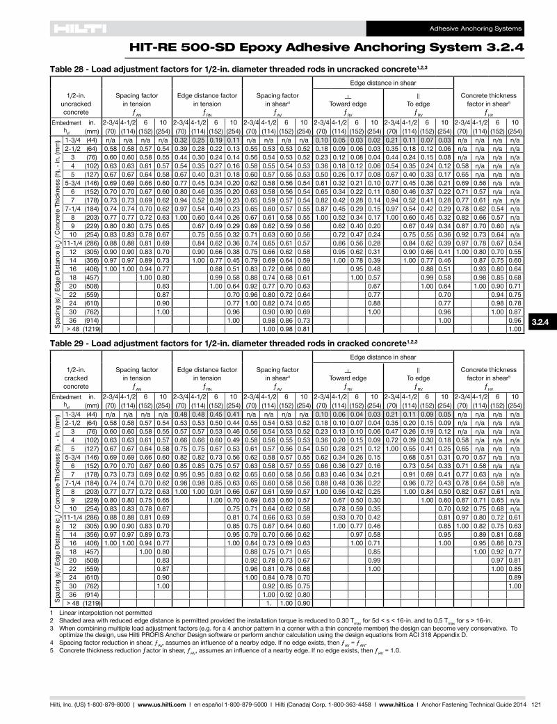
Adhesive Anchoring Systems
HIT-RE 500-SD Epoxy Adhesive Anchoring System 324
Hilti Inc (US) 1-800-879-8000 | wwwushilticom I en espantildeol 1-800-879-5000 I Hilti (Canada) Corp 1-800-363-4458 I wwwhiltica I Anchor Fastening Technical Guide 2014 121
328
325
326
327
324
325
325
323
Table 28 - Load adjustment factors for 12-in diameter threaded rods in uncracked concrete123
12-inuncracked concrete
Spacing factor in tension
ƒAN
Edgedistancefactor in tension
ƒRN
Spacing factor in shear4
ƒAV
Edgedistanceinshear
Concrete thickness factor in shear5
ƒHV
Toward edge
ƒRV
To edge
ƒRV
Embedmenthef
in 2-34 4-12 6 10 2-34 4-12 6 10 2-34 4-12 6 10 2-34 4-12 6 10 2-34 4-12 6 10 2-34 4-12 6 10(mm) (70) (114) (152) (254) (70) (114) (152) (254) (70) (114) (152) (254) (70) (114) (152) (254) (70) (114) (152) (254) (70) (114) (152) (254)
Spacing(s)Edg
eDistance(c
a) C
oncr
ete
Thic
knes
s (h
) - i
n (m
m) 1-34 (44) na na na na 032 025 019 011 na na na na 010 005 003 002 021 011 007 003 na na na na
2-12 (64) 058 058 057 054 039 028 022 013 055 053 053 052 018 009 006 003 035 018 012 006 na na na na3 (76) 060 060 058 055 044 030 024 014 056 054 053 052 023 012 008 004 044 024 015 008 na na na na4 (102) 063 063 061 057 054 035 027 016 058 055 054 053 036 018 012 006 054 035 024 012 058 na na na5 (127) 067 067 064 058 067 040 031 018 060 057 055 053 050 026 017 008 067 040 033 017 065 na na na
5-34 (146) 069 069 066 060 077 045 034 020 062 058 056 054 061 032 021 010 077 045 036 021 069 056 na na6 (152) 070 070 067 060 080 046 035 020 063 058 056 054 065 034 022 011 080 046 037 022 071 057 na na7 (178) 073 073 069 062 094 052 039 023 065 059 057 054 082 042 028 014 094 052 041 028 077 061 na na
7-14 (184) 074 074 070 062 097 054 040 023 065 060 057 055 087 045 029 015 097 054 042 029 078 062 054 na8 (203) 077 077 072 063 100 060 044 026 067 061 058 055 100 052 034 017 100 060 045 032 082 066 057 na9 (229) 080 080 075 065 067 049 029 069 062 059 056 062 040 020 067 049 034 087 070 060 na
10 (254) 083 083 078 067 075 055 032 071 063 060 056 072 047 024 075 055 036 092 073 064 na11-14 (286) 088 088 081 069 084 062 036 074 065 061 057 086 056 028 084 062 039 097 078 067 054
12 (305) 090 090 083 070 090 066 038 075 066 062 058 095 062 031 090 066 041 100 080 070 05514 (356) 097 097 089 073 100 077 045 079 069 064 059 100 078 039 100 077 046 087 075 06016 (406) 100 100 094 077 088 051 083 072 066 060 095 048 088 051 093 080 06418 (457) 100 080 099 058 088 074 068 061 100 057 099 058 098 085 06820 (508) 083 100 064 092 077 070 063 067 100 064 100 090 07122 (559) 087 070 096 080 072 064 077 070 094 07524 (610) 090 077 100 082 074 065 088 077 098 07830 (762) 100 096 090 080 069 100 096 100 08736 (914) 100 098 086 073 100 096
gt 48 (1219) 100 098 081 100
Table 29 - Load adjustment factors for 12-in diameter threaded rods in cracked concrete123
12-incracked concrete
Spacing factor in tension
ƒAN
Edgedistancefactor in tension
ƒRN
Spacing factor in shear4
ƒAV
Edgedistanceinshear
Concrete thickness factor in shear5
ƒHV
Toward edge
ƒRV
To edge
ƒRV
Embedmenthef
in 2-34 4-12 6 10 2-34 4-12 6 10 2-34 4-12 6 10 2-34 4-12 6 10 2-34 4-12 6 10 2-34 4-12 6 10(mm) (70) (114) (152) (254) (70) (114) (152) (254) (70) (114) (152) (254) (70) (114) (152) (254) (70) (114) (152) (254) (70) (114) (152) (254)
Spacing(s)Edg
eDistance(c
a) C
oncr
ete
Thic
knes
s (h
) - i
n (m
m) 1-34 (44) na na na na 048 048 045 041 na na na na 010 006 004 003 021 011 009 005 na na na na
2-12 (64) 058 058 057 054 053 053 050 044 055 054 053 052 018 010 007 004 035 020 015 009 na na na na3 (76) 060 060 058 055 057 057 053 046 056 054 053 052 023 013 010 006 047 026 019 012 na na na na4 (102) 063 063 061 057 066 066 060 049 058 056 055 053 036 020 015 009 072 039 030 018 058 na na na5 (127) 067 067 064 058 075 075 067 053 061 057 056 054 050 028 021 012 100 055 041 025 065 na na na
5-34 (146) 069 069 066 060 082 082 073 056 062 058 057 055 062 034 026 015 068 051 031 070 057 na na6 (152) 070 070 067 060 085 085 075 057 063 058 057 055 066 036 027 016 073 054 033 071 058 na na7 (178) 073 073 069 062 095 095 083 062 065 060 058 056 083 046 034 021 091 069 041 077 063 na na
7-14 (184) 074 074 070 062 098 098 085 063 065 060 058 056 088 048 036 022 096 072 043 078 064 058 na8 (203) 077 077 072 063 100 100 091 066 067 061 059 057 100 056 042 025 100 084 050 082 067 061 na9 (229) 080 080 075 065 100 070 069 063 060 057 067 050 030 100 060 087 071 065 na
10 (254) 083 083 078 067 075 071 064 062 058 078 059 035 070 092 075 068 na11-14 (286) 088 088 081 069 081 074 066 063 059 093 070 042 081 097 080 072 061
12 (305) 090 090 083 070 085 075 067 064 060 100 077 046 085 100 082 075 06314 (356) 097 097 089 073 095 079 070 066 062 097 058 095 089 081 06816 (406) 100 100 094 077 100 084 073 069 063 100 071 100 095 086 07318 (457) 100 080 088 075 071 065 085 100 092 07720 (508) 083 092 078 073 067 099 097 08122 (559) 087 096 081 076 068 100 100 08524 (610) 090 100 084 078 070 08930 (762) 100 092 085 075 10036 (914) 100 092 080
gt 48 (1219) 1 100 0901 Linear interpolation not permitted2 Shadedareawithreducededgedistanceispermittedprovidedtheinstallationtorqueisreducedto030Tmax for 5d lt s lt 16-in and to 05 Tmax for s gt 16-in3 When combining multiple load adjustment factors (eg for a 4 anchor pattern in a corner with a thin concrete member) the design can become very conservative To
optimizethedesignuseHiltiPROFISAnchorDesignsoftwareorperformanchorcalculationusingthedesignequationsfromACI318AppendixD4 Spacing factor reduction in shear ƒAVassumesaninfluenceofanearbyedgeIfnoedgeexiststhenƒAV = ƒAN5 Concrete thickness reduction ƒactor in shear ƒHVassumesaninfluenceofanearbyedgeIfnoedgeexiststhenƒHV = 10
Adhesive Anchoring Systems
324 HIT-RE 500-SD Epoxy Adhesive Anchoring System
122 Hilti Inc (US) 1-800-879-8000 | wwwushilticom I en espantildeol 1-800-879-5000 I Hilti (Canada) Corp 1-800-363-4458 I wwwhiltica I Anchor Fastening Technical Guide 2014
Table 30 - Load adjustment factors for 58-in diameter threaded rods in uncracked concrete123
58-inuncracked concrete
Spacing factor in tension
ƒAN
Edgedistancefactor in tension
ƒRN
Spacing factor in shear4
ƒAV
Edgedistanceinshear
Concrete thickness factor in shear5
ƒHV
Toward edge
ƒRV
To edge
ƒRV
Embedmenthef
in 3-18 5-58 7-12 12-12 3-18 5-58 7-12 12-12 3-18 5-58 7-12 12-12 3-18 5-58 7-12 12-12 3-18 5-58 7-12 12-12 3-18 5-58 7-12 12-12(mm) (79) (143) (191) (318) (79) (143) (191) (318) (79) (143) (191) (318) (79) (143) (191) (318) (79) (143) (191) (318) (79) (143) (191) (318)
Spacing(s)Edg
eDistance(c
a) C
oncr
ete
Thic
knes
s (h
) - i
n (m
m) 1-34 (44) na na na na 033 023 018 011 na na na na 009 004 003 001 019 008 006 003 na na na na
3-18 (79) 059 059 057 054 044 028 022 013 056 054 053 052 022 010 007 003 044 020 013 006 na na na na4 (102) 061 061 059 055 052 032 024 014 058 055 053 052 032 015 010 004 052 029 019 009 na na na na
4-58 (117) 063 063 060 056 059 034 026 015 059 055 054 052 040 018 012 006 059 034 024 011 060 na na na5 (127) 064 064 061 057 063 036 027 016 060 056 054 053 045 021 013 006 063 036 027 012 063 na na na6 (152) 066 066 063 058 074 040 030 018 062 057 055 053 059 027 018 008 076 040 033 016 069 na na na7 (178) 069 069 066 059 082 044 033 020 064 058 056 054 075 034 022 010 088 044 036 021 074 na na na
7-18 (181) 069 069 066 060 083 045 034 020 064 058 056 054 077 035 023 011 090 045 036 021 075 057 na na8 (203) 072 072 068 061 090 049 037 021 066 059 057 054 091 041 027 013 100 049 039 025 079 061 na na9 (229) 075 075 070 062 099 054 040 023 068 060 058 055 100 050 032 015 054 042 030 084 065 056 na10 (254) 077 077 072 063 100 061 044 026 070 062 059 055 058 038 018 061 046 032 089 068 059 na11 (279) 080 080 074 065 067 049 029 072 063 060 056 067 043 020 067 049 034 093 071 062 na12 (305) 083 083 077 066 073 053 031 074 064 060 056 076 050 023 073 053 036 097 075 065 na14 (356) 088 088 081 069 085 062 036 077 066 062 057 096 062 029 085 062 039 100 081 070 05416 (406) 094 094 086 071 097 071 042 081 069 064 058 100 076 036 097 071 043 086 075 05818 (457) 099 099 090 074 100 080 047 085 071 066 059 091 043 100 080 047 091 079 06120 (508) 100 100 094 077 089 052 089 073 067 060 100 050 089 052 096 083 06522 (559) 099 079 098 057 093 075 069 062 058 098 057 100 087 06824 (610) 100 082 100 062 097 078 071 063 066 100 062 091 07126 (660) 085 068 100 080 073 064 074 068 095 07428 (711) 087 073 082 074 065 083 073 099 07730 (762) 090 078 085 076 066 092 078 100 07936 (914) 098 094 092 081 069 100 094 087
gt48 (1219) 100 100 100 092 075 100
Table 31 - Load adjustment factors for 58-in diameter threaded rods in cracked concrete123
58-incracked concrete
Spacing factor in tension
ƒAN
Edgedistancefactor in tension
ƒRN
Spacing factor in shear4
ƒAV
Edgedistanceinshear
Concrete thickness factor in shear5
ƒHV
Toward edge
ƒRV
To edge
ƒRV
Embedmenthef
in 3-18 5-58 7-12 12-12 3-18 5-58 7-12 12-12 3-18 5-58 7-12 12-12 3-18 5-58 7-12 12-12 3-18 5-58 7-12 12-12 3-18 5-58 7-12 12-12(mm) (79) (143) (191) (318) (79) (143) (191) (318) (79) (143) (191) (318) (79) (143) (191) (318) (79) (143) (191) (318) (79) (143) (191) (318)
Spacing(s)Edg
eDistance(c
a) C
oncr
ete
Thic
knes
s (h
) - i
n (m
m) 1-34 (44) na na na na 045 045 043 040 na na na na 009 004 003 002 019 009 006 004 na na na na
3-18 (79) 059 059 057 054 054 054 050 044 056 054 053 052 022 010 008 005 045 020 015 009 na na na na4 (102) 061 061 059 055 060 060 055 046 058 055 054 053 033 015 011 007 065 030 022 013 na na na na
4-58 (117) 063 063 060 056 064 064 058 048 059 055 054 053 040 018 014 008 081 037 027 016 060 na na na5 (127) 064 064 061 057 067 067 060 049 060 056 055 053 045 021 015 009 091 041 030 018 063 na na na6 (152) 066 066 063 058 074 074 066 053 062 057 056 054 060 027 020 012 100 054 040 024 069 na na na7 (178) 069 069 066 059 082 082 072 056 064 058 057 055 075 034 025 015 068 050 030 074 na na na
7-18 (181) 069 069 066 060 083 083 073 056 064 058 057 055 077 035 026 016 070 052 031 075 058 na na8 (203) 072 072 068 061 090 090 078 059 066 059 058 055 092 042 031 019 084 062 037 079 061 na na9 (229) 075 075 070 062 099 099 085 062 068 060 059 056 100 050 037 022 100 074 044 084 065 059 na10 (254) 077 077 072 063 100 100 091 066 070 062 060 057 058 043 026 086 052 089 068 062 na11 (279) 080 080 074 065 098 069 072 063 060 057 067 050 030 098 060 093 072 065 na12 (305) 083 083 077 066 100 073 074 064 061 058 077 057 034 100 068 097 075 068 na14 (356) 088 088 081 069 081 078 066 063 059 097 071 043 081 100 081 073 06216 (406) 094 094 086 071 089 082 069 065 061 100 087 052 089 086 078 06618 (457) 099 099 090 074 097 085 071 067 062 100 062 097 092 083 07020 (508) 100 100 094 077 100 089 073 069 064 073 100 097 087 07422 (559) 099 079 093 076 071 065 084 100 091 07724 (610) 100 082 097 078 073 066 096 096 08126 (660) 085 100 080 075 068 100 099 08428 (711) 087 083 077 069 100 08730 (762) 090 085 079 070 09036 (914) 098 092 084 074 099
gt48 (1219) 100 100 096 082 1001 Linear interpolation not permitted2 Shadedareawithreducededgedistanceispermittedprovidedtheinstallationtorqueisreducedto030Tmax for 5d lt s lt 16-in and to 05 Tmax for s gt 16-in3 When combining multiple load adjustment factors (eg for a 4 anchor pattern in a corner with a thin concrete member) the design can become very conservative To
optimizethedesignuseHiltiPROFISAnchorDesignsoftwareorperformanchorcalculationusingthedesignequationsfromACI318AppendixD4 Spacing factor reduction in shear ƒAVassumesaninfluenceofanearbyedgeIfnoedgeexiststhenƒAV = ƒAN5 Concrete thickness reduction factor in shear ƒHVassumesaninfluenceofanearbyedgeIfnoedgeexiststhenƒHV = 10
Adhesive Anchoring Systems
HIT-RE 500-SD Epoxy Adhesive Anchoring System 324
Hilti Inc (US) 1-800-879-8000 | wwwushilticom I en espantildeol 1-800-879-5000 I Hilti (Canada) Corp 1-800-363-4458 I wwwhiltica I Anchor Fastening Technical Guide 2014 123
328
325
326
327
324
325
325
323
Table 32 - Load adjustment factors for 34-in diameter threaded rods in uncracked concrete123
34-inuncracked concrete
Spacing factor in tension
ƒAN
Edgedistancefactor in tension
ƒRN
Spacing factor in shear4
ƒAV
Edgedistanceinshear
Concrete thickness factor in shear5
ƒHV
Toward edge
ƒRV
To edge
ƒRV
Embedmenthef
in 3-12 6-34 9 15 3-12 6-34 9 15 3-12 6-34 9 15 3-12 6-34 9 15 3-12 6-34 9 15 3-12 6-34 9 15(mm) (89) (171) (229) (381) (89) (171) (229) (381) (89) (171) (229) (381) (89) (171) (229) (381) (89) (171) (229) (381) (89) (171) (229) (381)
Spacing(s)Edg
eDistance(c
a) C
oncr
ete
Thic
knes
s (h
) - i
n (m
m)
1-34 (44) na na na na 033 023 018 010 na na na na 009 003 002 001 017 007 005 002 na na na na3-34 (95) 059 059 057 054 049 029 022 013 057 054 053 052 027 011 007 003 049 022 014 007 na na na na
4 (102) 059 059 057 054 051 030 022 013 057 054 053 052 029 012 008 004 051 024 016 007 na na na na5 (127) 062 062 059 056 060 033 025 015 059 055 054 052 041 017 011 005 060 033 022 010 na na na na
5-14 (133) 062 062 060 056 063 034 025 015 060 055 054 052 044 018 012 005 063 034 023 011 062 na na na6 (152) 064 064 061 057 067 036 027 016 061 056 055 053 054 022 014 007 072 036 029 013 066 na na na7 (178) 066 066 063 058 074 040 030 017 063 057 055 053 068 028 018 008 084 040 033 017 072 na na na8 (203) 069 069 065 059 080 043 032 019 065 058 056 054 083 034 022 010 096 043 035 020 077 na na na
8-12 (216) 070 070 066 059 084 045 034 020 066 059 056 054 091 037 024 011 100 045 037 022 079 059 na na9 (229) 071 071 067 060 087 047 035 021 067 059 057 054 099 040 026 012 047 038 024 081 060 na na
10 (254) 073 073 069 061 094 051 038 022 068 060 058 055 100 047 031 014 051 041 029 086 064 na na10-34 (273) 075 075 070 062 100 055 040 024 070 061 058 055 053 034 016 055 043 031 089 066 057 na
12 (305) 078 078 072 063 061 045 026 072 062 059 055 062 040 019 061 046 033 094 070 060 na14 (356) 082 082 076 066 071 053 031 076 064 061 056 078 051 024 071 053 036 100 075 065 na16 (406) 087 087 080 068 082 060 035 079 066 062 057 096 062 029 082 060 039 080 070 na
16-34 (425) 089 089 081 069 085 063 037 081 067 063 058 100 067 031 085 063 040 082 071 05518 (457) 092 092 083 070 092 068 040 083 068 064 058 074 035 092 068 042 085 074 05720 (508) 096 096 087 072 100 075 044 087 070 065 059 087 040 100 075 045 090 078 06022 (559) 100 100 091 074 083 048 091 072 067 060 100 047 083 049 094 082 06324 (610) 094 077 090 053 094 074 068 061 053 090 053 099 085 06626 (660) 098 079 098 057 098 076 070 062 060 098 057 100 089 06928 (711) 100 081 100 062 100 078 071 063 067 100 062 092 07130 (762) 083 066 080 073 064 074 066 095 07436 (914) 100 100 086 077 066 100 100 100 081
gt 48 (1219) 099 086 072 094
Table 33 - Load adjustment factors for 34-in diameter threaded rods in cracked concrete123
34-incracked concrete
Spacing factor in tension
ƒAN
Edgedistancefactor in tension
ƒRN
Spacing factor in shear4
ƒAV
Edgedistanceinshear
Concrete thickness factor in shear5
ƒHV
Toward edge
ƒRV
To edge
ƒRV
Embedmenthef
in 3-12 6-34 9 15 3-12 6-34 9 15 3-12 6-34 9 15 3-12 6-34 9 15 3-12 6-34 9 15 3-12 6-34 9 15(mm) (89) (171) (229) (381) (89) (171) (229) (381) (89) (171) (229) (381) (89) (171) (229) (381) (89) (171) (229) (381) (89) (171) (229) (381)
Spacing(s)Edg
eDistance(c
a) C
oncr
ete
Thic
knes
s (h
) - i
n (m
m)
1-34 (44) na na na na 044 044 042 039 na na na na 009 003 002 001 017 007 005 003 na na na na3-34 (95) 059 059 057 054 054 054 050 044 057 054 053 052 027 011 008 005 054 022 015 009 na na na na
4 (102) 059 059 057 054 056 056 051 044 057 054 053 052 030 012 008 005 059 024 017 010 na na na na5 (127) 062 062 059 056 061 061 056 047 059 055 054 053 041 017 012 007 083 034 024 014 na na na na
5-14 (133) 062 062 060 056 063 063 057 047 060 055 054 053 045 018 013 008 089 036 026 015 062 na na na6 (152) 064 064 061 057 067 067 060 049 061 056 055 053 054 022 016 009 100 044 031 019 067 na na na7 (178) 066 066 063 058 074 074 065 052 063 057 056 054 069 028 020 012 056 039 024 072 na na na8 (203) 069 069 065 059 080 080 070 055 065 058 056 055 084 034 024 014 068 048 029 077 na na na
8-12 (216) 070 070 066 059 084 084 072 056 066 059 057 055 092 037 026 016 075 053 032 079 059 na na9 (229) 071 071 067 060 087 087 075 057 067 059 057 055 100 041 029 017 082 057 034 082 061 na na
10 (254) 073 073 069 061 094 094 080 060 069 060 058 056 048 034 020 095 067 040 086 064 na na10-34 (273) 075 075 070 062 100 100 084 062 070 061 059 056 053 037 022 100 075 045 089 066 059 na
12 (305) 078 078 072 063 091 066 072 062 060 057 063 044 026 088 053 094 070 062 na14 (356) 082 082 076 066 100 072 076 064 061 058 079 056 033 100 067 100 076 067 na16 (406) 087 087 080 068 078 080 066 063 059 097 068 041 078 081 072 na
16-34 (425) 089 089 081 069 081 081 067 063 060 100 073 044 081 083 073 06218 (457) 092 092 083 070 085 083 068 064 060 081 049 085 086 076 06420 (508) 096 096 087 072 091 087 070 066 061 095 057 091 090 080 06822 (559) 100 100 091 074 098 091 072 068 063 100 066 098 095 084 07124 (610) 094 077 100 094 074 069 064 075 100 099 088 07426 (660) 098 079 098 076 071 065 084 100 091 07728 (711) 100 081 100 079 073 066 094 095 08030 (762) 083 081 074 067 100 098 08336 (914) 090 087 079 071 100 091
gt 48 (1219) 100 099 089 077 1001 Linear interpolation not permitted2 Shadedareawithreducededgedistanceispermittedprovidedtheinstallationtorqueisreducedto030Tmax for 5d lt s lt 16-in and to 05 Tmax for s gt 16-in3 When combining multiple load adjustment factors (eg for a 4 anchor pattern in a corner with a thin concrete member) the design can become very conservative To
optimizethedesignuseHiltiPROFISAnchorDesignsoftwareorperformanchorcalculationusingthedesignequationsfromACI318AppendixD4 Spacing factor reduction in shear ƒAVassumesaninfluenceofanearbyedgeIfnoedgeexiststhenƒAV = ƒAN5 Concrete thickness reduction factor in shear ƒHVassumesaninfluenceofanearbyedgeIfnoedgeexiststhenƒHV = 10
Adhesive Anchoring Systems
324 HIT-RE 500-SD Epoxy Adhesive Anchoring System
124 Hilti Inc (US) 1-800-879-8000 | wwwushilticom I en espantildeol 1-800-879-5000 I Hilti (Canada) Corp 1-800-363-4458 I wwwhiltica I Anchor Fastening Technical Guide 2014
Table 34 - Load adjustment factors for 78-in diameter threaded rods in uncracked concrete123
78-inuncracked concrete
Spacing factor in tension
ƒAN
Edgedistancefactor in tension
ƒRN
Spacing factor in shear4
ƒAV
Edgedistanceinshear
Concrete thickness factor in shear5
ƒHV
Toward edge
ƒRV
To edge
ƒRV
Embedmenthef
in 3-12 7-78 10-12 17-12 3-12 7-78 10-12 17-12 3-12 7-78 10-12 17-12 3-12 7-78 10-12 17-12 3-12 7-78 10-12 17-12 3-12 7-78 10-12 17-12(mm) (89) (200) (267) (445) (89) (200) (267) (445) (89) (200) (267) (445) (89) (200) (267) (445) (89) (200) (267) (445) (89) (200) (267) (445)
Spacing(s)Edg
eDistance(c
a) C
oncr
ete
Thic
knes
s (h
) - i
n (m
m)
1-34 (44) na na na na 036 022 017 010 na na na na 009 003 002 001 018 005 004 002 na na na na4-38 (111) 059 059 057 054 055 029 022 013 058 054 053 052 035 011 007 003 060 022 014 007 na na na na
5 (127) 060 060 058 055 058 031 023 014 059 054 053 052 043 013 009 004 066 027 017 008 na na na na5-12 (140) 061 061 059 055 060 032 024 014 060 055 054 052 050 015 010 005 072 031 020 009 065 na na na
6 (152) 062 062 060 056 063 034 025 015 061 055 054 052 057 017 011 005 078 034 023 011 068 na na na7 (178) 064 064 061 057 068 037 027 016 063 056 055 053 071 022 014 007 091 037 029 013 073 na na na8 (203) 066 066 063 058 074 040 030 017 065 057 055 053 087 027 017 008 100 040 033 016 078 na na na9 (229) 068 068 064 059 079 043 032 019 067 058 056 054 100 032 021 010 043 035 019 083 na na na
9-78 (251) 070 070 066 059 084 046 034 020 069 059 056 054 037 024 011 046 037 022 087 059 na na10 (254) 070 070 066 060 085 046 034 020 069 059 057 054 038 024 011 046 037 023 087 059 na na11 (279) 072 072 067 060 091 049 037 022 071 060 057 054 043 028 013 049 040 026 091 062 na na12 (305) 074 074 069 061 098 053 039 023 073 060 058 055 049 032 015 053 042 030 095 065 na na
12-12 (318) 075 075 070 062 100 055 041 024 074 061 058 055 052 034 016 055 043 031 097 066 057 na14 (356) 078 078 072 063 062 046 027 077 062 059 055 062 040 019 062 047 033 100 070 060 na16 (406) 082 082 075 065 071 052 031 080 064 060 056 076 049 023 071 052 036 075 065 na18 (457) 086 086 079 067 080 059 034 084 066 062 057 091 059 027 080 059 038 079 068 na
19-12 (495) 089 089 081 069 086 063 037 087 067 063 058 100 066 031 086 063 040 082 071 05520 (508) 090 090 082 069 089 065 038 088 067 063 058 069 032 089 065 041 083 072 05622 (559) 094 094 085 071 097 072 042 092 069 064 059 080 037 097 072 044 087 076 05924 (610) 098 098 088 073 100 078 046 096 071 066 059 091 042 100 078 047 091 079 06126 (660) 100 100 091 075 085 050 099 073 067 060 100 048 085 050 095 082 06428 (711) 094 077 091 053 100 074 068 061 053 091 053 099 085 06630 (762) 098 079 098 057 076 070 062 059 098 057 100 088 06836 (914) 100 084 100 069 081 073 064 077 100 069 097 075
gt 48 (1219) 096 092 092 081 069 100 092 100 087
Table 35 - Load adjustment factors for 78-in diameter threaded rods in cracked concrete123
78-incracked concrete
Spacing factor in tension
ƒAN
Edgedistancefactor in tension
ƒRN
Spacing factor in shear4
ƒAV
Edgedistanceinshear
Concrete thickness factor in shear5
ƒHV
Toward edge
ƒRV
To edge
ƒRV
Embedmenthef
in 3-12 7-78 10-12 17-12 3-12 7-78 10-12 17-12 3-12 7-78 10-12 17-12 3-12 7-78 10-12 17-12 3-12 7-78 10-12 17-12 3-12 7-78 10-12 17-12(mm) (89) (200) (267) (445) (89) (200) (267) (445) (89) (200) (267) (445) (89) (200) (267) (445) (89) (200) (267) (445) (89) (200) (267) (445)
Spacing(s)Edg
eDistance(c
a) C
oncr
ete
Thic
knes
s (h
) - i
n (m
m)
1-34 (44) na na na na 042 042 041 038 na na na na 009 003 002 001 018 006 004 002 na na na na4-38 (111) 059 059 057 054 055 055 050 044 058 054 053 052 036 011 008 005 071 022 016 009 na na na na
5 (127) 060 060 058 055 058 058 052 045 060 054 053 052 043 013 009 006 087 027 019 011 na na na na5-12 (140) 061 061 059 055 060 060 054 046 061 055 054 053 050 015 011 007 100 031 022 013 065 na na na
6 (152) 062 062 060 056 063 063 056 047 061 055 054 053 057 018 012 007 035 025 015 068 na na na7 (178) 064 064 061 057 068 068 060 049 063 056 055 053 072 022 016 009 044 031 019 073 na na na8 (203) 066 066 063 058 074 074 064 052 065 057 056 054 088 027 019 012 054 038 023 078 na na na9 (229) 068 068 064 059 079 079 068 054 067 058 056 054 100 032 023 014 065 046 027 083 na na na
9-78 (251) 070 070 066 059 084 084 072 056 069 059 057 055 037 026 016 074 053 032 087 059 na na10 (254) 070 070 066 060 085 085 073 056 069 059 057 055 038 027 016 076 054 032 087 059 na na11 (279) 072 072 067 060 091 091 077 059 071 060 058 055 044 031 019 087 062 037 092 062 na na12 (305) 074 074 069 061 098 098 082 061 073 060 058 056 050 035 021 100 070 042 096 065 na na
12-12 (318) 075 075 070 062 100 100 084 062 074 061 059 056 053 037 022 075 045 098 066 059 na14 (356) 078 078 072 063 091 066 077 062 060 057 063 044 027 089 053 100 070 062 na16 (406) 082 082 075 065 100 071 081 064 061 058 077 054 033 100 065 075 067 na18 (457) 086 086 079 067 076 084 066 062 059 091 065 039 076 079 071 na
19-12 (495) 089 089 081 069 080 087 067 064 060 100 073 044 080 082 074 06220 (508) 090 090 082 069 082 088 067 064 060 076 045 082 084 074 06322 (559) 094 094 085 071 087 092 069 065 061 087 052 087 088 078 06624 (610) 098 098 088 073 093 096 071 067 062 100 060 093 092 082 06926 (660) 100 100 091 075 099 100 073 068 063 067 099 095 085 07228 (711) 094 077 100 074 069 064 075 100 099 088 07430 (762) 098 079 076 071 065 084 100 091 07736 (914) 100 084 081 075 068 100 100 084
gt 48 (1219) 096 092 083 074 0971 Linear interpolation not permitted2 Shadedareawithreducededgedistanceispermittedprovidedtheinstallationtorqueisreducedto030Tmax for 5d lt s lt 16-in and to 05 Tmax for s gt 16-in3 When combining multiple load adjustment factors (eg for a 4 anchor pattern in a corner with a thin concrete member) the design can become very conservative To
optimizethedesignuseHiltiPROFISAnchorDesignsoftwareorperformanchorcalculationusingthedesignequationsfromACI318AppendixD4 Spacing factor reduction in shear ƒAVassumesaninfluenceofanearbyedgeIfnoedgeexiststhenƒAV = ƒAN5 Concrete thickness reduction factor in shear ƒHVassumesaninfluenceofanearbyedgeIfnoedgeexiststhenƒHV = 10
Adhesive Anchoring Systems
HIT-RE 500-SD Epoxy Adhesive Anchoring System 324
Hilti Inc (US) 1-800-879-8000 | wwwushilticom I en espantildeol 1-800-879-5000 I Hilti (Canada) Corp 1-800-363-4458 I wwwhiltica I Anchor Fastening Technical Guide 2014 125
328
325
326
327
324
325
325
323
Table 36 - Load adjustment factors for 1-in diameter threaded rods in uncracked concrete123
1-inuncracked concrete
Spacing factor in tension
ƒAN
Edgedistancefactor in tension
ƒRN
Spacing factor in shear4
ƒAV
Edgedistanceinshear
Concrete thickness factor in shear5
ƒHV
Toward edge
ƒRV
To edge
ƒRV
Embedmenthef
in 4 4 12 20 4 4 12 20 4 4 12 20 4 4 12 20 4 4 12 20 4 4 12 20(mm) (102) (229) (305) (508) (102) (229) (305) (508) (102) (229) (305) (508) (102) (229) (305) (508) (102) (229) (305) (508) (102) (229) (305) (508)
Spacing(s)Edg
eDistance(c
a) C
oncr
ete
Thic
knes
s (h
) - i
n (m
m)
1-34 (44) na na na na 036 022 017 010 na na na na 008 002 001 001 015 005 003 001 na na na na5 (127) 059 059 057 054 055 030 022 013 059 054 053 052 037 011 007 003 061 022 014 007 na na na na6 (152) 061 061 058 055 059 032 024 014 060 055 053 052 048 014 009 004 070 029 019 009 na na na na
6-14 (159) 061 061 059 055 060 033 024 014 061 055 054 052 051 015 010 005 073 030 020 009 065 na na na7 (178) 063 063 060 056 064 035 026 015 062 055 054 052 061 018 012 005 082 035 023 011 069 na na na8 (203) 064 064 061 057 069 038 028 016 064 056 055 053 074 022 014 007 093 038 029 013 074 na na na9 (229) 066 066 063 058 074 040 029 017 065 057 055 053 089 026 017 008 100 040 033 016 078 na na na
10 (254) 068 068 064 058 079 043 032 018 067 058 056 053 100 031 020 009 043 035 019 083 na na na11 (279) 070 070 065 059 084 046 034 020 069 058 056 054 035 023 011 046 037 021 087 na na na
11-14 (286) 070 070 066 059 085 047 034 020 069 059 056 054 037 024 011 047 037 022 088 058 na na12 (305) 072 072 067 060 089 049 036 021 070 059 057 054 040 026 012 049 039 024 091 060 na na13 (330) 073 073 068 061 095 052 038 022 072 060 057 054 046 030 014 052 041 028 094 063 na na14 (356) 075 075 069 062 100 056 040 024 074 061 058 055 051 033 015 056 043 031 098 065 na na
14-14 (362) 076 076 070 062 057 041 024 074 061 058 055 052 034 016 057 043 031 099 066 057 na16 (406) 079 079 072 063 064 046 027 077 062 059 055 062 040 019 064 047 033 100 070 060 na18 (457) 082 082 075 065 072 052 030 081 064 060 056 074 048 022 072 052 036 074 064 na20 (508) 086 086 078 067 080 058 034 084 065 061 057 087 056 026 080 058 038 078 067 na22 (559) 089 089 081 068 087 063 037 088 067 063 058 100 065 030 087 063 040 082 071 na
22-14 (565) 090 090 081 069 088 064 038 088 067 063 058 066 031 088 064 041 082 071 05524 (610) 093 093 083 070 095 069 040 091 068 064 058 074 035 095 069 043 085 074 05726 (660) 097 097 086 072 100 075 044 094 070 065 059 084 039 100 075 045 089 077 06028 (711) 100 100 089 073 081 047 098 071 066 060 094 043 081 048 092 080 06230 (762) 092 075 086 051 100 073 067 060 100 048 086 051 095 083 06436 (914) 100 080 100 061 077 070 062 063 100 061 100 091 070
gt 48 (1219) 090 081 086 077 066 098 081 100 081
Table 37 - Load adjustment factors for 1-in diameter threaded rods in cracked concrete123
1-incracked concrete
Spacing factor in tension
ƒAN
Edgedistancefactor in tension
ƒRN
Spacing factor in shear4
ƒAV
Edgedistanceinshear
Concrete thickness factor in shear5
ƒHV
Toward edge
ƒRV
To edge
ƒRV
Embedmenthef
in 4 4 12 20 4 4 12 20 4 4 12 20 4 4 12 20 4 4 12 20 4 4 12 20(mm) (102) (229) (305) (508) (102) (229) (305) (508) (102) (229) (305) (508) (102) (229) (305) (508) (102) (229) (305) (508) (102) (229) (305) (508)
Spacing(s)Edg
eDistance(c
a) C
oncr
ete
Thic
knes
s (h
) - i
n (m
m)
1-34 (44) na na na na 042 042 040 038 na na na na 008 002 002 001 015 005 003 002 na na na na5 (127) 059 059 057 054 055 055 050 044 059 054 053 052 037 011 008 005 074 022 016 009 na na na na6 (152) 061 061 058 055 059 059 053 046 060 055 054 053 049 014 010 006 097 029 021 012 na na na na
6-14 (159) 061 061 059 055 060 060 054 046 061 055 054 053 052 015 011 007 100 031 022 013 066 na na na7 (178) 063 063 060 056 064 064 057 047 062 055 054 053 061 018 013 008 036 026 016 069 na na na8 (203) 064 064 061 057 069 069 060 049 064 056 055 053 075 022 016 010 044 032 019 074 na na na9 (229) 066 066 063 058 074 074 064 051 065 057 056 054 089 026 019 011 053 038 023 079 na na na
10 (254) 068 068 064 058 079 079 067 053 067 058 056 054 100 031 022 013 062 044 027 083 na na na11 (279) 070 070 065 059 084 084 071 055 069 058 057 055 036 026 015 072 051 031 087 na na na
11-14 (286) 070 070 066 059 085 085 072 056 069 059 057 055 037 026 016 074 053 032 088 059 na na12 (305) 072 072 067 060 089 089 075 057 071 059 057 055 041 029 018 082 058 035 091 061 na na13 (330) 073 073 068 061 095 095 079 059 072 060 058 056 046 033 020 092 066 039 095 063 na na14 (356) 075 075 069 062 100 100 083 062 074 061 059 056 051 037 022 100 074 044 098 065 na na
14-14 (362) 076 076 070 062 084 062 074 061 059 056 053 038 023 076 045 099 066 059 na16 (406) 079 079 072 063 091 066 077 062 060 057 063 045 027 090 054 100 070 063 na18 (457) 082 082 075 065 100 070 081 064 061 058 075 054 032 100 064 074 066 na20 (508) 086 086 078 067 075 084 065 062 059 088 063 038 075 078 070 na22 (559) 089 089 081 068 080 088 067 063 060 100 072 043 080 082 073 na
22-14 (565) 090 090 081 069 080 088 067 064 060 074 044 080 082 074 06224 (610) 093 093 083 070 085 091 068 065 060 083 050 085 086 077 06526 (660) 097 097 086 072 090 095 070 066 061 093 056 090 089 080 06728 (711) 100 100 089 073 095 098 071 067 062 100 062 095 092 083 07030 (762) 092 075 100 100 073 068 063 069 100 096 086 07236 (914) 100 080 077 072 066 091 100 094 079
gt 48 (1219) 090 087 079 071 100 100 0911 Linear interpolation not permitted2 Shadedareawithreducededgedistanceispermittedprovidedtheinstallationtorqueisreducedto030Tmax for 5d lt s lt 16-in and to 05 Tmax for s gt 16-in3 When combining multiple load adjustment factors (eg for a 4 anchor pattern in a corner with a thin concrete member) the design can become very conservative To
optimizethedesignuseHiltiPROFISAnchorDesignsoftwareorperformanchorcalculationusingthedesignequationsfromACI318AppendixD4 Spacing factor reduction in shear ƒAVassumesaninfluenceofanearbyedgeIfnoedgeexiststhenƒAV = ƒAN5 Concrete thickness reduction factor in shear ƒHVassumesaninfluenceofanearbyedgeIfnoedgeexiststhenƒHV = 10
Adhesive Anchoring Systems
324 HIT-RE 500-SD Epoxy Adhesive Anchoring System
126 Hilti Inc (US) 1-800-879-8000 | wwwushilticom I en espantildeol 1-800-879-5000 I Hilti (Canada) Corp 1-800-363-4458 I wwwhiltica I Anchor Fastening Technical Guide 2014
Table 38 - Load adjustment factors for 1-14-in diameter threaded rods in uncracked concrete123
1-14-inuncracked concrete
Spacing factor in tension
ƒAN
Edgedistancefactor in tension
ƒRN
Spacing factor in shear4
ƒAV
Edgedistanceinshear
Concrete thickness factor in shear5
ƒHV
Toward edge
ƒRV
To edge
ƒRV
Embedmenthef
in 5 11-14 15 25 5 11-14 15 25 5 11-14 15 25 5 11-14 15 25 5 11-14 15 25 5 11-14 15 25(mm) (127) (286) (381) (635) (127) (286) (381) (635) (127) (286) (381) (635) (127) (286) (381) (635) (127) (286) (381) (635) (127) (286) (381) (635)
Spacing(s)Edg
eDistance(c
a) C
oncr
ete
Thic
knes
s (h
) - i
n (m
m) 1-34 (44) na na na na 035 023 016 009 na na na na 005 002 001 000 011 003 002 001 na na na na
6-14 (159) 059 059 057 054 055 031 022 013 059 054 053 052 037 011 007 003 063 022 014 007 na na na na7 (178) 060 060 058 055 058 033 023 014 060 054 053 052 043 013 008 004 069 026 017 008 na na na na8 (203) 062 062 059 055 062 035 025 014 061 055 054 052 053 016 010 005 078 031 020 010 066 na na na9 (229) 063 063 060 056 066 037 026 015 062 055 054 052 063 019 012 006 087 037 024 011 070 na na na10 (254) 065 065 061 057 069 039 028 016 064 056 055 053 074 022 014 007 097 039 029 013 074 na na na11 (279) 066 066 062 057 074 041 029 017 065 057 055 053 086 025 016 008 100 041 033 015 078 na na na12 (305) 068 068 063 058 078 044 031 018 066 057 055 053 098 029 019 009 044 035 017 081 na na na13 (330) 069 069 064 059 082 046 033 019 068 058 056 054 100 033 021 010 046 036 020 084 na na na14 (356) 071 071 066 059 086 049 034 020 069 059 056 054 036 024 011 049 038 022 087 058 na na
14-14 (362) 071 071 066 060 087 049 035 020 069 059 056 054 037 024 011 049 038 023 088 059 na na15 (381) 072 072 067 060 091 051 036 021 070 059 057 054 040 026 012 051 039 024 091 060 na na16 (406) 073 073 068 061 095 054 038 022 072 060 057 054 045 029 013 054 041 027 094 062 na na17 (432) 075 075 069 061 100 056 040 023 073 060 058 055 049 032 015 056 043 029 096 064 na na18 (457) 076 076 070 062 060 042 025 075 061 058 055 053 035 016 060 045 032 099 066 057 na20 (508) 079 079 072 063 066 047 027 077 062 059 055 062 040 019 066 048 034 100 070 060 na22 (559) 082 082 074 065 073 051 030 080 063 060 056 072 047 022 073 052 036 073 063 na24 (610) 085 085 077 066 080 056 033 083 065 061 057 082 053 025 080 056 038 076 066 na26 (660) 088 088 079 067 086 061 036 086 066 062 057 092 060 028 086 061 040 079 069 na28 (711) 091 091 081 069 093 065 038 088 067 063 058 100 067 031 093 065 042 082 071 05530 (762) 094 094 083 070 100 070 041 091 068 064 058 074 035 100 070 044 085 074 05736 (914) 100 100 090 074 084 049 099 072 066 060 098 045 084 050 094 081 063
gt 48 (1219) 100 082 100 066 100 079 072 063 100 070 100 066 100 094 072
Table 39 - Load adjustment factors for 1-14-in diameter threaded rods in cracked concrete123
1-14-incracked concrete
Spacing factor in tension
ƒAN
Edgedistancefactor in tension
ƒRN
Spacing factor in shear4
ƒAV
Edgedistanceinshear
Concrete thickness factor in shear5
ƒHV
Toward edge
ƒRV
To edge
ƒRV
Embedmenthef
in 5 11-14 15 25 5 11-14 15 25 5 11-14 15 25 5 11-14 15 25 5 11-14 15 25 5 11-14 15 25(mm) (127) (286) (381) (635) (127) (286) (381) (635) (127) (286) (381) (635) (127) (286) (381) (635) (127) (286) (381) (635) (127) (286) (381) (635)
Spacing(s)Edg
eDistance(c
a) C
oncr
ete
Thic
knes
s (h
) - i
n (m
m) 1-34 (44) na na na na 040 040 039 037 na na na na 005 002 001 001 011 003 002 001 na na na na
6-14 (159) 059 059 057 054 055 055 050 044 059 054 053 052 037 011 008 005 074 022 016 010 na na na na7 (178) 060 060 058 055 058 058 052 045 060 054 054 053 044 013 010 006 088 026 019 012 na na na na8 (203) 062 062 059 055 062 062 055 046 061 055 054 053 054 016 012 007 100 032 024 014 066 na na na9 (229) 063 063 060 056 066 066 057 048 062 055 055 053 064 019 014 008 038 028 017 070 na na na10 (254) 065 065 061 057 069 069 060 049 064 056 055 054 075 022 017 010 044 033 020 074 na na na11 (279) 066 066 062 057 074 074 063 051 065 057 056 054 086 026 019 011 051 038 023 078 na na na12 (305) 068 068 063 058 078 078 066 053 066 057 056 054 098 029 022 013 058 044 026 081 na na na13 (330) 069 069 064 059 082 082 069 054 068 058 057 055 100 033 025 015 066 049 029 085 na na na14 (356) 071 071 066 059 086 086 072 056 069 059 057 055 037 027 016 073 055 033 088 058 na na
14-14 (362) 071 071 066 060 087 087 073 056 070 059 057 055 038 028 017 075 056 034 089 059 na na15 (381) 072 072 067 060 091 091 075 057 071 059 058 055 041 030 018 082 061 036 091 061 na na16 (406) 073 073 068 061 095 095 078 059 072 060 058 056 045 033 020 090 067 040 094 063 na na17 (432) 075 075 069 061 100 100 081 061 073 060 059 056 049 037 022 098 073 044 097 064 na na18 (457) 076 076 070 062 085 062 075 061 059 056 054 040 024 100 080 048 099 066 060 na20 (508) 079 079 072 063 091 066 077 062 060 057 063 047 028 091 056 100 070 063 na22 (559) 082 082 074 065 098 069 080 063 061 058 072 054 032 098 065 073 066 na24 (610) 085 085 077 066 100 073 083 065 062 059 082 062 037 100 073 077 069 na26 (660) 088 088 079 067 077 086 066 063 059 093 069 042 077 080 072 na28 (711) 091 091 081 069 081 088 067 064 060 100 078 047 081 083 075 06330 (762) 094 094 083 070 085 091 068 065 061 086 052 085 086 078 06536 (914) 100 100 090 074 097 099 072 068 063 100 068 097 094 085 072
gt 48 (1219) 100 082 100 100 079 074 067 100 100 100 098 0831 Linear interpolation not permitted2 Shadedareawithreducededgedistanceispermittedprovidedtheinstallationtorqueisreducedto030Tmax for 5d lt s lt 16-in and to 05 Tmax for s gt 16-in3 When combining multiple load adjustment factors (eg for a 4 anchor pattern in a corner with a thin concrete member) the design can become very conservative To
optimizethedesignuseHiltiPROFISAnchorDesignsoftwareorperformanchorcalculationusingthedesignequationsfromACI318AppendixD4 Spacing factor reduction in shear ƒAVassumesaninfluenceofanearbyedgeIfnoedgeexiststhenƒAV = ƒAN5 Concrete thickness reduction factor in shear ƒHVassumesaninfluenceofanearbyedgeIfnoedgeexiststhenƒHV = 10
Adhesive Anchoring Systems
HIT-RE 500-SD Epoxy Adhesive Anchoring System 324
Hilti Inc (US) 1-800-879-8000 | wwwushilticom I en espantildeol 1-800-879-5000 I Hilti (Canada) Corp 1-800-363-4458 I wwwhiltica I Anchor Fastening Technical Guide 2014 127
328
325
326
327
324
325
325
323
32433 HIT-RE 500-SD with HIS-N Inserts
HIS-N internally threaded insert specifications38-in HIS-N is manufactured from 11MnPb30+C carbon steel conforming to DIN 10277-3 with a minimum tensile strength of 711 ksi (490 MPa) and a minimum yield strength of 595 ksi (410 MPa)12- 58- and 34-in HIS-N is manufactured from 11MnPb30+C carbon steel conforming to DIN 10277-3 with a minimum tensile strength of 667 ksi (460 MPa) and a minimum yield strength of 544 ksi (375 MPa)HIS-RNismanufacturedfromX5CrNiMo17122K700stainlesssteelconformingtoDINEN10088-3withaminimumtensilestrength of 1015 ksi (700 MPa) and a minimum yield strength of 508 ksi (350 MPa)
Figure 3 - HIS-N and HIS-RN specifications
Setting information Symbol UnitsThread size
38-16 UNC 12-13 UNC 58-11 UNC 34-10 UNCOutside diameter of insert in 065 081 100 109Nominal bit diameter do in 1116 78 1-18 1-14
Effectiveembedment hef
in 4-38 5 6-34 8-18(mm) (110) (125) (170) (205)
Thread engagementminimum
hs
in 38 12 58 34maximum in 1516 1-316 1-12 1-78
Installationtorque Tinst
ft-lb 15 30 60 100(Nm) (20) (40) (81) (136)
Concrete thickness hmin
in 59 67 91 106(mm) (150) (170) (230) (270)
Table 40 - HIS-N and HIS-RN specifications
Adhesive Anchoring Systems
324 HIT-RE 500-SD Epoxy Adhesive Anchoring System
128 Hilti Inc (US) 1-800-879-8000 | wwwushilticom I en espantildeol 1-800-879-5000 I Hilti (Canada) Corp 1-800-363-4458 I wwwhiltica I Anchor Fastening Technical Guide 2014
Table 41 - Hilti HIT-RE 500-SD adhesive design strength (factored resistance) with concrete bond failure for Hilti HIS-N and HIS-RN internally threaded inserts in uncracked concrete1234567810
Thread size
Effective embedment
in (mm)
TensionmdashФNn or Nr ShearmdashФVn or Vr
ƒ´c = 2500 psi (172 Mpa)
lb (kN)
ƒ´c = 3000 psi (207 Mpa)
lb (kN)
ƒ´c = 4000 psi (276 Mpa)
lb (kN)
ƒ´c = 6000 psi (414 Mpa)
lb (kN)
ƒ´c = 2500 psi(172 Mpa)
lb (kN)
ƒ´c = 3000 psi(207 Mpa)
lb (kN)
ƒ´c = 4000 psi(276 Mpa)
lb (kN)
ƒ´c = 6000 psi(414 Mpa)
lb (kN)
38-16 UNC
4-38 7140 7820 9030 11060 15375 16840 19445 23815(111) (318) (348) (402) (492) (684) (749) (865) (1059)
12-13 UNC
5 8720 9555 11030 13510 18785 20575 23760 29100(127) (388) (425) (491) (601) (836) (915) (1057) (1294)
58-11 UNC
6-34 13680 14985 17305 21190 29460 32275 37265 45645(171) (609) (667) (770) (943) (1310) (1436) (1658) (2030)
34-10 UNC
8-18 18065 19790 22850 27985 38910 42620 49215 60275(206) (804) (880) (1016) (1245) (1731) (1896) (2189) (2681)
Table 42 - Hilti HIT-RE 500-SD adhesive design strength (factored resistance) with concrete bond failure for Hilti HIS-N and HIS-RN internally threaded inserts in cracked concrete12345678910
Thread size
Effective embedment
in (mm)
TensionmdashФNn or Nr ShearmdashФVn or Vr
ƒ´c = 2500 psi (172 Mpa)
lb (kN)
ƒ´c = 3000 psi (207 Mpa)
lb (kN)
ƒ´c = 4000 psi (276 Mpa)
lb (kN)
ƒ´c = 6000 psi (414 Mpa)
lb (kN)
ƒ´c = 2500 psi(172 Mpa)
lb (kN)
ƒ´c = 3000 psi(207 Mpa)
lb (kN)
ƒ´c = 4000 psi(276 Mpa)
lb (kN)
ƒ´c = 6000 psi(414 Mpa)
lb (kN)
38-16 UNC
4-38 5055 5540 6040 6400 10890 11930 13010 13790(111) (225) (246) (269) (285) (484) (531) (579) (613)
12-13 UNC
5 6175 6765 7815 8370 13305 14575 16830 18030(127) (275) (301) (348) (372) (592) (648) (749) (802)
58-11 UNC
6-34 9690 9855 9855 10445 20870 22860 25085 26590(171) (431) (438) (438) (465) (928) (1017) (1116) (1183)
34-10 UNC
8-18 12320 12320 12320 13060 27560 30190 31355 33240(206) (548) (548) (548) (581) (1226) (1343) (1395) (1479)
1 See Section 317 for explanation on development of load values2 See Section 3173 to convert design strength (factored resistance) value to ASD value3 Linear interpolation between embedment depths and concrete compressive strengths is not permitted4 Apply spacing edge distance and concrete thickness factors in Tables 44-45 as necessary Compare to the steel values in Table 43
The lesser of the values is to be used for the design5 Data is for temperature range A Max short term temperature = 110deg F (43deg C) max long term temperature = 80deg F (26deg C)
FortemperaturerangeBMaxshorttermtemperature=162degF(72degC)maxlongtermtemperature=110degF(43degC)multiplyabovevalueby034 Short term elevated concrete temperatures are those that occur over brief intervals eg as a result of diurnal cycling Long term concrete temperatures are roughlyconstantoversignificantperiodsoftime
6 Tabular values are for dry concrete conditions For water saturated concrete multiply design strength (factored resistance) by 069 Forwater-filleddrilledholesmultiplydesignstrength(factoredresistance)by062 For submerged (under water) applications multiply design strength (factored resistance) by 064
7 Tabular values are for short term loads only For sustained loads including overhead use see Section 31758 TabularvaluesarefornormalweightconcreteonlyForlightweightconcretemultiplydesignstrength(factoredresistance)byλa as follows
Forsand-lightweightλa=051Forall-lightweightλa = 0459 TabularvaluesareforstaticloadsonlyForseismicloadsmultiplyabovevaluebyαseis = 049 See section 3174 for additional information on
seismic applications10 Tabular values are for holes drilled in concrete with carbide tipped hammer drill bit For diamond core drilling multiply above value by 053
Diamondcoredrillingisnotpermittedcrackedconcreteandisnotpermittedforthewater-filledorunderwater(submerged)applications
Adhesive Anchoring Systems
HIT-RE 500-SD Epoxy Adhesive Anchoring System 324
Hilti Inc (US) 1-800-879-8000 | wwwushilticom I en espantildeol 1-800-879-5000 I Hilti (Canada) Corp 1-800-363-4458 I wwwhiltica I Anchor Fastening Technical Guide 2014 129
328
325
326
327
324
325
325
323
Table 43 - Steel design strength (factored resistance) for steel bolt cap screw for Hilti HIS-N and HIS-RN internally threaded inserts1
Thread size
ACI318AppendixDBasedDesign
ASTMA193B72 ASTMA193GradeB8Mstainless steel2
Tensile3
ϕNsalb (kN)
Shear4
ϕVsalb (kN)
SeismicShear5
ϕVsalb (kN)
Tensile3
ϕNsalb (kN)
Shear4
ϕVsalb (kN)
SeismicShear5
ϕVsalb (kN)
38-16 UNC
6300 3490 2443 5540 3070 2149(280) (155) (109) (246) (137) (96)
12-13 UNC
11530 6385 4470 10145 5620 3934(513) (284) (199) (451) (250) (175)
58-11 UNC
18365 10170 7119 16160 8950 6265(817) (452) (317) (719) (398) (279)
34-10 UNC
27180 15055 10539 23915 13245 9272(1209) (670) (469) (1064) (589) (412)
1 See Section 3173 to convert design strength (factored resistance) value to ASD value2 Steel bolt cap screw for Hilti HIS-N and HIS-RN inserts are considered brittle steel elements3 Tensile=фAseN futa as noted in ACI 318 Appendix D4 Shear=ф060AseN futa as noted in ACI 318 Appendix D5 SeismicshearvaluesdeterminedbymultiplyingфVsaxαVseiswhereαVseis = 07 for steel bolt
See Section 3174 for additional information on seismic applications
Adhesive Anchoring Systems
324 HIT-RE 500-SD Epoxy Adhesive Anchoring System
130 Hilti Inc (US) 1-800-879-8000 | wwwushilticom I en espantildeol 1-800-879-5000 I Hilti (Canada) Corp 1-800-363-4458 I wwwhiltica I Anchor Fastening Technical Guide 2014
Table 44 - Load adjustment factors for Hilti HIS-N and HIS-RN internally threaded inserts in uncracked concrete123
HIS-N and HIS-RN all diameters uncracked concrete
Spacing factor in tension
ƒAN
Edgedistancefactor in tension
ƒRN
Spacing factor in shear4
ƒAV
EdgeDistanceinShear
Concrete thickness factor in shear5
ƒHV
Toward edge
ƒRV
To edge
ƒRV
Thread size in 38 12 58 34 38 12 58 34 38 12 58 34 38 12 58 34 38 12 58 34 38 12 58 34
Embedmenthef
in 4-38 5 6-34 8-18 4-38 5 6-34 8-18 4-38 5 6-34 8-18 4-38 5 6-34 8-18 4-38 5 6-34 8-18 4-38 5 6-34 8-18(mm) (111) (127) (171) (206) (111) (127) (171) (206) (111) (127) (171) (206) (111) (127) (171) (206) (111) (127) (171) (206) (111) (127) (171) (206)
Spacing
(s)Edg
eDistance(c
a) C
oncr
ete
Thick
ness
(h)
- in
(mm
) 3-14 (83) 059 na na na 034 na na na 055 na na na 015 na na na 031 na na na na na na na4 (102) 061 059 na na 038 038 na na 056 055 na na 021 019 na na 038 038 na na na na na na5 (127) 063 061 059 na 044 043 037 na 057 057 055 na 029 026 017 na 044 043 033 na na na na na
5-12 (140) 065 062 060 059 047 046 039 035 058 058 056 055 034 030 019 015 047 046 039 029 na na na na6 (152) 066 063 061 060 050 048 041 037 059 058 056 055 039 035 022 017 050 048 041 033 060 na na na7 (178) 068 065 063 062 057 054 045 040 060 060 057 056 049 043 028 021 057 054 045 040 064 062 na na8 (203) 071 067 064 063 066 061 049 043 062 061 058 057 060 053 034 026 066 061 049 043 069 066 na na9 (229) 074 069 066 065 074 069 054 046 063 062 059 058 071 063 040 031 074 069 054 046 073 070 na na10 (254) 076 072 068 067 082 076 058 050 065 064 060 058 083 074 047 036 082 076 058 050 077 074 064 na11 (279) 079 074 070 068 090 084 064 053 066 065 061 059 096 086 055 041 090 084 064 053 081 078 067 06112 (305) 082 076 072 070 099 091 070 057 068 066 062 060 100 098 062 047 099 091 070 057 084 081 070 06414 (356) 087 080 075 073 100 100 081 066 071 069 064 062 100 100 078 059 100 100 081 066 091 087 075 06916 (406) 092 085 079 077 100 100 093 076 074 072 066 063 100 100 096 073 100 100 093 076 097 094 080 07318 (457) 097 089 082 080 100 100 100 085 077 075 068 065 100 100 100 087 100 100 100 085 100 099 085 07824 (610) 100 100 093 090 100 100 100 100 085 083 074 070 100 100 100 100 100 100 100 100 100 100 099 09030 (762) 100 100 100 100 100 100 100 100 094 091 080 075 100 100 100 100 100 100 100 100 100 100 100 10036 (914) 100 100 100 100 100 100 100 100 100 099 086 080 100 100 100 100 100 100 100 100 100 100 100 100
gt 48 (1219) 100 100 100 100 100 100 100 100 100 100 099 090 100 100 100 100 100 100 100 100 100 100 100 100
Table 45 - Load adjustment factors for Hilti HIS-N and HIS-RN internally threaded inserts in cracked concrete123
HIS-N and HIS-RN all diameters
cracked concrete
Spacing factor in tension
ƒAN
Edgedistancefactor in tension
ƒRN
Spacing factor in shear4
ƒAV
EdgeDistanceinShear
Concrete thickness factor in shear5
ƒHV
Toward edge
ƒRV
To edge
ƒRV
Thread size in 38 12 58 34 38 12 58 34 38 12 58 34 38 12 58 34 38 12 58 34 38 12 58 34
Embedmenthef
in 4-38 5 6-34 8-18 4-38 5 6-34 8-18 4-38 5 6-34 8-18 4-38 5 6-34 8-18 4-38 5 6-34 8-18 4-38 5 6-34 8-18(mm) (111) (127) (171) (206) (111) (127) (171) (206) (111) (127) (171) (206) (111) (127) (171) (206) (111) (127) (171) (206) (111) (127) (171) (206)
Spacing
(s)Edg
eDistance(c
a) C
oncr
ete
Thick
ness
(h)
- in
(mm
) 3-14 (83) 059 na na na 054 na na na 055 na na na 016 na na na 031 na na na na na na na4 (102) 061 059 na na 059 054 na na 056 055 na na 021 019 na na 042 038 na na na na na na5 (127) 063 061 059 na 066 059 055 na 057 057 055 na 030 026 017 na 059 053 034 na na na na na
5-12 (140) 065 062 060 059 069 062 057 055 058 058 056 055 034 031 019 015 069 061 039 029 na na na na6 (152) 066 063 061 060 073 065 059 057 059 058 056 055 039 035 022 017 078 070 044 034 060 na na na7 (178) 068 065 063 062 080 071 064 061 060 060 057 056 049 044 028 021 098 088 056 042 064 062 na na8 (203) 071 067 064 063 088 077 069 066 062 061 058 057 060 054 034 026 100 100 068 052 069 066 na na9 (229) 074 069 066 065 096 083 074 070 063 062 059 058 072 064 041 031 100 100 082 062 073 070 na na10 (254) 076 072 068 067 100 090 079 075 065 064 060 058 084 075 048 036 100 100 095 072 077 074 064 na11 (279) 079 074 070 068 100 096 084 080 066 065 061 059 097 086 055 042 100 100 100 083 081 078 067 06112 (305) 082 076 072 070 100 100 089 084 068 066 062 060 100 098 063 048 100 100 100 095 084 081 070 06414 (356) 087 080 075 073 100 100 100 094 071 069 064 062 100 100 079 060 100 100 100 100 091 088 076 06916 (406) 092 085 079 077 100 100 100 100 074 072 066 064 100 100 097 073 100 100 100 100 097 094 081 07418 (457) 097 089 082 080 100 100 100 100 077 075 068 065 100 100 100 087 100 100 100 100 100 099 086 07824 (610) 100 100 093 090 100 100 100 100 086 083 074 070 100 100 100 100 100 100 100 100 100 100 099 09030 (762) 100 100 100 100 100 100 100 100 095 091 081 075 100 100 100 100 100 100 100 100 100 100 100 10036 (914) 100 100 100 100 100 100 100 100 100 099 087 080 100 100 100 100 100 100 100 100 100 100 100 100
gt 48 (1219) 100 100 100 100 100 100 100 100 100 100 099 091 100 100 100 100 100 100 100 100 100 100 100 1001 Linear interpolation not permitted2 Shadedareawithreducededgedistanceispermittedprovidedtheinstallationtorqueisreducedto030Tmax for 5d lt s lt 16-in and to 05 Tmax for s gt 16-in3 When combining multiple load adjustment factors (eg for a 4 anchor pattern in a corner with a thin concrete member) the design can become very conservative To
optimizethedesignuseHiltiPROFISAnchorDesignsoftwareorperformanchorcalculationusingthedesignequationsfromACI318AppendixD4 Spacing factor reduction in shear ƒAVassumesaninfluenceofanearbyedgeIfnoedgeexiststhenƒAV = ƒAN5 Concrete thickness reduction factor in shear ƒHVassumesaninfluenceofanearbyedgeIfnoedgeexiststhenƒHV = 10
Adhesive Anchoring Systems
HIT-RE 500-SD Epoxy Adhesive Anchoring System 324
Hilti Inc (US) 1-800-879-8000 | wwwushilticom I en espantildeol 1-800-879-5000 I Hilti (Canada) Corp 1-800-363-4458 I wwwhiltica I Anchor Fastening Technical Guide 2014 131
328
325
326
327
324
325
325
323
3244 Installation instructionsInstallation Instructions For Use (IFU) are included with each product package They can also be viewed or downloaded online atwwwushilticom(US)andwwwhiltica(Canada)BecauseofthepossibilityofchangesalwaysverifythatdownloadedIFUarecurrentwhenusedProperinstallationiscriticaltoachievefullperformanceTrainingisavailableonrequestContactHiltiTechnical Services for applications and conditions not addressed in the IFU
HIT-RE 500-SD volume chartsTable 46 - Threaded rod installation
Nominal anchor
diameterin
Nominal bit
diameter in
Adhesive volumerequired
per inch of embedment in 3
14 516 005538 716 009512 916 013358 34 026134 78 032678 1 03911 1-18 0478
1-14 1-38 0626
TheuseablevolumeofHIT-RE500-SDrefillcartridge is 165 in3 (270 ml)
TheuseablevolumeofHIT-RE500-SD mediumrefillis269in3 (440 ml)
TheuseablevolumeofHIT-RE500-SD mediumrefillis818in3 (1340 ml)
ExAMPLE
58-in diameter rod with an embedment of 10 inches
10 in x 026 in3 in = 26 in3fastening
165 in3cartridge divide 26 in3fasteningasymp 6 fasteningscartridge
818 in3cartridge divide 26 in3fasteningasymp 31 fasteningscartridge
Table 48 - HIT-RE 500-SD cure time
Basematerialtemperature
Gel Time Full CuredegF degC41 5 25 h 72 h50 10 2 h 48 h59 15 15 h 24 h68 20 30 min 12 h86 30 20 min 8 h104 40 12 min 4 h
Table 47 - Rebar installation1
Rebarsize
Nominal bit1diameter
in
Adhesive volumerequired
per Inch of embedment
in 3
3 12 01104 58 01465 34 01766 78 02187 1 02528 1-18 02999 1-38 060110 1-12 065911 1-34 1037
1 Rebar diameter may vary Use smallest drill bit which will accommodate rebar
Table 49 - Resistance of HIT-RE 500-SD to chemicals
Chemical Chemicals Tested ResistantNot
ResistantAlkaline Concrete drilling mud (10) pH=126
Concrete drilling mud (10) pH=132Concrete potash solution (10) pH=140
+++
Acids Acetic acid (10)1 Nitric acid (10)1 Hydrochloric acid (10) 3 month - Sulfuric acid (10)
ndashndash ndash ndash
Solvents Benzylalcohol Ethanol Ethylacetate Methylethylketone(MEK) Trichlorethylene Xylene (mixture)
+
ndashndash ndash ndash ndash
Chemicals used on job sites
Concrete plasticizer Diesel oilOil Petrol Oil for form work (forming oil)
++ + + +
Environmentalchemicals
Salt water de-mineralized water salt spraying test SO2
Environmentweather
++ + + +
1 Concrete was dissolved by acid
Adhesive Anchoring Systems
324 HIT-RE 500-SD Epoxy Adhesive Anchoring System
132 Hilti Inc (US) 1-800-879-8000 | wwwushilticom I en espantildeol 1-800-879-5000 I Hilti (Canada) Corp 1-800-363-4458 I wwwhiltica I Anchor Fastening Technical Guide 2014
3245 Ordering information1
HIT-RE 500-SD Epoxy AdhesiveOrder information
Description Package contentsQty of foil
packsHIT-RE 500-SD (111 fl oz330 ml) Includes(1)foilpackwith(1)mixerand38fillertubeperpack 1HIT-RE 500-SD Master Carton (111 fl oz330 ml) Includes (1) master carton containing (25) foil packs with (1) mixer and 38
fillertubeperpack25
HIT-RE 500-SD Combo (111 fl oz330 ml) Includes (1) master carton containing (25) foil packs with (1) mixer and 38 fillertubeperpackand(1)HDM500manualdispenser
25
HIT-RE 500-SD Master Carton (169 fl oz500 ml) Includes (1) master carton containing (20) foil packs with (1) mixer and 38 fillertubeperpack
20
HIT-RE 500-SD Combo (169 fl oz500 ml) Includes (2) master cartons containing (20) foil packs each with (1) mixer and38fillertubeperpackand(1)HDM500manualdispenser
40
HIT-RE 500-SD Jumbo (473 fl oz1400 ml) Includes(4)jumbofoilpackswith(1)mixerand38fillertubeperpack 4HIT-RE 500-SD Jumbo (473 fl oz1400 ml) Pallet Combo
Includes(64)jumbofoilpackswith(1)mixerand38fillertubeperpackand (1) P8000 pneumatic dispenser
64
HIT-RE-M Static Mixer ForusewithHIT-RE500-SDcartridges 11 For complete information about Hilti anchors adhesive anchoring dispensers drilled hole preparation and other adhesive anchoring accessories see HIT-HY 200
Anchoring System Section 3235 Ordering Information
HITREMixer
HIT-RE500-SDRefill Pack Refill Pack Holder
Refill Pack Holder
HIT-RE500-SDMedium Cartridge
HIT-RE500-SDJumboCartridge
HAS Threaded Rods
HIS-N Internally Threaded Inserts
Rebar (supplied by contractor)
Fastener Components
P8000DDispenser
HDE500 BatteryDispenser
P3500Dispenser
HDM 500 ManualDispenser
Adhesive Anchoring Systems
Notes
Hilti Inc (US) 1-800-879-8000 | wwwushilticom I en espantildeol 1-800-879-5000 I Hilti (Canada) Corp 1-800-363-4458 I wwwhiltica I Anchor Fastening Technical Guide 2014 133

Adhesive Anchoring Systems
324 HIT-RE 500-SD Epoxy Adhesive Anchoring System
122 Hilti Inc (US) 1-800-879-8000 | wwwushilticom I en espantildeol 1-800-879-5000 I Hilti (Canada) Corp 1-800-363-4458 I wwwhiltica I Anchor Fastening Technical Guide 2014
Table 30 - Load adjustment factors for 58-in diameter threaded rods in uncracked concrete123
58-inuncracked concrete
Spacing factor in tension
ƒAN
Edgedistancefactor in tension
ƒRN
Spacing factor in shear4
ƒAV
Edgedistanceinshear
Concrete thickness factor in shear5
ƒHV
Toward edge
ƒRV
To edge
ƒRV
Embedmenthef
in 3-18 5-58 7-12 12-12 3-18 5-58 7-12 12-12 3-18 5-58 7-12 12-12 3-18 5-58 7-12 12-12 3-18 5-58 7-12 12-12 3-18 5-58 7-12 12-12(mm) (79) (143) (191) (318) (79) (143) (191) (318) (79) (143) (191) (318) (79) (143) (191) (318) (79) (143) (191) (318) (79) (143) (191) (318)
Spacing(s)Edg
eDistance(c
a) C
oncr
ete
Thic
knes
s (h
) - i
n (m
m) 1-34 (44) na na na na 033 023 018 011 na na na na 009 004 003 001 019 008 006 003 na na na na
3-18 (79) 059 059 057 054 044 028 022 013 056 054 053 052 022 010 007 003 044 020 013 006 na na na na4 (102) 061 061 059 055 052 032 024 014 058 055 053 052 032 015 010 004 052 029 019 009 na na na na
4-58 (117) 063 063 060 056 059 034 026 015 059 055 054 052 040 018 012 006 059 034 024 011 060 na na na5 (127) 064 064 061 057 063 036 027 016 060 056 054 053 045 021 013 006 063 036 027 012 063 na na na6 (152) 066 066 063 058 074 040 030 018 062 057 055 053 059 027 018 008 076 040 033 016 069 na na na7 (178) 069 069 066 059 082 044 033 020 064 058 056 054 075 034 022 010 088 044 036 021 074 na na na
7-18 (181) 069 069 066 060 083 045 034 020 064 058 056 054 077 035 023 011 090 045 036 021 075 057 na na8 (203) 072 072 068 061 090 049 037 021 066 059 057 054 091 041 027 013 100 049 039 025 079 061 na na9 (229) 075 075 070 062 099 054 040 023 068 060 058 055 100 050 032 015 054 042 030 084 065 056 na10 (254) 077 077 072 063 100 061 044 026 070 062 059 055 058 038 018 061 046 032 089 068 059 na11 (279) 080 080 074 065 067 049 029 072 063 060 056 067 043 020 067 049 034 093 071 062 na12 (305) 083 083 077 066 073 053 031 074 064 060 056 076 050 023 073 053 036 097 075 065 na14 (356) 088 088 081 069 085 062 036 077 066 062 057 096 062 029 085 062 039 100 081 070 05416 (406) 094 094 086 071 097 071 042 081 069 064 058 100 076 036 097 071 043 086 075 05818 (457) 099 099 090 074 100 080 047 085 071 066 059 091 043 100 080 047 091 079 06120 (508) 100 100 094 077 089 052 089 073 067 060 100 050 089 052 096 083 06522 (559) 099 079 098 057 093 075 069 062 058 098 057 100 087 06824 (610) 100 082 100 062 097 078 071 063 066 100 062 091 07126 (660) 085 068 100 080 073 064 074 068 095 07428 (711) 087 073 082 074 065 083 073 099 07730 (762) 090 078 085 076 066 092 078 100 07936 (914) 098 094 092 081 069 100 094 087
gt48 (1219) 100 100 100 092 075 100
Table 31 - Load adjustment factors for 58-in diameter threaded rods in cracked concrete123
58-incracked concrete
Spacing factor in tension
ƒAN
Edgedistancefactor in tension
ƒRN
Spacing factor in shear4
ƒAV
Edgedistanceinshear
Concrete thickness factor in shear5
ƒHV
Toward edge
ƒRV
To edge
ƒRV
Embedmenthef
in 3-18 5-58 7-12 12-12 3-18 5-58 7-12 12-12 3-18 5-58 7-12 12-12 3-18 5-58 7-12 12-12 3-18 5-58 7-12 12-12 3-18 5-58 7-12 12-12(mm) (79) (143) (191) (318) (79) (143) (191) (318) (79) (143) (191) (318) (79) (143) (191) (318) (79) (143) (191) (318) (79) (143) (191) (318)
Spacing(s)Edg
eDistance(c
a) C
oncr
ete
Thic
knes
s (h
) - i
n (m
m) 1-34 (44) na na na na 045 045 043 040 na na na na 009 004 003 002 019 009 006 004 na na na na
3-18 (79) 059 059 057 054 054 054 050 044 056 054 053 052 022 010 008 005 045 020 015 009 na na na na4 (102) 061 061 059 055 060 060 055 046 058 055 054 053 033 015 011 007 065 030 022 013 na na na na
4-58 (117) 063 063 060 056 064 064 058 048 059 055 054 053 040 018 014 008 081 037 027 016 060 na na na5 (127) 064 064 061 057 067 067 060 049 060 056 055 053 045 021 015 009 091 041 030 018 063 na na na6 (152) 066 066 063 058 074 074 066 053 062 057 056 054 060 027 020 012 100 054 040 024 069 na na na7 (178) 069 069 066 059 082 082 072 056 064 058 057 055 075 034 025 015 068 050 030 074 na na na
7-18 (181) 069 069 066 060 083 083 073 056 064 058 057 055 077 035 026 016 070 052 031 075 058 na na8 (203) 072 072 068 061 090 090 078 059 066 059 058 055 092 042 031 019 084 062 037 079 061 na na9 (229) 075 075 070 062 099 099 085 062 068 060 059 056 100 050 037 022 100 074 044 084 065 059 na10 (254) 077 077 072 063 100 100 091 066 070 062 060 057 058 043 026 086 052 089 068 062 na11 (279) 080 080 074 065 098 069 072 063 060 057 067 050 030 098 060 093 072 065 na12 (305) 083 083 077 066 100 073 074 064 061 058 077 057 034 100 068 097 075 068 na14 (356) 088 088 081 069 081 078 066 063 059 097 071 043 081 100 081 073 06216 (406) 094 094 086 071 089 082 069 065 061 100 087 052 089 086 078 06618 (457) 099 099 090 074 097 085 071 067 062 100 062 097 092 083 07020 (508) 100 100 094 077 100 089 073 069 064 073 100 097 087 07422 (559) 099 079 093 076 071 065 084 100 091 07724 (610) 100 082 097 078 073 066 096 096 08126 (660) 085 100 080 075 068 100 099 08428 (711) 087 083 077 069 100 08730 (762) 090 085 079 070 09036 (914) 098 092 084 074 099
gt48 (1219) 100 100 096 082 1001 Linear interpolation not permitted2 Shadedareawithreducededgedistanceispermittedprovidedtheinstallationtorqueisreducedto030Tmax for 5d lt s lt 16-in and to 05 Tmax for s gt 16-in3 When combining multiple load adjustment factors (eg for a 4 anchor pattern in a corner with a thin concrete member) the design can become very conservative To
optimizethedesignuseHiltiPROFISAnchorDesignsoftwareorperformanchorcalculationusingthedesignequationsfromACI318AppendixD4 Spacing factor reduction in shear ƒAVassumesaninfluenceofanearbyedgeIfnoedgeexiststhenƒAV = ƒAN5 Concrete thickness reduction factor in shear ƒHVassumesaninfluenceofanearbyedgeIfnoedgeexiststhenƒHV = 10
Adhesive Anchoring Systems
HIT-RE 500-SD Epoxy Adhesive Anchoring System 324
Hilti Inc (US) 1-800-879-8000 | wwwushilticom I en espantildeol 1-800-879-5000 I Hilti (Canada) Corp 1-800-363-4458 I wwwhiltica I Anchor Fastening Technical Guide 2014 123
328
325
326
327
324
325
325
323
Table 32 - Load adjustment factors for 34-in diameter threaded rods in uncracked concrete123
34-inuncracked concrete
Spacing factor in tension
ƒAN
Edgedistancefactor in tension
ƒRN
Spacing factor in shear4
ƒAV
Edgedistanceinshear
Concrete thickness factor in shear5
ƒHV
Toward edge
ƒRV
To edge
ƒRV
Embedmenthef
in 3-12 6-34 9 15 3-12 6-34 9 15 3-12 6-34 9 15 3-12 6-34 9 15 3-12 6-34 9 15 3-12 6-34 9 15(mm) (89) (171) (229) (381) (89) (171) (229) (381) (89) (171) (229) (381) (89) (171) (229) (381) (89) (171) (229) (381) (89) (171) (229) (381)
Spacing(s)Edg
eDistance(c
a) C
oncr
ete
Thic
knes
s (h
) - i
n (m
m)
1-34 (44) na na na na 033 023 018 010 na na na na 009 003 002 001 017 007 005 002 na na na na3-34 (95) 059 059 057 054 049 029 022 013 057 054 053 052 027 011 007 003 049 022 014 007 na na na na
4 (102) 059 059 057 054 051 030 022 013 057 054 053 052 029 012 008 004 051 024 016 007 na na na na5 (127) 062 062 059 056 060 033 025 015 059 055 054 052 041 017 011 005 060 033 022 010 na na na na
5-14 (133) 062 062 060 056 063 034 025 015 060 055 054 052 044 018 012 005 063 034 023 011 062 na na na6 (152) 064 064 061 057 067 036 027 016 061 056 055 053 054 022 014 007 072 036 029 013 066 na na na7 (178) 066 066 063 058 074 040 030 017 063 057 055 053 068 028 018 008 084 040 033 017 072 na na na8 (203) 069 069 065 059 080 043 032 019 065 058 056 054 083 034 022 010 096 043 035 020 077 na na na
8-12 (216) 070 070 066 059 084 045 034 020 066 059 056 054 091 037 024 011 100 045 037 022 079 059 na na9 (229) 071 071 067 060 087 047 035 021 067 059 057 054 099 040 026 012 047 038 024 081 060 na na
10 (254) 073 073 069 061 094 051 038 022 068 060 058 055 100 047 031 014 051 041 029 086 064 na na10-34 (273) 075 075 070 062 100 055 040 024 070 061 058 055 053 034 016 055 043 031 089 066 057 na
12 (305) 078 078 072 063 061 045 026 072 062 059 055 062 040 019 061 046 033 094 070 060 na14 (356) 082 082 076 066 071 053 031 076 064 061 056 078 051 024 071 053 036 100 075 065 na16 (406) 087 087 080 068 082 060 035 079 066 062 057 096 062 029 082 060 039 080 070 na
16-34 (425) 089 089 081 069 085 063 037 081 067 063 058 100 067 031 085 063 040 082 071 05518 (457) 092 092 083 070 092 068 040 083 068 064 058 074 035 092 068 042 085 074 05720 (508) 096 096 087 072 100 075 044 087 070 065 059 087 040 100 075 045 090 078 06022 (559) 100 100 091 074 083 048 091 072 067 060 100 047 083 049 094 082 06324 (610) 094 077 090 053 094 074 068 061 053 090 053 099 085 06626 (660) 098 079 098 057 098 076 070 062 060 098 057 100 089 06928 (711) 100 081 100 062 100 078 071 063 067 100 062 092 07130 (762) 083 066 080 073 064 074 066 095 07436 (914) 100 100 086 077 066 100 100 100 081
gt 48 (1219) 099 086 072 094
Table 33 - Load adjustment factors for 34-in diameter threaded rods in cracked concrete123
34-incracked concrete
Spacing factor in tension
ƒAN
Edgedistancefactor in tension
ƒRN
Spacing factor in shear4
ƒAV
Edgedistanceinshear
Concrete thickness factor in shear5
ƒHV
Toward edge
ƒRV
To edge
ƒRV
Embedmenthef
in 3-12 6-34 9 15 3-12 6-34 9 15 3-12 6-34 9 15 3-12 6-34 9 15 3-12 6-34 9 15 3-12 6-34 9 15(mm) (89) (171) (229) (381) (89) (171) (229) (381) (89) (171) (229) (381) (89) (171) (229) (381) (89) (171) (229) (381) (89) (171) (229) (381)
Spacing(s)Edg
eDistance(c
a) C
oncr
ete
Thic
knes
s (h
) - i
n (m
m)
1-34 (44) na na na na 044 044 042 039 na na na na 009 003 002 001 017 007 005 003 na na na na3-34 (95) 059 059 057 054 054 054 050 044 057 054 053 052 027 011 008 005 054 022 015 009 na na na na
4 (102) 059 059 057 054 056 056 051 044 057 054 053 052 030 012 008 005 059 024 017 010 na na na na5 (127) 062 062 059 056 061 061 056 047 059 055 054 053 041 017 012 007 083 034 024 014 na na na na
5-14 (133) 062 062 060 056 063 063 057 047 060 055 054 053 045 018 013 008 089 036 026 015 062 na na na6 (152) 064 064 061 057 067 067 060 049 061 056 055 053 054 022 016 009 100 044 031 019 067 na na na7 (178) 066 066 063 058 074 074 065 052 063 057 056 054 069 028 020 012 056 039 024 072 na na na8 (203) 069 069 065 059 080 080 070 055 065 058 056 055 084 034 024 014 068 048 029 077 na na na
8-12 (216) 070 070 066 059 084 084 072 056 066 059 057 055 092 037 026 016 075 053 032 079 059 na na9 (229) 071 071 067 060 087 087 075 057 067 059 057 055 100 041 029 017 082 057 034 082 061 na na
10 (254) 073 073 069 061 094 094 080 060 069 060 058 056 048 034 020 095 067 040 086 064 na na10-34 (273) 075 075 070 062 100 100 084 062 070 061 059 056 053 037 022 100 075 045 089 066 059 na
12 (305) 078 078 072 063 091 066 072 062 060 057 063 044 026 088 053 094 070 062 na14 (356) 082 082 076 066 100 072 076 064 061 058 079 056 033 100 067 100 076 067 na16 (406) 087 087 080 068 078 080 066 063 059 097 068 041 078 081 072 na
16-34 (425) 089 089 081 069 081 081 067 063 060 100 073 044 081 083 073 06218 (457) 092 092 083 070 085 083 068 064 060 081 049 085 086 076 06420 (508) 096 096 087 072 091 087 070 066 061 095 057 091 090 080 06822 (559) 100 100 091 074 098 091 072 068 063 100 066 098 095 084 07124 (610) 094 077 100 094 074 069 064 075 100 099 088 07426 (660) 098 079 098 076 071 065 084 100 091 07728 (711) 100 081 100 079 073 066 094 095 08030 (762) 083 081 074 067 100 098 08336 (914) 090 087 079 071 100 091
gt 48 (1219) 100 099 089 077 1001 Linear interpolation not permitted2 Shadedareawithreducededgedistanceispermittedprovidedtheinstallationtorqueisreducedto030Tmax for 5d lt s lt 16-in and to 05 Tmax for s gt 16-in3 When combining multiple load adjustment factors (eg for a 4 anchor pattern in a corner with a thin concrete member) the design can become very conservative To
optimizethedesignuseHiltiPROFISAnchorDesignsoftwareorperformanchorcalculationusingthedesignequationsfromACI318AppendixD4 Spacing factor reduction in shear ƒAVassumesaninfluenceofanearbyedgeIfnoedgeexiststhenƒAV = ƒAN5 Concrete thickness reduction factor in shear ƒHVassumesaninfluenceofanearbyedgeIfnoedgeexiststhenƒHV = 10
Adhesive Anchoring Systems
324 HIT-RE 500-SD Epoxy Adhesive Anchoring System
124 Hilti Inc (US) 1-800-879-8000 | wwwushilticom I en espantildeol 1-800-879-5000 I Hilti (Canada) Corp 1-800-363-4458 I wwwhiltica I Anchor Fastening Technical Guide 2014
Table 34 - Load adjustment factors for 78-in diameter threaded rods in uncracked concrete123
78-inuncracked concrete
Spacing factor in tension
ƒAN
Edgedistancefactor in tension
ƒRN
Spacing factor in shear4
ƒAV
Edgedistanceinshear
Concrete thickness factor in shear5
ƒHV
Toward edge
ƒRV
To edge
ƒRV
Embedmenthef
in 3-12 7-78 10-12 17-12 3-12 7-78 10-12 17-12 3-12 7-78 10-12 17-12 3-12 7-78 10-12 17-12 3-12 7-78 10-12 17-12 3-12 7-78 10-12 17-12(mm) (89) (200) (267) (445) (89) (200) (267) (445) (89) (200) (267) (445) (89) (200) (267) (445) (89) (200) (267) (445) (89) (200) (267) (445)
Spacing(s)Edg
eDistance(c
a) C
oncr
ete
Thic
knes
s (h
) - i
n (m
m)
1-34 (44) na na na na 036 022 017 010 na na na na 009 003 002 001 018 005 004 002 na na na na4-38 (111) 059 059 057 054 055 029 022 013 058 054 053 052 035 011 007 003 060 022 014 007 na na na na
5 (127) 060 060 058 055 058 031 023 014 059 054 053 052 043 013 009 004 066 027 017 008 na na na na5-12 (140) 061 061 059 055 060 032 024 014 060 055 054 052 050 015 010 005 072 031 020 009 065 na na na
6 (152) 062 062 060 056 063 034 025 015 061 055 054 052 057 017 011 005 078 034 023 011 068 na na na7 (178) 064 064 061 057 068 037 027 016 063 056 055 053 071 022 014 007 091 037 029 013 073 na na na8 (203) 066 066 063 058 074 040 030 017 065 057 055 053 087 027 017 008 100 040 033 016 078 na na na9 (229) 068 068 064 059 079 043 032 019 067 058 056 054 100 032 021 010 043 035 019 083 na na na
9-78 (251) 070 070 066 059 084 046 034 020 069 059 056 054 037 024 011 046 037 022 087 059 na na10 (254) 070 070 066 060 085 046 034 020 069 059 057 054 038 024 011 046 037 023 087 059 na na11 (279) 072 072 067 060 091 049 037 022 071 060 057 054 043 028 013 049 040 026 091 062 na na12 (305) 074 074 069 061 098 053 039 023 073 060 058 055 049 032 015 053 042 030 095 065 na na
12-12 (318) 075 075 070 062 100 055 041 024 074 061 058 055 052 034 016 055 043 031 097 066 057 na14 (356) 078 078 072 063 062 046 027 077 062 059 055 062 040 019 062 047 033 100 070 060 na16 (406) 082 082 075 065 071 052 031 080 064 060 056 076 049 023 071 052 036 075 065 na18 (457) 086 086 079 067 080 059 034 084 066 062 057 091 059 027 080 059 038 079 068 na
19-12 (495) 089 089 081 069 086 063 037 087 067 063 058 100 066 031 086 063 040 082 071 05520 (508) 090 090 082 069 089 065 038 088 067 063 058 069 032 089 065 041 083 072 05622 (559) 094 094 085 071 097 072 042 092 069 064 059 080 037 097 072 044 087 076 05924 (610) 098 098 088 073 100 078 046 096 071 066 059 091 042 100 078 047 091 079 06126 (660) 100 100 091 075 085 050 099 073 067 060 100 048 085 050 095 082 06428 (711) 094 077 091 053 100 074 068 061 053 091 053 099 085 06630 (762) 098 079 098 057 076 070 062 059 098 057 100 088 06836 (914) 100 084 100 069 081 073 064 077 100 069 097 075
gt 48 (1219) 096 092 092 081 069 100 092 100 087
Table 35 - Load adjustment factors for 78-in diameter threaded rods in cracked concrete123
78-incracked concrete
Spacing factor in tension
ƒAN
Edgedistancefactor in tension
ƒRN
Spacing factor in shear4
ƒAV
Edgedistanceinshear
Concrete thickness factor in shear5
ƒHV
Toward edge
ƒRV
To edge
ƒRV
Embedmenthef
in 3-12 7-78 10-12 17-12 3-12 7-78 10-12 17-12 3-12 7-78 10-12 17-12 3-12 7-78 10-12 17-12 3-12 7-78 10-12 17-12 3-12 7-78 10-12 17-12(mm) (89) (200) (267) (445) (89) (200) (267) (445) (89) (200) (267) (445) (89) (200) (267) (445) (89) (200) (267) (445) (89) (200) (267) (445)
Spacing(s)Edg
eDistance(c
a) C
oncr
ete
Thic
knes
s (h
) - i
n (m
m)
1-34 (44) na na na na 042 042 041 038 na na na na 009 003 002 001 018 006 004 002 na na na na4-38 (111) 059 059 057 054 055 055 050 044 058 054 053 052 036 011 008 005 071 022 016 009 na na na na
5 (127) 060 060 058 055 058 058 052 045 060 054 053 052 043 013 009 006 087 027 019 011 na na na na5-12 (140) 061 061 059 055 060 060 054 046 061 055 054 053 050 015 011 007 100 031 022 013 065 na na na
6 (152) 062 062 060 056 063 063 056 047 061 055 054 053 057 018 012 007 035 025 015 068 na na na7 (178) 064 064 061 057 068 068 060 049 063 056 055 053 072 022 016 009 044 031 019 073 na na na8 (203) 066 066 063 058 074 074 064 052 065 057 056 054 088 027 019 012 054 038 023 078 na na na9 (229) 068 068 064 059 079 079 068 054 067 058 056 054 100 032 023 014 065 046 027 083 na na na
9-78 (251) 070 070 066 059 084 084 072 056 069 059 057 055 037 026 016 074 053 032 087 059 na na10 (254) 070 070 066 060 085 085 073 056 069 059 057 055 038 027 016 076 054 032 087 059 na na11 (279) 072 072 067 060 091 091 077 059 071 060 058 055 044 031 019 087 062 037 092 062 na na12 (305) 074 074 069 061 098 098 082 061 073 060 058 056 050 035 021 100 070 042 096 065 na na
12-12 (318) 075 075 070 062 100 100 084 062 074 061 059 056 053 037 022 075 045 098 066 059 na14 (356) 078 078 072 063 091 066 077 062 060 057 063 044 027 089 053 100 070 062 na16 (406) 082 082 075 065 100 071 081 064 061 058 077 054 033 100 065 075 067 na18 (457) 086 086 079 067 076 084 066 062 059 091 065 039 076 079 071 na
19-12 (495) 089 089 081 069 080 087 067 064 060 100 073 044 080 082 074 06220 (508) 090 090 082 069 082 088 067 064 060 076 045 082 084 074 06322 (559) 094 094 085 071 087 092 069 065 061 087 052 087 088 078 06624 (610) 098 098 088 073 093 096 071 067 062 100 060 093 092 082 06926 (660) 100 100 091 075 099 100 073 068 063 067 099 095 085 07228 (711) 094 077 100 074 069 064 075 100 099 088 07430 (762) 098 079 076 071 065 084 100 091 07736 (914) 100 084 081 075 068 100 100 084
gt 48 (1219) 096 092 083 074 0971 Linear interpolation not permitted2 Shadedareawithreducededgedistanceispermittedprovidedtheinstallationtorqueisreducedto030Tmax for 5d lt s lt 16-in and to 05 Tmax for s gt 16-in3 When combining multiple load adjustment factors (eg for a 4 anchor pattern in a corner with a thin concrete member) the design can become very conservative To
optimizethedesignuseHiltiPROFISAnchorDesignsoftwareorperformanchorcalculationusingthedesignequationsfromACI318AppendixD4 Spacing factor reduction in shear ƒAVassumesaninfluenceofanearbyedgeIfnoedgeexiststhenƒAV = ƒAN5 Concrete thickness reduction factor in shear ƒHVassumesaninfluenceofanearbyedgeIfnoedgeexiststhenƒHV = 10
Adhesive Anchoring Systems
HIT-RE 500-SD Epoxy Adhesive Anchoring System 324
Hilti Inc (US) 1-800-879-8000 | wwwushilticom I en espantildeol 1-800-879-5000 I Hilti (Canada) Corp 1-800-363-4458 I wwwhiltica I Anchor Fastening Technical Guide 2014 125
328
325
326
327
324
325
325
323
Table 36 - Load adjustment factors for 1-in diameter threaded rods in uncracked concrete123
1-inuncracked concrete
Spacing factor in tension
ƒAN
Edgedistancefactor in tension
ƒRN
Spacing factor in shear4
ƒAV
Edgedistanceinshear
Concrete thickness factor in shear5
ƒHV
Toward edge
ƒRV
To edge
ƒRV
Embedmenthef
in 4 4 12 20 4 4 12 20 4 4 12 20 4 4 12 20 4 4 12 20 4 4 12 20(mm) (102) (229) (305) (508) (102) (229) (305) (508) (102) (229) (305) (508) (102) (229) (305) (508) (102) (229) (305) (508) (102) (229) (305) (508)
Spacing(s)Edg
eDistance(c
a) C
oncr
ete
Thic
knes
s (h
) - i
n (m
m)
1-34 (44) na na na na 036 022 017 010 na na na na 008 002 001 001 015 005 003 001 na na na na5 (127) 059 059 057 054 055 030 022 013 059 054 053 052 037 011 007 003 061 022 014 007 na na na na6 (152) 061 061 058 055 059 032 024 014 060 055 053 052 048 014 009 004 070 029 019 009 na na na na
6-14 (159) 061 061 059 055 060 033 024 014 061 055 054 052 051 015 010 005 073 030 020 009 065 na na na7 (178) 063 063 060 056 064 035 026 015 062 055 054 052 061 018 012 005 082 035 023 011 069 na na na8 (203) 064 064 061 057 069 038 028 016 064 056 055 053 074 022 014 007 093 038 029 013 074 na na na9 (229) 066 066 063 058 074 040 029 017 065 057 055 053 089 026 017 008 100 040 033 016 078 na na na
10 (254) 068 068 064 058 079 043 032 018 067 058 056 053 100 031 020 009 043 035 019 083 na na na11 (279) 070 070 065 059 084 046 034 020 069 058 056 054 035 023 011 046 037 021 087 na na na
11-14 (286) 070 070 066 059 085 047 034 020 069 059 056 054 037 024 011 047 037 022 088 058 na na12 (305) 072 072 067 060 089 049 036 021 070 059 057 054 040 026 012 049 039 024 091 060 na na13 (330) 073 073 068 061 095 052 038 022 072 060 057 054 046 030 014 052 041 028 094 063 na na14 (356) 075 075 069 062 100 056 040 024 074 061 058 055 051 033 015 056 043 031 098 065 na na
14-14 (362) 076 076 070 062 057 041 024 074 061 058 055 052 034 016 057 043 031 099 066 057 na16 (406) 079 079 072 063 064 046 027 077 062 059 055 062 040 019 064 047 033 100 070 060 na18 (457) 082 082 075 065 072 052 030 081 064 060 056 074 048 022 072 052 036 074 064 na20 (508) 086 086 078 067 080 058 034 084 065 061 057 087 056 026 080 058 038 078 067 na22 (559) 089 089 081 068 087 063 037 088 067 063 058 100 065 030 087 063 040 082 071 na
22-14 (565) 090 090 081 069 088 064 038 088 067 063 058 066 031 088 064 041 082 071 05524 (610) 093 093 083 070 095 069 040 091 068 064 058 074 035 095 069 043 085 074 05726 (660) 097 097 086 072 100 075 044 094 070 065 059 084 039 100 075 045 089 077 06028 (711) 100 100 089 073 081 047 098 071 066 060 094 043 081 048 092 080 06230 (762) 092 075 086 051 100 073 067 060 100 048 086 051 095 083 06436 (914) 100 080 100 061 077 070 062 063 100 061 100 091 070
gt 48 (1219) 090 081 086 077 066 098 081 100 081
Table 37 - Load adjustment factors for 1-in diameter threaded rods in cracked concrete123
1-incracked concrete
Spacing factor in tension
ƒAN
Edgedistancefactor in tension
ƒRN
Spacing factor in shear4
ƒAV
Edgedistanceinshear
Concrete thickness factor in shear5
ƒHV
Toward edge
ƒRV
To edge
ƒRV
Embedmenthef
in 4 4 12 20 4 4 12 20 4 4 12 20 4 4 12 20 4 4 12 20 4 4 12 20(mm) (102) (229) (305) (508) (102) (229) (305) (508) (102) (229) (305) (508) (102) (229) (305) (508) (102) (229) (305) (508) (102) (229) (305) (508)
Spacing(s)Edg
eDistance(c
a) C
oncr
ete
Thic
knes
s (h
) - i
n (m
m)
1-34 (44) na na na na 042 042 040 038 na na na na 008 002 002 001 015 005 003 002 na na na na5 (127) 059 059 057 054 055 055 050 044 059 054 053 052 037 011 008 005 074 022 016 009 na na na na6 (152) 061 061 058 055 059 059 053 046 060 055 054 053 049 014 010 006 097 029 021 012 na na na na
6-14 (159) 061 061 059 055 060 060 054 046 061 055 054 053 052 015 011 007 100 031 022 013 066 na na na7 (178) 063 063 060 056 064 064 057 047 062 055 054 053 061 018 013 008 036 026 016 069 na na na8 (203) 064 064 061 057 069 069 060 049 064 056 055 053 075 022 016 010 044 032 019 074 na na na9 (229) 066 066 063 058 074 074 064 051 065 057 056 054 089 026 019 011 053 038 023 079 na na na
10 (254) 068 068 064 058 079 079 067 053 067 058 056 054 100 031 022 013 062 044 027 083 na na na11 (279) 070 070 065 059 084 084 071 055 069 058 057 055 036 026 015 072 051 031 087 na na na
11-14 (286) 070 070 066 059 085 085 072 056 069 059 057 055 037 026 016 074 053 032 088 059 na na12 (305) 072 072 067 060 089 089 075 057 071 059 057 055 041 029 018 082 058 035 091 061 na na13 (330) 073 073 068 061 095 095 079 059 072 060 058 056 046 033 020 092 066 039 095 063 na na14 (356) 075 075 069 062 100 100 083 062 074 061 059 056 051 037 022 100 074 044 098 065 na na
14-14 (362) 076 076 070 062 084 062 074 061 059 056 053 038 023 076 045 099 066 059 na16 (406) 079 079 072 063 091 066 077 062 060 057 063 045 027 090 054 100 070 063 na18 (457) 082 082 075 065 100 070 081 064 061 058 075 054 032 100 064 074 066 na20 (508) 086 086 078 067 075 084 065 062 059 088 063 038 075 078 070 na22 (559) 089 089 081 068 080 088 067 063 060 100 072 043 080 082 073 na
22-14 (565) 090 090 081 069 080 088 067 064 060 074 044 080 082 074 06224 (610) 093 093 083 070 085 091 068 065 060 083 050 085 086 077 06526 (660) 097 097 086 072 090 095 070 066 061 093 056 090 089 080 06728 (711) 100 100 089 073 095 098 071 067 062 100 062 095 092 083 07030 (762) 092 075 100 100 073 068 063 069 100 096 086 07236 (914) 100 080 077 072 066 091 100 094 079
gt 48 (1219) 090 087 079 071 100 100 0911 Linear interpolation not permitted2 Shadedareawithreducededgedistanceispermittedprovidedtheinstallationtorqueisreducedto030Tmax for 5d lt s lt 16-in and to 05 Tmax for s gt 16-in3 When combining multiple load adjustment factors (eg for a 4 anchor pattern in a corner with a thin concrete member) the design can become very conservative To
optimizethedesignuseHiltiPROFISAnchorDesignsoftwareorperformanchorcalculationusingthedesignequationsfromACI318AppendixD4 Spacing factor reduction in shear ƒAVassumesaninfluenceofanearbyedgeIfnoedgeexiststhenƒAV = ƒAN5 Concrete thickness reduction factor in shear ƒHVassumesaninfluenceofanearbyedgeIfnoedgeexiststhenƒHV = 10
Adhesive Anchoring Systems
324 HIT-RE 500-SD Epoxy Adhesive Anchoring System
126 Hilti Inc (US) 1-800-879-8000 | wwwushilticom I en espantildeol 1-800-879-5000 I Hilti (Canada) Corp 1-800-363-4458 I wwwhiltica I Anchor Fastening Technical Guide 2014
Table 38 - Load adjustment factors for 1-14-in diameter threaded rods in uncracked concrete123
1-14-inuncracked concrete
Spacing factor in tension
ƒAN
Edgedistancefactor in tension
ƒRN
Spacing factor in shear4
ƒAV
Edgedistanceinshear
Concrete thickness factor in shear5
ƒHV
Toward edge
ƒRV
To edge
ƒRV
Embedmenthef
in 5 11-14 15 25 5 11-14 15 25 5 11-14 15 25 5 11-14 15 25 5 11-14 15 25 5 11-14 15 25(mm) (127) (286) (381) (635) (127) (286) (381) (635) (127) (286) (381) (635) (127) (286) (381) (635) (127) (286) (381) (635) (127) (286) (381) (635)
Spacing(s)Edg
eDistance(c
a) C
oncr
ete
Thic
knes
s (h
) - i
n (m
m) 1-34 (44) na na na na 035 023 016 009 na na na na 005 002 001 000 011 003 002 001 na na na na
6-14 (159) 059 059 057 054 055 031 022 013 059 054 053 052 037 011 007 003 063 022 014 007 na na na na7 (178) 060 060 058 055 058 033 023 014 060 054 053 052 043 013 008 004 069 026 017 008 na na na na8 (203) 062 062 059 055 062 035 025 014 061 055 054 052 053 016 010 005 078 031 020 010 066 na na na9 (229) 063 063 060 056 066 037 026 015 062 055 054 052 063 019 012 006 087 037 024 011 070 na na na10 (254) 065 065 061 057 069 039 028 016 064 056 055 053 074 022 014 007 097 039 029 013 074 na na na11 (279) 066 066 062 057 074 041 029 017 065 057 055 053 086 025 016 008 100 041 033 015 078 na na na12 (305) 068 068 063 058 078 044 031 018 066 057 055 053 098 029 019 009 044 035 017 081 na na na13 (330) 069 069 064 059 082 046 033 019 068 058 056 054 100 033 021 010 046 036 020 084 na na na14 (356) 071 071 066 059 086 049 034 020 069 059 056 054 036 024 011 049 038 022 087 058 na na
14-14 (362) 071 071 066 060 087 049 035 020 069 059 056 054 037 024 011 049 038 023 088 059 na na15 (381) 072 072 067 060 091 051 036 021 070 059 057 054 040 026 012 051 039 024 091 060 na na16 (406) 073 073 068 061 095 054 038 022 072 060 057 054 045 029 013 054 041 027 094 062 na na17 (432) 075 075 069 061 100 056 040 023 073 060 058 055 049 032 015 056 043 029 096 064 na na18 (457) 076 076 070 062 060 042 025 075 061 058 055 053 035 016 060 045 032 099 066 057 na20 (508) 079 079 072 063 066 047 027 077 062 059 055 062 040 019 066 048 034 100 070 060 na22 (559) 082 082 074 065 073 051 030 080 063 060 056 072 047 022 073 052 036 073 063 na24 (610) 085 085 077 066 080 056 033 083 065 061 057 082 053 025 080 056 038 076 066 na26 (660) 088 088 079 067 086 061 036 086 066 062 057 092 060 028 086 061 040 079 069 na28 (711) 091 091 081 069 093 065 038 088 067 063 058 100 067 031 093 065 042 082 071 05530 (762) 094 094 083 070 100 070 041 091 068 064 058 074 035 100 070 044 085 074 05736 (914) 100 100 090 074 084 049 099 072 066 060 098 045 084 050 094 081 063
gt 48 (1219) 100 082 100 066 100 079 072 063 100 070 100 066 100 094 072
Table 39 - Load adjustment factors for 1-14-in diameter threaded rods in cracked concrete123
1-14-incracked concrete
Spacing factor in tension
ƒAN
Edgedistancefactor in tension
ƒRN
Spacing factor in shear4
ƒAV
Edgedistanceinshear
Concrete thickness factor in shear5
ƒHV
Toward edge
ƒRV
To edge
ƒRV
Embedmenthef
in 5 11-14 15 25 5 11-14 15 25 5 11-14 15 25 5 11-14 15 25 5 11-14 15 25 5 11-14 15 25(mm) (127) (286) (381) (635) (127) (286) (381) (635) (127) (286) (381) (635) (127) (286) (381) (635) (127) (286) (381) (635) (127) (286) (381) (635)
Spacing(s)Edg
eDistance(c
a) C
oncr
ete
Thic
knes
s (h
) - i
n (m
m) 1-34 (44) na na na na 040 040 039 037 na na na na 005 002 001 001 011 003 002 001 na na na na
6-14 (159) 059 059 057 054 055 055 050 044 059 054 053 052 037 011 008 005 074 022 016 010 na na na na7 (178) 060 060 058 055 058 058 052 045 060 054 054 053 044 013 010 006 088 026 019 012 na na na na8 (203) 062 062 059 055 062 062 055 046 061 055 054 053 054 016 012 007 100 032 024 014 066 na na na9 (229) 063 063 060 056 066 066 057 048 062 055 055 053 064 019 014 008 038 028 017 070 na na na10 (254) 065 065 061 057 069 069 060 049 064 056 055 054 075 022 017 010 044 033 020 074 na na na11 (279) 066 066 062 057 074 074 063 051 065 057 056 054 086 026 019 011 051 038 023 078 na na na12 (305) 068 068 063 058 078 078 066 053 066 057 056 054 098 029 022 013 058 044 026 081 na na na13 (330) 069 069 064 059 082 082 069 054 068 058 057 055 100 033 025 015 066 049 029 085 na na na14 (356) 071 071 066 059 086 086 072 056 069 059 057 055 037 027 016 073 055 033 088 058 na na
14-14 (362) 071 071 066 060 087 087 073 056 070 059 057 055 038 028 017 075 056 034 089 059 na na15 (381) 072 072 067 060 091 091 075 057 071 059 058 055 041 030 018 082 061 036 091 061 na na16 (406) 073 073 068 061 095 095 078 059 072 060 058 056 045 033 020 090 067 040 094 063 na na17 (432) 075 075 069 061 100 100 081 061 073 060 059 056 049 037 022 098 073 044 097 064 na na18 (457) 076 076 070 062 085 062 075 061 059 056 054 040 024 100 080 048 099 066 060 na20 (508) 079 079 072 063 091 066 077 062 060 057 063 047 028 091 056 100 070 063 na22 (559) 082 082 074 065 098 069 080 063 061 058 072 054 032 098 065 073 066 na24 (610) 085 085 077 066 100 073 083 065 062 059 082 062 037 100 073 077 069 na26 (660) 088 088 079 067 077 086 066 063 059 093 069 042 077 080 072 na28 (711) 091 091 081 069 081 088 067 064 060 100 078 047 081 083 075 06330 (762) 094 094 083 070 085 091 068 065 061 086 052 085 086 078 06536 (914) 100 100 090 074 097 099 072 068 063 100 068 097 094 085 072
gt 48 (1219) 100 082 100 100 079 074 067 100 100 100 098 0831 Linear interpolation not permitted2 Shadedareawithreducededgedistanceispermittedprovidedtheinstallationtorqueisreducedto030Tmax for 5d lt s lt 16-in and to 05 Tmax for s gt 16-in3 When combining multiple load adjustment factors (eg for a 4 anchor pattern in a corner with a thin concrete member) the design can become very conservative To
optimizethedesignuseHiltiPROFISAnchorDesignsoftwareorperformanchorcalculationusingthedesignequationsfromACI318AppendixD4 Spacing factor reduction in shear ƒAVassumesaninfluenceofanearbyedgeIfnoedgeexiststhenƒAV = ƒAN5 Concrete thickness reduction factor in shear ƒHVassumesaninfluenceofanearbyedgeIfnoedgeexiststhenƒHV = 10
Adhesive Anchoring Systems
HIT-RE 500-SD Epoxy Adhesive Anchoring System 324
Hilti Inc (US) 1-800-879-8000 | wwwushilticom I en espantildeol 1-800-879-5000 I Hilti (Canada) Corp 1-800-363-4458 I wwwhiltica I Anchor Fastening Technical Guide 2014 127
328
325
326
327
324
325
325
323
32433 HIT-RE 500-SD with HIS-N Inserts
HIS-N internally threaded insert specifications38-in HIS-N is manufactured from 11MnPb30+C carbon steel conforming to DIN 10277-3 with a minimum tensile strength of 711 ksi (490 MPa) and a minimum yield strength of 595 ksi (410 MPa)12- 58- and 34-in HIS-N is manufactured from 11MnPb30+C carbon steel conforming to DIN 10277-3 with a minimum tensile strength of 667 ksi (460 MPa) and a minimum yield strength of 544 ksi (375 MPa)HIS-RNismanufacturedfromX5CrNiMo17122K700stainlesssteelconformingtoDINEN10088-3withaminimumtensilestrength of 1015 ksi (700 MPa) and a minimum yield strength of 508 ksi (350 MPa)
Figure 3 - HIS-N and HIS-RN specifications
Setting information Symbol UnitsThread size
38-16 UNC 12-13 UNC 58-11 UNC 34-10 UNCOutside diameter of insert in 065 081 100 109Nominal bit diameter do in 1116 78 1-18 1-14
Effectiveembedment hef
in 4-38 5 6-34 8-18(mm) (110) (125) (170) (205)
Thread engagementminimum
hs
in 38 12 58 34maximum in 1516 1-316 1-12 1-78
Installationtorque Tinst
ft-lb 15 30 60 100(Nm) (20) (40) (81) (136)
Concrete thickness hmin
in 59 67 91 106(mm) (150) (170) (230) (270)
Table 40 - HIS-N and HIS-RN specifications
Adhesive Anchoring Systems
324 HIT-RE 500-SD Epoxy Adhesive Anchoring System
128 Hilti Inc (US) 1-800-879-8000 | wwwushilticom I en espantildeol 1-800-879-5000 I Hilti (Canada) Corp 1-800-363-4458 I wwwhiltica I Anchor Fastening Technical Guide 2014
Table 41 - Hilti HIT-RE 500-SD adhesive design strength (factored resistance) with concrete bond failure for Hilti HIS-N and HIS-RN internally threaded inserts in uncracked concrete1234567810
Thread size
Effective embedment
in (mm)
TensionmdashФNn or Nr ShearmdashФVn or Vr
ƒ´c = 2500 psi (172 Mpa)
lb (kN)
ƒ´c = 3000 psi (207 Mpa)
lb (kN)
ƒ´c = 4000 psi (276 Mpa)
lb (kN)
ƒ´c = 6000 psi (414 Mpa)
lb (kN)
ƒ´c = 2500 psi(172 Mpa)
lb (kN)
ƒ´c = 3000 psi(207 Mpa)
lb (kN)
ƒ´c = 4000 psi(276 Mpa)
lb (kN)
ƒ´c = 6000 psi(414 Mpa)
lb (kN)
38-16 UNC
4-38 7140 7820 9030 11060 15375 16840 19445 23815(111) (318) (348) (402) (492) (684) (749) (865) (1059)
12-13 UNC
5 8720 9555 11030 13510 18785 20575 23760 29100(127) (388) (425) (491) (601) (836) (915) (1057) (1294)
58-11 UNC
6-34 13680 14985 17305 21190 29460 32275 37265 45645(171) (609) (667) (770) (943) (1310) (1436) (1658) (2030)
34-10 UNC
8-18 18065 19790 22850 27985 38910 42620 49215 60275(206) (804) (880) (1016) (1245) (1731) (1896) (2189) (2681)
Table 42 - Hilti HIT-RE 500-SD adhesive design strength (factored resistance) with concrete bond failure for Hilti HIS-N and HIS-RN internally threaded inserts in cracked concrete12345678910
Thread size
Effective embedment
in (mm)
TensionmdashФNn or Nr ShearmdashФVn or Vr
ƒ´c = 2500 psi (172 Mpa)
lb (kN)
ƒ´c = 3000 psi (207 Mpa)
lb (kN)
ƒ´c = 4000 psi (276 Mpa)
lb (kN)
ƒ´c = 6000 psi (414 Mpa)
lb (kN)
ƒ´c = 2500 psi(172 Mpa)
lb (kN)
ƒ´c = 3000 psi(207 Mpa)
lb (kN)
ƒ´c = 4000 psi(276 Mpa)
lb (kN)
ƒ´c = 6000 psi(414 Mpa)
lb (kN)
38-16 UNC
4-38 5055 5540 6040 6400 10890 11930 13010 13790(111) (225) (246) (269) (285) (484) (531) (579) (613)
12-13 UNC
5 6175 6765 7815 8370 13305 14575 16830 18030(127) (275) (301) (348) (372) (592) (648) (749) (802)
58-11 UNC
6-34 9690 9855 9855 10445 20870 22860 25085 26590(171) (431) (438) (438) (465) (928) (1017) (1116) (1183)
34-10 UNC
8-18 12320 12320 12320 13060 27560 30190 31355 33240(206) (548) (548) (548) (581) (1226) (1343) (1395) (1479)
1 See Section 317 for explanation on development of load values2 See Section 3173 to convert design strength (factored resistance) value to ASD value3 Linear interpolation between embedment depths and concrete compressive strengths is not permitted4 Apply spacing edge distance and concrete thickness factors in Tables 44-45 as necessary Compare to the steel values in Table 43
The lesser of the values is to be used for the design5 Data is for temperature range A Max short term temperature = 110deg F (43deg C) max long term temperature = 80deg F (26deg C)
FortemperaturerangeBMaxshorttermtemperature=162degF(72degC)maxlongtermtemperature=110degF(43degC)multiplyabovevalueby034 Short term elevated concrete temperatures are those that occur over brief intervals eg as a result of diurnal cycling Long term concrete temperatures are roughlyconstantoversignificantperiodsoftime
6 Tabular values are for dry concrete conditions For water saturated concrete multiply design strength (factored resistance) by 069 Forwater-filleddrilledholesmultiplydesignstrength(factoredresistance)by062 For submerged (under water) applications multiply design strength (factored resistance) by 064
7 Tabular values are for short term loads only For sustained loads including overhead use see Section 31758 TabularvaluesarefornormalweightconcreteonlyForlightweightconcretemultiplydesignstrength(factoredresistance)byλa as follows
Forsand-lightweightλa=051Forall-lightweightλa = 0459 TabularvaluesareforstaticloadsonlyForseismicloadsmultiplyabovevaluebyαseis = 049 See section 3174 for additional information on
seismic applications10 Tabular values are for holes drilled in concrete with carbide tipped hammer drill bit For diamond core drilling multiply above value by 053
Diamondcoredrillingisnotpermittedcrackedconcreteandisnotpermittedforthewater-filledorunderwater(submerged)applications
Adhesive Anchoring Systems
HIT-RE 500-SD Epoxy Adhesive Anchoring System 324
Hilti Inc (US) 1-800-879-8000 | wwwushilticom I en espantildeol 1-800-879-5000 I Hilti (Canada) Corp 1-800-363-4458 I wwwhiltica I Anchor Fastening Technical Guide 2014 129
328
325
326
327
324
325
325
323
Table 43 - Steel design strength (factored resistance) for steel bolt cap screw for Hilti HIS-N and HIS-RN internally threaded inserts1
Thread size
ACI318AppendixDBasedDesign
ASTMA193B72 ASTMA193GradeB8Mstainless steel2
Tensile3
ϕNsalb (kN)
Shear4
ϕVsalb (kN)
SeismicShear5
ϕVsalb (kN)
Tensile3
ϕNsalb (kN)
Shear4
ϕVsalb (kN)
SeismicShear5
ϕVsalb (kN)
38-16 UNC
6300 3490 2443 5540 3070 2149(280) (155) (109) (246) (137) (96)
12-13 UNC
11530 6385 4470 10145 5620 3934(513) (284) (199) (451) (250) (175)
58-11 UNC
18365 10170 7119 16160 8950 6265(817) (452) (317) (719) (398) (279)
34-10 UNC
27180 15055 10539 23915 13245 9272(1209) (670) (469) (1064) (589) (412)
1 See Section 3173 to convert design strength (factored resistance) value to ASD value2 Steel bolt cap screw for Hilti HIS-N and HIS-RN inserts are considered brittle steel elements3 Tensile=фAseN futa as noted in ACI 318 Appendix D4 Shear=ф060AseN futa as noted in ACI 318 Appendix D5 SeismicshearvaluesdeterminedbymultiplyingфVsaxαVseiswhereαVseis = 07 for steel bolt
See Section 3174 for additional information on seismic applications
Adhesive Anchoring Systems
324 HIT-RE 500-SD Epoxy Adhesive Anchoring System
130 Hilti Inc (US) 1-800-879-8000 | wwwushilticom I en espantildeol 1-800-879-5000 I Hilti (Canada) Corp 1-800-363-4458 I wwwhiltica I Anchor Fastening Technical Guide 2014
Table 44 - Load adjustment factors for Hilti HIS-N and HIS-RN internally threaded inserts in uncracked concrete123
HIS-N and HIS-RN all diameters uncracked concrete
Spacing factor in tension
ƒAN
Edgedistancefactor in tension
ƒRN
Spacing factor in shear4
ƒAV
EdgeDistanceinShear
Concrete thickness factor in shear5
ƒHV
Toward edge
ƒRV
To edge
ƒRV
Thread size in 38 12 58 34 38 12 58 34 38 12 58 34 38 12 58 34 38 12 58 34 38 12 58 34
Embedmenthef
in 4-38 5 6-34 8-18 4-38 5 6-34 8-18 4-38 5 6-34 8-18 4-38 5 6-34 8-18 4-38 5 6-34 8-18 4-38 5 6-34 8-18(mm) (111) (127) (171) (206) (111) (127) (171) (206) (111) (127) (171) (206) (111) (127) (171) (206) (111) (127) (171) (206) (111) (127) (171) (206)
Spacing
(s)Edg
eDistance(c
a) C
oncr
ete
Thick
ness
(h)
- in
(mm
) 3-14 (83) 059 na na na 034 na na na 055 na na na 015 na na na 031 na na na na na na na4 (102) 061 059 na na 038 038 na na 056 055 na na 021 019 na na 038 038 na na na na na na5 (127) 063 061 059 na 044 043 037 na 057 057 055 na 029 026 017 na 044 043 033 na na na na na
5-12 (140) 065 062 060 059 047 046 039 035 058 058 056 055 034 030 019 015 047 046 039 029 na na na na6 (152) 066 063 061 060 050 048 041 037 059 058 056 055 039 035 022 017 050 048 041 033 060 na na na7 (178) 068 065 063 062 057 054 045 040 060 060 057 056 049 043 028 021 057 054 045 040 064 062 na na8 (203) 071 067 064 063 066 061 049 043 062 061 058 057 060 053 034 026 066 061 049 043 069 066 na na9 (229) 074 069 066 065 074 069 054 046 063 062 059 058 071 063 040 031 074 069 054 046 073 070 na na10 (254) 076 072 068 067 082 076 058 050 065 064 060 058 083 074 047 036 082 076 058 050 077 074 064 na11 (279) 079 074 070 068 090 084 064 053 066 065 061 059 096 086 055 041 090 084 064 053 081 078 067 06112 (305) 082 076 072 070 099 091 070 057 068 066 062 060 100 098 062 047 099 091 070 057 084 081 070 06414 (356) 087 080 075 073 100 100 081 066 071 069 064 062 100 100 078 059 100 100 081 066 091 087 075 06916 (406) 092 085 079 077 100 100 093 076 074 072 066 063 100 100 096 073 100 100 093 076 097 094 080 07318 (457) 097 089 082 080 100 100 100 085 077 075 068 065 100 100 100 087 100 100 100 085 100 099 085 07824 (610) 100 100 093 090 100 100 100 100 085 083 074 070 100 100 100 100 100 100 100 100 100 100 099 09030 (762) 100 100 100 100 100 100 100 100 094 091 080 075 100 100 100 100 100 100 100 100 100 100 100 10036 (914) 100 100 100 100 100 100 100 100 100 099 086 080 100 100 100 100 100 100 100 100 100 100 100 100
gt 48 (1219) 100 100 100 100 100 100 100 100 100 100 099 090 100 100 100 100 100 100 100 100 100 100 100 100
Table 45 - Load adjustment factors for Hilti HIS-N and HIS-RN internally threaded inserts in cracked concrete123
HIS-N and HIS-RN all diameters
cracked concrete
Spacing factor in tension
ƒAN
Edgedistancefactor in tension
ƒRN
Spacing factor in shear4
ƒAV
EdgeDistanceinShear
Concrete thickness factor in shear5
ƒHV
Toward edge
ƒRV
To edge
ƒRV
Thread size in 38 12 58 34 38 12 58 34 38 12 58 34 38 12 58 34 38 12 58 34 38 12 58 34
Embedmenthef
in 4-38 5 6-34 8-18 4-38 5 6-34 8-18 4-38 5 6-34 8-18 4-38 5 6-34 8-18 4-38 5 6-34 8-18 4-38 5 6-34 8-18(mm) (111) (127) (171) (206) (111) (127) (171) (206) (111) (127) (171) (206) (111) (127) (171) (206) (111) (127) (171) (206) (111) (127) (171) (206)
Spacing
(s)Edg
eDistance(c
a) C
oncr
ete
Thick
ness
(h)
- in
(mm
) 3-14 (83) 059 na na na 054 na na na 055 na na na 016 na na na 031 na na na na na na na4 (102) 061 059 na na 059 054 na na 056 055 na na 021 019 na na 042 038 na na na na na na5 (127) 063 061 059 na 066 059 055 na 057 057 055 na 030 026 017 na 059 053 034 na na na na na
5-12 (140) 065 062 060 059 069 062 057 055 058 058 056 055 034 031 019 015 069 061 039 029 na na na na6 (152) 066 063 061 060 073 065 059 057 059 058 056 055 039 035 022 017 078 070 044 034 060 na na na7 (178) 068 065 063 062 080 071 064 061 060 060 057 056 049 044 028 021 098 088 056 042 064 062 na na8 (203) 071 067 064 063 088 077 069 066 062 061 058 057 060 054 034 026 100 100 068 052 069 066 na na9 (229) 074 069 066 065 096 083 074 070 063 062 059 058 072 064 041 031 100 100 082 062 073 070 na na10 (254) 076 072 068 067 100 090 079 075 065 064 060 058 084 075 048 036 100 100 095 072 077 074 064 na11 (279) 079 074 070 068 100 096 084 080 066 065 061 059 097 086 055 042 100 100 100 083 081 078 067 06112 (305) 082 076 072 070 100 100 089 084 068 066 062 060 100 098 063 048 100 100 100 095 084 081 070 06414 (356) 087 080 075 073 100 100 100 094 071 069 064 062 100 100 079 060 100 100 100 100 091 088 076 06916 (406) 092 085 079 077 100 100 100 100 074 072 066 064 100 100 097 073 100 100 100 100 097 094 081 07418 (457) 097 089 082 080 100 100 100 100 077 075 068 065 100 100 100 087 100 100 100 100 100 099 086 07824 (610) 100 100 093 090 100 100 100 100 086 083 074 070 100 100 100 100 100 100 100 100 100 100 099 09030 (762) 100 100 100 100 100 100 100 100 095 091 081 075 100 100 100 100 100 100 100 100 100 100 100 10036 (914) 100 100 100 100 100 100 100 100 100 099 087 080 100 100 100 100 100 100 100 100 100 100 100 100
gt 48 (1219) 100 100 100 100 100 100 100 100 100 100 099 091 100 100 100 100 100 100 100 100 100 100 100 1001 Linear interpolation not permitted2 Shadedareawithreducededgedistanceispermittedprovidedtheinstallationtorqueisreducedto030Tmax for 5d lt s lt 16-in and to 05 Tmax for s gt 16-in3 When combining multiple load adjustment factors (eg for a 4 anchor pattern in a corner with a thin concrete member) the design can become very conservative To
optimizethedesignuseHiltiPROFISAnchorDesignsoftwareorperformanchorcalculationusingthedesignequationsfromACI318AppendixD4 Spacing factor reduction in shear ƒAVassumesaninfluenceofanearbyedgeIfnoedgeexiststhenƒAV = ƒAN5 Concrete thickness reduction factor in shear ƒHVassumesaninfluenceofanearbyedgeIfnoedgeexiststhenƒHV = 10
Adhesive Anchoring Systems
HIT-RE 500-SD Epoxy Adhesive Anchoring System 324
Hilti Inc (US) 1-800-879-8000 | wwwushilticom I en espantildeol 1-800-879-5000 I Hilti (Canada) Corp 1-800-363-4458 I wwwhiltica I Anchor Fastening Technical Guide 2014 131
328
325
326
327
324
325
325
323
3244 Installation instructionsInstallation Instructions For Use (IFU) are included with each product package They can also be viewed or downloaded online atwwwushilticom(US)andwwwhiltica(Canada)BecauseofthepossibilityofchangesalwaysverifythatdownloadedIFUarecurrentwhenusedProperinstallationiscriticaltoachievefullperformanceTrainingisavailableonrequestContactHiltiTechnical Services for applications and conditions not addressed in the IFU
HIT-RE 500-SD volume chartsTable 46 - Threaded rod installation
Nominal anchor
diameterin
Nominal bit
diameter in
Adhesive volumerequired
per inch of embedment in 3
14 516 005538 716 009512 916 013358 34 026134 78 032678 1 03911 1-18 0478
1-14 1-38 0626
TheuseablevolumeofHIT-RE500-SDrefillcartridge is 165 in3 (270 ml)
TheuseablevolumeofHIT-RE500-SD mediumrefillis269in3 (440 ml)
TheuseablevolumeofHIT-RE500-SD mediumrefillis818in3 (1340 ml)
ExAMPLE
58-in diameter rod with an embedment of 10 inches
10 in x 026 in3 in = 26 in3fastening
165 in3cartridge divide 26 in3fasteningasymp 6 fasteningscartridge
818 in3cartridge divide 26 in3fasteningasymp 31 fasteningscartridge
Table 48 - HIT-RE 500-SD cure time
Basematerialtemperature
Gel Time Full CuredegF degC41 5 25 h 72 h50 10 2 h 48 h59 15 15 h 24 h68 20 30 min 12 h86 30 20 min 8 h104 40 12 min 4 h
Table 47 - Rebar installation1
Rebarsize
Nominal bit1diameter
in
Adhesive volumerequired
per Inch of embedment
in 3
3 12 01104 58 01465 34 01766 78 02187 1 02528 1-18 02999 1-38 060110 1-12 065911 1-34 1037
1 Rebar diameter may vary Use smallest drill bit which will accommodate rebar
Table 49 - Resistance of HIT-RE 500-SD to chemicals
Chemical Chemicals Tested ResistantNot
ResistantAlkaline Concrete drilling mud (10) pH=126
Concrete drilling mud (10) pH=132Concrete potash solution (10) pH=140
+++
Acids Acetic acid (10)1 Nitric acid (10)1 Hydrochloric acid (10) 3 month - Sulfuric acid (10)
ndashndash ndash ndash
Solvents Benzylalcohol Ethanol Ethylacetate Methylethylketone(MEK) Trichlorethylene Xylene (mixture)
+
ndashndash ndash ndash ndash
Chemicals used on job sites
Concrete plasticizer Diesel oilOil Petrol Oil for form work (forming oil)
++ + + +
Environmentalchemicals
Salt water de-mineralized water salt spraying test SO2
Environmentweather
++ + + +
1 Concrete was dissolved by acid
Adhesive Anchoring Systems
324 HIT-RE 500-SD Epoxy Adhesive Anchoring System
132 Hilti Inc (US) 1-800-879-8000 | wwwushilticom I en espantildeol 1-800-879-5000 I Hilti (Canada) Corp 1-800-363-4458 I wwwhiltica I Anchor Fastening Technical Guide 2014
3245 Ordering information1
HIT-RE 500-SD Epoxy AdhesiveOrder information
Description Package contentsQty of foil
packsHIT-RE 500-SD (111 fl oz330 ml) Includes(1)foilpackwith(1)mixerand38fillertubeperpack 1HIT-RE 500-SD Master Carton (111 fl oz330 ml) Includes (1) master carton containing (25) foil packs with (1) mixer and 38
fillertubeperpack25
HIT-RE 500-SD Combo (111 fl oz330 ml) Includes (1) master carton containing (25) foil packs with (1) mixer and 38 fillertubeperpackand(1)HDM500manualdispenser
25
HIT-RE 500-SD Master Carton (169 fl oz500 ml) Includes (1) master carton containing (20) foil packs with (1) mixer and 38 fillertubeperpack
20
HIT-RE 500-SD Combo (169 fl oz500 ml) Includes (2) master cartons containing (20) foil packs each with (1) mixer and38fillertubeperpackand(1)HDM500manualdispenser
40
HIT-RE 500-SD Jumbo (473 fl oz1400 ml) Includes(4)jumbofoilpackswith(1)mixerand38fillertubeperpack 4HIT-RE 500-SD Jumbo (473 fl oz1400 ml) Pallet Combo
Includes(64)jumbofoilpackswith(1)mixerand38fillertubeperpackand (1) P8000 pneumatic dispenser
64
HIT-RE-M Static Mixer ForusewithHIT-RE500-SDcartridges 11 For complete information about Hilti anchors adhesive anchoring dispensers drilled hole preparation and other adhesive anchoring accessories see HIT-HY 200
Anchoring System Section 3235 Ordering Information
HITREMixer
HIT-RE500-SDRefill Pack Refill Pack Holder
Refill Pack Holder
HIT-RE500-SDMedium Cartridge
HIT-RE500-SDJumboCartridge
HAS Threaded Rods
HIS-N Internally Threaded Inserts
Rebar (supplied by contractor)
Fastener Components
P8000DDispenser
HDE500 BatteryDispenser
P3500Dispenser
HDM 500 ManualDispenser
Adhesive Anchoring Systems
Notes
Hilti Inc (US) 1-800-879-8000 | wwwushilticom I en espantildeol 1-800-879-5000 I Hilti (Canada) Corp 1-800-363-4458 I wwwhiltica I Anchor Fastening Technical Guide 2014 133

Adhesive Anchoring Systems
HIT-RE 500-SD Epoxy Adhesive Anchoring System 324
Hilti Inc (US) 1-800-879-8000 | wwwushilticom I en espantildeol 1-800-879-5000 I Hilti (Canada) Corp 1-800-363-4458 I wwwhiltica I Anchor Fastening Technical Guide 2014 123
328
325
326
327
324
325
325
323
Table 32 - Load adjustment factors for 34-in diameter threaded rods in uncracked concrete123
34-inuncracked concrete
Spacing factor in tension
ƒAN
Edgedistancefactor in tension
ƒRN
Spacing factor in shear4
ƒAV
Edgedistanceinshear
Concrete thickness factor in shear5
ƒHV
Toward edge
ƒRV
To edge
ƒRV
Embedmenthef
in 3-12 6-34 9 15 3-12 6-34 9 15 3-12 6-34 9 15 3-12 6-34 9 15 3-12 6-34 9 15 3-12 6-34 9 15(mm) (89) (171) (229) (381) (89) (171) (229) (381) (89) (171) (229) (381) (89) (171) (229) (381) (89) (171) (229) (381) (89) (171) (229) (381)
Spacing(s)Edg
eDistance(c
a) C
oncr
ete
Thic
knes
s (h
) - i
n (m
m)
1-34 (44) na na na na 033 023 018 010 na na na na 009 003 002 001 017 007 005 002 na na na na3-34 (95) 059 059 057 054 049 029 022 013 057 054 053 052 027 011 007 003 049 022 014 007 na na na na
4 (102) 059 059 057 054 051 030 022 013 057 054 053 052 029 012 008 004 051 024 016 007 na na na na5 (127) 062 062 059 056 060 033 025 015 059 055 054 052 041 017 011 005 060 033 022 010 na na na na
5-14 (133) 062 062 060 056 063 034 025 015 060 055 054 052 044 018 012 005 063 034 023 011 062 na na na6 (152) 064 064 061 057 067 036 027 016 061 056 055 053 054 022 014 007 072 036 029 013 066 na na na7 (178) 066 066 063 058 074 040 030 017 063 057 055 053 068 028 018 008 084 040 033 017 072 na na na8 (203) 069 069 065 059 080 043 032 019 065 058 056 054 083 034 022 010 096 043 035 020 077 na na na
8-12 (216) 070 070 066 059 084 045 034 020 066 059 056 054 091 037 024 011 100 045 037 022 079 059 na na9 (229) 071 071 067 060 087 047 035 021 067 059 057 054 099 040 026 012 047 038 024 081 060 na na
10 (254) 073 073 069 061 094 051 038 022 068 060 058 055 100 047 031 014 051 041 029 086 064 na na10-34 (273) 075 075 070 062 100 055 040 024 070 061 058 055 053 034 016 055 043 031 089 066 057 na
12 (305) 078 078 072 063 061 045 026 072 062 059 055 062 040 019 061 046 033 094 070 060 na14 (356) 082 082 076 066 071 053 031 076 064 061 056 078 051 024 071 053 036 100 075 065 na16 (406) 087 087 080 068 082 060 035 079 066 062 057 096 062 029 082 060 039 080 070 na
16-34 (425) 089 089 081 069 085 063 037 081 067 063 058 100 067 031 085 063 040 082 071 05518 (457) 092 092 083 070 092 068 040 083 068 064 058 074 035 092 068 042 085 074 05720 (508) 096 096 087 072 100 075 044 087 070 065 059 087 040 100 075 045 090 078 06022 (559) 100 100 091 074 083 048 091 072 067 060 100 047 083 049 094 082 06324 (610) 094 077 090 053 094 074 068 061 053 090 053 099 085 06626 (660) 098 079 098 057 098 076 070 062 060 098 057 100 089 06928 (711) 100 081 100 062 100 078 071 063 067 100 062 092 07130 (762) 083 066 080 073 064 074 066 095 07436 (914) 100 100 086 077 066 100 100 100 081
gt 48 (1219) 099 086 072 094
Table 33 - Load adjustment factors for 34-in diameter threaded rods in cracked concrete123
34-incracked concrete
Spacing factor in tension
ƒAN
Edgedistancefactor in tension
ƒRN
Spacing factor in shear4
ƒAV
Edgedistanceinshear
Concrete thickness factor in shear5
ƒHV
Toward edge
ƒRV
To edge
ƒRV
Embedmenthef
in 3-12 6-34 9 15 3-12 6-34 9 15 3-12 6-34 9 15 3-12 6-34 9 15 3-12 6-34 9 15 3-12 6-34 9 15(mm) (89) (171) (229) (381) (89) (171) (229) (381) (89) (171) (229) (381) (89) (171) (229) (381) (89) (171) (229) (381) (89) (171) (229) (381)
Spacing(s)Edg
eDistance(c
a) C
oncr
ete
Thic
knes
s (h
) - i
n (m
m)
1-34 (44) na na na na 044 044 042 039 na na na na 009 003 002 001 017 007 005 003 na na na na3-34 (95) 059 059 057 054 054 054 050 044 057 054 053 052 027 011 008 005 054 022 015 009 na na na na
4 (102) 059 059 057 054 056 056 051 044 057 054 053 052 030 012 008 005 059 024 017 010 na na na na5 (127) 062 062 059 056 061 061 056 047 059 055 054 053 041 017 012 007 083 034 024 014 na na na na
5-14 (133) 062 062 060 056 063 063 057 047 060 055 054 053 045 018 013 008 089 036 026 015 062 na na na6 (152) 064 064 061 057 067 067 060 049 061 056 055 053 054 022 016 009 100 044 031 019 067 na na na7 (178) 066 066 063 058 074 074 065 052 063 057 056 054 069 028 020 012 056 039 024 072 na na na8 (203) 069 069 065 059 080 080 070 055 065 058 056 055 084 034 024 014 068 048 029 077 na na na
8-12 (216) 070 070 066 059 084 084 072 056 066 059 057 055 092 037 026 016 075 053 032 079 059 na na9 (229) 071 071 067 060 087 087 075 057 067 059 057 055 100 041 029 017 082 057 034 082 061 na na
10 (254) 073 073 069 061 094 094 080 060 069 060 058 056 048 034 020 095 067 040 086 064 na na10-34 (273) 075 075 070 062 100 100 084 062 070 061 059 056 053 037 022 100 075 045 089 066 059 na
12 (305) 078 078 072 063 091 066 072 062 060 057 063 044 026 088 053 094 070 062 na14 (356) 082 082 076 066 100 072 076 064 061 058 079 056 033 100 067 100 076 067 na16 (406) 087 087 080 068 078 080 066 063 059 097 068 041 078 081 072 na
16-34 (425) 089 089 081 069 081 081 067 063 060 100 073 044 081 083 073 06218 (457) 092 092 083 070 085 083 068 064 060 081 049 085 086 076 06420 (508) 096 096 087 072 091 087 070 066 061 095 057 091 090 080 06822 (559) 100 100 091 074 098 091 072 068 063 100 066 098 095 084 07124 (610) 094 077 100 094 074 069 064 075 100 099 088 07426 (660) 098 079 098 076 071 065 084 100 091 07728 (711) 100 081 100 079 073 066 094 095 08030 (762) 083 081 074 067 100 098 08336 (914) 090 087 079 071 100 091
gt 48 (1219) 100 099 089 077 1001 Linear interpolation not permitted2 Shadedareawithreducededgedistanceispermittedprovidedtheinstallationtorqueisreducedto030Tmax for 5d lt s lt 16-in and to 05 Tmax for s gt 16-in3 When combining multiple load adjustment factors (eg for a 4 anchor pattern in a corner with a thin concrete member) the design can become very conservative To
optimizethedesignuseHiltiPROFISAnchorDesignsoftwareorperformanchorcalculationusingthedesignequationsfromACI318AppendixD4 Spacing factor reduction in shear ƒAVassumesaninfluenceofanearbyedgeIfnoedgeexiststhenƒAV = ƒAN5 Concrete thickness reduction factor in shear ƒHVassumesaninfluenceofanearbyedgeIfnoedgeexiststhenƒHV = 10
Adhesive Anchoring Systems
324 HIT-RE 500-SD Epoxy Adhesive Anchoring System
124 Hilti Inc (US) 1-800-879-8000 | wwwushilticom I en espantildeol 1-800-879-5000 I Hilti (Canada) Corp 1-800-363-4458 I wwwhiltica I Anchor Fastening Technical Guide 2014
Table 34 - Load adjustment factors for 78-in diameter threaded rods in uncracked concrete123
78-inuncracked concrete
Spacing factor in tension
ƒAN
Edgedistancefactor in tension
ƒRN
Spacing factor in shear4
ƒAV
Edgedistanceinshear
Concrete thickness factor in shear5
ƒHV
Toward edge
ƒRV
To edge
ƒRV
Embedmenthef
in 3-12 7-78 10-12 17-12 3-12 7-78 10-12 17-12 3-12 7-78 10-12 17-12 3-12 7-78 10-12 17-12 3-12 7-78 10-12 17-12 3-12 7-78 10-12 17-12(mm) (89) (200) (267) (445) (89) (200) (267) (445) (89) (200) (267) (445) (89) (200) (267) (445) (89) (200) (267) (445) (89) (200) (267) (445)
Spacing(s)Edg
eDistance(c
a) C
oncr
ete
Thic
knes
s (h
) - i
n (m
m)
1-34 (44) na na na na 036 022 017 010 na na na na 009 003 002 001 018 005 004 002 na na na na4-38 (111) 059 059 057 054 055 029 022 013 058 054 053 052 035 011 007 003 060 022 014 007 na na na na
5 (127) 060 060 058 055 058 031 023 014 059 054 053 052 043 013 009 004 066 027 017 008 na na na na5-12 (140) 061 061 059 055 060 032 024 014 060 055 054 052 050 015 010 005 072 031 020 009 065 na na na
6 (152) 062 062 060 056 063 034 025 015 061 055 054 052 057 017 011 005 078 034 023 011 068 na na na7 (178) 064 064 061 057 068 037 027 016 063 056 055 053 071 022 014 007 091 037 029 013 073 na na na8 (203) 066 066 063 058 074 040 030 017 065 057 055 053 087 027 017 008 100 040 033 016 078 na na na9 (229) 068 068 064 059 079 043 032 019 067 058 056 054 100 032 021 010 043 035 019 083 na na na
9-78 (251) 070 070 066 059 084 046 034 020 069 059 056 054 037 024 011 046 037 022 087 059 na na10 (254) 070 070 066 060 085 046 034 020 069 059 057 054 038 024 011 046 037 023 087 059 na na11 (279) 072 072 067 060 091 049 037 022 071 060 057 054 043 028 013 049 040 026 091 062 na na12 (305) 074 074 069 061 098 053 039 023 073 060 058 055 049 032 015 053 042 030 095 065 na na
12-12 (318) 075 075 070 062 100 055 041 024 074 061 058 055 052 034 016 055 043 031 097 066 057 na14 (356) 078 078 072 063 062 046 027 077 062 059 055 062 040 019 062 047 033 100 070 060 na16 (406) 082 082 075 065 071 052 031 080 064 060 056 076 049 023 071 052 036 075 065 na18 (457) 086 086 079 067 080 059 034 084 066 062 057 091 059 027 080 059 038 079 068 na
19-12 (495) 089 089 081 069 086 063 037 087 067 063 058 100 066 031 086 063 040 082 071 05520 (508) 090 090 082 069 089 065 038 088 067 063 058 069 032 089 065 041 083 072 05622 (559) 094 094 085 071 097 072 042 092 069 064 059 080 037 097 072 044 087 076 05924 (610) 098 098 088 073 100 078 046 096 071 066 059 091 042 100 078 047 091 079 06126 (660) 100 100 091 075 085 050 099 073 067 060 100 048 085 050 095 082 06428 (711) 094 077 091 053 100 074 068 061 053 091 053 099 085 06630 (762) 098 079 098 057 076 070 062 059 098 057 100 088 06836 (914) 100 084 100 069 081 073 064 077 100 069 097 075
gt 48 (1219) 096 092 092 081 069 100 092 100 087
Table 35 - Load adjustment factors for 78-in diameter threaded rods in cracked concrete123
78-incracked concrete
Spacing factor in tension
ƒAN
Edgedistancefactor in tension
ƒRN
Spacing factor in shear4
ƒAV
Edgedistanceinshear
Concrete thickness factor in shear5
ƒHV
Toward edge
ƒRV
To edge
ƒRV
Embedmenthef
in 3-12 7-78 10-12 17-12 3-12 7-78 10-12 17-12 3-12 7-78 10-12 17-12 3-12 7-78 10-12 17-12 3-12 7-78 10-12 17-12 3-12 7-78 10-12 17-12(mm) (89) (200) (267) (445) (89) (200) (267) (445) (89) (200) (267) (445) (89) (200) (267) (445) (89) (200) (267) (445) (89) (200) (267) (445)
Spacing(s)Edg
eDistance(c
a) C
oncr
ete
Thic
knes
s (h
) - i
n (m
m)
1-34 (44) na na na na 042 042 041 038 na na na na 009 003 002 001 018 006 004 002 na na na na4-38 (111) 059 059 057 054 055 055 050 044 058 054 053 052 036 011 008 005 071 022 016 009 na na na na
5 (127) 060 060 058 055 058 058 052 045 060 054 053 052 043 013 009 006 087 027 019 011 na na na na5-12 (140) 061 061 059 055 060 060 054 046 061 055 054 053 050 015 011 007 100 031 022 013 065 na na na
6 (152) 062 062 060 056 063 063 056 047 061 055 054 053 057 018 012 007 035 025 015 068 na na na7 (178) 064 064 061 057 068 068 060 049 063 056 055 053 072 022 016 009 044 031 019 073 na na na8 (203) 066 066 063 058 074 074 064 052 065 057 056 054 088 027 019 012 054 038 023 078 na na na9 (229) 068 068 064 059 079 079 068 054 067 058 056 054 100 032 023 014 065 046 027 083 na na na
9-78 (251) 070 070 066 059 084 084 072 056 069 059 057 055 037 026 016 074 053 032 087 059 na na10 (254) 070 070 066 060 085 085 073 056 069 059 057 055 038 027 016 076 054 032 087 059 na na11 (279) 072 072 067 060 091 091 077 059 071 060 058 055 044 031 019 087 062 037 092 062 na na12 (305) 074 074 069 061 098 098 082 061 073 060 058 056 050 035 021 100 070 042 096 065 na na
12-12 (318) 075 075 070 062 100 100 084 062 074 061 059 056 053 037 022 075 045 098 066 059 na14 (356) 078 078 072 063 091 066 077 062 060 057 063 044 027 089 053 100 070 062 na16 (406) 082 082 075 065 100 071 081 064 061 058 077 054 033 100 065 075 067 na18 (457) 086 086 079 067 076 084 066 062 059 091 065 039 076 079 071 na
19-12 (495) 089 089 081 069 080 087 067 064 060 100 073 044 080 082 074 06220 (508) 090 090 082 069 082 088 067 064 060 076 045 082 084 074 06322 (559) 094 094 085 071 087 092 069 065 061 087 052 087 088 078 06624 (610) 098 098 088 073 093 096 071 067 062 100 060 093 092 082 06926 (660) 100 100 091 075 099 100 073 068 063 067 099 095 085 07228 (711) 094 077 100 074 069 064 075 100 099 088 07430 (762) 098 079 076 071 065 084 100 091 07736 (914) 100 084 081 075 068 100 100 084
gt 48 (1219) 096 092 083 074 0971 Linear interpolation not permitted2 Shadedareawithreducededgedistanceispermittedprovidedtheinstallationtorqueisreducedto030Tmax for 5d lt s lt 16-in and to 05 Tmax for s gt 16-in3 When combining multiple load adjustment factors (eg for a 4 anchor pattern in a corner with a thin concrete member) the design can become very conservative To
optimizethedesignuseHiltiPROFISAnchorDesignsoftwareorperformanchorcalculationusingthedesignequationsfromACI318AppendixD4 Spacing factor reduction in shear ƒAVassumesaninfluenceofanearbyedgeIfnoedgeexiststhenƒAV = ƒAN5 Concrete thickness reduction factor in shear ƒHVassumesaninfluenceofanearbyedgeIfnoedgeexiststhenƒHV = 10
Adhesive Anchoring Systems
HIT-RE 500-SD Epoxy Adhesive Anchoring System 324
Hilti Inc (US) 1-800-879-8000 | wwwushilticom I en espantildeol 1-800-879-5000 I Hilti (Canada) Corp 1-800-363-4458 I wwwhiltica I Anchor Fastening Technical Guide 2014 125
328
325
326
327
324
325
325
323
Table 36 - Load adjustment factors for 1-in diameter threaded rods in uncracked concrete123
1-inuncracked concrete
Spacing factor in tension
ƒAN
Edgedistancefactor in tension
ƒRN
Spacing factor in shear4
ƒAV
Edgedistanceinshear
Concrete thickness factor in shear5
ƒHV
Toward edge
ƒRV
To edge
ƒRV
Embedmenthef
in 4 4 12 20 4 4 12 20 4 4 12 20 4 4 12 20 4 4 12 20 4 4 12 20(mm) (102) (229) (305) (508) (102) (229) (305) (508) (102) (229) (305) (508) (102) (229) (305) (508) (102) (229) (305) (508) (102) (229) (305) (508)
Spacing(s)Edg
eDistance(c
a) C
oncr
ete
Thic
knes
s (h
) - i
n (m
m)
1-34 (44) na na na na 036 022 017 010 na na na na 008 002 001 001 015 005 003 001 na na na na5 (127) 059 059 057 054 055 030 022 013 059 054 053 052 037 011 007 003 061 022 014 007 na na na na6 (152) 061 061 058 055 059 032 024 014 060 055 053 052 048 014 009 004 070 029 019 009 na na na na
6-14 (159) 061 061 059 055 060 033 024 014 061 055 054 052 051 015 010 005 073 030 020 009 065 na na na7 (178) 063 063 060 056 064 035 026 015 062 055 054 052 061 018 012 005 082 035 023 011 069 na na na8 (203) 064 064 061 057 069 038 028 016 064 056 055 053 074 022 014 007 093 038 029 013 074 na na na9 (229) 066 066 063 058 074 040 029 017 065 057 055 053 089 026 017 008 100 040 033 016 078 na na na
10 (254) 068 068 064 058 079 043 032 018 067 058 056 053 100 031 020 009 043 035 019 083 na na na11 (279) 070 070 065 059 084 046 034 020 069 058 056 054 035 023 011 046 037 021 087 na na na
11-14 (286) 070 070 066 059 085 047 034 020 069 059 056 054 037 024 011 047 037 022 088 058 na na12 (305) 072 072 067 060 089 049 036 021 070 059 057 054 040 026 012 049 039 024 091 060 na na13 (330) 073 073 068 061 095 052 038 022 072 060 057 054 046 030 014 052 041 028 094 063 na na14 (356) 075 075 069 062 100 056 040 024 074 061 058 055 051 033 015 056 043 031 098 065 na na
14-14 (362) 076 076 070 062 057 041 024 074 061 058 055 052 034 016 057 043 031 099 066 057 na16 (406) 079 079 072 063 064 046 027 077 062 059 055 062 040 019 064 047 033 100 070 060 na18 (457) 082 082 075 065 072 052 030 081 064 060 056 074 048 022 072 052 036 074 064 na20 (508) 086 086 078 067 080 058 034 084 065 061 057 087 056 026 080 058 038 078 067 na22 (559) 089 089 081 068 087 063 037 088 067 063 058 100 065 030 087 063 040 082 071 na
22-14 (565) 090 090 081 069 088 064 038 088 067 063 058 066 031 088 064 041 082 071 05524 (610) 093 093 083 070 095 069 040 091 068 064 058 074 035 095 069 043 085 074 05726 (660) 097 097 086 072 100 075 044 094 070 065 059 084 039 100 075 045 089 077 06028 (711) 100 100 089 073 081 047 098 071 066 060 094 043 081 048 092 080 06230 (762) 092 075 086 051 100 073 067 060 100 048 086 051 095 083 06436 (914) 100 080 100 061 077 070 062 063 100 061 100 091 070
gt 48 (1219) 090 081 086 077 066 098 081 100 081
Table 37 - Load adjustment factors for 1-in diameter threaded rods in cracked concrete123
1-incracked concrete
Spacing factor in tension
ƒAN
Edgedistancefactor in tension
ƒRN
Spacing factor in shear4
ƒAV
Edgedistanceinshear
Concrete thickness factor in shear5
ƒHV
Toward edge
ƒRV
To edge
ƒRV
Embedmenthef
in 4 4 12 20 4 4 12 20 4 4 12 20 4 4 12 20 4 4 12 20 4 4 12 20(mm) (102) (229) (305) (508) (102) (229) (305) (508) (102) (229) (305) (508) (102) (229) (305) (508) (102) (229) (305) (508) (102) (229) (305) (508)
Spacing(s)Edg
eDistance(c
a) C
oncr
ete
Thic
knes
s (h
) - i
n (m
m)
1-34 (44) na na na na 042 042 040 038 na na na na 008 002 002 001 015 005 003 002 na na na na5 (127) 059 059 057 054 055 055 050 044 059 054 053 052 037 011 008 005 074 022 016 009 na na na na6 (152) 061 061 058 055 059 059 053 046 060 055 054 053 049 014 010 006 097 029 021 012 na na na na
6-14 (159) 061 061 059 055 060 060 054 046 061 055 054 053 052 015 011 007 100 031 022 013 066 na na na7 (178) 063 063 060 056 064 064 057 047 062 055 054 053 061 018 013 008 036 026 016 069 na na na8 (203) 064 064 061 057 069 069 060 049 064 056 055 053 075 022 016 010 044 032 019 074 na na na9 (229) 066 066 063 058 074 074 064 051 065 057 056 054 089 026 019 011 053 038 023 079 na na na
10 (254) 068 068 064 058 079 079 067 053 067 058 056 054 100 031 022 013 062 044 027 083 na na na11 (279) 070 070 065 059 084 084 071 055 069 058 057 055 036 026 015 072 051 031 087 na na na
11-14 (286) 070 070 066 059 085 085 072 056 069 059 057 055 037 026 016 074 053 032 088 059 na na12 (305) 072 072 067 060 089 089 075 057 071 059 057 055 041 029 018 082 058 035 091 061 na na13 (330) 073 073 068 061 095 095 079 059 072 060 058 056 046 033 020 092 066 039 095 063 na na14 (356) 075 075 069 062 100 100 083 062 074 061 059 056 051 037 022 100 074 044 098 065 na na
14-14 (362) 076 076 070 062 084 062 074 061 059 056 053 038 023 076 045 099 066 059 na16 (406) 079 079 072 063 091 066 077 062 060 057 063 045 027 090 054 100 070 063 na18 (457) 082 082 075 065 100 070 081 064 061 058 075 054 032 100 064 074 066 na20 (508) 086 086 078 067 075 084 065 062 059 088 063 038 075 078 070 na22 (559) 089 089 081 068 080 088 067 063 060 100 072 043 080 082 073 na
22-14 (565) 090 090 081 069 080 088 067 064 060 074 044 080 082 074 06224 (610) 093 093 083 070 085 091 068 065 060 083 050 085 086 077 06526 (660) 097 097 086 072 090 095 070 066 061 093 056 090 089 080 06728 (711) 100 100 089 073 095 098 071 067 062 100 062 095 092 083 07030 (762) 092 075 100 100 073 068 063 069 100 096 086 07236 (914) 100 080 077 072 066 091 100 094 079
gt 48 (1219) 090 087 079 071 100 100 0911 Linear interpolation not permitted2 Shadedareawithreducededgedistanceispermittedprovidedtheinstallationtorqueisreducedto030Tmax for 5d lt s lt 16-in and to 05 Tmax for s gt 16-in3 When combining multiple load adjustment factors (eg for a 4 anchor pattern in a corner with a thin concrete member) the design can become very conservative To
optimizethedesignuseHiltiPROFISAnchorDesignsoftwareorperformanchorcalculationusingthedesignequationsfromACI318AppendixD4 Spacing factor reduction in shear ƒAVassumesaninfluenceofanearbyedgeIfnoedgeexiststhenƒAV = ƒAN5 Concrete thickness reduction factor in shear ƒHVassumesaninfluenceofanearbyedgeIfnoedgeexiststhenƒHV = 10
Adhesive Anchoring Systems
324 HIT-RE 500-SD Epoxy Adhesive Anchoring System
126 Hilti Inc (US) 1-800-879-8000 | wwwushilticom I en espantildeol 1-800-879-5000 I Hilti (Canada) Corp 1-800-363-4458 I wwwhiltica I Anchor Fastening Technical Guide 2014
Table 38 - Load adjustment factors for 1-14-in diameter threaded rods in uncracked concrete123
1-14-inuncracked concrete
Spacing factor in tension
ƒAN
Edgedistancefactor in tension
ƒRN
Spacing factor in shear4
ƒAV
Edgedistanceinshear
Concrete thickness factor in shear5
ƒHV
Toward edge
ƒRV
To edge
ƒRV
Embedmenthef
in 5 11-14 15 25 5 11-14 15 25 5 11-14 15 25 5 11-14 15 25 5 11-14 15 25 5 11-14 15 25(mm) (127) (286) (381) (635) (127) (286) (381) (635) (127) (286) (381) (635) (127) (286) (381) (635) (127) (286) (381) (635) (127) (286) (381) (635)
Spacing(s)Edg
eDistance(c
a) C
oncr
ete
Thic
knes
s (h
) - i
n (m
m) 1-34 (44) na na na na 035 023 016 009 na na na na 005 002 001 000 011 003 002 001 na na na na
6-14 (159) 059 059 057 054 055 031 022 013 059 054 053 052 037 011 007 003 063 022 014 007 na na na na7 (178) 060 060 058 055 058 033 023 014 060 054 053 052 043 013 008 004 069 026 017 008 na na na na8 (203) 062 062 059 055 062 035 025 014 061 055 054 052 053 016 010 005 078 031 020 010 066 na na na9 (229) 063 063 060 056 066 037 026 015 062 055 054 052 063 019 012 006 087 037 024 011 070 na na na10 (254) 065 065 061 057 069 039 028 016 064 056 055 053 074 022 014 007 097 039 029 013 074 na na na11 (279) 066 066 062 057 074 041 029 017 065 057 055 053 086 025 016 008 100 041 033 015 078 na na na12 (305) 068 068 063 058 078 044 031 018 066 057 055 053 098 029 019 009 044 035 017 081 na na na13 (330) 069 069 064 059 082 046 033 019 068 058 056 054 100 033 021 010 046 036 020 084 na na na14 (356) 071 071 066 059 086 049 034 020 069 059 056 054 036 024 011 049 038 022 087 058 na na
14-14 (362) 071 071 066 060 087 049 035 020 069 059 056 054 037 024 011 049 038 023 088 059 na na15 (381) 072 072 067 060 091 051 036 021 070 059 057 054 040 026 012 051 039 024 091 060 na na16 (406) 073 073 068 061 095 054 038 022 072 060 057 054 045 029 013 054 041 027 094 062 na na17 (432) 075 075 069 061 100 056 040 023 073 060 058 055 049 032 015 056 043 029 096 064 na na18 (457) 076 076 070 062 060 042 025 075 061 058 055 053 035 016 060 045 032 099 066 057 na20 (508) 079 079 072 063 066 047 027 077 062 059 055 062 040 019 066 048 034 100 070 060 na22 (559) 082 082 074 065 073 051 030 080 063 060 056 072 047 022 073 052 036 073 063 na24 (610) 085 085 077 066 080 056 033 083 065 061 057 082 053 025 080 056 038 076 066 na26 (660) 088 088 079 067 086 061 036 086 066 062 057 092 060 028 086 061 040 079 069 na28 (711) 091 091 081 069 093 065 038 088 067 063 058 100 067 031 093 065 042 082 071 05530 (762) 094 094 083 070 100 070 041 091 068 064 058 074 035 100 070 044 085 074 05736 (914) 100 100 090 074 084 049 099 072 066 060 098 045 084 050 094 081 063
gt 48 (1219) 100 082 100 066 100 079 072 063 100 070 100 066 100 094 072
Table 39 - Load adjustment factors for 1-14-in diameter threaded rods in cracked concrete123
1-14-incracked concrete
Spacing factor in tension
ƒAN
Edgedistancefactor in tension
ƒRN
Spacing factor in shear4
ƒAV
Edgedistanceinshear
Concrete thickness factor in shear5
ƒHV
Toward edge
ƒRV
To edge
ƒRV
Embedmenthef
in 5 11-14 15 25 5 11-14 15 25 5 11-14 15 25 5 11-14 15 25 5 11-14 15 25 5 11-14 15 25(mm) (127) (286) (381) (635) (127) (286) (381) (635) (127) (286) (381) (635) (127) (286) (381) (635) (127) (286) (381) (635) (127) (286) (381) (635)
Spacing(s)Edg
eDistance(c
a) C
oncr
ete
Thic
knes
s (h
) - i
n (m
m) 1-34 (44) na na na na 040 040 039 037 na na na na 005 002 001 001 011 003 002 001 na na na na
6-14 (159) 059 059 057 054 055 055 050 044 059 054 053 052 037 011 008 005 074 022 016 010 na na na na7 (178) 060 060 058 055 058 058 052 045 060 054 054 053 044 013 010 006 088 026 019 012 na na na na8 (203) 062 062 059 055 062 062 055 046 061 055 054 053 054 016 012 007 100 032 024 014 066 na na na9 (229) 063 063 060 056 066 066 057 048 062 055 055 053 064 019 014 008 038 028 017 070 na na na10 (254) 065 065 061 057 069 069 060 049 064 056 055 054 075 022 017 010 044 033 020 074 na na na11 (279) 066 066 062 057 074 074 063 051 065 057 056 054 086 026 019 011 051 038 023 078 na na na12 (305) 068 068 063 058 078 078 066 053 066 057 056 054 098 029 022 013 058 044 026 081 na na na13 (330) 069 069 064 059 082 082 069 054 068 058 057 055 100 033 025 015 066 049 029 085 na na na14 (356) 071 071 066 059 086 086 072 056 069 059 057 055 037 027 016 073 055 033 088 058 na na
14-14 (362) 071 071 066 060 087 087 073 056 070 059 057 055 038 028 017 075 056 034 089 059 na na15 (381) 072 072 067 060 091 091 075 057 071 059 058 055 041 030 018 082 061 036 091 061 na na16 (406) 073 073 068 061 095 095 078 059 072 060 058 056 045 033 020 090 067 040 094 063 na na17 (432) 075 075 069 061 100 100 081 061 073 060 059 056 049 037 022 098 073 044 097 064 na na18 (457) 076 076 070 062 085 062 075 061 059 056 054 040 024 100 080 048 099 066 060 na20 (508) 079 079 072 063 091 066 077 062 060 057 063 047 028 091 056 100 070 063 na22 (559) 082 082 074 065 098 069 080 063 061 058 072 054 032 098 065 073 066 na24 (610) 085 085 077 066 100 073 083 065 062 059 082 062 037 100 073 077 069 na26 (660) 088 088 079 067 077 086 066 063 059 093 069 042 077 080 072 na28 (711) 091 091 081 069 081 088 067 064 060 100 078 047 081 083 075 06330 (762) 094 094 083 070 085 091 068 065 061 086 052 085 086 078 06536 (914) 100 100 090 074 097 099 072 068 063 100 068 097 094 085 072
gt 48 (1219) 100 082 100 100 079 074 067 100 100 100 098 0831 Linear interpolation not permitted2 Shadedareawithreducededgedistanceispermittedprovidedtheinstallationtorqueisreducedto030Tmax for 5d lt s lt 16-in and to 05 Tmax for s gt 16-in3 When combining multiple load adjustment factors (eg for a 4 anchor pattern in a corner with a thin concrete member) the design can become very conservative To
optimizethedesignuseHiltiPROFISAnchorDesignsoftwareorperformanchorcalculationusingthedesignequationsfromACI318AppendixD4 Spacing factor reduction in shear ƒAVassumesaninfluenceofanearbyedgeIfnoedgeexiststhenƒAV = ƒAN5 Concrete thickness reduction factor in shear ƒHVassumesaninfluenceofanearbyedgeIfnoedgeexiststhenƒHV = 10
Adhesive Anchoring Systems
HIT-RE 500-SD Epoxy Adhesive Anchoring System 324
Hilti Inc (US) 1-800-879-8000 | wwwushilticom I en espantildeol 1-800-879-5000 I Hilti (Canada) Corp 1-800-363-4458 I wwwhiltica I Anchor Fastening Technical Guide 2014 127
328
325
326
327
324
325
325
323
32433 HIT-RE 500-SD with HIS-N Inserts
HIS-N internally threaded insert specifications38-in HIS-N is manufactured from 11MnPb30+C carbon steel conforming to DIN 10277-3 with a minimum tensile strength of 711 ksi (490 MPa) and a minimum yield strength of 595 ksi (410 MPa)12- 58- and 34-in HIS-N is manufactured from 11MnPb30+C carbon steel conforming to DIN 10277-3 with a minimum tensile strength of 667 ksi (460 MPa) and a minimum yield strength of 544 ksi (375 MPa)HIS-RNismanufacturedfromX5CrNiMo17122K700stainlesssteelconformingtoDINEN10088-3withaminimumtensilestrength of 1015 ksi (700 MPa) and a minimum yield strength of 508 ksi (350 MPa)
Figure 3 - HIS-N and HIS-RN specifications
Setting information Symbol UnitsThread size
38-16 UNC 12-13 UNC 58-11 UNC 34-10 UNCOutside diameter of insert in 065 081 100 109Nominal bit diameter do in 1116 78 1-18 1-14
Effectiveembedment hef
in 4-38 5 6-34 8-18(mm) (110) (125) (170) (205)
Thread engagementminimum
hs
in 38 12 58 34maximum in 1516 1-316 1-12 1-78
Installationtorque Tinst
ft-lb 15 30 60 100(Nm) (20) (40) (81) (136)
Concrete thickness hmin
in 59 67 91 106(mm) (150) (170) (230) (270)
Table 40 - HIS-N and HIS-RN specifications
Adhesive Anchoring Systems
324 HIT-RE 500-SD Epoxy Adhesive Anchoring System
128 Hilti Inc (US) 1-800-879-8000 | wwwushilticom I en espantildeol 1-800-879-5000 I Hilti (Canada) Corp 1-800-363-4458 I wwwhiltica I Anchor Fastening Technical Guide 2014
Table 41 - Hilti HIT-RE 500-SD adhesive design strength (factored resistance) with concrete bond failure for Hilti HIS-N and HIS-RN internally threaded inserts in uncracked concrete1234567810
Thread size
Effective embedment
in (mm)
TensionmdashФNn or Nr ShearmdashФVn or Vr
ƒ´c = 2500 psi (172 Mpa)
lb (kN)
ƒ´c = 3000 psi (207 Mpa)
lb (kN)
ƒ´c = 4000 psi (276 Mpa)
lb (kN)
ƒ´c = 6000 psi (414 Mpa)
lb (kN)
ƒ´c = 2500 psi(172 Mpa)
lb (kN)
ƒ´c = 3000 psi(207 Mpa)
lb (kN)
ƒ´c = 4000 psi(276 Mpa)
lb (kN)
ƒ´c = 6000 psi(414 Mpa)
lb (kN)
38-16 UNC
4-38 7140 7820 9030 11060 15375 16840 19445 23815(111) (318) (348) (402) (492) (684) (749) (865) (1059)
12-13 UNC
5 8720 9555 11030 13510 18785 20575 23760 29100(127) (388) (425) (491) (601) (836) (915) (1057) (1294)
58-11 UNC
6-34 13680 14985 17305 21190 29460 32275 37265 45645(171) (609) (667) (770) (943) (1310) (1436) (1658) (2030)
34-10 UNC
8-18 18065 19790 22850 27985 38910 42620 49215 60275(206) (804) (880) (1016) (1245) (1731) (1896) (2189) (2681)
Table 42 - Hilti HIT-RE 500-SD adhesive design strength (factored resistance) with concrete bond failure for Hilti HIS-N and HIS-RN internally threaded inserts in cracked concrete12345678910
Thread size
Effective embedment
in (mm)
TensionmdashФNn or Nr ShearmdashФVn or Vr
ƒ´c = 2500 psi (172 Mpa)
lb (kN)
ƒ´c = 3000 psi (207 Mpa)
lb (kN)
ƒ´c = 4000 psi (276 Mpa)
lb (kN)
ƒ´c = 6000 psi (414 Mpa)
lb (kN)
ƒ´c = 2500 psi(172 Mpa)
lb (kN)
ƒ´c = 3000 psi(207 Mpa)
lb (kN)
ƒ´c = 4000 psi(276 Mpa)
lb (kN)
ƒ´c = 6000 psi(414 Mpa)
lb (kN)
38-16 UNC
4-38 5055 5540 6040 6400 10890 11930 13010 13790(111) (225) (246) (269) (285) (484) (531) (579) (613)
12-13 UNC
5 6175 6765 7815 8370 13305 14575 16830 18030(127) (275) (301) (348) (372) (592) (648) (749) (802)
58-11 UNC
6-34 9690 9855 9855 10445 20870 22860 25085 26590(171) (431) (438) (438) (465) (928) (1017) (1116) (1183)
34-10 UNC
8-18 12320 12320 12320 13060 27560 30190 31355 33240(206) (548) (548) (548) (581) (1226) (1343) (1395) (1479)
1 See Section 317 for explanation on development of load values2 See Section 3173 to convert design strength (factored resistance) value to ASD value3 Linear interpolation between embedment depths and concrete compressive strengths is not permitted4 Apply spacing edge distance and concrete thickness factors in Tables 44-45 as necessary Compare to the steel values in Table 43
The lesser of the values is to be used for the design5 Data is for temperature range A Max short term temperature = 110deg F (43deg C) max long term temperature = 80deg F (26deg C)
FortemperaturerangeBMaxshorttermtemperature=162degF(72degC)maxlongtermtemperature=110degF(43degC)multiplyabovevalueby034 Short term elevated concrete temperatures are those that occur over brief intervals eg as a result of diurnal cycling Long term concrete temperatures are roughlyconstantoversignificantperiodsoftime
6 Tabular values are for dry concrete conditions For water saturated concrete multiply design strength (factored resistance) by 069 Forwater-filleddrilledholesmultiplydesignstrength(factoredresistance)by062 For submerged (under water) applications multiply design strength (factored resistance) by 064
7 Tabular values are for short term loads only For sustained loads including overhead use see Section 31758 TabularvaluesarefornormalweightconcreteonlyForlightweightconcretemultiplydesignstrength(factoredresistance)byλa as follows
Forsand-lightweightλa=051Forall-lightweightλa = 0459 TabularvaluesareforstaticloadsonlyForseismicloadsmultiplyabovevaluebyαseis = 049 See section 3174 for additional information on
seismic applications10 Tabular values are for holes drilled in concrete with carbide tipped hammer drill bit For diamond core drilling multiply above value by 053
Diamondcoredrillingisnotpermittedcrackedconcreteandisnotpermittedforthewater-filledorunderwater(submerged)applications
Adhesive Anchoring Systems
HIT-RE 500-SD Epoxy Adhesive Anchoring System 324
Hilti Inc (US) 1-800-879-8000 | wwwushilticom I en espantildeol 1-800-879-5000 I Hilti (Canada) Corp 1-800-363-4458 I wwwhiltica I Anchor Fastening Technical Guide 2014 129
328
325
326
327
324
325
325
323
Table 43 - Steel design strength (factored resistance) for steel bolt cap screw for Hilti HIS-N and HIS-RN internally threaded inserts1
Thread size
ACI318AppendixDBasedDesign
ASTMA193B72 ASTMA193GradeB8Mstainless steel2
Tensile3
ϕNsalb (kN)
Shear4
ϕVsalb (kN)
SeismicShear5
ϕVsalb (kN)
Tensile3
ϕNsalb (kN)
Shear4
ϕVsalb (kN)
SeismicShear5
ϕVsalb (kN)
38-16 UNC
6300 3490 2443 5540 3070 2149(280) (155) (109) (246) (137) (96)
12-13 UNC
11530 6385 4470 10145 5620 3934(513) (284) (199) (451) (250) (175)
58-11 UNC
18365 10170 7119 16160 8950 6265(817) (452) (317) (719) (398) (279)
34-10 UNC
27180 15055 10539 23915 13245 9272(1209) (670) (469) (1064) (589) (412)
1 See Section 3173 to convert design strength (factored resistance) value to ASD value2 Steel bolt cap screw for Hilti HIS-N and HIS-RN inserts are considered brittle steel elements3 Tensile=фAseN futa as noted in ACI 318 Appendix D4 Shear=ф060AseN futa as noted in ACI 318 Appendix D5 SeismicshearvaluesdeterminedbymultiplyingфVsaxαVseiswhereαVseis = 07 for steel bolt
See Section 3174 for additional information on seismic applications
Adhesive Anchoring Systems
324 HIT-RE 500-SD Epoxy Adhesive Anchoring System
130 Hilti Inc (US) 1-800-879-8000 | wwwushilticom I en espantildeol 1-800-879-5000 I Hilti (Canada) Corp 1-800-363-4458 I wwwhiltica I Anchor Fastening Technical Guide 2014
Table 44 - Load adjustment factors for Hilti HIS-N and HIS-RN internally threaded inserts in uncracked concrete123
HIS-N and HIS-RN all diameters uncracked concrete
Spacing factor in tension
ƒAN
Edgedistancefactor in tension
ƒRN
Spacing factor in shear4
ƒAV
EdgeDistanceinShear
Concrete thickness factor in shear5
ƒHV
Toward edge
ƒRV
To edge
ƒRV
Thread size in 38 12 58 34 38 12 58 34 38 12 58 34 38 12 58 34 38 12 58 34 38 12 58 34
Embedmenthef
in 4-38 5 6-34 8-18 4-38 5 6-34 8-18 4-38 5 6-34 8-18 4-38 5 6-34 8-18 4-38 5 6-34 8-18 4-38 5 6-34 8-18(mm) (111) (127) (171) (206) (111) (127) (171) (206) (111) (127) (171) (206) (111) (127) (171) (206) (111) (127) (171) (206) (111) (127) (171) (206)
Spacing
(s)Edg
eDistance(c
a) C
oncr
ete
Thick
ness
(h)
- in
(mm
) 3-14 (83) 059 na na na 034 na na na 055 na na na 015 na na na 031 na na na na na na na4 (102) 061 059 na na 038 038 na na 056 055 na na 021 019 na na 038 038 na na na na na na5 (127) 063 061 059 na 044 043 037 na 057 057 055 na 029 026 017 na 044 043 033 na na na na na
5-12 (140) 065 062 060 059 047 046 039 035 058 058 056 055 034 030 019 015 047 046 039 029 na na na na6 (152) 066 063 061 060 050 048 041 037 059 058 056 055 039 035 022 017 050 048 041 033 060 na na na7 (178) 068 065 063 062 057 054 045 040 060 060 057 056 049 043 028 021 057 054 045 040 064 062 na na8 (203) 071 067 064 063 066 061 049 043 062 061 058 057 060 053 034 026 066 061 049 043 069 066 na na9 (229) 074 069 066 065 074 069 054 046 063 062 059 058 071 063 040 031 074 069 054 046 073 070 na na10 (254) 076 072 068 067 082 076 058 050 065 064 060 058 083 074 047 036 082 076 058 050 077 074 064 na11 (279) 079 074 070 068 090 084 064 053 066 065 061 059 096 086 055 041 090 084 064 053 081 078 067 06112 (305) 082 076 072 070 099 091 070 057 068 066 062 060 100 098 062 047 099 091 070 057 084 081 070 06414 (356) 087 080 075 073 100 100 081 066 071 069 064 062 100 100 078 059 100 100 081 066 091 087 075 06916 (406) 092 085 079 077 100 100 093 076 074 072 066 063 100 100 096 073 100 100 093 076 097 094 080 07318 (457) 097 089 082 080 100 100 100 085 077 075 068 065 100 100 100 087 100 100 100 085 100 099 085 07824 (610) 100 100 093 090 100 100 100 100 085 083 074 070 100 100 100 100 100 100 100 100 100 100 099 09030 (762) 100 100 100 100 100 100 100 100 094 091 080 075 100 100 100 100 100 100 100 100 100 100 100 10036 (914) 100 100 100 100 100 100 100 100 100 099 086 080 100 100 100 100 100 100 100 100 100 100 100 100
gt 48 (1219) 100 100 100 100 100 100 100 100 100 100 099 090 100 100 100 100 100 100 100 100 100 100 100 100
Table 45 - Load adjustment factors for Hilti HIS-N and HIS-RN internally threaded inserts in cracked concrete123
HIS-N and HIS-RN all diameters
cracked concrete
Spacing factor in tension
ƒAN
Edgedistancefactor in tension
ƒRN
Spacing factor in shear4
ƒAV
EdgeDistanceinShear
Concrete thickness factor in shear5
ƒHV
Toward edge
ƒRV
To edge
ƒRV
Thread size in 38 12 58 34 38 12 58 34 38 12 58 34 38 12 58 34 38 12 58 34 38 12 58 34
Embedmenthef
in 4-38 5 6-34 8-18 4-38 5 6-34 8-18 4-38 5 6-34 8-18 4-38 5 6-34 8-18 4-38 5 6-34 8-18 4-38 5 6-34 8-18(mm) (111) (127) (171) (206) (111) (127) (171) (206) (111) (127) (171) (206) (111) (127) (171) (206) (111) (127) (171) (206) (111) (127) (171) (206)
Spacing
(s)Edg
eDistance(c
a) C
oncr
ete
Thick
ness
(h)
- in
(mm
) 3-14 (83) 059 na na na 054 na na na 055 na na na 016 na na na 031 na na na na na na na4 (102) 061 059 na na 059 054 na na 056 055 na na 021 019 na na 042 038 na na na na na na5 (127) 063 061 059 na 066 059 055 na 057 057 055 na 030 026 017 na 059 053 034 na na na na na
5-12 (140) 065 062 060 059 069 062 057 055 058 058 056 055 034 031 019 015 069 061 039 029 na na na na6 (152) 066 063 061 060 073 065 059 057 059 058 056 055 039 035 022 017 078 070 044 034 060 na na na7 (178) 068 065 063 062 080 071 064 061 060 060 057 056 049 044 028 021 098 088 056 042 064 062 na na8 (203) 071 067 064 063 088 077 069 066 062 061 058 057 060 054 034 026 100 100 068 052 069 066 na na9 (229) 074 069 066 065 096 083 074 070 063 062 059 058 072 064 041 031 100 100 082 062 073 070 na na10 (254) 076 072 068 067 100 090 079 075 065 064 060 058 084 075 048 036 100 100 095 072 077 074 064 na11 (279) 079 074 070 068 100 096 084 080 066 065 061 059 097 086 055 042 100 100 100 083 081 078 067 06112 (305) 082 076 072 070 100 100 089 084 068 066 062 060 100 098 063 048 100 100 100 095 084 081 070 06414 (356) 087 080 075 073 100 100 100 094 071 069 064 062 100 100 079 060 100 100 100 100 091 088 076 06916 (406) 092 085 079 077 100 100 100 100 074 072 066 064 100 100 097 073 100 100 100 100 097 094 081 07418 (457) 097 089 082 080 100 100 100 100 077 075 068 065 100 100 100 087 100 100 100 100 100 099 086 07824 (610) 100 100 093 090 100 100 100 100 086 083 074 070 100 100 100 100 100 100 100 100 100 100 099 09030 (762) 100 100 100 100 100 100 100 100 095 091 081 075 100 100 100 100 100 100 100 100 100 100 100 10036 (914) 100 100 100 100 100 100 100 100 100 099 087 080 100 100 100 100 100 100 100 100 100 100 100 100
gt 48 (1219) 100 100 100 100 100 100 100 100 100 100 099 091 100 100 100 100 100 100 100 100 100 100 100 1001 Linear interpolation not permitted2 Shadedareawithreducededgedistanceispermittedprovidedtheinstallationtorqueisreducedto030Tmax for 5d lt s lt 16-in and to 05 Tmax for s gt 16-in3 When combining multiple load adjustment factors (eg for a 4 anchor pattern in a corner with a thin concrete member) the design can become very conservative To
optimizethedesignuseHiltiPROFISAnchorDesignsoftwareorperformanchorcalculationusingthedesignequationsfromACI318AppendixD4 Spacing factor reduction in shear ƒAVassumesaninfluenceofanearbyedgeIfnoedgeexiststhenƒAV = ƒAN5 Concrete thickness reduction factor in shear ƒHVassumesaninfluenceofanearbyedgeIfnoedgeexiststhenƒHV = 10
Adhesive Anchoring Systems
HIT-RE 500-SD Epoxy Adhesive Anchoring System 324
Hilti Inc (US) 1-800-879-8000 | wwwushilticom I en espantildeol 1-800-879-5000 I Hilti (Canada) Corp 1-800-363-4458 I wwwhiltica I Anchor Fastening Technical Guide 2014 131
328
325
326
327
324
325
325
323
3244 Installation instructionsInstallation Instructions For Use (IFU) are included with each product package They can also be viewed or downloaded online atwwwushilticom(US)andwwwhiltica(Canada)BecauseofthepossibilityofchangesalwaysverifythatdownloadedIFUarecurrentwhenusedProperinstallationiscriticaltoachievefullperformanceTrainingisavailableonrequestContactHiltiTechnical Services for applications and conditions not addressed in the IFU
HIT-RE 500-SD volume chartsTable 46 - Threaded rod installation
Nominal anchor
diameterin
Nominal bit
diameter in
Adhesive volumerequired
per inch of embedment in 3
14 516 005538 716 009512 916 013358 34 026134 78 032678 1 03911 1-18 0478
1-14 1-38 0626
TheuseablevolumeofHIT-RE500-SDrefillcartridge is 165 in3 (270 ml)
TheuseablevolumeofHIT-RE500-SD mediumrefillis269in3 (440 ml)
TheuseablevolumeofHIT-RE500-SD mediumrefillis818in3 (1340 ml)
ExAMPLE
58-in diameter rod with an embedment of 10 inches
10 in x 026 in3 in = 26 in3fastening
165 in3cartridge divide 26 in3fasteningasymp 6 fasteningscartridge
818 in3cartridge divide 26 in3fasteningasymp 31 fasteningscartridge
Table 48 - HIT-RE 500-SD cure time
Basematerialtemperature
Gel Time Full CuredegF degC41 5 25 h 72 h50 10 2 h 48 h59 15 15 h 24 h68 20 30 min 12 h86 30 20 min 8 h104 40 12 min 4 h
Table 47 - Rebar installation1
Rebarsize
Nominal bit1diameter
in
Adhesive volumerequired
per Inch of embedment
in 3
3 12 01104 58 01465 34 01766 78 02187 1 02528 1-18 02999 1-38 060110 1-12 065911 1-34 1037
1 Rebar diameter may vary Use smallest drill bit which will accommodate rebar
Table 49 - Resistance of HIT-RE 500-SD to chemicals
Chemical Chemicals Tested ResistantNot
ResistantAlkaline Concrete drilling mud (10) pH=126
Concrete drilling mud (10) pH=132Concrete potash solution (10) pH=140
+++
Acids Acetic acid (10)1 Nitric acid (10)1 Hydrochloric acid (10) 3 month - Sulfuric acid (10)
ndashndash ndash ndash
Solvents Benzylalcohol Ethanol Ethylacetate Methylethylketone(MEK) Trichlorethylene Xylene (mixture)
+
ndashndash ndash ndash ndash
Chemicals used on job sites
Concrete plasticizer Diesel oilOil Petrol Oil for form work (forming oil)
++ + + +
Environmentalchemicals
Salt water de-mineralized water salt spraying test SO2
Environmentweather
++ + + +
1 Concrete was dissolved by acid
Adhesive Anchoring Systems
324 HIT-RE 500-SD Epoxy Adhesive Anchoring System
132 Hilti Inc (US) 1-800-879-8000 | wwwushilticom I en espantildeol 1-800-879-5000 I Hilti (Canada) Corp 1-800-363-4458 I wwwhiltica I Anchor Fastening Technical Guide 2014
3245 Ordering information1
HIT-RE 500-SD Epoxy AdhesiveOrder information
Description Package contentsQty of foil
packsHIT-RE 500-SD (111 fl oz330 ml) Includes(1)foilpackwith(1)mixerand38fillertubeperpack 1HIT-RE 500-SD Master Carton (111 fl oz330 ml) Includes (1) master carton containing (25) foil packs with (1) mixer and 38
fillertubeperpack25
HIT-RE 500-SD Combo (111 fl oz330 ml) Includes (1) master carton containing (25) foil packs with (1) mixer and 38 fillertubeperpackand(1)HDM500manualdispenser
25
HIT-RE 500-SD Master Carton (169 fl oz500 ml) Includes (1) master carton containing (20) foil packs with (1) mixer and 38 fillertubeperpack
20
HIT-RE 500-SD Combo (169 fl oz500 ml) Includes (2) master cartons containing (20) foil packs each with (1) mixer and38fillertubeperpackand(1)HDM500manualdispenser
40
HIT-RE 500-SD Jumbo (473 fl oz1400 ml) Includes(4)jumbofoilpackswith(1)mixerand38fillertubeperpack 4HIT-RE 500-SD Jumbo (473 fl oz1400 ml) Pallet Combo
Includes(64)jumbofoilpackswith(1)mixerand38fillertubeperpackand (1) P8000 pneumatic dispenser
64
HIT-RE-M Static Mixer ForusewithHIT-RE500-SDcartridges 11 For complete information about Hilti anchors adhesive anchoring dispensers drilled hole preparation and other adhesive anchoring accessories see HIT-HY 200
Anchoring System Section 3235 Ordering Information
HITREMixer
HIT-RE500-SDRefill Pack Refill Pack Holder
Refill Pack Holder
HIT-RE500-SDMedium Cartridge
HIT-RE500-SDJumboCartridge
HAS Threaded Rods
HIS-N Internally Threaded Inserts
Rebar (supplied by contractor)
Fastener Components
P8000DDispenser
HDE500 BatteryDispenser
P3500Dispenser
HDM 500 ManualDispenser
Adhesive Anchoring Systems
Notes
Hilti Inc (US) 1-800-879-8000 | wwwushilticom I en espantildeol 1-800-879-5000 I Hilti (Canada) Corp 1-800-363-4458 I wwwhiltica I Anchor Fastening Technical Guide 2014 133

Adhesive Anchoring Systems
324 HIT-RE 500-SD Epoxy Adhesive Anchoring System
124 Hilti Inc (US) 1-800-879-8000 | wwwushilticom I en espantildeol 1-800-879-5000 I Hilti (Canada) Corp 1-800-363-4458 I wwwhiltica I Anchor Fastening Technical Guide 2014
Table 34 - Load adjustment factors for 78-in diameter threaded rods in uncracked concrete123
78-inuncracked concrete
Spacing factor in tension
ƒAN
Edgedistancefactor in tension
ƒRN
Spacing factor in shear4
ƒAV
Edgedistanceinshear
Concrete thickness factor in shear5
ƒHV
Toward edge
ƒRV
To edge
ƒRV
Embedmenthef
in 3-12 7-78 10-12 17-12 3-12 7-78 10-12 17-12 3-12 7-78 10-12 17-12 3-12 7-78 10-12 17-12 3-12 7-78 10-12 17-12 3-12 7-78 10-12 17-12(mm) (89) (200) (267) (445) (89) (200) (267) (445) (89) (200) (267) (445) (89) (200) (267) (445) (89) (200) (267) (445) (89) (200) (267) (445)
Spacing(s)Edg
eDistance(c
a) C
oncr
ete
Thic
knes
s (h
) - i
n (m
m)
1-34 (44) na na na na 036 022 017 010 na na na na 009 003 002 001 018 005 004 002 na na na na4-38 (111) 059 059 057 054 055 029 022 013 058 054 053 052 035 011 007 003 060 022 014 007 na na na na
5 (127) 060 060 058 055 058 031 023 014 059 054 053 052 043 013 009 004 066 027 017 008 na na na na5-12 (140) 061 061 059 055 060 032 024 014 060 055 054 052 050 015 010 005 072 031 020 009 065 na na na
6 (152) 062 062 060 056 063 034 025 015 061 055 054 052 057 017 011 005 078 034 023 011 068 na na na7 (178) 064 064 061 057 068 037 027 016 063 056 055 053 071 022 014 007 091 037 029 013 073 na na na8 (203) 066 066 063 058 074 040 030 017 065 057 055 053 087 027 017 008 100 040 033 016 078 na na na9 (229) 068 068 064 059 079 043 032 019 067 058 056 054 100 032 021 010 043 035 019 083 na na na
9-78 (251) 070 070 066 059 084 046 034 020 069 059 056 054 037 024 011 046 037 022 087 059 na na10 (254) 070 070 066 060 085 046 034 020 069 059 057 054 038 024 011 046 037 023 087 059 na na11 (279) 072 072 067 060 091 049 037 022 071 060 057 054 043 028 013 049 040 026 091 062 na na12 (305) 074 074 069 061 098 053 039 023 073 060 058 055 049 032 015 053 042 030 095 065 na na
12-12 (318) 075 075 070 062 100 055 041 024 074 061 058 055 052 034 016 055 043 031 097 066 057 na14 (356) 078 078 072 063 062 046 027 077 062 059 055 062 040 019 062 047 033 100 070 060 na16 (406) 082 082 075 065 071 052 031 080 064 060 056 076 049 023 071 052 036 075 065 na18 (457) 086 086 079 067 080 059 034 084 066 062 057 091 059 027 080 059 038 079 068 na
19-12 (495) 089 089 081 069 086 063 037 087 067 063 058 100 066 031 086 063 040 082 071 05520 (508) 090 090 082 069 089 065 038 088 067 063 058 069 032 089 065 041 083 072 05622 (559) 094 094 085 071 097 072 042 092 069 064 059 080 037 097 072 044 087 076 05924 (610) 098 098 088 073 100 078 046 096 071 066 059 091 042 100 078 047 091 079 06126 (660) 100 100 091 075 085 050 099 073 067 060 100 048 085 050 095 082 06428 (711) 094 077 091 053 100 074 068 061 053 091 053 099 085 06630 (762) 098 079 098 057 076 070 062 059 098 057 100 088 06836 (914) 100 084 100 069 081 073 064 077 100 069 097 075
gt 48 (1219) 096 092 092 081 069 100 092 100 087
Table 35 - Load adjustment factors for 78-in diameter threaded rods in cracked concrete123
78-incracked concrete
Spacing factor in tension
ƒAN
Edgedistancefactor in tension
ƒRN
Spacing factor in shear4
ƒAV
Edgedistanceinshear
Concrete thickness factor in shear5
ƒHV
Toward edge
ƒRV
To edge
ƒRV
Embedmenthef
in 3-12 7-78 10-12 17-12 3-12 7-78 10-12 17-12 3-12 7-78 10-12 17-12 3-12 7-78 10-12 17-12 3-12 7-78 10-12 17-12 3-12 7-78 10-12 17-12(mm) (89) (200) (267) (445) (89) (200) (267) (445) (89) (200) (267) (445) (89) (200) (267) (445) (89) (200) (267) (445) (89) (200) (267) (445)
Spacing(s)Edg
eDistance(c
a) C
oncr
ete
Thic
knes
s (h
) - i
n (m
m)
1-34 (44) na na na na 042 042 041 038 na na na na 009 003 002 001 018 006 004 002 na na na na4-38 (111) 059 059 057 054 055 055 050 044 058 054 053 052 036 011 008 005 071 022 016 009 na na na na
5 (127) 060 060 058 055 058 058 052 045 060 054 053 052 043 013 009 006 087 027 019 011 na na na na5-12 (140) 061 061 059 055 060 060 054 046 061 055 054 053 050 015 011 007 100 031 022 013 065 na na na
6 (152) 062 062 060 056 063 063 056 047 061 055 054 053 057 018 012 007 035 025 015 068 na na na7 (178) 064 064 061 057 068 068 060 049 063 056 055 053 072 022 016 009 044 031 019 073 na na na8 (203) 066 066 063 058 074 074 064 052 065 057 056 054 088 027 019 012 054 038 023 078 na na na9 (229) 068 068 064 059 079 079 068 054 067 058 056 054 100 032 023 014 065 046 027 083 na na na
9-78 (251) 070 070 066 059 084 084 072 056 069 059 057 055 037 026 016 074 053 032 087 059 na na10 (254) 070 070 066 060 085 085 073 056 069 059 057 055 038 027 016 076 054 032 087 059 na na11 (279) 072 072 067 060 091 091 077 059 071 060 058 055 044 031 019 087 062 037 092 062 na na12 (305) 074 074 069 061 098 098 082 061 073 060 058 056 050 035 021 100 070 042 096 065 na na
12-12 (318) 075 075 070 062 100 100 084 062 074 061 059 056 053 037 022 075 045 098 066 059 na14 (356) 078 078 072 063 091 066 077 062 060 057 063 044 027 089 053 100 070 062 na16 (406) 082 082 075 065 100 071 081 064 061 058 077 054 033 100 065 075 067 na18 (457) 086 086 079 067 076 084 066 062 059 091 065 039 076 079 071 na
19-12 (495) 089 089 081 069 080 087 067 064 060 100 073 044 080 082 074 06220 (508) 090 090 082 069 082 088 067 064 060 076 045 082 084 074 06322 (559) 094 094 085 071 087 092 069 065 061 087 052 087 088 078 06624 (610) 098 098 088 073 093 096 071 067 062 100 060 093 092 082 06926 (660) 100 100 091 075 099 100 073 068 063 067 099 095 085 07228 (711) 094 077 100 074 069 064 075 100 099 088 07430 (762) 098 079 076 071 065 084 100 091 07736 (914) 100 084 081 075 068 100 100 084
gt 48 (1219) 096 092 083 074 0971 Linear interpolation not permitted2 Shadedareawithreducededgedistanceispermittedprovidedtheinstallationtorqueisreducedto030Tmax for 5d lt s lt 16-in and to 05 Tmax for s gt 16-in3 When combining multiple load adjustment factors (eg for a 4 anchor pattern in a corner with a thin concrete member) the design can become very conservative To
optimizethedesignuseHiltiPROFISAnchorDesignsoftwareorperformanchorcalculationusingthedesignequationsfromACI318AppendixD4 Spacing factor reduction in shear ƒAVassumesaninfluenceofanearbyedgeIfnoedgeexiststhenƒAV = ƒAN5 Concrete thickness reduction factor in shear ƒHVassumesaninfluenceofanearbyedgeIfnoedgeexiststhenƒHV = 10
Adhesive Anchoring Systems
HIT-RE 500-SD Epoxy Adhesive Anchoring System 324
Hilti Inc (US) 1-800-879-8000 | wwwushilticom I en espantildeol 1-800-879-5000 I Hilti (Canada) Corp 1-800-363-4458 I wwwhiltica I Anchor Fastening Technical Guide 2014 125
328
325
326
327
324
325
325
323
Table 36 - Load adjustment factors for 1-in diameter threaded rods in uncracked concrete123
1-inuncracked concrete
Spacing factor in tension
ƒAN
Edgedistancefactor in tension
ƒRN
Spacing factor in shear4
ƒAV
Edgedistanceinshear
Concrete thickness factor in shear5
ƒHV
Toward edge
ƒRV
To edge
ƒRV
Embedmenthef
in 4 4 12 20 4 4 12 20 4 4 12 20 4 4 12 20 4 4 12 20 4 4 12 20(mm) (102) (229) (305) (508) (102) (229) (305) (508) (102) (229) (305) (508) (102) (229) (305) (508) (102) (229) (305) (508) (102) (229) (305) (508)
Spacing(s)Edg
eDistance(c
a) C
oncr
ete
Thic
knes
s (h
) - i
n (m
m)
1-34 (44) na na na na 036 022 017 010 na na na na 008 002 001 001 015 005 003 001 na na na na5 (127) 059 059 057 054 055 030 022 013 059 054 053 052 037 011 007 003 061 022 014 007 na na na na6 (152) 061 061 058 055 059 032 024 014 060 055 053 052 048 014 009 004 070 029 019 009 na na na na
6-14 (159) 061 061 059 055 060 033 024 014 061 055 054 052 051 015 010 005 073 030 020 009 065 na na na7 (178) 063 063 060 056 064 035 026 015 062 055 054 052 061 018 012 005 082 035 023 011 069 na na na8 (203) 064 064 061 057 069 038 028 016 064 056 055 053 074 022 014 007 093 038 029 013 074 na na na9 (229) 066 066 063 058 074 040 029 017 065 057 055 053 089 026 017 008 100 040 033 016 078 na na na
10 (254) 068 068 064 058 079 043 032 018 067 058 056 053 100 031 020 009 043 035 019 083 na na na11 (279) 070 070 065 059 084 046 034 020 069 058 056 054 035 023 011 046 037 021 087 na na na
11-14 (286) 070 070 066 059 085 047 034 020 069 059 056 054 037 024 011 047 037 022 088 058 na na12 (305) 072 072 067 060 089 049 036 021 070 059 057 054 040 026 012 049 039 024 091 060 na na13 (330) 073 073 068 061 095 052 038 022 072 060 057 054 046 030 014 052 041 028 094 063 na na14 (356) 075 075 069 062 100 056 040 024 074 061 058 055 051 033 015 056 043 031 098 065 na na
14-14 (362) 076 076 070 062 057 041 024 074 061 058 055 052 034 016 057 043 031 099 066 057 na16 (406) 079 079 072 063 064 046 027 077 062 059 055 062 040 019 064 047 033 100 070 060 na18 (457) 082 082 075 065 072 052 030 081 064 060 056 074 048 022 072 052 036 074 064 na20 (508) 086 086 078 067 080 058 034 084 065 061 057 087 056 026 080 058 038 078 067 na22 (559) 089 089 081 068 087 063 037 088 067 063 058 100 065 030 087 063 040 082 071 na
22-14 (565) 090 090 081 069 088 064 038 088 067 063 058 066 031 088 064 041 082 071 05524 (610) 093 093 083 070 095 069 040 091 068 064 058 074 035 095 069 043 085 074 05726 (660) 097 097 086 072 100 075 044 094 070 065 059 084 039 100 075 045 089 077 06028 (711) 100 100 089 073 081 047 098 071 066 060 094 043 081 048 092 080 06230 (762) 092 075 086 051 100 073 067 060 100 048 086 051 095 083 06436 (914) 100 080 100 061 077 070 062 063 100 061 100 091 070
gt 48 (1219) 090 081 086 077 066 098 081 100 081
Table 37 - Load adjustment factors for 1-in diameter threaded rods in cracked concrete123
1-incracked concrete
Spacing factor in tension
ƒAN
Edgedistancefactor in tension
ƒRN
Spacing factor in shear4
ƒAV
Edgedistanceinshear
Concrete thickness factor in shear5
ƒHV
Toward edge
ƒRV
To edge
ƒRV
Embedmenthef
in 4 4 12 20 4 4 12 20 4 4 12 20 4 4 12 20 4 4 12 20 4 4 12 20(mm) (102) (229) (305) (508) (102) (229) (305) (508) (102) (229) (305) (508) (102) (229) (305) (508) (102) (229) (305) (508) (102) (229) (305) (508)
Spacing(s)Edg
eDistance(c
a) C
oncr
ete
Thic
knes
s (h
) - i
n (m
m)
1-34 (44) na na na na 042 042 040 038 na na na na 008 002 002 001 015 005 003 002 na na na na5 (127) 059 059 057 054 055 055 050 044 059 054 053 052 037 011 008 005 074 022 016 009 na na na na6 (152) 061 061 058 055 059 059 053 046 060 055 054 053 049 014 010 006 097 029 021 012 na na na na
6-14 (159) 061 061 059 055 060 060 054 046 061 055 054 053 052 015 011 007 100 031 022 013 066 na na na7 (178) 063 063 060 056 064 064 057 047 062 055 054 053 061 018 013 008 036 026 016 069 na na na8 (203) 064 064 061 057 069 069 060 049 064 056 055 053 075 022 016 010 044 032 019 074 na na na9 (229) 066 066 063 058 074 074 064 051 065 057 056 054 089 026 019 011 053 038 023 079 na na na
10 (254) 068 068 064 058 079 079 067 053 067 058 056 054 100 031 022 013 062 044 027 083 na na na11 (279) 070 070 065 059 084 084 071 055 069 058 057 055 036 026 015 072 051 031 087 na na na
11-14 (286) 070 070 066 059 085 085 072 056 069 059 057 055 037 026 016 074 053 032 088 059 na na12 (305) 072 072 067 060 089 089 075 057 071 059 057 055 041 029 018 082 058 035 091 061 na na13 (330) 073 073 068 061 095 095 079 059 072 060 058 056 046 033 020 092 066 039 095 063 na na14 (356) 075 075 069 062 100 100 083 062 074 061 059 056 051 037 022 100 074 044 098 065 na na
14-14 (362) 076 076 070 062 084 062 074 061 059 056 053 038 023 076 045 099 066 059 na16 (406) 079 079 072 063 091 066 077 062 060 057 063 045 027 090 054 100 070 063 na18 (457) 082 082 075 065 100 070 081 064 061 058 075 054 032 100 064 074 066 na20 (508) 086 086 078 067 075 084 065 062 059 088 063 038 075 078 070 na22 (559) 089 089 081 068 080 088 067 063 060 100 072 043 080 082 073 na
22-14 (565) 090 090 081 069 080 088 067 064 060 074 044 080 082 074 06224 (610) 093 093 083 070 085 091 068 065 060 083 050 085 086 077 06526 (660) 097 097 086 072 090 095 070 066 061 093 056 090 089 080 06728 (711) 100 100 089 073 095 098 071 067 062 100 062 095 092 083 07030 (762) 092 075 100 100 073 068 063 069 100 096 086 07236 (914) 100 080 077 072 066 091 100 094 079
gt 48 (1219) 090 087 079 071 100 100 0911 Linear interpolation not permitted2 Shadedareawithreducededgedistanceispermittedprovidedtheinstallationtorqueisreducedto030Tmax for 5d lt s lt 16-in and to 05 Tmax for s gt 16-in3 When combining multiple load adjustment factors (eg for a 4 anchor pattern in a corner with a thin concrete member) the design can become very conservative To
optimizethedesignuseHiltiPROFISAnchorDesignsoftwareorperformanchorcalculationusingthedesignequationsfromACI318AppendixD4 Spacing factor reduction in shear ƒAVassumesaninfluenceofanearbyedgeIfnoedgeexiststhenƒAV = ƒAN5 Concrete thickness reduction factor in shear ƒHVassumesaninfluenceofanearbyedgeIfnoedgeexiststhenƒHV = 10
Adhesive Anchoring Systems
324 HIT-RE 500-SD Epoxy Adhesive Anchoring System
126 Hilti Inc (US) 1-800-879-8000 | wwwushilticom I en espantildeol 1-800-879-5000 I Hilti (Canada) Corp 1-800-363-4458 I wwwhiltica I Anchor Fastening Technical Guide 2014
Table 38 - Load adjustment factors for 1-14-in diameter threaded rods in uncracked concrete123
1-14-inuncracked concrete
Spacing factor in tension
ƒAN
Edgedistancefactor in tension
ƒRN
Spacing factor in shear4
ƒAV
Edgedistanceinshear
Concrete thickness factor in shear5
ƒHV
Toward edge
ƒRV
To edge
ƒRV
Embedmenthef
in 5 11-14 15 25 5 11-14 15 25 5 11-14 15 25 5 11-14 15 25 5 11-14 15 25 5 11-14 15 25(mm) (127) (286) (381) (635) (127) (286) (381) (635) (127) (286) (381) (635) (127) (286) (381) (635) (127) (286) (381) (635) (127) (286) (381) (635)
Spacing(s)Edg
eDistance(c
a) C
oncr
ete
Thic
knes
s (h
) - i
n (m
m) 1-34 (44) na na na na 035 023 016 009 na na na na 005 002 001 000 011 003 002 001 na na na na
6-14 (159) 059 059 057 054 055 031 022 013 059 054 053 052 037 011 007 003 063 022 014 007 na na na na7 (178) 060 060 058 055 058 033 023 014 060 054 053 052 043 013 008 004 069 026 017 008 na na na na8 (203) 062 062 059 055 062 035 025 014 061 055 054 052 053 016 010 005 078 031 020 010 066 na na na9 (229) 063 063 060 056 066 037 026 015 062 055 054 052 063 019 012 006 087 037 024 011 070 na na na10 (254) 065 065 061 057 069 039 028 016 064 056 055 053 074 022 014 007 097 039 029 013 074 na na na11 (279) 066 066 062 057 074 041 029 017 065 057 055 053 086 025 016 008 100 041 033 015 078 na na na12 (305) 068 068 063 058 078 044 031 018 066 057 055 053 098 029 019 009 044 035 017 081 na na na13 (330) 069 069 064 059 082 046 033 019 068 058 056 054 100 033 021 010 046 036 020 084 na na na14 (356) 071 071 066 059 086 049 034 020 069 059 056 054 036 024 011 049 038 022 087 058 na na
14-14 (362) 071 071 066 060 087 049 035 020 069 059 056 054 037 024 011 049 038 023 088 059 na na15 (381) 072 072 067 060 091 051 036 021 070 059 057 054 040 026 012 051 039 024 091 060 na na16 (406) 073 073 068 061 095 054 038 022 072 060 057 054 045 029 013 054 041 027 094 062 na na17 (432) 075 075 069 061 100 056 040 023 073 060 058 055 049 032 015 056 043 029 096 064 na na18 (457) 076 076 070 062 060 042 025 075 061 058 055 053 035 016 060 045 032 099 066 057 na20 (508) 079 079 072 063 066 047 027 077 062 059 055 062 040 019 066 048 034 100 070 060 na22 (559) 082 082 074 065 073 051 030 080 063 060 056 072 047 022 073 052 036 073 063 na24 (610) 085 085 077 066 080 056 033 083 065 061 057 082 053 025 080 056 038 076 066 na26 (660) 088 088 079 067 086 061 036 086 066 062 057 092 060 028 086 061 040 079 069 na28 (711) 091 091 081 069 093 065 038 088 067 063 058 100 067 031 093 065 042 082 071 05530 (762) 094 094 083 070 100 070 041 091 068 064 058 074 035 100 070 044 085 074 05736 (914) 100 100 090 074 084 049 099 072 066 060 098 045 084 050 094 081 063
gt 48 (1219) 100 082 100 066 100 079 072 063 100 070 100 066 100 094 072
Table 39 - Load adjustment factors for 1-14-in diameter threaded rods in cracked concrete123
1-14-incracked concrete
Spacing factor in tension
ƒAN
Edgedistancefactor in tension
ƒRN
Spacing factor in shear4
ƒAV
Edgedistanceinshear
Concrete thickness factor in shear5
ƒHV
Toward edge
ƒRV
To edge
ƒRV
Embedmenthef
in 5 11-14 15 25 5 11-14 15 25 5 11-14 15 25 5 11-14 15 25 5 11-14 15 25 5 11-14 15 25(mm) (127) (286) (381) (635) (127) (286) (381) (635) (127) (286) (381) (635) (127) (286) (381) (635) (127) (286) (381) (635) (127) (286) (381) (635)
Spacing(s)Edg
eDistance(c
a) C
oncr
ete
Thic
knes
s (h
) - i
n (m
m) 1-34 (44) na na na na 040 040 039 037 na na na na 005 002 001 001 011 003 002 001 na na na na
6-14 (159) 059 059 057 054 055 055 050 044 059 054 053 052 037 011 008 005 074 022 016 010 na na na na7 (178) 060 060 058 055 058 058 052 045 060 054 054 053 044 013 010 006 088 026 019 012 na na na na8 (203) 062 062 059 055 062 062 055 046 061 055 054 053 054 016 012 007 100 032 024 014 066 na na na9 (229) 063 063 060 056 066 066 057 048 062 055 055 053 064 019 014 008 038 028 017 070 na na na10 (254) 065 065 061 057 069 069 060 049 064 056 055 054 075 022 017 010 044 033 020 074 na na na11 (279) 066 066 062 057 074 074 063 051 065 057 056 054 086 026 019 011 051 038 023 078 na na na12 (305) 068 068 063 058 078 078 066 053 066 057 056 054 098 029 022 013 058 044 026 081 na na na13 (330) 069 069 064 059 082 082 069 054 068 058 057 055 100 033 025 015 066 049 029 085 na na na14 (356) 071 071 066 059 086 086 072 056 069 059 057 055 037 027 016 073 055 033 088 058 na na
14-14 (362) 071 071 066 060 087 087 073 056 070 059 057 055 038 028 017 075 056 034 089 059 na na15 (381) 072 072 067 060 091 091 075 057 071 059 058 055 041 030 018 082 061 036 091 061 na na16 (406) 073 073 068 061 095 095 078 059 072 060 058 056 045 033 020 090 067 040 094 063 na na17 (432) 075 075 069 061 100 100 081 061 073 060 059 056 049 037 022 098 073 044 097 064 na na18 (457) 076 076 070 062 085 062 075 061 059 056 054 040 024 100 080 048 099 066 060 na20 (508) 079 079 072 063 091 066 077 062 060 057 063 047 028 091 056 100 070 063 na22 (559) 082 082 074 065 098 069 080 063 061 058 072 054 032 098 065 073 066 na24 (610) 085 085 077 066 100 073 083 065 062 059 082 062 037 100 073 077 069 na26 (660) 088 088 079 067 077 086 066 063 059 093 069 042 077 080 072 na28 (711) 091 091 081 069 081 088 067 064 060 100 078 047 081 083 075 06330 (762) 094 094 083 070 085 091 068 065 061 086 052 085 086 078 06536 (914) 100 100 090 074 097 099 072 068 063 100 068 097 094 085 072
gt 48 (1219) 100 082 100 100 079 074 067 100 100 100 098 0831 Linear interpolation not permitted2 Shadedareawithreducededgedistanceispermittedprovidedtheinstallationtorqueisreducedto030Tmax for 5d lt s lt 16-in and to 05 Tmax for s gt 16-in3 When combining multiple load adjustment factors (eg for a 4 anchor pattern in a corner with a thin concrete member) the design can become very conservative To
optimizethedesignuseHiltiPROFISAnchorDesignsoftwareorperformanchorcalculationusingthedesignequationsfromACI318AppendixD4 Spacing factor reduction in shear ƒAVassumesaninfluenceofanearbyedgeIfnoedgeexiststhenƒAV = ƒAN5 Concrete thickness reduction factor in shear ƒHVassumesaninfluenceofanearbyedgeIfnoedgeexiststhenƒHV = 10
Adhesive Anchoring Systems
HIT-RE 500-SD Epoxy Adhesive Anchoring System 324
Hilti Inc (US) 1-800-879-8000 | wwwushilticom I en espantildeol 1-800-879-5000 I Hilti (Canada) Corp 1-800-363-4458 I wwwhiltica I Anchor Fastening Technical Guide 2014 127
328
325
326
327
324
325
325
323
32433 HIT-RE 500-SD with HIS-N Inserts
HIS-N internally threaded insert specifications38-in HIS-N is manufactured from 11MnPb30+C carbon steel conforming to DIN 10277-3 with a minimum tensile strength of 711 ksi (490 MPa) and a minimum yield strength of 595 ksi (410 MPa)12- 58- and 34-in HIS-N is manufactured from 11MnPb30+C carbon steel conforming to DIN 10277-3 with a minimum tensile strength of 667 ksi (460 MPa) and a minimum yield strength of 544 ksi (375 MPa)HIS-RNismanufacturedfromX5CrNiMo17122K700stainlesssteelconformingtoDINEN10088-3withaminimumtensilestrength of 1015 ksi (700 MPa) and a minimum yield strength of 508 ksi (350 MPa)
Figure 3 - HIS-N and HIS-RN specifications
Setting information Symbol UnitsThread size
38-16 UNC 12-13 UNC 58-11 UNC 34-10 UNCOutside diameter of insert in 065 081 100 109Nominal bit diameter do in 1116 78 1-18 1-14
Effectiveembedment hef
in 4-38 5 6-34 8-18(mm) (110) (125) (170) (205)
Thread engagementminimum
hs
in 38 12 58 34maximum in 1516 1-316 1-12 1-78
Installationtorque Tinst
ft-lb 15 30 60 100(Nm) (20) (40) (81) (136)
Concrete thickness hmin
in 59 67 91 106(mm) (150) (170) (230) (270)
Table 40 - HIS-N and HIS-RN specifications
Adhesive Anchoring Systems
324 HIT-RE 500-SD Epoxy Adhesive Anchoring System
128 Hilti Inc (US) 1-800-879-8000 | wwwushilticom I en espantildeol 1-800-879-5000 I Hilti (Canada) Corp 1-800-363-4458 I wwwhiltica I Anchor Fastening Technical Guide 2014
Table 41 - Hilti HIT-RE 500-SD adhesive design strength (factored resistance) with concrete bond failure for Hilti HIS-N and HIS-RN internally threaded inserts in uncracked concrete1234567810
Thread size
Effective embedment
in (mm)
TensionmdashФNn or Nr ShearmdashФVn or Vr
ƒ´c = 2500 psi (172 Mpa)
lb (kN)
ƒ´c = 3000 psi (207 Mpa)
lb (kN)
ƒ´c = 4000 psi (276 Mpa)
lb (kN)
ƒ´c = 6000 psi (414 Mpa)
lb (kN)
ƒ´c = 2500 psi(172 Mpa)
lb (kN)
ƒ´c = 3000 psi(207 Mpa)
lb (kN)
ƒ´c = 4000 psi(276 Mpa)
lb (kN)
ƒ´c = 6000 psi(414 Mpa)
lb (kN)
38-16 UNC
4-38 7140 7820 9030 11060 15375 16840 19445 23815(111) (318) (348) (402) (492) (684) (749) (865) (1059)
12-13 UNC
5 8720 9555 11030 13510 18785 20575 23760 29100(127) (388) (425) (491) (601) (836) (915) (1057) (1294)
58-11 UNC
6-34 13680 14985 17305 21190 29460 32275 37265 45645(171) (609) (667) (770) (943) (1310) (1436) (1658) (2030)
34-10 UNC
8-18 18065 19790 22850 27985 38910 42620 49215 60275(206) (804) (880) (1016) (1245) (1731) (1896) (2189) (2681)
Table 42 - Hilti HIT-RE 500-SD adhesive design strength (factored resistance) with concrete bond failure for Hilti HIS-N and HIS-RN internally threaded inserts in cracked concrete12345678910
Thread size
Effective embedment
in (mm)
TensionmdashФNn or Nr ShearmdashФVn or Vr
ƒ´c = 2500 psi (172 Mpa)
lb (kN)
ƒ´c = 3000 psi (207 Mpa)
lb (kN)
ƒ´c = 4000 psi (276 Mpa)
lb (kN)
ƒ´c = 6000 psi (414 Mpa)
lb (kN)
ƒ´c = 2500 psi(172 Mpa)
lb (kN)
ƒ´c = 3000 psi(207 Mpa)
lb (kN)
ƒ´c = 4000 psi(276 Mpa)
lb (kN)
ƒ´c = 6000 psi(414 Mpa)
lb (kN)
38-16 UNC
4-38 5055 5540 6040 6400 10890 11930 13010 13790(111) (225) (246) (269) (285) (484) (531) (579) (613)
12-13 UNC
5 6175 6765 7815 8370 13305 14575 16830 18030(127) (275) (301) (348) (372) (592) (648) (749) (802)
58-11 UNC
6-34 9690 9855 9855 10445 20870 22860 25085 26590(171) (431) (438) (438) (465) (928) (1017) (1116) (1183)
34-10 UNC
8-18 12320 12320 12320 13060 27560 30190 31355 33240(206) (548) (548) (548) (581) (1226) (1343) (1395) (1479)
1 See Section 317 for explanation on development of load values2 See Section 3173 to convert design strength (factored resistance) value to ASD value3 Linear interpolation between embedment depths and concrete compressive strengths is not permitted4 Apply spacing edge distance and concrete thickness factors in Tables 44-45 as necessary Compare to the steel values in Table 43
The lesser of the values is to be used for the design5 Data is for temperature range A Max short term temperature = 110deg F (43deg C) max long term temperature = 80deg F (26deg C)
FortemperaturerangeBMaxshorttermtemperature=162degF(72degC)maxlongtermtemperature=110degF(43degC)multiplyabovevalueby034 Short term elevated concrete temperatures are those that occur over brief intervals eg as a result of diurnal cycling Long term concrete temperatures are roughlyconstantoversignificantperiodsoftime
6 Tabular values are for dry concrete conditions For water saturated concrete multiply design strength (factored resistance) by 069 Forwater-filleddrilledholesmultiplydesignstrength(factoredresistance)by062 For submerged (under water) applications multiply design strength (factored resistance) by 064
7 Tabular values are for short term loads only For sustained loads including overhead use see Section 31758 TabularvaluesarefornormalweightconcreteonlyForlightweightconcretemultiplydesignstrength(factoredresistance)byλa as follows
Forsand-lightweightλa=051Forall-lightweightλa = 0459 TabularvaluesareforstaticloadsonlyForseismicloadsmultiplyabovevaluebyαseis = 049 See section 3174 for additional information on
seismic applications10 Tabular values are for holes drilled in concrete with carbide tipped hammer drill bit For diamond core drilling multiply above value by 053
Diamondcoredrillingisnotpermittedcrackedconcreteandisnotpermittedforthewater-filledorunderwater(submerged)applications
Adhesive Anchoring Systems
HIT-RE 500-SD Epoxy Adhesive Anchoring System 324
Hilti Inc (US) 1-800-879-8000 | wwwushilticom I en espantildeol 1-800-879-5000 I Hilti (Canada) Corp 1-800-363-4458 I wwwhiltica I Anchor Fastening Technical Guide 2014 129
328
325
326
327
324
325
325
323
Table 43 - Steel design strength (factored resistance) for steel bolt cap screw for Hilti HIS-N and HIS-RN internally threaded inserts1
Thread size
ACI318AppendixDBasedDesign
ASTMA193B72 ASTMA193GradeB8Mstainless steel2
Tensile3
ϕNsalb (kN)
Shear4
ϕVsalb (kN)
SeismicShear5
ϕVsalb (kN)
Tensile3
ϕNsalb (kN)
Shear4
ϕVsalb (kN)
SeismicShear5
ϕVsalb (kN)
38-16 UNC
6300 3490 2443 5540 3070 2149(280) (155) (109) (246) (137) (96)
12-13 UNC
11530 6385 4470 10145 5620 3934(513) (284) (199) (451) (250) (175)
58-11 UNC
18365 10170 7119 16160 8950 6265(817) (452) (317) (719) (398) (279)
34-10 UNC
27180 15055 10539 23915 13245 9272(1209) (670) (469) (1064) (589) (412)
1 See Section 3173 to convert design strength (factored resistance) value to ASD value2 Steel bolt cap screw for Hilti HIS-N and HIS-RN inserts are considered brittle steel elements3 Tensile=фAseN futa as noted in ACI 318 Appendix D4 Shear=ф060AseN futa as noted in ACI 318 Appendix D5 SeismicshearvaluesdeterminedbymultiplyingфVsaxαVseiswhereαVseis = 07 for steel bolt
See Section 3174 for additional information on seismic applications
Adhesive Anchoring Systems
324 HIT-RE 500-SD Epoxy Adhesive Anchoring System
130 Hilti Inc (US) 1-800-879-8000 | wwwushilticom I en espantildeol 1-800-879-5000 I Hilti (Canada) Corp 1-800-363-4458 I wwwhiltica I Anchor Fastening Technical Guide 2014
Table 44 - Load adjustment factors for Hilti HIS-N and HIS-RN internally threaded inserts in uncracked concrete123
HIS-N and HIS-RN all diameters uncracked concrete
Spacing factor in tension
ƒAN
Edgedistancefactor in tension
ƒRN
Spacing factor in shear4
ƒAV
EdgeDistanceinShear
Concrete thickness factor in shear5
ƒHV
Toward edge
ƒRV
To edge
ƒRV
Thread size in 38 12 58 34 38 12 58 34 38 12 58 34 38 12 58 34 38 12 58 34 38 12 58 34
Embedmenthef
in 4-38 5 6-34 8-18 4-38 5 6-34 8-18 4-38 5 6-34 8-18 4-38 5 6-34 8-18 4-38 5 6-34 8-18 4-38 5 6-34 8-18(mm) (111) (127) (171) (206) (111) (127) (171) (206) (111) (127) (171) (206) (111) (127) (171) (206) (111) (127) (171) (206) (111) (127) (171) (206)
Spacing
(s)Edg
eDistance(c
a) C
oncr
ete
Thick
ness
(h)
- in
(mm
) 3-14 (83) 059 na na na 034 na na na 055 na na na 015 na na na 031 na na na na na na na4 (102) 061 059 na na 038 038 na na 056 055 na na 021 019 na na 038 038 na na na na na na5 (127) 063 061 059 na 044 043 037 na 057 057 055 na 029 026 017 na 044 043 033 na na na na na
5-12 (140) 065 062 060 059 047 046 039 035 058 058 056 055 034 030 019 015 047 046 039 029 na na na na6 (152) 066 063 061 060 050 048 041 037 059 058 056 055 039 035 022 017 050 048 041 033 060 na na na7 (178) 068 065 063 062 057 054 045 040 060 060 057 056 049 043 028 021 057 054 045 040 064 062 na na8 (203) 071 067 064 063 066 061 049 043 062 061 058 057 060 053 034 026 066 061 049 043 069 066 na na9 (229) 074 069 066 065 074 069 054 046 063 062 059 058 071 063 040 031 074 069 054 046 073 070 na na10 (254) 076 072 068 067 082 076 058 050 065 064 060 058 083 074 047 036 082 076 058 050 077 074 064 na11 (279) 079 074 070 068 090 084 064 053 066 065 061 059 096 086 055 041 090 084 064 053 081 078 067 06112 (305) 082 076 072 070 099 091 070 057 068 066 062 060 100 098 062 047 099 091 070 057 084 081 070 06414 (356) 087 080 075 073 100 100 081 066 071 069 064 062 100 100 078 059 100 100 081 066 091 087 075 06916 (406) 092 085 079 077 100 100 093 076 074 072 066 063 100 100 096 073 100 100 093 076 097 094 080 07318 (457) 097 089 082 080 100 100 100 085 077 075 068 065 100 100 100 087 100 100 100 085 100 099 085 07824 (610) 100 100 093 090 100 100 100 100 085 083 074 070 100 100 100 100 100 100 100 100 100 100 099 09030 (762) 100 100 100 100 100 100 100 100 094 091 080 075 100 100 100 100 100 100 100 100 100 100 100 10036 (914) 100 100 100 100 100 100 100 100 100 099 086 080 100 100 100 100 100 100 100 100 100 100 100 100
gt 48 (1219) 100 100 100 100 100 100 100 100 100 100 099 090 100 100 100 100 100 100 100 100 100 100 100 100
Table 45 - Load adjustment factors for Hilti HIS-N and HIS-RN internally threaded inserts in cracked concrete123
HIS-N and HIS-RN all diameters
cracked concrete
Spacing factor in tension
ƒAN
Edgedistancefactor in tension
ƒRN
Spacing factor in shear4
ƒAV
EdgeDistanceinShear
Concrete thickness factor in shear5
ƒHV
Toward edge
ƒRV
To edge
ƒRV
Thread size in 38 12 58 34 38 12 58 34 38 12 58 34 38 12 58 34 38 12 58 34 38 12 58 34
Embedmenthef
in 4-38 5 6-34 8-18 4-38 5 6-34 8-18 4-38 5 6-34 8-18 4-38 5 6-34 8-18 4-38 5 6-34 8-18 4-38 5 6-34 8-18(mm) (111) (127) (171) (206) (111) (127) (171) (206) (111) (127) (171) (206) (111) (127) (171) (206) (111) (127) (171) (206) (111) (127) (171) (206)
Spacing
(s)Edg
eDistance(c
a) C
oncr
ete
Thick
ness
(h)
- in
(mm
) 3-14 (83) 059 na na na 054 na na na 055 na na na 016 na na na 031 na na na na na na na4 (102) 061 059 na na 059 054 na na 056 055 na na 021 019 na na 042 038 na na na na na na5 (127) 063 061 059 na 066 059 055 na 057 057 055 na 030 026 017 na 059 053 034 na na na na na
5-12 (140) 065 062 060 059 069 062 057 055 058 058 056 055 034 031 019 015 069 061 039 029 na na na na6 (152) 066 063 061 060 073 065 059 057 059 058 056 055 039 035 022 017 078 070 044 034 060 na na na7 (178) 068 065 063 062 080 071 064 061 060 060 057 056 049 044 028 021 098 088 056 042 064 062 na na8 (203) 071 067 064 063 088 077 069 066 062 061 058 057 060 054 034 026 100 100 068 052 069 066 na na9 (229) 074 069 066 065 096 083 074 070 063 062 059 058 072 064 041 031 100 100 082 062 073 070 na na10 (254) 076 072 068 067 100 090 079 075 065 064 060 058 084 075 048 036 100 100 095 072 077 074 064 na11 (279) 079 074 070 068 100 096 084 080 066 065 061 059 097 086 055 042 100 100 100 083 081 078 067 06112 (305) 082 076 072 070 100 100 089 084 068 066 062 060 100 098 063 048 100 100 100 095 084 081 070 06414 (356) 087 080 075 073 100 100 100 094 071 069 064 062 100 100 079 060 100 100 100 100 091 088 076 06916 (406) 092 085 079 077 100 100 100 100 074 072 066 064 100 100 097 073 100 100 100 100 097 094 081 07418 (457) 097 089 082 080 100 100 100 100 077 075 068 065 100 100 100 087 100 100 100 100 100 099 086 07824 (610) 100 100 093 090 100 100 100 100 086 083 074 070 100 100 100 100 100 100 100 100 100 100 099 09030 (762) 100 100 100 100 100 100 100 100 095 091 081 075 100 100 100 100 100 100 100 100 100 100 100 10036 (914) 100 100 100 100 100 100 100 100 100 099 087 080 100 100 100 100 100 100 100 100 100 100 100 100
gt 48 (1219) 100 100 100 100 100 100 100 100 100 100 099 091 100 100 100 100 100 100 100 100 100 100 100 1001 Linear interpolation not permitted2 Shadedareawithreducededgedistanceispermittedprovidedtheinstallationtorqueisreducedto030Tmax for 5d lt s lt 16-in and to 05 Tmax for s gt 16-in3 When combining multiple load adjustment factors (eg for a 4 anchor pattern in a corner with a thin concrete member) the design can become very conservative To
optimizethedesignuseHiltiPROFISAnchorDesignsoftwareorperformanchorcalculationusingthedesignequationsfromACI318AppendixD4 Spacing factor reduction in shear ƒAVassumesaninfluenceofanearbyedgeIfnoedgeexiststhenƒAV = ƒAN5 Concrete thickness reduction factor in shear ƒHVassumesaninfluenceofanearbyedgeIfnoedgeexiststhenƒHV = 10
Adhesive Anchoring Systems
HIT-RE 500-SD Epoxy Adhesive Anchoring System 324
Hilti Inc (US) 1-800-879-8000 | wwwushilticom I en espantildeol 1-800-879-5000 I Hilti (Canada) Corp 1-800-363-4458 I wwwhiltica I Anchor Fastening Technical Guide 2014 131
328
325
326
327
324
325
325
323
3244 Installation instructionsInstallation Instructions For Use (IFU) are included with each product package They can also be viewed or downloaded online atwwwushilticom(US)andwwwhiltica(Canada)BecauseofthepossibilityofchangesalwaysverifythatdownloadedIFUarecurrentwhenusedProperinstallationiscriticaltoachievefullperformanceTrainingisavailableonrequestContactHiltiTechnical Services for applications and conditions not addressed in the IFU
HIT-RE 500-SD volume chartsTable 46 - Threaded rod installation
Nominal anchor
diameterin
Nominal bit
diameter in
Adhesive volumerequired
per inch of embedment in 3
14 516 005538 716 009512 916 013358 34 026134 78 032678 1 03911 1-18 0478
1-14 1-38 0626
TheuseablevolumeofHIT-RE500-SDrefillcartridge is 165 in3 (270 ml)
TheuseablevolumeofHIT-RE500-SD mediumrefillis269in3 (440 ml)
TheuseablevolumeofHIT-RE500-SD mediumrefillis818in3 (1340 ml)
ExAMPLE
58-in diameter rod with an embedment of 10 inches
10 in x 026 in3 in = 26 in3fastening
165 in3cartridge divide 26 in3fasteningasymp 6 fasteningscartridge
818 in3cartridge divide 26 in3fasteningasymp 31 fasteningscartridge
Table 48 - HIT-RE 500-SD cure time
Basematerialtemperature
Gel Time Full CuredegF degC41 5 25 h 72 h50 10 2 h 48 h59 15 15 h 24 h68 20 30 min 12 h86 30 20 min 8 h104 40 12 min 4 h
Table 47 - Rebar installation1
Rebarsize
Nominal bit1diameter
in
Adhesive volumerequired
per Inch of embedment
in 3
3 12 01104 58 01465 34 01766 78 02187 1 02528 1-18 02999 1-38 060110 1-12 065911 1-34 1037
1 Rebar diameter may vary Use smallest drill bit which will accommodate rebar
Table 49 - Resistance of HIT-RE 500-SD to chemicals
Chemical Chemicals Tested ResistantNot
ResistantAlkaline Concrete drilling mud (10) pH=126
Concrete drilling mud (10) pH=132Concrete potash solution (10) pH=140
+++
Acids Acetic acid (10)1 Nitric acid (10)1 Hydrochloric acid (10) 3 month - Sulfuric acid (10)
ndashndash ndash ndash
Solvents Benzylalcohol Ethanol Ethylacetate Methylethylketone(MEK) Trichlorethylene Xylene (mixture)
+
ndashndash ndash ndash ndash
Chemicals used on job sites
Concrete plasticizer Diesel oilOil Petrol Oil for form work (forming oil)
++ + + +
Environmentalchemicals
Salt water de-mineralized water salt spraying test SO2
Environmentweather
++ + + +
1 Concrete was dissolved by acid
Adhesive Anchoring Systems
324 HIT-RE 500-SD Epoxy Adhesive Anchoring System
132 Hilti Inc (US) 1-800-879-8000 | wwwushilticom I en espantildeol 1-800-879-5000 I Hilti (Canada) Corp 1-800-363-4458 I wwwhiltica I Anchor Fastening Technical Guide 2014
3245 Ordering information1
HIT-RE 500-SD Epoxy AdhesiveOrder information
Description Package contentsQty of foil
packsHIT-RE 500-SD (111 fl oz330 ml) Includes(1)foilpackwith(1)mixerand38fillertubeperpack 1HIT-RE 500-SD Master Carton (111 fl oz330 ml) Includes (1) master carton containing (25) foil packs with (1) mixer and 38
fillertubeperpack25
HIT-RE 500-SD Combo (111 fl oz330 ml) Includes (1) master carton containing (25) foil packs with (1) mixer and 38 fillertubeperpackand(1)HDM500manualdispenser
25
HIT-RE 500-SD Master Carton (169 fl oz500 ml) Includes (1) master carton containing (20) foil packs with (1) mixer and 38 fillertubeperpack
20
HIT-RE 500-SD Combo (169 fl oz500 ml) Includes (2) master cartons containing (20) foil packs each with (1) mixer and38fillertubeperpackand(1)HDM500manualdispenser
40
HIT-RE 500-SD Jumbo (473 fl oz1400 ml) Includes(4)jumbofoilpackswith(1)mixerand38fillertubeperpack 4HIT-RE 500-SD Jumbo (473 fl oz1400 ml) Pallet Combo
Includes(64)jumbofoilpackswith(1)mixerand38fillertubeperpackand (1) P8000 pneumatic dispenser
64
HIT-RE-M Static Mixer ForusewithHIT-RE500-SDcartridges 11 For complete information about Hilti anchors adhesive anchoring dispensers drilled hole preparation and other adhesive anchoring accessories see HIT-HY 200
Anchoring System Section 3235 Ordering Information
HITREMixer
HIT-RE500-SDRefill Pack Refill Pack Holder
Refill Pack Holder
HIT-RE500-SDMedium Cartridge
HIT-RE500-SDJumboCartridge
HAS Threaded Rods
HIS-N Internally Threaded Inserts
Rebar (supplied by contractor)
Fastener Components
P8000DDispenser
HDE500 BatteryDispenser
P3500Dispenser
HDM 500 ManualDispenser
Adhesive Anchoring Systems
Notes
Hilti Inc (US) 1-800-879-8000 | wwwushilticom I en espantildeol 1-800-879-5000 I Hilti (Canada) Corp 1-800-363-4458 I wwwhiltica I Anchor Fastening Technical Guide 2014 133

Adhesive Anchoring Systems
HIT-RE 500-SD Epoxy Adhesive Anchoring System 324
Hilti Inc (US) 1-800-879-8000 | wwwushilticom I en espantildeol 1-800-879-5000 I Hilti (Canada) Corp 1-800-363-4458 I wwwhiltica I Anchor Fastening Technical Guide 2014 125
328
325
326
327
324
325
325
323
Table 36 - Load adjustment factors for 1-in diameter threaded rods in uncracked concrete123
1-inuncracked concrete
Spacing factor in tension
ƒAN
Edgedistancefactor in tension
ƒRN
Spacing factor in shear4
ƒAV
Edgedistanceinshear
Concrete thickness factor in shear5
ƒHV
Toward edge
ƒRV
To edge
ƒRV
Embedmenthef
in 4 4 12 20 4 4 12 20 4 4 12 20 4 4 12 20 4 4 12 20 4 4 12 20(mm) (102) (229) (305) (508) (102) (229) (305) (508) (102) (229) (305) (508) (102) (229) (305) (508) (102) (229) (305) (508) (102) (229) (305) (508)
Spacing(s)Edg
eDistance(c
a) C
oncr
ete
Thic
knes
s (h
) - i
n (m
m)
1-34 (44) na na na na 036 022 017 010 na na na na 008 002 001 001 015 005 003 001 na na na na5 (127) 059 059 057 054 055 030 022 013 059 054 053 052 037 011 007 003 061 022 014 007 na na na na6 (152) 061 061 058 055 059 032 024 014 060 055 053 052 048 014 009 004 070 029 019 009 na na na na
6-14 (159) 061 061 059 055 060 033 024 014 061 055 054 052 051 015 010 005 073 030 020 009 065 na na na7 (178) 063 063 060 056 064 035 026 015 062 055 054 052 061 018 012 005 082 035 023 011 069 na na na8 (203) 064 064 061 057 069 038 028 016 064 056 055 053 074 022 014 007 093 038 029 013 074 na na na9 (229) 066 066 063 058 074 040 029 017 065 057 055 053 089 026 017 008 100 040 033 016 078 na na na
10 (254) 068 068 064 058 079 043 032 018 067 058 056 053 100 031 020 009 043 035 019 083 na na na11 (279) 070 070 065 059 084 046 034 020 069 058 056 054 035 023 011 046 037 021 087 na na na
11-14 (286) 070 070 066 059 085 047 034 020 069 059 056 054 037 024 011 047 037 022 088 058 na na12 (305) 072 072 067 060 089 049 036 021 070 059 057 054 040 026 012 049 039 024 091 060 na na13 (330) 073 073 068 061 095 052 038 022 072 060 057 054 046 030 014 052 041 028 094 063 na na14 (356) 075 075 069 062 100 056 040 024 074 061 058 055 051 033 015 056 043 031 098 065 na na
14-14 (362) 076 076 070 062 057 041 024 074 061 058 055 052 034 016 057 043 031 099 066 057 na16 (406) 079 079 072 063 064 046 027 077 062 059 055 062 040 019 064 047 033 100 070 060 na18 (457) 082 082 075 065 072 052 030 081 064 060 056 074 048 022 072 052 036 074 064 na20 (508) 086 086 078 067 080 058 034 084 065 061 057 087 056 026 080 058 038 078 067 na22 (559) 089 089 081 068 087 063 037 088 067 063 058 100 065 030 087 063 040 082 071 na
22-14 (565) 090 090 081 069 088 064 038 088 067 063 058 066 031 088 064 041 082 071 05524 (610) 093 093 083 070 095 069 040 091 068 064 058 074 035 095 069 043 085 074 05726 (660) 097 097 086 072 100 075 044 094 070 065 059 084 039 100 075 045 089 077 06028 (711) 100 100 089 073 081 047 098 071 066 060 094 043 081 048 092 080 06230 (762) 092 075 086 051 100 073 067 060 100 048 086 051 095 083 06436 (914) 100 080 100 061 077 070 062 063 100 061 100 091 070
gt 48 (1219) 090 081 086 077 066 098 081 100 081
Table 37 - Load adjustment factors for 1-in diameter threaded rods in cracked concrete123
1-incracked concrete
Spacing factor in tension
ƒAN
Edgedistancefactor in tension
ƒRN
Spacing factor in shear4
ƒAV
Edgedistanceinshear
Concrete thickness factor in shear5
ƒHV
Toward edge
ƒRV
To edge
ƒRV
Embedmenthef
in 4 4 12 20 4 4 12 20 4 4 12 20 4 4 12 20 4 4 12 20 4 4 12 20(mm) (102) (229) (305) (508) (102) (229) (305) (508) (102) (229) (305) (508) (102) (229) (305) (508) (102) (229) (305) (508) (102) (229) (305) (508)
Spacing(s)Edg
eDistance(c
a) C
oncr
ete
Thic
knes
s (h
) - i
n (m
m)
1-34 (44) na na na na 042 042 040 038 na na na na 008 002 002 001 015 005 003 002 na na na na5 (127) 059 059 057 054 055 055 050 044 059 054 053 052 037 011 008 005 074 022 016 009 na na na na6 (152) 061 061 058 055 059 059 053 046 060 055 054 053 049 014 010 006 097 029 021 012 na na na na
6-14 (159) 061 061 059 055 060 060 054 046 061 055 054 053 052 015 011 007 100 031 022 013 066 na na na7 (178) 063 063 060 056 064 064 057 047 062 055 054 053 061 018 013 008 036 026 016 069 na na na8 (203) 064 064 061 057 069 069 060 049 064 056 055 053 075 022 016 010 044 032 019 074 na na na9 (229) 066 066 063 058 074 074 064 051 065 057 056 054 089 026 019 011 053 038 023 079 na na na
10 (254) 068 068 064 058 079 079 067 053 067 058 056 054 100 031 022 013 062 044 027 083 na na na11 (279) 070 070 065 059 084 084 071 055 069 058 057 055 036 026 015 072 051 031 087 na na na
11-14 (286) 070 070 066 059 085 085 072 056 069 059 057 055 037 026 016 074 053 032 088 059 na na12 (305) 072 072 067 060 089 089 075 057 071 059 057 055 041 029 018 082 058 035 091 061 na na13 (330) 073 073 068 061 095 095 079 059 072 060 058 056 046 033 020 092 066 039 095 063 na na14 (356) 075 075 069 062 100 100 083 062 074 061 059 056 051 037 022 100 074 044 098 065 na na
14-14 (362) 076 076 070 062 084 062 074 061 059 056 053 038 023 076 045 099 066 059 na16 (406) 079 079 072 063 091 066 077 062 060 057 063 045 027 090 054 100 070 063 na18 (457) 082 082 075 065 100 070 081 064 061 058 075 054 032 100 064 074 066 na20 (508) 086 086 078 067 075 084 065 062 059 088 063 038 075 078 070 na22 (559) 089 089 081 068 080 088 067 063 060 100 072 043 080 082 073 na
22-14 (565) 090 090 081 069 080 088 067 064 060 074 044 080 082 074 06224 (610) 093 093 083 070 085 091 068 065 060 083 050 085 086 077 06526 (660) 097 097 086 072 090 095 070 066 061 093 056 090 089 080 06728 (711) 100 100 089 073 095 098 071 067 062 100 062 095 092 083 07030 (762) 092 075 100 100 073 068 063 069 100 096 086 07236 (914) 100 080 077 072 066 091 100 094 079
gt 48 (1219) 090 087 079 071 100 100 0911 Linear interpolation not permitted2 Shadedareawithreducededgedistanceispermittedprovidedtheinstallationtorqueisreducedto030Tmax for 5d lt s lt 16-in and to 05 Tmax for s gt 16-in3 When combining multiple load adjustment factors (eg for a 4 anchor pattern in a corner with a thin concrete member) the design can become very conservative To
optimizethedesignuseHiltiPROFISAnchorDesignsoftwareorperformanchorcalculationusingthedesignequationsfromACI318AppendixD4 Spacing factor reduction in shear ƒAVassumesaninfluenceofanearbyedgeIfnoedgeexiststhenƒAV = ƒAN5 Concrete thickness reduction factor in shear ƒHVassumesaninfluenceofanearbyedgeIfnoedgeexiststhenƒHV = 10
Adhesive Anchoring Systems
324 HIT-RE 500-SD Epoxy Adhesive Anchoring System
126 Hilti Inc (US) 1-800-879-8000 | wwwushilticom I en espantildeol 1-800-879-5000 I Hilti (Canada) Corp 1-800-363-4458 I wwwhiltica I Anchor Fastening Technical Guide 2014
Table 38 - Load adjustment factors for 1-14-in diameter threaded rods in uncracked concrete123
1-14-inuncracked concrete
Spacing factor in tension
ƒAN
Edgedistancefactor in tension
ƒRN
Spacing factor in shear4
ƒAV
Edgedistanceinshear
Concrete thickness factor in shear5
ƒHV
Toward edge
ƒRV
To edge
ƒRV
Embedmenthef
in 5 11-14 15 25 5 11-14 15 25 5 11-14 15 25 5 11-14 15 25 5 11-14 15 25 5 11-14 15 25(mm) (127) (286) (381) (635) (127) (286) (381) (635) (127) (286) (381) (635) (127) (286) (381) (635) (127) (286) (381) (635) (127) (286) (381) (635)
Spacing(s)Edg
eDistance(c
a) C
oncr
ete
Thic
knes
s (h
) - i
n (m
m) 1-34 (44) na na na na 035 023 016 009 na na na na 005 002 001 000 011 003 002 001 na na na na
6-14 (159) 059 059 057 054 055 031 022 013 059 054 053 052 037 011 007 003 063 022 014 007 na na na na7 (178) 060 060 058 055 058 033 023 014 060 054 053 052 043 013 008 004 069 026 017 008 na na na na8 (203) 062 062 059 055 062 035 025 014 061 055 054 052 053 016 010 005 078 031 020 010 066 na na na9 (229) 063 063 060 056 066 037 026 015 062 055 054 052 063 019 012 006 087 037 024 011 070 na na na10 (254) 065 065 061 057 069 039 028 016 064 056 055 053 074 022 014 007 097 039 029 013 074 na na na11 (279) 066 066 062 057 074 041 029 017 065 057 055 053 086 025 016 008 100 041 033 015 078 na na na12 (305) 068 068 063 058 078 044 031 018 066 057 055 053 098 029 019 009 044 035 017 081 na na na13 (330) 069 069 064 059 082 046 033 019 068 058 056 054 100 033 021 010 046 036 020 084 na na na14 (356) 071 071 066 059 086 049 034 020 069 059 056 054 036 024 011 049 038 022 087 058 na na
14-14 (362) 071 071 066 060 087 049 035 020 069 059 056 054 037 024 011 049 038 023 088 059 na na15 (381) 072 072 067 060 091 051 036 021 070 059 057 054 040 026 012 051 039 024 091 060 na na16 (406) 073 073 068 061 095 054 038 022 072 060 057 054 045 029 013 054 041 027 094 062 na na17 (432) 075 075 069 061 100 056 040 023 073 060 058 055 049 032 015 056 043 029 096 064 na na18 (457) 076 076 070 062 060 042 025 075 061 058 055 053 035 016 060 045 032 099 066 057 na20 (508) 079 079 072 063 066 047 027 077 062 059 055 062 040 019 066 048 034 100 070 060 na22 (559) 082 082 074 065 073 051 030 080 063 060 056 072 047 022 073 052 036 073 063 na24 (610) 085 085 077 066 080 056 033 083 065 061 057 082 053 025 080 056 038 076 066 na26 (660) 088 088 079 067 086 061 036 086 066 062 057 092 060 028 086 061 040 079 069 na28 (711) 091 091 081 069 093 065 038 088 067 063 058 100 067 031 093 065 042 082 071 05530 (762) 094 094 083 070 100 070 041 091 068 064 058 074 035 100 070 044 085 074 05736 (914) 100 100 090 074 084 049 099 072 066 060 098 045 084 050 094 081 063
gt 48 (1219) 100 082 100 066 100 079 072 063 100 070 100 066 100 094 072
Table 39 - Load adjustment factors for 1-14-in diameter threaded rods in cracked concrete123
1-14-incracked concrete
Spacing factor in tension
ƒAN
Edgedistancefactor in tension
ƒRN
Spacing factor in shear4
ƒAV
Edgedistanceinshear
Concrete thickness factor in shear5
ƒHV
Toward edge
ƒRV
To edge
ƒRV
Embedmenthef
in 5 11-14 15 25 5 11-14 15 25 5 11-14 15 25 5 11-14 15 25 5 11-14 15 25 5 11-14 15 25(mm) (127) (286) (381) (635) (127) (286) (381) (635) (127) (286) (381) (635) (127) (286) (381) (635) (127) (286) (381) (635) (127) (286) (381) (635)
Spacing(s)Edg
eDistance(c
a) C
oncr
ete
Thic
knes
s (h
) - i
n (m
m) 1-34 (44) na na na na 040 040 039 037 na na na na 005 002 001 001 011 003 002 001 na na na na
6-14 (159) 059 059 057 054 055 055 050 044 059 054 053 052 037 011 008 005 074 022 016 010 na na na na7 (178) 060 060 058 055 058 058 052 045 060 054 054 053 044 013 010 006 088 026 019 012 na na na na8 (203) 062 062 059 055 062 062 055 046 061 055 054 053 054 016 012 007 100 032 024 014 066 na na na9 (229) 063 063 060 056 066 066 057 048 062 055 055 053 064 019 014 008 038 028 017 070 na na na10 (254) 065 065 061 057 069 069 060 049 064 056 055 054 075 022 017 010 044 033 020 074 na na na11 (279) 066 066 062 057 074 074 063 051 065 057 056 054 086 026 019 011 051 038 023 078 na na na12 (305) 068 068 063 058 078 078 066 053 066 057 056 054 098 029 022 013 058 044 026 081 na na na13 (330) 069 069 064 059 082 082 069 054 068 058 057 055 100 033 025 015 066 049 029 085 na na na14 (356) 071 071 066 059 086 086 072 056 069 059 057 055 037 027 016 073 055 033 088 058 na na
14-14 (362) 071 071 066 060 087 087 073 056 070 059 057 055 038 028 017 075 056 034 089 059 na na15 (381) 072 072 067 060 091 091 075 057 071 059 058 055 041 030 018 082 061 036 091 061 na na16 (406) 073 073 068 061 095 095 078 059 072 060 058 056 045 033 020 090 067 040 094 063 na na17 (432) 075 075 069 061 100 100 081 061 073 060 059 056 049 037 022 098 073 044 097 064 na na18 (457) 076 076 070 062 085 062 075 061 059 056 054 040 024 100 080 048 099 066 060 na20 (508) 079 079 072 063 091 066 077 062 060 057 063 047 028 091 056 100 070 063 na22 (559) 082 082 074 065 098 069 080 063 061 058 072 054 032 098 065 073 066 na24 (610) 085 085 077 066 100 073 083 065 062 059 082 062 037 100 073 077 069 na26 (660) 088 088 079 067 077 086 066 063 059 093 069 042 077 080 072 na28 (711) 091 091 081 069 081 088 067 064 060 100 078 047 081 083 075 06330 (762) 094 094 083 070 085 091 068 065 061 086 052 085 086 078 06536 (914) 100 100 090 074 097 099 072 068 063 100 068 097 094 085 072
gt 48 (1219) 100 082 100 100 079 074 067 100 100 100 098 0831 Linear interpolation not permitted2 Shadedareawithreducededgedistanceispermittedprovidedtheinstallationtorqueisreducedto030Tmax for 5d lt s lt 16-in and to 05 Tmax for s gt 16-in3 When combining multiple load adjustment factors (eg for a 4 anchor pattern in a corner with a thin concrete member) the design can become very conservative To
optimizethedesignuseHiltiPROFISAnchorDesignsoftwareorperformanchorcalculationusingthedesignequationsfromACI318AppendixD4 Spacing factor reduction in shear ƒAVassumesaninfluenceofanearbyedgeIfnoedgeexiststhenƒAV = ƒAN5 Concrete thickness reduction factor in shear ƒHVassumesaninfluenceofanearbyedgeIfnoedgeexiststhenƒHV = 10
Adhesive Anchoring Systems
HIT-RE 500-SD Epoxy Adhesive Anchoring System 324
Hilti Inc (US) 1-800-879-8000 | wwwushilticom I en espantildeol 1-800-879-5000 I Hilti (Canada) Corp 1-800-363-4458 I wwwhiltica I Anchor Fastening Technical Guide 2014 127
328
325
326
327
324
325
325
323
32433 HIT-RE 500-SD with HIS-N Inserts
HIS-N internally threaded insert specifications38-in HIS-N is manufactured from 11MnPb30+C carbon steel conforming to DIN 10277-3 with a minimum tensile strength of 711 ksi (490 MPa) and a minimum yield strength of 595 ksi (410 MPa)12- 58- and 34-in HIS-N is manufactured from 11MnPb30+C carbon steel conforming to DIN 10277-3 with a minimum tensile strength of 667 ksi (460 MPa) and a minimum yield strength of 544 ksi (375 MPa)HIS-RNismanufacturedfromX5CrNiMo17122K700stainlesssteelconformingtoDINEN10088-3withaminimumtensilestrength of 1015 ksi (700 MPa) and a minimum yield strength of 508 ksi (350 MPa)
Figure 3 - HIS-N and HIS-RN specifications
Setting information Symbol UnitsThread size
38-16 UNC 12-13 UNC 58-11 UNC 34-10 UNCOutside diameter of insert in 065 081 100 109Nominal bit diameter do in 1116 78 1-18 1-14
Effectiveembedment hef
in 4-38 5 6-34 8-18(mm) (110) (125) (170) (205)
Thread engagementminimum
hs
in 38 12 58 34maximum in 1516 1-316 1-12 1-78
Installationtorque Tinst
ft-lb 15 30 60 100(Nm) (20) (40) (81) (136)
Concrete thickness hmin
in 59 67 91 106(mm) (150) (170) (230) (270)
Table 40 - HIS-N and HIS-RN specifications
Adhesive Anchoring Systems
324 HIT-RE 500-SD Epoxy Adhesive Anchoring System
128 Hilti Inc (US) 1-800-879-8000 | wwwushilticom I en espantildeol 1-800-879-5000 I Hilti (Canada) Corp 1-800-363-4458 I wwwhiltica I Anchor Fastening Technical Guide 2014
Table 41 - Hilti HIT-RE 500-SD adhesive design strength (factored resistance) with concrete bond failure for Hilti HIS-N and HIS-RN internally threaded inserts in uncracked concrete1234567810
Thread size
Effective embedment
in (mm)
TensionmdashФNn or Nr ShearmdashФVn or Vr
ƒ´c = 2500 psi (172 Mpa)
lb (kN)
ƒ´c = 3000 psi (207 Mpa)
lb (kN)
ƒ´c = 4000 psi (276 Mpa)
lb (kN)
ƒ´c = 6000 psi (414 Mpa)
lb (kN)
ƒ´c = 2500 psi(172 Mpa)
lb (kN)
ƒ´c = 3000 psi(207 Mpa)
lb (kN)
ƒ´c = 4000 psi(276 Mpa)
lb (kN)
ƒ´c = 6000 psi(414 Mpa)
lb (kN)
38-16 UNC
4-38 7140 7820 9030 11060 15375 16840 19445 23815(111) (318) (348) (402) (492) (684) (749) (865) (1059)
12-13 UNC
5 8720 9555 11030 13510 18785 20575 23760 29100(127) (388) (425) (491) (601) (836) (915) (1057) (1294)
58-11 UNC
6-34 13680 14985 17305 21190 29460 32275 37265 45645(171) (609) (667) (770) (943) (1310) (1436) (1658) (2030)
34-10 UNC
8-18 18065 19790 22850 27985 38910 42620 49215 60275(206) (804) (880) (1016) (1245) (1731) (1896) (2189) (2681)
Table 42 - Hilti HIT-RE 500-SD adhesive design strength (factored resistance) with concrete bond failure for Hilti HIS-N and HIS-RN internally threaded inserts in cracked concrete12345678910
Thread size
Effective embedment
in (mm)
TensionmdashФNn or Nr ShearmdashФVn or Vr
ƒ´c = 2500 psi (172 Mpa)
lb (kN)
ƒ´c = 3000 psi (207 Mpa)
lb (kN)
ƒ´c = 4000 psi (276 Mpa)
lb (kN)
ƒ´c = 6000 psi (414 Mpa)
lb (kN)
ƒ´c = 2500 psi(172 Mpa)
lb (kN)
ƒ´c = 3000 psi(207 Mpa)
lb (kN)
ƒ´c = 4000 psi(276 Mpa)
lb (kN)
ƒ´c = 6000 psi(414 Mpa)
lb (kN)
38-16 UNC
4-38 5055 5540 6040 6400 10890 11930 13010 13790(111) (225) (246) (269) (285) (484) (531) (579) (613)
12-13 UNC
5 6175 6765 7815 8370 13305 14575 16830 18030(127) (275) (301) (348) (372) (592) (648) (749) (802)
58-11 UNC
6-34 9690 9855 9855 10445 20870 22860 25085 26590(171) (431) (438) (438) (465) (928) (1017) (1116) (1183)
34-10 UNC
8-18 12320 12320 12320 13060 27560 30190 31355 33240(206) (548) (548) (548) (581) (1226) (1343) (1395) (1479)
1 See Section 317 for explanation on development of load values2 See Section 3173 to convert design strength (factored resistance) value to ASD value3 Linear interpolation between embedment depths and concrete compressive strengths is not permitted4 Apply spacing edge distance and concrete thickness factors in Tables 44-45 as necessary Compare to the steel values in Table 43
The lesser of the values is to be used for the design5 Data is for temperature range A Max short term temperature = 110deg F (43deg C) max long term temperature = 80deg F (26deg C)
FortemperaturerangeBMaxshorttermtemperature=162degF(72degC)maxlongtermtemperature=110degF(43degC)multiplyabovevalueby034 Short term elevated concrete temperatures are those that occur over brief intervals eg as a result of diurnal cycling Long term concrete temperatures are roughlyconstantoversignificantperiodsoftime
6 Tabular values are for dry concrete conditions For water saturated concrete multiply design strength (factored resistance) by 069 Forwater-filleddrilledholesmultiplydesignstrength(factoredresistance)by062 For submerged (under water) applications multiply design strength (factored resistance) by 064
7 Tabular values are for short term loads only For sustained loads including overhead use see Section 31758 TabularvaluesarefornormalweightconcreteonlyForlightweightconcretemultiplydesignstrength(factoredresistance)byλa as follows
Forsand-lightweightλa=051Forall-lightweightλa = 0459 TabularvaluesareforstaticloadsonlyForseismicloadsmultiplyabovevaluebyαseis = 049 See section 3174 for additional information on
seismic applications10 Tabular values are for holes drilled in concrete with carbide tipped hammer drill bit For diamond core drilling multiply above value by 053
Diamondcoredrillingisnotpermittedcrackedconcreteandisnotpermittedforthewater-filledorunderwater(submerged)applications
Adhesive Anchoring Systems
HIT-RE 500-SD Epoxy Adhesive Anchoring System 324
Hilti Inc (US) 1-800-879-8000 | wwwushilticom I en espantildeol 1-800-879-5000 I Hilti (Canada) Corp 1-800-363-4458 I wwwhiltica I Anchor Fastening Technical Guide 2014 129
328
325
326
327
324
325
325
323
Table 43 - Steel design strength (factored resistance) for steel bolt cap screw for Hilti HIS-N and HIS-RN internally threaded inserts1
Thread size
ACI318AppendixDBasedDesign
ASTMA193B72 ASTMA193GradeB8Mstainless steel2
Tensile3
ϕNsalb (kN)
Shear4
ϕVsalb (kN)
SeismicShear5
ϕVsalb (kN)
Tensile3
ϕNsalb (kN)
Shear4
ϕVsalb (kN)
SeismicShear5
ϕVsalb (kN)
38-16 UNC
6300 3490 2443 5540 3070 2149(280) (155) (109) (246) (137) (96)
12-13 UNC
11530 6385 4470 10145 5620 3934(513) (284) (199) (451) (250) (175)
58-11 UNC
18365 10170 7119 16160 8950 6265(817) (452) (317) (719) (398) (279)
34-10 UNC
27180 15055 10539 23915 13245 9272(1209) (670) (469) (1064) (589) (412)
1 See Section 3173 to convert design strength (factored resistance) value to ASD value2 Steel bolt cap screw for Hilti HIS-N and HIS-RN inserts are considered brittle steel elements3 Tensile=фAseN futa as noted in ACI 318 Appendix D4 Shear=ф060AseN futa as noted in ACI 318 Appendix D5 SeismicshearvaluesdeterminedbymultiplyingфVsaxαVseiswhereαVseis = 07 for steel bolt
See Section 3174 for additional information on seismic applications
Adhesive Anchoring Systems
324 HIT-RE 500-SD Epoxy Adhesive Anchoring System
130 Hilti Inc (US) 1-800-879-8000 | wwwushilticom I en espantildeol 1-800-879-5000 I Hilti (Canada) Corp 1-800-363-4458 I wwwhiltica I Anchor Fastening Technical Guide 2014
Table 44 - Load adjustment factors for Hilti HIS-N and HIS-RN internally threaded inserts in uncracked concrete123
HIS-N and HIS-RN all diameters uncracked concrete
Spacing factor in tension
ƒAN
Edgedistancefactor in tension
ƒRN
Spacing factor in shear4
ƒAV
EdgeDistanceinShear
Concrete thickness factor in shear5
ƒHV
Toward edge
ƒRV
To edge
ƒRV
Thread size in 38 12 58 34 38 12 58 34 38 12 58 34 38 12 58 34 38 12 58 34 38 12 58 34
Embedmenthef
in 4-38 5 6-34 8-18 4-38 5 6-34 8-18 4-38 5 6-34 8-18 4-38 5 6-34 8-18 4-38 5 6-34 8-18 4-38 5 6-34 8-18(mm) (111) (127) (171) (206) (111) (127) (171) (206) (111) (127) (171) (206) (111) (127) (171) (206) (111) (127) (171) (206) (111) (127) (171) (206)
Spacing
(s)Edg
eDistance(c
a) C
oncr
ete
Thick
ness
(h)
- in
(mm
) 3-14 (83) 059 na na na 034 na na na 055 na na na 015 na na na 031 na na na na na na na4 (102) 061 059 na na 038 038 na na 056 055 na na 021 019 na na 038 038 na na na na na na5 (127) 063 061 059 na 044 043 037 na 057 057 055 na 029 026 017 na 044 043 033 na na na na na
5-12 (140) 065 062 060 059 047 046 039 035 058 058 056 055 034 030 019 015 047 046 039 029 na na na na6 (152) 066 063 061 060 050 048 041 037 059 058 056 055 039 035 022 017 050 048 041 033 060 na na na7 (178) 068 065 063 062 057 054 045 040 060 060 057 056 049 043 028 021 057 054 045 040 064 062 na na8 (203) 071 067 064 063 066 061 049 043 062 061 058 057 060 053 034 026 066 061 049 043 069 066 na na9 (229) 074 069 066 065 074 069 054 046 063 062 059 058 071 063 040 031 074 069 054 046 073 070 na na10 (254) 076 072 068 067 082 076 058 050 065 064 060 058 083 074 047 036 082 076 058 050 077 074 064 na11 (279) 079 074 070 068 090 084 064 053 066 065 061 059 096 086 055 041 090 084 064 053 081 078 067 06112 (305) 082 076 072 070 099 091 070 057 068 066 062 060 100 098 062 047 099 091 070 057 084 081 070 06414 (356) 087 080 075 073 100 100 081 066 071 069 064 062 100 100 078 059 100 100 081 066 091 087 075 06916 (406) 092 085 079 077 100 100 093 076 074 072 066 063 100 100 096 073 100 100 093 076 097 094 080 07318 (457) 097 089 082 080 100 100 100 085 077 075 068 065 100 100 100 087 100 100 100 085 100 099 085 07824 (610) 100 100 093 090 100 100 100 100 085 083 074 070 100 100 100 100 100 100 100 100 100 100 099 09030 (762) 100 100 100 100 100 100 100 100 094 091 080 075 100 100 100 100 100 100 100 100 100 100 100 10036 (914) 100 100 100 100 100 100 100 100 100 099 086 080 100 100 100 100 100 100 100 100 100 100 100 100
gt 48 (1219) 100 100 100 100 100 100 100 100 100 100 099 090 100 100 100 100 100 100 100 100 100 100 100 100
Table 45 - Load adjustment factors for Hilti HIS-N and HIS-RN internally threaded inserts in cracked concrete123
HIS-N and HIS-RN all diameters
cracked concrete
Spacing factor in tension
ƒAN
Edgedistancefactor in tension
ƒRN
Spacing factor in shear4
ƒAV
EdgeDistanceinShear
Concrete thickness factor in shear5
ƒHV
Toward edge
ƒRV
To edge
ƒRV
Thread size in 38 12 58 34 38 12 58 34 38 12 58 34 38 12 58 34 38 12 58 34 38 12 58 34
Embedmenthef
in 4-38 5 6-34 8-18 4-38 5 6-34 8-18 4-38 5 6-34 8-18 4-38 5 6-34 8-18 4-38 5 6-34 8-18 4-38 5 6-34 8-18(mm) (111) (127) (171) (206) (111) (127) (171) (206) (111) (127) (171) (206) (111) (127) (171) (206) (111) (127) (171) (206) (111) (127) (171) (206)
Spacing
(s)Edg
eDistance(c
a) C
oncr
ete
Thick
ness
(h)
- in
(mm
) 3-14 (83) 059 na na na 054 na na na 055 na na na 016 na na na 031 na na na na na na na4 (102) 061 059 na na 059 054 na na 056 055 na na 021 019 na na 042 038 na na na na na na5 (127) 063 061 059 na 066 059 055 na 057 057 055 na 030 026 017 na 059 053 034 na na na na na
5-12 (140) 065 062 060 059 069 062 057 055 058 058 056 055 034 031 019 015 069 061 039 029 na na na na6 (152) 066 063 061 060 073 065 059 057 059 058 056 055 039 035 022 017 078 070 044 034 060 na na na7 (178) 068 065 063 062 080 071 064 061 060 060 057 056 049 044 028 021 098 088 056 042 064 062 na na8 (203) 071 067 064 063 088 077 069 066 062 061 058 057 060 054 034 026 100 100 068 052 069 066 na na9 (229) 074 069 066 065 096 083 074 070 063 062 059 058 072 064 041 031 100 100 082 062 073 070 na na10 (254) 076 072 068 067 100 090 079 075 065 064 060 058 084 075 048 036 100 100 095 072 077 074 064 na11 (279) 079 074 070 068 100 096 084 080 066 065 061 059 097 086 055 042 100 100 100 083 081 078 067 06112 (305) 082 076 072 070 100 100 089 084 068 066 062 060 100 098 063 048 100 100 100 095 084 081 070 06414 (356) 087 080 075 073 100 100 100 094 071 069 064 062 100 100 079 060 100 100 100 100 091 088 076 06916 (406) 092 085 079 077 100 100 100 100 074 072 066 064 100 100 097 073 100 100 100 100 097 094 081 07418 (457) 097 089 082 080 100 100 100 100 077 075 068 065 100 100 100 087 100 100 100 100 100 099 086 07824 (610) 100 100 093 090 100 100 100 100 086 083 074 070 100 100 100 100 100 100 100 100 100 100 099 09030 (762) 100 100 100 100 100 100 100 100 095 091 081 075 100 100 100 100 100 100 100 100 100 100 100 10036 (914) 100 100 100 100 100 100 100 100 100 099 087 080 100 100 100 100 100 100 100 100 100 100 100 100
gt 48 (1219) 100 100 100 100 100 100 100 100 100 100 099 091 100 100 100 100 100 100 100 100 100 100 100 1001 Linear interpolation not permitted2 Shadedareawithreducededgedistanceispermittedprovidedtheinstallationtorqueisreducedto030Tmax for 5d lt s lt 16-in and to 05 Tmax for s gt 16-in3 When combining multiple load adjustment factors (eg for a 4 anchor pattern in a corner with a thin concrete member) the design can become very conservative To
optimizethedesignuseHiltiPROFISAnchorDesignsoftwareorperformanchorcalculationusingthedesignequationsfromACI318AppendixD4 Spacing factor reduction in shear ƒAVassumesaninfluenceofanearbyedgeIfnoedgeexiststhenƒAV = ƒAN5 Concrete thickness reduction factor in shear ƒHVassumesaninfluenceofanearbyedgeIfnoedgeexiststhenƒHV = 10
Adhesive Anchoring Systems
HIT-RE 500-SD Epoxy Adhesive Anchoring System 324
Hilti Inc (US) 1-800-879-8000 | wwwushilticom I en espantildeol 1-800-879-5000 I Hilti (Canada) Corp 1-800-363-4458 I wwwhiltica I Anchor Fastening Technical Guide 2014 131
328
325
326
327
324
325
325
323
3244 Installation instructionsInstallation Instructions For Use (IFU) are included with each product package They can also be viewed or downloaded online atwwwushilticom(US)andwwwhiltica(Canada)BecauseofthepossibilityofchangesalwaysverifythatdownloadedIFUarecurrentwhenusedProperinstallationiscriticaltoachievefullperformanceTrainingisavailableonrequestContactHiltiTechnical Services for applications and conditions not addressed in the IFU
HIT-RE 500-SD volume chartsTable 46 - Threaded rod installation
Nominal anchor
diameterin
Nominal bit
diameter in
Adhesive volumerequired
per inch of embedment in 3
14 516 005538 716 009512 916 013358 34 026134 78 032678 1 03911 1-18 0478
1-14 1-38 0626
TheuseablevolumeofHIT-RE500-SDrefillcartridge is 165 in3 (270 ml)
TheuseablevolumeofHIT-RE500-SD mediumrefillis269in3 (440 ml)
TheuseablevolumeofHIT-RE500-SD mediumrefillis818in3 (1340 ml)
ExAMPLE
58-in diameter rod with an embedment of 10 inches
10 in x 026 in3 in = 26 in3fastening
165 in3cartridge divide 26 in3fasteningasymp 6 fasteningscartridge
818 in3cartridge divide 26 in3fasteningasymp 31 fasteningscartridge
Table 48 - HIT-RE 500-SD cure time
Basematerialtemperature
Gel Time Full CuredegF degC41 5 25 h 72 h50 10 2 h 48 h59 15 15 h 24 h68 20 30 min 12 h86 30 20 min 8 h104 40 12 min 4 h
Table 47 - Rebar installation1
Rebarsize
Nominal bit1diameter
in
Adhesive volumerequired
per Inch of embedment
in 3
3 12 01104 58 01465 34 01766 78 02187 1 02528 1-18 02999 1-38 060110 1-12 065911 1-34 1037
1 Rebar diameter may vary Use smallest drill bit which will accommodate rebar
Table 49 - Resistance of HIT-RE 500-SD to chemicals
Chemical Chemicals Tested ResistantNot
ResistantAlkaline Concrete drilling mud (10) pH=126
Concrete drilling mud (10) pH=132Concrete potash solution (10) pH=140
+++
Acids Acetic acid (10)1 Nitric acid (10)1 Hydrochloric acid (10) 3 month - Sulfuric acid (10)
ndashndash ndash ndash
Solvents Benzylalcohol Ethanol Ethylacetate Methylethylketone(MEK) Trichlorethylene Xylene (mixture)
+
ndashndash ndash ndash ndash
Chemicals used on job sites
Concrete plasticizer Diesel oilOil Petrol Oil for form work (forming oil)
++ + + +
Environmentalchemicals
Salt water de-mineralized water salt spraying test SO2
Environmentweather
++ + + +
1 Concrete was dissolved by acid
Adhesive Anchoring Systems
324 HIT-RE 500-SD Epoxy Adhesive Anchoring System
132 Hilti Inc (US) 1-800-879-8000 | wwwushilticom I en espantildeol 1-800-879-5000 I Hilti (Canada) Corp 1-800-363-4458 I wwwhiltica I Anchor Fastening Technical Guide 2014
3245 Ordering information1
HIT-RE 500-SD Epoxy AdhesiveOrder information
Description Package contentsQty of foil
packsHIT-RE 500-SD (111 fl oz330 ml) Includes(1)foilpackwith(1)mixerand38fillertubeperpack 1HIT-RE 500-SD Master Carton (111 fl oz330 ml) Includes (1) master carton containing (25) foil packs with (1) mixer and 38
fillertubeperpack25
HIT-RE 500-SD Combo (111 fl oz330 ml) Includes (1) master carton containing (25) foil packs with (1) mixer and 38 fillertubeperpackand(1)HDM500manualdispenser
25
HIT-RE 500-SD Master Carton (169 fl oz500 ml) Includes (1) master carton containing (20) foil packs with (1) mixer and 38 fillertubeperpack
20
HIT-RE 500-SD Combo (169 fl oz500 ml) Includes (2) master cartons containing (20) foil packs each with (1) mixer and38fillertubeperpackand(1)HDM500manualdispenser
40
HIT-RE 500-SD Jumbo (473 fl oz1400 ml) Includes(4)jumbofoilpackswith(1)mixerand38fillertubeperpack 4HIT-RE 500-SD Jumbo (473 fl oz1400 ml) Pallet Combo
Includes(64)jumbofoilpackswith(1)mixerand38fillertubeperpackand (1) P8000 pneumatic dispenser
64
HIT-RE-M Static Mixer ForusewithHIT-RE500-SDcartridges 11 For complete information about Hilti anchors adhesive anchoring dispensers drilled hole preparation and other adhesive anchoring accessories see HIT-HY 200
Anchoring System Section 3235 Ordering Information
HITREMixer
HIT-RE500-SDRefill Pack Refill Pack Holder
Refill Pack Holder
HIT-RE500-SDMedium Cartridge
HIT-RE500-SDJumboCartridge
HAS Threaded Rods
HIS-N Internally Threaded Inserts
Rebar (supplied by contractor)
Fastener Components
P8000DDispenser
HDE500 BatteryDispenser
P3500Dispenser
HDM 500 ManualDispenser
Adhesive Anchoring Systems
Notes
Hilti Inc (US) 1-800-879-8000 | wwwushilticom I en espantildeol 1-800-879-5000 I Hilti (Canada) Corp 1-800-363-4458 I wwwhiltica I Anchor Fastening Technical Guide 2014 133

Adhesive Anchoring Systems
324 HIT-RE 500-SD Epoxy Adhesive Anchoring System
126 Hilti Inc (US) 1-800-879-8000 | wwwushilticom I en espantildeol 1-800-879-5000 I Hilti (Canada) Corp 1-800-363-4458 I wwwhiltica I Anchor Fastening Technical Guide 2014
Table 38 - Load adjustment factors for 1-14-in diameter threaded rods in uncracked concrete123
1-14-inuncracked concrete
Spacing factor in tension
ƒAN
Edgedistancefactor in tension
ƒRN
Spacing factor in shear4
ƒAV
Edgedistanceinshear
Concrete thickness factor in shear5
ƒHV
Toward edge
ƒRV
To edge
ƒRV
Embedmenthef
in 5 11-14 15 25 5 11-14 15 25 5 11-14 15 25 5 11-14 15 25 5 11-14 15 25 5 11-14 15 25(mm) (127) (286) (381) (635) (127) (286) (381) (635) (127) (286) (381) (635) (127) (286) (381) (635) (127) (286) (381) (635) (127) (286) (381) (635)
Spacing(s)Edg
eDistance(c
a) C
oncr
ete
Thic
knes
s (h
) - i
n (m
m) 1-34 (44) na na na na 035 023 016 009 na na na na 005 002 001 000 011 003 002 001 na na na na
6-14 (159) 059 059 057 054 055 031 022 013 059 054 053 052 037 011 007 003 063 022 014 007 na na na na7 (178) 060 060 058 055 058 033 023 014 060 054 053 052 043 013 008 004 069 026 017 008 na na na na8 (203) 062 062 059 055 062 035 025 014 061 055 054 052 053 016 010 005 078 031 020 010 066 na na na9 (229) 063 063 060 056 066 037 026 015 062 055 054 052 063 019 012 006 087 037 024 011 070 na na na10 (254) 065 065 061 057 069 039 028 016 064 056 055 053 074 022 014 007 097 039 029 013 074 na na na11 (279) 066 066 062 057 074 041 029 017 065 057 055 053 086 025 016 008 100 041 033 015 078 na na na12 (305) 068 068 063 058 078 044 031 018 066 057 055 053 098 029 019 009 044 035 017 081 na na na13 (330) 069 069 064 059 082 046 033 019 068 058 056 054 100 033 021 010 046 036 020 084 na na na14 (356) 071 071 066 059 086 049 034 020 069 059 056 054 036 024 011 049 038 022 087 058 na na
14-14 (362) 071 071 066 060 087 049 035 020 069 059 056 054 037 024 011 049 038 023 088 059 na na15 (381) 072 072 067 060 091 051 036 021 070 059 057 054 040 026 012 051 039 024 091 060 na na16 (406) 073 073 068 061 095 054 038 022 072 060 057 054 045 029 013 054 041 027 094 062 na na17 (432) 075 075 069 061 100 056 040 023 073 060 058 055 049 032 015 056 043 029 096 064 na na18 (457) 076 076 070 062 060 042 025 075 061 058 055 053 035 016 060 045 032 099 066 057 na20 (508) 079 079 072 063 066 047 027 077 062 059 055 062 040 019 066 048 034 100 070 060 na22 (559) 082 082 074 065 073 051 030 080 063 060 056 072 047 022 073 052 036 073 063 na24 (610) 085 085 077 066 080 056 033 083 065 061 057 082 053 025 080 056 038 076 066 na26 (660) 088 088 079 067 086 061 036 086 066 062 057 092 060 028 086 061 040 079 069 na28 (711) 091 091 081 069 093 065 038 088 067 063 058 100 067 031 093 065 042 082 071 05530 (762) 094 094 083 070 100 070 041 091 068 064 058 074 035 100 070 044 085 074 05736 (914) 100 100 090 074 084 049 099 072 066 060 098 045 084 050 094 081 063
gt 48 (1219) 100 082 100 066 100 079 072 063 100 070 100 066 100 094 072
Table 39 - Load adjustment factors for 1-14-in diameter threaded rods in cracked concrete123
1-14-incracked concrete
Spacing factor in tension
ƒAN
Edgedistancefactor in tension
ƒRN
Spacing factor in shear4
ƒAV
Edgedistanceinshear
Concrete thickness factor in shear5
ƒHV
Toward edge
ƒRV
To edge
ƒRV
Embedmenthef
in 5 11-14 15 25 5 11-14 15 25 5 11-14 15 25 5 11-14 15 25 5 11-14 15 25 5 11-14 15 25(mm) (127) (286) (381) (635) (127) (286) (381) (635) (127) (286) (381) (635) (127) (286) (381) (635) (127) (286) (381) (635) (127) (286) (381) (635)
Spacing(s)Edg
eDistance(c
a) C
oncr
ete
Thic
knes
s (h
) - i
n (m
m) 1-34 (44) na na na na 040 040 039 037 na na na na 005 002 001 001 011 003 002 001 na na na na
6-14 (159) 059 059 057 054 055 055 050 044 059 054 053 052 037 011 008 005 074 022 016 010 na na na na7 (178) 060 060 058 055 058 058 052 045 060 054 054 053 044 013 010 006 088 026 019 012 na na na na8 (203) 062 062 059 055 062 062 055 046 061 055 054 053 054 016 012 007 100 032 024 014 066 na na na9 (229) 063 063 060 056 066 066 057 048 062 055 055 053 064 019 014 008 038 028 017 070 na na na10 (254) 065 065 061 057 069 069 060 049 064 056 055 054 075 022 017 010 044 033 020 074 na na na11 (279) 066 066 062 057 074 074 063 051 065 057 056 054 086 026 019 011 051 038 023 078 na na na12 (305) 068 068 063 058 078 078 066 053 066 057 056 054 098 029 022 013 058 044 026 081 na na na13 (330) 069 069 064 059 082 082 069 054 068 058 057 055 100 033 025 015 066 049 029 085 na na na14 (356) 071 071 066 059 086 086 072 056 069 059 057 055 037 027 016 073 055 033 088 058 na na
14-14 (362) 071 071 066 060 087 087 073 056 070 059 057 055 038 028 017 075 056 034 089 059 na na15 (381) 072 072 067 060 091 091 075 057 071 059 058 055 041 030 018 082 061 036 091 061 na na16 (406) 073 073 068 061 095 095 078 059 072 060 058 056 045 033 020 090 067 040 094 063 na na17 (432) 075 075 069 061 100 100 081 061 073 060 059 056 049 037 022 098 073 044 097 064 na na18 (457) 076 076 070 062 085 062 075 061 059 056 054 040 024 100 080 048 099 066 060 na20 (508) 079 079 072 063 091 066 077 062 060 057 063 047 028 091 056 100 070 063 na22 (559) 082 082 074 065 098 069 080 063 061 058 072 054 032 098 065 073 066 na24 (610) 085 085 077 066 100 073 083 065 062 059 082 062 037 100 073 077 069 na26 (660) 088 088 079 067 077 086 066 063 059 093 069 042 077 080 072 na28 (711) 091 091 081 069 081 088 067 064 060 100 078 047 081 083 075 06330 (762) 094 094 083 070 085 091 068 065 061 086 052 085 086 078 06536 (914) 100 100 090 074 097 099 072 068 063 100 068 097 094 085 072
gt 48 (1219) 100 082 100 100 079 074 067 100 100 100 098 0831 Linear interpolation not permitted2 Shadedareawithreducededgedistanceispermittedprovidedtheinstallationtorqueisreducedto030Tmax for 5d lt s lt 16-in and to 05 Tmax for s gt 16-in3 When combining multiple load adjustment factors (eg for a 4 anchor pattern in a corner with a thin concrete member) the design can become very conservative To
optimizethedesignuseHiltiPROFISAnchorDesignsoftwareorperformanchorcalculationusingthedesignequationsfromACI318AppendixD4 Spacing factor reduction in shear ƒAVassumesaninfluenceofanearbyedgeIfnoedgeexiststhenƒAV = ƒAN5 Concrete thickness reduction factor in shear ƒHVassumesaninfluenceofanearbyedgeIfnoedgeexiststhenƒHV = 10
Adhesive Anchoring Systems
HIT-RE 500-SD Epoxy Adhesive Anchoring System 324
Hilti Inc (US) 1-800-879-8000 | wwwushilticom I en espantildeol 1-800-879-5000 I Hilti (Canada) Corp 1-800-363-4458 I wwwhiltica I Anchor Fastening Technical Guide 2014 127
328
325
326
327
324
325
325
323
32433 HIT-RE 500-SD with HIS-N Inserts
HIS-N internally threaded insert specifications38-in HIS-N is manufactured from 11MnPb30+C carbon steel conforming to DIN 10277-3 with a minimum tensile strength of 711 ksi (490 MPa) and a minimum yield strength of 595 ksi (410 MPa)12- 58- and 34-in HIS-N is manufactured from 11MnPb30+C carbon steel conforming to DIN 10277-3 with a minimum tensile strength of 667 ksi (460 MPa) and a minimum yield strength of 544 ksi (375 MPa)HIS-RNismanufacturedfromX5CrNiMo17122K700stainlesssteelconformingtoDINEN10088-3withaminimumtensilestrength of 1015 ksi (700 MPa) and a minimum yield strength of 508 ksi (350 MPa)
Figure 3 - HIS-N and HIS-RN specifications
Setting information Symbol UnitsThread size
38-16 UNC 12-13 UNC 58-11 UNC 34-10 UNCOutside diameter of insert in 065 081 100 109Nominal bit diameter do in 1116 78 1-18 1-14
Effectiveembedment hef
in 4-38 5 6-34 8-18(mm) (110) (125) (170) (205)
Thread engagementminimum
hs
in 38 12 58 34maximum in 1516 1-316 1-12 1-78
Installationtorque Tinst
ft-lb 15 30 60 100(Nm) (20) (40) (81) (136)
Concrete thickness hmin
in 59 67 91 106(mm) (150) (170) (230) (270)
Table 40 - HIS-N and HIS-RN specifications
Adhesive Anchoring Systems
324 HIT-RE 500-SD Epoxy Adhesive Anchoring System
128 Hilti Inc (US) 1-800-879-8000 | wwwushilticom I en espantildeol 1-800-879-5000 I Hilti (Canada) Corp 1-800-363-4458 I wwwhiltica I Anchor Fastening Technical Guide 2014
Table 41 - Hilti HIT-RE 500-SD adhesive design strength (factored resistance) with concrete bond failure for Hilti HIS-N and HIS-RN internally threaded inserts in uncracked concrete1234567810
Thread size
Effective embedment
in (mm)
TensionmdashФNn or Nr ShearmdashФVn or Vr
ƒ´c = 2500 psi (172 Mpa)
lb (kN)
ƒ´c = 3000 psi (207 Mpa)
lb (kN)
ƒ´c = 4000 psi (276 Mpa)
lb (kN)
ƒ´c = 6000 psi (414 Mpa)
lb (kN)
ƒ´c = 2500 psi(172 Mpa)
lb (kN)
ƒ´c = 3000 psi(207 Mpa)
lb (kN)
ƒ´c = 4000 psi(276 Mpa)
lb (kN)
ƒ´c = 6000 psi(414 Mpa)
lb (kN)
38-16 UNC
4-38 7140 7820 9030 11060 15375 16840 19445 23815(111) (318) (348) (402) (492) (684) (749) (865) (1059)
12-13 UNC
5 8720 9555 11030 13510 18785 20575 23760 29100(127) (388) (425) (491) (601) (836) (915) (1057) (1294)
58-11 UNC
6-34 13680 14985 17305 21190 29460 32275 37265 45645(171) (609) (667) (770) (943) (1310) (1436) (1658) (2030)
34-10 UNC
8-18 18065 19790 22850 27985 38910 42620 49215 60275(206) (804) (880) (1016) (1245) (1731) (1896) (2189) (2681)
Table 42 - Hilti HIT-RE 500-SD adhesive design strength (factored resistance) with concrete bond failure for Hilti HIS-N and HIS-RN internally threaded inserts in cracked concrete12345678910
Thread size
Effective embedment
in (mm)
TensionmdashФNn or Nr ShearmdashФVn or Vr
ƒ´c = 2500 psi (172 Mpa)
lb (kN)
ƒ´c = 3000 psi (207 Mpa)
lb (kN)
ƒ´c = 4000 psi (276 Mpa)
lb (kN)
ƒ´c = 6000 psi (414 Mpa)
lb (kN)
ƒ´c = 2500 psi(172 Mpa)
lb (kN)
ƒ´c = 3000 psi(207 Mpa)
lb (kN)
ƒ´c = 4000 psi(276 Mpa)
lb (kN)
ƒ´c = 6000 psi(414 Mpa)
lb (kN)
38-16 UNC
4-38 5055 5540 6040 6400 10890 11930 13010 13790(111) (225) (246) (269) (285) (484) (531) (579) (613)
12-13 UNC
5 6175 6765 7815 8370 13305 14575 16830 18030(127) (275) (301) (348) (372) (592) (648) (749) (802)
58-11 UNC
6-34 9690 9855 9855 10445 20870 22860 25085 26590(171) (431) (438) (438) (465) (928) (1017) (1116) (1183)
34-10 UNC
8-18 12320 12320 12320 13060 27560 30190 31355 33240(206) (548) (548) (548) (581) (1226) (1343) (1395) (1479)
1 See Section 317 for explanation on development of load values2 See Section 3173 to convert design strength (factored resistance) value to ASD value3 Linear interpolation between embedment depths and concrete compressive strengths is not permitted4 Apply spacing edge distance and concrete thickness factors in Tables 44-45 as necessary Compare to the steel values in Table 43
The lesser of the values is to be used for the design5 Data is for temperature range A Max short term temperature = 110deg F (43deg C) max long term temperature = 80deg F (26deg C)
FortemperaturerangeBMaxshorttermtemperature=162degF(72degC)maxlongtermtemperature=110degF(43degC)multiplyabovevalueby034 Short term elevated concrete temperatures are those that occur over brief intervals eg as a result of diurnal cycling Long term concrete temperatures are roughlyconstantoversignificantperiodsoftime
6 Tabular values are for dry concrete conditions For water saturated concrete multiply design strength (factored resistance) by 069 Forwater-filleddrilledholesmultiplydesignstrength(factoredresistance)by062 For submerged (under water) applications multiply design strength (factored resistance) by 064
7 Tabular values are for short term loads only For sustained loads including overhead use see Section 31758 TabularvaluesarefornormalweightconcreteonlyForlightweightconcretemultiplydesignstrength(factoredresistance)byλa as follows
Forsand-lightweightλa=051Forall-lightweightλa = 0459 TabularvaluesareforstaticloadsonlyForseismicloadsmultiplyabovevaluebyαseis = 049 See section 3174 for additional information on
seismic applications10 Tabular values are for holes drilled in concrete with carbide tipped hammer drill bit For diamond core drilling multiply above value by 053
Diamondcoredrillingisnotpermittedcrackedconcreteandisnotpermittedforthewater-filledorunderwater(submerged)applications
Adhesive Anchoring Systems
HIT-RE 500-SD Epoxy Adhesive Anchoring System 324
Hilti Inc (US) 1-800-879-8000 | wwwushilticom I en espantildeol 1-800-879-5000 I Hilti (Canada) Corp 1-800-363-4458 I wwwhiltica I Anchor Fastening Technical Guide 2014 129
328
325
326
327
324
325
325
323
Table 43 - Steel design strength (factored resistance) for steel bolt cap screw for Hilti HIS-N and HIS-RN internally threaded inserts1
Thread size
ACI318AppendixDBasedDesign
ASTMA193B72 ASTMA193GradeB8Mstainless steel2
Tensile3
ϕNsalb (kN)
Shear4
ϕVsalb (kN)
SeismicShear5
ϕVsalb (kN)
Tensile3
ϕNsalb (kN)
Shear4
ϕVsalb (kN)
SeismicShear5
ϕVsalb (kN)
38-16 UNC
6300 3490 2443 5540 3070 2149(280) (155) (109) (246) (137) (96)
12-13 UNC
11530 6385 4470 10145 5620 3934(513) (284) (199) (451) (250) (175)
58-11 UNC
18365 10170 7119 16160 8950 6265(817) (452) (317) (719) (398) (279)
34-10 UNC
27180 15055 10539 23915 13245 9272(1209) (670) (469) (1064) (589) (412)
1 See Section 3173 to convert design strength (factored resistance) value to ASD value2 Steel bolt cap screw for Hilti HIS-N and HIS-RN inserts are considered brittle steel elements3 Tensile=фAseN futa as noted in ACI 318 Appendix D4 Shear=ф060AseN futa as noted in ACI 318 Appendix D5 SeismicshearvaluesdeterminedbymultiplyingфVsaxαVseiswhereαVseis = 07 for steel bolt
See Section 3174 for additional information on seismic applications
Adhesive Anchoring Systems
324 HIT-RE 500-SD Epoxy Adhesive Anchoring System
130 Hilti Inc (US) 1-800-879-8000 | wwwushilticom I en espantildeol 1-800-879-5000 I Hilti (Canada) Corp 1-800-363-4458 I wwwhiltica I Anchor Fastening Technical Guide 2014
Table 44 - Load adjustment factors for Hilti HIS-N and HIS-RN internally threaded inserts in uncracked concrete123
HIS-N and HIS-RN all diameters uncracked concrete
Spacing factor in tension
ƒAN
Edgedistancefactor in tension
ƒRN
Spacing factor in shear4
ƒAV
EdgeDistanceinShear
Concrete thickness factor in shear5
ƒHV
Toward edge
ƒRV
To edge
ƒRV
Thread size in 38 12 58 34 38 12 58 34 38 12 58 34 38 12 58 34 38 12 58 34 38 12 58 34
Embedmenthef
in 4-38 5 6-34 8-18 4-38 5 6-34 8-18 4-38 5 6-34 8-18 4-38 5 6-34 8-18 4-38 5 6-34 8-18 4-38 5 6-34 8-18(mm) (111) (127) (171) (206) (111) (127) (171) (206) (111) (127) (171) (206) (111) (127) (171) (206) (111) (127) (171) (206) (111) (127) (171) (206)
Spacing
(s)Edg
eDistance(c
a) C
oncr
ete
Thick
ness
(h)
- in
(mm
) 3-14 (83) 059 na na na 034 na na na 055 na na na 015 na na na 031 na na na na na na na4 (102) 061 059 na na 038 038 na na 056 055 na na 021 019 na na 038 038 na na na na na na5 (127) 063 061 059 na 044 043 037 na 057 057 055 na 029 026 017 na 044 043 033 na na na na na
5-12 (140) 065 062 060 059 047 046 039 035 058 058 056 055 034 030 019 015 047 046 039 029 na na na na6 (152) 066 063 061 060 050 048 041 037 059 058 056 055 039 035 022 017 050 048 041 033 060 na na na7 (178) 068 065 063 062 057 054 045 040 060 060 057 056 049 043 028 021 057 054 045 040 064 062 na na8 (203) 071 067 064 063 066 061 049 043 062 061 058 057 060 053 034 026 066 061 049 043 069 066 na na9 (229) 074 069 066 065 074 069 054 046 063 062 059 058 071 063 040 031 074 069 054 046 073 070 na na10 (254) 076 072 068 067 082 076 058 050 065 064 060 058 083 074 047 036 082 076 058 050 077 074 064 na11 (279) 079 074 070 068 090 084 064 053 066 065 061 059 096 086 055 041 090 084 064 053 081 078 067 06112 (305) 082 076 072 070 099 091 070 057 068 066 062 060 100 098 062 047 099 091 070 057 084 081 070 06414 (356) 087 080 075 073 100 100 081 066 071 069 064 062 100 100 078 059 100 100 081 066 091 087 075 06916 (406) 092 085 079 077 100 100 093 076 074 072 066 063 100 100 096 073 100 100 093 076 097 094 080 07318 (457) 097 089 082 080 100 100 100 085 077 075 068 065 100 100 100 087 100 100 100 085 100 099 085 07824 (610) 100 100 093 090 100 100 100 100 085 083 074 070 100 100 100 100 100 100 100 100 100 100 099 09030 (762) 100 100 100 100 100 100 100 100 094 091 080 075 100 100 100 100 100 100 100 100 100 100 100 10036 (914) 100 100 100 100 100 100 100 100 100 099 086 080 100 100 100 100 100 100 100 100 100 100 100 100
gt 48 (1219) 100 100 100 100 100 100 100 100 100 100 099 090 100 100 100 100 100 100 100 100 100 100 100 100
Table 45 - Load adjustment factors for Hilti HIS-N and HIS-RN internally threaded inserts in cracked concrete123
HIS-N and HIS-RN all diameters
cracked concrete
Spacing factor in tension
ƒAN
Edgedistancefactor in tension
ƒRN
Spacing factor in shear4
ƒAV
EdgeDistanceinShear
Concrete thickness factor in shear5
ƒHV
Toward edge
ƒRV
To edge
ƒRV
Thread size in 38 12 58 34 38 12 58 34 38 12 58 34 38 12 58 34 38 12 58 34 38 12 58 34
Embedmenthef
in 4-38 5 6-34 8-18 4-38 5 6-34 8-18 4-38 5 6-34 8-18 4-38 5 6-34 8-18 4-38 5 6-34 8-18 4-38 5 6-34 8-18(mm) (111) (127) (171) (206) (111) (127) (171) (206) (111) (127) (171) (206) (111) (127) (171) (206) (111) (127) (171) (206) (111) (127) (171) (206)
Spacing
(s)Edg
eDistance(c
a) C
oncr
ete
Thick
ness
(h)
- in
(mm
) 3-14 (83) 059 na na na 054 na na na 055 na na na 016 na na na 031 na na na na na na na4 (102) 061 059 na na 059 054 na na 056 055 na na 021 019 na na 042 038 na na na na na na5 (127) 063 061 059 na 066 059 055 na 057 057 055 na 030 026 017 na 059 053 034 na na na na na
5-12 (140) 065 062 060 059 069 062 057 055 058 058 056 055 034 031 019 015 069 061 039 029 na na na na6 (152) 066 063 061 060 073 065 059 057 059 058 056 055 039 035 022 017 078 070 044 034 060 na na na7 (178) 068 065 063 062 080 071 064 061 060 060 057 056 049 044 028 021 098 088 056 042 064 062 na na8 (203) 071 067 064 063 088 077 069 066 062 061 058 057 060 054 034 026 100 100 068 052 069 066 na na9 (229) 074 069 066 065 096 083 074 070 063 062 059 058 072 064 041 031 100 100 082 062 073 070 na na10 (254) 076 072 068 067 100 090 079 075 065 064 060 058 084 075 048 036 100 100 095 072 077 074 064 na11 (279) 079 074 070 068 100 096 084 080 066 065 061 059 097 086 055 042 100 100 100 083 081 078 067 06112 (305) 082 076 072 070 100 100 089 084 068 066 062 060 100 098 063 048 100 100 100 095 084 081 070 06414 (356) 087 080 075 073 100 100 100 094 071 069 064 062 100 100 079 060 100 100 100 100 091 088 076 06916 (406) 092 085 079 077 100 100 100 100 074 072 066 064 100 100 097 073 100 100 100 100 097 094 081 07418 (457) 097 089 082 080 100 100 100 100 077 075 068 065 100 100 100 087 100 100 100 100 100 099 086 07824 (610) 100 100 093 090 100 100 100 100 086 083 074 070 100 100 100 100 100 100 100 100 100 100 099 09030 (762) 100 100 100 100 100 100 100 100 095 091 081 075 100 100 100 100 100 100 100 100 100 100 100 10036 (914) 100 100 100 100 100 100 100 100 100 099 087 080 100 100 100 100 100 100 100 100 100 100 100 100
gt 48 (1219) 100 100 100 100 100 100 100 100 100 100 099 091 100 100 100 100 100 100 100 100 100 100 100 1001 Linear interpolation not permitted2 Shadedareawithreducededgedistanceispermittedprovidedtheinstallationtorqueisreducedto030Tmax for 5d lt s lt 16-in and to 05 Tmax for s gt 16-in3 When combining multiple load adjustment factors (eg for a 4 anchor pattern in a corner with a thin concrete member) the design can become very conservative To
optimizethedesignuseHiltiPROFISAnchorDesignsoftwareorperformanchorcalculationusingthedesignequationsfromACI318AppendixD4 Spacing factor reduction in shear ƒAVassumesaninfluenceofanearbyedgeIfnoedgeexiststhenƒAV = ƒAN5 Concrete thickness reduction factor in shear ƒHVassumesaninfluenceofanearbyedgeIfnoedgeexiststhenƒHV = 10
Adhesive Anchoring Systems
HIT-RE 500-SD Epoxy Adhesive Anchoring System 324
Hilti Inc (US) 1-800-879-8000 | wwwushilticom I en espantildeol 1-800-879-5000 I Hilti (Canada) Corp 1-800-363-4458 I wwwhiltica I Anchor Fastening Technical Guide 2014 131
328
325
326
327
324
325
325
323
3244 Installation instructionsInstallation Instructions For Use (IFU) are included with each product package They can also be viewed or downloaded online atwwwushilticom(US)andwwwhiltica(Canada)BecauseofthepossibilityofchangesalwaysverifythatdownloadedIFUarecurrentwhenusedProperinstallationiscriticaltoachievefullperformanceTrainingisavailableonrequestContactHiltiTechnical Services for applications and conditions not addressed in the IFU
HIT-RE 500-SD volume chartsTable 46 - Threaded rod installation
Nominal anchor
diameterin
Nominal bit
diameter in
Adhesive volumerequired
per inch of embedment in 3
14 516 005538 716 009512 916 013358 34 026134 78 032678 1 03911 1-18 0478
1-14 1-38 0626
TheuseablevolumeofHIT-RE500-SDrefillcartridge is 165 in3 (270 ml)
TheuseablevolumeofHIT-RE500-SD mediumrefillis269in3 (440 ml)
TheuseablevolumeofHIT-RE500-SD mediumrefillis818in3 (1340 ml)
ExAMPLE
58-in diameter rod with an embedment of 10 inches
10 in x 026 in3 in = 26 in3fastening
165 in3cartridge divide 26 in3fasteningasymp 6 fasteningscartridge
818 in3cartridge divide 26 in3fasteningasymp 31 fasteningscartridge
Table 48 - HIT-RE 500-SD cure time
Basematerialtemperature
Gel Time Full CuredegF degC41 5 25 h 72 h50 10 2 h 48 h59 15 15 h 24 h68 20 30 min 12 h86 30 20 min 8 h104 40 12 min 4 h
Table 47 - Rebar installation1
Rebarsize
Nominal bit1diameter
in
Adhesive volumerequired
per Inch of embedment
in 3
3 12 01104 58 01465 34 01766 78 02187 1 02528 1-18 02999 1-38 060110 1-12 065911 1-34 1037
1 Rebar diameter may vary Use smallest drill bit which will accommodate rebar
Table 49 - Resistance of HIT-RE 500-SD to chemicals
Chemical Chemicals Tested ResistantNot
ResistantAlkaline Concrete drilling mud (10) pH=126
Concrete drilling mud (10) pH=132Concrete potash solution (10) pH=140
+++
Acids Acetic acid (10)1 Nitric acid (10)1 Hydrochloric acid (10) 3 month - Sulfuric acid (10)
ndashndash ndash ndash
Solvents Benzylalcohol Ethanol Ethylacetate Methylethylketone(MEK) Trichlorethylene Xylene (mixture)
+
ndashndash ndash ndash ndash
Chemicals used on job sites
Concrete plasticizer Diesel oilOil Petrol Oil for form work (forming oil)
++ + + +
Environmentalchemicals
Salt water de-mineralized water salt spraying test SO2
Environmentweather
++ + + +
1 Concrete was dissolved by acid
Adhesive Anchoring Systems
324 HIT-RE 500-SD Epoxy Adhesive Anchoring System
132 Hilti Inc (US) 1-800-879-8000 | wwwushilticom I en espantildeol 1-800-879-5000 I Hilti (Canada) Corp 1-800-363-4458 I wwwhiltica I Anchor Fastening Technical Guide 2014
3245 Ordering information1
HIT-RE 500-SD Epoxy AdhesiveOrder information
Description Package contentsQty of foil
packsHIT-RE 500-SD (111 fl oz330 ml) Includes(1)foilpackwith(1)mixerand38fillertubeperpack 1HIT-RE 500-SD Master Carton (111 fl oz330 ml) Includes (1) master carton containing (25) foil packs with (1) mixer and 38
fillertubeperpack25
HIT-RE 500-SD Combo (111 fl oz330 ml) Includes (1) master carton containing (25) foil packs with (1) mixer and 38 fillertubeperpackand(1)HDM500manualdispenser
25
HIT-RE 500-SD Master Carton (169 fl oz500 ml) Includes (1) master carton containing (20) foil packs with (1) mixer and 38 fillertubeperpack
20
HIT-RE 500-SD Combo (169 fl oz500 ml) Includes (2) master cartons containing (20) foil packs each with (1) mixer and38fillertubeperpackand(1)HDM500manualdispenser
40
HIT-RE 500-SD Jumbo (473 fl oz1400 ml) Includes(4)jumbofoilpackswith(1)mixerand38fillertubeperpack 4HIT-RE 500-SD Jumbo (473 fl oz1400 ml) Pallet Combo
Includes(64)jumbofoilpackswith(1)mixerand38fillertubeperpackand (1) P8000 pneumatic dispenser
64
HIT-RE-M Static Mixer ForusewithHIT-RE500-SDcartridges 11 For complete information about Hilti anchors adhesive anchoring dispensers drilled hole preparation and other adhesive anchoring accessories see HIT-HY 200
Anchoring System Section 3235 Ordering Information
HITREMixer
HIT-RE500-SDRefill Pack Refill Pack Holder
Refill Pack Holder
HIT-RE500-SDMedium Cartridge
HIT-RE500-SDJumboCartridge
HAS Threaded Rods
HIS-N Internally Threaded Inserts
Rebar (supplied by contractor)
Fastener Components
P8000DDispenser
HDE500 BatteryDispenser
P3500Dispenser
HDM 500 ManualDispenser
Adhesive Anchoring Systems
Notes
Hilti Inc (US) 1-800-879-8000 | wwwushilticom I en espantildeol 1-800-879-5000 I Hilti (Canada) Corp 1-800-363-4458 I wwwhiltica I Anchor Fastening Technical Guide 2014 133

Adhesive Anchoring Systems
HIT-RE 500-SD Epoxy Adhesive Anchoring System 324
Hilti Inc (US) 1-800-879-8000 | wwwushilticom I en espantildeol 1-800-879-5000 I Hilti (Canada) Corp 1-800-363-4458 I wwwhiltica I Anchor Fastening Technical Guide 2014 127
328
325
326
327
324
325
325
323
32433 HIT-RE 500-SD with HIS-N Inserts
HIS-N internally threaded insert specifications38-in HIS-N is manufactured from 11MnPb30+C carbon steel conforming to DIN 10277-3 with a minimum tensile strength of 711 ksi (490 MPa) and a minimum yield strength of 595 ksi (410 MPa)12- 58- and 34-in HIS-N is manufactured from 11MnPb30+C carbon steel conforming to DIN 10277-3 with a minimum tensile strength of 667 ksi (460 MPa) and a minimum yield strength of 544 ksi (375 MPa)HIS-RNismanufacturedfromX5CrNiMo17122K700stainlesssteelconformingtoDINEN10088-3withaminimumtensilestrength of 1015 ksi (700 MPa) and a minimum yield strength of 508 ksi (350 MPa)
Figure 3 - HIS-N and HIS-RN specifications
Setting information Symbol UnitsThread size
38-16 UNC 12-13 UNC 58-11 UNC 34-10 UNCOutside diameter of insert in 065 081 100 109Nominal bit diameter do in 1116 78 1-18 1-14
Effectiveembedment hef
in 4-38 5 6-34 8-18(mm) (110) (125) (170) (205)
Thread engagementminimum
hs
in 38 12 58 34maximum in 1516 1-316 1-12 1-78
Installationtorque Tinst
ft-lb 15 30 60 100(Nm) (20) (40) (81) (136)
Concrete thickness hmin
in 59 67 91 106(mm) (150) (170) (230) (270)
Table 40 - HIS-N and HIS-RN specifications
Adhesive Anchoring Systems
324 HIT-RE 500-SD Epoxy Adhesive Anchoring System
128 Hilti Inc (US) 1-800-879-8000 | wwwushilticom I en espantildeol 1-800-879-5000 I Hilti (Canada) Corp 1-800-363-4458 I wwwhiltica I Anchor Fastening Technical Guide 2014
Table 41 - Hilti HIT-RE 500-SD adhesive design strength (factored resistance) with concrete bond failure for Hilti HIS-N and HIS-RN internally threaded inserts in uncracked concrete1234567810
Thread size
Effective embedment
in (mm)
TensionmdashФNn or Nr ShearmdashФVn or Vr
ƒ´c = 2500 psi (172 Mpa)
lb (kN)
ƒ´c = 3000 psi (207 Mpa)
lb (kN)
ƒ´c = 4000 psi (276 Mpa)
lb (kN)
ƒ´c = 6000 psi (414 Mpa)
lb (kN)
ƒ´c = 2500 psi(172 Mpa)
lb (kN)
ƒ´c = 3000 psi(207 Mpa)
lb (kN)
ƒ´c = 4000 psi(276 Mpa)
lb (kN)
ƒ´c = 6000 psi(414 Mpa)
lb (kN)
38-16 UNC
4-38 7140 7820 9030 11060 15375 16840 19445 23815(111) (318) (348) (402) (492) (684) (749) (865) (1059)
12-13 UNC
5 8720 9555 11030 13510 18785 20575 23760 29100(127) (388) (425) (491) (601) (836) (915) (1057) (1294)
58-11 UNC
6-34 13680 14985 17305 21190 29460 32275 37265 45645(171) (609) (667) (770) (943) (1310) (1436) (1658) (2030)
34-10 UNC
8-18 18065 19790 22850 27985 38910 42620 49215 60275(206) (804) (880) (1016) (1245) (1731) (1896) (2189) (2681)
Table 42 - Hilti HIT-RE 500-SD adhesive design strength (factored resistance) with concrete bond failure for Hilti HIS-N and HIS-RN internally threaded inserts in cracked concrete12345678910
Thread size
Effective embedment
in (mm)
TensionmdashФNn or Nr ShearmdashФVn or Vr
ƒ´c = 2500 psi (172 Mpa)
lb (kN)
ƒ´c = 3000 psi (207 Mpa)
lb (kN)
ƒ´c = 4000 psi (276 Mpa)
lb (kN)
ƒ´c = 6000 psi (414 Mpa)
lb (kN)
ƒ´c = 2500 psi(172 Mpa)
lb (kN)
ƒ´c = 3000 psi(207 Mpa)
lb (kN)
ƒ´c = 4000 psi(276 Mpa)
lb (kN)
ƒ´c = 6000 psi(414 Mpa)
lb (kN)
38-16 UNC
4-38 5055 5540 6040 6400 10890 11930 13010 13790(111) (225) (246) (269) (285) (484) (531) (579) (613)
12-13 UNC
5 6175 6765 7815 8370 13305 14575 16830 18030(127) (275) (301) (348) (372) (592) (648) (749) (802)
58-11 UNC
6-34 9690 9855 9855 10445 20870 22860 25085 26590(171) (431) (438) (438) (465) (928) (1017) (1116) (1183)
34-10 UNC
8-18 12320 12320 12320 13060 27560 30190 31355 33240(206) (548) (548) (548) (581) (1226) (1343) (1395) (1479)
1 See Section 317 for explanation on development of load values2 See Section 3173 to convert design strength (factored resistance) value to ASD value3 Linear interpolation between embedment depths and concrete compressive strengths is not permitted4 Apply spacing edge distance and concrete thickness factors in Tables 44-45 as necessary Compare to the steel values in Table 43
The lesser of the values is to be used for the design5 Data is for temperature range A Max short term temperature = 110deg F (43deg C) max long term temperature = 80deg F (26deg C)
FortemperaturerangeBMaxshorttermtemperature=162degF(72degC)maxlongtermtemperature=110degF(43degC)multiplyabovevalueby034 Short term elevated concrete temperatures are those that occur over brief intervals eg as a result of diurnal cycling Long term concrete temperatures are roughlyconstantoversignificantperiodsoftime
6 Tabular values are for dry concrete conditions For water saturated concrete multiply design strength (factored resistance) by 069 Forwater-filleddrilledholesmultiplydesignstrength(factoredresistance)by062 For submerged (under water) applications multiply design strength (factored resistance) by 064
7 Tabular values are for short term loads only For sustained loads including overhead use see Section 31758 TabularvaluesarefornormalweightconcreteonlyForlightweightconcretemultiplydesignstrength(factoredresistance)byλa as follows
Forsand-lightweightλa=051Forall-lightweightλa = 0459 TabularvaluesareforstaticloadsonlyForseismicloadsmultiplyabovevaluebyαseis = 049 See section 3174 for additional information on
seismic applications10 Tabular values are for holes drilled in concrete with carbide tipped hammer drill bit For diamond core drilling multiply above value by 053
Diamondcoredrillingisnotpermittedcrackedconcreteandisnotpermittedforthewater-filledorunderwater(submerged)applications
Adhesive Anchoring Systems
HIT-RE 500-SD Epoxy Adhesive Anchoring System 324
Hilti Inc (US) 1-800-879-8000 | wwwushilticom I en espantildeol 1-800-879-5000 I Hilti (Canada) Corp 1-800-363-4458 I wwwhiltica I Anchor Fastening Technical Guide 2014 129
328
325
326
327
324
325
325
323
Table 43 - Steel design strength (factored resistance) for steel bolt cap screw for Hilti HIS-N and HIS-RN internally threaded inserts1
Thread size
ACI318AppendixDBasedDesign
ASTMA193B72 ASTMA193GradeB8Mstainless steel2
Tensile3
ϕNsalb (kN)
Shear4
ϕVsalb (kN)
SeismicShear5
ϕVsalb (kN)
Tensile3
ϕNsalb (kN)
Shear4
ϕVsalb (kN)
SeismicShear5
ϕVsalb (kN)
38-16 UNC
6300 3490 2443 5540 3070 2149(280) (155) (109) (246) (137) (96)
12-13 UNC
11530 6385 4470 10145 5620 3934(513) (284) (199) (451) (250) (175)
58-11 UNC
18365 10170 7119 16160 8950 6265(817) (452) (317) (719) (398) (279)
34-10 UNC
27180 15055 10539 23915 13245 9272(1209) (670) (469) (1064) (589) (412)
1 See Section 3173 to convert design strength (factored resistance) value to ASD value2 Steel bolt cap screw for Hilti HIS-N and HIS-RN inserts are considered brittle steel elements3 Tensile=фAseN futa as noted in ACI 318 Appendix D4 Shear=ф060AseN futa as noted in ACI 318 Appendix D5 SeismicshearvaluesdeterminedbymultiplyingфVsaxαVseiswhereαVseis = 07 for steel bolt
See Section 3174 for additional information on seismic applications
Adhesive Anchoring Systems
324 HIT-RE 500-SD Epoxy Adhesive Anchoring System
130 Hilti Inc (US) 1-800-879-8000 | wwwushilticom I en espantildeol 1-800-879-5000 I Hilti (Canada) Corp 1-800-363-4458 I wwwhiltica I Anchor Fastening Technical Guide 2014
Table 44 - Load adjustment factors for Hilti HIS-N and HIS-RN internally threaded inserts in uncracked concrete123
HIS-N and HIS-RN all diameters uncracked concrete
Spacing factor in tension
ƒAN
Edgedistancefactor in tension
ƒRN
Spacing factor in shear4
ƒAV
EdgeDistanceinShear
Concrete thickness factor in shear5
ƒHV
Toward edge
ƒRV
To edge
ƒRV
Thread size in 38 12 58 34 38 12 58 34 38 12 58 34 38 12 58 34 38 12 58 34 38 12 58 34
Embedmenthef
in 4-38 5 6-34 8-18 4-38 5 6-34 8-18 4-38 5 6-34 8-18 4-38 5 6-34 8-18 4-38 5 6-34 8-18 4-38 5 6-34 8-18(mm) (111) (127) (171) (206) (111) (127) (171) (206) (111) (127) (171) (206) (111) (127) (171) (206) (111) (127) (171) (206) (111) (127) (171) (206)
Spacing
(s)Edg
eDistance(c
a) C
oncr
ete
Thick
ness
(h)
- in
(mm
) 3-14 (83) 059 na na na 034 na na na 055 na na na 015 na na na 031 na na na na na na na4 (102) 061 059 na na 038 038 na na 056 055 na na 021 019 na na 038 038 na na na na na na5 (127) 063 061 059 na 044 043 037 na 057 057 055 na 029 026 017 na 044 043 033 na na na na na
5-12 (140) 065 062 060 059 047 046 039 035 058 058 056 055 034 030 019 015 047 046 039 029 na na na na6 (152) 066 063 061 060 050 048 041 037 059 058 056 055 039 035 022 017 050 048 041 033 060 na na na7 (178) 068 065 063 062 057 054 045 040 060 060 057 056 049 043 028 021 057 054 045 040 064 062 na na8 (203) 071 067 064 063 066 061 049 043 062 061 058 057 060 053 034 026 066 061 049 043 069 066 na na9 (229) 074 069 066 065 074 069 054 046 063 062 059 058 071 063 040 031 074 069 054 046 073 070 na na10 (254) 076 072 068 067 082 076 058 050 065 064 060 058 083 074 047 036 082 076 058 050 077 074 064 na11 (279) 079 074 070 068 090 084 064 053 066 065 061 059 096 086 055 041 090 084 064 053 081 078 067 06112 (305) 082 076 072 070 099 091 070 057 068 066 062 060 100 098 062 047 099 091 070 057 084 081 070 06414 (356) 087 080 075 073 100 100 081 066 071 069 064 062 100 100 078 059 100 100 081 066 091 087 075 06916 (406) 092 085 079 077 100 100 093 076 074 072 066 063 100 100 096 073 100 100 093 076 097 094 080 07318 (457) 097 089 082 080 100 100 100 085 077 075 068 065 100 100 100 087 100 100 100 085 100 099 085 07824 (610) 100 100 093 090 100 100 100 100 085 083 074 070 100 100 100 100 100 100 100 100 100 100 099 09030 (762) 100 100 100 100 100 100 100 100 094 091 080 075 100 100 100 100 100 100 100 100 100 100 100 10036 (914) 100 100 100 100 100 100 100 100 100 099 086 080 100 100 100 100 100 100 100 100 100 100 100 100
gt 48 (1219) 100 100 100 100 100 100 100 100 100 100 099 090 100 100 100 100 100 100 100 100 100 100 100 100
Table 45 - Load adjustment factors for Hilti HIS-N and HIS-RN internally threaded inserts in cracked concrete123
HIS-N and HIS-RN all diameters
cracked concrete
Spacing factor in tension
ƒAN
Edgedistancefactor in tension
ƒRN
Spacing factor in shear4
ƒAV
EdgeDistanceinShear
Concrete thickness factor in shear5
ƒHV
Toward edge
ƒRV
To edge
ƒRV
Thread size in 38 12 58 34 38 12 58 34 38 12 58 34 38 12 58 34 38 12 58 34 38 12 58 34
Embedmenthef
in 4-38 5 6-34 8-18 4-38 5 6-34 8-18 4-38 5 6-34 8-18 4-38 5 6-34 8-18 4-38 5 6-34 8-18 4-38 5 6-34 8-18(mm) (111) (127) (171) (206) (111) (127) (171) (206) (111) (127) (171) (206) (111) (127) (171) (206) (111) (127) (171) (206) (111) (127) (171) (206)
Spacing
(s)Edg
eDistance(c
a) C
oncr
ete
Thick
ness
(h)
- in
(mm
) 3-14 (83) 059 na na na 054 na na na 055 na na na 016 na na na 031 na na na na na na na4 (102) 061 059 na na 059 054 na na 056 055 na na 021 019 na na 042 038 na na na na na na5 (127) 063 061 059 na 066 059 055 na 057 057 055 na 030 026 017 na 059 053 034 na na na na na
5-12 (140) 065 062 060 059 069 062 057 055 058 058 056 055 034 031 019 015 069 061 039 029 na na na na6 (152) 066 063 061 060 073 065 059 057 059 058 056 055 039 035 022 017 078 070 044 034 060 na na na7 (178) 068 065 063 062 080 071 064 061 060 060 057 056 049 044 028 021 098 088 056 042 064 062 na na8 (203) 071 067 064 063 088 077 069 066 062 061 058 057 060 054 034 026 100 100 068 052 069 066 na na9 (229) 074 069 066 065 096 083 074 070 063 062 059 058 072 064 041 031 100 100 082 062 073 070 na na10 (254) 076 072 068 067 100 090 079 075 065 064 060 058 084 075 048 036 100 100 095 072 077 074 064 na11 (279) 079 074 070 068 100 096 084 080 066 065 061 059 097 086 055 042 100 100 100 083 081 078 067 06112 (305) 082 076 072 070 100 100 089 084 068 066 062 060 100 098 063 048 100 100 100 095 084 081 070 06414 (356) 087 080 075 073 100 100 100 094 071 069 064 062 100 100 079 060 100 100 100 100 091 088 076 06916 (406) 092 085 079 077 100 100 100 100 074 072 066 064 100 100 097 073 100 100 100 100 097 094 081 07418 (457) 097 089 082 080 100 100 100 100 077 075 068 065 100 100 100 087 100 100 100 100 100 099 086 07824 (610) 100 100 093 090 100 100 100 100 086 083 074 070 100 100 100 100 100 100 100 100 100 100 099 09030 (762) 100 100 100 100 100 100 100 100 095 091 081 075 100 100 100 100 100 100 100 100 100 100 100 10036 (914) 100 100 100 100 100 100 100 100 100 099 087 080 100 100 100 100 100 100 100 100 100 100 100 100
gt 48 (1219) 100 100 100 100 100 100 100 100 100 100 099 091 100 100 100 100 100 100 100 100 100 100 100 1001 Linear interpolation not permitted2 Shadedareawithreducededgedistanceispermittedprovidedtheinstallationtorqueisreducedto030Tmax for 5d lt s lt 16-in and to 05 Tmax for s gt 16-in3 When combining multiple load adjustment factors (eg for a 4 anchor pattern in a corner with a thin concrete member) the design can become very conservative To
optimizethedesignuseHiltiPROFISAnchorDesignsoftwareorperformanchorcalculationusingthedesignequationsfromACI318AppendixD4 Spacing factor reduction in shear ƒAVassumesaninfluenceofanearbyedgeIfnoedgeexiststhenƒAV = ƒAN5 Concrete thickness reduction factor in shear ƒHVassumesaninfluenceofanearbyedgeIfnoedgeexiststhenƒHV = 10
Adhesive Anchoring Systems
HIT-RE 500-SD Epoxy Adhesive Anchoring System 324
Hilti Inc (US) 1-800-879-8000 | wwwushilticom I en espantildeol 1-800-879-5000 I Hilti (Canada) Corp 1-800-363-4458 I wwwhiltica I Anchor Fastening Technical Guide 2014 131
328
325
326
327
324
325
325
323
3244 Installation instructionsInstallation Instructions For Use (IFU) are included with each product package They can also be viewed or downloaded online atwwwushilticom(US)andwwwhiltica(Canada)BecauseofthepossibilityofchangesalwaysverifythatdownloadedIFUarecurrentwhenusedProperinstallationiscriticaltoachievefullperformanceTrainingisavailableonrequestContactHiltiTechnical Services for applications and conditions not addressed in the IFU
HIT-RE 500-SD volume chartsTable 46 - Threaded rod installation
Nominal anchor
diameterin
Nominal bit
diameter in
Adhesive volumerequired
per inch of embedment in 3
14 516 005538 716 009512 916 013358 34 026134 78 032678 1 03911 1-18 0478
1-14 1-38 0626
TheuseablevolumeofHIT-RE500-SDrefillcartridge is 165 in3 (270 ml)
TheuseablevolumeofHIT-RE500-SD mediumrefillis269in3 (440 ml)
TheuseablevolumeofHIT-RE500-SD mediumrefillis818in3 (1340 ml)
ExAMPLE
58-in diameter rod with an embedment of 10 inches
10 in x 026 in3 in = 26 in3fastening
165 in3cartridge divide 26 in3fasteningasymp 6 fasteningscartridge
818 in3cartridge divide 26 in3fasteningasymp 31 fasteningscartridge
Table 48 - HIT-RE 500-SD cure time
Basematerialtemperature
Gel Time Full CuredegF degC41 5 25 h 72 h50 10 2 h 48 h59 15 15 h 24 h68 20 30 min 12 h86 30 20 min 8 h104 40 12 min 4 h
Table 47 - Rebar installation1
Rebarsize
Nominal bit1diameter
in
Adhesive volumerequired
per Inch of embedment
in 3
3 12 01104 58 01465 34 01766 78 02187 1 02528 1-18 02999 1-38 060110 1-12 065911 1-34 1037
1 Rebar diameter may vary Use smallest drill bit which will accommodate rebar
Table 49 - Resistance of HIT-RE 500-SD to chemicals
Chemical Chemicals Tested ResistantNot
ResistantAlkaline Concrete drilling mud (10) pH=126
Concrete drilling mud (10) pH=132Concrete potash solution (10) pH=140
+++
Acids Acetic acid (10)1 Nitric acid (10)1 Hydrochloric acid (10) 3 month - Sulfuric acid (10)
ndashndash ndash ndash
Solvents Benzylalcohol Ethanol Ethylacetate Methylethylketone(MEK) Trichlorethylene Xylene (mixture)
+
ndashndash ndash ndash ndash
Chemicals used on job sites
Concrete plasticizer Diesel oilOil Petrol Oil for form work (forming oil)
++ + + +
Environmentalchemicals
Salt water de-mineralized water salt spraying test SO2
Environmentweather
++ + + +
1 Concrete was dissolved by acid
Adhesive Anchoring Systems
324 HIT-RE 500-SD Epoxy Adhesive Anchoring System
132 Hilti Inc (US) 1-800-879-8000 | wwwushilticom I en espantildeol 1-800-879-5000 I Hilti (Canada) Corp 1-800-363-4458 I wwwhiltica I Anchor Fastening Technical Guide 2014
3245 Ordering information1
HIT-RE 500-SD Epoxy AdhesiveOrder information
Description Package contentsQty of foil
packsHIT-RE 500-SD (111 fl oz330 ml) Includes(1)foilpackwith(1)mixerand38fillertubeperpack 1HIT-RE 500-SD Master Carton (111 fl oz330 ml) Includes (1) master carton containing (25) foil packs with (1) mixer and 38
fillertubeperpack25
HIT-RE 500-SD Combo (111 fl oz330 ml) Includes (1) master carton containing (25) foil packs with (1) mixer and 38 fillertubeperpackand(1)HDM500manualdispenser
25
HIT-RE 500-SD Master Carton (169 fl oz500 ml) Includes (1) master carton containing (20) foil packs with (1) mixer and 38 fillertubeperpack
20
HIT-RE 500-SD Combo (169 fl oz500 ml) Includes (2) master cartons containing (20) foil packs each with (1) mixer and38fillertubeperpackand(1)HDM500manualdispenser
40
HIT-RE 500-SD Jumbo (473 fl oz1400 ml) Includes(4)jumbofoilpackswith(1)mixerand38fillertubeperpack 4HIT-RE 500-SD Jumbo (473 fl oz1400 ml) Pallet Combo
Includes(64)jumbofoilpackswith(1)mixerand38fillertubeperpackand (1) P8000 pneumatic dispenser
64
HIT-RE-M Static Mixer ForusewithHIT-RE500-SDcartridges 11 For complete information about Hilti anchors adhesive anchoring dispensers drilled hole preparation and other adhesive anchoring accessories see HIT-HY 200
Anchoring System Section 3235 Ordering Information
HITREMixer
HIT-RE500-SDRefill Pack Refill Pack Holder
Refill Pack Holder
HIT-RE500-SDMedium Cartridge
HIT-RE500-SDJumboCartridge
HAS Threaded Rods
HIS-N Internally Threaded Inserts
Rebar (supplied by contractor)
Fastener Components
P8000DDispenser
HDE500 BatteryDispenser
P3500Dispenser
HDM 500 ManualDispenser
Adhesive Anchoring Systems
Notes
Hilti Inc (US) 1-800-879-8000 | wwwushilticom I en espantildeol 1-800-879-5000 I Hilti (Canada) Corp 1-800-363-4458 I wwwhiltica I Anchor Fastening Technical Guide 2014 133

Adhesive Anchoring Systems
324 HIT-RE 500-SD Epoxy Adhesive Anchoring System
128 Hilti Inc (US) 1-800-879-8000 | wwwushilticom I en espantildeol 1-800-879-5000 I Hilti (Canada) Corp 1-800-363-4458 I wwwhiltica I Anchor Fastening Technical Guide 2014
Table 41 - Hilti HIT-RE 500-SD adhesive design strength (factored resistance) with concrete bond failure for Hilti HIS-N and HIS-RN internally threaded inserts in uncracked concrete1234567810
Thread size
Effective embedment
in (mm)
TensionmdashФNn or Nr ShearmdashФVn or Vr
ƒ´c = 2500 psi (172 Mpa)
lb (kN)
ƒ´c = 3000 psi (207 Mpa)
lb (kN)
ƒ´c = 4000 psi (276 Mpa)
lb (kN)
ƒ´c = 6000 psi (414 Mpa)
lb (kN)
ƒ´c = 2500 psi(172 Mpa)
lb (kN)
ƒ´c = 3000 psi(207 Mpa)
lb (kN)
ƒ´c = 4000 psi(276 Mpa)
lb (kN)
ƒ´c = 6000 psi(414 Mpa)
lb (kN)
38-16 UNC
4-38 7140 7820 9030 11060 15375 16840 19445 23815(111) (318) (348) (402) (492) (684) (749) (865) (1059)
12-13 UNC
5 8720 9555 11030 13510 18785 20575 23760 29100(127) (388) (425) (491) (601) (836) (915) (1057) (1294)
58-11 UNC
6-34 13680 14985 17305 21190 29460 32275 37265 45645(171) (609) (667) (770) (943) (1310) (1436) (1658) (2030)
34-10 UNC
8-18 18065 19790 22850 27985 38910 42620 49215 60275(206) (804) (880) (1016) (1245) (1731) (1896) (2189) (2681)
Table 42 - Hilti HIT-RE 500-SD adhesive design strength (factored resistance) with concrete bond failure for Hilti HIS-N and HIS-RN internally threaded inserts in cracked concrete12345678910
Thread size
Effective embedment
in (mm)
TensionmdashФNn or Nr ShearmdashФVn or Vr
ƒ´c = 2500 psi (172 Mpa)
lb (kN)
ƒ´c = 3000 psi (207 Mpa)
lb (kN)
ƒ´c = 4000 psi (276 Mpa)
lb (kN)
ƒ´c = 6000 psi (414 Mpa)
lb (kN)
ƒ´c = 2500 psi(172 Mpa)
lb (kN)
ƒ´c = 3000 psi(207 Mpa)
lb (kN)
ƒ´c = 4000 psi(276 Mpa)
lb (kN)
ƒ´c = 6000 psi(414 Mpa)
lb (kN)
38-16 UNC
4-38 5055 5540 6040 6400 10890 11930 13010 13790(111) (225) (246) (269) (285) (484) (531) (579) (613)
12-13 UNC
5 6175 6765 7815 8370 13305 14575 16830 18030(127) (275) (301) (348) (372) (592) (648) (749) (802)
58-11 UNC
6-34 9690 9855 9855 10445 20870 22860 25085 26590(171) (431) (438) (438) (465) (928) (1017) (1116) (1183)
34-10 UNC
8-18 12320 12320 12320 13060 27560 30190 31355 33240(206) (548) (548) (548) (581) (1226) (1343) (1395) (1479)
1 See Section 317 for explanation on development of load values2 See Section 3173 to convert design strength (factored resistance) value to ASD value3 Linear interpolation between embedment depths and concrete compressive strengths is not permitted4 Apply spacing edge distance and concrete thickness factors in Tables 44-45 as necessary Compare to the steel values in Table 43
The lesser of the values is to be used for the design5 Data is for temperature range A Max short term temperature = 110deg F (43deg C) max long term temperature = 80deg F (26deg C)
FortemperaturerangeBMaxshorttermtemperature=162degF(72degC)maxlongtermtemperature=110degF(43degC)multiplyabovevalueby034 Short term elevated concrete temperatures are those that occur over brief intervals eg as a result of diurnal cycling Long term concrete temperatures are roughlyconstantoversignificantperiodsoftime
6 Tabular values are for dry concrete conditions For water saturated concrete multiply design strength (factored resistance) by 069 Forwater-filleddrilledholesmultiplydesignstrength(factoredresistance)by062 For submerged (under water) applications multiply design strength (factored resistance) by 064
7 Tabular values are for short term loads only For sustained loads including overhead use see Section 31758 TabularvaluesarefornormalweightconcreteonlyForlightweightconcretemultiplydesignstrength(factoredresistance)byλa as follows
Forsand-lightweightλa=051Forall-lightweightλa = 0459 TabularvaluesareforstaticloadsonlyForseismicloadsmultiplyabovevaluebyαseis = 049 See section 3174 for additional information on
seismic applications10 Tabular values are for holes drilled in concrete with carbide tipped hammer drill bit For diamond core drilling multiply above value by 053
Diamondcoredrillingisnotpermittedcrackedconcreteandisnotpermittedforthewater-filledorunderwater(submerged)applications
Adhesive Anchoring Systems
HIT-RE 500-SD Epoxy Adhesive Anchoring System 324
Hilti Inc (US) 1-800-879-8000 | wwwushilticom I en espantildeol 1-800-879-5000 I Hilti (Canada) Corp 1-800-363-4458 I wwwhiltica I Anchor Fastening Technical Guide 2014 129
328
325
326
327
324
325
325
323
Table 43 - Steel design strength (factored resistance) for steel bolt cap screw for Hilti HIS-N and HIS-RN internally threaded inserts1
Thread size
ACI318AppendixDBasedDesign
ASTMA193B72 ASTMA193GradeB8Mstainless steel2
Tensile3
ϕNsalb (kN)
Shear4
ϕVsalb (kN)
SeismicShear5
ϕVsalb (kN)
Tensile3
ϕNsalb (kN)
Shear4
ϕVsalb (kN)
SeismicShear5
ϕVsalb (kN)
38-16 UNC
6300 3490 2443 5540 3070 2149(280) (155) (109) (246) (137) (96)
12-13 UNC
11530 6385 4470 10145 5620 3934(513) (284) (199) (451) (250) (175)
58-11 UNC
18365 10170 7119 16160 8950 6265(817) (452) (317) (719) (398) (279)
34-10 UNC
27180 15055 10539 23915 13245 9272(1209) (670) (469) (1064) (589) (412)
1 See Section 3173 to convert design strength (factored resistance) value to ASD value2 Steel bolt cap screw for Hilti HIS-N and HIS-RN inserts are considered brittle steel elements3 Tensile=фAseN futa as noted in ACI 318 Appendix D4 Shear=ф060AseN futa as noted in ACI 318 Appendix D5 SeismicshearvaluesdeterminedbymultiplyingфVsaxαVseiswhereαVseis = 07 for steel bolt
See Section 3174 for additional information on seismic applications
Adhesive Anchoring Systems
324 HIT-RE 500-SD Epoxy Adhesive Anchoring System
130 Hilti Inc (US) 1-800-879-8000 | wwwushilticom I en espantildeol 1-800-879-5000 I Hilti (Canada) Corp 1-800-363-4458 I wwwhiltica I Anchor Fastening Technical Guide 2014
Table 44 - Load adjustment factors for Hilti HIS-N and HIS-RN internally threaded inserts in uncracked concrete123
HIS-N and HIS-RN all diameters uncracked concrete
Spacing factor in tension
ƒAN
Edgedistancefactor in tension
ƒRN
Spacing factor in shear4
ƒAV
EdgeDistanceinShear
Concrete thickness factor in shear5
ƒHV
Toward edge
ƒRV
To edge
ƒRV
Thread size in 38 12 58 34 38 12 58 34 38 12 58 34 38 12 58 34 38 12 58 34 38 12 58 34
Embedmenthef
in 4-38 5 6-34 8-18 4-38 5 6-34 8-18 4-38 5 6-34 8-18 4-38 5 6-34 8-18 4-38 5 6-34 8-18 4-38 5 6-34 8-18(mm) (111) (127) (171) (206) (111) (127) (171) (206) (111) (127) (171) (206) (111) (127) (171) (206) (111) (127) (171) (206) (111) (127) (171) (206)
Spacing
(s)Edg
eDistance(c
a) C
oncr
ete
Thick
ness
(h)
- in
(mm
) 3-14 (83) 059 na na na 034 na na na 055 na na na 015 na na na 031 na na na na na na na4 (102) 061 059 na na 038 038 na na 056 055 na na 021 019 na na 038 038 na na na na na na5 (127) 063 061 059 na 044 043 037 na 057 057 055 na 029 026 017 na 044 043 033 na na na na na
5-12 (140) 065 062 060 059 047 046 039 035 058 058 056 055 034 030 019 015 047 046 039 029 na na na na6 (152) 066 063 061 060 050 048 041 037 059 058 056 055 039 035 022 017 050 048 041 033 060 na na na7 (178) 068 065 063 062 057 054 045 040 060 060 057 056 049 043 028 021 057 054 045 040 064 062 na na8 (203) 071 067 064 063 066 061 049 043 062 061 058 057 060 053 034 026 066 061 049 043 069 066 na na9 (229) 074 069 066 065 074 069 054 046 063 062 059 058 071 063 040 031 074 069 054 046 073 070 na na10 (254) 076 072 068 067 082 076 058 050 065 064 060 058 083 074 047 036 082 076 058 050 077 074 064 na11 (279) 079 074 070 068 090 084 064 053 066 065 061 059 096 086 055 041 090 084 064 053 081 078 067 06112 (305) 082 076 072 070 099 091 070 057 068 066 062 060 100 098 062 047 099 091 070 057 084 081 070 06414 (356) 087 080 075 073 100 100 081 066 071 069 064 062 100 100 078 059 100 100 081 066 091 087 075 06916 (406) 092 085 079 077 100 100 093 076 074 072 066 063 100 100 096 073 100 100 093 076 097 094 080 07318 (457) 097 089 082 080 100 100 100 085 077 075 068 065 100 100 100 087 100 100 100 085 100 099 085 07824 (610) 100 100 093 090 100 100 100 100 085 083 074 070 100 100 100 100 100 100 100 100 100 100 099 09030 (762) 100 100 100 100 100 100 100 100 094 091 080 075 100 100 100 100 100 100 100 100 100 100 100 10036 (914) 100 100 100 100 100 100 100 100 100 099 086 080 100 100 100 100 100 100 100 100 100 100 100 100
gt 48 (1219) 100 100 100 100 100 100 100 100 100 100 099 090 100 100 100 100 100 100 100 100 100 100 100 100
Table 45 - Load adjustment factors for Hilti HIS-N and HIS-RN internally threaded inserts in cracked concrete123
HIS-N and HIS-RN all diameters
cracked concrete
Spacing factor in tension
ƒAN
Edgedistancefactor in tension
ƒRN
Spacing factor in shear4
ƒAV
EdgeDistanceinShear
Concrete thickness factor in shear5
ƒHV
Toward edge
ƒRV
To edge
ƒRV
Thread size in 38 12 58 34 38 12 58 34 38 12 58 34 38 12 58 34 38 12 58 34 38 12 58 34
Embedmenthef
in 4-38 5 6-34 8-18 4-38 5 6-34 8-18 4-38 5 6-34 8-18 4-38 5 6-34 8-18 4-38 5 6-34 8-18 4-38 5 6-34 8-18(mm) (111) (127) (171) (206) (111) (127) (171) (206) (111) (127) (171) (206) (111) (127) (171) (206) (111) (127) (171) (206) (111) (127) (171) (206)
Spacing
(s)Edg
eDistance(c
a) C
oncr
ete
Thick
ness
(h)
- in
(mm
) 3-14 (83) 059 na na na 054 na na na 055 na na na 016 na na na 031 na na na na na na na4 (102) 061 059 na na 059 054 na na 056 055 na na 021 019 na na 042 038 na na na na na na5 (127) 063 061 059 na 066 059 055 na 057 057 055 na 030 026 017 na 059 053 034 na na na na na
5-12 (140) 065 062 060 059 069 062 057 055 058 058 056 055 034 031 019 015 069 061 039 029 na na na na6 (152) 066 063 061 060 073 065 059 057 059 058 056 055 039 035 022 017 078 070 044 034 060 na na na7 (178) 068 065 063 062 080 071 064 061 060 060 057 056 049 044 028 021 098 088 056 042 064 062 na na8 (203) 071 067 064 063 088 077 069 066 062 061 058 057 060 054 034 026 100 100 068 052 069 066 na na9 (229) 074 069 066 065 096 083 074 070 063 062 059 058 072 064 041 031 100 100 082 062 073 070 na na10 (254) 076 072 068 067 100 090 079 075 065 064 060 058 084 075 048 036 100 100 095 072 077 074 064 na11 (279) 079 074 070 068 100 096 084 080 066 065 061 059 097 086 055 042 100 100 100 083 081 078 067 06112 (305) 082 076 072 070 100 100 089 084 068 066 062 060 100 098 063 048 100 100 100 095 084 081 070 06414 (356) 087 080 075 073 100 100 100 094 071 069 064 062 100 100 079 060 100 100 100 100 091 088 076 06916 (406) 092 085 079 077 100 100 100 100 074 072 066 064 100 100 097 073 100 100 100 100 097 094 081 07418 (457) 097 089 082 080 100 100 100 100 077 075 068 065 100 100 100 087 100 100 100 100 100 099 086 07824 (610) 100 100 093 090 100 100 100 100 086 083 074 070 100 100 100 100 100 100 100 100 100 100 099 09030 (762) 100 100 100 100 100 100 100 100 095 091 081 075 100 100 100 100 100 100 100 100 100 100 100 10036 (914) 100 100 100 100 100 100 100 100 100 099 087 080 100 100 100 100 100 100 100 100 100 100 100 100
gt 48 (1219) 100 100 100 100 100 100 100 100 100 100 099 091 100 100 100 100 100 100 100 100 100 100 100 1001 Linear interpolation not permitted2 Shadedareawithreducededgedistanceispermittedprovidedtheinstallationtorqueisreducedto030Tmax for 5d lt s lt 16-in and to 05 Tmax for s gt 16-in3 When combining multiple load adjustment factors (eg for a 4 anchor pattern in a corner with a thin concrete member) the design can become very conservative To
optimizethedesignuseHiltiPROFISAnchorDesignsoftwareorperformanchorcalculationusingthedesignequationsfromACI318AppendixD4 Spacing factor reduction in shear ƒAVassumesaninfluenceofanearbyedgeIfnoedgeexiststhenƒAV = ƒAN5 Concrete thickness reduction factor in shear ƒHVassumesaninfluenceofanearbyedgeIfnoedgeexiststhenƒHV = 10
Adhesive Anchoring Systems
HIT-RE 500-SD Epoxy Adhesive Anchoring System 324
Hilti Inc (US) 1-800-879-8000 | wwwushilticom I en espantildeol 1-800-879-5000 I Hilti (Canada) Corp 1-800-363-4458 I wwwhiltica I Anchor Fastening Technical Guide 2014 131
328
325
326
327
324
325
325
323
3244 Installation instructionsInstallation Instructions For Use (IFU) are included with each product package They can also be viewed or downloaded online atwwwushilticom(US)andwwwhiltica(Canada)BecauseofthepossibilityofchangesalwaysverifythatdownloadedIFUarecurrentwhenusedProperinstallationiscriticaltoachievefullperformanceTrainingisavailableonrequestContactHiltiTechnical Services for applications and conditions not addressed in the IFU
HIT-RE 500-SD volume chartsTable 46 - Threaded rod installation
Nominal anchor
diameterin
Nominal bit
diameter in
Adhesive volumerequired
per inch of embedment in 3
14 516 005538 716 009512 916 013358 34 026134 78 032678 1 03911 1-18 0478
1-14 1-38 0626
TheuseablevolumeofHIT-RE500-SDrefillcartridge is 165 in3 (270 ml)
TheuseablevolumeofHIT-RE500-SD mediumrefillis269in3 (440 ml)
TheuseablevolumeofHIT-RE500-SD mediumrefillis818in3 (1340 ml)
ExAMPLE
58-in diameter rod with an embedment of 10 inches
10 in x 026 in3 in = 26 in3fastening
165 in3cartridge divide 26 in3fasteningasymp 6 fasteningscartridge
818 in3cartridge divide 26 in3fasteningasymp 31 fasteningscartridge
Table 48 - HIT-RE 500-SD cure time
Basematerialtemperature
Gel Time Full CuredegF degC41 5 25 h 72 h50 10 2 h 48 h59 15 15 h 24 h68 20 30 min 12 h86 30 20 min 8 h104 40 12 min 4 h
Table 47 - Rebar installation1
Rebarsize
Nominal bit1diameter
in
Adhesive volumerequired
per Inch of embedment
in 3
3 12 01104 58 01465 34 01766 78 02187 1 02528 1-18 02999 1-38 060110 1-12 065911 1-34 1037
1 Rebar diameter may vary Use smallest drill bit which will accommodate rebar
Table 49 - Resistance of HIT-RE 500-SD to chemicals
Chemical Chemicals Tested ResistantNot
ResistantAlkaline Concrete drilling mud (10) pH=126
Concrete drilling mud (10) pH=132Concrete potash solution (10) pH=140
+++
Acids Acetic acid (10)1 Nitric acid (10)1 Hydrochloric acid (10) 3 month - Sulfuric acid (10)
ndashndash ndash ndash
Solvents Benzylalcohol Ethanol Ethylacetate Methylethylketone(MEK) Trichlorethylene Xylene (mixture)
+
ndashndash ndash ndash ndash
Chemicals used on job sites
Concrete plasticizer Diesel oilOil Petrol Oil for form work (forming oil)
++ + + +
Environmentalchemicals
Salt water de-mineralized water salt spraying test SO2
Environmentweather
++ + + +
1 Concrete was dissolved by acid
Adhesive Anchoring Systems
324 HIT-RE 500-SD Epoxy Adhesive Anchoring System
132 Hilti Inc (US) 1-800-879-8000 | wwwushilticom I en espantildeol 1-800-879-5000 I Hilti (Canada) Corp 1-800-363-4458 I wwwhiltica I Anchor Fastening Technical Guide 2014
3245 Ordering information1
HIT-RE 500-SD Epoxy AdhesiveOrder information
Description Package contentsQty of foil
packsHIT-RE 500-SD (111 fl oz330 ml) Includes(1)foilpackwith(1)mixerand38fillertubeperpack 1HIT-RE 500-SD Master Carton (111 fl oz330 ml) Includes (1) master carton containing (25) foil packs with (1) mixer and 38
fillertubeperpack25
HIT-RE 500-SD Combo (111 fl oz330 ml) Includes (1) master carton containing (25) foil packs with (1) mixer and 38 fillertubeperpackand(1)HDM500manualdispenser
25
HIT-RE 500-SD Master Carton (169 fl oz500 ml) Includes (1) master carton containing (20) foil packs with (1) mixer and 38 fillertubeperpack
20
HIT-RE 500-SD Combo (169 fl oz500 ml) Includes (2) master cartons containing (20) foil packs each with (1) mixer and38fillertubeperpackand(1)HDM500manualdispenser
40
HIT-RE 500-SD Jumbo (473 fl oz1400 ml) Includes(4)jumbofoilpackswith(1)mixerand38fillertubeperpack 4HIT-RE 500-SD Jumbo (473 fl oz1400 ml) Pallet Combo
Includes(64)jumbofoilpackswith(1)mixerand38fillertubeperpackand (1) P8000 pneumatic dispenser
64
HIT-RE-M Static Mixer ForusewithHIT-RE500-SDcartridges 11 For complete information about Hilti anchors adhesive anchoring dispensers drilled hole preparation and other adhesive anchoring accessories see HIT-HY 200
Anchoring System Section 3235 Ordering Information
HITREMixer
HIT-RE500-SDRefill Pack Refill Pack Holder
Refill Pack Holder
HIT-RE500-SDMedium Cartridge
HIT-RE500-SDJumboCartridge
HAS Threaded Rods
HIS-N Internally Threaded Inserts
Rebar (supplied by contractor)
Fastener Components
P8000DDispenser
HDE500 BatteryDispenser
P3500Dispenser
HDM 500 ManualDispenser
Adhesive Anchoring Systems
Notes
Hilti Inc (US) 1-800-879-8000 | wwwushilticom I en espantildeol 1-800-879-5000 I Hilti (Canada) Corp 1-800-363-4458 I wwwhiltica I Anchor Fastening Technical Guide 2014 133

Adhesive Anchoring Systems
HIT-RE 500-SD Epoxy Adhesive Anchoring System 324
Hilti Inc (US) 1-800-879-8000 | wwwushilticom I en espantildeol 1-800-879-5000 I Hilti (Canada) Corp 1-800-363-4458 I wwwhiltica I Anchor Fastening Technical Guide 2014 129
328
325
326
327
324
325
325
323
Table 43 - Steel design strength (factored resistance) for steel bolt cap screw for Hilti HIS-N and HIS-RN internally threaded inserts1
Thread size
ACI318AppendixDBasedDesign
ASTMA193B72 ASTMA193GradeB8Mstainless steel2
Tensile3
ϕNsalb (kN)
Shear4
ϕVsalb (kN)
SeismicShear5
ϕVsalb (kN)
Tensile3
ϕNsalb (kN)
Shear4
ϕVsalb (kN)
SeismicShear5
ϕVsalb (kN)
38-16 UNC
6300 3490 2443 5540 3070 2149(280) (155) (109) (246) (137) (96)
12-13 UNC
11530 6385 4470 10145 5620 3934(513) (284) (199) (451) (250) (175)
58-11 UNC
18365 10170 7119 16160 8950 6265(817) (452) (317) (719) (398) (279)
34-10 UNC
27180 15055 10539 23915 13245 9272(1209) (670) (469) (1064) (589) (412)
1 See Section 3173 to convert design strength (factored resistance) value to ASD value2 Steel bolt cap screw for Hilti HIS-N and HIS-RN inserts are considered brittle steel elements3 Tensile=фAseN futa as noted in ACI 318 Appendix D4 Shear=ф060AseN futa as noted in ACI 318 Appendix D5 SeismicshearvaluesdeterminedbymultiplyingфVsaxαVseiswhereαVseis = 07 for steel bolt
See Section 3174 for additional information on seismic applications
Adhesive Anchoring Systems
324 HIT-RE 500-SD Epoxy Adhesive Anchoring System
130 Hilti Inc (US) 1-800-879-8000 | wwwushilticom I en espantildeol 1-800-879-5000 I Hilti (Canada) Corp 1-800-363-4458 I wwwhiltica I Anchor Fastening Technical Guide 2014
Table 44 - Load adjustment factors for Hilti HIS-N and HIS-RN internally threaded inserts in uncracked concrete123
HIS-N and HIS-RN all diameters uncracked concrete
Spacing factor in tension
ƒAN
Edgedistancefactor in tension
ƒRN
Spacing factor in shear4
ƒAV
EdgeDistanceinShear
Concrete thickness factor in shear5
ƒHV
Toward edge
ƒRV
To edge
ƒRV
Thread size in 38 12 58 34 38 12 58 34 38 12 58 34 38 12 58 34 38 12 58 34 38 12 58 34
Embedmenthef
in 4-38 5 6-34 8-18 4-38 5 6-34 8-18 4-38 5 6-34 8-18 4-38 5 6-34 8-18 4-38 5 6-34 8-18 4-38 5 6-34 8-18(mm) (111) (127) (171) (206) (111) (127) (171) (206) (111) (127) (171) (206) (111) (127) (171) (206) (111) (127) (171) (206) (111) (127) (171) (206)
Spacing
(s)Edg
eDistance(c
a) C
oncr
ete
Thick
ness
(h)
- in
(mm
) 3-14 (83) 059 na na na 034 na na na 055 na na na 015 na na na 031 na na na na na na na4 (102) 061 059 na na 038 038 na na 056 055 na na 021 019 na na 038 038 na na na na na na5 (127) 063 061 059 na 044 043 037 na 057 057 055 na 029 026 017 na 044 043 033 na na na na na
5-12 (140) 065 062 060 059 047 046 039 035 058 058 056 055 034 030 019 015 047 046 039 029 na na na na6 (152) 066 063 061 060 050 048 041 037 059 058 056 055 039 035 022 017 050 048 041 033 060 na na na7 (178) 068 065 063 062 057 054 045 040 060 060 057 056 049 043 028 021 057 054 045 040 064 062 na na8 (203) 071 067 064 063 066 061 049 043 062 061 058 057 060 053 034 026 066 061 049 043 069 066 na na9 (229) 074 069 066 065 074 069 054 046 063 062 059 058 071 063 040 031 074 069 054 046 073 070 na na10 (254) 076 072 068 067 082 076 058 050 065 064 060 058 083 074 047 036 082 076 058 050 077 074 064 na11 (279) 079 074 070 068 090 084 064 053 066 065 061 059 096 086 055 041 090 084 064 053 081 078 067 06112 (305) 082 076 072 070 099 091 070 057 068 066 062 060 100 098 062 047 099 091 070 057 084 081 070 06414 (356) 087 080 075 073 100 100 081 066 071 069 064 062 100 100 078 059 100 100 081 066 091 087 075 06916 (406) 092 085 079 077 100 100 093 076 074 072 066 063 100 100 096 073 100 100 093 076 097 094 080 07318 (457) 097 089 082 080 100 100 100 085 077 075 068 065 100 100 100 087 100 100 100 085 100 099 085 07824 (610) 100 100 093 090 100 100 100 100 085 083 074 070 100 100 100 100 100 100 100 100 100 100 099 09030 (762) 100 100 100 100 100 100 100 100 094 091 080 075 100 100 100 100 100 100 100 100 100 100 100 10036 (914) 100 100 100 100 100 100 100 100 100 099 086 080 100 100 100 100 100 100 100 100 100 100 100 100
gt 48 (1219) 100 100 100 100 100 100 100 100 100 100 099 090 100 100 100 100 100 100 100 100 100 100 100 100
Table 45 - Load adjustment factors for Hilti HIS-N and HIS-RN internally threaded inserts in cracked concrete123
HIS-N and HIS-RN all diameters
cracked concrete
Spacing factor in tension
ƒAN
Edgedistancefactor in tension
ƒRN
Spacing factor in shear4
ƒAV
EdgeDistanceinShear
Concrete thickness factor in shear5
ƒHV
Toward edge
ƒRV
To edge
ƒRV
Thread size in 38 12 58 34 38 12 58 34 38 12 58 34 38 12 58 34 38 12 58 34 38 12 58 34
Embedmenthef
in 4-38 5 6-34 8-18 4-38 5 6-34 8-18 4-38 5 6-34 8-18 4-38 5 6-34 8-18 4-38 5 6-34 8-18 4-38 5 6-34 8-18(mm) (111) (127) (171) (206) (111) (127) (171) (206) (111) (127) (171) (206) (111) (127) (171) (206) (111) (127) (171) (206) (111) (127) (171) (206)
Spacing
(s)Edg
eDistance(c
a) C
oncr
ete
Thick
ness
(h)
- in
(mm
) 3-14 (83) 059 na na na 054 na na na 055 na na na 016 na na na 031 na na na na na na na4 (102) 061 059 na na 059 054 na na 056 055 na na 021 019 na na 042 038 na na na na na na5 (127) 063 061 059 na 066 059 055 na 057 057 055 na 030 026 017 na 059 053 034 na na na na na
5-12 (140) 065 062 060 059 069 062 057 055 058 058 056 055 034 031 019 015 069 061 039 029 na na na na6 (152) 066 063 061 060 073 065 059 057 059 058 056 055 039 035 022 017 078 070 044 034 060 na na na7 (178) 068 065 063 062 080 071 064 061 060 060 057 056 049 044 028 021 098 088 056 042 064 062 na na8 (203) 071 067 064 063 088 077 069 066 062 061 058 057 060 054 034 026 100 100 068 052 069 066 na na9 (229) 074 069 066 065 096 083 074 070 063 062 059 058 072 064 041 031 100 100 082 062 073 070 na na10 (254) 076 072 068 067 100 090 079 075 065 064 060 058 084 075 048 036 100 100 095 072 077 074 064 na11 (279) 079 074 070 068 100 096 084 080 066 065 061 059 097 086 055 042 100 100 100 083 081 078 067 06112 (305) 082 076 072 070 100 100 089 084 068 066 062 060 100 098 063 048 100 100 100 095 084 081 070 06414 (356) 087 080 075 073 100 100 100 094 071 069 064 062 100 100 079 060 100 100 100 100 091 088 076 06916 (406) 092 085 079 077 100 100 100 100 074 072 066 064 100 100 097 073 100 100 100 100 097 094 081 07418 (457) 097 089 082 080 100 100 100 100 077 075 068 065 100 100 100 087 100 100 100 100 100 099 086 07824 (610) 100 100 093 090 100 100 100 100 086 083 074 070 100 100 100 100 100 100 100 100 100 100 099 09030 (762) 100 100 100 100 100 100 100 100 095 091 081 075 100 100 100 100 100 100 100 100 100 100 100 10036 (914) 100 100 100 100 100 100 100 100 100 099 087 080 100 100 100 100 100 100 100 100 100 100 100 100
gt 48 (1219) 100 100 100 100 100 100 100 100 100 100 099 091 100 100 100 100 100 100 100 100 100 100 100 1001 Linear interpolation not permitted2 Shadedareawithreducededgedistanceispermittedprovidedtheinstallationtorqueisreducedto030Tmax for 5d lt s lt 16-in and to 05 Tmax for s gt 16-in3 When combining multiple load adjustment factors (eg for a 4 anchor pattern in a corner with a thin concrete member) the design can become very conservative To
optimizethedesignuseHiltiPROFISAnchorDesignsoftwareorperformanchorcalculationusingthedesignequationsfromACI318AppendixD4 Spacing factor reduction in shear ƒAVassumesaninfluenceofanearbyedgeIfnoedgeexiststhenƒAV = ƒAN5 Concrete thickness reduction factor in shear ƒHVassumesaninfluenceofanearbyedgeIfnoedgeexiststhenƒHV = 10
Adhesive Anchoring Systems
HIT-RE 500-SD Epoxy Adhesive Anchoring System 324
Hilti Inc (US) 1-800-879-8000 | wwwushilticom I en espantildeol 1-800-879-5000 I Hilti (Canada) Corp 1-800-363-4458 I wwwhiltica I Anchor Fastening Technical Guide 2014 131
328
325
326
327
324
325
325
323
3244 Installation instructionsInstallation Instructions For Use (IFU) are included with each product package They can also be viewed or downloaded online atwwwushilticom(US)andwwwhiltica(Canada)BecauseofthepossibilityofchangesalwaysverifythatdownloadedIFUarecurrentwhenusedProperinstallationiscriticaltoachievefullperformanceTrainingisavailableonrequestContactHiltiTechnical Services for applications and conditions not addressed in the IFU
HIT-RE 500-SD volume chartsTable 46 - Threaded rod installation
Nominal anchor
diameterin
Nominal bit
diameter in
Adhesive volumerequired
per inch of embedment in 3
14 516 005538 716 009512 916 013358 34 026134 78 032678 1 03911 1-18 0478
1-14 1-38 0626
TheuseablevolumeofHIT-RE500-SDrefillcartridge is 165 in3 (270 ml)
TheuseablevolumeofHIT-RE500-SD mediumrefillis269in3 (440 ml)
TheuseablevolumeofHIT-RE500-SD mediumrefillis818in3 (1340 ml)
ExAMPLE
58-in diameter rod with an embedment of 10 inches
10 in x 026 in3 in = 26 in3fastening
165 in3cartridge divide 26 in3fasteningasymp 6 fasteningscartridge
818 in3cartridge divide 26 in3fasteningasymp 31 fasteningscartridge
Table 48 - HIT-RE 500-SD cure time
Basematerialtemperature
Gel Time Full CuredegF degC41 5 25 h 72 h50 10 2 h 48 h59 15 15 h 24 h68 20 30 min 12 h86 30 20 min 8 h104 40 12 min 4 h
Table 47 - Rebar installation1
Rebarsize
Nominal bit1diameter
in
Adhesive volumerequired
per Inch of embedment
in 3
3 12 01104 58 01465 34 01766 78 02187 1 02528 1-18 02999 1-38 060110 1-12 065911 1-34 1037
1 Rebar diameter may vary Use smallest drill bit which will accommodate rebar
Table 49 - Resistance of HIT-RE 500-SD to chemicals
Chemical Chemicals Tested ResistantNot
ResistantAlkaline Concrete drilling mud (10) pH=126
Concrete drilling mud (10) pH=132Concrete potash solution (10) pH=140
+++
Acids Acetic acid (10)1 Nitric acid (10)1 Hydrochloric acid (10) 3 month - Sulfuric acid (10)
ndashndash ndash ndash
Solvents Benzylalcohol Ethanol Ethylacetate Methylethylketone(MEK) Trichlorethylene Xylene (mixture)
+
ndashndash ndash ndash ndash
Chemicals used on job sites
Concrete plasticizer Diesel oilOil Petrol Oil for form work (forming oil)
++ + + +
Environmentalchemicals
Salt water de-mineralized water salt spraying test SO2
Environmentweather
++ + + +
1 Concrete was dissolved by acid
Adhesive Anchoring Systems
324 HIT-RE 500-SD Epoxy Adhesive Anchoring System
132 Hilti Inc (US) 1-800-879-8000 | wwwushilticom I en espantildeol 1-800-879-5000 I Hilti (Canada) Corp 1-800-363-4458 I wwwhiltica I Anchor Fastening Technical Guide 2014
3245 Ordering information1
HIT-RE 500-SD Epoxy AdhesiveOrder information
Description Package contentsQty of foil
packsHIT-RE 500-SD (111 fl oz330 ml) Includes(1)foilpackwith(1)mixerand38fillertubeperpack 1HIT-RE 500-SD Master Carton (111 fl oz330 ml) Includes (1) master carton containing (25) foil packs with (1) mixer and 38
fillertubeperpack25
HIT-RE 500-SD Combo (111 fl oz330 ml) Includes (1) master carton containing (25) foil packs with (1) mixer and 38 fillertubeperpackand(1)HDM500manualdispenser
25
HIT-RE 500-SD Master Carton (169 fl oz500 ml) Includes (1) master carton containing (20) foil packs with (1) mixer and 38 fillertubeperpack
20
HIT-RE 500-SD Combo (169 fl oz500 ml) Includes (2) master cartons containing (20) foil packs each with (1) mixer and38fillertubeperpackand(1)HDM500manualdispenser
40
HIT-RE 500-SD Jumbo (473 fl oz1400 ml) Includes(4)jumbofoilpackswith(1)mixerand38fillertubeperpack 4HIT-RE 500-SD Jumbo (473 fl oz1400 ml) Pallet Combo
Includes(64)jumbofoilpackswith(1)mixerand38fillertubeperpackand (1) P8000 pneumatic dispenser
64
HIT-RE-M Static Mixer ForusewithHIT-RE500-SDcartridges 11 For complete information about Hilti anchors adhesive anchoring dispensers drilled hole preparation and other adhesive anchoring accessories see HIT-HY 200
Anchoring System Section 3235 Ordering Information
HITREMixer
HIT-RE500-SDRefill Pack Refill Pack Holder
Refill Pack Holder
HIT-RE500-SDMedium Cartridge
HIT-RE500-SDJumboCartridge
HAS Threaded Rods
HIS-N Internally Threaded Inserts
Rebar (supplied by contractor)
Fastener Components
P8000DDispenser
HDE500 BatteryDispenser
P3500Dispenser
HDM 500 ManualDispenser
Adhesive Anchoring Systems
Notes
Hilti Inc (US) 1-800-879-8000 | wwwushilticom I en espantildeol 1-800-879-5000 I Hilti (Canada) Corp 1-800-363-4458 I wwwhiltica I Anchor Fastening Technical Guide 2014 133

Adhesive Anchoring Systems
324 HIT-RE 500-SD Epoxy Adhesive Anchoring System
130 Hilti Inc (US) 1-800-879-8000 | wwwushilticom I en espantildeol 1-800-879-5000 I Hilti (Canada) Corp 1-800-363-4458 I wwwhiltica I Anchor Fastening Technical Guide 2014
Table 44 - Load adjustment factors for Hilti HIS-N and HIS-RN internally threaded inserts in uncracked concrete123
HIS-N and HIS-RN all diameters uncracked concrete
Spacing factor in tension
ƒAN
Edgedistancefactor in tension
ƒRN
Spacing factor in shear4
ƒAV
EdgeDistanceinShear
Concrete thickness factor in shear5
ƒHV
Toward edge
ƒRV
To edge
ƒRV
Thread size in 38 12 58 34 38 12 58 34 38 12 58 34 38 12 58 34 38 12 58 34 38 12 58 34
Embedmenthef
in 4-38 5 6-34 8-18 4-38 5 6-34 8-18 4-38 5 6-34 8-18 4-38 5 6-34 8-18 4-38 5 6-34 8-18 4-38 5 6-34 8-18(mm) (111) (127) (171) (206) (111) (127) (171) (206) (111) (127) (171) (206) (111) (127) (171) (206) (111) (127) (171) (206) (111) (127) (171) (206)
Spacing
(s)Edg
eDistance(c
a) C
oncr
ete
Thick
ness
(h)
- in
(mm
) 3-14 (83) 059 na na na 034 na na na 055 na na na 015 na na na 031 na na na na na na na4 (102) 061 059 na na 038 038 na na 056 055 na na 021 019 na na 038 038 na na na na na na5 (127) 063 061 059 na 044 043 037 na 057 057 055 na 029 026 017 na 044 043 033 na na na na na
5-12 (140) 065 062 060 059 047 046 039 035 058 058 056 055 034 030 019 015 047 046 039 029 na na na na6 (152) 066 063 061 060 050 048 041 037 059 058 056 055 039 035 022 017 050 048 041 033 060 na na na7 (178) 068 065 063 062 057 054 045 040 060 060 057 056 049 043 028 021 057 054 045 040 064 062 na na8 (203) 071 067 064 063 066 061 049 043 062 061 058 057 060 053 034 026 066 061 049 043 069 066 na na9 (229) 074 069 066 065 074 069 054 046 063 062 059 058 071 063 040 031 074 069 054 046 073 070 na na10 (254) 076 072 068 067 082 076 058 050 065 064 060 058 083 074 047 036 082 076 058 050 077 074 064 na11 (279) 079 074 070 068 090 084 064 053 066 065 061 059 096 086 055 041 090 084 064 053 081 078 067 06112 (305) 082 076 072 070 099 091 070 057 068 066 062 060 100 098 062 047 099 091 070 057 084 081 070 06414 (356) 087 080 075 073 100 100 081 066 071 069 064 062 100 100 078 059 100 100 081 066 091 087 075 06916 (406) 092 085 079 077 100 100 093 076 074 072 066 063 100 100 096 073 100 100 093 076 097 094 080 07318 (457) 097 089 082 080 100 100 100 085 077 075 068 065 100 100 100 087 100 100 100 085 100 099 085 07824 (610) 100 100 093 090 100 100 100 100 085 083 074 070 100 100 100 100 100 100 100 100 100 100 099 09030 (762) 100 100 100 100 100 100 100 100 094 091 080 075 100 100 100 100 100 100 100 100 100 100 100 10036 (914) 100 100 100 100 100 100 100 100 100 099 086 080 100 100 100 100 100 100 100 100 100 100 100 100
gt 48 (1219) 100 100 100 100 100 100 100 100 100 100 099 090 100 100 100 100 100 100 100 100 100 100 100 100
Table 45 - Load adjustment factors for Hilti HIS-N and HIS-RN internally threaded inserts in cracked concrete123
HIS-N and HIS-RN all diameters
cracked concrete
Spacing factor in tension
ƒAN
Edgedistancefactor in tension
ƒRN
Spacing factor in shear4
ƒAV
EdgeDistanceinShear
Concrete thickness factor in shear5
ƒHV
Toward edge
ƒRV
To edge
ƒRV
Thread size in 38 12 58 34 38 12 58 34 38 12 58 34 38 12 58 34 38 12 58 34 38 12 58 34
Embedmenthef
in 4-38 5 6-34 8-18 4-38 5 6-34 8-18 4-38 5 6-34 8-18 4-38 5 6-34 8-18 4-38 5 6-34 8-18 4-38 5 6-34 8-18(mm) (111) (127) (171) (206) (111) (127) (171) (206) (111) (127) (171) (206) (111) (127) (171) (206) (111) (127) (171) (206) (111) (127) (171) (206)
Spacing
(s)Edg
eDistance(c
a) C
oncr
ete
Thick
ness
(h)
- in
(mm
) 3-14 (83) 059 na na na 054 na na na 055 na na na 016 na na na 031 na na na na na na na4 (102) 061 059 na na 059 054 na na 056 055 na na 021 019 na na 042 038 na na na na na na5 (127) 063 061 059 na 066 059 055 na 057 057 055 na 030 026 017 na 059 053 034 na na na na na
5-12 (140) 065 062 060 059 069 062 057 055 058 058 056 055 034 031 019 015 069 061 039 029 na na na na6 (152) 066 063 061 060 073 065 059 057 059 058 056 055 039 035 022 017 078 070 044 034 060 na na na7 (178) 068 065 063 062 080 071 064 061 060 060 057 056 049 044 028 021 098 088 056 042 064 062 na na8 (203) 071 067 064 063 088 077 069 066 062 061 058 057 060 054 034 026 100 100 068 052 069 066 na na9 (229) 074 069 066 065 096 083 074 070 063 062 059 058 072 064 041 031 100 100 082 062 073 070 na na10 (254) 076 072 068 067 100 090 079 075 065 064 060 058 084 075 048 036 100 100 095 072 077 074 064 na11 (279) 079 074 070 068 100 096 084 080 066 065 061 059 097 086 055 042 100 100 100 083 081 078 067 06112 (305) 082 076 072 070 100 100 089 084 068 066 062 060 100 098 063 048 100 100 100 095 084 081 070 06414 (356) 087 080 075 073 100 100 100 094 071 069 064 062 100 100 079 060 100 100 100 100 091 088 076 06916 (406) 092 085 079 077 100 100 100 100 074 072 066 064 100 100 097 073 100 100 100 100 097 094 081 07418 (457) 097 089 082 080 100 100 100 100 077 075 068 065 100 100 100 087 100 100 100 100 100 099 086 07824 (610) 100 100 093 090 100 100 100 100 086 083 074 070 100 100 100 100 100 100 100 100 100 100 099 09030 (762) 100 100 100 100 100 100 100 100 095 091 081 075 100 100 100 100 100 100 100 100 100 100 100 10036 (914) 100 100 100 100 100 100 100 100 100 099 087 080 100 100 100 100 100 100 100 100 100 100 100 100
gt 48 (1219) 100 100 100 100 100 100 100 100 100 100 099 091 100 100 100 100 100 100 100 100 100 100 100 1001 Linear interpolation not permitted2 Shadedareawithreducededgedistanceispermittedprovidedtheinstallationtorqueisreducedto030Tmax for 5d lt s lt 16-in and to 05 Tmax for s gt 16-in3 When combining multiple load adjustment factors (eg for a 4 anchor pattern in a corner with a thin concrete member) the design can become very conservative To
optimizethedesignuseHiltiPROFISAnchorDesignsoftwareorperformanchorcalculationusingthedesignequationsfromACI318AppendixD4 Spacing factor reduction in shear ƒAVassumesaninfluenceofanearbyedgeIfnoedgeexiststhenƒAV = ƒAN5 Concrete thickness reduction factor in shear ƒHVassumesaninfluenceofanearbyedgeIfnoedgeexiststhenƒHV = 10
Adhesive Anchoring Systems
HIT-RE 500-SD Epoxy Adhesive Anchoring System 324
Hilti Inc (US) 1-800-879-8000 | wwwushilticom I en espantildeol 1-800-879-5000 I Hilti (Canada) Corp 1-800-363-4458 I wwwhiltica I Anchor Fastening Technical Guide 2014 131
328
325
326
327
324
325
325
323
3244 Installation instructionsInstallation Instructions For Use (IFU) are included with each product package They can also be viewed or downloaded online atwwwushilticom(US)andwwwhiltica(Canada)BecauseofthepossibilityofchangesalwaysverifythatdownloadedIFUarecurrentwhenusedProperinstallationiscriticaltoachievefullperformanceTrainingisavailableonrequestContactHiltiTechnical Services for applications and conditions not addressed in the IFU
HIT-RE 500-SD volume chartsTable 46 - Threaded rod installation
Nominal anchor
diameterin
Nominal bit
diameter in
Adhesive volumerequired
per inch of embedment in 3
14 516 005538 716 009512 916 013358 34 026134 78 032678 1 03911 1-18 0478
1-14 1-38 0626
TheuseablevolumeofHIT-RE500-SDrefillcartridge is 165 in3 (270 ml)
TheuseablevolumeofHIT-RE500-SD mediumrefillis269in3 (440 ml)
TheuseablevolumeofHIT-RE500-SD mediumrefillis818in3 (1340 ml)
ExAMPLE
58-in diameter rod with an embedment of 10 inches
10 in x 026 in3 in = 26 in3fastening
165 in3cartridge divide 26 in3fasteningasymp 6 fasteningscartridge
818 in3cartridge divide 26 in3fasteningasymp 31 fasteningscartridge
Table 48 - HIT-RE 500-SD cure time
Basematerialtemperature
Gel Time Full CuredegF degC41 5 25 h 72 h50 10 2 h 48 h59 15 15 h 24 h68 20 30 min 12 h86 30 20 min 8 h104 40 12 min 4 h
Table 47 - Rebar installation1
Rebarsize
Nominal bit1diameter
in
Adhesive volumerequired
per Inch of embedment
in 3
3 12 01104 58 01465 34 01766 78 02187 1 02528 1-18 02999 1-38 060110 1-12 065911 1-34 1037
1 Rebar diameter may vary Use smallest drill bit which will accommodate rebar
Table 49 - Resistance of HIT-RE 500-SD to chemicals
Chemical Chemicals Tested ResistantNot
ResistantAlkaline Concrete drilling mud (10) pH=126
Concrete drilling mud (10) pH=132Concrete potash solution (10) pH=140
+++
Acids Acetic acid (10)1 Nitric acid (10)1 Hydrochloric acid (10) 3 month - Sulfuric acid (10)
ndashndash ndash ndash
Solvents Benzylalcohol Ethanol Ethylacetate Methylethylketone(MEK) Trichlorethylene Xylene (mixture)
+
ndashndash ndash ndash ndash
Chemicals used on job sites
Concrete plasticizer Diesel oilOil Petrol Oil for form work (forming oil)
++ + + +
Environmentalchemicals
Salt water de-mineralized water salt spraying test SO2
Environmentweather
++ + + +
1 Concrete was dissolved by acid
Adhesive Anchoring Systems
324 HIT-RE 500-SD Epoxy Adhesive Anchoring System
132 Hilti Inc (US) 1-800-879-8000 | wwwushilticom I en espantildeol 1-800-879-5000 I Hilti (Canada) Corp 1-800-363-4458 I wwwhiltica I Anchor Fastening Technical Guide 2014
3245 Ordering information1
HIT-RE 500-SD Epoxy AdhesiveOrder information
Description Package contentsQty of foil
packsHIT-RE 500-SD (111 fl oz330 ml) Includes(1)foilpackwith(1)mixerand38fillertubeperpack 1HIT-RE 500-SD Master Carton (111 fl oz330 ml) Includes (1) master carton containing (25) foil packs with (1) mixer and 38
fillertubeperpack25
HIT-RE 500-SD Combo (111 fl oz330 ml) Includes (1) master carton containing (25) foil packs with (1) mixer and 38 fillertubeperpackand(1)HDM500manualdispenser
25
HIT-RE 500-SD Master Carton (169 fl oz500 ml) Includes (1) master carton containing (20) foil packs with (1) mixer and 38 fillertubeperpack
20
HIT-RE 500-SD Combo (169 fl oz500 ml) Includes (2) master cartons containing (20) foil packs each with (1) mixer and38fillertubeperpackand(1)HDM500manualdispenser
40
HIT-RE 500-SD Jumbo (473 fl oz1400 ml) Includes(4)jumbofoilpackswith(1)mixerand38fillertubeperpack 4HIT-RE 500-SD Jumbo (473 fl oz1400 ml) Pallet Combo
Includes(64)jumbofoilpackswith(1)mixerand38fillertubeperpackand (1) P8000 pneumatic dispenser
64
HIT-RE-M Static Mixer ForusewithHIT-RE500-SDcartridges 11 For complete information about Hilti anchors adhesive anchoring dispensers drilled hole preparation and other adhesive anchoring accessories see HIT-HY 200
Anchoring System Section 3235 Ordering Information
HITREMixer
HIT-RE500-SDRefill Pack Refill Pack Holder
Refill Pack Holder
HIT-RE500-SDMedium Cartridge
HIT-RE500-SDJumboCartridge
HAS Threaded Rods
HIS-N Internally Threaded Inserts
Rebar (supplied by contractor)
Fastener Components
P8000DDispenser
HDE500 BatteryDispenser
P3500Dispenser
HDM 500 ManualDispenser
Adhesive Anchoring Systems
Notes
Hilti Inc (US) 1-800-879-8000 | wwwushilticom I en espantildeol 1-800-879-5000 I Hilti (Canada) Corp 1-800-363-4458 I wwwhiltica I Anchor Fastening Technical Guide 2014 133

Adhesive Anchoring Systems
Notes
Hilti Inc (US) 1-800-879-8000 | wwwushilticom I en espantildeol 1-800-879-5000 I Hilti (Canada) Corp 1-800-363-4458 I wwwhiltica I Anchor Fastening Technical Guide 2014 133


![Hilti HIT-RE 500-SD with HIT-V rod€¦ · rec HIT-V 5.8 [kN] 6,4 . 9,0 : 12,3 . 15,0 : 25,4 . 37,3 : 45,0 . 51,9 : Shear V. rec. HIT-V 5.8 [kN] 5,1 : 8,6 . 12,0 : 22,3 . 34,9 : 50,3](https://static.fdocuments.in/doc/165x107/5ed876fc54dcf351405ed5f7/hilti-hit-re-500-sd-with-hit-v-rod-rec-hit-v-58-kn-64-90-123-150-.jpg)


![HIT-RE 500-SD - Hilti United Kingdom ingredients Epoxy resin, Amines Hazard statements (CLP) H314 ... (EC) No. 1272/2008 [CLP] HIT-RE 500-SD, A 1 pcs (pieces) Skin Irrit. 2, H315](https://static.fdocuments.in/doc/165x107/5b083dc17f8b9a3d018be09b/hit-re-500-sd-hilti-united-kingdom-ingredients-epoxy-resin-amines-hazard-statements.jpg)