322C 325L XT-SERIES 322L 325C 325L 325C X ... - … 91 71-26 322C 322L 325L 325L X-SERIES Operator's...
36
101 91 71-26 322C 322L 325L 325L X-SERIES Operator's manual Read through the Operator‘s manual carefully and understand the content before using the machine. 325L XT-SERIES 325C 325C X-SERIES
Transcript of 322C 325L XT-SERIES 322L 325C 325L 325C X ... - … 91 71-26 322C 322L 325L 325L X-SERIES Operator's...

101 91 71-26
322C322L325L325L X-SERIES
Operator's manual
Read through the Operator‘s manual carefully andunderstand the content before using the machine.
325L XT-SERIES
325C325C X-SERIES

2 – English
Symbols
SYMBOL EXPLANATION
WARNING! Clearing saws,brushcutters and trimmers can bedangerous!Careless or incorrect use can result inserious or fatal injury to the operatoror others.
Read through the Operator‘s Manualcarefully and understand the contentbefore using the machine.
Always use• A protective helmet where there is
a risk of falling objects• Ear protection• Approved eye protection
Checks and/or maintenance shouldbe carried out with the engineswitched off, with the stop switch inthe STOP position.
Always wear approved protectivegloves.
Regular cleaning required.
Ocular control.
Approved eye protection must alwaysbe used.
10000 rpmmax • Max. speed of output axle, rpm
• This product is in accordance withapplicable CE directives.
• Beware of thrown objects andricochets.
50FT
15 m
50FT15 m
• Only use non-metallic, flexiblecutting elements, that is trimmerhead with trimmer cord.
• Use anti-slip and stable boots.
• Always wear approved protectivegloves.
• Only intended for the trimmerhead.
• The operator of the machine shallensure, while working, that nopersons or animals come closerthan 15 metres.
• Blade can thrust violently whencoming in contact with any object.Blade thrust can cause amputationof arms or legs. Keep people andanimals 50 feet away. Never useblades unless recommendedhandlebar, shoulder strap,attaching hardware and bladedeflector are installed.
• Arrows which show limits forhandle mounting.
Other symbols/decals on the machine refer tospecial certification requirements for certainmarkets.

English – 3
CONTENTS
List of contents
SYMBOL EXPLANATIONSymbols ............................................................................... 2CONTENTSList of contents .................................................................... 3SAFETY INSTRUCTIONSPersonal protective equipment ............................................. 4The machine‘s safety equipment .......................................... 4Control, maintenance and service of the machine‘s safety
equipment ...................................................................... 6Cutting equipment .............................................................. 7General safety instructions ................................................... 8General working instructions ............................................... 9Basic working techniques ..................................................... 9WHAT IS WHAT?What is what on the trimmer? ............................................ 11ASSEMBLYAssembling the loop handlebar (322C,325CX) .................. 12Assembling the loop handlebar
(322L, 325L-X/L-XT) .................................................. 12Assembling and dismantling the two-part shaft (325L-XT) 12Assembly of the trimmer head ........................................... 12Assembling the spray guard and trimmer head
Superauto II (322L, 325L-X/L-XT) ............................. 13Assembling other guards and cutting equipment
(322L, 325L-X/L-XT) .................................................. 13Fitting the spray guard and trimmer head (322C) .............. 13Fitting the spray guard and trimmer head (325CX) ........... 14FUEL HANDLINGFuel mixture ...................................................................... 15Fuelling.............................................................................. 15START AND STOPControl before starting ....................................................... 16Start and stop ..................................................................... 16MAINTENANCECarburettor ........................................................................ 17Muffler .............................................................................. 19Cooling system .................................................................. 19Spark plug .......................................................................... 19Two-part shaft .................................................................... 19Air filter ............................................................................. 20Angle gear .......................................................................... 20Maintenance schedule ........................................................ 20TECHNICAL DATA322C ................................................................................. 22322L .................................................................................. 22325L-X/L-XT .................................................................... 22325CX ............................................................................... 23
WARNING!Under no circumstances may the designof the machine be modified without thepermission of the manufacturer. Alwaysuse genuine accessories. Non-authorisedmodifications and/or accessories canresult in serious personal injury or thedeath of the operator or others.
!
Husqvarna AB has a policy of continuous productdevelopment and therefore reserves the right to modify thedesign and appearance of products without prior notice.

4 – English
The machine‘s safety equipment
This section describes the machine‘s safety equipment, itsfunction and how checks and maintenance are carried out toensure that it operates correctly. (See the chapter “What iswhat“ to locate where this equipment is positioned on yourmachine.)
Personal protective equipment
SAFETY INSTRUCTIONS
!
WARNING!Never use a machine with defective safetyequipment. Follow the control,maintenance and service instructionsdescribed in this section.
1. Throttle triggerlock
The throttle trigger lock isdesigned to prevent thethrottle from accidentallybeing engaged. When thetrigger lock (A) is pressedinto the handle (= when youhold the handle) the throttle(B) is released. When thegrip on the handle isreleased the throttle and thethrottle trigger lock returnto their original positions.This takes place via twoindependent return springsystems. This means that thethrottle is automaticallylocked in its “idling“position.
2. Stop switch
The stop switch should beused to stop the engine.
3. Cuttingattachment guard
This guard is intended toprevent objects from beingthrown towards theoperator and to protect theoperator fromunintentionel contact withthe cutting attachment.
WARNING!Under no circumstances may the cuttingequipment be used without an approvedguard fitted. See the chapter “Technicaldata”. If the wrong guard or a defectiveguard is fitted this can cause seriouspersonal injury.
!
MPORTANT INFORMATION
• A clearing saw, brushcutter or trimmer usedincorrectly or carelessly can become adangerous tool, that can cause serious or fatalinjury to the operator or others. It is extremelyimportant that you read and understand thecontent of this manual.
• When using a trimmer, personal protectiveequipment approved by the appropriateauthorities must be used. Personal protectiveequipment does not eliminate the risk ofaccidents, however, it can reduce the effects ofan injury in the event of an accident. Ask yourdealer for help when choosing protectiveequipment.
GLOVESGloves should be wornwhen necessary, e.g., whenassembling cuttingequipment.
EAR PROTECTIONEar protection offeringsufficient dampening effectshould be used.
EYE PROTECTIONBlows from branches orobjects thrown by therotating cutting equipmentcan damage the eyes.
BOOTSUse anti-slip and stableboots.
CLOTHINGWear clothes made of astrong fabric and avoidloose clothing that cancatch on shrubs andbranches. Always wearheavy, long pants. Do notwear jewelry, short pants,sandals or go barefoot.Secure hair so it is aboveshoulder level.
FIRST AID KITA first aid kit should becarried by operators ofclearing saws, brushcuttersor trimmers.
A
B
A
B
"
!
WARNING!Remove your hearing protection as soon asyou stop the engine, so that you can hearany noises or warning signals.
English – 5
SAFETY INSTRUCTIONS
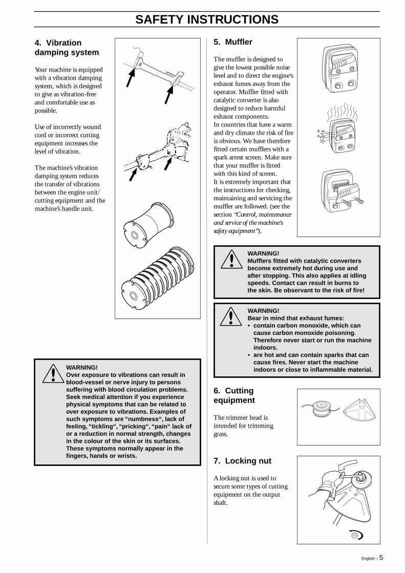
4. Vibrationdamping system
Your machine is equippedwith a vibration dampingsystem, which is designedto give as vibration-freeand comfortable use aspossible.
Use of incorrectly woundcord or incorrect cuttingequipment increases thelevel of vibration.
The machine’s vibrationdamping system reducesthe transfer of vibrationsbetween the engine unit/cutting equipment and themachine’s handle unit.
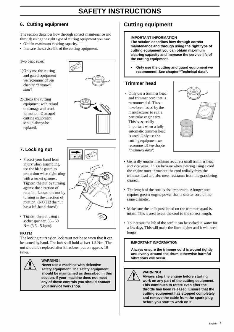
5. Muffler
The muffler is designed togive the lowest possible noiselevel and to direct the engine‘sexhaust fumes away from theoperator. Muffler fitted withcatalytic converter is alsodesigned to reduce harmfulexhaust components.In countries that have a warmand dry climate the risk of fireis obvious. We have thereforefitted certain mufflers with aspark arrest screen. Make surethat your muffler is fittedwith this kind of screen.It is extremely important thatthe instructions for checking,maintaining and servicing themuffler are followed. (see thesection “Control, maintenanceand service of the machine‘ssafety equipment“).
!
WARNING!Mufflers fitted with catalytic convertersbecome extremely hot during use andafter stopping. This also applies at idlingspeeds. Contact can result in burns tothe skin. Be observant to the risk of fire!
!
WARNING!Bear in mind that exhaust fumes:• contain carbon monoxide, which can
cause carbon monoxide poisoning.Therefore never start or run the machineindoors.
• are hot and can contain sparks that cancause fires. Never start the machineindoors or close to inflammable material.
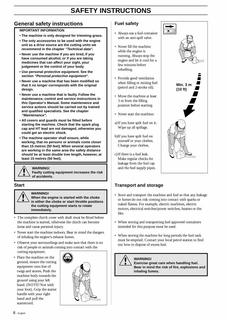
6. Cuttingequipment
The trimmer head isintended for trimminggrass.
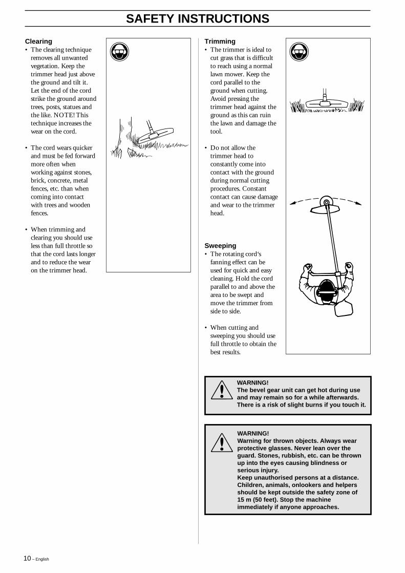
7. Locking nut
A locking nut is used tosecure some types of cuttingequipment on the outputshaft.
!
WARNING!Over exposure to vibrations can result inblood-vessel or nerve injury to personssuffering with blood circulation problems.Seek medical attention if you experiencephysical symptoms that can be related toover exposure to vibrations. Examples ofsuch symptoms are “numbness“, lack offeeling, “tickling“, “pricking“, “pain“ lack ofor a reduction in normal strength, changesin the colour of the skin or its surfaces.These symptoms normally appear in thefingers, hands or wrists.

6 – English
3. Cuttingattachment guard
• Ensure that the sprayguard is undamaged andis not cracked.
• Replace the guard if ithas been exposed toimpact or is cracked.
• Always use the prescribedblade an guardcombination, see chapter"Technical data".
SAFETY INSTRUCTIONS
Control, maintenance and service ofthe machine‘s safety equipment
IMPORTANT INFORMATION
• All service and repairs to the machine requirespecial training.
• This applies especially to the machine‘s safetyequipment. If the machine does not meet anyof the controls listed below you shouldcontact your service workshop.
• The purchase of one of our productsguarantees that professional repair andservicing will be carried out on it. If the pointof purchase is not one of our servicing dealers, please ask for details of the closestservice workshop.
1. Throttle triggerlock
• Check that the throttle islocked in the “idlingposition“ when thethrottle trigger lock is inits original position.
• Press in the throttletrigger lock and make sureit returns to its originalposition when released.
• Ensure that the throttleand throttle trigger lockmove easily and that theirreturn spring systemsfunction.
• See section "Start". Startthe machine and applyfull throttle. Release thethrottle and check that thecutting equipment stopsand remains at a standstill.If the cutting equipmentrotates with the throttle inthe idling position thenthe carburettor‘s idlingsetting must be checked.See chapter“Maintenance“.
2. Stop switch
• Start the engine and makesure that the engine stopswhen the stop switch ismoved to the stopposition.
4. Vibrationdamping system
• Check the vibrationdamping elementregularly for materialcracks and distortion.
• Check that the vibrationdamping element isundamaged and securelyattached.
#
5. Muffler
1.Never use a machine thathas a defective muffler.
2.Check regularly that themuffler is secure.
3. If your muffler is fittedwith a spark arrest screenthen it should be cleanedregularly. A blockedscreen leads to the engineoverheating with seriousdamage as a result. Neveruse a muffler with adefective spark arrestscreen.
English – 7
SAFETY INSTRUCTIONS
6. Cutting equipment
The section describes how through correct maintenance andthrough using the right type of cutting equipment you can:• Obtain maximum clearing capacity.• Increase the service life of the cutting equipment.
Two basic rules:
1)Only use the cuttingand guard equipmentwe recommend! Seechapter “Technicaldata“.
2)Check the cuttingequipment with regardto damage and crackformation. Damagedcutting equipmentshould always bereplaced.
Cutting equipment
7. Locking nut
• Protect your hand frominjury when assembling,use the blade guard asprotection when tighteningwith a socket spanner.Tighten the nut by turningagainst the direction ofrotation. Loosen the nut byturning in the direction ofrotation. (NOTE! the nuthas a left-hand thread).
• Tighten the nut using asocket spanner, 35 - 50Nm (3.5 - 5 kpm).
Trimmer head
• Only use a trimmer headand trimmer cord that isrecommended. Thesehave been tested by themanufacturer to suit aparticular engine size.This is especiallyimportant when a fullyautomatic trimmer headis used. Only use thecutting equipment werecommend! See chapter“Technical data“.
NOTE!The locking nut‘s nylon lock must not be so worn that it canbe turned by hand. The lock shall hold at least 1.5 Nm. Thenut should be replaced after it has been put on approx. 10times.
• Generally smaller machines require a small trimmer headand vice versa. This is because when clearing using a cordthe engine must throw out the cord radially from thetrimmer head and also meet resistance from the grass beingcleared.
• The length of the cord is also important. A longer cordrequires greater engine power than a shorter cord of thesame diameter.
• Make sure the knife positioned on the trimmer guard isintact. This is used to cut the cord to the correct length.
• To increase the life of the cord it can be soaked in water fora few days. This will make the line tougher and it will keeplonger.
WARNING!Never use a machine with defectivesafety equipment. The safety equipmentshould be maintained as described in thissection. If your machine does not meetany of these controls you should contactyour service workshop.
!
!
WARNING!Always stop the engine before startingwork on any part of the cutting equipment.This continues to rotate even after thethrottle has been released. Ensure that thecutting equipment has stopped completelyand remove the cable from the spark plugbefore you start to work on it.
IMPORTANT INFORMATIONThe section describes how through correctmaintenance and through using the right type ofcutting equipment you can obtain maximumclearing capacity and increase the service life ofthe cutting equipment.
• Only use the cutting and guard equipment werecommend! See chapter “Technical data“.
IMPORTANT INFORMATION
Always ensure the trimmer cord is wound tightlyand evenly around the drum, otherwise harmfulvibrations will occur.
8 – English
SAFETY INSTRUCTIONS
General safety instructions
Transport and storage
• Store and transport the machine and fuel so that any leakageor fumes do not risk coming into contact with sparks ornaked flames. For example, electric machines, electricmotors, electrical switches/power switches, heaters or thelike.
• When storing and transporting fuel approved containersintended for this purpose must be used.
• When storing the machine for long periods the fuel tankmust be emptied. Contact your local petrol station to findout how to dispose of excess fuel.
Fuel safety
• Always use a fuel containerwith an anti-spill valve.
• Never fill the machinewhile the engine isrunning. Always stop theengine and let it cool for afew minutes beforerefuelling.
• Provide good ventilationwhen filling or mixing fuel(petrol and 2-stroke oil).
• Move the machine at least3 m from the fillingposition before starting.
• Never start the machine:
a) If you have spilt fuel on it.Wipe up all spillage.
b)If you have spilt fuel onyourself or your clothes.Change your clothes.
c) If there is a fuel leak.Make regular checks forleakage from the fuel capand the fuel supply pipes.
Min. 3 m(10 ft)
IMPORTANT INFORMATION
• The machine is only designed for trimming grass.
• The only accessories to be used with the engineunit as a drive source are the cutting units werecommend in the chapter “Technical data“.
• Never use the machine if you are tired, if youhave consumed alcohol, or if you are takingmedicines that can affect your sight, yourjudgement or the control of your body.
• Use personal protective equipment. See thesection “Personal protective equipment“.
• Never use a machine that has been modified sothat it no longer corresponds with the originaldesign.
• Never use a machine that is faulty. Follow themaintenance, control and service instructions inthis Operator‘s Manual. Some maintenance andservice actions should be carried out by trainedand qualified specialists. See the chapter“Maintenance“.
• All covers and guards must be fitted beforestarting the machine. Check that the spark plugcap and HT lead are not damaged, otherwise youcould get an electric shock.
• The machine operator shall ensure, whileworking, that no persons or animals come closerthan 15 metres (50 feet). When several operatorsare working in the same area the safety distanceshould be at least double tree length, however, atleast 15 metres (50 feet).
• The complete clutch cover with shaft must be fitted beforethe machine is started, otherwise the clutch can becomeloose and cause personal injury.
• Never start the machine indoors. Bear in mind the dangersof inhaling the engine‘s exhaust fumes.
• Observe your surroundings and make sure that there is norisk of people or animals coming into contact with thecutting equipment.
• Place the machine on theground, ensure the cuttingequipment runs free oftwigs and stones. Push themachine body towards theground using your lefthand. (NOTE! Not withyour foot). Grip the starterhandle with your righthand and pull thestartercord.
!
WARNING!When the engine is started with the chokein either the choke or start throttle positionsthe cutting equipment starts to rotateimmediately.
WARNING!Exercise great care when handling fuel.Bear in mind the risk of fire, explosions andinhaling fumes.
!
Start
WARNING!Faulty cutting equipment increases the riskof accidents.!

English – 9
!
General working instructions
SAFETY INSTRUCTIONS
Basic working techniques
• Always drop to idling speed after each working operation.Longer periods running at full throttle without loading theengine (that is without resistance, which the engine feelsfrom the cutting equipment when trimming) can lead toserious engine damage.
Basic safety precautions
1.Observe your surroundings:
• To ensure that people, animals or other things cannot affectyour control of the machine.
• To ensure that the above mentioned do not come intocontact with the cutting equipment or objects that can bethrown by the cutting equipment.
• NOTE! Never use a machine without the possibility ofcalling for help in the event of an accident.
WARNING!Sometimes branches, grass or wood canget caught between the guard and cuttingequipment. Always stop the engine whencleaning.
2.Avoid usage inunfavourable weatherconditions. For example,thick fog, heavy rain,strong winds or extremecold, etc. To work in badweather conditions istiring and can createdangerous circumstances,e.g. slippery surfaces.
3.Make sure you can walkand stand safely. Look outfor any obstacles withunexpected movement(roots, stones, branches,pits, ditches, etc.). Takegreat care when workingon sloping ground.
4.The engine should be switched off before moving. Whenmoving over longer distances and transporting the transportguard should be used.
5.Never put the machine down with the engine running unlessyou have good sight of it.
6.. Do not over-reach
7.Keep Cutting attachment below waist level.
IMPORTANT INFORMATION
• This section takes up the basic safetyprecautions for working with the trimmer.
• If you encounter a situation where you areuncertain how to proceed you should ask anexpert. Contact your dealer or your serviceworkshop.
• Avoid all usage which you consider to bebeyond your capability.
Grass trimmingusing the trimmerhead and plasticknifes
• Hold the trimmer headjust above the ground atan angle. It is the end ofthe cord that carries outthe work. Let the cordwork at its own pace. Donot press the cord into thearea to be cut.
• The cord can easilyremove grass and weeds upagainst walls, fences, treesand borders, however, itcan also damage sensitivebark on trees and bushesand damage fence posts.
• Reduce the risk ofdamaging plants byshortening the cord to 10-12 cm and reducing theengine speed.
10 – English
SAFETY INSTRUCTIONS
Clearing• The clearing technique
removes all unwantedvegetation. Keep thetrimmer head just abovethe ground and tilt it.Let the end of the cordstrike the ground aroundtrees, posts, statues andthe like. NOTE! Thistechnique increases thewear on the cord.
• The cord wears quickerand must be fed forwardmore often whenworking against stones,brick, concrete, metalfences, etc. than whencoming into contactwith trees and woodenfences.
• When trimming andclearing you should useless than full throttle sothat the cord lasts longerand to reduce the wearon the trimmer head.
Trimming• The trimmer is ideal to
cut grass that is difficultto reach using a normallawn mower. Keep thecord parallel to theground when cutting.Avoid pressing thetrimmer head against theground as this can ruinthe lawn and damage thetool.
• Do not allow thetrimmer head toconstantly come intocontact with the groundduring normal cuttingprocedures. Constantcontact can cause damageand wear to the trimmerhead.
Sweeping• The rotating cord‘s
fanning effect can beused for quick and easycleaning. Hold the cordparallel to and above thearea to be swept andmove the trimmer fromside to side.
• When cutting andsweeping you should usefull throttle to obtain thebest results.
!
WARNING!Warning for thrown objects. Always wearprotective glasses. Never lean over theguard. Stones, rubbish, etc. can be thrownup into the eyes causing blindness orserious injury.Keep unauthorised persons at a distance.Children, animals, onlookers and helpersshould be kept outside the safety zone of15 m (50 feet). Stop the machineimmediately if anyone approaches.
!
WARNING!The bevel gear unit can get hot during useand may remain so for a while afterwards.There is a risk of slight burns if you touch it.

English – 11
WHAT IS WHAT?
What is what on the trimmer?
1. Trimmer head
2. Grease filler cap
3. Angle gear
4. Spray guard
5. Shaft
6. Loop handlebar
7. Throttle
8. Stop switch
9. Throttle trigger lock
10. Cylinder cover
11. Starter handle
12. Fuel tank
13. Choke
14. Air purge
15. Air filter cover
16. Clutch cover
17. Handlebar adjustment
18. Locking nut
19. Support flange
20. Drive disc
21. Socket spanner
22. Operator‘s Manual
23. Allen key
24. Locking pin
25. Shaft coupling
25
=
L-X/L-XT
¥
¢
C/C-X
L-XT

12 – English
ASSEMBLY
Assembling the loop handlebar(322C, 325CX)
Assembly of the trimmer head
It is extremely importantthat the disc drive’s/supportflange’s guide engagescorrectly in the cuttingequipment’s centre holewhen assembling the cuttingequipment. Cuttingequipment assembledincorrectly can result inserious and/or fatal personalinjury.
!
WARNING!Under no circumstances may the cuttingequipment be used without an approvedguard fitted. See the chapter “Technicaldata”. If the wrong guard or a defectiveguard is fitted this can cause seriouspersonal injury.
Assembling the loop handlebar(322L,325L-X/L-XT)
• Position the handle onthe shaft. Note that thehandle must be mountedbelow the arrow on theshaft.
• Fit the bolt, securing plateand wing nut as shown inthe diagram.
• Tighten the wing nut.
• Clip the loop handle ontothe shaft. Note that theloop handle must befitted between the arrowson the shaft.
• Slide the spacer into theslot in the loop handle.
• 322L: Fit the nut, washerand bolt.325L-X/L-XT, 325C-X:Fit the nut, knob andbolt. Do not overtighten.
• Now adjust the trimmerto give a comfortableworking position. Tightenthe bolt/knob.
Assembling and dismantling thetwo-part shaft (325L-XT)Assembling:
• Make sure the handle isloose.
• Guide the cut-out on thelower section of the shaftinto the coupling‘slocking plate on theupper section of theshaft. The sections arethen locked together.
• Tighten the handle.
Dismantling
• Undo the handle (at leastthree turns).
• Press the handle towardsthe coupling.
• Carefully twist the lowersection out of the lock.
• Hold both parts of theshaft and pull out thelower section from thecoupling.

English – 13
ASSEMBLY
• Fit the guard (A)intended for use withthe trimmer head. Hookthe guard onto the shaftfitting and secure it withthe bolt (L).
• Fit the disc drive (B) onthe output axle.
• Turn the blade axle untilone of the disc drive’sholes aligns with thecorresponding hole inthe gear housing.
• Insert the locking pin(C) into the hole to lockthe axle.
• Screw on the trimmerhead (H) in thedirection of rotation.
• Dismantling takes placein the reverse order.
Assembling other guards and cuttingequipment (322L, 325L-X/L-XT)
Assembling the spray guard andtrimmer head Superauto II (322L,325L-X/L-XT)
Fitting the spray guard and trimmerhead (322C)
• Fit the guard (A) intendedfor use with the trimmerhead. Hook the guard ontothe shaft fitting and secureit with the bolt (L).
• Fit the drive disc (B) on theoutput axle.
• Turn the blade axle untilone of the holes in thedrive disc aligns with thehole in the gear housing.
• Insert the locking pin (C)in the hole so that the axleis locked.
• The trimmer head must besplit to be fitted (see thediagram). Proceed asfollows:
• Insert your finger into thecentre hole of the cover (I)at the same time as youhold the cover with yourother fingers. Press the twocatches (J) that extend fromthe cut-out on the bottomsection (K) using thethumb and index finger ofyour other hand. Pressapart the trimmer headusing the fingers on thecover.
• Place the cover (I) and thesupport flange (F) on theoutput axle.
• Fit the nut (G). Thetightening torque of thenut is 35-50 Nm (3,5-5kpm). Use the socketspanner in the tool kit.Hold the handle of thespanner as close to thetrimmer guard as possible.The nut is tightened whenthe spanner is turnedagainst the direction ofrotation (left-hand thread).
• Fit the trimmer head‘sbottom section (K) on thecover (I) by pressing thetwo sections together with
K
JI
GFI
A
K
BC
H
the cut-outs on the bottom section aligned with the catcheson the cover.
• To dismantle follow the instructions in the reverse order.
Guard• Fit the guard as shown
in the diagram. Tightensecurely.
Trimmer head• Fit the dust cup on the
shaft. The nut must becompletely covered bythe dust cup.
• Hold the dust cup witha spanner to prevent theshaft from rotating.
• Screw the trimmer headonto the shaft.

14 – English
Fitting the spray guard and trimmerhead (325CX)• Fit the guard as shown in
the diagram. Tightensecurely.
• Insert the locking pin intothe hole to lock the axle.
• Screw the trimmer headonto the shaft. Tightensecurely.
ASSEMBLY
English – 15
FUEL HANDLING
Fuel mixture
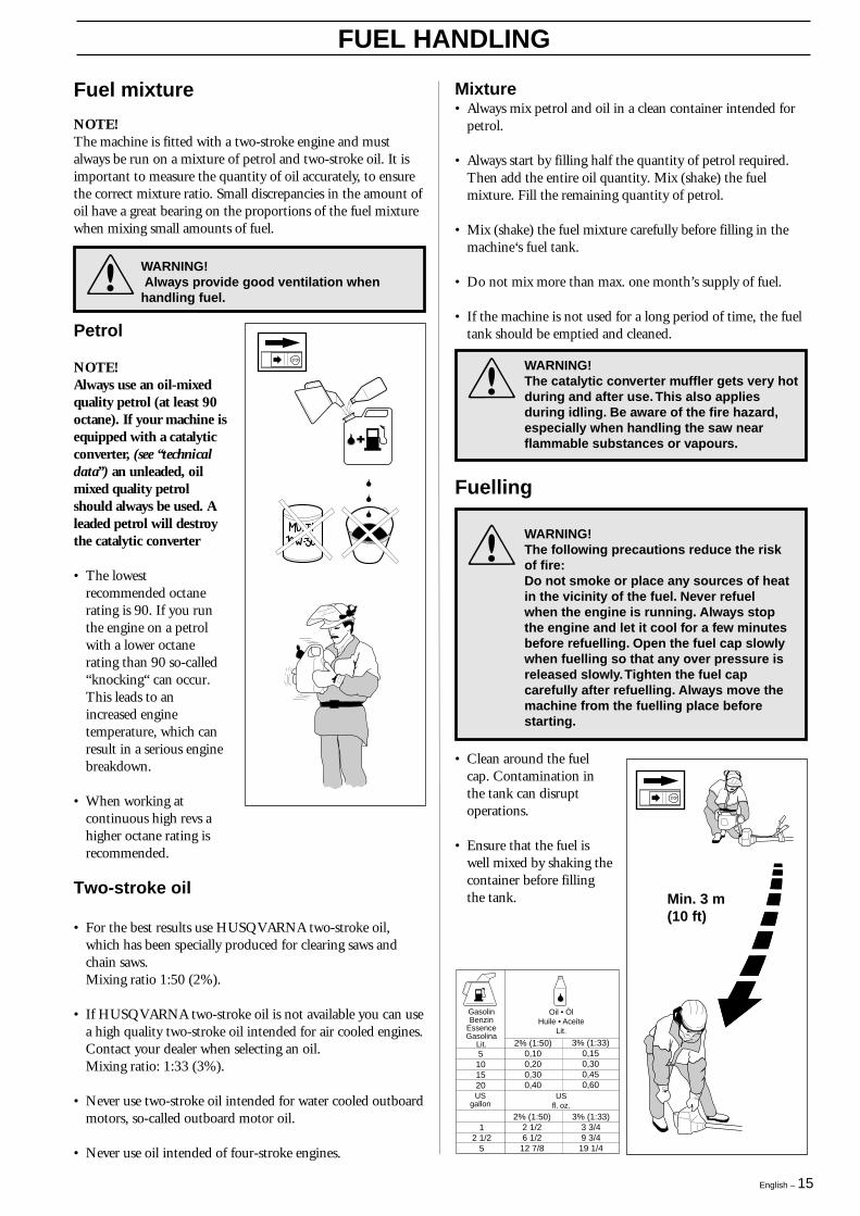
5101520
2% (1:50)0,100,200,300,40
3% (1:33)0,150,300,450,60
GasolinBenzin
EssenceGasolina
Lit.
Oil • ÖlHuile • Aceite
Lit.
12 1/2
5
2% (1:50)2 1/26 1/2
12 7/8
3% (1:33)3 3/49 3/4
19 1/4
USgallon
USfl. oz.
NOTE!The machine is fitted with a two-stroke engine and mustalways be run on a mixture of petrol and two-stroke oil. It isimportant to measure the quantity of oil accurately, to ensurethe correct mixture ratio. Small discrepancies in the amount ofoil have a great bearing on the proportions of the fuel mixturewhen mixing small amounts of fuel.
Petrol
NOTE!Always use an oil-mixedquality petrol (at least 90octane). If your machine isequipped with a catalyticconverter, (see “technicaldata”) an unleaded, oilmixed quality petrolshould always be used. Aleaded petrol will destroythe catalytic converter
• The lowestrecommended octanerating is 90. If you runthe engine on a petrolwith a lower octanerating than 90 so-called“knocking“ can occur.This leads to anincreased enginetemperature, which canresult in a serious enginebreakdown.
• When working atcontinuous high revs ahigher octane rating isrecommended.
WARNING! Always provide good ventilation whenhandling fuel.!
• Clean around the fuelcap. Contamination inthe tank can disruptoperations.
• Ensure that the fuel iswell mixed by shaking thecontainer before fillingthe tank.
!
WARNING!The catalytic converter muffler gets very hotduring and after use. This also appliesduring idling. Be aware of the fire hazard,especially when handling the saw nearflammable substances or vapours.
Fuelling
WARNING!The following precautions reduce the riskof fire:Do not smoke or place any sources of heatin the vicinity of the fuel. Never refuelwhen the engine is running. Always stopthe engine and let it cool for a few minutesbefore refuelling. Open the fuel cap slowlywhen fuelling so that any over pressure isreleased slowly. Tighten the fuel capcarefully after refuelling. Always move themachine from the fuelling place beforestarting.
!
Two-stroke oil
• For the best results use HUSQVARNA two-stroke oil,which has been specially produced for clearing saws andchain saws.Mixing ratio 1:50 (2%).
• If HUSQVARNA two-stroke oil is not available you can usea high quality two-stroke oil intended for air cooled engines.Contact your dealer when selecting an oil.Mixing ratio: 1:33 (3%).
• Never use two-stroke oil intended for water cooled outboardmotors, so-called outboard motor oil.
• Never use oil intended of four-stroke engines.
Min. 3 m(10 ft)
Mixture• Always mix petrol and oil in a clean container intended for
petrol.
• Always start by filling half the quantity of petrol required.Then add the entire oil quantity. Mix (shake) the fuelmixture. Fill the remaining quantity of petrol.
• Mix (shake) the fuel mixture carefully before filling in themachine‘s fuel tank.
• Do not mix more than max. one month’s supply of fuel.
• If the machine is not used for a long period of time, the fueltank should be emptied and cleaned.
16 – English
START AND STOP
Control before starting
For reasons of safety followthese recommendations!
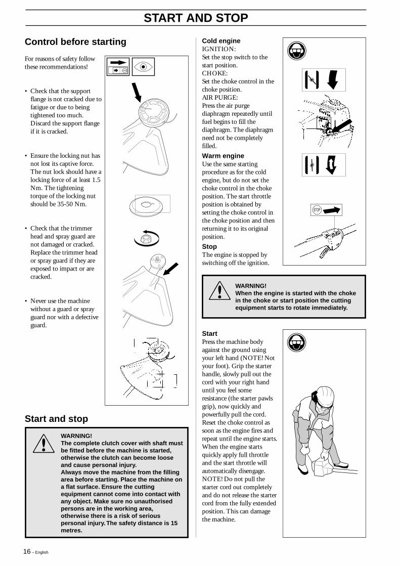
• Check that the supportflange is not cracked due tofatigue or due to beingtightened too much.Discard the support flangeif it is cracked.
• Ensure the locking nut hasnot lost its captive force.The nut lock should have alocking force of at least 1.5Nm. The tighteningtorque of the locking nutshould be 35-50 Nm.
• Check that the trimmerhead and spray guard arenot damaged or cracked.Replace the trimmer heador spray guard if they areexposed to impact or arecracked.
• Never use the machinewithout a guard or sprayguard nor with a defectiveguard.
!
WARNING!The complete clutch cover with shaft mustbe fitted before the machine is started,otherwise the clutch can become looseand cause personal injury.Always move the machine from the fillingarea before starting. Place the machine ona flat surface. Ensure the cuttingequipment cannot come into contact withany object. Make sure no unauthorisedpersons are in the working area,otherwise there is a risk of seriouspersonal injury. The safety distance is 15metres.
Start and stop
WARNING!When the engine is started with the chokein the choke or start position the cuttingequipment starts to rotate immediately.
!
StartPress the machine bodyagainst the ground usingyour left hand (NOTE! Notyour foot). Grip the starterhandle, slowly pull out thecord with your right handuntil you feel someresistance (the starter pawlsgrip), now quickly andpowerfully pull the cord.Reset the choke control assoon as the engine fires andrepeat until the engine starts.When the engine startsquickly apply full throttleand the start throttle willautomatically disengage.NOTE! Do not pull thestarter cord out completelyand do not release the startercord from the fully extendedposition. This can damagethe machine.
Cold engineIGNITION:Set the stop switch to thestart position.CHOKE:Set the choke control in thechoke position.AIR PURGE:Press the air purgediaphragm repeatedly untilfuel begins to fill thediaphragm. The diaphragmneed not be completelyfilled.
Warm engineUse the same startingprocedure as for the coldengine, but do not set thechoke control in the chokeposition. The start throttleposition is obtained bysetting the choke control inthe choke position and thenreturning it to its originalposition.
StopThe engine is stopped byswitching off the ignition.
English – 17
Basic setting• The carburettor is set to its basic setting when test run at the
factory. The basic setting is richer than the optimal settingand should be kept during the machine‘s first workinghours. Thereafter the carburettor should be finely adjusted.Fine adjustment should be carried out by a skilledtechnician.
NOTE! If the cutting attachment rotates/moves while theengine is idling the T-screw should be turned anti-clockwiseuntil the cutting attachment stops.Rec. idling speed: 2 700 rpm.
Recommended max. speed: See “Technical Data” .!
WARNING!The complete clutch cover with shaftmust be fitted before the machine isstarted, otherwise the clutch can becomeloose and cause personal injury.
Operation
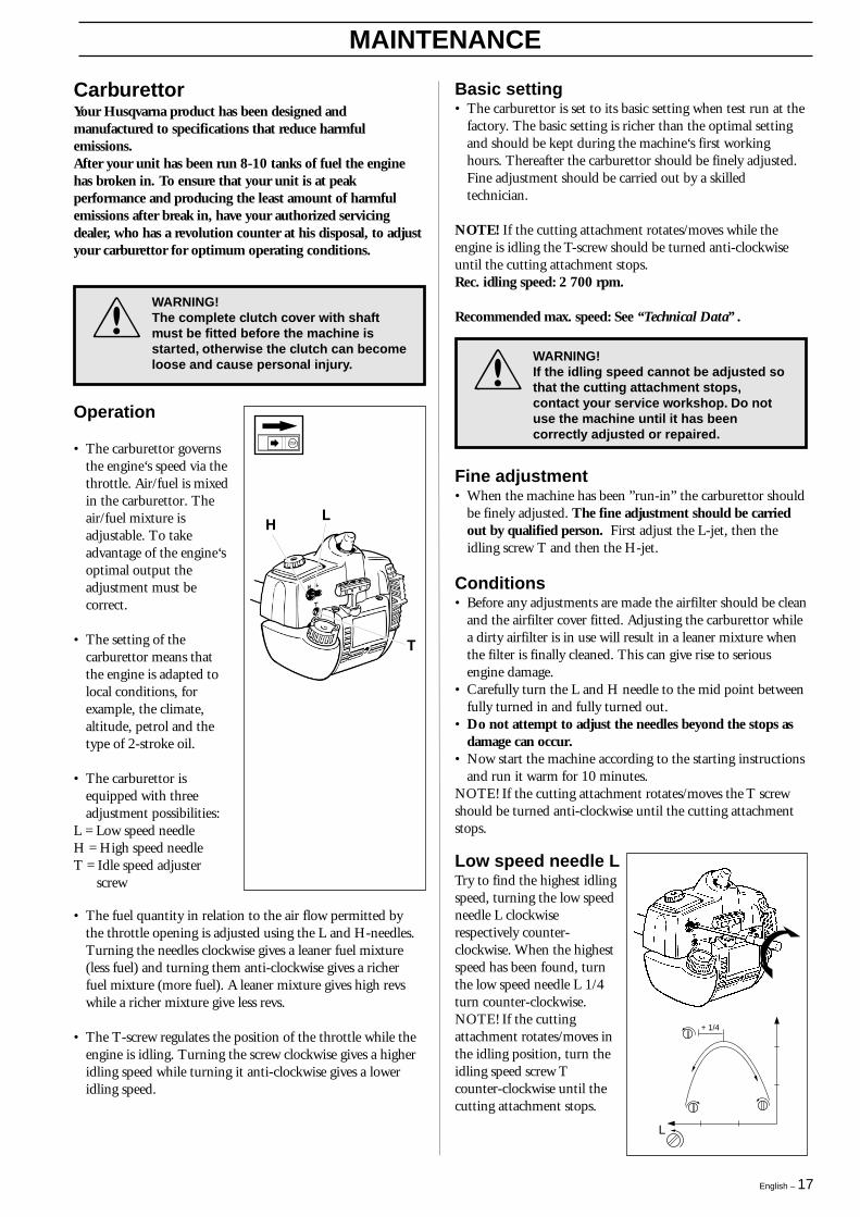
• The carburettor governsthe engine‘s speed via thethrottle. Air/fuel is mixedin the carburettor. Theair/fuel mixture isadjustable. To takeadvantage of the engine‘soptimal output theadjustment must becorrect.
• The setting of thecarburettor means thatthe engine is adapted tolocal conditions, forexample, the climate,altitude, petrol and thetype of 2-stroke oil.
• The carburettor isequipped with threeadjustment possibilities:
L = Low speed needleH = High speed needleT = Idle speed adjuster
screw
• The fuel quantity in relation to the air flow permitted bythe throttle opening is adjusted using the L and H-needles.Turning the needles clockwise gives a leaner fuel mixture(less fuel) and turning them anti-clockwise gives a richerfuel mixture (more fuel). A leaner mixture gives high revswhile a richer mixture give less revs.
• The T-screw regulates the position of the throttle while theengine is idling. Turning the screw clockwise gives a higheridling speed while turning it anti-clockwise gives a loweridling speed.
Fine adjustment• When the machine has been ”run-in” the carburettor should
be finely adjusted. The fine adjustment should be carriedout by qualified person. First adjust the L-jet, then theidling screw T and then the H-jet.
Conditions• Before any adjustments are made the airfilter should be clean
and the airfilter cover fitted. Adjusting the carburettor whilea dirty airfilter is in use will result in a leaner mixture whenthe filter is finally cleaned. This can give rise to seriousengine damage.
• Carefully turn the L and H needle to the mid point betweenfully turned in and fully turned out.
• Do not attempt to adjust the needles beyond the stops asdamage can occur.
• Now start the machine according to the starting instructionsand run it warm for 10 minutes.
NOTE! If the cutting attachment rotates/moves the T screwshould be turned anti-clockwise until the cutting attachmentstops.
Low speed needle LTry to find the highest idlingspeed, turning the low speedneedle L clockwiserespectively counter-clockwise. When the highestspeed has been found, turnthe low speed needle L 1/4turn counter-clockwise.NOTE! If the cuttingattachment rotates/moves inthe idling position, turn theidling speed screw Tcounter-clockwise until thecutting attachment stops.
!
WARNING!If the idling speed cannot be adjusted sothat the cutting attachment stops,contact your service workshop. Do notuse the machine until it has beencorrectly adjusted or repaired.
MAINTENANCE
CarburettorYour Husqvarna product has been designed andmanufactured to specifications that reduce harmfulemissions.After your unit has been run 8-10 tanks of fuel the enginehas broken in. To ensure that your unit is at peakperformance and producing the least amount of harmfulemissions after break in, have your authorized servicingdealer, who has a revolution counter at his disposal, to adjustyour carburettor for optimum operating conditions.
L
+ 1/4
18 – English
MAINTENANCE
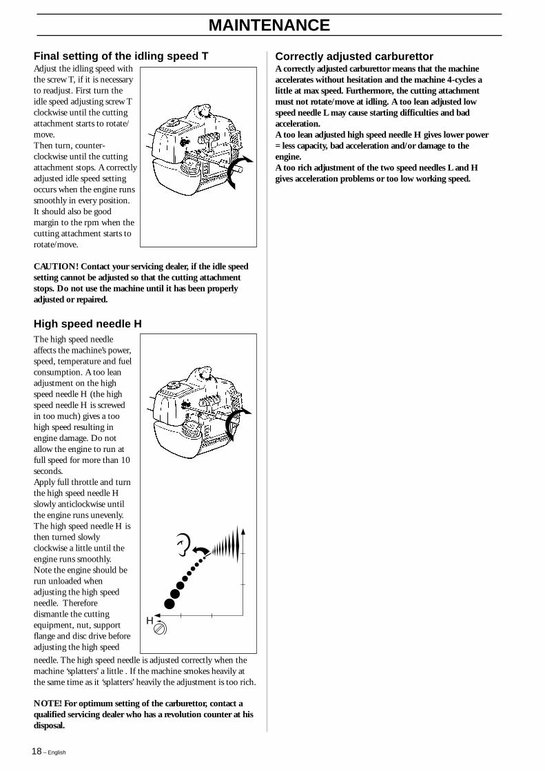
H
needle. The high speed needle is adjusted correctly when themachine ‘splatters’ a little . If the machine smokes heavily atthe same time as it ‘splatters’ heavily the adjustment is too rich.
The high speed needleaffects the machine’s power,speed, temperature and fuelconsumption. A too leanadjustment on the highspeed needle H (the highspeed needle H is screwedin too much) gives a toohigh speed resulting inengine damage. Do notallow the engine to run atfull speed for more than 10seconds.Apply full throttle and turnthe high speed needle Hslowly anticlockwise untilthe engine runs unevenly.The high speed needle H isthen turned slowlyclockwise a little until theengine runs smoothly.Note the engine should berun unloaded whenadjusting the high speedneedle. Thereforedismantle the cuttingequipment, nut, supportflange and disc drive beforeadjusting the high speed
Final setting of the idling speed TAdjust the idling speed withthe screw T, if it is necessaryto readjust. First turn theidle speed adjusting screw Tclockwise until the cuttingattachment starts to rotate/move.Then turn, counter-clockwise until the cuttingattachment stops. A correctlyadjusted idle speed settingoccurs when the engine runssmoothly in every position.It should also be goodmargin to the rpm when thecutting attachment starts torotate/move.
CAUTION! Contact your servicing dealer, if the idle speedsetting cannot be adjusted so that the cutting attachmentstops. Do not use the machine until it has been properlyadjusted or repaired.
NOTE! For optimum setting of the carburettor, contact aqualified servicing dealer who has a revolution counter at hisdisposal.
High speed needle H
Correctly adjusted carburettorA correctly adjusted carburettor means that the machineaccelerates without hesitation and the machine 4-cycles alittle at max speed. Furthermore, the cutting attachmentmust not rotate/move at idling. A too lean adjusted lowspeed needle L may cause starting difficulties and badacceleration.A too lean adjusted high speed needle H gives lower power= less capacity, bad acceleration and/or damage to theengine.A too rich adjustment of the two speed needles L and Hgives acceleration problems or too low working speed.
English – 19
MAINTENANCE
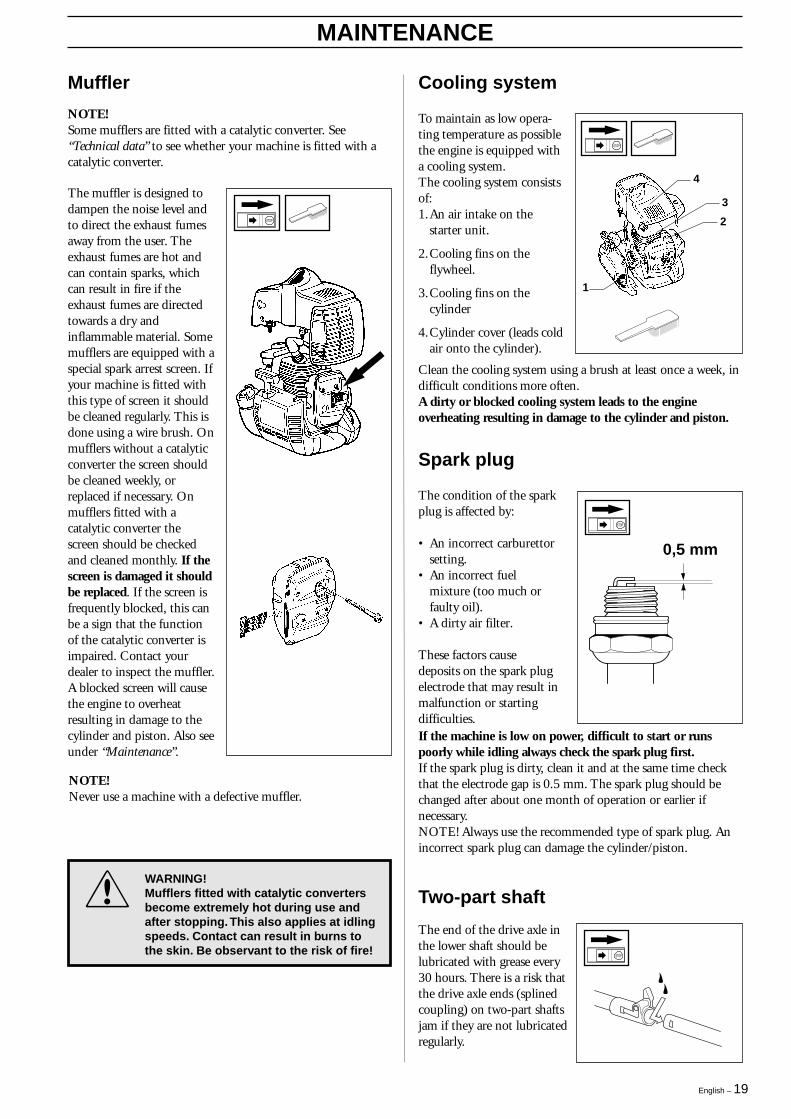
Cooling system
To maintain as low opera-ting temperature as possiblethe engine is equipped witha cooling system.The cooling system consistsof:1.An air intake on the
starter unit.
2.Cooling fins on theflywheel.
3.Cooling fins on thecylinder
4.Cylinder cover (leads coldair onto the cylinder).
Muffler
NOTE!Some mufflers are fitted with a catalytic converter. See“Technical data” to see whether your machine is fitted with acatalytic converter.
The muffler is designed todampen the noise level andto direct the exhaust fumesaway from the user. Theexhaust fumes are hot andcan contain sparks, whichcan result in fire if theexhaust fumes are directedtowards a dry andinflammable material. Somemufflers are equipped with aspecial spark arrest screen. Ifyour machine is fitted withthis type of screen it shouldbe cleaned regularly. This isdone using a wire brush. Onmufflers without a catalyticconverter the screen shouldbe cleaned weekly, orreplaced if necessary. Onmufflers fitted with acatalytic converter thescreen should be checkedand cleaned monthly. If thescreen is damaged it shouldbe replaced. If the screen isfrequently blocked, this canbe a sign that the functionof the catalytic converter isimpaired. Contact yourdealer to inspect the muffler.A blocked screen will causethe engine to overheatresulting in damage to thecylinder and piston. Also seeunder “Maintenance”.
NOTE!Never use a machine with a defective muffler.
!
WARNING!Mufflers fitted with catalytic convertersbecome extremely hot during use andafter stopping. This also applies at idlingspeeds. Contact can result in burns tothe skin. Be observant to the risk of fire!
1
4
3
2
Spark plug
The condition of the sparkplug is affected by:
• An incorrect carburettorsetting.
• An incorrect fuelmixture (too much orfaulty oil).
• A dirty air filter.
These factors causedeposits on the spark plugelectrode that may result inmalfunction or startingdifficulties.If the machine is low on power, difficult to start or runspoorly while idling always check the spark plug first.If the spark plug is dirty, clean it and at the same time checkthat the electrode gap is 0.5 mm. The spark plug should bechanged after about one month of operation or earlier ifnecessary.NOTE! Always use the recommended type of spark plug. Anincorrect spark plug can damage the cylinder/piston.
0,5 mm
Clean the cooling system using a brush at least once a week, indifficult conditions more often.A dirty or blocked cooling system leads to the engineoverheating resulting in damage to the cylinder and piston.
The end of the drive axle inthe lower shaft should belubricated with grease every30 hours. There is a risk thatthe drive axle ends (splinedcoupling) on two-part shaftsjam if they are not lubricatedregularly.
Two-part shaft

20 – English
MAINTENANCE
Maintenance schedule
Below follows some general maintenance instructions.If you need further information please contact your serviceworkshop.
Daily maintenance
1.Clean the outside of themachine.
2.Make sure the throttletrigger lock and thethrottle function correctlyfrom a safety point ofview.
3.Check that the stopswitch functions.
4.Check that the cuttinghead does not rotate whileidling.
5.Clean the air filter.Replace if necessary.
6.Check that the guard isundamaged and notcracked. Replace theguards if they have beenexposed to impact or arecracked.
7.Check that the trimmerhead is undamaged andnot cracked. Replace thetrimmer head if necessary.
8.Check that the lockingnut is tight.
9.Check that all nuts andscrews are tightened.
1
2
3
4
5
6
7
8
9The angle gear is filled with asufficient quantity of grease atthe factory. However, beforeusing the machine you shouldcheck that the angle gear isfilled to 3/4 with grease. UseHUSQVARNA specialgrease.
Normally, the grease does notneed to be changed exceptwhen repairs are carried out.
Air filter
The air filter should becleaned regularly removingdust and dirt to avoid:• carburettor malfunction• starting problems• reduced engine power• unnecessary wear to
engine parts• abnormal fuel
consumptionClean the filter after every25 hours or more regularlyif operating conditions areexceptionally dusty.
Cleaning the air filterDismantle the air filter cover and remove the air filter. Wash inclean, warm soapy water. Ensure that the filter is dry beforerefitting. An air filter used for a long period of time can neverbe cleaned completely. Therefore it is necessary to replace thefilter from time to time with a new filter. A damaged air filtermust always be replaced.If the machine is used in dusty conditions the air filtershould be soaked in oil, see the section on “Oiling the airfilter“.
Oiling the air filterAlways use HUSQVARNAfilter oil, order no. 503 4773-01. The filter oilcontains a solvent to make itspread evenly through thefilter. You should thereforeavoid skin contact. Put thefilter in a plastic bag and thepour the filter oil over it.Knead the plastic bag todistribute the oil. Squeezethe excess oil out of the filterinside the plastic bag andpour off the excess beforefitting the filter on the machine. Never use common engineoil. This would drain through the filter quite quickly andcollect in the bottom.
Angle gear (322L, 325L-X/L-XT)

English – 21
MAINTENANCE
Weeklymaintenance
1.Check the starter, thestarter cord and the returnspring.
2.Make sure that thevibration dampingelements are not damaged.
3.Clean the outside of thespark plug. Remove andcheck the electrode gap.Adjust the gap to 0.5 mmor change the spark plug.
4.Clean the cooling fins onthe flywheel.
5.Clean or replace themuffler’s spark arrestscreen (not on mufflerswith a catalytic converter).
6.Clean the carburettor area.
7.Clean the cooling fins onthe cylinder and check thatthe air intake in the starterunit is not blocked.
8.Check that the angle gearis 3/4 filled with grease.Fill if necessary usingspecial grease.
1
3
4
5
6
8
7
Monthlymaintenance
1.Clean the fuel tank.
2.Clean the carburettor andthe area surrounding it.
3.Clean the fan and the areaaround it.
4.Check the fuel filter and thefuel pipe, replace ifnecessary.
5.Check all cables andconnections.
6.Check the clutch, clutchsprings and the clutch drumwith regard to wear.Replace if necessary.
7.Change the spark plug.
8.Check and clean themuffler’s spark arrest screenif necessary (only mufflerswith a catalytic converter).
2
4
7
6
2
3
5
1
8

22 – English
TECHNICAL DATA
325L-X/L-XT
1,50/24,51,34/341,06/272 70011 000-11 7008 0140,9 kW/ 9 000 rpmYesYes
Walbro MB 20Champion RCJ 7Y0,02/0,5
Zama C1Q1,06/0,5
9.0/4,1 L-XT: 9,7/4,4
92/98
109/109
1,5/1,4 L-XT: 1,5/1,42,0/1,8 L-XT: 2,4/2,22,5/4,8 L-XT: 2,5/4,84,9/8,0 L-XT: 5,8/7,6
322L
1,33/21,71,26/321,06/272 70011 000 - 11 7008 0140,7 kW/ 9 000 rpmYesYes
Walbro MB 20Champion RCJ 7Y0,02/0,5
Zama C1Q1,06/0,5
8,4/3,8
92/98
109/109
1,5/1,42,0/1,82,5/4,84,9/8,0
Technical data
EngineCylinder capacity, cu. in/cm3
Cylinder bore, inch/mmStroke length, inch/mmIdling speed, rpmRecommended max. speed, rpmSpeed of output axle, rpmMax. engine output, acc. to ISO 8893Catalytic converter mufflerSpeed-regulated ignition system
Ignition systemManufacturer/type of ignition systemSpark plugElectrode gap, inch/mm
Fuel lubrication systemManufacturer/type of carburettorFuel tank capacity, US pint/litres
WeightWeight without fuel, cutting tool andguard, Lbs/kg
Noise levelsEquivalent noise pressure level at theuser’s ear, measured according to EN31806 and ISO 7917, dB(A), min/max:Equivalent noise power level at the user’sear, measured according to EN 31806and ISO 10884, dB(A), min/max:
Vibration levelsVibration levels on the handles,measured according to EN 31806 andISO 7916, m/sWhen idling, left/right handles, min:When idling, left/right handles, max:At max. speed, left/right handles, min:At max. speed, left/right handles, max:
322C
1,33/21,71,26/321,06/272 70011 000 - 11 70011 7000,7 kW/ 9 000 rpmYes-
Walbro MB 18Champion RCJ 7Y0,02/0,5
Zama C1Q1,06/0,5
8,8/4,0
91/94
103/105
1,8/1,83,2/2,24,4/3,35,5/4,6
NOTE!Noise and vibration measurements are made with all the machine’s approved cutting equipment fitted.The table indicates the highest and lowest values.
Approved accessoriesThread blade shaft M10 (L, L-X, L-XT)Thread blade shaft 3/8 (R) (322C)Plastic knifesTrimmer head
Cutting attachment guard Art No.
503 93 42-02530 05 37-99 / 537 07 67-01503 97 71-01 / 503 93 42-02503 97 71-01 / 503 93 42-02503 97 71-01 / 503 93 42-02503 97 71-01 / 503 93 42-02503 97 71-01 / 503 93 42-02537 07 67-01
Type
Tricut ∅ 300 mm (322L, 325L-X/L-XT)Trimmy Hit VI (R) (322C)Trimmy H II 1" (322L, 325L-X/L-XT)Trimmy Fix (322L, 325L-X/L-XT)Trimmy Hit (322L, 325L-X/L-XT)Trimmy Hit Pro (322L, 325L-X/L-XT)Superauto II 1" (322L, 325L-X/L-XT)Trimmy Hit Junior(322C, 325CX)

English – 23
Technical data
EngineCylinder capacity, cu. in/cm3
Cylinder bore, inch/mmStroke length, inch/mmIdling speed, rpmRecommended max. speed, rpmSpeed of output axle, rpmMax. engine output, acc. to ISO 8893Catalytic converter mufflerSpeed-regulated ignition system
Ignition systemManufacturer/type of ignition systemSpark plugElectrode gap, inch/mm
Fuel lubrication systemManufacturer/type of carburettorFuel tank capacity, US pint/litres
WeightWeight without fuel, cutting tool andguard, Lbs/kg
Noise levelsEquivalent noise pressure level at theuser’s ear, measured according to EN31806 and ISO 7917, dB(A), min/max:Equivalent noise power level at the user’sear, measured according to EN 31806and ISO 10884, dB(A), min/max:
Vibration levelsVibration levels on the handles,measured according to EN 31806 andISO 7916, m/sWhen idling, left/right handles, min:When idling, left/right handles, max:At max. speed, left/right handles, min:At max. speed, left/right handles, max:
325CX
1,50/24,51,34/341,06/272 70011 000-11 70011 7000,9 kW/ 9 000 rpmYes–
Walbro MB 18Champion RCJ 7Y0,02/0,5
Zama C1Q1,06/0,5
9,3/4,2
92/97
107/108
2,5/2,13,2/,24,4/4,26,2/8,4
Approved accessoriesThread blade shaft 3/8 (R)Plastic knifesTrimmer head
Cutting attachment guard Art No.
537 07 67-01537 07 67-01537 07 67-01537 07 67-01
Type
Tricut ∅ 230 mm (R)Trimmy Hit VI (R)Trimmy Fix (R)Trimmy Hit Junior (R)
NOTE!Noise and vibration measurements are made with all the machine’s approved cutting equipment fitted.The table indicates the highest and lowest values.

24 – English
EU declaration of conformity (Only applies to Europe)(Directive 98/37/EC, Annex II, A)
We, Husqvarna AB, S-561 82 Huskvarna, Sweden, tel: +46 36-146500, declare under sole responsibility that theclearings saws Husqvarna 322C, 322L, 325C-X, 325L-X/L-XT and 325CX from 1999’s serial numbers and onwards (theyear is clearly stated in plain text on the type plate with subsequent serial number), are in conformity with the followingstandards or other normative documents following the provisions in the COUNCIL’S DIRECTIVES:- of June 22 1998 “relating to machinery” 98/37/EC and applicable supplements.- of May 3 1989 “relating to electromagnetic compatibility” 89/336/EEC, and applicable supplements.The following standards have been applied: EN292-2, CISPR 12:1997, EN ISO 11806.
SMP Svensk Maskinprovning AB, Fyrisborgsgatan 3 S-754 50 Uppsala, Sweden, has carried out voluntary typeapproval for Husqvarna AB. The certificates are numbered: SEC/98/629 – 322C, SEC/98/630 – 322L,SEC/98/631–325L-X, SEC/99/695 – 325L-XT, SEC/00/741– 325CX.
Huskvarna 14 April 2000
Bo Andréasson, Development manager.

English – 25
1
Super Auto IISuper Auto II 1
2
3 4 5
6 7 8
9 10
4,0 m 13'
2,4
mm
.095
"
~2,0 m6,5 '
6"
6"
"
15 cm
15 cm
26 – English
1
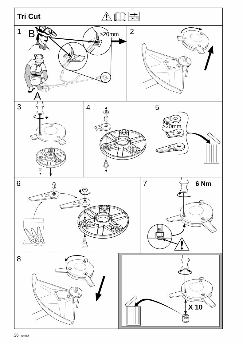
Tri Cut
2
3 4 5
6 7
8
>20mm
>20mm
!
B
A
6 Nm
X 10
English – 27
1
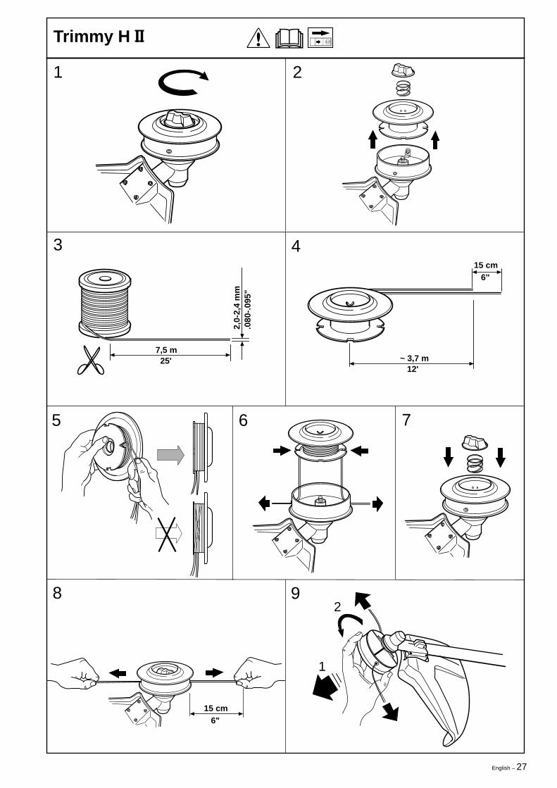
Trimmy H II
2
3 4
5 6 7
8 9
7,5 m 25'
2,0-
2,4
mm
.080
-.09
5"
1
2
15 cm 6"
~ 3,7 m 12'
15 cm 6"

28 – English
1
Trimmy Hit
2 3
4
5 6
7 8 9
10 11
“Click”
“Click”
7,0 m 23'
"
12 cm 5"
~ 3,5 m 11'
15 cm 6"
"2,
0-2,
4 m
m.0
80-.
095
~ 15 cm 6

English – 29
1
Trimmy Hit Junior
2
5 6
7 8 9
10 12
“Click”
3
4
5,75 m 19'
2,0-
2,4
mm
.080
-.09
5"
15 cm
6"
~ 2,8 m 9'
1.)
2.)
11
15 cm 6"
15 cm 6"
30 – English
1
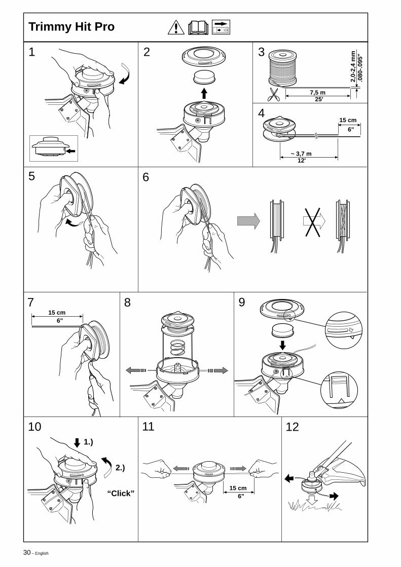
Trimmy Hit Pro
2
5 6
7 8 9
10 12
“Click”
3
4
7,5 m 25'
2,0-
2,4
mm
.080
-.09
5"
15 cm
6"
~ 3,7 m 12'
1.)
2.)
11
15 cm 6"
15 cm 6"
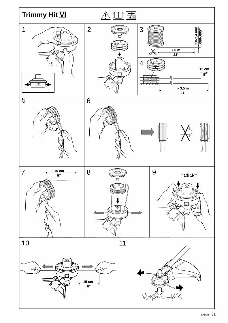
English – 31
1
Trimmy Hit VI
2
5 6
3
4
7 8 9
10 11
“Click”
7,0 m 23'
"
12 cm
5"
~ 3,5 m 11'
15 cm 6
"
"
2,0-
2,4
mm
.080
-.09
5
~ 15 cm 6
32 – English
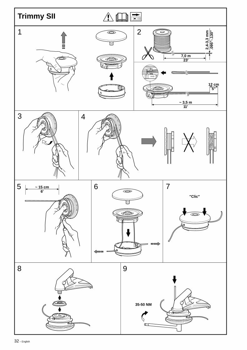
1 2
3 4
5 6 7
8 9
35-50 NM
~ 15 cm6'
"Clic"
~ 3,5 m11'
7,0 m23'
2,4-
3,3
mm
.095
"-.1
30"
12 cm5"
Trimmy SII
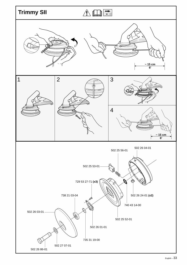
English – 33
~ 15 cm6'
N
~ 15 cm6'
502 25 56-01502 26 04-01
502 25 53-01
502 26 24-01 (x2)
740 43 14-00
502 25 52-01
502 26 01-01
735 31 19-00
729 53 27-71 (x3)
738 21 03-04
502 26 03-01
502 27 07-01502 26 86-01
1 2 3
4
Trimmy SII
34 – English´*31,¶6\¨
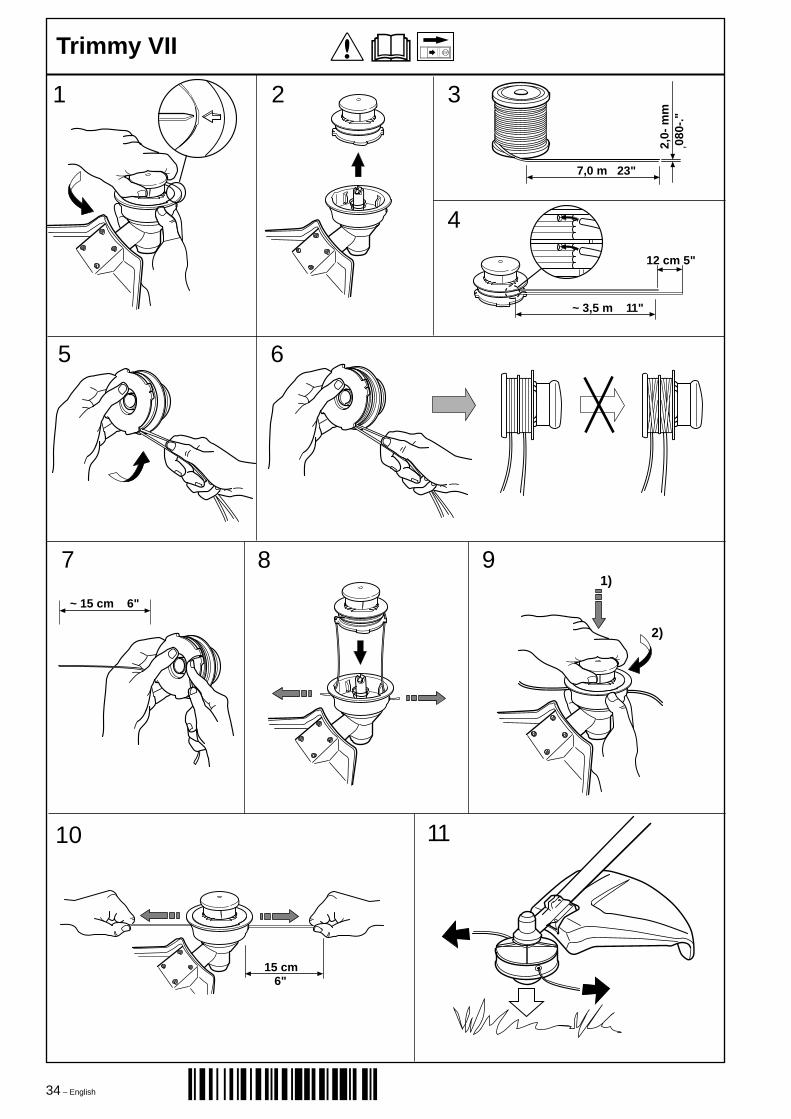
6"
2)
1)
~ 15 cm 6"
7 8 9
10 11
15 cm
1 2 3
4
5 6
7,0 m 23"
2,0-
mm
,080
-."
12 cm 5"
~ 3,5 m 11"
Trimmy VII

English – 35

2001W15´*31,¶6\¨