3200 Series Center Drive Flat Belt Conveyors · 3200 Series Center Drive Flat Belt Conveyors ... B...
48
For other service manuals visit our website at: www.dorner.com/service_manuals.asp DORNER MFG. CORP. INSIDE THE USA OUTSIDE THE USA P.O. Box 20 • 975 Cottonwood Ave. TEL: 1-800-397-8664 TEL: 262-367-7600 Hartland, WI 53029-0020 USA FAX: 1-800-369-2440 FAX: 262-367-5827 851-514 Rev. E 3200 Series Center Drive Flat Belt Conveyors Installation, Maintenance & Parts Manual
Transcript of 3200 Series Center Drive Flat Belt Conveyors · 3200 Series Center Drive Flat Belt Conveyors ... B...
3200 Series Center Drive Flat Belt Conveyors
Installation, Maintenance & Parts Manual
For other service manuals visit our website at:www.dorner.com/service_manuals.asp
DORNER MFG. CORP. INSIDE THE USA OUTSIDE THE USAP.O. Box 20 • 975 Cottonwood Ave. TEL: 1-800-397-8664 TEL: 262-367-7600Hartland, WI 53029-0020 USA FAX: 1-800-369-2440 FAX: 262-367-5827
851-514 Rev. E
Table of ContentsIntroduction ......................................................................... 2Warnings − General Safety ................................................. 3Product Description ............................................................. 4Specifications ...................................................................... 4Installation ........................................................................... 7
Required Tools................................................................. 7Recommended Installation Sequence .............................. 7Conveyors Up to 13 ft (3962 mm)................................... 7Mounting Brackets........................................................... 8Return Rollers .................................................................. 8
4–6¨ (51–152 mm) Wide Conveyors............................ 88–48¨ (203–1219 mm) Wide Conveyors...................... 8
Gearmotor Installation ..................................................... 9Preventive Maintenance and Adjustment.......................... 11
Required Tools............................................................... 11Standard Tools............................................................ 11
Checklist ........................................................................ 11Lubrication..................................................................... 11Maintaining Conveyor Belt ........................................... 11
Troubleshooting ......................................................... 11Cleaning ..................................................................... 11
Conveyor Belt Replacement .......................................... 11Conveyor Belt Replacement Sequence ...................... 11Belt Removal for Conveyor Without Stands.............. 12Belt Removal for Conveyor With Stands................... 13Belt Installation for Conveyor without Stands........... 14Belt Installation for Conveyor with Stands ................ 14
Conveyor Belt Tensioning ............................................. 15A - With Pneumatic Tensioning................................. 15B - With Manual Tensioning...................................... 15
Conveyor Belt Tracking................................................. 16V-Guided Belts........................................................... 16Non V-Guided Belts................................................... 16
Center Drive Module Tracking...................................... 17V-Guided Belts........................................................... 17Non V-Guided Belts................................................... 17
End Pulley Removal ...................................................... 17A − Idler Pulley Removal........................................... 18B − Transfer Tail Pulley Removal ............................. 19
Center Drive Pulleys Removal ....................................... 20A − Tensioner Pulley Removal................................... 20B − Idler Pulley Removal ........................................... 22C − Drive Pulley Removal.......................................... 23
Bearing Replacement ..................................................... 25A − Idler Bearing Replacement .................................. 25B − Drive Bearing Removal and Replacement........... 25Drive Side Bearing...................................................... 25Idler Side Bearing ....................................................... 26C − Transfer Tail Bearing Replacement ..................... 27
Pulley Replacement ........................................................ 27Idler Pulley.................................................................. 27Drive Pulley ................................................................ 27Transfer Tail Pulley .................................................... 27
Service Parts....................................................................... 28Center Drive Assembly .................................................. 28Center Drive Manual Tensioner ..................................... 30Center Drive 90º Industrial Gearmotors......................... 31Transfer Tail Assembly .................................................. 32Idler End Assembly ........................................................ 33Frame Assembly............................................................. 34Bed Plate and Frame Formulas ...................................... 34−04 3” (76mm) Aluminum Side..................................... 36−05 1.5” (38mm) Aluminum Side.................................. 37−07 Low to Side Wiper .................................................. 38−09 Low to High Side .................................................... 39−10 .5” (13mm) Extruded Plastic................................... 40−13 Adjustable Guiding ................................................. 41Flared Side Guiding........................................................ 42Flat Belt Mounting Brackets .......................................... 43Connecting Assembly without Stand Mount.................. 43Flat Belt Connecting Assembly with Stand Mount........ 444” (102mm) to 6” (152mm) Flat Belt Return Roller...... 448” (203mm) to 48” (1219mm) Flat Belt Return Roller.. 45Conveyor Belt Part Number Configuration.................... 46Flat Belt Part Number Configuration ............................. 46
Notes .................................................................................. 47Return Policy...................................................................... 48
Introduction
Upon receipt of shipment:• Compare shipment with packing slip. Contact factory
regarding discrepancies.• Inspect packages for shipping damage. Contact carrier
regarding damage.• Accessories may be shipped loose. See accessory instruc-
tions for installation.
Dorner’s Limited Warranty applies.Dorner 3200 series conveyors are covered by Patent Numbers 5,156,260, and corresponding patents and patent applications in other countries.Dorner reserves the right to make changes at any time without notice or obligation.Dorner has convenient, pre−configured kits of Key Service Parts for all conveyor products. These time saving kits are easy to order, designed for fast installation, and guarantee you will have what you need when you need it. Key Parts and Kits are marked in the Service Parts section of this manual with the Performance Parts Kits logo .
IMPORTANTSome illustrations may show guards removed. DO NOT operate equipment without guards.
Dorner Mfg. Corp. 2 851-514 Rev. E
3200 Series Center Drive Flat Belt Conveyors
Warnings − General Safety
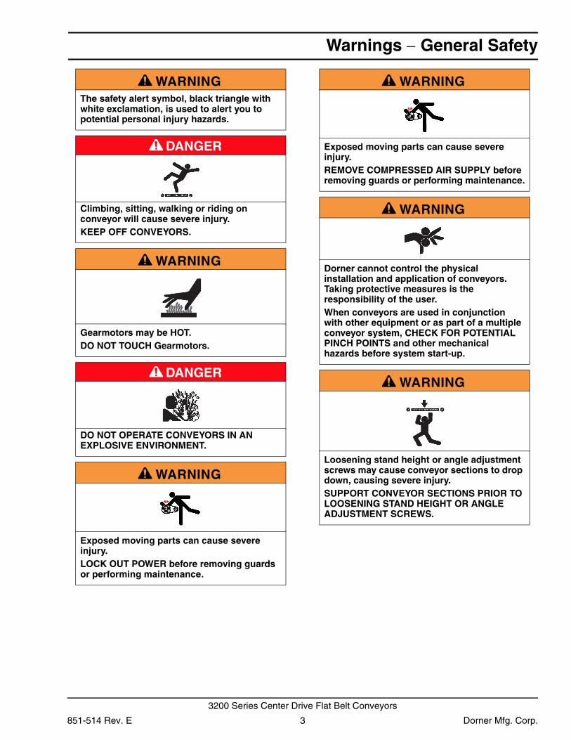
A WARNINGThe safety alert symbol, black triangle with white exclamation, is used to alert you to potential personal injury hazards.
A DANGER
Climbing, sitting, walking or riding on conveyor will cause severe injury.KEEP OFF CONVEYORS.
A WARNING
Gearmotors may be HOT.DO NOT TOUCH Gearmotors.
A DANGER
DO NOT OPERATE CONVEYORS IN AN EXPLOSIVE ENVIRONMENT.
A WARNING
Exposed moving parts can cause severe injury.LOCK OUT POWER before removing guards or performing maintenance.
A WARNING
Exposed moving parts can cause severe injury.REMOVE COMPRESSED AIR SUPPLY before removing guards or performing maintenance.
A WARNING
Dorner cannot control the physical installation and application of conveyors. Taking protective measures is the responsibility of the user.When conveyors are used in conjunction with other equipment or as part of a multiple conveyor system, CHECK FOR POTENTIAL PINCH POINTS and other mechanical hazards before system start-up.
A WARNING
Loosening stand height or angle adjustment screws may cause conveyor sections to drop down, causing severe injury.SUPPORT CONVEYOR SECTIONS PRIOR TO LOOSENING STAND HEIGHT OR ANGLE ADJUSTMENT SCREWS.
851-514 Rev. E 3 Dorner Mfg. Corp.
3200 Series Center Drive Flat Belt Conveyors
Product Description
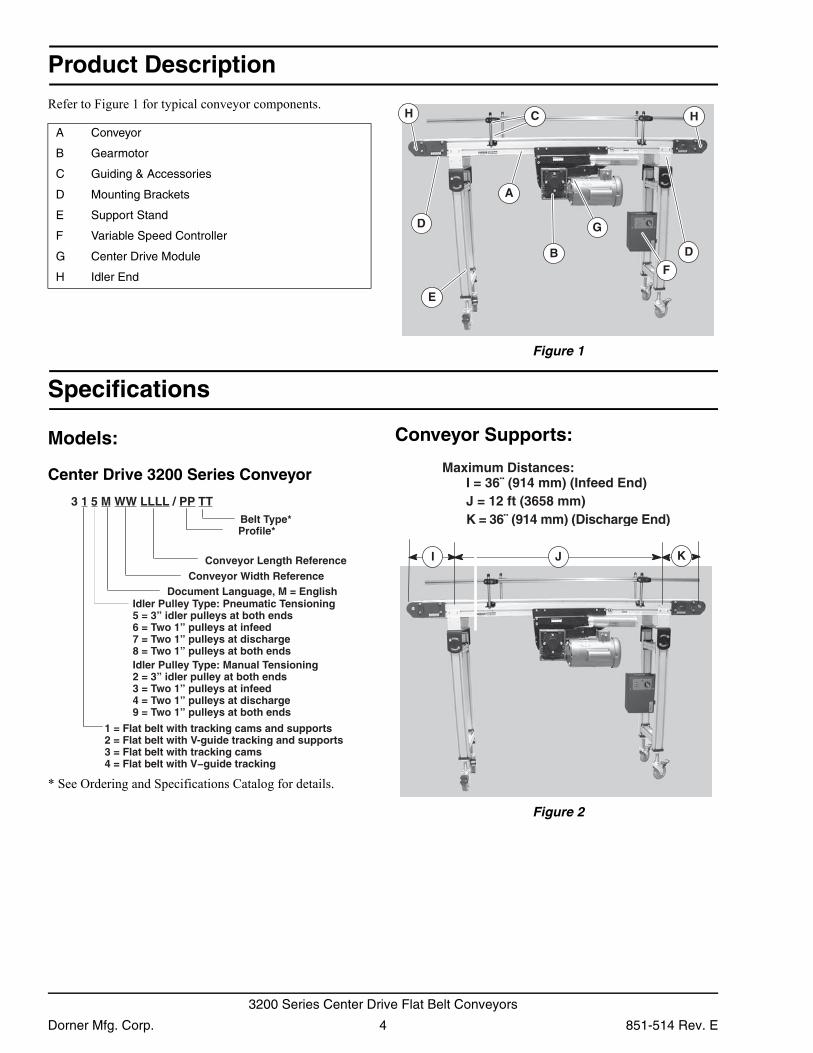
Refer to Figure 1 for typical conveyor components. Figure 1
Figure 1
Specifications
Models:
Center Drive 3200 Series Conveyor
* See Ordering and Specifications Catalog for details.
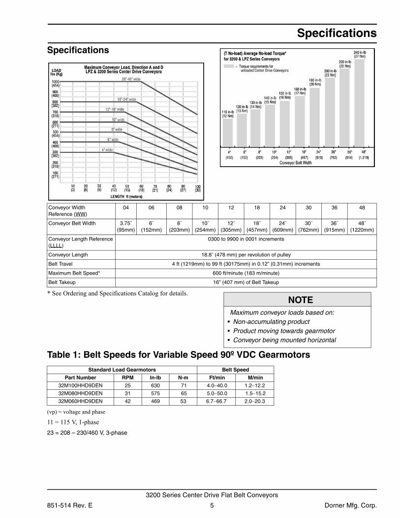
Conveyor Supports:
Figure 2
Figure 2
A Conveyor
B Gearmotor
C Guiding & Accessories
D Mounting Brackets
E Support Stand
F Variable Speed Controller
G Center Drive Module
H Idler End
A
B
C
D
D
H
E
F
G
H
Conveyor Width ReferenceConveyor Length Reference
Belt Type*Profile*
1 = Flat belt with tracking cams and supports2 = Flat belt with V-guide tracking and supports3 = Flat belt with tracking cams4 = Flat belt with V−guide tracking
Document Language, M = English
3 1 5 M WW LLLL / PP TT
Idler Pulley Type: Pneumatic Tensioning5 = 3” idler pulleys at both ends6 = Two 1” pulleys at infeed7 = Two 1” pulleys at discharge8 = Two 1” pulleys at both endsIdler Pulley Type: Manual Tensioning2 = 3” idler pulley at both ends3 = Two 1” pulleys at infeed4 = Two 1” pulleys at discharge9 = Two 1” pulleys at both ends
Maximum Distances:I = 36¨ (914 mm) (Infeed End)J = 12 ft (3658 mm)K = 36¨ (914 mm) (Discharge End)
JI K
Dorner Mfg. Corp. 4 851-514 Rev. E
3200 Series Center Drive Flat Belt Conveyors
Specifications
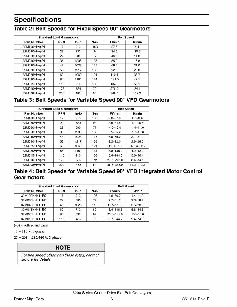
Specifications* See Ordering and Specifications Catalog for details.
Table 1: Belt Speeds for Variable Speed 90º VDC Gearmotors
(vp) = voltage and phase
11 = 115 V, 1-phase23 = 208 – 230/460 V, 3-phase
Conveyor Width Reference (WW)
04 06 08 10 12 18 24 30 36 48
Conveyor Belt Width 3.75¨ (95mm)
6¨ (152mm)
8¨(203mm)
10¨(254mm)
12¨(305mm)
18¨(457mm)
24¨(609mm)
30¨(762mm)
36¨(915mm)
48¨(1220mm)
Conveyor Length Reference (LLLL)
0300 to 9900 in 0001 increments
Conveyor Length 18.8¨ (478 mm) per revolution of pulley
Belt Travel 4 ft (1219mm) to 99 ft (30175mm) in 0.12” (0.31mm) increments
Maximum Belt Speed* 600 ft/minute (183 m/minute)
Belt Takeup 16” (407 mm) of Belt Takeup
NOTEMaximum conveyor loads based on:
• Non-accumulating product• Product moving towards gearmotor• Conveyor being mounted horizontal
Standard Load Gearmotors Belt Speed
Part Number RPM In-lb N-m Ft/min M/min
32M100HHD9DEN 25 630 71 4.0−40.0 1.2−12.2
32M080HHD9DEN 31 575 65 5.0−50.0 1.5−15.2
32M060HHD9DEN 42 469 53 6.7−66.7 2.0−20.3
851-514 Rev. E 5 Dorner Mfg. Corp.
3200 Series Center Drive Flat Belt Conveyors
Specifications
Table 2: Belt Speeds for Fixed Speed 90° GearmotorsTable 3: Belt Speeds for Variable Speed 90° VFD Gearmotors
Table 4: Belt Speeds for Variable Speed 90° VFD Integrated Motor Control Gearmotors
(vp) = voltage and phase
11 = 115 V, 1-phase23 = 208 – 230/460 V, 3-phase
Standard Load Gearmotors Belt Speed
Part Number RPM In-lb N-m Ft/min M/min
32M100HHvpfN 17 913 103 27.6 8.4
32M080HHvpfN 22 833 94 34.5 10.5
32M060HHvpfN 29 680 77 46.0 14.0
32M050HHvpfN 35 1206 136 55.2 16.8
32M040HHvpfN 43 1023 116 69.0 21.0
32M030HHvpfN 58 1217 138 92.0 28.0
32M025HHvpfN 69 1069 121 110.4 33.7
32M020HHvpfN 86 1184 134 138.0 42.1
32M015HHvpfN 115 910 103 184.0 56.1
32M010HHvpfN 173 636 72 276.0 84.1
32M008HHvpfN 230 482 54 368.0 112.2
Standard Load Gearmotors Belt Speed
Part Number RPM In-lb N-m Ft/min M/min
32M100HHvpfN 17 913 103 2.8−27.6 0.8−8.4
32M080HHvpfN 22 833 94 3.5−34.5 1.1−10.5
32M060HHvpfN 29 680 77 4.6−46.0 1.4−14.0
32M050HHvpfN 35 1206 136 5.5−55.2 1.7−16.8
32M040HHvpfN 43 1023 116 6.9−69.0 2.1−21.0
32M030HHvpfN 58 1217 138 9.2−92.0 2.8−28.0
32M025HHvpfN 69 1069 121 11.0−110 .4 3.4−33.7
32M020HHvpfN 86 1184 134 13.8−138.0 4.2−42.1
32M015HHvpfN 115 910 103 18.4−184.0 5.6−56.1
32M010HHvpfN 173 636 72 27.6−276.0 8.4−84.1
32M008HHvpfN 230 482 54 36.8−368.0 11.2−112.2
Standard Load Gearmotors Belt Speed
Part Number RPM In-lb N-m Ft/min M/min
32M100HH411EC 17 913 103 4.6−36.7 1.4−11.2
32M060HH411EC 29 680 77 7.7−61.2 2.3−18.7
32M040HH411EC 43 1023 116 11.5−91.8 3.5−28.0
32M015HH411EC 69 712 80 18.4−146.8 5.6−44.8
32M020HH411EC 86 592 67 23.0−183.5 7.0−56.0
32M015HH411EC 115 455 51 30.7−244.7 9.4−74.6
NOTEFor belt speed other than those listed, contact factory for details.
Dorner Mfg. Corp. 6 851-514 Rev. E
3200 Series Center Drive Flat Belt Conveyors
Installation
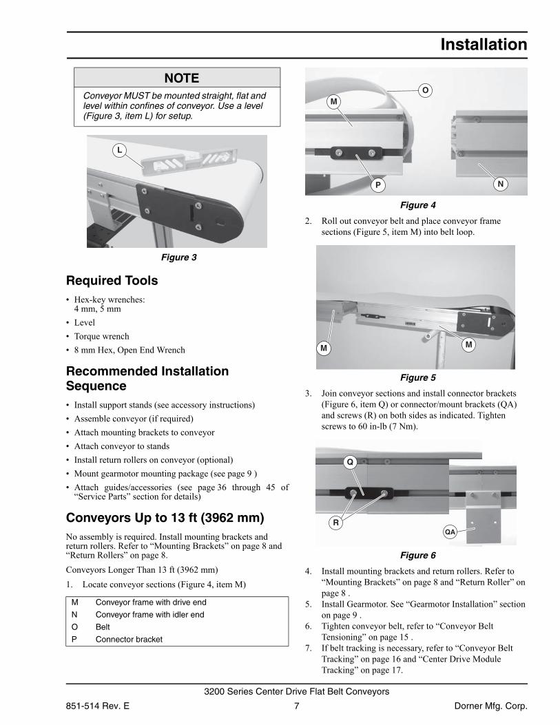
Figure 3
Figure 3
Required Tools• Hex-key wrenches:
4 mm, 5 mm• Level• Torque wrench• 8 mm Hex, Open End Wrench
Recommended Installation Sequence• Install support stands (see accessory instructions)• Assemble conveyor (if required)• Attach mounting brackets to conveyor• Attach conveyor to stands• Install return rollers on conveyor (optional)• Mount gearmotor mounting package (see page 9 )• Attach guides/accessories (see page 36 through 45 of
“Service Parts” section for details)
Conveyors Up to 13 ft (3962 mm)No assembly is required. Install mounting brackets and return rollers. Refer to “Mounting Brackets” on page 8 and “Return Rollers” on page 8.Conveyors Longer Than 13 ft (3962 mm)1. Locate conveyor sections (Figure 4, item M)
Figure 4
Figure 4
2. Roll out conveyor belt and place conveyor frame sections (Figure 5, item M) into belt loop.
Figure 5
Figure 5
3. Join conveyor sections and install connector brackets (Figure 6, item Q) or connector/mount brackets (QA) and screws (R) on both sides as indicated. Tighten screws to 60 in-lb (7 Nm).
Figure 6
Figure 6
4. Install mounting brackets and return rollers. Refer to “Mounting Brackets” on page 8 and “Return Roller” on page 8 .
5. Install Gearmotor. See “Gearmotor Installation” section on page 9 .
6. Tighten conveyor belt, refer to “Conveyor Belt Tensioning” on page 15 .
7. If belt tracking is necessary, refer to “Conveyor Belt Tracking” on page 16 and “Center Drive Module Tracking” on page 17.
NOTEConveyor MUST be mounted straight, flat and level within confines of conveyor. Use a level (Figure 3, item L) for setup.
M Conveyor frame with drive end
N Conveyor frame with idler end
O Belt
P Connector bracket
L
M
NP
O
M M
Q
RQA
851-514 Rev. E 7 Dorner Mfg. Corp.
3200 Series Center Drive Flat Belt Conveyors
Installation
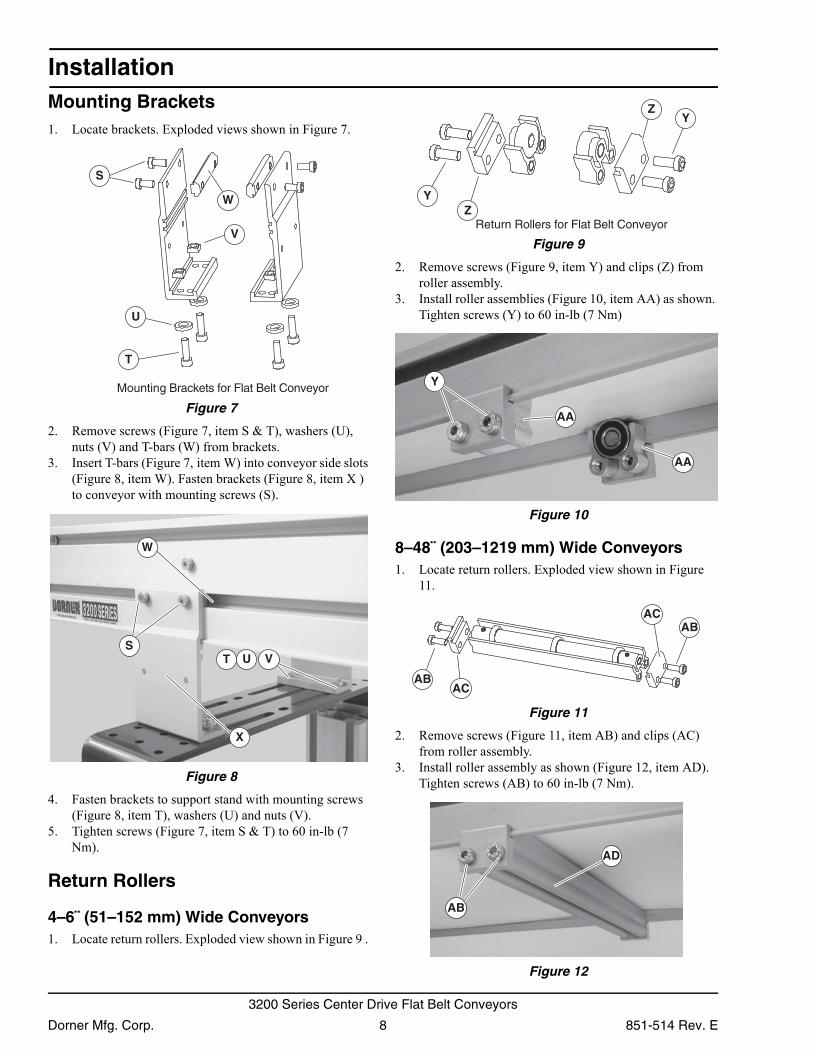
Mounting Brackets1. Locate brackets. Exploded views shown in Figure 7.Figure 7
Figure 7
2. Remove screws (Figure 7, item S & T), washers (U), nuts (V) and T-bars (W) from brackets.
3. Insert T-bars (Figure 7, item W) into conveyor side slots (Figure 8, item W). Fasten brackets (Figure 8, item X ) to conveyor with mounting screws (S).
Figure 8
Figure 8
4. Fasten brackets to support stand with mounting screws (Figure 8, item T), washers (U) and nuts (V).
5. Tighten screws (Figure 7, item S & T) to 60 in-lb (7 Nm).
Return Rollers
4–6¨ (51–152 mm) Wide Conveyors1. Locate return rollers. Exploded view shown in Figure 9 .
Figure 9
Figure 9
2. Remove screws (Figure 9, item Y) and clips (Z) from roller assembly.
3. Install roller assemblies (Figure 10, item AA) as shown. Tighten screws (Y) to 60 in-lb (7 Nm)
Figure 10
Figure 10
8–48¨ (203–1219 mm) Wide Conveyors1. Locate return rollers. Exploded view shown in Figure
11. Figure 11
Figure 11
2. Remove screws (Figure 11, item AB) and clips (AC) from roller assembly.
3. Install roller assembly as shown (Figure 12, item AD). Tighten screws (AB) to 60 in-lb (7 Nm).
Figure 12
Figure 12
S
W
V
U
T
Mounting Brackets for Flat Belt Conveyor
UT
W
S
X
V
YZ
YZ
Return Rollers for Flat Belt Conveyor
Y
AA
AA
ABAC
ABAC
AB
AD
Dorner Mfg. Corp. 8 851-514 Rev. E
3200 Series Center Drive Flat Belt Conveyors
Installation
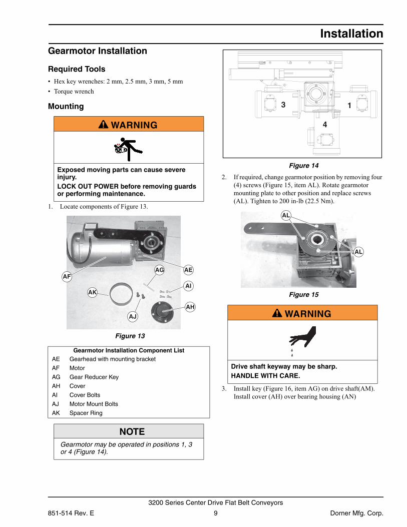
Gearmotor InstallationRequired Tools• Hex key wrenches: 2 mm, 2.5 mm, 3 mm, 5 mm• Torque wrench
Mounting
1. Locate components of Figure 13. Figure 13
Figure 13
Figure 14
Figure 14
2. If required, change gearmotor position by removing four (4) screws (Figure 15, item AL). Rotate gearmotor mounting plate to other position and replace screws (AL). Tighten to 200 in-lb (22.5 Nm).
Figure 15
Figure 15
3. Install key (Figure 16, item AG) on drive shaft(AM). Install cover (AH) over bearing housing (AN)
A WARNING
Exposed moving parts can cause severe injury.LOCK OUT POWER before removing guards or performing maintenance.
Gearmotor Installation Component ListAE Gearhead with mounting bracket
AF Motor
AG Gear Reducer Key
AH Cover
AI Cover Bolts
AJ Motor Mount Bolts
AK Spacer Ring
NOTEGearmotor may be operated in positions 1, 3 or 4 (Figure 14).
AFAEAG
AH
AI
AJ
AK
A WARNING
Drive shaft keyway may be sharp.HANDLE WITH CARE.
13
4
AL
AL
851-514 Rev. E 9 Dorner Mfg. Corp.
3200 Series Center Drive Flat Belt Conveyors
Installation
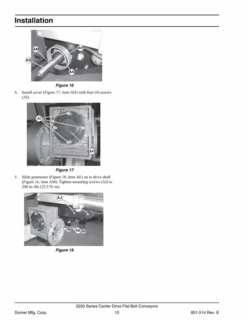
Figure 16Figure 16
4. Install cover (Figure 17, item AH) with four (4) screws (AI).
Figure 17
Figure 17
5. Slide gearmotor (Figure 18, item AE) on to drive shaft (Figure 16, item AM). Tighten mounting screws (AJ) to 200 in−lbs (22.5 N−m).
Figure 18
Figure 18
AG
AM AH
AN
AI
AH
AE
AJ
Dorner Mfg. Corp. 10 851-514 Rev. E
3200 Series Center Drive Flat Belt Conveyors
Preventive Maintenance and Adjustment
Required Tools
Standard Tools• Hex-key wrenches:
2.5 mm, 4 mm, 5 mm, 6 mm• 8 mm Hex, Open End Wrench
Checklist• Keep service parts on hand (see “Service Parts” section for
recommendations)• Keep supply of belt cleaner (part # 625619)• Clean entire conveyor and knurled pulley while disassem-
bled• Replace worn or damaged parts
LubricationNo lubrication is required. Replace bearings if worn.
Maintaining Conveyor Belt
Troubleshooting
Inspect conveyor belt for:• Surface cuts or wear• Stalling or slipping• Damage to V-guideSurface cuts and wear indicate:• Sharp or heavy parts impacting belt• Jammed parts• Improperly installed bottom wipers (if installed)• Accumulated dirt in wipers (if installed)• Foreign material inside the conveyor• Improperly positioned accessories• Bolt-on guiding is pinching beltStalling or slipping indicates:• Excessive load on belt• Conveyor belt or drive timing belt are not properly ten-
sioned• Worn knurl or impacted dirt on drive pulley• Intermittent jamming or drive train problemsDamage to V-guide indicates:• Twisted or damaged conveyor frame• Dirt impacted on pulleys• Excessive or improper side loading
Cleaning
Use Dorner Belt Cleaner (part # 625619). Mild soap and water may also be used. Do not soak the belt.For /05 woven polyester and /06 black anti-static belts, use a bristled brush to improve cleaning.
Conveyor Belt Replacement
Conveyor Belt Replacement Sequence
Remove old conveyor belt:• Conveyor without Stands or Gearmotor Mounting Pack-
ageConveyor with Stands and Gearmotor Mounting Package• Install new conveyor belt• Tension conveyor belt
NOTEVisit www.dorner.com for complete list of troubleshooting solutions.
IMPORTANTDo not use belt cleaners that contain alcohol, acetone, Methyl Ethyl Ketone (MEK) or other harsh chemicals.
A WARNING
Exposed moving parts can cause severe injury.LOCK OUT POWER before removing guards or performing maintenance.
A WARNING
Exposed moving parts can cause severe injury.REMOVE COMPRESSED AIR SUPPLY before removing guards or performing maintenance.
851-514 Rev. E 11 Dorner Mfg. Corp.
3200 Series Center Drive Flat Belt Conveyors
Preventive Maintenance and Adjustment
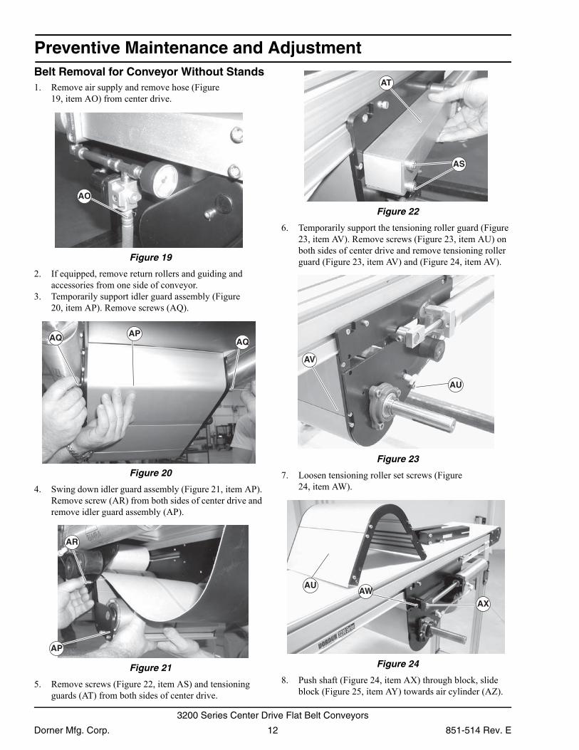
Belt Removal for Conveyor Without Stands1. Remove air supply and remove hose (Figure19, item AO) from center drive. Figure 19
Figure 19
2. If equipped, remove return rollers and guiding and accessories from one side of conveyor.
3. Temporarily support idler guard assembly (Figure 20, item AP). Remove screws (AQ).
Figure 20
Figure 20
4. Swing down idler guard assembly (Figure 21, item AP). Remove screw (AR) from both sides of center drive and remove idler guard assembly (AP).
Figure 21
Figure 21
5. Remove screws (Figure 22, item AS) and tensioning guards (AT) from both sides of center drive.
Figure 22
Figure 22
6. Temporarily support the tensioning roller guard (Figure 23, item AV). Remove screws (Figure 23, item AU) on both sides of center drive and remove tensioning roller guard (Figure 23, item AV) and (Figure 24, item AV).
Figure 23
Figure 23
7. Loosen tensioning roller set screws (Figure 24, item AW).
Figure 24
Figure 24
8. Push shaft (Figure 24, item AX) through block, slide block (Figure 25, item AY) towards air cylinder (AZ).
AO
APAQ AQ
AR
AP
AT
AS
AU
AV
AWAX
AU
Dorner Mfg. Corp. 12 851-514 Rev. E
3200 Series Center Drive Flat Belt Conveyors
Preventive Maintenance and Adjustment
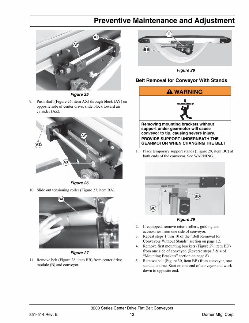
Figure 25Figure 25
9. Push shaft (Figure 26, item AX) through block (AY) on opposite side of center drive, slide block toward air cylinder (AZ).
Figure 26
Figure 26
10. Slide out tensioning roller (Figure 27, item BA). Figure 27
Figure 27
11. Remove belt (Figure 28, item BB) from center drive module (B) and conveyor.
Figure 28
Figure 28
Belt Removal for Conveyor With Stands
1. Place temporary support stands (Figure 29, item BC) at both ends of the conveyor. See WARNING.
Figure 29
Figure 29
2. If equipped, remove return rollers, guiding and accessories from one side of conveyor.
3. Repeat steps 1 thru 10 of the “Belt Removal for Conveyors Without Stands” section on page 12.
4. Remove first mounting brackets (Figure 29, item BD) from one side of conveyor. (Reverse steps 3 & 4 of “Mounting Brackets” section on page 8).
5. Remove belt (Figure 30, item BB) from conveyor, one stand at a time. Start on one end of conveyor and work down to opposite end.
AY
AZ
AX
AY
AZ
BA
A WARNING
Removing mounting brackets without support under gearmotor will cause conveyor to tip, causing severe injury.PROVIDE SUPPORT UNDERNEATH THE GEARMOTOR WHEN CHANGING THE BELT
BB
G
BC
BD
851-514 Rev. E 13 Dorner Mfg. Corp.
3200 Series Center Drive Flat Belt Conveyors
Preventive Maintenance and Adjustment
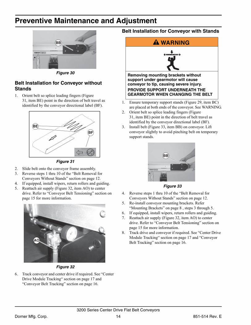
Figure 30Figure 30
Belt Installation for Conveyor without Stands1. Orient belt so splice leading fingers (Figure
31, item BE) point in the direction of belt travel as identified by the conveyor directional label (BF).
Figure 31
Figure 31
2. Slide belt onto the conveyor frame assembly.3. Reverse steps 1 thru 10 of the “Belt Removal for
Conveyors Without Stands” section on page 12.4. If equipped, install wipers, return rollers and guiding.5. Reattach air supply (Figure 32, item AO) to center
drive. Refer to “Conveyor Belt Tensioning” section on page 15 for more information.
Figure 32
Figure 32
6. Track conveyor and center drive if required. See “Center Drive Module Tracking“ section on page 17 and “Conveyor Belt Tracking” section on page 16.
Belt Installation for Conveyor with Stands
1. Ensure temporary support stands (Figure 29, item BC) are placed at both ends of the conveyor. See WARNING.
2. Orient belt so splice leading fingers (Figure 31, item BE) point in the direction of belt travel as identified by the conveyor directional label (BF).
3. Install belt (Figure 33, item BB) on conveyor. Lift conveyor slightly to avoid pinching belt on temporary support stands.
Figure 33
Figure 33
4. Reverse steps 1 thru 10 of the “Belt Removal for Conveyors Without Stands” section on page 12.
5. Re-install conveyor mounting brackets. Refer “Mounting Brackets” on page 8 , steps 3 through 5.
6. If equipped, install wipers, return rollers and guiding.7. Reattach air supply (Figure 32, item AO) to center
drive. Refer to “Conveyor Belt Tensioning” section on page 15 for more information.
8. Track drive and conveyor if required. See “Center Drive Module Tracking“ section on page 17 and “Conveyor Belt Tracking” section on page 16.
BB
BE
BF
AO
A WARNING
Removing mounting brackets without support under gearmotor will cause conveyor to tip, causing severe injury.PROVIDE SUPPORT UNDERNEATH THE GEARMOTOR WHEN CHANGING THE BELT
BB
Dorner Mfg. Corp. 14 851-514 Rev. E
3200 Series Center Drive Flat Belt Conveyors
Preventive Maintenance and Adjustment
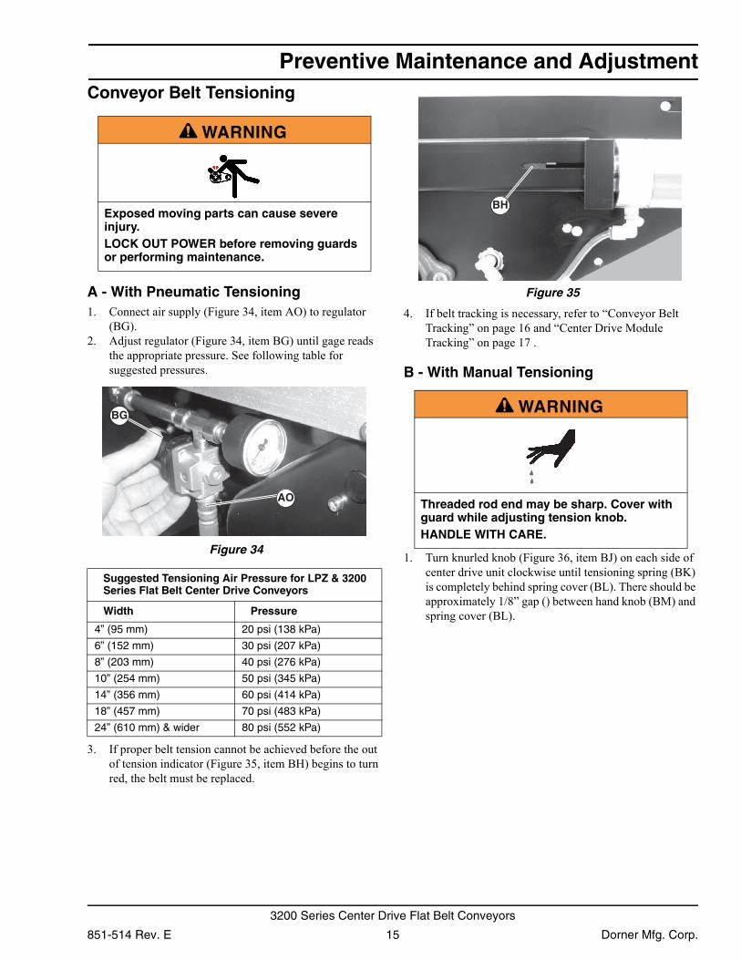
Conveyor Belt TensioningA - With Pneumatic Tensioning1. Connect air supply (Figure 34, item AO) to regulator
(BG).2. Adjust regulator (Figure 34, item BG) until gage reads
the appropriate pressure. See following table for suggested pressures.
Figure 34
Figure 34
3. If proper belt tension cannot be achieved before the out of tension indicator (Figure 35, item BH) begins to turn red, the belt must be replaced.
Figure 35
Figure 35
4. If belt tracking is necessary, refer to “Conveyor Belt Tracking” on page 16 and “Center Drive Module Tracking” on page 17 .
B - With Manual Tensioning
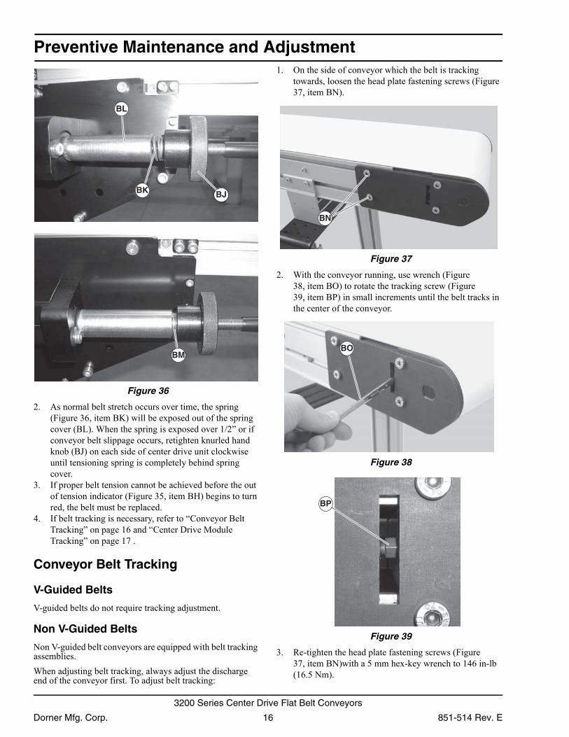
1. Turn knurled knob (Figure 36, item BJ) on each side of center drive unit clockwise until tensioning spring (BK) is completely behind spring cover (BL). There should be approximately 1/8” gap () between hand knob (BM) and spring cover (BL).
A WARNING
Exposed moving parts can cause severe injury.LOCK OUT POWER before removing guards or performing maintenance.
Suggested Tensioning Air Pressure for LPZ & 3200 Series Flat Belt Center Drive Conveyors
Width Pressure
4” (95 mm) 20 psi (138 kPa)
6” (152 mm) 30 psi (207 kPa)
8” (203 mm) 40 psi (276 kPa)
10” (254 mm) 50 psi (345 kPa)
14” (356 mm) 60 psi (414 kPa)
18” (457 mm) 70 psi (483 kPa)
24” (610 mm) & wider 80 psi (552 kPa)
BG
AO
A WARNING
Threaded rod end may be sharp. Cover with guard while adjusting tension knob.HANDLE WITH CARE.
BH
851-514 Rev. E 15 Dorner Mfg. Corp.
3200 Series Center Drive Flat Belt Conveyors
Preventive Maintenance and Adjustment
Figure 36Figure 36
2. As normal belt stretch occurs over time, the spring (Figure 36, item BK) will be exposed out of the spring cover (BL). When the spring is exposed over 1/2” or if conveyor belt slippage occurs, retighten knurled hand knob (BJ) on each side of center drive unit clockwise until tensioning spring is completely behind spring cover.
3. If proper belt tension cannot be achieved before the out of tension indicator (Figure 35, item BH) begins to turn red, the belt must be replaced.
4. If belt tracking is necessary, refer to “Conveyor Belt Tracking” on page 16 and “Center Drive Module Tracking” on page 17 .
Conveyor Belt Tracking
V-Guided Belts
V-guided belts do not require tracking adjustment.
Non V-Guided Belts
Non V-guided belt conveyors are equipped with belt tracking assemblies.When adjusting belt tracking, always adjust the discharge end of the conveyor first. To adjust belt tracking:
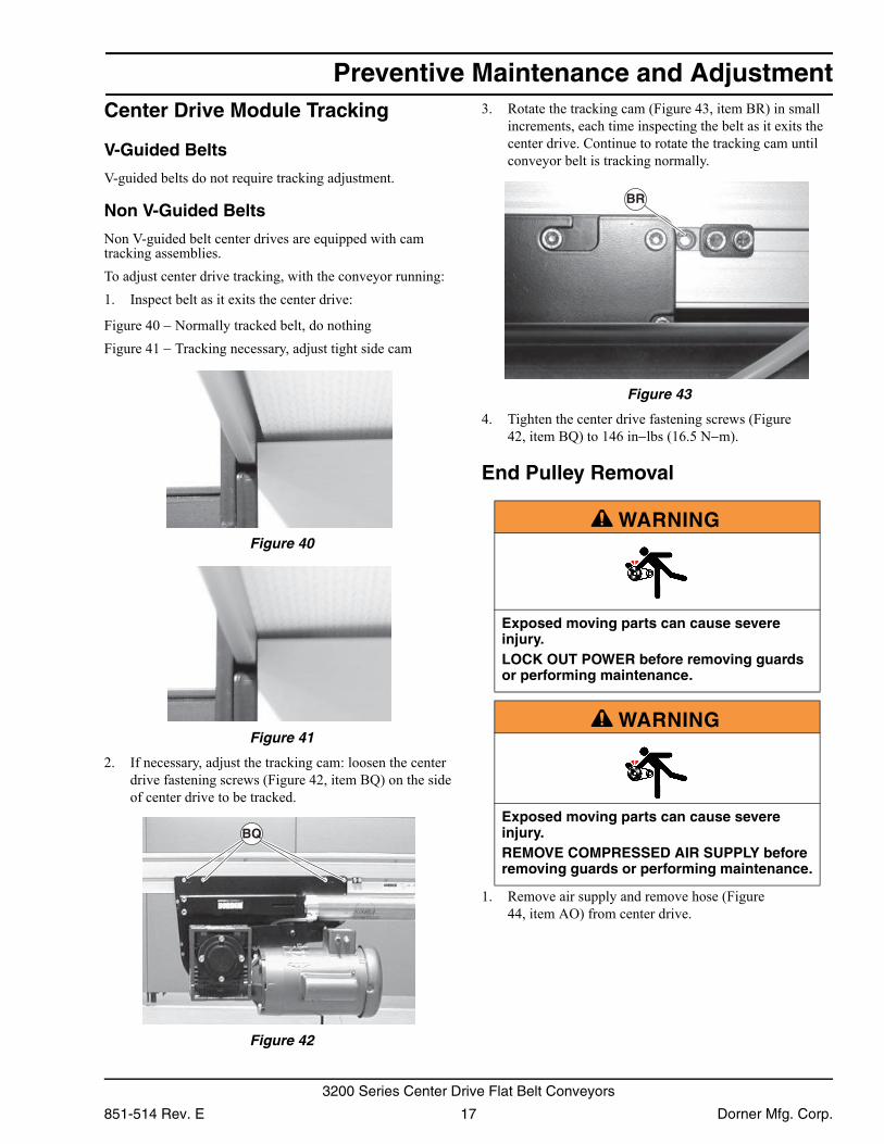
1. On the side of conveyor which the belt is tracking towards, loosen the head plate fastening screws (Figure 37, item BN).
Figure 37
Figure 37
2. With the conveyor running, use wrench (Figure 38, item BO) to rotate the tracking screw (Figure 39, item BP) in small increments until the belt tracks in the center of the conveyor.
Figure 38
Figure 38 Figure 39
Figure 39
3. Re-tighten the head plate fastening screws (Figure 37, item BN)with a 5 mm hex-key wrench to 146 in-lb (16.5 Nm).
BK BJ
BL
BM
BN
BO
BP
Dorner Mfg. Corp. 16 851-514 Rev. E
3200 Series Center Drive Flat Belt Conveyors
Preventive Maintenance and Adjustment
Center Drive Module TrackingV-Guided Belts
V-guided belts do not require tracking adjustment.
Non V-Guided Belts
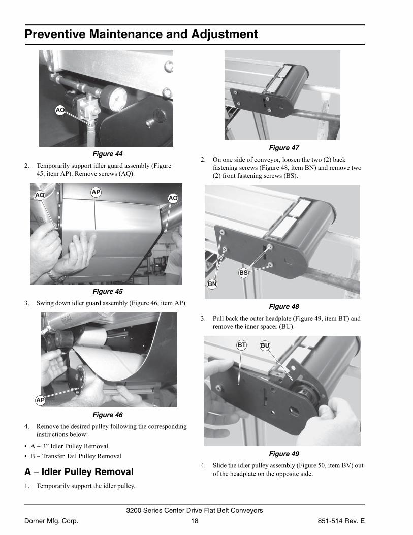
Non V-guided belt center drives are equipped with cam tracking assemblies.To adjust center drive tracking, with the conveyor running:1. Inspect belt as it exits the center drive:
Figure 40 − Normally tracked belt, do nothingFigure 41 − Tracking necessary, adjust tight side cam
Figure 40
Figure 40 Figure 41
Figure 41
2. If necessary, adjust the tracking cam: loosen the center drive fastening screws (Figure 42, item BQ) on the side of center drive to be tracked.
Figure 42
Figure 42
3. Rotate the tracking cam (Figure 43, item BR) in small increments, each time inspecting the belt as it exits the center drive. Continue to rotate the tracking cam until conveyor belt is tracking normally.
Figure 43
Figure 43
4. Tighten the center drive fastening screws (Figure 42, item BQ) to 146 in−lbs (16.5 N−m).
End Pulley Removal
1. Remove air supply and remove hose (Figure 44, item AO) from center drive.
BQ
A WARNING
Exposed moving parts can cause severe injury.LOCK OUT POWER before removing guards or performing maintenance.
A WARNING
Exposed moving parts can cause severe injury.REMOVE COMPRESSED AIR SUPPLY before removing guards or performing maintenance.
BR
851-514 Rev. E 17 Dorner Mfg. Corp.
3200 Series Center Drive Flat Belt Conveyors
Preventive Maintenance and Adjustment
Figure 44Figure 44
2. Temporarily support idler guard assembly (Figure 45, item AP). Remove screws (AQ).
Figure 45
Figure 45
3. Swing down idler guard assembly (Figure 46, item AP). Figure 46
Figure 46
4. Remove the desired pulley following the corresponding instructions below:
• A − 3” Idler Pulley Removal• B − Transfer Tail Pulley Removal
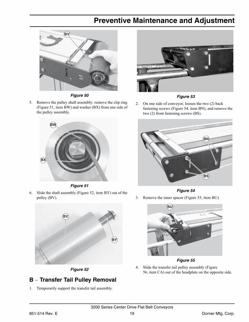
A − Idler Pulley Removal1. Temporarily support the idler pulley.
Figure 47
Figure 47
2. On one side of conveyor, loosen the two (2) back fastening screws (Figure 48, item BN) and remove two (2) front fastening screws (BS).
Figure 48
Figure 48
3. Pull back the outer headplate (Figure 49, item BT) and remove the inner spacer (BU).
Figure 49
Figure 49
4. Slide the idler pulley assembly (Figure 50, item BV) out of the headplate on the opposite side.
AO
APAQ AQ
AP
BN
BS
BUBT
Dorner Mfg. Corp. 18 851-514 Rev. E
3200 Series Center Drive Flat Belt Conveyors
Preventive Maintenance and Adjustment
Figure 50Figure 50
5. Remove the pulley shaft assembly: remove the clip ring (Figure 51, item BW) and washer (BX) from one side of the pulley assembly.
Figure 51
Figure 51
6. Slide the shaft assembly (Figure 52, item BY) out of the pulley (BV).
Figure 52
Figure 52
B − Transfer Tail Pulley Removal1. Temporarily support the transfer tail assembly.
Figure 53
Figure 53
2. On one side of conveyor, loosen the two (2) back fastening screws (Figure 54, item BN), and remove the two (2) front fastening screws (BS).
Figure 54
Figure 54
3. Remove the inner spacer (Figure 55, item BU). Figure 55
Figure 55
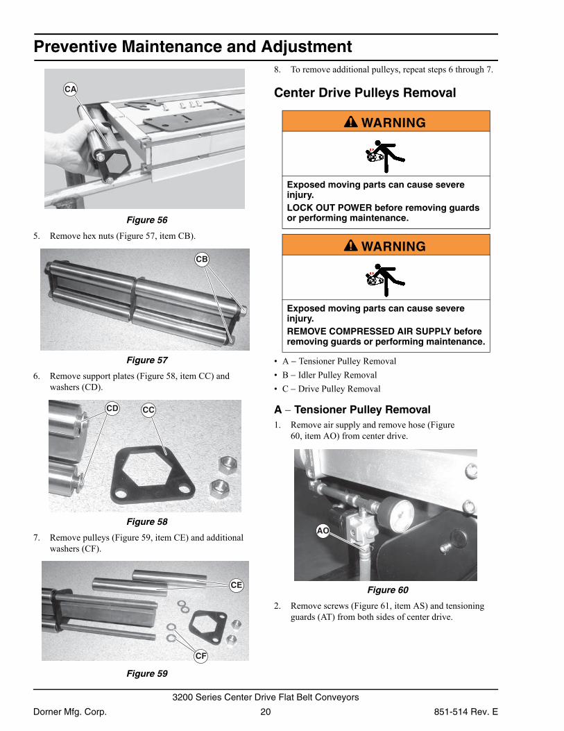
4. Slide the transfer tail pulley assembly (Figure 56, item CA) out of the headplate on the opposite side.
BV
BW
BX
BY
BV
BN
BS
BU
851-514 Rev. E 19 Dorner Mfg. Corp.
3200 Series Center Drive Flat Belt Conveyors
Preventive Maintenance and Adjustment
Figure 56Figure 56
5. Remove hex nuts (Figure 57, item CB). Figure 57
Figure 57
6. Remove support plates (Figure 58, item CC) and washers (CD).
Figure 58
Figure 58
7. Remove pulleys (Figure 59, item CE) and additional washers (CF).
Figure 59
Figure 59
8. To remove additional pulleys, repeat steps 6 through 7.
Center Drive Pulleys Removal
• A − Tensioner Pulley Removal• B − Idler Pulley Removal• C − Drive Pulley Removal
A − Tensioner Pulley Removal1. Remove air supply and remove hose (Figure
60, item AO) from center drive. Figure 60
Figure 60
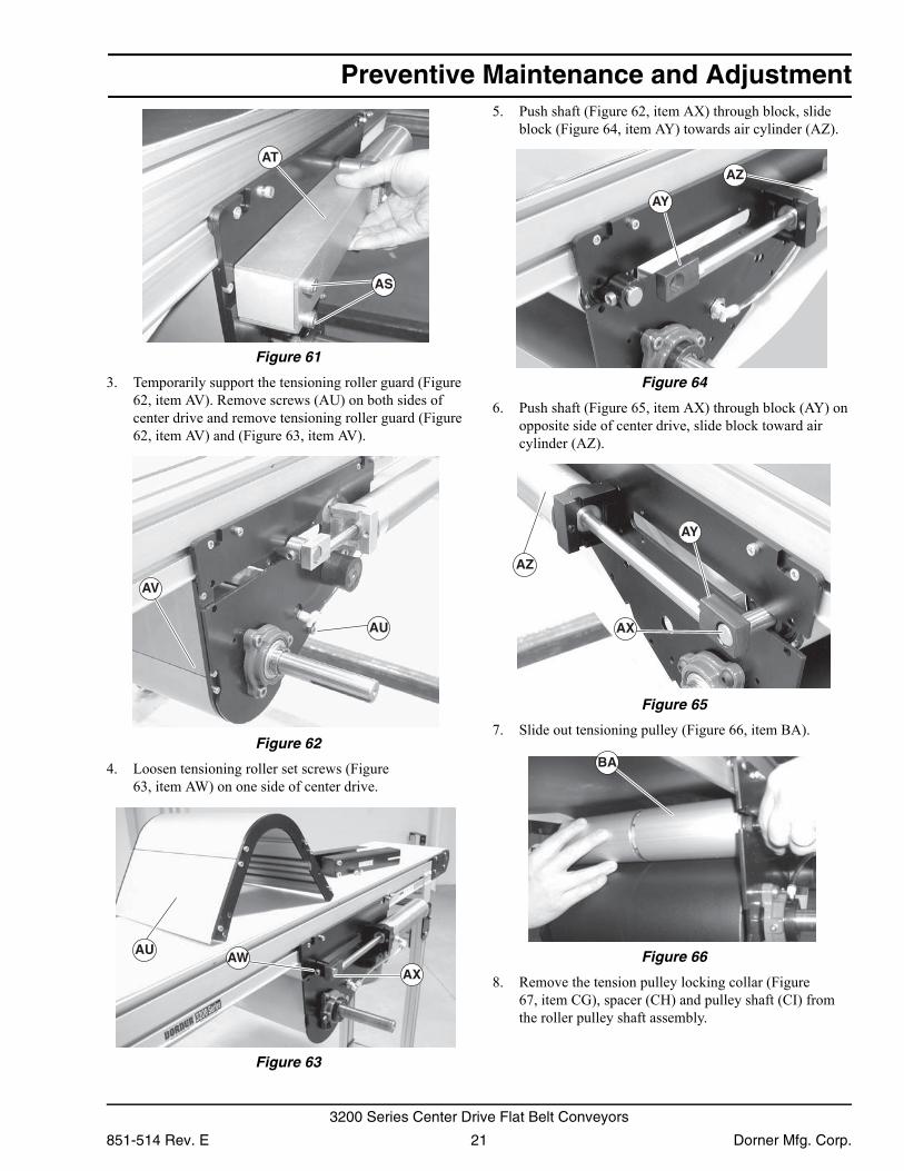
2. Remove screws (Figure 61, item AS) and tensioning guards (AT) from both sides of center drive.
CA
CB
CCCD
CE
CF
A WARNING
Exposed moving parts can cause severe injury.LOCK OUT POWER before removing guards or performing maintenance.
A WARNING
Exposed moving parts can cause severe injury.REMOVE COMPRESSED AIR SUPPLY before removing guards or performing maintenance.
AO
Dorner Mfg. Corp. 20 851-514 Rev. E
3200 Series Center Drive Flat Belt Conveyors
Preventive Maintenance and Adjustment
Figure 61Figure 61
3. Temporarily support the tensioning roller guard (Figure 62, item AV). Remove screws (AU) on both sides of center drive and remove tensioning roller guard (Figure 62, item AV) and (Figure 63, item AV).
Figure 62
Figure 62
4. Loosen tensioning roller set screws (Figure 63, item AW) on one side of center drive.
Figure 63
Figure 63
5. Push shaft (Figure 62, item AX) through block, slide block (Figure 64, item AY) towards air cylinder (AZ).
Figure 64
Figure 64
6. Push shaft (Figure 65, item AX) through block (AY) on opposite side of center drive, slide block toward air cylinder (AZ).
Figure 65
Figure 65
7. Slide out tensioning pulley (Figure 66, item BA). Figure 66
Figure 66
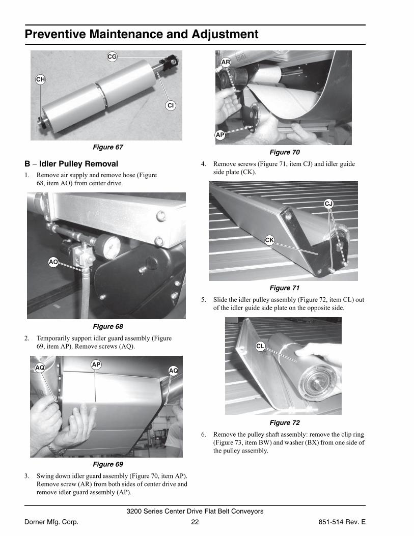
8. Remove the tension pulley locking collar (Figure 67, item CG), spacer (CH) and pulley shaft (CI) from the roller pulley shaft assembly.
AT
AS
AU
AV
AWAX
AU
AY
AZ
AX
AY
AZ
BA
851-514 Rev. E 21 Dorner Mfg. Corp.
3200 Series Center Drive Flat Belt Conveyors
Preventive Maintenance and Adjustment
Figure 67Figure 67
B − Idler Pulley Removal1. Remove air supply and remove hose (Figure
68, item AO) from center drive. Figure 68
Figure 68
2. Temporarily support idler guard assembly (Figure 69, item AP). Remove screws (AQ).
Figure 69
Figure 69
3. Swing down idler guard assembly (Figure 70, item AP). Remove screw (AR) from both sides of center drive and remove idler guard assembly (AP).
Figure 70
Figure 70
4. Remove screws (Figure 71, item CJ) and idler guide side plate (CK).
Figure 71
Figure 71
5. Slide the idler pulley assembly (Figure 72, item CL) out of the idler guide side plate on the opposite side.
Figure 72
Figure 72
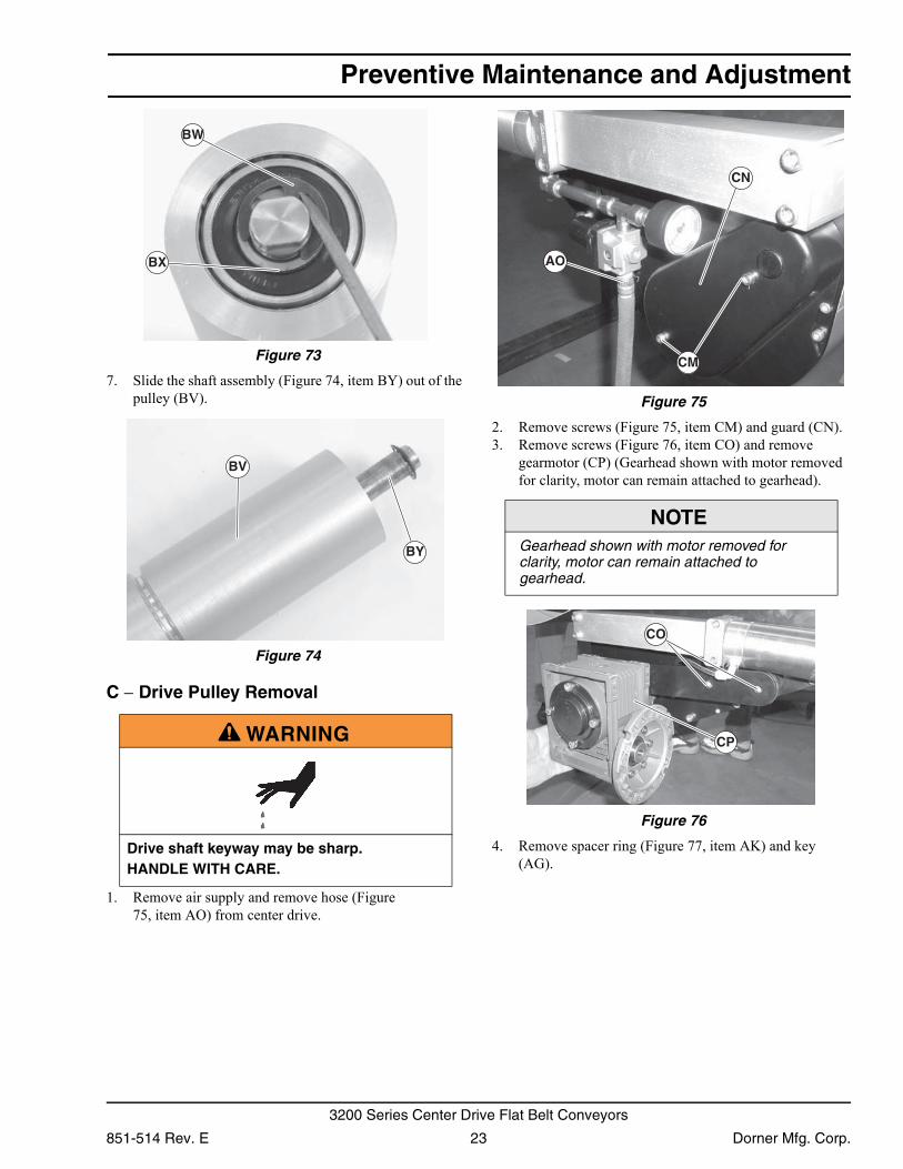
6. Remove the pulley shaft assembly: remove the clip ring (Figure 73, item BW) and washer (BX) from one side of the pulley assembly.
CG
CH
CI
AO
APAQ AQ
AR
AP
CK
CJ
CL
Dorner Mfg. Corp. 22 851-514 Rev. E
3200 Series Center Drive Flat Belt Conveyors
Preventive Maintenance and Adjustment
Figure 73Figure 73
7. Slide the shaft assembly (Figure 74, item BY) out of the pulley (BV).
Figure 74
Figure 74
C − Drive Pulley Removal
1. Remove air supply and remove hose (Figure 75, item AO) from center drive.
Figure 75
Figure 75
2. Remove screws (Figure 75, item CM) and guard (CN).3. Remove screws (Figure 76, item CO) and remove
gearmotor (CP) (Gearhead shown with motor removed for clarity, motor can remain attached to gearhead).
Figure 76
Figure 76
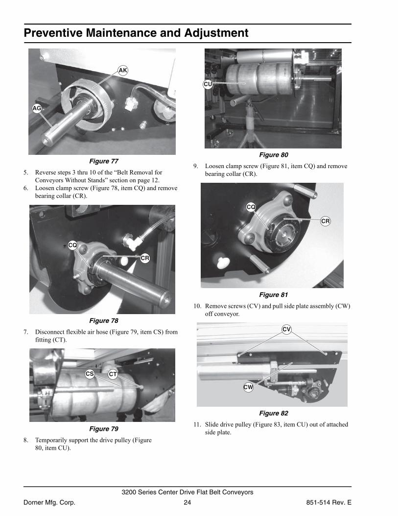
4. Remove spacer ring (Figure 77, item AK) and key (AG).
A WARNING
Drive shaft keyway may be sharp.HANDLE WITH CARE.
BW
BX
BY
BV
NOTEGearhead shown with motor removed for clarity, motor can remain attached to gearhead.
AO
CN
CM
CO
CP
851-514 Rev. E 23 Dorner Mfg. Corp.
3200 Series Center Drive Flat Belt Conveyors
Preventive Maintenance and Adjustment
Figure 77Figure 77
5. Reverse steps 3 thru 10 of the “Belt Removal for Conveyors Without Stands” section on page 12.
6. Loosen clamp screw (Figure 78, item CQ) and remove bearing collar (CR).
Figure 78
Figure 78
7. Disconnect flexible air hose (Figure 79, item CS) from fitting (CT).
Figure 79
Figure 79
8. Temporarily support the drive pulley (Figure 80, item CU).
Figure 80
Figure 80
9. Loosen clamp screw (Figure 81, item CQ) and remove bearing collar (CR).
Figure 81
Figure 81
10. Remove screws (CV) and pull side plate assembly (CW) off conveyor.
Figure 82
Figure 82
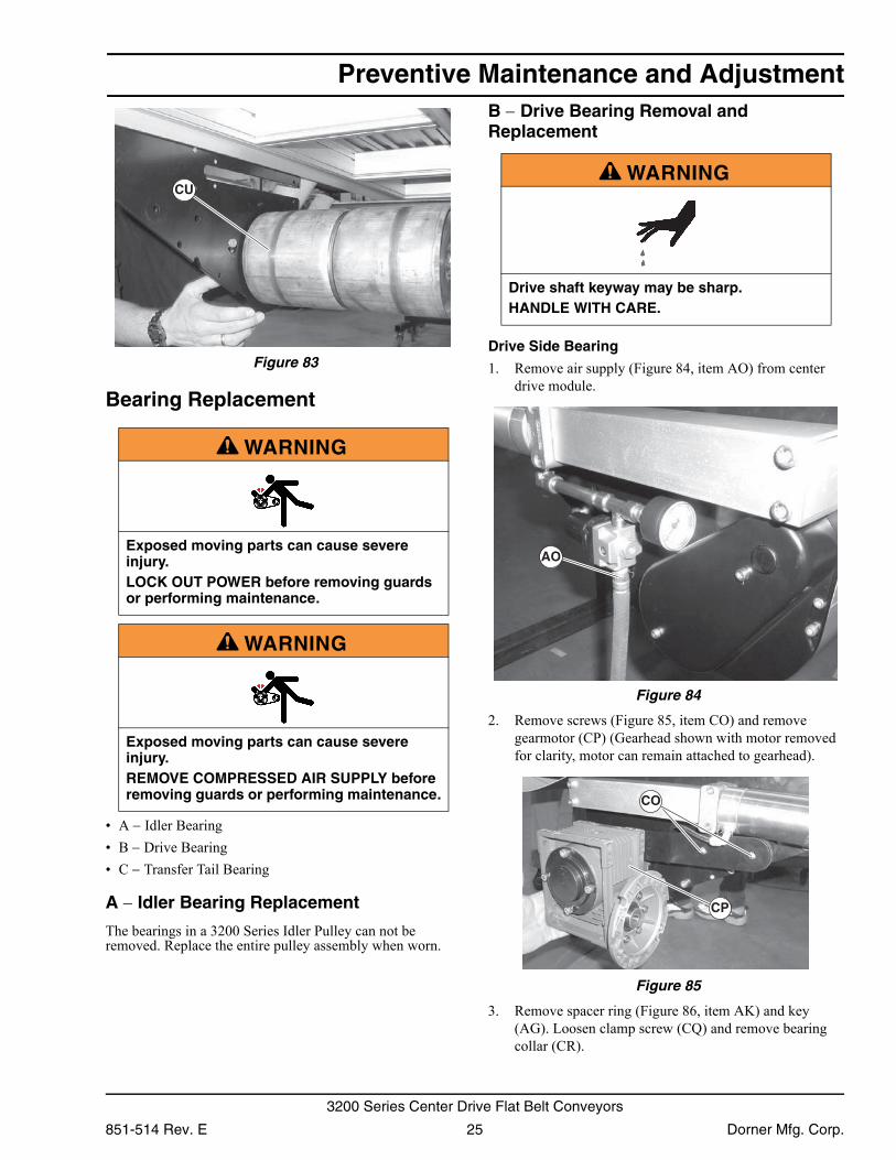
11. Slide drive pulley (Figure 83, item CU) out of attached side plate.
AK
AG
CR
CQ
CTCS
CU
CR
CQ
CW
CV
Dorner Mfg. Corp. 24 851-514 Rev. E
3200 Series Center Drive Flat Belt Conveyors
Preventive Maintenance and Adjustment
Figure 83Figure 83
Bearing Replacement
• A − Idler Bearing• B − Drive Bearing• C − Transfer Tail Bearing
A − Idler Bearing Replacement
The bearings in a 3200 Series Idler Pulley can not be removed. Replace the entire pulley assembly when worn.
B − Drive Bearing Removal and Replacement
Drive Side Bearing
1. Remove air supply (Figure 84, item AO) from center drive module.
Figure 84
Figure 84
2. Remove screws (Figure 85, item CO) and remove gearmotor (CP) (Gearhead shown with motor removed for clarity, motor can remain attached to gearhead).
Figure 85
Figure 85
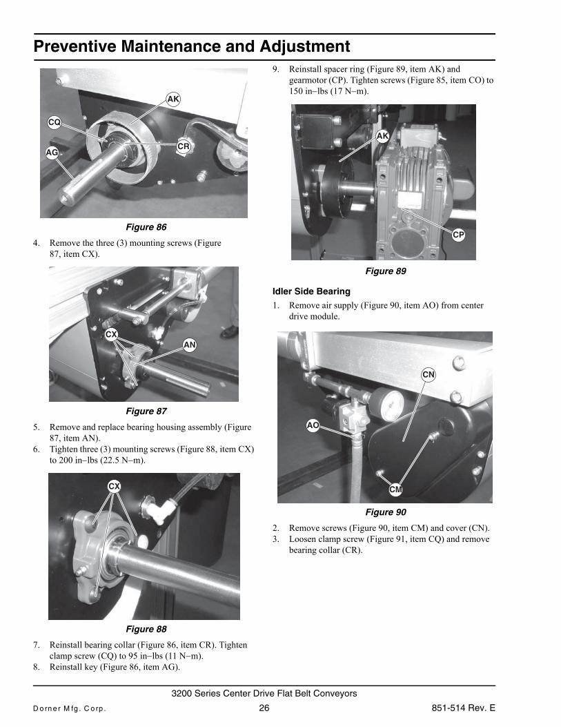
3. Remove spacer ring (Figure 86, item AK) and key (AG). Loosen clamp screw (CQ) and remove bearing collar (CR).
A WARNING
Exposed moving parts can cause severe injury.LOCK OUT POWER before removing guards or performing maintenance.
A WARNING
Exposed moving parts can cause severe injury.REMOVE COMPRESSED AIR SUPPLY before removing guards or performing maintenance.
CUA WARNING
Drive shaft keyway may be sharp.HANDLE WITH CARE.
AO
CO
CP
851-514 Rev. E 25 Dorner Mfg. Corp.
3200 Series Center Drive Flat Belt Conveyors
Preventive Maintenance and Adjustment
Figure 86Figure 86
4. Remove the three (3) mounting screws (Figure 87, item CX).
Figure 87
Figure 87
5. Remove and replace bearing housing assembly (Figure 87, item AN).
6. Tighten three (3) mounting screws (Figure 88, item CX) to 200 in−lbs (22.5 N−m).
Figure 88
Figure 88
7. Reinstall bearing collar (Figure 86, item CR). Tighten clamp screw (CQ) to 95 in−lbs (11 N−m).
8. Reinstall key (Figure 86, item AG).
9. Reinstall spacer ring (Figure 89, item AK) and gearmotor (CP). Tighten screws (Figure 85, item CO) to 150 in−lbs (17 N−m).
Figure 89
Figure 89
Idler Side Bearing
1. Remove air supply (Figure 90, item AO) from center drive module.
Figure 90
Figure 90
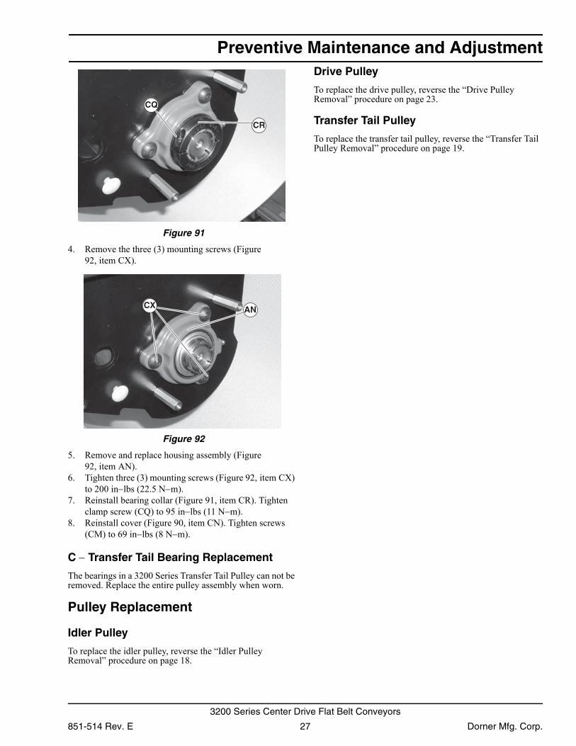
2. Remove screws (Figure 90, item CM) and cover (CN).3. Loosen clamp screw (Figure 91, item CQ) and remove
bearing collar (CR).
CQ
AK
AGCR
CXAN
CX
AK
CP
AO
CN
CM
D o rn e r M fg . C o rp . 26 851-514 Rev. E
3200 Series Center Drive Flat Belt Conveyors
Preventive Maintenance and Adjustment
Figure 91Figure 91
4. Remove the three (3) mounting screws (Figure 92, item CX).
Figure 92
Figure 92
5. Remove and replace housing assembly (Figure 92, item AN).
6. Tighten three (3) mounting screws (Figure 92, item CX) to 200 in−lbs (22.5 N−m).
7. Reinstall bearing collar (Figure 91, item CR). Tighten clamp screw (CQ) to 95 in−lbs (11 N−m).
8. Reinstall cover (Figure 90, item CN). Tighten screws (CM) to 69 in−lbs (8 N−m).
C − Transfer Tail Bearing Replacement
The bearings in a 3200 Series Transfer Tail Pulley can not be removed. Replace the entire pulley assembly when worn.
Pulley Replacement
Idler Pulley
To replace the idler pulley, reverse the “Idler Pulley Removal” procedure on page 18.
Drive Pulley
To replace the drive pulley, reverse the “Drive Pulley Removal” procedure on page 23.
Transfer Tail Pulley
To replace the transfer tail pulley, reverse the “Transfer Tail Pulley Removal” procedure on page 19.
CR
CQ
CX AN
851-514 Rev. E 27 Dorner Mfg. Corp.
3200 Series Center Drive Flat Belt Conveyors
Service Parts
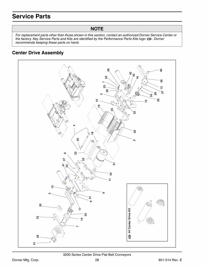
Center Drive Assembly
NOTEFor replacement parts other than those shown in this section, contact an authorized Dorner Service Center or the factory. Key Service Parts and Kits are identified by the Performance Parts Kits logo . Dorner recommends keeping these parts on hand.
3
7
5
8
13
10
91
2
4
14
15
6
12
11
2324
25
26
22
21
19
20
2728
18
30
17
16
31
29
32
33
34
35
36
37
3839
40
41
4243
41
33
33
33
22
44 C
ente
r D
rive
Kit
Dorner Mfg. Corp. 28 851-514 Rev. E
3200 Series Center Drive Flat Belt Conveyors
Service Parts
Item Part Number Description1 200038 Cam Clamping Plate
2 See Table 1 Flat Guard
3 301088 Tail Clamping Bar
4 3227WW Wand Assy for 3” Idler Roller
5 301214 Cylinder Channel Guard
6 301216 Cylinder Guard Mounting Block
7 301217 Torsion Arm Plate
8 301218 Side Plate Spacer
9 301219 Center Drive Side Plate
10 301220 End Roller Mounting Plate
11 301221 Horseshoe Guard Mount Plate
12 301222 Center Drive Tension Pulley Spacer
13 301278 Center Drive Bearing Guard
14 301281 Pipe Guard
15 301355 Cylinder Mounting Block
16 301356 Cylinder−Rod Mounting Block
17 301357 Tension Pulley Spacer
18 3242WW Tension Pulley Axle Shaft
19 3243WW Bottom End Guard
20 3244WW Bottom Corner Guard
21 3287WW 6” Diameter Pulley
22 3290WW 3” Center Drive Pulley
23 200039P Belt Tracking Cam
24 200341M Cam Retaining Block
25 See Table 1 Inner Shaft Tube
26 802−138 3 Bolt Bearing
27 807−226 Snap Out Plastic Plug
28 807−1162 Hex Stand Off
29 807−1167 Gearhead Cover
30 812−061 Anti−rotation Bushing
31 824−331 1/2” EMT Steel Connector
32 825−160 1/4” BSPT Pipe Plug
33 911020M Button Head Screw M10 x 20mm
34 912−111 Square Key
35 915−265 E Retaining Ring
36 920512M Socket Head Screw M5 x 12mm
37 920520M Socket Head Screw M5 x 20mm
38 920610M Socket Head Screw M6 x 10mm
39 920816M Socket Head Screw M8 x 16mm
40 920860M Socket Head Screw M8 x 60mm
41 920892M Low Head Screw M8 x 12mm
42 970820M Cup Set Screw M8 x 20mm
43 301213 Pneumatic Tension Assy
44 32CD-WW Center Drive Kit (includes items 4, 18, 22 and 26)
WW = Conveyor width reference: 04 − 60 in 02 increments
Table 1 − Part Number Per Conveyor Width
Conveyor Width
Item 2 − Flat GuardItem 25 − Inner Shaft
Tube
4” 300895−00374 301164
6” 300895−00599 301198−00209
8” 300895−00799 301198−00409
10 300895−00999 301198−00609
12 300895−01199 301198−00809
14 300895−01399 301198−01009
16 300895−01599 301198−01209
18 300895−01799 301198−01409
20 300895−01999 301198−01609
22 300895−02199 301198−01809
24 300895−02399 301198−02009
26 300895−02599 301198−02209
28 300895−02799 301198−02409
30 300895−02999 301198−02609
32 300895−03199 301198−02809
34 300895−03399 301198−03009
36 300895−03599 301198−03209
38 300895−03799 301198−03409
40 300895−03999 301198−03609
42 300895−04199 301198−03809
44 300895−04399 301198−04009
46 300895−04599 301198−04209
48 300895−04799 301198−04409
50 300895−04999 301198−04609
52 300895−05199 301198−04809
54 300895−05399 301198−05009
56 300895−05599 301198−05209
58 300895−05799 301198−05409
60 300895−05999 301198−05609
851-514 Rev. E 29 Dorner Mfg. Corp.
3200 Series Center Drive Flat Belt Conveyors
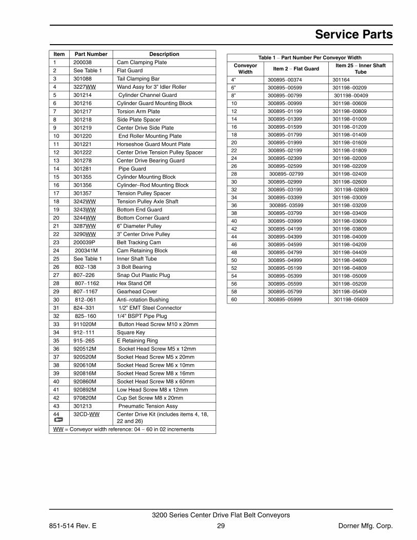
Service Parts
Center Drive Manual Tensioner3, 11
7
5
8
10
9
1
24
6
Item Part Number Description
1 301410 Threaded Rod 1/2” x 17” Long
2 3015WW Spring Cage (04” through 24” Wide Conveyor)
301524 Spring Cage (26” through 60” Wide Conveyor)
3 605280P Hard Washer
4 802−139 Thrust Bearing Cage
5 802−140 Thrust Bearing Washer
6 807−1182 Spring − Blue (04” through 08” Wide Conveyor)
807−1183 Spring − Red (10” through 12” Wide Conveyor)
807−1184 Spring − Bronze (14” through 60” Wide Conveyor)
7 807−1185 Knurled Knob
8 807−1186 End Cap
9 807−1187 Threaded Plug
10 910−081 Hex Jam Nut 1/2”−20
11 920893M Low Head Cap Screw M8 x 16mm
WW = Conveyor width reference: 04 − 60 in 02 increments
Dorner Mfg. Corp. 30 851-514 Rev. E
3200 Series Center Drive Flat Belt Conveyors
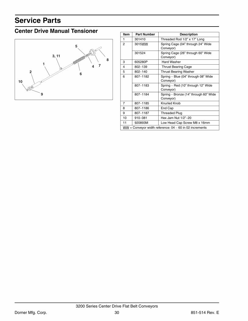
Service Parts
Center Drive 90º Industrial Gearmotors23
1 Item Part No. Part Description
1 32M008HH Gear Reducer, 7.5:1 NEMA 140TC
32M010HH Gear Reducer, 10:1 NEMA 140TC
32M015HH Gear Reducer, 15:1 NEMA 140TC
32M020HH Gear Reducer, 20:1 NEMA 140TC
32M025HH Gear Reducer, 25:1 NEMA 140TC
32M030HH Gear Reducer, 30:1 NEMA 140TC
32M040HH Gear Reducer, 40:1 NEMA 140TC
32M050HH Gear Reducer, 50:1 NEMA 140TC
32M060HH Gear Reducer, 60:1 NEMA 56C
32M080HH Gear Reducer, 80:1 NEMA 56C
32M100HH Gear Reducer, 100:1 NEMA 56C
2 62MS411FN Motor, 0.25hp (0.19Kw), 115/230 Volts, 60 Hz, 1-Phase
62MH411 Motor, 0.5hp (0.37Kw), 115/230 Volts, 60Hz, 1−Phase
62MH423 Motor, 0.5hp (0.37Kw) 208−230/460 Volts, 60Hz, 3 Phase
32MHH423FN10 Motor, 1 hp (0.75Kw), 230 Volts, 3 Phase
32MS423EN Motor, 0.5hp (0.37Kw), 230 Volts, 3 Phase Inverter Duty
32MHH423EN10 Motor, 1hp (0.75Kw), 230 Volts, 3 Phase Inverter Duty
32MHH423EN15 Motor, 1.5hp (1.1Kw), 230 Volts, 3 Phase Inverter Duty
32MHH423FN15 Motor, 1.5hp (1.1Kw), 230 Volts, 3 Phase
62MHD9DEN Motor, 0.5hp (0.37Kw), 90 Volts DC,
62MHD9DEN75 Motor, 0.75hp (0.56Kw), 90 Volts DC,
32MHH423EN20 Motor, 2.0hp (1.5Kw), 230 Volts, 3 Phase Inverter Duty
32MHH423FN20 Motor, 2.0hp (1.5Kw), 230 Volts, 3 Phase
32MHH411EC10 Motor, 1.0hp (0.75Kw), 115 Volts, Integrated Controller
32MHH411EC15 Motor, 0.5hp (0.37Kw), 115 Volts, Integrated Controller
3 820−329 Bushing Shaft Adapter, 56C to 140TC
851-514 Rev. E 31 Dorner Mfg. Corp.
3200 Series Center Drive Flat Belt Conveyors
Service Parts
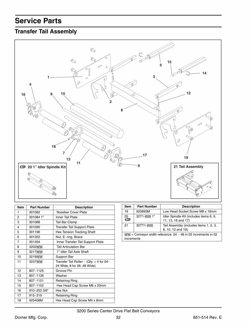
Transfer Tail Assembly7
8
2
3
129
4
14
13
18
19
1
10
17
611
16
515
21 Tail Assembly20 1” Idler Spindle Kit
Item Part Number Description
1 301082 Nosebar Cover Plate
2 301084 1” Inner Tail Plate
3 301088 Tail Bar Clamp
4 301090 Transfer Tail Support Plate
5 301196 Hex Tension Tracking Shaft
6 301352 Nut, E−ring, Brace
7 301354 Inner Transfer Tail Support Plate
8 3202WW Tail Articulation Bar
9 3217WW 1” Idler Tail Axle Shaft
10 3219WW Support Bar
11 3237WW Transfer Tail Roller − (Qty. = 4 for 04−24 Wide, 8 for 26−48 Wide)
12 807−1125 Groove Pin
13 807−1136 Washer
14 807−1151 Retaining Ring
15 807−1152 Hex Head Cap Screw M6 x 20mm
16 910−203 3/8” Hex Nut
17 915−319 Retaining Ring
18 920408M Hex Head Cap Screw M4 x 8mm
19 920893M Low Head Socket Screw M8 x 16mm
20 32T1-WW 1” Idler Spindle Kit (includes items 6, 9, 11, 13, 16 and 17)
21 32TT1-WW Tail Assembly (includes items 1, 2, 3, 8, 10, 12 and 19)
WW = Conveyor width reference: 04 − 48 in 02 increments in 02 increments
Item Part Number Description
Dorner Mfg. Corp. 32 851-514 Rev. E
3200 Series Center Drive Flat Belt Conveyors
Service Parts
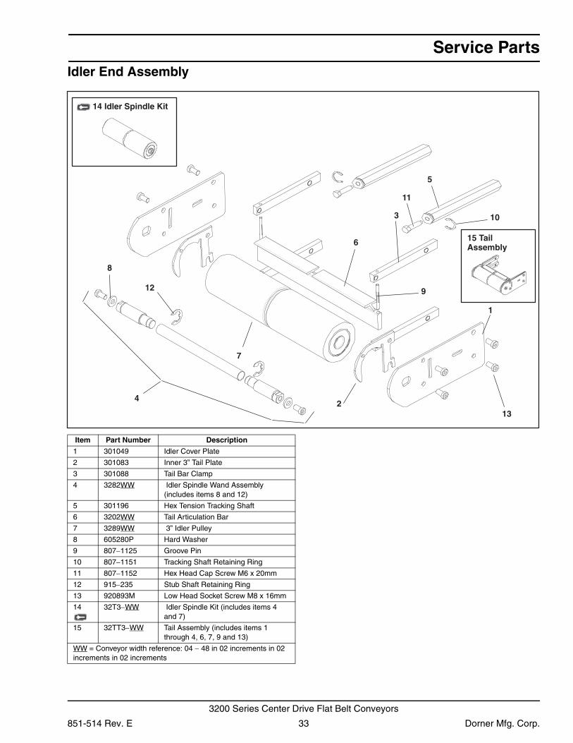
Idler End Assembly3
213
6
12
7
8
9
1
11
5
10
4
14 Idler Spindle Kit
15 Tail Assembly
Item Part Number Description
1 301049 Idler Cover Plate
2 301083 Inner 3” Tail Plate
3 301088 Tail Bar Clamp
4 3282WW Idler Spindle Wand Assembly (includes items 8 and 12)
5 301196 Hex Tension Tracking Shaft
6 3202WW Tail Articulation Bar
7 3289WW 3” Idler Pulley
8 605280P Hard Washer
9 807−1125 Groove Pin
10 807−1151 Tracking Shaft Retaining Ring
11 807−1152 Hex Head Cap Screw M6 x 20mm
12 915−235 Stub Shaft Retaining Ring
13 920893M Low Head Socket Screw M8 x 16mm
14 32T3−WW Idler Spindle Kit (includes items 4 and 7)
15 32TT3−WW Tail Assembly (includes items 1 through 4, 6, 7, 9 and 13)
WW = Conveyor width reference: 04 − 48 in 02 increments in 02 increments in 02 increments
851-514 Rev. E 33 Dorner Mfg. Corp.
3200 Series Center Drive Flat Belt Conveyors

Service Parts
Frame AssemblyBed Plate and Frame Formulas
4
11
1
36
7
8 10
2
9
5
Item Part Number Description
1 240420 Rack Gear
2 301091 Pinion Bearing
3 605279P Washer
4 920483M Flange Socket Screw M4 x 16mm
5 920616M Socket Head Screw M6 x 16mm
6 920693M Low Head Socket Screw M6 x 16mm
7 3245WW Cross Support Rail
8 301041−LLLLL RH Side Rail
9 301042−LLLLL LH Side Rail
10 3229WW Pinion
11 Bed Plate Rail
WW = Conveyor width reference: 04 − 48 in 02 increments LLLLL = Frame Length (see Bed Plate & Frame Formulas) in 02 increments in 02 increments in 02 increments
Item 11: Bed Plate Rail
Width Part Number
1.75” (mm) 300887−LLLLL
2” (54mm) 300888−LLLLL
4” (102mm) 300889−LLLLL
6” (152mm) 300890−LLLLL
LLLLL = Bed Plate Length (see Bed Plate & Frame Formulas)
Item 11: Bed Plate Rail
Width Part Number
Frame LLLLL = Conveyor Length LLLL X 12 − Tail Adder# of Sections of Conveyor
Tail Adder = 00600 for each Tension End00425 for each Non−Tension End
Bed Plate LLLLL = Frame LLLLL − 00013
Dorner Mfg. Corp. 34 851-514 Rev. E
3200 Series Center Drive Flat Belt Conveyors
Service Parts
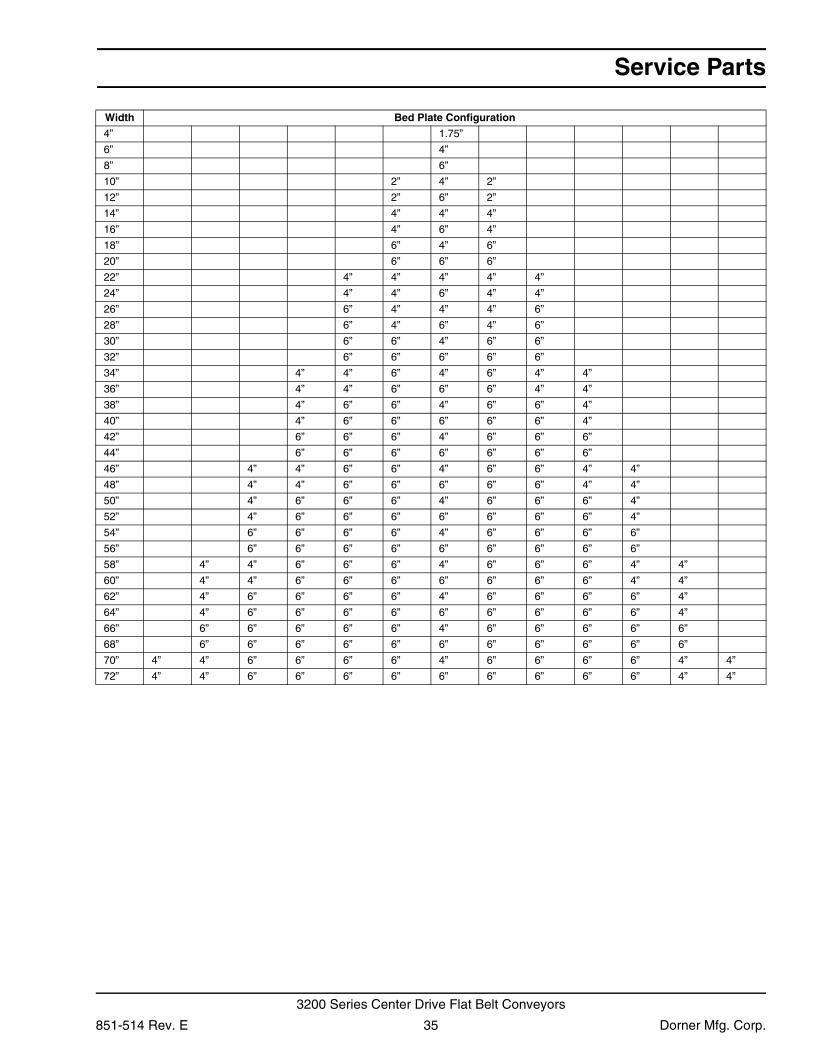
Width Bed Plate Configuration
4” 1.75”
6” 4”
8” 6”
10” 2” 4” 2”
12” 2” 6” 2”
14” 4” 4” 4”
16” 4” 6” 4”
18” 6” 4” 6”
20” 6” 6” 6”
22” 4” 4” 4” 4” 4”
24” 4” 4” 6” 4” 4”
26” 6” 4” 4” 4” 6”
28” 6” 4” 6” 4” 6”
30” 6” 6” 4” 6” 6”
32” 6” 6” 6” 6” 6”
34” 4” 4” 6” 4” 6” 4” 4”
36” 4” 4” 6” 6” 6” 4” 4”
38” 4” 6” 6” 4” 6” 6” 4”
40” 4” 6” 6” 6” 6” 6” 4”
42” 6” 6” 6” 4” 6” 6” 6”
44” 6” 6” 6” 6” 6” 6” 6”
46” 4” 4” 6” 6” 4” 6” 6” 4” 4”
48” 4” 4” 6” 6” 6” 6” 6” 4” 4”
50” 4” 6” 6” 6” 4” 6” 6” 6” 4”
52” 4” 6” 6” 6” 6” 6” 6” 6” 4”
54” 6” 6” 6” 6” 4” 6” 6” 6” 6”
56” 6” 6” 6” 6” 6” 6” 6” 6” 6”
58” 4” 4” 6” 6” 6” 4” 6” 6” 6” 4” 4”
60” 4” 4” 6” 6” 6” 6” 6” 6” 6” 4” 4”
62” 4” 6” 6” 6” 6” 4” 6” 6” 6” 6” 4”
64” 4” 6” 6” 6” 6” 6” 6” 6” 6” 6” 4”
66” 6” 6” 6” 6” 6” 4” 6” 6” 6” 6” 6”
68” 6” 6” 6” 6” 6” 6” 6” 6” 6” 6” 6”
70” 4” 4” 6” 6” 6” 6” 4” 6” 6” 6” 6” 4” 4”
72” 4” 4” 6” 6” 6” 6” 6” 6” 6” 6” 6” 4” 4”
851-514 Rev. E 35 Dorner Mfg. Corp.
3200 Series Center Drive Flat Belt Conveyors
Service Parts
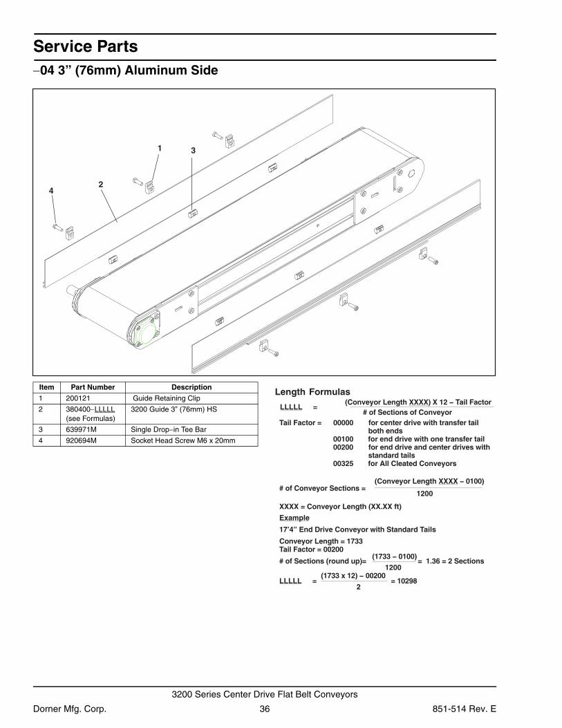
−04 3” (76mm) Aluminum Side2
1
4
3
Item Part Number Description
1 200121 Guide Retaining Clip
2 380400−LLLLL (see Formulas)
3200 Guide 3” (76mm) HS
3 639971M Single Drop−in Tee Bar
4 920694M Socket Head Screw M6 x 20mm
Length Formulas
LLLLL =(Conveyor Length XXXX) X 12 − Tail Factor
# of Sections of ConveyorTail Factor = 00000 for center drive with transfer tail
both ends00100 for end drive with one transfer tail00200 for end drive and center drives with
standard tails00325 for All Cleated Conveyors
(Conveyor Length XXXX − 0100)
1200# of Conveyor Sections =
XXXX = Conveyor Length (XX.XX ft)
Example
17’4” End Drive Conveyor with Standard Tails
Conveyor Length = 1733Tail Factor = 00200
# of Sections (round up)= = 1.36 = 2 Sections
LLLLL 89201 ==
(1733 − 0100)
1200 (1733 x 12) − 00200
2
Dorner Mfg. Corp. 36 851-514 Rev. E
3200 Series Center Drive Flat Belt Conveyors
Service Parts
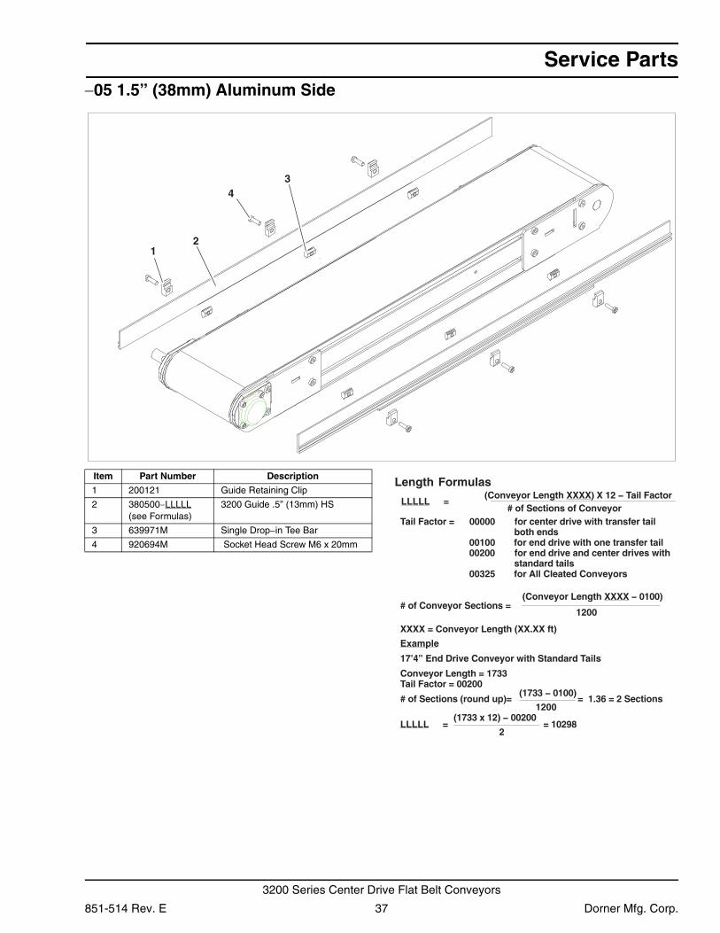
−05 1.5” (38mm) Aluminum Side3
21
4
Item Part Number Description
1 200121 Guide Retaining Clip
2 380500−LLLLL (see Formulas)
3200 Guide .5” (13mm) HS
3 639971M Single Drop−in Tee Bar
4 920694M Socket Head Screw M6 x 20mm
Length Formulas
LLLLL =(Conveyor Length XXXX) X 12 − Tail Factor
# of Sections of ConveyorTail Factor = 00000 for center drive with transfer tail
both ends00100 for end drive with one transfer tail00200 for end drive and center drives with
standard tails00325 for All Cleated Conveyors
(Conveyor Length XXXX − 0100)
1200# of Conveyor Sections =
XXXX = Conveyor Length (XX.XX ft)
Example
17’4” End Drive Conveyor with Standard Tails
Conveyor Length = 1733Tail Factor = 00200
# of Sections (round up)= = 1.36 = 2 Sections
LLLLL 89201 ==
(1733 − 0100)
1200 (1733 x 12) − 00200
2
851-514 Rev. E 37 Dorner Mfg. Corp.
3200 Series Center Drive Flat Belt Conveyors
Service Parts
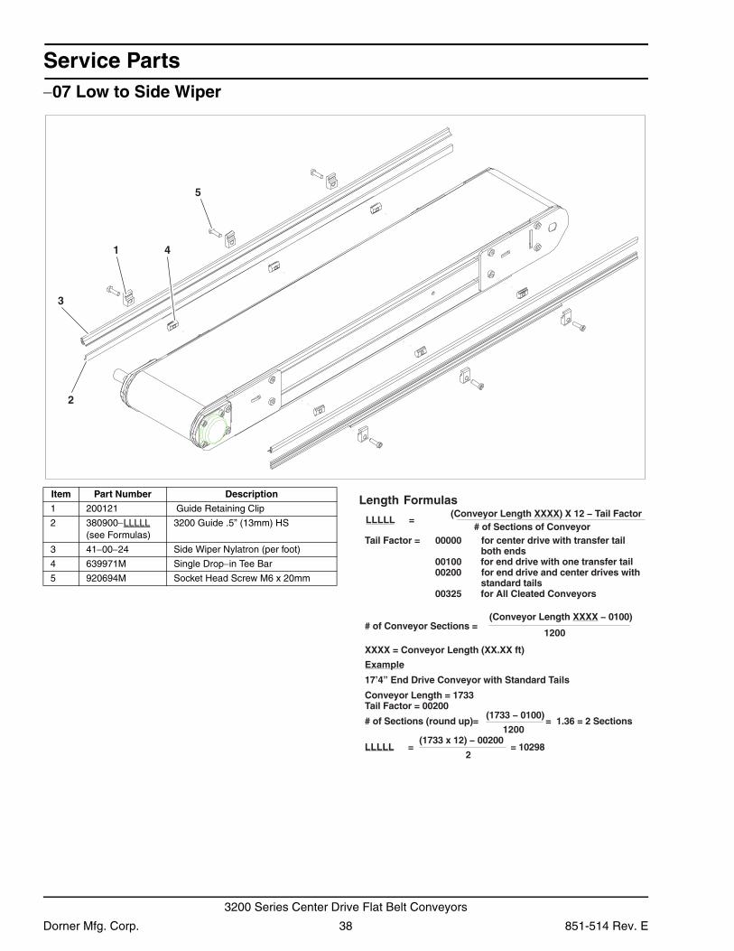
−07 Low to Side Wiper5
1
2
3
4
Item Part Number Description
1 200121 Guide Retaining Clip
2 380900−LLLLL (see Formulas)
3200 Guide .5” (13mm) HS
3 41−00−24 Side Wiper Nylatron (per foot)
4 639971M Single Drop−in Tee Bar
5 920694M Socket Head Screw M6 x 20mm
Length Formulas
LLLLL =(Conveyor Length XXXX) X 12 − Tail Factor
# of Sections of ConveyorTail Factor = 00000 for center drive with transfer tail
both ends00100 for end drive with one transfer tail00200 for end drive and center drives with
standard tails00325 for All Cleated Conveyors
(Conveyor Length XXXX − 0100)
1200# of Conveyor Sections =
XXXX = Conveyor Length (XX.XX ft)
Example
17’4” End Drive Conveyor with Standard Tails
Conveyor Length = 1733Tail Factor = 00200
# of Sections (round up)= = 1.36 = 2 Sections
LLLLL 89201 ==
(1733 − 0100)
1200 (1733 x 12) − 00200
2
Dorner Mfg. Corp. 38 851-514 Rev. E
3200 Series Center Drive Flat Belt Conveyors
Service Parts
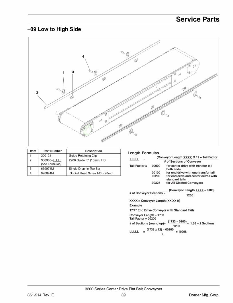
−09 Low to High Side1
2
3
4
Item Part Number Description
1 200121 Guide Retaining Clip
2 380900−LLLLL (see Formulas)
2200 Guide .5” (13mm) HS
3 639971M Single Drop−in Tee Bar
4 920694M Socket Head Screw M6 x 20mm
Length Formulas
LLLLL =(Conveyor Length XXXX) X 12 − Tail Factor
# of Sections of ConveyorTail Factor = 00000 for center drive with transfer tail
both ends00100 for end drive with one transfer tail00200 for end drive and center drives with
standard tails00325 for All Cleated Conveyors
(Conveyor Length XXXX − 0100)
1200# of Conveyor Sections =
XXXX = Conveyor Length (XX.XX ft)
Example
17’4” End Drive Conveyor with Standard Tails
Conveyor Length = 1733Tail Factor = 00200
# of Sections (round up)= = 1.36 = 2 Sections
LLLLL 89201 ==
(1733 − 0100)
1200 (1733 x 12) − 00200
2
851-514 Rev. E 39 Dorner Mfg. Corp.
3200 Series Center Drive Flat Belt Conveyors
Service Parts
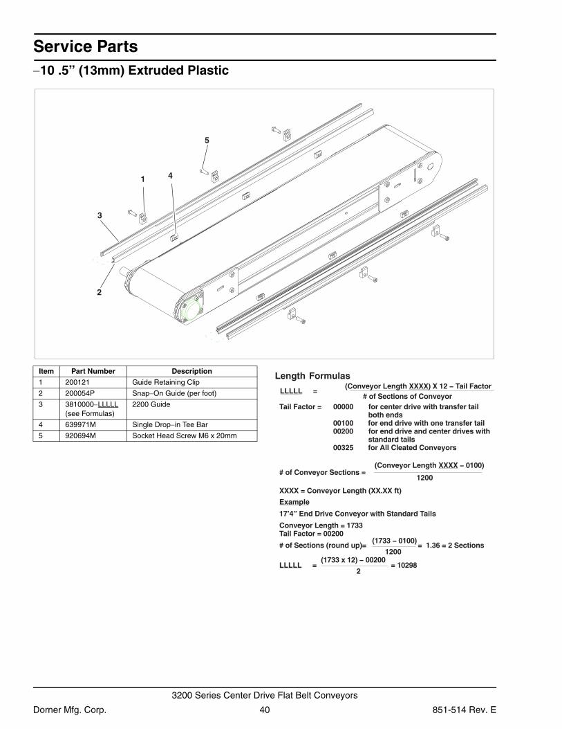
−10 .5” (13mm) Extruded Plastic3
2
1 4
5
Item Part Number Description
1 200121 Guide Retaining Clip
2 200054P Snap−On Guide (per foot)
3 3810000−LLLLL (see Formulas)
2200 Guide
4 639971M Single Drop−in Tee Bar
5 920694M Socket Head Screw M6 x 20mm
Length Formulas
LLLLL =(Conveyor Length XXXX) X 12 − Tail Factor
# of Sections of ConveyorTail Factor = 00000 for center drive with transfer tail
both ends00100 for end drive with one transfer tail00200 for end drive and center drives with
standard tails00325 for All Cleated Conveyors
(Conveyor Length XXXX − 0100)
1200# of Conveyor Sections =
XXXX = Conveyor Length (XX.XX ft)
Example
17’4” End Drive Conveyor with Standard Tails
Conveyor Length = 1733Tail Factor = 00200
# of Sections (round up)= = 1.36 = 2 Sections
LLLLL 89201 ==
(1733 − 0100)
1200 (1733 x 12) − 00200
2
Dorner Mfg. Corp. 40 851-514 Rev. E
3200 Series Center Drive Flat Belt Conveyors
Service Parts
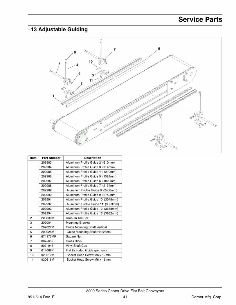
−13 Adjustable Guiding1
98
5 4
3
2
7
11
6
10
Item Part Number Description
1 202983 Aluminum Profile Guide 2’ (610mm)
202984 Aluminum Profile Guide 3’ (914mm)
202985 Aluminum Profile Guide 4’ (1219mm)
202986 Aluminum Profile Guide 5’ (1524mm)
202987 Aluminum Profile Guide 6’ (1829mm)
202988 Aluminum Profile Guide 7’ (2134mm)
202989 Aluminum Profile Guide 8’ (2438mm)
202990 Aluminum Profile Guide 9’ (2743mm)
202991 Aluminum Profile Guide 10’ (3048mm)
202992 Aluminum Profile Guide 11’ (3353mm)
202993 Aluminum Profile Guide 12’ (3658mm)
202994 Aluminum Profile Guide 13’ (3962mm)
2 200830M Drop−In Tee Bar
3 202004 Mounting Bracket
4 202027M Guide Mounting Shaft Vertical
5 202028M Guide Mounting Shaft Horizontal
6 674175MP Square Nut
7 807−652 Cross Block
8 807−948 Vinyl Shaft Cap
9 614068P Flat Extruded Guide (per foot)
10 920612M Socket Head Screw M6 x 12mm
11 920616M Socket Head Screw M6 x 16mm
851-514 Rev. E 41 Dorner Mfg. Corp.
3200 Series Center Drive Flat Belt Conveyors
Service Parts
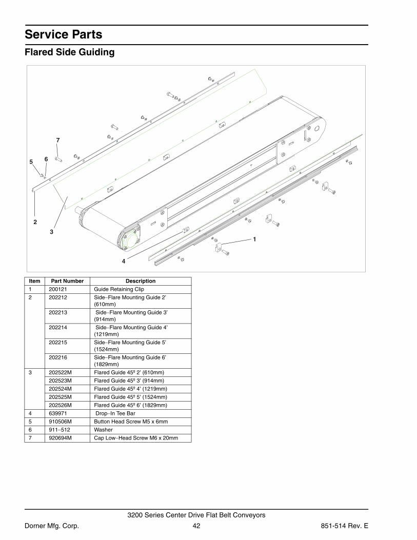
Flared Side Guiding1
4
6
3
5
7
2
Item Part Number Description
1 200121 Guide Retaining Clip
2 202212 Side−Flare Mounting Guide 2’ (610mm)
202213 Side−Flare Mounting Guide 3’ (914mm)
202214 Side−Flare Mounting Guide 4’ (1219mm)
202215 Side−Flare Mounting Guide 5’ (1524mm)
202216 Side−Flare Mounting Guide 6’ (1829mm)
3 202522M Flared Guide 45º 2’ (610mm)
202523M Flared Guide 45º 3’ (914mm)
202524M Flared Guide 45º 4’ (1219mm)
202525M Flared Guide 45º 5’ (1524mm)
202526M Flared Guide 45º 6’ (1829mm)
4 639971 Drop−In Tee Bar
5 910506M Button Head Screw M5 x 6mm
6 911−512 Washer
7 920694M Cap Low−Head Screw M6 x 20mm
Dorner Mfg. Corp. 42 851-514 Rev. E
3200 Series Center Drive Flat Belt Conveyors
Service Parts
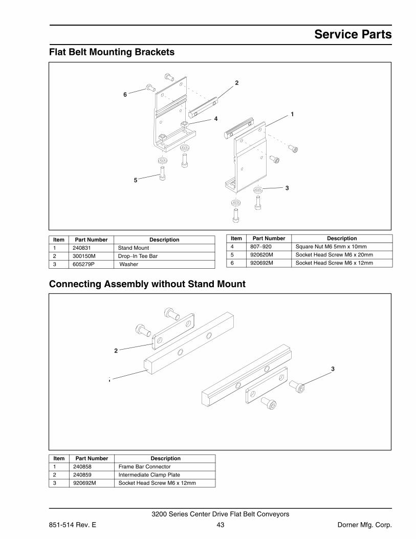
Flat Belt Mounting BracketsConnecting Assembly without Stand Mount
1
6
5
4
3
2
Item Part Number Description
1 240831 Stand Mount
2 300150M Drop−In Tee Bar
3 605279P Washer
4 807−920 Square Nut M6 5mm x 10mm
5 920620M Socket Head Screw M6 x 20mm
6 920692M Socket Head Screw M6 x 12mm
Item Part Number Description
3
2
1
Item Part Number Description
1 240858 Frame Bar Connector
2 240859 Intermediate Clamp Plate
3 920692M Socket Head Screw M6 x 12mm
851-514 Rev. E 43 Dorner Mfg. Corp.
3200 Series Center Drive Flat Belt Conveyors
Service Parts
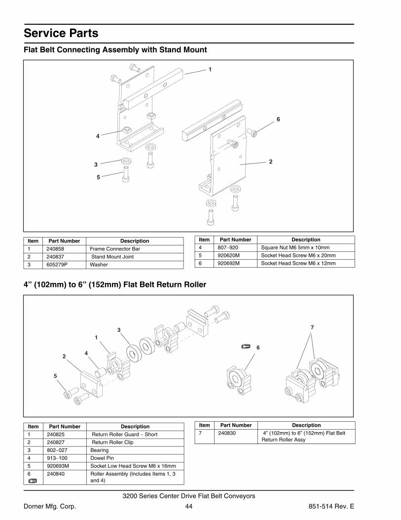
Flat Belt Connecting Assembly with Stand Mount4” (102mm) to 6” (152mm) Flat Belt Return Roller
6
5
4
3 2
1
Item Part Number Description
1 240858 Frame Connector Bar
2 240837 Stand Mount Joint
3 605279P Washer
4 807−920 Square Nut M6 5mm x 10mm
5 920620M Socket Head Screw M6 x 20mm
6 920692M Socket Head Screw M6 x 12mm
Item Part Number Description
2
5
4
31
7
6
Item Part Number Description
1 240825 Return Roller Guard − Short
2 240827 Return Roller Clip
3 802−027 Bearing
4 913−100 Dowel Pin
5 920693M Socket Low Head Screw M6 x 16mm
6 240840 Roller Assembly (Includes Items 1, 3 and 4)
7 240830 4” (102mm) to 6” (152mm) Flat Belt Return Roller Assy
Item Part Number Description
Dorner Mfg. Corp. 44 851-514 Rev. E
3200 Series Center Drive Flat Belt Conveyors
Service Parts
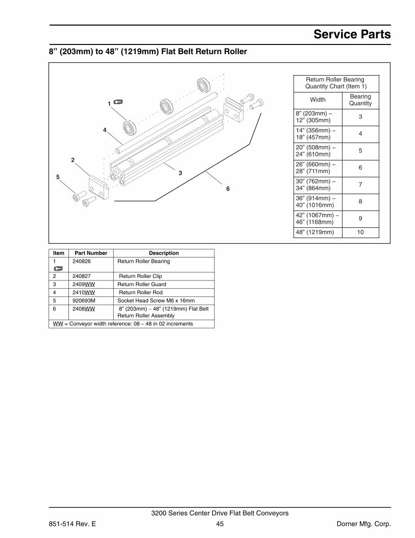
8” (203mm) to 48” (1219mm) Flat Belt Return Roller5
1
2
3
4
6
Return Roller Bearing Quantity Chart (Item 1)
Width BearingQuantity
8” (203mm) −12” (305mm)
3
14” (356mm) −18” (457mm)
4
20” (508mm) −24” (610mm)
5
26” (660mm) −28” (711mm)
6
30” (762mm) −34” (864mm)
7
36” (914mm) −40” (1016mm)
8
42” (1067mm) −46” (1168mm)
9
48” (1219mm) 10
Item Part Number Description
1 240826 Return Roller Bearing
2 240827 Return Roller Clip
3 2409WW Return Roller Guard
4 2410WW Return Roller Rod
5 920693M Socket Head Screw M6 x 16mm
6 2408WW 8” (203mm) − 48” (1219mm) Flat Belt Return Roller Assembly
WW = Conveyor width reference: 08 − 48 in 02 increments
851-514 Rev. E 45 Dorner Mfg. Corp.
3200 Series Center Drive Flat Belt Conveyors
Service Parts
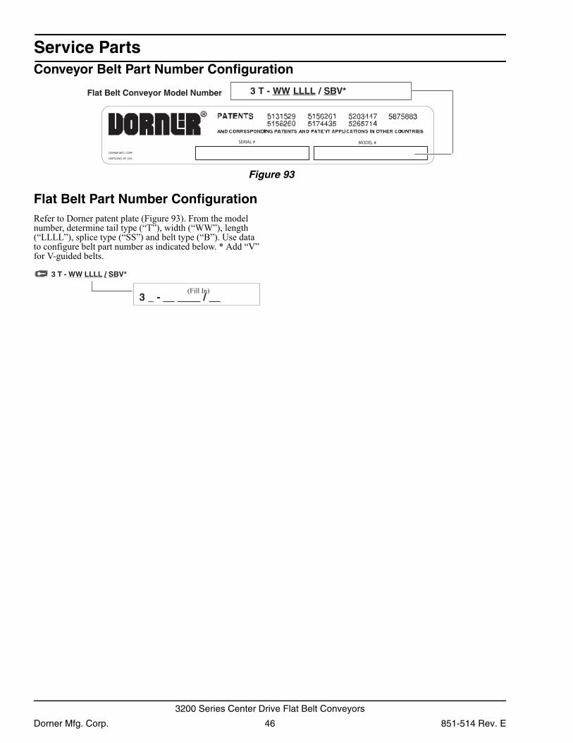
Conveyor Belt Part Number ConfigurationFigure 93
Figure 93
Flat Belt Part Number ConfigurationRefer to Dorner patent plate (Figure 93). From the model number, determine tail type (“T”), width (“WW”), length (“LLLL”), splice type (“SS”) and belt type (“B”). Use data to configure belt part number as indicated below. * Add “V” for V-guided belts.
Flat Belt Conveyor Model Number 3 T - WW LLLL / SBV*
DORNER MFG. CORP
HARTLAND, WI USA
SERIAL # MODEL #
(Fill In)
3 T - WW LLLL / SBV*
3 _ - __ ____ / __
Dorner Mfg. Corp. 46 851-514 Rev. E
3200 Series Center Drive Flat Belt Conveyors
Notes
851-514 Rev. E 47 Dorner Mfg. Corp.
3200 Series Center Drive Flat Belt Conveyors
Return Policy
Returns must have prior written factory authorization or they will not be accepted. Items that are returned to Dorner without authorization will not be credited nor returned to the original sender. When calling for authorization, please have the following information ready for the Dorner factory representative or your local distributor:
1. Name and address of customer.2. Dorner part number(s) of item(s) being returned.3. Reason for return.4. Customer's original order number used when ordering the item(s).5. Dorner or distributor invoice number.
A representative will discuss action to be taken on the returned items and provide a Returned Goods Authorization number for reference.
There will be a return charge on all new undamaged items returned for credit where Dorner was not at fault. Dorner is not responsible for return freight on such items.
Conveyors and conveyor accessoriesStandard catalog conveyors 30%MPB Series, cleated and specialty belt conveyors 50%7400 & 7600 Series conveyors non-returnable itemsEngineered special products case by caseDrives and accessories 30%Sanitary stand supports non-returnable items
PartsStandard stock parts 30%MPB, cleated and specialty belts non-returnable items
Returns will not be accepted after 60 days from original invoice date.
The return charge covers inspection, cleaning, disassembly, disposal and reissuing of components to inventory.
If a replacement is needed prior to evaluation of returned item, a purchase order must be issued. Credit (if any) is issued only after return and evaluation is complete.
Dorner has representatives throughout the world. Contact Dorner for the name of your local representative. Our Technical Sales, Catalog Sales and Service Teams will gladly help with your questions on Dorner products.
For a copy of Dorner's Warranty, contact factory, distributor, service center or visit our website at www.dorner.com.
For replacement parts, contact an authorized Dorner Service Center or the factory.
851-514 Rev. E Printed in U.S.A.
Dorner Mfg. Corp. reserves the right to change or discontinue products without notice. All products and services are covered in accordance with our standard warranty. All rights reserved. © Dorner Mfg. Corp. 2006
DORNER MFG. CORP.975 Cottonwood Ave., PO Box 20
Hartland, WI 53029-0020 USAUSA
TEL 1-800-397-8664 (USA)FAX 1-800-369-2440 (USA)Internet: www.dorner.com
Outside the USA:TEL 1-262-367-7600FAX 1-262-367-5827