32-SAMSS-020
18
Previous Issue: 9 August 2009 Next Planned Update: 14 November 2014 Page 1 of 18 Primary contact: Al-Dabass Abdulkarim Abdulaziz on 966-3-8735985 Copyright©Saudi Aramco 2009. All rights reserved. Materials System Specification 32-SAMSS-020 14 November 2009 Manufacture of Trays and Packing Trays and Packing Process Design Standards Committee Members Bu Naiyan, Ahmad Saleh, Chairman Dabass, Abdulkarim Abdulaziz, Vice Chairman Ghamdi, Khalid Hamid Ibrahim, Mohammed Abdulrahman Mugim, Salah Mohammed Mutawa, Husain Matouq Naffaa, Mahmoud Youniss Ofi, Saleh Hodaiban Qahtani, Abdullah Melfi Qahtani, Salem Mohummed Roy, Samit Utaibi, Khalid Saiyaf Saudi Aramco DeskTop Standards Table of Contents 1 Scope............................................................. 2 2 Conflicts and Deviations................................. 2 3 References..................................................... 2 4 Definitions....................................................... 5 5 Responsibilities.............................................. 5 6 Proposals....................................................... 6 7 Tray Design.................................................... 6 8 Packing Design.............................................. 9 9 Mechanical Design......................................... 9 10 Materials....................................................... 12 11 Tray Fabrication........................................... 14 12 Tray Installation............................................ 14 13 Inspection and Testing................................. 16 14 Marking and Shipping.................................. 17 15 Drawings, Calculations and Data................. 18
Transcript of 32-SAMSS-020
Previous Issue: 9 August 2009 Next Planned Update: 14 November 2014 Page 1 of 18 Primary contact: Al-Dabass Abdulkarim Abdulaziz on 966-3-8735985
Copyright©Saudi Aramco 2009. All rights reserved.
Materials System Specification
32-SAMSS-020 14 November 2009 Manufacture of Trays and Packing
Trays and Packing Process Design Standards Committee Members Bu Naiyan, Ahmad Saleh, Chairman Dabass, Abdulkarim Abdulaziz, Vice Chairman Ghamdi, Khalid Hamid Ibrahim, Mohammed Abdulrahman Mugim, Salah Mohammed Mutawa, Husain Matouq Naffaa, Mahmoud Youniss Ofi, Saleh Hodaiban Qahtani, Abdullah Melfi Qahtani, Salem Mohummed Roy, Samit Utaibi, Khalid Saiyaf
Saudi Aramco DeskTop Standards Table of Contents 1 Scope............................................................. 2 2 Conflicts and Deviations................................. 2 3 References..................................................... 2 4 Definitions....................................................... 5 5 Responsibilities.............................................. 5 6 Proposals....................................................... 6 7 Tray Design.................................................... 6 8 Packing Design.............................................. 9 9 Mechanical Design......................................... 9 10 Materials....................................................... 12 11 Tray Fabrication........................................... 14 12 Tray Installation............................................ 14 13 Inspection and Testing................................. 16 14 Marking and Shipping.................................. 17 15 Drawings, Calculations and Data................. 18

Document Responsibility: Trays and Packing Process Design 32-SAMSS-020
Issue Date: 14 November 2009
Next Planned Update: 14 November 2014 Manufacture of Trays and Packing
Page 2 of 18
1 Scope
This specification covers the minimum mandatory requirements for the manufacture
and installation of new tray systems and inert packing.
2 Conflicts and Deviations
2.1 Any conflicts between this Specification and other applicable Saudi Aramco
Materials System Specifications (SAMSSs), Engineering Standards (SAESs)
Standard Drawings (SASDs), or industry standards, codes, and forms shall be in
writing by the Company or Buyer Representative through the Manager, Process
and Control Systems Department of Saudi Aramco, Dhahran.
2.2 Direct all requests to deviate from this specification in writing to the Company
or Buyer Representative, who shall follow internal company procedure
SAEP-302 and forward such requests to the Manager, Process and Control
Systems Department of Saudi Aramco, Dhahran.
3 References
Materials or equipment supplied to this specification shall comply with the latest edition
of the references listed below, unless otherwise noted.
3.1 Saudi Aramco References
Saudi Aramco Engineering Procedure
SAEP-302 Instructions for Obtaining a Waiver of a Mandatory
Saudi Aramco Engineering Requirement
Saudi Aramco Materials System Specification
32-SAMSS-004 Manufacture of Pressure Vessels
Saudi Aramco Engineering Standards
SAES-A-007 Hydrotesting Fluids and Lay-up Procedures
SAES-A-206 Positive Material Identification
SAES-L-133 Corrosion Protection Requirements for Pipelines,
Piping and Process Equipment
SAES-W-010 Welding Requirements for Pressure Vessels
Saudi Aramco Standard Drawing
AD-036981 Tolerances for Pressure Vessels

Document Responsibility: Trays and Packing Process Design 32-SAMSS-020
Issue Date: 14 November 2009
Next Planned Update: 14 November 2014 Manufacture of Trays and Packing
Page 3 of 18
Saudi Aramco Inspection Requirements
Form 175-325000 Manufacture of Trays and Packing
Saudi Aramco Forms and Data Sheets
NMR-7919-2 Non-material Requirements for Column Trays
9524-ENG Process Design Data Sheet-Packing
9524-1-ENG Process Design Data Sheet-Stream Composition
9524-2-ENG Process Design Data Sheet-Trays
9527-ENG Pressure Vessel Data Sheet
3.2 Industry Codes and Standards
American Iron and Steel Institute
AISI SG-673 Specification for the Design of Cold Formed Steel
Structural Members
American Society of Mechanical Engineers
ASME SEC VIII D1 Boiler and Pressure Vessel Codes
ASME SEC VIII D2 Pressure Vessels, Alternative Rules
ASME SEC IX Qualification Standard for Welding and Brazing
Procedures, Welders, Brazers, and Welding and
Brazing Operators
International Organizational for Standardization
NACE MR0175/ Petroleum and Natural Gas Industries Materials
ISO 15156 for use in H2S-Containing Environments in Oil
and Gas Production
American Society for Testing and Materials
ASTM A36 Standard Specification for Carbon Structural Steel
ASTM A167 Standard Specification for Stainless and Heat-
Resisting Chromium-Nickel Steel Plate, Sheet,
and Strip
ASTM A176 Standard Specification for Stainless and Heat-
Resisting Chromium Steel Plate, Sheet, and Strip
ASTM A193 Standard Specification for Alloy-Steel and Stainless
Steel Bolting Materials for High-Temperature
Service
Document Responsibility: Trays and Packing Process Design 32-SAMSS-020
Issue Date: 14 November 2009
Next Planned Update: 14 November 2014 Manufacture of Trays and Packing
Page 4 of 18
ASTM A194 Standard Specification for Carbon and Alloy Steel
Nuts for Bolts for High-Pressure and High-
Temperature Service
ASTM A240 Standard Specification for Stainless and Heat-
Resisting Chromium and Chromium-Nickel Steel
Plate, Sheet, and Strip for Fusion-Welded
Unfired Pressure Vessel
ASTM A276 Standard Specification for Stainless and Heat-
Resisting Steel Bars and Shapes
ASTM A283 Standard Specification for Low and Intermediate
Strength Carbon Steel Plates
ASTM A285 Standard Specification for Pressure Vessel Plates,
Carbon Steel, Low-and Intermediate-Tensile
Strength
ASTM A307 Standard Specification for Carbon Steel Bolts and
Studs, 60,000 psi Tensile
ASTM A322 Standard Specification for Steel Bars, Alloy,
Standard Grades
ASTM A479 Stainless Steel Bars and Shapes for Use in Boilers
and Other Pressure Vessels
ASTM A515 Standard Specification for Pressure Vessel Plates,
Carbon Steel for Intermediate and High
Temperature Services
ASTM A516 Standard Specification for Pressure Vessel Plates,
Carbon Steel for Moderate and Lower
Temperature Services
ASTM A563 Standard Specification for Carbon and Alloy Steel
Nuts
ASTM A675 Standard Specification for Steel Bars, Carbon,
Hot-Wrought Special Quality, Mechanical
Properties
ASTM B127 Standard Specification for Nickel-Copper Alloy
Plate, Sheet and Strip
ASTM B164 Standard Specification for Nickel-Copper Alloy
Rod, Bar, and Wire
Document Responsibility: Trays and Packing Process Design 32-SAMSS-020
Issue Date: 14 November 2009
Next Planned Update: 14 November 2014 Manufacture of Trays and Packing
Page 5 of 18
4 Definitions
Major Beam: Beams that extend from wall to wall across the vessel without
interruptions. All other beams should be considered minor beams.
Tray Assemblies and Systems: Components required for the complete tray
installation, including tray decks, downcomers, feed distributors, and tray hardware.
Tray Hardware: Components required for assembling tray sections and attaching tray
assemblies to a vessel, including clamps, nuts, bolts, washers, and gaskets.
Design Engineer: The Engineering Company responsible for specifying on the data
sheets the process and mechanical requirements for trays and packing.
Packing Manufacturer: The company responsible for the process design and
manufacture of inert packing in accordance with this specification.
Tray Manufacturer: The company responsible for the process design and
manufacture of trays in accordance with this specification.
Saudi Aramco Engineer: The General Supervisor of the Downstream Process
Engineering Division, Dhahran.
Saudi Aramco Inspector: The person or company authorized by the Saudi Aramco
Inspection Department to inspect trays and packing to the requirements of this
specification.
5 Responsibilities
5.1 The Design Engineer is responsible for specifying all process design data
required for the design of trays and packing, verifying the validity, consistency
and completeness of data on the design data sheets, and verifying the process
designs of the Tray and Packing Manufacturers.
5.2 The Tray Manufacturer is responsible for the hydraulic and mechanical design
of tray systems, based on the process and mechanical design conditions
specified on the data sheets and the requirements of this specification.
5.3 The tray diameter(s), number of passes, and spacing as specified on the data
sheets are preliminary and are to be verified by the Tray Manufacturer with
proposal.
5.4 The Tray Manufacturer shall furnish all tray assemblies, including all
component parts such as, but not limited to tray decks, weirs, downcomers,
baffles, drawoffs, troughs, seal pans, valves, risers, bubble caps, support beams,
and tray hardware.

Document Responsibility: Trays and Packing Process Design 32-SAMSS-020
Issue Date: 14 November 2009
Next Planned Update: 14 November 2014 Manufacture of Trays and Packing
Page 6 of 18
5.5 The Tray Manufacturer is responsible for the mechanical design of all tray
supports that are to be welded to the vessel, including but not limited to tray
support rings, downcomer support bars, and chairs for support beams.
5.6 The Vessel Manufacturer is responsible for the supply and installation of all
supports that are welded to the vessel, in accordance with the Tray and Packing
Manufacturers' drawing.
5.7 Unless otherwise specified on the purchase order, the Vessel Manufacturer is
responsible for the installation of tray assemblies.
5.8 The Packing Manufacturer is responsible for the hydraulic and mechanical
design of packing, based on the process design conditions specified on the data
sheets and the requirements of this specification.
6 Proposals
6.1 The Tray and Packing Manufacturers' proposals shall be based on details for
individual vessels and the requirements of this specification.
6.2 The Tray or Packing Manufacturer may offer alternative designs, but must quote
on the base inquiry documents.
6.3 Proposals shall include a detailed description of any exception to the
requirements of this specification.
6.4 The Tray or Packing Manufacturer shall provide a written guarantee for the
length of the warranty period specified in the purchase order or contract
documents that the trays or packing shall perform under continuous operation at
design conditions specified on the data sheets.
7 Tray Design
7.1 General
7.1.1 The Tray Manufacturer shall determine the number of caps or valves
required and shall provide the final layout drawings for review and
approval by the Design Engineer.
7.1.2 Trays are to be designed using bolted sectional construction with
sections removable through vessel manways if specifically requested.
quick fastening method like lip type connection is acceptable. Bolting
connections shall be use to attach downcomer plates and for heavy liquid
load trays (e.g., vacuum stripping sections and amine regenerator).
Document Responsibility: Trays and Packing Process Design 32-SAMSS-020
Issue Date: 14 November 2009
Next Planned Update: 14 November 2014 Manufacture of Trays and Packing
Page 7 of 18
7.1.3 Draining shall be provided on trays when specified on the data sheets
(except blind trays).
7.1.4 Draining shall be accomplished by means of opening at the base of outlet
weir / inlet weir.. Draining from a blind tray shall be accomplished
through a draw-off nozzle and not through weep holes.
7.1.5 All draw-off trays shall be designed to establish a seal on the trays at
start-up, and hold a seal on the trays to facilitate cooling down of a
vessel at shutdown.
7.1.6 Draw-off shall be from the inlet of a fractionating tray, or from a blank
tray, or from a pan extending across the vessel.
7.1.7 All like parts of tray assemblies shall be made interchangeable.
Symmetrical tray layouts shall be used wherever possible.
7.1.8 Wedge-type trays and cap-type hold-down devices are prohibited.
7.1.9 Bubble cap and chimney trays that are used as draw-off trays (partial or
total draw-off) shall be seal welded unless accessibility/installation
requirements are prevailing. Seal welding is required at all panel to
panel, panel to supporting ring, panel to beam and chimney (riser) to
panel connections, except at tray man-ways which shall be provided with
gaskets. Gasket Material to be specified by the Design Engineer.
Commentary Note:
In case seal welding is not possible, special attention shall be given to chimney tray design (e.g,. minimum thickness, gaskets sizing) and special care has to be paid during installation and thermal expansion during operation.
7.2 Bubble Cap Trays
7.2.1 Caps shall be arranged in an equilateral triangular pitch with rows
normal to the liquid flow.
7.2.2 The distance between the centerline of the outer rows of caps and
downcomer inlets or overflow weirs shall be equal to at least the cap
diameter plus 25 mm.
7.2.3 The minimum distance between the centers of two adjacent caps shall be
equal to 1.25 times the cap diameter.
7.2.4 The end caps in each row shall lie in a circle with a radius of one cap
diameter less than the vessel radius.

Document Responsibility: Trays and Packing Process Design 32-SAMSS-020
Issue Date: 14 November 2009
Next Planned Update: 14 November 2014 Manufacture of Trays and Packing
Page 8 of 18
7.2.5 The type of cap shall be selected to permit a total superficial slot velocity
which lies between the following requirements:
½(V) X rho
14.8
> V (s) >
½(V) X rho
4.2
(1)
Where: V (s) = Total superficial slot velocity, m/s
rho (V) = Vapor density, Kgs/m³
7.2.6 Caps shall be selected so that net riser area, net reversal area, and net
annular area are approximately equal. Depending on the vapor load, the
slot area of the caps shall be between 1 and 2 times the cap riser area.
7.3 Sieve Trays
7.3.1 Holes shall have a uniform pitch on triangular spacing.
7.3.2 Holes covered by support beams, tray rings, or other internals shall not
be included in determining the available hole area. The space taken up
by obstructions in the perforated area shall not exceed 10% of the area of
the perforated tray sections.
7.3.3 Punched trays shall not be thicker than hole diameters. Punched trays
shall be installed with the punched side on the underside.
7.3.4 Holes shall be at least 100 mm from inlet weirs, unless recessed inlet
weirs are used with tops flush with the tray deck. In such cases, holes
are permitted within 50 mm of the inlet weir. The last row of holes shall
be located at least 100 mm from the outlet weir.
7.3.5 No holes shall be located closer than 75 mm from the shell of the vessel.
7.4 Valve Trays
7.4.1 Movable valves shall be supplied with guides and stops, wherein the
valve guides and stops are integral with the valve body.
Commentary Note:
Rectangular valves are preferred (optional). Rectangular valves shall have strips to prevent valve slipout.
7.4.2 Movable valves shall be supplied with tabs or other projections to
provide a clearance of 1.5 mm to 3 mm between the valve and the tray
when the valve is in the closed position.
Document Responsibility: Trays and Packing Process Design 32-SAMSS-020
Issue Date: 14 November 2009
Next Planned Update: 14 November 2014 Manufacture of Trays and Packing
Page 9 of 18
7.4.3 Valve legs and vertical travel stops shall be arranged so that valves
cannot work through the tray holes during normal operation.
7.4.5 Anti-rotation devices shall be provided to prevent valve spinning, except
caged type, axi-symmetrical valve designs.
8 Packing Design
8.1 The Design Engineer shall provide the following data to Packing Manufacture:
1. Bed length(s) and corresponding diameter
2. Equivalent number of theoretical stages
8.2 The Packing Manufacturer shall verify the following data based on the
information specified on the data sheets and any proprietary data on the packing
material:
1. Bed weights
2. Pressure drop across the bed
3. Allowable turndown ratio
8.3 The maximum height of a packed section shall be commensurate with the crush
strength of the packing material selected.
8.4 The Packing Manufacturer shall supply supporting data of crush strength to the
Design Engineer.
8.5 The design of packed section shall be such that the packing materials are
securely constrained and prevented from migrating in the vessel or into the
connecting piping.
8.6 For random packing materials (raschig rings, berl saddles, etc.), the ratio of the
vessel diameter to the diameter of the packing unit shall never be less than 8 to 1
in order to minimize channeling along the walls of a vessel.
9 Mechanical Design
9.1 General
9.1.1 Trays shall be mechanically designed to allow for manufacturing
tolerances on both the vessel and trays. Allowances shall be made for
the vessel shell being out of round as limited by ASME SEC VIII D1 or
ASME SEC VIII D2, as applicable.
Document Responsibility: Trays and Packing Process Design 32-SAMSS-020
Issue Date: 14 November 2009
Next Planned Update: 14 November 2014 Manufacture of Trays and Packing
Page 10 of 18
9.1.2 Allowances shall be made for differential thermal expansions between
the vessel and trays at the design temperature.
9.1.3 Provisions shall be made to transfer shear loads, resulting from upset
conditions whenever specified in process / mechanical data sheets for
the Column in webs at ends of trusses, using clips attached to the vessel
shell.
9.1.4 All tray parts (except parts welded to the vessel) affected by the
dimensions tolerances specified on SASD AD-036981 shall be made
adjustable so that when installed, tray assemblies will be within the
specified tolerances.
9.1.5 The weight of any single section of removable tray assembly except
downcomer trusses and inlet panel shall not exceed:
1. 35 Kgs (75 lbs.) for vessels up to and including 1.2 m diameter,
and
2. 70 Kgs (150 lbs.) for vessels above 1.2 m diameter.
9.1.6 Each tray shall be provided with one or more manways designed for
removal from above and below the tray deck. Whenever possible, the
minimum clear opening dimension shall be 380 mm x 460 mm.
9.1.7 Tray manways shall be aligned vertically and shall be located to provide
access to all sections of the vessel.
9.1.8 Unless otherwise specified on the data sheets, the clearance under tray
support beams shall be a minimum of 450 mm. If this is not achievable,
manways shall be provided on both sides of beams for both tray above
and below.
9.1.9 It is the responsibility of the Tray Manufacturer to determine the
required dimension of tray support rings in accordance with the
requirements of paragraph 9.2 and 9.3 of this specification.
9.1.10 All internal piping systems, such as feed and reflux distributors, shall be
supported from the vessel shell or head, and not from trays.
9.1.11 Bolts diameter smaller than 10 mm shall not be used. The lengths of
miscellaneous assembly bolts shall be grouped by 10-mm increments.
The minimum length for bolts is 25 mm for tray panels
9.1.12 Caps shall be designed so that they are removable from above the tray.
Document Responsibility: Trays and Packing Process Design 32-SAMSS-020
Issue Date: 14 November 2009
Next Planned Update: 14 November 2014 Manufacture of Trays and Packing
Page 11 of 18
9.1.13 Blind trays shall be seal welded after installation.
9.1.14 Liquid trough gravity distributors shall be self supported by independent
beams.
9.2 Loads, Deflections and Allowable Stresses
9.2.1 Maximum allowable stress of ⅓ of the ultimate tensile strength of the
material at the vessel design temperature shall be used to mechanically
design Tray assemblies and supports. Corrosion allowance shall not be
used for strength purpose.
9.2.2 Tray assemblies shall be mechanically designed for a uniform live load
using the greater of 0.01 Kgs/cm² (20 lbs./ft²) or the weight of the tray
assembly plus the maximum operating weight of liquid on the tray at
the design temperature of the vessel.
9.2.3 Tray assemblies shall also be designed for a concentrated load of
114 Kgs (250 lbs.) located at any location on the tray at an ambient
temperature of 38°C. The maximum allowable stresses for loads at
ambient temperatures shall be in accordance with AISI SG-673.
9.2.4 For vessels up to 3 m in diameter, the maximum deflection of carbon
and alloy steel assembled trays shall not exceed 3 mm. For vessels
greater than 3 m in diameter, the maximum deflection of carbon and
alloy steel assembled trays shall not exceed 0.1% of the vessel diameter.
9.2.5 Support beams and trusses shall not restrict the flow of vapor between
tray passes, flow of liquid into downcomers, or personnel accessibility.
Elements depth transversal to liquid flow shall be limited to maximum
of 20 % tray spacing.
9.3 Minimum Thickness and Corrosion Allowances
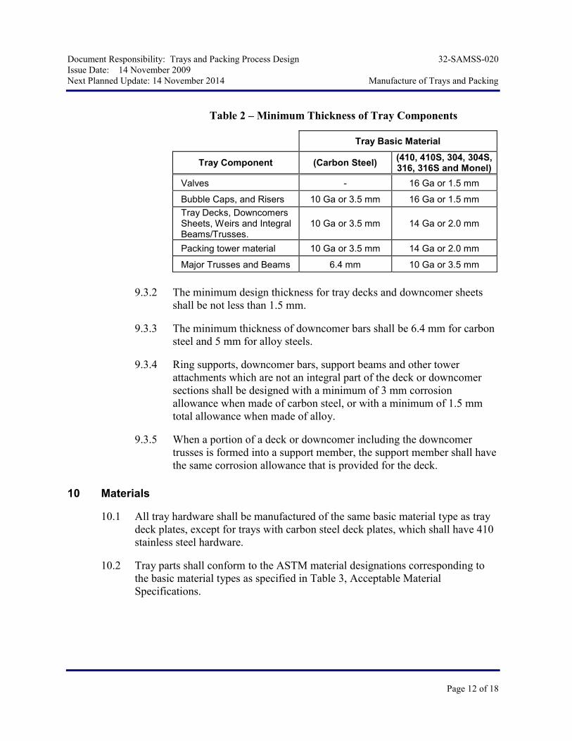
9.3.1 The minimum thickness of tray parts, in USS gage, including corrosion
allowance shall be in accordance with Table 2, Minimum Thickness of
Tray Components.
Document Responsibility: Trays and Packing Process Design 32-SAMSS-020
Issue Date: 14 November 2009
Next Planned Update: 14 November 2014 Manufacture of Trays and Packing
Page 12 of 18
Table 2 – Minimum Thickness of Tray Components
Tray Basic Material
Tray Component (Carbon Steel) (410, 410S, 304, 304S, 316, 316S and Monel)
Valves - 16 Ga or 1.5 mm
Bubble Caps, and Risers 10 Ga or 3.5 mm 16 Ga or 1.5 mm
Tray Decks, Downcomers Sheets, Weirs and Integral Beams/Trusses.
10 Ga or 3.5 mm 14 Ga or 2.0 mm
Packing tower material 10 Ga or 3.5 mm 14 Ga or 2.0 mm
Major Trusses and Beams 6.4 mm 10 Ga or 3.5 mm
9.3.2 The minimum design thickness for tray decks and downcomer sheets
shall be not less than 1.5 mm.
9.3.3 The minimum thickness of downcomer bars shall be 6.4 mm for carbon
steel and 5 mm for alloy steels.
9.3.4 Ring supports, downcomer bars, support beams and other tower
attachments which are not an integral part of the deck or downcomer
sections shall be designed with a minimum of 3 mm corrosion
allowance when made of carbon steel, or with a minimum of 1.5 mm
total allowance when made of alloy.
9.3.5 When a portion of a deck or downcomer including the downcomer
trusses is formed into a support member, the support member shall have
the same corrosion allowance that is provided for the deck.
10 Materials
10.1 All tray hardware shall be manufactured of the same basic material type as tray
deck plates, except for trays with carbon steel deck plates, which shall have 410
stainless steel hardware.
10.2 Tray parts shall conform to the ASTM material designations corresponding to
the basic material types as specified in Table 3, Acceptable Material
Specifications.

Document Responsibility: Trays and Packing Process Design 32-SAMSS-020
Issue Date: 14 November 2009
Next Planned Update: 14 November 2014 Manufacture of Trays and Packing
Page 13 of 18
Table 3 – Acceptable Material Specifications
Basic Material Type Plate, Sheet or Strip Bars and Shapes Nuts and Bolts
Carbon Steel A36, A283, A285, A515 or A516
A36, A322 or A675 (Excluding Grade 90)
A193 Grade B6 w/ A194 Grade 6 nuts
12% Chrome A176 or A240, Types 405 or 410S
A276 Type 410 A193 Grade B6 w/ A194 Grade 6 nuts
Type 304 Stainless Steel
A167 or A240, Types 304 or 304L
A276 Types 304 or 304L or A479 UNS S30400/S30403
A193 Grade B8 w/ A194 Grade 8 nuts
Type 316 Stainless Steel
A167 or A240, Types 316 or 316L
A276 Types 316 or 316L or A479 UNS S31600/S31603
A193 Grade B8M w/ A194 Grade 8M nuts
Monel B127 UNS N04400 B164 UNS N04400
B164 F468, UNS N04400, w/ F467 Grade N04400 nuts or F468 UNS N05500 w/ F467 Grade N05500 nuts
10.3 All materials for vessels in sour service shall conform to ISO 15156 and
SAES-L-133.
10.4 Materials for tray support rings shall be in accordance with 32-SAMSS-004.
10.5 The use of non-ASTM materials shall be approved by the Saudi Aramco
Engineer.
10.6 Gasket materials shall be asbestos-free and compatible with the service
conditions of the vessel.
10.7 Entire valve unit, i.e., valves, guides and stops, shall be a minimum of type 410
stainless steel for all new and revamped columns, unless a higher grade material
is specified in the data sheet.
10.8 The entire tray decks, i.e., active areas, blank areas, weirs and downcomers of
trays shall be a minimum of type 410 stainless steel for all new and revamped
columns, unless another grade material is specified in the data sheet. Carbon
steel is not allowed unless required for process reasons (e.g., HF Alkylation)
10.9 All support parts welded to the column shell, i.e., the tray support rings and the
downcomer support bars shall be the same basic material type as the inside wall
of the column, unless a higher grade material is specified in the data sheet.
10.10 Gravity liquid distributors shall be a minimum of type 410 stainless steel for all
new and revamped columns, unless a higher grade material is specified in the
data sheet. Gravity Liquid distributors shall be the same basic material type as
the packing bed located below.

Document Responsibility: Trays and Packing Process Design 32-SAMSS-020
Issue Date: 14 November 2009
Next Planned Update: 14 November 2014 Manufacture of Trays and Packing
Page 14 of 18
Commentary Note:
Internal feed pipe liquid distributors shall be made the same basic vessel material. For wet sour gas systems shall be minimum seamless or HIC resistant carbon steel unless a higher grade material is required and specified in the data sheet.
10.11 For existing columns, carbon steel valve units, tray decks, and/or liquid
distributors (such as detailed in clauses 10.7, 10.8 and 10.9 respectively) may be
replaced in kind, providing no corrosion reported by inspection, the service and
operating conditions remain unchanged, and the specifications remain as per the
original data sheet(s).
10.12 The material of packing (random, structured, or grids) shall be a minimum of
type 410 stainless steel for all new and revamped columns, unless a higher grade
material is specified by Design Engineer and approved by Saudi Aramco
Engineer.
10.13 Material identification of all non-carbon steel materials shall be in accordance
with SAES-A-206.
10.14 An isolation material (Gasket) between dissimilar materials is required to avoid
severe galvanic interaction ONLY in services where the bulk fluid is water
(e.g., Desalination & De-aerators columns).
11 Tray Fabrication
11.1 The surface of fabricated parts shall be free from scale, dents and defects.
11.2 Burrs shall be removed from all perforated areas and edges of tray sections.
Burrs on sheared edges are acceptable.
12 Tray Installation
12.1 General
12.1.1 All tray support rings and other attachments required for supporting
trays shall be welded to the vessel shell. The welding of tray sub-
assemblies and tray decks to tray supports is prohibited.
12.1.2 All segments of valve trays that contain valves shall be installed after
the vessel has been hydrotested, thoroughly dried, and cleaned.
12.1.3 Vessel circumferential seams shall not be covered by the tray or tray
support installations.

Document Responsibility: Trays and Packing Process Design 32-SAMSS-020
Issue Date: 14 November 2009
Next Planned Update: 14 November 2014 Manufacture of Trays and Packing
Page 15 of 18
12.1.4 Trays are to be installed in accordance with the acceptable tolerances as
per SASD AD-036981 and the Tray Manufacturer's Drawings.
12.1.5 All tray and distributor support clips shall be welded to the vessel prior
to any postweld heat treatment and prior to hydrostatic testing.
12.1.6 Tray bolts shall be tightened, using a calibrated torque wrench, to the
Tray Manufacturer's instructions and engaged to the full depth of the
nuts.
12.2 Welding
12.2.1 Welding of Shell Attachments
1. The welding of tray supports and all attachments to vessel shells is
the responsibility of the Vessel Manufacturer and shall conform to
SAES-W-010.
2. All attachments to vessel shells shall be fully welded on all sides.
Skip welding is not permitted.
3. All welding to vessel shells shall be completed prior to post weld
heat treatment and prior to the hydrostatic testing of a vessel.
12.2.2 Welding of Other Attachments
1. All welding procedures and welders shall be qualified in
accordance with ASME SEC IX.
2. Approved processes are SMAW and GTAW. Any other process
requires the approval of the Saudi Aramco Engineer.
3. The filler metal shall match the composition and mechanical
properties of the base metal. If two different base metals are to be
joined, the filler metal selection shall be approved by the Saudi
Aramco Engineer.
4. A weld map shall be prepared to indicate which welding
procedure will be used for each weld joint.
5. All WPSs, PQRs and Weld Maps shall be submitted for approval
to the Saudi Aramco Engineer prior to the start of the job. All
WPSs, PQRs and weld maps shall be available at the work site for
review at any time.
6. All full-penetration groove welds shall be welded from both sides.
Single-sided groove welds are not permitted unless approved by
Document Responsibility: Trays and Packing Process Design 32-SAMSS-020
Issue Date: 14 November 2009
Next Planned Update: 14 November 2014 Manufacture of Trays and Packing
Page 16 of 18
the Saudi Aramco Engineer. Double-sided welds shall be ground
or gouged to sound metal prior to welding the second side.
7. Thermally cut or gouged surfaces of all material shall be ground to
bright (un-oxidized) material prior to welding.
13 Inspection and Testing
13.1 Tray Manufacturers Shop
13.1.1 Tray materials and hardware are subject to shop inspection by the Saudi
Aramco Inspector, in accordance with Saudi Aramco Inspection
Requirements Form 175-325000.
13.1.2 One complete tray assembly of each type and size for each vessel being
manufactured shall be fully assembled and inspected at the Tray
Manufacturer shop for conformance to the requirements of this
specification. For symmetrical internal configuration (e.g., multipass
trays) only half tray can be assembled and inspected.
13.2 After Tray Installation
13.2.1 After installation, all trays shall be visually inspected for conformance
to the Tray Manufacturer's drawings and installation tolerances.
13.2.2 Bubble cap and valve trays are to be inspected by using a strong light.
Any open seams, holes or gaps, which exceed 6 mm, shall be closed by
non-asbestos gaskets and bolt tightening. Openings less than 6 mm
shall be repaired by bolt tightening or gaskets.
13.2.3 Water used for leakage testing shall not contain more than 50-PPM
chlorides in accordance with SAES-A-007.
13.2.4 The addition of gaskets and/or rope is to be regarded as the last course
of action to be taken to seal trays.
13.2.5 Materials for gaskets and rope must be compatible with the design
conditions of the vessel and chemically resistant to the service.
13.3 Leakage Test
13.3.1 Leakage test shall be performed, in the presence of the manufacturer, on
trays after installation in the erected vessel as follows:
Blind and draw-off Trays (including those as described by paragraph
7.1.9 of this specification).

Document Responsibility: Trays and Packing Process Design 32-SAMSS-020
Issue Date: 14 November 2009
Next Planned Update: 14 November 2014 Manufacture of Trays and Packing
Page 17 of 18
a) All tray assemblies shall be thoroughly cleaned.
b) Trays provided with man-ways shall be filled with water to the
overflow weir or chimney height, as applicable. The level shall
not drop by more than 25 mm after 1 hour and 15 minutes. If the
actual leakage rate exceeds this, gaskets shall be added or the tray
replaced and re-tested. All tray assemblies with no man-ways
shall have no leakage.
d) After testing, the tray assembly shall be thoroughly dried.
13.3.2 If the actual leakage rate exceeds this, gaskets shall be added or the tray
replaced and re-tested.
13.3.3 After testing, all plugs are to be removed and the tray assembly
thoroughly dried.
13.3.4 No leakage test is required for sieve, valves and cartridge trays.
14 Marking and Shipping
14.1 Marking
14.1.1 Each tray or packing material part segment shall be piece marked with
part number in the part-list as shown on the Tray/Packing
Manufacturer's drawings.
14.1.2 The marking shall be done with water-insoluble material that contains
no harmful substances that would attack or harmfully affect the material
at ambient or elevated temperatures. The marking material shall be free
of lead, sulfur, zinc, cadmium, mercury, chlorine, or other halogens.
14.1.3 Tray deck sections shall also be marked with the tray number on the
underside using metal stencils.
14.1.4 Tray hardware shall be packaged separately from the main tray
segments and marked with adequate identification.
14.2 Shipping
14.2.1 Tray and Packing components shall be properly packaged to prevent
damage during shipping.
14.2.2 Carbon steel trays and components shall be protected with a rust
inhibitor. The rust inhibitor must be easily removable.
Document Responsibility: Trays and Packing Process Design 32-SAMSS-020
Issue Date: 14 November 2009
Next Planned Update: 14 November 2014 Manufacture of Trays and Packing
Page 18 of 18
14.2.3 The Tray Manufacturer shall provide the type of inhibitor, and
procedures for the removal of inhibitor with proposal.
14.2.4 All stainless steel components shall be protected from salt water and
spray when shipped is by ocean freight.
14.2.5 All packages shall be marked with the order number, vessel equipment
number and tray number.
14.2.6 Tray parts and tray hardware for different tray designs shall not be
intermixed.
14.2.7 Copies of parts lists, assembly drawings and installation instructions
shall be included with the shipment.
14.2.8 The manufacturer shall provide the following supplementary material
hardware to compensate for installation losses and shall be the greater
of the following:
1. Bolts, nuts and washers, 10% or 10 of each size
2. Tray clamps, 5% or 5 of each size and type
3. Gaskets, 20%
4. Floating Valves 5 %
5. Random Packing 10 %
15 Drawings, Calculations and Data
15.1 The Tray Manufacturer shall prepare drawings, calculations, and data in
accordance with Form NMR-7919-2, Non-material Requirements.
15.2 Drawings and calculations, which are approved by the Design Engineer, shall
not relieve the Tray Manufacturer of the Tray Manufacturer's responsibilities to
comply with this specification.
15.3 The following technical data shall be provided by the Packing Manufacturer, for
review and approval:
1. Complete rating data including, liquid/vapor loading, and hydraulic
parameters
2. Installation instructions
Revision Summary
14 November 2009 Major revision.


![Index [doc. ] · PDF file09-SAMSS-091 Shop-AppliedInternalFBECoatings 2.1.2PolyethyleneCoating CSAZ245.21 ExternalPolyethyleneCoatingforPipe DIN30670](https://static.fdocuments.in/doc/165x107/5abb70597f8b9a441d8cd1f1/index-doc-shop-appliedinternalfbecoatings-212polyethylenecoating-csaz24521.jpg)