31.8.61.1.Rev.0-CMCF Software Requirements Specification-Fodje
38
CMCF Software Requirements Specification 31.8.61 .1 - Rev 0 Date: 2008-03-26 Copyrig ht 2008, Canadian Light Source I nc. This document is the property of Canadian Light Source Inc. (CLSI ). No exploitation or transfer of any information contained herein is permitted in the absence of an agreement with CLSI, and neither the document nor any such information may be released without the written consent of CLSI. Canadian Light Source Inc. 101 Perimeter Road University of Saskatchewan Saskatoon, Saskatchewan S7N 0X4 Canada Signature Date Original on File – Signed by: Author Michel Fodje Reviewer #1 Pawel Grochulski Reviewer #2 Russ Berg Reviewer #3 Elder Matias Approver Emil Hallin
Transcript of 31.8.61.1.Rev.0-CMCF Software Requirements Specification-Fodje

7/31/2019 31.8.61.1.Rev.0-CMCF Software Requirements Specification-Fodje
http://slidepdf.com/reader/full/318611rev0-cmcf-software-requirements-specification-fodje 1/38
CMCF Software Requirements Specification
31.8.61.1 - Rev 0
Date: 2008-03-26
Copyrig ht 2008, Canadian Light Source I nc. This document is the property of CanadianLight Source Inc. (CLSI). No exploitation or transfer of any information contained herein ispermitted in the absence of an agreement with CLSI, and neither the document nor any suchinformation may be released without the written consent of CLSI.
Canadian Light Source Inc.101 Perimeter Road
University of SaskatchewanSaskatoon, Saskatchewan
S7N 0X4 Canada
Signature Date
Original on File – Signed by:
AuthorMichel Fodje
Reviewer #1
Pawel Grochulski
Reviewer #2
Russ Berg
Reviewer #3
Elder Matias
ApproverEmil Hallin

7/31/2019 31.8.61.1.Rev.0-CMCF Software Requirements Specification-Fodje
http://slidepdf.com/reader/full/318611rev0-cmcf-software-requirements-specification-fodje 2/38
BLANK PAGE
7/31/2019 31.8.61.1.Rev.0-CMCF Software Requirements Specification-Fodje
http://slidepdf.com/reader/full/318611rev0-cmcf-software-requirements-specification-fodje 3/38
31.8.61.1 Rev. 0
2008-03-26 CMCF Software Requirements Specification Page i
Revision Histor y
Revision Date Descript ion Auth or
A 2007-02-22 Original Draft Michel Fodje
B 2007-12-06 First revision Michel Fodje
C 2008-03-01 Second revision Michel Fodje
0 2008-03-26 Issued for Use Michel Fodje

7/31/2019 31.8.61.1.Rev.0-CMCF Software Requirements Specification-Fodje
http://slidepdf.com/reader/full/318611rev0-cmcf-software-requirements-specification-fodje 4/38
BLANK PAGE

7/31/2019 31.8.61.1.Rev.0-CMCF Software Requirements Specification-Fodje
http://slidepdf.com/reader/full/318611rev0-cmcf-software-requirements-specification-fodje 5/38
2008-03-26 CMCF Software Requirements Specification Page ii
TABLE OF CONTENTS
1.0 INTRODUCTION........................................................................................1 1.1 Purpose ..................................................................................................... 1 1.2 Scope ........................................................................................................ 1 1.3 Definitions, Acronyms and Abbreviations.................................................. 1 1.4 Overview....................................................................................................1
2.0 GENERAL DESCRIPTION.........................................................................2 2.1 Operational Concepts................................................................................2
2.1.1 Operating Modes ........................................................................... 2 2.1.2 Operational Actions ....................................................................... 2
2.2 Product Perspective ..................................................................................3 2.2.1 Software Interfaces........................................................................ 3 2.2.2 Hardware Interfaces ......................................................................3 2.2.3 User Interfaces ..............................................................................4 2.2.4 Site Adaptation Requirements ....................................................... 5
2.3 Product Functions...................................................................................... 5 2.4 User Classes and Characteristics ............................................................. 6 2.5 Constraints ................................................................................................6 2.6 Assumptions ..............................................................................................7 2.7 Apportioning of Requirements ...................................................................7
3.0 SPECIFIC REQUIREMENTS.....................................................................7 3.1 System Functions ...................................................................................... 7
3.1.1 Sample Information Management.................................................. 7 3.1.2 Sample Shipment Preparation ....................................................... 8 3.1.3 Experimental Plan Management.................................................... 9 3.1.4 Dewar Reception and Storage Management...............................10 3.1.5 Beamline Control Functions......................................................... 11 3.1.6
Interactive Data Acquisition Functions.........................................16
3.1.7 Automatic Data Acquisition Functions .........................................29
3.2 Error Handling ......................................................................................... 31 4.0 REFERENCES.........................................................................................32

7/31/2019 31.8.61.1.Rev.0-CMCF Software Requirements Specification-Fodje
http://slidepdf.com/reader/full/318611rev0-cmcf-software-requirements-specification-fodje 6/38
BLANK PAGE

7/31/2019 31.8.61.1.Rev.0-CMCF Software Requirements Specification-Fodje
http://slidepdf.com/reader/full/318611rev0-cmcf-software-requirements-specification-fodje 7/38
31.8.61.1 Rev. 0
2008-03-26 CMCF Software Requirements Specification Page 1
1.0 I NTRODUCTI ON
1.1 PURPOSE
This Software Requirements Specification (SRS) document specifies the softwarerequirements for the CMCF Beamline Operating System (BOS). The goal of thespecification is to provide a functional tool for guiding the development of the system ina manner consistent with the goals of operation of the CMCF. It establishes both generalcriteria and specific functional requirements for software and controls design.
This document is oriented toward developers of the CMCF BOS.
1.2 SCOPE
The subject of this document is the CMCF Beamline Operating System , which will provideall software components required to operate the CMCF beamlines at the Canadian LightSource. The system will provide a highly integrated solution for interactive and
automated control of all beamline hardware, as well as provide all functionality requiredfor scientific data acquisition accessible both on-site and remotely via the internet.
CMCF BOS is all software directly involved in the control and use of CMCF Beamlinesystems, including commercial or third-party software packages used for that purpose.However, only the non-third-party portions of this software are addressed in detail here,along with the interfaces to those third-party packages.
1.3 DEFI NI TI ONS, ACRONYMS AND ABBREVI ATI ONS
SRS – Software Requirements Specification
CMCF – Canadian Macromolecular Crystallography Facility
BOS – Beamline Operating System
1.4 OVERVI EW
Section 2 presents the overall description of the CMCF BOS. It describes the generalfactors that affect the CMCF BOS and its requirements, thus serving as a generalbackground to the specific requirements outlined in section 3.
In section 2, the CMCF BOS is placed into perspective with other related products,hardware, software and human interfaces are introduced, the major functions expectedof the CMCF BOS will be summarized and the users of the system and theircharacteristics identified. This section also describes general constraints that will limit thedesign of the CMCF BOS Software, as well as assumptions that affect the specifications
outlined in Section 3. This section concludes by apportioning requirements into functionalgroups, and prioritizing them.
In section 3, all software requirements are presented in detail. Inputs, and outputs areidentified, as well as the functions which must be performed by the system in responseto inputs and in support of an output. Performance, reliability, availability,maintainability, portability and security requirements are also described in this section.

7/31/2019 31.8.61.1.Rev.0-CMCF Software Requirements Specification-Fodje
http://slidepdf.com/reader/full/318611rev0-cmcf-software-requirements-specification-fodje 8/38
31.8.61.1 Rev. 0
2008-03-26 CMCF Software Requirements Specification Page 2
2.0 GENERAL DESCRI PTI ON
2.1 OPERATI ONAL CONCEPTS
2.1.1 Operat ing ModesSeveral modes of data acquisition will be supported by the CMCF facility.
(a) Interactive data acquisition: This mode provides direct access to the beamline forthe collection of science data. In this mode, the ‘client’ scientist makes all controldecisions during the data acquisition period. In this mode, the ‘scientist’ is the ‘operator’.
(b) Assisted data acquisition: This is a special type of interactive acquisition mode, inwhich direct access to beamline minimized. This mode provides simple and safeaccess to the system for selection of experiment parameters, and ‘quick-look’ dataanalysis. In this mode, the system will make most control decisions but giving theoperator the possibility of overriding them before their execution.
(c) Automatic data acquisition : This implies a significant automation of the decisionmaking process, with as little human input as possible. In this mode, various data-collection requests are kept in a dynamic queue from which tasks are selected insome order in order to maximize utilization of the beamline. In this mode, there isno ‘operator’.
(d) Remote data acquisition : This mode provides similar functionality to both assistedand automated data acquisition except that the ‘operator’ is situated off-site.
2.1.2 Operat ional Act ions
Regardless of the mode of data acquisition, every data acquisition sequence involves thefollowing classes of action:
(e) Pre-data acquisition – these are actions that take place well before the scheduleddata acquisition period. These actions include experiment planning, where thescientists develops an experimental plan, is assigned beam time, prepares andeither ships the samples to the facility or brings them in person.
(f) Beamline setup actions – These activities are done prior to the data acquisitionperiod. These are typically system operation checks, instrument configurationchecks, optimizations and some calibrations.
(g) Data acquisition setup – these actions take place immediately prior to dataacquisition and include beamline configuration, sample mounting and someinstrument parameter selections.
(h) Sample screening/characterization – This is a data acquisition process in whichpreliminary data is collected on a sample and used for parameter optimization and
sample scoring resulting in improved parameters for full data acquisition. This stepcan be skipped if it has previously been performed on the sample or if currentsample parameters are already fully optimized.
(i) Data acquisition – The period of actual scientific data acquisition. During thisprocess, scientists may carry out actions such as ‘quick-look’ verification of dataquality, minimal parameter modifications and system operation monitoring.
(j) Data Storage – Actions and procedures that allow the scientist to access, transferand/or back-up their data
7/31/2019 31.8.61.1.Rev.0-CMCF Software Requirements Specification-Fodje
http://slidepdf.com/reader/full/318611rev0-cmcf-software-requirements-specification-fodje 9/38
31.8.61.1 Rev. 0
2008-03-26 CMCF Software Requirements Specification Page 3
(k) System security actions – On-going actions designed to protect the functionality of the beamline. These actions take place throughout the data acquisition processand are designed to protect both humans and beamline equipment.
(l) Data integrity – Actions that assist in validating and preserving scientific data.These include automatic logging of experimental actions, commands, operatorcomments and beamline states.
2.2 PRODUCT PERSPECTI VE
The growing impact of macromolecular structural analysis to pharmaceutical, academicand industrial research has resulted in a growing demand for access to proteincrystallography beamlines. This demand is also reflected in the number scientists of different fields now wanting to use structural information in their research. To achievethe goal of seamless access to, and use of the facility, the CMCF BOS software will needto interact with several external components to completely perform its function. Thesecomponents include beamline hardware, crystallographic data analysis packages, user-office services, and other CLS facility services such as Stores.
2.2.1 Softw are I nterfaces
The Crystallographic community has already made a significant investment in developingsoftware systems to accomplish specific analysis tasks such as diffraction image analysis,data reduction and crystallography toolkits. The CMCF BOS Software will integrate theservices of these tools where required.
• XDS, MOSFLM, HKL2000 – The system will provide automated data processingfunctionality by interfacing with these third-party software packages. Theinterfaces of these packages are described in their respective scientificpublications [1, 2, 11]
• LABELIT – The system will provide auto-indexing functionality by interfacing withXDS, MOSFLM, and/or LABELIT [3].
• SpotFinder/DISTL – The system will provide automated diffraction image analysisand crystal screening by interfacing with SpotFinder/DISTL [4].
• XREC – The system shall provide automated loop and crystal centering using theXREC software package [12].
• BEST – The system will provide automated data-acquisition strategy and dosagedetermination by interfacing with the BEST and RADDOSE packages [5, 6, 7].
• CHOOCH – The system will provide automated fluorescence scan analysis andMAD energy selection using CHOOCH [8].
• Third Party databases – The system will store experimental parameters andresults in third party databases such as xml databases or relational databases.
2.2.2 Hardw are I nterfaces
The system will provide instrument control by interfacing with beamline hardware.Beamline hardware will normally be of the following classes:
• Motors
• Beam position monitors
7/31/2019 31.8.61.1.Rev.0-CMCF Software Requirements Specification-Fodje
http://slidepdf.com/reader/full/318611rev0-cmcf-software-requirements-specification-fodje 10/38
31.8.61.1 Rev. 0
2008-03-26 CMCF Software Requirements Specification Page 4
• Intensity detectors
• Multi-channel analyzers
• Beam Viewers
• CCD Detectors
• Robotic Sample Changers• Cryogenic cooling systems
The specific hardware interfaces for each hardware type, are documented in the relevanthardware manuals.
2.2.3 User I nt erfaces
Different types of user interfaces will be available depending on the user-class andoperation mode. Users will interact with the system through the following interfaces
• Web User Portal – This interface is the first point of contact between Scientistand the Beamline Operating System. It enables the user to prepare and submit
experimental proposals, setup experiments, prepare samples, view experimentalresults, modify experimental parameters, make experimental requests, downloadresults, and submit usage reports. There shall be no direct instrument controlthrough this interface. This interface shall be accessible in a secure manner fromanywhere in the world through the world-wide web, and require no extrasoftware than a standards compliant web-browser. It shall be intuitive,experiment focused. The web portal shall integrate with user office andaccounting systems for user time tracking, safety review, user time billing andrun-permit generation.
• Interactive Data Acquisition Interface – This is the interface through whichScientists and operators will operate the beamline in the interactive and assisted-interactive modes of data acquisition. There shall be as little direct interaction
between this interface and beamline instruments as possible. As much aspossible, any instrument control shall be achieved indirectly through instrumentcontrol subsystems. The interface shall emphasize the experiment ratherinstrument control to reduce the learning curve and enable scientists to focus ontheir experiment. Only decisions impacting the experiments shall be deferred tothe Scientist/Operator. All functionality provided by this interface, shall be withina single integrated application.
• Beamline Administration Web Portal – This is the interface through whichBeamline Staff schedule tasks and beam time, manage shifts, review shifts,inspect logs, prepare shift reports and communicate with Scientists. Thisinterface shall be securely accessible via the www.
• Beamline Control Panel – This interface enables direct access to each subsystem
of the beamline, for setup, diagnostics and monitoring. It shall be a beamlinefocused interface rather than an experiment focused interface. Access to theBeamline Control Panel for monitoring purposes shall not adversely affect theperformance of functionality of any on-going data acquisition activities undernormal circumstances.
• Subsystem User Interfaces – Each subsystem shall provide a user interface fortesting, and maintenance independent of all other subsystems within the CMCFControl system.

7/31/2019 31.8.61.1.Rev.0-CMCF Software Requirements Specification-Fodje
http://slidepdf.com/reader/full/318611rev0-cmcf-software-requirements-specification-fodje 11/38
31.8.61.1 Rev. 0
2008-03-26 CMCF Software Requirements Specification Page 5
2.2.4 Site Adaptation Requirements
The CMCF will have more than one beamline running essentially the same software.However, the details of specific hardware at each beamline will vary. Even within a singlebeamline, the specific hardware components may vary in type over a length of time.Therefore the system shall be designed to be easily deployed on a beamline withdifferent underlying hardware in each hardware category identified under Hardwareinterface above. In such a case, only directly affected subsystems shall be required to bereconfigured.
2.3 PRODUCT FUNCTI ONS
The CMCF BOS Software shall provide the following functions. These functions areorganized in functional groups for the sake of clarity.
1. Web portal functions
(a) Assist users to prepare and code samples for shipment to the facility
(b) Collect and convey experimental plans from scientists to the facility
(c) Collect and convey experimental reports from scientists to the facility
(d) Present experimental results and assist users in analyzing the results
(e) Enable data retrieval by users.
2. Data Management functions
(f) Store and keep track of all samples related information.
(g) Keep an electronic log of all beamline commands, events and operator notes
(h) Store, preserve, secure and dispose of scientific data and sample parametersas required.
(i) Keep track of beamline and beam time usage.
3. Beamline Control functions
(j) Enable interactive and automated control of all beamline hardware.
(k) Enable scheduling of a series of data acquisition tasks to be carried out at alater time.
(l) Carry out Automatic and interactive initialization, calibration, alignment andoptimization of beamline hardware and other parameters.
(m) Carry out Automatic and interactive data acquisition.
(n) Facilitate the automation of sequences of tasks through an easy to usescripting interface
4. Data Analysis functions (o) Harness the services of external software to perform interactive and
automated data validation and analysis.
5. Other functions
(p) Protect the functionality and safety of the beamline instruments during use
(q) Alert users on experiment status, failures and errors.
(r) Control user access and authentication for the BOS

7/31/2019 31.8.61.1.Rev.0-CMCF Software Requirements Specification-Fodje
http://slidepdf.com/reader/full/318611rev0-cmcf-software-requirements-specification-fodje 12/38
31.8.61.1 Rev. 0
2008-03-26 CMCF Software Requirements Specification Page 6
2.4 USER CLASSES AND CHARACTERI STI CS
The users of the CMCF BOS Software are classified into the following classes.
(a) Scientist . Any person using the CMCF BOS for the acquisition of science data. In avery real sense, the scientist is the customer for the services provided by thebeamline. Whatever their level of experience, scientists will wish to concentrate on
the efficient acquisition of crystallographic data and on-line assessment of the dataquality rather than on the details of controlling beamline instruments.
(b) Operator . This is the on-site person responsible for controlling the beamlineinstruments for acquisition of science data. In most but not all cases, the ‘Scientist’ and the ‘Operator’ will be the same individual.
(c) Beamline Staff . On-site person responsible for monitoring and fine-tuning thebeamline instruments. This person is responsible for ensuring the integrity of thesystem and for keeping the system functioning accurately during measurements.The beamline Staff works with the ‘Scientist’ to ensure that the ‘Scientist’ obtainsas good data as is possible.
(d) Support Personnel . On-site (or near-site) support personnel are responsible for thereal-time maintenance of the system hardware and software. They are the first
point of contact during failures and ensure that smooth operation resumes as soonas possible after a failure.
(e) Developer . Developers are responsible for the designing, testing, installation,configuring, and upgrading of subsystems.
(f) Administrative Personnel – This includes User Office personnel responsible for theevaluation of proposals, beam-time allocation, user-permit generation andcreation of user accounts, Health and safety personnel.Stores (Shipping/Receiving)personnel, and Finance/Accounting personnel who may need access to the systemfor other administrative functions
2.5 CONSTRAI NTS
The CMCF BOS Software shall be designed under the following constraints.
(a) The deployment of all CMCF BOS Software across beamlines shall be free fromproprietary restrictions. As such, open-source and off-the-shelf public domainsoftware and standards shall be used whenever feasible.
(b) All CMCF Software is to be fully documented, internally and externally.
(c) All CMCF Software must be version labeled both in source and binary form. Theversion information shall be retrievable from the existing software at run time viacontrol commands.
(d) The syntax of control flow commands shall be consistent across the system.
(e) User interfaces shall be focused on the tasks being carried out, and be intuitivesuch that the target audience can learn to use it within 1 hour of training.
(f) The use of controls in Stand-alone user interfaces shall conform to the GNOMEHuman Interface Guide, version 2.0 or later [9] and CLS Human FactorsEngineering Standards [14].
(g) Browser based user interfaces shall conform to the guidelines outlined byWroblewski and Rantanen [10, 11].
(h) All user data shall be treated as confidential, and access restricted.

7/31/2019 31.8.61.1.Rev.0-CMCF Software Requirements Specification-Fodje
http://slidepdf.com/reader/full/318611rev0-cmcf-software-requirements-specification-fodje 13/38
31.8.61.1 Rev. 0
2008-03-26 CMCF Software Requirements Specification Page 7
(i) Access to all user interfaces shall be through controlled user accounts duringnormal operation.
2.6 ASSUMPTI ONS
(a) It is assumed that proposal submission and review is a separate process
(b) It is assumed that once the experimental proposal is approved, the user-officestaff or other delegated person will set up an account in the CMCF BOS.
(c) It is assumed that a shipment is defined as a single Dewar. Multiple Dewars shallbe considered as multiple shipments even if they are shipped together.
2.7 APPORTI ONI NG OF REQUI REMENTS
Since the CMCF BOS is a large and complex system, it is envisioned that the followingorder will be followed for deploying the system. It should be noted however that afunctional system requires deployment of all components and the following suggestionsare based on likely functional dependencies between subsystems
(a) The hardware abstraction layer consisting of all hardware control subsystemsshould be deployed first together with their associated test and configurationscreens
(b) Interactive data acquisition functionality should be deployed next
(c) Followed by automatic data acquisition and the web-based user interfaces
(d) Finally automatic data processing should be integrated.
3.0 SPECI FI C REQUI REMENTS
3.1 SYSTEM FUNCTI ONS
3.1.1 Sample I nform ation Management
3.1.1.1 Purpose
The purpose of this function is to capture as accurately and completely as possible detailedinformation about each sample that enters the system, and how the sample is to be treatedwithin the system.
3.1.1.2 Inputs
The input for sample information management consists of the following data to be provided by
the user. When users do not provide optional parameters, sensible defaults shall be substitutedbased on values to be determined:
Sample ID – A unique identifier for each sample
Sample name (a string)
Puck ID – A pointer to the puck containing the sample
Location within Puck – ( a string )
Pin length – The length of the pin in mm (floating point number >15 and < 22)

7/31/2019 31.8.61.1.Rev.0-CMCF Software Requirements Specification-Fodje
http://slidepdf.com/reader/full/318611rev0-cmcf-software-requirements-specification-fodje 14/38
31.8.61.1 Rev. 0
2008-03-26 CMCF Software Requirements Specification Page 8
Loop size – Size of the loop in mm (floating point number >0 and < 2)
Spacegroup (a string)
Cell parameters ( vector of 6 floating point numbers)
Diffraction Plan – Information about how the sample should be handled, whichincludes
Type of experiments (MAD, SAD or single wavelength)
Ideal required resolution (floating point number >0 and <20)
Optional: Minimum acceptable resolution (floating point number >0 and<20)
Optional: Exposure time (floating point number > 0)
Optional: Oscillation range (floating point number )
Shipment ID ( a unique identifier of the dewar, initially empty until shipments arecompleted)
Comments (text)
3.1.1.3 Processing
a) The system shall store the sample information in an appropriate persistent databasewhen the user submits it.
b) The system shall retrieve the stored information for each sample as requested.
c) The system shall allow users to edit and resubmit the previously stored information
d) The system shall delete sample information on request, provided the sample has notbeen shipped, in which case only editing shall be permitted.
3.1.1.4 User I nterf ace Requirements
a) Sample information shall be entered through a web-based HTML form.
b) A list of all samples entered shall be available to the user on request, and permit accessto the associated sample information through a single click of the mouse.
c) All actions that will potentially lead to loss of information shall require confirmation fromthe user
d) Information entry shall be validated on input according to the specified inputrequirements.
3.1.2 Sample Shipm ent Preparat ion
3.1.2.1 Purpose
The goal of this function is to keep track of which samples are included in a particular shipmentsent to the facility, when they are sent, and how they are sent. These requirements are notintented to supersede facility wide requirements for shipping and handling samples. Rather, theyare meant to emphasize aspects of specific importance to macromolecular crystallography.

7/31/2019 31.8.61.1.Rev.0-CMCF Software Requirements Specification-Fodje
http://slidepdf.com/reader/full/318611rev0-cmcf-software-requirements-specification-fodje 15/38
31.8.61.1 Rev. 0
2008-03-26 CMCF Software Requirements Specification Page 9
3.1.2.2 I nput s, Out put s and Processing Requirement s
a) The input to the sample shipment functionality shall include at least the followinginformation. More detailed requirements such as additional fields and field types will bespecified as part of the design process.
List of sample IDs.
Dewar type
Carrier information
Shipment date
Estimated Time of Arrival
b) On receiving the input, the system shall generate a unique shipment identifier, updatethe sample information for each of the samples to include the shipment identifier, andcreate a waybill which the users will include in the shipment. This waybill should not beconfused with the waybill generated by carriers.
c) The system shall create a shipment record in a persistent database with fieldscorresponding to the contents of the waybill.
d) The system shall generate a bar-code on the waybill corresponding to the generatedshipment identifier.
e) The user shall be presented with the final waybill in Portable Document Format.
f) The system shall send an electronic copy of the waybill in Portable Document Format to adesignated e-mail address at the facility.
g) The system shall present the user with further instructions on how to print the waybilland complete the shipment.
3.1.2.3 User I nterf ace Requirements
a) Sample information shall be entered through a web-based HTML form.
b) A list of all samples stored shall be presented to the user to permit inclusion of samplesby simply selecting a checkbox next to the sample to be included.
c) A summary sheet of the waybill shall be presented to the user for confirmation andpermit the user to edit the waybill prior to submission.
3.1.3 Experimental Plan Management
3.1.3.1 Purpose
The Purpose of this functionality is to capture as accurately as possible, what exactly the Scientistintends to be done with the samples. As such experimental plans can involve one or moresamples, and each shipment can be associated with multiple experimental plans.
3.1.3.2 Inputs
The information contained within an experimental plan shall be provided by the user including atleast the following information:
Experimental plan ID
List of sample IDs

7/31/2019 31.8.61.1.Rev.0-CMCF Software Requirements Specification-Fodje
http://slidepdf.com/reader/full/318611rev0-cmcf-software-requirements-specification-fodje 16/38
31.8.61.1 Rev. 0
2008-03-26 CMCF Software Requirements Specification Page 10
Type of experiment - one of
Screen all collect on best one
Screen all collect on all good ones
Collect on all without screening
3.1.3.3 Other Requirements
(a) On receiving experimental information input from the user, the system shall store theinformation in a persistent database.
(b) The system shall present a list of experimental plan associated with the currently activeexperimental program to the user on request.
(c) The system shall retrieve information associated with an experimental plan on request andpermit editing and resubmission.
(d) The system shall allow experimental plans to be deleted or edited provided they have notalready been performed by the system.
(e) The system shall allow the user to create a new experimental plan, using a previously
defined experimental plan as template.
3.1.4 Dewar Recept ion and Storage Management
3.1.4.1 Purpose
The purpose of this functionality is to record when a shipment arrives at the facility, and where itis stored within the facility, and when it is sent back to the users. The goal is to keep track at alltimes which samples are available at the beamline, and where they are located at the beamline.
3.1.4.2 I nput s, Output s and Processing
a) On receiving a shipment, a beamline staff shall provide as input, the shipment identifierfrom the waybill.
b) On receiving the input, the system shall create a Dewar record in a persistent database.The Dewar record shall contain the same information as a shipment record, in addition tothe following fields
Dewar ID
Storage Location
Status
Time of last Status
Comments
c) The system shall update the sample records within the persistent database, to reflect theDewar ID.
d) Before sending back a Dewar, beamline staff will provide as input the shipment identifierfrom the waybill.
e) On receiving the request, the system shall update the status field of the Dewar record inthe persistent database.
f) A History shall be maintained of Dewar records.
7/31/2019 31.8.61.1.Rev.0-CMCF Software Requirements Specification-Fodje
http://slidepdf.com/reader/full/318611rev0-cmcf-software-requirements-specification-fodje 17/38
31.8.61.1 Rev. 0
2008-03-26 CMCF Software Requirements Specification Page 11
3.1.4.3 User int erfaces
a) Shipment and Dewar storage information entry by the beamline staff shall be through anHTML web form and will be assisted by a bar-code reader device.
3.1.5 Beamli ne Cont rol Functions
3.1.5.1 Motor Control
a) Motor positions shall be maintained in at least two coordinate systems. Where a motordriven system is fitted with encoders, a third Encoder coordinate system shall be required
b) The Dial coordinate system shall be set to correspond to the physical dial settings of theinstrument where applicable and have the same engineering units as the User coordinatesystem.
c) The User coordinate system shall be related to the Dial coordinates by a simple linearrelation, determined by a calibration procedure for each motor. Dial, User and Encodercoordinates shall be related by the following equations.
User = Sign x Dial + user-offset
Dial = motor-steps / motor-resolution Encoder = (encoder-pulses / encoder-resolution) + encoder-offset
Where motor-steps is the motor step count reported by the motor controller andencoder-steps is the encoder step count reported by the encoder hardware.
d) Motor settings shall include at minimum the following: acceleration steady-state speed backlash distance dial high-limit and low-limit : Also known as soft-limits These shall enable motion
to be restricted within certain ranges of the dial coordinate system. Sign : shall be positive (+1) if User coordinates change in the same direction as
Dial coordinates and negative (-1) otherwise Motor-resolution : the number of steps or pulses per unit of the dial/user
coordinates. Encoder-resolution: The number of encoder pulses per unit of the dial/user
coordinates. For encoded motions only. User-offset : This is the offset required to bring the user coordinate system in
register with the dial coordinate system. Encoder-offset : This is the offset required to bring the encoder coordinate
system into register with the dial coordinate system. The encoder coordinatesystem shall always be in register with the user coordinate system.
Encoder-sign : shall be positive (+1) if Encoder coordinates change in the samedirection as Dial coordinates and negative (-1) otherwise.
Engineering units : the units for dial and user coordinates. The Engineering unitsshall be the same for dial and User coordinates.
e) Each motor shall have a calibration sequence which fixes the dial coordinates within theabsolute frame of reference of the range of motion of the motor.
f) Motor positions and settings shall be persistent across software and hardware restarts.

7/31/2019 31.8.61.1.Rev.0-CMCF Software Requirements Specification-Fodje
http://slidepdf.com/reader/full/318611rev0-cmcf-software-requirements-specification-fodje 18/38
31.8.61.1 Rev. 0
2008-03-26 CMCF Software Requirements Specification Page 12
g) The system shall verify on restart if stored motor positions are valid, and restore themfrom a persistent storage without moving any motors. In the event that motor positionsare not reliable, only a calibration of the dial coordinate shall be required.
h) The system shall support pseudo-motors otherwise known as compound motors. Theseare positioning systems requiring combinations of more than one physical motor.
i) Pseudo motor functionality shall be a sub-set of normal motor functionality with atminimum the following parameters
dial high-limit and low-limit : These shall enable motion to be restricted withincertain ranges of the dial coordinate system.
Sign : shall be positive (+1) if User coordinates change in the same direction asDial coordinates and negative (-1) otherwise
Motor-resolution : The motor steps and/or resolution shall be calculated valuesbased on the real motors and a predefined equation to be determined by thespecific application.
Encoder-resolution: The number of encoder pulses per unit of the dial/usercoordinates. For encoded motions only.
User-offset : This is the offset required to bring the user coordinate system inregister with the dial coordinate system.
Encoder-offset : This is the offset required to bring the encoder coordinatesystem into register with the dial coordinate system. The encoder coordinatesystem shall always be in register with the user coordinate system with no offsetrequired.
Encoder-sign : shall be positive (+1) if Encoder coordinates change in the samedirection as Dial coordinates and negative (-1) otherwise.
Engineering units : the units for dial and user coordinates. The Engineering unitsshall be the same for dial and User coordinates.
j) The individual motors forming part of a pseudo motor shall be independently supported.
k) Motor parameters shall be determined and stored to a precision higher than 10% of thetolerance of the application in question. For example a motor driving a distance whereerror-tolerances of 0.1% of an engineering unit or less are required, will require all motorparameters affecting position calculations ( such as offsets, resolutions, positions) to bedetermined to at least 4 significant digits (not decimal places).
l) The motor/pseudo-motor control interface shall support a least two types of motionrequest commands for each motor or pseudo-motor
Absolute motion shall have the User coordinate system as the fixed reference
Relative motion shall have the current motor position as reference.
m) Each motor shall provide status information on whether the motor is stationary, inmotion, calibrated, or needs calibration, at a soft-limit, at a hard-limit.
n) Each motor/Pseudo-motor shall respond to a STOP command at all times. On receiving aSTOP command, the motor shall immediately decelerate to a full stop.
o) Motors shall be indistinguishable from pseudo motors, to applications requiring only thecommon standard interfaces for
Reading the current position
Setting the target position and initiating a move
Stopping a move
7/31/2019 31.8.61.1.Rev.0-CMCF Software Requirements Specification-Fodje
http://slidepdf.com/reader/full/318611rev0-cmcf-software-requirements-specification-fodje 19/38
31.8.61.1 Rev. 0
2008-03-26 CMCF Software Requirements Specification Page 13
Checking the status of a motor/pseudo motor (moving, starting or stopping, stopped,at soft limit, at hard limit)
Enabling and setting the values of soft limits.
3.1.5.2 Beam Position Monitors
Beam position monitors (BPMs) provide horizontal and/or vertical positional diagnosticinformation at various points along the beamline. In some cases, Beam Position Monitorsdouble as intensity monitors or ionization detectors, in which case the requestedfunctionality in those modes will be guided by specifications under “Intensity Monitors” below. Beam Position monitoring functionality for each BPM shall be governed by thefollowing specifications:
a) The system shall provide horizontal and vertical displacement value pair for eachBPM. For BPMs which only measure position in one dimension, the value of thedisplacement in the other dimension shall be zero.
b) The Engineering units for beam positions shall be millimetres.
c) The processing for converting hardware signals to positional values shall be governed
by the hardware manuals on a case by case basis.
d) Positional information shall not be lost between updates. For example if the systemupdates positional information at a frequency of 2 Hz, each data point must bedetermined by using all the information available to the system within the 0.5 secondgap between updates.
e) The actual frequency of update for each BPM is dependent on the specific hardwareand can not be specified in detail here. It shall therefore be governed by thehardware manuals on a case by case basis. However, the update frequency shall beconfigurable for each BPM.
3.1.5.3 I ntensity Monitors
Support for Intensity Monitors shall be governed by the following specifications:
a) The system shall provide a single intensity value for each intensity monitor.
b) At least two interfaces shall be available for each intensity monitor. In the “continuous update” mode, no input is required and the system updates theintensity value at a specified frequency (default 1 Hz).
c) In the “timed update” mode, the system shall accept a time value in seconds asinput and return the integrated intensity value for the specified duration startingat the moment of request.
d) Both modes shall be able to be used simultaneously without adversely affectingthe results.
e) The engineering units for intensity values shall be photons/second orcounts/second.
3.1.5.4 Mult i-Channel Analyzers
A multi-Channel analyzer (MCA) simultaneously measures intensity data in thousands of individual channels. Support for multi-channel analyzers shall be governed by thefollowing specifications:

7/31/2019 31.8.61.1.Rev.0-CMCF Software Requirements Specification-Fodje
http://slidepdf.com/reader/full/318611rev0-cmcf-software-requirements-specification-fodje 20/38
31.8.61.1 Rev. 0
2008-03-26 CMCF Software Requirements Specification Page 14
a) Each channel within an MCA shall be treated as an “Intensity monitor” andgoverned by the specifications above, with the exception that the “continuousupdate” mode shall not be provided.
b) The system shall permit a group of contiguous channels also known as a Regionof Interest (ROI) to be accessed in the same manner as a single channel. In thiscase, the returned intensity value shall be a sum of the individual values in theROI.
c) The system shall provide commands for setting up the MCA parameters such astemperature, mode, detector range, ROI in preparation for data acquisition.
d) The system shall provide at least two modes or data acquisition. In the firstmode, intensity data shall be a single value, acquired in the same manner asspecified for “timed update” intensity monitoring above. In the second mode, thefull array of values for all channels or ROI shall be returned rather than a singlevalue.
3.1.5.5 Beam Viewers and Video Cameras
a) A video feed shall be provided for each beam viewer and video Camera.b) The video feed shall be accessible remotely via the Internet.
c) All video feeds shall support multiple simultaneous clients limited only bybandwidth. However local clients shall have bandwidth priority where bandwidthis limited.
d) The system must allow for close to real-time flow of video information. This maybe assisted by data-loss compression techniques.
e) In some cases such as for beam viewers, data loss is not desirable. As such dataloss-less compression techniques will be preferred. This choice can only be madeon a case by case basis therefore, the system should be designed such that themode of transmission of each video stream is configurable.
3.1.5.6 CCD Detector s
These detectors enable the acquisition of crystallographic diffraction data. The BeamlineOperating System shall provide the following commands for controlling the detector
a) ‘acquire background’ – take a zero beam image for use in background correction
b) ‘Start’ – start taking an image
c) ‘Set parameters’ – set image file names and image header parameters
d) ‘Stop and Save’ – stop acquiring, readout the image, correct it and write it out
e) ‘Stop and read section’ – collect one section of a multi-sectioned image. When
this command has been used to collect multiple sections, the final ‘stop and save’ command must combine all sections in a dezingering correction operation priorto saving.
f) `Abort’ – Stop all operations immediately, and reset to initial state.
g) ‘Setup’ – this command configures the detector system prior to acquisitionpermitting CCD binning to be configured where available.
h) `Status’ – returns the current detector configuration (binning) and status (idle,acquiring, reading, correcting, writing or error)

7/31/2019 31.8.61.1.Rev.0-CMCF Software Requirements Specification-Fodje
http://slidepdf.com/reader/full/318611rev0-cmcf-software-requirements-specification-fodje 21/38
31.8.61.1 Rev. 0
2008-03-26 CMCF Software Requirements Specification Page 15
3.1.5.7 Robotic Sample Auto-mounters
The robotic automounter picks up samples from a sample holding Dewar and positionsthem on the goniometer head in preparation for sample acquisition. The followingcommands shall be provided by the system for controlling robotic sample mounters. Thislist is aimed to represent the minimum of users’ expectated functionality.
a) ‘mount’ – this command takes as input the sample coordinate within the Dewar.On receiving this command the robot shall mount the sample on the goniometer,provided there is no sample already mounted. If a sample is already mounted, amount command shall ‘unmount’ the currently mounted sample prior tomounting the new sample.
b) The coordinate shall include all information required to identify the sampleposition within the dewar The sample coordinate shall be either an absoluteaddress such as ‘LA90’ or a relative address such as ‘next’, ‘previous’, ‘first’ or ‘last’.
c) Only valid coordinates shall be mountable. A valid coordinate is one that isoccupied and has been determined to be problem-free through a ‘probe’ operation. Relative coordinates shall also take into consideration the validity and
occupancy of addresses, such that only valid addresses are visited.
d) ‘probe’ – This command takes as parameter a cassette location, and determinesif the address is occupied, and can be accessed normally. A probe operation isrequired everytime a new cassette has been placed inside the dewar.
e) ‘unmount’ – on receiving the command, the robot shall un-mount the samplefrom the goniometer and transfer it back to it’s location within the Dewar.
f) Additional commands shall be provided for maintenance purposes such as ‘configure’, ‘calibrate’, ‘probe’, ‘reset’, etc, shall also be implemented according tothe automounter operating manual.
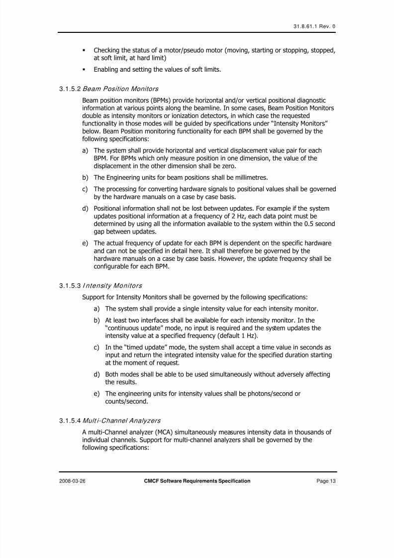
3.1.5.8 Beamlin e Script ing Environment
The goal of the beamline scripting environment is to allow for implementing proceduresspanning all of the hardware resources supported by the hardware control layer at abeamline. The scripting environment will enable the implementation of sophisticatedbeamline automation features in an easy to use scripting language. The requirements forthe scripting environment shall be as follows:
a) The syntax of the scripting language shall be easy to learn and should be basedon, an existing open-source scripting environment.
b) It shall support the control structures for decision-making, comparisons, loops,definition of procedures and procedure calls with parameter passing.
c) The environment must provide access to all hardware resources supported by
the underlying beamline hardware control layerd) The scripting environment must provide a similar level of functionality and
simplicity as illustrated in the following pseudo code example:
7/31/2019 31.8.61.1.Rev.0-CMCF Software Requirements Specification-Fodje
http://slidepdf.com/reader/full/318611rev0-cmcf-software-requirements-specification-fodje 22/38
31.8.61.1 Rev. 0
2008-03-26 CMCF Software Requirements Specification Page 16
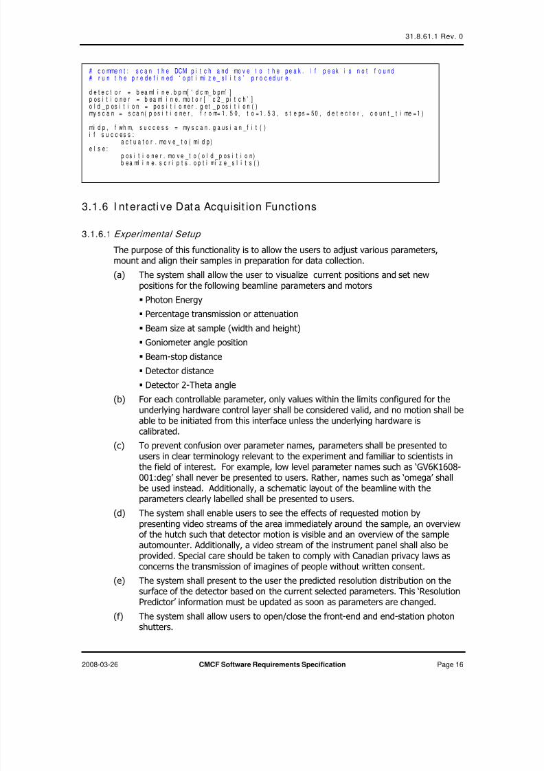
3.1.6 I nt eracti ve Data Acquisit ion Functions
3.1.6.1 Experimental Setup
The purpose of this functionality is to allow the users to adjust various parameters,mount and align their samples in preparation for data collection.
(a) The system shall allow the user to visualize current positions and set newpositions for the following beamline parameters and motors
Photon Energy
Percentage transmission or attenuation
Beam size at sample (width and height)
Goniometer angle position
Beam-stop distance
Detector distance
Detector 2-Theta angle
(b) For each controllable parameter, only values within the limits configured for theunderlying hardware control layer shall be considered valid, and no motion shall beable to be initiated from this interface unless the underlying hardware iscalibrated.
(c) To prevent confusion over parameter names, parameters shall be presented tousers in clear terminology relevant to the experiment and familiar to scientists inthe field of interest. For example, low level parameter names such as ‘GV6K1608-001:deg’ shall never be presented to users. Rather, names such as ‘omega’ shallbe used instead. Additionally, a schematic layout of the beamline with theparameters clearly labelled shall be presented to users.
(d) The system shall enable users to see the effects of requested motion bypresenting video streams of the area immediately around the sample, an overviewof the hutch such that detector motion is visible and an overview of the sampleautomounter. Additionally, a video stream of the instrument panel shall also beprovided. Special care should be taken to comply with Canadian privacy laws asconcerns the transmission of imagines of people without written consent.
(e) The system shall present to the user the predicted resolution distribution on thesurface of the detector based on the current selected parameters. This ‘ResolutionPredictor’ information must be updated as soon as parameters are changed.
(f) The system shall allow users to open/close the front-end and end-station photonshutters.
# c o mme n t : s c a n t h e DCM p i t c h a n d mo v e t o t h e p e a k . I f p e a k i s n o t f o u n d# r u n t h e p r e d e f i n e d ‘ o p t i mi z e _ s l i t s ’ p r o c e d u r e .
d e t e c t o r = b e a ml i n e . b p m[ ‘ d c m_ b p m’ ]p o s i t i o n e r = b e a ml i n e . mo t o r [ ‘ c 2 _ p i t c h ’ ]o l d _ p o s i t i o n = p o s i t i o n e r . g e t _ p o s i t i o n ( )my s c a n = s c a n ( p o s i t i o n e r , f r o m= 1 . 5 0 , t o = 1 . 5 3 , s t e p s = 5 0 , d e t e c t o r , c o u n t _ t i me = 1 )
mi d p , f wh m, s u c c e s s = my s c a n . g a u s i a n _ f i t ( )
i f s u c c e s s :a c t u a t o r . mo v e _ t o ( mi d p )
e l s e :p o s i t i o n e r . mo v e _ t o ( o l d _ p o s i t i o n )b e a ml i n e . s c r i p t s . o p t i mi z e _ s l i t s ( )

7/31/2019 31.8.61.1.Rev.0-CMCF Software Requirements Specification-Fodje
http://slidepdf.com/reader/full/318611rev0-cmcf-software-requirements-specification-fodje 23/38
31.8.61.1 Rev. 0
2008-03-26 CMCF Software Requirements Specification Page 17
(g) The system must allow some previously defined scripted commands to bepresented to users for execution.
(h) A command to prepare the sample environment for mounting a sample shall beprovided. Specifically, when the system receives a command to prepare formounting, it shall move the detector beam-stop and other equipment around thesample position to a safe distance. The specific distances will be determined on a
case by case basis and may be different for different beamlines. Therefore it mustbe configurable, post-deployment.
3.1.6.2 Sample Mount ing and Alignm ent
The purpose of this functionality is to enable users to visually position the sample at thebeam position.
(a) A live video stream of the sample shall be presented to the user.
(b) The system shall overlay on the live video stream, clear markings for the beamposition and size at all times.
(c) Users shall be presented with commands to increase, decrease the zoom-level orreturn to a default zoom level
(d) Similarly, the system shall provide commands to rotate the sample in steps of +/-90 degrees and +/180 degrees
(e) Commands shall be provided for fine-adjusting the sample position vertically andhorizontally.
(f) Additionally, a home command shall be available which positions the sampleholder to a predefined position. The target position of this command will vary fromone beamline to another and should therefore be configurable.
(g) At least three types of sample positioning commands shall be supported: ‘click centring’, ‘loop centring’ and ‘crystal centring’. ‘Loop’ and ‘Crystal’ centringcommands will require rotating the sample, capturing images at various anglesand processing the images to locate the loop or crystal. All three commands will
require accurate calibration of the video microscope at all accessible zoom levels.
‘Click centring’: In this mode, when a user clicks on a position on the samplevideo display, the system shall move the sample such that, the selectedposition coincides with beam centre marked on the display.
‘Loop centring’: On receiving a ‘loop centring’ command the system moves thesample such that the centre of the loop holding the sample coincides with thebeam centre marked on the display.
‘Crystal centring’: On receiving a ‘crystal centring’ command the system movesthe sample such that the centre of the sample crystal coincides with the beamcentre.
(h) The system shall provide controls for remotely adjusting the lighting around the
sample and the contrast of the video stream displayed.(i) A schematic view of the available sample coordinates within the sample holding
Dewar of the automounter shall be presented to the user. Each address with thisview must be clearly marked to reflect its state – whether ‘occupied’, ‘empty’ or ‘unusable’.
(j) The system shall provide commands for mounting a sample from the automounterby simply entering the sample address within the holding Dewar.

7/31/2019 31.8.61.1.Rev.0-CMCF Software Requirements Specification-Fodje
http://slidepdf.com/reader/full/318611rev0-cmcf-software-requirements-specification-fodje 24/38
31.8.61.1 Rev. 0
2008-03-26 CMCF Software Requirements Specification Page 18
(k) Commands shall also be provided for un-mounting a sample from the Goniometerinto the sample holding Dewar. In this case, samples shall be un-mounted to thesame address from which they were mounted.
3.1.6.3 Data Collect ion
The purpose of this functionality is to enable users to input data collection parameters,collect test images, and initiate collection of complete SAD, MAD or conventionaldiffraction images.
(a) The system shall allow users to input the following parameters for collectingdiffraction data
Data Prefix: A text string without any spaces, for identifying the data set.
Directory: The location where diffraction images will be stored.
Detector Distance in millimetres
Goniometer Delta: the rotation range in degrees for a single frame of data
Exposure Time: The duration of a single exposure in seconds
Start Frame number: the index number for the first frame in the set
Start Angle: The starting position of the Goniometer in degrees
End Frame number: the index number for the last frame in the set
End Angle: The final position of the goniometer in degrees
Wedge angle: This is the slice of data collection in degrees to be collected non-stop in the case of multiple energy data collection. The maximum wedge shallbe 180 degrees.
Inverse beam mode: One of two options ‘On’ or ‘Off’
Energy: This is the energy at which data should be collected. The system shallsupport up to 5 energies. Each energy entry shall be associated with a label.
(b) The system must perform input validation of entered parameters. The delta, start
angle, end angle, start frame and end frame values shall be consistent with eachother. Therefore, on changing one of these values, the system shall immediatelyupdate the others to maintain consistency, with the least loss of information.
(c) Methods shall be provided to enable users to recover overwritten parameters byundoing changes.
(d) The sequence of images to be collected shall be presented to the users andupdated on request.
(e) The system shall provide commands for initiating a data collection based on theselected parameters. On receiving a start command, the system shall verify thatpreviously collected data will not be overwritten and take appropriate actions toprevent data loss.
(f) As data collection proceeds, the list shall be updated to reflect completion status.(g) At least two methods of interrupting an on-going data collection shall be provided.
A ‘Pause’ command shall suspend data collection and permit data collection toresume as required. The system shall permit users to change the resume positionwithin the sequence while data collection is paused. Additionally, an ‘abort’ command shall stop data collection and reset the system to the same state asbefore data collection was initiated.
(h) A special ‘snapshot’ mode (or ‘Run 0 mode’) of operation shall be the default modeof operation. In this mode, only single frame data collection shall be supported.

7/31/2019 31.8.61.1.Rev.0-CMCF Software Requirements Specification-Fodje
http://slidepdf.com/reader/full/318611rev0-cmcf-software-requirements-specification-fodje 25/38
31.8.61.1 Rev. 0
2008-03-26 CMCF Software Requirements Specification Page 19
Therefore users will not be allowed to change ‘End Frame’, ‘End Angle’, ‘Wedge’, ‘Inverse mode’ and ‘Energy’ parameters. Instead, users shall be presented with ‘Resolution predictor’ functionality in this mode.
(i) The system shall allow for multiple runs of data collection to be defined, each withits own set of parameters prior to initiating data collection, after which the systemshall collect the full sequence of images defined in all runs without intervention.
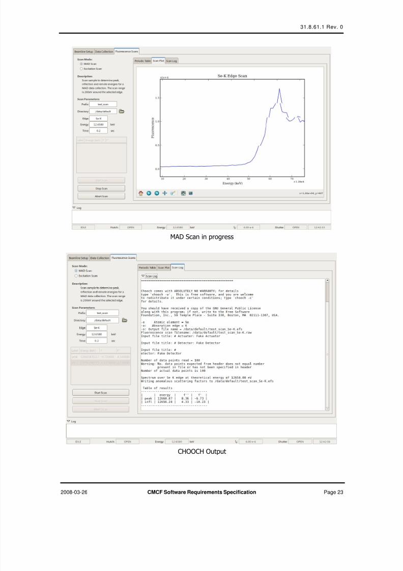
3.1.6.4 Fluor escence Scans and MAD Param eter Selecti on
The purpose of this functionality is to enable users to perform an absorption-edge energyscan on their samples, and determine the optimal wavelengths for MAD or SADanomalous dispersion experiments. Additionally, an excitation scan allows users toidentify or verify the existence of anomalous scatters in the sample.
(a) The system shall allow users to choose the type of scan to be performed, either ‘MAD’ or ‘Excitation’.
(b) The inputs for scans shall include the following parameters:
Prefix: identifier for naming data files, also used as Prefix for automaticallygenerated runs created as a result of a MAD scan.
Directory: Data directory
Edge: The absorption edge around which to scan
Energy: The energy corresponding to the absorption edge
Exposure time: This is the counting time for each position during the energyscan.
(c) On receiving input in the MAD mode, the system shall open the shutter and scanthe 100 eV region centred on the selected edge, at a step size of at most 1eV. Foreach point in the scan, the system shall count the multi-channel analyzer for thespecified duration.
(d) For each point in the MAD mode, the system shall return the sum of counts within
the region of interest defined by the emission energy of the selected absorptionedge, normalized to the beam intensity.
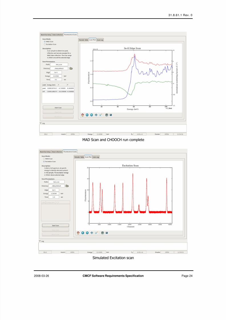
(e) At the end of the scan in the MAD mode, the output of the scan shall be used asinput to the external CHOOCH software package, and the CHOOCH outputprocessed to extract the energy, f’ and f’’ values for the ‘peak’ and ‘inflectionpoint’. A third energy or ‘remote’ shall be selected in the region above the ‘peak’ where the change in f’’ values is smallest ( usually ~200 eV above the inflectionpoint)
(f) All output files shall be saved in the data directory specified during input.
(g) The resulting peak and inflection point and remote parameters shall be used toautomatically set up a new data collection Run, with three energies equal to thevalues selected from the CHOOCH output, and the energies appropriately labelled
‘peak’, ‘infl’, and ‘remo’. The default prefix, and directories shall be the same asthose chosen for the scan.
(h) On receiving input in the Excitation mode, the system shall open the shutter, movethe energy to the excitation energy (usually ~500 eV above the input edge-energy) and collect a full spectrum from the Multi-channel analyzer for theduration specified.
(i) When the excitation scan is complete, the system shall perform a one-dimensionalpeak search on the spectrum and output a list of peaks, with each peak consisting
7/31/2019 31.8.61.1.Rev.0-CMCF Software Requirements Specification-Fodje
http://slidepdf.com/reader/full/318611rev0-cmcf-software-requirements-specification-fodje 26/38
31.8.61.1 Rev. 0
2008-03-26 CMCF Software Requirements Specification Page 20
of two values, the ‘peak position’ in eV, and the ‘peak height’ or amplitude incounts.
(j) For each peak identified, the system shall also search a database of emission linesand return a list of identified emission lines ordered according to confidence levelor likelihood.
3.1.6.5 Quick-look Data Analysis
The purpose of this functionality is to allow users to verify the quality of data beingcollected as it is being collected. The system shall be able to perform the followinganalysis on request:
(a) Diffraction image analysis using DISTL [4].
(b) Intensity distribution analysis, in which the BOS shall calculate intensitydistribution histogram, the mean pixel intensity, and the 5th and 95th percentiles.
(c) The maximum pixel intensity and the corresponding number of pixels
(d) Number of saturated pixels
3.1.6.6 Sample Screening/ Characteri zation
The purpose of this functionality is to allow users to characterize a sample in order todetermine suitability for successful data collection, initial parameters for data collectionand also to be able to compare similar samples in order to obtain the best sample fordata collection. The system shall be able to perform the following analysis on request
(a) Collect a predetermined number of frames of data
(b) Auto-Index and integrate the data using XDS and or MOSFLM
(c) Determine the space group
(d) Calculate the recommended data collection strategy for the sample
(e) Diffraction image analysis using DISTL [4].
(f) Calculate an absolute score based on the results of the analysis.
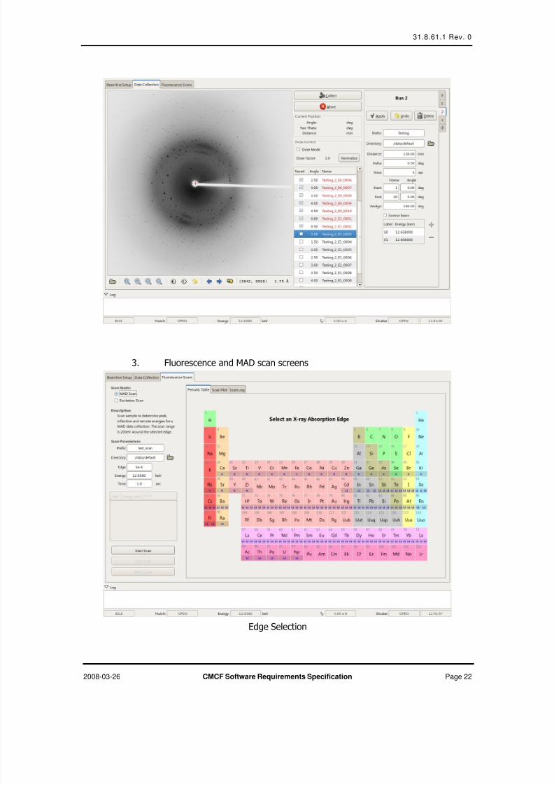
3.1.6.7 User I nterf ace Requirements
The following user interface layouts and requirements illustrate the level of simplicity andfunctionality required.
(a) All interactive data collection functionality shall be present within a single tabbedapplication window.
(b) Status information such as shutter states, intensity readings and motor positionsshall be clearly visible.
(c) The layout of the screens for interactive data collection should be similar to thefollowing illustrations:

7/31/2019 31.8.61.1.Rev.0-CMCF Software Requirements Specification-Fodje
http://slidepdf.com/reader/full/318611rev0-cmcf-software-requirements-specification-fodje 27/38
31.8.61.1 Rev. 0
2008-03-26 CMCF Software Requirements Specification Page 21
1. The Beamline Setup Screens
2. The Data collection screens
Run 0, ‘snapshot’ mode
7/31/2019 31.8.61.1.Rev.0-CMCF Software Requirements Specification-Fodje
http://slidepdf.com/reader/full/318611rev0-cmcf-software-requirements-specification-fodje 28/38
31.8.61.1 Rev. 0
2008-03-26 CMCF Software Requirements Specification Page 22
3. Fluorescence and MAD scan screens
Edge Selection
7/31/2019 31.8.61.1.Rev.0-CMCF Software Requirements Specification-Fodje
http://slidepdf.com/reader/full/318611rev0-cmcf-software-requirements-specification-fodje 29/38
31.8.61.1 Rev. 0
2008-03-26 CMCF Software Requirements Specification Page 23
MAD Scan in progress
CHOOCH Output
7/31/2019 31.8.61.1.Rev.0-CMCF Software Requirements Specification-Fodje
http://slidepdf.com/reader/full/318611rev0-cmcf-software-requirements-specification-fodje 30/38
31.8.61.1 Rev. 0
2008-03-26 CMCF Software Requirements Specification Page 24
MAD Scan and CHOOCH run complete
Simulated Excitation scan

7/31/2019 31.8.61.1.Rev.0-CMCF Software Requirements Specification-Fodje
http://slidepdf.com/reader/full/318611rev0-cmcf-software-requirements-specification-fodje 31/38
31.8.61.1 Rev. 0
2008-03-26 CMCF Software Requirements Specification Page 25
(d) The layout of the screens for web portal functionality should be similar to thefollowing illustrations:
1. Login Screen
2. Account Overview

7/31/2019 31.8.61.1.Rev.0-CMCF Software Requirements Specification-Fodje
http://slidepdf.com/reader/full/318611rev0-cmcf-software-requirements-specification-fodje 32/38
31.8.61.1 Rev. 0
2008-03-26 CMCF Software Requirements Specification Page 26
3. Proposal Context
4. Samples Context

7/31/2019 31.8.61.1.Rev.0-CMCF Software Requirements Specification-Fodje
http://slidepdf.com/reader/full/318611rev0-cmcf-software-requirements-specification-fodje 33/38
31.8.61.1 Rev. 0
2008-03-26 CMCF Software Requirements Specification Page 27
5. Results Context
6. Results Details

7/31/2019 31.8.61.1.Rev.0-CMCF Software Requirements Specification-Fodje
http://slidepdf.com/reader/full/318611rev0-cmcf-software-requirements-specification-fodje 34/38
31.8.61.1 Rev. 0
2008-03-26 CMCF Software Requirements Specification Page 28
7. Reports Context

7/31/2019 31.8.61.1.Rev.0-CMCF Software Requirements Specification-Fodje
http://slidepdf.com/reader/full/318611rev0-cmcf-software-requirements-specification-fodje 35/38
31.8.61.1 Rev. 0
2008-03-26 CMCF Software Requirements Specification Page 29
3.1.7 Automatic Data Acquisition Functions
3.1.7.1 Automatic Beamline Control Functionality
The purpose of this functionality is to enable automatic control of the beamline withouthuman intervention. Therefore the system shall make it possible for all functionality
required for data acquisition to be carried out without human intervention. Specifically,the following functionality shall be implemented.
(a) Automatic beamline alignment and optimization. To achieve this, the system shallimplement algorithms for aligning specific relevant beamline optical components,and interpret beamline diagnostics and error states.
(b) Beamline reconfiguration. This involves moving beamline components into arequested state. For example, energy, detector distance, beam size, detector-pitch, etc. in order to achieve a configuration suitable for a required experiment.The exact parameters required for an experiment will be selected from a relationaldatabase.
(c) Mounting or dismounting of samples. The system shall automatically mount ordismount a specific sample onto the goniometer.
(d) Automatic sample centering. This will require automatic adjustment of theillumination system, adjustment of the sample microscope, image analysis fordetermining loop or crystal positions and control of the goniometer head for crystalpositioning.
(e) Automatic data collection. The system will manage the sequence of eventsrequired for collecting single data frames for screening, or a series of frames forcomplete data sets. The exact parameters for data collection, such as exposuretime, oscillation range and beamline configuration will be read from a relationaldatabase.
3.1.7.2 Beamline Expert Functionality
The purpose of this functionality is to provide a level of expertise required to substitutean operator for automatic data acquisition. Therefore the system shall be equipped withalgorithms for carrying out a full crystallography experiment from start to finish.
(a) The input to the system will be a list of sample identifiers, corresponding to allsamples currently loaded into the sample holding dewar.
(b) For each sample, the system shall request specific experiment plans from therelational database and execute the data acquisition as determined by the inputparameters.
(c) The system shall then update the relational database to reflect the results of theexperiment.
(d) Execution of experiments shall include all the operational actions outlined in
section 2.1 of this document. Specifically, the following expert functionality mustbe supported:
1. Crystal characterization (screening)
The system shall control the beamline hardware to mount a crystal,automatically center it, and collect a series of images based onparameters to be determined based on the crystal parameters requestedexperimental plan.
7/31/2019 31.8.61.1.Rev.0-CMCF Software Requirements Specification-Fodje
http://slidepdf.com/reader/full/318611rev0-cmcf-software-requirements-specification-fodje 36/38
31.8.61.1 Rev. 0
2008-03-26 CMCF Software Requirements Specification Page 30
The images shall be analyzed using DISTL [4], and auto-indexed usingLABELIT, XDS and or MOSFLM [1, 2, and 3]. The output of this step willbe the cell parameters, crystal orientation, mosaic spread, diffractionquality, resolution and overall diffraction score.
2. Data acquisition setup
The system shall be able to select one or more samples from a list of characterized samples based on the diffraction score
The system shall then retrieve the diffraction plan
The system shall configure the beamline hardware as required by thediffraction plan, by selecting the appropriate energy, beam size, detectordistance, and optimizing the beam intensity.
The system shall then mount the sample, center it and initiate dataacquisition.
3. Data processing.
For each image collected, the BOS shall be capable of performing imageanalysis using the external program DISTL [4]. The input for the analysisshall be the image file. The output shall include, the total number of diffraction spots present in the image, the total number of overloadedspots, the spot the number of ice rings if any, ‘spot quality’ anddiffraction resolution.
Online data processing shall be supported. The images will be processedas they are being collected using MOSFLM or XDS [1,2], and thefollowing data quality statistics shall be extracted as data processingproceeds:
− Scaling factor
− The standard deviation of the reflecting range or mosaicity
− The standard deviation of spot position in pixels
− The standard deviation of spindle position in degrees
− The refined beam direct beam position on the detector surface
− The refined detector origin
− The number of accepted, and rejected reflections
− The average spot profile
− The refined unit cell parameters
− Completeness of data
− R-factors
− I/Sigma
4. Beamline alignment. Beamline alignment functionality includes low level
alignment of a single parameter of an optical element such as ‘mirror angle’, ‘bending radius’, etc. as well as high level alignment of a single opticalelement such as ‘toriodal mirror’ or even a complete beamline. Duringnormal operation, the CMCF BOS system must be able to produce optimumintensity at the sample position for any valid set of experimental parameters,without human intervention through automatic beamline alignment. Additionally, during maintenance and operation the system shall provideassisted beamline alignment. Specifically, the following beamline componentsshall be able to be aligned automatically

7/31/2019 31.8.61.1.Rev.0-CMCF Software Requirements Specification-Fodje
http://slidepdf.com/reader/full/318611rev0-cmcf-software-requirements-specification-fodje 37/38
31.8.61.1 Rev. 0
2008-03-26 CMCF Software Requirements Specification Page 31
Primary slits
Monochromator – Energy selection, optimization using crystal pitch andpiezo. Where sagittal focusing is available on the second crystal, assistedfocusing shall be supported.
Mirror stripe selection and alignment shall be automated. Where themirror is fitted with a bender, assisted focusing shall be supported.
Exposure box and experimental table.
3.1.7.3 Use Case for Autom atic Data Acquisit ion
The following illustrates a use case for automatic data acquisition.
(a) Scientist sets up an experimental plan
(b) Scientist prepares and ships samples to CLS
(c) Beamline Staff receives samples
(d) Scientist receives an e-mail with confirmation that samples have been received
(e) Before the beginning of a shift, Beamline staff sets up shift
(f) Samples are automatically screened and scored according to Scientistsspecifications
(g) At the end of a shift, Beamline staff reviews shift results
(h) Scientists receives an e-mail with confirmation that samples have been screeneduser
(i) Scientist logs onto website and reviews screening results.
(j) user requests data collection
(k) beamline staff sets up shift
(l) beamline collects data
(m) beamline staff reviews shift
(n) beamline notifies user
(o) user reviews collected data (if rejected return to 14)
(p) user downloads data
3.2 ERROR HANDLI NG
All run-time errors of the system shall be characterized based on the source and impact:
(a) Internal - Errors due to the internal logic of software systems. The system shallbe designed to minimize internal errors as much as possible.
(b) External – Errors due to events beyond the scope of the program, originating fromhardware, external software systems and humans
(c) Recoverable – These are errors from which the system is able to recover. Whereautomatic recovery is possible without adversely affect on-going experiments,recovery should be automatic.
(d) Non-recoverable – These errors have no recovery mechanism. However, theyshould be predictable in advance and encountered at relatively low levels.
7/31/2019 31.8.61.1.Rev.0-CMCF Software Requirements Specification-Fodje
http://slidepdf.com/reader/full/318611rev0-cmcf-software-requirements-specification-fodje 38/38
31.8.61.1 Rev. 0
The system shall handle errors as follows:
(e) Non-recoverable errors and Recoverable errors requiring human interventionduring recovery shall be fatal. This means all on-going activities in the subsystemshall be suspended.
(f) Each subsystem shall be designed such that the suspended mode preserves asmuch as possible, all equipment, personnel and samples in its proximity.
(g) Some error states which may be fatal include: Automounter errors, hardwarefailures, beamline-vacuum failure, among others to be determined as the system isdeveloped.
4.0 REFERENCES
1. Kabsch, W. Automatic processing of rotation diffraction data from crystals of initially unknown symmetry and cell constants. (1993) J. Appl. Cryst. 26, 795-800.
2. Leslie, A. G. Integration of macromolecular diffraction data. (1999) Acta Cryst.D55, 1696-1702.
3. Sauter, N. K., Grosse-Kunstleve, R. W. & Adams. J. Appl. Cryst. 2004 37:399-409.4. Zhang, Z., van den Bedem, H., Sauter, N. K., Snell, G. & Deacon, A. Automated
diffraction image analysis and spot searching for high-throughput crystalscreening. (2006) J. Appl. Cryst. 39, 112-119.
5. Gleb P. Bourenkov, and Alexander N. Popov (2006). A quantitative approach todata-collection strategies. Crystallography. Acta Cryst. D62, 58
6. Raimond B.G. Ravelli and Sean M. McSweeney (2000). The 'fingerprint' that X-rays can leave on structures. Structure, Vol 8, 315-328.
7. Martin Weik, Raimond B. G. Ravelli, Gitay Kryger, Sean McSweeney, Maria L.Raves, Michal Harel, Piet Gros, Israel Silman, Jan Kroon, and Joel L. Sussman.(2000) Specific chemical and structural damage to proteins produced bysynchrotron radiation. PNAS Vol. 97, Issue 2, 623-628.
8. Evans G., Pettifer R. F. CHOOCH: a program for deriving anomalous- scatteringfactors from X-ray fluorescence spectra. (2001) J. Appl. Cryst. 34, 82-86.
9. Calum et. al, (2004). GNOME Human Interface Guidelines 2.0http://developer.gnome.org/projects/gup/hig/2.0/
10. Wroblewski and Rantanen (2001). Design considerations for web-basedapplications. Proc. Of the 45th Ann meeting of the Human Factors andErgonomics Society.http://www.humanfactors.uiuc.edu/Reports&PapersPDFs/humfac01/wroblewskirantanenhf01.pdf
11. Wroblewski. AJAX & Interface Design.http://www.lukew.com/resources/articles/ajax_design.asp
12. Sudhir Babu Pothineni, Tilo Strutz & Victor S. Lamzin (2006) Automateddetection and centring of cryocooled protein crystals Acta Cryst. D62, 1358-1368.
13. Z. Otwinowski and W. Minor "Processing of X-ray Diffraction Data Collected inOscillation Mode", Methods in Enzymology, Volume 276: MacromolecularCrystallography, part A, p. 307-326, 1997, C.W. Carter, Jr. and R.M. Sweet, Eds., Academic Press
14. Control System Common Specification (CLS Document 7.4.39.1 Rev. 3)