318-2016 Addendum No. 1 - Toronto · Toronto, Ontario M5H 2N2 Joanne Kehoe Manager Construction...
40
Michael Pacholok, Chief Purchasing Official and Director Purchasing and Materials Management Division City Hall, 18 th Floor, West Tower 100 Queen Street West Toronto, Ontario M5H 2N2 Joanne Kehoe Manager Construction Services November 29, 2016 VIA Internet Posting (40 pages) ADDENDUM NO. 1 Tender Call No. 318-2016 CLOSING: 12:00 NOON (LOCAL TIME), December 8, 2016 For: The supply of all Labour, Products, Equipment and Supervision required to complete State-of Good Repair Works and Accessibility Improvements at Centennial Arena (Etobicoke), on behalf of the Parks, Forestry and Recreation Division of the City of Toronto Please refer to the Tender Call document in your possession and be advised of the following: 1. CHANGE - Drawings: Refer to the enclosed Drawings dated Nov 28/2016 (18 sheets): The following drawings replace the original drawings provided with the Tender documents: Sheet No. 6 Sheet No. 9 Sheet No. 15 Sheet No. 16 Sheet No. 17 Sheet No. 18 Sheet No. S1 Sheet No. S2 Sheet No. S3 Sheet No. S4 Sheet No. M3 Sheet No. M4 Sheet No. E1 Sheet No. E2 Sheet No. E3 Sheet No. P1 Sheet No. P2 The following drawing is added to the original tender drawings. Sheet No. E2A (Newly-issued Drawing) Bidders may obtain hard copies and a disk containing digital copies of these drawings from the Tender Office of the Purchasing and Materials Management Division, 19 th Floor, West Tower, Toronto City Hall, 100 Queen Street West. 2. ADDITION: Add the attached Tree Protection Policy and Specifications for Construction Near Trees (18 pages).
Transcript of 318-2016 Addendum No. 1 - Toronto · Toronto, Ontario M5H 2N2 Joanne Kehoe Manager Construction...

Michael Pacholok, Chief Purchasing Official and Director
Purchasing and Materials Management Division City Hall, 18th Floor, West Tower 100 Queen Street West Toronto, Ontario M5H 2N2
Joanne Kehoe Manager Construction Services
November 29, 2016 VIA Internet Posting (40 pages)
ADDENDUM NO. 1 Tender Call No. 318-2016
CLOSING: 12:00 NOON (LOCAL TIME), December 8, 2016 For: The supply of all Labour, Products, Equipment and Supervision required to complete State-of Good Repair Works and Accessibility Improvements at Centennial Arena (Etobicoke), on behalf of the Parks, Forestry and Recreation Division of the City of Toronto
Please refer to the Tender Call document in your possession and be advised of the following:
1. CHANGE - Drawings:
Refer to the enclosed Drawings dated Nov 28/2016 (18 sheets):
The following drawings replace the original drawings provided with the Tender documents:
Sheet No. 6
Sheet No. 9
Sheet No. 15
Sheet No. 16
Sheet No. 17
Sheet No. 18
Sheet No. S1
Sheet No. S2
Sheet No. S3
Sheet No. S4
Sheet No. M3
Sheet No. M4
Sheet No. E1
Sheet No. E2
Sheet No. E3
Sheet No. P1
Sheet No. P2
The following drawing is added to the original tender drawings.
Sheet No. E2A (Newly-issued Drawing)
Bidders may obtain hard copies and a disk containing digital copies of these drawings from the Tender Office of the Purchasing and Materials Management Division, 19th Floor, West Tower, Toronto City Hall, 100 Queen Street West.
2. ADDITION:
Add the attached Tree Protection Policy and Specifications for Construction Near Trees (18 pages).
3. CLARIFICATIONS:
a. The two new additions on the south side of the facility may have a second floor added in a future project; however, building a second floor addition on these two additions is not part of this project.
b. The contractor is to ensure that all mechanical and refrigeration equipment conforms to the City of Toronto’s Noise By-Law.
4. CHANGE: Specification Section 15601 (Refrigeration System & Equipment)
The contractor is directed to replace clause 1.1.3 of the Refrigeration System & Equipment Specification (section 15601) with the following:
1.1.3 The work shall be limited to qualified refrigeration contractors; refer to the City’s front-end documentation for reference details/submission requirements. Refrigeration contractors must be registered with TSSA and work shall be performed in accordance with the City's Industrial, Commercial, Institutional "I.C.I." fair wage schedule. See page 427 of the tender call.
For all other trade work where the work falls under the jurisdiction of the trades that City is signatory to, shall be performed by firms with the applicable binding collective agreement(s). See Page 425 of the tender call.
5. QUESTIONS AND ANSWERS:
The following are responses to questions received during the bid period.
Q1. Is any portion of the existing west rink refrigeration slab remaining?
A1. The entire existing west rink refrigeration slab and associated base material is to be removed and disposed of off-site
Q2. What is the size of the decorative screen around the roof top HVAC unit noted on Sheet No. 13?
A2. The prefabricated screens, provided by PHP Systems or approved equal, shall be a minimum of 1125 high x 3250 long x 2250 deep and shall be zero roof penetrations and shall effectively screen the roof top units from view.
Q3. Who is the manufacturer of the stainless steel trough sink in the Men’s W/R Room 118 and the Women’s W/R Room 119?
A3. The stainless steel trough sinks are custom designed and shop drawings shall be provided by Sani Metal Ltd (SML), Mississauga, 1-800-263-5170, or approved equal. The material shall be type 304 stainless steel with a satin smooth finish.
Q4. Clarify if the mounting heights for the upper stainless steel hooks in the new changerooms are 1200 AFF or 1600 AFF, on Sheet No.’s 11A and 11B?
A4. The upper stainless steel hooks in the new changerooms are to be mounted at 1600 AFF.

Q5. Is the new wheelchair viewing ramp constructed entirely of wood?
A5. The new wheelchair viewing ramp is to be constructed entirely of concrete. Refer to re-issued Sheet No. 9.
Q6. Please confirm the mounting heights for items in the new washrooms?
A6. As noted on Sheet No. 8, Scope of Work Items IN10.2, IN10.3, IN10.4 & IN10.7, the mounting height of these items shall be 1050 AFF and not 1200 AFF.
Q7. Is the existing dasherboard glazing being reused?
A7. No. All existing dasherboard glazing is to be demolished and disposed of off-site. Provide new dasherboard glazing. All dasherboard glazing shall be 16 tempered glass.
Q8. Please clarify if any new rubber flooring will be required for any areas outside the new changerooms and new washrooms?
A8. Provide new rubber flooring, Mondo Ramflex flooring, 10 thickness, in the following rooms:
Ent, Room 100 - 35 square metres Lobby, Room 103 - 60 square metres Ent, Room 120 - 35 square metres Tickets, Room 121 - 6 square metres Office, Room 122 - 30 square metres West Rink, Room 134 - 160 square metres
Q9. Is any new flooring required for the existing stairs and upper level?
A9. Yes. Provide new Vinyl Composite Tile (VCT), colour by owner to the following rooms:
Stair No. 1 – 100 square metres. Provide 50 wide textural/tonal contrast strip at the edge of each nosing and at the bottom and top of the stairs and provide tactile attention indicators at top of all stairs, width to match stair widths x 915 deep .
Mtg, Room 201 – 65 square metres Stor, Room 201A – 7 square metres Stor, Room 201B – 9 square metres Stor, Room 206 – 9 square metres Foyer, Room 202 – 60 square metres Concession, Room 205 – 22 square metres Mtg, Room 203 – 65 square metres Stor, Room 203A – 4 square metres Stor, Room 203B – 14 square metres Top Bleachers West – 175 square metres (includes ramp access area) Top Bleachers East – 110 square metres (includes ramp access area)
Q10. Is any portion of the existing west rink refrigeration header trench remaining?
A10. No. The existing piping within the existing header trench is to be removed and disposed of off-site. The existing header trench is to be filled solid with concrete. Refer to General Notes for Concrete Work on Sheet No. 1 for concrete specifications.

Q11. Please confirm the number of barrier free push button operators required?
A11. There are twenty-seven (27) push button operators required. Co-ordinate locations with tender and electrical plans. Some operators will be required to be installed on existing doors.
Q12. Please clarify the masonry anchors.
A12. Masonry anchors shall be ‘Flex-O-Lok’ by Blok-Lok.
Q13. Can the Mandatory Meeting signup sheet be circulated?
A13. No, the signup sheet cannot be circulated. Here is the list of companies that attended the meeting:
Anacond Contracting Inc. Aplus General Contractor Brown Daniels Associates Duron Ontario Ltd. Frank Pellegrino General Contracting Limited
Integrated Building And Design Corporation Joe Pace & Sons Contracting Inc. J R Certus Construction Co. Ltd. Lisgar Construction Company M J Dixon Construction Limited Torcom Construction Inc
Q14. Further to our pre-bid meeting conducted at Centennial Arena we are requesting clarification of the requested contractor qualification as noted in the call documents. Please confirm if the City is willing to accept the contractor having completed two projects within the past 10 years of similar scope and magnitude to this project with a combined value of not less than $6 million (net of taxes) in lieu of two projects each of which has a value of not less than $3 million (i.e. would the contractor qualify if one using $4 million project and a $2 million project?).
A14. The experience requirements that are included in the contract documents remain as they are stated therein.
Should you have any questions regarding this addendum contact Mike Voelker at e-mail: [email protected]
Please attach this addendum to your RFT document and be governed accordingly. Bidders must acknowledge receipt of all addenda on the space provided on the Tender Call Cover Page as per the Process Terms and Conditions, Section 1, Item 8 - Addenda, of the Tender Call document. All other aspects of the Tender remain the same.
Yours truly, Joanne Kehoe Manager, Construction Services, Purchasing and Materials Management
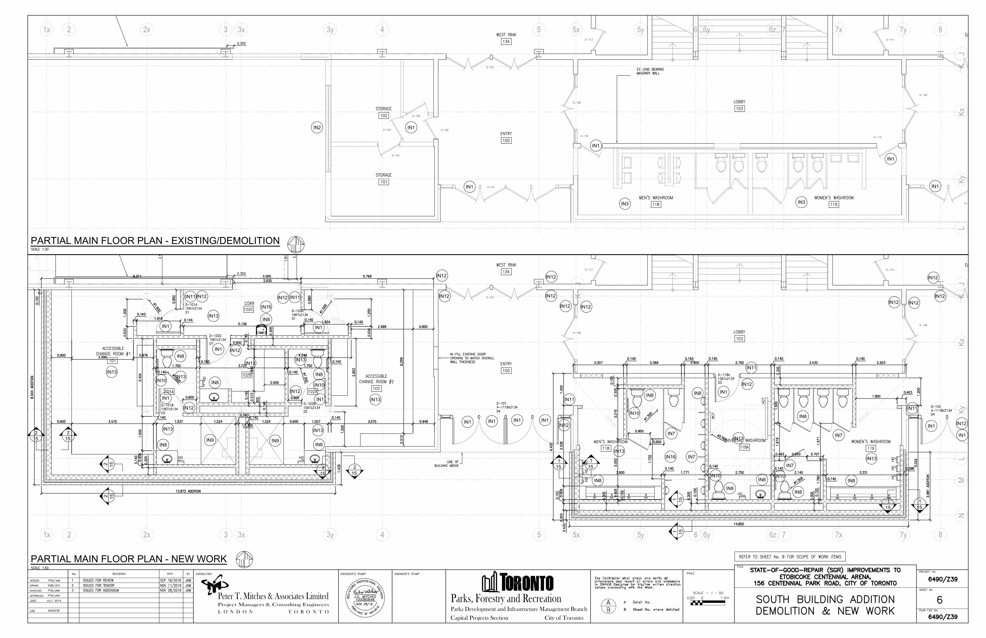
PARTIAL MAIN FLOOR PLAN - NEW WORK
Parks Development and Infrastructure Management Branch
Parks, Forestry and Recreation
City of TorontoCapital Projects SectionL O N D O N
Project Managers & Consulting Engineers
Peter T. Mitches & Associates Limited
T O R O N T O
PARTIAL MAIN FLOOR PLAN - EXISTING/DEMOLITION
3 42
NM
LK
J
LK
J
3 42
2x 3y
2x 3x
2
15
2
15
5 5x 5y 6 6z 7 7x 7y6y
5 5x 5y 6 6y 6z 7 87y1x
1x
3y 7x
8
Ky
Kx
LK
JK
yK
xM
N
3x
IN1
IN1
IN1
IN1
IN1
IN2
IN3
IN3
IN7
IN7
IN7
IN7
IN8
IN8
IN8
IN8
IN8
IN8
IN8
IN8
IN8
IN8
IN8
IN8IN8
IN9
IN9
IN8
IN10
IN10
IN10
IN10
IN10
IN11
IN11
IN11
IN11
IN11
IN12
IN12
IN12
IN12
IN12
IN12
IN12
IN12
IN13
IN13
IN13
IN13
IN13
IN13
IN13
IN13
IN13
IN13
IN13
1
15
1
15
IN16
IN16
IN1
IN1
IN1
IN1
IN1
IN1
IN1
IN1 IN1
IN1
IN1
IN1
2
15
2
15
1
15
1
15
IN12
IN12
IN12
IN12
IN12
IN12
IN12
IN12
IN12
IN12
2
15
2
15
1
15
1
15

KJ
HG
FE
DC
BA
Kx
Parks Development and Infrastructure Management Branch
Parks, Forestry and Recreation
City of TorontoCapital Projects SectionL O N D O N
Project Managers & Consulting Engineers
Peter T. Mitches & Associates Limited
T O R O N T O
PARTIAL MAIN FLOOR PLAN - NEW WORK
(@ AREA OF NEW VIEWING PLATFORM)
PARTIAL MAIN FLOOR PLAN
NEW WEST RINK LAYOUT
1 2 3 4 5
TYPICAL CROSS SECTION @ TOP RAMP
TYPICAL GUARD/HANDRAIL
SCOPE OF WORK VIEWING PLATFORM
VP1
VP1
VP1
VP1
DETAIL @ STAIR NOSING

SECTION
Parks Development and Infrastructure Management Branch
Parks, Forestry and Recreation
City of TorontoCapital Projects SectionL O N D O N
Project Managers & Consulting Engineers
Peter T. Mitches & Associates Limited
T O R O N T O
15
1
SECTION
15
2
WALL & COLUMN
COLUMN & CORNER

SECTION
Parks Development and Infrastructure Management Branch
Parks, Forestry and Recreation
City of TorontoCapital Projects SectionL O N D O N
Project Managers & Consulting Engineers
Peter T. Mitches & Associates Limited
T O R O N T O
16
3 SECTION
16
4

ZAMBONI ROOM ROOF PLAN
Parks Development and Infrastructure Management Branch
Parks, Forestry and Recreation
City of TorontoCapital Projects SectionL O N D O N
Project Managers & Consulting Engineers
Peter T. Mitches & Associates Limited
T O R O N T O
9x9
R1
9y 10
Ax
Ax
32 42x 3y
CHANGE ROOMS ROOF PLAN
JL
MN
K
R1
R1
SCOPE OF WORK - ROOF
LOBBY WASHROOMS ROOF PLAN
LM
N
JK
5x5 5y 6 6x 6y 7 7x 7y 8
R1
1x 3x
Kx
Ky

NEW ROOF ASSEMBLY
NEW FIBRE OR WOOD CANT
UPTURN AND TERMINATE ROOFING
MEMBRANE AS PER MANUFACTURER'S
DETAILS
NEW CONTINUOUS
PREFINISHED METAL
PARAPET/CANT
FLASHING &
COUNTERFLASHING
NEW PARAPET
SLOPED WITH WOOD
BLOCKING WHERE REQUIRED
TO ENSURE MIN 0.5%
BACK-SLOPE
Parks Development and Infrastructure Management Branch
Parks, Forestry and Recreation
City of TorontoCapital Projects SectionL O N D O N
Project Managers & Consulting Engineers
Peter T. Mitches & Associates Limited
T O R O N T O
NEW ROOF DETAIL
NEW ROOF DRAIN DETAIL
ROOF PLAN WORK SCHEDULE
1
2
3
4
NEW STACK JACK / PITCH POCKET DETAIL
GAS PIPE SUPPORT DETAIL
R1
TYPICAL PARAPET DETAIL

SOUTH ADDITION - FOUNDATION PLAN
Parks Development and Infrastructure Management Branch
Parks, Forestry and Recreation
City of TorontoCapital Projects SectionL O N D O N
Project Managers & Consulting Engineers
Peter T. Mitches & Associates Limited
T O R O N T O
FOOTING SCHEDULE
3 42 5 6 7
NM
LJ
K
2x 3y
43y
5x 6y 6z 7y 87x5y
NON-LOAD BEARING WALL DETAIL
WITH THICKENED SLAB FOR ALL NEW
INTERIOR BLOCK WALLS
NEW PIER AND FOOTING DETAIL
PIER SCHEDULE
3x
Kx
Ky
NOTES FOR WORK ALONG GRID LINE 3y
& GRID LINE J & GRID LINE L

SOUTH ADDITION FRAMING PLAN
Parks Development and Infrastructure Management Branch
Parks, Forestry and Recreation
City of TorontoCapital Projects SectionL O N D O N
Project Managers & Consulting Engineers
Peter T. Mitches & Associates Limited
T O R O N T O
LINTEL SCHEDULE
STEEL NOTES
JL
MK
3 4
3 43y2x
2
2x 3y2 5 5x 5y 6 6y 6z 7 7x 7y 8
COLUMN SCHEDULE
1x 3x 5 5x 5y 6 6y 6z 7 7x 7y 8
3x1x
Ky
Kx
DETAL @ LINTEL L-1
DETAIL @ LINTEL L-3A
DETAIL @ LINTEL L-3B
DETAIL @ LINTEL L-3C
DETAIL @ LINTEL L-5TYPICAL JAMB DETAIL
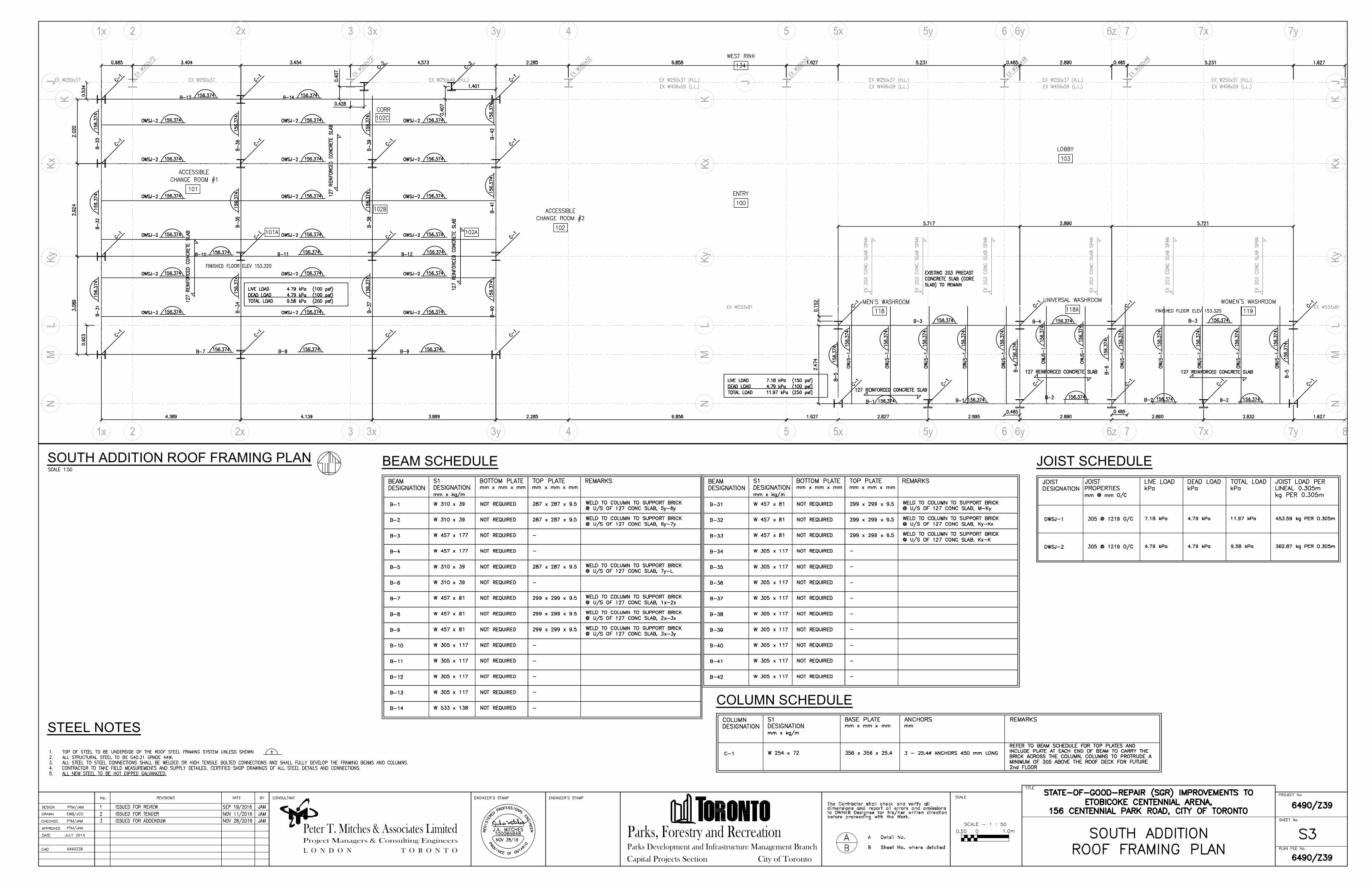
SOUTH ADDITION ROOF FRAMING PLAN
Parks Development and Infrastructure Management Branch
Parks, Forestry and Recreation
City of TorontoCapital Projects SectionL O N D O N
Project Managers & Consulting Engineers
Peter T. Mitches & Associates Limited
T O R O N T O
BEAM SCHEDULE JOIST SCHEDULE
STEEL NOTES
JL
M
K
3 4 5 6 75x 6y 6z 7y
NM
LK
J
8
32 4 5 5x 6 6y 6z 7 7y2x
2x
3y
3y 5y
5y
7x
7x
21x
1x
3x
3x
Ky
Kx
Kx
Ky
N NM
LK
yK
xK
J
COLUMN SCHEDULE

Parks Development and Infrastructure Management Branch
Parks, Forestry and Recreation
City of TorontoCapital Projects SectionL O N D O N
Project Managers & Consulting Engineers
Peter T. Mitches & Associates Limited
T O R O N T O
NORTH ADDITION FRAMING PLAN
LINTEL SCHEDULE
STEEL NOTES
9 10
Ax
A
9x 9y
Ax
A
NORTH ADDITION ROOF FRAMING PLAN
9 10
Ax
A
9x 9y
NORTH ADDITION FOUNDATION PLAN
Ax
A
9 109x 9y
BEAM SCHEDULE COLUMN SCHEDULE
FOOTING SCHEDULE
PIER SCHEDULE
JOIST SCHEDULE
DETAL @ LINTEL L-4
TYPICAL JAMB DETAIL
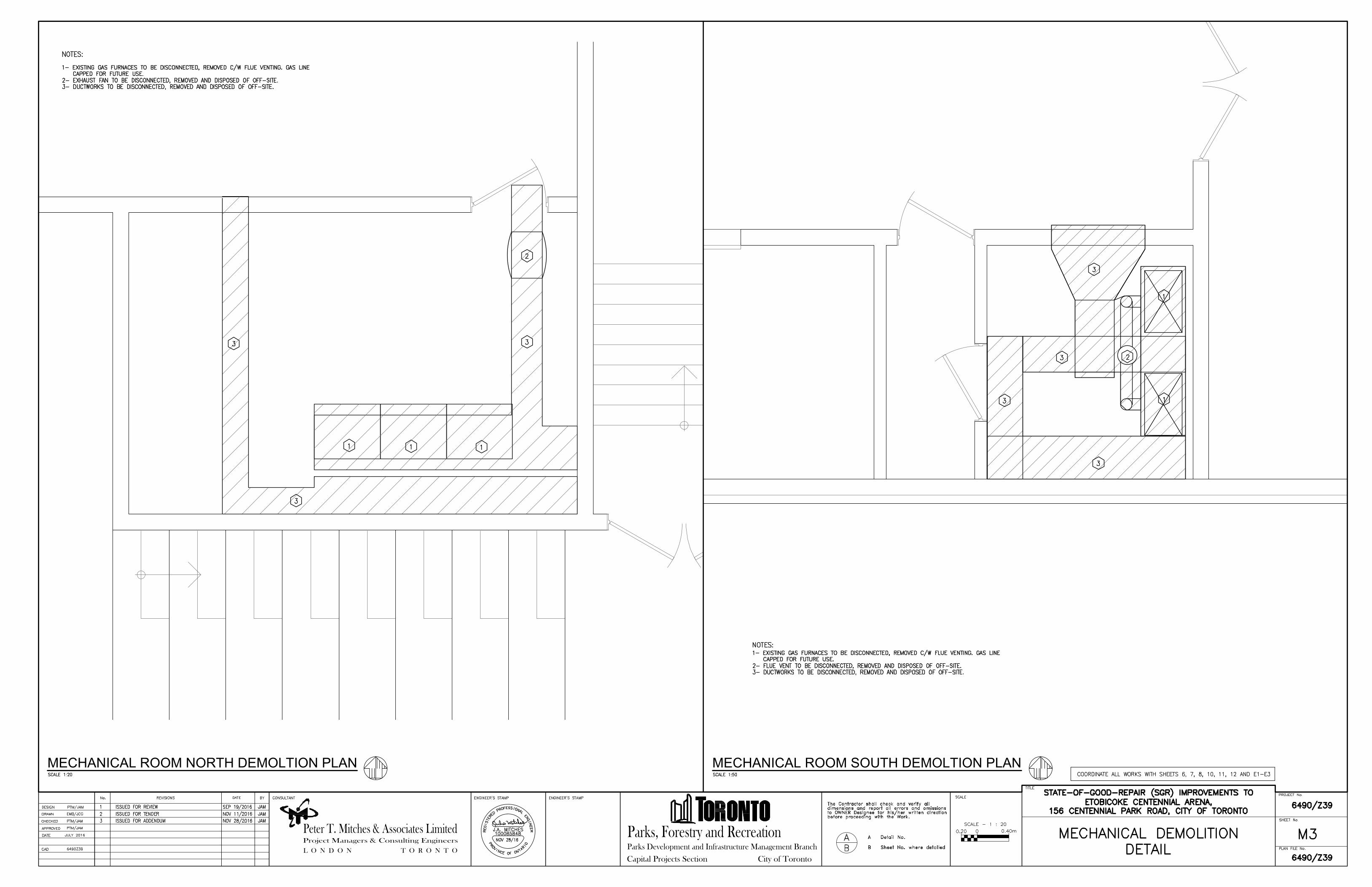
MECHANICAL ROOM NORTH DEMOLTION PLAN
Parks Development and Infrastructure Management Branch
Parks, Forestry and Recreation
City of TorontoCapital Projects SectionL O N D O N
Project Managers & Consulting Engineers
Peter T. Mitches & Associates Limited
T O R O N T O
MECHANICAL ROOM SOUTH DEMOLTION PLAN

PARTIAL MAIN FLOOR PLAN - VENTILATION PLAN
Parks Development and Infrastructure Management Branch
Parks, Forestry and Recreation
City of TorontoCapital Projects SectionL O N D O N
Project Managers & Consulting Engineers
Peter T. Mitches & Associates Limited
T O R O N T O
NEW ZAMBONI ROOM - VENTILATION PLAN PARTIAL SECOND FLOOR PLAN - EXHAUST SYSTEM REVISION

NEW MAIN DISTRIBUTION SWITCHBOARD 347/600 VAC,
3Ø, 4W, 800 A, COPPER BUS, FULL CAPACITY NEUTRAL,
200 kA BRACING, WITH EXISTING LOADS UNDER 100 A
RELOCATED TO NEW POWER PANELBOARD PPA
EXISTING INCOMING
SERVICE CONDUCTORS
VERIFY SUITABILITY AND
REUSE IF SUITABLE
#1/0 AWG COPPER GROUND CONDUCTOR IN
SUITABLE CONDUIT FOR MECHANICAL
PROTECTION TO SUITABLE NEW GROUND
ROD/PLATE. CONNECT TO NEUTRAL AND TO
EXISTING BUILDING GROUND SYSTEM TO SUIT
LOCAL INSPECTION AUTHORITIES
COPPER GROUND BUS
INCOMING CABLE
SECTION - 800 A
MAIN DISCONNECT SECTION - 800 A
DISTRIBUTION SECTION - 800 A
MAIN DISCONNECT - 800 A
BOLTED PRESSURE SWITCH
WITH NON-TIME DELAY 800 A
CLASS L FUSES
400 A
REFRIGERATION
EQUIPMENT MCC
100 A
100 A
100 A
200 A
100 A
SPARE
SPARE
METERING SECTION
TO SUIT TORONTO
HYDRO
W
19 20
23
21
24
22
11
13
15
17 18
14
16
12
1
7
5
3
9 10
6
8
4
2
L1 L2 L3
25
27
29
31
33
35
37
39
41
26
28
30
32
34
36
38
40
42
200A
NEW PANELBOARD, PB-A, 42
CIRCUIT, 200 A, 347/600 VAC, 3P, 4W,
30 KA IC RATING MINIMUM
19 20
23
21
24
22
11
13
15
17 18
14
16
12
1
7
5
3
9 10
6
8
4
2
L1 L2 L3
25
27
29
26
28
30
NEW PANELBOARD, PP-B, 200 A,
120/208 Vac, 3 P, 4W 22 kA IC RATING
MINIMUM, TO REPLACE EXISTING
PANELBOARD FED BY EXISTING
TRANSFORMER
NEW
PANELBOARD
PP-1
NEW
PANELBOARD
PP-2
NEW POWER PANELBOARDS TO REPLACE EXISTING PANELBOARDS
WITH SAME DESIGNATION. NEW PANELBOARDS TO BE RATED FOR
347/600 VAC, 100 A,42 CIRCUITS, 30 KA IC RATING MINIMUM.
TRANSFER EXISTING LOADS FROM EXISTING PANELBOARDS TO
NEW PANELBOARDS EXCEPT WHERE OTHERWISE NOTED
200 A, 600 VAC, 3P, 4W, HEAVY DUTY HP
RATED DISCONNECT SWITCH WOTH 200 A,
CLASS J, NON-TIME DELAY FUSES, SW-1
NEW THREE PHASE DRY TYPE DISTRIBUTION
TRANSFORMER 75 kVA, 600VAC - 120/208
VAC. TO REPLACE EXISTING
MINIMUM FOUR, #3 AWG T90 NYLON COPPER
CONDUCTORS IN 41 MM (1-1/2) CONDUIT
MINIMUM FOUR, #3 AWG T90 NYLON COPPER
CONDUCTORS IN 41 MM (1-1/2) CONDUIT
MINIMUM FOUR, #3/0 AWG T90 NYLON COPPER
CONDUCTORS IN 63 MM (2-1/2) CONDUIT
MINIMUM FOUR, #3/0 AWG T90
NYLON COPPER CONDUCTORS
IN 63 MM (2-1/2) CONDUIT
PANELBOARD LPB
PANELBOARD LPC
100A
100A
100A
100A
PANELBOARD LPA
OTHER EXISTING LOADS
RECONNECT TO NEW
CIRCUIT BREAKERS IN NEW
PANELBOARD. VERIFY
EXISTING AMPERE RATINGS
AND REPLACE WITH SAME
OTHER EXISTING LOADS
RECONNECT TO NEW
CIRCUIT BREAKERS IN NEW
PANELBOARD. VERIFY
EXISTING AMPERE RATINGS
AND REPLACE WITH SAME
NEW HVAC UNIT HV-1 NEW HVAC UNIT HV-2
OTHER EXISTING LOADS
FROM EXISTING
SWITCHBOARD
RECONNECT IN NEW
PANELBOARD PBA. VERIFY
EXISTING AMPERE RATINGS
AND REPLACE WITH SAME
OTHER EXISTING LOADS
FROM EXISTING
SWITCHBOARD
RECONNECT IN NEW
PANELBOARD PBA. VERIFY
EXISTING AMPERE RATINGS
AND REPLACE WITH SAME
MINIMUM FOUR, #3/0 AWG T90 NYLON COPPER
CONDUCTORS IN 63 MM (2-1/2) CONDUIT
30A
30A
30A
30A
MINIMUM FOUR, #10 AWG T90
NYLON COPPER CONDUCTORS
MINIMUM FOUR, #10 AWG T90
NYLON COPPER CONDUCTORS
MINIMUM FOUR, #10 AWG T90
NYLON COPPER CONDUCTORS
MINIMUM FOUR, #10 AWG T90
NYLON COPPER CONDUCTORS
LOCAL ISOLATION SWITCH FOR HVAC UNIT.
600 VAC, 30 A, 3 P, 4W, FAST MAKE/FAST
BREAK, HORSEPOWER RATED, IN CSA
TYPE 3 ENCLOSURE IF LOCATED OUTSIDE.
19 20
23
21
24
22
11
13
15
17 18
14
16
12
1
7
5
3
9 10
6
8
4
2
L1 L2 L3
25
27
29
26
28
30
100A
20A 15A
NEW PANELBOARD, PB-B-A, 30
CIRCUIT, 100 A, 120/208 VAC, 3P, 4W,
20 KA IC RATING MINIMUM
THREE PHASE DRY
TYPE DISTRIBUTION
XFORMER TX-B1 30 kVA,
600VAC - 120/208 VAC.
ISOLATION SWITCH SW-B1 600 VAC,
30 A, 3 P, 4W, FAST MAKE/FAST
BREAK, HORSEPOWER RATED
MINIMUM FOUR, #3 AWG T90
NYLON COPPER CONDUCTORS
IN 41 MM (1-1/2) CONDUIT
19 20
23
21
24
22
11
13
15
17 18
14
16
12
1
7
5
3
9 10
6
8
4
2
L1 L2 L3
25
27
29
26
28
30
100A
MINIMUM FOUR, #3 AWG T90
NYLON COPPER CONDUCTORS
IN 41 MM (1-1/2) CONDUIT
THREE PHASE DRY
TYPE DISTRIBUTION
XFORMER TX-B2 30 kVA,
600VAC - 120/208 VAC.
ISOLATION SWITCH SW-B2 600 VAC,
30 A, 3 P, 4W, FAST MAKE/FAST
BREAK, HORSEPOWER RATED
PANELBOARD, PB-B-B, 42
CIRCUIT, 100 A, 120/208 VAC, 3P,
4W, 20 KA IC RATING MINIMUM
15A
OUTSIDE OVERHEAD DOOR OPERATOR
ZAMBONI ROOM LIGHTING
15A
15A
RECEPTACLE
RECEPTACLE
RECEPTACLE
15A15A
ZAMBONI ROOM HEATER
15A
SPARE
LOCAL ISOLATION SWITCH FOR HVAC UNIT.
600 VAC, 30 A, 3 P, 4W, FAST MAKE/FAST
BREAK, HORSEPOWER RATED, IN CSA
TYPE 3 ENCLOSURE IF LOCATED OUTSIDE.
SPARE
M
EXHAUST FAN EF-2
LOCAL ISOLATION SWITCH FOR EXHAUST FAN
EF-2. 240 VAC, 30 A, 2 P, 3W, FAST MAKE/FAST
BREAK, HORSEPOWER RATED, IN CSA TYPE 3
ENCLOSURE IF LOCATED OUTSIDE.
20A
15A
RECEPTACLE
RECEPTACLE
RECEPTACLE
15A
15A
15A
LIGHTING ROOMS 101, 101A & HALL
LIGHTING ROOMS 102, 102A & 102B
LIGHTING ROOMS 100, 103 & 120
15A
LIGHTING ROOM 118
15A
LIGHTING ROOMS 1182A & 119
15A
LIGHTING ROOMS 102, 102A & 102B
20A
20A
15A
20A
RECEPTACLE
RECEPTACLE
RECEPTACLE
15A
HAND DRYER
15A
HAND DRYER
15A
HAND DRYER
15A
M
EXHAUST FAN EF-1
LOCAL ISOLATION SWITCH FOR EXHAUST FAN
EF-1. 240 VAC, 30 A, 2 P, 3W, FAST MAKE/FAST
BREAK, HORSEPOWER RATED, IN CSA TYPE 3
ENCLOSURE IF LOCATED OUTSIDE.
HAND DRYER
15A
HAND DRYER
15A
HAND DRYER
15A
15A
HAND DRYER
15A
HAND DRYER
15A
HAND DRYER
15A
SPARE
31
33
35
37
39
41
32
34
36
38
40
42
DOOR OPERATOR
15A
DOOR OPERATOR
15A
DOOR OPERATOR
15A
DOOR OPERATOR
15A15A
DOOR OPERATOR
15A
DOOR OPERATOR
15A
DOOR OPERATOR
15A
DOOR OPERATOR
HAND DRYER AND DOOR OPERATOR
CIRCUITS AS REQUIRED
Parks Development and Infrastructure Management Branch
Parks, Forestry and Recreation
City of TorontoCapital Projects SectionL O N D O N
Project Managers & Consulting Engineers
Peter T. Mitches & Associates Limited
T O R O N T O
PARTIAL SINGLE LINE

EF-1
HV-2
HV-1
EX
IT
EX
IT
(2
)
EXIT
EX
IT
EXIT
EXIT
EXIT
EX
IT
EX
IT
EXIT
EX
IT
EXIT
EX
IT
EX
IT
EB
EB
EB
G
G
G
G
G
G
G
G
PANELBOARD PB-B-B
TRANSFORMER TX-B2
SWITCH SW-B-2
PB-B-B-1
PB-B-B-3
PB-B-B-3
PB-B-B-3
PB-B-B-3
PB-B-B-5
PB-B-B-3
PB-B-B-7
PB-B-B-7
PB-B-B-7
PB-B-B-7
PB-B-B-5 PB-B-B-5
PB-B-B-9
PB-B-B-9
PB-B-B-9
PB-B-B-11PB-B-B-11
PB-B-B-11
PB-B-B-11
PB-B-B-11
DD
D
D
D
D
D
D
D
D
PB
PBPB
PB
PB
PB
PB
PB
PB
PB
PB
PB
PB
PB
PB
D
PB
PB
PB
PBPB
PB
DD
PBPB
PB
PB
D
PB
PB
PB
PB
PB
M
M
G
G
104A
ZAMBONI
MAIN FLOOR PLAN ELECTRICAL
Parks Development and Infrastructure Management Branch
Parks, Forestry and Recreation
City of TorontoCapital Projects SectionL O N D O N
Project Managers & Consulting Engineers
Peter T. Mitches & Associates Limited
T O R O N T O
MAIN FLOOR PLAN ELECTRICAL
SECOND FLOOR ELECTRICAL
& EMERGENCY LIGHTING

EX
IT
EX
IT
EXIT
EXIT
EXIT
EX
IT
EXIT
EX
IT
EX
IT
EXIT
EX
IT
EX
IT
EXIT
EXIT
EXIT(2)
EXIT
EXIT
EX
IT
EXIT
EX
IT
EXIT
EX
IT
EX
IT
EXIT
EX
IT
EXIT
EX
IT
EX
IT
EXIT
EX
IT
EX
IT
EX
IT
EXIT
EXIT
EX
IT
EX
IT
EX
IT
EX
IT
EX
IT
EX
IT
EX
IT
EX
IT
(2
)
EX
IT
EX
IT
EX
IT
EX
IT
EX
IT
EX
IT
EX
IT
EX
IT
EB
EB
EB
Parks Development and Infrastructure Management Branch
Parks, Forestry and Recreation
City of TorontoCapital Projects SectionL O N D O N
Project Managers & Consulting Engineers
Peter T. Mitches & Associates Limited
T O R O N T O
MAIN FLOOR
EMERGENCY LIGHTING

LED
LE
D2
LE
D2
LE
D2
LE
D2
LE
D2
LE
D2
LE
D2
LE
D2
LE
D2
LE
D2
LE
D2
LE
D2
LED
LED
LED
LEDLED
LEDLED
LEDLED
LEDLED
LED2 LED2
LED2LED2LED2LED2LED2
LED2 LED2
LED2 LED2 LED2 LED2
LED2LED2
LED2
LED2
LED2 LED2
LED2 LED2
LED2 LED2
LED2 LED2
1
LE
D1
LE
D1
LE
D1
LE
D1
LE
D1
LE
D1
LE
D1
LE
D1
2
MAIN FLOOR PLAN ELECTRICAL
Parks Development and Infrastructure Management Branch
Parks, Forestry and Recreation
City of TorontoCapital Projects SectionL O N D O N
Project Managers & Consulting Engineers
Peter T. Mitches & Associates Limited
T O R O N T O
MAIN FLOOR PLAN ELECTRICAL
ELECTRICAL NOTES
ELECTRICAL LEGEND
2. ALL NEW ENCLOSURES TO BE IDENTIFIED WITH NAMEPLATES TO MATCH NAMEPLATES ON OWNER'S EXISTING
ELECTRICAL ENCLOSURES.
3. CONTRACTOR SHALL NOTIFY THE CONSULTANT OF ANY SYSTEM FAULT THAT RESULTS IN THE OPERATION OF A
CIRCUIT PROTECTIVE DEVICE PRIOR TO INITIATING ANY REMEDIAL ACTION.
2. CONTRACTOR SHALL NOTIFY THE CONSULTANT OF AT LEAST THE FOLLOWING MILESTONES FOR INSPECTION
PURPOSES: WHEN ELECTRICAL ROUGH-IN IS COMPLETE; WHEN ANY STAGE IS COMPLETE, BUT BEFORE
ENERGIZATION; UPON COMPLETION OF THE WORK.
1. CONTRACTOR SHALL NOTIFY THE CONSULTANT A MINIMUM OF TWO BUSINESS DAYS BEFORE ANY SCHEDULED
OR REQUIRED ELECTRICAL INSPECTION, OR TEST, BY AN AUTHORITY HAVING JURISDICTION, OR AS LISTED BELOW.
MOTORS, CONTROL AND MECHANICAL LOADS:
1. WALL PLATES SHALL BE OF THE SAME COLOUR AS THE RECEPTACLE UNLESS OTHERWISE INSTRUCTED BY THE
CONSULTANT OR OWNER.
1. ELECTRICAL RATINGS OF ALL MECHANICAL LOADS (EXISTING OR SUPPLIED AND INSTALLED BY DIVISION 15
(MECHANICAL)) SHALL BE VERIFIED BY DIVISION 16 (ELECTRICAL) PRIOR TO INSTALLATION OF THE REQUIRED
ELECTRICAL SUPPLY.
2. EXTRA LOW VOLTAGE, 30 VAC OR LESS, CONTROL WIRING FOR MECHANICAL LOADS AND SYSTEMS MAY BE
DONE BY DIVISION 15 (MECHANICAL). ALL OTHER WIRING TO BE DONE BY DIVISION 16 (ELECTRICAL).
1. FIXTURES TO BE INSTALLED COMPLETE WITH LAMPS, DRIVERS OR BALLASTS SO AS TO BE FULLY FUNCTIONAL.
2. COPPER WIRE SIZE 6 AWG AND LESS MAY BE TERMINATED IN EITHER MANUFACTURER'S SUPPLIED SCREW
PRESSURE CONNECTORS OR WITH SUITABLY SIZED CRIMP CONNECTORS FASTENED TO TERMINAL STRIPS.
ALUMINIUM CONDUCTORS OR COPPER CONDUCTORS OVER SIZE 6 AWG SHALL BE TERMINATED USING PROPERLY
SIZED COMPRESSION CONNECTORS AND BOLTED TO THE TERMINAL. ALL SCREW AND BOLT TERMINATIONS SHALL
BE TIGHTENED TO THE RECOMMENDED TORQUE USING A SUITABLE TORQUE WRENCH.
3. REGARDLESS OF METHOD OF INSTALLATION, CONDUCTORS INSTALLED BELOW FINISHED GRADE SHALL BE
SUITABLE FOR DIRECT EARTH BURIAL AND CONDUCTORS INSTALLED OUTSIDE THE HEATED PORTIONS OF THE
BUILDINGS ABOVE GRADE SHALL BE SUITABLE FOR USE IN A WET ENVIRONMENT.
4. EXCEPT WHERE OTHERWISE NOTED, CONDUIT AND CONDUCTOR RUNS SHOWN ARE TO ILLUSTRATE
CONNECTIONS ONLY AND ARE NOT TO BE CONSTRUED AS THE INTENDED ROUTING OF ACTUAL RUNS.
CONTRACTOR TO DETERMINE THE MOST APPROPRIATE ROUTING BASED ON SITE CONDITIONS AND FOLLOWING
BUILDING LINES. EQUIPMENT LOCATIONS ARE ONLY SHOWN IN GENERAL. CONTRACTOR TO CONFIRM SUITABILITY
OF EXACT LOCATIONS AND TO MAKE ANY MEASUREMENTS WHERE DISTANCE OR SIZE IS CRITICAL.
1. EXCEPT WHERE OTHERWISE NOTED, CONDUCTORS (WIRE AND CABLE) SHALL BE T90 NYLON COPPER, AND WIRE
SHALL BE SELECTED IN ACCORDANCE WITH THE ONTARIO ELECTRICAL SAFETY CODE, BUT IN NO CASE BE LESS
THAN NO. 12 AWG COPPER FOR POWER CONDUCTORS AND NO. 14 AWG FOR CONTROL CONDUCTORS OUTSIDE OF
ENCLOSURES. VOLTAGE DROP ON ALL POWER CONDUCTORS SHALL NOT EXCEED 2 %. CONDUCTOR INSULATION
SHALL BE RATED 90 DEGREES CELCIUS AND SHALL BE OF A TYPE SUITABLE FOR DAMP LOCATIONS. ALL
CONDUCTOR RUNS SHALL BE CONTINUOUS BETWEEN TERMINALS.
6. ALL CONDUIT RUNS SHALL HAVE A SEPARATE COPPER BONDING CONDUCTOR AND ALL MULTIPLE CONDUCTOR
ARMOURED CABLE ASSEMBLIES SHALL HAVE AN INTEGRAL COPPER BONDING CONDUCTOR.
5. ALL WIRING IS TO BE RUN IN CONDUIT OR EMT, NOT LESS THAN 21MM (3/4'), EXCEPT WHERE NOTED. ARMOURED
CABLE MAY BE USED, EXCEPT WHERE NOTED, WHEN CONCEALED IN WALL CAVITIES, OR USED TO CONNECT LIGHT
FIXTURES AND OTHER EQUIPMENT SUSPENDED BY CHAIN. EMT MUST BE RUN IN WALL CAVITIES, INSIDE COLUMN
FLANGES OR OTHER AREAS SUITABLY GUARDED WITHIN 4.5M (15 FT) OF THE FINISHED FLOOR. PVC CONDUIT
SHALL ONLY BE USED FOR EXTERIOR RUNS OR WHEN ENCASED IN CONCRETE. FLEXIBLE CONDUIT SHALL BE USED
TO CONNECT MOTORS. NON-METALLIC SHEATHED CABLE SHALL NOT BE USED ON THIS PROJECT.
CONDUCTORS AND WIREWAYS:
INSPECTION AND TESTING:
8. DO NOT SCALE ELECTRICAL DRAWINGS FOR CONSTRUCTION PURPOSES. OBTAIN DIMENSIONS FROM TENDER
DRAWINGS, MANUFACTURER'S SHOP DRAWINGS, OR CONTRACTOR'S OWN FIELD MEASUREMENTS.
7. ALL PENETRATIONS OF FIRE SEPARATIONS SHALL BE FIRE STOPPED WITH A PRODUCT APPROVED FOR THE
PURPOSE. ALL PENETRATIONS OF EXTERIOR WALLS SHALL BE WEATHERPROOFED AND CONDUIT PENETRATIONS
WEATHERSTOPPED.
1. ALL WORK SHALL BE DONE IN STRICT ACCORD WITH THE ONTARIO ELECTRICAL SAFETY CODE 26TH
EDITION/2016, AND THESE DRAWINGS. ANY DISCREPANCIES OR CONFLICTS FOUND BETWEEN THIS CODE AND
THESE DRAWINGS SHALL BE IMMEDIATELY BROUGHT TO THE ATTENTION OF THE CONSULTANT. CONTRACTOR
SHALL OBTAIN AND PAY FOR ALL NECESSARY PERMITS, PLAN REVIEWS, AND ARRANGE FOR ALL NECESSARY
INSPECTIONS. WHERE REGULATORY AGENCIES REQUIRE PLAN REVIEWS ONLY THESE DRAWINGS SHALL BE
SUBMITTED. A COPY OF THE RECEIPT FOR THE ELECTRICAL PERMIT AND ALL SUBSEQUENT REPORTS SHALL BE
FORWARDED TO THE CONSULTANT
4. ALL EQUIPMENT AND MATERIAL SUPPLIED FOR THIS PROJECT, UNLESS SPECIFICALLY APPROVED OTHERWISE
BY THE CONSULTANT AND THE OWNER, SHALL BE NEW, OF CURRENT MANUFACTURE, AND OBTAINED
SPECIFICALLY FOR THIS PROJECT. THIS EQUIPMENT, MATERIAL AND THE INSTALLATION LABOUR SHALL CARRY A
ONE YEAR GUARANTEE FROM THE DATE OF CONSULTANT'S FINAL INSPECTION.
3. DIVISION 16 (ELECTRICAL) IS RESPONSIBLE FOR THE INSTALLATION AND MAINTENANCE OF ALL TEMPORARY
ELECTRICAL INSTALLATIONS WHETHER FOR THE OWNER OR FOR OTHER DIVISIONS DURING THE COURSE OF THIS
PROJECT. TEMPORARY INSTALLATIONS FOR THE OWNER SHALL BE RUN CLEAR OF ANY CONSTRUCTION AREAS.
2. DIVISION 16 (ELECTRICAL) IS RESPONSIBLE FOR DEACTIVATING AND REMOVING ALL ELECTRICAL EQUIPMENT,
FIXTURES, DEVICES AND CONDUCTORS FROM AREAS WHERE DEMOLITION AND CONSTRUCTION WILL OCCUR.
EQUIPMENT FORMING PART OF AREAS NOT BEING DEMOLISHED SHALL BE LEFT INTACT AND OPERATIONSL.
5. ALL SURFACES DISTURBED BY THIS WORK ARE TO BE REPAIRED AND RESTORED TO THEIR ORIGINAL
CONDITION.
6. ALTERNATIVE MATERIALS AND EQUIPMENT TO THAT SPECIFIED WILL BE ACCEPTED WHERE THEY ARE
EQUIVALENT. EQUIVALENCE OF ALTERNATIVES WILL BE DETERMINED BY THE CONSULTANT AND WILL REQUIRE
THE SUBMISSION OF SHOP DRAWINGS.
LIGHTING, EMERGENCY LIGHTING AND EXIT SIGNAGE:
GENERAL EQUIPMENT:
7. EXISTING CONDUIT/EMT, FITTINGS AND BOXES MAY BE REUSED WHERE THEY ARE CLEAN, UNDAMAGED, FREE
FROM CORROSION, UNDISTURBED, SUITABLE FOR THE APPLICATIONS AND MEET THE REQUIREMENTS OF THESE
SPECIFICATIONS AND ALL APPLICABLE CODES.
FIRE ALARM AND CO ALARM SYSTEMS:
1. WIRE SHALL BE SELECTED IN ACCORDANCE WITH THE ONTARIO ELECTRICAL SAFETY CODE, BUT IN NO CASE
SHALL BE LESS THAN #14 AWG COPPER, OR THE MAXIMUM RECOMMEDED BY THE DEVICE MANUFACTURER. ALL
CONDUCTOR RUNS SHALL BE CONTINUOUS BETWEEN TERMINALS. CONDUCTORS SHALL BE RUN IN EMT OR
CONDUIT WITH FIRE ALARM BOX COVERS MARKED IN RED.
2. ALL CONDUIT AND CABLE RUNS FOR FIRE ALARM AND CO SYSTEMS SHALL SERVE NO OTHER SYSTEMS AND
SHALL HAVE A SEPARATE COPPER BONDING CONDUCTOR.
3. THE EXISTING FIRE ALARM SYSTEM SHALL BE USED. ADDITIONS SHOWN ON THE DRAWINGS MUST BE
COMPATIBLE WITH THE EXISTING FIRE ALARM SYSTEM AND SHALL BE INSTALLED IN ACCORDANCE WITH THE
MANUFACTURER'S RECOMMENDATIONS
4. ON COMPLETION OF THE FIRE ALARM ADDITIONS, IF THE INSTALLATION HAS BEEN DONE BY THE FIRM
CURRENTLY PROVIDING SERVICE TO THE FACILITY A CERTIFICATE OF VERIFICATION FOR THE AFFECTED CIRCUITS
SHALL BE PROVIDED BY THE CONTRACTOR TO THE OWNER WITH A COPY TO THE CONSULTANT. iF THE FIRM IS
NOT CURRENTLY SERVICE THE SITE THEN A CERTIFICATE OF VERIFICATION FOR THE ENTIRE SYSTEM WILL BE
REQUIRED. ALL SYSTEM DEVICES AND COMPONENTS WILL BE TESTED IN ACCORDANCE WITH THE CURRENT
EDITION OF STANDARD CAN/ULC-S537.
8. WIRING FOR EMERGENCY LIGHTING SHALL BE SIZED IN ACCORDANCE WITH THE EMERGENCY LIGHTING
MANUFACTURER'S RECOMMENDATIONS FOR THE LOAD AND DISTANCES COVERED AND SHALL BE RUN IN CONDUIT
SEPARATE FROM ALL OTHER WIRING.
2. WHERE FIXTURES PENETRATE A FIRE SEPARATION THEY ARE BE ENCLOSED WITH A SUITABLE FIRE-RATED BOX.
3. AC POWER FOR EMERGENCY LIGHTING AND EXIT SIGNAGE SHALL BE SOURCED FROM A SUITABLE LOCAL
LIGHTING CIRCUIT.
4. ALL EXIT SIGNS SHALL BE OF THE GREEN "RUNNING MAN" DESIGN.
HEAT DETECTOR - TO SUIT EXISTING FIRE ALARM CONTROL SYSTEM
SMOKE DETECTOR - IONIZATION TYPE, MIRCOM 1400A, OR EQUIVALENT
TO SUIT FIRE ALARM CONTROL SYSTEM
SMOKE DETECTOR - ADDRESSABLE PHOTOELECTRIC TYPE, MIRCOM
MIX-3100, OR EQUIVALENT TO SUIT FIRE ALARM CONTROL SYSTEM
EB
EMERGENCY LIGHTING POWER SUPPLY, 12 VDC, 160 W FOR 30 MINUTES
MINIMUM , WITH TWO 7W LED-M16 HEADS AS SHOWN, & WIRE GUARD,
BEGHELLI NOVA NV-12-160-2BTMR-LED-MR16-WG, OR EQUIVALENT
MANUAL PULL STATION TO SUIT EXISTING FIRE ALARM CONTROL
SYSTEM.
LED1
SURFACE MOUNT, ENCLOSED 46- 48 INCH LONG LED FIXTURE, 5500
LUMENS OUTPUT, 3500K COLOUR TEMP.,120 VAC - LITHONIA
STL60LSLDLP835 OR EQUIVALENT
1
OUTDOOR LED BRONZE WALLMOUNT FIXTURE, 1150 LUMENS,
4000K COLOUR TEMP., 120 VAC, SUITABLE FOR WET LOCATION -
PHILIPS KEENE LPW7-8BZ OR EQUIVALENT
LED2
SURFACE MOUNT, ENCLOSED 46- 48 INCH LONG LED FIXTURE, 3800
LUMENS OUTPUT, 3500K COLOUR TEMP.,120 VAC - LITHONIA
STL40LSLDLP835 OR EQUIVALENT
LED
RECESSED LED DOWNLIGHT, SUITABLE FOR WET LOCATIONS, 1000
LUMENS OUTPUT, 3000K COLOUR TEMP.,120 VAC - LITHONIA
REAL6D6MWESL1000L30K.60SC OR EQUIVALENT
COMMERCIAL GRADE GRADE, GFI PROTECTED DUPLEX
RECEPTACLE, 15A, 125VAC, LEVITON 8599 SERIES, OR
EQUIVALENT.
G
HEAVY DUTY, INDUSTRIAL GRADE, DUPLEX RECEPTACLE.,
20A, 125VAC, LEVITON 5342, OR EQUIVALENT.
HAND DRYER SUPPLIED AND MOUNTED BY OTHERS.
2
OUTDOOR LED BRONZE WALLMOUNT FIXTURE, 2500 LUMENS,
4000K COLOUR TEMP., 120 VAC, SUITABLE FOR WET LOCATION -
PHILIPS KEENE LPW16-78BZ OR EQUIVALENT
PANEL OR EQUIPMENT AS NOTED
ITEM OR DEVICE AS NOTED
SINGLE POLE TOGGLE SWITCH, 15 A, 120 VAC, IVORY, HUBBELL CS1201I
GFCI PROTECTED DUPLEX RECEPTACLE, 15A, 120 VAC, IVORY, HUBBELL
GFR5252IA
G
EXIT SIGN, ONE FACE, HEADS & ARROW AS SHOWN LED LAMPS, 120/347
VAC, WITH BATTERY & CHARGER, WIRE GUARD, BEGHELLI QR-RM-12-72-L-
1(2)-0(L,R)-0(1,2)SR-WG WITH LED MR16 7W LAMPS, OR EQUIVALENT.
M
PB
PUSHBUTTON STATION FOR DOOR OPERATOR OR DOOR LOCK AS
NOTED. FOR BARRIER FREE DOORD REFER TO TENDER DRAWINGS
FOR DETAILS
OCCUPANCY SENSOR LIGHTING/FAN CONTROL FOR LED LIGHTING WITH
POWER SUPPLY AND SWITCHING CONTACTS AS REQUIRED - LEVITON
OSC20-RMW AND SUITABLE POWER PACK OR EQUIVALENT
EXIT
EXHAUST/VENTILATION FAN/CONDENSER/EVAPORATOR
REFER TO MECHANICAL DRAWINGS FOR DETAILS.
EXIT(2)
REMOTE EMERGENCY LIGHTING HEAD, 12 VDC, WITH NUMBER OF 7W
LED-M16 HEADS AS SHOWN, BEGHELLI SR-1(2,3 OR 4)-12V WITH LED-MR16
12V, 7W LAMPS, OR EQUIVALENT
EXIT SIGN, FACES, HEADS & ARROW AS INDICATED LED TYPE, 120/347
VAC, WITH INTERNAL BATTERY & CHARGER, WIRE GUARD, BEGHELLI
QR-RM-SP-L-1(2)-0(L,R)-M-WG OR EQUIVALENT.
MOTOR LOAD AS NOTED
D
BARRIER FREE DOOR OPERATOR - REFER TO GENERAL AND TENDER
DRAWINGS FOR DETAILS.
HD

Parks Development and Infrastructure Management Branch
Parks, Forestry and Recreation
City of TorontoCapital Projects SectionL O N D O N
Project Managers & Consulting Engineers
Peter T. Mitches & Associates Limited
T O R O N T O
32 42x 3y
SOUTH ADDITION PLUMBING PLAN
JL
MN
K
LM
N
J
K
5x5 5y 6 6y 6z 7 7x 7y 8
P1
PLUMBING LEGEND
P1
SCOPE OF WORK - PLUMBING
PLUMBING SCHEDULE
P1
P1
3x
Ky
Kx
1x
Kx
Ky

NORTH ADDITION PLUMBING PLAN
Parks Development and Infrastructure Management Branch
Parks, Forestry and Recreation
City of TorontoCapital Projects SectionL O N D O N
Project Managers & Consulting Engineers
Peter T. Mitches & Associates Limited
T O R O N T O
9x9 9y 10
Ax
Ax
PLUMBING LEGEND
P2
SCOPE OF WORK - PLUMBING
PLUMBING SCHEDULE
P2
8
7
11
6x54
P2

Parks, Forestry & Recreation Urban Forestry
Tree Protection Policy and
Specifications for Construction Near Trees
July 2016

Table of Contents
1. Introduction ............................................................................................................................ 3
Types of Tree Damage ................................................................................................... 3
2. Protecting Trees ..................................................................................................................... 6
Prohibited Activities Within a TPZ ................................................................................... 8
3. Tree and Site Protection Measures ........................................................................................ 9
4. Tree Protection Signage ........................................................................................................ 9
5. Tree Protection Plan .............................................................................................................10
6. Tree Protection Plan Notes ...................................................................................................10
General Notes ...............................................................................................................10
7. Tree Protection Plan Details ..................................................................................................13
8. Permits for Tree Removal or Injury ........................................................................................15
9. Tree Guarantee Deposits ......................................................................................................16
Tree Protection Guarantee ............................................................................................16
Tree Planting Security ...................................................................................................16
10. Emergency Repairs to Utilities ............................................................................................17
11. Tree Species that are Intolerant of Construction Disturbance ..............................................17
12. Contact Information .............................................................................................................18
Tree Protection and Plan Review (City-owned and Private Trees) .................................18
Ravine and Natural Feature Protection ..........................................................................18
July 2016 2

1. Introduction
Maintenance, growth and enhancement of the urban forest are important goals of the City of Toronto. Preserving and protecting healthy trees can help the City to achieve these goals. Considering tree protection in the initial stages of construction planning may mean the difference between preserving a healthy tree and having to remove it. Plans created with tree protection in mind help protect the city's urban forest.
The tree protection policy and specifications outlined below reflect the policy of Toronto City Council. Anyone failing to adhere to the tree protection policy and specifications will be financially responsible for any resulting damage to trees and may be charged under the provisions of the applicable City of Toronto tree by-law or subject to orders to comply.
Prior to commencing with any demolition or construction activity it is important that an arborist1 determines the location, species, size and condition of trees on the property and surrounding properties and becomes familiar with the tree protection by-laws that could impact the proposal.
The following by-laws protect trees in the City of Toronto:
• Street Tree By-law, City of Toronto Municipal Code Chapter 813, Article II, protects alltrees situated on City streets.
• Private Tree By-law, Article III, Chapter 813 of the City of Toronto Municipal Codeprotects trees on private property with diameter of 30cm or more and trees of anydiameter that were planted as a condition of a permit issued under this bylaw or a siteplan agreement.
• The Ravine & Natural Feature Protection By-law, Chapter 658 of the City of TorontoMunicipal Code prohibits and regulates the injury and destruction of trees, as well asfilling, grading and dumping within designated areas of the City. There is no minimumdiameter for a tree to qualify for protection under the Ravine and Natural FeatureProtection By-law. Trees of any size located in the designated areas qualify forprotection.
• The Parks By-law, Municipal Code Chapter 608, Article VII protects all trees located ina City park.
All above noted by-laws are implemented by Urban Forestry under the authority of the General Manager, Parks, Forestry and Recreation. City of Toronto's tree protection by-laws can be found at www.toronto.ca/trees.
Types of Tree Damage
Physical injury to the trunk, crown and roots of a tree will occur if construction equipment is permitted close to trees or if structures are built into the growing space of a tree. Inappropriate pruning may also result in tree injury. Physical injuries are permanent and can be fatal.
1 Arborist – An expert in the care and maintenance of trees including an arborist qualified by the Ontario Training and Adjustment Board Apprenticeship and Client Services Branch, a certified arborist qualified by the International Society of Arboriculture, a consulting arborist registered with the American Society of Consulting Arborists, a registered professional forester or a person with other similar qualifications as approved by the General Manager, Parks, Forestry and Recreation.
July 2016 3

Root cutting is another type of physical injury that can significantly impact the health of a tree. The majority of tree roots are found in the upper 30 to 60 cm of soil. Excavation for foundations or utility installation may cut roots if the excavation is too close to trees. Trees can become destabilized and may fall over if anchor roots are severed.
Compaction of the soil in the tree root zone is one of the leading causes of tree decline in Toronto’s urban forest. Soil compaction occurs primarily from vehicles and equipment moving across the root zones. Piling or storing materials or debris on top of the root system can also result in soil compaction. Soil compaction causes the pore spaces in the soil, which contains air and water necessary for root growth, to be reduced. Without space available for oxygen and water, tree roots will suffocate and tree decline will follow. With rutting, a form of intense compaction, roots are severed by the tires of equipment. Root destruction can also be caused by changes to the existing grade. Adding soil on top of tree roots can smother them by reducing the amount of oxygen and water they can receive. Only a few centimetres of added soil can have a detrimental impact on tree health.
The structural elements of a tree in an optimal growing environment are shown on Figure 1. This figure illustrates the terms used in this policy.
July 2016 4

Figure 1: Urban Forestry Detail TP-3
July 2016 5

2. Protecting Trees
There are a number of steps that can be taken to protect trees prior to, during and after any construction project. Hiring an arborist should be the first step. An arborist can advise on current tree maintenance requirements and determine the impact the proposal will have on trees and the surrounding natural environment.
An inventory of trees on subject and adjacent properties that may be impacted by the proposed work should be prepared in accordance with the City tree by-laws so that the project can be designed with tree protection in mind. A tree protection plan prepared by an arborist will identify the location, species, size and condition of all trees within the area of consideration, identify the extent of injury where applicable and outline proposed tree protection measures for the trees identified for protection.
The area of consideration for trees protected under the Private Tree By-law (Municipal Code, Chapter 813, Article III) includes the entire area of site disturbance, including construction related traffic and material storage, and extends 6m beyond the limit of site disturbance. For trees protected under Ravine and Natural Feature Protection By-law (Municipal Code, Chapter 658), the area of consideration includes the area of site disturbance and 12m area beyond.
The following chart provides the required distances for determining a minimum tree protection zone (TPZ) for trees located on a City street, in parks and on private property subject to Private Tree By-law and for trees located in areas regulated under the Ravine and Natural Feature Protection By-law. The minimum tree protection zones are based on the diameter of the tree. While these guidelines provide minimum protection distances for the anchor and transport roots of a tree, there can still be significant loss of the feeder roots beyond the established tree protection zone. Feeder roots are responsible for water and nutrient absorption and gas exchange. For this reason, Urban Forestry may require a TPZ larger than the minimum, depending on the tree and the surrounding environment.
Trunk Diameter (DBH)1
Minimum Protection Distances Required2
City-owned and Private Trees
Minimum Protection Distances Required
Trees in Areas Protected by the Ravine and Natural Feature
Protection By-law
Whichever of the two is greater: <10cm 1.2 m The drip line4 or 1.2 m
10- 29 cm 1.8 m The drip line or 3.6 m 303 – 40 cm 2.4 m The drip line or 4.8 m 41 – 50 cm 3.0 m The drip line or 6.0 m 51 – 60 cm 3.6 m The drip line or 7.2 m 61 – 70cm 4.2 m The drip line or 8.4 m 71 – 80cm 4.8 m The drip line or 9.6 m 81 – 90 cm 5.4 m The drip line or 10.8 m
91 – 100 cm 6.0 m The drip line or 12.0 m >100 cm 6 cm protection for each 1 cm
diameter 12cm protection for each 1 cm
diameter or the drip line5 Table 1: Minimum Tree Protection Zone (TPZ) Determination
July 2016 6

1Diameter at breast height (DBH) measurement of tree stem taken at 1.4 metres (m) above the ground. 2MinimumTree Protection Zone distances are to be measured from the outside edge of the tree base. 3Diameter (30 cm) at which trees qualify for protection under the Private Tree By-law. 4The drip line is defined as the area beneath the outer most branch tips of a tree. 5Converted from ISA Arborists’ Certification Study Guide, general guideline for tree protection barriers of 1 foot of diameter from the stem for each inch of stem diameter.
The diagram below shows how the TPZ is determined:
Figure 2: Minimum Tree Protection Zone (TPZ) Determination
In some cases, disturbances in the TPZ may be unavoidable, in which case, the TPZ must be adjusted in consultation with the arborist and Urban Forestry. In these situations, it may be necessary to implement other tree protection measures such as horizontal root protection as noted in section 3 of this document.
In addition to establishing and creating tree protection zones, it may be necessary to implement other protective measures, such as adding mulch to the root zone, aeration of the soil, pruning for deadwood or removing limbs that may be impacted by construction activity. This is also the time to determine the location where new trees can be planted to compliment the construction project and help with the renewal and growth of the urban forest.
Prior to commencing with any excavation, roots approved for pruning by Urban Forestry must first be exposed using pneumatic (air) excavation, by hand digging or by using a low pressure hydraulic (water) excavation. This exploratory excavation must be undertaken by an experienced operator under the supervision of a qualified and experienced arborist. The water pressure for hydraulic excavation must be low enough that root bark is not damaged or
July 2016 7

removed. This will allow a proper pruning cut and minimize tearing of the roots. The arborist retained to carry out root pruning must contact Urban Forestry no less than three (3) working days prior to conducting any specified work.
Exploratory excavation may also be required for open face cuts outside the minimum tree protection zone (TPZ).
Communication between owners and their designated agents, arborists, contractors and sub-contractors throughout the construction process is critical to ensure that everyone involved is aware of the issues surrounding tree protection, and fully understands the tree protection methodology. Construction damage to trees is often irreversible.
Prohibited Activities Within a TPZ
Except where authorized by Urban Forestry, any activity which could result in injury or destruction of a protected tree or natural feature, or alteration of grade within a Ravine and Natural Feature Protection (RNFP) area, is prohibited within a TPZ, including, but not limited to, any of the following examples:
• demolition, construction, replacement or alteration of permanent or temporary buildings orstructures, parking pads, driveways, sidewalks, walkways, paths, trails, dog runs, pools,retaining walls, patios, decks, terraces, sheds or raised gardens
• installation of large stones or boulders• altering grade by adding or removing soil or fill, excavating, trenching, topsoil or fill scraping,
compacting soil or fill, dumping or disturbance of any kind• storage of construction materials, equipment, wood, branches, leaves, soil or fill,
construction waste or debris of any sort• application, discharge or disposal of any substance or chemical that may adversely affect
the health of a tree e.g. concrete sluice, gas, oil, paint, pool water or backwash water from aswimming pool
• causing or allowing water or discharge, to flow over slopes or through natural areas• access, parking or movement of vehicles, equipment or pedestrians• cutting, breaking, tearing, crushing, exposing or stripping tree's roots, trunk and branches.• nailing or stapling into a tree, including attachment of fences, electrical wires or signs• stringing of cables or installing lights on trees• soil remediation, removal of contaminated fill• excavating for directional or micro-tunnelling and boring entering shafts
The above mentioned prohibitions are for area(s) designated as a TPZ. If possible, these prohibitions should also be implemented outside the TPZ in areas where tree roots are located. The roots of a tree can extend from the trunk to approximately 2-3 times the distance of the dripline.
July 2016 8

3. Tree and Site Protection Measures
The following are examples of specific tree and site protection measures that may be required by Urban Forestry:
• Plywood tree protection hoarding (minimum 19mm or ¾"), or equivalent barriers, asapproved by Urban Forestry, shall be installed in locations as detailed in an Urban Forestryapproved Tree Protection Plan. Tree protection barriers must be made of 2.4m (8ft) highplywood hoarding or equivalent as approved by Urban Forestry. Height of hoarding may beless than 2.4m (8ft), to accommodate tree branches that may be lower, or as approved byUrban Forestry. Within a City road allowance where visibility is a consideration, 1.2m (4ft)high orange plastic web snow fencing on a 38 x 89mm (2”x 4”) frame should be used. Thedetail on tree protection barrier construction is shown on Figure 4 in section 7 of thisdocument
• In specific situations where the required full minimum tree protection zone (TPZ) cannot beprovided, a horizontal (on grade) root protection, designed by a qualified professionalsuch as arborist or landscape architect, may be considered, subject to approval by UrbanForestry. Urban Forestry's objective is zero soil compaction within the tree protection zone,therefore best efforts must be made to achieve this objective using materials and bestpractices available that minimize the vertical loading and spread the loading horizontally.
• Any area designated for stockpiling of excavated soil must be outside of TPZs and beenclosed with sediment control fencing. Sediment control fencing shall be installed in thelocations as indicated in an Urban Forestry approved Tree Protection Plan. The sedimentcontrol fencing must be installed to Ontario Provincial Standards (OPSD-219.130 – seeSection 7, Figure 5) and to the satisfaction of Urban Forestry. When feasible, the sedimentcontrol fencing can be attached to the tree protection barrier as shown in Figure 6. Sedimentcontrol fencing near trees shall be constructed as per detail shown on Figure 6 of thisdocument
4. Tree Protection Signage
Parks, Forestry & Recreation
Tree Protection Zone (TPZ)
All construction related activities, including grade alteration, excavation, soil compaction, any materials or equipment storage, disposal of liquid
and vehicular traffic are NOT permitted within this TPZ.
This tree protection barrier must remain in good condition and must not be removed or altered without authorization of City of Toronto, Urban
Forestry.
Concerns or inquiries regarding this TPZ can be directed to: 311 or [email protected]
Figure 3: Tree Protection Sign
July 2016 9
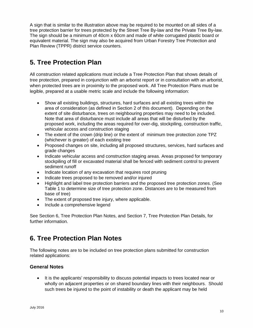
A sign that is similar to the illustration above may be required to be mounted on all sides of a tree protection barrier for trees protected by the Street Tree By-law and the Private Tree By-law. The sign should be a minimum of 40cm x 60cm and made of white corrugated plastic board or equivalent material. The sign may also be acquired from Urban Forestry Tree Protection and Plan Review (TPPR) district service counters.
5. Tree Protection Plan
All construction related applications must include a Tree Protection Plan that shows details of tree protection, prepared in conjunction with an arborist report or in consultation with an arborist, when protected trees are in proximity to the proposed work. All Tree Protection Plans must be legible, prepared at a usable metric scale and include the following information:
• Show all existing buildings, structures, hard surfaces and all existing trees within thearea of consideration (as defined in Section 2 of this document). Depending on theextent of site disturbance, trees on neighbouring properties may need to be included.Note that area of disturbance must include all areas that will be disturbed by theproposed work, including the areas required for over-dig, stockpiling, construction traffic,vehicular access and construction staging
• The extent of the crown (drip line) or the extent of minimum tree protection zone TPZ(whichever is greater) of each existing tree
• Proposed changes on site, including all proposed structures, services, hard surfaces andgrade changes
• Indicate vehicular access and construction staging areas. Areas proposed for temporarystockpiling of fill or excavated material shall be fenced with sediment control to preventsediment runoff
• Indicate location of any excavation that requires root pruning• Indicate trees proposed to be removed and/or injured• Highlight and label tree protection barriers and the proposed tree protection zones. (See
Table 1 to determine size of tree protection zone. Distances are to be measured frombase of tree)
• The extent of proposed tree injury, where applicable.• Include a comprehensive legend
See Section 6, Tree Protection Plan Notes, and Section 7, Tree Protection Plan Details, for further information.
6. Tree Protection Plan Notes
The following notes are to be included on tree protection plans submitted for construction related applications:
General Notes
• It is the applicants’ responsibility to discuss potential impacts to trees located near orwholly on adjacent properties or on shared boundary lines with their neighbours. Shouldsuch trees be injured to the point of instability or death the applicant may be held
July 2016 10

responsible through civil action. The applicant would also be required to replace such trees to the satisfaction of Urban Forestry
• Tree protection barriers shall be installed to standards as detailed in this document andto the satisfaction of Urban Forestry
• Tree protection barriers must be installed using plywood clad hoarding (minimum 19mmor ¾" thick) or an equivalent approved by Urban Forestry
• Where required, signs as specified in Section 4, Tree Protection Signage must beattached to all sides of the barrier
• Prior to the commencement of any site activity such as site alteration, demolition orconstruction, the tree protection measures specified on this plan must be installed to thesatisfaction of Urban Forestry
• Once all tree/site protection measures have been installed, Urban Forestry staff must becontacted to arrange for an inspection of the site and approval of the tree/site protectionrequirements. Photographs that clearly show the installed tree/site protection shall beprovided for Urban Forestry review
• Where changes to the location of the approved TPZ or sediment control or wheretemporary access to the TPZ is proposed, Urban Forestry must be contacted to obtainapproval prior to alteration
• Tree protection barriers must remain in place and in good condition during demolition,construction and/or site disturbance, including landscaping, and must not be altered,moved or removed until authorized by Urban Forestry
• No construction activities including grade changes, surface treatments or excavation ofany kind are permitted within the area identified on the Tree Protection Plan or Site Planas a minimum tree protection zone (TPZ). No root cutting is permitted. No storage ofmaterials or fill is permitted within the TPZ. No movement or storage of vehicles orequipment is permitted within the TPZ. The area(s) identified as a TPZ must beprotected and remain undisturbed at all times
• All additional tree protection or preservation requirements, above and beyond theinstallation of tree protection barriers, must be undertaken or implemented as detailed inthe Urban Forestry approved arborist report and/or the approved tree protection planand to the satisfaction of Urban Forestry
• If the minimum tree protection zone (TPZ) must be reduced to facilitate constructionaccess, the tree protection barriers must be maintained at a lesser distance and theexposed portion of TPZ must be protected using a horizontal root protection methodapproved by Urban Forestry
• Any roots or branches indicated on this plan which require pruning, as approved byUrban Forestry, must be pruned by an arborist. All pruning of tree roots and branchesmust be in accordance with good arboricultural practice. Roots that have receivedapproval from Urban Forestry to be pruned must first be exposed using pneumatic (air)excavation, by hand digging or by a using low pressure hydraulic (water) excavation.The water pressure for hydraulic excavation must be low enough that root bark is notdamaged or removed. This will allow a proper pruning cut and minimize tearing of theroots. The arborist retained to carry out crown or root pruning must contact UrbanForestry no less than three working days prior to conducting any specified work
• The applicant/owner shall protect all by-law regulated trees in the area of considerationthat have not been approved for removal throughout development works to thesatisfaction of Urban Forestry
July 2016 11

• Convictions of offences respecting the regulations in the Street Tree By-law and PrivateTree By-law are subject to fines. A person convicted of an offence under these by-lawsis liable to a minimum fine of $500 and a maximum fine of $100,000 per tree, and /or aSpecial Fine of $100,000. The landowner may be ordered by the City to stop thecontravening activity or ordered to undertake work to correct the contravention
• Prior to site disturbance the owner must confirm that no migratory birds are making useof the site for nesting. The owner must ensure that the works are in conformance withthe Migratory Bird Convention Act and that no migratory bird nests will be impacted bythe proposed work
The following additional notes shall be added on plans for properties regulated by the Ravine and Natural Feature Protection Bylaw:
• Ravine and Natural Feature Protection By-law (RNFP) note:
Ravine & Natural Feature Protection By-law
The Ravine & Natural Feature Protection By-law, Chapter 658 of the City of Toronto Municipal Code, regulates the injury and destruction of trees, dumping of refuse and changes to grade within protected
areas. Under this by-law protected trees may not be removed, injured or destroyed, and protected grades may
not be altered, without written authorisation from Urban Forestry Ravine & Natural Feature Protection, on behalf of the General Manager of Parks, Forestry & Recreation.
Convictions of offences respecting the regulations in the Ravine and Natural Feature Protection By-law are subject to fines, and the landowner may be ordered by the court to restore the area to the satisfaction of the City. A person convicted of an offence under this Bylaw is liable to a minimum fine of $500 and a maximum fine of $100,000 for each tree destroyed, a maximum fine of $100,000 for any other offence committed under this chapter, and /or a Special Fine of $100,000. A person convicted of a continuing
offence, including failure to comply with ravine permit conditions is liable to a maximum fine of not more than $10,000 for each day or a part of a day that the offence continues.
• The exact location of the limit of the RNFP area must be shown on all pertinent plansincluding Tree Protection Plan. The applicant/owner shall have this limit marked ontheir survey or other plans drawn to a suitable scale. This service costs $72.37 plus taxand can be requested by contacting the City of Toronto, Information and Technology,Geospatial Competency Centre, Map Service Counter at 416-392-2506 [email protected]. This line may then be transferred onto other plans to besubmitted.
• Sediment control fencing shall be installed in the locations as indicated in the Urban
Forestry approved sediment control plan. The sediment control fencing must beinstalled to Ontario Provincial Standards (OPSD-219.130, see Section 7, Figure 5) andto the satisfaction of Urban Forestry. Sediment control near trees and over root zonesshall be installed as shown on Figure 6 of this document and to the satisfaction of UrbanForestry.
July 2016 12

7. Tree Protection Plan Details
The following diagrams provide details for tree protection barriers and sediment protection barriers:
Figure 4: Urban Forestry Detail TP-1
July 2016 13

Figure 5: OPSD Detail for Heavy Duty Silt Fence Barrier
July 2016 14

The following detail shall be used when constructing sediment protection fencing near trees.
Figure 6: Sediment control barriers for use over tree root zone
8. Permits for Tree Removal or Injury
If the full minimum tree protection zone (TPZ) as identified in Section 2 cannot be provided, a permit to injure the tree must be obtained.
Any requests for removal or injury of a tree protected by City by-laws must be made on the appropriate application forms and submitted to Urban Forestry at the appropriate address. Permit application forms are available at www.toronto.ca/trees. Any requests for tree relocation will be considered as a tree injury.
If approval is granted for removal of a City-owned tree, applicants will assume all costs involved, which include appraised tree value, removal, and tree replacement costs. If approval is granted for removal of private trees or trees in ravine and natural feature protected areas, the permit will be subject to conditions, including tree replacement. If approval is granted for injury of City-owned, private trees or trees in ravine and natural feature protected areas, the permit will be subject to conditions, including implementation of a Tree Protection Plan, as determined by Urban Forestry.
In some instances, where the tree is healthy and the management of the tree or forest cover has not been addressed to the satisfaction of Urban Forestry, requests received by Urban Forestry may be forwarded to a Community Council and City Council for approval.
Urban Forestry does not have the authority to issue a permit to injure or remove a heritage tree2. Such requests would be forwarded to a Community Council and/or City Council for approval.
Butternut (Juglans cinerea, L.) is an endangered species. Butternuts and their habitat are protected under Endangered Species Act (S.O. 2007, c.6) available on the Government of Ontario website at http://www.ontario.ca/laws/statute/07e06/v1. A permit to injure or remove a butternut tree must be obtained from the Ministry of Natural Resources and Forestry Ontario.
2 Heritage Tree – A tree that has been designated under Part IV of the Ontario Heritage Act or trees recognized as heritage trees by the Ontario Heritage Tree Program of Trees Ontario.
July 2016 15

Any person who contravenes any provision of the City's tree protection by-law is guilty of an offence.
More information on tree protection and permit application forms for tree removal and injury are available on Urban Forestry web page at www.toronto.ca/trees.
For additional information regarding the removal or injury of trees protected under City by-laws, please call 311.
9. Tree Guarantee Deposits
Tree Protection Guarantee
Urban Forestry may request a tree protection guarantee to secure the protection of trees that may be impacted by work on city streets, or to secure the satisfaction of all conditions of permit issuance. Tree protection guarantees held by the City shall only be released by the City provided that all construction activities are complete, compliance with all permit terms and conditions has been verified, there has been no encroachment into the minimum tree protection zone (TPZ) and the trees are healthy and in a state of vigorous growth.
Where Urban Forestry has confirmed an unauthorized encroachment into the TPZ or the terms and conditions of a permit have not been complied with, Urban Forestry will retain the guarantee until satisfactory compliance.
It is the applicant’s responsibility to submit a written request to Urban Forestry for the refund of the tree protection guarantee deposit as soon as construction and landscaping is completed.
Tree Planting Security
Urban Forestry may request a tree planting security deposit in an amount equal to the cost of planting and maintenance for two (2) years in order to ensure compliance with approved landscape or replanting plans. The security deposit may be held by the City after the planting of the trees for a period of two (2) years and shall be released by the City provided that the trees have been maintained, are healthy and in a state of vigorous growth upon inspection, two (2) years after planting. It is the applicant’s responsibility to advise Urban Forestry that trees have been planted in accordance with approved plans, in order that the two (2) year maintenance period begin.
Prior to release by the City, any dead/dying trees must be replaced, deadwood and sucker growth should be pruned, and mulch should be topped up where necessary. If stakes and ties were used, they must be removed within one (1) year. Any encroachments are to be removed prior to assumption, including walkways, timbers or bricks that result in increased height of soil or mulch around the trees, and lights in trees.
It is the applicant’s responsibility to submit a written request to Urban Forestry for the refund of a Tree Guarantee Deposit, two (2) years after the completion of all construction activity and/or two (2) years after tree planting. This request should be made during the growing season, not while
July 2016 16

the trees are dormant, so that a site inspection can be arranged to confirm the trees are acceptable. The City will not release security deposits where trees are not in good condition, or if there are encroachments.
Financial securities must be in the form of a certified cheque, letter of credit or an alternative acceptable to Urban Forestry, with amounts payable to the Treasurer, City of Toronto.
10. Emergency Repairs to Utilities
The utility company is responsible for notifying Urban Forestry by calling 311 as soon as possible when by-law regulated trees are involved, so that an inspector can be dispatched. Urban Forestry staff may be contacted after hours by calling 311, and requesting the assistance of an on-call Urban Forestry inspector.
11. Tree Species that are Intolerant of ConstructionDisturbance
The following tree species are intolerant of construction disturbance, and tree protection plans must take this into account. The tree protection zones required by these species may need to be quite extensive to avoid damage to the roots and crown associated with compaction, excavation or construction above grade that will impact the branches.
Acer rubrum (red maple) Acer saccharum (sugar maple) Betula papyrifera (paper birch) Carya glabra (pignut hickory) Fagus grandifolia (American beech) Liriodendron tulipifera (tulip tree) Ostrya virginiana (ironwood) Pinus resinosa (red pine) Pinus strobus (white pine) Prunus serotina (black cherry) Quercus alba (white oak) Quercus velutina (black oak) Tsuga canadensis (eastern hemlock) Tilia americana (basswood)
July 2016 17

12. Contact Information
Tree Protection and Plan Review (City-owned and Private Trees)
North York District 5100 Yonge Street, 3rd Floor Toronto, ON, M2N 5V7 Telephone: 416-395-6670 Fax: 416-395-7886 [email protected]
Etobicoke York District 399 The West Mall, Main Floor, North Block Toronto, ON, M9C 2Y2 Telephone: 416-338-6596 Fax: 416-394-8935 [email protected]
Scarborough District 150 Borough Drive, 5th Floor Toronto, ON, M1P 4N7 Telephone: 416-338-5566 Fax: 416-396-4170 [email protected]
Toronto and East York District 50 Booth Avenue, 2nd Floor Toronto, ON, M4M 2M2 Telephone: 416-392-7391 Fax: 416-392-7277 [email protected]
Ravine and Natural Feature Protection
General Enquiries Telephone: 416-392-2513 Fax: 416-392-1915 Email: [email protected]
Office Location 18 Dyas Road, 1st Floor Toronto, ON, M3B 1V5
Areas regulated under Ravine and Natural Feature Protection By-law can be viewed using the City's mapping tool available at www.toronto.ca/trees.
July 2016 18