312146B MLX Lubrication System - Graco · MLX™ Lubrication System ... accepting grease using a...
28
312146B Instructions – Parts MLX ™ Lubrication System - For automatically lubricating Class 3, 4, and 5 vehicle chassis - 12 VDC Models: 258344, 258345, 563605, 563606, 563607, 563608, 563609, 563610, 563611, 563619, 563621, 24 VDC Models: 24B307, 24B308, 24B309, 24B310, 24B311, 24B312, 24B313, 24B314, 24B315, 24B316 1200 psi ( 8.3 MPa, 82.74 bar) Maximum Working Pressure Important Safety Instructions Read all warnings and instructions in this manual. Save these instructions. ti9792 Bulletin RW-40050, 30020
-
Upload
duongthien -
Category
Documents
-
view
227 -
download
1
Transcript of 312146B MLX Lubrication System - Graco · MLX™ Lubrication System ... accepting grease using a...
312146B
Instructions – Parts
MLX™ Lubrication System
- For automatically lubricating Class 3, 4, and 5 vehicle chassis -
12 VDC Models: 258344, 258345, 563605, 563606, 563607, 563608, 563609, 563610, 563611, 563619, 563621,
24 VDC Models: 24B307, 24B308, 24B309, 24B310, 24B311, 24B312,24B313, 24B314, 24B315, 24B316
1200 psi ( 8.3 MPa, 82.74 bar) Maximum Working Pressure
Important Safety InstructionsRead all warnings and instructions in this manual. Save these instructions.
ti9792
Bulletin RW-40050, 30020

Warnings
2 312146B
WarningsThe following warnings are for the setup, use, grounding, maintenance, and repair of this equipment. The exclama-tion point symbol alerts you to a general warning and the hazard symbol refers to procedure-specific risk. Refer back to these warnings. Additional, product-specific warnings may be found throughout the body of this manual where applicable.
WARNINGFIRE AND EXPLOSION HAZARD When flammable fluids are present in the work area, such as gasoline and windshield wiper fluid, be aware that flammable fumes can ignite or explode. To help prevent fire and explosion:• Use equipment only in well ventilated area.• Eliminate all ignition sources, such as cigarettes and portable electric lamps. • Keep work area free of debris, including rags and spilled or open containers of solvent and gasoline.• Do not plug or unplug power cords or turn lights on or off when flammable fumes are present.• Ground all equipment in the work area.• Use only grounded hoses.• If there is static sparking or you feel a shock, stop operation immediately. Do not use equipment
until you identify and correct the problem.• Keep a working fire extinguisher in the work area.
EQUIPMENT MISUSE HAZARD Misuse can cause death or serious injury.• Do not operate the unit when fatigued or under the influence of drugs or alcohol.• Do not exceed the maximum working pressure or temperature rating of the lowest rated system
component. See Technical Data in all equipment manuals.• Use fluids and solvents that are compatible with equipment wetted parts. See Technical Data in all
equipment manuals. Read fluid and solvent manufacturer’s warnings. For complete information about your material, request MSDS forms from distributor or retailer.
• Check equipment daily. Repair or replace worn or damaged parts immediately with genuine manu-facturer’s replacement parts only.
• Do not alter or modify equipment.• Use equipment only for its intended purpose. Call your distributor for information.• Route hoses and cables away from traffic areas, sharp edges, moving parts, and hot surfaces.• Do not kink or over bend hoses or use hoses to pull equipment.• Keep children and animals away from work area.• Comply with all applicable safety regulations.
ELECTRIC SHOCK HAZARDImproper grounding, setup, or usage of the system can cause electric shock.• Turn off and disconnect power at main switch before disconnecting any cables and before servicing
equipment.• Connect only to grounded power source.• All electrical wiring must be done by a qualified electrician and comply with all local codes and
regulations.

Warnings
312146B 3
SKIN INJECTION HAZARDHigh-pressure fluid from dispense valve, hose leaks, or ruptured components will pierce skin. This may look like just a cut, but it is a serious injury that can result in amputation. Get immediate surgical treatment.• Do not point dispense valve at anyone or at any part of the body.• Do not put your hand over the end of the dispense nozzle.• Do not stop or deflect leaks with your hand, body, glove, or rag.• Follow Pressure Relief Procedure in this manual, when you stop spraying and before cleaning,
checking, or servicing equipment.
MOVING PARTS HAZARD Moving parts can pinch or amputate fingers and other body parts.• Keep clear of moving parts.• Do not operate equipment with protective guards or covers removed.• Pressurized equipment can start without warning. Before checking, moving, or servicing equipment,
follow the Pressure Relief Procedure in this manual. Disconnect power or air supply.
BURN HAZARDEquipment surfaces and fluid that’s heated can become very hot during operation. To avoid severe burns, do not touch hot fluid or equipment. Wait until equipment/fluid has cooled completely.
PERSONAL PROTECTIVE EQUIPMENTYou must wear appropriate protective equipment when operating, servicing, or when in the operating area of the equipment to help protect you from serious injury, including eye injury, inhalation of toxic fumes, burns, and hearing loss. This equipment includes but is not limited to:• Protective eyewear • Clothing and respirator as recommended by the fluid and solvent manufacturer• Gloves• Hearing protection
WARNING
Installation
4 312146B
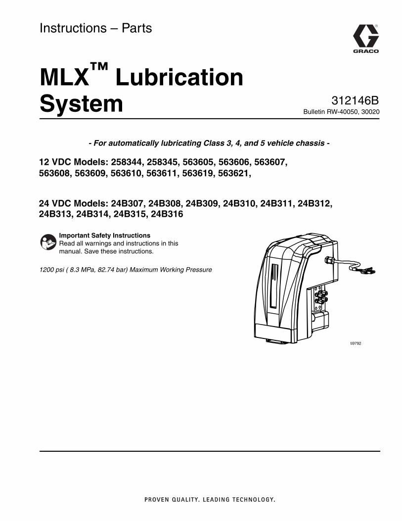
InstallationYou will need the items identified in Table 1 and all tools listed in Table 2 to install the MLX lubrication system.
Table 1
Table 2: Tools Needed
Before You Begin
1. Clean the area around the fitting using a wire brush and rags.
2. Verify that all existing zerk grease fittings are accepting grease using a grease gun set at a maxi-mum of 500 psi.
NOTE: If fitting does not accept grease at this pressure, do not connect the system to this point. Instead, deter-mine the reason the fitting is not accepting grease and rectify. All lube points should be filled with grease before removing the zerk fittings.
3. Jack the front end of the vehicle off the ground to ensure no part of the vehicle comes in contact with any MLX Pump components when turning the wheels.
1. Determine Mounting LocationFirst determine where to mount the MLX Pump. Depending on clearance and congestion, mount the MLX Pump for easy access to and protection for the unit. This unit can be mounted under the hood, behind the cab, on the frame or under the vehicle.
NOTE: Each tubing bundle is 20 ft long, therefore mount unit within 20 ft of the farthest lube point.
Units are shipped with manifolds and tubing attached. Reference the Manifolds section (Pages 9-11) for volu-metric output per point and recommended connection locations.
Proper Tubing and Fitting Assembly:
Original Assembly: With nut finger tight on fitting body, insert tubing until it bottoms in the fitting. Complete the seal with one wrench turn.
Re-Assembly: Tighten to original make-up position plus 1/16 turn to reseat sleeve. This can be done approxi-mately 8 times before new ferrules and nuts will be required if this assembly method is used.
Description
Quantity per Kit
8 Pt 9 Pt 10 Pt 11 Pt 12 PtInstallation Manual 1 1 1 1 1Mounting Guide 1 1 1 1 1Housing Assembly 1 1 1 1 1Manifold Assemblies (attached to Housing)
2 2 2 2 2
Hardware Kit (Includes Mounting Hardware)
1 1 1 1 1
Grease Cartridge 1 1 1 1 1Power Cord 1 1 1 1 1Tie Wraps / Pack 100 1 1 1 1 1Single Tube 20 ft 1 12 Tube Bundle 20 ft 1 4 2 2 33 Tube Bundle 20 ft 2 0 2 2 2
Center punch and Hammer3/16", 7/16", 9/16”, 1/2", 3/4” (19 mm) open end wrench3/16”, 7/16", 1/2" deep well socket and ratchetNylon tube cutter (available from Parker Hannifin or Synflex tubing)Wire brushGrease GunElectric drill motor5/16" drill bit9/64" Allen wrenchWire Cutters w/ stripper and crimper"Romex" Wire slitter (Available from any tool supply or electrical supply company.)
Use proper safety jack stands to secure the vehicle. Improper safety precaution can be fatal to the individ-ual installing and working under the vehicle.
Installation
312146B 5
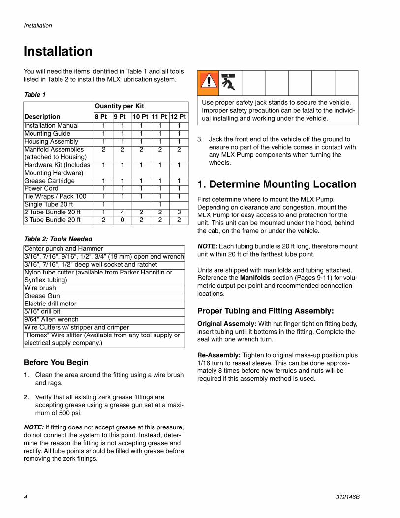
2. Replace Zerk Grease Fittings
a. Make sure area where fittings are to be installed is clean. Use rags, wire brush, or low-pressure air to clean area.
b. Remove zerk grease fittings.
c. Install the new 3/16 in. (8 mm) fittings to the lube points on the vehicle.
3. Mount Housinga. Select the desired location where the MLX will
be mounted.
b. Referring to the guide provided on page 25 for hole locations, mark the four holes with a cen-terpunch and hammer.
c. Drill 3/8 in. holes.
d. Use 5/16 in. grade 5 bolts and self-locking nuts to mount the MLX Pump unit to the chassis of the vehicle.
4. Route Grease Tubes and Electrical CablePre-measured lengths of tube bundles are supplied with each kit.
1. Route tubing and cable along the inside of the frame.
2. Anchor every 12 - 15 in. (305 - 381 mm).
NOTE: • Always use pre-filled approved 3/16 OD Graco tub-
ing. Other lines cannot withstand pressure devel-oped by the MLX Pump.
• The tube bundles should be routed inside the frame and secured for protection. The maximum distance between anchor points should be 12 - 15 in. (305 - 381 mm).
• When installing the tubing, AVOID routing any tub-ing within 3 in. (76 mm) of an exhaust manifold or muffler.
• The electrical cable should be routed at the same time as the tubing bundles. It is run between the MLX Pump unit and the electrical box where an “ignition on” signal, a constant 12 VDC or 24 VDC source and ground are presents.
• The electrical cable can be tied off with the tubing bundles to the frame of the vehicle.
5. Prepare Tubing Bundles and Install at the Various Lube Points
a. After the tubing bundles are secured to the frame and inserted into the tire well area, use the Romex wire stripper to score and cut the outside sheath on the tube bundles back to the point where the tube bundle meets the first lube point. Care must be used to prevent puncturing or cutting the tubes inside of sheath.
b. Peel back the outside sheath and roll the sheath back on itself to form a 1/2 - 3/4 in. ( 13 - 19 mm) protective collar. Any excess tubing sheath can be removed.
To protect your eyes, always wear safety glasses when working on this equipment.
Installation
6 312146B
c. Route tubes where they can be tied down securely with plastic tie straps and yet flex or move with moving parts.
d. Align tubing with the fittings and make square cuts using a tube cutter.
e. Turn the wheels in each direction and determine if tubing of the MLX Pump rubs or interferes.
f. After determining that there is no interference, attach and tighten the tubes to the lube points with a 7/16 in. open-end wrench.
6. Set the Time Delaya. Remove the front cover of the MLX Pump.
b. Slide the grease reservoir assembly out of the housing.
c. Remove the long black grommet on the right side to expose the setting switches. Verify initial time delay is set to 1 minute.
d. From top to bottom, set the switches to left (0), left (0), left (0), left (0). This same information can also be found on the label attached inside of the housing and on the chart in the MLX Time Delay section (Page 8).
e. Replace the black grommet after setting the switches.
NOTE: The 1 minute setting is for set-up testing of the MLX Pump system. Reset the wait time to the desired time prior to the vehicle heading back out on the road.
7. Connect Electrical Wiring
The MLX Pump has its own fused wiring. Refer to the Wire Diagram on page 26.
Perform the following actions in order:
a. Disconnect positive lead from battery.
b. Remove fuse from fuse holder.
c. Connect black lead to an environmentally pro-tected battery negative.
d. Connect white, fused lead to positive lead at convenient location, preferably close to the bat-tery.
e. Connect green lead to an ignition-switched lead.
f. Reinstall fuse in fuse holder.
8. Install Grease Cartridge to Grease Reservoir and Connect MLX Pump
a. Disassemble the grease reservoir.
b. Install the grease cartridge into the opening of the cartridge base.
c. Place plastic follower plate, spring and clear outer plastic reservoir cover over the grease cartridge and lock the cartridge base with the clear plastic cartridge cover.
Contents are under pressure. Open with care!
Installation
312146B 7
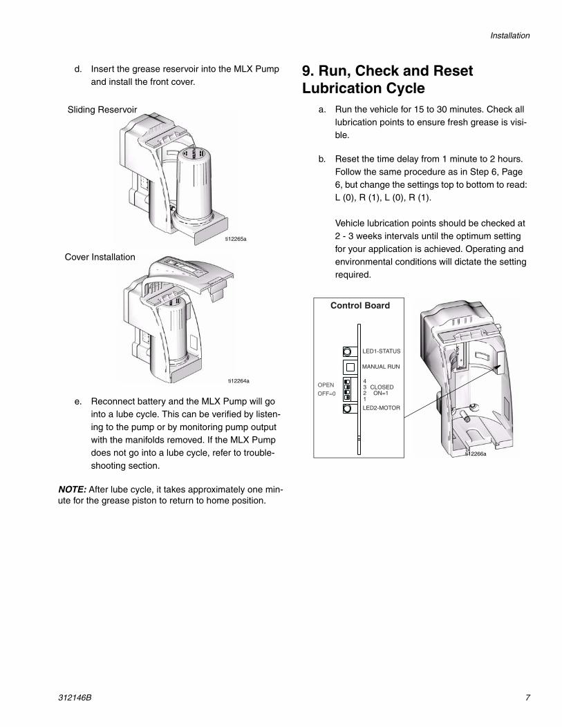
d. Insert the grease reservoir into the MLX Pump and install the front cover.
e. Reconnect battery and the MLX Pump will go into a lube cycle. This can be verified by listen-ing to the pump or by monitoring pump output with the manifolds removed. If the MLX Pump does not go into a lube cycle, refer to trouble-shooting section.
NOTE: After lube cycle, it takes approximately one min-ute for the grease piston to return to home position.
9. Run, Check and Reset Lubrication Cycle
a. Run the vehicle for 15 to 30 minutes. Check all lubrication points to ensure fresh grease is visi-ble.
b. Reset the time delay from 1 minute to 2 hours. Follow the same procedure as in Step 6, Page 6, but change the settings top to bottom to read: L (0), R (1), L (0), R (1).
Vehicle lubrication points should be checked at 2 - 3 weeks intervals until the optimum setting for your application is achieved. Operating and environmental conditions will dictate the setting required.
ti12265a
Sliding Reservoir
ti12264a
Cover Installation
ti12266a
Installation
8 312146B
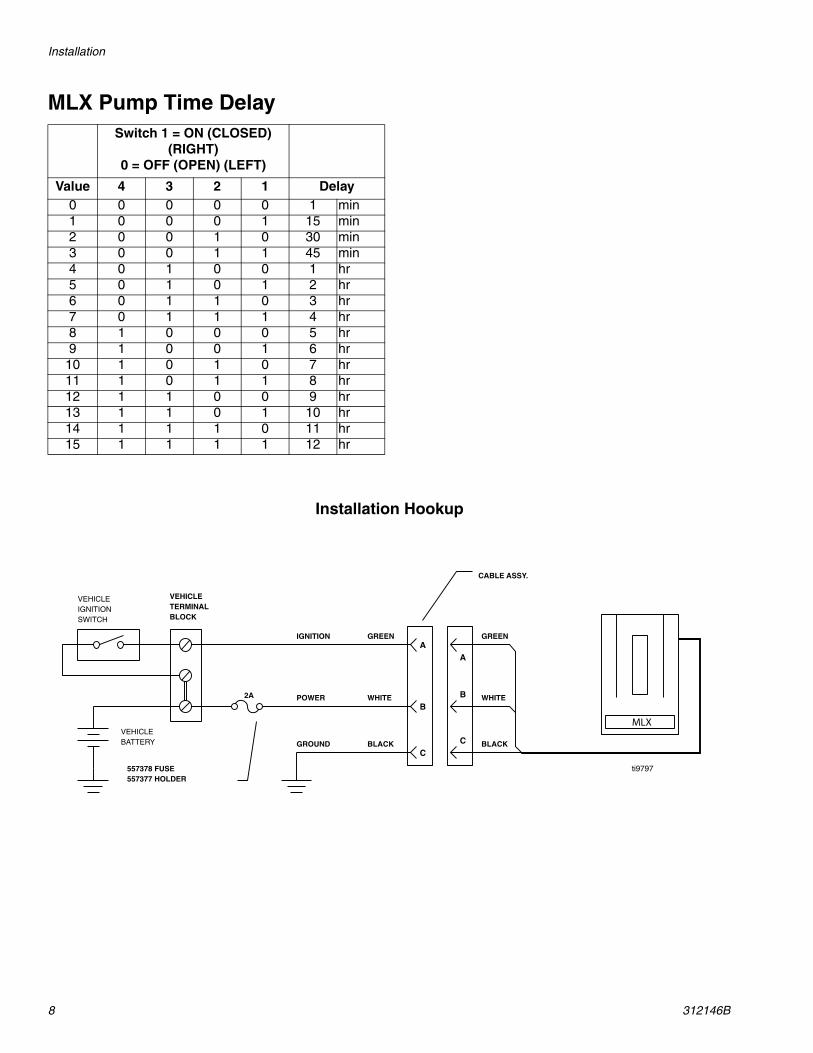
MLX Pump Time DelaySwitch 1 = ON (CLOSED)
(RIGHT)0 = OFF (OPEN) (LEFT)
Value 4 3 2 1 Delay0 0 0 0 0 1 min1 0 0 0 1 15 min2 0 0 1 0 30 min3 0 0 1 1 45 min4 0 1 0 0 1 hr5 0 1 0 1 2 hr6 0 1 1 0 3 hr7 0 1 1 1 4 hr8 1 0 0 0 5 hr9 1 0 0 1 6 hr
10 1 0 1 0 7 hr11 1 0 1 1 8 hr12 1 1 0 0 9 hr13 1 1 0 1 10 hr14 1 1 1 0 11 hr15 1 1 1 1 12 hr
2A
A
B
CBLACK
WHITE
GREEN
GROUND
POWER
IGNITION
VEHICLEIGNITIONSWITCH
VEHICLETERMINALBLOCK
VEHICLEBATTERY C
B
A
BLACK
GREEN
WHITE
CABLE ASSY.
557378 FUSE557377 HOLDER
Installation Hookup
MLX
ti9797
8 - Point Auto Lubrication System
312146B 9
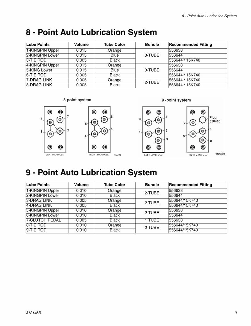
8 - Point Auto Lubrication System
9 - Point Auto Lubrication System
Lube Points Volume Tube Color Bundle Recommended Fitting1-KINGPIN Upper 0.015 Orange
3-TUBE556638
2-KINGPIN Lower 0.015 Blue 5566443-TIE ROD 0.005 Black 556644 / 15K7404-KINGPIN Upper 0.015 Orange
3-TUBE556638
5-KING Lower 0.015 Blue 5566446-TIE ROD 0.005 Black 556644 / 15K7407-DRAG LINK 0.005 Orange
2-TUBE556644 / 15K740
8-DRAG LINK 0.005 Black 556644 / 15K740
Lube Points Volume Tube Color Bundle Recommended Fitting1-KINGPIN Upper 0.010 Orange
2-TUBE556638
2-KINGPIN Lower 0.010 Black 5566443-DRAG LINK 0.005 Orange
2 TUBE556644/15K740
4-DRAG LINK 0.005 Black 556644/15K7405-KINGPIN Upper 0.010 Orange
2 TUBE556638
6-KINGPIN Lower 0.010 Black 5566447-CLUTCH PEDAL 0.005 Black 1 TUBE 5566388-TIE ROD 0.010 Orange
2 TUBE556644/15K740
9-TIE ROD 0.010 Black 556644/15K740
3
1
7
2
6
8
4
5
ti9798 ti12682a
10 312146B
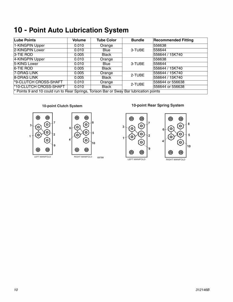
10 - Point Auto Lubrication System Lube Points Volume Tube Color Bundle Recommended Fitting1-KINGPIN Upper 0.010 Orange
3-TUBE556638
2-KINGPIN Lower 0.010 Blue 5566443-TIE ROD 0.005 Black 556644 / 15K7404-KINGPIN Upper 0.010 Orange
3-TUBE556638
5-KING Lower 0.010 Blue 5566446-TIE ROD 0.005 Black 556644 / 15K7407-DRAG LINK 0.005 Orange
2-TUBE556644 / 15K740
8-DRAG LINK 0.005 Black 556644 / 15K740*9-CLUTCH CROSS-SHAFT 0.010 Orange
2-TUBE556644 or 556638
*10-CLUTCH CROSS-SHAFT 0.010 Black 556644 or 556638* Points 9 and 10 could run to Rear Springs, Torison Bar or Sway Bar lubrication points
3
1
7
2
6
8
5
4
910
ti9799
3
1
7
2
6
8
5
4
910
312146B 11
11 - Point Auto Lubrication System
12 - Point Auto Lubrication System
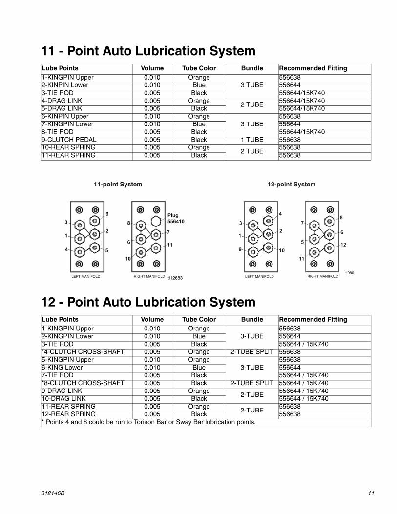
Lube Points Volume Tube Color Bundle Recommended Fitting1-KINGPIN Upper 0.010 Orange
3 TUBE556638
2-KINPIN Lower 0.010 Blue 5566443-TIE ROD 0.005 Black 556644/15K7404-DRAG LINK 0.005 Orange
2 TUBE556644/15K740
5-DRAG LINK 0.005 Black 556644/15K7406-KINPIN Upper 0.010 Orange
3 TUBE556638
7-KINGPIN Lower 0.010 Blue 5566448-TIE ROD 0.005 Black 556644/15K7409-CLUTCH PEDAL 0.005 Black 1 TUBE 55663810-REAR SPRING 0.005 Orange
2 TUBE556638
11-REAR SPRING 0.005 Black 556638
Lube Points Volume Tube Color Bundle Recommended Fitting1-KINGPIN Upper 0.010 Orange
3-TUBE556638
2-KINGPIN Lower 0.010 Blue 5566443-TIE ROD 0.005 Black 556644 / 15K740*4-CLUTCH CROSS-SHAFT 0.005 Orange 2-TUBE SPLIT 5566385-KINGPIN Upper 0.010 Orange
3-TUBE556638
6-KING Lower 0.010 Blue 5566447-TIE ROD 0.005 Black 556644 / 15K740*8-CLUTCH CROSS-SHAFT 0.005 Black 2-TUBE SPLIT 556644 / 15K7409-DRAG LINK 0.005 Orange
2-TUBE556644 / 15K740
10-DRAG LINK 0.005 Black 556644 / 15K74011-REAR SPRING 0.005 Orange
2-TUBE556638
12-REAR SPRING 0.005 Black 556638* Points 4 and 8 could be run to Torison Bar or Sway Bar lubrication points.
3
1
72 6
8
5
4
12109
11
ti9801ti12683
Connections
12 312146B
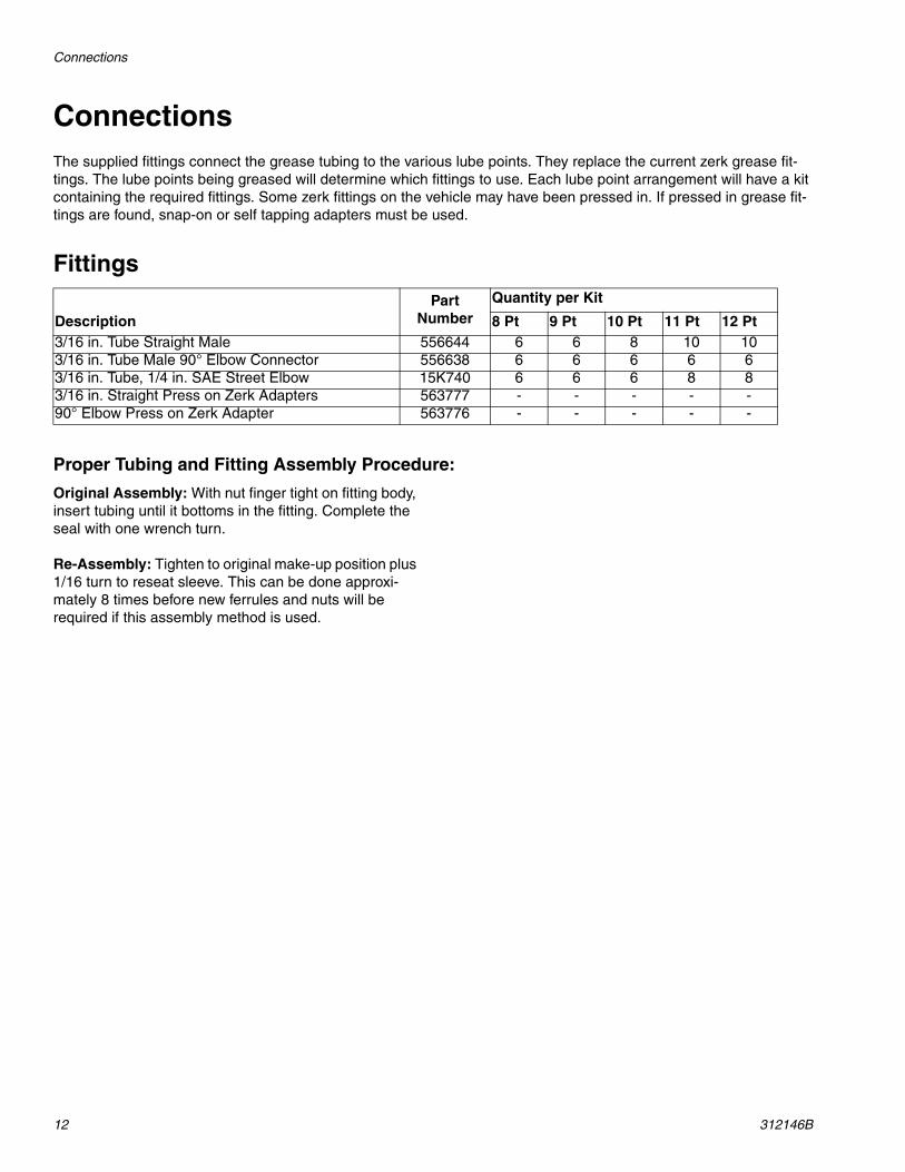
ConnectionsThe supplied fittings connect the grease tubing to the various lube points. They replace the current zerk grease fit-tings. The lube points being greased will determine which fittings to use. Each lube point arrangement will have a kit containing the required fittings. Some zerk fittings on the vehicle may have been pressed in. If pressed in grease fit-tings are found, snap-on or self tapping adapters must be used.
Fittings
Proper Tubing and Fitting Assembly Procedure:
Original Assembly: With nut finger tight on fitting body, insert tubing until it bottoms in the fitting. Complete the seal with one wrench turn.
Re-Assembly: Tighten to original make-up position plus 1/16 turn to reseat sleeve. This can be done approxi-mately 8 times before new ferrules and nuts will be required if this assembly method is used.
DescriptionPart
NumberQuantity per Kit
8 Pt 9 Pt 10 Pt 11 Pt 12 Pt3/16 in. Tube Straight Male 556644 6 6 8 10 103/16 in. Tube Male 90° Elbow Connector 556638 6 6 6 6 63/16 in. Tube, 1/4 in. SAE Street Elbow 15K740 6 6 6 8 83/16 in. Straight Press on Zerk Adapters 563777 - - - - -90° Elbow Press on Zerk Adapter 563776 - - - - -
System Components
312146B 13
System Components
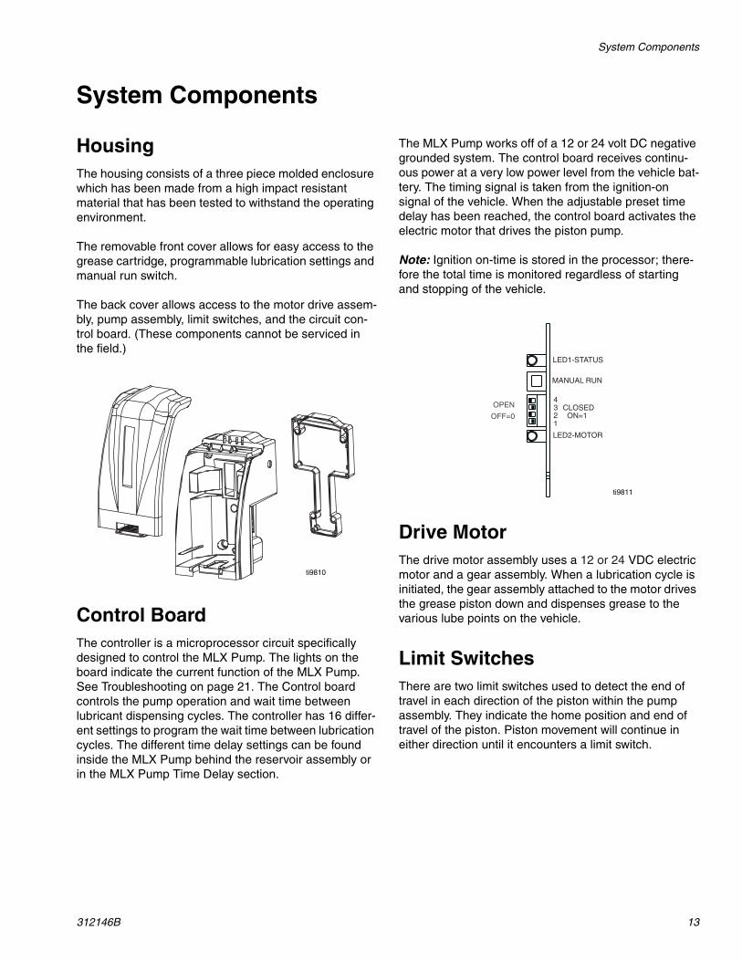
HousingThe housing consists of a three piece molded enclosure which has been made from a high impact resistant material that has been tested to withstand the operating environment.
The removable front cover allows for easy access to the grease cartridge, programmable lubrication settings and manual run switch.
The back cover allows access to the motor drive assem-bly, pump assembly, limit switches, and the circuit con-trol board. (These components cannot be serviced in the field.)
Control BoardThe controller is a microprocessor circuit specifically designed to control the MLX Pump. The lights on the board indicate the current function of the MLX Pump. See Troubleshooting on page 21. The Control board controls the pump operation and wait time between lubricant dispensing cycles. The controller has 16 differ-ent settings to program the wait time between lubrication cycles. The different time delay settings can be found inside the MLX Pump behind the reservoir assembly or in the MLX Pump Time Delay section.
The MLX Pump works off of a 12 or 24 volt DC negative grounded system. The control board receives continu-ous power at a very low power level from the vehicle bat-tery. The timing signal is taken from the ignition-on signal of the vehicle. When the adjustable preset time delay has been reached, the control board activates the electric motor that drives the piston pump.
Note: Ignition on-time is stored in the processor; there-fore the total time is monitored regardless of starting and stopping of the vehicle.
Drive MotorThe drive motor assembly uses a 12 or 24 VDC electric motor and a gear assembly. When a lubrication cycle is initiated, the gear assembly attached to the motor drives the grease piston down and dispenses grease to the various lube points on the vehicle.
Limit SwitchesThere are two limit switches used to detect the end of travel in each direction of the piston within the pump assembly. They indicate the home position and end of travel of the piston. Piston movement will continue in either direction until it encounters a limit switch.
ti9810
ti9811
System Components
14 312146B
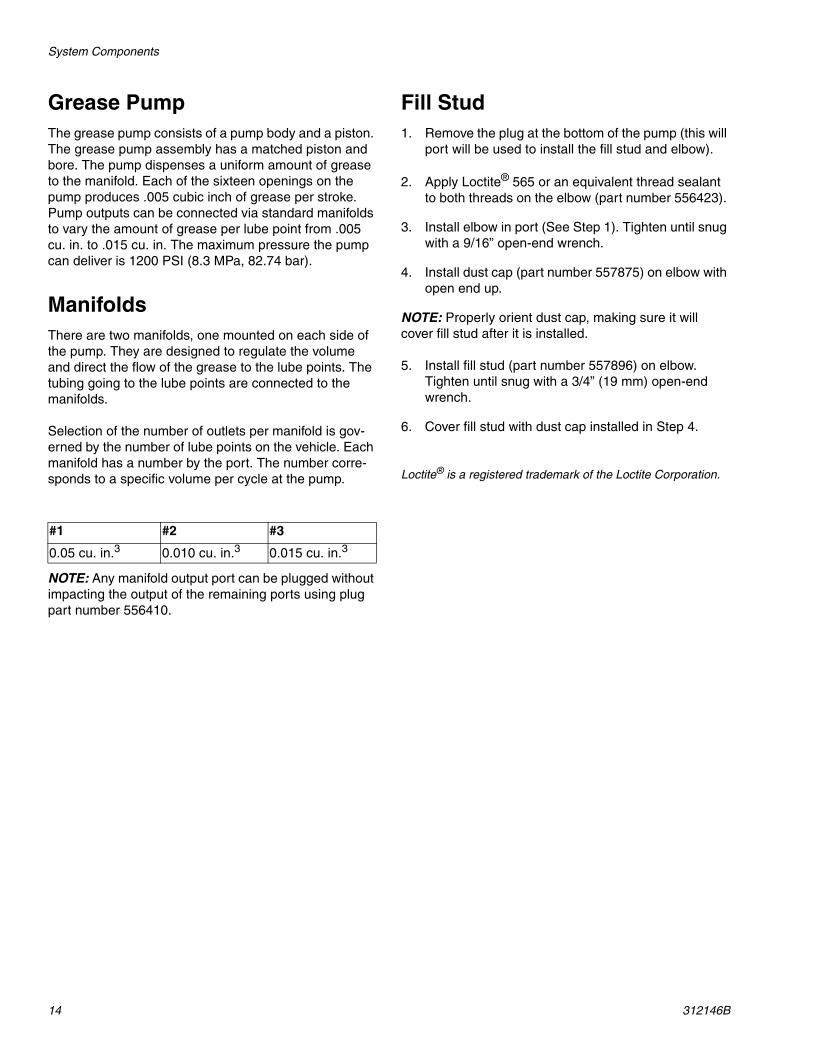
Grease Pump The grease pump consists of a pump body and a piston. The grease pump assembly has a matched piston and bore. The pump dispenses a uniform amount of grease to the manifold. Each of the sixteen openings on the pump produces .005 cubic inch of grease per stroke. Pump outputs can be connected via standard manifolds to vary the amount of grease per lube point from .005 cu. in. to .015 cu. in. The maximum pressure the pump can deliver is 1200 PSI (8.3 MPa, 82.74 bar).
ManifoldsThere are two manifolds, one mounted on each side of the pump. They are designed to regulate the volume and direct the flow of the grease to the lube points. The tubing going to the lube points are connected to the manifolds.
Selection of the number of outlets per manifold is gov-erned by the number of lube points on the vehicle. Each manifold has a number by the port. The number corre-sponds to a specific volume per cycle at the pump.
NOTE: Any manifold output port can be plugged without impacting the output of the remaining ports using plug part number 556410.
Fill Stud1. Remove the plug at the bottom of the pump (this will
port will be used to install the fill stud and elbow).
2. Apply Loctite® 565 or an equivalent thread sealant to both threads on the elbow (part number 556423).
3. Install elbow in port (See Step 1). Tighten until snug with a 9/16” open-end wrench.
4. Install dust cap (part number 557875) on elbow with open end up.
NOTE: Properly orient dust cap, making sure it will cover fill stud after it is installed.
5. Install fill stud (part number 557896) on elbow. Tighten until snug with a 3/4” (19 mm) open-end wrench.
6. Cover fill stud with dust cap installed in Step 4.
Loctite® is a registered trademark of the Loctite Corporation.
#1 #2 #3
0.05 cu. in.3 0.010 cu. in.3 0.015 cu. in.3
System Components
312146B 15
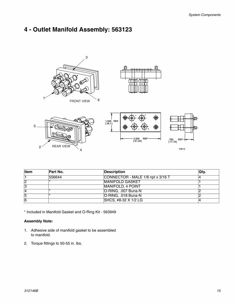
4 - Outlet Manifold Assembly: 563123
* Included in Manifold Gasket and O-Ring Kit - 563949
Assembly Note:
1. Adhesive side of manifold gasket to be assembled to manifold.
2. Torque fittings to 50-55 in. lbs.
REAR VIEW
REF.70017,78[ ]
FRONT VIEW
REF1.50038,1[ ]
REF3.20081,28[ ]
ti9812
5
24
1 6
3
Item Part No. Description Qty.1 556644 CONNECTOR - MALE 1/8 npt x 3/16 T 42 * MANIFOLD GASKET 13 MANIFOLD, 4 POINT 14 * O-RING, .007 Buna-N 25 * O-RING, .018 Buna-N 26 SHCS, #8-32 X 1/2 LG 4
System Components
16 312146B
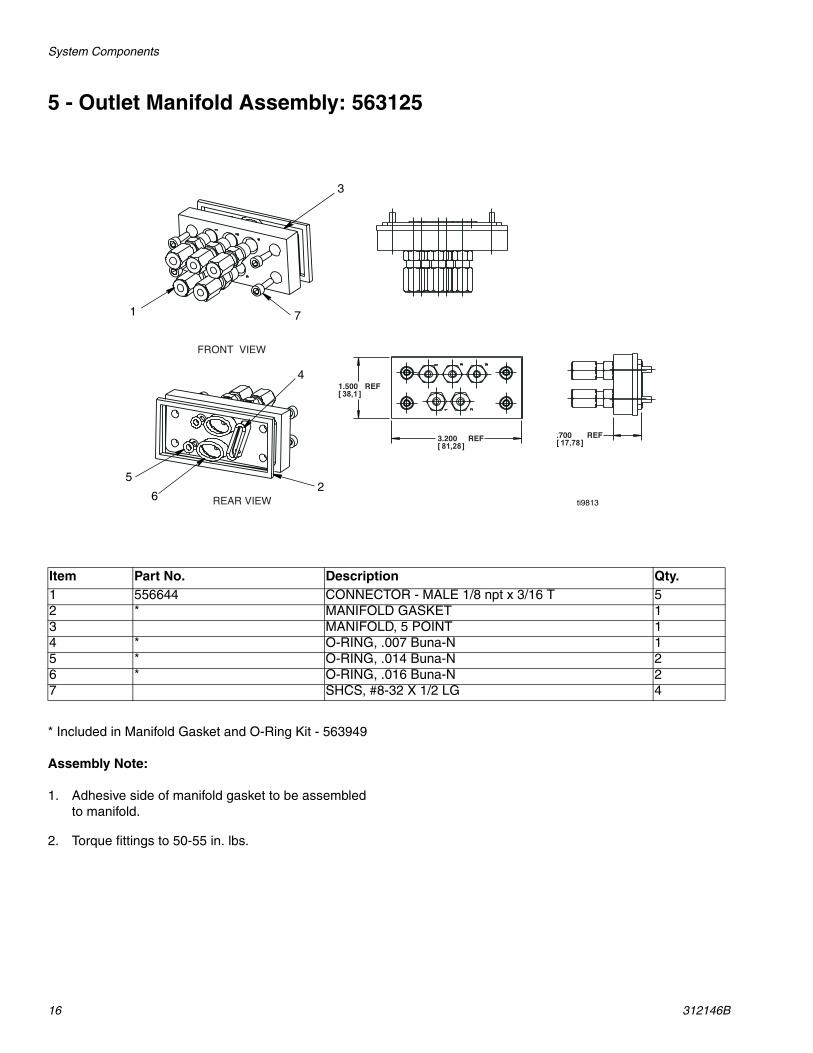
5 - Outlet Manifold Assembly: 563125
* Included in Manifold Gasket and O-Ring Kit - 563949
Assembly Note:
1. Adhesive side of manifold gasket to be assembled to manifold.
2. Torque fittings to 50-55 in. lbs.
REAR VIEW
FRONT VIEW
REF1.50038,1[ ]
REF3.20081,28[ ]
REF.70017,78[ ]
ti9813
3
71
4
26
5
Item Part No. Description Qty.1 556644 CONNECTOR - MALE 1/8 npt x 3/16 T 52 * MANIFOLD GASKET 13 MANIFOLD, 5 POINT 14 * O-RING, .007 Buna-N 15 * O-RING, .014 Buna-N 26 * O-RING, .016 Buna-N 27 SHCS, #8-32 X 1/2 LG 4
System Components
312146B 17
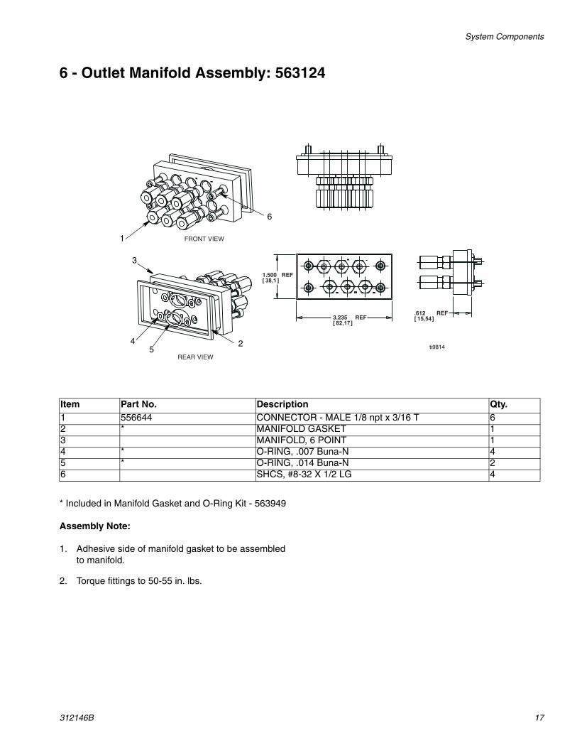
6 - Outlet Manifold Assembly: 563124
* Included in Manifold Gasket and O-Ring Kit - 563949
Assembly Note:
1. Adhesive side of manifold gasket to be assembled to manifold.
2. Torque fittings to 50-55 in. lbs.
REF1.50038,1 [ ]
REF3.23582,17 [ ]
REF.61215,54 [ ]
FRONT VIEW
REAR VIEW
ti9814245
3
1
6
Item Part No. Description Qty.1 556644 CONNECTOR - MALE 1/8 npt x 3/16 T 62 * MANIFOLD GASKET 13 MANIFOLD, 6 POINT 14 * O-RING, .007 Buna-N 45 * O-RING, .014 Buna-N 26 SHCS, #8-32 X 1/2 LG 4
System Components
18 312146B
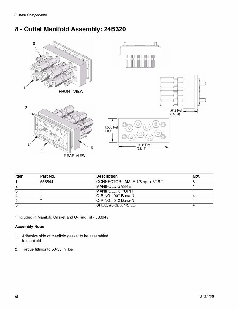
8 - Outlet Manifold Assembly: 24B320
* Included in Manifold Gasket and O-Ring Kit - 563949
Assembly Note:
1. Adhesive side of manifold gasket to be assembled to manifold.
2. Torque fittings to 50-55 in. lbs.
FRONT VIEW
REAR VIEW
1
6
34
2
5
1.500 Ref(38.1)
3.235 Ref(82.17)
.612 Ref(15.54)
Item Part No. Description Qty.1 556644 CONNECTOR - MALE 1/8 npt x 3/16 T 82 * MANIFOLD GASKET 13 MANIFOLD, 8 POINT 14 * O-RING, .007 Buna-N 45 * O-RING, .012 Buna-N 46 SHCS, #8-32 X 1/2 LG 4

System Components
312146B 19
Grease ReservoirA grease cartridge holds the supply of grease for the MLX Pump. The top cover, follower plate, spring, bottom base, and grease cartridge are the major components that make up the reservoir. The cartridge is designed for easy exchange by removing the front cover of the MLX Pump housing.
TubingThe MLX Pump uses 3/16 (8 mm) nylon tubing to deliver the grease from the manifolds to the different lube points. The tubing is made in different bundle sizes. The number of lube points determines the different tube bun-dle arrangements required for installing the MLX Pump. There are single, double and triple tubing bundles. Each tube is color-coded to help link tube location on the manifolds to the lube points on the vehicle during instal-lation.
Contents are under pressure. Open with care! ti9815
ti9816
Item Part No. Description Qty.1 557982 COVER FOLLOWER ASSEMBLY 12 557978 RESERVOIR BASE 13 556545 O-RING 1
Bundles563797 = 3 Tube bundles - 20 ft258346 = 2 Tube bundle - 20 ft563993 = 1 Tube orange - 20 ft
ti9817
Troubleshooting
20 312146B
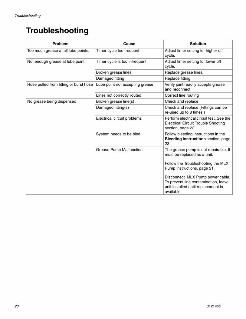
TroubleshootingProblem Cause Solution
Too much grease at all lube points. Timer cycle too frequent Adjust timer setting for higher off cycle.
Not enough grease at lube point. Timer cycle is too infrequent Adjust timer setting for lower off cycle.
Broken grease lines Replace grease lines.
Damaged fitting Replace fitting
Hose pulled from fitting or burst hose Lube point not accepting grease Verify joint readily accepts grease and reconnect.
Lines not correctly routed Correct line routing
No grease being dispensed Broken grease line(s) Check and replace
Damaged fitting(s) Check and replace (Fittings can be re-used up to 8 times.)
Electrical circuit problems Perform electrical circuit test. See the Electrical Circuit Trouble Shooting section, page 22.
System needs to be bled Follow bleeding instructions in the Bleeding Instructions section, page 23.
Grease Pump Malfunction The grease pump is not repairable. It must be replaced as a unit.
Follow the Troubleshooting the MLX Pump instructions, page 21.
Disconnect MLX Pump power cable. To prevent line contamination, leave unit installed until replacement is available.
Troubleshooting
312146B 21
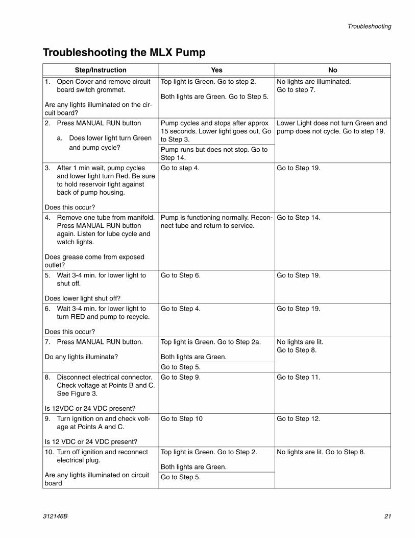
Troubleshooting the MLX Pump
Step/Instruction Yes No
1. Open Cover and remove circuit board switch grommet.
Are any lights illuminated on the cir-cuit board?
Top light is Green. Go to step 2.
Both lights are Green. Go to Step 5.
No lights are illuminated. Go to step 7.
2. Press MANUAL RUN button
a. Does lower light turn Green and pump cycle?
Pump cycles and stops after approx 15 seconds. Lower light goes out. Go to Step 3.
Lower Light does not turn Green and pump does not cycle. Go to step 19.
Pump runs but does not stop. Go to Step 14.
3. After 1 min wait, pump cycles and lower light turn Red. Be sure to hold reservoir tight against back of pump housing.
Does this occur?
Go to step 4. Go to Step 19.
4. Remove one tube from manifold. Press MANUAL RUN button again. Listen for lube cycle and watch lights.
Does grease come from exposed outlet?
Pump is functioning normally. Recon-nect tube and return to service.
Go to Step 14.
5. Wait 3-4 min. for lower light to shut off.
Does lower light shut off?
Go to Step 6. Go to Step 19.
6. Wait 3-4 min. for lower light to turn RED and pump to recycle.
Does this occur?
Go to Step 4. Go to Step 19.
7. Press MANUAL RUN button.
Do any lights illuminate?
Top light is Green. Go to Step 2a.
Both lights are Green.
No lights are lit.Go to Step 8.
Go to Step 5.
8. Disconnect electrical connector. Check voltage at Points B and C. See Figure 3.
Is 12VDC or 24 VDC present?
Go to Step 9. Go to Step 11.
9. Turn ignition on and check volt-age at Points A and C.
Is 12 VDC or 24 VDC present?
Go to Step 10 Go to Step 12.
10. Turn off ignition and reconnect electrical plug.
Are any lights illuminated on circuit board
Top light is Green. Go to Step 2.
Both lights are Green.
No lights are lit. Go to Step 8.
Go to Step 5.

Troubleshooting
22 312146B
11. Locate fuse in pump wiring. See Figure 4 for wiring schematic.
Is fuse blown?
Replace fuse. Go to Step 8. Go to Step 12.
12. Troubleshoot wiring from pump plug to vehicle.
Is wiring intact?
Go to Step 13. Repair wiring. Go to Step 8.
13. Troubleshoot vehicle wiring to connections.
Is wiring intact?
Go to Step 19. Repair wiring to restore voltage to pump. Go to Step 8.
14. Prepare to remove reservoir by pushing in and pulling out about 1/2 in. 2-3 times to break the vac-uum and allow valve to close. Remove reservoir and remove gear cover grommet at center of pump (See FIG. 1, FN1, page 25). Observe location of drive gear and piston rack.
Is the rack engaged with pinion and moving?
Go to Step 15 Go to Step 19.
15. Press MANUAL RUN button again and observe the male nip-ple at bottom that connects pump to reservoir.
Is the rack engaged with the pinion and moving?
Go to Step 19. Go to Step 16.
16. Replace switch grommet and reservoir before pump recycles.
Has pump been purged?
Go to Step 19. Go to Step 17.
17. Purge pump of air and re-prime.
18. After purge is complete, does pump function normally?
Return to service. Go to Step 19.
19. Disconnect Pump Electrical Con-nector and order replacement pump 563611 or 563623.
Step/Instruction Yes No
Troubleshooting
312146B 23
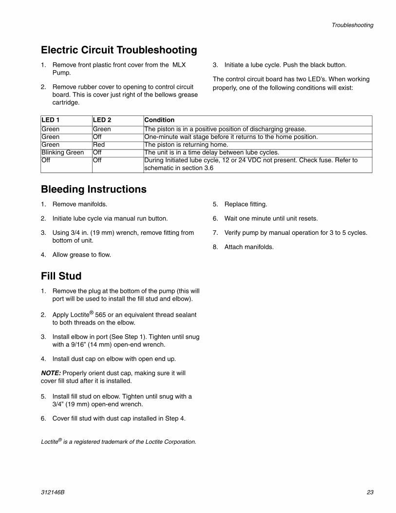
Electric Circuit Troubleshooting1. Remove front plastic front cover from the MLX
Pump.
2. Remove rubber cover to opening to control circuit board. This is cover just right of the bellows grease cartridge.
3. Initiate a lube cycle. Push the black button.
The control circuit board has two LED’s. When working properly, one of the following conditions will exist:
Bleeding Instructions1. Remove manifolds.
2. Initiate lube cycle via manual run button.
3. Using 3/4 in. (19 mm) wrench, remove fitting from bottom of unit.
4. Allow grease to flow.
5. Replace fitting.
6. Wait one minute until unit resets.
7. Verify pump by manual operation for 3 to 5 cycles.
8. Attach manifolds.
Fill Stud1. Remove the plug at the bottom of the pump (this will
port will be used to install the fill stud and elbow).
2. Apply Loctite® 565 or an equivalent thread sealant to both threads on the elbow.
3. Install elbow in port (See Step 1). Tighten until snug with a 9/16” (14 mm) open-end wrench.
4. Install dust cap on elbow with open end up.
NOTE: Properly orient dust cap, making sure it will cover fill stud after it is installed.
5. Install fill stud on elbow. Tighten until snug with a 3/4” (19 mm) open-end wrench.
6. Cover fill stud with dust cap installed in Step 4.
Loctite® is a registered trademark of the Loctite Corporation.
LED 1 LED 2 ConditionGreen Green The piston is in a positive position of discharging grease.Green Off One-minute wait stage before it returns to the home position.Green Red The piston is returning home.Blinking Green Off The unit is in a time delay between lube cycles.Off Off During Initiated lube cycle, 12 or 24 VDC not present. Check fuse. Refer to
schematic in section 3.6

Parts
24 312146B
PartsReplacement Parts
Part No. Description563622 12 VDC MLX Replacement Pump563620 24 VDC MLX Replacement Pump563779 MLX Pump Front Cover with decals
557894 Reservoir Assembly (complete)557982 Cover Follower Assy557978 Base Assembly556545 O-ring between grease cartridge and
base assembly563086 Cartridge with Grease - 6 pack557265 Grommet - Circuit Board Access557266 Grommet - Setting Switches Seal563949 Manifold Gasket and O-ring Kit
Precharged 3/16 in. Tubing Bundles563993 1 Tube Bundle - Orange 20 ft (7.5 m)258346 2 Tube Bundle - 20 ft (7.5 m)563797 3 Tube Bundle - 20 ft (7.5 m)
Nylon Tie Straps563770 100 bag56638 1/8 npt x 3/16 in. Tube Fitting 90°556644 1/8 npt x 3/16 in. Tube Fitting St.
15K783 Street Elbow 1/8 npt to 1/8 npt15K740 Street Elbow 1/4-28 SAE to 1/8 npt563777 Zerk Adaptor - Straight 3/16 in. Tube563776 Zerk Adaptor - Elbow 3/16 in. Tube15M037 Zerk Adaptor - Press-in 1/8 npsf556423 Elbow, 1/4 NPTF male557896 Fill Stud, 1/4 NPTF female557875 Dust Cap, 4TS2-02201
MALE CONNECTOR3/16 in. (8 mm) tube, 1/8 npt556644
MALE 90° ELBOW3/16 in. tube, 1/8 npt556638
ELBOW, STREET1/4-28 SAE to 1/8 npt15K740
ELBOW, STREET1/8 npt to 1/8 npt15K783
ZERK ADAPTORS,PRESS ON:3/16 in. TUBE CONNECTIONSTRAIGHT - 563777
ZERK ADAPTORS,PRESS ON:3/16 in. TUBE CONNECTIONELBOW - 563776
ti9804
ti9805
ti9806
ti9807
ti9808
ti9809
Parts
312146B 25
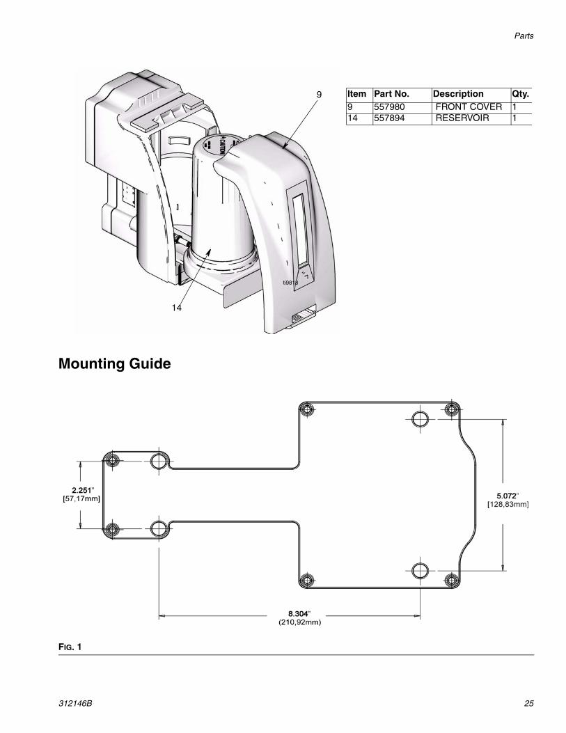
Mounting Guide
Item Part No. Description Qty.9 557980 FRONT COVER 114 557894 RESERVOIR 1
ti9818
9
14
FIG. 1
Technical Data
26 312146B
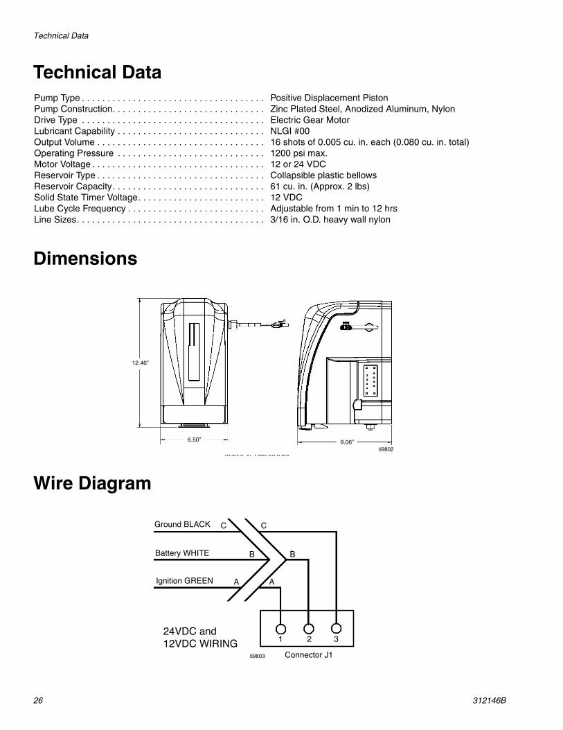
Technical Data
Dimensions
Wire Diagram
Pump Type . . . . . . . . . . . . . . . . . . . . . . . . . . . . . . . . . . . . Positive Displacement PistonPump Construction. . . . . . . . . . . . . . . . . . . . . . . . . . . . . . Zinc Plated Steel, Anodized Aluminum, NylonDrive Type . . . . . . . . . . . . . . . . . . . . . . . . . . . . . . . . . . . . Electric Gear MotorLubricant Capability . . . . . . . . . . . . . . . . . . . . . . . . . . . . . NLGI #00Output Volume . . . . . . . . . . . . . . . . . . . . . . . . . . . . . . . . . 16 shots of 0.005 cu. in. each (0.080 cu. in. total)Operating Pressure . . . . . . . . . . . . . . . . . . . . . . . . . . . . . 1200 psi max.Motor Voltage . . . . . . . . . . . . . . . . . . . . . . . . . . . . . . . . . . 12 or 24 VDCReservoir Type . . . . . . . . . . . . . . . . . . . . . . . . . . . . . . . . . Collapsible plastic bellowsReservoir Capacity. . . . . . . . . . . . . . . . . . . . . . . . . . . . . . 61 cu. in. (Approx. 2 lbs)Solid State Timer Voltage. . . . . . . . . . . . . . . . . . . . . . . . . 12 VDCLube Cycle Frequency . . . . . . . . . . . . . . . . . . . . . . . . . . . Adjustable from 1 min to 12 hrsLine Sizes. . . . . . . . . . . . . . . . . . . . . . . . . . . . . . . . . . . . . 3/16 in. O.D. heavy wall nylon
ti9802
Ground BLACK
Battery WHITE
Ignition GREEN
Connector J1
A
B
C C
1 2 3
B
A
24VDC and12VDC WIRING
ti9803
Notes
312146B 27
Notes
All written and visual data contained in this document reflects the latest product information available at the time of publication. Graco reserves the right to make changes at any time without notice.
This manual contains English. MM 312146
Graco Headquarters: MinneapolisInternational Offices: Belgium, China, Japan, Korea
GRACO INC. P.O. BOX 1441 MINNEAPOLIS, MN 55440-1441Copyright 2008, Graco Inc. is registered to I.S. EN ISO 9001
www.graco.com9/2008, revised 12/2008
Graco Standard WarrantyGraco warrants all equipment referenced in this document which is manufactured by Graco and bearing its name to be free from defects in material and workmanship on the date of sale to the original purchaser for use. With the exception of any special, extended, or limited warranty published by Graco, Graco will, for a period of twelve months from the date of sale, repair or replace any part of the equipment determined by Graco to be defective. This warranty applies only when the equipment is installed, operated and maintained in accordance with Graco’s written recommendations.
This warranty does not cover, and Graco shall not be liable for general wear and tear, or any malfunction, damage or wear caused by faulty installation, misapplication, abrasion, corrosion, inadequate or improper maintenance, negligence, accident, tampering, or substitution of non-Graco component parts. Nor shall Graco be liable for malfunction, damage or wear caused by the incompatibility of Graco equipment with structures, accessories, equipment or materials not supplied by Graco, or the improper design, manufacture, installation, operation or maintenance of structures, accessories, equipment or materials not supplied by Graco.
This warranty is conditioned upon the prepaid return of the equipment claimed to be defective to an authorized Graco distributor for verification of the claimed defect. If the claimed defect is verified, Graco will repair or replace free of charge any defective parts. The equipment will be returned to the original purchaser transportation prepaid. If inspection of the equipment does not disclose any defect in material or workmanship, repairs will be made at a reasonable charge, which charges may include the costs of parts, labor, and transportation.
THIS WARRANTY IS EXCLUSIVE, AND IS IN LIEU OF ANY OTHER WARRANTIES, EXPRESS OR IMPLIED, INCLUDING BUT NOT LIMITED TO WARRANTY OF MERCHANTABILITY OR WARRANTY OF FITNESS FOR A PARTICULAR PURPOSE.
Graco’s sole obligation and buyer’s sole remedy for any breach of warranty shall be as set forth above. The buyer agrees that no other remedy (including, but not limited to, incidental or consequential damages for lost profits, lost sales, injury to person or property, or any other incidental or consequential loss) shall be available. Any action for breach of warranty must be brought within two (2) years of the date of sale.
GRACO MAKES NO WARRANTY, AND DISCLAIMS ALL IMPLIED WARRANTIES OF MERCHANTABILITY AND FITNESS FOR A PARTICULAR PURPOSE, IN CONNECTION WITH ACCESSORIES, EQUIPMENT, MATERIALS OR COMPONENTS SOLD BUT NOT MANUFACTURED BY GRACO. These items sold, but not manufactured by Graco (such as electric motors, switches, hose, etc.), are subject to the warranty, if any, of their manufacturer. Graco will provide purchaser with reasonable assistance in making any claim for breach of these warranties.
In no event will Graco be liable for indirect, incidental, special or consequential damages resulting from Graco supplying equipment hereunder, or the furnishing, performance, or use of any products or other goods sold hereto, whether due to a breach of contract, breach of warranty, the negligence of Graco, or otherwise.
FOR GRACO CANADA CUSTOMERSThe Parties acknowledge that they have required that the present document, as well as all documents, notices and legal proceedings entered into, given or instituted pursuant hereto or relating directly or indirectly hereto, be drawn up in English. Les parties reconnaissent avoir convenu que la rédaction du présente document sera en Anglais, ainsi que tous documents, avis et procédures judiciaires exécutés, donnés ou intentés, à la suite de ou en rapport, directement ou indirectement, avec les procédures concernées.
Graco Information TO PLACE AN ORDER, contact your Graco distributor or call to identify the nearest distributor.Phone: 612-623-6928 or Toll Free: 1-800-533-9655, Fax: 612-378-3590