3120-N- Q1- Switch - Allied Electronics · 2019-09-19 · 3120-N5 0 4 - N7 Q1-W 19D G4 - 16 A...
8
www.e-t-a.de 1 3120-N...-... Q1-... Switch 1930 1 Description Typical applications Technical data The 3120-N...-...Q1-... switch serves for switching devices and machinery on or off. It is available in a range of design versions and meets the requirements of the relevant standard IEC/EN 61058 for switches for appliances. Type 3120-N is also available as a circuit breaker for equipment protection in accordance with IEC/EN 60934 (see data sheet 3120-N thermal circuit breaker). Features: l rocker or push button actuation l single pole and double pole versions l convenient snap-in mounting l international approvals Optional: l illumination l water splash protection l push-in terminals l with undervoltage release module Medical and laboratory equipment, apparatus and machine construction, professional tools, household and garden appliances, offices machines, audio equipment, machine tools Voltage rating per pole AC 240 V, DC 50 V Switching cycles: AC 240 V: 16 (4) A 25,000 switching cycles DC 50 V: 16 A 50,000 switching cycles Ambient temperature 0 … 55 °C Insulation coordination (IEC 60664) 2.5 kV /2 reinforced insulation at operating area Dielectric strength Operating area pole to pole (2-pole) test voltage AC 3,000 V test voltage AC 1,500 V Insulation resistance > 100 MΩ (DC 500 V) Degree of protection (IEC 60529) Operating area Terminal area IP40 with water splash cover IP65 IP00 with rear terminal shroud IP64 Vibration 8 g (57-500 Hz), ± 0.61 mm (10-57 Hz) test to IEC 60068-2-6, test Fc 10 frequency cycles/axis Shock 30 g (11 ms) test to IEC 60068-2-27, test Ea Corrosion 96 hours at 5 % salt mist, Test to IEC 60068-2-11, test Ka Humidity 240 hrs in 95 % RH test to IEC 60068-2-78, test Cab Mass approx. 33 g (2-pole) approx. 27 g (1-pole) approx. 42 g (2-pole with PT terminals) Approvals All information and data given on our products are accurate and reliable to the best of our knowledge, but E-T-A does not accept any responsibility for the use in applications which are not in accordance with the present specification. E-T-A reserves the right to change specifi- cations at any time in the interest of improved design, performance and cost effectiveness, Dimensions are subject to change without notice. Please enquire for the latest dimensional drawing with tolerances if required. All dimensions, data, pictures and descriptions are for information only and are not binding. Amendments, errors and omissions excepted. Ordering codes of the products may differ from their marking. Schematic diagrams 11 L N 12(i) load 1-pole 2-pole 12(i) 22(i) connection voltage L-N max. AC 240 V max. DC 50 V connection voltage L-N max. AC 415 V (240 V/pole) max. DC 50 V/pole load 11 L N 21 Approval authority Standard Voltage ratings Current ratings Approval logos VDE IEC/EN 61058 AC 240 V DC 50 V 16 (4) A 16 A CQC GB 17701 AC 240 V DC 50 V 0.1 – 16 A 3120-N...-... Q1-...
Transcript of 3120-N- Q1- Switch - Allied Electronics · 2019-09-19 · 3120-N5 0 4 - N7 Q1-W 19D G4 - 16 A...

www.e-t-a.de 1
3120-N...-... Q1-... Switch
1930
1
Description
Typical applications
Technical data
The 3120-N...-...Q1-... switch serves for switching devices and machinery on or off. It is available in a range of design versions and meets the requirements of the relevant standard IEC/EN 61058 for switches for appliances. Type 3120-N is also available as a circuit breaker for equipment protection in accordance with IEC/EN 60934 (see data sheet 3120-N thermal circuit breaker).
Features:l rocker or push button actuationl single pole and double pole versionsl convenient snap-in mountingl international approvals
Optional:l illuminationl water splash protectionl push-in terminalsl with undervoltage release module
Medical and laboratory equipment, apparatus and machine construction, professional tools, household and garden appliances, offices machines, audio equipment, machine tools
Voltage rating per pole AC 240 V, DC 50 V
Switching cycles:
AC 240 V: 16 (4) A 25,000 switching cyclesDC 50 V: 16 A 50,000 switching cycles
Ambient temperature 0 … 55 °C
Insulation coordination(IEC 60664)
2.5 kV /2 reinforced insulation at operating area
Dielectric strength
Operating areapole to pole (2-pole)
test voltage AC 3,000 Vtest voltage AC 1,500 V
Insulation resistance > 100 MΩ (DC 500 V)
Degree of protection (IEC 60529)Operating area
Terminal area
IP40 with water splash cover IP65
IP00 with rear terminal shroud IP64
Vibration 8 g (57-500 Hz), ± 0.61 mm (10-57 Hz)test to IEC 60068-2-6, test Fc 10 frequency cycles/axis
Shock 30 g (11 ms) test to IEC 60068-2-27, test Ea
Corrosion 96 hours at 5 % salt mist, Test to IEC 60068-2-11, test Ka
Humidity 240 hrs in 95 % RH test to IEC 60068-2-78, test Cab
Mass approx. 33 g (2-pole)approx. 27 g (1-pole) approx. 42 g (2-pole with PT terminals)
Approvals
All information and data given on our products are accurate and reliable to the best of our knowledge, but E-T-A does not accept any responsibility for the use in applications which are not in accordance with the present specification. E-T-A reserves the right to change specifi-cations at any time in the interest of improved design, performance and cost effectiveness, Dimensions are subject to change without notice. Please enquire for the latest dimensional drawing with tolerances if required. All dimensions, data, pictures and descriptions are for information only and are not binding. Amendments, errors and omissions excepted. Ordering codes of the products may differ from their marking.
Schematic diagrams
11
L N
12(i)load
1-pole
2-pole
12(i) 22(i)
connection voltage L-Nmax. AC 240 Vmax. DC 50 V
connection voltage L-Nmax. AC 415 V (240 V/pole)max. DC 50 V/pole
load
11
L N
21
Approval authority
Standard Voltage ratings
Current ratings
Approval logos
VDE IEC/EN 61058 AC 240 VDC 50 V
16 (4) A16 A
CQC GB 17701 AC 240 V DC 50 V
0.1 – 16 A
3120-N...-... Q1-...
www.e-t-a.de2
3120-N...-... Q1-... Switch
1930
1Order numbering code
Type No.3120 switch with rocker actuation Mounting method N3 snap-in, mounting cut-out 50.5 x 21.5 mm N5 snap-in, mounting cut-out 44.5 x 22 mm Number of poles 0 2-pole 6 1-pole Style 1 standard 3 with actuator guard 4 with water splash protection (IP65) A with actuator guard and cross-hole for optional
interlock Terminal design PT push-in terminals N7 blade terminals 6.3 x 0.8 G7 as N7, terminals 11 and 21 with additional flat
head screws M3.5 Version Q1 switch only Actuator style W rocker Rocker colour and illumination 01 . black without illumination 02 . white without illumination 04 . red without illumination 12 . Y white with illumination 14 . R red with illumination 15 . Y orange with illumination 16 . T blue with illumination 19 . G green with illumination Marking of rocker actuator rocker style A (not for mounting method 4) D F K L X Illumination voltage range (= operating voltage) 1 DC 12 V 2 DC 24 V 3 AC 115 V 4 AC 230 V 5 DC 48 V 6 AC 400 V (for 2-pole versions) Current ratings 16 A
3120-N5 0 4 - N7 Q1-W 19D G4 - 16 A ordering example
A D F K L X
Order numbering code
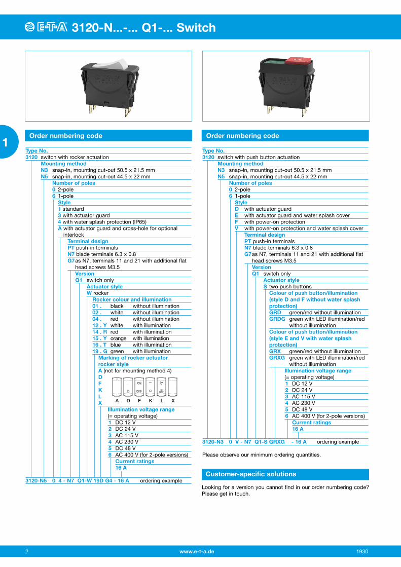
Type No.3120 switch with push button actuation Mounting method N3 snap-in, mounting cut-out 50.5 x 21.5 mm N5 snap-in, mounting cut-out 44.5 x 22 mm Number of poles 0 2-pole 6 1-pole Style D with actuator guard E with actuator guard and water splash cover F with power-on protection V with power-on protection and water splash cover Terminal design PT push-in terminals N7 blade terminals 6.3 x 0.8 G7 as N7, terminals 11 and 21 with additional flat
head screws M3.5 Version Q1 switch only Actuator style S two push buttons Colour of push button/illumination
(style D and F without water splash protection)
GRD green/red without illumination GRDG green with LED illumination/red
without illumination Colour of push button/illumination
(style E and V with water splash protection)
GRX green/red without illumination GRXG green with LED illumination/red
without illumination Illumination voltage range (= operating voltage) 1 DC 12 V 2 DC 24 V 3 AC 115 V 4 AC 230 V 5 DC 48 V 6 AC 400 V (for 2-pole versions) Current ratings 16 A
3120-N3 0 V - N7 Q1-S GRXG - 16 A ordering example
Please observe our minimum ordering quantities.
Customer-specific solutions
Looking for a version you cannot find in our order numbering code? Please get in touch.
www.e-t-a.de 3
3120-N...-... Q1-... Switch
1930
1
3120-N...-... Q1-... Switch
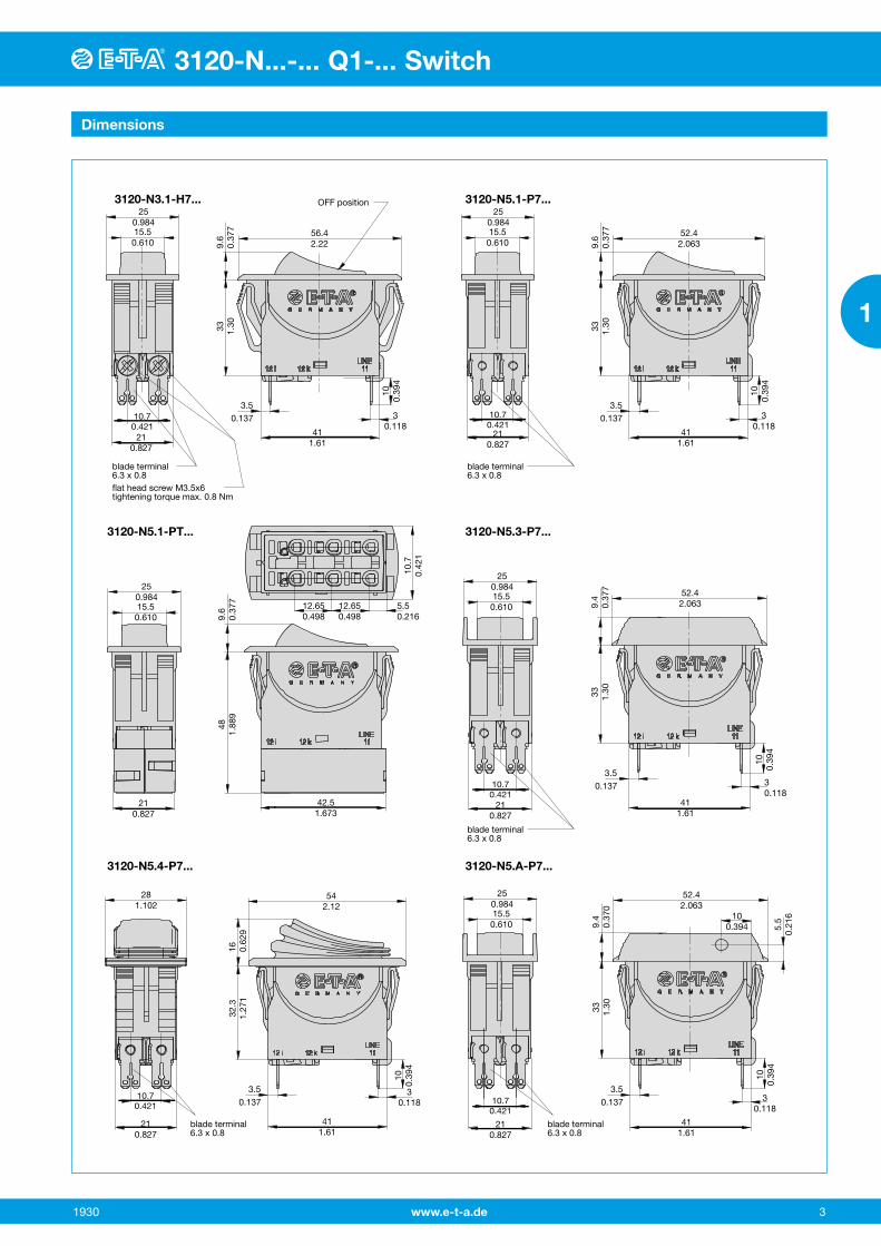
Dimensions
56.42.229.
60.
377
33 1.30
52.42.0639.
60.
377
33 1.30
52.42.0639.
40.
377
9.4
0.37
033 1.30
9.6
0.37
748
1.88
9
52.42.063
100.394
33 1.30
16 0.62
9
542.12
32.3
1.27
1
411.61
30.118
100.
394
411.61
30.118
100.
394
411.61
30.118
100.
394
10.7
0.42
1
411.61
30.118
100.
394
5.5
0.21
6
411.61
30.118
42.51.673
100.
394
250.98415.50.610
250.98415.50.610
250.98415.50.610
250.98415.50.610
250.98415.50.610
210.827
10.70.421
210.827
10.70.421
210.827
10.70.421
281.102
210.827
10.70.421
12.65 12.65 5.50.498 0.498 0.216
210.827
210.827
10.70.421
blade terminal6.3 x 0.8
blade terminal6.3 x 0.8
blade terminal6.3 x 0.8
blade terminal6.3 x 0.8
blade terminal6.3 x 0.8
flat head screw M3.5x6tightening torque max. 0.8 Nm
OFF position
3.50.137
3.50.137
3.50.137
3.50.137
3.50.137
3120-N3.1-H7... 3120-N5.1-P7...
3120-N5.3-P7...
3120-N5.A-P7...3120-N5.4-P7...
3120-N5.1-PT...

www.e-t-a.de4
3120-N...-... Q1-... Switch
1930
1
Dimensions
3120-N3.D-P7... 3120-N5.D-P7...
3120-N5.F-P7...3120-N5.E-P7...
3120-N5.V-P7...
9.1
0.35
833 1.30
52.42.063
ON position
9.1
0.35
833 1.30
52.42.063
9.1
0.35
8 5 0.19
6
5 0.19
6
33 1.30
17 0.66
9
552.165
32.3
1.27
1
411.61
30.118
56.42.22
100.
394
21.90.862
411.61
30.118
100.
394
411.61
30.118
100.
394
21.7
0.85
4
411.61
30.118
100.
394
210.827
10.70.421
26.41.039
210.827
10.70.421
26.41.039
210.827
10.70.421
29.21.149
210.827
10.70.421
blade terminal6.3 x 0.8
blade terminal6.3 x 0.8
blade terminal6.3 x 0.8
blade terminal6.3 x 0.8
17 0.66
9
552.165
32.3
1.27
1
411.61
30.118
100.
394
29.21.149
210.827
10.70.421
blade terminal6.3 x 0.8
26.4
1.03
9
ON position
3.50.137
3.50.137
3.50.137
3.50.137
3.50.137

www.e-t-a.de 5
3120-N...-... Q1-... Switch
1930
1
3120-N...-... Q1-... Switch
Cable cross sections PT terminals
Cable cross section with direct push-in wiring
Rigid 1 … 4 mm2 (stripping length: 10 mm)
Flexible with wire end ferrule (with or without plastic sleeve)
0.5 … 2.5 mm2
Cable cross section when opening the push-in terminals
Rigid 0.5 … 4 mm2
(stripping length: 10 mm)
Flexible without wire end ferrule 0.5 … 2.5 mm2
Terminal types
3120-N564-N7Q1
3120-N564-PT 3120-N504-PT
3120-N504-N7Q1
3120-N564-G7Q1
2-pole version1-pole version
3120-N504-G7Q1
Mounting method Installation drawing
Cut-out for mounting style -N3
Mounting styleCut-out for mounting style -N5
-0.2-0.4
a
±0.05±0.05
-0.2-0.4
-0.007-0.015
-0.007-0.015
+1
min. 49min. 55
+1±0.001±0.001 +0,039
min. 1.929min. 2.165
+0.039
44.5+0.2
+0.522+
0.3
50.5+0.3
+0.5
1.751+0,007
+0.019
1.988+0.011
+0.01921.5
+0.
3
0.86
6+0.
011
0.84
6+0.
011
b
panel thickness without water splash protection
with water splash protection
a 1 – 6.35 mm 1 – 5.5 mm
b 1 – 4 mm 1 – 3.5 mm
mounting area
7 8
10 0.39
3
7 100.314 0.275 0.393
7
0.275 0.275
When installing the circuit breaker apply pressure on bezel only.
operating area
15.5
0.61
0
3120 with blade terminals
mounting area
7 8
250.
984
7 107
When installing the circuit breaker apply pressure on bezel only.
operating area
30.5
1.20
3120 with push-in terminals
0.314 0.275 0.3930.275 0.275

www.e-t-a.de6
3120-N...-... Q1-... Switch
1930
1
All information and data given on our products are accurate and reliable to the best of our knowledge, but E-T-A does not accept any responsibility for the use in applications which are not in accordance with the present specification. E-T-A reserves the right to change specifi-cations at any time in the interest of improved design, performance and cost effectiveness, Dimensions are subject to change without notice. Please enquire for the latest dimensional drawing with tolerances if required. All dimensions, data, pictures and descriptions are for information only and are not binding. Amendments, errors and omissions excepted. Ordering codes of the products may differ from their marking.
Accessories
Rear terminal shroud, black (IP64)Y 304 275 01
50
70+
5
10
1.96
8
2.75
5+0.
196
0.39
3
40.51.75
ø8
+0.5-0.25 20.51.594
0.068
ø0.314
+0.019-0.009 0.807
blade terminals 6.3 x 0.8
Terminal adapterY 303 862 01
Insulated coverY 303 068 01
0.9
20
2.5
0.787
0.098
90.
035
0.35
4
4
0.157
413.5
0.15
7
0.53
1
3.7
0.14
5
R3.5R0.137
Blanking piece in -N3 frameY 303 885 31
36
25
16.5
21
33
1.41
7
1.29
9
540.9842.125
1 0.03
9
41
0.8261.614
310.6491.220
* Y 303 675 01 suitable for panel thickness < 2 mm* Y 303 675 02 suitable for panel thickness < 4 mm
Spacer for 3120-N3...Y 303 675 01/02
22
50.5
58
28
*
44.5
22.5
52
1.988
2.283
1.751
2.047
2.5
0.8
without bends
sharp-edged
28
0.86
6
1.10
2
0.88
5
0.09
8
0.03
1
1.10
2
Spacer for 3120-N5...Y 303 676 01

www.e-t-a.de 7
3120-N...-... Q1-... Switch
1930
1
3120-N...-... Q1-... Switch
Accessories
Plug-in connector Y 31214001 Connecting cables can be pre-wired. Two retaining clips ensure a tight fit.
Benefits:• Reduced installation time and costs for final assembly• Quick replacement of devices
Note:Delivery without receptacles.Dimensions of receptacles (width 6.3 mm) are in accordance with DIN 46340 part 3, shape A. Examples of suitable receptacles: Stocko RSB 7916 F6,3-1 / Klaucke type 2730 / Vogt type 3832d.67 / TE FASTON Terminals 250 Series / Delphi Packard 58 Series
42
5.5
4.5
240.
177
0.94
4
120.216 0.472
21.2
1.653 0.834
42 21.2
1.65 0.834
2432
.3
0.94
41.
271
Plug-in connector mounted on circuit breaker:

www.e-t-a.de8
3120-N...-... Q1-... Switch
1930
1
Typical applications
Description X3120-U undervoltage release module
Order numbering code
Technical data
All machines that could cause personal injury upon automatic re-start, e.g. drilling machines, electric saws, meat cutting machines etc.
The X3120-U02 version allows set up of a cost-effective safety circuit via the physically isolated undervoltage release module, which enables implementation for example of a remote disconnectioni with emergency stop.
Type No.X3120 module for type 3120-N Module U undervoltage release module Design 00 standard (without separate connections) 01 1 blade terminals 2.8x0.8 02 2 blade terminals 2.8x0.8 Voltage ratings 00 AC 230/240 V 50/60 Hz 01 AC 120 V 50/60 Hz 02 AC 100 V 50/60 Hz 03 DC 24 V 04 AC 400 V 50/60 Hz Supply status M module mounted to circuit breaker 3120-N
X3120- U 00 00 M ordering example
All information and data given on our products are accurate and reliable to the best of our knowledge, but E-T-A does not accept any responsibility for the use in applications which are not in accordance with the present specification. E-T-A reserves the right to change specifi-cations at any time in the interest of improved design, performance and cost effectiveness, Dimensions are subject to change without notice. Please enquire for the latest dimensional drawing with tolerances if required. All dimensions, data, pictures and descriptions are for information only and are not binding. Amendments, errors and omissions excepted. Ordering codes of the products may differ from their marking.
Voltage ratings AC 100 V; AC 120 V; AC 230/240 V; AC 400 V (50/60 Hz) DC 24 V
Voltage tolerances + 10 %/- 15 %
Typical life 20,000 cycles
Current consumption approx. 2.5 mA
Release values 0.2 x UN < U < 0.7 x UN(at a rated voltage of AC 100 Vthe device can trip at 70 V and must trip at 20 V)
Trip time < 20 ms
Latch-in values ≥ 85 % UN
Ambient temperature -30 … 60 °C
Vibration 8 g (57-500 Hz), ± 0.61 mm (10-57 Hz)test to IEC 60068-2-6, test Fc 10 frequency cycles/axis
Shock 30 g (11 ms)test to IEC 60068-2-27, test Ea
Corrosion 48 hours at 5 % salt mist, test to IEC 60068-2-11, test Ka
Humidity 240 hrs in 95 % RH test to IEC 60068-2-78, test Cab
Mass approx. 56 g (including base unit)
The undervoltage release module reliably excludes personal injury through automatic re-start after voltage dip or power failure.
Note: Basic unit 3120-N...-G7 requires screw terminals. Not possible in combination with PT terminals.
Please observe the following in combination with design version 4: In the event of voltage dip or power failure, the undervoltage release module trips the switch.
The rocker actuator will go into centre position. Reset is effectedin two steps:Step 1: Switch rocker into OFF position.Step 2: Reset switch.
Schematic diagrams
Dimensions – undervoltage release module
1 separate blade terminal X3120-U01…
blade terminal2.8 x 0.8
flat head screw M3.5x6for mains connectiontightening torque max. 0.8 Nm
21
.82722.866
21
.827
6.6
.260
23,5.925
33.5
1.32
7.6
.299
41 +0,1- 0,2
1.61 +.004- .008
Without separate terminal(s): X3120-U00…
Dimensional drawings of the standard version of 3120-N please see page 3-4
X3120-U00… X3120-U01… X3120-U02…
12(i) 22(i)
U<
11 21
12(i) 22(i)
U<
11 21
12(i) 22(i)
U<
11 21A2 A1 A2line
load
line
load
line line
load
line


![Untitled-1 []3120 3120 3120 3120 3120 4160 4160 4160 4160 4760 6300 6300 6300 6300 6300 (mm) 10 13 16 20 70 13 16 20 10 13 16 20 L (mm 3725 3745 3765 3785 3805 4910 4950 6910 6930](https://static.fdocuments.in/doc/165x107/5e4dbd11312dd96173529be7/untitled-1-3120-3120-3120-3120-3120-4160-4160-4160-4160-4760-6300-6300-6300.jpg)