311762ZAH, Manual, Xtreme Lowers, Instructions-Parts, English · 2020-03-27 · High-pressure fluid...
36
Instructions - Parts List Xtreme ™ Lowers High volume lowers for protective coatings. For professional use only. See page 3 for model information, see page 34 for maximum working pressure. Important Safety Instructions Read all warnings and instructions in this manual. Save these instructions. TI8630b Model L220C1 Lower without Filter Model L220C2 Lower with Built-in Filter TI8405a 311762ZAH EN
Transcript of 311762ZAH, Manual, Xtreme Lowers, Instructions-Parts, English · 2020-03-27 · High-pressure fluid...
Instructions - Parts List
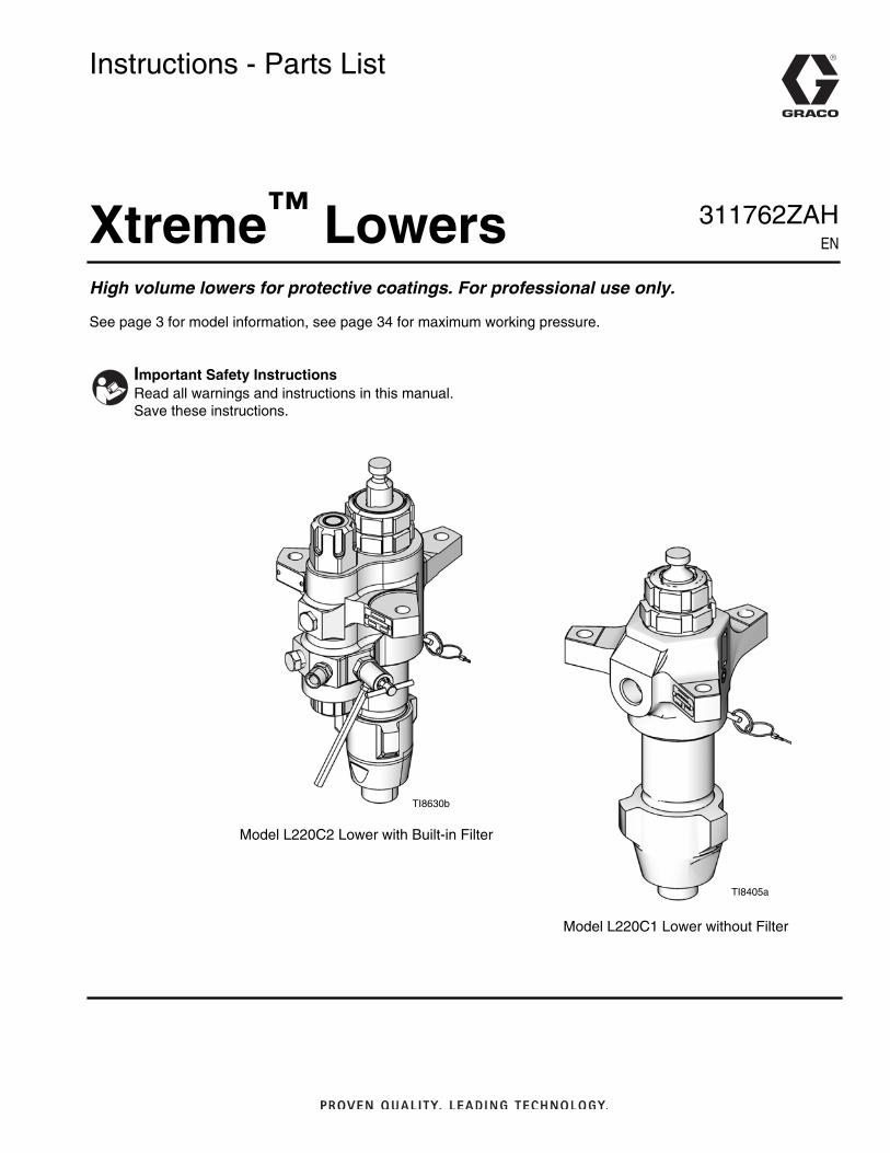
Xtreme™ LowersHigh volume lowers for protective coatings. For professional use only.
See page 3 for model information, see page 34 for maximum working pressure.
Important Safety InstructionsRead all warnings and instructions in this manual.Save these instructions.
TI8630b
Model L220C1 Lower without Filter
Model L220C2 Lower with Built-in Filter
TI8405a
311762ZAHEN

Related Manuals
2 311762ZAH
Contents
Related Manuals . . . . . . . . . . . . . . . . . . . . . . . . . . . 2
Models . . . . . . . . . . . . . . . . . . . . . . . . . . . . . . . . . . . 3Warnings . . . . . . . . . . . . . . . . . . . . . . . . . . . . . . . . . 4Component Identification . . . . . . . . . . . . . . . . . . . . 6Repair . . . . . . . . . . . . . . . . . . . . . . . . . . . . . . . . . . . . 7
Disassembly . . . . . . . . . . . . . . . . . . . . . . . . . . . . 7Service Built-in Filter . . . . . . . . . . . . . . . . . . . . . 14
Parts . . . . . . . . . . . . . . . . . . . . . . . . . . . . . . . . . . . . 16XP Sprayer Lower Models
36cc, 48cc, 54cc, 58cc, 72cc, 85cc, 90cc, 97cc,and 115cc . . . . . . . . . . . . . . . . . . . . . . . . . . 16
XP Sprayer Lower Models145cc, 180cc, 220cc, 250cc, and 290cc . . . 19
Xtreme and e-Xtreme Sprayer Lower Models85cc 115cc, 145cc, 180cc, 220cc, 250cc, and290cc . . . . . . . . . . . . . . . . . . . . . . . . . . . . . 21
Repair Kits . . . . . . . . . . . . . . . . . . . . . . . . . . . . . . . 27Repair Kits - Graco Formulated UHMWPE/Leather
27Repair Kits - PTFE . . . . . . . . . . . . . . . . . . . . . . 28Repair Kits - Graco Formulated UHMWPE/PTFE 29
Kits . . . . . . . . . . . . . . . . . . . . . . . . . . . . . . . . . . . . . 30Ceramic Balls . . . . . . . . . . . . . . . . . . . . . . . . . . 30
Dimensions . . . . . . . . . . . . . . . . . . . . . . . . . . . . . . 32Outlet Housing Mounting Hole Layout . . . . . . . . 33Technical Data . . . . . . . . . . . . . . . . . . . . . . . . . . . . 34Graco Standard Warranty . . . . . . . . . . . . . . . . . . . 36Graco Information . . . . . . . . . . . . . . . . . . . . . . . . 36
Related ManualsComponent Manuals in English:
Manual Description
3A3164 eXtreme Sprayer, Ex35/Ex45
311164 Xtreme Packages Instructions and Parts
3A0420 XP Sprayer Operation
311238 NXT® Air Motor Instructions and Parts
311239Air Control Modules for NXT Air MotorsInstructions and Parts
334645Xtreme XL Packages, Instructions andParts
Xtreme Lower Repair Kits
406882Filter Seal and Cap Conversion Kit,Instructions-Parts
406879 XP 36cc Lower, Repair-Parts
406880 XP 48cc Lower, Repair-Parts
406990 XP 54cc Lower, Repair-Parts
406881 XP 58cc Lower, Repair-Parts
406991 XP 72cc Lower, Repair-Parts
406888 XP/Xtreme 85cc Lower, Repair-Parts
406992 XP 90cc Lower, Repair-Parts
406993 XP 97cc Lower, Repair-Parts
406889 XP/Xtreme 115cc Lower, Repair-Parts
406890 XP/Xtreme 145cc Lower, Repair-Parts
406891 XP/Xtreme 180c Lower, Repair-Parts
406892 XP/Xtreme 220cc Lower, Repair-Parts
406893 XP/Xtreme 250cc Lower, Repair-Parts
406894 XP/Xtreme 290cc Lower, Repair-Parts

Models
311762ZAH 3
ModelsCheck the identification plate (ID) on your lower for the 6-digit part number of your lower.Use the following matrix to define the construction of your lower, based on the six digits.For example, Lower Part Number L180C1 represents the lower (L), output volume (180),
carbon steel construction (C), and no filter with Xtreme Seal™ packing stack (1).
To order replacement parts, see Parts, starting on page 16.
NOTE: For maximum fluid working pressures,see Technical Data section starting on page 34.
★ Models with a 5.9 in. bolt pattern; see page 33.
✖ Maximum fluid working pressure 7250 psi (50 MPa, 500 bar).
✿ XP proportioner models with inlet spring and no purge valve.
* See Repair Kits, page 27, for packing material details.
† Includes rupture disc.
Note: Not all options are available in all sizes.
L 180 C 1
First Digit
Second, Third, andFourth Digits Fifth Digit Sixth Digit
Lower Volume (cc) MaterialIntegrated
Filter
UHMWPE andLeather Packing
Set*PTFE Packing
Set*UHMWPE/PTFE
Packing Set*
L(lower)
36★ C Carbon Steel 0✿ ✔ ✔
48★ 1 ✔
54★ 2 ✔ ✔
58★ 3 ✔
72★ 4 ✔ ✔
85★ 7 ✔
90★ 8† ✔
97★ 9† ✔
115★ L† ✔ ✔
145 N† ✔
14A★
180
18A★
220
22A★
22H✖
22X✖★
250
25H✖
25A★
290
29A★
29H✖
145 M Max Life 2 ✔ ✔
180 ✔ ✔
220 ✔ ✔
290 ✔ ✔
ID TI8405a
Part No. Description Packings
24N942290 Xtreme carbon steel, with
hard chrome rodX-Tuff Packing
Set
25A710†250 Xtreme for high temperature
applicationTuff Stack Pack-
ing Set

Warnings
4 311762ZAH
WarningsThe following warnings are for the setup, use, grounding, maintenance, and repair of this equipment. The exclama-tion point symbol alerts you to a general warning and the hazard symbol refers to procedure-specific risk. Refer backto these warnings. Additional, product-specific warnings may be found throughout the body of this manual whereapplicable.
WARNINGFIRE AND EXPLOSION HAZARDFlammable fumes, such as solvent and paint fumes, in work area can ignite or explode. To help pre-vent fire and explosion:• Use equipment only in well ventilated area.• Eliminate all ignition sources; such as pilot lights, cigarettes, portable electric lamps, and plastic
drop cloths (potential static arc).• Keep work area free of debris, including solvent, rags and gasoline.• Do not plug or unplug power cords, or turn power or light switches on or off when flammable
fumes are present.• Ground all equipment in the work area. See Grounding instructions.• Use only grounded hoses.• Hold gun firmly to side of grounded pail when triggering into pail.• If there is static sparking or you feel a shock, stop operation immediately. Do not use equipment
until you identify and correct the problem.• Keep a working fire extinguisher in the work area.
SKIN INJECTION HAZARDHigh-pressure fluid from gun, hose leaks, or ruptured components will pierce skin. This may look likejust a cut, but it is a serious injury that can result in amputation. Get immediate surgical treatment.• Do not point gun at anyone or at any part of the body.• Do not put your hand over the spray tip.• Do not stop or deflect leaks with your hand, body, glove, or rag.• Do not spray without tip guard and trigger guard installed.• Engage trigger lock when not spraying.• Follow Pressure Relief Procedure in manual 311164, when you stop spraying and before clean-
ing, checking, or servicing equipment.
EQUIPMENT MISUSE HAZARDMisuse can cause death or serious injury.• Do not operate the unit when fatigued or under the influence of drugs or alcohol.• Do not exceed the maximum working pressure or temperature rating of the lowest rated system
component. See Technical Data in all equipment manuals.• Use fluids and solvents that are compatible with equipment wetted parts. See Technical Data in
all equipment manuals. Read fluid and solvent manufacturer’s warnings. For complete informationabout your material, request MSDS forms from distributor or retailer.
• Check equipment daily. Repair or replace worn or damaged parts immediately with genuine man-ufacturer’s replacement parts only.
• Do not alter or modify equipment.• Use equipment only for its intended purpose. Call your distributor for information.• Route hoses and cables away from traffic areas, sharp edges, moving parts, and hot surfaces.• Do not kink or over bend hoses or use hoses to pull equipment.• Keep children and animals away from work area.• Comply with all applicable safety regulations.

Warnings
311762ZAH 5
MOVING PARTS HAZARDMoving parts can pinch or amputate fingers and other body parts.• Keep clear of moving parts.• Do not operate equipment with protective guards or covers removed.• Pressurized equipment can start without warning. Before checking, moving, or servicing equip-
ment, follow the Pressure Relief Procedure in manual 311164. Disconnect power or air supply.
TOXIC FLUID OR FUMES HAZARDToxic fluids or fumes can cause serious injury or death if splashed in the eyes or on skin, inhaled, orswallowed.• Read MSDS’s to know the specific hazards of the fluids you are using.• Store hazardous fluid in approved containers, and dispose of it according to applicable guidelines.• Always wear impervious gloves when spraying or cleaning equipment.
PERSONAL PROTECTIVE EQUIPMENTYou must wear appropriate protective equipment when operating, servicing, or when in the operatingarea of the equipment to help protect you from serious injury, including eye injury, inhalation of toxicfumes, burns, and hearing loss. This equipment includes but is not limited to:• Protective eyewear• Clothing and respirator as recommended by the fluid and solvent manufacturer• Gloves• Hearing protection
WARNING

Component Identification
6 311762ZAH
Component Identification(Shown with Built-in Filter)
Key:
A Displacement RodB Packing NutC Throat CartridgeD Outlet HousingE Locking PinF CylinderG Drain/Purge Valve (not on XP Lowers)
H Inlet HousingJ Fluid OutletK Optional Fluid Outlet (for second spray gun; not on
XP Lowers)L Pipe Plug (non-filtered outlet)M Fluid FilterN Over Pressure Rupture Disc (for 36cc–145cc only)
A
B
C
D
E
G
H
J
K
L
M
TI8404b
F
XP Sprayer Xtreme Lowers ande-Xtreme Sprayer Lowers
A
B
C
D
E
H
L◆
N◆
F
M
r_b058C0_311762_6
◆ e-Xtreme Sprayer Lowers use opposite locationsfor the pipe plug and rupture disc. The pipe plug isinstalled at location (N), and the rupture disc isinstalled at location (L).

Repair
311762ZAH 7
Repair
Required Tools
• Set of adjustable wrenches• Torque wrench• Rubber mallet• Arbor press• Soft wooden block (approx. 1 square ft in size)• Large vise with soft jaws• Thread lubricant• Petroleum jelly• Anti-seize lubricant
DisassemblyLayout all removed parts in sequence to ease reassem-bly. Clean all parts with a compatible solvent andinspect them for wear or damage.
NOTE: Repair kits are available to replace the throat (3)and piston (4) packings, and to replace the o-rings andcylinder seals. For best results, use all new parts in thekit. Kit parts are marked with an asterisk, for example(25*). These kits can also be used to convert the lowerto different packing materials. See the Packing Kits sec-tions.
1. Relieve pressure. See your Xtreme Packages man-ual (311164) for instructions.
2. Disconnect lower from motor as illustrated in yourXtreme Packages manual (311164). Or, if you havea cart mounted system, tip cart up to service loweron cart.
3. For lowers with built-in filters, loosen and removeboth top filter cap (20) and bottom filter cap (26).See Service Built-in Filter, page 14.
4. Loosen and remove inlet housing (14) from lowercylinder (11).
5. Press inlet ball (16) out from bottom of inlet housing(14) (take care not to damage seat (18) to removeentire inlet ball guide assembly.
NOTE: On model L180C7 only, shims (17) will be belowinlet ball guide (15).
a. For Xtreme Lowers: Remove inlet ball, bottomo-ring (27*), and seat. Then remove remainingo-rings from top and bottom grooves of inlet ballguide (15).
FIG. 1:
TI8267b
20
26
TI8286a
11
14
TI8287a
} 1727*
15
27*
14
16*
18
Repair
8 311762ZAH
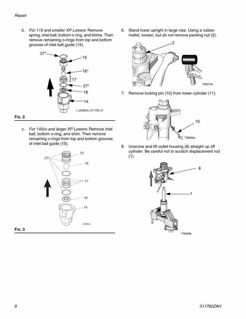
b. For 115 and smaller XP Lowers: Removespring, inlet ball, bottom o-ring, and shims. Thenremove remaining o-rings from top and bottomgrooves of inlet ball guide (15).
c. For 145cc and larger XP Lowers: Remove inletball, bottom o-ring, and shim. Then removeremaining o-rings from top and bottom groovesof inlet ball guide (15).
6. Stand lower upright in large vise. Using a rubbermallet, loosen, but do not remove packing nut (2).
7. Remove locking pin (10) from lower cylinder (11).
8. Unscrew and lift outlet housing (8) straight up offcylinder. Be careful not to scratch displacement rod(1).
FIG. 2
FIG. 3
} 17
27*15
27*
14
16*
18
r_b036C0_311762_8
TI8274a
2
TI8269a
10
TI8309b
8
1

Repair
311762ZAH 9
9. Remove cartridge assembly. Remove o-ring (27* or29*) from bottom of outlet housing (8), and thenunscrew packing nut (2) from packing cartridge (7).Remove female gland, male gland, v-packings (3),and spring from packing cartridge (7).
10. Stand lower cylinder (11) upright on a woodenblock. Using a rubber mallet or an arbor press, drivedisplacement rod (1) out of the bottom until the pis-ton comes free. Pull the rod and piston from the cyl-inder, being careful not to scratch the rod orcylinder.
11. Inspect outer surface of displacement rod (1) andinner surface of lower cylinder (11) for scoring orwear; replace if damaged.
12. Put flats of piston valve (13) in a vise. Use a wrenchto loosen displacement rod (1) from piston valve.
13. Remove displacement rod from piston valve. Becareful that piston ball (12*) does not fall as youseparate piston valve and rod.
14. Remove glands and v-packings (4) from pistonvalve (13). Inspect piston ball (12*) and piston valvefor wear or damage.
15. Clean all parts with a compatible solvent.
NOTICETo reduce the possibility of costly damage to dis-placement rod (1) and lower cylinder (11), first placelower cylinder on a soft block of wood. Always use arubber mallet or an arbor press to drive the displace-ment rod out of the lower cylinder. Never use a ham-mer to drive the rod out. Damage to the rod end willshorten pump life.
TI8467a
2
3
7
8
}
32*
Female Gland
Male Gland
Spring
TI8305a
1
11
TI8298a
1
13
TI8299a
12*
TI8300a
13
{4
12*

Repair
10 311762ZAH
Reassembly
1. Replace female gland on piston valve (13). Installthe five v-packings (4) one at a time with lips facingup. Refer to the Packing Kits sections for the correctpacking order for your lower. Install the male gland.
NOTE: To convert the lower to a different packing mate-rial, see the Packing Kits sections. For best results, soakleather packings in oil before reassembly.
2. Ensure there are no burrs or debris on matingthreads of displacement rod (1) and piston valve(13). Apply anti-seize lubricant to threads and mat-ing surfaces of displacement rod and piston valve.
3. Place flats of piston valve in a vise. Place piston ball(12*) on piston valve.
4. Screw displacement rod (1) onto piston valve (13),and hand tight. Then torque per table on page 13.
NOTE: Position crowfoot of torque wrench at a 90°angle to ensure accurate torque values.
TI8461a
{4
13
Female Gland
Male Gland
NOTICETo reduce the possibility of costly damage to dis-placement rod (1) and lower cylinder (11), first placelower cylinder on a soft block of wood. Always use arubber mallet or an arbor press to drive the displace-ment rod into the lower cylinder. Never use a hammerto drive the rod.
TI8462a
1
12*
13
Apply anti-seizelubricant to threadsbefore torquing.
TI8303a
1
13
Repair
311762ZAH 11
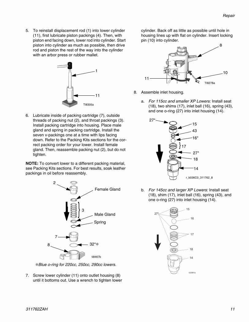
5. To reinstall displacement rod (1) into lower cylinder(11), first lubricate piston packings (4). Then, withpiston end facing down, lower rod into cylinder. Startpiston into cylinder as much as possible, then driverod and piston the rest of the way into the cylinderwith an arbor press or rubber mallet.
6. Lubricate inside of packing cartridge (7), outsidethreads of packing nut (2), and throat packings (3).Install packing cartridge into housing. Place malegland and spring in packing cartridge. Install theseven v-packings one at a time with lips facingdown. Refer to the Packing Kits sections for the cor-rect packing order for your lower. Install femalegland. Then, reassemble packing nut (2), but do nottighten.
NOTE: To convert lower to a different packing material,see Packing Kits sections. For best results, soak leatherpackings in oil before reassembly.
7. Screw lower cylinder (11) onto outlet housing (8)until it bottoms out. Use a wrench to tighten lower
cylinder. Back off as little as possible until hole inhousing lines up with flat on cylinder. Insert lockingpin (10) into cylinder.
8. Assemble inlet housing.
a. For 115cc and smaller XP Lowers: Install seat(18), two shims (17), inlet ball (16), spring (43),and one o-ring (27) into inlet housing (14).
b. For 145cc and larger XP Lowers: Install seat(18), shim (17), inlet ball (16), spring (43), andone o-ring (27) into inlet housing (14).
TI8305a
1
11
ti8467b
2
3
7
8
}
❄Blue o-ring for 220cc, 250cc, 290cc lowers.
32*❄
Female Gland
Male Gland
Spring
TI8278a
8
1011
} 17
27*15
27*
14
16*
18
r_b036C0_311762_8
43

Repair
12 311762ZAH
c. For Xtreme Lowers: Install inlet seat (18), inletball (16), and one o-ring (27*) into inlet housing(14).
9. Lubricate and install o-rings (27*) in top and bottomgrooves of inlet ball guide (15).
10. On model L180C7, L145CP and L145CR only,install shims (17) into inlet housing (14), then pressinlet ball guide (15) into inlet housing (14).
11. On all models except L180C7, press inlet ballguide (15) into inlet housing (14) and installshims (17).
NOTE: Shims (three maximum) can be assembledeither for short ball travel or long ball travel. See FIG. 4for an example of each.
12. Thread inlet housing (14) onto lower cylinder (11).Torque to 140-150 ft-lb (189-203 N•m).
TI8290a
27*
14
16
18
{17
15
17 {15
ti8746a
17 {15
ti8745a
FIG. 4: Shim Configuration for lowers without inletspring
TI8290a
} 17*27*
15
27*
14
Shortest Ball Travel Longest Ball Travel
TI8745a TI8746a
◆ ❖ ✠
◆ Factory set configuration for optimum pumpchange over.
❖ Shims can be configured to change ball travellength. Use longer ball travel length for higher vis-cosity fluids.
✠ Optional inlet ball spring kit available. Use toimprove change over rate with longer ball travelconfigurations. See Kits, page 30, for more infor-mation.

Repair
311762ZAH 13
13. Using torque wrench, torque packing cartridge (7) tooutlet housing (8). Torque to 140-150 ft-lb (189-203N•m).
14. Insert packings in correct orientation; see Parts,page 16. Install packing nut (2) and torque to thevalue in the table below.
Required Torque
15. For lowers with built-in filter, see Service Built-inFilter, page 14, if filter needs service. Then reinstallboth top filter cap (20) and bottom filter cap (26).
16. Reconnect lower to air motor. See Xtreme Pack-ages manual (311164).
Pump Throat Packing (2) Piston Valve (13)L036C0L048C0L054C0L058C0
70-80 ft-lb(95-108 N•m)
85 ft-lb(114 N•m)
L072C0L085C0L085C1L085C2
70-80 ft-lb(95-108 N•m)
125 ft-lb(168 N•m)
L085C3L085C4
70-80 ft-lb(95-108 N•m)
L090C0L097C0L115C0L115C1L115C2
70-80 ft-lb(95-108 N•m)
L115C3L115C4
70-80 ft-lb(95-108 N•m)
L145C0L145C1L145C2L145CLL145CNL145C8L14AC1L145M2L145CPL145CR
70-80 ft-lb(95-108 N•m)
L145C3L145C4
70-80 ft-lb(95-108 N•m)
L180C0L180C1L180CLL180CNL180C2L18AC1L180M2
125(168 N•m)
L180C3L180C4L180C7L180C9
125(168 N•m)
L220C0L220C1L220C2L22AC1L22HC1L22CH2L22XC0L220M2
125 ft-lb(168 N•m)
200 ft-lb(269 N•m
L220C3L220C4L220C9
125 ft-lb(168 N•m)
L250C0L250C1L250C2L250C8L25HC1L25HC225A710
125 ft-lb(168 N•m)
L250C3L250C4L25AC4
125 ft-lb(168 N•m)
L290C0L290C1L290C2L29AC1L29HC1L29HC2L290M224N942
125 ft-lb(168 N•m)
L290C3L290C4
125 ft-lb(168 N•m)
Pump Throat Packing (2) Piston Valve (13)
2 (see table)
TI8279b
8
7(Torque to 140-150 ft-lb)
TI8281b
20
26
Repair
14 311762ZAH
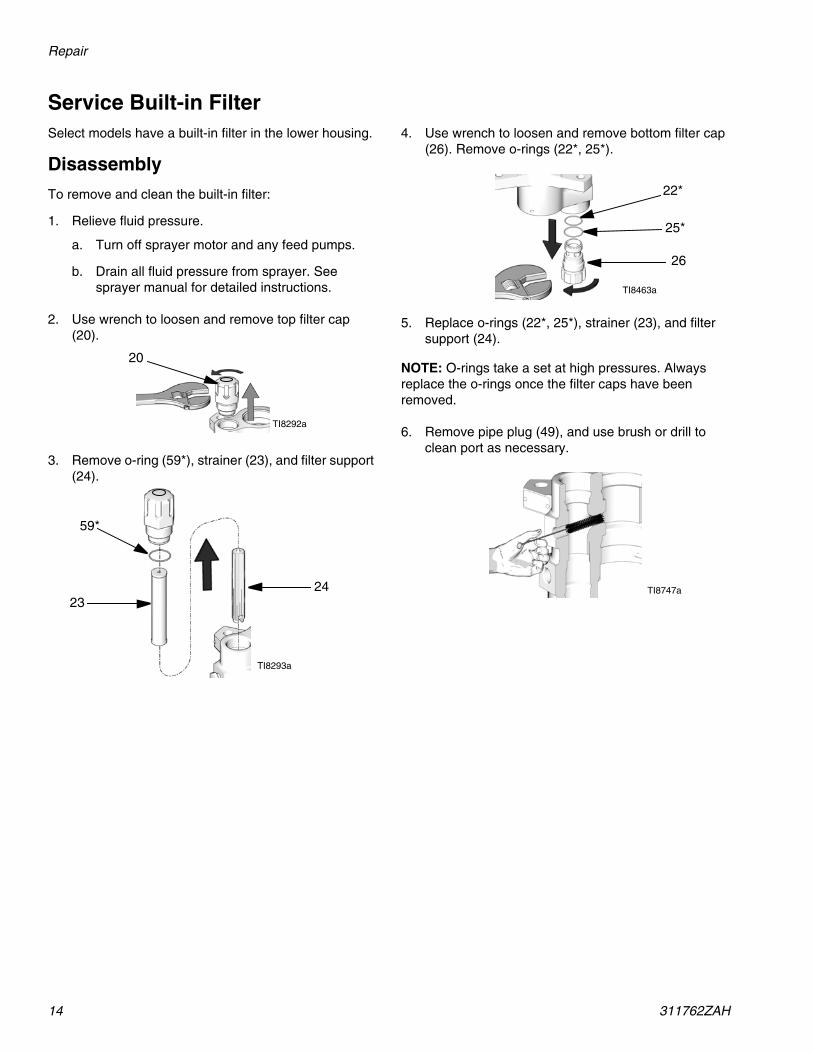
Service Built-in FilterSelect models have a built-in filter in the lower housing.
Disassembly
To remove and clean the built-in filter:
1. Relieve fluid pressure.
a. Turn off sprayer motor and any feed pumps.
b. Drain all fluid pressure from sprayer. Seesprayer manual for detailed instructions.
2. Use wrench to loosen and remove top filter cap(20).
3. Remove o-ring (59*), strainer (23), and filter support(24).
4. Use wrench to loosen and remove bottom filter cap(26). Remove o-rings (22*, 25*).
5. Replace o-rings (22*, 25*), strainer (23), and filtersupport (24).
NOTE: O-rings take a set at high pressures. Alwaysreplace the o-rings once the filter caps have beenremoved.
6. Remove pipe plug (49), and use brush or drill toclean port as necessary.
TI8292a
20
TI8293a
59*
2423
TI8463a
26
25*
22*
TI8747a

Repair
311762ZAH 15
Reassembly
To reassemble the built-in filter:
NOTE: Lubricate all o-rings before installation.
1. Install o-rings (22*, 25*) onto bottom filter cap (26).Then use wrench to reassemble and tighten bottomfilter cap. Torque to 40-60 ft-lb (52-82 N•m).
2. Reassemble o-ring (59*) onto top filter cap (20).Install strainer (23), and filter support (24) in top fil-ter cap. Then use wrench to install and tighten topfilter cap. Torque to 40-60 ft-lb (52-82 N•m).
NOTE: 36cc through 115cc Xtreme pump lowers no lon-ger use the short filter screens (23) or supports (24).See page 31 for details.
NOTICE
To prevent leaking, ensure that the proper repaircomponents are used for the appropriate seriespump. See Filter Cap Repair Kit, 24F975, page31, for more information.
TI8294a
26
25*
22* thin
medium
TI8402a
TI8464a
20
24
59*23
thick
pin facesup
slot is on bottom
open enddown
pin holefaces up

Parts
16 311762ZAH
PartsXP Sprayer Lower Models36cc, 48cc, 54cc, 58cc, 72cc, 85cc, 90cc, 97cc, and 115cc
ti32087a
19*
20
21
23
24
4
1259*
}7
3* (Throat)
2
8
10
54
26
25*
4
22*
9*
29*
11
56
12*
(Piston)4* {
1
{17
18
Torque per specifications in table on page 13.
Torque to 140-150 ft-lb (189-203 N•m).
Torque to 40-60 ft-lb (52-82 N•m).
Apply lubricant to threads before assembly.
Torque to 45-55 ft-lb (61-75 N•m).
Ensure orifice of rupture disc points down.
1
2
4
5
6
7
27*
15
43*
16*
27*
142
* Parts included in repair kits.See Repair Kits sections.
†Thick, medium, and thin refers to the relativecross-section thickness of the o-ring seals.
49 ✖
32*
6
1
6
5
5
1 5 ✿13
medium†
thin†
thin†
thin†
medium†
thick†
61
55 7
Parts
311762ZAH 17
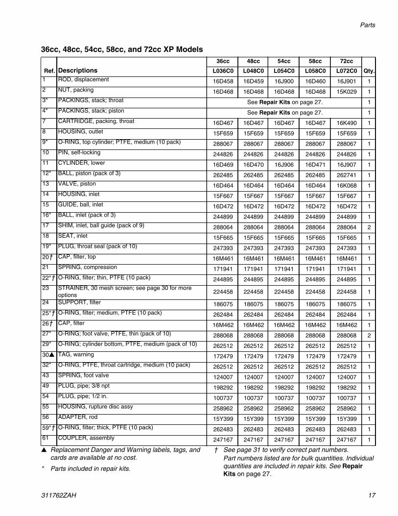
36cc, 48cc, 54cc, 58cc, and 72cc XP Models
▲ Replacement Danger and Warning labels, tags, andcards are available at no cost.
* Parts included in repair kits.
† See page 31 to verify correct part numbers.Part numbers listed are for bulk quantities. Individualquantities are included in repair kits. See RepairKits on page 27.
Ref. Descriptions36cc 48cc 54cc 58cc 72cc
Qty.L036C0 L048C0 L054C0 L058C0 L072C01 ROD, displacement 16D458 16D459 16J900 16D460 16J901 12 NUT, packing 16D468 16D468 16D468 16D468 15K029 13* PACKINGS, stack; throat See Repair Kits on page 27. 14* PACKINGS, stack; piston See Repair Kits on page 27. 17 CARTRIDGE, packing, throat 16D467 16D467 16D467 16D467 16K490 18 HOUSING, outlet 15F659 15F659 15F659 15F659 15F659 19* O-RING, top cylinder; PTFE, medium (10 pack) 288067 288067 288067 288067 288067 110 PIN, self-locking 244826 244826 244826 244826 244826 111 CYLINDER, lower 16D469 16D470 16J906 16D471 16J907 112* BALL, piston (pack of 3) 262485 262485 262485 262485 262741 113 VALVE, piston 16D464 16D464 16D464 16D464 16K068 114 HOUSING, inlet 15F667 15F667 15F667 15F667 15F667 115 GUIDE, ball, inlet 16D472 16D472 16D472 16D472 16D472 116* BALL, inlet (pack of 3) 244899 244899 244899 244899 244899 117 SHIM, inlet, ball guide (pack of 9) 288064 288064 288064 288064 288064 218 SEAT, inlet 15F665 15F665 15F665 15F665 15F665 119* PLUG, throat seal (pack of 10) 247393 247393 247393 247393 247393 1
20† CAP, filter, top 16M461 16M461 16M461 16M461 16M461 121 SPRING, compression 171941 171941 171941 171941 171941 1
22*† O-RING, filter; thin, PTFE (10 pack) 244895 244895 244895 244895 244895 123 STRAINER, 30 mesh screen; see page 30 for more
options 224458 224458 224458 224458 224458 1
24 SUPPORT, filter 186075 186075 186075 186075 186075 1
25*† O-RING, filter; medium, PTFE (10 pack) 262484 262484 262484 262484 262484 1
26† CAP, filter 16M462 16M462 16M462 16M462 16M462 127* O-RING; foot valve, PTFE, thin (pack of 10) 288068 288068 288068 288068 288068 229* O-RING; cylinder bottom, PTFE, medium (pack of 10) 262512 262512 262512 262512 262512 1
30▲ TAG, warning 172479 172479 172479 172479 172479 132* O-RING, PTFE, throat cartridge, medium (10 pack) 262512 262512 262512 262512 262512 143 SPRING, foot valve 124007 124007 124007 124007 124007 149 PLUG, pipe; 3/8 npt 198292 198292 198292 198292 198292 154 PLUG, pipe; 1/2 in. 100737 100737 100737 100737 100737 155 HOUSING, rupture disc assy 258962 258962 258962 258962 258962 156 ADAPTER, rod 15Y399 15Y399 15Y399 15Y399 15Y399 1
59*† O-RING, filter; thick, PTFE (10 pack) 262483 262483 262483 262483 262483 161 COUPLER, assembly 247167 247167 247167 247167 247167 1

Parts
18 311762ZAH
85cc, 90cc, 97cc, and 115cc XP Models
▲ Replacement Danger and Warning labels, tags, and cardsare available at no cost.
* Parts included in repair kits.
† See page 31 to verify correct part numbers.Part numbers listed are for bulk quantities. Individual quan-tities are included in repair kits. See Repair Kits on page27.
Ref. Descriptions85cc 90cc 97cc 115cc
Qty.L085C0 L090C0 L097C0 L115C01 ROD, displacement 24B819 16J902 16J903 24B820 12 NUT, packing 15K029 15K029 15K029 15K029 13* PACKINGS, stack; throat See Repair Kits on page 27. 14* PACKINGS, stack; piston See Repair Kits on page 27. 17 CARTRIDGE, packing, throat 15F660 16K490 16K490 15F661 18 HOUSING, outlet 15F659 15F659 15F659 15F659 19* O-RING, top cylinder; PTFE, medium (10 pack) 288067 288067 288067 288067 110 PIN, self-locking 244826 244826 244826 244826 111 CYLINDER, lower 15F682 16J908 16J909 15F656 112* BALL, piston (pack of 3) 288065 288065 288065 288065 113 VALVE, piston 24B818 24B818 24B818 24B817 114 HOUSING, inlet 15F667 15F667 15F667 15F667 115 GUIDE, ball, inlet 16D472 16D472 16D472 16D472 116* BALL, inlet (pack of 3) 244899 244899 244899 244899 117 SHIM, inlet, ball guide (pack of 9) 288064 288064 288064 288064 218 SEAT, inlet 15F665 15F665 15F665 15F665 119* PLUG, throat seal (pack of 10) 247393 247393 247393 247393 1
20† CAP, filter, top 16M461 16M461 16M461 16M461 121 SPRING, compression 171941 171941 171941 171941 1
22*† O-RING, filter; thin, PTFE (10 pack) 244895 244895 244895 244895 123 STRAINER, 30 mesh screen; see page 30 for more options 224458 224458 224458 224458 124 SUPPORT, filter 186075 186075 186075 186075 1
25*† O-RING, filter; medium, PTFE (10 pack) 262484 262484 262484 262484 1
26† CAP, filter 16M462 16M462 16M462 16M462 127* O-RING; foot valve, PTFE, thin (pack of 10) 288068 288068 288068 288068 229* O-RING; cylinder bottom, PTFE (pack of 10)
256512 medium, 288068 thin 288068 262512 262512 288068 1
30▲ TAG, warning 172479 172479 172479 172479 132* O-RING, PTFE, throat cartridge (10 pack)
256512 medium, 288068 thin 288068 262512 262512 288068 1
43 SPRING, foot valve 124007 124007 124007 124007 149 PLUG, pipe; 3/8 npt 198292 198292 198292 198292 154 PLUG, pipe; 1/2 in. 100737 100737 100737 100737 155 HOUSING, rupture disc assembly 258962 258962 258962 258962 156 ADAPTER, rod 1
59*† O-RING, filter; thick, PTFE (10 pack) 262483 262483 262483 262483 161 COUPLER, assembly 247167 247167 247167 247167 1
Parts
311762ZAH 19
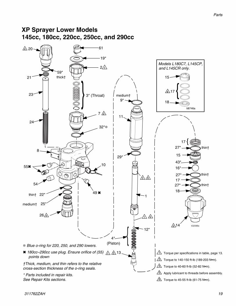
XP Sprayer Lower Models145cc, 180cc, 220cc, 250cc, and 290cc
ti32088a
19*
20
21
23
24
4
1259*
}7
3* (Throat)
2
8
10
54
26
25*
4
22*
9*
29*
11
12*
(Piston)4* {
1
142
Torque per specifications in table, page 13.
Torque to 140-150 ft-lb (189-203 N•m).
Torque to 40-60 ft-lb (52-82 N•m).
Apply lubricant to threads before assembly.
Torque to 45-55 ft-lb (61-75 N•m).
1
2
4
5
6
{17
27*
15
43*
16*
27*1727*
18
†Thick, medium, and thin refers to the relativecross-section thickness of the o-ring seals.
* Parts included in repair kits.See Repair Kits sections.
49 ✖
6
1
5
5
1 5
medium†
thin†
medium†
thick†
thin†
thin†
thin†
61
55✖
13
32*❄
❄ Blue o-ring for 220, 250, and 290 lowers.
✖ 180cc–290cc use plug. Ensure orifice of (55)points down
17
15
18
8
Models L180C7, L145CP,
ti8746a
and L145CR only.
{

Parts
20 311762ZAH
145cc, 180cc, 220cc, 250cc, and 290cc XP Models
▲ Replacement Danger and Warning labels, tags, and cardsare available at no cost.
* Parts included in repair kits.
† See page 31 to verify correct part numbers.Part numbers listed are for bulk quantities. Individual quan-tities are included in repair kits. See Repair Kits on page27.
Ref. Descriptions145cc 180cc 220cc 220cc 250cc 290cc
Qty.L14AC0 L18AC0 L22AC0 L22XC0 L25AC0 L29AC01 ROD, displacement 24B821 24B822 24B823 26A377 24B824 24B825 12 NUT, packing 15K030 15K030 15K031 15K031 15K031 15K031 13* PACKINGS, stack; throat See Repair Kits on page 27. 14* PACKINGS, stack; piston See Repair Kits on page 27. 17 CARTRIDGE, packing, throat 197325 197326 197327 197327 197328 197327 18 HOUSING, outlet 16E151 16E151 16A763 16A763 16A763 16A763 19* O-RING, top cylinder; PTFE, medium (10 pack) 244892 244892 244893 244893 244893 244893 110 PIN, self-locking 244826 244826 244826 244826 244826 244826 111 CYLINDER, lower 197315 197316 197317 197317 197318 197319 112* BALL, piston (pack of 3) 253029 253029 244898 244898 244898 244899 113 VALVE, piston 24B826 24B827 24B828 24B828 24B829 24B830 114 HOUSING, inlet 197303 197303 197304 197304 197304 197304 115 GUIDE, ball, inlet 198646 198646 198647 198647 198647 198647 116* BALL, inlet (pack of 3) 245128 245128 253030 253030 253030 253030 117 SHIM, inlet, ball guide (pack of 9) 244855 244855 244856 244856 244856 244856 318 SEAT, inlet 196358 196358 197344 197344 197344 197344 119* PLUG, throat seal (pack of 10) 247394 247394 247395 247395 247395 247395 1
20† CAP, filter, top 16M461 16M461 16M461 16M461 16M461 16M461 121 SPRING, compression 171941 171941 171941 171941 171941 171941 1
22*† O-RING, filter; thin, PTFE (10 pack) 244895 244895 244895 244895 244895 244895 123 STRAINER, 30 mesh screen; see page 30 for more options 224458 224458 224458 224458 224458 224458 124 SUPPORT, filter 186075 186075 186075 186075 186075 186075 1
25*† O-RING, filter; medium, PTFE (10 pack) 262484 262484 262484 262484 262484 262484 1
26† CAP, filter 16M462 16M462 16M462 16M462 16M462 16M462 127* O-RING; foot valve, PTFE, thin (pack of 10) 244890 244890 244894 244894 244894 244894 329* O-RING; cylinder bottom, PTFE, thin (pack of 10) 244890 244890 244894 244894 244894 244894 1
30▲ TAG, warning 172479 172479 172479 172479 172479 172479 132* O-RING, PTFE, throat cartridge, thin (10 pack) 244890 244890 244891 244891 244891 244891 143 SPRING, foot valve 116801 116801 116802 116802 116802 116802 149 PLUG, pipe; 3/8 npt 198292 198292 198292 198292 198292 198292 154 PLUG, pipe; 1/2 in. 100737 100737 100737 100737 100737 100737 155 PLUG, pipe; 3/8 npt 198292 198292 198292 198292 198292 1
HOUSING, rupture disc assembly 258962 1
59*† O-RING, filter; thick, PTFE (10 pack) 262483 262483 262483 262483 262483 262483 161 COUPLER, assembly 244819 244819 244819 244819 244819 244819 1

Parts
311762ZAH 21
Xtreme and e-Xtreme Sprayer Lower Models85cc 115cc, 145cc, 180cc, 220cc, 250cc, and 290cc
{
{
}
14
18
16*
15
17
13
4*
12*
1
27*
11
9*
8
10
30
7
2
19*
20
21
23
24
8
10
40
41
42
26
38
49
39
3* (Throat)
25*
32*❄
27*
27*
27*
* Parts included in repair kits.See Repair Kits sections.
1
2
4
4
55
1
1
2
(Piston Packings)
59*
22*
5
5
Torque per table on page 13.
Torque to 140-150 ft-lb (189-203 N•m).
Torque to 40-60 ft-lb (52-82 N•m).
Apply lubricant to threads before assembly.7. Thick, medium, and thin refers to the relative cross-section
thickness of the o-ring seals.
On models L180C7, L145CP, and L145CR only, all 3 shims (17)are installed together between inlet seat (18) and inlet ballguide (15).
1
2
4
5
8
❄ Blue o-ring for 220, 250, and 290 lowers.
thin
medium
thin
thin
thin
thin
thick
mediumthin
49
{17
15
18
8
8
Models L180C7, L145CP,
ti8746a
54
and L145CR only.

Parts
22 311762ZAH
85cc and 115cc Models
▲ Replacement Danger and Warning labels, tags, andcards are available at no cost.
* Parts included in repair kits.
† See page 31 to verify correct part numbers.
Part numbers listed are for bulk quantities. Individualquantities are included in repair kits. See RepairKits on page 27.
Ref. Descriptions
85cc 115cc
Qty.L085C1L085C3
L085C2L085C4
L115C1L115C3
L115C2L115C4
1 ROD, displacement 24B819 24B819 24B820 24B820 12 NUT, packing 15K029 15K029 15K029 15K029 13* PACKINGS, stack; throat See Repair Kits on page 27. 14* PACKINGS, stack; piston See Repair Kits on page 27. 17 CARTRIDGE, packing, throat 15F660 15F660 15F661 15F661 18 HOUSING, outlet 15F654 15F659 15F654 15F659 1
9*† O-RING, top cylinder; PTFE, medium (pack of 10) 288067 288067 288067 288067 110 PIN, self-locking 244826 244826 244826 244826 111 CYLINDER, lower 15F682 15F682 15F656 15F656 112* BALL, piston; (pack of 3) 288065 288065 288065 288065 113 VALVE, piston 24B818 24B818 24B817 24B817 114 HOUSING, inlet 15F667 15F667 15F667 15F667 115 GUIDE, ball, inlet 15F664 15F664 15F664 15F664 116* BALL, inlet; (pack of 3) 244899 244899 244899 244899 117 SHIM, inlet, ball guide (pack of 9) 288064 288064 288064 288064 318 SEAT, inlet 15F665 15F665 15F665 15F665 119* PLUG, throat seal (pack of 10) 247393 247393 247393 247393 1
20† CAP, filter, top 16M461 16M461 121 SPRING, compression 171941 171941 1
22*† O-RING, filter; thin, PTFE (10 pack) 244895 244895 123 STRAINER, 60 mesh screen; see page 30 for more options 224459 224459 124 SUPPORT, filter 186075 186075 1
25*† O-RING, filter; medium, PTFE (10 pack) 262484 262484 1
26† CAP, filter, lower 16M462 16M462 127* O-RING; foot valve and cylinder bottom, PTFE, thin (pack of 10) 288068 288068 288068 288068 4
30▲ TAG, warning 172479 172479 172479 172479 132* O-RING, PTFE, throat cartridge, thin (10 pack) 288068 288068 288068 288068 138 FITTING, nipple, outlet 1/2 in. 158491 158491 139 PLUG, packless; 1/2 in. 24N518 24N518 140 VALVE, pressure dump 245143 245143 141 FITTING, barbed, plated 116746 116746 142 TUBE, nylon 116750 116750 149 PLUG, pipe 101754 198292 101754 198292 1
59† O-RING, filter; thick, PTFE (10 pack) 262483 262483 1

Parts
311762ZAH 23
145cc Models
▲ Replacement Danger and Warning labels, tags, and cards areavailable at no cost.
* Parts included in repair kits.
† See page 31 to verify correct part numbers.
Part numbers listed are for bulk quantities. Individual quanti-ties are included in repair kits. See Repair Kits on page 27.
Ref. Descriptions
145cc
Qty.
L145C1L145C3L145CP
L145C2L145C4L145CR L145C8 L14AC1 L145M2 B145CL B145CN
1 ROD, displacement 24B821 24B821 24B821 24B821 25D349 24B821 24B821 12 NUT, packing 15K030 15K030 15K030 15K030 15K030 15K030 15K030 13* PACKINGS, stack; throat See Repair Kits on page 27. 14* PACKINGS, stack; piston See Repair Kits on page 27. 17 CARTRIDGE, packing, throat 197325 197325 197325 197325 197325 197325 197325 18 HOUSING, outlet 197334 197336 197334 15J673 197336 197336 197334 19*† O-RING, top cylinder; PTFE, medium
(pack of 10) 244892 244892 244892 244892 244892 244892 244892 1
10 PIN, self-locking 244826 244826 244826 244826 244826 244826 244826 111 CYLINDER, lower 197315 197315 197315 197315 17S911 197315 197315 112* BALL, piston; (pack of 3) 253029 253029 253029 253029 253029 253029 253029 113 VALVE, piston 24B826 24B826 24B826 24B826 24B826 24B826 24B826 114 HOUSING, inlet 197303 197303 197303 197303 197303 25C241 25C241 115 GUIDE, ball, inlet 197307 197307 197307 197307 197307 197307 197307 116* BALL, inlet; (pack of 3) 245128 245128 245128 245128 245178 245128 245128 117 SHIM, inlet, ball guide (pack of 9) 244855 244855 244855 244855 244855 244855 244855 318 SEAT, inlet 196358 196358 196358 196358 196358 196358 196358 119* PLUG, throat seal (pack of 10) 247394 247394 247394 247394 243304 247394 247394 120† CAP, filter, top 16M461 16M461 16M461 121 SPRING, compression 171941 171941 171941 122* O-RING, filter; thin, PTFE (10 pack) 244895 244895 244895 123 STRAINER, 60 mesh screen; (2 pack)
see page 30 for more options 224459 224459 224459 1
24 SUPPORT, filter 186075 186075 186075 125*† O-RING, filter; medium, PTFE (10
pack) 262484 262484 262484 1
26† CAP, filter 16M462 16M462 16M462 127* O-RING; foot valve and cylinder bot-
tom, PTFE, thin (pack of 10) 244890 244890 244890 244890 244890 244890 244890 4
30▲ TAG, warning 172479 172479 172479 172479 172479 172479 172479 132* O-RING, PTFE, throat cartridge, thin
(10 pack) 244890 244890 244890 244890 244890 244890 244890 1
38 FITTING, nipple, outlet 1/2 in. 158491 158491 139 PLUG, packless; 1/2 in. 24N518 24N518 100362 140 VALVE, pressure dump 245143 245143 141 FITTING, barbed, plated 116746 116746 142 TUBE, nylon 116750 116750 149 PLUG, pipe 101754 198292 101754 198292 198292 154 HOUSING, rupture disc 258962 127628 155 HOUSING, rupture disc 127628 159† O-RING, filter; thick, PTFE (10 pack) 262483 262483 262483 1
Parts
24 311762ZAH
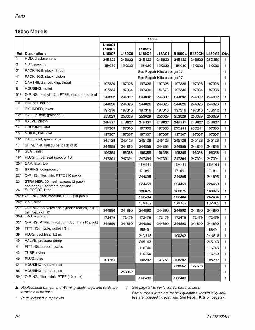
180cc Models
▲ Replacement Danger and Warning labels, tags, and cards areavailable at no cost.
* Parts included in repair kits.
† See page 31 to verify correct part numbers.
Part numbers listed are for bulk quantities. Individual quanti-ties are included in repair kits. See Repair Kits on page 27.
Ref. Descriptions
180cc
Qty.
L180C1L180C3L180C7 L180C9
L180C2L180C4 L18AC1 B180CL B180CN L180M2
1 ROD, displacement 24B822 24B822 24B822 24B822 24B822 24B822 25D350 12 NUT, packing 15K030 15K030 15K030 15K030 15K030 15K030 15K030 13* PACKINGS, stack; throat See Repair Kits on page 27. 14* PACKINGS, stack; piston See Repair Kits on page 27. 17 CARTRIDGE, packing, throat 197326 197326 197326 197326 197326 197326 197326 18 HOUSING, outlet 197334 197334 197336 15J673 197336 197334 197336 19*† O-RING, top cylinder; PTFE, medium (pack of
10) 244892 244892 244892 244892 244892 244892 244892 1
10 PIN, self-locking 244826 244826 244826 244826 244826 244826 244826 111 CYLINDER, lower 197316 197316 197316 197316 197316 197316 17S912 112* BALL, piston; (pack of 3) 253029 253029 253029 253029 253029 253029 253029 113 VALVE, piston 24B827 24B827 24B827 24B827 24B827 24B827 24B827 114 HOUSING, inlet 197303 197303 197303 197303 25C241 25C241 197303 115 GUIDE, ball, inlet 197307 197307 197307 197307 197307 197307 197307 116* BALL, inlet; (pack of 3) 245128 245128 245128 245128 245128 245128 245128 117 SHIM, inlet, ball guide (pack of 9) 244855 244855 244855 244855 244855 244855 244855 318 SEAT, inlet 196358 196358 196358 196358 196358 196358 196358 119* PLUG, throat seal (pack of 10) 247394 247394 247394 247394 247394 247394 247394 120† CAP, filter, top 16M461 16M461 16M461 121 SPRING, compression 171941 171941 171941 122* O-RING, filter; thin, PTFE (10 pack) 244895 244895 244895 123 STRAINER, 60 mesh screen; (2 pack)
see page 30 for more options 224459 224459 224459 1
24 SUPPORT, filter 186075 186075 186075 125*† O-RING, filter; medium, PTFE (10 pack) 262484 262484 262484 126† CAP, filter 16M462 16M462 16M462 127* O-RING; foot valve and cylinder bottom, PTFE,
thin (pack of 10) 244890 244890 244890 244890 244890 244890 244890 4
30▲ TAG, warning 172479 172479 172479 172479 172479 172479 172479 132* O-RING, PTFE, throat cartridge, thin (10 pack) 244890 244890 244890 244890 244890 244890 244890 138 FITTING, nipple, outlet 1/2 in. 158491 158491 139 PLUG, packless; 1/2 in. 24N518 100362 24N518 140 VALVE, pressure dump 245143 245143 141 FITTING, barbed, plated 116746 116746 142 TUBE, nylon 116750 116750 149 PLUG, pipe 101754 198292 101754 198292 198292 154 HOUSING, rupture disc 258962 127628 155 HOUSING, rupture disc 258962 159† O-RING, filter; thick, PTFE (10 pack) 262483 262483 1

Parts
311762ZAH 25
220cc and 250cc Models
▲ Replacement Danger and Warning labels, tags, and cards are avail-able at no cost.
* Parts included in repair kits.
† See page 31 to verify correct part numbers.
Part numbers listed are for bulk quantities. Individual quantities areincluded in repair kits. See Repair Kits on page 27.
Ref. Descriptions
220cc 250cc
Qty.L220C1L220C3 L220C9
L220C2L220C4 L22AC1 L22HC1 L22HC2 L220M2
L250C1L250C3
L250C2L250C4 L250C8 L25HC1 L25HC2 25A710
1 ROD, displacement 24B823 24B823 24B823 24B823 24X554 24X554 25D351 24B824 24B824 24B824 24X555 24X555 24B824 12 NUT, packing 15K031 15K031 15K031 15K031 15K031 15K031 15K031 15K031 15K031 15K031 15K031 15K031 15K031 13* PACKINGS, stack;
throat See Repair Kits on page 27. 1
4* PACKINGS, stack;packing See Repair Kits on page 27. 1
7 CARTRIDGE, packing,throat 197327 197327 197327 197327 197327 197327 197327 197328 197328 197328 197328 197328 197328 1
8 HOUSING, outlet 197335 197335 197337 15H722 197335 17D828 197337 197335 197337 197335 197335 17D828 197335 19† O-RING, top cylinder;
PTFE, medium (pack of10)
244893 244893 244893 244893 244893 244893 244893 244893 244893 244893 244893 244893 244893 1
10 PIN, self-locking 244826 244826 244826 244826 244826 244826 244826 244826 244826 244826 244826 244826 244826 111 CYLINDER, lower 197317 197317 197317 197317 17C109 17C109 17S913 197318 197318 197318 17C110 17C110 197318 112* BALL, piston; (pack of
3) 244898 244898 244898 244898 244898 244898 244898 244898 244898 244898 244898 244898 244898 1
13 VALVE, piston 24B828 24B828 24B828 24B828 24B828 24B828 24B828 24B829 24B829 24B829 24B829 24B829 24B829 114 HOUSING, inlet 197304 197304 197304 197304 17C167 17C167 197304 197304 197304 197304 17C167 17C167 197304 115 GUIDE, ball, inlet 198647 198647 198647 198647 198647 198647 198647 198647 198647 198647 198647 198647 198647 116* BALL, inlet; (pack of 3) 253030 253030 253030 253030 253030 253030 253030 253030 253030 253030 253030 253030 253030 117 SHIM, inlet, ball guide
(pack of 9) 244856 244856 244856 244856 244856 244856 244856 244856 244856 244856 244856 244856 244856 3
18 SEAT, inlet 197344 197344 197344 197344 197344 197344 197344 197344 197344 197344 197344 197344 17E318 119* PLUG, throat seal (pack
of 10) 247395 247395 247395 247395 247395 247395 247395 247395 247395 247395 247395 247395 247395 1
20† CAP, filter, top 16M461 16M461 16M461 16M461 16M461 121 SPRING, compression 171941 171941 171941 171941 171941 122*† O-RING, filter; thin,
PTFE (10 pack) 244895 244895 244895 244895 244895 1
23 STRAINER, 60 meshscreen (2 pack);see page 30 for moreoptions
224459 224459 224459 224459 224459 1
24 SUPPORT, filter 186075 186075 186075 186075 186075 125*† O-RING, filter; medium,
PTFE (10 pack) 262484 262484 262484 262484 262484 1
26† CAP, filter 16M462 16M462 16M462 16M462 16M462 127*† O-RING; foot valve and
cylinder bottom, PTFE,thin (pack of 10)
244894 244894 244894 244894 244894 244894 244894 244894 244894 244894 244894 244894 244894 4
30▲ TAG, warning 172479 172479 172479 172479 172479 172479 172479 172479 172479 172479 172479 172479 172479 132*† O-RING, PTFE, throat
cartridge, blue, thin (10pack)
244891 244891 244891 244891 244891 244891 244891 244891 244891 244891 244891 244891 244891 1
38 FITTING, nipple, outlet1/2 in. 158491 158491 158491 158491 158491 1
39 PLUG, packless; 1/2 in. 24N518 24N518 24N518 24N518 24N518 140 VALVE, pressure dump 245143 245143 245143 245143 245143 141 FITTING, barbed,
plated 116746 116746 116746 116746 116746 1
42 TUBE, nylon 116750 116750 116750 116750 116750 149 PLUG, pipe 101754 198292 101754 101754 198292 198292 101754 198292 198292 155 HOUSING, rupture disc 258962 258962 258962 159*† O-RING, filter; thick,
PTFE (10 pack) 262483 262483 262483 262483 262483 1

Parts
26 311762ZAH
290cc Models
▲ Replacement Danger and Warning labels, tags, and cards areavailable at no cost.
* Parts included in repair kits.
† See page 31 to verify correct part numbers.
Part numbers listed are for bulk quantities. Individual quanti-ties are included in repair kits. See Repair Kits on page 27.
Ref. Descriptions
290cc
Qty.24N942L290C1L290C3
L290C2L290C4 L29AC1 L29HC1 L29HC2 L290M2
1 ROD, displacement 16R994 24B825 24B825 24B825 24X556 24X556 25D352 1
2 NUT, packing 15K031 15K031 15K031 15K031 15K031 15K031 15K031 1
3* PACKINGS, stack. throat See Repair Kits, page 27. 1
4* PACKINGS, stack; piston See Repair Kits, page 27. 1
7 CARTRIDGE, packing, throat 197327 197327 197327 197327 197327 197327 197327 1
8 HOUSING, outlet 197335 197335 197337 15H722 197335 17D828 197337 1
9*† O-RING, top cylinder; PTFE, medium (packof 10) 244893 244893 244893 244893 244893 244893 244893 1
10 PIN, self-locking 244826 244826 244826 244826 244826 244826 244826 1
11 CYLINDER, lower 197319 197319 197319 197319 17C111 17C111 17S915 1
12* BALL, piston; (pack of 3) 244899 244899 244899 244899 244899 244899 244899 1
13 VALVE, piston 24B830 24B830 24B830 24B830 24B830 24B830 24B830 1
14 HOUSING, inlet 197304 197304 197304 197304 17C167 17C167 197304 1
15 GUIDE, ball, inlet 198647 198647 198647 198647 198647 198647 198647 1
16* BALL, inlet; (pack of 3) 253030 253030 253030 253030 253030 253030 253030 1
17 SHIM, inlet, ball guide (pack of 9) 244856 244856 244856 244856 244856 244856 244856 3
18 SEAT, inlet 197344 197344 197344 197344 197344 197344 197344 1
19* PLUG, throat seal (pack of 10) 247395 247395 247395 247395 247395 247395 247395 1
20† CAP, filter, top 16M461 16M461 16M461 1
21 SPRING, compression 171941 171941 171941 1
22*† O-RING, filter; thin, PTFE (10 pack) 244895 244895 244895 1
23 STRAINER, 60 mesh screen; (2 pack)see page 30 for more options 224459 224459 224459 1
24 SUPPORT, filter 186075 186075 186075 1
25*† O-RING, filter; medium, PTFE (10 pack) 262484 262484 262484 1
26† CAP, filter 16M462 16M462 16M462 1
27* O-RING; foot valve and cylinder bottom,PTFE, thin (pack of 10) 244894 244894 244894 244894 244894 244894 244894 4
30▲ TAG, warning 172479 172479 172479 172479 172479 172479 172479 1
32* O-RING, PTFE, throat cartridge, blue, thin(10 pack) 244891 244891 244891 244891 244891 244891 244891 1
38 FITTING, nipple, outlet 1/2 in. 158491 158491 158491 1
39 PLUG, packless; 1/2 in. 24N518 24N518 24N518 1
40 VALVE, pressure dump 245143 245143 245143 1
41 FITTING, barbed, plated 116746 116746 116746 1
42 TUBE, nylon 116750 116750 116750 1
49 PLUG, pipe 101754 101754 198292 101754 101754 198292 198292 1
59*† O-RING, filter; thick, PTFE (10 pack) 262483 262483 262483 1
Repair Kits
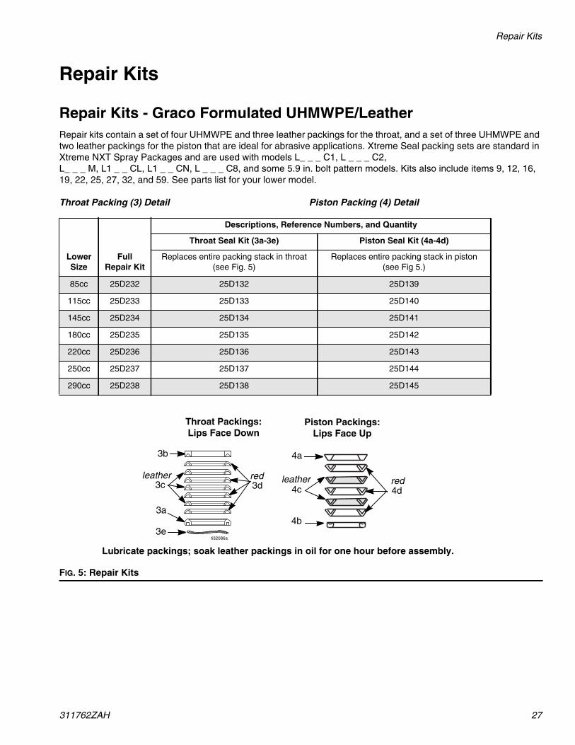
311762ZAH 27
Repair Kits
Repair Kits - Graco Formulated UHMWPE/LeatherRepair kits contain a set of four UHMWPE and three leather packings for the throat, and a set of three UHMWPE andtwo leather packings for the piston that are ideal for abrasive applications. Xtreme Seal packing sets are standard inXtreme NXT Spray Packages and are used with models L_ _ _ C1, L _ _ _ C2,L_ _ _ M, L1 _ _ CL, L1 _ _ CN, L _ _ _ C8, and some 5.9 in. bolt pattern models. Kits also include items 9, 12, 16,19, 22, 25, 27, 32, and 59. See parts list for your lower model.
Throat Packing (3) Detail Piston Packing (4) Detail
LowerSize
FullRepair Kit
Descriptions, Reference Numbers, and Quantity
Throat Seal Kit (3a-3e) Piston Seal Kit (4a-4d)
Replaces entire packing stack in throat(see Fig. 5)
Replaces entire packing stack in piston(see Fig 5.)
85cc 25D232 25D132 25D139
115cc 25D233 25D133 25D140
145cc 25D234 25D134 25D141
180cc 25D235 25D135 25D142
220cc 25D236 25D136 25D143
250cc 25D237 25D137 25D144
290cc 25D238 25D138 25D145
FIG. 5: Repair Kits
ti32086a
Throat Packings:Lips Face Down
Piston Packings:Lips Face Up
3b
3c
3a
3d
Lubricate packings; soak leather packings in oil for one hour before assembly.
4a
4c
4b
4dredleatherredleather
3e
Repair Kits
28 311762ZAH
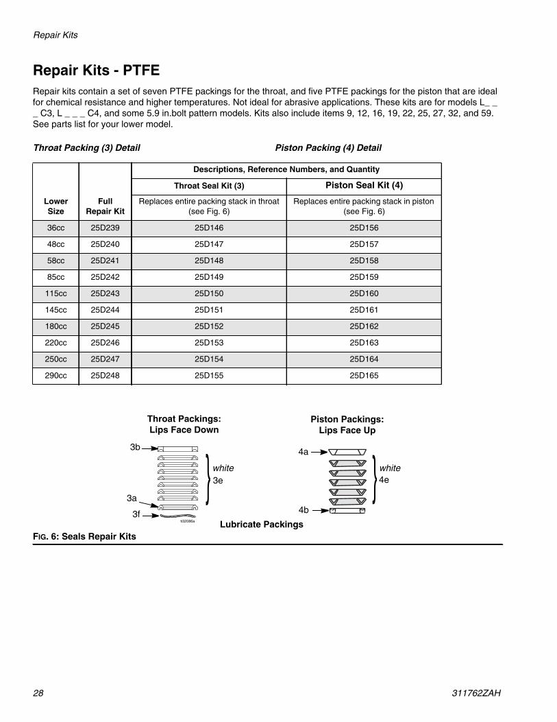
Repair Kits - PTFERepair kits contain a set of seven PTFE packings for the throat, and five PTFE packings for the piston that are idealfor chemical resistance and higher temperatures. Not ideal for abrasive applications. These kits are for models L_ __ C3, L _ _ _ C4, and some 5.9 in.bolt pattern models. Kits also include items 9, 12, 16, 19, 22, 25, 27, 32, and 59.See parts list for your lower model.
Throat Packing (3) Detail Piston Packing (4) Detail
LowerSize
FullRepair Kit
Descriptions, Reference Numbers, and Quantity
Throat Seal Kit (3) Piston Seal Kit (4)
Replaces entire packing stack in throat(see Fig. 6)
Replaces entire packing stack in piston(see Fig. 6)
36cc 25D239 25D146 25D156
48cc 25D240 25D147 25D157
58cc 25D241 25D148 25D158
85cc 25D242 25D149 25D159
115cc 25D243 25D150 25D160
145cc 25D244 25D151 25D161
180cc 25D245 25D152 25D162
220cc 25D246 25D153 25D163
250cc 25D247 25D154 25D164
290cc 25D248 25D155 25D165
FIG. 6: Seals Repair Kits
ti32086a
Piston Packings:Lips Face Up
}4a
4b
4e
Throat Packings:Lips Face Down
Lubricate Packings
}3a
3e
3b
whitewhite
3f

Repair Kits
311762ZAH 29
Repair Kits - Graco Formulated UHMWPE/PTFERepair kits contain a set of four UHWMPE and three PTFE packings for the throat, and three UHWMPE and twoPTFE packings for the piston that are for chemical resistance and durability in applications below 140 °F (60 °C).UHWMPE and PTFE packing sets are standard in XP Proportioners and are used with L_ _ _ C0, L_ _ _ C7, and L__ _ C9 models and some 5.9 in. bolt pattern models. Kits also include items 9, 12, 16, 19, 22, 25, 27, 29, 32, 43, and59. See parts list for your lower model.
NOTE: All L_ _ _ C0 XP lowers built prior to April 2012 came with Tuff-Stack packing sets.
Throat Packing (3) Detail Piston Packing (4) Detail
LowerSize Kit
Descriptions, Reference Numbers, and QuantityThroat Seal Kit (3) Piston Seal Kit (4)
Replaces entire packing stack in throat(see Fig. 7)
Replaces entire packing stack in piston(see Fig. 7)
36cc 25D249 25D166 25D180
48cc 25D250 25D167 25D181
54cc 25D251 25D168 25D182
58cc 25D252 25D169 25D183
72cc 25D253 25D170 25D184
85cc 25D254 25D171 25D185
90cc 25D255 25D172 25D186
97cc 25D256 25D173 25D187
115cc 25D257 25D174 25D188
145cc 25D258 25D175 25D189
180cc 25D259 25D176 25D190
220cc 25D260 25D177 25D191
250cc 25D261 25D178 25D192
290cc 25D262 25D179 25D193
FIG. 7: Repair Kits
ti32086a
Throat Packings:Lips Face Down
Piston Packings:Lips Face Up
3b
3c
3a
3d
Lubricate packings
4a
4c
4b
4dred
red whitewhite

Kits
30 311762ZAH
KitsInlet Ball Spring Kits
Use to improve change over rates in longer ball travel configurations. Order kit that corresponds with your lowermodel. See manual 406527.
NOTE: All XP Xtreme pumps include inlet springs.
Fluid Drain Valve Repair Kit 245145
NOTE: Not for use with XP lowers.
Replacement Strainers (Ref. 23)For models with built-in filters, Series A and B pumps used 3 in. (76.2 mm) strainers 236495 in pump sizes 36-115cc.All Xtreme pumps now use 5.65 in. (143.5 mm) strainers listed below. See page 31 for conversion kit
NOTE: Standard Xtreme filter pumps come with 60 mesh XP Xtreme filter pumps comes with 30 mesh.
Ceramic Balls
Kit Lower Models245190 145cc, 180cc sizes245191 220cc, 250cc, 290cc sizes
Ref. Description Qty.1 BALL, carbide 12 RING, retaining 13 O-RING, PTFE 24 SEAT, valve 15 GASKET 1
54
1
3
2
2 Pack 25 Pack
Lower Size 30 mesh 60 mesh 100 mesh 30 mesh 60 mesh 100 mesh
All 224458 224459 224468 238436 238438 238440
XtremeLower
Ceramic Piston Ball Ceramic Inlet Ball
145 111453 119264180 111453 119264220 118602 131271290 117321 131271

Kits
311762ZAH 31
Filter Cap Repair Kit, 24F975Use to improve sealing of Series A filters. See manual406882 for more information.
Series Change
The original filter cap seals were changed in 2010 forimproved sealing. The o-rings are not interchangeablebetween different series filter caps.
The pump series for all Xtreme and XP lowers are iden-tified by the circular grooves on the top filter cap (20).
Benefits of the new filter cap repair kit include:
• Compatible with all pump sizes
• Improves sealing
• Ensures filters are installed correctly
Ref. Description Qty.20 CAP, filter, top; all pumps 121 SPRING 122 O-RING; white, thin 123a STRAINER, 30 mesh,
5.65 in. (143.5 mm)1
23b STRAINER, 60 mesh,5.65 in. (143.5 mm)
1
24 SUPPORT, filter 125 O-RING; white, medium 126 CAP, filter 159 O-RING, PTFE; white, thick 1
59
20
25*
22*
26
thin
medium
thick
21
24
23
Series A Series B Series C Series Change Description
B Uses thick, medium, and thin cross-sectiono-rings.
Filter caps changed to accept new o-rings
CUses 5.65 in. (143.5 mm) strainers and sup-ports all sizes.

Dimensions
32 311762ZAH
Dimensions
Lower Dimensions
★ B145CL/N, B180CL/N e-Xtreme Lowers have a 1 in. npt (male) inlet.
Lowers with Built-in Filters Lowers without Built-in Filters
TI8630bTI8405a
AA
Cb
BB
CaCc
Lower
A(Height)in. (mm)
B(Inlet)
in. npt(m)
Ca(Outlet)
in. npt(m)
Cb(Outlet)in. npt(f)
Cc(Outlet)in. npt(f)
Weightlbs (kg)
Without Filter With Filter36cc 17.0 (432) 1-1/4 1/2 NA 1/2 NA 36 (16.3)48cc 17.0 (432) 1-1/4 1/2 NA 1/2 NA 36 (16.3)54cc 17.0 (432) 1-1/4 1/2 NA 1/2 NA 36 (16.3)58cc 17.0 (432) 1-1/4 1/2 NA 1/2 NA 36 (16.3)72cc 17.0 (432) 1-1/4 1/2 NA 1/2 NA 36 (16.3)85cc 17.0 (432) 1-1/4 1/2 1/2 1/2 28 (12.7) 36 (16.3)90cc 17.0 (432) 1-1/4 1/2 NA 1/2 NA 36 (16.3)97cc 17.0 (432) 1-1/4 1/2 NA 1/2 NA 36 (16.3)115cc 17.0 (432) 1-1/4 1/2 1/2 1/2 28 (12.7) 36 (16.3)
145cc★ 17.0 (432) 1-1/4★ 1/2 3/4 1/2 38 (17.3) 48 (21.8)14Acc 17.0 (432) 1-1/4 1/2 3/4 1/2 38 (17.3) 48 (21.8)
180cc★ 17.0 (432) 1-1/4★ 1/2 3/4 1/2 38 (17.3) 48 (21.8)18Acc 17.0 (432) 1-1/4 1/2 3/4 1/2 38 (17.3) 48 (21.8)220cc 17.0 (432) 1-1/4 1/2 1 1/2 42 (19.1) 52 (23.6)22Acc 17.0 (432) 1-1/4 1/2 1 1/2 42 (19.1) 52 (23.6)250cc 17.0 (432) 1-1/4 1/2 1 1/2 42 (19.1) 52 (23.6)290cc 17.0 (432) 1-1/4 1/2 1 1/2 43 (19.5) 53 (24.1)29Acc 17.0 (432) 1-1/4 1/2 1 1/2 43 (19.5) 53 (24.1)

Outlet Housing Mounting Hole Layout
311762ZAH 33
Outlet Housing Mounting Hole Layout
TI8616a
TI8617a
5.9 in. (150 mm) Outlet Housing (example) Shown
8.0 in. (203 mm) Outlet Housing (example) Shown
5.9 in. (150 mm)
8.0 in. (203 mm)
Applies to 36, 48, 54, 58, 72, 85, 90, 97, 115, 14A, 18A, 22A, 22X, and 29Acc Lowers
Applies to 145, 180, 220, 250, and 290cc Lowers

Technical Data
34 311762ZAH
Technical DataXtreme Lowers
US Metric
Maximum operating temperature★ 180° F 82° C
Wetted Parts Carbon Steel; Alloy Steel; 304, 440 and 17-4 PH Grades ofStainless Steel; Zinc and Nickel Plating; Ductile Iron; Tung-sten Carbide; PTFE; Leather
Stroke length 4.75 in. 12.06 cm
Maximum fluid working pressureL036C0 7250 psi 50 MPa, 500 barL046C0 7250 psi 50 MPa, 500 barL054C0 7250 psi 50 MPa, 500 barL058C0 7250 psi 50 MPa, 500 barL072C0 7250 psi 50 MPa, 500 barL085C0, L085C1, L085C2, L085C3, L085C4 7250 psi 50 MPa, 500 barL090C0 7250 psi 50 MPa, 500 barL097C0 7250 psi 50 MPa, 500 barL115C0, L115C1, L115C2, L115C3, L115C4 7250 psi 50 MPa, 500 barL145M2, L145C0, L145C1, L145C2, L145C3, L145C4, L14AC1,L145CP, L145CR
7400 psi 51 MPa, 511 bar
L145C8, L145CL, L145CN, L180CL, L180CN 6000 psi❄ 41 MPa, 410 bar❄L180C0, L180C1, L180C2, L180C3, L180C4, L180C7, L180C9,L18AC1, L180M2
7400 psi 51 MPa, 511 bar
L220M2, L220C0, L220C1, L220C2, L220C3, L220C4, L220C9,L22AC1
6000 psi 41 MPa, 414 bar
L250C0, L250C1, L250C2, L250C3, L250C4 5600 psi 39 MPa, 386 barL250C8, 25A710 5600 psi 39 MPa, 386 barL290M2, L290C0,L290C1, L290C2, L290C3, L290C4, L29AC1,24N942
5600 psi 39 MPa, 386 bar
L22HC1, L22HC2, L25HC1, L25HC2, L29HC1, L29HC2, L22XC0 7250 psi 50 MPa, 500 barNominal displacement per cycleL036C0 36ccL046C0 46ccL054C0 54ccL058C0 58ccL072C0 72ccL085C0, L085C1, L085C2, L085C3, L085C4 85ccL090C0 90ccL097C0 97ccL115C0, L115C1, L115C2, L115C3, L115C4 115ccL145C0, L145C1, L145C2, L145C3, L145C4, L145C8, L14AC1,L145M2, L145CP, L145CR, L145CL, L145CN
145cc
L180C0, L180C1, L180C2, L180C3, L180C4, L180C7, L180C9,L18AC1, L180M2, L180CL, L180CN
185cc
L220C0, L220C1, L220C2, L220C3, L220C4, L220C9, L22AC1,L22HC1, L22HC2, L22XC0, L220M2
220cc
L250C0, L250C1, L250C2, L250C3, L250C4, L250C8, L25HC1,L25HC2, 25A710
250cc
L290C0,L290C1, L290C2, L290C3, L290C4, L29AC1, 24N942,L29HC1, L29HC2, L290M2
290cc

Technical Data
311762ZAH 35
★ Maximum operating temperature of 25A710 is 390° F(200° C).
❄ Due to installed over pressure rupture discs.
Effective Area
L036C0 0.2325 in. 1.500 cm
L046C0 0.3100 in. 2.000 cm
L054C0 0.349 in. 2.250 cm
L058C0 0.3715 in. 2.397 cm
L072C0 0.465 in. 3.000 cm
L085C0, L085C1, L085C2, L085C3, L085C4 0.5542 in. 3.575 cm
L090C0 0.581 in. 3.750 cm
L097C0 0.620 in. 4.000 cm
L115C0, L115C1, L115C2, L115C3, L115C4 0.7430 in. 4.793 cm
L145M2, L145C0, L145C1, L145C2, L145C3, L145C4, L145C8,L14AC1, L145CP, L145CR, L145CL, L145CN
0.9300 in. 6.000 cm
L180C0, L180C1, L180C2, L180C3, L180C4, L180C7, L180C9,L18AC1, L180M2, L180CL, L180CN
1.1624 in. 7.500 cm
L220C0, L220C1, L220C2, L220C3, L220C4, L220C9, L22AC1,L22HC1, L22HC2, L22XC0, L220M2
1.395 in. 9.000 cm
L250C0, L250C1, L250C2, L250C3, L250C4, L250C8, L25HC1,L25HC2, 25A710
1.620 in. 10.452 cm
L290C0,L290C1, L290C2, L290C3, L290C4, L29AC1, 24N942,L29HC1, L29HC2, L290M2
1.860 in. 12.000 cm
Xtreme LowersUS Metric

All written and visual data contained in this document reflects the latest product information available at the time of publication.Graco reserves the right to make changes at any time without notice.
Original instructions. This manual contains English. MM 311762
Graco Headquarters: MinneapolisInternational Offices: Belgium, China, Japan, Korea
GRACO INC. AND SUBSIDIARIES • P.O. BOX 1441 • MINNEAPOLIS MN 55440-1441 • USACopyright 2006, Graco Inc. All Graco manufacturing locations are registered to ISO 9001.
www.graco.comRevision ZAH, June 2019
Graco Standard WarrantyGraco warrants all equipment referenced in this document which is manufactured by Graco and bearing its name to be free from defectsin material and workmanship on the date of sale to the original purchaser for use. With the exception of any special, extended, or limitedwarranty published by Graco, Graco will, for a period of twelve months from the date of sale, repair or replace any part of the equipmentdetermined by Graco to be defective. This warranty applies only when the equipment is installed, operated and maintained in accordancewith Graco’s written recommendations.
This warranty does not cover, and Graco shall not be liable for general wear and tear, or any malfunction, damage or wear caused byfaulty installation, misapplication, abrasion, corrosion, inadequate or improper maintenance, negligence, accident, tampering, orsubstitution of non-Graco component parts. Nor shall Graco be liable for malfunction, damage or wear caused by the incompatibility ofGraco equipment with structures, accessories, equipment or materials not supplied by Graco, or the improper design, manufacture,installation, operation or maintenance of structures, accessories, equipment or materials not supplied by Graco.
This warranty is conditioned upon the prepaid return of the equipment claimed to be defective to an authorized Graco distributor forverification of the claimed defect. If the claimed defect is verified, Graco will repair or replace free of charge any defective parts. Theequipment will be returned to the original purchaser transportation prepaid. If inspection of the equipment does not disclose any defect inmaterial or workmanship, repairs will be made at a reasonable charge, which charges may include the costs of parts, labor, andtransportation.
THIS WARRANTY IS EXCLUSIVE, AND IS IN LIEU OF ANY OTHER WARRANTIES, EXPRESS OR IMPLIED, INCLUDING BUT NOTLIMITED TO WARRANTY OF MERCHANTABILITY OR WARRANTY OF FITNESS FOR A PARTICULAR PURPOSE.
Graco’s sole obligation and buyer’s sole remedy for any breach of warranty shall be as set forth above. The buyer agrees that no otherremedy (including, but not limited to, incidental or consequential damages for lost profits, lost sales, injury to person or property, or anyother incidental or consequential loss) shall be available. Any action for breach of warranty must be brought within two (2) years of thedate of sale.
GRACO MAKES NO WARRANTY, AND DISCLAIMS ALL IMPLIED WARRANTIES OF MERCHANTABILITY AND FITNESS FOR APARTICULAR PURPOSE, IN CONNECTION WITH ACCESSORIES, EQUIPMENT, MATERIALS OR COMPONENTS SOLD BUT NOTMANUFACTURED BY GRACO. These items sold, but not manufactured by Graco (such as electric motors, switches, hose, etc.), aresubject to the warranty, if any, of their manufacturer. Graco will provide purchaser with reasonable assistance in making any claim forbreach of these warranties.
In no event will Graco be liable for indirect, incidental, special or consequential damages resulting from Graco supplying equipmenthereunder, or the furnishing, performance, or use of any products or other goods sold hereto, whether due to a breach of contract, breachof warranty, the negligence of Graco, or otherwise.
FOR GRACO CANADA CUSTOMERSThe Parties acknowledge that they have required that the present document, as well as all documents, notices and legal proceedingsentered into, given or instituted pursuant hereto or relating directly or indirectly hereto, be drawn up in English. Les parties reconnaissentavoir convenu que la rédaction du présente document sera en Anglais, ainsi que tous documents, avis et procédures judiciairesexécutés, donnés ou intentés, à la suite de ou en rapport, directement ou indirectement, avec les procédures concernées.
Graco InformationFor the latest information about Graco products, visit www.graco.com.
For patent information, see www.graco.com/patents.
TO PLACE AN ORDER, contact your Graco distributor or call to identify the nearest distributor.Phone: 612-623-6921 or Toll Free: 1-800-328-0211 Fax: 612-378-3505