3100651 MTU General WhitePaper CommonRail 2011
4
Common Rail Fuel Injection: Key technology for clean and economical combustion Pioneer of the common rail fuel injection system The emissions regulations for diesel engines in applications such as ships, trains and heavy- duty o-road vehicles and gensets worldwide are becoming more stringent and make exten- sive modications to the power units necessary. At the same time, customers are constantly call- ing for more economical engines. Exhaust af ter treatment systems such as SCR catalytic con- verters (selective catalytic reduction, short: SCR) or diesel particulate lters are one way of lower ing emissions, but also have a greater space requirement and potentially incr ease the engin e’s maintenance needs. For these reasons, MTU pr imarily pursues a policy of reducing emis- sions by internal engine enhancements. Fuel com - bustion inside the engine is improved so that, if at all possible, emissions are not produced in the rst place. If necessary, MTU introduces a Engine technology www.mtu-online.com With common rail fuel injection, the combustion proces s can be optimize d to achieve low pollutant levels combined with lower fuel consumption. Fuel is injected into the combus- tion chamber from a common rail under high pressure. The electronic control system ensures that the start of injection, the quantity and time are independent of the engine speed. In 1996, with the Series 4000 engine, MT U was the rst manufacturer of large diesel engines to introduce common rail fuel injection as a standard feature. Authors: Dr. Johannes Kech Head of Development Turbocharging, Fuel Injection and Components Dr. Michael Willmann Pre-development, L’Orange GmbH Dr. Philippe Gorse Team Leader , Engine concepts, Components and Systems Dr. Manuel Boog Engine concepts, Components and Systems
Transcript of 3100651 MTU General WhitePaper CommonRail 2011

7/26/2019 3100651 MTU General WhitePaper CommonRail 2011
http://slidepdf.com/reader/full/3100651-mtu-general-whitepaper-commonrail-2011 1/4
Common Rail Fuel Injection:Key technology for clean and economical combustion
Pioneer of the common rail fuel
injection system
The emissions regulations for diesel engines in
applications such as ships, trains and heavy-
duty o-road vehicles and gensets worldwide
are becoming more stringent and make exten-
sive modications to the power units necessary.
At the same time, customers are constantly call-ing for more economical engines. Exhaust af ter
treatment systems such as SCR catalytic con-
verters (selective catalytic reduction, short:
SCR) or diesel particulate lters are one way of
lowering emissions, but also have a greater
space requirement and potentially increase the
engine’s maintenance needs. For these reason
MTU pr imarily pursues a policy of reducing emis-
sions by internal engine enhancements. Fuel com
bustion inside the engine is improved so that, ifat all possible, emissions are not produced in
the rst place. If necessary, MTU introduces a
Engine technology
www.mtu-online.com
With common rail fuel injection, the combustion process can be optimized to achieve low
pollutant levels combined with lower fuel consumption. Fuel is injected into the combus
tion chamber from a common rail under high pressure. The electronic control system
ensures that the start of injection, the quantity and time are independent of the engine
speed. In 1996, with the Series 4000 engine, MTU was the rst manufacturer of large
diesel engines to introduce common rail fuel injection as a standard feature.
Authors:
Dr. Johannes Kech
Head of Development Turbocharging, Fuel
Injection and Components
Dr. Michael Willmann
Pre-development, L’Orange GmbH
Dr. Philippe Gorse
Team Leader, Engine concepts, Components
and Systems
Dr. Manuel Boog
Engine concepts, Components and Systems
7/26/2019 3100651 MTU General WhitePaper CommonRail 2011
http://slidepdf.com/reader/full/3100651-mtu-general-whitepaper-commonrail-2011 2/4
second phase of emission control whereby re-
maining harmful emissions are removed by ex-
haust aftertreatment systems.
As part of the internal engine enhancements,
one of the major means of control for obtaining
clean fuel combustion, besides exhaust gas
recirculation, is the fuel injection system. It
is designed to inject the fuel at high pressure
at precisely the right moment, while also accu-
rately metering the quantity of fuel injected in
order to create the conditions required for low-
emission combustion inside the cylinder. With
precise control of fuel volume delivery at high
pressure, fuel consumption can also be dra-
matically reduced. This is the reason why MTU
implemented a technology change from conven-
tional mechanical injection systems to the ex-
ible, electronically controlled common rail
system at a very early stage — at the time main-
ly with a view to producing more economical
engines. In 1996, MTU equipped the Series
4000, the rst large diesel engine, with a
common rail system as a standard feature.
A common fuel pipeline — the so-called rail that
gives the system its name — supplies all the en-
gine’s fuel injectors with fuel. When fuel is to be
injected into a cylinder, the system opens the
nozzle of the relevant injector and the fuel ows
from the rail into the combustion chamber, is
atomized by the high pressure in the process,
and mixes with the air. The common rail system
components have to be extremely precisely and
exibly controlled. For this purpose, MTU uses
its ECU (Engine Control Unit, see Figure 1),
a proprietary engine management system that
was developed in-house. Due to the increasingly
stringent emissions standards for engines of all
power classes and all types of application, MTU
in future will be tting all newly developed en-
gines with common rail fuel injection.
Lower emissions due to combination with
other key technologies
With combustion optimization by internal engine
design features there is a three-way interaction
between nitrogen-oxide formation, the produc -
tion of soot particulates and fuel consumption:
the more intensive the combustion and thus the
energy conversion, the lower the particulate
emissions and consumption and the higher the
nitrogen oxide emissions. Conversely, retarded
combustion leads to lower nitrogen oxide forma-
tion, but also to higher fuel consumption and
particulate emission levels. The job of the engine
developers is to nd a compromise between
these extremes for every point on the engine
performance map. When doing so, they must
harmonize the eect of the fuel injection system
with that of other internal engine measures such
as exhaust gas recirculation, which primarily
reduces nitrogen oxide emissions, and external
exhaust aftertreatment systems. As a pioneer in
this eld, MTU can draw from many years of
experience with fuel injection systems produced
by Rolls-Royce Power Systems brand L’Orange
and other suppliers. In the course of this period,
MTU has acquired comprehensive expertise in
the integration of the common rail fuel injection
system into the engine. This has enabled the
company to fully utilize the potential of the fuel
injection system in combination with other key
technologies for rening the combustion pro-
cess. The two key parameters in fuel injection
that aect fuel consumption and emissions
are injection rate and injection pressure.
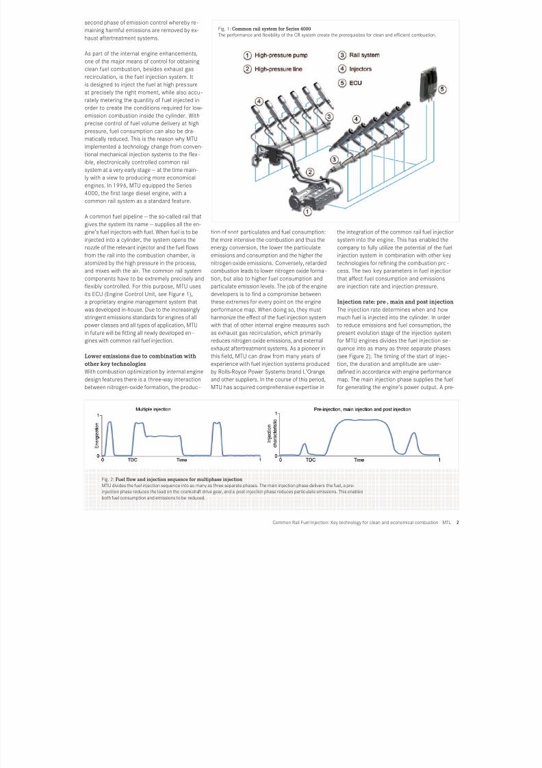
Injection rate: pre-, main and post injection
The injection rate determines when and how
much fuel is injected into the cylinder. In order
to reduce emissions and fuel consumption, the
present evolution stage of the injection system
for MTU engines divides the fuel injection se-
quence into as many as three separate phases
(see Figure 2). The timing of the start of injec-
tion, the duration and amplitude are user-
dened in accordance with engine performance
map. The main injection phase supplies the fuel
for generating the engine’s power output. A pre-
Common Rail Fuel Injection: Key technology for clean and economical combustion | MTU
Fig. 2: Fuel flow and injection sequence for multiphase injection
MTU divides the fuel injection sequence into as many as three separate phases. The main injection phase delivers the fuel, a pre-
injection phase reduces the load on the crankshaft drive gear, and a post-injection phase reduces particulate emissions. This enables
both fuel consumption and emissions to be reduced.
Fig. 1: Common rail system for Series 4000
The performance and exibility of the CR system create the prerequisites for clean and ecient combustion.
7/26/2019 3100651 MTU General WhitePaper CommonRail 2011
http://slidepdf.com/reader/full/3100651-mtu-general-whitepaper-commonrail-2011 3/4
injection phase initiates advance combustion to
provide controlled combustion of the fuel in the
main injection phase. This reduces nitrogen
oxide emissions, because the abrupt combus-
tion prevents high peak temperatures. A post
injection phase shortly after the main injection
phase reduces particulate emissions. It im-
proves the mixing of fuel and air during a late
phase of combustion to increase temperatures
in the combustion chamber, which promote
soot oxidation. Depending on the engine’s op -
erating point, the main injection phase can be
supplemented as required by including pre-
and/or post injection phases.
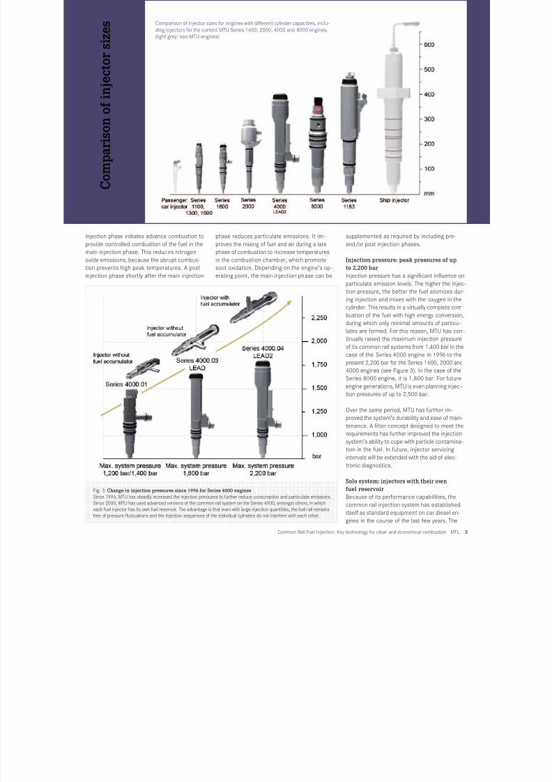
Injection pressure: peak pressures of up
to 2,200 bar
Injection pressure has a signicant inuence o
particulate emission levels. The higher the injec
tion pressure, the better the fuel atomizes dur
ing injection and mixes with the oxygen in the
cylinder. This results in a virtually complete com
bustion of the fuel with high energy conversion
during which only minimal amounts of particu-
lates are formed. For this reason, MTU has con
tinually raised the maximum injection pressure
of its common rail systems from 1,400 bar in the
case of the Series 4000 engine in 1996 to the
present 2,200 bar for the Series 1600, 2000 and
4000 engines (see Figure 3). In the case of the
Series 8000 engine, it is 1,800 bar. For future
engine generations, MTU is even planning injec-
tion pressures of up to 2,500 bar.
Over the same period, MTU has further im-
proved the system’s durability and ease of main-
tenance. A lter concept designed to meet therequirements has further improved the injection
system’s ability to cope with particle contamina-
tion in the fuel. In future, injector servicing
intervals will be extended with the aid of elec-
tronic diagnostics.
Solo system: injectors with their own
fuel reservoir
Because of its performance capabilities, the
common rail injection system has established
itself as standard equipment on car diesel en-
gines in the course of the last few years. The
Common Rail Fuel Injection: Key technology for clean and economical combustion | MTU
Comparison of injector sizes for engines with dierent cylinder capacities, inclu-
ding injectors for the current MTU Series 1600, 2000, 4000 and 8000 engines.
(light grey: non-MTU engines)
C o m p a r i s o n o f
i n j e c t o r s i z e s
Fig. 3: Change in injection pressures since 1996 for Series 4000 engines
Since 1996, MTU has steadily increased the injection pressures to further reduce consumption and particulate emissions.
Since 2000, MTU has used advanced versions of the common rail system on the Series 4000, amongst others, in which
each fuel injector has its own fuel reservoir. The advantage is that even with large injection quantities, the fuel rail remains
free of pressure uctuations and the injection sequences of the individual cylinders do not interfere with each other.

7/26/2019 3100651 MTU General WhitePaper CommonRail 2011
http://slidepdf.com/reader/full/3100651-mtu-general-whitepaper-commonrail-2011 4/4
Glossar
Fig. 4: Injector with integrated fuel reservoir
The use of injectors with an integrated fuel reservoir
prevents pressure uctuations in the common rail
system and, therefore, a momentary undersupply or
oversupply of fuel to the injectors.
version of the system as described is also wellsuited for use in small capacity industrial en-
gines. In the case of engines with larger cylin-
der capacities, however, the conventional
common rail system is now revealing its limita-
tions, since these require a relatively large
quantity of fuel to be injected into the cylinder
for each ignition stroke. This produces pressure
pulsations in the common rail system’s fuel
reservoir that can interfere with the subse-
quent injection sequences. Since 2000, MTU
has used an advanced version of the common
rail system for the Series 4000 and 8000 en-
gine, and since 2004 for the Ser ies 2000 as
well, in which the fuel injectors have an inte-
grated fuel reservoir (see Figure 4). This per-
mits the fuel lines between the injectors and
the common rail to have a relatively small cross
section. During an injection sequence, all that
happens is that the pressure in the injector’s
own fuel reservoir drops slightl y. This prevents
pressure uctuations in the common rail sys-
tem and, therefore, a momentary undersupply
or oversupply of fuel to the injectors.
Tailored solutions for exible use of fuelWith the higher technical performance levels of
the injection systems, the demands placed on the
fuel in terms of purity and quality also rise. Thus
the fuel must comply with pre-dened values for
viscosity and lubricity, as components of the high-
pressure pumps and injectors are lubricated by the
fuel. It must also be free of any contamination that
would lead to abrasive damage at the high pres-
sures employed. To ensure that the engine oper-
ates correctly, therefore, only diesel fuel that is
approved for the application in question and meets
the applicable standard may be used. At the cus -
tomer’s request, MTU carries out analyses for
specic application-related approval of other fuels
in close cooperation with Rolls-Royce Power Sys-
tems brand L’Orange or alternative suppliers. With
some applications, for example, a lack of lubricat-
ing properties on the part of the fuel can be com-
pensated for by special coatings on the injection
system. In addition, MTU assists customers when
designing the onsite tank and fuel system. This is
of great interest for mining vehicles, for instance,
that are subjected to high levels of dust exposure.
SummaryMTU continually develops its engines to ensure
they will meet the tough future emissions
standards, while at the same time consuming
as little fuel as possible. To this end, MTU
optimizes fuel combustion in the cylinder by
means of its electronically controlled common
rail fuel injection system in combination with
other technologies such as exhaust gas recircu-
lation. By achieving clean and ecient combus-
tion, the expense of exhaust aftertreatment
systems can be minimized and, in some cases,
eliminated altogether. MTU has used common
rail systems successfully since as long ago as
1996 and has continually advanced the tech -
nology in collaboration with Rolls-Royce Power
Systems brand L’Orange and other suppliers.
Due to its extensive expertise in common rail
injec-tion systems, MTU is able to optimally
exploit the potential of the technology in order
to make engines extremely economical and clea
3100651
www.mtu-online.com August 20
MTU Friedrichshafen GmbHA Rolls-Royce Power Systems Company
MTU is a brand of Rolls-Royce Power Systems AG. MTU high-speed
engines and propulsion systems provide power for marine, rail,
power generation, oil and gas, agriculture, mining, construction and
industrial, and defense applications. The port folio is comprised of
diesel engines with up to 10,000 kilowatts (kW) power output, gas
engines up to 2,150 kW and gas turbines up to 35,320 kW. MTU also
oers customized electronic monitoring and control systems for its
engines and propulsion systems.