31.- The Strength of Horizontally Loaded Prefabricated ...192 The Strength of Horizontally Loaded...
6
31.- The Strength of Horizontally Loaded Prefabricated Brick Panel Walls by I. H. E. NILSSON and A. LOSBERG Chalmers University o[ Tecl/ll%gy, Gorlrenbllrg, Sweden A BSTRACT The paper reporlS ali experimenta/ sludy Df prefabricaled brick pane/ lValls / ·96 x 2·80 m (6·5 x 9·2 f I) /aler- ally /oaded lo fai/ure. The lI'alls consist 01 I IVO rerli ca/ /ayers 01 brick s wi lh anel withoul reinlorcemelll. The /oa d is applied by compressed air acting inside a p/aslic bag mOlinled belween lhe lest wall and a rigid palle/. The influence o[ reinforcement mesh is sludied and an auempl is mode to ca/cu/ale fhe u/limale /oad by lhe y ie/d-/ill e Iheory. La R ésistance M écanique de Murs en Panneaux de Briques P"éfabriqués Chargés Horizontalement Die Festigkeit horizontal belasteter Wiinde aus vorgefertigten Ziegeltafeln Die Arbeit berichtet \'on einer experi- mente/len Sttldie 011 Wanden OuS \'orgelertigten, 1,96 x 2,80 m grossen Ziege/tafeln, clie seitlVarts bis zum einlretelldel1 Bruch belastet wurden. Die Wtinde bestehell aus zwei I'e rtika/en Ziegelschichl en mit bZlV. o/me Beweh rung. Die LaSI lVurde mil/eis Drucklufl durch Au!- bl asen eines zwischen einer slabilen Wand llnd der Prüfwand angebrachten Plaslikbeutels aufgebrachl. Der Einfluss des Beweh rungsnetzes wurde beslimml. Mit Hilf e der Fliess- Linien-Theorie iSI l'ersucht worden , die mogliche HochsI/ast Zll bereclmen. L'exposé relale une étude expéri- mellfale effectuée su r des murs en panneaux préfabriqués eu briques de }'96 x 2·80 In sallmis à une charge latérale jusqu'à ruplure. Les murs sont constilués de deux cOll ches rerticales de briques aree Oll sons armQlure. La charge esl appliquée par de rair comprimé agissol1l à I'imérieur d'u" soe en l11Gliere plas- tique disposé elltre te mur d'essa; el UII panneou rig ide. L' influence de /'armature esl érudiée el 011 e5saie de calculeI' la charge maximale suil'Gnt la théorie de la limite d'é /a stieité . 1. lNTRODUCTION The elfect of horizontal loading on wa ll s is a design problem of topical interest. This interest has been accentuated by the storm damage whi ch occurred in Sweden during the autumn of 1969 . Dilferent countries use dilferent methods of calculating the strength of an unreinforced brick wall subject to lateralloading. The wall is usua lly regarded for purposes of calculation as an elastic pia te. Load at fai lure is usually defined as the load which causes incipient tensile cracks in a joint. A series of single-Ieaf brick walls measuring 2 x 3·5 m (6·5 x 11 ·5 ft) supported along ali four edges and su b- jected to uniformly distributed horizontal loading, ha s been tested over the la st few years at the Oivision of StTUctural Engineering at Chalmers University of Tech- nology. The tests show that an increase in loading is poss ible after the fir st crack has formed. A crack paUern as shown in Figure I is obtained at final fai lu re. This pattern bears a striking resemblance to crack fo rma tion obtained on testing concrete slabs which are reinforced by two layers of bar s each parallel to the edges of lhe slab, which are usually analysed in accordance with lhe yield-line l he o ry of JOHA NSEN. I It would seem natur al therefore that an attempt should be made to calculate load at failure by means of lhe yield-like theory. Good agreement has been obtained with observed loads ai failure. This work wa s pre se nted elsewhere. 2 However, the method ha s been criticized on the grounds that a li the conditions of the yield-Iine theory are not satisfied, the objecti on being Ihat a moment cannot be tran sm itted along a joinl that has cracked. In spile of 1 91 this, so me increase in loading has been observed after cracking has slarted. This may be due to arching action in the wall and to the fact that so me moment can be absorbed in diagonal joints owing to friction in the connection . There is a great need for experimental work in this field, in view of the very approximate rules use d for lhe design of brickwork that is subjected lo lateral loading. 2. TEST PROGRAMME In order to sludy further the resistance of walls to wind loads, a new test series on horizontally-Ioaded walls, which is not yet fully compleled, has been performed. The wa ll s in this test series a re prefabricated under fa ctory conditions and are use d as i nfill panels in dwelling houses and as facing walls in other buildings. They are FIGURE l- Single-leaf unreinforced brick wa ll after load ing to fai lure in the test series accord ing to LOSBERG and JOHANSSON.2 Load indications in kgf/m 2 .
Transcript of 31.- The Strength of Horizontally Loaded Prefabricated ...192 The Strength of Horizontally Loaded...
31.- The Strength of Horizontally Loaded Prefabricated Brick Panel Walls
by I. H. E. NILSSON and A. LOSBERG Chalmers University o[ Tecl/ll%gy, Gorlrenbllrg, Sweden
A BSTRACT
The paper reporlS ali experimenta/ sludy Df prefab ricaled brick pane/ lValls / ·96 x 2·80 m (6·5 x 9·2 f I) /alerally /oaded lo fai/ure . The lI'alls consist 01 I IVO rerlica/ /ayers 01 bricks wilh anel withoul reinlorcemelll. The /oad is applied by compressed air acting inside a p/aslic bag mOlinled belween lhe lest wall and a rigid palle/. The influence o[ reinforcement mesh is sludied and an auempl is mode to ca/cu/ale fhe u/limale /oad by lhe y ie/d-/ille Iheory.
La R ésistance M écanique de Murs en Panneaux de Briques P"éfabriqués Chargés Horizontalement
Die Festigkeit horizontal belasteter Wiinde aus vorgefertigten Ziegeltafeln
Die Arbeit berichtet \'on einer experimente/len Sttldie 011 Wanden OuS
\'orgelertigten, 1,96 x 2,80 m grossen Ziege/tafeln, clie seitlVarts bis zum einlretelldel1 Bruch belastet wurden. Die Wtinde bestehell aus zwei I'ertika/en Ziegelschichlen mit bZlV. o/me Bewehrung. Die LaSI lVurde mil/eis Drucklufl durch Au!blasen eines zwischen einer slabilen Wand llnd der Prüfwand angebrachten Plaslikbeutels aufgebrachl . Der Einfluss des Bewehrungsnetzes wurde beslimml. Mit Hilfe der FliessLinien-Theorie iSI l'ersucht worden , die mogliche HochsI/ast Zll bereclmen.
L'exposé relale une étude expérimellfale effectuée sur des murs en panneaux préfabriqués eu briques de }'96 x 2·80 In sallmis à une charge latérale jusqu'à ruplure. Les murs sont constilués de deux cOllches rerticales de briques aree Oll sons armQlure. La charge esl appliquée par de rair comprimé agissol1l à I'imérieur d'u" soe en l11Gliere plastique disposé elltre te mur d'essa; el UII panneou rig ide. L' influence de /'armature esl érudiée el 011 e5saie de calculeI' la charge maximale suil'Gnt la théorie de la limite d'é/astieité.
1. lNTRODUCTION The elfect of horizontal loading on walls is a design problem of topical interest. This interest has been accentuated by the storm damage which occurred in Sweden during the autumn of 1969.
Dilferent countries use dilferent methods of calculating the strength of an unreinforced brick wall subject to lateralloading. The wall is usually regarded for purposes of calculation as an elastic pia te. Load at fai lure is usually defined as the load which causes incipient tensile cracks in a joint.
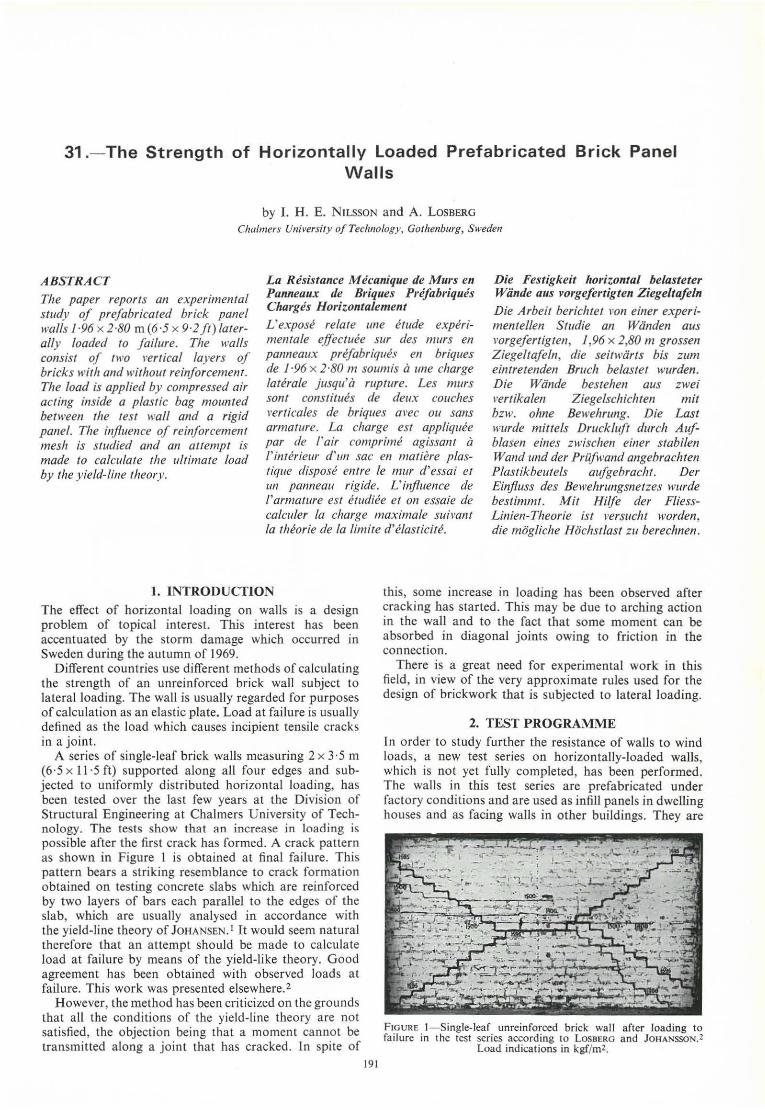
A series of single-Ieaf brick walls measuring 2 x 3·5 m (6·5 x 11 ·5 ft) supported along ali four edges and subjected to uniformly distributed horizontal loading, has been tested over the last few years at the Oivision of StTUctural Engineering at Chalmers University of Technology. The tests show that an increase in loading is possible after the first crack has formed. A crack paUern as shown in Figure I is obtained at final fai lure. This pattern bears a striking resemblance to crack formation obtained on testing concrete slabs which are reinforced by two layers of bars each parallel to the edges of lhe slab, which are usually analysed in accordance with lhe yield-line lheory of JOHANSEN. I It would seem natural therefore that an attempt should be made to calculate load at failure by means of lhe yield-like theory. Good agreement has been obtained with observed loads ai failure. Thi s work was presented elsewhere.2
However, the method has been criticized on the grounds that ali the conditions of the yield-Iine theory are not satisfied, the objection being Ihat a moment cannot be transmitted a long a joinl that has cracked. In spile of
191
this, some increase in loading has been observed after crack ing has slarted. This may be due to arching action in the wall and to the fact that some moment can be absorbed in diagonal joints owing to friction in the connection .
There is a great need for experimental work in this field, in view of the very approximate rules used for lhe design of brickwork that is subjected lo lateral loading.
2. TEST PROGRAMME In order to sludy further the resistance of walls to wind loads, a new test series on horizontally-Ioaded walls, which is not yet fully compleled, has been performed. The wall s in this test series a re prefabricated under factory conditions and are used as infill panels in dwelling houses and as facing walls in other buildings. They are
FIGURE l - Single-leaf unreinforced brick wa ll after loading to fai lure in the test series according to LOSBERG and JOHANSSON.2
Load indications in kgf/m2.
192 The Strength of Horizontally Loaded Prefabricated Brick Panel Walls also used as load-bearing facing walls in, for example, detached houses in which the wall is complemented by heat insulation and an internaI wall surface.
The walls are 2·g0-m (9'2-ft) high and 1'96-m (6'5-ft) long overall, have a thickness of 14 cm (5'5 in.) and consist af two vertical brick leaves with mesh reinforcemen! in the middle, as shown in Figure 2. The facing
I II 11 ai mUnd"'i'" (f...nntj DI I[ I çpslti?tj
I 11 I1 IC 101 ::: 11 I - '!:~1 __ 1
I 11 11 IC:; M CE ~ !~ I
~ VERTICAL SECTtON
HORIZONTAL $ECTION
FIGURE 2- Sections through prefabricated brick wall panel.
brick is 6-cm (2A-in.) thick and has the dimensions 23 x 5·2 cm (9 x 2 in.). The walls are prefabricaled horizontally and vibrated, as a result of which the cemenl morlar fill s the joints and the cavities in the bricks completely. The prefabricated panels have much lower permeability as a result and their bending strenglh is many times that of comparable brickwork constructed in the normal manner.
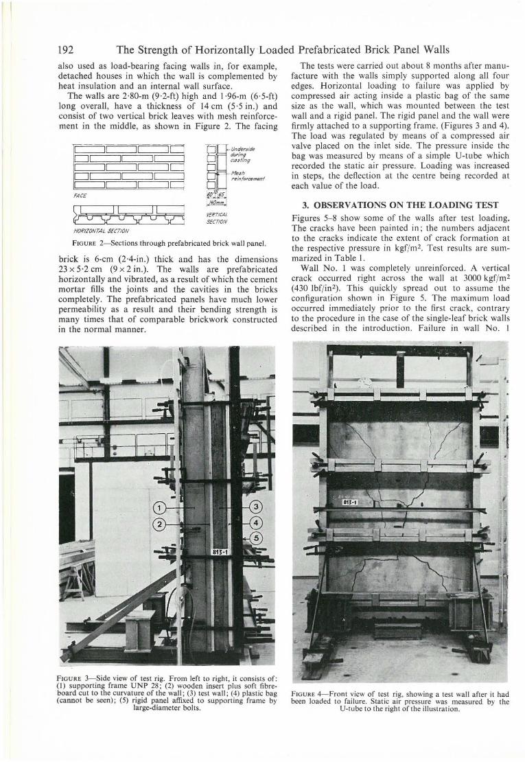
FIGURE 3- Side view of lest rig. From lerl to right, it consiSIS of: (I) supporting frame UNP 28; (2) wooden inserI plus 50ft fibreboard cut to lhe curvature of lhe wall; (3) lesl wa ll ; (4) plaslic bag (eanno! be seen) ; (5) rigid panel affi.xed to supporting frame by
large-diameter bolts.
The tests were carried out about 8 mont hs after manufacture wilh lhe walls simply supporled along ali four edges. Horizontal loading lO failure was applied by compressed air acting inside a plastic bag or lhe same size as lhe wall, which was mounted between lhe test wall and a rigid pane!. The rigid panel and lhe wall were firmly attached to a supporting frame . (Figures 3 and 4). The load was regulaled by means of a compressed air valve placed on the inlet side. The pressLlre inside the bag was measured by means of a simple U-lllbe which recorded the static air pressure. Loading was increased in steps, the deftection at lhe centre being recorded at each value of the load.
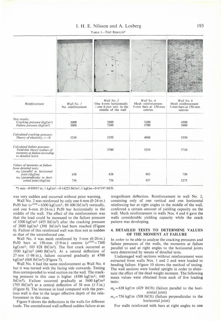
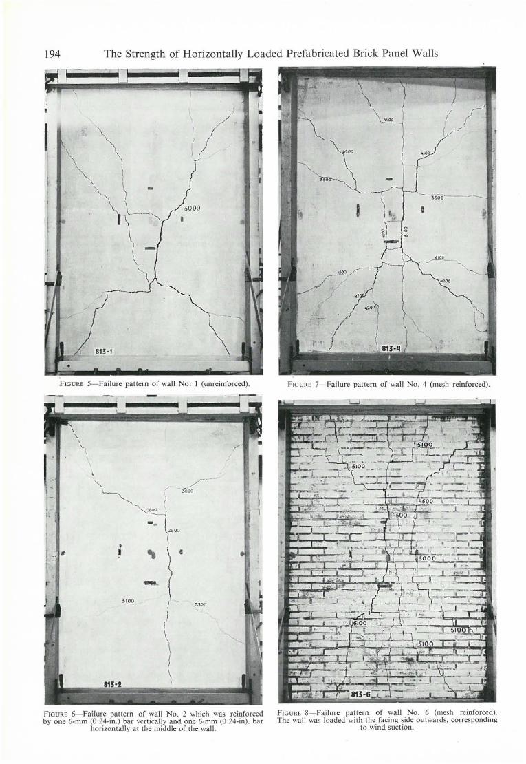
3. OBSERVATIONS ON THE LOADING TEST Figures 5- 8 show some of the walls after test loading. The cracks have been painted in ; the numbers adjacent to the cracks indicate the extent of crack formation at lhe respective pressure in kgf/m2. Test results are summarized in Table I.
Wall No. I was complelely unreinforced. A vertical crack occllrred righl across lhe wall aI 3000 kgf/m' (430 Ibf/in'). This quickly spread out to assume the configuration shown in Figure 5. The maximum load occurred immediately prior to the first crack , contrary to the procedure in the case of lhe single-Ieaf brick walls described in lhe introdllction . Failure in wall No. I
FIGURE 4-Front view or test rig , showing a lest wall after il had been loaded to failure. Stalic air pressure was measured by lhe
U-Iube 10 lhe right or lhe illustralion.
1. H. E. Nilsson and A. Losberg 193 TABLE t - TEST RESULTS·
(
-~""-.,.. _\ I L.......oIa.--.J... __
---------1 - -----Wall No. 2 Wal/ No. 4 Wall No. 6
Reinjorcemellf Wall No. I One 6·ml11 horizontally Mesh reinforcemcnt Mesh reinforccmenl No reinforcement + one 6-mm verto in lhe 5-mm bars aI 150-l11m I 5-mm bars aI 150-mm
middle of lhe wa ll centres cent res
Tesl resulls: I Crackillg pressure (kgflm !) 3()()() 2800 3100 4500 Foi/ure preSSllre (kgflm~) 3()()() 3200 4700 5600 ,
Calcu/aleel crackil/g pressure: Theory o[ e/asticity, v= O 3250 3250
I 4060 5550
Calclllared fai/ure pressure: Yield-fille Iheory (mll/es of
mamel/Is at fai/llre accordillg lO delailcd tests)
3780 52 10 57 10
Vall/es of momellts OI fajJllre I /tom derailed tex/s: I tIIp (porallel to flOrizomo!
joillt) (kgf/m) 638 638 983
I
750 11//1 (perpendicular to IIori-
I zonta! joillt) (kgf/m) 756 756 937 1275 I
'I mm~0 ' 03937 in ; I kgf/m'~0'14223 Ihf/m2; I kgf/m - 0 ·67197Ihf/fl.
was very sudden and occurred without prior warning. WalI No_ 2 was reinforced by only one 6-mm (0·24-in.)
Ps50 bar (a>'I"d~ 63oo kgf/cm'; 89 600 Ibf/in') vertica lly, and one 6-mm (0·24-in.) Ps50 bar horizontalIy in the middle of the wall. The efl'ect of the reinforcement was that the load could be increased to the failure pressure of 3200 kgf/m' (455 Ibf/in ') after the cracking pressure of 2800 kgf/ m2 (398 Ibf/in') had been reached (Figure 6). Failure of this rei nforced wall was thus nol as sudden as tha t of the unreinforced one.
WalI No. 4 was mesh reinforced by 5-mm (0·20-in .) Ps50 bars at 150-mm (5'9-in_) centres (",,1,/,/ ~ 7300 kgf/cm' ; 103 828 Ibf/in'). The first crack occurred aI 3100 kgf/m' (440 Ibf/in ' ). AI a cenlral deflection of 27 mm (1,06 in.), failure occurred gradualIy aI 4700 kgf/m' (668 Ibf/ in') (Figure 7).
WalI No. 6 had lhe same reinforcement as Wall No. 4 but it was lurned wilh the facing side outwards. Tesling thus corresponded to wind suction on lhe walI . The cracking pressure in this case is higher (4500 kgf/m' ; 640 Ibf/in'). Failure occurred gradually aI 5600 kgf/m' (795 Ibf/in2) at a central deflection of 38 mm (l'5 in.) (Figure 8). The increase in load compared wilh the previous walI is due to the larger efl'eclive depth of the reinforcement in this case.
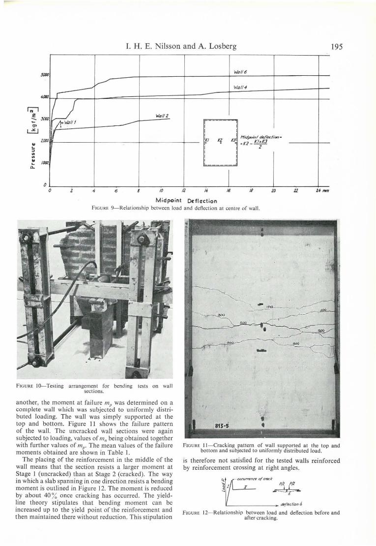
Figure 9 sbows the deflections in the walIs for difl'erenl loads. The unreinforced wall sufl'ered sudden failure at an
insignificant deflection. Reinforcement in wall No. 2, consisting only of one vert ica l and one horizontal reinforcing bar aI right angles in the middle of the wall , conferred a certain amount of yielding capacity on the wa ll. Mesh reinforcement in walls Nos. 4 and 6 gave the walls considerable yielding capacily while the crack pattem was developing.
4. DETAILED TESTS TO DETERMINE VALUES OF THE MOMENT AT FAILURE
ln a rder to be able to analyse the cracking pressures and failure pressures of the walIs, the moments aI failure paralIel to and at right angles to lhe horizontal joinls were determined by means of detailed tesls.
Undamaged wall sections without reinforcement were exlracted from walIs Nos. I and 2 and were loaded to bending failure. Figure lO shows the method of tesling. The walI sections \Vere loaded upright in order 10 eliminate the elfecl of the dead \Veight moment. The fo lIowing mean values were obtained from each of tive loading tesls:
mp ~638 kgf/m (429 Ibf/ft) (failure paralIel to lhe horizontal joint)
m,, ~ 756 kgf/m (508Ibf/ft) (failure perpendicular to the horizontal joint)
For walIs reinforced with bars aI righl angles lo ooe
194 The Strength of Horizontally Loaded Prefabricated Brick Panel Walls
•
I
813-1
FIGURE 5- Failure pattern of wall No. 1 (unreinforced) .
I : -, ~---
•
~ -I ' I~ -.
FIG URE 6-Fai lure pallern af \Va li No. 2 which was reinforccd by one 6-mm (0-24-io.) bar vertica ll y and one 6-0101 (0-24-in) . bar
ho rizonlally aI lhe middle af lhe wal l.
FIG URE 7- Failure pattern af wall No. 4 (mesh reinforced).
FIGURE 8-Failurc pattem of wa ll No. 6 (mesh reinforced). The wall was loaded with the facing sidc outwards, corresponding
to wind suclion.
L H. E. Nilsson and A. Losberg 195
Walló
...-' V
Ida /H
í
lJ, 'Wo112 r- -
il , Ir I ,
Nidpoinl dt/f«lion-
'" r? rJ .K2 _ K/#A'J f I 2 I I ,
o I O z 6 8 la /2 /6 zo
Midpoint De'fI~ction FIGURE 9- Relationship belween load and dcftec:lion aI centre af wall.
FIGURE IO---Testing arrangcment for bending tesls on wa ll sect ions.
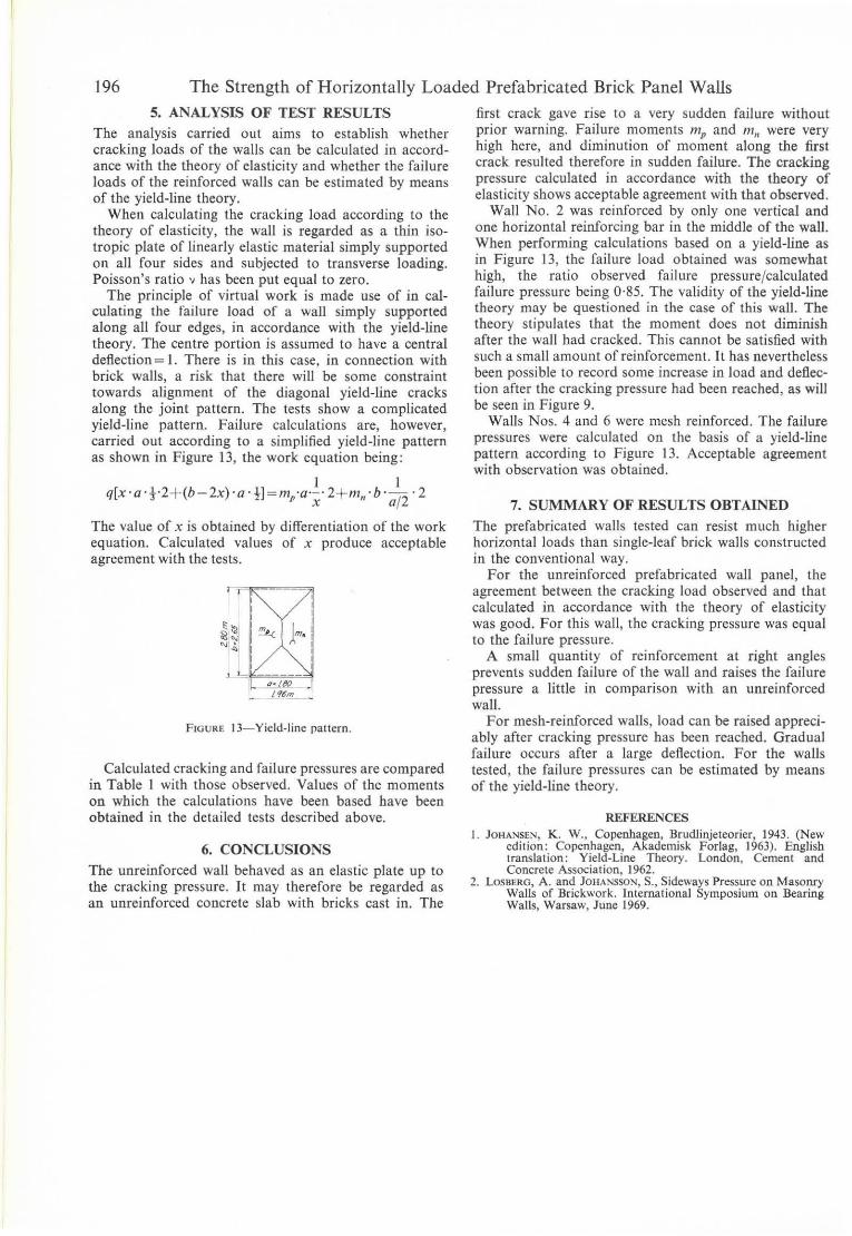
another, lhe moment at failure mp was determined on a complete wall which was subjected to uniformly distributed loading. The wall was simply supported at the top and bottom. Figure 11 shows the failure paliem of the wall. The uncracked wall sect ions were again subjected to loading, values of 111" being obtained together with further values of 111p ' The mean values of the failure moments obtained are shown in Table I.
The placing of the reinforcement in the middle of the wall rneans that the section resists a larger moment at Stage I (uncracked) than at Stage 2 (cracked). The way in which a slab spanning in one direction resists a bending moment is outlined in Figure 12. The moment is reduced by abollt 40 % ODce cracking has occurred. The yield!ine theory stipulates that bending moment can be increased IIp to the yield point of the reinforcement and then maintained there without reduction. This stipulation
FIGURE II - Cracking pattern cf wall supported at lhe top and bottom and subjected to uniformly distributed load.
is therefore not satisfied for the tested walls reinforced by reinforcement crossing at right angles.
L _______ ekf~cfiond
FIGURE 12- Relationship between load and deflection bcfore and after cracking.
]96 The Strength of Horizontally Loaded Prefabricated Brick Pane] Walls 5. ANALYSIS OF TEST RESULTS
The analysis carried oul aims lo eSlablish whelher cracking loads of lhe walls can be calculaled in accord· ance wilh lhe theory of elaslicily and whelher lhe fai lure loads of lhe reinforced walls can be eSlimaled by means of lhe yield-line Iheory.
When calculaling lhe cracking load according lo lhe Iheory of elaslicilY, lhe wall is regarded as a thin iso· Iropic plale of linearly elastic malerial simply supporled on ali four sides and subjecled lo Iransverse loading. Poisson's ratio 'J has been put equal to zero.
The principie of virlual work is made use of in calculaling lhe failure load of a wall simply supported along ali four edges, in accordance wilh lhe yield-line Iheory. The cenlre porlion is assumed lo have a cenlral deflection = 1. There is in this case, in connection witb brick walls, a risk thal Ihere will be some conslrainl IOwards al ignmenl of lhe diagonal yield-line cracks along lhe joinl pattern. The lesls show a complicaled yield-line pattern. Failure ca1culations are, however, carried oul according lO a simplified yield-line pattern as shown in Figure 13, lhe work equalion being:
I I q[x ·a ·t·2+ (b-2x)·a ·tl =m,a·x· 2+ m,,·b· aj2 ·2
The value of x is oblained by differenliation of lhe work equalion. Calculated values of x produce acceplable agreement wilh lhe tests.
I ~ I ~' ~ I
~~I ~ IJm. ~ I
L~ ___ ___ II (7· LM
I."~!!L.. _
FIGURE I3- Yield-line pallern.
Calculated cracking and failure pressures are compared in Table I with Ihose observed. Values of lhe moments on which the calculations have been based have been obtained in the detailed tesls described above.
6. CONCLUSIONS The unreinforced wall behaved as an elastic plate up lo lhe cracking pressure. It may therefore be regarded as an unreinforced concrete slab with bricks casl in. The
firsl crack gave rise to a very sudden failure withoul prior warning. Failure moments mp and m n were very high here, and diminulion of momenl along lhe first crack resulted Iherefore in sudden failure. The cracking pressure calculaled in accordance with lhe Iheory of elasticily shows acceplable agreement wilh that observed.
Wall No. 2 was reinforced by only one vertical and one horizonlal reinforcing bar in lhe middle of the wall. When performing calculations based on a yield-line as in Figure 13, the failure load oblained was somewhal high, lhe ralio observed failure pressurejcalculated failure pressure being 0·85. The validi ty of lhe yield-line theory may be questioned in lhe case af this waU. The theory stipulales lhal the moment does nol diminish afler the wall had cracked. This cannol be satisfied with such a small amounl of reinforcement. It has neverlheless been possible to record some increase in load and deHeclion afler the cracking pressure had been reached, as will be seen in Figure 9.
Walis Nos. 4 and 6 were mesh reinforced. The failure pressures were caiculated on the basis of a yield-Iine pattern according to Figure 13. Acceplable agreement with observation was obtained .
7. SUMMARY OF RESULTS OBTAINED The prefabricated walis tested can resist much higher horizontal loads lhan single-Ieaf brick walls construcled in the conventional way.
For lhe unreinforced prefabricaled wall panel, the agreement between lhe cracking load observed and Ihat caiculaled in accordance wilh lhe theory of elasticily was good. For this wall, lhe cracking pressure was equal lo the failure pressure.
A small quantily of reinforcemenl aI right angles prevents sudden failure of the wall and raises lhe failure pressure a little in comparison with an unreinforced wall.
For mesh-reinforced walls, load can be raised appreciably afler cracking pressure has been reached. Gradual failure occurs afler a large deflection. For lhe walls lested, lhe failure pressures can be eslimated by means of lhe yield-line Iheory.
REFERENCES I. JOHANSEN, K . w., Copenhagen, Brudlinjeteorier, 1943. (New
edition: Copenhagcn, Akademisk Forlas, 1963). English translation: Yield-Line Theory. London, Cement and Cancrete Associatian, 1962.
2. LOSBERG, A. and JOHANSSON, S., Sideways Pressure on Masonry Walls af Brickwork. lnternatiooal Sympasium 00 Bearing Walls, Warsaw, June 1969.