31 05 19 13 Geotextiles - passaic.sharepointspace.compassaic.sharepointspace.com/Public...
52
31 05 19.13 GEOTEXTILES Page 1 of 6 Revision: 0 August 2011 1 GENERAL 1.1 SECTION INCLUDES .1 Includes providing equipment, materials, labor, and services required to furnish and install geotextile materials at the Upland Processing Facility (UPF) described in this section and on the Technical Drawings, including: .1 Placing Geotex ® 44 geotextile above and below polyvinyl chloride (PVC) flexible membrane liner (FML) where installed below foundations and catch basins .2 Placing 8-ounce, non-woven geotextile for excavation/fill demarcation layer in areas without FML .3 Placing 16-ounce, non-woven geotextile protection layer above and below PVC FML installed in excavated material storage areas 1.2 RELATED SECTIONS .1 Section 31 05 19 16 – Geomembranes for Earthwork .2 Section 31 23 00 – Earthwork and Fill 1.3 SUBMITTALS .1 Manufacturer's data for geotextiles including, at a minimum, physical properties, packaging, and installation techniques for each required application 1.4 REFERENCES .1 ASTM International (ASTM) .1 D5261-10 – Standard Test Method for Measuring Mass per Unit Area of Geotextiles .2 D4632-08 – Standard Test Method for Grab Breaking Load and Elongation of Geotextiles .3 D3786/D3786M-09 – Standard Test Method for Bursting Strength of Textile Fabrics—Diaphragm Bursting Strength Tester Method .4 D4833-07 – Standard Test Method for Index Puncture Resistance of Geomembranes and Related Products
Transcript of 31 05 19 13 Geotextiles - passaic.sharepointspace.compassaic.sharepointspace.com/Public...

31 05 19.13 GEOTEXTILES Page 1 of 6
Revision: 0 August 2011
1 GENERAL
1.1 SECTION INCLUDES
.1 Includes providing equipment, materials, labor, and services required to furnish and install geotextile materials at the Upland Processing Facility (UPF) described in this section and on the Technical Drawings, including:
.1 Placing Geotex® 44 geotextile above and below polyvinyl chloride (PVC) flexible membrane liner (FML) where installed below foundations and catch basins
.2 Placing 8-ounce, non-woven geotextile for excavation/fill demarcation layer in areas without FML
.3 Placing 16-ounce, non-woven geotextile protection layer above and below PVC FML installed in excavated material storage areas
1.2 RELATED SECTIONS
.1 Section 31 05 19 16 – Geomembranes for Earthwork
.2 Section 31 23 00 – Earthwork and Fill
1.3 SUBMITTALS
.1 Manufacturer's data for geotextiles including, at a minimum, physical properties, packaging, and installation techniques for each required application
1.4 REFERENCES
.1 ASTM International (ASTM)
.1 D5261-10 – Standard Test Method for Measuring Mass per Unit Area of Geotextiles
.2 D4632-08 – Standard Test Method for Grab Breaking Load and Elongation of Geotextiles
.3 D3786/D3786M-09 – Standard Test Method for Bursting Strength of Textile Fabrics—Diaphragm Bursting Strength Tester Method
.4 D4833-07 – Standard Test Method for Index Puncture Resistance of Geomembranes and Related Products

31 05 19.13 GEOTEXTILES Page 2 of 6
Revision: 0 August 2011
.5 D4533-04(2009) Standard Test Method for Trapezoid Tearing Strength of Geotextiles
.6 D4355-07 – Standard Test Method for Deterioration of Geotextiles by Exposure to Light, Moisture, and Heat in a Xenon Arc Type Apparatus
.7 D4491-99a(2009) – Standard Test Methods for Water Permeability of Geotextiles by Permittivity
2 PRODUCTS
2.1 ACCEPTABLE MANUFACTURERS
.1 (Nonwoven Type 1): US Fabrics, Inc. US 380NW or equivalent as reviewed by the Engineer
.2 (Nonwoven Type 2): US 205NW or equivalent as reviewed by the Engineer
.3 (Woven Type 3): Propex Inc. Geotex® 44 or equivalent as reviewed by the Engineer
2.2 MATERIALS
.1 For these specifications and the Technical Drawings, the terms “geotextile” and “geotextile fabric” will be considered synonymous.
.2 The nonwoven geotextile will be of needle-punched construction and consist of long-chain polymeric fibers or filaments composed of polypropylene, will be free of any chemical treatment that reduces permeability, and will be inert to chemicals commonly found in soil.
.3 The geotextiles indicated on the Technical Drawings will have the minimum physical properties listed below:
.1 Nonwoven Geotextile Type 1 (for cushion layer above and below the PVC FML):
Property Unit of Measure Test Method Minimum Test
Value Mass Per Unit Area
oz/yd2 ASTM D5261
16 min
Grab Tensile lbs ASTM D4632
380 min

31 05 19.13 GEOTEXTILES Page 3 of 6
Revision: 0 August 2011
Property Unit of Measure Test Method Minimum Test
Value Grab Elongation % ASTM
D4632 50 max
Mullen Burst psi ASTM D3786
750 min
Puncture Strength lbs ASTM D4833
240 min
Trapezoidal Tear lbs ASTM D4533
145 min
UV Resistance % strength retained
at 500 hours ASTM D4355 70 min
Permittivity sec-1 ASTM D4491 0.70 min
Notes: % = percent oz = ounce(s) ASTM = ASTM International psi = pound(s) per square inch lb(s) = pound(s) sec = second(s) max = maximum yd2 = square yard(s) min = minimum
.2 Nonwoven Geotextile Type 2 (for demarcation of excavations):
Property Unit of Measure Test Method Minimum Test Value
Mass Per Unit Area oz/yd2 ASTM D 5261 8 min
Grab Tensile lbs ASTM D4632 180 min
Grab Elongation % ASTM D4632 50 max Mullen Burst psi ASTM D3786 330 min Puncture Strength lbs ASTM D4833 130 min Trapezoidal Tear lbs ASTM D4533 85 min
UV Resistance % strength retained
at 500 hours ASTM D4355 70 min
Permittivity sec-1 ASTM D4491 1.35 min
31 05 19.13 GEOTEXTILES Page 4 of 6
Revision: 0 August 2011
Property Unit of Measure Test Method Minimum Test Value
Notes: % = percent oz = ounce(s) ASTM = ASTM International psi = pound(s) per square inch lb(s) = pound(s) sec = second(s) max = maximum yd2 = square yard(s) min = minimum
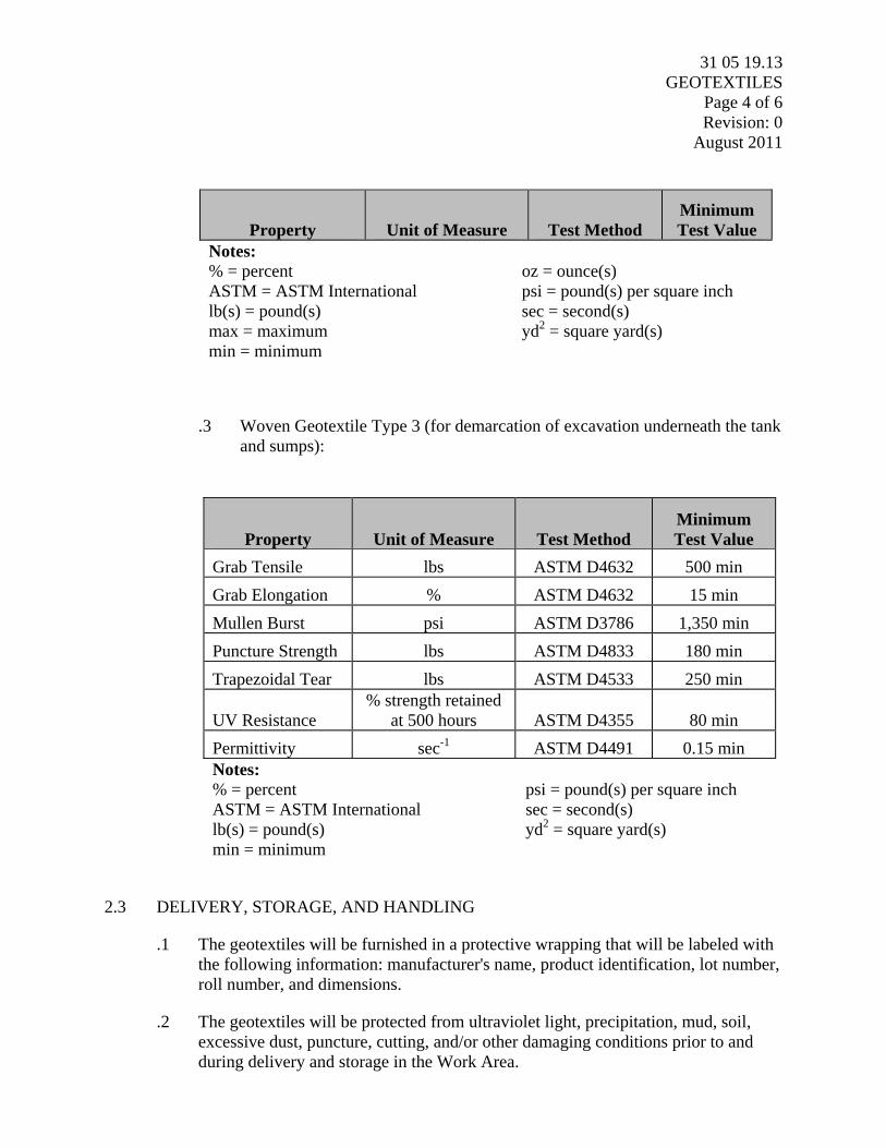
.3 Woven Geotextile Type 3 (for demarcation of excavation underneath the tank and sumps):
Property Unit of Measure Test Method Minimum Test Value
Grab Tensile lbs ASTM D4632 500 min
Grab Elongation % ASTM D4632 15 min
Mullen Burst psi ASTM D3786 1,350 min
Puncture Strength lbs ASTM D4833 180 min
Trapezoidal Tear lbs ASTM D4533 250 min
UV Resistance % strength retained
at 500 hours ASTM D4355 80 min
Permittivity sec-1 ASTM D4491 0.15 min Notes: % = percent psi = pound(s) per square inch ASTM = ASTM International sec = second(s) lb(s) = pound(s) yd2 = square yard(s) min = minimum
2.3 DELIVERY, STORAGE, AND HANDLING
.1 The geotextiles will be furnished in a protective wrapping that will be labeled with the following information: manufacturer's name, product identification, lot number, roll number, and dimensions.
.2 The geotextiles will be protected from ultraviolet light, precipitation, mud, soil, excessive dust, puncture, cutting, and/or other damaging conditions prior to and during delivery and storage in the Work Area.
31 05 19.13 GEOTEXTILES Page 5 of 6
Revision: 0 August 2011
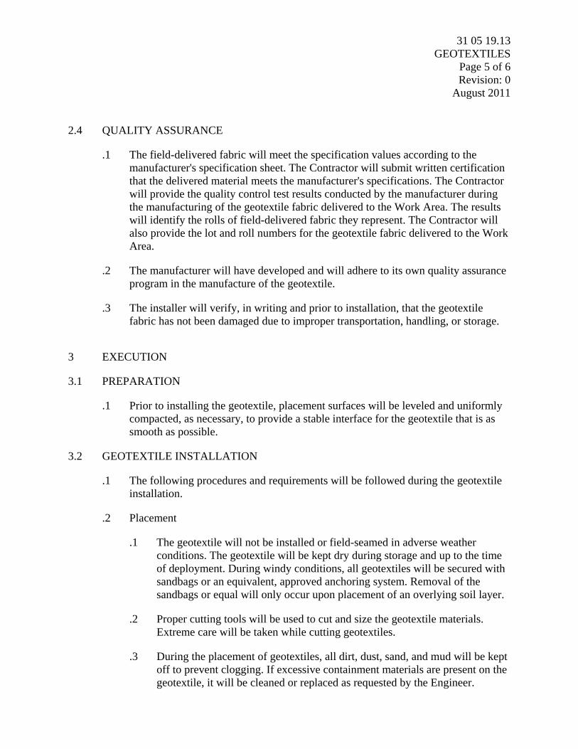
2.4 QUALITY ASSURANCE
.1 The field-delivered fabric will meet the specification values according to the manufacturer's specification sheet. The Contractor will submit written certification that the delivered material meets the manufacturer's specifications. The Contractor will provide the quality control test results conducted by the manufacturer during the manufacturing of the geotextile fabric delivered to the Work Area. The results will identify the rolls of field-delivered fabric they represent. The Contractor will also provide the lot and roll numbers for the geotextile fabric delivered to the Work Area.
.2 The manufacturer will have developed and will adhere to its own quality assurance program in the manufacture of the geotextile.
.3 The installer will verify, in writing and prior to installation, that the geotextile fabric has not been damaged due to improper transportation, handling, or storage.
3 EXECUTION
3.1 PREPARATION
.1 Prior to installing the geotextile, placement surfaces will be leveled and uniformly compacted, as necessary, to provide a stable interface for the geotextile that is as smooth as possible.
3.2 GEOTEXTILE INSTALLATION
.1 The following procedures and requirements will be followed during the geotextile installation.
.2 Placement
.1 The geotextile will not be installed or field-seamed in adverse weather conditions. The geotextile will be kept dry during storage and up to the time of deployment. During windy conditions, all geotextiles will be secured with sandbags or an equivalent, approved anchoring system. Removal of the sandbags or equal will only occur upon placement of an overlying soil layer.
.2 Proper cutting tools will be used to cut and size the geotextile materials. Extreme care will be taken while cutting geotextiles.
.3 During the placement of geotextiles, all dirt, dust, sand, and mud will be kept off to prevent clogging. If excessive containment materials are present on the geotextile, it will be cleaned or replaced as requested by the Engineer.

31 05 19.13 GEOTEXTILES Page 6 of 6
Revision: 0 August 2011
.4 The nonwoven geotextile will be covered within the time period recommended by the manufacturer, and in no case later than 2 weeks after its placement.
.5 In all cases, seams on sideslopes will be parallel to the line of slope. No horizontal seams will be allowed on side slopes.
.3 Seaming and Repairing
.1 Geotextiles will be overlapped a minimum of 24 inches.
.2 Repair of tears or holes in the geotextile will require the following procedures:
.1 Non-slopes: A patch made from the same geotextile will be spot-seamed in place with a minimum 24-inch overlap in all directions.
.3 Any geotextile damaged before, during, or after installation will be replaced by the Contractor at no additional cost.
3.3 INSPECTION
.1 The Engineer may randomly inspect geotextiles before or during installation.
END OF SECTION

31 05 19.16 GEOMEMBRANES FOR EARTHWORK
Page 1 of 6 Revision: 1
August 2011
1 GENERAL
1.1 SECTION INCLUDES
.1 Includes providing equipment, materials, labor, and services required to furnish and install 30-mil-thick, smooth polyvinyl chloride (PVC) flexible membrane liner (FML) material at the Upland Processing Facility (UPF) described in this section and on the Technical Drawings.
.2 The Contractor will be responsible for all Quality Assurance/Quality Control (QA/QC) testing specified herein and as indicated on the Technical Drawings. All QA/QC testing, with the exception of non-destructive tests, will be conducted by an independent laboratory at the Contractor’s expense.
1.2 RELATED SECTIONS
.1 Section 31 05 19 13 - Geotextile
.2 Section 31 23 00 – Earthwork and Fill
1.3 SUBMITTALS
.1 The Contractor will submit the following information to the Engineer, a minimum of 14 days prior to ordering FML:
.1 FML Manufacturer’s corporate background and information.
.2 FML manufacturing capabilities including:
.1 QC procedures for manufacturing
.2 List of material properties including certified test results, to which FML samples are attached
.2 The Contractor will submit Shop Drawings for review at least one week prior to installation that will include:
.1 Complete and detailed written instructions for the storage, handling, installation, seaming, inspection plan fail criteria for liner inspections, and QA/QC testing procedures of the liner in compliance with these specifications and the condition of its warranty.
1.4 REFERENCES
.1 ASTM International (ASTM)
.1 D5199 – Measuring the Nominal Thickness of Geosynthetics
31 05 19.16 GEOMEMBRANES FOR EARTHWORK
Page 2 of 6 Revision: 1
August 2011 .2 D882 – Tensile Properties of Thin Plastic Sheeting
.3 D1204 – Tear Resistance (Graves Tear) of Plastic Film and Sheeting
.4 D1204 – Linear Dimensional Changes of Nonrigid Thermoplastic Sheeting or Film at Elevated Temperature
.5 D1790 – Brittleness Temperature of Plastic Sheeting by Impact
.6 D792 – Density and Specific Gravity (Relative Density) of Plastics by Displacement
.7 D1239 – Resistance of Plastic Films to Extraction by Chemicals
.8 D2124 – Analysis of Components in Poly(Vinyl Chloride)Using an Infrared Spectrophotometric Technique
.9 D1203 – Volatile Loss from Plastics Using Activated Carbon Methods
.10 G160 – Evaluating Microbial Susceptibility of Nonmetallic Materials
.11 D751 – Grab Tensile Strength of Coated Fabrics
.12 Tensile Properties of Thin Plastic Sheeting
1.5 QUALIFICATIONS
.1 FML Installer
.1 The Installer performing field seaming (if required) must be trained and approved and/or licensed by the FML Manufacturer for the installation of FML.
2 PRODUCTS
2.1 ACCEPTABLE MANUFACTURERS
.1 Colorado Lining International PVC 30 or equivalent as reviewed by the Engineer. Reference to a specific product is not an endorsement.
2.2 MATERIALS
.1 PVC Lining Material Specifications
.1 PVC FML material will meet the following minimum specification values listed below and as listed in GRI GM17.

31 05 19.16 GEOMEMBRANES FOR EARTHWORK
Page 3 of 6 Revision: 1
August 2011 Table 1: FML Material Properties
Property Test Method (ASTM)
30-mm Smooth
Certified Properties Thickness D5199 30 +/- 1.5 mil
Strength at Break (Tensile Properties)
D882 Min
73 lbs/in
Elongation (Tensile Properties) 380%
Modulus at 100% (Tensile Properties) 32 lbs/in
Tear Strength D1004 Min 8 lbs
Dimensional Stability D1204 Max Chg 3%
Low Temperature Impact D1790 Pass -20oF
Index Properties
Specific Gravity D792 Typical 1.2 g/cc
Water Extraction Percent Loss (max) D1239 Max Loss 0.15%
Average Plasticizer Molecular Weight D2124 400 Volatile Loss Percent Loss (max) D1203 Max Loss 0.7%
Break Strength (Soil Burial)
G160 Max Chg
5%
Elongation (Soil Burial) 20%
Modulus at 100% (Soil Burial) 20%
Hydrostatic Resistance D751 Min 100 psi
Seam Strengths Shear Strengths D-882 Min 58.4 lbs/in
Peel Strength D-882 Min 15 lbs/in
Notes: % = percent in = inch(es) °F = degrees Fahrenheit lb(s) = pound(s) ASTM = ASTM International max = maximum cc = cubic centimeter(s) mil = 0.01 of an inch chg = change min = minimum g = gram(s) psi = pounds per square inch
2.3 DELIVERY, HANDLING, AND STORAGE
.1 The Contractor will be liable for all damage to the materials incurred prior to and during transportation to the site.
.2 Handling, storage, and care of the FML prior to and following installation at the site are the responsibility of the Contractor. The Contractor will be liable for all damage to the materials incurred prior to final acceptance of the lining system by the Engineer.
.3 The Contractor will notify the Engineer of the anticipated delivery time.

31 05 19.16 GEOMEMBRANES FOR EARTHWORK
Page 4 of 6 Revision: 1
August 2011 2.4 CONFORMANCE TESTING
.1 Manufacturer factory conformance test results will be provided to the Engineer by the Contractor and reviewed by the Engineer.
.2 The material will either be accepted or rejected by the Engineer based on the results of the manufacturer factory conformance test results. Deployment of the FML will not commence until the Engineer has determined that the material is acceptable.
3 EXECUTION
3.1 FML INSTALLATION
.1 Related Earthwork
.1 The Contractor will comply with the following earthwork requirements, in addition to those specified in Section 31 23 00 – Earthwork and Fill:
.1 The FML installations will be performed on a geotextile layer as shown on the Technical Drawings.
.2 The soil underlying the geotextile and FML will be firm, smooth soil free from stones, debris, or protruding objects and depressions
.3 All surfaces on which the FML is to be installed will be reviewed by the Engineer prior to FML installation
.2 FML Deployment
.1 FML will be deployed according to the following procedures:
.1 Placement of the FML panels will be according to the approved location and position plan provided by the Installer. Placement will follow all instructions on the boxes or wrapping containing the FML materials that describe the proper methods of unrolling panels.
.2 The method of placement will ensure that:
.1 Deployed FML is visually inspected for uniformity, tears, punctures, blisters, or other damage or imperfections. Any such imperfections will be immediately repaired and re-inspected.
.2 No equipment used will damage the FML by handling, trafficking, leakage of hydrocarbons, or other means.
.3 No personnel working on the FML will smoke, wear damaging shoes, or engage in other activities that could damage the FML.

31 05 19.16 GEOMEMBRANES FOR EARTHWORK
Page 5 of 6 Revision: 1
August 2011 .3 Any damage to the FML panels or portions of the panels as a result of
placement must be replaced or repaired at no cost. The decision to replace or repair any panel or portions of panels will be made by the Engineer.
.3 Seaming (if required)
.1 The field seaming procedures below will be implemented, where applicable, during installation of the FML. The seaming procedures are as follows:
.1 At liner penetrations and corners, the number of seams will be minimized.
.2 The area of the FML to be seamed will be cleaned and prepared according to the procedures specified by the material manufacturer. Any abrading of the FML will not extend more than 0.5 inches on either side of the weld. Care will be taken to eliminate or minimize the number of wrinkles and “fishmouths” resulting from seam orientation.
.3 Field seaming is prohibited when either the air or sheet temperature is below 32 degrees Fahrenheit (ºF), when the sheet temperature exceeds 122ºF, or when the air temperature is above 104ºF. At air or sheet temperatures between 32ºF and 39ºF, seaming will be conducted directly behind a preheating device. In addition, seaming will not be conducted when FML material is wet from precipitation, dew, fog, submersion, etc., or when winds are in excess of 20 miles per hour.
.4 Seaming will not be performed on frozen or excessively wet underlying soil or work surfaces.
.5 Where fishmouths occur, the material will be cut, overlapped, and an overlap weld will be applied. Where necessary, patching using the same liner material will be welded to the FML sheet.
.6 Acceptable seaming methods for FML are:
.1 Hot wedge welding using a proven fusion welder and experienced seamer
.2 Chemical fusion welding (for repairs only) using approved manufactured materials
.7 Seaming devices will not have any sharp edges that might damage the FML. Where self-propelled seaming devices are used, it will be necessary to prevent “bulldozing” of the device into the underlying soil.
.4 FML Repair

31 05 19.16 GEOMEMBRANES FOR EARTHWORK
Page 6 of 6 Revision: 1
August 2011 .1 All imperfections, flaws, construction damage, and destructive and
nondestructive seam failures will be repaired by the Installer of the FML. The appropriate methods of repair are listed below:
.1 Patching, used to repair holes, tears, undispersed raw materials, and contamination by foreign matter. Place a patch of the same material with a minimum of 6 inches overlap over the damaged area. The patch should have rounded corners. Apply chemical fusion agent to damaged FML, place the patch over the damaged area, and apply pressure to the two surfaces in order to achieve intimate contact between the liners. The bonded area of the patch perimeter should be a nominal 4 inches.
.2 Capping, used to repair large lengths of failed or damaged seams. Capping is the method of bonding a separate strip of the parent material over the seamed edge. Cap stripping may be used to repair and extended length of seam. Caps shall extend a minimum of 6 inches beyond the limits of the nonconforming seam, and all corners will be rounded. The bonded area of the cap-strip perimeter should be a nominal 4 inches. This method can also be achieved by using a hand-held heat gun and thermally welding the patch or cap-strip.
.3 Removing bad seams and replacing with a strip of new material welded into placed. This method will be used with large lengths of fusion seams.
.5 Construction Material Placement
.1 Wrinkles that develop from normal placement procedures must be controlled such that the underlying FML does not fold over. Small wrinkles, defined as having their height less than or equal to one-half their base width, may be trapped and pushed down by the overlying soil. Any wrinkle that becomes too large and uncontrollable or that folds the FML over must be brought to the attention of the Engineer. If necessary, the FML will be uncovered, cut, laid flat, seamed by extrusion welding, and non-destructively tested.
3.2 WARRANTY
.1 The Contractor will obtain and submit to the Engineer from the Manufacturer a standard warranty provided for the FML.
END OF SECTION

31 10 00 SITE CLEARING
Page 1 of 2 Revision: 2
August 2011
1 General
1.1 SECTION INCLUDES
.1 The Contractor will provide equipment, materials, labor, and services required to complete the following:
.1 Removal of surface debris and trash from excavation areas and haul routes.
.2 Removal of trees, shrubs, and other plant life from areas receiving fill and haul routes.
.3 Removal of fencing.
1.2 RELATED SECTIONS
.1 Section 01 76 00 – Protecting Installed Construction
.2 Section 02 61 32 – Construction Waste Management and Disposal
.3 Section 31 23 00 – Excavation and Fill
2 Products
NOT USED
3 Execution
3.1 PREPARATION
.1 Comply with applicable laws and regulations for environmental requirements, disposal of debris, and use of herbicides.
.2 Coordinate clearing work with utility companies.
.3 Verify that existing trees, shrubs, and other plant life designated to remain are tagged or identified.
.4 Identify a salvage area for placing removed materials.
.5 Salvage area location will be reviewed by the Engineer prior to placement.
31 10 00 SITE CLEARING
Page 2 of 2 Revision: 2
August 2011
3.2 PROTECTION
.1 Locate, identify, and protect from damage utilities and monitoring wells that remain on site as shown on the Technical Drawings and as discussed in Section 01 76 00 – Protection of Installed Construction and Section 31 23 00 – Excavation and Fill.
.2 Protect trees, plant growth, and features designated to remain.
.3 Protect benchmarks, survey control points, and existing structures from damage or displacement.
3.3 CLEARING
.1 Clear areas required for execution of the Work.
.2 Clear undergrowth and deadwood without disturbing subsoil.
.3 Relocate surface debris.
3.4 REMOVAL
.1 Remove portions of existing fencing identified on the Technical Drawings.
.2 Remove existing paving as required to complete the Work.
3.5 DISPOSAL
.1 Dispose of surface debris, extracted plants, and cleared vegetation materials off site in accordance with Section 02 61 32 – Construction Waste Management and Disposal, and with applicable laws and regulations.
END OF SECTION
31 23 00 EXCAVATION AND FILL
Page 1 of 9 Revision: 3
August 2011
1 General
1.1 SECTION INCLUDES
.1 Work in this Section includes providing equipment, materials, labor, and services required to perform excavation and backfilling activities at the Upland Processing Facility (UPF) described in this Section and on the Technical Drawings, including:
.1 Excavating for slabs-on-grade.
.2 Excavating for site structures.
.3 Excavating for asphalt pavement.
.4 Support of utilities across excavations.
.5 Stone under slabs where indicated.
.6 Backfilling site structures to subgrade elevations.
.7 Fill under slabs-on-grade.
.8 Fill for pipeline corridor/haul routes.
.9 Fill for over-excavation.
.10 Consolidation and compaction.
.11 Dewatering of excavations.
.12 Temporary excavation support for UPF installation.
.13 Excavating trenches for buried piping and appurtenances.
.14 Excavating for stormwater pump stations.
.15 Backfilling and compaction from top of pipe bedding to grade.
1.2 RELATED SECTIONS
.1 Section 01 76 00 – Protecting Installed Construction
.2 Section 03 30 00 – Cast-in Place Concrete
.3 Section 33 41 00 – Stormwater Piping

31 23 00 EXCAVATION AND FILL
Page 2 of 9 Revision: 3
August 2011
1.3 REFERNCES
.1 Tierra Solutions, Inc. (Tierra). 2011. Construction Quality Assurance Plan. Phase I Removal Action, CERCLA Non-Time-Critical Removal Action – Lower Passaic River Study Area. Revision 1. Tierra Solutions, Inc., East Brunswick, New Jersey. April.
.2 ASTM International (ASTM). 2007. D422 – Standard Test Method for Particle-Size Analysis of Soils. DOI: 10.1520/D0422-63R07. ASTM International, West Conshohocken, PA.
.3 ASTM. 2007. D698 – Standard Test Methods for Laboratory Compaction Characteristics of Soil Using Standard Effort (12,400 ft-lbf/ft3[600 kN-m/m3]). DOI: 10.1520/D0698-07E01. ASTM International, West Conshohocken, PA.
.4 ASTM. 2007. D1556 – Standard Test Method for Density and Unit Weight of Soil in Place by the Sand-Cone Method. DOI: 10.1520/D1556-07. ASTM International, West Conshohocken, PA..
.5 ASTM. 2009. D2321 - 09 Standard Practice for Underground Installation of Thermoplastic Pipe for Sewers and Other Gravity-Flow Applications. DOI: 10.1520/D2321-09. ASTM International, West Conshohocken, PA.
.6 ASTM. 2010. D6938 – Standard Test Method for In-Place Density and Water Content of Soil and Soil-Aggregate by Nuclear Methods (Shallow Depth). DOI: 10.1520/D6938-10. ASTM International, West Conshohocken, PA.
.7 New Jersey Department of Transportation (NJDOT). 2007. Standard Specifications for Road and Bridge Construction.
.8 U.S. Environmental Protection Agency (USEPA). 2008. U.S. Environmental Protection Agency Region 2 Administrative Settlement Agreement and Order on Consent for Removal Action in the Matter of Lower Passaic River Study Area of the Diamond Alkali Superfund Site Occidental Chemical Corporation and Tierra Solutions, Inc. CERCLA Docket No. 02-2008-2020. U.S. Environmental Protection Agency. June 23.
1.4 SUBMITTALS
.1 Results of moisture/density test performed on each proposed fill material (determined by ASTM D698).
.2 Results of in-place density tests performed on fill materials (determined by ASTM D1556 or ASTM D6938).

31 23 00 EXCAVATION AND FILL
Page 3 of 9 Revision: 3
August 2011
.3 For any off-site material proposed for use on site as general fill, select fill, or topsoil, the Contractor must provide the following information (for each material) at least 3 weeks prior to bringing such material on site:
.1 Certification that the proposed fill material is from a NJDOT-certified source (NJDEP 2007).
.2 Results of analytical testing for pH, volatile organic compounds, semivolatile organic compounds, polychlorinated biphenyls, pesticides/herbicides, dioxins, and metals to demonstrate that the proposed fill material meets the soil cleanup objectives identified in the CQAP (Tierra 2011). If multiple clean fill sources exceed these criteria, the Contractor must demonstrate the fill source is consistent with New Jersey soil quality requirements for commercial fill sites, and receive USEPA approval for its use.
.3 Certification that the laboratory used to analyze the proposed fill material is certified as required by the Administrative Order on Consent (USEPA 2008) , for the parameters being analyzed.
.4 The name and location of the source of each proposed fill material.
.5 Laboratory test report for each proposed fill material indicating the grain-size profile (determined by ASTM D422).
.6 Manufacturer specification for proposed smooth drum roller to be used for subgrade compaction and proof rolling. This will include model, type, size, weight, and related equipment details.
2 Products
2.1 FILL MATERIALS
.1 General Fill
.1 General fill will meet the requirements of NJDOT Item 901.11 No. I-4 Soil Aggregate.
.2 Select Fill
.1 Select fill will meet the requirements of NJDOT Item 901.11 No. I-2 Soil Aggregate.
.3 Class I Concrete: Follow Section 03 30 00 – Cast-in Place Concrete.
.4 Bedding Material

31 23 00 EXCAVATION AND FILL
Page 4 of 9 Revision: 3
August 2011
.1 Bedding material will meet the requirements of NJDOT Item 901.11 No. 67 Coarse Aggregate Bedding.
.5 Aggregate Surface Course
.1 Aggregate surface course will meet the requirements of NJDOT Item 901.10 Dense Graded Aggregate.
2.2 TEMPORARY SHEETING, SHORING, AND BRACING
.1 The type of excavation support used (for UPF temporary excavations), design, and method of installation, including embedment and bracing, will be determined by the Contractor and submitted to the Engineer for review.
.2 No embedded excavation support materials (sheet pile or slide rail posts) will penetrate the existing site confining layer described in paragraph 3.2.2.
3 Execution
3.1 PREPARATION
.1 Identify required lines, levels, contours, and datum.
.2 Protect existing utilities in accordance with Paragraph 3.3 of this Section and Section 01 76 00 – Protecting Installed Construction.
.3 Protect benchmarks, existing structures, fences, paving, monitoring wells, and curbs from excavation equipment and vehicular traffic in accordance with Section 01 76 00 – Protecting Installed Construction.
.4 Verify that survey benchmark and intended elevations for the Work are as indicated.
3.2 EXCAVATING
.1 Excavate material encountered to subgrade elevations, indicated slopes, lines, depths, and invert elevations required for foundations or piping as shown on the Technical Drawings and in accordance with Section 33 41 00 – Stormwater Piping.
.2 No excavation will be performed through the existing site confining layer identified as gray to black, organic silt/clay found approximately between elevation 2 and 0. If this layer is encountered, excavation will stop, and the Engineer will be notified immediately. Excavation will only resume when directed by the Engineer.
.3 Cut to uniform widths sufficient to enable installation and allow inspection, unless otherwise specified, and to provide for the minimum cover specified.

31 23 00 EXCAVATION AND FILL
Page 5 of 9 Revision: 3
August 2011
.4 Do not interfere with 45-degree bearing plane of foundations.
.5 Provide trench protection in accordance with Paragraph 3.6 of this Section.
.6 For stormwater piping, the trench width will be in accordance with ASTM D2321.
.7 If, in the Engineer’s opinion, the subgrade is not suitable to provide adequate foundation for the stormwater piping or pump stations being installed, the Engineer may direct the removal of the unsuitable material and replacement with approved granular material.
.8 Excavate subsoil to accommodate asphalt pavement, foundations, slabs-on-grade, site structures, and other construction operations. Foundations will bear on undisturbed earth or as noted on the Technical Drawings.
.9 Drain areas of standing rainwater prior to excavation in accordance with Paragraph 3.5 of this section.
.10 Excavate to remove soft or yielding saturated soils in areas drained of standing water to remove soft sediment/soil prior to placement of backfill.
.11 Place layers of Propex Geotex® 44 woven geotextile and polyvinyl chloride (PVC) membrane on the base and sidewalls of excavations for catch basin sumps and tank foundations prior to placing concrete as noted on the Technical Drawings.
.12 Place a permeable, 8-ounce-per-square-yard, non-woven geotextile demarcation layer on the base and sidewalls of all excavations not receiving PVC membrane as noted on the Technical Drawings.
.13 Fill unauthorized excavations carried or found below the grades given with general or select fill, as directed by the Engineer.
.14 Comply with applicable laws and regulations of authorities having jurisdiction to maintain stable excavations.
.15 Grade the top perimeter of the excavation to prevent surface water from draining into the excavation.
.16 Keep the excavation dry. Supply, operate, and maintain necessary pumps, piping, and other equipment necessary to perform the Work.
.17 Hand-trim the excavation. Remove loose material.
.18 Notify the Engineer of unexpected subsurface conditions and discontinue affected Work in the area until notified to resume the Work.

31 23 00 EXCAVATION AND FILL
Page 6 of 9 Revision: 3
August 2011
.19 Subgrade in asphalt pavement areas will be compacted by a minimum of three static passes of a 23,000-pound, smooth drum roller. Vibratory compaction will not be performed during subgrade compaction.
.20 Subgrade in areas below foundations will be compacted by a minimum of five static passes of a 23,000-pound, smooth drum roller. Vibratory compaction will not be performed during subgrade compaction. Yielding areas will be removed and replaced with compacted structural fill in the presence of the Engineer.
.21 If, in Engineer's opinion, the subgrade is unsuitable, the Engineer may direct that foundations be deepened, widened, and/or lowered or that the unsuitable material be removed and replaced with general or select fill, as determined by the Engineer.
.22 Stockpile excavated material for future disposition, as shown in the Technical Drawings.
3.3 SUPPORT OF UTILITIES
.1 Adequately support, shore up, or otherwise protect underground utilities whenever exposed in the trench. Extend supports a minimum of 12 inches into undisturbed earth on each side of the trench. Band or tie the utility to bridging for its full length. Where bridging cannot be supported by a firm foundation, provide vertical support, including any lateral bracing necessary to provide firm support.
.2 Aboveground (aerial) utilities, including power and telephone, will remain in service at all times. Any anticipated disruption of service will occur only with the full knowledge of the utility company and required advance notice to affected users. Removal of guy wires and holding of poles will be conducted as required to complete the Work, will be as agreed upon by the utility company and the Contractor, and will be at the expense of the Contractor.
.3 Arbitrary disruption of underground and aerial utility services will not be permitted.
3.4 FILL
.1 Do not use frozen material for backfill, or place backfill over porous, wet, frozen, or spongy subgrade surfaces.
.2 Fill around foundations with dense graded aggregate; compact to 95 percent of maximum density, as determined by ASTM D698, except where drainage layers are specified.
.3 Place dense graded aggregate fill in areas receiving asphalt pavement in maximum 8-inch-thick layers. Compact, as soon as possible after placing, to 95 percent of maximum density as determined by ASTM D698. Testing frequency will be in accordance with Paragraph 3.7 of this Section.

31 23 00 EXCAVATION AND FILL
Page 7 of 9 Revision: 3
August 2011
.4 Employ a placement and compaction method that does not disturb or damage other work.
.5 Maintain backfill materials at a moisture content as required to attain specified compaction density.
.6 Backfill simultaneously on each side of unsupported foundation walls until supports are in place.
.7 Place dense graded aggregate fill in areas designated for improved aggregate surface as shown on the Technical Drawings. Place in maximum 8-inch-thick layers over entire width of area prior to compaction. Compact, as soon as possible after placing, to 90 percent of maximum density as determined by ASTM D698.
.8 Haul routes will be inspected by the Engineer prior to fill placement to determine area or soft grade or areas requiring fill. Proof rolling utilizing a loaded dump truck, or other heavy construction equipment on site as reviewed by the Engineer, will be performed as directed by the Engineer to identify areas requiring improvement.
.9 Make gradual grade changes. Blend slope into level areas.
.10 Do not place heavy or large quantities of backfill material until backfilling has progressed to a depth of at least 3 feet (ft) over the top of the buried utility. Carefully place backfill material to avoid damaging the joints or displacing the buried utility.
.11 Backfill trenches immediately following excavation, trenching, and installation operations to reduce the possibility of damage to adjacent completed Work. Maintain excavations in accordance with Paragraph 3.6 of this Section.
.12 Place and compact pipe bedding material around installed pipes in accordance with Section 33 41 00 – Stormwater Piping.
.13 Backfill trenches coming within proposed paved areas with dense graded aggregate. Place the general fill material in maximum 8-inch layers, loose measurement, and mechanically compact to not less than 100 percent of maximum density as determined in accordance with ASTM D698 (Standard Proctor).
.14 If the line of construction is adjacent to existing buried utilities, backfill trenches with compacted general fill to the invert elevation of the existing buried utilities and other new buried utilities, as directed by the Engineer.
.15 Backfill trenches to contours and elevations with unfrozen materials.

31 23 00 EXCAVATION AND FILL
Page 8 of 9 Revision: 3
August 2011
3.5 EXCAVATION DEWATERING
.1 The Contractor will, at all times, provide and maintain proper and satisfactory means and devices for the removal of water currently present within and/or entering the excavation area.
.2 Water pumped or drained from the excavation areas of the site will be collected, containerized, and managed in a suitable manner reviewed by the Engineer and without injury to adjacent property; the Work under construction; or to pavement, roads, drives, and water courses. Water will be tested and if determined to be impacted will be disposed off site or treated in the temporary water treatment facility.
3.6 PROTECTION
.1 Prevent displacement or loose soil from falling into the excavation; maintain soil stability.
.2 Protect the bottom of excavations and soil adjacent to and beneath the foundation from freezing.
.3 The Contractor will furnish and place all excavation protection measures and other appurtenances necessary to prevent damage to the work and for the safety of employees, the general public, or adjacent property. Such work will be completed in accordance to applicable codes, rules, and regulations.
.4 Excavation protection will comply with the Occupational Safety and Health Administration.
3.7 FIELD QUALITY CONTROL
.1 The compaction specified will be the percent of maximum dry density or performance-based proof rolling.
.2 Proof Rolling:
.1 All subgrade will be verified by proof rolling prior to placement or overlying materials.
.2 The Engineer will be present when an area is proof rolled.
.3 Proof rolling will consist of a minimum of two static passes of a 23,000-pound, smooth drum roller over entire subgrade area.
.4 Subgrade will not yield or excessively pump during proof rolling.
.5 Areas failing proof rolling test will be compacted with additional passes with roller or using alternate means necessary and retested.
31 23 00 EXCAVATION AND FILL
Page 9 of 9 Revision: 3
August 2011
.6 Additional proof rolling may be required by the Engineer after rain or snow events.
.3 In-Place Density Testing:
.1 Compaction Testing: ASTM 1556 or ASTM D6938
.2 Fill materials will be within 2 percent of optimum moisture content as determined by lab moisture density testing (ASTM D698). Maximum dry density will be as specified in Paragraph 3.4 of this specification.
.3 Frequency of Compaction Tests:
.1 For Fill Materials: Two tests per lift for areas up to 4,000 square ft and one additional test per lift for each additional 2,000 square ft.
.2 For Trench Backfill Materials: One test per lift for each 250 linear ft of trench distance.
.4 If tests indicate that the work does not meet specified requirements, remove the fill materials, replace, and retest.
END OF SECTION


31 25 00 EROSION AND SEDIMENTATION CONTROLS
Page 1 of 3 Revision: 2
August 2011
1 General
1.1 SECTION INCLUDES
.1 Work under this Section includes furnishing, installing, and maintaining temporary water pollution and erosion and sediment control measures specified herein, proposed by the Contractor and reviewed by the Engineer, or ordered by the Engineer as Work proceeds. This Work is intended to prevent water pollution or erosion within the project, thereby protecting the Work, nearby lands, and nearby bodies of water.
.2 The Contractor will provide erosion and sediment control measures at the Upland Processing Facility (UPF) for temporary fill and other soil disturbance that may be needed to complete the Work. At a minimum, the Contractor will install the erosion and sediment controls in accordance with the Technical Drawings, the UPF Stormwater Pollution Prevention Plan, and the New Jersey Standards for Erosion and Sediment Control.
.3 The Contractor will provide erosion and sediment control measures at the Operable Unit 1 Upland Site (OU-1) for temporary fill and other soil disturbance that may be needed to complete the Work. At a minimum, the Contractor will install the erosion and sediment control features in accordance with the Technical Drawings and the New Jersey Standards for Soil Erosion and Sediment Control.
.4 The Contractor will perform temporary Work and will control pollution, erosion, stormwater runoff, and related damage as the Engineer requires. This Work may include:
.1 Providing ditches, berms, culverts, and other measures to control stormwater from the UPF.
.2 Providing sumps, storage tanks, drainage pipes, and other measures to control stormwater collected.
.3 Providing measures to control erosion of the excavated materials during staging.
1.2 RELATED SECTIONS
.1 Section 01 71 13 – Mobilization and Demobilization
.2 Section 31 23 00 – Excavation and Fill
31 25 00 EROSION AND SEDIMENTATION CONTROLS
Page 2 of 3 Revision: 2
August 2011
1.3 REFERENCES
.1 New Jersey Standards for Soil Erosion and Sediment Control (New Jersey Administrative Code 7:8). July 2009.
.2 New Jersey Department of Environmental Protection. 2004. Stormwater Best Management Practices (BMPs) Manual. New Jersey Department of Environmental Protection. February.
1.4 SUBMITTALS
.1 The Contractor will submit a Stormwater Pollution Prevention Plan.
.2 The Contractor will submit to the Engineer for review a Shop Drawing detailing methods and locations of erosion and sediment controls for OU-1.
.3 Prior to ordering erosion and sediment control materials, the Contractor will submit to the Engineer for review, product data for erosion control materials.
2 Products
.1 Products that are required to accomplish or be incorporated into the Work of this Section will be as specified on the Technical Drawings or will be determined by the Contractor subject to review by the Engineer.
.2 Products will meet the requirements of the New Jersey Standards for Soil Erosion and Sediment Control.
3 Execution
3.1 EROSION AND SEDIMENT CONTROL MEASURES
.1 Construction of temporary erosion and sediment control measures will be installed before soil disturbance at the site. Additional control features will be installed as soon as possible thereafter.
.2 Temporary erosion control measures will be installed and maintained throughout the duration of the operation activities in accordance with the site-specific Stormwater Pollution Prevention Plan. If exposed areas erode, repair the damage, with eroded material where possible, and clean up any remaining material in downstream drainage facilities. Temporary soil staging piles will be located such that they do not change site drainage and in accordance with Section 31 23 00 – Excavation and Fill. Temporary staging pile locations will be reviewed by the Engineer prior to staging soils.
31 25 00 EROSION AND SEDIMENTATION CONTROLS
Page 3 of 3 Revision: 2
August 2011
.3 Temporary erosion and sediment control measures will be installed around stockpiles as indicated on the Technical Drawings or as directed by the Engineer.
.4 The Engineer may require temporary water pollution and erosion control measures if it appears pollution or erosion may result from weather, the nature of the materials, or progress of the Work.
.5 When temporary control devices are no longer needed, remove them and restore any disturbance of the area associated with the controls or their removal, as directed by the Engineer and in accordance with Section 01 71 13 – Mobilization and Demobilization.
.6 The Contractor will bear full responsibility for temporary water pollution/erosion control measures for sources of material, disposal sites, and haul roads the Contractor provides.
.7 The Engineer may direct additional erosion and sediment controls to be installed. Comply with the Engineer’s request and immediately install the required controls.
END OF SECTION


31 51 00 TIEBACK ANCHORS
Page 1 of 10 Revision: 2
July 2011
1 General
1.1 SECTION INCLUDES
.1 Furnish, install, monitor, and maintain new Operable Unit 1 Upland Site (OU-1) Floodwall tiebacks, capable of supporting existing OU-1 Floodwall, and resisting soil and hydrostatic pressures as well as superimposed and construction loads.
.1 Install OU-1 permanent tieback anchors without damaging existing structures, pavement, overhead and subsurface utilities, and other improvements adjacent to the excavation as described in Section 01 76 00 – Protecting Installed Construction.
.2 Collect spoils and cuttings created by tieback installation activities so that no material generated from the tieback installation will be released into the Passaic River or mud flats.
.3 Provide adequate capacity to continuously collect, store, treat (through existing groundwater treatment system [GWTS]), and then re-use drilling fluids created by tieback installation activities. Provide pre-treatment of tieback drilling fluid before GWTS to reduce total suspended solids (TSS) to 100 milligrams per liter (mg/L) or less. This will include suitable equalization between pre-treatment system and GWTS to meet night-time and weekend batch treatment of tieback drilling fluid through the GWTS.
.4 Provide temporary storage for tieback cuttings and cover storage containers to reduce air emissions. Drain tieback drilling fluids to maximum extent practical to the pre-treatment system and stabilize cuttings for off-site transport by others using stabilization agent reviewed by the Engineer. Position containers to facilitate optimal transfer to off-site transport.
.5 Avoid water escape from the existing OU-1 Floodwall by properly sealing tieback anchor head assemblies.
.6 Maintain OU-1 tieback anchors during sediment removal and backfilling activities, including adjusting and/or re-stressing the lock-off load in any or all tiebacks as determined by the Engineer.
.7 After completion of backfilling of the Phase I Work Area, adjust and/or re-stress any or all of the OU-1 tieback anchors, identified by the Engineer, to a lock-off load determined by Engineer prior to demobilizing from site.
.2 Labor, materials, equipment, surveys, and services necessary for or incidental to Furnishing and installing grouted tieback anchors at the OU-1 Floodwall.
31 51 00 TIEBACK ANCHORS
Page 2 of 10 Revision: 2
July 2011
.3 In addition to identifying the technical requirements related to this component of the project, this Specification also establishes the Engineer’s expectations regarding the tieback installation. Specifically, if field conditions limit the effectiveness of standard installation equipment and practices and/or preclude the advancement of the tiebacks to the design configuration, the Contractor will be required to implement one or more of the contingency measures identified in this Specification or an Engineer-reviewed alternate approach submitted by the Contractor.
It is the Contractor’s responsibility to thoroughly review the subsurface conditions associated with OU-1. From this review, the Contractor will review and understand the scope of the tieback installation, and the nature of the subsurface conditions that may be encountered during installation. The Contractor will provide the materials, equipment, and level of experienced workforce necessary to install the tiebacks consistent with the removal design.
If the Contractor examines the tieback design configuration and existing subsurface information and determines that additional contingency measures are necessary beyond the methods typically employed to install tiebacks, the Engineer will be notified immediately of the site condition and the Contractor's anticipated difficulties. The Contractor will be equipped and prepared to implement contingency measures if such difficulties are encountered during installation.
The Contractor will notify the Engineer if the implemented contingency measures do not result in design tieback installation. The Engineer will provide the Contractor with direction for installing the difficult tieback. Tieback installations will continue while the Engineer is determining the proper path forward for the difficult tieback.
.4 The tieback length indicated on the Technical Drawings is the design minimum. Tiebacks will be installed with the grouted section extending at least 42 feet (ft) into the competent glaciofluvial sand layer unless otherwise directed by the Engineer.
.5 Select tiebacks, as indicated on the Technical Drawings, will have enough materials to be capable of extending approximately an additional 10 ft into the glaciofluvial sand layer (52 ft total). It will be determined by the Engineer, based on results of tieback performance and proof testing whether additional drilling to utilize this added length will be necessary.
1.2 RELATED SECTIONS
.1 Section 01 76 00 – Protecting Installed Construction
.2 Section 02 21 00 – Surveys
.3 Section 13 50 00 – Special Instrumentation

31 51 00 TIEBACK ANCHORS
Page 3 of 10 Revision: 2
July 2011
1.3 REFERENCES
.1 ASTM International (ASTM). 2007. A981 – Standard Test Method for Evaluating Bond Strength for 15.2 mm (0.6 in.) Diameter Prestressing Steel Strand, Grade 270, Uncoated, Used in Prestressed Ground Anchors. DOI: 10.1520/A0981-97R07. ASTM International, West Conshohocken, PA.
.2 ASTM. 2008. A36 – Standard Specification for Carbon Structural Steel. DOI: 10.1520/A0036_A0036M-08. ASTM International, West Conshohocken, PA.
.3 ASTM. 2008. C109 – Standard Test Method for Compressive Strength of Hydraulic Cement Mortars (Using 2-in or Cube Specimens). DOI: 10.1520/C0109_C0109M-08. ASTM International, West Conshohocken, PA.
.4 ASTM. 2009. A536 – Standard Specification for Ductile Iron Castings. DOI: 10.1520/A0536-84R09. ASTM International, West Conshohocken, PA.
.5 ASTM. 2009. C150 – Standard Specification for Portland Cement. DOI: 10.1520/C0150_C0150M-09. ASTM International, West Conshohocken, PA.
.6 ASTM. 2010. A416 – Standard Specification for Steel Strand, Uncoated Seven-Wire for Prestressed Concrete. DOI: 10.1520/A0416_A0416M-10. ASTM International, West Conshohocken, PA.
.7 ASTM. 2010. A500/A500M - 10 Standard Specification for Cold-Formed Welded and Seamless Carbon Steel Structural Tubing in Rounds and Shapes. DOI: 10.1520/A0500_A0500M-10. ASTM International, West Conshohocken, PA.
.8 Post-Tensioning Institute (PTI). 2004. Recommendations for Prestressed Rock and Soil Anchors. Fourth Edition.
.9 Tierra Solutions, Inc. (Tierra). 2011. Construction Quality Assurance Plan (CQAP). CERCLA Non-Time-Critical Removal Action – Lower Passaic River Study Area. Revision 1. Tierra Solutions, Inc., East Brunswick, New Jersey. April.
1.4 SUBMITTALS
.1 Mill test reports for each heat or lot of prestressing material used to fabricate tendons will be submitted to the Project Engineer. Test reports for strands will include bond capacity tests results in accordance with ASTM A981.
.2 Tieback Installation Plan: Submit a Tieback Installation Plan that presents the following:
.1 Number of years continuously engaged in tieback installation and summaries of a minimum of two representative projects.

31 51 00 TIEBACK ANCHORS
Page 4 of 10 Revision: 2
July 2011
.2 Resumes for key Contractor/Subcontractor personnel, including project manager, on-site superintendent/foreman, on-site health and safety officer, and equipment operators.
.3 Anticipated approach for installing the tiebacks to the design configuration, assuming that no significant installation difficulties are encountered.
.4 List of materials comprising permanent tiebacks and confirmation they are protected in accordance with accepted standards for permanence rather than temporary use.
.5 Details of proposed methods to drill to the depths indicated on the Technical Drawings and references to specific equipment makes/models and level of effort that will be used for tieback installation.
.6 How cuttings and drilling fluids will be collected and controlled to prevent the release of cuttings or drilling fluids to the Passaic River during tieback installation activities.
.7 Equipment and methods used (including shop drawings) to collect, pre-treat, and re-use tieback drilling fluids. Provide details including types and sizes of equipment, anticipated location and footprint, containment measures, and flowchart of treatment process.
.8 Equipment and methods used to stabilize drilling cuttings following removal of drilling fluid for treatment. Provide details including types and sizes of equipment, anticipated location and footprint, containment measures, and means and methods of stabilization for off-site transport (to avoid liberation of free liquids during transport) while minimizing quantity of stabilization agent.
.9 Anticipated installation methods for load testing tiebacks after installation. Load testing will be performed to 130 percent of the design load of each tieback.
.10 Contingency measures that the Contractor will employ in response to difficult subsurface conditions, including (but not limited to) different drill heads and tieback offset.
.11 Equipment that will be used to during installation of the tiebacks.
.12 Installation measures to ensure the tieback holes do not collapse prior to installation of the tieback strands and that grout does not permeate into the existing subsurface further than anticipated.
.13 Shop Drawings for tiebacks and related components to be installed. Include Manufacturer’s Drawings for anchor head assembly, spacers, load cell bearing plates, weatherproof covers, and other tieback components.
31 51 00 TIEBACK ANCHORS
Page 5 of 10 Revision: 2
July 2011
.14 Manufacturer’s data that indicates the material properties of the tieback strands and corrosion protection to be used. The strand information will include the strand dimension, wrapping scheme, and material properties including yield strength, ultimate strength, and elastic modulus.
.15 Manufacturer’s data that indicates the material properties of the grout to be used. The grout information will include the grout mix design, design strength, and reagents and materials used.
.16 Tieback installation schedule that demonstrates that tieback installation will be completed prior to the commencement of sediment dredging within the enclosure area.
.3 As-built records including drilling and grouting records, water testing, grout mix design, and lab tests on grout cubes (every five anchors) will be submitted to the Engineer.
.4 Anchor and grout testing and monitoring results and corresponding graphs recorded and submitted to the Engineer.
.5 Tieback installation contingencies:
.1 Drill head change: If the driller encounters difficult subsurface conditions, the Contractor will have extra drill heads on site that collectively are able to drill through treated timber, concrete, stone, gravel, brick, steel, and any other typical subsurface condition.
.2 Realignment of tieback: If the Contractor encounters impenetrable conditions while drilling tieback holes, with the review of the Engineer, the hole may be realigned horizontally to avoid the obstruction. Additionally, as part of the Contractor’s responsibility to avoid extraction well vaults and piezometers installed in OU-1 (minimum 5-ft clearance), realignment including horizontal offset and adjustment of installation angle may be considered. Any realignment must be submitted to and reviewed by the Engineer.
.3 Relocation of partial tieback core hole: If the Contractor encounters an obstruction while drilling tieback holes that prevents further drilling, with the review of the Engineer, the drill hole may need to be relocated. This relocation would require the partial hole to be abandoned, and the details of abandonment would need to be developed in coordination with the Engineer.
.4 Offset of tieback: Any offset must be reviewed by the Engineer and documented by the Contractor.
31 51 00 TIEBACK ANCHORS
Page 6 of 10 Revision: 2
July 2011
1.5 DELIVERY, STORAGE, AND HANDLING
.1 Tiebacks and associated components will be protected from precipitation and chemical hazards during storage. Protection will include at minimum, blocking to keep tiebacks from being stored on the ground and securely covered with a tarp.
.2 The OU-1 remedial cap area will be protected from damage during delivery, handling, and placement of tieback drilling fluids containment and treatment components.
2 Products
.1 Grout: Anchors will be grouted with high-strength, non-shrink grout for the full length of the anchor (i.e., bond length plus non-bond length) to mitigate shrinkage or cracking. Neat cement grout will be made with a water/cement ratio of 0.4 to 0.45 by weight, and Type I, II, or III cement will be used conforming to ASTM C150, subject to review by the Engineer. The grout will meet a minimum compressive strength of 3000 pounds per square inch (psi) at the time of stressing and will have bleed less than 2 percent. Accelerating admixtures that will not corrode the specified steel and that prevent bleed and shrinkage will be submitted for review by the Engineer, along with grout mixture details, to be used for the grout within the bond length of the tieback as necessary to provide cure times to allow proof and performance testing within 5 days of grouting. Tiebacks will be composed of prestressing steel. The steel will be 0.6-inch-diameter cable strand, Grade 270K; will conform to ASTM416, including the Supplementary Requirement S1; and will be weldless, low-relaxation grade.
.2 Steel shapes will conform to ASTM A536, Grade 50, or ASTM A992. Hollow structural section to conform to ASTM A500, Grade B. Plates to conform to ASTM A36.
.3 Corrosion protection for tiebacks will meet Class I protection as described by PTI (2004).
.4 Products used for the tieback drilling fluid containment and treatment system will be provided by the Contractor as part of 1.4.2 and reviewed by the Engineer.
3 Execution
3.1 PREPARATION, INSTALLATION, AND MONITORING
.1 PREPARATION
.1 Protect structures, utilities, pavements, and other facilities from damage caused by settlement, lateral movement, undermining, washout, and other
31 51 00 TIEBACK ANCHORS
Page 7 of 10 Revision: 2
July 2011
hazards that could develop during tieback installation. Protection will, at minimum, meet the requirements presented in Section 01 76 00 – Protecting Installed Construction.
.2 Provide adequate clearance of support and protection systems within Work Areas to allow for proper installation/construction of required site features.
.3 Determine horizontal and vertical location of tiebacks by survey. Survey will be performed in accordance with Section 02 21 00 – Surveys.
.4 The Contractor will identify the presence of underground utilities or other obstructions (e.g., well vaults, piezometers) that may be located within the alignment of the tieback anchors. underground utilities and obstructions located within the pathway of the tiebacks will be identified prior to installation and protected to facilitate installation of the tiebacks.
.5 Pre-drill through the OU-1 Floodwall, lean concrete, and historical timber Floodwall behind the OU-1 Floodwall.
.6 Damages to adjacent structures caused by installing tiebacks will be promptly repaired at the Contractor’s expense.
.7 Clearly mark using high visibility material, all extraction well monuments or other site features in the area of tieback drilling operations that may be affected by the work. Markings for extraction well monuments will be made visible to equipment operators.
.8 Identify and mark locations in field where additional 10 ft of tieback length may be used as indicated in the Technical Drawings.
.2 INSTALLATION
.1 The Contractor will not install tiebacks designated for an additional 10 ft of length, as indicated on the Technical Drawings, until performance/proof testing is completed on at least three tiebacks to verify that the lock-off load is achievable.
.2 Tiebacks will be constructed and tested consistent with the requirements of local, state, and federal regulations. Each tieback will be installed in accordance with U.S. Environmental Protection Agency requirements.
.3 The Contractor will limit the use of a crane to installation of tieback wales for the OU-1 Floodwall. Any other use of a crane at OU-1 must be reviewed by the Engineer. The maximum permissible crane for supporting wale installation is a 35-ton wheeled or track-mounted crane. The crane will only be driven on the OU-1 access road and will conduct lifts from crane mattresses placed below the crane and outriggers to lower ground pressure on the OU-1

31 51 00 TIEBACK ANCHORS
Page 8 of 10 Revision: 2
July 2011
remedial cap. The combination of loaded crane weight and orientation of crane mats must be reviewed by the Engineer.
.4 Drilling equipment will be suitable for the strata encountered. Drilling may be accomplished by rotary or percussion methods. The method selected will not cause cavitation or subsidence of the soils in and around the site. Drilling will be fully cased (i.e., no open-hole drilling). No auger drilling will be permitted.
.5 Drilling equipment and down-hole tools used for tieback installation will need to be decontaminated between drilling locations and prior to demobilization to avoid cross-contamination. Decontamination water will be containerized in approved containers. Decontamination water drums and any other necessary equipment needed for decontamination (e.g., steam cleaner/pressure washer, decontamination pad) will be provided by the Contractor.
.6 Tieback locations will be fully cased for the entire depth of the hole and installed using a duplex drilling system (or Engineer-reviewed alternate drilling method). Tieback drilled holes cannot be left open overnight.
.7 Tiebacks will be constructed while keeping the tieback spoils (i.e., water and soil) isolated from the Passaic River by use of equipment to capture and divert drilling materials. Derived waste, including drilling fluid and cuttings, from drilling operations associated with tieback installation will be captured and containerized on site for off-site disposal of cuttings and on-site treatment of decanted water in the existing OU-1 treatment system, if applicable.
.8 Bond breaker (e.g., polyvinyl chloride sleeve) will be used for the free-length of the tieback to prevent bonding of grout to steel.
.9 Centralizers will be placed at 10-ft intervals in the bond length starting at the end so that no less than 0.5 inch of grout cover is achieved along the anchor. Multi-element tendons will also employ spacers at 10-ft intervals throughout the tendon length to facilitate grout covering elements. Centralizers and spacers may be made of any material, except wood, not deleterious to the prestressing steel or plastic sheathing.
.10 The grouting equipment will include a mixer capable of producing a grout free of lumps and undispersed cement. The grout pump will be equipped with a pressure gauge to monitor grout pressures. The grouting equipment will be sized to enable the entire tieback to be grouted in one continuous operation (single stage). Neat cement grouts will be screened to remove lumps. The maximum size of the screen openings will be 0.25 inches (6.4 millimeters [mm]). Mixing and storage times will not cause excessive temperature build up in the grout. The mixer will be capable of continuously agitating the grout.
.11 High-early strength grout will be injected at the lowest point of the tieback after installation of tieback. Grout tubes will be used to place the grout.

31 51 00 TIEBACK ANCHORS
Page 9 of 10 Revision: 2
July 2011
Grouting pressure will not be less than 100 psi at the pump (unless reviewed by the Engineer).
.12 Supply secondary containment for excess grout and drilling fluids at the OU-1 Floodwall incorporating a watertight seal against the OU-1 Floodwall below the tieback core hole. Secondary containment will be in place prior to coring through concrete, lean concrete, and timber bulkhead.
.13 Supply equipment necessary to continuously collect, treat, and re-use tieback drilling fluids and cuttings including:
.1 At startup, provide treated groundwater from the OU-1 GWTS Adler tanks or potable water source to storage tank at sufficient quantity to supply drilling operation prior to treated drilling fluid being treated for re-use in drilling operations. At all times during drilling, provide potable water source as needed to supplement GWTS operations.
.2 Holding tank capable of initial storage capacity of drilling cuttings and fluids (discharged from drill rig) for pre-treatment of at least one day of tieback drilling.
.3 Sand filter media allowing at least 189 gallons per minute of pre-treatment capacity and capable of providing effluent TSS of 100 mg/L or less.
.4 Equalization tanks capable of providing three days tieback drilling capacity for pre-treated tieback drilling fluids (discharged from sand filter media) to be discharged to existing GWTS.
.5 Holding tanks capable of providing capacity for two days of tieback drilling for treated water to be transferred to drilling operations for reuse.
.6 Secondary containment to prevent any drilling fluids and cuttings from coming in contact with existing OU-1 remedial cap during storage and treatment of tieback drilling fluids and cuttings.
.3 TESTING/MONITORING
.1 At 10 tieback locations (as shown on the Technical Drawings), 200-kilopound (kip) capacity (minimum) Vibrating Wire Load Cells (i.e., Geokon Model 4900-200-3 or equal) will be installed for monitoring of tiebacks during dredging (see Section 13 50 00 – Special Instrumentation).
.2 Based on results of tieback load cells during dredging or backfilling, adjustment and/or re-stressing of the lock-off load will be required for any or all tiebacks as directed by the Engineer.
31 51 00 TIEBACK ANCHORS
Page 10 of 10 Revision: 2
July 2011
.3 The first three production anchors will be performance tested in accordance with the recommendations of the PTI.
.4 Production tieback anchors (not performance tested) will be proof tested to 1.33 times the design load (i.e., 150 kips) and have a post-tensioned (lock-off) load of 90 kips.
.5 Based on performance test results, the Engineer will determine if an additional 10 ft of bond length will be required at the tieback locations designated on the Technical Drawings.
.6 Monitoring of tieback anchors will be performed in accordance with the CQAP (Tierra 2011).
.7 During the installation of grouted tieback anchors, samples of grout will be collected and formed in cylinders for laboratory testing of compressive strength. Grout samples will consist of a set of four 3- by 6-inch cylinders to be made for each batch of grout made, with a minimum of two sets. For each set of four cylinders, one must be tested at 3 days and two must be tested at 7 days for compressive strength using ASTM Method C109. The remaining cylinder will be tested as needed. Concrete must have a minimum compressive strength of 3,000 psi prior to post-tensioning. The CQA Manager will select an independent testing laboratory to conduct laboratory testing of concrete.
.4 DRILLING FLUID AND CUTTINGS TESTING
.1 Drilling fluid being sent to the GWTS for treatment will be tested daily to confirm TSS results are below 100 mg/L.
.5 POST-BACKFILLING LOCK-OFF/RE-STRESSING
.1 After completion of backfilling, facilitate tieback load adjustments/re-stressing using 100-ton (minimum) jack for any or all tiebacks to be locked off at a nominal working load to be determined based on load monitoring during sediment removal and backfilling. This will likely be on the order of the initial lock-off load of 50 percent of the design load (or less than this value). The tieback anchors will remain in service for the OU-1 Floodwall for potential future use.
END OF SECTION

31 52 00 SHEET PILE ENCLOSURE
Page 1 of 10 Revision: 2
July 2011
1 General
1.1 SECTION INCLUDES
.1 Furnish, install, monitor, and maintain watertight excavation support and protection systems, including the enclosure and Operable Unit 1 Upland Site (OU-1), capable of supporting excavation sidewalls, and resisting soil and hydrostatic pressures as well as superimposed construction loads.
.1 Install excavation support and protection systems without damaging existing structures, pavement, overhead and subsurface utilities, and other improvements adjacent to the excavation as described in Section 01 76 00 – Protecting Installed Construction.
.2 Prevent hydraulic connection between the Passaic River and the Phase I Work Area by applying a sealant to the joints of the enclosure piling prior to installation and repairing any leaks during construction with standard quick-set joint sealant patching material. Also, sealing bolt holes used for structural connections as needed to supplement performance from the required neoprene washers.
.2 Labor, materials, equipment, surveys, and services necessary for or incidental to the following:
.1 Furnishing and driving the king piles, sheet piles, herein referred to in this specification as “enclosure piling.” Prevent water leakage through the enclosure piling interlocks.
.2 Removing and decontaminating/cleaning temporary enclosure piling.
.3 Constructing additional walkway for access beyond the limits of the walkway identified in Removal Action Work Plan Part 1 (along the remaining exterior perimeter of the enclosure).
.3 In addition to identifying the technical requirements related to this component of the project, this Specification also establishes the Engineer’s expectations regarding the enclosure piling installation. Specifically, if field conditions limit the effectiveness of standard installation equipment and practices and/or preclude the advancement of the enclosure piling to the design configuration, the Contractor will be required to implement one or more of the contingency measures identified in this Specification or an Engineer-reviewed alternate approach submitted by the Contractor.
It is the Contractor’s responsibility to thoroughly review the scope of the enclosure piling installation, and the nature of the subsurface conditions that may be
31 52 00 SHEET PILE ENCLOSURE
Page 2 of 10 Revision: 2
July 2011
encountered during installation. The Contractor will provide the materials, equipment, and experienced workforce necessary to install the enclosure piling consistent with the removal design.
If the Contractor examines the enclosure design configuration and existing subsurface information and determines that additional contingency measures are necessary beyond the methods typically employed to install piles and sheeting, the Engineer will be notified immediately of the site condition and the Contractor's anticipated difficulties. The Contractor will be equipped and prepared to implement contingency measures if such difficulties are encountered during installation.
The Contractor will notify the Engineer if the implemented contingency measures do not result in design piling depth. The Engineer will provide the Contractor with direction for installing the difficult piling. Piling installations will not continue until the Engineer has determined the proper path forward.
.4 Excavations will not extend below the limits depicted on the Technical Drawings (including over-excavation).
1.2 RELATED SECTIONS
.1 Section 01 76 00 – Protecting Installed Construction
.2 Section 01 74 23 – Decontamination
.3 Section 02 21 00 – Surveys
.4 Section 31 62 16 – Steel Piles
.5 Section 35 43 00 – Scour Protection
1.3 REFERENCES
.1 Adeka OCM, Inc. 2009. Adeka Ultra Seal P-201 Product Data Sheet. Available online at: www.adeka.com
.2 ArcelorMittal. 2008. Foundation Solutions Steel Sheet Piles – The HZM Steel Wall System 2008. Available online at www.skylinesteel.com. October.
.3 ASTM International (ASTM). 2006. D412 – Standard Test Methods for Vulcanized Rubber and Thermoplastic Elastomers – Tension. DOI: 10.1520/D0412-06AE02. ASTM International. West Conshohocken, PA.
.4 ASTM. 2007. A572 – Standard Specification for High-Strength Low-Alloy Columbium-Vanadium Structural Steel. DOI: 10.1520/A0572_A0572M-07. ASTM International. West Conshohocken, PA.

31 52 00 SHEET PILE ENCLOSURE
Page 3 of 10 Revision: 2
July 2011
.5 ASTM. 2008. D3574 – Standard Test Methods for Flexible Cellular Materials – Slab, Bonded, and Molded Urethane Foams. DOI: 10.1520/D3574-08. ASTM International. West Conshohocken, PA.
.6 ASTM. 2010. D93 – Standard Test Methods for Flash Point by Pensky – Martens Closed Cup Tester. DOI: 10.1520/D0093-10. ASTM International. West Conshohocken, PA.
.7 De Neef Construction Chemicals, Inc. Swellseal WA Product Data Sheet. Available online at: www.deneef.com.
.8 Tierra Solutions, Inc. (Tierra). 2011. Construction Quality Assurance Plan (CQAP). Non-Time-Critical Removal Action – Lower Passaic River Study Area. Revision 1. Tierra Solutions, Inc., East Brunswick, New Jersey. April.
1.4 SUBMITTALS
.1 Piling Installation Plan: Submit an Excavation Support Installation Plan that presents the following:
.1 Resumes for key Contractor/Subcontractor personnel, including project manager, on-site superintendent/foreman, on-site health and safety officer, and equipment operators.
.2 Shop Drawings for a piling installation template, showing details and specifications of template components used to maintain vertical and horizontal alignment during installation.
.3 Anticipated approach for installing the piling to the design configuration, assuming that no significant installation difficulties are encountered.
.4 Details of proposed methods to drive piling to the depths indicated on the Technical Drawings and references to specific equipment makes/models and level of effort that will be used for enclosure piling installation.
.5 Quality control measures and equipment that will be used to ensure that watertight interlocking joints are maintained to minimize water seepage through the wall interlocks. Also provides details of structural sheet pile interlock connectors to ensure the removal extents shown on the Technical Drawings. This plan will include the materials to be used during sealing activities and application techniques.
.6 Shop Drawings for internal structural supports to be installed. Include framing plans, details of members, connection details, and material and grades of members and connections.

31 52 00 SHEET PILE ENCLOSURE
Page 4 of 10 Revision: 2
July 2011
.7 Mill test documentation for structural steel to be used on the project. Mill documentation must be provided and checked with markings on the piling.
.8 Manufacturer’s data that indicates the structural properties of the piling section(s) to be used, including moment of inertia (I), section modulus (S), moment capacity, thickness, and width/depth dimensions.
.9 Proposed welding procedures and certification of welders.
.10 Equipment, including cut sheets, anticipated to be used for installation of the piling. For the piling installation, the Contractor will include certification that each pile hammer delivered to the site is suitable for the anticipated conditions, including impact energy, static weight, and overhead clearance.
.11 Piling installation schedule that demonstrates that in-water construction work on the enclosure will be completed outside of the “no-work” window required by the U.S. Environmental Protection Agency.
.2 Sheeting Installation Contingency Measures:
.1 For the piling, the Contractor will achieve the alignment and depths indicated in the design through the use of conventional pile driving methods or through the use of “best efforts.” If the piling cannot be installed to the design depth using the means and methods identified in the Contractor’s Piling Installation Plan (see Paragraph 1.4.1 of this Section), the Contractor will notify the Engineer. Subsequently, the Contractor may participate in discussions with on-site personnel representing the Engineer and Tierra regarding the potential implementation of one or more of the contingency measures identified below, and/or any Contractor-identified/Engineer-reviewed alternate approaches. The contingency measures or alternate approaches to be implemented (if any) will consider the specific circumstances of the installation (e.g., depth of refusal, location of piling relative to design depth, depth of the confining unit, measures that have already been implemented, and experience gained elsewhere within the site), and will be reviewed (through the use of written submittal) by the Engineer. The following contingency measures will be considered:
.1 Pre-Drilling: Pre-drilling using 6-inch-diameter augers to confirm the depth of the piling refusal, address/remove the obstruction, and/or further assess the nature of the obstruction. The pre-drilling will also be used in an attempt to open the obstruction by drilling through it (e.g., using a tricone bit). The spacing of pre-drilling location(s) will be determined in the field.
.2 Pre-Driving: Pre-driving using a small-diameter steel spud or a steel H-pile driven in location(s) where piling refusal has occurred. The spacing of the pre-driving locations will be determined in the field.

31 52 00 SHEET PILE ENCLOSURE
Page 5 of 10 Revision: 2
July 2011
.3 Off-Set Installation/Realignment: If three consecutive sections of piling meet refusal at depths less than the design depth, coordinate with the Engineer to determine an off-set/realigned installation pattern.
.3 Joint sealant data sheet will be provided by the Contractor to the Engineer, indicating that the joint sealant will meet the requirements specified in Paragraph 2.3 of this Section.
.4 Contractor will provide shop drawings for Occupational Safety and Health Administration-compliant, walkway extension equivalent in design to that shown in the Technical Drawings. Shop drawing submittal requirements will include:
.1 Drawing showing revised limits of enclosure walkway to scale.
.2 Walkway section and details, including connections.
.5 Engineer will provide structural inspection for steel king and sheet piles, for representative fabrication details prior to installation of enclosure piling.
1.5 DELIVERY, STORAGE, AND HANDLING
.1 Structural steel and miscellaneous metal will be stored on blocking so that no metal touches the ground and water cannot collect thereon. The material will be protected against bending under its own weight or under superimposed loads. Materials will not be permitted to sag more than 0.25 inch maximum.
.2 Before assembly, surfaces that will contact each other will be thoroughly cleaned. Parts will be assembled accurately as shown on the Technical Drawings. Light drifting will be permitted to draw parts together, but drifting to match unfair holes will not be permitted. Any enlargement of holes necessary to make connections in the field will be done by reaming with twist drills. Enlarging holes by burning is prohibited.
.3 Enclosure piling will be inspected by the Engineer upon delivery. Any piling that is not in conformance with the Technical Drawings or Specifications will be brought to the attention of the Engineer.
.4 During storage and handling, prior to installation, enclosure piling fabricated to a specific pile location on the enclosure alignment will be labeled in accordance with the identification system provided on the Technical Drawings.
2 Products
.1 Materials must be new and undamaged, unless otherwise accepted by the Engineer, and must conform to pertinent ASTM standards (ASTM A572, D93, D412,

31 52 00 SHEET PILE ENCLOSURE
Page 6 of 10 Revision: 2
July 2011
D3574). Unless specified otherwise in other Specifications, materials in fabricated metal items must conform to the following requirements:
.1 Enclosure piling (HZ880M A-12, AZ13-770), without discontinuities that may affect ability to drive vertical/plumb and water tightness) (ArcelorMittal 2008).
.2 Interlocking steel piling that meets or exceeds the following:
.1 ASTM A572 – Grade 50.
.3 Splicing of piling is not permitted.
.2 Hammer
.1 Select the proposed pile driving equipment, including hammers and other required items, and submit complete descriptions of the proposed equipment in accordance with Paragraph 1.4.1 of this Section. Use of the proposed equipment is subject to review by the Engineer. Changes in the selected pile driving equipment will not be allowed after the equipment has been reviewed by the Engineer, except as specified and directed. No schedule accommodation will be made for Contractor-proposed changes to the equipment.
.2 Pile driving hammers will be of the vibratory or impact type.
.1 Contractor will use vibratory pile driving to extent practical, and this will be supplemented by impact pile driving as needed to achieve the requirements of design
.2 Vibratory pile driving hammers will be sized appropriately by the pile driving contractor based on available subsurface information and specifications of piling to be driven. Proposed vibratory hammer type will be submitted as required in 1.4.1.4.
.3 For impact hammers, a pile cushion block will be required to protect the enclosure piling integrity.
.4 In accordance with Paragraph 1.4.1 of this Section, submit the following information for each impact hammer proposed:
.1 Make and model
.2 Ram mass weight (pounds)
.3 Anvil mass weight (pounds)
.4 Rated stroke (inches)

31 52 00 SHEET PILE ENCLOSURE
Page 7 of 10 Revision: 2
July 2011
.5 Rated energy range (foot-pounds)
.6 Rated speed (blows per minute)
.7 Steam or air pressure, hammer, and boiler and/or compressor (pounds per square inch [psi])
.8 Rated bounce chamber pressure curves or charts, including pressure correction chart for type and length of hose used with pressure gage (psi)
.9 Pile driving cap, make, and mass weight (pounds)
.10 Cushion block dimensions and material type
.11 Power pack description
.3 Adeka Ultra Seal P-201 Polyurethane Waterstop Sealant for initial joint sealant and repairing damaged joint sealant prior to installation.
.4 Adeka Ultra Seal KM-String Polyurethane Waterstop for joint leak repair throughout construction.
3 Execution
3.1 PREPARATION, INSTALLATION, AND MONITORING
.1 Preparation
.1 Protect structures, utilities, pavements, and other facilities from damage caused by settlement, lateral movement, undermining, washout, and other hazards that could develop during enclosure operations. Protection will, at minimum, meet the requirements presented in Section 01 76 00 – Protecting Installed Construction.
.2 Provide adequate clearance of support and protection systems within Work Areas to allow for proper installation/construction of required site features.
.3 Enclosure Piling
.1 Determine piling layout and grade by survey. Survey will be performed in accordance with Section 02 21 00 – Surveys.
.2 Establish necessary piling lengths as determined in the Sediment Excavation Enclosure Design.

31 52 00 SHEET PILE ENCLOSURE
Page 8 of 10 Revision: 2
July 2011
.4 Apply Polyurethane Waterstop gunnable sealant (Adeka Ultra Seal P-201) as follows:
.1 Must not be applied at ambient temperatures below 40 degrees Fahrenheit.
.2 The female interlock must be wire brush cleaned and air blown so there is no scale, dust, or debris in the annular space of the interlock. Immediately after cleaning, using the above procedure, and prior to application of the sealant, the female joint must be heated by flame (using a propane torch, or similar) to evaporate any moisture.
.3 Apply sealant into the female interlock and move the material so that it has an even thickness within the interlock (by means of a brush, or similar). The interlock will be coated, but not over-coated (to prevent the male section from dragging on the sealant during installation of the sheeting). Use of an electric caulking gun (Albion or similar) is required for consistency and to increase productivity.
.4 The 10.5-ounce (oz.) caulk tubes will yield approximately 20 linear feet coverage, and the 20.0-oz. caulk tubes (used with the electric gun) will yield approximately 40 linear feet of coverage using an average annular space interlock joint.
.5 Store enclosure piling up to 1 month prior to installation (the joint must be kept dry prior to installation). Stored enclosure piling must be protected from precipitation or other weather conditions that may react with sealant materials. Any sealant that has prematurely expanded prior to driving must be removed, the female interlock re-cleaned, and the sealant reapplied prior to installation.
.6 Check the maximum annular space in the interlock area to verify that enough sealant is being applied.
.5 Install navigational aids as described in Section 35 12 00 – Temporary Marine Navigational Aids.
.6 Install scour protection as described in Section 35 43 00 – Scour Protection.
.7 Install OU-1 Floodwall tiebacks as described in Section 31 51 00 – Tieback Anchors.
.8 Install ancillary steel structures and components as described in Section 01 76 00 – Protecting Installed Construction and Section 31 62 16 – Steel Piles.
.9 Damages to adjacent structures caused by installing excavation support and protection systems will be promptly repaired at the Contractor’s expense.

31 52 00 SHEET PILE ENCLOSURE
Page 9 of 10 Revision: 2
July 2011
.2 Installation
.1 The Contractor will identify the presence of underground utilities or other obstructions. Underground utilities located within the pathway of the proposed steel piling will be removed, relocated, protected, or abandoned to facilitate installation of the steel piling.
.2 The Contractor will remove any material that halts the driving of enclosure piling prior to continuing the driving, or will develop an alternate methodology (refer to 1.4.1 for examples of methods that may be considered), reviewed by the Engineer, to complete installation of the enclosure piling system.
.3 The Contractor will replace any damaged joint sealant prior to installation of enclosure piling.
.4 Plumb enclosure piling to 0.5 inch vertical and 0.5 inch per 10 feet of piling horizontally, and as required on the Technical Drawings.
.5 Enclosure piling will be constructed to keep the inside of the enclosure hydraulically isolated from the Passaic River.
.6 Enclosure piling will be installed using a template to maintain vertical and horizontal alignment during installation.
.7 Enclosure piling will interlock and be sealed in areas where water may infiltrate. The Contractor will minimize leakage through the piling joints (and other locations as required) by waterproofing the interlocks as described below. The Contractor is responsible for delays, repairs, or additional Work resulting from improper sealing of piling interlocks at no cost to Tierra.
.8 Drive enclosure piling with equipment suitable for the conditions encountered. The method and equipment selected will deliver the necessary energy to drive the piling to the design depths shown on the Technical Drawings and will minimize damage to each end of enclosure piling and adjacent interlocks. Employ suitable procedures to prevent damage to pile tops and joints (e.g. use of pile cushion block).
.9 Monitor, prevent, and correct any tendency of enclosure pilings to bend, twist, or rotate, and to pull out of the interlock. Take reasonable care throughout the installation process so that enclosure pilings do not declutch. Maintain the integrity of each pile and interlocked joint during and after driving.
.10 Enclosure pilings damaged or driven outside the above tolerances will be replaced. Immediately pull and replace any enclosure piling ruptured in the interlock or otherwise damaged during driving.

31 52 00 SHEET PILE ENCLOSURE
Page 10 of 10 Revision: 2
July 2011
.11 The Contractor will take necessary precautions so that adjacent piles do not penetrate deeper during pile installation.
.12 The Contractor will pull any enclosure piling that is known to have pulled out of the interlock or is suspected of having tip or interlock damage.
.13 Enclosure piling in the footprint of the weir gate will be driven to design elevation using “best efforts” by the Contractor as confirmed by the Engineer. If design elevation cannot be obtained, enclosure piles in this area may be cut to design elevation. Any cutting of piles will be reviewed by the Engineer prior to implementation.
.14 Splicing is not permitted unless reviewed by the Engineer.
.3 Monitoring
.1 Monitor excavation support and protection systems in accordance with the Section 13 50 00 – Special Instrumentation and CQAP (Tierra 2011) during excavation and for as long as the excavation remains open. Promptly correct bulges, breakage, or leaks to ensure that the excavation remains stable.
3.2 REMOVAL
.1 After dredging and backfilling operations have been completed, the King Piles and steel sheeting will be removed in a manner that minimizes damage to the members and resuspension of sediments.
.2 Piles and sheeting will be decontaminated according to the requirements set forth in Section 01 74 23 – Decontamination, at the time of removal.
.1 Reusable piles and sheeting will be stored in a location specified by the Engineer and in a manner that prevents damage. At a minimum, the members will be supported off the ground and separated from adjacent members by blocking.
.3 Piles and sheeting that were cut from original lengths during construction will be repaired to meet or exceed original structural properties and dimensions using welded steel plates equal as reviewed by the Engineer. Submit splicing details (and appropriate shop drawings) to Engineer for review.
END OF SECTION

31 62 16 STEEL PILES
Page 1 of 3 Revision: 2
July 2011
1 General
1.1 SECTION INCLUDES
.1 Monopiles.
.2 Dolphins.
.3 The steel piles will extend down to elevations indicated on the Technical Drawings.
1.2 REFERENCES
.1 ASTM International (ASTM). A53 – Standard Specification for Pipe, Steel, Black and Hot-Dipped, Zinc-Coated, Welded and Seamless. DOI: 10.1520/A0053_A0053M-07. ASTM International. West Conshohocken, PA.
.2 American Welding Society (AWS). 2008. D1.1/D1.1M: 2008 Structural Steel Welding Code – Steel (with 2009 Errata). 562 pp.
1.3 SUBMITTALS
.1 Shop Drawings
.1 Indicate details, including splices, and the sequence of pile installation.
.2 Include certified copies of mill test reports, which provide information about the physical and chemical tests performed on the steel, including a ladle analysis of each melt.
.3 Include methods and procedures for load testing.
.2 During construction, prepare and submit record documents that accurately record the following:
.1 Sizes, lengths, and locations of piles.
.2 Date of driving.
.3 Sequence of driving.
.4 Number of blows per foot for the entire length of the piles, and number of blows for the final 3 inches of driving.
.5 Final tip and cutoff elevations.
31 62 16 STEEL PILES
Page 2 of 3 Revision: 2
July 2011
.6 Splices.
.7 Pile hammer used.
.8 Other relevant information.
1.4 QUALITY ASSURANCE
.1 Welders Certificates: Certify welders employed on the Work, verifying AWS qualification within the previous 12 months.
.2 Welded splices will develop the full strength of the pile and will conform to the requirements of the AWS (2008).
2 Products
2.1 MATERIALS
.1 Piles: See the Technical Drawings for ASTM materials.
2.2 FABRICATION
.1 Deformations, imperfections, camber, and sweep of piles will be no more than allowed by ASTM A53.
3 Execution
3.1 PREPARATION
.1 Use a driving method that will not damage nearby structures.
.2 Protect structures near the Work from damage.
3.2 INSTALLATION
.1 Deliver hammer blows to the central axis of the pile.
.2 If driving is interrupted before refusal, drive the pile an additional 12 inches before continuing to record performance data.
.3 Re-drive piles that lifted as a result of driving adjacent piles or soil uplift.
.4 Do not damage piles during driving operations.
31 62 16 STEEL PILES
Page 3 of 3 Revision: 2
July 2011
.5 Splice piles as required. The lengths of piles to be spliced will be secured in proper alignment and in such a manner that there is no eccentricity between the axis of the two lengths to be spliced, and so that there is no angle between them.
.6 Cut off the tops of piles to the elevations indicated on the Technical Drawings.
.7 Weld cap plates in place as indicated on the Technical Drawings.
3.3 TOLERANCES
.1 Maximum variation from plumb: 2 percent.
.2 Maximum variation from pile cut-off elevation: 3 inches.
.3 Maximum out-of-position: 2 inches at top.
3.4 UNACCEPTABLE PILES
.1 Unacceptable Piles: Piles that fail tests, are placed out of position, are below cut-off elevations, or are damaged.
.2 The pile-driving Contractor will provide additional piles or replace unacceptable piles with equivalent materials to conform to specified requirements, as required by the Engineer at no additional cost to Tierra Solutions, Inc.
END OF SECTION