31-00190EF-02, Honeywell VR2, VR3, VR4, VR5 Resilient Seat … · 2019-09-23 · VR2, VR3, VR4, VR5...
64
PRODUCT DATA 31-00190EF-02 VR2, VR3, VR4, VR5 Resilient Seat Butterfly Valves with Lugged Connections FEATURES All Models • Bi-directional flow • 304 stainless steel disks • Ductile iron valve body for increased strength and durability • Stainless steel valve stem • EPDM resilient valve seat doubles as flange gasket • Bubble-tight seat leakage at rated close-off • Close-off rating of 200 psid in sizes 2 in. to 12 in. • Close-off rating of 150 psid in sizes 14 in. to 24 in. • ISO 5211 actuator mounting flange • Available with factory-installed electric actuation interfaces in 2-position, Floating (“tri-state”), or Modulating (2-10 Vdc) Control • Manual override on all models • Fail-safe actuators available on valves up to 12 inches • For use with hot, chilled or condensing water with up to 60% glycol in HVAC systems Two-Way Valves (VR2) • Sizes from 2 to 24 inches with ANSI Class 125/150 lug pipe connections • Modified equal percentage flow characteristic • Spring fail safe available on 2 and 2.5 inch models, Electronic fail safe available on 3 to 12 inch models • NEMA 2 and NEMA 4X actuators available on valves 5 inch and smaller, NEMA 4X actuators available on valves 5 inch to 24 inch Three-Way Valve Assemblies (VR3,4,5) • Sizes from 2 to 18 inches with ANSI Class 125/150 lug pipe connections • Mixing or diverting control • Modified linear flow characteristic • Standard cast-iron pipe T included • Multiple port configurations available to fit different applications • Spring fail safe available on 2 inch models, Electronic fail safe available on 2.5 to 12 inch models • NEMA 2 and NEMA 4X actuators available on valves 3 inch and smaller, NEMA 4X available on valves 3 inch to 18 inch Contents FEATURES ...................................................................................... 1 SPECIFICATIONS ........................................................................ 2 DIMENSIONAL DRAWINGS .................................................... 5 ACTUATOR SPECIFICATIONS ................................................ 16 3-WAY VALVE PATTERNS ........................................................ 20 INSTALLATION ............................................................................ 22
Transcript of 31-00190EF-02, Honeywell VR2, VR3, VR4, VR5 Resilient Seat … · 2019-09-23 · VR2, VR3, VR4, VR5...

PRODUCT DATA
31-00190EF-02
VR2, VR3, VR4, VR5 Resilient Seat Butterfly Valves with Lugged Connections
FEATURESAll Models • Bi-directional flow• 304 stainless steel disks• Ductile iron valve body for increased strength and
durability • Stainless steel valve stem• EPDM resilient valve seat doubles as flange gasket • Bubble-tight seat leakage at rated close-off• Close-off rating of 200 psid in sizes 2 in. to 12 in.• Close-off rating of 150 psid in sizes 14 in. to 24 in.• ISO 5211 actuator mounting flange• Available with factory-installed electric actuation
interfaces in 2-position, Floating (“tri-state”), or Modulating (2-10 Vdc) Control
• Manual override on all models• Fail-safe actuators available on valves up to 12 inches• For use with hot, chilled or condensing water with up to
60% glycol in HVAC systems
Two-Way Valves (VR2) • Sizes from 2 to 24 inches with ANSI Class 125/150 lug
pipe connections• Modified equal percentage flow characteristic• Spring fail safe available on 2 and 2.5 inch models,
Electronic fail safe available on 3 to 12 inch models• NEMA 2 and NEMA 4X actuators available on valves 5
inch and smaller, NEMA 4X actuators available on valves 5 inch to 24 inch
Three-Way Valve Assemblies (VR3,4,5) • Sizes from 2 to 18 inches with ANSI Class 125/150 lug
pipe connections • Mixing or diverting control• Modified linear flow characteristic • Standard cast-iron pipe T included• Multiple port configurations available to fit different
applications• Spring fail safe available on 2 inch models, Electronic
fail safe available on 2.5 to 12 inch models• NEMA 2 and NEMA 4X actuators available on valves 3
inch and smaller, NEMA 4X available on valves 3 inch to 18 inch
ContentsFEATURES ...................................................................................... 1SPECIFICATIONS ........................................................................ 2DIMENSIONAL DRAWINGS .................................................... 5ACTUATOR SPECIFICATIONS ................................................ 163-WAY VALVE PATTERNS ........................................................ 20INSTALLATION ............................................................................ 22
VR2, VR3, VR4, VR5 RESILIENT SEAT BUTTERFLY VALVES WITH LUGGED CONNECTIONS
31-00190EF—02 2
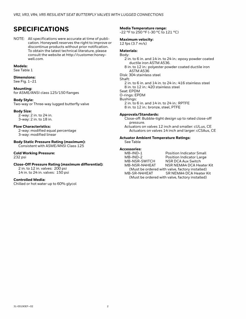
SPECIFICATIONSNOTE: All specifications were accurate at time of publi-
cation. Honeywell reserves the right to improve or discontinue products without prior notification. To obtain the latest technical literature, please consult the website at http://customer.honey-well.com.
Models: See Table 1
Dimensions: See Fig. 1–21
Mounting: for ASME/ANSI class 125/150 flanges
Body Style: Two-way or Three-way lugged butterfly valve
Body Size: 2-way: 2 in. to 24 in.3-way: 2 in. to 18 in.
Flow Characteristics:2-way: modified equal percentage3-way: modified linear
Body Static Pressure Rating (maximum): Consistent with ASME/ANSI Class 125
Cold Working Pressure:232 psi
Close-Off Pressure Rating (maximum differential):2 in. to 12 in. valves: 200 psi14 in. to 24 in. valves: 150 psi
Controlled Media: Chilled or hot water up to 60% glycol
Media Temperature range: -22 °F to 250 °F (-30 °C to 121 °C)
Maximum velocity: 12 fps (3.7 m/s)
Materials:Body:
2 in. to 6 in. and 14 in. to 24 in.: epoxy powder coated ductile iron ASTM A536.
8 in. to 12 in.: polyester powder coated ductile iron ASTM A536
Disk: 304 stainless steelShaft:
2 in. to 6 in. and 14 in. to 24 in.: 416 stainless steel8 in. to 12 in.: 420 stainless steel
Seat: EPDMO-rings: EPDMBushings:
2 in. to 6 in. and 14 in. to 24 in.: RPTFE8 in. to 12 in.: bronze, steel, PTFE
Approvals/Standards:Close-off: Bubble-tight design up to rated close-off
pressure.Actuators on valves 12 inch and smaller: cULus, CE
Actuators on valves 14 inch and larger: cCSAus, CE
Actuator Ambient Temperature Ratings:See Table
Accessories:MB-IND-1 Position Indicator SmallMB-IND-2 Position Indicator LargeMB-NSR-SWITCH NSR DCA Aux SwitchMB-NSR-N4HEAT NSR NEMA4 DCA Heater Kit
(Must be ordered with valve, factory installed)MB-SR-N4HEAT SR NEMA4 DCA Heater Kit
(Must be ordered with valve, factory installed)

VR2, VR3, VR4, VR5 RESILIENT SEAT BUTTERFLY VALVES WITH LUGGED CONNECTIONS
3 31-00190EF—02
Table 1. Butterfly valve assembly model selectionBu
tter
fly
Valv
e
Conn
ectio
n T
ype
Body
Pa
tter
n
Valv
e Si
ze
Actu
ator
Co
ntro
l Si
gnal
Actu
ator
Vol
tage
Fail
Safe
Fu
nctio
n
Volta
ge /
Switc
h Fe
edba
ck
Nem
a Ra
ting
DescriptionV Valve, Lugged (butterfly)
R Resilient Seat ANSI 125/150 (Standard)2 2-way3
3-way configurations (see Fig. 20)45
F 2 inch (DN 50)G 2.5 inch (DN 65)H 3 inch (DN 80)J 4 inch (DN 100)K 5 inch (DN 125)L 6 inch (DN 150)M 8 inch (DN 200)N 10 inch (DN 250)P 12 inch (DN 300)R 14 inch (DN 350)S 16 inch (DN 400)T 18 inch (DN 450)U 20 inch (DN 500) 2-way onlyV 24 inch (DN 600) 2-way only
6 Floating / Two-Position (SPDT)7 Analog Modulating (0)2-10 Vdc8 Two-Position (SPST)
L 24 Vac/VdcH 120 VacU 24-240 Vac / 24-125 Vdc
P Fail in placeS Spring Return A-port (Master) fail safe open T Spring Return A-port (Master) fail safe closedE Electronic Fail Safe (default fail closed, field adjustable)
N No FeedbackF Analog FeedbackS Built in Aux SwitchesB Both Analog Feedback and Aux Switches
2 NEMA 24 NEMA 4XH NEMA 4X (with Heater)
V R 2 H 7 L P F 2
Example: 2-WAY, 3 INCH, RESILIENT SEAT BUTTERFLY VALVE, CV302, CLOSE-OFF 200PSI, 24VAC, 2-10VDC, 150S, FAIL-SAFE IN PLACE, FEEDBACK, NEMA2, (INCLUDES MBP7L4F2/U ACTUATOR)

VR2, VR3, VR4, VR5 RESILIENT SEAT BUTTERFLY VALVES WITH LUGGED CONNECTIONS
31-00190EF—02 4
NOTE: The tables above are intended to explain the significance of the butterfly valve and actuator part numbering sys-tem, and is not a product configuration tool. Only part numbers printed in Honeywell price books may be ordered. Please refer to cpq.honeywell.com for available configurations.
Table 2. Butterfly valve replacement actuator model selection
Type
Fail
safe
Cont
rol
Powe
r
Actu
ator
type
Feed
back
Nem
a
DescriptionMB Motor Butterfly
S Spring fail-safe
E Electronic fail-safe
P Fail-in-place
6 Floating / Two-Position (SPST)
7 Analog Modulating (0)2-10 VDC
8 Two-Position (SPST)
L 24 Vac/Vdc
H 120 Vac
U 24-240 Vac / 24-125 Vdc
1 SR 180 in-lb
2 NSR 180 in-lb
3 SR 180 in-lb
A NSR 180 in-lb
4 EFS/FIP 360 in-lb (2-way VR)
R EFS/FIP 360 in-lb (VH and 3-way VR)
5 EFS/FIP 800 in-lb
6 EFS/FIP 1400 in-lb (3, 4, 5, 6, 12 inch valves)
7 EFS/FIP 1400 in-lb (8 inch valves)
8 EFS/FIP 1400 in-lb (10 inch valves)
9 FIP 3540 in-lb
B FIP 4425 in-lb
C FIP 5755 in-lb
D FIP 8850 in-lb
E FIP 13275 in-lb
F FIP 17700 in-lb
G FIP 22125 in-lb
H FIP 26550 in-lb
N No feedback
F Analog feedback
S Built in Aux Switches
B Both Analog Feedback and Aux Switches
2 NEMA 2
4 NEMA 4X
H NEMA 4X (with HEATER)
MB S 8 U 1 N 2 Example: BUTTERFLY VALVE ACTUATOR FOR VR AND VH SERIES, SPRING RETURN, 2-POSITION, 24-240VAC, 180 LB-IN, NEMA2
VR2, VR3, VR4, VR5 RESILIENT SEAT BUTTERFLY VALVES WITH LUGGED CONNECTIONS
5 31-00190EF—02
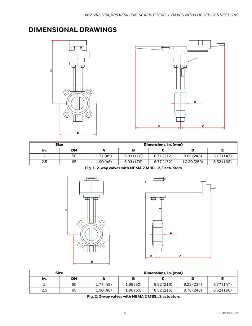
DIMENSIONAL DRAWINGS
Fig. 1. 2-way valves with NEMA 2 MBP... 2,3 actuators
Fig. 2. 2-way valves with NEMA 2 MBS...3 actuators
Size Dimensions, in. (mm)in. DN A B C D E2 50 1.77 (45) 6.93 (176) 6.77 (172) 9.65 (245) 5.77 (147)
2.5 65 1.90 (48) 6.93 (176) 6.77 (172) 10.20 (259) 6.52 (166)
Size Dimensions, in. (mm)in. DN A B C D E2 50 1.77 (45) 1.98 (50) 8.52 (216) 9.23 (234) 5.77 (147)
2.5 65 1.90 (48) 1.98 (50) 8.52 (216) 9.78 (248) 6.52 (166)
E
D
B C
A
E
D
B C
A

VR2, VR3, VR4, VR5 RESILIENT SEAT BUTTERFLY VALVES WITH LUGGED CONNECTIONS
31-00190EF—02 6
Fig. 3. 2-way valves with NEMA 4 MBP,E...3,4 actuators
Fig. 4. 2-way valves with NEMA 2 MBP...4 actuators
Size Dimensions, in. (mm)in. DN A B C D E2 50 1.77 (45) 3.62 (92) 10.49 (266) 13.54 (344) 5.77 (147)
2.5 65 1.90 (48) 3.62 (92) 10.49 (266) 14.09 (358) 6.52 (166)
3 80 1.90 (48) 3.62 (92) 10.49 (266) 14.32 (364) 7.02 (178)
Size Dimensions, in. (mm)in. DN A B C D E3 80 1.90 (48) 2.72 (69) 8.06 (205) 10.98 (279) 7.02 (178)
E
D
B C
A
E
D
B C
A

VR2, VR3, VR4, VR5 RESILIENT SEAT BUTTERFLY VALVES WITH LUGGED CONNECTIONS
7 31-00190EF—02
Fig. 5. 2-way valves with NEMA 2 MBE...4 actuators
Fig. 6. 2-way valves with NEMA 2 MBP,E...5 actuators
Size Dimensions, in. (mm)in. DN A B C D E3 80 1.90 (48) 1.42 (36) 9.43 (240) 13.11 (333) 7.02 (178)
Size Dimensions, in. (mm)in. DN A B C D E4 100 2.12 (55) 5.99 (152) 5.30 (135) 13.03 (331) 8.52 (216)
5 125 2.31 (59) 5.99 (152) 5.30 (135) 13.55 (344) 9.76 (248)
E
D
B C
A
E
D
B C
A

VR2, VR3, VR4, VR5 RESILIENT SEAT BUTTERFLY VALVES WITH LUGGED CONNECTIONS
31-00190EF—02 8
Fig. 7. 2-way valves with NEMA 4 MBP,E...5 actuators
Fig. 8. 2-way valves with MBP...6,7,8 actuators
Size Dimensions, in. (mm)in. DN A B C D E4 100 2.15 (55) 6.81 (173) 7.34 (186) 15.07 (383) 8.52 (216)
5 125 2.31 (59) 6.81 (173) 7.34 (186) 15.59 (396) 9.76 (248)
Size Dimensions, in. (mm)in. DN A B C D E6 150 2.20 (56) 2.65 (67) 9.30 (236) 16.03 (407) 10.76 (273)
8 200 2.36 (60) 2.65 (67) 9.30 (236) 17.37 (441) 13.02 (331)
10 250 2.68 (68) 2.65 (67) 9.30 (236) 18.63 (473) 15.68 (398)
12 300 3.07 (78) 2.65 (67) 9.30 (236) 20.40 (518) 18.40 (467)
E
D
B C
A
B
D
E
A
C

VR2, VR3, VR4, VR5 RESILIENT SEAT BUTTERFLY VALVES WITH LUGGED CONNECTIONS
9 31-00190EF—02
Fig. 9. 2-way valves with MBE...6,7,8 actuators
Size Dimensions, in. (mm)in. DN A B C D E5 125 2.20 (56) 2.65 (67) 9.30 (236) 17.77 (451) 9.76 (248)
6 150 2.20 (56) 2.65 (67) 9.30 (236) 18.28 (464) 10.76 (273)
8 200 2.36 (60) 2.65 (67) 9.30 (236) 19.62 (498) 12.96 (329)
10 250 2.68 (68) 2.65 (67) 9.30 (236) 20.88 (530) 15.66 (398)
12 300 3.07 (78) 2.65 (67) 9.30 (236) 22.65 (575) 18.40 (467)
D
E
B
A
C
VR2, VR3, VR4, VR5 RESILIENT SEAT BUTTERFLY VALVES WITH LUGGED CONNECTIONS
31-00190EF—02 10
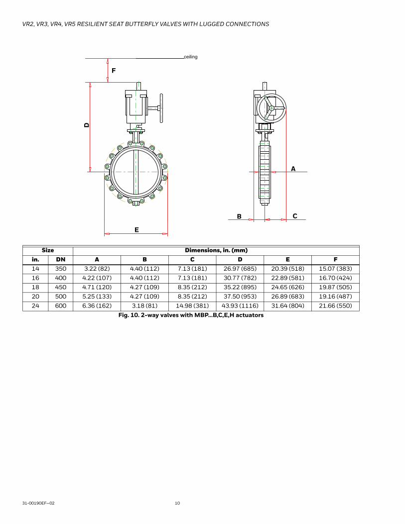
Fig. 10. 2-way valves with MBP...B,C,E,H actuators
Size Dimensions, in. (mm)in. DN A B C D E F14 350 3.22 (82) 4.40 (112) 7.13 (181) 26.97 (685) 20.39 (518) 15.07 (383)
16 400 4.22 (107) 4.40 (112) 7.13 (181) 30.77 (782) 22.89 (581) 16.70 (424)
18 450 4.71 (120) 4.27 (109) 8.35 (212) 35.22 (895) 24.65 (626) 19.87 (505)
20 500 5.25 (133) 4.27 (109) 8.35 (212) 37.50 (953) 26.89 (683) 19.16 (487)
24 600 6.36 (162) 3.18 (81) 14.98 (381) 43.93 (1116) 31.64 (804) 21.66 (550)
E
D
ceiling
B C
A
F

VR2, VR3, VR4, VR5 RESILIENT SEAT BUTTERFLY VALVES WITH LUGGED CONNECTIONS
11 31-00190EF—02
Fig. 11. 3-way valves with NEMA 2 MBP,E...2,3,A,R actuators
Fig. 12. 3-way valves with NEMA 2 MBS...1,3 actuators
Size Dimensions, in. (mm)in. DN A B C D E2 50 4.50 (114) 6.27 (159) 6.57 (167) 12.33 (313) 3.00 (76)
2.5 65 5.00 (127) 6.90 (175) 7.37 (187) 12.88 (327) 3.50 (89)
Size Dimensions, in. (mm)in. DN A B C D E2 50 4.50 (114) 6.27 (159) 7.37 (187) 12.33 (313) 3.00 (76)
DE
C A B
DE
BC A
VR2, VR3, VR4, VR5 RESILIENT SEAT BUTTERFLY VALVES WITH LUGGED CONNECTIONS
31-00190EF—02 12
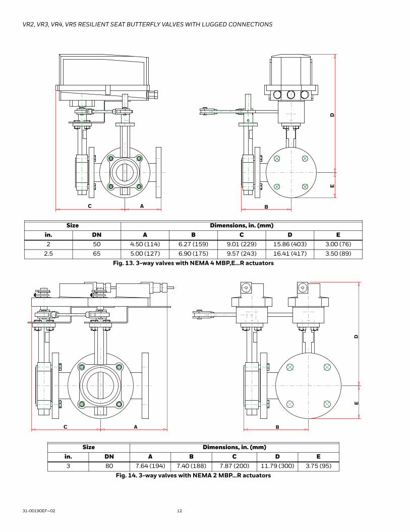
Fig. 13. 3-way valves with NEMA 4 MBP,E...R actuators
Fig. 14. 3-way valves with NEMA 2 MBP...R actuators
Size Dimensions, in. (mm)in. DN A B C D E2 50 4.50 (114) 6.27 (159) 9.01 (229) 15.86 (403) 3.00 (76)
2.5 65 5.00 (127) 6.90 (175) 9.57 (243) 16.41 (417) 3.50 (89)
Size Dimensions, in. (mm)in. DN A B C D E3 80 7.64 (194) 7.40 (188) 7.87 (200) 11.79 (300) 3.75 (95)
DE
BC A
DE
BC A

VR2, VR3, VR4, VR5 RESILIENT SEAT BUTTERFLY VALVES WITH LUGGED CONNECTIONS
13 31-00190EF—02
Fig. 15. 3-way valves with NEMA 2 MBE...R actuators
Fig. 16. 3-way valves with NEMA 4 MBP...R actuators
Size Dimensions, in. (mm)in. DN A B C D E3 80 9.43 (240) 7.40 (188) 7.87 (200) 13.11 (333) 3.75 (95)
Size Dimensions, in. (mm)in. DN A B C D E3 80 10.49 (266) 7.40 (188) 10.07 (256) 16.64 (423) 3.75 (95)
DE
BC A
DE
BC A

VR2, VR3, VR4, VR5 RESILIENT SEAT BUTTERFLY VALVES WITH LUGGED CONNECTIONS
31-00190EF—02 14
Fig. 17. 3-way valves with MBP...6,7,8 actuators
Size Dimensions, in. (mm)in. DN A B C D E3 80 5.50 (140) 7.56 (192) 8.89 (226) 14.97 (380) 3.75 (95)
4 100 6.50 (165) 8.55 (217) 11.13 (283) 14.22 (361) 4.50 (114)
5 125 7.50 (191) 9.70 (246) 12.05 (306) 14.74 (374) 5.00 (127)
6 150 8.00 (203) 10.20 (256) 12.55 (319) 15.25 (387) 5.50 (140)
8 200 9.00 (229) 11.36 (289) 13.47 (342) 16.59 (421) 6.75 (172)
10 250 11.00 (279) 13.68 (348) 15.31 (389) 17.85 (453) 8.00 (203)
12 300 12.00 (305) 15.07 (383) 16.12 (409) 19.62 (498) 9.50 (241)
BC A
DE

VR2, VR3, VR4, VR5 RESILIENT SEAT BUTTERFLY VALVES WITH LUGGED CONNECTIONS
15 31-00190EF—02
Fig. 18. 3-way valves with MBE...6,7,8 actuators
Fig. 19. 3-way valves with MBP...C,D,E actuators
Size Dimensions, in. (mm)in. DN A B C D E4 100 6.50 (165) 8.55 (217) 11.13 (283) 16.47 (418) 4.50 (114)
5 125 7.50 (191) 9.70 (246) 12.05 (306) 16.99 (432) 5.00 (127)
6 150 8.00 (203) 10.20 (259) 12.55 (319) 17.50 (445) 5.50 (140)
8 200 9.00 (229) 11.36 (289) 13.47 (342) 18.84 (479) 6.75 (172)
10 250 11.00 (279) 13.68 (348) 15.31 (389) 20.10 (511) 8.00 (203)
12 300 12.00 (305) 15.07 (383) 16.12 (409) 21.87 (556) 9.50 (241)
Size Dimensions, in. (mm)in. DN A B C D E F14 350 14.00 (356) 17.22 (437) 20.01 (508) 29.51 (750) 10.50 (267) 8.80 (224)
16 400 15.00 (381) 19.22 (488) 21.38 (543) 34.35 (873) 11.75 (299) 8.80 (224)
18 450 16.50 (419) 21.21 (539) 23.13 (588) 35.22 (895) 12.50 (318) 8.80 (224)
D
BC A
E
DE
B
F
ceiling
C A

VR2, VR3, VR4, VR5 RESILIENT SEAT BUTTERFLY VALVES WITH LUGGED CONNECTIONS
31-00190EF—02 16
ACTUATOR SPECIFICATIONS
Table 3. Actuators Used on 2-way Assemblies
Assembly Actuator Assembly Actuator Assembly ActuatorVR2F6LPN2/M MBP6L2N2/U VR2G7LTF2/M MBS7L3F2/U VR2K7LPF4/M MBP7L5F4/U
VR2F6LPN4/M MBP6L4N4/U VR2G7LTF4/M MBS7L3F4/U VR2K7UEBH/M MBE7U6BH/U
VR2F7LPF2/M MBP7L2F2/U VR2G8USN2/M MBS8U3N2/U VR2L6UESH/M MBE6U6SH/U
VR2F7LPF4/M MBP7L4F4/U VR2G8USN4/M MBS8U3N4/U VR2L6UPSH/M MBP6U6SH/U
VR2F7LSB2/M MBS7L3B2/U VR2G8USS2/M MBS8U3S2/U VR2L7UEBH/M MBE7U6BH/U
VR2F7LSB4/M MBS7L3B4/U VR2G8USS4/M MBS8U3S4/U VR2L7UPBH/M MBP7U6BH/U
VR2F7LSF2/M MBS7L3F2/U VR2G8UTN2/M MBS8U3N2/U VR2M6UESH/M MBE6U7SH/U
VR2F7LSF4/M MBS7L3F4/U VR2G8UTN4/M MBS8U3N4/U VR2M6UPSH/M MBP6U7SH/U
VR2F7LTB2/M MBS7L3B2/U VR2G8UTS2/M MBS8U3S2/U VR2M7UEBH/M MBE7U7BH/U
VR2F7LTB4/M MBS7L3B4/U VR2G8UTS4/M MBS8U3S4/U VR2M7UPBH/M MBP7U7BH/U
VR2F7LTF2/M MBS7L3F2/U VR2H6LEN2/M MBE6L4N2/U VR2N6UESH/M MBE6U8SH/U
VR2F7LTF4/M MBS7L3F4/U VR2H6LEN4/M MBE6L4N4/U VR2N6UPSH/M MBP6U8SH/U
VR2F8USN2/M MBS8U3N2/U VR2H6LPN2/M MBP6L4N2/U VR2N7UEBH/M MBE7U8BH/U
VR2F8USN4/M MBS8U3N4/U VR2H6LPN4/M MBP6L4N4/U VR2N7UPBH/M MBP7U8BH/U
VR2F8USS2/M MBS8U3S2/U VR2H7LEF2/M MBE7L4F2/U VR2P6UESH/M MBE6U6SH/U
VR2F8USS4/M MBS8U3S4/U VR2H7LEF4/M MBE7L4F4/U VR2P6UPSH/M MBP6U6SH/U
VR2F8UTN2/M MBS8U3N2/U VR2H7LPF2/M MBP7L4F2/U VR2P7UEBH/M MBE7U6BH/U
VR2F8UTN4/M MBS8U3N4/U VR2H7LPF4/M MBP7L4F4/U VR2P7UPBH/M MBP7U6BH/U
VR2F8UTS2/M MBS8U3S2/U VR2J6LEN2/M MBE6L5N2/U VR2R6LPSH/M MBP6LBSH/U
VR2F8UTS4/M MBS8U3S4/U VR2J6LEN4/M MBE6L5N4/U VR2R7LPBH/M MBP7LBBH/U
VR2G6LPN2/M MBP6L2N2/U VR2J6LPN2/M MBP6L5N2/U VR2S6HPSH/M MBP6HCSH/U
VR2G6LPN4/M MBP6L4N4/U VR2J6LPN4/M MBP6L5N4/U VR2S7HPBH/M MBP7HCBH/U
VR2G7LPF2/M MBP7L2F2/U VR2J7LEF2/M MBE7L5F2/U VR2T6HPSH/M MBP6HESH/U
VR2G7LPF4/M MBP7L4F4/U VR2J7LEF4/M MBE7L5F4/U VR2T7HPBH/M MBP7HEBH/U
VR2G7LSB2/M MBS7L3B2/U VR2J7LPF2/M MBP7L5F2/U VR2U6HPSH/M MBP6HESH/U
VR2G7LSB4/M MBS7L3B4/U VR2J7LPF4/M MBP7L5F4/U VR2U7HPBH/M MBP7HEBH/U
VR2G7LSF2/M MBS7L3F2/U VR2K6LPN2/M MBP6L5N2/U VR2V6HPSH/M MBP6HHSH/U
VR2G7LSF4/M MBS7L3F4/U VR2K6LPN4/M MBP6L5N4/U VR2V7HPBH/M MBP7HHBH/U
VR2G7LTB2/M MBS7L3B2/U VR2K6UESH/M MBE6U6SH/U
VR2G7LTB4/M MBS7L3B4/U VR2K7LPF2/M MBP7L5F2/U

VR2, VR3, VR4, VR5 RESILIENT SEAT BUTTERFLY VALVES WITH LUGGED CONNECTIONS
17 31-00190EF—02
Table 4. Actuators used on 3-way Assemblies
Assembly Actuator Assembly Actuator Assembly ActuatorVR3F6LPN2/M MBP6LAN2/U VR4F6LPN2/M MBP6LAN2/U VR5F6LPN2/M MBP6LAN2/UVR3F7LPF2/M MBP7L3F2/U VR4F7LPF2/M MBP7L3F2/U VR5F7LPF2/M MBP7L3F2/UVR3F7LPF4/M MBP7LRN4/U VR4F7LPF4/M MBP7LRN4/U VR5F7LPF4/M MBP7LRN4/UVR3F7LSF2/M MBS7L1F2/U VR4F7LSF2/M MBS7L1F2/U VR5F7LSF2/M MBS7L1F2/UVR3F7LTF2/M MBS7L1F2/U VR4F7LTF2/M MBS7L1F2/U VR5F7LTF2/M MBS7L1F2/UVR3F8USN2/M MBS8U1N2/U VR4F8USN2/M MBS8U1N2/U VR5F8USN2/M MBS8U1N2/UVR3F8UTN2/M MBS8U1N2/U VR4F8UTN2/M MBS8U1N2/U VR5F8UTN2/M MBS8U1N2/UVR3G6LPN2/M MBP6LRN2/U VR4G6LPN2/M MBP6LRN2/U VR5G6LPN2/M MBP6LRN2/UVR3G6LPN4/M MBP6LRN4/U VR4G6LPN4/M MBP6LRN4/U VR5G6LPN4/M MBP6LRN4/UVR3G7LEF2/M MBE7LRF2/U VR4G7LEF2/M MBE7LRF2/U VR5G7LEF2/M MBE7LRF2/UVR3G7LPF2/M MBP7LRF2/U VR4G7LPF2/M MBP7LRF2/U VR5G7LPF2/M MBP7LRF2/UVR3G7LPF4/M MBP7LRN4/U VR4G7LPF4/M MBP7LRN4/U VR5G7LPF4/M MBP7LRN4/UVR3G8LEN2/M MBE6LRN2/U VR4G8LEN2/M MBE6LRN2/U VR5G8LEN2/M MBE6LRN2/UVR3H6LEN2/M MBE6LRN2/U VR4H6LEN2/M MBE6LRN2/U VR5H6LEN2/M MBE6LRN2/UVR3H6UPNH/M MBP6U6SH/U VR4H6UPNH/M MBP6U6SH/U VR5H6UPNH/M MBP6U6SH/UVR3H7LEF2/M MBE7LRF2/U VR4H7LEF2/M MBE7LRF2/U VR5H7LEF2/M MBE7LRF2/UVR3H7LPF2/M MBP7LRF2/U VR4H7LPF2/M MBP7LRF2/U VR5H7LPF2/M MBP7LRF2/UVR3H7LPF4/M MBP7LRN4/U VR4H7LPF4/M MBP7LRN4/U VR5H7LPF4/M MBP7LRN4/UVR3J6UESH/M MBE6U6SH/U VR4J6UESH/M MBE6U6SH/U VR5J6UESH/M MBE6U6SH/UVR3J6UPSH/M MBP6U6SH/U VR4J6UPSH/M MBP6U6SH/U VR5J6UPSH/M MBP6U6SH/UVR3J7UEBH/M MBE7U6BH/U VR4J7UEBH/M MBE7U6BH/U VR5J7UEBH/M MBE7U6BH/UVR3J7UPBH/M MBP7U6BH/U VR4J7UPBH/M MBP7U6BH/U VR5J7UPBH/M MBP7U6BH/UVR3K6UESH/M MBE6U6SH/U VR4K6UESH/M MBE6U6SH/U VR5K6UESH/M MBE6U6SH/UVR3K6UPSH/M MBP6U6SH/U VR4K6UPSH/M MBP6U6SH/U VR5K6UPSH/M MBP6U6SH/UVR3K7UEBH/M MBE7U6BH/U VR4K7UEBH/M MBE7U6BH/U VR5K7UEBH/M MBE7U6BH/UVR3K7UPBH/M MBP7U6BH/U VR4K7UPBH/M MBP7U6BH/U VR5K7UPBH/M MBP7U6BH/UVR3L6UESH/M MBE6U6SH/U VR4L6UESH/M MBE6U6SH/U VR5L6UESH/M MBE6U6SH/UVR3L6UPSH/M MBP6U6SH/U VR4L6UPSH/M MBP6U6SH/U VR5L6UPSH/M MBP6U6SH/UVR3L7UEBH/M MBE7U6BH/U VR4L7UEBH/M MBE7U6BH/U VR5L7UEBH/M MBE7U6BH/UVR3L7UPBH/M MBP7U6BH/U VR4L7UPBH/M MBP7U6BH/U VR5L7UPBH/M MBP7U6BH/UVR3M6UESH/M MBE6U7SH/U VR4M6UESH/M MBE6U7SH/U VR5M6UESH/M MBE6U7SH/UVR3M6UPSH/M MBP6U7SH/U VR4M6UPSH/M MBP6U7SH/U VR5M6UPSH/M MBP6U7SH/UVR3M7UEBH/M MBE7U7BH/U VR4M7UEBH/M MBE7U7BH/U VR5M7UEBH/M MBE7U7BH/UVR3M7UPBH/M MBP7U7BH/U VR4M7UPBH/M MBP7U7BH/U VR5M7UPBH/M MBP7U7BH/UVR3N6UESH/M MBE6U8SH/U VR4N6UESH/M MBE6U8SH/U VR5N6UESH/M MBE6U8SH/UVR3N6UPSH/M MBP6U8SH/U VR4N6UPSH/M MBP6U8SH/U VR5N6UPSH/M MBP6U8SH/UVR3N7UEBH/M MBE7U8BH/U VR4N7UEBH/M MBE7U8BH/U VR5N7UEBH/M MBE7U8BH/UVR3N7UPBH/M MBP7U8BH/U VR4N7UPBH/M MBP7U8BH/U VR5N7UPBH/M MBP7U8BH/UVR3P6UESH/M MBE6U6SH/U VR4P6UESH/M MBE6U6SH/U VR5P6UESH/M MBE6U6SH/UVR3P6UPSH/M MBP6U6SH/U VR4P6UPSH/M MBP6U6SH/U VR5P6UPSH/M MBP6U6SH/UVR3P7UEBH/M MBE7U6BH/U VR4P7UEBH/M MBE7U6BH/U VR5P7UEBH/M MBE7U6BH/UVR3P7UPBH/M MBP7U6BH/U VR4P7UPBH/M MBP7U6BH/U VR5P7UPBH/M MBP7U6BH/UVR3R6HPSH/M MBP6HCSH/U VR4R6HPSH/M MBP6HCSH/U VR5R6HPSH/M MBP6HCSH/UVR3R7HPBH/M MBP7HCBH/U VR4R7HPBH/M MBP7HCBH/U VR5R7HPBH/M MBP7HCBH/UVR3S6HPSH/M MBP6HDSH/U VR4S6HPSH/M MBP6HDSH/U VR5S6HPSH/M MBP6HDSH/UVR3T6HPSH/M MBP7HDBH/U VR4S7HPBH/M MBP7HDBH/U VR5S7HPBH/M MBP7HDBH/UVR3T6HPSH/M MBP6HESH/U VR4T6HPSH/M MBP6HESH/U VR5T6HPSH/M MBP6HESH/UVR3T7HPBH/M MBP7HEBH/U VR4T7HPBH/M MBP7HEBH/U VR5T7HPBH/M MBP7HEBH/U

VR2, VR3, VR4, VR5 RESILIENT SEAT BUTTERFLY VALVES WITH LUGGED CONNECTIONS
31-00190EF—02 18
Table 5. Actuator Specifications.
Actuator Model TorqueControl Inputs
Fail Safe(Timing) Supply Voltage
Transformer Sizing Ambient Temp. Timing Enclosure
Aux. Switch
Wiring Diagram
MBP6L2N2/U
180 in-lb[20 Nm]
2-position;Floating
fail-in-place24 VAC, ±20%, 50/60 Hz;24 VDC, ±10%
5.5 VA (class 2)-22°F to 122°F[-30°C to 50°C]
90s
IP 54 NEMA 2
Fig. 35MBP6LAN2/U
MBP7L2F2/UModulating 6 VA (class 2) 150s Fig. 36
MBP7L3F2/U
MBS8U1N2/U
180 in-lb[20 Nm]
2-position
springfail-safe(<20s)
24...240 VAC -20% / +10%, 50/60 Hz;24...125 VDC ±10%
7 VA @ 24 VAC (class 2);8.5 VA @ 120 VAC;18 VA @ 240 VAC
-22°F to 122°F[-30°C to 50°C] <75s
IP 54 NEMA 2
Fig. 34
MBS8U3N2/U IP 54 NEMA 2
MBS8U3N4/U IP 66/67 NEMA 4X
MBS8U3S2/U IP 54 NEMA 22 x SPDT*
MBS8U3S4/U IP 66/67 NEMA 4X
MBS7L1F2/U
Modulating
24 VAC, ±20%, 50/60 Hz;24 VDC, -10% / +20%
10 VA (class 2) -22°F to 122°F[-30°C to 50°C] 150s
IP 54 NEMA 2
Fig. 36MBS7L3F2/U
24 VAC, ±20%, 50/60 Hz;24 VDC, ±10%
IP 54 NEMA 2
MBS7L3F4/U IP 66/67 NEMA 4X
MBS7L3B2/U IP 54 NEMA 22 x SPDT*
MBS7L3B4/U IP 66/67 NEMA 4X
MBP6L4N2/U
360 in-lb[40 Nm]
2-position;Floating
fail-in-place24 VAC, ±20%, 50/60 Hz;24 VDC, ±10%
6 VA (class 2)
-22°F to 122°F[-30°C to 50°C]
150s IP 54 NEMA 2
Fig. 35MBP6LRN2/U
MBP6L4N4/U
7 VA (class 2)
35s IP 66/67 NEMA 4XMBP6LRN4/U
MBP7L4F2/U
Modulating 150s
IP 54 NEMA 2
Fig. 36MBP7LRF2/U
MBP7L4F4/U IP 66/67 NEMA 4XMBP7LRN4/U
MBE6L4N2/U
360 in-lb[40 Nm]
2-position;Floating
electronicfail-safe(35s)
24 VAC ± 20%, 50/60 Hz;24 VDC ± 10%
21 VA (class 2) -22°F to 122°F[-30°C to 50°C] 150s
IP 54 NEMA 2Fig. 37MBE6LRN2/U
MBE6L4N4/U IP 66/67 NEMA 4X
MBE7L4F2/U
ModulatingIP 54 NEMA 2
Fig. 38MBE7LRF2/U
MBE7L4F4/U IP 66/67 NEMA 4X
*3A resistive (0.5A inductive) @ 250 VAC, one set at 10°, one adjustable 10° to 90°**3A resistive (0.5A inductive) @ 250 VAC, one set at 10°, one set at 85°

VR2, VR3, VR4, VR5 RESILIENT SEAT BUTTERFLY VALVES WITH LUGGED CONNECTIONS
19 31-00190EF—02
*3A resistive (0.5A inductive) @ 250 VAC, one set at 10°, one adjustable 10° to 90°**3A resistive (0.5A inductive) @ 250 VAC, one set at 10°, one set at 85°
MBP6L5N2/U
800 in-lb[90 Nm]
2-position;Floating
fail-in-place24 VAC, ±20%, 50/60 Hz;24 VDC, ±10%
12 VA (class 2) -22°F to 122°F[-30°C to 50°C]
35sNEMA 1
Fig. 35MBP6L5N4/U IP 66/67 NEMA
4X
MBP7L5F2/UModulating 150s
NEMA 1Fig. 36
MBP7L5F4/U IP 66/76 NEMA 4X
MBE6L5N2/U
800 in-lb[90 Nm]
2-position;Floating
electronicfail-safe(35s)
24 VAC, ±20%, 50/60 Hz
21 VA (class 2) -22°F to 122°F[-30°C to 50°C] 150s
NEMA 1Fig. 37
MBE6L5N4/U IP 66/67 NEMA 4X
MBE7L5F2/UModulating
24 VAC, ±20%, 50/60 Hz;24 VDC, ±10%
NEMA 1Fig. 38
MBE7L5F4/U IP 66/67 NEMA 4X
MBP6U6SH/U
1400 in-lb[160 Nm]
2-position;Floating
fail-in-place
24...240 VAC, -20% / +10%, 50/60 Hz;24...125 VDC, -20% / +10%
20 VA @ 24 VAC/DC (class 2);23 VA @ 120 VAC/DC;52 VA @ 230 VAC
-22°F to 122°F[-30°C to 50°C] 35s
IP 66/67NEMA 4Xw/Heater
2 x SPDT*
Fig. 39MBP6U7SH/U
MBP6U8SH/U
MBP7U6BH/U
Modulating Fig. 40MBP7U7BH/U
MBP7U8BH/U
MBE6U6SH/U
1400 in-lb[160 Nm]
2-position;Floating
electronicfail-safe(30s)
24...240 VAC, -20% / +10%, 50/60 Hz;24...125 VDC, -20% / +10%
55 VA @ 24 VAC/DC (class 2);43 VA @ 120 VAC/DC;68 VA @ 230 VAC
-22°F to 122°F[-30°C to 50°C] 35s
IP 66/67NEMA 4Xw/Heater
2 x SPDT*
Fig. 39MBE6U7SH/U
MBE6U8SH/U
MBE7U6BH/U
Modulating Fig. 40MBE7U7BH/U
MBE7U8BH/U
MBP6LBSH/U 4425 in-lb[500 Nm]
2-positionfail-in-place
24 VAC, ±10%, 50/60 Hz;24 VDC, ±10%
214 VA -22°F to 150°F[-30°C to 65°C] 26s
IP 66/67NEMA 4Xw/Heater
2 x SPDT**Fig. 42
MBP7LBBH/U Modulating Fig. 43
MBP6HCSH/U 5755 in-lb[650 Nm]
2-position
fail-in-place 120 VAC, ±10%, 50/60 Hz
288 VA
-22°F to 150°F[-30°C to 65°C]
34s
IP 66/67NEMA 4Xw/Heater
2 x SPDT**
Fig. 44
MBP7HCBH/U Modulating 240 VA 38s Fig. 45
MBP6HDSH/U 8850 in-lb[1000 Nm]
2-position 504 VA 50s Fig. 44
MBP7HDBH/U Modulating 240 VA 59s Fig. 45
MBP6HESH/U 13275 in-lb [1500 Nm]
2-position 504 VA 51s Fig. 44
MBP7HEBH/U Modulating 336 VA 79s Fig. 45
MBP6HHSH/U 26550 in-lb [3000 Nm]
2-position 432 VA 62s Fig. 44
MBP7HHBH/U Modulating 516 VA 71s Fig. 45
Table 5. Actuator Specifications. (Continued)
Actuator Model TorqueControl Inputs
Fail Safe(Timing) Supply Voltage
Transformer Sizing Ambient Temp. Timing Enclosure
Aux. Switch
Wiring Diagram
VR2, VR3, VR4, VR5 RESILIENT SEAT BUTTERFLY VALVES WITH LUGGED CONNECTIONS
31-00190EF—02 20
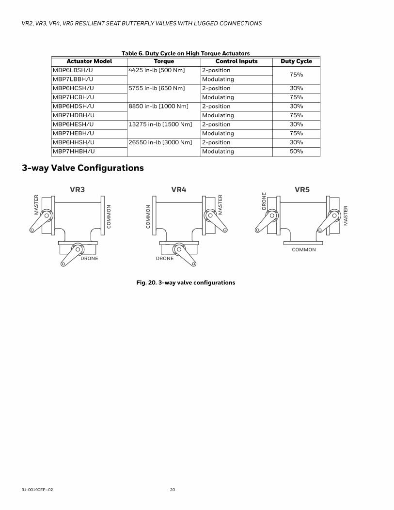
3-way Valve Configurations
Fig. 20. 3-way valve configurations
Table 6. Duty Cycle on High Torque ActuatorsActuator Model Torque Control Inputs Duty Cycle
MBP6LBSH/U 4425 in-lb [500 Nm] 2-position75%
MBP7LBBH/U Modulating
MBP6HCSH/U 5755 in-lb [650 Nm] 2-position 30%
MBP7HCBH/U Modulating 75%
MBP6HDSH/U 8850 in-lb [1000 Nm] 2-position 30%
MBP7HDBH/U Modulating 75%
MBP6HESH/U 13275 in-lb [1500 Nm] 2-position 30%
MBP7HEBH/U Modulating 75%
MBP6HHSH/U 26550 in-lb [3000 Nm] 2-position 30%
MBP7HHBH/U Modulating 50%
DRONE DRONE
MA
STE
R
MA
STE
R
MA
STE
R
NO
MM
OC
NO
MM
OC
COMMON
VR5VR4VR3
DR
ON
E

VR2, VR3, VR4, VR5 RESILIENT SEAT BUTTERFLY VALVES WITH LUGGED CONNECTIONS
21 31-00190EF—02
Flow Data
Fig. 21. Typical flow characteristics for VR valves
Table 7. Valve Cv
Valve Size Cv
in. DN 10° 20° 30° 40° 50° 60° 70° 80° 90°2 50 0.06 3 7 15 27 44 70 105 115
2.5 65 0.1 6 12 25 45 75 119 178 196
3 80 0.2 9 18 39 70 116 183 275 302
4 100 0.3 17 36 78 139 230 364 546 600
5 125 0.5 29 61 133 237 392 620 930 1022
6 150 0.8 45 95 205 366 605 958 1437 1579
8 200 2 89 188 408 727 1202 1903 2854 3136
10 250 3 151 320 694 1237 2047 3240 4859 5340
12 300 4 234 495 1072 1911 3162 5005 7507 8250
14 350 6 338 715 1549 2761 4568 7230 10844 11917
16 400 8 464 983 2130 3797 6282 9942 14913 16388
18 450 11 615 1302 2822 5028 8320 13168 19752 21705
20 500 14 791 1674 3628 6465 10698 16931 25396 27908
24 600 22 1222 2587 5605 9989 16528 26157 39236 43116
0
10
2010 30 5040 60 8070 90
20
30
40
60
50
70
80
90
100
% O
F M
AXI
MU
M F
LO
W

VR2, VR3, VR4, VR5 RESILIENT SEAT BUTTERFLY VALVES WITH LUGGED CONNECTIONS
31-00190EF—02 22
INSTALLATION
Storage of Butterfly Valve Assemblies• Assemblies must be stored indoors, protected from the
elements.• Materials received on job sites that have long
installation lead times should receive extra protection from construction damage.
• Resilient seats must be protected from abrasion, cutting and nicking, as this will damage the liner and may cause flange area leaks.
• Electric actuators cannot be stored in wet, damp or caustic areas.
• Do not store construction material on top of valve assemblies.
Installation Practices• VR series butterfly valves are designed to be installed
between ANSI 125/150 flat-faced, raised face, slip-on or weld neck flanges.
• Valve should be installed a minimum of 10 pipe diameters from upstream or downstream elbows, strainers, pumps, etc.
• For chilled water, condenser water or hot water applications, the valve should be installed with the stem in a vertical orientation, with the actuator mounted above the valve.
• For applications in which there is a possibility of sediment in the flow, the valve should be installed with the stem in a horizontal position and the bottom of the disc should close FROM the downstream side, rather than from the upstream side.
Fig. 22.
• Make sure the flange faces are clean and free of rust, scale and debris to prevent damage to the liner face.
• Do NOT use flange gaskets on VR series butterfly valves. (Fig. 23)
• Follow the recommended flange bolting sequence. (Fig. 32)
Installation using Welded Flanges• Mount flanges on both sides of valve body and install
bolts to properly align valve body and both flanges.• Install the valve with the disc in the “Almost Closed”
position (Fig. 22)• Do not use any flange gaskets (Fig. 23)• Make sure the valve liner and flange internal diameters
are in alignment. (Fig. 24)• Take valve body / flange pair assembly and align with
piping ends.
Table 8. Flow Rate
Valve Size Flow Rate in GPMin. DN 2 FPS 4 FPS 6 FPS 8 FPS 10 FPS 12 FPS2 50 19 39 59 78 98 117
2.5 65 30 61 92 122 153 184
3 80 44 88 132 176 220 264
4 100 78 157 235 313 392 470
5 125 122 245 367 490 612 734
6 150 176 352 529 705 881 1058
8 200 313 627 940 1253 1567 1880
10 250 490 979 1469 1958 2448 2738
12 300 705 1410 2115 2820 3525 4230
14 350 959 1919 2879 3838 4798 5758
16 400 1253 2507 3760 5013 6267 7520
18 450 1586 3173 4759 6345 7931 9518
20 500 1958 3917 5875 7834 9792 11750
24 600 2820 5640 8460 11280 14100 16921
15 ... 20°
VR2, VR3, VR4, VR5 RESILIENT SEAT BUTTERFLY VALVES WITH LUGGED CONNECTIONS
23 31-00190EF—02
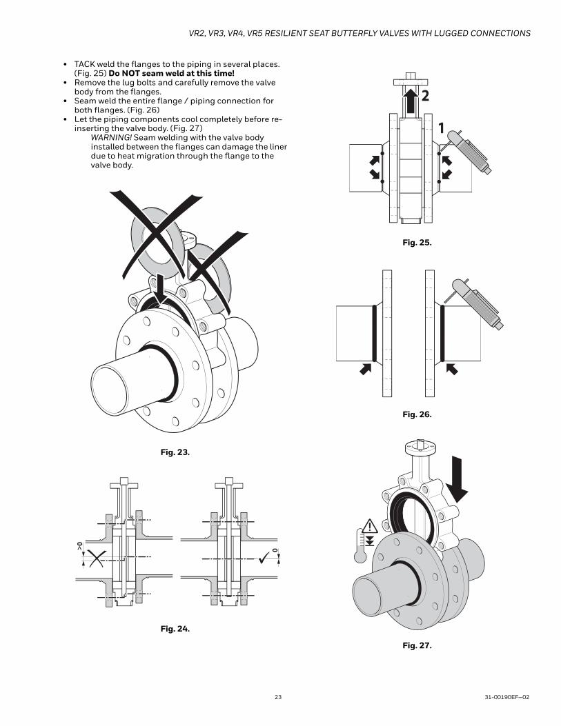
• TACK weld the flanges to the piping in several places. (Fig. 25) Do NOT seam weld at this time!
• Remove the lug bolts and carefully remove the valve body from the flanges.
• Seam weld the entire flange / piping connection for both flanges. (Fig. 26)
• Let the piping components cool completely before re-inserting the valve body. (Fig. 27)
WARNING! Seam welding with the valve body installed between the flanges can damage the liner due to heat migration through the flange to the valve body.
Fig. 23.
Fig. 24.
Fig. 25.
Fig. 26.
Fig. 27.
0> 0
1
2
VR2, VR3, VR4, VR5 RESILIENT SEAT BUTTERFLY VALVES WITH LUGGED CONNECTIONS
31-00190EF—02 24
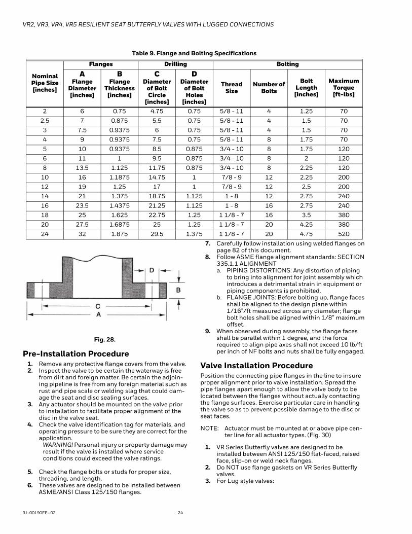
Fig. 28.
Pre-Installation Procedure1. Remove any protective flange covers from the valve.2. Inspect the valve to be certain the waterway is free
from dirt and foreign matter. Be certain the adjoin-ing pipeline is free from any foreign material such as rust and pipe scale or welding slag that could dam-age the seat and disc sealing surfaces.
3. Any actuator should be mounted on the valve prior to installation to facilitate proper alignment of the disc in the valve seat.
4. Check the valve identification tag for materials, and operating pressure to be sure they are correct for the application.
WARNING! Personal injury or property damage may result if the valve is installed where service conditions could exceed the valve ratings.
5. Check the flange bolts or studs for proper size, threading, and length.
6. These valves are designed to be installed between ASME/ANSI Class 125/150 flanges.
7. Carefully follow installation using welded flanges on page 82 of this document.
8. Follow ASME flange alignment standards: SECTION 335.1.1 ALIGNMENTa. PIPING DISTORTIONS: Any distortion of piping
to bring into alignment for joint assembly which introduces a detrimental strain in equipment or piping components is prohibited.
b. FLANGE JOINTS: Before bolting up, flange faces shall be aligned to the design plane within 1/16”/ft measured across any diameter; flange bolt holes shall be aligned within 1/8” maximum offset.
9. When observed during assembly, the flange faces shall be parallel within 1 degree, and the force required to align pipe axes shall not exceed 10 lb/ft per inch of NF bolts and nuts shall be fully engaged.
Valve Installation ProcedurePosition the connecting pipe flanges in the line to insure proper alignment prior to valve installation. Spread the pipe flanges apart enough to allow the valve body to be located between the flanges without actually contacting the flange surfaces. Exercise particular care in handling the valve so as to prevent possible damage to the disc or seat faces.
NOTE: Actuator must be mounted at or above pipe cen-ter line for all actuator types. (Fig. 30)
1. VR Series Butterfly valves are designed to be installed between ANSI 125/150 flat-faced, raised face, slip-on or weld neck flanges.
2. Do NOT use flange gaskets on VR Series Butterfly valves.
3. For Lug style valves:
Table 9. Flange and Bolting Specifications
Nominal Pipe Size [inches]
Flanges Drilling Bolting
AFlange
Diameter [inches]
BFlange
Thickness [inches]
CDiameter
of Bolt Circle
[inches]
DDiameter
of Bolt Holes
[inches]
Thread Size
Number of Bolts
Bolt Length [inches]
Maximum Torque[ft-lbs]
2 6 0.75 4.75 0.75 5/8 - 11 4 1.25 70
2.5 7 0.875 5.5 0.75 5/8 - 11 4 1.5 70
3 7.5 0.9375 6 0.75 5/8 - 11 4 1.5 70
4 9 0.9375 7.5 0.75 5/8 - 11 8 1.75 70
5 10 0.9375 8.5 0.875 3/4 - 10 8 1.75 120
6 11 1 9.5 0.875 3/4 - 10 8 2 120
8 13.5 1.125 11.75 0.875 3/4 - 10 8 2.25 120
10 16 1.1875 14.75 1 7/8 - 9 12 2.25 200
12 19 1.25 17 1 7/8 - 9 12 2.5 200
14 21 1.375 18.75 1.125 1 - 8 12 2.75 240
16 23.5 1.4375 21.25 1.125 1 - 8 16 2.75 240
18 25 1.625 22.75 1.25 1 1/8 - 7 16 3.5 380
20 27.5 1.6875 25 1.25 1 1/8 - 7 20 4.25 380
24 32 1.875 29.5 1.375 1 1/8 - 7 20 4.75 520
VR2, VR3, VR4, VR5 RESILIENT SEAT BUTTERFLY VALVES WITH LUGGED CONNECTIONS
25 31-00190EF—02
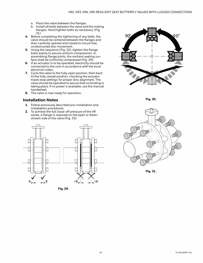
a. Place the valve between the flanges.b. Install all bolts between the valve and the mating
flanges. Hand tighten bolts as necessary. (Fig. 31)
4. Before completing the tightening of any bolts, the valve should be centered between the flanges and then carefully opened and closed to insure free, unobstructed disc movement.
5. Using the sequence (Fig. 32), tighten the flange bolts evenly to assure uniform compression. In assembling flange joints, the resilient seating sur-face shall be uniformly compressed (Fig. 29).
6. If an actuator is to be operated, electricity should be connected to the unit in accordance with the local electrical codes.
7. Cycle the valve to the fully open position, then back to the fully closed position, checking the actuator travel stop settings for proper disc alignment. The valve should be operated to assure that no binding is taking place. If no power is available, use the manual handwheel.
8. The valve is now ready for operation.
Installation Notes1. Follow previously described pre-installation and
installation procedures.2. To achieve the full close-off pressure of the VR
series, a flange is required on the open or down-stream side of the valve (Fig. 33).
Fig. 29.
Fig. 30.
Fig. 31.
>000 >0
90° 90°
Fig. 7

VR2, VR3, VR4, VR5 RESILIENT SEAT BUTTERFLY VALVES WITH LUGGED CONNECTIONS
31-00190EF—02 26
Fig. 32.
Fig. 33.
Fig. 34. Wiring for MBS8 actuators (Not all models have switches)
Fig. 35. Wiring for MBP6...2,4,5,A,R
31
24
1
4
3
2
5
67
8 9
10
11
12
13
14
15
16
1
4
3
2
5
6
7
8
9
10 11
12
1
4
3
2
5
6
7
8
MBS8U3N2/U and MBS8U3S2/U
Blk (1) Common
Red (2) + Hot
24 VAC Transformer
Line Volts
2 3 18 A
a
Function
100%Max
a
Notes:
On/OffAuxiliary Switches
Meets cULus requirements without the need of an
electrical ground connection
A Actuators with appliance cables are numbered.
2Actuators may be connected in parallel. Power
consumption and input impedance must be observed.
3 Actuators may also be powered by 24 VDC.
18Actuators with plenum rated cable do not have numbers
on wires; use color codes instead.
2 324 VAC Transformer
Blk (1) Common
Red (2) + Hot
Wht (3) + Inputa
LineVolts
18
Function
100%Max
a
24 VAC Transformer
Blk (1) Common
Red (2) + Hot
Wht (3) + Input
LineVolts
2 3 18
a
b
Function
100%Max
a b
Notes:
On/Off Floating Point
Meets cULus requirements without the need of an
electrical ground connection
2Actuators may be connected in parallel. Power
consumption and input impedance must be observed.
3 Actuators may also be powered by 24 VDC.
18Actuators with plenum rated cable do not have numbers
on wires; use color codes instead.
VR2, VR3, VR4, VR5 RESILIENT SEAT BUTTERFLY VALVES WITH LUGGED CONNECTIONS
27 31-00190EF—02
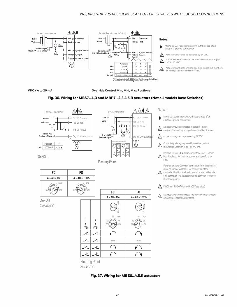
Fig. 36. Wiring for MBS7...1,3 and MBP7...2,3,4,5,R actuators (Not all models have Switches)
Fig. 37. Wiring for MBE6...4,5,R actuators
Notes:
7
Blk (1) Common
Red (2) + Hot
Pnk (4) Y2 Input
Wht (3) Y1 Input, 2 to 10V
Org (5) U Output, 2 to 10
(–)(+)
LineVolts
24 VAC Transformer
Ω 500 Ω1/4 watt
3 18
Control Signal4 to 20 mA or 2 to 10 VDC
18
Functions0%
50%
100%
Control mode acc. to Y
Min*
Mid*
Max*Normal**
* Default selectable 0-100%. See Configuration Data Sheet.** Customizable. See Configuration Data Sheet.
a b c
500 Ω
Ω
Blk (1) Common
Red (2) + Hot
Pnk (4) Y2 InputOrg (5)
Wht (3) Y1 Input, 2 to 10V(–)(+)
LineVolts
24 VAC Transformer (AC Only)
7
B
C
A
1/4 watt
2-10 VDC or 4 to 20 mAControl Signal
VDC / 4 to 20 mA Override Control Min, Mid, Max Postions
Meets cULus requirements without the need of an
electrical ground connection
3 Actuators may also be powered by 24 VDC.
7A 500 �� resistor converts the 4 to 20 mA control signal
to 2 to 10 VDC.
18Actuators with plenum rated cable do not have numbers
on wires; use color codes instead.
18
Blk (1) Common
Red (2) Hot
Wht (3) Y Input
Org (5) U Output 2 to 10V
Line
Volts
24 VAC Transformer
2 to 10 VDCFeedback Signal (+)
(–)
3
Function
100%Max
a
LineVolts
(–) (+)
24 VAC Transformer
Blk (1) – Common
Red (2) + Hot
Wht (3) Y1 Input
Org (5) U Output 2 to 10V
CCW
CW
A B 18
CCW
CW
A B
Direction of rotation switch
A
B
2
9
8
10
12
Feedback Signal 2 to 10 VDC
18
18
Notes:
On/Off
Floating Point
Meets cULus requirements without the need of an
electrical ground connection
2Actuators may be connected in parallel. Power
consumption and input impedance must be observed.
3 Actuators may also be powered by 24 VDC.
8Control signal may be pulsed from either the Hot
(Source) or Common (Sink) 24 VAC line.
9
Contact closures A & B also can be triacs. A & B should
both be closed for the triac source and open for triac
sink.
10
For triac sink the Common connection from the actuator
must be connected to the Hot connection of the
controller. Position feedback cannot be used with a triac
sink controller. The actuator internal common reference
is not compatible.
IN4004 or IN4007 diode. (IN4007 supplied)
18Actuators with plenum rated cable do not have numbers
on wires; use color codes instead.
FC FOA – AB = 0% A – AB = 100%
POP POP
CWCCWCWCCW
24V AC/DC
FC FOA – AB = 0% A – AB = 100%
3a
(Y1)
4b
(Y2)CWCCW
0.1
0.5
Y2
Y1
0.9
POP
0.1
0.5
0.9
POP
CWCCW
Y2
Y1
–– ––
24V AC/DC
On/Off
Floating Point
12
VR2, VR3, VR4, VR5 RESILIENT SEAT BUTTERFLY VALVES WITH LUGGED CONNECTIONS
31-00190EF—02 28
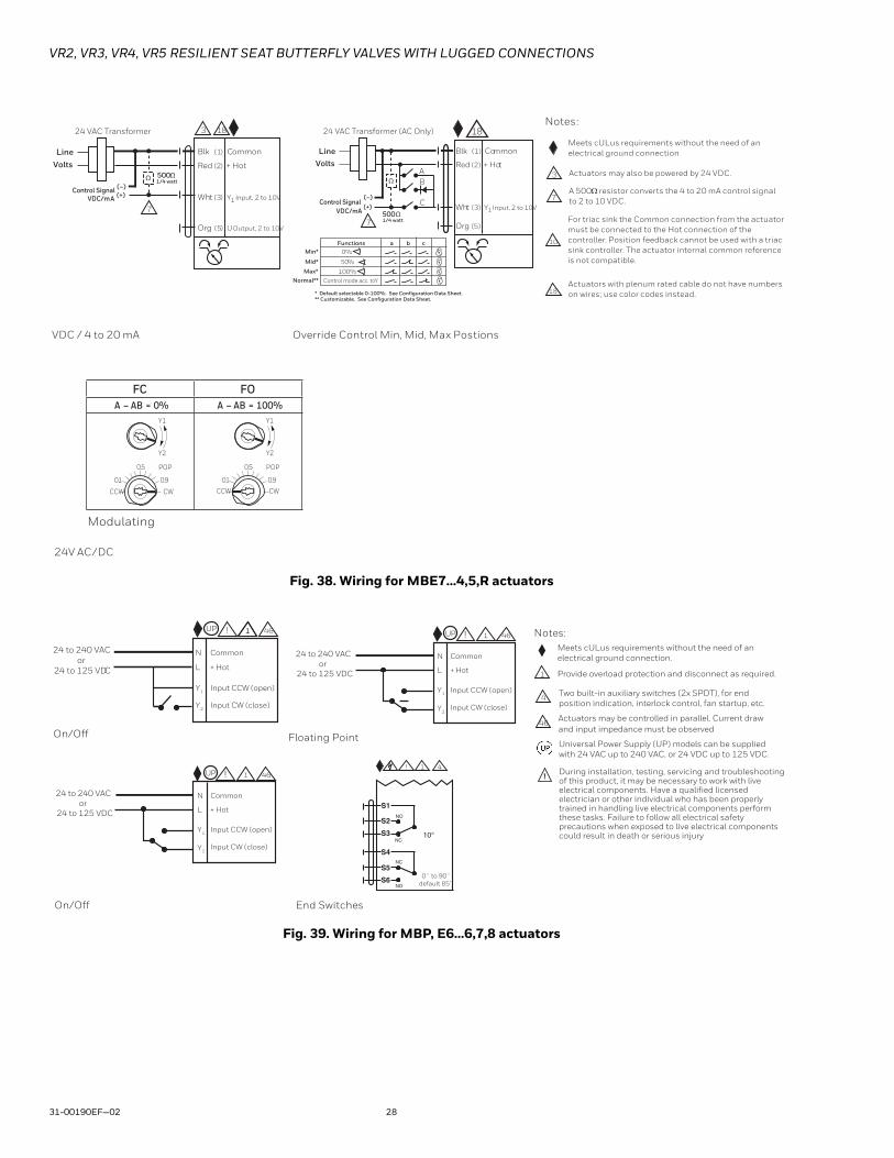
Fig. 38. Wiring for MBE7...4,5,R actuators
Fig. 39. Wiring for MBP, E6...6,7,8 actuators
Notes:
7
Blk (1) Common
Red (2) + Hot
Wht (3) Y1 Input, 2 to 10V
Org (5) U Output, 2 to 10V
(–)(+)
LineVolts
24 VAC Transformer
Ω 500 Ω1/4 watt
3 18
Control SignalVDC/mA
18
500 Ω
Ω
Blk (1) Common
Red (2) + Hot
Org (5)
Wht (3) Y1 Input, 2 to 10V
(–)(+)
LineVolts
24 VAC Transformer (AC Only)
7
B
C
A
1/4 watt
VDC/mAControl Signal
Functions0%
50%
100%
Control mode acc. to Y
Min*
Mid*
Max*Normal**
* Default selectable 0-100%. See Configuration Data Sheet.** Customizable. See Configuration Data Sheet.
a b c
VDC / 4 to 20 mA Override Control Min, Mid, Max Postions
Meets cULus requirements without the need of an
electrical ground connection
3 Actuators may also be powered by 24 VDC.
7A 500 �� resistor converts the 4 to 20 mA control signal
to 2 to 10 VDC.
10
For triac sink the Common connection from the actuator
must be connected to the Hot connection of the
controller. Position feedback cannot be used with a triac
sink controller. The actuator internal common reference
is not compatible.
18Actuators with plenum rated cable do not have numbers
on wires; use color codes instead.
FC FOA – AB = 0% A – AB = 100%
CWCCW
0.1
0.5
Y2
Y1
0.9
POP
0.1
0.5
0.9
POP
Y2
Y1
CWCCW
24V AC/DC
Modulating
Floating Point
End Switches
Notes:
0˚ to 90˚
default 85̊
41!
1 Provide overload protection and disconnect as required.
46Actuators may be controlled in parallel. Current draw
and input impedance must be observed
4Two built-in auxiliary switches (2x SPDT), for end
position indication, interlock control, fan startup, etc.
Universal Power Supply (UP) models can be supplied
with 24 VAC up to 240 VAC, or 24 VDC up to 125 VDC.
On/Off
N
L
Y1
Y2
1UP 46!
Common
+ Hot
Input CCW (open)
Input CW (close)
24 to 240 VAC
or
24 to 125 VDC
N
L
Y1
Y2
1UP 46!
Common
+ Hot
Input CCW (open)
Input CW (close)
24 to 240 VAC
or
24 to 125 VDC
N
L
Y1
Y2
Common
+ Hot
Input CCW (open)
Input CW (close)
24 to 240 VAC
or
24 to 125 VDC
1UP 461!
On/Off
! During installation, testing, servicing and troubleshooting of this product, it may be necessary to work with live electrical components. Have a qualified licensed electrician or other individual who has been properly trained in handling live electrical components perform these tasks. Failure to follow all electrical safety precautions when exposed to live electrical components could result in death or serious injury
Meets cULus requirements without the need of an
electrical ground connection.

VR2, VR3, VR4, VR5 RESILIENT SEAT BUTTERFLY VALVES WITH LUGGED CONNECTIONS
29 31-00190EF—02
Fig. 40. Wiring for MBP, E7...6,7,8 actuators
Fig. 41. MBP, E...6,7,8 switch adjustment
End Switches VDC / 4 to 20 mA
Notes:
0° to 90°
default 85°
41!
5
1 Provide overload protection and disconnect as required.
46Actuators may be controlled in parallel. Current draw
and input impedance must be observed.
4Two built-in auxiliary switches (2x SPDT), for end
position indication, interlock control, fan startup, etc.
Universal Power Supply (UP) models can be supplied
with 24 VAC up to 240 VAC, or 24 VDC up to 125 VDC.
N
L
Y1
Y2
N
5UP 46
24 to 240 VAC
or
24 to 125 VDC
-
+
Y3
U5
Com -
24 VDC Out
Y3
0 - 10 VDC**
U5/MP 0 - 10 VD
1
! During installation, testing, servicing and troubleshooting of this product, it may be necessary to work with live electrical components. Have a qualified licensed electrician or other individual who has been properly trained in handling live electrical components perform these tasks. Failure to follow all electrical safety precautions when exposed to live electrical components could result in death or serious injury.
Only connect common to neg. (-) leg of control circuits.
Meets cULus requirements without the need of an
electrical ground connection.
Optional: end switch adjustment
Power
Status
5
6
Push-buttons and display
B
A
1
2
3
o
pe
n
o
pe
n
S2 S3
S1
S5 S6
S4
S5 S6
S4
10°
S2 S3
S5 S6
S4
S5 S6
S4
S1 S2 S3 S4 S5 S6
4
Disconnect power.
1 Gear disengagementOpen the manual override cover and insert the hand crank.Manual override is possible.
Manual override2
Turn the hand crank until indicates the desired switching
position and then remove the crank.
A
B
3 Auxiliary switchOpen the auxiliary switch adjustment cover and properly seat
the arrow points to the vertical line.
4 TerminalsConnect continuity tester to S4 + S5 or to S4 + S6.
If the auxiliary switch should switch in the opposite direction,
rotate the hand crank by 180˚.
5 LED Display Green6 LED Display Yellow Off: No power supply or malfunction,
On: In operation Press button: Triggers test run, followed
by standard mode.
6 LED Display YellowOff: Standard mode, On: Test run active.
the hand crank into the actuator. Turn the crank until

VR2, VR3, VR4, VR5 RESILIENT SEAT BUTTERFLY VALVES WITH LUGGED CONNECTIONS
31-00190EF—02 30
Fig. 42. Wiring for MBP6...9,B
Fig. 43. Wiring for MBP7...9,B actuators
24V AC/DC Transformer
On/Off
24V AC/DC Transformer
Line Volts Open
Close
G Ground
1 Common
3 Open
4 Closed
5 Connect to #1 for fully
open indication
6 Connect to #1 for fully
closed indication
7 HTR
A
B
C
D
E
F
LS3
A-C (Open Indication)
LS4
D-F (Closed Indication)
Contact Rating: 5A 250 VAC Max.
SY2…5-24
G33
c33
Each actuator should be powered by a single,
isolated control transformer.
MBP...9, B
INSTALLATION NOTES
• Observe class 1 and class 2 wiring restrictions.
• Transformer sizing = MBP actuator draw X 1.25
(safety margin)
24 VAC Transformer
Line Volts
G Ground
1 Common
3 Open
4 Closed
5
6
7 HTR
A
B
C
D
E
F
LS3
A-C (Open Indication)
LS4
D-F (Closed Indication)
Contact Rating: 5A 250 VAC Max.
MBP...9, B
G Ground
1 Common
3 Open
4 Closed
5
6
7 HTR
A
B
C
D
E
F
LS3
A-C (Open Indication)
LS4
D-F (Closed Indication)
Contact Rating: 5A 250 VAC Max.
MBP...9, B
K1Open
Close K1-B
K1-A
Actuator A
Actuator BG
G
INSTALLATION NOTES
• Isolation relays must be used in parallel connection of multiple actuators
using a common control signal input.
• "H" (L2) cannot be connected to terminal #3 and #4 simultaneously.
• Required: Terminal #7 needs to be field wired to enable heater circuit.
Proportional, Multiple Wiring, 24V
MBP...9, B
A
B
C
D
E
F
LS3
A-C (Open Indication)
LS4
D-F (Closed Indication)
Contact Rating: 5A 250 VAC Max.
SY2…5-24MFT
┴1
Y
U5
C1
┴2
C2
B
A
1
9
8
10
3
2
┴/-
~/+
Internal Use Only
Internal Use Only
Internal Use Only
Not Used -
Not Used -
Internal Use Only
Internal Use Only
Internal Use Only
Internal Use Only
Power Supply Com
Power Supply Hot
24V AC/DC
Internal Use Only
Feedback
Control Signal (-)
Feedback Signal (+)
Feedback Signal (-)
Control Signal (+)
SYx-24MFT
PC Tool
Service Jack
┴1
Y
U5
C1
┴2
C2
B
A
1
9
8
10
3
2
┴/-
~/+
Internal Use Only
Internal Use Only
Internal Use Only
Not Used -
Control Signa
Not Used -
Internal Use Only
Internal Use Only
Internal Use Only
Internal Use Only
Power Supply Com
Power Supply Hot
24V AC/DC
Internal Use Only
Feedback
Control Signal (-)
Feedback Signal (+)
Feedback Signal (-)
Control Signal (+)
SYx-24MFT
PC Tool
Service Jack
G PE
G PE
Actuator B
Actuator A
Address
Adaption
Y1 Y2
Address
Adaption
Y1 Y2
33
35
36
33
35
36
33
Each actuator should be powered by a
single, isolated control transformer.
MBP...9, B
INSTALLATION NOTES
• Observe class 1 and class 2 wiring restrictions.
• Transformer sizing = MBP actuator draw X 1.25 (safety margin)

VR2, VR3, VR4, VR5 RESILIENT SEAT BUTTERFLY VALVES WITH LUGGED CONNECTIONS
31 31-00190EF—02
Fig. 44. Wiring for MBP6...C,D,E,F,G,H actuators
120V AC/DC
On/Off
G Ground
1 Common
3 Open
4 Closed
5 Connect to #1 for fully
open indication
6 Connect to #1 for fully
closed indication
7
120V or 230V AC/DCG
Open
Close
N L1
H L2
HTR
A
B
C
D
E
F
LS3
A-C (Open Indication)
LS4
D-F (Closed Indication)
Contact Rating: 5A 250 VAC Max.
SY2…12-120V or 230VMBP...C, D, E
INSTALLATION NOTES
• Observe class 1 and class 2 wiring restrictions.
• Transformer sizing = MBP actuator draw X 1.25 (safety margin)
G Ground
1 Common
3 Open
4 Closed
5
6
7 HTR
A
B
C
D
E
F
LS3
A-C (Open Indication)
LS4
D-F (Closed Indication)
Contact Rating: 5A 250 VAC Max.
G Ground
1 Common
3 Open
4 Closed
5
6
7 HTR
A
B
C
D
E
F
LS3
A-C (Open Indication)
LS4
D-F (Closed Indication)
Contact Rating: 5A 250 VAC Max.
MBP, C, D, E
MBP...C, D, E
Open
Close K1-B
K1-A
Actuator A
Actuator B120 VAC
N L1
H L2
G
G
K1
INSTALLATION NOTES
• Isolation relays must be used in parallel connection
of multiple actuators using a common control signal input.
• "H" (L2) cannot be connected to terminal
#3 and #4 simultaneously.
• Required: Terminal #7 needs to be field wired
to enable heater circuit.

VR2, VR3, VR4, VR5 RESILIENT SEAT BUTTERFLY VALVES WITH LUGGED CONNECTIONS
Honeywell Building TechnologiesIn the U.S.:
Honeywell
715 Peachtree Street NE
Atlanta, GA 30308
customer.honeywell.com
® U.S. Registered Trademark© 2019 Honeywell International Inc.31-00190EF—02 M.S. 07-19Printed in United States
Fig. 45. Wiring for MBP7...C,D,E,F,G,H actuators
Proportional, Multiple Wiring, 120V
MBP...C, D, E
A
B
C
D
E
F
LS3
A-C (Open Indication)
LS4
D-F (Closed Indication)
Contact Rating: 5A 250 VAC Max.
MBP...C, D, E
Power Supply Com – 120V
Power Supply Hot – 120V
┴1
Y
U5
C1
┴2
C2
B
A
1
9
8
10
3
2
Internal Use Only
Internal Use Only
Internal Use Only
Not Used -
Not Used -
Internal Use Only
Internal Use Only
Internal Use Only
Internal Use Only
Internal Use Only
Feedback
Control Signal (-)
Feedback Signal (+)
Feedback Signal (-)
Control Signal (+)
SYx-230MFT
Address Adaption
PC Tool
Service Jack
SYx-120MFT
LN
Power Supply Com – 120V
Power Supply Hot – 120V
┴1
Y
U5
C1
┴2
C2
B
A
1
9
8
10
3
2
Internal Use Only
Internal Use Only
Internal Use Only
Not Used -
Control Signa
Not Used -
Internal Use Only
Internal Use Only
Internal Use Only
Internal Use Only
Internal Use Only
Feedback
Control Signal (-)
Feedback Signal (+)
Feedback Signal (-)
Control Signal (+)
SYx-230MFT
Address Adaption
PC Tool
Service Jack
SYx-120MFT
LN
G PE
G PE
Actuator A
Actuator B
Y1
Y2
Y1
Y2
35
36
36
35
33
Each actuator should be powered by a single,
isolated control transformer.INSTALLATION NOTES
• Observe class 1 and class 2 wiring restrictions.
• Transformer sizing = MBP actuator draw X 1.25 (safety margin)

DONNÉES SUR LE PRODUIT
31-00190EF-02
Vannes papillon à siège résistant VR2, VR3, VR4 VR5 à raccords à oreilles
CARACTÉRISTIQUESTous les modèles• Tous les modèles• Disques en acier inoxydable 304• Corps de vanne en fonte ductile procurant une
résistance et une durabilité accrues• Tige de vanne en acier inoxydable• Le siège de soupape en EPDM robuste agit aussi
comme joint d’étanchéité de bride• Siège étanche aux bulles à la fermeture• Taux nominal de fermeture de 200 lb/po² pour les
diamètres de 2 à 12 po• Taux nominal de fermeture de 150 lb/po² pour les
diamètres de 14 à 24 po• Bride de fixation d’actionneur ISO 5211• Disponible avec interfaces d’actionneur électrique
installées en usine à deux positions : commande flottante (trois états) ou à modulation (2-10 V c.c.)
• Contournement manuel sur tous les modèles
• Les actionneurs à sécurité intrinsèque sont disponibles pour les vannes d’un diamètre maximal de 12 po
• Pour eau chaude, refroidie ou de condensation avec un maximum de 60 % de glycol dans les systèmes de CVC
Vannes à 2 voies (VR2)• Tailles de 2 à 24 po avec raccords à oreilles ANSI de
classe 125/150• Caractéristiques de débit à pourcentage égal modifié• Système de sécurité à ressort sur les modèles de 2 et
2,5 po et système électronique en option sur les modèles de 3 à 12 po.
• Actionneurs NEMA 2 et NEMA 4X disponibles sur les vannes de 5 po et moins; actionneurs NEMA 4X disponibles sur les vannes de 5 à 24 po
Ensembles de vannes à trois voies (VR3, 4, 5)• Tailles de 2 à 18 po avec raccords à oreilles ANSI de
classe 125/150• Commande de mélange ou de dérivation• Caractéristique de débit linéaire modifié• Raccord en T standard en fonte compris• Nombreuses configurations de ports convenant à
différentes applications• Système de sécurité à ressort sur les modèles de 2 po et
système électronique en option sur les modèles de 2,5 à 12 po
• Actionneurs NEMA 2 et NEMA 4X disponibles sur les vannes de 3 po et moins; actionneurs NEMA 4X disponibles sur les vannes de 3 à 18 po
Table des matièresCaractéristiques .......................................................................... 1Spécifications ............................................................................... 2Plans Dimensionnels ................................................................ 5Spécifications de l’actionneur ............................................... 16Modèles de vanne à 3 voies .................................................... 20Installation .................................................................................... 22
VANNES PAPILLON À SIÈGE RÉSISTANT VR2, VR3, VR4 VR5 À RACCORDS À OREILLES
31-00190EF—02 2
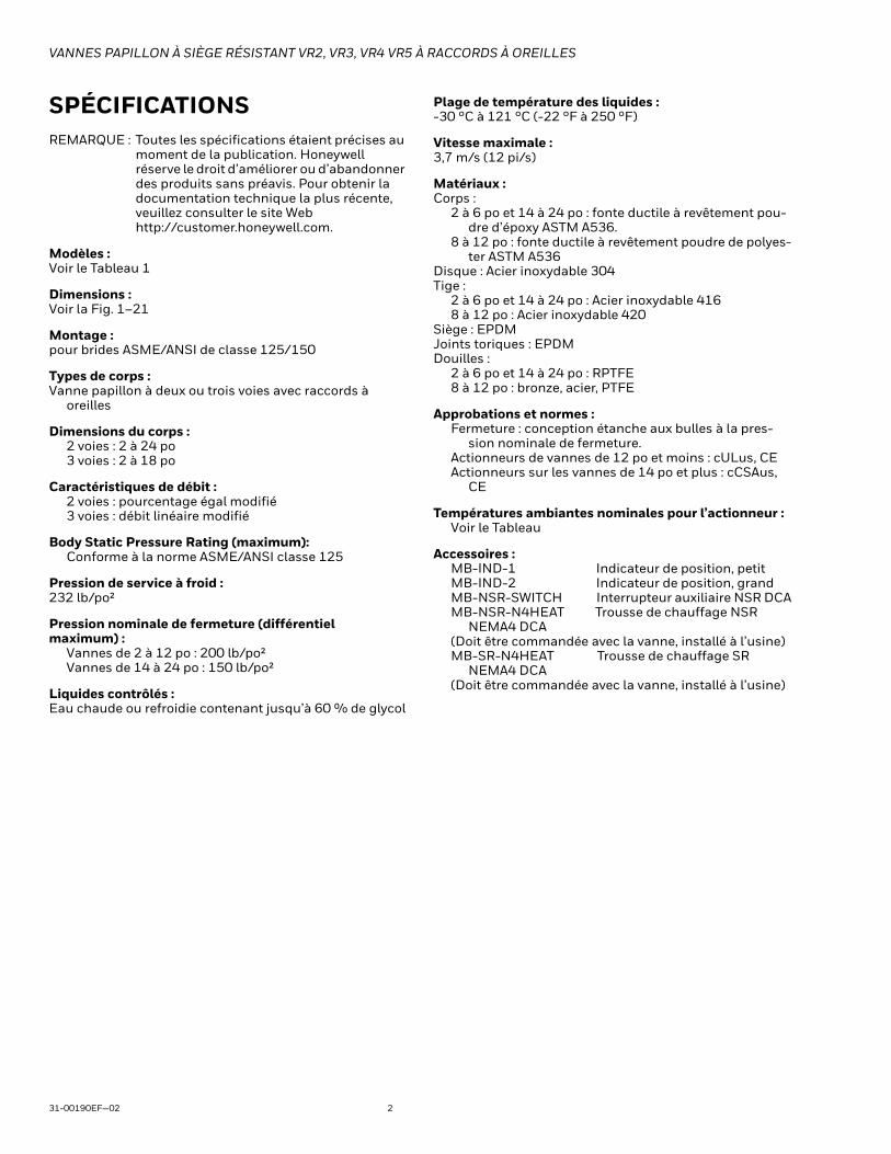
SPÉCIFICATIONSREMARQUE : Toutes les spécifications étaient précises au
moment de la publication. Honeywell réserve le droit d’améliorer ou d’abandonner des produits sans préavis. Pour obtenir la documentation technique la plus récente, veuillez consulter le site Web http://customer.honeywell.com.
Modèles : Voir le Tableau 1
Dimensions : Voir la Fig. 1–21
Montage : pour brides ASME/ANSI de classe 125/150
Types de corps : Vanne papillon à deux ou trois voies avec raccords à
oreilles
Dimensions du corps :2 voies : 2 à 24 po3 voies : 2 à 18 po
Caractéristiques de débit :2 voies : pourcentage égal modifié3 voies : débit linéaire modifié
Body Static Pressure Rating (maximum): Conforme à la norme ASME/ANSI classe 125
Pression de service à froid :232 lb/po²
Pression nominale de fermeture (différentiel maximum) :
Vannes de 2 à 12 po : 200 lb/po²Vannes de 14 à 24 po : 150 lb/po²
Liquides contrôlés :Eau chaude ou refroidie contenant jusqu’à 60 % de glycol
Plage de température des liquides :-30 °C à 121 °C (-22 °F à 250 °F)
Vitesse maximale :3,7 m/s (12 pi/s)
Matériaux :Corps :
2 à 6 po et 14 à 24 po : fonte ductile à revêtement pou-dre d’époxy ASTM A536.
8 à 12 po : fonte ductile à revêtement poudre de polyes-ter ASTM A536
Disque : Acier inoxydable 304Tige :
2 à 6 po et 14 à 24 po : Acier inoxydable 4168 à 12 po : Acier inoxydable 420
Siège : EPDMJoints toriques : EPDMDouilles :
2 à 6 po et 14 à 24 po : RPTFE8 à 12 po : bronze, acier, PTFE
Approbations et normes :Fermeture : conception étanche aux bulles à la pres-
sion nominale de fermeture.Actionneurs de vannes de 12 po et moins : cULus, CEActionneurs sur les vannes de 14 po et plus : cCSAus,
CE
Températures ambiantes nominales pour l’actionneur :Voir le Tableau
Accessoires :MB-IND-1 Indicateur de position, petitMB-IND-2 Indicateur de position, grand MB-NSR-SWITCH Interrupteur auxiliaire NSR DCAMB-NSR-N4HEAT Trousse de chauffage NSR
NEMA4 DCA(Doit être commandée avec la vanne, installé à l’usine)MB-SR-N4HEAT Trousse de chauffage SR
NEMA4 DCA(Doit être commandée avec la vanne, installé à l’usine)

VANNES PAPILLON À SIÈGE RÉSISTANT VR2, VR3, VR4 VR5 À RACCORDS À OREILLES
3 31-00190EF—02
Tableau 1. Sélection de modèle de vanne papillon V
anne
Papi
llon
Type
de
racc
orde
men
t
Mot
if de
corp
s
Diam
ètre
de va
nne
Sign
al d
eco
mm
ande
de
l’act
ionn
eur
Tens
ion
d’ac
tionn
eur
Fonc
tion
desé
curit
é
Tens
ion/
rétr
oact
ion
du co
ntac
teur
Cara
ctér
istiq
ues
nom
inal
esNE
MA
DescriptionV Vanne, à oreilles (papillon)
R Siège résistant ANSI 125/150 (Standard)2 2 voies3
Configurations à 3 voies (voir la Fig. 20)45
F 2 po (DN 50)G 2,5 po (DN 65)H 3 po (DN 80)J 4 po (DN 100)K 5 po (DN 125)L 6 po (DN 150)M 8 po (DN 200)N 10 po (DN 250)P 12 po (DN 300)R 14 po (DN 350)S 16 po (DN 400)T 18 po (DN 450)U 20 po (DN 500)V 24 po (DN 600)
6 Flottant/deux positions (SPDT)7 À modulation analogique (0) 2-10 V c.c.8 Deux positions (SPST)
L 24 V c.a./c.c.H 120 V c.a.U 24-240 V c.a./24-125 V c.c.
P Maintien de position en cas de panneS Ressort de rappel au port A (maître) pour maintien de position ouverte en cas
de panneT Ressort de rappel au port A (maître) pour maintien de position fermée en cas
de panneE Dispositif de sécurité électronique (position fermée par défaut, modifiable sur
place)N Aucune rétroactionF Rétroaction analogiqueS Interrupteurs auxiliaires intégrésB Rétroaction analogique et interrupteurs auxiliaires
2 NEMA 24 NEMA 4XH NEMA 4X (avec réchauffeur)
V R 2 H 7 L P F 2
Exemple : VANNE PAPILLON À SIÈGE RÉSISTANT, 2 VOIES, 3 PO, CV302 FERMETURE 200 LB/PO², 24 V C.A., 2 À 10 V C.C., 150 S, SÉCURITÉ INTRINSÈQUE, RÉTROACTION, NEMA2, (Y COMPRIS L’ACTIONNEUR MBP7L4F2/U)
VANNES PAPILLON À SIÈGE RÉSISTANT VR2, VR3, VR4 VR5 À RACCORDS À OREILLES
31-00190EF—02 4
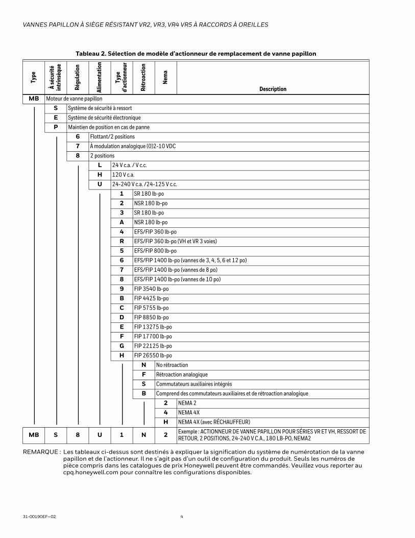
REMARQUE : Les tableaux ci-dessus sont destinés à expliquer la signification du système de numérotation de la vanne papillon et de l’actionneur. Il ne s’agit pas d’un outil de configuration du produit. Seuls les numéros de pièce compris dans les catalogues de prix Honeywell peuvent être commandés. Veuillez vous reporter au cpq.honeywell.com pour connaître les configurations disponibles.
Tableau 2. Sélection de modèle d’actionneur de remplacement de vanne papillon
Type
À sé
curit
éin
trin
sèqu
e
Régu
latio
n
Alim
enta
tion
Type
d’ac
tionn
eur
Rétr
oact
ion
Nem
a
DescriptionMB Moteur de vanne papillon
S Système de sécurité à ressort
E Système de sécurité électronique
P Maintien de position en cas de panne
6 Flottant/2 positions
7 À modulation analogique (0)2-10 VDC
8 2 positions
L 24 V c.a. / V c.c.
H 120 V c.a.
U 24-240 V c.a. /24-125 V c.c.
1 SR 180 lb-po
2 NSR 180 lb-po
3 SR 180 lb-po
A NSR 180 lb-po
4 EFS/FIP 360 lb-po
R EFS/FIP 360 lb-po (VH et VR 3 voies)
5 EFS/FIP 800 lb-po
6 EFS/FIP 1400 lb-po (vannes de 3, 4, 5, 6 et 12 po)
7 EFS/FIP 1400 lb-po (vannes de 8 po)
8 EFS/FIP 1400 lb-po (vannes de 10 po)
9 FIP 3540 lb-po
B FIP 4425 lb-po
C FIP 5755 lb-po
D FIP 8850 lb-po
E FIP 13275 lb-po
F FIP 17700 lb-po
G FIP 22125 lb-po
H FIP 26550 lb-po
N No rétroaction
F Rétroaction analogique
S Commutateurs auxiliaires intégrés
B Comprend des commutateurs auxiliaires et de rétroaction analogique
2 NEMA 2
4 NEMA 4X
H NEMA 4X (avec RÉCHAUFFEUR)
MB S 8 U 1 N 2 Exemple : ACTIONNEUR DE VANNE PAPILLON POUR SÉRIES VR ET VH, RESSORT DE RETOUR, 2 POSITIONS, 24-240 V C.A., 180 LB-PO, NEMA2
VANNES PAPILLON À SIÈGE RÉSISTANT VR2, VR3, VR4 VR5 À RACCORDS À OREILLES
5 31-00190EF—02
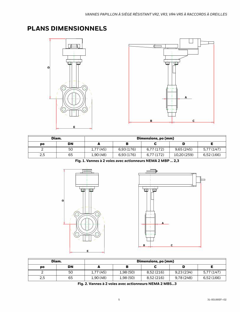
PLANS DIMENSIONNELS
Fig. 1. Vannes à 2 voies avec actionneurs NEMA 2 MBP ... 2,3
Fig. 2. Vannes à 2 voies avec actionneurs NEMA 2 MBS...3
Diam. Dimensions, po (mm)po DN A B C D E2 50 1,77 (45) 6,93 (176) 6,77 (172) 9,65 (245) 5,77 (147)
2,5 65 1,90 (48) 6,93 (176) 6,77 (172) 10,20 (259) 6,52 (166)
Diam. Dimensions, po (mm)po DN A B C D E2 50 1,77 (45) 1,98 (50) 8,52 (216) 9,23 (234) 5,77 (147)
2,5 65 1,90 (48) 1,98 (50) 8,52 (216) 9,78 (248) 6,52 (166)
E
D
B C
A
E
D
B C
A
VANNES PAPILLON À SIÈGE RÉSISTANT VR2, VR3, VR4 VR5 À RACCORDS À OREILLES
31-00190EF—02 6
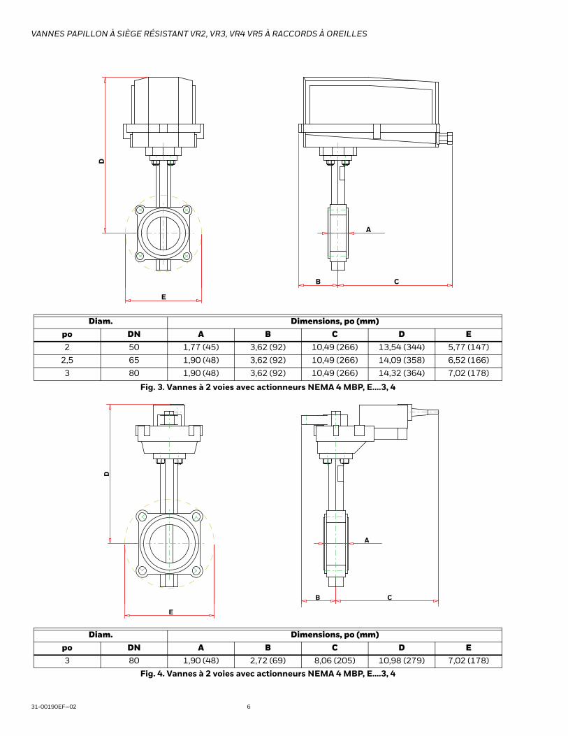
Fig. 3. Vannes à 2 voies avec actionneurs NEMA 4 MBP, E....3, 4
Fig. 4. Vannes à 2 voies avec actionneurs NEMA 4 MBP, E....3, 4
Diam. Dimensions, po (mm)po DN A B C D E2 50 1,77 (45) 3,62 (92) 10,49 (266) 13,54 (344) 5,77 (147)
2,5 65 1,90 (48) 3,62 (92) 10,49 (266) 14,09 (358) 6,52 (166)
3 80 1,90 (48) 3,62 (92) 10,49 (266) 14,32 (364) 7,02 (178)
Diam. Dimensions, po (mm)po DN A B C D E3 80 1,90 (48) 2,72 (69) 8,06 (205) 10,98 (279) 7,02 (178)
E
D
B C
A
E
D
B C
A

VANNES PAPILLON À SIÈGE RÉSISTANT VR2, VR3, VR4 VR5 À RACCORDS À OREILLES
7 31-00190EF—02
Fig. 5. Vannes à 2 voies avec actionneurs NEMA 2 MBE...4
Fig. 6. Vannes à 2 voies avec actionneurs NEMA 2 MBP, E...5
Diam. Dimensions, po (mm)po DN A B C D E3 80 1,90 (48) 1,42 (36) 9,43 (240) 13,11 (333) 7,02 (178)
Diam. Dimensions, po (mm)po DN A B C D E4 100 2,12 (55) 5,99 (152) 5,30 (135) 13,03 (331) 8,52 (216)
5 125 2,31 (59) 5,99 (152) 5,30 (135) 13,55 (344) 9,76 (248)
E
D
B C
A
E
D
B C
A
VANNES PAPILLON À SIÈGE RÉSISTANT VR2, VR3, VR4 VR5 À RACCORDS À OREILLES
31-00190EF—02 8
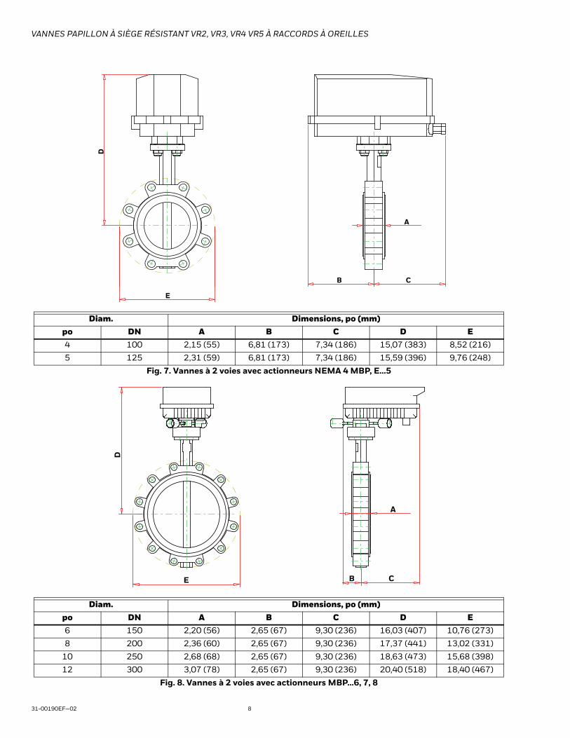
Fig. 7. Vannes à 2 voies avec actionneurs NEMA 4 MBP, E...5
Fig. 8. Vannes à 2 voies avec actionneurs MBP...6, 7, 8
Diam. Dimensions, po (mm)po DN A B C D E4 100 2,15 (55) 6,81 (173) 7,34 (186) 15,07 (383) 8,52 (216)
5 125 2,31 (59) 6,81 (173) 7,34 (186) 15,59 (396) 9,76 (248)
Diam. Dimensions, po (mm)po DN A B C D E6 150 2,20 (56) 2,65 (67) 9,30 (236) 16,03 (407) 10,76 (273)
8 200 2,36 (60) 2,65 (67) 9,30 (236) 17,37 (441) 13,02 (331)
10 250 2,68 (68) 2,65 (67) 9,30 (236) 18,63 (473) 15,68 (398)
12 300 3,07 (78) 2,65 (67) 9,30 (236) 20,40 (518) 18,40 (467)
E
D
B C
A
B
D
E
A
C

VANNES PAPILLON À SIÈGE RÉSISTANT VR2, VR3, VR4 VR5 À RACCORDS À OREILLES
9 31-00190EF—02
Fig. 9. Vannes à 2 voies avec actionneurs MBE...6, 7, 8
Diam. Dimensions, po (mm)po DN A B C D E5 125 2,20 (56) 2,65 (67) 9,30 (236) 17,77 (451) 9,76 (248)
6 150 2,20 (56) 2,65 (67) 9,30 (236) 18,28 (464) 10,76 (273)
8 200 2,36 (60) 2,65 (67) 9,30 (236) 19,62 (498) 12,96 (329)
10 250 2,68 (68) 2,65 (67) 9,30 (236) 20,88 (530) 15,66 (398)
12 300 3,07 (78) 2,65 (67) 9,30 (236) 22,65 (575) 18,40 (467)
D
E
B
A
C
VANNES PAPILLON À SIÈGE RÉSISTANT VR2, VR3, VR4 VR5 À RACCORDS À OREILLES
31-00190EF—02 10
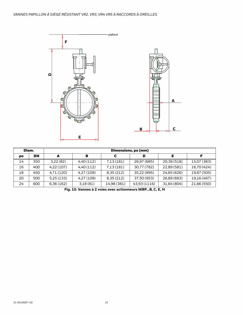
Fig. 10. Vannes à 2 voies avec actionneurs MBP...B, C, E, H
Diam. Dimensions, po (mm)po DN A B C D E F14 350 3,22 (82) 4,40 (112) 7,13 (181) 26,97 (685) 20,39 (518) 15,07 (383)
16 400 4,22 (107) 4,40 (112) 7,13 (181) 30,77 (782) 22,89 (581) 16,70 (424)
18 450 4,71 (120) 4,27 (109) 8,35 (212) 35,22 (895) 24,65 (626) 19,87 (505)
20 500 5,25 (133) 4,27 (109) 8,35 (212) 37,50 (953) 26,89 (683) 19,16 (487)
24 600 6,36 (162) 3,18 (81) 14,98 (381) 43,93 (1116) 31,64 (804) 21,66 (550)
E
D
plafond
B C
A
F

VANNES PAPILLON À SIÈGE RÉSISTANT VR2, VR3, VR4 VR5 À RACCORDS À OREILLES
11 31-00190EF—02
Fig. 11. Vannes à 3 voies avec actionneurs NEMA 2 MBP, E.... 2, 3, A, R
Fig. 12. Vannes à 3 voies avec actionneurs NEMA 2 MBS...1, 3
Diam. Dimensions, po (mm)po DN A B C D E2 50 4,50 (114) 6,27 (159) 6,57 (167) 12,33 (313) 3,00 (76)
2,5 65 5,00 (127) 6,90 (175) 7,37 (187) 12,88 (327) 3,50 (89)
Diam. Dimensions, po (mm)po DN A B C D E2 50 4,50 (114) 6,27 (159) 7,37 (187) 12,33 (313) 3,00 (76)
DE
C A B
DE
BC A

VANNES PAPILLON À SIÈGE RÉSISTANT VR2, VR3, VR4 VR5 À RACCORDS À OREILLES
31-00190EF—02 12
Fig. 13. Vannes à 3 voies avec actionneurs NEMA 4 MBP, E...R
Fig. 14. Vannes à 3 voies avec actionneurs NEMA 2 MBP...R
Diam. Dimensions, po (mm)po DN A B C D E2 50 4,50 (114) 6,27 (159) 9,01 (229) 15,86 (403) 3,00 (76)
2,5 65 5,00 (127) 6,90 (175) 9,57 (243) 16,41 (417) 3,50 (89)
Diam. Dimensions, po (mm)po DN A B C D E3 80 7,64 (194) 7,40 (188) 7,87 (200) 11,79 (300) 3,75 (95)
DE
BC A
DE
BC A

VANNES PAPILLON À SIÈGE RÉSISTANT VR2, VR3, VR4 VR5 À RACCORDS À OREILLES
13 31-00190EF—02
Fig. 15. Vannes à 3 voies avec actionneurs NEMA 2 MBE...R
Fig. 16. Vannes à 3 voies avec actionneurs NEMA 4 MBP...R
Diam. Dimensions, po (mm)po DN A B C D E3 80 9,43 (240) 7,40 (188) 7,87 (200) 13,11 (333) 3,75 (95)
Diam. Dimensions, po (mm)po DN A B C D E3 80 10,49 (266) 7,40 (188) 10,07 (256) 16,64 (423) 3,75 (95)
DE
BC A
DE
BC A

VANNES PAPILLON À SIÈGE RÉSISTANT VR2, VR3, VR4 VR5 À RACCORDS À OREILLES
31-00190EF—02 14
Fig. 17. Vannes à 3 voies avec actionneurs MBP...6, 7, 8
Diam. Dimensions, po (mm)po DN A B C D E3 80 5,50 (140) 7,56 (192) 8,89 (226) 14,97 (380) 3,75 (95)
4 100 6,50 (165) 8,55 (217) 11,13 (283) 14,22 (361) 4,50 (114)
5 125 7,50 (191) 9,70 (246) 12,05 (306) 14,74 (374) 5,00 (127)
6 150 8,00 (203) 10,20 (256) 12,55 (319) 15,25 (387) 5,50 (140)
8 200 9,00 (229) 11,36 (289) 13,47 (342) 16,59 (421) 6,75 (172)
10 250 11,00 (279) 13,68 (348) 15,31 (389) 17,85 (453) 8,00 (203)
12 300 12,00 (305) 15,07 (383) 16,12 (409) 19,62 (498) 9,50 (241)
BC A
DE

VANNES PAPILLON À SIÈGE RÉSISTANT VR2, VR3, VR4 VR5 À RACCORDS À OREILLES
15 31-00190EF—02
Fig. 18. Vannes à 3 voies avec actionneurs MBE...6, 7, 8
Fig. 19. Vannes à 3 voies avec actionneurs MBP...C, D, E
Diam. Dimensions, po (mm)po DN A B C D E4 100 6,50 (165) 8,55 (217) 11,13 (283) 16,47 (418) 4,50 (114)
5 125 7,50 (191) 9,70 (246) 12,05 (306) 16,99 (432) 5,00 (127)
6 150 8,00 (203) 10,20 (259) 12,55 (319) 17,50 (445) 5,50 (140)
8 200 9,00 (229) 11,36 (289) 13,47 (342) 18,84 (479) 6,75 (172)
10 250 11,00 (279) 13,68 (348) 15,31 (389) 20,10 (511) 8,00 (203)
12 300 12,00 (305) 15,07 (383) 16,12 (409) 21,87 (556) 9,50 (241)
Diam. Dimensions, po (mm)po DN A B C D E F14 350 14,00 (356) 17,22 (437) 20,01 (508) 29,51 (750) 10,50 (267) 8,80 (224)
16 400 15,00 (381) 19,22 (488) 21,38 (543) 34,35 (873) 11,75 (299) 8,80 (224)
18 450 16,50 (419) 21,21 (539) 23,13 (588) 35,22 (895) 12,50 (318) 8,80 (224)
D
BC A
E
DE
B
F
ceiling
C A

VANNES PAPILLON À SIÈGE RÉSISTANT VR2, VR3, VR4 VR5 À RACCORDS À OREILLES
31-00190EF—02 16
SPÉCIFICATIONS DE L’ACTIONNEUR
Tableau 3. Actionneurs utilisés sur les ensembles à 2 voies
Montage Actionneur Montage Actionneur Montage ActionneurVR2F6LPN2/M MBP6L2N2/U VR2G7LTF2/M MBS7L3F2/U VR2K7LPF4/M MBP7L5F4/U
VR2F6LPN4/M MBP6L4N4/U VR2G7LTF4/M MBS7L3F4/U VR2K7UEBH/M MBE7U6BH/U
VR2F7LPF2/M MBP7L2F2/U VR2G8USN2/M MBS8U3N2/U VR2L6UESH/M MBE6U6SH/U
VR2F7LPF4/M MBP7L4F4/U VR2G8USN4/M MBS8U3N4/U VR2L6UPSH/M MBP6U6SH/U
VR2F7LSB2/M MBS7L3B2/U VR2G8USS2/M MBS8U3S2/U VR2L7UEBH/M MBE7U6BH/U
VR2F7LSB4/M MBS7L3B4/U VR2G8USS4/M MBS8U3S4/U VR2L7UPBH/M MBP7U6BH/U
VR2F7LSF2/M MBS7L3F2/U VR2G8UTN2/M MBS8U3N2/U VR2M6UESH/M MBE6U7SH/U
VR2F7LSF4/M MBS7L3F4/U VR2G8UTN4/M MBS8U3N4/U VR2M6UPSH/M MBP6U7SH/U
VR2F7LTB2/M MBS7L3B2/U VR2G8UTS2/M MBS8U3S2/U VR2M7UEBH/M MBE7U7BH/U
VR2F7LTB4/M MBS7L3B4/U VR2G8UTS4/M MBS8U3S4/U VR2M7UPBH/M MBP7U7BH/U
VR2F7LTF2/M MBS7L3F2/U VR2H6LEN2/M MBE6L4N2/U VR2N6UESH/M MBE6U8SH/U
VR2F7LTF4/M MBS7L3F4/U VR2H6LEN4/M MBE6L4N4/U VR2N6UPSH/M MBP6U8SH/U
VR2F8USN2/M MBS8U3N2/U VR2H6LPN2/M MBP6L4N2/U VR2N7UEBH/M MBE7U8BH/U
VR2F8USN4/M MBS8U3N4/U VR2H6LPN4/M MBP6L4N4/U VR2N7UPBH/M MBP7U8BH/U
VR2F8USS2/M MBS8U3S2/U VR2H7LEF2/M MBE7L4F2/U VR2P6UESH/M MBE6U6SH/U
VR2F8USS4/M MBS8U3S4/U VR2H7LEF4/M MBE7L4F4/U VR2P6UPSH/M MBP6U6SH/U
VR2F8UTN2/M MBS8U3N2/U VR2H7LPF2/M MBP7L4F2/U VR2P7UEBH/M MBE7U6BH/U
VR2F8UTN4/M MBS8U3N4/U VR2H7LPF4/M MBP7L4F4/U VR2P7UPBH/M MBP7U6BH/U
VR2F8UTS2/M MBS8U3S2/U VR2J6LEN2/M MBE6L5N2/U VR2R6LPSH/M MBP6LBSH/U
VR2F8UTS4/M MBS8U3S4/U VR2J6LEN4/M MBE6L5N4/U VR2R7LPBH/M MBP7LBBH/U
VR2G6LPN2/M MBP6L2N2/U VR2J6LPN2/M MBP6L5N2/U VR2S6HPSH/M MBP6HCSH/U
VR2G6LPN4/M MBP6L4N4/U VR2J6LPN4/M MBP6L5N4/U VR2S7HPBH/M MBP7HCBH/U
VR2G7LPF2/M MBP7L2F2/U VR2J7LEF2/M MBE7L5F2/U VR2T6HPSH/M MBP6HESH/U
VR2G7LPF4/M MBP7L4F4/U VR2J7LEF4/M MBE7L5F4/U VR2T7HPBH/M MBP7HEBH/U
VR2G7LSB2/M MBS7L3B2/U VR2J7LPF2/M MBP7L5F2/U VR2U6HPSH/M MBP6HESH/U
VR2G7LSB4/M MBS7L3B4/U VR2J7LPF4/M MBP7L5F4/U VR2U7HPBH/M MBP7HEBH/U
VR2G7LSF2/M MBS7L3F2/U VR2K6LPN2/M MBP6L5N2/U VR2V6HPSH/M MBP6HHSH/U
VR2G7LSF4/M MBS7L3F4/U VR2K6LPN4/M MBP6L5N4/U VR2V7HPBH/M MBP7HHBH/U
VR2G7LTB2/M MBS7L3B2/U VR2K6UESH/M MBE6U6SH/U
VR2G7LTB4/M MBS7L3B4/U VR2K7LPF2/M MBP7L5F2/U

VANNES PAPILLON À SIÈGE RÉSISTANT VR2, VR3, VR4 VR5 À RACCORDS À OREILLES
17 31-00190EF—02
Tableau 4. Actionneurs utilisés sur les ensembles à 3 voies
Montage Actionneur Montage Actionneur Montage ActionneurVR3F6LPN2/M MBP6LAN2/U VR4F6LPN2/M MBP6LAN2/U VR5F6LPN2/M MBP6LAN2/UVR3F7LPF2/M MBP7L3F2/U VR4F7LPF2/M MBP7L3F2/U VR5F7LPF2/M MBP7L3F2/UVR3F7LPF4/M MBP7LRN4/U VR4F7LPF4/M MBP7LRN4/U VR5F7LPF4/M MBP7LRN4/UVR3F7LSF2/M MBS7L1F2/U VR4F7LSF2/M MBS7L1F2/U VR5F7LSF2/M MBS7L1F2/UVR3F7LTF2/M MBS7L1F2/U VR4F7LTF2/M MBS7L1F2/U VR5F7LTF2/M MBS7L1F2/UVR3F8USN2/M MBS8U1N2/U VR4F8USN2/M MBS8U1N2/U VR5F8USN2/M MBS8U1N2/UVR3F8UTN2/M MBS8U1N2/U VR4F8UTN2/M MBS8U1N2/U VR5F8UTN2/M MBS8U1N2/UVR3G6LPN2/M MBP6LRN2/U VR4G6LPN2/M MBP6LRN2/U VR5G6LPN2/M MBP6LRN2/UVR3G6LPN4/M MBP6LRN4/U VR4G6LPN4/M MBP6LRN4/U VR5G6LPN4/M MBP6LRN4/UVR3G7LEF2/M MBE7LRF2/U VR4G7LEF2/M MBE7LRF2/U VR5G7LEF2/M MBE7LRF2/UVR3G7LPF2/M MBP7LRF2/U VR4G7LPF2/M MBP7LRF2/U VR5G7LPF2/M MBP7LRF2/UVR3G7LPF4/M MBP7LRN4/U VR4G7LPF4/M MBP7LRN4/U VR5G7LPF4/M MBP7LRN4/UVR3G8LEN2/M MBE6LRN2/U VR4G8LEN2/M MBE6LRN2/U VR5G8LEN2/M MBE6LRN2/UVR3H6LEN2/M MBE6LRN2/U VR4H6LEN2/M MBE6LRN2/U VR5H6LEN2/M MBE6LRN2/UVR3H6UPNH/M MBP6U6SH/U VR4H6UPNH/M MBP6U6SH/U VR5H6UPNH/M MBP6U6SH/UVR3H7LEF2/M MBE7LRF2/U VR4H7LEF2/M MBE7LRF2/U VR5H7LEF2/M MBE7LRF2/UVR3H7LPF2/M MBP7LRF2/U VR4H7LPF2/M MBP7LRF2/U VR5H7LPF2/M MBP7LRF2/UVR3H7LPF4/M MBP7LRN4/U VR4H7LPF4/M MBP7LRN4/U VR5H7LPF4/M MBP7LRN4/UVR3J6UESH/M MBE6U6SH/U VR4J6UESH/M MBE6U6SH/U VR5J6UESH/M MBE6U6SH/UVR3J6UPSH/M MBP6U6SH/U VR4J6UPSH/M MBP6U6SH/U VR5J6UPSH/M MBP6U6SH/UVR3J7UEBH/M MBE7U6BH/U VR4J7UEBH/M MBE7U6BH/U VR5J7UEBH/M MBE7U6BH/UVR3J7UPBH/M MBP7U6BH/U VR4J7UPBH/M MBP7U6BH/U VR5J7UPBH/M MBP7U6BH/UVR3K6UESH/M MBE6U6SH/U VR4K6UESH/M MBE6U6SH/U VR5K6UESH/M MBE6U6SH/UVR3K6UPSH/M MBP6U6SH/U VR4K6UPSH/M MBP6U6SH/U VR5K6UPSH/M MBP6U6SH/UVR3K7UEBH/M MBE7U6BH/U VR4K7UEBH/M MBE7U6BH/U VR5K7UEBH/M MBE7U6BH/UVR3K7UPBH/M MBP7U6BH/U VR4K7UPBH/M MBP7U6BH/U VR5K7UPBH/M MBP7U6BH/UVR3L6UESH/M MBE6U6SH/U VR4L6UESH/M MBE6U6SH/U VR5L6UESH/M MBE6U6SH/UVR3L6UPSH/M MBP6U6SH/U VR4L6UPSH/M MBP6U6SH/U VR5L6UPSH/M MBP6U6SH/UVR3L7UEBH/M MBE7U6BH/U VR4L7UEBH/M MBE7U6BH/U VR5L7UEBH/M MBE7U6BH/UVR3L7UPBH/M MBP7U6BH/U VR4L7UPBH/M MBP7U6BH/U VR5L7UPBH/M MBP7U6BH/UVR3M6UESH/M MBE6U7SH/U VR4M6UESH/M MBE6U7SH/U VR5M6UESH/M MBE6U7SH/UVR3M6UPSH/M MBP6U7SH/U VR4M6UPSH/M MBP6U7SH/U VR5M6UPSH/M MBP6U7SH/UVR3M7UEBH/M MBE7U7BH/U VR4M7UEBH/M MBE7U7BH/U VR5M7UEBH/M MBE7U7BH/UVR3M7UPBH/M MBP7U7BH/U VR4M7UPBH/M MBP7U7BH/U VR5M7UPBH/M MBP7U7BH/UVR3N6UESH/M MBE6U8SH/U VR4N6UESH/M MBE6U8SH/U VR5N6UESH/M MBE6U8SH/UVR3N6UPSH/M MBP6U8SH/U VR4N6UPSH/M MBP6U8SH/U VR5N6UPSH/M MBP6U8SH/UVR3N7UEBH/M MBE7U8BH/U VR4N7UEBH/M MBE7U8BH/U VR5N7UEBH/M MBE7U8BH/UVR3N7UPBH/M MBP7U8BH/U VR4N7UPBH/M MBP7U8BH/U VR5N7UPBH/M MBP7U8BH/UVR3P6UESH/M MBE6U6SH/U VR4P6UESH/M MBE6U6SH/U VR5P6UESH/M MBE6U6SH/UVR3P6UPSH/M MBP6U6SH/U VR4P6UPSH/M MBP6U6SH/U VR5P6UPSH/M MBP6U6SH/UVR3P7UEBH/M MBE7U6BH/U VR4P7UEBH/M MBE7U6BH/U VR5P7UEBH/M MBE7U6BH/UVR3P7UPBH/M MBP7U6BH/U VR4P7UPBH/M MBP7U6BH/U VR5P7UPBH/M MBP7U6BH/UVR3R6HPSH/M MBP6HCSH/U VR4R6HPSH/M MBP6HCSH/U VR5R6HPSH/M MBP6HCSH/UVR3R7HPBH/M MBP7HCBH/U VR4R7HPBH/M MBP7HCBH/U VR5R7HPBH/M MBP7HCBH/UVR3S6HPSH/M MBP6HDSH/U VR4S6HPSH/M MBP6HDSH/U VR5S6HPSH/M MBP6HDSH/UVR3T6HPSH/M MBP7HDBH/U VR4S7HPBH/M MBP7HDBH/U VR5S7HPBH/M MBP7HDBH/UVR3T6HPSH/M MBP6HESH/U VR4T6HPSH/M MBP6HESH/U VR5T6HPSH/M MBP6HESH/UVR3T7HPBH/M MBP7HEBH/U VR4T7HPBH/M MBP7HEBH/U VR5T7HPBH/M MBP7HEBH/U

VANNES PAPILLON À SIÈGE RÉSISTANT VR2, VR3, VR4 VR5 À RACCORDS À OREILLES
31-00190EF—02 18
Tableau 5. Spécification d’actionneur
Modèle d’actionneur Couple
Entrées de commande
À sécurité intrinsèque
Tension d’alimentation
Calibrage du transformateur
Température ambiante Te
mpo
risat
ion
Boîtier Inte
rrup
teur
au
xilia
ire
Schéma de
câblageMBP6L2N2/U
180 lb-po (20 Nm)
2 positions; flottant Maintien de
position en cas de panne
24 V c.a., ±20 %, 50/60 Hz; 24 V c.c., ±10 %
5,5 VA (classe 2)-30 à 50 °C (-22 à 122 °F)
90 s
IP 54, NEMA 2
Fig. 35MBP6LAN2/U
MBP7L2F2/UModulation 6 VA (classe 2) 150 s Fig. 36
MBP7L3F2/U
MBS8U1N2/U
180 lb-po (20 Nm)
2 positions
Système de sécurité à ressort(<20 s)
24...240 V c.a., -20 %/+10 %, 50/60 Hz; 24...125 V c.c., ±10 %
7 VA à 24 V c.a. (classe 2); 8,5 VA à 120 V c.a.; 18 VA à 240 V c.a.
-30 à 50 °C (-22 à 122 °F)
moins de 75 s
IP 54, NEMA 2
Fig. 34
MBS8U3N2/U IP 54, NEMA 2
MBS8U3N4/U IP 66/67 NEMA 4X
MBS8U3S2/U IP 54, NEMA 22 x SPDT*MBS8U3S4/U IP 66/67 NEMA
4X
MBS7L1F2/U
Modulation
24 V c.a., ±20 %, 50/60 Hz; 24 V c.c., -10 %/+20 %
10 VA (classe 2) -30 à 50 °C (-22 à 122 °F) 150 s
IP 54, NEMA 2
Fig. 36MBS7L3F2/U
24 V c.a., ±20 %, 50/60 Hz; 24 V c.c., ±10 %
IP 54, NEMA 2
MBS7L3F4/U IP 66/67 NEMA 4X
MBS7L3B2/U IP 54, NEMA 22 x SPDT*MBS7L3B4/U IP 66/67 NEMA
4X
MBP6L4N2/U
360 lb-po (40 Nm)
2 positions; flottant
Maintien de position en cas de panne
24 V c.a., ±20 %, 50/60 Hz; 24 V c.c., ±10 %
6 VA (classe 2)
-30 à 50 °C (-22 à 122 °F)
150 s IP 54, NEMA 2
Fig. 35MBP6LRN2/U
MBP6L4N4/U
7 VA (classe 2)
35 s IP 66/67 NEMA 4XMBP6LRN4/U
MBP7L4F2/U
Modulation 150 s
IP 54, NEMA 2
Fig. 36MBP7LRF2/U
MBP7L4F4/U IP 66/67 NEMA 4XMBP7LRN4/U
MBE6L4N2/U
360 lb-po (40 Nm)
2 positions; flottant
Système de sécurité électronique(35 s)
24 V c.a., ±20 %, 50/60 Hz; 24 V c.c., ±10 %
21 VA (classe 2) -30 à 50 °C (-22 à 122 °F) 150 s
IP 54, NEMA 2Fig. 37MBE6LRN2/U
MBE6L4N4/U IP 66/67 NEMA 4X
MBE7L4F2/U
ModulationIP 54, NEMA 2
Fig. 38MBE7LRF2/U
MBE7L4F4/U IP 66/67 NEMA 4X
* 3 A résistive (0,5 A inductive) à 250 V c.a., un réglage à 10°, un réglage de 10 à 90°** 3 A résistive (0,5 A inductive) à 250 V c.a., un réglage à 10°, un réglage à 85°
MBP6L5N2/U
800 lb-po (90 Nm)
2 positions; flottant
Maintien de position en cas de panne
24 V c.a., ±20 %, 50/60 Hz; 24 V c.c., ±10 %
12 VA (classe 2) -30 à 50 °C (-22 à 122 °F)
35 sNEMA 1
Fig. 35MBP6L5N4/U IP 66/67 NEMA 4X
MBP7L5F2/UModulation 150 s
NEMA 1Fig. 36MBP7L5F4/U IP 66/76 NEMA
4X
MBE6L5N2/U
800 lb-po (90 Nm)
2 positions; flottant Système de
sécurité électronique(35 s)
24 V c.a., ±20 %, 50/60 Hz
21 VA (classe 2) -30 à 50 °C (-22 à 122 °F) 150 s
NEMA 1Fig. 37MBE6L5N4/U IP 66/67 NEMA
4X
MBE7L5F2/UModulation
24 V c.a., ±20 %, 50/60 Hz; 24 V c.c., ±10 %
NEMA 1Fig. 38MBE7L5F4/U IP 66/67 NEMA
4X
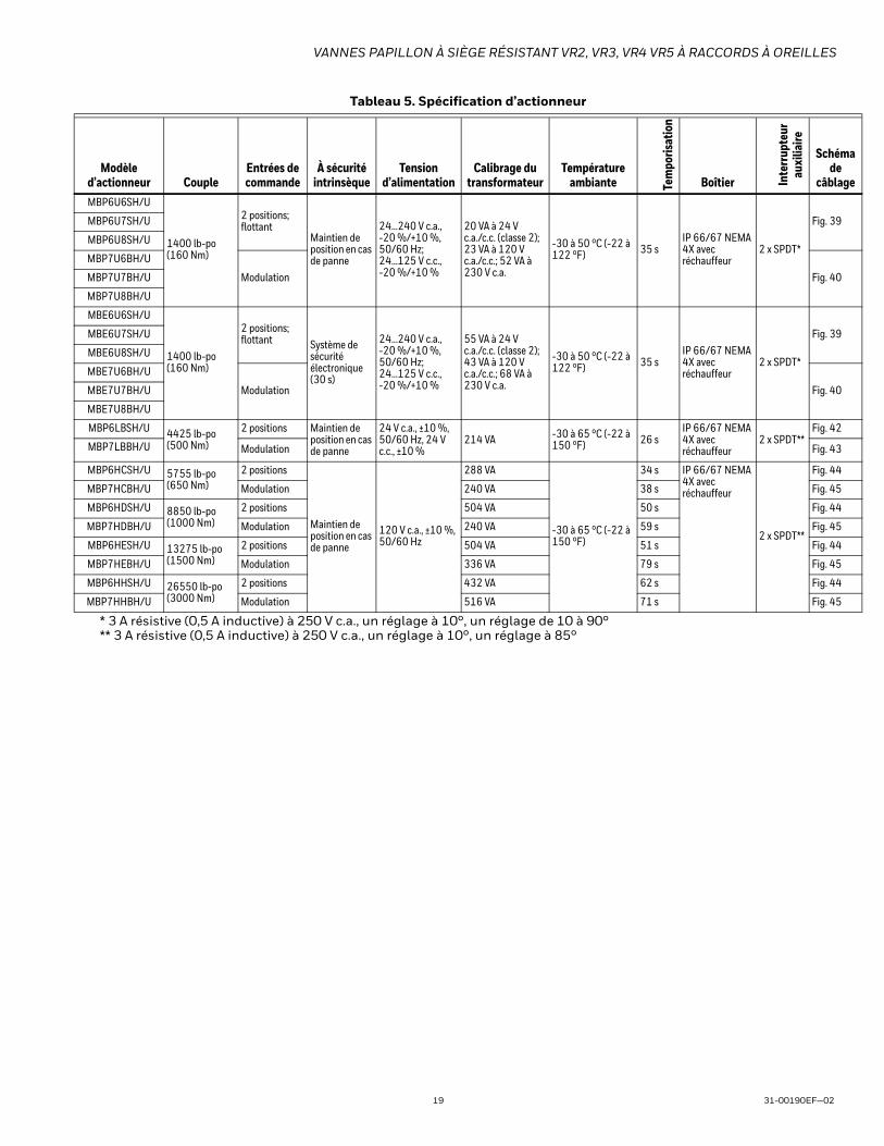
VANNES PAPILLON À SIÈGE RÉSISTANT VR2, VR3, VR4 VR5 À RACCORDS À OREILLES
19 31-00190EF—02
* 3 A résistive (0,5 A inductive) à 250 V c.a., un réglage à 10°, un réglage de 10 à 90°** 3 A résistive (0,5 A inductive) à 250 V c.a., un réglage à 10°, un réglage à 85°
MBP6U6SH/U
1400 lb-po (160 Nm)
2 positions; flottant
Maintien de position en cas de panne
24...240 V c.a., -20 %/+10 %, 50/60 Hz; 24...125 V c.c., -20 %/+10 %
20 VA à 24 V c.a./c.c. (classe 2); 23 VA à 120 V c.a./c.c.; 52 VA à 230 V c.a.
-30 à 50 °C (-22 à 122 °F) 35 s
IP 66/67 NEMA 4X avec réchauffeur
2 x SPDT*
Fig. 39MBP6U7SH/U
MBP6U8SH/U
MBP7U6BH/U
Modulation Fig. 40MBP7U7BH/U
MBP7U8BH/U
MBE6U6SH/U
1400 lb-po (160 Nm)
2 positions; flottant Système de
sécurité électronique(30 s)
24...240 V c.a., -20 %/+10 %, 50/60 Hz; 24...125 V c.c., -20 %/+10 %
55 VA à 24 V c.a./c.c. (classe 2); 43 VA à 120 V c.a./c.c.; 68 VA à 230 V c.a.
-30 à 50 °C (-22 à 122 °F) 35 s
IP 66/67 NEMA 4X avec réchauffeur
2 x SPDT*
Fig. 39MBE6U7SH/U
MBE6U8SH/U
MBE7U6BH/U
Modulation Fig. 40MBE7U7BH/U
MBE7U8BH/U
MBP6LBSH/U 4425 lb-po (500 Nm)
2 positions Maintien de position en cas de panne
24 V c.a., ±10 %, 50/60 Hz, 24 V c.c., ±10 %
214 VA -30 à 65 °C (-22 à 150 °F) 26 s
IP 66/67 NEMA 4X avec réchauffeur
2 x SPDT**Fig. 42
MBP7LBBH/U Modulation Fig. 43
MBP6HCSH/U 5755 lb-po (650 Nm)
2 positions
Maintien de position en cas de panne
120 V c.a., ±10 %, 50/60 Hz
288 VA
-30 à 65 °C (-22 à 150 °F)
34 s IP 66/67 NEMA 4X avec réchauffeur
2 x SPDT**
Fig. 44
MBP7HCBH/U Modulation 240 VA 38 s Fig. 45
MBP6HDSH/U 8850 lb-po (1000 Nm)
2 positions 504 VA 50 s Fig. 44
MBP7HDBH/U Modulation 240 VA 59 s Fig. 45
MBP6HESH/U 13275 lb-po (1500 Nm)
2 positions 504 VA 51 s Fig. 44
MBP7HEBH/U Modulation 336 VA 79 s Fig. 45
MBP6HHSH/U 26550 lb-po (3000 Nm)
2 positions 432 VA 62 s Fig. 44
MBP7HHBH/U Modulation 516 VA 71 s Fig. 45
Tableau 5. Spécification d’actionneur
Modèle d’actionneur Couple
Entrées de commande
À sécurité intrinsèque
Tension d’alimentation
Calibrage du transformateur
Température ambiante Te
mpo
risat
ion
Boîtier Inte
rrup
teur
au
xilia
ire
Schéma de
câblage

VANNES PAPILLON À SIÈGE RÉSISTANT VR2, VR3, VR4 VR5 À RACCORDS À OREILLES
31-00190EF—02 20
Modèles de vanne à 3 voies
Fig. 20. Configurations de vanne à 3 voies
Tableau 6. Duty Cycle on High Torque ActuatorsModèle d’actionneur Couple Entrées de commande Duty Cycle
MBP6LBSH/U 4425 lb-po [500 Nm] 2 positions75%
MBP7LBBH/U Modulation
MBP6HCSH/U 5755 lb-po [650 Nm] 2 positions 30%
MBP7HCBH/U Modulation 75%
MBP6HDSH/U 8850 lb-po [1000 Nm] 2 positions 30%
MBP7HDBH/U Modulation 75%
MBP6HESH/U 13275 lb-po [1500 Nm] 2 positions 30%
MBP7HEBH/U Modulation 75%
MBP6HHSH/U 26550 lb-po [3000 Nm] 2 positions 30%
MBP7HHBH/U Modulation 50%
DRONE DRONE
MA
STE
R
MA
STE
R
MA
STE
R
NO
MM
OC
NO
MM
OC
COMMON
VR5VR4VR3
DR
ON
E

VANNES PAPILLON À SIÈGE RÉSISTANT VR2, VR3, VR4 VR5 À RACCORDS À OREILLES
21 31-00190EF—02
Données d’écoulement
Fig. 21. Caractéristiques de débit type pour les vannes VR
Tableau 7. Cv de la vanne
Diamètre de vanne Cv
po DN 10° 20° 30° 40° 50° 60° 70° 80° 90°2 50 0.06 3 7 15 27 44 70 105 115
2.5 65 0.1 6 12 25 45 75 119 178 196
3 80 0.2 9 18 39 70 116 183 275 302
4 100 0.3 17 36 78 139 230 364 546 600
5 125 0.5 29 61 133 237 392 620 930 1022
6 150 0.8 45 95 205 366 605 958 1437 1579
8 200 2 89 188 408 727 1202 1903 2854 3136
10 250 3 151 320 694 1237 2047 3240 4859 5340
12 300 4 234 495 1072 1911 3162 5005 7507 8250
14 350 6 338 715 1549 2761 4568 7230 10844 11917
16 400 8 464 983 2130 3797 6282 9942 14913 16388
18 450 11 615 1302 2822 5028 8320 13168 19752 21705
20 500 14 791 1674 3628 6465 10698 16931 25396 27908
24 600 22 1222 2587 5605 9989 16528 26157 39236 43116
0
10
2010 30 5040 60 8070 90
20
30
40
60
50
70
80
90
100
% D
U D
ÉBIT
MAX
IMAL

VANNES PAPILLON À SIÈGE RÉSISTANT VR2, VR3, VR4 VR5 À RACCORDS À OREILLES
31-00190EF—02 22
INSTALLATIONEntreposage des ensembles de vanne papillon• Les ensembles doivent être entreposés à l’intérieur et
protégés des intempéries.• Des dispositions doivent être prises pour protéger les
matériaux reçus sur le chantier et dont le délai d’installation est long contre les dommages de la construction.
• Les sièges résistants doivent être protégés contre l’abrasion, les égratignures et les rayures puisque les garnitures seraient ainsi endommagées et pourraient causer des fuites dans la région de la bride.
• On ne peut pas entreposer des actionneurs électriques dans des endroits mouillés, humides ou corrosifs.
• N’entreposez pas de matériaux de construction sur les ensembles.
Pratiques d’installation• Les vannes papillon de série VR sont conçues pour être
installées entre des brides à collerette soudées ou à emmancher, à face plate ou surélevée ANSI 125/150.
• La vanne doit être installée à un minimum de 10 diamètres de tuyau de coudes, de crépines, de pompes, etc., en amont ou en aval.
• Pour l’eau refroidie, l’eau de condensateur ou l’eau chaude, la vanne doit être installée avec la tige en position verticale, l’actionneur étant monté au-dessus de la vanne.
• Lorsqu’il y a possibilité de sédimentation dans le débit de liquide, posez la vanne avec la tige en position horizontale. Le bas du disque doit fermer DEPUIS le côté en aval plutôt que du côté en amont.
Fig. 22.
• Assurez-vous que les faces de la bride sont propres et exemptes de rouille, de calcaire et de débris pour ne pas endommager la garniture.
• N’utilisez PAS de joints de bride sur les vannes papillon de série VR. (Fig. 23)
• Suivez la séquence de boulonnage de bride recommandée. (Fig. 32)
Installation avec des brides soudées• Posez les brides des deux côtés du corps de vanne, puis
posez les boulons pour aligner correctement le corps de vanne sur les deux brides.
• Posez la vanne alors que le disque est à la position « presque fermée » (Fig. 22)
• N’utilisez pas des joints de bride (Fig. 23)• Assurez-vous que les diamètres intérieurs de la
garniture de vanne et des brides sont alignés.(Fig. 24)• Prenez l’ensemble corps de vanne et bride, puis
alignez-le sur les extrémités des tuyaux.
Tableau 8. Débit
Diamètre de vanne Débit en gal/minpo DN 2 pi/s 4 pi/s 6 pi/s 8 pi/s 10 pi/s 12 pi/s2 50 19 39 59 78 98 117
2.5 65 30 61 92 122 153 184
3 80 44 88 132 176 220 264
4 100 78 157 235 313 392 470
5 125 122 245 367 490 612 734
6 150 176 352 529 705 881 1058
8 200 313 627 940 1253 1567 1880
10 250 490 979 1469 1958 2448 2738
12 300 705 1410 2115 2820 3525 4230
14 350 959 1919 2879 3838 4798 5758
16 400 1253 2507 3760 5013 6267 7520
18 450 1586 3173 4759 6345 7931 9518
20 500 1958 3917 5875 7834 9792 11750
24 600 2820 5640 8460 11280 14100 16921
15 ... 20°

VANNES PAPILLON À SIÈGE RÉSISTANT VR2, VR3, VR4 VR5 À RACCORDS À OREILLES
23 31-00190EF—02
• Soudez par points en plusieurs endroits les brides sur les tuyaux. (Fig. 25) Ne soudez PAS par joints à ce stade!
• Retirez les boulons d’oreilles, puis séparez avec soin le corps de vanne des brides.
• Effectuez la soudure par joints du raccordement entre chaque bride et son tuyau. (Fig. 26)
• Laissez complètement refroidir les composants de tuyauterie avant de réinsérer le corps de vanne. (Fig. 27)
AVERTISSEMENT Le soudage par joints alors que le corps de vanne est installé entre les brides peut endommager la garniture en raison de la transmission de chaleur de la bride au corps de vanne.
Fig. 23.
Fig. 24.
Fig. 25.
Fig. 26.
Fig. 27.
0> 0
1
2

VANNES PAPILLON À SIÈGE RÉSISTANT VR2, VR3, VR4 VR5 À RACCORDS À OREILLES
31-00190EF—02 24
Fig. 28.
Procédure d’avant installation1. Retirez tout couvercle de protection de bride de la
vanne.2. Vérifiez la vanne pour vous assurer que la voie d’eau
est exempte de poussière ou de corps étrangers. Assurez-vous que la conduite adjacente est exempte de tout corps étranger tels que la rouille, le calcaire ou le laitier qui risquent d’endommager le siège et les surfaces d’étanchéité du disque.
3. Vous devez poser les actionneurs sur la vanne avant l’installation afin de faciliter l’alignement du disque dans le siège de vanne.
4. Vérifiez l’étiquette d’identification de la vanne pour vous assurer que les matériaux et la pression de fonctionnement de la vanne sont conformes à l’usage prévu.
AVERTISSEMENT Des blessures corporelles ou des dommages matériels pourraient survenir si la vanne est installée lorsque les conditions de service pourraient dépasser les spécifications de la vanne.
5. Vérifiez les boulons ou goujons de la bride pour con-firmer leur taille, leur filetage et leur longueur.
6. Ces vannes sont conçues pour être installées entre des brides ASME/ANSI de classe 125/150.
7. Suivez avec soin les directives d’installation à l’aide de brides soudées à la page 82 du présent docu-ment.
8. Respectez les normes d’alignement de bride ASME : SECTION 335.1.1 ALIGNEMENTa. DÉFORMATIONS DE LA TUYAUTERIE : Toute
déformation de la tuyauterie visant à aligner le raccordement et qui cause un stress excessif sur l’équipement ou la tuyauterie est interdite.
b. JOINTS DE BRIDE : Avant d’effectuer le boulon-nage, les faces des brides doivent être alignées au plan de conception à moins de 1/16 po par pied mesuré sur tout diamètre; le décalage d’alignement des boulons doit être d’au plus 1/8 po.
9. Lorsqu’on les observe durant le montage, les faces des brides doivent être parallèles à moins d’un degré, et la force nécessaire à l’alignement des tuyaux ne doit pas dépasser 10 lb-pi par pouce de boulon NF; de plus, les écrous doivent être insérés à fond.
Procédure d’installation de vanneAlignez les brides de tuyau pour assurer un alignement correct avant l’installation de la vanne. Écartez les brides suffisamment l’une de l’autre pour permettre l’installation du corps de vanne entre les brides sans toucher aux surfaces de bride. Faites très attention lorsque vous manipulez la vanne pour ne pas endommager le disque ou les surfaces du siège.
REMARQUE : Peu importe le type d’actionneur, il doit être monté au moins dans l’axe de la conduite. (Fig. 30)
Tableau 9. Spécifications relatives aux brides et au boulonnage
Diamètre nominal du tuyau (po)
Brides Forage Boulonnage
Diamètre de bride A
(po)
Épaisseur de bride B
(po)
Diamètre C du cercle de boulonnage
(po)
Diamètre D des trous
de boulons (po)
Filetage Nombre de boulons
Longueur des
boulons (po)
Couple de serrage
maximal (lb-pi)
2 6 0,75 4,75 0,75 5/8 - 11 4 1,25 70
2,5 7 0,875 5,5 0,75 5/8 - 11 4 1,5 70
3 7,5 0,9375 6 0,75 5/8 - 11 4 1,5 70
4 9 0,9375 7,5 0,75 5/8 - 11 8 1,75 70
5 10 0,9375 8,5 0,875 3/4 - 10 8 1,75 120
6 11 1 9,5 0,875 3/4 - 10 8 2 120
8 13,5 1,125 11,75 0,875 3/4 - 10 8 2,25 120
10 16 1,1875 14,75 1 7/8 - 9 12 2,25 200
12 19 1,25 17 1 7/8 - 9 12 2,5 200
14 21 1,375 18,75 1,125 1 - 8 12 2,75 240
16 23,5 1,4375 21,25 1,125 1 - 8 16 2,75 240
18 25 1,625 22,75 1,25 1 1/8 - 7 16 3,5 380
20 27,5 1,6875 25 1,25 1 1/8 - 7 20 4,25 380
24 32 1,875 29,5 1,375 1 1/8 - 7 20 4,75 520

VANNES PAPILLON À SIÈGE RÉSISTANT VR2, VR3, VR4 VR5 À RACCORDS À OREILLES
25 31-00190EF—02
1. Les vannes papillon de série VR sont conçues pour être installées entre des brides à collerette soudées ou à emmancher, à face plate ou surélevée ANSI 125/150.
2. N’utilisez PAS de joints de bride sur les vannes papil-lon de série VR.
3. Pour les vannes à oreilles :a. Placez la vanne entre les brides.b. Posez tous les boulons entre la vanne et les
brides d’accouplement. Serrez les boulons à la main. (Fig. 31)
4. Avant d’effectuer le serrage des boulons, centrez la vanne entre les brides, puis vérifiez les positions d’ouverture et de fermeture complète pour assurer le libre mouvement du disque.
5. À l’aide de la séquence indiquée (Fig. 32), serrez les boulons de bride uniformément pour assurer une compression uniforme du joint d’étanchéité. Lors du montage des joints de bride, la surface du siège résistant doit être uniformément comprimée (Fig. 29).
6. Si un actionneur doit être utilisé, le raccordement électrique de l’unité doit s’effectuer conformément aux codes de l’électricité en vigueur.
7. Ouvrez, puis fermez complètement la vanne en véri-fiant la fin de course de l’actionneur et l’alignement du disque. Faites fonctionner la vanne pour vous assurer qu’elle ne grippe pas. Si l’alimentation n’est pas raccordée, utilisez le volant de manœuvre.
8. La vanne est maintenant prête à fonctionner.
Remarques sur l’installation1. Suivez les procédures d’avant l’installation et
d’installation décrites ci-dessus.2. Pour obtenir la pleine pression de fermeture d’une
vanne de série VR, une bride est requise du côté ouvert ou en aval de la vanne (Fig. 33).
Fig. 29.
Fig. 30.
Fig. 31.
>000 >0
90° 90°
Fig. 7

VANNES PAPILLON À SIÈGE RÉSISTANT VR2, VR3, VR4 VR5 À RACCORDS À OREILLES
31-00190EF—02 26
Fig. 32.
Fig. 33.
Fig. 34. Câblage des actionneurs MBS8 (tous les modèles n’ont pas un interrupteur)
Fig. 35. Câblage pour actionneurs MBP6...2, 4, 5, A, R
31
24
1
4
3
2
5
67
8 9
10
11
12
13
14
15
16
1
4
3
2
5
6
7
8
9
10 11
12
1
4
3
2
5
6
7
8
Noir (1) Neutre
Rouge(2) + Sous tension
Tension secteur
2 3 18 A
a
Fonction
100%Max.
a
Remarques :
Marche/arrêtInterrupteurs auxiliaires
Répond aux exigences cULus sans
raccordement de mise à la terre.
ALes actionneurs avec les câbles de
l’appareil sont numérotés.
2Les actionneurs peuvent être raccordés en parallèle.
La consommation électrique et l’impédance
d’entrée doivent être respectées.
3 Les actionneurs peuvent également être
alimentés à 24 V c.c.
18 Les actionneurs dotés de câbles pour plénum n’ont
pas de numéros sur les fils; utilisez le code-couleurs.
Transformateur 24 V c.a.
à
2 3
a
18
Fonction
100%Max.
a
Transformateur 24 V c.a.
Noir (1) Neutre
Rouge
(2)
Blanc
(3)
Tensionsecteur
2 3 18
a
b
Fonction
100%Max.
a b
Remarques :
Marche/arrêt Point flottant
Répond aux exigences cULus sans raccordement de
mise à la terre.
2
Les actionneurs peuvent être raccordés en parallèle. La
consommation électrique et l’impédance d’entrée doivent
être respectées.
3 Les actionneurs peuvent également être alimentés à 24 V c.c.
18Les actionneurs dotés de câbles pour plénum n’ont pas de
numéros sur les fils; utilisez le code-couleurs.
+ Sous
tension
+ Entrée
Tensionsecteur
Transformateur 24 V c.a.
Noir (1) Neutre
Rouge
(2)
Blanc
(3)
+ Sous
tension
+ Entrée

VANNES PAPILLON À SIÈGE RÉSISTANT VR2, VR3, VR4 VR5 À RACCORDS À OREILLES
27 31-00190EF—02
Fig. 36. Câblage pour actionneurs MBS7...1, 3 et MBP7...2, 3, 4, 5, R (certains modèles n’ont pas d’interrupteur)
Fig. 37. Câblage pour actionneurs MBE6...4, 5, R
Remarques :
7
Sortie U, 2 à 10V
(–)(+)
Transformateur 24 V c.a.
Ω 500 Ω1/4 watt
3 18
4 à 20 mA ou 2 à 10 V c.c.
18
Fonctions0%
50%
100%
Mode de commande acc. à Y
Min.*
Médian*
Max.*Normal**
* Sélectionnable par défaut 0-100 %. Voir la fiche technique de configuration..** Personnalisable. Voir la fiche technique de configuration..
a b c
500 Ω
Ω
Noir (1) Neutre
Rouge (2) Sous tension
Rose (4) Entrée Y2 Orange (5)
Blanc (3) Entrée Y 1
2 à 10V(–)(+)
Tension secteur
Transformateur de 24 V c.a.
(c.a. seulement)
7
B
C
A
1/4 watt
2 à 10 V c.c. ou 4 à 20 mASignal de commande
V c.c./4 à 20 mA Positions Min., Médian et Max. de commande d’annulation
Répond aux exigences cULus sans raccordement
de mise à la terre.
3Les actionneurs peuvent également être alimentés
à 24 V c.c.
7 Une résistance de 500 Ω transforme le signal de
commande de 4 à 20 mA en tension de 2 à 10 V c.c.
18 Les actionneurs dotés de câbles pour plénum n’ont
pas de numéros sur les fils; utilisez le code-couleurs.
Noir (1) Neutre
Rouge (2) Sous tension
Blanc (3) Entrée Y2 à 10V
Rose (4) Entrée Y
1
2
Orange (5)
Signal de commande
Tension secteur
18
Noir (1) Neutre
Rouge (2) Sous
tension
Blanc (3) Entrée Y
Orange (5) Sortie U
2 à 10V
Tension secteur
Transformateur 24 V c.a.
Signal de rétroaction de 2 à 10 V c.c. (+)
(–)
3
Fonction100%Max.
a
Tension secteur
(–) (+)
Transformateur 24 V c.a.
1
CCW
CW
A B 18
CCW
CW
A B
Contacteur de sens de rotation
A
B
2
9
8
10
12Signal de rétroaction de 2 à 10 V c.c.
18
18
Remarques :
Marche/arrêt
Point flottant
Répond aux exigences cULus sans raccordement
de mise à la terre.
2
Les actionneurs peuvent être raccordés en parallèle.
La consommation électrique et l’impédance d’entrée
doivent être respectées.
3 Les actionneurs peuvent également être alimentés à 24 V c.c.
8Le signal de commande peut être pulsé par le fil sous tension
(source) ou le fil neutre (collecteur) d’un circuit 24 V c.a.
9
Les fermetures de contact A et B peuvent également être à
triac. Les contacteurs A et B doivent être fermés pour la source
à triac et ouverts pour le collecteur à triac.
10
Pour un collecteur à triac, le fil neutre de l’actionneur doit être
raccordé au fil sous tension du régulateur. La rétroaction de
position ne peut pas être utilisée avec un régulateur à collecteur
à triac. La référence neutre interne de l’actionneur n’est
pas compatible.
Diode IN4004 ou IN4007. (IN4007 fournie)
18Les actionneurs dotés de câbles pour plénum n’ont pas de
numéros sur les fils; utilisez le code-couleurs.
FC FOA – AB = 0% A – AB = 100%
POP POP
CWCCWCWCCW
24 V c.a./c.c.
FC FOA – AB = 0% A – AB = 100%
3a
(Y1)
4b
(Y2)CWCCW
0.1
0.5
Y2
Y1
0.9
POP
0.1
0.5
0.9
POP
CWCCW
Y2
Y1
–– ––
24 V c.a./c.c.
Marche/arrêt
Point flottant
12
Noir (1) Neutre
Rouge (2) Sous tension
Blanc (3) Entrée Y
Orange (5) Sortie U
2 à 10V

VANNES PAPILLON À SIÈGE RÉSISTANT VR2, VR3, VR4 VR5 À RACCORDS À OREILLES
31-00190EF—02 28
Fig. 38. Câblage pour actionneurs MBE7...4, 5, R
Fig. 39. Câblage pour actionneurs MBP, E6...6, 7, 8
Remarques :
7
Noir (1) Neutre
Rouge (2) Sous
tension
Blanc (3) Entrée Y 1
2 à 10 V
Orange (5) Sortie U 2 à 10 V
(–)(+)
TensionVolts
Transformateur 24 V c.a.
Ω 500 Ω1/4 watt
3 18
Signal de commande V c.c./mA
18
500 Ω
Ω
Orange (5)
1
(–)(+)
TensionVolts
Transformateur de 24 V c.a.
(c.a. seulement)
7
B
C
A
1/4 watt
Signal de commande V c.c./mA
Fonctions0%
50%
100%
Mode de commande acc. à Y
Min.*
Médian*
Max.*Normal**
* Sélectionnable par défaut 0-100 %. Voir la fiche technique de configuration.** Personnalisable. Voir la fiche technique de configuration.
a b c
V c.c./4 à 20 mA Positions Min., Médian et Max. de commande d’annulation
Répond aux exigences cULus sans raccordement
de mise à la terre
3Les actionneurs peuvent également être
alimentés à 24 V c.c.
7Une résistance de 500 Ω transforme le signal de
commande de 4 à 20 mA en tension de 2 à 10 V c.c.
10
Pour un collecteur à triac, le fil neutre de l’actionneur
doit être raccordé au fil sous tension du régulateur.
La rétroaction de position ne peut pas être utilisée
avec un régulateur à collecteur à triac. La référence
neutre interne de l’actionneur n’est pas compatible.
18Les actionneurs dotés de câbles pour plénum n’ont
pas de numéros sur les fils; utilisez le code-couleurs.
FC FOA – AB = 0% A – AB = 100%
CWCCW
0.1
0.5
Y2
Y1
0.9
POP
0.1
0.5
0.9
POP
Y2
Y1
CWCCW
24 V c.a./c.c.
Modulation
Noir (1) Neutre
Rouge (2) Sous
tension
Blanc (3) Entrée Y2 à 10 V
Point flottant
Contacteurs de fin de course
Remarques :
0° à 90°
85° par defaut
41!
1 Prévoyez des mécanismes de coupure et de protection
contre les surcharges, au besoin.
46Les actionneurs peuvent être commandés en parallèle.
L’appel de courant et l’impédance d’entrée doivent être respectés
4Deux interrupteurs auxiliaires intégrés (2 x SPDT) pour
l’indication de position de fin de course, la commande d
e verrouillage, la mise en fonction du ventilateur, etc.
Les modèles à alimentation électrique tous courants
peuvent être alimentés de 24 V c.a. à 240 V c.a. ou de
24 V c.c. à 125 V c.c.
Marche/arrêt
N
L
Y1
Y2
1UP 46!
Neutre
+ Sous tension
24 à 240 V c.c.
N
L
Y1
Y2
1UP 46!
Neutre
+ Sous tension
24 à 240 V c.c.
N
L
Y1
Y2
Neutre
+ Sous tension
Entrée sens antihoraire (ouverture)
Entrée sens horaire (fermeture)
24 à 240 V c.c.Ou
24 à 125 V c.c.
1UP 461!
Marche/arrêt
!
Durant l’installation, la mise à l’essai, l’entretien et le
dépannage de ce produit, il peut être nécessaire de
travailler avec les composants électriques sous tension.
Faites exécuter ces tâches par un électricien qualifié ou
par une personne correctement formée dans la
manipulation de composants électriques sous tension.
Le non-respect des mesures de sécurité pour le travail
avec l’électricité pourrait entraîner des blessures graves,
voire mortelles.
Répond aux exigences cULus sans raccordement
de mise à la terre.Ou
24 à 125 V c.c.
Ou 24 à 125 V c.c.
Entrée sens antihoraire (ouverture)
Entrée sens antihoraire (ouverture)
Entrée sens horaire (fermeture)
Entrée sens horaire (fermeture)
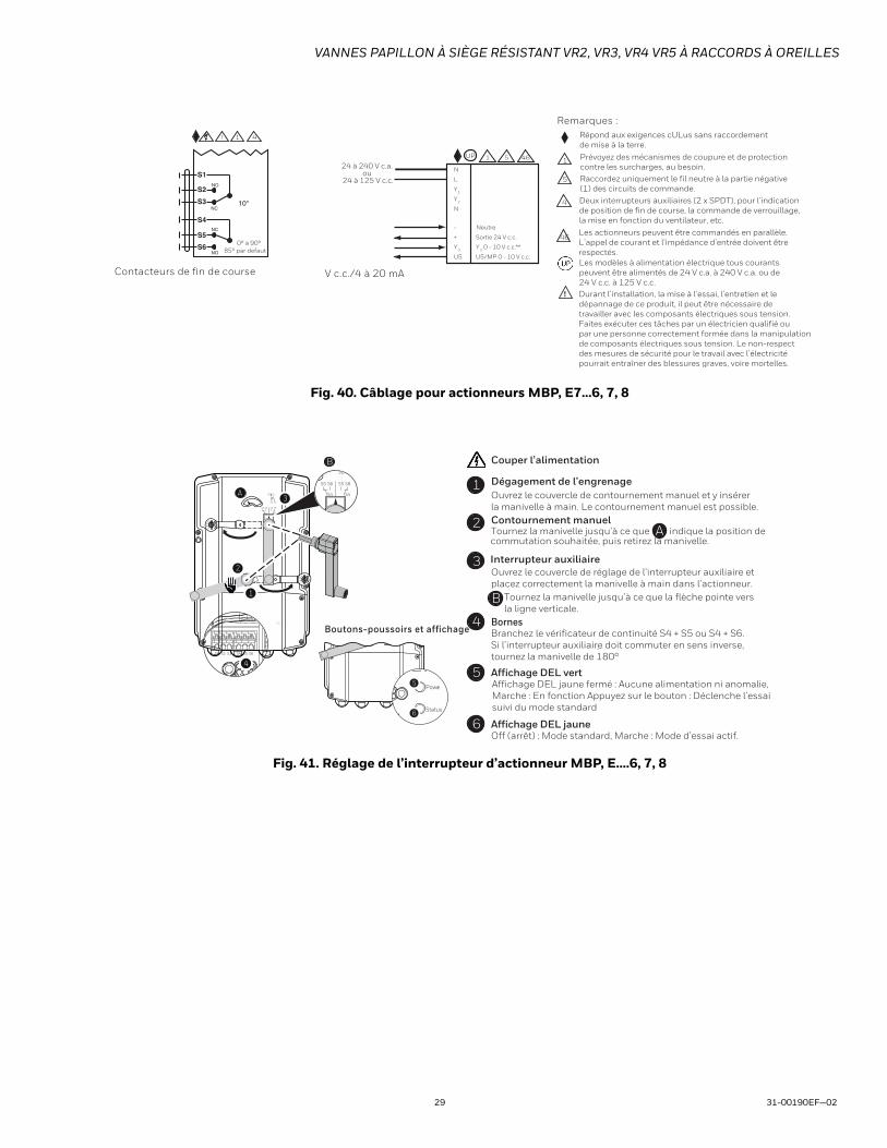
VANNES PAPILLON À SIÈGE RÉSISTANT VR2, VR3, VR4 VR5 À RACCORDS À OREILLES
29 31-00190EF—02
Fig. 40. Câblage pour actionneurs MBP, E7...6, 7, 8
Fig. 41. Réglage de l’interrupteur d’actionneur MBP, E....6, 7, 8
Contacteurs de fin de course V c.c./4 à 20 mA
Remarques :
0° à 90°
85° par defaut
41!
5
1Prévoyez des mécanismes de coupure et de protection
contre les surcharges, au besoin.
46Les actionneurs peuvent être commandés en parallèle.
L’appel de courant et l’impédance d’entrée doivent être
respectés.
4 Deux interrupteurs auxiliaires (2 x SPDT), pour l’indication
de position de fin de course, la commande de verrouillage,
la mise en fonction du ventilateur, etc.
Les modèles à alimentation électrique tous courants
peuvent être alimentés de 24 V c.a. à 240 V c.a. ou de
24 V c.c. à 125 V c.c.
N
L
Y1
Y2
N
5UP 46
24 à 240 V c.a. ou
24 à 125 V c.c.
-
+
Y3
U5
Neutre
Sortie 24 V c.c.
Y3
0 - 10 V c.c.**
U5/MP 0 - 10 V c.c.
1
! Durant l’installation, la mise à l’essai, l’entretien et le
dépannage de ce produit, il peut être nécessaire de
travailler avec les composants électriques sous tension.
Faites exécuter ces tâches par un électricien qualifié ou
par une personne correctement formée dans la manipulation
de composants électriques sous tension. Le non-respect
des mesures de sécurité pour le travail avec l’électricité
pourrait entraîner des blessures graves, voire mortelles.
Raccordez uniquement le fil neutre à la partie négative
(1) des circuits de commande.
Répond aux exigences cULus sans raccordement
de mise à la terre.
Optional: end switch adjustment
Power
Status
5
6
Boutons-poussoirs et affichage
B
A
1
2
3
o
pe
n
o
pe
n
S2 S3
S1
S5 S6
S4
S5 S6
S4
10°
S2 S3
S5 S6
S4
S5 S6
S4
S1 S2 S3 S4 S5 S6
4
Couper l’alimentation.
1 Dégagement de l’engrenageOuvrez le couvercle de contournement manuel et y insérer
la manivelle à main. Le contournement manuel est possible.
Contournement manuel2
indique la position deTournez la manivelle jusqu’à ce que A
B
3 Interrupteur auxiliaireOuvrez le couvercle de réglage de l’interrupteur auxiliaire et
placez correctement la manivelle à main dans l’actionneur.
4 BornesBranchez le vérificateur de continuité S4 + S5 ou S4 + S6.
Si l’interrupteur auxiliaire doit commuter en sens inverse,
tournez la manivelle de 180°
.
5 Affichage DEL vertAffichage DEL jaune fermé : Aucune alimentation ni anomalie,
Marche : En fonction Appuyez sur le bouton : Déclenche l’essai
suivi du mode standard
6 Affichage DEL jauneOff (arrêt) : Mode standard, Marche : Mode d’essai actif.
commutation souhaitée, puis retirez la manivelle.
Tournez la manivelle jusqu’à ce que la flèche pointe vers
la ligne verticale.

VANNES PAPILLON À SIÈGE RÉSISTANT VR2, VR3, VR4 VR5 À RACCORDS À OREILLES
31-00190EF—02 30
Fig. 42. Câblage pour actionneurs MBP6...9, B
Fig. 43. Câblage pour actionneurs MBP7...9, B
Marche/arrêt du transformateur 24 V c.a./c.c.
Transformateur 24 V c.a./c.c.
Tension secteur
Ouvrir
Fermer
G Terre
1 Neutre
3 Ouverte
4 Fermée
5 Se brancher au nº 1 pour
une indication d’ouverture
complète
6
Se brancher au nº 1 pour
une indication de fermeture
complète
7 HTR
A
B
C
D
E
F
LS3
A-C (Indication d’ouverture)
LS4
D-F (Indication de fermeture)
Valeur nominale des contacts :
5 A, 250 RMS max.
SY2…5-24
G33
c33
Chaque actionneur doit être alimenté par un seul
transformateur de commande isolé.
MBP...9, B
REMARQUES SUR L’INSTALLATION
• Respectez les restrictions de câblage de
classe 1 et de classe 2.
• Calibrage du transformateur = appel de courant de
l’actionneur MBP x 1,25 (marge de sécurité)
Transformateur 24 V c.a.
Tension secteur
G Terre
1 Neutre
3 Ouverte
4 Fermée
5
6
7 HTR
A
B
C
D
E
F
LS3
A-C (Indication d’ouverture)
LS4
D-F (Indication de fermeture)
Valeur nominale des contacts :
5 A, 250 RMS max.
MBP...9, B
G Terre
1 Neutre
3 Ouverte
4 Fermée
5
6
7 HTR
A
B
C
D
E
F
LS3
A-C (Indication d’ouverture)
LS4
D-F (Indication de fermeture)
Valeur nominale des contacts :
5 A, 250 RMS max.
MBP...9, B
K1Ouvrir
Fermer K1-B
K1-A
Actionneur A
Actionneur BG
G
REMARQUES SUR
L’INSTALLATION
• Les relais d’isolation doivent être raccordés en parallèle de plusieurs
actionneurs utilisant une entrée de signal de commande commune.
• « H » (L2) ne peut pas être raccordé simultanément à la borne 3
et la borne 4.
• Requis : La borne 7 doit être câblée sur place pour activer le circuit
de chauffage.
Régulation proportionnelle, plusieurs câbles, 24 V MBP...9 B
A
B
C
D
E
F
LS3
A-C
LS4
D-F
SY2…5-24MFT
┴1
Y
U5
C1
┴2
C2
B
A
1
9
8
10
3
2
┴/-
~/+
SYx-24MFT
┴1
Y
U5
C1
┴2
C2
B
A
1
9
8
10
3
2
┴/-
~/+
SYx-24MFT
G PE
G PE
Y1 Y2
Y1 Y2
33
35
36
33
35
36
33
Chaque actionneur doit être alimenté par
un seul transformateur de commande isolé.
MBP...9, B
REMARQUES SUR L’INSTALLATION
• Respectez les restrictions de câblage de classe 1 et de classe 2.
• Calibrage du transformateur = appel de courant de l’actionneur
MBP x 1,25 (marge de sécurité)
Signal de commande (-)
Signal de commande (-)
Rétroaction
Signal de rétroaction (+)
Signal de rétroaction (-)
Non utilisé -
Non utilisé -
Adresse
Adaptation
Prise d’entretien de l’outil PC
Actionneur A
Pour usage interne seulement
Pour usage interne seulement
Pour usage interne seulement
Pour usage interne seulement
Pour usage interne seulement
Neutre, bloc d’alimentation
Sous tension,
bloc d’alimentation
Pour usage interne seulement
Pour usage interne seulement
Pour usage interne seulement
24 V c.a./c.c.
Signal de commande (-)
Signal de commande (-)
Signal de rétroaction (+)
Signal de rétroaction (-)
Non utilisé -
Non utilisé -
Rétroaction
Prise d’entretien de l’outil PC
Adresse
Adaptation
Actionneur BPour usage interne seulement
Pour usage interne seulement
Pour usage interne seulement
Pour usage interne seulement
Pour usage interne seulement
Neutre, bloc d’alimentation
Sous tension,
bloc d’alimentation
Pour usage interne seulement
Pour usage interne seulement
Pour usage interne seulement
24 V c.a./c.c.Signal de commande
(Indication d’ouverture)
(Indication de fermeture)
Valeur nominale des contacts :
5 A, 250 RMS max.

VANNES PAPILLON À SIÈGE RÉSISTANT VR2, VR3, VR4 VR5 À RACCORDS À OREILLES
31 31-00190EF—02
Fig. 44. Câblage pour actionneurs MBP6...C, D, E, F, G, H
Marche/arrêt 120 V c.a./c.c.
G Terre
1 Neutre
3 Ouverte
4 Fermée
5 Se brancher au nº 1 pour une indication d’ouverture complète
6 Se brancher au nº 1 pour une indication de fermeture complète
7
120 V or 230V AC/DCG
Ouvrir
Fermer
N L1
H L2
HTR
A
B
C
D
E
F
LS3
A-C (Indication d’ouverture)
LS4
D-F (Indication de fermeture)
Valeur nominale des contacts :
5 A, 250 RMS max.
SY2…12-120V or 230VMBP...C, D, E
REMARQUES SUR
L’INSTALLATION
• Respectez les restrictions de câblage de classe 1 et de classe 2.
• Calibrage du transformateur = appel de courant de l’actionneur MBP x 1,25 (marge de sécurité)
G Terre
1 Neutre
3 Ouverte
4 Fermée
5
6
7 HTR
A
B
C
D
E
F
LS3
A-C (Indication d’ouverture)
LS4
D-F (Indication de fermeture)
Valeur nominale des contacts :
5 A, 250 RMS max..
G Terre
1 Neutre
3 Ouverte
4 Fermée
5
6
7 HTR
A
B
C
D
E
F
LS3
A-C (Indication d’ouverture)
LS4
D-F (Indication de fermeture)
Valeur nominale des contacts :
5 A, 250 RMS max.
MBP, C, D, E
MBP...C, D, E
Ouvrir
Fermer K1-B
K1-A
Actionneur A
Actionneur B
120 V c.a.
N L1
H L2
G
G
K1
REMARQUES SUR
L’INSTALLATION
• Les relais d’isolation doivent être raccordés en
parallèle de plusieurs actionneurs utilisant une
entrée de signal de commande commune.
• « H » (L2) ne peut pas être raccordé simultanément
à la borne 3 et la borne 4.
• Requis : La borne 7 doit être câblée sur place
pour activer le circuit de chauffage.

VANNES PAPILLON À SIÈGE RÉSISTANT VR2, VR3, VR4 VR5 À RACCORDS À OREILLES
Honeywell Building TechnologiesAux États-Unis :
Honeywell
715 Peachtree Street NE
Atlanta, GA 30308
customer.honeywell.com
® Marque de commerce déposée aux États-Unis© 2019 Honeywell International Inc. 31-00190EF—02 M.S. 07-19Imprimé aux États-Unis
Fig. 45. Câblage pour actionneurs MBP7...C, D, E, F, G, H
Régulation proportionnelle, plusieurs câbles,
1 20 V MBP... C, D, E
A
B
C
D
E
F
LS3
A-C
LS4
D-F
MBP...C, D, E
┴1
Y
U5
C1
┴2
C2
B
A
1
9
8
10
3
2
SYx-230MFT
SYx-120MFT
LN
┴1
Y
U5
C1
┴2
C2
B
A
1
9
8
10
3
2
SYx-230MFT
SYx-120MFT
LN
G PE
G PE
Y1
Y2
Y1
Y2
35
36
36
35
33
Chaque actionneur doit être alimenté par un
seul transformateur de commande isolé.
REMARQUES SUR L’INSTALLATION
• Respectez les restrictions de câblage de classe 1 et de classe 2.
• Calibrage du transformateur = appel de courant de l’actionneur
MBP x 1,25 (marge de sécurité)
Rétroaction
Signal de commande (+)
Signal de commande (-)
Signal de rétroaction (+)
Signal de rétroaction (-)
Non utilisé -
Non utilisé -
Actionneur A
Prise d’entretien de l’outil PC
Adaptation Adresse
Neutre, bloc d’alimentation – 120 V
Sous tension, bloc d’alimentation
– 120 V
Pour usage interne seulement
Pour usage interne seulement
Pour usage interne seulement
Pour usage interne seulement
Pour usage interne seulement
Pour usage interne seulement
Pour usage interne seulement
Pour usage interne seulement
Pour usage interne seulement
Pour usage interne seulement
Pour usage interne seulement
Pour usage interne seulement
Pour usage interne seulement
Pour usage interne seulement
Pour usage interne seulement
Pour usage interne seulement
Neutre, bloc d’alimentation – 120 V
Sous tension, bloc d’alimentation
– 120 V
Adaptation Adresse
Prise d’entretien de l’outil PC
Actionneur B
Signal de commande (+)
Signal de commande (-)
Signal de rétroaction (+)
Signal de rétroaction (-)
Non utilisé -
Non utilisé -
Rétroaction
Signal de commande
(Indication d’ouverture)
(Indication de fermeture)
Valeur nominale des contacts :
5 A, 250 RMS max.