30’X40’ 2 CAR GARAGE - Cabin, Garage, House - · PDF file30’x40’ 2 car...
13
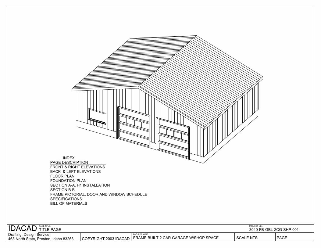
30’X40’ 2 CAR GARAGE •3’ ENTRY DOOR •2 WINDOWS •2-10’X10’ GARAGE DOORS •SHOP SPACE •4” CONCRETE SLAB •12’ WALLS •4/12 PITCH METAL ROOF •METAL SIDING •ELECTRICAL PLAN
Transcript of 30’X40’ 2 CAR GARAGE - Cabin, Garage, House - · PDF file30’x40’ 2 car...

30’X40’ 2 CAR GARAGE
•3’ ENTRY DOOR•2 WINDOWS•2-10’X10’ GARAGE DOORS•SHOP SPACE•4” CONCRETE SLAB
•12’ WALLS•4/12 PITCH METAL ROOF•METAL SIDING•ELECTRICAL PLAN
COPYRIGHT 2003 IDACADDrafting, Design ServiceIDACAD463 North State, Preston, Idaho 83263
PAGE TITLE:
TITLE PAGE
PAGE FRAME BUILT 2 CAR GARAGE W/SHOP SPACEPROJECT NAME
3040-FB-GBL-2CG-SHP-001
SCALE NTS
PROJECT NO.:
FRAME PICTORIAL, DOOR AND WINDOW SCHEDULE
BACK & LEFT ELEVATIONSFRONT & RIGHT ELEVATIONSPAGE DESCRIPTION
SECTION B-B
SPECIFICATIONSBILL OF MATERIALS
FOUNDATION PLANSECTION A-A, H1 INSTALLATION
FLOOR PLAN
INDEX

COPYRIGHT 2003 IDACADDrafting, Design ServiceIDACAD463 North State, Preston, Idaho 83263
PAGE TITLE:
FRONT AND RIGHT ELEVATIONS
PAGE 1FRAME BUILT 2 CAR GARAGE W/SHOP SPACEPROJECT NAME
3040-FB-GBL-2CG-SHP-001
SCALE 1/8" = 1'
PROJECT NO.:
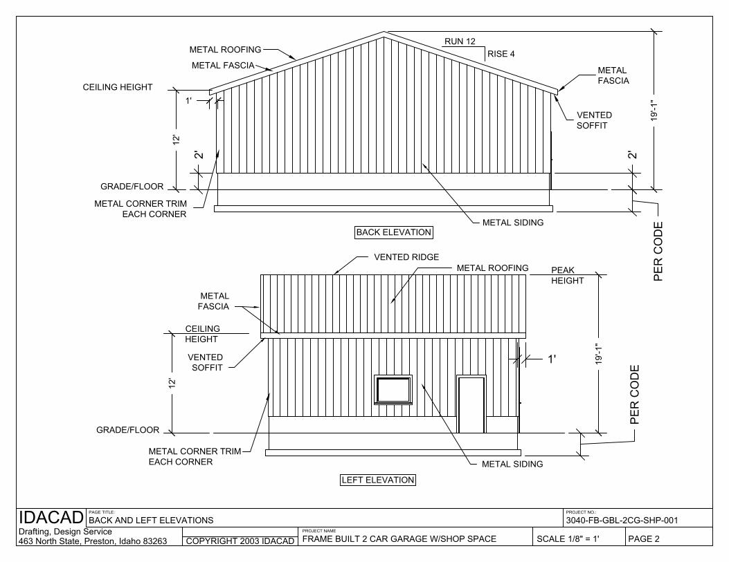
CEILING HEIGHT
12'
1'
METAL ROOFING
METAL FASCIA
19'-1
"
METAL FASCIA
VENTEDSOFFIT
PEAK HEIGHT
RISE 4RUN 12
METAL CORNER TRIMEACH CORNER
GRADE/FLOOR
12'
GRADE/FLOOR
VENTEDSOFFIT
CEILINGHEIGHT
METAL FASCIA
METAL CORNER TRIMEACH CORNER METAL SIDING
RIGHT ELEVATION
PEAKHEIGHT
19'-1
"
1'
VENTED RIDGEMETAL ROOFING
FRONT ELEVATION
2'
2'
PE
R C
OD
E
PE
R C
OD
E
METAL SIDING
2'
FRAME BUILT 2 CAR GARAGE W/SHOP SPACE463 North State, Preston, Idaho 83263
IDACADDrafting, Design Service
PAGE TITLE:
BACK AND LEFT ELEVATIONS
COPYRIGHT 2003 IDACADPROJECT NAME
PROJECT NO.:
SCALE 1/8" = 1'
3040-FB-GBL-2CG-SHP-001
PAGE 2
BACK ELEVATION
LEFT ELEVATION
METAL CORNER TRIMEACH CORNER
GRADE/FLOOR
CEILING HEIGHT
12'
METAL ROOFING
METAL FASCIA
1'
19'-1
"
RUN 12RISE 4
VENTEDSOFFIT
METAL FASCIA
PE
R C
OD
E
2'
METAL SIDING
GRADE/FLOOR
12'
METAL CORNER TRIMEACH CORNER
CEILINGHEIGHT
VENTEDSOFFIT
METAL FASCIA
METAL SIDING
PEAKHEIGHT
19'-1
"
PE
R C
OD
E
1'
METAL ROOFINGVENTED RIDGE
2'
FRAME BUILT 2 CAR GARAGE W/SHOP SPACE463 North State, Preston, Idaho 83263
IDACADDrafting, Design Service
PAGE TITLE:
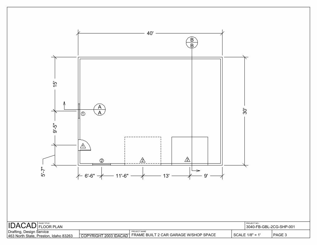
FLOOR PLAN
COPYRIGHT 2003 IDACADPROJECT NAME
PROJECT NO.:
SCALE 1/8" = 1'
3040-FB-GBL-2CG-SHP-001
PAGE 3
30'
15'
11'-6"6'-6"5'-7
"
9'-5
"
9'13'
40'
AA
BB
1
2
1
2 2
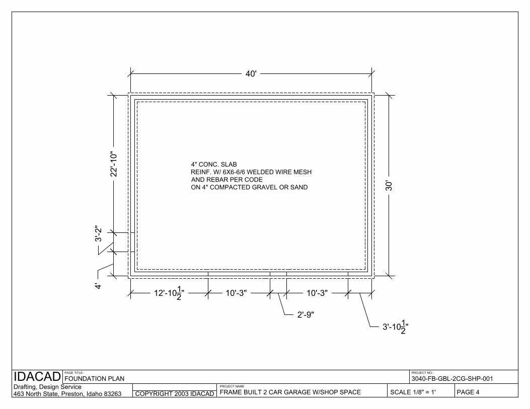
3'-2
"
10'-3"
2'-9"
10'-3"
3'-1012"
12'-1012"
4'
22'-1
0"
40'
30'
3040-FB-GBL-2CG-SHP-001PROJECT NO.:PAGE TITLE:IDACAD
Drafting, Design Service463 North State, Preston, Idaho 83263
PROJECT NAME
FRAME BUILT 2 CAR GARAGE W/SHOP SPACE SCALE 1/8" = 1'COPYRIGHT 2003 IDACAD PAGE 4
FOUNDATION PLAN
4" CONC. SLABREINF. W/ 6X6-6/6 WELDED WIRE MESH AND REBAR PER CODEON 4" COMPACTED GRAVEL OR SAND

FRAME BUILT 2 CAR GARAGE W/SHOP SPACE
ELECTRICAL PLANPAGE TITLE:
Drafting, Design Service463 North State, Preston, Idaho 83263
IDACADCOPYRIGHT 2003 IDACAD
PROJECT NAME
SCALE 1/8" = 1' PAGE 5
3040-FB-GBL-2CG-SHP-001PROJECT NO.:
$$$$
WP
WP
WP
WP
WP
$
110 VOLT OUTLET, WEATHER PROOF110 VOLT OUTLET110 VOLT OUTLET, CEILING MOUNT
CEILING FAN/LIGHTFLUORESCENT LIGHTPORCH LIGHTLIGHT SWITCHGARAGE DOOR OPENER SWITCH
~~ ~~
110 VOLT OUTLET, CEILING DROP CORD ~~
110 VOLT OUTLET, SPLIT WIRED, QUADRUPLEXBREAKER BOX

FRAME BUILT 2 CAR GARAGE W/SHOP SPACE463 North State, Preston, Idaho 83263Drafting, Design ServiceIDACAD PAGE TITLE:
SECTION A-A, H1 INSTALLATION
COPYRIGHT 2003 IDACADPROJECT NAME
PAGE 6
3040-FB-GBL-2CG-SHP-001
SCALE 1/4" = 1'
PROJECT NO.:
9"1'-6"
8"
STEEL REBAR PER CODEIN STEM WALL AND FOOTINGS
2 X 6 PRESSURE TREATED OR EQUAL MUDSILL/PLATE
W/ FOAM SEAL UNDERNEATH
2 X 6 D.F. STD & BTR. STUDS & CRIPPLES @ 16" O.C.
SIMPSON H1 HURRICANE TIEOR EQUAL EACH TRUSS
ENGINEERED TRUSS @ 24" O.C. 30 PSF LIVE LOAD 15 PSF DEAD LOAD
4" CONC. SLAB REINFORCE W/ 6x6-6/6 WELD WIRE MESH, AND REBAR PER CODE
4" MIN. COMPACTED GRAVEL OR SAND
DOUBLE 2 X 6 TOP PLATE
METAL DRIP EDGE
METAL SIDING OVER HOUSE WRAP ON 1/2" OR THICKER EXTERIOR GRADE PLYWOOD OR EQUAL
VENTED SOFFITS
METAL FASCIAOVER 2 X 8 FASCIA BOARD
2'
METAL ROOFINGOVER 30# FELT ON 5/8" OR THICKER EXTERIOR GRADE PLYWOOD OR EQUALINSTALLED PER MFG.'S SPECIFICATIONS
1/2" X 12 J-ANCHORSPACED PER CODE
2 X 12 HEADERS
2 X 6 HEADER2 X 6 ROUGH SILL
SIMPSON H1 INSTALLATIONSCALE: NTS
2 X 6 HEADER

COPYRIGHT 2003 IDACADDrafting, Design ServiceIDACAD463 North State, Preston, Idaho 83263
PAGE TITLE:
SECTION B-B
PAGE 7FRAME BUILT 2 CAR GARAGE W/SHOP SPACEPROJECT NAME
3040-FB-GBL-2CG-SHP-001
SCALE 1/4" = 1'
PROJECT NO.:
ENGINEERED REDUCED GABLE END TRUSS
ENGINEERED TRUSS @24" O.C.
2 X 4 LOOKOUT @24" O.C.2 X 4 NAILER
2 X 8 FLY RAFTER
METAL DRIP EDGE OVERMETAL FASCIAOVER 2 X 8 FLY RAFTER
SOFFITS
METAL SIDING OVER HOUSE WRAP ON 1/2" OR THICKER EXTERIOR GRADE PLYWOOD OR EQUAL
1/2" X 12 J-ANCHORSPACED PER CODE
STEEL REBAR PER CODEIN STEM WALL AND FOOTINGS
4" CONC. SLAB REINFORCE W/ 6x6-6/6 WELD WIRE MESH, AND REBAR PER CODE
4" MIN. COMPACTED GRAVEL OR SAND
2 X 6 PRESSURE TREATED OR EQUAL MUDSILL/PLATE
W/ FOAM SEAL UNDERNEATH
2 X 6 D.F. STD & BTR. STUDS @ 16" O.C.
DOUBLE 2 X 6 TOP PLATE
SIMPSON H1 HURRICANE TIEOR EQUAL EACH TRUSS
8"
9"1'-6"
INSTALL BLOCKING AS REQ'D PER CODE
2'
BACK FRONT
2 X 12 HEADERS
2 X 6 CRIPPLE
2 X 6 HEADER
SLAB ON STEM WALL @ DOORS
2 X 6 HEADER
DOUBLE 2 X 6 TOP PLATE
FRAME BUILT 2 CAR GARAGE W/SHOP SPACE463 North State, Preston, Idaho 83263
IDACADDrafting, Design Service
PAGE TITLE:
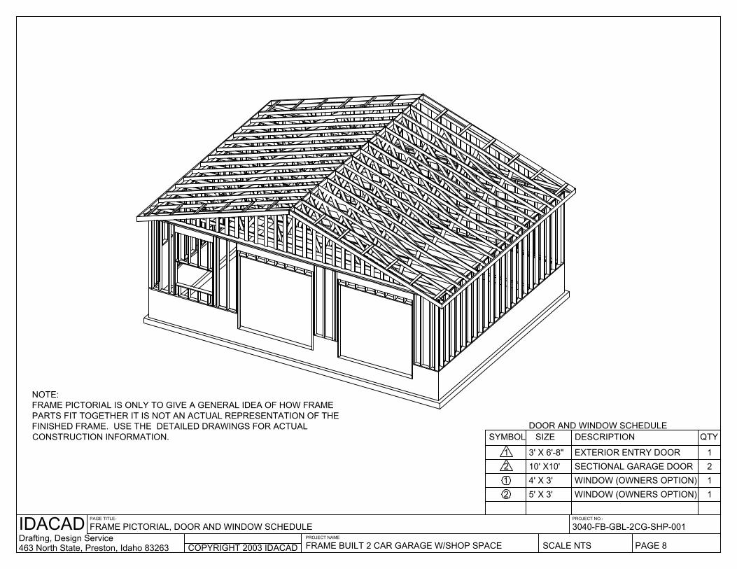
FRAME PICTORIAL, DOOR AND WINDOW SCHEDULE
COPYRIGHT 2003 IDACADPROJECT NAME
PROJECT NO.:
SCALE NTS
3040-FB-GBL-2CG-SHP-001
PAGE 8
NOTE:FRAME PICTORIAL IS ONLY TO GIVE A GENERAL IDEA OF HOW FRAME PARTS FIT TOGETHER IT IS NOT AN ACTUAL REPRESENTATION OF THE FINISHED FRAME. USE THE DETAILED DRAWINGS FOR ACTUAL CONSTRUCTION INFORMATION.
5' X 3'
DOOR AND WINDOW SCHEDULESYMBOL SIZE DESCRIPTION QTY
10' X10'212
4' X 3'
1 3' X 6'-8" 2SECTIONAL GARAGE DOOR
WINDOW (OWNERS OPTION)WINDOW (OWNERS OPTION)
11
EXTERIOR ENTRY DOOR 1

PAGE 9
General Specifications and Notes
General:
1. Construction shall meet all applicable codes and ordinances.
Site Work:
1. Make sure setbacks are in compliance with those
shown on plans and local building codes. 2. All stumps, roots, and organic matter shall be
removed from the soil in the area of the building. 3. Lot must be graded to insure proper drainage. This
must be completed prior to final inspection. 4. Soil should not be a highly expansive soil type
without having a soil report preformed by a soils engineer and receiving approval from local building department to construct building on said type soil.
5. Soil bearing capacity assumed to be 1500 psi at 2’ below adjacent finished grade for design.
6. Bottom of footings shall be placed 30” minimum below existing grade and tops of stems shall be 10” minimum above finished grade or per code if greater.
Concrete:
1. All slabs are to be 4” concrete over 4” gravel unless
otherwise noted on the plans. 2. Concrete to be ACI 301-66, Type II cement, 2500
psi at 28 days, 5” maximum slump. 3. Reinforcing to be ASTM A615-Bars with Fy=60 ksi
lap 30 diameter minimum at splices or weld per ACI Std.
4. Concrete design based on Fc 2000 psf, Fc 2500 psi for quality only.
5. Anchor bolts shall be A-307 embedded 7” minimum into concrete or masonry grout.
Roof Framing:
1. Fascia to be 2”x8” Douglas Fir per detail sheet
unless otherwise specified. 2. For soffit size see detail sheet.
3. For spans and dimensions refer to floor plans.
4. Trusses are to be an approved truss design from the truss manufacture’s engineer.
5. Use Simpson H-1 hurricane anchors at each truss or rafter to wall connection unless otherwise specified.
6. Solid blocking required between joists, rafters, and trusses. Such blocking shall be 1 ½” minimum thickness and full depth of joists, rafters, or trusses.
7. Minimum header sizes shall be according detail sheet.
8. Basis of design roof live/snow load of 30 psf, and roof dead load of 15 psf.
9. Plywood roof decking to be 5/8” thick, 24/0, CDX or equal wafer unless otherwise specified.
Woods:
General framing: (Douglas Fir)
1. Brace all exterior walls and cross-stud
partitions at each end of building and at least every 25’ of length by one of the following:
a. Simpson WB 126 wall bracing with 3-16d nails at each end and 1-8d nails at each stud.
b. Plywood sheathing of a minimum thickness of 3/8 inch.
3. Fire stopping: a. Fireblock stud spaces over 10’ in
height, furred spaces, soffits, bearing walls and ceiling joist lines, etc. Firestopping shall consist of 2” nominal lumber.
b. Firestop openings around vents, pipes, ducts, chimneys, and fireplaces at ceiling and floor levels with approved noncombustible materials.
4. CDX plywood is not approved where exposed to weather, i.e., roof overhangs.
5. Exterior wall framing to be 2”x6” studs at 16” o.c. Interior wall, framing at non-bearing walls to be 2”x4” studs at 24” o.c. and at bearing walls 2”x4” studs at 16” o.c. with double top plate unless otherwise specified.
6. Shear wall to be 1/2” CDX plywood. 7. All stress grade lumber shall comply with WCLA
specs and bear approval stamp on all pieces in place.
8. Framing lumber shall be Douglas Fir construction grade Fb 1450 or better unless otherwise noted.
9. Nailing to be per current U.B.C. unless otherwise noted.
10. All bearing partitions shall have double top plates. 11. Structural glued laminated timbers to be stamped
by an approved agency. 12. Use redwood or pressure treated sole plates at all
exterior walls. 13. Use pressure treated lumber or redwood any place
wood contacts concrete or is closer than 8” to the soil.
Thermal and Moisture Protection:
1. Metal roofing over Type 30 felt over 5/8” minimum
CDX plywood or equal wafer board installed per manufacturer’s instructions.
2. Install caulking compound at all penetrations in building envelope, i.e., holes drilled in top plates around windows, doors, and service entrance panel.
3. Cover the building exterior walls with house wrap. 3. Wrap all framing at exterior wall penetrations with a
layer of water and ice shield to prevent damage from moisture.
Doors, Windows, and Glass:
1. All exterior doors to be solid core.
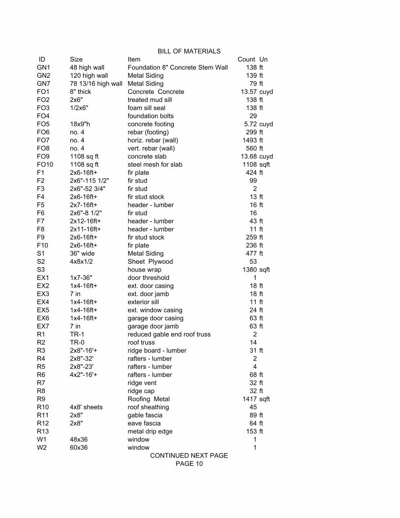
ID Size Item Count UnGN1 48 high wall Foundation 8" Concrete Stem Wall 138 ftGN2 120 high wall Metal Siding 139 ftGN7 78 13/16 high wall Metal Siding 79 ftFO1 8" thick Concrete Concrete 13.57 cuydFO2 2x6" treated mud sill 138 ftFO3 1/2x6" foam sill seal 138 ftFO4 foundation bolts 29FO5 18x9"h concrete footing 5.72 cuydFO6 no. 4 rebar (footing) 299 ftFO7 no. 4 horiz. rebar (wall) 1493 ftFO8 no. 4 vert. rebar (wall) 560 ftFO9 1108 sq ft concrete slab 13.68 cuydFO10 1108 sq ft steel mesh for slab 1108 sqftF1 2x6-16ft+ fir plate 424 ftF2 2x6"-115 1/2" fir stud 99F3 2x6"-52 3/4" fir stud 2F4 2x6-16ft+ fir stud stock 13 ftF5 2x7-16ft+ header - lumber 16 ftF6 2x6"-8 1/2" fir stud 16F7 2x12-16ft+ header - lumber 43 ftF8 2x11-16ft+ header - lumber 11 ftF9 2x6-16ft+ fir stud stock 259 ftF10 2x6-16ft+ fir plate 236 ftS1 36" wide Metal Siding 477 ftS2 4x8x1/2 Sheet Plywood 53S3 house wrap 1380 sqftEX1 1x7-36" door threshold 1EX2 1x4-16ft+ ext. door casing 18 ftEX3 7 in ext. door jamb 18 ftEX4 1x4-16ft+ exterior sill 11 ftEX5 1x4-16ft+ ext. window casing 24 ftEX6 1x4-16ft+ garage door casing 63 ftEX7 7 in garage door jamb 63 ftR1 TR-1 reduced gable end roof truss 2R2 TR-0 roof truss 14R3 2x8"-16'+ ridge board - lumber 31 ftR4 2x8"-32' rafters - lumber 2R5 2x8"-23' rafters - lumber 4R6 4x2"-16'+ rafters - lumber 68 ftR7 ridge vent 32 ftR8 ridge cap 32 ftR9 Roofing Metal 1417 sqftR10 4x8' sheets roof sheathing 45R11 2x8" gable fascia 89 ftR12 2x8" eave fascia 64 ftR13 metal drip edge 153 ftW1 48x36 window 1W2 60x36 window 1
BILL OF MATERIALS
CONTINUED NEXT PAGEPAGE 10

D1 36x80x1 3/4R ext. door hinged 1D2 120x120 garage door 2T1 1x2-16ft+ interior casing 40 ftT2 1x2-16ft+ window apron 10 ftT3 1x2-16ft+ sill 10 ft
Warning:This is a computer generated estimate of the materials needed. It is not to be construed as an accurate or complete list of materials. For a more accurate list of materials needed, you will have to calculate it by
hand.PAGE 11