30X Crisp Image Detection - masco.hu rendszer--CCTV System/SAMSUNG/Angol leiras... · COM1 8. 1N.C...
32
Thank you for purchasing a SAMSUNG CCD CAMERA. Before attempting to connect or operate this product, please read these instructions carefully and save this manual for future use. ENGLISH PTZ Dome Camera SPD-3000/2300 User’s Manual P/No. : Z6806-0737-01A VAN 06. 06 www.samsungtechwin.com www.samsungcctv.com • SAMSUNG TECHWIN CO., LTD. 145-3, Sangdaewon 1-dong, Jungwon-gu, Seongnam-si, Gyeonggi-do 462-703, Korea TEL : +82-31-740-8137~8139 FAX : +82-31-740-8145 • SAMSUNG OPTO-ELECTRONICS UK, LTD. Samsung House, 1000 Hillswood Drive, Hillswood Business Park Chertsey, Surrey KT16 OPS TEL : +44-1932-45-5308 FAX : +44-1932-45-5325 • TIANJIN SAMSUNG OPTO-ELECTRONICS CO., LTD. 7 Pingchang Rd, Nankai Dist. Tianjin 300190, P.R China TEL : +86-22-2761-4724(33821) FAX : +86-22-2761-6514 SALES NETWORK 30X Crisp Image Detection
Transcript of 30X Crisp Image Detection - masco.hu rendszer--CCTV System/SAMSUNG/Angol leiras... · COM1 8. 1N.C...

Thank you for purchasing a SAMSUNG CCD CAMERA.Before attempting to connect or operate this product,please read these instructions carefully and save this manual for future use.
ENGLISH
PTZ Dome Camera SPD-3000/2300 User’s Manual
P/No. : Z6806-0737-01AVAN 06. 06
www.samsungtechwin.comwww.samsungcctv.com
• SAMSUNG TECHWIN CO., LTD.145-3, Sangdaewon 1-dong, Jungwon-gu, Seongnam-si,Gyeonggi-do 462-703, KoreaTEL : +82-31-740-8137~8139 FAX : +82-31-740-8145
• SAMSUNG OPTO-ELECTRONICS UK, LTD.Samsung House, 1000 Hillswood Drive, Hillswood BusinessPark Chertsey, Surrey KT16 OPSTEL : +44-1932-45-5308 FAX : +44-1932-45-5325
• TIANJIN SAMSUNG OPTO-ELECTRONICS CO., LTD.7 Pingchang Rd, Nankai Dist. Tianjin 300190, P.R ChinaTEL : +86-22-2761-4724(33821) FAX : +86-22-2761-6514
SALES NETWORK
30X Crisp Image Detection

This installation should be made by a qualified service person and should conform to all local codes.
The lightning flash with an arrowhead symbol, within an equilateral triangle isintended to alert the user to the presence of uninsulated “dangerous voltage”within the product's enclosure that may be of sufficient magnitude toconstitute a risk of electric shock to persons.
The exclamation point within an equilateral triangle is intended to alert the userto the presence of important operating and maintenance (servicing)instructions in the literature accompanying the appliance.
INFORMATION -This equipment has been tested and found to comply with limitsfor a Class A digital device, pursuant to part 15 of the FCC Rules. These limits aredesigned to provide reasonable protection against harmful interference when theequipment is operated in a commercial environment. This equipment generates,uses, and can radiate radio frequency energy and, if not installed and used inaccordance with the instruction manual, may cause harmful interference to radiocommunications.Operation of this equipment in a residential area is likely to cause harmfulinterference in which case the user will be required to correct the interference athis own expense.
WARNING - Changes or modifications not expressly approved by the manufacturer
could void the user’s authority to operate the equipment.
CAUTION : To prevent electric shock and risk of fire hazards:
Do NOT use power sources other than that specified.
Do NOT expose this appliance to rain or moisture.

EN
GLIS
H Warnings & Cautions
This information is provided to ensure your safety and to prevent any losses, financial orotherwise. Please read it carefully and use the product accordingly.
Warning/Attention/Special Mark Messages
Features
Various Auto Surveillances
*Individual Preset Saving Modes 13 camera adjustment functions can be savedindependently in each Preset menu to provideoptimum images.
*Various ProtocolsFive different makersí protocols are supported:Samsung Techwin, Pelco, Samsung Electronics,Panasonic and Vicon.
*PTZ Tracking4 patterns operated with the joystick can besaved and replayed by users.
*AUTO SwingPan or Tilt is operated in sequence between 2designated positions.
*Group Search Maximum 128 Preset positions are toured inorder.
*Tour Search Maximum 6 Group Search functions are touredin order.
Day & Night
Day & Night function of ICR (IR Cut-FilterRemoval) and Sens-Up function can achieveoptimum images during day and night. *Sens-Up function improves the CCD sensitivity bylengthening the exposure time using electricity.
*Day&Night function enables users to select andadjust the colour and black and white imagesaccording to the light level.
30X/23X Zoom Lens with Auto-Focus FunctionThe 30X/23X zoom lens having Auto-focusfunction magnifies the image up to 300/230times when used with the digital 10X zoomfunction.
OSD (On Screen Display)
Items such as Camera ID, Camera Name, PresetNumber, Preset Name, Area Name and CameraStatus are displayed on the monitor. Camerafunctions can be set up on the OSD menu screen.
128 Preset Positions
A maximum of 128 Preset positions can beset up. This function enables users to set upthe monitoring place any time.
Digital Flip
When you want to monitor the moving objectbelow the camera, you can execute theDigital Flip using the controllerís joystick. Themoving object can be monitored withoutscreen reverse.
Area Masking
For privacy protection, a maximum of 8 areascan be masked among the surveillance areaspreventing them to be displayed on the screen.
Smart P/T
Even when the Zoom-In function is On for thePan and Tilt speed correction function linked tothe zoom position, fine manual operation ispossible.
EN
GLIS
H
Indicates “Never Allowed.”
Indicates “No Disassembling.”
Indicates Must Observe.
Ignoring this information may result in material loss and/or seriouspersonal injuries including death.
Samsung Techwin cares for the environment at all product manufacturingstages to preserve the environment, and is taking a number of steps toprovide customers with more environment-friendly products.The Eco markrepresents Samsung Techwin s will to create environment-friendly products,and indicates that the product satisfies the EU RoHS Directive.
EN
GLIS
H
Precautions
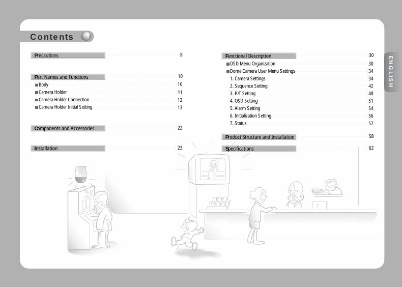
BodyCamera HolderCamera Holder ConnectionCamera Holder Initial Setting
8
Components and Accessories 22
Installation 23
Part Names and Functions 10
10
11
1213
OSD Menu OrganizationDome Camera User Menu Settings1. Camera Settings2. Sequence Setting3. P/T Setting4. OSD Setting5. Alarm Setting6. Initialization Setting7. Status
Functional Description 30
Product Structure and Installation 58
Specifications 62
3034344248515456
57
Contents
EN
GLIS
H

SPEED DOME CAMERASPEED DOME CAMERA User’s ManualUser’s Manual 9
EN
GLIS
H
8
EN
GLIS
H
Precautions
Installation by unqualifiedpersons is not recommended.
Experienced and skilled technicians have to installthis product. Unqualified and personal installationmay cause fire or electric shock. Contact the dealerfor installation.
If any unusual odors or smoke comesfrom the camera, stop using the product.
Do not install the product under humid conditionsor near flammable or explosive gases.
Install the product in a place strongenough to hold it.
Do not handle the power plugwith wet hands.
It may cause electric shock.
Do not disassemble or insertforeign objects.
It may cause failure or electric shock.
It may cause fire.
Do not install the product in toohot or too cold environments.
Do not use the camera under extreme temperatures (below -10° or above +50°). It may cause poor image quality orfailure. Be especially careful to provide ventilation whenoperating the camera under high temperatures.
Do not install the camera under severelychanging lighting environments such asfluorescent lamps. It may cause the camerato work improperly.
Never drop the camera or subjectit to severe shocks or vibrations.
It is the most important part of camera. Becareful not to mark it with fingerprints.
Do not install the camera where it mightbe exposed to rain, water or spillages.
If the camera gets wet, it may cause failure.
Do not install the camera inintermittent lighting environments.
Do not aim the camera at the sunor any other strong light source.
Do not touch the front glass ofthe camera.
It may cause failure, electric shock or fire. The product may fall. It may cause failure. It may cause fatal damage to CCD device orinternal circuit.

SPEED DOME CAMERASPEED DOME CAMERA User’s ManualUser’s Manual 1110
Function Setup Switch 1. Half/Full 2.3.4.5. RS-485/422 Terminal Setting 6. RS-485/422 Communication 7. Factory setting 8. RS-232
Controller Connection Input1. RXD+ 2. RXD- 3. TXD+ 4. TXD- 5. GND 6. TX 7. RX
ID Setup Switch
Alarm Connection Input 1. IN1 2. IN2 3. GND 4. IN3 5. IN4 6. GND 7. COM1 8. 1N.C 9. 1N.O 10. COM2 11. 2N.C 12. 2N.O
Protocol Selection Switch
AC 24V Input
Part Names and Functions
Power Switch Power ON/OFF (Factory Setting: OFF)
Body Camera Holder
<Figure: Door Part Label>
EN
GLIS
H

SPEED DOME CAMERASPEED DOME CAMERA User’s ManualUser’s Manual 1312
Camera Holder Connection Camera Holder Initial Settings
Setting Communications Protocol
Use the SW3 of installation bracket to set the communications protocol.
SW1 Protocol Baud Rate(BPS)0 Samsung 9,6001 Samsung 19,2002 Pelco-D 2,4003 Pelco-D 4,8004 Pelco-D 9,6005 Samsung Elec. 9,6006 Samsung Elec. 19,2007 Samsung Elec. 38,4008 Panasonic 9,6009 Panasonic 19,20010 Vicon 4,80011 Vicon 9,600
12~F Reserve
Part Names and Functions
EN
GLIS
H
• In order to control the speed dome camera by personal computer, exclusive programshould be used.
Notes
• If the speed dome camera is controlled by the Panasonic and Vicon controller, pleasecontact with our company custom satisfication part and technical part.
Notes

SPEED DOME CAMERASPEED DOME CAMERA User’s ManualUser’s Manual 15
EN
GLIS
H
14
EN
GLIS
H
Setting Camera ID (Camera Holder)
Set the Camera ID using 2 rotary switches (SW1and SW2).
SW1 is the upper level switch and SW2 is thelower level switch.
EX: If the Camera ID is 1, set the ID number asfollows.
Camera ID SW2 SW1 RemarksID = 0 0 0 N/AID = 1 0 1ID = 2 0 2ID = 3 0 3ID = 4 0 4ID = 5 0 5ID = 6 0 6ID = 7 0 7ID = 8 0 8ID = 9 0 9ID = 10 0 AID = 11 0 BID = 12 0 CID = 13 0 DID = 14 0 EID = 15 0 FID = 16 1 0ID = 17 1 1ID = 18 1 2ID = 19 1 3ID = 20 1 4ID = 21 1 5ID = 22 1 6ID = 23 1 7ID = 24 1 8ID = 25 1 9ID = 26 1 AID = 27 1 BID = 28 1 CID = 29 1 DID = 30 1 EID = 31 1 FID = 32 2 0ID = 33 2 1ID = 34 2 2ID = 35 2 3ID = 36 2 4ID = 37 2 5ID = 38 2 6ID = 39 2 7ID = 40 2 8ID = 41 2 9ID = 42 2 AID = 43 2 BID = 44 2 CID = 45 2 DID = 46 2 EID = 47 2 F
Camera ID SW2 SW1 RemarksID = 48 3 0ID = 49 3 1ID = 50 3 2ID = 51 3 3ID = 52 3 4ID = 53 3 5ID = 54 3 6ID = 55 3 7ID = 56 3 8ID = 57 3 9ID = 58 3 AID = 59 3 BID = 60 3 CID = 61 3 DID = 62 3 EID = 63 3 FID = 64 4 0ID = 65 4 1ID = 66 4 2ID = 67 4 3ID = 68 4 4ID = 69 4 5ID = 70 4 6ID = 71 4 7ID = 72 4 8ID = 73 4 9ID = 74 4 AID = 75 4 BID = 76 4 CID = 77 4 DID = 78 4 EID = 79 4 FID = 80 5 0ID = 81 5 1ID = 82 5 2ID = 83 5 3ID = 84 5 4ID = 85 5 5ID = 86 5 6ID = 87 5 7ID = 88 5 8ID = 89 5 9ID = 90 5 AID = 91 5 BID = 92 5 CID = 93 5 DID = 94 5 EID = 95 5 F
Setting Baud Rate Based on DVR Model (Camera Holder)
If the speed dome camera is controlled not by the camera controller but by aDVR, set the communication speed based on the DVR model as follows.
Samsung Pelco Samsung Elec.
SVR-430 9600,19200 9600 19,200,38,400SVR-440 9600,19200 4800, 9600 19,200,38,400SVR-1630 9600,19200 2400,4800,9600 19,200,38,400SVR-1650 9600,19200 2400,4800,9600 19,200,38400
ProtocolDVR Model
Part Names and Functions
• Depending on the DVR firmware version, the Control function may not besupported. Use this function after installation of the final version.
Notes
Setting Camera ID Switch (Camera Holder)

SPEED DOME CAMERA User’s Manual17
EN
GLIS
H
SPEED DOME CAMERA User’s Manual16
Camera ID SW2 SW1 RemarksID = 96 6 0ID = 97 6 1ID = 98 6 2ID = 99 6 3ID = 100 6 4ID = 101 6 5ID = 102 6 6ID = 103 6 7ID = 104 6 8ID = 105 6 9ID = 106 6 AID = 107 6 BID = 108 6 CID = 109 6 DID = 110 6 EID = 111 6 FID = 112 7 0ID = 113 7 1ID = 114 7 2ID = 115 7 3ID = 116 7 4ID = 117 7 5ID = 118 7 6ID = 119 7 7ID = 120 7 8ID = 121 7 9ID = 122 7 AID = 123 7 BID = 124 7 CID = 125 7 DID = 126 7 EID = 127 7 FID = 128 8 0ID = 129 8 1ID = 130 8 2ID = 131 8 3ID = 132 8 4ID = 133 8 5ID = 134 8 6ID = 135 8 7ID = 136 8 8ID = 137 8 9ID = 138 8 AID = 139 8 BID = 140 8 CID = 141 8 DID = 142 8 EID = 143 8 FID = 144 9 0ID = 145 9 1
Camera ID SW2 SW1 RemarksID = 146 9 2ID = 147 9 3ID = 148 9 4ID = 149 9 5ID = 150 9 6ID = 151 9 7ID = 152 9 8ID = 153 9 9ID = 154 9 AID = 155 9 BID = 156 9 CID = 157 9 DID = 158 9 EID = 159 9 FID = 160 A 0 N/AID = 161 A 1ID = 162 A 2ID = 163 A 3ID = 164 A 4ID = 165 A 5ID = 166 A 6ID = 167 A 7ID = 168 A 8ID = 169 A 9ID = 170 A AID = 171 A BID = 172 A CID = 173 A DID = 174 A EID = 175 A F N/AID = 176 B 0ID = 177 B 1ID = 178 B 2ID = 179 B 3ID = 180 B 4ID = 181 B 5ID = 182 B 6ID = 183 B 7ID = 184 B 8ID = 185 B 9ID = 186 B AID = 187 B BID = 188 B CID = 189 B DID = 190 B EID = 191 B FID = 192 C 0ID = 193 C 1ID = 194 C 2ID = 195 C 3
Camera ID SW2 SW1 RemarksD = 196 C 4ID = 197 C 5ID = 198 C 6ID = 199 C 7ID = 200 C 8ID = 201 C 9ID = 202 C AID = 203 C BID = 204 C CID = 205 C DID = 206 C EID = 207 C FID = 208 D 0ID = 209 D 1ID = 210 D 2ID = 211 D 3ID = 212 D 4ID = 213 D 5ID = 214 D 6ID = 215 D 7ID = 216 D 8ID = 217 D 9ID = 218 D AID = 219 D BID = 220 D CID = 221 D DID = 222 D EID = 223 D FID = 224 E 0ID = 225 E 1ID = 226 E 2ID = 227 E 3ID = 228 E 4ID = 229 E 5ID = 230 E 6ID = 231 E 7ID = 232 E 8ID = 233 E 9ID = 234 E AID = 235 E BID = 236 E CID = 237 E DID = 238 E EID = 239 E FID = 240 F 0ID = 241 F 1ID = 242 F 2ID = 243 F 3ID = 244 F 4ID = 245 F 5
Camera ID SW2 SW1 RemarksID = 246 F 6ID = 247 F 7ID = 248 F 8ID = 249 F 9ID = 250 F AID = 251 F BID = 252 F CID = 253 F DID = 254 F EID = 255 F F
• Factory Setting: Camera ID = 1
Notes
Part Names and Functions

SPEED DOME CAMERA User’s Manual19
EN
GLIS
H
SPEED DOME CAMERA User’s Manual18
The following 3 Camera ID’s cannot be used.
Camera ID R-SW2 R-SW1ID = 0 0 0ID = 160 A 0ID = 175 A F
Function ON OFFSW3- #6 Factory Release RS-422 RS-485
Function ON OFFSW3- #1 Transmission Mode Full Duplex Half Duplex
Selection (DVR) (SCC-16/SCC-3000/3100)
Location of Camera Connection SW3- #2 SW3- #3 SW3- #4 SW3- #5Termination of Longest Path ON ON ON ONOn the Path OFF OFF OFF OFF
Set the transmission mode using the ON/OFF of the Dip Switch 1.
Function ON OFFSW3- #7 Factory Release Always OFF
Function ON OFFSW3- #8 PC Communication RS-232 RS-485/422
Part Names and Functions
Setting Transmission Mode (Camera Holder)
Setting Communication Method (Camera Holder)
Setting for Factory Adjustment (Camera Holder)
PC Communication Setting (Camera Holder): For reservation
Set the termination using the ON/OFF of 2, 3, 4, 5 of the Dip Switch 3.
Setting RS-485/RS-422A Termination (Camera Holder)
• Factory Setting: OFF
Notes
• Factory Settings: Only #2 and #3 are ON.
Notes
• Factory Setting: OFF
Notes
• Factory Setting: OFF
Notes
• Factory Setting: OFF
Notes

SPEED DOME CAMERASPEED DOME CAMERA User’s ManualUser’s Manual 21
EN
GLIS
H
20
NAME PurposeCON7- #1 RXD+ Controller Data Line ConnectionCON7-#2 RXD- Controller Data Line ConnectionCON7-#3 TXD+ Controller Data Line ConnectionCON7-#4 TXD- Controller Data Line ConnectionCON7-#5 GND GNDCON7-#6 TX For RS-232 CommunicationCON7-#7 RX For RS-232 Communication
NAME PurposeIJP3 - #1 IN1 Alarm input sensor connection terminal 1IJP3 - #2 IN2 Alarm input sensor connection terminal 2IJP3 - #3 GND GNDIJP3 - #4 IN3 Alarm input sensor connection terminal 1IJP3 - #5 IN4 Alarm input sensor connection terminal 1IJP3 - #6 GND GNDIJP3 - #7 COM1 Alarm Output 1 CommonIJP3 - #8 1N.C Alarm Output 1 (for Normal Close)IJP3 - #9 1N.O Alarm Output 1 (for Normal Open)IJP3 - #10 COM2 Alarm Output 1IJP3 - #11 2N.C Alarm Output 2 (for Normal Close)IJP3 - #12 2N.O Alarm Output 2 (for Normal Open)
In order to prevent signal reduction, the termination resistance of the 2 endunits, which are the distant paths for camera and controller to be connectedon the RS485 interface, should be connected.
As the termination resistance is built in the camera, whether to make thetermination resistance valid or invalid is selected with the DIP switch.
See the connection diagram below for determining to which device thetermination resistance will be connected to.
Set up the termination resistance in the dark products.
The installation distance of the product for the termination resistance settingshould be less than 1.2 Km. (Maximum cable length is 1.2 Km according tothe RS-485 standards.)
Part Names and Functions
Controller Connection Terminal (Camera Holder) Setting Termination Resistance
Alarm Connection Terminal (Camera Holder)

SPEED DOME CAMERASPEED DOME CAMERA User’s ManualUser’s Manual 23
EN
GLIS
H
22
EN
GLIS
H
Adapter AC24V, Peak 2.5A) User s Manual Camera Holder
Terminal Block for AlarmConnection (12Pin)
Terminal Block for ControllerConnection (7Pin)
3 Screws for Fastening Camera Holder1 Screw for Fastening Cable
The following products are provided separately.
Item Model DescriptionOn-Ceiling Mount STB-330PC Mounted on the ceiling surfaceCamera Controller SCC-16 Pan/Tilt/Zoom/Focus control, OSD, Setting various functions Camera Controller SCC-3000/3100 Pan/Tilt/Zoom/Focus control, OSD, Setting various functionsIndoor Housing STH-330PI Housing for indoor installationIndoor Insertion Housing STH-330PE Installation by inserting the camera into the indoor ceiling Outdoor Housing STH-330PO Output DC 12V (including heater and fan)Wall Type Mount STB-270PW Attachment to the wallCeiling Type Mount STB-496PP Attachment to the ceiling
To install and use the SPD-3000/2300, the following cables should be used.
• Power Adapter CableThe cable connected to the power input terminal of SPD-3000/2300 is shownbelow with a rated voltage of AC24V 2.5A.
• Video CableThe cable connected to the video output terminal and to the monitor of SPD-3000/2300 is the BNC cable shown below.
• Communications CableThe cable connected to the controller of SPD-3000/2300 for RS-485/422 communicationis shown below.
Safety wire
Components and Accessories
Accessories Preparation for Cable
Products Sold Separately
• See pages 25 and 26 for product images.
Notes • Video cable and RS-485/422 communication cable are not provided in thisproduct’s package.
Notes
Installation

SPEED DOME CAMERA User’s Manual25
EN
GLIS
H
SPEED DOME CAMERA User’s Manual24
1. First, connect one end of the BNC videocable connector to the Video OutputTerminal.
2. Next, connect the other end of theconnector to the Video Input Terminal of the monitor.
• Installation Precautions- Check out the installation place. It should be strong enough to support morethan 4 times the total product weight including speed dome camera (SPD-3000/2300) and installation structure.
- Install the camera in a place having more than 500mm of space above theceiling board.
- Install the camera holder using the provided installation guide tab, screw andfastening cable.
- There is a risk of camera falling during installation. Prevent the fall using thefastening cable while installing the camera. Also, access of other people tothe place should not be allowed during installation.
• Accessories Sold SeparatelyUse the following accessories sold separately for convenient installationdepending on installation places.
1) On-Ceiling Installation Mount (STB-330PC)This mount is used to install the camera on the ceiling.
2) Indoor Insertion Housing (STH-330PE)This housing is used to attach the speed dome camera tothe ceiling for installation.
3. Then, connect the Power Adapter Cable. Use a driver (-) to screw one part ofthe Power Adapter consisting of two lines to thePower Input Terminal of the cameraholder.
4. Connect the Power Adapter’s plug to the Power Outlet.
5. Connect the Controller Connection Terminal of SPD-3000/2300 and the external Controller.
Video Out TerminalMonitor In Terminal
Monitor
Power Adapter
Controller Connection Terminal
DATA BOX
Controller
Installation
Cable Connection Installation of SPD-3000/2300

SPEED DOME CAMERA User’s Manual27
EN
GLIS
H
SPEED DOME CAMERA User’s Manual26
3) Indoor and Outdoor Housing (STH-330PI, STH-330PO)This housing is used to install the speed dome camera on the indoor or outdoorwall or ceiling. (For the indoor type, the fan and heater are excluded.)
4) Wall Type Mount (STB-270PW)This item is used to install the indoor or outdoor housing for speed dome on thewall.
5) Ceiling Type Mount (STB-496PP)This item is used to install the indoor and outdoor housing for speed dome on a concrete ceiling.
1. Fasten the ceiling mount on the ceiling.
2. Pull outside of the housing the safety wire fastened to the outdoor housing.
inside
3. Connect the fan heater PCB cable inside the housing to the camera holder connector.
4. Match the arrow sign marked on the camera holder to the arrow marked inside the housing and then install the camera holder in the housing.
outside
Installation
Camera Installation (outdoor Housing)

SPEED DOME CAMERA User’s Manual29
EN
GLIS
H
SPEED DOME CAMERA User’s Manual28
5. Connect the heater and fan cables within the housing to the fan heater PCB.
8. Remove the camera dome cover and then attach the housing dome cover.
6. Adjust and make the arrows marked on the bottom of the camera body face each other.
an arrow
Camera Dome Cover Housing Dome Cover
7. Insert the camera into the housing by matchingthe installation pin on the bottom of the cameraand the arrow inside the housing, and thenfasten the camera by inserting into the fasteninghole, turning the screw clockwise for fastening.
9. Connect the housing safety wires to the fixture inside the mount installed on the ceiling.
10. Connect the video cable, the controller cable, the power adapter cable and ID cable to the camera holder.
11. Check out the connection of all parts and the camera and install the completed outdoor housing on the ceiling mount.
• Check out the input voltage of the power adapter before connecting the power. • For an installation without housing, the camera can be installed with installation
template, fastening the cable and screw provided separately. • It is necessary to tighten the screw to prevent unfastening. • If the screw to prevent unfastening is not tight, the camera installed may fall due to
vibration or shock from the environment. • Set up the Camera ID, the Termination Resistance and the Protocol Selection
Switch before installing the outdoor housing on the ceiling type mount.
Notes
Installation

SPEED DOME CAMERA User’s Manual31
EN
GLIS
H
SPEED DOME CAMERA User’s Manual30
OSD Menu Organization
Dome camera can be set up on the OSD (On Screen Display) menu displayedon the video monitor by the camera controller. The joystick operations in theOSD menu are as follows. In addition, sending control codes to the camera fromthe PC can also use the camera functions. • Menu Organization
Menu Function Menu FunctionTILT UP Move up on the OSD menu PAN LEFT Move left on the OSD menu
TILT DOWN Move down on the OSD menu PAN RIGHT Move right on the OSD menu
Functional Description
P1 P2 P3 P4 DefaultsFocus Mode Auto/Manual/One Shot AF One Shot AF
Zoom TrackingMode On/Off ONSpeed Slow/Fast Fast
Digital Zoom Off(2~10X) OFF
AWB Mode
ATW/AWC/MANUAL ATW(O)ATW
-ATW(I): Indoor -ATW(O): OutdoorManual 30
-Red -Blue 40Brightness 50 050
IrisAuto AutoManual Iris Level 050
Shutter--- ESCA.FLKManual 1/60~1/120,000,x2~x128 1/60
Sens-Up Auto Sens-Up Limit x2~x128 x4Off
On/Off OFFAGC High/Middle/Low/Off MiddleSSNR High/Middle/Low/Off OFF
AutoB/W B/W Burst On/Off OFFColor Burst Level 150
Sync Internal 10
Exposure
Day & Night
Others
Back Light
WhiteBalance
CameraSetting
Focus
P1 P2 P3 P4 DefaultsSync Line Lock Line Lock Phase 225DIS On/Off OFF
Others Image Adj. Sharpness 008Color 050
Freeze On/Off OFFPreset Setting Edit Execute Clear Status
Swign SEQPan Swing Setting Execute ClearTilt Swing Setting Execute ClearP/T Swing Setting Execute Clear
Group SEQ
Group1 Setting Execute ClearGroup2 Setting Execute ClearGroup3 Setting Execute ClearGroup4 Setting Execute ClearGroup5 Setting Execute ClearGroup6 Setting Execute Clear
Tour SEQ Setting Execute Clear
PTZ TraceTrace1 Replay MemorizeTrace2 Replay MemorizeTrace3 Replay MemorizeTrace4 Replay Memorize
Off OFFPreset Preset NoSwing Swing Mode Pan/Tilt/P&T
Mode Group Group NoTourTrace Trace1~Trace4A.Pan Auto Pan Speed 20-50 32
Tilt Angle 10-45 25Time 1-59(Sec), 1-59(Min) 30 sec
Power OnOn/Off OFF
ResumePan Limit Position ON/OFFTilt Limit Position ON/OFF
Area Setting
Area1Area2Area3Area4
Auto Run
CameraSetting
P/TSetting
SequenceSetting
Area NamePositionON/OFF

SPEED DOME CAMERA User’s Manual33
EN
GLIS
H
SPEED DOME CAMERA User’s Manual32
Symbol Description
1. Auto Run in the Sequence Mode- “A” symbol is flashing on the right top of the screen.
2. Motion Stabilization Stand-by Operation- “D” symbol is flashing on the right top of the screen.
3. Alarm operation- “ ”symbol is flashing on the right top of the screen.
4. Alarm Input #1, 2, 3, 4 Sensor Operation- “ ”, “ ”, “ ” and “ ” symbols are flashing on the right top of the screen.
5. Alarm Output #1, 2 Sensor Operation- “ ” and “ ” symbols are flashing on the right top of the screen.
6. Motion Detect Operation- “Man Icon” is flashing on the right top of the screen.
7. When there are sub menus under the selected OSD menu- Numbers are displayed in white colour like on the right top of the screen.
8. When there is no sub menu under the selected OSD menu- Numbers are displayed in black colour like “ ” on the right top of the screen.
• Preset setting is only possible on the OSD menu or using the controller.
Notes
Functional Description
P1 P2 P3 P4 DefaultsArea5Area6Area7Area8Mask1Mask2Mask3Mask4
Prop. P/T ON / OFF ONDigital Flip ON / OFF ONCamera ID ON / OFF ONCamera Name Edit ON / OFFPreset Number ON / OFF ONPreset Name Edit ON / OFFSequence Status ON / OFF ONArea Name ON / OFF OFFPTZ Position ON / OFF OFFLanguage English/Chinese EnglishAlarm Enable ON / OFF OFF
Alarm1 NC/NO/COMAlarm2 1~4(Priority)Alarm2 Preset/Group/TourAlarm2 A.Pan/TraceSetting1 1-4, MDSetting2 1-4, MD
1-59(Sec)Timer1 1-59(Min)
1-59(Hour)1-59(Sec)
Timer2 1-59(Min)1-59(Hour)
Out Off1Out Off2
MD Dwell Time ON / OFF 1-59(Sec) / 1-59(Min) 30secPower On Reset Cancel ExecuteFactory Default Set Cancel ExecuteCamera Default Set Cancel ExecuteAuto Refresh OFF, 1~7Days OFF
P/TSetting
OSDSetting
AlarmSetting
Area NamePositionON/OFF
PositionON/OFF
Area Setting
Area Masking
Alarm Input
Alarm Out

SPEED DOME CAMERA User’s Manual35
EN
GLIS
H
SPEED DOME CAMERA User’s Manual34
Dome Camera User Menu Settings
• Execution of OSD Menu :After checking if the camera is in manual operation mode, press the OSD Menukey or 1+MENU (SCC-16 Model). The following commands are displayed on themonitor screen.
• Main Menu
• Camera Setting Menu
In Focus menu, you can set up the focus mode among Auto, Manual or OneShot AF.
Focus ModeAuto : The camera adjusts the focus automatically while monitoring the
screen continuously in the auto mode. In the auto focusing mode,zoom key operation is not recognized as the input of the focus key.
Manual : In the manual mode, users can adjust the camera focus manually. One Shot AF : Only when the camera does not move, it turns into the auto mode. It
is the same as the manual mode. Zoom TrackingMode: When you select ON, the Focus function is executed when the Zoom function
is on. When you select OFF, the Focus function is not executed even whenthe Zoom function is on.
Speed: Fast will speed up the Zoom. Slow will slow down the Zoom. Digital Zoom Magnification of the Digital Zoom can be selected among Off, 2X~10X. *It is recommended that the Digital Zoom should be set up before the preset operation.
Select the Camera Setting on the Main Menu screen to control camera settings
The selection key moves up and down. Press theexecution key switch on the selected menu tochange the setup menu. Press the ESC key to exitthe OSD Menu.
FOCUS
Main Menu
Camera Setting
Sequence Setting
P/T Setting
OSD Setting
Alarm Setting
Initialize
Status
Camera Setting
FocusWhite Balance ATW(O)ExposureBack Light OFFAGC MIDDLESSNR MIDDLEDay & Night COLOROthers
Focus
Focus Mode ONE SHOT AFZoom TrackingDigital Zoom OFF
Functional Description
1) Camera Setting
Digital Zoom •As the digital zoom magnification increases, the image quality is lowered.
Auto-focus• Auto-focus may not function normally under the following conditions.
- When the light level in the surveillance area is low- When the slow-shutter works- When the amplification is increased- When the light level in the surveillance area is excessively high- When the objects in the long and short distance are under the same surveillance area- When there is no contrast (white and black) in the object (e.g. sky or wall)- When the thin horizontal line is captured
Notes
SPEED DOME CAMERA User’s Manual37
EN
GLIS
H
SPEED DOME CAMERA User’s Manual36
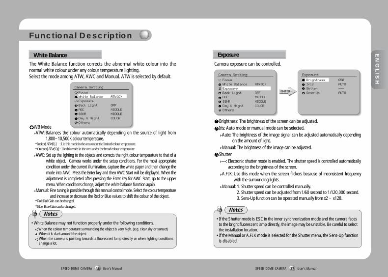
The White Balance function corrects the abnormal white colour into thenormal white colour under any colour temperature lighting. Select the mode among ATW, AWC and Manual. ATW is selected by default.
Exposure
Camera exposure can be controlled.
Brightness: The brightness of the screen can be adjusted. Iris: Auto mode or manual mode can be selected.
Auto: The brightness of the image signal can be adjusted automatically dependingon the amount of light.
Manual: The brightness of the image can be adjusted. Shutter
---: Electronic shutter mode is enabled. The shutter speed is controlled automaticallyaccording to the brightness of the screen.
A.FLK: Use this mode when the screen flickers because of inconsistent frequencywith the surrounding lights.
Manual: 1. Shutter speed can be controlled manually. 2. Shutter speed can be adjusted from 1/60 second to 1/120,000 second.3. Sens-Up function can be operated manually from x2 ~ x128.
WB ModeATW: Balances the colour automatically depending on the source of light from
1,800~10,500K colour temperature. * Indoor[ATW(I)] : Use this mode in the area under the limited colour temperature. * Outdoor[ATW(O)] : Use this mode in the area under the broad colour temperature.
AWC: Set up the lighting to the objects and corrects the right colour temperature to that of awhite object. Camera works under the setup conditions. For the most appropriatecondition under the current illumination, capture the white paper and then change themode into AWC. Press the Enter key and then AWC Start will be displayed. When theadjustment is completed after pressing the Enter key for AWC Start, go to the uppermenu. When conditions change, adjust the white balance function again.
Manual: Fine tuning is possible through this manual control mode. Select the colour temperatureand increase or decrease the Red or Blue values to shift the colour of the object.
* Red: Red Gain can be changed.
* Blue: Blue Gain can be changed.
Camera Setting
FocusWhite Balance ATW(O)ExposureBack Light OFFAGC MIDDLESSNR MIDDLEDay & Night COLOROthers
Camera Setting
FocusWhite Balance ATW(O)ExposureBack Light OFFAGC MIDDLESSNR MIDDLEDay & Night COLOROthers
Exposure
Brightness 050Iris AUTOShtter ---Sens-Up AUTO
Functional Description
White Balance
• White Balance may not function properly under the following conditions.When the colour temperature surrounding the object is very high. (e.g. clear sky or sunset)When it is dark around the object.When the camera is pointing towards a fluorescent lamp directly or when lighting conditionschange a lot.
Notes• If the Shutter mode is ESC in the inner synchronization mode and the camera faces
to the bright fluorescent lamp directly, the image may be unstable. Be careful to selectthe installation location.
• If the Manual or A.FLK mode is selected for the Shutter menu, the Sens-Up functionis disabled.
Notes

SPEED DOME CAMERA User’s Manual39
EN
GLIS
H
SPEED DOME CAMERA User’s Manual38
Sens-UpAuto: The low light level of the night or dark condition is detected automatically
and the bright and clear image can be maintained. Sens-Up Limit: Maximum accumulated magnification can be selected. Off: Sens-Up function is cancelled.
Select one mode among High, Middle, Low or Off.
ON : In contrasting lights, objects in the darker area also will show clearly in the picture.Off : BLC function is cancelled.
Camera Setting
FocusWhite Balance ATW(O)ExposureBack Light OFFAGC MIDDLESSNR MIDDLEDay & Night COLOROthers
Camera Setting
FocusWhite Balance ATW(O)ExposureBack Light OFFAGC OFFSSNR MIDDLEDay & Night COLOROthers
Functional Description
• As the accumulated magnification increases, the screen goes bright. But, the afterimage of the moving object also becomes larger and the optimum Auto Focusfunction may not work.
Notes
Unlike other cameras, Samsung Techwin’s unique W-III DSP chip gives you aclear image of the subject even with bright backlight.
Back Light
When the brightness of the image taken under dark light is under a certain level, the AGC(Automatic Gain Control) functions to define whether to control the Gain automatically or not.
AGC
Camera Setting
FocusWhite Balance ATW(O)ExposureBack Light OFFAGC MIDDLESSNR MIDDLEDay & Night COLOROthers
OFF : No noise reduction effect.LOW : Noise reduction effect is small but there is little afterimage. MIDDLE: Noise reduction effect is generally effective in this mode. Noise can be
reduced properly and the afterimage is not strong. HIGH : Noise reduction effect is excellent but afterimage is also strong.
Camera Setting
FocusWhite Balance ATW(O)ExposureBack Light OFFAGC MIDDLESSNR MIDDLEDay & Night COLOROthers
Camera Setting
FocusWhite Balance ATW(O)ExposureBack Light OFFAGC MIDDLESSNR OFFDay & Night COLOROthers
SSNR function reduces background noise under low light conditions differently in differentmodes. The noise reduction effect grows in Off, Low, Middle and High modes in order.
SSNR (Samsung Super Noise Reduction)
• When you select the AGC mode as “OFF”, you cannot use the SSNR function.
Notes

SPEED DOME CAMERA User’s Manual41
EN
GLIS
H
SPEED DOME CAMERA User’s Manual40
COLOR : Output images are displayed in colour all the time. Burst signal size can be adjusted. B/W : Output images are displayed in black and white all the time. Burst signal
can be kept or removed. AUTO : Under day condition, the mode is automatically changed into the COLOR
mode to keep an optimum colour. At night, the mode is automaticallychanged into the B/W mode to distinguish dark images clearly.
Camera Setting
FocusWhite Balance ATW(O)ExposureBack Light OFFAGC MIDDLESSNR MIDDLEDay & Night AUTOOthers
Camera Setting
FocusWhite Balance ATW(O)ExposureBack Light OFFAGC MIDDLESSNR MIDDLEDay & Night COLOROthers
Camera Setting
FocusWhite Balance ATW(O)ExposureBack Light OFFAGC MIDDLESSNR MIDDLEDay & Night B/WOthers
Functional Description
The darkness level is detected automatically under low light conditions such asat night or under dark light to keep the screen bright and clear.
Day & Night
• If the AGC is in OFF mode, the Auto mode cannot be used. Only COLOUR or B/Wmode can be used.
• If the sunlight or halogen lamp is used in B/W mode, the focus may be blurredcompared with the general illumination.
Notes
Sync: Internal Sync or Line Lock can be selected. Internal Sync is selected bydefault. Line Sync function can adjust the output phase of more than 1 unitwithout using sync signal generator. When the AC Line Lock is selected, thephases can be adjusted from 0 to 360 levels. Accordingly, the phase can beadjusted up to 360˚.
Internal : Internal synchronizationLine Lock : Power line synchronizationLine Lock Phase : The phase of line sync can be selected from 0˚ to 360˚. Initial
value is 225˚.
DIS(Digital Image Stabilizer) : Corrects camera shake.
Others
Ohter
Sync INTERNAL
DIS OFF
Image Adj
Freeze OFF
Camera Setting
FocusWhite Balance ATW(O)ExposureBack Light OFFAGC MIDDLESSNR MIDDLEDay & Night COLOROthers
• The DIS may not function properly under the conditions described below:1. Darkness (little or no light) around the subject2. No contrast on the subject3. Camera shake speed that is too fast and might not be corrected4. DIS is disabled while executing pan, tilt, zoom, or focus, or while displaying the
camera settings menu.5. When DIS is ON, part of the screen is ignored before the correction is made.
This results in narrower angle of view and reduction in resolution.
Notes
SPEED DOME CAMERA User’s Manual43
EN
GLIS
H
SPEED DOME CAMERA User’s Manual42
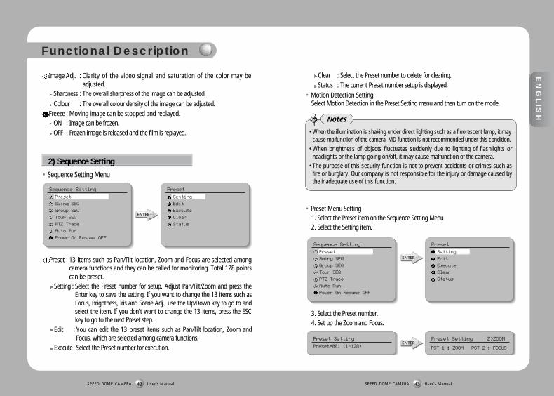
Image Adj. : Clarity of the video signal and saturation of the color may beadjusted.
Sharpness : The overall sharpness of the image can be adjusted. Colour : The overall colour density of the image can be adjusted.
Freeze : Moving image can be stopped and replayed. ON : Image can be frozen. OFF : Frozen image is released and the film is replayed.
Preset : 13 items such as Pan/Tilt location, Zoom and Focus are selected amongcamera functions and they can be called for monitoring. Total 128 pointscan be preset.
Setting : Select the Preset number for setup. Adjust Pan/Tilt/Zoom and press theEnter key to save the setting. If you want to change the 13 items such asFocus, Brightness, Iris and Scene Adj., use the Up/Down key to go to andselect the item. If you don’t want to change the 13 items, press the ESCkey to go to the next Preset step.
Edit : You can edit the 13 preset items such as Pan/Tilt location, Zoom andFocus, which are selected among camera functions.
Execute : Select the Preset number for execution.
Clear : Select the Preset number to delete for clearing. Status : The current Preset number setup is displayed.
• Motion Detection SettingSelect Motion Detection in the Preset Setting menu and then turn on the mode.
Functional Description
2) Sequence Setting
• Sequence Setting Menu
Sequence Setting
Preset
Swing SEQ
Group SEQ
Tour SEQ
PTZ Trace
Auto Run
Power On Resume OFF
Preset
Setting
Edit
Execute
Clear
Status
• Preset Menu Setting 1. Select the Preset item on the Sequence Setting Menu2. Select the Setting item.
3. Select the Preset number. 4. Set up the Zoom and Focus.
• When the illumination is shaking under direct lighting such as a fluorescent lamp, it maycause malfunction of the camera. MD function is not recommended under this condition.
• When brightness of objects fluctuates suddenly due to lighting of flashlights orheadlights or the lamp going on/off, it may cause malfunction of the camera.
• The purpose of this security function is not to prevent accidents or crimes such asfire or burglary. Our company is not responsible for the injury or damage caused bythe inadequate use of this function.
Notes
Sequence Setting
Preset
Swing SEQ
Group SEQ
Tour SEQ
PTZ Trace
Auto Run
Power On Resume OFF
Preset
Setting
Edit
Execute
Clear
Status
Preset Setting
Preset=001 (1~128)
Preset Setting Z>ZOOM
PST 1 : ZOOM PST 2 : FOCUS

SPEED DOME CAMERA User’s Manual45
EN
GLIS
H
SPEED DOME CAMERA User’s Manual44
5. To change the camera settings, select Editfrom the upper menu first. Select the item tochange, and then make the necessaryadjustments.
6. If you select the Scene Adj. item, such itemsas Shutter, AGC, SSNR, Sens-Up, WhiteBalance and DIS can be set up differently inevery Preset item.
Functional Description
• In the White Balance setting of the individual Preset Scene Adj., the AWC selection is notavailable.
Notes
Preset Edit [001]
PTZ 267/051/1XFocus Mode ManualBrightness 050Iris AUTOBack Light OFFDay & Night COLORMotion Det. OFFScene Adj
Scene Adj. [001]
Shutter ---
AGC MIDDLE
SSNR MIDDLE
Sens-Up AUTO
White Balance ATW
DIS OFF
Group SEQ: Sequence surveillance can be executed and set up and data can bedeleted. Up to 6 groups can be registered.
Swing SEQ: Swing surveillance can be executed and set up and the data can bedeleted.
Pan Swing : Swing surveillance for the Pan direction is executed and set up. Datais deleted.
Tilt Swing : Swing surveillance for the Tilt direction is executed and set up. Data isdeleted.
P&T Swing : Swing surveillance both for the Pan and the Tilt directions areexecuted and set up simultaneously. Data is deleted.
* Setting : The Preset Position for Swing function is selected with the joystick and confirmed with theExecution key. SPD is the moving speed (001-240˚/sec). DWL is the stop time (00-99 sec). Pressthe Execution key in the location with selection mark to finish the setting process.
* Execute : Swing surveillance is executed. Stop key designates this function. * Clear : Data in the Swing function is deleted.
Sequence Setting
Preset
Swing SEQ
Group SEQ
Tour SEQ
PTZ Trace
Auto Run
Power On Resume OFF
Group SEQ
Group 1
Group 2
Group 3
Group 4
Group 5
Group 6
Sequence Setting
Preset
Swing SEQ
Group SEQ
Tour SEQ
PTZ Trace
Auto Run
Power On Resume OFF
Swing SEQ
Pan Swing
Tilt Swing
P&T Swing
Setting : Preset position for swing is selected with the joystick and confirmed withthe Execution key. SPD is the moving speed (001-240˚/sec). DWL is thestop time (00-99 sec). Press the Execution key in the location withselection mark to finish the setting process.
Execute : Swing surveillance can be executed. Stop key will stop this function. Clear : Swing data can be deleted.

SPEED DOME CAMERA User’s Manual47
EN
GLIS
H
SPEED DOME CAMERA User’s Manual46
Tour : Group surveillance can be executed and set up and data can be deleted.
Setting : The registered Group Sequence is selected with the joystick andconfirmed with the Execution key. If the selected number is notregistered, it cannot be input. Press the Execution key in the locationwith selection mark to finish the setting process.
Execute : Group surveillance is executed.Clear : Group surveillance data are deleted.
PTZ Trace : Maximum 4 patterns of the manual operation paths (for Pan, Tilt,Zoom and Focus) are memorized and replayed.
Functional Description
Sequence Setting Tour SEQ
Setting
Execute
Clear
Preset
Swing SEQ
Group SEQ
Tour SEQ
PTZ Trace
Auto Run
Power On Resume OFF
Sequence Setting PTZ Trace
Trace 1
Trace 2
Trace 3
Trace 4
Preset
Swing SEQ
Group SEQ
Tour SEQ
PTZ Trace
Auto Run
Power On Resume OFF
Replay : The manual operation paths are repeated and replayed. Stop key will stop the replay. * If the operation range is limited using Pan Limit and Tilt Limit, please note that other operations
beyond the limited operation range are not possible. Memorize: Manual operations for minimum 120 seconds after executing this function are
memorized into the internal memory. Nevertheless, the memorizing time becomesdifferent depending on the PTZ operation. OVER mark will finish this function.
* If the operation range is limited using Pan Limit and Tilt Limit, only the operations within thelimited range are memorized.
Auto Run: If there is no controller operation by the user for a certain time, thesequence operation designated by the user will be executed.
Mode - • OFF : Auto Run will be cancelled. • Preset : Auto Run in the corresponding Preset number• Swing : Auto Run in the corresponding Swing mode• Group : Auto Run in the corresponding Group number• Tour : Auto Run in the corresponding Tour number• Trace : Auto Run in the corresponding Trace number• A. Pan : 360˚ Auto Run in Pan direction
* Auto Pan Speed: Pan operation in the speed designated by the user* Tilt Angle: The tilt angle set up by the user is kept.
Time : Auto Run operation is executed after a certain time designated by the user. *Time can be set up by the unit of 1-59 sec and 1-59 min.
• Press the OSD key to stop the internal memory to continue saving.
Notes
Power On Resume : When the power supply for the camera is stopped for somereason, such as electricity failure, and resumed, the SequenceSettings before the power off are restored.
Sequence Setting
Preset
Swing SEQ
Group SEQ
Tour SEQ
PTZ Trace
Auto Run
Power On Resume OFF
Sequence Setting
Preset
Swing SEQ
Group SEQ
Tour SEQ
PTZ Trace
Auto Run
Power On Resume ON

SPEED DOME CAMERA User’s Manual49
EN
GLIS
H
SPEED DOME CAMERA User’s Manual48
Pan Limit : The moving range in the Pan direction can be limited.
Position : Moving range can be set up. Set the position from the left using thejoystick and the Execution key. The stop position may change due to theinitialization by such operation as power resumption depending onposition setting. This does not mean it is out of order.
On/Off : When this function is on, the limit is effective. Default setting is Off.
Tilt Limit : Moving range in the tilt direction can be limited.
Position : Moving range can be set up. Set the position from the top directionusing the joystick and the Execution key. The stop position may changedue to initialization by such operation as power resumption dependingon position setting. This does not mean it is out of order.
On/Off : The application of limitation will be determined. Default setting is Off.
Functional Description
3) P/T Setting
Main Menu
Camera Setting
Sequence Setting
P/T Setting
OSD Setting
Alarm Setting
Initialize
Status
P/T Setting
Pan Limit
Tilt Limit
Area Setting
Area Masking
Prop. P/T ON
Digital Flip ON
Main Menu
Camera Setting
Sequence Setting
P/T Setting
OSD Setting
Alarm Setting
Initialize
Status
P/T Setting
Pan Limit
Tilt Limit
Area Setting
Area Masking
Prop. P/T ON
Digital Flip ON
Area Setting : Areas can be indicated. Areas can be designated up to 8.
Area Name : Area name can be set up. Use the joystick and the Execution keyto enter the area name. A maximum of 12 letters (English,Chinese, numbers) can be entered. When you finish inputting thename, adjust the position mark to ”SET” using the joystick andpress the Execution key. This is the end of Area Name setting.
Area Position : Area range can be designated. Use the joystick and the Executionkey to determine the position from the left. If the area range isoverlapped, the smaller area number will indicate the overlapping part.
On/Off : It can be determined whether or not to activate the area mark. Theactivation becomes effective as soon as the position moves from thecurrent area to other areas. Set up the OSD Setting as ON. If it is in OFFmode, this function does not work. Default setting is OFF.
Main Menu
Camera Setting
Sequence Setting
P/T Setting
OSD Setting
Alarm Setting
Initialize
Status
P/T Setting
Pan Limit
Tilt Limit
Area Setting
Area Masking
Prop. P/T ON
Digital Flip ON
Area Masking : If you want to exclude some areas for surveillance, they can beturned into black. You can mask 4 parts of one screen (maximum32 parts).
Main Menu
Camera Setting
Sequence Setting
P/T Setting
OSD Setting
Alarm Setting
Initialize
Status
P/T Setting
Pan Limit
Tilt Limit
Area Setting
Area Masking
Prop. P/T ON
Digital Flip ON

SPEED DOME CAMERA User’s Manual51
EN
GLIS
H
SPEED DOME CAMERA User’s Manual50
Prop. P/T : Pan and Tilt speeds can be changed depending on zoom magnification.Tele will slow down the speed of Pan/Tilt and Wide will increase thePan/Tilt speed. It will take about 15 seconds for 1 cycle in Tele modeand about 1.5 seconds in the Wide mode. Default setting is ON.
Digital Flip : When you operate the Tilt up to 90˚ limit using the joystick and keepit for a certain time, the image gets reversed automatically and theopposite Tilt area is seen. When you want to monitor the movingobject under the camera, execute the Digital Flip function using thecontroller’s joystick. You can observe the moving object withoutreversing of the screen.
Functional Description
Main Menu
Camera Setting
Sequence Setting
P/T Setting
OSD Setting
Alarm Setting
Initialize
Status
P/T Setting
Pan Limit
Tilt Limit
Area Setting
Area Masking
Prop. P/T ON
Digital Flip ON
Main Menu
Camera Setting
Sequence Setting
P/T Setting
OSD Setting
Alarm Setting
Initialize
Status
P/T Setting
Pan Limit
Tilt Limit
Area Setting
Area Masking
Prop. P/T ON
Digital Flip ON
Camera ID (Default setting is ON.) : Camera ID indication is set up.
4) OSD Setting
Main Menu
Camera Setting
Sequence Setting
P/T Setting
OSD Setting
Alarm Setting
Initialize
Status
OSD Setting
Camera ID ONCamera NamePreset Number ONPreset NameSequence Status OFFArea Name OFFPTZ Position ONLanguage English
Position : Use the joystick and the Execution key to determine the position forscreen operation from the left.
On/Off : Operation of screen area masking can be determined. Default setting is OFF.
Camera Name : Camera name is set up.
Main Menu
Camera Setting
Sequence Setting
P/T Setting
OSD Setting
Alarm Setting
Initialize
Status
OSD Setting
Camera ID ONCamera NamePreset Number ONPreset NameSequence Status OFFArea Name OFFPTZ Position ONLanguage English
Camera Name
ON/OFF ON
Edit
Camera Name [ ]
123456789
ABCDEFGHIJKLMNOPQRSTUVWXYZ
abcdefghijklmnopqrstuvwxyz

SPEED DOME CAMERA User’s Manual53
EN
GLIS
H
SPEED DOME CAMERA User’s Manual52
Edit : A maximum of 12 characters consisting of English (or Chinese, Japanese),numbers and special characters can be input for Camera Name.
On/Off : The operation of this function is preset. Default setting is On.
Preset Number (Default setting is ON.) : Preset numbering is set up.
Functional Description
Main Menu
Camera Setting
Sequence Setting
P/T Setting
OSD Setting
Alarm Setting
Initialize
Status
OSD Setting
Camera ID ONCamera NamePreset Number ONPreset NameSequence Status OFFArea Name OFFPTZ Position ONLanguage English
Preset Name
Edit : A maximum of 12 characters consisting of English (or Chinese), numbersand special characters can be input for Preset Name.
On/Off : The operation of this function is predetermined. Default setting is On.
Main Menu
Camera Setting
Sequence Setting
P/T Setting
OSD Setting
Alarm Setting
Initialize
Status
OSD Setting
Preset Name
ON/OFF ON
Edit
Preset Name [ ]
123456789
ABCDEFGHIJKLMNOPQRSTUVWXYZ
abcdefghijklmnopqrstuvwxyz
Camera ID ONCamera NamePreset Number ONPreset NameSequence Status OFFArea Name OFFPTZ Position ONLanguage English
Sequence Status (Default setting is ON.) : Display of the Sequence Group is set up.
Main Menu
Camera Setting
Sequence Setting
P/T Setting
OSD Setting
Alarm Setting
Initialize
Status
OSD Setting
Camera ID ONCamera NamePreset Number ONPreset NameSequence Status OFFArea Name OFFPTZ Position ONLanguage English
Area Name : Display of Area Name is set up. • When the Area Name is OFF, the Area Name cannot be displayed.
Main Menu
Camera Setting
Sequence Setting
P/T Setting
OSD Setting
Alarm Setting
Initialize
Status
OSD Setting
Camera ID ONCamera NamePreset Number ONPreset NameSequence Status OFFArea Name OFFPTZ Position ONLanguage English

SPEED DOME CAMERA User’s Manual55
EN
GLIS
H
SPEED DOME CAMERA User’s Manual54
Functional Description
Language : The OSD can be displayed either in English (default setting) or in Chinese.
Main Menu
Camera Setting
Sequence Setting
P/T Setting
OSD Setting
Alarm Setting
Initialize
Status
OSD Setting
Camera ID ONCamera NamePreset Number ONPreset NameSequence Status OFFArea Name OFFPTZ Position ONLanguage English
Alarm Enable : It can be determined whether to enable the alarm setting.
Main Menu
Camera Setting
Sequence Setting
P/T Setting
OSD Setting
Alarm Setting
Initialize
Status
Alarm Setting
Alarm Enable ON
Alarm Input
Alarm Output
MD Dwell Time ON 30 SEC
Alarm Input : Alarm Input Mode/Priority/Method is set up.
Alarm Input
IN 1 OFF 1 OFF
IN 2 OFF 2 OFF
IN 3 OFF 3 OFF
IN 4 OFF 4 OFF
Alarm Setting
Alarm Enable ON
Alarm Input
Alarm Output
MD Dwell Time ON 30 SEC
ON/OFF : Alarm is enabled in ON mode.
NC/NO/OFF : NC/NO/OFF can be selected depending on the alarm sensor. 1 - 4 (Priority) : Priority for the 4 alarm inputs is set up. Response comes first from
the alarm input of higher priority. Preset/Group/Tour Number :Whether to enable the operation of Preset/Group/Tour by alarm input can be setup. When the alarm is input, it stays in the Preset/Group/Tour position for theDwell Time set up by the Preset/Group/Tour Number of each alarm. The alarm inpattern is operated according to the pattern setting.
5) Alarm Setting
PTZ Position : Pan and Tilt position and Zoom magnification are displayed. • PTZ positions are not displayed in the OFF mode. (Only manual operation can display them.)
Main Menu
Camera Setting
Sequence Setting
P/T Setting
OSD Setting
Alarm Setting
Initialize
Status
OSD Setting
Camera ID ONCamera NamePreset Number ONPreset NameSequence Status OFFArea Name OFFPTZ Position ONLanguage English
Alarm Out : One of the 2 Alarm Outs corresponds to each Alarm input.
Alarm Output
Setting 1 1 2 3 4 MD
Setting 2 1 2 3 4 MD
Timer 1 OFF
Timer 2 OFF
OUT Off 1
OUT Off 2
Alarm Setting
OUT1 SET/OUT2 SET : One of the 4 Alarm Inputs corresponds to the 2 Alarm Outputs. OUT1 TIME/OUT2 TIME : For the 2 Alarm Outputs, On/Off and the operation time can be
set up in the units of second/minute/hour. (1-59 sec, 1-59 min,1-59 hour)
Alarm Enable ON
Alarm Input
Alarm Output
MD Dwell Time ON 30 SEC

SPEED DOME CAMERA User’s Manual57
EN
GLIS
H
SPEED DOME CAMERA User’s Manual56
ON/OFF : It can be set up how long the operation will be kept when the motion isdetected. (1-59 sec, 1-59 min)
Power On Reset : Camera is initialized into the original status of power input.
MD Dwell Time : When the Motion Detection function is on, the motion ofintruders can be detected. When the motion is detected, theAlarm signal is displayed in the Alarm Output Terminal. Fordetailed settings of the Motion Detection for each Preset menu,see page 43 and 44.
Alarm Setting
Alarm Enable ON
Alarm Input
Alarm Output
MD Dwell Time OFF
Alarm Setting
Alarm Enable ON
Alarm Input
Alarm Output
MD Dwell Time ON 30 SEC
Functional Description
Factory Default Settings : Camera is initialized into the factory default settings.Data including Preset is deleted. This function is usedfor initialization all settings.
Camera Default Settings: If only the camera module is replaced due to cameramodule failure, the new camera module can be set upwith the settings of the old camera module.
Auto Refresh : The electric circuit and the status of the equipment parts withinthe camera are optimized regularly. (The cycle can be set up.) Ifcamera faces toward a certain source of light or if the settingscannot be kept because of the long time rotation filming of a certainarea, the Auto Refresh function is used to maintain and re-set theexisting camera settings. Default setting is OFF.
OFF, 1-7 Days : This function is disabled in the OFF mode. 1-7 Days enables theAuto Refresh operation in the interval of the selected days. AutoRefresh takes less than 10 seconds. The message “Auto Refresh”disappears after finishing the operation.
Main Menu
Camera Setting
Sequence Setting
P/T Setting
OSD Setting
Alarm Setting
Initialize
Status
Initialize
Power ON Reset
Factory Default Set
Camera Default Set
Auto Refresh OFF
6) Initialization Setting
• Initialization Menu
OUT1 OFF/OUT2 OFF : If you want to cancel the operating Alarm outputs atonce, select the corresponding menu to cancel theoperating Alarm.
Main Menu
Camera Setting
Sequence Setting
P/T Setting
OSD Setting
Alarm Setting
Initialize
Status
Camera Status
CAM MODEL = 30NC
CAM VERSION = 03.06
DOME VERSION = 00.18
CON PROTOCOL = SAMSUNG TW
DOME ID = 001
CONTROLLER = Duplex-9600
Cam Model = 30NCCam Version = 03.06Dome Version = 00.01 Dome ID=001Controller=Duplex-9600
Camera ModelCamera S/W VersionControl Board S/W VersionDome Camera IDCommunication Mode Setup
7) Status
The status of dome camera setting is displayed.

SPEED DOME CAMERA User’s Manual59SPEED DOME CAMERA User’s Manual58
Product Structure Installation
Ø155
215.
727
.7
243.
4
R75
*Other Installations: The outdoor installation accessories, which are sold separately,can be applied in various ways. (See 25 and 26 page for theaccessories on sale.)
Product Structure and Installation
EN
GLIS
H

Installation 1
SPEED DOME CAMERA User’s Manual61SPEED DOME CAMERA User’s Manual60
Installation 2
Product Structure and Installation
EN
GLIS
H

SPEED DOME CAMERA User’s Manual63
EN
GLIS
H
SPEED DOME CAMERA User’s Manual62
1/4” Colour Vertical Double Density Interline CCD. 410.000pixel
NTSC
811(H) X 508(V)
768(H) X 494(V)
15.734kHz
59.94Hz
Internal Sync/External Sync(AC Line Lock)
1.0p-p/75Ω
Higher than 50dB (AGC OFF)
520 TV Lines (Colour)/570 TV Lines(B/W)
0.7Lux(Color), 0.1Lux(B/W)/(@50IRE), 0.0007Lux (Day & Night is On.)/(@50IRE)
Auto/Manual (1/60 - 1/120.000)
ON (x2 - x128 Fields) / OFF
ICR(Filter Switching) ON/OFF
Camera Shake Correction: DIS (Digital Image Stabilizer) may be set to “On” or “Off”
ATW(Indoor/Outdoor Selection)/AWC/Manual (1,800K - 10,500K)
Fixed Shutter Speed (1/100)
Auto/Manual (Iris Level Adjustment Mode)
Low, Middle, High, Off
ON/OFF
Adjustable Level
F3.3~99.0mm (30X Optical Zoom) F3.84~88.4mm (23X Optical Zoom)
OFF, 2~10X Selection (Total 300X Zoom) OFF, 2~10X Selection (Total 230X Zoom)
Ligh Angle 1: 1.6, Telescopic 1: 3.2 Ligh Angle 1: 1.6, Telescopic 1: 3.0
Wide:58.0˚(Horizontal)X44.8˚(Vertical) Wide:52.5˚(Horizontal)X40.3˚(Vertical)
Tele:2.22˚(Horizontal)X1.68˚(Vertical) Tele:2.36˚(Horizontal)X1.78˚(Vertical)
1.2m (Tele level)
360˚
Manual/Program
Manual: 0.5˚ ~ 120˚/s(64 levels) Preset: 0.5˚ ~ 240˚/s(64 levels)
0.05˚
Imaging device
TV
Total Number of Pixels
Valid Pixel
Horizontal Scan Frequency
Vertical Scan Frequency
Synchronization
Image Output
S/N Ratio
Horizontal Resolution
Minimum Light for Object
Electronic Shutter
Sens-Up
Day&Night
BLC
White Balance
Flickerless Adjustment
Iris
Gain Control
OSD Display
Outline Correction
Contact Point Distance
Digital Zoom
Maximum Aperture Rate
Coverage Angle
Proximity Distance
Horizontal Rotation Angle
Horizontal Rotation
Horizontal Rotation Speed
Horizontal Minimum
Moving Angle
SPD-3000 SPD-23000.30˚
-4˚~ 184˚ (Digital Flip)
Manual/Program
Manual: 0.5˚ - 120˚/s(64 levels) Preset: 0.5˚ - 240˚/s(64 levels)
0.04˚
0.30˚
Max 128 points
Max 4 locations
4 Alarm Inputs
2 Alarm Outputs (Relay: NC/NO/COM, 0.5A 125VAC, 2A 30VDC Max)
-10˚C - +50˚C
20% ~ 75%(Except for dew condensation)
-20˚C - +60˚C
20% ~ 95%(Except for dew condensation)
AC 24V±10%
Standby 8 Watts, Operation 10 Watts
Ø155 X 243.4mm
Less than 2.0kg
On-Ceiling Mount: STB-330PC
Indoor: Indoor Housing (STH-330PI), Indoor Insertion Type Housing (STH-330PE)
Outdoor: Outdoor Housing (STH-330PO)
Wall Installation Mount: STB-270PW
Ceiling Installation Mount: STB-496PP
Accuracy of Horizontal
Rotation Stop
Vertical Rotation Angle
Vertical Rotation
Vertical Rotation Speed
Vertical Minimum Moving
Angle
Accuracy of Vertical
Rotation Stop
Preset Position
Area Masking
Alarm
Operating Temperature
Operating Humidity
Storage Temperature
Storage Humidity
Power, Voltage
Consumption Electricity
Dimension
Weight
Installation Conditions
• The copyright of this manual belongs to Samsung Techwin Co. Ltd. • Parts or the whole of this manual cannot be reproduced or transmitted by any electric, mechanic or audio method
without the authorized written approval of Samsung Techwin. • The contents of this manual may be changed for an improvement of functions.
Specifications
* The product design and dimensions may change without previous notice for improvement of performance.