
3.0 MPa Maximum Supply Pressure High Pressure...
12
3.0 MPa Maximum supply pressure 3 W or less Power consumption Digital pressure display 0.2 to 2.0 MPa Stepless control of air pressure up to 2.0 MPa Set pressure range 3000 L /min (ANR) * * Supply pressure: 3.0 MPa, Set pressure: 1.0 MPa Maximum flow rate Fluorine grease Parts in contact with fluid Rc, NPT, G Pipe thread type * Without options Approx. 630 g * Weight Proof pressure test SUP. ([Example] Tank) ±1% F.S. * or less Stability * The value is confined to the static state. Pressure may fluctuate when air is consumed at the output side. Test sample ® RoHS 3.0 MPa Maximum Supply Pressure High Pressure Electro-Pneumatic Regulator CAT.ES60-23A Series ITVH
Transcript of 3.0 MPa Maximum Supply Pressure High Pressure...
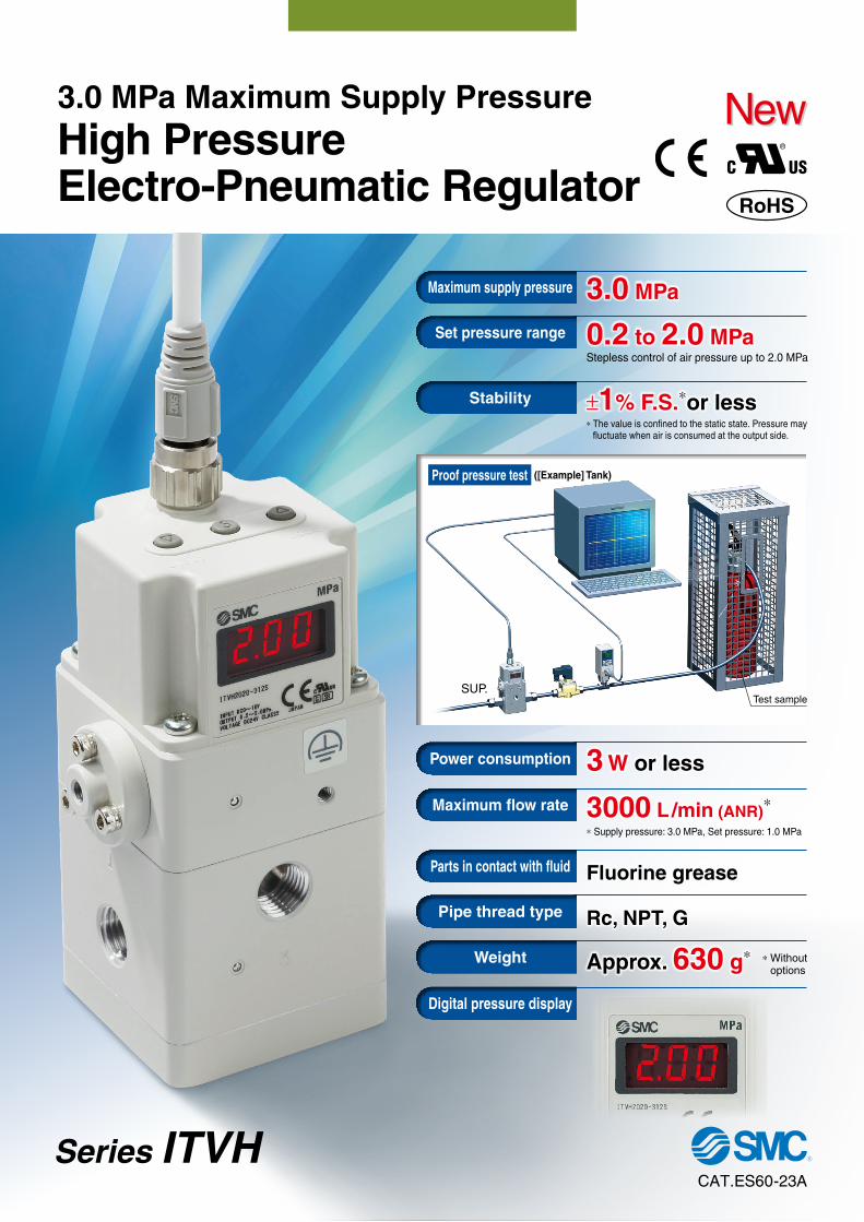
3.0 MPaMaximum supply pressure
3 W or lessPower consumption
Digital pressure display
0.2 to 2.0 MPaStepless control of air pressure up to 2.0 MPa
Set pressure range
3000 L /min (ANR)*
* Supply pressure: 3.0 MPa, Set pressure: 1.0 MPa
Maximum flow rate
Fluorine greaseParts in contact with fluid
Rc, NPT, GPipe thread type
* Without optionsApprox. 630 g*Weight
Proof pressure test
SUP.
([Example] Tank)
±1% F.S.*or lessStability
* The value is confined to the static state. Pressure may fluctuate when air is consumed at the output side.
Test sample
®
RoHS
3.0 MPa Maximum Supply PressureHigh PressureElectro-Pneumatic Regulator
CAT.ES60-23A
Series ITVH
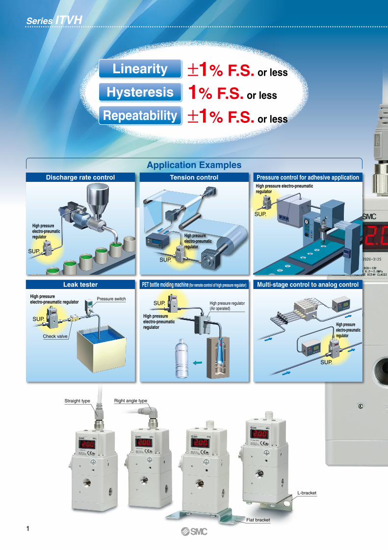
Discharge rate control
Leak tester
Tension control Pressure control for adhesive application
Multi-stage control to analog control
Series ITVH
PET bottle molding machine (for remote control of high pressure regulator)
±1% F.S. or less
1% F.S. or less
±1% F.S. or less
Application Examples
Linearity
Hysteresis
Repeatability
SUP.
High pressure electro-pneumatic regulator High pressure
electro-pneumatic regulator
High pressure electro-pneumatic regulator
High pressure electro-pneumatic regulator
High pressure electro-pneumatic regulator
High pressure electro-pneumatic regulator
SUP.
SUP.
SUP.
SUP.
SUP.Pressure switch
High pressure regulator(Air operated)
Check valve
Straight type Right angle type
Flat bracket
L-bracket
1
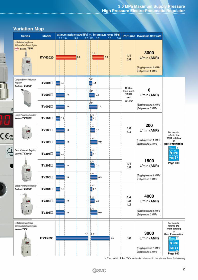
Series Model Maximum supply pressure [MPa] Set pressure range [MPa] Port size Maximum flow rate
3.0 MPa Maximum Supply PressureHigh Pressure Electro-Pneumatic Regulator
Series ITVH
ITVH20201/43/8
3000L/min (ANR)
Supply pressure: 3.0 MPa(Set pressure: 1.0 MPa )
Compact Electro-Pneumatic RegulatorSeries ITV0000
ITV001
Built-in One-touch
fittings
ø4ø5/32
6L/min (ANR)
For details,refer to the
WEB catalogor
Best Pneumatics
Page 803
ITV003
ITV005Supply pressure: 1.0 MPa(Set pressure: 0.6 MPa )
Electro-Pneumatic RegulatorSeries ITV1000 ITV101
1/81/4
200L/min (ANR)ITV103
ITV105Supply pressure: 1.0 MPa(Set pressure: 0.6 MPa )
Electro-Pneumatic RegulatorSeries ITV2000 ITV201
1/43/8
1500L/min (ANR)ITV203
ITV205Supply pressure: 1.0 MPa(Set pressure: 0.6 MPa )
Electro-Pneumatic RegulatorSeries ITV3000 ITV301
1/43/81/2
4000L/min (ANR)ITV303
ITV305Supply pressure: 1.0 MPa(Set pressure: 0.6 MPa )
5.0 MPa Maximum Supply PressureHigh Pressure Electro-Pneumatic RegulatorSeries ITVX
ITVX2030 3/8
3000L/min (ANR)
For details,refer to the
WEB catalogor
Best Pneumatics
Page 863
Supply pressure: 5.0 MPa(Set pressure: 3.0 MPa )
3.0 MPa Maximum Supply PressureHigh Pressure Electro-Pneumatic Regulator
* The outlet of the ITVX series is released to the atmosphere for blowing
Variation Map
0.20.001
1.0 0.0053.0
3.0 2.0
0.2
0.2 0.1
0.001
0.001
0.001
0.01
0.005
0.005
0.005
0.005
0.005
0.005
0.005
0.005
0.005
0.2 0.1
0.2 0.1
0.2 0.1
1.0 0.5
1.0 0.5
1.0 0.5
1.0 0.5
1.0 0.9
1.0 0.9
1.0 0.9
1.0 0.9
3.0
5.0
1.05.0 5.03.0
NewNew
2
3
®
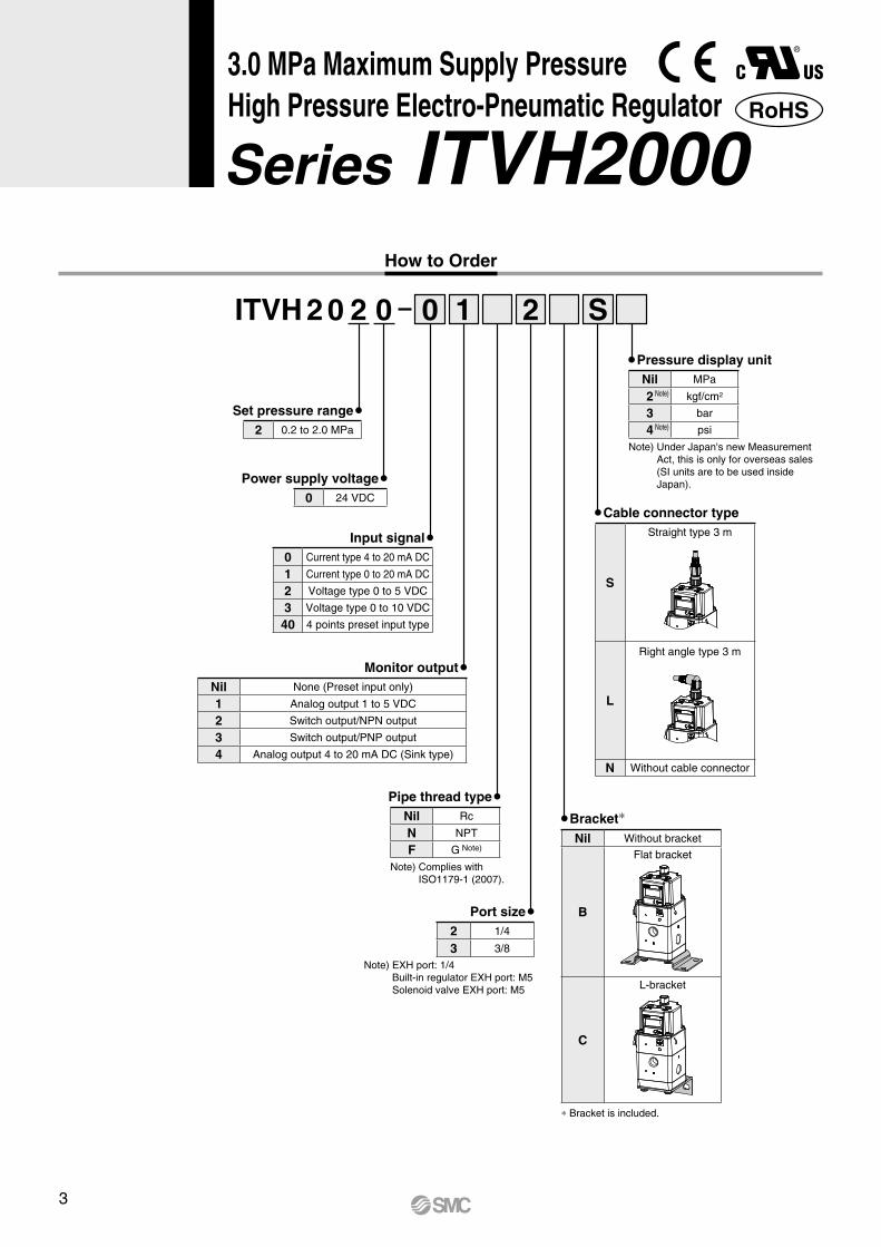
Nil Rc
N NPT
F G Note)
2 1/4
3 3/8
Nil Without bracket
B
Flat bracket
C
L-bracket
S
Straight type 3 m
L
Right angle type 3 m
N Without cable connector
Nil MPa
2 Note) kgf/cm2
3 bar
4 Note) psi
Nil None (Preset input only)
1 Analog output 1 to 5 VDC
2 Switch output/NPN output
3 Switch output/PNP output
4 Analog output 4 to 20 mA DC (Sink type)
0 Current type 4 to 20 mA DC
1 Current type 0 to 20 mA DC
2 Voltage type 0 to 5 VDC
3 Voltage type 0 to 10 VDC
40 4 points preset input type
0 24 VDC
2 0.2 to 2.0 MPa
ITVH 2 0 2 0 S0 21
Note) Under Japan's new Measurement Act, this is only for overseas sales (SI units are to be used inside Japan).
Note) Complies with ISO1179-1 (2007).
Note) EXH port: 1/4 Built-in regulator EXH port: M5 Solenoid valve EXH port: M5
* Bracket is included.
Set pressure range
Power supply voltage
Input signal
Monitor output
Pressure display unit
Cable connector type
Bracket*
Port size
Pipe thread type
How to Order
RoHS
Series ITVH20003.0 MPa Maximum Supply PressureHigh Pressure Electro-Pneumatic Regulator
4
Series ITVH20003.0 MPa Maximum Supply PressureHigh Pressure Electro-Pneumatic Regulator
Input signal [% F.S.]
0
2
0 100
Out
put p
ress
ure
[MP
a]
This range is outsideof the control (output).
0.2 MPa
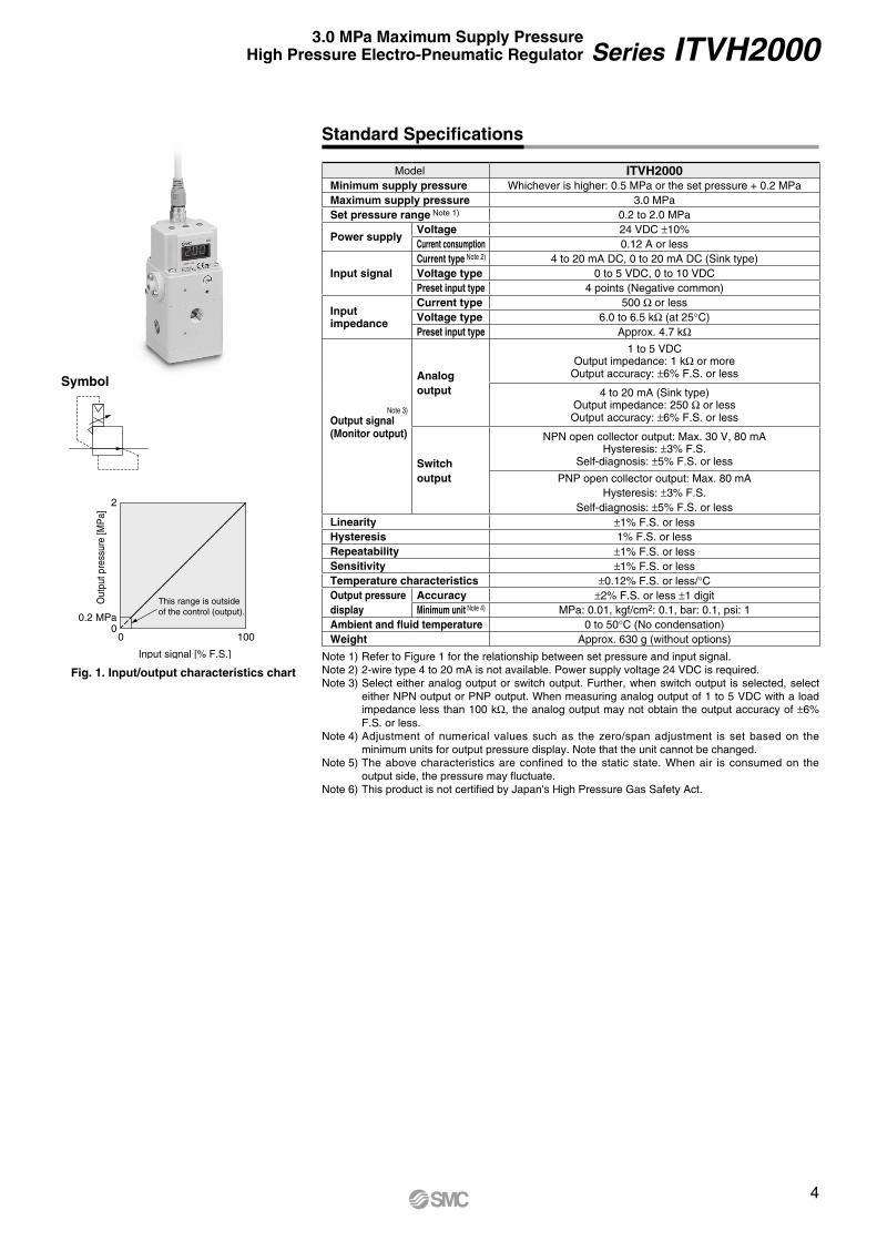
Model ITVH2000Minimum supply pressure Whichever is higher: 0.5 MPa or the set pressure + 0.2 MPaMaximum supply pressure 3.0 MPaSet pressure range Note 1) 0.2 to 2.0 MPa
Power supplyVoltage 24 VDC ±10%Current consumption 0.12 A or less
Input signalCurrent type Note 2) 4 to 20 mA DC, 0 to 20 mA DC (Sink type)Voltage type 0 to 5 VDC, 0 to 10 VDCPreset input type 4 points (Negative common)
Inputimpedance
Current type 500 Ω or lessVoltage type 6.0 to 6.5 kΩ (at 25°C)Preset input type Approx. 4.7 kΩ
Note 3)Output signal(Monitor output)
Analog output
1 to 5 VDCOutput impedance: 1 kΩ or more
Output accuracy: ±6% F.S. or less
4 to 20 mA (Sink type)Output impedance: 250 Ω or lessOutput accuracy: ±6% F.S. or less
Switch output
NPN open collector output: Max. 30 V, 80 mAHysteresis: ±3% F.S.
Self-diagnosis: ±5% F.S. or less
PNP open collector output: Max. 80 mAHysteresis: ±3% F.S.
Self-diagnosis: ±5% F.S. or lessLinearity ±1% F.S. or lessHysteresis 1% F.S. or lessRepeatability ±1% F.S. or lessSensitivity ±1% F.S. or lessTemperature characteristics ±0.12% F.S. or less/°COutput pressuredisplay
Accuracy ±2% F.S. or less ±1 digitMinimum unit Note 4) MPa: 0.01, kgf/cm2: 0.1, bar: 0.1, psi: 1
Ambient and fluid temperature 0 to 50°C (No condensation)Weight Approx. 630 g (without options)
Symbol
Fig. 1. Input/output characteristics chartNote 1) Refer to Figure 1 for the relationship between set pressure and input signal.Note 2) 2-wire type 4 to 20 mA is not available. Power supply voltage 24 VDC is required.Note 3) Select either analog output or switch output. Further, when switch output is selected, select
either NPN output or PNP output. When measuring analog output of 1 to 5 VDC with a load impedance less than 100 kΩ, the analog output may not obtain the output accuracy of ±6% F.S. or less.
Note 4) Adjustment of numerical values such as the zero/span adjustment is set based on the minimum units for output pressure display. Note that the unit cannot be changed.
Note 5) The above characteristics are confined to the static state. When air is consumed on the output side, the pressure may fluctuate.
Note 6) This product is not certified by Japan's High Pressure Gas Safety Act.
Standard Specifications
5
Series ITVH2000
1.6
12
2060
40
84
52
100
4 × ø7
2.3
70
50
(8.5)
7
4 x R3.5
15
33
10
50
25
y Air supply valve
t Diaphragm
SUP OUT
EXH
r Pilot chamber
P
Output signal
Built-in regulatorEXH
Solenoid valveEXH
Pressuredisplay
u Pressure sensor
w Exhaust solenoid valve
q Air supply solenoid valve
e Built-in regulator
Input signal
Power supply i Control circuit
Flat bracketMounting screw for the body
L-bracket
Mounting screw for the body
Straight type cable connector Right angle type cable connector
Flat bracket L-bracket
Right angle typecable connectorFlat bracket
Straight typecable connectorL-bracket
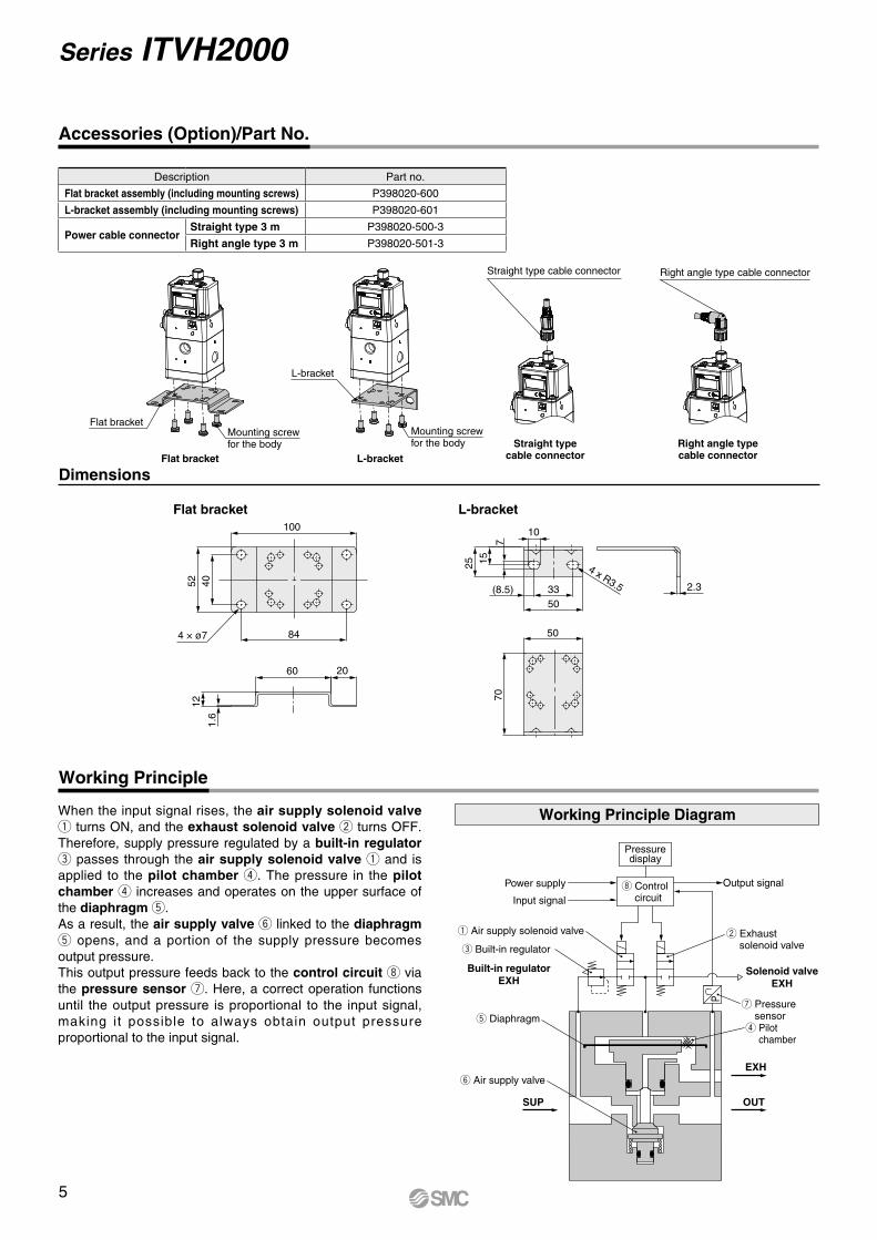
When the input signal rises, the air supply solenoid valve q turns ON, and the exhaust solenoid valve w turns OFF. Therefore, supply pressure regulated by a built-in regulator e passes through the air supply solenoid valve q and is applied to the pilot chamber r. The pressure in the pilot chamber r increases and operates on the upper surface of the diaphragm t.As a result, the air supply valve y linked to the diaphragm t opens, and a portion of the supply pressure becomes output pressure.This output pressure feeds back to the control circuit i via the pressure sensor u. Here, a correct operation functions until the output pressure is proportional to the input signal, making it possible to always obtain output pressure proportional to the input signal.
Working Principle Diagram
Dimensions
Accessories (Option)/Part No.
Working Principle
Description Part no.
Flat bracket assembly (including mounting screws) P398020-600
L-bracket assembly (including mounting screws) P398020-601
Power cable connectorStraight type 3 m P398020-500-3
Right angle type 3 m P398020-501-3
6
Series ITVH20003.0 MPa Maximum Supply PressureHigh Pressure Electro-Pneumatic Regulator
0 25 50 75 100
Set
pre
ssur
e [
MP
a]
Input signal [% F.S.]
0.0
0.5
1.0
1.5
2.0
2.5
Out
Return
0 25 50 75 100
Out
put d
evia
tion
fact
or
[% F
.S.]
Input signal [% F.S.]
−1.0
−0.5
0.0
0.5
1.0
0 1 2 3 4 5
Out
put d
evia
tion
fact
or
[% F
.S.]
Input signal [% F.S.]
−1.0
−0.5
0.0
0.5
1.0O
utpu
t dev
iatio
n fa
ctor
[%
F.S
.]
Supply pressure [MPa]
−1.0
−0.5
0.0
0.5
1.0
Out
Set pointReturn
1.0 1.5 2.0 2.5 3.0 3.5
0 500 1000 1500 2000
Set
pre
ssur
e [
MP
a]
Flow rate [L/min (ANR)]
0.0
0.1
1.0
0.2
0.3
0.4
0.5
0.6
0.7
0.8
0.9
Set
pre
ssur
e [
MP
a]
Flow rate [L/min (ANR)]
0.0
0.1
1.0
0.2
0.3
0.4
0.5
0.6
0.7
0.8
0.9
0 100 200 300 400 500 600
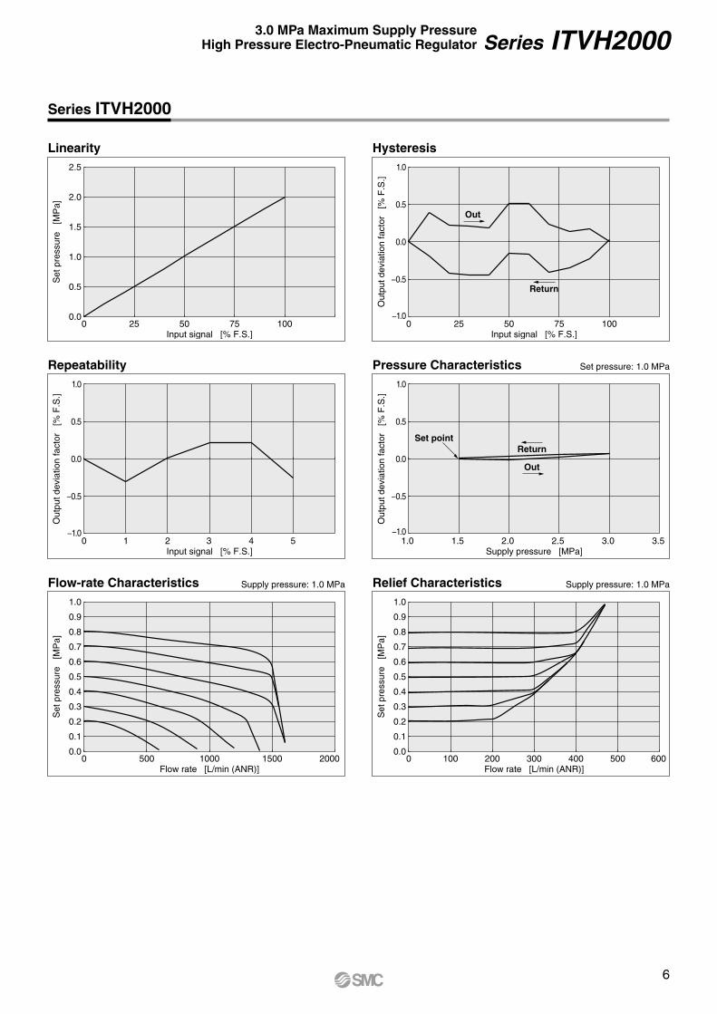
Linearity
Series ITVH2000
Hysteresis
Repeatability
Flow-rate Characteristics Relief Characteristics
Pressure Characteristics Set pressure: 1.0 MPa
Supply pressure: 1.0 MPa Supply pressure: 1.0 MPa

7
Series ITVH2000
(33)Straight type
cable connector 3 m
Right angle typecable connector 3 m
Breathinghole
Port 3(Exhaust port)
Solenoid valve EXH
Port 2(Output port)
Port 1(Supply port)
Built-in regulatorEXH
5210
Setting part
5212
.5
111
11
5.5
38.5
24
M5 x 0.8Built-in regulatorEXH
1/4, 3/8 (Rc, NPT)Port 1 (Supply port)
10M12 x 1Cable connection thread(Plug type)
Digital pressure display
1/4 (Rc, NPT)Port 3 (Exhaust port)
M4 x 0.7 depth 8F.G.
5839
36
364 x M5 x 0.8 depth 11Bracket mounting hole
8
M5 x 0.8Solenoid valveEXH
1/4, 3/8 (Rc, NPT)Port 2 (Output port)
7241
24
L-bracket
1/4, 3/8 (Rc, NPT)Port 2 (Output port)
24
452.3
7
5033(8.5)
10
3925
15
1/4 (Rc, NPT)Port 3 (Exhaust port)
1.6
3912
24
1/4 (Rc, NPT)Port 3 (Exhaust port)
1/4, 3/8 (Rc, NPT)Port 2 (Output port)
Flat bracket
4 x 7
10084
5240 39
24 24
G1/420 depth, depth of counterbore 1.5Port 3 (Exhaust port)
G1/420 depth, depth of counterbore 1.5Port 1 (Supply port), Port 2 (Output port)
G3/823 depth, depth of counterbore 2Port 1 (Supply port),Port 2 (Output port)
Do not turn the right angle type cable connector. It does not rotate and is limited to only one entry direction.
Do not block three EXH ports on this product.
G threadWith flat bracket
With L-bracket
Dimensions
8
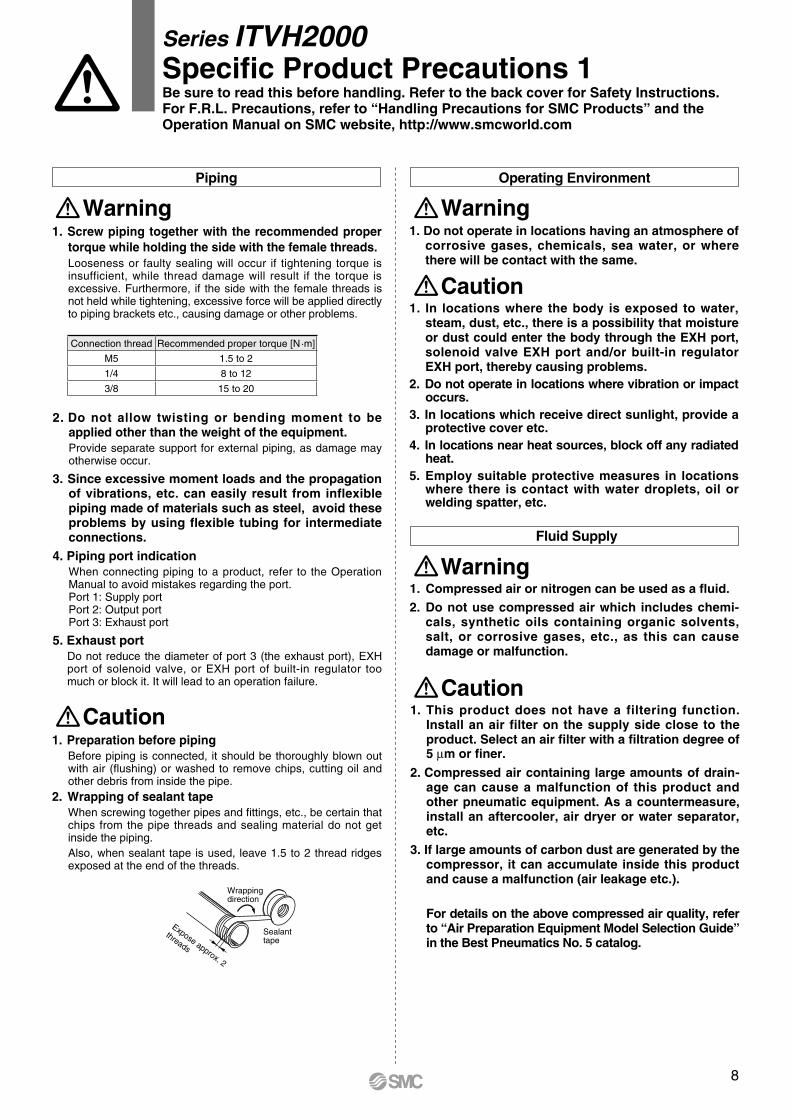
Wrappingdirection
Sealanttape
Expose approx. 2
threads
Piping
1. Screw piping together with the recommended proper torque while holding the side with the female threads.Looseness or faulty sealing will occur if tightening torque is insufficient, while thread damage will result if the torque is excessive. Furthermore, if the side with the female threads is not held while tightening, excessive force will be applied directly to piping brackets etc., causing damage or other problems.
WarningOperating Environment
Caution1. In locations where the body is exposed to water,
steam, dust, etc., there is a possibility that moisture or dust could enter the body through the EXH port, solenoid valve EXH port and/or built-in regulator EXH port, thereby causing problems.
2. Do not operate in locations where vibration or impact occurs.
3. In locations which receive direct sunlight, provide a protective cover etc.
4. In locations near heat sources, block off any radiated heat.
5. Employ suitable protective measures in locations where there is contact with water droplets, oil or welding spatter, etc.
1. Preparation before pipingBefore piping is connected, it should be thoroughly blown out with air (flushing) or washed to remove chips, cutting oil and other debris from inside the pipe.
2. Wrapping of sealant tapeWhen screwing together pipes and fittings, etc., be certain that chips from the pipe threads and sealing material do not get inside the piping. Also, when sealant tape is used, leave 1.5 to 2 thread ridges exposed at the end of the threads.
Caution
2. Do not allow twisting or bending moment to be applied other than the weight of the equipment.Provide separate support for external piping, as damage may otherwise occur.
3. Since excessive moment loads and the propagation of vibrations, etc. can easily result from inflexible piping made of materials such as steel, avoid these problems by using flexible tubing for intermediate connections.
4. Piping port indicationWhen connecting piping to a product, refer to the Operation Manual to avoid mistakes regarding the port.Port 1: Supply portPort 2: Output portPort 3: Exhaust port
5. Exhaust portDo not reduce the diameter of port 3 (the exhaust port), EXH port of solenoid valve, or EXH port of built-in regulator too much or block it. It will lead to an operation failure. Caution
1. This product does not have a filtering function. Install an air filter on the supply side close to the product. Select an air filter with a filtration degree of 5 μm or finer.
2. Compressed air containing large amounts of drain-age can cause a malfunction of this product and other pneumatic equipment. As a countermeasure, install an aftercooler, air dryer or water separator, etc.
3. If large amounts of carbon dust are generated by the compressor, it can accumulate inside this product and cause a malfunction (air leakage etc.).
For details on the above compressed air quality, refer to “Air Preparation Equipment Model Selection Guide” in the Best Pneumatics No. 5 catalog.
Fluid Supply
1. Compressed air or nitrogen can be used as a fluid.2. Do not use compressed air which includes chemi-
cals, synthetic oils containing organic solvents, salt, or corrosive gases, etc., as this can cause damage or malfunction.
Warning
1. Do not operate in locations having an atmosphere of corrosive gases, chemicals, sea water, or where there will be contact with the same.
Warning
Connection thread Recommended proper torque [N·m]
M5 1.5 to 2
1/4 8 to 12
3/8 15 to 20
Series ITVH2000Specific Product Precautions 1Be sure to read this before handling. Refer to the back cover for Safety Instructions. For F.R.L. Precautions, refer to “Handling Precautions for SMC Products” and the Operation Manual on SMC website, http://www.smcworld.com
9
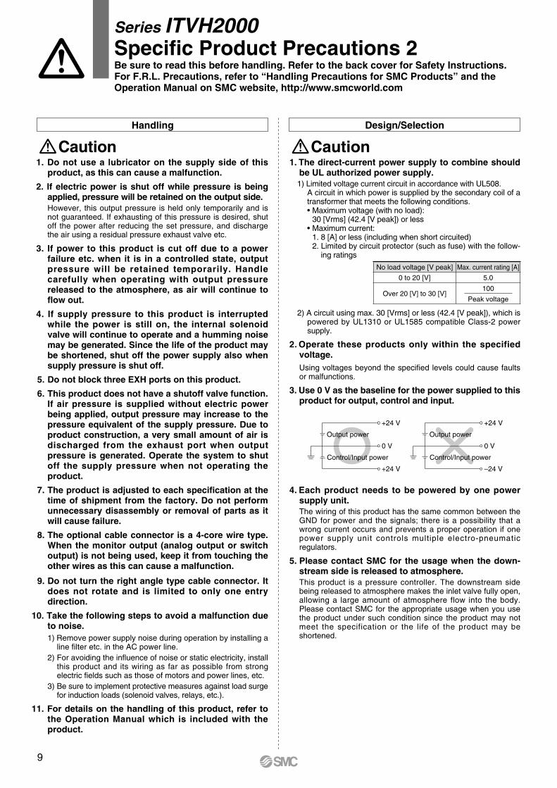
0 V
Output power
Control/Input power
+24 V
+24 V
0 V
Output power
Control/Input power
–24 V
+24 V
Handling Design/Selection
Caution1. The direct-current power supply to combine should
be UL authorized power supply. 1) Limited voltage current circuit in accordance with UL508.
A circuit in which power is supplied by the secondary coil of a transformer that meets the following conditions.•Maximumvoltage(withnoload): 30[Vrms](42.4[Vpeak])orless•Maximumcurrent: 1.8[A]orless(includingwhenshortcircuited) 2.Limitedbycircuitprotector(suchasfuse)withthefollow- ing ratings
2)Acircuitusingmax.30[Vrms]orless(42.4[Vpeak]),whichispoweredbyUL1310orUL1585compatibleClass-2powersupply.
2. Operate these products only within the specified voltage. Using voltages beyond the specified levels could cause faults or malfunctions.
3. Use 0 V as the baseline for the power supplied to this product for output, control and input.
Caution1. Do not use a lubricator on the supply side of this
product, as this can cause a malfunction.
2. If electric power is shut off while pressure is being applied, pressure will be retained on the output side.However, thisoutputpressure isheldonlytemporarilyand isnotguaranteed.Ifexhaustingofthispressureisdesired,shutoff thepowerafterreducingthesetpressure,anddischargetheairusingaresidualpressureexhaustvalveetc.
3. If power to this product is cut off due to a power failure etc. when it is in a controlled state, output pressure will be retained temporarily. Handle carefully when operating with output pressure released to the atmosphere, as air will continue to flow out.
4. If supply pressure to this product is interrupted while the power is still on, the internal solenoid valve will continue to operate and a humming noise may be generated. Since the life of the product may be shortened, shut off the power supply also when supply pressure is shut off.
5. Do not block three EXH ports on this product.
6. This product does not have a shutoff valve function. If air pressure is supplied without electric power being applied, output pressure may increase to the pressure equivalent of the supply pressure. Due to product construction, a very small amount of air is discharged from the exhaust port when output pressure is generated. Operate the system to shut off the supply pressure when not operating the product.
7. The product is adjusted to each specification at the time of shipment from the factory. Do not perform unnecessary disassembly or removal of parts as it will cause failure.
8. The optional cable connector is a 4-core wire type. When the monitor output (analog output or switch output) is not being used, keep it from touching the other wires as this can cause a malfunction.
9. Do not turn the right angle type cable connector. It does not rotate and is limited to only one entry direction.
10. Take the following steps to avoid a malfunction due to noise.1) Remove power supply noise during operation by installing a
line filter etc. in the AC power line.2)Foravoidingtheinfluenceofnoiseorstaticelectricity,install
this product and its wiring as far as possible from strong electricfieldssuchasthoseofmotorsandpowerlines,etc.
3) Be sure to implement protective measures against load surge forinductionloads(solenoidvalves,relays,etc.).
11. For details on the handling of this product, refer to the Operation Manual which is included with the product.
4. Each product needs to be powered by one power supply unit.The wiring of this product has the same common between the GND for power and the signals; there is a possibility that a wrong current occurs and prevents a proper operation if one power supply unit controls multiple electro-pneumaticregulators.
5. Please contact SMC for the usage when the down-stream side is released to atmosphere.This product is a pressure controller. The downstream side beingreleasedtoatmospheremakestheinletvalvefullyopen,allowing a large amount of atmosphere flow into the body. PleasecontactSMCfortheappropriateusagewhenyouusethe product under such condition since the product may not meet the specification or the life of the product may be shortened.
Series ITVH2000Specific Product Precautions 2Be sure to read this before handling. Refer to the back cover for Safety Instructions. For F.R.L. Precautions, refer to “Handling Precautions for SMC Products” and the Operation Manual on SMC website, http://www.smcworld.com
100
Peakvoltage
Noloadvoltage[Vpeak] Max.currentrating[A]
0to20[V] 5.0
Over20[V]to30[V]
10
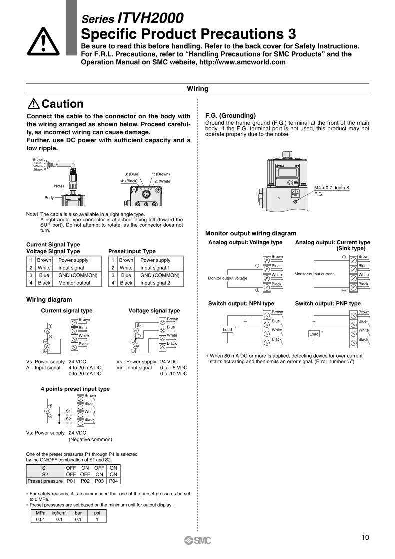
1 Brown Power supply
2 White Input signal
3 Blue GND (COMMON)
4 Black Monitor output
S1 OFF ON OFF ONS2 OFF OFF ON ON
Preset pressure P01 P02 P03 P04
1 Brown Power supply
2 White Input signal 1
3 Blue GND (COMMON)
4 Black Input signal 2
MPa kgf/cm2 bar psi0.01 0.1 0.1 1
BrownBlueWhiteBlack
Body
Note)
3: (Blue) 1: (Brown)
2: (White)4: (Black)
Vs
Blue
Brown
White
BlackS2
S1
M4 x 0.7 depth 8F.G.
Brown
Blue
White
Black
Monitor output voltage
Brown
Blue
White
Black
Monitor output current
Brown
Blue
White
Black
Load∗
Brown
Blue
White
BlackLoad ∗
Analog output: Voltage type
Switch output: NPN type Switch output: PNP type
Analog output: Current type(Sink type)
Monitor output wiring diagram
* When 80 mA DC or more is applied, detecting device for over current starts activating and then emits an error signal. (Error number “5”)
4 points preset input type
Vs: Power supply 24 VDC (Negative common)
Brown
Blue
White
Black
Vs
A
Brown
Blue
White
Black
Vs
Vin
Current signal type Voltage signal type
Vs : Power supply 24 VDCA : Input signal 4 to 20 mA DC 0 to 20 mA DC
Vs : Power supply 24 VDCVin : Input signal 0 to 5 VDC 0 to 10 VDC
Current Signal TypeVoltage Signal Type Preset Input Type
One of the preset pressures P1 through P4 is selected by the ON/OFF combination of S1 and S2.
* For safety reasons, it is recommended that one of the preset pressures be set to 0 MPa.
* Preset pressures are set based on the minimum unit for output display.
F.G. (Grounding) Ground the frame ground (F.G.) terminal at the front of the main body. If the F.G. terminal port is not used, this product may not operate properly due to the noise.
Wiring
Connect the cable to the connector on the body with the wiring arranged as shown below. Proceed careful-ly, as incorrect wiring can cause damage.Further, use DC power with sufficient capacity and a low ripple.
Caution
Wiring diagram
The cable is also available in a right angle type.A right angle type connector is attached facing left (toward the SUP port). Do not attempt to rotate, as the connector does not turn.
Note)
Series ITVH2000Specific Product Precautions 3Be sure to read this before handling. Refer to the back cover for Safety Instructions. For F.R.L. Precautions, refer to “Handling Precautions for SMC Products” and the Operation Manual on SMC website, http://www.smcworld.com
CautionSMC products are not intended for use as instruments for legal metrology.Measurement instruments that SMC manufactures or sells have not been qualified by type approval tests relevant to the metrology (measurement) laws of each country. Therefore, SMC products cannot be used for business or certification ordained by the metrology (measurement) laws of each country.
Compliance Requirements
∗1) ISO 4414: Pneumatic fluid power – General rules relating to systems. ISO 4413: Hydraulic fluid power – General rules relating to systems. IEC 60204-1: Safety of machinery – Electrical equipment of machines. (Part 1: General requirements) ISO 10218-1: Manipulating industrial robots – Safety. etc.
Caution indicates a hazard with a low level of risk which, if not avoided, could result in minor or moderate injury.Caution:Warning indicates a hazard with a medium level of risk which, if not avoided, could result in death or serious injury.Warning:
Danger : Danger indicates a hazard with a high level of risk which, if not avoided, will result in death or serious injury.
Warning Caution1. The compatibility of the product is the responsibility of the
person who designs the equipment or decides its specifications.Since the product specified here is used under various operating conditions, its compatibility with specific equipment must be decided by the person who designs the equipment or decides its specifications based on necessary analysis and test results. The expected performance and safety assurance of the equipment will be the responsibility of the person who has determined its compatibility with the product. This person should also continuously review all specifications of the product referring to its latest catalog information, with a view to giving due consideration to any possibility of equipment failure when configuring the equipment.
2. Only personnel with appropriate training should operate machinery and equipment.The product specified here may become unsafe if handled incorrectly. The assembly, operation and maintenance of machines or equipment including our products must be performed by an operator who is appropriately trained and experienced.
3. Do not service or attempt to remove product and machinery/equipment until safety is confirmed.1. The inspection and maintenance of machinery/equipment should only be
performed after measures to prevent falling or runaway of the driven objects have been confirmed.
2. When the product is to be removed, confirm that the safety measures as mentioned above are implemented and the power from any appropriate source is cut, and read and understand the specific product precautions of all relevant products carefully.
3. Before machinery/equipment is restarted, take measures to prevent unexpected operation and malfunction.
4. Contact SMC beforehand and take special consideration of safety measures if the product is to be used in any of the following conditions. 1. Conditions and environments outside of the given specifications, or use
outdoors or in a place exposed to direct sunlight.2. Installation on equipment in conjunction with atomic energy, railways, air
navigation, space, shipping, vehicles, military, medical treatment, combustion and recreation, or equipment in contact with food and beverages, emergency stop circuits, clutch and brake circuits in press applications, safety equipment or other applications unsuitable for the standard specifications described in the product catalog.
3. An application which could have negative effects on people, property, or animals requiring special safety analysis.
4. Use in an interlock circuit, which requires the provision of double interlock for possible failure by using a mechanical protective function, and periodical checks to confirm proper operation.
1. The product is provided for use in manufacturing industries.The product herein described is basically provided for peaceful use in manufacturing industries. If considering using the product in other industries, consult SMC beforehand and exchange specifications or a contract if necessary. If anything is unclear, contact your nearest sales branch.
Limited warranty and Disclaimer/Compliance RequirementsThe product used is subject to the following “Limited warranty and Disclaimer” and “Compliance Requirements”.Read and accept them before using the product.
Limited warranty and Disclaimer1. The warranty period of the product is 1 year in service or 1.5 years after
the product is delivered, whichever is first.∗2)
Also, the product may have specified durability, running distance or replacement parts. Please consult your nearest sales branch.
2. For any failure or damage reported within the warranty period which is clearly our responsibility, a replacement product or necessary parts will be provided. This limited warranty applies only to our product independently, and not to any other damage incurred due to the failure of the product.
3. Prior to using SMC products, please read and understand the warranty terms and disclaimers noted in the specified catalog for the particular products.
∗2) Vacuum pads are excluded from this 1 year warranty.A vacuum pad is a consumable part, so it is warranted for a year after it is delivered. Also, even within the warranty period, the wear of a product due to the use of the vacuum pad or failure due to the deterioration of rubber material are not covered by the limited warranty.
1. The use of SMC products with production equipment for the manufacture of weapons of mass destruction (WMD) or any other weapon is strictly prohibited.
2. The exports of SMC products or technology from one country to another are governed by the relevant security laws and regulations of the countries involved in the transaction. Prior to the shipment of a SMC product to another country, assure that all local rules governing that export are known and followed.
Safety Instructions Be sure to read “Handling Precautions for SMC Products” (M-E03-3) before using.
These safety instructions are intended to prevent hazardous situations and/or equipment damage. These instructions indicate the level of potential hazard with the labels of “Caution,” “Warning” or “Danger.” They are all important notes for safety and must be followed in addition to International Standards (ISO/IEC)∗1), and other safety regulations.
Safety Instructions


![Alkanes: Pressure Greater Than 0.2 MPa€¦ · Alkanes: Pressure Greater Than 0.2 MPa 251 COMPONENTS: ORIGINAL MEASUREMENTS: 1. Methane1 CH~1 [74-82-8] Bloomer, 0.'T.1 Gami, D. Cd](https://static.fdocuments.in/doc/165x107/5f83a254be6d763d254ab266/alkanes-pressure-greater-than-02-mpa-alkanes-pressure-greater-than-02-mpa-251.jpg)


![Alkanes: Pressure Greater Than 0.2 MPa …...320 COMPONENTS: Alkanes: Pressure Greater Than 0.2 MPa EVALUATOR: 1. Methane; CH 4; [74-82-8] 2. Hexane; C6H14; [110-54-3] EVALUATION:](https://static.fdocuments.in/doc/165x107/5f412d115d630538ad0e5359/alkanes-pressure-greater-than-02-mpa-320-components-alkanes-pressure-greater.jpg)


