
30 FREESTANDING SELF-CLEANING ELECTRIC...
72
CONSUMER SERVICES TECHNICAL EDUCATION GROUP PRESENTS KR-31 JOB AID Part No. 8178042 30″ FREESTANDING SELF-CLEANING ELECTRIC RANGE
Transcript of 30 FREESTANDING SELF-CLEANING ELECTRIC...

CONSUMER SERVICES TECHNICALEDUCATION GROUP PRESENTS KR-31
JOB AID
Part No. 8178042
30″ FREESTANDING
SELF-CLEANING
ELECTRIC RANGE

- ii -
WHIRLPOOL CORPORATION assumes no responsibility for any repairs madeon our products by anyone other than Authorized Service Technicians.
FORWARDThis Whirlpool Job Aid, “30˝ Freestanding Self-Cleaning Electric Range,” (Part No. 8178042),provides the technician with information on the operation and service of the Freestanding Self-Cleaning Electric Range. It is to be used as a training Job Aid and Service Manual. For specificinformation on the model being serviced, refer to the “Use and Care Guide,” or “Tech Sheet”provided with the electric range.
The Wiring Diagrams and Strip Circuits used in this Job Aid are typical and should be used fortraining purposes only. Always use the Wiring Diagram supplied with the product when servicingthe unit.
GOALS AND OBJECTIVESThe goal of this Job Aid is to provide detailed information that will enable the service technician toproperly diagnose malfunctions and repair the Whirlpool 30˝ Freestanding Self-Cleaning ElectricRange.
The objectives of this Job Aid are to:
• Understand and follow proper safety precautions.
• Successfully troubleshoot and diagnose malfunctions.
• Successfully perform necessary repairs.
• Successfully return the electric range to its proper operational status.
Copyright © 2001, Whirlpool Corporation, Benton Harbor, MI 49022

- iii -
TABLE OF CONTENTSPage
GENERAL ............................................................................................................................... 1-1Important Safety Information ............................................................................................. 1-1Whirlpool Model & Serial Number Designations ................................................................ 1-2Model & Serial Number Label And Tech Sheet Locations................................................. 1-3Specifications..................................................................................................................... 1-4Whirlpool Electric Range Warranty .................................................................................. 1-12
THEORY OF OPERATION ..................................................................................................... 2-1AccuBake VS. AccuBake Duo Cooking Systems .............................................................. 2-1AccuSimmer Basic Operation ............................................................................................ 2-3Keep Warm Element .......................................................................................................... 2-6Warming Drawer ................................................................................................................ 2-7Soft Close Door ................................................................................................................. 2-8
COMPONENT ACCESS ......................................................................................................... 3-1Component Locations ........................................................................................................ 3-1Removing A Single Element Infinite Switch ....................................................................... 3-2Removing The Normal Burner/AccuSimmer Switch .......................................................... 3-3Removing The Dual Element Infinite Switch...................................................................... 3-4Removing The Keep Warm Switch .................................................................................... 3-5Removing An Indicator Light .............................................................................................. 3-6Removing The Control Power Supply And The Electronic Oven Control .......................... 3-7Removing An Element & Limiter And The Cooktop Glass Assembly ................................ 3-8Removing The Hot Surface Indicators ............................................................................. 3-10Removing The Door Latch & The Door Switch ................................................................ 3-12Removing The Broil & Bake Elements............................................................................. 3-14Removing The Oven Light Socket Assembly .................................................................. 3-16Removing The Latch Drive Assembly.............................................................................. 3-17Removing The Oven Temperature Sensors And The Thermal Fuse .............................. 3-18Removing The Warming Drawer Element & Temperature Sensor .................................. 3-19Removing The Oven Door ............................................................................................... 3-20Removing The Oven Door Handle & Glass ..................................................................... 3-22Removing The Oven Door Gasket ................................................................................... 3-24Removing A Side Panel ................................................................................................... 3-25
COMPONENT TESTING ........................................................................................................ 4-1Door Switch ....................................................................................................................... 4-1Warming Drawer Element .................................................................................................. 4-1Bake Element .................................................................................................................... 4-2Broil Element ..................................................................................................................... 4-2Latch Drive......................................................................................................................... 4-3Oven & Warming Drawer Temperature Sensors ............................................................... 4-3Thermal Fuse..................................................................................................................... 4-4Single Element Infinite Switches........................................................................................ 4-4Dual Element Infinite Switch .............................................................................................. 4-5Keep Warm Switch ............................................................................................................ 4-6Normal Burner/AccuSimmer Switch .................................................................................. 4-7Surface Elements & Limiters ............................................................................................. 4-8

- iv -
Page
DIAGNOSIS & TROUBLESHOOTING ................................................................................... 5-1Failure / Error Display Codes—Tech Sheet 8522647........................................................ 5-1
WIRING DIAGRAMS & STRIP CIRCUITS ............................................................................. 6-1Wiring Diagram .................................................................................................................. 6-1Strip Circuits ...................................................................................................................... 6-2
TECH TIPS ............................................................................................................................. 7-1Duo Cooking System Flow Chart ....................................................................................... 7-1
1-1
ELECTRICAL SHOCK HAZARD
Disconnect power before servicing.
Replace all panels before operating.
Failure to do so could result in death orelectrical shock.
Important safety messages have been pro-vided in this Job Aid. Always read and obey allsafety messages.
GENERALIMPORTANT SAFETY INFORMATION
Your safety and the safety of others is very important.
This is the safety alert symbol.
This symbol alerts you to haz-ards that can kill or hurt youand others.
All safety messages will be preceded by thesafety alert symbol and the word “WARNING.”
All safety messages will identify the hazard, tellyou how to reduce the chance of injury, and tellyou what can happen if the instructions are notfollowed.
WARNING
ELECTROSTATIC DISCHARGE(ESD) SENSITIVE ELECTRONICS
ESD problems are present everywhere. ESDmay damage or weaken the electronic controlassembly. The new control assembly may ap-pear to work well after repair is finished, butfailure may occur at a later date due to ESDstress.
• Use an antistatic wrist strap. Connect thewrist strap to a green ground connectionpoint or unpainted metal in the appliance;or touch your finger repeatedly to a greenground connection point or unpainted metalin the appliance.
• Before removing the part from its pack-age, touch the antistatic bag to a greenground connection point or unpainted metalin the appliance.
• Avoid touching electronic parts or terminalcontacts. Handle the electronic controlassembly by the edges only.
• When repackaging the failed electroniccontrol assembly in an antistatic bag, ob-serve the above instructions.
PERSONAL INJURY HAZARD
To prevent tipping, install range anti-tipbracket.
Save the installation instructions. If the rangeis moved to a new location, the anti-tip bracketmust be removed and reinstalled in the newlocation.
Failure to follow these instructions couldresult in serious injury.
WARNING

1-2
WHIRLPOOL MODEL & SERIAL NUMBER DESIGNATIONS
MODEL NUMBER
SERIAL NUMBERSERIAL NUMBER R K 49 15548
MANUFACTURING SITE
R = TULSA, OKLAHOMA
YEAR OF PRODUCTION:
K = 2000, L = 2001, M = 2002
WEEK OF PRODUCTION:
49th WEEK
PRODUCT SEQUENCE NUMBER
MODEL NUMBER R F 3 6 4 P X K W
INTERNATIONAL SALES IND.
OR MARKETING CHANNEL
IF PRESENT
PRODUCT GROUP:
R = ELECTRIC RANGES
S = GAS RANGES
G = WHIRLPOOL GOLD
PRODUCT IDENTIFICATION:
A = ACCESSORY K = KITS
B = BUILT-IN M = MV COMBO
C = COOKTOP S = SET-IN
E = EYE-LEVEL W = SLIDE-IN GAS
F = FREESTANDING Y = SLIDE-IN ELECTRIC
H = HOODS
MODEL SIZE:
0 = 20˝ OR 24˝ FREESTANDING
1 = 30˝ IMPERIAL SERIES FREESTANDING (1996 & LATER)
2 = 30˝ FREESTANDING (1996 & LATER)
3 = 30˝ FREESTANDING
4 = 40˝ FREESTANDING
5 = 36˝ FREESTANDING
6 = 30˝ SET-IN RANGES
OVEN TYPES:
0 THRU 3 = STANDARD PORCELAIN
2 THRU 5 = CONTINUOUS CLEAN (BEFORE 1996)
4 THRU 9 = PYROLYTIC SELF-CLEAN
FEATURE / VARIATIONS:
ELECTRIC
0, 1, 2, 5, 7 = COIL ELEMENTS
4 = STANDARD PATTERN CERAMIC
6, 8, 9 = DELUXE PATTERN CERAMIC
GAS
0, 1, 2, 3, 4, 6 = OPEN BURNER
5 & 7 = SEALED BURNER
DOOR TYPE:
B = SOLID BLACK GLASS
L = LARGE WINDOW
O = METAL OVEN DOOR
P = STANDARD WINDOW GLASS
FEATURE CODE:
E = ELECTRONIC IGNITION (GAS ONLY)
S = STANDING IGNITION (GAS ONLY)
C = COLOR COORDINATED GLASS (BEFORE 1998)
X = NOT DEFINED
YEAR OF INTRODUCTION:
H = 1999. J = 2000, K = 2001
COLOR CODE:
B = BLACK W = WHITE P = PANORAMIC
N = ALMOND Z = ALMOND ON ALMOND
Q = WHITE ON WHITE T = BISCUIT
S = STAINLESS STEEL V = BISCUIT W / BLACK DOOR / PANEL

1-3
Tech Sheet Location(On Top Rear Cover)
MODEL & SERIAL NUMBER LABELAND TECH SHEET LOCATIONS
The Model/Serial Number label and Tech Sheet locations are shown below.
Model & SerialNumber Location

1-4
SPECIFICATIONS
Model Number RF196LXK RF199LXK RF314PXK RF341BXK Color Q / T / B / P Q / T / B / P W / V / Q W
GENERAL INFORMATIONCleaning System Self Clean Self Clean Std clean Self CleanBurner Type Ceran-Std Ceran-Dlx. FW Ceran-Std Ceran-Std Burner Sizes 2-6.5",2-7.5" 6"6"7" 9" 2-6.5",2-7.5" 2-6.5",2-7.5"Drip Pans or Glass Pattern 1 FW Pattern 2 FW Pattern 1 FW Pattern 1 FW PatternOven Door Type Wht/Bisc/Blk Glass Wht/Bisc/Blk Glass Black Glass Black GlassOven Window & Size XL window XL window Yes-Std NoOven Controls EZ151 EZ600 EZ150 Knob 150Special Features Clock/timer AccuBake2 Clock/timer No Clock Opening
Dual DisplayChoice Bake
DIMENSIONSHeight - Overall 46.8" 46.8" 46.8" 46.8"Height to Maintop 36" 36" 36" 36"Depth 25" 25" 25" 25"Width 29.875" 29.875" 29.875" 29.875"Depth with Handle 27.13" 27.13" 27.13" 27.13"Approx. Shipping Weight 151 151 162 162
BACKGUARD FEATURESTimer in control in control No NoOven Light Switch Yes-Rocker Yes-Touch No NoAccusimmer Switch No Yes-Selector No NoWarming Zone Switch No No No NoOven Heating Indicator Light in Oven Control in Oven Control in Oven Control in Oven ControlSurface Unit Indicator Light Mini Red (2) Mini Red (2) Mini Red (2) Mini Red (2)Surface Unit Controls Inf Detent Hi/Off Inf Detent Hi/Off Inf Detent Hi/Off Inf Detent Hi/Off
COOKTOP FEATURESCooktop High UpSwp-Porc High UpSwp-Porc High UpSwp-Porc High UpSwp-PorcBurner Type Ceran-Std Ceran-Dlx. FW Ceran-Std Ceran-Std Burner Configuration 2-6.5",2-7.5" 6"6"7" 9" 2-6.5",2-7.5" 2-6.5",2-7.5" R. Front (240V) 6.5"R-1500W 6"R-1200W 6.5"R-1500W 6.5"R-1500W L. Front (240V) 7.5"R-2000W 9"R-2500W 7.5"R-2000W 7.5"R-2000W R. Rear (240V) 7.5"R-2000W 7"R-1800W 7.5"R-2000W 7.5"R-2000W L. Rear (240V) 6.5"R-1500W 6"R-1200W 6.5"R-1500W 6.5"R-1500W Middle Rear (120V) n/a 5th ele - Warm Zone n/a n/aSimmer Burner n/a n/a n/a n/aHot Surface Indicator 1 Neon 4 Neon 1 Neon 1 NeonBurner Box No No No No

1-5
Model Number RF196LXK RF199LXK RF314PXK RF341BXK Color Q / T / B / P Q / T / B / P W / V / Q W
MAIN CHASSIS FEATURESFront Frame Porcelain Porcelain Porcelain PorcelainLeveling Legs - Plastic Four Four Four Four
OVEN FEATURESOven Type #REF! #REF! #REF! #REF!Oven Capacity 4.65 cubic ft 4.65 cubic ft 4.65 cubic ft 4.65 cubic ftOven Width 24.25" 24.25" 24.25" 24.25"Oven Height 17.5" 17.5" 17.5" 17.5"Oven Depth 19.0" 19.0" 19.0" 19.0"Broil Element 3400w 3400w 3400w 3400wBake Element 2400w 2400w 2400w 2400wTop Heat Percentage 240V Percentage 240V Percentage 240V Percentage 240VOven Light Yes Yes Yes No Auto Oven Light Yes Yes No No Manual Oven Light #REF! #REF! yes-rocker sw #REF!
OVEN DOOR FEATURESOven Window & Size #REF! #REF! Yes-std #REF!Door Liner Finish Porcelain Porcelain Porcelain PorcelainDoor Handle Roper Towel Bar Roper Towel Bar Curved Plastic Curved Plastic
LOWER PANEL/DRAWERWidth 22.375" 22.375" 22.375" 22.375"Height 6.125" 6.125" 6.125" 6.125"Depth 20.0" 20.0" 20.0" N / ADrawer Liner Yes Yes No NoGlides Rollers Rollers Nylon N / AWarming Drawer No No No No
TOTAL CONNECTED LOAD240 Volts 10480W 10480W 10180W 10180W208 Volts 7880W 7880W 7655W 7655W
LITERATUREUse & Care Guide Yes Yes Yes YesTech Sheets/Wiring Diagrams Yes Yes Yes YesInstallation Instructions Yes Yes Yes YesService Manual 8178042 8178042 8178042 8178042
OTHER SPECIFICATIONSU.L. Approval Yes Yes Yes YesAnti-Tip Device Approved Floor Brkt/Wall Brkt. Floor Brkt/Wall Brkt. Floor Brkt/Wall Brkt. Floor Brkt/Wall Brkt.Anti-Tip Device w/ Unit Floor Bracket Floor Bracket Floor Bracket Floor Bracket

1-6
Model Number RF364PXK RF364LXK RF368LXK Color W / V /Q / T Q / T Q / T / P / W
GENERAL INFORMATIONCleaning System Self Clean Self Clean Self CleanBurner Type Ceran-Std Ceran-Std Ceran-Dlx. FWBurner Sizes 2-6.5",2-7.5" 2-6.5",2-7.5" 6"6"7" 9" Drip Pans or Glass Pattern 1 FW Pattern 1 FW Pattern 2 FW PatternOven Door Type Black Glass White/Bisc Glass Wht/Bisc/Alm GlassOven Window & Size Yes-Std XL window XL windowOven Controls EZ150 EZ151 EZ151Special Features Clock/timer Clock/timer Clock/timer
DIMENSIONSHeight - Overall 46.8" 46.8" 46.8"Height to Maintop 36" 36" 36"Depth 25" 25" 25"Width 29.875" 29.875" 29.875"Depth with Handle 27.13" 27.13" 27.13"Approx. Shipping Weight 162 162 162
BACKGUARD FEATURESTimer No Yes in controlOven Light Switch No No Yes-RockerAccusimmer Switch No No NoWarming Zone Switch No No NoOven Heating Indicator Light in Oven Control in Oven Control in Oven ControlSurface Unit Indicator Light Mini Red (2) Mini Red (2) Mini Red (2)Surface Unit Controls Inf Detent Hi/Off Inf Detent Hi/Off Inf Detent Hi/Off
COOKTOP FEATURESCooktop High UpSwp-Porc High UpSwp-Porc High UpSwp-PorcBurner Type Ceran-Std Ceran-Std Ceran-Dlx. FWBurner Configuration 2-6.5",2-7.5" 2-6.5",2-7.5" 6"6"7" 9" R. Front (240V) 6.5"R-1500W 6.5"R-1500W 6"R-1200W L. Front (240V) 7.5"R-2000W 7.5"R-2000W 9"R-2500W R. Rear (240V) 7.5"R-2000W 7.5"R-2000W 7"R-1800W L. Rear (240V) 6.5"R-1500W 6.5"R-1500W 6"R-1200W Middle Rear (120V) n/a n/a n/aSimmer Burner n/a n/a n/aHot Surface Indicator 1 Neon 1 Neon 4 NeonBurner Box No No No

1-7
Model Number RF364PXK RF364LXK RF368LXK Color W / V /Q / T Q / T Q / T / P / W
MAIN CHASSIS FEATURESFront Frame Porcelain Porcelain PorcelainLeveling Legs - Plastic Four Four Four
OVEN FEATURESOven Type #REF! #REF! #REF!Oven Capacity 4.65 cubic ft 4.65 cubic ft 4.65 cubic ftOven Width 24.25" 24.25" 24.25"Oven Height 17.5" 17.5" 17.5"Oven Depth 19.0" 19.0" 19.0"Broil Element 3400w 3400w 3400wBake Element 2400w 2400w 2400wTop Heat Percentage 240V Percentage 240V Percentage 240VOven Light Yes Yes Yes Auto Oven Light No No Yes Manual Oven Light yes-rocker sw yes-rocker sw #REF!
OVEN DOOR FEATURESOven Window & Size Yes-std #REF! #REF!Door Liner Finish Porcelain Porcelain PorcelainDoor Handle Curved Plastic Curved Plastic Curved Plastic
LOWER PANEL/DRAWERWidth 22.375" 22.375" 22.375"Height 6.125" 6.125" 6.125"Depth 20.0" 20.0" 20.0"Drawer Liner No No YesGlides Nylon Rollers NylonWarming Drawer No No No
TOTAL CONNECTED LOAD240 Volts 10180W 10180W 10180W208 Volts 7655W 7655W 7655W
LITERATUREUse & Care Guide Yes Yes YesTech Sheets/Wiring Diagrams Yes Yes YesInstallation Instructions Yes Yes YesService Manual 8178042 8178042 8178042
OTHER SPECIFICATIONSU.L. Approval Yes Yes YesAnti-Tip Device Approved Floor Brkt/Wall Brkt. Floor Brkt/Wall Brkt. Floor Brkt/Wall Brkt.Anti-Tip Device w/ Unit Floor Bracket Floor Bracket Floor Bracket

1-8
Model Number RF378LXK RF378PXK RF388LXK RF390LXK Color W / V Q / T / B Q / T / B / P Q / T / P
GENERAL INFORMATIONCleaning System Self Clean Self Clean Self Clean Self CleanBurner Type Ceran-Dlx. FW Ceran-Dlx. FW Ceran-Dlx. FW Ceran-Dlx. FWBurner Sizes 6"6"7" 9" 6"6"7" 9" 6"6"7" 9" 6"6"7" 9" Oven Window & Size XL window XL window XL window XL windowOven Controls EZ200 EZ200 EZ600 EZ600Special Features Accubake l Accubake l Accubake 2 Accubake 2
Accusimmer AccusimmerDual Display Dual Display Dual Display Dual Display
Choice Bake Choice Bake
DIMENSIONSHeight - Overall 46.8" 46.8" 46.8" 46.8"Height to Maintop 36" 36" 36" 36"Depth 25" 25" 25" 25"Width 29.875" 29.875" 29.875" 29.875"Depth with Handle 27.13" 27.13" 27.13" 27.13"Approx. Shipping Weight 162 162 163 163
BACKGUARD FEATURESTimer in control in control in control in controlOven Light Switch Yes-Touch Yes-Touch Yes-Touch Yes-TouchAccusimmer Switch No No Yes-Selector Yes-SelectorWarming Zone Switch No No No NoOven Heating Indicator Light in Oven Control in Oven Control in Oven Control in Oven ControlSurface Unit Indicator Light Mini Red (2) Mini Red (2) Mini Red (3) Mini Red (3)Surface Unit Controls Inf Detent Hi/Off Inf Detent Hi/Off Inf Detent Hi/Off Inf Detent Hi/Off
COOKTOP FEATURESCooktop High UpSwp-Porc High UpSwp-Porc High UpSwp-Porc High UpSwp-PorcBurner Type Ceran-Dlx. FW Ceran-Dlx. FW Ceran-Dlx. FW Ceran-Dlx. FWBurner Configuration 6"6"7" 9" 6"6"7" 9" 6"6"7" 9" 6"6"7" 9" R. Front (240V) 6"R-1200W 6"R-1200W 6"R-1200W 6"R-1200W L. Front (240V) 9"R-2500W 9"R-2500W 9"R-2500W 9"R-2500W R. Rear (240V) 7"R-1800W 7"R-1800W 7"R-1800W 7"R-1800W L. Rear (240V) 6"R-1200W 6"R-1200W 6"R-1200W 6"R-1200W Middle Rear (120V) n/a n/a n/a n/aSimmer Burner n/a n/a L. Front L. Front
MAIN CHASSIS FEATURESCabinet Painted- Text Stl Painted- Text Stl Painted- Text Stl Painted- Text StlFront Frame Porcelain Porcelain Porcelain PorcelainLeveling Legs - Plastic Four Four Four Four

1-9
Model Number RF378LXK RF378PXK RF388LXK RF390LXK Color W / V Q / T / B Q / T / B / P Q / T / P
OVEN FEATURESOven Type #REF! #REF! #REF! #REF!Oven Capacity 4.65 cubic ft 4.65 cubic ft 4.65 cubic ft 4.65 cubic ftOven Width 24.25" 24.25" 24.25" 24.25"Oven Height 17.5" 17.5" 17.5" 17.5"Oven Depth 19.0" 19.0" 19.0" 19.0"Broil Element 3400w 3400w 3400w 3400wBake Element 2400w 2400w 2400w 2400wTop Heat Percentage 240V Percentage 240V Percentage 240V Percentage 240VOven Light Yes Yes Yes Yes Auto Oven Light Yes Yes Yes Yes Manual Oven Light #REF! #REF! #REF! #REF!
OVEN DOOR FEATURESOven Window & Size #REF! #REF! #REF! #REF!Door Latch Yes-Auto Yes-Auto Yes-Auto Yes-AutoRemovable Door & Hinges Yes Yes Yes YesDoor Liner Finish Porcelain Porcelain Porcelain PorcelainOven Door Vent Color Blk White/Bisc/Black Wht/Bisc/Blk Wht/BiscDoor Handle Curved Plastic Curved Plastic Curved Plastic Curved PlasticDoor Handle Color Blk White/Bisc/Black Wht/Bisc/Blk Wht/BiscSpecial Features n/a n/a n/a n/a
LOWER PANEL/DRAWERWidth 22.375" 22.375" 22.375" 22.375"Height 6.125" 6.125" 6.125" 6.125"Depth 20.0" 20.0" 20.0" 20.0"Drawer Liner Yes Yes Yes YesGlides Rollers Rollers Rollers RollersWarming Drawer No No No No
TOTAL CONNECTED LOAD240 Volts 10180W 10180W 12580W 12580W208 Volts 7655W 7655W 9455W 9455W
LITERATUREUse & Care Guide Yes Yes Yes YesTech Sheets/Wiring Diagrams Yes Yes Yes YesInstallation Instructions Yes Yes Yes YesService Manual 8178042 8178042 8178042 8178042
OTHER SPECIFICATIONSU.L. Approval Yes Yes Yes YesAnti-Tip Device Approved Floor Brkt/Wall Brkt. Floor Brkt/Wall Brkt. Floor Brkt/Wall Brkt. Floor Brkt/Wall Brkt.Anti-Tip Device w/ Unit Floor Bracket Floor Bracket Floor Bracket Floor Bracket

1-10
Model Number GR460LXK GR470LXK GR475LXK GR450LXH Color T / B / P Q / T / B S Q / B
GENERAL INFORMATIONCleaning System Self Clean Self Clean Self Clean Self CleanBurner Type Ceran-Dlx. FW Ceran-Dlx. FW Ceran-Dlx. FW Ceran-Dlx. FWBurner Sizes 6"6"7" 9" 6"6"7"9" 6"6"7"9" /6" 6"6"7"9" /6"Oven Window & Size XL window XL window XL window XL windowOven Controls EZ605 EZ625 EZ625 EZ400Special Features Accubake 2 Accubake 2 Accubake 2 Accubake 1
Accusimmer Accusimmer Accusimmer AccusimmerSentence Logic Sentence Logic Sentence Logic
Dual Display Dual Display Dual Display Dual DisplayChoice Bake Choice Bake Choice Bake
DIMENSIONSHeight - Overall 46.8" 46.8" 46.8" 46.8"Height to Maintop 36" 36" 36" 36"Depth 25" 25" 25" 25"Width 29.875" 29.875" 29.875" 29.875"Depth with Handle 27.13" 27.13" 27.13" 27.13"Approx. Shipping Weight 167 167 167 167
BACKGUARD FEATURESTimer in control in control in control in controlOven Light Switch Yes-Touch Yes-Touch Yes-Touch Yes-TouchAccusimmer Switch Yes-Selector Yes-Selector Yes-Selector Yes-SelectorWarming Zone Switch No Yes-small infinite Yes-small infinite Yes-small infiniteOven Heating Indicator Light in Oven Control in Oven Control in Oven Control in Oven ControlSurface Unit Indicator Light Mini Red (3) Mini Red (3) Mini Red (3) Mini Red (3)Surface Unit Controls Inf Detent Hi/Off Inf Detent Hi/Off Inf Detent Hi/Off Inf Detent Hi/Off
COOKTOP FEATURESCooktop High UpSwp-Porc High UpSwp-Porc High UpSwp-Porc High UpSwp-PorcBurner Type Ceran-Dlx. FW Ceran-Dlx. FW Ceran-Dlx. FW Ceran-Dlx. FWBurner Configuration 6"6"7" 9" 6"6"7"9" 6"6"7"9" /6" 6"6"7"9" /6" R. Front (240V) 6"R-1200W 6"R-1200W 6"R-1200W 6"R-1200W L. Front (240V) 9"R-2500W 9"/6"R-2400W/1000W 9"/6"R-2400W/1000W 9"/6"R-2400W/1000W R. Rear (240V) 7"R-1800W 7"R-1800W 7"R-1800W 7"R-1800W L. Rear (240V) 6"R-1200W 6"R-1200W 6"R-1200W 6"R-1200W Middle Rear (120V) 5th ele - 7"R-100W 5th ele - 7"R-100W 5th ele - 7"R-100W 5th ele - 7"R-100WSimmer Burner L. Front L. Front L. Front L. Front
MAIN CHASSIS FEATURESCabinet Painted- Text Stl Painted- Text Stl Painted- Text Stl Painted- Text StlFront Frame Porcelain Porcelain Porcelain PorcelainLeveling Legs - Plastic Four Four Four Four

1-11
Model Number GR460LXK GR470LXK GR475LXK GR450LXH Color T / B / P Q / T / B S Q / B
OVEN FEATURESOven Type #REF! #REF! #REF! #REF!Oven Capacity 4.65 cubic ft 4.65 cubic ft 4.65 cubic ft 4.65 cubic ftOven Width 24.25" 24.25" 24.25" 24.25"Oven Height 17.5" 17.5" 17.5" 17.5"Oven Depth 19.0" 19.0" 19.0" 19.0"Broil Element 3400w 3400w 3400w 3400wBake Element 2400w 2400w 2400w 2400wTop Heat Percentage 240V Percentage 240V Percentage 240V Percentage 240VOven Light Yes Yes Yes Yes Auto Oven Light Yes Yes Yes Yes Manual Oven Light #REF! #REF! #REF! #REF!
OVEN DOOR FEATURESOven Window & Size #REF! #REF! #REF! #REF!Door Latch Yes-Auto Yes-Auto Yes-Auto Yes-AutoRemovable Door & Hinges Yes Yes Yes YesDoor Liner Finish Porcelain Porcelain Porcelain PorcelainOven Door Vent Color Wht/Bisc/Blk Glass Wht/Bisc/Blk Black Wht/BlkDoor Handle Curved Plastic Curved Plastic Curved Plastic Curved PlasticDoor Handle Color Wht/Bisc/Blk Glass Wht/Bisc/Blk Black BlackSpecial Features Air Cushion Door Air Cushion Door Air Cushion Door Air Cushion Door
LOWER PANEL/DRAWERWidth 22.375" 22.375" 22.375" 22.375"Height 6.125" 6.125" 6.125" 6.125"Depth 20.0" 20.0" 20.0" 20.0"Drawer Liner Yes Yes Yes NoGlides Rollers Rollers Warming/AccuRide NylonWarming Drawer No Yes Yes No
TOTAL CONNECTED LOAD240 Volts 12580W 12780W 12780W 12780W208 Volts 9455W 9655W 9655W 9655W
LITERATUREUse & Care Guide Yes Yes Yes YesTech Sheets/Wiring Diagrams Yes Yes Yes YesInstallation Instructions Yes Yes Yes YesService Manual 8178042 8178042 8178042 8178042
OTHER SPECIFICATIONSU.L. Approval Yes Yes Yes YesAnti-Tip Device Approved Floor Brkt/Wall Brkt. Floor Brkt/Wall Brkt. Floor Brkt/Wall Brkt. Floor Brkt/Wall Brkt.Anti-Tip Device w/ Unit Floor Bracket Floor Bracket Floor Bracket Floor Bracket

1-12
WHIRLPOOL ELECTRIC RANGE WARRANTY
FULL ONE-YEARWARRANTY FROMDATE OF PUR-CHASE.
LENGTH OFWARRANTY:
WHIRLPOOL CORPORATION SHALL NOT BE LIABLE FOR INCIDENTAL OR CONSEQUENTIAL DAMAGES.Some states do not allow the exclusion or limitation of incidental or consequential damages, so this exclusion orlimitation may not apply to you. This warranty gives specific legal rights and you may also have other rights whichvary from state to state.
Outside the United States, a different warranty may apply. For details, please contact your authorizedWhirlpool dealer.
If you need service, first see the “Troubleshooting” section of the Use & Care Guide. After checking “Troubleshoot-ing,” additional help can be found by checking the “Requesting Assistance Or Service” section, or by calling theWhirlpool Consumer Assistance Center telephone number, 1-800-253-1301, from anywhere in the U.S.A.
FULL FIVE-YEARWARRANTY FROMDATE OFPURCHASE.
FSP® replacement partsand repair labor costs tocorrect defects in materialsor workmanship. Servicemust be provided by aWhirlpool-designatedservice company.
For ranges with a ceramicglass cooktop only: FSP®
replacement parts andrepair labor for CLEAN-TOP® ceramic glass cook-top.
Whirlpool warrants that:
- The ceramic glasscooktop will not discolor.
- The ceramic glass cook-top pattern will not wearoff.
- The rubber seal betweenthe ceramic glass cooktopand porcelain edge willnot crack.
- The ceramic glass cook-top will not crack due tothermal shock.
- The surface unit elementswill not burn out.
Service must be providedby a Whirlpool-designatedservice company.
WHIRLPOOL WILL NOT PAY FOR:
A. Service calls to:
1. Correct the installation of the range.
2. Instruct you how to use the range.
3. Replace house fuses or correct housewiring.
4. Replace owner-accessible light bulbs.
B. Repairs when the range is used in otherthan normal, single-family household use.
C. Pickup and delivery. The range is designedto be repaired in the home.
D. Damage to the range caused by accident,alteration, misuse, abuse, fire, flood, actsof God, or use of products not approved byWhirlpool.
E. Repairs to CLEANTOP® ceramic glasscooktop if it has not been cared for asrecommended in the Use And Care guide.
F. Repairs to parts or systems resulting fromunauthorized modifications made to theappliance.
G. Replacement parts or repair labor costs forunits operated outside the United States.
WHIRLPOOL WILL PAY FOR:

2-1
THEORY OF OPERATION
Top Sensor
Bottom Sensor
The AccuBake Duo system, which will be usedon Whirlpool “Gold Series” models, uses asecond temperature sensor to provide a moreuniform temperature distribution throughoutthe oven cavity. The AccuBake Duo systemuses two electronic temperature sensors in-side the oven cavity to help control tempera-tures, but the sensors work independently toprovide proper heat at the top and at the bottomof the oven cavity. The top sensor controlstemperatures at the top of the oven cavity, andcontrols the operation of the top (broil) ele-ment. The bottom sensor controls the opera-tion of the bottom (bake) element. By using twoindependent sensors, the temperature withinthe oven is more evenly distributed.
For servicing the system, it is important to knowthat neither of the oven elements are on at thesame time, except during preheat in the elec-tric oven. During that time, the bake element ison for one hundred percent (100%) of the time,and the broil element is on for thirty-threepercent (33%) of the time. During preheat ongas models, the bake burner is on for onehundred percent (100%) of the time.
Both AccuBake and AccuBake Duo cookingsystems will be used on K-line freestandinggas and electric self-cleaning ranges. Thechanges between the AccuBake and AccuBakeDuo systems, (refer to the illustration below),include the addition of a second temperaturesensor within the oven cavity, and softwarechanges to the electronic oven control.
The AccuBake system has been available onranges since 1996. It used a temperature sen-sor and an electronic oven control to monitorand maintain even heat throughout the cook-ing cycle. The system created a cooking envi-ronment that could evenly cook a variety offoods with very consistent results. TheAccuBake system used one temperature sen-sor to monitor temperatures throughout theoven cavity, and cycle both the bake and broilelements on at predetermined times during thecycle. The bake and broil elements work simul-taneously to maintain proper heat.
ACCUBAKE VS. ACCUBAKE DUOCOOKING SYSTEMS

2-2
REGULAR BAKE CYCLE
During Regular Bake, the bake element is themain source of heat in the oven, and will remainon until the lower sensor is satisfied. In theAccuBake system, the bake and broil elementsare programmed to operate for a defined per-centage of time during each one minute cycle.
In the AccuBake Duo system, the bake ele-ment is on for 24 seconds out of every minute,and the broil element will cycle for 10 secondsout of every minute. If the bake element isoperating, the broil element will remain off untilthe bake element cycles off.
AccuBake System
Bake Cycle
Bake Element ON Time
Broil Element ON Time
AccuBake DUO System
Bake Cycle
Bake
Broil
TYPICAL 1 MINUTE CYCLES
CHOICE BAKE
The Choice Bake cycle turns the top sensor offto eliminate top heat in the oven. The ChoiceBake feature is not available during the Broilmode.
The cooking results on an AccuBake Duo gasrange will be noticeably different than on anypreviously manufactured gas range, due to anadded top heat feature.
The broil element will not cycle on, even thoughit may sense cooler temperatures, until thelower element has cycled off.
NOTE: During a normal 350° Bake cycle, thetop element may not turn on for 5 minutes, oruntil the top sensor calls for heat.
WARM
The Warm feature defaults the oven to a “keepwarm” condition after a cooking cycle. Thedefault temperature is 170°, but can be pro-grammed for 100° to 200°. The Warm featureis independent and does not need to be pro-grammed with a cooking cycle. It can be pro-grammed at any time.

2-3
INFINITE SWITCH
L1
L2
BKOR/BK
VLTR
BU
P1
P2
S24A
OR/WH
4
2
L1
L2
BKOR/BK
VLTR
BU
P1
P2
S24A
OR/WH
4
2
SINGLE POSITION DUAL POSITION
P1
P2
S24A
2
4
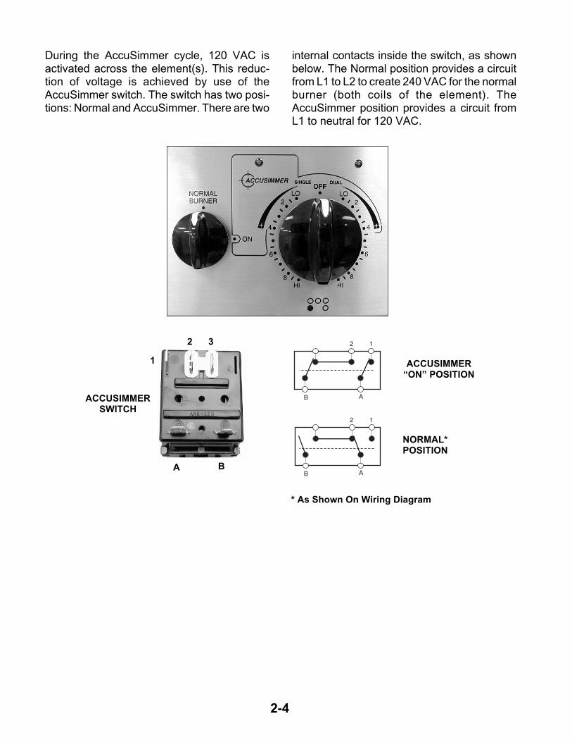
The AccuSimmer element is located at the leftfront position of the cooktop. The burner usesa dual element with a 1600 watt inner coil, andan 800 watt outer coil.
The controls (infinite switch and AccuSimmerswitch) for the element are both located on theleft side of the control panel, as shown above.The infinite switch for the AccuSimmer is differ-ent than the other infinite switches, because of
ACCUSIMMER BASIC OPERATION
the dual burner that it controls. It can be set forthe “DUAL” or “SINGLE” position. The illustra-tions below show the internal circuitry for theswitch.
The two coils can be activated individually ortogether, depending on the setting of the infi-nite switch. During AccuSimmer, the coils canalso be activated individually or together, butare used across a 120 VAC circuit.
2-4
2 1
B A
2 1
B AACCUSIMMERSWITCH
ACCUSIMMER“ON” POSITION
NORMAL* POSITION
1
2 3
A B
* As Shown On Wiring Diagram
During the AccuSimmer cycle, 120 VAC isactivated across the element(s). This reduc-tion of voltage is achieved by use of theAccuSimmer switch. The switch has two posi-tions: Normal and AccuSimmer. There are two
internal contacts inside the switch, as shownbelow. The Normal position provides a circuitfrom L1 to L2 to create 240 VAC for the normalburner (both coils of the element). TheAccuSimmer position provides a circuit fromL1 to neutral for 120 VAC.

2-5
A
2 P22A
ACCUSIMMER NORM.LIMITER
LIMITER
INFINITE SWITCHINFINITE SWITCH
BK
BK
HOT SURFACEINDICATOR LIGHT
OUTER ELEMENT
INNER ELEMENT
SURFACE INDICATOR LIGHT
A
1
2B 1B
A
ACCUSIMMERLIMITER
LIMITER
INFINITE SWITCH
BK
BK
HOT SURFACEINDICATOR LIGHT
OUTER ELEMENT
INNER ELEMENT
SURFACE INDICATOR LIGHT
NL1
W
BU
2 P2
INFINITE SWITCH
B 2
ACCUSIMMER SWITCHACCUSIMMER
INDICATOR LIGHT
S2
A 1
P1
4OR
ACCUSIMMER SWITCH
2 P2
INFINITE SWITCH
B 2
ACCUSIMMER SWITCH
INFINITE SWITCH LIMITER
LIMITERHOT SURFACE
INDICATOR LIGHT
ACCUSIMMERINDICATOR LIGHT
W
WINNER ELEMENT
S2
A
P1
4OR
ACCUSIMMER SWITCHINFINITE SWITCH
INFINITE SWITCH LIMITER
LIMITERHOT SURFACE
INDICATOR LIGHT
SURFACEINDICATOR LIGHT
W
INNER ELEMENT2 2 P2
R
2
DUAL FULL POWER
DUAL ACCUSIMMER
SINGLE FULL POWER
SINGLE ACCUSIMMER

2-6
L1
P
L2
H1 H2
INFINITE SWITCH
“OFF” POSITION
INFINITE SWITCH
INFINITE SWITCH
LIMITER
100 W ELEMENT
HOT SURFACEINDICATOR LIGHT
SURFACEINDICATOR LIGHT
W
W
W
BK
BK
L1 N
P L1 L2
H1 H2
A fifth element is an added feature to theelectric range, and is located at the center ofthe cooktop. This fifth element can be used tokeep foods warm when other foods are being
prepared. The fifth element operates at tem-peratures of between 100 degrees and 200degrees. This 100 watt element operates acrossL1 and Neutral (120 VAC) to maintain the lowertemperatures.
KEEP WARM ELEMENT

2-7
850W
WARMINGDRAWER
BK OR/BK
P3-1 P3-2
W
L1 N
Warming DrawerSensor
The warming drawer is accessed through theelectronic oven control. It operates an 850 wattheating element across 120 VAC (L1 to Neu-tral) that maintains a temperature of between108 and 195 degrees. As you turn the warmingdrawer on, it will default to the main setting of108 degrees (LOW). Other warming drawertemperatures may also be programmed, asshown in the chart. The temperature of thedrawer is controlled by a sensor that is similarto the main oven sensors. The warming drawersensor resistance is approximately 100 KΩ atroom temperature.
NOTE: To cancel the warming drawer opera-tion, press the DRAWER OFF keypad.
The warming drawer is supplied with an insu-lated liner that maintains the proper tempera-ture within the drawer. The chart, shown above,indicates the warming drawer temperatureswith the liner in place. If the liner is removed,the operating temperatures will increase by10° to 20°F. Do not use the warming drawerliner inside the oven.
TEMPERATURE°°°°F
108 LOW
140 2
160 3
180 4
195 HI
SETTINGS
WARMING DRAWER

2-8
Soft Close Door
Hinge Assembly WithOil-Filled Cylinder
Gold Series ranges will use a “Soft Close” doorfeature. This feature allows the oven door to beopened to any position, (between 30° and 80°),and will remain in that position until it is pushedclosed. When the door is pushed, an oil-filledcylinder will dampen the closing action, and the
door will close softly against the front of therange. The concept is similar to that which isused on screen doors, or on the hatchbacks ofcars. The oil-filled cylinder is part of one of therange hinge assemblies, and can be mountedon either side.
SOFT CLOSE DOOR

3-1
COMPONENT LOCATIONS
This section instructs you on how to service each component inside the range. The componentsand their locations are shown below.
COMPONENT ACCESS
ControlPower Supply
Latch Drive
Door Switch
Oven Light
Bake ElementWarming DrawerTemperature Sensor
Door Latch
Bottom OvenTemperature Sensor
Warming DrawerElement
Broil Element
Indicator Light
Hot Surface Indicators
Element &Limiter
Thermal Fuse
ElectronicOven Control
Single ElementInfinite Switch
Keep WarmSwitch
Top OvenTemperatureSensor
Normal Burner/AccuSimmer Switch
Dual Element Infinite Switch

3-2
ELECTRICAL SHOCK HAZARD
Disconnect power before servicing the range.
Replace all panels before operating range.
Failure to do so can result in death or electri-cal shock.
REMOVING A SINGLE ELEMENT INFINITE SWITCH
1. Turn off the electrical supply going to therange.
2. Pull the knob off the single element infiniteswitch you wish to service and remove thetwo screws.
CAUTION: When you work on the electricrange, be careful when handling the sheetmetal parts. Sharp edges may be present, andyou can cut yourself if you are not careful.
WARNING 3. Pull the range away from the wall so thatyou can access the rear panel.
4. Remove the eight screws from the rearpanel and remove the panel.
5. Remove the wires from the single elementinfinite switch terminals and remove theswitch.
Screw(1 of 8)
Rear Panel
Single Element Infinite Switch
4-H2 5-L2 3-L1
1-H1 2-P
Red Black
Dk. Blue
Screws
Single Element Infinite Switches

3-3
ELECTRICAL SHOCK HAZARD
Disconnect power before servicing the range.
Replace all panels before operating range.
Failure to do so can result in death or electri-cal shock.
REMOVING THE NORMAL BURNER/ACCUSIMMER SWITCH
CAUTION: When you work on the electricrange, be careful when handling the sheetmetal parts. Sharp edges may be present, andyou can cut yourself if you are not careful.
WARNING 3. Pull the range away from the wall so thatyou can access the rear panel.
4. Remove the eight screws from the rearpanel and remove the panel (see step 4 onpage 3-2).
5. Remove the wires from the Normal Burner/AccuSimmer switch terminals and removethe switch.
1. Turn off the electrical supply going to therange.
2. Pull the knob off the Normal Burner/AccuSimmer switch and remove the twoscrews.
B-Blue
1-White
A-Orange
Screws
Normal Burner/AccuSimmer Switch
2-Violet

3-4
ELECTRICAL SHOCK HAZARD
Disconnect power before servicing the range.
Replace all panels before operating range.
Failure to do so can result in death or electri-cal shock.
REMOVING THE DUAL ELEMENT INFINITE SWITCH
CAUTION: When you work on the electricrange, be careful when handling the sheetmetal parts. Sharp edges may be present, andyou can cut yourself if you are not careful.
WARNING 3. Pull the range away from the wall so thatyou can access the rear panel.
4. Remove the eight screws from the rearpanel and remove the panel (see step 4 onpage 3-2).
5. Remove the wires from the dual elementinfinite switch terminals and remove theswitch.
1. Turn off the electrical supply going to therange.
2. Pull the knob off the dual element infiniteswitch and remove the two screws.
Screws
Dual Element Infinite Switch
L1 - BlackP1
L2 - RedP2
2 - VioletPushbutton
4 - Or/BkInner Element
S2 - BluePilot Light
4A - Or/WhOuter Element
3-5
ELECTRICAL SHOCK HAZARD
Disconnect power before servicing the range.
Replace all panels before operating range.
Failure to do so can result in death or electri-cal shock.
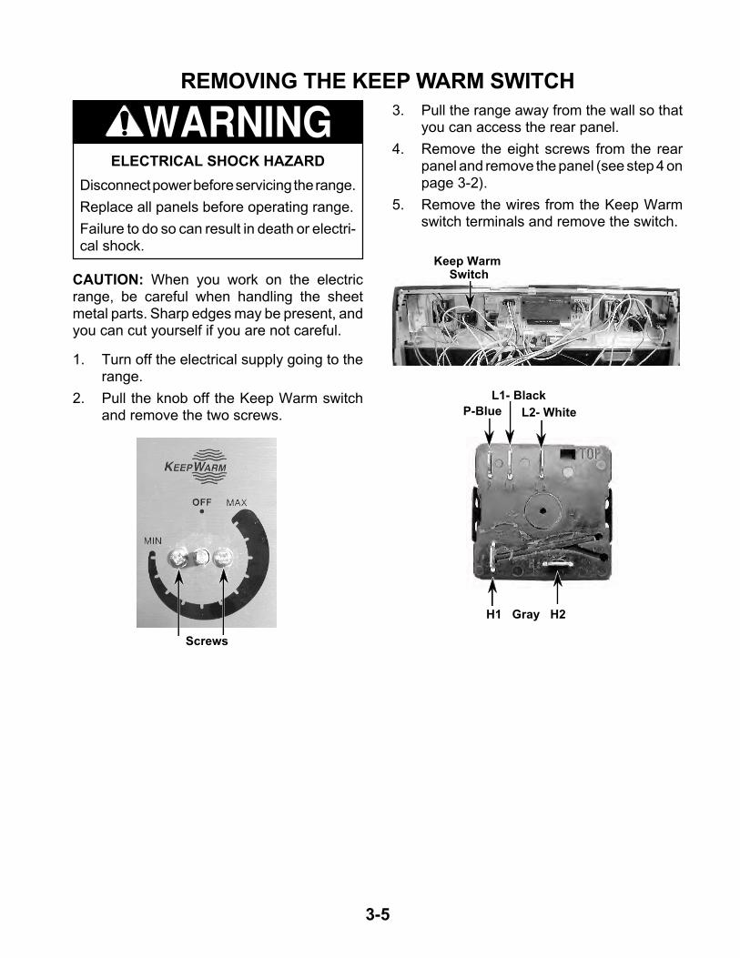
REMOVING THE KEEP WARM SWITCH
CAUTION: When you work on the electricrange, be careful when handling the sheetmetal parts. Sharp edges may be present, andyou can cut yourself if you are not careful.
WARNING 3. Pull the range away from the wall so thatyou can access the rear panel.
4. Remove the eight screws from the rearpanel and remove the panel (see step 4 onpage 3-2).
5. Remove the wires from the Keep Warmswitch terminals and remove the switch.
1. Turn off the electrical supply going to therange.
2. Pull the knob off the Keep Warm switchand remove the two screws.
Keep Warm Switch
Screws
P-Blue L2- White
H1 Gray H2
L1- Black

3-6
ELECTRICAL SHOCK HAZARD
Disconnect power before servicing the range.
Replace all panels before operating range.
Failure to do so can result in death or electri-cal shock.
REMOVING AN INDICATOR LIGHT
CAUTION: When you work on the electricrange, be careful when handling the sheetmetal parts. Sharp edges may be present, andyou can cut yourself if you are not careful.
WARNING
1. Turn off the electrical supply going to therange.
2. Pull the range away from the wall so thatyou can access the rear panel.
3. Remove the eight screws from the rearpanel and remove the panel (see step 4 onpage 3-2).
Indicator Lights
4. To remove an indicator light, push on thebody and slide the clip off the shoulder ofthe lens.
5. Disconnect the two indicator wires fromthe terminals.
Lens
Push
Indicator Light
Indicator Light
3-7
ELECTRICAL SHOCK HAZARD
Disconnect power before servicing the range.
Replace all panels before operating range.
Failure to do so can result in death or electri-cal shock.
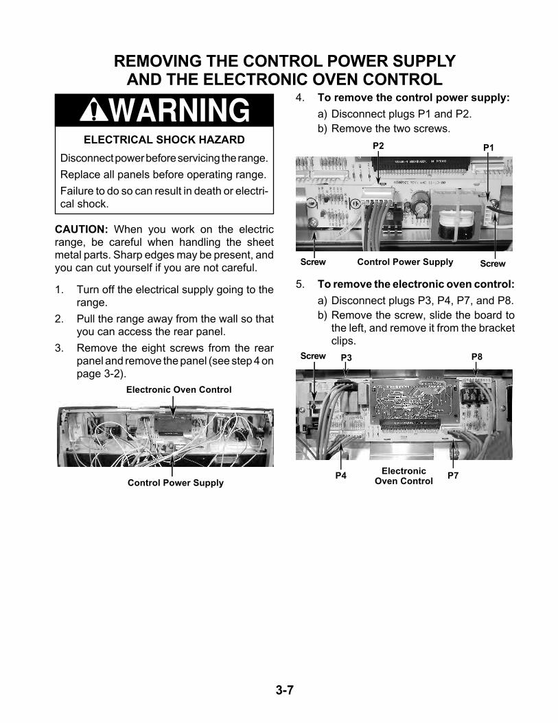
REMOVING THE CONTROL POWER SUPPLYAND THE ELECTRONIC OVEN CONTROL
CAUTION: When you work on the electricrange, be careful when handling the sheetmetal parts. Sharp edges may be present, andyou can cut yourself if you are not careful.
WARNING
1. Turn off the electrical supply going to therange.
2. Pull the range away from the wall so thatyou can access the rear panel.
3. Remove the eight screws from the rearpanel and remove the panel (see step 4 onpage 3-2).
4. To remove the control power supply:
a) Disconnect plugs P1 and P2.
b) Remove the two screws.
5. To remove the electronic oven control:
a) Disconnect plugs P3, P4, P7, and P8.
b) Remove the screw, slide the board tothe left, and remove it from the bracketclips.
P3
Control Power Supply
Control Power Supply
Electronic Oven Control
ElectronicOven Control
P8
P7
Screw
P4
ScrewScrew
P1P2
3-8
ELECTRICAL SHOCK HAZARD
Disconnect power before servicing the range.
Replace all panels before operating range.
Failure to do so can result in death or electri-cal shock.
REMOVING AN ELEMENT & LIMITERAND THE COOKTOP GLASS ASSEMBLY
CAUTION: When you work on the electricrange, be careful when handling the sheetmetal parts. Sharp edges may be present, andyou can cut yourself if you are not careful.
WARNING
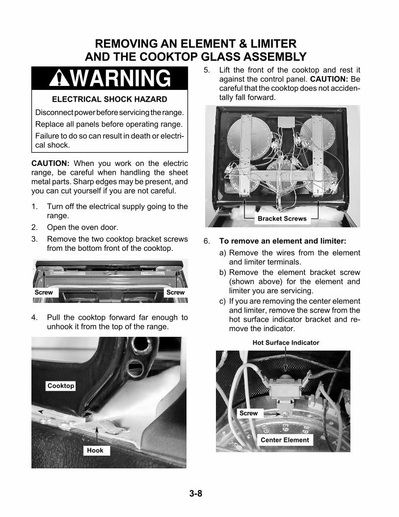
1. Turn off the electrical supply going to therange.
2. Open the oven door.
3. Remove the two cooktop bracket screwsfrom the bottom front of the cooktop.
4. Pull the cooktop forward far enough tounhook it from the top of the range.
5. Lift the front of the cooktop and rest itagainst the control panel. CAUTION: Becareful that the cooktop does not acciden-tally fall forward.
6. To remove an element and limiter:
a) Remove the wires from the elementand limiter terminals.
b) Remove the element bracket screw(shown above) for the element andlimiter you are servicing.
c) If you are removing the center elementand limiter, remove the screw from thehot surface indicator bracket and re-move the indicator.
Screw Screw
Hook
Cooktop
Bracket Screws
Hot Surface Indicator
Center Element
Screw

3-9
d) Carefully lift the bottom of the bracketjust far enough to remove the element.NOTE: If you are removing an elementat the top of the bracket, remove thelower element first, lay it on top of therange, and then remove the top ele-ment from the bracket.
e) Remove the screws from the limiterand remove it from the element. NOTE:Be careful when you remove the limiterthat you do not break the sensor tube(see below).
REASSEMBLY NOTE: When you reinstall theelement and limiter, make sure that the align-ment pins are inserted into the correct bracketslots, (see the photo to the right) then reinstallthe bracket screw to secure it to the cooktop.
7. To remove the cooktop glass assem-bly:
a) Remove the two screws from the hotsurface indicator assembly bracket andremove the assembly from the frame.
Limiter
Screws
Sensor Tube
Pin
Pin Pin
Pin
Pin Pin
PinPin
b) Carefully lift the bottom of the left bracketjust far enough to remove the bottomelement, then repeat the procedure forthe bottom right and center elements.Lay each of the elements on top of therange.
c) Lift the brackets and remove the toptwo elements and lay them on top of therange.
d) Lift the element brackets and unhookthem from the top of the cooktop.
e) Remove the old cooktop glass assem-bly from the range.
REASSEMBLY NOTE: When reinstalling theelements in the new cooktop glass assembly,make sure that the alignment pins are in theircorrect bracket slots, as shown in the photoabove
Hot Surface Indicator Bracket
Screw(1 of 2)

3-10
REMOVING THE HOT SURFACE INDICATORS
ELECTRICAL SHOCK HAZARD
Disconnect power before servicing the range.
Replace all panels before operating range.
Failure to do so can result in death or electri-cal shock.
CAUTION: When you work on the electricrange, be careful when handling the sheetmetal parts. Sharp edges may be present, andyou can cut yourself if you are not careful.
WARNING
1. Turn off the electrical supply going to therange.
2. Pull the range away from the wall so thatyou can access the rear panel.
3. Remove the eight screws from the rearpanel and remove the panel (see step 4 onpage 3-2).
4. Raise the cooktop (see page 3-8 for theprocedure).
Hot Surface Indicator Bracket
Screw(1 of 2)
5. To remove the four hot surface indica-tor assembly:
a) Remove the two screws from the hotsurface indicator assembly bracket andremove the assembly from the frame.
(1) Hot SurfaceIndicator
(4) Hot Surface Indicator Assembly
c) Disconnect the yellow, orange, brown,and blue wires from the element termi-nals.
d) From the back of the unit, disconnectthe white wire connector.
b) Unsnap four tabs on the hot surfaceindicator assembly from the bracketand remove the assembly.
Tabs Tabs

3-11
6. To remove the single hot surface indi-cator:
a) Remove the screw from the bracket onthe center element and remove theindicator.
b) Disconnect the two wires from the ter-minals.
Center Element
Screw
Single Hot Surface Indicator

3-12
b) Remove the door latch from the burnerbox and unhook the actuating rod.
5. To remove the door switch:
a) If not already done, raise the cooktop(see page 3-8 for the procedure).
b) Remove the four screws from the rightmounting plate and remove the plate.
REMOVING THE DOOR LATCH & THE DOOR SWITCH
ELECTRICAL SHOCK HAZARD
Disconnect power before servicing the range.
Replace all panels before operating range.
Failure to do so can result in death or electri-cal shock.
CAUTION: When you work on the electricrange, be careful when handling the sheetmetal parts. Sharp edges may be present, andyou can cut yourself if you are not careful.
WARNING
1. Turn off the electrical supply going to therange.
2. Open the oven door.
3. Raise the cooktop (see page 3-8 for theprocedure).
4. To remove the door latch:
a) Remove the two screws and rubberbumper from the door latch and removethe latch.
Screw &Rubber Bumper
Screw
UnhookActuating
Rod
Screw (1 of 4) Right Mounting Plate

3-13
d) Disconnect the wires from the termi-nals.
Door Switch
Wires
c) Remove the door switch from the range.To do this, use a ratchet extension or asmall socket, and tap it out of the holewith a hammer.
Door Switch
Ratchet Extension
3-14
REMOVING THE BROIL & BAKE ELEMENTS
ELECTRICAL SHOCK HAZARD
Disconnect power before servicing the range.
Replace all panels before operating range.
Failure to do so can result in death or electri-cal shock.
CAUTION: When you work on the electricrange, be careful when handling the sheetmetal parts. Sharp edges may be present, andyou can cut yourself if you are not careful.
WARNING
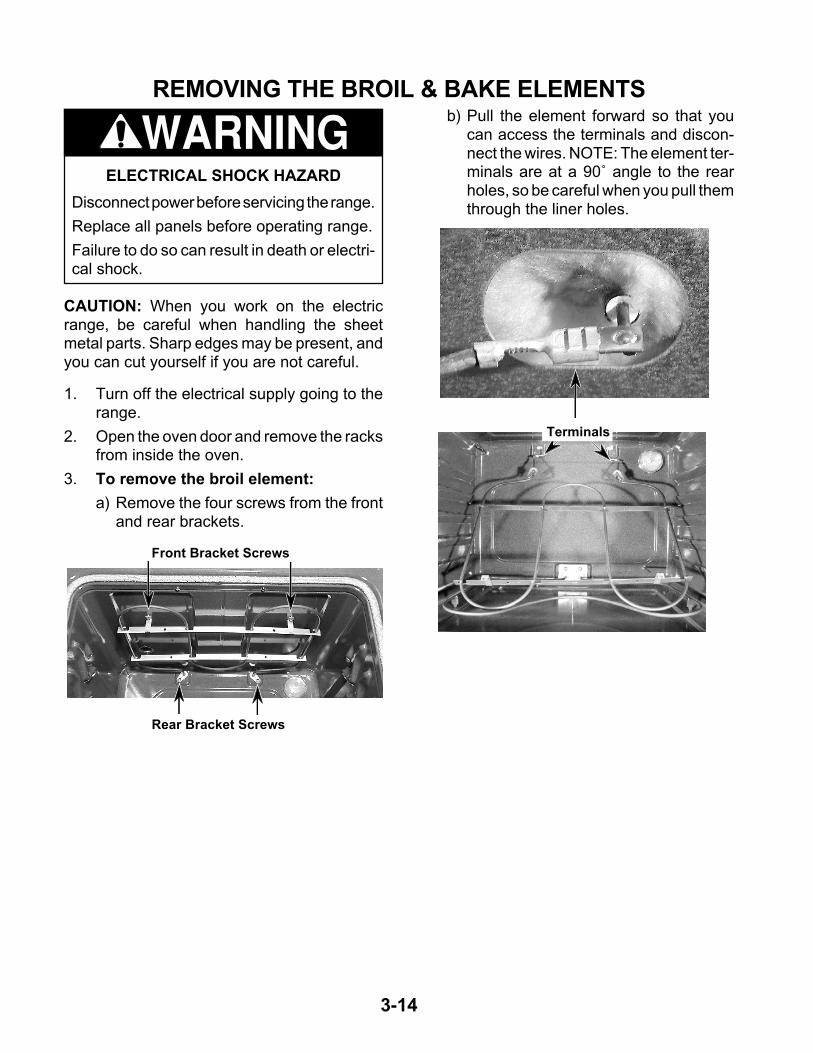
1. Turn off the electrical supply going to therange.
2. Open the oven door and remove the racksfrom inside the oven.
3. To remove the broil element:
a) Remove the four screws from the frontand rear brackets.
Front Bracket Screws
Rear Bracket Screws
b) Pull the element forward so that youcan access the terminals and discon-nect the wires. NOTE: The element ter-minals are at a 90˚ angle to the rearholes, so be careful when you pull themthrough the liner holes.
Terminals

3-15
4. To remove the bake element:
a) Remove the two screws from the ele-ment brackets.
Bracket Screws
b) Pull the element forward so that youcan access the terminals and discon-nect the wires.
BakeElement
Terminals

3-16
REMOVING THE OVEN LIGHT SOCKET ASSEMBLY
1. Turn off the electrical supply going to therange.
2. Open the oven door and remove the racksfrom the oven.
3. Unscrew the lens and bulb from the ovenlight socket assembly and remove them.
CAUTION: Be careful not to scratch or chip theoven liner paint when you remove the ovenlight socket in the next step.
4. Use a screwdriver and bend the clips onthe oven light socket away from the edgesof the liner hole, and pull the socket out ofthe liner. NOTE: If it is too difficult to re-move the socket from the front of the oven,you will have to push the socket out fromthe back of the unit.
5. Disconnect the wires from the socket ter-minals.
Socket Clips
Lens & Bulb
(Viewed From Rear Panel)
Socket Wires
ELECTRICAL SHOCK HAZARD
Disconnect power before servicing the range.
Replace all panels before operating range.
Failure to do so can result in death or electri-cal shock.
WARNING
CAUTION: When you work on the electricrange, be careful when handling the sheetmetal parts. Sharp edges may be present, andyou can cut yourself if you are not careful.

3-17
REMOVING THE LATCH DRIVE ASSEMBLY5. Disconnect the wires from the latch drive
motor and switch.
6. Remove the two mounting screws fromthe latch drive.
Actuating Rod
Cam
ELECTRICAL SHOCK HAZARD
Disconnect power before servicing the range.
Replace all panels before operating range.
Failure to do so can result in death or electri-cal shock.
WARNING
1. Turn off the electrical supply going to therange.
2. Open the oven door and remove the racksfrom the oven.
3. Pull the range away from the wall so thatyou can access the rear panel.
4. Remove the eight screws from the rearpanel and remove the panel (see step 4 onpage 3-2).
CAUTION: When you work on the electricrange, be careful when handling the sheetmetal parts. Sharp edges may be present, andyou can cut yourself if you are not careful.
Latch Drive Assembly
7. Unhook the actuating rod from the cam.
Switch Terminals
Screw
Motor Terminals
Screw

3-18
REMOVING THE OVEN TEMPERATURE SENSORSAND THE THERMAL FUSE
5. To remove an oven temperature sen-sor, disconnect the connector from themain harness and remove the two mount-ing screws.ELECTRICAL SHOCK HAZARD
Disconnect power before servicing the range.
Replace all panels before operating range.
Failure to do so can result in death or electri-cal shock.
WARNING
1. Turn off the electrical supply going to therange.
2. Open the oven door and remove the racksfrom the oven.
3. Pull the range away from the wall so thatyou can access the rear panel.
4. Remove the eight screws from the rearpanel and remove the panel (see step 4 onpage 3-2).
CAUTION: When you work on the electricrange, be careful when handling the sheetmetal parts. Sharp edges may be present, andyou can cut yourself if you are not careful.
Top OvenTemperature
Sensor
Bottom Oven Temperature
Sensor
Connectors
Thermal Fuse
6. To remove the thermal fuse, disconnectthe wires from the terminals and removethe mounting screw.
Wires
Thermal Fuse
Screws
Screw
3-19
REMOVING THE WARMING DRAWER ELEMENT & TEMPERATURE SENSOR
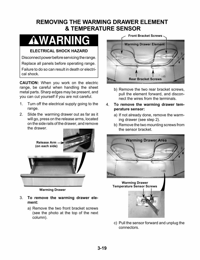
1. Turn off the electrical supply going to therange.
2. Slide the warming drawer out as far as itwill go, press on the release arms, locatedon the side rails of the drawer, and removethe drawer.
3. To remove the warming drawer ele-ment:
a) Remove the two front bracket screws(see the photo at the top of the nextcolumn).
Release Arm(on each side)
b) Remove the two rear bracket screws,pull the element forward, and discon-nect the wires from the terminals.
4. To remove the warming drawer tem-perature sensor:
a) If not already done, remove the warm-ing drawer (see step 2).
b) Remove the two mounting screws fromthe sensor bracket.
Warming Drawer
Rear Bracket Screws
ELECTRICAL SHOCK HAZARD
Disconnect power before servicing the range.
Replace all panels before operating range.
Failure to do so can result in death or electri-cal shock.
WARNING
CAUTION: When you work on the electricrange, be careful when handling the sheetmetal parts. Sharp edges may be present, andyou can cut yourself if you are not careful.
Warming Drawer Element
Front Bracket Screws
Warming Drawer Area
c) Pull the sensor forward and unplug theconnectors.
Warming DrawerTemperature Sensor Screws

3-20
REMOVING THE OVEN DOOR
CAUTION: Do not lift the oven door by itshandle.
To remove the oven door:
1. Open the oven door to its fully down posi-tion.
2. Remove the two door stop clips from theoven door slots.
4. Close the oven door as far as the two pinswill allow.
5. Grasp the sides of the door and lift the dooruntil it stops, then pull the hinge hangersout of the slots.
3. Install a pin in the hole of each oven doorhinge hanger.
Door Pin
Hinge Hanger
Door Stop Clip
Hinge Hanger
To reinstall the oven door:
1. Grasp the sides of the door and tilt it backat a slight angle, then insert the hingehangers into the hinge slots as far as theywill go.
2. Rotate the top of the door towards therange so the hinge hangers fit onto thesupport pins.
3. Close the oven door as far as the pins willallow, and make sure that the hinge hang-ers are fully seated on the support pins. Ifthey are not seated properly, the door willnot close tightly and may be off-center. Toseat the hinge hangers, open the doorslightly, and push in on the bottom until thehangers are fully seated.
4. Open the oven door to its fully open posi-tion and remove the two hinge hangerpins.
ELECTRICAL SHOCK HAZARD
Disconnect power before servicing the range.
Replace all panels before operating range.
Failure to do so can result in death or electri-cal shock.
WARNING
CAUTION: When you work on the electricrange, be careful when handling the sheetmetal parts. Sharp edges may be present, andyou can cut yourself if you are not careful.

3-21
5. Install the two door stop clips in the top ofthe door slots with the angled side facingup.
Angled Side up
6. Close the oven door completely and checkit for proper operation and alignment.

3-22
REMOVING THE OVEN DOOR HANDLE & GLASS
1. Remove the oven door from the range(see page 3-20 for the procedure).
2. Place the oven door on a padded worksurface with the front glass facing down.
3. Remove the two top door liner screws.
Top Liner Screws
4. Remove the three bottom screws from thedoor liner.
5. Lift the liner assembly off the front glassand set it aside.
6. To remove the door handle, unhook itfrom the top of the front glass and removethe two door handle screws.
Bottom Liner Screws
7. To remove the front door glass, removethe two side trim screws. Be careful not tobreak the trim near the mounting screw.
Door Handle Screws
Door Glass Trim Screws
ELECTRICAL SHOCK HAZARD
Disconnect power before servicing the range.
Replace all panels before operating range.
Failure to do so can result in death or electri-cal shock.
WARNING
CAUTION: When you work on the electricrange, be careful when handling the sheetmetal parts. Sharp edges may be present, andyou can cut yourself if you are not careful.

3-23
8. To remove a hinge hanger assembly:
a) Place the door liner assembly on apadded work surface with the hingehangers over the edge.
b) Remove the two bottom screws.
c) Unhook the hinge hanger tab from theslot at the top.
d) Lift the hinge hanger out of the doorliner slot.
9. To remove the oven door glass assem-bly:
a) Remove both hinge hangers (see step8).
b) Lift the insulation retainer off the doorliner.
d) Lift the inner oven door glass andbracket assembly out of the door liner.
c) Remove the insulation from around theoven door glass assembly.
REASSEMBLY NOTE: When you reinstall theinsulation around the oven door glass, makesure that the insulation is not visible in the glassafter the door is reassembled.
Unhook Tab From Slot
Hinge Hanger Screws
Insulation Retainer
Insulation
Inner Oven DoorGlass &Bracket n
e) Lift the outer oven door glass out of thedoor liner.
Outer Oven Door Glass

3-24
REMOVING THE OVEN DOOR GASKET
1. Open the oven door to its fully down posi-tion.
2. Pull the oven door gasket clips out of theliner holes until all of the clips are re-moved.
REASSEMBLY NOTE: When you install thenew gasket, make sure that all of the clips areseated in their liner holes, and that the ends ofthe gasket are pushed fully into their holes. Usethe pointed end of a pencil to push the gasketends into the holes.
3. Pull the ends of the gasket out of the linerholes.
End Of GasketIn Liner Hole
Push End OfGasket IntoHole With
PencilDoor Gasket
Gasket Clips
ELECTRICAL SHOCK HAZARD
Disconnect power before servicing the range.
Replace all panels before operating range.
Failure to do so can result in death or electri-cal shock.
WARNING
CAUTION: When you work on the electricrange, be careful when handling the sheetmetal parts. Sharp edges may be present, andyou can cut yourself if you are not careful.

3-25
8 . Pull the back of the side panel out from therange approximately 45˚.
9. Open the warming drawer several inches.
10. Push forward and unhook the three fronttabs from the chassis slots and removethe side panel.
Unhook3 Front TabsFrom Slots
REMOVING A SIDE PANEL
1. Turn off the electrical supply going to therange.
2. Remove the oven door from the range(see page 3-20 for the procedure).
3. Pull the range away from the wall so youcan access the back of the unit.
4. Remove the eight screws from the rearpanel and remove the panel (see step 4 onpage 3-2).
5. Raise the cooktop (see page 3-8 for theprocedure). NOTE: Position the side ofthe cooktop so that it does not rest on theside panel that you are removing.
6. Remove the five screws from the top of theside panel. NOTE: Set the small supportbracket aside with the screws.
7. Remove the three screws from the left orright side panel you are removing (the leftpanel is shown below).
ELECTRICAL SHOCK HAZARD
Disconnect power before servicing the range.
Replace all panels before operating range.
Failure to do so can result in death or electri-cal shock.
CAUTION: When you work on the electricrange, be careful when handling the sheetmetal parts. Sharp edges may be present, andyou can cut yourself if you are not careful.
WARNING
Bracket
3 Screws
Left SidePanel Screws

3-26
— NOTES —

4-1
COMPONENT TESTINGBefore testing any of the components, performthe following checks:
• The most common cause for control failure iscorrosion on connectors. Therefore, discon-necting and reconnecting wires will be nec-essary throughout test procedures.
• All tests/checks should be made with a VOMor DVM having a sensitivity of 20,000 ohms-per-volt DC, or greater.
• Check all connections before replacing com-ponents, looking for broken or loose wires,failed terminals, or wires not pressed intoconnectors far enough.
• Resistance checks must be made with powercord unplugged from outlet, and with wiringharness or connectors disconnected.
ELECTRICAL SHOCK HAZARD
Disconnect power before servicing.
Replace all panels before operating.
Failure to do so could result in death orelectrical shock.
WARNING
Refer to page 3-12 for the procedure for servic-ing the door switch.
1. Disconnect the electrical power to therange.
2. Set the ohmmeter to the R x 1 scale.
3. Touch the ohmmeter leads to the doorswitch terminals. The meter should indi-cate an open circuit (infinite).
4. Press the actuator button and the metershould indicate continuity (0 Ω).
DOOR SWITCH
ELECTRICAL SHOCK HAZARD
Disconnect power before servicing.
Replace all panels before operating.
Failure to do so could result in death orelectrical shock.
WARNING
Refer to page 3-19 for the procedure for servic-ing the warming drawer element.
1. Disconnect the electrical power to therange.
2. Set the ohmmeter to the R x 1 scale.
3. Touch one of the ohmmeter leads to thewarming drawer element terminals. Themeter should indicate between 14 and20 Ω.
WARMING DRAWER ELEMENT

4-2
ELECTRICAL SHOCK HAZARD
Disconnect power before servicing.
Replace all panels before operating.
Failure to do so could result in death orelectrical shock.
WARNING
Refer to page 3-14 for the procedure for servic-ing the bake element.
1. Disconnect the electrical power to therange.
2. Set the ohmmeter to the R x 1 scale.
3. Touch one of the ohmmeter leads to thebake element terminals. The meter shouldindicate between 20 and 28 Ω.
BAKE ELEMENT
ELECTRICAL SHOCK HAZARD
Disconnect power before servicing.
Replace all panels before operating.
Failure to do so could result in death orelectrical shock.
WARNING
Refer to page 3-14 for the procedure for servic-ing the broil element.
1. Disconnect the electrical power to therange.
2. Set the ohmmeter to the R x 1 scale.
3. Touch one of the ohmmeter leads to thebroil element terminals. The meter shouldindicate between 14 and 21 Ω.
BROIL ELEMENT

4-3
ELECTRICAL SHOCK HAZARD
Disconnect power before servicing.
Replace all panels before operating.
Failure to do so could result in death orelectrical shock.
WARNINGELECTRICAL SHOCK HAZARD
Disconnect power before servicing.
Replace all panels before operating.
Failure to do so could result in death orelectrical shock.
WARNING
Refer to page 3-17 for the procedure for servic-ing the latch drive.
1. Disconnect the electrical power to therange.
2. Disconnect the wires from the latch drivecomponent under test.
3. Set the ohmmeter to the R x 1K scale.
4. To test the motor, touch the ohmmeterleads to the terminals. The meter shouldindicate approximately 2800 Ω.
5. To test the door latch switch:
a) Touch the ohmmeter leads to the ter-minals. The meter should indicate anopen circuit (infinite).
b) Press the switch actuator and touch theohmmeter leads to the terminals. Themeter should indicate continuity (0 Ω).
LATCH DRIVE OVEN & WARMING DRAWERTEMPERATURE SENSORS
Motor
Switch Terminals
Actuator
Motor Terminals
Refer to page 3-18 for the procedure for servic-ing the oven temperature sensors, and to page3-19 for the warming drawer temperature sen-sor.
1. Disconnect the electrical power to therange.
2. Set the ohmmeter to the R x 100 scale.
3. Touch the ohmmeter test leads to theoven temperature sensor connector pins.The meter should indicate approximately1080 Ω at 75˚F for both sensors.
4. Set the ohmmeter to the R x 10K scale.
5. Touch the ohmmeter test leads to thewarming drawer temperature sensor con-nector pins. The meter should indicateapproximately 9 kΩ at 75˚F.
Door Latch Switch

4-4
ELECTRICAL SHOCK HAZARD
Disconnect power before servicing.
Replace all panels before operating.
Failure to do so could result in death orelectrical shock.
WARNING
Refer to page 3-18 for the procedure for servic-ing the thermal fuse.
1. Disconnect the electrical power to therange.
2. Set the ohmmeter to the R x 1 scale.
3. Touch one of the ohmmeter leads to thethermal fuse terminals. The meter shouldindicate continuity (0 Ω). NOTE: The ther-mal fuse will open at 363˚F (184˚C) and isnon-resettable.
THERMAL FUSE
ELECTRICAL SHOCK HAZARD
Disconnect power before servicing.
Replace all panels before operating.
Failure to do so could result in death orelectrical shock.
WARNING
Refer to page 3-2 for the procedure for servic-ing a single element infinite switch.
1. Disconnect the electrical power to therange.
2. Set the ohmmeter to the R x 1 scale.
3. Turn the appropriate infinite switch to theOn position.
4. Touch the ohmmeter test leads to termi-nals L1 and P. The meter should indicatecontinuity (0 Ω).
5. Touch the ohmmeter test leads to termi-nals L1 and H1. The meter should indicatecontinuity (0 Ω).
6. Touch the ohmmeter test leads to termi-nals L2 and H2. The meter should indicatecontinuity (0 Ω).
SINGLE ELEMENT INFINITESWITCHES (RF, RR, & LR)
L1
P
L2
H1 H2
L2H2
L1
P
H1
4-5
ELECTRICAL SHOCK HAZARD
Disconnect power before servicing.
Replace all panels before operating.
Failure to do so could result in death orelectrical shock.
WARNING
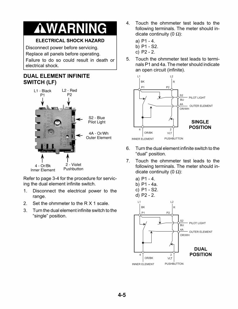
DUAL ELEMENT INFINITESWITCH (LF)
Refer to page 3-4 for the procedure for servic-ing the dual element infinite switch.
1. Disconnect the electrical power to therange.
2. Set the ohmmeter to the R X 1 scale.
3. Turn the dual element infinite switch to the“single” position.
L1 - BlackP1
L2 - RedP2
4 - Or/BkInner Element
S2 - BluePilot Light
2 - VioletPushbutton
L1 L2
BK
OR/BK VLT
R
P1 P2
S2
BU
OR/WH
4A
PILOT LIGHT
OUTER ELEMENT
INNER ELEMENT PUSHBUTTON
4 2
L1 L2
BK
OR/BK VLT
R
BU
P1 P2
S2
4A
OR/WH
PILOT LIGHT
OUTER ELEMENT
INNER ELEMENT PUSHBUTTON
4 2
4. Touch the ohmmeter test leads to thefollowing terminals. The meter should in-dicate continuity (0 Ω):
a) P1 - 4.b) P1 - S2.c) P2 - 2.
5. Touch the ohmmeter test leads to termi-nals P1 and 4a. The meter should indicatean open circuit (infinite).
6. Turn the dual element infinite switch to the“dual” position.
7. Touch the ohmmeter test leads to thefollowing terminals. The meter should in-dicate continuity (0 Ω):
a) P1 - 4.b) P1 - 4a.c) P1 - S2.d) P2 - 2.
SINGLEPOSITION
DUALPOSITION
4A - Or/WhOuter Element
4-6
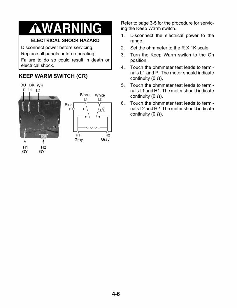
KEEP WARM SWITCH (CR)
Refer to page 3-5 for the procedure for servic-ing the Keep Warm switch.
1. Disconnect the electrical power to therange.
2. Set the ohmmeter to the R X 1K scale.
3. Turn the Keep Warm switch to the Onposition.
4. Touch the ohmmeter test leads to termi-nals L1 and P. The meter should indicatecontinuity (0 Ω).
5. Touch the ohmmeter test leads to termi-nals L1 and H1. The meter should indicatecontinuity (0 Ω).
6. Touch the ohmmeter test leads to termi-nals L2 and H2. The meter should indicatecontinuity (0 Ω).
P L1
H2
L2
H1
BU BK WH
GY GY
L1
P
L2
H1 H2
Black White
Blue
Gray Gray
ELECTRICAL SHOCK HAZARD
Disconnect power before servicing.
Replace all panels before operating.
Failure to do so could result in death orelectrical shock.
WARNING

4-7
B - BUA - OR
2 V 3 V
NORMAL BURNER/ACCUSIMMERSWITCH (LF)
ELECTRICAL SHOCK HAZARD
Disconnect power before servicing.
Replace all panels before operating.
Failure to do so could result in death orelectrical shock.
WARNINGRefer to page 3-3 for the procedure for servic-ing the Normal Burner/AccuSimmer switch.
1. Disconnect the electrical power to therange.
2. Set the ohmmeter to the R x 1 scale.
3. Turn the Normal Burner/AccuSimmerswitch to the Normal Burner position.
4. Touch the ohmmeter test leads to termi-nals 2 and A. The meter should indicatecontinuity (0 Ω).
5. Touch the ohmmeter test leads to termi-nals 3 and A. The meter should indicatecontinuity (0 Ω).
6. Touch the ohmmeter test leads to termi-nals 1 and A. The meter should indicate anopen (infinite) circuit.
7. Turn the Normal Burner/AccuSimmerswitch to the AccuSimmer position.
8. Touch the ohmmeter test leads to termi-nals 1 and A. The meter should indicatecontinuity (0 Ω).
9. Touch the ohmmeter test leads to termi-nals 2 and B. The meter should indicatecontinuity (0 Ω).
10. Touch the ohmmeter test leads to termi-nals 3 and B. The meter should indicatecontinuity (0 Ω).
NORMAL BURNERPOSITION
1 WH
A - OR B - BU
1 WH 2 V 3
A - OR B - BU
1 WH 2 V 3
ACCUSIMMER POSITION

4-8
SURFACE ELEMENTS & LIMITERS
Refer to page 3-8 for the procedure for servic-ing the elements & limiters.
1. Disconnect the electrical power to therange.
2. Set the ohmmeter to the R X 1 scale.
3. Raise the cooktop.
4. To test the RF, LR, & RR elements &limiters:
a) Disconnect one of the wires from theelement terminals.
b) Disconnect the wires from limiter ter-minals 1A and 1B.
c) Touch the ohmmeter test leads to thetwo element terminals. The metershould indicate 45 Ω ±10%.
d) Touch the ohmmeter test leads to lim-iter terminals 1A & 2A. The metershould indicate continuity (0 Ω).
ELECTRICAL SHOCK HAZARD
Disconnect power before servicing.
Replace all panels before operating.
Failure to do so could result in death orelectrical shock.
WARNING
Limiter
Element Terminals
1A
2A
1B
2B
e) Touch the ohmmeter test leads to lim-iter terminals 1B & 2B.
With the temperature below 150˚F, themeter should indicate an open circuit(infinite).
With the temperature above 150˚F, themeter should indicate continuity (0 Ω).
5. To test the center rear (CR) elementand limiter:
a) Disconnect either of the gray wires fromthe element terminals.
b) Disconnect the wires from limiter ter-minals 1A and 1B.
c) Touch the ohmmeter test leads to thetwo element terminals. The metershould indicate 120 Ω ±10%.
d) Touch the ohmmeter test leads to lim-iter terminals 1A & 2A. The metershould indicate continuity (0 Ω).
e) Touch the ohmmeter test leads to lim-iter terminals 1B & 2B.
With the temperature below 150˚F, themeter should indicate an open circuit(infinite).
With the temperature above 150˚F, themeter should indicate continuity (0 Ω).
4-9
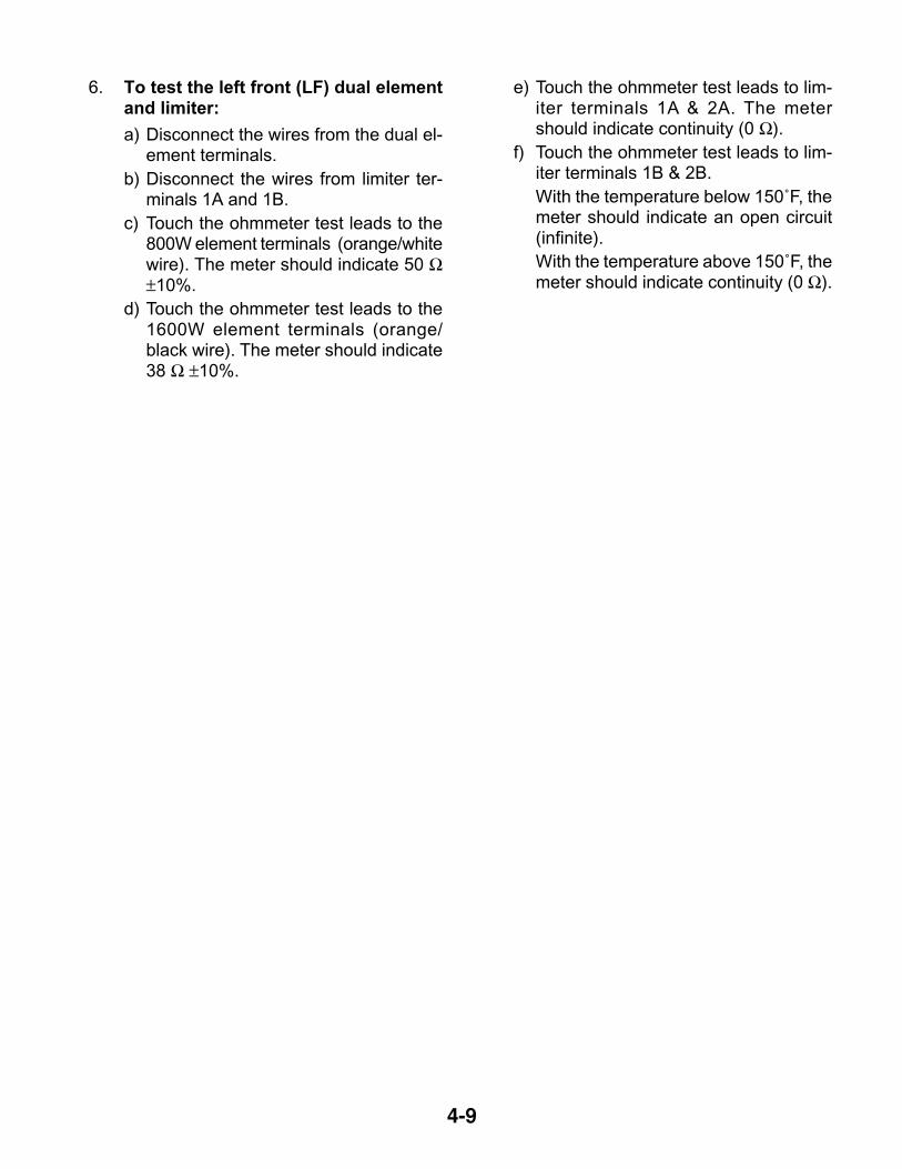
6. To test the left front (LF) dual elementand limiter:
a) Disconnect the wires from the dual el-ement terminals.
b) Disconnect the wires from limiter ter-minals 1A and 1B.
c) Touch the ohmmeter test leads to the800W element terminals (orange/whitewire). The meter should indicate 50 Ω±10%.
d) Touch the ohmmeter test leads to the1600W element terminals (orange/black wire). The meter should indicate38 Ω ±10%.
e) Touch the ohmmeter test leads to lim-iter terminals 1A & 2A. The metershould indicate continuity (0 Ω).
f) Touch the ohmmeter test leads to lim-iter terminals 1B & 2B.
With the temperature below 150˚F, themeter should indicate an open circuit(infinite).
With the temperature above 150˚F, themeter should indicate continuity (0 Ω).

4-10
— NOTES —

5-1
DIAGNOSIS & TROUBLESHOOTING• All units that have failed during the first few
days of use, should be checked for looseconnections, or miswiring.
• All checks should be made with a meterhaving a sensitivity of 20,000 ohms per volt,or greater.
FAILURE/ERROR DISPLAY CODESTECH SHEET 8522647, REV. A
• All diagnoses of this range must begin with anormal check of the line voltage, blown fuses,and failed components.
F1
F0
E0
E0
EEPROM communications
Factory default - not an error 1. No action required.
error1. Verify failure if not displayed, using CANCEL/OFF key. Press key for 5 seconds until last
error code is displayed.2. Disconnect power longer than 30 seconds.3. Re-apply power and observe for longer than 1 minute.4. If failure remains, disconnect power, replace control.
E1 EEPROM checksum error
E2 UL A/D error(s)
E4 Model ID error
E6 Latch signal mismatch error
F2
E0 Shorted key 1. Verify failure if not displayed, using CANCEL/OFF key. Press for 5 seconds.2. Disconnect power.3. If applicable, ensure membrane tail is seated in connector on back of control.4. Re-apply power and observe for longer than 1 minute.5. If failure remains, disconnect power, replace control.
E1 Key tail unplugged
F3
E0 Oven sensor opened - Top 1. Measure sensor value (between connector pins) between 1000 @ 32 F and 2697@ 900 F (room temperature approx. = 1080 ). If measurement does not correlate toreal temperature, disconnect power, replace sensor and refer to steps 3-5.Also measure from sensor connector to sensor casing for possible short.
2. Trace wires and connectors to sensor from control, then from sensor back to control. Ifall connections are made and no wire damage, refer to step 3.
3. Disconnect power longer than 30 seconds.4. Re-apply power and observe for longer than 1 minute.5. If failure remains, disconnect power, replace control, then go back to step 4.
E1 Oven sensor shorted - Top
E2 Bake range over temperature
E3 Clean range over temperature
E4 Oven sensor opened - Bottom
E5 Oven sensor shorted - Bottom
F3E6 Warming drawer sensor open 1. Same corrective action as for other F3 codes, with the exception that the warming
drawer resistance value at room temperature is approx. 100k .E7 Warming drawer sensor shorted
F5 E0 Door switches do not agree
1. Disconnect power from unit.2. Check wires and connectors from control to door switch, then from door switch to
control.3. If no damage to wires or connector, replace door switch.4. Re-apply power.5. Press CANCEL PROGRAM and start the clean mode, and observe for one minute to
ensure that operation is normal.
F5 E1 Door latch not operating
1. Verify error code by pressing and holding CANCEL/OFF key for 5 seconds. Momentarily(less than 5 sec.) press CANCEL key again to remove error code display.
2. Program and start the Clean mode. Observe to see if door locks. If it does not, inspectthe locking mechanism from the solenoid to the latch pawl and door to find the causeof the problem. If the door is not locking, then 1 minute from the start of the Clean, theF5 E1 code will again be displayed. Press CANCEL key to remove error code display.
3. Once any mechanical problems with the latch mechanism have been corrected, programand start a Clean cycle (after, if necessary, clearing F5 E1 error code) to ensure properoperation of the door lock. Immediately cancel the Clean mode to observe properoperation of door unlock.
F8 E0 N/A N/A
Ω Ω
Ω
Ω°
°
4-DIGIT DISPLAY
3-DIGIT DISPLAY
SUGGESTED LIKELY FAILURE
CONDITION CORRECTIVE ACTION PROCEDURE

5-2
— NOTES —

6-1
WIRING DIAGRAMS & STRIP CIRCUITSWIRING DIAGRAM
NOTE: SCHEMATIC SHOWS DOOR LATCH SWITCH IN THE“COOK” POSITION WITH THE OVEN DOOR OPEN, ANDELEMENTS OFF.
L1
BK
B A
PL2L1
H1 H2
Y 2AY
2B
1A 1B1200 W
LR PL1
H1BR
1200 W
W
RFP
L2L1
H1 H1H2 H2
BU GY GY2A BU 2B
1A 1B1800 W
RR
LR RRHOT SURFACEIND. LIGHTS
R
P8-5
P4-5
P3-3
P3-2
P8-3
OVEN CONTROL
SURFIND.
LIGHT
BU
1600 W
BU
2A
1A
2B
1B
P
2A
1A
2B
1B
L2L1
CR
100
LF
SURFACEIND. LIGHT
ACCU-SIMMERIND.LIGHT
CRHOT SURFACEIND. LIGHT
OR
123
OR/WT
P4-3
P3-4
P3-1
P4-1
P4-8
P4-4
P8-1
P4-7
P4-6 1 2 3 4 5 X 7
2 5 4 6 7 X 1
GY
BR VLT
OR
BU Y
P2
P7
R
BR
BU
GY
BKTAN
Y
TAN
BK
VLT
SW.DOOR
WWARMINGDRAWERSENSOR
UPPER OVEN TEMP SENSOR
LOWER OVEN TEMP SENSOR
OR
BR
POWER SUPPLYP1-1 P1-4
N
GND
OVEN LIGHT
R
L2
W
W
DOOR LATCHSWITCH
COM
N.O.
BU
OR/BK
R
BROIL ELEMENT3400 W
WARMING DRAWERELEMENT - 850W
BAKE ELEMENT
2400W
THERMAL FUSEOPENS @ 184°F
R
R
W
W
H2
1A 1B
2A 2BBR
L2
RF
INNER ELEMENT
OUTER ELEMENT800 W
4A S2P2
P1
2
4OR/BK
VLT
LF
BK
W
BU/W
Y
BROWN WIRE CONTAINS NON-RESETABLE FUSE
BU
M
ON SOME MODELS
ON SOME MODELS
ON SOME MODELS
ON SOME MODELS
8522647, Rev. A

6-2
STRIP CIRCUITSSURFACE UNIT (TYPICAL)
SURFACE UNIT (ACCUSIMMER)
SURFACE UNIT (DUAL)
S2
A 1
P1
4
ACCUSIMMER SWITCH
2 P2
INFINITE SWITCH
B 2
ACCUSIMMER SWITCH
INFINITE SWITCH LIMITER
LIMITERHOT SURFACE
INDICATOR LIGHT
ACCUSIMMERINDICATOR LIGHT
W
WBUINNER ELEMENT
A
2 P22AR
ACCUSIMMER NORM.
BK
BK

6-3
BROIL
BAKE
@
OVEN CONTROL
OVEN CONTROL
@
@
OVEN CONTROL
LOWER OVENTEMP SENSOR
UPPER OVENTEMP SENSOR
TAN TAN
TAN
CLEAN
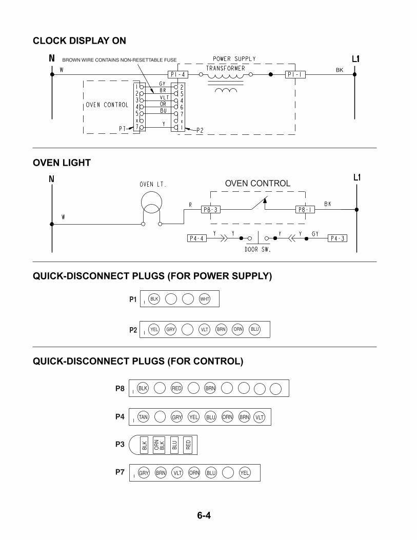
6-4
CLOCK DISPLAY ON
OVEN LIGHT
QUICK-DISCONNECT PLUGS (FOR POWER SUPPLY)
QUICK-DISCONNECT PLUGS (FOR CONTROL)
BROWN WIRE CONTAINS NON-RESETTABLE FUSE
BK
OVEN CONTROL
BLK
YEL GRY VLT BRN ORN BLU
WHTP1
P2
TAN GRY
GRY
YEL
YEL
BLU
BLU
BLU
RED
ORN
ORN
BLK RED
BRN
BRN
BRN
VLT
VLT
BLK
OR
NBL
K
P8
P4
P3
P7

7-1
DU
O C
OO
KIN
G S
YS
TE
M F
LO
W C
HA
RT
Set
the
Bak
e pa
ram
eter
s:
• T
otal
Cyc
le T
ime
•
Top
Ele
men
t / B
urne
r O
N T
ime
•
Bot
tom
Ele
men
t / B
urne
r O
N T
ime
•
Top
-To-
Bot
tom
Sen
sor
Offs
et
• T
op-T
o-B
otto
m A
mpl
itude
•
Bot
tom
Prio
rity
ON
/ O
FF
Use
r se
ts th
e te
mpe
ratu
rean
d st
arts
the
Bak
e cy
cle.
Ove
n pr
ehea
ts (
no c
hang
e fr
om c
urre
nt r
outin
e)
Rea
d th
e bo
ttom
sens
or te
mpe
ratu
re.
Rea
d th
e to
pse
nsor
tem
pera
ture
.Is
the
tem
pera
ture
abo
veth
e hi
gh te
mpe
ratu
re li
mit?
Is th
e te
mpe
ratu
re b
elow
the
low
tem
pera
ture
lim
it?
Is th
e te
mpe
ratu
re b
elow
the
low
tem
pera
ture
lim
it?
Is th
e bo
ttom
el
emen
t / b
urne
r O
FF
?
Is th
e to
p el
emen
t / b
urne
r O
N?
Is th
e to
p el
emen
t / b
urne
r O
FF
?
Is th
e bo
ttom
el
emen
t / b
urne
r O
N?
Is th
e ap
plia
nce
elec
tric
?
Tur
n O
ff th
e bo
ttom
ele
men
t / b
urne
r.
Tur
n O
ff th
e to
p el
emen
t / b
urne
r.
Tur
n O
ff th
e to
p el
emen
t / b
urne
r.
Is th
e te
mpe
ratu
re a
bove
the
high
tem
pera
ture
lim
it?
Cyc
le th
e bo
ttom
ele
men
t / b
urne
rre
lay
at th
e pr
eset
dut
y cy
cle.
Cyc
le th
e to
p el
emen
t / b
urne
rre
lay
at th
e pr
eset
dut
y cy
cle.
Has
the
burn
er p
urge
time
been
sat
isfie
d?
Pur
ge th
e bu
rner
.
Yes
Yes
Yes
Yes
Yes
Yes
Yes
Yes
Yes
Yes
No
No
No
No
No
No
No
No
No
TECH TIPS

7-2
— NOTES —

7-3
— NOTES —

7-4
— NOTES —

PRODUCT SPECIFICATIONSAND
WARRANTY INFORMATION SOURCES
IN THE UNITED STATES:
FOR PRODUCT SPECIFICATIONS AND WARRANTY INFORMATION CALL:
FOR TECHNICAL ASSISTANCE WHILE AT THE CUSTOMER’S HOME CALL:
THE TECHNICAL ASSISTANCE LINE: 1-800-253-2870
HAVE YOUR STORE NUMBER READY TO IDENTIFY YOU AS ANAUTHORIZED SERVICER
FOR LITERATURE ORDERS:
PHONE: 1-800-851-4605
IN CANADA:
FOR PRODUCT SPECIFICATIONS AND WARRANTY INFORMATION CALL:
1-800-461-5681
FOR TECHNICAL ASSISTANCE WHILE AT THE CUSTOMER’S HOME CALL:
THE TECHNICAL ASSISTANCE LINE: 1-800-488-4791
HAVE YOUR STORE NUMBER READY TO IDENTIFY YOU AS ANAUTHORIZED SERVICER
FOR WHIRLPOOL PRODUCTS: 1-800-253-1301FOR KITCHENAID PRODUCTS: 1-800-422-1230FOR ROPER PRODUCTS: 1-800-447-6737

CORPORATION


![TSUBAKI KABELSCHLEPP Parts listkabelschlepp.ru/fileadmin/img/carrier/PDFs/spare... · Item Materialtext [remarks] KR 052 KR 065 KR 095 KR 125 KR 150 KR 180 KR 200 KR 225 1](https://static.fdocuments.in/doc/165x107/5faa70404ba8b17fd45cfabf/tsubaki-kabelschlepp-parts-item-materialtext-remarks-kr-052-kr-065-kr-095-kr-125.jpg)