3-The Simulation of Burning-off the Deposited Carbon … Simulation of... · 14 The Simulation of...
8
The Simulation of Burning-off the Deposited Carbon in a Coke Oven DER-HER WANG*, YU-WEI CHUANG** and CHIEN-HSIUNG TSAI*** *Iron and Steel Research & Development Department, China Steel Corporation **Department of Mechanical and Electro-Mechanical Engineering, National Sun Yat-Sen University ***Department of Vehicle Engineering, National Pingtung University of Science and Technology The removal of deposited carbon in a coke oven is a regular task in the coke-making operation. One of the more efficient methods is ventilating the chamber to burn off the carbon. However, since the carbon combus- tion is an exothermic reaction, an inappropriate air draft might subject the coke oven to too high a tempera- ture or cool it too rapidly. Both would hurt the oven brick lining. Thus, how to effectively practice the carbon-burning operation is an important issue in the coke plant. In this work, the preliminary study of burning-off the carbon adhering to the inner surface of the coke chamber was performed by numerical simulations with the three-dimensional transport equations, turbulent reactive flow and quasi-steady state assumption. The simulation results revealed that, contracting the charging holes will choke the convection airflow beneath the covers and raise the temperatures around these holes. Under natural draft conditions, the charging holes could be changed into air intakes or exhaust vents by adjusting the opening degrees of their covers. Therefore, the carbon elimination operation could be more effectively performed according to the dominant deposition. Furthermore, with the forced convection operation, an adequate-designed air nozzle could amend the carbon removal efficiency by changing the air inflow route, especially for the carbon accu- mulated beneath the oven ceiling or on the upper chamber walls. Keywords: Coke oven, Burning off carbon deposit, Carbon combustion, Computational Fluid Dynamics (CFD) 1. INTRODUCTION For a long time, the carbon deposition in coke chambers were a common problem in coke plants. The carbon adhering to the oven ceiling and the inner sur- face of the ascension pipe could choke up the free space of the coke chamber, increase the flow resistance of coke oven gas and deteriorate the emissions problem of coke ovens. In addition, the excessive carbon deposit would raise the coke discharging force, trigger the troublesome hard-push and shorten the lifetime of a coke battery. Therefore, how to effectively remove the deposited carbon is an important issue in the coke- making operation. It is well known that the carbon growth rate depends on oven temperature, coal moisture and the volatile matter of a coal blend, etc (1) . The higher the working rate of coke ovens and the lower the moisture content of a charging coal blend will accelerate the carbon growth rate. Currently, there are several meth- ods used to control the growth rate of carbon deposi- tion. Those are cleaning by manual stick or mechanical scraper, burning-off by natural air flow or air blowing lance, and decomposition by spraying water or steam into the chamber top space (2,3) . All of these practices may delay the production of coke depending on their operation time. In China Steel (CSC), the natural ventilation of the empty chamber for a coking cycle (around 18hr) has been one of the main methods to eliminate the deposit- ed carbon for a long time. The procedure was per- formed by inducing the natural air draft from one of the charging holes, then exhausting it through the ascen- sion pipe. This operation is convenient, but one oven production of coke is lost because of its long execution time, especially since the Coal Moisture Control Pro- cess (CMCP) has been commissioned. As shown by the carbon growth test in Fig.1, the low moisture feedstock coal supplied by CMCP increases the carbon deposition remarkably. Thus, the high frequency of the carbon- burning operation has evidently resulted in the loss of coke production. Besides, the carbon combustion is an exothermic reaction. An inappropriate natural air draft might subject the coke oven to too high a temperature or cool it too low, both hurting the oven brick lining. China Steel Technical Report, No. 30, pp.12-19, (2017)
Transcript of 3-The Simulation of Burning-off the Deposited Carbon … Simulation of... · 14 The Simulation of...

12 The Simulation of Burning-off the Deposited Carbon in a Coke Oven
The Simulation of Burning-off the Deposited Carbon
in a Coke Oven
DER-HER WANG*, YU-WEI CHUANG** and CHIEN-HSIUNG TSAI***
*Iron and Steel Research & Development Department, China Steel Corporation **Department of Mechanical and Electro-Mechanical Engineering, National Sun Yat-Sen University
***Department of Vehicle Engineering, National Pingtung University of Science and Technology
The removal of deposited carbon in a coke oven is a regular task in the coke-making operation. One of the more efficient methods is ventilating the chamber to burn off the carbon. However, since the carbon combus-tion is an exothermic reaction, an inappropriate air draft might subject the coke oven to too high a tempera-ture or cool it too rapidly. Both would hurt the oven brick lining. Thus, how to effectively practice the carbon-burning operation is an important issue in the coke plant. In this work, the preliminary study of burning-off the carbon adhering to the inner surface of the coke chamber was performed by numerical simulations with the three-dimensional transport equations, turbulent reactive flow and quasi-steady state assumption. The simulation results revealed that, contracting the charging holes will choke the convection airflow beneath the covers and raise the temperatures around these holes. Under natural draft conditions, the charging holes could be changed into air intakes or exhaust vents by adjusting the opening degrees of their covers. Therefore, the carbon elimination operation could be more effectively performed according to the dominant deposition. Furthermore, with the forced convection operation, an adequate-designed air nozzle could amend the carbon removal efficiency by changing the air inflow route, especially for the carbon accu-mulated beneath the oven ceiling or on the upper chamber walls.
Keywords: Coke oven, Burning off carbon deposit, Carbon combustion, Computational Fluid Dynamics (CFD)
1. INTRODUCTION
For a long time, the carbon deposition in coke chambers were a common problem in coke plants. The carbon adhering to the oven ceiling and the inner sur-face of the ascension pipe could choke up the free space of the coke chamber, increase the flow resistance of coke oven gas and deteriorate the emissions problem of coke ovens. In addition, the excessive carbon deposit would raise the coke discharging force, trigger the troublesome hard-push and shorten the lifetime of a coke battery. Therefore, how to effectively remove the deposited carbon is an important issue in the coke- making operation.
It is well known that the carbon growth rate depends on oven temperature, coal moisture and the volatile matter of a coal blend, etc(1). The higher the working rate of coke ovens and the lower the moisture content of a charging coal blend will accelerate the carbon growth rate. Currently, there are several meth-ods used to control the growth rate of carbon deposi-tion. Those are cleaning by manual stick or mechanical scraper, burning-off by natural air flow or air blowing
lance, and decomposition by spraying water or steam into the chamber top space(2,3). All of these practices may delay the production of coke depending on their operation time.
In China Steel (CSC), the natural ventilation of the empty chamber for a coking cycle (around 18hr) has been one of the main methods to eliminate the deposit-ed carbon for a long time. The procedure was per-formed by inducing the natural air draft from one of the charging holes, then exhausting it through the ascen-sion pipe. This operation is convenient, but one oven production of coke is lost because of its long execution time, especially since the Coal Moisture Control Pro-cess (CMCP) has been commissioned. As shown by the carbon growth test in Fig.1, the low moisture feedstock coal supplied by CMCP increases the carbon deposition remarkably. Thus, the high frequency of the carbon- burning operation has evidently resulted in the loss of coke production. Besides, the carbon combustion is an exothermic reaction. An inappropriate natural air draft might subject the coke oven to too high a temperature or cool it too low, both hurting the oven brick lining.
China Steel Technical Report, No. 30, pp.12-19, (2017)
13 Der-Her Wang, Yu-Wei Chuang and Chien-Hsiung Tsai
In this preliminary study, the simulation of burn-ing-off the deposited carbon in a full scale three dimen-sional coke oven has been performed by the Computa-tional Fluid Dynamics (CFD) method. This provides the evaluations for different operations by natural air draft and by force convection in the carbon burning-off procedures. The results could be used as guides to amend the carbon removal operation, prevent oven brick damage and improve the coke production effi-ciency.
2. SIMULATION MODEL
2.1 System Definition
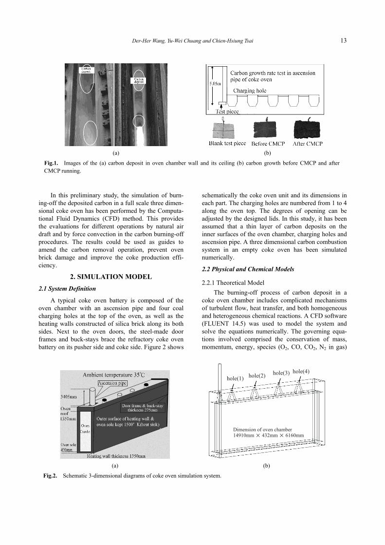
A typical coke oven battery is composed of the oven chamber with an ascension pipe and four coal charging holes at the top of the oven, as well as the heating walls constructed of silica brick along its both sides. Next to the oven doors, the steel-made door frames and buck-stays brace the refractory coke oven battery on its pusher side and coke side. Figure 2 shows
schematically the coke oven unit and its dimensions in each part. The charging holes are numbered from 1 to 4 along the oven top. The degrees of opening can be adjusted by the designed lids. In this study, it has been assumed that a thin layer of carbon deposits on the inner surfaces of the oven chamber, charging holes and ascension pipe. A three dimensional carbon combustion system in an empty coke oven has been simulated numerically.
2.2 Physical and Chemical Models
2.2.1 Theoretical Model
The burning-off process of carbon deposit in a coke oven chamber includes complicated mechanisms of turbulent flow, heat transfer, and both homogeneous and heterogeneous chemical reactions. A CFD software (FLUENT 14.5) was used to model the system and solve the equations numerically. The governing equa-tions involved comprised the conservation of mass, momentum, energy, species (O2, CO, CO2, N2 in gas)
(a)
(b)
Fig.1. Images of the (a) carbon deposit in oven chamber wall and its ceiling (b) carbon growth before CMCP and after CMCP running.
(a)
(b)
Fig.2. Schematic 3-dimensional diagrams of coke oven simulation system.
14 The Simulation of Burning-off the Deposited Carbon in a Coke Oven
and turbulent transport equations, as well as the equa-tion of state. A realizable k-ε model has been intro-duced to perform a better recovery in the turbulent vis-cosity at the viscous sub-layer region. In addition, the heterogeneous combustion reaction on the surface of the carbon deposit and its following homogeneous reaction in the gas phase will be addressed as follows.
2.2.2 Combustion Model
The chemical formulas of the heterogeneous and homogeneous reactions, consist of solid carbon, O2, CO and CO2, as shown below,
Reaction(1) 2 ( )+ 2( ) → 2 C ( ) ........ (R1)
Reaction(2) 2 ( )+ 2( ) → 2C 2( ) ........ (R2)
Where, reaction (R1) is the heterogeneous reaction on the carbon surface. The reaction rate is considered to be first order kinetics, proportional to the concentration of the gas reactant species O2. Reaction (R2) is the homogeneous reaction in the gas phase, being second order reaction of CO and O2. The two kinetic rates are expressed in Arrhenius forms as the following,
1 rate = − 1 exp(− 1/ ) 2 (kg/ 2s)
2 rate = − 2 exp(− 2 / ) 2
2 (kg/ 3s)
Within the above, ρs and ρ are the densities of solid carbon and gas respectively. YCO and YO2 are the mass
fractions of CO and O2 in gas phase. The experiments performed in the industrial coke
oven revealed that the composition of deposited carbon contained the mixture of pyrolysis carbon and char (2,3,4). Therefore, the combustion of carbon deposit could be considered as the burning-off of solid carbon. The kinetic parameter constants of the reactions are shown in Table 1(5,6).
2.3 Modeling and Boundary Condition
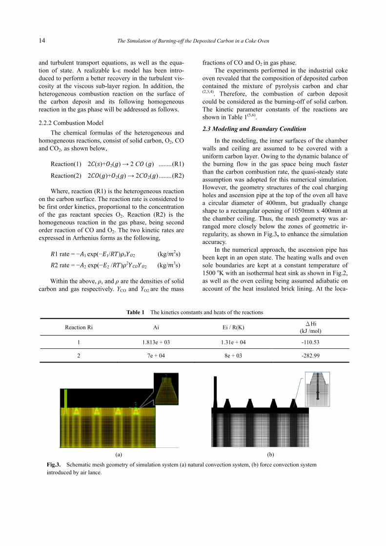
In the modeling, the inner surfaces of the chamber walls and ceiling are assumed to be covered with a uniform carbon layer. Owing to the dynamic balance of the burning flow in the gas space being much faster than the carbon combustion rate, the quasi-steady state assumption was adopted for this numerical simulation. However, the geometry structures of the coal charging holes and ascension pipe at the top of the oven all have a circular diameter of 400mm, but gradually change shape to a rectangular opening of 1050mm x 400mm at the chamber ceiling. Thus, the mesh geometry was ar-ranged more closely below the zones of geometric ir-regularity, as shown in Fig.3, to enhance the simulation accuracy.
In the numerical approach, the ascension pipe has been kept in an open state. The heating walls and oven sole boundaries are kept at a constant temperature of 1500 oK with an isothermal heat sink as shown in Fig.2, as well as the oven ceiling being assumed adiabatic on account of the heat insulated brick lining. At the loca-
Table 1 The kinetics constants and heats of the reactions
Reaction Ri Ai Ei / R(K) ΔHi
(kJ /mol)
1 1.813e + 03 1.31e + 04 -110.53
2 7e + 04 8e + 03 -282.99
(a)
(b)
Fig.3. Schematic mesh geometry of simulation system (a) natural convection system, (b) force convection system introduced by air lance.

15 Der-Her Wang, Yu-Wei Chuang and Chien-Hsiung Tsai
tion of the coal charging hole and ascension pipe, a natural convection occurs spontaneously due to tem-perature gradients in gravitational fluid flow. In addi-tion, the cooling effects of thermal radiation and air convection happen on both pusher side and coke side because of the steel-made braces being in contact with the ambient air (35°C).
3. RESULTS AND DISCUSSION
3.1 Effects by changing the opening degrees of coal charging holes Figure 4 shows the simulation results in the case of
the charging hole lids all being fully opened for natural convection. The velocity vector diagram in Fig.4(a) reveals that fresh air has been drawn into the oven chamber through holes (1) and (2), then discharged through the ascension pipe. The ascension pipe plays the role of a chimney as the main exhaust vent. In addi-tion, the maximum velocity of inhaling air is around 3.5m/s occurring in the coal charging hole near the chimney. In addition, the region around the air intakes are the main carbon-burning sites, as displayed in Fig.4(b).
Furthermore, with one chimney but four charging holes at the top of the oven, the excessive suction will
cause air to flow downward to the oven sole, then along the bottom to the rear of the chamber (coke side); meanwhile, the burning hot flow circulates and exhales by the hole(3) and hole(4). The amount of drawn-in air and the generated hot blown-out fluid should be on balance in the steady state simulation system.
The temperature distributions on the symmetry plane of chamber and on the oven wall are illustrated below. Compared with the display above, it reveals that the diagrams in Fig.5(a) and (b) are highly relative to the route of reactive fluid shown in Fig.4.
However, in the coke-making process, carbon mainly accumulated in the vicinities of charging hole(3) to charging hole(4). The ports for air inlet need to be adjusted. In the following simulation, the charg-ing hole(1) has been covered with a lid leaving a 30% opening to limit the amount of drawn air. The results are depicted in Fig.6.
The distribution of airflow velocity in Fig.6(a) shows that, to compensate for the reduction of drawn air in charging hole(1), the role of charging hole(3) was changed from exhaust vent into the air intake, which significantly increases the carbon burning rate around the new air inlet.
Furthermore, adding a lid leaving a 50% opening to charging hole(2), the simulation results are shown in
(a)
(b)
Fig.4. Holes (1)-(4) being 100% fully opened (a) velocity vector field in oven center (b) carbon elimination rate on oven wall.
(a)
(b)
Fig.5. Opening degrees for holes (1)-(4) being 100% (a) temperature distribution in oven center (b) temperature distribution on oven wall.
16 The Simulation of Burning-off the Deposited Carbon in a Coke Oven
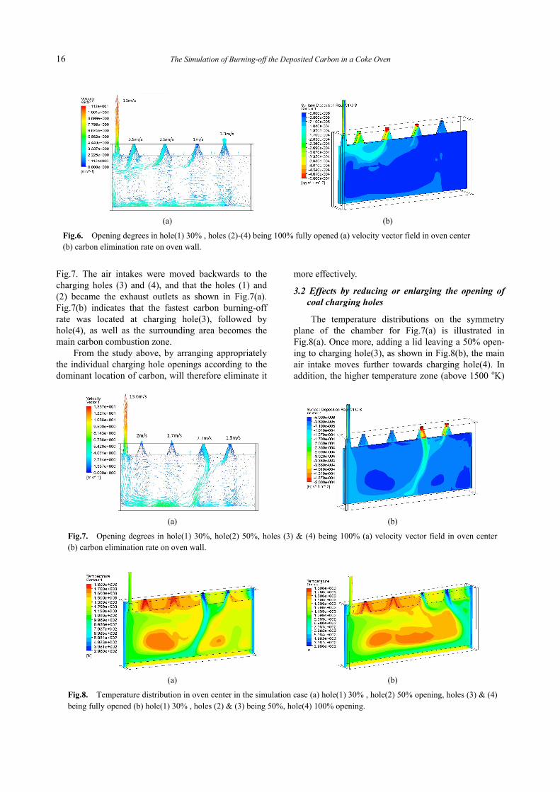
Fig.7. The air intakes were moved backwards to the charging holes (3) and (4), and that the holes (1) and (2) became the exhaust outlets as shown in Fig.7(a). Fig.7(b) indicates that the fastest carbon burning-off rate was located at charging hole(3), followed by hole(4), as well as the surrounding area becomes the main carbon combustion zone.
From the study above, by arranging appropriately the individual charging hole openings according to the dominant location of carbon, will therefore eliminate it
more effectively.
3.2 Effects by reducing or enlarging the opening of coal charging holes
The temperature distributions on the symmetry plane of the chamber for Fig.7(a) is illustrated in Fig.8(a). Once more, adding a lid leaving a 50% open-ing to charging hole(3), as shown in Fig.8(b), the main air intake moves further towards charging hole(4). In addition, the higher temperature zone (above 1500 oK)
(a)
(b)
Fig.6. Opening degrees in hole(1) 30% , holes (2)-(4) being 100% fully opened (a) velocity vector field in oven center (b) carbon elimination rate on oven wall.
(a)
(b)
Fig.7. Opening degrees in hole(1) 30%, hole(2) 50%, holes (3) & (4) being 100% (a) velocity vector field in oven center (b) carbon elimination rate on oven wall.
(a)
(b)
Fig.8. Temperature distribution in oven center in the simulation case (a) hole(1) 30% , hole(2) 50% opening, holes (3) & (4) being fully opened (b) hole(1) 30% , holes (2) & (3) being 50%, hole(4) 100% opening.
17 Der-Her Wang, Yu-Wei Chuang and Chien-Hsiung Tsai
expands owing to a lesser amount of cool air being drawn in.
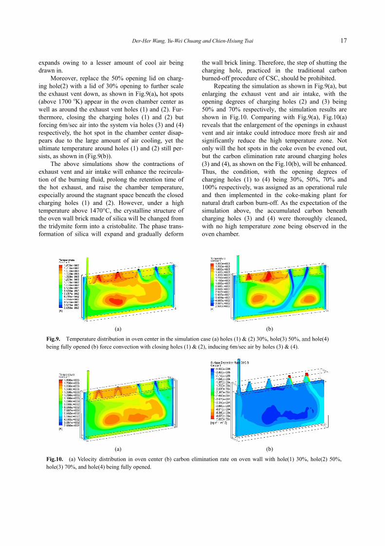
Moreover, replace the 50% opening lid on charg-ing hole(2) with a lid of 30% opening to further scale the exhaust vent down, as shown in Fig.9(a), hot spots (above 1700 oK) appear in the oven chamber center as well as around the exhaust vent holes (1) and (2). Fur-thermore, closing the charging holes (1) and (2) but forcing 6m/sec air into the system via holes (3) and (4) respectively, the hot spot in the chamber center disap-pears due to the large amount of air cooling, yet the ultimate temperature around holes (1) and (2) still per-sists, as shown in (Fig.9(b)).
The above simulations show the contractions of exhaust vent and air intake will enhance the recircula-tion of the burning fluid, prolong the retention time of the hot exhaust, and raise the chamber temperature, especially around the stagnant space beneath the closed charging holes (1) and (2). However, under a high temperature above 1470°C, the crystalline structure of the oven wall brick made of silica will be changed from the tridymite form into a cristobalite. The phase trans-formation of silica will expand and gradually deform
the wall brick lining. Therefore, the step of shutting the charging hole, practiced in the traditional carbon burned-off procedure of CSC, should be prohibited.
Repeating the simulation as shown in Fig.9(a), but enlarging the exhaust vent and air intake, with the opening degrees of charging holes (2) and (3) being 50% and 70% respectively, the simulation results are shown in Fig.10. Comparing with Fig.9(a), Fig.10(a) reveals that the enlargement of the openings in exhaust vent and air intake could introduce more fresh air and significantly reduce the high temperature zone. Not only will the hot spots in the coke oven be evened out, but the carbon elimination rate around charging holes (3) and (4), as shown on the Fig.10(b), will be enhanced. Thus, the condition, with the opening degrees of charging holes (1) to (4) being 30%, 50%, 70% and 100% respectively, was assigned as an operational rule and then implemented in the coke-making plant for natural draft carbon burn-off. As the expectation of the simulation above, the accumulated carbon beneath charging holes (3) and (4) were thoroughly cleaned, with no high temperature zone being observed in the oven chamber.
(a)
(b)
Fig.9. Temperature distribution in oven center in the simulation case (a) holes (1) & (2) 30%, hole(3) 50%, and hole(4) being fully opened (b) force convection with closing holes (1) & (2), inducing 6m/sec air by holes (3) & (4).
(a)
(b)
Fig.10. (a) Velocity distribution in oven center (b) carbon elimination rate on oven wall with hole(1) 30%, hole(2) 50%, hole(3) 70%, and hole(4) being fully opened.

18 The Simulation of Burning-off the Deposited Carbon in a Coke Oven
3.3 Force convection with the air nozzle In the previous study, the fresh airflow intake from
charging holes (3) and (4) usually merges into a main cold stream and settles at the bottom of the chamber. Then, part of the stream will exhaust through the ascension pipe, and the rest circulates in the oven to implement the carbon burning. However, in the upper free space of the coke chamber, the coke oven gas will be cracked and accumulated as a thick carbon layer on the oven ceiling or upper walls. Such a flow pattern of natural convection will not exhibit a high efficiency to burn the deposited carbon off. Thus, the forced convec-tion with an air nozzle should be introduced to amend the performance of carbon burn-off.
However, in practice there are three constraints in an air nozzle design. They are: (1)The discharge of air needed to cool the air pipe to a
moderate temperature (below 600°C) to sustain the severe thermal radiation in a coke oven.
(2) The placement of the air nozzle module would not interfere with the movement of the coal charging car. Accordingly charging hole(4) was picked for inserting the air pipe.
(3)The introduced air would spread far beneath charg-ing holes (1) through (4). A simulation of the air nozzle design is illustrated
in Fig.11. The assigned condition is a symmetry- nozzle air pipe (L=2.5m, ID=62.6mm) in the 1500 oK space with a 3K Pa air source and a steady state assumption. As shown in Fig.11(a), the temperature distribution on the outer surface of the air nozzle pipe could agree with the temperature demand (<600°C), and the average air velocity at the nozzle outlet was around 46 m/sec. However, when the air nozzle pipe was combined with the original coke oven system (the opening degrees of charging holes all being 30%), as
shown in Fig.3(b), the simulation result did not meet expectation.
Figure 11(b) reveals that the high speed air jets from the air nozzle will drag the nearby fluid and cause a strong wake effect beneath the air pipe. In addi-tion, the air jets toward the coke side will flow partly along the oven sole towards the chamber front, yet part of the current will flow backwards and resist against the air jets toward the pusher side. Both causes make the air jets form the vortexes and reflux locally below the charging holes (3) and (4).
However, an asymmetry-nozzle air pipe, by con-tracting the outlets toward the coke side to reduce the airflow in that way, could spread fresh air far beneath the charging holes (1) through (4), and improve the carbon burning-off rate in the oven upper space, as shown in Fig.12. The on-site experimental results showed such an asymmetry air lance could effectively eliminate the carbon adhering to the upper chamber in 30 minutes, thus largely reducing the carbon burn-off time and its cleaning period.
4. CONCLUSIONS
The simulations of the burning-off of deposited carbon in the three dimensional real-size coke oven have been performed with the transport equations, tur-bulent reactive flow and quasi-steady state assumption. The results reveal that, (1) In the natural draft practice, the carbon elimination
could be effectively performed by properly adjust-ing the cover’s opening according to the dominant location of carbon.
(2) The contraction of the charging holes will raise the temperature around those ports, and damage the wall lining bricks accordingly. The step of shutting the charging hole in the traditional carbon burned- off procedure should be prohibited.
(a)
(b)
Fig.11. A designed case of the symmetry- nozzle air pipe (a) temperature & air velocity distributions in nozzle pipe (b) velocity vector field in the system of coke oven with the air nozzle.

19 Der-Her Wang, Yu-Wei Chuang and Chien-Hsiung Tsai
(3) With the forced convection operation, an asymmetry- nozzle air pipe could amend the carbon removal efficiency by changing the air inflow route, espe-cially for the carbon accumulated beneath the oven ceiling or on the upper walls. The conclusions above could help to achieve a
better carbon burning-off performance, prevent the damage to wall lining brick and improve the efficiency of coke production.
REFERENCES
1. Tomoyuki Nakagawa, Kenji Kato and Masaaki Naito, “Growth Rate of Carbon Deposit by Pyroly-sis Reaction of Coal Carbonization Gas”, Interna-tional Congress of Science and Technology of Iron-making Proceedings (ICSTI’06), Osaka, Japan, 2006, pp. 406-409.
2. V. Zymla and F. Honnart, “Coke Oven Carbon Deposits Growth and Their Burning off”, ISIJ
International, 2007, Vol.47, No. 10, pp. 1422- 1431.
3. Jean-Paul Gaillet and Dominique Le Mouel, “Re-duction of Carbon Deposits Formation at No.6 Coke Oven Battery of ArcelorMittal Dunkerque”, AISTech 2014 Proceedings, 2014, pp. 367-376.
4. Der-Her Wang, M.T. Hung, C.W. Chen, “The Improvements of the Coal Moisture Control Sys-tem in Cokemaking Plant”, AISTech 2013 Pro-ceedings, 2013, pp.355-366.
5. S. R. Turns., An Introduction to Combustion Con-cepts and Applications, 3rd ed., McGraw Hill, 2012.
6. J.G. Hang, K.C. Chang, U.K. Hsu and D.H. Wang, “Burning Off Simulation of Carbon Deposition in Coke Oven”, The 24th National Conference on Combustion and Energy Proceedings, Tainan, Taiwan, ID: 038, 2014. □
(a)
(b)
Fig.12. A simulation in the coke oven system with an asymmetry-nozzle air pipe (a) velocity vector field in oven center (b) carbon elimination rate on oven wall.