
3 Tactics for Configuring Phase-Coherent RF Signal ... · Generator Channel Emulator Figure 3....
13
Page 1 Find us at www.keysight.com WHITE PAPER 3 Tactics for Configuring Phase- Coherent RF Signal Generation How to Overcome Multi-Antenna System Test Challenges Overview As the number of higher throughput applications grows sharply, there is a need for wider bandwidth and network coverage in wireless systems. However, given limited spectrum allocation, you must look for ways to improve spectral efficiency and signal-to-noise ratio (SNR). Multi-antenna techniques, such as Multi-input Multi- output (MIMO) and beamforming, can help you achieve diversity, multiplexing, and antenna gain in order to improve spectral efficiency and signal-to-noise ratio (SNR). This white paper will help you understand phase coherence and why it matters, and offer tactics for generating phase-coherent signals. Testing multi-antenna systems requires a test system capable of providing multiple signals and a constant phase relationship between the signals. Employing different tactics for con- figuring phase-coherent signal generation leads to different measurement results.
Transcript of 3 Tactics for Configuring Phase-Coherent RF Signal ... · Generator Channel Emulator Figure 3....

Page 1Find us at www.keysight.com
W H I T E P A P E R
3 Tactics for Configuring Phase-Coherent RF Signal Generation How to Overcome Multi-Antenna System Test Challenges Overview
As the number of higher throughput applications grows sharply, there is a need for
wider bandwidth and network coverage in wireless systems. However, given limited
spectrum allocation, you must look for ways to improve spectral efficiency and
signal-to-noise ratio (SNR). Multi-antenna techniques, such as Multi-input Multi-
output (MIMO) and beamforming, can help you achieve diversity, multiplexing, and
antenna gain in order to improve spectral efficiency and signal-to-noise ratio (SNR).
This white paper will help you understand phase coherence and why it matters, and
offer tactics for generating phase-coherent signals.
Testing multi-antenna systems requires a test system capable of providing multiple signals and a constant phase relationship between the signals. Employing different tactics for con-figuring phase-coherent signal generation leads to different measurement results.

Page 2Find us at www.keysight.com
What Is Phase Coherence?
Two signals are coherent if they have a constant relative phase at all times, as shown
in Figure 1b. When present together, coherent signals will combine constructively or
destructively, depending on their relative phase.
In cases where you characterize a multi-channel component such as a phased-array
antenna, you need to control the phase angle relationship precisely between the
channels (Figure 1c). For digitally modulated signals, phase coherence means both
timing synchronization between baseband generators and coherence between RF
carriers (see Figure 1d). Similarly, radar pulses require precise timing of the pulse bursts
to simulate the appropriate spatial delays (see Figure 1e).
Figure 1. Phase relations between two signals
a) Non-Coherent Signals
b) Coherent Signal Generation
c) Controllable Phase Relation
d) Configurable Modulations
e) Trigger-able Pulses
PhaseVaries
Adjustable Phase
Precision Timed
Page 3Find us at www.keysight.com
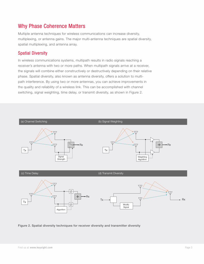
Why Phase Coherence MattersMultiple antenna techniques for wireless communications can increase diversity,
multiplexing, or antenna gains. The major multi-antenna techniques are spatial diversity,
spatial multiplexing, and antenna array.
Spatial Diversity
In wireless communications systems, multipath results in radio signals reaching a
receiver’s antenna with two or more paths. When multipath signals arrive at a receiver,
the signals will combine either constructively or destructively depending on their relative
phase. Spatial diversity, also known as antenna diversity, offers a solution to multi-
path interference. By using two or more antennas, you can achieve improvements in
the quality and reliability of a wireless link. This can be accomplished with channel
switching, signal weighting, time delay, or transmit diversity, as shown in Figure 2.
Figure 2. Spatial diversity techniques for receiver diversity and transmitter diversity
Tx
Signal Strength
Rx
(a) Channel Switching
(c) Time Delay
Tx
WeightingAlgorithm
Rx
Tx
ModifySignal
RxTx
Algorithm
Rx
Ø
Ø
(b) Signal Weighting
(d) Transmit Diversity

Page 4Find us at www.keysight.com
To simulate the multipath signals for spatial diversity tests, you need a signal generator
and a channel emulator to simulate the multi-path scenario for receiver diversity tests
(Figure 3a), and multiple signal generators and a channel emulator for transmit diversity
tests (Figure 3b). To accurately emulate the multipath scenarios, you must synchronize
both signal generators’ baseband and you must also align the phase of both carriers.
ReceiverRx1Rx2
SignalGenerator
#1 Channel Emulator Receiver
(a) Receiver diversity test
(b) Receiver test for transmit diversity
ClockTrigger
LO
SignalGenerator
#2
SignalGenerator
Channel Emulator
Figure 3. Spatial diversity test setups

Page 5Find us at www.keysight.com
Spatial Multiplexing
Spatial multiplexing is a transmission technique in a Multi-Input Multi-Output (MIMO)
system. The system splits transmit data into multiple encoded data streams. The
system transmits all data streams simultaneously, over the same radio channel, through
different antennas. In order to recover the original data at the receiver, MIMO systems
use computationally inverse channel property estimation algorithms. Figure 4 represents
a 2x2 (two transmitters and two receivers) MIMO diagram where two symbols (b1 and
b2) are transmitted simultaneously for double the data throughput. A simple formula
appears below.
001 01 1
102 11 2
hr h s
hr h s
=
where r is the received signal, s is the source signal, and h is the wireless channel
response.
The receiver can perform channel estimation (the h matrix above) using training
sequence algorithms. You can recover the transmit signals (s1 and s2) through signal
processing with the formula below:
11 011 1
10 002 200 11 01 10
1
h hs r
h hs rh h h h
− = −−
Figure 4. A 2x2 MIMO system diagram
The calculation above uses timing-aligned signals and a common local oscillator (LO)
to up-convert and down-convert multi-channel signals. This technique increases
test challenges for simulating multi-channel RF signals, as most commercial signal
generators have an individual baseband generator and a LO.
DataMapping
Tx 1
Tx 2
Rx 1
r2
r1
s2
s1
b2
Rx Data
...b2, b1
T
...b2, b1
h00
Wireless Channel
h11
h10
h01
b1
Rx 2
SignalProcessing

Page 6Find us at www.keysight.com
Antenna Array – Beamforming
An antenna array is a set of antenna elements used to transmit or receive signals.
Coherently-driven antennas with the appropriate phase delay between antenna elements
can form signal beams. Phased array antennas use phase shifters in the beamforming
network (BFN) to produce a uniform wave front traveling in a specific direction. The
uniform wave front allows a group of low directivity antenna elements to behave like a
highly directional antenna for either transmit or receive applications. The phase delays
between the channels decide the antenna pattern as shown in Figure 5.
Figure 5. A phased array of antennas forms a beam by adjusting the phase between coherent antennas
1τ 2τ 3τ 4τ 5τ 6τ 7τ 8τ
∑
Wave Front
Delay{Beam Forming Network (BFN)

Page 7Find us at www.keysight.com
Figure 6 illustrates the impact of using multiple antenna elements at a specific spacing.
As you increase the number of antenna elements (a half wavelength separation), the
antenna beamwidth gets narrower (Figure 6a to 6d). By applying a 90-degree phase
shift to the signal at each antenna, you can change the direction of the beam as shown
in Figure 6e. By changing phase shifts between elements in different amounts, you are
able to steer the beam in a range of directions. To simulate such multi-channel signals,
you need to precisely control the phase difference between the channels for both
transmitter and receiver tests.
Figure 6. Antenna pattern vs. the number of antenna elements
–90 deg
–60 deg
–30 deg0 deg
+30 deg
+60 deg
+90 deg –90 deg
–60 deg
–30 deg0 deg
+30 deg
+60 deg
+90 deg
–90 deg
–60 deg
–30 deg0 deg
+30 deg
+60 deg
+90 deg
3 antenna elements0.5 wavelength separation
0 deg phase shift per ant element(c)
4 antenna elements0.5 wavelength separation
0 deg phase shift per ant element(d)
4 antenna elements0.5 wavelength separation
90 deg phase shift per ant element(e)
1 antenna elements
(a)
2 antenna elements0.5 wavelength separation
0 deg phase shift per ant element(b)
Main lobe = 0 deg azimuth# nulls = 2
Main lobe = 0 deg azimuth# nulls = 3
Main lobe = –30 deg azimuth# nulls = 3
Main lobe = omnidirectional Main lobe = 0 deg azimuth# nulls = 1
–90 deg
–60 deg
–30 deg0 deg
+30 deg
+60 deg
+90 deg –90 deg
–60 deg
–30 deg0 deg
+30 deg
+60 deg
+90 deg

Page 8Find us at www.keysight.com
Generate Multiple Phase Coherent SignalsTesting multi-antenna systems such as spatial diversity, spatial multiplexing, and
antenna array requires a test system capable of providing multiple signals with stable
phase relationships between them. However, a commercial signal generator has an
independent synthesizer to upconvert an IF signal to an RF signal. To simulate the multi-
channel test signals, the phase between test signals must be coherent and controllable.
We explore different tactics to generate multichannel signals below, and assess the pros
and cons of these tactics.
Independent Local Oscillator
The simplest way to achieve a certain amount of phase stability between signal
generators is to lock a 10 MHz frequency reference. Figure 7 shows two signal
generators with baseband generators synchronized using a triggering signal and
a common 10 MHz time base. To learn more about time synchronization between
instruments, download the white paper “Understanding and Testing Multi-Channel RF
Systems with Signal Generators Part 1.”
Figure 7. Phase drift between two time-synchronized signal generators
x2n I/QModulator
Dual ARBI Q
Detector
ALC Loop
x2n I/QModulator
Dual ARB
I QDetector
ALC Loop
10 MHz Ref Clock
TriggerPhase drift
Trigger delay

Page 9Find us at www.keysight.com
Phase Drift
The signal generators have separate oscillators, each with their own phase-locked loops
(PLL). This results in phase drift between the signal generators, as shown in the right
of Figure 7. Most of the time, PLL can lock the phase drift within the constraints of the
loop bandwidth (PLL’s loop filter). However, PLL cannot completely track out higher
order responses.
In MIMO test systems, slow phase drift between channels is less of an issue, so test
channels that share a common frequency reference may deliver acceptable performance.
Phase Noise
Uncorrelated phase noise contributes to phase error between reference-locked signal
generators. Inside the loop bandwidth of PLL, the frequency reference has the most
impact on phase noise performance. Outside the loop bandwidth, the PLL’s oscillator
determines the phase noise.
Using high-quality stable references and instruments with low phase noise can improve
phase drift and phase error. Applications such as MIMO and spatial diversity can use
these “phase-stable” multi-channel signals for testing. However, for precise component
characteristics testing, a common LO may still be appropriate in order to achieve the
best performance.
Page 10Find us at www.keysight.com
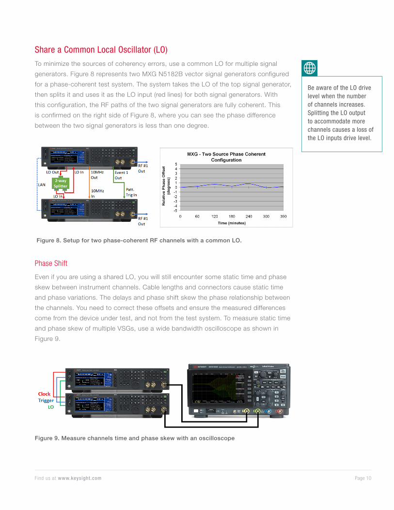
Share a Common Local Oscillator (LO)
To minimize the sources of coherency errors, use a common LO for multiple signal
generators. Figure 8 represents two MXG N5182B vector signal generators configured
for a phase-coherent test system. The system takes the LO of the top signal generator,
then splits it and uses it as the LO input (red lines) for both signal generators. With
this configuration, the RF paths of the two signal generators are fully coherent. This
is confirmed on the right side of Figure 8, where you can see the phase difference
between the two signal generators is less than one degree.
Figure 8. Setup for two phase-coherent RF channels with a common LO.
Phase Shift
Even if you are using a shared LO, you will still encounter some static time and phase
skew between instrument channels. Cable lengths and connectors cause static time
and phase variations. The delays and phase shift skew the phase relationship between
the channels. You need to correct these offsets and ensure the measured differences
come from the device under test, and not from the test system. To measure static time
and phase skew of multiple VSGs, use a wide bandwidth oscilloscope as shown in
Figure 9.
Figure 9. Measure channels time and phase skew with an oscilloscope
Be aware of the LO drive level when the number of channels increases. Splitting the LO output to accommodate more channels causes a loss of the LO inputs drive level.
Page 11Find us at www.keysight.com
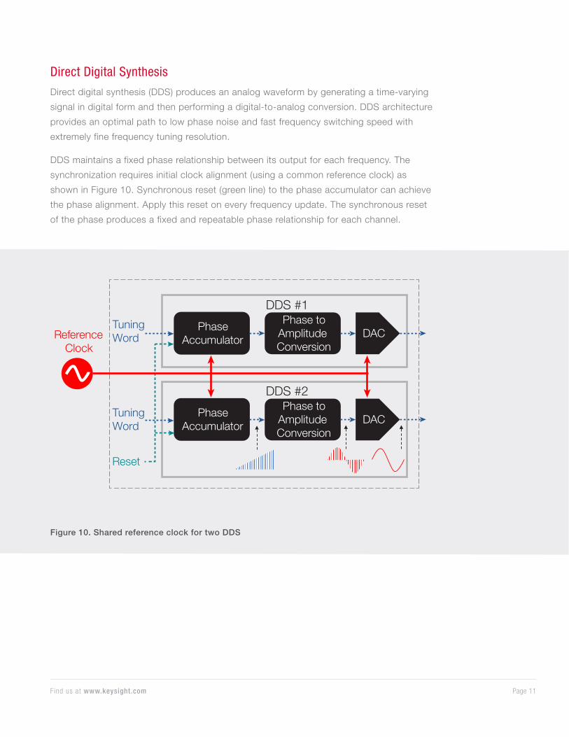
Direct Digital Synthesis
Direct digital synthesis (DDS) produces an analog waveform by generating a time-varying
signal in digital form and then performing a digital-to-analog conversion. DDS architecture
provides an optimal path to low phase noise and fast frequency switching speed with
extremely fine frequency tuning resolution.
DDS maintains a fixed phase relationship between its output for each frequency. The
synchronization requires initial clock alignment (using a common reference clock) as
shown in Figure 10. Synchronous reset (green line) to the phase accumulator can achieve
the phase alignment. Apply this reset on every frequency update. The synchronous reset
of the phase produces a fixed and repeatable phase relationship for each channel.
Phase Accumulator
DDS #1Phase to
Amplitude Conversion
DACReferenceClock
Phase Accumulator
DDS #2Phase to
Amplitude Conversion
DACTuning Word
Reset
Tuning Word
Figure 10. Shared reference clock for two DDS
Page 12Find us at www.keysight.com
Phase-stable test system Phase-coherence test system
Method Independent LO Share LO Direct Digital Synthesis
Implementation Share a common 10 MHz time base
Share a common LO
Share an RF reference clock for DDS’s
Advantage Easy setup Phase coherence • Phase coherence
• Easiest setup
Challenge • Uncorrelated phase noise
• Phase drift
• Static time delays and phase shift corrections
• High precision reference clock for DDS
Resolution • High-quality stable references
• Iinstruments with low phase noise
• Adjust I/Q Delay for time delays
• Adjust I/Q Phase for phase shifts
• High-frequency reference clock. 1
• Adjust I/Q Delay for time delays
• Adjust I/Q Phase for phase shifts
Application MIMO system tests MIMO, beamforming, array antenna calibration
MIMO, beamforming, array antenna calibration
Table 1. Various implementations for testing multi-antenna RF systems
1. Keysight VXG M9384B and M9383B’s dual-channel signal generators use enhanced high-performance reference at 19.2 GHz as DDS’s reference clock.
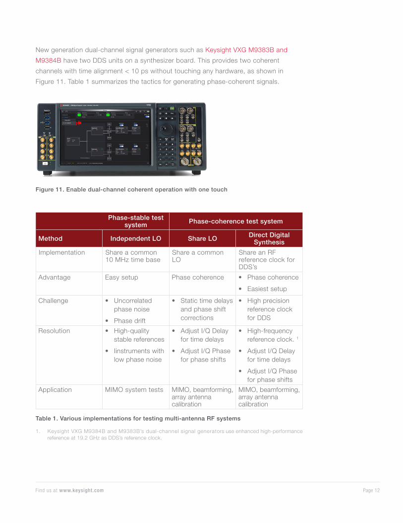
New generation dual-channel signal generators such as Keysight VXG M9383B and
M9384B have two DDS units on a synthesizer board. This provides two coherent
channels with time alignment < 10 ps without touching any hardware, as shown in
Figure 11. Table 1 summarizes the tactics for generating phase-coherent signals.
Figure 11. Enable dual-channel coherent operation with one touch

Page 13This information is subject to change without notice. © Keysight Technologies, 2019, Published in USA, April 10, 2019, 5992-3853EN
Find us at www.keysight.com
Learn more at: www.keysight.com
For more information on Keysight Technologies’ products, applications or services,
please contact your local Keysight office. The complete list is available at:
www.keysight.com/find/contactus
ConclusionAs multi-antenna technology matures and the demand for diversity, multiplexing, and
antenna gains grows, test systems require tightly aligned channels for accurate tests.
When performing a characterization test, you need to accurately recreate the operational
environment. You need to create signals in such a way that they will coherently combine
to simulate their real-world behavior.
For different multi-antenna test applications and requirements, there are different
tactics for generating phase-coherent or phase-stable signals. Always strive to
minimize the errors that various tactics cause. In addition, ensure test instruments
are phase-coherent and phase-controllable for your test applications, such as
beamforming tests.
ReferencesApplication note “Signal Source Solutions for Coherent and Phase Stable Multi-Channel
Systems”, July 31, 2014
White paper “Understanding and Testing Multi-Channel RF Systems with Signal
Generators Part 1”, October 20, 2018
White paper “Understanding and Testing Multi-Channel RF Systems with Signal
Generators Part 2”, October 20, 2018
White paper “Calibration Techniques for Improved MIMO and Beamsteering
Characterization”, June 13, 2017


![Transmit Diversity v. Spatial Multiplexing in Modern … · Transmit Diversity v. Spatial Multiplexing in ... also considered for microwave links [7]. ... diversity, and thus reliability](https://static.fdocuments.in/doc/165x107/5ae13be77f8b9ac0428e7a69/transmit-diversity-v-spatial-multiplexing-in-modern-diversity-v-spatial-multiplexing.jpg)


![CS-MUVI: Video Compressive Sensing for Spatial ...vip.ece.cornell.edu/papers/12ICCP-csmuvi.pdf · applications. Spatial-multiplexing cameras: The single-pixel camera (SPC) [3], the](https://static.fdocuments.in/doc/165x107/5f747cf77ea9f1395139a8cb/cs-muvi-video-compressive-sensing-for-spatial-vipece-applications-spatial-multiplexing.jpg)


![CS-MUVI: Video Compressive Sensing for Spatial ...studer/papers/12ICCP-csmuvi.pdfapplications. Spatial-multiplexing cameras: The single-pixel camera (SPC) [3], the flexible voxels](https://static.fdocuments.in/doc/165x107/5f491c2b2b07a76cb9739add/cs-muvi-video-compressive-sensing-for-spatial-studerpapers12iccp-csmuvipdf.jpg)


