3 Series Thumbwheel Switches - C&K Switches Thumbwheel M–3 Dimensions are shown:Inches (mm)...
8
M Thumbwheel M–3 Dimensions are shown: Inches (mm) Specifications and dimensions subject to change www.ckswitches.com 3 Series Thumbwheel Switches Features/Benefits • Most complete product offering in the industry • Spacers available to fit most panel cutouts • Front or rear mounting options Typical Applications • Test & measurement equipment • Industrial equipment • Computer devices Specifications CONTACT RATING: CARRY: 1 AMP continuous. SWITCH: 100 mA max. OPERATING VOLTAGE: 50 mV to 28 V DC or 120 V AC. ELECTRICAL LIFE: 100,000 actuations. CONTACT RESISTANCE: Below 100 m Ω typ. initial @ 2-4 V DC, 100 mA. INSULATION RESISTANCE: 10 9 Ω min. DIELECTRIC STRENGTH: 500 Vrms min. @ sea level between common terminal and any output. OPERATING TEMPERATURE: -40ºC to 65ºC. Materials HOUSING: ABS plastic. THUMBWHEEL: ABS plastic. ROTOR CONTACTS: Precious metal on copper alloy. STATOR CONTACTS: Hard gold over nickel over copper on epoxy fiberglass. NOTE: Specifications and materials listed above are for switches with standard options For information on specific and custom switches, consult Customer Service Center. * Note: All models listed are RoHS compliant. See Technical Data section of this catalog for RoHS compliant and compatible definitions and specifications. Build-A-Switch To order, simply select desired option from each category and place in the appropriate box. Available options are shown and described on pages M–4 thru M–10. For additional options not shown in catalog, consult Customer Service Center. Consult factory for illumination availability. Series 3 Thumbwheel switch Number of Sections 0 Switch section 1 1 Switch section 2 2 Switch sections 3 3 Switch sections 4 4 Switch sections 5 5 Switch sections 6 6 Switch sections 7 7 Switch sections 8 8 Switch sections 9 More than 8 switch sections Seal 0 No seal 1 Sealed contacts 2 Dust lens 3 Sealed contacts & dust lens Function Code 11 Decimal, SP, 10 position 14 Resistor decade 21 BCD, 10 position 23 Complement of BCD, 10 position 27 BCD, 10 position 31 BCD, 10 position 71 BCH, 16 position Terminations 0 Type 0 1 Type 1, extended type 0 N Solder pins with .100” spacing** P Solder pins with .156” spacing** 6 Type 6 No pins 9 Any combination Color/Marking/Stops 0 Matte black body, gloss black wheel, white marking Mounting Style 00 Snap-in, front mount 09 Snap-in, front mount* 10 Rear mount 19 Rear mount* 20 Rear mount 29 Rear mount* *X9 mounting styles must be ordered with ‘0’ number of sections. ** Note: Termination option N (RoHS compliant) replaced termination option 3 (Non-RoHS compliant). Termination option P (RoHS compliant) replaced termination option B (Non-RoHS compliant).
Transcript of 3 Series Thumbwheel Switches - C&K Switches Thumbwheel M–3 Dimensions are shown:Inches (mm)...

M
Th
um
bw
heel
M–3
Dimensions are shown: Inches (mm) Specifications and dimensions subject to change
www.ckswitches.com
3 SeriesThumbwheel Switches
Features/Benefits• Most complete product offering in the industry
• Spacers available to fit most panel cutouts
• Front or rear mounting options
Typical Applications• Test & measurement equipment
• Industrial equipment
• Computer devices
SpecificationsCONTACT RATING:
CARRY: 1 AMP continuous. SWITCH: 100 mA max.
OPERATING VOLTAGE: 50 mV to 28 V DC or 120 V AC.ELECTRICAL LIFE: 100,000 actuations.CONTACT RESISTANCE: Below 100 m Ω typ. initial @
2-4 V DC, 100 mA.INSULATION RESISTANCE: 109 Ω min.DIELECTRIC STRENGTH: 500 Vrms min. @ sea level
between common terminal and any output.OPERATING TEMPERATURE: -40ºC to 65ºC.
MaterialsHOUSING: ABS plastic.THUMBWHEEL: ABS plastic.ROTOR CONTACTS: Precious metal on copper alloy.STATOR CONTACTS: Hard gold over nickel over copper
on epoxy fiberglass.
NOTE: Specifications and materials listed above are for switches with standard options For information on specific and custom switches, consult Customer Service Center.
* Note: All models listed are RoHS compliant. See Technical Data section of this catalog for RoHS compliant and compatible definitions and specifications.
Build-A-SwitchTo order, simply select desired option from each category and place in the appropriate box. Available options are shown and described on pages M–4 thru M–10. For additional options not shown in catalog, consult Customer Service Center.Consult factory for illumination availability.
Series3 Thumbwheel switch
Number of Sections0 Switch section1 1 Switch section2 2 Switch sections 3 3 Switch sections 4 4 Switch sections 5 5 Switch sections 6 6 Switch sections 7 7 Switch sections 8 8 Switch sections 9 More than 8
switch sections
Seal0 No seal 1 Sealed contacts 2 Dust lens 3 Sealed contacts & dust lens
Function Code11 Decimal, SP, 10 position14 Resistor decade21 BCD, 10 position23 Complement of BCD, 10 position27 BCD, 10 position31 BCD, 10 position71 BCH, 16 position
Terminations0 Type 01 Type 1, extended type 0N Solder pins with .100” spacing**P Solder pins with .156” spacing**6 Type 6 No pins9 Any combination
Color/Marking/Stops0 Matte black body, gloss
black wheel, white marking
Mounting Style00 Snap-in, front mount09 Snap-in, front mount*10 Rear mount19 Rear mount*20 Rear mount29 Rear mount*
*X9 mounting styles must be ordered with ‘0’ number of sections.
** Note: Termination option N (RoHS compliant) replaced termination option 3 (Non-RoHS compliant). Termination option P (RoHS compliant) replaced termination option B (Non-RoHS compliant).
M–4
Dimensions are shown: Inches (mm) Specifications and dimensions subject to change
www.ckswitches.com
3 SeriesThumbwheel Switches
SERIES
NUMBER OF SECTIONS
FUNCTION CODE
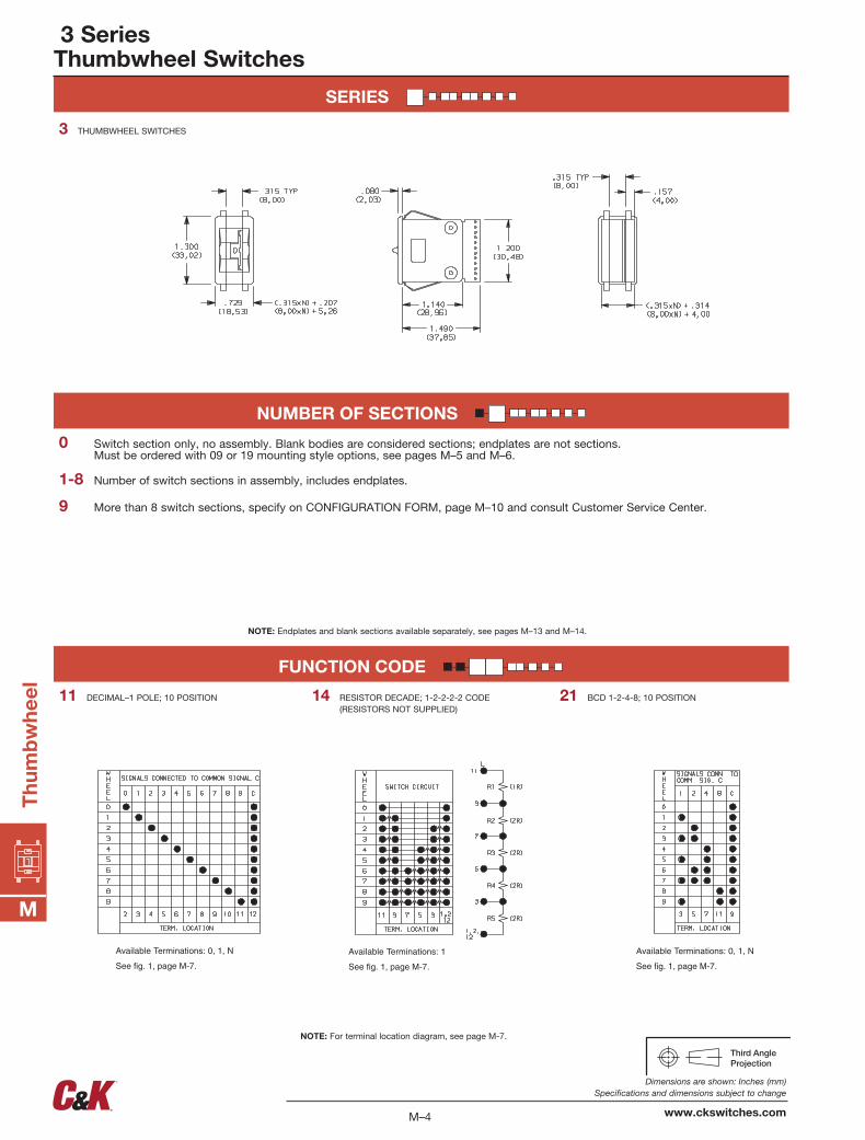
Available Terminations: 0, 1, N
See fig. 1, page M-7.
Available Terminations: 1
See fig. 1, page M-7. See fig. 1, page M-7.
Available Terminations: 0, 1, N
21 BCD 1-2-4-8; 10 POSITION14 RESISTOR DECADE; 1-2-2-2-2 CODE (RESISTORS NOT SUPPLIED)
11 DECIMAL–1 POLE; 10 POSITION
9 More than 8 switch sections, specify on CONFIGURATION FORM, page M–10 and consult Customer Service Center.
1-8 Number of switch sections in assembly, includes endplates.
0 Switch section only, no assembly. Blank bodies are considered sections; endplates are not sections. Must be ordered with 09 or 19 mounting style options, see pages M–5 and M–6.
3 THUMBWHEEL SWITCHES
NOTE: Endplates and blank sections available separately, see pages M–13 and M–14.
NOTE: For terminal location diagram, see page M-7.
M
Th
um
bw
hee
l

M–5
Dimensions are shown: Inches (mm) Specifications and dimensions subject to change
www.ckswitches.com
3 SeriesThumbwheel Switches
FUNCTION CODE
MOUNTING STYLE
Available Terminations: 0, 1, N
See fig. 1, page M-7.
Available Terminations: P
See fig. 2, page M-7. See fig. 1, page M-7.
Available Terminations: 0, 1, N
Available Terminations: 0, 1, N
See fig. 1, page M-7.
N = Number of sections.
PANEL MOUNTING
09 SWITCH SECTION ONLY–UNASSEMBLED WITHOUT ENDPLATES OR SPACERS (Must be ordered with number of sections option “0”, see Page M–4.)
00 SWITCH ASSEMBLY W/ ENDPLATES–.315 (8,00) SECTION PITCH
Type 0 Snap-In Front Mount
23 COMPLEMENT OF BCD 1-2-4-8; 10 POSITION
71 BINARY CODED HEXADECIMAL, 16 POSITION
31 BCD 1-2-4-8; 10 POSITION27 BCD 1-2-4-8; 10 POSITION
NOTE: For terminal location diagram, see page M–7.
NOTE: Endplates, blank sections, spacersand assembly hardware available separately, see pages M–8 and M–9.
MOUNTING STYLE DIM. ‘A’00 (.315 x N) + .326
(8,00 x N) + (8,28)
N = Number of sections.
Recommended panel thickness: 0.46-.125 (1,16-3,18)
M
Th
um
bw
heel

M–6
Dimensions are shown: Inches (mm) Specifications and dimensions subject to change
www.ckswitches.com
3 SeriesThumbwheel Switches
MOUNTING STYLE
N = Number of sections.
PANEL MOUNTING
Mtg. Holes
N = Number of sections.
MOUNTING STYLE DIM. ‘A’ DIM. ‘B’
10 (.350 x N) + .340 (8,89 x N) + (8,64)
(.350 x N) + .560 (8,89 x N) + (14,22)
N = Number of sections.
Recommended panel thickness: 0.46-.125 (1,16-3,18)
20 SWITCH ASSEMBLY W/ ENDPLATES–.350 (8,89) SECTION PITCH
29 SWITCH SECTION ONLY–UNASSEMBLED WITHOUT ENDPLATES OR SPACERS (Must be ordered with number of sections option “0”, see Page M–4.)
19 SWITCH SECTION ONLY–UNASSEMBLED WITHOUT ENDPLATES OR SPACERS (Must be ordered with number of sections option “0”, see Page M–4.)
10 SWITCH ASSEMBLY W/ ENDPLATES–.350 (8,89) SECTION PITCH
Type 1 Rear Mount
Type 2 Rear Mount
NOTE: Endplates, blank sections, spacers and assembly hardware available separately, see pages M–8 and M–9.
M
Th
um
bw
hee
l

M–7
Dimensions are shown: Inches (mm) Specifications and dimensions subject to change
www.ckswitches.com
COLOR/MARKING/STOPS
SEAL
Signal traces cut except for common(s).
FIG. 1 FIG. 2
9 ANY COMBINATION OF TERMINATION CONFIGURATIONS OR SPECIAL TERMINATIONS.
P SOLDER PINS WITH .156” SPACING
N SOLDER PINS WITH .100” SPACING1 TYPE 1, EXTENDED TYPE 00 TYPE 0
3 SEALED SWITCHING CONTACTS AND DUST LENS
2 DUST LENS. (Protects the character face of the wheel from abrasion and dirt).
1 SEALED SWITCHING CONTACTS. (Sealing is by means of an o-ring rotary seal and a cured-in-place elastomer gasket. Switching contact area is protected from moisture, oil, and airborne contaminants.)
0 UNSEALED SWITCHING CONTACTS.
0 MATTE BLACK HOUSING (Gloss black wheel with white characters; no stops.)
PC Board 1/32” (0,79) thick.
NOTE: See function codes, pages M–4 and M–5, for signal locations.
NOTE: Stop pins are available separately, see page M–8.
Dust Lens
NOTE: All terminal holes shown may not be present for all function codes, consult Customer Service Center. Terminal connector available for termination options 0 & 1, see page M–9.
Specify on configuration form, page M–10and consult Customer Service Center.
Terminal Location Numbers
3 SeriesThumbwheel Switches
TERMINATIONS
NOTE: Termination option N (RoHS compliant) replaced termination option 3 (Non-RoHS compliant). Termination option P (RoHS compliant) replaced termination option B (Non-RoHS compliant).
M
Th
um
bw
heel
6 TYPE 6, NO PINS
.882[22,4]
.156[3,96]
.080[2,03]
.210[5,33]

M–8
Dimensions are shown: Inches (mm) Specifications and dimensions subject to change
www.ckswitches.com
3 SeriesThumbwheel Switches
AVAILABLE HARDWARE
Blank sections, Type 0, .315 THK.
PART NO.
413602000 W/RIB-BLACK
400502000 W/RIB & W/OUT SPRINGS-BLACK
Blank sections, Front mount, Type 0, .315 THK.
PART NO.
413502000 PLAIN-BLACK
400702000 PLAIN & W/OUT SPRINGS-BLACK
PART NO.
400602000 W/RIB-BLACK
400802000 PLAIN-BLACK
Blank sections, Rear mount, Type 1, .350 THK.
Blank sections, Rear mount, Type 2, .350 THK.
PART NO.
473402000 W/RIB-BLACK
473302000 PLAIN-BLACK
End plates, Front mount, Type 0
PART NO.
413402000 BLACK
PART NO.
400402003 BLACK
End plates, Rear mount, Type 1
Stop pinsEnd plates, Rear mount, Type 2
PART NO.
473202003 BLACK
PART NO.
402900000PART NO.
410802000 BLACK
Spacers, Front mount, Type 0 & 3, .078 THK. (Makes section pitch 10mm)
Two required for complete assembly.
Two required for complete assembly.
4734 4733
4006 4008
Two required for complete assembly.
M
Th
um
bw
hee
l

M
Th
um
bw
heel
M–9
Dimensions are shown: Inches (mm) Specifications and dimensions subject to change
www.ckswitches.com
3 SeriesThumbwheel Switches
AVAILABLE HARDWARE
PART NO.
605A00000 PC605A02000 SOLDER LUG
Fits 0 & 1 terminations only.
Terminal connector
PART NO.
403500000
Nut
Two nuts required per assembly and screws.
Screws for field assembly of thumbwheel switches (2 screws needed per assembly + 403500000 nuts)
605A00000 605A02000
PART NO.
406100652
Nut driver (For 403500000 nut)
SCREW PART NUMBER (0-80 UNF THD. SIZE)
NUMBER OF SECTIONS IN ASSEMBLY
FRONT MOUNTING REAR MOUNTING
MTG. STYLE – 00 MTG. STYLE – 10
412700000
412701000
412702000
1–2 1–2
3–4 3
5–7 4–6

M–10
Dimensions are shown: Inches (mm) Specifications and dimensions subject to change
www.ckswitches.com
3 SeriesThumbwheel Switches
QUALITY CONTROL INSTRUCTIONS PRODUCTION APPROVAL DATE
C&K PART NUMBER
REV. INITIALS DATE
3CATALOG PART NO.
COMPANY NAME CUSTOMERPRINTREVISION:ADDRESS TEL.#
CUSTOMER CONTACT DATE
ORIGINATED BY SALES REP.
DETAILS:
Q.C. APPROVAL DATE
Configuration FormGRAY SHADED AREAS TO BE FILLED IN BY CUSTOMER SERVICE.
SHEET _____ OF _____
C&
K P
AR
T N
UM
BE
R
10
11
1
2
3
4
5
6
7
8
9
THUMBWHEELSECTIONS
DESCRIBE IN APPROPRIATE ROW
SPECIAL INSTRUCTIONS OR SPECIFICATIONS:
3 –
FUNCTION CODE – TERMINATIONS–COLOR/MARKING/STOPS/SEAL –
ILLUMINATION
FOR SWITCHES WITH MORE THAN 11 SECTIONS, CONTINUE ON ADDITIONAL SHEETS.
ENTER OPTION CODES IN APPROPRIATE BOXES. FUNCTIONCODES INCLUDE BLANK SECTIONS (SEE PAGES M-9 & M-10).
NO.OF
SEC.
– –
3 – – –
3 – – –
3 – – –
3 – – –
3 – – –
3 – – –
3 – – –
3 – – –
3 – – –
3 – – –
M
Th
um
bw
hee
l