3 Screw Water Cooled Water Chiller-V2014.01
16
Water Cooled Water Chiller 220kW-3100kW Vicot Air Conditioning Co., Ltd
Transcript of 3 Screw Water Cooled Water Chiller-V2014.01

Water Cooled Water Chiller 220kW-3100kW
Vicot Air Conditioning Co., Ltd

ABO
UT
US
Vicot Group is a high-tech corporation specialized in R&D, production, sales and service of renewable
energy products.
The corporation has almost 2000 staff and nine business divisions and/or centers as following: Solar
Thermal Energy Equipment Division, Vacuum Tube Division, Gas Fired Air Conditioning Division, Electrical Air
Conditioning Division, Domestic Marketing & Sales Division, Export & Import Division, Administrative & Human
Resource Center, Company Management Center and General Manager Office.
Our production base locates in Solar City, Dezhou, China, it covers an area of 150,000 m2 with modern
workshops and office buildings of more than 80,000 m2. Annual yield capabilities are as follows: 100,000
electrical AC units; 10,000 gas fired AC units; 200,000 m2 of collectors; 100,000 pieces of tubes; 5,000 standard
sets of solar air conditioning system (20kW/ standard set), 200,000 standard sets of S.A.P central hot water
system (10T/ standard set), 10,000 standard sets of S.A.P central distributed heating system (40kW/ standard
set) and 500 standard sets of solar boiler system (700kW/ standard set). Designed annual production value
reaches RMB 5 billion.
With the mission of “The same breath, energy saving together”, the corporation realizes energy saving
and environment protection by focusing on effective utilization of solar energy, air source energy, geothermal
energy and other renewable energies in cooling, heating and domestic hot water fields, in pursuit of
technology innovations in the field of global renewable energy utilization.
After years’ practice in geothermal chiller & heat pump, air source chiller and heat pump and floor
heating fields, Vicot accumulates rich experience in development and production and reaches a nationally
advanced level. With a total investment of RMB 16 million in April 2008, after 3 years’ collaboration with more
than 20 global universities and research institutes in sequence, Vicot successfully and innovatively launched
solar air conditioning system, S.A.P central hot water system, S.A.P central distributed heating system, solar
boiler system, having more than 150 patents, large scale production of them has been realized, the past and
current scientists and engineers’ cherished wish has been realized. It places China at the world top level in
solar medium temperature application field, it turns the dream into truth, for solar energy scale application in
commercial and industrial field.
In the meantime of developing the technology of world leading new energy product, the corporation
is operated with global advanced ERP technique, UPDI\WMS barcode storage system and ABC cost control
system. Information, logistics and cash flow are highly integrated, which austerely shows its concept of “Quality
based on science, Price optimized for customer”.

Features
Technical specification
Optional accessories
Introduction
Nomenclature
Installation & Maintenance
8
9
1
Water Cooled Water Chiller
Contents
1 2 2 3
10
Wiring at Site
Variable performance

Introduction
Water cooled water chiller is one of the cooling system in central air conditioner, uses cooling tower to cool the water, and the cold water is cooling source. Water cooled water chiller has advantages of high efficient, low noise, reasonable structure, simple and stable operation, convenient installation and maintenance, which is comfortable central air conditioner that suitable for hotel, shopping mall, office building, exhibition mall, airport, gymnasium.
VWSA series water cooled water chiller is the stable product developed by VICOT with the using of new technologies of international and domestic air conditioning industry, which is designed and produced according to international standard, adopting world famous high quality compressor, system accessories and computerized controller, with the reasonable match and structure design, it’s stable, high quality, low noise and no contamination to outdoor environment.
1. Selecting sophisticated parts
Choosing world-renowned brand parts to ensure unit's high-efficient and reliable;
Using the most advanced DAE/DAC high-efficient heat transfer tube. Its multiple spiral ribs and spiral-shaped protrusions improve its heat transfer coefficiency; the unique structural design, best copper layout and precise refrigerant control improve its heat transfer efficiency largely.
2. Easy to operate and reliable running
(1) Full computerized control with standby manual operation system;
(2) Multiple protection to ensure safe and reliable running;(3) High speed embedded microprocessor;(4) Reserved the terminal for SMS control;(5) Reserved the terminal for PC monitoring hardware;(6) Hardware has self-diagnosis function and automatically
eliminates its faults. Software uses redundancy and trap technology, which combined with WATCHDOG of hardware can improve unit's capability of anti-jamming;
(7) Advanced touch screen: the lifetime of consecutive touch is more than 1 million times;
(8) The power supply of control system is independent, improving its anti-jamming capability.
1
Features
Structure of heat exchanger
High-efficient heat transfer tube
DAE/DAC
Heat-transfer surface
Refrigerant control
Imported compressor

Intro
du
ction
Features
Featu
res
Nom
enclatureA
ccessoriesTech. spec.
Inst. & m
aint.
2
3. High efficiency and energy-saving
Flooded evaporator, inverter, spray and heat recovery technologies improve unit's efficiency greatly. COP>6 and saving 30%-40% running cost for users.
Variable perf.
Wiring at site
Nomenclature
VWS A 1200 X
Default if dry typeF: flooded type
VICOT Water Cooled
A: Cooling only
Cooling capacity kW
Optional accessories
Anti-corrosion
Heat recovery
Rubber absorber
Water flow switch
Wooden package
Soft start
Channel iron base
PLC controller
2.0Mpa pressure bearing Spring shock absorber
Remote controller
Stepless adjustment
Cooling tower Water pump
Water Cooled Water Chiller

3
Technical specificationWater Cooled Water ChillerSpecification I - Table 1
ModelModel VWSA220VWSA220 VWSA260VWSA260 VWSA340VWSA340 VWSA380VWSA380 VWSA430VWSA430 VWSA480VWSA480 VWSA560VWSA560 VWSA660VWSA660
Refrigerant R22 R22 R22 R22 R22 R134a R22 R134a R22 R134a R22 R134a
Cooling Capacity kW 220 260 340 380 430 420 480 480 560 560 660 680
Total Power Input kW 46 53 70 76 88 84 96 95 112 111 132 135
Max. Operating Current A 108 119 192 196 217 199 246 229 275 266 339 330
Energy Steps 25%~100%
Refrigerant Circuit Nos 1
Compressor Quantity Nos 1
Compressor Type Semi-Hermetic Twin Screw
Noise(Standard) dB(A) 65 69 69 71 70 70 70 73 73 73 73 73
Power - 380V/3Ph/50Hz *
Refrigerant Charge Amount Kg 37 46 40 70 75 80 90 100 105 125 125 140
Chilled Water
Water in/out Temp.
oC 12/7 12/7 12/7 12/7 12/7 12/7 12/7 12/7 12/7 12/7 12/7 12/7
Water Flow m3/h 38 45 59 69 74 72 83 83 96 96 114 117
Water Pressure Drop
kPa 50 44 50 50 50 50 50 55 65 85 65 75
Water Pipe Connection DN80 DN80 DN125 DN100 DN125 DN125 DN125 DN125 DN125 DN125 DN125 DN125
Cooling Water
Water in/out Temp.
oC 30/35 30/35 30/35 30/35 30/35 30/35 30/35 30/35 30/35 30/35 30/35 30/35
Water Flow m3/h 46 53 70 83 89 87 99 99 116 116 136 140
Water Pressure Drop
kPa 55 50 55 55 55 55 55 55 58 58 58 58
Water Pipe Connection DN80 DN80 DN100 DN100 DN125 DN125 DN125 DN125 DN125 DN125 DN150 DN150
Partial Heat Recovery (Optional)
Capacity kW - - - 80 86 84 96 96 112 112 132 136
Water Flow m3/h - - - 14 15 15 17 17 19 19 23 23
Pressure Drop kPa - - - 30 32 32 32 32 33 33 34 34
Water in/out Temp.
oC - - - 40/45 40/45 40/45 40/45 40/45 40/45 40/45 40/45 40/45
Total Heat Recovery (Optional)
Capacity kW - - - 444 477 464 530 529 619 617 731 750
Water Flow m3/h - - - 76 82 80 91 91 106 106 126 129
Pressure Drop kPa - - - 37 38 38 37 37 38 38 38 38
Water in/out Temp.
oC - - - 40/45 40/45 40/45 40/45 40/45 40/45 40/45 40/45 40/45
Net Weight Kg 1700 1850 2200 2500 2550 2750 3150 3250 3450 3550 3600 3700
Operating Weight Kg 1790 1940 2300 2620 2670 2900 3300 3400 3580 3680 3740 3840
Note:1- Water side max. bearing pressure: 1.0MPa.2- The data above is subject to change without prior notice.* Various power supply are optional.

4
Technical specificationWater Cooled Water ChillerSpecification II - Table 2
ModelModel VWSA760VWSA760 VWSA900VWSA900 VWSA960VWSA960 VWSA1120VWSA1120 VWSA1320VWSA1320 VWSA1520VWSA1520
Refrigerant R22 R134a R22 R134a R22 R134a R22 R134a R22 R134a R22 R134a
Cooling Capacity kW 760 780 900 900 960 960 1120 1120 1320 1320 1520 1520
Total Power Input kW 152 156 180 180 192 192 224 222 264 260 308 300
Max. Operating Current A 400 367 418 214*2 520 229*2 540 266*2 678 330*2 800 367*2
Energy Steps 25%~100% 25%~100% 25%~100% 12.5%~100% 25%~100% 12.5%~100% 25%~100% 12.5%~100% 12.5%~100%
Refrigerant Circuit Nos 1 1 1 2 1 2 1 2 2 2 2 2
Compressor Quantity Nos 1 1 1 2 1 2 1 2 2 2 2 2
Compressor Type Semi-Hermetic Twin Screw
Noise(Standard) dB(A) 73 73 75 76 75 76 74 74 74 74 74 74
Power - 380V/3Ph/50Hz *
Refrigerant Charge Amount
Kg 140 160 170 180 180 190 210 230 255 275 280 310
Chilled Water
Water in/out Temp.
oC 12/7 12/7 12/7 12/7 12/7 12/7 12/7 12/7 12/7 12/7 12/7 12/7
Water Flow m3/h 131 134 155 155 165 165 193 193 227 227 262 262
Water Pressure Drop
kPa 55 85 50 50 55 50 55 50 55 55 60 60
Water Pipe Connection
DN150 DN150 DN150 DN150 DN200 DN200 DN200 DN200 DN200 DN200 DN200 DN200
Cooling Water
Water in/out Temp.
oC 30/35 30/35 30/35 30/35 30/35 30/35 30/35 30/35 30/35 30/35 30/35 30/35
Water Flow m3/h 157 161 186 186 198 198 231 231 273 273 315 315
Water Pressure Drop
kPa 58 58 60 60 60 60 60 60 60 60 65 65
Water Pipe Connection
DN150 DN150 DN150 2*DN125 DN200 2*DN125 DN200 2*DN125 2*DN125 2*DN125 2*DN150 2*DN150
Partial Heat Recovery (Optional)
Capacity kW 152 156 180 180 192 192 224 224 264 264 304 304
Water Flow m3/h 26 27 31 31 33 33 39 39 45 45 52 52
Pressure Drop kPa 34 34 34 34 32 32 32 32 33 33 34 34
Water in/out Temp.
oC 40/45 40/45 40/45 40/45 40/45 40/45 40/45 40/45 40/45 40/45 40/45 40/45
Total Heat Recovery (Optional)
Capacity kW 841 861 995 994 1062 1058 1238 1235 1463 1463 1682 1674
Water Flow m3/h 145 148 171 171 183 182 213 213 252 252 289 288
Pressure Drop kPa 38 38 39 39 37 37 39 39 39 39 38 38
Water in/out Temp.
oC 40/45 40/45 40/45 40/45 40/45 40/45 40/45 40/45 40/45 40/45 40/45 40/45
Net Weight Kg 3800 3900 3890 4300 4650 4800 5400 5500 6400 6400 8000 8200
Operating Weight Kg 3950 4100 4020 4450 4830 4950 5610 5700 6650 6650 8320 8400
Note:1- Water side max. bearing pressure: 1.0MPa.2- The data above is subject to change without prior notice.* Various power supply are optional.
Intro
du
ction
Featu
res
Nom
enclatureA
ccessoriesTech. spec.
Inst. & m
aint.V
ariable perf.W
iring at site Water Cooled Water Chiller

Technical specification
5
Water Cooled Water ChillerSpecification III - Table 3
ModelModel VWSA1660VWSA1660 VWSA1800VWSA1800 VWSA1920VWSA1920 VWSA2080VWSA2080 VWSA2240VWSA2240 VWSA2480VWSA2480 VWSA2720VWSA2720 VWSA3100VWSA3100
Refrigerant R22 R22 R22 R22 R22 R22 R22 R22
Cooling Capacity kW 1660 1800 1920 2080 2240 2480 2720 3100
Total Power Input kW 336 362 388 420 459 498 548 624
Max. Operating Current A 418*2 418*2 520*2 520*2 590*2 407*3 416*3 444*3
Energy Steps 12.5%-100% 8.3%-100%
Refrigerant Circuit Nos 2 3
Compressor Quantity Nos 2 3
Compressor Type Semi-Hermetic Twin Screw
Noise(Standard) dB(A) 79 80 80 81 81 81 83 83
Power - 380V/3Ph/50Hz *
Refrigerant Charge Amount
Kg 300 340 360 380 420 465 510 550
Chilled Water
Water in/out Temp.
oC 12/7 12/7 12/7 12/7 12/7 12/7 12/7 12/7
Water Flow m3/h 250 305 345 370 400 438 480 545
Water Pressure Drop
kPa 53 53 53 55 55 60 60 60
Water Pipe Connection
DN200 DN200 DN250 DN250 DN250 DN250 + DN200
Cooling Water
Water in/out Temp.
oC 30/35 30/35 30/35 30/35 30/35 30/35 30/35 30/35
Water Flow m3/h 342 372 397 428 462 511 562 641
Water Pressure Drop
kPa 60 60 60 65 65 65 65 65
Water Pipe Connection
2*DN150 2*DN150 2*DN200 2*DN200 2*DN200 3*DN200 3*DN200 3*DN200
Partial Heat Recovery (Optional)
Capacity kW 332 360 384 416 448 496 544 620
Water Flow m3/h 57 62 66 72 77 85 94 107
Pressure Drop kPa 35 35 35 35 35 35 35 35
Water in/out Temp.
oC 40/45 40/45 40/45 40/45 40/45 40/45 40/45 40/45
Total Heat Recovery (Optional)
Capacity kW 1836 1989 2123 2300 2483 2740 3007 3426
Water Flow m3/h 316 342 365 396 427 471 517 589
Pressure Drop kPa 39 39 39 39 39 39 39 39
Water in/out Temp.
oC 40/45 40/45 40/45 40/45 40/45 40/45 40/45 40/45
Net Weight Kg 8500 8800 9500 11000 11800 12800 13000 13500
Operating Weight Kg 8750 9060 9780 11280 12100 13130 13330 13850
Note:1- Water side max. bearing pressure: 1.0MPa.2- The data above is subject to change without prior notice.* Various power supply are optional.
Technical specification
6
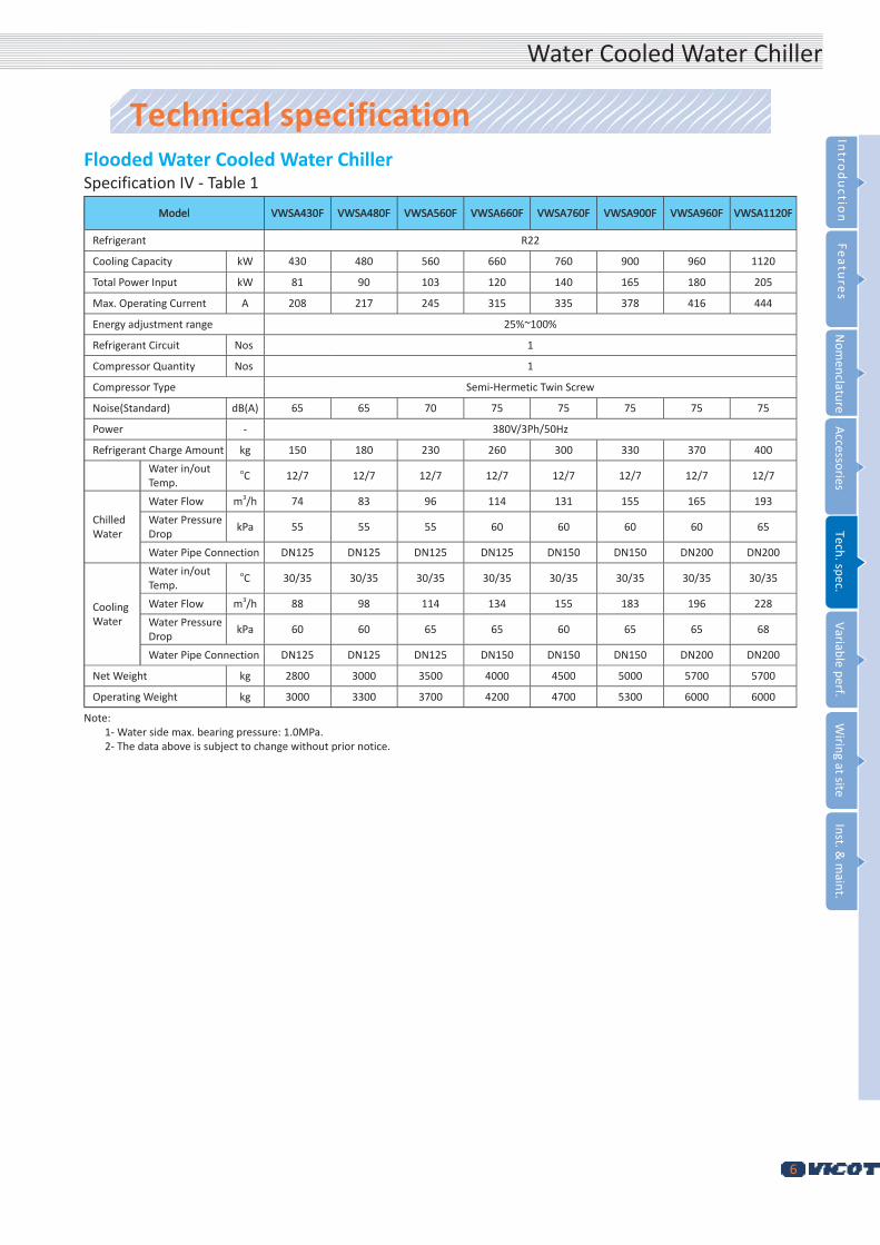
Flooded Water Cooled Water ChillerSpecification IV - Table 1
ModelModel VWSA430FVWSA430F VWSA480FVWSA480F VWSA560FVWSA560F VWSA660FVWSA660F VWSA760FVWSA760F VWSA900FVWSA900F VWSA960FVWSA960F VWSA1120FVWSA1120F
Refrigerant R22
Cooling Capacity kW 430 480 560 660 760 900 960 1120
Total Power Input kW 81 90 103 120 140 165 180 205
Max. Operating Current A 208 217 245 315 335 378 416 444
Energy adjustment range 25%~100%
Refrigerant Circuit Nos 1
Compressor Quantity Nos 1
Compressor Type Semi-Hermetic Twin Screw
Noise(Standard) dB(A) 65 65 70 75 75 75 75 75
Power - 380V/3Ph/50Hz
Refrigerant Charge Amount kg 150 180 230 260 300 330 370 400
Water in/out Temp.
oC 12/7 12/7 12/7 12/7 12/7 12/7 12/7 12/7
Chilled Water
Water Flow m3/h 74 83 96 114 131 155 165 193
Water Pressure Drop
kPa 55 55 55 60 60 60 60 65
Water Pipe Connection DN125 DN125 DN125 DN125 DN150 DN150 DN200 DN200
Cooling Water
Water in/out Temp.
oC 30/35 30/35 30/35 30/35 30/35 30/35 30/35 30/35
Water Flow m3/h 88 98 114 134 155 183 196 228
Water Pressure Drop
kPa 60 60 65 65 60 65 65 68
Water Pipe Connection DN125 DN125 DN125 DN150 DN150 DN150 DN200 DN200
Net Weight kg 2800 3000 3500 4000 4500 5000 5700 5700
Operating Weight kg 3000 3300 3700 4200 4700 5300 6000 6000
Note:1- Water side max. bearing pressure: 1.0MPa.2- The data above is subject to change without prior notice.
Intro
du
ction
Featu
res
Nom
enclatureA
ccessoriesTech. spec.
Inst. & m
aint.V
ariable perf.W
iring at site Water Cooled Water Chiller

Technical specification
7
Flooded Water Cooled Water ChillerSpecification V - Table 2
ModelModel VWSA1320FVWSA1320F VWSA1520FVWSA1520F VWSA1660FVWSA1660F VWSA1800FVWSA1800F VWSA1920FVWSA1920F VWSA2080FVWSA2080F VWSA2240FVWSA2240F
Refrigerant R22
Cooling Capacity kW 1320 1520 1660 1800 1920 2080 2240
Total Power Input kW 240 280 308 335 335 385 415
Max. Operating Current A 315*2 335*2 378*2 378+416 416*2 416+444 444*2
Energy adjustment range 12.5%~100%
Refrigerant Circuit Nos 2
Compressor Quantity Nos 2
Compressor Type Semi-Hermetic Twin Screw
Noise(Standard) dB(A) 70 70 75 78 80 80 80
Power - 380V/3Ph/50Hz
Refrigerant Charge Amount kg 480 550 600 700 780 840 900
Water in/out Temp.
oC 12/7 12/7 12/7 12/7 12/7 12/7 12/7
Chilled Water
Water Flow m3/h 227 262 286 310 331 358 386
Water Pressure Drop
kPa 60 60 60 65 65 67 70
Water Pipe Connection
DN200 DN200 DN200 DN250 DN250 DN250 DN250
Cooling Water
Water in/out Temp.
oC 30/35 30/35 30/35 30/35 30/35 30/35 30/35
Water Flow m3/h 269 310 339 368 392 425 457
Water Pressure Drop
kPa 65 60 65 65 66 68 70
Water Pipe Connection
DN200 DN200 DN200 DN250 DN250 DN250 DN250
Net Weight kg 7200 7800 8200 8700 9000 9600 10000
Operating Weight kg 7500 8100 8500 9100 9500 10000 10500
Note:1- Water side max. bearing pressure: 1.0MPa.2- The data above is subject to change without prior notice.

Variable performace
8
Intro
du
ction
Featu
res
Nom
enclatureA
ccessoriesTech. spec.
Inst. & m
aint.V
ariable perf.W
iring at site
Cool
ing
capa
city
cor
rect
ion
coef
ficie
nt
0.80
0.90
1.00
1.20
1.10
1.30
1.40
Chilled water outlet 5oCChilled water outlet 7oCChilled water outlet 9oCChilled water outlet 11oCChilled water outlet 13oCChilled water outlet 15oC
25 26 32 33 34 35 36 37Cooling water inlet temperature oC
27 28 29 30 31
Cool
ing
pow
er c
orre
ctio
n co
effic
ient
0.80
0.90
1.00
1.20
1.10
1.30
1.40
25 26 32 33 34 35 36 37Cooling water inlet temperature oC
27 28 29 30 31
Chilled water outlet 5oCChilled water outlet 7oCChilled water outlet 9oCChilled water outlet 11oCChilled water outlet 13oCChilled water outlet 15oC
Cooling Power Correction Coefficient
Cooling Capacity Correction Coefficient
Water Cooled Water Chiller

9
Wirings at Site
Single Refrigerant Circiut Unit
Double Refrigerant Circiut Unit

10
Intro
du
ction
Featu
res
Nom
enclatureA
ccessoriesTech. spec.
Inst. & m
aint.V
ariable perf.W
iring at site
Installation & maintenance• Machine room requirements
1. For a convenient operation and maintenance, there should be at least leave 1-1.5m space in front of the operation side, and enough space allow easy movement of people in other sides.
2. Good ventilation environment should be ensured in the operation room, the room temp will be increased as the environment temp is lower than the temperature of compressor gas discharge end and gas discharge pipe, and the machine room temperature should not beyond 35oC.
3. The operation room should be sound insulated according to specific situation so as to avoid the operation noise disturbs environment surrounding. It is better that main machine and pump not installed in the same room.
• Lifting
Handle the machine carefully during lifting to avoid damage, especially no damage to compressor, control system, piping system etc.. Soft material should be used at the point of touching between the lifting rope and the unit. And to decrease the pressure on the unit, supporter bar between the rope and the unit is necessary for heavy unit. Crane can be applied during the handling, the lifting rope and the unit should be connected firmly, the unit should be horizontal without slope, and no rope touch on heat exchanger side, panel and the top of machine.
Hoisting Graph
• InstallationTo guarantee sound quality and perfect performance, each unit has been strictly tested before leaving factory. Great care should be required during handling and installation, no any damage on control system or on pipes is allowed.
1. Before open the package, move the unit to the installation site as close as possible and pay attention on keeping the unit to be vertical.
2. During the installation, the sling bearing capacity should be 3 times of the unit’s weight, and no people under the suspending unit are allowed. Please refer to rating label for unit weight.
3. Must have horizontal level calibration after the unit is on the foundation and the horizontal deviation should be within 0.02%.
Water Cooled Water Chiller

11
4. The direction of the water pipe connected with the unit should be in line with the specification and the pipeline diameter should not be too small. Water flow switch should be equipped on the pipeline and connected with the compressor.
5. Temperature and pressure indicators should be equipped at both inlets and outlets of the chilled water pipe and cooling pipe for the convenient monitoring on the unit’s operation condition.
6. Power capacity provided should be big enough, power supply voltage fluctuation should be within ±10%, the earthing should be well done.
1. The installation should in line with the national and local authorities’ requirement.
2. Chilled water pipe must be insulated to avoid capacity loss and having condensed water.
3. For the sake of water quality, filter on input pipe is necessary.
4. Dimension of the joint of connection pipe should meet requirement (refer to Technical data)
5. For the sake of automatically discharge air, supply water indirectly and expanding or shrinking of chilled water system, expansion tank is required. And it should 1.5m higher than the highest point of the water system. No valve is allowed in the pipe between the expansion tank and return water system.
6. The air discharge valve should be fixed the highest point of the chilled water system. After connection of the chilled water system finished, and pressure testing is acceptable, open the air discharge valve to exhaust the air in chilled water and close the valve after completely air exhausted. If the water or the pipe inside is not clean, it needs to clean the filter after half an hour’s pump operation.
7. Before the first running of the circulation water, close the input/output valve first, then open the bypass valve, run the water pump only to circulate the water in pipe to clean the pipe and clean the filter after that, then add clean water again to the system, then turn on the inlet/outlet valve and close the bypass valve for normal operation.
8. Water segregator, water collector and water pressure balance valve are required when several units to be parallelized.
9. Water drain valve should be fixed at the lowest point of the water system.
10. The design of water piping, please refer to the Air conditioning Design Manual, and the project operation and inspection refer to GB50243-1997 Ventilation & air conditioning project operation and inspection Norms.
Installation & maintenance
• Water system and piping
• Power connection
1. Wire selection and connection should be carried out strictly according to requirement.
2. Should have earthing well done, no earthing to gas pipe, water pipe, telephone line, to avoid electric shock cause by bad earthing.
3. Ensure the phase sequence is correct, to avoid not running.

12
Installation & maintenance
Intro
du
ction
Featu
res
Nom
enclatureA
ccessoriesTech. spec.
Inst. & m
aint.V
ariable perf.W
iring at site
• Maintenance 1. The qualified technician is required for the maintenance; all the protection devices and controller must be checked before restart.
2. Regular and correct maintenance is required for stability and good performance. Chilled and cooling water must be complete drained when long time no use to avoid possible freezing.
• Notice1. Antifreezer should be added in chilled water if water temp. set below zero or near zero.
2. Clean water system regularly.
3. Pay attention to antifreeze when ambient temp. is around 0oC in winter.
4. Antifreezer or other antifreeze measure must be used in bad ambient(under 0oC outdoor).
• Appendix : water system diagram
Expansion tank
Automatic water feeding pipe
Expansion pipe
Overflow pipe
Drain pipe
Chilled water outlet pipe
Chilled water inlet pipe
FCU
FCU
FCU
Drain pipe Evaporator
Condenser
Cooling tower
Cool
ing
wat
er
outl
et p
ipe
Cool
ing
wat
er
inle
t p
ipe
Water pump
Pressure gauge
Thermometer
Auto air vent
Stop valve
Flexible connector
Butterfly valve
Check valve
Pressure switch
Y-stainer
Water Cooled Water Chiller

The Same Breath, Energy Saving Together.
Add: Hongdu Road, Dezhou Eoonomic Development Zone, Shandong Province, China. Post Code: 253022Sales Tel: +86-8235 5566/68/76 Fax: +86-8235 7911 Email: [email protected] Http://www.vicot com cn
2014.01Vicot reserves the right of modification without prior notice
VICOT AIR CONDITIONING CO., LTD