3. Programming Model - Duke University
24
Altera Corporation 3–1 May 2006 3. Programming Model Introduction This chapter describes the Nios ® II programming model, covering processor features at the assembly language level. The programmer’s view of the following features are discussed in detail: ■ General-purpose registers, page 3–1 ■ Control registers, page 3–2 ■ Supervisor mode vs. user mode privileges, page 3–4 ■ Hardware-assisted debug processing, page 3–14 ■ Exception processing, page 3–8 ■ Hardware interrupts, page 3–9 ■ Unimplemented instructions, page 3–11 ■ Memory and peripheral organization, page 3–15 ■ Cache memory, page 3–16 ■ Processor reset state, page 3–16 ■ Instruction set categories, page 3–17 ■ Custom instructions, page 3–23 High-level software development tools are not discussed here. See the Nios II Software Developer’s Handbook for information about developing software. General- Purpose Registers The Nios II architecture provides thirty-two 32-bit general-purpose registers, r0 through r31. See Table 3–1 on page 2. Some registers have names recognized by the assembler. The zero register (r0) always returns the value 0, and writing to zero has no effect. The ra register (r31) holds the return address used by procedure calls and is implicitly accessed by call and ret instructions. C and C++ compilers use a common procedure-call convention, assigning specific meaning to registers r1 through r23 and r26 through r28. f For more information, refer to the Application Binary Interface chapter of the Nios II Processor Reference Handbook. NII51003-6.0.0
Transcript of 3. Programming Model - Duke University

Altera Corporation May 2006
NII51003-6.0.0
3. Programming Model
Introduction This chapter describes the Nios® II programming model, covering processor features at the assembly language level. The programmer’s view of the following features are discussed in detail:
■ General-purpose registers, page 3–1■ Control registers, page 3–2■ Supervisor mode vs. user mode privileges, page 3–4■ Hardware-assisted debug processing, page 3–14■ Exception processing, page 3–8■ Hardware interrupts, page 3–9■ Unimplemented instructions, page 3–11■ Memory and peripheral organization, page 3–15■ Cache memory, page 3–16■ Processor reset state, page 3–16■ Instruction set categories, page 3–17■ Custom instructions, page 3–23
High-level software development tools are not discussed here. See the Nios II Software Developer’s Handbook for information about developing software.
General-Purpose Registers
The Nios II architecture provides thirty-two 32-bit general-purpose registers, r0 through r31. See Table 3–1 on page 2. Some registers have names recognized by the assembler. The zero register (r0) always returns the value 0, and writing to zero has no effect. The ra register (r31) holds the return address used by procedure calls and is implicitly accessed by call and ret instructions. C and C++ compilers use a common procedure-call convention, assigning specific meaning to registers r1 through r23 and r26 through r28.
f For more information, refer to the Application Binary Interface chapter of the Nios II Processor Reference Handbook.
3–1

Control Registers
Access to certain registers, such as et (r24), bt (r25), ea (r29), and ba (r30) is limited to certain execution modes. For further information, see “Operating Modes” on page 3–4.
Control Registers
There are six 32-bit control registers, ctl0 through ctl5. All control registers have names recognized by the assembler.
Control registers are accessed differently than the general-purpose registers. The special instructions rdctl and wrctl provide the only means to read and write to the control registers. Control registers can be accessed only in supervisor mode; they are not accessible in user mode. See “Operating Modes” on page 3–4 for further details.
Table 3–1. The Nios II Register File
General Purpose Registers
Register Name Function Register Name Function
r0 zero 0x00000000 r16
r1 at Assembler Temporary r17
r2 Return Value r18
r3 Return Value r19
r4 Register Arguments r20
r5 Register Arguments r21
r6 Register Arguments r22
r7 Register Arguments r23
r8 Caller-Saved Register r24 et Exception Temporary (1)
r9 Caller-Saved Register r25 bt Breakpoint Temporary (2)
r10 Caller-Saved Register r26 gp Global Pointer
r11 Caller-Saved Register r27 sp Stack Pointer
r12 Caller-Saved Register r28 fp Frame Pointer
r13 Caller-Saved Register r29 ea Exception Return Address (1)
r14 Caller-Saved Register r30 ba Breakpoint Return Address (2)
r15 Caller-Saved Register r31 ra Return Address
Notes to Table 3–1:(1) This register is not available in user mode.(2) This register is not available in user mode or supervisor mode. It is used exclusively by the JTAG debug module.
3–2 Altera CorporationNios II Processor Reference Handbook May 2006

Programming Model
Details of the control registers are shown in Table 3–2. For details on the relationship between the control registers and exception processing, see Figure 3–2 on page 3–10.
status (ctl0)
The value in the status register controls the state of the Nios II processor. All status bits are cleared after processor reset. See “Processor Reset State” on page 3–16. Two bits are defined: PIE and U, as shown in Table 3–3.
estatus (ctl1)
The estatus register holds a saved copy of the status register during exception processing. Two bits are defined: EPIE and EU. These are the saved values of PIE and U, as defined in Table 3–3.
The exception handler can examine estatus to determine the pre-exception status of the processor. When returning from an interrupt, the eret instruction causes the processor to copy estatus back to status, restoring the pre-exception value of status.
f See “Exception Processing” on page 3–8 for more information.
Table 3–2. Control Register & Bits
Register Name 31…2 1 0
ctl0 status Reserved U PIE
ctl1 estatus Reserved EU EPIE
ctl2 bstatus Reserved BU BPIE
ctl3 ienable Interrupt-enable bits
ctl4 ipending Pending-interrupt bits
ctl5 cpuid Unique processor identifier
Table 3–3. status Register Bits
Bit Description
PIE bit PIE is the processor interrupt-enable bit. When PIE is 0, external interrupts are ignored. When PIE is 1, external interrupts can be taken, depending on the value of the ienable register.
U bit U is the user-mode bit. 1 indicates user mode; 0 indicates supervisor mode.
Altera Corporation 3–3May 2006 Nios II Processor Reference Handbook

Operating Modes
bstatus (ctl2)
The bstatus register holds a saved copy of the status register during debug break processing. Two bits are defined: BPIE and BU. These are the saved values of PIE and U, as defined in Table 3–3 on page 3–3.
When a break occurs, the value of the status register is copied into bstatus. Using bstatus, the status register can be restored to the value it had prior to the break.
f See “Debug Mode” on page 3–6 for more information.
ienable (ctl3)
The ienable register controls the handling of external hardware interrupts. Each bit of the ienable register corresponds to one of the interrupt inputs, irq0 through irq31. A bit value of 1 means that the corresponding interrupt is enabled; a bit value of 0 means that the corresponding interrupt is disabled.
f See “Exception Processing” on page 3–8 for more information.
ipending (ctl4)
The value of the ipending register indicates which interrupts are pending. A value of 1 in bit n means that the corresponding irqn input is asserted, and that the corresponding interrupt is enabled in the ienable register. The effect of writing a value to the ipending register is undefined.
cpuid (ctl5)
The cpuid register holds a static value that uniquely identifies the processor in a multi-processor system. The cpuid value is determined at system generation time. Writing to the cpuid register has no effect.
f See “Exception Processing” on page 3–8 for more information.
Operating Modes
The Nios II processor has three operating modes:
■ Supervisor mode■ User mode■ Debug mode
3–4 Altera CorporationNios II Processor Reference Handbook May 2006
Programming Model
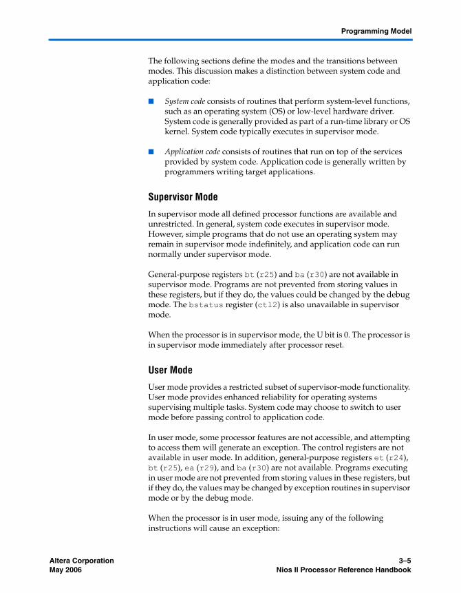
The following sections define the modes and the transitions between modes. This discussion makes a distinction between system code and application code:
■ System code consists of routines that perform system-level functions, such as an operating system (OS) or low-level hardware driver. System code is generally provided as part of a run-time library or OS kernel. System code typically executes in supervisor mode.
■ Application code consists of routines that run on top of the services provided by system code. Application code is generally written by programmers writing target applications.
Supervisor Mode
In supervisor mode all defined processor functions are available and unrestricted. In general, system code executes in supervisor mode. However, simple programs that do not use an operating system may remain in supervisor mode indefinitely, and application code can run normally under supervisor mode.
General-purpose registers bt (r25) and ba (r30) are not available in supervisor mode. Programs are not prevented from storing values in these registers, but if they do, the values could be changed by the debug mode. The bstatus register (ctl2) is also unavailable in supervisor mode.
When the processor is in supervisor mode, the U bit is 0. The processor is in supervisor mode immediately after processor reset.
User Mode
User mode provides a restricted subset of supervisor-mode functionality. User mode provides enhanced reliability for operating systems supervising multiple tasks. System code may choose to switch to user mode before passing control to application code.
In user mode, some processor features are not accessible, and attempting to access them will generate an exception. The control registers are not available in user mode. In addition, general-purpose registers et (r24), bt (r25), ea (r29), and ba (r30) are not available. Programs executing in user mode are not prevented from storing values in these registers, but if they do, the values may be changed by exception routines in supervisor mode or by the debug mode.
When the processor is in user mode, issuing any of the following instructions will cause an exception:
Altera Corporation 3–5May 2006 Nios II Processor Reference Handbook

Operating Modes
■ rdctl■ wrctl■ bret■ eret■ initd■ initi
When the processor is in user mode, the U bit is 1.
Processor Implementation & User Mode Support
Some Nios II processor implementations do not support user mode. On these cores, all code executes in supervisor mode, and the U bit is always 0. Therefore, application code should never be written such that it depends on a particular value of the U bit in order to execute correctly.
Application code executes normally in both user mode or supervisor mode. On Nios II processor cores that do not support user mode, system code cannot rely on user mode or access violation exceptions for protection of restricted resources.
f Refer to the Nios II Core Implementation Details chapter of the Nios II Processor Reference Handbook for complete details of which processor cores support user mode.
Debug Mode
Debug mode is used by software debugging tools to implement features such as breakpoints and watch-points. System code and application code never execute in debug mode. The processor enters debug mode only after the break instruction or after the JTAG debug module forces a break via hardware.
In debug mode all processor functions are available and unrestricted to the software debugging tool. In debug mode, the U bit is 0. Refer to “Break Processing” on page 3–14 for further information.
Changing Modes
Figure 3–1 diagrams the transitions between user, supervisor and debug modes.
3–6 Altera CorporationNios II Processor Reference Handbook May 2006

Programming Model
Figure 3–1. Transitions Between Operating Modes
The processor starts in supervisor mode after reset.
A program may switch from supervisor mode into user mode using an eret (exception return) instruction. eret copies the value of the estatus register (ctl1) to the status register (ctl0), and then transfers control to the address in the ea register (r29). To enter user mode for the first time after processor reset, system code must set up the estatus and ea registers appropriately and then execute an eret instruction.
The processor remains in user mode until an exception occurs, at which point the processor reenters supervisor mode. All exceptions clear the U bit to 0 and save the contents of status to estatus. Assuming the exception routines do not modify the estatus register, using eret to return from the exception will restore the pre-exception mode.
The processor enters debug mode only as directed by software debugging tools. System code and application code have no control over when the processor enters debug mode. The processor always returns to its prior state when exiting from debug mode.
f For further details, refer to “Exception Processing” on page 3–8 and “Break Processing” on page 3–14.
break condition Debug(U == 0)
Resetbret
eret
bretexception
breakcondition
User(U == 1)
Supervisor (U == 0)
Altera Corporation 3–7May 2006 Nios II Processor Reference Handbook

Exception Processing
Exception Processing
An exception is a transfer of control away from a program’s normal flow of execution, caused by an event, either internal or external to the processor, which requires immediate attention. Exception processing is the act of responding to an exception, and then returning to the pre-exception execution state.
An exception causes the processor to take the following steps automatically. The processor:
1. Copies the contents of the status register (ctl0) to estatus (ctl1) saving the processor’s pre-exception status
2. Clears the U bit of the status register, forcing the processor into supervisor mode
3. Clears the PIE bit of the status register, disabling external processor interrupts
4. Writes the address of the instruction after the exception to the ea register (r29)
5. Transfers execution to the address of the exception handler that determines the cause of the interrupt
The address of the exception handler is specified at system generation time. At run-time this address is fixed, and it cannot be changed by software. Programmers do not directly access the exception handler address, and can write programs without awareness of the address.
The exception handler is a routine that determines the cause of each exception, and then dispatches an appropriate exception routine to respond to the interrupt.
f For a detailed discussion of writing programs to take advantage of exception and interrupt handling, see the Exception Handling chapter in the Nios II Software Developer’s Handbook.
Exception Types
Nios II exceptions fall into the following categories:
■ Hardware interrupt ■ Software trap■ Unimplemented instruction■ Other
Each exception type is described in detail in the following sections.
3–8 Altera CorporationNios II Processor Reference Handbook May 2006

Programming Model
Hardware Interrupt
An external source such as a peripheral device can request a hardware interrupt by asserting one of the processor’s 32 interrupt-request inputs, irq0 through irq31. A hardware interrupt is generated if and only if all three of these conditions are true:
■ The PIE bit of the status register (ctl0) is 1■ An interrupt-request input, irqn, is asserted■ The corresponding bit n of the ienable register (ctl3) is 1.
Upon hardware interrupt the PIE bit is set to 0, disabling further interrupts. The value of the ipending register (ctl4) shows which interrupt requests (IRQ) are pending. By peripheral design, an IRQ bit is guaranteed to remain asserted until the processor explicitly responds to the peripheral. Figure 3–2 shows the relationship between ipending, ienable, PIE, and the generation of an interrupt.
Altera Corporation 3–9May 2006 Nios II Processor Reference Handbook

Exception Processing
Figure 3–2. Relationship Between ienable, ipending, PIE & Hardware Interrupts
A software exception routine determines which of the pending interrupts has the highest priority, and then transfers control to the appropriate interrupt service routine (ISR). The ISR must stop the interrupt from being visible (either by clearing it at the source or masking it using ienable) before returning and/or before re-enabling PIE. The ISR must also save estatus (ctl1) and ea (r29) before re-enabling PIE.
Interrupts can be re-enabled by writing 1 to the PIE bit, thereby allowing the current ISR to be interrupted. Typically, the exception routine adjusts ienable so that IRQs of equal or lower priority are disabled before re-enabling interrupts.
IPE
ND
ING
0
IPE
ND
ING
1
IPE
ND
ING
2
ipending Register
IPE
ND
ING
31
irq0
irq1
irq2
irq31
31 0
IEN
AB
LE0
IEN
AB
LE1
IEN
AB
LE2
31 0
ienable Register
External hardwareinterrupt requestinputs irq[31..0]
Relationship Between ienable, ipending, PIE, and Interrupt Generation
. . .
. . .
. . .
PIE bit
GenerateHardware Interrupt
IEN
AB
LE31
3–10 Altera CorporationNios II Processor Reference Handbook May 2006

Programming Model
f See “Nested Exceptions” on page 3–13.
Software Trap
When a program issues the trap instruction, it generates a software trap exception. A program typically issues a software trap when the program requires servicing by the operating system. The exception handler for the operating system determines the reason for the trap and responds appropriately.
Unimplemented Instruction
When the processor issues a valid instruction that is not implemented in hardware, an unimplemented instruction exception is generated. The exception handler determines which instruction generated the exception. If the instruction is not implemented in hardware, control is passed to an exception routine that emulates the operation in software.
f See “Potential Unimplemented Instructions” on page 3–24 for further details.
1 Note that “unimplemented instruction” does not mean “invalid instruction.” Processor behavior for undefined, i.e., invalid, instruction words is dependent on the Nios II core. For most Nios II core implementations, executing an invalid instruction produces an undefined result. See the Nios II Core Implementation Details chapter of the Nios II Processor Reference Handbook for details.
Other Exceptions
The previous sections describe all of the exception types defined by the Nios II architecture at the time of publishing. However, some processor implementations may generate exceptions that do not fall into the above categories. For example, a future implementation may provide a memory management unit (MMU) that generates access violation exceptions. Therefore, a robust exception handler should provide a safe response (such as issuing a warning) in the event that it cannot exactly identify the cause of an exception.
Determining the Cause of Exceptions
The exception handler must determine the cause of each exception and then transfer control to an appropriate exception routine. Figure 3–3 shows an example of the process used to determine the exception source.
Altera Corporation 3–11May 2006 Nios II Processor Reference Handbook

Exception Processing
Figure 3–3. Process to Determine the Cause of an Exception
If the EPIE bit of the estatus register (ctl1) is 1 and the value of the ipending register (ctl4) is non-zero, the exception was caused by an external hardware interrupt. Otherwise, the exception may be caused by a software trap or an unimplemented instruction. To distinguish between software traps and unimplemented instructions, read the instruction at address ea–4 (the Nios II data master must have access to the code memory to read this address). If the instruction is trap, the exception is a software trap. If the instruction at address ea-4 is one of the instructions that may be implemented in software, the exception was caused by an unimplemented instruction. See “Potential Unimplemented Instructions” on page 3–24 for details. If none of the above conditions apply, the exception type is unrecognized, and the exception handler should report the condition.
Enter Exception Handler
(EPIE == 1)&(ipending != 0)?
Is Instruction at (ea-4) trap?
Is instruction at (ea-4) div, mul, mulxuu, etc.?
Yes
Yes
Yes
No
Process hardware interrupt
Process software trap
Processunimplemented instuction
No
Other exception
No
3–12 Altera CorporationNios II Processor Reference Handbook May 2006

Programming Model
Nested Exceptions
Exception routines must take special precautions before:
■ Issuing a trap instruction■ Issuing an unimplemented instruction■ Re-enabling hardware interrupts
Before allowing any of these actions, the exception routine must save estatus (ctl1) and ea (r29), so that they can be restored properly before returning.
Returning from an Exception
The eret instruction is used to resume execution from the pre-exception address. Except for the et register (r24), any registers modified during exception processing must be restored by the exception routine before returning from exception processing.
When executing the eret instruction, the processor:
1. Copies the contents of estatus (ctl1) to status (ctl0)
2. Transfers program execution to the address in the ea register (r29)
Return Address
The return address requires some consideration when returning from exception processing routines. After an exception occurs, ea contains the address of the instruction after the point where the exception was generated.
When returning from software trap and unimplemented instruction exceptions, execution must resume from the instruction following the software trap or unimplemented instruction. Therefore, ea contains the correct return address.
On the other hand, hardware interrupt exceptions must resume execution from the interrupted instruction itself. In this case, the exception handler must subtract 4 from ea to point to the interrupted instruction.
Altera Corporation 3–13May 2006 Nios II Processor Reference Handbook

Break Processing
Break Processing
A break is a transfer of control away from a program’s normal flow of execution caused by a break instruction or the JTAG debug module. Software debugging tools can take control of the Nios II processor via the JTAG debug module. Only debugging tools control the processor when executing in debug mode; application and system code never execute in this mode.
Break processing is the means by which software debugging tools implement debug and diagnostic features, such as breakpoints and watchpoints. Break processing is similar to exception processing, but the break mechanism is independent from exception processing. A break can occur during exception processing, enabling debug tools to debug exception handlers.
Processing a Break
The processor enters the break processing state under the following conditions:
■ The processor issues the break instruction■ The JTAG debug module asserts a hardware break
A break causes the processor to take the following steps automatically. The processor:
1. Stores the contents of the status register (ctl0) to bstatus (ctl2)
2. Clears the U bit of the status register, forcing the processor into supervisor mode
3. Clears the PIE bit of the status register, disabling external processor interrupts
4. Writes the address of the instruction following the break to the ba register (r30).
5. Transfers execution to the address of the break handler. The address of the break handler is specified at system generation time.
Returning from a Break
After performing break processing, the debugging tool releases control of the processor by executing a bret instruction. The bret instruction restores status and returns program execution to the address in ba.
3–14 Altera CorporationNios II Processor Reference Handbook May 2006

Programming Model
Register Usage
The break handler may use bt (r25) to help save additional registers. Aside from bt, all other registers are guaranteed to be returned to their pre-break state after returning from the break-processing routine.
Memory & Peripheral Access
Nios II addresses are 32 bits, allowing access up to a 4 gigabyte address space. However, many Nios II core implementations restrict addresses to 31 bits or fewer.
f For details, refer to the Nios II Core Implementation Details chapter of the Nios II Processor Reference Handbook.
Peripherals, data memory, and program memory are mapped into the same address space. The locations of memory and peripherals within the address space are determined at system generation time. Reading or writing to an address that does not map to a memory or peripheral produces an undefined result.
The processor’s data bus is 32-bits wide. Instructions are available to read and write byte, half-word (16-bit), or word (32-bit) data.
The Nios II architecture is little endian. For data wider than 8-bits stored in memory, the more-significant bits are located in higher addresses.
Addressing Modes
The Nios II architecture supports the following addressing modes:
■ Register addressing■ Displacement addressing■ Immediate addressing■ Register indirect addressing■ Absolute addressing
In register addressing, all operands are registers, and results are stored back to a register. In displacement addressing, the address is calculated as the sum of a register and a signed, 16-bit immediate value. In immediate addressing, the operand is a constant within the instruction itself. Register indirect addressing uses displacement addressing, but the displacement is the constant 0. Limited-range absolute addressing is achieved by using displacement addressing with register r0, whose value is always 0x00.
Altera Corporation 3–15May 2006 Nios II Processor Reference Handbook

Processor Reset State
Cache Memory
The Nios II architecture and instruction set accommodate the presence of data cache and instruction cache memories. Cache management is implemented in software by using cache management instructions. Instructions are provided to initialize the cache, flush the caches whenever necessary, and to bypass the data cache to properly access memory-mapped peripherals.
Some Nios II processor cores support a mechanism called bit-31 cache bypass to bypass the cache depending on the value of the most-significant bit of the address. The address space of these processor implementations is 2 GBytes, and the high bit of the address controls the caching of data memory accesses.
f Refer to the Nios II Core Implementation Details chapter of the Nios II Processor Reference Handbook for complete details of which processor cores support bit-31 cache bypass.
Code written for a processor core with cache memory will behave correctly on a processor core without cache memory. The reverse is not true. Therefore, for a program to work properly on all Nios II processor core implementations, the program must behave as if the instruction and data caches exist. In systems without cache memory, the cache management instructions perform no operation, and their effects are benign. For a complete discussion of cache management, see the Nios II Software Developer’s Handbook.
Some consideration is necessary to ensure cache coherency after processor reset. See “Processor Reset State” on page 3–16 for details.
f For details on the cache architecture and the memory hierarchy see the Processor Architecture chapter of the Nios II Processor Reference Handbook.
Processor Reset State
After reset, the Nios II processor:
1. Clears the status register to 0x0.
2. Invalidates the instruction-cache line associated with the reset address, the address of the reset routine.
3. Begins executing from the reset address.
3–16 Altera CorporationNios II Processor Reference Handbook May 2006

Programming Model
Clearing status (ctl0) has the effect of putting the processor in supervisor mode and disabling hardware interrupts. Invalidating the reset cache line guarantees that instruction fetches for reset code will come from uncached memory. The reset address is specified at system generation time.
Aside from the instruction-cache line associated with the reset address, the contents of the cache memories are indeterminate after reset. To ensure cache coherency after reset, the reset routine must immediately initialize the instruction cache. Next, either the reset routine or a subsequent routine should proceed to initialize the data cache.
The reset state is undefined for all other system components, including but not limited to:
■ General-purpose registers, except for zero (r0) which is permanently zero.
■ Control registers, except for status (ctl0) which is reset to 0x0.■ Instruction and data memory.■ Cache memory, except for the instruction-cache line associated with
the reset address.■ Peripherals. Refer to the appropriate peripheral data sheet or
specification for reset conditions.■ Custom instruction logic. Refer to the custom instruction
specification for reset conditions.
Instruction Set Categories
This section introduces the Nios II instructions categorized by type of operation performed.
Data Transfer Instructions
The Nios II architecture is a load-store architecture. Load and store instructions handle all data movement between registers, memory, and peripherals. Memories and peripherals share a common address space. Some Nios II processor cores use memory caching and/or write buffering to improve memory bandwidth. The architecture provides instructions for both cached and uncached accesses.
Altera Corporation 3–17May 2006 Nios II Processor Reference Handbook

Instruction Set Categories
Table 3–4 describes the ldw, stw, ldwio, and stwio instructions.
The data-transfer instructions in Table 3–5 support byte and half-word transfers.
Table 3–4. Data Transfer Instructions (ldw, stw, ldwio & stwio)
Instruction Description
ldwstw
The ldw and stw instructions load and store 32-bit data words from/to memory. The effective address is the sum of a register's contents and a signed immediate value contained in the instruction. Memory transfers may be cached or buffered to improve program performance. This caching and buffering may cause memory cycles to occur out of order, and caching may suppress some cycles entirely.
Data transfers for I/O peripherals should use ldwio and stwio.
ldwiostwio
ldwio and stwio instructions load and store 32-bit data words from/to peripherals without caching and buffering. Access cycles for ldwio and stwio instructions are guaranteed to occur in instruction order and never will be suppressed.
Table 3–5. Data Transfer Instructions
Instruction Description
ldbldbustb ldhldhusth
ldb, ldbu, ldh and ldhu load a byte or half-word from memory to a register. ldb and ldh sign-extend the value to 32 bits, and ldbu and ldhu zero-extend the value to 32 bits. stb and sth store byte and half-word values, respectively.Memory accesses may be cached or buffered to improve performance. To transfer data to I/O peripherals, use the “io” versions of the instructions, described below.
ldbioldbuiostbioldhioldhuiosthio
These operations load/store byte and half-word data from/to peripherals without caching or buffering.
3–18 Altera CorporationNios II Processor Reference Handbook May 2006

Programming Model
Arithmetic & Logical Instructions
Logical instructions support and, or, xor, and nor operations. Arithmetic instructions support addition, subtraction, multiplication, and division operations. See Table 3–6.
Table 3–6. Arithmetic & Logical Instructions
Instruction Description
andorxornor
These are the standard 32-bit logical operations. These operations take two register values and combine them bit-wise to form a result for a third register.
andiorixori
These operations are immediate versions of the and, or, and xor instructions. The 16-bit immediate value is zero-extended to 32 bits, and then combined with a register value to form the result.
andhiorhixorhi
In these versions of and, or, and xor, the 16-bit immediate value is shifted logically left by 16 bits to form a 32-bit operand. Zeroes are shifted in from the right.
addsubmuldivdivu
These are the standard 32-bit arithmetic operations. These operations take two registers as input and store the result in a third register.
addisubimuli
These instructions are immediate versions of the add, sub, and mul instructions. The instruction word includes a 16-bit signed value.
mulxssmulxuu
These instructions provide access to the upper 32 bits of a 32x32 multiplication operation. Choose the appropriate instruction depending on whether the operands should be treated as signed or unsigned values. It is not necessary to precede these instructions with a mul.
mulxsu This instruction is used in computing a 128-bit result of a 64x64 signed multiplication.
Altera Corporation 3–19May 2006 Nios II Processor Reference Handbook

Instruction Set Categories
Move Instructions
These instructions provide move operations to copy the value of a register or an immediate value to another register. See Table 3–7.
Comparison Instructions
The Nios II architecture supports a number of comparison instructions. All of these compare two registers or a register and an immediate value, and write either 1 (if true) or 0 to the result register. These instructions perform all the equality and relational operators of the C programming language. See Table 3–8.
Table 3–7. Move Instructions
Instruction Description
movmovhimovimovuimovia
mov copies the value of one register to another register. movi moves a 16-bit signed immediate value to a register, and sign-extends the value to 32 bits. movui and movhi move an immediate 16-bit value into the lower or upper 16-bits of a register, inserting zeros in the remaining bit positions. Use movia to load a register with an address.
Table 3–8. Comparison Instructions (Part 1 of 2)
Instruction Description
cmpeq ==
cmpne !=
cmpge signed >=
cmpgeu unsigned >=
cmpgt signed >
cmpgtu unsigned >
cmple unsigned <=
cmpleu unsigned <=
cmplt signed <
3–20 Altera CorporationNios II Processor Reference Handbook May 2006

Programming Model
Shift & Rotate Instructions
Shift and rotate operations are provided by the following instructions. The number of bits to rotate or shift can be specified in a register or an immediate value. See Table 3–9.
cmpltu unsigned <
cmpeqicmpneicmpgeicmpgeuicmpgticmpgtuicmpleicmpleuicmplticmpltui
These instructions are immediate versions of the comparison operations. They compare the value of a register and a 16-bit immediate value. Signed operations sign-extend the immediate value to 32-bits. Unsigned operations fill the upper bits with zero.
Table 3–8. Comparison Instructions (Part 2 of 2)
Instruction Description
Table 3–9. Shift & Rotate Instructions
Instruction Description
rolrorroli
The rol and roli instructions provide left bit-rotation. roli uses an immediate value to specify the number of bits to rotate. The ror instructions provides right bit-rotation. There is no immediate version of ror, because roli can be used to implement the equivalent operation.
sllsllisrasrlsraisrli
These shift instructions implement the << and >> operators of the C programming language. The sll, slli, srl, srli instructions provide left and right logical bit-shifting operations, inserting zeros. The sra and srai instructions provide arithmetic right bit-shifting, duplicating the sign bit in the most significant bit. slli, srli and srai use an immediate value to specify the number of bits to shift.
Altera Corporation 3–21May 2006 Nios II Processor Reference Handbook

Instruction Set Categories
Program Control Instructions
The Nios II architecture supports the unconditional jump and call instructions listed in Table 3–10. These instructions do not have delay slots.
The conditional-branch instructions compare register values directly, and branch if the expression is true. See Table 3–11. The conditional branches support the equality and relational comparisons of the C programming language:
■ == and !=■ < and <= (signed and unsigned)■ > and >= (signed and unsigned)
The conditional-branch instructions do not have delay slots.
Table 3–10. Unconditional Jump & Call Instructions
Instruction Description
call This instruction calls a subroutine using an immediate value as the subroutine's absolute address, and stores the return address in register ra.
callr This instruction calls a subroutine at the absolute address contained in a register, and stores the return address in register ra. This instruction serves the roll of dereferencing a C function pointer.
ret The ret instruction is used to return from subroutines called by call or callr. ret loads and executes the instruction specified by the address in register ra.
jmp The jmp instruction jumps to an absolute address contained in a register. jmp is used to implement switch statements of the C programming language.
br Branch relative to the current instruction. A signed immediate value gives the offset of the next instruction to execute.
Table 3–11. Conditional-Branch Instructions
Instruction Description
bgebgeubgtbgtublebleubltbltubeqbne
These instructions provide relative branches that compare two register values and branch if the expression is true. See “Comparison Instructions” on page 3–20 for a description of the relational operations implemented.
3–22 Altera CorporationNios II Processor Reference Handbook May 2006

Programming Model
Other Control Instructions
Table 3–12 shows other control instructions.
Custom Instructions
The custom instruction provides low-level access to custom instruction logic. The inclusion of custom instructions is specified at system generation time, and the function implemented by custom instruction logic is design dependent.
f For further details, see the “Custom Instructions” section of the Processor Architecture chapter of the Nios II Processor Reference Handbook and the Nios II Custom Instruction User Guide.
Machine-generated C functions and assembly macros provide access to custom instructions, and hide implementation details from the user. Therefore, most software developers never use the custom assembly instruction directly.
No-Operation Instruction
The Nios II assembler provides a no-operation instruction, nop.
Table 3–12. Other Control Instructions
Instruction Description
traperet
The trap and eret instructions generate and return from exceptions. These instructions are similar to the call/ret pair, but are used for exceptions. trap saves the status register in the estatus register, saves the return address in the ea register, and then transfers execution to the exception handler. eret returns from exception processing by restoring status from estatus, and executing the instruction specified by the address in ea.
breakbret
The break and bret instructions generate and return from breaks. break and bret are used exclusively by software debugging tools. Programmers never use these instructions in application code.
rdctlwrctl
These instructions read and write control registers, such as the status register. The value is read from or stored to a general-purpose register.
flushdflushiinitdiniti
These instructions are used to manage the data and instruction cache memories.
flushp This instruction flushes all pre-fetched instructions from the pipeline. This is necessary before jumping to recently-modified instruction memory.
sync This instruction ensures that all previously-issued operations have completed before allowing execution of subsequent load and store operations.
Altera Corporation 3–23May 2006 Nios II Processor Reference Handbook

Instruction Set Categories
Potential Unimplemented Instructions
Some Nios II processor cores do not support all instructions in hardware. In this case, the processor generates an exception after issuing an unimplemented instruction. Only the following instructions may generate an unimplemented-instruction exception:
■ mul■ muli■ mulxss■ mulxsu■ mulxuu■ div■ divu
All other instructions are guaranteed not to generate an unimplemented-instruction exception.
An exception routine must exercise caution if it uses these instructions, because they could generate another exception before the previous exception was properly handled. See “Unimplemented Instruction ” on page 3–11 for details regarding unimplemented instruction processing.
3–24 Altera CorporationNios II Processor Reference Handbook May 2006