3 LTE Mobility Managment v1
67
1 1
-
Upload
anand-kumar -
Category
Documents
-
view
56 -
download
6
description
ddddddddddddddddddddddddddddddddddddddddddddddddddddd
Transcript of 3 LTE Mobility Managment v1

11
Chapter-3LTE/SAE Mobility & Session Management
22
Module Objectives
After completing this module, the participant should be able to:
Introduce the concept of Tracking Area.
List different UE identifications.
Compare the terminology used in 3G and LTE when referring to Mobility
and Session Management.
Describe the LTE Mobility & Connection States.
Explain the LTE/SAE Bearer Architecture and Attributes.
Analyze different LTE/SAE procedures: Attach, S1 Release, Detach,
Service Request, Tracking Area Update, Dedicated SAE Bearer
Activation and inter eNB handover.
Review the LTE/SAE Authentication Procedure and the Security Keys
Generation.
33
Module Contents
The concept of Tracking Area
Different UE Identifications
Mobility & Connection Management Terminology
LTE/SAE Mobility & Connection States
LTE/SAE Bearer
LTE/SAE Procedures: Attach, S1 Release, Detach, Service
Request, Tracking Area Update, Dedicated SAE Bearer
Activation and inter eNB handover
Security: EPS Authentication and Key Agreement (AKA)
44
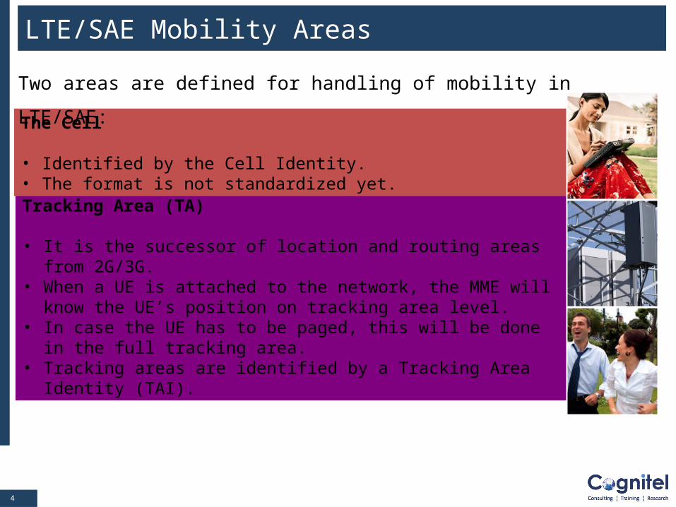
Tracking Area (TA)
• It is the successor of location and routing areas from 2G/3G.• When a UE is attached to the network, the MME will know the UE’s
position on tracking area level. • In case the UE has to be paged, this will be done in the full tracking
area. • Tracking areas are identified by a Tracking Area Identity (TAI).
The Cell
• Identified by the Cell Identity. • The format is not standardized yet.
LTE/SAE Mobility Areas
Two areas are defined for handling of mobility in LTE/SAE:
55
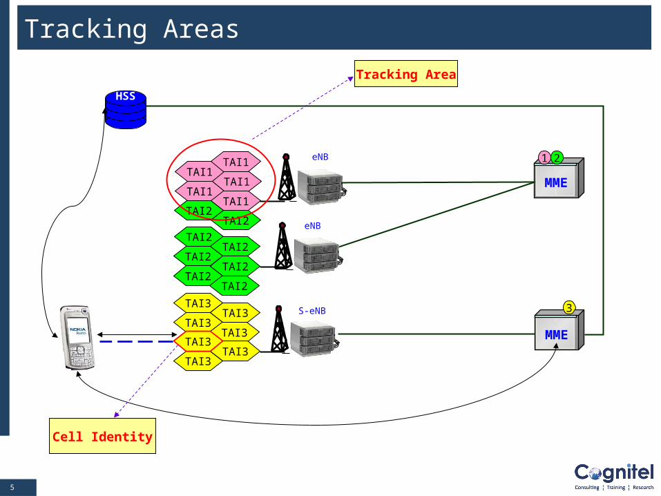
Tracking Areas
S-eNBTAI3
TAI3TAI3
TAI3
TAI3TAI3
TAI3
MME
HSS
eNB
TAI2
TAI2TAI2
TAI2
TAI2
TAI2
TAI2
TAI2
TAI1
TAI1TAI1
TAI1
TAI1 eNB 1 2
MME
3
Cell Identity
Tracking Area
66
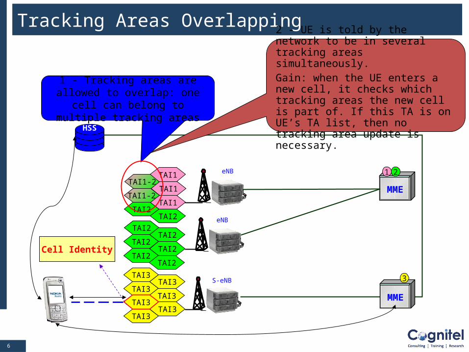
Tracking Areas Overlapping
S-eNBTAI3
TAI3TAI3
TAI3
TAI3TAI3
TAI3
MME
HSS
eNB
TAI2
TAI2TAI2
TAI2
TAI2
TAI2
TAI2
TAI2
TAI1-2TAI1
TAI1
TAI1 eNB 1 2
MME
3
Cell Identity
1 - Tracking areas are allowed to overlap: one cell can belong to
multiple tracking areas
TAI1-2
2 - UE is told by the network to be in several tracking areas simultaneously. Gain: when the UE enters a new cell, it checks which tracking areas the new cell is part of. If this TA is on UE’s TA list, then no tracking area update is necessary.
77
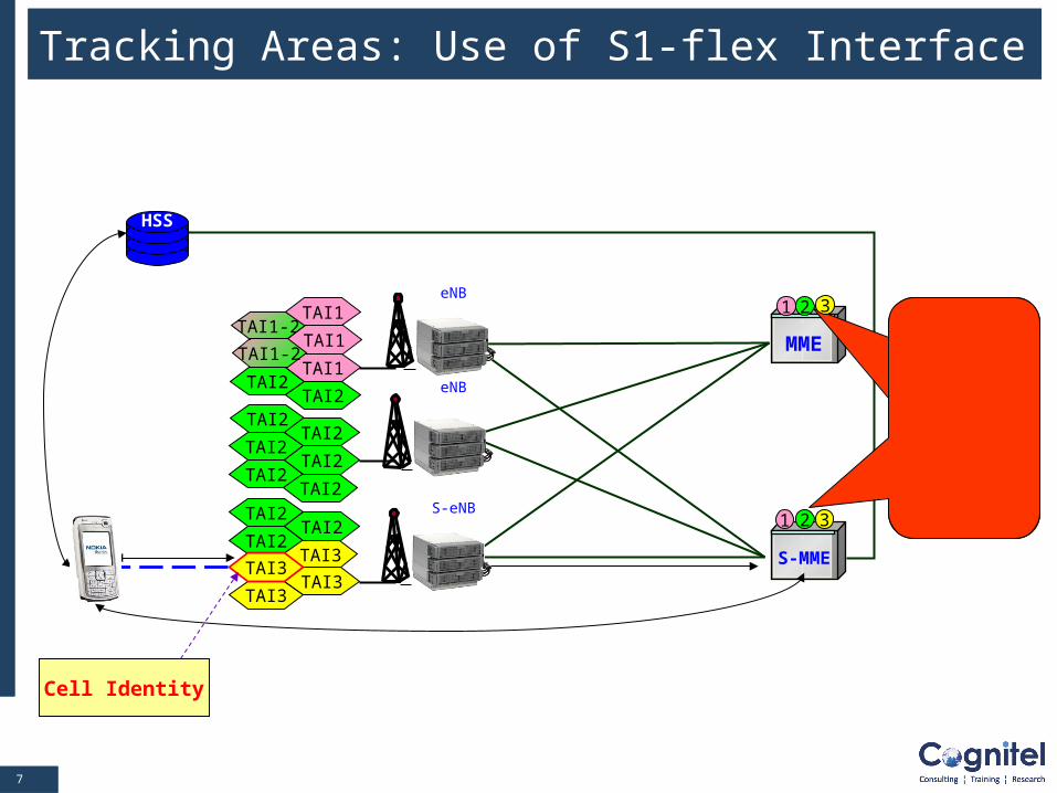
Tracking Areas: Use of S1-flex Interface
TAI1-2
S-eNBTAI2
TAI2TAI2
TAI3
TAI3TAI3
TAI3
MME
HSS
eNB
TAI2
TAI2TAI2
TAI2
TAI2
TAI2TAI2
TAI2
TAI1
TAI1
TAI1eNB
S-MME
TAI1-2
MME Pooling:
several MME
handle the same
tracking area
Cell Identity
321
1 2 3
88
Module Contents
The concept of Tracking Area
Different UE Identifications
Mobility & Connection Management Terminology
LTE/SAE Mobility & Connection States
LTE/SAE Bearer
LTE/SAE Procedures: Attach, S1 Release, Detach, Service
Request, Tracking Area Update, Dedicated SAE Bearer
Activation and inter eNB handover
Security: EPS Authentication and Key Agreement (AKA)
99
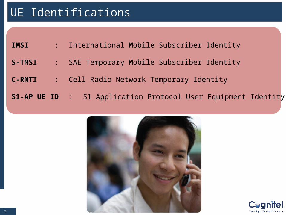
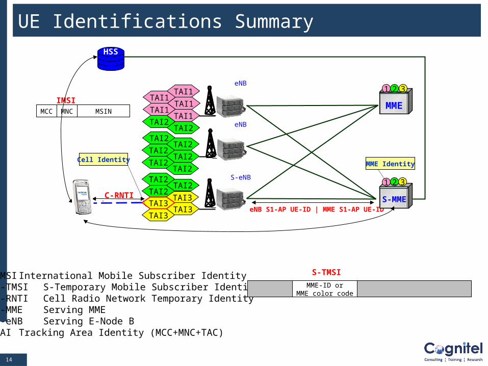
IMSI : International Mobile Subscriber Identity
S-TMSI : SAE Temporary Mobile Subscriber Identity
C-RNTI : Cell Radio Network Temporary Identity
S1-AP UE ID : S1 Application Protocol User Equipment Identity
UE Identifications
1010
UE Identifications : IMSI
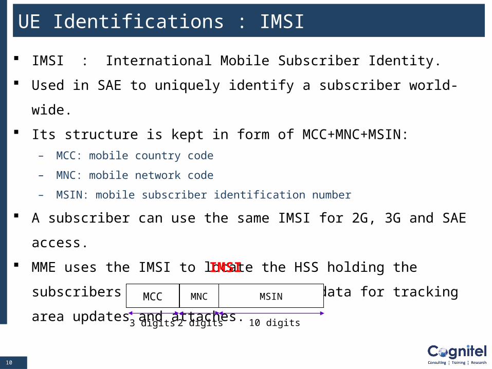
IMSI : International Mobile Subscriber Identity.
Used in SAE to uniquely identify a subscriber world-wide.
Its structure is kept in form of MCC+MNC+MSIN:
– MCC: mobile country code
– MNC: mobile network code
– MSIN: mobile subscriber identification number
A subscriber can use the same IMSI for 2G, 3G and SAE access.
MME uses the IMSI to locate the HSS holding the subscribers permanent
registration data for tracking area updates and attaches.
IMSI
MCC MNC MSIN
3 digits 2 digits 10 digits
1111
UE Identifications : S-TMSI
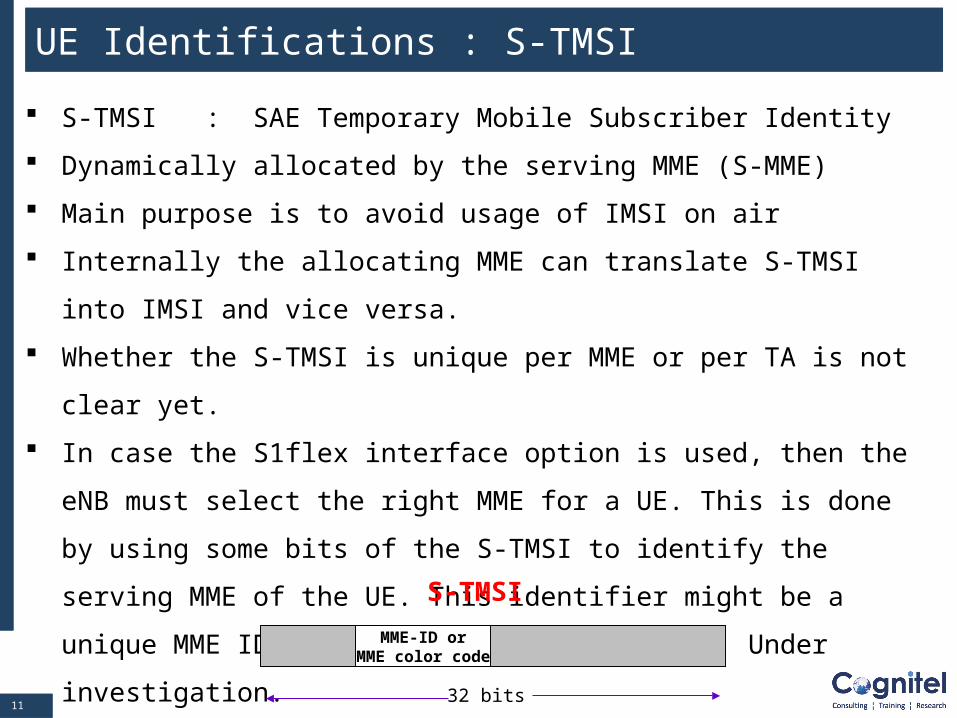
S-TMSI : SAE Temporary Mobile Subscriber Identity
Dynamically allocated by the serving MME (S-MME)
Main purpose is to avoid usage of IMSI on air
Internally the allocating MME can translate S-TMSI into IMSI and vice
versa.
Whether the S-TMSI is unique per MME or per TA is not clear yet.
In case the S1flex interface option is used, then the eNB must select the
right MME for a UE. This is done by using some bits of the S-TMSI to
identify the serving MME of the UE. This identifier might be a unique
MME ID or a form of MME color code. Under investigation.
S-TMSI
MME-ID orMME color code
32 bits
1212
UE Identifications : C-RNTI
C-RNTI : Cell Radio Network Temporary Identity
C-RNTI is allocated by the eNB serving a UE when it is in active mode
(RRC_CONNECTED)
A temporary identity for the user only
Valid within the serving cell of the UE
Exclusively used for radio management procedures
X-RNTI identifications under investigation
1313
UE Identifications : S1-AP UE ID
S1-AP UE ID : S1 Application Protocol User Equipment Identity.
Two additional temporary identifiers allocated by eNB and MME:
– eNB S1-AP UE ID
– MME S1-AP IE ID
Purpose is to allow efficient implementation of S1 control signaling
(S1AP=S1 Application Protocol)
Allow easy distribution of S1 signaling messages inside MME and eNB.
NOTE: This concept is similar to SCCP local references known from Iu
or A interface in 3G/2G.
1414
IMSI International Mobile Subscriber IdentityS-TMSI S-Temporary Mobile Subscriber IdentityC-RNTI Cell Radio Network Temporary IdentityS-MME Serving MMES-eNB Serving E-Node BTAI Tracking Area Identity (MCC+MNC+TAC)
S-TMSI
MME-ID orMME color code
UE Identifications Summary
C-RNTI
eNB S1-AP UE-ID | MME S1-AP UE-ID
MCC
IMSIMNC MSIN
S-eNBTAI2
TAI2TAI2
TAI3
TAI3TAI3
TAI3
MME
HSS
eNB
TAI2
TAI2TAI2
TAI2
TAI2
TAI2TAI2
TAI2
TAI1
TAI1TAI1
TAI1
TAI1eNB
1 2
S-MME
32
Cell IdentityMME Identity
3
1
1515
Module Contents
The concept of Tracking Area
Different UE Identifications
Mobility & Connection Management Terminology
LTE/SAE Mobility & Connection States
LTE/SAE Bearer
LTE/SAE Procedures: Attach, S1 Release, Detach, Service
Request, Tracking Area Update, Dedicated SAE Bearer
Activation and inter eNB handover
Security: EPS Authentication and Key Agreement (AKA)
1616
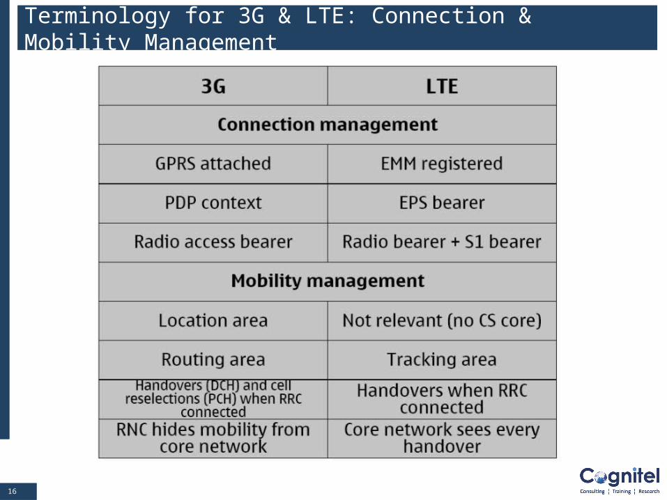
Terminology for 3G & LTE: Connection & Mobility Management
1717
Module Contents
The concept of Tracking Area
Different UE Identifications
Mobility & Connection Management Terminology
LTE/SAE Mobility & Connection States
LTE/SAE Bearer
LTE/SAE Procedures: Attach, S1 Release, Detach, Service
Request, Tracking Area Update, Dedicated SAE Bearer
Activation and inter eNB handover
Security: EPS Authentication and Key Agreement (AKA)
1818
LTE Mobility & Connection States
There are two sets of states defined for the UE based on the information
held by the MME.
1. EPS* Mobility Management (EMM) states
2. EPS* Connection Management (ECM) states
*EPS: Evolved Packet System
1919
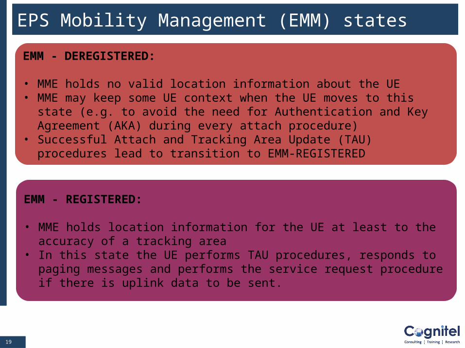
EMM - REGISTERED:
• MME holds location information for the UE at least to the accuracy of a tracking area
• In this state the UE performs TAU procedures, responds to paging messages and performs the service request procedure if there is uplink data to be sent.
EMM - DEREGISTERED:
• MME holds no valid location information about the UE• MME may keep some UE context when the UE moves to this state (e.g. to
avoid the need for Authentication and Key Agreement (AKA) during every attach procedure)
• Successful Attach and Tracking Area Update (TAU) procedures lead to transition to EMM-REGISTERED
EPS Mobility Management (EMM) states
2020
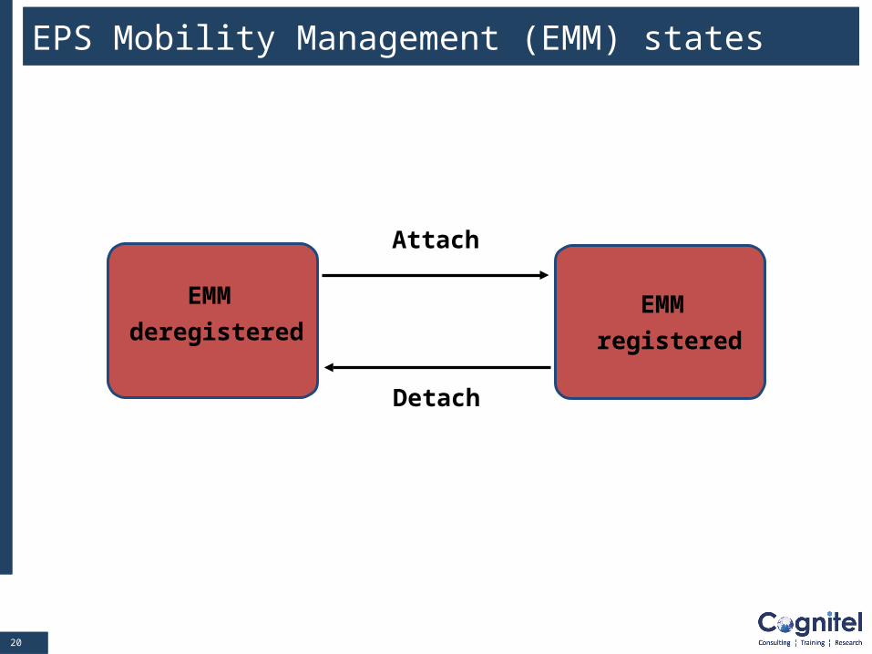
EPS Mobility Management (EMM) states
EMM
deregisteredEMM
registered
Attach
Detach
2121
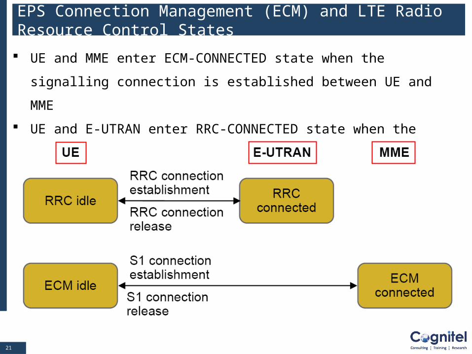
EPS Connection Management (ECM) and LTE Radio Resource Control States
UE and MME enter ECM-CONNECTED state when the signalling
connection is established between UE and MME
UE and E-UTRAN enter RRC-CONNECTED state when the signalling
connection is established between UE and E-UTRAN
2222
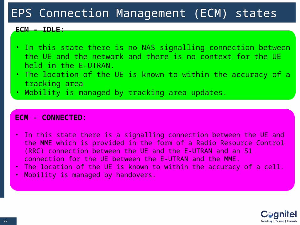
ECM - CONNECTED:
• In this state there is a signalling connection between the UE and the MME which is provided in the form of a Radio Resource Control (RRC) connection between the UE and the E-UTRAN and an S1 connection for the UE between the E-UTRAN and the MME.
• The location of the UE is known to within the accuracy of a cell.• Mobility is managed by handovers.
ECM - IDLE:
• In this state there is no NAS signalling connection between the UE and the network and there is no context for the UE held in the E-UTRAN.
• The location of the UE is known to within the accuracy of a tracking area • Mobility is managed by tracking area updates.
EPS Connection Management (ECM) states
2323
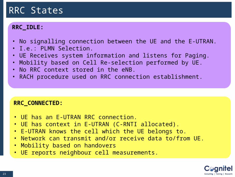
RRC_CONNECTED:
• UE has an E-UTRAN RRC connection.• UE has context in E-UTRAN (C-RNTI allocated).• E-UTRAN knows the cell which the UE belongs to.• Network can transmit and/or receive data to/from UE.• Mobility based on handovers• UE reports neighbour cell measurements.
RRC_IDLE:
• No signalling connection between the UE and the E-UTRAN.• I.e.: PLMN Selection.• UE Receives system information and listens for Paging.• Mobility based on Cell Re-selection performed by UE.• No RRC context stored in the eNB.• RACH procedure used on RRC connection establishment.
RRC States
2424
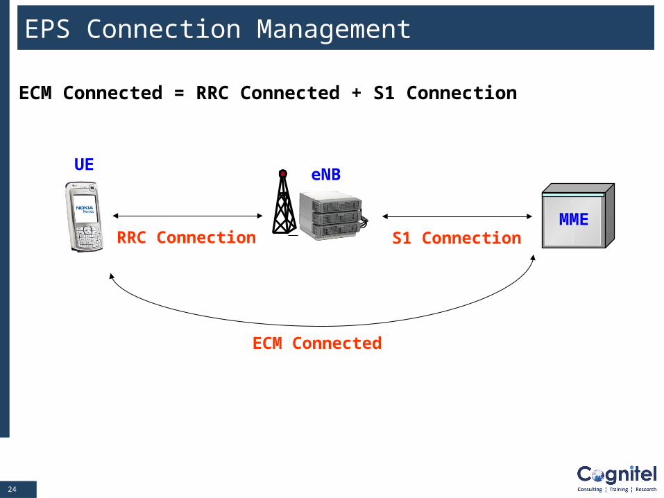
EPS Connection Management
ECM Connected = RRC Connected + S1 Connection
eNB
MME
UE
RRC Connection S1 Connection
ECM Connected
2525
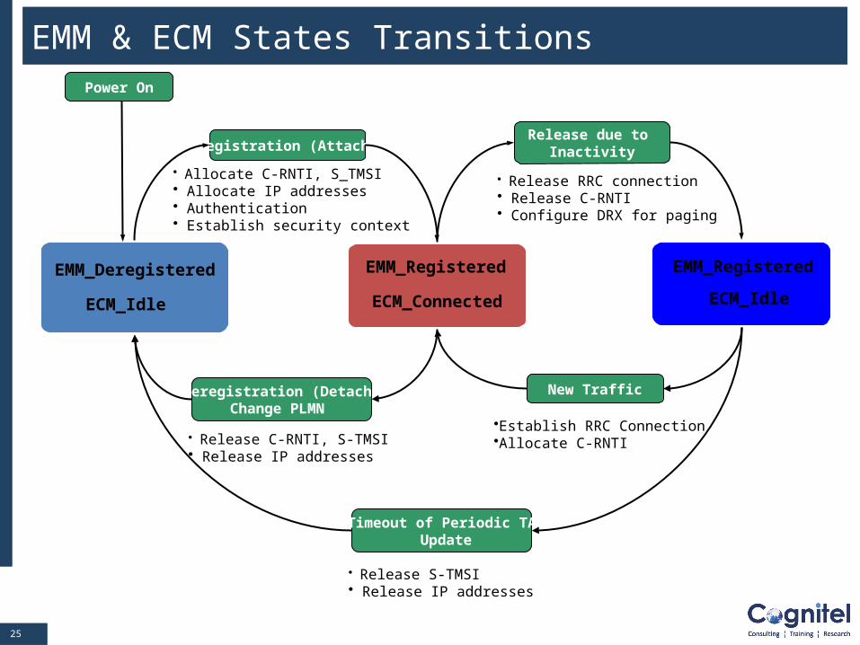
EMM & ECM States Transitions
EMM_Deregistered
ECM_Idle
Power On
Registration (Attach)
EMM_Registered
ECM_Connected
• Allocate C-RNTI, S_TMSI• Allocate IP addresses• Authentication• Establish security context
• Release RRC connection • Release C-RNTI• Configure DRX for paging
EMM_Registered
ECM_Idle
Release due to Inactivity
•Establish RRC Connection•Allocate C-RNTI
New TrafficDeregistration (Detach)Change PLMN
• Release C-RNTI, S-TMSI• Release IP addresses
Timeout of Periodic TA Update
• Release S-TMSI• Release IP addresses
2626
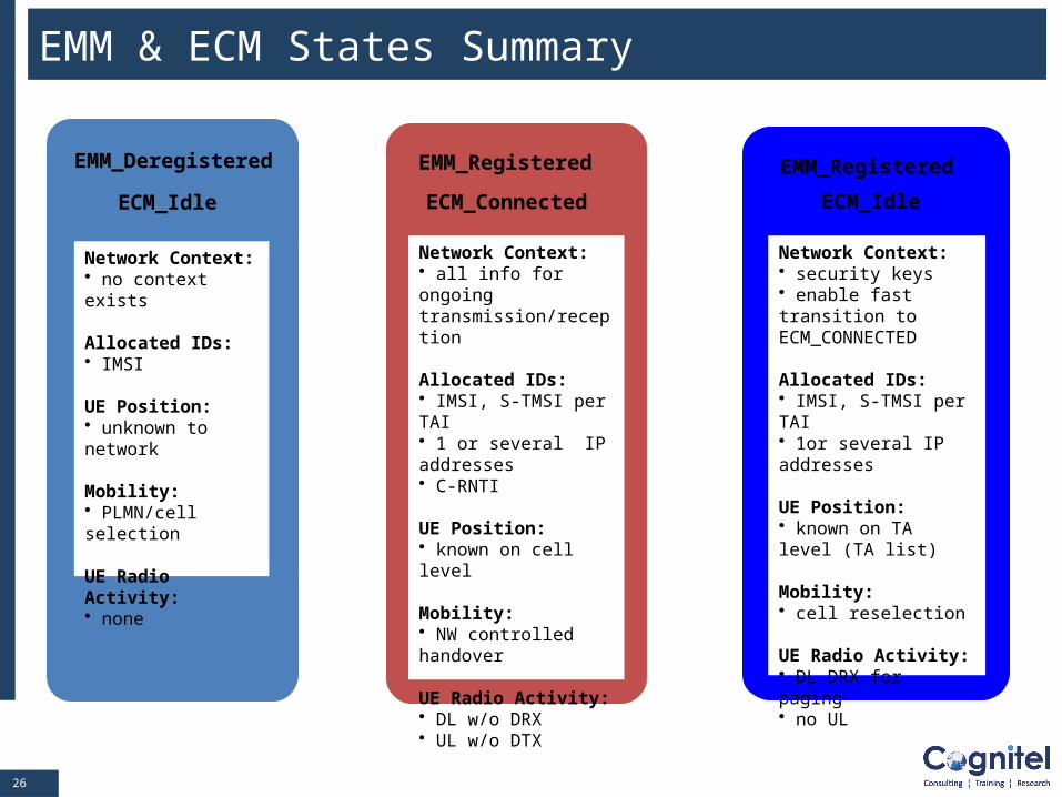
EMM & ECM States Summary
EMM_Deregistered
ECM_Idle
Network Context:• no context exists
Allocated IDs:• IMSI
UE Position:• unknown to network
Mobility:• PLMN/cell selection
UE Radio Activity:• none
EMM_Registered
ECM_Connected
Network Context:• all info for ongoing transmission/reception
Allocated IDs:• IMSI, S-TMSI per TAI• 1 or several IP addresses• C-RNTI
UE Position:• known on cell level
Mobility:• NW controlled handover
UE Radio Activity:• DL w/o DRX• UL w/o DTX
EMM_Registered
ECM_Idle
Network Context:• security keys• enable fast transition to ECM_CONNECTED
Allocated IDs:• IMSI, S-TMSI per TAI• 1or several IP addresses
UE Position:• known on TA level (TA list)
Mobility:• cell reselection
UE Radio Activity:• DL DRX for paging• no UL
2727
Module Contents
The concept of Tracking Area
Different UE Identifications
Mobility & Connection Management Terminology
LTE/SAE Mobility & Connection States
LTE/SAE Bearer
LTE/SAE Procedures: Attach, S1 Release, Detach, Service
Request, Tracking Area Update, Dedicated SAE Bearer
Activation and inter eNB handover
Security: EPS Authentication and Key Agreement (AKA)
2828
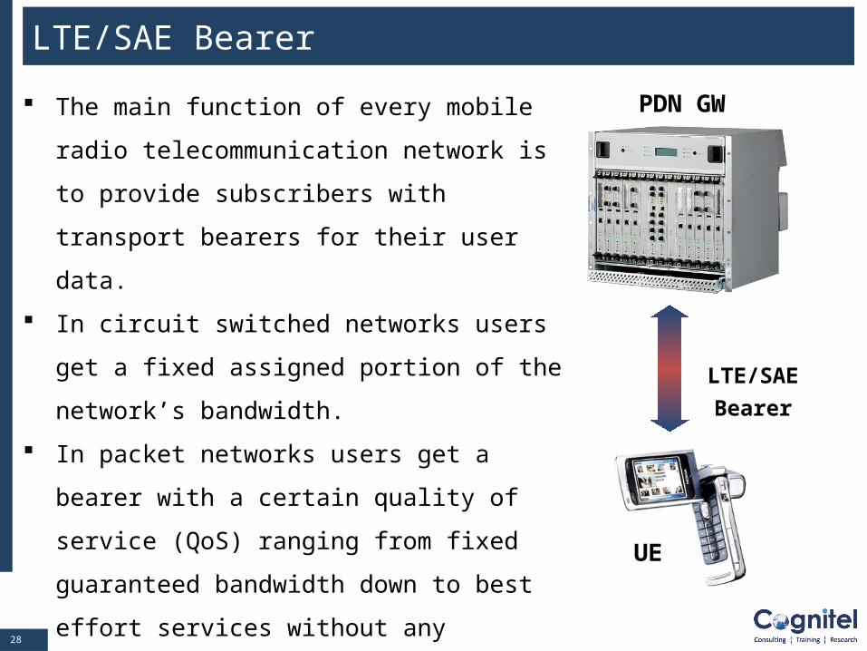
LTE/SAE Bearer
The main function of every mobile radio
telecommunication network is to provide
subscribers with transport bearers for their user
data.
In circuit switched networks users get a fixed
assigned portion of the network’s bandwidth.
In packet networks users get a bearer with a
certain quality of service (QoS) ranging from
fixed guaranteed bandwidth down to best effort
services without any guarantee.
LTE/SAE is a packet oriented system
LTE/SAE
Bearer
PDN GW
UE
2929
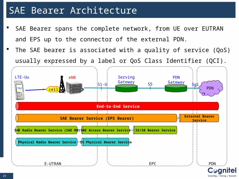
SAE Bearer Architecture
SAE Bearer spans the complete network, from UE over EUTRAN and EPS up to
the connector of the external PDN.
The SAE bearer is associated with a quality of service (QoS) usually expressed by
a label or QoS Class Identifier (QCI).
cellS1-U
LTE-Uu
S5PDN
Sgi
eNB ServingGateway
PDNGateway
End-to-End Service
SAE Bearer Service (EPS Bearer)External Bearer
Service
SAE Radio Bearer Service (SAE RB) SAE Access Bearer Service
Physical Radio Bearer Service S1 Physical Bearer Service
E-UTRAN EPC PDN
S5/S8 Bearer Service
3030
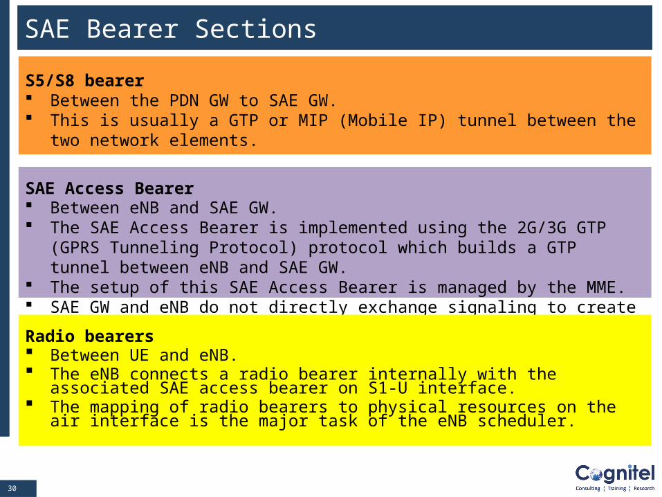
SAE Bearer Sections
S5/S8 bearer Between the PDN GW to SAE GW. This is usually a GTP or MIP (Mobile IP) tunnel between the two network
elements.
SAE Access Bearer Between eNB and SAE GW. The SAE Access Bearer is implemented using the 2G/3G GTP (GPRS Tunneling
Protocol) protocol which builds a GTP tunnel between eNB and SAE GW. The setup of this SAE Access Bearer is managed by the MME. SAE GW and eNB do not directly exchange signaling to create it.
Radio bearers Between UE and eNB. The eNB connects a radio bearer internally with the associated SAE access
bearer on S1-U interface. The mapping of radio bearers to physical resources on the air interface is the
major task of the eNB scheduler.
3131
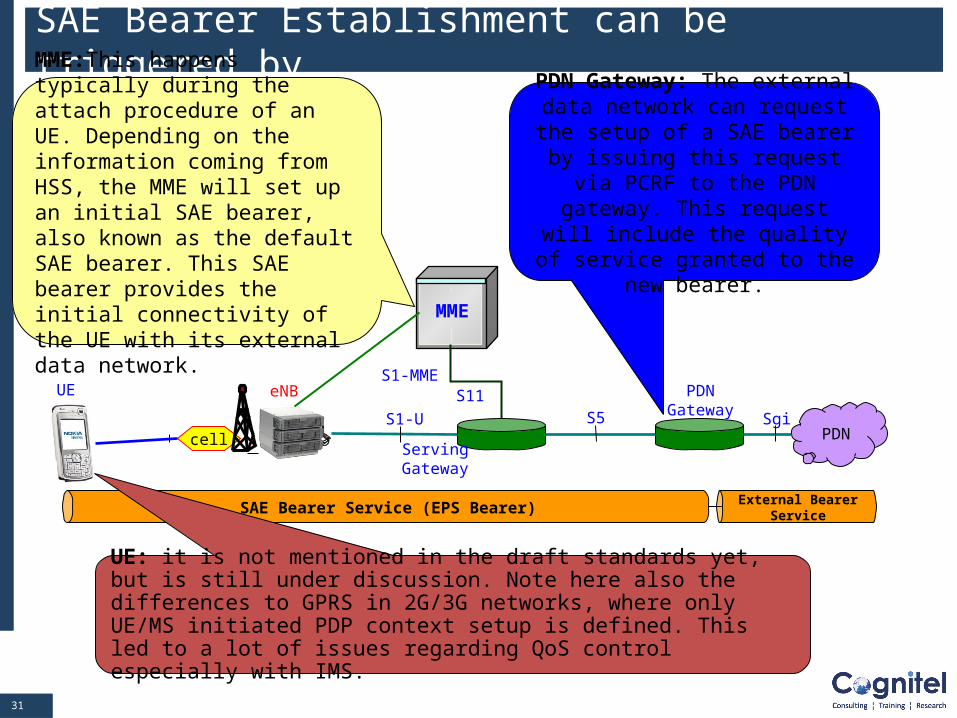
SAE Bearer Establishment can be triggered by….
cellS1-U
UE
S5PDN
Sgi
eNB
ServingGateway
PDNGateway
SAE Bearer Service (EPS Bearer)External Bearer
Service
MME:This happens typically during the attach procedure of an UE. Depending on the information coming from HSS, the MME will set up an initial SAE bearer, also known as the default SAE bearer. This SAE bearer provides the initial connectivity of the UE with its external data network. MME
S1-MMES11
PDN Gateway: The external data network can request the setup of a SAE bearer by issuing this request
via PCRF to the PDN gateway. This request will include the quality
of service granted to the new bearer.
UE: it is not mentioned in the draft standards yet, but is still under discussion. Note here also the differences to GPRS in 2G/3G networks, where only UE/MS initiated PDP context setup is defined. This led to a lot of issues regarding QoS control especially with IMS.
3232
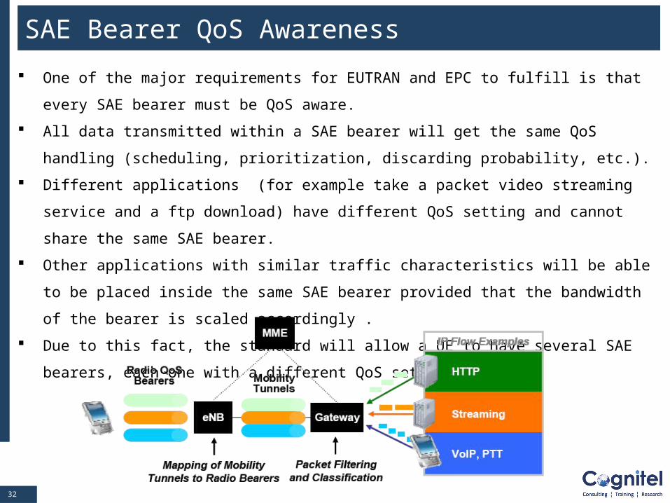
SAE Bearer QoS Awareness
One of the major requirements for EUTRAN and EPC to fulfill is that every SAE bearer must
be QoS aware.
All data transmitted within a SAE bearer will get the same QoS handling (scheduling,
prioritization, discarding probability, etc.).
Different applications (for example take a packet video streaming service and a ftp
download) have different QoS setting and cannot share the same SAE bearer.
Other applications with similar traffic characteristics will be able to be placed inside the same
SAE bearer provided that the bandwidth of the bearer is scaled accordingly .
Due to this fact, the standard will allow a UE to have several SAE bearers, each one with a
different QoS setting.
3333
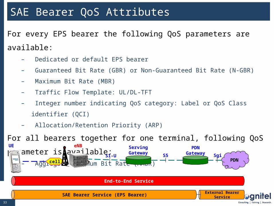
SAE Bearer QoS Attributes
For every EPS bearer the following QoS parameters are available:
– Dedicated or default EPS bearer
– Guaranteed Bit Rate (GBR) or Non-Guaranteed Bit Rate (N-GBR)
– Maximum Bit Rate (MBR)
– Traffic Flow Template: UL/DL-TFT
– Integer number indicating QoS category: Label or QoS Class identifier (QCI)
– Allocation/Retention Priority (ARP)
For all bearers together for one terminal, following QoS parameter is
available:
– Aggregate Maximum Bit Rate (AMBR)
cellS1-U
UE
S5PDN
Sgi
eNB ServingGateway
PDNGateway
End-to-End Service
SAE Bearer Service (EPS Bearer)External Bearer
Service
3434
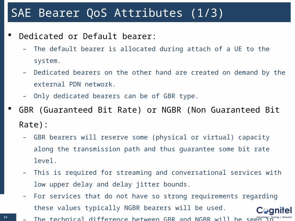
SAE Bearer QoS Attributes (1/3)
Dedicated or Default bearer:
– The default bearer is allocated during attach of a UE to the system.
– Dedicated bearers on the other hand are created on demand by the external PDN
network.
– Only dedicated bearers can be of GBR type.
GBR (Guaranteed Bit Rate) or NGBR (Non Guaranteed Bit Rate):
– GBR bearers will reserve some (physical or virtual) capacity along the transmission
path and thus guarantee some bit rate level.
– This is required for streaming and conversational services with low upper delay and
delay jitter bounds.
– For services that do not have so strong requirements regarding these values typically
NGBR bearers will be used.
– The technical difference between GBR and NGBR will be seen in the admission control
functions of eNB, SAE GW and PDN GW.
– GBR bearers will usually block more virtual resources for the same throughput and
peak bit rate than NGBR bearers.
3535
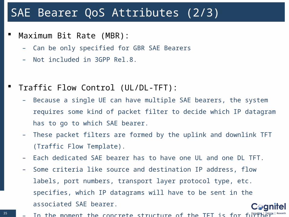
SAE Bearer QoS Attributes (2/3)
Maximum Bit Rate (MBR):
– Can be only specified for GBR SAE Bearers
– Not included in 3GPP Rel.8.
Traffic Flow Control (UL/DL-TFT):
– Because a single UE can have multiple SAE bearers, the system requires some kind of
packet filter to decide which IP datagram has to go to which SAE bearer.
– These packet filters are formed by the uplink and downlink TFT (Traffic Flow Template).
– Each dedicated SAE bearer has to have one UL and one DL TFT.
– Some criteria like source and destination IP address, flow labels, port numbers,
transport layer protocol type, etc. specifies, which IP datagrams will have to be sent in
the associated SAE bearer.
– In the moment the concrete structure of the TFT is for further study, especially whether
additional QoS parameters might be inside or not.
3636
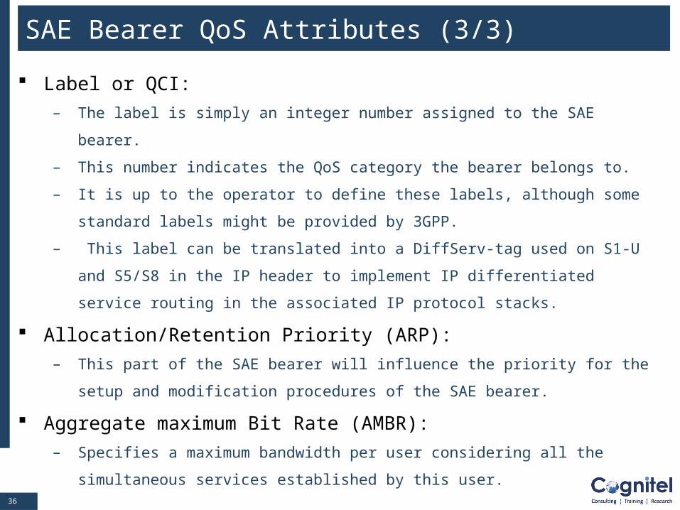
SAE Bearer QoS Attributes (3/3)
Label or QCI:
– The label is simply an integer number assigned to the SAE bearer.
– This number indicates the QoS category the bearer belongs to.
– It is up to the operator to define these labels, although some standard labels might be
provided by 3GPP.
– This label can be translated into a DiffServ-tag used on S1-U and S5/S8 in the IP
header to implement IP differentiated service routing in the associated IP protocol
stacks.
Allocation/Retention Priority (ARP):
– This part of the SAE bearer will influence the priority for the setup and modification
procedures of the SAE bearer.
Aggregate maximum Bit Rate (AMBR):
– Specifies a maximum bandwidth per user considering all the simultaneous services
established by this user.
3737
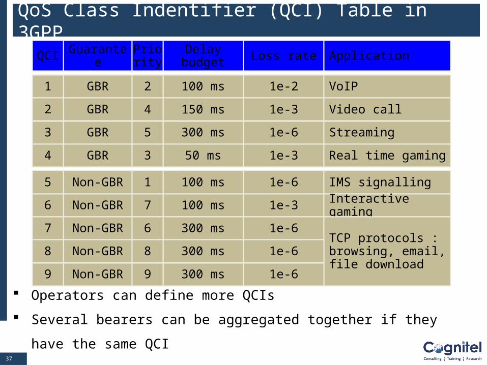
QoS Class Indentifier (QCI) Table in 3GPP
Operators can define more QCIs
Several bearers can be aggregated together if they have the same QCI
GBR1
Guarantee Delay budget Loss rate ApplicationQCI
GBR
100 ms 1e-2 VoIP
2
GBR
150 ms 1e-3 Video call
3
GBR
300 ms 1e-6 Streaming
4
Non-GBR 100 ms 1e-6 IMS signalling5
Non-GBR 100 ms 1e-3 Interactive gaming6
Non-GBR 300 ms 1e-6TCP protocols : browsing, email, file download
7
Non-GBR 300 ms 1e-68
Non-GBR 300 ms 1e-69
Priority
2
4
5
1
7
6
8
9
50 ms 1e-3 Real time gaming3
3838
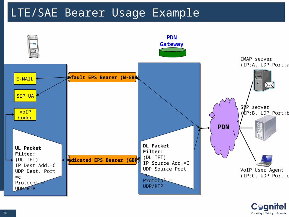
LTE/SAE Bearer Usage Example
PDNGateway
PDN
IMAP server(IP:A, UDP Port:a)
SIP server(IP:B, UDP Port:b)
VoIP User Agent(IP:C, UDP Port:c)
Default EPS Bearer (N-GBR)
Dedicated EPS Bearer (GBR)
SIP UA
VoIPCodec
DL Packet Filter:(DL TFT)IP Source Add.=C UDP Source Port =cProtocol = UDP/RTP
UL Packet Filter:(UL TFT)IP Dest Add.=C UDP Dest. Port =cProtocol = UDP/RTP
3939
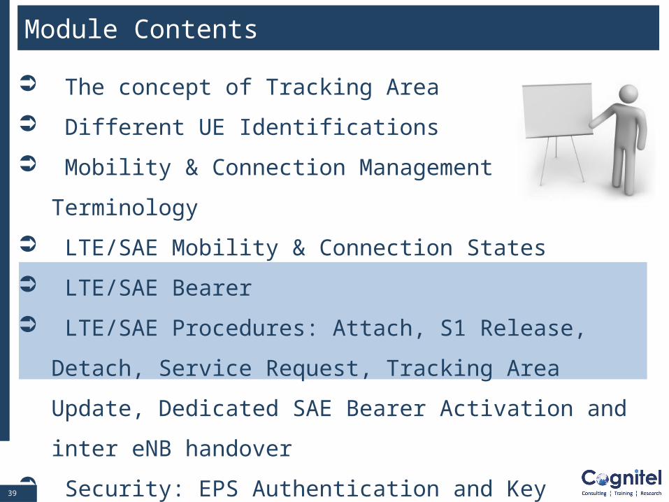
Module Contents
The concept of Tracking Area
Different UE Identifications
Mobility & Connection Management Terminology
LTE/SAE Mobility & Connection States
LTE/SAE Bearer
LTE/SAE Procedures: Attach, S1 Release, Detach, Service
Request, Tracking Area Update, Dedicated SAE Bearer
Activation and inter eNB handover
Security: EPS Authentication and Key Agreement (AKA)
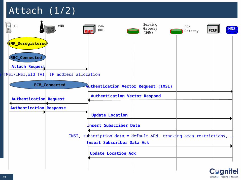
4040
MMEHSSPCRF
UE eNB newMME
ServingGateway(SGW)
PDNGateway
Attach Request
S-TMSI/IMSI,old TAI, IP address allocation
Authentication Request
Authentication Response
Update Location
Authentication Vector Request (IMSI)
Insert Subscriber Data
IMSI, subscription data = default APN, tracking area restrictions, …
Insert Subscriber Data Ack
Update Location Ack
EMM_Deregistered
Attach (1/2)
Authentication Vector Respond
RRC_Connected
ECM_Connected
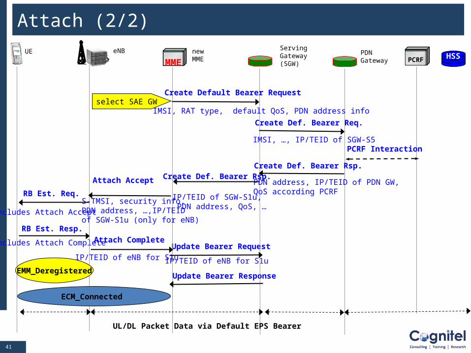
4141
Update Bearer Response
Update Bearer Request
IP/TEID of eNB for S1u
Attach Complete
IP/TEID of eNB for S1u
RB Est. Resp.
Includes Attach Complete
Create Def. Bearer Req.
MMEHSSPCRF
UE eNB newMME
ServingGateway(SGW)
PDNGateway
Attach (2/2)
S-TMSI, security info, PDN address, …,IP/TEID of SGW-S1u (only for eNB)
Create Def. Bearer Rsp.
IP/TEID of SGW-S1u, PDN address, QoS, …
Create Def. Bearer Rsp.
PDN address, IP/TEID of PDN GW,QoS according PCRF
select SAE GWCreate Default Bearer Request
IMSI, RAT type, default QoS, PDN address info
IMSI, …, IP/TEID of SGW-S5
Attach Accept
RB Est. Req.
Includes Attach Accept
UL/DL Packet Data via Default EPS Bearer
PCRF Interaction
EMM_Deregistered
ECM_Connected
4242
RRC Connection Release
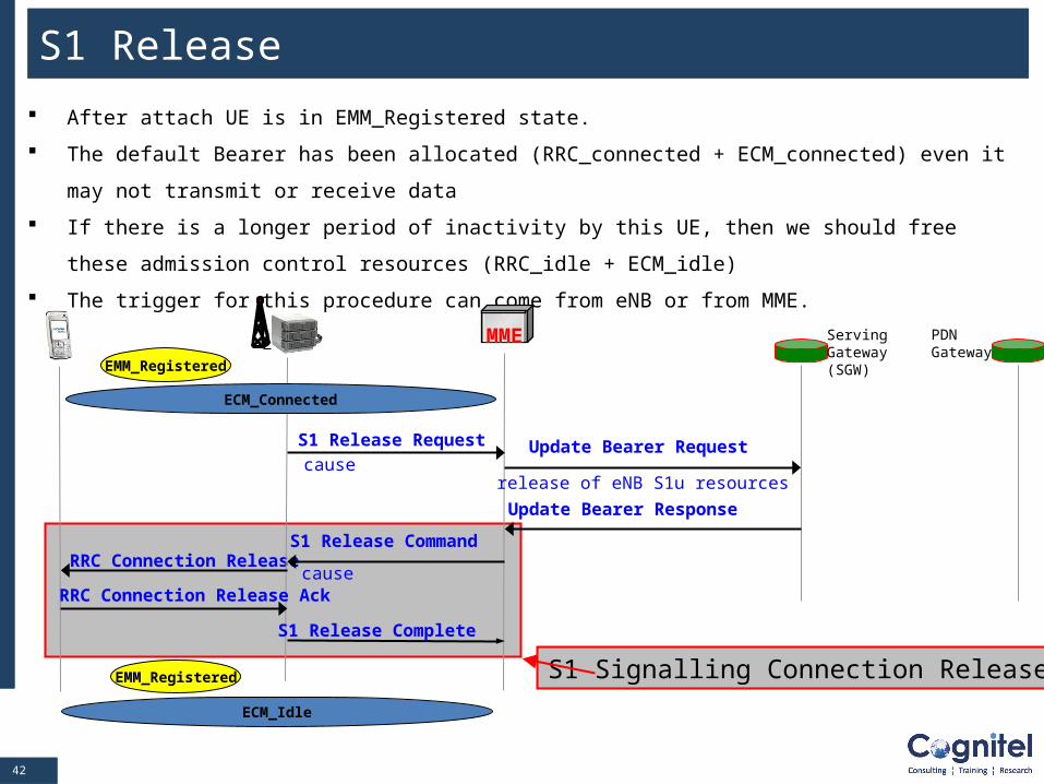
S1 Release
After attach UE is in EMM_Registered state.
The default Bearer has been allocated (RRC_connected + ECM_connected) even it may not transmit or
receive data
If there is a longer period of inactivity by this UE, then we should free these admission control resources
(RRC_idle + ECM_idle)
The trigger for this procedure can come from eNB or from MME.
MME
S1 Release Request
causeUpdate Bearer Request
release of eNB S1u resources
Update Bearer Response
ServingGateway(SGW)
PDNGateway
S1 Release Command
cause
S1 Release Complete
RRC Connection Release Ack
EMM_Registered
ECM_Connected
S1 Signalling Connection ReleaseEMM_Registered
ECM_Idle
4343
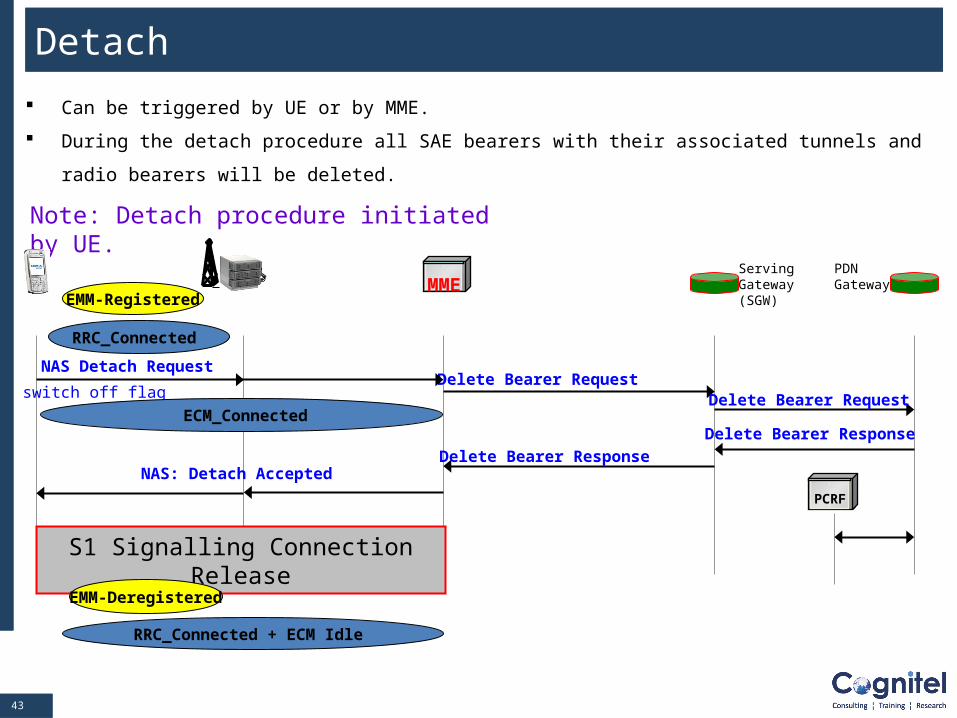
Detach
Can be triggered by UE or by MME.
During the detach procedure all SAE bearers with their associated tunnels and radio bearers will be
deleted.
Note: Detach procedure initiated by UE.
MME
NAS: Detach Accepted
Delete Bearer Request
Delete Bearer Response
EMM-Registered
ServingGateway(SGW)
PDNGateway
NAS Detach Request
switch off flag Delete Bearer Request
Delete Bearer Response
PCRF
S1 Signalling Connection Release
RRC_Connected
ECM_Connected
EMM-Deregistered
RRC_Connected + ECM Idle
4444
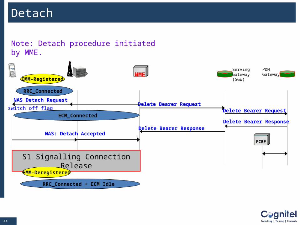
Detach
Note: Detach procedure initiated by MME.
MME
NAS: Detach Accepted
Delete Bearer Request
Delete Bearer Response
EMM-Registered
ServingGateway(SGW)
PDNGateway
NAS Detach Request
switch off flag Delete Bearer Request
Delete Bearer Response
PCRF
S1 Signalling Connection Release
RRC_Connected
ECM_Connected
EMM-Deregistered
RRC_Connected + ECM Idle
4545
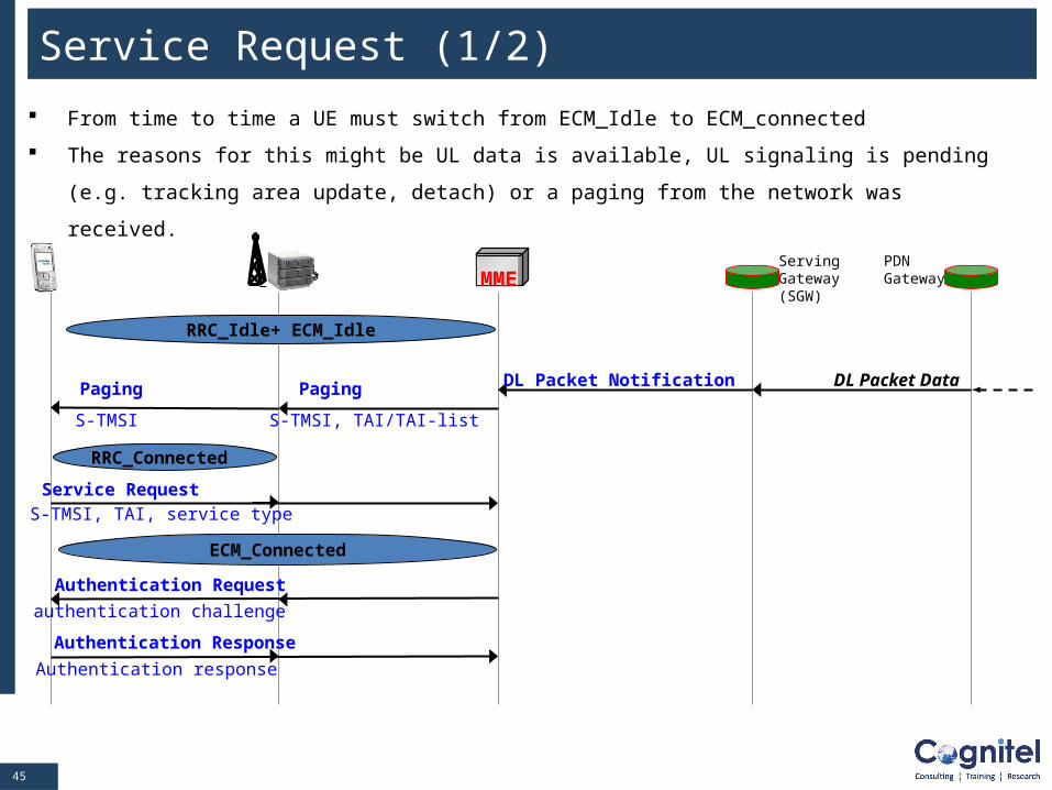
Service Request (1/2)
From time to time a UE must switch from ECM_Idle to ECM_connected
The reasons for this might be UL data is available, UL signaling is pending (e.g. tracking area update,
detach) or a paging from the network was received.
MMEServingGateway(SGW)
PDNGateway
Paging
S-TMSI, TAI/TAI-list
Service Request
DL Packet DataDL Packet NotificationPaging
S-TMSI
S-TMSI, TAI, service type
Authentication Request
authentication challenge
Authentication Response
Authentication response
RRC_Idle+ ECM_Idle
ECM_Connected
RRC_Connected
4646
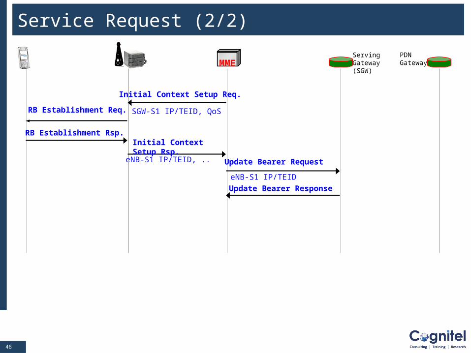
Service Request (2/2)
MME
Initial Context Setup Req.
Update Bearer Request
eNB-S1 IP/TEID
Update Bearer Response
ServingGateway(SGW)
PDNGateway
SGW-S1 IP/TEID, QoSRB Establishment Req.
RB Establishment Rsp.Initial Context Setup Rsp.
eNB-S1 IP/TEID, ..
4747
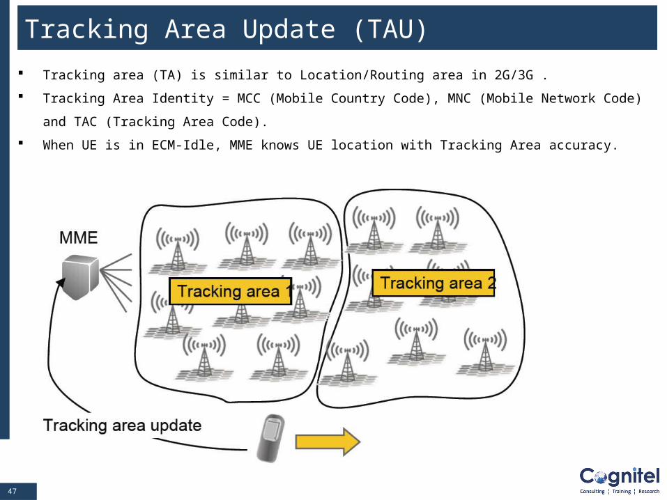
Tracking Area Update (TAU)
Tracking area (TA) is similar to Location/Routing area in 2G/3G .
Tracking Area Identity = MCC (Mobile Country Code), MNC (Mobile Network Code) and TAC (Tracking
Area Code).
When UE is in ECM-Idle, MME knows UE location with Tracking Area accuracy.
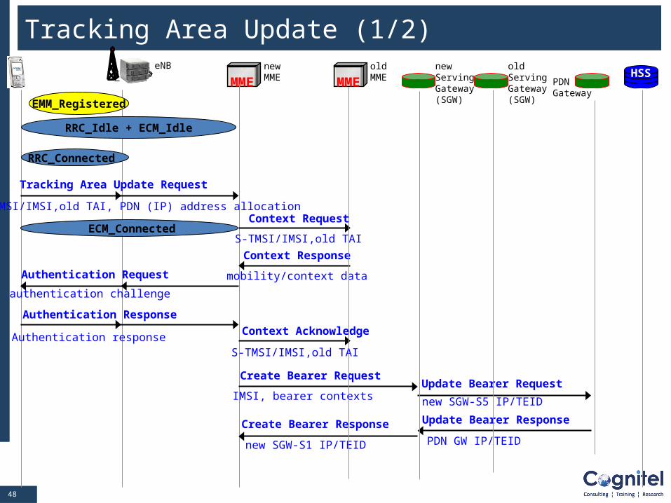
4848
MMEHSS
eNB newMME MME
oldMME
newServingGateway(SGW)
PDNGateway
Tracking Area Update Request
Context RequestS-TMSI/IMSI,old TAI, PDN (IP) address allocation
S-TMSI/IMSI,old TAI
Context Response
mobility/context dataAuthentication Request
authentication challenge
Authentication Response
Authentication response
Create Bearer Request
IMSI, bearer contexts
Context Acknowledge
S-TMSI/IMSI,old TAI
Update Bearer Request
new SGW-S5 IP/TEID
Create Bearer Response
new SGW-S1 IP/TEID
Update Bearer Response
PDN GW IP/TEID
oldServingGateway(SGW)
Tracking Area Update (1/2)
UEEMM_Registered
RRC_Idle + ECM_Idle
RRC_Connected
ECM_Connected
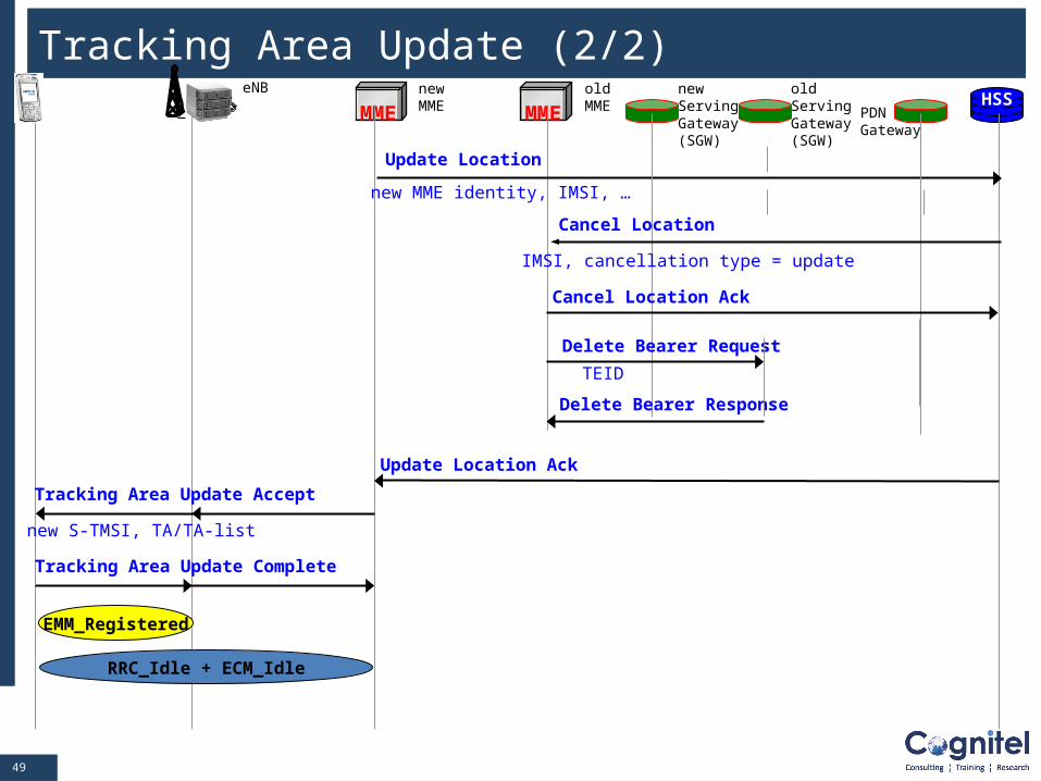
4949
MMEHSS
eNB newMME MME
oldMME
newServingGateway(SGW)
PDNGateway
Update Location
new MME identity, IMSI, …
IMSI, cancellation type = update
Cancel Location Ack
Delete Bearer Request
TEID
Delete Bearer Response
Cancel Location
oldServingGateway(SGW)
Update Location Ack
Tracking Area Update Accept
new S-TMSI, TA/TA-list
Tracking Area Update Complete
Tracking Area Update (2/2)
EMM_Registered
RRC_Idle + ECM_Idle
5050
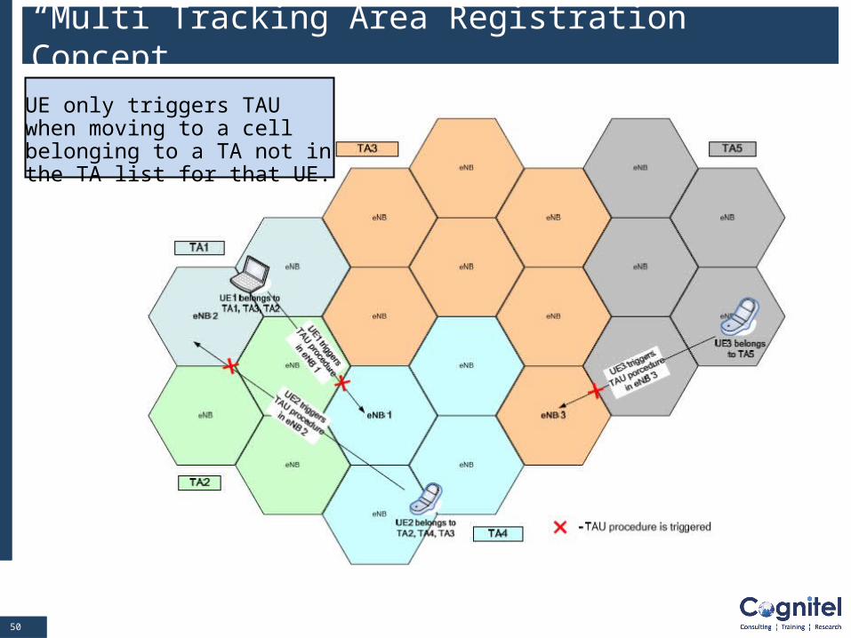
“Multi Tracking Area Registration” Concept
UE only triggers TAU when moving to a cell belonging to a TA not in the TA list for that UE.
5151
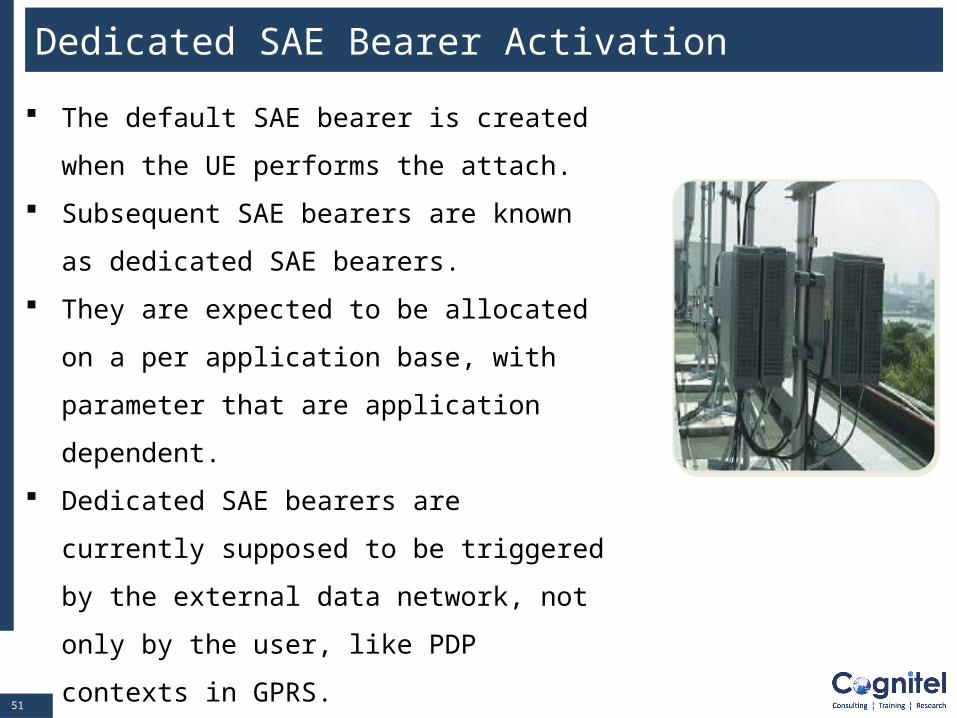
Dedicated SAE Bearer Activation
The default SAE bearer is created when the
UE performs the attach.
Subsequent SAE bearers are known as
dedicated SAE bearers.
They are expected to be allocated on a per
application base, with parameter that are
application dependent.
Dedicated SAE bearers are currently
supposed to be triggered by the external data
network, not only by the user, like PDP
contexts in GPRS.
5252
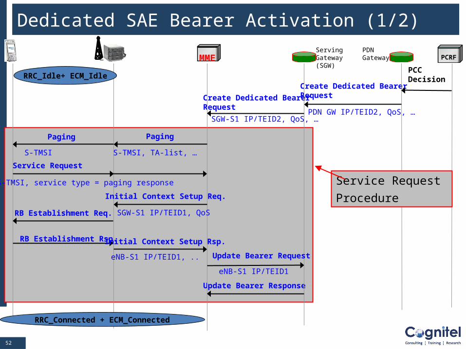
Update Bearer Response
SGW-S1 IP/TEID2, QoS, …
Create Dedicated BearerRequest
Create Dedicated BearerRequest
Dedicated SAE Bearer Activation (1/2)
MMEServingGateway(SGW)
PDNGateway
PDN GW IP/TEID2, QoS, …
Service Request
PCRF
PCCDecision
Paging
S-TMSI, TA-list, …
Paging
S-TMSI
S-TMSI, service type = paging response
Initial Context Setup Req.
Update Bearer Request
eNB-S1 IP/TEID1
SGW-S1 IP/TEID1, QoSRB Establishment Req.
RB Establishment Rsp. Initial Context Setup Rsp.
eNB-S1 IP/TEID1, ..
RRC_Connected + ECM_Connected
Service Request
Procedure
RRC_Idle+ ECM_Idle
5353
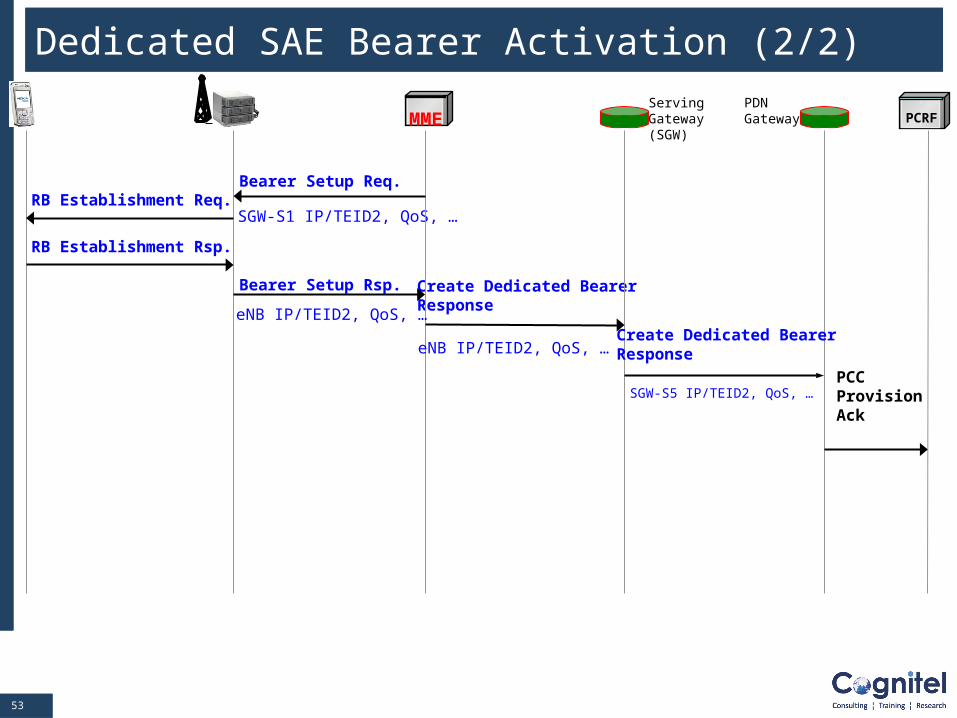
SGW-S5 IP/TEID2, QoS, …
Create Dedicated BearerResponse
RB Establishment Rsp.
SGW-S1 IP/TEID2, QoS, … RB Establishment Req.
Dedicated SAE Bearer Activation (2/2)
MME
Bearer Setup Req.
ServingGateway(SGW)
PDNGateway
Create Dedicated BearerResponse
PCRF
Bearer Setup Rsp.
eNB IP/TEID2, QoS, …
eNB IP/TEID2, QoS, …
PCCProvisionAck
5454
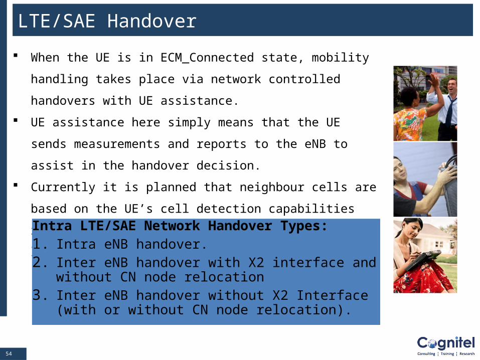
LTE/SAE Handover
When the UE is in ECM_Connected state, mobility handling takes
place via network controlled handovers with UE assistance.
UE assistance here simply means that the UE sends
measurements and reports to the eNB to assist in the handover
decision.
Currently it is planned that neighbour cells are based on the UE’s
cell detection capabilities rather than on a network supplied
neighbour cell list.
Intra LTE/SAE Network Handover Types:1. Intra eNB handover. 2. Inter eNB handover with X2 interface and without CN
node relocation3. Inter eNB handover without X2 Interface (with or
without CN node relocation).
5555
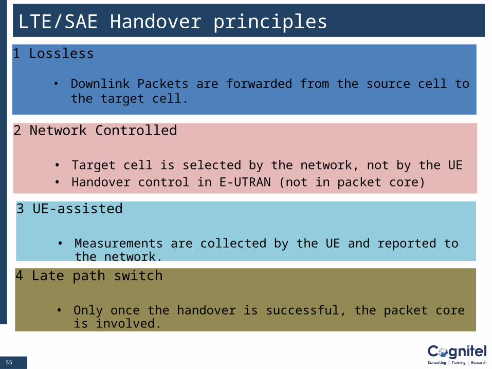
LTE/SAE Handover principles
2 Network Controlled
• Target cell is selected by the network, not by the UE• Handover control in E-UTRAN (not in packet core)
3 UE-assisted
• Measurements are collected by the UE and reported to the network.
4 Late path switch
• Only once the handover is successful, the packet core is involved.
1 Lossless
• Downlink Packets are forwarded from the source cell to the target cell.
5656
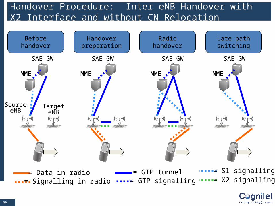
Handover Procedure: Inter eNB Handover with X2 Interface and without CN Relocation
SAE GW
MME
Source eNB
Target eNB
SAE GW
MME
SAE GW
MME
SAE GW
MME
= Data in radio= Signalling in radio
= GTP tunnel= GTP signalling
= S1 signalling= X2 signalling
Before handover
Handover preparation
Radio handoverLate path switching
5757
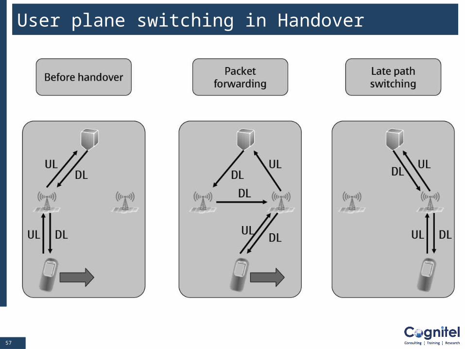
User plane switching in Handover
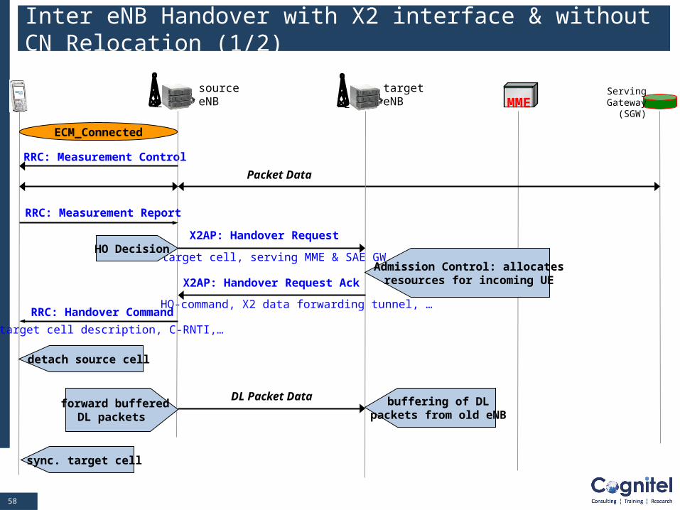
5858
HO-command, X2 data forwarding tunnel, …
X2AP: Handover Request
target cell, serving MME & SAE GW, …
RRC: Measurement Control
Inter eNB Handover with X2 interface & without CN Relocation (1/2)
MME
ECM_Connected
ServingGateway
(SGW)
Packet Data
sourceeNB
targeteNB
RRC: Measurement Report
HO Decision
Admission Control: allocatesresources for incoming UEX2AP: Handover Request Ack
RRC: Handover Command
target cell description, C-RNTI,…
detach source cell
sync. target cell
forward bufferedDL packets
buffering of DLpackets from old eNB
DL Packet Data
5959
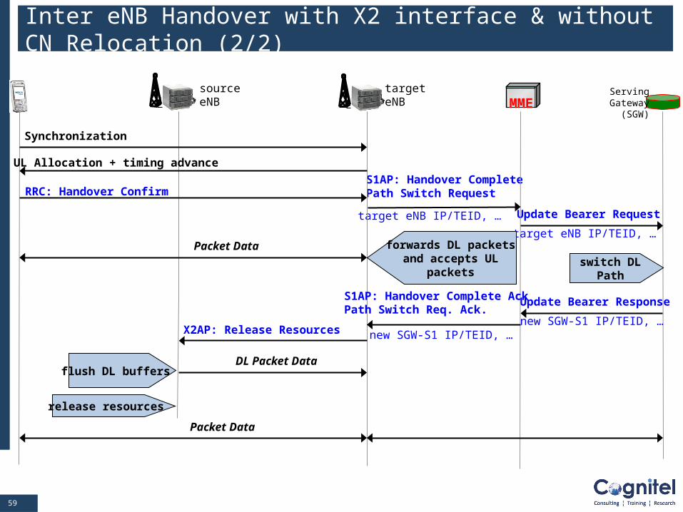
Update Bearer Response
Update Bearer Request
S1AP: Handover CompletePath Switch Request
Inter eNB Handover with X2 interface & without CN Relocation (2/2)
MMEServing
Gateway(SGW)
target eNB IP/TEID, …
sourceeNB
targeteNB
Synchronization
UL Allocation + timing advance
RRC: Handover Confirm
target eNB IP/TEID, …
switch DLPath
new SGW-S1 IP/TEID, …
S1AP: Handover Complete AckPath Switch Req. Ack.
new SGW-S1 IP/TEID, … X2AP: Release Resources
flush DL buffersDL Packet Data
release resources
Packet Data
Packet Data forwards DL packetsand accepts UL
packets
6060
Module Contents
The concept of Tracking Area
Different UE Identifications
Mobility & Connection Management Terminology
LTE/SAE Mobility & Connection States
LTE/SAE Bearer
LTE/SAE Procedures: Attach, S1 Release, Detach, Service
Request, Tracking Area Update, Dedicated SAE Bearer
Activation and inter eNB handover
Security: EPS Authentication and Key Agreement (AKA)
6161
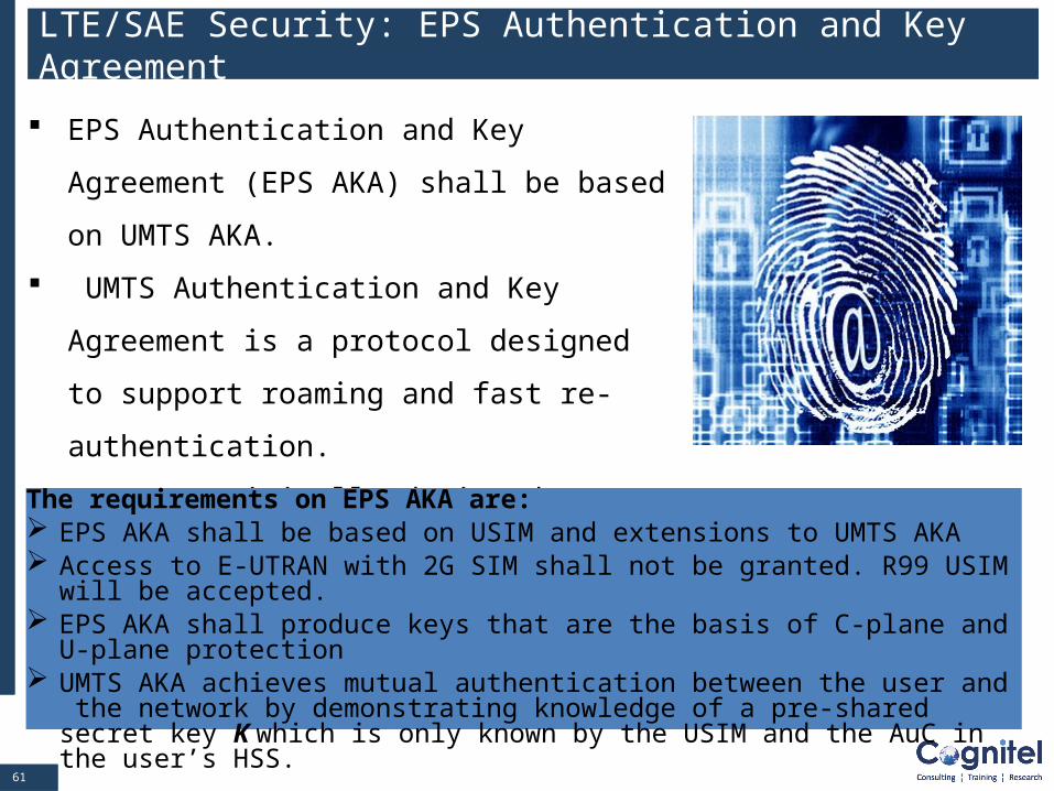
LTE/SAE Security: EPS Authentication and Key Agreement
EPS Authentication and Key Agreement (EPS
AKA) shall be based on UMTS AKA.
UMTS Authentication and Key Agreement is a
protocol designed to support roaming and fast
re-authentication.
It was originally designed to achieve maximum
compatibility with 2G security mechanisms.
The requirements on EPS AKA are: EPS AKA shall be based on USIM and extensions to UMTS AKA Access to E-UTRAN with 2G SIM shall not be granted. R99 USIM will be
accepted. EPS AKA shall produce keys that are the basis of C-plane and U-plane protection UMTS AKA achieves mutual authentication between the user and the network by
demonstrating knowledge of a pre-shared secret key K which is only known by the USIM and the AuC in the user’s HSS.
6262
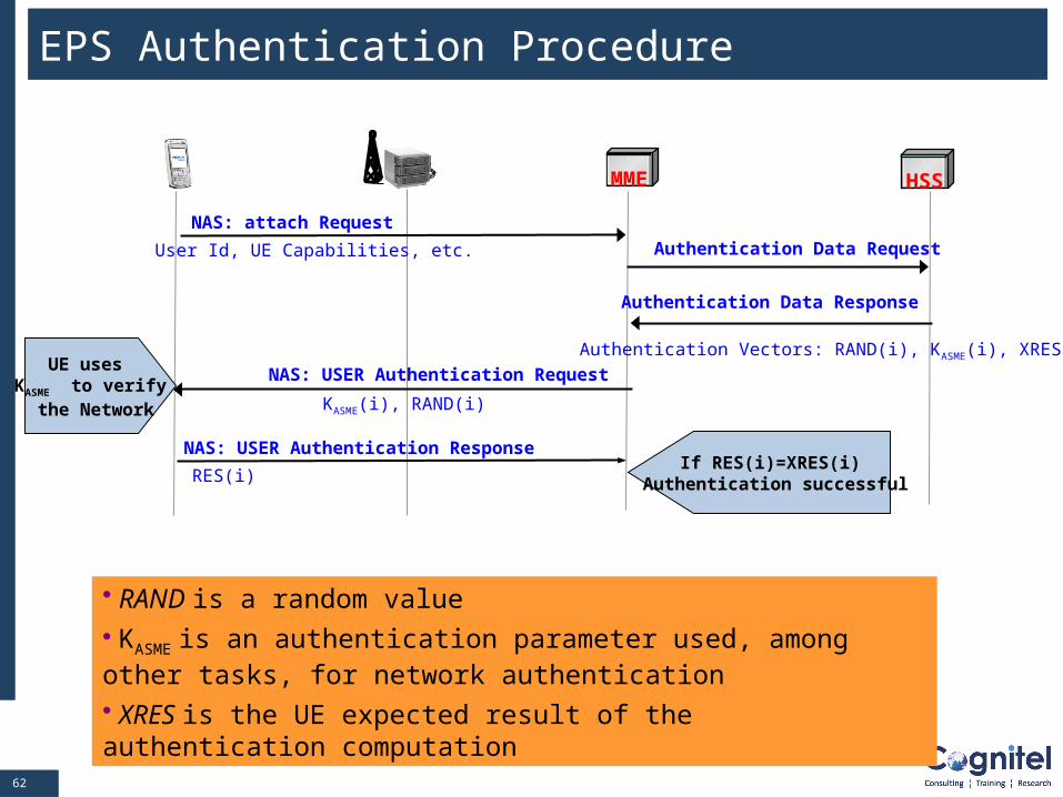
EPS Authentication Procedure
• RAND is a random value
• KASME is an authentication parameter used, among other tasks, for network authentication • XRES is the UE expected result of the authentication computation
MME
Authentication Vectors: RAND(i), KASME(i), XRES(i)
Authentication Data Response
HSS
NAS: attach Request
User Id, UE Capabilities, etc. Authentication Data Request
NAS: USER Authentication Request
KASME(i), RAND(i)
NAS: USER Authentication Response
RES(i)If RES(i)=XRES(i)
Authentication successful
UE uses KASME to verify the Network
6363
Security Functions - Encryption
Signaling protection
For core network (NAS) signaling, integrity and confidentiality protection
terminate in MME.
For radio network (RRC) signaling, integrity and confidentiality protection
terminate in eNodeB.
User plane protection
Encryption terminates in eNodeB.
6464
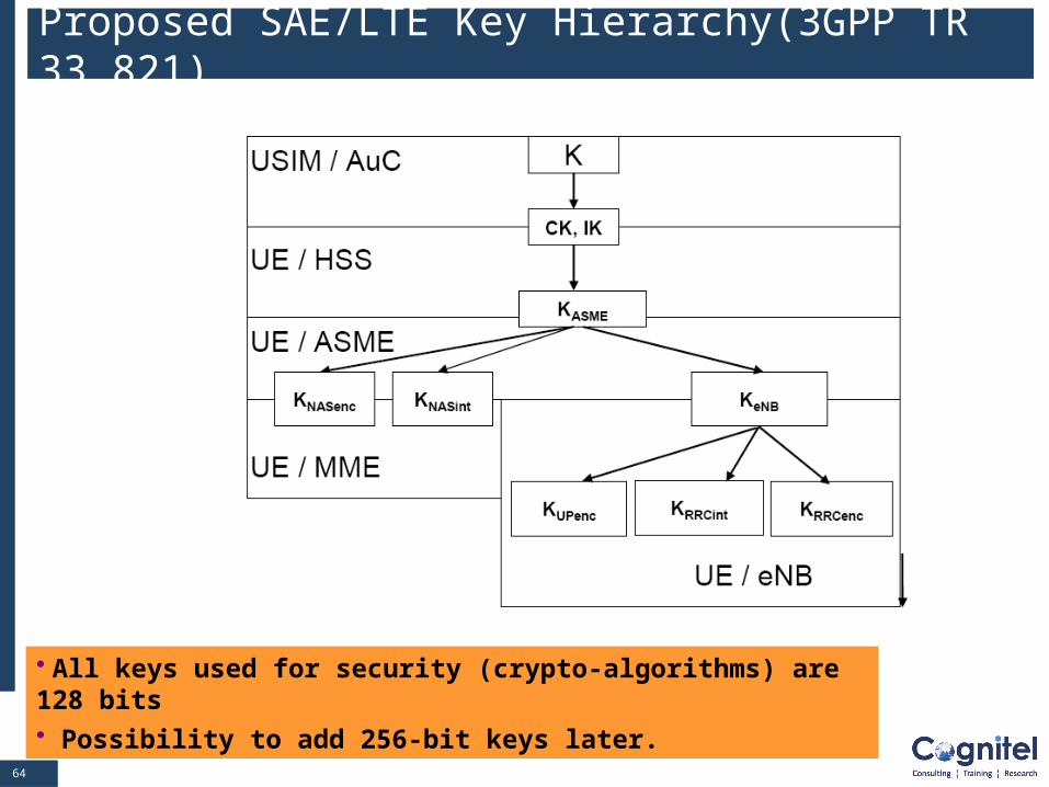
Proposed SAE/LTE Key Hierarchy(3GPP TR 33.821)
• All keys used for security (crypto-algorithms) are 128 bits• Possibility to add 256-bit keys later.
6565
SAE/LTE Keys (1/2)
Keys shared between the UE and HSS
– K : This is a permanent key stored on the USIM and in the Authorization Centre (AuC).
The AuC resides in the HSS.
– CK, IK : A pair of keys derived in the AuC and on the USIM during an AKA run.
Intermediate Key shared by the UE and Access Security Management Entity
(ASME=MME)
– KASME : This key is derived from the CK, IK and serving PLMN’s identity by the UE and HSS
during an AKA run. It is transferred to the ASME (MME) by the HSS as part of the authentication
vector response. The serving PLMN’s identity becomes known to the UE as part of the attachment
procedure.
Intermediate Keys for Access Networks
– KeNB : This key is derived from KASME by the UE and MME. It depends on the identity of the
eNB. This key is transferred to the eNB.
6666
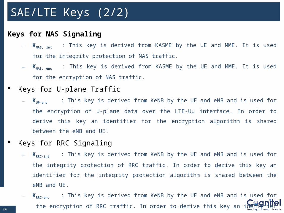
SAE/LTE Keys (2/2)
Keys for NAS Signaling
– KNAS, int : This key is derived from KASME by the UE and MME. It is used for the integrity
protection of NAS traffic.
– KNAS, enc : This key is derived from KASME by the UE and MME. It is used for the encryption of
NAS traffic.
Keys for U-plane Traffic
– KUP-enc : This key is derived from KeNB by the UE and eNB and is used for the encryption of U-
plane data over the LTE-Uu interface. In order to derive this key an identifier for the encryption
algorithm is shared between the eNB and UE.
Keys for RRC Signaling
– KRRC-int : This key is derived from KeNB by the UE and eNB and is used for the integrity
protection of RRC traffic. In order to derive this key an identifier for the integrity protection algorithm
is shared between the eNB and UE.
– KRRC-enc : This key is derived from KeNB by the UE and eNB and is used for the encryption of
RRC traffic. In order to derive this key an identifier for the encryption algorithm is shared between
the eNB and UE.
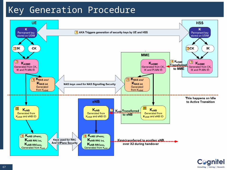
6767
Key Generation Procedure