3 in 1, Type K/J, Pt 100 ohm, Infrared Thermometer Real ... · Real time data logger, 16000 Data...
28
3 in 1, Type K/J, Pt 100 ohm, Infrared Thermometer Real time data logger, 16000 Data logger no., RS232 THERMOMETER Model : YK-2005TM
-
Upload
hoangtuyen -
Category
Documents
-
view
213 -
download
0
Transcript of 3 in 1, Type K/J, Pt 100 ohm, Infrared Thermometer Real ... · Real time data logger, 16000 Data...

3 in 1, Type K/J, Pt 100 ohm, Infrared ThermometerReal time data logger, 16000 Data logger no., RS232
THERMOMETERModel : YK-2005TM

TABLE OF CONTENTS1. FEATURES................................................................1
2. SPECIFICATIONS...................................................... 22-1 General Specifications..........................................22-2 Electrical Specifications........................................ 4
3. FRONT PANEL DESCRIPTION.....................................6
4. GENERAL MEASURING PROCEDURE........................... 84-1 Thermocouple ( Type K/J ) Thermometer Measurement......................................................84-2 Pt 100 ohm Measurement.................................... 94-3 Infrared Thermometer Measurement.....................94-4 Data Hold............................................................104-5 Data Record (Max., Min. reading)......................... 104-6 Data Logger........................................................ 11
5. ADVANCED ADJUSTMENT PROCEDURE...................... 135-1 Check Memory Space...........................................145-2 Clear Memory......................................................155-3 Date/Time Setting................................................155-4 Sample Time Setting............................................155-5 Auto Power Off Default Setting.............................165-6 Temp. Unit Default Setting...................................165-7 Escape from the SETTING function....................... 16
6. HOW TO SEND THE DATA OUT FROM THE METER......17
7. RS232 PC SERIAL INTERFACE....................................20
8. BATTERY REPLACEMENT...........................................22
9. Type K/J OFFSET ADJUSTMENT.................................22
10. SYSTEM RESET....................................................... 24
11. OPTIONAL ACCESSORIES........................................ 25

1. FEATURES
* 3 in 1, Thermocouple ( Type K/J ) thermometer, Pt 100 ohm thermometer + Infrared thermometer.
* 0.1 degree resolution for Pt 100 ohm & type K/J.* Wide temperature measuring range.* 4 wires PT 100 ohm probe input, 0.00385 alpha
coefficient, meet DIN IEC 751, high precision.* Offset adjustment.* Fast humidity measuring response time.* Real time data logger, build in clock ( hour-min.-sec.,
year-month-date ).* Auto or manual data record, 16,000 Data logger no.* Wide sampling time adjustment range from two
seconds to 8 hours 59 minutes 59 seconds. * RS232 computer interface.* Can default auto power off or manual power off.* Multi function with easy operation* Large LCD with multiple display.* Data hold, record max. and min. reading.* Microcomputer circuit provides special function & offer
high accuracy.* Power by UM3 ( 1.5 V ) x 4 batteries or DC 9V adapter.* RS232 PC serial interface.* Separate probe, easy for operation of different
measurement environment.
1

2. SPECIFICATIONS
2-1 General SpecificationsCircuit Custom one-chip of microprocessor LSI
circuit.Display LCD size : 58 mm x 34 mm.Measurement 1. Thermocouple probe
@ Thermocouple type K@ Thermocouple type J
2. Platinum Pt 100 ohm ( 0.00385 alpha coefficient, meet DIN IEC 751 )
3. Infrared ThermometerDisplay Unit , .℃ ℉Resolution 0.1 , 0.1 .℃ ℉Sampling Time Manual Push the data logger button of Data Logger once will save data one time.
@Set the sampling time to 0 second
Auto 2 sec to 8 hour 59 min. 59 sec.Temperature Automatic temp. compensation for theCompensation type K/J thermometer and Infrared
Thermometer.Linear Both for Type K/J. Pt 100 ohm andCompensation the IR thermometer.Offset Available to adjust the zero drift value,Adjustment adjustment by pushing button.Probe Input Type K/J probe : Socket Standard 2 pin thermocouple socket.
Pt 100 and IR probe :Exclusive socket.
2
Over Indication Show " ".Data Hold Freeze the display reading.Memory Recall Maximum & Minimum value.Sampling Time Approx. 1 second.of displayPower off Auto shut off saves battery life or
manual off by push button.Data Output RS 232 PC serial interface.Operating 0 to 50 .℃TemperatureOperating Less than 80% R.H.HumidityPower Supply DC 1,5 V battery ( UM3 ) x 4 PCs, * main instrument ( Heavy duty type ).
DC 9V adapter input. @ AC/DC power adapter is optional.
Power Supply DC 3V silver battery.* clock module Type : CR2032.Power Current Approx. DC 21.5 mA
@ Main instrument.+ Type K/J ( Pt 100 ) probeWeight 515 g/ 1.13 LB. @ Battery is included.Dimension 2000 x 762 x 368 mmAccessories Instruction manual......................1 PCIncluded Type K probe, TP-01...................1 PC
DC 3V silver battery, CR2032.......1 PCCarrying case..............................1 PC
3

Optional * Type K thermocouple probe.Accessories TP-02A. TP-03, TP-04
* Pt 100 ohm probe, PT-100P* Infrared Probe, YK-200PIR* AC to DC 9V adapter.* RS232 cable, UPCB-02.* Data Acquisition software,
SW-U801-WIN.* Data Logger software, SW-DL2005.
2-2 Electrical Specifications (23± 5 )℃
Type K/J thermometer
Sensor Reso- Range AccuracyType lutionType K 0.1 ℃ -50.0 to 1300.0 ℃ ± ( 0.2 % + 0.5 )℃
-50.1 to -100.0 ℃ ± ( 0.2 % + 1 )℃
0.1 ℉ -58.0 to 2372.0 ℉ ± ( 0.2 % + 1 )℉
-58.1 to -148.0 ℉ ± ( 0.2 % + 1.8 )℉
Type J 0.1 ℃ -100.0 to 1100.0 ℃ ± ( 0.2 % + 0.5 )℃
-50.1 to -100.0 ℃ ± ( 0.2 % + 1 )℃
0.1 ℉ -58.0 to 2012.0 ℉ ± ( 0.2 % + 1 )℉
-58.1 to -148.0 ℉ ± ( 0.2 % + 1.8 )℉
* Accuracy value is specified for the meter only.* Type K probe, TP-01 is the standard accessory.* Other Type K probe. TP-02A, TP-03. TP-04 is the
optional accessory, refer page 25.
4

Platinum PT 100 ohm Thermometer
Resolution Range Accuracy0.1 ℃ -200.0 to 850.0 ℃ ± ( 0.2 % + 0.5 )℃0.1 ℉ -328.0 to 1562.0 ℉ ± ( 0.2 % + 1.0 )℉Remark :
a. Accuracy value is specified for the meter only.b. Linearity Correction :
Memorize the Pt 100 ohm's curve into the intelligent CPU circuit.
c. Pt 100 probe input, 0.00385 alpha coefficient, meetDIN IEC 751.
d. 4 wires Pt 100 ohm probe ( Model : PT-100P ) is optional, refer page 25.
Infrared Thermometer
Measurement -10 to 300 / 14 to 572 .℃ ℃ ℉ ℉RangeResolution/ 1 or 1 .℃ ℉Accuracy ± 3 % of reading or ± 3 which ever is ℃
greater.* It should cooperate the optional
IR probe, YK-200PIR.* Meter operating Temp. within 23± 5℃
& the emissivity value of measurementtarget is 0.95.
* Spec. tested under the 20 cm dia.black body, the measuring distancefrom the Probe sensing Head is 30 cm.
@ Above specification tests under the environment RF FieldStrength less than 3 V/M & frequency less than 30 MHz only.
5

3. FRONT PANEL DESCRIPTION
6

3-1 Display3-2 Power Button3-3 HOLD Button ( ESC Button )3-4 REC Button ( Enter Button )3-5 Up Button ▲3-6 Function Button ( Down Button )▼3-7 Send Button ( Clock Button )3-8 SET Button ( Logger Button )3-9 Stand3-10 Battery Compartment/Cover3-11 Tripod Fix Nut3-12 LCD Brightness Adjust VR3-13 System Reset Switch3-14 RS-232 Output Terminal3-15 DC 9V Power Adapter Input Socket3-16 Type K/J Probe Input Socket3-17 Probe Input Socket3-18 Probe Lock Switch ( System On/Off Switch )3-19 Probe Plug3-20 Pt 100 ohm Probe ( optional )3-21 IR ( Infrared Thermometer ) Probe ( optional )
7

4. GENERAL MEASURING PROCEDURE
4-1 Thermocouple ( Type K/J ) Thermometer Measurement
Attention :It should not connect any probe into the Probe Input Socket " ( 3-17, Fig. 1 ) and slideProbe Lock Switch " ( 3-18, Fig. 1 ) to the Onposition ( right position ).
1)Plug the Thermocouple Temp. Probe ( Type K Temp.probe pr Type J Temp. probe, optional ) into " TypeK/J Probe Input Socket " ( 3-16, Fig. 1 )
2)Power on the meter by pressing the " Power Button "( 3-2, Fig. 1 ).
3)For the Type K Probe, press the " Function Button " ( 3-6, Fig. 1 ) to let the bottom right LCD show the " K type " indicatorFor the Type J Probe, press the " Function Button " ( 3-6, Fig. 1 ) to let the bottom right LCD show the " J type " indicator
Remark :The specification of included Type K probe ( TP-01 )* Max. short-tern operating temperature :
300 ( 572 ).℃ ℉* It is an ultra fast response naked-bead
thermocouple suitable for many general purpose application.
8

4-2 Pt 100 ohm Measurement1)Install the " Pt 100 ohm Probe's Plug " ( 3-19, Fig. 1 )
into the " Probe Input Socket " ( 3-17, Fig. 1 ).
Attention :After install the " Probe Plug ", should slide Probe Lock Switch " ( 3-18, Fig. 1 ) to the Onposition ( right position ).
2)Power on the meter by pressing the " Power Button "( 3-2, Fig. 1 ). The bottom right LCD will show theindicator " PT100 ", now the meter is ready for the Pt 100 ohm Measurement.
4-3 Infrared Thermometer Measurement1)Install the " Probe Plug " ( 3-19, Fig. 1 ) into the
" Probe Input Socket " ( 3-17, Fig. 1 ).
Attention :After install the " Probe Plug ", should slide Probe Lock Switch " ( 3-18, Fig. 1 ) to the Onposition ( right position ).
2)Power on the meter by pressing the " Power Button "( 3-2, Fig. 1 ). The bottom right LCD will show theindicator " IR ", now the meter is ready for the Infrared Thermometer Measurement.Hold the IR probe, let the probe sensor head againstthe measurement object.
9

, unit selection℃ ℉
The meter Temp. display unit is defaulted to " ".℃If intend to let the meter's temperature unit defaultto " " , please refer chapter 5-6 ( page 15 ).℉
Auto power off/Manaul power selection
The meter's power management is defaulted to auto power off. If intend use the meter as themanual power off , please refer chapter 5-5 ( page 16 ).
4-4 Data HoldDuring the measurement, press the " Hold Button " ( 3-3,Fig. 1 ) once will hold the measured value & the LCD willdisplay a " HOLD " symbol.* Press the " Hold Button " once again will release the data
hold function.
4-5 Data Record ( Max., Min. reading )* The data record function records the maximum and
minimum readings. Press the " REC Button " ( 3-4, Fig.1 ) once to start the Data Record function and therewill be a " REC. " symbol on the display.
* With the " REC. " symbol on the display :
10
a)Press the " REC Button " ( 3-4, Fig. 1 ) once, the "REC. MAX. " symbol along with the maximum valuewill appear on the display.If intend to delete the maximum value, just pressthe " Hold Button " ( 3-3, Fig. 1 ) once, then thedisplay will show the " REC. " symbol only & executethe memory function continuously.
b)Press the " REC Button " ( 3-4, Fig. 1 ) again, the " REC. MIN. " symbol along with the minimum valuewill appear on the display.If intend to delete the minimum value, just pressthe " Hold Button " ( 3-3, Fig. 1 ) once, then the display will show the " REC. " symbol only &execute the memory function continuously.
c) To exit the memory record function, just press the " REC " button for 2 seconds at least. The display willrevert to the current reading.
4-6 Data LoggerThe data logger function can save 16,000 measuringdata with the clock time ( Real time data logger, buildin clock ( hour-min.-sec., year-month-date ).
The data logger procedures are as following :a) If push the Logger Button " ( 3-8, Fig. 1 ) once will
show the sampling time value on the bottom leftdisplay then disappeared.
b)Press the " REC Button " ( 3-4, Fig. 1 ) once tostart the Data Record function and there will be a " REC. " symbol on the display.
11
c) Auto Data Logger ( Sampling time set from 2 seconds to 8 hours 59 minutes 59 seconds )Press the " Logger Button " ( 3-8, Fig. 1 ) once to startthe Auto Data Logger function, at the same thebottom right display will show the indicator " Recording.... ", now the Data Logger function isexecuted. The upper display will show " DATA "indicator along with " REC " marker.
d)Manual Data Logger ( Sampling time set to 0second ) Press the " Logger Button " ( 3-6, Fig. 1 ) once willsave the data one time into the memory, at the sametime the bottom right display will show the indicator " Recording.... " a while. Now the Data logger function isexecuted. The upper display will show " DATA "indicator along with " REC " marker.
e)Memory fullUnder execute the data logger, if the bottom rightdisplay show the " Full ", it indicate the memory dataalready over 16,000 no. and the memory is full.
12
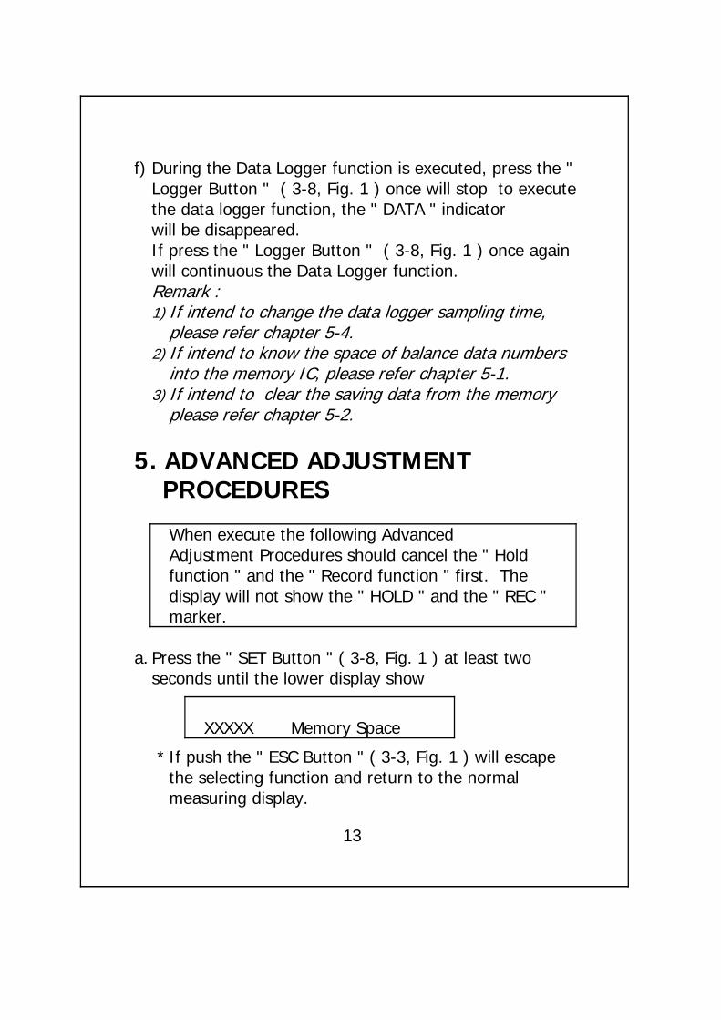
f) During the Data Logger function is executed, press the "Logger Button " ( 3-8, Fig. 1 ) once will stop to executethe data logger function, the " DATA " indicatorwill be disappeared.If press the " Logger Button " ( 3-8, Fig. 1 ) once againwill continuous the Data Logger function.Remark :1) If intend to change the data logger sampling time,
please refer chapter 5-4.2) If intend to know the space of balance data numbers
into the memory IC, please refer chapter 5-1.3) If intend to clear the saving data from the memory
please refer chapter 5-2.
5. ADVANCED ADJUSTMENT PROCEDURES
When execute the following AdvancedAdjustment Procedures should cancel the " Holdfunction " and the " Record function " first. Thedisplay will not show the " HOLD " and the " REC "marker.
a. Press the " SET Button " ( 3-8, Fig. 1 ) at least twoseconds until the lower display show
XXXXX Memory Space
* If push the " ESC Button " ( 3-3, Fig. 1 ) will escapethe selecting function and return to the normalmeasuring display.
13

b. One by one to press the " Set Button " ( 3-8, Fig. 1 )once a while to select the ten main function, at thesame time lower display will show on the lower display will show on the lower display as :
Memory SpaceClear MemoryDate/Time SetSample TimeAuto Power OffTemp. UnitESC Finish→
c. When make Advanced Adjustment Procedurewill use the following key buttons :
ESC Button ( 3-3, Fig. 1 ), Enter Button ( 3-4, Fig. 1 ) Up Button ( 3-5, Fig. 1 ), Down Button ( 3-6, Fig. 1 )▲ ▼
SET Button ( 3-8, Fig. 1 ), SEND Button ( 3-7, Fig. 1 )
5-1 Check Memory SpaceTo check the balance data numbers that exist into thememory ( allow memorize data no. ).
XXXXX Memory Space
@XXXXX is the balance data numbers, for exampleXXXXX=15417.
14

5-2 Clear Memory* To delete the existing save data numbers from the
memory.* Push ENTER Button once, then push ENTER Button
to confirm.* Press the ESC Button once to quite and return to
the main measurement manual.
5-3 Date/Time Setting* Use Up Button, Down Button and ▲ ▼
Enter ( ) Button to select the expect Date →( year-month-date ) and the time (HOUR-MIN.-SEC.).
* After finish the Date/Time adjustment, Push the " Enter Button " , then press the " ESC Button "will quite and save the clock data into the memory.
5-4 Sample Time Setting* Use Up Button, Down Button and Enter ( ) ▲ ▼ →
Button to select the expect Sample Time ( HOUR-MIN.-SEC.).* After finish the Sample Time adjustment,
Push the " Enter Button " , then press the " ESC Button "will quite and save the clock data into the memory.
15

5-5 Auto Power Off Default Setting* Use Up Button, Down Button to select " 1 " or ▲ ▼
" 0 ".
1 = Auto power On. 0 = Auto power Off.
*After finish the Auto Power Off adjustment, push the " Enter Button " , then press the " ESC Button "will quite and return to the normal measurementdisplay.
5-6 Temp. Unit Default Setting*
Use Up Button, Down Button to select " 1 " or ▲ ▼" 0 ".
1 = ℉ 0 = ℃
*After finish the Temperature unit adjustment, push the " Enter Button " , then press the " ESC Button "will quite and return to the normal measurementdisplay.
5-7 Escape from the SETTING functionPress the " ESC Button " once a while will quite andreturn to the normal measurement display.
16

6. HOW TO SEND THE DATA OUT FROM THE METER
1)If intend to send the data out from the meter, itshould cancel the " Hold function " and the " Recordfunction " first. The display will not show the " HOLD "and the " REC " marker.
2)Press the " SEND Button " ( 3-7, Fig. 1 ) at least 2seconds until the bottom right display show " Transmitmode ", then release the button.
LCD display will show the fowling screen alternately.
19.0 1 ℃ ← ℃
→1 Transmit mode xx:xx:xx Transmit mode
Block no. The first Start time Start datadata of of each address ofeach block block each block
Use Up Button, Down Button to select the▲ ▼different data memory block no. ( 1 to 250 ).
17

The meter can save 16,000 data max. , thosedata will saved into 250 memory block max.
* The data that save into one routine Data Loggerprocedures ( Push " REC " button , following pushthe " Logger " button to save the data, the displaywill show the " REC " and " DATA " . After save thedata push the " Logger " button, following pushthe " REC " button, will exist the Data Loggerfunction. The " REC " and " DATA " indicator of LCDwill be disappeared ). Please refer Chapter 4-6,page 12.
Block 1 Data 1to
Data X↓
Block 2 Data X+1to
Data Y ......↓ ..................
↓Block 250 Data Z
toData 16,000
18

3)Until the desired Memory Block no. be selected.Push the " Send Button " ( 3-7, Fig. 1 ) once, the data in the Memory Block will send out.During the data send out, the bottom right display willshow the " Sending Data ! " indicator. When dataalready send out completely, the bottom right displaywill show the Transmit mode " indicator again.
5)Push the " ESC Button " ( 3-3, Fig. 1 ) will existthe data sending function and return to the normaldisplay.
Remarks :@If intend up load the data to the computer,
then should connect the RS232 cable ( optional, model : UPCB-02) and apply theData Logger software ( optional, Model :SW-DL2005 ).
@When sending the data, each time just cansend one Memory Block data out. for exampleblock 1 data, block 2 data... or block 250 data.
19

7. RS232 PC SERIAL INTERFACE
The instrument has RS232 PC serial interface via a 3.5mm terminal ( 3-14, Fig. 1 ).
The data output is a 16 digit stream which can beutilized for user's specific application.
A RS232 lead with the following connection will berequired to link the instrument with the PC serial port.
Meter PC(3.5 mm jack plug) (9W 'D" Connector)
Center Pin........................Pin 4
Ground/shield.....................Pin 2 2.2 Kresister
Pin 5
The 16 digits data stream will be displayed in thefollowing format :
D15 D14 D13 D12 D11 D10 D9 D8 D7 D6 D5 D4 D3 D2 D1 D0
20
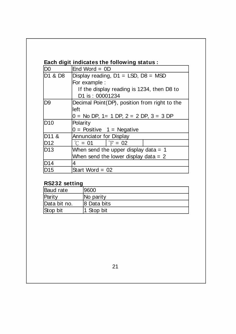
Each digit indicates the following status :D0 End Word = 0DD1 & D8 Display reading, D1 = LSD, D8 = MSD
For example : If the display reading is 1234, then D8 toD1 is : 00001234
D9 Decimal Point(DP), position from right to theleft0 = No DP, 1= 1 DP, 2 = 2 DP, 3 = 3 DP
D10 Polarity0 = Positive 1 = Negative
D11 & Annunciator for DisplayD12 = 01 ℃ = 02℉D13 When send the upper display data = 1
When send the lower display data = 2D14 4D15 Start Word = 02
RS232 settingBaud rate 9600Parity No parityData bit no. 8 Data bitsStop bit 1 Stop bit
21
8. BATTERY REPLACEMENT
1)The time to change the UM3 ( 1.5 V ) x 4 PCs
When the left corner of LCD display show " ", itis necessary to replace the batteries ( UM3/1.5 V x 4 PCs ).
The time to change the CR2032 ( 3V silver battery )
When the clock is not accurate or power off the meterthen on, the clock time is disappeared or garbled, it isnecessary to replace the battery ( CR2032 )
2)Slide the " Battery Cover " ( 3-10, Fig. 1 ) away from theinstrument and remove the battery.
3)Replace with batteries ( UM3/1.5 V x 4 PCs or CR2032 )and reinstate the cover.
4)Make sure the battery cover is secured after changingthe battery.
9. Type K/J OFFSET ADJUSTMENT
IF the thermocouple ( type K, type J ) temperaturemeasurement exist the offset drift ( under the differentmeasuring value always exist the same deviation value ), then the following procedures can be fixed.
22

1)LCD under the normal measurement screen, forexample as Fig. 2.
23.2 ℃ Fig. 2K type
At the same time press both the " REC Button "( 3-4, Fig. 1 ) and the " HOLD Button " ( 3-3, Fig.1 ) together, then release the fingers from thosetwo buttons. The display will show the LCD screen asfollowing for example ( Fig. 3 )
23.2 ℃ Fig. 3K type
23.2
The lower display just The larger display justshow the none adjusting show the value that intendvalue to be adjusted
3)Use the " Button " ( 3-5, Fig. 1 ) and the " ▲ ▼Button " ( 3-6, Fig. 1 ) to adjust the desired newvalue ( 22.5, for example ) exactly on the up largerdisplay, refer Fig. 4
22.5 ℃ Fig. 4K type
23.223

4)After the desired value is already set to the upperdisplay, press the " REC Button " ( 3-4, Fig. 1 ) oncea while, will save the adjusted value into circuit'smemory permanently and finish the offset adjustmentprocedures. The display will return to the normalscreen and the new adjustment value will present onthe LCD as
22.5 ℃K type
Remark :The above adjustment procedures should beexecuted under the Temp. unit is selected to .℃If the primary unit is set to , then during℉execute the offset adjustment procedures, thedisplay unit will change to automatically.℃
10. SYSTEM RESET
If the meter happen the troubles such as :
CPU system is garbled ( for example, the key button cannot be operated .......).
Then make the system RESET will fix the problem.The system RESET procedures will be either followingmethod :
24

Slide the " Probe Lock Switch/System On/Off1)Switch " from the On to Off, then On again.
Or during the Power On, used a pin tool to push2)the " System Reset Switch " ( 3-13, Fig. 1 ) once
a while.
11. OPTIONAL ACCESSORIES
RS232 cable * Isolated RS232 cable.UPCB-02 * Used to connect the meter to
the computerData Logger * Software the used to download software the data logger ( data recorder )SW-DL2005 from the meter to computer.Data Acquisition * The SW-U801-WIN is a multisoftware displays ( 1/2/4/6/8 displays )SW-U801-WIN powerful application software,
provides the functions of datalogging system, text display,angular display, chart display,data recorder high/low limit, dataquery, text report, chart report...xxx.mdb data file can beretrieved for EXCEL, ACESS..,wide intelligent applications.
25

(Type K) TP-01 * Max. short-tern operating Temperature: 300 (572 ).℃ ℉* It is an ultra fast response naked-bead thermocouple suitable for many general purpose application.
Thermocouple * Measure Range: -50 to 900 ,℃ ℃Probe -50 to 1650 .℉ ℉ (Type K), TP-02A * Dimension:10cm tube, 3.2mm Dia.Thermocouple * Measure Range: -50 to 1200 ,℃ ℃Probe -50 to 2200 .℉ ℉ (Type K), TP-03 * Dimension: 10cm tube, 8mm Dia. Surface Probe * Measure Range: -50 to 400 ,℃ ℃ (Type K), TP-04 -50 to 752 .℉ ℉
* Size :Temp. sensing head - 15 mm Dia.Probe length - 120 mm.
Infrared Temp. * Measure Range: -10 to 300 ,℃ ℃Probe -14 to 572 .℉ ℉YK-200PIR * Emissivity : 0.95.
* Resolution : 0.1 /0.1 .℃ ℉PT 100 ohm Temp. * Measure Range: -50 to 400 ,℃ ℃Probe -58 to 752 .℉ ℉TP-100P * Resolution : 0.1 /0.1 .℃ ℉
26
0501-YK2005TM