3 DESCRIPTION OF THE PROPOSED DEVELOPMENTaviationfuelpipeline.com/downloads/reports/Section 3...
21
Section 3 Fingleton White EIS for Proposed Aviation Fuel Pipeline Q:/2010/LE10/727/01/Rpt002-1.doc Page 15 of 294 3 DESCRIPTION OF THE PROPOSED DEVELOPMENT This chapter of the EIS details the principal elements of the proposed development. It provides information on the proposed design, construction, operation and decommissioning of the pipeline. 3.1 Jet A1 Aviation Fuel Jet A1 aviation fuel is a kerosene and is classified as a Category B substance i.e. flammable and/or toxic fluids that are liquids at ambient temperature and at atmospheric pressure conditions in accordance with I.S. EN 14161:2011 – Petroleum and natural gas industries – Pipeline transportation systems (ISO 13623:2009 modified). It is used for fuel for aviation turbine engines fitted to aircraft and thus is subject to strict quality requirements and product integrity by users. It is colourless to straw-coloured in appearance and has a relatively high flash point of >38 o C. It is the most commonly used fuel for commercial aviation given its low freezing point of -47°C. It is produced to a standardised international specification 1 and is a complex mixture of hydrocarbons consisting of paraffins, cycloparaffins, aromatic and olefinic hydrocarbons with carbon numbers predominately in the C9 to C16 range. Jet A1 fuel contains several additives at concentrations less than 0.1% v/v. Total aromatic hydrocarbons present are typically in the range of 10-20% v/v. Table 3.1 summarises the typical composition of Jet A1 fuel and its associated hazards. Table 3.1: Typical Composition of Jet A1 Fuel Substance Name Values (%) CAS no EC No EC Index Symbol(s) R-phrase(s) Note 1 Kerosine (petroleum), hydrodesulfurized 0-100 64742- 81-0 265-184-9 649-423-00-8 Xn, N R10, R38, R51/53, R65 Napthalene 0-0,5 91-20-3 202-049-5 601-052-00-2 Xn, N R22, R50/53, R40 Ethylbenzene 0-0,5 100-41- 4 202-849-4 601-023-00-4 F, Xn R11, R20 Kerosine (petroleum) 0-100 8008- 20-6 232-366-4 649-404-00-4 Xn, N R10, R38, R65, R51/53 Note 1 R10 Flammable R11 Highly Flammable R38 Irritating to Skin R22 Harmful if Swallowed R40 Limited evidence of a carcinogenic effect R65 Harmful: may cause lung damage if swallowed R51/53 Toxic to aquatic organisms Stocks of kerosene held in Ireland are aviation fuel. Kerosene has of course many other uses including domestic central heating, stand-alone domestic heaters, camping stoves and lights. In these situations the kerosene is stored in plastic tanks or containers within the curtilage of a domestic dwelling. Kerosene is stable in normal conditions. Vapour will not form unless the temperature is >38 o - 42 o C. The fuel will not ignite unless the temperature is > 220 o C. 1 ASTM Standard Specification D1655-049 of 1 Nov 2004 for Aviation Fuels @Jet A-1’ British Ministry of Defence Standard DEF STAN 91-91/Issue 5 of 8 February 2005 for Turbine Fuel Aviation ‘Kerosine Type’, Jet A-1 NATO Code F-35, Joint Service Designation AVTUR
Transcript of 3 DESCRIPTION OF THE PROPOSED DEVELOPMENTaviationfuelpipeline.com/downloads/reports/Section 3...

Section 3 Fingleton White EIS for Proposed Aviation Fuel Pipeline
Q:/2010/LE10/727/01/Rpt002-1.doc Page 15 of 294
3 DESCRIPTION OF THE PROPOSED DEVELOPMENT This chapter of the EIS details the principal elements of the proposed development. It provides information on the proposed design, construction, operation and decommissioning of the pipeline. 3.1 Jet A1 Aviation Fuel Jet A1 aviation fuel is a kerosene and is classified as a Category B substance i.e. flammable and/or toxic fluids that are liquids at ambient temperature and at atmospheric pressure conditions in accordance with I.S. EN 14161:2011 – Petroleum and natural gas industries – Pipeline transportation systems (ISO 13623:2009 modified). It is used for fuel for aviation turbine engines fitted to aircraft and thus is subject to strict quality requirements and product integrity by users. It is colourless to straw-coloured in appearance and has a relatively high flash point of >38oC. It is the most commonly used fuel for commercial aviation given its low freezing point of -47°C. It is produced to a standardised international specification1 and is a complex mixture of hydrocarbons consisting of paraffins, cycloparaffins, aromatic and olefinic hydrocarbons with carbon numbers predominately in the C9 to C16 range. Jet A1 fuel contains several additives at concentrations less than 0.1% v/v. Total aromatic hydrocarbons present are typically in the range of 10-20% v/v. Table 3.1 summarises the typical composition of Jet A1 fuel and its associated hazards. Table 3.1: Typical Composition of Jet A1 Fuel
Substance Name Values (%) CAS no EC No EC Index Symbol(s) R-phrase(s) Note 1
Kerosine (petroleum),
hydrodesulfurized
0-100 64742-81-0
265-184-9 649-423-00-8 Xn, N R10, R38, R51/53, R65
Napthalene 0-0,5 91-20-3 202-049-5 601-052-00-2 Xn, N R22, R50/53, R40 Ethylbenzene 0-0,5 100-41-
4 202-849-4 601-023-00-4 F, Xn R11, R20
Kerosine (petroleum)
0-100 8008-20-6
232-366-4 649-404-00-4 Xn, N R10, R38, R65, R51/53
Note 1 R10 Flammable R11 Highly Flammable R38 Irritating to Skin R22 Harmful if Swallowed R40 Limited evidence of a carcinogenic effect R65 Harmful: may cause lung damage if swallowed R51/53 Toxic to aquatic organisms Stocks of kerosene held in Ireland are aviation fuel. Kerosene has of course many other uses including domestic central heating, stand-alone domestic heaters, camping stoves and lights. In these situations the kerosene is stored in plastic tanks or containers within the curtilage of a domestic dwelling. Kerosene is stable in normal conditions. Vapour will not form unless the temperature is >38o - 42oC. The fuel will not ignite unless the temperature is > 220oC.
1 ASTM Standard Specification D1655-049 of 1 Nov 2004 for Aviation Fuels @Jet A-1’ British Ministry of Defence Standard DEF STAN 91-91/Issue 5 of 8 February 2005 for Turbine Fuel Aviation ‘Kerosine Type’, Jet A-1 NATO Code F-35, Joint Service Designation AVTUR

Section 3 Fingleton White EIS for Proposed Aviation Fuel Pipeline
Q:/2010/LE10/727/01/Rpt002-1.doc Page 16 of 294
Section 5.2 of I.S. EN 14161:2011 classifies fluids being transported into 5 categories based on their hazard potential with respect to public safety. These are as follows: Table 3.2: Fluid Category as per I.S. EN 14161:2011
Classification Fluid Type
Category A Non-flammable, water based fluids Category B Flammable and/or toxic fluids that re liquids at ambient temperature and at
atmospheric pressure condition. Typical examples are oil and petroleum products. Methanol is an example of a flammable and toxic fluid
Category C Non-flammable fluids that are non-toxic gases at ambient temperature and atmospheric pressure conditions. Typical examples are nitrogen, carbon dioxide, argon and air
Category D Non- toxic, single phase natural gas Category E Flammable and/or toxic fluids that are gases at ambient temperature and
atmospheric pressure conditions and are conveyed as gases and or liquids. Typical examples are hydrogen, natural gas (not otherwise covered in category D) ethane, ethylene, liquefied petroleum gas (such as propane and butane), natural gas liquids, ammonia and chlorine
Jet A1 is a Category B substance. In the unlikely event of damage to the pipe and a subsequent leak the fuel will form a pool around the pipe. As part of the operator’s emergency response plan (Appendix 3.7 of Volume 3 of the EIS) the leaked fuel will be pumped out into a tanker. The fuel stays in a liquid form. The procedure for clean-up is similar to that for a spillage from a road tanker, in relation to the use of Personal Protective Equipment (PPE), notification to statutory bodies, prevention of the spreading of fuel, absorbing fuel and removing or pumping fuel to a tanker. A safety data sheet for Jet A-1 has been included in Appendix 3.1 of Volume 3 of the EIS. 3.2 Pipeline Design A design basis report has been included in Appendix 3.2 of Volume 3 of the EIS of which a summary is provided hereunder. The proposed pipeline will be a 200 mm (8”) nominal diameter, continuously welded steel pipe and 14.4 km in length. It will be capable of delivering 300 m3 per hour (equivalent to 2,700 million litres per annum) of aviation fuel to Dublin Airport at 40 bar. The estimated 2035 demand is 1,450 million litres which will be delivered at 170 m3 per hour at an operating pressure of 16-20 bar. The safest way to transport aviation fuel is by pipeline and this is reflected by the number of pipelines in operation throughout the UK and Europe. The failure frequency of the proposed pipeline, which has been designed with inbuilt mitigation measures, is over 90 times lower than that of a road tanker. The pipeline does not fall under the scope of EU Council Directive 2012/18/EU on the Control of Major Accident Hazards involving Dangerous Substances (SEVESO). Article 2 states that the following is not covered by the Seveso Directive “the transport of dangerous substances in pipelines including the pumping stations outside establishments covered by this directive.” The expected life of the pipeline is 50 years, after which it can be revalidated for a further period. This includes for continued use as an aviation fuel pipeline or alternatively as a water or gas pipeline (following decommissioning) or telecommunications. The overall design of the scheme from the inlet station at Dublin Port to the reception station at Dublin Airport is shown in Figure 3.1.

Sec
tion
3
F
ing
leto
n W
hit
e
EIS
for
Pro
po
sed
Avi
atio
n F
uel
Pip
elin
e
Q:/
2010
/LE1
0/72
7/01
/Rpt
002-
1.do
c
Pa
ge 1
7 of
294
Fig
ure
3.1
: Pip
e Fl
ow D
iag
ram
Section 3 Fingleton White EIS for Proposed Aviation Fuel Pipeline
Q:/2010/LE10/727/01/Rpt002-1.doc Page 18 of 294
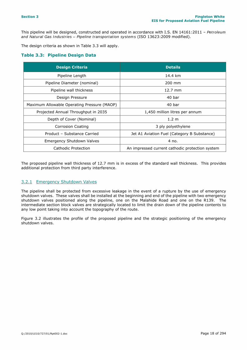
This pipeline will be designed, constructed and operated in accordance with I.S. EN 14161:2011 – Petroleum and Natural Gas Industries – Pipeline transportation systems (ISO 13623:2009 modified). The design criteria as shown in Table 3.3 will apply. Table 3.3: Pipeline Design Data
Design Criteria Details
Pipeline Length 14.4 km
Pipeline Diameter (nominal) 200 mm
Pipeline wall thickness 12.7 mm
Design Pressure 40 bar
Maximum Allowable Operating Pressure (MAOP) 40 bar
Projected Annual Throughput in 2035 1,450 million litres per annum
Depth of Cover (Nominal) 1.2 m
Corrosion Coating 3 ply polyethylene
Product – Substance Carried Jet A1 Aviation Fuel (Category B Substance)
Emergency Shutdown Valves 4 no.
Cathodic Protection An impressed current cathodic protection system The proposed pipeline wall thickness of 12.7 mm is in excess of the standard wall thickness. This provides additional protection from third party interference. 3.2.1 Emergency Shutdown Valves The pipeline shall be protected from excessive leakage in the event of a rupture by the use of emergency shutdown valves. These valves shall be installed at the beginning and end of the pipeline with two emergency shutdown valves positioned along the pipeline, one on the Malahide Road and one on the R139. The intermediate section block valves are strategically located to limit the drain down of the pipeline contents to any low point taking into account the topography of the route. Figure 3.2 illustrates the profile of the proposed pipeline and the strategic positioning of the emergency shutdown valves.

Sec
tion
3
Fin
gle
ton
Wh
ite
EI
S f
or P
rop
ose
d A
viat
ion
Fu
el P
ipel
ine
Q:/
2010
/LE1
0/72
7/01
/Rpt
002-
1.do
c
Pa
ge 1
9 of
294
Fig
ure
3.2
: Gro
un
d P
rofi
le o
f P
rop
osed
Pip
elin
e

Section 3 Fingleton White EIS for Proposed Aviation Fuel Pipeline
Q:/2010/LE10/727/01/Rpt002-1.doc Page 20 of 294
3.3 Safety & Environmental Evaluation AMEC Environmental and Infrastructure UK Ltd. carried out Safety and Environmental Impact Evaluations in 2004, 2007 and 2011, for FW, for various route options. The evaluations covered the likelihood of leaks and their potential size. AMEC have carried out a similar evaluation of the risk of a leak and the potential size of leaks for this proposed pipeline. The Safety and Environmental Impact Evaluation Report 2014 is included in Appendix 2.1. The risks associated with transporting the same volume of fuel by tanker have also been analysed and presented for comparison. The table below summarises the failure frequencies and spill sizes.
200mm Pipeline Road Tanker Transport No intermediate
Section Isolation valve(s)
Two intermediate Section Isolation valves at 4.5 and
11km
Projected 1500 Ml/yr
Max Capacity 2700 Ml/yr
Total Failure Frequencies 1 in 5,130 years 1 in 5,130 years 1 in 57 years 1 in 32 years
Failure Frequencies (yr-1) 1.95 x 10⁻⁴ 1.95 x 10⁻⁴ 0.017 0.031
Average Spill Rate (litres/yr) 37 14 51.1 91.9
Maximum Spill size (litres) 278,702 103,128 38,000 38,000
The average spill rate for the pipeline is less than for road tankers. The maximum spill size of a pipeline with two Section Isolation Valves is less than three times that for a road tanker but the release frequency (all releases sizes) is lower by approximately a factor of 90. In summary, although the average spill size from the pipeline is higher than from a tanker, the failure frequency is very much lower giving a much reduced risk. The failure frequencies in the table above correspond to all failure modes. No distinction is made between the worst case rupture scenario and a small corrosion hole. The predicted failure frequencies for each scenario are shown in the table below.
Minor leak (Pinhole)
Major leak (hole) Full bore rupture
Failure frequency
1 in 10,577 years
1 in 14,292 years
1 in 34,903 years
Risk Analysis The failure frequency analysis is based on the Fingleton White design basis, which complies with ISEN 14161 Petroleum and Natural Gas Industries – Pipeline Transportation, and published data for failures of steel pipelines, adjusted for depth of cover, pipelines thickness, lean mix concrete backfill, cathodic protection. In the leak volumes analysis a conservative approach is taken. It is assumed that all the material above a leak will come out of the pipeline. Comparison with Road Tankers In the evaluation of road tanker failure the UK Health and Safety Commission statistics and road traffic statistics, in both the UK and Ireland, were reviewed. Safety Case The purpose of the Safety Case is to demonstrate that the pipeline has been designed, constructed, tested and commissioned and will be operated to reduce risks to a suitable level. The Safety Case will demonstrate safety in design, construction, operation, inspection, monitoring and leak detection, emergency procedures. It is normally developed prior to operation.

Section 3 Fingleton White EIS for Proposed Aviation Fuel Pipeline
Q:/2010/LE10/727/01/Rpt002-1.doc Page 21 of 294
“To prepare a safety Case it is necessary to identify the potential hazards and their effects. In the context of aviation fuel, because it is being transported at a temperature well below its flash point,” (the temperature above which it vaporises) “the flammability risk is likely to be extremely low. The major impacts resulting from a release are environmental.” These are covered in this EIS. The AMEC Report and together with this EIS fulfil the requirement of ISEN 14161:2011 Petroleum and Natural Gas Industries- Pipeline Transportation. 3.4 Construction of the Pipeline A construction plan has been included in Appendix 3.3 of Volume 3 of the EIS. This should be read in conjunction with the following sections. The final construction plan will be prepared upon appointment of a contractor and will be agreed with DCC and FCC. 3.4.1 Construction Programme The construction phase of the project is subject to obtaining all the necessary approvals. It is anticipated that construction works will be completed over a 10 month period commencing in February and continuing until November of that year (dependent on consent timelines). Construction works will focus on the more heavily trafficked sections during July and August when traffic density is reduced due to school holidays and to comply with other identified constraints. This 10 month programme can be broken down into a number of sub-phases which may overlap. These are:
Set up and establishment of traffic management plans Construction Permanent Re-instatement Commissioning
An outline construction programme has been included in Figure 3.3.

Sec
tion
3
Fin
gle
ton
Wh
ite
EI
S f
or P
rop
ose
d A
viat
ion
Fu
el P
ipel
ine
Q:/
2010
/LE1
0/72
7/01
/Rpt
002-
1.do
c
Pa
ge 2
2 of
294
Fig
ure
3.3
: Co
nst
ruct
ion
Pro
gra
mm
e

Section 3 Fingleton White EIS for Proposed Aviation Fuel Pipeline
Q:/2010/LE10/727/01/Rpt002-1.doc Page 23 of 294
3.4.2 Construction Phasing The linear and repetitive nature of the works is similar to the works required to provide other utility infrastructure such as water, drainage, gas, telecoms and electricity. It lends itself to a progressive and sequential form of construction. The proposed pipeline route will be laid simultaneously in three to four working zones. This will minimise the duration of impacts from the works. Maximum separation will be maintained between work sites so that effective traffic and pedestrian management plans can be put in place. An average of 24 m of pipeline per day will be laid by each team. Each crew will require an overall working zone of approximately 72 m x 4 m which will be fenced off from the general public. It is proposed that the trenches will be backfilled and temporarily reinstated each evening, ensuring minimum disruption to pedestrians, home owners and businesses. Tie in points will have excavation covered by steel plates. 3.4.3 Hours of Work DCC has classified roads and streets within their functional area with a Traffic Impact Number (TIN). This is set out in their publication Directions for the Control and Management of Roadworks in Dublin City (2010), with the classification based on the strategic importance of each route. Table 3.4 lists the classification of the relevant roads along which the pipeline passes with 5 indicating the highest TIN and 1 the lowest. Table 3.4: Traffic Impact Numbers of Roads within DCC Functional Area
Road Name Traffic Impact Number
East Wall Road 4
Alfie Byrne Road 3
Clontarf Road 4
Howth Road 3
Copeland Avenue 3
Malahide Road R107 5
R139 4 Having regard to the need to minimise disruption to traffic caused by road works, DCC developed general restrictions which apply in relation to times at which non-emergency road works may be carried out in each TIN. These are summarised in Table 3.5. Table 3.5: Restrictions in each TIN
TIN Times During which Road Works may be Carried Out
1 Mon – Fri 08.00 – 23.00 hrs
2 Mon – Fri 08.00 – 23.00 hrs
3 Mon – Wed 10.00 – 16.00 hrs & 19.30 – 23.00 hrs Thursdays 10.00 – 16.00 hrs, & 21.00 – 23.00 hrs Fridays 10.00 – 15.00 hrs, & 21.00 – 23.00 hrs Sat & Sun 09.00 – 23.00 hrs Public Holiday 09.00 – 23.00 hrs
4 Mon – Wed 19.30 – 23.00 hrs Thurs & Fri 21.00 – 23.00 hrs Sat & Sun 09.00 – 23.00 hrs

Section 3 Fingleton White EIS for Proposed Aviation Fuel Pipeline
Q:/2010/LE10/727/01/Rpt002-1.doc Page 24 of 294
TIN Times During which Road Works may be Carried Out
Public Holiday 09.00 – 23.00 hrs
5 Mon – Wed 19.30 – 23.00 hrs Thurs & Fri 21.00 – 23.00 hrs Saturday 09.00 – 12.00 hrs & 18.30 – 23.00 hrs Sunday 09.00 – 23.00 hrs Public Holiday 09.00 – 23.00 hrs
As an estimated 60% of the proposed pipeline route is within areas designated as either category 4 or 5, discussions will take place with DCC to reach agreement on working hours outside those specified in Table 3.5 above (for which the DCC publication allows for). This will allow the works to progress in an efficient manner and to ensure project viability. This is similar to the approach that was taken in the 2001 application where Condition 5 of the An Bord Pleanála determination (PL29N.122692) stated that:
“All work shall be carried out in accordance with Directions for the Control and Management of Roadwork’s in Dublin City” administrated by the Roads Control Unit of the Roads and Traffic Department within Dublin City Council. In this regard, a detailed schedule of working hours and related requirements shall be submitted to the planning authority for agreement prior to commencement of development.”
3.4.4 Construction Methods The construction of the pipeline will consist of the following sequences:
1. Construction Compound Set Up & Delivery of Pipe There will be the requirement for one to two storage compounds. Potential sites have been identified at:
1. Dublin Port 2. Malahide Road Industrial Park off Greencastle Road
These are vacant sites, having existing hardstanding and will not require any works to accommodate the pipe. The use of these sites is dependent on availability and the terms and conditions when a contractor is appointed. The compounds will be used for the storage of the pipe itself along with pipe fitting which is typically delivered in lots of 400 – 500 m in 12 m lengths direct from Europe via Dublin Port to the storage compound. There will be no requirement for the storage of fill material at these sites as this will be delivered direct to the point of excavation by suppliers on an as needed basis. Plant and machinery will be housed overnight at these locations. Refuelling from bunded fuel tanks will take place in dedicated hardstanding areas within the compounds. Upon completion of the pipeline the compounds will be restored to their previous condition.
2. Route Proofing & Trench Excavation Strip mapping for the pipeline corridor has been included in Appendix 3.4 of Volume 3 of the EIS. This indicates the preliminary pipeline location with the planning corridor. The proposed route of the pipeline has been selected based on a review of information available in relation to known services and consultation with the various utility providers. Notwithstanding this, the final location of the pipeline within the roadway will be determined through slit trenching which will be conducted by each working crew. The slit trenching will advance a few meters ahead of the excavation and laying of the pipe.

Section 3 Fingleton White EIS for Proposed Aviation Fuel Pipeline
Q:/2010/LE10/727/01/Rpt002-1.doc Page 25 of 294
An open-cut approach using trenching will be adopted as it is a standard method for the construction of a steel pipeline of this nature. Each trench will be 500 mm to 700 mm in width. To date approximately 200 km of similar steel pipelines ranging from 100 mm to 600 mm (nominal bore) have been laid through urban areas in Ireland (gas network). The sequence of construction works will be as follows:
Set up of Traffic Management Plan in agreement with DCC and/or FCC Roads and Traffic departments, DAA and Dublin Port
Establish a safe working zone with barriers which will only be accessible to authorised personnel Saw cut carriageway Break out the surface with an excavator with breaker attachment Excavate to the required depth to accommodate the pipeline at 1.2 metres of cover Remove the excavated material directly to awaiting vehicles for transport to an appropriate
permitted/licensed facility (in agreement with the local authorities) At road crossings steel plates will be installed over the first half of the carriageway to facilitate traffic
management during excavation of the second half of the carriageway Steel plates will also be installed as a temporary measure, where required, to allow temporary access
to property or to facilitate traffic movement along a carriageway. The estimated total volume of soil to be excavated and removed from site is approximately 15,120 m3, with a similar volume of material being required as backfill. A breakdown of these quantities is as follows: Imported Material:
Surfacing 3,024 m3
Leanmix 6,048m3
Granular 5,397m3 All material excavated will be loaded directly into 12 tonne trucks which will remove the material offsite for disposal at an appropriate facility. In the event the facility is not open (i.e. outside of normal working hours), the material will be transported to the temporary construction compounds and stored on the truck (and covered) until the next working day. Where contaminated material or made ground is encountered, this will be left in-situ and tested to determine its nature and composition in accordance with the Landfill Directive waste acceptance criteria (WAC). In the interim the material will be covered to prevent leaching. The material will subsequently be removed by a permitted contractor and taken directly to an appropriate facility all of which will be agreed with the respective local authority and/or EPA.
3. Pipe Laying & Reinstatement Operations Pipe laying operations will consist of the following:
Laying of pipe bedding material which will typically consist of compacted sand or pea gravel Welding of pipe lengths together, radiographing and wrapping of joints Installation of pipe section in trench Welding of the new section to previous sections Radiographing the welded joint Acceptance of radiographic results Wrapping of the pipe joint with a 3 ply external coating in accordance with DIN 30670 - Polyethylene
coatings of steel pipes and fittings Completing as-build records Surrounding the pipe with imported sand/pea gravel backfill Installation of sub-duct for management system including optical fibre cable Installation of safety warning tape Backfilling of the trench with lean mix concrete compacted during and following placement

Section 3 Fingleton White EIS for Proposed Aviation Fuel Pipeline
Q:/2010/LE10/727/01/Rpt002-1.doc Page 26 of 294
Re-instatement of the trench and road surface Removal of debris and sweep clean Removal of route markers, safety fencing etc. Re-opening of the section to traffic Close down traffic management.
The backfill material for each section will be delivered by a HGV on an as required basis and placed directly into the trench. Figure 3.4 over shows a cross-section through a reinstated section. This reinstatement also applies to the entry/exit pits at each of the river and stream crossings.

Section 3 Fingleton White EIS for Proposed Aviation Fuel Pipeline
Q:/2010/LE10/727/01/Rpt002-1.doc Page 27 of 294
Figure 3.4: Typical Reinstatement Detail for the Trench The type of re-surfacing will be determined by the road opening licence and may vary across the route. It is anticipated that permanent reinstatement will be carried out shortly after the pipeline is installed.

Section 3 Fingleton White EIS for Proposed Aviation Fuel Pipeline
Q:/2010/LE10/727/01/Rpt002-1.doc Page 28 of 294
4. Testing & Commissioning Prior to testing, swabbing pigs are passed through the pipe to clear any extraneous matter from the pipeline. The pipeline will then be pressure tested to ensure it meets design requirements. Hydrostatic testing involves filling the entire pipeline or sections of it with clean water and pressurising in accordance with IS EN 14161 - 2011. The test water will be sourced from the mains. The pipeline is emptied of water using air swabbing pigs. The test water (approximately 400 m3) will be collected and tested for contamination and then disposed of in a controlled manner to either an appropriate water body in accordance with a discharge licence from the relevant local authority or collected and discharged to an appropriate wastewater treatment plant. The pipeline is then dried by desiccant drying. The fuel is then admitted and the pipeline is pressurised in accordance with IS EN 14161 - 2011, after which the pipeline becomes operational. 3.5 Special Engineering Difficulties A number of Special Engineering Difficulties (SED’s) have been identified along the route which will require permission from the relevant bodies to install the pipeline over and/or under their respective structures. The location of each of the SEDs is listed in Table 3.6. Table 3.6: Location of Special Engineering Difficulties (SED’s)
SED Location Permitting Authority
Tolka River Crossing - East Wall Rd to Alfie Byrne Rd Department of Environment, Community &
Local Government
Port Tunnel Crossing – Alfie Byrne Road NRA / Egis Road and Tunnel Operations (Ireland)
Railway Bridge – Clontarf Road (under pass) Iarnród Éireann
Santry River Crossing - Malahide Rd/Greencastle Rd Dublin City Council
Mayne River Crossing - Clonshaugh Road Fingal County Council
Cuckoo Stream Crossing - Clonshaugh Road Fingal County Council
M1 Crossing –FAI Grounds to DAA Long Term Car Park (Red) NRA
Swords Road Crossing (R132) at Corballis entrance to Airport Fingal County Council
Meetings have been held with the appropriate bodies (refer to Section 5 for further details) to discuss and agree proposals for the installation of the pipeline through these areas and communications will continue throughout the project. 3.5.1 River/Stream Crossings There are seven crossing points of watercourses including the Tolka, Santry, Mayne, Wad and Naniken Rivers and the Cuckoo and Kilbarrack Streams. Two of these (the Tolka and Santry Rivers) are open channel while the remaining are culverted.
Section 3 Fingleton White EIS for Proposed Aviation Fuel Pipeline
Q:/2010/LE10/727/01/Rpt002-1.doc Page 29 of 294
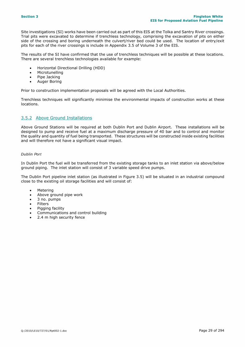
Site investigations (SI) works have been carried out as part of this EIS at the Tolka and Santry River crossings. Trial pits were excavated to determine if trenchless technology, comprising the excavation of pits on either side of the crossing and boring underneath the culvert/river bed could be used. The location of entry/exit pits for each of the river crossings is include in Appendix 3.5 of Volume 3 of the EIS. The results of the SI have confirmed that the use of trenchless techniques will be possible at these locations. There are several trenchless technologies available for example:
Horizontal Directional Drilling (HDD) Microtunelling Pipe Jacking Auger Boring
Prior to construction implementation proposals will be agreed with the Local Authorities. Trenchless techniques will significantly minimise the environmental impacts of construction works at these locations. 3.5.2 Above Ground Installations Above Ground Stations will be required at both Dublin Port and Dublin Airport. These installations will be designed to pump and receive fuel at a maximum discharge pressure of 40 bar and to control and monitor the quality and quantity of fuel being transported. These structures will be constructed inside existing facilities and will therefore not have a significant visual impact. Dublin Port In Dublin Port the fuel will be transferred from the existing storage tanks to an inlet station via above/below ground piping. The inlet station will consist of 3 variable speed drive pumps. The Dublin Port pipeline inlet station (as illustrated in Figure 3.5) will be situated in an industrial compound close to the existing oil storage facilities and will consist of:
Metering Above ground pipe work 3 no. pumps Filters Pigging facility Communications and control building 2.4 m high security fence

Section 3 Fingleton White EIS for Proposed Aviation Fuel Pipeline
Q:/2010/LE10/727/01/Rpt002-1.doc Page 30 of 294
Figure 3.5: Layout of Inlet Station at Dublin Port Dublin Airport The Dublin Airport pipeline reception station will be located within the existing loading and storage facilities at the airport. The present storage at Dublin Airport is 3 x 800 m3 tanks, with plans to upgrade this to 3 no. 5,000 m3 tanks for future demands. The station will be similar in appearance to that in Dublin Port consisting of:
Metering Above ground pipe work Filters Pigging facility Control valves Communications and control building 2.4 m high security fence
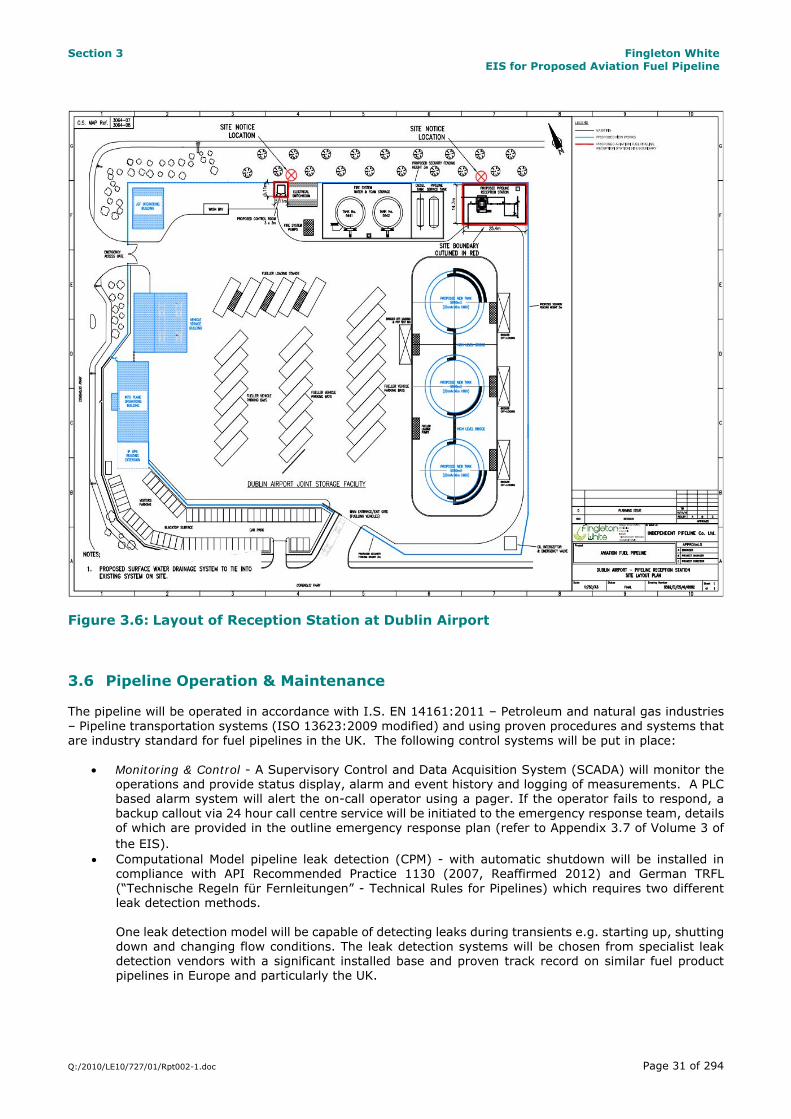
Figure 3.6 shows the layout of this reception station.
Section 3 Fingleton White EIS for Proposed Aviation Fuel Pipeline
Q:/2010/LE10/727/01/Rpt002-1.doc Page 31 of 294
Figure 3.6: Layout of Reception Station at Dublin Airport 3.6 Pipeline Operation & Maintenance The pipeline will be operated in accordance with I.S. EN 14161:2011 – Petroleum and natural gas industries – Pipeline transportation systems (ISO 13623:2009 modified) and using proven procedures and systems that are industry standard for fuel pipelines in the UK. The following control systems will be put in place:
Monitoring & Control - A Supervisory Control and Data Acquisition System (SCADA) will monitor the operations and provide status display, alarm and event history and logging of measurements. A PLC based alarm system will alert the on-call operator using a pager. If the operator fails to respond, a backup callout via 24 hour call centre service will be initiated to the emergency response team, details of which are provided in the outline emergency response plan (refer to Appendix 3.7 of Volume 3 of the EIS).
Computational Model pipeline leak detection (CPM) - with automatic shutdown will be installed in compliance with API Recommended Practice 1130 (2007, Reaffirmed 2012) and German TRFL (“Technische Regeln für Fernleitungen” - Technical Rules for Pipelines) which requires two different leak detection methods. One leak detection model will be capable of detecting leaks during transients e.g. starting up, shutting down and changing flow conditions. The leak detection systems will be chosen from specialist leak detection vendors with a significant installed base and proven track record on similar fuel product pipelines in Europe and particularly the UK.

Section 3 Fingleton White EIS for Proposed Aviation Fuel Pipeline
Q:/2010/LE10/727/01/Rpt002-1.doc Page 32 of 294
Leak detection systems will utilise current best available technology fiscal grade, International Organisation of Legal Metrology (OIML) approved Coriolis 0.1% uncertainty mass flow meters at both ends of the pipeline. The two computation models proposed are:
Negative Pressure Wave - API Method B.5. Analysis of the pressure and flow measurements to detect negative pressure and rarefaction
Flow/Pressure Mode - API Method B.4. Analysis of flow and pressure measurements using signature recognition to detect an imbalance anomaly which would indicate a leak. Flow/Pressure model will incorporate Mass Balance, Static Pressure (shut-in), and Leak Location functions.
The performance figures for CPM leak detection are as follows:
Performance Criteria Limit
Minimum detectable leak rate under static conditions 10 litres /hr Minimum detectable leak rate under flowing conditions 1% of flowrate
Time to confirm 1% flowing leak 10 minutes ( approximately 500 litres loss)
Response time for a 5% flowing leak 2 minutes ( approximately 500 litres loss) Response time for 10% or greater flowing leak 1 minute ( approximately 500 litres loss)
Leak location accuracy +/- 100 meters The leak detection system will be calibrated and validated using leaks simulated by drawing off fuel at the terminals and at intermediate points along the pipeline route (emergency shutdown valve chambers).
Safety - A set of safety plans and procedures will be put in place to cover the unlikely event of an accident with the pipeline. This safety plan will include a communications link to Dublin Port, DCC, FCC, the DAA and the HSA. The plan will be based on existing plans used by the aviation fuel transportation industry in the UK and adapted or modified as necessary to meet local conditions and the requirements of Dublin Fire Brigade.
Cathodic Protection - A Cathodic Protection (CP) system will be installed to prevent external corrosion of the pipe. An impressed current cathodic protection system with deep well anode groundbeds will be installed to prevent external corrosion of the pipe. This is to avoid and minimise sensitivity to stray currents e.g. as compared with a sacrificial anode system.
Physical Protection- The depth of cover to the pipeline will be 1.2 m. The trench will be backfilled with
300 mm of sand and pea gravel, then 700 mm of lean mix concrete to 200 mm below ground surface.
Visual Leak detection - Fortnightly inspections will be carried out on the pipeline route. An operator will survey the route on foot to detect factors that could affect the safety and the operation of the pipeline. Inspections will identify any third party activities along the route which may encroach on the pipeline.
Maintenance - Regular inspection of the inlet stations, filters, valves and other fittings will take place on a planned maintenance schedule. This will ensure that the line is properly maintained and meets the safety requirements. Within the first year of operation an inline corrosion survey/intelligent pigging run will be carried out to establish a baseline. This will be repeated every 10 years.
Emergency Shutdown Valves – Emergency shutdown valves will be installed on the pipeline, one on
the Malahide Road and one on the R139 at the junction of Clonshaugh Road and Riverside Road as well as the start and the end of the pipeline.
Further details in relation to these systems are included in the Design Basis Report in Appendix 3.2 of Volume 3 of the EIS.

Section 3 Fingleton White EIS for Proposed Aviation Fuel Pipeline
Q:/2010/LE10/727/01/Rpt002-1.doc Page 33 of 294
3.6.1 Standby Capability Provision will be made to have tankers available on standby to transport fuel to the airport in the event of a loss of the pipeline. A loss of the pipeline could occur for any of the following reasons:
Loss of ESB Supply Break in the pipeline Loss of control system
It is anticipated that any loss of the pipeline would not exceed 2 days duration. A loss of 1 no. pump will not lead to a loss capacity as 3 no. pumps will be installed. 3.6.2 Quality Checks – Fuel Quality checks will be carried out on the fuel to ensure that it is not contaminated. 3.7 Waste Management It will be the objective of the Developer in conjunction with appointed contractor to prevent, reduce, reuse and recover as much of the waste generated on site as practicable and to ensure the appropriate transport and disposal of residual waste off site. This is in line with the relevant National Waste Management Guidelines and the European Waste Management Hierarchy. Any waste generated by the development will be collected, source separated and stored in dedicated receptacles at the temporary compound(s) during construction. It will be the responsibility of the contractor for the main construction works (when appointed) to nominate a suitable site representative such as a Project Manager, Site Manager or Site Engineer as Waste Manager who will have overall responsibility for the management of waste. The waste manager will have overall responsibility to instruct all site personnel including sub-contractors to comply with on-site requirements. They will ensure that at an operational level that each crew foreman are assigned direct responsibility. 3.7.1 Waste Generated It is envisaged that the following categories of waste will be generated during the construction of the project:
Municipal solid waste (MSW) from workers Construction and demolition waste including soil Waste oil/hydrocarbons/lubricants Paper/cardboard
A permitted waste collection contractor will be appointed prior to construction works commencing. This contractor will provide appropriate receptacles for the collection of the various waste streams from the temporary storage compound(s) and will ensure the regular emptying/and or collection of these receptacles. All efforts will be made by site management to minimise the creation of waste throughout the project. This will be done by:
Materials ordering will be optimised to ensure only the necessary quantities of materials are delivered to site
All plant will be serviced before arriving on site. This will reduce the risk of breakdown and the possible generation of waste oil/hydrocarbons on site
Where materials such as concrete are being ordered care will be practiced in the calculation of quantities to reduce wastage.

Section 3 Fingleton White EIS for Proposed Aviation Fuel Pipeline
Q:/2010/LE10/727/01/Rpt002-1.doc Page 34 of 294
3.7.2 Waste Recovery In accordance with national waste policy, source separation of recyclable material will take place. This will include the provision of receptacles for the separation and collection of dry recyclables (paper, cardboard, plastics etc.) biological waste and residual waste. Receptacles will be clearly labelled, signposted and stored in dedicated areas. The following sourced segregated materials container will be made available the compound(s) for the duration of the construction works:
Ferrous Metals Dry Mixed Recyclables Food Waste Packaging Waste Residual Waste
3.7.3 Waste Disposal Residual waste, including the excavated trench material will require disposal. Excavated material will be loaded directly to an awaiting vehicle and transported by a contractor permitted under the Waste Management (Collection Permit) Regulations 2007 as amended to an appropriate facility. All waste movements will be recorded, of which records will be held by the waste manager on-site. 3.8 Emergency Measures The operation of the pipeline will be supervised 24/7 by the SCADA system. Alerts will be generated for abnormal conditions and the manager and operator will be presented with live real-time status and historical trend data for the entire process from the sending to receiving terminal. The SCADA system will activate callouts via SMS mobile messaging with an independent backup communications system if there is no response to the initial page. The SMS system will routinely send text messages throughout each day incorporating summary information. The SCADA system will alert the operator regardless of whether he/she is in the control room, outdoors on the plant or off site e.g. at the receiving terminal. It will also be capable of directly alerting 3rd parties e.g. Emergency Services. The control system will ensure that the pumps automatically shut down and the isolation valves close (within three minutes of an ‘event’. This will minimise the potential volume of fuel leaked in the event of a leak. Further details are provided in the Emergency Response Plan which has been included in Appendix 3.7 of Volume 3 of the EIS. 3.9 Pipeline Monitoring & Regulation In the UK, which has an extensive network of fuel pipelines, the HSE is the regulating authority. All the pipelines are operated in accordance with the UK Pipeline Safety Regulations (No. 825 of 1996). Given that there are no corresponding Regulations in Ireland at this time, it is proposed that this pipeline will be operated in accordance with the UK Pipeline Regulations and will be independently audited on an annual basis by an internationally recognised body, the British Pipeline Agency. The audit report will be submitted each year to both DCC and FCC.
Section 3 Fingleton White EIS for Proposed Aviation Fuel Pipeline
Q:/2010/LE10/727/01/Rpt002-1.doc Page 35 of 294
3.10 Decommissioning and Re-Validation Scenarios that would require decommissioning of the pipeline are as follows:
Structural Integrity of the pipe is compromised Relocation of Dublin Port or Dublin Airport Importation of fuel via Dublin Airport ceases.
This pipeline will be built and operated in accordance with ISEN 14161 so the risk of damage to the pipe is very low as detailed in the AMEC report contained in Appendix 2.1 of Volume 3 of the EIS. The risk of relocation of Dublin Port or Dublin Airport or the cessation of the importation of fuel via Dublin Port within the next 50 years is neglible. In the unlikely event that the pipeline is decommissioned, the pipeline will be cleaned in accordance with Sections 13.2.4 and 13.6 of I.S. EN 14161:2011. The pipeline will be emptied of fuel and flushed with water sourced from mains. The water will then be collected, sampled for contaminants and disposed of either to a surface water body (if deemed appropriate) or collected and taken offsite for disposal at an appropriate wastewater treatment facility (under licence). The pipeline can then be used for gas, water or telecoms cables. The cost of decommissioning the pipeline would be €120,000. The value of the asset would then be in the range €5 million to €10 million. There will be no financial risk to the local authorities. Re-Validation When records or estimates show that the design fatigue life has been reached, which will be in excess of 50 years, the pipeline can be revalidated by hydrotesting, or by internal inspection using a tool capable of the detection of longitudinal crack-like defects, particularly in or near the seam weld. If inspection is used, the detection limits of the inspection tool for crack-like defects will be taken into account when establishing the future fatigue life of the revalidated pipeline.