3 Decades in Supply - Pressure Max€¦ · M Tube Fitting Pressure-Temperature Ratings are designed...
96
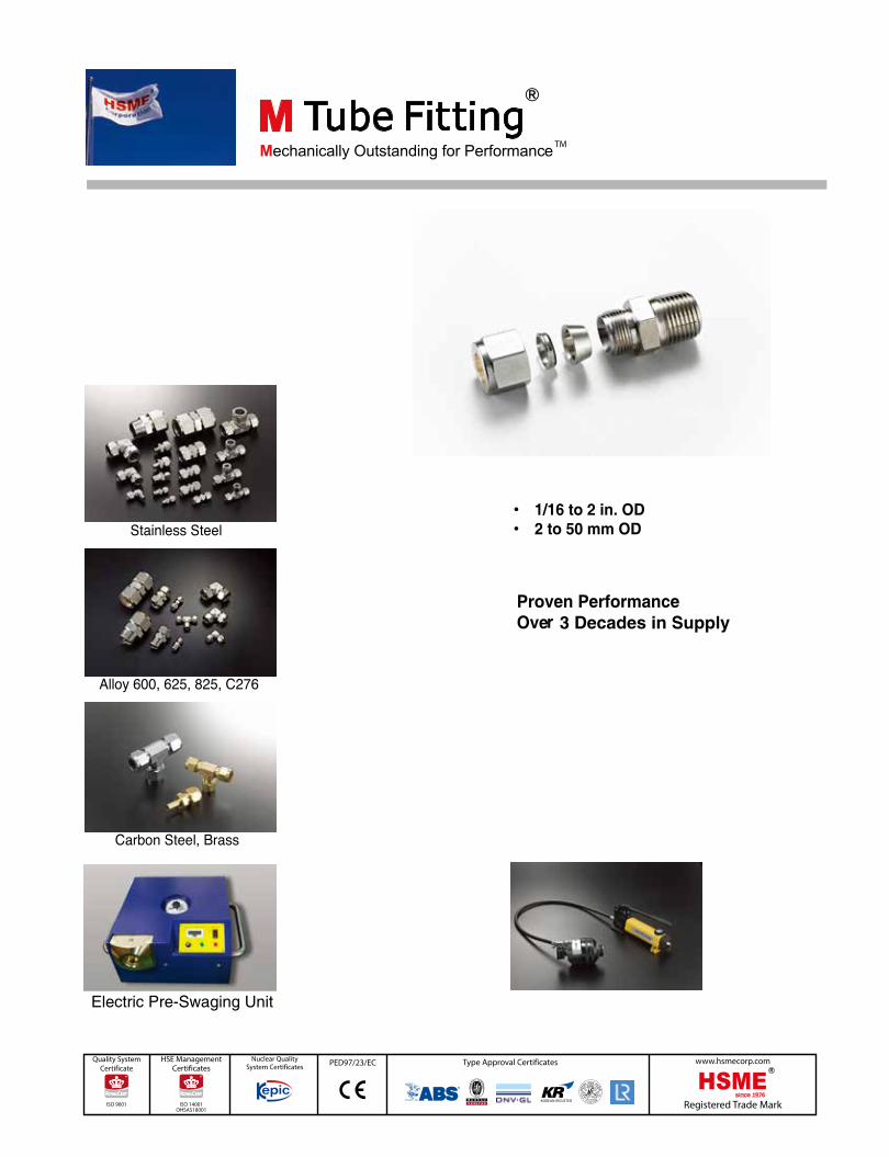
PED97/23/EC 3 Decades in Supply Electric Pre-Swaging Unit
Transcript of 3 Decades in Supply - Pressure Max€¦ · M Tube Fitting Pressure-Temperature Ratings are designed...
PED97/23/EC
3 Decades in Supply
Electric Pre-Swaging Unit

1 www.hsmecorp.com
M Tube Fitting Design Standards & Codes
Pre-lubricatedNut
20 TPI thread on Body & Nut to ASME B1.120 TPI Thread tolerance as specified in ASME B1.1 ensures gaugeability
Additionally engineered "Carpenter" TM ferrulematerials for outstanding sealing performance
Cold Roll Male Thread Constructionfor High Load Strength
ID or Sealing System Designed to ASTMA269 for min. to max. Tube OD Installation
Sealing Surface Finish to AME B46.1for Outstanding metal seal Performance
Forging quenched to ASTM A484for high mechanical strength
NPT Thread to ASME B1,20.1In-house L1 gauge inspection
M Tube Fitting Components & SectionsM Tube Fitting End (or Port)
Sealing faceon Body
Sealing faceon Ferrule
Sealing System
Pre-lubricatedNut
Tube Grip Angle
Pipe End
Tube Shoulder
Mechanically Outstanding for “Metal Seal" Leak-Tight Performance
Pressure-Temperature Ratings
Interchangeability
M Tube Fittings provide metal to metal sealing and are designed to exceed the requirements of industrial codes and standards with additionalCutting-Edge Engineering on leak-free pressure retaining performance.
M Tube Fitting Pressure-Temperature Ratings are designed to ASME B31.3 & B31.1 Codes.
Two ferrule geometry is a generic design that has been used in industry since 1940th. M Tube Fittings are interchangeable with those productsdesigned to the codes and standards referred to in M Tube Fitting catalog.
Gauge-AbilityMake-up 1 1/4 turns from finger-tight position moves NUT forward by 1.25 pitches.
On 20 TPI, the distance of 1.25 pitches equals 1/16 in. (1.5875 mm).The 1/16 in. leaves consistent Gap between nut & body for Gaugeability
Finger-tightPosition
1 1/4 TurnsPulled-UpPosition
1 1/4 Turns = 1.25 Threads1/16 in. = 1.5875mm
Gap forGaugeability
2www.hsmecorp.com
M Tube Fittings
AUUnion 15
AURReducing Union 16
AUBBulkhead Union 17
ABR Bulkhead Retainner
18
ABLBulkheadElbow Union
18
AUAAN Union 19
AUBA AN Bulkhead
Union19
ALUnion Elbow 20
ALRReducing Union Elbow 21
ATUnion Tee 21,22
ATR Reducing Union Tee 22,23
AXUnion Cross 24
AXR Reducing Union Cross 25
ALBM-N45° Male NPTElbow
37
ALBS-UPPositionable 45° SAE Male Elbow
37
ALM-NMale NPT Elbow 38,39
ALM-R Male BSPTElbow
40,41
ALM-GRPositionable Male ISOParallel ThreadElbow
42
ALS-UPPositionableSAE Male Elbow
43
ATRS-UP PositionableSAE Male Run Tee
44
ATBS-UPPositionableSAE Male Branch Tee
44
ATRM-NMale NPT Run Tee 45
ATRM-RMale BSPT Run Tee 46
ATBM-N,-R Male NPT/BSPTBranch Tee
47
ATBM-NMale NPT Branch Tee
48
ATBM-RMale BSPT Branch Tee
49
AMCB-NBulkheadMale NPT Connector
28
AMC-R Male BSPT Connector 29,30
AMC-GMale ISO ParallelConnector
31,33
AMC-GBMale ISO ParallelConnector
31,33
9PBN-G9PBV-GBonded Gasket
32
9PP-GCopper Gasket 32
AMC-UFNon-PositionableSAE Male Connector
34
AMC-UOO-Seal SAE MaleConnector
36
AMC-NO O-Seal NPTMale Connector
36
Tube to Tube Union
Male Elbows
AMCT/ARTBored-ThroughFittings
25
AMC-NMale NPT Connector 26,27
Tube to Male Pipe
Male Connector
ACF-NFemale NPTConnector
50,51
ACF-RFemale BSPTConnector
52,53
9PP-GGCopper Gasket 54
ACF-GG Female GaugeConnector
55
ACBF-N BulkheadFemale NPT Connector
56
ALF-N Female NPTElbows
57
ATRF-N Female NPT Run Tee 58
ATBF-N Female NPT Branch Tee
59
Tube to Female PipeFemale Connectors
Female Elbows
Female Run / Branch Tees
Index

3 www.hsmecorp.com
Index
AEUDielectric Fittings 79
AFUFusible Plugs 80
AVPVent Protector 80
AC Tube Cap 81
APPort Plugs 82
AITube Insert 82
AFF Front Ferrule 83
AFBBack Ferrule 83
AFSFerrule Set 84
AFSNNut-Ferrule Set 84
AN Nut 84
AJN BulkheadJam Nut
85
APN-UP/GR Positionable Lock Nut
85
AIG Gap Inspection Gauge 86
86
ATM Tube Depth Marker 88
APS Preswaging Tool 88
AHP/AEPPre-Swaging Unit 89
ACP Port Connector 60
ACPR Reducing PortConnector
61
AR Port Reducer 62,63
AABBulkhead TubeAdapter
64
ALAElbow TubeAdapter
64
ATRARun Tee TubeAdapter
65
ATBA Branch Tee TubeAdapter
65
AAM-NMale NPT Tube Adapter
AAM-RMale BSPT TubeAdapter
67
66
AAM-GMale ISO Parallel TubeAdapter
68
AAM-UF
Male O-Seal Tube Adapter
69
AAM-UO
Male SAE Tube Adapter
69
AMAAMale AN Tube Adapter 70
AAF-N Female NPT Tube Adapter 70,71
AAF-RFemale BSPT TubeAdapter
71
AAF-GZFemale ISO ParallelTube Adapter
72
AAF-GGFemale Gauge Tube Adapter 72,73
AAA AN Adapter 73
ACSW Tube Socket Weld Connector
74
ALSW Tube Socket Weld Elbow
Pipe Butt Weld Connector
74
ACBW 75
ALBW Pipe Butt Weld Elbow 76
ABUW Bulkhead Weld Union 76
AF Flange Adapters 77,78
AFCLap Joint Flange Connector
78
Tube Adapters
Engineered Products
Caps, Plugs, Tube Inserts
Spare Parts
Inspection Tools
Tube Handling Tools
Tools
Tube to Weld End
Tube to Flange
Tube Adapter to Male Pipe
Tube Adapter to Female PipeTube Adapter to Tube
ASC Stop Collar
Tube BenderTube CutterTube Deburring Tool
87

4www.hsmecorp.com
Material Standards / Application
Outstanding Performance
Material Standards
M Tube Fittings are supplied in a wide range of materials forextensive applications.
Over 1 in. / 25mm OD fittings are supplied with stainless steel ferrulescoated with PFA. For applications beyond 450 °F (232 °C) silver-platedfront ferrule and uncoated back ferrule are supplied.
Carbon steel fittings are White Zinc Electroplated with Chrome VI freeand supplied with stainless steel 316 back ferrule.
Stainless steel nuts are pre-lubricated with silver plating that eliminates thread galling and reduces assembly torque.
M Tube Fitting provides Outstanding Leak-Tight Performanceacross applications; Gas, Liquid, Steam in High Pressure, Heavy Vibration, Thermal Stress, and Extreme Impulse application.
To run flow,fluid system is pressurized. Especially a gas needs to be highly compressed to fill smaller tank orcontainer.
Pressure over 500 psig (34.5 bar) is considered high pressure. M Tube Fittings provide gas leak-tight performance based on theworking pressure of the tubing selected.
Use heavier wall tubing for gas application.
Heavier wall tubing recommended for gas service is identified inthe non-shaded area of the tubing tables beginning on page 8. The thin wall tubes are shaded for identification from heavierwall tubes that are not shaded.
Gases such as steam, air, oxygen, helium, nitrogen, methane, propane, etc have extremely small molecules that can escapethrough even the most minute leak path.
Heavier wall tubing allows the ferrules to coin out minor defectson tube surface whereas thin wall provides less resistance toferrule action, resulting in less chance of coining out surfacedefects.
Defects on tubing surface should be considered leak paths.
Outstanding Sealing System of M Tube Fitting eliminatesair-ingress into the tubing system at vacuum conditions. With properly selected tubing, M Tube Fittings performleak-tight up to the vacuum level of 10-9 torr.
Below -100 °F (– 37 °C) is considered cryogenic temperature. Stainless Steel M Tube Fittings provide outstanding leak-tightperformance up to -328 °F (– 200 °C) cryogenic application.
Stainless Steel Tube Fittings
Carbon Steel Tube Fittings
Pre-Lubricated Nuts
High Pressure Gas Application
Tubing For Gas Application
Vacuum Application
Cryogenic Application
• Shipbuilding
• On Shore Oil & Gas
• Offshore Oil & Gas
• Chemical & Petrochemical
• Refinery
• Analytical Instrumentation
• Power Generation
• Steel Mill
• Alternative Fuel
• Pharmaceutical
• Diesel & Dual Fuel Engine
• Cold roll M Tube Fitting Port thread provides higher load strength.
• Ferrules are constructed using proven CarpenterTM materials.
• Mechanical properties of ferrules are designed to swage the maximum hardness of tubing.
• Selectively hardened back ferrule only on leading edge provides elasticity, driving front ferrule for full metal surface contact.
• Excellent make & remake performance with outstanding combination of mechanical properties.
• Excellent performance in gas leak tight with outstanding sealing system.
• 4 to 1 safety ratio between working vs. burst pressure.
• Heat code traceable.
D*: Material Designator
D* Material Grade
ASTM Standards
Bar Stock Forging
SS Stainless Steel
A479, A276 Type 316/316L
JIS G4303 SUS316
A182 F316/F316LJIS G 3214 SUS F316
C Carbon Steel
A108 JIS G4051
S20C-S53C
A105 JIS G4051
S20C-S53C
B BrassB16, B453 C35300
JIS H3250 C3604, C3771
B283 Alloy 37700JIS H3250 C3771
6MO 6MoA 276 S31254 A182 Grade F44 S31254
L20 Alloy 20 B473 N08020 B462 N08020
L400 Monel 400 B164 N04400 B564 N04400
L600 Alloy 600 B166 N06600 B564 N06600
L625 Alloy 625 B446 N06625 B564 N06625
L825 Alloy 825 B425 N08825 B564 N08825
C276 Hastelloy C276 B574 N10276 B564 N10276
D Duplex SAF 2205 TM
A276 S31803 A479 S31803 A182 F51
SD Super Duplex SAF 2507TM A479 S32750 A182 F51
TI4 Titanium Gr.4 B348 Gr. 4 B381 F-4
AL AluminiumB211 Alloy 2024T6
JIS H4040 A2024, A6061
B247
TE PTFE D1710 D3294

5
M Tube Fittings
www.hsmecorp.com
Make and Remake
Leak-Free
Metric M Tube Fittings
High Quality Tubing Selection
Tubing Surface
Oval
Welded Tubing
Tubing Wall Thickness
Tubing Hardness
Cleaning and Surface Protection Tube Handling
Tube Cutting
Outstanding mechanical properties of M Tube Fittingprovides excellent make and remake performance.
Following M Tube Fitting’s Installation Instructions leads toa leak-free tubing system.
Purchasing high quality tubing, maintaining the tubing qualityon the good quality tubing rack, and proper handling of thetubing are the key to leak-tight tubing system.
Tube surface must be free from defects; scratches, draw mark, and flat spots
Tube OD being out of roundness may not fit into fitting.
Welded Tube must not have a measurable bead on outsidediameter.
Tubing must be carefully handled to keep the tubing surface condition as good as they are delivered.
Wall thickness of tubing governs the working pressure of tubing.
M Tube Fittings are designed to use with TUBING WALLs listedon tubing tables beginning on page 8.
Tubing for gas application must use those wall thicknesses outside of the shade in the tubing tables.
Wall thickness not listed in the tubing tables is not recommendedfor use with M Tube Fittings.
• Tubing must be fully annealed.• Tubing must be suitable for flaring and bending.
• Do not drag tubing out of tubing racks.
• Do not drag tubing across a rough surface such as cement.
• Select right tube cutter; wrong cutter may result in excessive deformation on tube end.
• Do not cut deep with each turn of cutter.
• Hacksaw blades should have at least 32 teeth per inch.
• Tube ends should be deburred on both OD and ID before use with tube fitting.
Metric M Tube Fittings are visually identifiable by the steppedshoulders on nut and body. Metric nut and straight body areconstructed out of metric hexagonal barstock.
Tube fittings are cleaned to remove surface contamination,loose particles, iron particles from machining tools, and oil fromcutting fluid. Additional processing takes place to protect tubefittings form corrosion and to improve performance
Special cleaning in compliance with the requirements of ASTM G93 Level C is optional.
Fractional M Tube Fittings
Metric M Tube Fittings
Stepped Shoulder
Stepped Shoulder
Fitting Body Materials Additional Processing
Stainless Steel, 6Mo Passivation
Carbon Steel White Zinc Electoplating with Chrome VI free
Brass Acid Cleaning
Alloy 20, Monel 400, Alloy 600, Alloy 625, Alloy 825, C276,
Duplex, Super DuplexHydrocarbon Film
Titanium Gr.4 Anodizing
Aluminum Anodizing, Hydrocarbon Film
PTFE Cleaning

6www.hsmecorp.com
Thread Standards
Pressure Rating
The table below contains the thread designator and relevant information of entire pipe thread constructed to M Tube Fittings.
M Tube Fitting Pressure RatingM Tube Fitting End is rated to the working pressure of tubing aslisted in the tubing tables.
Threaded / Butt Weld / Socket Weld /O-ring End /AN EndPressure RatingWhen fitting is combined with threaded / butt weld / socket weld /O-ring End, the pressure rating of these ends may be the limiting factor on thefitting’s pressure rating.
Pressure ratings are based on ASME B31.3 Process Pipe Code at ambient temperature unless otherwisw specified.
D*: Thread Designator E*: Equivalent
Tapered Pipe Thread End – N, and R
Parallel Pipe Thread End – G, and GB
1/16 14,000 965 6,600 455 7,400 510 3,300 2271/8 10,000 689 6,400 441 5,000 345 3,200 2201/4 8,300 572 6,500 448 4,100 282 3,200 2203/8 8,000 551 5,200 358 4,000 275 2,600 1791/2 7,800 537 4,800 331 3,900 269 2,400 1653/4 7,500 517 4,600 317 3,700 255 2,300 1581 5,300 365 4,400 303 2,600 179 2,200 152
1-1/4 6,200 427 5,000 345 3,100 214 2,500 1721-1/2 5,100 351 4,500 310 2,500 172 2,200 152
2 4,000 276 3,900 269 2,000 138 1,900 131
Pipe Sizein.
Stainless and Carbon Steel BrassMale FemaleM ale Female
psi bar psi bar psi bar psi barS Value 20ksi 10ksi
Pipe Size,
in.
Stainless and Carbon Steel
Malepsi bar
S Value 20ksi 1/8 16000 1103 1/4 12500 861 3/8 12000 827 1/2 11900 820 3/4 8000 5511 5600 386
1 1/4 5400 3721 1/2 5100 351
SAE Straight Threads
UF
ASME B1.1, SAE J514ISO R725, DIN 3852 (FORM F)Non-Positionable Seal by O-ring to SAE J1926/1Straight Thread Boss
O-Seal SAE straight threadSeal by O-ring to SAE J1926/1 Straight Thread Boss
Positionable Seal by O-ring to SAEJ1926/1 Straight Thread Boss
SR
UO
ASME B1.1SAE J514, ISO R725
OR
UP
ASME B1.1SAE J514, ISO R725
ST
D* Standards E*
Tapered Pipe Threads
N ASME B1.20.1 (NPT) -
RISO 7-1BS EN 10226 (BSPT)JIS B0203 (PF)
RT
NO
ASME B1.20.1SAE AS71051SAE J514
O-Seal NPT ThreadSeal by O-ring
OR
Parallel Pipe Threads
G
ISO 228-1BS 2779 (BSPP)DIN 3852 (FORM A)JIS B0202 (PF)Seal by Bonded Gasketor Copper Gasket
RS
GB
ISO 228-1BS 2779 (BSPP)DIN 3852 (FORM B)JIS B0202 (PF)
Seal by Copper Gasket,Compression against
RP
GR
ISO 228-1BS 2779 (BSPP)JIS B0202 (PF) PositionableSeal by O-ring
PR
GG
ISO 228-1, BS 2779 (BSPP)EN837-1, 837-3, JIS B0202 (PF)Gauge PortSeal by copper gasket at the bottom of GG female port
RG
GZ
ISO 228-1BS 2779 (BSPP)DIN 3852 (FORM Z)JIS B0202 (PF)
With G & GB Male threadSeal by copper gasket
RP
GY
ISO 228-1, BS 2779 (BSPP)DIN 3852 (FORM Y)JIS B0202 (PF)With G & GB male threadSeal by PTFE Gasket at theBottom of GY port.
RJ

7
M Tube Fittings
www.hsmecorp.com
SAE Straight Thread End - UF, and UP
SAE J514 37° Flare AN End
Temperature Rating
Fitting and Tubing Materials
O-ring Temperature Ratings
Pipe Butt Weld End – BW Tube Socket Weld End - SW
O Seal Fitting “NO” and “UO” Ends
Pressure Equivalents
Pressure ratings are based on SAE J1926/3 at ambient temperature.
Pressure Ratings are extracted from SAE J514 Standard.
When combining with O-ring, the temperature rating of the O-ring may be the limiting factor on fitting’s temperature rating.Brass and Carbon Steel O-ring fittings are supplied with 70 durometer NBR O-ring; Stainless Steel O-ring fittings are suppliedwith 90 durometer FKM O-ring.
Use of like tubing and fitting material is essential for leak-tight tubing system.Use of unlike material may affect sealing integrity. Copper tubing with brass M Tube Fitting is only exception.
Pressure ratings are at ambient temperature.
Pressure ratings are at ambient temperature.
Socket Weld End is rated to the workingpressure of tubing connected.
Stainless and Carbon Steel “NO” & “UO” Ends up to 1 in. are rated to 3000 psig (206 bar) at ambient temperature.
Positionable ISO/BSPP Parallel Thread – GRNominal
SAEDash Size
SAEThread
Size
Stainless and Carbon SteelNon-Positionable
"UF"Positionable
"UP"psi bar psi bar
2 5/16-24
4568 3154568 315
4 7/16-206 9/16-18
3626 2508 3/4-1610 7/8-14
3626 250 2900 20012 1 1/16-1214 1 3/16-12
2900 200 2320 16016 1 5/16-1220 1 5/8-12
2320 160 1813 12524 1 7/8-1232 2 1/2-12 1813 125 1450 100
ISO/BSPPMale Pipe
Size in.
Stainless Steel and
Carbon Steel
psi bar 1/8
4568 315 1/4 3/8 1/2
2320 160 3/41
Tube ODStainless and Carbon Steel
SAE J514, Table 1.Metric,
mm in. psi bar
2 1/8 5000 3446 1/4 5000 3448 5/16 5000 344
10 3/8 4000 27512 1/2 3000 20616 5/8 3000 20620 3/4 2500 17225 1 2000 13732 1 1/4 1150 79.238 1 1/2 1000 68.950 2 1000 68.9
Nom. Pipe Size
Stainless and Carbon Steel
Butt Weld End
psi bar
S Value 20ksi
1/8 5300 365
1/4 5200 358
3/8 4400 303
1/2 4100 282
3/4 3200 220
1 3100 213
1 1/4 3000 206
1 1/2 2900 199
2 1900 131
O-ring Designator Temperature Rating°F ( °C)
NBR BN -13 to 230 (-25 to 110)FKM VT - 20 to 400 (-28 to 204)
FFKM (Kalrez®) KZ4 - 22 to 600 (-30 to 315 )
BAR Mpa PSI
1 0.1 14.5100 10 1450160 16 2321210 21 3045315 31.5 4569350 35 5075400 40 5801
413.68 41.36 6000

8www.hsmecorp.com
Table 1. Fractional Seamless Stainless Steel Tubing
Table 2. Metric Seamless Stainless Steel Tubing
Welded Stainless Steel Tubing
Fully annealed seamless stainless steel tubing ASTM A269 or A213 TP 316/316L, 304/304L or equivalent. Tubing free from scratches,and suitable for bending and flaring. Hardness 90 HRB or less.
Allowable working pressures are calculated using S value of 20 000psi (1378 bar) for ASTM A269 tubing at -20 to 100°F (-28 to 37°C)as listed in ASME B31.3 Process Piping Code and ASME B31.1 Power Piping Code.
ASME B31.3 Code requires that for welded tubing, a de-rating factor must be applied for the allowable working pressure. For single welded tubing, multiply working pressure by 0.80, and for double welded tubing, multiply working pressure by 0.85.
• Pressure calculations are made with maximum O.D. and minimum wall thickness. No allowance is made for corrosion and erosion. Example: ASTM A 269 Type 316 Tubing, 1/2 in. OD x 0.065 in. WT. ASTM A269 standard spectifies permissible OD tolerance: +/- 0.005 in. (+/-0.13mm), permissible WT tolerance: +/- 15% Allowable working pressure is therefore calculated with maximum OD 0.505 in. and minimum WT 0.0552 in.• Safety Factor 3.75 to 1, considering specified ultimate tensile strength of 75,000 psi.
TubeODin
Wall Thickness (in) 0.012 0.014 0.016 0.02 0.028 0.035 0.049 0.065 0.083 0.095 0.109 0.12 0.134 0.156 0.188
Working Pressure (psi)1/16 6800 8100 9400 120001/8 8500 10900
3/16 5400 7000 102001/4 4000 5100 7500 10200
5/16 4000 5800 80003/8 3300 4800 6500 86001/2 2600 3700 5100 67005/8 2900 4000 5200 60003/4 2400 3300 4200 4900 5800 64007/8 2000 2800 3600 4200 4800 5400 61001 2400 3100 3600 4200 4700 5300 6200
1 1/4 2400 2800 3300 3600 4100 49001 1/2 2300 2700 3000 3400 4000 4900
2 2000 2200 2500 2900 3600
TubeODin
Wall Thickness (mm) 0.6 0.8 1 1.2 1.5 1.8 2 2.2 2.5 2.8 3 3.5 4 4.5 5.0
Working Pressure (bar) 2 780 10503 516 7104 520 6606 330 420 520 6708 310 380 490
10 240 300 38012 200 240 310 380 43014 180 220 280 340 390 43015 170 200 260 320 360 40016 190 240 300 330 37018 170 210 260 290 320 37020 150 190 230 260 290 330 38022 130 170 210 230 260 300 34025 180 200 230 260 300 32028 180 200 230 260 280 33030 170 190 210 240 260 31032 160 170 200 230 240 290 33038 140 170 190 200 240 280 31042 170 180 210 250 28050 150 180 200 230 260
9
M Tube Fittings
www.hsmecorp.com
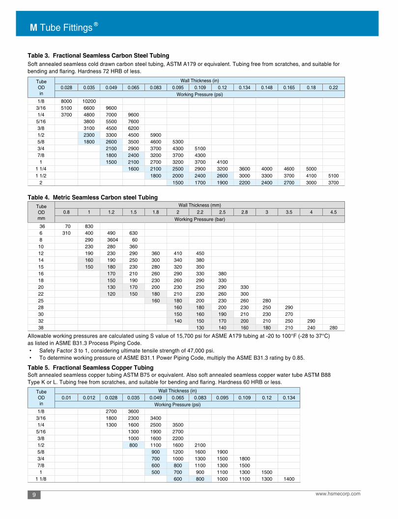
Table 3. Fractional Seamless Carbon Steel Tubing
Table 4. Metric Seamless Carbon steel Tubing
Table 5. Fractional Seamless Copper Tubing
Soft annealed seamless cold drawn carbon steel tubing, ASTM A179 or equivalent. Tubing free from scratches, and suitable forbending and flaring. Hardness 72 HRB of less.
Allowable working pressures are calculated using S value of 15,700 psi for ASME A179 tubing at -20 to 100°F (-28 to 37°C)as listed in ASME B31.3 Process Piping Code.
Soft annealed seamless copper tubing ASTM B75 or equivalent. Also soft annealed seamless copper water tube ASTM B88Type K or L. Tubing free from scratches, and suitable for bending and flaring. Hardness 60 HRB or less.
• Safety Factor 3 to 1, considering ultimate tensile strength of 47,000 psi.• To determine working pressure of ASME B31.1 Power Piping Code, multiply the ASME B31.3 rating by 0.85.
TubeODin
Wall Thickness (in) 0.028 0.035 0.049 0.065 0.083 0.095 0.109 0.12 0.134 0.148 0.165 0.18 0.22
Working Pressure (psi)1/8 8000 102003/16 5100 6600 96001/4 3700 4800 7000 96005/16 3800 5500 76003/8 3100 4500 62001/2 2300 3300 4500 59005/8 1800 2600 3500 4600 53003/4 2100 2900 3700 4300 51007/8 1800 2400 3200 3700 43001 1500 2100 2700 3200 3700 4100
1 1/4 1600 2100 2500 2900 3200 3600 4000 4600 50001 1/2 1800 2000 2400 2600 3000 3300 3700 4100 5100
2 1500 1700 1900 2200 2400 2700 3000 3700
TubeODmm
Wall Thickness (mm) 0.8 1 1.2 1.5 1.8 2 2.2 2.5 2.8 3 3.5 4 4.5
Working Pressure (bar) 36 70 8306 310 400 490 6308 290 3604 60
10 230 280 36012 190 230 290 360 410 45014 160 190 250 300 340 38015 150 180 230 280 320 35016 170 210 260 290 330 38018 150 190 230 260 290 33020 130 170 200 230 250 290 33022 120 150 180 210 230 260 30025 160 180 200 230 260 28028 160 180 200 230 250 29030 150 160 190 210 230 27032 140 150 170 200 210 250 29038 130 140 160 180 210 240 280
TubeODin
Wall Thickness (in) 0.01 0.012 0.028 0.035 0.049 0.065 0.083 0.095 0.109 0.12 0.134
Working Pressure (psi)1/8 2700 36003/16 1800 2300 34001/4 1300 1600 2500 3500
5/16 1300 1900 27003/8 1000 1600 22001/2 800 1100 1600 21005/8 900 1200 1600 19003/4 700 1000 1300 1500 18007/8 600 800 1100 1300 15001 500 700 900 1100 1300 1500
1 1/8 600 800 1000 1100 1300 1400

10www.hsmecorp.com
Table 6. Metric Seamless Copper Tubing
Alloy 400 (Monel)Tubing
Table 7. Fractional Seamless Alloy 400 Tubing
Table 8. Metric Seamless Alloy 400 Tubing
Allowable working pressures are calculated using S value of 6000 psi for ASTM B75 and B88 tubing at -20 to 100°F (-28 to 37°C)as listed in ASME B31.3 Process Piping Code and ASME B31.1 Power Piping Code.• Safety Factor 5 to 1, considering ultimate tensile strength of 30,000 psi.
Allowable working pressures are calculated using S value of 18.700 psi for ASTM B165 tubing at -20 to 100°F (-28 to 37°C)as listed in ASME B31.3 and ASME B31.1.• Safety Factor 3.7 to 1, considering ultimate tensile strength of 70,000 psi.
Fully annealed seamless Alloy 400 tubing, ASTM B165 or equivalent. Tubing to be free from scratches, and suitable for bendingand flaring. Hardness 75HRB or less. OD tolerance not to exceed +/- 0.005 in. or +/- 0.13 mm.
TubeODmm
Wall Thickness (mm) 0.7 0.8 1.0 1.2 1.5 1.6 1.8 2.0 2.2 2.5 2.8 3.0
Working Pressure (bar) 3 220 2504 160 190 240 2906 120 150 190 240 26088 0 110 130 170 190
10 70 80 100 130 150 170 19012 50 70 80 110 120 130 15014 60 70 90 100 110 130 140 170 190 20016 50 60 80 80 100 110 120 140 160 18018 40 50 70 70 80 100 110 120 140 15022 30 40 50 60 70 80 80 100 110 12025 30 40 50 50 60 70 70 80 100 10028 50 60 60 70 80 90
TubeODin
Wall Thickness (in) 0.028 0.035 0.049 0.065 0.083 0.095 0.109 0.12
Working Pressure (psi)1/8 7900 102001/4 3700 4800 7000 96003/8 3100 4400 61001/2 2300 3300 44003/4 2200 3000 4000 46001 2200 2900 3400 3900 4300
TubeODmm
Wall Thickness (mm)0.8 1.0 1.2 1.5 1.8 2.0 2.2 2.5 2.8 3.0
Working Pressure (bar)6 370 480 590 7508 350 430 55010 270 330 43012 220 270 35014 190 230 290 36018 170 220 270 310 34020 200 240 270 300 35025 170 210 240 270 310 330

11
M Tube Fittings
www.hsmecorp.com
Alloy C276 Tubing
Alloy 825 Tubing
Table 13. Fractional Seamless Super Duplex Tubing
Table 9. Metric Seamless Alloy C276 Tubing
Table 11. Fractional Seamless Alloy 825 Tubing Table 12. Metric Seamless Alloy 825 Tubing
Table 10. Metric Seamless Alloy C276 Tubing
Fully annealed seamless Alloy C276 tubing, ASTM B622 or equivalent. Tubing to be free from scratches, and suitable forbending and flaring. Hardness 100 HRB or less. OD tolerance not to exceed +/- 0.005 in. or +/-0.13 mm.
Fully annealed seamless Alloy 825 tubing, ASTM B423 or equivalent. Tubing to be free from scratches, and suitable for bending and flaring. Hardness not to exceed 201 HV.
Fully annealed seamless super duplex tubing, ASTM A789 S32750 or equivalent. Tubing to be free from scratches, andsuitable for bending and flaring. Hardenss 32 HRC or less.
Allowable working pressures are calculated using S value of 23,300 psi for ASTM B423 tubing at -20 to 100°F (-28 to 37°C) as listed inASME B31.3 and ASME B31.1. • Safety Factor 3.65 to 1, considering ultimate tensile strength of 85,000 psi.
• Allowable working pressures are calculated using S value of 38,700 psi for ASTM A789 tubing at -20 to 100°F (-28 to 37°C) as listed in ASME B31.3.
• Safety Factor is 3 to 1, considering ultimate tensile strength of 116,000 psi.
Allowable working pressures are calculated using S value of 27,300 psi for ASTM B622 tubing at -20 to 100°F (-28 to 37°C)as listed in ASME B31.3 and ASME B31.1.• Safety Factor 3.6 to 1, considering ultimate tensile strength of 100,000 psi.
TubeODin
Tube Wall Thickness (in)0.020 0.028 0.035 0.049 0.065 0.083
Working Pressure (psig)1/8 8,200 12,000 15,3003/16 5,300 7,700 9,900 14,4001/4 5,600 7,200 10,600 14,400
5/16 5,700 8,200 11,3003/8 4,700 6,700 9,2001/2 3,400 4,900 6,700 8,800
TubeODin
Tube Wall Thickness, in.0.028 0.035 0.049 0.065 0.083
Working Pressure (psig)1/4 7,800 9,900 14,5003/8 6,400 9,200 12,7001/2 4,700 6,800 9,200 12,100
TubeODin
Tube Wall Thickness, in.0.020 0.028 0.035 0.049 0.065 0.083
Working Pressure (psig)1/8 7,300 10,700 13,7003/16 4,700 6,800 8,800 12,8001/4 5,000 6,400 9,300 12,7005/16 5,000 7,300 10,0003/8 4,100 5,900 8,2001/2 3,000 4,300 5,900 7,800
TubeODmm
Tube Wall Thickness, mm0.8 1.0 1.2 1.5 1.8 2.0
Working Pressure (bar)6 460 600 730 9308 430 530 680
10 340 410 53012 280 340 430 530 600
Tube OD mm
Tube Wall Thickness (mm)0.8 1.0 1.2 1.5 1.8 2.0
Working Pressure (bar)6 450 600 760 1,000 8 440 550 730 10 340 430 570 12 280 350 460 580 660
12www.hsmecorp.com
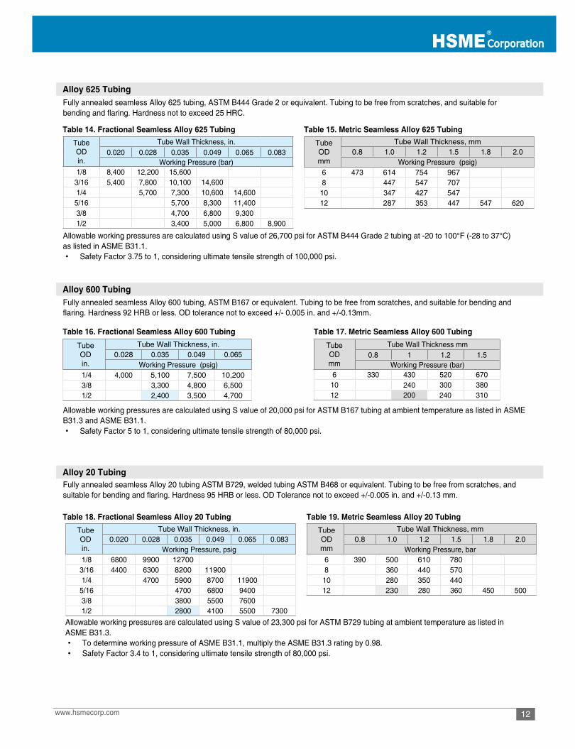
Alloy 625 Tubing
Alloy 600 Tubing
Alloy 20 Tubing
Table 14. Fractional Seamless Alloy 625 Tubing
Table 16. Fractional Seamless Alloy 600 Tubing
Table 18. Fractional Seamless Alloy 20 Tubing
Table 17. Metric Seamless Alloy 600 Tubing
Table 19. Metric Seamless Alloy 20 Tubing
Table 15. Metric Seamless Alloy 625 Tubing
Fully annealed seamless Alloy 625 tubing, ASTM B444 Grade 2 or equivalent. Tubing to be free from scratches, and suitable forbending and flaring. Hardness not to exceed 25 HRC.
Fully annealed seamless Alloy 600 tubing, ASTM B167 or equivalent. Tubing to be free from scratches, and suitable for bending and flaring. Hardness 92 HRB or less. OD tolerance not to exceed +/- 0.005 in. and +/-0.13mm.
Fully annealed seamless Alloy 20 tubing ASTM B729, welded tubing ASTM B468 or equivalent. Tubing to be free from scratches, and suitable for bending and flaring. Hardness 95 HRB or less. OD Tolerance not to exceed +/-0.005 in. and +/-0.13 mm.
Allowable working pressures are calculated using S value of 20,000 psi for ASTM B167 tubing at ambient temperature as listed in ASME B31.3 and ASME B31.1.• Safety Factor 5 to 1, considering ultimate tensile strength of 80,000 psi.
Allowable working pressures are calculated using S value of 23,300 psi for ASTM B729 tubing at ambient temperature as listed in ASME B31.3.• To determine working pressure of ASME B31.1, multiply the ASME B31.3 rating by 0.98.• Safety Factor 3.4 to 1, considering ultimate tensile strength of 80,000 psi.
Allowable working pressures are calculated using S value of 26,700 psi for ASTM B444 Grade 2 tubing at -20 to 100°F (-28 to 37°C) as listed in ASME B31.1.• Safety Factor 3.75 to 1, considering ultimate tensile strength of 100,000 psi.
TubeODmm
Tube Wall Thickness mm0.8 1 1.2 1.5
Working Pressure (bar)6 330 430 520 67010 240 300 38012 200 240 310
TubeODin.
Tube Wall Thickness, in.0.020 0.028 0.035 0.049 0.065 0.083
Working Pressure (bar)1/8 8,400 12,200 15,600
3/16 5,400 7,800 10,100 14,6001/4 5,700 7,300 10,600 14,600
5/16 5,700 8,300 11,4003/8 4,700 6,800 9,3001/2 3,400 5,000 6,800 8,900
Tube OD mm
Tube Wall Thickness, mm0.8 1.0 1.2 1.5 1.8 2.0
Working Pressure (psig)6 473 614 754 9678 447 547 707
10 347 427 54712 287 353 447 547 620
Tube OD in.
Tube Wall Thickness, in.0.028 0.035 0.049 0.065
Working Pressure (psig) 1/4 4,000 5,100 7,500 10,200 3/8 3,300 4,800 6,500 1/2 2,400 3,500 4,700
Tube OD in.
Tube Wall Thickness, in.0.020 0.028 0.035 0.049 0.065 0.083
Working Pressure, psig 1/8 6800 9900 12700
3/16 4400 6300 8200 11900 1/4 4700 5900 8700 11900
5/16 4700 6800 9400 3/8 3800 5500 7600 1/2 2800 4100 5500 7300
Tube OD mm
Tube Wall Thickness, mm0.8 1.0 1.2 1.5 1.8 2.0
Working Pressure, bar6 390 500 610 7808 360 440 570
10 280 350 44012 230 280 360 450 500
13
M Tube Fittings
www.hsmecorp.com
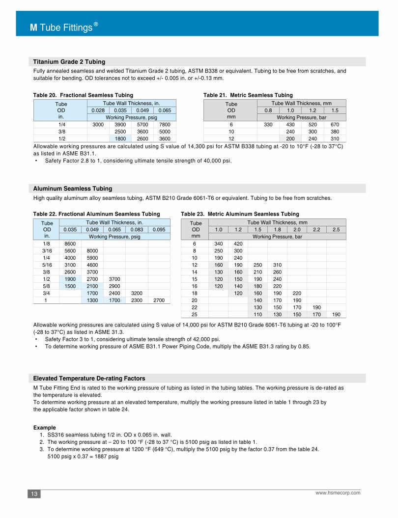
Titanium Grade 2 Tubing
Aluminum Seamless Tubing
Elevated Temperature De-rating Factors
Table 20. Fractional Seamless Tubing Table 21. Metric Seamless Tubing
Table 22. Fractional Aluminum Seamless Tubing Table 23. Metric Aluminum Seamless Tubing
Fully annealed seamless and welded Titanium Grade 2 tubing, ASTM B338 or equivalent. Tubing to be free from scratches, and suitable for bending. OD tolerances not to exceed +/- 0.005 in. or +/-0.13 mm.
High quality aluminum alloy seamless tubing, ASTM B210 Grade 6061-T6 or equivalent. Tubing to be free from scratches.
M Tube Fitting End is rated to the working pressure of tubing as listed in the tubing tables. The working pressure is de-rated as the temperature is elevated.To determine working pressure at an elevated temperature, multiply the working pressure listed in table 1 through 23 bythe applicable factor shown in table 24.
Example 1. SS316 seamless tubing 1/2 in. OD x 0.065 in. wall. 2. The working pressure at – 20 to 100 °F (-28 to 37 °C) is 5100 psig as listed in table 1. 3. To determine working pressure at 1200 °F (649 °C), multiply the 5100 psig by the factor 0.37 from the table 24. 5100 psig x 0.37 = 1887 psig
Allowable working pressures are calculated using S value of 14,000 psi for ASTM B210 Grade 6061-T6 tubing at -20 to 100°F (-28 to 37°C) as listed in ASME 31.3.• Safety Factor 3 to 1, considering ultimate tensile strength of 42,000 psi.• To determine working pressure of ASME B31.1 Power Piping Code, multiply the ASME B31.3 rating by 0.85.
Allowable working pressures are calculated using S value of 14,300 psi for ASTM B338 tubing at -20 to 10°F (-28 to 37°C) as listed in ASME B31.1.• Safety Factor 2.8 to 1, considering ultimate tensile strength of 40,000 psi.
Tube OD in.
Tube Wall Thickness, in.0.028 0.035 0.049 0.065
Working Pressure, psig 1/4 3000 3900 5700 7800 3/8 2500 3600 5000 1/2 1800 2600 3600
Tube OD mm
Tube Wall Thickness, mm0.8 1.0 1.2 1.5
Working Pressure, bar6 330 430 520 67010 240 300 38012 200 240 310
Tube OD in.
Tube Wall Thickness, in. 0.035 0.049 0.065 0.083 0.095
Working Pressure, psig 1/8 8600
3/16 5600 8000 1/4 4000 5900
5/16 3100 4600 3/8 2600 3700 1/2 1900 2700 3700 5/8 1500 2100 2900 3/4 1700 2400 32001 1300 1700 2300 2700
Tube OD mm
Tube Wall Thickness, mm1.0 1.2 1.5 1.8 2.0 2.2 2.5
Working Pressure, bar6 340 420 8 250 300
10 190 240 12 160 190 250 310 14 130 160 210 260 15 120 150 190 240 16 120 140 180 220 18 120 160 190 220 20 140 170 190 22 130 150 170 190 25 110 130 150 170 190

14www.hsmecorp.com
Table 24. Elevated Temperature De-rating Factors
Ordering Information Tube OD Designator
Pipe Thread Size Designator
Material Designators To order, select a part number and suffix an applicable material designator tothe part number.• To order complete assembly fitting, apply the material designator of complete assembly. Example: AU-8-SSA• To order component only, apply the material designator of component. Examples: Stainless steel Nut 1/2 in. OD : AN-8-SS Stainless steel Front Ferrule 1/2 in. OD: AFF-8-SS
Tee part number is described by firstthe run (1 and 2) and then the branch (3).
Cross part number is described by firstthe run (1 and 2) and then the branch(3 and 4).
Metric OD 2mm 3mm 4mm 6mm 8mm 10mm 12mm 16mm 18mm 22mm 25mm 32mm 38mm 50mm
Designator 2M 3M 4M 6M 8M 10M 12M 16M 18M 22M 25M 32M 38M 50M
ASTM Standard A269 B75 A179 B165 B622 B423 B444 B167 A789 B729 B338 B210Temperature
SS316 Copper CarbonSteel
Alloy400 C276 Alloy
825Alloy625
Alloy600
SuperDuplex
Alloy20
TitaniumGr.2 Aluminum
F° C°100 38 1 1 1 1 1 1 1 1 1 1 1 1200 93 1 0.80 0.96 0.88 1 1 0.92 1 1 0.86 0.88 1300 149 1 0.78 0.90 0.82 1 1 0.88 1 0.86 0.85 0.72 1400 204 0.97 0.50 0.86 0.79 1 1 0.85 1 0.82 0.83 0.61 0.94500 260 0.9 0.13 0.82 0.79 0.99 1 0.81 1 0.81 0.83 0.53 0.81600 316 0.85 0.77 0.79 0.93 1 0.79 1 0.81 0.83 0.45 0.56650 343 0.84 0.75 0.79 0.90 1 0.78 1 0.82 0.40700 371 0.82 0.73 0.79 0.88 1 0.77 1 0.82750 399 0.81 0.68 0.78 0.86 1 0.76 1 0.82800 427 0.80 0.59 0.76 0.84 0.99 0.75 1 0.82850 454 0.79 0.50 0.59 0.83 0.98 0.74 0.98900 482 0.78 0.41 0.43 0.82 0.98 0.73 0.80950 510 0.77 0.29 0.81 0.97 0.73 0.531000 538 0.77 0.16 0.80 0.96 0.72 0.351050 566 0.73 0.10 0.68 0.72 0.231100 593 0.62 0.06 0.55 0.72 0.151150 621 0.49 0.45 0.72 0.111200 649 0.37 0.36 0.72 0.101250 677 0.28 0.29
FractionalOD 1/16 1/8 3/16 1/4 5/16 3/8 1/2 5/8 3/4 7/8 1 1 1/4 1 1/2 2
Designator 1 2 3 4 5 6 8 10 12 14 16 20 24 32
NominalPipe Size, in. 1/16 1/8 1/4 3/8 1/2 3/4 1 1 1/4 1 1/2 2
Size Designator 1 2 4 6 8 12 16 20 24 32N 1N 2N 4N 6N 8N 12N 16N 20N 24N 32NR 1R 2R 4R 6R 8R 12R 16R 20R 24R 32RG - 2G 4G 6G 8G 12G 16G 20G 24G 32G
MaterialGrade
Designators
Component CompleteAssembly
Stainless Steel 316/316L SS SSA
Carbon Steel C CA
Brass B BA
6Mo 6MO 6MOA
Alloy 20 L20 L20A
Monel 400 L400 L400A
Alloy 600 L600 L600A
Alloy 625 L625 L625A
Alloy 825 L825 L825A
Hastelloy C276 C276ADuplex D DA
Super Duplex SD SDA
Titanium Gr.4 TI4 TI4A
Aluninium AL ALA
PTFE PE PEA
1 2
3
4
1 2
3
M Tube Fittings
15 www.hsmecorp.comAll dimensions are in millimeters unless otherwise specified. Dimensions are for reference only, subject to change.
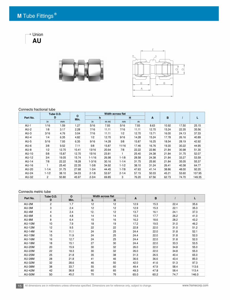
Union
AU
Connects fractional tube
Connects metric tube
Part No.Tube O.D.
D OMin. l L
in mm in m mi nm mAU-1 1/16 1.59 1.27 5/16 7.93 5/16 7.93 8.63 10.92 17.50 25.15AU-2 1/8 3.17 2.28 7/16 11.11 7/16 11.11 12.70 15.24 22.35 35.56AU-3 3/16 4.76 3.04 7/16 11.11 1/2 12.70 13.71 16.00 24.13 37.33AU-4 1/4 6.35 4.82 1/2 12.70 9/16 14.28 15.24 17.78 26.16 40.89AU-5 5/16 7.93 6.35 9/16 14.28 5/8 15.87 16.25 18.54 28.19 42.92
AU-6 3/8 9.52 7.11 5/8 15.87 11/16 17.46 16.76 19.30 30.22 44.95AU-8 1/2 12.70 10.41 13/16 20.64 7/8 22.22 22.86 21.84 30.98 51.30AU-10 5/8 15.87 12.70 15/16 23.81 1 25.40 24.38 21.84 31.75 52.07AU-12 3/4 19.05 15.74 1-1/16 26.98 1-1/8 28.58 24.38 21.84 33.27 53.59AU-14 7/8 22.22 18.28 1-3/16 30.16 1-1/4 31.75 25.90 21.84 35.05 55.37AU-16 1 25.40 22.35 1-3/8 34.92 1-1/2 38.10 31.24 26.41 40.38 64.77AU-20 1-1/4 31.75 27.68 1-3/4 44.45 1-7/8 47.63 41.14 38.86 48.00 92.20AU-24 1-1/2 38.10 34.03 2-1/8 53.97 2-1/4 57.15 50.03 45.21 53.60 107.95AU-32 2 50.80 45.97 2-3/4 69.85 3 76.20 67.56 62.73 74.70 149.35
h H A B
Part No. Tube O.D.D
OMin. l L
AU-2M 2 1.7 12 12 12.9 15.3 22.4 35.6AU-3M 3 2.4 12 12 12.9 15.3 22.1 35.3AU-4M 4 2.4 12. 12 13.7 16.1 24.1 37.3AU-6M 6 4.8 14 14 15.3 17.7 26.2 41.0AU-8M 8 6.4 15 16 16.2 18.6 28.2 43.2AU-10M 10 7.9 18 19 17.2 19.5 31.0 46.2AU-12M 12 9.5 22 22 22.8 22.0 31.0 51.2AU-14M 14 11.1 24 25 24.4 22.0 31.8 52.1AU-15M 15 11.9 24 25 24.4 22.0 31.8 52.0AU-16M 16 12.7 24 25 24.4 22.0 31.8 52.0AU-18M 18 15.1 27 30 24.4 22.0 33.3 53.5AU-20M 20 15.9 30 32 26.0 22.0 34.8 55.0AU-22M 22 18.3 30 32 26.0 22.0 34.8 55.0AU-25M 25 21.8 35 38 31.3 26.5 40.4 65.0AU-28M 28 21.8 41 46 36.6 36.6 43.4 85.0AU-32M 32 28.6 46 50 42.0 41.6 51.3 97.3AU-38M 38 33.7 55 60 49.4 47.9 58.4 113.6AU-42M 42 49.3 47.8AU-50M 50 65.0 60.2 74.7 146.0
h H A B
36.845.2
6070
6576
58.4 113.4

16www.hsmecorp.com All dimensions are in millimeters unless otherwise specified. Dimensions are for reference only, subject to change.
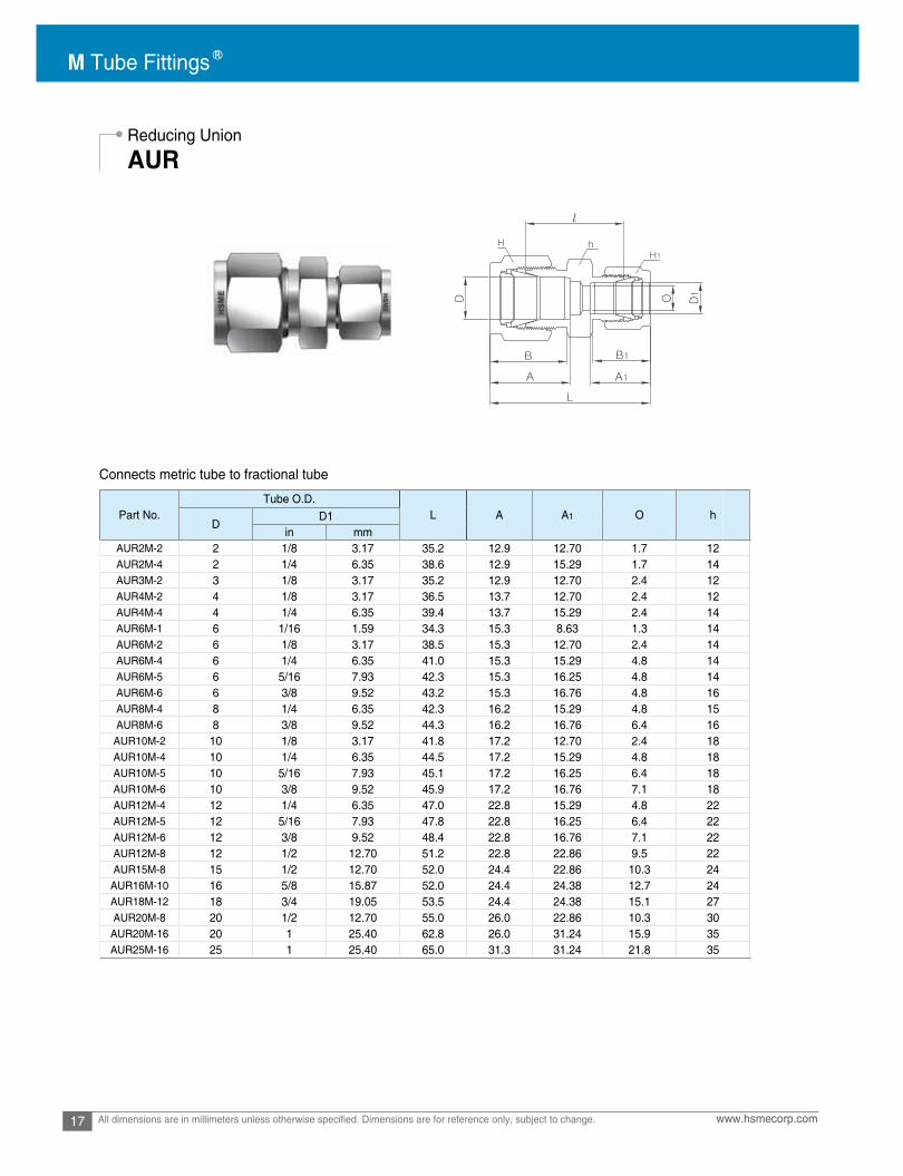
Reducing Union
AUR
Connects fractional tube
Connects metric tube
Part No.Tube O.D. O
Min. 1 1 l Lin mm i n mm in mm in mm in mm
AUR2-1 1/8 3.18 1/16 1.59 1.27 7/16 11.11 7/16 11.11 5/16 7.93 12.70 8.63 15.24 10.92 20.60 30.91AUR3-1 3/16 4.76 1/16 1.59 1.27 7/16 11.11 1/2 12.70 5/16 7.93 13.71 8.63 16.00 10.92 21.84 32.25AUR3-2 3/16 4.76 1/8 3.17 2.28 7/16 11.11 1/2 12.70 7/16 11.11 13.71 12.70 16.00 15.24 23.36 36.57AUR4-1 1/4 6.35 1/16 1.59 1.27 1/2 12.70 9/16 14.28 5/16 7.93 15.24 8.63 17.78 10.92 23.11 34.29AUR4-2 1/4 6.35 1/8 3.17 2.28 1/2 12.70 9/16 14.28 7/16 11.11 15.24 12.70 17.78 15.24 24.63 38.60AUR4-3 1/4 6.35 3/16 4.76 3.04 1/2 12.70 9/16 14.28 1/2 12.70 15.24 13.71 17.78 16.00 25.40 39.37AUR5-2 5/16 7.93 1/8 3.17 2.28 9/16 14.28 5/8 15.87 7/16 11.11 16.25 12.70 18.54 15.24 25.90 39.87AUR5-4 5/16 7.93 1/4 6.35 4.82 9/16 14.28 5/8 15.87 9/16 14.28 16.25 15.24 18.54 17.78 27.43 42.16AUR6-1 3/8 9.52 1/16 1.59 1.27 5/8 15.87 11/16 17.46 5/16 7.93 16.76 8.63 19.30 10.92 25.40 36.57AUR6-2 3/8 9.52 1/8 3.17 2.28 5/8 15.87 11/16 17.46 7/16 11.11 16.76 12.70 19.30 15.24 26.92 40.89AUR6-4 3/8 9.52 1/4 6.35 4.82 5/8 15.87 11/16 17.46 9/16 14.28 16.76 15.24 19.30 17.78 28.44 43.18AUR6-5 3/8 9.52 5/16 7.93 6.35 5/8 15.87 11/16 17.46 5/8 15.87 16.76 16.25 19.30 18.54 29.46 44.19AUR8-2 1/2 12.70 1/8 3.17 2.28 13/16 20.64 7/8 22.22 7/16 11.11 22.86 12.70 21.84 15.24 28.44 45.21AUR8-4 1/2 12.70 1/4 6.35 4.82 13/16 20.64 7/8 22.22 9/16 14.28 22.86 15.24 21.84 17.78 29.46 46.99AUR8-6 1/2 12.70 3/8 9.52 7.11 13/16 20.64 7/8 22.22 11/16 17.46 22.86 16.76 21.84 19.30 30.98 48.51AUR10-6 5/8 15.87 3/8 9.52 7.11 15/16 23.81 1 25.40 11/16 17.46 24.38 16.76 21.84 19.30 31.75 49.27AUR10-8 5/8 15.87 1/2 12.70 10.41 15/16 23.81 1 25.40 7/8 22.22 24.38 22.86 21.84 21.84 31.75 52.07AUR12-4 3/4 19.05 1/4 6.35 4.82 1-1/16 26.98 1-1/8 28.57 9/16 14.48 24.38 15.24 21.84 17.78 31.75 49.27AUR12-6 3/4 19.05 3/8 9.52 7.11 1-1/16 26.98 1-1/8 28.57 11/16 17.46 24.38 16.76 21.84 19.30 33.27 50.80AUR12-8 3/4 19.05 1/2 12.70 10.41 1-1/16 26.98 1-1/8 28.57 7/8 22.22 24.38 22.86 21.84 21.84 33.27 53.59AUR12-10 3/4 19.05 5/8 15.87 12.70 1-1/16 26.98 1-1/8 28.57 1 25.40 24.38 24.38 21.84 21.84 33.27 53.59AUR16-8 1 25.40 1/2 12.70 10.41 1-3/8 34.92 1-1/2 38.10 7/8 22.22 31.24 22.86 26.41 21.84 40.89 63.24AUR16-12 1 25.40 3/4 19.05 15.74 1-3/8 34.92 1-1/2 38.10 1-1/8 28.58 31.24 24.38 26.41 21.84 40.38 62.73
D h H H1 A A B BD1
Part No. Tube O.D. OMin.
Width across flat A A1 B B1 l LD D1 h H H1AUR3M-2M 3 2 1.7 12 12 12 12.9 12.9 15.3 15.3 22.1 35.3AUR6M-2M 6 2 1.7 14 14 12 15.3 12.9 17.7 15.3 24.6 38.6AUR6M-3M 6 3 2.4 14 14 12 15.3 12.9 17.7 15.3 24.6 38.6AUR6M-4M 6 4 2.4 14 14 12 15.3 13.7 17.7 16.1 25.4 39.4AUR8M-6M 8 6 4.8 15 16 14 16.2 15.3 18.6 17.7 27.4 42.3AUR10M-3M 10 3 2.4 18 19 12 17.2 12.9 19.5 15.3 27.7 41.9AUR10M-4M 10 4 2.4 18 19 12 17.2 13.7 19.5 16.1 28.7 42.9AUR10M-6M 10 6 4.8 18 19 14 17.2 15.3 19.5 17.7 29.5 44.5AUR10M-8M 10 8 6.4 18 19 16 17.2 16.2 19.5 18.6 30.0 45.1AUR12M-6M 12 6 4.8 22 22 14 22.8 15.3 22.0 17.7 29.5 47.0AUR12M-8M 12 8 6.4 22 22 16 22.8 16.2 22.0 18.6 30.2 47.8AUR12M-10M 12 10 7.9 22 22 19 22.8 17.2 22.0 19.5 31.0 48.7AUR16M-10M 16 10 7.9 24 25 19 24.4 17.2 22.0 19.5 31.8 49.5AUR16M-12M 16 12 9.5 24 25 22 24.4 22.8 22.0 22.0 31.8 52.0AUR18M-10M 18 10 7.9 27 30 19 24.4 17.2 22.0 19.5 33.0 51.0AUR18M-12M 18 12 9.5 27 30 22 24.4 22.8 22.0 22.0 33.3 53.5AUR25M-18M 25 18 15.1 35 38 30 31.3 24.4 26.5 22.0 38.6 61.0AUR25M-20M 25 20 15.9 35 50 32 31.3 26.0 26.5 22.0 39.9 62.3AUR30M-18M 30 18 15.1 46 50 30 39.7 24.4 39.3 22.0 43.7 75.4AUR30M-20M 30 20 15.9 46 50 32 39.7 26.0 39.3 22.0 43.7 75.4AUR30M-25M 30 25 21.8 46 50 38 39.7 31.3 39.3 26.5 46.2 80.1AUR32M-18M 32 18 15.1 46 50 30 42.0 24.4 41.6 22.0 44.7 77.8AUR32M-20M 32 20 15.9 46 50 32 42.0 26.0 41.6 22.0 44.7 77.8AUR32M-25M 32 25 21.8 46 50 38 42.0 31.3 41.6 26.5 47.0 82.3AUR38M-20M 38 20 15.9 55 60 32 49.4 26.0 47.9 22.0 49.8 87.5AUR38M-25M 38 25 21.8 55 60 38 49.4 31.3 47.9 26.5 52.1 92.0AUR38M-30M 38 30 26.2 55 60 50 49.4 39.7 47.9 39.3 55.4 104.6
M Tube Fittings
17 www.hsmecorp.comAll dimensions are in millimeters unless otherwise specified. Dimensions are for reference only, subject to change.
Connects metric tube to fractional tube
Reducing Union
AUR
Part No.Tube O.D.
L A A1 O hD
D1in mm
AUR2M-2 2 1/8 3.17 35.2 12.9 12.70 1.7 12AUR2M-4 2 1/4 6.35 38.6 12.9 15.29 1.7 14AUR3M-2 3 1/8 3.17 35.2 12.9 12.70 2.4 12AUR4M-2 4 1/8 3.17 36.5 13.7 12.70 2.4 12AUR4M-4 4 1/4 6.35 39.4 13.7 15.29 2.4 14AUR6M-1 6 1/16 1.59 34.3 15.3 8.63 1.3 14AUR6M-2 6 1/8 3.17 38.5 15.3 12.70 2.4 14AUR6M-4 6 1/4 6.35 41.0 15.3 15.29 4.8 14AUR6M-5 6 5/16 7.93 42.3 15.3 16.25 4.8 14AUR6M-6 6 3/8 9.52 43.2 15.3 16.76 4.8 16AUR8M-4 8 1/4 6.35 42.3 16.2 15.29 4.8 15AUR8M-6 8 3/8 9.52 44.3 16.2 16.76 6.4 16
AUR10M-2 10 1/8 3.17 41.8 17.2 12.70 2.4 18AUR10M-4 10 1/4 6.35 44.5 17.2 15.29 4.8 18AUR10M-5 10 5/16 7.93 45.1 17.2 16.25 6.4 18AUR10M-6 10 3/8 9.52 45.9 17.2 16.76 7.1 18AUR12M-4 12 1/4 6.35 47.0 22.8 15.29 4.8 22AUR12M-5 12 5/16 7.93 47.8 22.8 16.25 6.4 22AUR12M-6 12 3/8 9.52 48.4 22.8 16.76 7.1 22AUR12M-8 12 1/2 12.70 51.2 22.8 22.86 9.5 22AUR15M-8 15 1/2 12.70 52.0 24.4 22.86 10.3 24
AUR16M-10 16 5/8 15.87 52.0 24.4 24.38 12.7 24AUR18M-12 18 3/4 19.05 53.5 24.4 24.38 15.1 27AUR20M-8 20 1/2 12.70 55.0 26.0 22.86 10.3 30
AUR20M-16 20 1 25.40 62.8 26.0 31.24 15.9 35AUR25M-16 25 1 25.40 65.0 31.3 31.24 21.8 35

18www.hsmecorp.com All dimensions are in millimeters unless otherwise specified. Dimensions are for reference only, subject to change.
Bulkhead Union
AUB
Connects fractional tube
Connects metric tube
Part No.Tube O.D.
D OMin. L1
PanelHole Drill
Size
PanelMax
Thicknessin mm in mm in mm
AUB-1 1/16 1.59 1.27 5/16 7.93 5/16 7.93 8.63 10.92 23.87 13.46 31.50 17.27 5.16 3.05AUB-2 1/8 3.17 2.28 1/2 12.70 7/16 11.11 12.70 15.24 38.10 24.63 51.30 31.24 8.33 12.70AUB-3 3/16 4.76 3.04 9/16 14.28 1/2 12.70 13.71 16.00 40.38 25.40 53.59 32.00 9.92 12.70AUB-4 1/4 6.35 4.82 5/8 15.87 9/16 14.28 15.24 17.78 42.92 26.16 57.65 33.52 11.50 10.16AUB-5 5/16 7.93 6.35 11/16 17.46 5/8 15.87 16.25 18.54 45.97 28.44 60.70 35.81 13.09 11.17AUB-6 3/8 9.52 7.11 3/4 19.05 11/16 17.46 16.76 19.30 47.49 29.46 62.23 36.83 14.68 11.17AUB-8 1/2 12.70 10.41 15/16 23.81 7/8 22.22 22.86 21.84 50.80 31.75 71.12 41.91 19.44 12.70AUB-10 5/8 15.87 12.70 1-1/16 26.98 1 25.40 24.38 21.84 52.32 32.51 72.64 42.67 22.62 12.70AUB-12 3/4 19.05 15.74 1-3/16 30.16 1-1/8 28.58 24.38 21.84 58.67 37.33 78.99 47.49 25.79 16.76AUB-14 7/8 22.22 18.28 1-3/8 34.92 1-1/4 31.75 25.90 21.84 64.26 42.92 84.58 53.08 28.97 19.05AUB-16 1 25.40 22.35 1-5/8 41.27 1-1/2 38.10 31.24 26.41 71.37 45.21 95.75 57.40 33.73 19.05AUB-20 1-1/4 31.75 27.68 1-7/8 47.63 1-7/8 47.63 41.14 38.86 78.99 47.75 123.19 69.85 41.67 19.05AUB-24 1-1/2 38.10 34.03 2-1/4 57.15 2-1/4 57.15 50.03 45.21 84.83 49.27 139.19 76.45 49.61 19.05AUB-32 2 50.80 45.97 2-3/4 69.85 3 76.20 67.56 62.73 105.66 56.38 180.34 93.72 57.94 19.05
Hh A B Ll1l
Part No. Tube O.D.D
OMin L1
PanelHole
Drill Size
PanelMax
Thickness
AUB-3M 3 2.4 14.0 12 12.9 15.3 38.1 24.6 51.3 31.2 8.3 12.7AUB-4M 4 2.4 14.0 12 13.7 16.1 40.4 25.4 53.6 32.0 9.9 12.7AUB-6M 6 4.8 16.0 14 15.3 17.7 42.9 26.2 57.7 33.6 11.5 10.2AUB-8M 8 6.4 18.0 16 16.2 18.6 46.0 28.6 61.0 36.1 13.1 11.2AUB-10M 10 7.9 22.0 19 17.2 19.5 48.5 29.4 63.7 37.0 16.2 11.2AUB-12M 12 9.5 24.0 22 22.8 22.0 50.8 31.8 71.0 41.9 19.5 12.7AUB-15M 15 11.9 27.0 25 24.4 22.0 52.3 32.5 72.5 42.6 22.8 12.7AUB-16M 16 12.7 27.0 25 24.4 22.0 52.3 32.5 72.5 42.6 22.8 12.7AUB-18M 18 15.1 30.0 30 24.4 22.0 58.7 37.3 78.9 47.4 26.0 16.8AUB-20M 20 15.9 35.0 32 26.0 22.0 64.3 42.9 84.5 53.0 29.0 17.0AUB-22M 22 18.3 35.0 32 26.0 22.0 64.3 42.9 84.5 53.0 29.0 19.1AUB-25M 25 21.8 41.3 38 31.3 26.5 71.4 45.2 95.9 57.5 33.7 19.1AUB-32M 32 28.6 50.0 50 42.0 41.6 82.3 49.5 128.3 72.5 42.5 19.0AUB-38M 38 33.7 60.0 60 49.4 47.9 89.4 51.5 144.6 79.1 50.5 19.0
HhA B Ll1l
M Tube Fittings
19 www.hsmecorp.comAll dimensions are in millimeters unless otherwise specified. Dimensions are for reference only, subject to change.
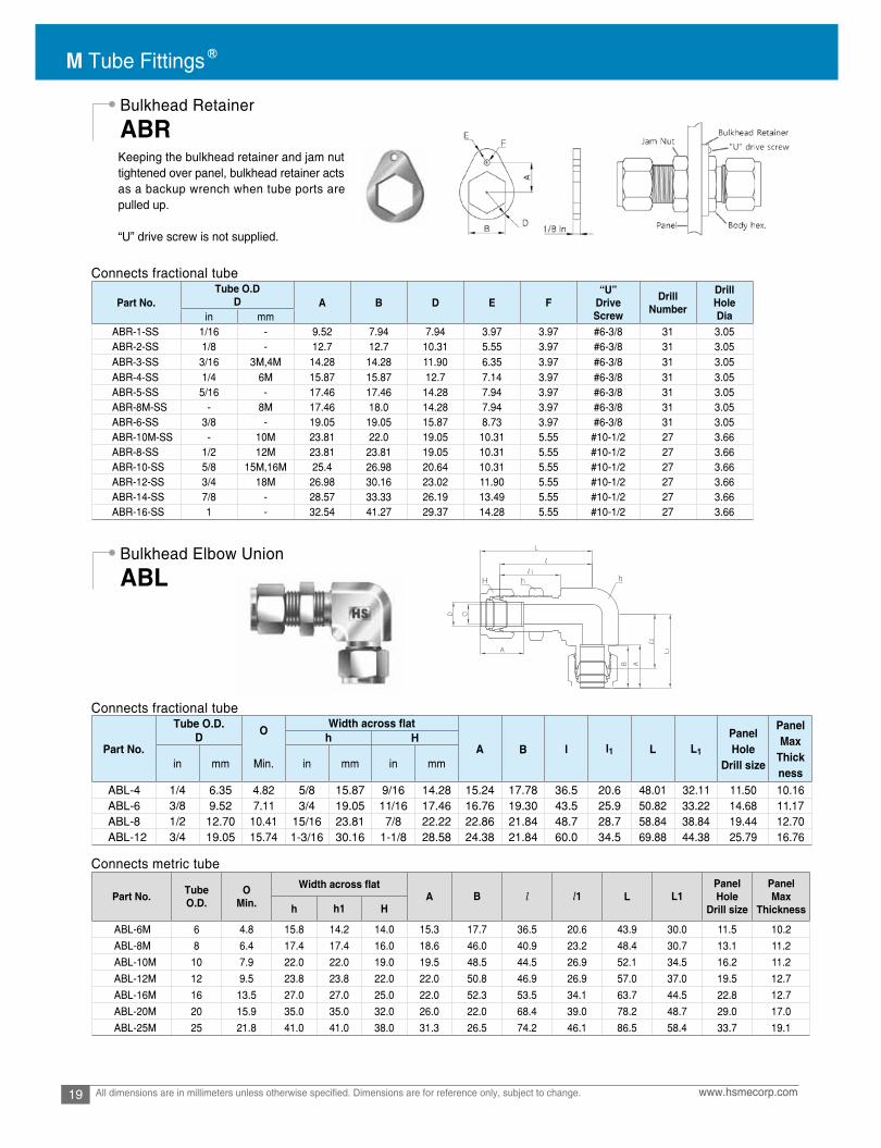
Bulkhead Retainer
Bulkhead Elbow Union
ABR
ABL
Keeping the bulkhead retainer and jam nut tightened over panel, bulkhead retainer acts as a backup wrench when tube ports are pulled up.
“U” drive screw is not supplied.
Connects fractional tube
Connects fractional tube
Connects metric tube
Part No.Tube O.D
D“U”
DriveScrew
DrillNumber
DrillHoleDiain mm
ABR-1-SS 1/16 - 9.52 7.94 7.94 3.97 3.97 #6-3/8 31 3.05ABR-2-SS 1/8 - 12.7 12.7 10.31 5.55 3.97 #6-3/8 31 3.05ABR-3-SS 3/16 3M,4M 14.28 14.28 11.90 6.35 3.97 #6-3/8 31 3.05ABR-4-SS 1/4 6M 15.87 15.87 12.7 7.14 3.97 #6-3/8 31 3.05ABR-5-SS 5/16 - 17.46 17.46 14.28 7.94 3.97 #6-3/8 31 3.05ABR-8M-SS 8M 17.46 18.0 14.28 7.94 3.97 #6-3/8 31 3.05ABR-6-SS 3/8 - 19.05 19.05 15.87 8.73 3.97 #6-3/8 31 3.05ABR-10M-SS 10M 23.81 22.0 19.05 10.31 5.55 #10-1/2 27 3.66ABR-8-SS 1/2 12M 23.81 23.81 19.05 10.31 5.55 #10-1/2 27 3.66ABR-10-SS 5/8 15M,16M 25.4 26.98 20.64 10.31 5.55 #10-1/2 27 3.66ABR-12-SS 3/4 18M 26.98 30.16 23.02 11.90 5.55 #10-1/2 27 3.66ABR-14-SS 7/8 - 28.57 33.33 26.19 13.49 5.55 #10-1/2 27 3.66ABR-16-SS - 32.54 41.27 29.37 14.28 5.55 #10-1/2 27 3.66
Part No.
Tube O.D.D O
A B l l1 L L1
PanelHole
Drill size
PanelMax
Thickness
h H
in mm Min. in mm in mm
ABL-4 1/4 6.35 4.82 5/8 15.87 9/16 14.28 15.24 17.78 36.5 20.6 48.01 32.11 11.50 10.16ABL-6 3/8 9.52 7.11 3/4 19.05 11/16 17.46 16.76 19.30 43.5 25.9 50.82 33.22 14.68 11.17ABL-8 1/2 12.70 10.41 15/16 23.81 7/8 22.22 22.86 21.84 48.7 28.7 58.84 38.84 19.44 12.70ABL-12 3/4 19.05 15.74 1-3/16 30.16 1-1/8 28.58 24.38 21.84 60.0 34.5 69.88 44.38 25.79 16.76
Part No. Tube O.D.
OMin. A B l l1 L L1
PanelHole
Drill size
PanelMax
Thicknessh h1 H
ABL-6M 6 4.8 15.8 14.2 14.0 15.3 17.7 36.5 20.6 43.9 30.0 11.5 10.2
ABL-8M 8 6.4 17.4 17.4 16.0 18.6 46.0 40.9 23.2 48.4 30.7 13.1 11.2
ABL-10M 10 7.9 22.0 22.0 19.0 19.5 48.5 44.5 26.9 52.1 34.5 16.2 11.2
ABL-12M 12 9.5 23.8 23.8 22.0 22.0 50.8 46.9 26.9 57.0 37.0 19.5 12.7
ABL-16M 16 13.5 27.0 27.0 25.0 22.0 52.3 53.5 34.1 63.7 44.5 22.8 12.7
ABL-20M 20 15.9 35.0 35.0 32.0 26.0 22.0 68.4 39.0 78.2 48.7 29.0 17.0
ABL-25M 25 21.8 41.0 41.0 38.0 31.3 26.5 74.2 46.1 86.5 58.4 33.7 19.1
20www.hsmecorp.com All dimensions are in millimeters unless otherwise specified. Dimensions are for reference only, subject to change.
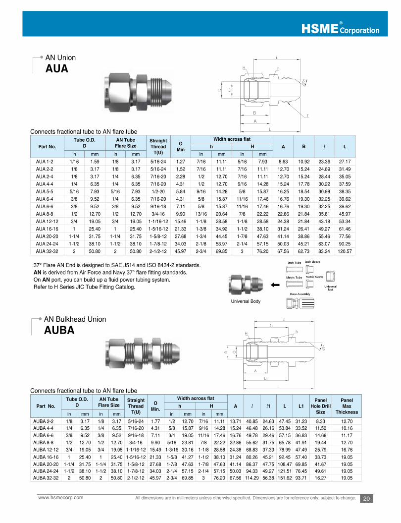
AN Union
AN Bulkhead Union
AUA
AUBA
Connects fractional tube to AN flare tube
Connects fractional tube to AN flare tube
Universal Body
37° Flare AN End is designed to SAE J514 and ISO 8434-2 standards. AN is derived from Air Force and Navy 37° flare fitting standards.On AN port, you can build up a fluid power tubing system.Refer to H Series JIC Tube Fitting Catalog.
Part No.Tube O.D.
DAN Tube
Flare SizeStraightThread
T(U)
OMin A B l Lh H
in mm in mm in mm in mm
AUA 1-2 1/16 1.59 1/8 3.17 5/16-24 1.27 7/16 11.11 5/16 7.93 8.63 10.92 23.36 27.17
AUA 2-2 1/8 3.17 1/8 3.17 5/16-24 1.52 7/16 11.11 7/16 11.11 12.70 15.24 24.89 31.49
AUA 2-4 1/8 3.17 1/4 6.35 7/16-20 2.28 1/2 12.70 7/16 11.11 12.70 15.24 28.44 35.05
AUA 4-4 1/4 6.35 1/4 6.35 7/16-20 4.31 1/2 12.70 9/16 14.28 15.24 17.78 30.22 37.59
AUA 5-5 5/16 7.93 5/16 7.93 1/2-20 5.84 9/16 14.28 5/8 15.87 16.25 18.54 30.98 38.35
AUA 6-4 3/8 9.52 1/4 6.35 7/16-20 4.31 5/8 15.87 11/16 17.46 16.76 19.30 32.25 39.62
AUA 6-6 3/8 9.52 3/8 9.52 9/16-18 7.11 5/8 15.87 11/16 17.46 16.76 19.30 32.25 39.62
AUA 8-8 1/2 12.70 1/2 12.70 3/4-16 9.90 13/16 20.64 7/8 22.22 22.86 21.84 35.81 45.97
AUA 12-12 3/4 19.05 3/4 19.05 1-1/16-12 15.49 1-1/8 28.58 1-1/8 28.58 24.38 21.84 43.18 53.34
AUA 16-16 1 25.40 1 25.40 1-5/16-12 21.33 1-3/8 34.92 1-1/2 38.10 31.24 26.41 49.27 61.46
AUA 20-20 1-1/4 31.75 1-1/4 31.75 1-5/8-12 27.68 1-3/4 44.45 1-7/8 47.63 41.14 38.86 55.46 77.56
AUA 24-24 1-1/2 38.10 1-1/2 38.10 1-7/8-12 34.03 2-1/8 53.97 2-1/4 57.15 50.03 45.21 63.07 90.25
AUA 32-32 2 50.80 2 50.80 2-1/2-12 45.97 2-3/4 69.85 3 76.20 67.56 62.73 83.24 120.57
Part No.Tube O.D.
DAN Tube
Flare SizeStraightThread
T(U)
OMin. A l l1 L L1
PanelHole Drill
Size
PanelMax
Thicknessh H
in mm in mm in mm in mm
AUBA 2-2 1/8 3.17 1/8 3.17 5/16-24 1.77 1/2 12.70 7/16 11.11 13.71 40.85 24.63 47.45 31.23 8.33 12.70AUBA 4-4 1/4 6.35 1/4 6.35 7/16-20 4.31 5/8 15.87 9/16 14.28 15.24 46.48 26.16 53.84 33.52 11.50 10.16AUBA 6-6 3/8 9.52 3/8 9.52 9/16-18 7.11 3/4 19.05 11/16 17.46 16.76 49.78 29.46 57.15 36.83 14.68 11.17AUBA 8-8 1/2 12.70 1/2 12.70 3/4-16 9.90 5/16 23.81 7/8 22.22 22.86 55.62 31.75 65.78 41.91 19.44 12.70AUBA 12-12 3/4 19.05 3/4 19.05 1-1/16-12 15.49 1-3/16 30.16 1-1/8 28.58 24.38 68.83 37.33 78.99 47.49 25.79 16.76
AUBA 16-16 1 25.40 1 25.40 1-5/16-12 21.33 1-5/8 41.27 1-1/2 38.10 31.24 80.26 45.21 92.45 57.40 33.73 19.05AUBA 20-20 1-1/4 31.75 1-1/4 31.75 1-5/8-12 27.68 1-7/8 47.63 1-7/8 47.63 41.14 86.37 47.75 108.47 69.85 41.67 19.05AUBA 24-24 1-1/2 38.10 1-1/2 38.10 1-7/8-12 34.03 2-1/4 57.15 2-1/4 57.15 50.03 94.33 49.27 121.51 76.45 49.61 19.05AUBA 32-32 2 50.80 2 50.80 2-1/2-12 45.97 2-3/4 69.85 3 76.20 67.56 114.29 56.38 151.62 93.71 16.27 19.05

M Tube Fittings
21 www.hsmecorp.comAll dimensions are in millimeters unless otherwise specified. Dimensions are for reference only, subject to change.
Union Elbow
AL
Connects fractional tube
Connects metric tube
Part No.Tube O.D.
D OMin A B l Lh H
in mm in mm in mm
AL-1 1/16 1.59 1.27 3/8 9.52 5/16 7.93 8.63 10.92 14.00 17.88
AL-2 1/8 3.17 2.28 3/8 9.52 7/16 11.11 12.70 15.24 15.74 22.35
AL-3 3/16 4.76 3.04 1/2 12.70 1/2 12.70 13.71 16.00 17.78 24.38
AL-4 1/4 6.35 4.82 1/2 12.70 9/16 14.28 15.24 17.78 19.55 26.92
AL-5 5/16 7.93 6.35 9/16 14.28 5/8 15.87 16.25 18.54 21.33 28.70
AL-6 3/8 9.52 7.11 5/8 15.87 11/16 17.46 16.76 19.30 23.11 30.48
AL-8 1/2 12.70 10.41 13/16 20.64 7/8 22.22 22.86 21.84 25.90 36.06
AL-10 5/8 15.87 12.70 15/16 23.81 1 25.40 24.38 21.84 28.70 38.80
AL-12 3/4 19.05 15.74 1-1/16 26.98 1-1/8 28.58 24.38 21.84 29.71 39.87
AL-14 7/8 22.22 18.28 1-3/8 34.92 1-1/4 31.75 25.90 21.84 34.54 44.70
AL-16 1 25.40 22.35 1-3/8 34.92 1-1/2 38.10 31.24 26.41 36.83 49.02
AL-20 1-1/4 31.75 27.68 1-11/16 42.86 1-7/8 47.63 41.14 38.86 44.50 66.54
AL-24 1-1/2 38.10 34.03 2 50.80 2-1/4 57.15 50.03 45.21 50.80 77.97
AL-32 2 50.80 45.97 2-3/4 69.85 3 76.20 67.56 62.73 69.80 107.18
Part No. Tube O.D.D
OMin A B l L
h HAL-2M 2 1.7 9.5 12 12.9 15.3 15.7 22.3
AL-3M 3 2.4 9.5 12 12.9 15.3 15.7 22.3
AL-4M 4 2.4 12.7 12 13.7 16.4 18.8 25.4
AL-6M 6 4.8 12.7 14 15.3 17.7 19.6 27.0
AL-8M 8 6.4 14.3 16 16.2 18.6 21.3 28.8
AL-10M 10 7.9 17.5 19 17.2 19.5 23.9 31.5
AL-12M 12 9.5 20.6 22 22.8 22.0 25.9 36.0
AL-15M 15 11.9 25.4 25 24.4 22.0 28.7 38.8
AL-16M 16 12.7 25.4 25 24.4 22.0 28.7 38.8
AL-18M 18 15.1 27.0 30 24.4 22.0 29.7 39.8
AL-20M 20 15.9 34.92 32 26.0 22.0 32.5 42.6
AL-22M 22 18.3 34.92 32 26.0 22.0 32.5 42.6
AL-25M 25 21.8 34.92 38 31.3 26.5 36.8 49.1
AL-28M 28 21.8 41.0 46 36.6 36.6 43.2 64.0
AL-32M 32 28.6 46.0 50 42.0 41.6 49.3 72.3
AL-38M 38 33.7 55.0 60 49.4 47.9 56.4 84.0

22www.hsmecorp.com All dimensions are in millimeters unless otherwise specified. Dimensions are for reference only, subject to change.
Reducing Union Elbow
Union Tee
ALR
AT
Connects fractional tube
Connects metric tube
Connects fractional tube
Part No.Tube O.D.
O O1 A A1 B B1 l l1 L L1D D1 h H H1in mm in mm in mm in mm in mm
ALR2-1 1/8 3.17 1/16 1.59 3/8 9.52 7/16 11.11 5/16 7.93 2.4 1.3 12.7 8.63 15.24 10.93 15.74 14.2 22.35 18.0ALR4-2 1/4 6.35 1/8 3.17 1/2 12.7 9/16 14.28 7/16 11.11 4.8 2.4 15.24 12.7 17.78 15.24 19.55 17.9 26.92 24.5ALR6-4 3/8 9.32 1/4 6.35 5/8 15.87 11/16 17.46 9/16 14.28 7.1 4.8 16.76 15.24 19.3 17.78 23.1 21.92 30.47 29.29ALR8-4 1/2 12.7 1/4 6.35 13/16 20.64 7/8 22.22 9/16 14.28 10.41 4.8 22.86 15.24 21.84 17.78 25.9 24.4 36.06 31.77ALR8-6 1/2 12.7 3/8 9.52 13/16 20.64 7/8 22.22 11/16 17.46 10.41 7.1 22.86 16.76 21.84 19.30 25.9 25.9 36.06 33.27
Part No.Tube O.D
O O1 A A1 B B1 l l1 L L1D
D1 h H1in mm in mm mm in mm
ALR8M-4 8 1/4 6.35 9/16 14.28 16 9/16 14.28 6.4 4.8 16.2 15.24 18.6 17.78 21.3 20.6 28.7 28.0
Part No.Tube O.D O
Min. A B l Lh Hin mm in mm in mm
AT-1 1/16 1.59 1.27 3/8 9.52 5/16 7.93 8.63 10.92 14.00 17.88AT-2 1/8 3.17 2.28 3/8 9.52 7/16 11.11 12.70 15.24 15.74 22.35AT-3 3/16 4.76 3.04 1/2 12.70 1/2 12.70 13.71 16.00 17.78 24.38AT-4 1/4 6.35 4.82 1/2 12.70 9/16 14.28 15.24 17.78 19.55 26.92AT-5 5/16 7.93 6.35 9/16 14.28 5/8 15.87 16.25 18.54 21.33 28.70
AT-6 3/8 9.52 7.11 5/8 15.87 11/16 17.46 16.76 19.30 23.11 30.48AT-8 1/2 12.70 10.41 13/16 20.64 7/8 22.22 22.86 21.84 25.90 36.06AT-10 5/8 15.87 12.70 15/16 23.81 1 25.40 24.38 21.84 28.70 38.80AT-12 3/4 19.05 15.74 1-1/16 26.98 1-1/8 28.58 24.38 21.84 29.71 39.87AT-14 7/8 22.22 18.28 1-3/8 34.92 1-1/4 31.75 25.90 21.84 34.54 44.70AT-16 1 25.40 22.35 1-3/8 34.92 1-1/2 38.10 31.24 26.41 36.83 49.02AT-20 1-1/4 31.75 27.68 1-11/16 42.86 1-7/8 47.63 41.14 38.86 44.50 66.54AT-24 1-1/2 38.10 34.03 2 50.80 2-1/4 57.15 50.03 45.21 50.80 77.97AT-32 2 50.80 45.97 2-3/4 69.85 3 76.20 67.56 62.73 69.80 107.18

M Tube Fittings
23 www.hsmecorp.comAll dimensions are in millimeters unless otherwise specified. Dimensions are for reference only, subject to change.
Reducing Union Tee
ATR1 2
3
Connects metric tube
Connects fractional tube
Part No. Tube O.DD
OMin A B l L
h HAT-2M 2 1.7 9.5 12 12.9 15.3 15.7 22.3
AT-3M 3 2.4 9.5 12 12.9 15.3 15.7 22.3
AT-4M 4 2.4 12.7 12 13.7 16.4 18.8 25.4
AT-6M 6 4.8 12.7 14 15.3 17.7 19.6 27.0
AT-8M 8 6.4 14.3 16 16.2 18.6 21.3 28.8
AT-10M 10 7.9 17.5 19 17.2 19.5 23.9 31.5
AT-12M 12 9.5 20.6 22 22.8 22.0 25.9 36.0
AT-15M 15 11.9 25.4 25 24.4 22.0 28.7 38.8
AT-16M 16 12.7 25.4 25 24.4 22.0 28.7 38.8
AT-18M 18 15.1 27.0 30 24.4 22.0 29.7 39.8
AT-20M 20 15.9 34.92 32 26.0 22.0 32.5 42.6
AT-22M 22 18.3 34.92 32 26.0 22.0 32.5 42.6
AT-25M 25 21.8 34.92 38 31.3 26.5 36.8 49.1
AT-28M 28 21.8 41.0 46 36.6 36.6 43.2 64.0
AT-32M 32 28.6 46.0 50 42.0 41.6 49.3 72.3
AT-38M 38 33.7 55.0 60 49.4 47.9 56.4 84.0
Part No.Port 1
DPort 2
D1Port 3
D2O
Min. l l1 l2 L L1 L2h H H1 H2in Mm i n mm i n Mm in mm in mm in mm in mm
ATR4-4-2 1/4 6.35 1/4 6.35 1/8 3.17 2.4 1/2 12.7 9/16 14.28 9/16 14.28 7/16 11.11 19.55 19.55 17.9 26.91 26.91 24.5ATR4-4-6 1/4 6.35 1/4 6.35 3/8 9.52 4.8 5/8 15.87 9/16 14.28 9/16 14.28 11/16 17.46 21.92 21.92 17.9 29.28 29.28 30.46ATR4-8-8 1/4 6.35 1/2 12.7 1/2 12.7 4.8 13/16 20.64 9/16 14.28 7/8 22.22 7/8 22.22 24.4 25.9 23.1 31.76 36.06 36.06ATR6-4-6 3/8 9.52 1/4 6.35 3/8 9.52 4.8 5/8 15.87 11/16 17.46 9/16 14.28 11/16 17.46 23.1 21.92 25.9 30.46 29.28 30.46ATR6-6-4 3/8 9.52 3/8 9.52 1/4 6.35 4.8 5/8 15.87 11/16 17.46 11/16 17.46 9/16 14.28 23.1 23.1 23.1 30.46 30.46 29.28ATR6-6-8 3/8 9.52 3/8 9.52 1/2 12.7 7.1 13/16 20.64 11/16 17.46 11/16 17.46 7/8 22.22 25.9 25.9 21.92 33.26 33.26 36.06ATR8-4-6 1/2 12.7 1/4 6.35 3/8 9.52 4.8 13/16 20.64 7/8 22.22 9/16 14.28 11/16 17.46 25.9 25.9 25.9 36.06 33.26 33.26ATR8-4-8 1/2 12.7 1/4 6.35 1/2 12.7 7.1 13/16 20.64 7/8 22.22 9/16 14.28 7/8 22.22 25.9 24.4 25.9 36.06 31.76 36.06ATR8-6-6 1/2 12.7 3/8 9.52 3/8 9.52 7.1 13/16 20.64 7/8 22.22 11/16 17.46 11/16 17.46 25.9 25.9 25.9 36.06 33.26 33.26ATR8-8-4 1/2 12.7 1/2 12.7 1/4 6.35 4.8 13/16 20.64 7/8 22.22 7/8 22.22 9/16 14.28 25.9 25.9 25.9 36.06 36.06 31.76ATR8-8-6 1/2 12.7 1/2 12.7 3/8 9.52 7.1 13/16 20.64 7/8 22.22 7/8 22.22 11/16 17.46 25.9 25.9 24.4 36.06 36.06 33.26ATR10-10-6 5/8 15.87 5/8 15.87 3/8 9.52 7.1 15/16 23.81 1 25.4 1 25.4 11/16 17.46 28.7 28.7 25.9 38.86 38.86 36.06ATR12-8-12 3/4 19.05 1/2 12.7 3/4 19.05 10.41 1-1/16 26.98 1-1/8 28.57 7/8 22.22 1-1/8 28.57 29.71 29.71 28.7 39.87 39.87 39.87ATR12-12-4 3/4 19.05 3/4 19.05 1/4 6.35 4.8 1-1/16 26.98 1-1/8 28.57 1-1/8 28.57 9/16 14.28 29.71 29.71 29.71 39.87 39.87 35.57ATR12-12-6 3/4 19.05 3/4 19.05 3/8 9.52 7.1 1-1/16 26.98 1-1/8 28.57 1-1/8 28.57 11/16 17.46 29.71 29.71 28.21 39.87 39.87 35.57ATR12-12-8 3/4 19.05 3/4 19.05 1/2 12.7 10.41 1-1/16 26.98 1-1/8 28.57 1-1/8 28.57 7/8 22.22 29.71 29.71 29.71 39.87 39.87 38.37ATR12-12-16 3/4 19.05 3/4 19.05 1 25.4 16.0 1-3/8 34.92 1-1/8 28.57 1-1/8 28.57 1-1/2 38.10 34.43 34.43 29.71 49.02 49.02 45.7ATR12-12-20 3/4 19.05 3/4 19.05 1 1/4 31.75 16.0 1-11/16 42.86 1-1/8 28.57 1-1/8 28.57 1-7/8 47.63 39.41 39.41 36.83 49.57 49.57 66.55ATR14-14-8 7/8 22.22 7/8 22.22 1/2 12.7 10.41 1-1/4 31.75 1-1/4 31.75 1-1/4 31.75 7/8 22.22 34.54 34.54 44.45 44.7 44.7 44.7ATR16-12-12 1 25.4 3/4 19.05 3/4 19.05 16.0 1-3/8 34.92 1-1/2 38.10 1-1/8 28.57 1-1/8 28.57 36.83 35.54 34.54 49.02 45.7 45.7ATR16-16-4 1 25.4 1 25.4 1/4 6.35 4.8 1-3/8 34.92 1-1/2 38.10 1-1/2 38.10 9/16 14.28 36.83 36.83 35.54 49.02 49.02 40.4ATR16-16-6 1 25.4 1 25.4 3/8 9.52 7.1 1-3/8 34.92 1-1/2 38.10 1-1/2 38.10 11/16 17.46 36.83 36.83 33.04 49.02 49.02 41.9ATR16-16-8 1 25.4 1 25.4 1/2 12.7 10.41 1-3/8 34.92 1-1/2 38.10 1-1/2 38.10 7/8 22 36.83 36.83 34.54 49.02 49.02 44.7ATR16-16-12 1 25.4 1 25.4 3/4 19.05 16.0 1-3/8 34.92 1-1/2 38.10 1-1/2 38.10 1-1/8 22 36.83 36.83 34.54 49.02 49.02 45.7ATR20-12-12 1 1/4 31.75 3/4 19.05 3/4 19.05 16.0 1-11/16 42.86 1-7/8 47.63 1-1/8 28.57 1-1/8 28.57 44.45 39.41 35.54 66.55 49.57 49.57ATR20-20-12 1 1/4 31.75 1 1/4 31.75 3/4 19.05 16.0 1-11/16 42.86 1-7/8 47.63 1-7/8 47.63 1-1/8 28.57 44.45 44.45 39.41 66.55 66.55 49.57ATR24-20-20 1 1/2 38.10 1 1/4 31.75 1 1/4 31.75 27.69 2 50.8 2-1/4 57.15 1-7/8 47.63 1-7/8 47.63 50.8 49.62 39.41 77.97 71.72 71.72ATR24-24-8 1 1/2 38.10 1 1/2 38.10 1/2 12.7 10.41 2 50.8 2-1/4 57.15 2-1/4 57.15 7/8 22.22 50.8 50.8 49.62 77.97 77.97 54.74ATR24-24-12 1 1/2 38.10 1 1/2 38.10 3/4 19.05 16.0 2 50.8 2-1/4 57.15 2-1/4 57.15 1-1/8 28.57 50.8 50.8 44.58 77.97 77.97 54.74ATR24-24-16 1 1/2 38.10 1 1/2 38.10 1 25.4 22.3 2 50.8 2-1/4 57.15 2-1/4 57.15 1-1/2 38.10 50.8 50.8 44.58 77.97 77.97 59.94

24www.hsmecorp.com All dimensions are in millimeters unless otherwise specified. Dimensions are for reference only, subject to change.
Reducing Union Tee
ATR
1 2
3
Connects metric tube
Part No.Port 1 Port 2 Port 3 O
Min. l l1 l2 L L1 L2D D1 D2 h H H1 H2
ATR3M-3M-6M 3 3 6 2.4 12.7 12 12 14 18.0 18.0 19.6 24.6 24.6 27.0ATR8M-8M-6M 8 8 6 4.8 15. 16 16 14 21.3 21.3 20.5 28.8 28.8 28.0ATR10M-10M-6M 10 10 6 4.8 17.4 19 19 14 23.9 23.9 22.4 31.5 31.5 29.8ATR10M-10M-12M 10 10 12 7.9 20.6 19 19 22 25.9 25.9 25.9 33.5 33.5 36.0ATR12M-6M-10M 12 6 10 4.8 20.6 22 14 19 25.9 24.4 25.9 36.0 31.8 33.5ATR12M-6M-12M 12 6 12 4.8 20.6 22 14 22 25.9 24.4 25.9 36.0 31.8 36.0ATR12M-10M-10M 12 10 10 7.9 20.6 22 19 19 25.9 25.9 25.9 36.0 33.5 33.5ATR12M-12M-10M 12 12 10 7.9 20.6 22 22 19 25.9 25.9 25.9 36.0 36.0 33.5ATR12M-12M-6M 12 12 6 4.8 20.6 22 22 14 25.9 25.9 24.4 36.0 36.0 31.8ATR15M-15M-12M 15 15 12 9.8 25.4 25 25 22 28.7 28.7 28.7 38.8 38.8 38.8ATR16M-16M-12M 16 16 12 9.8 25.4 25 25 22 28.7 28.7 28.7 38.8 38.8 38.8ATR18M-18M-12M 18 18 12 9.8 27 30 30 22 29.7 29.7 28.2 39.8 39.8 38.3ATR20M-12M-20M 20 12 20 9.8 34.9 32 22 32 32.5 32.5 32.5 42.6 42.6 42.6ATR20M-20M-6M 20 20 6 4.8 34.9 32 32 14 32.5 32.5 31.0 42.6 42.6 38.4ATR20M-20M-10M 20 20 10 7.9 34.9 32 32 19 32.5 32.5 32.5 42.6 42.6 40.1ATR20M-20M-12M 20 20 12 9.8 34.9 32 32 22 32.5 32.5 32.5 42.6 42.6 42.6ATR20M-20M-25M 20 20 25 15.9 34.9 32 32 38 34.3 34.3 36.8 44.4 44.4 49.1ATR20M-20M-32M 20 20 32 15.9 46 32 32 50 42.5 42.5 49.3 52.6 52.6 72.3ATR22M-22M-12M 22 22 12 9.8 34.9 32 32 22 32.5 32.5 32.5 42.6 42.6 42.6ATR25M-20M-20M 25 20 20 15.9 34.9 38 32 32 36.8 34.3 34.3 49.1 44.4 44.4ATR25M-25M-10M 25 25 10 7.9 34.9 38 38 19 36.8 36.8 34.3 49.1 49.1 38.9ATR25M-25M-12M 25 25 12 9.8 34.9 38 38 22 36.8 36.8 34.3 49.1 49.1 44.4ATR25M-25M-20M 25 25 20 15.9 34.9 38 38 32 36.8 36.8 34.3 49.1 49.1 44.4ATR32M-32M-20M 32 32 20 15.9 46 38 38 32 49.3 49.3 42.5 72.3 72.3 52.6ATR38M-32M-32M 38 32 32 28.6 50.8 60 38 38 56.4 54.7 54.7 84.0 77.7 77.7ATR38M-38M-20M 38 38 20 15.9 50.8 60 60 32 56.4 56.4 47.9 84.0 84.0 58.0ATR38M-38M-25M 38 38 25 21.8 50.8 60 60 38 56.4 56.4 50.4 84.0 84.0 62.7
M Tube Fittings
25 www.hsmecorp.comAll dimensions are in millimeters unless otherwise specified. Dimensions are for reference only, subject to change.
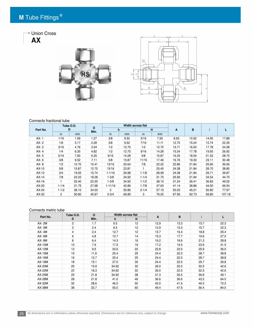
Connects fractional tube
Connects metric tube
Union Cross
AX
Part No.Tube O.D.
D OMin. A B l Lh H
in mm in mm in mmAX- 1 1/16 1.59 1.27 3/8 9.52 5/16 7.93 8.63 10.92 14.00 17.88AX- 2 1/8 3.17 2.28 3/8 9.52 7/16 11.11 12.70 15.24 15.74 22.35AX- 3 3/16 4.76 3.04 1/2 12.70 1/2 12.70 13.71 16.00 17.78 24.38AX- 4 1/4 6.35 4.82 1/2 12.70 9/16 14.28 15.24 17.78 19.55 26.92AX- 5 5/16 7.93 6.35 9/16 14.28 5/8 15.87 16.25 18.54 21.33 28.70AX- 6 3/8 9.52 7.11 5/8 15.87 11/16 17.46 16.76 19.30 23.11 30.48AX- 8 1/2 12.70 10.41 13/16 20.64 7/8 22.22 22.86 21.84 25.90 36.06AX-10 5/8 15.87 12.70 15/16 23.81 1 25.40 24.38 21.84 28.70 38.80AX-12 3/4 19.05 15.74 1-1/16 26.98 1-1/8 28.58 24.38 21.84 29.71 39.87AX-14 7/8 22.22 18.28 1-3/8 34.92 1-1/4 31.75 25.90 21.84 34.54 44.70AX-16 1 25.40 22.35 1-3/8 34.92 1-1/2 38.10 31.24 26.41 36.83 49.02AX-20 1-1/4 31.75 27.68 1-11/16 42.86 1-7/8 47.63 41.14 38.86 44.50 66.54AX-24 1-1/2 38.10 34.03 2 50.80 2-1/4 57.15 50.03 45.21 50.80 77.97AX-32 2 50.80 45.97 2-3/4 69.85 3 76.20 67.56 62.73 69.80 107.18
Part No. Tube O.D.D
OMin. A B l L
h HAX- 2M 2 1.7 9.5 12 12.9 15.3 15.7 22.3AX- 3M 3 2.4 9.5 12 12.9 15.3 15.7 22.3AX- 4M 4 2.4 12.7 12 13.7 16.4 18.8 25.4AX- 6M 6 4.8 12.7 14 15.3 17.7 19.6 27.0AX- 8M 8 6.4 14.3 16 16.2 18.6 21.3 28.8AX-10M 10 7.9 17.5 19 17.2 19.5 23.9 31.5AX-12M 12 9.5 20.6 22 22.8 22.0 25.9 36.0AX-15M 15 11.9 25.4 25 24.4 22.0 28.7 38.8AX-16M 16 12.7 25.4 25 24.4 22.0 28.7 38.8AX-18M 18 15.1 27.0 30 24.4 22.0 29.7 39.8AX-20M 20 15.9 34.92 32 26.0 22.0 32.5 42.6AX-22M 22 18.3 34.92 32 26.0 22.0 32.5 42.6AX-25M 25 21.8 34.92 38 31.3 26.5 36.8 49.1AX-28M 28 21.8 41.0 46 36.6 36.6 43.2 64.0AX-32M 32 28.6 46.0 50 42.0 41.6 49.3 72.3AX-38M 38 33.7 55.0 60 49.4 47.9 56.4 84.0

26www.hsmecorp.com All dimensions are in millimeters unless otherwise specified. Dimensions are for reference only, subject to change.
Reducing Union Tee
Bored-Through Fittings For Dip Tubes, Thermocouples, and Heat Exchanger Fittings
ATR
AMCT / ART
1 2
3
4
Connects fractional tube
Connects metric tube
Bored-through fitting has no tube shoulder, allowing Dip tube of Thermocouple to pass through the fitting.
1. Position the length of dip tube / thermocouple passed through the fitting. 2. Once positioned, hold it to prevent from shifting during assembly.3. Wrench tightens the nut 1 1/4 turns from finger-tight position, keeping the body steady with a backup wrench.
Assembly Instruction
• Thermocouple is a sensor for measuring temperature.• Dip tube is to direct the incoming cold water to the bottom of water heater tank or to use for removing debris
from the bottom of water tank.
Most male connectors –AMC can be bored-through except those fittings with 1/8 in. NPT or BSPT end.
To order bored-through male connector, add T to the ordering number. Example: AMCT8-8N-SSA
The combination of standard tee and bored- through port reducer –AR can be used to chill or heat a process line as heat exchange r fitting.
To order bored-through port reducer, add T to the ordering number. Example: ART8-8-SSA
Diagram shown;Jacketing tube 1/2 in. OD Process tube: 1/4 in. OD
Part No.Port 1 Port2 Port3 Port4 O
Min. A A1 B B1 l l1 L L1D D1 h H H1
AXR16M-6M-6M-6M 16 6 4.8 25.4 25 14 24.4 15.3 22.0 17.7 28.7 27.2 38.8 34.6
Part No.Port 1 Port2 Port3 Port4
OMin. A A1 1 l l1 L L1D D1 h H H1
in mm in mm in mm in mm in mmAXR 12-12-6-6 3/4 19.05 3/8 9.52 7.1 1-1/16 26.98 1-1/8 28.57 11/16 17.46 24.38 16.76 21.84 19.3 29.71 29.71 39.87 37.07
B B
M Tube Fittings
27 www.hsmecorp.comAll dimensions are in millimeters unless otherwise specified. Dimensions are for reference only, subject to change.
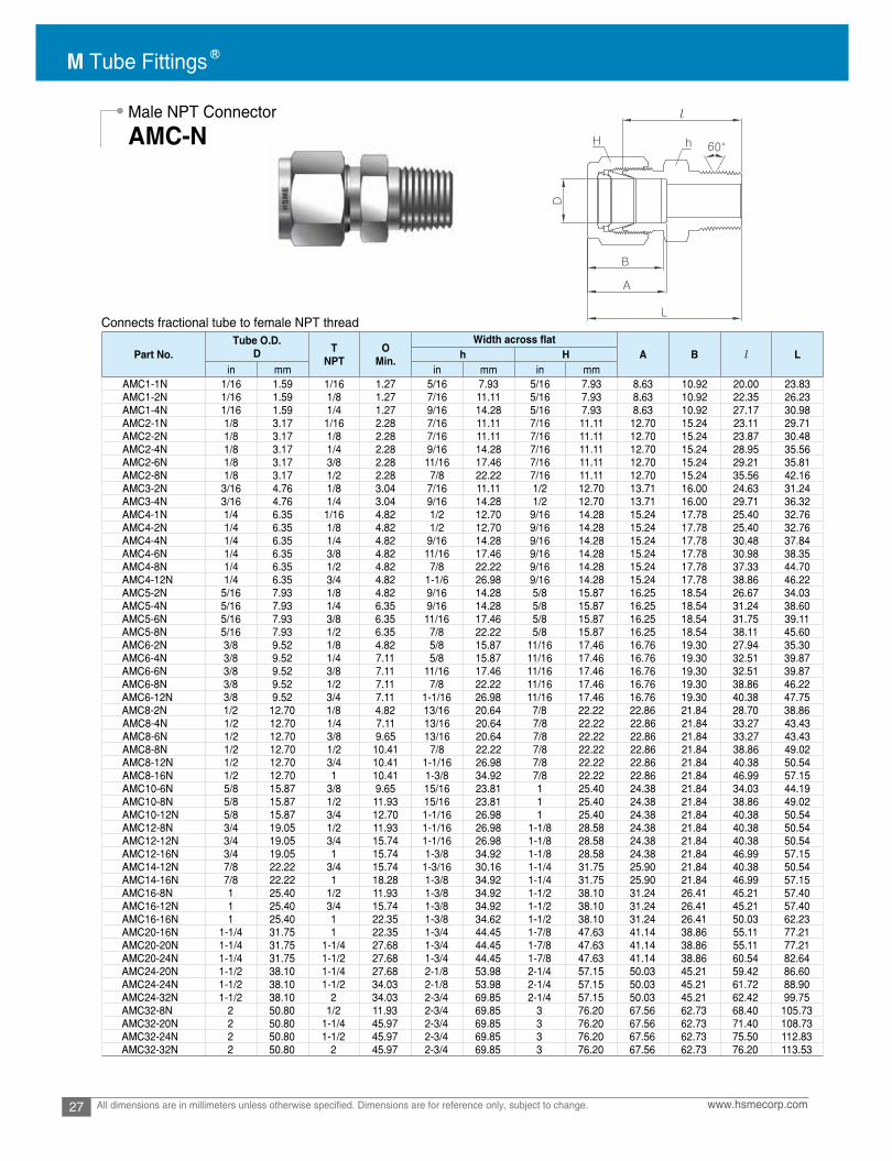
Connects fractional tube to female NPT thread
Male NPT Connector
AMC-N
Part No.Tube O.D.
D TNPT
OMin. A B l Lh H
in mm in mm in mmAMC1-1N 1/16 1.59 1/16 1.27 5/16 7.93 5/16 7.93 8.63 10.92 20.00 23.83AMC1-2N 1/16 1.59 1/8 1.27 7/16 11.11 5/16 7.93 8.63 10.92 22.35 26.23AMC1-4N 1/16 1.59 1/4 1.27 9/16 14.28 5/16 7.93 8.63 10.92 27.17 30.98AMC2-1N 1/8 3.17 1/16 2.28 7/16 11.11 7/16 11.11 12.70 15.24 23.11 29.71AMC2-2N 1/8 3.17 1/8 2.28 7/16 11.11 7/16 11.11 12.70 15.24 23.87 30.48AMC2-4N 1/8 3.17 1/4 2.28 9/16 14.28 7/16 11.11 12.70 15.24 28.95 35.56AMC2-6N 1/8 3.17 3/8 2.28 11/16 17.46 7/16 11.11 12.70 15.24 29.21 35.81AMC2-8N 1/8 3.17 1/2 2.28 7/8 22.22 7/16 11.11 12.70 15.24 35.56 42.16AMC3-2N 3/16 4.76 1/8 3.04 7/16 11.11 1/2 12.70 13.71 16.00 24.63 31.24AMC3-4N 3/16 4.76 1/4 3.04 9/16 14.28 1/2 12.70 13.71 16.00 29.71 36.32AMC4-1N 1/4 6.35 1/16 4.82 1/2 12.70 9/16 14.28 15.24 17.78 25.40 32.76AMC4-2N 1/4 6.35 1/8 4.82 1/2 12.70 9/16 14.28 15.24 17.78 25.40 32.76AMC4-4N 1/4 6.35 1/4 4.82 9/16 14.28 9/16 14.28 15.24 17.78 30.48 37.84AMC4-6N 1/4 6.35 3/8 4.82 11/16 17.46 9/16 14.28 15.24 17.78 30.98 38.35AMC4-8N 1/4 6.35 1/2 4.82 7/8 22.22 9/16 14.28 15.24 17.78 37.33 44.70AMC4-12N 1/4 6.35 3/4 4.82 1-1/6 26.98 9/16 14.28 15.24 17.78 38.86 46.22AMC5-2N 5/16 7.93 1/8 4.82 9/16 14.28 5/8 15.87 16.25 18.54 26.67 34.03AMC5-4N 5/16 7.93 1/4 6.35 9/16 14.28 5/8 15.87 16.25 18.54 31.24 38.60AMC5-6N 5/16 7.93 3/8 6.35 11/16 17.46 5/8 15.87 16.25 18.54 31.75 39.11AMC5-8N 5/16 7.93 1/2 6.35 7/8 22.22 5/8 15.87 16.25 18.54 38.11 45.60AMC6-2N 3/8 9.52 1/8 4.82 5/8 15.87 11/16 17.46 16.76 19.30 27.94 35.30AMC6-4N 3/8 9.52 1/4 7.11 5/8 15.87 11/16 17.46 16.76 19.30 32.51 39.87AMC6-6N 3/8 9.52 3/8 7.11 11/16 17.46 11/16 17.46 16.76 19.30 32.51 39.87AMC6-8N 3/8 9.52 1/2 7.11 7/8 22.22 11/16 17.46 16.76 19.30 38.86 46.22AMC6-12N 3/8 9.52 3/4 7.11 1-1/16 26.98 11/16 17.46 16.76 19.30 40.38 47.75AMC8-2N 1/2 12.70 1/8 4.82 13/16 20.64 7/8 22.22 22.86 21.84 28.70 38.86AMC8-4N 1/2 12.70 1/4 7.11 13/16 20.64 7/8 22.22 22.86 21.84 33.27 43.43AMC8-6N 1/2 12.70 3/8 9.65 13/16 20.64 7/8 22.22 22.86 21.84 33.27 43.43AMC8-8N 1/2 12.70 1/2 10.41 7/8 22.22 7/8 22.22 22.86 21.84 38.86 49.02AMC8-12N 1/2 12.70 3/4 10.41 1-1/16 26.98 7/8 22.22 22.86 21.84 40.38 50.54AMC8-16N 1/2 12.70 1 10.41 1-3/8 34.92 7/8 22.22 22.86 21.84 46.99 57.15AMC10-6N 5/8 15.87 3/8 9.65 15/16 23.81 1 25.40 24.38 21.84 34.03 44.19AMC10-8N 5/8 15.87 1/2 11.93 15/16 23.81 1 25.40 24.38 21.84 38.86 49.02AMC10-12N 5/8 15.87 3/4 12.70 1-1/16 26.98 1 25.40 24.38 21.84 40.38 50.54AMC12-8N 3/4 19.05 1/2 11.93 1-1/16 26.98 1-1/8 28.58 24.38 21.84 40.38 50.54AMC12-12N 3/4 19.05 3/4 15.74 1-1/16 26.98 1-1/8 28.58 24.38 21.84 40.38 50.54AMC12-16N 3/4 19.05 1 15.74 1-3/8 34.92 1-1/8 28.58 24.38 21.84 46.99 57.15AMC14-12N 7/8 22.22 3/4 15.74 1-3/16 30.16 1-1/4 31.75 25.90 21.84 40.38 50.54AMC14-16N 7/8 22.22 1 18.28 1-3/8 34.92 1-1/4 31.75 25.90 21.84 46.99 57.15AMC16-8N 1 25.40 1/2 11.93 1-3/8 34.92 1-1/2 38.10 31.24 26.41 45.21 57.40AMC16-12N 1 25.40 3/4 15.74 1-3/8 34.92 1-1/2 38.10 31.24 26.41 45.21 57.40AMC16-16N 1 25.40 1 22.35 1-3/8 34.62 1-1/2 38.10 31.24 26.41 50.03 62.23AMC20-16N 1-1/4 31.75 1 22.35 1-3/4 44.45 1-7/8 47.63 41.14 38.86 55.11 77.21AMC20-20N 1-1/4 31.75 1-1/4 27.68 1-3/4 44.45 1-7/8 47.63 41.14 38.86 55.11 77.21AMC20-24N 1-1/4 31.75 1-1/2 27.68 1-3/4 44.45 1-7/8 47.63 41.14 38.86 60.54 82.64AMC24-20N 1-1/2 38.10 1-1/4 27.68 2-1/8 53.98 2-1/4 57.15 50.03 45.21 59.42 86.60AMC24-24N 1-1/2 38.10 1-1/2 34.03 2-1/8 53.98 2-1/4 57.15 50.03 45.21 61.72 88.90AMC24-32N 1-1/2 38.10 2 34.03 2-3/4 69.85 2-1/4 57.15 50.03 45.21 62.42 99.75AMC32-8N 2 50.80 1/2 11.93 2-3/4 69.85 3 76.20 67.56 62.73 68.40 105.73AMC32-20N 2 50.80 1-1/4 45.97 2-3/4 69.85 3 76.20 67.56 62.73 71.40 108.73AMC32-24N 2 50.80 1-1/2 45.97 2-3/4 69.85 3 76.20 67.56 62.73 75.50 112.83AMC32-32N 2 50.80 2 45.97 2-3/4 69.85 3 76.20 67.56 62.73 76.20 113.53

28www.hsmecorp.com All dimensions are in millimeters unless otherwise specified. Dimensions are for reference only, subject to change.
Male NPT Connector
AMC-N
Connects metric tube to female NPT thread
Part No. Tube O.D.D
TNPT
EMin. A B l L
h HAMC2M-2N 2 1/8 1.7 12 12 12.9 15.3 23.9 30.5AMC3M-2N 3 1/8 2.4 12 12 12.9 15.3 23.1 29.7AMC3M-4N 3 1/4 2.4 14 12 12.9 15.3 29.0 35.6AMC4M-2N 4 1/8 2.4 12 12 13.7 16.1 24.6 31.2AMC4M-4N 4 1/4 2.4 14 12 13.7 16.1 29.7 36.3AMC6M-2N 6 1/8 4.8 14 14 15.3 17.7 25.4 32.8AMC6M-4N 6 1/4 4.8 14 14 15.3 17.7 30.2 37.6AMC6M-6N 6 3/8 4.8 18 14 15.3 17.7 31.0 38.4AMC6M-8N 6 1/2 4.8 22 14 15.3 17.7 37.3 44.0AMC8M-2N 8 1/8 4.8 15 16 16.2 18.6 26.7 34.2AMC8M-4N 8 1/4 6.4 15 16 16.2 18.6 31.2 38.7AMC8M-6N 8 3/8 6.4 18 16 16.2 18.6 31.8 39.2AMC8M-8N 8 1/2 6.4 22 16 16.2 18.6 37.3 44.8AMC10M-2N 10 1/8 4.8 18 19 17.2 19.5 28.7 36.3AMC10M-4N 10 1/4 7.1 18 19 17.2 19.5 33.3 40.9AMC10M-6N 10 3/8 7.9 18 19 17.2 19.5 33.3 40.9AMC10M-8N 10 1/2 7.9 22 19 17.2 19.5 38.1 45.7AMC10M-12N 10 3/4 7.9 27 19 17.2 19.5 38.9 46.5AMC12M-2N 12 1/8 4.8 22 22 22.8 22.0 28.7 38.8AMC12M-4N 12 1/4 7.1 22 22 22.8 22.0 33.3 43.4AMC12M-6N 12 3/8 9.5 22 22 22.8 22.0 33.3 43.4AMC12M-8N 12 1/2 9.5 22 22 22.8 22.0 38.1 48.2AMC12M-12N 12 3/4 9.5 27 22 22.8 22.0 38.9 49.0AMC14M-4N 14 1/4 6.4 24 25 24.4 22.0 34.0 44.1AMC14M-6N 14 3/8 9.5 24 25 24.4 22.0 34.0 44.1AMC14M-8N 14 1/2 11.1 24 25 24.4 22.0 34.0 44.1AMC15M-8N 15 1/2 11.9 24 25 24.4 22.0 38.9 49.0AMC16M-4N 16 1/4 7.1 24 25 24.4 22.0 34.0 44.1AMC16M-6N 16 3/8 9.5 24 25 24.4 22.0 34.0 44.1AMC16M-8N 16 1/2 11.9 24 25 24.4 22.0 38.9 49.0AMC16M-12N 16 3/4 12.7 27 25 24.4 22.0 38.9 49.0AMC18M-8N 18 1/2 11.9 27 30 24.4 22.0 40.4 50.5AMC18M-12N 18 3/4 15.1 27 30 24.4 22.0 40.4 50.5AMC20M-8N 20 1/2 11.9 30 32 26.0 22.0 42.2 52.3AMC20M-12N 20 3/4 15.9 30 32 26.0 22.0 42.2 52.3AMC22M-12N 22 3/4 15.9 30 32 26.0 22.0 42.2 52.3AMC22M-16N 22 1 18.3 35 32 26.0 22.0 47.8 57.9AMC25M-8N 25 1/2 11.9 35 38 31.3 26.5 45.2 57.5AMC25M-12N 25 3/4 15.9 35 38 31.3 26.5 45.2 57.5AMC25M-16N 25 1 21.8 35 38 31.3 26.5 50.0 62.3AMC28M-16N 28 1 21.8 41 46 36.6 36.6 51.6 72.4AMC28M-20N 28 1-1/4 21.8 46 46 36.6 36.6 52.3 73.1AMC32M-20N 32 1-1/4 28.6 46 50 42.0 41.6 56.6 79.6AMC38M-24N 38 1-1/2 33.7 55 60 49.4 47.9 64.0 91.6

M Tube Fittings
29 www.hsmecorp.comAll dimensions are in millimeters unless otherwise specified. Dimensions are for reference only, subject to change.
Connects fractional tube to female NPT thread
Connects metric tube to female NPT thread
Bulkhead Male NPT Connector
AMCB-N
Part No.Tube O.D.
D TNPT
OMin. A l l1 L L1
PanelHole
Drill Size
PanelMax
Thicknessh h1 H
in mm in mm in mm in mm
AMCB2-2N 1/8 3.17 1/8 2.28 1/2 12.70 1/2 12.70 7/16 11.11 12.70 39.87 24.63 46.48 31.24 8.33 12.70AMCB4-2N 1/4 6.35 1/8 4.82 5/8 15.87 5/8 15.87 9/16 14.28 15.24 42.16 26.16 49.53 33.52 11.50 10.16AMCB4-4N 1/4 6.35 1/4 4.82 5/8 15.87 5/8 15.87 9/16 14.28 15.24 45.97 26.16 53.34 33.52 11.50 10.16AMCB6-4N 3/8 9.52 1/4 7.11 3/4 19.05 3/4 19.05 11/16 17.46 16.76 50.03 29.46 57.40 36.83 14.68 11.17AMCB6-6N 3/8 9.52 3/8 7.11 3/4 19.05 3/4 19.05 11/16 17.46 16.76 50.03 29.46 57.40 36.83 14.68 11.17
AMCB6-8N 3/8 9.52 1/2 7.11 7/8 22.22 3/4 19.05 11/16 17.46 16.76 56.38 29.46 63.75 36.83 14.68 11.17AMCB8-6N 1/2 12.70 3/8 9.39 15/16 23.81 15/16 23.81 7/8 22.22 22.86 53.08 31.75 63.24 41.91 19.44 12.70AMCB8-8N 1/2 12.70 1/2 10.41 15/16 23.81 15/16 23.81 7/8 22.22 22.86 58.67 31.75 68.83 41.91 19.44 12.70AMCB12-12N 3/4 19.05 3/4 15.74 1-3/16 30.16 1-3/16 30.16 1-1/8 28.58 24.38 66.04 37.33 76.20 47.49 25.76 16.76AMCB16-16N 1 25.40 1 22.35 1-5/8 41.28 1-5/8 41.28 1-1/2 38.10 31.24 81.02 45.21 93.21 57.40 33.73 19.05AMCB20-20N 1-1/4 31.75 1-1/4 27.68 1-7/8 47.63 1-7/8 47.63 1-7/8 47.63 41.14 85.97 47.75 108.07 69.85 41.67 19.05AMCB24-24N 1-1/2 38.10 1-1/2 34.03 2-1/4 57.15 2-1/4 57.15 2-1/4 57.15 50.03 93.03 49.27 120.21 76.45 49.61 19.05AMCB32-32N 2 50.80 2 45.97 2-3/4 69.85 2-3/4 69.85 3 76.20 67.56 107.29 56.38 144.62 93.71 16.27 19.05
Part No. Tube O.D.D
TNPT
OMin. A l l1 L L1
PanelHole
Drill size
PanelMax
Thicknessh h1 H
AMCB6M-2N 6 1/8 2.28 16 16 14 15.3 42.2 26.2 49.6 33.6 11.5 10.2
AMCB6M-4N 6 1/4 4.82 16 16 14 15.3 46.2 26.2 53.6 33.6 11.5 10.2
AMCB6M-6N 6 3/8 4.82 16 16 14 15.3 46.2 26.2 53.6 33.6 11.5 10.2
AMCB6M-8N 6 1/4 7.11 16 16 14 15.3 52.6 26.2 60.0 33.6 11.5 10.2
AMCB8M-6N 8 3/8 7.11 18 18 16 16.2 50.0 28.6 57.5 36.1 13.1 11.2
AMCB10M-4N 10 1/4 7.11 22 22 19 17.2 50.0 29.4 57.5 37.0 16.2 11.2
AMCB10M-6N 10 3/8 9.39 22 22 19 17.2 50.0 29.4 57.5 37.0 16.2 11.2
AMCB10M-8N 10 1/2
1/2
10.41 22 22 19 17.2 55.9 29.4 63.5 37.0 16.2 11.2
AMCB12M-6N 12 3/8 15.74 24 24 22 22.8 53.3 31.8 63.4 41.9 19.5 12.7
AMCB12M-8N 12 22.35 24 24 22 22.8 58.7 31.8 68.8 41.9 19.5 12.7
AMCB20-20N 1-1/4 1-1/4 27.68 1-7/8 1-7/8 1-7/8 41.14 85.97 47.75 108.07 69.85 41.67 19.05
AMCB24-24N 1-1/2 1-1/2 34.03 2-1/4 2-1/4 2-1/4 50.03 93.03 49.27 120.21 76.45 49.61 19.05
AMCB32-32N 2 2 45.97 2-3/4 2-3/4 3 67.56 107.29 56.38 144.62 93.71 16.27 19.05

30www.hsmecorp.com All dimensions are in millimeters unless otherwise specified. Dimensions are for reference only, subject to change.
Male BSPT Connector
AMC-R
Connects fractional tube to female ISO tapered thread
Part No.Tube O.D.
D TPT
OMin. A B l Lh H
in mm in mm in mm
AMC2-2R 1/8 3.17 1/8 2.28 7/16 11.11 7/16 11.11 12.70 15.24 23.87 30.48AMC2-4R 1/8 3.17 1/4 2.28 9/16 14.28 7/16 11.11 12.70 15.24 28.95 35.56AMC4-2R 1/4 6.35 1/8 4.82 1/2 12.70 9/16 14.28 15.24 17.78 25.40 32.76AMC4-4R 1/4 6.35 1/4 4.82 9/16 14.28 9/16 14.28 15.24 17.78 30.48 37.84AMC4-6R 1/4 6.35 3/8 4.82 11/16 17.46 9/16 14.28 15.24 17.78 30.98 38.35
AMC4-8R 1/4 6.35 1/2 4.82 7/8 22.22 9/16 14.28 15.24 17.78 37.33 44.70AMC5-2R 5/16 7.93 1/8 4.82 9/16 14.28 5/8 15.87 16.25 18.54 26.67 34.03AMC5-4R 5/16 7.93 1/4 6.35 9/16 14.28 5/8 15.87 16.25 18.54 31.24 38.60AMC5-16R 5/16 7.93 1 6.35 1-3/8 34.92 5/8 15.87 16.25 18.54 46.2 50.0AMC6-2R 3/8 9.52 1/8 4.82 5/8 15.87 11/16 17.46 16.76 19.30 27.94 35.30AMC6-4R 3/8 9.52 1/4 7.11 5/8 15.87 11/16 17.46 16.76 19.30 32.51 39.87AMC6-6R 3/8 9.52 3/8 7.11 11/16 17.46 11/16 17.46 16.76 19.30 32.51 39.87AMC6-8R 3/8 9.52 1/2 7.11 7/8 22.22 11/16 17.46 16.76 19.30 38.86 46.22AMC6-12R 3/8 9.52 3/4 7.11 1-1/16 26.98 11/16 17.46 16.76 19.30 40.38 47.75AMC8-2R 1/2 12.70 1/8 4.82 13/16 20.64 7/8 22.22 22.86 21.84 28.70 38.86AMC8-4R 1/2 12.70 1/4 7.11 13/16 20.64 7/8 22.22 22.86 21.84 33.27 43.43AMC8-6R 1/2 12.70 3/8 9.65 13/16 20.64 7/8 22.22 22.86 21.84 33.27 43.43AMC8-8R 1/2 12.70 1/2 10.41 7/8 22.22 7/8 22.22 22.86 21.84 38.86 49.02AMC8-12R 1/2 12.70 3/4 10.41 1-1/16 26.98 7/8 22.22 22.86 21.84 40.38 50.54AMC8-16R 1/2 12.70 1 10.41 1-3/8 34.92 7/8 22.22 22.86 21.84 46.99 57.15AMC10-6R 5/8 15.87 3/8 9.65 15/16 23.81 1 25.40 24.38 21.84 34.03 44.19AMC10-8R 5/8 15.87 1/2 11.93 15/16 23.81 1 25.40 24.38 21.84 38.86 49.02AMC10-12R 5/8 15.87 3/4 12.70 1-1/16 26.98 1 25.40 24.38 21.84 40.38 50.54AMC12-8R 3/4 19.05 1/2 11.93 1-1/16 26.98 1-1/8 28.58 24.38 21.84 40.38 50.54AMC12-12R 3/4 19.05 3/4 15.74 1-1/16 26.98 1-1/8 28.58 24.38 21.84 40.38 50.54AMC12-16R 3/4 19.05 1 15.74 1-3/8 34.92 1-1/8 28.58 24.38 21.84 46.99 57.15AMC16-12R 1 25.40 3/4 15.74 1-3/8 34.92 1-1/2 38.10 31.24 26.41 45.21 57.40AMC16-16R 1 25.40 1 22.35 1-3/8 34.62 1-1/2 38.10 31.24 26.41 50.03 62.23AMC20-12R 1-1/4 31.75 3/4 15.74 1-3/4 44.45 1-7/8 47.63 41.14 38.86 50.0 72.10AMC20-16R 1-1/4 31.75 1 22.35 1-3/4 44.45 1-7/8 47.63 41.14 38.86 55.11 77.21AMC20-20R 1-1/4 31.75 1-1/4 27.68 1-3/4 44.45 1-7/8 47.63 41.14 38.86 55.11 77.21AMC32-32R 2 50.80 2 45.97 2-3/4 69.85 3 76.20 67.56 62.73 76.20 113.53
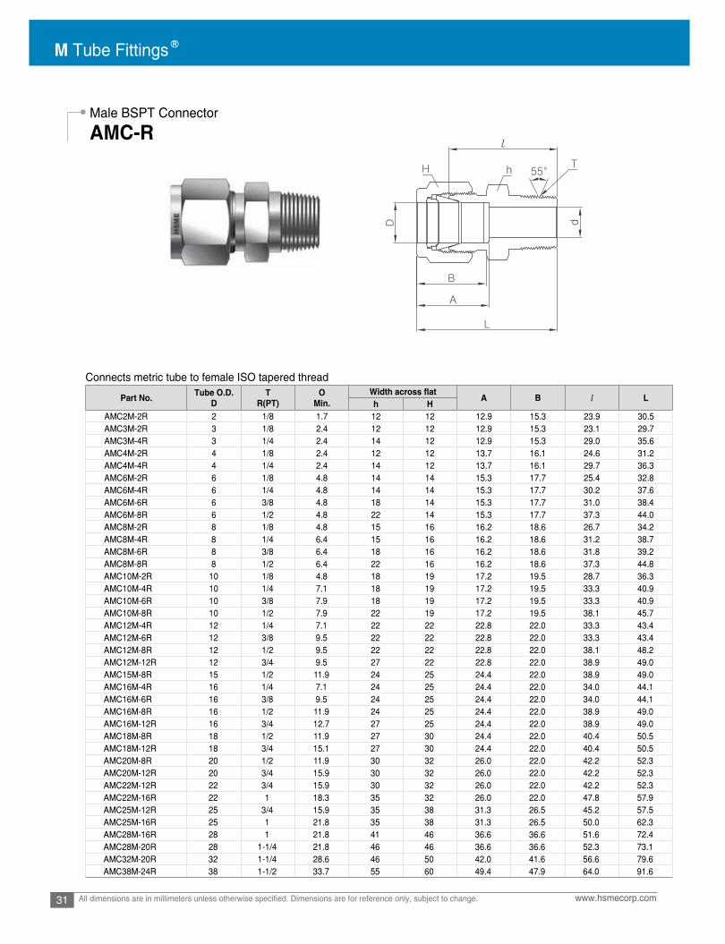
M Tube Fittings
31 www.hsmecorp.comAll dimensions are in millimeters unless otherwise specified. Dimensions are for reference only, subject to change.
Connects metric tube to female ISO tapered thread
Male BSPT Connector
AMC-R
Part No. Tube O.D.D
TR(PT)
OMin. A B l L
h HAMC2M-2R 2 1/8 1.7 12 12 12.9 15.3 23.9 30.5AMC3M-2R 3 1/8 2.4 12 12 12.9 15.3 23.1 29.7AMC3M-4R 3 1/4 2.4 14 12 12.9 15.3 29.0 35.6AMC4M-2R 4 1/8 2.4 12 12 13.7 16.1 24.6 31.2AMC4M-4R 4 1/4 2.4 14 12 13.7 16.1 29.7 36.3AMC6M-2R 6 1/8 4.8 14 14 15.3 17.7 25.4 32.8AMC6M-4R 6 1/4 4.8 14 14 15.3 17.7 30.2 37.6AMC6M-6R 6 3/8 4.8 18 14 15.3 17.7 31.0 38.4AMC6M-8R 6 1/2 4.8 22 14 15.3 17.7 37.3 44.0AMC8M-2R 8 1/8 4.8 15 16 16.2 18.6 26.7 34.2AMC8M-4R 8 1/4 6.4 15 16 16.2 18.6 31.2 38.7AMC8M-6R 8 3/8 6.4 18 16 16.2 18.6 31.8 39.2AMC8M-8R 8 1/2 6.4 22 16 16.2 18.6 37.3 44.8AMC10M-2R 10 1/8 4.8 18 19 17.2 19.5 28.7 36.3AMC10M-4R 10 1/4 7.1 18 19 17.2 19.5 33.3 40.9AMC10M-6R 10 3/8 7.9 18 19 17.2 19.5 33.3 40.9AMC10M-8R 10 1/2 7.9 22 19 17.2 19.5 38.1 45.7AMC12M-4R 12 1/4 7.1 22 22 22.8 22.0 33.3 43.4AMC12M-6R 12 3/8 9.5 22 22 22.8 22.0 33.3 43.4AMC12M-8R 12 1/2 9.5 22 22 22.8 22.0 38.1 48.2AMC12M-12R 12 3/4 9.5 27 22 22.8 22.0 38.9 49.0AMC15M-8R 15 1/2 11.9 24 25 24.4 22.0 38.9 49.0AMC16M-4R 16 1/4 7.1 24 25 24.4 22.0 34.0 44.1AMC16M-6R 16 3/8 9.5 24 25 24.4 22.0 34.0 44.1AMC16M-8R 16 1/2 11.9 24 25 24.4 22.0 38.9 49.0AMC16M-12R 16 3/4 12.7 27 25 24.4 22.0 38.9 49.0AMC18M-8R 18 1/2 11.9 27 30 24.4 22.0 40.4 50.5AMC18M-12R 18 3/4 15.1 27 30 24.4 22.0 40.4 50.5AMC20M-8R 20 1/2 11.9 30 32 26.0 22.0 42.2 52.3AMC20M-12R 20 3/4 15.9 30 32 26.0 22.0 42.2 52.3AMC22M-12R 22 3/4 15.9 30 32 26.0 22.0 42.2 52.3AMC22M-16R 22 1 18.3 35 32 26.0 22.0 47.8 57.9AMC25M-12R 25 3/4 15.9 35 38 31.3 26.5 45.2 57.5AMC25M-16R 25 1 21.8 35 38 31.3 26.5 50.0 62.3AMC28M-16R 28 1 21.8 41 46 36.6 36.6 51.6 72.4AMC28M-20R 28 1-1/4 21.8 46 46 36.6 36.6 52.3 73.1AMC32M-20R 32 1-1/4 28.6 46 50 42.0 41.6 56.6 79.6AMC38M-24R 38 1-1/2 33.7 55 60 49.4 47.9 64.0 91.6

32www.hsmecorp.com All dimensions are in millimeters unless otherwise specified. Dimensions are for reference only, subject to change.
Male ISO Parallel ConnectorDIN3852 Form A
Male ISO Parallel ConnectorDIN3852 Form B
AMC-G
AMC-GB
Connects fractional tube to female ISO parallel thread
Connects fractional tube to female ISO parallel thread
Part No.Tube O.D.
D T(PF)
OMin. A B l l1 L Kh H
in mm in mm in mmAMC2-2G 1/8 3.17 1/8 2.28 9/16 14.28 7/16 11.11 12.70 15.24 23.37 7.11 29.97 13.72AMC2-4G 1/8 3.17 1/4 2.28 3/4 19.05 7/16 11.11 12.70 15.24 28.70 11.18 35.31 18.03AMC2-6G 1/8 3.17 3/8 2.28 7/8 22.22 7/16 11.11 12.70 15.24 29.72 11.18 36.21 21.84AMC4-2G 1/4 6.35 1/8 2.28 9/16 14.28 9/16 14.28 15.24 17.78 24.89 7.11 32.26 13.72AMC4-4G 1/4 6.35 1/4 4.82 3/4 19.05 9/16 14.28 15.24 17.78 30.23 11.18 37.59 18.03AMC4-6G 1/4 6.35 3/8 4.82 7/8 22.22 9/16 14.28 15.24 17.78 31.50 11.18 38.86 21.84AMC4-8G 1/4 6.35 1/2 4.82 1-1/16 26.98 9/16 14.28 15.24 17.78 37.34 14.22 44.70 25.91AMC6-4G 3/8 9.53 1/4 4.82 3/4 19.05 11/16 17.46 16.76 19.30 31.75 11.18 39.12 18.03AMC6-6G 3/8 9.53 3/8 7.11 7/8 22.22 11/16 17.46 16.76 19.30 33.02 11.18 40.39 21.84AMC6-8G 3/8 9.53 1/2 7.11 1-1/16 26.98 11/16 17.46 16.76 19.30 38.86 14.22 46.23 25.91AMC8-4G 1/2 12.70 1/4 7.11 13/16 20.64 7/8 22.22 22.86 21.84 32.51 11.18 42.67 18.03AMC8-6G 1/2 12.70 3/8 9.65 7/8 22.22 7/8 22.22 22.86 21.84 33.02 11.18 43.18 21.84AMC8-8G 1/2 12.70 1/2 10.41 1-1/16 26.98 7/8 22.22 22.86 21.84 38.86 14.22 49.02 25.91AMC12-8G 3/4 19.05 1/2 11.93 1-1/16 26.98 1-1/8 28.58 24.38 21.84 38.86 14.22 49.02 25.91AMC12-12G 3/4 19.05 3/4 15.74 1-5/16 33.33 1-1/8 28.58 24.38 21.84 42.67 15.75 52.83 32.00AMC16-8G 1 25.40 1/2 11.93 1-3/8 34.92 1-1/2 38.10 31.24 26.41 43.69 14.22 55.88 25.91AMC16-16G 1 25.40 1 22.35 1-5/8 41.27 1-1/2 38.10 31.24 26.41 47.75 18.29 59.94 39.12AMC20-20G 1-1/4 31.75 1-1/4 27.68 2 50.80 1-7/8 47.63 41.14 38.86 51.16 20.00 73.26 49.00AMC24-24G 1-1/2 38.10 1-1/2 34.03 2-1/4 57.15 2-1/4 57.15 50.03 45.21 57.57 22.00 84.75 54.70
Part No.Tube O.D.
D T(PF)
OMin. A B l l1 L Kh H
in mm in mm in mmAMC2-2GB 1/8 3.17 1/8 2.28 9/16 14.28 7/16 11.11 12.70 15.24 23.37 7.11 29.97 13.72AMC2-4GB 1/8 3.17 1/4 2.28 3/4 19.05 7/16 11.11 12.70 15.24 28.70 11.18 35.31 18.03AMC2-6GB 1/8 3.17 3/8 2.28 7/8 22.22 7/16 11.11 12.70 15.24 29.72 11.18 36.21 21.84AMC4-2GB 1/4 6.35 1/8 2.28 9/16 14.28 9/16 14.28 15.24 17.78 24.89 7.11 32.26 13.72AMC4-4GB 1/4 6.35 1/4 4.82 3/4 19.05 9/16 14.28 15.24 17.78 30.23 11.18 37.59 18.03AMC4-6GB 1/4 6.35 3/8 4.82 7/8 22.22 9/16 14.28 15.24 17.78 31.50 11.18 38.86 21.84AMC4-8GB 1/4 6.35 1/2 4.82 1-1/16 26.98 9/16 14.28 15.24 17.78 37.34 14.22 44.70 25.91AMC6-4GB 3/8 9.53 1/4 4.82 3/4 19.05 11/16 17.46 16.76 19.30 31.75 11.18 39.12 18.03AMC6-6GB 3/8 9.53 3/8 7.11 7/8 22.22 11/16 17.46 16.76 19.30 33.02 11.18 40.39 21.84AMC6-8GB 3/8 9.53 1/2 7.11 1-1/16 26.98 11/16 17.46 16.76 19.30 38.86 14.22 46.23 25.91AMC8-4GB 1/2 12.70 1/4 7.11 13/16 20.64 7/8 22.22 22.86 21.84 32.51 11.18 42.67 18.03AMC8-6GB 1/2 12.70 3/8 9.65 7/8 22.22 7/8 22.22 22.86 21.84 33.02 11.18 43.18 21.84AMC8-8GB 1/2 12.70 1/2 10.41 1-1/16 26.98 7/8 22.22 22.86 21.84 38.86 14.22 49.02 25.91AMC12-8GB 3/4 19.05 1/2 11.93 1-1/16 26.98 1-1/8 28.58 24.38 21.84 38.86 14.22 49.02 25.91AMC12-12GB 3/4 19.05 3/4 15.74 1-5/16 33.33 1-1/8 28.58 24.38 21.84 42.67 15.75 52.83 32.00AMC16-8GB 1 25.40 1/2 11.93 1-3/8 34.92 1-1/2 38.10 31.24 26.41 43.69 14.22 55.88 25.91AMC16-16GB 1 25.40 1 22.35 1-5/8 41.27 1-1/2 38.10 31.24 26.41 47.75 18.29 59.94 39.12AMC20-20GB 1-1/4 31.75 1-1/4 27.68 2 50.80 1-7/8 47.63 41.14 38.86 51.16 20.00 73.26 49.00AMC24-24GB 1-1/2 38.10 1-1/2 34.03 2-1/4 57.15 2-1/4 57.15 50.03 45.21 57.57 22.00 84.75 54.70

M Tube Fittings
33 www.hsmecorp.comAll dimensions are in millimeters unless otherwise specified. Dimensions are for reference only, subject to change.
Parallel Pipe Threads – Male
ISO 228-1 Pipe threads where pressure-tight joints are not made on the threads
Bonded GasketOrdering Information and Dimensions
Copper Gasket Ordering Information and Dimensions
Either compressing two tightening surfaces (of internal and external threads) outside the threads or by interposing an appropriate gasket seal, the parallel threads make pressure-tight.
Thread end form to DIN 3852 Form ASealing by compression of bonded gasket
A*: NBR inner ring bonded to zinc plated carbon steel outer ring.B*: FKM inner ring bonded to stainless steel outer ring.
A self-centering taper is constructed at thread end.This taper centers a bonded gasket to seal up on theface of threaded female.
A copper gasket performs sealing between reversed bevel of fitting and the face of threaded female.
Thread end form to DIN 3852 Form BSealing by compression of copper gasket
Thread Designator: G
Thread Designator: GB
Gasket Temperature Ratings
G Thread,
in.
Dimensions, mm (in.) Bonded Gasket Part Number
D d T A* B* 1/8 16.0 (0.63) 10.4 (0.41)
2.0 (0.08)
9PBN-2G-C 9PBV-2G-SS 1/4 20.6 (0.81) 13.7 (0.54) 9PBN-4G-C 9PBV-4G-SS 3/8 23.9 (0.94) 17.3 (0.68) 9PBN-6G-C 9PBV-6G-SS 1/2 28.7 (1.13) 21.6 (0.85)
2.5 (0.1)
9PBN-8G-C 9PBV-8G-SS 3/4 35.1 (1.38) 27.2 (1.06) 9PBN-12G-C 9PBV-12G-SS1 42.9 (1.69) 33.8 (1.33) 9PBN-16G-C 9PBV-16G-SS
1 1/4 51.05 (2.01) 42.4 (1.67) 9PBN-20G-C 9PBV-20G-SS1 1/2 59.18 (2.33) 48.8 (1.92) 9PBN-24G-C 9PBV-24G-SS
Threadin.
Dimensions, mm (in.) Part NumberD d T
1/8 18.0 (0.71) 10.0 (0.39)
2.3 (0.09)
9PP-2G-CU 1/4 22.1 (0.87) 14.0 (0.55) 9PP-4G-CU 3/8 24.0 (0.94) 17.0 (0.67) 9PP-6G-CU 1/2 30.0 (1.18) 22.0 (0.87) 9PP-8G-CU 3/4 35.0 (1.38) 27.0 (1.06) 9PP12G-CU1 42.0 (1.65) 34.0 (1.34) 9PP-16G-CU
1 1/4 49.8 (1.96) 42.2 (1.66) 9PP-20G-CU1 1/2 58.4 (2.30) 48.0 (1.89) 9PP-24G-CU
Gasket Temperature, °F (°C)Copper -325 to 400 (-198 to 204)
NBR bonded carbon steel outer ring -13 to 230 (-25 to 110)FKM bonded stainless steel outer ring -20 to 400 (-28 to204)
Kalrez ® bonded stainless steel outer ring -22 to 600 (-30 to 315)
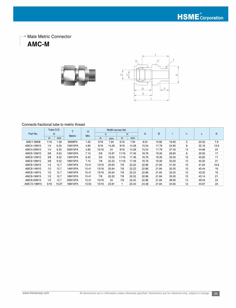
34www.hsmecorp.com All dimensions are in millimeters unless otherwise specified. Dimensions are for reference only, subject to change.
Male Metric Connector
AMC-M
Connects fractional tube to metric thread
Part No.Tube O.D.
DT
Metric
O
Min.
Width across flatA B l l1 L Kh H
in mm in mm in mmAMC1-5M08 1/16 1.58 5M08PA 1.30 5/16 7.94 5/16 7.94 8.54 10.82 16.60 5 20.32 7.9
AMC4-10M10 1/4 6.35 10M10PA 4.80 9/16 14.28 9/16 14.28 15.24 17.78 24.90 8 32.16 13.8AMC4-20M15 1/4 6.35 20M15PA 4.80 15/16 24 9/16 14.28 15.24 17.78 37.40 14 44.66 24AMC6-10M10 3/8 9.52 10M10PA 7.10 5/8 15.87 11/16 17.46 16.76 19.30 28.60 8 35.92 17AMC6-12M10 3/8 9.52 12M10PA 6.40 3/4 19.05 11/16 17.46 16.76 19.30 33.50 12 40.82 17AMC6-16M15 3/8 9.52 16M15PA 7.10 7/8 22.22 11/16 17.46 16.76 19.30 33.00 12 40.32 21AMC8-12M15 1/2 12.7 12M15PA 10.41 13/16 20.64 7/8 22.22 22.86 21.84 31.50 10 41.64 16.8AMC8-14M10 1/2 12.7 14M10PA 10.41 13/16 20.64 7/8 22.22 22.86 21.84 30.30 10 40.44 19AMC8-14M15 1/2 12.7 14M15PA 10.41 13/16 20.64 7/8 22.22 22.86 21.84 33.20 12 43.32 19AMC8-16M15 1/2 12.7 16M15PA 10.41 7/8 22.22 7/8 22.22 22.86 21.84 33.00 12 43.14 21AMC8-20M15 1/2 12.7 20M15PA 10.41 15/16 24 7/8 22.22 22.86 21.84 38.90 14 49.04 24
AMC10-18M15 5/18 15.87 18M15PA 13.50 15/16 23.81 1 25.40 24.38 21.84 34.60 12 44.67 23
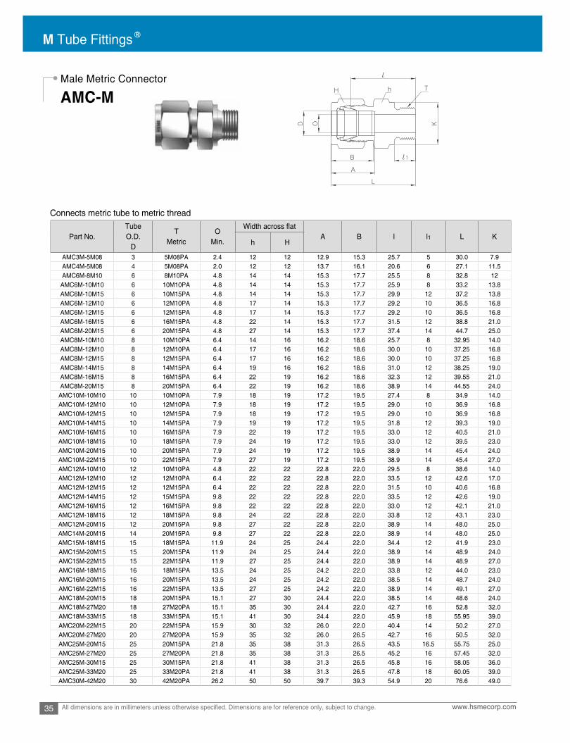
M Tube Fittings
35 www.hsmecorp.comAll dimensions are in millimeters unless otherwise specified. Dimensions are for reference only, subject to change.
Connects metric tube to metric thread
Male Metric Connector
AMC-M
Part No.Tube O.D.
D
TMetric
OMin.
Width across flatA B l l1 L K
h H
AMC3M-5M08 3 5M08PA 2.4 12 12 12.9 15.3 25.7 5 30.0 7.9AMC4M-5M08 4 5M08PA 2.0 12 12 13.7 16.1 20.6 6 27.1 11.5AMC6M-8M10 6 8M10PA 4.8 14 14 15.3 17.7 25.5 8 32.8 12
AMC6M-10M10 6 10M10PA 4.8 14 14 15.3 17.7 25.9 8 33.2 13.8AMC6M-10M15 6 10M15PA 4.8 14 14 15.3 17.7 29.9 12 37.2 13.8AMC6M-12M10 6 12M10PA 4.8 17 14 15.3 17.7 29.2 10 36.5 16.8AMC6M-12M15 6 12M15PA 4.8 17 14 15.3 17.7 29.2 10 36.5 16.8AMC6M-16M15 6 16M15PA 4.8 22 14 15.3 17.7 31.5 12 38.8 21.0AMC6M-20M15 6 20M15PA 4.8 27 14 15.3 17.7 37.4 14 44.7 25.0AMC8M-10M10 8 10M10PA 6.4 14 16 16.2 18.6 25.7 8 32.95 14.0AMC8M-12M10 8 12M10PA 6.4 17 16 16.2 18.6 30.0 10 37.25 16.8AMC8M-12M15 8 12M15PA 6.4 17 16 16.2 18.6 30.0 10 37.25 16.8AMC8M-14M15 8 14M15PA 6.4 19 16 16.2 18.6 31.0 12 38.25 19.0AMC8M-16M15 8 16M15PA 6.4 22 19 16.2 18.6 32.3 12 39.55 21.0AMC8M-20M15 8 20M15PA 6.4 22 19 16.2 18.6 38.9 14 44.55 24.0
AMC10M-10M10 10 10M10PA 7.9 18 19 17.2 19.5 27.4 8 34.9 14.0AMC10M-12M10 10 12M10PA 7.9 18 19 17.2 19.5 29.0 10 36.9 16.8AMC10M-12M15 10 12M15PA 7.9 18 19 17.2 19.5 29.0 10 36.9 16.8AMC10M-14M15 10 14M15PA 7.9 19 19 17.2 19.5 31.8 12 39.3 19.0AMC10M-16M15 10 16M15PA 7.9 22 19 17.2 19.5 33.0 12 40.5 21.0AMC10M-18M15 10 18M15PA 7.9 24 19 17.2 19.5 33.0 12 39.5 23.0AMC10M-20M15 10 20M15PA 7.9 24 19 17.2 19.5 38.9 14 45.4 24.0AMC10M-22M15 10 22M15PA 7.9 27 19 17.2 19.5 38.9 14 45.4 27.0AMC12M-10M10 12 10M10PA 4.8 22 22 22.8 22.0 29.5 8 38.6 14.0AMC12M-12M10 12 12M10PA 6.4 22 22 22.8 22.0 33.5 12 42.6 17.0AMC12M-12M15 12 12M15PA 6.4 22 22 22.8 22.0 31.5 10 40.6 16.8AMC12M-14M15 12 15M15PA 9.8 22 22 22.8 22.0 33.5 12 42.6 19.0AMC12M-16M15 12 16M15PA 9.8 22 22 22.8 22.0 33.0 12 42.1 21.0AMC12M-18M15 12 18M15PA 9.8 24 22 22.8 22.0 33.8 12 43.1 23.0AMC12M-20M15 12 20M15PA 9.8 27 22 22.8 22.0 38.9 14 48.0 25.0AMC14M-20M15 14 20M15PA 9.8 27 22 22.8 22.0 38.9 14 48.0 25.0AMC15M-18M15 15 18M15PA 11.9 24 25 24.4 22.0 34.4 12 41.9 23.0AMC15M-20M15 15 20M15PA 11.9 24 25 24.4 22.0 38.9 14 48.9 24.0AMC15M-22M15 15 22M15PA 11.9 27 25 24.4 22.0 38.9 14 48.9 27.0AMC16M-18M15 16 18M15PA 13.5 24 25 24.2 22.0 33.8 12 44.0 23.0AMC16M-20M15 16 20M15PA 13.5 24 25 24.2 22.0 38.5 14 48.7 24.0AMC16M-22M15 16 22M15PA 13.5 27 25 24.2 22.0 38.9 14 49.1 27.0AMC18M-20M15 18 20M15PA 15.1 27 30 24.4 22.0 38.5 14 48.6 24.0AMC18M-27M20 18 27M20PA 15.1 35 30 24.4 22.0 42.7 16 52.8 32.0AMC18M-33M15 18 33M15PA 15.1 41 30 24.4 22.0 45.9 18 55.95 39.0AMC20M-22M15 20 22M15PA 15.9 30 32 26.0 22.0 40.4 14 50.2 27.0AMC20M-27M20 20 27M20PA 15.9 35 32 26.0 26.5 42.7 16 50.5 32.0AMC25M-20M15 25 20M15PA 21.8 35 38 31.3 26.5 43.5 16.5 55.75 25.0AMC25M-27M20 25 27M20PA 21.8 35 38 31.3 26.5 45.2 16 57.45 32.0AMC25M-30M15 25 30M15PA 21.8 41 38 31.3 26.5 45.8 16 58.05 36.0AMC25M-33M20 25 33M20PA 21.8 41 38 31.3 26.5 47.8 18 60.05 39.0AMC30M-42M20 30 42M20PA 26.2 50 50 39.7 39.3 54.9 20 76.6 49.0

36www.hsmecorp.com All dimensions are in millimeters unless otherwise specified. Dimensions are for reference only, subject to change.
Male ISO Parallel ConnectorDIN3852 Form B
DIN3852 Form A
Connects metric tube to female ISO parallel thread
Image Shown “GB” End
AMC-GB
AMC-G-GB
-G
Part No. Tube O.D
TG(PF)
OMin. A B l l1 L k
h HAMC3M-2GB(-2G) 3 1/8 2.4 14 12 12.9 15.3 23.4 7.1 30.0 13.8AMC3M-4GB(-4G) 3 1/4 2.4 19 12 12.9 15.3 28.7 11.2 35.3 18.0AMC4M-2GB(-2G) 4 1/8 2.4 14 12 13.7 16.1 24.1 7.1 30.7 13.8AMC4M-4GB(-4G) 4 1/4 2.4 19 12 13.7 16.1 29.4 11.2 36.0 18.0AMC6M-2GB(-2G) 6 1/8 4.0 14 14 15.3 17.7 24.9 7.1 32.3 13.8AMC6M-4GB(-4G) 6 1/4 4.8 19 14 15.3 17.7 30.2 11.2 37.6 18.0AMC6M-6GB(-6G) 6 3/8 4.8 22 14 15.3 17.7 31.5 11.2 38.9 21.8AMC6M-8GB(-8G) 6 1/2 4.8 27 14 15.3 17.7 37.3 14.2 44.7 26.0AMC8M-2GB(-2G) 8 1/8 4.0 15 16 16.2 18.6 25.7 7.1 33.2 13.8AMC8M-4GB(-4G) 8 1/4 6.4 19 16 16.2 18.6 31.0 11.2 38.5 13.8AMC8M-6GB(-6G) 8 3/8 6.4 22 16 16.2 18.6 32.3 11.2 39.8 21.8AMC8M-8GB(-8G) 8 1/2 6.4 27 16 16.2 18.6 38.1 14.2 45.6 26.0AMC10M-4GB(-4G) 10 1/4 6.4 19 19 17.2 19.5 31.8 11.2 39.4 18.0AMC10M-6GB(-6G) 10 3/8 7.9 22 19 17.2 19.5 33.0 11.2 40.6 21.8AMC10M-8GB(-8G) 10 1/2 7.9 27 19 17.2 19.5 38.9 14.2 46.5 26.0AMC12M-4GB(-4G) 12 1/4 5.9 22 22 22.8 22.0 32.5 11.2 42.6 18.0AMC12M-6GB(-6G) 12 3/8 7.9 22 22 22.8 22.0 33.0 11.2 43.1 21.8AMC12M-8GB(-8G) 12 1/2 9.5 27 22 22.8 22.0 38.9 14.2 49.0 26.0AMC12M-12GB(-12G) 12 3/4 9.5 32 22 22.8 22.0 42.7 15.2 52.8 32.0AMC16M-6GB(-6G) 16 3/8 7.9 24 25 24.4 22.0 33.8 11.2 43.9 21.8AMC16M-8GB(-8G) 16 1/2 11.9 27 25 24.4 22.0 38.9 14.2 49.0 26.0AMC18M-8GB(-8G) 18 1/2 11.9 27 30 24.4 22.0 38.9 14.2 49.0 26.0AMC18M-12GB(-12G) 18 3/4 15.1 35 30 24.4 22.0 42.7 15.7 52.8 32.0AMC20M-8GB(-8G) 20 1/2 11.9 30 32 26.0 22.0 40.4 14.2 50.5 26.0AMC20M-12G(-12G) 20 3/4 15.9 35 32 26.0 22.0 42.7 15.7 52.8 32.0AMC22M-12G(-12G) 22 3/4 15.9 35 32 26.0 22.0 42.7 15.7 52.8 32.0AMC22M-16G(-16G) 22 1 18.3 41 32 26.0 22.0 45.2 18.3 55.3 39.0AMC25M-12G(-12G) 25 3/4 15.9 35 38 31.3 26.5 45.2 15.7 57.5 32.0AMC25M-16G(-16G) 25 1 19.8 41 38 31.3 26.5 47.8 18.3 60.1 39.0AMC28M-16G(-16G) 28 1 19.8 41 46 36.6 36.6 49.3 18.3 70.1 39.0AMC28M-20G(-20G) 28 1-1/4 21.8 50 46 36.6 36.6 53.1 19.8 73.9 49.0AMC32M-20G(-20G) 32 1-1/4 25.0 50 50 42.0 41.6 55.9 19.8 78.9 49.0AMC38M-24G(-24G) 38 1-1/2 31.8 55 60 49.4 47.9 63.2 22.1 90.8 54.7

M Tube Fittings
37 www.hsmecorp.comAll dimensions are in millimeters unless otherwise specified. Dimensions are for reference only, subject to change.
Connects fractional tube to SAE straight thread boss
Connects metric tube to SAE straight thread boss
Non-PositionableSAE Male ConnectorAMC-UF
Part No.Tube O.D.
DStraightThread
T(U)
OMin. A B l l1 L
O-RingUniform
SizeNumber
h Hin mm in mm in mm
AMC2-2UF 1/8 3.17 5/16-24 2.28 7/16 11.11 7/16 11.11 12.70 15.24 23.26 7.62 29.97 -902AMC4-4UF 1/4 6.35 7/16-20 4.82 9/16 14.28 9/16 14.28 15.24 17.78 26.67 9.14 34.03 -904AMC4-6UF 1/4 6.35 9/16-18 4.82 11/16 17.46 9/16 14.28 15.24 17.78 28.19 9.90 35.56 -906AMC4-8UF 1/4 6.35 3/4-16 4.82 7/8 22.22 9/16 14.28 15.24 17.78 30.22 11.17 37.59 -908AMC4-10UF 1/4 6.35 7/8-14 4.82 1 25.40 9/16 14.28 15.24 17.78 33.27 12.70 40.64 -910AMC5-5UF 5/16 7.93 1/2-20 5.84 5/8 15.87 5/8 15.87 16.25 18.54 27.43 9.14 34.79 -905AMC6-4UF 3/8 9.52 7/16-20 5.08 5/8 15.87 11/16 17.46 16.76 19.30 28.19 9.14 35.56 -904AMC6-6UF 3/8 9.52 9/16-18 7.11 11/16 17.46 11/16 17.46 16.76 19.30 29.71 9.90 37.08 -906AMC6-8UF 3/8 9.52 3/4-16 7.11 7/8 22.22 11/16 17.46 16.76 19.30 31.75 11.17 39.11 -908AMC6-10UF 3/8 9.52 7/8-14 7.11 1 25.40 11/16 17.46 16.76 19.30 34.79 12.70 42.16 -910AMC8-6UF 1/2 12.70 9/16-18 7.11 13/16 20.64 7/8 22.22 22.86 21.84 28.95 9.90 39.11 -906AMC8-8UF 1/2 12.70 3/4-16 10.41 7/8 22.22 7/8 22.22 22.86 21.84 31.75 11.17 41.91 -908AMC8-10UF 1/2 12.70 7/8-14 10.41 1 25.40 7/8 22.22 22.86 21.84 34.79 12.70 44.95 -910AMC8-12UF 1/2 12.70 1-1/16-12 10.41 1-1/4 31.75 7/8 22.22 22.86 21.84 38.86 14.98 49.02 -912AMC10-8UF 5/8 15.87 3/4-16 10.66 15/16 23.81 1 25.40 24.38 21.84 31.75 11.17 41.91 -908AMC10-10UF 5/8 15.87 7/8-14 12.70 1 25.40 1 25.40 24.38 21.84 35.05 12.70 45.21 -910AMC12-8UF 3/4 19.05 3/4-16 10.66 1-1/16 26.98 1-1/8 28.57 24.38 21.84 35.81 11.17 45.97 -908AMC12-12UF 3/4 19.05 1-1/16-12 15.74 1-1/4 31.75 1-1/8 28.57 24.38 21.84 38.86 14.98 49.02 -912AMC14-14UF 7/8 22.22 1-3/16-12 18.28 1-3/8 34.92 1-1/4 31.75 25.90 21.84 38.86 14.98 49.02 -914AMC16-12UF 1 25.40 1-1/16-12 16.76 1-3/8 34.92 1-1/2 38.10 31.24 26.41 41.14 14.98 53.54 -912AMC16-16UF 1 25.40 1-5/16-12 22.35 1-1/2 38.10 1-1/2 38.10 31.24 26.41 42.16 14.98 54.35 -916AMC20-20UF 1-1/4 31.75 1-5/8-12 27.68 1-7/8 47.63 1-7/8 47.63 41.14 38.86 46.22 14.98 68.32 -920AMC24-24UF 1-1/2 38.10 1-7/8-12 34.03 2-1/8 53.98 2-1/4 57.15 50.03 45.21 50.54 14.98 77.72 -924AMC32-32UF 2 50.80 2-1/2-12 45.97 2-3/4 69.85 3 76.20 67.56 62.73 64.26 14.98 101.60 -932
Part No. Tube O.D.D
StraightThread
T(U)
OMin. A B l l1 L
O-RingUniform
Size Numberh HAMC6M-6UF 6 9/16-18 4.8 18 14 15.3 17.7 28.2 9.90 36.5 -906AMC10M-6UF 10 9/16-18 7.9 18 19 17.2 19.5 29.7 9.90 37.3 -906AMC10M-8UF 10 3/4-16 7.9 22 19 17.2 19.5 31.8 11.17 39.4 -908AMC12M-4UF 12 7/16-20 5.2 22 22 22.8 22.0 28.2 9.14 38.3 -904AMC12M-6UF 12 9/16-18 7.5 22 22 22.8 22.0 29.0 9.90 39.1 -906

38www.hsmecorp.com All dimensions are in millimeters unless otherwise specified. Dimensions are for reference only, subject to change.
SAE Straight Thread Mounting to SAE J1926
Mounting Dimension for O-Seal Male Connector
Thread Designator: UF
The sealing and holding function are separated in SAE Straight Thread with O-ring.
UNF threads have only the holding function and sealing is achievedwith a high durometer O-ring seated in a chamber at the top of thefemale port.
Installation Instruction1. Lubricate the O-ring compatible with system fluid.2. Finger-tighten the fitting in the port.3. Hand-tighten the fitting until the O-ring is compressed in the chamber at the top of the female port.4. Tighten slightly further with wrench to compress the O-ring completely.
The minimum diameter A allows metal- to-metal contact outside of O-ring that prevents O-ring extrusion.
1. Lubricate the O-ring compatible with system fluid.2. Finger-tighten the O-Seal fitting in the port.3. Hand-tighten the fitting until squeezing of O-ring is felt during the last 1/4 turn.3. Gently wrench-tighten the fitting until the round shoulder outside of O-ring achieves metal-to-metal contact against the flat face of female port. This compresses O-ring completely for leak-tight.
• Port should have a smooth, flat surface perpendicular to the port. NPT thread in short length ensures thread interference.
The round shoulder of O-Seal fitting is recessed into counter-bored port.
The Hex of O-Seal fitting is recessed into the recessed port.
UO: SAE straight with O-ring in grooveNO: NPT thread with O-ring in grooveO-ring is contained in a precision groove that prevents O-ring extrusion at pressure and vacuum.
Raised Port Counter-Bored Port Recessed Port
1. Raised Port
2. Counter-Bored Port
3. Recessed Port
Installation Instruction
SAEThread
Size
NPTSize
AMin. Flat
Dia.
BMin.
ClearanceDia.
CMin.
ClearanceDia.
DMax
Depth
EMax
Depth
Dimensions, in.
5/16-24 -0.50 0.59 0.66 0.09
0.165/16-24 - 0.223/8-24 - 0.56 0.66 0.75 0.09 0.22
7/16-20 - 0.69 0.78 0.88 0.16 0.281/2-20 - 0.75 0.91 1.03 0.16 0.31
9/16-18 - 0.81 0.97 1.09 0.16 0.313/4-16 - 1.00 1.16 1.31 0.16 0.34
11/16-12 - 1.41 1.53 1.75 0.22 0.5015/16-12 - 1.69 1.78 2.03 0.22 0.56
- 1/8 0.69 0.78 0.88 0.16 0.28- 1/4 0.87 0.97 1.09 0.16 0.31- 3/8 1.00 1.16 1.31 0.16 0.34- 1/2 1.22 1.34 1.53 0.22 0.44
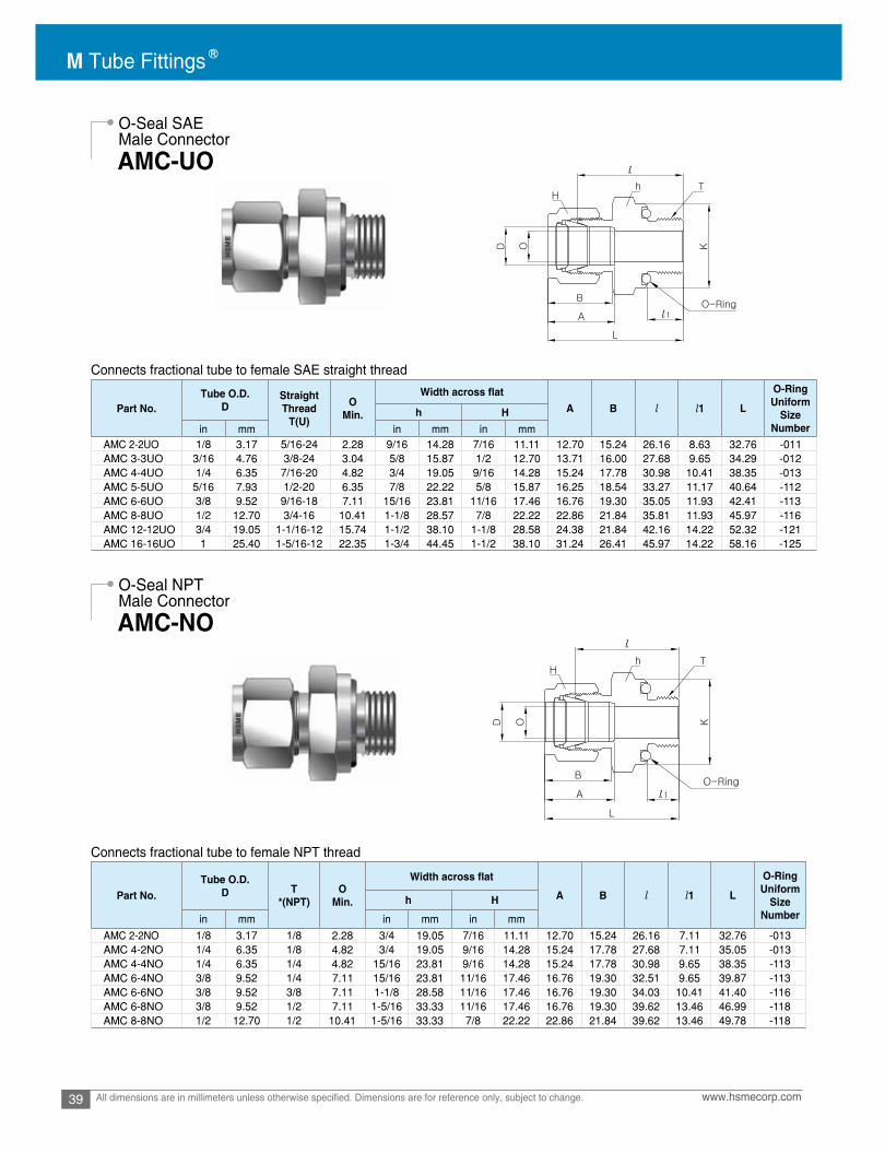
M Tube Fittings
39 www.hsmecorp.comAll dimensions are in millimeters unless otherwise specified. Dimensions are for reference only, subject to change.
O-Seal SAEMale Connector
O-Seal NPTMale Connector
AMC-UO
AMC-NO
Connects fractional tube to female SAE straight thread
Connects fractional tube to female NPT thread
Part No.Tube O.D.
DStraightThread
T(U)
OMin. A B l l1 L
O-RingUniform
SizeNumber
h Hin mm in mm in mm
AMC 2-2UO 1/8 3.17 5/16-24 2.28 9/16 14.28 7/16 11.11 12.70 15.24 26.16 8.63 32.76 -011AMC 3-3UO 3/16 4.76 3/8-24 3.04 5/8 15.87 1/2 12.70 13.71 16.00 27.68 9.65 34.29 -012AMC 4-4UO 1/4 6.35 7/16-20 4.82 3/4 19.05 9/16 14.28 15.24 17.78 30.98 10.41 38.35 -013AMC 5-5UO 5/16 7.93 1/2-20 6.35 7/8 22.22 5/8 15.87 16.25 18.54 33.27 11.17 40.64 -112AMC 6-6UO 3/8 9.52 9/16-18 7.11 15/16 23.81 11/16 17.46 16.76 19.30 35.05 11.93 42.41 -113AMC 8-8UO 1/2 12.70 3/4-16 10.41 1-1/8 28.57 7/8 22.22 22.86 21.84 35.81 11.93 45.97 -116AMC 12-12UO 3/4 19.05 1-1/16-12 15.74 1-1/2 38.10 1-1/8 28.58 24.38 21.84 42.16 14.22 52.32 -121AMC 16-16UO 1 25.40 1-5/16-12 22.35 1-3/4 44.45 1-1/2 38.10 31.24 26.41 45.97 14.22 58.16 -125
Part No.Tube O.D.
D T*(NPT)
OMin. A B l l1 L
O-RingUniform
SizeNumber
h H
in mm in mm in mm
AMC 2-2NO 1/8 3.17 1/8 2.28 3/4 19.05 7/16 11.11 12.70 15.24 26.16 7.11 32.76 -013AMC 4-2NO 1/4 6.35 1/8 4.82 3/4 19.05 9/16 14.28 15.24 17.78 27.68 7.11 35.05 -013AMC 4-4NO 1/4 6.35 1/4 4.82 15/16 23.81 9/16 14.28 15.24 17.78 30.98 9.65 38.35 -113AMC 6-4NO 3/8 9.52 1/4 7.11 15/16 23.81 11/16 17.46 16.76 19.30 32.51 9.65 39.87 -113AMC 6-6NO 3/8 9.52 3/8 7.11 1-1/8 28.58 11/16 17.46 16.76 19.30 34.03 10.41 41.40 -116AMC 6-8NO 3/8 9.52 1/2 7.11 1-5/16 33.33 11/16 17.46 16.76 19.30 39.62 13.46 46.99 -118AMC 8-8NO 1/2 12.70 1/2 10.41 1-5/16 33.33 7/8 22.22 22.86 21.84 39.62 13.46 49.78 -118
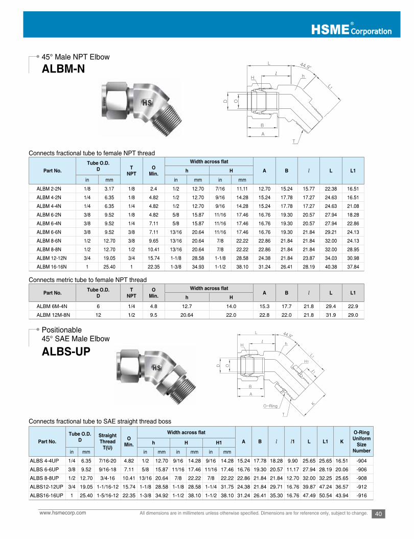
40www.hsmecorp.com All dimensions are in millimeters unless otherwise specified. Dimensions are for reference only, subject to change.
45° Male NPT Elbow
Positionable45° SAE Male Elbow
ALBM-N
ALBS-UP
Connects fractional tube to female NPT thread
Connects metric tube to female NPT thread
Connects fractional tube to SAE straight thread boss
Part No.Tube O.D.
D TNPT
OMin. A B l L L1h H
in mm in mm in mm
ALBM 2-2N 1/8 3.17 1/8 2.4 1/2 12.70 7/16 11.11 12.70 15.24 15.77 22.38 16.51
ALBM 4-2N 1/4 6.35 1/8 4.82 1/2 12.70 9/16 14.28 15.24 17.78 17.27 24.63 16.51
ALBM 4-4N 1/4 6.35 1/4 4.82 1/2 12.70 9/16 14.28 15.24 17.78 17.27 24.63 21.08
ALBM 6-2N 3/8 9.52 1/8 4.82 5/8 15.87 11/16 17.46 16.76 19.30 20.57 27.94 18.28
ALBM 6-4N 3/8 9.52 1/4 7.11 5/8 15.87 11/16 17.46 16.76 19.30 20.57 27.94 22.86
ALBM 6-6N 3/8 9.52 3/8 7.11 13/16 20.64 11/16 17.46 16.76 19.30 21.84 29.21 24.13
ALBM 8-6N 1/2 12.70 3/8 9.65 13/16 20.64 7/8 22.22 22.86 21.84 21.84 32.00 24.13
ALBM 8-8N 1/2 12.70 1/2 10.41 13/16 20.64 7/8 22.22 22.86 21.84 21.84 32.00 28.95
ALBM 12-12N 3/4 19.05 3/4 15.74 1-1/8 28.58 1-1/8 28.58 24.38 21.84 23.87 34.03 30.98
ALBM 16-16N 1 25.40 1 22.35 1-3/8 34.93 1-1/2 38.10 31.24 26.41 28.19 40.38 37.84
Part No. Tube O.D.D
TNPT
OMin. A B l L L1
h H
ALBM 6M-4N 6 1/4 4.8 12.7 14.0 15.3 17.7 21.8 29.4 22.9
ALBM 12M-8N 12 1/2 9.5 20.64 22.0 22.8 22.0 21.8 31.9 29.0
Part No.Tube O.D.
DStraightThread
T(U)
OMin. A B l l1 L L1 K
O-RingUniform
SizeNumber
h H H1
in mm in mm in mm in mm
ALBS 4-4UP 1/4 6.35 7/16-20 4.82 1/2 12.70 9/16 14.28 9/16 14.28 15.24 17.78 18.28 9.90 25.65 25.65 16.51 -904
ALBS 6-6UP 3/8 9.52 9/16-18 7.11 5/8 15.87 11/16 17.46 11/16 17.46 16.76 19.30 20.57 11.17 27.94 28.19 20.06 -906
ALBS 8-8UP 1/2 12.70 3/4-16 10.41 13/16 20.64 7/8 22.22 7/8 22.22 22.86 21.84 21.84 12.70 32.00 32.25 25.65 -908
ALBS12-12UP 3/4 19.05 1-1/16-12 15.74 1-1/8 28.58 1-1/8 28.58 1-1/4 31.75 24.38 21.84 29.71 16.76 39.87 47.24 36.57 -912
ALBS16-16UP 1 25.40 1-5/16-12 22.35 1-3/8 34.92 1-1/2 38.10 1-1/2 38.10 31.24 26.41 35.30 16.76 47.49 50.54 43.94 -916

M Tube Fittings
41 www.hsmecorp.comAll dimensions are in millimeters unless otherwise specified. Dimensions are for reference only, subject to change.
Connects frractional tube to female NPT thread
Male NPT Elbow
ALM-N
Part No.Tube O.D.
D TNPT
OMin. A B l L L1h H
in mm in mm in mmALM1-1N 1/16 1.59 1/16 1.27 7/16 11.11 5/16 7.93 8.63 10.92 15.24 19.05 17.78ALM1-2N 1/16 1.59 1/8 1.27 7/16 11.11 5/16 7.93 8.63 10.92 15.24 19.05 17.78ALM2-2N 1/8 3.17 1/8 2.28 1/2 12.70 7/16 11.11 12.70 15.24 18.30 24.91 18.90ALM2-4N 1/8 3.17 1/4 2.28 1/2 12.70 7/16 11.11 12.70 15.24 18.30 24.91 23.26ALM3-2N 3/16 4.76 1/8 3.04 1/2 12.70 1/2 12.70 13.71 16.00 18.79 25.40 18.79ALM3-4N 3/16 4.76 1/4 3.04 1/2 12.70 1/2 12.70 13.71 16.00 18.79 25.40 23.36ALM4-1N 1/4 6.35 1/16 3.04 1/2 12.70 9/16 14.28 15.24 17.78 19.55 26.90 18.79ALM4-2N 1/4 6.35 1/8 4.82 1/2 12.70 9/16 14.28 15.24 17.78 19.55 26.47 18.79ALM4-4N 1/4 6.35 1/4 4.82 1/2 12.70 9/16 14.28 15.24 17.78 19.81 27.18 23.87ALM4-6N 1/4 6.35 3/8 4.82 11/16 17.46 9/16 14.28 15.24 17.78 22.35 29.71 26.20ALM4-8N 1/4 6.35 1/2 4.82 13/16 20.64 9/16 14.28 15.24 17.78 24.60 31.97 33.02ALM5-2N 5/16 7.93 1/8 4.82 9/16 14.28 5/8 15.87 16.25 18.54 21.33 28.70 19.81ALM5-4N 5/16 7.93 1/4 6.35 9/16 14.28 5/8 15.87 16.25 18.54 21.33 29.77 24.50ALM5-6N 5/16 7.93 3/8 6.35 11/16 17.46 5/8 15.87 16.25 18.54 23.11 30.48 26.20ALM6-2N 3/8 9.52 1/8 4.82 5/8 15.87 11/16 17.46 16.76 19.30 23.11 30.48 20.60ALM6-4N 3/8 9.52 1/4 7.11 5/8 15.87 11/16 17.46 16.76 19.30 23.11 30.48 25.40ALM6-6N 3/8 9.52 3/8 7.11 11/16 17.46 11/16 17.46 16.76 19.30 23.87 31.24 26.20ALM6-8N 3/8 9.52 1/2 7.11 13/16 20.64 11/16 17.46 16.76 19.30 25.90 31.42 33.02ALM6-12N 3/8 9.52 3/4 7.11 1-1/16 26.98 11/16 17.46 16.76 19.30 29.71 37.08 36.83ALM8-4N 1/2 12.70 1/4 7.11 13/16 20.64 7/8 22.22 22.86 21.84 25.90 36.06 28.30ALM8-6N 1/2 12.70 3/8 9.65 13/16 20.64 7/8 22.22 22.86 21.84 25.90 36.06 28.30ALM8-8N 1/2 12.70 1/2 10.41 13/16 20.64 7/8 22.22 22.86 21.84 25.90 36.06 33.02ALM8-12N 1/2 12.70 3/4 10.41 1-1/16 26.98 7/8 22.22 22.86 21.84 29.71 39.87 36.83ALM10-6N 5/8 15.87 3/8 9.65 15/16 23.81 1 25.40 24.38 21.84 28.00 37.06 30.22ALM10-8N 5/8 15.87 1/2 11.93 15/16 23.81 1 25.40 24.38 21.84 28.00 37.06 35.10ALM10-12N 5/8 15.87 3/4 12.70 1-1/16 26.98 1 25.40 24.38 21.84 29.71 39.87 36.83ALM12-8N 3/4 19.05 1/2 11.93 1-1/16 26.98 1-1/8 28.57 24.38 21.84 29.71 39.87 37.00ALM12-12N 3/4 19.05 3/4 15.74 1-1/16 26.98 1-1/8 28.57 24.38 21.84 29.71 39.87 36.83ALM14-12N 7/8 22.22 3/4 15.74 1-3/8 34.92 1-1/4 31.75 25.90 21.84 34.54 44.70 41.65ALM16-12N 1 25.40 3/4 15.74 1-3/8 34.92 1-1/2 38.10 31.24 26.41 36.83 49.02 42.20ALM16-16N 1 25.40 1 22.35 1-3/8 34.92 1-1/2 38.10 31.24 26.41 36.83 49.02 46.70ALM20-20N 1-1/4 31.75 1-1/4 27.68 1-11/16 42.86 1-7/8 47.63 41.14 38.86 44.50 66.54 47.75ALM24-24N 1-1/2 38.10 1-1/2 34.03 2 50.80 2-1/4 57.15 50.03 45.21 50.80 77.97 60.45ALM32-32N 2 50.80 2 45.97 2-3/4 69.85 3 76.20 62.73 63.73 69.80 107.18 70.61

42www.hsmecorp.com All dimensions are in millimeters unless otherwise specified. Dimensions are for reference only, subject to change.
Male NPT Elbow
ALM-N
Connects metric tube to female NPT thread
Part No. Tube O.D.D
TR(PT)
OMin. A B l L L1
h HALM3M-1N 3 1/16 2.4 11.1 12 12.9 15.3 17.0 23.6 17.8ALM3M-2N 3 1/8 2.4 12.7 12 12.9 15.3 17.0 23.6 17.8ALM3M-4N 3 1/4 2.4 12.7 12 12.9 15.3 18.0 24.6 23.4ALM4M-2N 4 1/8 2.4 12.7 12 13.7 16.1 18.8 25.4 18.8ALM4M-4N 4 1/4 2.4 12.7 12 13.7 16.1 18.8 25.4 23.4ALM6M-2N 6 1/8 4.8 12.7 14 15.3 17.7 19.6 27.0 18.8ALM6M-4N 6 1/4 4.8 12.7 14 15.3 17.7 19.6 27.0 23.4ALM6M-6N 6 3/8 4.8 17.5 14 15.3 17.7 22.4 29.8 26.2ALM6M-8N 6 1/2 4.8 20.6 14 15.3 17.7 24.4 31.8 33.0ALM8M-2N 8 1/8 4.8 14.3 16 16.2 18.6 21.3 28.8 19.8ALM8M-4N 8 1/4 6.4 14.3 16 16.2 18.6 21.3 28.8 24.4ALM8M-6N 8 3/8 6.4 17.5 16 16.2 18.6 23.1 30.6 26.2ALM8M-8N 8 1/2 6.4 20.6 16 16.2 18.6 25.1 32.6 33.0ALM10M-2N 10 1/8 4.8 17.5 19 17.2 19.5 23.9 31.5 23.6ALM10M-4N 10 1/4 7.1 17.5 19 17.2 19.5 23.9 31.5 26.2ALM10M-6N 10 3/8 7.9 17.5 19 17.2 19.5 23.9 31.5 26.2ALM10M-8N 10 1/2 7.9 20.6 19 17.2 19.5 25.9 33.5 33.0ALM12M-2N 12 1/8 4.8 20.6 22 22.8 22.0 25.9 36.0 23.6ALM12M-4N 12 1/4 7.1 20.6 22 22.8 22.0 25.9 36.0 28.2ALM12M-6N 12 3/8 9.5 20.6 22 22.8 22.0 25.9 36.0 28.2ALM12M-8N 12 1/2 9.5 20.6 22 22.8 22.0 25.9 36.0 33.0ALM12M-12N 12 3/4 9.5 27.0 22 22.8 22.0 29.7 39.8 36.8ALM16M-6N 16 3/8 9.5 25.4 25 24.4 22.0 27.9 38.0 30.2ALM16M-8N 16 1/2 11.9 23.81 25 24.4 22.0 27.9 38.0 35.1ALM16M-12N 16 3/4 12.7 23.81 25 24.4 22.0 29.7 39.8 36.8ALM18M-8N 18 1/2 11.9 27.0 30 24.4 22.0 29.7 39.8 36.8ALM18M-12N 18 3/4 15.1 27.0 30 24.4 22.0 29.7 39.8 36.8ALM20M-8N 20 1/2 11.9 34.92 32 26.0 22.0 34.5 44.6 41.7ALM20M-12N 20 3/4 15.9 34.92 32 26.0 22.0 34.5 44.6 41.7ALM22M-12N 22 3/4 15.9 34.92 32 26.0 22.0 34.5 44.6 41.7ALM22M-16N 22 1 18.3 34.92 32 26.0 22.0 34.5 44.6 46.5ALM25M-12N 25 3/4 15.9 34.92 38 31.3 26.5 36.8 49.1 41.7ALM25M-16N 25 1 21.8 34.92 38 31.3 26.5 36.8 49.1 46.5ALM28M-16N 28 1 21.8 41.0 46 36.6 36.6 43.2 64.0 53.7ALM30M-20N 30 1-1/4 26.2 46.0 50 39.6 39.2 48.3 69.9 53.1ALM32M-20N 32 1-1/4 27.8 46.0 50 42.0 41.6 49.3 72.3 53.1ALM38M-24N 38 1-1/2 33.7 50.8 60 49.4 47.9 56.4 84.0 60.4

M Tube Fittings
43 www.hsmecorp.comAll dimensions are in millimeters unless otherwise specified. Dimensions are for reference only, subject to change.
Male BSPT Elbow
ALM-R
Connects fractional tube to female ISO tapered thread
Part No.Tube O.D.
D TPT
OMin. A B l L L1h H
in mm in mm in mmALM 2-2R 1/8 3.17 1/8 2.28 1/2 12.70 7/16 11.11 12.70 15.24 18.30 24.91 18.90ALM2-4R 1/8 3.17 1/4 2.28 1/2 12.70 7/16 11.11 12.70 15.24 18.30 24.91 23.26ALM3-4R 3/16 4.76 1/4 3.04 1/2 12.70 1/2 12.70 13.71 16.00 18.79 25.40 23.36ALM4-2R 1/4 6.35 1/8 4.82 1/2 12.70 9/16 14.28 15.24 17.78 19.55 26.47 18.79ALM4-4R 1/4 6.35 1/4 4.82 1/2 12.70 9/16 14.28 15.24 17.78 19.81 27.18 23.87ALM4-6R 1/4 6.35 3/8 4.82 11/16 17.46 9/16 14.28 15.24 17.78 22.35 29.71 26.20ALM4-8R 1/4 6.35 1/2 4.82 13/16 20.64 9/16 14.28 15.24 17.78 24.60 31.97 33.02ALM5-4R 5/16 7.93 1/4 6.35 9/16 14.28 5/8 15.87 16.25 18.54 21.33 29.77 24.50ALM5-6R 5/16 7.93 3/8 6.35 11/16 17.46 5/8 15.87 16.25 18.54 23.11 30.48 26.20ALM6-2R 3/8 9.52 1/8 4.82 5/8 15.87 11/16 17.46 16.76 19.30 23.11 30.48 20.60ALM6-4R 3/8 9.52 1/4 7.11 5/8 15.87 11/16 17.46 16.76 19.30 23.11 30.48 25.40ALM6-6R 3/8 9.52 3/8 7.11 11/16 17.46 11/16 17.46 16.76 19.30 23.87 31.24 26.20ALM6-8R 3/8 9.52 1/2 7.11 13/16 20.64 11/16 17.46 16.76 19.30 25.90 31.42 33.02ALM6-12R 3/8 9.52 3/4 7.11 1-1/16 26.98 11/16 17.46 16.76 19.30 29.71 37.08 36.83ALM8-4R 1/2 12.70 1/4 7.11 13/16 20.64 7/8 22.22 22.86 21.84 25.90 36.06 28.30ALM8-6R 1/2 12.70 3/8 9.65 13/16 20.64 7/8 22.22 22.86 21.84 25.90 36.06 28.30ALM8-8R 1/2 12.70 1/2 10.41 13/16 20.64 7/8 22.22 22.86 21.84 25.90 36.06 33.02ALM8-12R 1/2 12.70 3/4 10.41 1-1/16 26.98 7/8 22.22 22.86 21.84 29.71 39.87 36.83ALM10-6R 5/8 15.87 3/8 9.65 15/16 23.81 1 25.40 24.38 21.84 28.00 37.06 30.22ALM10-8R 5/8 15.87 1/2 11.93 15/16 23.81 1 25.40 24.38 21.84 28.00 37.06 35.10ALM10-12R 5/8 15.87 3/4 12.70 1-1/16 26.98 1 25.40 24.38 21.84 29.71 39.87 36.83ALM12-8R 3/4 19.05 1/2 11.93 1-1/16 26.98 1-1/8 28.57 24.38 21.84 29.71 39.87 37.00ALM12-12R 3/4 19.05 3/4 15.74 1-1/16 26.98 1-1/8 28.57 24.38 21.84 29.71 39.87 36.83ALM12-16R 3/4 19.05 1 16.0 1-3/8 34.92 1-1/8 28.57 24.38 21.84 34.54 44.59 46.48ALM16-12R 1 25.40 3/4 15.74 1-3/8 34.92 1-1/2 38.10 31.24 26.41 36.83 49.02 42.20ALM16-16R 1 25.40 1 22.35 1-3/8 34.92 1-1/2 38.10 31.24 26.41 36.83 49.02 46.70ALM20-12R 1-1/4 31.75 3/4 15.74 1-11/16 42.86 1-7/8 47.63 41.14 38.86 44.50 66.54 42.95ALM20-20R 1-1/4 31.75 1-1/4 27.68 1-11/16 42.86 1-7/8 47.63 41.14 38.86 44.50 66.54 47.75

44www.hsmecorp.com All dimensions are in millimeters unless otherwise specified. Dimensions are for reference only, subject to change.
Male BSPT Elbow
ALM-R
Connects metric tube to female ISO tapered thread
Part No. Tube O.D.D
TR(PT)
OMin. A B l L L1
h HALM3M-1R 3 1/16 2.4 11.1 12 12.9 15.3 17.0 23.6 17.8ALM3M-2R 3 1/8 2.4 12.7 12 12.9 15.3 17.0 23.6 17.8ALM3M-4R 3 1/4 2.4 12.7 12 12.9 15.3 18.0 24.6 23.4ALM4M-2R 4 1/8 2.4 12.7 12 13.7 16.1 18.8 25.4 18.8ALM4M-4R 4 1/4 2.4 12.7 12 13.7 16.1 18.8 25.4 23.4ALM6M-2R 6 1/8 4.8 12.7 14 15.3 17.7 19.6 27.0 18.8ALM6M-4R 6 1/4 4.8 12.7 14 15.3 17.7 19.6 27.0 23.4ALM6M-6R 6 3/8 4.8 17.5 14 15.3 17.7 22.4 29.8 26.2ALM6M-8R 6 1/2 4.8 20.6 14 15.3 17.7 24.4 31.8 33.0ALM8M-2R 8 1/8 4.8 14.3 16 16.2 18.6 21.3 28.8 19.8ALM8M-4R 8 1/4 6.4 14.3 16 16.2 18.6 21.3 28.8 24.4ALM8M-6R 8 3/8 6.4 17.5 16 16.2 18.6 23.1 30.6 26.2ALM8M-8R 8 1/2 6.4 20.6 16 16.2 18.6 25.1 32.6 33.0ALM10M-2R 10 1/8 4.8 17.5 19 17.2 19.5 23.9 31.5 23.6ALM10M-4R 10 1/4 7.1 17.5 19 17.2 19.5 23.9 31.5 26.2ALM10M-6R 10 3/8 7.9 17.5 19 17.2 19.5 23.9 31.5 26.2ALM10M-8R 10 1/2 7.9 20.6 19 17.2 19.5 25.9 33.5 33.0ALM12M-2R 12 1/8 4.8 20.6 22 22.8 22.0 25.9 36.0 23.6ALM12M-4R 12 1/4 7.1 20.6 22 22.8 22.0 25.9 36.0 28.2ALM12M-6R 12 3/8 9.5 20.6 22 22.8 22.0 25.9 36.0 28.2ALM12M-8R 12 1/2 9.5 20.6 22 22.8 22.0 25.9 36.0 33.0ALM12M-12R 12 3/4 9.5 27.0 22 22.8 22.0 29.7 39.8 36.8ALM14M-8R 14 1/2 11.1 23.81 25 24.4 22.0 27.9 38.0 30.2ALM15M-6R 15 3/8 9.5 23.81 25 24.4 22.0 27.9 38.0 30.2ALM15M-8R 15 1/2 11.9 23.81 25 24.4 22.0 27.9 38.0 35.1ALM16M-6R 16 3/8 9.5 25.4 25 24.4 22.0 27.9 38.0 30.2ALM16M-8R 16 1/2 11.9 23.81 25 24.4 22.0 27.9 38.0 35.1ALM18M-8R 18 1/2 11.9 27.0 30 24.4 22.0 29.7 39.8 36.8ALM18M-12R 18 3/4 15.1 27.0 30 24.4 22.0 29.7 39.8 36.8ALM20M-8R 20 1/2 11.9 34.92 32 26.0 22.0 34.5 44.6 41.7ALM20M-12R 20 3/4 15.9 34.92 32 26.0 22.0 34.5 44.6 41.7ALM22M-8R 22 1/2 11.9 34.92 32 26.0 22.0 32.5 42.6 39.6ALM22M-12R 22 3/4 15.9 34.92 32 26.0 22.0 34.5 44.6 41.7ALM22M-16R 22 1 18.3 34.92 32 26.0 22.0 34.5 44.6 46.5ALM25M-8R 25 1/2 11.9 34.92 38 31.3 26.5 36.8 49.1 41.7ALM25M-12R 25 3/4 15.9 34.92 38 31.3 26.5 36.8 49.1 41.7ALM25M-16R 25 1 21.8 34.92 38 31.3 26.5 36.8 49.1 46.5ALM28M-16R 28 1 21.8 41.0 46 36.6 36.6 43.2 64.0 53.7

M Tube Fittings
45 www.hsmecorp.comAll dimensions are in millimeters unless otherwise specified. Dimensions are for reference only, subject to change.
PositionableMale ISO ParallelThread Elbow
ALM-GR
Connects fractional tube to ISO parallel thread
Connects metric tube to ISO parallel thread
Part No.Tube O.D.
D TG(PF)
OMin. A B l l1 L L1 K
O-RingUniform
SizeNumber
h H H1
in mm in mm in mm in mm
ALM4-2GR 1/4 6.35 1/8 4.06 1/2 12.70 9/16 14.28 9/16 14.28 15.24 17.78 19.6 8.12 26.92 26.42 15.20 P8ALM4-4GR 1/4 6.35 1/4 4.82 5/8 15.87 11/16 17.46 3/4 19.05 15.24 17.78 21.6 9.14 28.95 32.30 20.30 -111ALM6-4GR 3/8 9.52 1/4 5.84 5/8 15.87 11/16 17.46 3/4 19.05 16.76 19.30 23.1 9.14 30.48 32.30 20.30 -111ALM6-6GR 3/8 9.52 3/8 7.11 13/16 20.64 11/16 17.46 3/4 19.05 16.76 19.30 25.9 9.39 33.27 37.10 24.40 -113ALM8-4GR 1/2 12.70 1/4 5.84 13/16 20.64 7/8 22.22 7/8 22.22 22.86 21.84 25.9 9.14 36.06 35.10 20.30 -111ALM8-6GR 1/2 12.70 3/8 7.87 13/16 20.64 7/8 22.22 7/8 22.22 22.86 21.84 25.9 9.39 36.06 37.10 24.40 -113ALM8-8GR 1/2 12.70 1/2 10.41 15/16 23.81 7/8 22.22 1-1/16 26.98 22.86 21.84 27.9 12.95 38.10 43.40 29.50 P18ALM12-8GR 3/4 19.05 1/2 11.93 1-1/16 26.98 1-1/8 28.57 1-1/16 26.98 24.38 21.84 29.7 12.95 39.87 45.21 29.50 P18ALM12-12GR 3/4 19.05 3/4 15.74 1-1/16 26.93 1-1/8 28.57 1-3/8 34.92 24.38 21.84 29.7 12.95 39.87 48.77 36.30 -119ALM16-16GR 1 25.40 1 19.81 1-3/8 34.92 1-1/2 38.10 1-3/8 41.28 31.24 26.41 36.8 13.97 49.02 53.60 46.20 -217
Part No.Tube O.D.
D
TG(PF)
OMin. A B l l1 L L1 K
O-RingUniform
SizeNumberh H H1
ALM6M-2GR 6 1/8 4.0 12.7 14 14.28 15.3 17.7 19.6 8.1 27.0 26.4 15.20 P8ALM6M-4GR 6 1/4 4.8 15.8 14 19.05 15.3 17.7 21.6 9.1 29.0 32.3 20.30 -111ALM6M-6GR 6 3/8 4.8 20.6 14 22.22 15.3 17.7 24.4 9.4 31.8 37.1 24.40 -113ALM8M-2GR 8 1/8 4.0 14.2 16 14.28 16.2 18.6 21.3 8.1 28.8 27.4 15.20 P8ALM8M-4GR 8 1/4 5.9 15.8 16 19.05 16.2 18.6 22.4 9.1 29.9 32.2 20.30 -111ALM10M-4GR 10 1/4 5.9 20.6 19 19.05 17.2 19.5 25.9 9.1 33.5 35.0 20.30 -113ALM10M-6GR 10 3/8 7.9 20.6 19 22.22 17.2 19.5 25.9 9.4 33.5 37.1 24.40 -111ALM12M-4GR 12 1/4 5.9 20.6 22 19.05 22.8 22.0 25.9 9.1 36.0 35.0 20.30 -113ALM12M-6GR 12 3/8 7.9 20.6 22 22.22 22.8 22.0 25.9 9.4 36.0 37.1 24.40 -113ALM12M-8GR 12 1/2 9.5 23.8 22 26.98 22.8 22.0 27.9 13.0 38.0 43.4 29.50 P18

46www.hsmecorp.com All dimensions are in millimeters unless otherwise specified. Dimensions are for reference only, subject to change.
Installation Instruction for Positionable Fittings
Thread Designator “GR” - ISO parallel pipe thread with O-ring
Thread Designator “UP”-Unified thread with O-ring
1. Lubricate O-ring compatible with system fluid.2. Slip retainer ring over the O-ring.3. Screw fitting in the port until retainer ring bottoms.4. To adjust direction, turn the fitting back to a maximum of one full turn.5. Position the direction and hand-tighten locknut.6. Holding the fitting in the desired direction and wrench-tight the locknut.
APN
APN
1. Lubricate O-ring compatible with system fluid.2. Move back locknut to a maximum position.3. Screw fitting in the port until O-ring is compressed in the chamber at the top of the port.4. To adjust direction, turn the fitting back to a maximum of one full turn.5. Position the direction and hand-tighten locknut.6. Hold the fitting in the desired direction and wrench-tighten the locknut until washer contacts the face of the port.
PositionableSAE Male Elbow
ALS-UP
Connects fractional tube to SAE straight thread boss
Part No.Tube O.D.
DStraightThread
T(U)
OMin. A B l l1 L L1 K
O-RingUniform
SizeNumber
h H H1
in mm in mm in mm in mm
ALS 4-4UP 1/4 6.35 7/16-20 4.82 1/2 12.70 9/16 14.28 9/16 14.28 15.24 17.78 21.08 9.90 28.44 28.44 16.51 -904
ALS 5-5UP 5/16 7.93 1/2-20 5.84 9/16 14.28 5/8 15.87 5/8 15.87 16.25 18.54 22.86 9.90 30.22 29.46 18.28 -905
ALS 6-6UP 3/8 9.52 9/16-18 7.11 5/8 15.87 11/16 17.46 11/16 17.46 16.76 19.30 24.63 11.17 32.00 32.25 20.06 -906
ALS 6-8UP 3/8 9.52 3/4-16 7.11 13/16 20.64 11/16 17.46 7/8 22.22 16.76 19.30 27.43 12.70 34.79 37.84 25.65 -908
ALS 8-8UP 1/2 12.70 3/4-16 10.41 13/16 20.64 7/8 22.22 7/8 22.22 22.86 21.84 27.43 12.70 37.59 37.84 25.65 -908
ALS 10-10UP 5/8 15.87 7/8-14 12.70 1 25.40 1 25.40 1 25.40 24.38 21.84 29.46 14.22 39.62 43.43 29.46 -910
ALS 12-12UP 3/4 19.05 1-1/16-12 15.74 1-1/16 26.98 1-1/8 28.57 1-1/4 31.75 24.38 21.84 31.24 16.76 41.40 48.76 36.57 -912
ALS 14-14UP 7/8 22.22 1-3/16-12 18.28 1-1/4 31.75 1-1/4 31.75 1-3/8 34.92 25.90 21.84 33.02 16.76 43.18 50.54 40.38 -914
ALS 16-16UP 1 25.40 1-5/16-12 22.35 1-3/8 34.92 1-1/2 38.10 1-1/2 38.10 31.24 26.41 38.35 16.76 50.54 53.59 43.94 -916
ALS 20-20UP 1-1/4 31.75 1-5/8-12 27.68 1-11/16 42.76 1-7/8 47.63 1-7/8 47.63 41.14 38.86 45.72 16.76 67.81 58.16 54.86 -920
ALS 24-24UP 1-1/2 38.10 1-7/8-12 34.03 2 50.80 2-1/4 57.15 2-1/8 53.98 50.03 45.21 50.80 16.76 77.97 60.45 62.23 -924
ALS 32-32UP 2 50.80 2-1/2-12 45.97 2-3/4 69.85 3 76.20 2-3/4 69.85 67.56 62.73 69.85 16.76 107.18 71.62 80.26 -932

M Tube Fittings
47 www.hsmecorp.comAll dimensions are in millimeters unless otherwise specified. Dimensions are for reference only, subject to change.
Positionable SAEMale Run Tee
Positionable SAEMale Branch Tee
ATRS-UP
ATBS-UP
Connects fractional tube to SAE straight thread boss
Connects fractional tube to SAE straight thread boss
Part No.Tube O.D.
DStraightThread
T(U)
OMin. A B l l1 L L1 K
O-RingUniform
SizeNumber
h H H1
In mm in mm in mm in mm
ATRS4-4UP 1/4 6.35 7/16-20 4.82 1/2 12.70 9/16 14.28 9/16 14.28 15.24 17.78 21.08 9.90 28.44 28.44 16.51 -904
ATRS6-6UP 3/8 9.52 9/16-18 7.11 5/8 15.87 11/16 17.46 11/16 17.46 16.76 19.30 24.63 11.17 32.00 32.25 20.06 -906
ATRS8-8UP 1/2 12.70 3/4-16 10.41 13/16 20.64 7/8 22.22 7/8 22.22 22.86 21.84 27.43 12.70 37.59 37.84 25.65 -908
ATRS12-12UP 3/4 19.05 1-1/16-12 15.74 1-1/8 26.98 1-1/8 28.58 1-1/4 31.75 24.38 21.84 31.24 16.76 41.40 48.76 36.57 -912
ATRS16-16UP 1 25.40 1-5/16-12 22.35 1-3/8 34.92 1-1/2 38.10 1-1/2 38.10 31.24 26.41 38.35 16.76 50.54 50.54 43.94 -916
ATRS20-20UP 1-1/4 31.75 1-5/8-12 27.68 1-11/16 42.86 1-7/8 47.63 1-7/8 47.63 41.14 38.86 45.72 16.76 67.81 58.16 54.86 -920
ATRS24-24UP 1-1/2 38.10 1-7/8-12 34.03 2 50.80 2-1/4 57.15 2-1/8 53.98 50.03 45.21 50.80 16.76 77.97 60.45 62.23 -924
ATRS32-32UP 2 50.80 2-1/2-12 45.97 2-3/4 69.85 3 76.20 2-3/4 69.85 67.56 62.73 69.85 16.76 107.18 71.62 80.26 -932
Part No.Tube O.D.
DStraightThread
T(U)
OMin. A B l l1 L L1 K
O-RingUniform
SizeNumber
h H H1
In mm in mm in mm in mm
ATBS4-4UP 1/4 6.35 7/16-20 4.82 1/2 12.70 9/16 14.28 9/16 14.28 15.24 17.78 21.08 9.90 28.44 28.44 16.51 -904
ATBS6-6UP 3/8 9.52 9/16-18 7.11 5/8 15.87 11/16 17.46 11/16 17.46 16.76 19.30 24.63 11.17 32.00 32.25 20.06 -906
ATBS8-8UP 1/2 12.70 3/4-16 10.41 13/16 20.64 7/8 22.22 7/8 22.22 22.86 21.84 27.43 12.70 37.59 37.84 25.65 -908
ATBS12-12UP 3/4 19.05 1-1/16-12 15.74 1-1/16 26.98 1-1/8 28.58 1-1/4 31.75 24.38 21.84 31.24 16.76 41.40 48.76 36.57 -912
ATBS16-16UP 1 25.40 1-5/16-12 22.35 1-3/8 34.92 1-1/2 38.10 1-1/2 38.10 31.24 26.41 38.35 16.76 50.54 53.59 43.94 -916
ATBS20-20UP 1-1/4 31.75 1-5/8-12 27.68 1-11/16 42.86 1-7/8 47.63 1-7/8 47.63 41.14 38.86 45.72 16.76 67.81 58.16 54.86 -920
ATBS24-24UP 1-1/2 38.10 1-7/8-12 34.03 2 50.80 2-1/4 57.15 2-1/8 53.98 50.03 45.21 50.80 16.76 77.97 60.45 62.23 -924
ATBS32-32UP 2 50.80 2-12-12 45.97 2-3/4 69.85 3 76.20 2-3/4 69.85 67.56 62.73 69.85 16.76 107.18 71.62 80.26 -932

48www.hsmecorp.com All dimensions are in millimeters unless otherwise specified. Dimensions are for reference only, subject to change.
Male NPT Run Tee
ATRM-N
Connects fractional tube to female NPT thread
Part No.Tube O.D.
D TNPT
OMin. A B l L L1h H
in mm in mm in mmATRM1-1N 1/16 1.59 1/16 1.27 7/16 11.11 5/16 7.93 8.63 10.92 15.24 19.05 17.78ATRM1-2N 1/16 1.59 1/8 1.27 7/16 11.11 5/16 7.93 8.63 10.92 15.24 19.05 17.78ATRM 2-2N 1/8 3.17 1/8 2.28 1/2 12.70 7/16 11.11 12.70 15.24 18.30 24.91 18.90ATRM2-4N 1/8 3.17 1/4 2.28 1/2 12.70 7/16 11.11 12.70 15.24 18.30 24.91 23.26ATRM3-2N 3/16 4.76 1/8 3.04 1/2 12.70 1/2 12.70 13.71 16.00 18.79 24.38 18.79ATRM3-4N 3/16 4.76 1/4 3.04 1/2 12.70 1/2 12.70 13.71 16.00 18.79 25.40 23.36ATRM4-1N 1/4 6.35 1/16 3.04 1/2 12.70 9/16 14.28 15.24 17.78 19.55 26.90 18.79ATRM4-2N 1/4 6.35 1/8 4.82 1/2 12.70 9/16 14.28 15.24 17.78 19.55 26.92 18.79ATRM4-4N 1/4 6.35 1/4 4.82 1/2 12.70 9/16 14.28 15.24 17.78 19.55 27.08 23.87ATRM4-6N 1/4 6.35 3/8 4.82 11/16 17.46 9/16 14.28 15.24 17.78 22.35 29.71 28.40ATRM4-8N 1/4 6.35 1/2 4.82 13/16 20.64 9/16 14.28 15.24 17.78 24.60 31.97 35.10ATRM5-2N 5/16 7.93 1/8 4.82 9/16 14.28 5/8 15.87 16.25 18.54 22.35 29.71 19.81ATRM5-4N 5/16 7.94 1/4 6.35 9/16 14.28 5/8 15.87 16.25 18.54 22.35 29.77 24.50ATRM5-6N 5/16 7.94 3/8 6.35 11/16 17.46 5/8 15.87 16.25 18.54 23.11 30.48 28.40ATRM6-4N 3/8 9.52 1/4 7.11 5/8 15.87 1/16 17.46 16.76 19.30 23.11 30.48 25.40ATRM6-6N 3/8 9.52 3/8 7.11 11/16 17.46 11/16 17.46 16.76 19.30 23.87 31.24 28.44ATRM6-8N 3/8 9.52 1/2 7.11 13/16 20.64 11/16 17.46 16.76 19.30 25.90 33.27 33.02ATRM6-12N 3/8 9.52 3/4 7.11 1-1/16 26.98 11/16 17.46 16.76 19.30 29.71 37.08 36.83ATRM8-4N 1/2 12.70 1/4 7.11 13/16 20.64 7/8 22.22 22.86 21.84 25.90 36.06 28.30ATRM8-6N 1/2 12.70 3/8 9.65 13/16 20.64 7/8 22.22 22.86 21.84 25.90 36.06 28.30ATRM8-8N 1/2 12.70 1/2 10.41 13/16 20.64 7/8 22.22 22.86 21.84 25.90 36.06 33.02ATRM8-12N 1/2 12.70 3/4 10.41 1-1/16 26.98 7/8 22.22 22.86 21.84 29.71 39.84 36.83ATRM10-6N 5/8 15.87 3/8 9.65 15/16 23.81 1 25.40 24.38 21.84 27.90 38.10 29.40ATRM10-8N 5/8 15.87 1/2 11.93 15/16 23.81 1 25.40 24.38 21.84 27.90 38.10 34.00ATRM10-12N 5/8 15.87 3/4 12.70 1-1/16 26.98 1 25.40 24.38 21.84 29.71 39.87 36.83ATRM12-8N 3/4 19.05 1/2 11.93 1-1/16 26.98 1-1/8 28.58 24.38 21.84 29.71 39.87 37.00ATRM12-12N 3/4 19.05 3/4 15.74 1-1/16 26.98 1-1/8 28.58 24.38 21.84 29.71 39.81 36.83ATRM14-12N 7/8 22.23 3/4 15.74 1-3/8 34.92 1-1/4 31.75 25.90 21.84 34.54 44.70 41.65ATRM16-12N 1 25.40 3/4 15.74 1-3/8 34.92 1-1/2 38.10 31.24 26.41 36.83 49.02 42.20ATRM16-16N 1 25.40 1 22.35 1-3/8 34.92 1-1/2 38.10 31.24 26.41 36.83 49.02 46.70ATRM20-20N 1-1/4 31.75 1-1/4 27.68 1-11/16 42.86 1-7/8 47.63 41.14 38.86 44.50 66.54 47.75ATRM24-24N 1-1/2 38.10 1-1/2 34.03 2 50.80 2-14 57.15 50.03 45.21 50.80 77.97 60.45ATRM32-32N 2 50.80 2 45.97 2-3/4 69.85 3 76.20 67.56 62.73 69.80 107.18 70.61
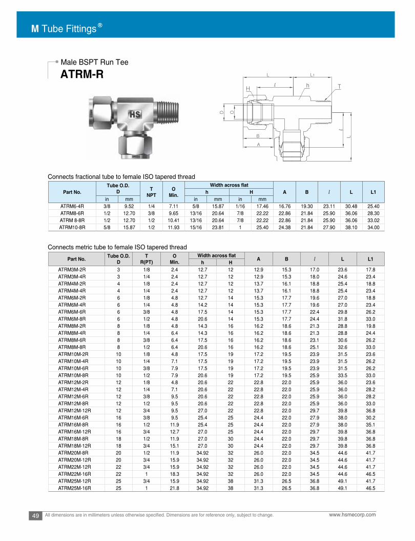
M Tube Fittings
49 www.hsmecorp.comAll dimensions are in millimeters unless otherwise specified. Dimensions are for reference only, subject to change.
Connects fractional tube to female ISO tapered thread
Connects metric tube to female ISO tapered thread
Male BSPT Run Tee
ATRM-R
Part No.Tube O.D.
D TNPT
OMin. A B l L L1h H
in mm in mm in mmATRM6-4R 3/8 9.52 1/4 7.11 5/8 15.87 1/16 17.46 16.76 19.30 23.11 30.48 25.40ATRM8-6R 1/2 12.70 3/8 9.65 13/16 20.64 7/8 22.22 22.86 21.84 25.90 36.06 28.30ATRM 8-8R 1/2 12.70 1/2 10.41 13/16 20.64 7/8 22.22 22.86 21.84 25.90 36.06 33.02ATRM10-8R 5/8 15.87 1/2 11.93 15/16 23.81 1 25.40 24.38 21.84 27.90 38.10 34.00
Part No. Tube O.D.D
TR(PT)
OMin. A B l L L1
h HATRM3M-2R 3 1/8 2.4 12.7 12 12.9 15.3 17.0 23.6 17.8ATRM3M-4R 3 1/4 2.4 12.7 12 12.9 15.3 18.0 24.6 23.4ATRM4M-2R 4 1/8 2.4 12.7 12 13.7 16.1 18.8 25.4 18.8ATRM4M-4R 4 1/4 2.4 12.7 12 13.7 16.1 18.8 25.4 23.4ATRM6M-2R 6 1/8 4.8 12.7 14 15.3 17.7 19.6 27.0 18.8ATRM6M-4R 6 1/4 4.8 14.2 14 15.3 17.7 19.6 27.0 23.4ATRM6M-6R 6 3/8 4.8 17.5 14 15.3 17.7 22.4 29.8 26.2ATRM6M-8R 6 1/2 4.8 20.6 14 15.3 17.7 24.4 31.8 33.0ATRM8M-2R 8 1/8 4.8 14.3 16 16.2 18.6 21.3 28.8 19.8ATRM8M-4R 8 1/4 6.4 14.3 16 16.2 18.6 21.3 28.8 24.4ATRM8M-6R 8 3/8 6.4 17.5 16 16.2 18.6 23.1 30.6 26.2ATRM8M-8R 8 1/2 6.4 20.6 16 16.2 18.6 25.1 32.6 33.0ATRM10M-2R 10 1/8 4.8 17.5 19 17.2 19.5 23.9 31.5 23.6ATRM10M-4R 10 1/4 7.1 17.5 19 17.2 19.5 23.9 31.5 26.2ATRM10M-6R 10 3/8 7.9 17.5 19 17.2 19.5 23.9 31.5 26.2ATRM10M-8R 10 1/2 7.9 20.6 19 17.2 19.5 25.9 33.5 33.0ATRM12M-2R 12 1/8 4.8 20.6 22 22.8 22.0 25.9 36.0 23.6ATRM12M-4R 12 1/4 7.1 20.6 22 22.8 22.0 25.9 36.0 28.2ATRM12M-6R 12 3/8 9.5 20.6 22 22.8 22.0 25.9 36.0 28.2ATRM12M-8R 12 1/2 9.5 20.6 22 22.8 22.0 25.9 36.0 33.0ATRM12M-12R 12 3/4 9.5 27.0 22 22.8 22.0 29.7 39.8 36.8ATRM16M-6R 16 3/8 9.5 25.4 25 24.4 22.0 27.9 38.0 30.2ATRM16M-8R 16 1/2 11.9 25.4 25 24.4 22.0 27.9 38.0 35.1ATRM16M-12R 16 3/4 12.7 27.0 25 24.4 22.0 29.7 39.8 36.8ATRM18M-8R 18 1/2 11.9 27.0 30 24.4 22.0 29.7 39.8 36.8ATRM18M-12R 18 3/4 15.1 27.0 30 24.4 22.0 29.7 39.8 36.8ATRM20M-8R 20 1/2 11.9 34.92 32 26.0 22.0 34.5 44.6 41.7ATRM20M-12R 20 3/4 15.9 34.92 32 26.0 22.0 34.5 44.6 41.7ATRM22M-12R 22 3/4 15.9 34.92 32 26.0 22.0 34.5 44.6 41.7ATRM22M-16R 22 1 18.3 34.92 32 26.0 22.0 34.5 44.6 46.5ATRM25M-12R 25 3/4 15.9 34.92 38 31.3 26.5 36.8 49.1 41.7ATRM25M-16R 25 1 21.8 34.92 38 31.3 26.5 36.8 49.1 46.5

50www.hsmecorp.com All dimensions are in millimeters unless otherwise specified. Dimensions are for reference only, subject to change.
Male NPT Branch Tee
Male BSPT Branch TeeATBM-N
ATBM-R
Connects fractional tube to female NPT thread
Connects fractional tube to female ISO tapered thread
Part No.Tube O.D.
D TNPT
OMin. A B l L L1h H
in mm in mm in mmATBM1-1N 1/16 1.59 1/16 1.27 7/16 11.11 5/16 7.93 8.63 10.92 15.24 19.05 17.78ATBM1-2N 1/16 1.59 1/8 1.27 7/16 11.11 5/16 7.93 8.63 10.92 15.24 19.05 17.78ATBM2-2N 1/8 3.17 1/8 2.28 1/2 12.70 7/16 11.11 12.70 15.24 18.30 24.91 18.90ATBM2-4N 1/8 3.17 1/4 2.28 1/2 12.70 7/16 11.11 12.70 15.24 18.30 24.91 23.26ATBM3-2N 3/16 4.76 1/8 3.04 1/2 12.70 1/2 12.70 13.71 16.00 18.79 24.38 18.79ATBM3-4N 3/16 4.76 1/4 3.04 1/2 12.70 1/2 12.70 13.71 16.00 18.79 25.40 23.36ATBM4-1N 1/4 6.35 1/16 3.04 1/2 12.70 9/16 14.28 15.24 17.78 19.55 26.90 18.79ATBM4-2N 1/4 6.35 1/8 4.82 1/2 12.70 9/16 14.28 15.24 17.78 19.55 26.92 18.79ATBM4-4N 1/4 6.35 1/4 4.82 1/2 12.70 9/16 14.28 15.24 17.78 19.55 27.08 23.87ATBM4-6N 1/4 6.35 3/8 4.82 11/16 17.46 9/16 14.28 15.24 17.78 22.35 29.71 28.40ATBM4-8N 1/4 6.35 1/2 4.82 13/16 20.64 9/16 14.28 15.24 17.78 24.60 31.97 35.10ATBM5-2N 5/16 7.93 1/8 4.82 9/16 14.28 5/8 15.87 16.25 18.54 22.35 29.71 19.81ATBM5-4N 5/16 7.94 1/4 6.35 9/16 14.28 5/8 15.87 16.25 18.54 22.35 29.77 24.50ATBM5-6N 5/16 7.94 3/8 6.35 11/16 17.46 5/8 15.87 16.25 18.54 23.11 30.48 28.40ATBM6-4N 3/8 9.52 1/4 7.11 5/8 15.87 1/16 17.46 16.76 19.30 23.11 30.48 25.40ATBM6-6N 3/8 9.52 3/8 7.11 11/16 17.46 11/16 17.46 16.76 19.30 23.87 31.24 28.44ATBM6-8N 3/8 9.52 1/2 7.11 13/16 20.64 11/16 17.46 16.76 19.30 25.90 33.27 33.02ATBM6-12N 3/8 9.52 3/4 7.11 1-1/16 26.98 11/16 17.46 16.76 19.30 29.71 37.08 36.83ATBM8-4N 1/2 12.70 1/4 7.11 13/16 20.64 7/8 22.22 22.86 21.84 25.90 36.06 28.30ATBM8-6N 1/2 12.70 3/8 9.65 13/16 20.64 7/8 22.22 22.86 21.84 25.90 36.06 28.30ATBM8-8N 1/2 12.70 1/2 10.41 13/16 20.64 7/8 22.22 22.86 21.84 25.90 36.06 33.02ATBM8-12N 1/2 12.70 3/4 10.41 1-1/16 26.98 7/8 22.22 22.86 21.84 29.71 39.84 36.83ATBM10-6N 5/8 15.87 3/8 9.65 15/16 23.81 1 25.40 24.38 21.84 27.90 38.10 29.40ATBM10-8N 5/8 15.87 1/2 11.93 15/16 23.81 1 25.40 24.38 21.84 27.90 38.10 34.00ATBM10-12N 5/8 15.87 3/4 12.70 1-1/16 26.98 1 25.40 24.38 21.84 29.71 39.87 36.83ATBM12-8N 3/4 19.05 1/2 11.93 1-1/16 26.98 1-1/8 28.58 24.38 21.84 29.71 39.87 37.00ATBM12-12N 3/4 19.05 3/4 15.74 1-1/16 26.98 1-1/8 28.58 24.38 21.84 29.71 39.81 36.83ATBM14-12N 7/8 22.23 3/4 15.74 1-3/8 34.92 1-1/4 31.75 25.90 21.84 34.54 44.70 41.65ATBM16-12N 1 25.40 3/4 15.74 1-3/8 34.92 1-1/2 38.10 31.24 26.41 36.83 49.02 42.20ATBM16-16N 1 25.40 1 22.35 1-3/8 34.92 1-1/2 38.10 31.24 26.41 36.83 49.02 46.70ATBM20-20N 1-1/4 31.75 1-1/4 27.68 1-11/16 42.86 1-7/8 47.63 41.14 38.86 44.50 66.54 47.75ATBM24-24N 1-1/2 38.10 1-1/2 34.03 2 50.80 2-14 57.15 50.03 45.21 50.80 77.97 60.45ATBM32-32N 2 50.80 2 45.97 2-3/4 69.85 3 76.20 67.56 62.73 69.80 107.18 70.61
Part No.Tube O.D.
D TPT
OMin. A B l L L1h H
in mm in mm in mmATBM6-4R 3/8 9.52 1/4 7.11 5/8 15.87 1/16 17.46 16.76 19.30 23.11 30.48 25.40ATBM8-6R 1/2 12.70 3/8 9.65 13/16 20.64 7/8 22.22 22.86 21.84 25.90 36.06 28.30ATBM8-8R 1/2 12.70 1/2 10.41 13/16 20.64 7/8 22.22 22.86 21.84 25.90 36.06 33.02ATBM10-8R 5/8 15.87 1/2 11.93 15/16 23.81 1 25.40 24.38 21.84 27.90 38.10 34.00

M Tube Fittings
51 www.hsmecorp.comAll dimensions are in millimeters unless otherwise specified. Dimensions are for reference only, subject to change.
Connects metric tube to female NPT thread
Male NPT Branch Tee
ATBM-N
Part No. Tube O.D.D
TNPT
OMin. A B l L L1
h HATBM3M-2N 3 1/8 2.4 12.7 12 12.9 15.3 17.0 23.6 17.8ATBM3M-4N 3 1/4 2.4 12.7 12 12.9 15.3 18.0 24.6 23.4ATBM4M-2N 4 1/8 2.4 12.7 12 13.7 16.1 18.8 25.4 18.8ATBM4M-4N 4 1/4 2.4 12.7 12 13.7 16.1 18.8 25.4 23.4ATBM6M-2N 6 1/8 4.8 12.7 14 15.3 17.7 19.6 27.0 18.8ATBM6M-4N 6 1/4 4.8 14.2 14 15.3 17.7 19.6 27.0 23.4ATBM6M-6N 6 3/8 4.8 17.5 14 15.3 17.7 22.4 29.8 26.2ATBM6M-8N 6 1/2 4.8 20.6 14 15.3 17.7 24.4 31.8 33.0ATBM8M-2N 8 1/8 4.8 14.3 16 16.2 18.6 21.3 28.8 19.8ATBM8M-4N 8 1/4 6.4 14.3 16 16.2 18.6 21.3 28.8 24.4ATBM8M-6N 8 3/8 6.4 17.5 16 16.2 18.6 23.1 30.6 26.2ATBM8M-8N 8 1/2 6.4 20.6 16 16.2 18.6 25.1 32.6 33.0ATBM10M-2N 10 1/8 4.8 17.5 19 17.2 19.5 23.9 31.5 23.6ATBM10M-4N 10 1/4 7.1 17.5 19 17.2 19.5 23.9 31.5 26.2ATBM10M-6N 10 3/8 7.9 17.5 19 17.2 19.5 23.9 31.5 26.2ATBM10M-8N 10 1/2 7.9 20.6 19 17.2 19.5 25.9 33.5 33.0ATBM12M-2N 12 1/8 4.8 20.6 22 22.8 22.0 25.9 36.0 23.6ATBM12M-4N 12 1/4 7.1 20.6 22 22.8 22.0 25.9 36.0 28.2ATBM12M-6N 12 3/8 9.5 20.6 22 22.8 22.0 25.9 36.0 28.2ATBM12M-8N 12 1/2 9.5 20.6 22 22.8 22.0 25.9 36.0 33.0ATBM12M-12N 12 3/4 9.5 27.0 22 22.8 22.0 29.7 39.8 36.8ATBM16M-6N 16 3/8 9.5 25.4 25 24.4 22.0 27.9 38.0 30.2ATBM16M-8N 16 1/2 11.9 25.4 25 24.4 22.0 27.9 38.0 35.1ATBM16M-12N 16 3/4 12.7 27.0 25 24.4 22.0 29.7 39.8 36.8ATBM18M-8N 18 1/2 11.9 27.0 30 24.4 22.0 29.7 39.8 36.8ATBM18M-12N 18 3/4 15.1 27.0 30 24.4 22.0 29.7 39.8 36.8ATBM20M-8N 20 1/2 11.9 34.92 32 26.0 22.0 34.5 44.6 41.7ATBM20M-12N 20 3/4 15.9 34.92 32 26.0 22.0 34.5 44.6 41.7ATBM22M-12N 22 3/4 15.9 34.92 32 26.0 22.0 34.5 44.6 41.7ATBM22M-16N 22 1 18.3 34.92 32 26.0 22.0 34.5 44.6 46.5ATBM25M-12N 25 3/4 15.9 34.92 38 31.3 26.5 36.8 49.1 41.7ATBM25M-16N 25 1 21.8 34.92 38 31.3 26.5 36.8 49.1 46.5

52www.hsmecorp.com All dimensions are in millimeters unless otherwise specified. Dimensions are for reference only, subject to change.
Male BSPT Branch Tee
ATBM-R
Connects metric tube to female ISO tapered thread
Part No. Tube O.D.D
TR(PT)
OMin. A B l L L1
h HATBM3M-2R 3 1/8 2.4 12.7 12 12.9 15.3 17.0 23.6 17.8ATBM3M-4R 3 1/4 2.4 12.7 12 12.9 15.3 18.0 24.6 23.4ATBM4M-2R 4 1/8 2.4 12.7 12 13.7 16.1 18.8 25.4 18.8ATBM4M-4R 4 1/4 2.4 12.7 12 13.7 16.1 18.8 25.4 23.4ATBM6M-2R 6 1/8 4.8 12.7 14 15.3 17.7 19.6 27.0 18.8ATBM6M-4R 6 1/4 4.8 14.2 14 15.3 17.7 19.6 27.0 23.4ATBM6M-6R 6 3/8 4.8 17.5 14 15.3 17.7 22.4 29.8 26.2ATBM6M-8R 6 1/2 4.8 20.6 14 15.3 17.7 24.4 31.8 33.0ATBM8M-2R 8 1/8 4.8 14.3 16 16.2 18.6 21.3 28.8 19.8ATBM8M-4R 8 1/4 6.4 14.3 16 16.2 18.6 21.3 28.8 24.4ATBM8M-6R 8 3/8 6.4 17.5 16 16.2 18.6 23.1 30.6 26.2ATBM8M-8R 8 1/2 6.4 20.6 16 16.2 18.6 25.1 32.6 33.0ATBM10M-2R 10 1/8 4.8 17.5 19 17.2 19.5 23.9 31.5 23.6ATBM10M-4R 10 1/4 7.1 17.5 19 17.2 19.5 23.9 31.5 26.2ATBM10M-6R 10 3/8 7.9 17.5 19 17.2 19.5 23.9 31.5 26.2ATBM10M-8R 10 1/2 7.9 20.6 19 17.2 19.5 25.9 33.5 33.0ATBM12M-2R 12 1/8 4.8 20.6 22 22.8 22.0 25.9 36.0 23.6ATBM12M-4R 12 1/4 7.1 20.6 22 22.8 22.0 25.9 36.0 28.2ATBM12M-6 12 3/8 9.5 20.6 22 22.8 22.0 25.9 36.0 28.2ATBM12M-8R 12 1/2 9.5 20.6 22 22.8 22.0 25.9 36.0 33.0ATBM12M-12R 12 3/4 9.5 27.0 22 22.8 22.0 29.7 39.8 36.8ATBM16M-6R 16 3/8 9.5 25.4 25 24.4 22.0 27.9 38.0 30.2ATBM16M-8R 16 1/2 11.9 25.4 25 24.4 22.0 27.9 38.0 35.1ATBM16M-12R 16 3/4 12.7 27.0 25 24.4 22.0 29.7 39.8 36.8ATBM18M-8R 18 1/2 11.9 27.0 30 24.4 22.0 29.7 39.8 36.8ATBM18M-12R 18 3/4 15.1 27.0 30 24.4 22.0 29.7 39.8 36.8ATBM20M-8R 20 1/2 11.9 34.92 32 26.0 22.0 34.5 44.6 41.7ATBM20M-12R 20 3/4 15.9 34.92 32 26.0 22.0 34.5 44.6 41.7ATBM22M-12R 22 3/4 15.9 34.92 32 26.0 22.0 34.5 44.6 41.7ATBM22M-16R 22 1 18.3 34.92 32 26.0 22.0 34.5 44.6 46.5ATBM25M-12R 25 3/4 15.9 34.92 38 31.3 26.5 36.8 49.1 41.7ATBM25M-16R 25 1 21.8 34.92 38 31.3 26.5 36.8 49.1 46.5

M Tube Fittings
53 www.hsmecorp.comAll dimensions are in millimeters unless otherwise specified. Dimensions are for reference only, subject to change.
Connects fractional tube to male NPT thread
Male NPT Branch Tee
ATBM-N
Part No.Tube O.D.
D TNPT
OMin. A B l Lh H
in mm in mm in mmACF1-1N 1/16 1.59 1/16 1.27 7/16 11.11 5/16 7.93 8.63 10.92 19.81 23.62ACF1-2N 1/16 1.59 1/8 1.27 9/16 14.28 5/16 7.93 8.63 10.92 20.57 24.38ACF2-2N 1/8 3.17 1.8 2.28 9/16 14.28 7/16 11.11 12.70 15.24 22.09 28.70ACF2-4N 1/8 3.17 1/4 2.28 3/4 19.05 7/16 11.11 12.70 15.24 26.92 33.52ACF3-2N 3/16 4.76 1/8 3.04 9/16 14.28 1/2 12.70 13.71 16.00 23.11 29.71ACF4-2N 1/4 6.35 1/8 4.82 9/16 14.28 9/16 14.28 15.24 17.78 23.87 31.24ACF4-4N 1/4 6.35 1/4 4.82 3/4 19.05 9/16 14.28 15.24 17.78 28.44 35.81ACF4-6N 1/4 6.35 3/8 4.82 7/8 22.22 9/16 14.28 15.24 17.78 30.22 37.59ACF4-8N 1/4 6.35 1/2 4.82 1-1/16 26.98 9/16 14.28 15.24 17.78 35.05 42.41ACF5-2N 5/16 7.93 1/8 6.35 9/16 14.28 5/8 15.87 16.25 18.54 24.63 32.00ACF5-4N 5/16 7.93 1/4 6.35 3/4 19.05 5/8 15.87 16.25 18.54 29.46 36.83ACF6-2N 3/8 9.52 1/8 7.11 5/8 15.87 15.87 11/16 17.46 16.76 19.30 25.40ACF6-4N 3/8 9.52 1/4 7.11 3/4 19.05 11/16 17.46 16.76 19.30 30.22 37.59ACF6-6N 3/8 9.52 3/8 7.11 7/8 22.22 11/16 17.46 16.76 19.30 31.75 39.11ACF6-8N 3/8 9.52 1/2 7.11 1-1/16 26.98 11/16 17.46 16.76 19.30 36.57 43.94ACF6-12N 3/8 9.52 3/4 7.11 1-5/16 33.33 11/16 17.46 16.76 19.30 40.38 47.45ACF8-4N 1/2 12.70 1/4 10.41 1-3/16 20.64 7/8 22.22 22.86 21.84 30.22 40.38ACF8-6N 1/2 12.70 3/8 10.41 7/8 22.22 7/8 22.22 22.86 21.84 31.75 41.91ACF8-8N 1/2 12.70 1/2 10.41 1-1/16 26.98 7/8 22.22 22.86 21.84 36.57 46.73ACF8-12N 1/2 12.70 3/4 10.41 1-5/16 33.33 7/8 22.22 22.86 21.84 38.10 48.26ACF10-6N 5/8 15.87 3/8 12.70 15/16 23.81 1 25.40 24.38 21.84 31.75 41.91ACF10-8N 5/8 15.87 1/2 12.70 1-1/16 26.98 1 25.40 24.38 21.84 36.57 46.73ACF10-12N 5/8 15.87 3/4 12.70 1-5/16 33.33 1 25.40 24.38 21.84 38.10 48.26ACF12-8N 3/4 19.05 1/2 15.74 1-1/16 26.98 1-1/8 28.58 24.38 21.84 36.57 46.73ACF12-12N 3/4 19.05 3/4 15.74 1-5/16 33.33 1-1/8 28.58 24.38 21.84 38.10 48.26ACF14-12N 7/8 22.22 3/4 18.28 1-5/16 33.33 1-1/4 31.75 25.90 21.84 39.62 49.78ACF16-12N 1 25.40 3/4 22.35 1-3/8 34.92 1-1/2 38.10 31.24 26.41 41.14 53.34ACF16-16N 1 25.40 1 22.35 1-5/8 41.27 1-1/2 38.10 31.24 26.41 50.03 62.23ACF20-20N 1-1/4 31.75 1-1/4 27.68 2-1/8 53.98 1-7/8 47.63 41.14 38.86 52.57 74.67ACF24-24N 1-1/2 38.10 1-1/2 34.03 2-3/8 60.33 2-1/4 57.15 50.03 45.21 56.13 83.81ACF32-32N 2 50.80 2 45.97 2-1/8 73.03 3 76.20 67.56 62.73 64.26 101.60

54www.hsmecorp.com All dimensions are in millimeters unless otherwise specified. Dimensions are for reference only, subject to change.
Female NPT Connector
ACF-N
Connects metric tube to male NPT thread
Part No. Tube O.D.D
TNPT
OMin. A B l L
h HACF3M-2N 3 1/8 2.4 14 12 12.9 15.3 22.1 28.7ACF3M-4N 3 1/4 2.4 19 12 12.9 15.3 26.9 33.5ACF4M-2N 4 1/8 2.4 14 12 13.7 16.1 23.1 29.7ACF6M-2N 6 1/8 4.8 14 14 15.3 17.7 23.9 31.3ACF6M-4N 6 1/4 4.8 19 14 15.3 17.7 28.4 35.8ACF6M-6N 6 3/8 4.8 22 14 15.3 17.7 29.5 36.9ACF6M-8N 6 1/2 4.8 27 14 15.3 17.7 35.1 42.5ACF8M-2N 8 1/8 6.4 15 16 16.2 18.6 24.6 32.1ACF8M-4N 8 1/4 6.4 19 16 16.2 18.6 29.5 37.0ACF8M-6N 8 3/8 6.4 22 16 16.2 18.6 30.2 37.7ACF8M-8N 8 1/2 6.4 27 16 16.2 18.6 35.8 43.3ACF10M-2N 10 1/8 7.9 18 19 17.2 19.5 25.4 33.0ACF10M-4N 10 1/4 7.9 19 19 17.2 19.5 30.2 37.8ACF10M-6N 10 3/8 7.9 22 19 17.2 19.5 31.0 38.6ACF10M-8N 10 1/2 7.9 27 19 17.2 19.5 36.6 44.2ACF12M-2N 12 1/8 8.3 22 22 22.8 22.0 28.4 38.5ACF12M-4N 12 1/4 9.5 22 22 22.8 22.0 30.24 .03ACF12M-6N 12 3/8 9.5 22 22 22.8 22.0 31.0 41.1ACF12M-8N 12 1/2 9.5 27 22 22.8 22.0 36.6 46.7ACF12M-12N 12 3/4 9.5 35 22 22.8 22.0 38.9 49.0ACF15M-8N 15 1/2 11.9 27 25 24.4 22.0 36.6 46.7ACF16M-8N 16 1/2 12.7 27 25 24.4 22.0 36.8 46.9ACF20M-8N 20 1/2 15.9 30 32 26.0 22.0 37.8 47.9ACF20M-12N 20 3/4 15.9 35 32 26.0 22.0 39.6 49.7ACF22M-12N 22 3/4 18.3 35 32 26.0 22.0 39.6 49.7ACF22M-16N 22 1 18.3 41 32 26.0 22.0 47.8 57.9ACF25M-12N 25 3/4 21.8 35 38 31.3 26.5 41.1 53.4ACF25M-16N 25 1 21.8 41 38 31.3 26.5 50.0 62.3

M Tube Fittings
55 www.hsmecorp.comAll dimensions are in millimeters unless otherwise specified. Dimensions are for reference only, subject to change.
Male NPT Branch Tee
ATBM-N
Connects fractional tube to male ISO tapered thread
Part No.Tube O.D.
D TPT
OMin. A B l Lh H
in mm in mm in mmACF 2-2R 1/8 3.17 1/8 2.28 9/16 14.28 7/16 11.11 12.70 15.24 22.09 28.70ACF4-2R 1/4 6.35 1/8 4.82 9/16 14.28 9/16 14.28 15.24 17.78 23.87 31.24ACF4-4R 1/4 6.35 1/4 4.82 3/4 19.05 9/16 14.28 15.24 17.78 28.44 35.81ACF4-6R 1/4 6.35 3/8 4.82 7/8 22.22 9/16 14.28 15.24 17.78 30.22 37.59ACF4-8R 1/4 6.35 1/2 4.82 1-1/16 26.98 9/16 14.28 15.24 17.78 35.05 42.41ACF6-4R 3/8 9.52 1/4 7.11 3/4 19.05 11/16 17.46 16.76 19.30 30.22 37.59ACF6-6R 3/8 9.52 3/8 7.11 7/8 22.22 11/16 17.46 16.76 19.30 31.75 39.11ACF6-8R 3/8 9.52 1/2 7.11 1-1/16 26.98 11/16 17.46 16.76 19.30 36.57 43.94ACF8-2R 1/2 12.70 1/8 10.41 13/16 20.64 7/8 22.22 22.86 21.84 25.40 35.56ACF8-4R 1/2 12.70 1/4 10.41 1-3/16 20.64 7/8 22.22 22.86 21.84 30.22 40.38ACF8-6R 1/2 12.70 3/8 10.41 7/8 22.22 7/8 22.22 22.86 21.84 31.75 41.91ACF8-8R 1/2 12.70 1/2 10.41 1-1/16 26.98 7/8 22.22 22.86 21.84 36.57 46.73ACF8-12R 1/2 12.70 3/4 10.41 1-5/16 33.33 7/8 22.22 22.86 21.84 38.10 48.26ACF10-6R 5/8 15.87 3/8 12.70 15/16 23.81 1 25.40 24.38 21.84 31.75 41.91ACF10-8R 5/8 15.87 1/2 12.70 1-1/16 26.98 1 25.40 24.38 21.84 36.57 46.73ACF10-12R 5/8 15.87 3/4 12.70 1-5/16 33.33 1 25.40 24.38 21.84 38.10 48.26ACF12-8R 3/4 19.05 1/2 15.74 1-1/16 26.98 1-1/8 28.58 24.38 21.84 36.57 46.73ACF12-12R 3/4 19.05 3/4 15.74 1-5/16 33.33 1-1/8 28.58 24.38 21.84 38.10 48.26ACF16-12R 1 25.40 3/4 22.35 1-3/8 34.92 1-1/2 38.10 31.24 26.41 41.14 53.34ACF16-16R 1 25.40 1 22.35 1-5/8 41.27 1-1/2 38.10 31.24 26.41 50.03 62.23ACF20-16R 1-1/4 31.75 1 27.68 1-3/4 44.45 1-7/8 47.63 41.14 38.86 52.57 74.67ACF20-20R 1-1/4 31.75 1-1/4 27.68 2-1/8 53.98 1-7/8 47.63 41.14 38.86 52.57 74.67ACF24-24R 1-1/2 38.10 1-1/2 34.03 2-3/8 60.33 2-1/4 57.15 50.03 45.21 56.13 83.81

56www.hsmecorp.com All dimensions are in millimeters unless otherwise specified. Dimensions are for reference only, subject to change.
Female BSPT Connector
ACF-R
Connects metric tube to male ISO tapered thread
Part No. Tube O.D.D
TR(PT)
OMin. A B l L
h HACF3M-2R 3 1/8 2.4 14 12 12.9 15.3 22.1 28.7ACF3M-4R 3 1/4 2.4 19 12 12.9 15.3 26.9 33.5ACF4M-2R 4 1/8 2.4 14 12 13.7 16.1 23.1 29.7ACF6M-2R 6 1/8 4.8 14 14 15.3 17.7 23.9 31.3ACF6M-4R 6 1/4 4.8 19 14 15.3 17.7 28.4 35.8ACF6M-6R 6 3/8 4.8 22 14 15.3 17.7 29.5 36.9ACF6M-8R 6 1/2 4.8 27 14 15.3 17.7 35.1 42.5ACF8M-2R 8 1/8 6.4 15 16 16.2 18.6 24.6 32.1ACF8M-4R 8 1/4 6.4 19 16 16.2 18.6 29.5 37.0ACF8M-6R 8 3/8 6.4 22 16 16.2 18.6 30.2 37.7ACF8M-8R 8 1/2 6.4 27 16 16.2 18.6 35.8 43.3ACF10M-2R 10 1/8 7.9 18 19 17.2 19.5 25.4 33.0ACF10M-4R 10 1/4 7.9 19 19 17.2 19.5 30.2 37.8ACF10M-6R 10 3/8 7.9 22 19 17.2 19.5 31.0 38.6ACF10M-8R 10 1/2 7.9 27 19 17.2 19.5 36.6 44.2ACF12M-2R 12 1/8 8.3 22 22 22.8 22.0 28.4 38.5ACF12M-4R 12 1/4 9.5 22 22 22.8 22.0 30.2 4.03ACF12M-6R 12 3/8 9.5 22 22 22.8 22.0 31.0 41.1ACF12M-8R 12 1/2 9.5 27 22 22.8 22.0 36.6 46.7ACF12M-12R 12 3/4 9.5 35 22 22.8 22.0 38.9 49.0ACF15M-8R 15 1/2 11.9 27 25 24.4 22.0 36.6 46.7ACF16M-8R 16 1/2 12.7 27 25 24.4 22.0 36.8 46.9ACF20M-8R 20 1/2 15.9 30 32 26.0 22.0 37.8 47.9ACF20M-12R 20 3/4 15.9 35 32 26.0 22.0 39.6 49.7ACF22M-12R 22 3/4 18.3 35 32 26.0 22.0 39.6 49.7ACF22M-16R 22 1 18.3 41 32 26.0 22.0 47.8 57.9ACF25M-12R 25 3/4 21.8 35 38 31.3 26.5 41.1 53.4ACF25M-16R 25 1 21.8 41 38 31.3 26.5 50.0 62.3

M Tube Fittings
57 www.hsmecorp.comAll dimensions are in millimeters unless otherwise specified. Dimensions are for reference only, subject to change.
Parallel Pipe Threads – Female
ISO 228-1 Pipe threads where pressure-tight joints are not made on the threads
Thread Designator: GG
Copper Gasket Ordering Information and Dimensions
Thread end form to DIN 3852 Form YSealing by copper gasket
A copper gasket is dropped into the flat bottom of female port.The face of gauge male thread exerts a load over the gasketfor sealing.
Thread in.
Dimensions, mm (in.) Part NumberD d T
1/8 8.2 (0.322) 5.5 (0.218)
1.6 (0.062)
9PP-2GG-CU 1/4 11.1 (0.436) 7.9 (0.312) 9PP-4GG-CU 3/8 14.6 (0.574) 11.1 (0.437) 9PP-6GG-CU 1/2 18.3 (0.719) 14.3 (0.562) 9PP-8GG-CU 3/4 23.7 (0.935) 20.6 (0.812) 9PP-12GG-CU
1 29.9 (1.178) 25.4 (1) 2.4 (0.093) 9PP-16GG-CU

58www.hsmecorp.com All dimensions are in millimeters unless otherwise specified. Dimensions are for reference only, subject to change.
FemaleGauge Connector
ACF-GG
Connects fractional tube to Gauge (male ISO parallel thread)
Connects metric tube to Gauge (male ISO parallel thread)
Part No.Tube O.D.
D TPT
OMin. O1 A B l l1 Lh H
in mm in mm in mmACF2-4GG 1/8 3.17 1/4 2.4 5.5 3/4 19.05 7/16 11.11 12.70 15.24 28.70 13.00 35.31ACF4-2GG 1/4 6.35 1/8 4.82 - 9/16 14.28 9/16 14.28 15.24 17.78 26.30 12.00 33.55ACF4-4GG 1/4 6.35 1/4 4.82 5.5 3/4 19.05 9/16 14.28 15.24 17.78 30.22 13.00 37.59ACF4-6GG 1/4 6.35 3/8 4.82 6.5 15/16 23.81 9/16 14.28 15.24 17.78 30.22 14.22 37.59ACF4-8GG 1/4 6.35 1/2 4.82 7.0 1-1/16 26.98 9/16 14.28 15.24 17.78 30.07 18.80 43.43ACF5-4GG 5/16 7.93 1/4 5.58 5.5 3/4 19.05 5/8 15.87 16.25 18.54 30.98 13.00 38.35ACF5-8GG 5/16 7.93 1/2 7.11 7.0 1-1/16 26.98 5/8 15.87 16.25 18.54 33.02 18.80 40.38ACF6-4GG 3/8 9.52 1/4 5.58 5.5 3/4 19.05 11/16 17.46 16.76 19.30 31.75 12.95 39.12ACF6-6GG 3/8 9.52 3/8 6.60 6.5 15/16 23.81 11/16 17.46 16.76 19.30 31.24 14.22 38.61ACF6-8GG 3/8 9.52 1/2 7.11 7.0 1-1/16 26.98 11/16 17.46 16.76 19.30 34.54 18.80 41.91ACF8-4GG 1/2 12.70 1/4 5.50 5.5 7/8 22.22 7/8 22.22 22.86 21.84 31.80 13.00 41.95ACF8-6GG 1/2 12.70 3/8 6.60 6.5 15/16 23.81 7/8 22.22 22.86 21.84 34.29 14.24 44.45ACF8-8GG 1/2 12.70 1/2 7.11 7.0 1-1/16 26.98 7/8 22.22 22.86 21.84 38.10 18.80 48.26
Part No. Tube O.D.D
TR(PT)
OMin. A B l L1 L
h HACF3M-4GG 3 1/4 2.4 19 12 12.9 15.3 28.7 13 35.3ACF6M-4GG 6 1/4 4.8 19 14 15.3 17.7 30.2 13 37.6ACF6M-6GG 6 3/8 4.8 24 14 15.3 17.7 30.2 14 37.6ACF6M-8GG 6 1/2 4.8 27 14 15.3 17.7 36.3 19 43.0ACF8M-4GG 8 1/4 5.5 19 16 16.2 18.6 31.0 13 38.5ACF8M-6GG 8 3/8 6.5 24 16 16.2 18.6 28.7 14 36.2ACF8M-8GG 8 1/2 7.0 27 16 16.2 18.6 33.0 19 40.5ACF10M-4GG 10 1/4 5.5 19 19 17.2 19.5 31.8 13 39.4ACF10M-6GG 10 3/8 6.5 24 19 17.2 19.5 31.2 14 38.8ACF10M-8GG 10 1/2 7.0 27 19 17.2 19.5 33.8 19 41.4ACF12M-4GG 12 1/4 5.5 22 22 22.8 22.0 31.8 13 41.9ACF12M-6GG 12 3/8 6.5 24 22 22.8 22.0 34.3 14 44.4ACF12M-8GG 12 1/2 7.0 27 22 22.8 22.0 38.1 19 48.2ACF20M-8GG 20 1/2 7.0 30 32 26.0 22.0 44.2 19 54.3ACF22M-8GG 22 1/2 7.0 30 32 26.0 22.0 44.2 19 54.3
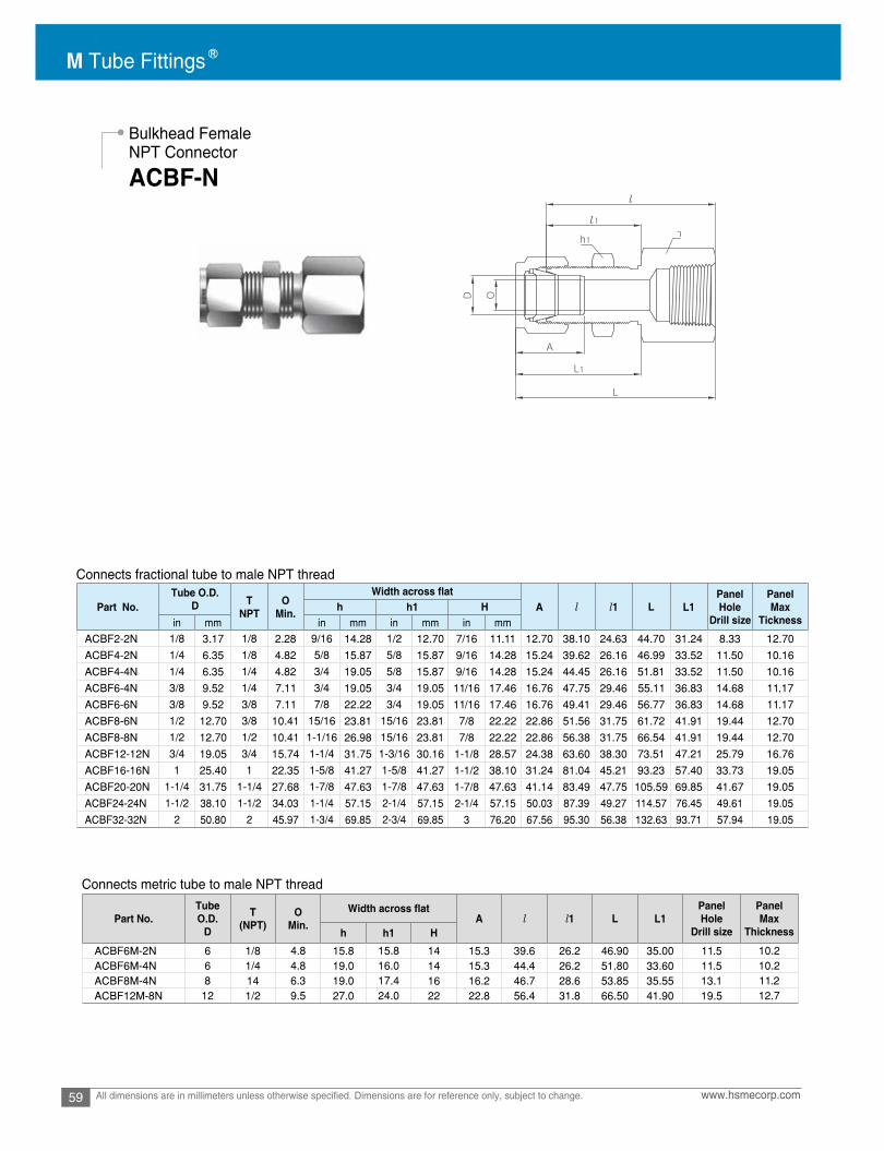
M Tube Fittings
59 www.hsmecorp.comAll dimensions are in millimeters unless otherwise specified. Dimensions are for reference only, subject to change.
Bulkhead FemaleNPT Connector
ACBF-N
Connects fractional tube to male NPT thread
Connects metric tube to male NPT thread
Part No.Tube O.D.
D TNPT
OMin. A l l1 L L1
PanelHole
Drill size
PanelMax
Ticknessh h1 H
in mm in mm in mm in mmACBF2-2N 1/8 3.17 1/8 2.28 9/16 14.28 1/2 12.70 7/16 11.11 12.70 38.10 24.63 44.70 31.24 8.33 12.70
ACBF4-2N 1/4 6.35 1/8 4.82 5/8 15.87 5/8 15.87 9/16 14.28 15.24 39.62 26.16 46.99 33.52 11.50 10.16
ACBF4-4N 1/4 6.35 1/4 4.82 3/4 19.05 5/8 15.87 9/16 14.28 15.24 44.45 26.16 51.81 33.52 11.50 10.16
ACBF6-4N 3/8 9.52 1/4 7.11 3/4 19.05 3/4 19.05 11/16 17.46 16.76 47.75 29.46 55.11 36.83 14.68 11.17
ACBF6-6N 3/8 9.52 3/8 7.11 7/8 22.22 3/4 19.05 11/16 17.46 16.76 49.41 29.46 56.77 36.83 14.68 11.17
ACBF8-6N 1/2 12.70 3/8 10.41 15/16 23.81 15/16 23.81 7/8 22.22 22.86 51.56 31.75 61.72 41.91 19.44 12.70
ACBF8-8N 1/2 12.70 1/2 10.41 1-1/16 26.98 15/16 23.81 7/8 22.22 22.86 56.38 31.75 66.54 41.91 19.44 12.70
ACBF12-12N 3/4 19.05 3/4 15.74 1-1/4 31.75 1-3/16 30.16 1-1/8 28.57 24.38 63.60 38.30 73.51 47.21 25.79 16.76
ACBF16-16N 1 25.40 1 22.35 1-5/8 41.27 1-5/8 41.27 1-1/2 38.10 31.24 81.04 45.21 93.23 57.40 33.73 19.05
ACBF20-20N 1-1/4 31.75 1-1/4 27.68 1-7/8 47.63 1-7/8 47.63 1-7/8 47.63 41.14 83.49 47.75 105.59 69.85 41.67 19.05
ACBF24-24N 1-1/2 38.10 1-1/2 34.03 1-1/4 57.15 2-1/4 57.15 2-1/4 57.15 50.03 87.39 49.27 114.57 76.45 49.61 19.05
ACBF32-32N 2 50.80 2 45.97 1-3/4 69.85 2-3/4 69.85 3 76.20 67.56 95.30 56.38 132.63 93.71 57.94 19.05
Part No.Tube O.D.
D
T(NPT)
OMin. A l l1 L L1
PanelHole
Drill size
PanelMax
Thicknessh h1 H
ACBF6M-2N 6 1/8 4.8 15.8 15.8 14 15.3 39.6 26.2 46.90 35.00 11.5 10.2ACBF6M-4N 6 1/4 4.8 19.0 16.0 14 15.3 44.4 26.2 51.80 33.60 11.5 10.2ACBF8M-4N 8 14 6.3 19.0 17.4 16 16.2 46.7 28.6 53.85 35.55 13.1 11.2ACBF12M-8N 12 1/2 9.5 27.0 24.0 22 22.8 56.4 31.8 66.50 41.90 19.5 12.7

60www.hsmecorp.com All dimensions are in millimeters unless otherwise specified. Dimensions are for reference only, subject to change.
Female NPT Elbow
ALF-N
Connects fractional tube to male NPT thread
Connects metric tube to male NPT thread
Part No.Tube O.D.
D TNPT
OMin. A B l L L1h H
in mm in mm in mmALF2-2N 1/8 3.17 1/8 2.28 1/2 12.70 7/16 11.11 12.70 15.24 18.03 24.63 19.05ALF2-4N 1/8 3.17 1.4 2.28 11/16 17.46 7/16 11.11 12.70 15.24 20.82 27.43 22.35ALF3-2N 3/16 4.76 1/8 3.04 1/2 12.70 1/2 12.70 13.71 16.00 18.79 25.40 19.05ALF4-2N 1/4 6.35 1/8 4.82 1/2 12.70 9/16 14.28 15.24 17.78 19.55 26.92 19.05ALF4-4N 1/4 6.35 1/4 4.82 11/16 17.46 9/16 14.28 15.24 17.78 22.35 29.71 22.35ALF4-6N 1/4 6.35 3/8 4.82 13/16 20.64 9/16 14.28 15.24 17.78 24.38 31.75 22.35ALF4-8N 1/4 6.35 1/2 4.82 1 25.40 9/16 14.28 15.24 17.78 27.17 34.54 28.44ALF5-2N 5/16 7.93 1/8 6.35 9/16 14.28 5/8 15.87 16.25 18.54 21.33 28.70 19.05ALF5-4N 5/16 7.93 1/4 6.35 11/16 17.46 5/8 15.87 16.25 18.54 23.11 30.48 22.35ALF6-2N 3/8 9.52 1/8 7.11 5/8 15.87 11/16 17.46 16.76 19.30 23.11 30.48 19.05ALF6-4N 3/8 9.52 1/4 7.11 11/16 17.46 11/16 17.46 16.76 19.30 23.87 31.24 22.35ALF6-6N 3/8 9.52 3/8 7.11 13/16 20.64 11/16 17.46 16.76 19.30 25.90 33.27 22.35ALF6-8N 3/8 9.52 1/2 7.11 1 25.40 11/16 17.46 16.76 19.30 28.70 36.06 28.44ALF8-4N 1/2 12.70 1/4 10.41 13/16 20.64 7/8 22.22 22.86 21.84 25.90 36.06 22.35ALF8-6N 1/2 12.70 3/8 10.41 13/16 20.64 7/8 22.22 22.86 21.84 25.90 36.06 22.35ALF8-8N 1/2 12.70 1/2 10.41 1 25.40 7/8 22.22 22.86 21.84 28.70 38.86 28.44ALF10-6N 5/8 15.87 3/8 12.70 15/16 23.81 1 25.40 24.38 21.84 27.94 38.10 22.35ALF10-8N 5/8 15.87 1/2 12.70 1 25.40 1 25.40 24.38 21.84 29.71 39.87 28.44ALF12-8N 3/4 19.05 1/2 15.74 1-1/16 26.98 1-1/8 28.58 24.38 21.84 29.71 39.87 28.44ALF12-12N 3/4 19.05 3/4 15.74 1-3/8 34.92 1-1/8 28.58 24.38 21.84 34.54 44.70 31.75ALF14-12N 7/8 22.22 3/4 18.28 1-3/8 34.92 1-1/4 31.75 25.90 21.84 34.54 44.70 31.75ALF16-12N 1 25.40 3/4 22.35 1-3/8 34.92 1-1/2 38.10 31.24 26.41 36.83 49.02 31.75ALF16-16N 1 25.40 1 22.35 1-11/16 42.86 1-1/2 38.10 31.24 26.41 41.40 50.29 38.10
Part No. Tube O.D.D
T(NPT)
OMin. A B l L L1
h HALF6M-2N 6 1/8 4.8 12.70 14 15.3 17.7 19.6 27.0 19.00ALF6M-4N 6 1/4 4.8 17.46 14 15.3 17.7 22.4 29.8 22.40ALF6M-6N 6 3/8 4.8 20.64 14 15.3 17.7 24.4 31.7 22.40ALF6M-8N 6 1/2 4.8 25.40 14 15.3 17.7 27.2 34.6 28.40ALF8M-2N 8 1/8 6.4 15.87 16 16.2 18.6 23.1 29.9 19.00ALF8M-4N 8 1/4 6.4 17.46 16 16.2 18.6 23.1 30.6 22.40ALF8M-8N 8 1/2 6.4 25.40 16 16.2 18.6 28.0 35.2 28.40ALF10M-2N 10 1/8 7.9 17.46 19 17.2 19.5 23.9 31.5 19.00ALF10M-4N 10 1/4 7.9 17.46 19 17.2 19.5 25.9 33.5 22.35ALF10M-6N 10 3/8 7.9 20.64 19 17.2 19.5 25.9 33.5 22.40ALF10M-8N 10 1/2 7.9 25.40 19 17.2 19.5 28.7 36.1 28.40ALF12M-4N 12 1/4 9.5 20.64 22 22.8 22.0 25.9 36.0 22.40ALF12M-6N 12 3/8 9.5 20.64 22 22.8 22.0 25.9 36.2 22.35ALF12M-8N 12 1/2 9.5 25.40 22 22.8 22.0 28.7 38.8 28.40ALF16M-8N 16 1/2 12.7 26.98 25 24.4 22.0 29.7 39.5 28.40

M Tube Fittings
61 www.hsmecorp.comAll dimensions are in millimeters unless otherwise specified. Dimensions are for reference only, subject to change.
Female NPT Run Tee
ACBF-N
Connects fractional tube to male NPT thread
Connects metric tube to male NPT thread
Part No.Tube O.D.
D TNPT
OMin. A B l L L1h H
in mm in mm in mmATRF2-2N 1/8 3.17 1/8 2.28 1/2 12.70 7/16 11.11 12.70 15.24 18.03 24.63 19.05ATRF2-4N 1/8 3.17 1/4 2.28 11/16 17.46 7/16 11.11 12.70 15.24 20.82 27.43 22.35ATRF3-2N 3/16 4.76 1/8 3.04 1/2 12.70 1/2 12.70 13.71 16.00 18.79 25.40 19.05ATRF4-2N 1/4 6.35 1/8 4.82 1/2 12.70 9/16 14.28 15.24 17.78 19.55 26.92 19.05ATRF4-4N 1/4 6.35 1/4 4.82 11/16 17.46 9/16 14.28 15.24 17.78 22.86 29.71 22.35ATRF4-6N 1/4 6.35 3/8 4.82 13/16 20.64 9/16 14.28 15.24 17.78 24.38 31.75 22.35ATRF4-8N 1/4 6.35 1/2 4.82 1 25.40 9/16 14.28 15.24 17.78 27.17 34.54 28.44ATRF5-2N 5/16 7.94 1/8 6.35 9/16 14.28 5/8 15.87 16.25 18.54 21.33 28.70 19.05ATRF5-4N 5/16 7.94 1/4 6.35 11/16 17.46 5/8 15.87 16.25 18.54 23.11 30.48 22.35ATRF6-2N 3/8 9.52 1/8 7.11 5/8 15.87 11/16 17.46 16.76 19.30 23.11 30.48 19.05ATRF6-4N 3/8 9.52 1/4 7.11 11/16 17.46 11/16 17.46 16.76 19.30 23.87 31.24 22.35ATRF6-6N 3/8 9.52 3/8 6.35 13/16 20.64 11/16 17.46 16.76 19.30 25.90 33.27 22.35ATRF6-8N 3/8 9.52 1/2 7.11 1 25.40 11/16 17.46 16.76 19.30 28.70 36.06 28.44ATRF8-4N 1/2 12.70 1/4 10.41 13/16 20.64 7/8 22.22 22.86 21.84 25.90 36.06 22.35ATRF8-6N 1/2 12.70 3/8 10.41 13/16 20.64 7/8 22.22 22.86 21.84 25.90 36.06 22.35ATRF8-8N 1/2 12.70 1/2 10.41 1 25.40 7/8 22.22 22.86 21.84 29.71 39.87 28.44ATRF10-6N 5/8 15.87 3/8 12.70 15/16 23.81 1 25.40 24.38 21.84 27.94 38.10 22.35ATRF10-8N 5/8 15.87 1/2 12.70 1 25.40 1 25.40 24.38 21.84 29.71 38.86 28.44ATRF12-8N 3/4 19.05 1/2 15.74 1-1/16 26.98 1-1/8 28.58 24.38 21.84 29.71 39.87 28.44ATRF12-12N 3/4 19.05 3/4 15.74 1-3/8 34.92 1-1/8 28.58 24.38 21.84 34.54 44.70 31.75ATRF14-12N 7/8 22.22 3/4 18.28 1-3/8 34.92 1-1/4 31.75 31.75 21.84 34.54 44.70 31.75ATRF16-12N 1 25.40 3/4 22.35 1-3/8 34.92 1-1/2 38.10 38.10 26.41 36.83 49.02 31.75ATRF16-16N 1 25.40 1 22.35 1-1/16 42.86 1-1/2 38.10 38.10 26.41 41.40 50.29 38.10
Part No. Tube O.D.D
T(NPT)
OMin. A B l L L1
h HATRF6M-2N 6 1/8 4.8 12.70 14 15.3 17.7 19.6 27.0 19.00ATRF6M-4N 6 1/4 4.8 17.46 14 15.3 17.7 22.4 29.8 22.40ATRF6M-6N 6 3/8 4.8 20.64 14 15.3 17.7 24.4 31.7 22.40ATRF6M-8N 6 1/2 4.8 25.40 14 15.3 17.7 27.2 34.5 28.40ATRF8M-2N 8 1/8 6.4 15.87 16 16.2 18.6 23.1 29.9 19.00ATRF8M-4N 8 1/4 6.4 17.46 16 16.2 18.6 23.1 30.6 22.40ATRF8M-6N 8 3/8 6.4 20.64 16 16.2 18.6 25.2 32.4 22.40ATRF8M-8N 8 1/2 6.4 25.40 16 16.2 18.6 28.0 35.2 28.40ATRF10M-2N 10 1/8 7.9 20.64 19 17.2 19.5 23.9 31.5 19.00ATRF10M-4N 10 1/4 7.9 20.64 19 17.2 19.5 25.9 33.6 22.40ATRF10M-6N 10 3/8 7.9 20.64 19 17.2 19.5 25.9 33.6 22.40ATRF10M-8N 10 1/2 7.9 25.40 19 17.2 19.5 26.2 33.6 28.40ATRF12M-4N 12 1/4 9.5 20.64 22 22.8 22.0 25.9 36.0 22.40ATRF12M-6N 12 3/8 9.5 20.64 22 22.8 22.0 25.9 36.0 22.40ATRF12M-8N 12 1/2 9.5 25.40 22 22.8 22.0 29.7 40.0 28.40ATRF16M-8N 16 1/2 12.7 25.40 25 24.4 22.0 29.7 39.5 28.40

62www.hsmecorp.com All dimensions are in millimeters unless otherwise specified. Dimensions are for reference only, subject to change.
Female NPT Branch Tee
ATBF-N
Connects fractional tube to male NPT thread
Connects metric tube to male NPT thread
Part No.Tube O.D.
D TNPT
OMin. A B l L L1h H
in mm in mm in mmATBF2-2N 1/8 3.17 1/8 2.28 1/2 12.70 7/16 11.11 12.70 15.24 18.03 24.38 19.05ATBF2-4N 1/8 3.17 1.4 2.28 11/16 17.46 7/16 11.11 12.70 15.24 20.82 27.43 22.35ATBF3-2N 3/16 4.76 1/8 3.04 1/2 12.70 1/2 12.70 13.71 16.00 18.79 25.40 19.05ATBF4-2N 1/4 6.35 1/8 4.82 1/2 12.70 9/16 14.28 15.24 17.78 19.55 26.92 19.05ATBF4-4N 1/4 6.35 1/4 4.82 11/16 17.46 9/16 14.28 15.24 17.78 22.35 29.71 22.35ATBF4-6N 1/4 6.35 3/8 4.82 13/16 20.64 9/16 14.28 15.24 17.78 24.38 31.75 22.35ATBF4-8N 1/4 6.35 1/2 4.82 1 25.40 9/16 14.28 15.24 17.78 27.17 34.54 28.44ATBF5-2N 5/16 7.94 1/8 6.35 9/16 14.28 5/8 15.87 16.25 18.54 21.33 28.70 19.05ATBF5-4N 5/16 7.94 1/4 6.35 11/16 17.46 5/8 15.87 16.25 18.54 23.11 30.48 22.35ATBF6-2N 3/8 9.52 1/8 7.11 5/8 15.87 11/16 17.46 16.76 19.30 23.11 30.48 19.05ATBF6-4N 3/8 9.52 1/4 7.11 11/16 17.46 11/16 17.46 16.76 19.30 23.87 31.24 22.35ATBF6-6N 3/8 9.52 3/8 6.35 13/16 20.64 11/16 17.46 16.76 19.30 25.90 33.27 22.35ATBF6-8N 3/8 9.52 1/2 7.11 1 25.40 11/16 17.46 16.76 19.30 28.70 36.06 28.44ATBF8-4N 1/2 12.70 1/4 10.41 13/16 20.64 7/8 22.22 22.86 21.84 25.90 36.06 22.35ATBF8-6N 1/2 12.70 3/8 10.41 13/16 20.64 7/8 22.22 22.86 21.84 25.90 36.06 22.35ATBF8-8N 1/2 12.70 1/2 10.41 1 25.40 7/8 22.22 22.86 21.84 29.71 39.87 28.44ATBF10-6N 5/8 15.87 3/8 12.70 15/16 23.81 1 25.40 24.38 21.84 27.94 38.10 22.35ATBF10-8N 5/8 15.87 1/2 12.70 1 25.40 1 25.40 24.38 21.84 28.70 38.86 28.44ATBF12-8N 3/4 19.05 1/2 15.74 1-1/16 26.98 1-1/8 28.58 24.38 21.84 29.71 39.87 28.44ATBF12-12N 3/4 19.05 3/4 15.74 1-3/8 34.92 1-1/8 28.58 24.38 21.84 34.54 44.70 31.75ATBF14-12N 7/8 22.22 3/4 18.28 1-3/8 34.92 1-1/4 31.75 25.90 21.84 34.54 44.70 31.75ATBF16-12N 1 25.40 3/4 22.35 1-3/8 34.92 1-1/2 38.10 31.24 26.41 36.83 49.02 31.75ATBF16-16N 1 25.40 1 22.35 1-11/16 42.86 1-1/2 38.10 31.24 26.41 41.40 53.59 38.10
Part No. Tube O.D.D
T(NPT)
OMin. A B l L L1
h HATBF6M-2N 6 1/8 4.8 12.70 14 15.3 17.7 19.6 27.0 19.00ATBF6M-4N 6 1/4 4.8 17.46 14 15.3 17.7 22.4 29.8 22.40ATBF6M-6N 6 3/8 4.8 20.64 14 15.3 17.7 24.4 31.7 22.40ATBF6M-8N 6 1/2 4.8 25.40 14 15.3 17.7 27.2 34.5 28.40ATBF8M-2N 8 1/8 6.4 15.87 16 16.2 18.6 23.1 29.9 19.00ATBF8M-4N 8 1/4 6.4 17.46 16 16.2 18.6 23.1 30.6 22.40ATBF8M-6N 8 3/8 6.4 20.64 16 16.2 18.6 25.2 32.4 22.40ATBF8M-8N 8 1/2 6.4 25.40 16 16.2 18.6 28.0 35.2 28.40ATBF10M-2N 10 1/8 7.9 17.50 19 17.2 19.5 23.9 31.5 19.00ATBF10M-4N 10 1/4 7.9 20.64 19 17.2 19.5 25.9 33.6 22.40ATBF10M-6N 10 3/8 7.9 20.64 19 17.2 19.5 25.9 33.5 22.40ATBF10M-8N 10 1/2 9.5 25.40 19 17.2 19.5 26.2 33.6 22.40ATBF12M-4N 12 1/4 9.5 20.64 22 22.8 22.0 25.9 36.0 22.40ATBF12M-6N 12 3/8 9.5 20.64 22 22.8 22.0 25.9 36.0 22.40ATBF12M-8N 12 1/2 9.5 25.40 22 22.8 22.0 29.7 40.0 28.40ATBF16M-8N 16 1/2 12.7 25.40 25 24.4 22.0 29.7 40.0 28.70

M Tube Fittings
63 www.hsmecorp.comAll dimensions are in millimeters unless otherwise specified. Dimensions are for reference only, subject to change.
Port Connector
Installation Instruction
Machined Ferrule End
Tube Adapter End
Connects fractional ports
Apply port connector where two tube ports are requirede connection.
Port connectors are designed with two different ends.These two ends require different installation.
1. Gently insert machined ferrule end into the tube port. (Figure 1)2. Place nut only over the machined ferrule. (Figure 1)3. Finger tighten the nut. (Figure 2)4. Wrench-tighten the nut 1/4 turn beyoud the finger-tight position. (Figure 2)
1. Insert tube adapter end into the M Tube fitting. (Figure 3)2. Follow M tube fitting’s standard installation instruction. (Figure 3)
Connects metric ports
Port Connector
ACP
M Tube fitting M Tube fitting
Part No.Tube O.D.
D OMin. D1 l L
in mm
ACP-1 1/16 1.59 1.00 3.30 10.66 13.72
ACP-2 1/8 3.17 1.77 6.09 15.75 22.35
ACP-4 1/4 6.35 4.57 9.39 18.79 24.64
ACP-5 5/16 7.93 6.35 10.92 20.06 25.90
ACP-6 3/8 9.52 7.11 12.70 20.32 26.16
ACP-8 1/2 12.70 9.90 15.74 25.90 35.81
ACP-12 3/4 19.05 14.98 22.09 27.68 37.33
ACP-16 1 25.40 20.06 28.44 34.54 48.00
Part No. Tube O.D.D
OMin. D1 l L
ACP-3M 3 2.1 6.0 15.70 22.20ACP-4M 4 2.2 7.0 16.67 25.81ACP-6M 6 4.4 9.0 18.70 24.60ACP-8M 8 6.2 11.0 20.00 25.90ACP-10M 10 8.2 13.1 20.20 26.10ACP-12M 12 9.1 15.0 26.00 35.80ACP-15M 15 12.7 19.0 27.78 37.40ACP-16M 16 12.7 19.0 27.60 37.40ACP-18M 18 13.9 21.0 27.91 37.40ACP-20M 20 15.1 23.0 29.20 38.90ACP-22M 22 17.9 24.97 29.30 39.20ACP-25M 25 19.8 28.0 34.50 48.00ACP-28M 28 23.8 34.3 48.30 63.50ACP-32M 32 27.4 39.5 52.40 69.70ACP-38M 38 33.3 47.1 61.40 81.90

64www.hsmecorp.com All dimensions are in millimeters unless otherwise specified. Dimensions are for reference only, subject to change.
ReducingPort Connector
ACPR
Port Reducer
Connects fractional ports
Connects metric ports
Solution for reducing the Port OD size of an existing port.
By using the port reducer, you may reduce an existing M Tube Fitting Port OD size.
M Tube fitting
M Tube fitting
Part No.Tube O.D.
OMin. D2 l l1 LD1 D
in mm in mmACPR2-1 1/8 3.17 1/16 1.59 1.00 6.10 8.64 2.03 17.27ACPR4-2 1/4 6.35 1/8 3.17 2.28 9.39 13.45 3.30 22.60ACPR6-2 3/8 9.52 1/8 3.17 2.28 12.70 13.45 3.81 23.11ACPR6-4 3/8 9.52 1/4 6.35 4.82 12.70 15.75 3.30 24.89ACPR8-4 1/2 12.70 1/4 6.35 4.82 15.74 15.75 3.81 29.21ACPR8-6 1/2 12.70 3/8 9.52 7.11 15.74 17.67 3.30 30.48ACPR12-8 3/4 19.05 1/2 12.70 9.90 22.09 23.20 3.81 37.85ACPR16-8 1 25.40 1/2 12.70 9.90 28.40 24.47 4.82 42.67ACPR16-12 1 25.40 3/4 19.05 14.98 28.40 25.90 4.06 43.43
Part No.Tube O.D. O
Min. D2 l l1 LD1 D
ACPR6M-3M 6 3 2.2 9.0 13.50 3.2 22.60ACPR8M-6M 8 6 4.6 11.0 15.70 3.1 24.70ACPR10M-6M 10 6 4.6 13.1 15.70 3.4 25.00ACPR10M-8M 10 8 6.4 13.1 16.80 3.1 26.00ACPR12M-6M 12 6 4.6 15.0 15.70 3.6 29.10ACPR12M-8M 12 8 6.4 15.0 16.80 3.4 29.80ACPR12M-10M 12 10 7.7 15.0 17.50 3.1 30.40ACPR16M-6M 16 6 4.6 19.0 15.75 3.6 30.40ACPR16M-12M 16 12 9.1 19.0 23.10 3.4 36.20ACPR28M-25M 28 25 19.8 34.3 33.00 8.2 56.50ACPR32M-25M 32 25 19.8 39.5 33.00 9.9 60.30ACPR38M-25M 38 25 19.8 47.1 33.00 12.3 65.80

M Tube Fittings
65 www.hsmecorp.comAll dimensions are in millimeters unless otherwise specified. Dimensions are for reference only, subject to change.
Connects fractional tube to fractional portM Tube fitting
Port Reducer
AR
Part No.Tube O.D.
OMin. A B l LD D1 h H
in mm in mm in mm in mmAR1-2 1/16 1.59 1/8 3.17 1.27 5/16 7.93 5/16 7.93 8.63 10.92 25.40 29.21AR1-4 1/16 1.59 1/4 6.35 1.27 5/16 7.93 5/16 7.93 8.63 10.92 27.68 31.49AR2-1 1/8 3.17 1/16 1.59 1.76 7/16 11.11 7/16 11.11 12.70 15.24 22.35 28.95AR2-2 1/8 3.17 1/8 3.17 2.03 7/16 11.11 7/16 11.11 12.70 15.24 26.92 33.52AR2-3 1/8 3.17 3/16 4.76 2.28 7/16 11.11 7/16 11.11 12.70 15.24 27.68 34.29AR2-4 1/8 3.17 1/4 6.35 2.28 7/16 11.11 7/16 11.11 12.70 15.24 29.46 36.06AR2-6 1/8 3.17 3/8 9.52 2.28 7/16 11.11 7/16 11.11 12.70 15.24 30.98 37.59AR2-8 1/8 3.17 1/2 12.70 2.28 9/16 14.28 7/16 11.11 12.70 15.24 37.59 44.19AR3-2 3/16 4.76 1/8 3.17 2.03 7/16 11.11 1/2 12.70 13.71 16.00 28.19 34.79AR3-4 3/16 4.76 1/4 6.35 3.04 7/16 11.11 1/2 12.70 13.71 16.00 30.48 37.08AR4-2 1/4 6.35 1/8 3.17 2.03 1/2 12.70 9/16 14.28 15.24 17.78 29.46 36.83AR4-3 1/4 6.35 3/16 4.76 3.04 1/2 12.70 9/16 14.28 15.24 17.78 30.22 37.59AR4-4 1/4 6.35 1/4 6.35 4.82 1/2 12.70 9/16 14.28 15.24 17.78 31.75 39.11AR4-5 1/4 6.35 5/16 7.93 4.82 1/2 12.70 9/16 14.28 15.24 17.78 32.51 39.87AR4-6 1/4 6.35 3/8 9.52 4.82 1/2 12.70 9/16 14.28 15.24 17.78 33.27 40.64AR4-8 1/4 6.35 1/2 12.70 4.82 9/16 14.28 9/16 14.28 15.24 17.78 38.86 46.22AR4-10 1/4 6.35 5/8 15.87 4.82 11/16 17.46 9/16 14.28 15.24 17.78 40.64 48.00AR4-12 1/4 6.35 3/4 19.05 4.82 13/16 20.64 9/16 14.28 15.24 17.78 40.38 47.75AR5-6 5/16 7.93 3/8 9.52 6.35 9/16 14.28 5/8 15.87 16.25 18.54 34.54 41.91AR5-8 5/16 7.93 1/2 12.70 6.35 9/16 14.28 5/8 15.87 16.25 18.54 40.13 47.49AR6-4 3/8 9.52 1/4 6.35 4.82 5/8 15.87 11/16 17.46 16.76 19.30 34.03 41.40AR6-6 3/8 9.52 3/8 9.52 7.11 5/8 15.87 11/16 17.46 16.76 19.30 35.81 43.18AR6-8 3/8 9.52 1/2 12.70 7.11 5/8 15.87 11/16 17.46 16.76 19.30 41.14 45.81AR6-10 3/8 9.52 5/8 15.87 7.11 11/16 17.46 11/16 17.46 16.76 19.30 42.92 50.29AR6-12 3/8 9.52 3/4 19.05 7.11 13/16 20.64 11/16 17.46 16.76 19.30 42.92 50.29AR8-4 1/2 12.70 1/4 6.35 4.82 13/16 20.64 7/8 22.22 22.86 21.84 34.79 44.95AR8-6 1/2 12.70 3/8 9.52 7.11 13/16 20.64 7/8 22.22 22.86 21.84 36.57 46.73AR8-8 1/2 12.70 1/2 12.70 9.90 13/16 20.64 7/8 22.22 22.86 21.84 42.16 52.32AR8-10 1/2 12.70 5/8 15.87 10.41 13/16 20.64 7/8 22.22 22.86 21.84 43.68 53.84AR8-12 1/2 12.70 3/4 19.05 10.41 13/16 20.64 7/8 22.22 22.86 21.84 43.68 53.84AR8-16 1/2 12.70 1 25.40 10.41 1-1/16 26.98 7/8 22.22 22.86 21.84 50.03 60.19AR10-12 5/8 15.87 3/4 19.05 12.70 15/16 23.81 1 25.40 24.38 21.84 44.45 54.61AR10-14 5/8 15.87 7/8 22.22 12.70 15/16 23.81 1 25.40 24.38 21.84 45.97 56.13AR10-16 5/8 15.87 1 25.40 12.70 1-1/16 26.98 1 25.40 24.38 21.84 50.80 60.96AR12-8 3/4 19.05 1/2 12.70 9.90 1-1/16 26.98 1-1/8 28.57 24.38 21.84 44.45 54.61AR12-16 3/4 19.05 1 25.40 15.74 1-1/16 26.98 1-1/8 28.57 24.38 21.84 52.32 62.48AR16-20 1 25.40 1-1/4 31.75 22.35 1-3/8 34.93 1-1/2 38.10 31.24 26.41 68.32 80.51AR16-24 1 25.40 1-1/2 38.10 22.35 1-5/8 41.28 1-1/2 38.10 31.24 26.41 76.96 89.15AR16-32 1 25.40 2 50.80 22.35 2-1/8 53.98 1-1/2 38.10 31.24 26.41 100.33 112.52AR20-24 1-1/4 31.75 1-1/2 38.10 27.68 1-7/8 47.63 1-7/8 57.15 41.14 38.86 82.04 104.14AR20-32 1-1/4 31.75 2 50.80 27.68 1-7/8 47.63 1-7/8 76.20 41.14 38.86 103.12 125.22AR24-32 1-1/2 38.10 2 50.80 34.03 2-1/4 57.15 2-1/4 76.20 50.03 45.21 104.14 131.31

66www.hsmecorp.com All dimensions are in millimeters unless otherwise specified. Dimensions are for reference only, subject to change.
Port Reducer
AR Connects metric tube to fractional port
Connects metric tube to metric port
M Tube fitting
M Tube fitting
Part No.
Tube O.D.O
Min.
Width across A B l L
DD1
in mm h HAR2M-2 2 1/8 3.17 1.7 12 12 12.9 15.3 26.9 33.5
3 1/8 3.17 2.0 12 12 12.9 15.3 26.9 33.5
4 1/4 6.35 2.4 12 12 13.7 16.1 30.5 37.1
6 1/4 6.35 4.8 14 14 15.3 17.7 31.8 39.2
12 1/2 12.70 9.5 22 22 22.8 22.0 42.2 52.3
18 3/4 19.05 15.1 27 30 24.4 22.0 46.0 56.1
6 3/8 9.52 4.8 14 14 15.3 17.7 33.3 40.7
8 3/8 9.52 6.4 15 16 16.2 18.6 34.5 42.0
10 3/8 9.52 7.1 18 19 17.2 19.5 36.6
AR3M-2AR3M-4 3 1/4 6.35 2.4 12 12 12.9 15.3 29.5 36.1AR4M-4AR6M-2 6 1/8 3.18 2.0 14 14 15.3 17.7 29.5 36.9AR6M-4AR6M-5 6 5/16 7.93 4.8 14 14 15.3 17.7 32.5 39.9AR6M-6AR6M-8 6 1/2 12.70 4.8 14 14 15.3 17.7 38.9 46.3AR8M-6AR8M-8 8 1/2 12.70 6.4 15 16 16.2 18.6 40.1 47.6
44.2AR10M-6AR10M-8 10 1/2 12.70 7.9 18 19 17.2 19.5 42.2 49.8AR12M-8AR12M-12 12 3/4 19.05 9.5 22 22 22.8 22.0 43.7 53.8AR18M-12AR18M-16 18 1 25.40 15.1 27 30 24.4 22.0 52.3 62.4AR25M-16 25 1 25.40 20.2 35 38 31.3 26.5 57.2 69.5
Part No.Tube O.D. O
Min.
Width across A B l L
D1 D h HAR2M-3M 2 3 1.7 12 12 12.9 15.3 26.9 35.3AR3M-4M 3 4 2.4 12 12 12.9 15.3 28.4 35.0AR3M-6M 3 6 2.4 12 12 12.9 15.3 29.5 36.1AR3M-10M 3 10 2.4 12 12 12.9 15.3 31.8 38.4AR4M-6M 4 6 2.4 12 12 13.7 16.1 30.5 37.1AR6M-3M 6 3 1.8 14 14 15.3 17.7 29.5 36.9AR6M-8M 6 8 4.8 14 14 15.3 17.7 32.5 39.9AR6M-10M 6 10 4.8 14 14 15.3 17.7 33.3 40.7AR6M-12M 6 12 4.8 14 14 15.3 17.7 38.9 46.3AR8M-6M 8 6 4.6 15 16 16.2 18.6 32.8 40.3AR8M-10M 8 10 6.4 15 16 16.2 18.6 34.5 42.0AR8M-12M 8 12 6.4 15 16 16.2 18.6 40.1 47.6AR10M-6M 10 6 4.6 18 19 17.2 19.5 34.8 42.4AR10M-12M 10 12 7.9 18 19 17.2 19.5 42.2 49.8AR10M-15M 10 15 7.9 18 19 17.2 19.5 43.7 51.3AR10M-18M 10 18 7.9 19 19 17.2 19.5 43.7 51.3AR12M-6M 12 6 4.6 22 22 22.8 22.0 34.8 44.9AR12M-10M 12 10 7.7 22 22 22.8 22.0 36.6 46.7AR12M-16M 12 16 9.5 22 22 22.8 22.0 43.7 53.8AR12M-18M 12 18 9.5 22 22 22.8 22.0 43.7 53.8AR12M-20M 12 20 9.5 22 22 22.8 22.0 46.0 56.1AR12M-22M 12 22 9.5 24 22 22.8 22.0 46.0 56.1AR12M-25M 12 25 9.5 27 22 22.8 22.0 52.3 62.4AR16M-12M 16 12 9.1 24 25 24.4 22.0 42.9 53.0AR18M-12M 18 12 9.1 27 30 24.4 22.0 44.5 54.6AR18M-16M 18 16 12.7 27 30 24.4 22.0 46.0 56.1AR18M-20M 18 20 15.1 27 30 24.4 22.0 47.5 57.6AR18M-22M 18 22 15.1 27 30 24.4 22.0 47.5 57.6AR18M-25M 18 25 15.1 27 30 24.4 22.0 52.3 62.4AR20M-16M 20 16 12.7 30 32 26.0 22.0 47.8 57.9AR20M-18M 20 18 13.9 30 32 26.0 22.0 47.8 57.9AR20M-22M 20 22 15.8 30 32 26.0 22.0 49.3 59.4AR20M-25M 20 25 15.8 30 32 26.0 22.0 54.1 64.2AR22M-18M 22 18 13.9 30 32 26.0 22.0 47.8 57.9AR22M-20M 22 20 15.1 30 32 26.0 22.0 49.3 59.4AR22M-25M 22 25 18.3 30 32 26.0 22.0 54.1 64.2AR25M-18M 25 18 13.9 35 38 31.3 26.5 50.8 63.1AR25M-20M 25 20 15.1 35 38 31.3 26.5 52.3 64.6

M Tube Fittings
67 www.hsmecorp.comAll dimensions are in millimeters unless otherwise specified. Dimensions are for reference only, subject to change.
Connects fractional tube to fractional port
Connects fractional tube to fractional port.
Connects metric tube to metric port
Bulkhead TubeAdapter
Elbow TubeAdapter
AAB
ALA
M Tube fitting
M Tube fitting
M Tube fitting
Part No.Tube O.D.
D OMin. A l l1 l2 L L1
PanelHole
Drill size
PanelMax
Thicknessh H
in mm in mm in mmAAB2-2 1/8 3.17 2.03 1/2 12.70 7/16 11.11 12.70 42.92 24.63 13.45 49.53 31.24 8.33 12.70AAB4-4 1/4 6.35 4.82 5/8 15.87 9/16 14.28 15.24 48.51 26.16 15.74 55.88 33.52 11.50 10.16AAB6-6 3/8 9.52 7.11 3/4 19.05 11/16 17.46 16.76 53.84 29.46 17.50 61.21 36.83 14.68 11.17AAB8-8 1/2 12.70 10.41 15/16 23.81 7/8 22.22 22.86 62.73 31.75 23.11 72.89 41.91 19.44 12.70AAB10-10 5/8 15.87 12.70 1-1/16 26.98 1 25.40 24.38 65.02 32.51 24.70 75.18 42.67 22.62 12.70AAB16-16 1 25.40 20.32 1-5/8 41.28 1-1/2 38.10 31.24 88.13 45.21 31.70 100.33 57.40 33.73 19.05AAB20-20 1-1/4 31.75 27.68 1-7/8 47.63 1-7/8 47.63 41.14 102.07 47.75 40.00 124.17 69.85 41.67 19.05AAB24-24 1-1/2 38.10 34.03 2-1/4 57.15 2-1/4 57.15 50.03 118.33 49.27 51.50 145.51 76.45 49.61 19.05AAB32-32 2 50.80 45.97 2-3/4 69.85 3 76.20 67.56 148.79 56.38 68.40 185.82 93.71 57.94 19.05
Part No.
Tube O.D.D O
A B l l1 L L1h H
in mm Min. in mm in mm
ALA-4 1/4 6.35 4.8 1/2 12.70 9/16 14.28 15.24 17.78 19.55 15.75 27.0 25.00ALA-6 3/8 9.52 7.10 5/8 15.87 11/16 17.46 16.76 19.30 23.11 17.50 31.5 29.10ALA-8 1/2 12.70 10.41 13/16 20.63 7/8 22.22 22.86 21.84 25.90 23.10 36.0 37.3ALA-12 3/4 19.05 16.00 1-1/16 26.98 1-1/8 28.57 24.38 21.84 29.71 24.70 38.8 42.6ALA-16 1 25.40 22.30 1-3/8 34.92 1-1/2 38.10 31.24 26.41 46.83 31.70 42.6 54.40
Part No. Tube O.D.D
OMin. A B l l1 L L1
h HALA-6M 6 4.6 12.7 14 15.3 17.7 19.6 15.7 27.0 25.0ALA-8M 8 6.4 15.8 16 16.2 18.6 21.3 16.8 28.8 27.05ALA-10M 10 7.7 17.4 19 17.2 19.5 23.9 17.5 31.5 30.0ALA-12M 12 9.1 20.6 22 22.8 22.0 25.9 23.1 36.0 37.3ALA-14M 14 11.1 25.4 25 24.4 22.0 28.7 24.6 38.8 41.5ALA-15M 15 11.9 25.4 25 24.4 22.0 28.7 24.65 38.8 41.55ALA-16M 16 12.7 25.4 25 24.4 22.0 28.7 24.6 38.8 41.5ALA-18M 18 13.9 26.9 30 24.4 22.0 29.7 24.6 39.8 42.5ALA-20M 20 15.1 31.8 32 26.0 22.0 32.5 26.2 42.6 47.0ALA-22M 22 18.3 31.8 32 26.0 22.0 32.5 26.6 42.6 47.15ALA-25M 25 19.8 34.9 38 31.3 26.5 36.8 31.7 49.1 55.2ALA-28M 28 21.8 41.0 46 36.6 36.6 43.2 37.5 64.0 64.9

68www.hsmecorp.com All dimensions are in millimeters unless otherwise specified. Dimensions are for reference only, subject to change.
Run TeeTube Adapter
Branch TeeTube Adapter
ATRA
ATBA
Connects fractional tube to fractional port.
Connects metric tube to metric port.
Connects metric tube to metric port.
Connects fractional tube to fractional port.
M Tube fitting
M Tube fitting
M Tube fitting
M Tube fitting
Part No.
Tube O.D.D O
A B l l1 L L1h H
in mm Min. in mm in mm
ATRA-4 1/4 6.35 4.8 1/2 12.70 9/16 14.28 15.24 17.78 19.55 15.75 27.0 25.00ATRA-6 3/8 9.52 7.10 5/8 15.87 11/16 17.46 16.76 19.30 23.11 17.50 31.5 29.10ATRA-8 1/2 12.70 10.41 13/16 20.63 7/8 22.22 22.86 21.84 25.90 23.10 36.0 37.3ATRA-12 3/4 19.05 16.00 1-1/16 26.98 1-1/8 28.57 24.38 21.84 29.71 24.70 38.8 42.6ATRA-16 1 25.40 22.30 1-3/8 34.92 1-1/2 38.10 31.24 26.41 46.83 31.70 42.6 54.40
Part No. Tube O.D.D
OMin. A B l l1 L L1
h HATRA-8M 8 6.4 15.8 16 16.2 18.6 21.3 16.8 28.8 27.5ATRA-10M 10 7.9 17.4 19 17.2 19.5 23.9 17.5 31.5 30.0
Part No.
Tube O.D.D O
A B l l1 L L1h H
in mm Min. in mm in mm
ATBA-4 1/4 6.35 4.8 1/2 12.70 9/16 14.28 15.24 17.78 19.55 15.75 27.0 25.00ATBA-6 3/8 9.52 7.10 5/8 15.87 11/16 17.46 16.76 19.30 23.11 17.50 31.5 29.10ATBA-8 1/2 12.70 10.41 13/16 20.63 7/8 22.22 22.86 21.84 25.90 23.10 36.0 37.3ATBA-12 3/4 19.05 16.00 1-1/16 26.98 1-1/8 28.57 24.38 21.84 29.71 24.70 38.8 42.6ATBA-16 1 25.40 22.30 1-3/8 34.92 1-1/2 38.10 31.24 26.41 46.83 31.70 42.6 54.40
Part No. Tube O.D.D
OMin. A B l l1 L L1
h HATBA-8M 8 6.4 15.8 16 16.2 18.6 21.3 16.8 28.8 27.5
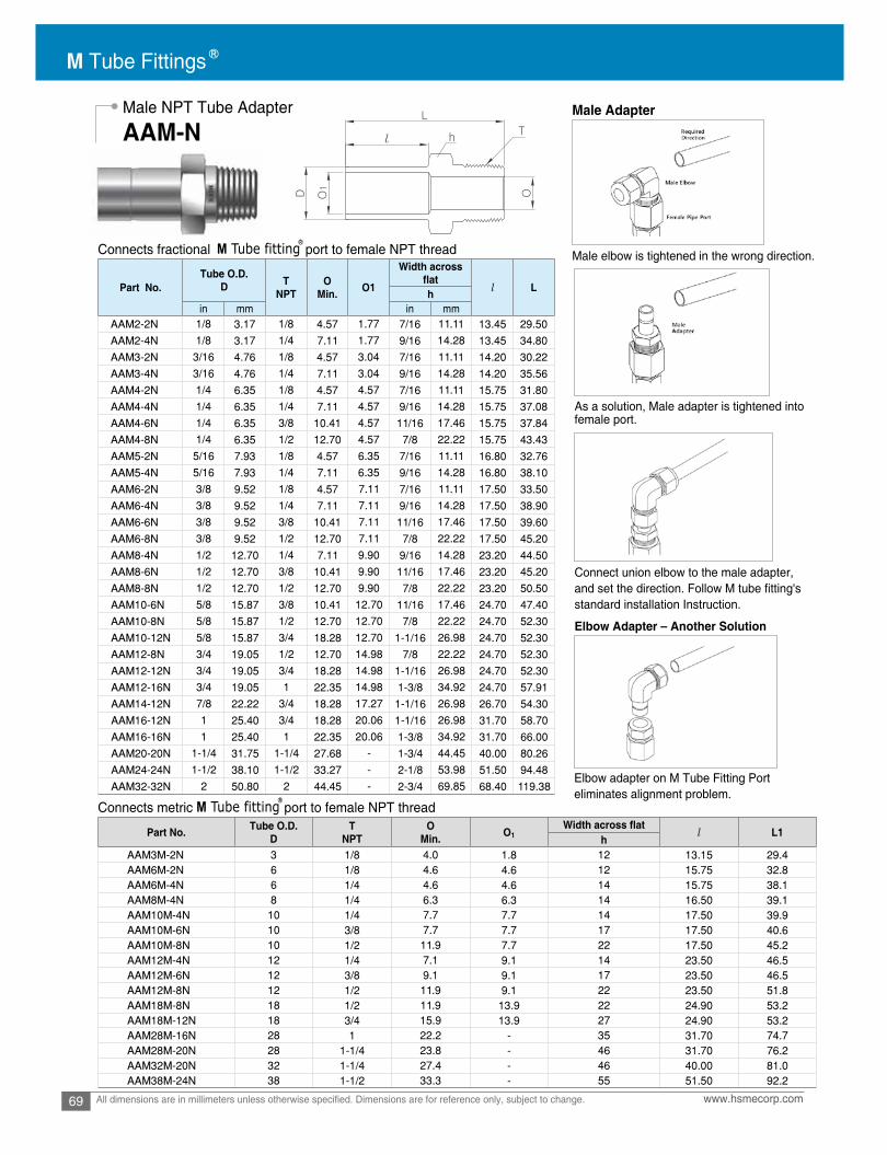
M Tube Fittings
69 www.hsmecorp.comAll dimensions are in millimeters unless otherwise specified. Dimensions are for reference only, subject to change.
Male NPT Tube Adapter Male Adapter
AAM-N
Connects fractional port to female NPT thread
Connects metric port to female NPT thread
Male elbow is tightened in the wrong direction.
As a solution, Male adapter is tightened into female port.
Elbow adapter on M Tube Fitting Porteliminates alignment problem.
Elbow Adapter – Another Solution
Connect union elbow to the male adapter,and set the direction. Follow M tube fitting'sstandard installation Instruction.
M Tube fitting
M Tube fitting
Part No.Tube O.D.
D TNPT
OMin. O1
Width across
l Lhin mm in mm
AAM2-2N 1/8 3.17 1/8 4.57 1.77 7/16 11.11 13.45 29.50
AAM2-4N 1/8 3.17 1/4 7.11 1.77 9/16 14.28 13.45 34.80
AAM3-2N 3/16 4.76 1/8 4.57 3.04 7/16 11.11 14.20 30.22
AAM3-4N 3/16 4.76 1/4 7.11 3.04 9/16 14.28 14.20 35.56
AAM4-2N 1/4 6.35 1/8 4.57 4.57 7/16 11.11 15.75 31.80
AAM4-4N 1/4 6.35 1/4 7.11 4.57 9/16 14.28 15.75 37.08
AAM4-6N 1/4 6.35 3/8 10.41 4.57 11/16 17.46 15.75 37.84
AAM4-8N 1/4 6.35 1/2 12.70 4.57 7/8 22.22 15.75 43.43
AAM5-2N 5/16 7.93 1/8 4.57 6.35 7/16 11.11 16.80 32.76
AAM5-4N 5/16 7.93 1/4 7.11 6.35 9/16 14.28 16.80 38.10
AAM6-2N 3/8 9.52 1/8 4.57 7.11 7/16 11.11 17.50 33.50
AAM6-4N 3/8 9.52 1/4 7.11 7.11 9/16 14.28 17.50 38.90
AAM6-6N 3/8 9.52 3/8 10.41 7.11 11/16 17.46 17.50 39.60
AAM6-8N 3/8 9.52 1/2 12.70 7.11 7/8 22.22 17.50 45.20
AAM8-4N 1/2 12.70 1/4 7.11 9.90 9/16 14.28 23.20 44.50
AAM8-6N 1/2 12.70 3/8 10.41 9.90 11/16 17.46 23.20 45.20
AAM8-8N 1/2 12.70 1/2 12.70 9.90 7/8 22.22 23.20 50.50
AAM10-6N 5/8 15.87 3/8 10.41 12.70 11/16 17.46 24.70 47.40
AAM10-8N 5/8 15.87 1/2 12.70 12.70 7/8 22.22 24.70 52.30
AAM10-12N 5/8 15.87 3/4 18.28 12.70 1-1/16 26.98 24.70 52.30
AAM12-8N 3/4 19.05 1/2 12.70 14.98 7/8 22.22 24.70 52.30
AAM12-12N 3/4 19.05 3/4 18.28 14.98 1-1/16 26.98 24.70 52.30
AAM12-16N 3/4 19.05 1 22.35 14.98 1-3/8 34.92 24.70 57.91
AAM14-12N 7/8 22.22 3/4 18.28 17.27 1-1/16 26.98 26.70 54.30
AAM16-12N 1 25.40 3/4 18.28 20.06 1-1/16 26.98 31.70 58.70
AAM16-16N 1 25.40 1 22.35 20.06 1-3/8 34.92 31.70 66.00
AAM20-20N 1-1/4 31.75 1-1/4 27.68 - 1-3/4 44.45 40.00 80.26
AAM24-24N 1-1/2 38.10 1-1/2 33.27 - 2-1/8 53.98 51.50 94.48
AAM32-32N 2 50.80 2 44.45 - 2-3/4 69.85 68.40 119.38
Part No. Tube O.D.D
TNPT
OMin. O1 l L1
hAAM3M-2N 3 1/8 4.0 1.8 12 13.15 29.4AAM6M-2N 6 1/8 4.6 4.6 12 15.75 32.8AAM6M-4N 6 1/4 4.6 4.6 14 15.75 38.1AAM8M-4N 8 1/4 6.3 6.3 14 16.50 39.1AAM10M-4N 10 1/4 7.7 7.7 14 17.50 39.9AAM10M-6N 10 3/8 7.7 7.7 17 17.50 40.6AAM10M-8N 10 1/2 11.9 7.7 22 17.50 45.2AAM12M-4N 12 1/4 7.1 9.1 14 23.50 46.5AAM12M-6N 12 3/8 9.1 9.1 17 23.50 46.5AAM12M-8N 12 1/2 11.9 9.1 22 23.50 51.8AAM18M-8N 18 1/2 11.9 13.9 22 24.90 53.2AAM18M-12N 18 3/4 15.9 13.9 27 24.90 53.2AAM28M-16N 28 1 22.2 - 35 31.70 74.7AAM28M-20N 28 1-1/4 23.8 - 46 31.70 76.2AAM32M-20N 32 1-1/4 27.4 - 46 40.00 81.0AAM38M-24N 38 1-1/2 33.3 - 55 51.50 92.2

70www.hsmecorp.com All dimensions are in millimeters unless otherwise specified. Dimensions are for reference only, subject to change.
Male elbow is tightened in the wrong direction.
As a solution, Male adapter is tightened into female port.
Elbow Adapter – Another Solution
Connect union elbow to the male adapter,and set the direction. Follow M tube fitting'sstandard installation Instruction.
Male BSPTTube Adapter
AAM-R
Connects fractional port to female ISO tapered thread
Connects metric port to female ISO tapered thread
M Tube fitting
M Tube fitting
Part No.Tube O.D.
D TPT
OMin. O1 l Lh
in mm in mmAAM2-2R 1/8 3.17 1/8 4.57 1.77 7/16 11.11 13.45 29.50AAM2-4R 1/8 3.17 1/4 7.11 1.77 9/16 14.28 13.45 34.80AAM4-2R 1/4 6.35 1/8 4.57 4.57 7/16 11.11 15.75 31.80AAM4-4R 1/4 6.35 1/4 7.11 4.57 9/16 14.28 15.75 37.08AAM4-6R 1/4 6.35 3/8 10.41 4.57 11/16 17.46 15.75 37.84AAM6-4R 3/8 9.52 1/4 7.11 7.11 9/16 14.28 17.50 38.90AAM6-6R 3/8 9.52 3/8 10.41 7.11 11/16 17.46 17.50 39.60AAM6-8R 3/8 9.52 1/2 12.70 7.11 7/8 22.22 17.50 45.20AAM8-4R 1/2 12.70 1/4 7.11 9.90 9/16 14.28 23.20 44.50AAM8-6R 1/2 12.70 3/8 10.41 9.90 11/16 17.46 23.20 45.20AAM8-8R 1/2 12.70 1/2 12.70 9.90 7/8 22.22 23.20 50.50AAM8-12R 1/2 12.70 3/4 15.74 9.90 1-1/16 26.98 23.10 50.70AAM12-8R 3/4 19.05 1/2 12.70 14.98 7/8 22.22 24.70 52.30AAM12-12R 3/4 19.05 3/4 14.98 14.98 1-1/16 26.98 24.70 52.30
Part No. Tube O.D.D
TNPT
OMin.
O1
Min. h l L
AAM3M-2R 3 1/8 4.0 1.8 12 13.15 29.4AAM6M-2R 6 1/8 4.6 4.6 12 15.75 32.8AAM6M-4R 6 1/4 4.6 4.6 14 15.75 38.1AAM8M-4R 8 1/4 6.3 6.3 14 16.50 39.1AAM10M-4R 10 1/4 7.7 7.7 14 17.50 39.9AAM10M-6R 10 3/8 7.7 7.7 17 17.50 40.6AAM10M-8R 10 1/2 11.9 7.7 22 17.50 45.2AAM12M-4R 12 1/4 7.1 9.1 14 23.50 46.5AAM12M-6R 12 3/8 9.1 9.1 17 23.50 46.5AAM12M-8R 12 1/2 11.9 9.1 22 23.50 51.8AAM18M-8R 18 1/2 11.9 13.9 22 24.90 53.2AAM18M-12R 18 3/4 15.9 13.9 27 24.90 53.2AAM25M-16R 25 1 19.8 19.8 35 31.70 66.0AAM28M-16R 28 1 22.2 - 35 31.70 74.7AAM28M-20R 28 1-1/4 23.8 - 46 31.70 76.2AAM30M-20R 30 1-1/4 24.6 - 46 40.60 80.0AAM32M-20R 32 1-1/4 27.4 - 46 40.00 81.0AAM38M-24R 38 1-1/2 33.3 - 55 51.50 92.2

M Tube Fittings
71 www.hsmecorp.comAll dimensions are in millimeters unless otherwise specified. Dimensions are for reference only, subject to change.
Connects fractional port to female ISO tapered thread
Connects metric port to female ISO tapered thread
M Tube fitting
M Tube fitting
Bulkhead TubeAdapter
AAM-G
Part No.Tube O.D.
D TPT
OMin. O1 l l1 L Kh
in mm in mmAAM2-2G 1/8 3.17 1/8 1.77 1.77 9/16 14.28 13.45 7.10 40.0 13.8AAM2-4G 1/8 3.17 1/4 6.4 1.77 3/4 19.05 13.45 11.2 35.8 18.0AAM4-2G 1/4 6.35 1/8 4.57 4.57 9/16 14.28 15.75 7.10 33.27 13.8AAM4-4G 1/4 6.35 1/4 4.57 4.57 3/4 19.05 15.75 11.2 38.1 18.0AAM6-4G 3/8 9.52 1/4 5.9 7.11 3/4 19.05 17.50 11.2 39.8 18.0AAM6-6G 3/8 9.52 3/8 7.11 7.11 7/8 22.22 17.50 11.2 40.64 21.8AAM8-4G 1/2 12.70 1/4 5.9 9.90 3/4 19.05 23.10 11.2 45.5 18.0AAM8-6G 1/2 12.70 3/8 7.9 9.90 7/8 22.22 23.10 11.2 46.2 21.8AAM8-8G 1/2 12.70 1/2 11.9 9.90 1-1/16 26.98 23.10 14.2 49.3 26.0AAM12-12G 3/4 19.05 3/4 14.98 14.98 1-5/16 33.33 24.70 15.7 54.86 32.0AAM16-16G 1 25.40 1 20.06 20.06 1-5/8 41.28 31.7 18.3 64.5 39.0
Part No. Tube O.D.D
TNPT
OMin.
O1
Min.
Width
hl l1 L K
AAM6M-2G 6 1/8 4.6 4.6 14 15.7 7.1 34.3 13.8AAM6M-4G 6 1/4 4.6 4.6 19 15.7 11.2 39.1 18.0AAM8M-4G 8 1/4 5.9 5.9 19 16.8 11.2 40.1 18.0AAM10M-4G 10 1/4 5.9 7.7 19 17.5 11.2 40.9 18.0AAM10M-6G 10 3/8 7.7 7.7 22 17.5 11.2 41.7 21.8AAM10M-8G 10 1/2 7.7 7.7 27 17.5 14.2 44.7 26.0AAM12M-4G 12 1/4 5.9 9.1 19 23.1 11.2 46.7 18.0AAM12M-6G 12 3/8 7.9 9.1 22 23.1 11.2 47.2 21.8AAM12M-8G 12 1/2 9.1 9.1 27 23.1 14.2 50.5 26.0AAM18M-8G 18 1/2 11.9 13.9 27 24.6 14.2 52.1 26.0AAM18M-12G 18 3/4 15.9 13.9 35 24.6 15.7 56.1 32.0AAM22M-12G 22 3/4 15.9 18.3 35 26.6 15.7 57.4 32.0AAM25M-16G 25 1 19.8 19.8 41 31.7 18.3 67.1 39.0AAM28M-16G 28 1 19.8 22.2 41 37.5 18.3 72.9 39.0AAM28M-20G 28 1-1/4 23.8 23.8 50 37.5 19.8 77.0 49.0AAM30M-20G 30 1-1/4 24.6 24.6 50 40.66 19.8 80.8 49.0AAM32M-20G 32 1-1/4 25.0 25.0 50 40.0 19.8 81.8 49.0AAM38M-24G 38 1-1/2 31.8 31.8 55 50.4 22.1 94.5 54.7
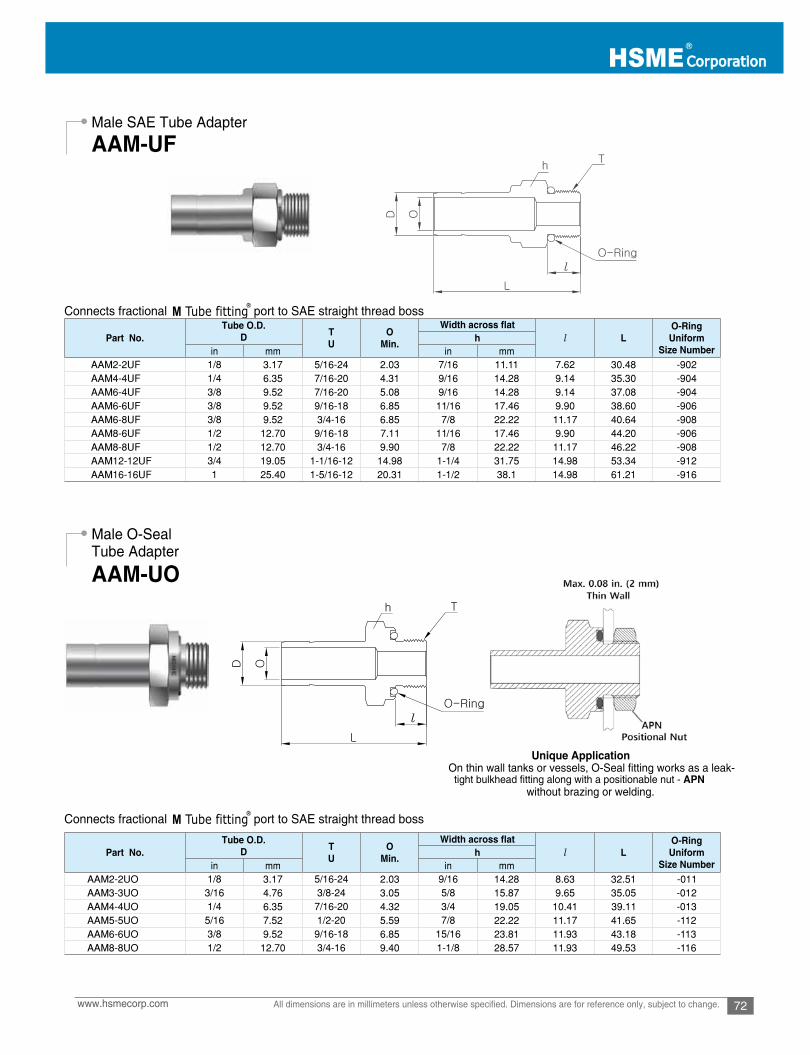
72www.hsmecorp.com All dimensions are in millimeters unless otherwise specified. Dimensions are for reference only, subject to change.
Male SAE Tube Adapter
Male O-Seal Tube Adapter
AAM-UF
AAM-UO
Connects fractional port to SAE straight thread boss
Connects fractional port to SAE straight thread boss
M Tube fitting
M Tube fitting
Unique ApplicationOn thin wall tanks or vessels, O-Seal fitting works as a leak- tight bulkhead fitting along with a positionable nut - APN without brazing or welding.
Part No.Tube O.D.
D TU
OMin. l L
O-RingUniform
Size Numberh
in mm in mmAAM2-2UF 1/8 3.17 5/16-24 2.03 7/16 11.11 7.62 30.48 -902AAM4-4UF 1/4 6.35 7/16-20 4.31 9/16 14.28 9.14 35.30 -904AAM6-4UF 3/8 9.52 7/16-20 5.08 9/16 14.28 9.14 37.08 -904AAM6-6UF 3/8 9.52 9/16-18 6.85 11/16 17.46 9.90 38.60 -906AAM6-8UF 3/8 9.52 3/4-16 6.85 7/8 22.22 11.17 40.64 -908AAM8-6UF 1/2 12.70 9/16-18 7.11 11/16 17.46 9.90 44.20 -906AAM8-8UF 1/2 12.70 3/4-16 9.90 7/8 22.22 11.17 46.22 -908AAM12-12UF 3/4 19.05 1-1/16-12 14.98 1-1/4 31.75 14.98 53.34 -912AAM16-16UF 1 25.40 1-5/16-12 20.31 1-1/2 38.1 14.98 61.21 -916
Part No.Tube O.D.
D TU
OMin. l L
O-RingUniform
Size Numberh
in mm in mmAAM2-2UO 1/8 3.17 5/16-24 2.03 9/16 14.28 8.63 32.51 -011AAM3-3UO 3/16 4.76 3/8-24 3.05 5/8 15.87 9.65 35.05 -012AAM4-4UO 1/4 6.35 7/16-20 4.32 3/4 19.05 10.41 39.11 -013AAM5-5UO 5/16 7.52 1/2-20 5.59 7/8 22.22 11.17 41.65 -112AAM6-6UO 3/8 9.52 9/16-18 6.85 15/16 23.81 11.93 43.18 -113AAM8-8UO 1/2 12.70 3/4-16 9.40 1-1/8 28.57 11.93 49.53 -116
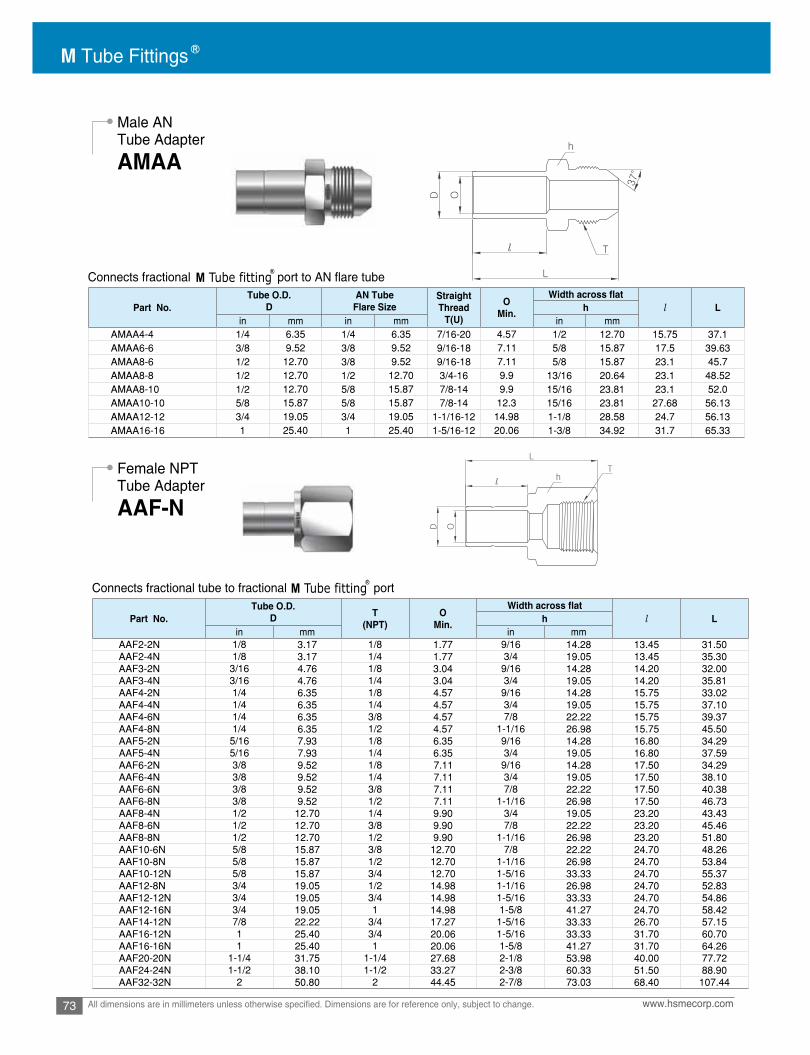
M Tube Fittings
73 www.hsmecorp.comAll dimensions are in millimeters unless otherwise specified. Dimensions are for reference only, subject to change.
Connects fractional port to AN flare tube
Connects fractional tube to fractional port
M Tube fitting
M Tube fitting
Male AN Tube Adapter
Female NPTTube Adapter
AMAA
AAF-N
Part No.Tube O.D.
DAN Tube
Flare SizeStraightThread
T(U)
OMin. l Lh
in mm in mm in mmAMAA4-4 1/4 6.35 1/4 6.35 7/16-20 4.57 1/2 12.70 15.75 37.1AMAA6-6 3/8 9.52 3/8 9.52 9/16-18 7.11 5/8 15.87 17.5 39.63AMAA8-6 1/2 12.70 3/8 9.52 9/16-18 7.11 5/8 15.87 23.1 45.7AMAA8-8 1/2 12.70 1/2 12.70 3/4-16 9.9 13/16 20.64 23.1 48.52AMAA8-10 1/2 12.70 5/8 15.87 7/8-14 9.9 15/16 23.81 23.1 52.0AMAA10-10 5/8 15.87 5/8 15.87 7/8-14 12.3 15/16 23.81 27.68 56.13AMAA12-12 3/4 19.05 3/4 19.05 1-1/16-12 14.98 1-1/8 28.58 24.7 56.13AMAA16-16 1 25.40 1 25.40 1-5/16-12 20.06 1-3/8 34.92 31.7 65.33
Part No.Tube O.D.
D T(NPT)
OMin. l Lh
in mm in mmAAF2-2N 1/8 3.17 1/8 1.77 9/16 14.28 13.45 31.50AAF2-4N 1/8 3.17 1/4 1.77 3/4 19.05 13.45 35.30AAF3-2N 3/16 4.76 1/8 3.04 9/16 14.28 14.20 32.00AAF3-4N 3/16 4.76 1/4 3.04 3/4 19.05 14.20 35.81AAF4-2N 1/4 6.35 1/8 4.57 9/16 14.28 15.75 33.02AAF4-4N 1/4 6.35 1/4 4.57 3/4 19.05 15.75 37.10AAF4-6N 1/4 6.35 3/8 4.57 7/8 22.22 15.75 39.37AAF4-8N 1/4 6.35 1/2 4.57 1-1/16 26.98 15.75 45.50AAF5-2N 5/16 7.93 1/8 6.35 9/16 14.28 16.80 34.29AAF5-4N 5/16 7.93 1/4 6.35 3/4 19.05 16.80 37.59AAF6-2N 3/8 9.52 1/8 7.11 9/16 14.28 17.50 34.29AAF6-4N 3/8 9.52 1/4 7.11 3/4 19.05 17.50 38.10AAF6-6N 3/8 9.52 3/8 7.11 7/8 22.22 17.50 40.38AAF6-8N 3/8 9.52 1/2 7.11 1-1/16 26.98 17.50 46.73AAF8-4N 1/2 12.70 1/4 9.90 3/4 19.05 23.20 43.43AAF8-6N 1/2 12.70 3/8 9.90 7/8 22.22 23.20 45.46AAF8-8N 1/2 12.70 1/2 9.90 1-1/16 26.98 23.20 51.80AAF10-6N 5/8 15.87 3/8 12.70 7/8 22.22 24.70 48.26AAF10-8N 5/8 15.87 1/2 12.70 1-1/16 26.98 24.70 53.84AAF10-12N 5/8 15.87 3/4 12.70 1-5/16 33.33 24.70 55.37AAF12-8N 3/4 19.05 1/2 14.98 1-1/16 26.98 24.70 52.83AAF12-12N 3/4 19.05 3/4 14.98 1-5/16 33.33 24.70 54.86AAF12-16N 3/4 19.05 1 14.98 1-5/8 41.27 24.70 58.42AAF14-12N 7/8 22.22 3/4 17.27 1-5/16 33.33 26.70 57.15AAF16-12N 1 25.40 3/4 20.06 1-5/16 33.33 31.70 60.70AAF16-16N 1 25.40 1 20.06 1-5/8 41.27 31.70 64.26AAF20-20N 1-1/4 31.75 1-1/4 27.68 2-1/8 53.98 40.00 77.72AAF24-24N 1-1/2 38.10 1-1/2 33.27 2-3/8 60.33 51.50 88.90AAF32-32N 2 50.80 2 44.45 2-7/8 73.03 68.40 107.44

74www.hsmecorp.com All dimensions are in millimeters unless otherwise specified. Dimensions are for reference only, subject to change.
Female NPTTube Adapter
Female BSPTTube Adapter
AAF-N
AAF-R
Connects metric port to male NPT thread
Connects metric port to male NPT thread
M Tube fitting
M Tube fitting
Connects fractional port to male ISO tapered threadM Tube fitting
Part No. Tube O.D.D
TNPT
OMin. h l L
AAF6M-2N 6 1/8 4.6 14 15.75 32.50
AAF6M-4N 6 1/4 4.6 19 15.75 37.10
AAF8M-4N 8 1/4 6.3 19 16.50 37.60
AAF10M-4N 10 1/4 7.7 19 17.50 38.10
AAF10M-6N 10 3/8 7.7 22 17.50 40.10
AAF10M-8N 10 1/2 7.7 27 17.50 46.50
AAF12M-4N 12 1/4 9.1 19 23.50 43.70
AAF12M-6N 12 3/8 9.1 22 23.50 46.00
AAF12M-8N 12 1/2 9.1 27 23.50 52.30
Part No.Tube O.D.
D TPT
OMin. l Lh
in mm in mmAAF4-2R 1/4 6.35 1/8 4.57 9/16 14.28 15.75 33.02AAF4-4R 1/4 6.35 1/4 4.57 3/4 19.05 15.75 37.10AAF6-4R 3/8 9.52 1/4 7.11 3/4 19.05 17.50 38.10AAF6-6R 3/8 9.52 3/8 7.11 7/8 22.22 17.50 40.38AAF8-4R 1/2 12.70 1/4 9.90 3/4 19.05 23.20 43.43AAF8-6R 1/2 12.70 3/8 9.90 7/8 22.22 23.20 45.46AAF8-8R 1/2 12.70 1/2 9.90 1-1/16 26.98 23.20 51.80AAF10-8R 5/8 15.87 1/2 12.70 1-1/16 26.98 24.70 53.84AAF12-8R 3/4 19.05 1/2 14.98 1-1/16 26.98 24.70 52.83AAF12-12R 3/4 19.05 3/4 14.98 1-5/16 33.33 24.70 54.86AAF16-16R 1 25.40 1 20.06 1-5/8 41.27 31.70 64.26
Part No. Tube O.D.D
TR(PT)
OMin. h l L
AAF6M-2R 6 1/8 4.6 14 15.75 32.50AAF6M-4R 6 1/4 4.6 19 15.75 37.10AAF8M-4R 8 1/4 6.3 19 16.50 37.60AAF10M-4R 10 1/4 7.7 19 17.50 38.10AAF10M-6R 10 3/8 7.7 22 17.50 40.10AAF12M-4R 12 1/4 9.1 19 23.50 43.70AAF12M-6R 12 3/8 9.1 22 23.50 46.00AAF12M-8R 12 1/2 9.1 27 23.50 52.30
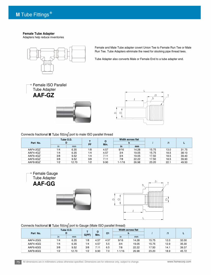
M Tube Fittings
75 www.hsmecorp.comAll dimensions are in millimeters unless otherwise specified. Dimensions are for reference only, subject to change.
Connects fractional port to male ISO parallel thread
Connects fractional port to Gauge (Male ISO parallel thread)
M Tube fitting
M Tube fitting
Female Tube AdapterAdapters help reduce inventories
Female and Male Tube adapter covert Union Tee to Female Run Tee or MaleRun Tee. Tube Adapters eliminate the need for stocking pipe thread tees.
Tube Adapter also converts Male or Female End to a tube adapter end.
Female ISO Parallel Tube Adapter
Female Gauge Tube Adapter
AAF-GZ
AAF-GG
Part No.Tube O.D.
D TPF
OMin. l l1 Lh
in mm in mmAAF4-2GZ 1/4 6.35 1/8 4.57 9/16 14.28 15.75 13.0 31.75AAF4-4GZ 1/4 6.35 1/4 4.57 3/4 19.05 15.75 18.5 38.10AAF6-4GZ 3/8 9.52 1/4 7.11 3/4 19.05 17.50 18.5 39.40AAF6-6GZ 3/8 9.52 3/8 7.11 7/8 22.22 17.50 18.5 39.90AAF8-8GZ 1/2 12.70 1/2 9.90 1-1/16 26.98 23.20 22.1 49.50
Part No.Tube O.D.
D TG(PF)
OMin. O1 l l1 Lh
in mm in mmAAF4-2GG 1/4 6.35 1/8 4.57 4.57 9/16 14.28 15.75 12.0 32.00AAF4-4GG 1/4 6.35 1/4 4.57 5.5 3/4 19.05 15.75 12.9 35.30AAF6-6GG 3/8 9.52 3/8 7.11 6.5 7/8 22.22 17.50 14.1 39.37AAF8-8GG 1/2 12.70 1/2 9.90 7.0 1-1/16 26.98 23.20 18.9 45.72

76www.hsmecorp.com All dimensions are in millimeters unless otherwise specified. Dimensions are for reference only, subject to change.
Female Gauge Tube Adapter
AN Adapter
AAF-GG
AAA
Gauge Adapter helps seta gauge-facing direction.
Connects metric port to Gauge (Male ISO parallel thread)M Tube fitting
Connects fractional port to AN maleM Tube fitting
Part No. Tube O.D.D
TG(PF)
OMin. O1 h l l1 L
AAF6M-2GG 6M 1/8 4.0 4.0 14 15.7 12.0 32.0AAF6M-4GG 6M 1/4 4.0 5.5 19 15.7 13.0 35.3AAF6M-6GG 6M 3/8 4.0 6.5 24 15.7 14.22 38.4AAF6M-8GG 6M 1/2 4.0 7.0 27 15.7 18.9 42.9AAF8M-4GG 8M 1/4 5.6 5.5 19 16.8 13.0 33.0AAF8M-6GG 8M 3/8 5.6 6.5 24 16.8 14.22 39.3AAF8M-8GG 8M 1/2 5.6 7.0 27 16.8 18.9 43.7AAF10M-4GG 10M 1/4 7.7 5.5 19 17.5 13.0 34.5AAF10M-6GG 10M 3/8 7.7 6.5 24 17.5 14.22 39.3AAF10M-8GG 10M 1/2 7.7 7.0 27 17.5 18.9 40.1AAF12M-4GG 12M 1/4 9.1 5.5 19 23.1 13.0 40.1AAF12M-6GG 12M 3/8 9.1 6.5 24 23.1 14.22 44.9AAF12M-8GG 12M 1/2 9.1 7.0 27 23.1 18.9 48.8AAF15M-8GG 15M 1/2 12.0 7.0 27 24.65 18.9 49.0AAF16M-8GG 16M 1/2 12.0 7.0 27 24.6 18.9 49.0AAF18M-8GG 18M 1/2 13.9 7.0 27 24.9 18.9 49.3AAF22M-8GG 22M 1/2 18.3 7.0 27 26.6 18.9 52.0AAF25M-8GG 25M 1/2 19.8 7.0 30 31.7 18.9 56.1
Part No.Tube O.D.
DAN Tube
Flare SizeStraightThread
T(U)A l l1h H
in mm in mm in mm in mmAAA2-2 1/8 3.17 1/8 3.17 5/16-24 3/8 9.52 7/16 11.11 13.71 13.46 18.54AAA2-4 1/8 3.17 1/4 6.35 7/16-20 9/16 14.28 7/16 11.11 15.74 13.46 19.05AAA4-4 1/4 6.35 1/4 6.35 7/16-20 9/16 14.28 9/16 14.28 15.74 15.74 21.33AAA6-6 3/8 9.52 3/8 9.52 9/16-18 11/16 17.46 11/16 17.46 18.28 17.52 24.89AAA8-8 1/2 12.70 1/2 12.70 3/4-16 7/8 22.22 7/8 22.22 21.59 23.11 31.75

M Tube Fittings
77 www.hsmecorp.comAll dimensions are in millimeters unless otherwise specified. Dimensions are for reference only, subject to change.
Connects fractional tubes
Connects fractional tubes
Tube SocketWeld Connector
Tube Socket Weld Elbow
Tube Socket Weld Port designed to ASME B16.11.
ACSW
ALSW
Part No.Tube O.D.
D OMin. D1 A B l l1 l2 Lh H
in mm in mm in mmACSW2-2 1/8 3.17 2.28 7.87 7/16 11.11 7/16 11.11 12.70 15.24 22.35 8.63 6.35 28.95ACSW4-4 1/4 6.35 4.82 11.17 1/2 12.70 9/16 14.28 15.24 17.78 26.16 10.41 7.87 33.52ACSW6-6 3/8 9.52 7.11 15.74 5/8 15.87 11/16 17.46 16.76 19.30 30.22 11.93 9.65 37.59ACSW8-8 1/2 12.70 10.41 19.05 13/16 20.64 7/8 22.22 22.86 21.84 30.98 11.93 12.70 41.14ACSW12-12 3/4 19.05 15.74 26.67 1-1/16 26.98 1-1/8 28.58 24.38 21.84 33.27 11.93 14.22 43.43ACSW16-16 1 25.40 22.35 33.27 1-3/8 34.92 1-1/2 38.10 31.24 26.41 40.38 14.22 19.05 52.57
Part No.Tube O.D.
D OMin. D1 A B l l1 L L1h H
in mm in mm in mmALSW4-4 1/4 6.35 4.82 12.70 1/2 12.70 9/16 14.28 15.24 17.78 19.55 7.87 26.92 19.55ALSW6-6 3/8 9.52 7.11 15.74 5/8 15.87 11/16 17.46 16.76 19.30 23.11 9.65 30.48 23.11ALSW8-8 1/2 12.70 10.41 20.57 13/16 20.64 7/8 22.22 22.86 21.84 25.90 12.70 36.06 25.90ALSW12-12 3/4 19.05 15.74 26.92 1-1/16 26.98 1-1/8 28.58 24.38 21.84 29.71 14.22 39.87 29.71ALSW16-16 1 25.40 22.35 35.05 1-3/8 34.93 1-1/2 38.10 31.24 26.41 36.83 19.05 49.02 36.83

78www.hsmecorp.com All dimensions are in millimeters unless otherwise specified. Dimensions are for reference only, subject to change.
Pipe Butt WeldConnector
ACBW
Connects fractional tube to pipe
Connects metric tube to pipe
Part No.Tube O.D.
DMale Pipe Size
P OMin. A B l l1 Lh H
in mm Nom O.D in mm in mmACBW2-2P 1/8 3.17 1/8 10.29 2.28 7/16 11.11 7/16 11.11 12.70 15.24 23.87 9.65 31.24ACBW3-2P 3/16 4.76 1/8 10.29 3.04 7/16 11.11 1/2 12.70 13.71 16.00 24.63 9.65 31.24ACBW4-2P 1/4 6.35 1/8 10.29 4.82 1/2 12.70 9/16 14.28 15.24 17.78 25.40 9.65 32.76ACBW4-4P 1/4 6.35 1/4 13.72 4.82 9/16 14.28 9/16 14.28 15.24 17.78 30.48 14.22 37.84ACBW5-2P 5/16 7.93 1/8 10.29 5.08 9/16 14.28 5/8 15.87 16.25 18.54 26.67 9.65 34.03ACBW5-4P 5/16 7.93 1/4 13.72 6.35 9/16 14.28 5/8 15.87 16.25 18.54 31.24 14.22 38.60ACBW6-4P 3/8 9.52 1/4 13.72 7.11 5/8 15.87 11/16 17.46 16.76 19.30 32.51 14.22 39.87ACBW6-6P 3/8 9.52 3/8 17.15 7.11 11/16 17.46 11/16 17.46 16.76 19.30 32.51 14.22 39.87ACBW6-8P 3/8 9.52 1/2 21.34 7.11 7/8 22.22 11/16 17.46 16.76 19.30 38.86 11.05 43.23ACBW8-6P 1/2 12.70 3/8 17.15 10.41 13/16 20.64 7/8 22.22 22.86 21.84 33.27 14.22 43.43ACBW8-8P 1/2 12.70 1/2 21.34 10.41 7/8 22.22 7/8 22.22 22.86 21.84 38.86 19.05 49.02ACBW8-12P 1/2 12.70 3/4 26.67 10.41 1-1/16 26.98 7/8 22.22 22.86 21.84 40.38 19.05 50.54ACBW10-8P 5/8 15.87 1/2 21.34 12.70 15/16 23.81 1 25.40 24.38 21.84 38.86 19.05 49.02ACBW12-12P 3/4 19.05 3/4 26.67 15.74 1-1/16 26.98 1-1/8 28.58 24.38 21.84 40.38 19.05 50.54ACBW16-16P 1 25.40 1 33.40 22.35 1-3/8 34.92 1-1/2 38.10 31.24 26.41 50.03 23.87 62.23ACBW20-20P 1-1/4 31.75 1-1/4 42.16 27.68 1-3/4 44.45 2 50.80 41.14 38.86 55.11 23.87 77.21ACBW24-24P 1-1/2 38.10 1-1/2 48.26 34.03 2-1/8 53.98 2-1/4 57.15 50.03 45.21 61.72 26.16 88.90ACBW32-32P 2 50.80 2 60.33 47.75 2-3/4 69.85 3 76.20 67.56 62.73 76.20 26.92 113.53
Part No. Tube O.D.D
Male Pipe SizeP O
Min. A B l l1 LNom O.D h H
ACBW3M-2P 3 1/8 10.29 2.4 12 12 12.9 15.3 23.1 9.7 29.7ACBW4M-2P 4 1/8 10.29 2.4 12 12 13.7 16.1 24.1 9.7 30.7ACBW6M-2P 6 1/8 10.29 4.8 14 14 15.3 17.7 25.4 9.7 32.8ACBW6M-4P 6 1/4 13.72 4.8 14 14 15.3 17.7 30.2 14.2 37.6ACBW8M-2P 8 1/8 10.29 5.1 15 16 16.2 18.6 26.7 9.7 34.2ACBW8M-4P 8 1/4 13.72 6.4 15 16 16.2 18.6 31.2 14.2 38.7ACBW8M-8P 8 1/2 21.34 6.4 22 16 16.2 18.6 37.3 19.0 44.8ACBW10M-4P 10 1/4 13.72 7.1 18 19 17.2 19.5 33.3 14.2 40.9ACBW10M-6P 10 3/8 17.15 7.9 18 19 17.2 19.5 32.5 14.2 40.1ACBW10M-8P 10 1/2 21.34 7.9 22 19 17.2 19.5 38.1 19.0 45.7ACBW12M-4P 12 1/4 13.72 7.1 22 22 22.8 22.0 33.3 14.2 43.4ACBW12M-6P 12 3/8 17.15 9.5 22 22 22.8 22.0 33.3 14.2 43.4ACBW12M-8P 12 1/2 21.34 9.5 22 22 22.8 22.0 38.1 19.0 48.2ACBW14M-6P 14 3/8 17.15 10.3 24 25 24.4 22.0 34.0 14.2 44.1ACBW15M-8P 15 1/2 21.34 11.9 24 25 24.4 22.0 38.9 19.0 49.0ACBW16M-8P 16 1/2 21.34 12.7 24 25 24.4 22.0 38.9 19.0 49.0ACBW18M-8P 18 1/2 21.34 13.5 27 30 24.4 22.0 40.4 19.0 50.5ACBW32M-20P 32 1-1/4 42.16 28.6 46 50 42.0 41.6 56.6 23.9 79.6ACBW38M-24P 38 1-1/2 48.26 33.7 55 60 49.4 47.9 64.0 26.2 91.6

M Tube Fittings
79 www.hsmecorp.comAll dimensions are in millimeters unless otherwise specified. Dimensions are for reference only, subject to change.
Welding Information M Tube Fitting butt weld ends are constructed to SCH 80 or greater.
Prior to weld, remove nut and ferrules from M Tube Fitting.• This protects the nut and ferrules from weld heat.
Cover the M Tube Fitting Port with a protective device such as port plug. • This protects threads and sealing surface of fitting port from weld splatter.• Finger-tighten the port plug so that it can be used many times.
After welding, replace the port plug with the nut and ferrules.
Connects fractional tube to pipe
Connects fractional tubes
Pipe Butt WeldElbow
Bulkhead WeldUnion
ALBW
ABUWTank or
Vessel Wall
Weldingon
Wall
Part No.Tube O.D.
DMale Pipe Size
P OMin. A B l l1 L L1h H
in mm Nom O.D in mm in mmALBW 2-2P 1/8 3.17 1/8 10.29 4.82 1/2 12.70 9/16 14.28 15.24 17.78 19.55 9.65 26.92 18.79ALBW 4-4P 1/4 6.35 1/4 13.72 4.82 1/2 12.70 9/16 14.28 15.24 17.78 19.55 14.22 26.92 23.36ALBW 6-4P 3/8 9.52 1/4 13.72 7.11 5/8 15.87 11/16 17.46 16.76 19.30 23.11 14.22 30.48 25.40ALBW 8-8P 1/2 12.70 1/2 21.34 10.41 13/16 20.64 7/8 22.22 22.86 21.84 25.90 19.05 36.06 33.02ALBW 12-12P 3/4 19.05 3/4 26.67 15.74 1-1/16 26.98 1-1/8 28.58 24.38 21.84 29.71 19.05 39.87 36.83
Part No.Tube O.D.
D OMin.
ADiameter l LH
in mm in mmABUW-4 1/4 6.35 4.8 16.0 9/16 14.28 80.0 115.4ABUW-6 3/8 9.52 7.1 19.0 11/16 17.46 80.0 118.4ABUW-8 1/2 12.70 10.41 22.0 7/8 22.22 80.0 124.0
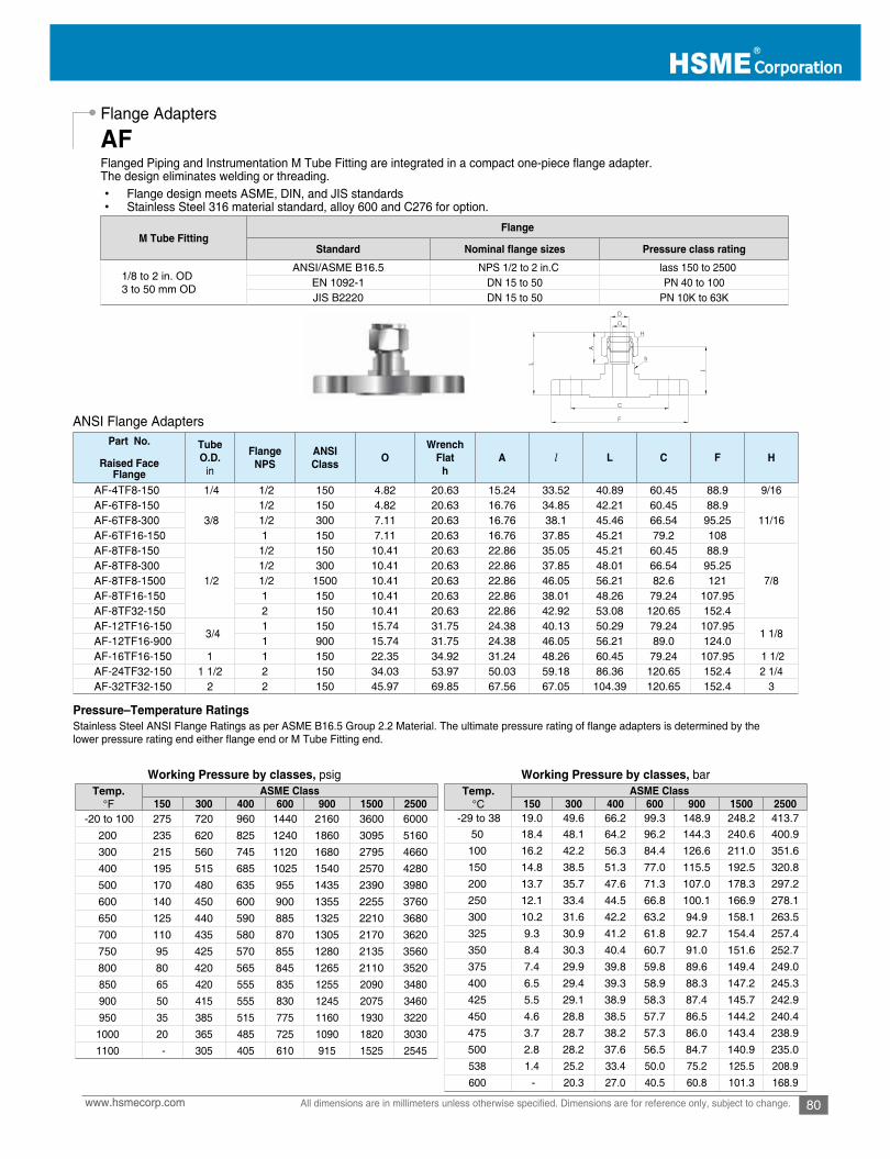
80www.hsmecorp.com All dimensions are in millimeters unless otherwise specified. Dimensions are for reference only, subject to change.
Flange Adapters
Flanged Piping and Instrumentation M Tube Fitting are integrated in a compact one-piece flange adapter.The design eliminates welding or threading. • Flange design meets ASME, DIN, and JIS standards • Stainless Steel 316 material standard, alloy 600 and C276 for option.
ANSI Flange Adapters
Stainless Steel ANSI Flange Ratings as per ASME B16.5 Group 2.2 Material. The ultimate pressure rating of flange adapters is determined by thelower pressure rating end either flange end or M Tube Fitting end.
Pressure–Temperature Ratings
Working Pressure by classes, psig Working Pressure by classes, bar
AF
M Tube FittingFlange
Standard Pressure class rating
1/8 to 2 in. OD3 to 50 mm OD
ANSI/ASME B16.5 NPS 1/2 to 2 in.C lass 150 to 2500EN 1092-1 DN 15 to 50 PN 40 to 100JIS B2220 DN 15 to 50 PN 10K to 63K
Part No.
Raised Face Flange
Tube O.D.
in
FlangeNPS
ANSIClass O
WrenchFlat
hA l L C F H
AF-4TF8-150 1/4 1/2 150 4.82 20.63 15.24 33.52 40.89 60.45 88.9 9/16AF-6TF8-150
3/8 1/2 150 4.82 20.63 16.76 34.85 42.21 60.45 88.9
11/16AF-6TF8-300 1/2 300 7.11 20.63 16.76 38.1 45.46 66.54 95.25AF-6TF16-150 1 150 7.11 20.63 16.76 37.85 45.21 79.2 108AF-8TF8-150
1/2
1/2 150 10.41 20.63 22.86 35.05 45.21 60.45 88.9
7/8AF-8TF8-300 1/2 300 10.41 20.63 22.86 37.85 48.01 66.54 95.25AF-8TF8-1500 1/2 1500 10.41 20.63 22.86 46.05 56.21 82.6 121AF-8TF16-150 1 150 10.41 20.63 22.86 38.01 48.26 79.24 107.95AF-8TF32-150 2 150 10.41 20.63 22.86 42.92 53.08 120.65 152.4AF-12TF16-150
3/41 150 15.74 31.75 24.38 40.13 50.29 79.24 107.95
1 1/8AF-12TF16-900 1 900 15.74 31.75 24.38 46.05 56.21 89.0 124.0AF-16TF16-150 1 1 150 22.35 34.92 31.24 48.26 60.45 79.24 107.95 1 1/2AF-24TF32-150 1 1/2 2 150 34.03 53.97 50.03 59.18 86.36 120.65 152.4 2 1/4AF-32TF32-150 2 2 150 45.97 69.85 67.56 67.05 104.39 120.65 152.4 3
Temp.°F
ASME Class150 300 400 600 900 1500 2500
-20 to 100 275 720 960 1440 2160 3600 6000200 235 620 825 1240 1860 3095 5160300 215 560 745 1120 1680 2795 4660400 195 515 685 1025 1540 2570 4280500 170 480 635 955 1435 2390 3980600 140 450 600 900 1355 2255 3760650 125 440 590 885 1325 2210 3680700 110 435 580 870 1305 2170 3620750 95 425 570 855 1280 2135 3560800 80 420 565 845 1265 2110 3520850 65 420 555 835 1255 2090 3480900 50 415 555 830 1245 2075 3460950 35 385 515 775 1160 1930 3220
1000 20 365 485 725 1090 1820 30301100 - 305 405 610 915 1525 2545
Temp.°C
ASME Class150 300 400 600 900 1500 2500
-29 to 38 19.0 49.6 66.2 99.3 148.9 248.2 413.7 50 18.4 48.1 64.2 96.2 144.3 240.6 400.9
100 16.2 42.2 56.3 84.4 126.6 211.0 351.6 150 14.8 38.5 51.3 77.0 115.5 192.5 320.8 200 13.7 35.7 47.6 71.3 107.0 178.3 297.2 250 12.1 33.4 44.5 66.8 100.1 166.9 278.1 300 10.2 31.6 42.2 63.2 94.9 158.1 263.5 325 9.3 30.9 41.2 61.8 92.7 154.4 257.4 350 8.4 30.3 40.4 60.7 91.0 151.6 252.7 375 7.4 29.9 39.8 59.8 89.6 149.4 249.0 400 6.5 29.4 39.3 58.9 88.3 147.2 245.3 425 5.5 29.1 38.9 58.3 87.4 145.7 242.9 450 4.6 28.8 38.5 57.7 86.5 144.2 240.4 475 3.7 28.7 38.2 57.3 86.0 143.4 238.9 500 2.8 28.2 37.6 56.5 84.7 140.9 235.0 538 1.4 25.2 33.4 50.0 75.2 125.5 208.9 600 - 20.3 27.0 40.5 60.8 101.3 168.9
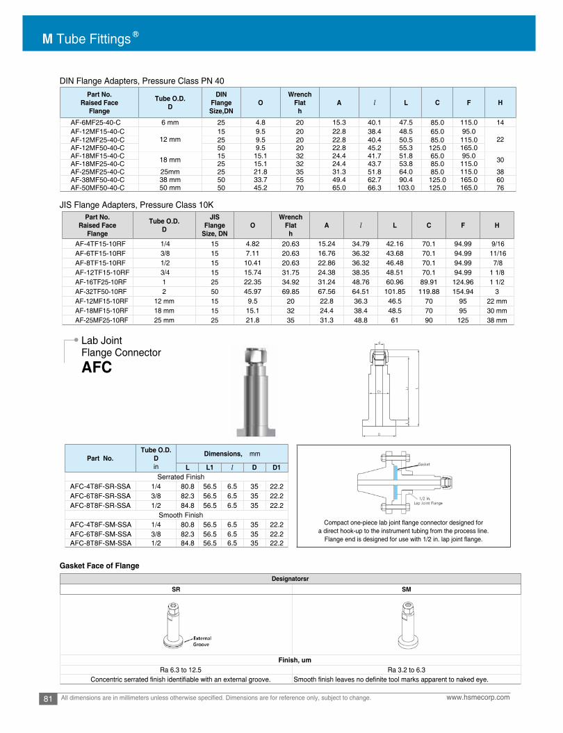
M Tube Fittings
81 www.hsmecorp.comAll dimensions are in millimeters unless otherwise specified. Dimensions are for reference only, subject to change.
DIN Flange Adapters, Pressure Class PN 40
JIS Flange Adapters, Pressure Class 10K
Gasket Face of Flange
Lab JointFlange Connector
AFC
Compact one-piece lab joint flange connector designed for a direct hook-up to the instrument tubing from the process line.
Flange end is designed for use with 1/2 in. lap joint flange.
Part No.Raised Face
Flange
Tube O.D.D
DINFlangeSize,DN
OWrench
Flath
A l L C F H
AF-6MF25-40-C 6 mm 25 4.8 20 15.3 40.1 47.5 85.0 115.0 14AF-12MF15-40-C
12 mm15 9.5 20 22.8 38.4 48.5 65.0 95.0
22AF-12MF25-40-C 25 9.5 20 22.8 40.4 50.5 85.0 115.0AF-12MF50-40-C 50 9.5 20 22.8 45.2 55.3 125.0 165.0AF-18MF15-40-C 18 mm 15 15.1 32 24.4 41.7 51.8 65.0 95.0 30AF-18MF25-40-C 25 15.1 32 24.4 43.7 53.8 85.0 115.0AF-25MF25-40-C 25mm 25 21.8 35 31.3 51.8 64.0 85.0 115.0 38AF-38MF50-40-C 38 mm 50 33.7 55 49.4 62.7 90.4 125.0 165.0 60AF-50MF50-40-C 50 mm 50 45.2 70 65.0 66.3 103.0 125.0 165.0 76
Part No.Raised Face
Flange
Tube O.D.D
JISFlange
Size, DNO
WrenchFlat
hA l L C F H
AF-4TF15-10RF 1/4 15 4.82 20.63 15.24 34.79 42.16 70.1 94.99 9/16AF-6TF15-10RF 3/8 15 7.11 20.63 16.76 36.32 43.68 70.1 94.99 11/16AF-8TF15-10RF 1/2 15 10.41 20.63 22.86 36.32 46.48 70.1 94.99 7/8AF-12TF15-10RF 3/4 15 15.74 31.75 24.38 38.35 48.51 70.1 94.99 1 1/8AF-16TF25-10RF 1 25 22.35 34.92 31.24 48.76 60.96 89.91 124.96 1 1/2AF-32TF50-10RF 2 50 45.97 69.85 67.56 64.51 101.85 119.88 154.94 3AF-12MF15-10RF 12 mm 15 9.5 20 22.8 36.3 46.5 70 95 22 mmAF-18MF15-10RF 18 mm 15 15.1 32 24.4 38.4 48.5 70 95 30 mmAF-25MF25-10RF 25 mm 25 21.8 35 31.3 48.8 61 90 125 38 mm
Part No.Tube O.D.
Din
Dimensions, mm
L L1 l D D1Serrated Finish
AFC-4T8F-SR-SSA 1/4 80.8 56.5 6.5 35 22.2AFC-6T8F-SR-SSA 3/8 82.3 56.5 6.5 35 22.2AFC-8T8F-SR-SSA 1/2 84.8 56.5 6.5 35 22.2
Smooth Finish AFC-4T8F-SM-SSA 1/4 80.8 56.5 6.5 35 22.2AFC-6T8F-SM-SSA 3/8 82.3 56.5 6.5 35 22.2AFC-8T8F-SM-SSA 1/2 84.8 56.5 6.5 35 22.2
DesignatorsrSR SM
Finish, umRa 6.3 to 12.5 Ra 3.2 to 6.3
Concentric serrated finish identifiable with an external groove. Smooth finish leaves no definite tool marks apparent to naked eye.

82www.hsmecorp.com All dimensions are in millimeters unless otherwise specified. Dimensions are for reference only, subject to change.
Dielectric Fittings
AEU
CAUTIONDO NOT WRENCH THIS HEXNOR DISASSEMBLE THIS CONNECTION
Features1. Interruption on electrical current while permitting fluid flow.2. Fitting interrupts cathodical current flow.3. Electrical resistance:
• 108 ohms at 70°F (21 °C) and 50% relative humidity.
• 106 ohms at 100°F (37 °C) and 90% relative humidity.
M tube fitting Dielectric fittings are designed to interrupt the electrical current flowing through a pipe or tubing in order to protectvital instruments and metering equipment while permitting fluid flow.
Warning: The warning label below is placed over the insulation section hex.on every dielectric fitting. Do not disconnect at this point!
Materials of Construction
• Fitting material: Stainless Steel 316
• Insulator: Molded Thermoplastic
• O-ring: 90 Durometer FKM
• O-ring back up washer: Virgin PTFE
Widely used in the natural gas transmission industry, the dielectric fittingprevents current flow, static electricity or even lightning strikes from reaching the monitoring station equipment.
If the current flow is not interrupted before reaching the monitoringstation, sensitive equipment could be damaged or rendered inaccurate.
By using M Tube Dielectric Fitting on impulse linesbetween the pipeline and the monitoring station, current flow isinterrupted while full fluid flow is permitted.
M Tube Two Ferrule system provides outstanding sealing in theimpulse line.
Technical DataPressure Rating: 4,000 psig (275 bar) @ 70°F(21°C)Temperature Rating: -40 to -200°F (-40 to 93°C)
Typical Application
Part No.Tube O.D.
D
PipeThreadT(NPT)
Dimensions, in. (mm)
OMin. A L L1 h H H1 H2
AEU-4 1/4 - 0.19 (4.8) 15.24 mm 95.8 mm 65.3 mm 1/2 (12.7) 9/16 (14.28)
7/8 (22.22)
-
AEU-6 3/8 -
0.28 (7.1)
16.76 mm 99.6 mm 65.8 mm 5/8 (15.87) 11/16 (17.46) 13/16 (20.64)
AEU-8 1/2 - 22.86 mm 106 mm 60.2 mm 13/16 (20.64) 7/8 (22.22) -
AEU-12M 12 mm - 22.8 mm 107 mm 61.7 mm 22 mm 22 mm 22 mm
AEU6-4N 3/8 1/4 16.76 mm 94.7 mm - 5/8 (15.87) 11/16 7/8 (22.22)

M Tube Fittings
83 www.hsmecorp.comAll dimensions are in millimeters unless otherwise specified. Dimensions are for reference only, subject to change.
M Tube Fitting Fusible Plug is thermally actuated relief device that melts against the rated temperature not against pressure.
These safety devices are typically used over offshore platform where diesel engine runs to generate electrical power andthe temperature inside of the engine chamber needs to be controlled. Usually instrument air is charged in the fusible plug thathits an alarm physically once the plug melts or yields against the chamber temperature.This fire protection pressure relief plug is non-reclosing device.Therefore the plug needs to be periodically examined for replacement if symptoms on corrosion are obvious on melting alloy.
Materials of Construction: Stainless steel Tube Adapter 3/8 in. OD and alloy metal inside.
For installation, follow the standard M Tube Fitting installation instruction.
Connects to female NPT Port
M Tube Fitting Vent Protectors known as a bug protectorprotect open ends of outlet vents, instruments, and tubing.
The mesh wire screen prevents foreign bodies like insectsor debris from entering and clogging open ends of systems.
Construction with bored-through pipe plug and stainlesssteel 40 x 40 mesh, 0.010 in. diameter wire screen.
Connects to Port 3/8 in. OD Technical Information
Fusible Plug
Vent Protector
AFU
AVP
DM Tube fitting
h
LL1
O
TTh
L1
L
OPart No.
Plug ODDin.
MeltingTemperature Designator
AFU6-160-SS
3/8
160102SS-102-6UFA552SS-552-6UFA182SS-182-6UFA
Designator
Nominal Melting
Temperature°F
Melting TemperatureRanges °F (°C)
Maximum Charging Pressure
psig (bar)
160 160 160 (71) +/- 3%
150 (10.3)201 201 201 (94) +/- 3%255 255 255 (124) +/- 3%281 281 281 (138) +/- 3%
Part No. TNPT
OMin
h L L1in mm
AVP-4N 1/4 7.11 9/16 15.87 20.57 14.22AVP-6N 3/8 10.40 11/16 17.46 20.57 14.22AVP-8N 1/2 12.70 7/8 23.81 26.92 19.05AVP-12N 3/4 16.00 1-1/16 26.98 28.70 19.05

84www.hsmecorp.com All dimensions are in millimeters unless otherwise specified. Dimensions are for reference only, subject to change.
Tube Cap
AC
Cap Fractional tube end
Cap metric tube end
• For installation, follow the standard M Tube Fitting installation instruction.
Application : Tube Cap & Port PlugIn tubing system, it is necessary to install either portplugs or tube caps for test ports or future runs.
• Tube cap for closing off tube end.• Port plug for closing off an existing fitting port.
M Tube FittingPort Plug
M Tube FittingTube Cap
Part No.Tube O.D.
DWidth across at
A B l LHhin mm in mm in mm
AC-1 1/16 1.59 5/16 7.93 5/16 7.93 8.63 10.92 11.20 14.18AC-2 1/8 3.17 7/16 11.11 7/16 11.11 12.70 15.14 13.46 20.06AC-3 3/16 4.76 7/16 11.11 1/2 12.70 13.71 16.00 14.73 21.33AC-4 1/4 6.35 1/2 12.70 9/16 14.28 15.24 17.78 16.00 23.26AC-5 5/16 7.93 9/16 14.28 5/8 15.87 16.25 18.54 17.01 24.38AC-6 3/8 9.52 5/8 15.87 11/16 17.46 16.76 19.30 18.28 25.65AC-8 1/2 12.70 13/16 20.63 7/8 22.22 22.86 21.84 19.05 29.21AC-10 5/8 15.87 15/16 23.81 1 25.40 24.38 21.84 19.81 29.97AC-12 3/4 19.05 1-1/16 26.98 1-1/8 28.57 24.38 21.84 21.33 31.49AC-14 7/8 22.22 1-3/16 30.16 1-1/4 31.75 25.90 21.84 23.87 34.03AC-16 1 25.40 1-3/8 34.92 1-1/2 38.10 31.24 26.41 26.16 38.35AC-20 1-1/4 31.75 1-3/4 44.45 1-7/8 47.63 41.14 38.86 31.24 53.34AC-24 1-1/2 38.10 2-1/8 53.98 2-1/4 57.15 50.15 45.21 37.33 64.51AC-32 2 50.80 2-3/4 69.85 3 76.20 67.56 62.73 49.27 86.61
Part No. Tube O.D.D
Width across atA B l L
h H1.025.313.519.2121212M2-CA1.025.313.519.2121213M3-CA3.127.411.617.3121214M4-CA1.327.517.713.5141416M6-CA5.420.716.812.6161518M8-CA6.620.915.912.71918101M01-CA1.920.910.228.22222221M21-CA9.928.910.224.42524251M51-CA9.928.910.224.42524261M61-CA4.133.120.224.42037281M81-CA0.439.320.220.62230302M02-CA0.439.320.220.62230322M22-CA5.832.625.623.13835352M52-CA5.847.726.636.63641482M82-CA8.558.236.140.2405642323-CA4.568.739.744.94065583M83-CA
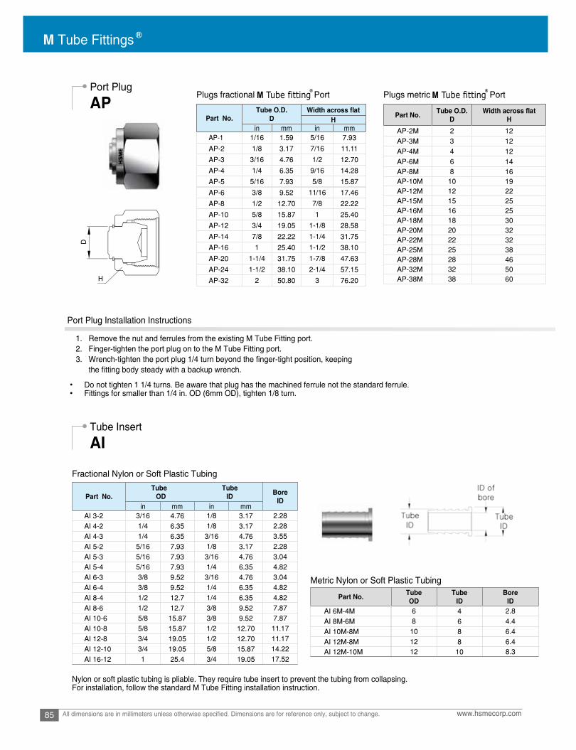
M Tube Fittings
85 www.hsmecorp.comAll dimensions are in millimeters unless otherwise specified. Dimensions are for reference only, subject to change.
Port Plug
Tube Insert
Fractional Nylon or Soft Plastic Tubing
Metric Nylon or Soft Plastic Tubing
Nylon or soft plastic tubing is pliable. They require tube insert to prevent the tubing from collapsing. For installation, follow the standard M Tube Fitting installation instruction.
AP
AI
D
H
Plugs fractional Port
Port Plug Installation Instructions
1. Remove the nut and ferrules from the existing M Tube Fitting port. 2. Finger-tighten the port plug on to the M Tube Fitting port. 3. Wrench-tighten the port plug 1/4 turn beyond the finger-tight position, keeping the fitting body steady with a backup wrench.
• Do not tighten 1 1/4 turns. Be aware that plug has the machined ferrule not the standard ferrule.• Fittings for smaller than 1/4 in. OD (6mm OD), tighten 1/8 turn.
Plugs metric PortM Tube fitting M Tube fitting
Part No.Tube O.D.
DWidth across at
Hin mm in mm
AP-1 1/16 1.59 5/16 7.93
AP-2 1/8 3.17 7/16 11.11
AP-3 3/16 4.76 1/2 12.70
AP-4 1/4 6.35 9/16 14.28
AP-5 5/16 7.93 5/8 15.87
AP-6 3/8 9.52 11/16 17.46
AP-8 1/2 12.70 7/8 22.22
AP-10 5/8 15.87 1 25.40
AP-12 3/4 19.05 1-1/8 28.58
AP-14 7/8 22.22 1-1/4 31.75
AP-16 1 25.40 1-1/2 38.10
AP-20 1-1/4 31.75 1-7/8 47.63
AP-24 1-1/2 38.10 2-1/4 57.15
AP-32 2 50.80 3 76.20
Part No. Tube O.D.D
Width across atH
AP-2M 2 12AP-3M 3 12AP-4M 4 12AP-6M 6 14AP-8M 8 16AP-10M 10 19AP-12M 12 22AP-15M 15 25AP-16M 16 25AP-18M 18 30AP-20M 20 32AP-22M 22 32AP-25M 25 38AP-28M 28 46AP-32M 32 50AP-38M 38 60
Part No.Tube Tube
OD ID Bore ID
in mm in mmAI 3-2 3/16 4.76 1/8 3.17 2.28AI 4-2 1/4 6.35 1/8 3.17 2.28AI 4-3 1/4 6.35 3/16 4.76 3.55AI 5-2 5/16 7.93 1/8 3.17 2.28AI 5-3 5/16 7.93 3/16 4.76 3.04AI 5-4 5/16 7.93 1/4 6.35 4.82AI 6-3 3/8 9.52 3/16 4.76 3.04AI 6-4 3/8 9.52 1/4 6.35 4.82AI 8-4 1/2 12.7 1/4 6.35 4.82AI 8-6 1/2 12.7 3/8 9.52 7.87AI 10-6 5/8 15.87 3/8 9.52 7.87AI 10-8 5/8 15.87 1/2 12.70 11.17AI 12-8 3/4 19.05 1/2 12.70 11.17AI 12-10 3/4 19.05 5/8 15.87 14.22AI 16-12 1 25.4 3/4 19.05 17.52
Part No. TubeOD
TubeID
BoreID
AI 6M-4M 6 4 2.8AI 8M-6M 8 6 4.4AI 10M-8M 10 8 6.4AI 12M-8M 12 8 6.4AI 12M-10M 12 10 8.3

86www.hsmecorp.com All dimensions are in millimeters unless otherwise specified. Dimensions are for reference only, subject to change.
Front Ferrule
Back Ferrule
Fractional
Fractional
Ordering Information Stainless Steel over 1 in. and 25 mm OD fittings are supplied with stainless steel ferrules coated with PFA. For applicationbeyond 450ºF (232 ºC) silver-plated front ferrule are supplied. To order silver plated front ferrule, insert “SL” to the ordering number. Example: AFF-32-SL-SS
Ordering Information Stainless Steel over 1 in. and 25 mm OD fittings are supplied with stainless steel ferrules coated with PFA. For applicationbeyond 450ºF (232 ºC) uncoated back ferrule are supplied. To order uncoated back ferrule, insert “UC” to the ordering number. Example: AFB-32-UC-SS
Metric
Metric
AFF
AFB
DD
Part No.
Tube O.D.
D
in mm
AFF-1 1/16 1.59AFF-2 1/8 3.17AFF-3 3/16 4.76AFF-4 1/4 6.35AFF-5 5/16 7.93AFF-6 3/8 9.52AFF-8 1/2 12.70AFF-10 5/8 15.87AFF-12 3/4 19.05AFF-14 7/8 22.22AFF-16 1 25.40AFF-20 1-1/4 31.75AFF-24 1-1/2 38.10AFF-32 2 50.80
Part No. Tube O.D.D
AFF-2M 2AFF-3M 3AFF-4M 4AFF-6M 6AFF-8M 8AFF-10M 10AFF-12M 12AFF-15M 15AFF-16M 16AFF-18M 18AFF-20M 20AFF-22M 22AFF-25M 25AFF-28M 28AFF-32M 32AFF-38M 38
Part No.
Tube O.D.
D
in mm
AFB-1 1/16 1.59AFB-2 1/8 3.17AFB-3 3/16 4.76AFB-4 1/4 6.35AFB-5 5/16 7.93AFB-6 3/8 9.52AFB-8 1/2 12.70AFB-10 5/8 15.87AFB-12 3/4 19.05AFB-14 7/8 22.22AFB-16 1 25.40AFB-20 1-1/4 31.75AFB-24 1-1/2 38.10AFB-32 2 50.80
Part No. Tube O.D.D
AFB-2M 2AFB-3M 3AFB-4M 4AFB-6M 6AFB-8M 8AFB-10M 10AFB-12M 12AFB-15M 15AFB-16M 16AFB-18M 18AFB-20M 20AFB-22M 22AFB-25M 25AFB-28M 28AFB-32M 32AFB-38M 38
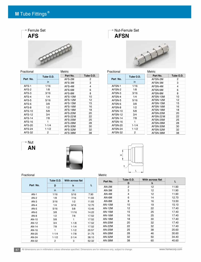
M Tube Fittings
87 www.hsmecorp.comAll dimensions are in millimeters unless otherwise specified. Dimensions are for reference only, subject to change.
Fractional Fractional
Fractional
Metric Metric
Metric
Ferrule Set Nut-Ferrule Set
Nut
AFS AFSN
AN
D
h
L
Part No.Tube O.D.
in
AFS-1 1/16AFS-2 1/8AFS-3 3/16AFS-4 1/4AFS-5 5/16AFS-6 3/8AFS-8 1/2AFS-10 5/8AFS-12 3/4AFS-14 7/8AFS-16 1AFS-20 1-1/4AFS-24 1-1/2AFS-32 2
Part No. Tube O.D.AFS-2M 2AFS-3M 3AFS-4M 4AFS-6M 6AFS-8M 8AFS-10M 10AFS-12M 12AFS-15M 15AFS-16M 16AFS-18M 18AFS-20M 20AFS-22M 22AFS-25M 25AFS-28M 28AFS-30M 30AFS-32M 32AFS-38M 38
Part No.Tube O.D.
in
AFSN-1 1/16AFSN-2 1/8AFSN-3 3/16AFSN-4 1/4AFSN-5 5/16AFSN-6 3/8AFSN-8 1/2AFSN-10 5/8AFSN-12 3/4AFSN-14 7/8AFSN-16 1AFSN-20 1-1/4AFSN-24 1-1/2AFSN-32 2
Part No. Tube O.D.AFSN-2M 2AFSN-3M 3AFSN-4M 4AFSN-6M 6AFSN-8M 8AFSN-10M 10AFSN-12M 12AFSN-15M 15AFSN-16M 16AFSN-18M 18AFSN-20M 20AFSN-22M 22AFSN-25M 25AFSN-28M 28AFSN-30M 30AFSN-32M 32AFSN-38M 38
Part No.
Tube O.D. With across at
LhD
in in
AN-1 1/16 5/16 7.90AN-2 1/8 7/16 11.93AN-3 3/16 1/2 11.93AN-4 1/4 9/16 12.70AN-5 5/16 5/8 13.46AN-6 3/8 11/16 14.22AN-8 1/2 7/8 17.52
AN-10 5/8 1 17.52AN-12 3/4 1-1/8 17.52AN-14 7/8 1-1/4 17.52AN-16 1 1-1/2 20.57AN-20 1-1/4 1-7/8 31.75AN-24 1-1/2 2-1/4 38.10AN-32 2 3 52.32
Part No.Tube O.D. With across at
LD h
AN-2M 2 12 11.90AN-3M 3 12 11.90AN-4M 4 12 11.90AN-6M 6 14 12.70AN-8M 8 16 13.50
AN-10M 10 19 15.10AN-12M 12 22 17.40AN-15M 15 25 17.40AN-16M 16 25 17.40AN-18M 18 30 17.40AN-20M 20 32 17.40AN-22M 22 32 17.40AN-25M 25 38 20.60AN-28M 28 46 30.60AN-32M 32 50 34.40AN-38M 38 60 40.60
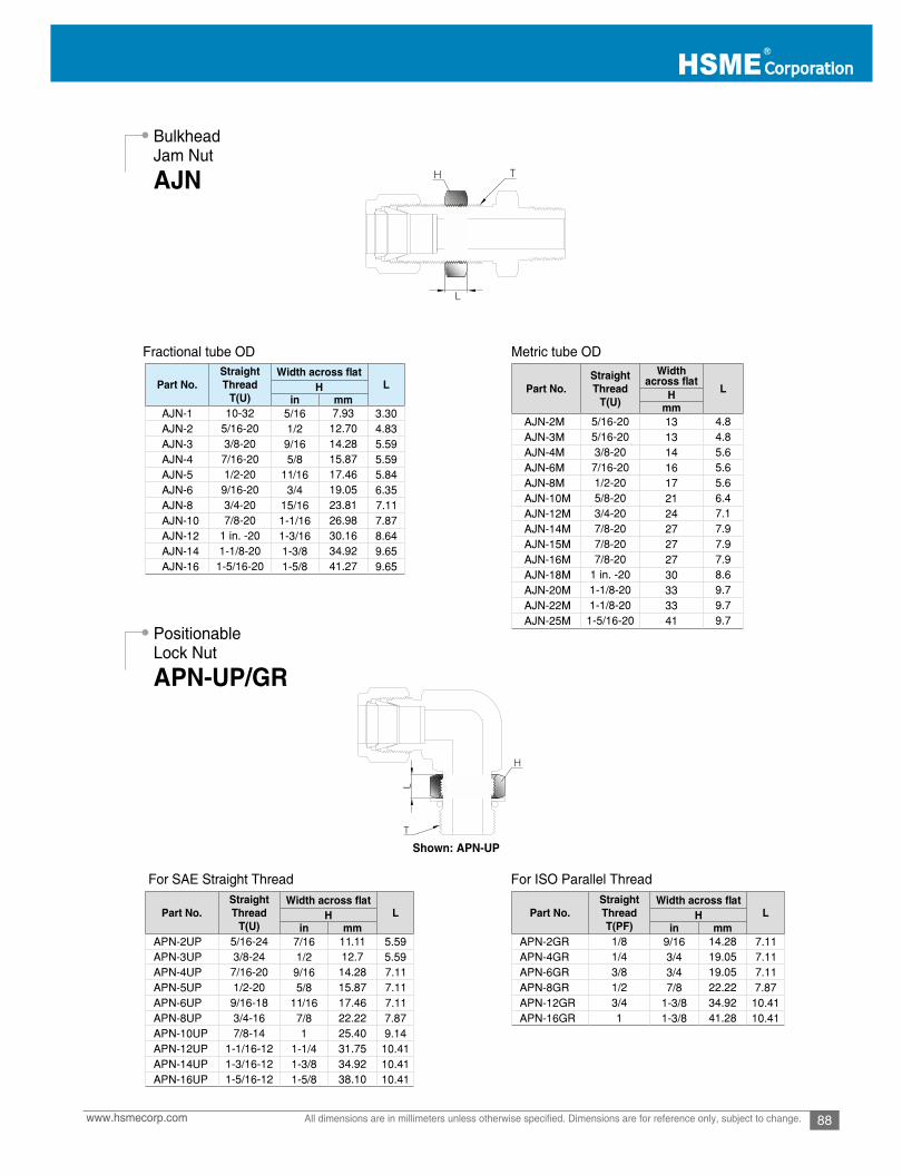
88www.hsmecorp.com All dimensions are in millimeters unless otherwise specified. Dimensions are for reference only, subject to change.
Bulkhead Jam Nut
Positionable Lock Nut
AJN
APN-UP/GR
Fractional tube OD
For SAE Straight Thread
Metric tube OD
For ISO Parallel Thread
Shown: APN-UP
Part No.StraightThread
T(U)
Width across atLH
in mmAJN-1 10-32 5/16 7.93 3.30 AJN-2 5/16-20 1/2 12.70 4.83 AJN-3 3/8-20 9/16 14.28 5.59 AJN-4 7/16-20 5/8 15.87 5.59 AJN-5 1/2-20 11/16 17.46 5.84 AJN-6 9/16-20 3/4 19.05 6.35 AJN-8 3/4-20 15/16 23.81 7.11 AJN-10 7/8-20 1-1/16 26.98 7.87 AJN-12 1 in. -20 1-3/16 30.16 8.64 AJN-14 1-1/8-20 1-3/8 34.92 9.65 AJN-16 1-5/16-20 1-5/8 41.27 9.65
Part No.StraightThread
T(U)
Width across at
LHmm
AJN-2M 5/16-20 13 4.8AJN-3M 5/16-20 13 4.8AJN-4M 3/8-20 14 5.6AJN-6M 7/16-20 16 5.6AJN-8M 1/2-20 17 5.6AJN-10M 5/8-20 21 6.4AJN-12M 3/4-20 24 7.1AJN-14M 7/8-20 27 7.9AJN-15M 7/8-20 27 7.9AJN-16M 7/8-20 27 7.9AJN-18M 1 in. -20 30 8.6AJN-20M 1-1/8-20 33 9.7AJN-22M 1-1/8-20 33 9.7AJN-25M 1-5/16-20 41 9.7
Part No.StraightThread
T(U)
Width across atLH
in mmAPN-2UP 5/16-24 7/16 11.11 5.59APN-3UP 3/8-24 1/2 12.7 5.59APN-4UP 7/16-20 9/16 14.28 7.11APN-5UP 1/2-20 5/8 15.87 7.11APN-6UP 9/16-18 11/16 17.46 7.11APN-8UP 3/4-16 7/8 22.22 7.87APN-10UP 7/8-14 1 25.40 9.14APN-12UP 1-1/16-12 1-1/4 31.75 10.41APN-14UP 1-3/16-12 1-3/8 34.92 10.41APN-16UP 1-5/16-12 1-5/8 38.10 10.41
Part No.StraightThreadT(PF)
Width across atLH
in mmAPN-2GR 1/8 9/16 14.28 7.11APN-4GR 1/4 3/4 19.05 7.11APN-6GR 3/8 3/4 19.05 7.11APN-8GR 1/2 7/8 22.22 7.87APN-12GR 3/4 1-3/8 34.92 10.41APN-16GR 1 1-3/8 41.28 10.41

M Tube Fittings
89 www.hsmecorp.comAll dimensions are in millimeters unless otherwise specified. Dimensions are for reference only, subject to change.
M Tube Fittings are gaugeable.
M Tube Fitting Gap Inspection No-Go gauge ensuressufficient pull-up on initial installation
Position the Gap Inspection Gauge over the gap between the nut and body
Gap gauge enters the gap, the fittingrequires additional tightening.
Gap gauge does not enter the gap, the fitting istightened sufficiently.
Inspection Tool
Stop collar in the fitting allows on-siteleak-tight inspection.
How to Make-Up1. Place stop collar over the neck of M Tube Fitting as shown on “Before Make-Up”.2. Place front & back ferrule in the right direction over the fitting port and finger-tighten the nut.3. Insert the tubing into the body until the tubing end bottoms up.4. Spanner-tighten the nut until the stop collar is fully jammed up between nut and body as shown on “After Make-Up”.
Inspection while the fitting in service5. Spin the nut by finger gently to check out if it spins.6. If it would not spin, it tells that the fitting remains in leak-tight position.7. If it spins, it tells that nut needs re-tightening by spanner until the collar is fully jammed up again in the fitting.
Gap Inspection Gauge
Stop Collar
AIG
ASC
Before Make-Up After Make-Up Inspection
Part No.Fitting OD
in.m mAIG-4 1/4, 5/16 6, 8AIG-6 3/8, 5/8 10, 15, 16AIG-8 1/2, 3/4 12, 18
AIG-16 1 25
Part No. Tube OD D din. mm mm
ASC-4ASC-6ASC-8ASC-12ASC-16
1/43/81/23/41
17.1 12.414.419.225.533.5
20.827.233.643

90www.hsmecorp.com All dimensions are in millimeters unless otherwise specified. Dimensions are for reference only, subject to change.
Inspection Tool
Stop collar in the fitting allows on-siteleak-tight inspection.
Hand Tube Benders
Tube Cutter
Tube Deburring Tool
ST-HTB
ST-TC
ST-TD
M tube fitting bender provides precise, high quality and consistentbending.
Benders applicable to stainless andcopper tubing for 1 to 180°bending range.
M tube Fitting manual cutter is applicable to stainless steel and copper tubing for 1/4 to 2 in. and 6 – 50mm OD.
M Tube Fitting manual deburring tool is applicable for deburring the inside and outside of diameter of stainless steel and coppertubing 1/4 to 2 in. and 6 – 50mm OD.
Dimensions, in.
Part No. Tube OD Bend Radius
ST-HTB4ST-HTB5ST-HTB6ST-HTB8
1/45/163/81/2
5/815/1615/161 1/2
Dimensions, in. ST-HTB6MST-HTB8MST-HTB10MST-HTB12M
68
1012
16242438
Part No. Tube O.D
ST-TC432 1/4 - 2 in. 6 - 50 mm
Part No. Tube O.D
ST-TD432 1/4 - 2 in. 6 - 50 mm

M Tube Fittings
91 www.hsmecorp.comAll dimensions are in millimeters unless otherwise specified. Dimensions are for reference only, subject to change.
Tube DepthMarker
Preswaging Tool
ATM
APS
Operation Instructions1. Insert the tubing into the ATM until it bottoms.2. Mark the tube at top on the ATM.3. Remove the tube from the ATM and insert it into M Tube Fitting until the marking line becomes flush with the top face of the nut.
Fractional
1. Clamp the preswaging tool over the vise firmly.2. Follow the standard M Tube Fitting installation instruction.3. Unthread the nut then remove the ferrules-preswaged tubing from the vise.
4. Reassemble the tubing by following M Tube Fitting reassembly instruction. Note: lubricate the preswaging tool threads on every operation.
Warning: do not rotate the tubing, but gently rock back and forth if you face difficulty in removing the tubing from the preswaging tool.
Operation Instructions
Metric
Fractional M Tube fitting Metric M Tube fitting
Part No. Tube O.D.(In.)
ATM-4-C 1/4ATM-6-C 3/8ATM-8-C 1/2ATM-10-C 5/8ATM-12-C 3/4ATM-16-C 1
Part No. Tube O.D.(mm)
ATM-6M-C 6ATM-8M-C 8ATM-10M-C 10ATM-12M-C 12ATM-16M-C 16ATM-25M-C 25
Part No. Tube O.D.(In.)
APS-4-C 1/4
APS-5-C 5/16
APS-6-C 3/8
APS-8-C 1/2
APS-12-C 3/4
Part No. Tube O.D.(mm)
APS-3M-C 3APS-6M-C 6APS-8M-C 8
APS-10M-C 10APS-12M-C 12APS-16M-C 16APS-18M-C 18APS-20M-C 20

92www.hsmecorp.com All dimensions are in millimeters unless otherwise specified. Dimensions are for reference only, subject to change.
Hydraulic Pre-Swaging Unit
Pre-Swaging Ferrules onto Tubing
Pre-Swaging Dieset
Standard Installation Instruction
AHP and AEP Electric Pre-swaging Unit pre-swages 1/2 to 2 in. and 12 to 50 mm of M Tube Fitting front and back ferrule ontostainless steel and carbon steel tubing.
To order dieset, select an applicable part number.
M Tube Fittings are supplied with finger-tight position. Therefore fitting disassembly is not necessary prior to installation.For tubing installation, make sure that tubing end is prepared with a square cut, inside and outside burrs are removed.
AHP unit is supplied in a sturdy plastic case containing swaging head, hydraulic hand pump, hose, and pre-swaging die set.AEP unit is built in sturdy steel case and pre-swaging die sets are supplied in separate case.
• Handy and portable for one person operation.• Reduction in makeup torque up to 70% compared to manual pull-up.• Prevent body thread galling and deformation.• Consistent swaging onto fitting.• No initial strain over body seal finish and body thread.
Electric Pre-Swaging Unit
AHP AEP
Unit Ordering Number
Tube ODPower
in. mm
Hydraulic Pre-Swaging Unit
Electric Pre-Swaging UnitAHP
AEP-220VAEP-110V
1/2 - 2
1/2 - 2
12 - 50
12 - 50
-
220V 50-60 Hz110V 60 Hz
Tube OD, mm Part No.
1/2 A8A10A12A16A20A24A32
5/83/4
1 1/41 1/2
2
1
Tube OD, mm Part No.
M21A21M41A41M61A61M81A81M02A02M22A22M52A52M82A82M03A03M23A23M83A83M05A05

M Tube Fittings
93 www.hsmecorp.comAll dimensions are in millimeters unless otherwise specified. Dimensions are for reference only, subject to change.
M Tube Fittings Up to 1 in. and 25 mm OD
Fittings Over 1 in. and 25 mm OD
Reassembly – All Fittings
Step 1 Step 2
Insert the tubing into the M Tube Fitting until it bottomsthe fitting shoulder and finger-tighten the nut.
Mark the nut at 6 o’clock position and wrench-tighten the nut 1 1/4turns to the 9 o’clock position while holding the body with a secondwrench.
For fittings 1/16, 1/8, 2mm, 3mm, and 4 mm OD, tighten thenut 3/4 turn to the 3 o’clock position.
1. Using Hydraulic or Electric pre-swaging unit, preswage the ferrules onto the tubing.
2. Insert the tube with preswaged ferrules into the fitting until the front ferrule seats on the sealing face of the fitting.
3. Finger-tighten the nut and mark the nut at the 6 o’clock position.
4. While holding the body firmly, wrench-tighten the nut 1/2 turn to 12 o’clock position.
M tube Fittings provide excellent make and remake performance
1. Prior to disassembly, mark a line along the nut and body hex; mark the tube flush with the top face of the nut.
2. Insert the ferrules-preswaged tube into the fitting until the front ferrule seats on the sealing face of the body.
3. While holding the fitting body steady, wrench-tighten the nut until the nut line to be in line with the body line. At this point a sharprise in torque is felt. Only after several remakes will it become necessary to advance the nut slightly past the original position.This advance need only be 10° to 20°, less than 1/3 of a hex flat.
M Tube Fitting Gap Inspection “No-Go gauge” makes sure the make-up distance is sufficiently pulled-up on initial installation.Inspection on initial Installation
High Pressure and High Safety ApplicationsOn step 1, hand-tighten the nut until the tubing does notmove axially nor turn by hand in the fitting,
12
6
39
12
6
3
9
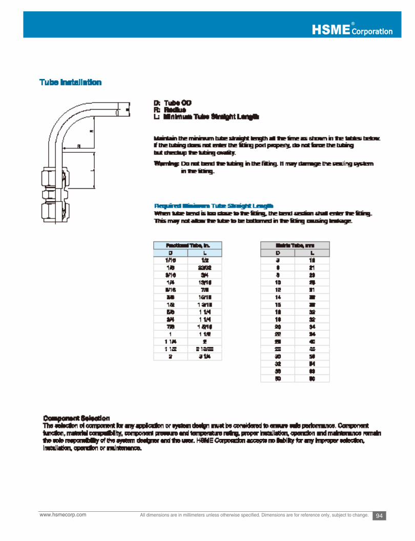
94www.hsmecorp.com All dimensions are in millimeters unless otherwise specified. Dimensions are for reference only, subject to change.
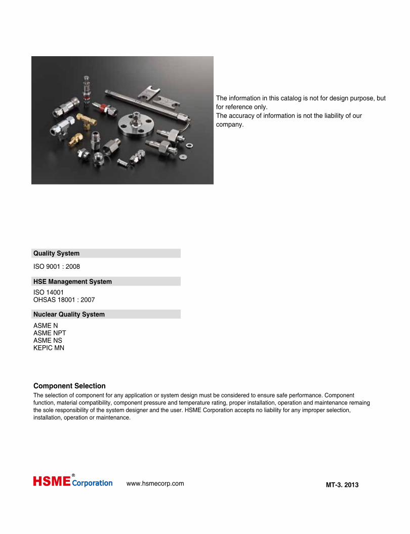
The information in this catalog is not for design purpose, butfor reference only.The accuracy of information is not the liability of ourcompany.
Quality System
ISO 9001 : 2008
ISO 14001OHSAS 18001 : 2007
ASME NASME NPTASME NSKEPIC MN
Component SelectionThe selection of component for any application or system design must be considered to ensure safe performance. Componentfunction, material compatibility, component pressure and temperature rating, proper installation, operation and maintenance remaingthe sole responsibility of the system designer and the user. HSME Corporation accepts no liability for any improper selection,installation, operation or maintenance.
HSE Management System
Nuclear Quality System