3-D NUMERICAL STUDY AND COMPARISON OF ECCENTRIC AND CONCENTRIC …jestec.taylors.edu.my/Vol 10 Issue...
17
Journal of Engineering Science and Technology Vol. 10, No.11 (2015) 1508 - 1524 © School of Engineering, Taylor’s University 1508 3-D NUMERICAL STUDY AND COMPARISON OF ECCENTRIC AND CONCENTRIC ANNULAR-FINNED TUBE HEAT EXCHANGERS FAROUK TAHROUR 1 , ABDELMOUMENE HAKIM BENMACHICHE 2, *, MOUNIR AKSAS 1 , CHERIF BOUGRIOU 3 1 LPEA Laboratory, Department of Physics, University of Batna, (05000) Batna, Algeria 2 Department of Mechanical Engineering, University of Biskra, (07000) Biskra, Algeria 3 LESIE Laboratory, Department of Mechanical Engineering, University of Batna, (05000) Batna, Algeria *Corresponding Author: [email protected] Abstract The use of 3-D computational fluid dynamics (CFD) is proposed to simulate the conjugate conduction-convection of heat transfer problems in eccentric annular- finned tube heat exchangers. The numerical simulation results allow us to evaluate the heat transfer coefficient over fin surfaces, the fin efficiency and the pressure drop. The aim of the present paper is to determine the optimum tube position in the circular fin that maximizes heat dissipation and minimizes pressure drop. In addition, this study analyzes the effects of fin spacing and fin tube diameter on heat transfer and flow characteristics for a range of Reynolds numbers, 4500≤Re≤22500. A satisfactory qualitative and quantitative agreement was obtained between the numerical predictions and the results published in the literature. For small fin spacings, the eccentric annular finned tube is more efficient than the concentric one. Among the cases examined, the average heat transfer coefficient of the eccentric annular-finned tube, for a tube shift S t =12 mm and a Reynolds number Re = 9923, was 7.61% greater than that of the concentric one. This gain is associated with a 43.09% reduction in pressure drop. Keywords: 3-D CFD simulation, Heat exchanger, Annular-finned tubes, Geometry parameters, Heat transfer, Pressure drop. 1. Introduction Annular-finned tube heat exchangers are widely used in industry, such as in air conditioning, energy recovery and thermal power station applications. In this type of heat exchangers, the three-dimensional flow characteristics vary considerably
Transcript of 3-D NUMERICAL STUDY AND COMPARISON OF ECCENTRIC AND CONCENTRIC …jestec.taylors.edu.my/Vol 10 Issue...

Journal of Engineering Science and Technology Vol. 10, No.11 (2015) 1508 - 1524 © School of Engineering, Taylor’s University
1508
3-D NUMERICAL STUDY AND COMPARISON OF ECCENTRIC AND CONCENTRIC ANNULAR-FINNED TUBE
HEAT EXCHANGERS
FAROUK TAHROUR1, ABDELMOUMENE HAKIM BENMACHICHE
2,*,
MOUNIR AKSAS1, CHERIF BOUGRIOU
3
1LPEA Laboratory, Department of Physics, University of Batna, (05000) Batna, Algeria 2Department of Mechanical Engineering, University of Biskra, (07000) Biskra, Algeria
3LESIE Laboratory, Department of Mechanical Engineering, University of Batna, (05000) Batna, Algeria
*Corresponding Author: [email protected]
Abstract
The use of 3-D computational fluid dynamics (CFD) is proposed to simulate the conjugate conduction-convection of heat transfer problems in eccentric annular-finned tube heat exchangers. The numerical simulation results allow us to evaluate the heat transfer coefficient over fin surfaces, the fin efficiency and the pressure drop. The aim of the present paper is to determine the optimum tube position in the circular fin that maximizes heat dissipation and minimizes pressure drop. In addition, this study analyzes the effects of fin spacing and fin tube diameter on heat transfer and flow characteristics for a range of Reynolds numbers, 4500≤Re≤22500. A satisfactory qualitative and quantitative agreement was obtained between the numerical predictions and the results published in the literature. For small fin spacings, the eccentric annular finned tube is more efficient than the concentric one. Among the cases examined, the average heat transfer coefficient of the eccentric annular-finned tube, for a tube shift St =12 mm and a Reynolds number Re = 9923, was 7.61% greater than that of the concentric one. This gain is associated with a 43.09% reduction in pressure drop.
Keywords: 3-D CFD simulation, Heat exchanger, Annular-finned tubes, Geometry parameters, Heat transfer, Pressure drop.
1. Introduction
Annular-finned tube heat exchangers are widely used in industry, such as in air conditioning, energy recovery and thermal power station applications. In this type of heat exchangers, the three-dimensional flow characteristics vary considerably

3-D Numerical Study and Comparison of Eccentric and Concentric . . . . 1509
Journal of Engineering Science and Technology November 2015, Vol. 10(11)
Nomenclatures
fA Area of the fin, m2
jA Area of the jth sub-fin, m2
1 2, ,C C Cε ε µ Turbulence model constants
d Tube outside diameter, mm
dc Collar tube outside diameter (d+2tf), mm df Outside diameter of the fin, mm h Heat transfer coefficient, W/(m2.K)
h Average heat transfer coefficient, W/(m2.K)
k Turbulent kinetic energy, m2/s2 P∆ Pressure drop, Pa
Q& Heat flow rate, W
Re S
St
T
T0
Tb
tf
u
Vin
y+
Reynolds number ( )in cV d ν
Fin spacing, mm Tube shift, mm Temperature, K Wall temperature, K
Bulk temperature, K
Fin thickness, mm Velocity, m/s Inlet velocity, m/s Dimensionless distance to the wall
Greek Symbols
pα
Inverse Prandtl number
λ
Thermal conductivity, W/(m.K) ε Turbulent energy dissipation rate, m2/s3
fη Fin efficiency
µ Dynamic viscosity, Kg/(m.s) ν Kinematic viscosity, m2/s ρ Density, Kg/m3
Subscripts
a Air f Fin
in t
Inlet Turbulent
over the fin surfaces, resulting in large variations in heat transfer. Because of the dependency of the flow structure on the geometrical parameters of heat exchangers [1, 2], further investigation of the effect of these parameters on the performance of various devices is required. To examine the effect of the tube location in the circular fin, 3-D numerical simulations of the turbulent heat transfer and the fluid flow characteristics of eccentric annular-finned tube heat exchangers were performed for this study.

1510 F. Tahrour et al.
Journal of Engineering Science and Technology November 2015, Vol. 10(11)
Many experimental and numerical studies that examine the influence of the geometrical parameters of various fin-and-tube heat exchangers on characteristics of heat transfer and pressure drop have been conducted [3-5]. Some of these studies have assessed the performance of annular-finned tubes. For example, Chen et al. [6, 7] conducted a numerical study of an inverse heat conduction problem based on some temperature measurements on the annular fin surfaces. As this study was concerned with forced and natural convections, the goal was to show the effects of the Reynolds number and the fin spacing on the heat transfer coefficient and the fin efficiency. Karaback [8] presented an experimental investigation of the free convective-radiative heat transfer from an annular-finned cylindrical heater to analyze the effects of fin diameter and fin spacing. An experimental investigation of the free convection from a wide range of annular fin arrays mounted on a horizontal cylinder was conducted by Yildiz and Yüncü [9]. These authors reported that the optimum fin spacing that provides the maximum heat transfer rate depends on the fin diameter and the base-to-ambient temperature difference.
The thermal performance of annular fins has been widely investigated for various fin profiles. Mokheimer [10] investigated the circular fins that were subjected to locally variable heat transfer coefficients. The fin-efficiency results were presented as a series of curves for several fin profiles with different radius ratios.
Aziz and Khani [11] analytically developed an algebraic expression to compute the thermal performance of a rotating circular fin. Their investigation was performed for rectangular and various convex parabolic profiles. The effects of the fin thickness, the outer-to-inner radius ratio and the shaft angular speed were examined.
Recently, Lee et al. [12] and Banerjee et al. [13] evaluated the air-side performance of perforated circular finned tubes. Lee et al. [12] experimentally determined both the heat transfer coefficients and the pressure drop for different perforation numbers on the finned tubes. These authors demonstrated that an increase in the convective heat transfer coefficient was related to a reduction of the recirculation zone by introducing perforations at the flow-separation locations.
Mon and Gross [14] performed 3-D numerical simulations of the turbulent heat transfer and fluid flow characteristics in a heat exchanger with annular-finned tubes positioned in a bundle of four rows, both in staggered and aligned arrangements. The effects of the fin spacing on the heat transfer, the pressure drop and the flow behavior were investigated. Performing this same numerical simulation for a single row of annular-finned tubes subjected to a cross flow. Bilirgen et al. [15] presented a finer examination of the effect of Reynolds number, as well as the effects of the fin spacing, fin height, fin thickness and fin material on the overall heat transfer and pressure drop. Benmachiche et al. [16] applied the conjugate gradient method, which is based on an inverse algorithm, to estimate the heat transfer coefficient over a circular plane fin in a finned-tube bundle for both aligned and staggered arrangements. This study considered a wide range of Reynolds numbers, for three different positions of the finned tube inside the heat exchangers.
Kundu and Das [17, 18] were the first to study the performance of eccentric annular fins in terms of their heat transfer, but did not take the behavior of the

3-D Numerical Study and Comparison of Eccentric and Concentric . . . . 1511
Journal of Engineering Science and Technology November 2015, Vol. 10(11)
flow into account. In [18], the authors analytically solved the two-dimensional heat conduction equation for an eccentric annular fin to investigate the effect of the eccentricity on the thermal fin performance. However, the heat transfer over a circular plane fin is related to the flow within the annular-finned tube heat exchanger; therefore, a 3-D CFD study should be performed for a more detailed description of the heat transfer and fluid flow characteristics.
In fin-and-tube heat exchangers, the local heat transfer coefficient over the upstream portion of the fin is far greater than that over the downstream portion. This wide variation in heat transfer indicates a poor utilization of the secondary surface. To the authors' knowledge, only Erek et al. [3], numerically analyzed this parameter using CFD simulations to examine the heat transfer and pressure drop in a plate fin and tube heat exchangers with a one-row tube configuration. Their analysis was confined to assessing the importance of the placement of the fin tube in the downstream region of the heat exchanger.
In this paper, an attempt was made in this work to improve the heat transfer characteristics over a circular fin by placing the tube in the wake zone (see Fig. 1). Our CFD study reports on a series of numerical results employed to find the optimum position of the tube in a circular fin for maximizing heat dissipation and minimizing pressure drop. The effects of the fin spacing and the tube outside diameter, as well as the Reynolds number, on the performance of eccentric annular-finned tubes were assessed.
2. Modelling of the Problem
2.1. Physical model
The configuration of the proposed eccentric annular-finned tube heat exchanger is shown in Fig. 1. Cold air flows between the circular fins while hot fluid flows inside the round tube. The circular fins surrounding the tube are the same as those considered in [6, 7], with an outer diameter of 99 mm and a thickness of 1 mm. The thermal conductivity of these fins is 14.9 W/m K.
In this study, we examined various tube positions relative to the fin centers. Schematic of the examined models, with their dimensions, are provided in Fig. 2. The values of the geometric parameters are listed in Table 1.
Fig. 1. Cross-Section of an Eccentric Annular-Finned Tube.

1512 F. Tahrour et al.
Journal of Engineering Science and Technology November 2015, Vol. 10(11)
Table 1. Tube and Fin Geometric Parameters.
Name Range of values (mm)
Fin diameter, ��
Fin spacing, S
Tube diameter, �
Tube shift, St
99 (fixed) 2, 3, 4, 5, 6, 7 and 8 20, 27, 35 and 45 -10, -7, -5, 0, 5, 7, 10, 12, 14 and 16
To simplify the design and reduce the number of elements of the volume mesh and to speed up the computation time, we opted for a geometrical configuration of symmetry. As shown in Fig. 2, the computational domain (sketched by dotted lines) extends from the center of the fin to 1.2 and 3.5 fin diameters upstream and downstream, respectively, and 1.2 fin diameters to the side with free flowing air.
Fig. 2. Computational Domain (Dotted Lines), Including
the Boundary Conditions and the Extended Flow Volumes.
The flow is assumed to be three-dimensional, incompressible, steady state and turbulent. The Reynolds number, based on the inlet airflow velocity and the outside diameter of the fin collar tube, dc=d+2tf, ranged from approximately 4500 to 22500, which represents flows that can be turbulent for most of the models examined. The details concerning the choice of flow regime for the computational model (laminar or turbulent) can be found in [19-21].
3-D Numerical Study and Comparison of Eccentric and Concentric . . . . 1513
Journal of Engineering Science and Technology November 2015, Vol. 10(11)
2.2. Mathematical formulation
2.2.1. Governing equations
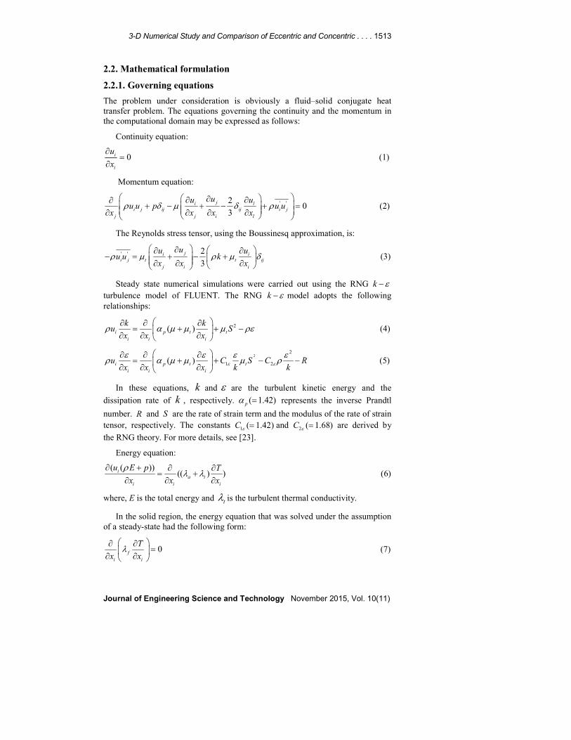
The problem under consideration is obviously a fluid–solid conjugate heat transfer problem. The equations governing the continuity and the momentum in the computational domain may be expressed as follows:
Continuity equation:
0i
i
u
x
∂=
∂ (1)
Momentum equation:
' '20
3i
i j ij ij i j
j j i l
j luu u
u u p u ux x x x
ρ δ µ δ ρ ∂∂ ∂∂ + − + − + = ∂ ∂ ∂ ∂
(2)
The Reynolds stress tensor, using the Boussinesq approximation, is:
' ' 2
3ji i
i j t t ij
j i i
uu uu u k
x x xρ µ ρ µ δ
∂ ∂ ∂− = + − + ∂ ∂ ∂
(3)
Steady state numerical simulations were carried out using the RNG k ε−turbulence model of FLUENT. The RNG k ε− model adopts the following relationships:
2( )i p t t
i i i
k ku S
x x xρ α µ µ µ ρε
∂ ∂ ∂= + + −
∂ ∂ ∂ (4)
22
1 2( )i p t t
i i i
u C S C Rx x x k k
ε ε
ε ε ε ερ α µ µ µ ρ
∂ ∂ ∂= + + − −
∂ ∂ ∂ (5)
In these equations, k and ε are the turbulent kinetic energy and the
dissipation rate of k , respectively. ( 1.42)p
α = represents the inverse Prandtl
number. R and S are the rate of strain term and the modulus of the rate of strain tensor, respectively. The constants 1 ( 1.42)C ε = and 2 ( 1.68)C ε = are derived by
the RNG theory. For more details, see [23].
Energy equation:
( ( ))(( ) )i
a t
i i i
u E p T
x x x
ρλ λ
∂ + ∂ ∂= +
∂ ∂ ∂ (6)
where, E is the total energy and tλ is the turbulent thermal conductivity.
In the solid region, the energy equation that was solved under the assumption of a steady-state had the following form:
0f
i i
T
x xλ ∂ ∂
= ∂ ∂
(7)

1514 F. Tahrour et al.
Journal of Engineering Science and Technology November 2015, Vol. 10(11)
2.2.2. Boundary conditions
The boundary conditions, shown in Fig. 2, are defined as follows:
Entry conditions: Dry air at a temperature of 298.9 K enters the computational domain with a uniform velocity (Vin) in the x-direction only. The turbulent intensity (I = 1%) and hydraulic diameter (dc) are specified.
Exit condition: The exit of the computational domain is assumed to maintain a static pressure.
Boundary conditions at the tube surface: A constant temperature of T0
=330.13 K is assigned to the tube surface and all of the velocity components are set to zero.
Boundary conditions on the fin surface: no-slip was specified at the walls. The temperatures on the fins are calculated by solving the conjugate conduction-convection of heat transfer problem (Eqs. 1–7).
The symmetry planes and the free stream plane are as shown in Fig. 2: The temperature gradients and tangential components of the velocity gradients in the normal direction are set to zero.
2.3. Numerical treatment
The GAMBIT meshing tool was used to create the geometry and generate grids. After being preformed, tests of independence between the numerical solution and the mesh (Fig. 3.), 2,100,000 hexahedral meshes were conducted for all of the cases considered.
Fig. 3. Grid Independence Test.
The governing equations (1)-(7) and their associated boundary conditions were solved using the computational fluid dynamics commercial software of FLUENT. Based on the study presented in [19], the renormalization-group (RNG) k-ε model was selected to simulate the heat transfer and fluid flow characteristics. The y+ value of the near-wall nodes is kept, in all computations, to less than 5. The iteration error was at least 10-4 on all calculations, for the energy equation at least 10-6.

3-D Numerical Study and Comparison of Eccentric and Concentric . . . . 1515
Journal of Engineering Science and Technology November 2015, Vol. 10(11)
3. Heat Transfer and Flow Characteristics
To calculate the average heat transfer coefficient ( h ) on the whole flat surfaces of the fin, we divided the fin into 36 sub-fins as shown in Fig. 4, after a grid test was carried out. Then, using the CFD simulation results, we computed the unknown heat transfer coefficient for each sub-fin.
The average heat transfer coefficient ( h ) can be expressed as: 36
1j j f
j
h h A A=
=∑ (8)
where, jh and j
A are the heat transfer coefficient and the area of the jth sub-fin,
respectively.
The temperature and the heat rate distribution on the air-side of the fin were determined using the FLUENT software, and then the heat transfer coefficient on each sub-fin region was calculated using the following expression:
( )jk jk jk k
h Q T Tb= − for k =1,2,3; j = 1,2,...,12 (9)
where, kTb is the bulk temperature of the ambient air at the inlet of the sub-fin
region k with a central angle of 60o (see Fig. 4).
(St > 0) (St < 0)
Fig. 4. Grid for the Eccentric Annular Fins.
The fin efficiency is defined by:
3 12
01 1
2 ( )f jk f k k
k j
Q A h T Tbη= =
= −∑∑ (10)
where, T0 is the outer surface temperature of the circular tube and is assumed to be the temperature of the fin base.
4. Validation of the Numerical Model
For a better appreciation of the performance and the limits of the present computational model, a quantitative comparison between the numerical inverse results based on the experimental fin temperatures obtained for the concentric annular-finned tube examined in [7] and the results from our CFD simulations

1516 F. Tahrour et al.
Journal of Engineering Science and Technology November 2015, Vol. 10(11)
was performed. For various air speeds, the average values of the heat transfer coefficients computed for the three sub-fin regions with central angles of 60o and over the whole flat surfaces of the fin are reported along with the Chen et al. numerical results [7] in Table 2.
Average heat transfer coefficient values for the turbulence models (k-ω and RNG k-ε) and Chen results [7] are given in Table 3.
Although our study was performed under the assumption of symmetry in the flow and the thermal fields, the results obtained using RNG k-ε turbulence model and those of Chen are in reasonably good agreement.
Table 2. Comparison Between the Numerical Results
for h ( W/m2K) and those of Chen et al. [7].
Vin = 5(m/s)
Tin=298.9 K
T0=330.13 K
Vin=3 (m/s)
Tin=298.15 K
T0=331.7 K
Vin=1(m/s)
Tin=298.03K
T0=330.63K
Present work [7] Present work [7] Present work [7]
h�� 107.31 102.5 106.94 116.86 22.83 24.72
h�� 86.94 98.83 48.87 45.01 30.43 35.86
h�� 30.11 24.03 9.92 9.38 4.76 3.2
h� 74.79 75.12 55.24 57.08 19.34 21.26
Table 3. Comparison of Average Heat Transfer Coefficient
for the Turbulence Models (k-ω and RNG k-ε).
Vin= 5(m/s)
Tin=298.9 K
Tin=330.13 K
Vin=3 (m/s)
Tin=298.15 K
T0=331.7 K
Vin=1(m/s)
Tin=298.03K
T0=330.63K k-ω RNG k-ε [7] k-ω RNG k-ε [7] k-ω RNG k-ε [7]
h� 67.13 74.7 75.12 50.16 55.24 57.08 16.70 19.34 21.26
5. Results and Discussions
5. 1. Flow behavior
The heat transfer on fin surfaces and the pressure drop along the direction of airflow are related to the flow configuration around it. The form and size of the horseshoe structure and the thickness of boundary layer change from its front to its rear portions. In fact, both the thickening of the boundary layer and the reverse flow behind the tube result in poor heat transfer.
For both the eccentric and the concentric annular-finned tubes, Figs. 5 and 6 depict, in the front and rear parts, the velocity and temperature in a cross section positioned mid-plane between two adjacent fins. From the initial qualitative inspection of these graphs, when comparing the different portions of these heat exchangers, there is a better convective heat transfer in the front portion because of the greater velocity and temperature gradients.

3-D Numerical Study and Comparison of Eccentric and Concentric . . . . 1517
Journal of Engineering Science and Technology November 2015, Vol. 10(11)
Fig. 5. Velocity Distribution for Fin with St = 12 mm
at a Vin of 5 m/s (Re = 9923).
The depiction of the eccentric annular-finned tubes for a Vin of 5 m/s (Re = 9923), shown in Fig. 5, illustrates the development of the velocity boundary layer between the fins and the formation of the horseshoe vortex. It is evident that, for St = 12 mm, an increased mass flow penetrates between the fins, which produces high local heat transfer coefficients between the fins and the fluid.
Figure 6 compares the isotherms for St = 0 mm and St = 12 mm. Greater temperature gradients exist in the frontal portion of the fin for the case of St = 12 mm, indicating that the highest local heat transfer coefficient occurs when using this tube shift.
The effect of the horseshoe vortex is demonstrated clearly in Fig. 6. At the fin-tube junction, for St = 12 mm, the thermal boundary layer in eccentric annular-finned tube is thinner than that of the concentric one.
St = 12 mm
St = 0 mm
Fig. 6. Temperature Distribution for Fin with St = 12 mm
at a Vin of 5 m/s (Re = 9923).

1518 F. Tahrour et al.
Journal of Engineering Science and Technology November 2015, Vol. 10(11)
Interestingly, the dissipation of the actual heat transfer rate across the wake region is much smaller than the total heat transfer rate drawn across the whole fin; therefore, as shown in Fig. 7, the small increase in the heat transfer coefficient in this region for St = 0 mm in comparison with that of St =12 mm is insignificant.
Fig. 7. Average Heat Transfer Coefficients for the Three
Sub-Fin Regions: the Frontal Region (1), the Middle Region (2) and the Rear
Region (3), for St = 0 and St =12 mm.
5.2. Influence of fin tube position
The purpose of this study was, on the one hand, to determine the best position of the tube in the circular fin, and on the other hand, to examine the influences of the fin spacing, the outer tube diameter and the Reynolds number on the performance of eccentric annular-finned tubes.
Figures 8-11 provide clear evidence of the influence of the fin tube position on heat transfer parameters and the magnitude of pressure drop. To study the effects of this geometric parameter, numerical investigations were performed for various air speeds: Vin= 3 m/s, Vin=5 m/s and Vin=7 m/s. The fin spacing and the tube diameter were varied over the ranges of 2-8 mm and 20-45 mm, respectively.
Fig. 8. Effect of Tube Shift on the
Average Heat Transfer Coefficient. Fig. 9. Effect of Tube Shift on the
Heat Transfer Rate.

3-D Numerical Study and Comparison of Eccentric and Concentric . . . . 1519
Journal of Engineering Science and Technology November 2015, Vol. 10(11)
Fig. 10. Effect of Tube Shift on the
Fin Efficiency. Fig. 11. Effect of Tube Shift on the
Pressure Drop.
Figures 8, 9 and 10 present, for a fixed fin spacing of S = 5 mm (the optimum value for the best performing eccentric annular-finned tube, see Fig. 12) and a fixed outer tube diameter of d = 27 mm, the variations in the average heat transfer
coefficient ( h ), the impact of the amount of tube shift (St) on the heat rate
dissipated by the whole fin ( Q& ) and the fin efficiency ( fη ). The values of h and
Q& increase from the front tip of the fin to a peak value at a tube shift of St = 12
mm, whereas fη decreases during this interval. Then, the thermal parameters h
and Q& decrease while fη increases slightly along the fin until reaching the rear
tip of the fin. These figures also reveal that h and Q& increase much more rapidly
for tube shifts from approximately -6 mm to 0 mm.
In most heat exchangers, the allowed pressure drop is limited. Thus, the assessments of the heat transfer in these devices are often followed by studies of the pressure drop. As shown in Fig. 11, the pressure drop increases as St increases from -10 to 0 mm. Then, for the tube positions in the rear portion of the fin, the pressure drop decreases with an increase in the tube shift until St (10 14 mm)∈ − , after that,
the pressure drop again increases. Hence, for St (0 10 mm)∈ − , the heat transfer is
enhanced with the decrease in the pressure drop, unlike the majority of heat exchangers. This is due to the reduction of the recirculation zone behind the tube.
Notably, from the quantitative analysis, the average heat transfer coefficient and the heat transfer rate attain their maximum values at the optimum tube shift of St = 12 mm. In comparison with the performance of the concentric annular-finned tube heat exchanger, for the same fins ( as shown in Figs. 8, 9 and 11), the average heat transfer coefficient and the heat transfer rate for the eccentric annular-finned tube, which range from 5.43% (when Re = 12939) to 14.34 % (when Re = 5954) and from 3.43% (when Re = 13892) to 9.34 %(when Re = 5954), are higher than the ranges for the concentric annular-finned tube, while the pressure drop of the former, which ranges from 7.86% (when Re = 13892) to 88.06% (when Re = 5954), is lower than that of the latter (see Fig. 11).

1520 F. Tahrour et al.
Journal of Engineering Science and Technology November 2015, Vol. 10(11)
These results indicate that the gain in heat transfer increases with a decrease in the Reynolds number. Therefore, we suggest that it is best to use an eccentric annular-finned tube in heat exchangers at low Reynolds numbers.
5. 3. Influence of fin spacing
To investigate the effect of fin spacing, numerical simulations were performed for the same flow conditions and fin geometrical configuration as described in the previous section. However, the tube shift and the outer tube diameter were fixed at 12 and 27 mm, respectively, and the fin spacing was varied from 2 to 8 mm in increments of 1 mm. The predicted average heat transfer coefficients and pressure drop are illustrated in Figs. 12 and 13. For the three cases, when the Reynolds numbers were 5954, 9242 and 13892, h increased with an increase in S until reaching a maximum value at S = 5 mm. Then, for 5 mmS ≥ , the values of h remained relatively constant because the fin spacing sufficiently exceeded the boundary layer thickness at the base of the fin (see Fig. 6b). This result is qualitatively supported by the results of Mon and Gross [14] and several other experimental studies, including Watel et al. [22] among others. These authors reported that, if the fin spacing exceeds approximately twice the boundary layer thickness at the base of the fin, the influence of the fin spacing on the heat transfer coefficient is negligible. On the other hand, the results presented in Fig. 12 reveal similar trend to those obtained from heat exchangers with concentric circular fins that were examined in [7, 14].
Fig. 12. Effect of Fin Spacing on
the Average Heat Transfer
Coefficient, for St =12 mm.
Fig. 13. Effect of Fin Spacing on the
Pressure Drop, for St =12 mm.
A comparison of the heat transfer rate between eccentric and concentric annular-finned tubes exposed to the same conditions is presented in Table 4. The results show that the average heat transfer coefficient and the heat transfer rate of the eccentric heat exchanger are greater than those of the concentric heat exchanger for values of 5 mmS ≤ . Therefore, the use of the eccentric configuration is recommended in compact heat exchangers, especially if the manufacturing process is similar and thus, the cost is comparable.

3-D Numerical Study and Comparison of Eccentric and Concentric . . . . 1521
Journal of Engineering Science and Technology November 2015, Vol. 10(11)
Table 4. Comparison of the Heat Transfer Rate, Q& (W),
between Eccentric with St =12 mm and Concentric Annular-Finned Tubes.
&Q(w) S = 2 mm S = 3 mm S = 5 mm
St =0 St =12 St =0 St =12 St =0 St =12
Vin=5(m/s) 4.62 7.1 5.15 7.67 9.04 12.56
Vin=7 (m/s) 5.33 7.94 6.23 10.43 12.08 14.8
The effect of fin spacing on the pressure drop is presented in Fig. 13. For Reynolds numbers of 5950 Re 13900≤ ≤ , the pressure drop decreases as the fin spacing increases. As expected, the results shown in Fig. 13 demonstrate that, the pressure drop increases with an increase in Reynolds number at fixed fin spacing.
For larger fin spacings, greater than approximately S = 5 mm, the fin spacing has only a small effect on the pressure drop at the three Reynolds numbers examined. These results are in good qualitative agreement with those of Mon et al. and Bilirgen et al. [14, 15].
5. 4. Influence of the outside diameter of the tube
To examine the influence of the tube outside diameter on the heat transfer and pressure drop, the geometrical parameters examined were: tf = 1 mm, S =5 mm, St= 12 mm, df = 99 mm, and d was varied from 20 to 45 mm. The results for air speeds of 3, 5 and 7 m/s were calculated.
Figure 14 shows that the average heat transfer coefficient increases as the tube diameter increases. This coefficient increases significantly as d increases from 20 mm to 27 mm. The same observation was reported for larger fin heights in [15], and the smaller tube diameters that correspond to greater fin heights lead to an increase in the fin surface area. Consequently, the heat transfer coefficient is lower because it does not account for the total surface area available for heat transfer. It is also apparent from the results shown in Figs. 14 and 15 that the convective heat transfer coefficient and the pressure drop decrease as the tube diameter increases for a given Reynolds number. This effect is due to a decrease in velocity.
Fig. 14. Effect of Tube Diameter
on the Average Heat Transfer
Coefficient, for St =12 mm.
Fig. 15. Effect of the Outside
Diameter of the Tube on the Pressure
Drop, for St =12 mm.

1522 F. Tahrour et al.
Journal of Engineering Science and Technology November 2015, Vol. 10(11)
5.5. Influence of Reynolds number
As expected, and in line with the findings of [7, 14, 16], the results presented in Figs. 8, 9, 10 and 11 demonstrate that, for all of tube shifts examined, the average heat transfer coefficient, the heat rate dissipated by the fin and the pressure drop increase as Reynolds number increases, but the efficiency of the fin decreases. For St = 0 mm and S = 5 mm, the values of fη ( fη = 28% when Vin= 3 m/s and
fη = 25% when Vin= 5 m/s; Fig. 10) are similar to the values given in [7]. These
values decrease for St = 12 mm, when fη = 24% for a Vin= 3 m/s and fη = 22 %
for a Vin= 5 m/s.
Figures 12 and 13 show that the heat transfer coefficient and the pressure drop increase with Reynolds number for all fin spacings. These numerical simulation results follow the same trend as that described in [14].
Figures 8, 12 and 14 clearly illustrate the uniformity of the variation in the heat transfer coefficient for various Reynolds numbers at all tube shifts, all fin spacings and all tube diameters. These results indicate that we can obtain a correlation between the Nusselt number and fin efficiency based on St, d, S and Re.
6. Conclusion
In this paper, an eccentric annular-finned tube heat exchanger was proposed. We focused our attention on the effect of the tube shift on the thermal and flow characteristics of this heat exchanger. A comparative study of this model's performance and that of a concentric annular-finned tube was performed. From the examination of the parameters considered, the following conclusions may be drawn:
• Simulations results allowed us to find the tube position in the circular fin that provided the optimal thermo-hydraulic performance. Contrary to the majority of heat exchangers, this position produces a significant improvement in heat transfer parameters with a distinct decrease in the pressure drop.
• The eccentric annular finned tube is more efficient for small fin spacings. Therefore, it is more appropriate for use in compact heat exchangers, especially if its production cost is comparable to that of the concentric heat exchanger.
• Similarly to a concentric annular-finned tube:
o The average heat transfer coefficient and the heat transfer rate increase with an increase in the Reynolds number, but the fin efficiency decreases.
o An increase in tube diameter results in an increase in both the heat transfer and the pressure drop.
o The average heat transfer coefficient increases with an increase in fin spacing up to a maximum value at S = 5 mm (for the studied case), and then it remains constant.
• A uniform variation in the heat transfer coefficient for various Reynolds numbers was observed for all tube shifts, fin spacings and tube diameters. These results suggest that we can obtain correlations of the Nusselt number based on St, d, S and Re.

3-D Numerical Study and Comparison of Eccentric and Concentric . . . . 1523
Journal of Engineering Science and Technology November 2015, Vol. 10(11)
References
1. Neal, S.B.; and Hitchcock, J.A. (1966). A study of the heat transfer processes in banks of finned tubes in cross flow using a large scale model technique. Proceeding of 3rd International Heat Transfer Conference. Chicago (1966) 290-298.
2. Sung, H.J.; Yang, J.S.; and Park, T.S. (1996). Local convective mass transfer on annular cylinder with transverse annular fins in cross flow. International
Journal Heat Mass Transfer, 39, 1093-1101.
3. Erec, A.; Õzerdem, B.; Bilir, L.; and Ilken, Z. (2005). Effect of geometrical parameters on heat transfer and pressure drop characteristics of plate fin and tube heat exchangers. Applied Thermal Engineering, 25, 2421-2431.
4. Tao, Y.B.; He, Y.L.; Huang, J.; Wu, Z.G.; and Tao, W.Q. (2007). Three-dimensional numerical study of wavy fin-and-tube heat exchangers and field synergy principle analysis. International Journal of Heat and Mass Transfer, 50, 1163-1175.
5. Pongsoi, P.; Promoppatum, P.; Pikulkajorn, S.; and Wongwises, S. (2013). Effect of fin pitches on the air-side performance of L-footed spiral fin-and-tube heat exchangers. International Journal of Heat and Mass Transfer, 59, 75-82.
6. Chen, H.T.; and Hsu, W.L. (2007). Estimation of heat transfer coefficient on the fin of annular-finned-tube heat exchangers in natural convection for various fin spacings. International Journal of Heat and Mass Transfer, 50, 1750-1761.
7. Chen, H.T.; and Hsu, W.L. (2008). Estimation of heat transfer characteristics on a vertical annular circular fin of finned-tube heat exchangers in forced convection. International Journal of Heat and Mass Transfer, 51, 1920-1932.
8. Karaback, R. (1992). The effect of fin parameter on the radiation and free convection from a finned horizontal cylindrical heater. Energy Conversion and
Management, 33(11), 997-1005.
9. Yildiz, S.; and Yüncü, H. (2004). An experimental investigation on performance of annular fins on a horizontal cylinder in free convection heat transfer. Heat Mass Transfer, 40, 239-251.
10. Mokheimer, E.M.A. (2002). Performance of annular fins with different profiles subject to variable heat transfer coefficient. International Journal of
Heat and Mass Transfer, 45, 3631-3642.
11. Aziz, A.; and Khani, F. (2010). Analytic solutions for a rotating radial fin of rectangular and various convex parabolic profiles. Communications in
Nonlinear Science and Numerical Simulations, 15, 1565-1574.
12. Lee, D.H.; Jung, J.M.; Ha, J.H.; and Cho, Y.I. (2012). Improvement of heat transfer with perforated circular holes in finned tubes of air-cooled heat exchanger. International Communications in Heat and Mass Transfer, 39, 161-166.
13. Banerjee, R.K.; Karve, M.; Ha, J.H.; Lee, D.H.; and Cho, Y.I. (2012). Evaluation of enhanced heat transfer within a four row finned tube array of an air cooled steam condenser. Numerical Heat Transfer, Part A 61, 735-753.
14. Mon, M.S.; and Gross, U. (2004). Numerical study of fin-spacing effects in annular-finned tube heat exchangers. International Journal of Heat and Mass
Transfer, 47, 1953-1964.

1524 F. Tahrour et al.
Journal of Engineering Science and Technology November 2015, Vol. 10(11)
15. Bilirgen, H.; Dunbar, S.; and Levy, E.K. (2013). Numerical modeling of finned heat exchangers. Applied Thermal Engineering, 61, 278-288.
16. Benmachiche, A.H.; Bougriou, C.; and Abboudi, S. (2010). Inverse determination of the heat transfer characteristics on a circular plane fin in a finned-tube bundle. Heat Mass Transfer, 46, 1367-1377.
17. Kundu, B.; and Das, P.K. (1999). Performance analysis of eccentric annular fins with a variable base temperature. Numerical Heat Transfer, Part A 36, 751-766.
18. Kundu, B.; and Das, P.K. (1999). Performance analysis and optimization of eccentric annular disk fins. Journal Heat Transfer, 121, 128-135.
19. Mon, M.S. (2003). Numerical investigation of air-side heat transfer and
pressure drop in circular finned-tube heat exchangers. Ph.D., Dissertation, Von der Fakultät für Maschinenbau, Verfahrens- und Energietechnik der Technischen Universität Bergakademie Freiberg, Germany.
20. Xie, G.; Wang, Q.; and Sunden, B. (2009). Parametric study and multiple correlations on air-side heat transfer and friction characteristics of fin-and-tube heat exchangers with large number of large-diameter tube rows. Applied
Thermal Engineering, 29, 1-16.
21. He, Y.L.; Tao, W.Q.; Song, F.Q.; and Zhang, W. (2005). Three-dimensional numerical study of heat transfer characteristics of plain plate fin-and-tube heat exchangers from view point of field synergy principle. International Journal of
Heat and Fluid Flow, 26, 459-473.
22. Watel, B.; Harmand, S.; and Desmet, B. (1999). Influence of flow velocity and fin spacing on the forced convective heat transfer from an annular-finned tube. JSME International Journal, Ser. B 42, 56-64.
23. FLUENT Incorporated, (2006). FLUENT 6.2 User’s Manual, Fluent Incorporated Lebanon, NH-USA.