3-D Holographic Display Using Strontium Barium Niobate · The read beam, which is generated from...
22
by Christy A. Heid, Brian P. Ketchel, Gary L. Wood, Richard J. Anderson, and Gregory J. Salamo 3-D Holographic Display Using Strontium Barium Niobate ARL-TR-1520 February 1998 Approved for public release; distribution unlimited.
Transcript of 3-D Holographic Display Using Strontium Barium Niobate · The read beam, which is generated from...
by Christy A. Heid, Brian P. Ketchel, Gary L. Wood,Richard J. Anderson, and Gregory J. Salamo
3-D Holographic Display UsingStrontium Barium Niobate
ARL-TR-1520 February 1998
Approved for public release; distribution unlimited.

The findings in this report are not to be construed as an official Department ofthe Army position unless so designated by other authorized documents.
Citation of manufacturer’s or trade names does not constitute an officialendorsement or approval of the use thereof.
Destroy this report when it is no longer needed. Do not return it to the originator.
Army Research LaboratoryAdelphi, MD 20783-1197
ARL-TR-1520 February 1998
3-D Holographic Display UsingStrontium Barium NiobateChristy A. Heid, Brian P. Ketchel, Gary L. WoodSensors and Electron Devices Directorate, ARL
Richard J. AndersonNational Science Foundation
Gregory J. SalamoUniversity of Arkansas
Approved for public release; distribution unlimited.

AbstractAn innovative technique for generating a three-dimensional holographicdisplay using strontium barium niobate (SBN) is discussed. The resultantimage is a hologram that can be viewed in real time over a wide perspectiveor field of view (FOV). The holographic image is free from system-inducedaberrations and has a uniform, high quality over the entire FOV. Theenhanced image quality results from using a phase-conjugate read beamgenerated from a second photorefractive crystal acting as a double-pumpedphase-conjugate mirror (DPPCM). Multiple three-dimensional images havebeen stored in the crystal via wavelength multiplexing.
ii

3iii
Contents
1. Introduction .......................................................................................................................... 1
2. Theory .................................................................................................................................... 2
3. Experimental Setup ............................................................................................................. 53.1 Holographic Display ...................................................................................................................... 63.2 Image Storage ................................................................................................................................. 9
4. Conclusions ......................................................................................................................... 11
Acknowledgements ................................................................................................................. 11
References ................................................................................................................................. 12
Distribution .............................................................................................................................. 13
Report Documentation Page .................................................................................................. 17
Figures
1. Dynamic holography in photorefractive crystals via four-wave mixing .................................... 22. Experimental setup used to record and reconstruct a 3-D hologram using SBN ...................... 53. 3-D hologram stored in a Ce-doped SBN:60 photorefractive crystal and viewed at various
angles with an FOV of ~14° ............................................................................................................... 74. Method of measuring expected FOV for recording a hologram in a crystal of
length Lc .................................................................................................................................................................................... 75. Hologram stored in a mosaic of two Ce-doped SBN:60 photorefractive crystals with an FOV
of ~30° ................................................................................................................................................... 8
Tables
1. Relative powers of writing and reading beams used to study wavelength multiplexing inSBN ........................................................................................................................................................ 9

1
1. IntroductionPresent holographic displays, such as those generated by computers oremulsion films, usually require intermediate preprocessing or post-processing and are, therefore, not capable of real-time production andviewing and have limited information storage capacity. The use of photo-refractive crystals, such as strontium barium niobate (SBN), as a holo-graphic storage medium eliminates these and other limiting factors. Forexample, when a photorefractive storage medium is used, holograms maybe recorded and projected without time-consuming processing and withgreater storage capacity through various forms of multiplexing. Addition-ally, the photorefractive recording medium is sensitive to low level inten-sity and is reusable. Therefore, previously stored holograms may beerased, and the crystal can be reused to store other holograms. Until re-cently, however, research in photorefractive holography has been limitedto the production of two-dimensional (2-D) holograms and very limitedfield-of-view (FOV) 3-D holograms.
The proposed method employs a volume hologram recorded and read inreal time in a photorefractive crystal to produce a 3-D image. This innova-tive technique is simple, and it differs from previous attempts at 3-D dis-plays. We used a photorefractive material, SBN, to record a hologram, anda phase-conjugate read beam, which is generated from a double-pumpedphase-conjugate mirror (DPPCM), to accurately reproduce the holographicimage in space over a large perspective. The resultant holographic image isfree from system-induced aberrations, may be viewed over a wide range ofangles that can be expanded by the use of a mosaic of crystals, and has uni-form high quality over the entire FOV.
2
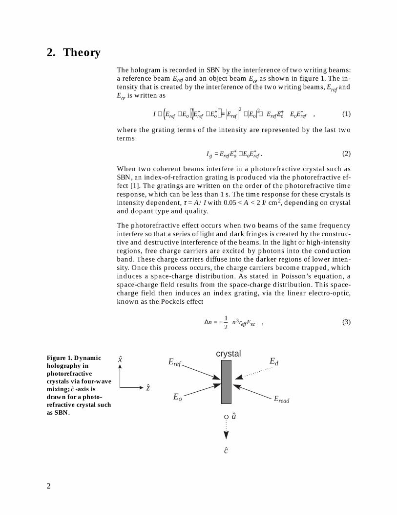
2. TheoryThe hologram is recorded in SBN by the interference of two writing beams:a reference beam Eref and an object beam Eo, as shown in figure 1. The in-tensity that is created by the interference of the two writing beams, Eref andEo, is written as
I E E E E E E E E E Eref o ref o ref o ref o o ref∝ +( ) +( ) = + + +* * * * ,
2 2 (1)
where the grating terms of the intensity are represented by the last twoterms
I E E E Eg ref o o ref= +* * . (2)
When two coherent beams interfere in a photorefractive crystal such asSBN, an index-of-refraction grating is produced via the photorefractive ef-fect [1]. The gratings are written on the order of the photorefractive timeresponse, which can be less than 1 s. The time response for these crystals isintensity dependent, τ = A/I with 0.05 < A < 2 J/cm2, depending on crystaland dopant type and quality.
The photorefractive effect occurs when two beams of the same frequencyinterfere so that a series of light and dark fringes is created by the construc-tive and destructive interference of the beams. In the light or high-intensityregions, free charge carriers are excited by photons into the conductionband. These charge carriers diffuse into the darker regions of lower inten-sity. Once this process occurs, the charge carriers become trapped, whichinduces a space-charge distribution. As stated in Poisson’s equation, aspace-charge field results from the space-charge distribution. This space-charge field then induces an index grating, via the linear electro-optic,known as the Pockels effect
∆n n r Eeff sc= − 1
23 , (3)
Figure 1. Dynamicholography inphotorefractivecrystals via four-wavemixing; c -axis isdrawn for a photo-refractive crystal suchas SBN. a
c
z
xcrystal
Eref
Eo
Ed
Eread

3
where n is the index of refraction, reff is the effective electro-optic coeffi-cient, and Esc is the strength of the space-charge field.
With no applied or photovoltaic electric field, the index-of-refraction grat-ing is phase shifted by 90° from the intensity grating, which leads to en-ergy exchange between the two beams. Energy exchange leads to signifi-cant beam fanning if there is sufficient interaction length in the crystal.Beam fanning is undesirable for the holographic storage crystal because itwill degrade the hologram. Therefore, the crystal used in this study, SBNdoped with cerium, had a length of ~1 mm, which is less than the criticalinteraction length.
The hologram is read by the introduction of a third beam Eread, which iscounter-propagating to the reference beam as shown in figure 1. The readbeam is diffracted off the index grating, which has been previously re-corded in the photorefractive material. This process produces the dif-fracted wave Ed, and is written as
E E I E E E E E E E E E E Ed read g read ref o o ref ref o read o ref read∝ = +( ) = +* * * * , (4)
where Ig is defined in equation (2). The first term on the right-hand side ofthe equation, E E Eref o read
* , represents a beam that is diffracted off the indexgrating, counter-propagating to the object beam, with wave vector
k kd o1= − .
The second term, E E Eo ref read* , represents a beam propagating with wave
vector kd2 = ko – 2kref. Only the first-order wave kd1 will be Bragg-matched[2], because we are in the thick or volume grating regime. We are in thethick (volume) grating regime because the following inequality is satisfied:
2πλd » nΛ2 , (5)
where λ is the wavelength in free space, d is the grating thickness, n is theaverage index of refraction, and L is the grating period.
There are several advantages to using volume holograms over those re-corded in the thin grating regime. First, the diffraction efficiency of volumegratings is significantly greater than what is offered by thin gratings be-cause a volume grating has fewer diffracted orders. Thus, only a singlebeam is diffracted from the grating, which eliminates the appearance ofghost images due to higher order diffraction. Second, there is less angularspread in the diffracted beam as compared to the beam from a thin grating.This feature allows numerous holograms to be written and read in thesame crystal, because the Bragg angle is used to selectively store and readthe images. Finally, only light that is incident at the narrow Bragg anglecan be diffracted by these gratings, which minimizes crosstalk during vol-ume readout.
A simple method of reading the hologram involves using the reflection ofthe reference beam from a plane mirror. The generated diffracted beam iswritten as follows, where equation (4) is used for a volume grating:

4
E E E E rA e Ed o ref read readik x
ox∝ =* * ,2 2 (6)
where E rEread ref= , E Aeik x ik zx z= + (such that the beam is propagating in the x - z plane with wave vector k and amplitude A), and r is the reflection co-
efficient of the plane mirror.
The image-bearing beam Ed contains a spatially dependent term becausethe read beam is only truly phase-matched on axis. Thus, the maximumFOV of the hologram is severely restricted as the read beam diverges. Thisproblem can be remedied by careful collimation of the read beam and ref-erence beam; however, this is a cumbersome task. It is much easier to usethe laws of nonlinear optics and use a read beam that is naturally self-aligning, such as a phase-conjugate read beam. Since the phase-conjugatebeam is exactly counter-propagating to the reference beam, it would notmatter if the reference beam is diverging because the read beam will re-trace its path precisely, and read all the written gratings over the entirebeam width. The read beam, which is generated from the phase conjugateof the reference beam, is written as follows, where equation (4) is used fora volume grating:
E E E E qE E qI E I I Ed o ref read ref o ref o ref read o∝ = ∝ =* * * * ,
2(7)
where E qEread ref= * and q is the phase-conjugate reflectivity.
The divergence of the read beam from a plane mirror, evident in equation(6), is not present when a phase-conjugate read beam is used, as shown inequation (7). Furthermore, phase conjugation is a process in which thephase aberrations of an optical system are removed without beam manipu-lation. The use of a phase-conjugate read beam also has added benefitssuch as higher resolution, a larger FOV, and a simpler, more robust holo-graphic production [3].
Phase conjugation at low beam powers can be obtained by the use ofphotorefractive crystals [4] and generated by four-wave mixing geometries[5]. One method, which uses the internal reflection of one beam within thecrystal, is called self-pumped phase conjugation. The self-pumped, phase-conjugate mirror offers reflectivities in the range of 0 ≤ q ≤ 1. However,reflectivities greater than 1 can be achieved by the use of a DPPCM. Weused the photorefractive crystal SBN doped with cerium as a DPPCM. Thebridge-conjugator geometry was used to generate the phase-conjugateread beam because a large gain in SBN is easier to achieve [6]. In the bridgeconjugator geometry, the reference and pump beams are incident on oppo-site faces of a photorefractive crystal, which are parallel to the ̂c -axis. Sincethe pump beam does not have to be mutually coherent with the referencebeam, the pump beam can be generated from the original laser or a secondlaser operating at the same wavelength. Actually, the DPPCM is more effi-cient when the beams are not coherent.
5
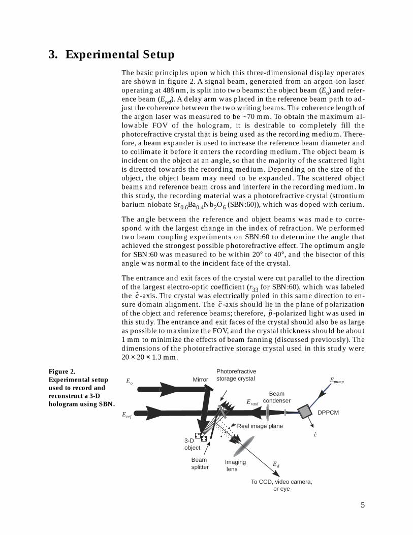
3. Experimental SetupThe basic principles upon which this three-dimensional display operatesare shown in figure 2. A signal beam, generated from an argon-ion laseroperating at 488 nm, is split into two beams: the object beam (Eo) and refer-ence beam (Eref). A delay arm was placed in the reference beam path to ad-just the coherence between the two writing beams. The coherence length ofthe argon laser was measured to be ~70 mm. To obtain the maximum al-lowable FOV of the hologram, it is desirable to completely fill thephotorefractive crystal that is being used as the recording medium. There-fore, a beam expander is used to increase the reference beam diameter andto collimate it before it enters the recording medium. The object beam isincident on the object at an angle, so that the majority of the scattered lightis directed towards the recording medium. Depending on the size of theobject, the object beam may need to be expanded. The scattered objectbeams and reference beam cross and interfere in the recording medium. Inthis study, the recording material was a photorefractive crystal (strontiumbarium niobate Sr0.6Ba0.4Nb2O6 (SBN:60)), which was doped with cerium.
The angle between the reference and object beams was made to corre-spond with the largest change in the index of refraction. We performedtwo beam coupling experiments on SBN:60 to determine the angle thatachieved the strongest possible photorefractive effect. The optimum anglefor SBN:60 was measured to be within 20° to 40°, and the bisector of thisangle was normal to the incident face of the crystal.
The entrance and exit faces of the crystal were cut parallel to the directionof the largest electro-optic coefficient (r33 for SBN:60), which was labeledthe ̂c -axis. The crystal was electrically poled in this same direction to en-sure domain alignment. The ̂c -axis should lie in the plane of polarizationof the object and reference beams; therefore, ̂p -polarized light was used inthis study. The entrance and exit faces of the crystal should also be as largeas possible to maximize the FOV, and the crystal thickness should be about1 mm to minimize the effects of beam fanning (discussed previously). Thedimensions of the photorefractive storage crystal used in this study were20 × 20 × 1.3 mm.
DPPCM
Photorefractivestorage crystal
c
Ere f
Eread
EoMirror
Beam splitter Ed
Real image plane
Imaginglens
3-Dobject
Epump
To CCD, video camera,or eye
Beamcondenser
Figure 2.Experimental setupused to record andreconstruct a 3-Dhologram using SBN.

6
The hologram recording process occurs wherever the reference beam andscattered object beams intersect in the crystal volume. As long as thesebeams are mutually coherent and the photorefractive material has suffi-cient response, interference will occur, which will result in an intensitymodulation. These interference gratings transform into index-of-refractiongratings via the photorefractive effect that was discussed previously. Theobject is recorded as a conglomeration of index gratings in the crystal vol-ume, which is referred to as a volume hologram.
After the reference beam transmits through the storage crystal, it is inci-dent upon a second photorefractive crystal that is used as a DPPCM. TheDPPCM crystal, which is used to obtain the necessary phase-conjugateread beam, has parameters identical to the storage crystal except for thedimensions. In our experiment, the DPPCM SBN:60 crystal is 6 mm long,which provides a sufficient path length for significant beam fanning. Sincethe reference beam may be too large in diameter to enter the DPPCM crys-tal cleanly, a beam condenser is used. The beam condenser ensures that thedesired beam size is achieved at the entrance face of the crystal. TheDPPCM crystal is oriented so that the reference beam (Eref) and a secondpump beam (Epump) enter opposite faces of the crystal with wave vectorcomponents in the + ̂c -direction. The pump beam, which was ̂p -polarized,originated from a second argon-ion laser, which was operating at 488 nm.
The read beam (Eread) will exactly retrace the original beam’s path from theDPPCM crystal—through any lenses—to the storage crystal. The readbeam is counter-propagating to the reference beam in the storage crystal.Consequently, the read beam is perfectly Bragg-matched to the hologram’sgratings at all points in the crystal. The exact match ensures that all grat-ings or holograms are read and allows the maximum perspective (FOV) ofthe image for the size of the storage material. Since the read beam is aphase conjugate, any inhomogeneities or phase-distorting properties of theoptical elements between the DPPCM crystal and the hologram will cancelout. The Bragg-matched read beam will diffract off these gratings and re-trace the path of the scattered object beam. The diffracted beam from thestorage crystal is separated from the object beam by a beam splitter with anantireflection coating that is placed between the object and storage crystal.This process forms the three-dimensional hologram of the object as shownin figure 2.
3.1 Holographic Display
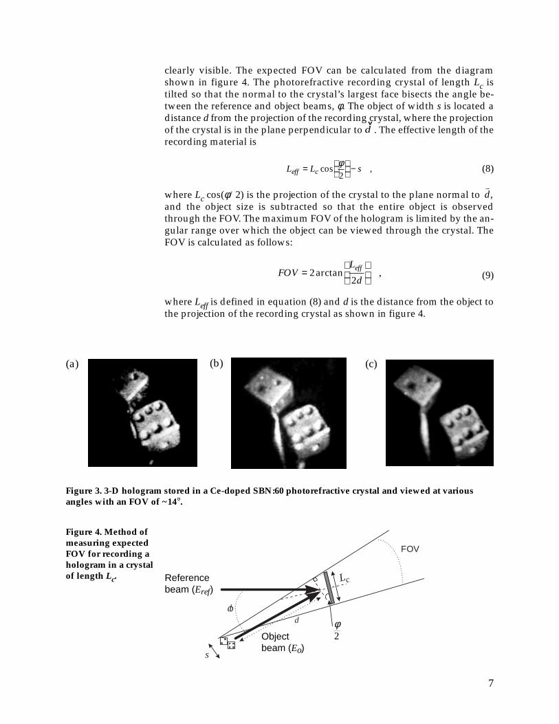
The three-dimensional hologram is a real image of the object and can bedisplayed in free space. The image can be viewed by projection, via lensrelays, directly into the eye or a camera. Figure 3 shows the hologram oftwo dice earrings recorded in the SBN:60 photorefractive crystal. The dicehave dimensions of 2 mm on a side. We verified the third dimension of theimage by viewing the hologram at different perspectives, which demon-strated parallax when we rotated the viewing angle by placing the cameraon a pivot arm. The FOV of the hologram (fig. 3) was measured to be ~14°.We determined the FOV by the angular range in which the hologram was
7
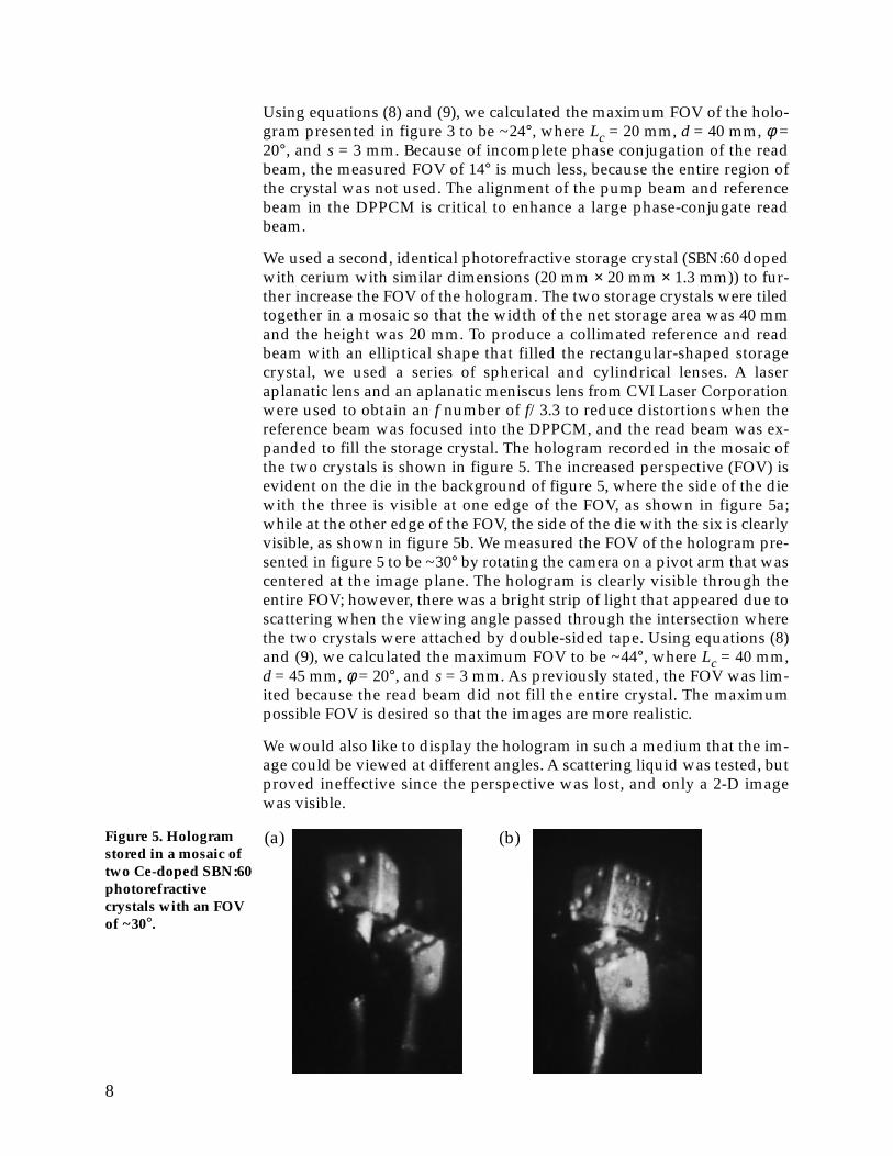
clearly visible. The expected FOV can be calculated from the diagramshown in figure 4. The photorefractive recording crystal of length Lc istilted so that the normal to the crystal’s largest face bisects the angle be-tween the reference and object beams, φ. The object of width s is located adistance d from the projection of the recording crystal, where the projectionof the crystal is in the plane perpendicular to
vd . The effective length of the
recording material is
L L seff c=
−cos ,
φ2
(8)
where Lc cos(φ/2) is the projection of the crystal to the plane normal to vd,
and the object size is subtracted so that the entire object is observedthrough the FOV. The maximum FOV of the hologram is limited by the an-gular range over which the object can be viewed through the crystal. TheFOV is calculated as follows:
FOV
L
deff=
22
arctan , (9)
where Leff is defined in equation (8) and d is the distance from the object tothe projection of the recording crystal as shown in figure 4.
Lc
s
d
FOV
φ
Referencebeam (Eref)
Objectbeam (Eo)
Figure 4. Method ofmeasuring expectedFOV for recording ahologram in a crystalof length Lc.
(c)
Figure 3. 3-D hologram stored in a Ce-doped SBN:60 photorefractive crystal and viewed at variousangles with an FOV of ~14°.
(a) (b)
φ2
8
Using equations (8) and (9), we calculated the maximum FOV of the holo-gram presented in figure 3 to be ~24°, where Lc = 20 mm, d = 40 mm, φ =20°, and s = 3 mm. Because of incomplete phase conjugation of the readbeam, the measured FOV of 14° is much less, because the entire region ofthe crystal was not used. The alignment of the pump beam and referencebeam in the DPPCM is critical to enhance a large phase-conjugate readbeam.
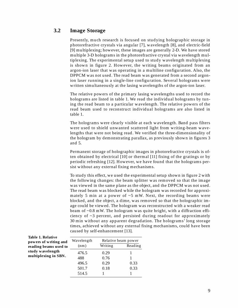
We used a second, identical photorefractive storage crystal (SBN:60 dopedwith cerium with similar dimensions (20 mm × 20 mm × 1.3 mm)) to fur-ther increase the FOV of the hologram. The two storage crystals were tiledtogether in a mosaic so that the width of the net storage area was 40 mmand the height was 20 mm. To produce a collimated reference and readbeam with an elliptical shape that filled the rectangular-shaped storagecrystal, we used a series of spherical and cylindrical lenses. A laseraplanatic lens and an aplanatic meniscus lens from CVI Laser Corporationwere used to obtain an f number of f/3.3 to reduce distortions when thereference beam was focused into the DPPCM, and the read beam was ex-panded to fill the storage crystal. The hologram recorded in the mosaic ofthe two crystals is shown in figure 5. The increased perspective (FOV) isevident on the die in the background of figure 5, where the side of the diewith the three is visible at one edge of the FOV, as shown in figure 5a;while at the other edge of the FOV, the side of the die with the six is clearlyvisible, as shown in figure 5b. We measured the FOV of the hologram pre-sented in figure 5 to be ~30° by rotating the camera on a pivot arm that wascentered at the image plane. The hologram is clearly visible through theentire FOV; however, there was a bright strip of light that appeared due toscattering when the viewing angle passed through the intersection wherethe two crystals were attached by double-sided tape. Using equations (8)and (9), we calculated the maximum FOV to be ~44°, where Lc = 40 mm,d = 45 mm, φ = 20°, and s = 3 mm. As previously stated, the FOV was lim-ited because the read beam did not fill the entire crystal. The maximumpossible FOV is desired so that the images are more realistic.
We would also like to display the hologram in such a medium that the im-age could be viewed at different angles. A scattering liquid was tested, butproved ineffective since the perspective was lost, and only a 2-D imagewas visible.
Figure 5. Hologramstored in a mosaic oftwo Ce-doped SBN:60photorefractivecrystals with an FOVof ~30°.
(a) (b)
9
3.2 Image Storage
Presently, much research is focused on studying holographic storage inphotorefractive crystals via angular [7], wavelength [8], and electric-field[9] multiplexing; however, these images are generally 2-D. We have storedmultiple 3-D holograms in the photorefractive crystal via wavelength mul-tiplexing. The experimental setup used to study wavelength multiplexingis shown in figure 2. However, the writing beams originated from anargon-ion laser that was operating in a multiline configuration. Also, theDPPCM was not used. The read beam was generated from a second argon-ion laser running in a single-line configuration. Several holograms werewritten simultaneously at the lasing wavelengths of the argon-ion laser.
The relative powers of the primary lasing wavelengths used to record theholograms are listed in table 1. We read the individual holograms by tun-ing the read beam to a particular wavelength. The relative powers of theread beam used to reconstruct individual holograms are also listed intable 1.
The holograms were clearly visible at each wavelength. Band pass filterswere used to shield unwanted scattered light from writing-beam wave-lengths that were not being read. We verified the three-dimensionality ofthe hologram by demonstrating parallax, as previously shown in figures 3and 5.
Permanent storage of holographic images in photorefractive crystals is of-ten obtained by electrical [10] or thermal [11] fixing of the gratings or byperiodic refreshing [12]. However, we have found that the holograms per-sist without any external fixing mechanisms.
To study this effect, we used the experimental setup shown in figure 2 withthe following changes: the beam splitter was removed so that the imagewas viewed in the same plane as the object, and the DPPCM was not used.The read beam was blocked while the hologram was recorded for approxi-mately 5 min at a power of ~5 mW. Next, the recording beams wereblocked, and the object, a dime, was removed so that the holographic im-age could be viewed. The hologram was reconstructed with a weaker readbeam of ~0.8 mW. The hologram was quite bright, with a diffraction effi-ciency of ~3 percent, and persisted during readout for approximately30 min without any apparent degradation. The holograms’ long storagetimes, achieved without any external fixing mechanisms, could have beencaused by self-enhancement [13].
Wavelength Relative beam power(nm) Writing Reading
476.5 0.29 1488 0.76 1496.5 0.29 0.33501.7 0.18 0.33514.5 1 1
Table 1. Relativepowers of writing andreading beams used tostudy wavelengthmultiplexing in SBN.

10
A hologram was also recorded in a photorefractive storage crystal for~5 min; then, it was placed in a sealed, dark box for three days. The holo-gram was reconstructed after three days with a read beam of ~1.7 mW, andthe hologram was still quite bright. Since external light will slowly erasethe grating in the crystal, we turned off the room lights during thesemeasurements.
11
4. ConclusionsA simple method for recording a real-time, 3-D hologram using SBN hasbeen demonstrated. The 3-D hologram is a realistic image that can beviewed over a large FOV. A DPPCM was used to produce a phase-conjugate read beam in order to view the hologram over the maximumperspective (FOV). We further increased the FOV of the hologram by stor-ing the hologram in a mosaic of two SBN crystals. Multiple 3-D imageshave been stored and read out of the crystal via wavelength multiplexing.The holograms were also noted to persist without any external fixingmechanisms. During readout, the holograms persisted for hours. When thephotorefractive storage crystal was kept in a dark environment, the holo-grams persisted for days.
AcknowledgementsThe principal author is on a fellowship appointment from the AmericanSociety for Engineering Education, Washington, DC, for the U.S. Army Re-search Laboratory. The authors wish to thank R. R. Neurgaonkar fromRockwell International Science Center, Thousand Oaks, CA, for supplyingthe photorefractive crystals.

12
References1. R. W. Boyd, Nonlinear Optics, Academic Press, San Diego (1992), ch 10.
2. H. Kogelnik, “Coupled wave theory for thick hologram gratings,” BellSyst. Tech. J. 48, No. 9 (November 1969), 2909–2947.
3. B. P. Ketchel, G. L. Wood, R. J. Anderson, and G. J. Salamo, “Three-dimensional image reconstruction using strontium barium niobate,” Appl.Phys. Lett. 71, No. 27 (2–4 July 1997).
4. P. Gunter, “Holography, coherent light amplification and optical phaseconjugation with photorefractive materials,” Physics Reports, North Hol-land Publishing Co., Amsterdam (1982).
5. G. L. Wood, W. W. Clark, M. J. Miller, G. J. Salamo, E. J. Sharp, R. R.Neurgaonkar, and J. R. Oliver, “Photorefractive materials,” Spatial LightModulator Technology, Materials, Devices, and Applications, U. Efron, ed.,Marcel Dekker, Inc., New York (1995).
6. E. J. Sharp, W. W. Clark, M. J. Miller, G. L. Wood, B. Monson, G. J. Salamo,and R. R. Neurgaonkar, ”Double phase conjugation in tungsten bronzecrystals,” Appl. Opt. 29, No. 6 (1990), 743–749.
7. F. H. Mok, M. C. Tachitt, and H. M. Stoll, “Storage of 500 high-resolutionholograms in a LiNbO3 crystal,” Opt. Lett. 16, No. 8 (15 April 1991), 605–607.
8. J. H. Hong, I. McMichael, T. Y. Chang, W. Christian, and E. G. Paek, “Vol-ume holographic memory systems: Techniques and architectures,” Opt.Eng. 34, No. 8 (August 1995), 2193–2203.
9. A. Kewitsch, M. Segev, A. Yariv, and R. R. Neurgaonkar, “Electric-fieldmultiplexing/demultiplexing of volume holograms in photorefractivemedia,” Opt. Lett. 18, No. 7 (1 April 1993), 534–536.
10. Y. Qiao, S. Orlov, D. Psaltis, and R. R. Neurgaonkar, “Electrical fixing ofphotorefractive holograms in Sr0.75Ba0.25Nb2O6,” Opt. Lett. 18, No. 12 (15June 1993), 1004–1006.
11. A. Y. Liu, M. C. Bashaw, L. Hesselink, M. Lee, and R. S. Feigelson, “Obser-vation and thermal fixing of holographic gratings in lead barium niobatecrystal,” Opt. Lett. 22, No. 3 (1 February 1997), 187–189.
12. D. Brady, K. Hsu, and D. Psaltis, “Periodically refreshed multiply exposedphotorefractive holograms,” Opt. Lett. 15, No. 14 (15 July 1990), 817–819.
13. J. Otten, A. Ozols, M. Reinfelde, and K. H. Ringhofer, “Self enhancement inlithium niobate,” Opt. Lett. 72, No. 3, 4 (15 July 1989), 175–179.

13
Distribution
AdmnstrDefns Techl Info CtrAttn DTIC-OCP8725 John J Kingman Rd Ste 0944FT Belvoir VA 22060-6218
Ofc of the Dir Rsrch and EngrgAttn R MenzPentagon Rm 3E1089Washington DC 20301-3080
Ofc of the Secy of DefnsAttn ODDRE (R&AT) G SingleyAttn ODDRE (R&AT) S GontarekThe PentagonWashington DC 20301-3080
OSDAttn OUSD(A&T)/ODDDR&E(R) R TruWashington DC 20301-7100
CECOMAttn PM GPS COL S YoungFT Monmouth NJ 07703
CECOM RDEC Elect System Div DirAttn J NiemelaFT Monmouth NJ 07703
CECOMSp & Terrestrial Commctn DivAttn AMSEL-RD-ST-MC-M H SoicherFT Monmouth NJ 07703-5203
Dir of Assessment and EvalAttn SARD-ZD H K Fallin Jr103 Army Pentagon Rm 2E673Washington DC 20301-0163
Hdqtrs Dept of the ArmyAttn DAMO-FDT D Schmidt400 Army Pentagon Rm 3C514Washington DC 20301-0460
MICOM RDECAttn AMSMI-RD W C McCorkleRedstone Arsenal AL 35898-5240
US Army Avn Rsrch, Dev, & Engrg CtrAttn T L House4300 Goodfellow BlvdSt Louis MO 63120-1798
US Army CECOM Rsrch, Dev, & Engrg CtrAttn R F GiordanoFT Monmouth NJ 07703-5201
US Army Edgewood Rsrch, Dev, & Engrg CtrAttn SCBRD-TD J VervierAberdeen Proving Ground MD 21010-5423
US Army Info Sys Engrg CmndAttn ASQB-OTD F JeniaFT Huachuca AZ 85613-5300
US Army Materiel Sys Analysis AgencyAttn AMXSY-D J McCarthyAberdeen Proving Ground MD 21005-5071
US Army Matl CmndDpty CG for RDE HdqtrsAttn AMCRD BG Beauchamp5001 Eisenhower AveAlexandria VA 22333-0001
US Army Matl CmndPrin Dpty for Acquisition HdqrtsAttn AMCDCG-A D Adams5001 Eisenhower AveAlexandria VA 22333-0001
US Army Matl CmndPrin Dpty for Techlgy HdqrtsAttn AMCDCG-T M Fisette5001 Eisenhower AveAlexandria VA 22333-0001
US Army Natick Rsrch, Dev, & Engrg CtrActing Techl Dir
Attn SSCNC-T P BrandlerNatick MA 01760-5002
US Army Rsrch OfcAttn G Iafrate4300 S Miami BlvdResearch Triangle Park NC 27709
US Army Simulation, Train, & InstrmntnCmnd
Attn J Stahl12350 Research ParkwayOrlando FL 32826-3726

Distribution
14
US Army Tank-Automotive & ArmamentsCmnd
Vetronics Techl CtrAttn AMSTA-TR-R G M Bochenek MS 264Attn AMSTA-AR-TD C Spinelli Bldg 1Attn AMSTA-TA J ChapinWarren Mi 48397-5000
US Army Test & Eval CmndAttn R G Pollard IIIAberdeen Proving Ground MD 21005-5055
US Army Train & Doctrine CmndBattle Lab Integration & Techl DirctrtAttn ATCD-B J A KleveczFT Monroe VA 23651-5850
US Military AcademyDept of Mathematical SciAttn MAJ D EngenWest Point NY 10996
USAASAAttn MOAS-AI W Parron9325 Gunston Rd Ste N319FT Belvoir VA 22060-5582
Nav Surface Warfare CtrAttn Code B07 J Pennella17320 Dahlgren Rd Bldg 1470 Rm 1101Dahlgren VA 22448-5100
GPS Joint Prog Ofc DirAttn COL J Clay2435 Vela Way Ste 1613Los Angeles AFB CA 90245-5500
Special Assist to the Wing CmndrAttn 50SW/CCX Capt P H Bernstein300 O’Malley Ave Ste 20Falcon AFB CO 80912-3020
DARPAAttn B KasparAttn L Stotts3701 N Fairfax DrArlington VA 22203-1714
ARL Electromag GroupAttn Campus Mail Code F0250 A TuckerUniversity of TexasAustin TX 78712
Univ of Arkansas Dept of PhysicsAttn G SalamoFayetteville AR 72701
Dir for MANPRINTOfc of the Deputy Chief of Staff for PrsnnlAttn J HillerThe Pentagon Rm 2C733Washington DC 20301-0300
Natl Sci FoundationAttn R J Anderson4201 Wilson Blvd Ste 875Arlington VA 22230
Palisades Instit for Rsrch Svc IncAttn E Carr1745 Jefferson Davis Hwy Ste 500Arlington VA 22202-3402
US Army Rsrch LabAttn AMSRL-SE-EO B ZandiBldg 357FT Belvoir VA 22060
US Army Rsrch LabAttn J ZavadaPO Box 12211Research Triangle Park NC 27709-2211
US Army Rsrch LabAttn AMSRL-CI-LL Techl Lib (3 copies)Attn AMSRL-CS-AL-TA Mail & Records
MgmtAttn AMSRL-CS-AL-TP Techl Pub (3 copies)Attn AMSRL-SE-EO A LeeAttn AMSRL-SE-EO A MottAttn AMSRL-SE-EO B KetchelAttn AMSRL-SE-EO C Heid (20 copies)Attn AMSRL-SE-EO C WalkerAttn AMSRL-SE-EO D Chiu
(cont'd)

15
Distribution
US Army Rsrch Lab (cont’d)Attn AMSRL-SE-EO D MackieAttn AMSRL-SE-EO D MortonAttn AMSRL-SE-EO D PratherAttn AMSRL-SE-EO D RobertsonAttn AMSRL-SE-EO D SmithAttn AMSRL-SE-EO D WilmotAttn AMSRL-SE-EO G DauntAttn AMSRL-SE-EO G EulissAttn AMSRL-SE-EO G WoodAttn AMSRL-SE-EO J GoffAttn AMSRL-SE-EO J LiuAttn AMSRL-SE-EO J MaitAttn AMSRL-SE-EO J PellegrinoAttn AMSRL-SE-EO J Van der GrachtAttn AMSRL-SE-EO K BennettAttn AMSRL-SE-EO L Harrison
US Army Rsrch Lab (cont’d)Attn AMSRL-SE-EO L MerkleAttn AMSRL-SE-EO M FerryAttn AMSRL-SE-EO M MillerAttn AMSRL-SE-EO N DharAttn AMSRL-SE-EO N GuptaAttn AMSRL-SE-EO P BrodyAttn AMSRL-SE-EO P TaylorAttn AMSRL-SE-EO R DahmaniAttn AMSRL-SE-EO S BlomquistAttn AMSRL-SE-EO S SaramaAttn AMSRL-SE-EO T TayagAttn AMSRL-SE-EO T WongAttn AMSRL-SE-EO W ClarkAttn AMSRL-SE-EO H PollehnAdelphi MD 20783-1197
(cont'd)

1. AGENCY USE ONLY
8. PERFORMING ORGANIZATION REPORT NUMBER
7. PERFORMING ORGANIZATION NAME(S) AND ADDRESS(ES)
12a. DISTRIBUTION/AVAILABILITY STATEMENT
10. SPONSORING/MONITORING AGENCY REPORT NUMBER
5. FUNDING NUMBERS4. TITLE AND SUBTITLE
6. AUTHOR(S)
REPORT DOCUMENTATION PAGE
3. REPORT TYPE AND DATES COVERED2. REPORT DATE
11. SUPPLEMENTARY NOTES
14. SUBJECT TERMS
13. ABSTRACT (Maximum 200 words)
Form ApprovedOMB No. 0704-0188
(Leave blank)
9. SPONSORING/MONITORING AGENCY NAME(S) AND ADDRESS(ES)
Public reporting burden for this collection of information is estimated to average 1 hour per response, including the time for reviewing instructions, searching existing data sources,gathering and maintaining the data needed, and completing and reviewing the collection of information. Send comments regarding this burden estimate or any other aspect of thiscollection of information, including suggestions for reducing this burden, to Washington Headquarters Services, Directorate for Information Operations and Reports, 1215 JeffersonDavis Highway, Suite 1204, Arlington, VA 22202-4302, and to the Office of Management and Budget, Paperwork Reduction Project (0704-0188), Washington, DC 20503.
12b. DISTRIBUTION CODE
15. NUMBER OF PAGES
16. PRICE CODE
17. SECURITY CLASSIFICATION OF REPORT
18. SECURITY CLASSIFICATION OF THIS PAGE
19. SECURITY CLASSIFICATION OF ABSTRACT
20. LIMITATION OF ABSTRACT
NSN 7540-01-280-5500 Standard Form 298 (Rev. 2-89)Prescribed by ANSI Std. Z39-18298-102
Unclassified
ARL-TR-1520
Progress, from Nov. 1996 to Aug. 1997February 1998
PE: 611102A
23
3-D Holographic Display Using Strontium Barium Niobate
Christy A. Heid, Brian P. Ketchel, Gary L. Wood (ARL), Richard J.Anderson (National Science Foundation), and Gregory J. Salamo(University of Arkansas)
U.S. Army Research LaboratoryAttn: AMSRL-SE-EO (e-mail: [email protected])2800 Powder Mill RoadAdelphi, MD 20783-1197
U.S. Army Research Laboratory2800 Powder Mill RoadAdelphi, MD 20783-1197
Approved for public release; distribution unlimited.
AMS code: 611102.H44ARL PR: 8NE3AA
An innovative technique for generating a three-dimensional holographic display using strontiumbarium niobate (SBN) is discussed. The resultant image is a hologram that can be viewed in real timeover a wide perspective or field of view (FOV). The holographic image is free from system-inducedaberrations and has a uniform, high quality over the entire FOV. The enhanced image quality resultsfrom using a phase-conjugate read beam generated from a second photorefractive crystal acting as adouble-pumped phase-conjugate mirror (DPPCM). Multiple three-dimensional images have beenstored in the crystal via wavelength multiplexing.
Hologram, 3-D display, photorefraction, phase-conjugate mirror
Unclassified Unclassified UL
17

DEP
AR
TMEN
T O
F TH
E A
RM
YA
n E
qual
Opp
ortu
nity
Em
ploy
erU
.S. A
rmy
Res
earc
h La
bora
tory
2800
Pow
der
Mill
Roa
dA
delp
hi, M
D 2
0783
-119
7