3 Connections - Civil Technocrats · PDF file3.2 Bolted connections 3.2.1 Connection...
56
Design of Steel Structures Prof. S.R.Satish Kumar and Prof. A.R.Santha Kumar Indian Institute of Technology Madras 3 Connections 3.1 Introduction Connections form an important part of any structure and are designed more conservatively than members. This is because, connections are more complex than members to analyse, and the discrepancy between analysis and actual behaviour is large. Further, in case of overloading, we prefer the failure confined to an individual member rather than in connections, which could affect many members. Connections account for more than half the cost of structural steelwork and so their design and detailing are of primary importance for the economy of the structure. The type of connection designed has an influence on member design and so must be decided even prior to the design of the structural system and design of members. For example, in the design of bolted tension members, the net area is calculated assuming a suitable number and diameter of bolts based on experience. Therefore, it is necessary to verify the net area after designing the connection. Similarly in the analysis of frames, the member forces are determined by assuming the connections to be pinned, rigid, or semi-rigid, as the actual behaviour cannot be precisely defined. Just as members are classified as bending members or axially loaded members depending on the dominant force/moment resisted, connections are also classified into idealised types while designing. But the actual behaviour of the connection may be different and this point should always be kept in mind so that the connection designed does not differ significantly from the intended type. Take for example, the connection of an axially loaded truss member at a joint. If the truss is assumed to be pin jointed, then the member should ideally be connected by means of a single pin or bolt. However, in practice, if the pin or bolt diameter works out to be larger than that possible, more than one bolt will be used. The truss can then be considered pin-jointed only if the bending due to self-weight or other superimposed loads beta joints is negligible. Note that the
Transcript of 3 Connections - Civil Technocrats · PDF file3.2 Bolted connections 3.2.1 Connection...

Design of Steel Structures Prof. S.R.Satish Kumar and Prof. A.R.Santha Kumar
Indian Institute of Technology Madras
3 Connections
3.1 Introduction
Connections form an important part of any structure and are designed more
conservatively than members. This is because, connections are more complex than
members to analyse, and the discrepancy between analysis and actual behaviour is
large. Further, in case of overloading, we prefer the failure confined to an individual
member rather than in connections, which could affect many members. Connections
account for more than half the cost of structural steelwork and so their design and
detailing are of primary importance for the economy of the structure.
The type of connection designed has an influence on member design and so
must be decided even prior to the design of the structural system and design of
members. For example, in the design of bolted tension members, the net area is
calculated assuming a suitable number and diameter of bolts based on experience.
Therefore, it is necessary to verify the net area after designing the connection. Similarly
in the analysis of frames, the member forces are determined by assuming the
connections to be pinned, rigid, or semi-rigid, as the actual behaviour cannot be
precisely defined.
Just as members are classified as bending members or axially loaded members
depending on the dominant force/moment resisted, connections are also classified into
idealised types while designing. But the actual behaviour of the connection may be
different and this point should always be kept in mind so that the connection designed
does not differ significantly from the intended type. Take for example, the connection of
an axially loaded truss member at a joint. If the truss is assumed to be pin jointed, then
the member should ideally be connected by means of a single pin or bolt. However, in
practice, if the pin or bolt diameter works out to be larger than that possible, more than
one bolt will be used. The truss can then be considered pin-jointed only if the bending
due to self-weight or other superimposed loads beta joints is negligible. Note that the

Design of Steel Structures Prof. S.R.Satish Kumar and Prof. A.R.Santha Kumar
Indian Institute of Technology Madras
connection behaviour will also influence the calculation of the effective length for the
buckling analysis of struts.
Connection elements consist of components such as cleats, gusset plates,
brackets, connecting plates and connectors such as rivets, bolts, pins, and weld. The
connections provided in steel structures can be classified as 1) riveted 2) bolted and 3)
welded connections. Riveted connections were once very popular and are still used in
some cases but will gradually be replaced by bolted connections. This is due to the low
strength of rivets, higher installation costs and the inherent inefficiency of the
connection. Welded connections have the advantage that no holes need to be drilled in
the member and consequently have higher efficiencies. However, welding in the field
may be difficult, costly, and time consuming. Welded connections are also susceptible
to failure by cracking under repeated cyclic loads due to fatigue which may be due to
working loads such as trains passing over a bridge (high-cycle fatigue) or earthquakes
(low-cycle fatigue). A special type of bolted connection using High Strength Friction Grip
(HSFG) bolts has been found to perform better under such conditions than the
conventional black bolts used to resist predominantly static loading. Bolted connections
are also easy to inspect and replace. The choice of using a particular type of connection
is entirely that of the designer and he should take his decision based on a good
understanding of the connection behaviour, economy and speed of construction. Ease
of fabrication and erection should be considered in the design of connections. Attention
should be paid to clearances necessary for field erection, tolerances, tightening of
fasteners, welding procedures, subsequent inspection, surface treatment and
maintenance.

Design of Steel Structures Prof. S.R.Satish Kumar and Prof. A.R.Santha Kumar
Indian Institute of Technology Madras
3.2 Bolted connections
3.2.1 Connection classification
(a) Classification based on the type of resultant force transferred: The bolted
connections are referred to as concentric connections (force transfer in tension and
compression member), eccentric connections (in reaction transferring brackets) or
moment resisting connections (in beam to column connections in frames).
Ideal concentric connections should have only one bolt passing through all the
members meeting at a joint [Fig.3.1 (a)]. However, in practice, this is not usually
possible and so it is only ensured that the centroidal axes of the members meet at one
point [See Fig.3.1 (b)].
The Moment connections are more complex to analyse compared to the above
two types and are shown in Fig.3.2 (a) and Fig.3.2 (b). The connection in Fig.3.2 (a) is
also known as bracket connection and the resistance is only through shear in the bolts.
The connection shown in Fig.3.2 (b) is often found in moment resisting frames
where the beam moment is transferred to the column. The connection is also used at
the base of the column where a base plate is connected to the foundation by means of
anchor bolts. In this connection, the bolts are subjected to a combination of shear and
axial tension.
(a) (b)
Fig. 3.1 Concentric connections

Design of Steel Structures Prof. S.R.Satish Kumar and Prof. A.R.Santha Kumar
Indian Institute of Technology Madras
(b) Classification based on the type of force experienced by the bolts: The bolted
connections can also be classified based on geometry and loading conditions into three
types namely, shear connections, tension connections and combined shear and tension
connections.
Fig 3.2 Moment connections
Typical shear connections occur as a lap or a butt joint used in the tension
members [See Fig.3.3]. While the lap joint has a tendency to bend so that the forces
tend to become collinear, the butt joint requires cover plates. Since the load acts in the
plane of the plates, the load transmission at the joint will ultimately be through shearing
forces in the bolts.
In the case of lap joint or a single cover plate butt joint, there is only one shearing
plane, and so the bolts are said to be in single shear. In the case of double cover butt
joint, there are two shearing planes and so the bolts will be in double shear. It should be
noted that the single cover type butt joint is nothing but lap joints in series and also
bends so that the centre of the cover plate becomes collinear with the forces. In the of
single cover plate (lap) joint, the thickness of the cover plate is chosen to be equal to or
greater than the connected plates. while in double cover plate (butt) joint, the combined
thickness of the cover plates should be equal to or greater than the connected plates.
(a) (b)

Design of Steel Structures Prof. S.R.Satish Kumar and Prof. A.R.Santha Kumar
Indian Institute of Technology Madras
Fig 3.3 Shear connections
A hanger connection is shown in Fig.3.4 (a). In this connection, load transmission
is by pure tension in the bolts. In the connection shown in Fig.3.4 (b), the bolts are
subjected to both tension and shear.
(c) Classification based on force transfer mechanism by bolts: The bolted
connections are classified as bearing type (bolts bear against the holes to transfer the
force) or friction type (force transfer between the plates due to the clamping force
generated by the pre–tensioning of the bolts). The force transfer in either case is
discussed in more detail later.
Fig 3.4(a) Tension connection (b) Tension plus shear connection
3.2.2 Bolts and bolting
Bolts used in steel structures are of three types: 1) Black Bolts 2) Turned and
Fitted Bolts and 3) High Strength Friction Grip (HSFG) Bolts.
(a) Lap Connection (b) Butt Connection
Support
(a) (b)

Design of Steel Structures Prof. S.R.Satish Kumar and Prof. A.R.Santha Kumar
Indian Institute of Technology Madras
The International Standards Organisation designation for bolts, also followed in
India, is given by Grade x.y. In this nomenclature, x indicates one-tenth of the minimum
ultimate tensile strength of the bolt in kgf/mm2 and the second number, y, indicates one-
tenth of the ratio of the yield stress to ultimate stress, expressed as a percentage. Thus,
for example, grade 4.6 bolt will have a minimum ultimate strength 40 kgf/mm2 (392 Mpa)
and minimum yield strength of 0.6 times 40, which is 24 kgf/mm2 (235 Mpa).
Black bolts are unfinished and are made of mild steel and are usually of Grade
4.6. Black bolts have adequate strength and ductility when used properly; but while
tightening the nut snug tight (“Snug tight” is defined as the tightness that exists when all
plies in a joint are in firm contact) will twist off easily if tightened too much. Turned –and-
fitted bolts have uniform shanks and are inserted in close tolerance drilled holes and
made snug tight by box spanners. The diameter of the hole is about 1.5 to 2.0 mm
larger than the bolt diameter for ease in fitting. High strength black bolts (grade 8.8) may
also be used in connections in which the bolts are tightened snug fit. ]
In these bearing type of connections, the plates are in firm contact but may slip
under loading until the hole surface bears against the bolt .The load transmitted from
plate to bolt is therefore by bearing and the bolt is in shear as explained in the next
section. Under dynamic loads, the nuts are liable to become loose and so these bolts
are not allowed for use under such loading. In situations where small slips can cause
significant effects as in beam splices, black bolts are not preferred. However, due to the
lower cost of the bolt and its installation, black bolts are quite popular in simple
structures subjected to static loading.
Turned and fitted bolts are available from grade 4.6 to grade 8.8. For the higher
grades there is no definite yield point and so 0.2% proof stress is used.
High Strength Friction Grip bolts (HSFG) provide extremely efficient connections
and perform well under fluctuating/fatigue load conditions. These bolts should be

Design of Steel Structures Prof. S.R.Satish Kumar and Prof. A.R.Santha Kumar
Indian Institute of Technology Madras
tightened to their proof loads and require hardened washers to distribute the load under
the bolt heads. The washers are usually tapered when used on rolled steel sections.
The tension in the bolt ensures that no slip takes place under working conditions and so
the load transmission from plate to the bolt is through friction and not by bearing as
explained in the next section. However, under ultimate load, the friction may be
overcome leading to a slip and so bearing will govern the design.
HSFG bolts are made from quenched and tempered alloy steels with grades from
8.8 to 10.9. The most common are the so-called, general grade of 8.8 and have medium
carbon content, which makes them less ductile. The 10.9 grade have a much higher
tensile strength, but lower ductility and the margin between the 0.2% yield strength and
the ultimate strength is also lower.
The tightening of HSFG bolts can be done by either of the following methods (IS
4000-..):
1. Turn-of-nut tightening method: In this method the bolts are first made snug tight
and then turned by specific amounts (usually either half or three-fourth turns) to
induce tension equal to the proof load (Fig 3.5(a)).
2. Calibrated wrench tightening method: In this method the bolts are tightened by a
wrench (Fig 3.5(b)) calibrated to produce the required tension.
3. Alternate design bolt installation: In this method special bolts are used which
indicate the bolt tension. Presently such bolts are not available in India.
4. Direct tension indicator method: In this method special washers with protrusions
are used [Fig.3.5(c)]. As the bolt is tightened, these protrusions are compressed
and the gap produced by them gets reduced in proportion to the load. This gap is
Design of Steel Structures Prof. S.R.Satish Kumar and Prof. A.R.Santha Kumar
Indian Institute of Technology Madras
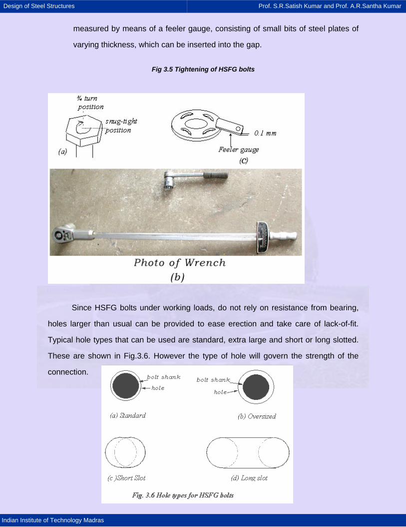
measured by means of a feeler gauge, consisting of small bits of steel plates of
varying thickness, which can be inserted into the gap.
Fig 3.5 Tightening of HSFG bolts
Since HSFG bolts under working loads, do not rely on resistance from bearing,
holes larger than usual can be provided to ease erection and take care of lack-of-fit.
Typical hole types that can be used are standard, extra large and short or long slotted.
These are shown in Fig.3.6. However the type of hole will govern the strength of the
connection.

Design of Steel Structures Prof. S.R.Satish Kumar and Prof. A.R.Santha Kumar
Indian Institute of Technology Madras
Holes must also satisfy pitch and edge/end distance criteria (Cl.10.2). A minimum
pitch is usually specified for accommodating the spanner and to limit adverse interaction
between the bearing stresses on neighbouring bolts. A maximum pitch criterion takes
care of buckling of the plies under compressive loads.
3.2.3 Shear connections with bearing type bolts
In this section the force transfer mechanisms of bearing and friction type of
bolted connections are described. This would help in identifying the modes of failure
discussed in the next section.
3.2.3.1 Force transfer of bearing type bolts
Fig. 3.7 shows the free body diagram of the shear force transfer in bearing type
of bolted connection. It is seen that tension in one plate is equilibrated by the bearing
stress between the bolt and the hole in the plate. Since there is a clearance between
the bolt and the hole in which it is fitted, the bearing stress is mobilised only after the
plates slip relative to one another and start bearing on the bolt .The section x-x in the
bolt is critical section for shear. Since it is a lap joint there is only one critical section in
shear (single shear) in the bolt .In the case of butt splices there would be two critical
sections in the bolt in shear (double shear), corresponding to the two cover plates.
Fig. 3.7 Shear transfer by bearing type bolt

Design of Steel Structures Prof. S.R.Satish Kumar and Prof. A.R.Santha Kumar
Indian Institute of Technology Madras
3.2.3.2 Design shear strength of bearing type bolts
The failure of connections with bearing bolts in shear involves either bolt failure
or the failure of the connected plates. In this section, the failure modes are described
along with the codal provisions for design and detailing shear connections.
In connections made with bearing type of bolts, the behaviour is linear until i)
yielding takes place at the net section of the plate under combined tension and flexure
or ii) shearing takes place at the bolt shear plane or iii) failure of bolt takes place in
bearing, iv) failure of plate takes place in bearing and v) block shear failure occurs. Of
these, i) and v) are discussed in the chapter on tension members. The remaining three
are described below.
1. Shearing of bolts: The shearing of bolts can take place in the threaded portion
of the bolt and so the area at the root of the threads, also called the tensile stress area
At, is taken as the shear area As. Since threads can occur in the shear plane, the area
Ae for resisting shear should normally be taken as the net tensile stress area, An, of the
bolts. The shear area is specified in the code and is usually about 0.8 times the shank
area. However, if it is ensured that the threads will not lie in the shear plane then the full
area can be taken as the shear area.
A bolt subjected to a factored shear force (Vsb) shall satisfy
Vsb < Vnsb / γmb
Where
Vnsb = nominal shear capacity of a bolt, calculated as follows:
γmb = 1.25
( )unsb n nb s sb
fV n A n A
3= + (3.1)
Where
fu = ultimate tensile strength of a bolt

Design of Steel Structures Prof. S.R.Satish Kumar and Prof. A.R.Santha Kumar
Indian Institute of Technology Madras
nn = number of shear planes with threads intercepting the shear plane
ns = number of shear planes without threads intercepting the shear plane
Asb = nominal plain shank area of the bolt
Anb = net tensile area at threads, may be taken as the area corresponding to root
diameter at the thread
For bolts in single shear, either nn or ns is one and the other is zero. For bolts in
double shear the sum of nn and ns is two.
2. Bearing failure: If the connected plates are made of high strength steel then failure
of bolt can take place by bearing of the plates onthe bolts. If the plate material is weaker
than the bolt material, then failure will occur by bearing of the bolt on the plate and the
hole will elongate . The beating area is given by the nominal diameter of the bolt times
the combined thickness of the plates bearing in any direction. − A bolt bearing on any
plate subjected to a factored shear force (Vsb) shall satisfy
Vsb < Vnpb / γmb (3.2)
Where, γmb = 1.25
Vnpb = bearing strength of a bolt, calculated as
Vnpb = 2.5dtfu (3.3)
Where
fu = smaller of the ultimate tensile stress of the bolt and the ultimate tensile stress of the
plate
d = nominal diameter of the bolt
t = summation of the thicknesses of the connected plates experiencing bearing stress in
the same direction.

Design of Steel Structures Prof. S.R.Satish Kumar and Prof. A.R.Santha Kumar
Indian Institute of Technology Madras
Fig. 3.8 Types of failures in a shear connection (a) Shearing of bolts (b) Bearing failure of plate (c) Bearing failure of bolt
The underlying assumption behind the design of bolted connections, namely that
all bolts carry equal load is not true in some cases as mentioned below.
In long joints, the bolts farther away from the centre of the joint will carry more
load than the bolts located close to the centre. Therefore, for joints having more than
two bolts on either side of the building connection with the distance between the first
and the last bolt exceeding 15d in the direction of load, the nominal shear capacity Vns,
shall be reduced by the factor, βlj, given by (Cl.10.3.2.1)
βlj = 1.075 – lj / (200 d) but 0.75 < βlj < 1.0
Where, d= nominal diameter of the bolt
Similarly, if the grip length exceeds five times the nominal diameter, the strength
is reduced as specified in IS 800. In multibolt connections, due to hole mismatch, all the
bolts may not carry the same load. However, under ultimate load, due to high bearing
ductility of the plates considerable redistribution of the load is possible and so the
assumption that all bolts carry equal load may be considered valid.
3.2.4 Shear connection with HSFG bolts
3.2.4.1 Force transfer of HSFG bolts
The free body diagram of an HSFG connection is shown in Fig. 3.9. It can be
seen that the pretension in the bolt causes clamping forces between the plates even
(a (b) Zone of plastificati
(c)

Design of Steel Structures Prof. S.R.Satish Kumar and Prof. A.R.Santha Kumar
Indian Institute of Technology Madras
before the external load is applied. When the external load is applied, the tendency of
two plates to slip against one another is resisted by the friction between the plates. The
frictional resistance is equal to the coefficient of friction multiplied by the normal
clamping force between the plates. Until the externally applied force exceeds this
frictional resistance the relative slip between the plates is prevented. The HSFG
connections are designed such that under service load the force does not exceed the
frictional resistance so that the relative slip is avoided during service. When the external
force exceeds the frictional resistance the plates slip until the bolts come into contact
with the plate and start bearing against the hole. Beyond this point the external force is
resisted by the combined action of the frictional resistance and the bearing resistance.
Fig. 3.9 Shear transfer by HSFG Bolt
3.2.4.2 Design shear strength of HSFG bolts
HSFG bolts will come into bearing only after slip takes place. Therefore if slip is
critical (i.e. if slip cannot be allowed) then one has to calculate the slip resistance, which
will govern the design. However, if slip is not critical, and limit state method is used then
bearing failure can occur at the Limit State of collapse and needs to be checked. Even
in the Limit State method, since HSFG bolts are designed to withstand working loads
without slipping, the slip resistance needs to be checked anyway as a Serviceability
Limit State.

Design of Steel Structures Prof. S.R.Satish Kumar and Prof. A.R.Santha Kumar
Indian Institute of Technology Madras
1. Slip Resistance: Design for friction type bolting in which slip is required to be
limited, a bolt subjected only to a factored design shear force, Vsf, in the interface of
connections shall satisfy the following (Cl.10.4.3):
Vsf < Vnsf / γmf
Where γmf= 1.25
Vnsf = nominal shear capacity of a bolt as governed by slip for friction type
connection, calculated as follows:
Vnsf = µf ne Kh Fo (3.4)
Where, µf = coefficient of friction (slip factor) as specified in Table 3.1 (µf <
0.55)(Table 3.1 of code).
ne =number of effective interfaces offering frictional resistance to slip
Kh = 1.0 for fasteners in clearance holes
= 0.85 for fasteners in oversized and short slotted holes, and for fasteners in long
slotted holes loaded perpendicular to the slot
= 0.7 for fasteners in long slotted holes loaded parallel to the slot.
γmf= 1.10 (if slip resistance is designed at service load)
γmf= 1.25 (if slip resistance is designed at ultimate load)
Fo= minimum bolt tension (proof load) at installation and may be taken as 0.8 Asb
Fo
A sb= shank area of the bolt in tension
f o= proof stress (= 0.70 fub)
Vns may be evaluated at a service load or ultimate load using appropriate partial
safety factors, depending upon whether slip resistance is required at service load or
ultimate load.

Design of Steel Structures Prof. S.R.Satish Kumar and Prof. A.R.Santha Kumar
Indian Institute of Technology Madras
Table 3.1 Typical average values for coefficient of friction (µf)
Treatment of surface Coeff. of friction (µf)
Clean mill scale 0.33 Sand blasted surface 0.48 Surfaces blasted with shot or grit and hot-dip galvanized
0.10
2. Bearing strength: The design for friction type bolting, in which bearing stress in the
ultimate limit state is required to be limited, (V ub=factored load bearing force) shall
satisfy (Cl.10.4.4)
Vbf < Vnbf / γmf
Where γmf= 1.25
Vnbf= bearing capacity of a bolt, for friction type connection, calculated as follows:
Vnbf = 2.2 d t fup < 3 d t fyp (3.5)
Where
fup= ultimate tensile stress of the plate
fyp = tensile yield stress of the plate
d = nominal diameter of the bolt
t = summation of thicknesses of all the connected plates experiencing bearing stress
in the same direction
The block shear resistance of the edge distance due to bearing force shall also
be checked.
3.2.5 Tension connections with bearing and HSFG bolts
3.2.5.1 Force transfer by bearing and HSFG bolts
The free body diagram of the tension transfer in a bearing type of bolted
connection is shown in Fig. 3.10(a). The variation of bolt tension due to externally
applied tension is shown in Fig.3.10(c). It is seen that before any external tension is
applied, the force in the bolt is almost zero, since the bolts are only snug tight. As the
external tension is increased it is equilibrated by the increase in bolt tension. Failure is

Design of Steel Structures Prof. S.R.Satish Kumar and Prof. A.R.Santha Kumar
Indian Institute of Technology Madras
reached due to large elongation when the root of the bolt starts yielding. Depending on
the relative flexibility of the plate and the bolt, sometimes the opening of the joint may
be accompanied by prying action [Fig. 3.10(d)].
The free body diagram of an HSFG bolted connection is shown in Fig. 3.10(b). It
is seen that even before any external load is applied, the force in the bolt is equal to
proof load. Correspondingly there is a clamping force between the plates in contact.
When the external load is applied, part of the load (nearly 10%) of the load is
equilibrated by the increase in the bolt force. The balance of the force is equilibrated by
the reduction in contact between the plates. This process continues and the contact
between the plates is maintained until the contact force due to pre-tensioning is reduced
to zero by the externally applied load. Normally, the design is done such that the
externally applied tension does not exceed this level. After the external force exceeds
this level, the behaviour of the bolt under tension is essentially the same as that in a
bearing type of joint.
22
To+TT To+T(b) HSFG Connection (a) Bearing type connection
To
QApplied load 2T
HSFG
Bearing type
(d) Prying Effect ( c) External Tension versus bolt force
Bolt force B kN
Proof Load Po
2Te
Te+Te+
le lv
A B

Design of Steel Structures Prof. S.R.Satish Kumar and Prof. A.R.Santha Kumar
Indian Institute of Technology Madras
Fig. 3.10 Bolts under tension and prying effect
Where prying force, Q, is significant, prying force shall be calculated as given below and
added to the tension in the bolt (Cl.10.4.7).
4o ev
e 2e e v
f b tlQ T
2 l 27 l l
⎡ ⎤β γ⎢ ⎥= −⎢ ⎥⎣ ⎦
(3.7)
Where, lv = distance from the bolt centreline to the toe of the fillet weld or to half
the root radius for a rolled section; le = distance between prying force and bolt centreline
and is the minimum of, either the end distance, or the value given by
oe
y
fl 1.1 t
fβ
= (3.8)
Where,
β = 2 for non pre-tensioned bolt and 1 for pre-tensioned bolt
γ = 1.5
be = effective width of flange per pair of bolts
fo = proof stress in consistent units
t = thickness of the end plate
Even if the bolts are strong enough to carry the additional prying forces, the plate
can fail by developing a mechanism with yield lines at the centreline of the bolt and at
the distance b from it. Therefore, the minimum thickness of the end plate (t), to avoid
yielding of the plate, can be obtained by equating the moment in the plate at the bolt
centreline (point A) and at the distance b from it (point B), to the plastic moment
capacity of the plate Mp. Thus,
A BM Qn; M Tb Qn= = − (3.9)
A B pTbM M M2
= = = (3.10)
taking Mp as

Design of Steel Structures Prof. S.R.Satish Kumar and Prof. A.R.Santha Kumar
Indian Institute of Technology Madras
2y
pf wtM
1.15 4= (3.11)
the minimum thickness for the end plate can be obtained as
pmin
y
1.15 4 Mt
f w× ×
=×
(3.12)
The corresponding prying force can then be obtained as Q = Mp/n. If the total
force in the bolt (T+Q) exceeds the tensile capacity of the bolt, then the thickness of the
end plate will have to be increased.
3.2.5.2 Design tensile strength of bearing and HSFG bolts
In a tension or hanger connection, the applied load produces tension in the bolts
and the bolts are designed as tension members. If the attached plate is allowed to
deform, additional tensile forces called prying forces are developed in the bolts.
Tension Capacity − A bolt subjected to a factored tension force (Tb) shall satisfy
(Cl.10.3.4)
Tb < Tnb / γmb γmb = 1.25
Where, Tnb= nominal tensile capacity of the bolt, calculated as follows:
Tnb =0.90 fub An < fyb Asb (γm1 / γm0) γmo = 1.10 and γmf = 1.25
Where,
fub = ultimate tensile stress of the bolt
fyb = yield stress of the bolt
An = net tensile stress area as specified in the appropriate Indian Standard. For bolts
where the tensile stress area is not defined, An shall be taken as the area at the root of
the threads (explained in next - chapter)
Asb = shank area of the bolt

Design of Steel Structures Prof. S.R.Satish Kumar and Prof. A.R.Santha Kumar
Indian Institute of Technology Madras
3.2.5.3 Combined shear and tension failure
Bolt Subjected to Combined Shear and Tension − A bolt required to resist both
design shear force (Vsd) and design tensile force (Tnd) at the same time shall satisfy
2 2e
sd nd
TV 1.0V T
⎛ ⎞ ⎛ ⎞+ ≤⎜ ⎟ ⎜ ⎟
⎝ ⎠ ⎝ ⎠ (3.13)
Where, V = applied shear; Vsd = design shear capacity; Te = externally applied
tension and Tnd = design tension capacity. This gives a circular interaction curve as
shown in Fig. 3.11.
Bolts in a connection for which slip in the serviceability limit state shall be limited,
which are subjected to a tension force, T, and shear force, V, shall satisfy (Cl.10.4.6)
2 2e
sdf ndf
TV 1.0V T
⎛ ⎞ ⎛ ⎞+ ≤⎜ ⎟ ⎜ ⎟
⎝ ⎠ ⎝ ⎠ (3.14)
Where, V = applied shear at service load; Vsdf = design shear strength; Te =
externally applied tension at service load; Tndf = design tension strength.
Fig. 3.11 Shear and Tension Interaction Curve
V/Vsdf
Te/Tndf 1.0
1.0

Design of Steel Structures Prof. S.R.Satish Kumar and Prof. A.R.Santha Kumar
Indian Institute of Technology Madras
3.3 Welding and welded connections
Welding is the process of joining two pieces of metal by creating a strong
metallurgical bond between them by heating or pressure or both. It is distinguished from
other forms of mechanical connections, such as riveting or bolting, which are formed by
friction or mechanical interlocking. It is one of the oldest and reliable methods of joining.
Welding offers many advantages over bolting and riveting. Welding enables
direct transfer of stress between members eliminating gusset and splice plates
necessary for bolted structures. Hence, the weight of the joint is minimum. In the case
of tension members, the absence of holes improves the efficiency of the section. It
involves less fabrication cost compared to other methods due to handling of fewer parts
and elimination of operations like drilling, punching etc. and consequently less labour
leading to economy. Welding offers air tight and water tight joining and hence is ideal for
oil storage tanks, ships etc. Welded structures also have a neat appearance and enable
the connection of complicated shapes. Welded structures are more rigid compared to
structures with riveted and bolted connections. A truly continuous structure is formed by
the process of fusing the members together. Generally welded joints are as strong or
stronger than the base metal, thereby placing no restriction on the joints. Stress
concentration effect is also considerably less in a welded connection.
Some of the disadvantages of welding are that it requires skilled manpower for
welding as well as inspection. Also, non-destructive evaluation may have to be carried
out to detect defects in welds. Welding in the field may be difficult due to the location or
environment. Welded joints are highly prone to cracking under fatigue loading. Large
residual stresses and distortion are developed in welded connections.
3.3.1 Fundamentals of welding
A welded joint is obtained when two clean surfaces are brought into contact with
each other and either pressure or heat, or both are applied to obtain a bond. The
tendency of atoms to bond is the fundamental basis of welding. The inter-diffusion

Design of Steel Structures Prof. S.R.Satish Kumar and Prof. A.R.Santha Kumar
Indian Institute of Technology Madras
between the materials that are joined is the underlying principle in all welding
processes. The diffusion may take place in the liquid, solid or mixed state. In welding
the metallic materials are joined by the formation of metallic bonds and a perfect
connection is formed. In practice however, it is very difficult to achieve a perfect joint;
for, real surfaces are never smooth. When welding, contact is established only at a few
points in the surface, joins irregular surfaces where atomic bonding occurs. Therefore
the strength attained will be only a fraction of the full strength. Also, the irregular surface
may not be very clean, being contaminated with adsorbed moisture, oxide film, grease
layer etc. In the welding of such surfaces, the contaminants have to be removed for the
bonding of the surface atoms to take place. This can be accomplished by applying
either heat or pressure. In practical welding, both heat and pressure are applied to get a
good joint.
As pointed out earlier, any welding process needs some form of energy, often
heat, to connect the two materials. The relative amount of heat and pressure required to
join two materials may vary considerably between two extreme cases in which either
heat or pressure alone is applied. When heat alone is applied to make the joint,
pressure is used merely to keep the joining members together. Examples of such a
process are Gas Tungsten Arc Welding (GTAW), Shielded Metal Arc Welding (SMAW),
Submerged Arc Welding (SAW) etc. On the other hand pressure alone is used to make
the bonding by plastic deformation, examples being cold welding, roll welding, ultrasonic
welding etc. There are other welding methods where both pressure and heat are
employed, such as resistance welding, friction welding etc. A flame, an arc or
resistance to an electric current, produces the required heat. Electric arc is by far the
most popular source of heat used in commercial welding practice.
3.3.2 Welding process
In general, gas and arc welding are employed; but, almost all structural welding
is arc welding.

Design of Steel Structures Prof. S.R.Satish Kumar and Prof. A.R.Santha Kumar
Indian Institute of Technology Madras
In gas welding a mixture of oxygen and some suitable gas is burned at the tip of
a torch held in the welder’s hand or by an automatic machine. Acetylene is the gas used
in structural welding and the process is called oxyacetylene welding. The flame
produced can be used both for cutting and welding of metals. Gas welding is a simple
and inexpensive process. But, the process is slow compared to other means of welding.
It is generally used for repair and maintenance work.
The most common welding processes, especially for structural steel, use electric
energy as the heat source produced by the electric arc.IS:816 in this process, the base
metal and the welding rod are heated to the fusion temperature by an electric arc. The
arc is a continuous spark formed when a large current at a low voltage is discharged
between the electrode and the base metal through a thermally ionised gaseous column,
called plasma. The resistance of the air or gas between the electrode and the objects
being welded changes the electric energy into heat. A temperature of 33000 C to 55000
C is produced in the arc. The welding rod is connected to one terminal of the current
source and the object to be welded to the other. In arc welding, fusion takes place by
the flow of material from the welding rod across the arc without pressure being applied.
The Shielded Metal Arc Welding process is explained in the following paragraph.
In Shielded Metal Arc Welding or SMAW (Fig.3.12), heating is done by means of
electric arc between a coated electrode and the material being joined. In case bare wire
electrode (without coating) is employed, the molten metal gets exposed to atmosphere
and combines chemically with oxygen and nitrogen forming defective welds. The
electrode coating on the welding rod forms a gaseous shield that helps to exclude
oxygen and stabilise the arc.
The coated electrode also deposits a slag in the molten metal, which because of
its lesser density compared to the base metal, floats on the surface of the molten metal
pool, shields it from atmosphere, and slows cooling. After cooling, the slag can be easily
removed by hammering and wire brushing.

Design of Steel Structures Prof. S.R.Satish Kumar and Prof. A.R.Santha Kumar
Indian Institute of Technology Madras
The coating on the electrode thus: shields the arc from atmosphere; coats the molten
metal pool against oxidation; stabilises the arc; shapes the molten metal by surface
tension and provides alloying element to weld metal.
Fig.3.12 Shielded metal arc welding (SMAW) process
Fig.3.12 Shielded metal arc welding (SMAW) process
The type of welding electrode used would decide the weld properties such as
strength, ductility and corrosion resistance. The type to be used for a particular job
depends upon the type of metal being welded, the amount of material to be added and
the position of the work. The two general classes of electrodes are lightly coated and
heavily coated. The heavily coated electrodes are normally used in structural welding.
The resulting welds are stronger, more corrosion resistant and more ductile compared
to welds produced by lightly coated electrodes. Usually the SMAW process is either
automatic or semi-automatic.
The term weldability is defined as the ability to obtain economic welds, which are
good, crack-free and would meet all the requirements. Of great importance are the
chemistry and the structure of the base metal and the weld metal. The effects of heating
and cooling associated with fusion welding are experienced by the weld metal and the
Heat Affected Zone (HAZ) of the base metal. The cracks in HAZ are mainly caused by
high carbon content, hydrogen enbrittlement and rate of cooling. For most steels, weld
cracks become a problem as the thickness of the plates increases.

Design of Steel Structures Prof. S.R.Satish Kumar and Prof. A.R.Santha Kumar
Indian Institute of Technology Madras
3.3.3 Types of joints and welds
By means of welding, it is possible to make continuous, load bearing joints
between the members of a structure. A variety of joints is used in structural steel work
and they can be classified into four basic configurations namely, Lap joint, Tee joint,
Butt joint and Corner joint.
For lap joints, the ends of two members are overlapped and for butt joints, the
two members are placed end to end. The T- joints form a Tee and in Corner joints, the
ends are joined like the letter L. Most common joints are made up of fillet weld or the
butt (also calling groove) weld. Plug and slot welds are not generally used in structural
steel work. Fig.3.14 Fillet welds are suitable for lap joints and Tee joints and groove
welds for butt and corner joints. Butt welds can be of complete penetration or
incomplete penetration depending upon whether the penetration is complete through
the thickness or partial. Generally a description of welded joints requires an indication of
the type of both the joint and the weld.
Though fillet welds are weaker than butt welds, about 80% of the connections are
made with fillet welds. The reason for the wider use of fillet welds is that in the case of
fillet welds, when members are lapped over each other, large tolerances are allowed in
erection. For butt welds, the members to be connected have to fit perfectly when they
are lined up for welding. Further butt welding requires the shaping of the surfaces to be
joined as shown in Fig. 3.15. To ensure full penetration and a sound weld, a backup
plate is temporarily provided as shown in Fig.3.15
Butt welds:
Full penetration butt welds are formed when the parts are connected together
within the thickness of the parent metal. For thin parts, it is possible to achieve full
penetration of the weld. For thicker parts, edge preparation may have to be done to
achieve the welding. There are nine different types of butt joints: square, single V,
Design of Steel Structures Prof. S.R.Satish Kumar and Prof. A.R.Santha Kumar
Indian Institute of Technology Madras
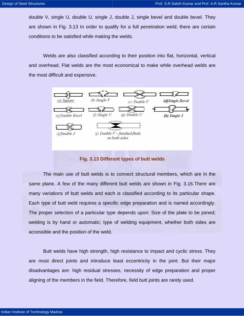
double V, single U, double U, single J, double J, single bevel and double bevel. They
are shown in Fig. 3.13 In order to qualify for a full penetration weld; there are certain
conditions to be satisfied while making the welds.
Welds are also classified according to their position into flat, horizontal, vertical
and overhead. Flat welds are the most economical to make while overhead welds are
the most difficult and expensive.
Fig. 3.13 Different types of butt welds
The main use of butt welds is to connect structural members, which are in the
same plane. A few of the many different butt welds are shown in Fig. 3.16.There are
many variations of butt welds and each is classified according to its particular shape.
Each type of butt weld requires a specific edge preparation and is named accordingly.
The proper selection of a particular type depends upon: Size of the plate to be joined;
welding is by hand or automatic; type of welding equipment, whether both sides are
accessible and the position of the weld.
Butt welds have high strength, high resistance to impact and cyclic stress. They
are most direct joints and introduce least eccentricity in the joint. But their major
disadvantages are: high residual stresses, necessity of edge preparation and proper
aligning of the members in the field. Therefore, field butt joints are rarely used.

Design of Steel Structures Prof. S.R.Satish Kumar and Prof. A.R.Santha Kumar
Indian Institute of Technology Madras
Fig.3.14 Common types of welds
Fig.3.15 Shaping of surface and backup plate
Fig.3.16 Typical connections with butt weld
To minimise weld distortions and residual stresses, the heat input is minimised
and hence the welding volume is minimised. This reduction in the volume of weld also

Design of Steel Structures Prof. S.R.Satish Kumar and Prof. A.R.Santha Kumar
Indian Institute of Technology Madras
reduces cost. Hence for thicker plates, double Butt welds and U welds are generally
used. For a butt weld, the root gap, R, is the separation of the pieces being joined and is
provided for the electrode to access the base of a joint. The smaller the root gap the
greater the angle of the bevel. The depth by which the arc melts into the plate is called
the depth of penetration [Fig.3.17 (a)]. Roughly, the penetration is about 1 mm per 100A
and in manual welding the current is usually 150 – 200 A. Therefore, the mating edges
of the plates must be cut back if through-thickness continuity is to be established. This
groove is filled with the molten metal from the electrode. The first run that is deposited in
the bottom of a groove is termed as the root run [Fig.3.176 (c)]. For good penetration,
the root faces must be melted. Simultaneously, the weld pool also must be controlled,
preferably, by using a backing strip.
Fig.3.17 Butt weld details
Fillet welds:
Owing to their economy, ease of fabrication and adaptability, fillet welds are
widely used. They require less precision in the fitting up because the plates being joined
can be moved about more than the Butt welds. Another advantage of fillet welds is that
special preparation of edges, as required by Butt welds, is not required. In a fillet weld
the stress condition in the weld is quite different from that of the connected parts. A
typical fillet weld is shown in Fig.3.18

Design of Steel Structures Prof. S.R.Satish Kumar and Prof. A.R.Santha Kumar
Indian Institute of Technology Madras
Fig. 3.18 Typical fillet weld
The root of the weld is the point where the faces of the metallic members meet.
The theoretical throat of a weld is the shortest distance from the root to the hypotenuse
of the triangle. The throat area equals the theoretical throat distance times the length of
the weld.
The concave shape of free surface provides a smoother transition between the
connected parts and hence causes less stress concentration than a convex surface. But
it is more vulnerable to shrinkage and cracking than the convex surface and has a much
reduced throat area to transfer stresses. On the other hand, convex shapes provide
extra weld metal or reinforcement for the throat. For statically loaded structures, a
slightly convex shape is preferable, while for fatigue – prone structures, concave
surface is desirable.
Large welds are invariably made up of a number of layers or passes. For reasons
of economy, it is desirable to choose weld sizes that can be made in a single pass.
Large welds scan be made in a single pass by an automatic machine, though manually,
8 mm fillet is the largest single-pass layer.

Design of Steel Structures Prof. S.R.Satish Kumar and Prof. A.R.Santha Kumar
Indian Institute of Technology Madras
3.3.4 Weld symbols
The information concerning type, size, position, welding process etc. of the welds
in welded joints is conveyed by standard symbols in drawings. The symbolic
representation includes elementary symbols along with a) supplementary symbol, b) a
means of showing dimensions, or c) some complementary indications. IS: 813 “Scheme
of Symbols for Welding” gives all the details of weld representation in drawings.
Elementary symbols represent the various categories of the weld and look similar
to the shape of the weld to be made. Combination of elementary symbols may also be
used, when required. Elementary symbols are shown in Table 3.2.
Table 3.2 Elementary symbols
Illustration (Fig) Symbol Description
Butt weld between plates with raised edges*(the raised edges being melted down completely)
Square butt weld
Single-V butt weld
Single-bevel butt weld
Single – V butt weld with broad root face
Single – bevel butt weld with broad root face
Single – U butt weld (parallel or sloping sides)

Design of Steel Structures Prof. S.R.Satish Kumar and Prof. A.R.Santha Kumar
Indian Institute of Technology Madras
Single – J butt joint
Backing run; back or backing weld
Fillet weld
Plug weld; plug or slot weld
Spot weld
Seam weld
Supplementary symbols characterise the external surface of the weld and they
complete the elementary symbols. Supplementary symbols are shown in Table 3.3. The
weld locations are defined by specifying, a) position of the arrow line, b) position of the
reference line, and c) the position of the symbol. More details of weld representation
may be obtained from IS 813.

Design of Steel Structures Prof. S.R.Satish Kumar and Prof. A.R.Santha Kumar
Indian Institute of Technology Madras
Table 3.3. Supplementary symbols
Flat (flush) single – V butt weld
Convex double – V butt weld
Concave fillet weld
Flat (flush) single – V butt with flat (flush) backing run
Position of symbols in drawings:
Apart from the symbols as covered earlier, the methods of representation (Fig.3.19)
also include the following:
· An arrow line for each joint
. A dual reference line, consisting of two parallel lines, one continuous and the other
dashed.
. A certain number of dimensions and conventional signs
The location of welds is classified on the drawings by specifying:
Position of the arrow line, position of the reference line and the position of the
symbol
Fig. 3.19 Method of representation

Design of Steel Structures Prof. S.R.Satish Kumar and Prof. A.R.Santha Kumar
Indian Institute of Technology Madras
The position of arrow line with respect to the weld has no special significance.
The arrow line joins one end of the continuous reference line such that it forms an angle
with it and shall be completed by an arrowhead or a dot. The reference line is a straight
line drawn parallel to the bottom edge of the drawing.
The symbol is placed either above or beneath the reference line. The symbol is
placed on the continuous side of the reference line if the weld is on the other side of the
joint; the symbol is placed on the dashed line side
3.3.5 Design of welds
Design of butt welds:
For butt welds the most critical form of loading is tension applied in the
transverse direction. It has been observed from tests conducted on tensile coupons
containing a full penetration butt weld normal to the applied load that the welded joint
had higher strength than the parent metal itself. The yield stress of the weld metal and
the parent metal in the HAZ region was found to be much higher than the parent metal.
The butt weld is normally designed for direct tension or compression. However, a
provision is made to protect it from shear. Design strength value is often taken the same
as the parent metal strength. For design purposes, the effective area of the butt-welded
connection is taken as the effective length of the weld times the throat size. Effective
length of the butt weld is taken as the length of the continuous full size weld. The throat
size is specified by the effective throat thickness. For a full penetration butt weld, the
throat dimension is usually assumed as the thickness of the thinner part of the
connection. Even though a butt weld may be reinforced on both sides to ensure full
cross-sectional areas, its effect is neglected while estimating the throat dimensions.
Such reinforcements often have a negative effect, producing stress concentration,
especially under cyclic loads.

Design of Steel Structures Prof. S.R.Satish Kumar and Prof. A.R.Santha Kumar
Indian Institute of Technology Madras
Unsealed butt welds of V, U, J and bevel types and incomplete penetration butt
welds should not be used for highly stressed joints and joints subjected to dynamic and
alternating loads. Intermittent butt welds are used to resist shear only and the effective
length should not be less than four times the longitudinal space between the effective
length of welds nor more than 16 times the thinner part. They are not to be used in
locations subjected to dynamic or alternating stresses. Some modern codes do not
allow intermittent welds in bridge structures.
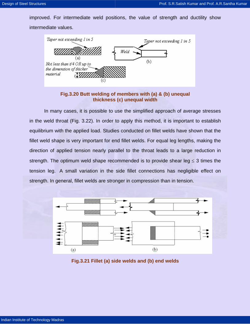
For butt welding parts with unequal cross sections, say unequal width, or
thickness, the dimensions of the wider or thicker part should be reduced at the butt joint
to those of the smaller part. This is applicable in cases where the difference in thickness
exceeds 25 % of the thickness of the thinner part or 3.0 mm, whichever is greater. The
slope provided at the joint for the thicker part should not be steeper than one in five
[Figs.3.20 (a) & (b)]. In instances, where this is not practicable, the weld metal is built up
at the junction equal to a thickness which is at least 25 % greater than the thinner part
or equal to the dimension of the thicker part [Fig.3.20 (c)]. Where reduction of the wider
part is not possible, the ends of the weld shall be returned to ensure full throat
thickness.
Stresses for butt welds are assumed same as for the parent metal with a
thickness equal to the throat thickness (Cl.10.5.7.1). For field welds, the permissible
stresses in shear and tension calculated using a partial factor γmw of 1.5. (Cl.10.5.7.2)
Design of fillet welds:
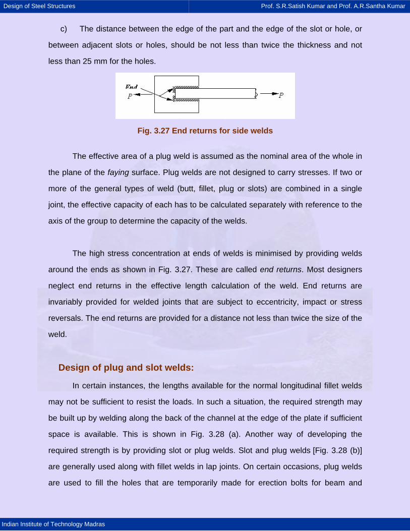
Fillet welds are broadly classified into side fillets and end fillets (Fig.3.21). When
a connection with end fillet is loaded in tension, the weld develops high strength and the
stress developed in the weld is equal to the value of the weld metal. But the ductility is
minimal. On the other hand, when a specimen with side weld is loaded, the load axis is
parallel to the weld axis. The weld is subjected to shear and the weld shear strength is
limited to just about half the weld metal tensile strength. But ductility is considerably
Design of Steel Structures Prof. S.R.Satish Kumar and Prof. A.R.Santha Kumar
Indian Institute of Technology Madras
improved. For intermediate weld positions, the value of strength and ductility show
intermediate values.
Fig.3.20 Butt welding of members with (a) & (b) unequal thickness (c) unequal width
In many cases, it is possible to use the simplified approach of average stresses
in the weld throat (Fig. 3.22). In order to apply this method, it is important to establish
equilibrium with the applied load. Studies conducted on fillet welds have shown that the
fillet weld shape is very important for end fillet welds. For equal leg lengths, making the
direction of applied tension nearly parallel to the throat leads to a large reduction in
strength. The optimum weld shape recommended is to provide shear leg ≤ 3 times the
tension leg. A small variation in the side fillet connections has negligible effect on
strength. In general, fillet welds are stronger in compression than in tension.
Fig.3.21 Fillet (a) side welds and (b) end welds

Design of Steel Structures Prof. S.R.Satish Kumar and Prof. A.R.Santha Kumar
Indian Institute of Technology Madras
Fig.3.22 Average stress in the weld throat
A simple approach to design is to assume uniform fillet weld strength in all
directions and to specify a certain throat stress value. The average throat thickness is
obtained by dividing the applied loads summed up in vectorial form per unit length by
the throat size.
This method is limited in usage to cases of pure shear, tension or compression
(Fig.3.23). It cannot be used in cases where the load vector direction varies around
weld group. For the simple method, the stress is taken as the vector sum of the force
components acting in the weld divided by the throat area.
Fig.3.23 (a) connections with simple weld design, (b) connections with Direction- dependent weld design
Stresses Due to Individual forces - When subjected to either compressive or
tensile or shear force alone, the stress in the weld is given by:

Design of Steel Structures Prof. S.R.Satish Kumar and Prof. A.R.Santha Kumar
Indian Institute of Technology Madras
fa or q = t w
Pt l
Where
fa = calculated normal stress due to axial force in N/mm2
q = shear stress in N/mm2
P = force transmitted (axial force N or the shear force Q)
tt = effective throat thickness of weld in mm
lw= effective length of weld in mm
Fig. 3.24 End fillet weld normal to direction of force
The design strength of a fillet weld, fwd, shall be based on its throat area
(Cl.10.5.7).
fwd = fwn / γmw in which fwn = uf / 3
Where fu = smaller of the ultimate stress of the weld and the parent metal and
γmw = partial safety factor (=1.25 for shop welds and = 1.5 for field welds)
The design strength shall be reduced appropriately for long joints as prescribed in the
code.
The size of a normal fillet should be taken as the minimum leg size (Fig. 3.25)

Design of Steel Structures Prof. S.R.Satish Kumar and Prof. A.R.Santha Kumar
Indian Institute of Technology Madras
Fig. 3.25 Sizes of fillet welds
For a deep penetration weld, the depth of penetration should be a minimum of
2.4 mm. Then the size of the weld is minimum leg length plus 2.4 mm. The size of a
fillet weld should not be less than 3 mm or more than the thickness of the thinner part
joined. Minimum size requirement of fillet welds is given below in Table 3.4
(Cl.10.5.2.3). Effective throat thickness should not be less than 3 mm and should not
exceed 0.7 t and 1.0 t under special circumstances, where’t’ is the thickness of thinner
part.
Table 3.4 Minimum size of first run or of a single run fillet weld
Thickness of thicker part (mm) Minimum size (mm) t ≤ 10 3
10 < t ≤ 20 5 20 < t ≤ 32 6 32 < t ≤ 50 8 (First run)10 (Minimum size of fillet)
For stress calculations, the effective throat thickness should be taken as K times
fillet size, where K is a constant. Values of K for different angles between tension fusion
faces are given in Table 3.5 (Cl.10.5.3.2). Fillet welds are normally used for connecting
parts whose fusion faces form angles between 60° and 120°. The actual length is taken
as the length having the effective length plus twice the weld size. Minimum effective
length should not be less than four times the weld size. When a fillet weld is provided to
square edge of a part, the weld size should be at least 1.5 mm less than the edge

Design of Steel Structures Prof. S.R.Satish Kumar and Prof. A.R.Santha Kumar
Indian Institute of Technology Madras
thickness [Fig. 3.26 (a)]. For the rounded toe of a rolled section, the weld size should
not exceed 3/4 thickness of the section at the toe [Fig. 3.26 (b)] (Cl.10.5.8.1).
Fig.3.26 (a) Fillet welds on square edge of plate, (b) Fillet Welds on round toe of rolled section
Table 3.5. Value of K for different angles between fusion faces
Angle between fusion faces 60° - 90° 91°-100° 101°-106° 107°-113° 114°-120° Constant K 0.70 0.65 0.60 0.55 0.50
Intermittent fillet welds may be provided where the strength required is less than
that can be developed by a continuous fillet weld of the smallest allowable size for the
parts joined. The length of intermediate welds should not be less than 4 times the weld
size with a minimum of 40 mm. The clear spacing between the effective lengths of the
intermittent welds should be less than or equal to 12 times the thickness of the thinner
member in compression and 16 times in tension; in no case the length should exceed
20 cm. Chain intermittent welding is better than staggered intermittent welding.
Intermittent fillet welds are not used in main members exposed to weather. For lap
joints, the overlap should not be less than five times the thickness of the thinner part.
For fillet welds to be used in slots and holes, the dimension of the slot or hole should
comply with the following limits:
a) The width or diameter should not be less than three times the thickness or 25
mm whichever is greater
b) Corners at the enclosed ends or slots should be rounded with a radius not less
than 1.5 times the thickness or 12 mm whichever is greater, and
Design of Steel Structures Prof. S.R.Satish Kumar and Prof. A.R.Santha Kumar
Indian Institute of Technology Madras
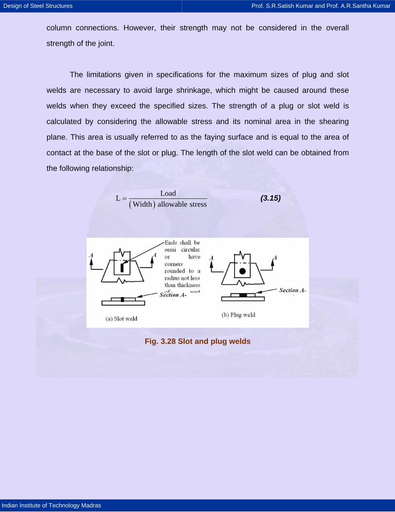
c) The distance between the edge of the part and the edge of the slot or hole, or
between adjacent slots or holes, should be not less than twice the thickness and not
less than 25 mm for the holes.
Fig. 3.27 End returns for side welds
The effective area of a plug weld is assumed as the nominal area of the whole in
the plane of the faying surface. Plug welds are not designed to carry stresses. If two or
more of the general types of weld (butt, fillet, plug or slots) are combined in a single
joint, the effective capacity of each has to be calculated separately with reference to the
axis of the group to determine the capacity of the welds.
The high stress concentration at ends of welds is minimised by providing welds
around the ends as shown in Fig. 3.27. These are called end returns. Most designers
neglect end returns in the effective length calculation of the weld. End returns are
invariably provided for welded joints that are subject to eccentricity, impact or stress
reversals. The end returns are provided for a distance not less than twice the size of the
weld.
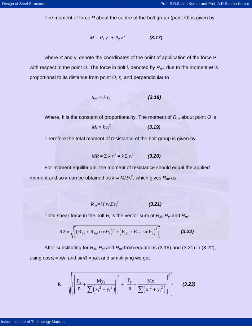
Design of plug and slot welds:
In certain instances, the lengths available for the normal longitudinal fillet welds
may not be sufficient to resist the loads. In such a situation, the required strength may
be built up by welding along the back of the channel at the edge of the plate if sufficient
space is available. This is shown in Fig. 3.28 (a). Another way of developing the
required strength is by providing slot or plug welds. Slot and plug welds [Fig. 3.28 (b)]
are generally used along with fillet welds in lap joints. On certain occasions, plug welds
are used to fill the holes that are temporarily made for erection bolts for beam and
Design of Steel Structures Prof. S.R.Satish Kumar and Prof. A.R.Santha Kumar
Indian Institute of Technology Madras
column connections. However, their strength may not be considered in the overall
strength of the joint.
The limitations given in specifications for the maximum sizes of plug and slot
welds are necessary to avoid large shrinkage, which might be caused around these
welds when they exceed the specified sizes. The strength of a plug or slot weld is
calculated by considering the allowable stress and its nominal area in the shearing
plane. This area is usually referred to as the faying surface and is equal to the area of
contact at the base of the slot or plug. The length of the slot weld can be obtained from
the following relationship:
( )LoadL
Width allowable stress= (3.15)
Fig. 3.28 Slot and plug welds

Design of Steel Structures Prof. S.R.Satish Kumar and Prof. A.R.Santha Kumar
Indian Institute of Technology Madras
3.4 Analysis of bolt groups
In general, any group of bolts resisting a moment can be classified into either of
two cases depending on whether the moment is acting in the shear plane or in a plane
perpendicular to it. Both cases are described in this section.
3.4.1 Combined shear and moment in plane
Consider an eccentric connection carrying a load of P as shown in Fig. 3.29. The
basic assumptions in the analysis are (1) deformations of plate elements are negligible,
(2) the total shear is assumed to be shared equally by all bolts and (3) the equivalent
moment at the geometric centre (point O in Fig. 3.29) of the bolt group, causes shear in
any bolt proportional to the distance of the bolt from the point O acting perpendicular to
the line joining the bolt centre to point O (radius vector).
Resolving the applied force P into its components Px and Py in x and y-directions
respectively and denoting the corresponding force on any bolt i to these shear
components by Rxi and Ryi and applying the equilibrium conditions we get the following:
Rxi = Px/n and Ryi = Py/n (3.16)
Where n is the total number of bolts in the bolt group and Rxi and Ryi act in
directions opposite to Px and Py respectively.
Fig. 29 Bolt group eccentrically loaded in shear
Design of Steel Structures Prof. S.R.Satish Kumar and Prof. A.R.Santha Kumar
Indian Institute of Technology Madras
The moment of force P about the centre of the bolt group (point O) is given by
M = Px y’ + Py x’ (3.17)
where x’ and y’ denote the coordinates of the point of application of the force P
with respect to the point O. The force in bolt i, denoted by Rmi, due to the moment M is
proportional to its distance from point O, ri, and perpendicular to
Rmi = k ri (3.18)
Where, k is the constant of proportionality. The moment of Rmi about point O is
Mi = k ri2 (3.19)
Therefore the total moment of resistance of the bolt group is given by
MR = Σ k ri2 = k Σ ri
2 (3.20)
For moment equilibrium, the moment of resistance should equal the applied
moment and so k can be obtained as k = M/Σri2, which gives Rmi as
Rmi=M ri/Σ ri2 (3.21)
Total shear force in the bolt Ri is the vector sum of Rxi, Ryi and Rmi
( ) ( )22xi mi i yi mi iR2 R R cos R R sin⎡ ⎤= + θ + + θ⎢ ⎥⎣ ⎦
(3.22)
After substituting for Rxi, Ryi and Rmi from equations (3.16) and (3.21) in (3.22),
using cosθi = xi/ri and sinθi = yi/ri and simplifying we get
( ) ( )
2 2
yx i ii 2 2 2 2
i i i i
PP My MxR
n nx y x y
⎧ ⎫⎡ ⎤ ⎡ ⎤⎪ ⎪⎢ ⎥ ⎢ ⎥= + + +⎨ ⎬⎢ ⎥ ⎢ ⎥+ +⎪ ⎪⎢ ⎥ ⎢ ⎥⎣ ⎦ ⎣ ⎦⎩ ⎭∑ ∑
(3.23)

Design of Steel Structures Prof. S.R.Satish Kumar and Prof. A.R.Santha Kumar
Indian Institute of Technology Madras
The xi and yi co-ordinates should reflect the positive and negative values of the
bolt location as appropriate.
3.4.2 Combined shear and moment out-of-plane
In the connection shown in Fig. 3.30, the bolts are subjected to combined shear
and tension. The neutral axis may be assumed to be at a distance of one-sixth of the
depth d above the bottom flange of the beam so as to account for the greater area in
the compressed portions of the connection per unit depth.
The nominal tensile force in the bolts can be calculated assuming it to be
proportional to the distance of the bolt from the neutral axis li in Fig. 3.30. If there exists
a hard spot on the compressive load path such as a column web stiffener on the other
side of the lower beam flange, the compressive force may be assumed to be acting at
the mid-depth of the hard spot as shown in Fig. 3.30c. In such a case, the nominal
tensile force in the bolts can be calculated in proportion to the distance of the bolt from
the compressive force (li = Li).
Ti = kli where k = constant (3.24)
M = Σ Ti Li = k Σ li Li (3.25)
Ti = Mli/Σ li Li (3.26)
Fig. 30 Bolt group resisting out-of-plane moment
Design of Steel Structures Prof. S.R.Satish Kumar and Prof. A.R.Santha Kumar
Indian Institute of Technology Madras
In the case of extended end plate connections, the top portion of the plate
behaves as a T-stub symmetric about the tension flange. For calculating the bolt
tensions in the rows immediately above and below the tension flange, li can be taken as
the distance of the tension flange from the neutral axis to the line of action of the
compressive force, as the case may be. If the end plate is thin, prying tension is likely to
arise in addition to the nominal bolt tension calculated as above.
The shear can be assumed to share equally by all the bolts in the connection.
Therefore, the top bolts will have to be checked for combined shear and tension as
explained before.

Design of Steel Structures Prof. S.R.Satish Kumar and Prof. A.R.Santha Kumar
Indian Institute of Technology Madras
3.5 Analysis of weld group
3.5.1 Eccentric welded connections
In some cases, eccentric loads may be applied to fillet welds causing either
shear and torsion or shear and bending in the welds. Examples of such loading are
shown in Fig. These two common cases are treated in this section.
Shear and torsion:
Considering the welded bracket shown in Fig. 3.31 (a), an assumption is made to
the effect that the parts being joined are completely rigid and hence all the deformations
occur in the weld. As seen from the figure, the weld is subjected to a combination of
shear and torsion. The force caused by torsion is determined using the formula
F = T.s/J = (Moment / Polar moment of inertia) (3.27)
Where, T is the tension, s is the distance from the centre of gravity of the weld to
the point under consideration, and J is the polar moment of inertia of the weld. For
convenience, the force can be decomposed into its vertical and horizontal components:
Fh = Tv/J and fv = Th/J (3.28)
Where, v and h denote the vertical and horizontal components of the distance s. The
stress due to shear force is calculated by the following expression
τ = R/L (3.29)
Where, τ is the shearing stress and R is the reaction and L is the total length of
the weld. While designing a weld subjected to combined shear and torsion, it is a usual
practice to assume a unit size weld and compute the stresses on a weld of unit length.
From the maximum weld force per unit length the required size of the fillet weld can be
calculated.

Design of Steel Structures Prof. S.R.Satish Kumar and Prof. A.R.Santha Kumar
Indian Institute of Technology Madras
Shear and bending:
Welds, which are subjected to combined shear and bending, are shown in Fig.
3.31 (b). It is a common practice to treat the variation of shear stress as uniform if the
welds are short. But, if the bending stress is calculated by the flexure formula, the shear
stress variation for vertical welds will be parabolic with a maximum value equal to 1.5
times the average value. These bending and shear stress variations are shown in Fig.
3.32.
It may be observed here that the locations of maximum bending and shearing
stresses are not the same. Hence, for design purposes the stresses need not be
combined at a point. It is generally satisfactory if the weld is designed to withstand the
maximum bending stress and the maximum shear stress separately. If the welds used
are as shown in Fig. 3.33 it can be safely assumed that the web welds would carry all
the of the shear and the flange welds all of the moment.
Fig. 3.31 (a) Welds subjected to shear and torsion, (b) Welds subjected to shear and bending

Design of Steel Structures Prof. S.R.Satish Kumar and Prof. A.R.Santha Kumar
Indian Institute of Technology Madras
Fig. 3.32 Variation of bending and shear stress
Fig.3.33 Weld provision for carrying shear and moment
When fillet welds are subjected to a combination of normal and shear stress, the
equivalent stress fe shall satisfy the following
2 2 ue a
mw
ff f 3q
3= + ≤
γ (3.30)
Where, fa is the normal stresses, compression or tension, due to axial force or
bending moment and q is the shear stress due to shear force or tension.
However, check for the combination of stresses need not be done:
i) for side fillet welds joining cover plates and flange plates, and
ii) for fillet welds where sum of normal and shear stresses does not exceed fwd.
Similarly, the check for the combination of stresses in butt welds need not be done if:
i) butt welds are axially loaded, and

Design of Steel Structures Prof. S.R.Satish Kumar and Prof. A.R.Santha Kumar
Indian Institute of Technology Madras
ii) in single and double bevel welds the sum of normal and shear stresses does not
exceed the design normal stress, and the shear stress does not exceed 50 percent of
the design shear stress.
Combined bearing, bending and shear:
Where bearing stress, fbr is combined with bending (tensile or compressive) and
shear stresses under the most unfavorable conditions of loading, the equivalent stress,
fe, shall be obtained from the following
formula
2 2 2e b br b brf f f f f 3q= + + + (3.31)
Where, fe is the equivalent stress; fb = calculated stress due to bending in N/mm2;
fbr is the calculated stress due to bearing in N/mm2 and q = shear stress in N/mm2.
However, the equivalent stress so calculated shall not exceed the values allowed for the
parent metal.
Design of Steel Structures Prof. S.R.Satish Kumar and Prof. A.R.Santha Kumar
Indian Institute of Technology Madras
3.6 Beam and column splices
It is often required to join structural members along their length due to the
available length of sections being limited and also due to transportation and
erection constraints. Such joints are called splices. Splices have to be designed
so as to transmit all the member forces and at the same time provide sufficient
stiffness and ease in erection. Splices are usually located away from critical
sections. In members subjected to instability, the splice should be preferably
located near the point of lateral restraint else the splice may have to be designed
for additional forces arising due to instability effects. In all cases, the
requirements of the code should be satisfied.
3.6.1 Beam splices
Beam splices typically resist large bending moments and shear forces. If a
rolled section beam splice is located away from the point of maximum moment, it
is usually assumed that the flange splice carries all the moment and the web
splice carries the shear. Such an assumption simplifies the splice design
considerably. Where such simplification is not possible, as in the case of a plate
girder, the total moment is divided between the flange and the web in accordance
with the stress distribution. The web connection is then designed to resist its
share of moment and shear (Cl.G.3).
A typical bolted splice plate connection is shown in Fig. 3.34 (a). To avoid
deformation associated with slip before bearing in bearing bolts, HSFG bolts
should be used. Usually double-splice plates are more economical because they
require less number of bolts. However, for rolled steel sections with flange widths
less than 200 mm, single splice plates may be used in the flange. End-plate

Design of Steel Structures Prof. S.R.Satish Kumar and Prof. A.R.Santha Kumar
Indian Institute of Technology Madras
connections may also be used as beam splices [Fig. 3.34(b)] although they are
more flexible.
Fig. 3.34 Bolted beam splice: (a) Conventional splice (b) End-plate splice
3.6.2 Column splice
Column splices can be of two types. In the bearing type, the faces of the
two columns are prepared to butt against each other and thus transmit the load
by physical bearing. In such cases only a nominal connection needs to be
provided to keep the columns aligned. However, this type of splice cannot be
used if the column sections are not prepared by grinding, if the columns are of
different sizes, if the column carries moment or if continuity is required. In such
cases, HSFG bolts will have to be used and the cost of splice increases. When
connecting columns of different sizes, end plates or packing plates should be
provided similar to the beam splice shown in Fig. 3.34(b) (Cl.G.3).

Design of Steel Structures Prof. S.R.Satish Kumar and Prof. A.R.Santha Kumar
Indian Institute of Technology Madras
3.7 Summary
Different types of bolted connections were described and classified. The
bearing and friction grip bolts were introduced and their installation procedures
described. The force transfer mechanisms were explained and the failure modes
and corresponding strength calculations were given. This will help in the design
of simple bolted connections as in the worked examples. Simple analysis
methods for bolt groups resisting in-plane and out-of-plane moments were
described. Beam and column splices as well as various types of beam-to-column
connections were described and their general behaviour as well as points to be
kept in mind during their design was explained.

Design of Steel Structures Prof. S.R.Satish Kumar and Prof. A.R.Santha Kumar
Indian Institute of Technology Madras
3.8 References
1) IS 800-2005 (Draft) ‘Code of Practice for general construction in steel’,
Bureau of Indian Standards, New Delhi.
2) IS 812-1957 Glossary of terms relating to welding and cutting of metals
3) IS 813-1986 Scheme of symbols for welding
4) IS 814-1991 Covered electrodes for manual metal arc welding of carbon
and carbon manganese steel (fifth revision)
5) IS 1367-1992 (Parts 1 to 18) Technical supply conditions for threaded
steel fasteners
6) IS 1395-1982 Low and medium alloy steel covered electrodes for manual
metal arc welding (third revision)
7) IS 3640-1982 Specification for Hexagon fit bolts (first revision)
8) IS 3757-1985 Specification for high strength structural bolts (second
revision)
9) IS 4000-1992 Code of practice for high strength bolts in steel structures
(first revision)
10) IS 6610-1972 Specifications for heavy washers for steel structures
Design of Steel Structures Prof. S.R.Satish Kumar and Prof. A.R.Santha Kumar
Indian Institute of Technology Madras
11) IS 6623-1985 Specifications for high strength structural nuts (first revision)
12) IS 6639-1972 Specifications for hexagonal bolts for steel structures
13) Teaching resources for structural Steel Design (Volume 1 to 3), INSDAG
publication, Calcutta2000.
14) Owens. G.W and Cheal. B.D., (1989): ‘Structural Steelwork Connections’,
Butterworths.
15) Owens G.W and Knowles P.R., (1994): ‘Steel Designers Manual’, The
Steel Construction Institute, Blackwell Scientific Publications, ELBS 5th
edition.
16) Geschwindner L.F. et al (1994): ‘Load and Resistance Factor Design of
Steel Structures’, Prentice Hall, Englewood Cliffs, New Jersey.

Design of Steel Structures Prof. S.R.Satish Kumar and Prof. A.R.Santha Kumar
Indian Institute of Technology Madras
1
Design Example 1:
Design a Lap joint between plates 100? 8 so as to transmit a factored load of 100
kN using black bolts of 12mm diameter and grade 4.6. The plates are made of steel of
grade ST-42-S.
Solution:
1) Strength Calculations:
Nominal diameter of bolt d= 12 mm
For grade 4.6 bolt, fu =40 kgf / mm2=392.4 MPa, �mb =1.25
Assuming threads in the shear plane, nn=1, ns=0
Shear Area of one bolt Anb = 0.8 Asb = 0.8 x 113.1 = 90.5 mm2
Design shear strength per bolt Vnsb = fu Anb / γmb 3 = 16.4 kN (Cl. 10.3.2)
Design bearing strength per bolt Vnpb = 2.5 d t fu
=2.5 x 12 x 8 x 392.4 x 10-3 =75.2 kN (Cl. 10.3.3)
Therefore, bolt value = 16.4 kN
No. of bolts required = 100 / 16.4 = 6.1 say 7 bolts
2) Detailing:
Minimum pitch = 2.5 d = 30 mm (Cl. 10.2.1)
Minimum edge distance = 1.4 D = 16.8 mm say 20 mm (Cl. 10.2.3)
Provide 8 bolts as shown in Fig. E1.
Fig. E1

Design of Steel Structures Prof. S.R.Satish Kumar and Prof. A.R.Santha Kumar
Indian Institute of Technology Madras
2
Design Example 2:
Design a hanger joint along with an end plate to carry a downward load of 2T = 330
kN. Use end plate size 240 mm x 160 mm and appropriate thickness and 2 nos of M25
Gr.8.8 HSFG bolts ( fo = 565 MPa ).
Solution
Assume 10mm fillet weld between the hanger plate and the end plate
Distance from center line of bolt to toe of fillet weld lv = 60 mm
1) For minimum thickness design, M = T lv / 2 = 165 x 60 / 2 = 4950 N-m
mmt 25say 56.24160236
104950415.1 3
min =×
×××=∴
Wt2 fyMp Zp.fy .4 m0
m0t 4Mp x wfy
= =γ
γ=
2) Check for prying forces distance’ le’ from center line of bolt to prying force is the
minimum of edge distance or 1.1t
(βpo / fy) = 1.1 x 25 (2 x 565 / 236) = 60mm (Cl. 10.4.7)
le = 40 mm
prying force Q= M / le = 4950 / 40= 123.75 kN
bolt load = 165 + 123.75=288.75 kN (Cl. 10.4.5)
tension capacity of 25 mm dia HSFG bolt = 0.9FuAnb/γmb = 222 kN << 288.75
Load carrying Capacity << Required load Capacity
Fig E2
Design of Steel Structures Prof. S.R.Satish Kumar and Prof. A.R.Santha Kumar
Indian Institute of Technology Madras
3
In order to reduce the load on bolt to a value less than the bolt capacity, a thicker end
plate will have to be used.
Allowable prying force Q = 222 - 165 = 57 kN
Trying a 36 mm thick end plate gives le = 40 mm as before
Moment at toe of weld = T lv - Q le = 165 x 60 – 57 x 40 = 7620 N-m
Moment capacity = (236 / 1.10) (160 x 362/4) x 10-3 = 11122 N-m > 7620 OK
Minimum prying force
⎥⎦
⎤⎢⎣
⎡××
××××−
×=⎥
⎦
⎤⎢⎣
⎡−= 2
4
2
4
60402736160565.05.12165
40260
272 ve
eo
e
v
lltbpT
llQ βγ
(Cl. 10.4.7)
= 36 kN < 57 kN safe! Therefore, 36 mm end plate needs to be used to avoid significant prying action.