(3) Acceptance. - Riverside County Clerk of the Board | … … · · 2016-08-09accordance with...
100
French Valley Airport Division V Riverside County, California Item P-401, Hot Mix Asphalt Pavements South Apron Pavement Reconstruction Bid Set Prior to testing, the bulk specific gravity of each test specimen shall be measured by the Engineer in accordance with ASTM D2726 using the procedure for laboratory-prepared thoroughly dry specimens for use in computing air voids and pavement density. For air voids determination, the theoretical maximum specific gravity of the mixture shall be measured one time for each sublot in accordance with ASTM D2041. The value used in the air voids computation for each sublot shall be based on theoretical maximum specific gravity measurement for the sublot. The stability and flow for each sublot shall be computed by averaging the results of all test specimens representing that sublot. (3) Acceptance. Acceptance of plant produced HMA for stability, flow, and air voids shall be determined by the Engineer in accordance with the requirements of paragraph 401-5.2b. B. In-place HMA. HMA placed in the field shall be tested for mat and joint density on a lot basis. A standard lot shall be equal to one day’s production or 2000 tons whichever is smaller. If the day’s production is expected to exceed 2000 tons, but less than 4000 tons , the lot size shall be 1/2 day’s production. If the day’s production exceeds 4000 tons , the lot size shall be an equal sized fraction of the day’s production, but shall not exceed 2000 tons. (1) Mat density. The lot size shall be the same as that indicated in paragraph 401-5.1a and shall be divided into four equal sublots. One core of finished, compacted HMA shall be taken by the Contractor from each sublot. Core locations will be determined by the Engineer on a random basis in accordance with procedures contained in ASTM D3665. Cores for mat density shall not be taken closer than one foot (30 cm) from a transverse or longitudinal joint. (2) Joint density. The lot size shall be the total length of longitudinal joints constructed by a lot of HMA as defined in paragraph 401-5.1a. The lot shall be divided into four equal sublots. One core of finished, compacted HMA shall be taken by the Contractor from each sublot. Core locations will be determined by the Engineer on a random basis in accordance with procedures contained in ASTM D3665. All cores for joint density shall be taken centered on the joint. The minimum core diameter for joint density determination shall be 5 inches. (3) Sampling. Samples shall be neatly cut with a diamond core drill bit. Samples will be taken in accordance with ASTM D979. The minimum diameter of the sample shall be 5 inches. Samples that are clearly defective, as a result of sampling, shall be discarded and another sample taken. The Contractor shall furnish all tools, labor, and materials for cutting samples, cleaning, and filling the cored pavement. Cored pavement shall be cleaned and core holes shall be filled in a manner acceptable to the Engineer and within one day after sampling. Laitance produced by the coring operation shall be removed immediately. The top most lift of HMA shall be completely bonded to the underlying layer. If any of the cores reveal that the surface is not bonded to the layer immediately below the surface then additional cores shall be taken as directed by the Engineer in accordance with paragraph 401- 5.1b to determine the extent of any delamination. All delaminated areas shall be completely TS-64
Transcript of (3) Acceptance. - Riverside County Clerk of the Board | … … · · 2016-08-09accordance with...
French Valley Airport Division V
Riverside County, California Item P-401, Hot Mix Asphalt Pavements
South Apron Pavement Reconstruction Bid Set
Prior to testing, the bulk specific gravity of each test specimen shall be measured by the
Engineer in accordance with ASTM D2726 using the procedure for laboratory-prepared
thoroughly dry specimens for use in computing air voids and pavement density.
For air voids determination, the theoretical maximum specific gravity of the mixture shall be
measured one time for each sublot in accordance with ASTM D2041. The value used in the
air voids computation for each sublot shall be based on theoretical maximum specific gravity
measurement for the sublot.
The stability and flow for each sublot shall be computed by averaging the results of all test
specimens representing that sublot.
(3) Acceptance. Acceptance of plant produced HMA for stability, flow, and air voids shall be
determined by the Engineer in accordance with the requirements of paragraph 401-5.2b.
B. In-place HMA. HMA placed in the field shall be tested for mat and joint density on a lot basis.
A standard lot shall be equal to one day’s production or 2000 tons whichever is smaller. If the
day’s production is expected to exceed 2000 tons, but less than 4000 tons , the lot size shall be
1/2 day’s production. If the day’s production exceeds 4000 tons , the lot size shall be an equal
sized fraction of the day’s production, but shall not exceed 2000 tons.
(1) Mat density. The lot size shall be the same as that indicated in paragraph 401-5.1a and shall
be divided into four equal sublots. One core of finished, compacted HMA shall be taken by
the Contractor from each sublot. Core locations will be determined by the Engineer on a
random basis in accordance with procedures contained in ASTM D3665. Cores for mat
density shall not be taken closer than one foot (30 cm) from a transverse or longitudinal joint.
(2) Joint density. The lot size shall be the total length of longitudinal joints constructed by a lot
of HMA as defined in paragraph 401-5.1a. The lot shall be divided into four equal sublots.
One core of finished, compacted HMA shall be taken by the Contractor from each sublot.
Core locations will be determined by the Engineer on a random basis in accordance with
procedures contained in ASTM D3665. All cores for joint density shall be taken centered on
the joint. The minimum core diameter for joint density determination shall be 5 inches.
(3) Sampling. Samples shall be neatly cut with a diamond core drill bit. Samples will be taken in
accordance with ASTM D979. The minimum diameter of the sample shall be 5 inches.
Samples that are clearly defective, as a result of sampling, shall be discarded and another
sample taken. The Contractor shall furnish all tools, labor, and materials for cutting samples,
cleaning, and filling the cored pavement. Cored pavement shall be cleaned and core holes
shall be filled in a manner acceptable to the Engineer and within one day after sampling.
Laitance produced by the coring operation shall be removed immediately.
The top most lift of HMA shall be completely bonded to the underlying layer. If any of the
cores reveal that the surface is not bonded to the layer immediately below the surface then
additional cores shall be taken as directed by the Engineer in accordance with paragraph 401-
5.1b to determine the extent of any delamination. All delaminated areas shall be completely
TS-64

French Valley Airport Division V
Riverside County, California Item P-401, Hot Mix Asphalt Pavements
South Apron Pavement Reconstruction Bid Set
removed by milling to the limits and depth and replaced as directed by the Engineer at no
additional cost.
(4) Testing. The bulk specific gravity of each cored sample will be measured by the Engineer in
accordance with ASTM D2726 . Samples will be taken in accordance with ASTM D979.
The percent compaction (density) of each sample will be determined by dividing the bulk
specific gravity of each sublot sample by the average bulk specific gravity of all laboratory
prepared specimens for the lot, as determined in paragraph 401-5.1a(2). The bulk specific
gravity used to determine the joint density at joints formed between different lots shall be the
lowest of the bulk specific gravity values from the two different lots.
(5) Acceptance. Acceptance of field placed HMA format density will be determined by the
Engineer in accordance with the requirements of paragraph 401-5.2b(1). Acceptance for joint
density will be determined by the Engineer in accordance with the requirements of paragraph
401-5.2b(3).
C. Partial lots. When operational conditions cause a lot to be terminated before the specified
number of tests have been made for the lot, or when the Contractor and Engineer agree in writing
to allow overages or other minor tonnage placements to be considered as partial lots, the
following procedure will be used to adjust the lot size and the number of tests for the lot.
The last batch produced where production is halted will be sampled, and its properties shall be
considered as representative of the particular sublot from which it was taken. In addition, an
agreed to minor placement will be sampled, and its properties shall be considered as
representative of the particular sublot from which it was taken. Where three sublots are produced,
they shall constitute a lot. Where one or two sublots are produced, they shall be incorporated into
the next lot, and the total number of sublots shall be used in the acceptance plan calculation, that
is, n = 5 or n = 6, for example. Partial lots at the end of asphalt production on the project shall be
included with the previous lot. The lot size for field placed material shall correspond to that of the
plant material, except that, in no cases, shall less than three (3) cored samples be obtained, that is,
n = 3.
401-5.2 Acceptance criteria.
A. General. Acceptance will be based on the following characteristics of the HMA and completed
pavement as well as the implementation of the Contractor Quality Control Program and test
results:
(1) Air voids
(2) Mat density
(3) Joint density
(4) Thickness
(5) Smoothness
(6) Grade
(7) Stability
TS-65

French Valley Airport Division V
Riverside County, California Item P-401, Hot Mix Asphalt Pavements
South Apron Pavement Reconstruction Bid Set
(8) Flow
Mat density and air voids will be evaluated for acceptance in accordance with paragraph 401-
5.2b(1). Stability and flow will be evaluated for acceptance in accordance with paragraph 401-
5.2b(2). Joint density will be evaluated for acceptance in accordance with paragraph 401-5.2b(3).
Thickness will be evaluated by the Engineer for compliance in accordance with paragraph 401-
5.2b(4). Acceptance for smoothness will be based on the criteria contained in paragraph 401-
5.2b(5). Acceptance for grade will be based on the criteria contained in paragraph 401-5.2b(7).
The Engineer may at any time, reject and require the Contractor to dispose of any batch of HMA
which is rendered unfit for use due to contamination, segregation, incomplete coating of
aggregate, or improper mix temperature. Such rejection may be based on only visual inspection or
temperature measurements. In the event of such rejection, the Contractor may take a
representative sample of the rejected material in the presence of the Engineer, and if it can be
demonstrated in the laboratory, in the presence of the Engineer, that such material was
erroneously rejected, payment will be made for the material at the contract unit price.
B. Acceptance criteria.
(1) Mat density and air voids. Acceptance of each lot of plant produced material for mat
density and air voids shall be based on the percentage of material within specification limits
(PWL). If the PWL of the lot equals or exceeds 90%, the lot shall be acceptable. Acceptance
and payment shall be determined in accordance with paragraph 401-8.1.
(2) Stability and flow . Acceptance of each lot of plant produced HMA for stability and flow
shall be based on the PWL. If the PWL of the lot equals or exceeds 90%, the lot shall be
acceptable. If the PWL is less than 90%, the Contractor shall determine the reason and take
corrective action. If the PWL is below 80%, the Contractor must stop production until the
reason for poor stability and/or flow has been determined and adjustments to the HMA are
made.
(3) Joint density. Acceptance of each lot of plant produced HMA for joint density shall be based
on the PWL. If the PWL of the lot is equal to or exceeds 90%, the lot shall be considered
acceptable. If the PWL is less than 90%, the Contractor shall evaluate the reason and act
accordingly. If the PWL is less than 80%, the Contractor shall cease operations and until the
reason for poor compaction has been determined. If the PWL is less than 71%, the pay factor
for the lot used to complete the joint shall be reduced by five (5) percentage points. This lot
pay factor reduction shall be incorporated and evaluated in accordance with paragraph 401-
8.1.
(4) Thickness. Thickness of each lift of surface course shall be evaluated by the Engineer for
compliance to the requirements shown on the plans. Measurements of thickness shall be
made by the Engineer using the cores extracted for each sublot for density measurement. The
maximum allowable deficiency at any point shall not be more than 1/4 inch less than the
thickness indicated for the lift. Average thickness of lift, or combined lifts, shall not be less
than the indicated thickness. Where the thickness tolerances are not met, the lot or sublot
TS-66

French Valley Airport Division V
Riverside County, California Item P-401, Hot Mix Asphalt Pavements
South Apron Pavement Reconstruction Bid Set
shall be corrected by the Contractor at his expense by removing the deficient area and
replacing with new pavement. The Contractor, at his expense, may take additional cores as
approved by the Engineer to circumscribe the deficient area.
(5) Smoothness. The final surface shall be free from roller marks. After the final rolling, but not
later than 24 hours after placement, the surface of each lot shall be tested in both longitudinal
and transverse directions for smoothness to reveal all surface irregularities exceeding the
tolerances specified. The Contractor shall furnish paving equipment and employ methods
that produce a surface for each pavement lot having an average profile index meeting the
requirements of paragraph 401-8.1d when evaluated with a profilograph; and the finished
surface course of the pavement shall not vary more than 1/4 inch when evaluated with a 12-
foot straightedge. When the surface course smoothness exceeds specification tolerances
which cannot be corrected by diamond grinding of the surface course, full depth removal and
replacement of surface course corrections shall be to the limit of the longitudinal placement.
Corrections involving diamond grinding will be subject to the final pavement thickness
tolerances specified. The Contractor shall apply a surface treatment per Item P-608 or P-609
to all areas that have been subject to grinding as directed by the Engineer.
(a) Transverse measurements. Transverse measurements will be taken for each lot placed.
Transverse measurements will be taken perpendicular to the pavement centerline each 50
feet or more often as determined by the Engineer.
(i) Testing shall be continuous across all joints, starting with one-half the length of the
straightedge at the edge of pavement section being tested and then moved ahead one-
half the length of the straightedge for each successive measurement. Smoothness
readings will not be made across grade changes or cross slope transitions; at these
transition areas, the straightedge position shall be adjusted to measure surface
smoothness and not design grade or cross slope transitions. The amount of surface
irregularity shall be determined by placing the freestanding (unleveled) straightedge
on the pavement surface and allowing it to rest upon the two highest spots covered by
its length, and measuring the maximum gap between the straightedge and the
pavement surface in the area between these two high points. High spots on final
surface course > 1/4 inch in transverse direction shall be corrected with diamond
grinding per paragraph 401-4.15 or by removing and replacing full depth of surface
course. Grinding will be tapered in all directions to provide smooth transitions to
areas not requiring grinding. The area corrected by grinding should not exceed 10%
of the total area and these areas shall be retested after grinding.
(ii) The joint between lots shall be tested separately to facilitate smoothness between lots.
The amount of surface irregularity shall be determined by placing the freestanding
(unleveled) straightedge on the pavement surface, with half the straightedge on one
side of the joint and the other half of the straightedge on the other side of the joint.
Measure the maximum gap between the straightedge and the pavement surface in the
area between these two high points. One measurement shall be taken at the joint every
50 feet or more often if directed by the Engineer. Deviations on final surface course
TS-67

French Valley Airport Division V
Riverside County, California Item P-401, Hot Mix Asphalt Pavements
South Apron Pavement Reconstruction Bid Set
> 1/4 inch in transverse direction shall be corrected with diamond grinding per
paragraph 401-4.15 or by removing and replacing full depth of surface course. Each
measurement shall be recorded and a copy of the data shall be furnished to the
Engineer at the end of each days testing.
(b) Longitudinal measurements. Longitudinal measurements will be taken for each lot
placed. Longitudinal tests will be parallel to the centerline of paving; at the center of
paving lanes when widths of paving lanes are less than 20 feet; and at the third points of
paving lanes when widths of paving lanes are 20 ft. or greater.
(i) Longitudinal Short Sections. Longitudinal Short Sections are when the longitudinal
lot length is less than 200 feet and areas not requiring a profilograph. When approved
by the Engineer, the first and last 15 feet of the lot can also be considered as short
sections for smoothness. The finished surface shall not vary more than 1/4 inch when
evaluated with a 12-foot straightedge. Smoothness readings will not be made across
grade changes or cross slope transitions; at these transition areas, the straightedge
position shall be adjusted to measure surface smoothness and not design grade or cross
slope transitions. Testing shall be continuous across all joints, starting with one-half
the length of the straightedge at the edge of pavement section being tested and then
moved ahead one-half the length of the straightedge for each successive measurement.
The amount of surface irregularity shall be determined by placing the freestanding
(unleveled) straightedge on the pavement surface and allowing it to rest upon the two
highest spots covered by its length, and measuring the maximum gap between the
straightedge and the pavement surface in the area between these two high points.
Deviations on final surface course > 1/4 inch in longitudinal direction will be
corrected with diamond grinding per paragraph 401-4.15 or by removing and
replacing full depth of surface course. Grinding will be tapered in all directions to
provide smooth transitions to areas not requiring grinding. The area corrected by
grinding should not exceed 10% of the total area and these areas shall be retested after
grinding.
(ii) Profilograph Testing. Profilograph testing shall be performed by the contractor using
approved equipment and procedures as described as ASTM E1274. The equipment
shall utilize electronic recording and automatic computerized reduction of data to
indicate “must grind” bumps and the Profile Index for the pavement using a 0.2 inch
blanking band. The bump template must span one inch with an offset of 0.4 inches.
The profilograph must be calibrated prior to use and operated by a factory or State
DOT approved operator. Profilograms shall be recorded on a longitudinal scale of one
inch equals 25 feet and a vertical scale of one inch equals one inch. A copy of the
reduced tapes shall be furnished to the Engineer at the end of each days testing.
The pavement must have an average profile index meeting the requirements of
paragraph 401-8.1d. High spots, or “must grind” spots, on final surface course in
longitudinal direction shall be corrected with diamond grinding per paragraph 401-
4.15 or by removing and replacing full depth of surface course. Grinding will be
TS-68
French Valley Airport Division V
Riverside County, California Item P-401, Hot Mix Asphalt Pavements
South Apron Pavement Reconstruction Bid Set
tapered in all directions to provide smooth transitions to areas not requiring grinding.
The area corrected by grinding should not exceed 10% of the total area and these areas
shall be retested after grinding.
Where corrections are necessary, second profilograph runs shall be performed to
verify that the corrections produced an average profile index of 15 inches per mile or
less. If the initial average profile index was less than 15 inches, only those areas
representing greater than 0.4 inch deviation will be re-profiled for correction
verification.
Smoothness testing indicated in the above paragraphs shall be performed within 24
hours of placement of material. The primary purpose of smoothness testing is to
identify areas that may be prone to ponding of water which could lead to hydroplaning
of aircraft. If the contractor’s machines and/or methods are producing significant
areas that need corrective actions then production should be stopped until corrective
measures can be implemented. If corrective measures are not implemented and when
directed by the Engineer, production shall be stopped until corrective measures can be
implemented.
(6) Grade. Grade shall be evaluated on the first day of placement and then as a minimum, every
day to allow adjustments to paving operations if measurements do not meet specification
requirements. The Contractor must submit the survey data to the Engineer by the following
day after measurements have been taken. The finished surface of the pavement shall not vary
from the gradeline elevations and cross-sections shown on the plans by more than 1/2 inch.
The finished grade of each lot will be determined by running levels at intervals of 50 feet or
less longitudinally and all breaks in grade transversely (not to exceed 50 feet) to determine
the elevation of the completed pavement. The Contractor shall pay the cost of surveying of
the level runs that shall be performed by a licensed surveyor. The documentation, stamped
and signed by a licensed surveyor, shall be provided by the Contractor to the Engineer. The
lot size shall be 2,000 square yards. When more than 15% of all the measurements within a
lot are outside the specified tolerance, or if any one shot within the lot deviates 3/4 inch or
more from planned grade, the Contractor shall remove the deficient area to the depth of the
final course plus 1/2 inch of pavement and replace with new material. Skin patching shall not
be permitted. Isolated high points may be ground off provided the course thickness complies
with the thickness specified on the plans. The surface of the ground pavement shall have a
texture consisting of grooves between 0.090 and 0.130 inches wide. The peaks and ridges
shall be approximately 1/32 inch higher than the bottom of the grooves. The pavement shall
be left in a clean condition. The removal of all of the slurry resulting from the grinding
operation shall be continuous The grinding operation should be controlled so the residue from
the operation does not flow across other lanes of pavement. High point grinding will be
limited to 15 square yards. Areas in excess of 15 square yards will require removal and
replacement of the pavement in accordance with the limitations noted above. The Contractor
shall apply a surface treatment per P-608 to all areas that have been subject to grinding.
TS-69

French Valley Airport Division V
Riverside County, California Item P-401, Hot Mix Asphalt Pavements
South Apron Pavement Reconstruction Bid Set
C. Percentage of material within specification limits (PWL). The PWL shall be determined in
accordance with procedures specified in Section 110 of the General Provisions. The specification
tolerance limits (L) for lower and (U) for upper are contained in Table 5.
Table 5. Marshall acceptance limits for stability, flow, air voids, density
TEST PROPERTY
Number of Blows 50 blows
Specification Tolerance
L U
Stability, minimum (pounds) 1000 --
Flow, 0.01 inch 8 ---
Air Voids Total Mix (%) 2 5
Mat Density (%) 96.3 101.3
Joint Density (%) 95.5 101.3
D. Outliers. All individual tests for mat density and air voids shall be checked for outliers (test
criterion) in accordance with ASTM E178, at a significance level of 5%. Outliers shall be
discarded, and the PWL shall be determined using the remaining test values. The criteria in Table
5 is based on production processes which have a variability with the following standard
deviations: Surface Course Mat Density (%), 1.30; Base Course Mat Density (%), 1.55; Joint
Density (%), 2.1.
The Contractor should note that (1) 90 PWL is achieved when consistently producing a surface
course with an average mat density of at least 98% with 1.30% or less variability, (2) 90 PWL is
achieved when consistently producing a base course with an average mat density of at least
97.5% with 1.55% or less variability, and (3) 90 PWL is achieved when consistently producing
joints with an average joint density of at least 96% with 2.1% or less variability.
401-5.3 Resampling pavement for mat density.
A. General. Resampling of a lot of pavement will only be allowed for mat density, and then, only if
the Contractor requests same, in writing, within 48 hours after receiving the written test results
from the Engineer. A retest will consist of all the sampling and testing procedures contained in
paragraphs 401-5.1b and 401-5.2b(1). Only one resampling per lot will be permitted.
(1) A redefined PWL shall be calculated for the resampled lot. The number of tests used to
calculate the redefined PWL shall include the initial tests made for that lot plus the retests.
(2) The cost for resampling and retesting shall be borne by the Contractor.
TS-70

French Valley Airport Division V
Riverside County, California Item P-401, Hot Mix Asphalt Pavements
South Apron Pavement Reconstruction Bid Set
B. Payment for resampled lots. The redefined PWL for a resampled lot shall be used to calculate
the payment for that lot in accordance with Table 6.
C. Outliers. Check for outliers in accordance with ASTM E178, at a significance level of 5%.
CONTRACTOR QUALITY CONTROL
401-6.1 General. The Contractor shall develop a Quality Control Program in accordance with Section 100
of the General Provisions. The program shall address all elements that affect the quality of the pavement
including, but not limited to:
A. Mix design
B. Aggregate grading
C. Quality of materials
D. Stockpile management
E. Proportioning
F. Mixing and transportation
G. Placing and finishing
H. Joints
I. Compaction
J. Surface smoothness
K. Personnel
L. Laydown plan
The Contractor shall perform quality control sampling, testing, and inspection during all phases of the work
and shall perform them at a rate sufficient to ensure that the work conforms to the contract requirements,
and at minimum test frequencies required by paragraph 401-6.3 and Section 100 of the General Provisions.
As a part of the process for approving the Contractor’s plan, the Engineer may require the Contractor’s
technician to perform testing of samples to demonstrate an acceptable level of performance.
No partial payment will be made for materials that are subject to specific quality control requirements
without an approved plan.
401-6.2 Contractor testing laboratory. The lab shall meet the requirements of ASTM D3666 including
all necessary equipment, materials, and current reference standards to comply with the specifications.
401-6.3 Quality control testing. The Contractor shall perform all quality control tests necessary to control
the production and construction processes applicable to these specifications and as set forth in the approved
TS-71

French Valley Airport Division V
Riverside County, California Item P-401, Hot Mix Asphalt Pavements
South Apron Pavement Reconstruction Bid Set
Quality Control Program. The testing program shall include, but not necessarily be limited to, tests for the
control of asphalt content, aggregate gradation, temperatures, aggregate moisture, field compaction, and
surface smoothness. A Quality Control Testing Plan shall be developed as part of the Quality Control
Program.
A. Asphalt content. A minimum of two asphalt content tests shall be performed per lot in
accordance with ASTM D6307 or ASTM D2172 if the correction factor in ASTM D6307 is
greater than 1.0. The asphalt content for the lot will be determined by averaging the test results.
B. Gradation. Aggregate gradations shall be determined a minimum of twice per lot from
mechanical analysis of extracted aggregate in accordance with ASTM D5444, ASTM C136, and
ASTM C117.
C. Moisture content of aggregate. The moisture content of aggregate used for production shall be
determined a minimum of once per lot in accordance with ASTM C566.
D. Moisture content of HMA. The moisture content shall be determined once per lot in accordance
with ASTM D1461.
E. Temperatures. Temperatures shall be checked, at least four times per lot, at necessary locations
to determine the temperatures of the dryer, the asphalt binder in the storage tank, the HMA at the
plant, and the HMA at the job site.
F. In-place density monitoring. The Contractor shall conduct any necessary testing to ensure that
the specified density is being achieved. A nuclear gauge may be used to monitor the pavement
density in accordance with ASTM D2950.
G. Additional testing. Any additional testing that the Contractor deems necessary to control the
process may be performed at the Contractor’s option.
H. Monitoring. The Engineer reserves the right to monitor any or all of the above testing.
401-6.4 Sampling. When directed by the Engineer, the Contractor shall sample and test any material that
appears inconsistent with similar material being sampled, unless such material is voluntarily removed and
replaced or deficiencies corrected by the Contractor. All sampling shall be in accordance with standard
procedures specified.
401-6.5 Control charts. The Contractor shall maintain linear control charts both for individual
measurements and range (that is, difference between highest and lowest measurements) for aggregate
gradation, asphalt content, and VMA. The VMA for each sublot will be calculated and monitored by the
Quality Control laboratory.
Control charts shall be posted in a location satisfactory to the Engineer and shall be kept current. As a
minimum, the control charts shall identify the project number, the contract item number, the test number,
each test parameter, the Action and Suspension Limits applicable to each test parameter, and the
Contractor’s test results. The Contractor shall use the control charts as part of a process control system for
identifying potential problems and assignable causes before they occur. If the Contractor’s projected data
TS-72

French Valley Airport Division V
Riverside County, California Item P-401, Hot Mix Asphalt Pavements
South Apron Pavement Reconstruction Bid Set
during production indicates a problem and the Contractor is not taking satisfactory corrective action, the
Engineer may suspend production or acceptance of the material.
A. Individual measurements. Control charts for individual measurements shall be established to
maintain process control within tolerance for aggregate gradation, asphalt content, and VMA. The
control charts shall use the job mix formula target values as indicators of central tendency for the
following test parameters with associated Action and Suspension Limits:
Control Chart Limits For Individual Measurements
Sieve Action Limit Suspension Limit
3/4 inch ±6% ±9%
1/2 inch ±6% ±9%
3/8 inch ±6% ±9%
No. 4 ±6% ±9%
No. 16 ±5% ±7.5%
No. 50 ±3% ±4.5%
No. 200 ±2% ±3%
Asphalt Content ±0.45% ±0.70%
VMA -1.00% -1.50%
B. Range. Control charts for range shall be established to control process variability for the test
parameters and Suspension Limits listed below. The range shall be computed for each lot as the
difference between the two test results for each control parameter. The Suspension Limits
specified below are based on a sample size of n = 2. Should the Contractor elect to perform more
than two tests per lot, the Suspension Limits shall be adjusted by multiplying the Suspension
Limit by 1.18 for n = 3 and by 1.27 for n = 4.
Control Chart Limits Based On Range
(Based On n = 2)
Sieve Suspension Limit
1/2 inch 11%
3/8 inch (9 mm) 11%
No. 4 11%
No. 16 9%
No. 50 6%
No. 200 3.5%
Asphalt Content 0.8%
TS-73

French Valley Airport Division V
Riverside County, California Item P-401, Hot Mix Asphalt Pavements
South Apron Pavement Reconstruction Bid Set
C. Corrective Action. The Contractor Quality Control Program shall indicate that appropriate action
shall be taken when the process is believed to be out of tolerance. The Plan shall contain sets of
rules to gauge when a process is out of control and detail what action will be taken to bring the
process into control. As a minimum, a process shall be deemed out of control and production
stopped and corrective action taken, if:
(1) One point falls outside the Suspension Limit line for individual measurements or range; or
(2) Two points in a row fall outside the Action Limit line for individual measurements.
401-6.6 Quality control reports. The Contractor shall maintain records and shall submit reports of quality
control activities daily, in accordance with the Contractor Quality Control Program described in General
Provisions, Section 100.
METHOD OF MEASUREMENT
401-7.1 Measurement. HMA shall be measured by the number of tons of HMA used in the accepted work.
Recorded batch weights or truck scale weights will be used to determine the basis for the tonnage.
BASIS OF PAYMENT
401-8.1 Payment. Payment for a lot of HMA meeting all acceptance criteria as specified in paragraph 401-
5.2 shall be made based on results of tests for smoothness, mat density and air voids. Payment for
acceptable lots shall be adjusted according to paragraph 401-8.1a for mat density and air voids and 401-
8.1c for smoothness, subject to the limitation that:
A. The total project payment for plant mix bituminous concrete pavement shall not exceed 100
percent of the product of the contract unit price and the total number of tons of HMA used in the
accepted work (See Note 1 under Table 6).
B. The price shall be compensation for furnishing all materials, for all preparation, mixing, and
placing of these materials, and for all labor, equipment, tools, and incidentals necessary to
complete the item.
C. Basis of adjusted payment. The pay factor for each individual lot shall be calculated in
accordance with Table 6. A pay factor shall be calculated for both mat density and air voids. The
lot pay factor shall be the higher of the two values when calculations for both mat density and air
voids are 100% or higher. The lot pay factor shall be the product of the two values when only one
of the calculations for either mat density or air voids is 100% or higher. The lot pay factor shall
be the lower of the two values when calculations for both mat density and air voids are less than
100%. If PWL for joint density is less than 71 percent then the lot pay factor shall be reduced by
5% but be no higher than 95%.
For each lot accepted, the adjusted contract unit price shall be the product of the lot pay factor for
the lot and the contract unit price. Payment shall be subject to the total project payment limitation
specified in paragraph 401-8.1. Payment in excess of 100% for accepted lots of HMA shall be
TS-74

French Valley Airport Division V
Riverside County, California Item P-401, Hot Mix Asphalt Pavements
South Apron Pavement Reconstruction Bid Set
used to offset payment for accepted lots of bituminous concrete pavement that achieve a lot pay
factor less than 100%.
Table 6. Price Adjustment Schedule 1
Percentage of Material
Within Specification Limits (PWL)
Lot Pay Factor
(Percent of Contract Unit Price)
93 – 100 103
90 – 93 PWL + 10
70 – 89 0.125 PWL + 88.75
40 – 69 0.75 PWL + 45
Below 40 Reject 2
1 Although it is theoretically possible to achieve a pay factor of 103% for each lot, actual
payment above 100% shall be subject to the total project payment limitation specified in
paragraph 401-8.1.
2 The lot shall be removed and replaced. However, the Engineer may decide to allow the
rejected lot to remain. In that case, if the Engineer and Contractor agree in writing that the
lot shall not be removed, it shall be paid for at 50% of the contract unit price and the total
project payment shall be reduced by the amount withheld for the rejected lot.
D. Profilograph smoothness. When the final average profile index (subsequent to any required
corrective action) does not exceed 7 inches per mile, payment will be made at the contract unit
price for the completed pavement. If the final average profile index (subsequent to any required
corrective action) exceeds 7 inches per mile, but does not exceed 15 inches per mile, the
Contractor may elect to accept a contract unit price adjustment in lieu of reducing the profile
index.
E. Basis of adjusted payment for smoothness. Price adjustment for pavement smoothness will be
made in accordance with Table 7. The adjustment will apply to the total tonnage of HMA within
a lot of pavement and shall be applied with the following equation:
(Tons of asphalt concrete in lot) × (lot pay factor) × (unit price per ton) × (smoothness pay factor)
= payment for lot
Table 7. Profilograph Average Profile Index Smoothness Pay Factor
Inches/miles per 1/10 mile Short Sections Pay Factor
0.0 - 7 00.0 - 15.0 100%
7.1 - 9 15.1 - 16 98%
9.1 - 11 16.1 - 17 96%
11.1 - 13 17.1 - 18 94%
13.1 - 14 18.1 - 20 92%
TS-75

French Valley Airport Division V
Riverside County, California Item P-401, Hot Mix Asphalt Pavements
South Apron Pavement Reconstruction Bid Set
Inches/miles per 1/10 mile Short Sections Pay Factor
14.1 - 15 20.1 - 22 90%
15.1 and up 22.1 and up Corrective work required1
1 The Contractor shall correct pavement areas not meeting these tolerances by removing
and replacing the defective work. If the Contractor elects to construct an overlay to
correct deficiencies, the minimum thickness of the overlay should be at least three times
the maximum aggregate size (approximately four (4) times the nominal maximum
aggregate size). The corrective overlay shall not violate grade Criteria and butt joints
shall be constructed by sawing and removing the original pavement in compliance with
the thickness/ maximum aggregate size ratio. Skin patching shall not be permitted.
HMA placed above the specified grade shall not be included in the quantities for payment.
401-8.2 Payment. Payment will be made under:
Item P-401-8.2 Bituminous Surface Course – per ton
TESTING REQUIREMENTS
ASTM C29 Standard Test Method for Bulk Density (“Unit Weight”) and Voids in Aggregate
ASTM C88 Standard Test Method for Soundness of Aggregates by Use of Sodium Sulfate or
Magnesium Sulfate
ASTM C117 Standard Test Method for Materials Finer than (No. 200) Sieve in Mineral
Aggregates by Washing
ASTM C127 Standard Test Method for Density, Relative Density (Specific Gravity) and
Absorption of Coarse Aggregate
ASTM C131 Standard Test Method for Resistance to Degradation of Small-Size Coarse
Aggregate by Abrasion and Impact in the Los Angeles Machine
ASTM C136 Standard Test Method for Sieve or Screen Analysis of Fine and Coarse
Aggregates
ASTM C183 Standard Practice for Sampling and the Amount of Testing of Hydraulic Cement
ASTM C566 Standard Test Method for Total Evaporable Moisture Content of Aggregate by
Drying
ASTM D75 Standard Practice for Sampling Aggregates
ASTM D979 Standard Practice for Sampling Bituminous Paving Mixtures
ASTM D1073 Standard Specification for Fine Aggregate for Bituminous Paving Mixtures
TS-76

French Valley Airport Division V
Riverside County, California Item P-401, Hot Mix Asphalt Pavements
South Apron Pavement Reconstruction Bid Set
ASTM D2172 Standard Test Method for Quantitative Extraction of Bitumen from Bituminous
Paving Mixtures
ASTM D1461 Standard Test Method for Moisture or Volatile Distillates in Bituminous Paving
Mixtures
ASTM D2041 Standard Test Method for Theoretical Maximum Specific Gravity and Density of
Bituminous Paving Mixtures
ASTM D2419 Standard Test Method for Sand Equivalent Value of Soils and Fine Aggregate
ASTM D2489 Standard Practice for Estimating Degree of Particle Coating of Bituminous-
Aggregate Mixtures
ASTM D2726 Standard Test Method for Bulk Specific Gravity and Density of Non-Absorptive
Compacted Bituminous Mixtures
ASTM D2950 Standard Test Method for Density of Bituminous Concrete in Place by Nuclear
Methods
ASTM D3203 Standard Test Method for Percent Air Voids in Compacted Dense and Open
Bituminous Paving Mixtures
ASTM D3665 Standard Practice for Random Sampling of Construction Materials
ASTM D3666 Standard Specification for Minimum Requirements for Agencies Testing and
Inspecting Road and Paving Materials
ASTM D4318 Standard Test Methods for Liquid Limit, Plastic Limit, and Plasticity Index of
Soils
ASTM D4791 Standard Test Method for Flat Particles, Elongated Particles, or Flat and
Elongated Particles in Coarse Aggregate
ASTM D4867 Standard Test Method for Effect of Moisture on Asphalt Concrete Paving
Mixtures
ASTM D5444 Standard Test Method for Mechanical Size Analysis of Extracted Aggregate
ASTM D6084 Standard Test Method for Elastic Recovery of Bituminous Materials by
Ductilometer
ASTM D6307 Standard Test Method for Asphalt Content of Hot Mix Asphalt by Ignition
Method
ASTM D6752 Standard Test Method for Bulk Specific Gravity and Density of Compacted
Bituminous Mixtures Using Automatic Vacuum Sealing Method
ASTM D6926 Standard Practice for Preparation of Bituminous Specimens Using Marshall
Apparatus
ASTM D6927 Standard Test Method for Marshall Stability and Flow of
Bituminous mixtures
TS-77

French Valley Airport Division V
Riverside County, California Item P-401, Hot Mix Asphalt Pavements
South Apron Pavement Reconstruction Bid Set
ASTM E11 Standard Specification for Woven Wire Test Sieve Cloth and Test Sieves
ASTM E178 Standard Practice for Dealing with Outlying Observations
ASTM E1274 Standard Test Method for Measuring Pavement Roughness Using a Profilograph
AASHTO T030 Standard Method of Test for Mechanical Analysis of Extracted Aggregate
AASHTO T110 Standard Method of Test for Moisture or Volatile Distillates in Hot Mix Asphalt
(HMA)
AASHTO T275 Standard Method of Test for Bulk Specific Gravity (Gmb) of Compacted Hot
Mix Asphalt (HMA) Using Paraffin-Coated Specimens
AASHTO M156 Standard Specification for Requirements for Mixing Plants for Hot-Mixed, Hot-
Laid Bituminous Paving Mixtures.
AASHTO T329 Standard Method of Test for Moisture Content of Hot Mix Asphalt (HMA) by
Oven Method
Asphalt Institute Handbook MS-26,
Asphalt Binder
Asphalt Institute MS-2 Mix Design Manual, 7th Edition
MATERIAL REQUIREMENTS
ASTM D242 Standard Specification for Mineral Filler for Bituminous Paving Mixtures
ASTM D946 Standard Specification for Penetration-Graded Asphalt Cement for Use in
Pavement Construction
ASTM D3381 Standard Specification for Viscosity-Graded Asphalt Cement for Use in
Pavement Construction
ASTM D4552 Standard Practice for Classifying Hot-Mix Recycling Agents
ASTM D6373 Standard Specification for Performance Graded Asphalt Binder
END OF ITEM P-401
TS-78

French Valley Airport Division V
Riverside County, California Item P-602, Bituminous Prime Coat
South Apron Pavement Reconstruction Bid Set
Technical Specifications
Item P-602 Bituminous Prime Coat
DESCRIPTION
602-1.1 This item shall consist of an application of bituminous material on the prepared base course in
accordance with these specifications and in reasonably close conformity to the lines shown on the plans.
MATERIALS
602-2.1 Bituminous material. The bituminous material shall be an emulsified asphalt indicated in ASTM
D3628 as a bituminous application for prime coat appropriate to local conditions or as designated by the
Engineer.
CONSTRUCTION METHODS
602-3.1 Weather limitations. The prime coat shall be applied only when the existing surface is dry; the
atmospheric temperature is 50°F or above, and the temperature has not been below 35°F for the 12 hours
prior to application; and when the weather is not foggy or rainy. The temperature requirements may be
waived when directed by the Engineer.
602-3.2 Equipment. The equipment shall include a self-powered pressure bituminous material distributor
and equipment for heating bituminous material.
Provide a distributor with pneumatic tires of such size and number that the load produced on the base
surface does not exceed 65.0 psi of tire width to prevent rutting, shoving or otherwise damaging the base,
surface or other layers in the pavement structure. Design and equip the distributor to spray the bituminous
material in a uniform coverage at the specified temperature, at readily determined and controlled rates from
0.05 to 2.0 gallons per square yard, with a pressure range of 25 to 75 psi and with an allowable variation
from the specified rate of not more than ±5%, and at variable widths. Include with the distributor equipment
a separate power unit for the bitumen pump, full-circulation spray bars, tachometer, pressure gauges,
volume-measuring devices, adequate heaters for heating of materials to the proper application temperature,
a thermometer for reading the temperature of tank contents, and a hand hose attachment suitable for
applying bituminous material manually to areas inaccessible to the distributor. Equip the distributor to
circulate and agitate the bituminous material during the heating process. If the distributor is not equipped
with an operable quick shutoff valve, the prime operations shall be started and stopped on building paper.
The Contractor shall remove blotting sand prior to asphalt concrete lay down operations at no additional
expense to the Owner.
A power broom and power blower suitable for cleaning the surfaces to which the bituminous coat is to be
applied shall be provided.
TS-79
1135dme
Typewritten Text

French Valley Airport Division V
Riverside County, California Item P-602, Bituminous Prime Coat
South Apron Pavement Reconstruction Bid Set
602-3.3 Application of bituminous material. Immediately before applying the prime coat, the full width
of the surface to be primed shall be swept with a power broom to remove all loose dirt and other
objectionable material.
The bituminous material shall be uniformly applied with a bituminous distributor at the rate of 0.15 to 0.30
gallons per square yard depending on the base course surface texture. The type of bituminous material and
application rate shall be approved by the Engineer prior to application.
Following application of the bituminous material and prior to application of the succeeding layer of
pavement, allow the bituminous coat to cure and to obtain evaporation of any volatiles or moisture. Maintain
the coated surface until the succeeding layer of pavement is placed, by protecting the surface against
damage and by repairing and recoating deficient areas. Allow the prime coat to cure without being disturbed
for a period of at least 48 hours or longer, as may be necessary to attain penetration into the treated course.
Furnish and spread enough sand to effectively blot up and cure excess bituminous material. Keep traffic off
surfaces freshly treated with bituminous material. Provide sufficient warning signs and barricades so that
traffic will not travel over freshly treated surfaces.
602-3.4 Trial applications. Before providing the complete bituminous coat, the Contractor shall apply
three lengths of at least 100 feet for the full width of the distributor bar to evaluate the amount of bituminous
material that can be satisfactorily applied with the equipment. Apply three different trial application rates
of bituminous materials within the application range specified in paragraph 602-3.3. Other trial applications
will be made using various amounts of material as deemed necessary by the Engineer.
602-3.5 Bituminous material Contractor’s responsibility. The Contractor shall provide a statement of
source and character of the proposed bituminous material which must be submitted to and approved by the
Engineer before any shipment of bituminous materials to the project. The Contractor shall furnish vendor’s
certified test reports for each carload, or equivalent, of bituminous material shipped to the project. The test
reports shall be provided to and approved by the Engineer before the bituminous material is applied. If the
bituminous material does not meet the specifications, it shall be replaced at the Contractor’s expense.
Furnishing the vendor’s certified test report for the bituminous material shall not be interpreted as basis for
final acceptance.
602-3.6 Freight and weigh bills. The Contractor shall submit waybills and delivery tickets during the
progress of the work. Before the final estimate is allowed, file with the Engineer certified waybills and
certified delivery tickets for all bituminous materials used in the construction of the pavement covered by
the contract. Do not remove bituminous material from storage until the initial outage and temperature
measurements have been taken. The delivery or storage units will not be released until the final outage has
been taken.
TS-80

French Valley Airport Division V
Riverside County, California Item P-602, Bituminous Prime Coat
South Apron Pavement Reconstruction Bid Set
METHOD OF MEASUREMENT
602-4.1 The bituminous material for prime coat shall be measured by the ton. Volume shall be corrected to
the volume at 60°F in accordance with ASTM D1250. The bituminous material paid for will be the
measured quantities used in the accepted work, provided that the measured quantities are not 10% over the
specified application rate. Any amount of bituminous material more than 10% over the specified application
rate for each application will be deducted from the measured quantities, except for irregular areas where
hand spraying of the bituminous material is necessary. Water added to emulsified asphalt will not be
measured for payment.
BASIS OF PAYMENT
602-5.1 Payment shall be made at the contract unit price per ton for bituminous prime coat. This price shall
be full compensation for furnishing all materials and for all preparation, delivering, and applying the
materials, and for all labor, equipment, tools, and incidentals necessary to complete this item.
Payment will be made under:
Item P-602-5.1 Bituminous Prime Coat – per ton
TESTING REQUIREMENTS
ASTM D1250 Standard Guide for Use of the Petroleum Measurement Tables
MATERIAL REQUIREMENTS
ASTM D977 Standard Specification for Emulsified Asphalt
ASTM D2028 Standard Specification for Cutback Asphalt (Rapid-Curing Type)
ASTM D2397 Standard Specification for Cationic Emulsified Asphalt
ASTM D3628 Standard Practice for Selection and Use of Emulsified Asphalts
END OF ITEM P-602
TS-81
French Valley Airport Division V
Riverside County, California Item P-603, Bituminous Tack Coat
South Apron Pavement Reconstruction Bid Set
Technical Specifications
Item P-603, Bituminous Tack Coat
DESCRIPTION
603-1.1 This item shall consist of preparing and treating a bituminous or concrete surface with bituminous
material in accordance with these specifications and in reasonably close conformity to the lines shown on
the plans.
MATERIALS
603-2.1 Bituminous materials. The bituminous material shall be an emulsified asphalt indicated in ASTM
D3628 as a bituminous application for tack coat appropriate to local conditions or as designated by the
Engineer.
CONSTRUCTION METHODS
603-3.1 Weather limitations. The tack coat shall be applied only when the existing surface is dry and the
atmospheric temperature is 50°F or above; the temperature has not been below 35°F for the 12 hours prior
to application; and when the weather is not foggy or rainy. The temperature requirements may be waived
when directed by the Engineer.
603-3.2 Equipment. The Contractor shall provide equipment for heating and applying the bituminous
material.
Provide a distributor with pneumatic tires of such size and number that the load produced on the base
surface does not exceed 65.0 psi of tire width to prevent rutting, shoving or otherwise damaging the base,
surface or other layers in the pavement structure. Design and equip the distributor to spray the bituminous
material in a uniform coverage at the specified temperature, at readily determined and controlled rates from
0.05 to 2.0 gallons per square yard, with a pressure range of 25 to 75 psi and with an allowable variation
from the specified rate of not more than ±5%, and at variable widths. Include with the distributor equipment
a separate power unit for the bitumen pump, full-circulation spray bars, tachometer, pressure gauges,
volume-measuring devices, adequate heaters for heating of materials to the proper application temperature,
a thermometer for reading the temperature of tank contents, and a hand hose attachment suitable for
applying bituminous material manually to areas inaccessible to the distributor. Equip the distributor to
circulate and agitate the bituminous material during the heating process. If the distributor is not equipped
with an operable quick shutoff valve, the tack operations shall be started and stopped on building paper.
The Contractor shall remove blotting sand prior to asphalt concrete lay down operations at no additional
expense to the Owner.
TS-82
1135dme
Typewritten Text

French Valley Airport Division V
Riverside County, California Item P-603, Bituminous Tack Coat
South Apron Pavement Reconstruction Bid Set
A power broom and/or power blower suitable for cleaning the surfaces to which the bituminous tack coat
is to be applied shall be provided.
603-3.3 Application of bituminous material. Immediately before applying the tack coat, the full width of
surface to be treated shall be swept with a power broom and/or power blower to remove all loose dirt and
other objectionable material.
Emulsified asphalt shall be diluted by the addition of water when directed by the Engineer and shall be
applied a sufficient time in advance of the paver to ensure that all water has evaporated before the overlying
mixture is placed on the tacked surface.
The bituminous material including vehicle shall be uniformly applied with a bituminous distributor at the
rate of 0.05 to 0.10 gallons per square yard depending on the condition of the existing surface. The type of
bituminous material and application rate shall be approved by the Engineer prior to application.
After application of the tack coat, the surface shall be allowed to cure without being disturbed for the period
of time necessary to permit drying and setting of the tack coat. This period shall be determined by the
Engineer. The Contractor shall protect the tack coat and maintain the surface until the next course has been
placed.
603-3.4 Bituminous material Contractor’s responsibility. The Contractor shall provide a statement of
source and character of the proposed bituminous material which must be submitted and approved by the
Engineer before any shipment of bituminous materials to the project.
The Contractor shall furnish the vendor’s certified test reports for each carload, or equivalent, of bituminous
material shipped to the project. The tests reports shall be provided to and approved by the Engineer before
the bituminous material is applied. If the bituminous material does not meet the specifications, it shall be
replaced at the Contractor’s expense. Furnishing the vendor’s certified test report for the bituminous
material shall not be interpreted as a basis for final acceptance.
603-3.5 Freight and weigh bills The Contractor shall submit waybills and delivery tickets, during progress
of the work. Before the final statement is allowed, file with the Engineer certified waybills and certified
delivery tickets for all bituminous materials used in the construction of the pavement covered by the
contract. Do not remove bituminous material from storage until the initial outage and temperature
measurements have been taken. The delivery or storage units will not be released until the final outage has
been taken.
METHOD OF MEASUREMENT
603-4.1 There will be no separate measurement for bituminous tack coat.
TS-83

French Valley Airport Division V
Riverside County, California Item P-603, Bituminous Tack Coat
South Apron Pavement Reconstruction Bid Set
BASIS OF PAYMENT
603-5.1 There will be no separate payment for bituminous tack coat. All costs shall be included in the
respective CONTRACT price for P-401 or P-403 Asphalt Concrete. Those costs shall be full compensation
for furnishing all materials, for all preparation, delivery, and application of these materials, and for all labor,
equipment, tools, and incidentals necessary to complete the item.
MATERIAL REQUIREMENTS
ASTM D633 Standard Volume Correction Table for Road Tar
ASTM D977 Standard Specification for Emulsified Asphalt
ASTM D1250 Standard Guide for Use of the Petroleum Measurement Tables
ASTM D2028 Standard Specification for Cutback Asphalt (Rapid-Curing Type)
ASTM D2397 Standard Specification for Cationic Emulsified Asphalt
ASTM D3628 Standard Practice for Selection and Use of Emulsified Asphalts
END ITEM P-603
TS-84

French Valley Airport Division V
Riverside County, California Item P-605, Joint Sealants for Concrete Pavements
South Apron Pavement Reconstruction Bid Set
Technical Specifications
Item P-605, Joint Sealants for Concrete Pavements
DESCRIPTION
605-1.1 This item shall consist of providing and installing a resilient and adhesive joint sealing material
capable of effectively sealing joints and cracks in rigid pavements.
MATERIALS
605-2.1 Joint sealants. Joint sealant materials shall meet the requirements of:
ASTM D6690 Standard Specification for Joint and Crack Sealants, Hot Applied, for
Concrete and Asphalt Pavements
Each lot or batch of sealant shall be delivered to the jobsite in the manufacturer’s original sealed container.
Each container shall be marked with the manufacturer’s name, batch or lot number, the safe heating
temperature, and shall be accompanied by the manufacturer’s certification stating that the sealant meets the
requirements of this specification.
605-2.2 Backer rod. The material furnished shall be a compressible, non-shrinking, non-staining, non-
absorbing material that is non-reactive with the joint sealant. The material shall have a water absorption of
not more than 5% when tested in accordance with ASTM C509. The backer-rod material shall be 25% ± 5
% larger in diameter than the nominal width of the crack.
605-2.3 Backup materials. Provide backup material that is a compressible, nonshrinking, nonstaining,
nonabsorbing material, nonreactive with the joint sealant. The material shall have a melting point at least
5°F greater than the pouring temperature of the sealant being used when tested in accordance with ASTM
D789. The material shall have a water absorption of not more than 5% of the sample weight when tested in
accordance with ASTM C509. The backup material shall be 25 ±5% larger in diameter than the nominal
width of the crack.
605-2.4 Bond breaking tapes. Provide a bond breaking tape or separating material that is a flexible,
nonshrinkable, nonabsorbing, nonstaining, and nonreacting adhesive-backed tape. The material shall have
a melting point at least 5°F greater than the pouring temperature of the sealant being used when tested in
accordance with ASTM D789. The bond breaker tape shall be approximately 1/8 inch wider than the
nominal width of the joint and shall not bond to the joint sealant.
TS-85
1135dme
Typewritten Text

French Valley Airport Division V
Riverside County, California Item P-605, Joint Sealants for Concrete Pavements
South Apron Pavement Reconstruction Bid Set
CONSTRUCTION METHODS
605-3.1 Time of application. Joints shall be sealed as soon after completion of the curing period as feasible
and before the pavement is opened to traffic, including construction equipment. The pavement temperature
shall be 50°F and rising at the time of application of the poured joint sealing material. Do not apply sealant
if moisture is observed in the joint.
605-3.2 Equipment. Machines, tools, and equipment used in the performance of the work required by this
section shall be approved before the work is started and maintained in satisfactory condition at all times.
Submit a list of proposed equipment to be used in performance of construction work including descriptive
data, during the Mobilization phase.
A. Concrete saw. Provide a self-propelled power saw, with water-cooled diamond or abrasive saw
blades, for cutting joints to the depths and widths specified or for refacing joints or cleaning
sawed joints where sandblasting does not provide a clean joint.
B. Sandblasting equipment. Sandblasting is not allowed.
C. Waterblasting equipment. Include with the waterblasting equipment a trailer-mounted water
tank, pumps, high-pressure hose, wand with safety release cutoff control, nozzle, and auxiliary
water resupply equipment. Provide water tank and auxiliary resupply equipment of sufficient
capacity to permit continuous operations. The nozzle shall have an adjustable guide that will hold
the nozzle aligned with the joint approximately one inch above the pavement surface. Adjust the
height, angle of inclination and the size of the nozzle as necessary to obtain satisfactory results. A
pressure gauge mounted at the pump shall show at all times the pressure in psi at which the
equipment is operating.
D. Hand tools. Hand tools may be used, when approved, for removing defective sealant from a
crack and repairing or cleaning the crack faces.
E. Hot-poured sealing equipment. The unit applicators used for heating and installing ASTM
D6690 joint sealant materials shall be mobile and shall be equipped with a double-boiler,
agitator-type kettle with an oil medium in the outer space for heat transfer; a direct-connected
pressure-type extruding device with a nozzle shaped for inserting in the joint to be filled; positive
temperature devices for controlling the temperature of the transfer oil and sealant; and a recording
type thermometer for indicating the temperature of the sealant. The applicator unit shall be
designed so that the sealant will circulate through the delivery hose and return to the inner kettle
when not in use.
605-3.3 Preparation of joints.
A. Sawing. All joints shall be sawed in accordance with specifications and plan details. Immediately
after sawing the joint, the resulting slurry shall be completely removed from joint and adjacent
area by flushing with a jet of water, and by use of other tools as necessary.
B. Sealing. Immediately before sealing, the joints shall be thoroughly cleaned of all remaining
laitance, curing compound, filler, protrusions of hardened concrete, old sealant and other foreign
TS-86

French Valley Airport Division V
Riverside County, California Item P-605, Joint Sealants for Concrete Pavements
South Apron Pavement Reconstruction Bid Set
material from the sides and upper edges of the joint space to be sealed. Cleaning shall be
accomplished by concrete saw and waterblaster as specified in paragraph 605-3.2. The newly
exposed concrete joint faces and the pavement surface extending a minimum of 1/2 inch from the
joint edge shall be sandblasted clean. Sandblasting shall be accomplished in a minimum of two
passes. One pass per joint face with the nozzle held at an angle directly toward the joint face and
not more than 3 inches from it. After final cleaning and immediately prior to sealing, blow out
the joints with compressed air and leave them completely free of debris and water. The joint faces
shall be surface dry when the seal is applied.
C. Back-up material. When the joint opening is of a greater depth than indicated for the sealant
depth, plug or seal off the lower portion of the joint opening using a back-up material to prevent
the entrance of the sealant below the specified depth. Take care to ensure that the backup material
is placed at the specified depth and is not stretched or twisted during installation.
D. Bond-breaking tape. Where inserts or filler materials contain bitumen, or the depth of the joint
opening does not allow for the use of a backup material, insert a bond-breaker separating tape to
prevent incompatibility with the filler materials and three-sided adhesion of the sealant. Securely
bond the tape to the bottom of the joint opening so it will not float up into the new sealant.
605-3.4 Installation of sealants. Joints shall be inspected for proper width, depth, alignment, and
preparation, and shall be approved by the Engineer before sealing is allowed. Sealants shall be installed in
accordance with the following requirements:
Immediately preceding, but not more than 50 feet ahead of the joint sealing operations, perform a final
cleaning with compressed air. Fill the joints from the bond breaker material up to 1/4 inch ±1/16 inch
below the pavement surface. Remove and discard excess or spilled sealant from the pavement by approved
methods. Install the sealant in such a manner as to prevent the formation of voids and entrapped air. In no
case shall gravity methods or pouring pots be used to install the sealant material. Traffic shall not be
permitted over newly sealed pavement until authorized by the Contracting Officer. When a primer is
recommended by the manufacturer, apply it evenly to the joint faces in accordance with the manufacturer’s
instructions. Check the joints frequently to ensure that the newly installed sealant is cured to a tack-free
condition within the time specified.
605-3.5 Inspection. The Contractor shall inspect the joint sealant for proper rate of cure and set, bonding
to the joint walls, cohesive separation within the sealant, reversion to liquid, entrapped air and voids.
Sealants exhibiting any of these deficiencies at any time prior to the final acceptance of the project shall be
removed from the joint, wasted, and replaced as specified at no additional cost to the airport.
605-3.6 Clean-up. Upon completion of the project, remove all unused materials from the site and leave the
pavement in a clean condition.
TS-87

French Valley Airport Division V
Riverside County, California Item P-605, Joint Sealants for Concrete Pavements
South Apron Pavement Reconstruction Bid Set
METHOD OF MEASUREMENT
605-4.1 Joint sealing material shall be measured by the linear foot of sealant in place, completed, and
accepted.
BASIS OF PAYMENT
605-5.1 Payment for joint sealing material shall be made at the contract unit price per linear foot. The price
shall be full compensation for furnishing all materials, for all preparation, delivering, and placing of these
materials, and for all labor, equipment, tools, and incidentals necessary to complete the item.
Payment will be made under:
Item P-605-5.1 Joint Sealing Filler – per linear foot
TESTING REQUIREMENTS
ASTM D412 Standard Test Methods for Vulcanized Rubber and Thermoplastic Elastomers –
Tension
ASTM C509 Standard Specification for Elastomeric Cellular Preformed Gasket and Sealing
Material
ASTM D1644 Standard Test Methods for Nonvolatile Content of Varnishes
MATERIAL REQUIREMENTS
AC 150/5340-30 Design and Installation Details for Airport Visual Aids
ASTM D789 Standard Test Method for Determination of Relative Viscosity of Polyamide
(PA)
ASTM D5893 Standard Specification for Cold Applied, Single Component, Chemically Curing
Silicone Joint Sealant for Portland Cement Concrete Pavements
ASTM D6690 Standard Specification for Joint and Crack Sealants, Hot Applied, for Concrete
and Asphalt Pavements
END ITEM P-605
TS-88

French Valley Airport Division V
Riverside County, California Item P-610, Structural Portland Cement Concrete
South Apron Pavement Reconstruction Bid Set
Technical Specifications
Item P-610, Structural Portland Cement Concrete
DESCRIPTION
610-1.1 This item shall consist of plain structural portland cement concrete (PCC), prepared and
constructed in accordance with these specifications, at the locations and of the form and dimensions shown
on the plans. This specification shall be used for all structural and miscellaneous concrete including signage
bases.
MATERIALS
610-2.1 General. Only approved materials, conforming to the requirements of these specifications, shall
be used in the work. Materials may be subject to inspection and tests at any time during their preparation
or use. The source of all materials shall be approved by the Engineer before delivery or use in the work.
Representative preliminary samples of the materials shall be submitted by the Contractor, when required,
for examination and test. Materials shall be stored and handled to ensure preservation of their quality and
fitness for use and shall be located to facilitate prompt inspection. All equipment for handling and
transporting materials and concrete must be clean before any material or concrete is placed in them.
The use of pit-run aggregates shall not be permitted unless the pit-run aggregate has been screened and
washed, and all fine and coarse aggregates stored separately and kept clean. The mixing of different
aggregates from different sources in one storage stockpile or alternating batches of different aggregates
shall not be permitted.
A. Reactivity. Fine and Coarse aggregates to be used in all concrete shall be evaluated and tested by
the Contractor for alkali-aggregate reactivity in accordance with both ASTM C1260 and C1567.
Aggregate and mix proportion reactivity tests shall be performed for each project.
(1) Coarse and fine aggregate shall be tested separately in accordance with ASTM C1260. The
aggregate shall be considered innocuous if the expansion of test specimens, tested in
accordance with ASTM C1260, does not exceed 0.10% at 28 days (30 days from casting).
(2) Combined coarse and fine aggregate shall be tested in accordance with ASTM C1567, modified
for combined aggregates, using the proposed mixture design proportions of aggregates,
cementitious materials, and/or specific reactivity reducing chemicals. If lithium nitrate is
proposed for use with or without supplementary cementitious materials, the aggregates shall be
tested in accordance with Corps of Engineers (COE) CRD C662. If lithium nitrate admixture is
used, it shall be nominal 30% ±0.5% weight lithium nitrate in water.
(3) If the expansion of the proposed combined materials test specimens, tested in accordance with
ASTM C1567, modified for combined aggregates, or COE CRD C662, does not exceed 0.10%
at 28 days, the proposed combined materials will be accepted. If the expansion of the proposed
combined materials test specimens is greater than 0.10% at 28 days, the aggregates will not be
TS-89
1135dme
Typewritten Text

French Valley Airport Division V
Riverside County, California Item P-610, Structural Portland Cement Concrete
South Apron Pavement Reconstruction Bid Set
accepted unless adjustments to the combined materials mixture can reduce the expansion to less
than 0.10% at 28 days, or new aggregates shall be evaluated and tested.
610-2.2 Coarse aggregate. The coarse aggregate for concrete shall meet the requirements of ASTM C33.
The Engineer may consider and reserve final approval of other State classification procedures addressing
aggregate durability.
Coarse aggregate shall be well graded from coarse to fine and shall meet the following gradation shown in
the table below when tested per ASTM C136.
Gradation For Coarse Aggregate
Sieve Designation
(square openings)
Percentage by Weight
Passing Sieves
2ʺ
1-1/2ʺ
1ʺ
3/4ʺ
1/2ʺ
3/8ʺ
No. 4
No. 4 to 3/4 in. 100 90-100 20-55 0-10
610-2.2.1 Aggregate susceptibility to durability (D) cracking.
Coarse aggregate may be accepted from sources that have a 20 year service history for the same gradation
to be supplied with no durability issues.
A. Material currently being produced shall have a durability factor 95 using ASTM C666. Coarse
aggregates that are crushed granite, calcite cemented sandstone, quartzite, basalt, diabase, rhyolite
or trap rock are considered to meet the D-cracking test but must meet all other quality tests.
Aggregates meeting State Highway Department material specifications may be acceptable with
concurrence of the FAA.
B. The Contractor shall submit a current certification that the aggregate does not have a history of D-
cracking and that the aggregate meets the state specifications for use in PCC pavement for use on
interstate highways. Certifications, tests and any history reports must be for the same gradation as
being proposed for use on the project. Certifications which are not dated or which are over one (1)
year old or which are for different gradations will not be accepted. Test results will only be
accepted when tests were performed by a State Department of Transportation (DOT) materials
laboratory or an accredited laboratory.
610-2.3 Fine aggregate. The fine aggregate for concrete shall meet the requirements of ASTM C33.
The fine aggregate shall be well graded from fine to coarse and shall meet the requirements of the table
below when tested in accordance with ASTM C136:
TS-90

French Valley Airport Division V
Riverside County, California Item P-610, Structural Portland Cement Concrete
South Apron Pavement Reconstruction Bid Set
Gradation For Fine Aggregate
Sieve Designation
(square openings)
Percentage by Weight
Passing Sieves
3/8 inch
No. 4
No. 16 No. 30
No. 50
No. 100
100
95-100
45-80
25-55
10-30
2-10
Blending will be permitted, if necessary, to meet the gradation requirements for fine aggregate. Fine
aggregate deficient in the percentage of material passing the No. 50 mesh sieve may be accepted, if the
deficiency does not exceed 5% and is remedied by the addition of pozzolanic or cementitious materials
other than Portland cement, as specified in paragraph 610-2.6, Admixtures, in sufficient quantity to produce
the required workability as approved by the Engineer.
610-2.4 Cement. Cement shall conform to the requirements of ASTM C150 Type II/V.
If aggregates are deemed innocuous when tested in accordance with paragraph 610-2.1.a.1 and accepted in
accordance with paragraph 610-2.1.a.3, higher equivalent alkali content in the cement may be allowed if
approved by the Engineer and FAA. If cement becomes partially set or contains lumps of caked cement, it
shall be rejected. Cement salvaged from discarded or used bags shall not be used.
The Contractor shall furnish vendors’ certified test reports for each carload, or equivalent, of cement
shipped to the project. The report shall be delivered to the Engineer before use of the cement is granted. All
test reports shall be subject to verification by testing sample materials received for use on the project.
610-2.5 Water. The water used in concrete shall be fresh, clean and potable; free from injurious amounts
of oils, acids, alkalies, salts, organic materials or other substances deleterious to concrete.
610-2.6 Admixtures and supplementary cementitious material. The Contractor shall submit certificates
indicating that the material to be furnished meets all of the requirements indicated below. In addition, the
Engineer may require the Contractor to submit complete test data from an approved laboratory showing
that the material to be furnished meets all of the requirements of the cited specifications. Subsequent tests
may be made of samples taken by the Engineer from the supply of the material being furnished or proposed
for use on the work to determine whether the admixture is uniform in quality with that approved.
A. Air-entraining admixtures. Air-entraining admixtures shall meet the requirements of ASTM C260
and shall consistently entrain the air content in the specified ranges under field conditions. The air-
entrainment agent and any water reducer admixture shall be compatible.
TS-91
French Valley Airport Division V
Riverside County, California Item P-610, Structural Portland Cement Concrete
South Apron Pavement Reconstruction Bid Set
B. Water-reducing admixtures. Water-reducing admixture shall meet the requirements of ASTM
C494, Type A, B, or D. ASTM C494, Type F and G high range water reducing admixtures and
ASTM C1017 flowable admixtures shall not be used.
C. Other chemical admixtures. The use of set retarding, and set-accelerating admixtures shall be
approved by the Engineer. Retarding shall meet the requirements of ASTM C494, Type A, B, or D
and set-accelerating shall meet the requirements of ASTM C494, Type C. Calcium chloride and
admixtures containing calcium chloride shall not be used.
D. Lithium nitrate. The lithium admixture shall be a nominal 30% aqueous solution of Lithium
Nitrate, with a density of 10 pounds/gallon, and shall have the approximate chemical form as
shown below:
Constituent Limit (Percent by Mass)
LiNO3 (Lithium Nitrate) 30 ±0.5
SO4 (Sulfate Ion) 0.1 (max)
Cl (Chloride Ion) 0.2 (max)
Na (Sodium Ion) 0.1 (max)
K (Potassium Ion) 0.1 (max)
Provide a trained representative to supervise the lithium nitrate admixture dispensing and mixing
operations.
E. Fly ash. Fly ash shall meet the requirements of ASTM C618, with the exception of loss of ignition,
where the maximum shall be less than 6%. Fly ash for use in mitigating alkali-silica reactivity shall
have a Calcium Oxide (CaO) content of less than 13%.
610-2.7 Premolded joint material. Premolded joint material for expansion joints shall meet the
requirements of ASTM 1752.
610-2.8 Joint filler. The filler for joints shall meet the requirements of Item P-605, unless otherwise
specified.
610-2.9 Steel reinforcement. Reinforcing shall consist of Welded Steel Wire Fabric conforming to the
requirements of ASTM A1064.
610-2.10 Materials for curing concrete. Curing materials shall conform to White-pigmented Liquid
Membrane-Forming Compound, Type 2, Class B, ASTM C309.
CONSTRUCTION METHODS
610-3.1 General. The Contractor shall furnish all labor, materials, and services necessary for, and incidental
to, the completion of all work as shown on the drawings and specified here. All machinery and equipment
used by the Contractor on the work, shall be of sufficient size to meet the requirements of the work. All
work shall be subject to the inspection and approval of the Engineer.
TS-92

French Valley Airport Division V
Riverside County, California Item P-610, Structural Portland Cement Concrete
South Apron Pavement Reconstruction Bid Set
610-3.2 Concrete composition. The concrete shall develop a compressive strength of 3,000 psi in 28 days
as determined by test cylinders made in accordance with ASTM C31 and tested in accordance with ASTM
C39. The concrete shall contain not less than 470 pounds of cement per cubic yard. The concrete shall
contain 5% of entrained air, ±1%, as determined by ASTM C231 and shall have a slump of not more than
4 inches as determined by ASTM C143.
610-3.3 Acceptance sampling and testing. Concrete for each structure will be accepted on the basis of the
compressive strength specified in paragraph 610-3.2. The concrete shall be sampled in accordance with
ASTM C172. Concrete cylindrical compressive strength specimens shall be made in accordance with
ASTM C31 and tested in accordance with ASTM C39. The Contractor shall cure and store the test
specimens under such conditions as directed by the Engineer. The Engineer will make the actual tests on
the specimens at no expense to the Contractor.
610-3.4 Qualifications for concrete testing service. Perform concrete testing by an approved laboratory
and inspection service experienced in sampling and testing concrete. Testing agency must meet the
requirements of ASTM C1077 or ASTM E329.
610-3.5 Proportioning and measuring devices. When package cement is used, the quantity for each
batch shall be equal to one or more whole sacks of cement. The aggregates shall be measured separately
by weight. If aggregates are delivered to the mixer in batch trucks, the exact amount for each mixer
charge shall be contained in each batch compartment. Weighing boxes or hoppers shall be approved by
the Engineer and shall provide means of regulating the flow of aggregates into the batch box so the
required, exact weight of aggregates is obtained.
610-3.6 Consistency. The consistency of the concrete shall be determined by the slump test specified in
ASTM C143.
610-3.7 Mixing. Concrete may be mixed at the construction site, at a central point, or wholly or in part in
truck mixers. The concrete shall be mixed and delivered in accordance with the requirements of ASTM
C94.
610-3.8 Mixing conditions. The concrete shall be mixed only in quantities required for immediate use.
Concrete shall not be mixed while the air temperature is below 40°F without permission of the Engineer. If
permission is granted for mixing under such conditions, aggregates or water, or both, shall be heated and
the concrete shall be placed at a temperature not less than 50°F nor more than 100°F. The Contractor shall
be held responsible for any defective work, resulting from freezing or injury in any manner during placing
and curing, and shall replace such work at his expense.
Retempering of concrete by adding water or any other material shall not be permitted.
The rate of delivery of concrete to the job shall be sufficient to allow uninterrupted placement of the
concrete.
TS-93

French Valley Airport Division V
Riverside County, California Item P-610, Structural Portland Cement Concrete
South Apron Pavement Reconstruction Bid Set
610-3.9 Forms. Concrete shall not be placed until all the forms and reinforcements have been inspected
and approved by the Engineer. Forms shall be of suitable material and shall be of the type, size, shape,
quality, and strength to build the structure as shown on the plans. The forms shall be true to line and grade
and shall be mortar-tight and sufficiently rigid to prevent displacement and sagging between supports. The
surfaces of forms shall be smooth and free from irregularities, dents, sags, and holes. The Contractor shall
be responsible for their adequacy.
The internal form ties shall be arranged so no metal will show in the concrete surface or discolor the surface
when exposed to weathering when the forms are removed. All forms shall be wetted with water or with a
non-staining mineral oil, which shall be applied immediately before the concrete is placed. Forms shall be
constructed so they can be removed without injuring the concrete or concrete surface. The forms shall not
be removed until at least 30 hours after concrete placement for vertical faces, walls, slender columns, and
similar structures. Forms supported by falsework under slabs, beams, girders, arches, and similar
construction shall not be removed until tests indicate the concrete has developed at least 60% of the design
strength.
610-3.10 Placing reinforcement. All reinforcement shall be accurately placed, as shown on the plans, and
shall be firmly held in position during concrete placement. Bars shall be fastened together at intersections.
The reinforcement shall be supported by approved metal chairs. Shop drawings, lists, and bending details
shall be supplied by the Contractor when required.
610-3.11 Embedded items. Before placing concrete, all embedded items shall be firmly and securely
fastened in place as indicated. All embedded items shall be clean and free from coating, rust, scale, oil, or
any foreign matter. The concrete shall be spaded and consolidated around and against embedded items. The
embedding of wood shall not be allowed.
610-3.12 Placing concrete. All concrete shall be placed during daylight hours, unless otherwise approved.
The concrete shall not be placed until the depth and condition of foundations, the adequacy of forms and
falsework, and the placing of the steel reinforcing have been approved by the Engineer. Concrete shall be
placed as soon as practical after mixing, but in no case later than one (1) hour after water has been added
to the mix. The method and manner of placing shall avoid segregation and displacement of the
reinforcement. Troughs, pipes, and chutes shall be used as an aid in placing concrete when necessary. The
concrete shall not be dropped from a height of more than 5 feet. Concrete shall be deposited as nearly as
practical in its final position to avoid segregation due to rehandling or flowing. Do not subject concrete to
procedures which cause segregation. Concrete shall be placed on clean, damp surfaces, free from running
water, or on a properly consolidated soil foundation.
610-3.13 Vibration. Vibration shall follow the guidelines in American Concrete Institute (ACI) Committee
309, Guide for Consolidation of Concrete. Where bars meeting ASTM A775 or A934 are used, the vibrators
shall be equipped with rubber or non-metallic vibrator heads. Furnish a spare, working, vibrator on the job
site whenever concrete is placed. Consolidate concrete slabs greater than 4 inches in depth with high
frequency mechanical vibrating equipment supplemented by hand spading and tamping. Consolidate
TS-94

French Valley Airport Division V
Riverside County, California Item P-610, Structural Portland Cement Concrete
South Apron Pavement Reconstruction Bid Set
concrete slabs 4 inches or less in depth by wood tampers, spading, and settling with a heavy leveling
straightedge. Operate internal vibrators with vibratory element submerged in the concrete, with a minimum
frequency of not less than 6000 cycles per minute when submerged. Do not use vibrators to transport the
concrete in the forms. Penetrate the previously placed lift with the vibrator when more than one lift is
required. Use external vibrators on the exterior surface of the forms when internal vibrators do not provide
adequate consolidation of the concrete. Vibrators shall be manipulated to work the concrete thoroughly
around the reinforcement and embedded fixtures and into corners and angles of the forms. The vibration at
any point shall be of sufficient duration to accomplish compaction but shall not be prolonged to where
segregation occurs. Concrete deposited under water shall be carefully placed in a compact mass in its final
position by means of a tremie or other approved method and shall not be disturbed after placement.
610-3.14 Construction joints. If the placement of concrete is suspended, necessary provisions shall be
made for joining future work before the placed concrete takes its initial set. For the proper bonding of old
and new concrete, provisions shall be made for grooves, steps, reinforcing bars or other devices as specified.
The work shall be arranged so that a section begun on any day shall be finished during daylight of the same
day. Before depositing new concrete on or against concrete that has hardened, the surface of the hardened
concrete shall be cleaned by a heavy steel broom, roughened slightly, wetted, and covered with a neat
coating of cement paste or grout.
610-3.15 Expansion joints. Expansion joints shall be constructed at such points and dimensions as
indicated on the drawings. The premolded filler shall be cut to the same shape as the surfaces being joined.
The filler shall be fixed firmly against the surface of the concrete already in place so that it will not be
displaced when concrete is deposited against it.
610-3.16 Defective work. Any defective work discovered after the forms have been removed, which in the
opinion of the Engineer cannot be repaired satisfactorily, shall be immediately removed and replaced at the
expense of the Contractor. Defective work shall include deficient dimensions, or bulged, uneven, or
honeycomb on the surface of the concrete.
610-3.17 Surface finish. All exposed concrete surfaces shall be true, smooth, and free from open or rough
areas, depressions, or projections. All concrete horizontal plane surfaces shall be brought flush to the proper
elevation with the finished top surface struck-off with a straightedge and floated. Mortar finishing shall not
be permitted, nor shall dry cement or sand-cement mortar be spread over the concrete during the finishing
of horizontal plane surfaces.
The surface finish of exposed concrete shall be a rubbed finish. If forms can be removed while the concrete
is still green, the surface shall be wetted and then rubbed with a wooden float until all irregularities are
removed. If the concrete has hardened before being rubbed, a carborundum stone shall be used to finish the
surface. When approved, the finishing can be done with a finishing machine.
610-3.18 Curing and protection. All concrete shall be properly cured and protected by the Contractor.
The concrete shall be protected from the weather, flowing water, and from defacement of any nature during
TS-95

French Valley Airport Division V
Riverside County, California Item P-610, Structural Portland Cement Concrete
South Apron Pavement Reconstruction Bid Set
the project. The concrete shall be cured by covering with an approved material as soon as it has sufficiently
hardened. Water-absorptive coverings shall be thoroughly saturated when placed and kept saturated for at
least three (3) days following concrete placement. All curing mats or blankets shall be sufficiently weighted
or tied down to keep the concrete surface covered and to prevent the surface from being exposed to air
currents. Wooden forms shall be kept wet at all times until removed to prevent opening of joints and drying
out of the concrete. Traffic shall not be allowed on concrete surfaces for seven (7) days after the concrete
has been placed.
610-3.19 Drains or ducts. Drainage pipes, conduits, and ducts that are to be encased in concrete shall be
installed by the Contractor before the concrete is placed. The pipe shall be held rigidly so that it will not be
displaced or moved during the placing of the concrete.
610-3.20 Cold weather placing. When concrete is placed at temperatures below 40°F, the Contractor shall
provide satisfactory methods and means to protect the mix from injury by freezing. The aggregates, or
water, or both, shall be heated to place the concrete at temperatures between 50°F and 100°F.
Calcium chloride may be incorporated in the mixing water when directed by the Engineer. Not more than
2 pounds of Type 1 nor more than 1.6 pounds of Type 2 shall be added per bag of cement. After the concrete
has been placed, the Contractor shall provide sufficient protection such as cover, canvas, framework,
heating apparatus, etc., to enclose and protect the structure and maintain the temperature of the mix at not
less than 50°F until at least 60% of the designed strength has been attained.
610-3.21 Hot weather placing. Concrete shall be properly placed and finished with procedures previously
submitted. The concrete-placing temperature shall not exceed 120°F when measured in accordance with
ASTM C1064. Cooling of the mixing water and aggregates, or both, may be required to obtain an adequate
placing temperature. A retarder meeting the requirements of paragraph 610-2.6 may be used to facilitate
placing and finishing. Steel forms and reinforcement shall be cooled prior to concrete placement when steel
temperatures are greater than 120°F. Conveying and placing equipment shall be cooled if necessary to
maintain proper concrete-placing temperature. Submit the proposed materials and methods for review and
approval by the Engineer, if concrete is to be placed under hot weather conditions.
610-3.22 Filling joints. All joints that require filling shall be thoroughly cleaned, and any excess mortar or
concrete shall be cut out with proper tools. Joint filling shall not start until after final curing and shall be
done only when the concrete is completely dry. The cleaning and filling shall be done with proper
equipment to obtain a neat looking joint free from excess filler.
METHOD OF MEASUREMENT
610-4.1 Portland cement concrete shall be measured by the number of cubic yards of concrete complete in
place and accepted. In computing the yardage of concrete for payment, the dimensions used shall be those
shown on the plans or ordered by the Engineer. No measurements or other allowances shall be made for
TS-96

French Valley Airport Division V
Riverside County, California Item P-610, Structural Portland Cement Concrete
South Apron Pavement Reconstruction Bid Set
reinforcing steel, forms, falsework, cofferdams, pumping, bracing, expansion joints, or finishing of the
concrete. No deductions in yardage shall be made for the volumes of reinforcing steel or embedded items.
BASIS OF PAYMENT
610-5.1 Payment shall be made at the contract unit price per cubic yard for structural Portland cement
concrete. This price shall be full compensation for furnishing all materials and for all preparation, delivery
and installation of these materials, and for all labor, equipment, tools, and incidentals necessary to complete
the item.
Payment will be made under:
Item P-610-5.1 Structural Portland Cement Concrete – per cubic yard
TESTING REQUIREMENTS
ASTM C31 Standard Practice for Making and Curing Concrete Test Specimens in the Field
ASTM C39 Standard Test Method for Compressive Strength of Cylindrical Concrete
Specimens
ASTM C136 Standard Test Method for Sieve or Screen Analysis of Fine and Coarse
Aggregates
ASTM C138 Standard Test Method for Density (Unit Weight), Yield, and Air Content
(Gravimetric) of Concrete
ASTM C143 Standard Test Method for Slump of Hydraulic-Cement Concrete
ASTM C231 Standard Test Method for Air Content of Freshly Mixed Concrete by the Pressure
Method
ASTM C666 Standard Test Method for Resistance of Concrete to Rapid Freezing and Thawing
ASTM C1017 Standard Specification for Chemical Admixtures for Use in Producing Flowing
Concrete
ASTM C1064 Standard Test Method for Temperature of Freshly Mixed Hydraulic-Cement
Concrete
ASTM C1077 Standard Practice for Agencies Testing Concrete and Concrete Aggregates for
Use in Construction and Criteria for Testing Agency Evaluation
ASTM C1260 Standard Test Method for Potential Alkali Reactivity of Aggregates (Mortar-Bar
Method)
ASTM C1567 Standard Test Method for Determining the Potential Alkali-Silica Reactivity of
Combinations of Cementitious Materials and Aggregates (Accelerated Mortar-
Bar Method)
TS-97

French Valley Airport Division V
Riverside County, California Item P-610, Structural Portland Cement Concrete
South Apron Pavement Reconstruction Bid Set
ASTM E329 Standard Specification for Agencies Engaged in Construction Inspection,
Testing, or Special Inspection
U.S. Army Corps of Engineers (USACE) Concrete Research Division (CRD) C662
Determining the Potential Alkali-Silica Reactivity of Combinations of
Cementitious Materials, Lithium Nitrate Admixture and Aggregate (Accelerated
Mortar-Bar Method)
MATERIAL REQUIREMENTS
ASTM A184 Standard Specification for Welded Deformed Steel Bar Mats for Concrete
Reinforcement
ASTM A185 Standard Specification for Steel Welded Wire Reinforcement, Plain, for Concrete
ASTM A615 Standard Specification for Deformed and Plain Carbon-Steel Bars for Concrete
Reinforcement
ASTM A704 Standard Specification for Welded Steel Plain Bar or Rod Mats for Concrete
Reinforcement
ASTM A706 Standard Specification for Low-Alloy Steel Deformed and Plain Bars for
Concrete Reinforcement
ASTM A775 Standard Specification for Epoxy-Coated Steel Reinforcing Bars
ASTM A934 Standard Specification for Epoxy-Coated Prefabricated Steel Reinforcing Bars
ASTM A1064 Standard Specification for Carbon-Steel Wire and Welded Wire Reinforcement,
Plain and Deformed, for Concrete
ASTM C33 Standard Specification for Concrete Aggregates
ASTM C94 Standard Specification for Ready-Mixed Concrete
ASTM C150 Standard Specification for Portland Cement
ASTM C171 Standard Specification for Sheet Materials for Curing Concrete
ASTM C172 Standard Practice for Sampling Freshly Mixed Concrete
ASTM C260 Standard Specification for Air-Entraining Admixtures for Concrete
ASTM C309 Standard Specification for Liquid Membrane-Forming Compounds for Curing
Concrete
ASTM C494 Standard Specification for Chemical Admixtures for Concrete
ASTM C595 Standard Specification for Blended Hydraulic Cements
ASTM C618 Standard Specification for Coal Fly Ash and Raw or Calcined Natural Pozzolan
for Use in Concrete
TS-98

French Valley Airport Division V
Riverside County, California Item P-610, Structural Portland Cement Concrete
South Apron Pavement Reconstruction Bid Set
ASTM D1751 Standard Specification for Preformed Expansion Joint Filler for Concrete Paving
and Structural Construction (Nonextruding and Resilient Asphalt Types)
ASTM D1752 Standard Specification for Preformed Sponge Rubber Cork and Recycled PVC
Expansion Joint Fillers for Concrete Paving and Structural Construction
ACI 305R Hot Weather Concreting
ACI 306R Cold Weather Concreting
ACI 309R Guide for Consolidation of Concrete
END OF ITEM P-610
TS-99

French Valley Airport Division V
Riverside County, California Item P-620, Runway and Taxiway Marking
South Apron Pavement Reconstruction Bid Set
Technical Specifications
Item P-620, Runway and Taxiway Marking
DESCRIPTION
620-1.1 This item shall consist of the preparation and painting of numbers, markings, and stripes on the
surface of runways, taxiways, and aprons, in accordance with these specifications and at the locations
shown on the plans, or as directed by the Engineer. The terms “paint” and “marking material” as well as
“painting” and “application of markings” are interchangeable throughout this specification.
MATERIALS
620-2.1 Materials acceptance. The Contractor shall furnish manufacturer’s certified test reports for
materials shipped to the project. The certified test reports shall include a statement that the materials meet
the specification requirements. The reports can be used for material acceptance or the Engineer may perform
verification testing. The reports shall not be interpreted as a basis for payment. The Contractor shall notify
the Engineer upon arrival of a shipment of materials to the site. All material shall arrive in sealed containers
55 gallons or smaller for inspection by the Engineer. Material shall not be loaded into the equipment until
inspected by the Engineer.
620-2.2 Marking materials. Paint shall be waterborne in accordance with the requirements of paragraph
620-2.2 a. Paint shall be furnished in Yellow, 33538 or 33655 in accordance with Federal Standard No.
595.
A. Waterborne. Paint shall meet the requirements of Federal Specification TT-P-1952E, Type II .
The non-volatile portion of the vehicle for all paint types shall be composed of a 100% acrylic
polymer as determined by infrared spectral analysis.
620-2.3 Reflective media. Glass beads shall meet the requirements for Type III. Glass beads shall be
treated with all compatible coupling agents recommended by the manufacturers of the paint and reflective
media to ensure adhesion and embedment.
Paint Color Glass Beads, Type III
Yellow See Table 1
Black Not used
CONSTRUCTION METHODS
620-3.1 Weather limitations. The painting shall be performed only when the surface is dry and when the
surface temperature is at least 45°F and rising and the pavement surface temperature is at least 5°F above
TS-100
1135dme
Typewritten Text

French Valley Airport Division V
Riverside County, California Item P-620, Runway and Taxiway Marking
South Apron Pavement Reconstruction Bid Set
the dew point or meets the manufacturer’s recommendations. Markings shall not be applied when the
pavement temperature is greater than 130°F. Markings shall not be applied when the wind speed exceeds
10 mph unless windscreens are used to shroud the material guns.
620-3.2 Equipment. Equipment shall include the apparatus necessary to properly clean the existing surface,
a mechanical marking machine, a bead dispensing machine, and such auxiliary hand-painting equipment as
may be necessary to satisfactorily complete the job.
The mechanical marker shall be an atomizing spray-type or airless-type marking machine suitable for
application of traffic paint. It shall produce an even and uniform film thickness at the required coverage
and shall apply markings of uniform cross-sections and clear-cut edges without running or spattering and
without over spray.
620-3.3 Preparation of surface. Immediately before application of the paint, the surface shall be dry and
free from dirt, grease, oil, laitance, or other foreign material that would reduce the bond between the paint
and the pavement. The area to be painted shall be cleaned by waterblasting or by other methods as required
to remove all contaminants minimizing damage to the pavement surface. Use of any chemicals or impact
abrasives during surface preparation shall be approved in advance by the Engineer. After the cleaning
operations, sweeping, blowing, or rinsing with pressurized water shall be performed to ensure the surface
is clean and free of grit or other debris left from the cleaning process.
Paint shall not be applied to Portland cement concrete pavement until the areas to be painted are clean of
curing material. Sandblasting or high-pressure water shall be used to remove curing materials.
At least 24 hours prior to remarking existing markings, loose existing markings must be removed such that
100% of the loose existing markings are removed. After removal, the surface shall be cleaned of all residue
or debris either with sweeping or blowing with compressed air or both.
Prior to the initial application of any markings, the Contractor shall certify in writing that the surface has
been prepared in accordance with the paint manufacturer’s requirements, that the application equipment is
appropriate for the type of marking paint and that environmental conditions are appropriate for the material
being applied. This certification along with a copy of the paint manufacturer’s surface preparation and
application requirements must be submitted and approved by the Engineer prior to the initial application of
markings.
620-3.4 Layout of markings. The proposed markings shall be laid out in advance of the paint application.
The locations of markings to receive glass beads shall be shown on the plans.
620-3.5 Application. Paint shall be applied at the locations and to the dimensions and spacing shown on
the plans. Paint shall not be applied until the layout and condition of the surface has been approved by the
Engineer. The edges of the markings shall not vary from a straight line more than 1/2 inch in 50 feet, and
marking dimensions and spacings shall be within the following tolerances:
TS-101

French Valley Airport Division V
Riverside County, California Item P-620, Runway and Taxiway Marking
South Apron Pavement Reconstruction Bid Set
Dimension and Spacing Tolerance
36 inch or less ±1/2 inch
greater than 36 inch to 6 feet ±1 inch
greater than 6 feet to 60 feet ±2 inch
greater than 60 feet ±3 inch
The paint shall be mixed in accordance with the manufacturer’s instructions and applied to the pavement
with a marking machine at the rate shown in Table 1. The addition of thinner will not be permitted. A period
of 30 calendar days shall elapse between placement of a bituminous surface course or seal coat and final
application of the paint. A period of 60 calendar days shall elapse between placement of PCC and final
application of the paint.
Prior to the initial application of markings, the Contractor shall certify in writing that the surface has been
prepared in accordance with the paint manufacturer’s requirements, that the application equipment is
appropriate for the marking paint and that environmental conditions are appropriate for the material being
applied. This certification along with a copy of the paint manufactures application and surface preparation
requirements must be submitted to the Engineer prior to the initial application of markings.
620-3.6 Test strip. Prior to the full application of airfield markings, the Contractor shall produce a test
strip in the presence of the Engineer. The test strip shall include the application of a minimum of 5 gallons
of paint and application of 50 lbs of Type III glass beads. The test strip shall be used to establish
thickness/darkness standard for all markings. The test strip shall cover no more than the maximum area
prescribed in Table 1 (e.g., for 5 gallons of waterborne paint shall cover no more than 575 square feet.
Table 1. Application Rates For Paint And Glass Beads
Paint Type
Paint
Square feet per
gallon, ft2/gal
Glass Beads,
Type III
Pounds per
gallon of paint-
lb/gal
Waterborne
Temporary
Markings
230 ft2/gal max
-
Waterborne
Final Markings
115 ft2/gal max
10 lb/gal min
Note: The glass bead application rate for Red and Pink paint shall be reduced by 2 lb/gal
for Type I and Type IV beads. Type III beads shall not be applied to Red or Pink paint.
TS-102

French Valley Airport Division V
Riverside County, California Item P-620, Runway and Taxiway Marking
South Apron Pavement Reconstruction Bid Set
Glass beads shall be distributed upon the marked areas at the locations shown on the plans to receive glass
beads immediately after application of the paint. A dispenser shall be furnished that is properly designed
for attachment to the marking machine and suitable for dispensing glass beads. Glass beads shall be applied
at the rate shown in Table 1. Glass beads shall not be applied to black paint or green paint. Glass beads
shall adhere to the cured paint or all marking operations shall cease until corrections are made. Different
bead types shall not be mixed. Regular monitoring of glass bead embedment should be performed.
All emptied containers shall be returned to the paint storage area for checking by the Engineer. The
containers shall not be removed from the airport or destroyed until authorized by the Engineer.
620-3.7 Application--preformed thermoplastic airport pavement markings. Not applicable for this
project.
620-3.8 Protection and cleanup. After application of the markings, all markings shall be protected from
damage until dry. All surfaces shall be protected from excess moisture and/or rain and from disfiguration
by spatter, splashes, spillage, or drippings. The Contractor shall remove from the work area all debris,
waste, loose or unadhered reflective media, and by-products generated by the surface preparation and
application operations to the satisfaction of the Engineer. The Contractor shall dispose of these wastes in
strict compliance with all applicable state, local, and Federal environmental statutes and regulations.
METHOD OF MEASUREMENT
620-4.1 The quantity of runway and taxiway markings to be paid for shall be the number of square feet of
painting performed in accordance with the specifications and accepted by the Engineer.
BASIS OF PAYMENT
620-5.1 Payment shall be made at the respective contract price per square foot for pavement markings.
This price shall be full compensation for furnishing all materials and for all labor, equipment, tools, and
incidentals necessary to complete the item.
Payment will be made under:
Item P-620-5.1 Pavement Marking, Yellow (including reflective media) – per square foot
Item P-620-5.2 Pavement Marking, Black – per square foot
TESTING REQUIREMENTS
ASTM C371 Standard Test Method for Wire-Cloth Sieve Analysis of Nonplastic Ceramic
Powders
ASTM D92 Standard Test Method for Flash and Fire Points by Cleveland Open Cup Tester
ASTM D711 Standard Test Method for No-Pick-Up Time of Traffic Paint
TS-103

French Valley Airport Division V
Riverside County, California Item P-620, Runway and Taxiway Marking
South Apron Pavement Reconstruction Bid Set
ASTM D968 Standard Test Methods for Abrasion Resistance of Organic Coatings by Falling
Abrasive
ASTM D1652 Standard Test Method for Epoxy Content of Epoxy Resins
ASTM D2074 Standard Test Method for Total, Primary, Secondary, and Tertiary Amine Values
of Fatty Amines by Alternative Indicator Method
ASTM D2240 Standard Test Method for Rubber Property - Durometer Hardness
ASTM D7585 Standard Practice for Evaluating Retroreflective Pavement Markings Using
Portable Hand-Operated Instruments
ASTM E1710 Standard Test Method for Measurement of Retroreflective Pavement Marking
Materials with CEN-Prescribed Geometry Using a Portable Retroreflectometer
ASTM E2302 Standard Test Method for Measurement of the Luminance Coefficient Under
Diffuse Illumination of Pavement Marking Materials Using a Portable
Reflectometer
ASTM G154 Standard Practice for Operating Fluorescent Ultraviolet (UV) Lamp Apparatus
for Exposure of Nonmetallic Materials
MATERIAL REQUIREMENTS
ASTM D476 Standard Classification for Dry Pigmentary Titanium Dioxide Products
40 CFR Part 60, Appendix A-7, Method 24
Determination of volatile matter content, water content, density, volume solids,
and weight solids of surface coatings
29 CFR Part 1910.1200 Hazard Communication
FED SPEC TT-B-1325D
Beads (Glass Spheres) Retro-Reflective
American Association of State Highway and Transportation Officials (AASHTO) M247
Standard Specification for Glass Beads Used in Pavement Markings
FED SPEC TT-P-1952E
Paint, Traffic and Airfield Marking, Waterborne
Commercial Item Description A-A-2886B
Paint, Traffic, Solvent Based
FED STD 595 Colors used in Government Procurement
AC 150/5340-1 Standards for Airport Markings
END OF ITEM P-620
TS-104

APPENDICES
Appendix 1
Construction Safety and Phasing Plan

FRENCH VALLEY AIRPORT
CONSTRUCTION SAFETY
AND
PHASING PLAN
South Apron Pavement Reconstruction
AIP-3-06-0338-028-2016
Prepared by
July 21, 2016

TABLE OF CONTENTS
I. OVERVIEW ......................................................................................................................................... 1
II. PURPOSE ........................................................................................................................................... 1
III. CONSTRUCTION SAFETY AND PHASING RESPONSIBILITIES........................................... 2
A. AIRPORT OPERATOR ......................................................................................................................... 2
B. CONSTRUCTION CONTRACTOR ...................................................................................................... 2
C. AIRPORT USERS AND TENANTS ...................................................................................................... 2
D. PROJECT ENGINEER ......................................................................................................................... 2
IV. CONSTRUCTION SAFETY AND PHASING ................................................................................. 2
A. COORDINATION .................................................................................................................................. 2
B. PHASING AND TIME LIMITATIONS .................................................................................................... 3
C. AREAS AND OPERATIONS AFFECTED BY CONSTRUCTION ........................................................ 8
D. NAVAID PROTECTION ........................................................................................................................ 9
E. CONTRACTOR ACCESS..................................................................................................................... 9
F. WILDLIFE MANAGEMENT .................................................................................................................. 10
G. FOREIGN OBJECT DEBRIS (FOD) MANAGEMENT AND DUST CONTROL ................................... 11
H. HAZARDOUS MATERIALS (HAZMAT) MANAGEMENT .................................................................... 12
I. NOTIFICATION OF CONSTRUCTION ACTIVITIES ........................................................................... 13
J. INSPECTION REQUIREMENTS .......................................................................................................... 14
K. UNDERGROUND UTILITIES AND NOTIFICATION RESPONSIBILITIES .......................................... 14
L. PENALTIES .......................................................................................................................................... 14
M. SPECIAL CONDITIONS ....................................................................................................................... 14
N. RUNWAY AND TAXIWAY VISUAL AIDS ............................................................................................. 15
O. MARKING AND SIGNS FOR ACCESS ROUTES................................................................................ 15
P. HAZARD MARKING AND LIGHTING ................................................................................................. 15
Q. PROTECTION OF RUNWAY AND TAXIWAY CRITICAL AREAS ...................................................... 16
R. OTHER LIMITATIONS ON CONSTRUCTION ..................................................................................... 18
S. SAFETY PLAN COMPLIANCE DOCUMENT (SPCD). ........................................................................ 19
ATTACHMENTS TO THIS CSPP:
Attachment A – Plan Sheets
Attachment B – Safety Plan Compliance Document, Example
Attachment C – Daily Safety Inspection Checklist
Attachment D – Definition of Terms

Page 1 of 19
X:\3171300\140035.01\TECH\reports\CSPP\FRV-CSPP-South Apron Reconstruction.doc
CONSTRUCTION SAFETY AND PHASING PLAN – FRENCH VALLEY AIRPORT
________ AIRPORT
REPORT
I. OVERVIEW
This document presents the Construction Safety and Phasing Plan (CSPP) for the proposed improvements of the South Apron Rehabilitation Project at the French Valley Airport (Airport), being performed under Federal Aviation Administration (FAA) Airport Improvement Program (AIP) Grant No. 3-06-0338-028-2016. The anticipated construction duration is August 2016 through November 2016. Specifically, the Project scope includes the following elements:
1) Demolition of the existing apron tie-down anchors, chains, and Portland Cement Concrete (PCC) utility box collars and drainage inlets and disposal of the material.
2) Saw cutting existing pavement at proposed asphalt pavement joins, pulverization of the existing asphalt pavement and existing aggregate baserock.
3) Site work, excavation and recompacting of earthwork, and fine grading of subgrade and baserock material for the proposed pavement reconstruction.
4) Installing rebar, forms, and PCC for the Project’s drainage structures that include valley gutters, trench drains, and adjustments to catch basins.
5) Asphalt concrete paving for the reconstructed south apron.
6) Installation for the new tie-down anchors.
7) Application of pavement markings. The objective of this CSPP is to provide a general outline of the construction safety and phasing provisions for working in or near the Air Operations Area (AOA) contained in the Contract Documents (Project Plans and Specifications), and to explain how those provisions will be implemented during construction.
II. PURPOSE
The CSPP provides single source procedural information for all key Project personnel to use during construction, and defines the specific responsibilities of the Airport Operator, the Contractor, Airport users/tenants, and the Project Engineer. The FAA’s Safety and Phasing Plan Checklist was utilized in the preparation of this CSPP, which includes (but is not limited to) provisions for Airport safety and security, operational limitations on construction activities, identifying potential hazards and the impacts those hazards may have on airfield and construction activities, and construction phasing requirements to minimize impact on airfield operations.
Requirements for maintaining operational safety during construction are in conformance with FAA Advisory Circular 150/5370-2F, “Operational Safety on Airports During Construction.” The Project specific safety and phasing provisions for the Project elements are shown on Plan Sheets G-021, G-041, G-081, G-082, and G-083 as well as detailed in the Project Specifications. Copies of the Plan Sheets are attached to this report as Attachment A.

Page 2 of 19
X:\3171300\140035.01\TECH\reports\CSPP\FRV-CSPP-South Apron Reconstruction.doc
CONSTRUCTION SAFETY AND PHASING PLAN – FRENCH VALLEY AIRPORT
________ AIRPORT
REPORT III. CONSTRUCTION SAFETY AND PHASING RESPONSIBILITIES
A. AIRPORT OPERATOR
The Airport Operator is responsible for operational safety on the Airport at all times. The County of Riverside (County) is the Airport Operator. The County will issue Notice to Airmen (NOTAMS) whenever construction activities occur in the AOA. County staff will provide oversight of all construction activities and coordinate those activities with the Airport users (pilots), and Airport tenants. The County will hold weekly construction progress and safety meetings. During those meetings, operational safety will be reviewed and an action plan will be developed as needed to address any discrepancies in safety that need to be corrected. The County will require the Contractor to submit a Safety Plan Compliance Document (SPCD) which details the Contractor’s compliance with the CSPP.
County approval of the SPCD will be required prior to issuance of the Notice to Proceed with Construction.
B. CONSTRUCTION CONTRACTOR
The Contractor will be determined by a competitive bidding process. The Contractor’s responsibilities
for safety and phasing are detailed and defined in the Contract Documents. The Contractor will be required to attend weekly progress and safety meetings and to correct any discrepancies found in safety. The Contractor is required to submit a completed SPCD to the County for approval by the County and FAA before the Notice to Proceed for Construction can be issued. A sample SPCD is included as Attachment B.
C. AIRPORT USERS AND TENANTS
The County will notify Airport users and tenants of all pending construction activities that impact them and advise the users and tenants of planned pavement closures and other activities in the AOA that will affect aircraft/Airport operations. Users and tenants will be permitted to attend weekly construction progress and safety meetings when appropriate.
D. PROJECT ENGINEER
As part of the Project construction management, observation, and quality assurance process, the Project Engineer will monitor construction safety on a daily basis, utilizing the “Construction Project
Daily Safety Inspection Checklist” (see Attachment C) to ensure an appropriate level of priority is given to safety. Any discrepancies in safety will be immediately brought to the attention of the Contractor and County for corrective action implementation.
IV. CONSTRUCTION SAFETY AND PHASING
A. COORDINATION
1. Design Progress Meetings. Predesign conferences were held during the design development and design (Preliminary, 90%, and Final Bid Documents) phases. These meetings were held to help avoid possible conflicts between construction activities and the operation of the Airport. The CSPP will be formally submitted to the FAA for approval when the Project design is 90% complete.
2. Prebid Conference. A prebid conference will be held to help clarify and explain construction methods, procedures, and safety measures required by the Contract. The prebid conference will be held a minimum of 10 (ten) days prior to the bid opening date.

Page 3 of 19
X:\3171300\140035.01\TECH\reports\CSPP\FRV-CSPP-South Apron Reconstruction.doc
CONSTRUCTION SAFETY AND PHASING PLAN – FRENCH VALLEY AIRPORT
________ AIRPORT
REPORT 3. Preconstruction Conference. A preconstruction conference will be held as soon as practicable after the Contract has been awarded and before issuance of the Notice to Proceed. The preconstruction conference participants should include, but not be limited to, the County, Project Engineer, Airport management, testing laboratory representative, Contractor and subcontractor(s), Contractor’s project superintendent, Contractor’s project clerk, Airport users, utility companies, emergency personnel, federal, state, or local agencies affected by the proposed construction, and FAA representative. The Contractor shall present and distribute copies of the proposed construction schedule at the preconstruction meeting. Five (5) copies of Contract Documents will be provided to the Contractor by the County.
4. Contractor Progress Meetings. Contractor progress meetings will be held weekly for the duration of construction. Operational safety will be a standing agenda item for discussion during progress meetings throughout the Project. Date, time, and location of the progress meetings will be determined at the preconstruction meeting.
5. Scope or Schedule Changes. Scope or schedule changes for the Project may necessitate revisions to the CSPP and require review and approval by the County and the FAA.
6. FAA Air Traffic Organization (ATO) Coordination. The Airport currently has the following facilities maintained by the FAA ATO: PAPI (Runways 18 and 36). This Project will not require shutdowns and/or restarts of the FAA-maintained NAVAIDS. It will be not be necessary for the FAA ATO to take part in the coordination meetings and kept current on the construction schedule.
B. PHASING AND TIME LIMITATIONS
The Project has been divided into two Elements: 1) Mobilization and 2) Construction. The Construction Element has been divided into four (4) phases with sub-phases to separate the construction areas and define the sequence of the work associated with the Project. A separate Notice to Proceed shall be issued for Mobilization Element and the Construction Element. The Notice to Proceed for the Construction Element will not be issued until the Mobilization Element is complete and the SPCD is approved by the County. The work efforts and affected airfield areas within the AOA are detailed below. The Mobilization Element shall be completed within twenty (20) working days and the Construction Element (Phases 1-4) shall be completed within eighty (80) working days. If the Contractor fails to meet any of these time limitations, liquidated damages will be assessed as described in Division V, Section A-100 of the Project Specifications.
1. Element 1 – Mobilization. (20 working days)
During this Element of the Project, no work shall be conducted that in any way restricts Airport operations. Mobilization work shall include, but not be limited to, the following:
Processing of required submittals, including the Contractor’s work schedule.
Preparation and submission of the SPCD.
All prequalification testing, review, and approval.
Mix design preparation, review, and approval.
Airfield Safety Devices delivered to site (construction flags, low profile barricades, airport radios).
All miscellaneous Mobilization efforts required to commence construction.
Materials and equipment delivered to site, as applicable.
Page 4 of 19
X:\3171300\140035.01\TECH\reports\CSPP\FRV-CSPP-South Apron Reconstruction.doc
CONSTRUCTION SAFETY AND PHASING PLAN – FRENCH VALLEY AIRPORT
________ AIRPORT
REPORT All preliminary work required to pursue construction to completion shall be finalized during the Mobilization Element to minimize delays during construction.
2. Element 2 – Construction. (80 working days)
Phasing Limitations. The following phasing restrictions apply:
Contractor shall be responsible for placement, maintenance, and removing low profile barricades, 42-inch high delineators, and traffic control items prior to the start of work, throughout construction, and in coordination with the County for issuance of NOTAMs.
Work within the Taxiway Safety Area (TSA) requires closure of associated taxiway/airfield pavement.
All existing airfield pavements to remain open throughout the Project except as permitted during phases 1-4.
All trenching in areas of new pavement construction shall be complete and the trenches backfilled and compaction verified prior to placing aggregate base and asphalt concrete.
Construction traffic hauling over new asphalt concrete pavement constructed under this Project shall not be permitted.
Contractor to remain clear of Runway 18-36 Runway Obstacle Free Zone (ROFZ) and Runway Safety Area (RSA) at all times unless permitted and under escort by the County for survey control tie-ins.
Phases 1-3 have been determined to minimize the duration of hangar taxilane closure and the total number of hangars to be blocked by construction activities
The areas delineated for the phases were determined to allow safe movement of aircraft from hangars bordering the construction area to Taxiway A and the runway.
Prior to reopening airfield pavements to traffic, the areas must be safety area compliant per Section IV.Q “Protection of Runway and Taxiway Critical Areas.” Contractor to confirm areas are compliant and the County to verify prior to reopening.
Any open excavations remaining within the TOFA after work hours shall be trench-plated to accommodate aircraft loading (dual wheel 90,000 pound wheel loading).
Phase Construction Limits
a) Phase 1 – Phase 1 consists of the work performed in an area that is west of the TSA of Taxiway A, and east of the hangars along “Baseline – Valley Gutter” alignment. This phase is broken into three sub-phases: 1A, 1B, and 1C. This work shall include the demolition of existing pavement, excavation of subgrade material, and all new work, which includes the installation of drainage structures, reconstruction of pavement sections, and installation of tie-downs and pavement markings. All Phase 1 work shall be completed within sixty-five (65) working days and the finished pavement approved and ready for aircraft movement prior to the start of Phase 2 work.
Phase 1A shall be completed in no more than two (2) consecutive working days and may not run concurrent with Phases 1B or 1C. This work shall include the excavation and installation of new 15-inch RCP connecting to the existing catch basin in Baseline – Valley Gutter alignment. After placement of the RCP, the trench will be backfilled with Controlled Low-Strength Material up to the finished subgrade, and the ditch will be covered with a trench-plate suitable for the required loads. The pavement section will be placed during Phase 1C or Phase 2. Phase 1A

Page 5 of 19
X:\3171300\140035.01\TECH\reports\CSPP\FRV-CSPP-South Apron Reconstruction.doc
CONSTRUCTION SAFETY AND PHASING PLAN – FRENCH VALLEY AIRPORT
________ AIRPORT
REPORT shall not restrict or impact aircraft operations or airfield pavement in anyway except for the closure of Taxilane 2, west of the area limit.
Phase 1B shall not restrict or impact aircraft operation or airfield pavement in anyway. Phase 1B shall be completed in no more than two (2) consecutive working days and may not run concurrent with Phases 1A or 1C. This work shall include the excavation and installation of new 15-inch RCP connecting to the existing catch basin in Baseline – Valley Gutter alignment. After placement of the RCP, the trench will be backfilled with Controlled Low-Strength Material up to the finished subgrade and the ditch will be covered with a trench-plate suitable for the required loads. Pavement section will be placed during Phase 1C or Phase 3. Phase 1B shall not restrict or impact aircraft operations or airfield pavement in anyway except for the closure of the Baseline – Valley Gutter alignment between Taxilanes 4 and 5.
Phase 1C shall install temporary taxiway centerline markings along Taxiway A so required TSA dimensions are maintained and aircraft operations on Taxiway A may be active during construction. The closed taxiway directly to the south from the construction limits (Taxilane 10) will be temporarily open during Phase 1C work and will also have temporary taxiway centerline markings installed as well as edge reflectors. Work within the TTOFA shall be done only when appropriate NOTAMs are issued and approved low profile barricades are placed along the outside of the TSA line. A minimum of five-foot clearance must be provided between any equipment and materials and any part of an aircraft (including wingtip overhang). A full-time flagger must be used to monitor aircraft movements on the active Taxiway A when work is being performed within the TTOFA. When larger wingspan aircraft need to pass the construction zone, the flagger must direct construction equipment to move out of the TTOFA during its passage. If for any reason, equipment or materials cannot pull back beyond the TTOFA line, then wing walkers must be used to guide aircraft in order to ensure the minimum 5-foot clearance. Wing walkers shall be County/aviation personnel rather than construction workers. If the 5-foot clearance cannot be maintained and an aircraft cannot have full use of the entire taxiway width (with its main landing gear at the edge of the pavement), then it will be necessary to remove construction equipment and material from the TTOFA for the passage of that aircraft. Closure of Taxiway A is not allowable.
Phases 1A, 1B, and 1C Summary
o Scope of Work – Removal, off-haul, and disposal of the existing tie-down anchors, and PCC; Pulverization, recycling and stockpiling of the existing South Apron pavement section within the Phase 1 work area limits; preparation of AC pavement joins; earthwork, site grading, and subgrade preparation; installation of drainage systems; placement of aggregate base, asphalt concrete paving, installation of tie-down anchors, temporary pavement markings, and initial application of pavement markings.
o Area closed to aircraft operations – Taxilane 2 to the west of the Phase 1A work area limits. South Apron closed as shown on Plan Sheet G-081 during Phase 1C. Baseline-Valley Gutter taxilane will be closed between Taxilanes 4 and 5 during Phase 1B construction. Alternative access routes are available during all Phases except for Taxilane 2. These tenants will be given the option to relocate to apron tie-downs during construction closures.
o Duration of closure – Up to sixty-five (65) consecutive working days for entire Phase 1 work. (Phases 1A, 1B, 1C)

Page 6 of 19
X:\3171300\140035.01\TECH\reports\CSPP\FRV-CSPP-South Apron Reconstruction.doc
CONSTRUCTION SAFETY AND PHASING PLAN – FRENCH VALLEY AIRPORT
________ AIRPORT
REPORT o Alternate taxi route – Airport users south of the work area shall temporally utilize the taxilane pavement directly to the south of the Phase 1 work limits (Taxilane 10), which will have temporary markings and reflectors installed to help guide Airport users, from the southernmost hangars to Taxiway A and Runway 18-36. Except for the temporarily closed hangar taxilanes affected by each phase, aircraft shall have continuous access to Taxiway A and Runway 18-36 throughout construction.
o Emergency access routes – County will coordinate alternate Airport access routes with emergency personnel for temporary construction conditions.
o Construction staging area – Material and contractor equipment storage east of the aircraft fueling area (per Plan Sheets G-021, G-081, G-082, G-083). Contractor employee parking will be outside the AOA.
o Construction access and haul route – Via Contractor access routes shown on Plan Sheets G-021, G-081, G-082, and G-083.
o Impacts to NAVAIDs – Not Applicable.
o Lighting and marking changes – The Contractor will be required to obscure or disconnect the South Apron area “Taxilane 12” lights.
o Required hazard marking and lighting – Low profile barricades shall be placed at the following locations: North and west edges of South Apron rehabilitation for Phase 1. Easterly side of South Apron in between the proposed pavement join and the
Taxiway A TSA. Southern edge of the South Apron for Phase 1 and around any stub outs for drainage
features to extend for connections during Phase 1A and 1B.
o Lead times for required notification – Five (5) working days.
Additional Phase 1 Notes.
o No work in Phases 2 and 3 can be performed concurrent with Phase 1 work.
b) Phase 2 – Phase 2 consists of the work between the west edge of Phase 1C limits and the east edge of the hangars, from Taxilane 4 to Taxilane 13. Phase 2 shall impact aircraft operations by diverting traffic around the work area and for the closure of Taxilanes 1, 2, and 3, adjacent to the west of the Phase 2 limits described above. Those tenants impacted by the taxilane closures will be offered apron tie-down locations during construction.
Phase 2 shall be completed within seven (7) working days.
Phase 2 Summary
o Scope of Work – Removal, off-haul, and disposal of the existing tie-down anchors, chains, and PCC; Pulverization, recycling and stockpiling of the existing South Apron pavement section within the Phase 2 work area limits; preparation of AC pavement joins; earthwork, site grading, and subgrade preparation; installation of drainage systems; placement of aggregate base, asphalt concrete, removal of temporary markings, initial application of pavement markings and installation of tie-down anchors.
o Area closed to aircraft operations – Three hangar taxilanes to the west of the Phase 2 work area limits and the temporary Taxilane 10 opened for Phase 1.
o Duration of closure – Up to seven (7) consecutive working days.

Page 7 of 19
X:\3171300\140035.01\TECH\reports\CSPP\FRV-CSPP-South Apron Reconstruction.doc
CONSTRUCTION SAFETY AND PHASING PLAN – FRENCH VALLEY AIRPORT
________ AIRPORT
REPORT o Alternate taxi route – Airport users south of the work area shall utilize Taxilane 12 on the South Apron and Taxilane 14 to the north, which is outside of the project limits to have access from the hangars to Taxiway A and Runway 18-36. Except for the closed hangar taxilanes, aircraft shall have continuous access to Taxiway A and Runway 18-36 throughout construction during this phase.
o Emergency access routes – County will coordinate alternate Airport access routes with emergency personnel for temporary construction conditions.
o Construction staging area – Material and equipment storage east of the aircraft fueling area (per Plan Sheets G-021, G-081, G-082, G-083).
o Construction access and haul route – Via Contractor access routes shown on Plan Sheets G-021, G-041, G-081, G-082, and G-083.
o Impacts to NAVAIDs – Not Applicable.
o Lighting and marking changes – Not applicable.
o Required hazard marking and lighting – Low profile barricades shall be placed at the locations shown on Plan Sheet G-082.
o Lead times for required notification – Five (5) working days.
Additional Phase 2 Notes.
o No work in Phases 1 and 3 can be performed concurrent with Phase 2 work.
c) Phase 3 – Phase 3 consists of the work area between the west edge of Phase 1 limits and the east edge of the hangars, and Taxilane 3 to Taxilane 7. Phase 3 shall not restrict or impact aircraft operations or airfield pavements in anyway except for the closure of hangar Taxilanes 4, 5, and 6 adjacent to the west of the Phase 3 limits described above.
Phase 3 shall be completed within the overall Project construction period of eighty (80) working days.
Phase 3 Summary
o Scope of Work – Removal, off-haul, and disposal of the existing tie-down anchors, chains, and PCC; pulverization, recycling and stockpiling of the existing South Apron pavement section within the Phase 3 work area limits; preparation of AC pavement joins; earthwork, site grading, and subgrade preparation; installation of drainage systems; placement of aggregate base, asphalt concrete, removal of temporary markings, initial application of pavement markings and installation of tie-down anchors..
o Area closed to aircraft operations – Three hangar row taxilanes to the west of the Phase 3 work area limits and the taxiway opened for Phase 1.
o Duration of closure – Up to seven (7) consecutive working days.
o Alternate taxi route – Airport users south of the work area shall utilize the taxilane through the fueling area to have access from the hangars to Taxiway A and Runway 18-36. Except for the closed hangar taxilanes, aircraft shall have continuous access to Taxiway A and Runway 18-36 throughout the phase.
o Emergency access routes – County will coordinate alternate Airport access routes with emergency personnel for temporary construction conditions.
o Construction staging area – Material and equipment storage east of the aircraft fueling area (per Plan Sheets G-021 and G-083).

Page 8 of 19
X:\3171300\140035.01\TECH\reports\CSPP\FRV-CSPP-South Apron Reconstruction.doc
CONSTRUCTION SAFETY AND PHASING PLAN – FRENCH VALLEY AIRPORT
________ AIRPORT
REPORT o Construction access and haul route – Via Contractor access routes shown on Plan Sheet G-021.
o Impacts to NAVAIDs – Not Applicable.
o Lighting and marking changes – The Contractor will be required to obscure or disconnect the South Apron area lights.
o Required hazard marking and lighting – Low profile barricades shall be placed at the locations shown on Plan Sheet G-083.
o Lead times for required notification – Five (5) working days.
d) Phase 4 – Phase 4 consists of the final application of pavement markings. Phase 4 shall be completed in one (1) working day; a minimum of 30 calendar days after final paving. The contract clock will be stopped when paving and tie-down installation is complete and started again when conditions allow the paint markings to be applied.
Phase 4 Summary
o Scope of Work –Application of pavement markings.
o Area closed to aircraft operations – Temporary and isolated closures will be coordinated by the County to route aircraft around pavement marking application work and cure time.
o Duration of closure – Varies.
o Alternate taxi route – To be provided.
o Emergency access routes – Unaffected by construction.
o Construction staging area – Material and equipment storage north of the aircraft wash rack (per Plan Sheet G-021).
o Construction access and haul route – Via Contractor access routes shown on Plan Sheets G-021, G-041, and G-081.
o Impacts to NAVAIDs – Not Applicable.
o Lighting and marking changes – Not applicable.
o Required hazard marking and lighting – Vehicles and equipment will be marked with amber flashing lights and orange and white flags.
o Lead times for required notification – Five (5) working days.
Additional Phase 4 Notes.
Final pavement marking application shall be done a minimum of 30 calendar days after the completion and acceptance of AC paving.
3. Construction Safety and Phasing Plan Sheets. Drawings specifically indicating operational safety procedures and methods in affected areas have been developed for each construction phase and work area. These Drawings are included as Attachment A to this report, and will be in the Contract Plan Set.
C. AREAS AND OPERATIONS AFFECTED BY CONSTRUCTION
1. Runways. Runways unaffected by construction.
2. Taxiways. Phase 1A will only restrict or impact aircraft operations or airfield pavement with the closure of Taxilane 2, west of the work area limit. Phase 1B will restrict the Baseline Valley Gutter taxilane, but traffic will be directed around the work area safely. Phase 1C will relocate the TOFA

Page 9 of 19
X:\3171300\140035.01\TECH\reports\CSPP\FRV-CSPP-South Apron Reconstruction.doc
CONSTRUCTION SAFETY AND PHASING PLAN – FRENCH VALLEY AIRPORT
________ AIRPORT
REPORT width of Taxiway A to the east of the work limit to minimize the amount of construction within the TOFA that will be managed by the County.
Phase 2 will not restrict or impact aircraft operations on the runway or taxiway in any way, but will cause the closure of the three taxilanes (1, 2, and 3) adjacent to the west side of the Phase 2 work limits described above, and several tie-downs in the row adjacent to the north side area limit.
Phase 3 will not restrict or impact aircraft operations on the runway or taxiway in any way but will cause the closure of the three taxilanes (4, 5, and 6) adjacent to the west side of the Phase 3 work limits described above, and several tie-downs in the row adjacent to the north side area limit.
D. NAVAID PROTECTION
NAVAIDs will be unaffected by construction.
E. CONTRACTOR ACCESS 1. Location of Stockpiled Construction Materials and Equipment. Location of stockpiled
materials and equipment storage shall be in the staging areas or as approved by the County. Stockpiling materials and equipment outside the staging areas and within the AOA will require prior approval from the County and will be subjected to additional limitations depending on the height(s). Stockpiled material shall meet the requirements of Section IV.F “Wildlife Management” to prevent the stockpile location(s) from becoming wildlife attractants.
2. Vehicle and Pedestrian Operations.
a) Construction Site Parking. Employees’ vehicles shall be parked in the Contractor employee parking areas outside the AOA designated on the Plans.
b) Construction Equipment Parking. All service and construction vehicles and/or equipment shall be parked in the staging area when not in use, and shall be positioned a minimum of 10 feet away from either side of a perimeter security fence. See Section IV.Q, “Protection of
Runway and Taxiway Critical Areas” for further parking restrictions within safety areas and object free areas. Unless a complex setup procedure makes movement of specialized equipment infeasible, inactive equipment will not be allowed to park on closed aircraft pavement. If it is necessary to leave specialized equipment on closed pavement at night, the County must approve the request, and the equipment shall be lighted in accordance with Section IV.R, “Other Limitations on Construction.”
c) Access and Haul Roads. The Contractor will be restricted to use only the Project security gates and haul routes shown on the Drawings. Phase specific haul routes are shown on the Project Layout Plan. Right-of-way shall be given to all emergency vehicles and aircraft sharing the haul routes with the Contractor. See paragraphs d) through h) for operating within the airfield environment requirements.
d) Marking and Lighting of Vehicles. Only marked Contractor-owned/operated vehicles required for the proper execution of the work will be allowed in the work area. Motor vehicles shall be equipped with an omni-directional amber flashing light, head lights, tail lights, and flashers that shall be used between sunset and sunrise or when visibility is low. Vehicles within the airfield environment shall display company identification markings on both sides of the vehicle. Non-motorized equipment shall have reflective devices displayed on the front, back, and sides. Vehicles and equipment shall have an FAA orange and white checkered flag, 3 feet by 3 feet minimum, attached to a pole mounted on the rear bumper, and visible from 300 feet

Page 10 of 19
X:\3171300\140035.01\TECH\reports\CSPP\FRV-CSPP-South Apron Reconstruction.doc
CONSTRUCTION SAFETY AND PHASING PLAN – FRENCH VALLEY AIRPORT
________ AIRPORT
REPORT at all angles during daytime hours. All supervisory and survey personnel operating with a County escort within the airfield environment but outside the work area, shall have a company vehicle with an amber flashing light mounted on the roof of the cab and identifying markings visible from 300 feet mounted on both sides of the vehicle.
e) Training Requirement for Vehicle Drivers. The Contractor shall designate construction personnel (maximum of 3) to receive training on movement around the Airport during the construction Project. The designated trained personnel will be responsible for escorting non-trained construction personnel who will be working within the airfield environment. The designated construction personnel shall attend an airfield orientation/driver training class conducted by the County as part of the requirements to obtain authorization to operate on the airfield. The Contractor shall contact the County, a minimum of 48 hours in advance to schedule training class for the select construction personnel. No training classes will be available on Saturdays or Sundays. The approximate duration of the training class is one hour (Airfield Orientation/Driver).
f) Situational Awareness. Yield the right-of-way to moving aircraft (whether under tow or their own power) and pedestrians. While driving or working within the airfield environment, personnel shall not wear any devices in or on their ears, other than those used to protect hearing or communicate company business. Yield right-of-way to emergency vehicles displaying rotating beacons (other than amber) and/or using sirens, and other audible emergency signals. In the event of an emergency, be prepared to move workers, vehicles, and equipment immediately at the direction of the County.
g) Two-Way Radio Communication Procedures. All radio communications with the Common Traffic Advisory Frequency (CTAF) will be performed by County personnel and/or a trained Contractor-provided construction safety coordinator. The Contractor shall provide escort by a radio controlled vehicle as required to safely guide non-radio vehicles to or from the work areas or when necessary to enter or cross areas requiring radio control. All County requirements for escorting vehicles on the Airport shall be met. All activities within aircraft movement areas will require two-way radio communication. The Contractor’s on-site superintendents and foremen/leads shall carry (or have immediately available) a VHF aviation radio. Additionally, if a sweeper is being used in the movement area and a flagger is not coordinating his/her movements, the sweeper operator shall also carry a radio. Frequencies that will be used by County personnel are: CTAF – 122.800
h) Airport Security. In areas of work activities, the Contractor shall maintain security against unauthorized access to the airfield area through the security gate(s). Gates shall be locked or manned at all times. The gate shall be closed and locked when not in use. Where the Contractor’s lock is used for access through County gates, the lock shall be marked to identify the ownership of the Contractor. Place the lock in series with existing locks. Failure to adhere to these requirements will result in the Contractor’s lock being removed by the County.
F. WILDLIFE MANAGEMENT
Procedures to maintain existing wildlife mitigation devices, limit wildlife attractants, and notify County of wildlife encounters.

Page 11 of 19
X:\3171300\140035.01\TECH\reports\CSPP\FRV-CSPP-South Apron Reconstruction.doc
CONSTRUCTION SAFETY AND PHASING PLAN – FRENCH VALLEY AIRPORT
________ AIRPORT
REPORT 1. Trash. Receptacles shall be provided by the Contractor and equipped with metal, canvas, or plastic covers. Food scraps or other trash may not be disposed on the ground and must be collected and placed in the covered receptacles so not to attract wildlife.
2. Standing Water. Staging areas, stockpile areas, and the work area shall be graded to drain to avoid attracting wildlife.
3. Tall Grass and Seeds. The use of low quality seed mixtures that contain seeds of plants (such as clover) that attract wildlife shall not be used. Grass and weeds shall be managed, or cut if necessary, within work areas to avoid attracting wildlife habitation.
4. Fencing and Gates. Fences and/or gates that are unmaintained and/or left open and unattended permit unwanted wildlife to enter inside the Airport perimeter fence. Refer to Section E.2.h for requirements of maintaining the secured area of the Airport. Contractor personnel shall immediately notify the County if any unwanted wildlife is observed inside the Airport perimeter fence.
5. Disruption of Existing Wildlife Habitat. Not applicable for this Project.
G. FOREIGN OBJECT DEBRIS (FOD) MANAGEMENT AND DUST CONTROL
The Contractor shall be required to ensure the airfield environment is kept continuously free of construction debris, equipment and/or materials that might endanger or be ingested by an aircraft. Contractor shall take extreme care to ensure that no work-related debris or other loose items are allowed to be blown by wind or aircraft engine blast. The Contractor shall be responsible for any resulting damage to aircraft engines and/or other property arising from failure to secure and/or protect debris, tools, supplies, or other loose items. Following the requirements described herein will help eliminate the potential for FOD. In areas that may result in the tracking of soil, sediments, or hazardous materials on the wheels of hauling equipment outside the area that are enclosed by erosion and silt/sediment control devices, the Contractor shall provide the means and methods to remove these materials prior to the vehicle exiting the controlled area. If water wash stations are used, the Contractor shall provide systems for the collection, treatment, and disposal of wheel wash water and accumulated sediment. Equipment operated on haul routes over existing pavements shall be kept free of material spillage and foreign matter at all times. Haul routes that are shared with aircraft operations shall be cleaned continuously with regenerative air vacuum sweepers, or other County approved methods.
Dust control shall be in conformance with Section 10, "Dust Control" of the State Standard Specifications and these Special Provisions. The Contractor shall provide the ways and means to prevent dust, grit and other waste products from becoming a nuisance in and around the working areas. The Contractor shall take action as necessary, with the approval of the County, to reduce or eliminate such nuisance. The Contractor shall control dust during the entire Contract period, including holidays and weekends.
Application of water for controlling dust caused by construction operations or the passage of traffic through the work area(s) shall be applied as directed by the County at the Contractor’s expense.

Page 12 of 19
X:\3171300\140035.01\TECH\reports\CSPP\FRV-CSPP-South Apron Reconstruction.doc
CONSTRUCTION SAFETY AND PHASING PLAN – FRENCH VALLEY AIRPORT
________ AIRPORT
REPORT H. HAZARDOUS MATERIALS (HAZMAT) MANAGEMENT
1. If shipments of hazardous material (including hazardous debris, contaminated soil or water, and hazardous waste) will be unloaded onto or loaded from County property, the Contractor shall have a qualified person available onsite when shipments are received or prepared to ship, who is current with U.S. Department of Transportation (DOT) approved training for the transportation of hazardous materials. Contractor shall properly characterize and manifest waste material leaving the County property for disposal. When the waste reaches its final destination, the owner or operator of the designated and permitted treatment, storage, and disposal (TSD) facility shall sign the manifest and return a copy to the County within 35 days to confirm receipt.
2. Minor spills can be controlled by the first responder at the discovery of the spill. Use absorbent materials on small spills rather than hosing down or burying the spill. First responder should contain the spread of the spill, recover spilled materials, clean the contaminated area, and properly dispose of contaminated materials. For minor spills, consult the products Material Safety Data Sheets (MSDS) for recommended actions for spills or container leaks. Additionally, MSDSs shall provide emergency phone numbers and occupational health hazard information.
3. Semi-significant spills can be controlled by the first responder along with the aid of other personnel such as laborers, the foreman, etc. Notify the County of semi-significant spills. Spills should be cleaned up immediately. Contain the spread of the spill and notify the Project foreman immediately. If the spill occurs on paved or impermeable surfaces, clean up by using dry methods (absorbent materials, cat litter and/or rags). Contain the spill by encircling with absorbent materials and do not let the spill spread widely. If the spill occurs in dirt areas, immediately contain the spill by constructing an earthen dike. Dig up and properly dispose of contaminated soil. If the spill occurs during rain, cover spill with tarps or other material to prevent contaminating runoff.
4. Significant/Hazardous spills that cannot be controlled by personnel in the immediate vicinity must be reported to the local emergency response by dialing 911. In addition to 911, the Contractor shall notify the County, proper County officials, and the state Emergency Services Warning Center. The services of a Spills Contractor or a HAZMAT team should be obtained immediately. Construction personnel should not attempt to clean up until the appropriate and qualified staff arrives at the jobsite. Other agencies that may need to be consulted include, but are not limited to, the Fire Department, the Public Works Department, the Highway Patrol, the City/County Police Department, and the Department of Toxic Substance.
5. Ensure that hazardous goods and material delivered to or from the construction site meet applicable DOT labeling and placarding requirements. Upon request from the County, supply MSDS for all hazardous material being delivered to the site.
6. The storage and shipment of hazardous waste shall also comply with the requirements of this section.
7. It is emphasized, however, that although spills resulting from incidents or accidents should be responded to, securing the well-being of people shall be the first priority.
8. Good housekeeping practices should be utilized during equipment fueling and maintenance operations. Inspect fueling equipment for leaks prior to dispensing. Fueling operations shall be continuously attended to while dispensing fuel. Fueling and maintenance operations shall not be performed within 50 feet of a storm drain, inlet, ditch, surface water, wetland, etc. to allow adequate time for containment in the event of a spill.
Page 13 of 19
X:\3171300\140035.01\TECH\reports\CSPP\FRV-CSPP-South Apron Reconstruction.doc
CONSTRUCTION SAFETY AND PHASING PLAN – FRENCH VALLEY AIRPORT
________ AIRPORT
REPORT I. NOTIFICATION OF CONSTRUCTION ACTIVITIES
1. Responsible Representatives / Points of Contact:
Airports Staff Member Title Phone/Office Cell
Daryl Shippy Airports Manager 951-955-9418 951-538-5046 Additional points of contact will be provided at the Preconstruction Meeting.
2. Notices to Airmen (NOTAM). Only the County may initiate or cancel a NOTAM on Airport conditions and is the only entity that can close or open a runway. Points of contact for issuing NOTAMS are as follows: Main Contact: Daryl Shippy.
3. Emergency Contact Information
a) Emergency – Dial 911
b) Division of Aviation Emergency Line – 951-712-5995
c) Police Department –951-304-2677 (Murrieta Police Department)
d) Fire Department – 951-696-0962 (Station 83- Riverside Co. French Valley Fire Station)
e) Hospital – 951-696-6000-Rancho Springs Medical Center
f) California Poison Center – 1-800-222-1222
4. Coordination with Emergency Personnel. The proposed Project does not deactivate waterlines or hydrants, does not block airfield emergency routes and is not anticipated to include the use of hazardous materials. Emergency personnel will be briefed by the County as to the construction schedule. If additional notification of Emergency personnel is required, the Contractor shall contact the County.
5. Notification of the FAA
a) Part 77. The Project will not affect navigable airspace, therefore, the County will not be required to submit a FAA Form 7460-1, “Notice of Proposed Construction or Alteration” for a specific element. Any equipment (cranes, graders, other equipment) used by the Contractor that exceeds the height limitation in Section IV.R, “Other Limitations on Construction” must also have a Form 7460-1 airspace evaluation and determination prior to use.
b) Airport owned/FAA maintained NAVAIDS. If construction operations require a shutdown of more than 24 hours or more than 4 hours on consecutive days of a NAVAID owned by the Airport but maintained by the FAA, provide a 45-day minimum notice to FAA ATO/Technical Operations prior to facility shutdown.
c) FAA owned NAVAIDS. The County must notify the appropriate FAA ATO Service Area Planning and Requirements (P&R) Group a minimum of 45 days prior to implementing an event that causes impacts to NAVAIDs. Impacts to FAA equipment covered by a Reimbursable Agreement (RA) do not have to be reported by the Airport Operator. The County must coordinate work for an FAA owned NAVAID shutdown with the local FAA ATO/Technical Operations office including any necessary reimbursable agreements and flight checks. In the event of an unanticipated utility outage or cable cuts that impact FAA NAVAIDs, contact Daryl Shippy. The County must provide seven days’ notice to schedule the actual
shutdown.

Page 14 of 19
X:\3171300\140035.01\TECH\reports\CSPP\FRV-CSPP-South Apron Reconstruction.doc
CONSTRUCTION SAFETY AND PHASING PLAN – FRENCH VALLEY AIRPORT
________ AIRPORT
REPORT J. INSPECTION REQUIREMENTS
1. Daily Inspections. Inspections should be conducted by the Contractor at least daily, but more frequently if necessary, to ensure conformance with the CSPP. Special attention shall be given to areas shared by construction traffic and air traffic. These areas shall be maintained in accordance with Section IV.G, “Foreign Object Debris Management.” The County will have the final authority in determining if the area is suitable for aircraft use.
2. Final Inspections. A final inspection shall be conducted by the County prior to the commissioning of any construction-impacted areas open to air traffic. The County will have the final authority in determining if the area is suitable for aircraft use.
Attachment C contains a Daily Safety Inspection Checklist that may be used by the Contractor or County.
K. UNDERGROUND UTILITIES AND NOTIFICATION RESPONSIBILITIES
Contractor must notify the Underground Service Alert of Southern California by calling 8-1-1 (www.digalert.org), and any other owners of underground utilities within the construction area or within affected public rights-of-way or easements in advance of the commencement of excavation activities. Also, notify the County when the call is being initiated so the County can provide information to Airport utilities as well.
Contractor shall not cross electrical or communication cables unless protected by approved means. In the event of interruption to field-located utility services as a result of the work, promptly notify the County first, and then the proper authority. Cooperate with said authority in restoring service as promptly as possible. If required, the Contractor shall install suitable temporary service until permanent repair is completed.
L. PENALTIES
The Contractor is responsible for maintaining security during construction as detailed herein.
The Airport is subject to fines up to $20,000 for security violations. The Contractor shall be responsible for any fines caused by his failure to observe the security requirements contained herein or required by the SPCD. Violations will be cause for the Project to be stopped and Project safety procedures evaluated. Contractor working days will continue to be charged, even if the County ceases construction operations. The County will decide if and when work will continue. Enforcement of these regulations will be by the County, Police, and/or Airport Operations Staff.
M. SPECIAL CONDITIONS
1. An aircraft in distress may require the Contractor to immediately move equipment away from an aircraft movement area. The County will notify the Contractor in the unlikely event of an aircraft in distress. The Contractor will be required to comply with all County instructions.
2. Various circumstances, such as an aircraft accident, security breach, or other unforeseen events may require suspension of the construction. The County will notify the Contractor when suspension of the work will be required. See Section IV.I, “Notification of Construction Activities” for emergency contact information.
3. A VPD (vehicle / pedestrian deviation) is any entry or movement on the movement area by a vehicle or pedestrian that has not been authorized. In the event of a VPD, the County reserves the

Page 15 of 19
X:\3171300\140035.01\TECH\reports\CSPP\FRV-CSPP-South Apron Reconstruction.doc
CONSTRUCTION SAFETY AND PHASING PLAN – FRENCH VALLEY AIRPORT
________ AIRPORT
REPORT right to suspend the work or any portion thereof and continue suspension until the completion of any investigation or evaluation by the County and full compliance with any corrective measures that the County may reasonably require. In addition, the County may require the Contractor to provide to the County a written plan, satisfactory to the County, to demonstrate the Contractor’s ability to
prevent future violations. See Section IV.E, “Contractor Access” for vehicle and pedestrian operations and two-way radio communication requirements.
4. During CAL FIRE, U.S. Forest Service or any other emergency air operations, the Contractor may be instructed to cease work or vacate specific areas of the Airport. Any delays caused by ordered cessation of work shall be grounds for time extensions as approved by the Engineer. No additional payment will be allowed for emergency cessation of work.
N. RUNWAY AND TAXIWAY VISUAL AIDS
1. Temporary Signs or Visual NAVAIDS. The nature of this construction Project and duration of closures will not require the addition of temporary lighting signs or visual NAVAIDs to be incorporated into this Project.
2. Lighting.
a) Temporarily Closed Taxiways. Temporarily closed taxiways are identified in Section IV. B, “Phasing and Time Limitations” and in the work area Plans attached as Attachment A. If present, the temporarily closed taxiway(s) will have the edge lighting circuit deactivated. When deactivation is not possible (e.g., other taxiways on the same circuit remain open), the light fixtures shall be covered in such a way to prevent light leakage. The use of temporary jumper wires shall be required to maintain operation of existing edge lights. Low profile barricades will be used to indicate closed portions of taxiways and taxilanes.
b) Temporarily Closed Runways. The runway is not intended to be closed for any portion of this work.
3. Airfield Signs
a) Temporarily Closed Taxiways. Temporarily closed taxiways are identified in Section IV. B, “Phasing and Time Limitations” and in the work area Plans attached as Attachment A. If possible, the temporarily closed taxiway(s) will have the taxiway signs deactivated. When deactivation is not possible (e.g., other taxiways on the same circuit remain open), the signs shall be covered in such a way to prevent light leakage.
b) Temporarily Closed Runways. Not affected by this Project.
O. MARKING AND SIGNS FOR ACCESS ROUTES
1. The Contractor shall place traffic control signs and/or devices along Sky Canyon Drive and adjacent to the Airport entrance as appropriate, to advise the Airport users of construction operations and hauling. Signs and/or devices shall conform to the California Manual on Uniform
Traffic Control Devices (MUTCD), 2012 Edition.
P. HAZARD MARKING AND LIGHTING
1. Before starting work, provide and have available all signs, barricades, and lights necessary for protection of the work. Install and maintain adequate warning signs and lighted barricades to

Page 16 of 19
X:\3171300\140035.01\TECH\reports\CSPP\FRV-CSPP-South Apron Reconstruction.doc
CONSTRUCTION SAFETY AND PHASING PLAN – FRENCH VALLEY AIRPORT
________ AIRPORT
REPORT protect property and personnel in the work area. Barricades shall be weighted or anchored to prevent overturning from wind or aircraft engine blast.
2. Barricades are not permitted in any active safety area. Barricades located within a runway or taxiway object free area and/or on aprons must be as low as possible to the ground, and no more than 18 inches high, exclusive of supplementary lights. The Contractor shall provide low-level barricades, marked with diagonal, alternating orange and white stripes, to separate all construction/maintenance areas from the movement areas listed above. The low-level barricades shall have red omni-directional flashers and an orange vinyl flag. Low-level barricades shall be spaced a maximum of 4 feet apart unless directed otherwise by the County. The barricades shall be 8-foot long, low profile, as manufactured by Multi-Barrier (Model AR-10 x 96), Sherwin Industries, Inc., or approved equal.
4. The Contractor shall have a person on call 24 hours a day for emergency maintenance of Airport hazard lighting and barricades. The Contractor must file the contact person’s information with the
County. Lighting shall be checked for proper operation at least once per day, preferably at dusk.
5. Open trenches, excavations, or obstructions not being actively worked shall be marked with lighted and weighted barricades that can be seen from a reasonable distance.
6. 42-inch high plastic delineators shall be used to delineate restricted areas as shown on the Plans. Delineators shall be four inches in diameter, florescent orange, supplied with a weighted base and reflective stripes. The delineators shall be interconnected with high visibility yellow rope.
Q. PROTECTION OF RUNWAY AND TAXIWAY CRITICAL AREAS
1. Runway Safety Area (RSA). No construction may occur within the existing RSA while the runway is open for aircraft operations. Open trenches or excavations are not permitted within the RSA while the runway is open. If possible, backfill trenches before the runway is opened. If the runway must be opened before excavations are backfilled, cover the excavations appropriately. Covering for open trenches must be designed to allow the safe operation of the heaviest aircraft (90,000 pound duel wheel loading) operating on the runway across the trench without damage to the aircraft. Contractors must prominently mark open trenches and excavations at the construction site with red or orange flags, as approved by the County, and light them with red lights during hours of restricted visibility or darkness. Soil erosion must be controlled to maintain RSA standards, that is, the RSA must be cleared and graded and have no potentially hazardous ruts, humps, depressions, or other surface variations, and capable, under dry conditions, of supporting the occasional passage of aircraft without causing structural damage to the aircraft. The ground surface within the RSA shall not have edges exceeding 3 inches or slopes greater than 5 percent unless the runway is closed. The dimensions for the Runway 18-36 RSA (Category II) is 75 feet each side of centerline and 300 feet beyond each runway end. The RSA is depicted on the work area Plans contained in Attachment A.
2. Runway Object Free Area (ROFA). Construction, including excavations, may be permitted within the ROFA. However, equipment must be removed from the ROFA when not in use and material should not be stockpiled in the ROFA if not necessary. Stockpiling material in the ROFA requires submittal of a 7460-1 form and COUNTY approval. The dimension for the Runway 18-36 ROFA is 250 feet each side of centerline and 300 feet beyond each runway end. The ROFA is depicted on the work area Plans.
Page 17 of 19
X:\3171300\140035.01\TECH\reports\CSPP\FRV-CSPP-South Apron Reconstruction.doc
CONSTRUCTION SAFETY AND PHASING PLAN – FRENCH VALLEY AIRPORT
________ AIRPORT
REPORT 3. Taxiway Safety Area (TSA). No construction may occur in the TSA while the taxiway is open to aircraft operations, unless otherwise specified. Open trenches or excavations are not permitted within the TSA while the taxiway is open. If possible, trenches should be backfilled before the taxiway is opened. If the taxiway must be opened before excavations are backfilled, cover the excavations appropriately. Covering for open trenches must be designed to allow the safe operations of the heaviest aircraft (90,000 pound duel wheel loading) operating on the taxiway across the trench without damage to the aircraft. Contractors must prominently mark open trenches and excavations at the construction site with red or orange flags, as approved by the County, and light them with red lights during hours of restricted visibility or darkness. The ground surface within the TSA shall not have edges exceeding 3 inches or slopes greater than 5 percent unless the taxiway is closed. Soil erosion must be controlled to maintain TSA standards, that is, the TSA must be cleared and graded and have no potentially hazardous ruts, humps, depressions, or other surface variations, and be capable, under dry conditions, of supporting the occasional passage of aircraft without causing structural damage to the aircraft. The TSA (applicable for all taxiways) is 39.5 feet each side of centerline. The TSAs are depicted on the work area Plans.
4. Taxiway/Taxilane Object Free Area (TOFA). Work inside the parallel Taxiway A TOFA shall be done only when appropriate NOTAMs are issued and low profile barricades with lights at no more than 18 inches high are placed along the outside of the TSA line. A minimum of 5-foot clearance must be provided between equipment and materials and any part of an aircraft (including wingtip overhang). A full-time flagger must be used to monitor aircraft movements on the active Taxiway A when work is being accomplished within the TOFA. When larger wingspan aircraft need to pass the construction zone, the flagger must direct construction equipment to move out of the TOFA during its passage. If for any reason, equipment or materials cannot pull back beyond the TOFA line, then wing walkers must be used to guide aircraft in order to ensure the minimum 5-foot clearance. Wing walkers shall be County/aviation personnel rather than construction workers. If such clearance can only be maintained if an aircraft does not have full use of the entire taxiway width (with its main landing gear at the edge of the pavement), then it will be necessary to move construction equipment and material for the passage of that aircraft. The TOFA will be 65.5 feet on each side of the taxiway centerline. The TOFA’s are depicted as the RWAs on the work area Plans.
5. Obstacle Free Zone (OFZ). Personnel, material, and/or equipment may not penetrate the OFZ while the runway is open to aircraft operations. The dimension for Runway 18-36 OFZ 125 feet each side of centerline and 200 feet beyond each runway end. The runway OFZ is depicted on the work area Plans.
6. Runway Approach/Departure Surfaces. When runway is open, all personnel, material, and/or equipment must remain clear of the threshold siting surfaces (approach and departure surfaces).
a) Runway 18 Approach Surface. Runway 18 is a non-precision runway. Using Table 3-2 and Figure 3-2 from AC150/5300-13A for Runway Type 6, the resulting approach surface begins 200 feet from the runway threshold and consists of a trapezoid with the following dimensions: Width at inner departure – 800 feet Width at outer departure – 3,800 feet Length of departure – 10,000 feet Approach slope – 20:1

Page 18 of 19
X:\3171300\140035.01\TECH\reports\CSPP\FRV-CSPP-South Apron Reconstruction.doc
CONSTRUCTION SAFETY AND PHASING PLAN – FRENCH VALLEY AIRPORT
________ AIRPORT
REPORT b) Runway 36 Approach Surface. Runway 36 is a visual runway. Using Table 3-2 and Figure 3-2 from AC150/5300-13A for Runway Type 3, the resulting approach surface begins at the runway threshold and consists of a trapezoid with the following dimensions: Width at inner departure – 400 feet Width at outer departure – 1,000 feet Length of departure – 1,500 feet Approach slope – 20:1
c) Runway 18-36 Departure Surfaces. Using Table 3-2 and Figure 3-2 from AC150/5300-13A for Runway Type 9, the resulting departure surfaces begins at the runway thresholds and consists of trapezoids with the following dimensions: Width at inner departure (runway threshold) – 1,000 feet Width at outer departure – 6,466 feet Length of departure – 10,200 feet Departure slope – 40:1
d) Affected Runway 18-36 Approach Surface. The Runway 18-36 approach surface will be unaffected by construction.
e) Affected Runway 18-36 Departure Surface. The Runway 18-36 departure surface will be unaffected by construction.
R. OTHER LIMITATIONS ON CONSTRUCTION
1. Prohibitions.
a) Open flame welding or torches are prohibited unless fire safety precautions are provided and the County has approved their use.
b) Electrical blasting caps are prohibited on or within 1,000 feet of the Airport property.
c) The use of flare pots are prohibited within the AOA.
d) No smoking will be allowed within the airfield environment except as designated by the County.
e) Texting while driving on Airport property is strictly prohibited.
2. Restrictions
a) Equipment
1) Construction equipment that extends 15 feet or more above ground level shall be cleared through the County prior to moving onto site. Equipment that may be lowered readily shall be lowered at night, during reduced daytime visibility, and during other periods of storage to comply with the 15-foot height limitation.
2) If directed by the County, construction equipment that cannot be lowered below the 15-foot height limitation shall be lighted at night and during periods of reduced daytime visibility. The light shall be mounted on the highest point of equipment; shall be omni-directional; and shall consist of, at a minimum, one 100-watt bulb enclosed within an aviation red lens. Also, for daytime operations, mount an FAA-approved 3-foot square orange and white checkered flag at the highest point.

Page 19 of 19
X:\3171300\140035.01\TECH\reports\CSPP\FRV-CSPP-South Apron Reconstruction.doc
CONSTRUCTION SAFETY AND PHASING PLAN – FRENCH VALLEY AIRPORT
________ AIRPORT
REPORT 3) During daylight hours with severe visibility problems or heavy fog, cranes shall not operate. The County will determine when visibility problems exist and will coordinate and designate requirements for position and location of flag and light.
S. SAFETY PLAN COMPLIANCE DOCUMENT (SPCD).
The SPCD shall detail how the Contractor will comply with the CSPP. This shall include all Project-specific Construction Safety Plan details not included in the CSPP, including construction equipment heights, any applicable hazard management requirements, and contact information for the Contractor’s
safety management staff responsible for monitoring the CSPP and SPCD during construction. The SPCD shall be an attachment to, and enhancement of, the Project CSPP. See Attachment B for example of SPCD.
The SPCD must include a statement that the Contractor understands the operational safety requirements of the CSPP and an assertion that the Contractor will not deviate from the approved CSPP and SPCD without written approval from the County. Any construction operation, activity, or practice proposed by the Contractor that does not conform to the CSPP and SPCD will require a revision to those documents. The revised CSPP and SPCD must be submitted to the County for review and approval prior to performing any activities that are not in compliance with a previously approved CSPP.
Copies of the approved CSPP and SPCD must be available on-site at all times. The Contractor shall ensure all construction personnel are familiar with safety procedures and regulations applicable to construction on the Airport. At least one of the Contractor’s safety management staff must be on-site whenever active construction is ongoing to act as point of contact and immediate response coordinator to correct any construction-related activity that may adversely affect operational safety of the Airport.
ATTACHMENTS:
Attachment A – Plan Sheets
Attachment B – SPCD Example
Attachment C – Inspection Checklist
Attachment D – Definition of Terms

French Valley Airport Construction Safety and Phasing Plan AIP No. 3-06-0338-027
Attachment A
PLAN SHEETS
1135dme
Typewritten Text
See Project Contract Plan Set

French Valley Airport Construction Safety and Phasing Plan AIP No. 3-06-0338-027
Attachment B
SAFETY PLAN COMPLIANCE DOCUMENT (SPCD)

CONTRACTOR’S
SAFETY PLAN COMPLIANCE DOCUMENT (SPCD)
(AC 150/5370-2F)
Project Information
Airport and Sponsor: FRENCH VALLEY AIRPORT, RIVERSIDE COUNTY, CALIFORNIA
Project ID: FAA AIP NO. 3-06-0338-028-2016
Description of Project: South Apron Pavement Reconstruction
Type of Work:
FAA Project Manager: Phone:
Airport Operator Contact: Daryl Shippy, Airport Manager Phone: 951-955-8916
Contractor’s Information
Prime Contractor:
Address:
Contractor Contact: Phone:
Contractor’s Responsibility
In accordance with Federal Aviation Administration (FAA) Advisory Circular (AC) 150/5370-2F, Operational Safety During Airport Construction, a SPCD for a project must be submitted to the FAA and to the Airport Operator for review and approval prior to the issuance of a Notice-to-Proceed for Construction. The SPCD shall be prepared in a detailed written and graphical format that identifies the timing and methodology for the Contractor's compliance with the project’s Construction Safety and
Phasing Plan (CSPP).
The Contractor shall comply with all provisions contained herein and provide the following
project-specific complementary and supplemental information to the FAA-approved Construction
Safety and Phasing Plan:
1. Contractor shall have copies of the CSPP and SPCD available at all times for reference by the Airport Operator and its representatives, and by Contractor’s and subcontractor’s employees.
Location(s) of CSPP and SPCD:
2. Provide contact information for the person responsible for initiating and coordinating an immediate response to correct any construction-related activity that may adversely affect the operational safety of the Airport. Project will require 24-hour coverage.

Point of Contact: Phone:
3. Provide list of Contractor’s on-site employees responsible for monitoring compliance with the CSPP
and SPCD whenever active construction is ongoing.
Contact Person: Phone:
Contact Person: Phone:
Contact Person: Phone:
Contact Person: Phone:
4. Contractor shall conduct inspections at least once daily, and more frequently if necessary to ensure
construction personnel comply with the CSPP and SPCD and that there are no altered construction activities that could create potential safety hazards. A Construction Project Daily Safety Inspection Checklist is attached.
5. Describe details of Contractor’s plan to restrict movement of construction vehicles and personnel to
permitted construction areas by flagging, barricading, erecting temporary fencing, or providing escorts, as appropriate and as specified in the CSPP. Include the appropriate plan sheets to identify timing and/or location of control measures: [Contractor to insert detailed description.]
6. Describe details of Contractor’s plan to ensure that no employees of Contractor, subcontractors, suppliers, or other persons enter any part of the Air Operations Area (AOA) unless authorized. [Contractor to insert detailed description.]
7. Provide a description and schedule of anticipated operation for all Contractor equipment over 15 feet in height (e.g. cranes, concrete pumps, other similarly tall equipment) and heights of stockpiles and haul routes when different from what is shown on previously filed CSPP. [Contractor to insert
detailed equipment list/stockpile heights as applicable.]
(As necessary, the Contractor must coordinate with the Airport Operator for the purpose of filing a supplemental submittal of FAA Form 7460-1 to the FAA for determination of whether or not an aeronautical study must be conducted prior to allowing tall equipment operations to begin.)

8. Provide a description of Contractor’s plan to ensure that construction personnel are familiar with the
safety procedures and regulations on the Airport, the CSPP, and the SPCD. [Contractor to insert
detailed description.]
SPCD Amendment
The SPCD shall be amended when there is a construction practice proposed by the Contractor that does not conform to the CSPP and SPCD and may impact the Airport’s operational safety. This will require a
revision to the CSPP and SPCD and re-coordination with the Airport Operator and the FAA in advance.
Statement of Certification
I certify that we understand the operational safety requirements of the CSPP and assert that we will not deviate from the approved CSPP and SPCD unless written approval is granted by the Airport Operator and FAA.
Print Name: Title:
Signature: Date:

French Valley Airport Construction Safety and Phasing Plan AIP No. 3-06-0338-028-2016
Attachment C
DAILY SAFETY INSPECTION CHECKLIST

CONSTRUCTION PROJECT DAILY SAFETY INSPECTION CHECKLIST
The situations identified below are potentially hazardous conditions that may occur during airport construction projects. Safety area encroachments, unauthorized and improper ground vehicle operations, and unmarked or uncovered holes and trenches near aircraft operating surfaces pose the most prevalent threats to airport operational safety during airport construction projects. The list below is one tool that the airport operator or contractor may use to aid in identifying and correcting potentially hazardous conditions. It should be customized as appropriate for each project.
Potentially Hazardous Conditions
Item Action Required or None
Excavation adjacent to runways, taxiways, and aprons improperly backfilled.
Mounds of earth, construction materials, temporary structures, and other obstacles near any open runway, taxiway, or taxi lane; in the related Object Free area and aircraft approach or departure areas/zones; or obstructing any sign or marking.
Runway resurfacing projects resulting in lips exceeding 3 in (7.6 cm) from pavement edges and ends. Heavy equipment (stationary or mobile) operating or idle near AOA, in runway approaches and departures areas, or in OFZ. Equipment or material near NAV AIDs that may degrade or impair radiated signals and/or the monitoring of navigation and visual aids. Unauthorized or improper vehicle operations in localizer or glide slope critical areas, resulting in electronic interference and/or facility shutdown. Tall and especially relatively low visibility units (that is, equipment with slim profiles) – cranes, drills, and similar objects – located in critical areas, such as OFZ and approach zones. Improperly positioned or malfunctioning lights or unlighted airport hazards, such as holes or excavations, on any apron, open taxiway, or open taxi lane or in a related safety, approach, or departure area. Obstacles, loose pavement, trash, and other debris on or near AOA. Construction debris (gravel, sand, mud, paving materials) on airport pavements may result in aircraft propeller, turbine engine, or tire damage. Also, loose materials may blow about, potentially causing personal injury or equipment damage.

Item Action Required or None
Inappropriate or poorly maintained fencing during construction intended to deter human and animal intrusions into the AOA. Fencing and other markings that are inadequate to separate construction areas from open AOA create aviation hazards.
Improper or inadequate marking or lighting of runways (especially thresholds that have been displaced or runways that have been closed) and taxiways that could cause pilot confusion and provide a potential for a runway incursion. Inadequate or improper methods of marking, barricading, and lighting of temporarily closed portions of AOA create aviation hazards.
Wildlife attractants – such as trash (food scraps not collected from construction personnel activity), grass seeds, tall grass, or standing water – on or near airports.
Obliterated or faded temporary markings on active operational areas.
Misleading or malfunctioning obstruction lights. Unlighted or unmarked obstructions in the approach to any open runway pose aviation hazards.
Failure to issue, update, or cancel NOT AMs about airport or runway closures or other construction related airport conditions.
Failure to mark and identify utilities or power cables. Damage to utilities and power cables during construction activity can result in the loss of runway / taxiway lighting; loss of navigation, visual, or approach aids; disruption of weather reporting services; and/or loss of communications.
Restrictions on ARFF access from fire stations to the runway / taxiway system or airport building.
Lack of radio communications with construction vehicles in airport movement areas.
Objects, regardless of whether they are marked or flagged, or activities anywhere on or near an airport that could be distracting, confusing, or alarming to pilots during aircraft operations.
Water, snow, dirt, debris, or other contaminants that temporarily obscure or derogate the visibility of runway/taxiway marking, lighting, and pavement edges. Any condition or factor that obscures or diminishes the visibility of areas under construction.
Spillage from vehicles (gasoline, diesel fuel, oil) on active pavement areas, such as runways, taxiways, aprons, and airport roadways.

Item Action Required or None
Failure to maintain drainage system integrity during construction (for example, no temporary drainage provided when working on a drainage system).
Failure to provide for proper electrical lockout and tagging procedures. At larger airports with multiple maintenance shifts/workers, construction contractors should make provisions for coordinating work on circuits.
Failure to control dust. Consider limiting the amount of area from which the contractor is allowed to strip turf.
Exposed wiring that creates an electrocution or fire ignition hazard. Identify and secure wiring, and place it in conduit or bury it.
Site burning, which can cause possible obscuration.
Construction work taking place outside designated work areas and out of phase.

French Valley Airport Construction Safety and Phasing Plan AIP No. 3-06-0338-028-2016
Attachment D
DEFINITIONS OF TERMS

Definition of Terms
Term Definition
7460-1
Notice Of Proposed Construction Or Alteration. For on-airport projects, the form submitted to the FAA regional or airports division office as formal written notification of any kind of construction or alteration of objects that affect navigable airspace, as defined in 14 CFR Part 77, safe, efficient use, and preservation of the navigable airspace. (See guidance available on the FAA web site at oeaaa.faa.gov.) The form may be downloaded at http://www.faa.gov/airports/resources/forms/, or filed electronically at: https://oeaaa.faa.gov.
7480-1
Notice Of Landing Area Proposal. Form submitted to the FAA Airports Regional Division Office or Airports District Office as formal written notification whenever a project without an airport layout plan on file with the FAA involves the construction of a new airport; the construction, realigning, altering, activating, or abandoning of a runway, landing strip, or associated taxiway; or the deactivation or abandoning of an entire airport The form may be downloaded at http://www.faa.gov/airports/resources/forms/.
AC Advisory Circular
ACRC Aircraft Reference Code
ACSI Airport Certification Safety Inspector
ADG Airplane Design Group
AIP Airport Improvement Program
ALECP Airport Lighting Equipment Certification Program
ANG Air National Guard
AOA
Air Operations Area. Any area of the airport used or intended to be used for the landing, takeoff, or surface maneuvering of aircraft. An air operations area includes such paved or unpaved areas that are used or intended to be used for the unobstructed movement of aircraft in addition to its associated runways, taxiways, or aprons.
ARFF Aircraft Rescue and Fire Fighting
ARP FAA Office of Airports
ASDA Accelerate-Stop Distance Available
ATCT Airport Traffic Control Tower
ATIS Automatic Terminal Information Service
ATO Air Traffic Organization
Certificated Airport An airport that has been issued an Airport Operating Certificate by the FAA under the authority of 14 CFR Part 139, Certification of Airports.
CFR Code of Federal Regulations
Construction The presence and movement of construction-related personnel, equipment, and materials in any location that could infringe upon the movement of aircraft.
CSPP
Construction Safety And Phasing Plan. The overall plan for safety and phasing of a construction project developed by the airport operator, or developed by the airport operator’s consultant and approved by the airport operator. It is included in the invitation for bids and becomes part of the project specifications.
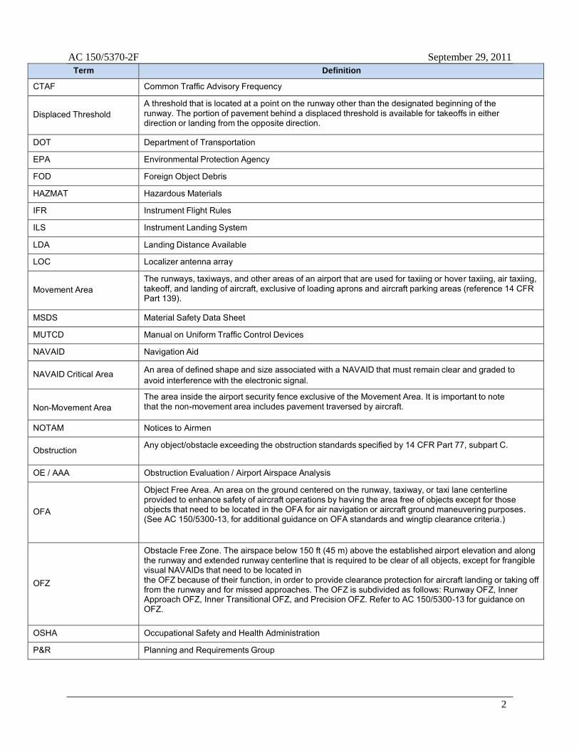
AC 150/5370-2F September 29, 2011
2
Term Definition
CTAF Common Traffic Advisory Frequency
Displaced Threshold
A threshold that is located at a point on the runway other than the designated beginning of the runway. The portion of pavement behind a displaced threshold is available for takeoffs in either direction or landing from the opposite direction.
DOT Department of Transportation
EPA Environmental Protection Agency
FOD Foreign Object Debris
HAZMAT Hazardous Materials
IFR Instrument Flight Rules
ILS Instrument Landing System
LDA Landing Distance Available
LOC Localizer antenna array
Movement Area
The runways, taxiways, and other areas of an airport that are used for taxiing or hover taxiing, air taxiing, takeoff, and landing of aircraft, exclusive of loading aprons and aircraft parking areas (reference 14 CFR Part 139).
MSDS Material Safety Data Sheet
MUTCD Manual on Uniform Traffic Control Devices
NAVAID Navigation Aid
NAVAID Critical Area An area of defined shape and size associated with a NAVAID that must remain clear and graded to avoid interference with the electronic signal.
Non-Movement Area
The area inside the airport security fence exclusive of the Movement Area. It is important to note that the non-movement area includes pavement traversed by aircraft.
NOTAM Notices to Airmen
Obstruction Any object/obstacle exceeding the obstruction standards specified by 14 CFR Part 77, subpart C.
OE / AAA Obstruction Evaluation / Airport Airspace Analysis
OFA
Object Free Area. An area on the ground centered on the runway, taxiway, or taxi lane centerline provided to enhance safety of aircraft operations by having the area free of objects except for those objects that need to be located in the OFA for air navigation or aircraft ground maneuvering purposes. (See AC 150/5300-13, for additional guidance on OFA standards and wingtip clearance criteria.)
OFZ
Obstacle Free Zone. The airspace below 150 ft (45 m) above the established airport elevation and along the runway and extended runway centerline that is required to be clear of all objects, except for frangible visual NAVAIDs that need to be located in the OFZ because of their function, in order to provide clearance protection for aircraft landing or taking off from the runway and for missed approaches. The OFZ is subdivided as follows: Runway OFZ, Inner Approach OFZ, Inner Transitional OFZ, and Precision OFZ. Refer to AC 150/5300-13 for guidance on OFZ.
OSHA Occupational Safety and Health Administration
P&R Planning and Requirements Group
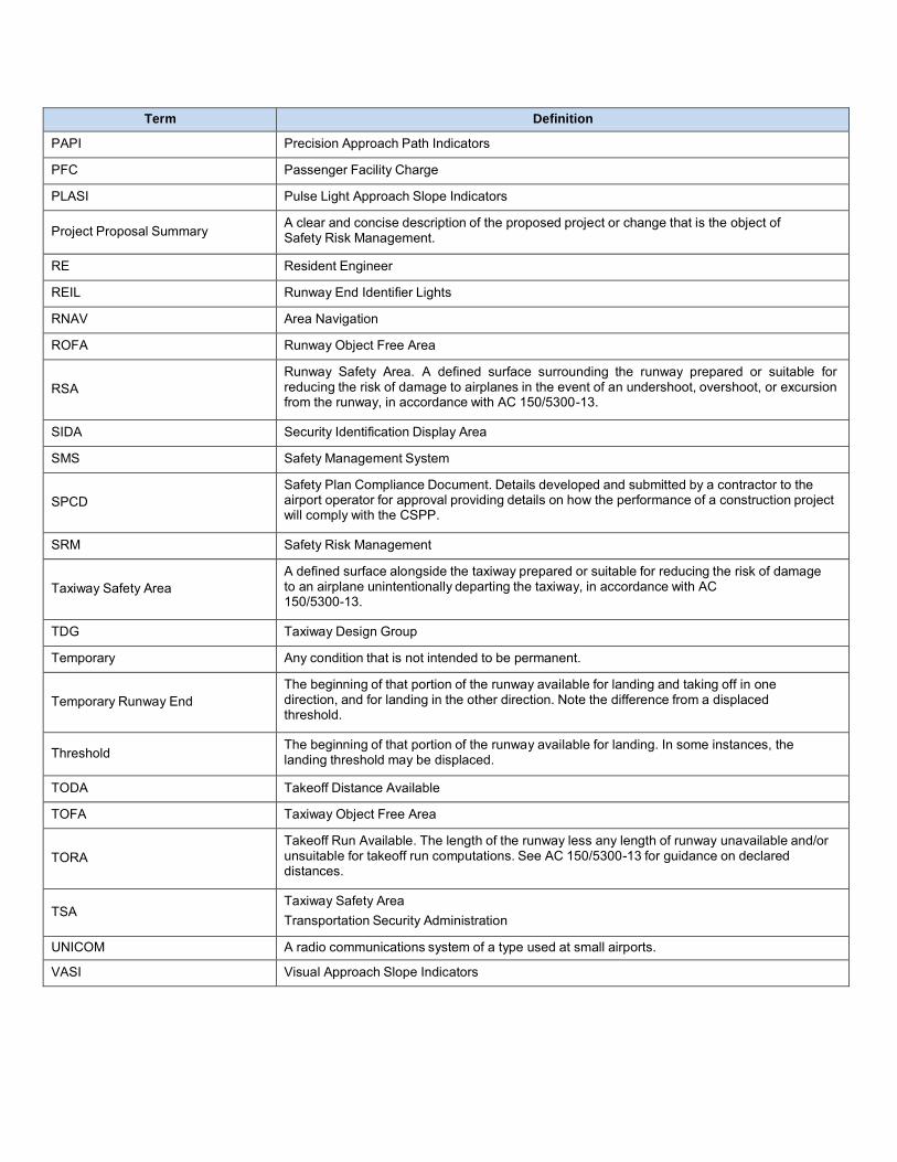
Term Definition
PAPI Precision Approach Path Indicators
PFC Passenger Facility Charge
PLASI Pulse Light Approach Slope Indicators
Project Proposal Summary A clear and concise description of the proposed project or change that is the object of Safety Risk Management.
RE Resident Engineer
REIL Runway End Identifier Lights
RNAV Area Navigation
ROFA Runway Object Free Area
RSA
Runway Safety Area. A defined surface surrounding the runway prepared or suitable for reducing the risk of damage to airplanes in the event of an undershoot, overshoot, or excursion from the runway, in accordance with AC 150/5300-13.
SIDA Security Identification Display Area
SMS Safety Management System
SPCD
Safety Plan Compliance Document. Details developed and submitted by a contractor to the airport operator for approval providing details on how the performance of a construction project will comply with the CSPP.
SRM Safety Risk Management
Taxiway Safety Area
A defined surface alongside the taxiway prepared or suitable for reducing the risk of damage to an airplane unintentionally departing the taxiway, in accordance with AC 150/5300-13.
TDG Taxiway Design Group
Temporary Any condition that is not intended to be permanent.
Temporary Runway End
The beginning of that portion of the runway available for landing and taking off in one direction, and for landing in the other direction. Note the difference from a displaced threshold.
Threshold The beginning of that portion of the runway available for landing. In some instances, the
landing threshold may be displaced.
TODA Takeoff Distance Available
TOFA Taxiway Object Free Area
TORA
Takeoff Run Available. The length of the runway less any length of runway unavailable and/or unsuitable for takeoff run computations. See AC 150/5300-13 for guidance on declared distances.
TSA
Taxiway Safety Area Transportation Security Administration
UNICOM A radio communications system of a type used at small airports.
VASI Visual Approach Slope Indicators

AC 150/5370-2F September 29, 2011
4
Term Definition
VGSI
Visual Glide Slope Indicator. A device that provides a visual glide slope indicator to landing pilots. These systems include precision approach path indicators (PAPI), visual approach slope indicators (VASI), and pulse light approach slope indicators (PLASI).
VFR Visual Flight Rules
VOR VHF Omnidirectional Radio Range
VPD Vehicle / Pedestrian Deviation

Appendix 2
Geotechnical Report
August 6, 2015 CTE Project No. 40-3128 Mead & Hunt, Inc. Attn. Mr. Robert Casagrande 133 Aviation Boulevard, Suite 100 Santa Rosa, California 95403 Subject: Report of Geotechnical Investigation French Valley Airport Project County of Riverside, California Dear Mr. Casagrande: CTE South, Inc. (CTE) is pleased to submit this report for the subject project. The site is located in Riverside County, California at the French Valley Airport. PROPOSED CONSTRUCTION AND SCOPE OF SERVICES The French Valley Airport project will consist of reconstruction of the existing asphalt apron. The existing apron consists of asphalt concrete (AC) overlying compacted base and subbase. The existing pavement is weathered and has numerous large cracks through the AC. The work was performed within an active Air Operations Area adjacent to Taxiway A. The scope of work consisted of drilling 16, 10-foot deep borings on the apron. Field CBR tests were performed at two of the locations and laboratory CBR tests were performed on samples from three other locations. Specifically, the scope of work consisted of the following:
• Measure the thickness of existing asphalt and aggregate base and subbase. • USCS classification of soils encountered. • Logs of the test borings • Liquid limit, plastic limit and plasticity index of selected samples of site soils. • Maximum density/optimum moisture content per ASTM D 698. • California Bearing Ratio per ASTM D 1883 • In-situ California Bearing Ratio per ASTM D 4429. • Discussion of subsurface conditions obtained from the boring program.

Report of Geotechnical Investigation French Valley Airport Apron Replacement Riverside County, California August 6, 2015 CTE Job No. 40-3128G
Page 2
FIELD AND LABORATORY INVESTIGATION
Field Investigation
Our field investigation was performed on June 23 and 24, 2015 and included 16 exploratory borings identified as B-1 through B-16. These borings were drilled at locations within the apron adjacent to Taxiway A. In addition, two field CBR tests were run in borings B-3 and B-13. The exploration locations are shown on Figure 1. The explorations were excavated to investigate and obtain samples of the subsurface soils. The borings were excavated using a truck-mounted, eight-inch diameter, hollow-stem auger drill rig to a maximum explored depth of 11-1/2 feet below the existing pavement surface. Soils encountered within the explorations were classified in the field in accordance with the Unified Soil Classification System. The field descriptions were later modified (as appropriate) based on the results of our laboratory-testing program. In general, soil samples were obtained at depths of 1, 5 and 10 feet with standard split spoon (SPT and California Modified) samplers. Bulk samples were obtained from borings B-5, B-11 and B-12 for laboratory testing. Specifics of the soils encountered can be found in the Exploration Logs, which are presented in Appendix A.
Laboratory Analyses Laboratory tests were conducted on representative soil samples. Specific laboratory tests included: maximum dry density and optimum moisture content, in-place moisture and density, CBR, Atterberg limits, and 200 washes. Test method descriptions and laboratory results are presented in Appendix B and on the Exploration Logs. SITE MATERIALS ENCOUNTERED Based on our investigation, the site is underlain by medium dense to very dense clayey and silty sand and medium stiff to stiff clay and sandy clay. The borings encountered 2 to 3 inches of AC overlying 4-1/2 to 5-1/2 inches of aggregate base and 10 to 11 inches of subbase. A woven, biaxial filter fabric overlying natural subgrade soils was encountered at a depth of approximately 1-1/2 feet. Thicknesses of pavement structural components are presented in Table 1. Underlying the pavement section, very old alluvial channel deposits, consisting of medium dense to very dense clayey sand and firm to hard sandy lean clay, were encountered in each of the borings. Fractured rock was encountered at approximately 7 feet in boring B-4. Groundwater was not encountered in the borings. More detailed descriptions are provided in the exploration logs in Appendix A.

Report of Geotechnical Investigation French Valley Airport Apron Replacement Riverside County, California August 6, 2015 CTE Job No. 40-3128G
Page 3
TABLE 1 PAVEMENT STRUCTURAL SECTIONS Boring No. AC
(inches) Aggregate Base (inches)
Subbase (inches)
B-1 2-1/2 5-1/2 10 B-2 2-1/2 4-1/2 11 B-3 2-1/2 5-1/2 10 B-4 2-1/2 5-1/2 10 B-5 2-1/2 5 10-1/2 B-6 2-1/2 5 10-1/2
B-7 2-1/2 5 10-1/2 B-8 2-1/2 5-1/2 10-1/2 B-9 2 5 10-1/2 B-10 2-1/2 5 10-1/2
B-11 2-1/2 5 10-1/2 B-12 3 4-1/2 10-1/2 B-13 2-1/2 5 10-1/2 B-14 2 5 11 B-15 2-1/2 5-1/2 10 B-16 3 5 10
The on-site soils should be placed and compacted in accordance with FAA specifications. Proper compaction equipment and moisture control will be critical to achieve specified compaction. The contractor should be aware of the difficulties compacting clay soils. If these soils have high moisture contents, they may need to be dried or replaced. Spreading and working these soils will be necessary to reduce or increase moisture content. These soils should be spread in thin layers and turned over using a disc or other suitable equipment. Compaction of clay soils should utilize kneading or sheepsfoot compactors. Major compaction problems are not anticipated in granular soils provided moisture content is carefully controlled. Base, granular soils and pavement may be compacted using smooth drum (vibratory) and smooth-wheeled compactors. Granular soils should be placed wet of optimum. It is the responsibility of the contractor to utilize proper equipment to compact site soils. FIELD AND LABORATORY TEST RESULTS Field CBR Tests Field CBR tests were performed in borings B-3 and B-13. Tests were performed in accordance with ASTM D 4429. Tests were taken in the subgrade soils below the fabric at a depth of approximately three feet. Plots of the field results are included in Appendix C. Table 2 presents a summary of the test results.

Report of Geotechnical Investigation French Valley Airport Apron Replacement Riverside County, California August 6, 2015 CTE Job No. 40-3128G
Page 4
TABLE 2 FIELD CBR TEST RESULTS
Boring No. Depth (inches)
CBR at 0.1” Penetration
B-3 36 24
B-13 36 20
Laboratory CBR Tests Laboratory CBR tests were performed on samples obtained from the borings in accordance with ASTM D 1883. Laboratory test results are presented in Appendix B. A summary of the laboratory CBR test results is presented in Table 3.
TABLE 3 LABORATORY CBR TEST RESULTS
Boring No. Depth (feet)
CBR at 0.1” or 0.2” Penetration 90% 95% 100%
B-5 1-5 1 3 8
B-11 1-5 3 7 16
B-12 1-5 1 2 3
Maximum Density- Optimum Moisture Content Tests Maximum density/optimum moisture content tests were performed on three samples obtained from the borings B-5, B-11 and B-12. Tests were performed in accordance with ASTM D 698. Test results are included in Appendix B. A summary of test results is presented in Table 4.
TABLE 4 MAXIMUM DENSITY/OPTIMUM MOISTURE CONTENT TEST RESULTS
Boring No. Depth (feet)
Maximum Density (pcf)
Opt. Moisture Content (%)
B-5 1-5 126.9 8.9
B-11 1-5 118.1 11.7
B-12 1-5 113.1 12.5

Report of Geotechnical Investigation French Valley Airport Apron Replacement Riverside County, California August 6, 2015 CTE Job No. 40-3128G
Page 5
Atterberg Limits & In-situ Moisture/Density Atterberg limits were performed on selected samples obtained from the borings in accordance with ASTM D 4318. In-situ moisture /density (ASTM D 2216 and D 2937) tests were performed on selected samples of undisturbed soil. Atterberg limits results are presented in Table 5. In-situ moisture/density and Atterberg limits tests are presented on the boring logs.
TABLE 5 ATTERBERG LIMITS TEST RESULTS
Boring No. Depth (feet)
Liquid Limit %
Plastic Limit %
Plasticity Index %
USCS (entire sample)
B-2 1-2.5 33 21 12 CL
B-6 1-2.5 31 21 10 SC
B-11 1-2.5 35 22 13 SC
B-16 1-5 28 17 11 SC We appreciate this opportunity to be of service on this project. If you have questions regarding this report, please do not hesitate to contact the undersigned. Respectfully submitted, CTE, South, Inc.
Clifford A. Craft, GE #243 Vincent J. Patula, CEG #2057 Senior Geotechnical Engineer Senior Engineering Geologist
Robert L. Ellerbusch Staff Geologist


APPENDIX A
FIELD EXPLORATION METHODS AND EXPLORATION LOGS

APPENDIX A
FIELD EXPLORATION METHODS AND EXPLORATION LOGS
Soil Boring Methods Relatively “Undisturbed” Soil Samples Relatively “undisturbed” soil samples were collected using a modified California-drive sampler (2.4-inch inside diameter, 3-inch outside diameter) lined with sample rings. Drive sampling was conducted in general accordance with ASTM D-3550. The steel sampler was driven into the bottom of the borehole with successive drops of a 140-pound weight falling 30-inches. Blow counts (N) required for sampler penetration are shown on the boring logs in the column “Blows/Foot.” The soil was retained in brass rings (2.4 inches in diameter, 1.0 inch in height) and sealed in waterproof plastic containers for shipment to the CTE, South, Inc. geotechnical laboratory. Disturbed Soil Sampling Bulk soil samples were collected for laboratory analysis using two methods. Standard Penetration Tests (SPT) were performed according to ASTM D-1586 at selected depths in the borings using a standard (1.4-inches inside diameter, 2-inches outside diameter) split-barrel sampler. The steel sampler was driven into the bottom of the borehole with successive drops of a 140-pound weight falling 30-inches. Blow counts (N) required for sampler penetration are shown on the boring logs in the column “Blows/Foot.” Samples collected in this manner were placed in sealed plastic bags. Bulk soil samples of the drill cuttings were also collected in large plastic bags. The disturbed soil samples were returned to the CTE, South, Inc. geotechnical laboratory for analysis.
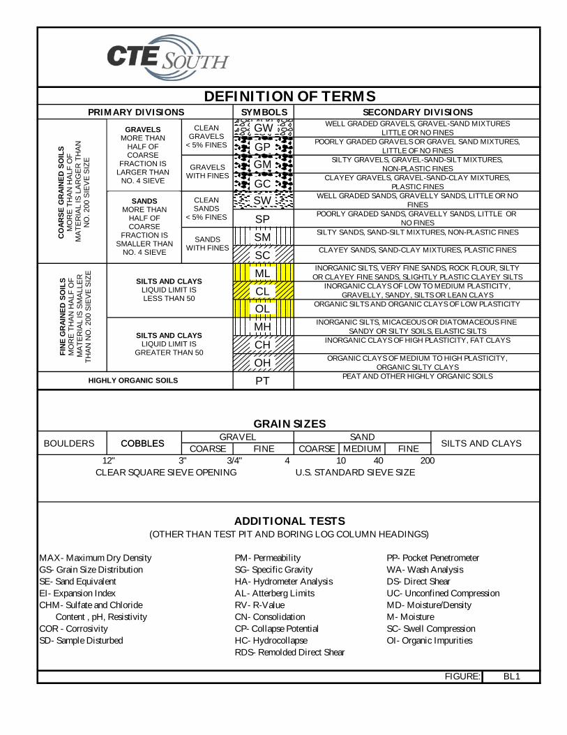
DEFINITION OF TERMSPRIMARY DIVISIONS SYMBOLS SECONDARY DIVISIONS
WELL GRADED GRAVELS, GRAVEL-SAND MIXTURESLITTLE OR NO FINES
POORLY GRADED GRAVELS OR GRAVEL SAND MIXTURES,LITTLE OF NO FINES
SILTY GRAVELS, GRAVEL-SAND-SILT MIXTURES,NON-PLASTIC FINES
CLAYEY GRAVELS, GRAVEL-SAND-CLAY MIXTURES,PLASTIC FINES
WELL GRADED SANDS, GRAVELLY SANDS, LITTLE OR NOFINES
POORLY GRADED SANDS, GRAVELLY SANDS, LITTLE OR NO FINES
SILTY SANDS, SAND-SILT MIXTURES, NON-PLASTIC FINES
CLAYEY SANDS, SAND-CLAY MIXTURES, PLASTIC FINES
INORGANIC SILTS, VERY FINE SANDS, ROCK FLOUR, SILTYOR CLAYEY FINE SANDS, SLIGHTLY PLASTIC CLAYEY SILTS
INORGANIC CLAYS OF LOW TO MEDIUM PLASTICITY,GRAVELLY, SANDY, SILTS OR LEAN CLAYS
ORGANIC SILTS AND ORGANIC CLAYS OF LOW PLASTICITY
INORGANIC SILTS, MICACEOUS OR DIATOMACEOUS FINE SANDY OR SILTY SOILS, ELASTIC SILTS
INORGANIC CLAYS OF HIGH PLASTICITY, FAT CLAYS
ORGANIC CLAYS OF MEDIUM TO HIGH PLASTICITY,ORGANIC SILTY CLAYS
PEAT AND OTHER HIGHLY ORGANIC SOILS
GRAIN SIZESGRAVEL SAND
COARSE FINE COARSE MEDIUM FINE 12" 3" 3/4" 4 10 40 200
CLEAR SQUARE SIEVE OPENING U.S. STANDARD SIEVE SIZE
ADDITIONAL TESTS(OTHER THAN TEST PIT AND BORING LOG COLUMN HEADINGS)
MAX- Maximum Dry Density PM- Permeability PP- Pocket PenetrometerGS- Grain Size Distribution SG- Specific Gravity WA- Wash AnalysisSE- Sand Equivalent HA- Hydrometer Analysis DS- Direct ShearEI- Expansion Index AL- Atterberg Limits UC- Unconfined CompressionCHM- Sulfate and Chloride RV- R-Value MD- Moisture/Density Content , pH, Resistivity CN- Consolidation M- MoistureCOR - Corrosivity CP- Collapse Potential SC- Swell CompressionSD- Sample Disturbed HC- Hydrocollapse OI- Organic Impurities
RDS- Remolded Direct Shear
FIGURE: BL1
GW
SILTS AND CLAYS LIQUID LIMIT IS LESS THAN 50
SILTS AND CLAYS LIQUID LIMIT IS
GREATER THAN 50
SANDS MORE THAN
HALF OF COARSE
FRACTION IS SMALLER THAN
NO. 4 SIEVE
GRAVELS MORE THAN
HALF OF COARSE
FRACTION IS LARGER THAN
NO. 4 SIEVE
CLEAN GRAVELS
< 5% FINES
GRAVELS WITH FINES
CLEAN SANDS
< 5% FINES
SANDS WITH FINES
CO
AR
SE
GR
AIN
ED
SO
ILS
M
OR
E T
HA
N H
ALF
OF
M
AT
ER
IAL
IS L
AR
GE
R T
HA
N
NO
. 200
SIE
VE
SIZ
E
GP
GM
GC
SW
SP
SM
SC
ML
CL
OL
MH
CH
OH
PT
FIN
E G
RA
INE
D S
OIL
S
MO
RE
TH
AN
HA
LF O
F
MA
TE
RIA
L IS
SM
ALL
ER
T
HA
N N
O. 2
00 S
IEV
E S
IZE
HIGHLY ORGANIC SOILS
SILTS AND CLAYS COBBLES COBBLES BOULDERS

PROJECT: DRILLER: SHEET: ofCTE JOB NO: DRILL METHOD: DRILLING DATE:
LOGGED BY: SAMPLE METHOD: ELEVATION:
Dep
th (
Feet
)
Bul
k
Sa
mpl
e
Dri
ven
Typ
e
Blo
ws/
Foot
Dry
Den
sity
(pc
f)
Moi
stur
e (%
)
U.S
.C.S
. Sym
bol
Gra
phic
Log BORING LEGEND Laboratory Tests
DESCRIPTION
Block or Chunk Sample
Bulk Sample
Standard Penetration Test
Modified Split-Barrel Drive Sampler (Cal Sampler)
Groundwater Table
Soil Type or Classification Change
? ? ? ? ? ? ?
Formation Change [(Approximate boundaries queried (?)]
"SM" Quotes are placed around classifications where the soilsexist in situ as bedrock
FIGURE: BL2

Boring B-1
PROJECT: SHEET: of
CTE JOB NO: DRILL METHOD: DRILLING DATE:
LOGGED BY: SAMPLE METHOD: ELEVATION:
Dep
th (
Feet
)
Bul
k
Sa
mpl
e
Dri
ven
Typ
e
Blo
ws/
6 in
ches
Dry
Den
sity
(pc
f)
Moi
stur
e (%
)
U.S
.C.S
. Sym
bol
Gra
phic
Log
DESCRIPTION
SC
14 Clayey SAND, very dense, damp, grayish brown, fractured rock43 fragments, well-indurated.50 3.5
3327
50/5" 3.7 fragments, well indurated.
Clayey SAND with scattered gravel, moist, brown.
M
M
Total depth 11.5 ft. below pavement surface.
B-1
Bore hole backfilled with soil cuttings and capped with 8" of No ground water encountered.
concrete.
2.5" AC over 5.5" Base over 10" Subbase (clayey sand)
(woven biaxial filter fabric encountered at approximately 1.5 ft.)Very Old Alluvial Channel Deposits (Qvoa)
Clayey SAND, very dense, damp, grayish brown, fractured rock
2R Drilling CME 75
8" Hollow Stem Auger
140 lb/30" Autohammer
40-3128
BORING: B-1
R. Ellerbusch
DRILLER: 1 1French Valley Airport Pavement Rehab.
6/24/2015
Laboratory Tests
0
5
10
15
20
25

Boring B-2
PROJECT: SHEET: of
CTE JOB NO: DRILL METHOD: DRILLING DATE:
LOGGED BY: SAMPLE METHOD: ELEVATION:
Dep
th (
Feet
)
Bul
k
Sa
mpl
e
Dri
ven
Typ
e
Blo
ws/
6 in
ches
Dry
Den
sity
(pc
f)
Moi
stur
e (%
)
U.S
.C.S
. Sym
bol
Gra
phic
Log
DESCRIPTION
44 CL9 13.9
568 12.5
2513 12.1
2R Drilling CME 75
8" Hollow Stem Auger
140 lb/30" Autohammer
40-3128
R. Ellerbusch
Laboratory Tests
DRILLER: 1 1French Valley Airport Pavement Rehab.
BORING: B-2
Lean CLAY with Sand, very stiff, moist, dark gray.
2.5" AC over 4.5" Base over 11" Subbase (sandy clay)
(woven biaxial filter fabric encountered at approximately 1.5 ft.)Very Old Alluvial Channel Deposits (Qvoa)
Bore hole backfilled with soil cuttings and capped with 8" of No ground water encountered.
concrete.
B-2
Sandy Lean CLAY, stiff, moist, reddish brown, carbonate veinlets
6/24/2015
WA (51% pass #200)AL (LL=33, PI=12)
MSandy Lean CLAY, stiff, moist, reddish-brown, trace gravel.
Total depth 11.5 ft. below pavement surface.
M
M
0
5
10
15
20
25

Boring B-3
PROJECT: SHEET: of
CTE JOB NO: DRILL METHOD: DRILLING DATE:
LOGGED BY: SAMPLE METHOD: ELEVATION:
Dep
th (
Feet
)
Bul
k
Sa
mpl
e
Dri
ven
Typ
e
Blo
ws/
6 in
ches
Dry
Den
sity
(pc
f)
Moi
stur
e (%
)
U.S
.C.S
. Sym
bol
Gra
phic
Log
DESCRIPTION
CL
236 14.8
15 SC1628 9.3
Sandy Lean CLAY, stiff, moist, reddish-brown, trace gravel.
Field CBR conducted at approximately 3 ft.
M
M
Total depth 11.5 ft. below pavement surface.
B-3
Bore hole backfilled with soil cuttings and capped with 8" of No ground water encountered.
concrete.
2.5" AC over 5.5" Base over 10" Subbase (sandy clay)
(woven biaxial filter fabric encountered at approximately 1.5 ft.)
Lean CLAY, stiff, moist, dark gray.
Very Old Alluvial Channel Deposits (Qvoa)
Clayey SAND, dense, moist, dark brown, carbonate concretions.
2R Drilling CME 75
8" Hollow Stem Auger
140 lb/30" Autohammer
40-3128
BORING: B-3
R. Ellerbusch
DRILLER: 1 1French Valley Airport Pavement Rehab.
6/24/2015
Laboratory Tests
0
5
10
15
20
25

Boring B-4
PROJECT: SHEET: of
CTE JOB NO: DRILL METHOD: DRILLING DATE:
LOGGED BY: SAMPLE METHOD: ELEVATION:
Dep
th (
Feet
)
Bul
k
Sa
mpl
e
Dri
ven
Typ
e
Blo
ws/
6 in
ches
Dry
Den
sity
(pc
f)
Moi
stur
e (%
)
U.S
.C.S
. Sym
bol
Gra
phic
Log
DESCRIPTION
1232 SC
50/4" 142.0 6.5
37 SC-SM50/4" 2.1
50/5" 2.9
2R Drilling CME 75
8" Hollow Stem Auger
140 lb/30" Autohammer
40-3128
R. Ellerbusch
Laboratory Tests
DRILLER: 1 1French Valley Airport Pavement Rehab.
BORING: B-4
Fractured granitic rock, dark gray and brown, weathered.
2.5" AC over 5.5" Base over 10" Subbase (clayey sand)
(woven biaxial filter fabric encountered at approximately 1.5 ft.)
fractured rock fragments.
Very Old Alluvial Channel Deposits (Qvoa)
Fractured granitic rock, dark gray(very hard drilling from 7' to 9' - rock)
M
concrete.
B-4
Silty Clayey SAND, very dense, damp, dark grayish brown,
6/23/2015
Clayey SAND, dense, moist, dark grayish brown. MD
No ground water encountered.Total depth 10.4 ft. below pavement surface.
Bore hole backfilled with soil cuttings and capped with 8" of
M
0
5
10
15
20
25

Boring B-5
PROJECT: SHEET: of
CTE JOB NO: DRILL METHOD: DRILLING DATE:
LOGGED BY: SAMPLE METHOD: ELEVATION:
Dep
th (
Feet
)
Bul
k
Sa
mpl
e
Dri
ven
Typ
e
Blo
ws/
6 in
ches
Dry
Den
sity
(pc
f)
Moi
stur
e (%
)
U.S
.C.S
. Sym
bol
Gra
phic
Log
DESCRIPTION
1613 SC16 116.1 14.3
2 CL47 12.2
368 18.7
Clayey SAND, medium dense, moist, brown, trace gravel.CBR, MAX
MD
Sandy Lean CLAY, stiff, moist, dark gray.
Sandy Lean CLAY, stiff, very moist, light brown, carbonate
M
M
Total depth 11.5 ft. below pavement surface.
B-5
Bore hole backfilled with soil cuttings and capped with 8" of No ground water encountered.
concrete.
2.5" AC over 5" Base over 10.5" Subbase (clayey sand)
(woven biaxial filter fabric encountered at approximately 1.5 ft.)Very Old Alluvial Channel Deposits (Qvoa)
concretions.
2R Drilling CME 75
8" Hollow Stem Auger
140 lb/30" Autohammer
40-3128
BORING: B-5
R. Ellerbusch
DRILLER: 1 1French Valley Airport Pavement Rehab.
6/23/2015
Laboratory Tests
0
5
10
15
20
25

Boring B-6
PROJECT: SHEET: of
CTE JOB NO: DRILL METHOD: DRILLING DATE:
LOGGED BY: SAMPLE METHOD: ELEVATION:
Dep
th (
Feet
)
Bul
k
Sa
mpl
e
Dri
ven
Typ
e
Blo
ws/
6 in
ches
Dry
Den
sity
(pc
f)
Moi
stur
e (%
)
U.S
.C.S
. Sym
bol
Gra
phic
Log
DESCRIPTION
48 SC9 13.4
45 CL9 104.3 19.4
559 7.6
2R Drilling CME 75
8" Hollow Stem Auger
140 lb/30" Autohammer
40-3128
R. Ellerbusch
Laboratory Tests
DRILLER: 1 1French Valley Airport Pavement Rehab.
BORING: B-6
Sandy Lean CLAY, stiff, moist, dark reddish brown.
2.5" AC over 5" Base over 10.5" Subbase (clayey sand)
(woven biaxial filter fabric encountered at approximately 1.5 ft.)
Lean CLAY, stiff, very moist, dark gray.
Very Old Alluvial Channel Deposits (Qvoa)
Bore hole backfilled with soil cuttings and capped with 8" of No ground water encountered.
concrete.
B-6
6/23/2015
WA (45% pass #200)AL (LL=31, PI=10)
Clayey SAND, dense, moist, brown, trace gravel. M
Total depth 11.5 ft. below pavement surface.
MD
M
0
5
10
15
20
25

Boring B-7
PROJECT: SHEET: of
CTE JOB NO: DRILL METHOD: DRILLING DATE:
LOGGED BY: SAMPLE METHOD: ELEVATION:
Dep
th (
Feet
)
Bul
k
Sa
mpl
e
Dri
ven
Typ
e
Blo
ws/
6 in
ches
Dry
Den
sity
(pc
f)
Moi
stur
e (%
)
U.S
.C.S
. Sym
bol
Gra
phic
Log
DESCRIPTION
55 SC-SM6 10.6
7 SC1313 8.7
41013 8.9
B-7
Bore hole backfilled with soil cuttings and capped with 8" of concrete.
Total depth 11.5 ft. below pavement surface.No ground water encountered.
Clayey SAND, medium dense, moist, reddish brown.M
M
Clayey SAND, medium dense, moist, reddish brown.
(woven biaxial filter fabric encountered at approximately 1.5 ft.)Very Old Alluvial Channel Deposits (Qvoa)Silty Clayey SAND, medium dense, moist, orangish brown. M
2.5" AC over 5" Base over 10.5" Subbase (clayey sand)
R. Ellerbusch 140 lb/30" Autohammer
BORING: B-7 Laboratory Tests
French Valley Airport Pavement Rehab. DRILLER: 2R Drilling CME 75 1 1
40-3128 8" Hollow Stem Auger 6/23/2015
0
5
10
15
20
25
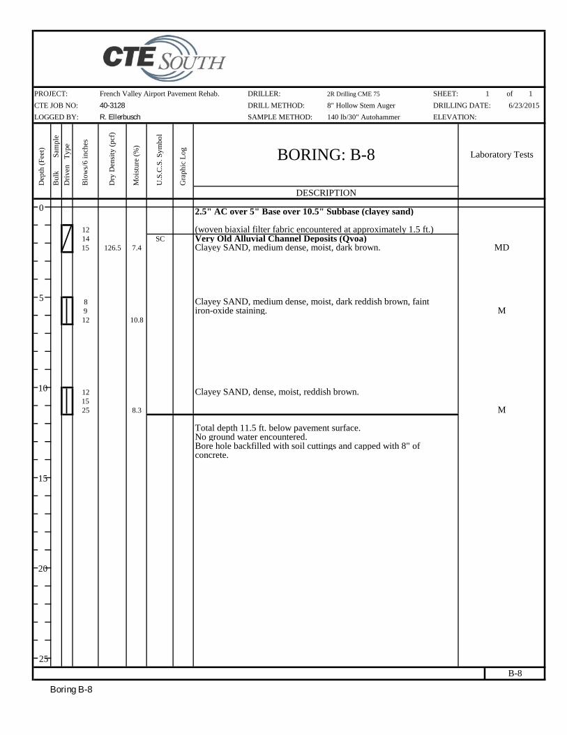
Boring B-8
PROJECT: SHEET: of
CTE JOB NO: DRILL METHOD: DRILLING DATE:
LOGGED BY: SAMPLE METHOD: ELEVATION:
Dep
th (
Feet
)
Bul
k
Sa
mpl
e
Dri
ven
Typ
e
Blo
ws/
6 in
ches
Dry
Den
sity
(pc
f)
Moi
stur
e (%
)
U.S
.C.S
. Sym
bol
Gra
phic
Log
DESCRIPTION
1214 SC15 126.5 7.4
8912 10.8
121525 8.3
B-8
Bore hole backfilled with soil cuttings and capped with 8" of concrete.
Total depth 11.5 ft. below pavement surface.No ground water encountered.
Clayey SAND, dense, moist, reddish brown.
M
iron-oxide staining. MClayey SAND, medium dense, moist, dark reddish brown, faint
(woven biaxial filter fabric encountered at approximately 1.5 ft.)Very Old Alluvial Channel Deposits (Qvoa)Clayey SAND, medium dense, moist, dark brown. MD
2.5" AC over 5" Base over 10.5" Subbase (clayey sand)
R. Ellerbusch 140 lb/30" Autohammer
BORING: B-8 Laboratory Tests
French Valley Airport Pavement Rehab. DRILLER: 2R Drilling CME 75 1 1
40-3128 8" Hollow Stem Auger 6/23/2015
0
5
10
15
20
25
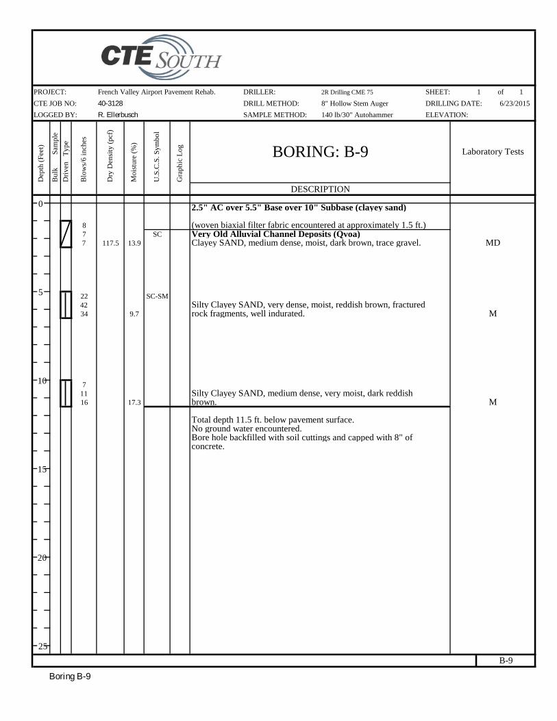
Boring B-9
PROJECT: SHEET: of
CTE JOB NO: DRILL METHOD: DRILLING DATE:
LOGGED BY: SAMPLE METHOD: ELEVATION:
Dep
th (
Feet
)
Bul
k
Sa
mpl
e
Dri
ven
Typ
e
Blo
ws/
6 in
ches
Dry
Den
sity
(pc
f)
Moi
stur
e (%
)
U.S
.C.S
. Sym
bol
Gra
phic
Log
DESCRIPTION
87 SC7 117.5 13.9
22 SC-SM4234 9.7
71116 17.3
B-9
Bore hole backfilled with soil cuttings and capped with 8" of concrete.
Total depth 11.5 ft. below pavement surface.No ground water encountered.
Silty Clayey SAND, medium dense, very moist, dark reddishbrown. M
Silty Clayey SAND, very dense, moist, reddish brown, fracturedrock fragments, well indurated. M
(woven biaxial filter fabric encountered at approximately 1.5 ft.)Very Old Alluvial Channel Deposits (Qvoa)Clayey SAND, medium dense, moist, dark brown, trace gravel. MD
2.5" AC over 5.5" Base over 10" Subbase (clayey sand)
R. Ellerbusch 140 lb/30" Autohammer
BORING: B-9 Laboratory Tests
French Valley Airport Pavement Rehab. DRILLER: 2R Drilling CME 75 1 1
40-3128 8" Hollow Stem Auger 6/23/2015
0
5
10
15
20
25

Boring B-10
PROJECT: SHEET: of
CTE JOB NO: DRILL METHOD: DRILLING DATE:
LOGGED BY: SAMPLE METHOD: ELEVATION:
Dep
th (
Feet
)
Bul
k
Sa
mpl
e
Dri
ven
Typ
e
Blo
ws/
6 in
ches
Dry
Den
sity
(pc
f)
Moi
stur
e (%
)
U.S
.C.S
. Sym
bol
Gra
phic
Log
DESCRIPTION
97 CL
11 13.0
15 SC36
50/5" 126.0 9.5
141622 8.1
B-10
Bore hole backfilled with soil cuttings and capped with 8" of concrete.
Total depth 11.5 ft. below pavement surface.No ground water encountered.
Clayey SAND, dense, moist, reddish brown.M
MD
Clayey SAND, very dense, moist, reddish brown, well indurated.
(woven biaxial filter fabric encountered at approximately 1.5 ft.)Very Old Alluvial Channel Deposits (Qvoa)Sandy Lean CLAY, very stiff, moist, dark brown, trace gravel. M
2.5" AC over 5" Base over 10.5" Subbase (sandy clay)
R. Ellerbusch 140 lb/30" Autohammer
BORING: B-10 Laboratory Tests
French Valley Airport Pavement Rehab. DRILLER: 2R Drilling CME 75 1 1
40-3128 8" Hollow Stem Auger 6/23/2015
0
5
10
15
20
25

Boring B-11
PROJECT: SHEET: of
CTE JOB NO: DRILL METHOD: DRILLING DATE:
LOGGED BY: SAMPLE METHOD: ELEVATION:
Dep
th (
Feet
)
Bul
k
Sa
mpl
e
Dri
ven
Typ
e
Blo
ws/
6 in
ches
Dry
Den
sity
(pc
f)
Moi
stur
e (%
)
U.S
.C.S
. Sym
bol
Gra
phic
Log
DESCRIPTION
76 SC8 19.9
161513 123.2 9.5
5 CL813 16.9
B-11
Bore hole backfilled with soil cuttings and capped with 8" of concrete.
Total depth 11.5 ft. below pavement surface.No ground water encountered.
Sandy Lean CLAY, very stiff, moist, dark brown.M
MD
Clayey SAND, medium dense, moist, reddish brown.
CBR, MAX
(woven biaxial filter fabric encountered at approximately 1.5 ft.) WA (40% pass #200)Very Old Alluvial Channel Deposits (Qvoa) AL (LL=35, PI=13)Clayey SAND, medium dense, very moist, dark brown. M
2.5" AC over 5" Base over 10.5" Subbase (clayey sand)
R. Ellerbusch 140 lb/30" Autohammer
BORING: B-11 Laboratory Tests
French Valley Airport Pavement Rehab. DRILLER: 2R Drilling CME 75 1 1
40-3128 8" Hollow Stem Auger 6/23/2015
0
5
10
15
20
25