
3-41marcis
8
1 INTRODUCTION 1.1 Backgroun d Cone penetration testing (CPT) has recently gained importance in pile design, due to both the reduction of the cost of such investigations and the need for more precise and accurate estimations of the bearing capacity of piles. The growing interest in construct- ing on-shore and, above all, off-shore pile installations has prompted several design codes to adopt new and more refined CPT-based design methods. Even the most recent version of API RP2A (2007) has accepted four modern techniques based on CPT (UWA-05, NGI-05, ICP-05, Fugro-05), replacing the traditional approach based on plas- ticity theory. Among the existing types of piles a relatively new one, known as jacked or pressed-in piles, is becoming more widely used. Jacked piles combine a high bearing ca- pacity and stiffness, ev en higher than driven piles (Deeks et al., 2005; Yetginer et al., 2006), with low levels of noise and vibration during installation (White et al., 2002), which makes them particularly suitable for urban applications. However, the fact that existing design methods are, at least partly, calibrated on data coming from dynamically installed piles, requires designers to pay particular attention. The possibility of getting Comparing in-situ cone resistance and pile jacking force M. Marchi, L. Balbarini & G. Gottardi DISTART U niversity o f Bologna, ITALY L. Zambianchi Soles S.p.A., ITALY ABSTRACT: Pile jacking is a relatively recent piling technique, characterized by low vibrations during execution, small size installation equipment and good axial bearing capacity performance. These features make it a viable alternative to traditional dy- namic pile driving, particularly for historical buildings and urban sites. The prediction of the short-term resistance encountered during installation, generally different from the medium-term bearing capacity, is important in any application of the technique. For this purpose, a correlation between the short-term jacked pile installation force and the CPT tip resistance will improve the prediction reliability. Data from a well documented field study in Italy are reported, in which a number of jacked piles were installed and their short-term base resistance recorded. The subsoil is composed of a predominantly clay ey and silty fraction with local sandy laye rs. Data analysis is pro- vided and comparison with previous studies and CPT-based design methods dis- cussed.
-
Upload
prunici-ion -
Category
Documents
-
view
216 -
download
0
Transcript of 3-41marcis

8/12/2019 3-41marcis
http://slidepdf.com/reader/full/3-41marcis 1/8
8/12/2019 3-41marcis
http://slidepdf.com/reader/full/3-41marcis 2/8
accurate records of the installation resistance, through instruments applied to the hydrau-
lic jacks, gives the designers additional information for evaluating the pile behaviour.Recent studies on driven closed-ended piles based on load-test data (White & Bolton,
2005) suggest that, taking into account the correct reduction factors, the ultimate unit
base capacity qb and the cone tip resistance qt assume very similar values – i.e. qb /qt =
0.9 - confirming the analogy between piles and penetrometer behaviour. Considering
jacked piles, which are driven into the soil by a pseudo-static force in the same way as
the penetrometer, the analogy is even more consistent and, therefore, similar values forqb and qt are expected. However, studies carried out on base installation resistance qb of
jacked piles in sandy and silty soils (Jackson, 2007; Jackson et al., 2008) have shown
that the qb values can be significantly lower (approximately α = qb /qt = 0.35 for sands
and 0.45 for silts). These results are assumed to be related to the effect of different de-
gree of partial drainage during penetration in such soils. In this paper a particular type of jacked pile, known as Soles
® pile, is investigated and installation data discussed. The
base resistance records qb have been analysed and compared with qt values. The predic-
tion of the short-term resistance encountered during installation, generally different fromthe medium-term bearing capacity, plays a major role in efficient project design.
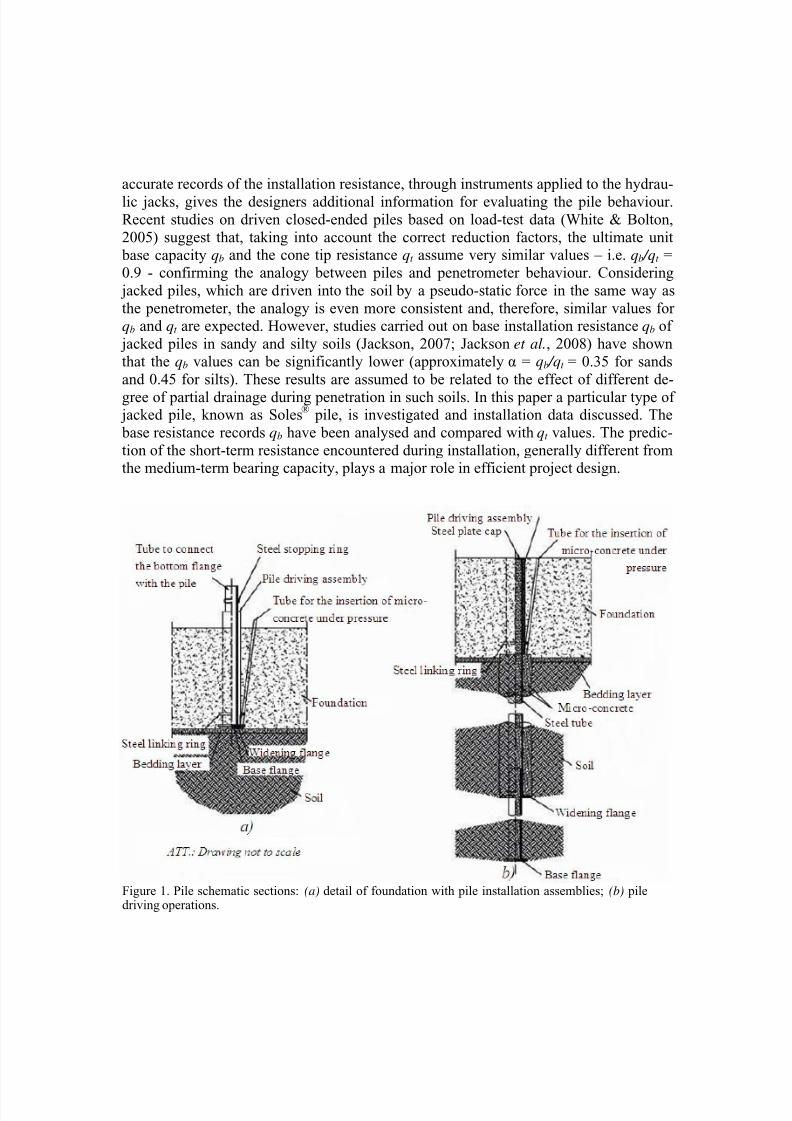
Figure 1. Pile schematic sections: (a) detail of foundation with pile installation assemblies; (b) piledriving operations.

8/12/2019 3-41marcis
http://slidepdf.com/reader/full/3-41marcis 3/8
1.2 The jacked piling technique
The Soles® pile (Figure 1) is a specific type of jacked pile, installed by means of special
hydraulic jacks (Figure 2) and cast in-situ. This relatively new piling technique offers
many advantages over traditional dynamic pile driving. In particular, the low level of
noise and vibration produced during installation make the use of this pile particularly
suitable for applications in historical buildings and urban sites. In addition, the small sizeinstallation equipment can be easily handled in restricted spaces. The schematic section
of Figure 1 shows the main pile components. The pile steel hollow tube (Figure 1b) is
driven into the ground via a static jacking force applied by hydraulic jacks (Figure 2).
The foundation raft serves as counterweight and creates a connection between piles andsuperstructure by means of the driving assembly, previously positioned inside the
concrete foundation. The pile base is closed by two flanges, a base flange and a widen-ing flange. During installation, the flanges create an annular space between pile and soil
which is filled with micro-concrete, maintained under pressure during installation. Con-sequently, the pile-soil contact surface is quite rugged and the shaft resistance improved.
At the end of the installation process, the inner part of the pile is filled with concrete.
Figure 2. Pile installation process.
2 A CASE STUDY
2.1 Installation and test methodology
Data herein presented and discussed come from a site in Forlì (Italy), where 43 piles
(lay-out in Figure 3) were installed in February 2008 at a penetration rate ν≈20 mm/s.The diameter of the widening flange was D=450 mm. The pile installation was part of a
major intervention of raising a traditional farmhouse (see the view of the building in
Figure 4), in order to reach the current roadway and to create extra height for a basement
below the existing structure. The building was jacked vertically upwards, using an elec-tronically controlled system to keep the whole structure in plane during lifting - a tech-
nique developed by the company to move buildings intact. The old structure was pre-
pared for jacking by construction of a new mat in which driving assemblies were positioned and piles installed. The unit base resistance qb of 12 piles was automatically
8/12/2019 3-41marcis
http://slidepdf.com/reader/full/3-41marcis 4/8
recorded by calibrated pressure cells. Note that, due to the fluid lateral micro-concrete,
the shaft resistance during installation is negligible.
2.2 Foundation soil profile
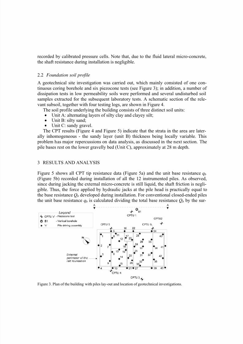
A geotechnical site investigation was carried out, which mainly consisted of one con-
tinuous coring borehole and six piezocone tests (see Figure 3); in addition, a number ofdissipation tests in low permeability soils were performed and several undisturbed soil
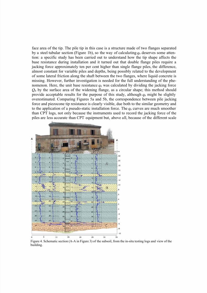
samples extracted for the subsequent laboratory tests. A schematic section of the rele-
vant subsoil, together with four testing logs, are shown in Figure 4.The soil profile underlying the building consists of three distinct soil units:• Unit A: alternating layers of silty clay and clayey silt;
• Unit B: silty sand;• Unit C: sandy gravel.
The CPT results (Figure 4 and Figure 5) indicate that the strata in the area are later-ally inhomogeneous - the sandy layer (unit B) thickness being locally variable. This
problem has major repercussions on data analysis, as discussed in the next section. The
pile bases rest on the lower gravelly bed (Unit C), approximately at 28 m depth.
3 RESULTS AND ANALYSIS
Figure 5 shows all CPT tip resistance data (Figure 5a) and the unit base resistance qb
(Figure 5b) recorded during installation of all the 12 instrumented piles. As observed,since during jacking the external micro-concrete is still liquid, the shaft friction is negli-
gible. Thus, the force applied by hydraulic jacks at the pile head is practically equal to
the base resistance Qb developed during installation. For conventional closed-ended pilesthe unit base resistance qb is calculated dividing the total base resistance Qb by the sur-
Figure 3. Plan of the building with piles lay-out and location of geotechnical investigations.
8/12/2019 3-41marcis
http://slidepdf.com/reader/full/3-41marcis 5/8
face area of the tip. The pile tip in this case is a structure made of two flanges separated
by a steel tubular section (Figure 1b), so the way of calculating qb deserves some atten-tion: a specific study has been carried out to understand how the tip shape affects the
base resistance during installation and it turned out that double flange piles require a
jacking force approximately ten per cent higher than single flange piles, the difference,almost constant for variable piles and depths, being possibly related to the development
of some lateral friction along the shaft between the two flanges, where liquid concrete is
missing. However, further investigation is needed for the full understanding of the phe-
nomenon. Here, the unit base resistance qb was calculated by dividing the jacking force
Qb by the surface area of the widening flange, as a circular shape; this method should
provide acceptable results for the purpose of this study, although qb might be slightly
overestimated. Comparing Figures 5a and 5b, the correspondence between pile jacking
force and piezocone tip resistance is clearly visible, due both to the similar geometry andto the application of a pseudo-static installation force. The qb curves are much smoother
than CPT logs, not only because the instruments used to record the jacking force of the
piles are less accurate than CPT equipment but, above all, because of the different scale
Figure 4. Schematic section (A-A in Figure 3) of the subsoil, from the in-situ testing logs and view of the building.

8/12/2019 3-41marcis
http://slidepdf.com/reader/full/3-41marcis 6/8
effect induced by the significant diameter size difference between cone and piles, when
penetrating soil layers of variable thickness; therefore, the presence of thin layers barelyaffects the unit base resistance curves. Considering the qb curves in the depth ranges
where the soil is laterally homogeneous (Figure 5b), the piles show a rather consistent
and repeatable behaviour. For a reliable analysis to be developed, attention was focusedon the three following layers: a first silty clay layer, from 4 to 8 m below ground level, a
second sandy layer from 14 to 17 m and a third silty layer from 25 to 28 m. As shown by
CPT logs (Figure 4), the sandy layer (Unit B) must be handled with care, because of its
variable thickness within the site and of the diffused silty lens. In Figure 6 the ratio be-
tween qb and qt (α = qb /qt ) is plotted for such three homogeneous layers, with qt from the
most representative CPT 2 only. The mean values of the ratio for each section is plotted
with a solid red line. The other dashed lines show the results of previous relevant studies
and design methods; note that two of them (White and Bolton, 2005 and UWA-05) arerelated to medium-term behaviour, as they were obtained from pile load test databases.
A more relevant comparison can be made with the work by Jackson (2007), who ana-
lysed closed-ended jacked piles. Figure 6 shows for this study the strong dependence of
0
5
10
15
20
25
30
0 1 2 3 4 5 6 7 8
d e p t h [ m ]
CPTU1
CPTU2
CPTU3
CPTU4
CPTU5
CPTU6
0 1 2 3 4 5 6 7 8
(a) (b)
qt [MPa] qb [MPa]
Figure 5. (a) CPT tip resistance data and (b) records of jacking force during pile installation.

8/12/2019 3-41marcis
http://slidepdf.com/reader/full/3-41marcis 7/8
the qb /qt ratio on the grain size confirming Jackson’s trend: the finer the soil, the higher
the ratio. Nevertheless, average values here are typically higher: 0.5 for sand, 1 for siltand 1.1 for silty clay. Such values for the sand layer, confirm the importance of partial
drainage effects (Jackson et al., 2008): variable degrees of drainage, in fact, differently
affect the tip resistance of devices of variable size, when penetrating soil layers of inter-mediate behaviour. In particular, ratios obtained in silt tend to unity (i.e an ideal value,
usually not reached even for medium-term capacity), as both cone and piles tend to the
same undrained regime. For this specific type of pile, in case of silty clay the ratio
reaches values consistently greater than one and in other sites, where piles have been
jacked in pure clay, values up to 1.3 have been obtained. The fact that qb is slightly
overestimated by the presence of the double flange can partly give reason of the results,
but a better understanding of the relative importance of partial drainage during penetra-
tion and of its implications in the correct estimate of the parameter α = qb /qt requires fur-ther investigation, from fully drained to fully undrained conditions, suitably expressed
by the dimensionless normalized velocity ν D/ch.
Figure 6. Comparison between this case and previous studies.
4 CONCLUSIONS
An extensive field test, carried out near Forlì (Italy) with the aim of comparing the short-
term jacked pile installation force and the CPT tip resistance, has been presented in the
paper. For this purpose, a number of piles were installed and 6 CPT tests performed. Arather innovative pile jacking technique and devices for recording relevant data have
been described. The close analogy between CPT and jacked piles installation processes
15
d e p t h [ m ]
25
0
5
0 0,5 1 1,5
qb/qt [-]
Silty clay
Sand
Silt

8/12/2019 3-41marcis
http://slidepdf.com/reader/full/3-41marcis 8/8
has been discussed, thus confirming that modern pile design methods based on CPT pa-
rameters are especially suitable for predicting their long-term performance. The specificcase study was selected among other reported test sites, both for the quality of available
data and for the presence of different natural soils, i.e. predominantly clayey and silty
fractions with local sandy layers. The investigated test site shows a ratio between the jacked pile installation force and the CPT tip resistance rather consistent with the few
reported data in the literature and strongly dependent on the soil type. In particular, in
silty sand layers, variable degrees of partial drainage during penetration are likely to oc-
cur on devices of different size, providing a ratio considerably less than unity. On the
other hand, in finer layers, such ratio tends to increase and become even higher than one.Data analysis has been shown and comparison with previous studies discussed. CPT data
appear to provide a better understanding of the jacking mechanisms and hence enable to
predict the short-term resistance that will be encountered during installation.
ACKNOLEDGEMENTS
The authors would like to thank all the staff and engineers who provided assistance at
the Forlì test site. The paper is the outcome of a research collaboration between the Uni-versity of Bologna and Soles Spa, whose support is gratefully acknowledged.
REFERENCES
American Petroleum Institute - API (2007). Recommended Practice (RP2A-WSD) for Planning, Designing
and Constructing Fixed Offshore Platforms – Working Stress Design, Supplement 3 to 21st Edition,
issued October 2007, Section C6.4.3.
Deeks, A. J., White, D. J. & Bolton, M. D. (2005). A comparison of jacked, driven and bored piles in
sand. Proceedings, 16th International Conference on Soil Mechanics and Geotechnical Engineering,
Osaka, Japan. Millpress, 3:2103-2106.
Jackson, A. M. (2007). Pile jacking in sand and silt. Winner of the ICE's national Graduates and Students
Papers Competition 2008, Feb 2008 .
Jackson, A. M., White, D. J., Bolton, M. D., Nagayama, T. (2008). Pore pressure effects in sand and silt
during pile jacking. Proceedings, BGA International Conference on Foundations, Dundee, Scotland,
24-27 June 2008. HIS BRE Press.
White, D. J. & Bolton, M. D. (2005). Comparing CPT and pile base resistance in sand. Proceedings, Insti-
tution of Civil Engineers, Geotechnical Engineering, 158 (GE1), 3-14.White, D. J., Finlay, T. C. R., Bolton, M. D. & Bearss, G. (2002). Press-in piling: Ground vibration and
noise during pile installation. International Deep Foundations Congress. Orlando, USA. ASCE . special
publication 116:363-371.
Yetginer, A. G., White, D. J. & Bolton, M. D. (2006). Field measurements of the stiffness of jacked piles
and pile groups. Géotechnique, 56 (5), 349-354.