3 14 - Montolit · 2019. 8. 5. · ENGLISH 14. 2 Art. Item F1-101 230 V~ 2,2 kW (3 HP) 13,5 A 50 Hz...
28
ITALIANO 3 ENGLISH 14
Transcript of 3 14 - Montolit · 2019. 8. 5. · ENGLISH 14. 2 Art. Item F1-101 230 V~ 2,2 kW (3 HP) 13,5 A 50 Hz...

ITAL
IANO
3EN
GLIS
H 14

2
Art.Item
F1-101230 V~
2,2 kW (3 HP)
13,5 A
50 Hz
2.800 min-1
101 (71x71) cm40 (28x28) inch
0 ÷ 5 cm
0 ÷ 2 inch250/25,4 mm
10 / 1 inch
F1-131 131 (92x92) cm51,5 (36x36) inch
F1-151 151 (106x106) cm59,5 (41,5x41,5) inch
F1-181 181 (128x128) cm71,5 (50x50) inch
F1-101-115V115 V~
1,5 kW (2 HP)
18 A
60 Hz
3.360 min-1
101 (71x71) cm40 (28x28) inch
0 ÷ 5 cm
0 ÷ 2 inch250/25,4 mm
10 / 1 inch
F1-131-115V 131 (92x92) cm51,5 (36x36) inch
F1-151-115V 151 (106x106) cm59,5 (41,5x41,5) inch
F1-181-115V 181 (128x128) cm71,5 (50x50) inch
mod. 101cm mod. 131cm mod. 151cm mod. 181cm

ITAL
IANO
3
4
3
PericoloDivietoObbligo
1
2
CertificazioneEuropea
di Sicurezza
Diametro e foro del disco diamantato
Peso
ModelloDisposizioni RAEEDivietiLeggere le istruzioni
Max numero di giriNumero di matricolaAnno di produzione
Dispositividi protezioneindividuale
Nome del costruttore
ISTRUZIONI D’USO
Leggere e conservare accuratamente.
TAGLIERINA ELETTRICA AD ACQUA
• ESCLUSIVAMENTE per il taglio e lo smusso (Jolly) di piastrelle in gres, gres por-cellanato, klinker, cotto, monocottura, ceramica, cemento e materiali lapidei.
• Solo per uso professionale.
• Prima di lasciare l’Officina di produzione, la Vostra macchina è stata sottoposta a seri collaudi a garanzia della qualità, della sicurezza e dell’efficienza del prodotto.
Seguendo attentamente le istruzioni contenute nel presente manuale, assicurerete alla Vostra mac-china, in condizioni d’uso normali, una lunga durata.
• Prima di usare la macchina leggere attentamente questo manuale di istruzioni, al fine di evitare incidenti o malfunzionamenti.
• Non manomettere in alcun modo le protezioni e i ripari previsti dal costruttore.• Non modificare in alcun modo nessuna parte della macchina.• Eventuali modifiche possono essere apportate solo dal costruttore.• Usare solo ricambi originali.• La Brevetti MONTOLIT declina ogni responsabilità in caso di inosservanza.
SEGUIRE SCRUPOLOSAMENTE LE NORME VIGENTI IN MATERIA D’IGIENE E DI SICUREZZA SUL LAVORO
• In riferimento alla direttiva 2003/10/CE è obbligatorio l’uso dei dispositivi individuali di protezione dell’udito.
• Le vibrazioni trasmesse dalla macchina e valutate se-condo la normativa UNI-EN-ISO 5349-1-2004 sono da considerarsi irrilevanti.
TARGHETTA IDENTIFICATIVA

ITAL
IANO
4
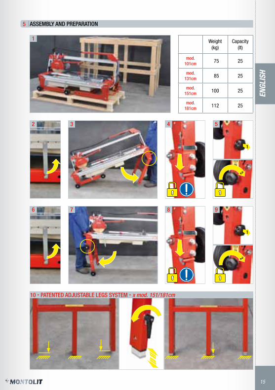
5
Peso(kg)
Capacità(lt)
mod.101cm 75 25
mod.131cm 85 25
mod.151cm 100 25
mod.181cm 112 25
1
2 3 4 5
6 7
10 • PATENTED ADJUSTABLE LEGS SYSTEM • x mod. 151/181cm
8 9
MONTAGGIO E PREPARAZIONE
1
2
1
2
ITAL
IANO
5
6
11 12
13 14
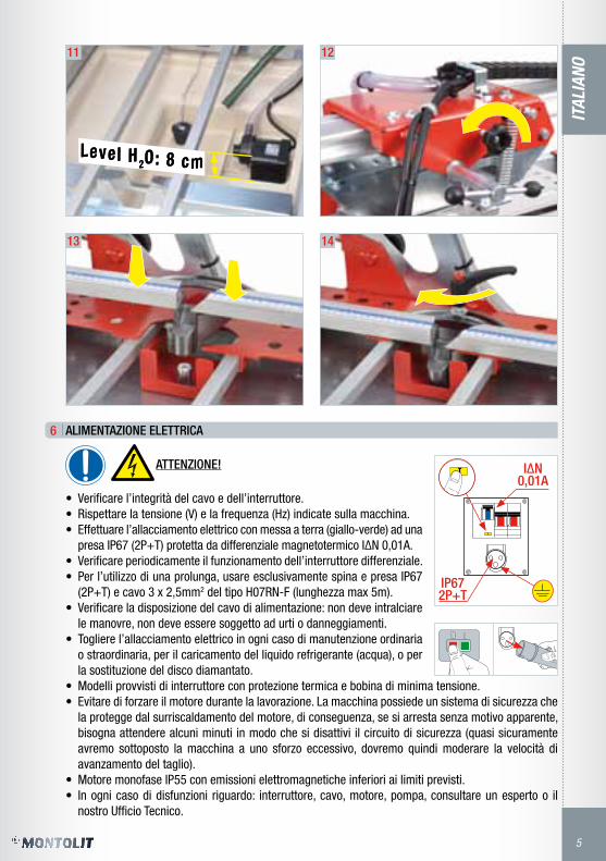
ALIMENTAZIONE ELETTRICA
ATTENZIONE!
• Verificare l’integrità del cavo e dell’interruttore.• Rispettare la tensione (V) e la frequenza (Hz) indicate sulla macchina.• Effettuare l’allacciamento elettrico con messa a terra (giallo-verde) ad una
presa IP67 (2P+T) protetta da differenziale magnetotermico I∆N 0,01A.• Verificare periodicamente il funzionamento dell’interruttore differenziale.• Per l’utilizzo di una prolunga, usare esclusivamente spina e presa IP67
(2P+T) e cavo 3 x 2,5mm2 del tipo H07RN-F (lunghezza max 5m).• Verificare la disposizione del cavo di alimentazione: non deve intralciare
le manovre, non deve essere soggetto ad urti o danneggiamenti.• Togliere l’allacciamento elettrico in ogni caso di manutenzione ordinaria
o straordinaria, per il caricamento del liquido refrigerante (acqua), o per la sostituzione del disco diamantato.
• Modelli provvisti di interruttore con protezione termica e bobina di minima tensione.• Evitare di forzare il motore durante la lavorazione. La macchina possiede un sistema di sicurezza che
la protegge dal surriscaldamento del motore, di conseguenza, se si arresta senza motivo apparente, bisogna attendere alcuni minuti in modo che si disattivi il circuito di sicurezza (quasi sicuramente avremo sottoposto la macchina a uno sforzo eccessivo, dovremo quindi moderare la velocità di avanzamento del taglio).
• Motore monofase IP55 con emissioni elettromagnetiche inferiori ai limiti previsti.• In ogni caso di disfunzioni riguardo: interruttore, cavo, motore, pompa, consultare un esperto o il
nostro Ufficio Tecnico.
Level H 2O: 8 cmLevel H 2O: 8 cm

ITAL
IANO
6
7
r= 3m
max 5m
1 2 3
CORRETTO POSIZIONAMENTO
• L’operatore deve posizionarsi in modo sicuro ed equilibrato e non distrarsi durante la lavorazione.• L’operatore è sempre responsabile di incidenti che si possono verificare ad altre persone o alle loro
proprietà. • Non permettere ad altre persone di toccare la macchina o il cavo. Bisogna tenerle lontane dall’area
di lavoro.• È raccomandabile indossare guanti di gomma e scarpe con suola antiscivolo. Se si portano i capelli
lunghi, bisogna raccoglierli o usare un berretto di protezione. Indossare occhiali di protezione.• Utilizzare adeguate protezioni per l’udito.• Non indossare capi d’abbigliamento larghi, oggetti o gioielli che possano restare impigliati nei dispo-
sitivi in movimento.• L’area di lavoro deve essere piana, asciutta, libera da ostacoli, ben ventilata ed illuminata.• Non utilizzare la macchina nelle vicinanze di liquidi infiammabili o di gas.• Tenere il cavo al riparo dalle temperature elevate, dall’olio e dagli spigoli vivi.• Prima di iniziare qualsiasi operazione di taglio assicurarsi che i pomoli blocca piantone siano avvitati
a fondo (fig. 1), che le gambe siano bloccate con gli appositi catenacci (fig. 2-3) e verificare il livello dell’acqua di raffreddamento.

ITAL
IANO
7
8
1
2
3 4 5
6 7
108
9
CORRETTO UTILIZZO - 90°
• Posizionare la piastrella in appoggio alla squadra. Bloccarla con Squeeze System (fig. 6/7).• Premere verso il basso fino a fine corsa la maniglia di azionamento e bloccarla.• La posizione corretta delle mani è indicata in figura 10.• Procedere al taglio accostando lentamente il disco diamantato al materiale da tagliare avanzando
con velocità proporzionata allo spessore ed alla durezza del materiale.• Rallentare la velocità di avanzamento in prossimità di fine taglio.• Dopo avere eseguito il taglio, tramite l’interruttore, spegnere il motore. Riportare il motore nella posi-
zione iniziale.
0°
12

ITAL
IANO
8
8.1
8.2
1
2
3
1
2
3 4
5
6
7
CORRETTO UTILIZZO - FORI QUADRATI E RETTANGOLARI
CORRETTO UTILIZZO - 45°
• Posizionare la piastrella in appoggio alla squadra.• Premere verso il basso fino a fine corsa la maniglia di azionamento e bloccarla.• La posizione corretta delle mani è indicata in figura 7.• Procedere al taglio accostando lentamente il disco diamantato al materiale da tagliare avanzando
con velocità proporzionata allo spessore ed alla durezza del materiale.• Rallentare la velocità di avanzamento in prossimità di fine taglio.• Dopo avere eseguito il taglio, tramite l’interruttore, spegnere il motore. Riportare il motore nella posi-
zione iniziale.• Qualora si verifichi la rottura della parte terminale della piastrella (ultimo centimetro) ravvivare il
disco diamantato. Se il difetto permane si può ovviare nel modo seguente: 1 - effettuare un taglio di circa 2 cm da un lato della piastrella. 2 - girarla ed eseguire il taglio fino al ricongiungimento con il taglio di 2 cm precedentemente eseguito.
• Spessore massimo del mate-riale 3,5 cm.
• Premere verso il basso la ma-niglia di azionamento in modo che il disco entri nella pia-strella fino alla sua fuoriuscita dal lato opposto.
• La posizione corretta delle mani è indicata in figura 3.
45°
ITAL
IANO
9
8.3
1
2
3 4
5 6
7
8
9
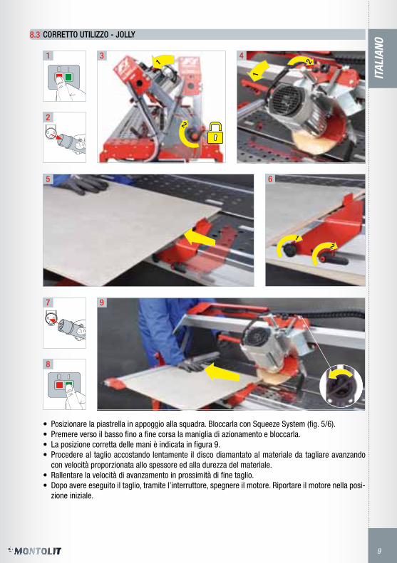
CORRETTO UTILIZZO - JOLLY
• Posizionare la piastrella in appoggio alla squadra. Bloccarla con Squeeze System (fig. 5/6).• Premere verso il basso fino a fine corsa la maniglia di azionamento e bloccarla.• La posizione corretta delle mani è indicata in figura 9.• Procedere al taglio accostando lentamente il disco diamantato al materiale da tagliare avanzando
con velocità proporzionata allo spessore ed alla durezza del materiale.• Rallentare la velocità di avanzamento in prossimità di fine taglio.• Dopo avere eseguito il taglio, tramite l’interruttore, spegnere il motore. Riportare il motore nella posi-
zione iniziale.
12
1
2
1
2

ITAL
IANO
10
9
1
2
3 4
5 6 7
8 10 11
14 15
9
1312
ISTRUZIONI PER LA MOVIMENTAZIONE ED IL TRASPORTO
2
1
2
2
1

ITAL
IANO
11
10
16
1
2
3 4 5
SOSTITUZIONE DEL DISCO DIAMANTATO
• Usare solo dischi diamantati del dia-metro e del tipo stabilito dalla Brevetti MONTOLIT.
• Per una maggiore precisione ed econo-mia di taglio scegliere il disco diaman-tato MONTOLIT specifico all’uso consul-tando il catalogo MONTOLIT.
IMPORTANTE!
• L’utensile diamantato ed il relativo sistema di fissaggio devono sempre essere in condizioni perfette. • É pericoloso l’utilizzo di utensili diamantati con eccessiva usura, eccentricità e/o microfessurazioni
sulla corona diamantata. • Nel caso in cui l’utensile non tagliasse occorrerà ravvivarlo utilizzando l’apposito stick ravvivatore
MONTOLIT art. 395B.
ATTENZIONE! Filetto sinistro: per svitare, girare in senso orario
OK

ITAL
IANO
12
11
12
13
14
15
1 2 3
PULIZIA PERIODICA
• Prima di procedere alla pulizia, alla manutenzione o alla riparazione del-la macchina, così come prima di effettuare il trasporto, la macchina va spenta e bisogna staccare la spina.
• Pulizia della macchina: - non usare getti d’acqua ma una spugna umida, - mantenere pulita la barra di scorrimento (non ingrassare).
• Per la pulizia è sconsigliato l’uso di utensili che possano intaccare la vernice.• Pulizia vasca:
- estrarre la griglia e togliere il tappo, lasciare defluire l’acqua dalla vasca e procedere alla pulizia,- estrarre la vasca e pulirla dai detriti e dai residui di taglio.
MANUTENZIONE ORDINARIA
• Esaminare periodicamente i cavi della macchina e, nel caso in cui siano danneggiati, farli riparare dal servizio tecnico autorizzato.
• Mantenere le impugnature asciutte, pulite e senza olio o grasso.
ATTENZIONE!
Una protezione o un’altra parte danneggiata, va riparata correttamente o fatta sostituire dal servizio tecnico autorizzato, salvo che sia indicato diversamente in questo manuale d’istruzioni.
MESSA FUORI SERVIZIO
• Effettuare la pulizia periodica, la manutenzione ordinaria.• Immagazzinare il tutto in un luogo asciutto, sicuro e lontano dalla portata dei bambini.
SMANTELLAMENTO DELLA MACCHINA
• Attenersi alle disposizioni locali per lo smaltimento di prodotti elettrici.• Attraverso una rottamazione ecologica è possibile recuperare materiali pregiati.• I componenti elettrici utilizzati per la costruzione sono in accordo alla normativa RoHS 2002/95/EC.• Per ulteriori informazioni contattare il nostro Ufficio Tecnico.
ACCESSORI
• La macchina viene fornita corredata di una chiave a forchetta semplice ed una chiave esagonale da utilizzarsi per il montaggio/smontaggio del disco e dal presente manuale d’uso e manutenzione.
1
2

ITAL
IANO
13
16
17
LOCALIZZAZIONE GUASTI
PROBLEMA CAUSA RIMEDIO
La macchina nonfunziona.
• La spina è mal inserita nella presa di alimentazione.• Il cavo di alimentazione è interrotto. • Non c’è tensione alla presa di corrente.• L’interruttore è danneggiato.• Motore non collegato.
• Spingere a fondo la spina nella presa.• Rivolgersi al centro assistenza autorizzato o al
rivenditore di fiducia.
Il motore parte condifficoltà.
• Il condensatore é guasto. • Al motore non arriva la tensione indicata sull’eti-
chetta dati tecnici.
• Rivolgersi al centro assistenza autorizzato o al rivenditore di fiducia.
La macchina si spegne durante il lavoro.
• Eccessiva temperatura del motore. • Attendere che il motore si raffreddi.
Non arriva acqua aldisco diamantato.
• La pompa non funziona. • Il livello dell’acqua nella vasca è troppo basso.• Il rubinetto è otturato.• Il tubo di ricircolo dell’acqua è piegato od otturato.• Fori otturati nel filtro o nel coprigirante della
pompa.
• Verificare che la pompa sia libera da residui di taglio. Se é necessaria la sostituzione della pom-pa rivolgersi al centro assistenza autorizzato o al rivenditore di fiducia.
• Aggiungere acqua nella vasca.• Pulire o sostituire il rubinetto.• Staccare dalla pompa il tubo di mandata acqua e
soffiare. Pulirlo o sostituirlo a seconda dello stato di usura.
• Liberare tutti i fori presenti nel filtro e nel copri-girante della pompa.
Il dispositivo discorrimento haeccessivo gioco.
• Eccessiva usura. • Rivolgersi al centro assistenza autorizzato o al rivenditore di fiducia.
GARANZIA
Validità 2 (due) anni a partire dalla data di vendita (fattura o bolla di consegna o scontrino fiscale). Guasti derivanti da un uso non conforme o da normale usura sono esclusi dalla presente garanzia.
Da sempre, la Brevetti MONTOLIT impiega e fornisce materiali di prima scelta. Si tratta di un impegno di serietà e moralità commerciale che eleva la Nostra Azienda al di sopra dello standard. Sicurezza e garanzia del prodotto costituiscono per noi motivo di vanto. Una realtà operativa che non è fatta solo di parole, ma anche di vere e proprie garanzie scritte. Infatti assicuriamo tutti i nostri prodotti contro i danni involontariamente cagionati in conseguenza di un fatto accidentale verificatosi per difetto di costruzione e fabbricazione del prodotto anche dopo la sua consegna e commercializzazione.
Descrizioni ed illustrazioni s’intendono fornite a semplice titolo indicativo. La Casa si riserva il diritto, ferme restando le caratteristiche essenziali dei modelli qui descritti ed illustrati, di apportare ai propri prodotti, in qualunque momento e senza preavviso, le eventuali modifiche da essa ritenute necessarie a scopo di miglioramento o per qualsiasi esigenza di carattere costruttivo o commerciale.Si vieta ogni riproduzione totale o parziale dell’opera in qualsiasi formato e con qualsiasi mezzo o procedimento, sia meccanico, fotografico o elettronico, senza previa autorizzazione di Brevetti MONTOLIT S.p.A. Ciascuna delle succitate attività potrebbe condurre a conseguenti procedimenti penali.

ENGL
ISH
14
4
3
DangerProhibitedNecessity
1
2
European Safety Certification
Diameter and bore of diamond disk
Weight
ModelRAEE provisionsProhibitionsRead the instructions
Max RPMRegistration numberYear of production
Personal protective equipment
Manufacturer name
USAGE INSTRUCTIONS
Carefully read and maintain.
ELECTRIC WATER CUTTER
• EXCLUSIVELY for the cutting and beveling (Jolly) of porcelain tile, klinker, ter-racotta, single-fired, ceramics, concrete and stone materials.
• For professional use only.
• Before leaving the production workshop, your machine has been subjected to serious testing to en-sure its quality, safety and efficiency. By carefully following the instructions contained in this manual, you ensure a long life for your machine under normal usage conditions.
• Before using the machine, carefully read this instruction manual in order to avoid accidents or mal-functions.
• Do not tamper with the protections and guards provided by the manufacturer in any way.• Do not modify any part of the machine in any way.• All modifications must be made by the manufacturer only.• Only use original spare parts.• Brevetti MONTOLIT disclaims any liability in the event of non-compliance.
CAREFULLY FOLLOW THE REGULATIONS IN PLACE REGARDING HEALTH AND SAFETY IN THE WORKPLACE
• The use of individual hearing protectors is mandatory as per Directive 2003/10/CE.
• The vibrations produced by the machine and evaluated according to regulation UNI-EN-ISO 5349-1-2004 are considered to be irrelevant.
IDENTIFICATION PLATE
ENGL
ISH
15
5
Weight(kg)
Capacity(lt)
mod.101cm 75 25
mod.131cm 85 25
mod.151cm 100 25
mod.181cm 112 25
1
2 3 4 5
6 7
10 • PATENTED ADJUSTABLE LEGS SYSTEM • x mod. 151/181cm
8 9
ASSEMBLY AND PREPARATION
1
2
1
2

ENGL
ISH
16
6
13 14
15 16
ELECTRIC POWER SUPPLY
WARNING!
• Check the integrity of the cable and breakers.• Respect the voltage (V) and frequency (Hz) indicated on the machine.• Carry out the electrical connection with ground (yellow/green) to an IP67
outlet (2P+T) protected by an I∆N 0.01A differential breaker.• Periodically check the operation of the differential breaker.• For an extension, use only the IP67 (2P+T) socket and plug and a 3 x
2.5mm2 cable of the H 07 RN-F type (max length 5 m).• Check the placement of the power cable: it must not obstruct movement,
and should not be subject to shock or damage.• Remove the electrical connection during each routine or extraordinary
maintenance operation, for the loading of coolant (water), or for the sub-stitution of the diamond disk.
• Models equipped with a thermal protection switch and minimum voltage coil.• Avoid forcing the motor during processing. The machine has a security system that protects it from
engine overheating; consequently, if the motor is arrested without apparent reason, it is necessary to wait a few minutes so that the safety circuit is disactivated, as the machine has almost certainly been subjected to excessive force and the cutting advancement speed must therefore be moderated.
• IP55 single phase engine with electromagnetic emissions below the provided limits.• In the case of malfunction regarding a breaker, cable, engine, or pump, consult an expert or our
Technical Office.
Level H 2O: 8 cmLevel H 2O: 8 cm

ENGL
ISH
17
7
r= 3m
max 5m
1 2 3
CORRECT POSITIONING
• The operator must position himself in a safe and balanced way and must not be distracted during processing.
• The operator is always responsible for accidents that may occur to other people or their proper-ty.
• Do not allow other people to touch the machine or the cable. They must be kept away from the work space.
• It is advisable to wear rubber gloves and shoes with slip-resistant soles. If you have long hair, it must be gathered up or a protective cap used. Wear protective goggles.
• Use adequate hearing protection.• Do not wear large clothing, objects or jewelry that can become stuck in moving parts.• The work area must be flat, dry, free of obstacles, well ventilated and illuminated.• Do not use the machine near flammable liquids or gas.• Keep the cable away from high temperatures, oil, and sharp edges.• Before starting any cutting operation, ensure that the column locking knobs are screwed to the bot-
tom (fig. 1), that the legs are locked with the appropriate bolts (fig. 2-3), and check the cooling water level.

ENGL
ISH
18
8
1
2
3 4 5
6 7
108
9
CORRECT USE - 90°
• Position the tile against the square. Lock the tile with Squeeze System (fig. 6/7).• Press down to switch the driving handle and lock it.• The correct position of the hands is shown in figure 10.• Proceed to cutting by slowly positioning the diamond disk against the material to be cut, advancing
with a speed proportional to the thickness and hardness of the material.• Slow down the advancement speed near the end of cutting.• After having completed the cut, turn the engine off through the switch. Bring the engine back to its
original position.
0°
12

ENGL
ISH
19
8.1
8.2
1
2
3
1
2
3 4
5
6
7
CORRECT USE - SQUARE AND RECTANGULAR HOLES
CORRECT USE - 45°
• Position the tile against the square.• Press down to switch the driving handle and lock it.• The correct position of the hands is shown in figure 7.• Proceed to cutting by slowly positioning the diamond disk against the material to be cut, advancing
with a speed proportional to the thickness and hardness of the material.• Slow down the advancement speed near the end of cutting.• After having completed the cut, turn off the engine through the switch. Bring the engine back to its
original position.• Whenever the end of the tile breaks (the last centimeter), sharpen the diamond disk. If the defect
remains it can remedied in the following way: 1 - make a cut of about 2 cm from one side of the tile. 2 - rotate it and follow the cut through until reunification with the 2 cm cut previously carried out.
• Maximum material thickness 3.5 cm.
• Gradually press down on the driving handle so that the disk enters the plate and emerges from the opposite side.
• The correct position of the hands is shown in figure 3.
45°

ENGL
ISH
20
8.3
1
2
3 4
5 6
7
8
9
CORRECT USE - JOLLY
• Position the tile against the square. Lock the tile with Squeeze System (fig. 5/6).• Press down to switch the driving handle and lock it.• The correct position of the hands is shown in figure 9.• Proceed to cutting by slowly positioning the diamond disk against the material to be cut, advancing
with a speed proportional to the thickness and hardness of the material.• Slow down the advancement speed near the end of cutting.• After having completed the cut, turn off the engine through the switch. Bring the engine back to its
original position.
12
1
2
1
2

ENGL
ISH
21
9
1
2
3 4
5 6 7
8 10 11
14 15
9
1312
INSTRUCTIONS FOR HANDLING AND TRANSPORT
2
1
2
2
1

ENGL
ISH
22
10
16
1
2
3 4 5
SUBSTITUTION OF THE DIAMOND DISK
• Use only diamond disks of the diameter and type set out by Brevetti MONTOLIT.
• For greater cut precision and economy, choose the MONTOLIT diamond disk specific to the use by consulting the MONTOLIT catalog.
IMPORTANT!
• The diamond tool and its mounting system must always be in perfect condition. • The use of diamond tools with excessive wear, eccentricity and/or micro-scratches on the diamond
crown is dangerous. • In case the tool does not cut, it should be sharpened by using the appropriate MONTOLIT sharpening
stick (art. 395B).
ATTENTION! Left thread: to unscrew, turn clockwise
OK

ENGL
ISH
23
1 2 3
11
12
13
14
15
PERIODIC CLEANING
• Prior to cleaning, maintenance or repair of equipment, as before transport, the machine must be turned off and unplugged.
• Machine cleaning: - do not use water jets but a wet sponge, - keep the scroll bar clean (not oily).
• The use of tools that may affect the paint is not recommended.
• Tank cleaning:- extract the grill and remove the cap, letting the water flow from the tank and proceeding to cleaning,- remove the tank and clean it of cutting debris and residue.
ROUTINE MAINTENANCE
• Periodically examine the machine cables, and in the case that they are damaged, have them repaired by the authorized technical service.
• Keep the handles dry, clean and without oil or grease.
ATTENTION!
Guards or other damaged parts should be properly repaired or replaced by the authorized technical service, unless otherwise indicated in this operation manual.
PUTTING OUT OF SERVCE
• Carry out regular cleaning and routine maintenance.• Store everything in a dry, safe place, away from children.
DISMANTLING OF THE MACHINE
• Follow the local provisions for the disposal of electrical products.• Valuable materials can be recovered by recycling.• The electrical components used for construction are in accordance with the regulation
RoHS 2002/95/EC.• Contact our Technical Office for further information.
ACCESSORIES
• The machine comes with a simple forked wrench and a hexagonal wrench to use for disk mounting/dismantling, of an already mounted disk series in this use and maintenance manual.
1
2

ENGL
ISH
24
16
17
LOCATION TROUBLESHOOTING
PROBLEM CAUSE REMEDY
The machine is not working.
• The plug is badly inserted in the power socket.• The power cable is interrupted. • There is no voltage at the outlet.• The switch is damaged.• The engine is not connected.
• Push the plug into the outlet all the way.• Consult the authorized service center or dealer.
The engine starts with difficulty.
• The condenser is broken. • The voltage indicated on the technical data tag
does not reach the motor.
• Consult the authorized service center or dealer.
The machine turns off during working.
• Excessive engine temperature. • Wait for the engine to cool.
Water does not get to the diamond disk.
• The pump is not working. • The water level in the tank is too low.• The tap is blocked.• The water recirculation tube is bent or blocked.• Clogged holes in the filter or in the pump rotor
cover.
• Make sure that the pump is free of cutting de-bris. If the pump needs to be substituted, con-tact the authorized service center or dealer.
• Add water to the tank.• Clean or replace the tab.• Remove the water delivery tube from the pump
and blow into it. Clean or substitute it according to its state of wear.
• Unblock all of the holes present in the filter and pump rotor cover.
The slider has exces-sive play.
• Excessive wear. • Consult the authorized service center or dealer.
GUARANTEE
Valid for 2 (two) years from the date of sale (invoice or delivery note or sales tax receipt). Breakdowns resulting from non-conforming use or normal wear are excluded from this guarantee.
Brevetti MONTOLIT has always employed and provided first choice materials. This is a commitment to seriousness and commercial morality that elevates our company to the highest standard. The product’s safety and warranty are a source of pride for us. This operational reality is not just words, but a real and written guarantee. In fact, we ensure all of our products against involuntary damage caused by accidents occurring as a result of a construction or manufacturing defect, even after delivery and commercialization.
The descriptions and diagrams are intended to provide a simple means of illustration. The Company reserves the right, without prejudice to the essential characteristics of the models described and illustrated here, to make any modifications it deems necessary for improvement or for any constructive or commercial need at any time and without notice.All total or partial reproductions of this document in any format or by any means or procedure, photographic or electronic, without prior authorization of Brevetti MONTOLIT S.p.A. is prohibited. Each of these activities could lead to subsequent criminal proceedings.

25
OP
TIO
NA
LS -
OPT
ION
S -
VA
LGFR
ITT
- O
PCIO
NES
-
VOLI
TELN
É VY
BA
VEN
Í -
OPC
JE
Art. 1049 - Art. 1051• TAVOLINO DI SUPPORTO LATERALE
• LateraL suPPort tabLe
Art. 1305F1 (standard x mod. 181cm)• KIT AVANzAMENTO CON VOLANTINO
• KIt CuttING ProGress sYsteM WItH HaND WHeeL
Art. 58E• TAPPETINO IN GOMMA PER MOSAICI, PIASTRELLE IN VETRO, DELICATE E SOTTILI (3MM).
• rubber PaD for MosaIC tILes, PLus DeLICate aND verY tHIN 3MM GLass tILes.
Art. 1049Art. 1051

26
PART
I DI
RIC
AMBI
O - S
PARE
PAR
TS -
PART
IES
DE R
ECHA
NGE
- ERS
ATZT
EILE
- RE
SERV
EDEL
ER -
PIEZ
AS d
E RE
PuES
TO -
NÁHR
ADNÍ
DÍLY
- CZ
ĘŚCI
ZAM
IENN
E
Nr. Art. Descrizione Description
1 1080MB Motore 230V~/50Hz 230v~/50Hz - Motor
1 1081MB Motore 115V~/60Hz 115v~/60Hz - Motor
2 1208F1 Carter copridisco completo Complete blade guard
3 1088 Paraspruzzi Water - splash guard
4 1103MB Flangia disco completa Complete blade flange
5 1195 Cuscinetto Wheel - bearing
6 1132 Rubinetto dell’acqua Water tap
7 1126F1 Pomolo bloccaggio piantone screw for upright
8 1095F1SX Supporto SX upright sX
9 1161F1 Bloccaggio piastrella “Squeeze System” Clamp for tile “squeeze system”
10 1300F1 Binario x mod. 101cm sliding bar x mod. 101cm
10 1301F1 Binario x mod. 131cm sliding bar x mod. 131cm
10 1302F1 Binario x mod. 151cm sliding bar x mod. 151cm
10 1303F1 Binario x mod. 181cm sliding bar x mod. 181cm
11 1305F1 Kit avanzamento con volantino Kit cutting progress system with hand wheel
12 1201 Nasello Measurement guide
13 450P Manettino bloccaggio squadra screw measurement guide
14 1073EV Righette adesive millimetrate Measurement guide stickers
15 1089EV Squadra goniometrica x mod. 101-131cm Goniometrical square x mod. 101-131cm
15 1198EV Squadra goniometrica x mod. 151-181cm Goniometrical square x mod. 151-181cm
16 1307F1 Lamiera inox “corta” con apertura x mod. 131cm Stainless steel support “short” with opening x mod. 131cm
16 1308F1 Lamiera inox “lunga” con apertura x mod. 101-151-181cm Stainless steel support “long” with opening x mod. 101-151-181cm
17 1309F1 Lamiera inox “corta” x mod. 131-151cm Stainless steel support “short” x mod. 131-151cm
17 1310F1 Lamiera inox “lunga” x mod. 101-151-181cm Stainless steel support “long” x mod. 101-151-181cm
18 1095F1DX Supporto DX upright DX
19 1312F1 Pomolo bloccaggio gamba screw for locking leg
20 1191 Interruttore 230V~ 230v~ - switch
20 1155 Interruttore 115V~ 115v~ - switch
21 1082 Pompa elettrica ad immersione - 230V~ x mod. 101-131cm 230v~ - electric immersion pump x mod. 101-131cm
21 1082F1 Pompa elettrica ad immersione - 230V~ x mod. 151-181cm 230v~ - electric immersion pump x mod. 151-181cm
21 1083 Pompa elettrica ad immersione - 115V~ x mod. 101-131cm 115v~ - electric immersion pump x mod. 101-131cm
21 1083F1 Pompa elettrica ad immersione - 115V~ x mod. 151-181cm 115v~ - electric immersion pump x mod. 151-181cm
22 1206F1 Vasca dell’acqua con tappo di scarico Water tank with drain plug
23 302F1 Ruota Wheel

27
PART
I DI
RIC
AMBI
O - S
PARE
PAR
TS -
PART
IES
DE R
ECHA
NGE
- ERS
ATZT
EILE
- RE
SERV
EDEL
ER -
PIEZ
AS d
E RE
PuES
TO -
NÁHR
ADNÍ
DÍLY
- CZ
ĘŚCI
ZAM
IENN
E

Brevetti Montolit S.p.A.Sedi operative/Company headquarters:Largo Cav. Montoli - 21050 Cantello (VA) Italy Via Varese 4/A - 21050 Cantello (VA) Italy Sede legale/Legal head office:Via Turconi, 25 - 21050 Cantello (VA) ItalyTel. ++39 0332 419 211Fax ++39 0332 418 444www.montolit.com - [email protected]
Art.
F1-2
0130
- P
rinte
d in
ItaL
Y


![MULTILAYER CERAMIC CHIP CAPACITORS€¦ · Type: C1005 [0402 inch], C1608 [0603 inch], C2012 [0805 inch], C3216 [1206 inch], C3225 [1210 inch], C4520 [1808 inch], C4532 [1812 inch],](https://static.fdocuments.in/doc/165x107/5f2a18c3f073e37da14b10b6/multilayer-ceramic-chip-capacitors-type-c1005-0402-inch-c1608-0603-inch-c2012.jpg)
![MLCC Commercial grade C series · Type: C0402 [01005 inch], C0603 [0201 inch], C1005 [0402 inch], C1608 [0603 inch], C2012 [0805 inch], C3216 [1206 inch], C3225 [1210 inch], C4532](https://static.fdocuments.in/doc/165x107/5f2a1b6cea53687ca900e2cc/mlcc-commercial-grade-c-series-type-c0402-01005-inch-c0603-0201-inch-c1005.jpg)


![· PDF file3" Flange is Van Stone Style Size [inch] Part No. USD # holes bolt hole dia. [inch] bolt cir. dia. [inch] L [inch] M [inch] N [inch] R [inch]](https://static.fdocuments.in/doc/165x107/5a79cf987f8b9ad7608cd05d/flange-is-van-stone-style-size-inch-part-no-usd-holes-bolt-hole-dia-inch.jpg)

![Commercial Grade, General (Up to 50V) C series€¦ · Type: C0402 [01005 inch] zC0603 [0201 inch] zC1005 [0402 inch] zC1608 [0603 inch] zC2012 [0805 inch] z C3216 [1206 inch] zC3225](https://static.fdocuments.in/doc/165x107/5f2a1ad70d2a3612680cda61/commercial-grade-general-up-to-50v-c-series-type-c0402-01005-inch-zc0603-0201.jpg)