
2V68 - rmspl.com.au · impedance type buswire protection schemes. The relay will detect open...
4
Visit www.rmspl.com.au for the latest product information. Due to RMS continuous product improvement policy this information is subject to change without notice. 2V68/Issue E/128/02/013 - 1/3 Features Low AC burden No external resistors required 3 latching N/O (Hand reset), alarm contacts 3 latching N/O (Hand reset), buswire shorting contacts Hand reset flag 40-300V DC auxiliary supply 40-275V AC auxiliary supply Optional 20-70V DC supply Auxiliary supply fail alarm 3 second fixed time delay 4M28 draw out case Application The 2V68 is a three phase monitoring device designed to provide continuous supervision of the buswires in high impedance type buswire protection schemes. The relay will detect open circuited buswires as well as open circuited main current transformers. The relay provides three (3) latching N/O alarm output contacts to signal faults. Three (3) additional N/O latching output contacts are provided for an integral buswire CT shorting facility. Technical Bulletin 2V68 Busbar CT Supervision & Shorting Relay 2V68 depicted in a 4M28 case Operation Made in Australia The 2V68 type relays have a setting range of 2-14V adjusted on a per phase basis from calibrated potentiometers at the front panel. The relay is continuously rated at 300V RMS & no external components are required. Isolation from the main CT’s is achieved by using a transformer whose primary winding is connected in series with a high value and power rated resistor. The secondary output signal from this isolating transformer is fed into a current to voltage converter, then rectified for comparison with the front panel pre-set value. The AC input is continuously monitored & when it exceeds the pre-set level. Latching contacts are actuated after a three (3) second time delay. Three (3) latching contacts are intended to be connected across the buswires of the busbar protection thus short-circuiting the busbar protection relay & rendering the protection of the zone concerned inoperative. The remaining three (3) latching contacts are available for alarm & signaling functions. Operation of the relay is indicated by a hand reset flag. A switchmode power supply provides a very wide auxiliary operating range. A relay fail alarm is provided in the form of a C/O contact which is picked up when the auxiliary supply is healthy.
-
Upload
duongduong -
Category
Documents
-
view
226 -
download
0
Transcript of 2V68 - rmspl.com.au · impedance type buswire protection schemes. The relay will detect open...

Visit www.rmspl.com.au for the latest product information.
Due to RMS continuous product improvement policy this information is subject to change without notice. 2V68/Issue E/128/02/013 - 1/3
Features Low AC burden No external resistors required 3 latching N/O (Hand reset),
alarm contacts 3 latching N/O (Hand reset),
buswire shorting contacts Hand reset flag 40-300V DC auxiliary supply 40-275V AC auxiliary supply Optional 20-70V DC supply Auxiliary supply fail alarm 3 second fixed time delay 4M28 draw out case Application The 2V68 is a three phase monitoring device designed to provide continuous supervision of the buswires in high impedance type buswire protection schemes. The relay will detect open circuited buswires as well as open circuited main current transformers. The relay provides three (3) latching N/O alarm output contacts to signal faults. Three (3) additional N/O latching output contacts are provided for an integral buswire CT shorting facility.
Technical Bulletin 2V68 Busbar CT Supervision & Shorting Relay
2V68 depicted in a 4M28 case
Operation Made in Australia The 2V68 type relays have a setting range of 2-14V adjusted on a per phase basis from calibrated potentiometers at the front panel. The relay is continuously rated at 300V RMS & no external components are required. Isolation from the main CT’s is achieved by using a transformer whose primary winding is connected in series with a high value and power rated resistor. The secondary output signal from this isolating transformer is fed into a current to voltage converter, then rectified for comparison with the front panel pre-set value. The AC input is continuously monitored & when it exceeds the pre-set level. Latching contacts are actuated after a three (3) second time delay. Three (3) latching contacts are intended to be connected across the buswires of the busbar protection thus short-circuiting the busbar protection relay & rendering the protection of the zone concerned inoperative. The remaining three (3) latching contacts are available for alarm & signaling functions. Operation of the relay is indicated by a hand reset flag. A switchmode power supply provides a very wide auxiliary operating range. A relay fail alarm is provided in the form of a C/O contact which is picked up when the auxiliary supply is healthy.
Visit www.rmspl.com.au for the latest product information.
Due to RMS continuous product improvement policy this information is subject to change without notice. 2V68/Issue E/128/02/013 - 2/3
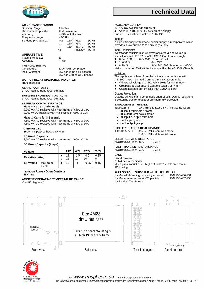
AC VOLTAGE SENSING Sensing Range: 2 to 14V Dropout/Pickup Ratio: 85% minimum Accuracy: +/-5% of full scale Frequency range: 47-61Hz Burdens (VA) approx: 0.2 x10
-3 @2V 50 Hz
3 x10⁻³
@8V 50 Hz 7 x10
-3 @14V 50 Hz
<4
@300V 50 Hz OPERATE TIME Fixed time delay: 3s Accuracy: +/-5% THERMAL RATING Continuous: 300V RMS per phase Peak withstand: 2KV for 3s on all 3 phases 3KV for 0.5s on all 3 phases OUTPUT RELAY OPERATION INDICATOR Hand reset flag ALARM CONTACTS 3 N/O latching hand reset contacts BUSWIRE SHORTING CONTACTS 3 N/O latching hand reset contacts 6R RELAY CONTACT RATINGS
Make & Carry Continuously 3,000 VA AC resistive with maximums of 660V & 12A 3,000 W DC resistive with maximums of 660V & 12A
Make & Carry for 3 Seconds 7,500 VA AC resistive with maximums of 660V & 30A 7,500 W DC resistive with maximums of 660V & 30A
Carry for 0.5s 150A rms peak withstand for 0.5s
AC Break Capacity 3,000 VA AC resistive with maximums of 660V & 12A
DC Break Capacity (Amps) Voltage
24V
48V
125V
250V
Resistive rating
a b
12 12
1.5 12
0.5 10
0.25 5
L/R=40ms Maximum break
a 12 1 0.25 0.15
Isolation Across Open Contacts 3KV rms
AMBIENT OPERATING TEMPERATURE RANGE -5 to 55 degrees C.
Technical Data
AUXILIARY SUPPLY 20-70V DC switchmode supply or 40-275V AC / 40-300V DC switchmode supply Burden: Less than 5 watts at 110V DC Inputs: A high efficiency switchmode power supply is incorporated which provides a low burden to the auxiliary supply. Input Transients: Withstands multiple high-energy transients & ring waves in accordance with IEEE28 - ANSI C26.1 Cat. II, accordingly: 0.5uS 100KHz 6KV O/C, 500A S/C, 4J 1.2/50uS 6Kv O/C 8/20uS 3KA S/C, 80J clamped at 1,000V Mains conducted EMI within limits specified by AS 3548 Class B. Isolation: The inputs are isolated from the outputs in accordance with AS3260 Class II Limited Current Circuitry, accordingly: Withstand voltage of 2.5Kv RMS 50Hz for one minute Creepage & clearance distance greater than 4mm Output leakage current less than 0.25A to earth Output Protection: Outputs will withstand continuous short circuit. Output regulators & switching control regulator are thermally protected. INSULATION WITHSTAND IEC60255-5 2KV RMS & 1.2/50 5KV impulse between:
all input terminals & frame all output terminals & frame all input & output terminals each input group each output group
HIGH FREQUENCY DISTURBANCE IEC60255-22-1 2.5KV 1MHz common mode 1.0KV 1MHz differential mode ELECTROSTATIC DISCHARGE EN61000-4-2:1995 8KV Level 3 FAST TRANSIENT DISTURBANCE EN61000-4-4:1995 4KV Level 4 CASE Size 4 draw out 28 M4 screw terminals Flush panel mount or 4U high 1/4 width 19 inch rack mount IP51 rating ACCESSORIES SUPPLIED WITH EACH RELAY 1 x M4 self threading mounting screw kit P/N 290-406-151 1 x M4 terminal screw kit (28 per kit) P/N 290-407-153 1 x Product Test Manual

Visit www.rmspl.com.au for the latest product information.
Due to RMS continuous product improvement policy this information is subject to change without notice. 2V68/Issue E/128/02/013 - 3/3
Ordering Information Generate the required ordering code as follows: e.g. 2V68-B 1
2V68
1 AUXILIARY SUPPLY RANGE
A 20-70V DC
B 40-300V DC / 40-275V AC

®R e l a y M o n i t o r i n g S y s t e m s P t y L t d
6 Anzed CourtMulgrave, Victoria 3170AUSTRALIAPh: +61 3 8544 1200Fax +61 3 8544 1201Email: [email protected]
Relay Monitoring Systems Pty Ltd
Due to RMS continuous product improvement policy the informationcontained in this document is subject to change without prior notice.
© 2013 Relay Monitoring Systems Pty Ltd ABN 76 052 484 483
®
Image of back of unit togo here
Image of back of unit togo here
www.rmspl.com.au
Re lay Mon i to r i ng Sys tems P ty L td des ign,manufac ture and marke t a wide range o fe lec t r ica l p ro tec t i on and cont ro l p roduc ts fo rapp l i ca t ion on h igh vo l tage power sys tems .The company 's dep th o f l oca l manufac tur ingand eng ineer ing exper t ise i s backed up bymany years o f exper ience s ince th eformat ion o f i t s p redecessor , Re lays P ty L td(RPL) , in 1955 . Th is exper ience combinedwi th a b road base o f f i e ld proven producttypes enab les RMS to serv i ce spec i f i ccus tomer needs by produc ing re lay ondemand and w i th typ ica l ly shor t lead t imes.


![GENERALIZED ANALYTICAL DESIGN OF BROAD- BAND PLANAR … · For the phase shifter section, short-circuited and open-circuited coupled lines have been employed in [10,11] but, there](https://static.fdocuments.in/doc/165x107/5fcce0ec5b71ae364c513b72/generalized-analytical-design-of-broad-band-planar-for-the-phase-shifter-section.jpg)


