2TR-FE ENGINE MECHANICAL – TIMING CHAIN ENGINE MECHANICAL – TIMING CHAIN EM–21 EM REMOVAL 1....
15
2TR-FE ENGINE MECHANICAL – TIMING CHAIN EM–21 EM REMOVAL 1. REMOVE HOOD SUB-ASSEMBLY 2. DISCHARGE FUEL SYSTEM PRESSURE (See page FU-1) 3. REMOVE NO. 1 ENGINE UNDER COVER SUB- ASSEMBLY (for 4WD and Pre-Runner) (a) Remove the 4 bolts, then remove the No. 1 engine under cover. 4. REMOVE NO. 2 ENGINE UNDER COVER SUB- ASSEMBLY (for 4WD and Pre-Runner, Regular Cab) (a) Remove the 4 bolts, then remove the No. 2 engine under cover. 5. DRAIN ENGINE OIL (See page LU-3) 6. DRAIN ENGINE COOLANT (See page CO-3) 7. REMOVE BATTERY 8. REMOVE BATTERY TRAY 9. REMOVE RADIATOR SUPPORT TO FRAME SEAL LH (See page CO-12) 10. REMOVE FAN SHROUD (See page CO-13) 11. REMOVE AIR CLEANER CAP SUB-ASSEMBLY (See page EC-14) 12. REMOVE AIR CLEANER FILTER ELEMENT SUB- ASSEMBLY 13. REMOVE AIR CLEANER CASE (a) Remove the 3 bolts, then remove the air cleaner case. 14. SEPARATE VANE PUMP ASSEMBLY (a) Disconnect the vane pump connector. (b) Remove the 2 bolts, then separate the vane pump. HINT: Do not disconnect the hose. Hang the vane pump with a rope. 15. REMOVE NO. 2 RADIATOR HOSE 16. SEPARATE COMPRESSOR AND MAGNETIC CLUTCH (w/ Air Conditioning System) (a) Remove the bolt shown in the illustration. G037555E01 G038205E01
-
Upload
nguyentuong -
Category
Documents
-
view
326 -
download
23
Transcript of 2TR-FE ENGINE MECHANICAL – TIMING CHAIN ENGINE MECHANICAL – TIMING CHAIN EM–21 EM REMOVAL 1....

2TR-FE ENGINE MECHANICAL – TIMING CHAIN EM–21
M
EREMOVAL1. REMOVE HOOD SUB-ASSEMBLY2. DISCHARGE FUEL SYSTEM PRESSURE
(See page FU-1)
3. REMOVE NO. 1 ENGINE UNDER COVER SUB-ASSEMBLY (for 4WD and Pre-Runner)(a) Remove the 4 bolts, then remove the No. 1 engine
under cover.
4. REMOVE NO. 2 ENGINE UNDER COVER SUB-ASSEMBLY (for 4WD and Pre-Runner, Regular Cab)(a) Remove the 4 bolts, then remove the No. 2 engine
under cover.
5. DRAIN ENGINE OIL (See page LU-3)6. DRAIN ENGINE COOLANT (See page CO-3)7. REMOVE BATTERY8. REMOVE BATTERY TRAY9. REMOVE RADIATOR SUPPORT TO FRAME SEAL LH
(See page CO-12)10. REMOVE FAN SHROUD (See page CO-13)11. REMOVE AIR CLEANER CAP SUB-ASSEMBLY (See
page EC-14)12. REMOVE AIR CLEANER FILTER ELEMENT SUB-
ASSEMBLY13. REMOVE AIR CLEANER CASE
(a) Remove the 3 bolts, then remove the air cleaner case.
14. SEPARATE VANE PUMP ASSEMBLY(a) Disconnect the vane pump connector.(b) Remove the 2 bolts, then separate the vane pump.
HINT:Do not disconnect the hose. Hang the vane pump with a rope.
15. REMOVE NO. 2 RADIATOR HOSE
16. SEPARATE COMPRESSOR AND MAGNETIC CLUTCH (w/ Air Conditioning System)(a) Remove the bolt shown in the illustration.
G037555E01
G038205E01

EM–22 2TR-FE ENGINE MECHANICAL – TIMING CHAIN
EM
(b) Disconnect the compressor and magnetic clutch connector.
(c) Remove the 4 bolts, then separate the compressor and magnetic clutch.HINT:Do not disconnect the hose. Hang the vane pump with a rope.
17. REMOVE RADIATOR HOSE INLET18. SEPARATE WATER HOSE SUB-ASSEMBLY (See
page EM-92)19. DISCONNECT FUEL HOSE (See page FU-11)20. DISCONNECT FUEL HOSE NO.2 (See page FU-11)21. SEPARATE FUEL VAPOR FEED HOSE ASSEMBLY
(See page EM-93)22. DISCONNECT NO. 1 AIR INJECTION HOSE (See page
EM-93)23. DISCONNECT ENGINE WIRE (See page EM-93)24. REMOVE EXHAUST PIPE ASSEMBLY (See page EX-
2)25. REMOVE FRONT EXHAUST PIPE ASSEMBLY (See
page EX-2)26. REMOVE MANUAL TRANSMISSION UNIT
ASSEMBLY
27. REMOVE AUTOMATIC TRANSMISSION ASSEMBLY(See page AT-109)
28. REMOVE ENGINE ASSEMBLY (See page EM-93)29. REMOVE CLUTCH COVER ASSEMBLY (for Manual
Transmission)
30. REMOVE CLUTCH DISC ASSEMBLY (for Manual Transmission)
31. REMOVE FLYWHEEL SUB-ASSEMBLY (for Manual Transmission) (See page EM-77)
32. REMOVE DRIVE PLATE AND RING GEAR SUB-ASSEMBLY (for Automatic Transmission) (See page EM-78)
G038234E01
Transmission See page
R155 MT-6
R155F MT-8
Transmission See page
R155 CL-30
R155F CL-35
Transmission See page
R155 CL-30
R155F CL-35

2TR-FE ENGINE MECHANICAL – TIMING CHAIN EM–23
M
E33. REMOVE REAR END PLATE(a) Remove the 2 bolts, then remove the rear end plate.
34. REMOVE INTAKE AIR CONNECTOR (See page ES-452)
35. REMOVE GENERATOR ASSEMBLY (See page CH-7)36. REMOVE V-RIBBED BELT TENSIONER ASSEMBLY
(See page CO-5)37. REMOVE NO. 1 IDLER PULLEY SUB-ASSEMBLY
(a) Remove the bolt and No. 1 idler pulley sub-assembly.
38. REMOVE IDLE PULLEY ASSEMBLY WITH BRACKET (w/ Air Conditioning System) (See page ES-446)
39. REMOVE CRANKSHAFT POSITION SENSOR (See page ES-444)
40. REMOVE CAMSHAFT POSITION SENSOR (See page ES-444)
41. REMOVE NO. 1 INTAKE MANIFOLD TO HEAD GASKET (See page ES-463)
42. REMOVE CYLINDER HEAD COVER SUB-ASSEMBLY (See page EM-38)
43. REMOVE CRANKSHAFT PULLEY(a) Set the No. 1 cylinder to the TDC/ compression.
(1) Turn the crankshaft pulley clockwise and align its timing mark notch with the timing mark "0".
(2) Check that the timing marks of the camshaft timing gear are located as illustrated.HINT:If not, turn the crankshaft to align the marks.
A099635E01
Timing Marks
Groove
13°
Timing Marks
Timing Marks
A097861E06

EM–24 2TR-FE ENGINE MECHANICAL – TIMING CHAIN
EM
(b) Using SST, loosen the crankshaft pulley bolt.SST 09213-54015 (91651-60855), 09330-00021HINT:Loosen the crankshaft pulley bolt until only 2 or 3 threads are still installed in the crankshaft.
(c) Using SST, remove the crankshaft pulley and crankshaft pulley bolt.SST 09950-50013 (09951-05010, 09952-05010,
09953-05010, 09954-05021)44. REMOVE OIL LEVEL GAGE SUB-ASSEMBLY
45. REMOVE NO. 2 OIL PAN SUB-ASSEMBLY(a) Remove the 18 bolts and 2 nuts.
(b) Insert the blade of SST between the pans. Cut through the applied sealer and remove the oil pan.SST 09032-00100NOTICE:Be careful not to damage the contact surface of the oil pans.
46. REMOVE OIL STRAINER SUB-ASSEMBLY(a) Remove the 2 bolts, 2 nuts, oil strainer and gasket.
SST
LoosenG037559E01
SST
G035121E03
G037265E01
SST SST
A099215E03
G037268E01

2TR-FE ENGINE MECHANICAL – TIMING CHAIN EM–25
M
E47. REMOVE OIL PAN SUB-ASSEMBLY(a) Remove the 16 bolts and 2 nuts.
(b) Remove the oil pan by prying between the oil pan and cylinder block with a screwdriver.HINT:Tape the screwdriver tip before use.NOTICE:Be careful not to damage the contact surfaces of the cylinder block and oil pan.
48. REMOVE TIMING CHAIN COVER (See page LU-21)
49. REMOVE TIMING CHAIN GUIDE(a) Make sure that each matchmark is in the position
shown in the illustration.
A086858E01
Protective Tape
Protective TapeG037270E01
Timing Marks
13°
Timing Marks
Timing Marks
Mark Plate
Mark Plate
Mark Plate
Timing Marks
G037546E01

EM–26 2TR-FE ENGINE MECHANICAL – TIMING CHAIN
EM
(b) Remove the 2 bolts, timing chain guide and O-ring.
50. REMOVE NO. 1 CHAIN TENSIONER ASSEMBLYNOTICE:• When the chain tensioner is removed, do not
rotate the crankshaft.• When the chain is removed and the camshaft
needs to be rotated, rotate the crankshaft 90° to the right.
(a) Move the stopper plate upward to release the lock, and push the plunger deep into the tensioner.
(b) Move the stopper plate downward to set the lock, and insert a 3.0 mm (0.118 in.) diameter bar into the stopper plate hole.
(c) Remove the bolt, nut, chain tensioner and gasket.
51. REMOVE CHAIN TENSIONER SLIPPER(a) Remove the bolt and tensioner slipper.
O-ring
G037278E05
Plunger
Stopper PlateA097899E04
G037279E01
G037281E03
2TR-FE ENGINE MECHANICAL – TIMING CHAIN EM–27
M
E52. REMOVE NO. 1 CHAIN VIBRATION DAMPER(a) Remove the 2 bolts and vibration damper.
53. REMOVE CHAIN SUB-ASSEMBLY
54. REMOVE CRANKSHAFT TIMING GEAR OR SPROCKET(a) Remove the crankshaft timing gear from the
crankshaft.
55. REMOVE NO. 2 CHAIN VIBRATION DAMPER(a) Remove the bolt and No. 2chain vibration damper.
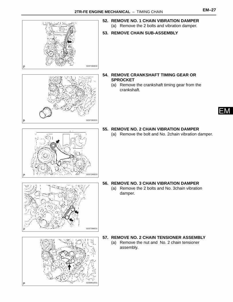
56. REMOVE NO. 3 CHAIN VIBRATION DAMPER(a) Remove the 2 bolts and No. 3chain vibration
damper.
57. REMOVE NO. 2 CHAIN TENSIONER ASSEMBLY(a) Remove the nut and No. 2 chain tensioner
assembly.
G037280E04
G037282E01
G037295E03
G037296E01
G039451E01
EM–28 2TR-FE ENGINE MECHANICAL – TIMING CHAIN
EM
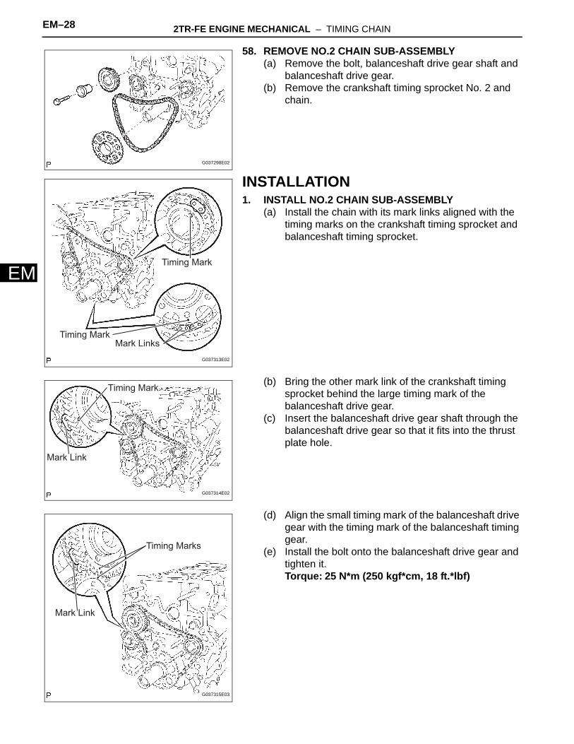
58. REMOVE NO.2 CHAIN SUB-ASSEMBLY(a) Remove the bolt, balanceshaft drive gear shaft and
balanceshaft drive gear.(b) Remove the crankshaft timing sprocket No. 2 and
chain.
INSTALLATION1. INSTALL NO.2 CHAIN SUB-ASSEMBLY
(a) Install the chain with its mark links aligned with the timing marks on the crankshaft timing sprocket and balanceshaft timing sprocket.
(b) Bring the other mark link of the crankshaft timing sprocket behind the large timing mark of the balanceshaft drive gear.
(c) Insert the balanceshaft drive gear shaft through the balanceshaft drive gear so that it fits into the thrust plate hole.
(d) Align the small timing mark of the balanceshaft drive gear with the timing mark of the balanceshaft timing gear.
(e) Install the bolt onto the balanceshaft drive gear and tighten it.Torque: 25 N*m (250 kgf*cm, 18 ft.*lbf)
G037298E02
Timing Mark
Timing MarkMark Links
G037313E02
Timing Mark
Mark Link
G037314E02
Timing Marks
Mark Link
G037315E03
2TR-FE ENGINE MECHANICAL – TIMING CHAIN EM–29
M
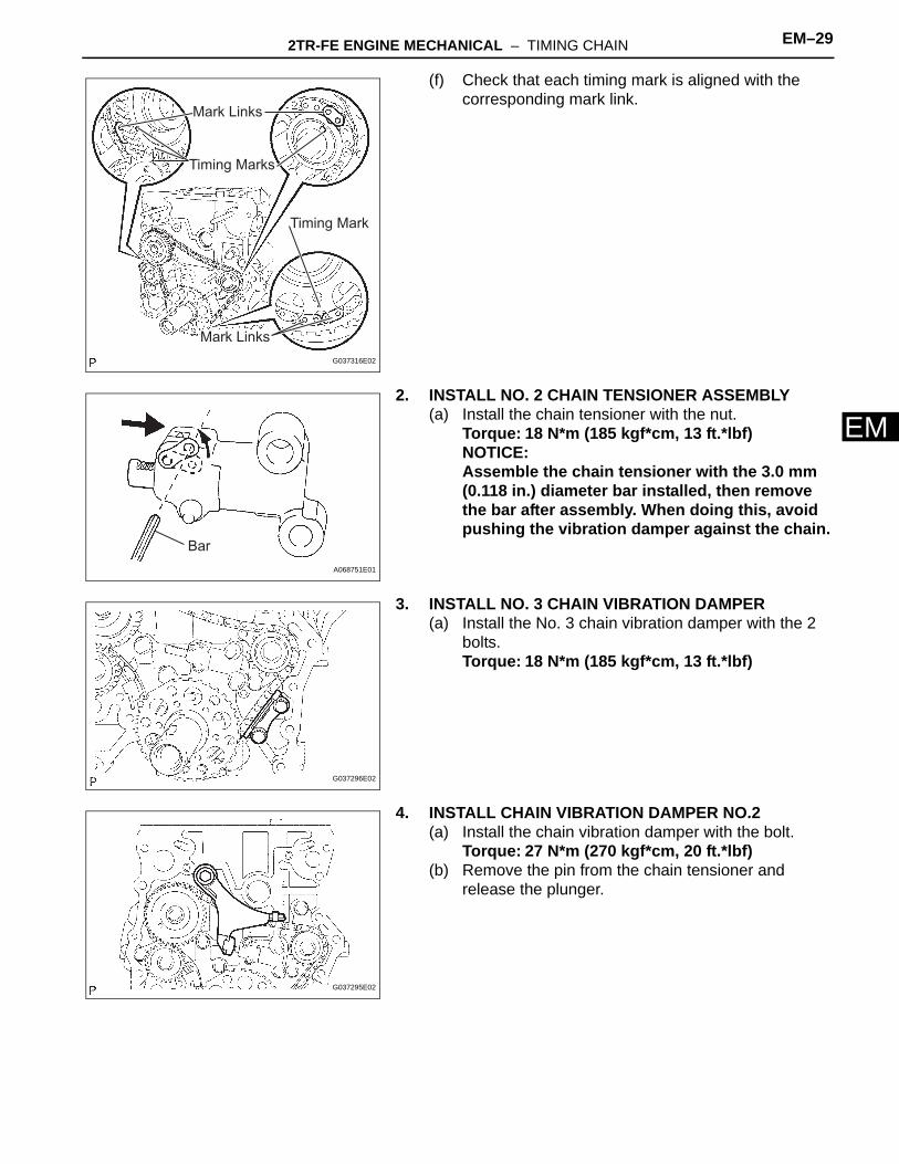
E(f) Check that each timing mark is aligned with the corresponding mark link.
2. INSTALL NO. 2 CHAIN TENSIONER ASSEMBLY(a) Install the chain tensioner with the nut.
Torque: 18 N*m (185 kgf*cm, 13 ft.*lbf)NOTICE:Assemble the chain tensioner with the 3.0 mm (0.118 in.) diameter bar installed, then remove the bar after assembly. When doing this, avoid pushing the vibration damper against the chain.
3. INSTALL NO. 3 CHAIN VIBRATION DAMPER(a) Install the No. 3 chain vibration damper with the 2
bolts.Torque: 18 N*m (185 kgf*cm, 13 ft.*lbf)
4. INSTALL CHAIN VIBRATION DAMPER NO.2(a) Install the chain vibration damper with the bolt.
Torque: 27 N*m (270 kgf*cm, 20 ft.*lbf)(b) Remove the pin from the chain tensioner and
release the plunger.
Mark Links
Timing Marks
Mark Links
Timing Mark
G037316E02
BarA068751E01
G037296E02
G037295E02

EM–30 2TR-FE ENGINE MECHANICAL – TIMING CHAIN
EM
5. INSTALL CRANKSHAFT TIMING GEAR OR SPROCKET(a) Install the timing sprocket as shown in the
illustration.
6. INSTALL NO. 1 CHAIN VIBRATION DAMPER(a) Install the vibration damper with the bolt and nut.
Torque: 21 N*m (214 kgf*cm, 15 ft.*lbf)
7. INSTALL CHAIN SUB-ASSEMBLY(a) As shown in the illustration, install the chain onto the
sprocket and gear with the painted marks aligned with the timing marks on the sprocket and gear.HINT:• The camshaft mark plate is orange.• The crankshaft mark plate is yellow.
(b) Use a rope to tie the chain of the crankshaft timing sprocket. Tie the rope near the sprocket.NOTICE:After the chain tensioner has been installed, the rope must be removed.HINT:The rope is tied to prevent gear jumping.
G037282E01
G037280E04
Timing Mark
13°
Timing Marks
Timing Mark
Mark Link
Mark Link
Timing Mark
Mark Link
G037332E03
G037333E01

2TR-FE ENGINE MECHANICAL – TIMING CHAIN EM–31
M
E8. INSTALL CHAIN TENSIONER SLIPPER(a) Install the tensioner slipper with the bolt.
Torque: 21 N*m (214 kgf*cm, 15 ft.*lbf)
9. INSTALL NO. 1 CHAIN TENSIONER ASSEMBLY(a) Install a new gasket and the chain tensioner with the
bolt and nut.Torque: 10 N*m (102 kgf*cm, 7 ft.*lbf)
10. INSTALL TIMING CHAIN GUIDE(a) Install a new O-ring and the chain guide with the 2
bolts.Torque: 10 N*m (102 kgf*cm, 7 ft.*lbf)
11. INSTALL TIMING CHAIN COVER (See page LU-24)
12. INSTALL OIL PAN SUB-ASSEMBLY(a) Apply continuous beads of seal packing to the
places shown in the illustration.Seal packing:
Part No. 08826-00080 or equivalentSeal width:
2 to 3 mm (0.079 to 0.118 in.)NOTICE:• Remove any oil from the contact surface.• Install the crankcase within 3 minutes of
applying the seal packing.• Do not start the engine for at least 2 hours
after installation.
G037281E03
G037279E01
O-ring
G037278E05
Seal Packing
A A
A-A B-BB
B
8.0 mm(0.315 in.)
6.5 mm(0.256 in.)
2 to 3 mm 2 to 3 mm
G037340E03

EM–32 2TR-FE ENGINE MECHANICAL – TIMING CHAIN
EM
(b) Loosely install the oil pan with the 16 bolts and 2 nuts.HINT:Bolt length: 20 mm (0.79 in.) for bolt A,40 mm (1.57 in.) for bolt B
(c) Uniformly tighten the 16 bolts and 2 nuts in the sequence shown in the illustration.Torque: 26 N*m (265 kgf*cm, 19 ft.*lbf)
13. INSTALL OIL STRAINER SUB-ASSEMBLY(a) Install a new gasket and the oil strainer with the 2
bolts and 2 nuts.Torque: 26 N*m (265 kgf*cm, 19 ft.*lbf)
14. INSTALL NO. 2 OIL PAN SUB-ASSEMBLY(a) Apply continuous beads of seal packing to the
places shown in the illustration.Seal packing:
Part No. 08826-00080 or equivalentSeal width:
3 to 4 mm (0.118 to 0.157 in.)NOTICE:• Remove any oil from the contact surface.• Install the crankcase within 3 minutes of
applying the seal packing.• Do not start the engine for at least 2 hours
after installation.
(b) Provisionally install the oil pan with the 18 bolts and 2 nuts.
(c) Uniformly tighten the 18 bolts and 2 nuts in the sequence shown in the illustration.Torque: 9.0 N*m (92 kgf*cm, 80 in.*lbf)
(d) Install a new gasket and the drain plug.
15. INSTALL OIL LEVEL GAGE SUB-ASSEMBLY16. INSTALL CRANKSHAFT PULLEY (See page EM-75)17. INSTALL CYLINDER HEAD COVER SUB-ASSEMBLY
(See page EM-48)18. INSTALL NO. 1 INTAKE MANIFOLD TO HEAD
GASKET (See page EM-38)19. INSTALL CAMSHAFT POSITION SENSOR (See page
ES-444)
NutNutA
B
4
BA
98
7
6 5 3 2
B 22
10
11 12 13 14 1516
2120
191718
A
A
1
G038130E02
G037268E01
Seal Packing
A - A
Seal Width:
3 to 4 mm
6.0 mm(0.236 in.)
A A
G038131E02
2
1 39
45
87
6
1011 12 13
14 15
16
17
18
1920 G037265E02
2TR-FE ENGINE MECHANICAL – TIMING CHAIN EM–33
M
E20. INSTALL CRANKSHAFT POSITION SENSOR (See page ES-444)
21. INSTALL IDLE PULLEY ASSEMBLY WITH BRACKET (w/ Air Conditioning System) (See page ES-444)
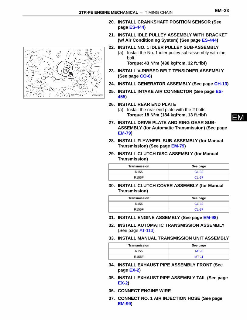
22. INSTALL NO. 1 IDLER PULLEY SUB-ASSEMBLY(a) Install the No. 1 idler pulley sub-assembly with the
bolt.Torque: 43 N*m (438 kgf*cm, 32 ft.*lbf)
23. INSTALL V-RIBBED BELT TENSIONER ASSEMBLY (See page CO-6)
24. INSTALL GENERATOR ASSEMBLY (See page CH-13)25. INSTALL INTAKE AIR CONNECTOR (See page ES-
455)26. INSTALL REAR END PLATE
(a) Install the rear end plate with the 2 bolts.Torque: 18 N*m (184 kgf*cm, 13 ft.*lbf)
27. INSTALL DRIVE PLATE AND RING GEAR SUB-ASSEMBLY (for Automatic Transmission) (See page EM-79)
28. INSTALL FLYWHEEL SUB-ASSEMBLY (for Manual Transmission) (See page EM-79)
29. INSTALL CLUTCH DISC ASSEMBLY (for Manual Transmission)
30. INSTALL CLUTCH COVER ASSEMBLY (for Manual Transmission)
31. INSTALL ENGINE ASSEMBLY (See page EM-98)32. INSTALL AUTOMATIC TRANSMISSION ASSEMBLY
(See page AT-113)
33. INSTALL MANUAL TRANSMISSION UNIT ASSEMBLY
34. INSTALL EXHAUST PIPE ASSEMBLY FRONT (See page EX-2)
35. INSTALL EXHAUST PIPE ASSEMBLY TAIL (See page EX-2)
36. CONNECT ENGINE WIRE37. CONNECT NO. 1 AIR INJECTION HOSE (See page
EM-99)
A099635E01
Transmission See page
R155 CL-32
R155F CL-37
Transmission See page
R155 CL-32
R155F CL-37
Transmission See page
R155 MT-9
R155F MT-11

EM–34 2TR-FE ENGINE MECHANICAL – TIMING CHAIN
EM
38. CONNECT FUEL VAPOR FEED HOSE ASSEMBLY (See page EM-99)
39. CONNECT NO. 2 FUEL HOSE (See page FU-17)40. CONNECT FUEL HOSE (See page FU-17)41. INSTALL WATER HOSE SUB-ASSEMBLY (See page
EM-99)42. INSTALL RADIATOR HOSE INLET43. INSTALL COMPRESSOR AND MAGNETIC CLUTCH
(w/ Air Conditioning System)(a) Install the compressor and magnetic clutch with the
4 bolts.Torque: 21 N*m (214 kgf*cm, 16 ft.*lbf)
(b) Connect the compressor and magnetic clutch connector.
(c) Install the bolt shown in the illustration.Torque: 7.5 N*m (76 kgf*cm, 66 in.*lbf)
44. INSTALL NO. 2 RADIATOR HOSE
45. INSTALL VANE PUMP ASSEMBLY(a) Install the vane pump with the 2 bolts.
Torque: 21 N*m (214 kgf*cm, 16 ft.*lbf)(b) Connect the vane pump connector.
46. INSTALL AIR CLEANER CASE(a) Install the air cleaner case with the 3 bolts.
Torque: 12 N*m (122 kgf*cm, 9 ft.*lbf)47. INSTALL AIR CLEANER FILTER ELEMENT SUB-
ASSEMBLY48. INSTALL AIR CLEANER CAP SUB-ASSEMBLY (See
page EC-17)49. INSTALL FAN SHROUD (See page CO-18)50. INSTALL RADIATOR SUPPORT TO FRAME SEAL LH
(See page CO-19)51. INSTALL BATTERY TRAY52. INSTALL BATTERY53. ADD ENGINE OIL (See page LU-4)54. ADD ENGINE COOLANT (See page CO-3)55. CHECK FOR ENGINE OIL LEVEL
G038234E01
G038205E01
G037555E01

2TR-FE ENGINE MECHANICAL – TIMING CHAIN EM–35
M
E56. CHECK FOR FUEL LEAKAGE57. CHECK FOR ENGINE COOLANT LEAKAGE (See
page CO-2)58. CHECK FOR OIL LEAKAGE59. CHECK FOR EXHAUST GAS LEAKAGE60. INSTALL NO. 1 ENGINE UNDER COVER SUB-
ASSEMBLY (for 4WD and Pre-Runner)(a) Install the No. 1 engine under cover with the 4 bolts.
Torque: 30 N*m (306 kgf*cm, 22 ft.*lbf)61. INSTALL NO. 2 ENGINE UNDER COVER SUB-
ASSEMBLY (for 4WD and Pre-Runner, Regular Cab)(a) Install the No. 2 engine under cover with the 4 bolts.
Torque: 30 N*m (306 kgf*cm, 22 ft.*lbf)62. INSTALL HOOD SUB-ASSEMBLY
(See page ED-7)