
2s TEC1000a manual - Topline Pools & Wellness
83
Drawing 9644 Rev 5 01-05-01 Page 1 of 83 TEC1000A Amperometric Chemistry Control System Manual
Transcript of 2s TEC1000a manual - Topline Pools & Wellness

Drawing 9644 Rev 5 01-05-01 Page 1 of 83
TEC1000A Amperometric
Chemistry Control System
Manual
Drawing 9644 Rev 5 01-05-01 Page 2 of 83 Topline Electronics Ltd Introduction Topline were established in 1986 to provide high quality equipment. Topline now provide integrated dosing equipment packages with a comprehensive service backup. We believe that our after sales service is an integral part of the company’s success, and wish to assure existing and new customers that we will continually review product and service performance with the aim of improving both. If you are experiencing any problems with your dosing system or general water quality please do not hesitate to contact a Topline engineer on 01323-440760. Topline are always willing to develop new products and services with clients, so if you have an idea on how to improve any Topline product or wish to develop a product for your own use, please contact Andrew Hunt on 01323 440760.
Drawing 9644 Rev 5 01-05-01 Page 3 of 83
Contents Section 1 Installation Instructions Section 2 Commissioning Handover Instructions Section 3 Operating Instructions Section 4 Trouble Shooting Section 5 Maintenance Instructions Section 6 Operating / Warranty Conditions and Advisory Notes Section 7 Servicing / Extended Warranty Contracts Section 8 Index

Drawing 9644 Rev 5 01-05-01 Page 4 of 83

Drawing 9644 Rev 5 01-05-01 Page 5 of 83
SECTION 1
INSTALLATION INSTRUCTIONS

Drawing 9644 Rev 5 01-05-01 Page 6 of 83

Drawing 9644 Rev 5 01-05-01 Page 7 of 83
Installation Instructions for TEC Pool Dosing Equipment This equipment is only to be installed by a person qualified in electrical and
chemical plumbing systems Technical Data TEC1000A Control System Dimensions 565mm wide x 725mm tall x 100mm deep Power Requirement 240 VAC single phase 50 Hz. Power Consumption 15 watts (Excluding Feeders) Operating Temperature 0 - 50 degrees centigrade Enclosure Metal IP54 Front control panel Polyester membrane Display 16 x 2 alphanumeric Liquid crystal display Chlorine sensor Amperometric 3 electrode system Measuring range 0 - 10 mg/l pH sensor Glass with internal reference Measuring Range 6.5 - 9.0 pH Outputs Chemical feeders 2 x 240 VAC switched External Alarm, Voltage free (no/nc) RS232 data port Inputs 3 analogue 1 digital flow sensor 3 Button keypad for user data input CE Certificate Declaration of conformance Manufacturer's Name Topline Electronics Ltd Manufacturer's Address Unit 7, Crown Close Hailsham, E.Sussex England, BN27 3JF Declares that the product TEC1000a Conforms to the following product specifications EMC EN50081-1:1992 EN55022:1995 CLASS B EN50082-1:1992 IEC801-2:1984 IEC801-3:1984 IEC801-4:1988 The product complies with the requirements of the following directives and carries the CE marking. EMC Directive 89/336/EEC (inclusive 93/68/EEC) I the undersigned, declare that the equipment above, conforms to the above directive. Manufacturer Topline Electronics Ltd
Signature A.Hunt Date Feb 10th 1996

Drawing 9644 Rev 5 01-05-01 Page 8 of 83 Installation Instructions (Cont.) Position of chemistry Control System A wall space of at least 750mm high by 600mm wide is required. Mount the controller with the TOP of the assembly no more than 1700mm from ground level. The system is mounted on a backboard, and the water sample Inlet is on the left hand side with the Outlet (return) on the right hand side of the measuring cell and flow switch. The control unit and chemical storage areas should be easily accessible to the operator. Protective clothing should be available for use and warning signs present. The injection points and storage containers/day tanks (pH correction and chlorine donor chemicals) should be not less than 2 metres apart and easily accessible. The injection points should be situated after the control system sample line take off point, not above head height, but above the top of the day tanks to avoid siphoning. They should not be placed above any equipment that could be damaged by leakage. The dosing lines should be as short as possible and run in protective sleeving marked with red and white tape for acid and yellow and black for chlorine. Dosing pump foot valve assemblies should be supported in rigid pipe held clear of agitators and 4cm clear of the day tank bottom. If CO2 is used to correct the pH and the plant room is confined or below ground level, then a CO2 leakage detection sensor must be provided. A water supply (mains, not pool water) should be provided for making up chemical solutions. Equipment selection check list TYPE POOL POOL POOL SPA SPA Pool capacity >350M3 >200M3 >50M3 >10M3 >1M3 Controller 1000A 1000A 1000A 1000A 1000A LMI Pumps only Dry acid @ 10% ( Na HSO4 ) Incoming calcium hardness and alkalinity are above 100 ppm Day tank size litres +110% bund 300 200 100 50 50 Agitator Man Man Man Man Man Pump model +4 function valve B145 PO65 PO65 PO55 PO55 Injector type LMI LMI LMI LMI LMI Dosing hose size 1/2 3/8 3/8 3/8 3/8 Sodium Hypo @ 10-14% ( Na OCl ) Incoming calcium hardness and alkalinity are above 100 ppm Day tank size in litres 300 200 100 50 50 Agitator No No No No No Hand transfer pump Yes Yes Yes Yes Yes Pump model inc. 4 function valve B145 PO65 PO65 PO55 PO55 Injector type LMI LMI LMI LMI LMI Dosing hose size 1/2 3/8 3/8 3/8 3/8 Cal Hypo @ 3% ( Ca OCL2 ) Incoming calcium hardness and alkalinity are below 100 ppm Day tank size in litres 500 300 200 100 100 Agitator Elec Elec Elec Elec Elec Pump model inc. 4 function valve B145 B145 PO65 PO65 PO55 Injector type Rod Rod Rod Rod Rod Dosing hose size 1/2 1/2 3/8 3/8 3/8 Bund tanks are 110% of day tank capacity Carbon dioxide (CO2 ) Incoming calcium hardness and alkalinity are below 100 ppm CO2 detector to be used if plant room floor is below ground level CO2 correction system TLE TLE TLE TLE TLE
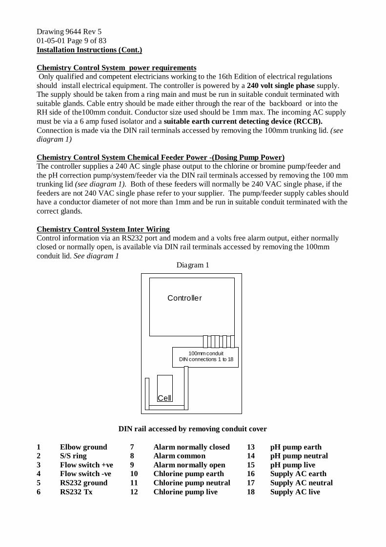
Drawing 9644 Rev 5 01-05-01 Page 9 of 83 Installation Instructions (Cont.) Chemistry Control System power requirements Only qualified and competent electricians working to the 16th Edition of electrical regulations should install electrical equipment. The controller is powered by a 240 volt single phase supply. The supply should be taken from a ring main and must be run in suitable conduit terminated with suitable glands. Cable entry should be made either through the rear of the backboard or into the RH side of the100mm conduit. Conductor size used should be 1mm max. The incoming AC supply must be via a 6 amp fused isolator and a suitable earth current detecting device (RCCB). Connection is made via the DIN rail terminals accessed by removing the 100mm trunking lid. (see diagram 1) Chemistry Control System Chemical Feeder Power -(Dosing Pump Power) The controller supplies a 240 AC single phase output to the chlorine or bromine pump/feeder and the pH correction pump/system/feeder via the DIN rail terminals accessed by removing the 100 mm trunking lid (see diagram 1). Both of these feeders will normally be 240 VAC single phase, if the feeders are not 240 VAC single phase refer to your supplier. The pump/feeder supply cables should have a conductor diameter of not more than 1mm and be run in suitable conduit terminated with the correct glands. Chemistry Control System Inter Wiring Control information via an RS232 port and modem and a volts free alarm output, either normally closed or normally open, is available via DIN rail terminals accessed by removing the 100mm conduit lid. See diagram 1
Diagram 1
100mm conduit DIN connections 1 to 18
Cell
Controller
DIN rail accessed by removing conduit cover 1 Elbow ground 7 Alarm normally closed 13 pH pump earth 2 S/S ring 8 Alarm common 14 pH pump neutral 3 Flow switch +ve 9 Alarm normally open 15 pH pump live 4 Flow switch -ve 10 Chlorine pump earth 16 Supply AC earth 5 RS232 ground 11 Chlorine pump neutral 17 Supply AC neutral 6 RS232 Tx 12 Chlorine pump live 18 Supply AC live

Drawing 9644 Rev 5 01-05-01 Page 10 of 83 Installation Instructions (Cont.) Water sample supply for the cell assembly A water sample supply should be taken from the under side of the main circulation pipe, via a 3/8 inch PVC isolating valve, and a ‘Y’ strainer. The sample line should be 3/8 inch BSP rigid PVC pipe. The pipe work from the cell assembly is 3/8 inch, and this connection is made with a 3/8 inch PVC plain/threaded union (supplied) to allow for servicing of the cell assembly if required. The sample return can either be run to waste, to the balance tank or returned back into the suction side of the main circulation via a 3/8 inch PVC isolating valve. It is essential that there is a positive flow through the probe cell assembly i.e. pressure on the sample input and vacuum or no pressure on the return. A flow detection switch is fitted so if there is no circulation the chemical feeders will be shut down and the alarm led on the controller will flash.
Diagram of connections to circulation system
PUMP
CELL INPUT OUTPUT
ISOLATION VALVE
ISOLATION VALVE
Y STRAINER
FLOW
FILTER
CONTROLLER
pH CORRECTION
2 METRES
Cl CORRECTION
FLOW
FLOW Inserting the Electrodes Before inserting the electrodes ensure that you shake them to remove air from the tip of the electrode. Do not insert the electrodes unless you intend to leave water in the cell assembly. The electrodes must not be allowed to dry out.

Drawing 9644 Rev 5 01-05-01 Page 11 of 83
SECTION 2
COMMISSIONING HANDOVER
INSTRUCTIONS

Drawing 9644 Rev 5 01-05-01 Page 12 of 83

Drawing 9644 Rev 5 01-05-01 Page 13 of 83
Commissioning of the Pool Dosing Equipment REMOVE THIS PAGE AT COMMISSIONING
Commissioning procedure It is important that the commissioning is comprehensive and complete, leaving no grey areas of responsibility or accountability. Clarity of description and explanation of the equipment to the client is therefore vital. Before the chemical dosing plant is explained, complete the below check list. All of the lines are to be completed, no blank lines are to be left. If any item is not OK then an explanation must be given. Commissioning Check list 1. Pool |__________|__________|__________|__________|__________| 2. Positon of controller |__________|__________|__________|__________|__________| 3. Cell / pipework leaks |__________|__________|__________|__________|__________| 4. Cell assembly water flow |__________|__________|__________|__________|__________| 5. Electrical RCCB |__________|__________|__________|__________|__________| 6. Cl / pH day & bund tank |__________|__________|__________|__________|__________| 7. Cl / pH warning labels |__________|__________|__________|__________|__________| 8. Cl / pH pump fixing |__________|__________|__________|__________|__________| 9. Cl / pH chemical leaks |__________|__________|__________|__________|__________| 10. Cl / pH injector position |__________|__________|__________|__________|__________| 11. Electrical Cl / pH pump correct pool |__________|__________|__________|__________|__________| 12. Injection lines Cl / pH pump correct pool |__________|__________|__________|__________|__________| 13. Cl / pH agitator fixings |__________|__________|__________|__________|__________| Notes reference above numbers ________________________________________________________________________________ ________________________________________________________________________________ ________________________________________________________________________________ ________________________________________________________________________________ ________________________________________________________________________________ ________________________________________________________________________________ ________________________________________________________________________________ ________________________________________________________________________________

Drawing 9644 Rev 5 01-05-01 Page 14 of 83
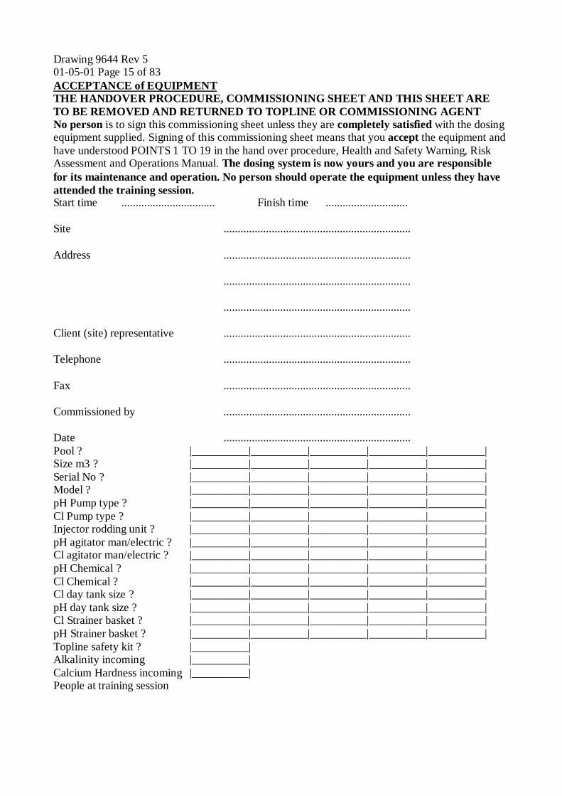
Drawing 9644 Rev 5 01-05-01 Page 15 of 83 ACCEPTANCE of EQUIPMENT THE HANDOVER PROCEDURE, COMMISSIONING SHEET AND THIS SHEET ARE TO BE REMOVED AND RETURNED TO TOPLINE OR COMMISSIONING AGENT No person is to sign this commissioning sheet unless they are completely satisfied with the dosing equipment supplied. Signing of this commissioning sheet means that you accept the equipment and have understood POINTS 1 TO 19 in the hand over procedure, Health and Safety Warning, Risk Assessment and Operations Manual. The dosing system is now yours and you are responsible for its maintenance and operation. No person should operate the equipment unless they have attended the training session. Start time ................................. Finish time ............................. Site .................................................................. Address .................................................................. .................................................................. .................................................................. Client (site) representative .................................................................. Telephone .................................................................. Fax .................................................................. Commissioned by .................................................................. Date .................................................................. Pool ? |__________|__________|__________|__________|__________| Size m3 ? |__________|__________|__________|__________|__________| Serial No ? |__________|__________|__________|__________|__________| Model ? |__________|__________|__________|__________|__________| pH Pump type ? |__________|__________|__________|__________|__________| Cl Pump type ? |__________|__________|__________|__________|__________| Injector rodding unit ? |__________|__________|__________|__________|__________| pH agitator man/electric ? |__________|__________|__________|__________|__________| Cl agitator man/electric ? |__________|__________|__________|__________|__________| pH Chemical ? |__________|__________|__________|__________|__________| Cl Chemical ? |__________|__________|__________|__________|__________| Cl day tank size ? |__________|__________|__________|__________|__________| pH day tank size ? |__________|__________|__________|__________|__________| Cl Strainer basket ? |__________|__________|__________|__________|__________| pH Strainer basket ? |__________|__________|__________|__________|__________| Topline safety kit ? |__________| Alkalinity incoming |__________| Calcium Hardness incoming |__________| People at training session

Drawing 9644 Rev 5 01-05-01 Page 16 of 83

Drawing 9644 Rev 5 01-05-01 Page 17 of 83 Hand over procedure Explain and/or demonstrate: 1. Pool and spa water to be clear, no smell and no foaming. 2. All areas close to pool to be kept clean, appropriate cleaning agents to be used that do not contain detergents. 3. The pH must be maintained between 7.2 and 7.8 for the chlorine donor to be efficient. Combined chlorine will form quicker if these levels are not maintained together with an increase in associated smell and irritated skin and eyes. More acid or CO2 will be used at first on a new pool due to the grouting and the controller may enter pH time-out at first due to this. Acid reduces pH level. 4. Break point chlorination is to be maintained i.e. that free chlorine is to be no less than 2/3 of total. If break point chlorination is lost, 10 times as much chlorine will be used to re- achieve break point with the associated increase in chemical costs. 5. Under dosing of chlorine will mean that bacteria will multiply in the water. 6. Over dosing chlorine will bleach costumes (consider that fashion costumes are not suitable for chlorinated pools), irritate skin and effect bleached hair. 7. Correct use of DPD1, DPD3, phenol red, alkalinity & calcium hardness tablets, record of tablet results to be maintained. 8. Balanced water is essential and achieved when, alkalinity is between 75mg/l and 150mg/l, calcium hardness is between 75mg/l and 500mg/l and TDS is not above 1000mg/l above source water (not salt water pools). 9. The general overview of the system.
Point out: The sample line, the route the sample takes through the pipe work to the sensor and the sequence of sample line isolating valves i.e. the isolation valves operation. Explain the necessity of having a regular un-changing flow through the sensor assembly and the function of the flow control valve. Explain the function and operation of the flow switch and how this de-activates the chemical feeders.
10. Explain that subjecting the electrodes to very high pressure or vacuum will damage the electrodes. Indicate the electrodes and show which is which. Explain how the sensors work, how they are removed and how they are cleaned with Topline cleaning solution.
11. Explain the calibration procedure for the chlorine sensor, go through the operation of the controller, i.e. reading, set point (required level), standardisation (actual level) (point out that the water sample used for standardising the electrodes must be taken from the sample tap adjacent to the controller, not from the pool), time out and proportional feed set up, show how to set and change all the parameters as described in the operations manual
12. Dosing pumps. Show how to tighten up the set screws on dosing pump heads and state that this should be done every six weeks. Show four function valve operation, foot valve assembly and injector maintenance. Point out the dosing system supplier is not responsible for blocked injectors or any damage caused by blockages.
13. CO2 controller. Show how to change the CO2 flow. Explain changing over gas bottles, pressure gauges, inform that the first stage regulator is set to 1.5 bar and explain how to clean the CO2 injection diffuser.

Drawing 9644 Rev 5 01-05-01 Page 18 of 83 Hand over procedure (cont.) Explain and/or demonstrate: 14. Show Risk assessment and Health and Safety sheet to staff. 15. When mixing the chemicals and filling the day tanks the following guidelines are to be observed: a. State that staff should always wear personal protective equipment (PPE) when mixing
chemicals or handling system parts that have come in contact with chemicals. Warning signs are to be put up to this effect.
b. COSHH sheets should be kept covering all chemicals kept on site. c. Calcium hypochlorite ratio is NO MORE than 3 kilograms per 100 litres of water, agitate solution for half an hour before use. d. Sodium Hypochlorite should be transferred to the day tank from the delivery drums using a
manual hand transfer pump. The chemical should never be poured from container to container directly. The hand transfer pump must be flushed with water after use, if not, the pump will be permanently damaged. The repair/replacement will be charged for.
e. Sodium bisulphate strength should be no more than 10 kilograms per 100 litres of water agitation is required when mixing sodium bisulphate. f. Chemical levels should not be allowed to fall below 25% of tank capacity. g. If acid and chlorine are allowed to mix, chlorine gas is generated. This is extremely
dangerous. h. Only Vapour take off CO2 bottles to be used with TEC1000a. CO2 is an asphyxiate and if this product is used in a below ground level or in a confined plant room then a CO2 detector must be installed. i. All chemical storage areas and chemical pumps must be kept clean. Any spillage must be
cleared up immediately, absorbed using an inert material and placed in suitable containers for correct disposal. Appropriate authorities must be informed of any spillage.
16. Explain the de-activation of chemical pumps/feeders during backwashing. 17. Inform that organic polymer flocculents and cyanuric acid based (STABILISED)
chlorine should not be used due to coating of the electrodes and chlorine lock out problems.
18. Cover terms and conditions 19. Point out that service calls will be charged for if the responsibility for the fault lies with the operator or the maintenance schedule has not been kept up to date. 20. Ask everyone if they have any questions and have understood all the information.

Drawing 9644 Rev 5 01-05-01 Page 19 of 83
TWELVE MONTH GUARANTEE Product Valid from Purchased From Installed by: Commissioned by: Your new Topline Product carries a full 12 month guarantee against faulty materials and workmanship. In the unlikely event that you have cause to complain during this period you should contact Topline Electronics Ltd. Unit 7, Crown Close, Hailsham, East Sussex. BN7 3JF. Phone 01323 440760. We will replace components or the equipment without charge, provided that: Topline Electronics Ltd. Carried out the Commissioning or have approved the Commissioning. The Operating Instructions (provided with equipment) have been followed. Operating conditions have been met for the TEC1000a. All routine maintenance has been carried out. Service Components installed are approved by Topline Electronics Ltd. The Product has not had a repair attempted by others. The Product has not been damaged, abused or altered. The Product is being used for the purpose for which it is intended. We reserve the right to use substitute Components of similar or higher quality. This Guarantee does not affect your statutory rights. PRODUCT SUPPORT. All of our products can be supported by an Extended Warranty, Service Agreements and System Training. Free training is available at time of commissioning. Our Technical Helpline 01323 440760 can provide assistance during office hours. Extended warranty Topline Electronics Ltd offer an extended warranty on new equipment. The extended warranty includes one service and all parts used on that service. The extension periods are 1year, 2year and 3 year. Terms are per 12 month guarantee. The offer of an extended warranty is only available within 4 months of the commissioning date. The costs are detailed in the Topline Electronics Ltd price list. Extended warranty must be paid for in advance.

Drawing 9644 Rev 5 01-05-01 Page 20 of 83
Drawing 9644 Rev 5 01-05-01 Page 21 of 83
Topline Electronics
Ltd
This is to Certify that the following Staff can operate the dosing system at
.......................................... .......................................... .......................................... ..........................................
..........................................
They have been trained and achieved the required standard in the use and operation of Topline TEC 1000
Chemical Controller.
The holders of this Certificate were present for training by
Topline Electronics Ltd
A. Hunt

Drawing 9644 Rev 5 01-05-01 Page 22 of 83

Drawing 9644 Rev 5 01-05-01 Page 23 of 83
SECTION 3
OPERATING INSTRUCTIONS

Drawing 9644 Rev 5 01-05-01 Page 24 of 83

Drawing 9644 Rev 5 01-05-01 Page 25 of 83
Health and Safety Warning
You must have safety clothing available for use when mixing or using any chemicals. Always wear protective clothing when handling chemicals. It is imperative that eye protection is employed at all times. Details of the correct clothing to be worn is given on the COSHH health and safety data sheets. You must have the safety data sheets for the chemicals you use on site, these are provided by your chemical supplier. Topline cannot be held responsible for any accidents. Trained personnel should be the only people allowed access to chemical dosing systems. Remember, if something is wrong with any of the swimming pool systems,
TAKE THE APPROPRIATE ACTION!
Even if this is only to alert your manager. Do not just record a fault and walk away - bad pool management can affect bathers health.

Drawing 9644 Rev 5 01-05-01 Page 26 of 83
Drawing 9644 Rev 5 01-05-01 Page 27 of 83
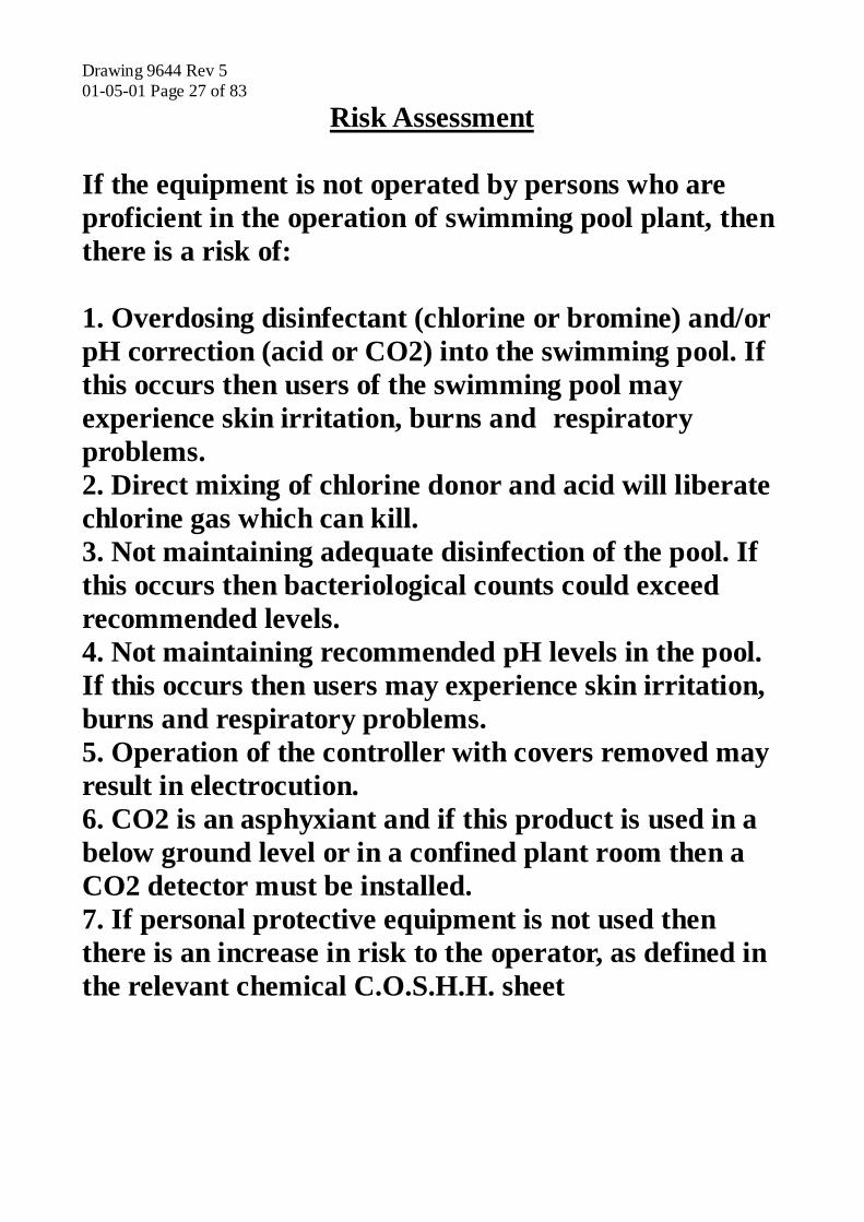
Risk Assessment
If the equipment is not operated by persons who are proficient in the operation of swimming pool plant, then there is a risk of: 1. Overdosing disinfectant (chlorine or bromine) and/or pH correction (acid or CO2) into the swimming pool. If this occurs then users of the swimming pool may experience skin irritation, burns and respiratory problems. 2. Direct mixing of chlorine donor and acid will liberate chlorine gas which can kill. 3. Not maintaining adequate disinfection of the pool. If this occurs then bacteriological counts could exceed recommended levels. 4. Not maintaining recommended pH levels in the pool. If this occurs then users may experience skin irritation, burns and respiratory problems. 5. Operation of the controller with covers removed may result in electrocution. 6. CO2 is an asphyxiant and if this product is used in a below ground level or in a confined plant room then a CO2 detector must be installed. 7. If personal protective equipment is not used then there is an increase in risk to the operator, as defined in the relevant chemical C.O.S.H.H. sheet

Drawing 9644 Rev 5 01-05-01 Page 28 of 83

Drawing 9644 Rev 5 01-05-01 Page 29 of 83
Operating Instructions for TEC Pool Dosing Equipment Overview Controller Although the TEC1000A control system has been designed for ease of use, it is important that this manual is studied before you begin to use the TEC1000A Control System. The TEC1000A control system will control the water chemistry in your swimming pool, but it is necessary for you to understand the principles of operation of the TEC1000A Control System before you start to use the system. System Overview The TEC1000A control system consists of five items, the control module which receives information on water chemistry, the sensor assembly which sends information on water chemistry, two dosing devices one for chlorine/bromine, one for pH correction and the chemical storage tanks. A water sample is taken from the main circulation system (post filtration) via a sample strainer to the sensor assembly which contains the electrodes. The sample flow is either run to waste (preferred) or returned back into the main circulation. Isolating valves are placed at each end of the sample line. The pH and chlorine probes are the main element of the sensors. A bypass arrangement diverts the water sample, and a flow of about 60 litres per hour is maintained past the pH and chlorine probes. This flow is indicated by the flow ball in the flow indicator and is adjusted with the flow valve control knob. The flow ball should be approximately in the middle of the window. A regular non changing flow is essential for correct operation of the system. A sample tap is fitted to the sensor cell from which water samples should be taken for tests used to standardise or calibrate the controller. The pH and chlorine probes monitor the water chemistry levels (free chlorine and pH) and this signal is sent to the control module. The control module instructs the chemical dosing devices to supply chemicals into the water stream as required. The control module displays operational information. LED's. The status LED's (Light emitting Diodes) indicate if the pH and chlorine levels are within the alarm limits, RED = high, RED = low and GREEN = normal. The flow LED is linked to a flow sensor and will normally be on, if there is no flow the LED will go out and there will be no chemical dosing. The alarm LED will flash if a high/low level is equalled/exceeded, flow LED out (flow interrupted), or a pump has timed out. The pump LED's will be on when the controller is dosing pH or Chlorine. Circuit Breakers. The pump circuit breaker will trip in a pump overload condition. If a pump circuit breaker trips, identify the cause before resetting. The dosing pumps can also be turned off by pressing the circuit breaker, the off position is with the circuit breaker out. The key pad buttons are used to cancel any time-outs and adjust the control parameters. The LCD panel display’s the actual pH, chlorine and temperature levels (if fitted) and system messages. All of the normal system messages are detailed on the following page.

Drawing 9644 Rev 5 01-05-01 Page 30 of 83 System Overview normal system messages
(C) 1998 Topline Electronics LTD.
Power up sign on message displayed for 45 seconds
1.5ppm 7.3pH
No time-outs and not dosing
1.5ppm 7.5pH
pH dose pH pump being turned on and off to correct pH level
1.0ppm 7.3pH Chlor dose
Chlorine pump being turned on and off to correct the chlorine level.
1.0ppm 7.5pH Chlor+pH dose
pH and Chlorine pumps being turned on and off to correct the pH and chlorine levels.
1.5ppm 7.5pH pH timeout
pH pump permanently disabled and no chlorine dosing.
1.0ppm 7.5pH pH timeout Chlor
pH pump permanently disabled and chlorine pump being turned on and off to correct the chlorine level.
1.0ppm 7.3pH Chlor timeout
Chlorine pump permanently disabled and no pH dosing.
1.0ppm 7.5pH Chlor timeout pH
Chlorine pump permanently disabled and pH pump being turned on and off to correct the pH level.
1.0ppm 7.5pH pH+Chlor timeout
The pH and chlorine pumps are permanently disabled.

Drawing 9644 Rev 5 01-05-01 Page 31 of 83 System Set-up During commissioning the TEC1000A Control System will be set up and you will be shown how to operate the TEC1000A control system. The following pages show you how to change the control parameters. All the option screens and the sub screens that are available are shown below, these are examples only: Set up mode Access set up mode by pressing the "Enter" key. The controller will display the message "Standardise". There are six set-up menus Standardise, Setpoint, Time-out, Pump, Alarm, Calibrate, and these are obtained by pressing the up or down keys. Select the required menu by pressing the enter key. To change any of the values use the "enter" key to position the flashing cursor beneath the value you wish to change, and use the "up" or "down" keys to increase or decrease the value. To return the unit to normal operation simply press the "enter" key until the normal operation screen is displayed. If you make a mistake simply re-enter set-up mode. Set-up Mode Options Standardise. In operation all sensing systems for pool control need to be standardised. Standardise is the DPD1 and phenol red tablet test results from the sample tap (not the pool) entered into TEC1000 (i.e. the actual pH and chlorine level in the pool). When taking a DPD1 test, a dilution test must be carried out if the first test is above 2ppm. Only standardise the unit when required, if you are standardising frequently contact Topline for advice.
Standardise pH and Chlorine display
standardise
pH standardise 7.5pH
Chlor standardise 1.5ppm
Setpoint. The TEC1000A control system controls the water chemistry to a setpoint, if the water chemistry moves either side of this set point, then pH or Chlorine correction will begin or stop. Setpoint is the pH or chlorine level required in the pool or spa water.
Setpoint pH and Chlorine display
setpoint
pH setpoint 7.5pH
Chlor setpoint 1.5ppm

Drawing 9644 Rev 5 01-05-01 Page 32 of 83 System Set-up (Cont.) Time-outs. Each pump has a time-out value. This is the time allowed to re-achieve setpoint. This is used to prevent over dosing of chemicals and it is important that it is set to suit pump ‘on’ times and pump capacity. Incorrect setting of this time-out can result in over dosing. The pump time out can be given a value of 0-255 minutes in 1 minute increments. Setting the time-out value to zero will disable the time-out function. Cancel Time-out. To cancel a time-out, press the ‘up’ key for 4 seconds.
Time-out pH and Chlorine display
timeout
pH timeout 30 minutes
Chlor timeout 15 minutes
Pump on Times. The TEC1000A control system has full proportional control of the dosing pumps. This is so that pump times can be adjusted to pool sizes, e.g. a short on and off time for spa pools and longer on and off times for swimming pools, the proportional control also helps to prevent over dosing of chemicals. There are 3 parameters that control the pump on time, "Pump Window", "Pump Range" and "Pump scale". The pump window defines the pump duty cycle i.e. if the window was set to 120 then the TEC1000A would dose chemical every 120 seconds, the pump range defines when the pump will utilise the maximum duty cycle and the pump scale gives you a scale factor for the pump on time within the pump duty cycle. So the calculation for pump on time is Pump window * (Distance from Setpoint / Pump range) * Pump Scale = Pump on Time. Note: Dosing pumps will only be on when level correction is required and for the time calculated by the proportional range, not all the time.
Pump window, range & duty cycle pH and Chlorine display
pump pH pump window
30 seconds Chlor pump window
20 seconds
pH pump range 1.0pH
Chlo r p ump ra nge 0.5ppm
pH pump scale 5.0 * 10 %
C hlo r p um p sc a le 7 .0 * 10%
Drawing 9644 Rev 5 01-05-01 Page 33 of 83
System set up (Cont.)
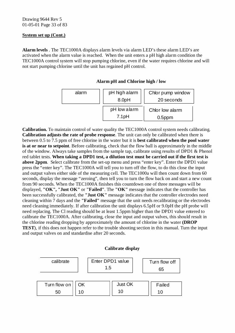
Alarm levels . The TEC1000A displays alarm levels via alarm LED’s these alarm LED’s are activated when the alarm value is reached. When the unit enters a pH high alarm condition the TEC1000A control system will stop pumping chlorine, even if the water requires chlorine and will not start pumping chlorine until the unit has regained pH control.
Alarm pH and Chlorine high / low
alarm pH high alarm 8.0pH
Chlor pump window 20 seconds
pH low alarm 7.1pH
Chlor low alarm 0.5ppm
Calibration. To maintain control of water quality the TEC1000A control system needs calibrating. Calibration adjusts the rate of probe response. The unit can only be calibrated when there is between 0.5 to 7.5 ppm of free chlorine in the water but it is best calibrated when the pool water is at or near to setpoint. Before calibrating, check that the flow ball is approximately in the middle of the window. Always take samples from the sample tap, calibrate using results of DPD1 & Phenol red tablet tests. When taking a DPD1 test, a dilution test must be carried out if the first test is above 2ppm. Select calibrate from the set-up menu and press “enter key”. Enter the DPD1 value press the “enter key”. The TEC1000A will tell you to turn off the flow, to do this close the input and output valves either side of the measuring cell. The TEC1000a will then count down from 60 seconds, display the message “zeroing”, then tell you to turn the flow back on and start a new count from 90 seconds. When the TEC1000A finishes this countdown one of three messages will be displayed, "OK", "Just OK" or "Failed". The "OK" message indicates that the controller has been successfully calibrated, the "Just OK" message indicates that the controller electrodes need cleaning within 7 days and the "Failed" message that the unit needs recalibrating or the electrodes need cleaning immediately. If after calibration the unit displays 6.5pH or 9.0pH the pH probe will need replacing. The Cl reading should be at least 1.5ppm higher than the DPD1 value entered to calibrate the TEC1000A. After calibrating, close the input and output valves, this should result in the chlorine reading dropping by approximately the amount of chlorine in the water (DROP TEST), if this does not happen refer to the trouble shooting section in this manual. Turn the input and output valves on and standardise after 20 seconds.
Calibrate display
calibrate
Enter DPD1 value 1.5
Turn flow off 65
Turn flow on 50
OK 10
Just OK 10
Failed 10

Drawing 9644 Rev 5 01-05-01 Page 34 of 83

Drawing 9644 Rev 5 01-05-01 Page 35 of 83
SECTION 4
TROUBLE SHOOTING

Drawing 9644 Rev 5 01-05-01 Page 36 of 83

Drawing 9644 Rev 5 01-05-01 Page 37 of 83 Trouble shooting Before contacting Topline for technical advice, please ensure you make a note of the current chemical test results, what the problem is and the current controller readings and settings. SYMPTOM PROBLEM REMEDY 1 NO LIGHTS ON UNIT POWER FAILURE OR TURNED OFF CHECK SUPPLY / TURN ON NO STATUS LEDS ON POOR RESET TURN POWER OFF UNIT KEEPS RESETTING AFTER 2MIN TURN POWER ON 2 FLOW BALL AT BOTTOM NO CIRCULATION CHECK CIRCULATION PUMPS SAMPLE LINE VALVE SHUT OPEN SAMPLE LINE VALVES BLOCKED SAMPLE CELL CLEAR SAMPLE CELL 3 NO CHLORINE PROBE RESPONSE NEED RECALIBRATION RECALIBRATE UNSTABLE READINGS AIR BUBBLE IN Cl PROBE REMOVE AND SHAKE DOWN NO CIRCULATION CHECK CIRCULATION PUMP SAMPLE LINE VALVE SHUT OPEN SAMPLE LINE VALVES SAMPLE CELL BLOCKED CLEAR SAMPLE CELL BLOCKED Y STRAINER REMOVE & CLEAN CL PROBE DIRTY REMOVE & CLEAN STAINLESS ELECTRODE DIRTY CLEAN EXCESSIVE FLOCULENT CONTACT TOPLINE EXCESSIVE CYANURIC ACID CONTACT TOPLINE Cl PROBE FAULTY REPLACE Cl PROBE SUBJECTED TO VACUUM REPLACE STANDARDISING FROM POOL TAKE DPD1 TEST FROM SAMPLE TAP DPD1 TEST RECALIBRATING FROM POOL TAKE DPD1 TEST FROM SAMPLE TAP DPD1 TEST 4 NO pH PROBE RESPONSE NO CIRCULATION CHECK CIRCULATION PUMP SAMPLE LINE VALVE SHUT OPEN SAMPLE LINE VALVES AIR BUBBLE IN pH PROBE REMOVE AND SHAKE DOWN SAMPLE CELL BLOCKED CLEAR SAMPLE CELL BLOCKED Y STRAINER REMOVE & CLEAN pH PROBE DIRTY REMOVE & CLEAN pH PROBE FAULTY REPLACE pH PROBE SUBJECTED TO VACUUM REPLACE STANDARDISING FROM POOL TAKE PHENOL RED TEST FROM SAMPLE TAP PHENOL RED TEST 5 ALARM LED ON NO FLOW CHECK CIRCULATION PUMP, CLEAN Y STRAINER OPEN SAMPLE LINE VALVES HIGH pH ALARM SEE 6 LOW pH ALARM SEE 7 LOW CHLORINE ALARM SEE 8 HIGH CHLORINE ALARM SEE 9 pH TIME-OUT SEE 6 CHLORINE TIME-OUT SEE 8 6 UNDER DOSING ACID/CO2 EMPTY DAY TANK FILL (pH TIME-OUT) FLOW LED OUT SEE 2 OR 5 PUMP WINDOW TO SMALL INCREASE PUMP WINDOW PUMP RANGE TO LARGE DECREASE PUMP RANGE PUMP SCALE TO SMALL INCREASE PUMP SCALE ENTERS TIME-OUT INCREASE TIME-OUT SETPOINT TOO HIGH DECREASE SETPOINT HIGH ALKALINITY LOWER TO AT LEAST 150 DOSING PUMP LOST PRIME REPRIME DOSIMG PUMP TURNED OFF TURN ON DOSING PUMP TURNED DOWN TURN UP MIXTURE TOO WEAK TAKE CARE MIXING NEXT BATCH BLOCKED TANK FOOT ASSEMBLY REMOVE & CLEAN OR REPLACE BLOCKED FEED PIPE REPLACE DAMAGED FEED PIPE REPLACE BLOCKED INJECTOR PIPE REPLACE DAMAGED INJECTOR PIPE REPLACE ONE WAY VALVE REVERSED CHECK ALL ONE WAY VALVES DOSING PUMP DIAPHRAGM BLOCK REMOVE PUMP HEAD CLEAN OR REPLACE BLOCKED 4 FUNCTION VALVE REMOVE & CLEAN OR REPLACE BLOCKED INJECTOR REMOVE & CLEAN OR REPLACE FAULTY DOSING PUMP SERVICE OR REPLACE CIRCUIT BREAKER TRIPPED CHECK CAUSE / RESET NO pH PROBE RESPONSE SEE SYMPTOM 4

Drawing 9644 Rev 5 01-05-01 Page 38 of 83 Trouble shooting (Cont.) SYMPTOM PROBLEM REMEDY 7 OVER DOSING ACID/CO2 SIPHONING REMOVE INJECTOR, CLEAN & SERVICE MIXTURE TOO STRONG TAKE CARE MIXING NEXT BATCH NO pH PROBE RESPONSE SEE SYMPTOM 4 PUMP RANGE TOO SMALL INCREASE PUMP RANGE PUMP SCALE TOO LARGE DECREASE PUMP SCALE SETPOINT TOO LOW INCREASE SETPOINT LOW ALKALINITY RAISE TO AT LEAST 75 NO pH PROBE RESPONSE SEE SYMPTOM 4 8 UNDER DOSING CHLORINE EMPTY DAY TANK FILL (Cl TIME-OUT) FLOW LED OUT SEE 2 OR 5 PUMP WINDOW TO SMALL INCREASE PUMP WINDOW PUMP RANGE TO LARGE DECREASE PUMP RANGE PUMP SCALE TO SMALL INCREASE PUMP SCALE ENTERS TIME-OUT INCREASE TIME-OUT SETPOINT TOO LOW INCREASE SETPOINT DOSING PUMP LOST PRIME REPRIME DOSIMG PUMP TURNED OFF TURN ON DOSING PUMP TURNED DOWN TURN UP MIXTURE TOO WEAK TAKE CARE MIXING NEXT BATCH BLOCKED TANK FOOT ASSEMBLY REMOVE & CLEAN OR REPLACE BLOCKED FEED PIPE REPLACE DAMAGED FEED PIPE REPLACE BLOCKED INJECTOR PIPE REPLACE DAMAGED INJECTOR PIPE REPLACE ONE WAY VALVE REVERSED CHECK ALL ONE WAY VALVES DOSING PUMP DIAPHRAGM FAILED REMOVE PUMP HEAD CLEAN OR REPLACE BLOCKED 4 FUNCTION VALVE REMOVE & CLEAN OR REPLACE BLOCKED INJECTOR REMOVE & CLEAN OR REPLACE FAULTY DOSING PUMP SERVICE OR REPLACE CIRCUIT BREAKER TRIPPED CHECK CAUSE / RESET NO Cl PROBE RESPONSE SEE SYMPTOM 4 9 OVER DOSING CHLORINE SIPHONING REMOVE INJECTOR, CLEAN & SERVICE MIXTURE TOO STRONG TAKE CARE MIXING NEXT BATCH NO Cl PROBE RESPONSE SEE SYMPTOM 3 PUMP RANGE TOO SMALL INCREASE PUMP RANGE PUMP SCALE TOO LARGE DECREASE PUMP SCALE NO Cl PROBE RESPONSE SEE SYMPTOM 2 SETPOINT TO HIGH DECREASE SETPOINT 10 INACCURATE pH READINGS UNIT OUT of STANDARD RESTANDARDISE NO pH PROBE RESPONSE SEE SYMPTOM 4 INACCURATE TEST KIT READINGS REFER TO TEST KIT INSTRUCTIONS. CHECK TABLET DATE 11 INACCURATE Cl READINGS UNIT OUT of STANDARD RESTANDARDISE NO Cl PROBE RESPONSE SEE SYMPTOM 3 INACCURATE TEST KIT READINGS REFER TO TEST KIT INSTRUCTIONS. CHECK TABLET DATE 12 pH PROBE RETURNS 6.5 OR FAULTY PROBE REPLACE 9.0 AFTER CALIBRATION

Drawing 9644 Rev 5 01-05-01 Page 39 of 83 Trouble Shooting pH and Cl Probe Function test For more detail on the below procedures refer to the appropriate page in the Operating Manual 1a Take DPD1, Phenol red tests, from sample tap and record results 2a Is green flow LED on? if not, rectify. 2b Is flow ball in middle of window? if not, rectify. 3a. Does TEC1000 agree with tests 25% DPD1 and 0.2 pH? 3b. If yes take no more action. 3c. If no turn off chemical feeders. 3d Standardise and perform drop test. 3e If drop test is correct turn on chemical feeders and take no more action. 4a If Cl reading does not drop by approximately the amount of free Cl in water, calibrate. 4b If after calibration failed message is displayed or pH level is 6.5 or 9.0 go to 5a 4c If after calibration OK message is displayed and displayed pH level on TEC1000 is not 6.0 or 9.0 go to 3d. 5a If first calibration attempt fails, go to 3d. If unit has been calibrated twice clean probes. 5b Clean pH and Cl probe for 3 minutes in Topline probe cleaner. 5c Replace pH and Cl probe, leave pool water flowing over the probes for 20 minutes. 6a Re calibrate if pH level is 6.5 or 9.0 contact Topline. 6b Standardise and perform drop test. 6c If drop test is correct turn on chemical feeders and take no more action. 6d If Cl reading does not drop by approximately the amount of free Cl in water contact Topline
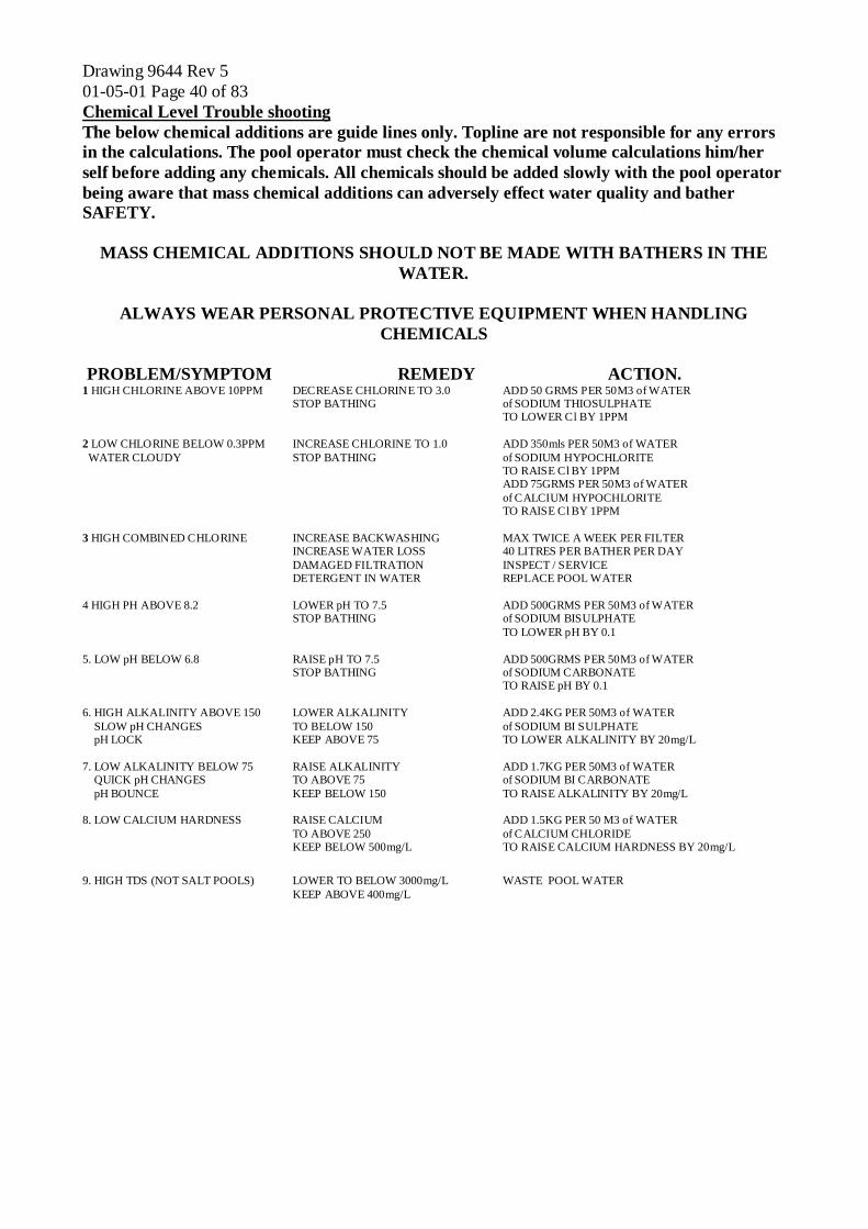
Drawing 9644 Rev 5 01-05-01 Page 40 of 83 Chemical Level Trouble shooting
The below chemical additions are guide lines only. Topline are not responsible for any errors in the calculations. The pool operator must check the chemical volume calculations him/her self before adding any chemicals. All chemicals should be added slowly with the pool operator being aware that mass chemical additions can adversely effect water quality and bather SAFETY.
MASS CHEMICAL ADDITIONS SHOULD NOT BE MADE WITH BATHERS IN THE WATER.
ALWAYS WEAR PERSONAL PROTECTIVE EQUIPMENT WHEN HANDLING
CHEMICALS PROBLEM/SYMPTOM REMEDY ACTION. 1 HIGH CHLORINE ABOVE 10PPM DECREASE CHLORINE TO 3.0 ADD 50 GRMS PER 50M3 of WATER STOP BATHING of SODIUM THIOSULPHATE TO LOWER Cl BY 1PPM 2 LOW CHLORINE BELOW 0.3PPM INCREASE CHLORINE TO 1.0 ADD 350mls PER 50M3 of WATER WATER CLOUDY STOP BATHING of SODIUM HYPOCHLORITE TO RAISE Cl BY 1PPM ADD 75GRMS PER 50M3 of WATER of CALCIUM HYPOCHLORITE TO RAISE Cl BY 1PPM 3 HIGH COMBINED CHLORINE INCREASE BACKWASHING MAX TWICE A WEEK PER FILTER INCREASE WATER LOSS 40 LITRES PER BATHER PER DAY DAMAGED FILTRATION INSPECT / SERVICE DETERGENT IN WATER REPLACE POOL WATER 4 HIGH PH ABOVE 8.2 LOWER pH TO 7.5 ADD 500GRMS PER 50M3 of WATER STOP BATHING of SODIUM BISULPHATE TO LOWER pH BY 0.1 5. LOW pH BELOW 6.8 RAISE pH TO 7.5 ADD 500GRMS PER 50M3 of WATER STOP BATHING of SODIUM CARBONATE TO RAISE pH BY 0.1 6. HIGH ALKALINITY ABOVE 150 LOWER ALKALINITY ADD 2.4KG PER 50M3 of WATER SLOW pH CHANGES TO BELOW 150 of SODIUM BI SULPHATE pH LOCK KEEP ABOVE 75 TO LOWER ALKALINITY BY 20mg/L 7. LOW ALKALINITY BELOW 75 RAISE ALKALINITY ADD 1.7KG PER 50M3 of WATER QUICK pH CHANGES TO ABOVE 75 of SODIUM BI CARBONATE pH BOUNCE KEEP BELOW 150 TO RAISE ALKALINITY BY 20mg/L 8. LOW CALCIUM HARDNESS RAISE CALCIUM ADD 1.5KG PER 50 M3 of WATER TO ABOVE 250 of CALCIUM CHLORIDE KEEP BELOW 500mg/L TO RAISE CALCIUM HARDNESS BY 20mg/L
9. HIGH TDS (NOT SALT POOLS) LOWER TO BELOW 3000mg/L WASTE POOL WATER KEEP ABOVE 400mg/L

Drawing 9644 Rev 5 01-05-01 Page 41 of 83
SECTION 5
MAINTENANCE INSTRUCTIONS

Drawing 9644 Rev 5 01-05-01 Page 42 of 83

Drawing 9644 Rev 5 01-05-01 Page 43 of 83 Routine Maintenance of system See pictures at end of section for reference When carrying out any maintenance on the chemical dosing system, turn off the dosing pump circuit breakers and the electricity supply to the TEC1000a. Close input/output sensor assembly valves and sample line input/output valves. When handling chemicals or parts of the chemical dosing system that have come into contact with chemicals WEAR SUITABLE PERSONAL PROTECTIVE EQUIPMENT. All parts of the dosing system should be kept clean and dry where possible. Sensor Assembly Maintenance Probe cleaning The probes should not be cleaned more than once every 4 weeks, if you are cleaning the probes more often, there is another problem, which needs investigation. Only probe cleaner supplied by Topline should be used. Chlorine probe/pH probe cleaning and inserting of new probes Carefully disconnect the probe from the TEC1000a, unscrew the probe from the sensor assembly and place the probe in Topline probe cleaner in a plastic container for about 3 minutes, remove, rinse in fresh water and shake down to remove any air trapped in the probe tip. Replace probe in sensor assembly. Recalibrate and standardise after cleaning. Stainless steel (S/S) electrode cleaning The stainless steel (S/S) electrode is directly below the chlorine electrode. Open the sample tap and remove some of the water from the sensor assembly and then close the sample tap. Remove the chlorine probe and pour 10ml of Topline probe cleaner into the sensor assembly, agitate with a small brush and leave for 20 minutes, then carefully replace the chlorine probe.

Drawing 9644 Rev 5 01-05-01 Page 44 of 83 Routine Maintenance of system sensor assembly(Cont.) Flushing the Flow Tube (situated behind the flow knob) The flow tube in the sensor assembly is to be cleared every 2 weeks. Fully open the flow knob allowing the water to run through for 5 mins. Adjust the flow using the flow knob so that the white flow ball is between the max and min marks on the picture of the sensor assembly in this manual ie approximately in the middle of the window. Removal of flow Tube To clear the flow tube of any debris that cannot be removed by fully opening the flow knob, remove the flow knob, and the M8 button head screw in the bottom of the sensor assembly and slide out the flow tube. Clear the flow tube or replace if damaged. Sensor assembly blockage If the sensor assembly is blocked at another point then access can be gained by removing the sensor assembly from the backboard, and removing the screw that gives access to the blockage. Reassembly Reassemble using PTFE tape on all threads. ‘Y’ Strainer Not all systems are fitted with a ‘Y’ strainer. The ‘Y’ strainer is a small filter which removes small particles that might otherwise block the sensor assembly situated to the left of the sensor assembly. Flow Switch The Topline flow switch function should be checked by closing the Inlet and Outlet isolation valves which should cause the flow LED to go out. The flow switch is to the right of the sensor assembly and is removed by isolating the flow of water to and from the sensor assembly, disconnecting the connector beneath the conduit and unscrewing the union either side of the flow switch. The flow switch can then be taken apart, checked for condition and cleaned.

Drawing 9644 Rev 5 01-05-01 Page 45 of 83 Routine Maintenance of system Cont.) Auxiliary dosing equipment dosing pumps etc. The following instructions apply to Topline supplied products only Dosing pump maintenance General Dosing pumps The dosing pump is mounted on the day tank and pumps the chemical solution into the pool. By removing the dosing pump fixing screws, the pump can be lifted clear of the day tank. The dosing pump has a knob on the rear which adjusts the dosing rate, this knob should always be set at 90. The knob should never be rotated unless the pump is working, if the knob is rotated when the pump is off then the pump may be permanently damaged. Before removing or replacing any dosing pump parts, release the pressure via the 4 function valve. When reconnecting the dosing pipes ensure that the pipe is pushed fully into the recess and that the locking ring is secure. When dismantling any of the below assemblies, clean with an injector cleaner which can be obtained from your chemical supplier. Remove any scaling as this scaling acts as a key to further scale build up. (Note: spraying with a silicone based lubricant after cleaning will help prevent scale build up). Re-assemble taking care to fit the one way valves are in the correct position and feed and injector pipes are secure. Foot valve assembly The foot valve assembly filters the solution (chlorine, acid etc.) so that the dosing pump cannot be damaged by solids in the solution. It also stops the solution from draining back into the day tank and the dosing pump from losing prime. The foot valve assembly is located at the bottom of the chemical day tank linked to the bottom one way valve on the dosing pump via the feed pipe, and will need cleaning or replacing if the dosing pump does not work or prime. The feed pipe connects to the foot valve assembly with a coupling nut, the feed pipe is pushed fully into the recess and the coupling nut tightened by hand only, see photo. Feed Pipe The feed pipe connects the foot valve assembly to the dosing pump. If this pipe is blocked replace with new pipe. Bottom one way valve on dosing pump The bottom one way valve stops the dosing pump from losing prime. The bottom one way valve is located below the dosing pump head connected to the foot assembly via the feed pipe and will need cleaning or replacing if the dosing pump does not work or prime. The feed pipe connects to the bottom one way valve in the same way as the foot valve assembly connects to the feed pipe but with the addition of a clamp ring. The coupling nut is slid onto the feed pipe before the clamp ring, the feed pipe is pushed fully into the recess, slide the clamp ring down followed by the coupling nut which should be tightened by hand only, see photo. Drawing 9644 Rev 5 01-05-01 Page 46 of 83 Routine Maintenance of system (Cont.) Auxiliary dosing equipment dosing pumps etc. Set Screws The set screws secure the pump head to the pump body. These will need checking for tightness as the force of the diaphragm hitting the pump head may loosen them. The set screws are recessed into the pump head and must be checked every 6 weeks, see photo. If these screws are not tightened the pump will start to leak and could be permanently damaged.

Diaphragm The diaphragm moves forwards when the dosing pump is activated and forces the solution out of the dosing pump towards the 4 function valve. The force with which the diaphragm moves is controlled by the knob on the rear of the pump. The diaphragm is located behind the pump head and is accessed by undoing the set screws and will need cleaning or replacing if the dosing pump does not work or prime. Before cleaning or replacing the diaphragm, release any pressure via the 4 function valve. The diaphragm should be free of cuts or splits. If you are in any doubt over its condition, replace it. The diaphragm is located on a thread and is removed by rotating anti-clockwise. Reassemble and ensure that the set screws are tightened evenly and correctly. Four function valve and dosing pump priming The four function valve allows the pump to be primed, acts as a pressure relief valve in the event of the injector or injector pipe becoming blocked and stops the chemical solution from returning into the diaphragm area via a one way valve. The 4 function valve is located on the top of the pump head with the one way valve between the pump head and 4 function valve, connected to the injector via the injector pipe and will need cleaning or replacing if the dosing pump will not work or prime. To prime the dosing pump rotate the black knob on the 4 function valve 45 degrees and activate the dosing pump. The dosing pump is primed when there is no air visible through the pump head and the solution returns to the day tank via the 4 function valve return pipe. The four function valve is used to release pressure from the injector pipe enabling safe removal of the injector for servicing. To release the pressure in the injector pipe pull the yellow knob away from the black knob on the four function valve for 5 seconds. The injector pipe reconnects to the four function valve in the same way as the feed pipe connects to the bottom one way valve. Injector pipe (Dosing line) The injector pipe connects the dosing pump via the four function valve to the injector. The pipe connects to the four function valve and injector with a clamp ring washer and moulded coupling nut. The pipe should be free of cuts and abrasions, if there is any doubt on the condition of the injector pipe then it should be replaced. Before removing or replacing the injector pipe release the pressure via the four function valve.

Drawing 9644 Rev 5 01-05-01 Page 47 of 83 Routine Maintenance of system Cont.) Auxiliary dosing equipment dosing pumps etc. Injector LMI & rodding unit The injector allows the chemical solution into the pool and prevents pool water from entering the injector pipe. The injector is either mounted directly or via a rodding unit into the pool pipe work and connected to the dosing pump via the injector pipe. Rodding units do not negate the need to clean the LMI injector, they just increase the maintenance period. PTFE tape is used on the injector where it screws into the pool pipe work. The PTFE tape will need replacing when the injector is removed. The injector should only be hand tight. It will need cleaning or replacing if the dosing pump does not work or prime. Before removing or replacing the injector, release the pressure via the four function valve. The injector pipe connects to the injector in the same way as the feed pipe connects to the four function valve. If a rodding unit is fitted the rod should normally be fully withdrawn, and pushed in to clean the injector every day. The rodding unit is pushed in by loosening the cap a half turn, pushing the rod fully in, withdrawing fully and retightening the cap. If the rod is stiff then the rodding assembly should be removed and cleaned. Electric agitator The electric agitator contains no parts that can be serviced by the operator. If an electric agitator is fitted, the chemical solution should not be allowed to fall below half way in the day tank. Hand Transfer Pump After using the hand transfer pump it is essential that the pump is flushed with fresh water. If the pump is not flushed with fresh water it will leak and be permanently damaged. CO2 injector (diffuser) Maintenance The CO2 system (apart from an annual parts replacement) do not normally need any day to day maintenance, but in hard water areas it may be necessary to examine the CO2 diffuser for calcium salt blockage and if necessary removal of this with a de-scaling acid. Restarting the TEC1000a after maintenance Open the sensor assembly and sample line Input/Output valves, allow pool water to flow through the sensor assembly for 20 minutes. Turn the TEC1000a electricity supply on, calibrate, standardise and turn the dosing pump circuit breakers on. The TEC1000a will need calibrating and standardising 24 hours later if the probes have been cleaned Winter shut down procedure If the pool that the TEC1000a is controlling is to be closed for a long period, then the following procedure should be implemented on the TEC1000a. 1. Turn off TEC1000a. 2. Isolate sensor assembly using the input and output isolation valves. 3. Empty chemical day tanks. 4. Flush dosing pumps with fresh water.
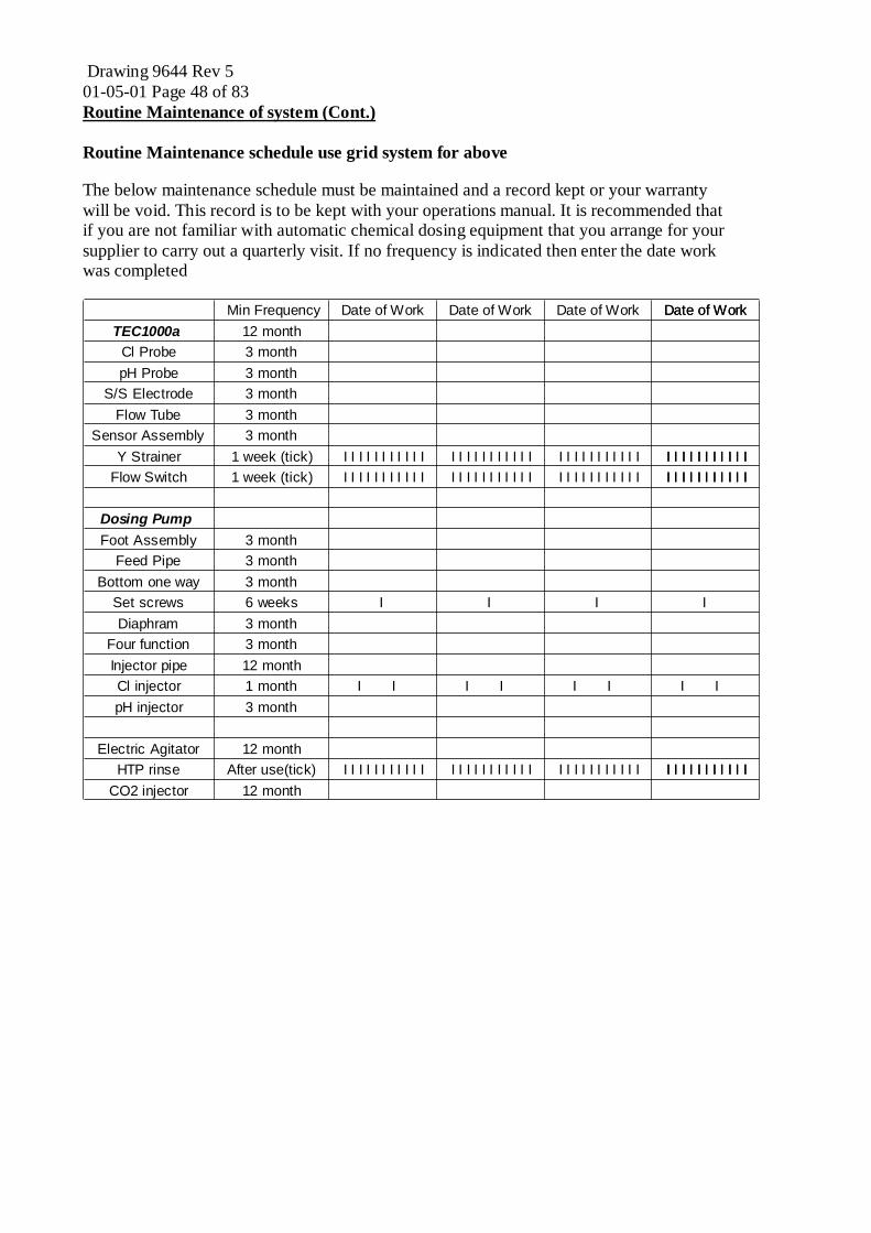
Drawing 9644 Rev 5 01-05-01 Page 48 of 83 Routine Maintenance of system (Cont.)
Routine Maintenance schedule use grid system for above
The below maintenance schedule must be maintained and a record kept or your warranty will be void. This record is to be kept with your operations manual. It is recommended that if you are not familiar with automatic chemical dosing equipment that you arrange for your supplier to carry out a quarterly visit. If no frequency is indicated then enter the date work was completed
Min Frequency Date of Work Date of Work Date of Work Date of WorkDate of WorkTEC1000a 12 month
Cl Probe 3 monthpH Probe 3 month
S/S Electrode 3 monthFlow Tube 3 month
Sensor Assembly 3 monthY Strainer 1 week (tick) I I I I I I I I I I I I I I I I I I I I I I I I I I I I I I I I I I I I I I I I I I I II I I I I I I I I I I
Flow Switch 1 week (tick) I I I I I I I I I I I I I I I I I I I I I I I I I I I I I I I I I I I I I I I I I I I II I I I I I I I I I I
Dosing PumpFoot Assembly 3 month
Feed Pipe 3 monthBottom one way 3 month
Set screws 6 weeks I I I I Diaphram 3 month
Four function 3 monthInjector pipe 12 monthCl injector 1 month I I I I I I I IpH injector 3 month
Electric Agitator 12 monthHTP rinse After use(tick) I I I I I I I I I I I I I I I I I I I I I I I I I I I I I I I I I I I I I I I I I I I II I I I I I I I I I I
CO2 injector 12 month

Drawing 9644 Rev 5 01-05-01 Page 49 of 83 Maintenance pictures 1

Drawing 9644 Rev 5 01-05-01 Page 50 of 83 Maintenance pictures 2

Drawing 9644 Rev 5 01-05-01 Page 51 of 83 Maintenance pictures 3

Drawing 9644 Rev 5 01-05-01 Page 52 of 83 Maintenance pictures 4

01-05-01 Page 53 of 83 Maintenance pictures 5

Drawing 9644 Rev 5 01-05-01 Page 54 of 83

Drawing 9644 Rev 5 01-05-01 Page 55 of 83
Apen 1 Probe cleaner COSHH sheets

Drawing 9644 Rev 5 01-05-01 Page 56 of 83

Drawing 9644 Rev 5 01-05-01 Page 61 of 83
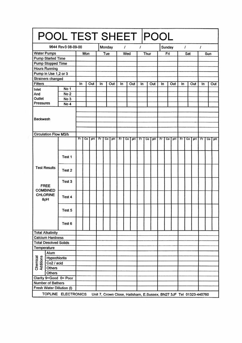
Apen 2 Pool Test sheet

Drawing 9644 Rev 5 01-05-01 Page 62 of 83

Drawing 9644 Rev 5 01-05-01 Page 64 of 83

Drawing 9644 Rev 5 01-05-01 Page 65 of 83
SECTION 6
OPERATING/WARRANTY CONDITIONS
AND ADVISORY NOTES

Drawing 9644 Rev 5 01-05-01 Page 66 of 83

Drawing 9644 Rev 5 01-05-01 Page 67 of 83
Operating Conditions affecting TEC parts and service warranty
A Only staff who have been trained by Topline Electronics Ltd. should operate the dosing system. B Ensure the maintenance schedule for the TEC1000 has been adhered to and all actions
recorded. C Ensure DPD1, Phenol red, Alkalinity and calcium hardness test results are recorded, water
balance is maintained, the ratio of free to combined levels of chorine are within guide lines and pH is between 7.2 to 7.8.
D When testing with DPD1 tablets, dilution tests are carried out if the first reading is above 2.5ppm.
E Ensure all tests to calibrate or standardise the TEC1000a are taken from the sample tap beneath the TEC1000A. All tablet tests should be taken and readings entered within 3 minutes.
F Ensure the Swimming Pool Water Treatment and Quality Standards are implemented when possible. G Plant backwashing should be carried out as per the installers instructions. During backwashing the chemical pumps/feeders must be turned off. H Ensure regular pathology testing is undertaken, Topline recommend once a month. I Ensure poolside areas are kept clean, including the deck level grating and all scum lines,
only approved cleaning products to be used. J Use of flocculents: Aluminium sulphate solution (kibbled alum solution) is used in a 5% solution. The rate for dosing aluminium sulphate is 0.05mg/l. Organic polymer based flocculents such as poly-aluminium chloride or equivalents, can be used but rate of dosing must be carefully controlled at 0.1ml/m3. The above rates are continuous. All flocculents can damage electrodes, If the above conditions are not met our electrode and service warranty is invalidated K Only inorganic chlorine donors should be used. Before the use of cyanuric acid based (Stabilised) chlorine refer to Topline Electronics Ltd. L Excessive use of defoaming agent will stop the control system from working. Consult Topline Electronics Ltd. before using any defoaming agent.

Drawing 9644 Rev 5 01-05-01 Page 68 of 83 Advisory Notes Automatic water chemistry controllers are rapidly becoming the norm within water treatment circles. They can be an invaluable aid to swimming pool operators, helping to minimise the length of downtime periods, chemical costs and maximising water quality achievements. However, it must be remembered that automatic chemistry controllers do NOT negate the need for common sense and the adherence to guidelines as defined in the Swimming Pool Water Treatment and Quality Standards issued by the Pool Water Treatment Advisory Group. The notes below are not intended to replace these guidelines, but are intended to show how the operator can meet Topline’s operating conditions. A. Staff: Although all dosing systems work in a similar way, they all have there own particular way in achieving high quality water. It is therefore essential that the TEC1000a dosing system is only used by staff who have been trained by Topline Electronics Ltd. B. Maintenance: For the dosing system to function correctly, regular maintenance must be performed by qualified personal. There are a number of swimming pool companies who profess to be experts in dosing systems. If the company has not been trained by Topline then it will not be able to look after your Topline dosing system. We would therefore recommend using your own trained staff, companies approved by Topline or Topline engineers to look after your dosing system. Maintenance contracts, extended warranties and routine services are available from Topline. C/D Chemical balance: is essential for smooth operation. You should have available a chemical test kit that measures free chlorine, combined chlorine, pH, alkalinity and calcium hardness. The instructions below are for Lovibond comparator balanced water kit AF129/CYS. If a photometer is used then great care must be taken with the equipment, the manufactures instructions must be strictly followed and dilution tests carried out when the reading for free chlorine is above 2.5ppm. You should also have available a thermometer and TDS meter. These are the minimum requirements for a commercial swimming pool. Free chlorine DPD1 test (Guide between 1-4 PPM) 1. Fit the chlorine disc into the comparator. Rinse out 2 cells thoroughly with water sample,
leave one filled to the 10ml mark and place it in the left-hand compartment to act as a “blank” behind the colour standards.
2. Leave a few drops of sample in the second cell and add a DPD1 tablet. Crush with a clean stirring rod. Make up to the 10ml mark with sample and mix. Note: if the colour appears in the few drops, but disappears when volume is made up to 10ml mark, a high level of chlorine is present and the test should be repeated with the sample diluted with tap water.
3. Place in the right-hand compartment and match the colour against the disc immediately, reading the value from the bottom right hand corner. The result is free chlorine in mg/l. The dilution technique applies if the colour is deeper than the highest value on the disc.
Total and combined chlorine (guide combined chlorine no more than 1.5 times free i.e. breakpoint chlorination) After the free chorine reading has been taken, add one DPD3 tablet to the cell containing the dissolved DPD1 tablet. Crush with clean stirring rod and mix. After 2 minutes, match the colour against the disc. The DPD1 and DPD3 test must be repeated using the dilution technique if the colour is deeper than the highest value on the disc. The reading is the total residual chlorine in mg/l. The difference between the free chlorine and total residual chlorine reading is the combined chlorine. After testing, wash out the cells using clean water and the brush provided.

Drawing 9644 Rev 5 01-05-01 Page 69 of 83 Advisory Notes (Cont.) C/D Chemical balance (Cont.) Chlorine in the water provides two functions: (1) To kill infection causing bacteria. (2) To degrade the pollutants introduced by bathers.
Remember the water may be free of bacteria but this does not necessarily mean that the water is clean and free of pollutants. Water will only be free of bacteria and organic pollutants if the filtration is adequate and break point Chlorination conditions are in place. Take water tests regularly to confirm these levels, otherwise operators run the risk of not achieving breakpoint Chlorination conditions, hence wasting chemicals and not ensuring optimum water quality. This affects smell and the ability of poor water quality to irritate bathers eyes. Operators should be aware shock dosing can cause a rise in combined chlorine. Chlorine will not remove detergent from the water, if there is detergent in the water then high levels of combined chorine can be expected.
pH Test (guide between 7.2 & 7.8) 1. Fit the pH disc into the comparator. Rinse out 2 cells thoroughly with water sample, leave
both filled to the 10ml mark and place one in the left-hand compartment to act as a “blank” behind the colour standards.
2. Add a Phenol red tablet to the other cell and crush with a clean stirring rod. 3. Place in the right-hand compartment and match the colour against the disc immediately, reading the value from the bottom right hand corner. The result is the pH value. Adjustment of the pH value of pool water is essential because: (1) The bactericidal actions of most disinfectants depends on pH, it is therefore necessary to
maintain pH value within an optimum effective range, lower limit 7.2 upper limit 8.0. (2) As the pH rises towards 8 bactericidal efficacy of chlorination decreases rapidly. (3) As the pH rises towards 8, the water has an increasing tendency to encourage precipitation of hardness salts. (4) As the pH falls below 7, the water becomes corrosive towards materials used in the
construction of the pool. (5) If the pH value is too low or too high, the water can irritate the skin and eyes.
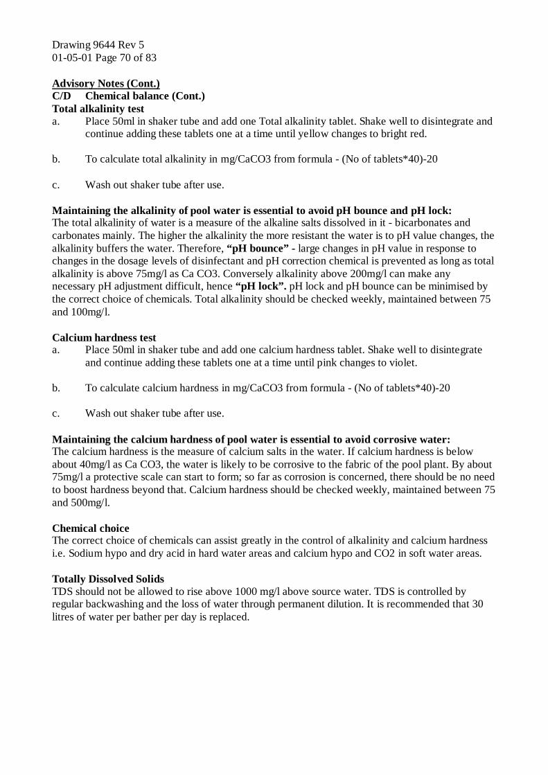
Drawing 9644 Rev 5 01-05-01 Page 70 of 83 Advisory Notes (Cont.) C/D Chemical balance (Cont.) Total alkalinity test a. Place 50ml in shaker tube and add one Total alkalinity tablet. Shake well to disintegrate and
continue adding these tablets one at a time until yellow changes to bright red. b. To calculate total alkalinity in mg/CaCO3 from formula - (No of tablets*40)-20 c. Wash out shaker tube after use. Maintaining the alkalinity of pool water is essential to avoid pH bounce and pH lock: The total alkalinity of water is a measure of the alkaline salts dissolved in it - bicarbonates and carbonates mainly. The higher the alkalinity the more resistant the water is to pH value changes, the alkalinity buffers the water. Therefore, “pH bounce” - large changes in pH value in response to changes in the dosage levels of disinfectant and pH correction chemical is prevented as long as total alkalinity is above 75mg/l as Ca CO3. Conversely alkalinity above 200mg/l can make any necessary pH adjustment difficult, hence “pH lock”. pH lock and pH bounce can be minimised by the correct choice of chemicals. Total alkalinity should be checked weekly, maintained between 75 and 100mg/l. Calcium hardness test a. Place 50ml in shaker tube and add one calcium hardness tablet. Shake well to disintegrate
and continue adding these tablets one at a time until pink changes to violet. b. To calculate calcium hardness in mg/CaCO3 from formula - (No of tablets*40)-20 c. Wash out shaker tube after use. Maintaining the calcium hardness of pool water is essential to avoid corrosive water: The calcium hardness is the measure of calcium salts in the water. If calcium hardness is below about 40mg/l as Ca CO3, the water is likely to be corrosive to the fabric of the pool plant. By about 75mg/l a protective scale can start to form; so far as corrosion is concerned, there should be no need to boost hardness beyond that. Calcium hardness should be checked weekly, maintained between 75 and 500mg/l. Chemical choice The correct choice of chemicals can assist greatly in the control of alkalinity and calcium hardness i.e. Sodium hypo and dry acid in hard water areas and calcium hypo and CO2 in soft water areas. Totally Dissolved Solids TDS should not be allowed to rise above 1000 mg/l above source water. TDS is controlled by regular backwashing and the loss of water through permanent dilution. It is recommended that 30 litres of water per bather per day is replaced.
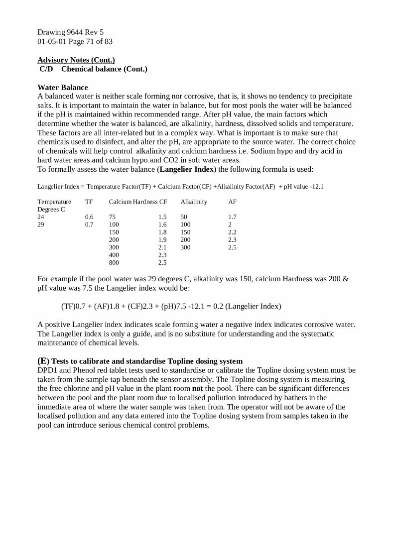
Drawing 9644 Rev 5 01-05-01 Page 71 of 83 Advisory Notes (Cont.) C/D Chemical balance (Cont.) Water Balance A balanced water is neither scale forming nor corrosive, that is, it shows no tendency to precipitate salts. It is important to maintain the water in balance, but for most pools the water will be balanced if the pH is maintained within recommended range. After pH value, the main factors which determine whether the water is balanced, are alkalinity, hardness, dissolved solids and temperature. These factors are all inter-related but in a complex way. What is important is to make sure that chemicals used to disinfect, and alter the pH, are appropriate to the source water. The correct choice of chemicals will help control alkalinity and calcium hardness i.e. Sodium hypo and dry acid in hard water areas and calcium hypo and CO2 in soft water areas. To formally assess the water balance (Langelier Index) the following formula is used: Langelier Index = Temperature Factor(TF) + Calcium Factor(CF) +Alkalinity Factor(AF) + pH value -12.1 Temperature TF Calcium Hardness CF Alkalinity AF Degrees C 24 0.6 75 1.5 50 1.7 29 0.7 100 1.6 100 2 150 1.8 150 2.2 200 1.9 200 2.3 300 2.1 300 2.5 400 2.3 800 2.5 For example if the pool water was 29 degrees C, alkalinity was 150, calcium Hardness was 200 & pH value was 7.5 the Langelier index would be: (TF)0.7 + (AF)1.8 + (CF)2.3 + (pH)7.5 -12.1 = 0.2 (Langelier Index) A positive Langelier index indicates scale forming water a negative index indicates corrosive water. The Langelier index is only a guide, and is no substitute for understanding and the systematic maintenance of chemical levels. (E) Tests to calibrate and standardise Topline dosing system DPD1 and Phenol red tablet tests used to standardise or calibrate the Topline dosing system must be taken from the sample tap beneath the sensor assembly. The Topline dosing system is measuring the free chlorine and pH value in the plant room not the pool. There can be significant differences between the pool and the plant room due to localised pollution introduced by bathers in the immediate area of where the water sample was taken from. The operator will not be aware of the localised pollution and any data entered into the Topline dosing system from samples taken in the pool can introduce serious chemical control problems.
Drawing 9644 Rev 5 01-05-01 Page 72 of 83 Advisory Notes (Cont.) (F) The Swimming Pool Water Treatment and Quality Standards issued by the Pool Water Treatment Advisory Group, is the recommended source of data not supplied in this manual. However no document can replace training and common sense. PWTAG Tel Nos. 01379-783678. (G) Backwashing. If the pool/spa filters are not backwashed at the appropriate rate and routinely, then there will be an increase in combined chlorine and the amount of chlorine used to reach acceptable levels of free chlorine with an associated increase in running costs. Backwashing should not be used to control the TDS. TDS should be controlled by constant dilution i.e 30 litres of water per bather per day. Backwashing to reduce TDS will reduce the life of the filtration media. (H) Pathology testing. The pools and spas should be tested at least once a month for E.Coli, Pseudomonas, total viable counts, Staphaureus and coliforms. EWS on 01457-877755 can conduct these tests. (I) Pool Surround Cleaning Use protective clothing when handling all chemicals. Check the product COSHH regulations. A rigid cleaning regime is absolutely essential, pool surrounds and balance tank access hole lid areas. Balance tank lids should be lifted every three months and the edges of both surfaces should be scrubbed with HIPHOS and VANODINE before the lid is be replaced. Deck level pool surround channels and scum channels build up a layer of fats. This fatty layer is best removed by scrubbing with a hot 15% solution of sodium bi-carbonate every three months. The rest of the pool surround areas (especially where people walk) is cleaned with a strong safe cleaner, we recommend a two stage cleaning process using Hi-PHOS and Vanodine which is available from Evans Vanodine International 01772 322200.
DETERGENT BASED PRODUCTS SHOULD NEVER BE USED POOLSIDE. The Hi-phos cleaner is mixed 1-25 with water and applied using a flat sponge type mop, leave to dry. Do not let the cleaner enter the pool. We suggest cleaning about 15 square meters at a time. This procedure is carried out every month. The Vanodine cleaner is mixed 1-200 with water and applied using a flat sponge type mop, leave to dry. Do not let the cleaner enter the pool. We suggest cleaning about 15 square meters at a time. This procedure is carried out every day. (J) Floculents enhance the removal of dissolved , colloidal or suspended material by bringing it out of solution or suspension as solids, then clumping the solids together, which is more easily trapped in the filter. Floculents also help filter the infective cysts of cryptosporidium and Giardia which are resistant to chlorination. The pH must be maintained within recommended operating range or the floculent will not be effective. Overdosing floculent will adversely affect the TEC1000a dosing system performance. (K) Cyanuric acid is a stabiliser added to pool water to reduce chlorine loss due to ultraviolet light from the Sun and should therefore only be used in outdoor pools. Cyanuric acid can be used with TEC1000a dosing system but levels should not exceed 30ppm. (L) Defoaming agent is used to reduce the amount of visible foam on a spa. The foaming is usually caused by detergent in the water, from bathers who do not shower before using the facilities. We do not recommend the use of defoaming agents which can adversely effect filtration media and dosing system performance.

Drawing 9644 Rev 5 01-05-01 Page 73 of 83
SECTION 7
SERVICING, EXTENDED WARRANTY CONTRACT

Drawing 9644 Rev 5 01-05-01 Page 74 of 83

Drawing 9644 Rev 5 01-05-01 Page 75 of 83 Servicing including calls made under guarantee
SERVICE METHOD STATEMENT Telephone Contact 01323-440760. The number will be manned between 09.00hrs and 17.00hrs Monday to Friday excluding Bank Holidays (Answer phone at all other times redirecting to mobile no:s) Between 09.00hrs and 17.00 the response times detailed below will be achieved (subject to our terms and conditions). Calls received between 17.00hrs and 09.00hrs will be treated as received at 09.00hrs that morning. First action will be to discuss the situation and to try and find a resolution over the telephone. If required a Topline engineer will attend site as detailed below, in accordance with the Service price list or service agreement, an estimated time of arrival will be given. Callouts The type of response will be agreed at the time a call is placed. These are divided into the following Categories -: Emergency: System not functioning Within 48 hours Standard : General difficulties, but system functioning Within 72 hours Nominated: Routine visits, servicing and Training As agreed To achieve the response time Topline servicing is divided into geographic areas covered by designated engineers. The time of a callout and estimated time of arrival will be logged by Topline on the service sheet. If required, a copy of the work sheet will be faxed to site. To help ensure an immediate fix, all Topline Engineers will have standard parts with them. In the unlikely event that the fault cannot be rectified by the Engineer you will be provided with details of the intended action to rectify the fault. Standard Terms and Conditions All work is carried out subject to our normal trading terms and conditions (Copies available). We aim to meet the target times above, 90% of the time. Difficulties experienced due to a traffic delay or force majeure, may mean that occasionally we are unable to meet the target times. Labour, parts and equipment are supplied as detailed in the price list, special discounts may apply by prior arrangement. VAT is at the current rate in addition to our charges.

Drawing 9644 Rev 5 01-05-01 Page 76 of 83 Service Method Statement (Cont.) Code of conduct. All Topline engineers carry identity, they will wear appropriate clothing and have portable protective equipment available. On arrival at site the engineer will sign in and contact the facilities manager or the duty manager. When the engineer has finished, the work area will be left clean and tidy. Our work sheet must be signed by either the facilities manager or the duty manager to confirm the work is completed or pending a further visit and that all the above conditions have been met. The engineer will sign out from the site. Health & Safety All our engineers have been trained to carry out their duties and are familiar with relevant Health & Safety legislation. If any faults or hazards are found, that are not part of our equipment, they will be noted on the service sheet and reported verbally to the facilities manager or duty manager. All Topline equipment meets or exceeds relevant regulations. The Health and Safety Officer at Topline Electronics Ltd is Mr A. Hunt. 01323 440760 Reporting Procedures. When work is completed a report will be left with the site. The report will detail work carried out and parts supplied. Topline will maintain a service record of each site and will periodically review performance for that site. It is anticipated that meetings will be required from time to time. Topline Electronics Ltd are keen to support this as an important part of our service. On Site Remote Monitoring The system will be set up to provide the data available in the format you require. Providing a Complete Service Topline will quote any additional work that we can carry out, not covered by warranty or a service agreement. Work carried out immediately without a quote will have a labour charge applied as detailed in the price list. An order will be required before this work is carried out. We aim to provide a fast and efficient service, if the site is experiencing difficulties with pools and spa’s outside our remit we will make our resources available to help find a solution. Topline will review all statements and prices from time to time. Topline Electronics Ltd reserve the right to make changes when necessary.

Drawing 9644 Rev 5 01-05-01 Page 77 of 83
ANNUAL SERVICE AGREEMENTS
All Topline equipment is supplied with a one year parts and labour warranty. This warranty includes a commissioning visit with on site training. A Service Agreement can be provide in the first years warranty at a 40% discount. During the specified twelve month period we will provide one service and three other visits as required. Topline components that are due for replacement or require replacement will be supplied free of charge. All equipment that is beyond economic repair or that has failed due to causes other than normal wear and tear (see Standard Terms and Conditions) will be quoted for a replacement. Training sessions can also be provided. All equipment will be assessed before cover is provided. Equipment from other suppliers can be included, all these parts will be provided at cost plus 20%, where applicable delivery will be charged. * At the end of five continuous years with a Service Agreement we will offer to replace all the equipment covered at a 40% discount. (Retail Price) * Service Agreements are available for Pool and Spa Chemical dosing at a site, renewable annually. 40% discount applies for the first year in the Warranty period. Extended warranties are available within 4 months of commissioning. All prices are subject to VAT. Please see our Normal Trading Terms and Conditions. Prices may vary without notice, please ensure you have an up to date price list before placing orders.

Drawing 9644 Rev 5 01-05-01 Page 78 of 83

Drawing 9644 Rev 5 01-05-01 Page 79 of 83
SERVICE EXTENDED WARRANTY CONTRACT Service Provider -: Service Provided to -: Topline Electronics Ltd Unit 7, Crown Close, Hailsham, East Sussex BN7 3JF Contract No -: Site No -: Order No. -: Start Date Valid for: Signed for Topline Electronics Ltd Signed for Client Print Print Date Date Position Position Service Agreement Contract to be carried out as detailed in the “Annual Service Agreement” and the “Service Method Statement”. Equipment Covered Type/Model Serial No. Asset No. Serving Area Equipment Covered Type/Model Serial No. Asset No. Serving Area Equipment Covered Type/Model Serial No. Asset No. Serving Area Equipment Covered Type/Model Serial No. Asset No. Serving Area Equipment Covered Type/Model Serial No. Asset No. Serving Area Equipment Covered Type/Model Serial No. Asset No. Serving Area

Drawing 9644 Rev 5 01-05-01 Page 80 of 83

Drawing 9644 Rev 5 01-05-01 Page 81 of 83 Section 1 Installation Index CE Certificate Declaration of conformance Page 7 Chemistry Control System Chemical Feeder Power Page 9 Chemistry Control System Inter Wiring Page 9 Chemistry Control System Power Requirements Page 9 Equipment selection check list Page 8 Inserting the Electrodes Page 10 Position of chemistry Control System Page 8 Technical Data TEC1000A Control System Page 7 Topline Electronics Ltd Introduction Page 2 Water sample supply for the cell assembly Page 10 Section 2 Commissioning Index Acceptance of equipment Page 15 Certificate of staff training Page 21 Commissioning Check list Page 13 Commissioning procedure Page 13 Extended warranty Page 19 Guarantee 12 month Page 19 Hand over procedure Page 17 to 18 Product support Page 19 Section 3 Operating Instructions Index Health and Safety Warning Page 25 Risk Assessment Page 27 Alarm levels Page 33 Calibrate Page 33 Pump on Times Page 32 System Overview Page 29 to 30 System Set-up Page 31 to 33 Set up mode Page 31 Set point Page 31 Standardise. Page 31 Time-outs Page 32 Section 4 Trouble shooting Index Chemical Level Trouble Shooting Page 240 Probe Trouble Shooting Page 39 System Trouble Shooting Page 37 to 38

Drawing 9644 Rev 5 01-05-01 Page 82 of 83 Section 5 Maintenance Index Apen 1 Probe Cleaner COSHH sheets Page 55 to 60 Apen 2 Pool water test sheet Page 63 Bottom one way valve on dosing pump Page 45 Chlorine probe/pH probe cleaning Page 43 CO2 injector Maintenance Page 47 Diaphragm Page 46 Dosing pump maintenance Page 45 to 47 Dosing pump picture Page 50 to 52 Electric agitator Page 47 Feed Pipe Page 45 Flow Switch Page 44 Flow Switch Picture Page 49 Flow Tube Page 44 Foot assembly Page 45 Foot assembly picture Page 53 Four function valve and dosing pump priming Page 46 Hand Transfer Pump Page 47 Injector LMI & rodding Page 47 Injector LMI & rodding Picture Page 49 & 53 Injector pipe Page 46 Maintenance schedule Page 48 Probe cleaning Page 43 Restarting the TEC1000a after maintenance Page 47 Sensor assembly blockage Page 44 Sensor Assembly Maintenance Page 43 to 44 Sensor Assembly Picture Page 49 Sensor Reassembly Page 44 Set Screws Page 46 Stainless steel (S/S) electrode cleaning Page 43 Winter shut down procedure Page 47 Y Strainer Page 44

Drawing 9644 Rev 5 01-05-01 Page 83 of 83 Section 6 Operating/Warranty Conditions & Advisory Notes Index Advisory Notes Page 68 Backwashing. Page 72 Calcium hardness test Page 70 Chemical balance Page 68 to 71 Chemical choice Page 70 Cyanuric acid Page 72 Defoaming agent Page 72 Floculents Page 72 Free chlorine DPD1 test Page 68 Maintenance Page 68 Operating Conditions Page 67 Pathology testing Page 72 pH Bounce page 70 pH Lock Page 70 pH Test Page 69 Pool Surround Cleaning Page 72 Staff Training Page 68 Swimming Pool Water Treatment & Quality Standards Page 72 Tests to calibrate and standardise (source) Page 71 Total alkalinity test Page 70 Totally Dissolved Solids Page 70 Water Balance Page 71 Section 7 Servicing & Extended Warranty Contract Annual Service Agreements Page 77 Code of conduct Page 76 Health & Safety Page 76 Reporting Procedures Page 76 Extended Service Contract Page 79 Service Method Statement and Standard Terms and Conditions Page 75 to 76