2nd Workshop – Ohrid, Sept. 2, 2010 Role of the Research ...
32
2nd Workshop – Ohrid, Sept. 2, 2010 Role of the Research Infrastructure in Performance Based Engineering Towards a New European Facility for Advanced Seismic Testing (E-FAST) F. Marrazzi European Commission, Joint Research Centre, Italy A. Pavese European Centre for Training and Research in Earthquake Engineering, Italy I. Politopoulos Commissariat à l'Énergie Atomique, France
Transcript of 2nd Workshop – Ohrid, Sept. 2, 2010 Role of the Research ...

2nd Workshop – Ohrid, Sept. 2, 2010
Role of the Research Infrastructure in Performance Based
Engineering
Towards a New European Facility for Advanced Seismic Testing (E-FAST)
F. MarrazziEuropean Commission, Joint Research Centre, Italy
A. PaveseEuropean Centre for Training and Research in Earthquake
Engineering, Italy
I. PolitopoulosCommissariat à l'Énergie Atomique, France

Design Study of a European Facility for Advanced
Seismic Testing
FP7 -> capacities-research infrastructures
Partners of the project
22/09/2010
CEA – Saclay (Project leader)
ELSA JRC - Ispra
EUCENTRE – Pavia
TUASI – Iasi
University of Kassel

Design study OBJECTIVES
• Define the features of a new testing facility, complementary to existing
research infrastructures in Europe, combining high capacity and flexibility
• Make progress in advanced testing methods (multiple shaking table control,
real time sub-structuring techniques etc.) and carry out demonstration tests.
• Study the technical and financial feasibility of this facility taking into account
future networking collaboration with other European and extra-European
laboratories.
22/09/2010
laboratories.
Actions•Analysis of Research Community needs (Focused on the European Countries)
•Analysis of the technological solutions available: equipments and testing
techniques
•Design implementation of a testing facility at the state-of-the-art and inspired to
needs

• Real/large scale testing (reduce uncertainties, requires high
performance)
• Several high performance facilities
2) Current tendency of seismic testing
1) Seismic risk in Europe
European risk > other industrialized seismic countries (Japan, US)European risk > other industrialized seismic countries (Japan, US)(morphology, cultural heritage, several (morphology, cultural heritage, several underdesignedunderdesigned cases, etc.)cases, etc.)
22/09/2010
• Several high performance facilities
– Existing (e.g. University of California San Diego, EDefense)
– Projects or facilities under construction (China, Korea, Japan)
• New experimental techniques
– Real-time substructuring
– Advanced control techniques
– Distributed testing

1st step: needs performance

1st International WS: Testing needs for research in Earthquake
Engineering
• In plan irregular buildings (strength eccentricity, failure criteria)
• Flat slab systems (increase of their behavior factor)
• Precast and prestressed elements and systems (further study of joints, foundation, post-tensioning)
• Masonry buildings and infills (tests of multi-storey masonry buildings, out of plane behavior, contribution to the actual building capacity)
• Infrastructures (Bridges multi-support excitation)
• Retrofitting (assessment of new techniques and materials)
22/09/2010
• Retrofitting (assessment of new techniques and materials)
• Aseismic devices (testing of large isolation devices dedicated machines, structure response large displacement capacity)
• Equipment (qualification tests, floor spectra high acceleration and displacement capacity)
• Soil-structure interaction (only simple configurations, massive heavy specimen because of the soil weight)
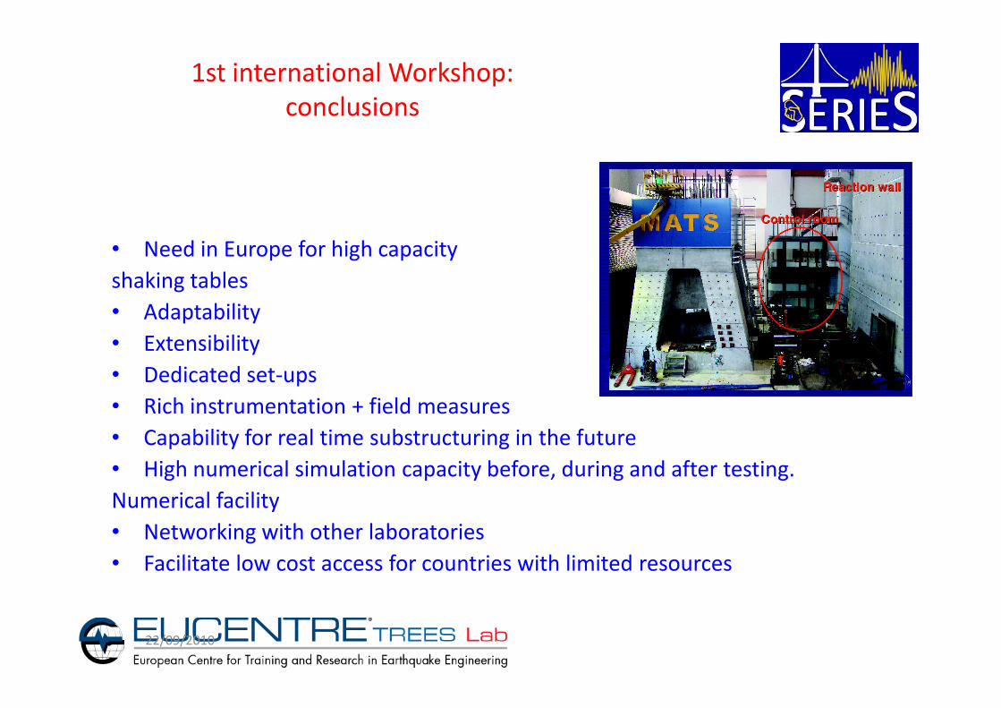
1st international Workshop:
conclusions
• Need in Europe for high capacity
shaking tables
• Adaptability
• Extensibility
22/09/2010
• Extensibility
• Dedicated set-ups
• Rich instrumentation + field measures
• Capability for real time substructuring in the future
• High numerical simulation capacity before, during and after testing.
Numerical facility
• Networking with other laboratories
• Facilitate low cost access for countries with limited resources

Design proposal: Philosophy
• Go much further than existing shaking table facilities in Europe
• Combination of elements and technology that have already been validated
by their operational use in other existing facilities.
– Technical reasons (accurate experiments from the 1st day after
construction)
– Safety reasons
22/09/2010
– Safety reasons
– Minimize techno-economical risk for potential investors (divergence
from the foreseen date of operational start and from the foreseen
budget at the moment of their commitment)
• Trade-off between dreams and real world. Too high cost (construction,
maintenance, handling, specimen transport etc) will kill any chance for the
facility to be constructed.

Performance demand (trade-off between cost and performance)
22/09/2010

35
m
16
m12
Proposed solution
10DEN/DANS/DM2S/SEMT/EMSI
Principle of the proposal
35
m13
m
36
m
12
m
45
m

11DEN/DANS/DM2S/SEMT/EMSI 22/09/2010
-Hybrid testing
-Or additional actuators for
bounding conditions in all axes

12DEN/DANS/DM2S/SEMT/EMSI 22/09/2010

First attempt
•Due to kinematic constrains the
minimum dimensions of the
table are of about 10mx10m
(could be too big for modular
tables set-up)
13

Solution proposed by Kassel University
�based on the needs of testing and
data of strong earthquake, UNIKA has
proposed a concept of equipment
�major features of the concept
�diffent test setups with their
criteria were demonstrated
70 m
45 m
�major features of the concept
- moveable and flexible testequipment (including table,actuators and reaction system)
- saving operating costs, suitablefor SMEs
=> UNIKA is working on a pre-design of a moveable steel and/or steel-concrete
composite reaction system as one of the two construction techniques considered.

Solution proposed by EUCENTRE-Pavia
15

16

17

Comparison with existing facilities
E-DEFENSE
Miki
LHPost
SanDiego
SEESL -SUNY
Buffalo
Proposed
configuration
Size 1 [15 m X 20 m] 1 [6,7 m X 12 m] 2 [3,5 m x 3,5 m]
or 2 [7mx7m]
2 [6 m x 6 m] or
1 [6 m x 12 m]
+
1 [12m x 12 m] 1dof
DDL 6 1 6 6
Displacement H : ± 1000 mm
V : ± 700 mm
H : ± 750 mm H : ± 150 mm
V : ± 75 mm
H : ± 1000 mm
V : ± 750 mm
22/09/2010
Velocity 1 m/s 1,8 m/s 1,25 m/s 2 m/s
Mass x
acceleration
1200 tonsX 0,9g
(1000 t.g)
2250 x 1 g
(300 t.g)
20 tx 1,15
(23 t.g)
200 tons x 2g
(400 t.g)
Flexibility
Trench length
No No 2 tables
gap : 1 to 10 m
37 m
2 tables
gap : 0 to 20 m
35- 40 m
Reaction wall No No Yes (one at the
end of the
trench)
Yes (all arround the
trench)
Hybrid testing No No Yes Yes

Design of technological components for proposed solution:Table and actuators configuration
19
All actuators in the same direction to avoid
dilatation problems
Constructor 1
Constructor 2
No dead area

Constructor 1 Constructor 2
Design of technological components for proposed solution:Dynamic actuators
20
Type A: length at mid-stroke ≈ 4.5 m
Type A Type C
Type C: length at mid-stroke ≈ 5.7 m

40 power supply accumulatorsRegulation accumulators
2x12 (close to the actuators) + 8 + 4
1
1.2
1.4
1.6
1.8
2x 10
7
co
st (e
uro
s)
pumpspumps +accumulators
Design of technological components for proposed solution:Hydraulic system configuration
21
6 + 22 pumps
0 10 20 30 40 500
0.2
0.4
0.6
0.8
test duration (s)
co
st (e
uro
s)
sinus test 0.3 Hz
Trade off between pumps and
accumulators

The FE 3D modeling& simulations have been carried out using SAP2000 v. 14.
FE used: SOLID elements of 3 ×3 × 3 m.
Utility Room
45 m
Design of technological components for proposed solution:Reaction mass, foundation & soil-structure interaction
22
Top View of the FoundationSection Views of the Foundation
35 m
13 m
36 m
Location of the
shaking tables

Foundation + Equipment
S11 stresses
Max = 0.04 MPa Max = 0.04 MPa
21
S11 stresses
Max = 0.04 MPa Max = 0.04 MPa
21
Foundation + Equipment + Payload
Design of technological components for proposed solution:
Reaction mass, foundation & soil-structure interaction
23
Max = 0.04 MPa
Min = -0.092 MPa
S22 stresses
Max = 0.138 MPa
Min = -0.086 MPa
Max = 0.04 MPa
Min = -0.093 MPa
Max = 0.13 MPa
Min = -0.086 MPa
21
Max = 0.04 MPa
Min = -0.092 MPa
S22 stresses
Max = 0.138 MPa
Min = -0.086 MPa
Max = 0.04 MPa
Min = -0.093 MPa
Max = 0.13 MPa
Min = -0.086 MPa
21

2D - FE modeling and simulations using PLAXIS v. 9.2,
structure-ground soil 2D Modeling
Foundation SiltClay 1Clay 2Clay 3
SandstoneSand 1
Design of technological components for proposed solution:Reaction mass, foundation & soil-structure interaction
24
SandstoneSand 1
Sand 2
Sand 3

Results on horizontal displacements
Static Analysis Results (2D - SSI)-1
25
Section A-A*
-1.49×10⁻³ m
Section E-E*
-14.9×10⁻³ m
Section G-G*
0.01 m
Section K-K*
1.46×10⁻³ m

FE with Lysmer
boundaries and
BE analyses
Design of technological components for proposed solution:Reaction mass, foundation & wavw propagation study
26

Design of technological components for proposed solution:Reaction system for structural testing and hybrid applications
27/tot

10
15
20
25
30
35
Fre
qu
en
cy d
ecre
ase (
%)
33,7 Hz
21,4 Hz
6,8 Hz
7,3 HzCamus Ox et Oy
11 Hz
SM ART mode 1
SM ART mode 2
16 Hz
21 Hz
34 Hz
8 Hz
5 Hz5,3 Hz
14,4 Hz
10,6 Hz
5,3 Hz
Chart for lateral (flexural) modes
10,6 Hz
10,6 Hz
10,6 Hz
11,1 Hz
Frequency on rigid base
Design of technological components for proposed solution:Rigidity, interaction platten-specimen
28
0
5
10
0 20 40 60 80 100 120 140 160 180
modal mass x distance of centroid from base (tons.m)
3,73 Hz
5 Hz2,56 Hz
2,64 Hz Ecoleader
SM ART mode 1 5 Hz
3 Hz
5,3 Hz
5,3 Hz
5,3 Hz
5,3 Hz
8,02 Hz
1,44 Hz
10,6 Hz
Frequency decrease without local effects Frequency decrease with local effects
SMART mode 1 9 % 23 %
SMART mode 1 21 % 33 %
CAMUS mode 1 (Ox) - 15 %
CAMUS mode 2 (Oy) - 14 %
ECOLEADER - 2 %

Data Acquisition and Servo-Control module
High speed
data exchange
module
Signal Processing Unit and data Storage
Actuator
Design of technological components for proposed solution:Control software
New controller for
structural testing (JRC)
29
moduledata Storage
AT-Bus
Customized controller for
ST application developed by
UniKa
ST modelling and off-line
tuning (EUCENTRE)

•Video Conference Room
Secondary Conference Room
Design of technological components for proposed solution:Multimedia rooms & telepresence implementation
30
Secondary Conference Room
Technical Room

•Thirty people can find place in this
room where they have more multi
medial devices at their disposal
The most important information are
automatically directed to the
Facilities: Secondary Conference room
Developed into the E-Fast framework
31
automatically directed to the
technical direction staff into this
room
Projection system, table
microphones, laptops and satellite
phones icrease the interoperativity
level

Telepresence Scheme
•Example of hardware election (AXIS solution)
32
AXIS telepresence system