2G Parameter Description
233
BSS Quick Reference Guide The following features are available. Click below to jump to the sheet Feature Parameters Algorithm Adaptive Configuration of Logical Channels Parameters Algorithm Adaptive Multirate Parameters Assignment to Other Cell Parameters Algorithm BTS Power Control Parameters Algorithm BTS Power Savings Parameters Algorithm Cell Load Sharing Parameters Algorithm Channel Administration(CHAP) Parameters Algorithm DTX Uplink/Downlink Parameters Dynamic Half Rate Allocation & Dynamic Mode Adaption Parameters Algorithm Hierarchical Cell Structure Parameters Algorithm Idle Channel Measurements Parameters Algorithm Idle Mode Behavior Parameters Immediate Assignment on TCH Parameters Intra-Cell Handover Parameters Algorithm Locating Parameters Algorithm MS Power Control Parameters Algorithm Overlaid/Underlaid Subcells Parameters Algorithm GPRS/EGPRS Idle Mode Behaviour Parameters Extra Parameters Tandem Free Operation (TFO) Parameters Antenna Hopping Parameters Tranceiver Coherent Combining/Software Power Boost Parameters Extended Range Parameters Tight BCCH Reuse Parameters GPRS/EGPRS Idle Mode Parameters GPRS/EGPRS Cell Reselection Parameters Sytem Information Messages Parameters GPRS/EGPRS MS Power Control Parameters EGPRS Link Quality Control Parameters GPRS/EGPRS Connection Control Parameters GPRS/EGPRS Channel Administration Parameters Additions in Revision-A: GPRS/EGPRS Idle Mode Behaviour Extra Tandem Free Operation (TFO) Antenna Hopping Tranceiver Coherent Combining/Software Power Boost Extended Range Tight BCCH Reuse GPRS/EGPRS Idle Mode GPRS/EGPRS Cell Reselection Sytem Information Messages Muhammad Bilal Nawaz (ENAWMUH) +92-321-4774776 [email protected] To search a specific parameter in all sheets: Use Ctrl+F, Click Options, Select Within: Workbook
-
Upload
hirak-jyoti-mazumdar -
Category
Documents
-
view
191 -
download
21
description
2G Parameter Description
Transcript of 2G Parameter Description

BSS Quick Reference GuideThe following features are available. Click below to jump to the sheet
Feature Parameters AlgorithmAdaptive Configuration of Logical Channels Parameters AlgorithmAdaptive Multirate ParametersAssignment to Other Cell Parameters AlgorithmBTS Power Control Parameters AlgorithmBTS Power Savings Parameters AlgorithmCell Load Sharing Parameters AlgorithmChannel Administration(CHAP) Parameters AlgorithmDTX Uplink/Downlink ParametersDynamic Half Rate Allocation & Dynamic Mode Adaption Parameters AlgorithmHierarchical Cell Structure Parameters AlgorithmIdle Channel Measurements Parameters AlgorithmIdle Mode Behavior ParametersImmediate Assignment on TCH ParametersIntra-Cell Handover Parameters AlgorithmLocating Parameters AlgorithmMS Power Control Parameters AlgorithmOverlaid/Underlaid Subcells Parameters AlgorithmGPRS/EGPRS Idle Mode Behaviour ParametersExtra ParametersTandem Free Operation (TFO) ParametersAntenna Hopping ParametersTranceiver Coherent Combining/Software Power Boost ParametersExtended Range ParametersTight BCCH Reuse ParametersGPRS/EGPRS Idle Mode ParametersGPRS/EGPRS Cell Reselection ParametersSytem Information Messages ParametersGPRS/EGPRS MS Power Control ParametersEGPRS Link Quality Control ParametersGPRS/EGPRS Connection Control ParametersGPRS/EGPRS Channel Administration Parameters
Additions in Revision-A:GPRS/EGPRS Idle Mode BehaviourExtraTandem Free Operation (TFO)Antenna HoppingTranceiver Coherent Combining/Software Power BoostExtended RangeTight BCCH ReuseGPRS/EGPRS Idle ModeGPRS/EGPRS Cell ReselectionSytem Information Messages
Muhammad Bilal Nawaz (ENAWMUH)+92-321-4774776
To search a specific parameter in all sheets:Use Ctrl+F, Click Options, Select Within: Workbook

GPRS/EGPRS MS Power ControlEGPRS Link Quality ControlGPRS/EGPRS Connection ControlGPRS/EGPRS Channel Administration

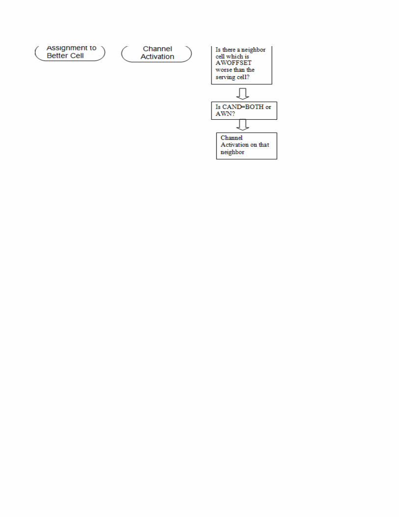
Assignment to Other Cell To Start
MSC Level
Parameter Default Value Recommended Value Value RangeHNDSDCCHTCH 1 1 0,1HOMAPVERSION 2 2 1,2HNDBEFOREBANSW 1 1 0,1
BSC Level
Parameter Default Value Recommended Value Value RangeASSOC OFF ON ON, OFFIBHOASS OFF ON ON, OFFFASTASSIGN 0,1TALLOC SAACH Periods
Cell LevelParameter Default Value Recommended Value Value RangeAW OFF ON ON,OFFAWOFFSET 3 10 0 to 63CAND BOTH BOTH AWN, NHN, BOTH
Assignment to Other Cell To Start

Command---
CommandRLLBP;RLLBP;
RAEPP:ID=FASTASSIGN;RLLBP;
CommandRLLOP:CELL={cell};
RLNRP:CELL={cell}, CELLR={cellr};RLNRP:CELL={cell}, CELLR={cellr};

DescriptionIntra-MSC handover from signalling to traffic channel 0=OFF 1=ONDetermines the primary MAP version to be used when establishing outgoing inter-MSC handover dialogue towards non-anchor MSCsDetermines if inter-MSC handover and inter-MSC assignment before answer from B-subscriber are allowed (=1) or not allowed (=0)
DescriptionBSC switch for Assignment to other cell than serving celldetermines whether an assignment to another BSC can be performed.If 1 the BSC will not wait for any measurement results before it assigns a traffic channelIf assignment fails due to congestion then locating & new allocation attempts are prevented for this time
DescriptionAssignment to worse cell switchSignal Strength Offset Parameter for which assignment to a worse cell is possibleCandidate Type of Cell. Indicates in which cases the related cell will be treated as a possible handover candidateAWN: Neighbour at assignment to worse cellNHN: Neighbour at normal handover

Determines the primary MAP version to be used when establishing outgoing inter-MSC handover dialogue towards non-anchor MSCs

Adaptive Configuration of Logical Channels To Start
BSC Level
Parameter Default Value RecommendeValue Range
EBANDINCLUDED OFF - ON, OFFADAPTIVECONFIG - - 0,1
Cell Level
Parameter Default Value RecommendeValue RangeTN - - 0 — 7 0, 2,4,6(extended range cell)SLEVEL 0 - 0-2, CONGSTIME 20 40 15-360 sCHGR -GPRSPRIO - - 0 to 15
Algorithm for Adaptive Configuration of Logical ChannelsIncrease Criterion
0— 15 Used together with parameters INCL, EXCL


Command
RAEPP:ID=EBANDINCLUDED;DBTSP:TAB=AXEPARS, NAME=ADAPTIVECONFIG;
CommandRLCFP:CELL={cell};RLACP:CELL={cell};RLACP:CELL={cell};RLACP:CELL={cell};RLCLP:CELL={cell};
To StartDecrease Criterion


Description
Defines whether or not to take the G1-GSM channels into account at evaluation of the SDCCH/8 subchannel load. 1=ON, 0=OFFSwitch for turning the feature on or off. 1=ON, 0=OFF
DescriptionTime slot number on which Adaptive SDCCH can be configuredLevel of remaining Stand Alone Dedicated Control Channels (SDCCHs) subchannels when an attempt to increase the number of SDCCH/8 will take place. CONG=attempt to increase the number of SDCCH/8 will take place when allocation of an SDCCH has failed due to congestionMinimum time interval in seconds before the number of SDCCH/8 added by this function is decreased when SDCCH demand is lowChannel group numberParameter that controls whether on-demand PDCHs shall be treated as idle or busy when calculating the percentage of idle channels


Cell Load Sharing To Start
BSC Level
Parameter Default Value Recommended Value
CLSTIMEINTERVAL 100 100 100 to 1000 msEBANDINCLUDED OFF(0) - ON(1), OFF(0)LSSTATE - - ACTIVE, INACTIVE
Cell Level
Parameter Default Value Recommended Value Value RangeHOCLSACC OFF ON OFF, ONCLSACC 40% - 1 to 100 %RHYST 75% 100% 0 to 100 %CLSRAMP 5 s 8 s 0 to 30 sCLSLEVEL 20% - 0 to 99 %GPRSIO - - 0 to 15
Cell Load Sharing Algorithm To Start
The amount of idle full rate traffic channels is examined every Cell Load Sharingtime interval for each cell that is activated for Cell Load Sharing. The time
The following criterion then defines when Cell Load Sharing evaluations areperformed in a cell where the feature is enabled:• If the number of idle full rate traffic channels is equal to or below parameter
rate traffic channels in the cell) in a cell, that cell tries to rid itself of some
Value Range(Command Output)
interval is given by a BSC exchange property CLSTIMEINTERVAL .
CLSLEVEL (the parameter value is given as the percentage of all idle full

traffic by initiating Cell Load Sharing handovers to neighbouring cells.When the result of the Cell Load Sharing evaluations in a cell indicates that aconnection should be moved to a neighbouring cell, the traffic load in the targetcell is examined. To accept an incoming handover due to Cell Load Sharing thecell must both indicate that it accepts incoming Cell Load Sharing handovers
The following criterion for the traffic level in a target cell is relevant:• If the number of idle full rate traffic channels is above the value of parameter
Cell Load Sharing handovers from other cells.Note that the amount of idle traffic channels is counted as if only full-ratechannels exist. This means that if one of a pair of half-rate channels in adual rate channel is busy, and the other is idle, the entire dual-rate channel iscounted as busy. However, both connections using a full rate channel and ahalf rate channel respectively can be selected for load sharing handovers.Cell Load Sharing evaluations are not performed at all for channels inmultislot configurations. Also, the E-GSM band channels can be included inthe Cell Load Sharing evaluation by turning on the BSC exchange propertyEBANDINCLUDED
Conditions for the Neighbouring Cell:the neighbouring cell must belong to the same BSC as the serving cellThe neighbouring cell must belong to the same hierarchical layer as the serving cellIncoming Cell Load Sharing handover must be allowed (parameter HOCLSACC ) for the neighbouring cell. Note that Cell load Sharingcan still be set to inactive in the neighbouring cell if Cell Load Sharingevaluations in that cell are to be avoided.
Statistics To Start
Object Type(s) Counter Name DescriptionCELEVENTH CLSTIME Accumulated time in seconds when Cell Load Sharing evaluation is performed in the cell.CELEVENTH TOTCLSTIME Total time for the Cell Load Sharing feature being active in seconds.CELEVENTH HOATTLS Number of handover attempts due to Cell Load Sharing.CELEVENTH HOSUCLS Number of successful handovers due to Cell Load Sharing.
according to the HOCLSACC parameter and have a low enough traffic level.
CLSACC (given as a percentage) in a cell, that cell will accept incoming

Command
RAEPP:ID=CLSTIMEINTERVAL;RAEPP:ID=EBANDINCLUDED;
RLLSP;
CommandRLLCP:CELL={cell}; RLLCP:CELL={cell}; RLLCP:CELL={cell}; RLLCP:CELL={cell}; RLLCP:CELL={cell}; RLCLP:CELL={cell};

Incoming Cell Load Sharing handover must be allowed (parameter HOCLSACC ) for the neighbouring cell. Note that Cell load Sharing
Accumulated time in seconds when Cell Load Sharing evaluation is performed in the cell.Total time for the Cell Load Sharing feature being active in seconds.Number of handover attempts due to Cell Load Sharing.Number of successful handovers due to Cell Load Sharing.

Description
Time interval after which the amount of idle full rate traffic channels is examined for each cell that is activated for Cell Load Sharing.Defines whether E-GSM band channels can be included for Cell Load sharing calculationsState of Cell Load Sharing in the BSC
DescriptionHandover due to Cell Load Sharing accepted.Defines a percentage of idle TCHs, at or below which no handovers due to cell load sharing are accepted. The parameter is defined as a percentage of the total number of available TCHs in the cell. The value of CLSACC shall be greater than that of CLSLEVELPercentage of hysteresis area to be used in Cell Load Sharing evaluationsInterval during which the value of RHYST is ramped up from zero to the final value.Defines a percentage of idle TCHs, at or below which the ranking recalculations are started. The parameter is defined as a percentage of the total number of available TCHs in the cell. It is defined per cell.Parameter that controls whether on-demand PDCHs shall be treated as idle or busy when calculating the percentage of idle channelsThis parameters controls whether preemptable on-demand Packet Data Channels (PDCHs) will be treated as idle or busy for Cell Load Sharing0-Preemptable on-demand PDCHs will be treated as idle for all the functions.1-Preemptable on-demand PDCHs will be treated as busy for the Dynamic HR allocation and TCH packing functions and idle for the following functions: Cell Load Sharing/Hierarchical Cell Structures, BTS Power Savings, Subcell Load Distribution, GSM - UMTS Cell Reselection and Handover.2-Preemptable on-demand PDCHs will be treated as busy for the following functions: Cell Load Sharing/Hierarchical Cell Structures, BTS Power Savings and idle for the following functions: Dynamic HR allocation and TCH packing, Subcell Load Distribution, GSM - UMTS Cell Reselection and Handover.3-Preemptable on-demand PDCHs will be treated as busy for the following functions: Dynamic HR allocation and TCH packing, Cell Load Sharing/Hierarchical Cell Structures, BTS Power Savings and idle for the following functions: Subcell Load Distribution, GSM - UMTS Cell Reselection and Handover.4-Preemptable on-demand PDCHs will be treated as busy for the Subcell Load Distribution function and idle for the following functions: Dynamic HR allocation and TCH packing, Cell Load Sharing/Hierarchical Cell Structures, BTS Power Savings, GSM - UMTS Cell Reselection and Handover.5-Preemptable on-demand PDCHs will be treated as busy for the following functions: Dynamic HR allocation and TCH packing, Subcell Load Distribution and idle for the following functions: Cell Load Sharing/Hierarchical Cell Structures, BTS Power Savings, GSM - UMTS Cell Reselection and Handover.6-Preemptable on-demand PDCHs will be treated as busy for the following functions: Cell Load Sharing/Hierarchical Cell Structures, BTS Power Savings, Subcell Load Distribution and idle for the following functions: Dynamic HR allocation and TCH packing, GSM - UMTS Cell Reselection and Handover.7-Preemptable on-demand PDCHs will be treated as busy for the following functions: Dynamic HR allocation and TCH packing, Cell Load Sharing/Hierarchical Cell Structures, BTS Power Savings, Subcell Load Distribution and idle for the GSM - UMTS Cell Reselection and Handover function.8-Preemptable on-demand PDCHs will be treated as busy for the GSM - UMTS Cell Reselection and Handover function and idle for the following functions: Dynamic HR allocation and TCH packing, Cell Load Sharing/Hierarchical Cell Structures, BTS Power Savings, Subcell Load Distribution.9-Preemptable on-demand PDCHs will be treated as busy for the following functions: Dynamic HR allocation and TCH packing, GSM - UMTS Cell Reselection and Handover and idle for the following functions: Cell Load Sharing/Hierarchical Cell Structures, BTS Power Savings, Subcell Load Distribution.10-Preemptable on-demand PDCHs will be treated as busy for the following functions: Cell Load Sharing/Hierarchical Cell Structures, BTS Power Savings, GSM - UMTS Cell Reselection and Handover and idle for the following functions: Dynamic HR allocation and TCH packing, Subcell Load Distribution.11-Preemptable on-demand PDCHs will be treated as busy for the following functions: Dynamic HR allocation and TCH packing, Cell Load Sharing/Hierarchical Cell Structures, BTS Power Savings, GSM - UMTS Cell Reselection and Handover and idle for the Subcell Load Distribution function.12-Preemptable on-demand PDCHs will be treated as busy for the following functions: Subcell Load Distribution, GSM - UMTS Cell Reselection and Handover and idle for the following functions: Dynamic HR allocation and TCH packing, Cell Load Sharing/Hierarchical Cell Structures, BTS Power Savings.13-Preemptable on-demand PDCHs will be treated as busy for the following functions: Dynamic HR allocation and TCH packing, Subcell Load Distribution, GSM - UMTS Cell Reselection and Handover and idle for the following functions: Cell Load Sharing/Hierarchical Cell Structures, BTS Power Savings.14-Preemptable on-demand PDCHs will be treated as busy for the following functions: Cell Load Sharing/Hierarchical Cell Structures, BTS Power Savings, Subcell Load Distribution, GSM - UMTS Cell Reselection and Handover and idle for the Dynamic HR allocation and TCH packing function.15-Preemptable on-demand PDCHs will be treated as busy for all the functions.

Incoming Cell Load Sharing handover must be allowed (parameter HOCLSACC ) for the neighbouring cell. Note that Cell load Sharing
Accumulated time in seconds when Cell Load Sharing evaluation is performed in the cell.

Dynamic Half Rate Allocation & Dynamic Mode Adaption
BSC Level
Parameter Default Value Value Range
DYNHRALLOC 0 1 ON(1) , OFF(0)DYMA 0 1 ON(1) , OFF(0)EBANDINCLUDED OFF(0) - ON(1), OFF(0)
Cell Level
Parameter Default Value Value Range
DHA OFF ON ON, OFFDTHAMR 30% 30% 0 to 100 %DTHNAMR 15% 15% 0 to 100 %DMSUPP OFF ON ON, OFFDMQB OFF ON ON, OFFDMQBAMR 50 dtqu 50 dtqu 0 to 100 dtquDMQBNAMR 45 dtqu 45 dtqu 0 to 100 dtquDMQG OFF ON ON, OFFDMQGAMR 35 dtqu 35 dtqu 0 to 100 dtquDMQGNAMR 30 dtqu 30 dtqu 0 to 100 dtquDMTHAMR 20% 20% 0 to 100 %
DMTHNAMR 10% 10% 0 to 100 %GPRSPRIO - - 0 to 15DMTFAMR - - 0 to 100DMTFNAMR - - 0 to 100DHASSTHRASS 96 96 47 to 110 dBmDHASSTHRHO 98 98 47 to 110 dBmDHASS OFF ON OFF, ONDHPRDHPRL
DHA Algorithm To Start
Recommended Value
Recommended Value

Statistics
Object Type(s) Counter DescriptionCLRATECHG HOATFRHRAMR Number of intra cell handover attempts, due to FR to HR channel rate change triggered by high cell load or high Abis load, made by an AMR capable mobile
HOSUCFRHRAMR Number of successful intra cell handovers, due to FR to HR channel rate change triggered by high cell load or high Abis load, made by an AMR capable mobileHOATFRHRNAMR Number of intra cell handover attempts, due to FR to HR channel rate change triggered by high cell load or high Abis load, made by a mobile not capable of AMRHOSUCFRHRNAMR Number of successful intra cell handovers, due to FR to HR channel rate change triggered by high cell load or high Abis load, made by a mobile not capable of AMRHOATHRFRAMR Number of intra cell handover attempts, due to HR to FR channel rate change triggered by bad quality, made by an AMR capable mobileHOSUCHRFRAMR Number of successful intra cell handovers, due to HR to FR channel rate change triggered by bad quality, made by an AMR capable mobileHOATHRFRNAMR Number of intra cell handover attempts, due to HR to FR channel rate change triggered by bad quality, made by a mobile not capable of AMRHOSUCHRFRNAMR Number of successful intra cell handovers, due to HR to FR channel rate change triggered by bad quality, made by a mobile not capable of AMRATAMRLDHRFRHO Number of intra cell handover attempts, due to HR to FR channel rate change triggered by low cell load and low Abis load, for AMR/HR callsSUCAMRLDHRFRHO Number of successful intra cell handovers, due to HR to FR channel rate change triggered by low cell load and low Abis load, for AMR/HR callsATNAMRLDHRFRHO Number of intra cell handover attempts, due to HR to FR channel rate change triggered by low cell load and low Abis load, for HR callsSUCNAMRLDHRFRHO Number of successful intra cell handovers, due to HR to FR channel rate change triggered by low cell load and low Abis load, for HR calls

Dynamic Half Rate Allocation & Dynamic Mode Adaption To Start
Command Description
DBTSP:TAB=AXEPARS, NAME=DYNHRALLOC; Switch for Dynamic HR Allocation in the BSCDBTSP:TAB=AXEPARS, NAME=DYMA; Switch for Dynamic FR/HR Adaption in the BSCRAEPP:ID=EBANDINCLUDED; Defines whether E-GSM band channels can be included for DHA/DYMA Calculations
Command Description
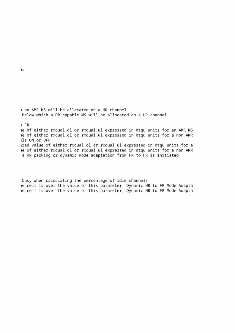
RLDHP:CELL={cell}; Used to turn the feature Dynamic Half Rate Allocation ON or OFF.RLDHP:CELL={cell}; Threshold parameter for AMR HR capable MSs at channel allocation below which an AMR MS will be allocated on a HR channelRLDHP:CELL={cell}; Threshold parameter for non AMR HR but DR capable MSs at channel allocation below which a DR capable MS will be allocated on a HR channelRLDMP:CELL={cell}; Parameter controlling the activation of DYMARLDMP:CELL={cell}; Used to switch ON or OFF the quality based channel rate switching from HR to FRRLDMP:CELL={cell}; Threshold triggering a switch from a HR channel to a FR if the filtered value of either rxqual_dl or rxqual_ul expressed in dtqu units for an AMR MS is exceeding this thresholdRLDMP:CELL={cell}; Threshold triggering a switch from a HR channel to a FR if the filtered value of either rxqual_dl or rxqual_ul expressed in dtqu units for a non AMR DR capable MS is exceeding this thresholdRLDMP:CELL={cell}; Used to switch the quality based channel rate switching from FR to HR channels ON or OFFRLDMP:CELL={cell}; Threshold triggering a switch from a FR channel to a HR channel if the filtered value of either rxqual_dl or rxqual_ul expressed in dtqu units for an AMR MS is less than this threshold.RLDMP:CELL={cell}; Threshold triggering a switch from a FR channel to a HR if the filtered value of either rxqual_dl or rxqual_ul expressed in dtqu units for a non AMR DR capable MS is less than this thresholdRLDMP:CELL={cell}; HR packing threshold parameter for AMR HR capable MSs.When below this value a HR packing or dynamic mode adaptation from FR to HR is initiated
RLDMP:CELL={cell};RLCLP:CELL={cell}; Parameter that controls whether on-demand PDCHs shall be treated as idle or busy when calculating the percentage of idle channelsRLDMP:CELL={cell}; When the % of idle FR traffic channels to total de-blocked FR channels in the cell is over the value of this parameter, Dynamic HR to FR Mode Adaptation will be initiated for AMR supported MSRLDMP:CELL={cell}; When the % of idle FR traffic channels to total de-blocked FR channels in the cell is over the value of this parameter, Dynamic HR to FR Mode Adaptation will be initiated for non AMR supported MSRLCSP:CELL={cell}; DHA signal strength threshold at call setupRLCSP:CELL={cell}; DHA signal strength threshold at handoverRLCSP:CELL={cell}; DHA signal strength thresholds statusRLDHP:CELL={cell};RLDHP:CELL={cell};
DYMA Algorithm
HR packing threshold parameter for non AMR but DR capable MSs. When below this value a HR packing or dynamic mode adaptation from FR to HR is initiated

Number of intra cell handover attempts, due to FR to HR channel rate change triggered by high cell load or high Abis load, made by an AMR capable mobileNumber of successful intra cell handovers, due to FR to HR channel rate change triggered by high cell load or high Abis load, made by an AMR capable mobileNumber of intra cell handover attempts, due to FR to HR channel rate change triggered by high cell load or high Abis load, made by a mobile not capable of AMRNumber of successful intra cell handovers, due to FR to HR channel rate change triggered by high cell load or high Abis load, made by a mobile not capable of AMRNumber of intra cell handover attempts, due to HR to FR channel rate change triggered by bad quality, made by an AMR capable mobileNumber of successful intra cell handovers, due to HR to FR channel rate change triggered by bad quality, made by an AMR capable mobileNumber of intra cell handover attempts, due to HR to FR channel rate change triggered by bad quality, made by a mobile not capable of AMRNumber of successful intra cell handovers, due to HR to FR channel rate change triggered by bad quality, made by a mobile not capable of AMRNumber of intra cell handover attempts, due to HR to FR channel rate change triggered by low cell load and low Abis load, for AMR/HR callsNumber of successful intra cell handovers, due to HR to FR channel rate change triggered by low cell load and low Abis load, for AMR/HR callsNumber of intra cell handover attempts, due to HR to FR channel rate change triggered by low cell load and low Abis load, for HR callsNumber of successful intra cell handovers, due to HR to FR channel rate change triggered by low cell load and low Abis load, for HR calls

Defines whether E-GSM band channels can be included for DHA/DYMA Calculations
Used to turn the feature Dynamic Half Rate Allocation ON or OFF.Threshold parameter for AMR HR capable MSs at channel allocation below which an AMR MS will be allocated on a HR channelThreshold parameter for non AMR HR but DR capable MSs at channel allocation below which a DR capable MS will be allocated on a HR channel
Used to switch ON or OFF the quality based channel rate switching from HR to FRThreshold triggering a switch from a HR channel to a FR if the filtered value of either rxqual_dl or rxqual_ul expressed in dtqu units for an AMR MS is exceeding this thresholdThreshold triggering a switch from a HR channel to a FR if the filtered value of either rxqual_dl or rxqual_ul expressed in dtqu units for a non AMR DR capable MS is exceeding this thresholdUsed to switch the quality based channel rate switching from FR to HR channels ON or OFFThreshold triggering a switch from a FR channel to a HR channel if the filtered value of either rxqual_dl or rxqual_ul expressed in dtqu units for an AMR MS is less than this threshold.Threshold triggering a switch from a FR channel to a HR if the filtered value of either rxqual_dl or rxqual_ul expressed in dtqu units for a non AMR DR capable MS is less than this thresholdHR packing threshold parameter for AMR HR capable MSs.When below this value a HR packing or dynamic mode adaptation from FR to HR is initiated
Parameter that controls whether on-demand PDCHs shall be treated as idle or busy when calculating the percentage of idle channelsWhen the % of idle FR traffic channels to total de-blocked FR channels in the cell is over the value of this parameter, Dynamic HR to FR Mode Adaptation will be initiated for AMR supported MSWhen the % of idle FR traffic channels to total de-blocked FR channels in the cell is over the value of this parameter, Dynamic HR to FR Mode Adaptation will be initiated for non AMR supported MS

Number of intra cell handover attempts, due to FR to HR channel rate change triggered by high cell load or high Abis load, made by an AMR capable mobileNumber of successful intra cell handovers, due to FR to HR channel rate change triggered by high cell load or high Abis load, made by an AMR capable mobileNumber of intra cell handover attempts, due to FR to HR channel rate change triggered by high cell load or high Abis load, made by a mobile not capable of AMRNumber of successful intra cell handovers, due to FR to HR channel rate change triggered by high cell load or high Abis load, made by a mobile not capable of AMRNumber of intra cell handover attempts, due to HR to FR channel rate change triggered by bad quality, made by an AMR capable mobileNumber of successful intra cell handovers, due to HR to FR channel rate change triggered by bad quality, made by an AMR capable mobileNumber of intra cell handover attempts, due to HR to FR channel rate change triggered by bad quality, made by a mobile not capable of AMRNumber of successful intra cell handovers, due to HR to FR channel rate change triggered by bad quality, made by a mobile not capable of AMRNumber of intra cell handover attempts, due to HR to FR channel rate change triggered by low cell load and low Abis load, for AMR/HR callsNumber of successful intra cell handovers, due to HR to FR channel rate change triggered by low cell load and low Abis load, for AMR/HR callsNumber of intra cell handover attempts, due to HR to FR channel rate change triggered by low cell load and low Abis load, for HR callsNumber of successful intra cell handovers, due to HR to FR channel rate change triggered by low cell load and low Abis load, for HR calls

Threshold triggering a switch from a HR channel to a FR if the filtered value of either rxqual_dl or rxqual_ul expressed in dtqu units for an AMR MS is exceeding this thresholdThreshold triggering a switch from a HR channel to a FR if the filtered value of either rxqual_dl or rxqual_ul expressed in dtqu units for a non AMR DR capable MS is exceeding this threshold
Threshold triggering a switch from a FR channel to a HR channel if the filtered value of either rxqual_dl or rxqual_ul expressed in dtqu units for an AMR MS is less than this threshold.Threshold triggering a switch from a FR channel to a HR if the filtered value of either rxqual_dl or rxqual_ul expressed in dtqu units for a non AMR DR capable MS is less than this thresholdHR packing threshold parameter for AMR HR capable MSs.When below this value a HR packing or dynamic mode adaptation from FR to HR is initiated
When the % of idle FR traffic channels to total de-blocked FR channels in the cell is over the value of this parameter, Dynamic HR to FR Mode Adaptation will be initiated for AMR supported MSWhen the % of idle FR traffic channels to total de-blocked FR channels in the cell is over the value of this parameter, Dynamic HR to FR Mode Adaptation will be initiated for non AMR supported MS

Dynamic BTS Power Control To Start
BSC Level
Parameter Value Range
EMRSUPPORT 0 1 0(OFF), 1(ON)
EMRSTATE - - ACTIVE, NOT ACTIVE
AMRPWRCTRL 0 1 0(OFF), 1(ON)BTSPWRCTRL 1 1 1(ON), 0(OFF)REGINTDL 1 1 1 to 10 SACCH periods(480 ms)UPDWNRATIO 200% 300% 100 to 700 %QLENDL 3 3 3 to 15 SACCH periods(480 ms)SSLENDL 8 3 1 to 20 SACCH periods(480 ms)
Cell Level
Parameter Value Range
DBPSTATE - - ACTIVE, INACTIVESSDESDL 90 90 110 to 47 dBmQDESDL 30 dtqu 30 dtqu 0 to 76 dtquLCOMPDL 5% 5% 0 to 100 %QCOMPDL 55% 55% 0 to 100 %BSPWRMINP - - 0 to 50 dBmBSPWRMINN 20 20 0 to 20 dBmSSDESDLAFR 90 90 110 to 47 dBmQDESDLAFR 40 40 0 to 76 dtquSSDESDLAHR 90 90 110 to 47 dBmQDESDLAHR 30 30 0 to 76 dtqu
Default Value
Recommended Value
Default Value
Recommended Value
BTS Power Control Algorithm To Start
1) Preparation of Input Data
Compensation for Freq. HoppingSSTCH=SSM-(BSPWR-BSTXPWR+2*PLused)/Nf
Where, SSTCH is the signal strength on the down regulated TCH carrier SSM is the measured signal strength reported by the MS BSPWR,BSTXPWR is the BTS output power on the BCCH frequency and TCH frequency respectively. Nf is the number of frequencies in the hopping frequency set
All signal strength measurements are compensated before the filtering. SSTCH is also compensated for power control according to the equation given below, SS_COMP = SSTCH + 2*PLused where SS_COMP is the signal strength compensated for both down regulation and frequency hopping
2) Filtering of Measurements
SSFILTERED(k) = b*SS_COMP(k) + a*SSFILTERED(k-1)
if SS_COMP(k) < SSFILTERED (k-1)

then L = SSLENDL else L = SSLENDL * UPDWNRATIO / 100
3) Calculation of Power Order
pui = αi * (SSDESDL - SSFILTERED ) + βi * (QDESDL_dB - QFILTERED ) i = 1, 2 where,α1 = LCOMPDL / 100 (pathloss compensation) β1 = QCOMPDL / 100 (quality compensation) α2 = 0.3 (pathloss compensation) β2 = 0.4 (quality compensation)
pu = max(pu1 ,pu2 )
PLused = Int(-pu/2 )where, PLused is the power level. PLused = 0 represents full power and PLused =15 represents 30 dB down regulation.
BTS_outputpower(k) = BSPWR - 2*PLused in dBm

Command
DBTSP:TAB=AXEPARS, NAME=EMRSUPPORT;
RLEMP;
DBTSP:TAB=AXEPARS, NAME=AMRPWRCTRL;DBTSP:TAB=AXEPARS, NAME=BTSPWRCTRL;
RLBAP;RAEPP:ID=UPDWNRATIO;
RLBAP;RLBAP;
Command
RLBCP:CELL={cell};RLBCP:CELL={cell};RLBCP:CELL={cell};RLBCP:CELL={cell};RLBCP:CELL={cell};RLBCP:CELL={cell};RLBCP:CELL={cell};RLAPP:CELL={cell};RLAPP:CELL={cell};RLAPP:CELL={cell};RLAPP:CELL={cell};

All signal strength measurements are compensated before the filtering. SSTCH is also compensated for power control according to the equation given below,
where SS_COMP is the signal strength compensated for both down regulation
where b=1-a

where L is the length of the filter and the deciding factor for a
pui = αi * (SSDESDL - SSFILTERED ) + βi * (QDESDL_dB - QFILTERED )
where, PLused is the power level. PLused = 0 represents full power and PLused =15 represents 30 dB down regulation.

Description
Switch to turn on or off EMR measurement on BSC
The parameter indicates the status of Enhanced Measurement Reporting
AMR Power control switch on BSCBSC level parameter to switch on BTS Power ControlMinimum time period between two consecutive power ordersRatio between the up- and down regulation speedDefines the length of the quality filterDefines the length of the signal strength filter
Description
Indicates the state of Dynamic Base Transceiver Station (BTS) Power Control
Target value for the desired signal strength measured by the receiver in the MS at the outer rim of the regulation areaTarget value for the desired quality level measured by the receiver in the MS.Parameter that determines how much of the path loss that shall be compensated for in the algorithm that regulates towards qualityParameter that determines the weight of the quality compensationMinimum allowed positive output power for the BTS on the non-BCCH frequenciesMinimum allowed negative output power for the BTS on the non-BCCH frequenciesTarget value for the desired signal strength for AMR FR connection measured by the receiver in the MS at the outer rim of the regulation areaTarget value for the desired quality level for AMR FR connection measured by the receiver in the MSTarget value for the desired signal strength for AMR HR connection measured by the receiver in the MS at the outer rim of the regulation areaTarget value for the desired dtq level for AMR HR connection measured by the receiver in the MS
Tips:Down regulation due to SS depends on SSLENDL*UPDOWNRATIO/100. Larger value, takes longer time to down regulateUp regulation due to SS depends on SSLENDL. Smaller value leads to short time of up-regulationDown regulation due to quality depends on QLENDL*UPDOWNRATIO/100. Larger value, takes longer time to down regulateUp regulation due to quality depends on QLENDL. Smaller value leads to short time of up-regulation
Figure:Point 1 is decided by SSDESDL & QDESDLFor Plane 3 QCOMPDL sets the angle along the QDESDL value and LCOMPDL along the SSDESDL. Higher the value more steep the gradient.The angles of plane 2 towards the two dimensional (RxLevel vs Quality) plane are constantPositions of Plane 2 and 3 are decided by SSDESDL and QDESDL, or SSDESDLAFR and QDESDLAFR, orSSDESDLAHR and QDESDLAHR
Filter has a trasnfer function H(k) = (1-a).a^k u(k)where u(k) is a step functionL is the length of the filter which is chosen as follows:For quality If Q_COMP(k) < QFILTERED(k-1) then L=QLENDL else L=QLENDL*UPDOWNRATIO/100For signal strength if SS_COMP(k) < SSFILTERED(k-1) then L=SSLENDL else L=SSLENDL*UPDOWNRATIO/100The response time for down regulation is determined by the expressionsQLENDL *UPDWNRATIO /100 and SSLENDL *UPDWNRATIO /100 where

UPDWNRATIO is the ratio between up- and down regulation speed. Thisresults in a quick up regulation and a smooth down regulation.
All signal strength measurements are compensated before the filtering. SSTCH is also compensated for power control according to the equation given below,
where L is the length of the filter and the deciding factor for a

Dynamic MS Power Control To Start
BSC Level
Parameter Value Range
MSPWRCTRL 1 1 0(OFF), 1(ON)UPDWNRATIO 200 300 100 to 700 %REGINTUL 1 1 1 to 30 SACCH periods (480 ms)SSLENUL 3 3 3 to 15 SACCH periods (480 ms)QLENUL 3 3 1 to 20 SACCH periods (480 ms)DTXFUL 5 5 0 to 40 SACCH periods (480 ms)
Cell Level
Parameter Value Range
SSDESUL 92 92 110 to 47 dBmQDESUL 30 30 0 to 76 dtquLCOMPUL 6 6 0 to 100 %QCOMPUL 75 75 0 to 100 %SSDESULAFR 92 92 110 to 47 dBmQDESULAFR 40 40 0 to 76 dtquSSDESULAHR 92 92 110 to 47 dBmQDESULAHR 30 30 0 to 76 dtquMSTXPWR - - 13 to 43 dBm (odd values only)
MS Power Control Algorithm To Start
1) Preparation of input data
Where SS_COMP is the signal strength compensated for down regulation, PWR_U is the output power used by the MS during the measurement period, MSTXPWR is the maximum allowed power level for the MS in the current subcell and MSPWRMAX is the maximum output power according to the power class
Default Value
Recommended Value
Default Value
Recommended Value

2) Filtering of Measurements
3) Calculation of Power Order


Command
DBTSP:TAB=AXEPARS, NAME=MSPWRCTRL;RAEPP:ID=UPDWNRATIO;
RLMAP;RLMAP;RLMAP;RLMAP;
Command
RLPCP:CELL={cell};RLPCP:CELL={cell};RLPCP:CELL={cell};RLPCP:CELL={cell};RLAPP:CELL={cell};RLAPP:CELL={cell};RLAPP:CELL={cell};RLAPP:CELL={cell};RLCPP:CELL={cell};Refer to BTS Power Control for how values of parameters effect power regulation
Where SS_COMP is the signal strength compensated for down regulation, PWR_U is the output power used by the MS during the measurement period, MSTXPWR is the maximum allowed power level for the MS in the current subcell and MSPWRMAX is the maximum output power according to the power class

where b=1-a


Description
Switch for turning this feature on or offRatio between the up- and down regulation speed.Minimum time period between two consecutive power ordersLength of the signal strength filterLength of the quality filterNumber of measurement periods, after a call has been established on a TCH, before the full set measurements shall be used
Description
Desired signal strength at the outer rim of the regulation areaDesired quality level measured by the receiver in the BTSParameter that determines how much of the pathloss that shall be compensated for in the algorithmParameter that determines the weight of the quality compensationDesired signal strength for AMR FR connection at the outer rim of the regulation areaDesired quality level for AMR FR connection measured by the receiver in the BTSDesired signal strength for AMR HR connection at the outer rim of the regulation area.Desired quality level for AMR HR connection measured by the receiver in the BTSMaximum allowed power level for MSs in the current subcell
Refer to BTS Power Control for how values of parameters effect power regulation
Where SS_COMP is the signal strength compensated for down regulation, PWR_U is the output power used by the MS during the measurement period, MSTXPWR is the maximum allowed power level for the MS in the current subcell and MSPWRMAX is the maximum output power according to the power class

Number of measurement periods, after a call has been established on a TCH, before the full set measurements shall be used
Where SS_COMP is the signal strength compensated for down regulation, PWR_U is the output power used by the MS during the measurement period, MSTXPWR is the maximum allowed power level for the MS in the current subcell and MSPWRMAX is the maximum output power according to the power class

Discontinuous Transmit Uplink/Downlink To Start
Cell Level
Command
DTXU 2 1 0, 1, 2 RLSSP:CELL={cell} Uplink parameter and states whether the mobile stations located in that cell shall (DTXU =1) or shall not (=2) use DTX. With DTXU =0 the MS may use DTX which means that MSs in battery saving mode (option on some MS models) shall use DTXDTXD OFF ON OFF, ON RLCXP:CELL={cell}; Downlink parameter and states whether discontinuous transmission is enabled or not in the cell. This applies for all TCHs allocated on the non BCCH carriers in that cell
Parameter
Default Value
Recommended Value
Value Range
Description

Uplink parameter and states whether the mobile stations located in that cell shall (DTXU =1) or shall not (=2) use DTX. With DTXU =0 the MS may use DTX which means that MSs in battery saving mode (option on some MS models) shall use DTXDownlink parameter and states whether discontinuous transmission is enabled or not in the cell. This applies for all TCHs allocated on the non BCCH carriers in that cell

Uplink parameter and states whether the mobile stations located in that cell shall (DTXU =1) or shall not (=2) use DTX. With DTXU =0 the MS may use DTX which means that MSs in battery saving mode (option on some MS models) shall use DTXDownlink parameter and states whether discontinuous transmission is enabled or not in the cell. This applies for all TCHs allocated on the non BCCH carriers in that cell

Uplink parameter and states whether the mobile stations located in that cell shall (DTXU =1) or shall not (=2) use DTX. With DTXU =0 the MS may use DTX which means that MSs in battery saving mode (option on some MS models) shall use DTX

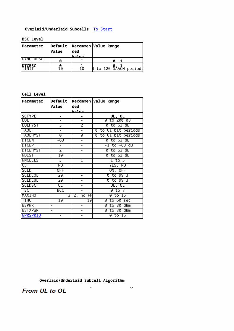
Overlaid/Underlaid Subcells To Start
BSC Level
Parameter Value Range
DYNOLULSC 0 - 0, 1DTCBSC 0 1 0, 1TINIT 10 10 0 to 120 SAACH periods
Cell Level
Parameter Value Range
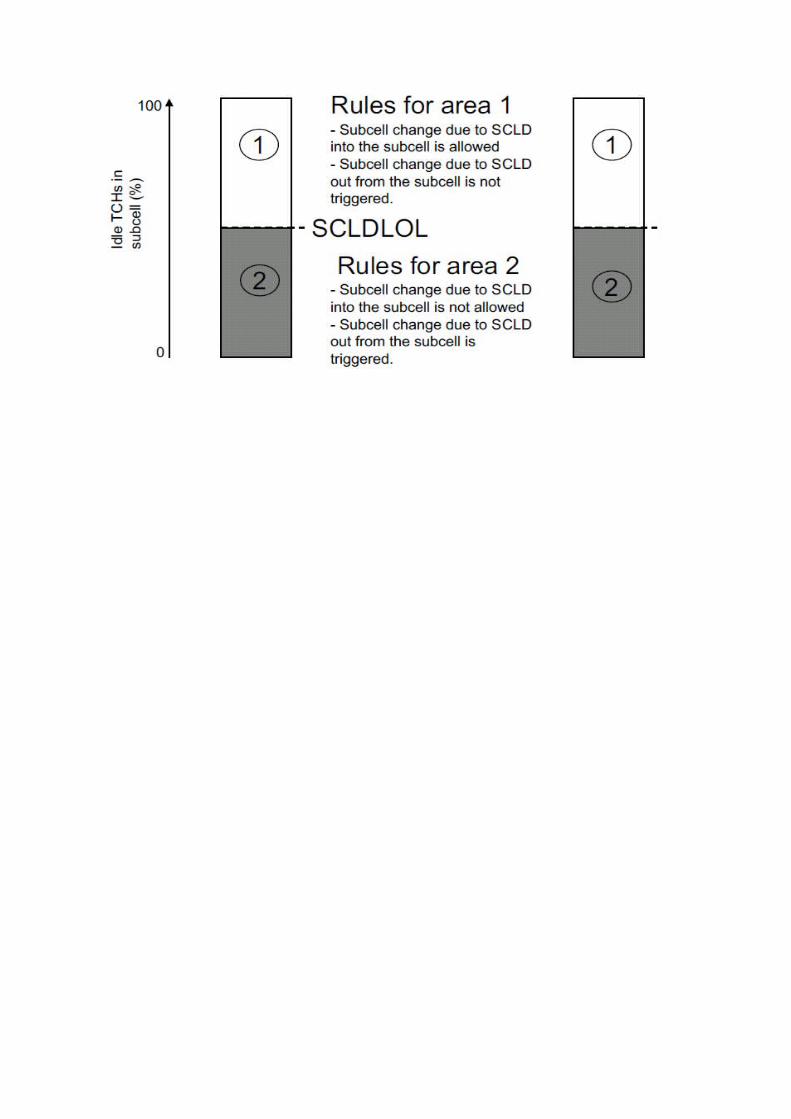
SCTYPE - - UL, OLLOL - - 0 to 200 dBLOLHYST 3 2 0 to 63 dBTAOL - - 0 to 61 bit periodsTAOLHYST 0 0 0 to 61 bit periodsDTCBN -63 - 0 to 63 dBDTCBP - - -1 to -63 dBDTCBHYST 2 - 0 to 63 dBNDIST 10 0 to 63 dBNNCELLS 3 1 1 to 5CS NO YES, NOSCLD OFF ON, OFFSCLDLOL 20 - 0 to 99 %SCLDLUL 20 - 0 to 99 %SCLDSC UL - UL, OLTSC BCC - 0 to 7MAXIHO 3FH: 2, no FH: 3 0 to 15TIHO 10 10 0 to 60 secBSPWR - - 0 to 80 dBmBSTXPWR - - 0 to 80 dBmGPRSPRIO - - 0 to 15
Overlaid/Underlaid Subcell Algorithm
Default Value
Recommended Value
Default Value
Recommended Value


Command
DBTSP:TAB=AXEPARS, NAME=DYNOLULSC;RAEPP:ID=DTCBSC;RLLBP;
Command
RLDGP:CELL={cell};RLOLP:CELL={cell};RLOLP:CELL={cell};RLOLP:CELL={cell};RLOLP:CELL={cell};RLOLP:CELL={cell};RLOLP:CELL={cell};RLOLP:CELL={cell};RLOLP:CELL={cell};RLOLP:CELL={cell};RLNRP:CELL={cell} , CELLR={cellr};RLLLP:CELL={cell};RLLLP:CELL={cell};RLLLP:CELL={cell};RLLLP:CELL={cell};RLDTP:CELL={cell};RLIHP:CELL={cell};RLIHP:CELL={cell};RLLOP:CELL={cell};RLLOP:CELL={cell};
RLCLP:CELL={cell};
To Start


Description
To turn the feature ON/OFF
Minimum time before handover is allowed on an initial call or after handover
Description
Identifies the subcell type, OL or UL, within a cellPath loss threshold for the serving area of the OL subcell within a cellPath loss hysteresis for the serving area of the OL subcell within a cellThe timing advance threshold for the serving area of the OL subcell within a cellTiming advance hysteresis for the serving area of the OL subcell within a cellNegative Distance to cell border threshold for the serving area of the OL subcell within a cellPositive Distance to cell border threshold for the serving area of the OL subcell within a cellDistance to cell border hysteresis for the serving area of the OL subcell within a cellThreshold in dB. A non-cosited neighbouring cell’s signal strength has to be above or equal to SSserv- (DTCB + DTCBHYST + NDIST) to be included as an interfering neighbour in NNCELLSNumber of non-cosited neighbouring cells that must be within NDIST from DTCB + DTCBHYST of the serving area of the OL subcell to trigger a DTCB evaluationIndicates if a cell shares the same site as its neighbourUsed to activate Sub Cell Load Distribution in a cellDefines the percentage of idle full rate capable TCHs in the OL subcell at or below which subcell change from the OL subcell to the UL subcell is attemptedDefines the percentage of idle full rate capable TCHs in the UL subcell at or below which subcell change from the UL subcell to the OL subcell is attemptedUsed to define the preferred subcellTraining Sequence Code for the specified channel group within a cellMaximum number of consecutive intra-cell handoversIntra-cell handover inhibition timer, during which intra-cell handover is not allowedBase station output power at the reference point for the locating algorithm on the BCCH frequency within a cellBase station output power at the reference point for the locating algorithm on the non-BCCH frequencies within a cellParameter that controls whether on-demand PDCHs shall be treated as idle or busy when calculating the percentage of idle channels
SCLD
Defines if the DTCB criterion is taken into consideration during subcell changes (1) or not (0)

Threshold in dB. A non-cosited neighbouring cell’s signal strength has to be above or equal to SSserv- (DTCB + DTCBHYST + NDIST) to be included as an interfering neighbour in NNCELLSNumber of non-cosited neighbouring cells that must be within NDIST from DTCB + DTCBHYST of the serving area of the OL subcell to trigger a DTCB evaluation
Defines the percentage of idle full rate capable TCHs in the OL subcell at or below which subcell change from the OL subcell to the UL subcell is attemptedDefines the percentage of idle full rate capable TCHs in the UL subcell at or below which subcell change from the UL subcell to the OL subcell is attempted
Base station output power at the reference point for the locating algorithm on the BCCH frequency within a cellBase station output power at the reference point for the locating algorithm on the non-BCCH frequencies within a cellParameter that controls whether on-demand PDCHs shall be treated as idle or busy when calculating the percentage of idle channels


Immediate Assignment on TCH To Start
Cell Level
Parameter Command Description
CHAP 0 1 0 to 13 RLHPP:CELL={cell}; Channel Allocation Profile
Immediate Assignment on TCH works even with maximum number of SDCCH configured.Immediate assignment on TCH is not allowed for Immediate assignment STs that are used for location updating or GSM phase 2 MSs sending or receiving SMS
Default Value
Recommended Value
Value Range

CHAP = 0, 5, 7, 8, 9 or 10 No immediate assignment on TCHCHAP = 1, 6, or 11 TCH last (SDCCH first)CHAP = 2, 3, 4, 12 or 13 TCH first
Immediate assignment on TCH is not allowed for Immediate assignment STs that are used for location updating or GSM phase 2 MSs sending or receiving SMS

Immediate assignment on TCH is not allowed for Immediate assignment STs that are used for location updating or GSM phase 2 MSs sending or receiving SMS
Idle Channel Measurements To Start
Cell Level
Parameter Value Range Command
LIMIT1 2 SSDES+92 0 to 59 RLIMP:CELL={cell};LIMIT2 6 SSDES+100 1 to 60 RLIMP:CELL={cell};LIMIT3 12 SSDES+108 2 to 61 RLIMP:CELL={cell};LIMIT4 22 SSDES+129 3 to 62 RLIMP:CELL={cell};INTAVE 6 25 1 to 31 SACCH periods (480 ms) RLIMP:CELL={cell};ICMSTATE PASSIVE ACTIVE ACTIVE, PASSIVE, NOALLOC RLIMP:CELL={cell};
Idle Channel Measurements Algorithm To Start
When a channel is available for channel allocation (deblocked), the BSC putsthe channel in the interference band 1 (which represents the lowest measuredinterference)At normal release, the channel is placed in the same interference band thatit was taken from at channel allocation. At abnormal release however, e.g.a dropped call, the channel is placed in the interference band immediatelyabove the one from which it was taken, that is in a band representing a higherinterference.
When a half rate channel is released and its related half rate channel is idle,the channel that is released is placed in the same interference band as itsrelated channel. This is done regardless of whether the release was normalor abnormal
INTAVE may change the BSC CP load. If INTAVE isset to a low value, less measurements are used when calculating the average.This may lead to more fluctuations in the interference measurement. Thesefluctuations will lead to an increased number of changes of interference bandand hence a higher BSC CP load. Increasing INTAVE will lead to a more stable
Default Value
Recommended Value

interference measurement and therefor less changes of interference band andwill reduce the number of reports sent to the BSC.

Description
ICMBAND 1 is from 0 to LIMIT1ICMBAND 2 is from LIMIT1+1 to LIMIT2ICMBAND 3 is from LIMIT2+1 to LIMIT3ICMBAND 4 is from LIMIT3+1 to LIMIT4 and ICMBAND 5 is from LIMIT4+1 to 63Number of SACCH periods over which the BTS takes average of UL signal strength measurements on the idle channelsACTIVE: ICM activated for channel allocation, NOALLOC: ICM initiated for statistics only

Adaptive Multirate To Start
BSC Level
Parameter Value Range
AMR 0 - 0, 1AMRHR 0 - 0, 1
AMRFRSUPPORT 0 -AMRHRSUPPORT 0 -SET - - FR3, FR4, HR3, HR4MODE - - 1 to 8THR - - 0 to 63 * 0.5 dBHYST - - 0 to 15 * 0.5 dB
If AMRFRSUPPORT and/or AMRHRSUPPORT are not set to 3 or 4 then the manual codec settings are over-riddenAMR HR / FR Codec Sets 3 & 4 are available, which can be tuned manually
PREDEFINED CODEC SETSFR Codec Set 1 Bit Rate Threshold Value
1 4.75 kbps THR_1 12(6dB)3 5.90 kbps THR_2 16(8dB)4 6.70 kbps THR_3 21(10.5dB)7 10.2 kbps
FR Codec Set 2 Bit Rate Threshold Value1 4.75 kbps THR_1 12(6dB)3 5.90 kbps THR_2 17(8.5dB)6 7.95 kbps THR_3 25(12.5dB)8 12.2 kbps
FR Codec Set 5 Bit Rate Threshold Value1 4.75 kbps THR_1 12(6dB)3 5.90 kbps THR_2 16(8dB)5 7.40 kbps THR_3 25(12.5dB)8 12.2 kbps
Default Value
Recommended Value
0=off,0=off,

Command
DBTSP:TAB=AXEPARS, NAME=AMR; Switch for AMR in BSCDBTSP:TAB=AXEPARS, NAME=AMRHR; Switch for AMR HR in BSc
RAEPP:ID=AMRFRSUPPORT; Indicates if AMR FR is turned ON or OFF and also which full rate codec set that shall be used within the BSCRAEPP:ID=AMRHRSUPPORT; Indicates if AMR HR is turned ON or OFF and also which half rate codec set that shall be used within the BSCRLADP:SET=ALL; Indicates which of the codec sets for a specific channel rate that shall be modifiedRLADP:SET=ALL; Specifies the codec modes that shall be included in the codec set. For Full Rate all 8 codec modes can be used, expressed as a numeral between 1 and 8, and defined in ascending order.RLADP:SET=ALL; Specifies the thresholds between the codec modes in the codec set, expressed as a numeral between 0 and 63, in steps of 0.5 dB
RLADP:SET=ALL; Specifies the hysteresis values for the threshold in the codec set. It is expressed as a numeral between 0 and 15, in steps of 0.5 dB
If AMRFRSUPPORT and/or AMRHRSUPPORT are not set to 3 or 4 then the manual codec settings are over-riddenAMR HR / FR Codec Sets 3 & 4 are available, which can be tuned manually
PREDEFINED CODEC SETSHysteresis Value HR Codec Set 1 Bit RateHYST_1 2(1dB) 1 4.75 kbpsHYST_2 3(1.5dB) 3 5.90 kbpsHYST_3 3(1.5dB) 4 6.70 kbps
5 7.40 kbps
Hysteresis Value HR Codec Set 2 Bit RateHYST_1 2(1dB) 1 4.75 kbpsHYST_2 3(1.5dB) 3 5.90 kbpsHYST_3 3(1.5dB) 5 7.40 kbps
Hysteresis Value Full Rate Codec ModesHYST_1 2(1dB) Mode Bit RateHYST_2 2(1dB) 1 4.75 KbpsHYST_3 3(1.5dB) 2 5.15 Kbps
3 5.90 Kbps4 6.70 Kbps5 7.40 Kbps6 7.95 Kbps7 10.2 Kbps8 12.2 Kbps
Description

Switch for AMR in BSCSwitch for AMR HR in BSc
Indicates if AMR FR is turned ON or OFF and also which full rate codec set that shall be used within the BSCIndicates if AMR HR is turned ON or OFF and also which half rate codec set that shall be used within the BSCIndicates which of the codec sets for a specific channel rate that shall be modifiedSpecifies the codec modes that shall be included in the codec set. For Full Rate all 8 codec modes can be used, expressed as a numeral between 1 and 8, and defined in ascending order.Specifies the thresholds between the codec modes in the codec set, expressed as a numeral between 0 and 63, in steps of 0.5 dB
Specifies the hysteresis values for the threshold in the codec set. It is expressed as a numeral between 0 and 15, in steps of 0.5 dB
PREDEFINED CODEC SETSThreshold Value Hysteresis ValueTHR_1 23(11.5dB) HYST_1 3(1.5dB)THR_2 28(14dB) HYST_2 4(2dB)THR_3 32(16dB) HYST_3 4(2dB)
Threshold Value Hysteresis ValueTHR_1 23(11.5dB) HYST_1 3(1.5dB)THR_2 31(15.5dB) HYST_2 4(2dB)
Half Rate Codec ModesMode Bit Rate
1 4.75 Kbps2 5.15 Kbps3 5.90 Kbps4 6.70 Kbps5 7.40 Kbps

Specifies the codec modes that shall be included in the codec set. For Full Rate all 8 codec modes can be used, expressed as a numeral between 1 and 8, and defined in ascending order.

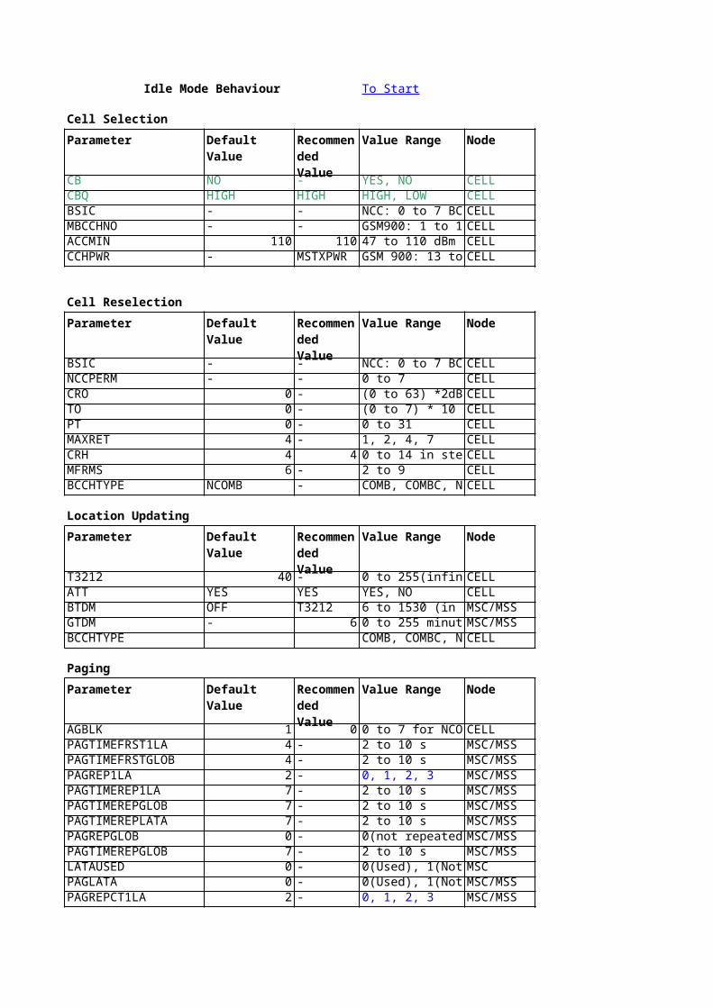
Idle Mode Behaviour To Start
Cell Selection
Parameter Default Value Value Range Node
CB NO - YES, NO CELLCBQ HIGH HIGH HIGH, LOW CELLBSIC - - NCC: 0 to 7 BCC: CELLMBCCHNO - - GSM900: 1 to 124CELLACCMIN 110 110 47 to 110 dBm CELLCCHPWR - MSTXPWRGSM 900: 13 to 43CELL
Cell Reselection
Parameter Default Value Value Range Node
BSIC - - NCC: 0 to 7 BCC: CELLNCCPERM - - 0 to 7 CELLCRO 0 - (0 to 63) *2dB CELLTO 0 - (0 to 7) * 10 dB CELLPT 0 - 0 to 31 CELLMAXRET 4 - 1, 2, 4, 7 CELLCRH 4 4 0 to 14 in steps of CELLMFRMS 6 - 2 to 9 CELLBCCHTYPE NCOMB - COMB, COMBC, CELL
Location Updating
Parameter Default Value Value Range Node
T3212 40 - 0 to 255(infinite) CELLATT YES YES YES, NO CELLBTDM OFF T3212 6 to 1530 (in step MSC/MSSGTDM - 6 0 to 255 minutes MSC/MSSBCCHTYPE COMB, COMBC, CELL
Paging
Parameter Default Value Value Range Node
AGBLK 1 0 0 to 7 for NCOMB,CELLPAGTIMEFRST1LA 4 - 2 to 10 s MSC/MSSPAGTIMEFRSTGLOB 4 - 2 to 10 s MSC/MSSPAGREP1LA 2 - 0, 1, 2, 3 MSC/MSSPAGTIMEREP1LA 7 - 2 to 10 s MSC/MSSPAGTIMEREPGLOB 7 - 2 to 10 s MSC/MSSPAGTIMEREPLATA 7 - 2 to 10 s MSC/MSSPAGREPGLOB 0 - 0(not repeated),1 MSC/MSSPAGTIMEREPGLOB 7 - 2 to 10 s MSC/MSSLATAUSED 0 - 0(Used), 1(Not UsMSCPAGLATA 0 - 0(Used), 1(Not UsMSC/MSSPAGREPCT1LA 2 - 0, 1, 2, 3 MSC/MSS
Recommended Value
Recommended Value
Recommended Value
Recommended Value

0 = Paging in one location area is not repeated.1 = Paging in one location area is repeated with either TMSI or IMSI.2 = Paging in one location area is repeated with IMSI.3 = Paging is repeated as call delivery LATA paging with IMSI.
System Informaton
Parameter Default Value Value Range Node
SIMSG - - 1, 7, 8 CELL
MSGDIST - ON, OFF CELL
Recommended Value
Type 1 = ONType 7 = OFFType 8 = OFF

Command Description
RLSBP:CELL={cell}; Used to define if a certain cell is barred for accessRLSBP:CELL={cell}; Used to control the priority of a cell. The priority of the cell is controlled by parameter CBQ in conjunction with CBRLDEP:CELL={cell}; Base Station Identity Code: NCC(Network Color Code) + BCC(Base Station Color Code). A station is uniquely identified by a combination of BSIC & BCCH.RLMFP:CELL={cell} Absolute Radio Frequency (RF) channel number for measurement on Broadcast Control Channel (BCCH), Max 32 can be definedRLSSP:CELL={cell}; Minimum received signal level in dBm at the Mobile Station (MS) for permission to access the systemRLSSP:CELL={cell}; Maximum Transceiver Power Level (TXPWR) in dBm an MS may use when accessing on a Control Channel (CCH).
Command Description
RLDEP:CELL={cell}; Base Station Identity Code: NCC(Network Color Code) + BCC(Base Station Color Code). A station is uniquely identified by a combination of BSIC & BCCH.RLSSP:CELL={cell}; Permitted network colour code, NCC, to be monitoredRLSBP:CELL={cell}; Signal strength offset to encourage(PT!=31) or discourage(with PT=31) MSs to reselect that cellRLSBP:CELL={cell}; Negative temporary offset applied to C2. Used with PT for fast moving MSsRLSBP:CELL={cell}; Duration for which the temporary offset, TO, is appliedRLSBP:CELL={cell}; Maximum number of retransmissions an MS may do when accessing the systemRLSSP:CELL={cell}; Receiving signal strength hysteresis in dB for required cell reselection over a location area borderRLDEP:CELL={cell}; Multiframes period and defines the period of transmission for paging messages to the same paging group. Paging groups=MFRMS*(9-AGBLK)RLDEP:CELL={cell};
Command Description
RLSBP:CELL={cell}; Timeout value that controls the periodic registration procedureRLSBP:CELL={cell}; Indicates if IMSI attach/detach is used in the cellMGIDP; Base time duration of implicit detach of a mobile subscriber by the networkMGIDP; Guard time for implicit detachRLDEP:CELL={cell};
Command Description
RLDEP:CELL={cell}; Number of CCCH blocks reserved for the access grant channel. The remaining CCCH blocks are used as paging channelsDBTSP:TAB=AXEPARS, NAME=PTimer for local pagingDBTSP:TAB=AXEPARS, NAME=PTimer for global pagingDBTSP:TAB=AXEPARS, NAME=PDefines how the paging in one location area is repeated, if the first paging attempt was local.DBTSP:TAB=AXEPARS, NAME=PDefines the time supervision for the paging response of repeated paging in one location area. After the expiration of this timer, no new paging repetition for this call is performed.DBTSP:TAB=AXEPARS, NAME=PDefines the time supervision for paging response of repeated global paging. After the expiration of this timer, no new paging repetition for this call is performed.DBTSP:TAB=AXEPARS, NAME=PDefines the time supervision for page response of repeated LATA paging. After expiration of this timer no new paging repetition for this call is doneDBTSP:TAB=AXEPARS, NAME= Defines how the global paging is repeated, if the first paging attempt was globalDBTSP:TAB=AXEPARS, NAME=PDefines the time supervision for paging response of repeated global paging. After the expiration of this timer, no new paging repetition for this call is performedMGEPP:ID=LATAUSED; Usage of LATA administration. The parameter is only valid if the function Equal Access and Transit network Selection in MSC/VLR and GMSC is implementedDBTSP:TAB=AXEPARS, NAME=PIndicates if LATA paging is used for mobile terminating calls or notDBTSP:TAB=AXEPARS, NAME=PDefines how the paging in one location area is repeated, if the first paging attempt was local. This parameter is only valid when PAGLATA =1
COMB: Combined; Indicates that the cell has a combined BCCH and SDCCH/4.
COMB: Combined; Indicates that the cell has a combined BCCH and SDCCH/4.

0 = Paging in one location area is not repeated.1 = Paging in one location area is repeated with either TMSI or IMSI.2 = Paging in one location area is repeated with IMSI.3 = Paging is repeated as call delivery LATA paging with IMSI.
Command Description
RLSMP:CELL={cell}; System information BCCH message parameter. It specifies which system information message(s) to be turned on or off
RLSMP:CELL={cell}; System information BCCH message distribution parameter. It specifies if the system information messages specified with the SIMSG parameter are turned on or off

Used to control the priority of a cell. The priority of the cell is controlled by parameter CBQ in conjunction with CBBase Station Identity Code: NCC(Network Color Code) + BCC(Base Station Color Code). A station is uniquely identified by a combination of BSIC & BCCH.Absolute Radio Frequency (RF) channel number for measurement on Broadcast Control Channel (BCCH), Max 32 can be definedMinimum received signal level in dBm at the Mobile Station (MS) for permission to access the systemMaximum Transceiver Power Level (TXPWR) in dBm an MS may use when accessing on a Control Channel (CCH).
Base Station Identity Code: NCC(Network Color Code) + BCC(Base Station Color Code). A station is uniquely identified by a combination of BSIC & BCCH.
Signal strength offset to encourage(PT!=31) or discourage(with PT=31) MSs to reselect that cellNegative temporary offset applied to C2. Used with PT for fast moving MSs
Maximum number of retransmissions an MS may do when accessing the systemReceiving signal strength hysteresis in dB for required cell reselection over a location area borderMultiframes period and defines the period of transmission for paging messages to the same paging group. Paging groups=MFRMS*(9-AGBLK)
Base time duration of implicit detach of a mobile subscriber by the network
Number of CCCH blocks reserved for the access grant channel. The remaining CCCH blocks are used as paging channels
Defines how the paging in one location area is repeated, if the first paging attempt was local.Defines the time supervision for the paging response of repeated paging in one location area. After the expiration of this timer, no new paging repetition for this call is performed.Defines the time supervision for paging response of repeated global paging. After the expiration of this timer, no new paging repetition for this call is performed.Defines the time supervision for page response of repeated LATA paging. After expiration of this timer no new paging repetition for this call is doneDefines how the global paging is repeated, if the first paging attempt was globalDefines the time supervision for paging response of repeated global paging. After the expiration of this timer, no new paging repetition for this call is performedUsage of LATA administration. The parameter is only valid if the function Equal Access and Transit network Selection in MSC/VLR and GMSC is implementedIndicates if LATA paging is used for mobile terminating calls or notDefines how the paging in one location area is repeated, if the first paging attempt was local. This parameter is only valid when PAGLATA =1
Combined; Indicates that the cell has a combined BCCH and SDCCH/4. COMBC: Combined with CBCH; Indicates that the cell has a combined BCCH and SDCCH/4 with a CBCH subchannel.
Combined; Indicates that the cell has a combined BCCH and SDCCH/4. COMBC: Combined with CBCH; Indicates that the cell has a combined BCCH and SDCCH/4 with a CBCH subchannel.

System information BCCH message parameter. It specifies which system information message(s) to be turned on or off
System information BCCH message distribution parameter. It specifies if the system information messages specified with the SIMSG parameter are turned on or off

Defines the time supervision for the paging response of repeated paging in one location area. After the expiration of this timer, no new paging repetition for this call is performed.
Combined with CBCH; Indicates that the cell has a combined BCCH and SDCCH/4 with a CBCH subchannel. NCOMB: No combined; Indicates that the cell does not have a combined BCCH and SDCCH/4
Combined with CBCH; Indicates that the cell has a combined BCCH and SDCCH/4 with a CBCH subchannel. NCOMB: No combined; Indicates that the cell does not have a combined BCCH and SDCCH/4

No combined; Indicates that the cell does not have a combined BCCH and SDCCH/4
No combined; Indicates that the cell does not have a combined BCCH and SDCCH/4
Hierarchical Cell Structure To Start
BSC Level
Parameter Value Range
HCSBAND 2 - 1 to 8HCSBANDTHR 95 - 150 to 0HCSBANDHYST 2 2 0 to 63 dBMAXCELLSINLAYER 1 1 1 to 31MAXDBDEVINLAYER 3 3 0 to 63 dBHCSTRAFDISSTATE 0 1 0(Inactive), 1(Active)HCSCHAVAILTIMER 500 200 200 to 5000 msTHO 30 - 10 to 100 sNHO 3 - 2 to 10PFASTMSREG 0 - 0(OFF), 1(ON)
Cell Level
Parameter Value Range
LAYER 2 - 1 to 8LAYERTHR 75 - 0 to 150 dBmLAYERHYST 2 2 0 to 63 dBHCSIN 0 - 0 to 100 %HCSOUT 100 - 0 to 100 %PSSTEMP 0 0 0 to 63 dBPTIMTEMP 0 0 0 to 600 sPLAYER MAPPED - MAPPED, 1-8PHCSTHR MAPPED - MAPPED, 48 to 110 dBmFASTMSREG OFF - ON, OFF
Cells that have channel availabilities below HCSIN will be removed from HCS ranking and moved to basic ranking insteadServing Cell’s channel availability is also checked against HCSOUT and if greater than this it is considered to be taking too little t
HCSIN & HCSOUT work only with internal cells
Hierarchical Cell Structures To Start
Default Value
Recommended Value
Default Value
Recommended Value


Command Description
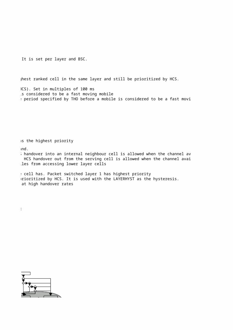
DBTSP:TAB=AXEPARS, NAME=HCSBAND; Defines the priority for group of layers. HCS band 1 has the highest priority. It is set per layer and BSC.RLHBP; The signal strength threshold prioritizes cells within a HCS band.RLHBP; The signal strength hysteresis, set in dB, prioritizes cells between HCS bands
RAEPP:ID=MAXCELLSINLAYER; Defines the number of cells of the same layer that can be prioritized by HCSRAEPP:ID=MAXDBDEVINLAYER; Defines the maximum value in dB that a cell in a layer can deviate from the highest ranked cell in the same layer and still be prioritized by HCS.RAEPP:ID=HCSTRAFDISSTATE; HCS Traffic Distribution StateRAEPP:ID=HCSCHAVAILTIMER; Interval for check of idle traffic channels for Hierarchical Cell Structures (HCS). Set in multiples of 100 ms
RLLBP; Time interval for measuring number of handovers allowed (NHO) before a mobile is considered to be a fast moving mobileRLLBP; Determines how many inter-cell handovers that should be allowed within the time period specified by THO before a mobile is considered to be a fast moving mobile
DBTSP:TAB=AXEPARS, NAME=PFASTMSREG; BSC Level switch for advanced handling of fast moving mobiles
Command Description
RLLHP:CELL={cell}; Defines which layer the cell belongs, i.e. the priority of the cell. Layer 1 has the highest priorityRLLHP:CELL={cell}; Signal strength hysteresis for the layer thresholdRLLHP:CELL={cell}; Signal strength threshold used to rank cells in different layers within each band.RLLHP:CELL={cell}; HCS traffic distribution level threshold to allow HCS handover into a cell. HCS handover into an internal neighbour cell is allowed when the channel availability of the neighbour cell is above or equal to its HCSIN threshold. When the default value for HCSIN (0%) is used it is always allowed to perform HCS handover into the cell.RLLHP:CELL={cell}; HCS traffic distribution level threshold to allow HCS handover out from a cell. HCS handover out from the serving cell is allowed when the channel availability of the serving cell is below or equal to its HCSOUT threshold. When the default value for HCSOUT (100%) is used it is always allowed to perform HCS handover out from the cell.RLLHP:CELL={cell}; Temporary signal strength penalty. Used to prevent many of the fast moving mobiles from accessing lower layer cellsRLLHP:CELL={cell}; Duration of the temporary signal strength penaltyRLPSP:CELL={cell}; Defines to which packet switched layer the cell belongs i.e. which priority the cell has. Packet switched layer 1 has highest priorityRLPSP:CELL={cell}; Signal strength threshold that needs to be fulfilled by a cell in order to be prioritized by HCS. It is used with the LAYERHYST as the hysteresis.RLLHP:CELL={cell}; Switch for activating the mechanism that direct mobiles towards a higher layer at high handover rates
HCS must be implemented with care in FLP (1/1 and 1/3) networks. All cellsCells that have channel availabilities below HCSIN will be removed from HCS ranking and moved to basic ranking instead using the same frequencies should be allocated to the same layer. This isServing Cell’s channel availability is also checked against HCSOUT and if greater than this it is considered to be taking too little t because in an FLP network it is more important to be connected to the strongest
server. If dedicated frequencies have been allocated to for examples indoor orhot spot cells these cells can be placed in another band.


Defines the priority for group of layers. HCS band 1 has the highest priority. It is set per layer and BSC.The signal strength threshold prioritizes cells within a HCS band.The signal strength hysteresis, set in dB, prioritizes cells between HCS bandsDefines the number of cells of the same layer that can be prioritized by HCSDefines the maximum value in dB that a cell in a layer can deviate from the highest ranked cell in the same layer and still be prioritized by HCS.
Interval for check of idle traffic channels for Hierarchical Cell Structures (HCS). Set in multiples of 100 msTime interval for measuring number of handovers allowed (NHO) before a mobile is considered to be a fast moving mobileDetermines how many inter-cell handovers that should be allowed within the time period specified by THO before a mobile is considered to be a fast moving mobileBSC Level switch for advanced handling of fast moving mobiles
Defines which layer the cell belongs, i.e. the priority of the cell. Layer 1 has the highest priority
Signal strength threshold used to rank cells in different layers within each band.HCS traffic distribution level threshold to allow HCS handover into a cell. HCS handover into an internal neighbour cell is allowed when the channel availability of the neighbour cell is above or equal to its HCSIN threshold. When the default value for HCSIN (0%) is used it is always allowed to perform HCS handover into the cell.HCS traffic distribution level threshold to allow HCS handover out from a cell. HCS handover out from the serving cell is allowed when the channel availability of the serving cell is below or equal to its HCSOUT threshold. When the default value for HCSOUT (100%) is used it is always allowed to perform HCS handover out from the cell.Temporary signal strength penalty. Used to prevent many of the fast moving mobiles from accessing lower layer cells
Defines to which packet switched layer the cell belongs i.e. which priority the cell has. Packet switched layer 1 has highest prioritySignal strength threshold that needs to be fulfilled by a cell in order to be prioritized by HCS. It is used with the LAYERHYST as the hysteresis.Switch for activating the mechanism that direct mobiles towards a higher layer at high handover rates
HCS must be implemented with care in FLP (1/1 and 1/3) networks. All cellsusing the same frequencies should be allocated to the same layer. This isbecause in an FLP network it is more important to be connected to the strongestserver. If dedicated frequencies have been allocated to for examples indoor orhot spot cells these cells can be placed in another band.


Determines how many inter-cell handovers that should be allowed within the time period specified by THO before a mobile is considered to be a fast moving mobile
HCS traffic distribution level threshold to allow HCS handover into a cell. HCS handover into an internal neighbour cell is allowed when the channel availability of the neighbour cell is above or equal to its HCSIN threshold. When the default value for HCSIN (0%) is used it is always allowed to perform HCS handover into the cell.HCS traffic distribution level threshold to allow HCS handover out from a cell. HCS handover out from the serving cell is allowed when the channel availability of the serving cell is below or equal to its HCSOUT threshold. When the default value for HCSOUT (100%) is used it is always allowed to perform HCS handover out from the cell.

HCS traffic distribution level threshold to allow HCS handover into a cell. HCS handover into an internal neighbour cell is allowed when the channel availability of the neighbour cell is above or equal to its HCSIN threshold. When the default value for HCSIN (0%) is used it is always allowed to perform HCS handover into the cell.HCS traffic distribution level threshold to allow HCS handover out from a cell. HCS handover out from the serving cell is allowed when the channel availability of the serving cell is below or equal to its HCSOUT threshold. When the default value for HCSOUT (100%) is used it is always allowed to perform HCS handover out from the cell.
Intra-Cell Handover To Start
BSC Level
Parameter Command
TINIT 10 10 0 to 120 SAA RLLBP; Minimum time before handover is allowed on an initial call or after a handoverIHOSICH OFF OFF ON, OFF RLLBP; Intra-cell handover on signalling channel
Cell Level
Parameter Command
IHO OFF ON ON, OFF RLIHP:CELL={cell}; Intracell handover switchQOFFSETULP 0 freq hop: 0 0 to 50 dtqu RLIHP:CELL={cell}; Positive offset for quality uplink in dtquQOFFSETULN - no freq hop: 101 to 50 dtqu RLIHP:CELL={cell}; Negative offset for quality uplink in dtquSSOFFSETULP 0 - 0 to 30 dB RLIHP:CELL={cell}; Positive offset for signal strength uplink in dBSSOFFSETULN - 10 1 to 30 dB RLIHP:CELL={cell}; Negative offset for signal strength uplink in dBQOFFSETDLP 0freq. hop: 10 no freq. hop: 00 to 50 dtqu RLIHP:CELL={cell}; Positive offset for quality downlink in dtquQOFFSETDLN - - 1 to 50 dtqu RLIHP:CELL={cell}; Negative offset for quality downlink in dtquSSOFFSETDLP 0 0 0 to 30 dB RLIHP:CELL={cell}; Positive offset for signal strength downlink in dBSSOFFSETDLN - - 1 to 30 dB RLIHP:CELL={cell}; Negative offset for signal strength downlink in dBSSOFFSETULAFRP 0 - 0 to 30 dB RLIHP:CELL={cell}; Positive offset for signal strength uplink in dB for AMR FR codecSSOFFSETULAFRN - 10 1 to 30 dB RLIHP:CELL={cell}; Negative offset for signal strength uplink in dB for AMR FR codecSSOFFSETDLAFRP 0 0 0 to 30 dB RLIHP:CELL={cell}; Positive offset for signal strength downlink in dB for AMR FR codecSSOFFSETDLAFRN - - 1 to 30 dB RLIHP:CELL={cell}; Negative offset for signal strength downlink in dB for AMR FR codecQOFFSETULAFRP 0freq. hop: 10 no freq. hop: 00 to 50 dtqu RLIHP:CELL={cell}; Positive Quality offset in the uplink direction for traffic using the AMR FR codec typeQOFFSETULAFRN - - 1 to 50 dtqu RLIHP:CELL={cell}; Negative Quality offset in the uplink direction for traffic using the AMR FR codec typeQOFFSETDLAFRP 0freq. hop: 20 no freq. hop: 100 to 50 dtqu RLIHP:CELL={cell}; Positive Quality offset in the downlink direction for traffic using the AMR FR codec typeQOFFSETDLAFRN - - 1 to 50 dtqu RLIHP:CELL={cell}; Negative Quality offset in the downlink direction for traffic using the AMR FR codec typeTMAXIHO 6 7 0 to 60 sec RLIHP:CELL={cell}; Maximum time between intra-cell handovers, which are considered consecutiveMAXIHO 3 0 to 15 RLIHP:CELL={cell}; Maximum number of allowed consecutive intra-cell handoversTIHO 10 10 0 to 60 sec RLIHP:CELL={cell}; Timer during which intra-cell handover is inhibited after having performed too many consecutive intra-cell handovers. The parameter is also used when inhibiting a subcell change from an underlaid to an overlaid subcell
Intra-Cell Handover Algorithm To Start
Intracell Handover Calculator Assginment Cases for intra-cell Handoverrxqual_dl_dtqu 50 For non-hopping: QOFFSETDL -3 1) Assignment on different frequency
Default Value
Recommended Value
Value Range
Description
Default Value
Recommended Value
Value Range
Description

SSOFFSETDL 0 2) Else Assignment on same frequency different timeslotrxlevel_dl 75
For Hopping:rxqual_ul_dtqu 40 1) Assignment on different channel groupQOFFSETUL -3 2) Else timeslot changed in the same channel groupSSOFFSETUL 6 3) Else same timeslot and channel group remainsrxlevel_ul 72
DecisionIntra-Cell Handover YES

Minimum time before handover is allowed on an initial call or after a handoverIntra-cell handover on signalling channel
Intracell handover switchPositive offset for quality uplink in dtquNegative offset for quality uplink in dtquPositive offset for signal strength uplink in dBNegative offset for signal strength uplink in dBPositive offset for quality downlink in dtquNegative offset for quality downlink in dtquPositive offset for signal strength downlink in dBNegative offset for signal strength downlink in dBPositive offset for signal strength uplink in dB for AMR FR codecNegative offset for signal strength uplink in dB for AMR FR codecPositive offset for signal strength downlink in dB for AMR FR codecNegative offset for signal strength downlink in dB for AMR FR codecPositive Quality offset in the uplink direction for traffic using the AMR FR codec typeNegative Quality offset in the uplink direction for traffic using the AMR FR codec typePositive Quality offset in the downlink direction for traffic using the AMR FR codec typeNegative Quality offset in the downlink direction for traffic using the AMR FR codec typeMaximum time between intra-cell handovers, which are considered consecutiveMaximum number of allowed consecutive intra-cell handoversTimer during which intra-cell handover is inhibited after having performed too many consecutive intra-cell handovers. The parameter is also used when inhibiting a subcell change from an underlaid to an overlaid subcell


Timer during which intra-cell handover is inhibited after having performed too many consecutive intra-cell handovers. The parameter is also used when inhibiting a subcell change from an underlaid to an overlaid subcell


Timer during which intra-cell handover is inhibited after having performed too many consecutive intra-cell handovers. The parameter is also used when inhibiting a subcell change from an underlaid to an overlaid subcell
1 1002 100
3 1004 1005 1006 1007 100
8 1009 100
10 10011 10012 10013 10014 10015 10016 10017 10018 10019 10020 10021 10022 10023 10024 10025 10026 10027 10028 100
29 10030 10031 6032 5933 59

34 5935 5936 5837 5838 5839 5740 57
41 5742 5643 5644 5645 5646 5547 5548 5549 5450 5451 5452 5453 5354 5355 5356 5257 5258 5259 5160 5161 5162 5163 5064 5065 5066 5067 5068 5069 5070 5071 5072 5073 5074 5075 5076 5077 5078 5079 5080 5081 5082 5083 5084 5085 5086 50

87 5088 5089 5090 5091 5092 5093 5094 5095 5096 5097 5098 5099 50
100 50

To Start
Traffic case Channel modeST1 Immediate Assignment signalling Not Relevant
ST2 Immediate Assignment signalling Not Relevant
ST3 Immediate Assignment signalling Not Relevant
ST4 Immediate Assignment signalling Not Relevant
ST5 Immediate Assignment signalling Not Relevant
ST6 Immediate Assignment signalling Not Relevant
ST7 Immediate Assignment signalling Not Relevant
ST8 Immediate Assignment signalling Not Relevant
ST9 Immediate Assignment signalling Not Relevant
ST10 Immediate Assignment signalling Not Relevant
ST11 Immediate Assignment signalling Not Relevant
ST12 Immediate Assignment signalling Not Relevant
ST13 Immediate Assignment signalling Not Relevant
ST14 Immediate Assignment signalling Not Relevant
ST15.1 Assignment to serving cell speech, data or signalling TCH/FR
ST15.2 Assignment to serving cell speech, data or signalling TCH/HR
ST15.3 Assignment to serving cell signalling SDCCH
ST16.1 Assignment to serving cell speech, data or signalling TCH/FR
ST16.2 Assignment to serving cell speech, data or signalling TCH/HR
ST16.3 Assignment to serving cell signalling SDCCH
ST17.1 Inter cell handover due to Cell load sharing speech, data TCH/FR
ST17.2 Inter cell handover due to Cell load sharing speech, data TCH/HR
ST18.1 Inter cell handover due to Cell load sharing speech, data TCH/FR
ST18.2 Inter cell handover due to Cell load sharing speech, data TCH/HR
ST19.1 Inter cell handover, all other reasons speech, data or signalling TCH/FR
ST19.2 Inter cell handover, all other reasons speech, data or signalling TCH/HR
ST19.3 Inter cell handover, all other reasons signalling SDCCH
ST20.1 Inter cell handover, all other reasons speech, data or signalling TCH/FR
ST20.2 Inter cell handover, all other reasons speech, data or signalling TCH/HR
ST20.3 Inter cell handover, all other reasons signalling SDCCH
ST21.2 Intra cell handover due to Half Rate Packing. speech, data or signalling TCH/HR
ST22.2 Intra cell handover due to Half Rate Packing. speech, data or signalling TCH/HR
ST23.1 Intra-cell handover, all other reasons speech, data or signalling TCH/FR
ST23.2 Intra-cell handover, all other reasons speech, data or signalling TCH/HR
ST23.3 Intra-cell handover, all other reasons signalling SDCCH
ST24.1 Intra-cell handover, all other reasons speech, data or signalling TCH/FR
ST24.2 Intra-cell handover, all other reasons speech, data or signalling TCH/HR
ST24.3 Intra-cell handover, all other reasons signalling SDCCH
ST25.1 Subcell change speech, data or signalling TCH/FR
ST25.2 Subcell change speech, data or signalling TCH/HR
ST25.3 Subcell change signalling SDCCH
ST26.1 Subcell change speech, data or signalling TCH/FR
ST26.2 Subcell change speech, data or signalling TCH/HR
ST26.3 Subcell change signalling SDCCH
ST27.1 Assignment to worse cell speech, data or signalling TCH/FR
ST27.2 Assignment to worse cell speech, data or signalling TCH/HR
ST27.3 Assignment to worse cell signalling SDCCH
ST28.1 Assignment to worse cell speech, data or signalling TCH/FR
ST28.2 Assignment to worse cell speech, data or signalling TCH/HR
ST28.3 Assignment to worse cell signalling SDCCH
Selection Type
(ST)Channel
type
ST29.1 Assignment to better cell speech, data or signalling TCH/FR
ST29.2 Assignment to better cell speech, data or signalling TCH/HR
ST29.3 Assignment to better cell signalling SDCCH
ST30.1 Assignment to better cell speech, data or signalling TCH/FR
ST30.2 Assignment to better cell speech, data or signalling TCH/HR
ST30.3 Assignment to better cell signalling SDCCH
ST31 Multislot configuration change data TCH/FR
ST32 Multislot configuration change data TCH/FR
ST33.1 Intra cell handover due to Channel Rate change: FR speech TCH/HR
ST33.2 Intra cell handover due to Channel Rate change: FR speech TCH/HR
ST33.3 Intra cell handover due to Channel Rate change: HR speech TCH/FR
ST33.4 Intra cell handover due to Channel Rate change: HR speech TCH/FR
ST34.1 Assignment of Voice Group channel speech TCH/FR
ST34.2 Assignment of Voice Group channel speech TCH/HR
ST34.3 Assignment of Voice Group channel speech TCH/FR
ST34.4 Assignment of Voice Group channel speech TCH/HR
ST35.1 Intra Cell handover due to Resource Optimization speech, data or signalling TCH/FR
ST35.2 Intra Cell handover due to Resource Optimization speech, data or signalling TCH/HR
ST35.3 Intra Cell handover due to Resource Optimization speech, data or signalling TCH/FR
ST35.4 Intra Cell handover due to Resource Optimization speech, data or signalling TCH/HR

Establishment Cause
Resource Type Priority List (RTPL)
UL Answer to paging UL/SDCCH UL/SDCCH
UL Answer to paging UL/SDCCH UL/SDCCH->UL/TCH/HR->UL/TCH/FR
UL Answer to paging UL/SDCCH UL/SDCCH->UL/TCH/HR->UL/TCH/FR
UL Answer to paging UL/SDCCH UL/SDCCH->UL/TCH/FR
UL Immediate assignment; Emergency call UL/SDCCH UL/SDCCH->UL/TCH/FR
UL TCH/FR was in use UL/SDCCH UL/SDCCH
UL TCH/HR was in use UL/SDCCH UL/SDCCH
UL TCH/HR + TCH/HR was in use UL/SDCCH UL/SDCCH
UL TCH/FR is needed UL/SDCCH UL/SDCCH->UL/TCH/FR
ULMS capability dual rate, channel for speech is needed, TCH/HR is sufficientUL/SDCCH UL/SDCCH->UL/TCH/HR->UL/TCH/FR
ULMS capability dual rate, channel for data is needed, TCH/HR is sufficientUL/SDCCH UL/SDCCH->UL/TCH/HR->UL/TCH/FR
UL Immediate assignment; Location updatingUL/SDCCH UL/SDCCH
UL Reserved for future use UL/SDCCH UL/SDCCH
UL Reserved for future use UL/SDCCH UL/SDCCH
UL UL/TCH/FR UL/TCH/FR
UL UL/TCH/HR UL/TCH/HR
UL UL/SDCCH UL/SDCCH
OL OL/TCH/FR->UL/TCH/FR OL/TCH/FR->UL/TCH/FR
OL OL/TCH/HR->UL/TCH/HR OL/TCH/HR->UL/TCH/HR
OL OL/SDCCH->UL/SDCCH OL/SDCCH->UL/SDCCH
UL UL/TCH/FR UL/TCH/FR
UL UL/TCH/HR UL/TCH/HR
OL OL/TCH/FR->UL/TCH/FR OL/TCH/FR->UL/TCH/FR
OL OL/TCH/HR->UL/TCH/HR OL/TCH/HR->UL/TCH/HR
UL UL/TCH/FR UL/TCH/FR
UL UL/TCH/HR UL/TCH/HR
UL UL/SDCCH UL/SDCCH
OL OL/TCH/FR->UL/TCH/FR OL/TCH/FR->UL/TCH/FR
OL OL/TCH/HR->UL/TCH/HR OL/TCH/HR->UL/TCH/HR
OL OL/SDCCH->UL/SDCCH OL/SDCCH->UL/SDCCH
UL UL/TCH/HR UL/TCH/HR
OL OL/TCH/HR OL/TCH/HR
UL UL/TCH/FR UL/TCH/FR
UL UL/TCH/HR UL/TCH/HR
UL UL/SDCCH UL/SDCCH
OL OL/TCH/FR->UL/TCH/FR OL/TCH/FR->UL/TCH/FR
OL OL/TCH/HR->UL/TCH/HR OL/TCH/HR->UL/TCH/HR
OL OL/SDCCH->UL/SDCCH OL/SDCCH->UL/SDCCH
UL UL/TCH/FR UL/TCH/FR
UL UL/TCH/HR UL/TCH/HR
UL UL/SDCCH UL/SDCCH
OL OL/TCH/FR OL/TCH/FR
OL OL/TCH/HR OL/TCH/HR
OL OL/SDCCH OL/SDCCH
UL UL/TCH/FR UL/TCH/FR
UL UL/TCH/HR UL/TCH/HR
UL UL/SDCCH UL/SDCCH
OL OL/TCH/FR->UL/TCH/FR OL/TCH/FR->UL/TCH/FR
OL OL/TCH/HR->UL/TCH/HR OL/TCH/HR->UL/TCH/HR
OL OL/SDCCH->UL/SDCCH OL/SDCCH->UL/SDCCH
Preferred
subcellCHAP 0 (default) CHAP 1

UL UL/TCH/FR UL/TCH/FR
UL UL/TCH/HR UL/TCH/HR
UL UL/SDCCH UL/SDCCH
OL OL/TCH/FR->UL/TCH/FR OL/TCH/FR->UL/TCH/FR
OL OL/TCH/HR->UL/TCH/HR OL/TCH/HR->UL/TCH/HR
OL OL/SDCCH->UL/SDCCH OL/SDCCH->UL/SDCCH
UL UL/TCH/FR UL/TCH/FR
OL OL/TCH/FR->UL/TCH/FR OL/TCH/FR->UL/TCH/FR
UL UL/TCH/HR UL/TCH/HR
OL OL/TCH/HR OL/TCH/HR
UL UL/TCH/FR UL/TCH/FR
OL OL/TCH/FR OL/TCH/FR
UL UL/TCH/FR UL/TCH/FR
UL UL/TCH/HR UL/TCH/HR
OL OL/TCH/FR->UL/TCH/FR OL/TCH/FR->UL/TCH/FR
OL OL/TCH/HR->UL/TCH/HR OL/TCH/HR->UL/TCH/HR
UL UL/TCH/FR UL/TCH/FR
UL UL/TCH/HR UL/TCH/HR
OL OL/TCH/FR OL/TCH/FR
OL OL/TCH/HR OL/TCH/HR

Resource Type Priority List (RTPL)
UL/SDCCH UL/SDCCH UL/SDCCH
UL/TCH/HR->UL/TCH/FR->UL/SDCCH UL/SDCCH->UL/TCH/HR->UL/TCH/FR UL/SDCCH->UL/TCH/HR->UL/TCH/FR
UL/TCH/HR->UL/TCH/FR->UL/SDCCH UL/TCH/HR->UL/TCH/FR->UL/SDCCH UL/TCH/HR->UL/TCH/FR->UL/SDCCH
UL/TCH/FR->UL/SDCCH UL/SDCCH->UL/TCH/FR UL/SDCCH->UL/TCH/FR
UL/TCH/FR->UL/SDCCH UL/TCH/FR->UL/SDCCH UL/TCH/FR->UL/SDCCH
UL/SDCCH UL/SDCCH UL/SDCCH
UL/SDCCH UL/SDCCH UL/SDCCH
UL/SDCCH UL/SDCCH UL/SDCCH
UL/TCH/FR->UL/SDCCH UL/TCH/FR->UL/SDCCH UL/SDCCH->UL/TCH/FR
UL/TCH/HR->UL/TCH/FR->UL/SDCCH UL/TCH/HR->UL/TCH/FR->UL/SDCCH UL/TCH/HR->UL/TCH/FR->UL/SDCCH
UL/TCH/HR->UL/TCH/FR->UL/SDCCH UL/TCH/HR->UL/TCH/FR->UL/SDCCH UL/TCH/HR->UL/TCH/FR->UL/SDCCH
UL/SDCCH UL/SDCCH UL/SDCCH
UL/SDCCH UL/SDCCH UL/SDCCH
UL/SDCCH UL/SDCCH UL/SDCCH
UL/TCH/FR UL/TCH/FR UL/TCH/FR
UL/TCH/HR UL/TCH/HR UL/TCH/HR
UL/SDCCH UL/SDCCH UL/SDCCH
OL/TCH/FR->UL/TCH/FR OL/TCH/FR->UL/TCH/FR OL/TCH/FR->UL/TCH/FR
OL/TCH/HR->UL/TCH/HR OL/TCH/HR->UL/TCH/HR OL/TCH/HR->UL/TCH/HR
OL/SDCCH->UL/SDCCH OL/SDCCH->UL/SDCCH OL/SDCCH->UL/SDCCH
UL/TCH/FR UL/TCH/FR UL/TCH/FR
UL/TCH/HR UL/TCH/HR UL/TCH/HR
OL/TCH/FR->UL/TCH/FR OL/TCH/FR->UL/TCH/FR OL/TCH/FR->UL/TCH/FR
OL/TCH/HR->UL/TCH/HR OL/TCH/HR->UL/TCH/HR OL/TCH/HR->UL/TCH/HR
UL/TCH/FR UL/TCH/FR UL/TCH/FR
UL/TCH/HR UL/TCH/HR UL/TCH/HR
UL/SDCCH UL/SDCCH UL/SDCCH
OL/TCH/FR->UL/TCH/FR OL/TCH/FR->UL/TCH/FR OL/TCH/FR->UL/TCH/FR
OL/TCH/HR->UL/TCH/HR OL/TCH/HR->UL/TCH/HR OL/TCH/HR->UL/TCH/HR
OL/SDCCH->UL/SDCCH OL/SDCCH->UL/SDCCH OL/SDCCH->UL/SDCCH
UL/TCH/HR UL/TCH/HR UL/TCH/HR
OL/TCH/HR OL/TCH/HR OL/TCH/HR
UL/TCH/FR UL/TCH/FR UL/TCH/FR
UL/TCH/HR UL/TCH/HR UL/TCH/HR
UL/SDCCH UL/SDCCH UL/SDCCH
OL/TCH/FR->UL/TCH/FR OL/TCH/FR->UL/TCH/FR OL/TCH/FR->UL/TCH/FR
OL/TCH/HR->UL/TCH/HR OL/TCH/HR->UL/TCH/HR OL/TCH/HR->UL/TCH/HR
OL/SDCCH->UL/SDCCH OL/SDCCH->UL/SDCCH OL/SDCCH->UL/SDCCH
UL/TCH/FR UL/TCH/FR UL/TCH/FR
UL/TCH/HR UL/TCH/HR UL/TCH/HR
UL/SDCCH UL/SDCCH UL/SDCCH
OL/TCH/FR OL/TCH/FR OL/TCH/FR
OL/TCH/HR OL/TCH/HR OL/TCH/HR
OL/SDCCH OL/SDCCH OL/SDCCH
UL/TCH/FR UL/TCH/FR UL/TCH/FR
UL/TCH/HR UL/TCH/HR UL/TCH/HR
UL/SDCCH UL/SDCCH UL/SDCCH
OL/TCH/FR->UL/TCH/FR OL/TCH/FR->UL/TCH/FR OL/TCH/FR->UL/TCH/FR
OL/TCH/HR->UL/TCH/HR OL/TCH/HR->UL/TCH/HR OL/TCH/HR->UL/TCH/HR
OL/SDCCH->UL/SDCCH OL/SDCCH->UL/SDCCH OL/SDCCH->UL/SDCCH
CHAP 2 CHAP 3 CHAP 4

UL/TCH/FR UL/TCH/FR UL/TCH/FR
UL/TCH/HR UL/TCH/HR UL/TCH/HR
UL/SDCCH UL/SDCCH UL/SDCCH
OL/TCH/FR->UL/TCH/FR OL/TCH/FR->UL/TCH/FR OL/TCH/FR->UL/TCH/FR
OL/TCH/HR->UL/TCH/HR OL/TCH/HR->UL/TCH/HR OL/TCH/HR->UL/TCH/HR
OL/SDCCH->UL/SDCCH OL/SDCCH->UL/SDCCH OL/SDCCH->UL/SDCCH
UL/TCH/FR UL/TCH/FR UL/TCH/FR
OL/TCH/FR->UL/TCH/FR OL/TCH/FR->UL/TCH/FR OL/TCH/FR->UL/TCH/FR
UL/TCH/HR UL/TCH/HR UL/TCH/HR
OL/TCH/HR OL/TCH/HR OL/TCH/HR
UL/TCH/FR UL/TCH/FR UL/TCH/FR
OL/TCH/FR OL/TCH/FR OL/TCH/FR
UL/TCH/FR UL/TCH/FR UL/TCH/FR
UL/TCH/HR UL/TCH/HR UL/TCH/HR
OL/TCH/FR->UL/TCH/FR OL/TCH/FR->UL/TCH/FR OL/TCH/FR->UL/TCH/FR
OL/TCH/HR->UL/TCH/HR OL/TCH/HR->UL/TCH/HR OL/TCH/HR->UL/TCH/HR
UL/TCH/FR UL/TCH/FR UL/TCH/FR
UL/TCH/HR UL/TCH/HR UL/TCH/HR
OL/TCH/FR OL/TCH/FR OL/TCH/FR
OL/TCH/HR OL/TCH/HR OL/TCH/HR

Resource Type Priority List (RTPL)
UL/SDCCH UL/SDCCH OL/SDCCH->UL/SDCCH UL/SDCCH
UL/SDCCH UL/SDCCH->UL/TCH/HR->UL/TCH/FR OL/SDCCH->UL/SDCCH UL/SDCCH
UL/SDCCH UL/SDCCH->UL/TCH/HR->UL/TCH/FR OL/SDCCH->UL/SDCCH UL/SDCCH
UL/SDCCH UL/SDCCH->UL/TCH/FR OL/SDCCH->UL/SDCCH UL/SDCCH
UL/SDCCH UL/SDCCH->UL/TCH/FR OL/SDCCH->UL/SDCCH UL/SDCCH
UL/SDCCH UL/SDCCH OL/SDCCH->UL/SDCCH UL/SDCCH
UL/SDCCH UL/SDCCH OL/SDCCH->UL/SDCCH UL/SDCCH
UL/SDCCH UL/SDCCH OL/SDCCH->UL/SDCCH UL/SDCCH
UL/SDCCH UL/SDCCH->UL/TCH/FR OL/SDCCH->UL/SDCCH UL/SDCCH
UL/SDCCH UL/SDCCH->UL/TCH/HR->UL/TCH/FR OL/SDCCH->UL/SDCCH UL/SDCCH
UL/SDCCH UL/SDCCH->UL/TCH/HR->UL/TCH/FR OL/SDCCH->UL/SDCCH UL/SDCCH
UL/SDCCH UL/SDCCH OL/SDCCH->UL/SDCCH UL/SDCCH
UL/SDCCH UL/SDCCH OL/SDCCH->UL/SDCCH UL/SDCCH
UL/SDCCH UL/SDCCH OL/SDCCH->UL/SDCCH UL/SDCCH
UL/TCH/FR->OL/TCH/FR UL/TCH/FR->OL/TCH/FR UL/TCH/FR->OL/TCH/FR UL/TCH/FR
UL/TCH/HR->OL/TCH/HR UL/TCH/HR->OL/TCH/HR UL/TCH/HR->OL/TCH/HR UL/TCH/HR
UL/SDCCH->OL/SDCCH UL/SDCCH->OL/SDCCH UL/SDCCH->OL/SDCCH UL/SDCCH
OL/TCH/FR->UL/TCH/FR OL/TCH/FR->UL/TCH/FR OL/TCH/FR->UL/TCH/FR OL/TCH/FR->UL/TCH/FR
OL/TCH/HR->UL/TCH/HR OL/TCH/HR->UL/TCH/HR OL/TCH/HR->UL/TCH/HR OL/TCH/HR->UL/TCH/HR
OL/SDCCH->UL/SDCCH OL/SDCCH->UL/SDCCH OL/SDCCH->UL/SDCCH OL/SDCCH->UL/SDCCH
UL/TCH/FR->OL/TCH/FR UL/TCH/FR->OL/TCH/FR UL/TCH/FR->OL/TCH/FR UL/TCH/FR
UL/TCH/HR->OL/TCH/HR UL/TCH/HR->OL/TCH/HR UL/TCH/HR->OL/TCH/HR UL/TCH/HR
OL/TCH/FR->UL/TCH/FR OL/TCH/FR->UL/TCH/FR OL/TCH/FR->UL/TCH/FR UL/TCH/FR
OL/TCH/HR->UL/TCH/HR OL/TCH/HR->UL/TCH/HR OL/TCH/HR->UL/TCH/HR UL/TCH/HR
UL/TCH/FR->OL/TCH/FR UL/TCH/FR->OL/TCH/FR UL/TCH/FR->OL/TCH/FR UL/TCH/FR
UL/TCH/HR->OL/TCH/HR UL/TCH/HR->OL/TCH/HR UL/TCH/HR->OL/TCH/HR UL/TCH/HR
UL/SDCCH->OL/SDCCH UL/SDCCH->OL/SDCCH UL/SDCCH->OL/SDCCH UL/SDCCH
OL/TCH/FR->UL/TCH/FR OL/TCH/FR->UL/TCH/FR OL/TCH/FR->UL/TCH/FR UL/TCH/FR
OL/TCH/HR->UL/TCH/HR OL/TCH/HR->UL/TCH/HR OL/TCH/HR->UL/TCH/HR UL/TCH/HR
OL/SDCCH->UL/SDCCH OL/SDCCH->UL/SDCCH OL/SDCCH->UL/SDCCH UL/SDCCH
UL/TCH/HR UL/TCH/HR UL/TCH/HR UL/TCH/HR
OL/TCH/HR OL/TCH/HR OL/TCH/HR OL/TCH/HR
UL/TCH/FR->OL/TCH/FR UL/TCH/FR->OL/TCH/FR UL/TCH/FR->OL/TCH/FR UL/TCH/FR
UL/TCH/HR->OL/TCH/HR UL/TCH/HR->OL/TCH/HR UL/TCH/HR->OL/TCH/HR UL/TCH/HR
UL/SDCCH->OL/SDCCH UL/SDCCH->OL/SDCCH UL/SDCCH->OL/SDCCH UL/SDCCH
OL/TCH/FR->UL/TCH/FR OL/TCH/FR->UL/TCH/FR OL/TCH/FR->UL/TCH/FR OL/TCH/FR->UL/TCH/FR
OL/TCH/HR->UL/TCH/HR OL/TCH/HR->UL/TCH/HR OL/TCH/HR->UL/TCH/HR OL/TCH/HR->UL/TCH/HR
OL/SDCCH->UL/SDCCH OL/SDCCH->UL/SDCCH OL/SDCCH->UL/SDCCH OL/SDCCH->UL/SDCCH
UL/TCH/FR UL/TCH/FR UL/TCH/FR UL/TCH/FR
UL/TCH/HR UL/TCH/HR UL/TCH/HR UL/TCH/HR
UL/SDCCH UL/SDCCH UL/SDCCH UL/SDCCH
OL/TCH/FR OL/TCH/FR OL/TCH/FR OL/TCH/FR
OL/TCH/HR OL/TCH/HR OL/TCH/HR OL/TCH/HR
OL/SDCCH OL/SDCCH OL/SDCCH OL/SDCCH
UL/TCH/FR->OL/TCH/FR UL/TCH/FR->OL/TCH/FR UL/TCH/FR->OL/TCH/FR UL/TCH/FR
UL/TCH/HR->OL/TCH/HR UL/TCH/HR->OL/TCH/HR UL/TCH/HR->OL/TCH/HR UL/TCH/HR
UL/SDCCH->OL/SDCCH UL/SDCCH->OL/SDCCH UL/SDCCH->OL/SDCCH UL/SDCCH
OL/TCH/FR->UL/TCH/FR OL/TCH/FR->UL/TCH/FR OL/TCH/FR->UL/TCH/FR UL/TCH/FR
OL/TCH/HR->UL/TCH/HR OL/TCH/HR->UL/TCH/HR OL/TCH/HR->UL/TCH/HR UL/TCH/HR
OL/SDCCH->UL/SDCCH OL/SDCCH->UL/SDCCH OL/SDCCH->UL/SDCCH UL/SDCCH
CHAP 5 CHAP 6 CHAP 8 CHAP 9

UL/TCH/FR->OL/TCH/FR UL/TCH/FR->OL/TCH/FR UL/TCH/FR->OL/TCH/FR UL/TCH/FR
UL/TCH/HR->OL/TCH/HR UL/TCH/HR->OL/TCH/HR UL/TCH/HR->OL/TCH/HR UL/TCH/HR
UL/SDCCH->OL/SDCCH UL/SDCCH->OL/SDCCH UL/SDCCH->OL/SDCCH UL/SDCCH
OL/TCH/FR->UL/TCH/FR OL/TCH/FR->UL/TCH/FR OL/TCH/FR->UL/TCH/FR UL/TCH/FR
OL/TCH/HR->UL/TCH/HR OL/TCH/HR->UL/TCH/HR OL/TCH/HR->UL/TCH/HR UL/TCH/HR
OL/SDCCH->UL/SDCCH OL/SDCCH->UL/SDCCH OL/SDCCH->UL/SDCCH UL/SDCCH
UL/TCH/FR->OL/TCH/FR UL/TCH/FR->OL/TCH/FR UL/TCH/FR->OL/TCH/FR UL/TCH/FR
OL/TCH/FR->UL/TCH/FR OL/TCH/FR->UL/TCH/FR OL/TCH/FR->UL/TCH/FR OL/TCH/FR->UL/TCH/FR
UL/TCH/HR UL/TCH/HR UL/TCH/HR UL/TCH/HR
OL/TCH/HR OL/TCH/HR OL/TCH/HR OL/TCH/HR
UL/TCH/FR UL/TCH/FR UL/TCH/FR UL/TCH/FR
OL/TCH/FR OL/TCH/FR OL/TCH/FR OL/TCH/FR
UL/TCH/FR UL/TCH/FR UL/TCH/FR UL/TCH/FR
UL/TCH/HR UL/TCH/HR UL/TCH/HR UL/TCH/HR
OL/TCH/FR->UL/TCH/FR OL/TCH/FR->UL/TCH/FR OL/TCH/FR->UL/TCH/FR OL/TCH/FR->UL/TCH/FR
OL/TCH/HR->UL/TCH/HR OL/TCH/HR->UL/TCH/HR OL/TCH/HR->UL/TCH/HR OL/TCH/HR->UL/TCH/HR
UL/TCH/FR UL/TCH/FR UL/TCH/FR UL/TCH/FR
UL/TCH/HR UL/TCH/HR UL/TCH/HR UL/TCH/HR
OL/TCH/FR OL/TCH/FR OL/TCH/FR OL/TCH/FR
OL/TCH/HR OL/TCH/HR OL/TCH/HR OL/TCH/HR

Resource Type Priority List (RTPL)
UL/SDCCH OL/SDCCH OL/SDCCH
UL/SDCCH OL/SDCCH->OL/TCH/HR->OL/TCH/FR OL/TCH/FR->OL/TCH/HR->OL/SDCCH
UL/SDCCH OL/SDCCH->OL/TCH/HR->OL/TCH/FR OL/TCH/FR->OL/TCH/HR->OL/SDCCH
UL/SDCCH OL/SDCCH->OL/TCH/FR OL/TCH/FR->OL/SDCCH
UL/SDCCH OL/SDCCH->OL/TCH/FR OL/TCH/FR->OL/SDCCH
UL/SDCCH OL/SDCCH OL/SDCCH
UL/SDCCH OL/SDCCH OL/SDCCH
UL/SDCCH OL/SDCCH OL/SDCCH
UL/SDCCH OL/SDCCH->OL/TCH/FR OL/TCH/FR->OL/SDCCH
UL/SDCCH OL/SDCCH->OL/TCH/HR->OL/TCH/FR OL/TCH/FR->OL/TCH/HR->OL/SDCCH
UL/SDCCH OL/SDCCH->OL/TCH/HR->OL/TCH/FR OL/TCH/FR->OL/TCH/HR->OL/SDCCH
UL/SDCCH OL/SDCCH OL/SDCCH
UL/SDCCH OL/SDCCH OL/SDCCH
UL/SDCCH OL/SDCCH OL/SDCCH
UL/TCH/FR->OL/TCH/FR UL/TCH/FR->OL/TCH/FR UL/TCH/FR->OL/TCH/FR
UL/TCH/HR->OL/TCH/HR UL/TCH/HR->OL/TCH/HR UL/TCH/HR->OL/TCH/HR
UL/SDCCH->OL/SDCCH UL/SDCCH->OL/SDCCH UL/SDCCH->OL/SDCCH
OL/TCH/FR->UL/TCH/FR OL/TCH/FR->UL/TCH/FR OL/TCH/FR->UL/TCH/FR
OL/TCH/HR->UL/TCH/HR OL/TCH/HR->UL/TCH/HR OL/TCH/HR->UL/TCH/HR
OL/SDCCH->UL/SDCCH OL/SDCCH->UL/SDCCH OL/SDCCH->UL/SDCCH
UL/TCH/FR->OL/TCH/FR UL/TCH/FR->OL/TCH/FR UL/TCH/FR->OL/TCH/FR
UL/TCH/HR->OL/TCH/HR UL/TCH/HR->OL/TCH/HR UL/TCH/HR->OL/TCH/HR
UL/TCH/FR->OL/TCH/FR OL/TCH/FR->UL/TCH/FR OL/TCH/FR->UL/TCH/FR
UL/TCH/HR->OL/TCH/HR OL/TCH/HR->UL/TCH/HR OL/TCH/HR->UL/TCH/HR
UL/TCH/FR->OL/TCH/FR UL/TCH/FR->OL/TCH/FR UL/TCH/FR->OL/TCH/FR
UL/TCH/HR->OL/TCH/HR UL/TCH/HR->OL/TCH/HR UL/TCH/HR->OL/TCH/HR
UL/SDCCH->OL/SDCCH UL/SDCCH->OL/SDCCH UL/SDCCH->OL/SDCCH
UL/TCH/FR->OL/TCH/FR OL/TCH/FR->UL/TCH/FR OL/TCH/FR->UL/TCH/FR
UL/TCH/HR->OL/TCH/HR OL/TCH/HR->UL/TCH/HR OL/TCH/HR->UL/TCH/HR
UL/SDCCH->OL/SDCCH OL/SDCCH->UL/SDCCH OL/SDCCH->UL/SDCCH
UL/TCH/HR UL/TCH/HR UL/TCH/HR
OL/TCH/HR OL/TCH/HR OL/TCH/HR
UL/TCH/FR->OL/TCH/FR UL/TCH/FR->OL/TCH/FR UL/TCH/FR->OL/TCH/FR
UL/TCH/HR->OL/TCH/HR UL/TCH/HR->OL/TCH/HR UL/TCH/HR->OL/TCH/HR
UL/SDCCH->OL/SDCCH UL/SDCCH->OL/SDCCH UL/SDCCH->OL/SDCCH
OL/TCH/FR->UL/TCH/FR OL/TCH/FR->UL/TCH/FR OL/TCH/FR->UL/TCH/FR
OL/TCH/HR->UL/TCH/HR OL/TCH/HR->UL/TCH/HR OL/TCH/HR->UL/TCH/HR
OL/SDCCH->UL/SDCCH OL/SDCCH->UL/SDCCH OL/SDCCH->UL/SDCCH
UL/TCH/FR UL/TCH/FR UL/TCH/FR
UL/TCH/HR UL/TCH/HR UL/TCH/HR
UL/SDCCH UL/SDCCH UL/SDCCH
OL/TCH/FR OL/TCH/FR OL/TCH/FR
OL/TCH/HR OL/TCH/HR OL/TCH/HR
OL/SDCCH OL/SDCCH OL/SDCCH
UL/TCH/FR->OL/TCH/FR UL/TCH/FR->OL/TCH/FR UL/TCH/FR->OL/TCH/FR
UL/TCH/HR->OL/TCH/HR UL/TCH/HR->OL/TCH/HR UL/TCH/HR->OL/TCH/HR
UL/SDCCH->OL/SDCCH UL/SDCCH->OL/SDCCH UL/SDCCH->OL/SDCCH
UL/TCH/FR->OL/TCH/FR OL/TCH/FR->UL/TCH/FR OL/TCH/FR->UL/TCH/FR
UL/TCH/HR->OL/TCH/HR OL/TCH/HR->UL/TCH/HR OL/TCH/HR->UL/TCH/HR
UL/SDCCH->OL/SDCCH OL/SDCCH->UL/SDCCH OL/SDCCH->UL/SDCCH
CHAP 10 CHAP 11 CHAP 12

UL/TCH/FR->OL/TCH/FR UL/TCH/FR->OL/TCH/FR UL/TCH/FR->OL/TCH/FR
UL/TCH/HR->OL/TCH/HR UL/TCH/HR->OL/TCH/HR UL/TCH/HR->OL/TCH/HR
UL/SDCCH->OL/SDCCH UL/SDCCH->OL/SDCCH UL/SDCCH->OL/SDCCH
UL/TCH/FR->OL/TCH/FR OL/TCH/FR->UL/TCH/FR OL/TCH/FR->UL/TCH/FR
UL/TCH/HR->OL/TCH/HR OL/TCH/HR->UL/TCH/HR OL/TCH/HR->UL/TCH/HR
UL/SDCCH->OL/SDCCH OL/SDCCH->UL/SDCCH OL/SDCCH->UL/SDCCH
UL/TCH/FR->OL/TCH/FR UL/TCH/FR->OL/TCH/FR UL/TCH/FR->OL/TCH/FR
OL/TCH/FR->UL/TCH/FR OL/TCH/FR->UL/TCH/FR OL/TCH/FR->UL/TCH/FR
UL/TCH/HR UL/TCH/HR UL/TCH/HR
OL/TCH/HR OL/TCH/HR OL/TCH/HR
UL/TCH/FR UL/TCH/FR UL/TCH/FR
OL/TCH/FR OL/TCH/FR OL/TCH/FR
UL/TCH/FR UL/TCH/FR UL/TCH/FR
UL/TCH/HR UL/TCH/HR UL/TCH/HR
OL/TCH/FR->UL/TCH/FR OL/TCH/FR->UL/TCH/FR OL/TCH/FR->UL/TCH/FR
OL/TCH/HR->UL/TCH/HR OL/TCH/HR->UL/TCH/HR OL/TCH/HR->UL/TCH/HR
UL/TCH/FR UL/TCH/FR UL/TCH/FR
UL/TCH/HR UL/TCH/HR UL/TCH/HR
OL/TCH/FR OL/TCH/FR OL/TCH/FR
OL/TCH/HR OL/TCH/HR OL/TCH/HR

Resource Type Priority List (RTPL) Resource Type Priority List (RTPL)
UL/SDCCH 1 1 1 1 1 1 1
UL/TCH/HR->UL/TCH/FR->UL/SDCCH 1 7.2 8.2 7.2 7.2 1 7.2
UL/TCH/HR->UL/TCH/FR->UL/SDCCH 1 7.2 8.2 8.2 8.2 1 7.2
UL/TCH/FR->UL/SDCCH 1 7.1 8.1 7.1 7.1 1 7.1
UL/TCH/FR->UL/SDCCH 1 7.1 8.1 8.1 8.1 1 7.1
UL/SDCCH 1 1 1 1 1 1 1
UL/SDCCH 1 1 1 1 1 1 1
UL/SDCCH 1 1 1 1 1 1 1
UL/TCH/FR->UL/SDCCH 1 7.1 8.1 8.1 7.1 1 7.1
UL/TCH/HR->UL/TCH/FR->UL/SDCCH 1 7.2 8.2 8.2 8.2 1 7.2
UL/TCH/HR->UL/TCH/FR->UL/SDCCH 1 7.2 8.2 8.2 8.2 1 7.2
UL/SDCCH 1 1 1 1 1 1 1
UL/SDCCH 1 1 1 1 1 1 1
UL/SDCCH 1 1 1 1 1 1 1
UL/TCH/FR->OL/TCH/FR 2.1 2.1 2.1 2.1 2.1 10.1 10.1
UL/TCH/HR->OL/TCH/HR 2.2 2.2 2.2 2.2 2.2 10.2 10.2
UL/SDCCH->OL/SDCCH 1 1 1 1 1 9 9
OL/TCH/FR->UL/TCH/FR 6.1 6.1 6.1 6.1 6.1 6.1 6.1
OL/TCH/HR->UL/TCH/HR 6.2 6.2 6.2 6.2 6.2 6.2 6.2
OL/SDCCH->UL/SDCCH 5 5 5 5 5 5 5
UL/TCH/FR->OL/TCH/FR 2.1 2.1 2.1 2.1 2.1 10.1 10.1
UL/TCH/HR->OL/TCH/HR 2.2 2.2 2.2 2.2 2.2 10.2 10.2
OL/TCH/FR->UL/TCH/FR 6.1 6.1 6.1 6.1 6.1 6.1 6.1
OL/TCH/HR->UL/TCH/HR 6.2 6.2 6.2 6.2 6.2 6.2 6.2
UL/TCH/FR->OL/TCH/FR 2.1 2.1 2.1 2.1 2.1 10.1 10.1
UL/TCH/HR->OL/TCH/HR 2.2 2.2 2.2 2.2 2.2 10.2 10.2
UL/SDCCH->OL/SDCCH 1 1 1 1 1 9 9
OL/TCH/FR->UL/TCH/FR 6.1 6.1 6.1 6.1 6.1 6.1 6.1
OL/TCH/HR->UL/TCH/HR 6.2 6.2 6.2 6.2 6.2 6.2 6.2
OL/SDCCH->UL/SDCCH 5 5 5 5 5 5 5
UL/TCH/HR 2.2 2.2 2.2 2.2 2.2 2.2 2.2
OL/TCH/HR 4.2 4.2 4.2 4.2 4.2 4.2 4.2
UL/TCH/FR->OL/TCH/FR 2.1 2.1 2.1 2.1 2.1 10.1 10.1
UL/TCH/HR->OL/TCH/HR 2.2 2.2 2.2 2.2 2.2 10.2 10.2
UL/SDCCH->OL/SDCCH 1 1 1 1 1 9 9
OL/TCH/FR->UL/TCH/FR 6.1 6.1 6.1 6.1 6.1 6.1 6.1
OL/TCH/HR->UL/TCH/HR 6.2 6.2 6.2 6.2 6.2 6.2 6.2
OL/SDCCH->UL/SDCCH 5 5 5 5 5 5 5
UL/TCH/FR 2.1 2.1 2.1 2.1 2.1 2.1 2.1
UL/TCH/HR 2.2 2.2 2.2 2.2 2.2 2.2 2.2
UL/SDCCH 1 1 1 1 1 1 1
OL/TCH/FR 4.1 4.1 4.1 4.1 4.1 4.1 4.1
OL/TCH/HR 4.2 4.2 4.2 4.2 4.2 4.2 4.2
OL/SDCCH 3 3 3 3 3 3 3
UL/TCH/FR->OL/TCH/FR 2.1 2.1 2.1 2.1 2.1 10.1 10.1
UL/TCH/HR->OL/TCH/HR 2.2 2.2 2.2 2.2 2.2 10.2 10.2
UL/SDCCH->OL/SDCCH 1 1 1 1 1 9 9
OL/TCH/FR->UL/TCH/FR 6.1 6.1 6.1 6.1 6.1 6.1 6.1
OL/TCH/HR->UL/TCH/HR 6.2 6.2 6.2 6.2 6.2 6.2 6.2
OL/SDCCH->UL/SDCCH 5 5 5 5 5 5 5
CHAP 13CHAP 0 (default)
CHAP 1 CHAP 2 CHAP 3 CHAP 4 CHAP 5 CHAP 6

UL/TCH/FR->OL/TCH/FR 2.1 2.1 2.1 2.1 2.1 10.1 10.1
UL/TCH/HR->OL/TCH/HR 2.2 2.2 2.2 2.2 2.2 10.2 10.2
UL/SDCCH->OL/SDCCH 1 1 1 1 1 9 9
OL/TCH/FR->UL/TCH/FR 6.1 6.1 6.1 6.1 6.1 6.1 6.1
OL/TCH/HR->UL/TCH/HR 6.2 6.2 6.2 6.2 6.2 6.2 6.2
OL/SDCCH->UL/SDCCH 5 5 5 5 5 5 5
UL/TCH/FR->OL/TCH/FR 2.1 2.1 2.1 2.1 2.1 10.1 10.1
OL/TCH/FR->UL/TCH/FR 6.1 6.1 6.1 6.1 6.1 6.1 6.1
UL/TCH/HR 2.2 2.2 2.2 2.2 2.2 2.2 2.2
OL/TCH/HR 4.2 4.2 4.2 4.2 4.2 4.2 4.2
UL/TCH/FR 2.1 2.1 2.1 2.1 2.1 2.1 2.1
OL/TCH/FR 4.1 4.1 4.1 4.1 4.1 4.1 4.1
UL/TCH/FR 2.1 2.1 2.1 2.1 2.1 2.1 2.1
UL/TCH/HR 2.2 2.2 2.2 2.2 2.2 2.2 2.2
OL/TCH/FR->UL/TCH/FR 6.1 6.1 6.1 6.1 6.1 6.1 6.1
OL/TCH/HR->UL/TCH/HR 6.2 6.2 6.2 6.2 6.2 6.2 6.2
UL/TCH/FR 2.1 2.1 2.1 2.1 2.1 2.1 2.1
UL/TCH/HR 2.2 2.2 2.2 2.2 2.2 2.2 2.2
OL/TCH/FR 4.1 4.1 4.1 4.1 4.1 4.1 4.1
OL/TCH/HR 4.2 4.2 4.2 4.2 4.2 4.2 4.2

Resource Type Priority List (RTPL)
5 1 1 3 3 1
5 1 1 11.2 11.1 8.2
5 1 1 11.2 11.1 8.2
5 1 1 12.1 12.2 8.1
5 1 1 12.1 12.2 8.1
5 1 1 3 3 1
5 1 1 3 3 1
5 1 1 3 3 1
5 1 1 12.1 12.2 8.1
5 1 1 11.2 11.1 8.2
5 1 1 11.2 11.1 8.2
5 1 1 3 3 1
5 1 1 3 3 1
5 1 1 3 3 1
10.1 2.1 10.1 10.1 10.1 10.1
10.2 2.2 10.2 10.2 10.2 10.2
9 1 9 9 9 9
6.1 6.1 6.1 6.1 6.1 6.1
6.2 6.2 6.2 6.2 6.2 6.2
5 5 5 5 5 5
10.1 2.1 10.1 10.1 10.1 10.1
10.2 2.2 10.2 10.2 10.2 10.2
6.1 2.1 10.1 6.1 6.1 6.1
6.2 2.2 10.2 6.2 6.2 6.2
10.1 2.1 10.1 10.1 10.1 10.1
10.2 2.2 10.2 10.2 10.2 10.2
9 1 9 9 9 9
6.1 2.1 10.1 6.1 6.1 6.1
6.2 2.2 10.2 6.2 6.2 6.2
5 1 9 5 5 5
2.2 2.2 2.2 2.2 2.2 2.2
4.2 4.2 4.2 4.2 4.2 4.2
10.1 2.1 10.1 10.1 10.1 10.1
10.2 2.2 10.2 10.2 10.2 10.2
9 1 9 9 9 9
6.1 6.1 6.1 6.1 6.1 6.1
6.2 6.2 6.2 6.2 6.2 6.2
5 5 5 5 5 5
2.1 2.1 2.1 2.1 2.1 2.1
2.2 2.2 2.2 2.2 2.2 2.2
1 1 1 1 1 1
4.1 4.1 4.1 4.1 4.1 4.1
4.2 4.2 4.2 4.2 4.2 4.2
3 3 3 3 3 3
10.1 2.1 10.1 10.1 10.1 10.1
10.2 2.2 10.2 10.2 10.2 10.2
9 1 9 9 9 9
6.1 2.1 10.1 6.1 6.1 6.1
6.2 2.2 10.2 6.2 6.2 6.2
5 1 9 5 5 5
CHAP 8 CHAP 9 CHAP 10 CHAP 11 CHAP 12 CHAP 13

10.1 2.1 10.1 10.1 10.1 10.1
10.2 2.2 10.2 10.2 10.2 10.2
9 1 9 9 9 9
6.1 2.1 10.1 6.1 6.1 6.1
6.2 2.2 10.2 6.2 6.2 6.2
5 1 9 5 5 5
10.1 2.1 10.1 10.1 10.1 10.1
6.1 6.1 6.1 6.1 6.1 6.1
2.2 2.2 2.2 2.2 2.2 2.2
4.2 4.2 4.2 4.2 4.2 4.2
2.1 2.1 2.1 2.1 2.1 2.1
4.1 4.1 4.1 4.1 4.1 4.1
2.1 2.1 2.1 2.1 2.1 2.1
2.2 2.2 2.2 2.2 2.2 2.2
6.1 6.1 6.1 6.1 6.1 6.1
6.2 6.2 6.2 6.2 6.2 6.2
2.1 2.1 2.1 2.1 2.1 2.1
2.2 2.2 2.2 2.2 2.2 2.2
4.1 4.1 4.1 4.1 4.1 4.1
4.2 4.2 4.2 4.2 4.2 4.2

Channel Allocation To Start
MSC Level
Parameter Default Value Value Range
CRT - -
PSCVL - -14DOT4 0 - 0 , 1
MSCODER 0 - 0, 1MSLOT 0 - 0 to 4
BSC Level
Parameter Default Value Value Range
HALFRATESUPP 0 - 0 to 1AMRHRSUPPORT 0 - 0 to 4AMRFRSUPPORT 0 - 0 to 5SPEECHVERUSED 1 - 0, 1AMRSPEECHVERUSE 1 - 0, 1
BSCMC OFF - ON , OFFMAXCHDATARATE 96 - 96 or 144 * 100 b/sEBANDINCLUDED 0 - ON(1), OFF(0)FBCHALLOC 2 - 0, 1, 2
Cell Level
Parameter Default Value Value Range
CHAP 0 - 0 to 13SAS QUALITY - QUALITY, MAIO, MULTICMDR 144 - 96 or 144 *100 b/s
CSPSALLOC CSPSNOPRF CSPSNOPRFCSPSPRIO PSPRIO PSPRIO PSPRIO or CSPRIOGPRSPRIO - - 0 to 15MC OFF - ON, OFFNECI 0 1 0, 1
Channel Allocation Algorithm To Start
Recommended Value
All combinations of A-B where A is (FR, DFR, DHR) & B ( FR, HR, DFRC, DHRC, DFRN,
FRV1, FRV2, FRV3, HRV1, HRV3
Recommended Value
Recommended Value
CSPSNOPRF, CSNOPRFPSFIRST, CSNOPRFPSLAST, CSFIRSTPSNOPRF,


Command Description
MGTEP:TSC=ALL; Channel rate and type
MGTEP:TSC=ALL;MGBSP:BSC={bsc};
MGBSP:BSC={bsc};MGBSP:BSC={bsc};
Command Description
RAEPP:ID=HALFRATESUPP; Indicates whether support for HR channels is activated (=0) or not (=1)RAEPP:ID=AMRHRSUPPORT;Indicates if AMR HR is supported and which codec set is active in the BSCRAEPP:ID=AMRFRSUPPORT; Indicates if AMR FR is supported and which codec set is active in the BSCRAEPP:ID=SPEECHVERUSED; Used for non AMR calls to sRAEPP:ID=AMRSPEECHVERUSE; Used for AMR calls to speciRLCDP; Used to determine if multislot connections are allowed (=ON) or not allowed (=OFF) in the BSCRAEPP:ID=MAXCHDATARATE; Indicates the maximum CS channel data rate allowed in the BSC. The CS channel data rates are 9.6 kb/s (=96) and 14.4 kb/s (=144)
RAEPP:ID=EBANDINCLUDED; Defines whether E-GSM band channels can be included for allocationRAEPP:ID=FBCHALLOC; Used to determine whether a channel in the BCCH frequency band or subband should be allocated first (=1), last (=2) or with no preference (=0) for CS TCH and SDCCH allocation
Command Description
RLHPP:CELL={cell}; Channel allocation profileRLGAP:CELL={cell}; Used to specify the Singelsot Allocation Strategy for a CHGR.RLDRP:CELL={cell}; Used to set the maximum channel data rate for the cell. The lowest value of CMDR and MAXCHDATARATE will be the actual channel data rate in the cell
RLCLP:CELL={cell}; Used to determine whether non-hopping TCHs on the BCCH frequency should be allocated first, last or with no preference for both CS and PSRLCLP:CELL={cell}; Used to determine priority order between the selection criterion CS selection preference for non-hopping TCHs on the BCCH frequency and the criterion to avoid TCHGRPs prioritized for the PS domainRLCLP:CELL={cell}; Parameter that controls whether on-demand PDCHs shall be treated as idle or busy when calculating the percentage of idle channelsRLCDP:CELL={cell}; Used to determine if multislot connections are allowed (=ON) or not allowed (=OFF) in the cellRLSSP:CELL={cell}; Used to indicate to a GSM phase 2 MS whether to use GSM phase 1 establishment causes (NECI =0) or the full set of GSM phase 2 establishment causes (NECI =1)
Used to specify all provided or allowed speech coders for the service
This parameter determines whether the BSC supports the 14.4 kbps channel coding. 0
This parameter determines whether the multiple speech coder function is enabled
This parameter determines whether the multi-slot configuration function is enabled


Notes
Indicates whether support for HR channels is activated (=0) or not (=1)Indicates if AMR HR is supported and which codec set is active in the BSC
Indicates if AMR FR is supported and which codec set is active in the BSC
DHA, DYMA & DTM overide these settings Used to determine if multislot connections are allowed (=ON) or not allowed (=OFF) in the BSCIndicates the maximum CS channel data rate allowed in the BSC. The CS channel data rates are 9.6 kb/s (=96) and 14.4 kb/s (=144)Defines whether E-GSM band channels can be included for allocationUsed to determine whether a channel in the BCCH frequency band or subband should be allocated first (=1), last (=2) or with no preference (=0) for CS TCH and SDCCH allocation
Channel allocation profileUsed to specify the Singelsot Allocation Strategy for a CHGR.Used to set the maximum channel data rate for the cell. The lowest value of CMDR and MAXCHDATARATE will be the actual channel data rate in the cell
Used to determine whether non-hopping TCHs on the BCCH frequency should be allocated first, last or with no preference for both CS and PSUsed to determine priority order between the selection criterion CS selection preference for non-hopping TCHs on the BCCH frequency and the criterion to avoid TCHGRPs prioritized for the PS domainParameter that controls whether on-demand PDCHs shall be treated as idle or busy when calculating the percentage of idle channelsUsed to determine if multislot connections are allowed (=ON) or not allowed (=OFF) in the cellUsed to indicate to a GSM phase 2 MS whether to use GSM phase 1 establishment causes (NECI =0) or the full set of GSM phase 2 establishment causes (NECI =1)
Description: Expressed as rcr-scrt where:


Indicates the maximum CS channel data rate allowed in the BSC. The CS channel data rates are 9.6 kb/s (=96) and 14.4 kb/s (=144)
Used to determine whether a channel in the BCCH frequency band or subband should be allocated first (=1), last (=2) or with no preference (=0) for CS TCH and SDCCH allocation
Used to set the maximum channel data rate for the cell. The lowest value of CMDR and MAXCHDATARATE will be the actual channel data rate in the cell
Used to determine whether non-hopping TCHs on the BCCH frequency should be allocated first, last or with no preference for both CS and PSUsed to determine priority order between the selection criterion CS selection preference for non-hopping TCHs on the BCCH frequency and the criterion to avoid TCHGRPs prioritized for the PS domainParameter that controls whether on-demand PDCHs shall be treated as idle or busy when calculating the percentage of idle channels
Used to indicate to a GSM phase 2 MS whether to use GSM phase 1 establishment causes (NECI =0) or the full set of GSM phase 2 establishment causes (NECI =1)

BTS Power Saving To Start
BSC Level
Parameter Value Range
BTSPS - 1 0(OFF), 1(ON)TRXOFFTARGET 50 50 20 to 100TRXOFFDELAY 30 30 (6 to 90)*10 secTRXONTARGET 49 49 20 to 100
Cell Level
Parameter Value Range
BTSPS OFF - ON, OFFBTSPSHYST 4 4 1 to 16GPRSPRIO - - 0 to 15
BTS Power Saving Alogorithm To StartDisable TRX Algo:
Default Value
Recommended Value
Default Value
Recommended Value
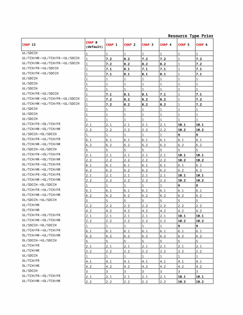

Command
DBTSP:TAB=AXEPARS, NAME=BTSPS; Switch for turning on/off BTS Power Savings in a BSCRAEPP:ID=TRXOFFTARGET; The value that the cell-level counter for turning off a TRX must reach before a TRX turn-off will be kicked offRAEPP:ID=TRXOFFDELAY; The delay period before scanning for a TRX to turn off will be restarted within a cellRAEPP:ID=TRXONTARGET; The value that the counter for turning on a TRX must reach before a TRX turn-on will be kicked off.
Command
RLSVP:CELL={cell}; Indicates if the BTS Power Savings is activated for the cellRLSVP:CELL={cell}; Hysteresis for BTS Power Savings. The value is expressed as the number of idle FR TCHsRLCLP:CELL={cell}; Parameter that controls whether on-demand PDCHs shall be treated as idle or busy when calculating the percentage of idle channels
Enabling TRX algo:
Description
Description


The value that the cell-level counter for turning off a TRX must reach before a TRX turn-off will be kicked offThe delay period before scanning for a TRX to turn off will be restarted within a cellThe value that the counter for turning on a TRX must reach before a TRX turn-on will be kicked off.
Indicates if the BTS Power Savings is activated for the cellHysteresis for BTS Power Savings. The value is expressed as the number of idle FR TCHsParameter that controls whether on-demand PDCHs shall be treated as idle or busy when calculating the percentage of idle channels


Locating To Start
MSC Level
Parameter Default Value Recommended Value Value RangeTIMHNDCMDINTRAM 15 - 5 to 120 secHNDRELCHINTRAM 1 - 0, 1TIMHNDGSINTRAM 80 0 0 to 2500 * 20msHNDBEFOREBANSWM 1 - 0, 1HNDSDCCHTCHM 1 - 0, 1HNDSDCCHM 1 - 0, 1HNDSDCCHINTOM 1 - 0, 1HNDSDCCHINTI 1 - 0, 1
BSC Level
Parameter Default Value Recommended Value Value RangeTINIT 10 10 0 to 120 SAACH periodsTAAVELEN 4 4 1 to 20 SAACH periodsEVALTYPE 1 - 1, 3IBHOSICH OFF - ON , OFFTALLOC 2 2 0 to 120 SAACH periodsTURGEN 2 2 0 to 120 SAACH periods
Cell Level
Parameter Default Value Recommended Value Value RangeSCHO OFF - ON, OFF
FilteringSSEVALSI 6 6 1 to 9SSLENSI 4 4 1 to 20 SAACH periodsSSRAMPSI 2 1 1 to 20 SAACH periodsQEVALSI 6 6 1 to 9QLENSI 4 4 1 to 20 SAACH periodsSSEVALSD 6 6 1 to 9SSLENSD 10 10 1 to 20 SAACH periods
SSRAMPSD 5 5 1 to 20 SAACH periodsQEVALSD 6 6 1 to 9QLENSD 10 10 1 to 20 SAACH periods
Basic RankingBSPWR - - 0 to 80 dBmBSTXPWR - - 0 to 80 dBmMSRXMIN - - 0 to 150 dBmBSRXMIN - - 0 to 150 dBm
Ericsson1
MSRXSUFF - - 0 to 150 dBm
BSRXFUFF - - 0 to 150 dBmTROFFSETP 0 0 0 to 63 dBTROFFSETN - - 1 to 63 dBTRHYST 2 2 0 to 63 dB

KHYST 3 3 0 to 63 dBKOFFSETP 0 0 0 to 63 dBKOFFSETN - - 1 to 63 dBLHYST 3 3 0 to 63 dBLOFFSETP 0 0 0 to 63 dBLOFFSETN - - 1 to 63 dB
Ericsson3HYSTSEP 90 - 0 to 150 dBmLOHYST 3 3 0 to 63 dBHIHYST 5 3 0 to 63 dBOFFSETP 0 0 0 to 63 dBOFFSETN - - 1 to 63 dB
Urgency ConditionsQLIMUL 55 55 0 to 100 dtquQLIMDL 55 55 0 to 100 dtquQLIMULAFR 55 65 0 to 100 dtquQLIMDLAFR 55 65 0 to 100 dtquBQOFFSET 3 3 0 to 63 dBBQOFFSETAFR 3 3 0 to 63 dBPSSBQ 10 7 0 to 63 dBPTIMBQ 15 15 0 to 600 secTALIM 62 62 0 to 63 bit periodsPSSTA 63 63 0 to 63 dBPTIMTA 30 30 0 to 600 secEXTPEN OFF OFF ON, OFF
Handover FailurePSSHF 63 63 0 to 63 dBPTIMHF 5 5 0 to 600 sec
Disconnection Algo ParametersRLINKT 16 - 4 to 64 SAACH periods in steps of 4RLINKTAFR 16 32 4 to 64 SAACH periods in steps of 4RLINKTAHR 16 20 4 to 64 SAACH periods in steps of 4RLINKUP 16 - 1 to 63 SAACH periodsRLINKUPAFR 16 32 1 to 63 SAACH periodsRLINKUPAHR 16 20 1 to 63 SAACH periodsMAXTA 63 - 0 to 63 bit periods

Locating Algorithm To Start

CommandDBTSP:TAB=AXEPARS, NAME=TIMHNDCMDINTRAM;DBTSP:TAB=AXEPARS, NAME=HNDRELCHINTRAM;DBTSP:TAB=AXEPARS, NAME=TIMHNDGSINTRAM;DBTSP:TAB=AXEPARS, NAME=HNDBEFOREBANSWM;DBTSP:TAB=AXEPARS, NAME=HNDSDCCHTCHM;DBTSP:TAB=AXEPARS, NAME=HNDSDCCHM;DBTSP:TAB=AXEPARS, NAME=HNDSDCCHINTOM;MGEPP:ID=HNDSDCCHINTI;
CommandRLLBP;RLLBP;RLLBP;RLLBP;RLLBP;RLLBP;
CommandRLLOP:CELL={cell};
FilteringRLLFP:CELL={cell};RLLFP:CELL={cell};RLLFP:CELL={cell};RLLFP:CELL={cell};RLLFP:CELL={cell};RLLFP:CELL={cell};RLLFP:CELL={cell};
RLLFP:CELL={cell};RLLFP:CELL={cell};RLLFP:CELL={cell};
Basic RankingRLLOP:CELL={cell};RLLOP:CELL={cell};RLLOP:CELL={cell};RLLOP:CELL={cell};
Ericsson1
RLLOP:CELL={cell};
RLLOP:CELL={cell};RLNRP:CELL={cell}, CELLR={cellr};RLNRP:CELL={cell}, CELLR={cellr};RLNRP:CELL={cell}, CELLR={cellr};

RLNRP:CELL={cell}, CELLR={cellr};RLNRP:CELL={cell}, CELLR={cellr};RLNRP:CELL={cell}, CELLR={cellr};RLNRP:CELL={cell}, CELLR={cellr};RLNRP:CELL={cell}, CELLR={cellr};RLNRP:CELL={cell}, CELLR={cellr};
Ericsson3RLNRP:CELL={cell}, CELLR={cellr};RLNRP:CELL={cell}, CELLR={cellr};RLNRP:CELL={cell}, CELLR={cellr};RLNRP:CELL={cell}, CELLR={cellr};RLNRP:CELL={cell}, CELLR={cellr};
Urgency ConditionsRLLUP:CELL={cell};RLLUP:CELL={cell};RLLUP:CELL={cell};RLLUP:CELL={cell};RLNRP:CELL={cell}, CELLR={cellr};RLNRP:CELL={cell}, CELLR={cellr};RLLPP:CELL={cell};RLLPP:CELL={cell};RLLUP:CELL={cell};RLLPP:CELL={cell};RLLPP:CELL={cell};RLLOP:CELL={cell};
Handover FailureRLLPP:CELL={cell};RLLPP:CELL={cell};
Disconnection Algo ParametersRLSSP:CELL={cell};RLSSP:CELL={cell};RLSSP:CELL={cell};RLLDP:CELL={cell};RLLDP:CELL={cell};RLLDP:CELL={cell};RLLDP:CELL={cell};

DescriptionDetermines the time between the HANDOVER COMMAND and HANDOVER COMPLETE messages in the MSC at intra-MSC inter-BSC handoverDefines the release of the original channel after expiration of the handover time supervision timer TIMHNDCMDINTRAM at intra-MSC inter-BSC handover. 0 Handover is terminated and the call continues on the original channel. 1 The original channel is releasedTime supervision of the switching moment of the group switch (GS) in the MSC at intra-MSC inter-BSC handover. The timer is started at sending of the HANDOVER COMMAND message. The path in the GS will be changed at the first occurrence of one of the following events: • Timer expiry. • Reception of HANDOVER DETECTED from target BSC. • Reception of HANDOVER COMPLETE from target BSCDetermines whether inter-MSC handover and inter-MSC assignment are allowed before answer from B-subscriber (= 1) or not (= 0)Determines whether inter-MSC/intra-MSC inter-BSC handover is allowed from a signalling to a traffic channel (= 1) or not (= 0). The inter-MSC case is allowed if MAP version 2 is used (HOMAPVERSION = 2) and if HNDBEFOREBANSWM is set to 1Determines whether intra-MSC inter-BSC handover is allowed on a signalling channel (= 1) or not (= 0)Determines whether an outgoing inter-MSC handover on a signalling channel in an anchor MSC is allowed (= 1) or not (= 0).Determines whether incoming an inter-MSC handover on signalling channels in non-anchor MSC is allowed (= 1) or not (= 0). The parameter is only valid if the inter-MSC handover dialogue has been established with MAP version 2 by the anchor MSC
DescriptionPrevents handovers till it expires, but assignment to own cell or other cell can take placeTiming advance filter is used for all cells. The filter is a straight averaging filter.Chooses between Ericsson1(SS + Pathloss) & Ericsson3(SS only) Algo
Switches on and off the possibility of making inter-BSC handover on a signalling channelInhibits handover for a time interval after a failed assignment or handover, when the failure was due to congestion. It also inhibits handover for a time interval after a failed subcell change or intra-cell handover, when the failure was due to congestion or signalling failure
Inhibits handover after a failed assignment or handover, when the attempt was due to an urgency condition, and the failure was due to congestion
DescriptionSwitches on and off the possibility of performing handover on SDCCH
Signal Strength Filter that is used during the signalling phase of a connectionUsed to specify the length of the SSEVALSI filterNumber of SACCH periods during which the ramping shall be active in signalling phase for SS filterQuality Filter that is used during the signalling phase of a connectionUsed to specify the length of the QEVALSI filterSignal Strength Filter during the speech/data phase of a connectionUsed to specify the length of the SSEVALSD filter
Number of SACCH periods during which the ramping shall be active in speech/data phaseQuality Filter that is used during the speech/data phase of a connectionUsed to specify the length of the QEVALSD filter
BCCH PowerTCH PowerThe compensated SS_DOWN(Compensated for Fhopping, Power Control etc.) >= MSRXMIN & SS_UP >= BSRXMIN to be considered eligible for handoverSS_UP >= BSRXMIN to be considered for handover where SS_UP=MS_PWR - L
Signal strength positive offset in dB when transition between K- and L-cellsSignal strength negative offset in dB when transition between K- and L-cellsHysteresis for a cell border that is defined by a K-L transition
Threshold for the downlink signal strength from neighbouring cells, as measured by the MS, for allowing a cell to be eligible for path loss ranking
Threshold for the uplink signal strength to neighbouring cells, as calculated from the downlink measurements

Hysteresis for cell borders defined by the signal strength criterion (K-K borders), that is at low signal strengthSignal strength positive offset in dB when evaluating K-cellsSignal strength negative offset in dB when evaluating K-cellsHysteresis for cell borders defined by the path loss criterion (L-L borders), that is at high signal strengthSignal strength positive offset in dB when evaluating L-cellsSignal strength negative offset in dB when evaluating L-cells
Signal strength level specifying whether serving cell currently is a low or high signal strength cellhysteresis used if serving cell is a low signal strength cellhysteresis used if serving cell is a high signal strength cellSignal strength positive offset in dB when evaluating cells with Ericsson3 algorithmSignal strength negative offset in dB when evaluating cells with Ericsson3 algorithm
Threshold for uplink quality, for bad quality urgencyThreshold for downlink quality, for bad quality urgencyThreshold for uplink quality, for bad quality urgency for AMR FR connectionsThreshold for downlink quality, for bad quality urgency for AMR FR connectionsSignal strength corridor in dB for bad quality urgency handoverSignal strength corridor in dB for bad quality urgency handover.This parameter is used only for the codec type AMR FRSignal strength penalty in dB when handover due to bad qualityPenalty time in seconds when handover due to bad qualityThreshold for timing advance, for excessive TA urgencySignal strength penalty in dB when handover due to too large timing advancePenalty time in seconds when handover due to too large timing advanceShall be set for an external neighbouring cell. It defines whether urgency handover to that cell is allowed (that is if the MSC and the target BSC support the penalty handling between BSCs)
Penalty given to a cell if a handover to that cell failed as a result of signalling failurePenalty time associated with PSSHF
Leaky bucket size for the downlink frame detection disconnection criterionLeaky bucket size for the downlink frame detection disconnection criterion for AMR FR connectionsLeaky bucket size for the downlink frame detection disconnection criterion for AMR HR connectionsLeaky bucket size for the uplink frame detection disconnection criterionLeaky bucket size for the uplink frame detection disconnection criterion for AMR FR connectionsLeaky bucket size for the uplink frame detection disconnection criterion for AMR HR connectionsThreshold for disconnection in the timing advance disconnection criterion

Determines the time between the HANDOVER COMMAND and HANDOVER COMPLETE messages in the MSC at intra-MSC inter-BSC handoverDefines the release of the original channel after expiration of the handover time supervision timer TIMHNDCMDINTRAM at intra-MSC inter-BSC handover. 0 Handover is terminated and the call continues on the original channel. 1 The original channel is releasedTime supervision of the switching moment of the group switch (GS) in the MSC at intra-MSC inter-BSC handover. The timer is started at sending of the HANDOVER COMMAND message. The path in the GS will be changed at the first occurrence of one of the following events: • Timer expiry. • Reception of HANDOVER DETECTED from target BSC. • Reception of HANDOVER COMPLETE from target BSCDetermines whether inter-MSC handover and inter-MSC assignment are allowed before answer from B-subscriber (= 1) or not (= 0)Determines whether inter-MSC/intra-MSC inter-BSC handover is allowed from a signalling to a traffic channel (= 1) or not (= 0). The inter-MSC case is allowed if MAP version 2 is used (HOMAPVERSION = 2) and if HNDBEFOREBANSWM is set to 1
Determines whether an outgoing inter-MSC handover on a signalling channel in an anchor MSC is allowed (= 1) or not (= 0).Determines whether incoming an inter-MSC handover on signalling channels in non-anchor MSC is allowed (= 1) or not (= 0). The parameter is only valid if the inter-MSC handover dialogue has been established with MAP version 2 by the anchor MSC
Inhibits handover for a time interval after a failed assignment or handover, when the failure was due to congestion. It also inhibits handover for a time interval after a failed subcell change or intra-cell handover, when the failure was due to congestion or signalling failureInhibits handover after a failed assignment or handover, when the attempt was due to an urgency condition, and the failure was due to congestion
Locating algorithms aims at letting the pure traffic frequencies control the cell bordersThe compensated SS_DOWN(Compensated for Fhopping, Power Control etc.) >= MSRXMIN & SS_UP >= BSRXMIN to be considered eligible for handover
MSPWR=min(P, MSTXPWR) & L=BSTXPWR - SS_DOWN
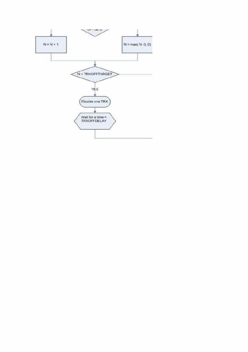
Maximum of 64 neighbors can be defined for each cell.
Hysteresis for cell borders defined by the path loss criterion (L-L borders), that is at high signal strength
Signal strength level specifying whether serving cell currently is a low or high signal strength cell
Signal strength corridor in dB for bad quality urgency handover.This parameter is used only for the codec type AMR FR
Shall be set for an external neighbouring cell. It defines whether urgency handover to that cell is allowed (that is if the MSC and the target BSC support the penalty handling between BSCs)
Leaky bucket size for the downlink frame detection disconnection criterion for AMR FR connectionsLeaky bucket size for the downlink frame detection disconnection criterion for AMR HR connections
Leaky bucket size for the uplink frame detection disconnection criterion for AMR HR connections

Defines the release of the original channel after expiration of the handover time supervision timer TIMHNDCMDINTRAM at intra-MSC inter-BSC handover. 0 Handover is terminated and the call continues on the original channel. 1 The original channel is releasedTime supervision of the switching moment of the group switch (GS) in the MSC at intra-MSC inter-BSC handover. The timer is started at sending of the HANDOVER COMMAND message. The path in the GS will be changed at the first occurrence of one of the following events: • Timer expiry. • Reception of HANDOVER DETECTED from target BSC. • Reception of HANDOVER COMPLETE from target BSC
Determines whether inter-MSC/intra-MSC inter-BSC handover is allowed from a signalling to a traffic channel (= 1) or not (= 0). The inter-MSC case is allowed if MAP version 2 is used (HOMAPVERSION = 2) and if HNDBEFOREBANSWM is set to 1
Determines whether incoming an inter-MSC handover on signalling channels in non-anchor MSC is allowed (= 1) or not (= 0). The parameter is only valid if the inter-MSC handover dialogue has been established with MAP version 2 by the anchor MSC

Time supervision of the switching moment of the group switch (GS) in the MSC at intra-MSC inter-BSC handover. The timer is started at sending of the HANDOVER COMMAND message. The path in the GS will be changed at the first occurrence of one of the following events: • Timer expiry. • Reception of HANDOVER DETECTED from target BSC. • Reception of HANDOVER COMPLETE from target BSC

To Start
Parameter name Default value Recommended value
IRC OFF ON
AGBLK 1 0
MFRMS 6
ACSTATE OFF ONTX 50

Value range Command Comment
ON/OFF RLDEP:CELL={cell};
0 to 7
RLDEP:CELL={cell};
2 to 9 RLDEP:CELL={cell};
ON/OFF RLACP:CELL={cell}; Switches on/off adaptive configuration of logical channels on a cell basis3 to 12, 14, 16, 20, 25, RLSBP:CELL={cell}; Defines the number of timeslots over which the MS may spread transmission when accessing the system
Can be used to increase capacity in a radio network limited in the uplink, improve speech quality, and increase data throughput in the uplink
Dedicated CCCH blocks for access grant
Paging groups= (9-AGBLK)*MFRMS

Switches on/off adaptive configuration of logical channels on a cell basisDefines the number of timeslots over which the MS may spread transmission when accessing the system

To Start
BSC Level
Parameter Default Value Recommended Value Value Range CommandTFOSTATUS 0 - 0,1 RAEPP:ID=TFOSTATUS;
TFOCONFIGTRA 0 - 0,1 RAEPP:ID=TFOCONFIGTRA;TFOPRIO 0 - 0,1 RAEPP:ID=TFOPRIO;RNOTRA - - - RRTPP:TRAPOOL=ALL;PCMLAW 0 - 0,1 RRTPP:TRAPOOL=ALL;

DescriptionUsed to turn the feature TFO ON (=1) or OFF (=0).
Used to steer optimization features for AMR in TFO. If this parameter is set to 0 all types of optimization will be allowed in TFO, if set to 1 the optimization features DYMA, HR Packing will not be allowed in TFO.Required number of transcoder resourcesUsed to set the correct PCM law type on the A-interface, A-Law (=0) or μ-Law (=1).
Used to switch on (=1) or off (=0) the configuration of TRA R6 to support TFO.

Used to steer optimization features for AMR in TFO. If this parameter is set to 0 all types of optimization will be allowed in TFO, if set to 1 the optimization features DYMA, HR Packing will not be allowed in TFO.

Antenna Hopping To Start
Tranceiver Group Level
Parameter Default Value RecommenValue Range CommandAHOP OFF - ON, ONXC0, OFF RXMOP:MO=RXOTG-{tg-number};

DescriptionDefines the wanted state for antenna hopping on a transceiver group. The wanted state can be either of ON, NXC0 or OFF. In state ONXC0, all channels except those on the BCCH frequency/frequencies will antenna hop.

Software Power Boost and TCC To Start
SWPBCell Level
Parameter Default Value Recommended Value Value Range Command DescriptionBSPWRB - - Maxpwr+2 dBm RLCPP:CELL={cell}; SWPB is enabled by configuring theBSPWRT - - Maxpwr+2 dBm RLCPP:CELL={cell}; To enable SWPB, BSPWRT is set 2 d
TCCCell Level
Parameter Default Value Recommended Value Value Range Command DescriptionBSPWRB - - Maxpwr+4 dBm RLCPP:CELL={cell}; TCC is enabled by configuring the
BSPWRT - - Maxpwr+4 dBm RLCPP:CELL={cell}; To enable TCC, BSPWRT is set 4 dB
Maximum possible output power of the TRX (Maxpwr) is the maximum power without any combiner connected.
Transmitter Coherent Combing (TCC) increases the maximum output power of a RBS 21yx/22yx (y=0, x≥6 | y≥1,any x), except RBS 2109, with an additional 2.5 dB compared to the output power from each of the TRXs
in a dTRU when the internal hybrid combiner is not used. Compared to a configuration where the internal hybrid combiner is used, the increase is 6 dB.
SWPB Requires two transmitting antennas. SW Power Boost (SWPB) increases the transmitted power by 3 dB compared to the output from each TRX. This is achieved by using two transmitters of a dTRU (RBS
21yx/22yx (y=0, x≥6 | y≥1,any x)), two cTRUs or two sTRUs (RBS 210x/220x (x≤3)) or two TRXs connected to separate antennas (RBS 230x (any x)) to implement one carrier by sending identical bursts on the same
frequency with equal amplitude on separate transmit antennas.

SWPBCheck MPWR of RXOTX with the following. SWPB is supported if the value of parameter MPWR for TX is greater than or equal to the values of parameters BSPWRB and BSPWRT given in table
Equipment BSPWRB BSPWRTSWPB is enabled by configuring the RBS 2301/2302/2308 35 35To enable SWPB, BSPWRT is set 2 dRBS 2106/2206, 800 MHz 49 49
RBS 2101/2102/2202, 900 MHz 49 49RBS 2101/2102/2202, 1800/1900 MHz 47 47
TCCTCC is supported if the value of parameter MPWR for MO TX is greater than or equal to the values of parameters BSPWRB and BSPWRT given in table
Equipment BSPWRB BSPWRTTCC is enabled by configuring the Macro RBS with DXU-21 800/900 MHz 51 51
To enable TCC, BSPWRT is set 4 dB Macro RBS with DXU-21 1800/1900 MHz 49 49
Maximum possible output power of the TRX (Maxpwr) is the maximum power without any combiner connected.

Check MPWR of RXOTX with the following. SWPB is supported if the value of parameter MPWR for TX is greater than or equal to the values of parameters BSPWRB and BSPWRT given in table
TCC is supported if the value of parameter MPWR for MO TX is greater than or equal to the values of parameters BSPWRB and BSPWRT given in table
Extended Range To StartBSC Level
Parameter Default Value Recommended Value Value RangeXRANGECELL 1 - 0, 1XRANGESUBCELL 0 - 0, 1
Cell Level
Parameter Default Value Recommended Value Value RangeXRANGE OFF - ON, OFFMAXTA 62 219 0-219 for extenTALIM 61 218 0-219 for exten

Command DescriptionDBTSP:TAB=AXEPARS, NAME=XRANGECELL; Switch for enabling this feature at a BSC level. 1(ON) and 0(OFF)DBTSP:TAB=AXEPARS, NAME=XRANGESUBCELL; Switch for enabling this feature at a BSC level. 1(ON) and 0(OFF)
Command DescriptionRLDEP:CELL={cell}; Switches the Extended Range feature on/off.RLLDP:CELL={cell}; TA threshold for call disconnection caused by excessive TA (or VTA). It applies for all subcells except for the OL subcell in a combined normal and extended range cell.RLLUP:CELL={cell}; TA threshold for excessive TA (or VTA) urgency. It applies for all subcells except for the OL subcell in a combined normal and extended range cell.

Switch for enabling this feature at a BSC level. 1(ON) and 0(OFF)Switch for enabling this feature at a BSC level. 1(ON) and 0(OFF)
TA threshold for call disconnection caused by excessive TA (or VTA). It applies for all subcells except for the OL subcell in a combined normal and extended range cell.TA threshold for excessive TA (or VTA) urgency. It applies for all subcells except for the OL subcell in a combined normal and extended range cell.

TA threshold for call disconnection caused by excessive TA (or VTA). It applies for all subcells except for the OL subcell in a combined normal and extended range cell.

Tight BCCH Reuse To Start
BSC Level
Parameter Default Value Recommended Value Value RangeTIGHTBCCHREUSE - - 0(OFF), 1(ON)
Cell Level
Parameter Default Value Recommended Value Value Range
BCCHREUSE 0 (NORMAL) - 0, 1 (0=NORMAL, 1=TIGHT)BCCHLOSS 200 - 0 to 200 dBBCCHDTCB(N or P) -63 - -63 to 63 dBBCCHLOSSHYST 3 - 0 to 63 dBBCCHDTCBHYST 2 - 0 to 63 dB
StatisticsCounterBCDTCBCOM is stepped by intra-cell handover attempt out of BCCH CHGR, BCCHDTCB criteria.BCLOSSCOM is stepped by intra-cell handover attempt out of BCCH CHGR, BCCHLOSS critera.BCDTCBSUC is stepped by successful intra-cell handover out of BCCH CHGR, BCCHDTCB criteria.BCLOSSSUC is stepped by successful intra-cell handover out of BCCH CHGR, BCCHLOSS criteria.

CommandDBTSP:TAB=AXEPARS, NAME=TIGHTBCCHREUSE;
Command
RLLOP:CELL={cell};RLLOP:CELL={cell};RLLOP:CELL={cell};RLLOP:CELL={cell};RLLOP:CELL={cell};
is stepped by intra-cell handover attempt out of BCCH CHGR, BCCHDTCB criteria.is stepped by intra-cell handover attempt out of BCCH CHGR, BCCHLOSS critera.is stepped by successful intra-cell handover out of BCCH CHGR, BCCHDTCB criteria.is stepped by successful intra-cell handover out of BCCH CHGR, BCCHLOSS criteria.

DescriptionSwitch for turning on Tight BCCH Reuse feature
Description
Pathloss threshold for the BCCH channel group. It defines the CHGR 0 service coverage border in terms of the pathloss from the serving cell.Distance to cell border threshold for the BCCH channel group. It defines the CHGR 0 service coverage border in terms of the signal strength difference between the active channel and the strongest neighbouring cells' BCCHs.Hysteresis for the pathloss criterion during evaluations for the CHGR 0 service coverage.Hysteresis for the DTCB criterion during evaluations for the CHGR 0 service coverage.
BCCH frequency Reuse. Specifies if the BCCH frequency reuse is considered tight so that pathloss and DTCB criteria should be specifically evaluated for channel group 0.TIGHT: Pathloss and DTCB are specifically evaluated for channel group 0. BCCHLOSS and BCCHDTCB are used for channel group 0. NORMAL: Pathloss and DTCB are not specifically evaluated for channel group 0. LOL and DTCB are used for all channel groups

Pathloss threshold for the BCCH channel group. It defines the CHGR 0 service coverage border in terms of the pathloss from the serving cell.Distance to cell border threshold for the BCCH channel group. It defines the CHGR 0 service coverage border in terms of the signal strength difference between the active channel and the strongest neighbouring cells' BCCHs.

GPRS Idle Mode To Start
MSC Level
Parameter Default Value Recommended Value Value Range
TIMPAGINGM 9 9 2 to 20 s
SECPAGEPATH 1 1 0 to 2 s
PAGREP1LA 2 2 0 to 3
PAGREPGLOB 0 0 0 to 1
To StartBSC Level
Parameter Default Value Recommended Value Value RangeGPRSNWMODE 2 - 1,2,3
Cell Level
Parameter Default Value Recommended Value Value RangeMAXSBLK 2 - 1 to 4MAXSMSG 7 - 1 to 16TRAFBLK 0 - 0 to 10PRACHBLK 2 - 1 to 12CBCHD NO - YES, NO
SGSN Level
Parameter Default Value Recommended Value Value RangeT3313 5 5 FixedT3312 54 54 Fixed

Algorithm:

Command Description
DBTSP:TAB=AXEPARS, NAME=TIMPAGINGM; The AXE parameter determines the value for timer T5. This timer supervises the paging procedure in MSC/VLR Server. The timer is started, when the last PAGING REQUEST message is sent and stopped, when the PAGE RESPONSE message is received over A-interface, or when MS UNREACHABLE or all possible PAGING REJECT messages are received. When the timer expires the first time the PAGING REQUEST message is retransmitted, if allowed and T5 is restarted. When the timer expires the second time the paging procedure is stopped and regarded as unsuccessful.The AXE parameter determines the time for waiting for a response after Paging Request message is sent
DBTSP:TAB=AXEPARS, NAME=SECPAGEPATH;
DBTSP:TAB=AXEPARS, NAME=PAGREP1LA;
DBTSP:TAB=AXEPARS, NAME=PAGREPGLOB;
Command DescriptionRAEPP:ID=GPRSNWMODE; 1 Network Mode of Operation I; master PDCH can exist; Gs interface exists. 2 Network Mode of Operation II; no master PDCH can exist; no Gs interface exists. 3 Network Mode of Operation III; master PDCH can exist; no Gs interface exists.
Command DescriptionRLPDP:CELL={cell}; Defines the maximum value that BS_PBCCH_BLKS is allowed to have, that is the maximum number of reserved radio blocks to be used for the PBCCH.RLPDP:CELL={cell}; Defines maximum number of PSI messages that preferably shall be scheduled on one PBCCH block.RLPDP:CELL={cell}; Defines the value of BS_PAG_BLKS_RES, that is the number of blocks within a multiframe where neither paging nor PSI messages shall appear.RLPDP:CELL={cell}; Defines the minimum number of reserved radio block periods for PRACH.RLPDP:CELL={cell}; Defines if CBCH description, that is, PSI8 shall be transferred on the PBCCH or not.
Command Description- T3313 defines the timer for supervision of the PS Paging. At expiry of the timer, the paging is repeated. The value of the timer is fixed and set to five seconds. The paging is repeated up to five times.- T3312 defines the timer for the periodic routing area update procedure. At expiry of the timer, a routing area update will be performed by the MS. The value of the timer is fixed and set to 54 minutes.
The AXE parameter specifies whether the
The AXE parameter defines repeating
The AXE parameter defines repeating

The AXE parameter determines the value for timer T5. This timer supervises the paging procedure in MSC/VLR Server. The timer is started, when the last PAGING REQUEST message is sent and stopped, when the PAGE RESPONSE message is received over A-interface, or when MS UNREACHABLE or all possible PAGING REJECT messages are received. When the timer expires the first time the PAGING REQUEST message is retransmitted, if allowed and T5 is restarted. When the timer expires the second time the paging procedure is stopped and regarded as unsuccessful.The AXE parameter determines the time for waiting for a response after Paging Request message is sent
1 Network Mode of Operation I; master PDCH can exist; Gs interface exists. 2 Network Mode of Operation II; no master PDCH can exist; no Gs interface exists. 3 Network Mode of Operation III; master PDCH can exist; no Gs interface exists.
Defines the maximum value that BS_PBCCH_BLKS is allowed to have, that is the maximum number of reserved radio blocks to be used for the PBCCH.Defines maximum number of PSI messages that preferably shall be scheduled on one PBCCH block.Defines the value of BS_PAG_BLKS_RES, that is the number of blocks within a multiframe where neither paging nor PSI messages shall appear.Defines the minimum number of reserved radio block periods for PRACH.Defines if CBCH description, that is, PSI8 shall be transferred on the PBCCH or not.
T3313 defines the timer for supervision of the PS Paging. At expiry of the timer, the paging is repeated. The value of the timer is fixed and set to five seconds. The paging is repeated up to five times.T3312 defines the timer for the periodic routing area update procedure. At expiry of the timer, a routing area update will be performed by the MS. The value of the timer is fixed and set to 54 minutes.

The AXE parameter determines the value for timer T5. This timer supervises the paging procedure in MSC/VLR Server. The timer is started, when the last PAGING REQUEST message is sent and stopped, when the PAGE RESPONSE message is received over A-interface, or when MS UNREACHABLE or all possible PAGING REJECT messages are received. When the timer expires the first time the PAGING REQUEST message is retransmitted, if allowed and T5 is restarted. When the timer expires the second time the paging procedure is stopped and regarded as unsuccessful.The AXE parameter determines the time for waiting for a response after Paging Request message is sent
1 Network Mode of Operation I; master PDCH can exist; Gs interface exists. 2 Network Mode of Operation II; no master PDCH can exist; no Gs interface exists. 3 Network Mode of Operation III; master PDCH can exist; no Gs interface exists.
Defines the maximum value that BS_PBCCH_BLKS is allowed to have, that is the maximum number of reserved radio blocks to be used for the PBCCH.
T3313 defines the timer for supervision of the PS Paging. At expiry of the timer, the paging is repeated. The value of the timer is fixed and set to five seconds. The paging is repeated up to five times.T3312 defines the timer for the periodic routing area update procedure. At expiry of the timer, a routing area update will be performed by the MS. The value of the timer is fixed and set to 54 minutes.

The AXE parameter determines the value for timer T5. This timer supervises the paging procedure in MSC/VLR Server. The timer is started, when the last PAGING REQUEST message is sent and stopped, when the PAGE RESPONSE message is received over A-interface, or when MS UNREACHABLE or all possible PAGING REJECT messages are received. When the timer expires the first time the PAGING REQUEST message is retransmitted, if allowed and T5 is restarted. When the timer expires the second time the paging procedure is stopped and regarded as unsuccessful.The AXE parameter determines the time for waiting for a response after Paging Request message is sent

The AXE parameter determines the value for timer T5. This timer supervises the paging procedure in MSC/VLR Server. The timer is started, when the last PAGING REQUEST message is sent and stopped, when the PAGE RESPONSE message is received over A-interface, or when MS UNREACHABLE or all possible PAGING REJECT messages are received. When the timer expires the first time the PAGING REQUEST message is retransmitted, if allowed and T5 is restarted. When the timer expires the second time the paging procedure is stopped and regarded as unsuccessful.The AXE parameter determines the time for waiting for a response after Paging Request message is sent

The AXE parameter determines the value for timer T5. This timer supervises the paging procedure in MSC/VLR Server. The timer is started, when the last PAGING REQUEST message is sent and stopped, when the PAGE RESPONSE message is received over A-interface, or when MS UNREACHABLE or all possible PAGING REJECT messages are received. When the timer expires the first time the PAGING REQUEST message is retransmitted, if allowed and T5 is restarted. When the timer expires the second time the paging procedure is stopped and regarded as unsuccessful.The AXE parameter determines the time for waiting for a response after Paging Request message is sent

The AXE parameter determines the value for timer T5. This timer supervises the paging procedure in MSC/VLR Server. The timer is started, when the last PAGING REQUEST message is sent and stopped, when the PAGE RESPONSE message is received over A-interface, or when MS UNREACHABLE or all possible PAGING REJECT messages are received. When the timer expires the first time the PAGING REQUEST message is retransmitted, if allowed and T5 is restarted. When the timer expires the second time the paging procedure is stopped and regarded as unsuccessful.The AXE parameter determines the time for waiting for a response after Paging Request message is sent

The AXE parameter determines the value for timer T5. This timer supervises the paging procedure in MSC/VLR Server. The timer is started, when the last PAGING REQUEST message is sent and stopped, when the PAGE RESPONSE message is received over A-interface, or when MS UNREACHABLE or all possible PAGING REJECT messages are received. When the timer expires the first time the PAGING REQUEST message is retransmitted, if allowed and T5 is restarted. When the timer expires the second time the paging procedure is stopped and regarded as unsuccessful.The AXE parameter determines the time for waiting for a response after Paging Request message is sent

GPRS Cell Reselection To StartCell Level
Parameter Default Value Recommended Value Value RangePSCELLPLAN 0 (OFF) - 0, 1NACCACT 0 (OFF) - 0, 1INTERBSCNACC 0 - 0,1
Cell Level
Parameter Default Value Recommended Value Value RangeMAXRETCRHRIMNACC OFF OFF, ON
RAC 0 (OFF) - 0-255


CommandRAEPP:ID=PSCELLPLAN;RAEPP:ID=NACCACT;DBTSP:TAB=AXEPARS, NAME=INT
Command
RLDEP:CELL={cell};
RLDEP:CELL={cell};


DescriptionActivates (1) or deactivates (0) the feature Packet Specific Cell Plan.Activates (1) or deactivates (0) the feature Network Assisted Cell Change (NACC).-
Description
If the GPRS attached MS is in Ready state or if the neighbouring cell is in a new RA, then C2(n) must exceed C2(s) with at least CRH for 5 seconds. If a cell reselection occurred less than 15 seconds ago, then C2(n) must exceed C2(s) with at least 5 dB for 5 seconds.The parameter is used to activate and deactivate NACC for external neighbors.
The Routing Area Code (RAC) is, together with the Cell Identity (CI), used for routing of RAN-INFORMATION messages between BSCs.0 OFF1 ON

If the GPRS attached MS is in Ready state or if the neighbouring cell is in a new RA, then C2(n) must exceed C2(s) with at least CRH for 5 seconds. If a cell reselection occurred less than 15 seconds ago, then C2(n) must exceed C2(s) with at least 5 dB for 5 seconds.
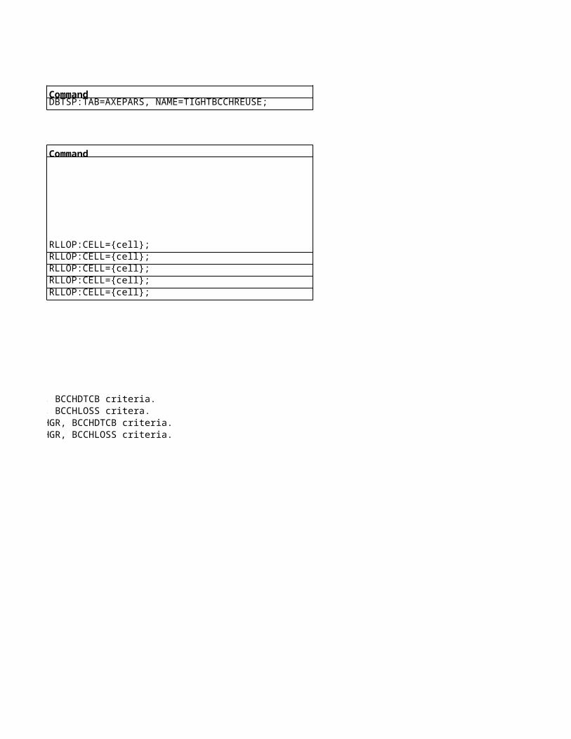
If the GPRS attached MS is in Ready state or if the neighbouring cell is in a new RA, then C2(n) must exceed C2(s) with at least CRH for 5 seconds. If a cell reselection occurred less than 15 seconds ago, then C2(n) must exceed C2(s) with at least 5 dB for 5 seconds.

To StartSystem Info 1 ( Idle Mode)
Note:
System Info 2 ( Idle Mode)
Note:
System Info 3 ( Idle Mode)
This message normally for the Cell channel Informations. This will give the no of frequencies allocated for the particular cell. In hopping case this will indicate the frequencies in the MAL list along with the BCCH frequency. In non hopping case will indicate the TCH & BCCH frequencies.
Click to return to main page
This message gives the information about the neighbor frequencies in the idle mode. Will only gives the BCCH of the neighbors defined. And the NCC permitted parameter allows the mobile to restrict the neighbors to be sent in the measurement report.
Click to return to main page

System Info 4 ( Idle Mode)
Note:
Click to return to main page
This message gives the information about the CBCH for the mobile to decode the CBCH. Along with the other cell level details like LAC, RACH control parameters etc…..

System Info 5 ( Dedicated Mode)
Note:
System Info 6 ( Dedicated Mode)
Click to return to main page
This message gives the information about the neighbor frequencies in the dedicated mode. Will only gives the BCCH of the neighbors defined.
Click to return to main page

System Info 13 ( Idle Mode, GPRS Information) Click to return to main page

This message normally for the Cell channel Informations. This will give the no of frequencies allocated for the particular cell. In hopping case this will indicate the frequencies in the MAL list along with the BCCH frequency. In non hopping case will indicate the TCH & BCCH frequencies.
This message gives the information about the neighbor frequencies in the idle mode. Will only gives the BCCH of the neighbors defined. And the NCC permitted parameter allows the mobile to restrict the neighbors to be sent in the measurement report.

This message gives the information about the CBCH for the mobile to decode the CBCH. Along with the other cell level details like LAC, RACH control parameters etc…..

This message gives the information about the neighbor frequencies in the dedicated mode. Will only gives the BCCH of the neighbors defined.


GPRS EGPRS MS Power Control To Start
BSC Level
Parameter Default Value Recommended Value Value Range
ALPHA 0 0 0 to 10
Cell Level
Parameter Default Value Recommended Value Value RangeGAMMA 0 0 0 to 62 (even values)
CCHPWR - -BSPWRB - - 0 to 63 dBmMFRMS 6 - 2 to 9
Algorithm To Start
Packet Idle Mode:
Pb is the BTS output power reduction (relative to the output power used on the BCCH). It is fixed and is set to 0.N is the # of blocks received on BCCH frequency.
13 to 43 dBm (800/900)4 to 30 dBm (1800/1900)

Packet Transfer Mode:
How to calculate GAMMA with the given parameters:

Command Description
RAEPP:ID=ALPHA;
Command DescriptionRLGSP:CELL={cell}; Set to give a desired received signal strength at the BTS. It is defined for each cell and can be sent to the GPRS/EGPRS MS in Packet Downlink Assignment, Packet Uplink Assignment and Immediate Assignment messages.
RLSSP:CELL={cell}; Maximum output power an GPRS/EGPRS MS may use when accessing the system on a control channel. It is defined for each cell and is broadcast on BCCH in System Information Type 3.RLCPP:CELL={cell}; Maximum allowed output power of BTSs on the BCCH frequency.RLDEP:CELL={cell}; Indicates the number of 51 multiframe periods for transmission of paging request messages to GPRS/EGPRS MSs in the same paging group. It is defined for each cell and is broadcast on BCCH in System Information Type 3
Pb is the BTS output power reduction (relative to the output power used on the BCCH). It is fixed and is set to 0.
ALPHA is sent from the BSC to the MS and decides the level of reduction of the MS output power in relation to the path loss. The values are given as a multiple of 10, i.e. the value 5 means the reduction level of 0.5.BSC parameter for GPRS/EGPRS Dynamic MS Power Control. It is broadcast on PBCCH in Packet System Information Type 1 or, if PBCCH does not exist, on BCCH in System Information Type 13. It can also be sent to the GPRS/EGPRS MS in Packet Downlink Assignment and Packet Uplink Assignment messages. It is set between zero


Set to give a desired received signal strength at the BTS. It is defined for each cell and can be sent to the GPRS/EGPRS MS in Packet Downlink Assignment, Packet Uplink Assignment and Immediate Assignment messages.
Maximum output power an GPRS/EGPRS MS may use when accessing the system on a control channel. It is defined for each cell and is broadcast on BCCH in System Information Type 3.
Indicates the number of 51 multiframe periods for transmission of paging request messages to GPRS/EGPRS MSs in the same paging group. It is defined for each cell and is broadcast on BCCH in System Information Type 3


Set to give a desired received signal strength at the BTS. It is defined for each cell and can be sent to the GPRS/EGPRS MS in Packet Downlink Assignment, Packet Uplink Assignment and Immediate Assignment messages.
Indicates the number of 51 multiframe periods for transmission of paging request messages to GPRS/EGPRS MSs in the same paging group. It is defined for each cell and is broadcast on BCCH in System Information Type 3

EGPRS Link Quality Control To Start
BSC Level
Parameter Default Value Recommended Value Value RangeLQCMODEDL 1 2 0 to 2EGPRSIRUL 1 1 0, 1LQCMODEUL 0 1 0 to 2EGPRSIRU - - 0, 1LQCUNACK 1 2 0 to 2LQCHIGHMCS 9 9 1 to 9LQCACT 0 3 0 to 3LQCDEFAULTMCSDL 5 5 1 to 9LQCDEFAULTMCSUL 5 5 1 to 9INITMCS 3 3 1 to 9
Cell Level
Parameter Default Value Recommended Value Value RangePSKONBCCH ENABLED ENABLED ENABLED, DISABLED
CS and MCS data rateEDGE

Command DescriptionRAEPP:ID=LQCMODEDL; Used to control the LQC mode for downlink TBFs in RLC acknowledged mode. If LQCMODEDL is set to 0 then LA mode will be used. If LQCMODEDL is set to 1 then LA/IR mode will be used. If LQCMODEDL is set to 2 then LA/IR-BLER mode will be usedRAEPP:ID=EGPRSIRUL; Used to switch IR ON and OFF for the uplink direction. If EGPRSIRUL is set to 0 then IR is deactivated. If EGPRSIRUL is set to 1 and LQCMODEUL is set to a value higher than 0, then IR is activatedRAEPP:ID=LQCMODEUL; Used to control the LQC mode for uplink TBFs in RLC acknowledged mode if EGPRSIRUL is set to 1 (otherwise LA mode is always used). If LQCMODEUL is set to 0 then LA mode will be used. If LQCMODEUL is set to 1 then LA/IR mode will be used. If LQCMODEUL is set to 2 then LA/IR-BLER mode will be used.DBTSP:TAB=AXEPARS, NAME=EGPRSIRU; Used to turn on the feature of Incremental RedundancyRAEPP:ID=LQCUNACK; Used to shift the selection of MCS to a more robust one when RLC unacknowledged mode is used.RAEPP:ID=LQCHIGHMCS; Used to limit the highest allowed MCS.RAEPP:ID=LQCACT; Used to switch LQC ON and OFF per downlink and uplink direction. If LQCACT is set to 0 then LQC is switched OFF for both directions. If LQCACT is set to 1 then LQC is switched ON only for the downlink direction. If LQCACT is set to 2 then LQC is switched ON only for the uplink direction. If LQCACT is set to 3 then LQC is switched ON for both directions.RAEPP:ID=LQCDEFAULTMCSDL; Used to control which MCS that shall be used on the downlink when LQC is switched OFF.RAEPP:ID=LQCDEFAULTMCSUL; Used to control which MCS that shall be used on the uplink when LQC is switched OFFRAEPP:ID=INITMCS; Used to control the initial MCS for both uplink and downlink TBFs. The initial MCS is used at the beginning of a TBF, when no BEP measurements are available
Command DescriptionRLGSP:CELL={cell}; Used to disable the use of 8-PSK for downlink TBFs on the BCCH carrier
GPRS

Used to control the LQC mode for downlink TBFs in RLC acknowledged mode. If LQCMODEDL is set to 0 then LA mode will be used. If LQCMODEDL is set to 1 then LA/IR mode will be used. If LQCMODEDL is set to 2 then LA/IR-BLER mode will be usedUsed to switch IR ON and OFF for the uplink direction. If EGPRSIRUL is set to 0 then IR is deactivated. If EGPRSIRUL is set to 1 and LQCMODEUL is set to a value higher than 0, then IR is activatedUsed to control the LQC mode for uplink TBFs in RLC acknowledged mode if EGPRSIRUL is set to 1 (otherwise LA mode is always used). If LQCMODEUL is set to 0 then LA mode will be used. If LQCMODEUL is set to 1 then LA/IR mode will be used. If LQCMODEUL is set to 2 then LA/IR-BLER mode will be used.
Used to shift the selection of MCS to a more robust one when RLC unacknowledged mode is used.
Used to switch LQC ON and OFF per downlink and uplink direction. If LQCACT is set to 0 then LQC is switched OFF for both directions. If LQCACT is set to 1 then LQC is switched ON only for the downlink direction. If LQCACT is set to 2 then LQC is switched ON only for the uplink direction. If LQCACT is set to 3 then LQC is switched ON for both directions.Used to control which MCS that shall be used on the downlink when LQC is switched OFF.Used to control which MCS that shall be used on the uplink when LQC is switched OFFUsed to control the initial MCS for both uplink and downlink TBFs. The initial MCS is used at the beginning of a TBF, when no BEP measurements are available
Used to disable the use of 8-PSK for downlink TBFs on the BCCH carrier

Used to control the LQC mode for downlink TBFs in RLC acknowledged mode. If LQCMODEDL is set to 0 then LA mode will be used. If LQCMODEDL is set to 1 then LA/IR mode will be used. If LQCMODEDL is set to 2 then LA/IR-BLER mode will be usedUsed to switch IR ON and OFF for the uplink direction. If EGPRSIRUL is set to 0 then IR is deactivated. If EGPRSIRUL is set to 1 and LQCMODEUL is set to a value higher than 0, then IR is activatedUsed to control the LQC mode for uplink TBFs in RLC acknowledged mode if EGPRSIRUL is set to 1 (otherwise LA mode is always used). If LQCMODEUL is set to 0 then LA mode will be used. If LQCMODEUL is set to 1 then LA/IR mode will be used. If LQCMODEUL is set to 2 then LA/IR-BLER mode will be used.
Used to switch LQC ON and OFF per downlink and uplink direction. If LQCACT is set to 0 then LQC is switched OFF for both directions. If LQCACT is set to 1 then LQC is switched ON only for the downlink direction. If LQCACT is set to 2 then LQC is switched ON only for the uplink direction. If LQCACT is set to 3 then LQC is switched ON for both directions.

Used to control the LQC mode for uplink TBFs in RLC acknowledged mode if EGPRSIRUL is set to 1 (otherwise LA mode is always used). If LQCMODEUL is set to 0 then LA mode will be used. If LQCMODEUL is set to 1 then LA/IR mode will be used. If LQCMODEUL is set to 2 then LA/IR-BLER mode will be used.
Used to switch LQC ON and OFF per downlink and uplink direction. If LQCACT is set to 0 then LQC is switched OFF for both directions. If LQCACT is set to 1 then LQC is switched ON only for the downlink direction. If LQCACT is set to 2 then LQC is switched ON only for the uplink direction. If LQCACT is set to 3 then LQC is switched ON for both directions.

GPRS EGPRS Connection Control and Transfer To Start
BSC Level
Parameter Default Value Recommended ValueAQMMAXIPSIZE 1700 -AQMMINBUFF 10 -AQMMINIPSIZE 300 -AQMRTTCONST 850 1200AQMSUPPORT 0 -MSRACREQCCCH 0 -MSRACREQPCCCH 0 -DLDELAY 2200 2200ESDELAY 750 750
LOADOPT 0 -LOPTETHR 10 -LOPTGTHR 8 -PULSCHEDINT 0 2
TBFMODEACT 0 -TFILIMIT 4 4ULDELAY 1000 1500USFLIMIT 2 2
PULSCHEDINT
0 Feature deactivated1 20 402 40 40
Minimum insertion interval per TBF, EUL [ms]
Minimum insertion interval per TBF, DDL [ms]
3 60 804 80 805 100 1206 120 1207 140 1608 160 1609 180 20010 200 20099 20 40

Value Range Command Description100–2000 bytes RAEPP:ID=AQMMAXIPSIZE; Maximum Internet Protocol (IP) packet size for Active Queue Management (AQM). This exchange property specifies the maximum size of IP packet to discard when AQM is used. The value must be set higher or equal to the value of exchange property AQMMINIPSIZE1–200 Kbytes RAEPP:ID=AQMMINBUFF; Minimum buffer level for AQM. This exchange property specifies the minimum buffer value, MinTmin, which ensures that at least a few IP packets are buffered at a very low leak rate.
100–2000 bytes RAEPP:ID=AQMMINIPSIZE; Minimum IP packet size for AQM. This exchange property specifies the minimum size of IP packet to discard when AQM is used. The value must be set lower or equal to value of exchange property AQMMAXIPSIZE.100-4000 ms RAEPP:ID=AQMRTTCONST; Constant part of round-trip time for AQM. This exchange property specifies the constant part of the end-to-end round-trip time, that is used to estimate the pipe capacity. The constant part includes delays in server, core network, BSC, Mobile Station (MS), and laptop as well as transmission delays on, for example the Gn, Gb, and Abis interface.
0–1 RAEPP:ID=AQMSUPPORT; AQM support.This exchange property indicates whether the support for AQM is activated or not.0–1 RAEPP:ID=MSRACREQCCCH; Additional Radio Access Capabilities (ARAC) re-transmission on Common Control Channel (CCCH). This exchange property indicates whether ARAC re-transmission, when EGPRS capable mobiles makes an one-phase access on CCCH, is activated or not.0–1 RAEPP:ID=MSRACREQPCCCH; Used to activate or deactivate ARAC(Additional Radio Access Capabilities) re-transmission when EGPRS capable mobiles make a one-phase access on PCCCH
0-5000 RAEPP:ID=DLDELAY; Defines the time to keep a downlink TBF alive after the last downlink RLC data block with real data is sent.0–2000 RAEPP:ID=ESDELAY; Defines the time to keep an early set-up downlink TBF alive after it has been set-up
0–2 RAEPP:ID=LOADOPT;0–60 kbps RAEPP:ID=LOPTETHR; Radio link bit rate threshold for EPRS TBFs. The default value shall be 10 and it shall only be possible to change the value if the global parameter GPRSLOADOPT indicates that the feature is available. The threshold defines when an EGPRS TBF is considered to be in bad radio environment. The radio link is measured per PDCH.0–20 kbps RAEPP:ID=LOPTGTHR; Radio link bit rate threshold for GPRS TBFs. The default value shall be 8 and it shall only be possible to change the value if the global parameter GPRSLOADOPT indicates that the feature is available.0–10,99 RAEPP:ID=PULSCHEDINT; Defines the scheduling periods for a TBF in Extended UL TBF mode (EUL) and delayed release o
0–3 RAEPP:ID=TBFMODEACT;0–31 RAEPP:ID=TFILIMIT; Defines the minimum number of TFIs that have to be available for the TBF keep alive mechanism. If less TFIs are available TBFs will be released unless they carry real data.
0–5000 ms RAEPP:ID=ULDELAY; Defines the time to keep an uplink TBF in Extended UL TBF mode alive after the last uplink RLC data block is received0–6 RAEPP:ID=USFLIMIT; Defines the minimum number of USFs that have to be available for Extended UL TBF mode. If less USFs are available TBFs will be released unless they carry real data
Feature deactivated11
Support for GPRS Load Optimization. 0: Feature OFF1: Feature ON for Background 2: Feature ON for Background and Interactive
This parameter defines if change of TBF mode for QoS traffic classes Streaming, Interactive and Background is activated or not.0 = Change of TBF Mode not activated1 = Streaming2 = Interactive and Background3 = Streaming, Interactive and Background
No of TSs scheduled, EUL

11111111all assigned

Maximum Internet Protocol (IP) packet size for Active Queue Management (AQM). This exchange property specifies the maximum size of IP packet to discard when AQM is used. The value must be set higher or equal to the value of exchange property AQMMINIPSIZEMinimum buffer level for AQM. This exchange property specifies the minimum buffer value, MinTmin, which ensures that at least a few IP packets are buffered at a very low leak rate. Minimum IP packet size for AQM. This exchange property specifies the minimum size of IP packet to discard when AQM is used. The value must be set lower or equal to value of exchange property AQMMAXIPSIZE.Constant part of round-trip time for AQM. This exchange property specifies the constant part of the end-to-end round-trip time, that is used to estimate the pipe capacity. The constant part includes delays in server, core network, BSC, Mobile Station (MS), and laptop as well as transmission delays on, for example the Gn, Gb, and Abis interface.AQM support.This exchange property indicates whether the support for AQM is activated or not.Additional Radio Access Capabilities (ARAC) re-transmission on Common Control Channel (CCCH). This exchange property indicates whether ARAC re-transmission, when EGPRS capable mobiles makes an one-phase access on CCCH, is activated or not.Used to activate or deactivate ARAC(Additional Radio Access Capabilities) re-transmission when EGPRS capable mobiles make a one-phase access on PCCCHDefines the time to keep a downlink TBF alive after the last downlink RLC data block with real data is sent.Defines the time to keep an early set-up downlink TBF alive after it has been set-up
Radio link bit rate threshold for EPRS TBFs. The default value shall be 10 and it shall only be possible to change the value if the global parameter GPRSLOADOPT indicates that the feature is available. The threshold defines when an EGPRS TBF is considered to be in bad radio environment. The radio link is measured per PDCH.Radio link bit rate threshold for GPRS TBFs. The default value shall be 8 and it shall only be possible to change the value if the global parameter GPRSLOADOPT indicates that the feature is available.Defines the scheduling periods for a TBF in Extended UL TBF mode (EUL) and delayed release o
Defines the minimum number of TFIs that have to be available for the TBF keep alive mechanism. If less TFIs are available TBFs will be released unless they carry real data.Defines the time to keep an uplink TBF in Extended UL TBF mode alive after the last uplink RLC data block is receivedDefines the minimum number of USFs that have to be available for Extended UL TBF mode. If less USFs are available TBFs will be released unless they carry real data

Maximum Internet Protocol (IP) packet size for Active Queue Management (AQM). This exchange property specifies the maximum size of IP packet to discard when AQM is used. The value must be set higher or equal to the value of exchange property AQMMINIPSIZEMinimum buffer level for AQM. This exchange property specifies the minimum buffer value, MinTmin, which ensures that at least a few IP packets are buffered at a very low leak rate. Minimum IP packet size for AQM. This exchange property specifies the minimum size of IP packet to discard when AQM is used. The value must be set lower or equal to value of exchange property AQMMAXIPSIZE.Constant part of round-trip time for AQM. This exchange property specifies the constant part of the end-to-end round-trip time, that is used to estimate the pipe capacity. The constant part includes delays in server, core network, BSC, Mobile Station (MS), and laptop as well as transmission delays on, for example the Gn, Gb, and Abis interface.
Additional Radio Access Capabilities (ARAC) re-transmission on Common Control Channel (CCCH). This exchange property indicates whether ARAC re-transmission, when EGPRS capable mobiles makes an one-phase access on CCCH, is activated or not.Used to activate or deactivate ARAC(Additional Radio Access Capabilities) re-transmission when EGPRS capable mobiles make a one-phase access on PCCCH
Radio link bit rate threshold for EPRS TBFs. The default value shall be 10 and it shall only be possible to change the value if the global parameter GPRSLOADOPT indicates that the feature is available. The threshold defines when an EGPRS TBF is considered to be in bad radio environment. The radio link is measured per PDCH.Radio link bit rate threshold for GPRS TBFs. The default value shall be 8 and it shall only be possible to change the value if the global parameter GPRSLOADOPT indicates that the feature is available.
Defines the minimum number of TFIs that have to be available for the TBF keep alive mechanism. If less TFIs are available TBFs will be released unless they carry real data.
Defines the minimum number of USFs that have to be available for Extended UL TBF mode. If less USFs are available TBFs will be released unless they carry real data

Maximum Internet Protocol (IP) packet size for Active Queue Management (AQM). This exchange property specifies the maximum size of IP packet to discard when AQM is used. The value must be set higher or equal to the value of exchange property AQMMINIPSIZE
Constant part of round-trip time for AQM. This exchange property specifies the constant part of the end-to-end round-trip time, that is used to estimate the pipe capacity. The constant part includes delays in server, core network, BSC, Mobile Station (MS), and laptop as well as transmission delays on, for example the Gn, Gb, and Abis interface.
Additional Radio Access Capabilities (ARAC) re-transmission on Common Control Channel (CCCH). This exchange property indicates whether ARAC re-transmission, when EGPRS capable mobiles makes an one-phase access on CCCH, is activated or not.
Radio link bit rate threshold for EPRS TBFs. The default value shall be 10 and it shall only be possible to change the value if the global parameter GPRSLOADOPT indicates that the feature is available. The threshold defines when an EGPRS TBF is considered to be in bad radio environment. The radio link is measured per PDCH.

GPRS/EGPRS Channel Administration To Start
BSC Level
Parameter Default Value Recommended Valu Value RangeONDEMANDGPHDEV 20 20 1 to 256ONDEMANDGPHDG2 140 140 1 to 512PSETCHKPERIOD 5 - 0 to 60 minuteGPRSNWMODE 2 - 1 to 3MBCRAC 0 (BCCH band only) -0 to 2 (0=BCCH band only, 1=all bands, 2=P-GSM and G1-GSM)DYNULDLACT 0 (off) - 0,1 (0=off, 1=on)GPRS5TSDLACT 0 (off) - 0,1 (0=off, 1=on)GPRSEDAACT 0 (off) - 0,1 (0=off, 1=on)GPRSNEUTRALACT 0 (off) - 0,1 (0=off, 1=on)TBFDLLIMIT 20 20 10 to 80 (10 means 1 sec)TBFULLIMIT 20 20 10 to 60 (10 means 1 sec)PILTIMER 10 5 1 to 3600
Cell Level
Parameter Default Value Recommended Valu Value RangeFPDCH 0 - 0 to 15SPDCH 0 - 0 to 16MPDCH NO NO YES, NOGPRSSUP OFF - ON, OFFNUMREQCS3CS4BPC 0 - 0 to 128NUMREQEGPRSBPC 0 - 0 to 128TN7BCCH GPRS - GPRS/EGPRSEACPREF NO NOYES (feature ON, most capable radio unit), NO (feature OFF, least capable radio unit)FLEXHIGHGPRS 0 - 0 , 1ABISALLOC FIXED - FIXED, FLEXIBLECSPSALLOC CSPSNOPRF CSPSNOPRFCSPSNOPRF, CSNOPRFPSFIRST, CSNOPRFPSLAST, CSFIRSTPSNOPRF, CSFIRSTPSLAST, CSLASTPSNOPRF, CSLASTPSFIRST, CSLASTPSLASTPRIMPLIM 8 - 1 to 8EFACTOR 0 -0 to 100 (0 = off, 1= load balancing activated and all TBFs have same priority, 2 to 100 = E-TBFs have higher relative priority over Gand B-TBFs)EITEXCLUDED 0 0 0 to 15OPDCHLIMIT 100 100 0 to 100PDCHPREEMPT 0 - 0 to 8SCALLOC UL - UL, OL, BOTHUL, BOTHOL

Command DescriptionRAEPP:ID=ONDEMANDGPHDEV; ONDEMANDGPHDEV is a parameter for the minimum number of 16 kbps GSL devices reserved for semi-dedicated and on-demand PDCHs per RPP based RP, set per BSC. If E TCHs or G-TCHs are configured then four 16 kbps GSL devices must be reserved for each semi-dedicated or on-demand PDCH.RAEPP:ID=ONDEMANDGPHDG2; ONDEMANDGPHDG2 is a parameter for the minimum number of 16 kbps GSL devices reserved for semi-dedicated and on-demand PDCHs per GARP-2 based RP, set per BSC. If E-TCHs or G-TCHs are configured then four 16 kbps GSL devices must be reserved for each semi-dedicated or on-demand PDCHRAEPP:ID=PSETCHKPERIOD; Periodical check of GPRS dedicated channels. It sets how often a check will be performed to verify that the GPRS dedicated channels are allocated on the best possible TCH group in the cell.RAEPP:ID=GPRSNWMODE; GPRSNWMODE sets the GPRS/EGPRS network operation mode.The following values are available: 1: GPRS/EGPRS Network operation mode I, with Master PDCH. The Gs interface between the MSC and the SGSN shall be present. The first dedicated PDCH allocated in the cell will be the master PDCH, see the parameter FPDCH (see FPDCH) 2: GPRS/EGPRS Network operation mode II. No master PDCH will be allocated in the cell. 3: GPRS/EGPRS Network operation mode III. The first dedicated PDCH allocated in the cell will be the master PDCH, see the parameter FPDCH (see FPDCH)RAEPP:ID=MBCRAC; Defines the way that GPRS/EGPRS MS frequency band capabilities are handled: 0: MS frequency capability is considered when allocating and revising channels for TBF transfers. If the MS frequency capabilities are not available, only the BCCH frequency band is available. 1: All GPRS/EGPRS MSs are assumed to be capable of all frequency bands. MS frequency capability is considered when allocating and reserving cahnnels for TBF transfers. If the MS frequency capabilities are not available, all frequency bands are available 2: All GPRS/EGPRS MSs are assumed to be capable of both GSM 900 frequency sub-bands. MS frequency capability is considered when allocating and reserving channels for TBF transfers. If the MS frequency capabilities are not available, both GSM 900 frequency sub-bands are available. Note that this parameter value is only applicable if the BCCH is configured in the P-GSM band.RAEPP:ID=DYNULDLACT; Activates (1) and deactivates (0) the Dynamic downlink/uplink PDCH reservationRAEPP:ID=GPRS5TSDLACT; Indicates if support for MS multislot classes 30–33 is available or not. 0 = MS multislot classes 30–33 not available 1 = MS multislot classes 30–33 availableRAEPP:ID=GPRSEDAACT; GPRS Extended Dynamic Allocation Activation This parameter indicates whether a support for GPRS Extended Dynamic Allocation is allowed or not. 0 = OFF 1 = ONRAEPP:ID=GPRSNEUTRALACT; Indicates if support for the Neutral UL/DL state is available or not. 0 = Neutral UL/DL state not available 1 = Neutral UL/DL state availableRAEPP:ID=TBFDLLIMIT; When all currently allocated PDCH have the TBFDLLIMIT number of TBFs allocated an allocation attempt of more on-demand PDCH is done. If the allocation attempt fails, TBFs will be allocated on the existing PDCH, up to and including the limit of 80, when congestion occurs. Note this parameter has a decimal granularity, i.e. 20 represents value 2.0.RAEPP:ID=TBFULLIMIT; When all currently allocated PDCH have the TBFULLIMIT number of TBFs allocated an allocation attempt of more on-demand PDCH is done. If the allocation attempt fails, TBFs will be allocated on the existing PDCH, up to and including the limit of 60, when congestion occurs. Note this parameter has a decimal granularity, i.e. 20 represents value 2.0RAEPP:ID=PILTIMER; When an on-demand PDCH becomes idle it is placed in the idle list for the packet switched domain and PILTIMER is started. When the PILTIMER expires for a PDCH the channel is returned to circuit switched domain
Command DescriptionRLGSP:CELL={cell}; FPDCH is used:CELL={cell};RLGSP:CELL={cell}; Optional preference parameter for the number of semi-dedicated PDCHsRLGSP:CELL={cell}; It decides whether or not a MPDCH shall be allocated. MPDCH can only be allocated if at least one FPDCH exists and the network operation mode is either 1 or 3 (see GPRSNWMODE, GPRSNWMODE).RLGSP:CELL={cell}; Activates/deactivates GPRS/EGPRS support in the cell.RLBDP:CELL={cell}; The wanted number of BPCs in a channel group to be G-TCHRLBDP:CELL={cell}; The wanted number of BPCs in a channel group to be E-TCHRLBDP:CELL={cell}; Indicates if Timeslot Number 7 on the BCCH frequency can be configured with TCHs supporting EGPRS and GPRS, or GPRS only.TN7BCCH is only valid for the channel group 0. EGPRS: TN7 on the BCCH frequency can be configured with TCHs supporting both EGPRS and GPRS. GPRS: TN7 on the BCCH frequency can only be configured with TCHs supporting GPRS.RLBDP:CELL={cell}; The parameter EACPREF is used to indicate if the BCCH shall be configured on a TRX capable of EPCR (EGPRS Packet Channel Request) or on the least capable TRX. YES: Traverse the list of TRX:s from the most capable to the least capable. NO: Traverse the list of TRX:s from the least capable to the most capable.EACPREF is only valid for Channel Group 0.RLGSP:CELL={cell}; This parameter defines whether 16 kbps (0) or 64 kbps (1) Abis paths shall be allocated for non-EGPRS capable mobiles.
RXMOP:MO=RXOTG-{tg-num}; Controls the way Abis paths are allocated to the TCHs capable of 64 kbps. The parameter is set per TG.RLCLP:CELL={cell}; This parameter determines if non-hopping TCHs on the BCCH frequency should be selected first, last or if there is no preference at CS and PS allocationRLGSP:CELL={cell}; PRIMPLIM defines the maximum number of dedicated and semi-dedicated PDCHs allowed in the primary PSET.RLGSP:CELL={cell}; The parameter defines the level of priority EGPRS shall have over GPRS. 0 = OFF 1= Load balacing activated and all TBFs have same priority 2 – 100(This number of times priority of E and G and B TBF) = E-TBFs have higher priority over G- and B-TBFsRLGQP:CELL={cell}; The parameter EITEXCLUDED defines the number of PDCHs (Packet Data Channel) excluded from EIT (Ericsson Instant Talk) usageRLGAP:CELL={cell}; This parameter limits the total number of on-demand PDCHs in the channel group. The parameter indicates a percentage value of number of deblocked FR TCHs in the channel group that can be allocated as on-demand PDCHs. Note: The number of TCHs that can be used as on-demand PDCHs will be truncated to an integer.RLGSP:CELL={cell};Defines what kind of on-demand PDCHs are possible to pre-empt for the CS traffic: 0 No PDCHs protected. 1 PDCHs used for DTM protected 2 PDCHS used for Streaming protected. 3 PDCHs used for DTM and PDCHs used for Streaming protected. 4 Essential PDCHs protected. 5 Essential PDCHs and PDCHs used for DTM protected. 6 Essential PDCHs and PDCHs used for Streaming protectedRLGSP:CELL={cell};This parameter restricts and prioritises GPRS/EGPRS traffic to a certain subcell: UL GPRS/EGPRS is restricted to the underlaid subcell. OL GPRS/EGPRS is restricted to the overlaid subcell. BOTHUL GPRS is allowed in both subcells and the underlaid subcell will be prioritised. BOTHOL GPRS is allowed in both subcells and the overlaid subcell will be prioritised.

ONDEMANDGPHDEV is a parameter for the minimum number of 16 kbps GSL devices reserved for semi-dedicated and on-demand PDCHs per RPP based RP, set per BSC. If E TCHs or G-TCHs are configured then four 16 kbps GSL devices must be reserved for each semi-dedicated or on-demand PDCH.ONDEMANDGPHDG2 is a parameter for the minimum number of 16 kbps GSL devices reserved for semi-dedicated and on-demand PDCHs per GARP-2 based RP, set per BSC. If E-TCHs or G-TCHs are configured then four 16 kbps GSL devices must be reserved for each semi-dedicated or on-demand PDCHPeriodical check of GPRS dedicated channels. It sets how often a check will be performed to verify that the GPRS dedicated channels are allocated on the best possible TCH group in the cell.GPRSNWMODE sets the GPRS/EGPRS network operation mode.The following values are available: 1: GPRS/EGPRS Network operation mode I, with Master PDCH. The Gs interface between the MSC and the SGSN shall be present. The first dedicated PDCH allocated in the cell will be the master PDCH, see the parameter FPDCH (see FPDCH) 2: GPRS/EGPRS Network operation mode II. No master PDCH will be allocated in the cell. 3: GPRS/EGPRS Network operation mode III. The first dedicated PDCH allocated in the cell will be the master PDCH, see the parameter FPDCH (see FPDCH)Defines the way that GPRS/EGPRS MS frequency band capabilities are handled: 0: MS frequency capability is considered when allocating and revising channels for TBF transfers. If the MS frequency capabilities are not available, only the BCCH frequency band is available. 1: All GPRS/EGPRS MSs are assumed to be capable of all frequency bands. MS frequency capability is considered when allocating and reserving cahnnels for TBF transfers. If the MS frequency capabilities are not available, all frequency bands are available 2: All GPRS/EGPRS MSs are assumed to be capable of both GSM 900 frequency sub-bands. MS frequency capability is considered when allocating and reserving channels for TBF transfers. If the MS frequency capabilities are not available, both GSM 900 frequency sub-bands are available. Note that this parameter value is only applicable if the BCCH is configured in the P-GSM band.Activates (1) and deactivates (0) the Dynamic downlink/uplink PDCH reservationIndicates if support for MS multislot classes 30–33 is available or not. 0 = MS multislot classes 30–33 not available 1 = MS multislot classes 30–33 availableGPRS Extended Dynamic Allocation Activation This parameter indicates whether a support for GPRS Extended Dynamic Allocation is allowed or not. 0 = OFF 1 = ONIndicates if support for the Neutral UL/DL state is available or not. 0 = Neutral UL/DL state not available 1 = Neutral UL/DL state availableWhen all currently allocated PDCH have the TBFDLLIMIT number of TBFs allocated an allocation attempt of more on-demand PDCH is done. If the allocation attempt fails, TBFs will be allocated on the existing PDCH, up to and including the limit of 80, when congestion occurs. Note this parameter has a decimal granularity, i.e. 20 represents value 2.0.When all currently allocated PDCH have the TBFULLIMIT number of TBFs allocated an allocation attempt of more on-demand PDCH is done. If the allocation attempt fails, TBFs will be allocated on the existing PDCH, up to and including the limit of 60, when congestion occurs. Note this parameter has a decimal granularity, i.e. 20 represents value 2.0When an on-demand PDCH becomes idle it is placed in the idle list for the packet switched domain and PILTIMER is started. When the PILTIMER expires for a PDCH the channel is returned to circuit switched domain
Optional preference parameter for the number of semi-dedicated PDCHsIt decides whether or not a MPDCH shall be allocated. MPDCH can only be allocated if at least one FPDCH exists and the network operation mode is either 1 or 3 (see GPRSNWMODE, GPRSNWMODE).
Indicates if Timeslot Number 7 on the BCCH frequency can be configured with TCHs supporting EGPRS and GPRS, or GPRS only.TN7BCCH is only valid for the channel group 0. EGPRS: TN7 on the BCCH frequency can be configured with TCHs supporting both EGPRS and GPRS. GPRS: TN7 on the BCCH frequency can only be configured with TCHs supporting GPRS.The parameter EACPREF is used to indicate if the BCCH shall be configured on a TRX capable of EPCR (EGPRS Packet Channel Request) or on the least capable TRX. YES: Traverse the list of TRX:s from the most capable to the least capable. NO: Traverse the list of TRX:s from the least capable to the most capable.EACPREF is only valid for Channel Group 0.This parameter defines whether 16 kbps (0) or 64 kbps (1) Abis paths shall be allocated for non-EGPRS capable mobiles.Controls the way Abis paths are allocated to the TCHs capable of 64 kbps. The parameter is set per TG.This parameter determines if non-hopping TCHs on the BCCH frequency should be selected first, last or if there is no preference at CS and PS allocationPRIMPLIM defines the maximum number of dedicated and semi-dedicated PDCHs allowed in the primary PSET.The parameter defines the level of priority EGPRS shall have over GPRS. 0 = OFF 1= Load balacing activated and all TBFs have same priority 2 – 100(This number of times priority of E and G and B TBF) = E-TBFs have higher priority over G- and B-TBFsThe parameter EITEXCLUDED defines the number of PDCHs (Packet Data Channel) excluded from EIT (Ericsson Instant Talk) usageThis parameter limits the total number of on-demand PDCHs in the channel group. The parameter indicates a percentage value of number of deblocked FR TCHs in the channel group that can be allocated as on-demand PDCHs. Note: The number of TCHs that can be used as on-demand PDCHs will be truncated to an integer.
Defines what kind of on-demand PDCHs are possible to pre-empt for the CS traffic: 0 No PDCHs protected. 1 PDCHs used for DTM protected 2 PDCHS used for Streaming protected. 3 PDCHs used for DTM and PDCHs used for Streaming protected. 4 Essential PDCHs protected. 5 Essential PDCHs and PDCHs used for DTM protected. 6 Essential PDCHs and PDCHs used for Streaming protectedThis parameter restricts and prioritises GPRS/EGPRS traffic to a certain subcell: UL GPRS/EGPRS is restricted to the underlaid subcell. OL GPRS/EGPRS is restricted to the overlaid subcell. BOTHUL GPRS is allowed in both subcells and the underlaid subcell will be prioritised. BOTHOL GPRS is allowed in both subcells and the overlaid subcell will be prioritised.

ONDEMANDGPHDEV is a parameter for the minimum number of 16 kbps GSL devices reserved for semi-dedicated and on-demand PDCHs per RPP based RP, set per BSC. If E TCHs or G-TCHs are configured then four 16 kbps GSL devices must be reserved for each semi-dedicated or on-demand PDCH.ONDEMANDGPHDG2 is a parameter for the minimum number of 16 kbps GSL devices reserved for semi-dedicated and on-demand PDCHs per GARP-2 based RP, set per BSC. If E-TCHs or G-TCHs are configured then four 16 kbps GSL devices must be reserved for each semi-dedicated or on-demand PDCHPeriodical check of GPRS dedicated channels. It sets how often a check will be performed to verify that the GPRS dedicated channels are allocated on the best possible TCH group in the cell.GPRSNWMODE sets the GPRS/EGPRS network operation mode.The following values are available: 1: GPRS/EGPRS Network operation mode I, with Master PDCH. The Gs interface between the MSC and the SGSN shall be present. The first dedicated PDCH allocated in the cell will be the master PDCH, see the parameter FPDCH (see FPDCH) 2: GPRS/EGPRS Network operation mode II. No master PDCH will be allocated in the cell. 3: GPRS/EGPRS Network operation mode III. The first dedicated PDCH allocated in the cell will be the master PDCH, see the parameter FPDCH (see FPDCH)Defines the way that GPRS/EGPRS MS frequency band capabilities are handled: 0: MS frequency capability is considered when allocating and revising channels for TBF transfers. If the MS frequency capabilities are not available, only the BCCH frequency band is available. 1: All GPRS/EGPRS MSs are assumed to be capable of all frequency bands. MS frequency capability is considered when allocating and reserving cahnnels for TBF transfers. If the MS frequency capabilities are not available, all frequency bands are available 2: All GPRS/EGPRS MSs are assumed to be capable of both GSM 900 frequency sub-bands. MS frequency capability is considered when allocating and reserving channels for TBF transfers. If the MS frequency capabilities are not available, both GSM 900 frequency sub-bands are available. Note that this parameter value is only applicable if the BCCH is configured in the P-GSM band.
When all currently allocated PDCH have the TBFDLLIMIT number of TBFs allocated an allocation attempt of more on-demand PDCH is done. If the allocation attempt fails, TBFs will be allocated on the existing PDCH, up to and including the limit of 80, when congestion occurs. Note this parameter has a decimal granularity, i.e. 20 represents value 2.0.When all currently allocated PDCH have the TBFULLIMIT number of TBFs allocated an allocation attempt of more on-demand PDCH is done. If the allocation attempt fails, TBFs will be allocated on the existing PDCH, up to and including the limit of 60, when congestion occurs. Note this parameter has a decimal granularity, i.e. 20 represents value 2.0When an on-demand PDCH becomes idle it is placed in the idle list for the packet switched domain and PILTIMER is started. When the PILTIMER expires for a PDCH the channel is returned to circuit switched domain
It decides whether or not a MPDCH shall be allocated. MPDCH can only be allocated if at least one FPDCH exists and the network operation mode is either 1 or 3 (see GPRSNWMODE, GPRSNWMODE).
Indicates if Timeslot Number 7 on the BCCH frequency can be configured with TCHs supporting EGPRS and GPRS, or GPRS only.TN7BCCH is only valid for the channel group 0. EGPRS: TN7 on the BCCH frequency can be configured with TCHs supporting both EGPRS and GPRS. GPRS: TN7 on the BCCH frequency can only be configured with TCHs supporting GPRS.The parameter EACPREF is used to indicate if the BCCH shall be configured on a TRX capable of EPCR (EGPRS Packet Channel Request) or on the least capable TRX. YES: Traverse the list of TRX:s from the most capable to the least capable. NO: Traverse the list of TRX:s from the least capable to the most capable.EACPREF is only valid for Channel Group 0.
The parameter defines the level of priority EGPRS shall have over GPRS. 0 = OFF 1= Load balacing activated and all TBFs have same priority 2 – 100(This number of times priority of E and G and B TBF) = E-TBFs have higher priority over G- and B-TBFs
This parameter limits the total number of on-demand PDCHs in the channel group. The parameter indicates a percentage value of number of deblocked FR TCHs in the channel group that can be allocated as on-demand PDCHs. Note: The number of TCHs that can be used as on-demand PDCHs will be truncated to an integer.Defines what kind of on-demand PDCHs are possible to pre-empt for the CS traffic: 0 No PDCHs protected. 1 PDCHs used for DTM protected 2 PDCHS used for Streaming protected. 3 PDCHs used for DTM and PDCHs used for Streaming protected. 4 Essential PDCHs protected. 5 Essential PDCHs and PDCHs used for DTM protected. 6 Essential PDCHs and PDCHs used for Streaming protected
This parameter restricts and prioritises GPRS/EGPRS traffic to a certain subcell: UL GPRS/EGPRS is restricted to the underlaid subcell. OL GPRS/EGPRS is restricted to the overlaid subcell. BOTHUL GPRS is allowed in both subcells and the underlaid subcell will be prioritised. BOTHOL GPRS is allowed in both subcells and the overlaid subcell will be prioritised.

ONDEMANDGPHDEV is a parameter for the minimum number of 16 kbps GSL devices reserved for semi-dedicated and on-demand PDCHs per RPP based RP, set per BSC. If E TCHs or G-TCHs are configured then four 16 kbps GSL devices must be reserved for each semi-dedicated or on-demand PDCH.ONDEMANDGPHDG2 is a parameter for the minimum number of 16 kbps GSL devices reserved for semi-dedicated and on-demand PDCHs per GARP-2 based RP, set per BSC. If E-TCHs or G-TCHs are configured then four 16 kbps GSL devices must be reserved for each semi-dedicated or on-demand PDCH
GPRSNWMODE sets the GPRS/EGPRS network operation mode.The following values are available: 1: GPRS/EGPRS Network operation mode I, with Master PDCH. The Gs interface between the MSC and the SGSN shall be present. The first dedicated PDCH allocated in the cell will be the master PDCH, see the parameter FPDCH (see FPDCH) 2: GPRS/EGPRS Network operation mode II. No master PDCH will be allocated in the cell. 3: GPRS/EGPRS Network operation mode III. The first dedicated PDCH allocated in the cell will be the master PDCH, see the parameter FPDCH (see FPDCH)Defines the way that GPRS/EGPRS MS frequency band capabilities are handled: 0: MS frequency capability is considered when allocating and revising channels for TBF transfers. If the MS frequency capabilities are not available, only the BCCH frequency band is available. 1: All GPRS/EGPRS MSs are assumed to be capable of all frequency bands. MS frequency capability is considered when allocating and reserving cahnnels for TBF transfers. If the MS frequency capabilities are not available, all frequency bands are available 2: All GPRS/EGPRS MSs are assumed to be capable of both GSM 900 frequency sub-bands. MS frequency capability is considered when allocating and reserving channels for TBF transfers. If the MS frequency capabilities are not available, both GSM 900 frequency sub-bands are available. Note that this parameter value is only applicable if the BCCH is configured in the P-GSM band.
When all currently allocated PDCH have the TBFDLLIMIT number of TBFs allocated an allocation attempt of more on-demand PDCH is done. If the allocation attempt fails, TBFs will be allocated on the existing PDCH, up to and including the limit of 80, when congestion occurs. Note this parameter has a decimal granularity, i.e. 20 represents value 2.0.When all currently allocated PDCH have the TBFULLIMIT number of TBFs allocated an allocation attempt of more on-demand PDCH is done. If the allocation attempt fails, TBFs will be allocated on the existing PDCH, up to and including the limit of 60, when congestion occurs. Note this parameter has a decimal granularity, i.e. 20 represents value 2.0
Indicates if Timeslot Number 7 on the BCCH frequency can be configured with TCHs supporting EGPRS and GPRS, or GPRS only.TN7BCCH is only valid for the channel group 0. EGPRS: TN7 on the BCCH frequency can be configured with TCHs supporting both EGPRS and GPRS. GPRS: TN7 on the BCCH frequency can only be configured with TCHs supporting GPRS.The parameter EACPREF is used to indicate if the BCCH shall be configured on a TRX capable of EPCR (EGPRS Packet Channel Request) or on the least capable TRX. YES: Traverse the list of TRX:s from the most capable to the least capable. NO: Traverse the list of TRX:s from the least capable to the most capable.EACPREF is only valid for Channel Group 0.
This parameter limits the total number of on-demand PDCHs in the channel group. The parameter indicates a percentage value of number of deblocked FR TCHs in the channel group that can be allocated as on-demand PDCHs. Note: The number of TCHs that can be used as on-demand PDCHs will be truncated to an integer.

GPRSNWMODE sets the GPRS/EGPRS network operation mode.The following values are available: 1: GPRS/EGPRS Network operation mode I, with Master PDCH. The Gs interface between the MSC and the SGSN shall be present. The first dedicated PDCH allocated in the cell will be the master PDCH, see the parameter FPDCH (see FPDCH) 2: GPRS/EGPRS Network operation mode II. No master PDCH will be allocated in the cell. 3: GPRS/EGPRS Network operation mode III. The first dedicated PDCH allocated in the cell will be the master PDCH, see the parameter FPDCH (see FPDCH)Defines the way that GPRS/EGPRS MS frequency band capabilities are handled: 0: MS frequency capability is considered when allocating and revising channels for TBF transfers. If the MS frequency capabilities are not available, only the BCCH frequency band is available. 1: All GPRS/EGPRS MSs are assumed to be capable of all frequency bands. MS frequency capability is considered when allocating and reserving cahnnels for TBF transfers. If the MS frequency capabilities are not available, all frequency bands are available 2: All GPRS/EGPRS MSs are assumed to be capable of both GSM 900 frequency sub-bands. MS frequency capability is considered when allocating and reserving channels for TBF transfers. If the MS frequency capabilities are not available, both GSM 900 frequency sub-bands are available. Note that this parameter value is only applicable if the BCCH is configured in the P-GSM band.

GPRSNWMODE sets the GPRS/EGPRS network operation mode.The following values are available: 1: GPRS/EGPRS Network operation mode I, with Master PDCH. The Gs interface between the MSC and the SGSN shall be present. The first dedicated PDCH allocated in the cell will be the master PDCH, see the parameter FPDCH (see FPDCH) 2: GPRS/EGPRS Network operation mode II. No master PDCH will be allocated in the cell. 3: GPRS/EGPRS Network operation mode III. The first dedicated PDCH allocated in the cell will be the master PDCH, see the parameter FPDCH (see FPDCH)Defines the way that GPRS/EGPRS MS frequency band capabilities are handled: 0: MS frequency capability is considered when allocating and revising channels for TBF transfers. If the MS frequency capabilities are not available, only the BCCH frequency band is available. 1: All GPRS/EGPRS MSs are assumed to be capable of all frequency bands. MS frequency capability is considered when allocating and reserving cahnnels for TBF transfers. If the MS frequency capabilities are not available, all frequency bands are available 2: All GPRS/EGPRS MSs are assumed to be capable of both GSM 900 frequency sub-bands. MS frequency capability is considered when allocating and reserving channels for TBF transfers. If the MS frequency capabilities are not available, both GSM 900 frequency sub-bands are available. Note that this parameter value is only applicable if the BCCH is configured in the P-GSM band.

Defines the way that GPRS/EGPRS MS frequency band capabilities are handled: 0: MS frequency capability is considered when allocating and revising channels for TBF transfers. If the MS frequency capabilities are not available, only the BCCH frequency band is available. 1: All GPRS/EGPRS MSs are assumed to be capable of all frequency bands. MS frequency capability is considered when allocating and reserving cahnnels for TBF transfers. If the MS frequency capabilities are not available, all frequency bands are available 2: All GPRS/EGPRS MSs are assumed to be capable of both GSM 900 frequency sub-bands. MS frequency capability is considered when allocating and reserving channels for TBF transfers. If the MS frequency capabilities are not available, both GSM 900 frequency sub-bands are available. Note that this parameter value is only applicable if the BCCH is configured in the P-GSM band.

Defines the way that GPRS/EGPRS MS frequency band capabilities are handled: 0: MS frequency capability is considered when allocating and revising channels for TBF transfers. If the MS frequency capabilities are not available, only the BCCH frequency band is available. 1: All GPRS/EGPRS MSs are assumed to be capable of all frequency bands. MS frequency capability is considered when allocating and reserving cahnnels for TBF transfers. If the MS frequency capabilities are not available, all frequency bands are available 2: All GPRS/EGPRS MSs are assumed to be capable of both GSM 900 frequency sub-bands. MS frequency capability is considered when allocating and reserving channels for TBF transfers. If the MS frequency capabilities are not available, both GSM 900 frequency sub-bands are available. Note that this parameter value is only applicable if the BCCH is configured in the P-GSM band.

Defines the way that GPRS/EGPRS MS frequency band capabilities are handled: 0: MS frequency capability is considered when allocating and revising channels for TBF transfers. If the MS frequency capabilities are not available, only the BCCH frequency band is available. 1: All GPRS/EGPRS MSs are assumed to be capable of all frequency bands. MS frequency capability is considered when allocating and reserving cahnnels for TBF transfers. If the MS frequency capabilities are not available, all frequency bands are available 2: All GPRS/EGPRS MSs are assumed to be capable of both GSM 900 frequency sub-bands. MS frequency capability is considered when allocating and reserving channels for TBF transfers. If the MS frequency capabilities are not available, both GSM 900 frequency sub-bands are available. Note that this parameter value is only applicable if the BCCH is configured in the P-GSM band.