2C-bus controller to 80C51 family microcontrollers U2 is necessary to demultiplex the lower address...
21
Philips Semiconductors AN425 Interfacing the PCF8584 I 2 C-bus controller to 80C51 family microcontrollers April 1990 (Revised: June 1994) MICROCONTROLLER PRODUCTS
Transcript of 2C-bus controller to 80C51 family microcontrollers U2 is necessary to demultiplex the lower address...

Philips Semiconductors
AN425Interfacing the PCF8584 I 2C-buscontroller to 80C51 familymicrocontrollers
April 1990(Revised: June 1994)
MICROCONTROLLER PRODUCTS

Philips Semiconductors Application note
AN425Interfacing the PCF8584 I 2C-bus controllerto 80C51 family microcontrollers
2041April 1990 Revised: June 1994
DESCRIPTIONThis application note shows how to use the PCF8584 I2C-buscontroller with 80C51 family microcontrollers. One typical way ofconnecting the PCF8584 to an 80C31 is shown. Some basicsoftware routines are described showing how to transmit andreceive bytes in a single master system. An example is given of howto use these routines in an application that makes use of the I2Ccircuits on an I2C demonstration board.
The PCF8584 is used to interface between parallel microprocessoror microcontroller buses and the serial I2C bus. For a description ofthe I2C bus protocol refer to the I2C bus specification which isprinted in the microcontroller user guide.
The PCF8584 controls the transmission and reception of data on theI2C bus, arbitration, clock speeds and transmission and reception ofdata on the parallel bus. The parallel bus is compatible with 80C51,68000, 8085 and Z80 buses. Communication with the I2C-bus canbe done on an interrupt or polled basis. This application notefocuses on interfacing with 8051 microcontrollers in single mastersystems.
PCF8584In Figure 1, a block diagram is shown of the PCF8584. Basically itconsists of an I2C-interface similar to the one used in 84Cxx familymicrocontrollers, and a control block for interfacing to themicrocontroller.
The control block can automatically determine whether the controlsignals are from 80xx or 68xxx type of microcontrollers.
This is determined after the first write action from the microcontrollerto the PCF8584. The control block also contains a programmabledivider which allows the selection of different PCF8584 and I2Cclocks.
The I2C interface contains several registers which can be writtenand read by the microcontroller.
S1 is the control/status register. This register is accessed while theA0 input is 1. The meaning of the bits depends on whether theregister is written to or read from. When used as a single mastersystem the following bits are important:
PIN: Interrupt bit. This bit is made active when a byte issent/received to/from the I2C-bus. When ENI is made active, PINalso controls the external INT line to interrupt the microcontroller.
ES0-ES2: These bits are used as pointer for addressing S0, S0’,S2 and S3. Setting ES0 also enables the Serial I/O.
ENI: Enable Interrupt bit. Setting this bit enables the generation ofinterrupts on the INT line.
STA, STO: These bits allow the generation of START or STOPconditions.
ACK: With this bit set and the PCF8584 is in master/receivermode, no acknowledge is generated by the PCF8584. Theslave/transmitter now knows that no more data must be sent to theI2C-bus.
BER: This bit may be read to check if bus errors have occurred.
BB: This bit may be read to check whether the bus is free forI2C-bus transmission.
S2 is the clock register. It is addressed when A0 = 0 and ES0-ES2 =010 in the previous write cycle to S1. With the bits S24-S20 it ispossible to select 5 input clock frequencies and 4 I2C clockfrequencies.
S3 is the interrupt vector register. It is addressed when A0 = 0 andES0-ES2 = 001 in the previous write cycle to S1. This register is notused when an 80C51 family microcontroller is used. An 80C51microcontroller has fixed interrupt vector addresses.
S0’ is the own address register. It is addressed when A0 = 0 andES0-ES2 = 000. This register contains the slave address of thePCF8584. In the single master system described here, this registerhas no functional use. However, by writing a value to S0’, thePCF8584 determines whether an 80Cxx or 68xxx typemicrocontroller is the controlling microcontroller by looking at the CSand WR lines. So independent of whether the PCF8584 is used asmaster or slave, the microcontroller should always first write a valueto S0’ after reset.
S0 is the I2C data register. It is addressed when A0 = 0 andES0-ES2 = 1x0. Transmission of a byte on the I2C bus is done bywriting this byte to S0. When the transmission is finished, the PIN bitin S1 is reset and if ENI is set, an interrupt will be generated.Reception of a byte is signaled by resetting PIN and by generatingan interrupt if ENI is set. The received byte can be read from S0.
The SDA and SCL lines have no protection diodes to VDD. This isimportant for multimaster systems. A system with a PCF8584 cannow be switched off without causing the I2C-bus to hang-up. Othermasters still can use the bus.
For more information of the PCF8584 refer to the data sheet.
PCF8584/8031 Hardware InterfaceFigure 2 shows a minimum system with an 8051 family controllerand a PCF8584. In this example, an 80C31 is used. However any80C51 family controller with external addressing capability can beused.
The software resides in EPROM U3. For addressing this device,latch U2 is necessary to demultiplex the lower address bits from thedata bits. The PCF8584 is mapped in the external data memoryarea. It is selected when A1 = 0. Because in this example noexternal RAM or other mapped peripherals are used, no extraaddress decoding components are necessary. A0 is used by thePCF8584 for proper register selection in the PCF8584.
U5A is an inverter with Schmitt trigger input and is used to buffer theoscillator signal of the microcontroller. Without buffering, the rise andfall time specifications of the CLK signal are not met. It is alsoimportant that the CLK signal has a duty cycle of 50%. If this is notpossible with certain resonators or microcontrollers, then an extraflip-flop may me necessary to obtain the correct duty cycle.
U5C and U5D are used to generate the proper reset signals for themicrocontroller and the PCF8584.

Philips Semiconductors Application note
AN425Interfacing the PCF8584 I2C-bus controllerto 80C51 family microcontrollers
April 1990 2042
(DEFAULT 00H 80XX/0FH 68XXX)
A0 ES0 ES1 ES2 *IACK
SELECT
R/W
R/W
R/W
R(ACK)
W
R
W
0 1 X 0 H
0 0 0 0 X
0 0 0 1 X
X 1 0 X L
0 0 1 0 X
1 0 X X X
1 1 X X H
1 1 X X H
X 1 1 X L
CONTROL BLOCK
DIGITALFILTER
DIGITALFILTER
BUS BUFFER
S0 DATAREGISTER
COMPARATOR
OWN ADDRESS S0’
INTERRUPT VECTOR
0 0 0 S24 S23 S22 S21 S20
PIN ES0 ES1 ES2 EN1 STA STO ACK
PIN 0 STS BER AD0/LRB AAS LAB *BBSCL
CONTROL
SCLCONTROL
0
SCL
SCL
*IACK
(R/W)
DATA SHIFT REGISTER S0
S0’ ADDRESSREGISTER
S3 INT VECTORREGISTER
S2 CLOCKREGISTER
S1 CONTROL/STATUS REGISTER
DB7 DB6 DB5 DB4 DB3 DB2 DB1 DB0
*RESET*STROBE
(O.C.)
*CS A0*WR/*R/W
*RD/*DACK
*INT *IACK CLK50:50
I2C OWN ADDR.WAKE UP INT.
(S.ADDR.P)
FILTERt = 16 CLK
D
EN
D
ENSCL 0
(1.5MHz)
SIO DIVIDER(S20, S21)
:16/:32/:128/:1024
DIVIDER(S22–S24):2/:3/:4/:5/:8OR
80XXX/68XXXMODE
ENRD
SU00371
Figure 1. PCF8584 Block Diagram

Philips Semiconductors Application note
AN425Interfacing the PCF8584 I2C-bus controllerto 80C51 family microcontrollers
April 1990 2043
JP1
4321
16151413121110987654321
I/O
JP2
VCC
X112MHz
C1 (22pF)
C2(12pF)
31
19
18
9
1213141512345678
U5C U5D
74HCT14 74HCT14 R310K
C310uF
VCC VCCVCC
C447uF
C5 C6 C7 C8 C9 C10
40
20
20
10
28
14
20
10
14
7
AD0 . . . AD7 C5 . . . C10 = 0.1uF
D11N4148
U1
A8 . . . A1274HCT373
27C64
PCF8584
VCCU5A21
74HCT14R1
R2VCC
100
100
PCD80C31BH–3
39
38373635343332
2122232425262728171629301110
EA/VP P0.0
X1
X2
RESET
INT0INT1T0T1P1.0P1.1P1.2P1.3P1.4P1.5P1.6P1.7
P0.1P0.2P0.3P0.4P0.5P0.6P0.7
P2.0
P2.1P2.2P2.3P2.4P2.5P2.6P2.7
RDWR
PSENALE/P
TxDRxD
U2
U3
U4
A0 . . . A7
A1
A0VCC
3
478
13141718
2
56912151619
D0D1D2D3D4D5D6D7
OCG
Q0Q1Q2Q3Q4
Q5Q6Q7
10
9876543
252421232
20
22271
11
12131516171819
O0O1O2O3O4
O5O6O7
A0A1A2A3A4A5A6A7A8A9A10A11A12
CEOEPGMVPP
I2C CONNECTOR
16186
17
195412
3
7891112131415
DB0DB1DB2DB3DB4
DB5DB6DB7
RDWR
A0CS
RESETINTIACKCLK
SDASCL
S1RESET
56 8 9
U1 U2 U3 U4 U5
SU00372A
Figure 2. PCF8584 to 80C31 Interface
Basic PCF8584/8031 Driver RoutinesIn the listing section (page 2045), some basic routines are shown.The routines are divided in two modules. The module ROUTINEcontains the driver routines and initialization of the PCF8584. Themodule INTERR contains the interrupt handler. These modules maybe linked to a module with the user program that uses the routines inINTERR and ROUTINE. In this application note, this module will becalled USER. A description of ROUTINE and INTERR follows.
Module ROUTINE
Routine Sendbyte (Lines 17-20)—This routine sends the contents of the accumulator to the PCF8584.The address is such that A0 = 0. Which register is accesseddepends on the contents of ES0-ES2 of the control register. Theaddress of the PCF8584 is in variable ‘PCF8584’. This must havebeen previously defined in the user program. The DPTR is used asa pointer for addressing the peripheral. If the address is less than255, then R0 or R1 may be used as the address pointer.
Routine Sendcontr (Lines 25, 26)—This routine is similar to Sendbyte, except that now A0 = 1. This
means that the contents of the accumulator are sent to the controlregister S1 in the PCF8584.
Routine Readbyte (Lines 30-33)—This routine reads a register in the PCF8584 with A0 = 0. Whichregister depends on ES0-ES2 of the control register. The result ofthe read operation is returned in the accumulator.
Routine Readcontr (Lines 37-39)—This routine is similar to Readbyte, except that now A0 = 1. Thismeans that the accumulator will contain the value of status registerS1 of the PCF8584.
Routine Start Lines (44-56)—This routine generates a START-condition and the slave addresswith a R/W bit. In line 44, the variable IIC_CNT is reset. Thisvariable is used as a byte counter to keep track of the number ofbytes that are received or transmitted. IIC_CNT is defined in moduleINTERR.
Lines 45-46 increment the variable NR_BYTES if the PCF8584 mustreceive data. NR_BYTES is a variable that indicates how manybytes have to be received or transmitted. It must be given thecorrect value in the USER module. Receiving or transmitting is

Philips Semiconductors Application note
AN425Interfacing the PCF8584 I2C-bus controllerto 80C51 family microcontrollers
April 1990 2044
distinguished by the value of the DIR bit. This must also be given thecorrect value in the USER module.
Then the status register of PCF8584 must be read to check if theI2C bus is free. First the status register must be addressed by givingES0-ES2 of the control register the correct value (lines 47-48). Thenthe Bus Busy bit is tested until the bus is free (lines 49-50). If this isthe case, the slave address is sent to data register S0 and theI2C_END bit is cleared (lines 51-53). The slave address is set by theuser program in variable USER. The LSB of the slave address is theR/W bit. I2C_END can be tested by the user program whether anI2C reception/transmission is in progress or not.
Next the START condition will be generated and interrupt generationenabled by setting the appropriate bits in control register S1 (lines54-55).
Now the routine will return back to the user program and other tasksmay be performed. When the START condition, slave address andR/W bit are sent, and the ACK is received, the PCF8584 willgenerate an interrupt. The interrupt routine will determine if morebytes have to be received or transmitted.
Routine Stop (Lines 59-62) —Calling this routine, a STOP condition will be sent to the I2C bus.This is done by sending the correct value to control register S1(lines 59-61). After this the I2C_END bit is set, to indicate to the userprogram that a complete I2C sequence has been received ortransmitted.
Routine I2C_Init (Lines 65-76)—This routine initializes the PCF8584. This must be done directly afterreset. Lines 67-70 write data to ’own address’ register S0’. First thecorrect address of S0’ is set in control register S1 (lines 67-68), thenthe correct value is written to it (lines 69-70). The value for S0’ is invariable SLAVE_ADR and set by the user program. As notedpreviously, register S0’ must always be the first register to beaccessed after reset, because the PCF8584 now determineswhether an 80Cxxx or 68xxx microcontroller is connected. Lines72-76 set the clock register S2. The variable I2C_CLOCK is also setby the user program.
Module INTERRThis module contains the I2C interrupt routine. This routine is calledevery time a byte is received or transmitted on the I2C bus. In lines12-15 RAM space for variables is reserved.
BASE is the start address in the internal 80C51 RAM where the datais stored that is received, or where the data is stored that has to betransmitted.
NR_BYTES, IIC_CNT and SLAVE were explained earlier. I2C_ENDand DIR are flags that are used in the program. I2C_END indicateswhether an I2C transmission or reception is in progress. DIRindicates whether the PCF8584 has to receive or transmit bytes.The interrupt routine makes use of register bank 1.
The transmission part of the routine starts at line 42. In lines 42-43,a check is made whether IIC_CNT = NR_BYTES. If true, all bytesare sent and a STOP condition may be generated (lines 44-45).
Next the pointer for the internal RAM is restored (line 46) and thebyte to be transmitted is fetched from the internal RAM (line 47).Then this byte is sent to the PCF8584 and the variables are updated(lines 47-49). The interrupt routine is left and the user program mayproceed. The receive part starts from line 55. First a check is madeif the next byte to be received is the last byte (lines 56-59). If true theACK must be disabled when the last byte is received. This isaccomplished by resetting the ACK bit in the control register S1(lines 60-61).
Next the received byte may be read (line 62) from data register S0.The byte will be temporary stored in R4 (line 63). Then a check ismade if this interrupt was the first after a START condition. If so, thebyte read has no meaning and the interrupt routine will be left (lines68-70). However by reading the data register S0 the next read cycleis started.
If valid data is received, it will be stored in the internal RAMaddressed by the value of BASE (lines 71-73). Finally a check ismade if all bytes are received. If true, a STOP condition will be sent(lines 75-78).
EXAMPLESIn the listing section (starting on page 2049), some examples areshown that make use of the routines described before. Theexamples are transmission of a sequence, reception of I2C data andan example that combines both.
The first example sends bytes to the PCD8577 LCD driver on theOM1016 demonstration board. Lines 7 to 10 define the interfacewith the other modules and should be included in every userprogram. Lines 14 to 16 define the segments in the user module. Itis completely up to the user how to organize this.
Lines 24 and 28 are the reset and interrupt vectors. The actual userprogram starts at line 33. Here three variables are defined that areused in the I2C driver routines. Note that PCF8584 must be an evenaddress, otherwise the wrong internal registers will be accessed!Lines 37-42 initialize the interrupt logic of the microcontroller. Nextthe PCF8584 will be initialized (line 45).
The PCF8584 is now ready to transmit data. A table is made in theroutine at line 61. For the PCD8577, the data is a control byte andthe segment data. Note that the table does not contain the slaveaddress of the LCD driver. In lines 51-54, variables are made readyto start the transmission. This consists of defining the direction ofthe transmission (DIR), the address where the data table starts(BASE), the number of bytes to transmit (NR_BYTES, without slaveaddress!) and the slave address (SLAVE) of the I2C peripheral thathas to be accessed.
In line 55 the transmission is started. Once the I2C transmission isstarted, the user program can do other tasks because thetransmission works on interrupts. In this example a loop isperformed (line 58). The user can check the end of the transmissionduring the other tasks, by testing the I2C_END bit regularly.
The second example program receives 2 bytes from the PCF8574PI/O expander on the OM1016 demonstration board. Until line 45 theprogram is identical to the transmit routine because it consists ofinitialization and variable definition. From line 48, the variables areset for I2C reception. The received bytes are stored in RAM areafrom label TABLE. During reception, the user program can do othertasks. By testing the I2C_END bit the user can determine when tostart processing the data in the TABLE.
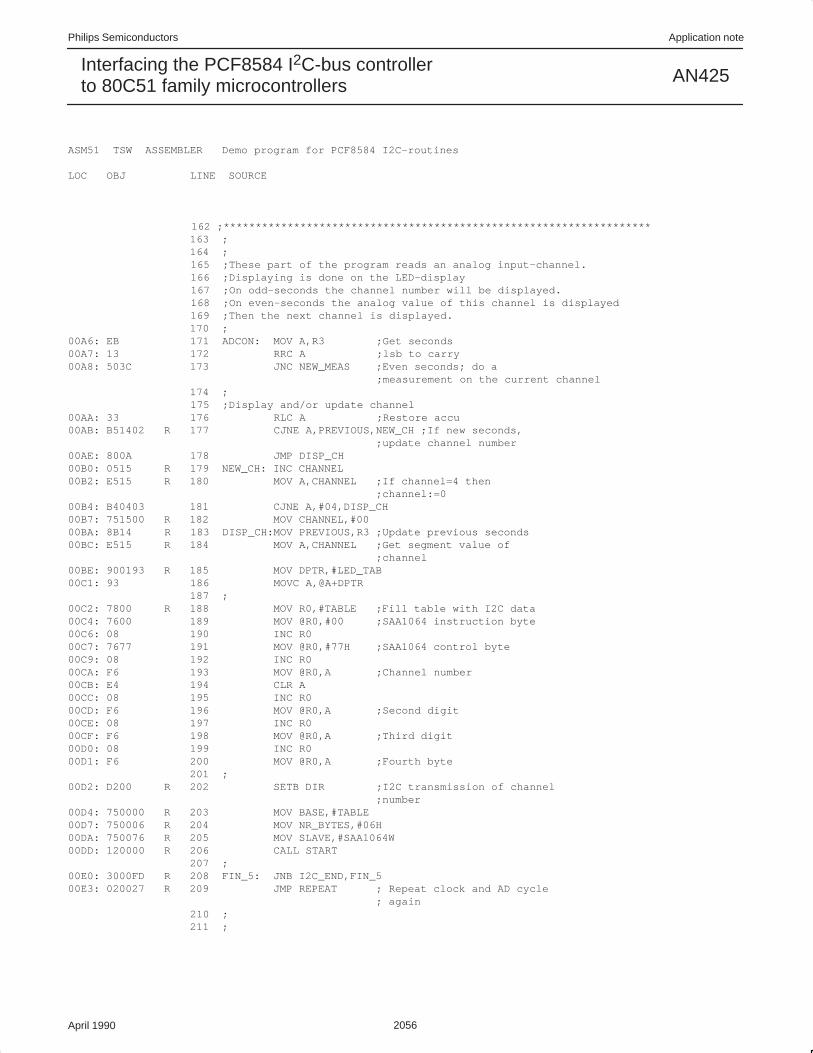
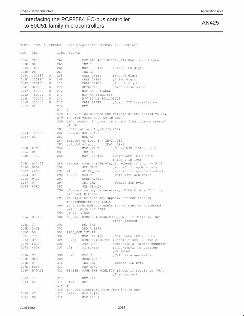
The third example program displays time from the PCF8583Pclock/calendar/RAM on the LCD display driven by the PCD8577.The LED display (driven by SAA1064) shows the value of theanalog inputs of the A/D converter PCF8591. The four analog inputsare scanned consecutively.
In this example, both transmit and receive sequences areimplemented as shown in the previous examples. The main clockpart is from lines 62-128. This contains the calls to the I2C routines.From lines 135-160, routines are shown that prepare the data to betransmitted. Lines 171 to 232 are the main program for the ADconverter and LED display. Lines 239 to 340 contain routines usedby the main program. This demo program can also be used with theI2C peripherals on the OM1016 demonstration board.

Philips Semiconductors Application note
AN425Interfacing the PCF8584 I2C-bus controllerto 80C51 family microcontrollers
April 1990 2045
ASM51 TSW ASSEMBLER Routines for PCF8584 LOC OBJ LINE SOURCE 1 $TITLE (Routines for PCF8584) 2 $PAGELENGTH(40) 3 ;Program written for PCF8584 as master 4 ; 5 PUBLIC READBYTE,READCONTR,SENDBYTE PUBLIC SENDCONTR,START,STOP 6 PUBLIC I2C_INIT 7 EXTRN BIT(I2C_END,DIR) 8 EXTRN DATA(SLAVE,IIC_CNT,NR_BYTES) 9 EXTRN NUMBER(SLAVE_ADR,I2C_CLOCK,PCF8584) 10 ; 11 ;Define code segment 12 ROUTINE SEGMENT CODE –––– 13 RSEG ROUTINE 14 ; 15 ;SENDBYTE sends a byte to PCF8584 with A0=0 16 ;Byte to be send must be in accu 0000: R 17 SENDBYTE: 0000: 900000 R 18 MOV DPTR,#PCF8584 ;Register address 0003: F0 19 SEND: MOVX @DPTR,A ;Send byte 0004: 22 20 RET 21 ; 22 ;SENDCONTR sends a byte to PCF8584 with A0=1 23 ;Byte to be send must be in accu 0005: 24 SENDCONTR: 0005: 900001 R 25 MOV DPTR,#PCF8584+01H ;Register address 0008: 80F9 26 JMP SEND 27 ; 28 ;READBYTE reads a byte from PCF8584 with A0=0 29 ;Received byte is stored in accu 000A: 30 READBYTE: 000A: 900000 R 31 MOV DPTR,#PCF8584 ;Register address 000D: E0 32 REC: MOVX A,@DPTR ;Receive byte 000E: 22 33 RET 34 ; 35 ;READCONTR reads a byte from PCF8584 with A0=1 36 ;Received byte is stored in accu 000F: 37 READCONTR: 000F: 900001 R 38 MOV DPTR,#PCF8584+01H ;Register address 0012: 80F9 39 JMP REC 40 ; 41 ;START tests if the I2C bus is ready. If ready a 42 ;START–condition will be sent, interrupt generation 43 ;and acknowledge will be enabled. 0014: 750000 R 44 START: MOV IIC_CNT,#00 ;Clear I2C byte counter 0017: 200002 R 45 JB DIR,PROCEED ;If DIR is ’receive’ then 001A: 0500 R 46 INC NR_BYTES ;increment NR_BYTES 001C: 7440 47 PROCEED:MOV A,#40H ; Read STATUS register of ; 8584 001E: 120005 R 48 CALL SENDCONTR 0021: 12000F R 49 TESTBB: CALL READCONTR 0024: 30E0FA 50 JNB ACC.0,TESTBB; Test BB/ bit 0027: E500 R 51 MOV A,SLAVE 0029: C200 R 52 CLR I2C_END ;Reset I2C ready bit002B: 120000 R 53 CALL SENDBYTE ;Send slave address 002E: 744D 54 MOV A,#01001101B;Generate START, set ENI, ;set ACK 0030: 120005 R 55 CALL SENDCONTR 0033: 22 56 RET 57 ; 58 ;STOP will generate a STOP condition and set the ;I2C_END bit 0034: 74C3 59 STOP: MOV A,#11000011B

Philips Semiconductors Application note
AN425Interfacing the PCF8584 I2C-bus controllerto 80C51 family microcontrollers
April 1990 2046
0036: 120005 R 60 CALL SENDCONTR ;Send STOP condition 0039: D200 R 61 SETB I2C_END ;Set I2C_END bit 003B: 22 62 RET 63 ; 64 ;I2C_init does the initialization of the PCF8584 003C: 65 I2C_INIT: 66 ;Write own slave address 003C: E4 67 CLR A 003D: 120005 R 68 CALL SENDCONTR ;Write to control register 0040: 7400 R 69 MOV A,#SLAVE_ADR 0042: 120000 R 70 CALL SENDBYTE ;Write to own slave ;register 71 ;Write clock register 0045: 7420 72 MOV A,#20H 0047: 120005 R 73 CALL SENDCONTR ;Write to control register 004A: 7400 R 74 MOV A,#I2C_CLOCK 004C: 120000 R 75 CALL SENDBYTE ;Write to clock register 004F: 22 76 RET 77 ; 0050: 78 END

Philips Semiconductors Application note
AN425Interfacing the PCF8584 I2C-bus controllerto 80C51 family microcontrollers
April 1990 2047
ASM51 TSW ASSEMBLER I2C INTERRUPT ROUTINE LOC OBJ LINE SOURCE 1 $TITLE (I2C INTERRUPT ROUTINE) 2 $PAGELENGTH(40) 3 ; 4 PUBLIC INT0_SRV 5 PUBLIC DIR,I2C_END 6 PUBLIC BASE,NR_BYTES,IIC_CNT,SLAVE 7 EXTRN CODE(SENDBYTE,SENDCONTR,STOP) EXTRN CODE(READBYTE,READCONTR) 8 ; 9 ;Define variables in RAM 10 IIC_VAR SEGMENT DATA –––– 11 RSEG IIC_VAR 0000: R 12 BASE: DS 1 ;Pointer to I2C table (till ;256) 0001: 13 NR_BYTES: DS 1 ;Number of bytes to rcv/trm0002: 14 IIC_CNT:DS 1 ;I2C byte counter 0003: 15 SLAVE: DS 1 ;Slave address after START 16 ; 17 ;Define variable segment 18 BIT_VAR SEGMENT DATA BITADDRESSABLE –––– 19 RSEG BIT_VAR 0000: R 20 STATUS: DS 1 ;Byte with flags 0000 R 21 I2C_END BIT STATUS.0 ;Defines if a I2C ;transmission is finished 22 ;’1’ is finished 23 ;’0’ is not ready 0000 R 24 DIR BIT STATUS.3 ;Defines direction of I2C ;transmission 25 ;’1’:Transmit ’0’:Receive 26 ; 27 ;Define code segment for routine 28 IIC_INT SEGMENT CODE PAGE –––– 29 RSEG IIC_INT 30 ; 31 ;Program uses registers in RB1 32 USING 1 33 ; 0000: R 34 INT0_SRV: 0000: C0E0 35 PUSH ACC ;Save acc. en psw on stack 0002: C0D0 36 PUSH PSW0004: 75D008 37 MOV PSW,#08H ;Select register bank 1 0007: 300016 R 38 JNB DIR,RECEIVE ;Test direction bit 39 ;8584 is MST/TRM 40 41 ;Program part to transmit bytes to IIC bus 000A: E502 R 42 MOV A,IIC_CNT ;Compare IIC_CNT and ;NR_BYTES 000C: B50105 R 43 CJNE A,NR_BYTES,PROCEED 000F: 120000 R 44 CALL STOP ;All bytes transmitted 0012: 8032 45 JMP EXIT 0014: A800 R 46 PROCEED:MOV R0,BASE ;RAM pointer 0016: E6 47 MOV A,@R0 ;Source is internal RAM 0017: 0500 R 48 INC BASE ;Update pointer of table 0019: 120000 R 49 CALL SENDBYTE ;Send byte to IIC bus 001C: 0502 R 50 INC IIC_CNT ;Update byte counter 001E: 8026 51 JMP EXIT 52 ; 53 ; 54 ;Program to receive byte from IIC bus 0020: 55 RECEIVE: 0020: E502 R 56 MOV A,IIC_CNT ;Test if last byte is to be ;received 0022: 04 57 INC A

Philips Semiconductors Application note
AN425Interfacing the PCF8584 I2C-bus controllerto 80C51 family microcontrollers
April 1990 2048
0023: 04 58 INC A 0024: B50105 R 59 CJNE A,NR_BYTES,PROC_RD 0027: 7448 60 MOV A,#01001000B;Last byte to be received. ;Disable ACK 0029: 120000 R 61 CALL SENDCONTR ;Write control word to ;PCF8584 002C: 120000 R 62 PROC_RD:CALL READBYTE ;Read I2C byte 002F: FC 63 MOV R4,A ;Save accu 64 ;If RECEIVE is entered after the transmission of 65 ;START+address then the result of READBYTE is not 66 ;relevant. READBYTE is used to start the generation ;of the clock pulses for the next byte to read. 67 ;This situation occurs when IIC_CNT is 0 0030: E4 68 CLR A ;Test IIC_CNT 0031: B50202 R 69 CJNE A,IIC_CNT,SAVE 0034: 8006 70 JMP END_TEST ;START is send. No relevant ;data in data reg. of 8584 0036: A800 R 71 SAVE: MOV R0,BASE 0038: EC 72 MOV A,R4 ;Destination is internal RAM0039: F6 73 MOV @R0,A 003A: 0500 R 74 INC BASE 003C: 0502 R 75 END_TEST:INC IIC_CNT ;Test if all bytes are ;received 003E: E501 R 76 MOV A,NR_BYTES 0040: B50203 R 77 CJNE A,IIC_CNT,EXIT 0043: 120000 R 78 CALL STOP ;All bytes received 79 ; 0046: D0D0 80 EXIT: POP PSW ;Restore PSW and accu 0048: D0E0 81 POP ACC 004A: 32 82 RETI 83 ; 004B: 84 END

Philips Semiconductors Application note
AN425Interfacing the PCF8584 I2C-bus controllerto 80C51 family microcontrollers
April 1990 2049
ASM51 TSW ASSEMBLER Send a string of bytes to the PCD8577 on OM1016 LOC OBJ LINE SOURCE 1 $TITLE (Send a string of bytes to the PCD8577 on OM1016) 2 $PAGELENGTH(40) 3 ; 4 ;This program is an example to transmit bytes via ;PCF8584 5 ;to the I2C–bus 6 ; 7 PUBLIC SLAVE_ADR,I2C_CLOCK,PCF8584 8 EXTRN CODE(I2C_INIT,INT0_SRV,START) 9 EXTRN BIT(I2C_END,DIR) 10 EXTRN DATA(BASE,NR_BYTES,IIC_CNT,SLAVE) 11 ; 12 ; 13 ;Define used segments 14 USER SEGMENT CODE ;Segment for user program 15 RAMTAB SEGMENT DATA ;Segment for table in ;internal RAM 16 RAMVAR SEGMENT DATA ;Segment for RAM variables ;in RAM 17 ; 18 ; –––– 19 RSEG RAMVAR 0000: R 20 STACK: DS 20 ;Reserve stack area 21 ; 22 ; –––– 23 CSEG AT 00H 0000: 020000 R 24 JMP MAIN ;Reset vector 25 ; 26 ; –––– 27 CSEG AT 03H 0003: 020000 R 28 JMP INT0_SRV ;I2C interrupt vector ;(INT0/) 29 ; 30 ; –––– 31 RSEG USER 32 ;Define I2C clock, own slave address and PCF8584 ;hardware address 0055 33 SLAVE_ADR EQU 55H ;Own slave address is 55H 001C 34 I2C_CLOCK EQU 00011100B ;12.00MHz/90kHz 0000 35 PCF8584 EQU 0000H ;PCF8584 address with A0=0 36 ;0000: 7581FF R 37 MAIN: MOV SP,#STACK–1 ;Initialize stack pointer 38 ;Initialize 8031 interrupt registers for I2C ;interrupt 0003: D2A8 39 SETB EX0 ;Enable interrupt INT0/ 0005: D2AF 40 SETB EA ;Set global enable 0007: D2B8 41 SETB PX0 ;Priority level ’1’ 0009: D288 42 SETB IT0 ;INT0/ on falling edge 43 ; 44 ;Initialize PCF8584 000B: 120000 R 45 CALL I2C_INIT 46 ; 47 ;Make a table in RAM with data to be transmitted. 000E: 120021 R 48 CALL MAKE_TAB 49 ; 50 ;Set variables to control PCF8584 0011: D200 R 51 SETB DIR ;DIR=’transmission’ 0013: 750000 R 52 MOV BASE,#TABLE ;Start address of I2C–data 0016: 750005 R 53 MOV NR_BYTES,#05H ;5 bytes must be ;transferred 0019: 750074 R 54 MOV SLAVE,#01110100B ;Slave address PCD8577 ; + WR/

Philips Semiconductors Application note
AN425Interfacing the PCF8584 I2C-bus controllerto 80C51 family microcontrollers
April 1990 2050
001C: 120000 R 55 CALL START ;Start I2C transmission 56 ; 57 ; 001F: 80FE 58 LOOP: JMP LOOP ;Endless loop when program ;is finished 59 ; 60 ; 0021: 61 MAKE_TAB: 0021: 7800 R 62 MOV R0,#TABLE ;Make data ready for I2C ;transmission 0023: 7600 63 MOV @R0,#00 ;Controlword PCD8577 0025: 08 64 INC R0 0026: 76FC 65 MOV @R0,#0FCH ;’0’ 0028: 08 66 INC R0 0029: 7660 67 MOV @R0,#60H ;’1’ 002B: 08 68 INC R0 002C: 76DA 69 MOV @R0,#0DAH ;’2’ 002E: 08 70 INC R0 002F: 76F2 71 MOV @R0,#0F2H ;’3’ 0031: 22 72 RET 73 ; 74 ; –––– 75 RSEG RAMTAB 0000: R 76 TABLE: DS 10 ;Reserve space in internal ;data RAM 77 ;for I2C data to transmit 78 ; 79 ; 000A: 80 END

Philips Semiconductors Application note
AN425Interfacing the PCF8584 I2C-bus controllerto 80C51 family microcontrollers
April 1990 2051
ASM51 TSW ASSEMBLER Receive 2 bytes from the PCF8574P on OM1016 LOC OBJ LINE SOURCE 1 $TITLE (Receive 2 bytes from the PCF8574P on OM1016) 2 $PAGELENGTH(40) 3 ; 4 ;This program is an example to receive bytes via ;PCF8584 5 ;from the I2C–bus 6 ; 7 PUBLIC SLAVE_ADR,I2C_CLOCK,PCF8584 8 EXTRN CODE(I2C_INIT,INT0_SRV,START) 9 EXTRN BIT(I2C_END,DIR) 10 EXTRN DATA(BASE,NR_BYTES,IIC_CNT,SLAVE) 11 ; 12 ; 13 ;Define used segments 14 USER SEGMENT CODE ;Segment for user program 15 RAMTAB SEGMENT DATA ;Segment for table in ;internal RAM 16 RAMVAR SEGMENT DATA ;Segment for RAM variables ;in RAM 17 ; 18 ; –––– 19 RSEG RAMVAR 0000: R 20 STACK: DS 20 ;Reserve stack area 21 ; 22 ; –––– 23 CSEG AT 00H 0000: 020000 R 24 JMP MAIN ;Reset vector 25 ; 26 ; –––– 27 CSEG AT 03H 0003: 020000 R 28 JMP INT0_SRV ;I2C interrupt vector ;(INT0/) 29 ; 30 ; –––– 31 RSEG USER 32 ;Define I2C clock, own slave address and PCF8584 ;hardware address 0055 33 SLAVE_ADR EQU 55H ;Own slave address is 55H 001C 34 I2C_CLOCK EQU 00011100B ;12.00MHz/90kHz 0000 35 PCF8584 EQU 0000H ;PCF8584 address with A0=0 36 ;0000: 7581FF R 37 MAIN: MOV SP,#STACK–1 ;Initialize stack pointer 38 ;Initialize 8031 interrupt registers for I2C ;interrupt 0003: D2A8 39 SETB EX0 ;Enable interrupt INT0/ 0005: D2AF 40 SETB EA ;Set global enable 0007: D2B8 41 SETB PX0 ;Priority level ’1’ 0009: D288 42 SETB IT0 ;INT0/ on falling edge 43 ; 44 ;Initialize PCF8584 000B: 120000 R 45 CALL I2C_INIT 46 ; 47 ;Set variables to control PCF8584 000E: C200 R 48 CLR DIR ;DIR=’receive’ 0010: 750000 R 49 MOV BASE,#TABLE ;Start address of I2C–data 0013: 750002 R 50 MOV NR_BYTES,#02H ;2 bytes must be received0016: 75004F R 51 MOV SLAVE,#01001111B ;Slave address PCF8574 ; + RD 0019: 120000 R 52 CALL START ;Start I2C transmission 53 ; 54 ; 001C: 80FE 55 LOOP: JMP LOOP ;Endless loop when program ;is finished

Philips Semiconductors Application note
AN425Interfacing the PCF8584 I2C-bus controllerto 80C51 family microcontrollers
April 1990 2052
56 ; 57 ; –––– 58 RSEG RAMTAB 0000: R 59 TABLE: DS 10 ;Reserve space in internal ;data RAM 60 ;for received I2C data 61 ; 62 ; 000A: 63 END

Philips Semiconductors Application note
AN425Interfacing the PCF8584 I2C-bus controllerto 80C51 family microcontrollers
April 1990 2053
ASM51 TSW ASSEMBLER Demo program for PCF8584 I2C–routines LOC OBJ LINE SOURCE 1 $TITLE (Demo program for PCF8584 I2C–routines) 2 $PAGELENGTH(40) 3 ;Program displays on the LCD display the time (with ;PCF8583). Dots on LCD display blink every second. 5 ;On the LED display the values of the successive ;analog input channels are shown. 7 ;Program reads analog channels of PCF8591P. 8 ;Channel number and channel value are displayed ;successively. 9 ;Values are displayed on LCD and LED display on I2C ;demo board. 10 ; 11 PUBLIC SLAVE_ADR,I2C_CLOCK,PCF8584 12 EXTRN CODE(I2C_INIT,INT0_SRV,START) 13 EXTRN BIT(I2C_END,DIR) 14 EXTRN DATA(BASE,NR_BYTES,IIC_CNT,SLAVE) 15 ; 16 ; 17 ;Define used segments 18 USER SEGMENT CODE ;Segment for user program 19 RAMTAB SEGMENT DATA ;Segment for table in ;internal RAM 20 RAMVAR SEGMENT DATA ;Segment for variables 21 ; –––– 22 RSEG RAMVAR 0000: R 23 STACK: DS 20 ;Stack area (20 bytes) 0014: 24 PREVIOUS: DS 1 ;Store for previous seconds0015: 25 CHANNEL:DS 1 ;Channel number to be ;sampled 0016: 26 AN_VAL: DS 1 ;Analog value sampled ;channel 0017: 27 CONVAL: DS 3 ;Converted BCD value sampled ;channel 28 ; –––– 29 CSEG AT 00H 0000: 020000 R 30 LJMP MAIN ;Reset vector 31 ; –––– 32 CSEG AT 03H ;INT0/ 0003: 020000 R 33 LJMP INT0_SRV ;Vector I2C–interrupt 34 ; 35 ; –––– 36 RSEG USER 37 ;Define I2C clock, own slave address and address for ;main processor 0055 38 SLAVE_ADR EQU 55H ;Own slaveaddress is 55h 001C 39 I2C_CLOCK EQU 00011100B ;12.00MHz/90kHz 0000 40 PCF8584 EQU 0000H ;Address of PCF8584. This ;must be an EVEN number!! 41 ;Define addresses of I2C peripherals 00A3 42 PCF8583R EQU 10100011B ;Address PCF8583 with Read ;active 00A2 43 PCF8583W EQU 10100010B ;Address PCF8583 with Write ;active 009F 44 PCF8591R EQU 10011111B ;Address PCF8591 with Read ;active 009E 45 PCF8591W EQU 10011110B ;Address PCF8591 with Write ;active 0074 46 PCD8577W EQU 01110100B ;Address PCD8577 with Write ;active 0076 47 SAA1064W EQU 01110110B ;Address SAA1064 with Write ;active 48 ; 0000: 7581FF R 49 MAIN: MOV SP,#STACK–1 ;Define stack pointer

Philips Semiconductors Application note
AN425Interfacing the PCF8584 I2C-bus controllerto 80C51 family microcontrollers
April 1990 2054
ASM51 TSW ASSEMBLER Demo program for PCF8584 I2C–routines
LOC OBJ LINE SOURCE 50 ;Initialize 80C31 interrupt registers for I2C ;interrupt (INT0/) 0003: D2A8 51 SETB EX0 ;Enable interrupt INT0/ 0005: D2AF 52 SETB EA ;Set global enable 0007: D2B8 53 SETB PX0 ;Priority level is ’1’ 0009: D288 54 SETB IT0 ;INT0/ on falling edge 55 ;Initialize PCF8584 000B: 120000 R 56 CALL I2C_INIT 57 ; 000E: 751500 R 58 MOV CHANNEL,#00 ;Set AD–channel 59 ; 60 ;Time must be read from PCF8583. 61 ;First write word address and control register of ;PCF8583. 0011: D200 R 62 SETB DIR ;DIR=’transmission’ 0013: 750000 R 63 MOV BASE,#TABLE ;Start address I2C data 0016: 750002 R 64 MOV NR_BYTES,#02H ;Send 2 bytes 0019: 7500A2 R 65 MOV SLAVE,#PCF8583W 001C: E4 66 CLR A 001D: F500 R 67 MOV TABLE,A ;Data to be sent (word ;address). 001F: F501 R 68 MOV TABLE+1,A ; ” (control ;byte) 0021: 120000 R 69 CALL START ;Start transmission. 0024: 3000FD R 70 FIN_1: JNB I2C_END,FIN_1 ;Wait till transmission ;finished 71 ;Send word address before reading time 0027: D200 R 72 REPEAT: SETB DIR ;’transmission0029: 750000 R 73 MOV BASE,#TABLE ;I2C data 002C: 7500A2 R 74 MOV SLAVE,#PCF8583W 002F: 7401 75 MOV A,#01 0031: F500 R 76 MOV NR_BYTES,A ;Send 1 byte 0033: F500 R 77 MOV TABLE,A ;Data to be sent is ’1’ 0035: 120000 R 78 CALL START ;Start I2C transmission 0038: 3000FD R 79 FIN_2: JNB I2C_END,FIN_2 ;Wait till transmission ;finished 80 ; 81 ;Time can now be read from PCF8583. Data read is 82 ;hundredths of sec’s, sec’s, min’s and hr’s 003B: C200 R 83 CLR DIR ;DIR=’receive’ 003D: 750000 R 84 MOV BASE,#TABLE ;I2C table 0040: 750004 R 85 MOV NR_BYTES,#04; 4 bytes to receive 0043: 7500A3 R 86 MOV SLAVE,#PCF8583R 0046: 120000 R 87 CALL START ;Start I2C reception 0049: 3000FD R 88 FIN_3: JNB I2C_END,FIN_3 ;Wait till finished 89 ; 90 ;Transfer data to R2...R5 004C: 7800 R 91 MOV R0,#TABLE ;Set pointers 004E: 7902 92 MOV R1,#02H ;Pointer R2 0050: E6 93 TRANSFER:MOV A,@R0 0051: F7 94 MOV @R1,A 0052: 08 95 INC R0 0053: 09 96 INC R1 0054: D500F9 R 97 DJNZ NR_BYTES,TRANSFER 0057: ED 98 MOV A,R5 ;Mask of hour counter 0058: 543F 99 ANL A,#3FH 005A: FD 100 MOV R5,A 101 ; 102 ;Data must now be displayed on LCD display. 103 ;First minutes and hours (in R4 and R5) must be 104 ;converted from BCD to LCD segment data.The segment ;data 105 ;will be transferred to TABLE. R0 is pointer to table

Philips Semiconductors Application note
AN425Interfacing the PCF8584 I2C-bus controllerto 80C51 family microcontrollers
April 1990 2055
ASM51 TSW ASSEMBLER Demo program for PCF8584 I2C–routines
LOC OBJ LINE SOURCE 005B: 7800 R 106 MOV R0,#TABLE 005D: 7600 107 MOV @R0,#00H ;Control word for PCD8577 005F: 08 108 INC R0 0060: 120080 R 109 CALL CONV 110 ; 111 ;Switch on dp between hours and minutes 0063: 430301 R 112 ORL TABLE+3,#01H 113 ;If lsb of seconds is ’0’ then switch on dp. 0066: EB 114 MOV A,R3 ;Get seconds 0067: 13 115 RRC A ;lsb in carry 0068: 4003 116 JC PROCEED 006A: 430101 R 117 ORL TABLE+1,#01H;switch on dp 118 ; 119 ;Now the time (hours,minutes) can be displayed on ;the LCD 006D: 120 PROCEED: 006D: D200 R 121 SETB DIR ;Direction ’transmit’ 006F: 750000 R 122 MOV BASE,#TABLE 0072: 750005 R 123 MOV NR_BYTES,#05H 0075: 750074 R 124 MOV SLAVE,#PCD8577W 0078: 120000 R 125 CALL START ;Start transmission 126 ; 007B: 3000FD R 127 FIN_4: JNB I2C_END,FIN_4 007E: 8026 128 JMP ADCON ;Proceed with AD–conversion ;part 129 ; 130 ;***************************************************************** 131 ;Routines used by clock part of demo 132 ; 133 ;CONV converts hour and minute data to LCD data and stores 134 ;it in TABLE. 0080: 90009C R 135 CONV: MOV DPTR,#LCD_TAB ;Base for LCD segment table0083: ED 136 MOV A,R5 ;Hours to accu 0084: C4 137 SWAP A ;Swap nibbles 0085: 120096 R 138 CALL LCD_DATA ;Convert 10’s hours to LCD ;data in table 0088: ED 139 MOV A,R5 ;Get hours 0089: 120096 R 140 CALL LCD_DATA 008C: EC 141 MOV A,R4 ;Get minutes 008D: C4 142 SWAP A008E: 120096 R 143 CALL LCD_DATA ;Convert 10’s minutes 0091: EC 144 MOV A,R4 0092: 120096 R 145 CALL LCD_DATA ;Convert minutes 0095: 22 146 RET 147 ; 148 ;LCD_DATA gets data from segment table and stores it in TABLE 0096: 540F 149 LCD_DATA:ANL A,#0FH ;Mask off LS–nibble 0098: 93 150 MOVC A,@A+DPTR ;Get LCD segment data 0099: F6 151 MOV @R0,A ;Save data in table 009A: 08 152 INC R0 009B: 22 153 RET 154 ; 155 ;LCD_TAB is conversion table for LCD 009C: 156 LCD_TAB: 009C: FC60DA 157 DB 0FCH,60H,0DAH; ’0’,’1’,’2’ 009F: F266B6 158 DB 0F2H,66H,0B6H; ’3’,’4’,’5’ 00A2: 3EE0FE 159 DB 3EH,0E0H,0FEH; ’6’,’7’,’8’ 00A5: E6 160 DB 0E6H ; ’9’ 161 ;
Philips Semiconductors Application note
AN425Interfacing the PCF8584 I2C-bus controllerto 80C51 family microcontrollers
April 1990 2056
ASM51 TSW ASSEMBLER Demo program for PCF8584 I2C–routines
LOC OBJ LINE SOURCE
162 ;******************************************************************* 163 ; 164 ; 165 ;These part of the program reads an analog input–channel. 166 ;Displaying is done on the LED–display 167 ;On odd–seconds the channel number will be displayed. 168 ;On even–seconds the analog value of this channel is displayed 169 ;Then the next channel is displayed. 170 ; 00A6: EB 171 ADCON: MOV A,R3 ;Get seconds 00A7: 13 172 RRC A ;lsb to carry 00A8: 503C 173 JNC NEW_MEAS ;Even seconds; do a ;measurement on the current channel 174 ; 175 ;Display and/or update channel 00AA: 33 176 RLC A ;Restore accu 00AB: B51402 R 177 CJNE A,PREVIOUS,NEW_CH ;If new seconds, ;update channel number 00AE: 800A 178 JMP DISP_CH 00B0: 0515 R 179 NEW_CH: INC CHANNEL 00B2: E515 R 180 MOV A,CHANNEL ;If channel=4 then ;channel:=000B4: B40403 181 CJNE A,#04,DISP_CH 00B7: 751500 R 182 MOV CHANNEL,#00 00BA: 8B14 R 183 DISP_CH:MOV PREVIOUS,R3 ;Update previous seconds 00BC: E515 R 184 MOV A,CHANNEL ;Get segment value of ;channel 00BE: 900193 R 185 MOV DPTR,#LED_TAB 00C1: 93 186 MOVC A,@A+DPTR 187 ; 00C2: 7800 R 188 MOV R0,#TABLE ;Fill table with I2C data 00C4: 7600 189 MOV @R0,#00 ;SAA1064 instruction byte 00C6: 08 190 INC R0 00C7: 7677 191 MOV @R0,#77H ;SAA1064 control byte 00C9: 08 192 INC R0 00CA: F6 193 MOV @R0,A ;Channel number 00CB: E4 194 CLR A 00CC: 08 195 INC R0 00CD: F6 196 MOV @R0,A ;Second digit 00CE: 08 197 INC R0 00CF: F6 198 MOV @R0,A ;Third digit 00D0: 08 199 INC R0 00D1: F6 200 MOV @R0,A ;Fourth byte 201 ; 00D2: D200 R 202 SETB DIR ;I2C transmission of channel ;number 00D4: 750000 R 203 MOV BASE,#TABLE 00D7: 750006 R 204 MOV NR_BYTES,#06H 00DA: 750076 R 205 MOV SLAVE,#SAA1064W 00DD: 120000 R 206 CALL START 207 ; 00E0: 3000FD R 208 FIN_5: JNB I2C_END,FIN_5 00E3: 020027 R 209 JMP REPEAT ; Repeat clock and AD cycle ; again 210 ; 211 ;

Philips Semiconductors Application note
AN425Interfacing the PCF8584 I2C-bus controllerto 80C51 family microcontrollers
April 1990 2057
ASM51 TSW ASSEMBLER Demo program for PCF8584 I2C–routines
LOC OBJ LINE SOURCE 212 ;Measure and display the value of an AD–channel 00E6: 120108 R 213 NEW_MEAS: CALL AD_VAL ;Do measurement 214 ;Wait till values are available 00E9: 3000FD R 215 FIN_6: JNB I2C_END,FIN_6 216 ;Relevant byte in TABLE+1. Transfer to AN_VAL 00EC: 7801 R 217 MOV R0,#TABLE+1 00EE: 8616 R 218 MOV AN_VAL,@R0 00F0: E516 R 219 MOV A,AN_VAL ;Channel value in accu for ;conversion 220 ;AN_VAL is converted to BCD value of the measured ;voltage. 221 ;Input value for CONVERT in accu 222 ;Address for MSByte in R1 00F2: 7917 R 223 MOV R1,#CONVAL 00F4: 120154 R 224 CALL CONVERT 225 ;Convert 3 bytes of CONVAL to LED–segments 00F7: 900193 R 226 MOV DPTR,#LED_TAB ;Base of segment table 00FA: 7817 R 227 MOV R0,#CONVAL 00FC: 12018A R 228 CALL SEG_LOOP 229 ;Display value of channel to LED display 00FF: 12012C R 230 CALL LED_DISP 0102: 3000FD R 231 FIN_8: JNB I2C_END,FIN_8 ;Wait till I2C ;transmission is ended 0105: 020027 R 232 JMP REPEAT ;Repeat clock and AD cycle 233 ; 234 ;**************************************************************** 235 ;Routines used for AD converter. 236 ; 237 ;AIN reads an analog values from channel denoted by ;CHANNEL. 238 ;Send controlbyte: 0108: D200 R 239 AD_VAL: SETB DIR ;I2C transmission 010A: 7800 R 240 MOV R0,#TABLE ;Define control word 010C: A615 R 241 MOV @R0,CHANNEL 010E: 750000 R 242 MOV BASE,#TABLE ;Set base at table 0111: 750001 R 243 MOV NR_BYTES,#01H ;Number of bytes to be ;send 0114: 75009E R 244 MOV SLAVE,#PCF8591W ;Slave address PCF85910117: 120000 R 245 CALL START ;Start transmission of ;controlword 011A: 3000FD R 246 FIN_7: JNB I2C_END,FIN_7 ;Wait until transmission is ;finished 247 ;Read 2 data bytes from AD–converter 248 ;First data byte is from previous conversion and not 249 ;relevant 011D: C200 R 250 CLR DIR ;I2C reception 011F: 750000 R 251 MOV BASE,#TABLE ;Bytes must be stored in ;TABLE 0122: 750002 R 252 MOV NR_BYTES,#02H; Receive 3 bytes0125: 75009F R 253 MOV SLAVE,#PCF8591R ;Slave address PCF8591 0128: 120000 R 254 CALL START 012B: 22 255 RET 256 ; 257 ;LED_DISP displays the data of 3 bytes from address ;CONVAL 012C: 258 LED_DISP: 012C: 431780 R 259 ORL CONVAL,#80H ;Set decimal point 012F: 7800 R 260 MOV R0,#TABLE 0131: 7917 R 261 MOV R1,#CONVAL 0133: 7600 262 MOV @R0,#00 ;SAA1064 instruction byte 0135: 08 263 INC R0
Philips Semiconductors Application note
AN425Interfacing the PCF8584 I2C-bus controllerto 80C51 family microcontrollers
April 1990 2058
ASM51 TSW ASSEMBLER Demo program for PCF8584 I2C–routines
LOC OBJ LINE SOURCE 0136: 7677 264 MOV @R0,#01110111B ;SAA1064 control byte 0138: 08 265 INC R0 0139: 7600 266 MOV @R0,#00 ;First LED digit 013B: 08 267 INC R0 013C: 120185 R 268 CALL GETBY ;Second digit 013F: 120185 R 269 CALL GETBY ;Third digit 0142: 120185 R 270 CALL GETBY ;Fourth digit 0145: D200 R 271 SETB DIR ;I2C transmission 0147: 750000 R 272 MOV BASE,#TABLE 014A: 750006 R 273 MOV NR_BYTES,#06 014D: 750076 R 274 MOV SLAVE,#01110110B 0150: 120000 R 275 CALL START ;Start I2C transmission 0153: 22 276 RET 277 ; 278 ;CONVERT calculates the voltage of the analog value. 279 ;Analog value must be in accu 280 ;BCD result (3 bytes) is stored from address stored ;in R1 281 ;Calculation: AN_VAL*(5/256) 0154: 75F005 282 CONVERT:MOV B,#05 0157: A4 283 MUL AB 284 ;b2..b0 of reg. B : 2E+2..2E0 285 ;b7..b0 of accu : 2E–1..2E–8 0158: A7F0 286 MOV @R1,B ;Store MSB (10E0–units) 015A: 09 287 INC R1 015B: 7700 288 MOV @R1,#00 ;Calculate 10E–1 unit ;(10E–1 is 19h)015D: B41C02 289 TEN_CH: CJNE A,#19H+03H,V1 ;Check if accu <= 0.11 0160: 8002 290 JMP TENS ;accu=0.11; update tens 0162: 4006 291 V1: JC NX_CON ;accu<0.11; update hundreds0164: C3 292 TENS: CLR C ;Calculate new value 0165: 9419 293 SUBB A,#19H 0167: 07 294 INC @R1 ;Update BCD byte 0168: 80F3 295 JMP TEN_CH 296 ;Correction may be necessary. With 8 bits ’0.1’ is ;in fact 0.0976. 297 ;A digit of ’0A’ may appear. Correct this by ;decrementing the digit. 298 ;The intermediate result result must be corrected ;with 10*(0.1–0.0976) 299 ;This is 06H 016A: B70A03 300 NX_CON: CJNE @R1,#0AH,PROC_CON ; If digit is ’0A’ ;then correct 016D: 17 301 DEC @R1 016E: 2419 302 ADD A,#19H 0170: 09 303 PROC_CON:INC R1 0171: 7700 304 MOV @R1,#00 ;Calculate 10E–2 units 0173: B40302 305 HUND: CJNE A,#03H,V2 ;Check if accu <= 10E–2 0176: 8002 306 JMP HUNS ;accu=10E–2; update hundreds0178: 4006 307 V2: JC FINISH ;accu<10E–2; conversion ;finished 017A: C3 308 HUNS: CLR C ;Calculate new value 017B: 9403 309 SUBB A,#03H 017D: 07 310 INC @R1 ;Update BCD byte 017E: 80F3 311 JMP HUND 0180: B70A01 312 FINISH: CJNE @R1,#0AH,FIN ;Check if result is ’0A’. ;Then correct. 0183: 17 313 DEC @R1 0184: 22 314 FIN: RET 315 ; 316 ;CALLBY transfers byte from @R1 to @R0 0185: E7 317 GETBY: MOV A,@R1 0186: F6 318 MOV @R0,A

Philips Semiconductors Application note
AN425Interfacing the PCF8584 I2C-bus controllerto 80C51 family microcontrollers
April 1990 2059
ASM51 TSW ASSEMBLER Demo program for PCF8584 I2C–routines
LOC OBJ LINE SOURCE
0187: 08 319 INC R0 0188: 09 320 INC R1 0189: 22 321 RET 322 ; 323 ;SEG_LOOP converts 3 values to segment values. 324 ;R0 contains address of source and destination 325 ;DPTR contains base of table 018A: 7903 326 SEG_LOOP: MOV R1,#03 ;Loop counter 018C: E6 327 INLOOP: MOV A,@R0 ;Get value to be displayed 018D: 93 328 MOVC A,@A+DPTR ;Get segment value from ;table 018E: F6 329 MOV @R0,A ;Store segment data 018F: 08 330 INC R0 0190: D9FA 331 DJNZ R1,INLOOP 0192: 22 332 RET 333 ; 334 ; 335 ;LED_TAB is conversion table for BCD to LED segments0193: 336 LED_TAB: 0193: 7D483E 337 DB 7DH,48H,3EH ; ’0’,’1’,’2’ 0196: 6E4B67 338 DB 6EH,4BH,67H ; ’3’,’4’,’5’ 0199: 734C7F 339 DB 73H,4CH,7FH ; ’6’,’7’,’8’ 019C: 4F 340 DB 4FH ; ’9’ 341 ; 342 ;************************************************************ 343 ; –––– 344 RSEG RAMTAB 0000: R 345 TABLE: DS 10 346 ; 000A: 347 END
Philips Semiconductors Products Product specification
AN425Interfacing the PCF8584 I2C-bus controllerto 80C51 family microcontrollers
Philips Semiconductors and Philips Electronics North America Corporation reserve the right to make changes, without notice, in the products,including circuits, standard cells, and/or software, described or contained herein in order to improve design and/or performance. PhilipsSemiconductors assumes no responsibility or liability for the use of any of these products, conveys no license or title under any patent, copyright,or mask work right to these products, and makes no representations or warranties that these products are free from patent, copyright, or maskwork right infringement, unless otherwise specified. Applications that are described herein for any of these products are for illustrative purposesonly. Philips Semiconductors makes no representation or warranty that such applications will be suitable for the specified use without further testingor modification.
LIFE SUPPORT APPLICATIONSPhilips Semiconductors and Philips Electronics North America Corporation Products are not designed for use in life support appliances, devices,or systems where malfunction of a Philips Semiconductors and Philips Electronics North America Corporation Product can reasonably be expectedto result in a personal injury. Philips Semiconductors and Philips Electronics North America Corporation customers using or selling PhilipsSemiconductors and Philips Electronics North America Corporation Products for use in such applications do so at their own risk and agree to fullyindemnify Philips Semiconductors and Philips Electronics North America Corporation for any damages resulting from such improper use or sale.
Philips Semiconductors811 East Arques AvenueP.O. Box 3409Sunnyvale, California 94088–3409Telephone 800-234-7381
Copyright Philips Electronics North America Corporation 1997All rights reserved. Printed in U.S.A.