
29540824708539
362
Ceramic Fabrication Technology Roy W. Rice Alexandria, Virginia M A R C E L E L MARCEL DEKKER, INC. N E W YORK • BASEL Copyright © 2003 Marcel Dekker, Inc.
Transcript of 29540824708539
7/29/2019 29540824708539
http://slidepdf.com/reader/full/29540824708539 1/361
C e r a m i c
Fabr ica t ionTechnology
R oy W . RiceAlexandria, Virginia
M A R C E L
E LM A R C E L D E K K E R , I N C . N E W Y O R K • B A S E L
Copyright © 2003 Marcel Dekker, Inc.

7/29/2019 29540824708539
http://slidepdf.com/reader/full/29540824708539 2/361
Library of Congress Cataloging-in-Publication Data
A ca t a log r eco rd fo r t h i s book is ava i l ab le f rom th e Libra ry o f Congress .
ISBN: 0-8247-0853-9
This book is pr inted on ac id-free paper .
Headquarters
Marcel Dekker , I n c .
27 0 Madison A venue , N ew York, N Y 10016
tel: 212-696-9000; fa x: 212-685-4540
Eastern Hemisphere Distribution
Marcel Dekker AG
Hutgasse 4, Postfach 812, CH-4001 Basel , Switzer lan d
tel : 41-61-260-6300; fa x: 41-61-260-6333
W o rld W id e W e b
http://www.dekker.com
T h e publ isher offers discounts o n th is book when ordered in bulk quantit ies. F or m ore in fo r -
mat io n , write to Special Sales/Professional Market ing a t the headquarters address above.
Copyright © 2003 by Marcel Dekker, Inc. All Rights Reserved.
Nei the r t h i s book n o r an y part m a y b e reproduced o r t r ansmi t t ed i n an y form o r b y an y
m eans , e l ec tron ic o r m e c h a n i c a l , i n c l u d in g p h o t o c o p y i n g , m i c r o f il m i n g , a n d r eco rd ing , o r
b y a n y i n f o r m a t i o n s to r a g e a n d r e t r i eva l sys t em , wi tho u t pe rmiss ion in wri t ing from th e
publ isher .
C u r r e n t pr in t ing ( l as t d ig i t ) :
1 0 9 8 7 6 5 4 3 2 1
PRINTED IN THE UNITED STATES OF A M E R I C A
Copyright © 2003 Marcel Dekker, Inc.
7/29/2019 29540824708539
http://slidepdf.com/reader/full/29540824708539 3/361
MATERIALS ENGINEERING
1. Modern Ceramic Engineering: Properties, Processing, and Use in De-
sign: Second Edition, Revised and Expanded, David W . Richer-son
2. Introduction to Engineering Materials: Behavior, Properties, and
Selection, G. T. Murray
3. Rapidly Solidified Alloys: Processes .Structures .Applications, editedby Howard H. Liebermann
4. Fiber and Whisker Reinforced Ceramics for Structural Applications,
David Belitskus
5. Thermal Analysis of Materials, Robert F. Speyer6. Friction and Wear of Ceramics, edited by Said Jahanmir7. Mechanical Properties of Metallic Composites, edited by Shojiro
Ochiai
8. Chemical Processing of Ceramics, edited by Burtrand I. Lee and
Edward J. A. Pope
9. Handbook of Advanced Materials Testing, edited by Nicholas P.
Cheremisinoff and Pa ul N. Cheremisinoff10. Ceramic Processing and Sintering, M. N. Rahaman
11. Composites Engineering Handbook, edited by P. K. Mallick
12. Porosity of Ceramics, Roy W. Rice13. Intermetallic and Ceramic Coatings, edited by Narendra B. Dahotre
and T. S. Sudarshan
14. Adhesion Promotion Techniques: Technological Applications, editedby K.LMittal and A. Pizzi
15. Impurities in Engineering Materials: Impact, Reliability, and Control,
edited by Clyde L Briant16. Ferroelectric Devices, Kenji Uchino17. Mechanical Properties of Ceramics and Composites: Grain and Par-
ticle Effects, Roy W. Rice
18. Solid Lubrication Fundamentals and Applications, Kazuhisa Miyoshi19. Modeling for Casting and Solidification Processing, edited by Kuang-
O (Oscar) Yu
20. Ceramic Fabrication Technology, Roy W. Rice
Additional Volumes in Preparation
Coatings for Polymers and Plastics, edited by Rose Ann Ryntz and PhilipV . Yaneff
Micromechatronics, Kenji Uchino and Jayne Giniewicz
Copyright © 2003 Marcel Dekker, Inc.
7/29/2019 29540824708539
http://slidepdf.com/reader/full/29540824708539 4/361
Preface
There is a spectrum of needs fo r reference, overview, and instruct ional m ater ia lconcern ing the fabr icat ion of ceramic and ceramic composi te specimens and es-
pecial ly components. These needs range f rom, a t one extreme, addressing basic
scientific principles and paramete rs of different processing and f ab r ica t ion m eth-
ods to, at the other extreme, basic engineering aspects, including costs and re-
lated operat ional factors. Scientific principles a re most extensively t reated invarious books that foc us on in dividual, or a l im ited rang e of, establ ishe d process-
in g methods, mostly those based exclusively on pressureless sintering. Such
books m ay address in a per func to ry m anner , or not a t al l , im portant topics such
as pressure sintering processes, melt processing and fabricat ion, and chemical
reac t ion processes, e special ly the im portant subjec t of che m ical vapor deposit ion
(CVD). Some engineering aspects of some processes are t reated in some books,
but most ly in a l imi ted way and often in older books. The counterpart of basic
scientific and basic e ngine er ing aspects a re deta i led operat ional factors that ad-
dress both cost and com ponent performa nce t rade-offs that are needed for a suc-
cessful m an ufacturin g process. However, these are addressed very l i t tle or not at
a l l in the l i tera ture s ince they would be very extensive and general ly proscr ibed
in their t reatment by proprietary concerns.
The concept and goal of this book is to provide a l ink between basic sci-
ence and the ul t imate, but nonexistent , deta i led engineer ing/operat ional t reat -
in
Copyright © 2003 Marcel Dekker, Inc.

7/29/2019 29540824708539
http://slidepdf.com/reader/full/29540824708539 5/361
iv Preface
m ent of the subject . I t is in tended to com pleme nt several very useful book s em -
phas izing scientific aspects by providing a more pragmat ic eng ineer ing-or iented
approach and a broader , mo re co m prehen s ive perspect ive. T he book includes in-dust r ia l ly and technolog ical ly important topics such as pressure s in ter ing , reac-
t ion processing and fabricat ion, and various fusion processes, as well as
speciali ty processing/fabricat ion, e.g . , for porous or composite bodies. This is
not a t the expense of the m ore e xtens ively used powder c onsol idat ion and pres-
sureless sintering, but some less used methods, such a s electrophoretic deposi-
tion, an d emerging ones, such as rapid prototyping/solid free-form fabricat ion,
a re also t reated. Ins tead, a balance has been sought by focus ing on overal l and
key eng ineer ing aspects , with more l imited detailed discussion of processes that
are extens ively t reated in o ther books. Important eng ineer ing factors are often
addressed via summary descriptions of successful solutions to engineering chal-
lenges , e .g . , a t the ext reme of process ing parameters such as handl ing g reat
shr inkages in s in ter ing large par ts.
Th e pract ica l eng inee r ing aspect of the book is provided in th ree fash ions .
The f i rs t is the select ion and balance of topics , as ment ioned above, including
substant ial discussion of costs an d trade-offs. Such discussion is extended to
promis ing processes not yet used in product ion, to a id in thei r developm ent and
evaluat ion fo r n ich e , a n d possibly more extensive, opportunit ies fo r production.
Exam ples of th is broader , m ore pragm at ic approach include substant ia l em phas is
on process ing and fabr icat ion by methods o ther than pressureless s in ter ing , aswel l as a chapter on densificat ion with addit ives and one on use of addit ives in
powder preparat ion and other process ing and fabr icat ion methods . Another im-
portant exam ple of the broader approach taken in th is book is a t ten t ion to the ca-
pabi l i t ies a n d l i m i t a t i o n s o f var ious proc essing an d fab r i ca t ion meth ods in t e r m s
of mater i a l s an d micros t ructures , hence th e effect on componen t per fo rmance , as
well as component character, e.g . , s ize, shape, and costs .
Th e f i rst of th ree addi t ional factors to note about th is book is the re ferenc -
ing . There is a h ug e an d s ti l l rapidly g row ing l i terature o n topics included in the
book, making a comprehens ive presentat ion imposs ib le . Li terature searches of
data bases ca n help provide inform at ion on specific topics, and were used som e,but such searches cannot be effective as a m e a n s o f assembl ing th e bulk of the
inf orma t ion f o r preparat ion o f a book. Th is author h as ins tead fo l lowed near ly a ll
of th e topics of th is book, and in two compan ion books (Porosity o f Ceramics
and Mechanical Propert ies o f Ceramics and Composi tes: Grain and Part icle E f-
fects, both t i t les, Marcel Dekker, Inc. ) con t inuously for over 30 yea rs . Much of
th is included obtain ing and f i l ing, on an ongoing basis, copies of the f irst , mul t i -
ple, or complete page(s) of papers or reports of interest . This organized collec-
t ion, w h i c h fills over 10 full-sized file cabinets , was the pr imary bas is fo r
r e fe rences fo r th is book (and the two com pan ion ones ), but the bulk o f th is infor-
mat ion wa s still to o v o l u m i n o u s to include. Thus, per t ine nt f i les were r ev iewed
Copyright © 2003 Marcel Dekker, Inc.
7/29/2019 29540824708539
http://slidepdf.com/reader/full/29540824708539 6/361
Preface v
to select mater ial to be used an d referenced, with th e primary selection cr i ter ia
be ing the per t inence and impor tance of the resul ts . The bulk of the references
c a m e from the author 's fi les, but sti l l general ly consti tute a few to several per-cent of his fi les. Other reviews and summaries along with earlier, especially
landmark, as well as more recent, work indicating newer directions, giv ing other
pertinent references, or both, have been included to the extent possible. Overal l
the author 's perspective from continuous interest, contacts, and activi ty in im-
proved fabr ica t ion and processing of advanced ceram ics and ceramic com posi tes
has been the basis of selecting the topics covered and the l i terature referenced.
The second additional feature of this book to note is i ts relation to the two
other books referenced above. T h e three books together summar ize th e l inkage
between fabr ica t ion/processing and most impor tant proper t i es of ceramics . In
particular, this book notes th e i m p ac t of fabrication and processing o n m i -
crostructure and, to some extent , on properties, as a guide, while more detai led
property effects vi a i m p ac ts of microstructure c a n b e found in the two books
noted above.
The third additional aspect to m ent i on of this book is the evaluation of spe-
cific industrial practices, especially uses of specific processes. Such information
is general ly l imited, especial ly more recent changes in usage, due to proprietary
interes ts . Where such usage i s not c lear ly documen ted or widely know n, but i s
k nown to the author wi th a reasonable degree o f certainty, it is indicated with
qualif icat ions such as probable, appears, or be l ieved.M a n y people have contr ibuted in a variety of w a y s to the development of
th is book, especia l ly col leagues a t my three p laces of em ploym ent: The Boeing
C o. (Seat tl e W A), the U.S. N aval Research Lab (Washington, DC), and W R.
Grace (Columbia , MD), par t i cu lar ly the fol lowing from Grace: Ken Anderson,
Jer ry Block, Rasto Brezny, Cra ig Cameron, Jyot i Chakraver t i , Jack Enloe, A v
Kerkar, and Tariq Quidir at W. R. Grace. Several people have aided by reading
drafts of chapters or sections of them (num bers shown in paren thesis), providing
comments, and somet imes addi t iona l references, as fol lows: Dave Lewis (U.S.
N a v a l Res. Lab.) and Bob Ruh (Air Force Materials Lab.) (1-8); Jack Sibold
(TDA Res. Inc.) (2); Ken Anderson (now with Zircoa), and Jyoti Chakraverti(now with Ferro C orp.) (4); Jack Rubin (con sultant) (5); John Locher
(Saphikon), Rich Pal icka (Cercom Inc.), Ken Sandhage (Ohio State Univ.), and
Fred Schmid (Cry stal System s) (6), as wel l as Curt Scott (now dece ased) for sev-
eral discussion and inputs. Finally, Drs. Steve Freiman an d Sheldon Wiedrehorn
and Mr. George Quinn of NIST a re thanked fo r m ak i ng m e a visi t ing scientist
there and hence g iv ing m e l ibrary access .
Roy W . Rice
Copyright © 2003 Marcel Dekker, Inc.

7/29/2019 29540824708539
http://slidepdf.com/reader/full/29540824708539 7/361
Contents
Preface H i
Abbreviations xi
1. B A C K G R O U N D A N D OVERVIEW 1
1.1 Introduction 1
1.2 Why Ceramics and Which Ones 3
1.3 Political and Economic Factors Impacting Development
and Application of Advanced Ceramics 8
1.4 Cost and Profit Factors 12
1.5 Overview of Ceramic Fabrication Technology 211.6 Summary and Conclusions 24
Ref e rences 25
2. PREPARATION OF CERAMIC POWDERS 27
2. 1 Introduction a nd Background 27
2.2 Processing Established Binary Oxide Powders via Conventional
Chemical Salt Precipitation and Calcination 29
2.3 Production of Other Single and Mixed-Oxide Powders via
Salt Precursor Decomposition 35
vii
Copyright © 2003 Marcel Dekker, Inc.
7/29/2019 29540824708539
http://slidepdf.com/reader/full/29540824708539 8/361
viii Contents
2. 4 Direc t Product ion of Oxide Powders 41
2. 5 Processing o f N onoxi de P owde r s 48
2. 6 Powder Par t i c le Coa t ing an d C h a r a c t e r i za t i on 57
2. 7 Powder a nd Par t ic le Charac te r iza t ion 60
2.8 D i sc uss i on , S um m a r y , a n d C o n c l u s i o n s 62
Re fe r e nc e s 63
3. USE OF ADDITIVES IN POWDER PREPARATION
A N D OTHER RA W MATERIALS A N D
N O N D E N S I F I C A T I O N U S E S 73
3. 1 In t r oduc t i on 733.2 U se of Addi t ives in P r e pa r ing C e r a m i c P owde r s 74
3. 3 Addit ive Effects o n C r y s ta l l og r a ph i c P h a se T r a ns fo r m a t ions 78
3.4 Use of Addi t ives in the G r owt h of C e r a m i c an d Rela ted
Whiskers an d Platelets 83
3.5 Use of Addi t ives in Other C eram ic Process ing , Espec ia l ly
Mel t Processing 85
3. 6 D i sc ussi on , S um m a r y , a n d C o n c l u s i o n s 90
Re fe r e nc e s 91
4. F O R M I N G AND PRESSURELESS S I N T E R I N G OF POWER-
DERIVED BODIES 99
4. 1 In t roduct ion 99
4.2 Powder C onsol ida t ion U nder Pressure wi th Lit t le Binder
and Plast ic Flow 100
4.2.1 Die Pressing 10 0
4.2.2 Hy drosta t ic/isostat ic pressing 110
4.3 P l a st ic Fo r m i ng 11 3
4.3.1 Extrusion 113
4.3.2 Injec t ion m olding 1184.4 Col lo ida l Process ing 121
4.4.1 Slip, tape, and pressure cast ing 12 1
4.4.2 Elec troph ore t ic deposi t ion (EPD) 12 6
4. 5 Mi sc e l l a ne o us P owde r C onso l i da t i on T e c h no l og ie s 12 9
4.6 B i nde r S y s t e m s , D r y i ng , G r e e n Ma c h i n i ng , B i nde r -B ur nou t,
a nd B i sque F i r i ng /Ma c h i n i ng 13 1
4.7 Sinte r ing 135
4. 8 Discuss ion a n d S u m m a r y 13 8
Re fe r e nc e s 141
Copyright © 2003 Marcel Dekker, Inc.
7/29/2019 29540824708539
http://slidepdf.com/reader/full/29540824708539 9/361
Contents ix
5. USE OF ADDITIVES TO AID DENSIFICATION 147
5.1 Introduction 1475.2 Addit ives fo r Densification of Aluminum Oxide 149
5.3 Other Oxides 155
5.4 Mixed Oxides 1665.4.1 Aluminates 166
5.4.2 Silicates 167
5.4.3 Ferrites 1675.4.4 Electrical ceramics 169
5.5 Nonoxides 172
5.6 Ceram ic C om posit es 181
5.7 Discussion and C onc lusions 184References 187
6. OTHER GENERAL DENSIFICATION AN D FABRICATION
METHODS 205
6.1 Introduction 205
6.2 Hot Pressing 206
6.2.1 Practice and results 206
6.2.2 Extending pract ical capabil i ties of hot pressing 215
6.3 Press Forging and Other Deform at ion Form ing
Processes 220
6.4 Hot Isostatic Pressing 225
6.5 React ion Processing 228
6.6 Me lt Processing 246
6.6.1 Glasses and polycrysta l l ine bodies 246
6.6.2 Single cry stals 2516.6.3 Eutect ic cera m ics and direct ional cry stal l izat ion
of glasses 257
6.7 S u m m a r y 259References 261
7. SPECIAL F ABRICAT ION METHODS 270
7.1 Introduction 270
7.2 Fa brica tion of Filam ents, Fibe rs, and Related Entities for
Reinforcement and Other Applicat ions 270
7.2.1 In t roduct ion to m iscel laneous an d polym er-der ived
ceramic fibers 270
Copyright © 2003 Marcel Dekker, Inc.
7/29/2019 29540824708539
http://slidepdf.com/reader/full/29540824708539 10/361
x Contents
7.2.2 Preparation o f ceramic fibers from c e r a m i c powders
and by convers ion of other f ibers 275
7.2.3 C VD of cera m ic f ilam ents and m el t-der ived
f ibers and f i l amen ts 278
7.2.4 Fiber and f ilam ent beha vior , uses in com posi tes,
a n d future di rec t ions 28 1
7.3 Fab r icat ion of Porous Bodies 28 3
7.3.1 Introduction 28 3
7.3.2 Porous bodies via ceram ic bead and bal loon and
o th er f ab r i ca t ion m eth ods 28 8
7.4 Rapid Prototy ping/Solid Freeform Fabricat ion (SFF) 292
7.4.1 In t roduc t ion and m etho ds 29 37.4.2 SFF appl ica t ions , com parisons , and t rends 297
7 .5 Ce ram ic F iber Co m posi tes 302
7.6 C o a t i n g s 306
7 .7 Dis cus sion and Summ ary 30 9
Ref e rences 310
8. C R O S S C U T T I N G , M A N U F A C T U R I N G F A C T O RS, AN D
FABR ICAT ION 317
8.1 In t roduct ion 317
8.2 Im portant C rosscut ting Factors 31 7
8.2.1 An ion/ga seous im purit ies and outg assing prior to
o r dur ing densificat ion 317
8.2.2 Effects of a l t e rna t e h ea t ing m eth ods 32 2
8.2.3 Fabricat ion of ce ramic compos i t es 32 5
8.3 Man ufac tu r ing Fac to rs 32 9
8.3.1 Ma ch in in g and surface finishing 329
8.3.2 C om pone nt inspect ion and non des t ruct ive
eva lua t ion (NDE) 33 3
8.3.3 Attachment a nd jo in ing 33 58.4 Fab r icat ion Overview and Opportuni t ies to Im prove
Ma nufa c t u r i ng Processes 341
R eferences 34 8
Index 353
Copyright © 2003 Marcel Dekker, Inc.

7/29/2019 29540824708539
http://slidepdf.com/reader/full/29540824708539 11/361
Abbreviations
C VD chemical vapor deposit ion
CVI chem ica l vapor infiltration
EFG edge f ilm -fed gro wth (of single crystals or eutect ic system s)
HEM heat excha nge r m ethod (of s ingle crysta l growth and possib ly
of eutect ic or polycrystal l ine bodies)
PVD phy sical vapor deposit ion (e.g., evapora t ion or sputtering
processes)
RBSN or RSSN react ion bonded or sintered sil icon nit r ideRSSC reac t ion sintered SiC
SF F solid freeform fabricat ion, closely related to, and often
s y n o n y m o u s with, rapid prototyping
v/o volume percent
w/o weigh t percent
Copyright © 2003 Marcel Dekker, Inc.
7/29/2019 29540824708539
http://slidepdf.com/reader/full/29540824708539 12/361
Background and Overview
1.1 INTRODUCTION
Most books on making ceramic bodies focus on the dominant technology of con-
solidating and densification of (primarily chemically derived) powders, mainly
via sintering [1-3]. These books provide valuable insight into the underlying sci-
entific principles that control such processing, as well as provide useful informa-
tion on many of the process parameters, bu t their perspective on choice of
fabrication method(s) is a basic on e rather than an engineering one. Thus, such
books generally have limited or no information on many of the important engi-
neering or cost aspects of producing ceramic components. Further, even within
their more basic scope, they are generally focused on the most common meth-ods, e.g., of liquid chemical preparations of powders and their die pressing andsintering. Generally, they provide limited or no information on other methods of
producing ceramic components, e.g., of chemical vapor deposition (CVD) or
various melt processing routes, an d typically no information on the property an d
engineering trade-offs between different basic production methods or within
variations of a given approach, such as sintering of bodies from different form-
ing methods. Thus, while existing books address the use of additives in densifi-
cation, they do so only in broad terms of liquid-phase sintering, not by
discussing specific additive uses fo r sintering, an d they do not address a number
of other additive uses. Further, there is limited discussion of the shape, especially
Copyright © 2003 Marcel Dekker, Inc.

7/29/2019 29540824708539
http://slidepdf.com/reader/full/29540824708539 13/361
2 Chapter 1
of component size, capabilities of the processing an d fabrication technologies
addressed, nor their cost aspects.
A t the other extreme there are books that focus more on specific engi-neering aspects, fo r instance, specific formulations, including uses of both ad-
ditives and of binders, but mainly fo r more traditional ceramics [4], fo r which
such information is general ly know n, but is often proprietary for many newer
ceramic materials. There are also some books that focus on specific powder
fabrication/forming techniques [5-8], as well as on some other fabrication
techniques, mainly CVD [9,10].
This book is intended to complement and supplement previous books by
providing a much broader perspective on ceramic fabrication, which is defined
as the combination of various process technologies to produce monolithic or
composite ceramic p ieces/components within given shape, size, and microstruc-
ture property bounds for a given composition. The focus is on higher perfor-
mance monolithic ceramics, but with considerable attention to ceramic
composites, especially paniculate composites, as well as attention to some spe-
cialized bodies, e.g., those of designed porosity. This book is not intended to be
an engineering fabrication "cookbook" since m any of the technologies are not in
production, and ma ny that are may have various proprietary aspects. Instead, it is
meant as a guide to the technological alternatives fo r practical application fo r
those concerned with development of practical fabrication technologies beyond
laboratory preparation of specimens fo r research purposes. Thus, while a broadrange of topics is addressed for completeness, emphasis is given to technologies
that are addressed less or not at all in previou s books, but have known or poten-
tial practicality. Hence, while, both conventional and alternative powder-based
fabrication are addressed, considerable attention is given to both CVD and melt
processes, as well as to reaction processing. Further, the use of additives in all of
these processes is reviewed, an d specific attention is given to the issue of size
and shape capabilities of different fabrication methods. Also, to the extent feasi-
ble, cost aspects are addressed, and examples of specific engineering extensionof limits of given fabrication technologies are give n. Finally , some overall trends
and opportunities are discussed.Before proceeding to the discussion of the various processing/fabrication
technologies of subsequent chapters, four basic topics are addressed in the fol-
lowing three sections, the first being rational—why ceramics and opportunities
and challenges to selecting candidate ceramics. Then, broad issues impacting ce-
ramic development an d application are discussed, followe d by discussion and il-
lustration of costs and trade-offs. Finally, some overall engineering factors are
discussed, particularly sizes and shapes achievable, as well as possibilities of
joining, and their associated costs and ramifications. These topics are treated inthis chapter from a wide perspective, while some of these factors are discussed
in more detail where specific fabrication technologies are addressed. These are
Copyright © 2003 Marcel Dekker, Inc.
7/29/2019 29540824708539
http://slidepdf.com/reader/full/29540824708539 14/361
Background and Overview 3
large subjects that can only be illustrated and summarized here (especially pro-
duction costs) to provide guidance and awareness of their parameters, variations,
and importance.
1.2 WHY CERAMICS AND WHICH ONES
The first decision to be made in selecting material candidates for an applicationis to determine which types of materials to consider. This commonly entails
both fabrication and cost issues discussed below, especially where ready avail-ability is desired or required, and significant development is not realistic. How-
ever, a basic question for many needs, especially longer term ones, is , What
material candidates have the best intrinsic property potential to meet the re-
quirements of the application, especially if they are demanding? This is espe-cially true for ceramics and ceramic composites, since there is such a diversity
of materials and properties, with much of their potential partially or substan-
tially demonstrated, but often untapped. This potential arises from both the ex-tremes and the unique combinations of properties that are obtainable from the
diversity of ceramic materials.
Perspective on diversity can be obtained by remem bering that solid m ateri-als can be divided into nominally single-phase materials that are polymeric
(mainly plastics or rubbers), metallic, or ceramic, or into two- or multiphase
composites of constituents from any one of the three basic single-phase materi-als, or combinations of two or three of the single-phase materials. Ceramics, or
more specifically monolithic ceramics, are thus defined as nominally single-
phase bodies that are not composites nor metals or polymers. W hile this includes
a few elemental materials such as sulfur, or much more importantly, the various
forms of carbon, the great bulk and diversity of ceramics are chemical com-
pounds of atoms of one or more metallic elements with one or more metalloid or
nonmetallic elements.
The more developed ceramics are mostly compounds of two types of
atoms, that is, binary comp ounds, which are typically classified by the nonmetal-
lic or metalloid anion element they contain—for example, compounds of metalswith nonmetals, such as oxides and nonoxides, the latter including borides, car-
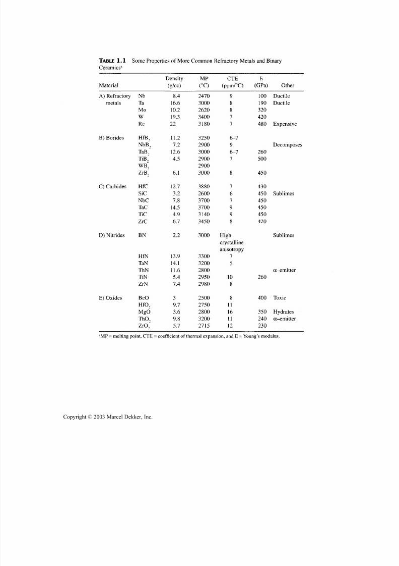
bides, halides, nitrides, silicides, and sulfides. Key examples are listed in Table1.1. However, there are a variety of kno wn ternary ceramic com pounds form ed
with a third atom constituent. Those that contain either two metallic and one
metalloid or nonmetallic types of atom continue to be classified as carbides, ox-ides, etc., as for binary ceramics. H owever those containing one type of metallic
atom w ith two types of atom s of either metalloid or nonm etallic designation or a
combination of one of each, are named by their latter atoms, e.g., as carboni-
trides and oxysilicides, fo r compounds containing carbon and nitrogen or oxy-
gen and silicon atoms, respectively. There are also higher-order ceramic
Copyright © 2003 Marcel Dekker, Inc.
7/29/2019 29540824708539
http://slidepdf.com/reader/full/29540824708539 15/361
Chapter 1
TABLE 1.1 Some Properties of More Com mon R efractory Metals and Binary
Ceramics"
Material
A) Refractory
metals
B) Borides
C) Carbides
D) Nitrides
E ) Oxides
N b
Ta
M o
W
Re
HfB,
NbB~9TaB,~
TiB^
WB~
ZrB~
HfC
SiC
N bCTaC
TiC
Z rC
BN
HfN
TaN
ThN
TiN
Z rN
BeO
HfO,
M gO
ThO,
Zr<X
Density
(g/cc)
8.4
16.6
10.2
19.3
22
11.2
7.212.6
4.5
6 .1
12.7
3.2
7.8
14.5
4.9
6.7
2 .2
13.9
14.1
11.6
5.4
7.4
3
9 .7
3 .6
9 .8
5.7
M P
(°Q
2470
3000
2 6 2 0
3400
3180
3250
2 90 03000
2900
2900
3000
3880
2600
3700
3700
3140
3450
3000
3300
3200
2800
2950
2980
2500
2750
2800
3200
2715
CTE
(ppm/°C)
9
8
8
7
7
6-7
96-7
7
8
7
6
7
9
9
8
High
crystalline
anisotropy
7
5
10
8
8
11
16
11
12
E
(GPa)
100
190
320
420
480
260
500
450
430
450
450
450
450
420
260
400
350
240
230
Other
Ductile
Ductile
Expensive
Decomposes
Sublimes
Sublimes
oc-emitter
Toxic
Hydrates
a-emitter
:'MP = melt ing point , CTE = coefficient of thermal expansion, and E = Young's modulus.
Copyright © 2003 Marcel Dekker, Inc.
7/29/2019 29540824708539
http://slidepdf.com/reader/full/29540824708539 16/361
Background and Overview 5
comp ounds, that is, ceramic comp ounds consisting of four or more atomic con-
stituents that are generally much less known. Such higher-order compounds of -
fer opportunity for extending ceramic technology via more diverse properties.The diversity of ceramics and their properties is significantly extended by
the fact that the properties of a given ceramic comp ound can be varied, often sub-
stantially, by changing microstructure via differences in fabrication/processing,
which is extensively discussed elsewhere [11,12]. The diversity is also signifi-
cantly extended by addition of one or more other ceramic compounds that form a
solid solution with the base ceramic compound. The limitations of such solid so-lution extension of prop erties are the limits of solubility due either to prec ipitation
or reaction, or both. However, these limits on solubility also provide more spe-
cialized ways of extending the range of ceramic properties via ceramic compos-
ites, i.e., ceramic bodies consisting of two or more ceramic phases that have
limited or no m utual solubility and a considerable range of chemical com patibil-ity. More extensively, ceramic composites are made by co nsolidating m ixtures of
composite phases, which are classified by the character of the additional, usu ally
second, phase, that is, particulate, whisker, platelet, or fiber composites, which areaddressed in this book, generally in decreasing extent in the order listed.
The resultant diversity of ceramic properties from all of the ceramic
com pou nds, their solid solutions, and comp osites is illustrated in part by a very
abbreviated listing of some properties of the more refractory members of the
more common and more extensively developed binary ceramic materials inTable 1.1. Note that other binary systems have refractory compounds, for ex-
ample, sulfides and phosphides with melting points of 2000 to 2500-2700°C,
and man y systems w ith comp ounds ha ving melting points of 1500-2200°C or
above. Also note that, while ternary and higher-order compounds typically
have lower melting temperatures than the more refractory binary compounds,
this is not always true.
The property diversity of ceramics is further shown by the following ob -
servations addressing the six categories of functional properties: (1) thermal-chemical, (2 ) mechanical, (3 ) thermal conduction, (4) electrical, (5 ) magnetic,
and (6 ) electromagnetic. Thus, there are a number of ceramics that have amongthe highest potential operating temperatures, approaching their melting points
at and above those of their only other competitors, the refractory metals (Table1.1), and have the highest energies for ablation, especially in the absence of
melting, as is the case fo r important ceramics that commonly sublime without
melting. Further, the diversity of ceramic c om positions provides cand idates for
a diversity of environments, fo r example, halides fo r halide environments an d
sulfides for sulfur environments, as well as the formation or application of atleast partially protective coatings that are chemically compatible with the ce-ramic substrate.
Copyright © 2003 Marcel Dekker, Inc.

7/29/2019 29540824708539
http://slidepdf.com/reader/full/29540824708539 17/361
6 Chapter 1
Considering mechanical performance, many ceramics have high stiffness
an d high melting points, reflecting the strong atomic bonding. While stiffness
generally decreases with increasing temperature, as for other m aterials, it is typi-cally an important attribute of many ceramics across the temperature spectrum.
High bond strengths of many refractory ceramics also correlates with their high
hardnesses, which tends to correlate some with armor performance and espe-
cially with much wear and erosion resistance, as well as with compressive
strengths that can also be of importance at high temperatures, but are typically
more important at modest temperatures [2,11,12]. Tensile strengths, though be-
ing particularly sensitive to microstructural and thus to fabrication process para-
meters, also correlate in part with elastic moduli, and can be quite substantial
over a broad range of temperatures. Also note that some ternary compounds
(such as mullite and perhaps higher-order compounds) can have much higher
creep resistance than their more refractory binary constituents. At the extreme of
mechanical p recision, many ceramics offer the highest degrees of precision elas-
tic stability, i.e., dimensional stability under mechanical and thermal loading,
which is typically most pronounced and important at modest temperatures [12].
Different ceramics hav e am ong the lowest intrinsic thermal conductivities
an d others the highest ranges of thermal conduc tivities, with even more extremes
shown for electrical conductivity or resistivity. This includes both highest-tem-
perature superconductors (TiN and TiC) prior to the discovery of much higher-
temperature ternary and higher-oxide superconductors of extensive interest fo rabout the past 10 years. Some ceramics also have the highest resistance to di-
electric breakdown, hence the ability to be good insulators even under very high
electrical fields, as well as other important electrical properties [2,11,12]. These
include high-temperature semiconductors for a variety of applications and ionic
conductors fo r diverse applications, such as advanced fuel cells and batteries, as
well as sensors. Of particular importance fo r many technological applications
are ferroelectric and related electrical properties, especially in some ternary ce-
ramics, w hich like many other properties are most often of particular imp ortanceat or near room and moderate temperatures. This is commonly also the case for
their important magnetic and electromagnetic properties, but elevated tempera-ture performance of such functions can also be important.
While a single property m ay drive applications, unique combinations of
properties are commonly an imp ortant factor. Thus, fo r example, good magnetic
properties in nonconductive, i.e., dielectric, ceramics is an important factor in
their magnetic applications, while application of the transparency of dielectricceramics to ultraviolet (UV), visible, infrared (IR), microwave, and other elec-
tromagnetic waves is often made due in part to the temperature capabilities of
many ceramics. These and other applications are also often partly driven by the
substantial hardnesses of many ceramics as reflected in their resistance to wear,
erosion, and ballistic im pact, fo r example, fo r transparent armor wind ow s.
Copyright © 2003 Marcel Dekker, Inc.

7/29/2019 29540824708539
http://slidepdf.com/reader/full/29540824708539 18/361
Background and Overview 7
The challenge of fabricating ceramic components for various applications
requires that the properties an d performance sought be obtained in a reliable an dcost-effective fashion. However, both these goals of suitable reliability and cost
are dependent on the impacts of component composition as well as size, shape,
and dimensional-surface finish requirements on fabrication routes, and the para-
meters of the processing techniques within these routes.
The properties sought are usually determined by the composition of the
body, mainly by the compound selected. However, there may be uniform, hetero-
geneous, or both variations in either the composition of the ceramic compound
sought, other constituents or impurities in solid solution or as second phases, or
combinations of these. Thus, some compounds are very stable in composition
during use, bu t others are less so , while fabrication processing parameters may of-ten present greater problems of composition stability. For example, some oxides
such as A12O 2, BeO, and SiO2 are quite stable, while others such as oxides of Ce,
Ti, and Zr are less so , such that they may be reduced from their normal oxygen
stoichiometry in varying degrees, depending on the extent of reducing conditions,
temperatures, and times of exposure. Component sizes and shapes are key factors
in resultant composition gradients and their effects. Such reduction can be very
detrimental to some uses, especially electrical and electromagnetic and some-
times mechanical properties, as well as some possible use in special cases. Simi-
lar, though often less extreme effects of stoichiometry deviations may occur with
useful nonoxide ceramics. Both the presence of impurities and use of additivescan be important issues, since increased purification typically means increased
costs and may have other ramifications on fabrication, as additives may be impor-
tant in fabrication bu t present limitations in use. Chapter 3 addresses the use of
additives in preparation of ceramic raw materials that, while having some desir-
able effect, may retain some impurities, variations in composition, or both. Chap-
ter 5 extensively addresses use of additives in fabrication.
Another basic impact of fabrication on properties is its effects on mi-
crostructure, which arise fo r both intrinsic an d extrinsic reasons, the latter often
reflecting effects of chemical or physical heterogeneities in the body. The reason
for this is that microstructure plays an important role in many properties, withthe most critical microstructural factor being porosity. While porosity is critical
to some important applications such as catalysis or filtration, and can also aid
some other properties an d applications, it commonly significantly reduces many
important properties, such as mechanical an d optical ones [11]. Thus, a fraction
of a percent of porosity that scatters visible light may render a potentially trans-
parent ceramic window ineffective for its purpose, while the ~ 5% porosity left
from much sintering can reduce many mechanical properties by 10-25%. Next
most significant is grain size (G), with many mechanical properties increasing as
G decreases, by ~ 50% or more as G goes from ~ 100 to ~1 jam, bu t other prop-
erties may be unaffected by G or increase with increasing G [12]. In composites
Copyright © 2003 Marcel Dekker, Inc.

7/29/2019 29540824708539
http://slidepdf.com/reader/full/29540824708539 19/361
8 Chapter 1
the dispersed particle size plays a similar role as G in monolithic ceramics, bu t
the matrix grain size also still has similar effects in composites as in monolithicceramics, though it may be mo re restrained in grain growth by the dispersed par-
ticles. Heterogeneities of grain and partic le struc ture and poros ity, as well as im-
purities or additives, can also be important in limiting levels and reliability of
properties. All of these microstructural effects are impacted by the ceramic, the
fabrication route, and processing parameters selected for a given application.
The above diversity of ceramic performance based on both the diversity of
ceramic materials and on impacts of fabrication via effects on microstructure is a
double-edged swo rd. On the one hand, performance div ersity provides w ider op-portunity for application. On the other hand, it can dilute resources between pos-
sible competing candidates, which may jeopardize success of any candidate. Itcan also mean that the candidate that may be implemented is not the best one
overall, but the one that required less devel opm ent; however, once established, it
is harder to replace w ith a potentially sup erior candidate. Suc h trade-offs are im-
pacted by specific economic factors (see Sec. 1.4), as well as by larger political
and economic factors, (see Sec. 1.3).
1.3 POLITICAL AND ECONOMIC FACTORS
IMPACTING DEVELOPMENT ANDAPPLICATION OF ADVANCED CERAMICS
A major change reducing opportunities for development an d application of ce-
ramics (and other advanced materials) was the end of the cold war's reductionof military-aerospace funding. It probably also reduced opportunities for ad-
vanced processing and materials development, such as of ceramics with poten-tial for extremes of performance, by shifting the balance from more impetus on
performance to more on availability/affordability. This made such funding deci-
sions driven even less by technology push, which is rare in general industry,
where market pull dominates as the drivin g force for new technology. Thus, fo r
example, implementation of some m ilitary systems, such as phased-array radar,
was paced by the commercial development of cost-effective applicable technol-ogy developed in volume fo r home microwave ovens. Also, fo r perspective, it
should be noted that the primary justification for one of the earlier major ce-
ramic turbine engine program s was driven p rimarily by geopolitical concerns of
the cold war for the availability of elements such as Cr, Co, and Mn critical for
super-alloys in hot sections of metal tur bine engines, to potentially be replaced
by Si from sand and N from the air. Improved fuel efficiency was also cited as a
benefit, but was not a major driving force, especially when oil costs were no t
high. Such efficiency provides much less driving force in the consumer market
as shown by poor sales of fuel-efficient cars in the past, except when gas was
scarce. The high sales of higher-fuel-consuming sport utility vehicles in recent
Copyright © 2003 Marcel Dekker, Inc.

7/29/2019 29540824708539
http://slidepdf.com/reader/full/29540824708539 20/361
Background and Overview 9
years in part resulted from low fuel costs. More recent justifications for ceram-ics in turbines have focused on reduced erosion, hence less maintenance and
longer life fo r ground-based turbine auxiliary power units, (APUs) i.e., turbine-driven electrical auxiliary power units, and also possibly lighter weight for air-
borne APUs.Two other related changes have been the revolutionary changes in medical
and biological technology and electronics, especially in telecommunications and
personal computers. While both offer opportunities for ceramic applications, for
example, of bio- and electronic ceramics respectively, these are generally modest
and also have some negative effects. The ceramic opportunities in these areas arelimited on the one hand by distribution and liability issues for bioceramics (espe-cially in the United States which has less use of bioceramics than Europe), and
on the other hand by the short, rapid product development cycles of many elec-
tronic systems, which make it very difficult to implement newer technologies
such as use of ceramics often represent. Further, these areas are absorbing large
amounts of government and industrial funding, which leaves less money forother technologies. Additionally, the broad and growing availability of computer
design technology has made design changes using existing materials, such asmetals, much more rapid and cost-effective, thus allowing significant product
improvem ents via new or im proved design rather than new materials imp lemen-
tation, the latter typically being a much longer and more costly process. Thus,
the addition of an additional set of valves in each cylinder of many automobileengines and the aerodynamic designs of cars, especially truck tractors, reduced
driving forces for more fuel-efficient ceramic engine technology.Another important factor is regulation, along with other public policy fac-
tors. Governm ent engine emission controls generated the market of at least $300
million per year for ceramic exhaust catalyst supports. Other existing and pend-
ing emission controls also provide further opportunity for ceramics (e.g., forburn ers), as well as for some com petition from metallic burn ers and catalyst sup-
ports. Taxes can also be a factor, for example, an earlier tax on larger auto en-
gines in Japan provided a financial impetus for development and sales of Si3N 4
turbocharger rotors, and elimination of the tax greatly reduced the ceramic tur-bocharger market—which, if it does grow in the future could experience compe-tition from other materials, such as metals, allowing variable pitch or
carbon-carbon for lower mass. The high petroleum fuel taxes in most other de-veloped countries were a major factor in the development of better fuel-efficient
cars, which allowed other countries to expand their market share in the UnitedStates. Subsequent U.S. auto fleet fuel-efficiency standards helped provide a
more uniform incentive for improvement of U.S. automobile efficiency in theface of fluctuating fuel costs.
Two other imp ortant and related factors that are com mo nly not adequately
recognized are that there is alw ays competition for any material app lication, and
Copyright © 2003 Marcel Dekker, Inc.

7/29/2019 29540824708539
http://slidepdf.com/reader/full/29540824708539 21/361
10 Chapter 1
that the competition is not static. Thus, many ceramic applications must com-
pete with application of other materials, such as plastics or metals, as well as
lower cost ceramics in bulk form by themselves or via coating technology, al-
ternative designs, or both. Thus, various ceramic, intermetall ic, or metall ic
coatings can compete with bulk ceramic comp onents for a variety of wear and
other (e.g. , biomedical) ap plicatio ns. L ow costs for man y traditional ceramics
due to use of low-cost m ineral constituents and especially of processed mate-rials, in particular, A12O3 due to the economies of scale that are a result of the
aluminum industry and generally lower processing costs for oxide ceramics,
provide competition for higher performance ceramics, especially nonoxides.
Metals are clearly the major competition for ceramics in engines, where air-
cooling designs al low m etals to be used beyond their normal temperature l im -its, but wil l most likely be replaced by ceramics (possibly also air-cooled) in
some applications. In other cases it is strict cost compet i t ion—ceramic cam
followers were considered for a number of years by Chrysler to replace metal-
li c needle bearings in some of their auto engines. Ceramic cam followers have
not been implemented in Chrysler auto engines due to reduced costs of the
metal bearings s t imulated by the potential of ceramic competition. (Note:
The ceramic followers had to be lower cost than the metal bearings to be con-
sidered for autom otive imp lem entation; ceramic cam followers have been im-
plemented in some diesel engines where cost-performance trade-offs are
different.)The above example of ceramic cam followers in auto engines also illus-
trates the fact that it is difficult to displace an established technology that can still
be improved. This is also shown by other examples, such as solar cell panels for
power in space, which have repeatedly been extended to larger sizes and higher
powers beyond previously projected limits. However, changing of the balances
between competing technologies over time is important, but can be complex.
Thus, radomes used on m issiles and aircraft used to be polymeric based compos-ites below Mach 1, and ceramic above it, but the former have been improved
over time for use to Mach 2-3, thus potentially reducing the market fo r ceramic
radomes. However, the upper missile velocities for which ceramic radomes areused have also been substantially extended, thus m aintainin g considerable use of
ceramic radomes. Similarly, plastic electronic packages have increased in their
temperature-environmental and other capabilities allowing them to replace some
ceramic packages, but application of ceramic packages in more demanding envi-
ronments has also increased, leaving ceramic packages still a large and growing
business. However, commercial A1N electronic substrates an d packages for
higher heat dissipation, though present as items of commerce, are well short ofearlier expectations due to AIN's higher cost, competition from other heat dissi-
pating materials and methods, as well as reductions in power to operate some
semiconductor devices, and hence reduced needs for high heat dissipation. The
Copyright © 2003 Marcel Dekker, Inc.
7/29/2019 29540824708539
http://slidepdf.com/reader/full/29540824708539 22/361
Background and Overview 11
higher cost of A1N, especially versus that of A12O3, can be reduced with in-
creased volum e, as for most m aterial. How ever, imp ortant questions for all mate-
rials are whether costs can be reduced enough to attract high-volum e use, and arethere intermediate cost/volume applications to bridge the gap(s) between lower
and higher volume applications. Note that this issue of progressively expanding
markets to provide an opportunity to progressively increase production volume
and thus reduce costs can be particularly problematical for new technologies asdiscussed by Christenson [13]. Thus, major technological developments often
start as niche markets, which may not be of interest to the business discoveringthem but may ultimately replace them. For example, bug gy makers were gener-
ally not interested in autom obiles, which w ere considerably developed by others
before they started to replace the horse-drawn buggy.
It is useful to briefly take a long-term and broad p erspective on ceramic en-gine program s. These actually began around the end of W orld War II with Allied
intelligence indicating possible work in Germany to use ceramics to enhance
perform ance of their jet fighter aircraft introduced late in the war [14], leading to
a U.S. program following the war. The U.S. turbine blade cand idates w ere a silli-
manite (—A12O3—SiO 2) and a BeO "porcelain" (~ 85% BeO), then later MoSi2 ,and especially, an ~ 80% TiC-20% Co cermet. All were unsuccessful (the latter
giving cermets their reputation for often giving the brittleness of ceramics at
lower and the poor deformation resistance of metals at high temperatures, rather
than the hoped for combination of higher toughness of metals at lower and ce-ramic creep resistance at higher temperatures). This earlier turbine program ap -parently lead to industrial investigation of ceramics for piston engines, fo r
example, cylinder liners, app arently focused on alumina-based ceramics. T hus,
one could say that these types of ceramic programs have been investigated for ~
50 and ~ 40 years, respectively, w ithout success, and one could add that ceramic
ball or roller bearings have been investigated for nearly 40 years and have only
begun recently to achieve moderate commercial success. These earlier programs
showed the need for better ceramic materials, development of which, especially
silicon nitrides and related materials, stimulated subsequent programs and were
further improved by them.Thus, viewed in a broader p erspective, the above programs are interrelated
and moderate successes, and both bearing and piston engine cam applications ofsilicon nitride are, in part, derivatives of turbine engine programs, as was thetemporary success of silicon nitride turbocharger rotors. This is also at least par-
tially true of the increasing use of other ceramics (e.g., Z rO 2), in other diesel en-
gine fuel-wear applications, which took fewer years from investigation to
application and are growing with progression to newer engine models. Vehicles
using hybrid combustion-battery or fuel-cell propulsion offer impo rtant opportu-
nities fo r ceramics that benefit from past ceramic engine efforts. (A hybrid tur-
bine-electric drive wa s proposed by this author as a follow-up to ceramic engine
Copyright © 2003 Marcel Dekker, Inc.

7/29/2019 29540824708539
http://slidepdf.com/reader/full/29540824708539 23/361
12 Chapter 1
programs, but was w ithdrawn based on advice that it was too expensive to have
two power sources, an assumption that will be tested by the hybrid vehicles in
production and development.) Overall, some possible stalls of uses, such as sili-con nitride turbocharger rotors or thermal shock-resistant oxides as exhaust portliners, may prove permanent or temporary. Expansion of the ongoing applica-tions and other developing opportunities, however, indicate growing engine ap-plication of ceramics—for example, silicon nitride or carbon-carbon valves orhigh-performance graphite pistons.
It is useful to note that electronic applications of ceramics are greater andhave experienced much better growth than initially projected, especially in theirearlier inception, (application forecasts were often short of actual results, while
forecasts for engine applications of ceramics have typically been far above ac-tual results). Thus, technology p ush can be succes sful, especially for new devel-
opments (but probably requires substantial government support), while market
pull developments are typically faster and more likely to be successful, espe-cially in modest time frames.
1.4 COST AND PROFIT FACTORS
W hile there are factors tha t im pac t the markets for ceramics on a broader, often
long-term basis as outli ned above, more fundamental to the success of any spe-
cific product is first its specific potential market and its producibility at accept-able costs. The market outlines the character of the product, such as its
technical requirements, scale of potential production, product pricing, and pos-sible interrelation of these, but much may be speculative and uncertain, espe-cially for new applications. The producibility is directly related to fabrication
(i.e., determining whether the perceived or known component performance,size, shape, dimensional, and other requirements can be met), as well as whatits costs are likely to be and how they compare with potential prices and thus
what the potential profitability may be. Again it mu st be emp hasized that all ofthese factors may be quite uncertain for a new product bu t better defined for a
manufacturer entering an existing market for an existing component. Many ofthe issues, especially those of marketing, are well beyond the scope of thisbook and are thus addressed little or not at all. The focus is on those issuesmost directly related to fabrication—focusing on costs—with some limited
comments on prices and profitability.
Cost of technology development and especially of actual production im-plementation are critical to a product's successful introduction and success. Ac-
tual production costs for a given part are typically proprietary, so much of theinformation available comes from general production knowledge and especiallyfrom the increasing use of computer modeling of fabrication costs. Cost evalua-
tions via modeling are a critical factor in successful development and implemen-
Copyright © 2003 Marcel Dekker, Inc.

7/29/2019 29540824708539
http://slidepdf.com/reader/full/29540824708539 24/361
Background and Overview 13
tation of ceramic component fabrication, both in the early stages of considera-
tion as well as during development and implementation, since this indicates both
possible fabrication routes and the more costly steps that need particular atten-tion. However, such evaluations are quite dependent on key operational parame-
ters (e.g., the specific fabrication route, processing parameters, and volumes ofproduction), as well as factors such as excess material used, sharing of produc-
tion resources, and especially yields achieved (the percent of components manu-
factured that are suitable for sale versus those that have to be scrapped). These
factors are typically highly proprietary, and thus not available publically, as istrue for much data to verify cost models. However, there are some generally
known cost aspects as well as specific cost modeling studies that provide useful
guidelines, recognizing that there are exceptions to all trends that require specific
evaluations of specific cases. A gain, the purpose here is not a tutorial on model-ing methods, which is a large subject in itself, but to give some sources of suchinformation, and especially familiarize readers w ith factors, variations, and some
basic guidelines.
First, consider overall trends, a major one being wh at technical m arket intowhich the specific component will fall, with a major differentiation being
whether the component is an electronic one, especially a multilayer electronic
package, or for some other use, such as for thermal-structural functions. Elec-tronic packages (and to a lesser extent other electronic and some electrical com-
ponentsas
wellas
ceramic cutting tools) sellat
prices much higherper
unit
weight, reflecting both higher production costs and their small size, hence lim-
ited per part cost, and probable more value added. An overall assessment of theadvanced ceramics industry in the United States outlined by Agarwal [15], that isapparently more focused on structural ceramics, noted that ceramic processing is
typically batch and labor intensive. He attributed 40-50% of manufacturingcosts of high-performance ceramics to inspection and rejection (basically toyield), versus 5-10% for high-performance metals, thus again emphasizing this
as a major cost issue for ceramic production. Agarwal cited typical 15-20% oftotal costs for ceramic finishing, m ainly for machining, and only 5-10% for met-
als. However, for precision parts (e.g., those in engines), machining costs can besubstantially higher (e.g., machining costs were a major factor in projected high
costs of toughened zirconia components for possible use in more efficient diesel
engines (see Table 1.2). The potentially high costs of much machining of ce-ramic components is a major reason for emphasizing near net-shape fabrication,
though an imp ortant exception has been ceramic ball manufa cturing for bearings
as discussed later.
While machining costs can be very high, and often the dominant singleprocess cost if extensive machining is required, it is important to again empha-size another factor that often determines the viability of a product, namely its
yield—the percentage of outpu t that ends up in useable prod uct. Resulting yields
Copyright © 2003 Marcel Dekker, Inc.

7/29/2019 29540824708539
http://slidepdf.com/reader/full/29540824708539 25/361
14 Chapter 1
TABLE 1.2 Estimated Manufacturing Costs for PSZ Diesel Engine Components3
ComponentBody costs ($ )
Forming costs ($ )
Firing costs ($)
Grinding costs ($ )
Total costs ($)
Headface plate1 .55 (1%)
2 . 8 8 ( 1 % )
17.45 (9%)
173.93 (89%)
195.81
Piston cap1 . 36 (1%)
8.08 (3%)
12.97 (5%)
2 5 9 . 0 3 ( 9 1 % )
281.44
Cylinder liner7.84 (3%)
38.09 (15%)
47.48 (19%)
161 . 32 ( 63%)
154.74
"Costs of subsidiary operations [16] shown as a percent of the total component cost in parentheses.
Note that in another related study modeling costs of some of the first two listed and other related
components directed at design and m anufac turing changes to reduce mac hining, showed overall
costs substantially reduced to somewhat un der $100 each, with grinding costs reduced to 37-68% of
total costs ( but inc reas ing the other fixed costs as a percent of other their total reduced costs [16,17]).
at each fabrication step vary in amount and cost impact, with the limited amountof recovery often being greater, hence som ewhat less costly, in earlier processing
stages, such as powder, and much greater in later stages, such as firing and ma-
chining. However, the cumulative product yield, which can be well < 50% in
earlier stages of product production and possibly < 80% in later stages of pro-
duction of complex components, is most critical, and is often the determining
factor in product success and of constraints on costs of individu al fabrication
steps, especially more c ostly ones [18-23].Turning to other specific fabrication costs, raw materials are a factor;
Agarwal cites them as 5-10% of total costs (for structural ceramics, metals, andpolymers), which is a common range, but subject to a variety of conditions,
they are sometimes lower or higher (see Table 1.2). Thus, for example, Roth-
man and coworkers [18,19] report that higher cost SiC powder ($22/kg, givingmaterial costs at 22%) could be used for making small disk seals if a high over-
al l yield (86%) was assumed, versus ~ $3/kg powder (giving material costs at
-5%) with 40 % overall yield. The impact of raw materials costs dependsgreatly on the amount used—expensive materials such as silver, gold, and plat-
inum are used in electronic ceramics, but in small quantities, such that manypackages can be sold for a few dollars each. More generally, consider a range ofsmall, structural components, such as a Si3N 4 balls fo r bearing applications: A
'/4-in. diameter ball requires a modest amount of Si3N 4 powder, while a larger
V2-in. diameter one requires eight times as much powder, so the sensitivity ofsuch balls to raw material costs increases substantially as ball size increases.
Thus, ra w materials used fo r small balls may not be economically viable fo r
larger ones. This issue of raw ma terials costs is imp ortant because m any desir-able powders have been developed, but their high costs severely limit their eco-
nomical viability. For example, Schoenung, and coworkers [20-21] conducted
substantial modeling of ceramic costs for a variety of advanced engine uses,
Copyright © 2003 Marcel Dekker, Inc.

7/29/2019 29540824708539
http://slidepdf.com/reader/full/29540824708539 26/361
Background and Overview 15
such as cam rollers, valves, and guides, showing that zirconia toughened com-ponents never or barely allowed the costs to get down to target component
prices at substantial product volumes of 5-10 million/yr with $13/kg powder,whereas $4.50/kg powder cost allows component costs to reach target prices atproduction quantities of 2-4 million/yr. However, also note that many compo-nents, such as many in engine applications, have an approximately fixed physi-
cal volume, in which case zirconia suffers a disadvantage of requiring nearlytwice the weight of powder per component relative to other candidate ceramicssuch as Si3N 4. On the other hand, other pow ders such as those of Si3N 4 are com-monly m uch more expensive than $4.50/kg, thus not changing the raw materialcost limitations m uch if at all favorably. Schoenung and coworkers' evaluationsof similar Si3N4 components also showed similar material cost limitations—$44/kg powder costs not even coming close to target prices even at productionvolumes of 10 million/yr, and even $ll/kg pow der costs barely reaching the up-
per target price rang e at volumes of ~ 7 million/yr.Das and Curlee [24] have also shown the importance of reducing Si3N4
pow der costs (from ~ $44/kg) along with machining costs making cam roller fol-lowers and turbocharger rotors more cost competitive with costs of metal com-ponents. However, their assertion that such higher cost ceramic engine
components will be implemented where the improved benefits are adequatelycommunicated must be viewed with considerable uncertainty. Morgan [25] cor-
rectly cites potential cost savings from broader use of advanced chemical prepa-ration of ceramic raw powders and their processing, but does not address the keyissue of how various production steps can be successfully made to go from thetypical modest starting m arkets and common less-efficient batch processes usedat such earlier levels of p roduction to achieve potential large-scale lower costs.
Quadir et al. [26] corroborated that lower raw materials costs, includingadditives, are important in developing a lower cost Si3N4 (e.g., fo r wear, moremodest temperature applications, and thermal shock resistance) and that com-minution is an imp ortant powder cost factor where it must be used.
Tooling costs can vary from very modest to quite su bstantial depending on
several factors, but particularly on the fabrication process selected. Thus, toolingcosts for colloidal processing such as electrophoretic deposition and tape or slipcasting, as well as isopressing, can be quite limited (though times fo r thicker de-posits, tape lamination, drying times, die storage, and loading isopresses can beimportant cost factors). Pressure casting can entail m ore expens ive tooling (andagain deposition time issues). Die pressing and extrusion tooling costs can bemodest (e.g., a few ten thousand dollars), since shapes are often simple, bu t even
limited complexity and multiple cavity dies (for faster production and better use
of presses) can substantially increase costs. Injection molding tooling can besubstantially more expensive since it can form comp lex parts, a key virtue of in-
jection molding, with tooling costs often reaching $50,000 or more. Such die
Copyright © 2003 Marcel Dekker, Inc.
7/29/2019 29540824708539
http://slidepdf.com/reader/full/29540824708539 27/361
16 Chapter 1
cost are thus a factor in the choice of forming methods since modest levels of
production, e.g., a few thousand components, often cannot cost effectively sup-
port more expensive tooling.Some have assumed explicitly or implicitly that energy costs of sintering
or other fabrication/densification processes are an important problem, avoiding
some fabrication and seeking other approaches such as use of some highly
exothermic reaction processes, such as self-propagating synthesis, to eliminate
energy costs of densification. However, the energy costs (the "fuel bill" for most
industrial ceramic processing), for example of sintering and hot pressing, arecommonly < 5% of component costs (see Table 1.2). Thus, while savings on
these costs are of value since these normally increase profits, they are not a ma-
jor factor in determining process selection. (Further such energy savings can be
greatly overshadowed by the high costs of the raw materials to yield the energy
saving of such reaction processing [27,28]. Also, as discussed in later chapters,
energy costs for other fabrication methods such as CVD and even melt process-
ing are commonly similar.) Such energy savin gs would be of more im pact if they
also reduced the costs of heating facilities—their size, maintenance, and plant
space used, (which are often factored into firing costs)—but these savings by
such reaction processing also appear limited [27,28]. On the other hand, these or
other reaction processes can give beneficial raw materials an d (unexpected)
comminution costs as discussed below and in subsequent chapters.
As noted above, there are other imp ortant factors in firing costs for ceram-ics, such as the furnace atmosphere, temp eratures, volum e, and more. Thus, oxide
ceramics often have low er costs, sinc e they can be fired in air, and at more moder-
ate temperatures than nonoxides, the combination of which allows for both larger
furnaces and especially continuous ones, such as tunnel kilns for oxides, both of
which can increase cost effectiveness. While nonoxides are typically fired in
batch kilns with significant lower through-cap acity due to heat-up and cool-down
times, some of the significant advantages of con tinuous firing of oxides can be re-
alized by co ntinuou s firing of nonoxides. Thus, Wittmer and coworkers [29]
showed substantial savings (e.g., 50-70% lower firing costs fo r silicon nitride
fired in a (continuous) belt furnace than for firing in batch kilns). Though suchbelt furna ces typica lly do not have near the throughput of typica l air fired tunnel
kilns for firing oxides, they show substantial potential for continuous firing of
nonoxides with sufficient production volume to justify higher belt furnace costs.
There has been a preliminary attempt at addressing cost aspects of hotforming of ceramics. Thus, Kellett and Wittenauer [30] discuss the possibilities
of superplastic forming of nanograin ceramics such as Al2O 3-ZrO 9 and Si 3N4 as a
means of lowering costs by producing components of near net shape, requiring
less machining. Their focus was on effects of deformation rates on costs, report-
ing that strain rates of 1 0 ~3 to 10 5 sec ' translate into forming times respectively
of 4 min versus 6 hrs giving part costs of $4 and $400, respectively, for the case
Copyright © 2003 Marcel Dekker, Inc.
7/29/2019 29540824708539
http://slidepdf.com/reader/full/29540824708539 28/361
Background and Overview 17
chosen. They also noted steps to improve these, in particular grain growth inhibi-tion. (Note: Large deformation at higher strain rates, e.g., ~ 10"
1 sec'1, have re-
cently been reported for a nanograin oxide composite; See Sec. 6.3.)The impact of time required for individual process steps, as well as the
overall cost factors and constraints in processing materials, can be seen by rec-
ognizing that there are just over 31.5 million seconds in a year, i.e., about 10.5million for each 8-hr shift, with no days off, and about 7 million seconds for an8-hr shift with typical days off. Thus, w hatever the annual production expected,this time constraint is a fundamental factor in production costs since it defines
how many parts must be produced per unit time and the impact of this on theproductivity at each step to achieve the production goal. For example, if a mil-lion parts per year is the goal, then, depending on the shifts and days of produc-tion, a part m ust be produced every 7-31 sec (and even faster to allow forproduction losses, yields of < 100% ). Thus if a process consists of 10 steps, onaverage a part m ust take no m ore than 0.7-3.1 sec in each step. Most steps in aprocess take longer, often m uch longer per part, than the allowed average times,
which means that many parts must be made simultaneously to achieve the tar-geted average tim e per part. For exam ple if parts are formed in a press with a sin-gle cavity die, then the number of such presses needed w ill be the actual time forforming each part divided by the average time allowed for the forming step,which means that process steps that take longer times and have low or no multi-
plicity of simultaneous part formation from each press requires large numbers ofpresses and their associated costs.Turning briefly to costs of producing ceramic powders (and whiskers),
there are similarities to producing ceramic bodies, for example, impacts of start-ing materials. Thus, Schoenung [31] has modeled the costs of making Si3N4
powder by direct nitridation of Si versus by laser-stimulated CVD gas-phase nu-cleation of powder. For the assumed parameters, she showed nitridation yieldingpowder costs of $17-230/kg, mainly $25-50/kg, depending on seed powdercosts, time of nitriding, and especially comm inution costs; w hile the costs of thelaser-CVD powder were more, > $100/kg, driven heavily by the high cost of
silane gas (assumed to be $160/kg).Schoenung [32] has also modeled costs of producing SiC whiskers via va-
por solid (VS) reaction of SiO 2 and carbon, showing that costs could not be re-duced to < $50/kg for the assumptions made, with raw materials cost and yieldsbeing important factors. Another indicator of the impact of precursor costs forceramics is shown by the cost per kg of three comm on oxides in Table 1.3, whichcontrast with costs from other more conventional precursors of <$1 to < $3/kg.The costs of additives used in processing—commonly to aid densification and
properties (see Chap. 5)—can also be significant. Thus, use of rare earth andother oxides for PSZ and TZP as well as Si3N4 often m easurably increase raw
materials costs, especially more expensive additives such as yttria versus others
Copyright © 2003 Marcel Dekker, Inc.
7/29/2019 29540824708539
http://slidepdf.com/reader/full/29540824708539 29/361
18 Chapter 1
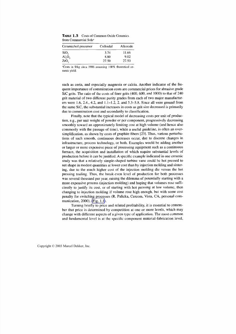
TABLE 1.3 Costs of Common Oxide Ceramics
from Commercial Sols3
Ceramic/sol precursor
SiO 2
Alp^
Z rO 2
Colloidal
3.74
8.80
27.50
Alkoxide
11.66
9.02
27.50
"Costs in $/kg circa 1986 assuming 100% theoretical ce -
ramic yield.
such as ceria, and especially magnesia or calcia. Another indicator of the fre-
quent importance of comminution costs are commercial prices for abrasive grade
SiC grits. The ratio of the costs of finer grits (400, 600, and 1000)to that of 2 40
grit material of two different purity grades from each of two major manufactur-
ers were 1.6, 2.4., 4.2, and 1.1-1.2, 2, and 5.3-5.8. Since al l were ground from
the same SiC, the substan tial increases in costs as grit size decreased is prim arilydue to comminution cost and secondarily to classification.
Finally, note that the typical model of decreasing costs per unit of produc-tion, e.g.,per unit weight of pow der or per com ponen t, progressively decreasing
smoothly toward an approximately limiting cost at high volume (and hence also
commonly with the passage of time), while a useful guideline, is often an over-simplification, as shown by costs of graphite fibers [23]. Thus, various perturba-
tions of such smooth, continuous decreases occur, due to discrete changes in
infrastructure, process technology, or both. Examples would be adding another
or larger or more expensive piece of processing equipment such as a continuousfurnace, the acquisition and installation of which require substantial levels of
production before it can be justified. A specific example indicated in one ceramicstudy was that a relatively simple-shaped turbine vane could be hot pressed to
ne t shape in modest quantities at lower cost than by injection molding and sinter-
ing, due to the much higher cost of the injection molding die versus the hot
pressing tooling. Thus, the break-even level of production fo r both processeswas several tho usan d per year, raising the dilemm a of potentially starting with a
more expensive process (injection molding) and hoping that volumes rose suffi-
ciently to justi fy its cost, or of starting with ho t pressing at low volume, thenchanging to injection molding if volume rose high enough, bu t with some cost
penalty for switching processes (R . Palicka, Cercom, Vista, CA, personal com-
munication, 2000). (Fig.1.1).
Turning briefly to price and related profitability, it is essential to remem-ber that price is determined by competition at one or more levels, which may
change with different aspects of a given type of application. The most common
an d funda men tal level is at the specific component material-fabrication level,
Copyright © 2003 Marcel Dekker, Inc.

7/29/2019 29540824708539
http://slidepdf.com/reader/full/29540824708539 30/361
Background and Overview 19
SALES VOLUME PER UNIT TIME
FIGURE 1.1 Schematic of cost impacts of changing manufacturing methods. Curves 1
and 2 reflect two different processes, e.g., ho t pressing to net shape versus injection mold-
ing and sintering, respectively, with one reflecting a more efficient process at low volumes,
but more inefficient at high volume. Thus, if process 2 is initially selected and produc-
tion/sales volumes increase beyond the crossover point, this was a good selection, but not
if the crossover point is not reached. On the other hand, if the process that is more efficient
at lower volumes (curve 1) is chosen and volumes rise past the crossover volume, some
added costs of changing the process would be required, shown schematically as a shift of
curve 2 to curve 3 (probably with other changes in curve 3 not shown for sim plicity).
bu t competition at the subsystem or complete system level can also be impor-
tant, and may vary with the specific character of a given application. This is
briefly illustrated fo r turbochargers, where at the fundamental level, ceramic
(silicon nitride) turbocharger rotors compete with established use of metal ro-
tors. This may be on a direct ceramic-metal rotor cost difference, or on the ba-sis of overall turbocharger cost versus performance, but in either case the cost
of metal components individually or collectively is a major factor in the com-
petitive balance.
However, cost competition of different technologies may change as a func-
tion of component size, performance requirements, and market size, as well as
other factors. As noted earlier, an important factor that drove use of ceramic tur-
bocharger rotors for smaller auto engines was a Japanese tax on engine horse-
power above a certain level, putting a premium on more performance from
smaller engines. This shifted the balance in favor of ceramic rotors by putting a
greater premium on faster response due to the lower ceramic versus metal density
Copyright © 2003 Marcel Dekker, Inc.
7/29/2019 29540824708539
http://slidepdf.com/reader/full/29540824708539 31/361
20 Chapter 1
(3.2 versus ~ 5.8 g/cc) until the tax was repealed. However, other circumstances
could impact turbochargers—carbon-carbon rotors should be feasible with still
faster response due to still lower density (e.g., 1.6-1.8 g/cc) and possibly less costthan silicon nitride rotors. On the other hand, variable pitch blades may be advan-
tageous on some larger turbochargers, such as for diesel truck engines, again
probably fa voring m etal rotors. Larger m arkets for turbochargers cou ld also bring
competition from other devices and related fabrication technologies, since a tur-
bocharger is really only a way of temporarily increasing the volume of air deliv-
ered to the engine for faster acceleration; other devices to do this may be feasible,
such as a small air compressor, storage tank, and valv ing to draw compressed air
from the tank as needed, which could completely change the materials and fabri-
cation technology picture.
Price constraints from existing technology can be seen in broad terms byconsidering resultan t pricin g of individual components or systems in which ce-
ramics might be used. Thus, prices paid for major system purchases such as cars,tanks, and ships can provide some guidance. For example, the sales price of a
1200 kg car is ~ $20,000, whic h translates to ~ $17/kg, which, allo wing for profit
and assembly costs, mean s that the average purchase price for the indi vid ualcomponents and basic materials (mainly steels) is generally < $10/kg. Thus,
while small amounts of much more expensive materials, such as some ceramic
components, can be tolerated, larger quantities of use rapidly become seriously
price constrained by the existing technology. Such evaluation readily indicates
cost constraints of substantia l substitutions of ceramic for metal armor for tanks.
While the competiting technology is commonly that of metals, it can also beother materials, including other ceramics. A particular case in point is that the
modest use and grow th of A1N for electronic packages with higher heat dissipa-
tion than A12O3 is, in part, due to the lower costs of A12O3 packages, providing in-centives for designs that reduce the thermal dissipation in packages or alternative
ways of accomplishing the dissipation.
Finally, once the comm itment to a product has been made, whether or not
the uncertainties have been adequately addressed, the issue is whether suitable
profitability, in both amo unt and timing , can be reached. T his is a function of thedevelopment costs, which include research and development, especially produc-
tion and market development, as well as interest costs, and of profits, that is vol-
ume and price-cost differential (Fig. 1.2 ) [23,33]. Interest is a factor since to be
adequately profitable, a new product needs to not only pay back the costs of itsdevelopment, but do so with a return of interest that makes the development a
worthwhile investment by the company versus other possible investments. For a
substantial new product the interest costs can be a significant factor, which canbe easily estimated by the rule of 72 , that is, the tim e in years to double an inter-
est cost or return multiplied by the annual interest rate is 72. Thus for an annual
interest of 10%, the amo unt of money to be returned by product sales to the com-
Copyright © 2003 Marcel Dekker, Inc.
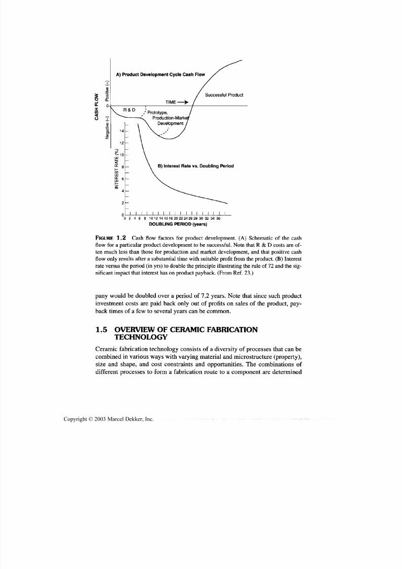
7/29/2019 29540824708539
http://slidepdf.com/reader/full/29540824708539 32/361
Background and Overview 21
A) Product Development Cycle Cash Flow
Successful Product
,' Prototype,
Production-Marke
Development
B) Interest Rate vs. Doubling Period
0 2 4 6 8 1012141618202224262830323436
DOUBLING PERIOD (years)
FIGURE 1.2 Cash flow factors for product development. (A) Schematic of the cash
flow for a particular p roduct development to be successful. Note that R & D costs are of-
ten much less than those for production and market development, and that positive cash
flow only results after a substantial time with suitable profit from the product. (B) Interest
rate versus the period (in yrs) to double the principle illustrating the rule of 72 and the sig-
nificant impact that interest has on product payback. (From Ref. 23.)
pany would be doubled over a period of 7.2 years. Note that since such productinvestment costs are paid back only out of profits on sales of the product, pay-
back times of a few to several years can be common.
1.5 OVERVIEW OF CERAMIC FABRICATIONTECHNOLOGY
Ceramic fabrication technology consists of a diversity of processes that can becombined in various ways with varying m aterial and m icrostructure (property),size and shape, and cost constraints and opportunities. The combinations of
different processes to form a fabrication route to a component are determined
Copyright © 2003 Marcel Dekker, Inc.
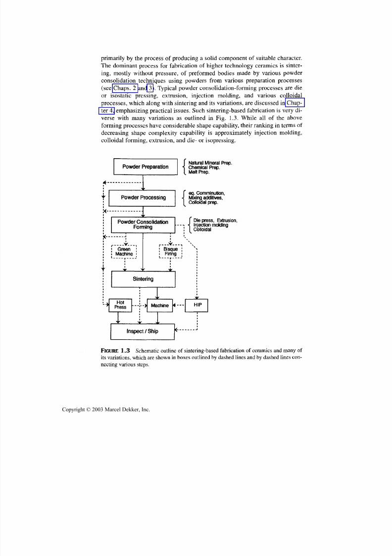
7/29/2019 29540824708539
http://slidepdf.com/reader/full/29540824708539 33/361
22 Chapter 1
primarily by the process of producing a solid component of suitable character.
The dominant process for fabrication of higher technology ceramics is sinter-
ing, mostly without pressure, of preformed bodies made by various powderconsolidation techniques using powders from various preparation processes
(see Chaps. 2 and 3 ). Typical powder c onsolidation-forming processes are die
or isostatic pressing, extrusion, injection molding, and various colloidal
processes, w hich along wi th sintering and its variations, are discussed in Chap-
ter 4, emphasizing practical issues. Such sintering-based fabrication is very di-
verse with many variations as outlined in Fig. 1.3. While all of the aboveforming processes ha ve considerable shape cap ability, their rank ing in terms of
decreasing shape complexity capability is approximately injection molding,
colloidal form ing, extrusion , and die- or isopressing.
I Natural Mineral Prep.• \ Chemical Prep.[ Melt Prep.
eq. Comminution,Mixing additives,Colloidal prep.
{Diepress, Extrusion,Injection moldingColloidal
FIGURE 1.3 Schematic outline of sintering-based fabrication of ceramics and many of
its variations, which are shown in boxes outlined by dashed lines and by dashed lines con-
necting various steps.
Copyright © 2003 Marcel Dekker, Inc.
7/29/2019 29540824708539
http://slidepdf.com/reader/full/29540824708539 34/361
Background and Overview 23
Variations in sintering-based fabrication include both newer methods of
heating not shown in Fig. 1.3 that have been under investigation and can effect
the sintering process, as well as ma ny variations show n in Fig. 1.3. The latter in-clude sintering under uniaxial pressure (i.e., ho t pressing), which has seen con-
siderable production use, and sintering under hydrostatic pressure (HIPing),
done either follow ing sintering or instead of sintering, whic h has seen some pro-
duction use. Both of these pressure-sintering processes generally reflect higher
costs, but have growing areas of ap plication, and oppo rtunities for further devel-
opment as discussed in Chapter 6 . There are also hot-forming processes, such aspress fo rging, that have seen some inv estigation by starting w ith a sintered body
or combining powder consolidation and hot forming of simple shapes. Such
forming, though facing important time-cost issues (as discussed in Sec. 1.4),
may have some specialized applications. Various reaction processes carried ou tin conjunction with either sintering without pressure or via various processes
with pressure, especially for fabrication of ceramic composites are also ad-
dressed. Su bstantial discussion of this and other shifts in fabrication m ethods for
monolithic versus composite ceramics is presented.Other fabrication methods for producing ceramics without sintering, and
may or may not entail use of powders (for example, polymer pyrolysis, deposi-
tion, and melting, as well as other reaction processes) are discussed in Chapter
6 . There are also other fabrication methods for some speciality bodies, that is ,fibers, balloons, beads, and bodies of designed porosity, including foams, which
may entail various combinations of these methods (polymer pyrolysis), those
entailing sintering, or both, which are discussed in Chapter 7. Deposition ofcoatings by various vapor processes is briefly discussed, while the use and sig-
nificant potential of CVD for bulk monolithic and comp osite ceramics are more
extensively discussed. Similarly, coating via various melt spray deposition tech-
niques are noted, while making large bulk bodies by such methods are more ex-tensively treated. Bulk melting and solidification are actually used to produce
both some of the largest individual components as well as product volume of
ceramics produced in view of its wide use for both the glasses and refractories,
but has been more limited in its use for higher tech materials, mainly to singlecrystal growth. Earlier development of press forging of single crystals to pro-
duce shaped, polycrystalline optical (e.g., IR) windows, which has seen someuse in production, is discussed along with other possible extensions of single
crystal growth and m elt casting.
Many issues discussed include effects of atmosphere on both calcining
and sintering of powders as well as of adequate outgassing of anion impuritiesand adsorbed species, not only in various sintering processes but also other fab-
rication processes such as melting—for example, single crystal growth. Other
methods of making powders and coarser particles, including melt forming, for
fabrication of ceramic bodies for use by themselves or in nonceramic matrix
Copyright © 2003 Marcel Dekker, Inc.

7/29/2019 29540824708539
http://slidepdf.com/reader/full/29540824708539 35/361
24 Chapter 1
composites are discussed. Important shifts in fabrication methods fo r various
types of ceramic composites are addressed, as is the array of various rapid pro-
totyping-free form fabrication methods emerging. As noted earlier, preparationof raw materials, densification of powders, and control of microstructures via
use of additives is extensively discussed. The size and shape potential and limi-tations of vari ous fabrication routes are also addressed, inclu ding joinin g ce-
ramics to themselves, as well as other materials. This shows some important
advantages of hot pressing, CVD, and especially of melt processing. Some as-
pects of surface machining and other methods of surface finishing as well as
joining are also discussed. Again, in all of these subjects the focus is on practi-
cal aspects including costs.
1.6 SUMMARY AND CONCLUSIONS
In summary, the large and growing families of ceramics have many known indi-
vidual, as well as com binatio ns of, properties of great technological importance.
While the ending of the cold w ar substantially reduced the driving force for appli-
cation of ceramics, especially more performance-driven development, and tax
and regulation driving forces may come, change, and go, there is still substantial
need and opportunity for ceramic applications, an d this is likely to increase in the
future. However, much of the development must be more focused and conscious
of costs and economic constraints. There is even more limited opportunity fortechnology push applications, and competitive materials costs, such as for metals,will commonly be a limitation, except for the advantage that ceramics often have
lower densities than common metal competitors, so less mass of ceramic is used
in the m any cases w here comp onent v olu m e is dictated by the design.
These changes provide added needs for evaluating and modeling costs of
various ceramics and their fabrication/processing. While detailed evaluation of
these costs as a function of produc tion methods and factors such as volum e is theultim ate arbiter, some issues or flags for more attention were noted. Thus, yields
are often a major factor, especially in earlier stages of manufacturing, but can be
a sporadic problem in long term production. Machining costs can often be veryhigh, being an important motivation for near net-shape fabrication, but details of
methods and volum es are imp ortant. Direct energy costs are often modest, espe-
cially in comparison to many impressions (e.g., < 5% of total production costs)
but must be considered, often with attention to broader factors such as through-
put and duplication of firing facilities. Tooling costs for forming methods such as
die pressing, extrusion, and injection molding can be substantial, with high tool-
ing costs requiring high levels of production over which to spread those costs.
Raw materials, commonly ~ 10% or less of total costs still must be considered,
especially if their percentage of total costs is substantially higher, with additive
costs often being a factor needing attention.
Copyright © 2003 Marcel Dekker, Inc.

7/29/2019 29540824708539
http://slidepdf.com/reader/full/29540824708539 36/361
Background and Overview 25
The key for successful production of ceramic is profitably producing com-
ponents that perform with suitable reliability at cost-effective prices. This means
that much change typically has to occur in transitioning from laboratory prepara-tion to production, which commonly means changes in raw materials and fabrica-
tion and processing. Thus, for example typical laboratory use of many fine but
expensive powders that are ideal for processing is often not cost-effective; the fo-
cus needs to be not on what is ideal—that is, the finest, most uniform, purest pow-
der with the optimum ceramic phase content—but on what are the true needs to
achieve the product goal. A great deal of development of the actual manufacturing
steps, including evaluation of alternative approaches, is commonly necessary.
REFERENCES
1. M.N. Rahaman. Ceramic Processing and Sintering. New York: Marcel Dekker,Inc.,
1995.
2 . D.W. Richerson. Modern Ceramic Engineering. New York: Marcel Dekker, Inc., 1992.
3. J.G.P. Binner, ed.Advanced Ceramic Processing and Technology. New Jersey:
Noyes Publications, 1990.
4. F. Singer, F.F. Singer. Industrial Ceramics. London: Chapman and Hall, 1984.
5. J.S. Reed. Introduction to the Principles of Ceramic Processing. New York: John
Wiley & Sons, 1988.
6 . J.A.Mangles, G.L.Messing, eds.Forming of Ceramics, Advances in Ceramics, Vol.
9. Westerville, OH: American Ceramic Soc., 1984.
7. W.A.Knepper, ed . Agglomeration. New York: Interscience Publishers, 1962.
8. PJ. James. Isostatic Pressing Technology. London: Applied Science Publishers, 1983.
9. H.O. Pierson. Chemically Vapor Deposited Coatings. Westerville, OH: American
Ceramic Soc., 1981.
lOa. F.S. Glasso. Chemical Vapor Deposited Materials. CRC Press Inc.,Boca Raton, FL,
1991.
lOb. H.O.Pierson. Handbook of CVD, Noyes Pub. Inc.,Park Ridge, NJ, 1992.
lOc. R.F. Bunshah. Handbook of Deposition Technology for Films and Coatings. Noyes
Pub. Inc.,Park Ridge, NJ, 1994.
11. R.W. Rice. Porosity of Ceramics. New York: Marcel Dekker, 1998.
12 . R.W.Rice. Mechanical Properties of Monolithic and Composite Ceramics, Grain
and Particle Effects. New York: Marcel Dekker, 2000.
13. C.M.Christensen. The Innovator's Dilemma: When New Technologies Cause Great
Firms to Fail. Boston, MA: Harvard Business School Press, 1997.
14 . R.W.Rice. An Assessment of the Use of Ceramics in Heat Engines. NRL Memo,
Report 4499, 1981.
15. J.C. Agarwal. Process economics and strategies in the advanced ceramics industry.
Adv. Cer. Mat. l(4):332-334, 1986.
16 . J.C. Bentz. Ceramic Mmanufacturing development for adiabatic engine compo-
nents. Cummins Engine Co. Report AMMRC TR 84-24, for AMMRC Contract
DAA646-83-C-0002, 1984.
Copyright © 2003 Marcel Dekker, Inc.

7/29/2019 29540824708539
http://slidepdf.com/reader/full/29540824708539 37/361
26 Chapter 1
17. J.C. Bentz. Ceramic Manufacturing Methods and Technology Development for Adi-
abatic E ngine Components. Cum mins E ngine Co. Final Report MTL TR 89-75, for
AMMRC Contract DAA646-83-C-0002, 1989.18 . E.P. Rothman, H.K. Bowen. New and old ceramic processes: man ufacturing costs.
MIT Ceramics Processing Res. Lab. Report No. 63, 6, 1986.
19 . E.P. Rothman, J.P. Clark, H.K. Bowen. Cost modeling of structural ceramics. Adv.
Cer. Mats. 2(1 ):34-38, 1987.
20. J .M. Schoenung, E. R othm an, H. Bowen, J. Clark. Sim ulation of the potential m ar-
ket for ceramic engine com ponents. In: W. Bu nk, H. Hausner, eds. Ceramic Materi-
als and Components for Engines, Proceedings of the Second International
Symposium . Lubrck-Travemiinde, FRG. Verlag Deutsche K eramische Gesellschaft,
1090-1098, 1986.
2 1. J.M. S choenung. An E ngineering and Econom ic Assessment of the Potential for Ce-
ramics in Au tomotive Engines. MIT Ceramics Processing Res. Lab. Report No. 84,
1987.
2 2 . K. Sub ram anian, P.D. Red ington. Total cost approach for ceramic com ponent devel-
opment. Cer. Eng. Sci. Proc. 14(1-2):309-320, 1993.
23 . R.W. Ric e. Perform ance and applic ations of structu ral ceramics: status and needs.
In: D.J. Viechnicki, ed. Thirty-Seventh Sagamore Army Research Conference,
Structural Ceramics. Army Materials Technology Lab. Publication, 15-61, 1990.
24. S. Das, T.R. Curlee. The cost of silicon nitride powder and the economic v iability of
advanced ceramics. Am. Cer. Soc. Bui . 71(7): 1103-1112, 1992.
25. P.E.D. Morgan. Stru ctur ing chem ical technology to produce cost-effective ceramic
products on a large scale. Am. Cer. Soc. Bui. 72(7):65-70, 1993.26 . T. Quadir, R.W. Rice, J.C. Chakraverty, J.A. Breind el, C. Cm. W u,. Developm ent of
lower cost Si3N 4. Cer. & Eng. Sci. Proc. 12(9-10): 1952-1957, 1991.
27. R.W. Rice. Assess men t of the applic ation of SPS and related reaction processing to
produce dense ceramics. Cer. & Eng. Sci. Proc. 11(9-10): 1226-1250, 1991.
28. R.W. Rice. Sum ma ry assessm ent of the application of SPS and related reaction pro-
cessing to produce dense ceramics. In: Z. A. Munir and J. B. Holt, eds. Combustion
and Plasma Synthesis of High-Tem perature Materials. New York: VCH Publishers,
Inc., 1990, pp. 303-308.
29 . D.E. W ittmer, J.J. Conover, V.A. Knap p, C.W. Miller, Jr. Continu ous and batch sin-
tering of sil icon nitride. Am. Cer. Soc. Bui. 72(6): 129-137, 1993 .
3 0 . B.J. Kellett and J. Wittenauer. Com mercialization Issues in Superplastic Forming ofNanocrystalline Ceramics, Cer. & Eng. Sci. Proc. 17(3): 101-108, 1996.
3 1. J .M. Schoenu ng. Analysis of the economics of silicon nitride powder production.
Am. Cer. Soc. Bui . 70(1):112-116, 1991.
32 . J.M. Schoen ung. The economics of silicon carbide whisker fabrication. Cer. & Eng.
Sci. Proc. 12(9 -10):1943 -1951, 199 1.
3 3 . E.E. Conabee. The business of technology: integrating marketing, R & D, manufac-
turing, an d sales (m ark etin g perspective). Cer. Eng. Sci. Proc. 10(7-8):685-692,
1989.
Copyright © 2003 Marcel Dekker, Inc.

7/29/2019 29540824708539
http://slidepdf.com/reader/full/29540824708539 38/361
Preparation ofCeramic Powders
2.1 INTRODUCTIONAND BACKGROUND
Ceramic powders are the basic starting materials for the majority of fabrication
processes for producing components and samples of both monolithic and com-
posite ceramics. Thus, sintering processes, whether with or without pressure, are
the most used processes for fabrication of monolithic and composite ceramics.
These processes not only start with powders, but generally depend critically on
the nature of the powder for both component shape fabrication and subsequent
sintering to be successful in their goals. Meeting these two goals of forming and
densifying components generally imposes conflicting demands on powder char-
acter, for example, particle size, thus requiring adequate control of the powderpreparation to provide powders of suitable compromise character. Very fine par-
ticle sizes are desirable for easier, more complete sintering, but can present prob-
lems of anion contamination, as well as green body fabrication limitations (see
Sec. 2.2 and 8.2.1). Fabrication of many ceramic composites requires some sim-
ilar and some different requirements on the particle character used as the dis-
persed phase in particulate composites. More severe densification challenges are
found with composites with dispersed whiskers, platelets, or fibers. Fabrication
of such composites shifts the emphasis in fabrication from pressureless to pres-
sure sintering and some other processes as one goes progressively from mono-
lithic ceramics to ceramic particulate composites. While some preparation of
27
Copyright © 2003 Marcel Dekker, Inc.
7/29/2019 29540824708539
http://slidepdf.com/reader/full/29540824708539 39/361
28 Chapter 2
whiskers and platelets is briefly noted in this chapter, such preparation is typi-
cally dependent on additives (see Chap. 3), and preparation of fibers is via spe-
cially modified or designed processes (see Sec. 7.2).It is desirable to have pow ders tailored to the specific ceramic fabrication
process of interest, for example, pressureless sintering. However, this is often
not practical, especially in development and limited production stages, since it
is often more cost-effective to use available powders, possibly by modifying
them (e.g., by c om m inu tion), the fabrication process, or both. There are a vari-
ety of other uses of ceramic powders that have different requirements, some of-
ten less demanding than in sintering. The latter includes the large field of raw
materials for melt processing of ceramics, much of which is less demanding in
terms of physical character of the powder (see Sec. 6.7). The broad field ofabrasives fo r sawing, grinding, lapping, sanding, an d polishing, though often
using diamond, also often uses other ceramics, such as SiC and alumina, and
other processes than typical preparation of sinterable powders. Another impor-
tant application of ceramic powders is as feed material for plasma and other
melt sp raying processes, w here there have been m ajor shifts in processing tech-
nology for feed materials in the past 20 years, (see Sec. 7.5). There are also
needs for dispersed ceramic particles for a variety of metal as well as some
polymer matrix composites that differ in character from those fo r ceramic com-
posites and the particles needed; for instance, in terms of size, shape, and single
crystal or poly crys talline character.It shou ld be noted that the earlier powder prepa ration for traditional ceram-
ics such as glasses and various porcelain bodies were primarily extraction, clean-
ing, and com m inu tion of natural minerals such as clays, talc, silica sands, quartz,
limestone, and feldspars. Such traditional ceramics are still important, but are
not central to this book, the interested reader is referred to other sources [1,2].
The technology of interest in this book and chapter, that of fine or higher tech-
nology ceramics, entails more chemical processing in preparing of the ceramicpowders, which is thus the focus of this chapter. However, physical aspects of
powder processing such as comminution are still important, and are thus noted
here, but are often accomplished in conjunction with other steps, such as millingfor mixing of other ceramic, and organic (e.g., binder) constituents, and thus not
extensively addressed here.
There is now a diverse and expanding array of various methods of prepar-
ing ceramic powders, many focused on conventional wet chemical processing,
as well as use of other physic al and especially chemical methods. The latter have
resulted from increased chemical input to ceramic powder preparation, which
has significantly broadened technical opportunities, but has also often left issues
of practicality and cost. Only key aspects and examples of the processes can be
addressed here, since most of these topics are large subjects in thems elves, but at
least some of the practicality issues will be addressed. There are other reviews,
Copyright © 2003 Marcel Dekker, Inc.
7/29/2019 29540824708539
http://slidepdf.com/reader/full/29540824708539 40/361
Preparation of Ceramic Powders 29
generally not as comprehensive, but with different perspectives, and with somedifferent examples [1-9].
Processes based on conventional wet chemical processing of various saltprecursors for oxide ceramics are addressed first along with their conversion(i.e., calcining) to ceramic powders. Then, extensions of conversion of oxide saltprecursors to ceramics via processes such as freeze-drying and spray pyrolysisare discussed, followed by ex tension to other chemical processing of precursors,via sol-gel and preceramic polymers and their conversion to ceramics. This isfollowed by various melt, vapor, and other reaction processing of oxide powders,especially ternary oxides; then processing of nonoxide powders, especially byvarious reaction processes, including extensively used carbothermal reduction,and other processes (e.g., wet chemical, melt, or vapor-phase based) are ad-dressed. While there has only been limited use of ternary nonoxide or mixednonoxide-oxide com pounds, their preparation is briefly addressed. T hen, the im-portant emerging technologies of coating ceramic (and metal) powder particleswith a ceramic (or metal) coating are addressed, along with a summary of pow-der characterization.
2.2 PROCESSING ESTABLISHED BINARY OXIDEPOWDERS VIA CONVENTIONAL CHEMICALSALT PRECIPITATION AND CALCINATION
The most comm on method for commercial production of powders of binary ox-ide ceramic compounds with higher purity than typically occurs naturally is toobtain salts that can be thermally decomposed to the desired oxide compound.Com mon salts used are hydroxides, carbonates (and com binations of these, i.e.,basic or bicarbonates), nitrates, sulfates, formates, acetates, and citrates. Diges-tion of a parent m ineral in an acid or base is often a basic step in such p rocesses,as is precipitation of the desired salt from a water-based solution. The final stepis thermal decomposition of the salt to the desired oxide. The selection of thechemical p rocess is imp acted primarily by cost and the powder product charac-
ter. Costs include those of the parent mineral and its processing, the acid or base,and the steps and facilities in the digestion, precipitation, and thermal decompo-sition (often referred to as calcining). Key aspects of required powder productcharacter are chemical pu rity and particulate size and shape.
Application of the above factors in some respects is a straightforward se-lection of the chemical route guided by both its costs and resultant powder char-acter, but can be more complicated. Thus, there are increasing limitations due toenvironmental factors, costs, or both; for example exhaust emissions from de-composition of salts, such as sulfates and especially nitrates. Key factors in thesalt selection are: (1) the absence of salt melting (melting is frequent for some
common salts suc h as nitrates, especially hydrated ones), since this is incomp ati-
Copyright © 2003 Marcel Dekker, Inc.
7/29/2019 29540824708539
http://slidepdf.com/reader/full/29540824708539 41/361
30 Chapter 2
ble with powder p roduc tion; and (2) salt decomposition temperature, as is read-ily obtained from reference sources [10,11], which is typically somewhat below
the actual calcination temperature. These temperatures are important since insome special cases of differing crystal structures of the resultant oxide, too high
a calcining temperature can preclude obtaining lower temperature crystal phases
that may be desired. More generally, too high a calcining temperature can pre-
clude obtaining a sufficiently fine (e.g., particles of a few microns to submicron
in size) and unagglomerated powder, preferably of dense, single-crystal parti-cles, due to varying, often excessive, particle growth and sintering.
Two complications that are not fully documented or understood are (1)
What is "too high" a decomposition temperature (which varies for different ce-ramics)? and (2) How much greater should the calcination temperature be than
the decomposition temperature? Thus, for example, the common calcination
temperatures of the order of 1000°C or more for alum-derived A1 2O3 would be
excessive for basic-carbonate derived MgO, despite MgO being a more refrac-
tory oxide than A12O3 (though MgC O 3 does lose CO 2 until ~ 900°C. More seri-ous is that much of the important details of the results of calcining are
determined by the local atm osphere in the powder being calcined [12-20]. This,
in part, explains some of the above variation s but also has important operational
ramifications. Within the powder mass being calcined, gases such as H 2O, CO 2,and SO 2 are inherently produced, primarily based on the salt being calcined and
secondarily on volatilization of species absorbed or adsorbed on the starting saltpowder particles. These, especially the former gases, affect the calcinationprocess and resultant powder character in three interrelated fashions that are of-
ten no t adequately recognized:
1. Reduced the decomposition rate (in proportion to the partial pressure
of gases given off in decomposition) and hence increases the time,
temperature, or both of calcination.
2. Higher local partial pressures of active gases increase the rates of ox-
ide powder particle growth, sintering, or both (and hardening agglom-
erates and entrapping porosity), thus reducing resultant powdersinterability.
3. Higher local partial pressures of active gases also increase the oppor-tunity for their adsorption and possible reaction with the high surfacearea powder, to form or reform salts during its cooling from calcina-tion temperatures [19], often with negative consequences as discussed
in this section and Section 8.2.1.
Thus, for example, Anderson and coworkers [20] noted in their review of
calcination of oxide powders that water vapor at pressures of 1 0 ~3 to ~ 5 mm Hg
profoundly affects the course of many decomposition reactions and can increase
the rate of crystallite growth by more than two orders of magnitude.
Copyright © 2003 Marcel Dekker, Inc.
7/29/2019 29540824708539
http://slidepdf.com/reader/full/29540824708539 42/361
Preparation of Ceramic Powders 31
The above effects of local gaseous atmosphere within the powder mass be-ing calcined has sign ificant, widely neglected effects on calcining practice, since
m uch of the atm osphere arises from the calcining process itself. Thus, the calcin-ing furnace atmosphere only affects the actual atm osphere in the powder m ass tothe extent that the gas from calcining diffuses out of, and the furnace atmosphere
diffuses into, the powder mass. This counterexchange of gaseous atmospheres isa function of the powder masses being calcined, their physical size and shape,
particle packing (which is a function of particle size and shape, humidity, and
powder mass), the amount and character of the gases released, the stage of cal-
cining, and the gas flow and circulation in the furnace and around the powderm asses. M any of these factors also further com plicate the process du e to the tim e
for thermal diffusion to occur through the powder mass on both heating and
cooling. The net result is considerable variation of resultant powder character,
particularly between different calcining systems of different character, as well as
scale. However, even within a given calcining furnace there are variations, forexample, due to gradients within a given powder mass.
A key engineering decision to be made is the type of furnace to be used: a
batch (e.g., a general box furnace) or a rotary calciner (or possibly a fluidized
bed). Rotary calciners offer the most uniform calcining environment as well as
continuous operation, but often need larger volumes to be cost-effective and may
give cross-contamination if used with different materials without sufficient
cleaning. Besides being inherently noncontinuous, batch furnaces generally re-quire bulk m asses of powder to be contained in crucibles or trays (the latter are
preferred). The size and shape, as well as loading of these, are sources of varia-tion in pow der results, especially from laboratory scale trials, but also in produc-
tion. That variation of powder character is a factor in subsequent processing is
shown by past experiences. Rice [21,22] found in hot pressing transparent MgO
from commercial powders that some powder lots would produce transparent
MgO within normal hot pressing parameters, while other lots would not; so lots
were sampled on a trial basis, and only material from lots successfully densified
in trials were accepted, leading to substantially higher success rates than use of
random lots. A likely im m ediate reason for this variation was use of batch calcin-ing. How ever, a broader issue with regard to this problem is that m any ceramic
powders, such as MgO, are manufactured for a variety of uses, many of which
may have little if any thing to do with requirements of various ceramic fabrica-tion methods. Thus, the substantial and variable "loss on ignition" of the MgOand many oxide powders can be a source of problems (see Sec. 8.2.1), but arenot necessarily a problem for m any other uses of such powders. An example of
this multiple use of powders is that Linde A (alum-sulfate derived) a-alumina
powder was used in the production of high-pressure sodium vapor lamp enve-
lope production, despite the fact that the major m arket for it was as pow der for
polishing abrasives. However, once the ceramic market for lamp envelopes
Copyright © 2003 Marcel Dekker, Inc.

7/29/2019 29540824708539
http://slidepdf.com/reader/full/29540824708539 43/361
32 Chapter 2
developed sufficiently to be a sizeable and continuing market, modifications
were made in the production process to yield a more consistent "ceramic grade"
pow der wi th larger particle size for lamp envelope production.Consider now some general examples of binary ceramic oxide powder
production, start ing with A12O3, which is produced on a large scale and de-
rives imp ortant economies of scale from the parallel use of much of the prepa-
ration technolog y for the alum inum metal industry. The dominant and lowercost process is the Bayer process of dig esting and solubilizing a maj or portionof the aluminum hydrates in bauxite ore via formation of NaAlO, in heated
NaOH. The resultant liquor is separated by dilution and cooling, with the alu-
minate fraction being further cooled and seeded to produce a significantly
purer Bayer alu m inu m hydrate that can be calcined to 98.5 to 99.7% pure
A12O 3 (with 0.1-0.6% Na2O ) depending on process details [23,24]. Whilethere are a variety of routes to higher purity alumina powders, a common one
is forming aluminum sulfate by digestion of Bayer hydrate in sulfuric acid,
then often converting this to an ammonium a lum by reaction of the sulfate
with anhydrous ammonia [25-28]. T he high ly hydrated alum is commercially
calcined to produce various crystall ine A12O3 phases, mainly of y or a struc-
ture, usually calcined, respectively, at <1100°C and >1150°C (for 2 hrs ormore) [23-28]. Particle sizes depend on calcination and comminution, but are
commonly approximately 0.05|im an d 0.3iim, respectively (and ~ 1 |im fo r
ceramic production grade).BeO is com m only obtained by calcining either BeSO 4 or (nitrate derived)Be(OH)2 (e.g., the latter at >900°C [29-31]. These yield powders commercially
designated respectively as UOX and AOX , the latter being somewhat less pure
and the former c ontaining su bstantial needlelike particles that can limit sinteringand yield preferred orientation in some fabrication (see Chap. 4) , while AOX has
a more equiaxed particle structure, producing isotropic bodies.
CaO is commonly calcined from Ca(OH)2 or CaCO 3, the former at temper-
atures of ~600°C or above giving particle sizes of 0.1-0.4 Jim, while the latter is
calcined at higher temperatures (e.g., 1000°C) giving coarser particles [32,33].
Similarly, MgO is derived from Mg(OH)2 or MgCO 3, but at somewhat lowertemperatures w ith similar or somewhat finer particle sizes. However, calcination
of hydrated basic carbonate—MgCO 3«Mg(OH)2«4H 2O—is probably morewidely used industrially. Similar resultant M gO particle sizes of ~ 0.1 (im for
both laboratory and commercial powders indicate commercial calcination tem-
peratures of- 550°C [13,14,20,34,35]. Various additives and impurities can alsoeffect calcination—by reducing or increasing by a few percent the aragonite-cal-
cite transition tem perature if starting from aragonite, and in this case decreasing
the decomposition temp erature by similar levels, or increasing it by ~ 7% (for ~
1 atom % Sr) [33]. Both MgO and especially CaO powders present serious hy-
dration problem s that must be addressed in their use.
Copyright © 2003 Marcel Dekker, Inc.

7/29/2019 29540824708539
http://slidepdf.com/reader/full/29540824708539 44/361
Preparation of Ceramic Powders 33
ZnO powders of uniform size distribution and uniform coating of the parti-
cles with dopants (i.e., Bi2O 3, MnO, CoO, Sb2O 3, and Cr2O 3) needed for varistor
behavior were aqueously prepared via precipitation of Zn(OH)2 then decompos-ing this at > 55°C by Haile and coworkers [36].
Briefly, further consider some of the above factors, namely, powder parti-
cle crystal phase, physical, and impurity character. As noted above, oxides that
can exist in m ore than one crys tal structure will exhibit the crystal structures ap-
propriate to the calcination temperature, that is, as long as the calcination tem-
perature is below the transform ation temp erature for the phase of interest, withinconstraints of relations between starting salt crystal structure and resultant oxide
crystal structure. Thus, calcining of alum inum alums yields primarily y- and sec-
ondarily T1-A12O3 at 1000-1100°C, primarily 8- and secondarily 0-A12O3 at
1100-1150°C, and <X-A12O3 at 1150°C and above [23-28]. This is generally trueof the three trihydrates of A12O3 and of one of two of the monohydrates, but is
not true of the other monohydrate, diaspore, which is unique in being the only
hydrate that transforms only and directly to a-A!2O3 on decomposition. Similar
trends of calcining temp erature v ersus oxide product crystal structure as for most
aluminum hydrates also commonly hold for other oxides of differing structures
(e.g., TiO 2). However, there are again variations (e.g., particle surface energy or
other factors may affect results), such as for pure (u nstabilized) submicron parti-cles of ZrO 2 form ing in the interm ediate temperature tetragonal versu s the lower
temp erature monoclinic structure. (M ixed crystal phases can aid or inhibit subse-quent sintering.)
Tu rning to the physical c haracter of the calcined produc t, a critical factor isparticle size, which as seen above can be quite fine, that is , submicron and thus
in or approaching nanometer scale. Particle size may in the limit be the crystal-
lite size, but is often m uch larger, where particle size is frequently controlled bypost calcining milling. It should be noted that while very fine particles are desir-
able for lower, easier, and possibly more complete sintering and finer resultant
grain size, such particles also present practical limitations on manufacturability.Thus, for most ceramic production powder particle sizes ranging from a few
tenths of a micron to < 10 |im are desired, which are obtained by higher temper-ature calcining.
Other important physical characteristics include particle shape (morphol-ogy) and related orientation, as well as the amount and character of porosity. Thus ,
in some cases, mainly those where fine, individual, separated crystallites of theprecursor are converted to similar fine, individual separated crystallites of product
(e.g., ~ 4 |im cuboidal particles of anhydrous A12(SO 4)3 yielded somewhat smaller
cuboidal particles of T|-A12O3 on calcining at 1000°C and still somewhat smaller
cuboidal particles of a-A!2O3 on calcining at 1250°C [28]. Such calcined crystal-lite morphology was also noted above for sulfate versus hydroxide precursors of
BeO. Some porosity may occur in such individual crystallites, but this is much
Copyright © 2003 Marcel Dekker, Inc.

7/29/2019 29540824708539
http://slidepdf.com/reader/full/29540824708539 45/361
34 Chapter 2
more common in the frequent case where oxide crystallites from calcination are
smaller than the salt particles being calcined. Gas trapped in porosity in the cal-
cined oxide particles may present densification problems, in which case vacuumcalcining may be sufficiently beneficial to warrant added costs and constraints, for
example, the use of rotary calcining. Commonly resultant calcined particles are
polycry stalline in character and may have various am ounts and character of poros-ity related in part to the starting precursor and resulting oxide crystallite sizes,
growth and orientation of the latter due to the topotactic (crystallographic) rela-
tions of precursor and product [37,38].Chem ical pu rity of the calcined product is also imp ortant— not only based
on the impurity effects on the resultant ceramic product, bu t also on the effects
on the nature of the calcined powder and on fabrication of the ceramic compo-
nents from the powders produced. While much of the reduction of particularly
undesirable impurities is addressed in the chemical preparation of purer precur-
sors, some purification may occur during or after calcining. However, imp urities
may be introduced during and after the powder processing. Clearly, additives
used in powder processing (see Chap. 3) must be selected based on their either
being sufficiently benign or removable. H owever, an important impu rity concern
that is often not adequately addressed is contamination in preparation and stor-
age of powders. Milling of precursor or calcined powders can introduce impuri-
ties, the extent and impact of which can be limited by choices of milling media
and parameters. Another source of impurities can be debris particles from thecalcining furnace, possibly more so in rotary or fluidized bed calciners versus
normal furnace batch calcining, since the use of crucibles in the latter case can
limit furnace contamination, especially with crucible stacking, lids, or both, but
this can limit desired outgassing of the powder mass. However, chipping from
crucibles, possibly more so with coarser, rougher exteriors of crucibles, e.g., asshown from silica crucibles for calcining production of M gF 2 of IR windows and
domes [39,40], can be a problem.
An important source of impurities that is widely neglected, but can have
significant effects, especially on bodies of thick cross sections and from pressure
sintering are anion species left from adsorbed species on the precursor powderparticles and especially those from decomposition during calcining. These in -
clude H 2O and CO 2 that are available from either the atmosphere, decomposi-
tion, or both, as well as S-O, N-O, and P-O species from sulfate, nitrate, andphosphate precursors, w hich are all part of the ubiquitous "loss on ignition". Thelatter arise from incomplete decomposition, and rereaction on cooling, and all
such im purities can arise from entrapment in closed pores in the calcined parti-
cles, and adsorption on powder surfaces on cooling [6,41,42]. An example of the
data from limited measurements of such anion species is shown in Table 2.1 for
sulfate derived alum ina (most evidence of such impu rities comes from measure-
ments and effects on ceramic bodies made from powders). Inadequate subse-
Copyright © 2003 Marcel Dekker, Inc.
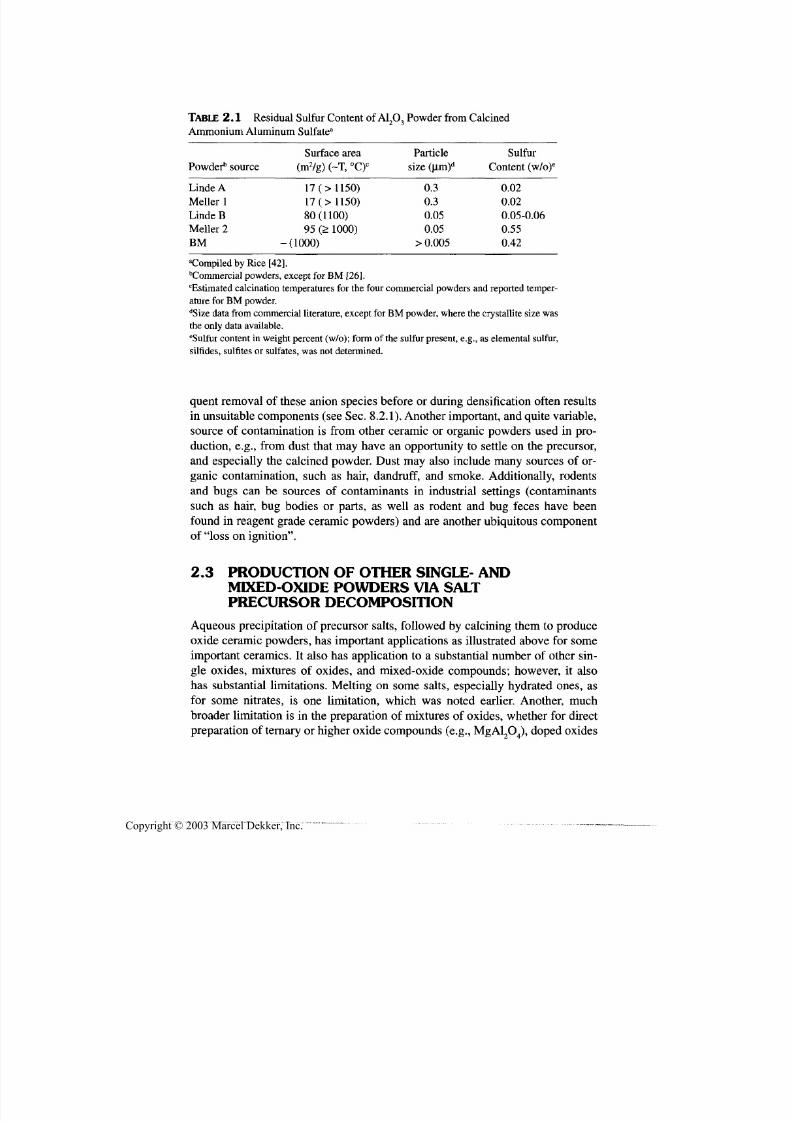
7/29/2019 29540824708539
http://slidepdf.com/reader/full/29540824708539 46/361
Preparation of Ceramic Powders 35
TABLE 2.1 Residual Sulfur Content of A1 2O3 Powder from Calcined
Ammonium Aluminum Sulfate3
Powderb
source
Linde A
Meller 1
Linde B
Meller 2
BM
Surface area
(m 2/g ) (~T, °C)C
17 (> 1150)
17 (> 1150)
80(1100)
95 (> 1000)
-(1000)
Particle
size (um)d
0.30.3
0.05
0.05
> 0.005
Sulfur
Content (w/o)e
0.02
0.02
0.05-0.06
0.55
0.42
Compiled by Rice [42].bCommercial powders, except for BM [26].
Estimated calcination temperatures for the four commercial powders an d reported temper-ature for BM powder.dSize data from commercial literature, except for BM powder, where the crystallite size was
the only data available.eSulfur content in weight percent (w/o); form of the sulfur present, e.g., as elemental sulfur,
silfides, sulfites or sulfates, was not determined.
quent removal of these anion species before or during densification often results
in unsuitable components (see Sec. 8.2.1). Another important, and quite variable,
source of contamination is from other ceramic or organic powders used in pro-
duction, e.g., from dust that m ay have an opportunity to settle on the precursor,
and especially the calcined powder. Dust may also include many sources of or-ganic contamination, such as hair, dandruff, and smoke. Additionally, rodents
and bugs can be sources of contaminants in industrial settings (contaminants
such as hair, bu g bodies or parts, as well as rodent and bug feces have been
found in reagent grade ceramic powders) and are another ubiquitous component
of "loss on ignition".
2.3 PRODUCTION OF OTHER SINGLE- AND
MIXED-OXIDE POWDERS VIA SALTPRECURSOR DECOMPOSITION
Aqueous precipitation of precursor salts, followed by calcining them to produce
oxide ceramic powders, has important applications as illustrated above for some
important ceramics. It also has application to a substantial number of other sin-
gle oxides, mixtures of oxides, and mixed-oxide compounds; however, it also
has substantial limitations. Melting on some salts, especially hydrated ones, as
for some nitrates, is one limitation, which was noted earlier. Another, much
broader limitation is in the preparation of mixtures of oxides, whether for direct
preparation of ternary or higher oxide compounds (e.g., MgAl2O 4), doped oxides
Copyright © 2003 Marcel Dekker, Inc.

7/29/2019 29540824708539
http://slidepdf.com/reader/full/29540824708539 47/361
36 Chapter 2
(e.g., ZrO 2 with stabilizer), or with additives for composites such as Al2O 3-ZrO 2,
due to limitations on coprecipitation of two or more constituent oxide species.
Many of these limitations can be at least partially overcome by separate prepara-tion of the cons tituent oxides, then mixing them and reacting them by solid-state
reactions as discussed in Section 2.4, bu t this may be at some cost for addedsteps and some powder limitations of chemical homogeneity and homogeneous,
fine particle size. Partly balancing these limitations are that several salts can be
considered in precip itation processes giv ing opportunities to obtain salts that are
compatible for coprecipitation and are free of melting or other limitations. Thus,
for example, both barium [43] and strontium [44] hexaferrites powders have
each been produced via precipitation from chloride solutions using mixtures of
sodium hydroxide and carbonate. Similarly, LaNiO 3 powder was prepared via
hydrous chlorides dissolved in water then coprecipitation as oxalates using a wa-ter-alcohol solution of oxalic acid [45]. Another example is the preparation of
ZrO 2-A l2O 3 composite powder by coprecipitated from nitrate solution using am -
monium hydroxide [46].
There are, however, modifications of the precipitation process as well asmore basic changes (considered below) that considerably diversify solution pro-
cessing of ceramic powders. A modest modification referred to as homogeneous
precipitation, entails the chemical source of precipitation being contained in acom pound included in a solution of the salt constituents. The release of the pre-
cipitation agent (e.g., thermally via decomposition of urea) then causes more
uniform precipitation and may allow a somewhat broader range of precursor
chemistry. Thus, pure ZrO 2 [47] and oxides of Y, La, Ce, and Nd [48] have each
been produced by this process, producing fairly uniform oxide particles ranging
from < 1 (im to 1 jim or more, and spherical to polyhedral morphology depend-
ing on material and processing. Such processing has also been used for prepara-
tion of various ferrite and related ternary ox ides [49], as well as m ulli te [50] and
M g A l 2O 4[51 ] .
An alternativ e to the above precipitation processing is emulsion process-
ing, which entails dispersing droplets of a liquid precursor in an immiscible
fluid. This entails use of a salt solution, commonly a water solution, bu t othersolvents and compatible soluble sources of the desired ceramics are also feasi-
ble. T he solution is m ixed w ith another liquid which is imm iscible with the sol-
vent of the solution (e.g., an oil for water-based solutions), but contains a
suitable surfactant so the solution form s an emulsion with the immiscible liq-
uid, i.e., the solution forms small spherical (e.g., 0.1-0.3 fim) droplets in the
immiscible liquid. The number and size of droplets formed depends on thesolute and immiscible liquid, the surfactant, and the mixing, especially high-
shear m ixin g. In the solution m anifestation, m ost of the imm iscible liquid (e.g.,
oil) and all of the solution solvent (water) is removed by vacu um evaporation.
Then, the resultant slurry is pyrolyzed in an atmosphere of limited or no oxygen
Copyright © 2003 Marcel Dekker, Inc.
7/29/2019 29540824708539
http://slidepdf.com/reader/full/29540824708539 48/361
Preparation of Ceramic Powders 37
so enough of the remaining immiscible liquid forms a char continuing to sepa-
rate the individual dried spherical particles resulting from the droplets. The
char-dried particle mixture is then calcined to both oxidize away the char andconvert the precursor salt to the oxide sought, avoiding as much as possible in-
terparticle sintering and other agglomeration, for example, via a belt or rotary
furnace (calciner). This is generally followed by some milling to reduce ag -glomeration (e.g., giving particles similar in size to the original droplet sizes).
Maher and coworkers [52] reported successful preparation of several oxide ce-
ramics, including both single an d multiple oxides of interest for electrical and
electronic applications, including high-temperature superconductors. In another
manifestation, use of either a binder with the precursor or a precursor that poly-
merizes via thermal treatment or use of a catalyst allows the droplets to be
rigidized in the emulsion state, so they can simply be sieved out of the immisci-
ble liquid. This eliminates the vacuum evaporation step, and may allow reuse of
the immiscible liquid, but may often result in larger droplets or particles. While
this is often more applicable to nonoxides derived from preceramic polymers, it
has some applicability to oxides.
Another alternative to precipitation of ceramic precursor salts to prepare
ceramic powders is via sol-gel processing. This basically entails conversion of a
"sol solution" to a rigid solid or to solid particles in a liquid via gelling, the latter
similar to precipitation. This has a variety of manifestations depending, in part,
on whether the sol is based on alkoxides or on stabilization of colloidal particles
of hydrated oxides or hydroxides in water. While each type of sol has its limita-
tions in terms of oxides to which it is applicable, a substantial number of oxides
can be made by one or the other approach. This and combinations within (and
possibly between) so l approaches and specifics of gellation methods result in
considerable diversity for making powders (as well as for making fibers, films,coatings, and bulk bodies). The basis of the sol determines what oxide solcom-
positions can be made, their oxide yield, compatibility for processing mixed ox-
ide compositions, and limited additive levels and types (e.g., for colloidal
stabilization) and costs (Table 1.2).
Both so l sources can often produce similar compositions at similar costs,with colloidal sols commonly gelled by water removal and alkoxide sols by re-
action with water (of which only very small amounts are needed since the re-
sulting polymerization for gelling produces more water fo r further
polymerization). Thus, gelled beads can be produced by dripping colloidal sol
droplets into a fluid medium that will extract enough water (or other solvent)
fast enough from the sol droplets to gel them. A n important earlier manifesta-
tion of this was the demonstration of the feasibility of producing uniform spher-
ical particles from a few microns to a few millimeters in diameter that could becalcined to the desired oxides, then sintered to approximately theoretical den-
sity. Thus, by dripping colloidal so l droplets into a water-absorbing fluid, very
Copyright © 2003 Marcel Dekker, Inc.
7/29/2019 29540824708539
http://slidepdf.com/reader/full/29540824708539 49/361
38 Chapter 2
uniform spherical beads of possible nuclear reactor oxide fuels were demon-
strated, oxide catalyst support beads commercially produced [53] and making
feed material for melt spraying dem onstrated [54]. Spray-drying and related ex-tensions of this are also feasible [55]. Alkoxide sols can also be gelled in bulk
(similar to a casting operation), then ground into powder as discussed below (or
directly further dried and fired into a bulk body; Sec. 6.6). However, narrow
size distributions of uniform submicron spherical oxide powders can be pro-
duced in tailored reactors [56] or by in situ production of free water in solution
[57]. In either case, whether a binary, mixed oxide, or higher-order oxide com-
pound is gelled, the actual oxide crystallites obtained upon calcining dried gel
particles are submicron in nature [58].
Despite the diversity of powders produced and the quality of those pro-duced as fine, subm icron, uniform crystallite particle sizes that allow sintering to
high densities [59] at lower temperatures than many other powders, sol-derived
powders are limited in their commercial applications, primarily because of costs.
Crushing of bulk gelled and dried pieces, then calcining these pieces to produce
oxide powders usually presents limitations on resultant sintering since this pro-
duces porous agglomerates, with the pores between the agglomerates being more
resistant to sintering. This can be overcome by hot pressing, for example, as
shown by Becher's use of this approach to prepare extremely uniform A1 2O3-
ZrO 2 com posites [60] that were app arently the first to show both strength as well
as toughness increases in such composites; but hot pressing is generally con-strained because it is often more ex pensiv e than pressureless sintering.
The use of sols to produce alumina-based abrasive particles is a major
commercial application of sol-gel processing that is illustrative of how and
where processes that entail more ex pen siv e aspects, in this case, sol-gel process-
ing, can be commercially viable in specialized applications. The process is to gel
alumina-based sols with appropriate additives such as MgO or ZrOr Gelling of
sols in trays gives bulk gelled bodies that are comminuted to yield the desired
size abrasive particles after calcining and sintering of crystallites within the indi-
vidual particles, sintering of the abrasive particles to one another being pur-
posely avoided [61,62]. Despite some potential advantage of gel versus fusedabrasive comminution and avoiding the problem of sintering comminuted gel-
derived particles to one another, the process was seen as being about tenfold
more costly than competing fused abrasives. Changes in composition, mainly
use of much cheaper MgO for ZrO 2, and resultant processing improvements,
some due to composition changes, allowed commercial introduction to replace
some of the fused abrasive particles for some applications of coated abrasiveproducts, particularly for finishing some steels. Note that this initial success fo-
cused on applications where limited amounts of the sol-derived abrasive parti-
cles were needed by mixing them with the normally used (cheaper) fused
abrasive particles and in coated abrasives (i.e., sandpaper-type abrasive products
Copyright © 2003 Marcel Dekker, Inc.
7/29/2019 29540824708539
http://slidepdf.com/reader/full/29540824708539 50/361
Preparation of Ceramic Powders 39
where only a partial single layer of abrasive particles is needed, so abrasive ma-
terials costs are less significant to product costs). Three things w ere needed to get
the abrasive used in some grinding wheels, where much greater abrasive vol-umes are used and abrasive costs are much more critical. The first was further
lowering of gel-derived abrasive costs since just the raw materials costs were ~$4/kg, while finished fused abrasive costs were $0.50-0.70/kg. Second was fur-
ther improving the gel-derived abrasive performance versus its competition
(fused A l2O 3-ZrO 2); and third getting the customers to recognize that the resul-
tant product was more cost-effective in some applications despite higher abra-
sive cost. Note that improving gel-derived abrasive performance was in part
obtained by seeding to enhance formation of alpha alumina, which was done be-fore such seeding became a popular research topic.
The above gelling of alkoxide-based sols to produce oxide powders, which
occurs via polymerization, is but one chemical system in which polymerization
plays a role. Lessing [63] has reviewed two others, n am ely polyesters of the pop-
ular Pechini type and cross-linked poly(acrylic acid) polymers, with the former
having been used on over 100 different mixed-oxide compounds. This starts with
various common precursor, water-soluble salts, such as chlorides, carbonates,hydroxides, isopropoxides, and nitrates chelated with a hydroxycarboxylic (usu-
ally citric) acid. The solution of these two ingredients is, in turn, dissolved with
either ethylene or dietylene glycol by heating (80-110°C) and stirring to achieve
a clear solution. Further heating then results in (reversible) polymerization of thesolution and removes water freed in polymerization. Calcining, often in air, re-
sults first in charring of the polymer resin (e.g., at ~ 400°C), then oxide com-
pound formation at 500-900°C. Lessing discusses a number of practical aspects
of these polymer processes, such as advantages and disadvantages of foaming
that may occur during pyrolysis, temperature control issues raised by the amount
of organic material to be pyrolyzed, interaction with other processes such as
freeze-drying (discussed below), and other practical issu es, inclu ding costs. Thelatter are driven substantially by starting salt costs.
The first of four significant modifications of deriving oxide powders from
salt precursors was freeze-drying, originally demonstrated by Schnettler andcoworkers [64] for powders to sinter for ceramic applications. This entails rapidfreezing of the salt precursor solution, commonly by spraying solution droplets
into a cold liquid such as N2 or hexane surrounded by an acetone-dry-ice bath,
then subliming off the solute, usually w ater, often as water of hydration. This al-lows a sub stantially broader range of salts and their m ixtures for doping or form-
ing ternary or higher compounds to be processed. (Directional freezing can also
be used to produce fibrous or cellular pieces.) There are still some limitations,
primarily melting of some constituents during sublimation drying, though thiscan frequently be subdued with additives, e.g., amm onium hydroxide [65]. Ap-
plication of this process to oxides of high surface area has been shown [66] and
Copyright © 2003 Marcel Dekker, Inc.
7/29/2019 29540824708539
http://slidepdf.com/reader/full/29540824708539 51/361
40 Chapter 2
studied in some detail by Hibbert an d coworkers [67-69]. Though apparently no t
yet applied on a significant industrial scale, evaluation of the process by Rig-
terink [70] shows potential for being a production process, while more theoreti-
cal considerations provide guidance fo r further development [71].
Removal of water from salt precursors, an d frequently attendant melting
problems, is also accomplished chemically by spraying droplets of the salt solu-
tion into a l iquid that will extract the water. Th us, for exam ple, O'Toole and Card
[72] reported forming submicron spherical particles of Y 2O 3-ZrO 2 by spraying
droplets of sulfate solu tions into an absolute alcohol.
An other alternative is to therm ally remove the water in a fashion that min-
imizes negative effects of m elting, mainly the formation of large, hard agglomer-
ates. Benign water removal has been demonstrated in a number of cases byspraying droplets of the precursor solution into a heated, stirred liqu id that is not
miscible with, nor decomposed by, the precursor or its products. The liquid, of-
ten an oil ma terial such as kerosene, is heated sufficiently to evaporate the w ater,
and encapsulate the residues of the dried droplets as particulates, which can sub-
sequently be removed by filtering an d then calcined, ground, and so forth. Rich-
erson [4] has summarized some of this work, and Richardson and Akinic [73]
describe preparation of small (1 -3|im) spherical granules of yttria with crystal-
lites of 0.1 |im size.
The fourth alternative and extension to solution-calcining processing is at-
omization of a solution and thermal treatment in the aerosol state. This can bejust spray-drying, but is often extended to temperatures to also includ e calcina-
tion in the aerosol state. The process incorporating calcining in the aerosol state
has a variety of names in the literature, with spray pyrolysis being the most
widely used, as noted in the subs tantial reviews by M essing and coworkers [74]
and Kladnig and K arner [75]. This process, which clearly limits the effects of lo-
cally produced calcining atmosphere on products, as discussed in the previous
section, is qu ite versatile and has been applied to a variety of materials. It can be
readily applied to almost any solution, as well as slurries or emulsions of single
or mixed compositions. Depending on atomization capabilities, submicron to
mu ltimicron particles can be produc ed, possibly retaining some of the sphericityof the aerosol droplets, but serious shape variations and distortions as well as
hard agglomeration can occur. Melting of intermediates can result in substan-
tially larger (otherwise often nm) crystallite sizes, as well as hard, calcined ag-
glomerates. Spray pyrolysis has considerable commercial use indicating its
potential for cost-effectiveness as reviewed by K ladnig and K arner [75]. An im-
portant example of this is the spray-roasting of pickling liquors, which are a
waste product of the steel industry. These are spray-roasted (after reduction of
silica contents) to produce ferric oxide for ferrites as well as regeneration of HC 1
to be reused in pickling more steel. From a research and development standpoint,
spray pyrolysis is a useful tool for making powders, often of a nanometer scale,
Copyright © 2003 Marcel Dekker, Inc.
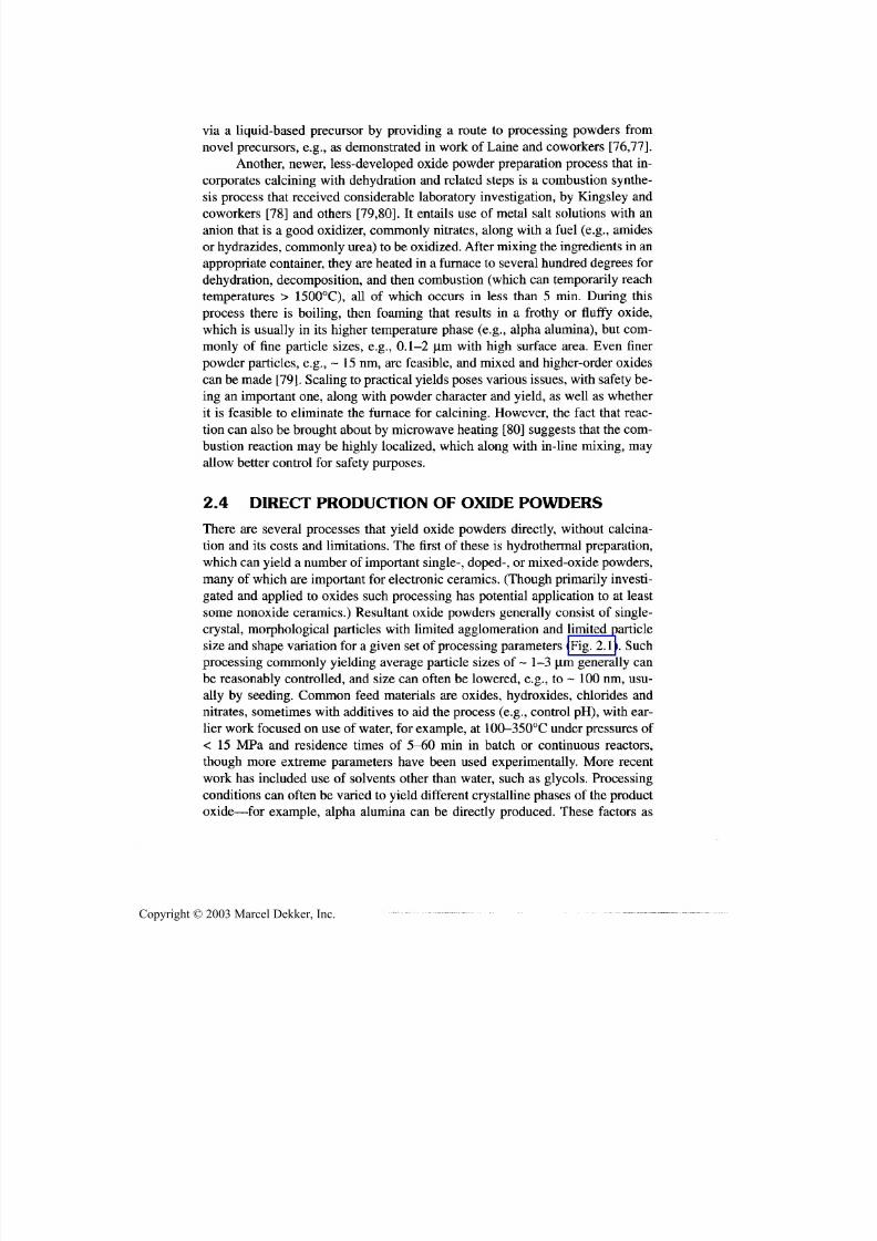
7/29/2019 29540824708539
http://slidepdf.com/reader/full/29540824708539 52/361
Preparation of Ceramic Powders 41
via a liquid-based precursor by providing a route to processing powders from
novel precursors, e.g., as demonstrated in work of Laine and coworkers [76,77].
Another, newer, less-developed oxide powder preparation process that in-corporates calcining with dehydration and related steps is a combustion synthe-
sis process that received considerable laboratory investigation, by Kingsley andcoworkers [78] and others [79,80]. It entails use of metal salt solutions with an
anion that is a good oxidizer, commonly nitrates, along with a fuel (e.g., amides
or hydrazides, com monly urea) to be oxidized. After mixing the ingredients in anappropriate container, they are heated in a furnace to several hundred degrees for
dehydration, decomposition, and then combustion (which can temporarily reach
temperatures > 1500°C), all of which occurs in less than 5 min. During thisprocess there is boiling, then foaming that results in a frothy or fluffy oxide,
which is usually in its higher temperature phase (e.g., alpha alumina), but com-
monly of fine particle sizes, e.g., 0.1-2 |im with high surface area. Even finer
powder particles, e.g., -15nm, are feasible, and mixed and higher-order oxides
can be made [79]. Scaling to practical yields poses v arious issues, with safety be-ing an important one, along with powder character and yield, as well as whether
it is feasible to eliminate the furnace for calcining. However, the fact that reac-
tion can also be brou ght about by microw ave heating [80] su gges ts that the com-
bustion reaction may be highly localized, which along with in-line mixing, m ayallow better control for safety purposes.
2.4 DIRECT PRODUCTION OF OXIDE POWDERS
There are several processes that yield oxide powders directly, without calcina-
tion and its costs and limitations. The first of these is hydrothermal preparation,
which can yield a number of important single-, doped-, or mixed-oxide pow ders,
many of which are important for electronic ceramics. (Though primarily investi-gated and applied to oxides such processing has potential application to at least
some nonoxide ceramics.) Resultant oxide powders generally consist of single-
crystal, morphological particles with limited agglomeration and limited particle
size and shape v ariation for a given set of processing param eters (Fig. 2.1). Suchprocessing commonly yielding average particle sizes of ~ 1-3 Jim generally canbe reasonably controlled, and size can often be lowered, e.g., to ~ 100 nm, usu-
ally by seeding. Common feed materials are oxides, hydroxides, chlorides and
nitrates, sometimes with additives to aid the process (e.g., control pH), with ear-
lier wo rk focused on use of water, for examp le, at 100-350°C under pressures of
< 15 MPa and residence times of 5-60 min in batch or continuous reactors,
though more extreme parameters have been used experimentally. More recent
work has included use of solvents other than water, such as glycols. Processing
conditions can often be varied to yield different crystalline phases of the produc t
oxide—for example, alpha alumina can be directly produced. These factors as
Copyright © 2003 Marcel Dekker, Inc.
7/29/2019 29540824708539
http://slidepdf.com/reader/full/29540824708539 53/361
42 Chapter 2
FIGURE 2.1 Micrographs of hydrothermally produced a-A!2O3, single-crystal (sap-
phire) powder particles. (A ) Thin platelets and (B) mixed thick platelets and approxi-
mately equiaxial polyhedra. Multifaceted double-terminated pyrimidal particles are also
produced depending on processing conditions, including the speed and extent of stirring
the liquid. See also Fig. 3.3 for similar particle (crystal) morphologies obtained as a func-
tion of different liquid-phase processing parameters. (Photos courtesy of Prof. J. Adair,
Penn. State U.)
well as practical issu es are discussed in extensi ve literature, such as a review by
Dawson [81], and papers by Adair and coworkers [82]. Considerable work on
scaling and economics of the process has resulted in some comm ercial applica-
tions of hyd rotherm ally prepared BaTiO3 where the finer, more uniform, bu t
more costly, powder can be cost-effective in view of better performance and lim-
ited quantities used. Note that the different particle morphologies readily pro-
duced should produce different extents and character of preferred orientation in
components made from such powders as a function of fabrication m ethods and
Copyright © 2003 Marcel Dekker, Inc.

7/29/2019 29540824708539
http://slidepdf.com/reader/full/29540824708539 54/361
Preparation of Ceramic Powders 43
parameters. Characterizing such effects is important in optimizing uses of these
morphological particles.
Another process of promise for a number of single and particularly mixedoxides for bo th structural and, especially, electrical-electronic applications is that
which is carried out in molten salt baths [83-85]. Besides producing m any of the
same or similar oxides as hydrothermal processing, it also often yields m orpho-
logical shaped, dense single-crystal particles (e.g., of 1 to several |om in size).However, it also yields much finer morphological or equiaxed particles, often as
more agglomerated powders, which m ay often be friable agglomerates. It hasbroad applicability due in part to the diversity of salt systems that can be used.
Two examples of such synthesis are
BaCO 3 + TiO 2 => BaTiO 3 + CO 2 (2.1)and
2PbO +ZrO 2 + TiO 2 => PbTiO 3 + PbZrO 3 (2.2)
carried out, respectively, in m olten NaK CO 3 at 800°C [83] and in molten NaCl-KC1 mix at 1000°C [84]. The criteria for a suitable salt m edia, besides its chemi-
cal suitability for the reaction, is a low m elting point, often aided by using mixed
salts [e.g., Eq. (2.2) above], and good solubility of the salt, preferably in water,for easy recovery of the product powder. Besides scaling issues, costs of the op-
eration, crucibles, product recovery, and salt recovery are likely to be important
in determining use of this versatile process.
An important and broad method of preparing oxide powders is reaction
processing, that is, processing that entails one or more chemical reactions as an
important aspect of the powder preparation. Actually, reaction processing is an
imp ortant aspect of most other powder m aking processes, including m any or all
aspects of the processes discussed above and those below. However, of specific
interest are solid-state reactions to produce doped or alloyed ox ide pow ders, and,especially, powders of ternary or higher oxide compounds from binary oxides ortheir precursors. The most commonly used method of production of doped or
ternary or higher order oxide powders is via such solid-state reactions. Key is-sues are the uniformity and intimacy of the mixing of the reactant oxide con-
stituents and the fineness of the reactant pow der particles. U sing one or m ore ofthe oxide constituents in precursor form, often preferably a soluble one, can of-
ten aid in both the uniformity and intimacy of mixing as well as the resultant ox -
ide particle size; for example, due to m utual inhibition of particle growth of each
oxide constituent by the other constituent(s). Other issues can be obtaining or
maintaining desired stoichiometry, for example, due to vapor losses, which canoften be cou ntered by excess source of the vapo r lost, calcining in crucibles withlids (which a balance between desired outgassing of the powders or precursors
and vapor losses), or both. Common overall issues are agglomeration and grain
Copyright © 2003 Marcel Dekker, Inc.
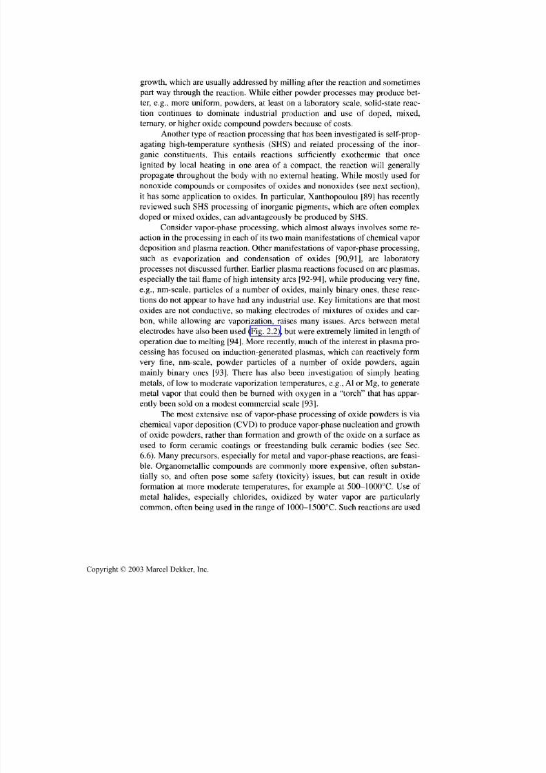
7/29/2019 29540824708539
http://slidepdf.com/reader/full/29540824708539 55/361
44 Chapter 2
growth, which are usually addressed by milling after the reaction and sometimes
part way through the reaction. While either powder processes m ay produce bet-
ter, e.g., more uniform, powders, at least on a laboratory scale, solid-state reac-tion continues to dominate industrial production and use of doped, mixed,
ternary, or higher oxide compound p owders because of costs.
Ano ther type of reaction processing that has been investigated is self-prop-
agating high-temperature synthesis (SHS) and related processing of the inor-
ganic constituents. This entails reactions sufficiently exothermic that once
ignited by local heating in one area of a compact, the reaction will generally
propagate throughout the body with no external heating. While mostly used for
nonoxide compounds or composites of oxides and nonoxides (see next section),
it has some application to oxides. In particular, Xanthopoulou [89] has recently
reviewed such SHS processing of inorganic pigments, which are often complex
doped or mixed oxides, can advantageously be produced by SHS.
Consider vapor-phase processing, which almost alway s involves some re-action in the processing in each of its two mai n ma nifestation s of chemical vapo r
deposition and plasm a reaction. Other manifestations of vapor-phase processing,
such as evaporization and condensation of oxides [90,91], are laboratory
processes no t discussed further. Earlier plasma reactions focused on arc plasmas,
especially the tail flame of high inten sity arcs [92-94], while producing very fine,
e.g., nm-scale, particles of a number of oxides, mainly binary ones, these reac-
tions do not appear to have had any industrial use. Key limitations are that mostoxides are not conductive, so making electrodes of mixtures of oxides and car-
bon, while allowing arc vaporization, raises many issues. Arcs between metal
electrodes have also been used (Fig. 2.2), but were extremely limited in length of
operation due to melting [94]. More recently, mu ch of the interest in plasma pro-
cessing has focused on induction-generated plasmas, which can reactively form
very fine, nm-scale, powder particles of a number of oxide powders, again
mainly binary ones [93]. There has also been investigation of simply heating
metals, of low to moderate vaporization temperatures, e.g., Al or Mg, to generatemetal vapor that could then be burned with oxygen in a "torch" that has appar-
ently been sold on a modest commercial scale [93].The most extensive use of vapor-phase processing of oxide powders is via
chemical vapor deposition (CVD) to produce vapor-phase nucleation and growth
of oxide powders, rather than formation and growth of the oxide on a surface as
used to form ceramic coatings or freestanding bulk ceramic bodies (see Sec.
6.6). Many precursors, especially for metal and vapor-phase reactions, are feasi-
ble. Organometallic compounds are commonly more expensive, often substan-
tially so, and often pose some safety (toxicity) issues, but can result in oxide
formation at more moderate temperatures, for example at 500-1000°C. Use of
metal halides, especially chlorides, oxidized by water vapor are particularly
common, often being used in the range of 1000-1500°C. Such reactions are used
Copyright © 2003 Marcel Dekker, Inc.
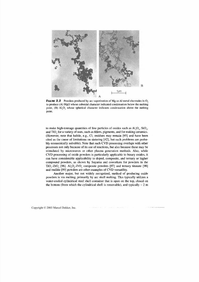
7/29/2019 29540824708539
http://slidepdf.com/reader/full/29540824708539 56/361
Preparation of Ceramic Powders 45
FIGURE 2.2 Powders produced by arc vaporization of Mg or A l metal electrodes in O2
to produce (A) MgO whose cuboidal character indicated condensation below the melting
point, (B ) A12O3 whose spherical character indicates condensation above the melting
point.
to make high-tonnage quantities of fine particles of oxides such as A12O3, SiO 2,
and TiO2 for a variety of uses, such as fillers, pigments, and for making ceramics.
(However, note that halide, e.g., Cl, residues may remain [95] and have been
cited as the cause of limitations on sintering [42], bu t such problems are proba-
bly economically solvable). Note that such C V D processing overlaps with other
processes no t only because of its use of reactions, bu t also because these may bestimulated by microwaves or other plasma generation methods. Also, while
CV D processing of oxide powders is particularly applicable to binary oxides, it
can have considerable applicability to doped, composite, and ternary or higher
compound powders, as shown by Suyama an d coworkers for powders in the
TiO2-ZrO2 [96]. Al2O 3-ZrO 2 composite powders [97] and ternary titanate [98]
and mullite [99] powders are other examples of CVD versatility.
Another major, but not widely recognized, method of producing oxide
powders is via melting, primarily by arc skull melting. This typically utilizes a
water-cooled cylindrical steel shell container that is open on the top, closed on
the bottom (from which the cylindrical shell is removable), and typically ~ 2 m
Copyright © 2003 Marcel Dekker, Inc.
7/29/2019 29540824708539
http://slidepdf.com/reader/full/29540824708539 57/361
46 Chapter 2
in diameter with an aspect ratio of ~ 2 or more. This container is partly loadedwith oxide powder into which horizontal graphite starting bars are placed such
that they will contact the large vertical graphite electrodes (usually three forthree-phase he ating) that enter from the top of the container and terminate on the
starting bars. Following further filling of much of the container with the powder
to be m elted, power is applied to the electrodes, which heats the starting bars tothe point where enough of the surrounding ceramic powder is melted before the
sacrificial starting bars are consumed by oxidation. Subsequent heating contin-
ues via arcing from the electrodes to the molten ceramic and electrical conduc-
tion in the molten ceramic. Besides having a ceramic composition that melts
with sufficient congruency , and wi thou t excessive vaporization, adeq uate electri-
cal conductivity in its molten state, an d sufficient resistance to reduction underthe harsh reducing conditions from the consumption of the starting bars and the
presence and partial consumption of the electrodes are needed. An important op-
erational factor is having powder that is coarse enough such that outgassing of
adsorbed and entrapped g as is not explos ive. It is also im portant that the charac-
ter and packing of the powder in the container is such that upon m elting, settling
of the molten pool into the unmelted powder below is at a limited, reliable rate
so the electrodes can be advanced to maintain electrical contact with the melt,
and a suitable fraction of the powder load can be melted in a reasonable ru n-tim e
(e.g., a few hours). After cooling for several hours, the cylindrical shell is re-
moved, then the unmelted material around the solidified melt is removed, fol-lowed by breaking up the solidified molten mass, often initially m anually with
sledge ham mers, then throug h varying degrees of com m inution.
Despite the batch nature and related manual aspects of the process (which
are major factors why much of the production has gone offshore), it is a widely
used process whic h produces large tonnages of refractory grain, prim arily for the
refractories industry. Major oxide grains produced are A12O3, MgO, SiO,, and
ZrO 2 (which undergoes some to substantial, but generally not destructive, reduc-
tion). A12O3 is also used for abrasives, with two grades being made, brown and
white, based or raw m aterials and res ultant purity. As noted above in conjunction
with sol processing of A12O3 based abrasives, production of ~A12O3 - ZrO 2 eutec-tic compositions via fusion and quench casting (e.g., in graphite book molds) isan important application of resultant fused grain for higher performance abra-
sives. (Note: The reduction of the ZrO 2 from the arc melting and casting in
graphite appears to partially stabilize, hence toug hen it, but ox idation may be afactor in the wear of the abrasive as indicated by loss of strength and toughness
due to cracking on oxid ation [100,101].) Higher quality fused MgO grain is also
used as the electrical insulator, but thermal conductor, in electrical heating ele-
ments (e.g., as used in home electric stoves and some other home and industrial
heater appliances). (Sized MgO grain is apparently vibratorialy filled between
the central heating wire and the outer steel tube, with the latter then being
Copyright © 2003 Marcel Dekker, Inc.
7/29/2019 29540824708539
http://slidepdf.com/reader/full/29540824708539 58/361
Preparation of Ceramic Powders 47
swaged to reduce its diameter and increase both the thermal contact between the
M gO grain and the metal tube as well as the Mg O density (to ~ 90% of theoreti-
cal) and thermal conductivity.)
Two other more recent applications of fused-oxide powders have occurred.
First, fused grain has replaced some use of spray-dried agglomerates of conven-
tionally produced oxide powders to become the dominant source of powders for
melt spraying of ceramics, especially for powders of doped or mixed oxides,
e.g., such as Al2O 3-TiO 2, and ZrO2 with stabilizers, as well as ternary or higher-
order oxides such as MgAl2O4. Eliminating binders needed for spray-drying,
which are a possible source of problems in plasma spraying, is one of the advan-
tages of fused powders for melt spraying. However, a major advantage is the
compositional uniformity and stability of melt-derived powders versus often in -complete melting and mixing heterogeneities of mixed spray-dried powders.
More recently there has been some commercial sale and use of melt-produced
PSZ powders for production of PSZ bodies. Though such powders have appar-
ently been somewhat more expensive than conventionally produced powders,
e.g., due to costs of comminuting the solidified fused ingot, the fusion-derived
powders not only offer more homogeneous composition, bu t also environmental
stability. Thus, conventional powders of ZrO2 mixed with low-cost CaO or MgO
stabilizers are unstable in the presence of moisture, and hence in aqueous
milling, air storage, or slip casting, while the fused powders of such composi-
tions are stable, and replacement of the CaO or MgO with stable precursors suchas carbonates in conventional powders still pose some issues. (Note: Substantial
cost reductions should be feasible for PSZ powder production if ZrO2 extraction
from zircon and fusion of desired compositions can be combined, by boiling off
much or all of the SiO2, which is apparently already done to some extent. A key
issue could be the partition of stabilizer between the ZrO2 and the SiO2. All fu-
sion-derived powder costs should be substantially reduced if thin sheets are cast,
e.g., as for fused Al2O3-ZrO2 abrasives, and, especially, if streams of molten
droplets can be splat cooled to reduce comminution costs, as well as calcination
costs to reoxidize reduced materials such as ZrO2.)
Two other processes for, and application of, melt-derived ceramic particlesshould be noted. The first is for finer (sand) milling media, e.g., used extensively
in the paint industry. Approximately spherical, dense, wear-resistant ceramic
particles, mainly ZrO2 or A12O3, of various sizes from < 1 mm to > 1 mm desired
diameters are produced by various agglomeration techniques and sintering.
However, a possibly superior product is also apparently produced by melt
quenching such size droplets of zircon, which generally produces smoother,
more spherical particles (Fig. 2.3A) which contributes to wear resistance. The
quenching freezes in the decomposed ZrO 2-SiO 2 composition, which presum-
ably provides some ZrO 2 toughening an d limits microstructural scale (Fig.
2.3B), which also aids wear resistance.
Copyright © 2003 Marcel Dekker, Inc.
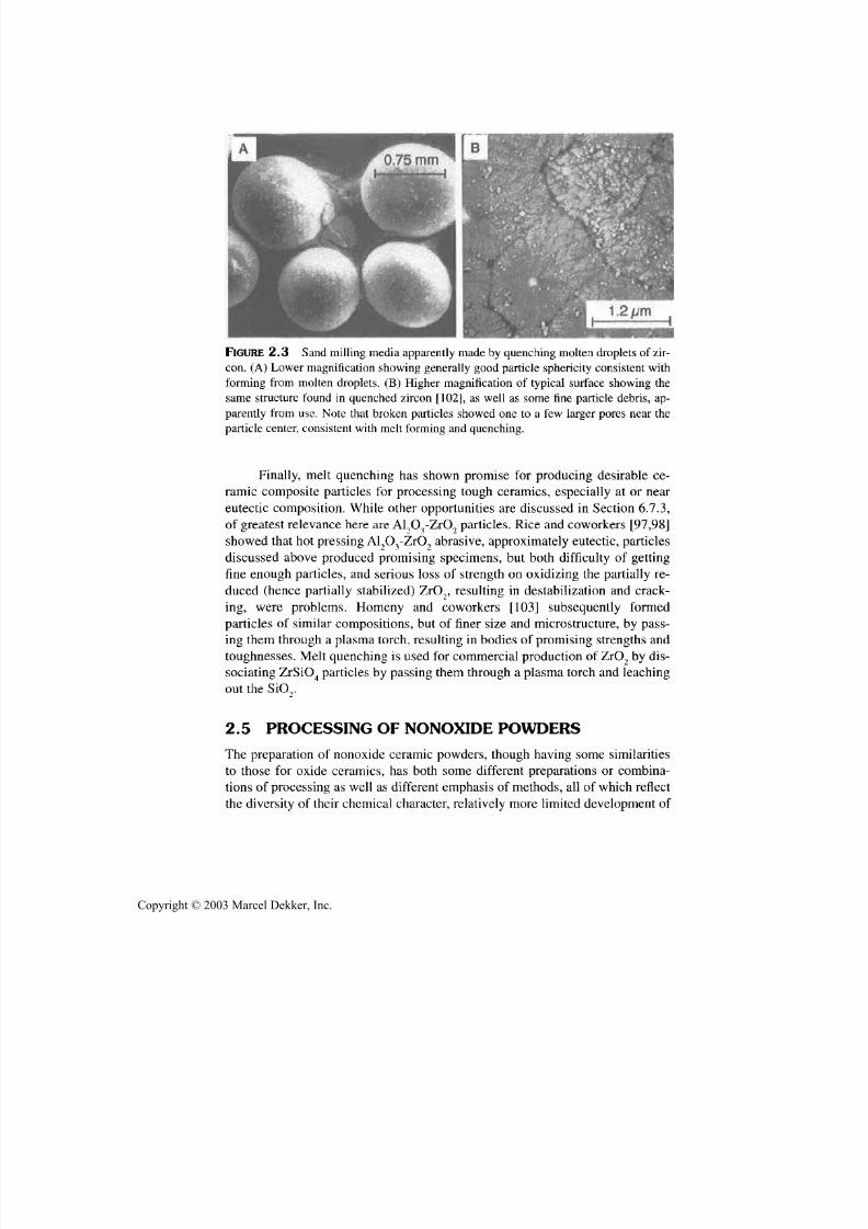
7/29/2019 29540824708539
http://slidepdf.com/reader/full/29540824708539 59/361
48 Chapter 2
FIGURE 2.3 Sand mil l ing media app arently made by quenching molten droplets of zir-
con. (A ) Lower mag nification showing generally good particle sphericity consistent with
forming from molten droplets. (B ) Higher magnification of typical surface showing the
same structure found in quenched zircon [102], as well as some fine particle debris, ap -
parently from use. Note that broken particles showed one to a few larger pores near the
particle center, consistent with melt forming and quenching.
Finally, melt quenching has shown promise for producing desirable ce-ramic composite particles for processing tough ceramics, especially at or near
eutectic composition. While other opportunities are discussed in Section 6.7.3,
of greatest relevance here are Al9O 3-ZrO 9 particles. Rice and coworkers [97,98]
showed that hot pressin g Al 2O 3-ZrO 2 abrasive, approximately eu tectic, particles
discussed above produced promising specimens, but both difficulty of getting
fine enough particles, and serious loss of strength on oxidizing the partially re-
duced (hence partially stabilized) ZrO 2, resulting in destabilization an d crack-
ing, were problems. Hom eny and coworkers [103] subseq uently formed
particles of similar com positions, but of finer size and microstructure, by pass-
ing them through a plasma torch, res ul ting in bodies of promising strengths andtoughnesses. Melt quenching is used for commercial production of ZrO 2 by dis-
sociating ZrSiO 4 particles by pass ing them throug h a plasma torch and leaching
ou t the SiOr
2.5 PROCESSING OF NONOXIDE POWDERS
The preparation of nonoxide ceramic powders, thoug h havi ng some similarities
to those for oxide ceramics, has both some different preparations or combina-
tions of processing as well as different emphasis of methods, all of which reflect
the diversity of their chemical character, relatively more lim ited developm ent of
Copyright © 2003 Marcel Dekker, Inc.
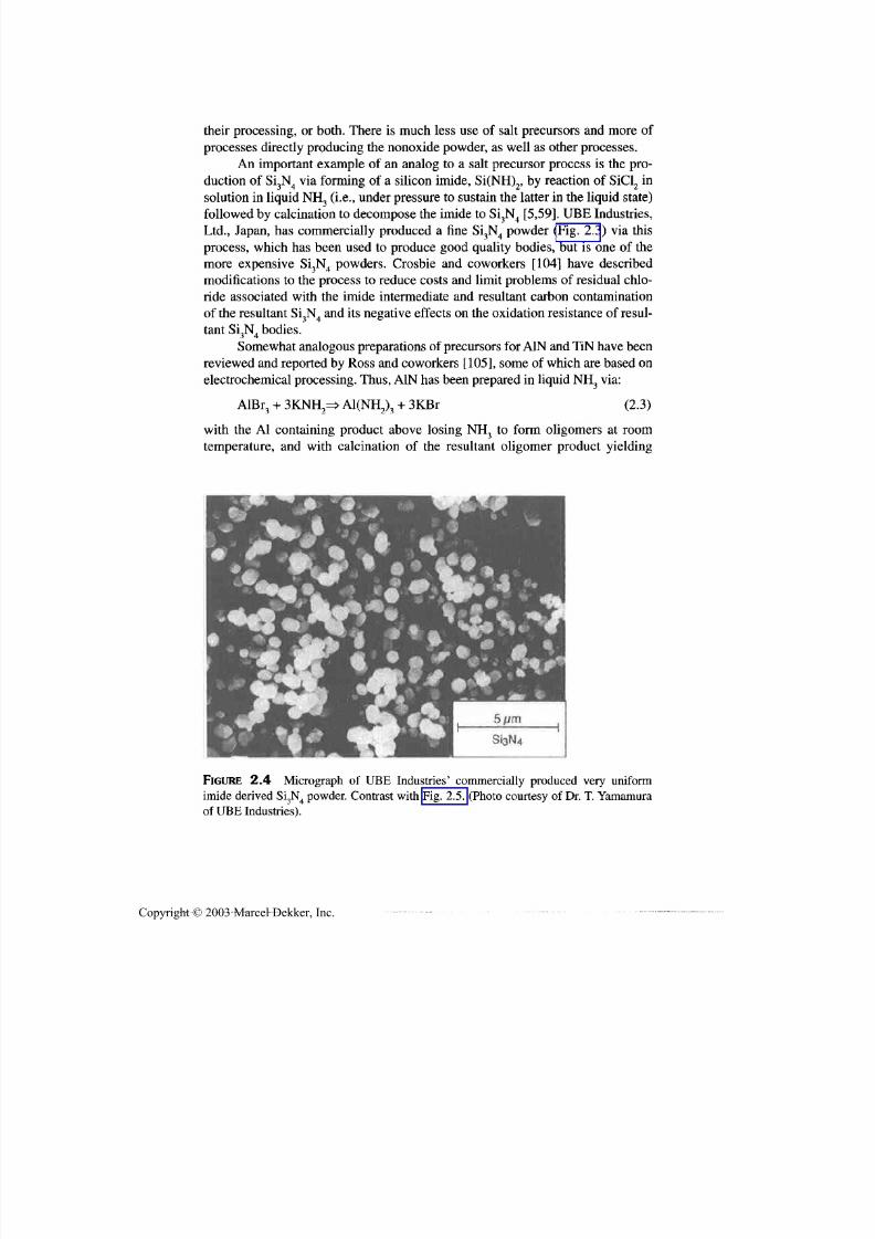
7/29/2019 29540824708539
http://slidepdf.com/reader/full/29540824708539 60/361
Preparation of Ceramic Powders 49
their processing, or both. There is much less use of salt precursors and more of
processes directly producing the nonoxide powder, as well as other processes.
An important example of an analog to a salt precursor process is the pro-duction of Si3N4 via forming of a silicon imide, Si(NH)2, by reaction of SiCl2 in
solution in liquid NH 3 (i.e., under pressure to sustain the latter in the liquid state)
followed by calcination to decompose the imide to Si3N4 [5,59]. UBE Industries,
Ltd., Japan, has commercially produced a fine Si3N4 powder (Fig. 2.3) via this
process, which has been used to produce good quality bodies, but is one of the
more expensive Si3N4 powders. Crosbie and coworkers [104] have described
modifications to the process to reduce costs and limit problems of residual chlo-
ride associated with the imide intermediate and resultant carbon contamination
of the resultant Si3N4 and its negative effects on the oxidation resistance of resul-
tant Si3N4 bodies.
Somewhat analogous preparations of precursors for A1N and TiN have been
reviewed and reported by Ross and coworkers [105], some of which are based on
electrochemical processing. Thus, A1N has been prepared in liquid NH 3 via:
AlBr A1(NH2)3 + 3KBr (2.3)
with the Al containing product above losing NH 3 to form oligomers at room
temperature, an d with calcination of the resultant oligomer product yielding
FIGURE 2.4 Micrograph of UBE Industries' commercially produced very uniform
imide derived Si3N4 powder. Contrast with Fig. 2.5. (Photo courtesy of Dr. T. Yamamura
of UBE Industries).
Copyright © 2003 Marcel Dekker, Inc.

7/29/2019 29540824708539
http://slidepdf.com/reader/full/29540824708539 61/361
50 Chapter 2
FIGURE 2.5 Comparison of Si3N4 powders from (A) CVD and (B) nitridation or car-
bothermal preparation. Note the inclusion of whisker m aterial in A, which often occurs to
various degrees in such CVD-derived material an d larger agglomerates, which often oc -
cur in powder from conversion, such as nitriding Si or carbothermal preparation.
Copyright © 2003 Marcel Dekker, Inc.

7/29/2019 29540824708539
http://slidepdf.com/reader/full/29540824708539 62/361
Preparation of Ceramic Powders 51
A1N. Ross and coworkers modified the process to use electrolysis to form the
intermediate oligomer, which when calcined at 1100°C, yielded extremely fine
(10-25 nm) A1N particles in the very small quantities made. The similarly pre-pared TiN had crystallite and particle seizes respectively of 60 and 480 nm.Note that other electrochemical preparations of nonoxide ceramics in moltensalts are also discussed in Section 3.2 where the role of additives in the prepara-
tion processes are noted.Examples of the extension of similar solution-based reactions to those
used fo r oxides, but instead to directly yield a nonoxide ceramic powder
rather than a precursor salt on precipitation, are those of Ritter and Frase
[106]. They report reactions of Na and various chlorides in an organic solvent
(possibly heated)to
produce powdersof
compounds suchas
B4C, SiC,
an dTiB 2, the latter via:
10 Na + TiCl4 + 2 BC1 3 => 10 NaCl + "TiB2" (2.4)
They reported that the NaC l could be distilled off and the amorphous "TiB2" pre-
cursor crystallized to TiB 2 at ~ 700°C, but no details on the powders, e.g., their
purity, particle size, agglom eration, and possible costs, were given . These prepa-rations have sim ilarities and differences from that of homogeneous precipitation
of fine (e.g. ~ 3 ^im to submicron) ZnS particles by thermal decomposition of
thioacetamide in acidic aqueous solutions [107], a key difference again being the
direct p recipitation of ZnS, not a precursor. Another similar process is the reac-tion of BF3 and NH 3 at a low temperature in an aqueous solution that is then
treated with NaOH to precipitate BN to be dried and heated to 800°C in N2, bu t
probably contains boria and borate products as reviewed by Ingles and Popper
[108]. However, many details such as processing yields, rates, and costs as well
as product q uality and consistency are unknown.
Closer analogs are often found between sol-gel processing of oxide and
nonoxide powders since a variety of organometallic compounds can form gels or
other polymerizing nonoxide precursors. Many of these entail more conven-tional alkoxide-based sol processing with water-initiated polymerization where
the organic part of the alkoxide is selected to pyroly ze in an inert atmosphere tovery fine homogeneously distributed carbon to react with the metal oxide prod-uct, for example, SiO 2 to yield SiC [109-111]. This is a fairly comm on type of
route, that is , using chemical processing to improve more conventional reaction,
carbothermal, processing as discussed below. However, there have been a vari-
ety of laboratory demonstrations of polymerizing organometallic precursors that
thermally decompose to, at least approximately, single-phase nonoxide com-
pounds or mixtures of them (e.g., polysilanes reacting with NH 3 to produce Si3N4
[112] or directly produce it from polysilazanes, or directly produce SiC from
polycarbosilanes). However, in many of these cases, particularly the latter ones,
Copyright © 2003 Marcel Dekker, Inc.
7/29/2019 29540824708539
http://slidepdf.com/reader/full/29540824708539 63/361
52 Chapter 2
the intermediate product is a polymeric mass, as from many conventional sol-gelprocesses. These often produce particles that m ay have very fine crystallites, bu t
are agglom erated in particles whose size is mainly a function of comm inution ofthe intermediate polymer or the pyrolyzed product. Again there may be some
specialized uses for such particles such as abrasives as for alumina-based gels,
but otherwise such powders are normally not advantageous for making dense ce-
ramics by pressureless sintering whether of oxide or nonoxide composition. On
the other hand, processing of powders from liquid precursors or solutions to
form droplets, for example, by spraying, that are then rigidized by polymeriza-
tion may prove fruitful, as suggested by aerosol decomposition of a polymeric
precursor of BN [113].
The first of two related reaction processes that collectively are the mostsignificant sources of typical nonoxide ceramic powders, especially on a com-
mercial scale, is direct elemental reaction, w hich in turn consists of two m ain ap-
proaches. The first, and primary commercial one, is the forming of important
nitride ceramics, mainly A1N and S i3N4, via direct nitridation by heating Al and
Si powders respectively in a m ainly N2 (often with H 2) or NH 3 atmosphere. Pro-
cessing is commonly assisted by use of additives (see Sec. 3.2), such as Fe in
Si3N4 (where it is often an impurity in the Si, from comminution) to aid the ni-
triding reaction and halide salts; for example, L iF or CaF 2, for A1N, apparently to
aid in penetrating the surface oxide layer on the Al particle surfaces. In the case
of Si, the reaction becomes exothermic as temperatures approach that for melt-ing Si (just over 1400°C) so keeping the temperature below this level by control-
ling reactant gas flow and furnace temperature is important, since Si melting
results in coalescence of much of the Si and incomplete nitridation. E ven with-
ou t such coalesence some grinding and reminding of the comminuted material
may be necessary, especially for higher quality Si3N4, which is widely used.
However, by far the highest tonnages of Si3N4 powder made by this process are
used to make Si3N4 refractories. A1N powder made by nitriding Al metal has
been sold commercially for fabrication of high-quality A1N (e.g., for high ther-
m al conduc tivity bodies), but the vo lume and history of this are substantially less
than for Si3N4. Such direct reaction of the elements can in principle be used, andhave been tried, for other nonoxid e (especially binary) ceramics, such as bolides,
carbides, and silicides, besides other nitrides, but is often limited by elemental
powder costs—for exam ple, of Ti, Zr, and especially B—as well as frequently by
processing details for these other materials being less forgiving than in making
A1N or Si3N4 (e.g., in limiting m elting problems).The second, more recent processing of nonoxide powders of binary ceram-
ics is by self-propagating high-temperature synthesis (SHS) that was popularized
by substantial investigation in the Soviet Union [114]. This entails processing of
ceramics from the elements whose compound formation is sufficiently exother-
m ic that if the reaction is ignited by local heating in one area of a powder com-
Copyright © 2003 Marcel Dekker, Inc.

7/29/2019 29540824708539
http://slidepdf.com/reader/full/29540824708539 64/361
Preparation of Ceramic Powders 53
pact, it will propagate through the compact in much the same fashion as a fuse
for firecrackers, dynamite, and other explosives burns by propagation along the
tube of fuse material. Many of these reactions can be very vigorous (depending
in part on the other factors such as the particle size of the reactants), and thus re-
quire safety precautions, which has been a factor in limiting their use. Originally,
these reactions were seen as being desirable due to lower costs since the natural
exotherm of the reactions eliminated furnace and heating costs, as well as their
very transient nature being beneficial, for example, to produce finer particles and
possibly different phases. However, cost benefits from self-heating appear to be
marginal, but in at least some cases, the transient nature of the reactions may be
advantageous, e.g., little or no longer range melting and resultant agglomeration.
Thus, for example Golubjatnikov [115] showed that SHS processing (of Si3N4
powder) had some cost advantage, primarily due to lower comminution costs
due to greater friability of the reacted powder mass. This is again a reminder
that, while general trends can often be discerned from principles an d experience,
specific process evaluation m ay hold some surprises. While such SHS powder
preparation is used mostly for preparation of binary compounds of nonoxides, it
has also been used for some of the more limited work on ternary nonoxide ce -
ramics, e.g., of Ti3SiC2 by Lis and coworkers [116].
Consider now the second an d much more broadly applicable and used
method of traditional reaction processing of mainly binary nonoxide ceramic
powders, namely carbothermal reduction. This simply entails intimate mixing ofoxide powders of the desired metals, metalloids, and carbon (or a source of it) to
reduce the oxides, and if producing a carbide, to react with the reduced metal to
form its desired carbide. Fine, uniformly, and intimately mixed reactive ingredi-
ents are important to react to the desired products with little or no residual oxide
or excess carbon, at temperatures and times to limit excessive particle growth
and sintering. Removal of residual undesired phases can sometimes be done with
limited negative effects, but are an added cost and pose their ow n contamination
problems. Fine carbon powders or liquid precursors such as sugar (dissolved in
water) or furfuryl alcohol can be useful and are of modest cost, especially sugar
[117], which has been used in a number of cases.The first of a few examples are preparation of Si3N4 by carbothermal re-
duction of SiO 2 (which basically avoids the issue of Si melting) in a N 2 or NH 3
atmosphere, the latter being somewhat more reactive, generally producing
mostly a Si3N4 (~ 2 [im) at ~ 1400°C [118]. Either fluidized-bed reactors [119]
or rotary calciners [120] can be useful whether one of the reactants is a gas or all
are solid (e.g., as for SiC) and may reduce agglomeration common in static bed
reactors (see Fig. 2.5B). The phase of the oxides can aid in some cases; for ex-ample, y A12O3 is beneficial for making A1N at ~ 1500°C because of its finer
character, bu t with effects of the starting skeletal structure of different A1 2O3
phases [117,121]. On the other hand, anatase or rutile precursors for TiN have
Copyright © 2003 Marcel Dekker, Inc.

7/29/2019 29540824708539
http://slidepdf.com/reader/full/29540824708539 65/361
54 Chapter 2
limited differences other than via some benefit of finer TiO 2 particle size and
negative effects of purp osely added particle TiO 2 coatings for pigment-grade ma-
terial in making TiN at ~ 1 150°C [122]. Reactions can be affected, often signifi-
cantly, by various parameters, particularly temperature— e.g., SiC formation is
via a solid-state carbon-SiO 2 reaction below 1400°C, while above this tempera-ture gaseous reaction of SiO and C becomes dom inant [123]. Vacuu m processing
or other control of CO pressure and continuous m ixing (e.g., via a fluidized bed
or rotary calciner) can also be important. While the above examples are binary
compounds, more complex compositions can be made, such as sialons [124],
sometimes using natural clays as lower cost raw materials [125]. Processing of
ceramics such as TiB 2, SiC, and S i _ 3N 4 in pilot plant or production scale are re-
viewed by Shepard [93].There are three extensions of carbothermal processing that should be
noted. First, while such processing reduces or precludes melting of elemental
precursors such as Al and especially Si, there are im po rtant cases where a low
melting precursor is used, with the use of B 2O 3 fo r boron containing com-
pounds being particularly important. Thus, for example, 4 of the 7 prepara-
tions of BN reviewed by Ingles and Popper [108] used B 2O 3 as the B source.
B 2O 3 (o r boric acid) is also the typical source of B in a variety of reactions in -
volving carbothermal or other reductions, th e latter being a second and larger
extension of such reaction processing. Complications that m ay result from
forming liquid phases during reaction are l imited by actual or effective encap-sulation of the initial solid particles that will melt so melted particles cannot
coalesce. Such encapsulation may be via other solid constituents of the reac-tion, fillers inert to the reaction [108], or an initial liquid p hase, e.g., su gar so-
lution or furfuryl alcohol precursor fo r carbon where this is a constituent of
the reaction.
The second extension of carbothermal processin g is to more comp lex com -pounds than just binary compounds, e.g., of ternary compounds TiZrC an d
TiZrB2 by Mroz [126], where such processing of the end members at ~ 2000°C
resulted in particle sizes of ~ 2-13 |im and various stoichiometries of ternary
solid solution com pou nds with interm ediate particle sizes. The third extension ofreduction processing noted above is often used to directly produce ceramic com-posites (Sec. 8.2.3) without specifically producing a powder that is subsequentlydensified, but the latter route has also been pursued. Thus, for example Cutlerand coworkers [127] showed that composite powders produced by the following
reactions gave composite powders that could yield composite character and
properties comparable to those obtained by making the composites from con-
stituents oxide and nonoxide powders:
3TiO 2 + 4 Al +3to3TiC + 2A12O3 (2.5)
3SiO 2 + 4 Al + 3C=> 3SiC + 2A12O3 (2.6)
Copyright © 2003 Marcel Dekker, Inc.

7/29/2019 29540824708539
http://slidepdf.com/reader/full/29540824708539 66/361
Preparation of Ceramic Powders 55
Though investigation of ternary nonoxide ceramics is substantially less ex -tensive than of ternary oxide ceramics, it might be expected that typical solid-
state reactions of constituent members of the desired nonoxide compoundswould be a common route to preparation of powders of the ternary compounds.
Though much of such reaction processing is conducted during densification
rather than separately producing a powder, there is some literature data on sepa-
rate powder preparation. Thus, for example Groen and coworkers [128,129] re-port formation of CaSiN2 and MgSiN2 from the respective end members of
Ca3N2 or Mg3N2 and Si3N4, each producing (at ~ 1250°C with a N2 atmosphere tolimit volatilization) the desired compound powders of 1-2 Jim that could be sin-
tered to reasonable densities. Similarly, Yamane and coworkers [130] have pre-pared Li3AlN 2 powder from Li3N and A 1N at ~ 700-900°C
Another class of reaction processes are those carried out in a molten me-
dia. W hile some nonoxide ceramic powders can be produced in m olten salts in asimilar fashion to preparation of some oxide powders, as discussed below,
m olten metal baths can prov ide suitable solvents for reactions to produc e nonox -
ide ceramic powders. Kieffer and Jangg [131,132] discussed producing particles
of various binary nonoxides such as typical carbides of Nb, Ta, Ti, and W, sev-
eral silicides, and a few borides, nitrides or carbonitrides in various molten metal
baths. Particles, often having single crystal character and morphology, up to ~ 1
mm in size can be extracted by dissolving the solidified metal. W hile this leaves
many questions, especially regarding practicality, Bairamashvili and coworkers[133] reported making powders of oc-A!B12 or MgAlB 14 by crystallization in alu-
minum melts and acid extraction that could be hot-pressed to give suitable bod-ies of these materials.
Nonoxide ceramic powders can also be produced from molten salt baths
similar to processes for some oxides (see Sec. 2.4). Thus, Morgan and Kout-
soutis [134] discovered in attempts to produce CaLa2S4 the preparation of almost
spherical particles of NaLaS 2 a few m icrons in diameter, by reaction of Na2S and
LaCl3 in an eutectic bath of 2 Na 2S + 3NaCl at ~ 900°C under an atmosphere of
H 2S. Though not successful in their attemp t to m ake CaLa2S4, they noted consid-
erable potential for m aking variou s chalcogenide and related com poun ds by sim-ilar methods. More recently, Chan and Kauzlarich [135] reported preparation ofcarbides of either Nb or Ta by elemental reaction in molten YC13 or LuCl3 at1000-1150°C for a few days. Hooker and K labunde [136] reported that evapora-tion of Ni metal in the presence of alkali acetate, formate, or nitrate salt melts at170-220°C could yield nanoscale particles of Ni, NiO, or Ni3C depending onprocessing parameters.
Next consider vapor-phase preparation of nonoxide ceramic powders
starting with CVD of mainly binary compounds, by first noting the high ton-nages of very low-cost carbon black powder produced each year by pyrolysis,
m ainly of m ethane, via gas-phase nucleation instead of surface nucleation and
Copyright © 2003 Marcel Dekker, Inc.
7/29/2019 29540824708539
http://slidepdf.com/reader/full/29540824708539 67/361
56 Chapter 2
growth for CVD graphite. There has been substantial investigation of prepara-
tion of mainly binary nonoxide ceramic powders via CVD [8,9 and papers in
Refs. 137,138], with some of this done at the pilot plant or production scale, for
example, for SiC and Si3N4. Further, the broad applicability of CVD to binary
ceramic compounds for bulk, coating, or thin film deposition shows broad ap-
plicability to powder preparation since the chang e from such surface deposition
to gas-phase nucleation for powders is normally a reasonable controlled
process. Similarly, the more limited demonstrations of CVD of mixed (compos-
ite) nonoxides or ternary nonoxide compound deposits (Sec. 6.6) implies goodpotential for CVD of powders of these and related bodies. Again commercial
potential for CVD of ceramic powders is greater when materials costs are
lower, which commonly favors uses of halide, especially chloride, sources ofthe metals or metalloids (e.g., B) and methane and ammonia or nitrogen for C
and N. The often lower CVD temperatures of most organometallic sources gen-
erally do not compensate for their higher costs and frequent safety issues (and
resultant added process costs). However, some alternatives may be feasible,
such as trimethyl a luminum as a source of Al and SiS2 as a silicon intermediary
in making S i 3 N 4 [ l 39].There are extensions of vapor-phase preparation of ceramic powders by
stimulating vapor reactions via lasers or plasmas from either arcs or indu ction
heating. Thus, laser stimulation of CVD has been investigated to produce very
fine high-quality powders of Si3N4 and SiC [93,138,140], but which are pro-jected to be of high cost (Sec. 1.4). Laboratory scale investigation of making
nanoscale powders such as TiC and SiC by arcing electrodes, com monly of the
metal carbide desired under a dielectric fluid, which in this case can be the
source of carbon [141]. While this has some potential versatility, mainly for
nonoxides, especially carbides, by limiting melting of the electrode and using
various electrode-fluid reactions, this process is probably limited to spec ialized
laboratory applications. Arc plasm as have been used to produce on at least a pi-
lot plant scale fine, good quality powders of TiB 9 [142] and SiC, but with prob-
able high costs. Induction plasmas have been used to produce a variety of
ceramic p owders on a laboratory scale [93,142], but again wou ld probably be ofhigh cost.
Finally consider briefly preparation of powders of compounds or com-
posites of both oxygen and nonoxide anions, th e most extensively investi-
gated of the former being oxynitrides, especially SiAlONs and ALON. All
of these materials are commonly prepared by reaction sintering from con-
stituent compounds, as are many ternary and higher compounds as well as
composites. However, separate preparation of constituent powders is also fre-
quently done, usual ly via one or more common reaction processes such as
carbothermal reduction. Corbin [143] has briefly reviewed this and other as-
pects of AL ON.
Copyright © 2003 Marcel Dekker, Inc.
7/29/2019 29540824708539
http://slidepdf.com/reader/full/29540824708539 68/361
Preparation of Ceramic Powders 57
2.6 POWDER PARTICLE COATING
AND CHARACTERIZATIONIt is increasingly being realized that coating of pow der particles can be im portantfrom several standpoints. A narrower aspect of powder coating is for limiting in-
teraction of the powder particles with the environm ent during storage and early
stages of processing. This has been of interest in recent years to limit moistureeffects on A1N powders, especially those for producing electronic substrates or
packages of high thermal conductivity, and is apparently being done on some
production powders. Such organic-based coatings would also suggest possible
coating w ith organic binders for various fabrication processes since coating them
on the particles would yield more uniform bodies, eliminating binder deficien-
cies and excesses, both of which reduce com ponent quality. However, since each
fabrication process use different types and am ounts of binders and many ceramic
manufacturers consider binder technology part proprietary. This may create seri-
ous "territorial" issues between (mainly the larger) ceramic processors and raw
material suppliers for such binder coating, but may be an asset to smaller ce-ramic m anufacturers.
More broadly being investigated are the possibilities of coating ceramicpowder particles with either additives such as densification aids, such as forSi3N4, or composite phases, such as ZrO 2 for zirconia toughened composites. In
these cases better uniformity of the distribution of the added phase should againresult in more uniform, better quality components. Of even greater possiblebenefit is coating much or all of the matrix material on whiskers or platelets so
that the resultant whisker or platelet composites can be freed of much of the
constraints on pressureless sintering normally found in such composites (which
are thus normally hot-pressed), besides possible benefits in resultant uniformity
of the composite structure. Another important coating area for fiber composites
is fiber coatings to prevent strong fiber-matrix bonding in order to have suitable
toughening and noncatastrophic failure.
In response to these needs and opportunities there has been a fair amount
of investigation and development in this area, examples of which are given be-low. Basically three coating techniques, two based on liquid processes, and oneon CVD, have been used depending in part on the materials involved and the
function of the coating. One liquid method of partial coating, for example ofdensification aids, on particles that will form the bulk of the resultant body is via
colloidal techniq ues using surface charges to attract smaller particles o f the addi-
tive^) to the oppositely charged surfaces of larger particles of the main body
composition. More extensive has been use of salt solutions, polymeric precur-
sors, and especially of sols to coat particles as well as some whiskers, platelets,
and fibers—the former two often heavily, bu t much of the fiber coating, as well
as some particle coating is done by CV D. Som ewhat heavier coatings, while also
Copyright © 2003 Marcel Dekker, Inc.

7/29/2019 29540824708539
http://slidepdf.com/reader/full/29540824708539 69/361
58 Chapter 2
possibly used some for processing additives, are used more extensively for com-
posites (e.g., cermets such as WC-Co or finer scale analogs of fiberous mono-
liths), and especially heavier coatings for whisker or platelet composites.Heavier coatings are also being used to fabricate bodies of ternary or more com-
plex compounds. Finally, the third coating method is via vapor deposition, espe-cially CVD for fiber coatings and coating nuclear fuel particles.
Han and coworkers [144] and Wang and Riley [145] used sol techniques to
coat a few percent of alum ina as a thin (e.g., 15 nm) coating on Si3N4 particles
with resultant faster sintering than with conventional mixing of the alumina.
Garg and De Jonghe [146] demonstrated similar, bu t also heavier, coating of
Si3N4 particles with yttria or yttria-alumina precursors. Coating of YIG particles
with nanoscale coatings of 0.5-2 w/o each of SiO 2 and MnO applied via respec-tively a sol and an acetate to yiel d good densification and uniform m icrostructure
were reported by Cho and Am arakoon [147], while sol based coating of hydrous
alum ina on hematite, chromia, or titania were reported by Kratohvl and Matijevi
[148]. Use of a polymeric precursor to successfully apply thin BN coatings of
fine particles of alumina, magnesia, and titania (but not silica) was done byBorek and coworkers [149].
Turning to often heavier coatings, ty pically applied more explic itly for bet-
ter fabrication of composites, Mitchell and De Jonghe [150] reported coating
SiC whiskers or platelets with up to 20 v/o alumina via precipitation of a sulfate
precursor. This allowed densific ation by pressureless sintering to closed porositywith at least 20 v/o SiC. Jang and Moon [151] reported more homogeneous ZTA
composites by coating the zirconia particles on the alumina particles. Harmer
and coworkers [152] reported sol coating of alumina particles with up to 50 v/o
borosilicate markedly improved densification over mechanical mixtures of the
ingredients. While the coating was moisture sensitive, this could be eliminated
by a thin overcoat of silica. Huang coworkers [153] reported fabrication of im-
proved alu m inum titanate-25 v/o mu llite composites by sol coating a m ullite pre-cursor on alum inum titanate particles.
Liquid-based particle coating can have other composite and noncomposite
applications. Bartsch and coworkers [154] showing sol coating of amorphous sil-ica on gamma alumina particles reduced the sintering temperature by ~ 300°Cover that found for sim ilar coated alph a-alum ina particles or other alumina-silica
mixtures. Composite applications of liquid-based particle coatings can also entail
some metal phases; e.g., Ohtsuka and coworkers [155] reported solution-precipi-
tation of nickel precursor coating on clay particles from nickel nitrate solutions
followed by redu ction. Alu m ina- nickel composites hav e been fabricated by elec-
troless-nickel coating of alum ina powder particles by Lin and Jiang [156].Turning to CVD coating, more recent work has included considerable ef-
fort on coating finer ceramic (and metal) particles, with metals or ceramics.
Thus, fo r example Franquin an d coworkers [157] reported coating nanoscale Ni
Copyright © 2003 Marcel Dekker, Inc.
7/29/2019 29540824708539
http://slidepdf.com/reader/full/29540824708539 70/361
Preparation of Ceramic Powders 59
particles on y-alumina for catalytic purposes and Chen and Chen [158] have used
fluidized-bed CVD of Ni or Cu on A1 2O3 or SiC particles to aid in their bonding
in metal matrix composites. Itoh and coworkers [159] CVD coated TiN on Fepowder using TiCl4, N2, and H 2 at ~ 1000°C to significantly improve oxidation
resistance. CVD coating of sintering aids on metal particles, e.g., Fe and Ni on
W particles, has similar benefits as in ceramics, resulting in finer, more homoge-
neous microstructures. (A. Sherman, personal communication, 2000).
Turning to other ceramic particles, Li and coworkers [161] reported TiO2
coatings on larger (10-30 (im) particles via CVD with a sol source of Ti in a ro-
tary reactor. Itoh and coworkers [161] coated coarser (5 0 fim) A12O3 particles
with TiN, which upon hot-pressing gave composites with properties, such as
electrical conductivity, tailorable with composition. Tsugeki and coworkers
[162] also CVD coated A12O3 particles (agglomerated to ~ 200 |im) with TiN
(via TiCl4, NH 3 at ~ 700°C) to similarly control properties, for example, give
higher electrical conductivity. It should be noted, however, that there is a sub-
stantial background in CVD multilayer coatings, e.g., of ZrC or SiC and doped
CV D graphite developed to extend the life of potential (sol-gel derived) oxide
nuclear beads (~ V2 m m dia.) for nuclear reactor fuels [163].
There has been substantial investigation and development of coatings for
various ceramic fibers in various matrices, ranging from glass fibers in cement
matrices to graphite and other ceramic fibers in metal or ceramic matrices. This
is a large and specialized subject that cannot be fully treated here because of thediversity of matrix and fiber materials, needs, and processes. Instead, a summary
of the most pertinent needs and results is presented for ceramic matrix compos-
ites. While protection of fibers from handling damage is desirable for all matri-
ces, and a key need for glass fibers in cement is corrosion protection, a key need
for SiC-based fibers in ceramic oxide matrices is coatings that limit fiber-matrix
bonding. That such fiber coatings might be effective in improving fiber pullout
and resultant toughness an d noncatastrophic failure was suggested by mainly
two sets of observations. First were those of Ysuda and Schlichting [164] show-
ing that SiC coating of graphite fibers used in some ceramic matrices such as alu-
mina improved strength an d toughness. Second, Prewo and coworkers [165]showed that SiC fibers in crystallized glass matrices using TiO2 as a nucleation
agent for crystallization had greater fiber pullout than in matrices with ZrO2 nu -
cleating agent. This difference was associated with the TiO 2 nucleating agent re-
acting to form TiC along at least some of the fiber-matrix interface. This led Rice
[166,167] to propose use of BN because of its inertness in many chemical inter-
actions, and with many ceramic matrices, and related lack of bonding as well as
its frequent cleavage-type failure like graphite, with which it is isostructural.
This coating, originally applied by CVD using borazine (selected for its lower
deposition temperatures), has become the standard for many ceramic fiber com-
posites, and is now in commercial production (now using BC13 and NH 3 for
Copyright © 2003 Marcel Dekker, Inc.

7/29/2019 29540824708539
http://slidepdf.com/reader/full/29540824708539 71/361
60 Chapter 2
lower costs). The rationale was originally given for two- and three-layer coat-
ings, and some work has been done on SiC overcoats. Continuou s SiC fiber tow
coating with BN is available, along with some cloth coating , and bolt-to-bolt SiCcloth coating is expected soon (R. Engdahl, President of Synterials, Inc., Hern-don, VA, personal comm unication, 2000).
The extensive continuing search for fiber coatings arises mainly due to the
oxidative embrittlement problem encountered with composites with SiC (and
probably other nonoxide) fibers composites u pon high-temperature oxidizing ex -
posure, which is not cured by BN or related coatings. The focus has thus turnedto use of oxide fibers in oxide matrices with oxide fiber coatings, e.g., of rare
earth phosphates [168,169], but whether these will prove both technically and
econom ically v iable is uncertain. There is also limited information on longer
term limitations due to sintering or reaction of such all oxide composites con-
stituents causing problems similar to and different from those of oxidation of
fiber composites with nonoxide, fiber, constituents.
2.7 POWDER AND PARTICLECHARACTERIZATION
Consider now characterization of powders and the powder particles, especially,
starting with some overall characterizations that are of primary use for compar-
ing one powder to another. A sum m ary is given below with the reader referred toother sources (e.g., Refs. 1-9) for more detail.
An overall measure of powder flow is the angle of repose, that is, the in-
cluded angle of a conical pile of powder poured onto a flat base. More flowablepowders have higher angles (i.e., result in a shorter conical pile with a broader
base). Two related parameters are the pour density and tap density (i.e., the ap-
parent density of the powder mass respectively as poured and after tapping of thebase on wh ich the powder rests or the sides of the container into whic h the pow-
der has been poured). The actual density of the particles is obtained from helium
pycno m etric density measurements of the powder.
Closely related to the above are the porosity in the powder mass. If the the-oretical d ensity of the powder m aterial is kno wn, then the ratio of the pycnom et-
ric to the theoretical density is the relative particle density and hence the volu m efraction of solid (5), and one minus this is the volume fraction porosity in the
particles (P.), i.e.,
S. = 1 - P. and P t.= 1 - S. (2.7)
The total volume fraction solid (5) and total volume fraction porosity (P) inthe powder mass are similarly given by the same equations without the i
subscripts. In principle, the volume fraction porosity between the powder
particles (P () in the powder mass can then be obtained as P -P.. However,
Copyright © 2003 Marcel Dekker, Inc.
7/29/2019 29540824708539
http://slidepdf.com/reader/full/29540824708539 72/361
Preparation of Ceramic Powders 61
such figures are only approximate since there is no clearly defined boundarybetween pores between and within the powder particles. Further, many ag-
glomerated particles m ay undergo changes in their degree of agglomerationwith powder handling and flow which will thus change these porosity val-
ues. The first of two other m ethods that can be useful in measuring porosity
of both powder masses and green powder bodies is surface area. This re -quires assumption of a pore structure, usually of a single size of perfectlyspherical pores, and thus typically is of primary use for relative comparison
of powders. The second method of measuring porosity in powder particles is
via transmission or scanning electron microscopy (TEM and SEM) where
pores can often be directly seen. Porosity measurements are best done by
stereological techniques, but this is dependent on "seeing" all of the poresin the particles which depends on both the technique, the porosity (size),
and on the stability of agglomerated powder particles. As is t rue of all mi-crostructural characterization, it is often of value or crit ical to compare
measurements of parameters by different techniques, and somet imes underdifferent condit ions.
Consider now particle size measurement, which for agglom erated particles
depends on their friability, reagglomeration, and aspects of their handling and
measurement that m ay effect their attrition or agglomeration. Measurement
methods depend in part on particle sizes. For larger particles with sizes of ~ 5,
and especially ~ 40-50 |im in diameter, sieving is applicable and often used.Sedimentation is also used, covering much of the same particle size range as
sieving, as well as particle about an order of magnitude finer. Both techniques
also can give information on particle size distribution. Measurements via light
scattering are quite rapid, versatile and extensively used, especially where dilute
suspen sions are available. Both x-ray and neu tron scattering are also used, espe-
cially at fine particle sizes and are applicable to more concentrated suspensions.
Consider next grain or crystallite size m easurement in poly crystallinepow der particles. X -ray line broadening can be used, but does not distinguish be-
tween individual or agglomerated particles. Similarly x-ray and neu tron scatter-
ing can be used. However, most common are SEM and TEM where individualcrystallites ( grains) can be seen. Stereological m ethods are of m ost value if suffi-
cient grains can be observed. Where more than one phase is present, distinguish-
ing the microstructures of both phases and their interrelation is important
whether the second p hase is another chemical or crystal phase or porosity of theintra- of inter granular type, or both can be important.
Both particle and crystallite shape and orientation can be important, with
both often being interrelated for particles and for crystallites with some possible
cross relations between the two. T here is also some relation between size andshape of each. These factors are primarily determined by stereological measure-ments from TEM or SEM observations, which can also yield information on
Copyright © 2003 Marcel Dekker, Inc.

7/29/2019 29540824708539
http://slidepdf.com/reader/full/29540824708539 73/361
62 Chapter 2
orientation, bu t much of this characterization depends on assumed size and
shape parameters.
Finally, note that whether particles are coated or have gradients of compo-sition can also be important and thus deserves characterization. This is true not
only for particles that are already coated, bu t also for those that are going to be
coated, for example, since porous particles with a coating of limited gas perme-
ability m ay entrap some gases in internal pores. Sim ilar entrapm ent m ay also oc -
cur for intragranular pores, especially if particle grain sizes are not particularly
small. Also note that use of some characterization methods in controlling fabri-
cation in manufacturing is discussed in Sec. 8.4.
2.8 DISCUSSION, SUMMARY,AND CONCLUSIONS
There is a substantial and growing diversity of powder preparation methods to
address the broader range of powder com positions and character desired. How-
ever, many of the methods are of more limited investigation and leave consider-able uncertainties about the unifo rm ity, repeatability, scalability, an d costs. Thus,
traditional methods still dominate most commercial production, for example, salt
precipitation and calcining for most binary oxides and solid-state reactions of bi-
nary oxide constituents of ternary oxides. An imp ortant exception is CV D prepa-
ration of some binary oxides such as A12O3, SiO 2, and TiO 2; though residual Clcan inhibit densification from such typ ical processing, there are possible meth-ods of addressing this. W here s ingle-c rystal particles (e.g., platelets or whiskers)
are desired, hydrothermal or molten salt (or metal) methods are often appropri-
ate, besides CVD, though these and other techniques are often influenced signif-
icantly by use of additives (see Sec. 3.2).Traditional reaction processing still dominates for most binary nonoxide
powder preparation. Thus, those compounds for which the metallic element is avail-
able at reasonable prices in suitable powder form and whose agglomeration due to
melting is not an issue or can be controlled may be directly reacted with the appro-
priate cation powder to produce the desires nonoxide. This is most common for A1Nand Si3N4. However, the dominant traditional reaction method of preparation of
nonoxide powders remains carbothermal reduction for most binary nonoxide com-
pounds, including commercial production of A1N and Si3N4. Other reactionprocesses, such as SHS and related processing, have shown some potential for somespecific powders, but more demonstration of their practical aspects of uniformity,
repeatability, scalability, and costs is needed. CVD and some plasma processinghave been shown to have potential, but remain unc ertain in their future roles. Mor-phological single-crystal particles, are often a product of CVD, often entailing use
of additives (see Sec. 3.2) New er techniques based on more diverse chemistry have
considerable promise, bu t need much more evaluation and development.
Copyright © 2003 Marcel Dekker, Inc.

7/29/2019 29540824708539
http://slidepdf.com/reader/full/29540824708539 74/361
Preparation of Ceramic Powders 63
Scale-up of powder processing from lab to pilot to production is an im por-tant and challenging transition as it is for other fabrication steps. For example,
reactions that are either endothermic or exothermic provide challenges of keep-ing thermal uniformity as the scale of operation and sources of heat input and
output increase and increasing m asses of reactants and products often increase
driving forces for agglomeration and back pressures limiting escape of gaseous
reaction products. Such problems are often not documented, since successful
scale-up, not difficulty along the way, is the goal. Thu s, liquid m edia processing
has resulted in powders of changing character on scaling from 10 to 100 to 1000
mL in the laboratory, changing raw materials has changed results due to previ-
ously unknow n effects of modest levels of im purities, and scaling directions m ay
be found incompatible with anticipations (J. Voight, D. D emos, R . E gan, S andiaNational Lab., personal com mu nication, 2001). For example, so l preparation ofPZT powders required nonaqueous solvents, which in turn required explosion
proof facilities, but such a peristaltic pump needed for the desired continuousprocess was not available, requiring reversion to a batch process in scale-up.
Further, three factors should be noted. First, ceramics is a diverse field andbecoming more so, as both the number of ceramic compositions addressed and the
diversity of product scale and microstructures increases. Thus, there may be more
opportunities for speciality powders, for example, as shown for sol-gel derived
abrasives and hydrothernial BaTiO 3. How ever, these were only achieved through
substantial development to demonstrate quality, uniformity, scalability, repeatabil-ity, and acceptable cost for use in limited quantities. Larger volume applications re-
quire further cost reductions as demonstrated for sol-gel abrasives. Second, while
many of the processes can produce micron- to nm-scale powder particles that are
of interest for very fine microstructures, such particles pose important challenges
for fabrication of bodies, especially dense ones. Third, many powders used for ce-ramic fabrications are not specifically made for such fabrication, bu t making tai-lored ceramic powders is becoming more common, as noted for alumina lamp
envelopes. Such tailoring is also becoming more com m on even for special pow der
applications such as for thermal conducting ceramic particle-organic matrix com-
posites for electronics and for plasma sprayed ceramic coating (H . Herman, per-sonal comm unication, 2002) [170], as also discussed in Section 7.5.
REFERENCES
1. F. Singer, F.F. Singer, Industrial Ceramics. London: Chapman and Hall, 1984.
2. W. Ryan, Properties of Ceramic Raw Materials. New York: Pergamon Press, 1968.
3. M.N. Rahaman, ed. Handbook of Ceramic Engineering. New York: Marcel
Dekker, Inc., 2001.
4. D.W. Richerson. Modern Ceramic Engineering. New York: Marcel Dekker, Inc.,
1992.
Copyright © 2003 Marcel Dekker, Inc.
7/29/2019 29540824708539
http://slidepdf.com/reader/full/29540824708539 75/361
64 Chapter 2
5. P.E.D. Morgan, Chemical processing for ceramics (and polymers). In: H. Palmour
III, R.F. Davis, T.M. Hare, eds. Processing of Crystalline Ceramics, Materials Sci-
ence Research, Vol. 11. New York: Plenum Press, 67-77, 1978.6. R.W. Rice. Ceramic Processing: An Overview. J. AiChE 36(4):481-510, 1990.
7. M .N. Rah am an. Ceramic Processing and Sintering. New York: Marcel Dekker,
Inc., 1995.
8. C.R. Veale. Fine Powders Preparation, Properties and Uses. London: Applied Sci-
ence Publishers LTD, 1972.
9. D. Segal. Chem ical Synthesis of Adv anced Ceramic M aterials. Cam bridge: Cam-
bridge Univ. Press, 1989.
10. K.H . Stern, E.L. Weise. Hig h temperature properties and decomposition of inor-
ganic salts, part 1. Sulfates. NSRDS-NBS 7, U.S. Govt. Printing Office, 1966.
11. K.H . Stern, E.L. Weise. High temp erature properties and decomposition of inor-
ganic salts, part 2. Carbonates. NSRDS-NBS 30, U.S. Govt. Printing Office. 1969.
12. A.R. Miller. Possibility of error in limestone calcination. J. Am. Cer. Soc.
56(8):443, 1973.
13. P.J. A nderson, R.F. Ho rlock. Thermal decom position of m agnesiu m hydrox ide.
Trans. Faraday Soc. 58(478):1993-2004, 1962.
14. R.F. H orlock, PL. M organ, P.J. An derson. Effects of water vapor on the decompo-
sition of magnesium hydroxide. Trans. Faraday Soc. 59(483):721-728, 1963.
15. W.D. Caleister, Jr., I .E . Cutler, R.S. Gordon. Thermal decomposition kinetics of
boehmite. J. Am . Cer. Soc. 49(8):419-22, 1966.
16. K.J.D. Mackenzie, P.J. Melling. The calcination of titania, II. Influence of atmos-
phere on crystal growth in anatase powders. Trans, J. Brit. Cer. Soc.173(6): 179-183, 1974.
17. J. Ewin g, D. Beruto, A.W. Searcy. The nature of CaO produc ed by calcite powd er
decomposition in vacuum and in CO,. J . Am. Cer. Soc. 62(ll-12):580-584, 1979.
18. P.D. Garn, F. Freund. Variation of the thermal decomposition of magnesium hy-
droxide w ith water-vapor pressure. Trans J. Brit. C er. Soc 74(l):23-28, 1975.
19. Ta.I. Zel 'manovich, L.A. Reznitski i . Reversability of thermal decomposition of
magnesium carbonate. Inorg. Matls. 18(12):1750-1753, 1982.
20 . P.J. And erson, R.F. Horlok, R .G. Avery. Some effects of water vapour du ring the prepa-
ration and calcination of oxide powders. Proc. Brit. Cer. Soc. No. 3, 33^-2, 1965.
21 . R.W. Rice. Fabrication of Dense MgO. Naval Research Lab. NRL Report 7334,
1971.22. R.W. Rice. C haracterization of Hot-Pressed MgO . Nav al Research Lab. NR L Re-
port 7335, 1971.
23. L.L. M usselm an. Produ ction processes, properties, and applications for aluminum-
containing hydroxides. In: L.D. Hart, S. Lense, eds. Alumina Chemicals, Science
and Technology Handbook. Westerville, OH: Am. Cer. Soc., 1990, pp. 75-92.
24. T.J. Carbone. Production processes, properties, an d applications for calcined an d
high-purity aluminas. In: L.D. Hart, S. Lense, eds. Alumina Chemicals, Science
and Technology H andbook . W esterville, OH: Am. Cer. Soc., 1990, pp. 281-294.
25. S.J. W ilson. Phase transform ations and developm ent of m icrostructure in boehmite-
derived transition alum inas. Proc. Brit. Cer. Soc. No. 28, 1979, pp. 281-294.
Copyright © 2003 Marcel Dekker, Inc.
7/29/2019 29540824708539
http://slidepdf.com/reader/full/29540824708539 76/361
Preparation of Ceramic Powders 65
26. J.L. Henry, H.J. Kelly. Preparation and properties of ultrafine high-purity alumina.
J. Am. Cer. Soc. 48(4):217-218, 1965.
27. M.D. Sacks, T.-Y. Tseng, S.Y. Lee. Thermal decomposition of sperical hydratedbasic aluminum sulfate. J. Am. Cer. Soc. 63(2):301-310, 1984.
28. E. Kato, K. Daimon, M . Nanbu. Decomposition of two aluminum sulfates and
characterization of the resultant sluminas. J. Am. Cer. Soc. 64(8):436-443, 1981.
29. R.F. Horlock, P.J. Anderson. Molecular size pores in beryllium oxide powders.
Trans. Faraday Soc. 63(531), (Part 3), 717-726, 1967.
30. B. A. Chandler, E.G. Duderstadt, J.F. White. Fabrication and Properties of Extruded
and Sintered BeO. J. Nuc. Matls. 8(3):329-347, 1963.
31. R.E. Fryxell, B.A. Chandler. Creep, strength, expansion, and elastic moduli of sin-
tered BeO as a function of grain size, porosity, and grain orientation. J. Am. Cer.
Soc. 47(6):283-291, 1964.
32. R.W. Rice. CaO: I, fabrication and characterization. J. Am. Cer. Soc. 52(8): 1969.
33. G.V.S. Rao, M . Natarajan, C.N.R. Rao. Effect of impurities on the phase transfor-
mations and decomposition of CaCO3. J. Am. Cer. Soc. 51(3):179-180, 1968.
34 . D.T. Livey, B.M. Wanklyn, M . Hewitt, P. Murray. The properties of MgO powder
prepared by decomposition of Mg(OH)r Trans. Brit. Cer. Soc. 56:217-236, 1957.
35. M.G. Kim, U. Dahmen, A.W. Searcy. Structural transformation in the decomposi-
tion of Mg(OH)2 and MgCO3. J. Am. Cer. Soc. 70(3): 146-154, 1987.
36. S.M. Haile, D.W. Johnson, Jr., G.H. Wiseman, H.K. Bowen. Aqueous precipita-
tionn of spherical zinc oxide powders for varistor applications. J. Am. Cer. Soc.
72(10):2004-2008, 1989.
37. R.K. Stringer, C.E. Warble, L.S. Williams. Phenomenological observations duringsolid state reactions. In : Kinetics of Reactions in Ionic Systems, Materials Science
Research. Vol. 4. T.G. Gran, V.D. Frechette Eds. New York: Plenum Press, 1969,
pp . 53-95.
38. A.W. Hey, D.T. Livey. Calcination processes in oxides. Proc. Brit. Cer. Soc.
12:13-31, 1969.
39. R.W. Rice. Processing induced sources of mechanical failure in ceramics. In: H.
Palmour III, R.F. Davis, T.M. Hare, eds. Processing of Crystalline Ceramics, Mate-
rials Science Research. Vol. 11. New York: Plenum Press, 1978, pp. 303-319.
40. R.W. Rice. Failure analysis of ceramics. In: J. Varner, G. Quinn, eds. Fractography
of Glasses and Ceramics IV.Westerville, OH: Am. Cer. Soc. 369-388, 2001.
41. R.W. Rice. The effect of gaseous impurities on the hot pressing an d behavior ofMgO, CaO, and A12O 3. Proc. Brit. Cer. Soc. Fabrication Science 2:99-123,
1969.
42. R. W . Rice. Fabrication and Characterization of Hot Pressed A12O3. Naval Re-
search Lab. NRL Report 7111, 1970.
43. R. Chandrasekhar, S.W. Charles, K. O'Grady, S. M0rup, J. Van Wonterghen.
Preparation and characterization of barium hexaferrite powders produced by de-
composition of organometallic complexes. Adv. Cer. Mtls. 2(l):65-68, 1987.
44. S. Kulkarni, J. Shrotri, C.E. Deshpande, S.K. Date. Synthesis of chemically coprecip-
itated hexagonal strontium-ferrite and its characterization. J. Mat. Sci. 24:3739-3744,
1989.
Copyright © 2003 Marcel Dekker, Inc.

7/29/2019 29540824708539
http://slidepdf.com/reader/full/29540824708539 77/361
66 Chapter 2
45. J. Takahashi, T. Toyda, T. Ito, M. Tak atsu. Preparation of LaNiO 3 powder from co-
precipitated lanthinum-nickel oxalates. J. M at. Sci. 25:1557-1562, 1990.
46. K.-L. Lin, T.-H. Lin. Cop recipitatied Zirconia-A lum ina Powders. Matls. Sci. andEng.Alll:211-216, 1989.
47. M. Dechamps, B. Djuricic, S. Pickering. Structure of zirconia prepared by homo-
geneous precipitation. J . Am. Cer. Soc. 78(11):2873-2880, 1995.
48. M. Ak inc, D. Sordelet. Preparation of yttrium , lanthanum , cerium, and neodym ium
basic carbonate particles by homogeneous precipitation. Adv, Cer. Mtls. 2(3A):
232-238, 1987.
49. A. Pathak, D.K. M ukopadhy ay, P. Pramanik. A new co-precipitation technique for
the preparation of m ixed-oxides. Mat. Res. Bui. 27:155-159, 1992.
50. I. Jaym es, A. Douy , D. Masssiot, J.-P. Bu snel. Synthesis of a m ullite precursor
from aluminum nitrate and tetraethoxysilane via aqueous homogeneous precipita-
tion: An 27A1 and 29Si l iquid- and solid-state NM R spectroscopic study. J . Am. Cer.
Soc. 78(10):2648-2654, 1995.
51. S. Ho kazono, K . M anako, A. Kato. The sintering behavio r of spinel powd ers pro-
duced by a hom ogeneou s precipitation technique. Br. Cer. Soc Trans. J. 91:77-79,
1992.
52. G.H. Maher, C.E. Hutchins, S.D. Ross. Preparation and characterization of ce-
ramic fine powders produced by the emulsion process. A m . Cer. Soc. Bui .
72(5):72-76, 1993.
53. J.M . Fletcher, C.J. Hardy. Ap plication of sol-gel processes to indus trial oxides.
Chem. and Ind. 75:48-51, 1968.
54. G. W ilson, R. Heathcote. Role of sol-gel powders in thermal-sp raying processes.Am. Cer. Soc. Bui . 69(7):1137-1139, 1990.
55. H.K. Varma, T.V. M ani, A.D. D amodaran, K .G. Warrier, U. Balachandran. C harac-
teristics of alumina powders prepared by spray-drying of boehmite sol. J . Am. Cer.
Soc. 77(6): 1597-1600, 1994.
56. J.H. Jean, D.M . Goy, T.A. Ring. Con tinuous production of narrow-sized and anag-
glomerated TiO 2 powders. Am Cer. Soc. Bui . 66(10): 1517-1520, 1987.
57. B. Fegley, Jr., P. W hite, H.K . Bowen. Processing and characterization of ZrO 2 and
Y-Doped ZrO 2 powder. Am . Cer. Soc. Bui . 64(8): 1115-20, 1985.
58 . A.J. Fanelli, J.V. Burlew. Preparation of fine alumina powder in alcohol. J . Am.
Cer. Soc. 69(8):C-174-75, 1986.
59. K.S. Mazdiyasni. Powder synthesis from metal-organic precursors. Cer. Intl.8(2):42-56, 1982.
60. P.P. Becher. Transie nt therm al stress behavior in ZrO 9-toughened A12OV J . Am.
Cer. Soc. 64(l):37-39, 1981.
61. M.G . Schwabel, P.E. K endall. A lum ina abrasive grains produced by sol-gel tech-
nology. Am. Cer. Soc. Bui . 70(10):1596-1598, 1991.
62. M.A. Leitheiser, H.G. Sowman. Non-Fused Aluminum Oxide-Based Abrasive
M ineral. U.S. Patent 4,314,827, 1982.
63. P.A. Lessing. M ixed-cation oxide powders via polymeric precursors. Am. Cer. Soc.
Bul.68(5):1002-1007,1989.
64 . F.J. Schnettler, F.R. Monforte, W.W. Rhodes. A cryochemical method for preparing
Copyright © 2003 Marcel Dekker, Inc.
7/29/2019 29540824708539
http://slidepdf.com/reader/full/29540824708539 78/361
Preparation of Ceramic Powders 67
ceramic materials. In:G.H. Stewart, ed. Science of Ceramics. V.I. 4. Brit. Cer. Soc,
Stoke on Trent, 79-90, 1968.
65. R.E. Jaeger, T.J. Miller, J.C. Williams. Effects of ammonium hydroxide on phaseseparation in the cryochemical processing of salt solutions. Am. Cer. Soc. Bui.
53(12):850-852, 1974.
66. A.C.C. Tseung, H.L. Bevan. Preparation and characterisation of high surface area
semiconduction oxides. J. Mat, Sci. 5:604-610, 1970.
67. J. Kelly, D.B. Hibbert, A.C.C. Tseung. A critical examination of a cryochemical
method for the preparation of high surface area semiconducting powders. Part 1.
Rate of freeze-drying. J. Mat. Sci. 13:1053-60, 1978.
68 . D.B.Hibber, A.C.C. Tseung. A critical examination of a cryochemical method for the
preparation of high surface area semiconducting powders. Part 2. Nonaqueous sol-
vents, the behavior of solid solutions in freeze drying.J. Mat. Sci. 14:1665-1671,1979.
69. D.B. Hibber, J. Lovegrove, A.C.C. Tseung. A critical examination of a cryochemi-
ca l method for the preparation of high surface area semiconducting powders. Part
2. Factors which determine surface area. J. Mat. Sci. 22:3755-3761, 1987.
70. M.D. Rigterink. Advances in technology of the cryochemical process. Am. Cer.
Soc. Bui. 51(2):158-161, 1972.
71. P.J. McGrath, R.M. Laine. Theoretical process development for freeze-drying
spray-frozen aerosols. J. Am. Cer. Soc. 75(5): 1223-1228, 1992.
72. M.P. O'Toole, R.J. Card. Y2O3-ZrO2 powder synthesis via alcohol dehydration of
aqueous salt solutions. Am Cer, Soc. Bui. 66(10):1486-1489, 1987.
73. K. Richardson, M. Akinc. Preparation of spherical yttrium oxide powders using
emulsion evaporization. Cer. Intl. 13:253-261, 1987.74. G.L. Messing, S.-C. Zhang, G.V. Jayanthi. Ceramic powder synthesis by spray
roasting. J. Am. Cer. Soc. 76(11):1707-1726, 1993.
75. W.F.Kladnig, W . Karner. Pyrohydrolysis for the production of ceramic raw materi-
als. Am Cer. Soc. Bui. 69(5):814-817, 1990.
76a. A.C. Sutorik, S.S. Neo, D.R. Treadwell, R.M. Laine. Synthesis of ultrafine J 3 -
alumina via flame spray pyrolysis of polymeric precursors. J. Am. Cer. Soc.
81(6): 1477-1486, 1998.
76b. R. Baranwal, M.P.Villar, R. Garcia, R.M.Laine. Flame spray pyrolysis of precur-
sors as a route to nano-mullite: powder characterization and sintering behavior. J.
Am. Cer. Soc. 84(5):951-961, 2001.
77a. C.R. Bickmore, K.F. Waldner, R. Baranwal, T. Hinkin, D.R. Treadwell, R.M.Laine. Ultrafine titania by flame spray pyrolysis of a titanatrane complex. J. Eur.
Cer. Soc. 18:287-297, 1998.
77b. R.M. Laine, T. Hinkin, G.Williams, S.C. Rand. Low-cost nanopowders for phos-
phor and laser applications by flame spray pyrolysis. Mats. Sci. Forum Vols. 343-
346, J. Metastable and Nanocrystalline Mats. 8:500-510, 2000.
78a. J.J. Kingsley, K. Suresh, K.C. Patil. Combustion synthesis of fine particle rare
earth orthoaluminates and yttrium aluminum garnet. J. Solid State Chem.
87:435^42, 1990.
78b. J.J. Kingsley, K. Suresh, K.C. Patil. Combustion synthesis of fine-particle metal
aluminates. J. Mat. Sci. 25:1305-1312, 1990.
Copyright © 2003 Marcel Dekker, Inc.
7/29/2019 29540824708539
http://slidepdf.com/reader/full/29540824708539 79/361
68 Chapter 2
78c. J.J. Kingsley, N. Manickam, K.C. Patil. Combustion synthesis and properties of
fine particle fluorescent alum inous oxides. Bull. M ater. Sci. 13(3): 179-189, 1990.
79. S. Hirano, A. Kaw abata, M. Yosinaka, K. Hirato, O. Yamaguchi. Formation andcharacterization of Ce3ZrO 8 prepared by the hydrazine m ethod. J. Am. Cer. Soc.
78(5):1414-1416, 1995.
80. R.H.G.A. Kiminami, M.R. Morelli, D.C. Folz, D.E. Clark. Microwave synthesis of
alumina powders. Am. Cer. Bui . 79(3):63-67, 2000.
81. W.J. Daw son. H ydrotherm al synthesis of advanced ceramic powders. Am . Cer.
Soc. Bui . 67(10):1673-1678, 1988.
82a. N.S. Bell, S.-B Cho, J.H . Adair. Size control of a-alumina particles synthesized in
1,4-butanediol by a-alumina and a-hematiate seeding. J . Am. Cer. Soc.
81(6):1411-1420, 1998.
82b. J.H. Adair, S.-B Cho, N.S. Bell, H.A . Perotta. Recent developm ents in morpholog-
ical control of a-Al0O3 particles synthesized in 1,4 butanediol solution. J. Disper-
sion Sci. Tech.; 22(2&3) 143-165, 2001.
83. Y. Hay ashi, T. Kim ura, T. Ya m aguch i. Preparation of rod-shaped BaTiO 3 powder.
J.Mat. Sci. 21:757-762, 1986.
84 . R.H. A rendt, J.H. Rosolowski, J.W. Szymaszek. Lead Zirconate Titanate Ceramics
from Molten Salt Solvent Synthesized Powders. Mat. Res. Bull. 14:703-709, 1979.
85. K .H. Yoon, Y.S. Cho, D.H. K ang. Rev iew: m olten salt synthesis of lead-based re-
laxors. J. Mat. Sci. 33:2977-2984, 1998.
86. T. K imu ra, T. K anazaw a, T. Yam aguchi. Preparation of Bi4Ti3O 12 powders in the
presence of molten salt containing LiCl. J. Am. Cer. Soc. 66(8):597-600, 1983.
87. Y. Hayashi , T. Kimura , T. Yam aguchi . Mechanism of Ni-Zn ferrite formation in thepresence of molten Li0SO 4-N a2SO 4. J. Am. Cer. Soc. 69(4):322-325, 1986.
88. K. Nagata, K. O kaza ki. O ne-directional grain-oriented lead m etaniobate ceramics.
Jap. J. Appl . Phy. 24(7):81 2-14, 1985.
89. G.G. Xanthopoulou. Self-propagating SHS of inorganic pigments. Am . Cer. Soc.
Bui. 87-96, 1998.
90. J.D.F. Ram say, R.G . Av ery. Ultrafine oxide powders prepared by electron beam
evaporization. Part 1. Evaporization and condensation processes. J. Mat. Sci.
9:1681-1688,1974.
91 . J.D.F. Ramsay, R.G. Avery. Ultrafine oxide powders prepared by electron beam
evaporization. Part 2. Powder Charcteristics. J. Mat. Sci. 9:1689-1695,1974.
92 . J.D. Holmgren, J.O. Gibson, C. Sheer. Some characteristics of arc vaporized su b-micron particulates. J. Electrochem. Soc. lll(3):362-369, 1964.
93 . L.M. Sheppard. Vapor-phase synthesis of ceramics. A dv. Matls. & Proc. 53-58, 1987.
94. R.W. Ric e. Hot Form ing of Ceram ics. In: J.J. Burk e, N.L. Reed, V. W eiss, eds.
Ultrafine-Grain Ceramics. Syracuse. NY: Syracuse Univ. Press, 1970, pp.
203-250.
95 . I.V. Antipov, L.B. Ku z 'm in, L.M. Gofman, N.L. Opolchenova, V.S. Kutsev, V.S.
Mirochnikov. Removal of chlorine-containing impurities from t i tanium dioxide
obtained by the chlorine method. Inorg. Matls. 14(5):896-899, 1978.
96. Y. Suy am a, M. Tanaka, and A. Kato. Subm icron TiO 2-ZrO 2 powders produced by
vapor phase reaction of TiCl.-ZrCl.-O, system. Cer. Intl. 5(2):84-88, 1979.
Copyright © 2003 Marcel Dekker, Inc.
7/29/2019 29540824708539
http://slidepdf.com/reader/full/29540824708539 80/361
Preparation of Ceramic Powders 69
97. S. Hori, M. Yoshimura, S.S_miya. A l2O 3-ZrO 2 ceramics prepared from CVD pow-
ders. In: N. Claussen, A.H. Heuer, eds. Science and Technology of Zirconia II.
Adv. in Cer. Vol 12. Westerville, OH: Am. Cer. Soc., 794-805, 1984.98. EC. Gennari, J.J.A. Gamboa, D.P. Pasquevich. Formation of pseudobrookite
through gaseous chlorides and by solid-state reaction. J. Mat. Sci. 33:1563-1569,
1998.
99. K. Itatani, T. Kubozono, F.S. Howell, A. Kishioa, M. Kinoshita. Some properties of
mullite powders prepared by chemical vapor deposition. Part 1. Preparation of
mullite powder. J. Mat. Sci. 30:1158-1165, 1995.
100. R.W. Rice. Processing of ceramic composites. In: J.G.P. Binner, ed. Advanced Ce-
ramic Processing and Technology. Vol. 1. Park Ridge, NJ: Noyes Publications,
1990, pp. 123-213.
101. R.W. Rice, B.A. Bender, R.P. Ingel, T.W. Coyle, J.R. Spann. Tougher ceramics using
tetragonal ZrO2 of HfO 2. In: L. L. Hench, D.R. Ulrich, eds. Ultrastructure Processing
of Ceramics, Glasses, and Composites. New York: Wiley-Interscience,1984, pp.
507-523.
102. A.M. Wong, R. McPherson. The Structure of Plasma Dissociated Zircon. J. Mat.
Sci. Let., 16:1732-1735, 1981.
103. J. Homeny, J.J. Nick. Microstructure-Property Relations of Alumina-Zirconia Eu-
tectic Ceramics. Mat. Sci. & Eng. A127:123-133, 1990.
104. G.M. Crosbie, R.L. Predmesky, J.M. Nocholson, E.D. Stiles. Prepilot scale synthe-
sis of silicon nitride under pressure. Am. Cer. Soc. Bui. 68(5):1010-1-14, 1989.
105. C.B, Ross, T.Wade, R.M. Crooks. Electrochemical synthesis of metal nitride ceramic
precursors in liquid ammonia electrolyte solutions. Chem. Mater., 3:768-771, 1991.
106. J.J. Ritter, K.G. Frase. Low-temperature synthesis of ceramic powders for struc-
tural and electronic applications.In: L.L. Hench, D.R. Ulrich, eds. Science of Ce-
ramic Chemical Processing. New York: John Wiley & Sons, 1986, pp. 497-503.
107. A. Celikkaya, M . Akinc. Preparation and mechanism of formation of spherical
submicron zinc sulfide powder. J. Am. Cer. Soc. 73(8):2360-2365, 1990.
108. T.A. Ingles, P. Popper. The preparation and properties of boron nitride.In: P. Pop-
per, ed. Special Ceramics. London: Academic Press, 1960, pp. 144-152.
109. D.A. White, S.M. Oleff, R.D. Boyer, PA. Budinger, J.R. Fox. Preparation of sili-
con carbide from organosilicon gels: I, synthesis and characterization of precursor
gels. Adv. Cer. Mats. 2(l):45-52, 1987.
110. D.A. White, S.M. Oleff, J.R. Fox. Preparation of silicon carbide from organosili-con gels: II, gel pyrolysis and SiC characterization. Adv. Cer. Mats. 2(l):53-59,
1987.
111. F. Hatakeyama, S. K anaki. Synthesis of monodispersed spherical p-silicon carbide
powder by a sol-gel process. J. Am. Cer. Soc. 73(7):2107-2119, 1990.
112. W.R. Schnidt, V. Sukumar, W.J. Hurly, Jr., R. Garcia, R.H. Doremus, L.V. Inter-
ante. Silicon nitride derived from an organometallic polymeric precursor: prepara-
tion and characterization. J. Am. Cer. Soc. 73(8):2412-2418, 1990.
113. D.A. Lindquist, T.T. Kodas, D.M. Smith, X. Xiu, S.L. Hietala, R.T. Paine. Boron
nitride powders formed by aerosol decomposition of poly(borazinylamine) solu-
tions. J. Am. Cer. Soc. 74(14): 3126-3128, 1991.
Copyright © 2003 Marcel Dekker, Inc.

7/29/2019 29540824708539
http://slidepdf.com/reader/full/29540824708539 81/361
70 Chapter 2
114. Z.A. Munir, J.B. Holt, eds. Combustion an d Plasma Synthesis of High-Tempera-
ture Materials. New York: VCH Publishers, Inc. 1990.
115. K.A. Golubjatnikov, G.C. Stengal, R.M. Spriggs. The economics of advanced self-propogating, high-temperature synthesis materials fabrication. Am Cer. Soc. Bui.
72(12):96-102, 1993.
116. J. Lis, R. Pampuch, J. Piekarczyk, L. Stobierski. New Ceramics Based on Ti3SiCr
Cer. Intl. 19:219-222, 1993.
117. Y. Baik, K . Shanker. J. . McD ermid, R.A.L. Drew. Carbothermal synthesis of alu-
minum nitride using sucrose. J . Am. Cer. Soc. 77(8):2165-2172, 1994.
118. E.G. Durham, M.J. Murtha, G. Burnet. Si3N4 by the carbothermal ammonolysis of
silica. Adv, Cer. M atls. 3(l):45-48, 1988.
119. F.K. van Dijen. The design of a circulating fluid bed reactor for the carbothermal
synthesis if silicon nitride. J. Eur. Cer. Soc. 14:397^401, 1994.
120. F.K. van Dije n, R. M etselaar. Ch em ical reaction engineering aspects of a rotary re-
actor for carbothermal synthesis of SiC. J. Eur. Cer. Soc. 5:55-61, 1989.
121. A. Tsuge, H. Inque, M. Kasori, K. Shinozaki. Raw material effects on A1N powder
synthesis from A12O3 carbothermal reduction. J. Mat. Sci. 25:2359-2361, 1990.
122. G.V. W hite, K.J.D. M acken zie, J.H. Johnston. Carbothermal synthesis of titaniu m
nitride. Part I. Influence of starting m aterials. J. Mat. Sci. 27:4287-^293, 1992
123. V.D. K rstic. Production of fine, high-p urity beta silicon carbide powders. J. Am .
Cer. Soc. 75(1): 170-174, 1992.
124. H. Yoshimatsu, H. Kawasaki, Y. M iura, A. Osaka. Carbon-thermal reduction and ni-
tridation of m ixtures of SiO 2 and A1M->2O 3»2 H 2O. J. M at. Sci. 24:1280-1284, 1989.
125. Y. Sugahara, J. M iyam oto, K. Kuroda , C. Kato. Preparation of nitrides from 1:1type clay m inerals by carbothermal reduction. Appl. Clay Sci. 4:11-26, 1989.
126. C . Mroz. Processing TiZrC and TiZrBr A m Cer. Soc. 73(4):78-81, 1994.
127. R.A . Cutler, A.V. Virkar, J.B. Holt. Synthesis and densification of oxide-carbide
comp osites. Cer. Eng. Sci. Proc. 6(7-8):715-728, 1985.
128. W.A. Groen, M.J. Krann, G. De With . New ternary nitride ceramics: CaSiN2. J.
Mat. Sci. 29:3161-3166, 1994.
129. W.A. Groen, M .J. Krann , G. De With. Preparation, micros tructure and properties
of CaSiN 2 Ceramics. J. Eur. Cer. Soc. 12:413-420, 1993.
130. H. Yam ane, S. Kikawa, M. Koizumi. Lithium aluminum nitride, Li3A lN 2, as a
Lithium Solid Electrolyte. Solid State Ionics, 15:51-54, 1985.
131. R. Kieffer, G. Jangg. Production of hard comp ounds according to the m enstruumprocess. Pwd . Met. Intl. 4(4): 191-193, 1972.
132. R. Kieffer, G. Jangg. Production of hard compounds according to the menstruum
process. Pwd. Met. Intl. 5(l):25-27, 1973.
133. L.A. Bairam ashvili, L.I. Kekelidze, G.A. Golikova, V.M. Orlov,"The preparation
of (X-AlBp and AlM gB ]4 samples and an inve stigation of their electrothermal prop-
erties. J. Less-Common Metals 67:461-464, 1979.
134. P.E.D. Morgan, M.S. Koutsoutis. Fused salt synthesis of materials for Ir windows.
Mat. Res. Bull. 22:617-621, 1987.
135. J.Y. Chan. S.M . K auzla rich. Rare-earth halides as fluxes for the synthesis of tanta-
lu m and niobiu m carbide. Chem . Mater. 9:531-534, 1997.
Copyright © 2003 Marcel Dekker, Inc.
7/29/2019 29540824708539
http://slidepdf.com/reader/full/29540824708539 82/361
Preparation of Ceramic Powders 71
136. P.D. Hooker, K .J. Klabunde. Reaction of nickel atoms with molten salts. A new ap-
proach to the synthesis of nanoscale metal, metal oxide, and metal carbide parti-
cles. Chem. Mater. 5:1089-1093,1993.137. H.O.Pierson, ed. Chemically Vapor Deposited Ceramics. Westerville, OH: Am
Cer. Soc.1981.138. R.F. Davis, H. Palmour, III,R.L. Porter. Emergent process methods for high-tech-
nology ceramics, Mater Sci Res. Vol. 17. 1984.
139. P.E.D. M organ, E .A. Pugar. Synthesis of Si3N4 with emphasis on Si-S-N chemistry.
J .Am. Cer. Soc. 68(12 ): 1985.140. Y. Suyama, R.M. M ara, J.S. Haggerty, H.K. Bowen. Synthesis of ultrafine SiC pow-
ders by laser-driven gas phase reactions. Am. Cer. Soc. Bui. 64(10): 1356-1359,
1985.
141. A. Kumar, R. Roy. Reactive-electrode submerged-arc process for producing fine
non-oxide powders. J. Am. Cer. Soc. 72(2):354-356, 1989.142. H.R.Baumgartner, R.A. Steiger. Sintering and properties of titanium diboride
made from powder synthesized in a plasma-arc heater. J. Am. Cer. Soc.
67(3):207-212,1984.
143. N.D. Corbin,. Alum inum oxynitride spinel: a review. J. Eu r. Cer. Soc.5:143-154,
1989.144. K.R. Han, C.S.Lim, M.J. Hong, S.K. Choi, S.H.Kw on. Surface m odification of
silicon nitride powder with aluminum . J. Am. Cer. Soc. 79(2):574-576, 1996.
145. C.-M. Wang, F.L. Riley. Alumina-coating of silicon nitride powder. J. Eur. Cer.
Soc. 10:83-93,1992.
146. A.K . Garg, L.C. De Jonghe. Microencapsu lation of silicon nitride particles with yt-tria and yttria-alurnina precursors. J. Mater. Res. 5(1): 136-142,1990.
147. Y.S. Cho, V.R.W. Am arakoon. Nanoscale Coating of Silicon and Manganese onFerrimagnetic Yttrium Iron G arnet. J. Am. Cer. Soc. 79(10):2755-2758,1996.
148. S. Kratovil, E. Matijvi_. Preparation and properties of coated, uniform, inorganiccolloidal particles: I, aluminum (hydrous) oxide on hematite, chromia, and titania.Adv. Cer. Mats. 2(4):798-803, 1987.
149. T.T. Borek, X. Qiu, L.M. Rayfuse, A.K . Datye, R.T. Paine, L.F. Allard. Boron Ni-tride Coatings on Oxide Substrates: Role of Surface Modifications. J. Am. Cer.
Soc. 74(10):2587-2591, 1991.
150. T.D. Mitchell, Jr., L.C. De Jonghe. Processing and properties of paniculate com-
posites from coated particles. J. Am. Cer. Soc. 78(1): 199-204, 1998.151. H.M. Jang, J.H.Moon. Homogeneous fabrication and densification of zirconia-
toughened alumina (ZTA) composite by the su rface-induced coating. J. Mater. Res.5(3):615- 1990.
152. M.A. Harmer, H. Bergna, M. Saltzberg, Y.H. Hu. Preparation and Properties ofBorosilicate-Coated Alumina Particles from Alkoxides. J. Am. Cer. Soc.
79(6): 1546-1552,1996.
153. Y.X. Hu ang, A.M .R. Senos, J.L. Baptista. Preparation of an Alum inum Titanate-25vol% mullite composite by sintering of gel-coated powders. J. Eur, Ser. Soc.
17:1239-1292,1999.
154. M. Bartsch, B. Saruhan, H. Schneider. Novel low-tem perature processing rou te of
Copyright © 2003 Marcel Dekker, Inc.

7/29/2019 29540824708539
http://slidepdf.com/reader/full/29540824708539 83/361
72 Chapter 2
dense mullite ceramics by reaction sintering of amorphous SiO 2- coated y-Al2O 3
particle nanocomposites. J. Am. Cer. Soc. 82(6): 1388-1392, 1999.
155. K. Ohtsu ka, J. Kog a, M . Sud a, M . Ono. Fabrication of m etal-layer (nickel) silicatemicrocomposite particles by a surface-nucleated precipitation route. J . Am. Cer.
Soc. 72(10):!924-, 1989.
156. Y-J. Lin, B.-F. Jian g. Sintering and phase evolu tion of electroless-nickel-coated
alumina powder. J. Am. Cer. Soc. 81(9):2481-2484, 1998.
157. D. Franquinm S. Monteverdi , S. M olina, M.M . Bettahar, Y . Fort. Colloidal nano-
metric particles of nickel deposited on y-alumina: characteristics and catalytic
properties. J. Mat. Sci. 34:4481^4488, 1999.
158. C.-C. Chen, S.-W. Chen . Nickel and copper deposition on A1 2O3 and SiC particu-
lates by using the chemical vapour deposition-fluidized bed reactor technique. J.
Mats. Sci. 32:4429-4435, 1997.
159. H. Itoh, K . Hattori, S. Naka. Rotary powder bed chemical vapour deposition of ti-
tanium nitride on spherical iron powder. J. Mat. Sci. 24:1641-1646, 1989.
160. C. Li, J. Han, Z. Zhang, H. Gu. Preparation of TiO 2-coated A12O3 particles by chem-
ical vapor deposition in a rotary reactor. J. Am. Cer. Soc. 82(8):2044-2048, 1999.
161. H. Itoh, H. Sugimoto, H. Iwahara, J. Otsuka. Microstructure and properties of the
sintered composite prepared by hot pressing of TiN-coated alumina powder. J.
Mat. Sci. 28:6761-6766, 1993.
162. K. Tsugeki, T. Kato, Y. Koyanagi , K. Kusakabe, S. Morooka. Electroconductivity
of sintered bodies of cx-A^C^-TiN composite prepared by CVD reaction in a flu-
idized bed. J. Mat. Sci. 28:3168-3172, 1993.
163. J.L. Kaae, S.A. Sterling, L. Yang. Im provem ent in the performan ce of nuclear fuelparticles offered by silicon-alloyed carbon co atings. Nuc. Tech. 35:536-547, 1977.
164. E. Yasud a, J. Schlicting . Carbon fiber reinforced AL,O3 and mullite. Z. Werk-
stofftech, 9:3110-3115, 1978.
165. K.M . Prewo, J.J. Brenn an. Fiber Reinforced Glasses and Glass Ceramics for High
Performanc e App lications. In: S.M. Lee, ed. Reference Book for Composites Tech-
nology. Lancaster, PA : Technomic Pub. Co. Inc.,1989, pp. 97-116.
166. R.W. Rice, D. Lew is, III. Ceram ic fiber com posites based upo n refractory poly-
crystalline ceramic matrices. In: S.M. Lee, ed. Reference Book for Composites
Technology. V ol. 1. Lancaster, PA: Technomic Pub. C o. Inc., 1989, pp. 117-142.
167. R.W. Rice. BN Coating of Ceramic Fibers for Ceramic Fiber Composites. U.S.
Patent 4,642,271, 1987.168. D.B. M arshall, P.E.D. M organ, R.M . Hou sley, J.T. Ch eung. Hig h-temperature sta-
bility of the A12 CyLaPO4. J. Am. Cer. Soc. 81(4):951-956, 1998.
169. T.A. Parthasarathy, E. Boakye, M .K. Cinibu lk, M.D. Petry. Fabrication and testing
of oxide/oxide microcomposites with monazite and hibonite as interlayers. J. Am.
Cer. Soc 82(12):3575-3583, 1999.
170. H. Herm an. Powd ers for therm al spray technology. K O NA , Powder and Particles,
No. 9, 187-99, 1991.
Copyright © 2003 Marcel Dekker, Inc.

7/29/2019 29540824708539
http://slidepdf.com/reader/full/29540824708539 84/361
Use of Additives inPowder Preparation and
Other Raw Material andNondcnsification Uses
3.1 INTRODUCTION
Use of additives plays a large role in ceramic technology, with two of the largest
uses being to aid densification, as addressed in Chapter 5, and in modifying
properties. The latter is a very large field, with various classes of properties and
mechanisms of controlling properties ranging from various microstructural con-
trol, second phase, crystal structure, or lattice effects, and combinations of these.
Many of these require considerable expertise in specific properties to be properly
addressed and hence are not generally addressed in this book (but are illustrated
some, e.g., in Sec. 3.3 and Chap. 5). However, there are other applications of ad-
ditives in fabricating and processing of ceramics that are addressed here. Theseinclude processing of ceramic powders, whiskers, and platelets, (i.e., of some
raw materials), and of enhancing, retarding, or eliminating formation of some
crystalline phases, i.e. of structural changes that occur and are significant in
some important ceramics. Such transformation control impacts some aspects of
fabrication as well as some important applications, including some structural
ones an d especially the very important field of catalysis. Other uses of additives
covered include nucleation of crystallization of glasses, solidifying melts, and of
seeding and control of grain structure in and following sintering, including in
situ growth of single crystals. Finally, additives also play a role in flux growth of
ceramic crystals, and for various other miscellaneous uses such as surface ef-
73
Copyright © 2003 Marcel Dekker, Inc.

7/29/2019 29540824708539
http://slidepdf.com/reader/full/29540824708539 85/361
74 Chapter 3
fects. All of these uses are covered in this chapter, in the order listed. Besides be-
ing of importance to the specific goal for the additive, their individual uses can
have implications fo r other uses, including fo r densification.
3.2 USE OF ADDITIVES IN PREPARINGCERAMIC POWDERS
Most ceramic powder preparation is done without additives. However, there are
some cases where additives are used for preparing ceramic powders for subse-
quent densification into solid ceramic bodies. This is generally more extensive
for nonoxide versus oxide powders, but additives ar e also used in preparing ox-
ide powders. Another use of additives is in preparing powders for specific appli-
cations, generally not used in making densified ceramic bodies. Both are
discussed here, with oxide pow der preparation discussed first.
Most powders of binar y oxides are produced by thermal decomposition,
that is, calcination, of salt precursors such as hydroxides, carbonates, sulfates,
and so forth, as discussed in Chapter 2. Such powder preparation generally
does not use additives, especially those that are typically introduced as solid
phases (which may have their effect in the solid, liquid, or gaseous state).
However, it is important to first note that gases in the calcination atmosphere
during part of the thermal cycle of preparing binary (and some other) oxides,
can be extremely important in the resultant powder character. Both the charac-ter and amount of gases given off in the salt decomposition, commonly H 2O ,
CO 2, and SO 4, and their extent and time of retention in the powder mass being
calcined, can play an important role in the resultant powder character (Sec.
8.2.1). However, other gas species, e.g. variable amounts and types of species
adsorbed on the precursor powder surfaces, as well as purposely introduced
gases, including very reactive ones such as C12 can be very important. An ex-
tension, and in part an example, of this is work of Shimbo and coworkers [1]
on additions (2 m/o) of A1F3 an d especially M gF 2, with or without added mois-
ture, to hydroxide powders fo r obtaining MgO and effects on resultant crystal
growth and surface area. They showed that while moistu re enhanced crys tallitegrowth with or without MgF 2, MgF 2 additions resulted in finer Mg O crystallite
size in calcining from 600 to nearly 900°C (e.g., 15-30 nm) and larger an d
rapidly accelerating cry stallite sizes at higher temp eratures. In a similar study,
they showed that addition of A1F3 (hydrolyzed by steam) delayed decomposi-
tion of brucite (Mg(OH)2), while MgF 0, which was less hydrolyzable, had little
effect on decomposition [2].
Mu ch of the above and subsequent effects of additives is via their presenceas a separate phase in the solid, liquid, vapor, or mixed phase at the surface of
solid particles of the material whose behavior is to be mod ified. However, some
effects may also entail the additive in solid solution in the starting or final phase
Copyright © 2003 Marcel Dekker, Inc.
7/29/2019 29540824708539
http://slidepdf.com/reader/full/29540824708539 86/361
Additives in Powder Preparation 75
to be affected. Both effects ar e illustrated in effects of additives on the decompo-
sition of CaCO3 [3-5].
An important application fo r coarser, uniform powders of A12O3 (and BN,as well as A1N and possibly MgO, all with particle sizes of ~ 20-100 |0,m) is as
fillers in organic matrices, e.g., rubber, especially silicone, to give good thermal
conductivity of the resultant composites for use in electronic systems. Single-
crystal particles that are polyhedral to ~ spherical in shape in order to make good
thermal contact with each other in the matrix are particularly effective. Crushed
fused A12O3 has been used, but is generally more variable in size and angular in
shape than desired. An example of such A12O3 powders was discussed in the
open literature [6]. While preparation of such powders is generally proprietary
and not known in detail, on e probable approach is partial sintering of powder
compacts with additives that both promote grain growth (which, as noted in
Chap. 5, is common) and that remain in sufficient quantities and character at
grain boundaries (and preferably only there) to allow subsequent dissolution to
yield the individual polyhedral grains, which then may be milled to round sharp
edges and corners of the grains. Firing of compacts in active, e.g., C12, atmos-
pheres may also be effective if crushing or other reduction to individual grains
can be achieved in high yield [7-10].
Preparation of oxide powders with different stoichiometry is a fairly com-
m on need fo r compounds of anions allowing varying stoichiometry, e.g., CeO2
versus Ce2O 3, TiO2 versus Ti2O3, and FeO versus Fe2O3 or Fe3O4. While carboth-ermal reduction of oxides to metals is common, less extreme reduction is needed
to obtain lower degrees of oxidation, which m ay often be obtained by controlling
the degree of atmospheric reduction. However, some use of solid (or liquid) re -
ducing agents is made. Thus, Hauf and coworkers [11] showed that a range of Ti-
O compositions could be obtained from TiO2 using Si powder, e.g.,with added
CaCl2, a static versus flowing atmosphere (a t 800-1000°C), and use of anatase or
rutile as the TiO 2 powder. Jallouli and Ajersch [12]reported effects of A12O3,
CaO, MgO, and SiO 2 on the hematite to magnetite (Fe2O3-Fe3O4) transformation,
especially on swelling an d resultant cracking.
Another important method of powder preparation of increasing interest ishydrothermal preparation, which can also benefit from use of additives as dis-
cussed in Section 2.4. As an additional example, McGarvey an d Owen [13]
showed that such preparation of magnetite resulted in different crystallitemor-
phologies, whether their preparation was without or with CuO additions.
In processing mixed-oxide compounds, additives may be used to acceler-
ate reaction of particles and the formation of phases. Thus, for example, Huang
and coworkers [14] reported that reaction of A12O3 and MgO powder particles to
form magnesia alumina spinel was accelerated by addition of (2 w/o) LiF or LiF
and CaCO3 an d that the additives could increase the alumina content and aid sin-
tering of the spinel. This work corroborates earlier work of Kosti and coworkers
Copyright © 2003 Marcel Dekker, Inc.

7/29/2019 29540824708539
http://slidepdf.com/reader/full/29540824708539 87/361
76 Chapter 3
[15], which showed that the presence of A1F 3 or CaF2 additions (e.g., 1.5%) sig-
nificantly aided reaction of A12O3 with MgCOr Kosti and coworkers also
showed that A1F3 accelerated reactions between A12O3 and Dy2O 3, Y 2O 3, or SiO 2,
as well as lowed the A12O3 y-a transition by 140°C. Note similar effects of LiF
on formation of ZnAl2O 4 in Section 5.4. Kosti and coworkers [16] also showed
enhanced reaction of NiO and Fe^O3 to form NiFe2O 4 at lower temperatures
(e.g., 800-900°C), but a retardation at higher temperatures.
Additives are used more frequently fo r preparation of nonoxide powders
of binary compounds than for binary oxides. While a large amount of nonoxide
powder is produced by carbothermal (o r other elemental reactions) or by CVD
(Chap. 2), preparation with additives is also common. Thus, fo r example Man-
sour and Han na [17] showed that addition of Fe (as FeSO 4) to rice hulls heated to1500°C substantially aided formation of (3-SiC, with optimum results with a
Fe/SiO 2 ratio of 0.075. Small amo unts of Si3N 4 and Fe3Si also formed, but Si3N4
was the dominant product in a NH 4 atmosphere at 1400°C. They concluded that
the controlling step was solubility of Si in molten Fe. Similarly Krishnarao [18]
showed that small addition of CoCl2 to burnt rice hulls resulted in production of
primarily (3-SiC powder at 1600°C. He extende d these results showing some (3 -
SiC whisker formation occurred under some processing conditions [19]. Mc-
Cluskey and Jaccodine [20] showed that the depth and nitrogen content of
nitrided layers on Si wafers heated in a 30% NH 4 70% N 2 atmosphere at
1000-1200°C were greatly increased by the addition of 200 ppm NF 3, especiallyat the lower temperature.
Diamond, an elemental carbide, is industrially syn thesized from graphite
using transition metal catalysts, particularly Fe, Co, and Ni [21]. However, these
have also been used in com bination with one another or other m etals, e.g., Ni with
Fe, Mn, Cr, Ti, or Zr [22], as well as ternary alloys, for example, Ni7Q Mn25Co5
[23], and some other elements have been used by themselves (e.g., P [21]. At least
one nonmetal has been used, MnCO 3 (but MnO was apparently not effective)
[24]. Pressures of 5-8 GPa and temperatures of 1500-2000°C, usua lly intermedi-
ate values, are common.
Carbotherm ic prep aration of A1N powd er is important, but so is CVD ,and especially direct nitridation of Al powder. While, direct nitriding can be
done withou t additiv es, this often requires higher oxygen content to keep th e
Al particles from coalescing [25]. Thus , Komeya and coworkers [26] reported
that CaF 2 additions were an excellent promoter of Al nitridation. Li (e.g., 2.3
w/o) alloying of the Al is also reported to promote nitrdation and limit oxygen
contamination [27]. LiF additions have been used, apparently aiding nitida-
tion by attacking oxide coating on the Al particles. Regardless of how A1N
powder is prepared, it is of value to stabilize it s surface from reaction with
water and oxygen; carboxylic acids as coatings on particles have been re-
ported to be useful [28].
Copyright © 2003 Marcel Dekker, Inc.

7/29/2019 29540824708539
http://slidepdf.com/reader/full/29540824708539 88/361
Additives in Powder Preparation 77
Turning to cubic boron n itride (c-BN ), this is formed from hexagonal BN us-
ing catalysts at high temperatures and especially high pressures analogous to dia-
mond production from graphite, with the catalysts being in each case similar tothose for sintering polycrystalline compacts of the cubic phase. However, for both
cubic powder preparation and sintering, BN processing typically uses ceramic cat-
alysts versus typical transition metal catalysts for diamond. Mg 3N2 is a common
catalyst for forming (and sintering) BN, as discussed by Endo and colleagues
[29-31] and Lorenz and colleagues [32,33]. Formation of Mg3B2N4 occurs, which
apparently plays an important role in eutectic formation and solution-precipitation
of BN and also reacts with B2O 3, typically present, to produce MgO, which forms
as a layer around the c-BN particles, with both the oxygen (i.e., borate) content and
resultant MgO impacting the process. Typical pressures and temperatures used
were 5-6 GPa and 1300-1400°C, and decreasing oxygen content and adding Zr
metal powder increased c-BN yields [29]. Mg3B2N4 can be formed directly at nor-
mal pressures and then used for c-B N synthesis at ~ 4 GPa and temperatures to ~
1550°C [34]. Other ternary nitrides such as Li3BN2 [31,35] and Ca3B2N4 [35] have
also been used and effects of B2O 3 studied further [36], along with effects of am-
monium borate [37], which lead to the discovery of using B with urea or amm o-
nium nitrate [38]. Fluorides, especially NH4F, have been used, the latter yielding
very fine particle size (0.2-1 (im) due to the lower temperatures [39].
Other catalysts have been used to form c-BN, for example, Al metal [40].
More refractory ceramic catalysts such as MgB 2 [41] and A1N [42] have alsobeen used. Besides the above static synthesis of c-BN, it has been shock synthe-
sized from wurtzite BN, again with catalysts, with B enhancing conversion an d
TiB 2 retarding conversion [43].
Some study of additives on converting Si powder particles to Si3N4 powder
has been made, but much of the effect of additives on nitriding Si is in Si com-
pacts to form RSS N, so the reader is referred to effects of additions of metal such
as Fe or their oxides in Section 5.5. Other studies include Jennings' study of ef-
fects of Fe on nitriding [44a], and of Cofer and Lewis on effects of Cr [44b], the
latter showing extensive nitridation with 5 a/o Cr at 1150-1200°C versus
1300-1400°C for Fe additions. Bhatt and Palczer [45] reported that addition of ~0.5 w/o Fe or Ni (the latter as NiO) allows complete nitridation at 1250°C. Other
studies show that small amounts Na [46,47], Al [47], Ca [47], or Ba [48] fluo-
rides also can accelerate, at least earlier stages of nitriding Si, attributed mainly
to disruption of oxide coatings on the Si. However, higher melting fluorides,
such as CaF 2, appear better and some of them, e.g., CaF 2 increase oc-Si3N4 con-
tent. In carbothermal reduction of SiO 2 and sim ultaneous nitridation, the fine na-
ture of sol-derived SiO 2 can be an advan tage, as can addition of chemical sources
of C or N, or both, (e.g., dimethyl formamide or pan fibers) [49]. Pavarajarn an d
Kimura [50] have recently reported some more comprehensive evaluation of cat-
alysts for nitriding Si.
Copyright © 2003 Marcel Dekker, Inc.
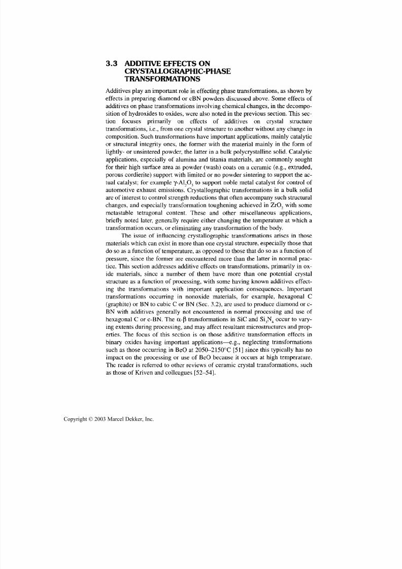
7/29/2019 29540824708539
http://slidepdf.com/reader/full/29540824708539 89/361
78 Chapter 3
3.3 ADDITIVE EFFECTS ON
CRYSTALLOGRAPHIC-PHASETRANSFORMATIONS
Add itives play an important role in effecting phase transformations, as shown by
effects in preparing diamond or cBN powders discussed above. Some effects of
additives on phase transformations inv olving chemical changes, in the decompo-
sition of hydroxides to oxides, were also noted in the previous section. This sec-
tion focuses primarily on effects of additives on crystal structure
transformations, i.e., from one crystal structure to another without an y change in
composition. Such tran sform ations have imp ortant app lications, mainly catalytic
or structural integrity ones, the former with the material mainly in the form of
lightly- or unsintered powder, the latter in a bulk polycrystalline solid. Catalytic
applications, especially of alumina and titania materials, are commonly sought
for their high surface area as powder (wash) coats on a ceramic (e.g., extruded,
porous cordierite) support with limited or no powder sintering to support the ac-
tual catalyst; for example y-AL,O 3 to support noble metal catalyst for control of
automotive exhaust emissions. Crystallographic transformations in a bulk solid
are of interest to control stren gth red uction s that often accompany such structural
changes, and especially transformation toughening achieved in ZrO 2 with some
metastable tetragonal content. These an d other miscellaneous applications,
briefly noted later, gen erally require either changing the temperature at which atransformation occurs, or eliminating any transformation of the body.
The issue of influencing crystallographic transformations arises in those
materials w hich can exist in more tha n one crystal stru cture, especially those that
do so as a function of temp erature, as opposed to those that do so as a function of
pressure, since the former ar e encountered more than the latter in normal prac-
tice. This section addresses additive effects on transformations, primarily in ox-
ide materials, since a number of them have more than on e potential crystal
structure as a function of processing, with some having known additives effect-
ing the transformations with important application consequences. Important
transformations occurring in nonoxide materials, for example, hexagonal C(graphite) or BN to cubic C or BN (Sec. 3.2), are used to produce diamond or c-
BN with additives generally not encountered in normal processing and use of
hexagonal C or c-BN. The a-p1
transformations in SiC and Si3N4 occur to vary-
ing extents d uring processing, and may affect resultant microstructures an d prop-
erties. The focus of this section is on those additive transformation effects in
binary oxides having important applications—e.g., neglecting transformations
such as those occurring in BeO at 2050-2150°C [51] since this typically has no
impact on the processing or use of BeO because it occurs at high temperature.
The reader is referred to other reviews of ceramic crystal transformations, such
as those of Kriven and colleagues [52-54].
Copyright © 2003 Marcel Dekker, Inc.

7/29/2019 29540824708539
http://slidepdf.com/reader/full/29540824708539 90/361
Additives in Powder Preparation 79
Consider A12O3, which typically exists in the thermodynamically stable o c -
phase of rhombohedral (trigonal) structure, but can exist in about six other struc-
tures depending on processing route an d history, as reviewed by Levin an dBrandon [55]. Thus, the only precursor to directly yield cc-Al2O 3 is diaspore (cc-
A1OOH), which does so at the lowest temperatures of ~ 700-800°C. Other alu-
minum hydrates of different structure, composition, or both decompose first to
other A12O3 crystal structures, usually at lower temperatures (e.g., 150-700°C),
then convert to a-A!2O3 at 900-1100°C, after existing in one or two other inter-
mediate phases. Such initial forming of other crystal phases, with subsequent
conversion at higher temperatures to cc-Al2O 3 occurs not only with other chemi-
cal precursors, but also with other processing methods, including anodic films,
vapor deposited (e.g., CVD), as well as via melting. The latter is mainly in
rapidly quenched, especially melt-sprayed material, and quenching also plays a
role in some of the deposited non-a phases.
The existence of A12O3 in the above phases has various consequences that
are the driving forces behind the use of additives to impact transformation. Thus,
conversion of non-oc-Al2O 3 phases in melt-sprayed or vapor-deposited bodies,
such as coatings, to cc-Al2O 3 leads to increased porosity and possibly microc-
racking due to the oc-phase having the highest density, hence the smallest vol-
ume, of the A12O3 phases. However, the greatest interest in control of A12O3
phase arises from its use for catalysis. It has long been known that yA !2O 3, which
forms at 300-500°C from boehmite (y-AlOOH), is much more effective forcatalysis than other phases, especially a-A!2O3. It was uncertain whether this
was the result of intrinsic or extrinsic causes; the latter possibly stemming from
the much lower temperatures for obtaining y- versus (X-A12O3 and the resultant
much greater surface area of y- versus oc-A!2O3, thus greatly favoring catalytic
effects of y- versus a-A!2O3. However, Tsuchida [56] reports that y-A!2O 3 is in-
trinsically better for catalysis based on tests of high surface area a-A!2O3 from
diaspore. Thus, an important factor in catalysis is avoiding additives or impuri-
ties that enhance y- to a-A!2O3 transformation, and finding and using additives
that retard it.
Consider use of additives to effect the y- to a-A!2O3 transformation. BothXue and Chen [57] and Ozawa and coworkers [58] investigated such effects of
mainly oxide additives introduced via solutions. Thoug h their transition temper-
ature for undoped A12O3 differed by 64°C (due to different precursors and pro-
cessing conditions) an d their relative trends differ due to different levels of
additives (respectively 1 and 10 m/o), they both show most additives lowering
rather than raising the transition temp erature, with greater lowering than increas-
ing of the transition temperature (Fig. 3.1). Xue and Chen showed only B, Si,
and Zr oxide additions increasing the transition temp erature by ~ 40-75 °C. They
also showed that increasing the additive level to 5 m/o had negligible effect on
changes due to B additions, but substantially further lowered transformation
Copyright © 2003 Marcel Dekker, Inc.
7/29/2019 29540824708539
http://slidepdf.com/reader/full/29540824708539 91/361
80 Chapter 3
Effects of Additives on y- to a- AfeOs Transformation
TEMPERATURE (°C, Xue & Chen)950
|
Fe
|
1100
1000 1050 1100
I I I
IZnF2
Mn
I
G'U ' '1050 1100 1150
1150 1200 1250 13(Ti+MnV Si| | | | NA |
1 1 1 1TI+Cu Cu LiF.Li B
Co Ni NAI I I 1
1 Crl 11200 1250 1300
I ,iI I
Zr
I
1300
TEMPERATURE (°C, Ozawa et a l )
FIGURE 3.1 Effects of add itives on the y to ex-transformation temperature of A12O3 pow-
ders after X ue and Chen [57] and Ozawa and coworkers [58]. Note that: (1 ) since the tran-
sition temperatures with no additives (NA) differed between the two studies, the two
temperature scales have been shifted so these tw o transition temperatures align vertically;
(2) oxide additions are shown by the metal only (the two fluoride additives are fully desig-
nated), and (3) data of Xue and Chen is for Im/o additions and that of Ozawa and cowork-
ers is for 10 m /o additions, which is a factor in their larger transition temperature shifts.
temperatures with CuO/CuO 2 or ZnF 2 additions respectively by ~ 5 and 10%.Note that both investigations showed reductions of up to 150-260°C an d that
Ozawa and coworkers ' results showed a trend for substantially lower surface ar-
eas (hence increased particle size, sintering, or both) with additives giving lower
transition temperatures. Earlier work of Bye and Simpkin [59] showing in -
creased a A12O3 formation with Fe versus Cr additions is generally consistent
with Ozawa an d coworkers' results.
Besides effects of additive precursor and processing noted above, there are
other effects of additives on the y to cc-A!2O3 transformation. Thus, Saito an d
coworkers' study [60] showed that the form of SiO 2 additions is important with
crystalline additions, such as quar tz or cristobalite additions en hanc ing transfor-mation to a-Al2O3, while amorphous SiO 2 retards it, as also shown by X ue and
Chen [57]. Similarly, Messing an d colleagues [61-63] showed that while addi-
tion of Fe2O 3 via solution significantly reduced the 6 to a-A!2O3 transformation,
so did seeding with fine a-Fe2O3 particles, which also enhanced microstructural
development and aided densification at ~ 1200°C. The success with seeding was
attributed to epitaxial growth of oc-A!2O3 on the oc-Fe2O3 seeds. Similarly, they
showed that seeding y-A!2O 3 with oc-A!2O 3 significantly enhanced the y- to
(X-A12O3 transformation, which was also further aided by a wet versus a dry firing
atmosphere, again showing the substantial effects that atmosphere can have on
microstructural development. Consistent with this, Lopasso an d coworkers [64]
Copyright © 2003 Marcel Dekker, Inc.

7/29/2019 29540824708539
http://slidepdf.com/reader/full/29540824708539 92/361
Additives in Powder Preparation 81
showed that firing in a C12 atmosphere accelerates the conversion to a A12O3 and
cited earlier work on this as well as other work showing similar acceleration of
transformations to rutile TiO2 an d monoclinic ZrO2.
Transformations of TiO2 powders can occur between its 3 forms: brookite
(orthorhombic), anatase (tetragonal) or rutile (tetragonal), with the latter being
the stable phase, and anatase or anatase/rutile mixtures being of particular inter-
est for catalysis. Eppler, in an earlier brief review, noted that the anatase to rutile
transformation was inhibited by WO3, as well as by chloride, sulfate, fluoride, or
phosphate ions and accelerated by alkalies and transition metal ions [65]. He
also showed that Sb2O 3 (a common impurity in TiO 2) accelerates this transforma-
tion. Similarly, Debnath and Chaudhuri [66] briefly reviewed additive effects
and showed that A1PO4 and (fumed) SiO2 both inhibited transformation to rutile,
which commonly occurs at 550-800°C. A12O3 additions retard the transforma-
tion, e.g., to ~ 1060°C with Al/Ti ratios of 0.2, as shown by Yang and coworkers
[67], as do rare earth oxide additions (e.g., Hishita and coworkers [68], but is
lowered by Fe2O3 additions as shown by Gennari an d Pasquevich [69]. Again,
other factors such as precursors and processing history need to be considered,
such as atmosphere effects of C12 noted earlier and in conjunction with Fe2O3 ad-
ditions [70]. Other factors affecting phase transitions are grain size [71], and me-
chanical treatment of the powder, typically by milling [72], which also can cause
transformations in other materials (e.g., Fe2O3) [73].
The above use of additives is to impact, commonly delay, the crystallo-
graphic transformation of powders or very porous bodies to higher temperatures
or longer times at temperature at or beyond the range where a high surface area
can be retained. However, there are also important needs to suppress such trans-
formations in materials where densification, use temperatures, or both, require
heating a body of at least limited porosity to a reasonable fraction of its melting
point. Usually the need an d approach is to suppress transformation by forming
solid solutions of the material to be stabilized and a stabilizing agent such that
the resultant solution has a crystal structure, usually a natural high temperature
structure of the material of interest, that is stable over the temperature range of
interest. There are a number of such stabilizations, but only a few are summa-rized here. A more recent example of this is the stabilization of D y2O 3 in its high
temperature monoclinic (not its higher temperature cubic) structure via ~ 8 m/o
CaO by Kim and Kriven [74], but with some microstructural complications.
Another example is Bi2O3, which is of interest for neutron, fuel cell, and
other electrical and optical applications, but transitions through four polymor-
phic structures before melting at ~ 825°C, which limits it s utility without sta-
bilization in a suitable high temperature structure [75]. Thus, Bi2O3 has been
stabilized in a high temperature cubic fluoride structure with either 25 m/o
Y 2O 3 or 15 m/o Nb2O 5, which have differing effects on both the grain struc-
ture and electrical properties [76]. It has also been stabilized in the metastable
Copyright © 2003 Marcel Dekker, Inc.
7/29/2019 29540824708539
http://slidepdf.com/reader/full/29540824708539 93/361
82 Chapter 3
high-temperature tetragonal form with 4-10 a/o Sb2O 3, which again affects it s
electrical properties [77-79].
Consider what is probably the most investigated and used stabilization to
prevent crystal-phase transformation, i.e., of ZrO 2 (and secondarily that of its
closely related compound HfO 2), which have been the subject of a number of
(mostly earlier) reviews [80-87]. The primary phases, other than possible
metastable phases, are monoclinic, tetragonal, an d cubic structures which exist
respectively to ~ 1000, 2370, and 2700°C for ZrO 2 and ~ 1700, 2600, 2900°C for
HfO 2, where the highest temperatures are for melting. The cubic phase in both
cases is that of the CaF 2 structure. The transformation temperatures are affected
by other factors, with composition (including oxygen stoichiometry) being the
most important as discussed below, but also include factors such as microstruc-
ture an d rate an d especially direction of temperature change. The latter arises du e
to hysteresis in the transformations, especially that for the monoclinic to tetrago-
nal transformation of ZrO 7 which is ~ 150-300°C, but is mu ch less for HfO 2, i.e.
~ 20-30°C.
Though ZrO 2 has been studied m uch more, data for HfO 7, as well as it be-
ing isostructural with ZrO 2, indicates that the following phase stabilization fo r
ZrO 2 applies to HfO 2. As with most solid-phase stabilization, this is accom-
plished by using additives in solid solution that yield the high-temperature struc-
ture across the temperature range of interest, that is, the fluorite structure. The
primary stabilizers for this for ZrO 2 are either alkaline earth oxides, especiallyMgO or CaO, an d rare earth an d related oxides, especially Y 2O 3 or CeO 2, usually
with more than a few m/o for complete stabilization of the cubic structure. There
is also considerable use of combinations of two or more stabilizers, especially
various com binations of rare earth oxides. These combinations are commonly ei-
ther naturally occurring mixtures or such mixtures after removal of selected,
more expensive individual rare earth oxides, thus lowering stabilizer costs,
which are typically a measurable cost factor in the bodies. The first of three
things to note about stabilization of ZrO 2 is that much investigation and consid-
erable use has been made of partial stabilization to retain some metastable tetrag-
onal ZrO 2 and the resultant transformation toughening [82]. Second, oxygendeficiency can also stabilize ZrO, [86,87]. Thus, processing, such as heat treating
to achieve complete solid solution of the stabilizer under high-temp erature re -
ducing conditions aids stabilization, which can then be lost, usually via subse-
quent precipitation un der mo re o xidizin g conditions. Such stabilization effects of
reducing atmospheres have been neglected in some studies of partially stabilized
ZrO 2. Third, the diversity of stabilization additives fo r ZrO 2 and their combina-
tions allow opportunities to balance electrical property effects where these are of
importance in ZrO 2 use, for example, as sensors or fuel cell components.
Finally, while the above examples have been for binary oxides, additives
ar e also used fo r stabilizing desired crystal structures fo r ternary and more com-
Copyright © 2003 Marcel Dekker, Inc.
7/29/2019 29540824708539
http://slidepdf.com/reader/full/29540824708539 94/361
Additives in Powder Preparation 83
plex oxides, as well as for binary and more complex nonoxides, though there is
less data on both. In particular, note that ternary and more complex oxide phases
have a number of important electrical and other app lications which depend criti-cally on the crystal phase in which they exist and the temperature, composi-
tional, etc., ranges over which the desired phase(s) exist. An example of this is
the well-known solid solution of lead titanate and lead zirconate (PZT ) for sonar
transducers.
3.4 USE OF ADDITIVES IN THE GROWTHOF CERAMIC AND RELATED WHISKERS
AND PLATELETS
Thoug h ge nerally constrained in their use by health issues, ceramic whiskers are
of interest for use in ceramic composites, which have found some industrial use
as speciality wear parts and especially in cutting tools, and are also of interest for
some metal and possibly other composites. Whiskers, which are small filamen-
tary single crystals, are also of importance as a tool in understanding both the
crystal physics of their properties and the crystal chemistry of their growth.
Platelets, which are an extension of whisker growth processes since they basi-
cally reflect a change from filamentary to plate growth of small single crystals,
are also similarly of interest and have also been investigated for use in ceramic
and other composites.There are various growth m echanisms for whiskers, all of which can be af-
fected some by additives or impurities, but the vapor-liquid-solid (VLS) mecha-
nism of whisker growth is a major method of produ cing excellent whiskers. VLS
whisker growth is inherently dependent on use of additives, which are the source
of the liquid phase, as well as possible m odifications of it and is thus the focus of
this section. In the VLS growth mechanism, gaseous sources of the whisker con-
stituents are dissolved in liquid droplets of the "additive phase," which at the
start of whisker growth are on a substrate supporting them and the subsequent
whiskers. Growth proceeds with the whisker m aterial p recipitating from the liq-
uid droplet such that the whisker is attached to the substrate and the liquiddroplet is carried along on the tip of the whisker for further growth. Thus, a gen-
eral characteristic of VLS whisker growth is the solidified droplet ball on top of
the whisker (see Fig. 3.2), unless the droplet is lost, due to subseq uent evapora-
tion or by being broken off.
While whisker growth has been extensively studied over a number of
years, with much attention to VLS growth, much less is published on the
specifics of platelet growth, though some specific aspects of their growth is
noted from the literature. Also n ote that the morphology of single-crystal parti-
cles growing in a liquid is often significantly impacted by minor amounts of ma-
terials in the the growth liquid, so growth of platelets is often a modification of
Copyright © 2003 Marcel Dekker, Inc.

7/29/2019 29540824708539
http://slidepdf.com/reader/full/29540824708539 95/361
84 Chapter 3
FIGURE 3.2 Examples of solidified balls of l iquid Al or Al-Si on the tips of sapphire
whiskers. (A) Lower magnification showing a ball for every whisker; (B) higher magnifi-
cation showing more detail. Note the darker material on the bottom of the balls (identified
as precipitated Si) near their intersection with the whisker. (From I. Ahmed [88].)
whisker growth. Thus, though the focus of this section is on refractory materials,especially ceramics, there is substantial information on the morphological, i.e.,
single-crystal shape aspects, of growth of less refractory whiskers, platelets and
other particles with var ying cry stalline morphologies. Thus, for example Genk
[89] has review ed the morphological aspects of growth of man y inorganic mate-
rials such as salts from water or other solutions, noting the pronounced effects
that additives can have on growth habits.
While the liquid phase for VLS whisker growth varies some with the
source of the vapor phase for a given material of whisker growth, there is a sub-
stantial commonality of liquid phases used, e.g., as shown in Givargizov's exten-
sive review [90]. Thus, noble metals such as Au, Ag, Pt, and Pd, as well as
Copyright © 2003 Marcel Dekker, Inc.

7/29/2019 29540824708539
http://slidepdf.com/reader/full/29540824708539 96/361
Additives in Powder Preparation 85
metals such as Cu and Ni are common liquid phases for growth of elemental
whiskers of Si, Ge, and B, while metals such as Ni, Fe, and Mn are cited for
growth of C whiskers (including diamond, for which these m etals are also usedfor making diamond powder and compacts, Sec. 3.2). Metal whiskers are also
often grown with metal liquid droplets.
VLS growth of whiskers of binary compounds of borides (e.g., of Nb, Ti,
or Zr), carbides (e.g., of B or Si), nitrides (e.g., of Al, Si, Ti, or Zr), and phos-
phides (e.g., of B, Nb, Ti, or Zr) also commonly use liquids of the same or re-
lated metals, especially noble or transition metals as noted for growth of
elemental whiskers noted above. Some other metals such as Al, Si, Cr, Fe, or Ta
were used for SiC whisker growth. Such usage of liquid metals has continued,
e.g., the excellent S iC whiskers grow n by Milewsk i et al. [91] were grown using
particles of 304 stainless steel as the source of the liquid droplets (with the size ~
30 |J,m and spatial dispersion of the particles an important factor in the size and
density of whisker growth). Subsequently, boric acid, e.g., ~ 5 w/o, has been
found to influence SiC whisker growth, but it is uncertain whether the growth is
still VLS growth an d what is the resultant chemical form of the boric acid addi-
tion [92,93]. On the other hand , use of SiO2-C H 4-N a3AlF 3 as raw materials is re-
ported to give SiC whiskers via VLS growth from Al/Si droplets formed on the
graphite boats used [94]. Also replacing CH 4 with N2 and addition of some F e2O 3
results in VLS growth of Si3N4 whiskers [95]. A1N whiskers have also been
grown by the VLS method using carbothermal reduction of A12O3 in a N 2 atmos-phere using 2 w/o addition of CaF2 and B 2O 3 for the liquid phase [96], but the na-
ture of the resultant composition of the additive phase during actual whisker
growth appears uncertain.
3.5 USE OF ADDITIVES IN OTHER
CERAMIC PROCESSING, ESPECIALLYMELT PROCESSING
While the above VLS growth of whiskers involves a liquid droplet of an additive
out of which a whisker grows, there is also some use of additives in melt pro-cessing of ceramics. Consider first flux growth of single crystals, wherein the
material for the desired crystals is dissolved in a suitable flux and the crystals
grown essentially by precipitation from the flux-based solution using various
crystal seeding an d growth me chanisms, including traveling solvent zones [97].
Flux crystal growth has been used most extensively for oxides where com monly
no atmosphere protection is required. It is particularly advantageous for growing
refractory crystals of materials that do not melt congruently, undergo little or no
melting due to high vapor pressure, or have possibly destructive high tempera-
ture phase transformations (e.g., BeO). These uses balance out the limitations of
slower growth rate an d smaller faceted crystals (but whose growth habit can be
Copyright © 2003 Marcel Dekker, Inc.

7/29/2019 29540824708539
http://slidepdf.com/reader/full/29540824708539 97/361
86 Chapter 3
changed by changes in the flux, e.g., Fig. 3.3). As discussed in the substantial re-
view by Tolksdorf [97], fluxes for oxide crystal growth commonly consist of two
or three of basic oxides and fluorides: PbO, PbF 2, BaO, BaF, Bi2O 3, Li2O, Na?O ,
K 2O , KF; and acidic oxides: B 2O 3, SiO 2,P 2O 5, V 2O 5, MoOr Again, as with hy-
drothermal (as well as some v apor phase) gr owth of crystallites, modest changes
or additives to the flux can rea dily change the grow th habit of the crystals.
The above solvent method of crystal growth can be extended to a variety
of ceramics via electrochemical deposition of crystals (or coatings) on an elec-
trode in a conductive mixture of compounds containing the atomic constituents
of the ceramic sought, as reviewed by Elwell [99]. Thus, for example solutions
of borates in alkali have been used with a source of the cation to produce many (
more than three dozen) refractory borides, and of phosphates to produce a simi-
lar number of phosphides, e.g., NaPO 3 an d NaCl or NaF with W O 3 to produce
W 2P or W4P. Similarly some sulfides, e.g., of W and Mo, have been produced
from the oxide dissolved in Na2SO 4, Na2B 4O 7, and NaF, and some carbides and
silicides have also been formed electrochemically, though formation of carbides
(and of nitrides) is hindered by the ease of decomposing carbonates (and ni-
trates). A number of oxides can also be produced by such m olten salt electroly-
sis, especially tungsten bronzes, as well as some spinels.
Consider now the use of additives to refine the microstructures in fusion
casting of oxide ceramics, for example, in the production of refractories, where
such fusion casting produces some of the largest ceramic components. Thus, asreviewed by McNally and Beall [100], ZrO 2-A l2O 3-SiO 2 refractories are arc-
skull melted and cast fo r construction of glass-melting tanks. For higher temper-
ature melting (e.g., 1550-1650°C), high ZrO 2 contents (68-82.5 w/o) ar e used
with 10-20 w/o (pref erab ly > 15 w/o ) SiO 2, 0~5-2.5 w/o Na2O, < 1 w/o (prefer-
able < 0.4 w/o) Fe2O 3 + TiO 2, and A1 2O3 so the Al2O 3/SiO 2 ratio is 0.3-0.65, with
the Na9O content and the Al7O 3/SiO 2 ratio being particularly important. Fusion
casting of pure A1 2O3 results in weak bodies due to growth of large columnar
grains, bu t addition of 1.2-1.8 m/o CaO breaks up the coarse grains and im-
proves room temperature strengths. The addition of ~ 0.9 m/o of metal fluoride
aids manu facturing and further improves strengths. They noted that additions ofa few percent of Li2O to MgO-chrome fusion cast refractory compositions give
bodies with more favorable phase composition as well as moisture stability.
They also noted some effects of composition and additives in controlling mi-
crostructures of fusion cast compositions in the Ti-B-C and ZrC-based systems.
The more extensive field of using nucleating agents to obtain volum e crys-
tallization of glasses is widley used to produce such oxide glasses, commonly re-
ferred to as glass-ceramics. Thakur [101] lists a number of such additives
grouped as (1) metals an d com poun ds inducing phase separation (Pt, Ag, Au, Cu,
and sulfides, fluorides, etc.); (2) oxides such as TiO 2, SnO 2, MoO 3, WO 3; (3) ox-
Copyright © 2003 Marcel Dekker, Inc.
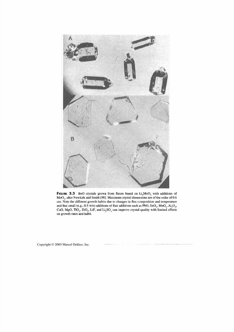
7/29/2019 29540824708539
http://slidepdf.com/reader/full/29540824708539 98/361
Additives in Powder Preparation 87
FIGURE 3.3 BeO crystals grown from fluxes based on Li2MoO4 with additions of
MoO3, after Newkirk and Sm ith [98]. M axim um crystal dimensions are of the order of 0.6
cm. Note the different growth habits due to changes in flux composition and tem perature
and that small (e.g., 0.5 w/o) additions of flux additives such as PbO, SnO2, MnO2, A12O3,
CaO, MgO, TiO2, ZrO2, LiF, and Li2SO4 can imp rove crystal qua lity with limited effects
on growth rates and habit.
Copyright © 2003 Marcel Dekker, Inc.
7/29/2019 29540824708539
http://slidepdf.com/reader/full/29540824708539 99/361
88 Chapter 3
ides which can exist in two valence states in glass melts (V 2O 5, Fe2O 3, Cr2O 3);
and (4) oxides with high coordination for the cations (ZrO 2,ThO 2, Ta2O 5). Gut-
zow and Toschev [102] studied noble metal nucleation of crystallization of
model Na phosphate and borate glasses, w hile Ham mel [103], Tomozawa [104],
Nielson [105], and Stewart [106] reported on the use of one or more of the com-
mon oxide nucleating agents of P2O 5, TiO 2, or ZrO 2 . McNally and Beall [100]
also discussed nucleation of SiO 2-A l2O 3-L i2O glasses with 4 m/o TiO 2, noting
that the glass phase separates on quenching, and that on subsequent heating to ~
825°C aluminum titanate, crystallites form to start crystallization, with subse-
quent typical complex crystallization as a function of thermal exposure. They
note even greater crystallization com plexity in SiO 2-A l2O 3-MgO glasses with ~
10 w/o of TiO,,, ZrO 2, or combinations of them, and use of Cr,O3 as a nuc leatingagent in comm ercial production of fused basalt products.
As indicated above, some additives affect phase separation in glasses.
Other studies also show this; for example, M arkis and coworkers [107] reported
that fluoride additions via NaF to Na2O-SiO 2 glasses raised the temperature at
which phase separation com mence d, e.g., by ~ 10% at 1.2 m/o addition, but with
no change in the scale of the phase separated microstructure, in marked contrast
to large increases in water containin g glasses. Sim ilarly, additives can alter phase
seperation in crystalline materials; Takahashi and coworkers [108] tested effects
of 14 oxide additions to the SnO 2-TiO 2 system, noting sub stantial effects of ZrO 2
additions, more with Ta2O 5, an d especially, W O 3 or Sb2O3.Consider now use of additives in a specialized reaction process that is of-
ten referred to as the Lanxide™ process, which was originally and most exten-
sively developed for making Al2O 3-based bodies via controlled oxidative g rowth
from molten Al held in an open refractory container compatible with the process.
While this process may be used to form large monolithic bodies of A12O3 with
limited residual Al, it is more com mo nly used to form composite bodies, again of
potential large size, by growth of such a matrix through a preform of paniculate
(e.g., of larger grains of A1 2O3 or SiC) or fiber (e.g., SiC) reinforcement. The ex-
tent of such oxidative growth is sensitive to limited quantities of additives, espe-
cially Mg as well as a second addition of Si, Ge, Sn, Pb [109-111], or Zn [112]Such additions ar e typica lly added as alloying agents in the Al used, typically at
2-10 w/o (usually 2-5 w/o), which greatly increase the extent of oxidative
growth (e.g., 2-4 cm of thickness per day), particularly in the oxidation tempera-
ture range 1150-1300°C. Apparently some additives or impurities inhibit the
process, and can be used to define at least the approximate shape of the product
body by placement in the particulate or fiber preform , in addition to some prod-
uc t body shaping via shaping of the preform.
The above method of oxidative growth from molten metal in a refractory
container open to the furnace environ me nt has been extended to composites of a
nitride ceramic: A 1N, TiN, or ZrN with some residue of the respective metal of
Copyright © 2003 Marcel Dekker, Inc.

7/29/2019 29540824708539
http://slidepdf.com/reader/full/29540824708539 100/361
Additives in Powder Preparation 89
A l, Ti, or Zr [113]. Such growth can again occur through an open preform, e.g.,
of comp atible grains of other compatible refractory ceramic phases to make v ar-
ious com posites. U se of additives in the gro wth of such nitride-based bodies has
not been discussed in the literature, but growth of Al-based materials has been
reported using comm ercial A l alloys such as A380.1 (8.5% Si, 3.5% Cu, 3% Zn,
1% Fe, 0.5% Mn, and 0.1% Mg), that is, with constituents similar to important
additives for gro wing Al2O 3-based bodies [114].
Consider next use of additives in the in situ growth of macroscopic single
crystals within a dense polycrystalline body. Researchers at General Electric in
the last few years acciden tly discovered that part or all of Lucalox A12O3 bodies or
portions of them cou ld be con verted to sap phire single crystals by first firing in H 2
at1850°C
to boil out the MgO, reducing the level of Mg
++
to at least or below thesolubility limit of 30-50 ppm (C. Scott, General Electric, C leveland OH, personal
communication, 1999,[115]). Then firing at 1880-1900°C will convert the area
of sufficiently reduced MgO content of such A12O3 bodies to sapphire in situ in
the body, essentially via greatly exaggerated grain growth, provided the body is
suitably free of porosity, microcracks (i.e., has a grain size below that for microc-
racking or has not been cooled between the two firings), and other second phases
impeding grain boundary migration (e.g., La2O3 or other rare earths present as
second phases, used instead of MgO to obtain full density). The second heating to
bring about the polycrystalline to single-crystal conversion, which occurs in min-
utes, even over substantial lengths, for example, in thin wall tubes > 60 cm long,can be via laser heating of one end. This conversion, besides being impeded by
some additives or impurities, as noted above, can also be accelerated by some
other materials in solid solution, e.g., 50-100 ppm of Ga2O 3 (discovered since
alumina powders used having this as an impurity showed easier conversion),
Cr2O3 (i.e., resulting in ruby ), and to some extent TiO 2. Thu s, for example, rods on
which a spiral pattern of Ga2O 3 powder was painted, than appropriately fired re-
sulted in a corresponding spiral of conversion to sapphire. While limited by the
depths from which MgO can be sufficiently diffused out of the body, such growth
of single-crystal parts from a polycrystalline body has potential for producing at
least thin, shaped single-crystal parts. However, such growth appears limited tolower quality crystals due to residual porosity and second phases incorporated
from the polycrystalline material, which may often more seriously limit optical
performance. Thus, use of the in situ crystal growth generally presents trade-offs
between lower quality and costs versus higher quality and costs for comparable
parts machined from conventionally gro wn bulk crystals.
Limited work has also been conducted to grow single crystals of other mate-
rials via grain growth within polycrystalline bodies. Earlier work investigating ef-
fects of limited excesses of TiO 2 added to BaTiO 3, such as the work of Hennings
and coworkers [116], showed exaggerated growth of isolated grains—e.g., ~ 50
|im versus a matrix grain size of a few microns, attributed to liquid-phase effects
Copyright © 2003 Marcel Dekker, Inc.
7/29/2019 29540824708539
http://slidepdf.com/reader/full/29540824708539 101/361
90 Chapter 3
on firing above 1312°C is in part a precursor to such poly- to single-crystal conver-
sion. More recently Yoo and coworkers [117] reported that adding a small amo unt
of a SiO 2 slurry on top of a green BaTiO 3 compact subsequen tly sintered at 1370°C
for up to 80 hrs resulted in in situ growth of grains to sizes of a few centimeters.
SiO 2 was seen as a catalyst in forming twinned seed grains that were seen as cen-
tral to the subsequent grain growth. Combination of this SiO 2 additive approach
with other additives such as LiF that aid densification an d enhance grain growth
(Sec. 5.4) may be worthy of exploration. Recently Kahn and coworkers and others
[118] have reported growth of various lead titanate or niobate-based crystals for
electrical functions via seeded polycrystal conversion. Thus, conversion of poly-
crystalline areas or bodies to single crystal areas or parts shows some promise, bu t
is limited by diffusion requirements and distances and by incorporation of mi-
crostructural variations such as residual grain boundary pores or second phases in
the polycrystalline precursor into the resu ltant single area.
Another use of additives, primarily SiO 2, is to increase the surface smooth-
ness of bodies with as fired surfaces, which often also improves the as-fired
strengths. Yamada and coworkers [119] reported that mixing additions of up to
0.1 w/o of fine, high purity SiO 2 powder with a high purity Bayer A1 2O3 with 0.2
w/o of MgO and 0.03 w/o of Cr2O 3 increased surface roughn ess (as measured by
surface gloss) as the SiO 2 content and firing temperatures (1500-1650°C in H 2)
increased despite some reduction in grain size, such as from 1.6 to 1 um without
and with 0.1 w/o SiO 2, respectively. However, forming a SiO 2 coating on denseA12O3 fibers commonly increases strengths, e.g., by up to a maximum of ~ '/3 at
-10% addition, despite some elastic moduli decrease as SiO 2 content increases
[120-122]. Reduced grain sizes of the A12O3 phase, regardless of its crystal struc-
ture, with increased SiO 2 is clearly an important factor in the increased strength
despite the decrease in elastic moduli. However, increased surface smoothness
with increased SiO 2 addition is a factor since improved strengths were obtained in
FP A1 2O 3 fibers in m anu factur ing them with an added surface SiO 2 coating rather
than SiO 2 additions to the bulk of the fiber [120,121]. The differences between
these fiber observations and those of Yamada and coworkers for bulk A1 2O3 bod-
ies mus t reflect differences primarily in processing an d possibly some in compo-sition (though both Yamada and coworkers ' bulk bodies and F P fibers contained
MgO as an additive). (See also use of glass coatings on sapphire windows to
eliminate the need for polishin g the win dow s, as discussed in Sec. 8.3.1.)
3.6 DISCUSSION, SUMMARY,AND CONCLUSIONS
This chapter, which is mainly on use of additives in preparation of powders and
other raw materials, illustrates the diversity of ceramic fabrication and related
processing steps by both the diversity of approaches, additives, materials, uses
Copyright © 2003 Marcel Dekker, Inc.

7/29/2019 29540824708539
http://slidepdf.com/reader/full/29540824708539 102/361
Additives in Powder Preparation 91
and mechanisms noted or outlined. Thus, for example, additives are critical in
producing materials such as C and BN in their high-pressure cubic diamond
phase which, while not the normal stable phase, will be stable at atmosphericpressure and to do so while also providing the powder character needed for sub-
sequent densification. It should also be noted that a variety of factors can be in-
teractive with the use of additives, such as temperature, pressure, atmosphere,
and particle and grain size, as well as impurities. In this spirit, note the ove rlap or
complementary character of treatment of topics in this chap ter w ith that of Chap-
ters 4-8, especially Chapter 5. Thus, the use of silica coatings to give smoother
surfaces on alumina fibers was noted in this chapter, while other coatings of
mostly other fibers with other m aterials an d methods, for example, with BN by
CVD, are discussed in various subsequent chapters. Again note that besides the
extensive use of additives to aid densification (Chap. 5) , they are extensively
used to modify properties (addressed some in Sec. 3.3 and illustrated some in
other chapters, especially Chap. 5, such as making black alumina microelec-
tronic packages, Sec. 5.3).
REFERENCES
1. M. Shimbo, Z .-e Nakagawa, Y. Ohya, K. Hamano. Effect of fluoride addition on
crystal growth of MgO. J. Cer. Soc. Jap. Intl. Ed. 97:844-850, 1989.
2. M. Shimbo, Z.-e Nakagawa, Y. Ohya, K. Hamano. Effect of HF addition on de-
composition of MgO(OH)2. J. Cer. Soc. Jap. Intl. Ed. 97:629-633, 1989.
3. G.V.S. Rao, M. Natarajan, C.N.R. Rao. Effect of impurities on the phase trans-
formations and decomposition of CaCO 3. J. Am. Cer. Soc. 51(3):179-180,
1968.
4. G.F. Knutsen, A.W. Searcy, D. B eruto. Effect of LiCl on the rate of calcite decom-position. J. Am. Cer. Soc. 65(4):219-222, 1982.
5. D. Beruto, G. Belleri, L. Barco, V. Longo. Interactions of LiBr with calcite and cal-
cium oxide powders. Cer. Intl. 9(2):53-, 1983.
6. A spherical alumina filler. Material Innovation. Am. Cer. Soc. Bui. 70(6):963-964,
1991.
7. MJ. Readey, D.W. Readey. Sintering of ZrO 2 in HC1 atmospheres. J. Am, Cer. Soc.69(7):580-582, 1986.
8. MJ. Readey, D.W. R eadey. Sintering of TiO 2 in HC1 atmospheres. J. A m, Cer. Soc.
70(12):C-358-361, 1987.9. D.W. Readey, D.J. Aldrich, M.A. Ritland. Vapor transport and sintering. In: R.A.
German, G.L. Messing, R.G. Cornwall, eds. Sintering Technology. New York:
Marcel Dekker, Inc., 1996, pp. 53-60.
10. D.J. A ldrich, D.W. Readey. Microstructures in multicomponent oxides by vapor
phase sintering. In: T.S. Srivatsanm, J.J. More, eds. Processing and Fabrication of
Advanced Materials V. TMS,1996, 545-555.
11. C. Hauf, R. Kniep, G. Pfaff. Preparation of various titanium suboxide powders by
reduction of TiO2 with silicon. J. M at. Sci. 34:1287-1292, 1999.
Copyright © 2003 Marcel Dekker, Inc.

7/29/2019 29540824708539
http://slidepdf.com/reader/full/29540824708539 103/361
92 Chapter 3
12. M. Jallouli, F. Ajersch. A nalytical model for the swelling of sintered iron oxide pel-
lets during the haematite-magnetite transformation. J. Mat. Sci. 21:3528-3538,
1986.
13. G.B. McGarvey, D.G. Ow en. Copper (II) oxide as a morphology directing agent in
the hydrothermal crystall ization of magnetite. J. Mat. Sci. 31:49-53, 1996.
14 . J.-L. Huang, si-Y. Sun, Y.-C. Ko. Investigation of high-alumina spinel: effect of
LiF and CaCO 3 addition. J . Am . Cer. Soc. 80(12):3237-3241, 1997.
15. E. K ostic, S. Bosovi, S. K is. Influen ce of fluoride ion on the spinel synthesis. J.
Mat. Sci. Let. 1:507-510, 1982.
16. S. Bosovi, E. Kosti, S. J. Kiss. Synthesis of NiFe 2O 4 in the presence of fluorine. J.
Mat. Sci. Let. 4:200-202, 1985.
17 . N.A .L. Mansou r, S.B. Hann a. Silicon carbide and nitride from rice hulls II. Effect
of iron on the form ation of silicon carbide. Trans. & J. Brit. Cer. Soc.78(6): 132-136, 1979.
18. R.V. Krishnarao. Effect of cobalt chloride treatment on the formation of SiC from
burnt rice husks. J. Eur. Cer. Soc. 12:395-401, 1993.
19. R.V. Krishnarao. Effect of cobalt catalyst on the formation of SiC from rice husk
silica-carbon mixture. J. Mat. Sci. 3645-3651, 1995.
20. P.P. Mc Clus key , R.J . Jaccodine. Effect of NF 3 on the direct thermal nitridation of
silicon. J. Electrochem. Soc. 136(8):2328-2331, 1989.
21. M. Akaishi, H. Kanada, S. Yamaoka. Phosphorous: an elemental catalyst for di-
mond synthesis an d growth. Science 259:1592-1593, 1993.
22. H. Kanada, O . Fukun aga. Growth of large diamond crystals. In: S. Akimoto, M. H.
Manghnani, eds. Advances in Earth and Planetary Sciences Center for AcademicPublications, Tokyo, Japan, 1982.
23. L. Gou, S. Hong , Q . Gou. Investigation of the process of diamond formation from
SiC unde r high pressure an d high temperature. J. Mat. Sci. 30:5687-5690, 1995.
24. V. Srikanth, M. Akasishi, S. Yamaoka, H. Yamada, T. Taniguchi. Diamond synthe-
sis from graphite in the presence of MnCOr J. Am . Cer. Soc. 80(3):786-790, 1997.
25. S. Ito, I. Ebato, H. Fukui, N. Koura, N. Yoneda. Perparation of aluminum nitride
using slightly oxidized Al powders. J. Cer. Soc. Jap. 100:622, 1992.
26. K. Komeya, E. Mitsuhashi, T. Mrguro. Synthesis of A1N powder by carbothermal
reduction-nitridation me thod -effe ct of additiv es on reaction rate. J. Cer. Soc. Jap.
101:366, 1993.
27. H. Scholz, P. Greil. Synthesis of high purity A1N by nitridation of Li-doped Al-
melt. J. Eur. Cer. Soc. 6:237-642, 1990.
28. M. Egashira, Y. S h im iz u , Y. Tako, R. Yamaguchi, Y. Isikawa. Effect of carboxylic
acid adsorption on the hydrolysis and Ssintered properties of aluminum nitride
powder. J . Am. Cer. Soc. 77(7): 1793-1798, 1994.
29. T. Endo, O. Fu kunag a, M. Iwata. Growth pressure-temperature region of cubic BN
in the system BN-Mg. J. Mat. Sci. 14:1375-1380, 1979.
30. T. Sato, H. Hiraoka, T. Endo, O. Fu kunaga, M. Iwata. Effect of oxygen on the growth
of cub ic boron nitride using M g3N, as catalyst, J. Mat. Sci. 16:1829-1834, 1981.
31. T. Endo, O. Fuku naga, M. Iwata. Precipitation m echanism of BN in the ternary
system B-Mg-N. J. Mat. Sci. 14:1676-1680, 1979.
Copyright © 2003 Marcel Dekker, Inc.
7/29/2019 29540824708539
http://slidepdf.com/reader/full/29540824708539 104/361
Additives in Powder Preparation 93
32. H. Lorenz, U . Kiihne, C. Hohlfeld, K. Hegel. Influence of MgO on the growth of
cubic boron nitride using the catalyst Mg3N 2. J. Mat.Sci. Let.7:23-24, 1988.
33. H. Lorenz, B. Lorenz, U . Kiihne, C. Hohlfeld. The kinetics of cubic boron nitridein the system BN- M g3N 2. J. Mat. Sci. Let.7:23-24, 1988.
34. S. Nak ano, H. Ikawa, O. Fukunag a. Synthesis of cubic boron nitride by decompo-
sition of mag nesium boron nitride. J. Am. Cer. Soc. 75(l):240-243, 1992.
35. T. Endo, O. Fukun aga, M. Iwata. The synthesis of cBN using Ca3B 2N 4. J. Mat. Sci.
16:2227-2232,1981.
36. J.-Y.Choi, S.-J. L. Kang, O. Fukunaga, J.-Ku Park, K.Y. Eun.Effect of B 2O 3
and hBN crystallinity on cBN synthesis. J. Am. Cer. Soc. 76(10):2525-2528,
1993.
37. T. Kobayashi, K. Susa, S. Taniguchi. Pressure and temperature stability region of
cubic BN in the presence of amm onium borate. Mat.Res. Bui. 12:847-852, 1977.
38. T. Kobayashi, K. Susa, S. Taniguchi. New catalyst for the high pressure synthesis
of cubic BN. Mat. Res. Bui. 10:1231-1236, 1975.
39. T. Kobayashi. Solvent effects of fluorides in cubic BN high pressure synthesis.
Mat. Res. Bui. 14:1541-1552,1979.
40 . N.M. Olekhnovich, O.I. Pashkovskii, I.M.Starchenko, V.T. Sharai, V. B. Shipilo.
Mechanism of the phase transition in BN during its reaction with Al at high pres-
sures and temperatures. lorg. Mats. 16:1209-1212,1980
41 . T.I. Serebryakova, V.A. Ponomarenko, A.I. Karasev, V.I.Shemanin, E.V.Marek.
Magnesium diboride and its application in synthesis reactions of cubic boron ni-
tride. Sov. Pwd.Met. & Met.Cer.19:791-792, 1981.
42 . S.-I. Hirano, T. Yamaguchi, S. Naka. Effects of A1N additions and atmosphere onthe synthesis of cubic boron nitride. J. Am. Cer. Soc. 64(12):734-736,1981.
43. T. Akashi, A. Sawaoka, S. Saito. Effect of TiB 2 and boron additions on the stability
of wur tzite-type boron nitride at high temperatures and pressures. J. Am . Cer. Soc.
61(5-6):245-246, 1978.
44a. H.M.Jennings. On the influence of iron on the reaction between silicon and nitro-
gen. J. Mater. Sci.3(5):907-909,1988.
44b. C.G. Cofer, J.A. Lewis. Chromium catalysed silicon nitridation. J. Mat. Sci.
29:5880-5886, 1994.
45. R.T. Bhatt, A.R.Palczer. Effects of surface area, polym er char, oxidation, and NiO
additive on nitridation kinetics of silicon powder compacts. J. Mat. Sci.
34:1483-1492, 1999.46. T. Hayashi, H. Ushida, H. Saito, S. Hirano. Effects of NaF and NH 3 on preparation
of Si3N4 powders from SiO 2. J. Cer. Soc. Jap. 95(2):278- 1987.
47. D. Cam pos-Loriz, S.P.Howlett, F.L.Riley, F. Yusaf. Fluoride accelerated nitrida-
tion of silicon. J. Mat. Sci. 14:2325-2334, 1979.
48. S.K. Biswas, J. Mukerji. Effect of BaF 2 on the nitridation of commercial silicon. J.
Am. Cer. Soc. 63(3 ):232, 1980.
49. V. Raman, V.K.Parashar, O.P. Bahl. Effect of additives on the thermal nitridation
of sol-gel derived silica gel.J. Mat. Sci.28:4159^162, 1993.
50. V. Pavarajarn, S. Kimura. Catalytic effects of metals on direct nitridation of sili-
con. J. Am. Cer. Soc.81(8):669-674, 2001.
Copyright © 2003 Marcel Dekker, Inc.
7/29/2019 29540824708539
http://slidepdf.com/reader/full/29540824708539 105/361
94 Chapter 3
51. D.K. Smith, C.F. Cline. The crystal structure of (3-beryllia. Acta Cryst.
18:393-397, 1965.
52 . W.M. Kriven. Possible alternative transform ation tougheners to zirconia: crystallo-graphic aspects. J. Am. Cer. Soc. 71(12):1021-1030, 1988.
53. J.L. Shull, W.M. Kriven, W.D. Porter, C.R. Hubbard. High temperature phase
transformations in Y 4A12O 9, G d4Al2O g, and Dy4A l2O 9. In: W.C. Johnson, J.M.
Howe, D.E. Laughlin, W.A. Soffa, eds. Solid—>Solid Phase Transformations. The
Minerals, Metals, an d Materials Soc., 1994, 95-100.
54. W.M. Kriven. Displacive transform ations and their application in structural ceram-
ics. J. de Physique IV, Colloque C8, Supplement au J. de Physique III.
5:C8-101-110, 1995.
55. I. Levin, D . Brandon. Metastable alumina polymorphs: crystal structures an d tran-
sition sequences. J. Am. Cer. Soc. 81(8): 1995-2012, 1998.
56. T. Tsuchida. Preparation of high surface area a-Al,O3 and its surface properties.
Appl. Cat. A:General 105:L141^6, 1993.
57. L.A. X ue, I.-W. Chen. Influence of additives on the y-to-cc transformation of alu-
mina. J. Mat. Sci. Let. 11:443-445, 1992.
58. M. Ozawa, O . Kato, S. Suzuki, Y. Hattori, M. Yam amura. Sintering and phase evo-
lution of y-A!2O 3 with transition-metals addition at around a-transition tempera-
ture. J. M at. Sci. Let. 15:564-567, 1996.
59. G.C. Bye, G.T. Simpkin. Influence of Cr and Fe formation of oc-Al2O 3 from y-
A12O3. J. Am. Cer. Soc. 57(8):367-, 1974.
60. Y. Saito, T. Takei, S. Ha yas hi, A. Y asumori, K. O kada. Effects of amorphous and
crystalline SiO 2 additives on y-Al2O 3- to—A12O 3 phase transition, J. Am . Cer. S oc.81(8):2197-2200, 1999.
61 . J.L. McArdle, G.L. Messing. Transformation and microstructure control in
boehm ite-derived alum ina by ferric oxide seeding. Adv. Cer. Mat. 3(4):387-392,
1988.
62. J. Tartaj, G.L. Messing. Effect of the Addition of oc-Fe2O3 on the microstructural
development of boehmite-derived alumina. J. M at. Sci. Let. 16:68-70, 1997.
63. R.B. B agwell, G.L. Messing. Effect of seeding and water vapor on the nucleation
and growth of a-A!2O3 from y-A!2O 3. J. Am . Cer. Soc. 82(4):825-832, 1999.
64. E.M. Lopasso, J.J. A. Gamboa, J.M. Astigueta. Enhancing effect of C12 atmosphere
on transition aluminas transformation. J. Mat. Sci. 32:3299-3304, 1997.
65. R.A. Eppler. Effect of antimony oxide on the anatase-rutile transformation in tita-
nium dioxide. J. Am. Cer. Soc. 70(4):C-64-66, 1987.
66. R. Debnath, J. Chaudhuri. Inhibiting effect of A1PO4 and SiO 2 on the anatase — > ru -
tile transformation reaction: an x-ray an d laser raman study. J. Mater. Res.
7(12):3348-, 1992.
67. J. Yang, Y.X . Hu ang, J.M.F. Ferreira. Inhibitory effect of alumina additive on the
titania phase transformation of a sol-gel-derived powder. J. Mat. Sci. Let.
16:1933-1935, 1997.
68. S. Hishita, I . M uto h, K. Koum oto, H. Yanagida. Inhibition m echanism of the
anatase-ruti le phase t ransformation by rare earth oxides. Cer. Intl. 9(2):6-,
1983.
Copyright © 2003 Marcel Dekker, Inc.
7/29/2019 29540824708539
http://slidepdf.com/reader/full/29540824708539 106/361
Additives in Powder Preparation 95
69. EC. Gennari, D.M. Pasquevich. Kinetics of the anatase-rutile transformation in
TiO 2 in the presence of Fe2O 3. J. Mat.Sci. 33:1571-1578,1998.
70 . F.C. Gennari, D.M.Pasquevich. Enhancing effect of iron chlorides on the anatase-rutile transition in titanium dioxide. J. Am. Cer. Soc. 82(7): 1915-1921, 1999.
71 . X.-Z.Ding, X.-H. Liu, Y.-Z. He. Grain size dependence of anatase- to-rutile struc-
tural transformation in gel-derived nanocrystalline titania powders. J. Mat. Sci.
Let. 5:1789-1791, 1996.
72 . E.M. Kosti, S.J.Kiss, S.B. Boskovi, S.P.Zee. Mechanically activated transition of
anatase to rutile. Am. Cer. Soc. Bui. 76(6):60-61, 1997.
73 . R.M. Torres Sanchez. Phase transformation of y to ex-Fe2O3 by grinding. J. Mat.
Sci. Let. 13:461 62, 1996.
74. YJ. Kim, W.M. Kriven. Crystallography and microstructural studies of phase
transformations in the Dy2O 3 system. J. Mater. Res. 13(10):2920-2931, 1998.
75. J.R. Keski. Bism uth oxide ceramics. Am, Cer.Soc. Bui. 51(6):527-531, 1972.
76 . A.V. Joshi, S. Kulkarni, J. Naclas, J. Diamond, N. Weber, A.N.Virkar. Phase sta-
bility and oxygen transport characteristics of yttria- and niobia-stabilized bismuth
oxide. J. Mat.Sci. 25:1237-1245, 1990.
77 . A.M. Azad, S. Larose, S.A.Akbar. Review: bismuth oxide-based solid electrolytes
for fuel cells. J. Mat.Sci. 29:4135-4151, 1994.
78. M. Miyay ama , H. Terada, H. Yanagida. Stabilization of (3-Bi2O3 by Sb2O 3 doping.
J. Am. Cer. Soc. 64(1):C-19, 1981.
79. M. May ayama, S. Katinichi, Y. Suenaga, H. Y anagida. Electrical conduction in P-
Bi2O 3 doped with Sb2O 3. J. Am. Cer.Soc. 66(8):585-588,1983.
80 . E.G. Subbarao, U.S. Maiti, K.K. Srivastava. Martensitic transformation in zirco-nia. Phys. S tat. Sol. (a) 21 (9):9-40, 1977.
81. M. Yoshimura. Phase stability of Zirconia. Am. Cer. Soc. Bui. 67(12): 1950-1955,
1988.
82. S. Somiya, N. Yamamoto, H. Hanagida, eds.Science and Technology of Zirconia
III, Advances in Ceramics. Vol.24. Westerville, OH: A m. Cer. Soc., 1988.
83 . R.C.Garvie. Zirconium dioxide and some of its binary systems. In: A. M. Alper,
ed . High Temperature Oxides. Part II . Oxides of Rare Earths, Titanium, Zirco-
nium, Hafnium, Niobium, and Tantalum. New York: Academic Press,1970,
117-166.
84 . C.T. Lynch. Hafnium oxide. In: A.M. Alper, ed. High temperature Oxides. Part II.
Oxides of Rare Earths, Titanium, Zirconium, Hafnium, Niobium, and Tantalum.New York: Academic Press, 1970, pp. 193-216.
85. J. Wang, H.P. Li, R. Stevens. Review hafnia and hafnia-toughened ceramics. J.
Mat. Sci. 27:5397-5430,1992.
86. R. Ruh, H.J. Garrett. Nonstoichiometry of ZrO 2 and its relation to tetragonal-cubic
inversion in ZrO 2. J. Am Cer. Soc. 50(5):257-261, 1967.
87 . R.J.Ackermann, S.P. Garg, E.G. Rauh. The lower phase boundary of Z rO2 x. J. Am
Cer. Soc. 61(5-6):275-276, 1978.
88. I. Ahm ad. Contributions to the Deve lopment of the Whisker Reinforced Compos-
ites. Presentation from U . S. Arm y Watervliet Arsnel, for the IS^Refractory Com-
posites W orking Group in Seattle, 1967.
Copyright © 2003 Marcel Dekker, Inc.

7/29/2019 29540824708539
http://slidepdf.com/reader/full/29540824708539 107/361
96 Chapter 3
89. W.J. Genck. Crystal habit an d size distribution: the influence of additives and im-
purities. Chem Process. 78-82, 1990.
90. E.I. Givargizov . Grow th of whiskers by the vapor -liquid-solid mechanism. In: E.
Kaldis, ed. Curr ent Topics in Materials Science, 1. New York: North-Holland Pub.
Co., 1978,79-145.
91. J.V. M ilewski, F.D. Gac, J.J. Petrovic, S.R. Skaggs. Growth of beta-silicon carbide
whiskers by the VLS process. J. Mat. Sci. 20:1160-1166, 1985.
92 . L.J. Serovi, S.K. Milonji, N.M . Bibi . Influence of boric acid concentration on sili-
con carbide morphology. J. Mat. Sci. Let. 14:1052-1054, 1995.
93. V. Raman, V.K. Parashar, O.P. Bahl. Influence of boric acid on the synthesis of sil-
icon carbide whiskers from rice husks an d polyacrylonitrile. J. Mat. Sci. Let.
16:1252-1254, 1997.
94. T. Hashishin, Y. Kaneko, H. Iwanaga, Y. Yamamoto. Silicon carbide whisker syn-thesis from SiO 2-C H 4-N a?A lF 6 system. J. Mat. Sci. 34:2189-2192, 1999.
95. T. Hashishin, Y. Kaneko, H. Iwanaga, Y. Yamamoto. The synthesis of silicon ni-
tride whiskers from SiO 2-N 2-Na,AlF 6 system . J. Mat. Sci. 34:2193-2197, 1999.
96 . He-P. Zhou, H. Chen, Y. Wu, W.-G. Miao, X . Liu. S tructure characteristics of A1N
whiskers fabricated by the carbo-thermal reduction method. J. Mat. Sci.
33:4249-4253, 1998.
97. W. Tolksdorf. Flux growth. In : D.T.J. Hurle, ed. Handbook of Cry stal Growth, Vol.
2. New Y ork: Elsev ier Science B.V. 1994, 563-611.
98. H.W. Newkirk, D.K. Smith. Studies on the Formation of Beryllium Oxide Macro-
crystals. U . Ca. Lawrence Radiation Laboratory report for Contract No. W-7405-
eng-48, 1963.99. D. Elwe ll. Electrolytic grow th from high-temperature solutions. In: E. Kaldis and
H. J. Scheel, eds. Curr ent Topics in Materials Science, 1976 C rystal Grow th and
Materials, 2. New York: North-H olland Pub . Co., 1977, 605-637.
100. R.N. M cN ally, G.H . Beall. Crystallization of fusion cast ceramics an d glass-ce-
ramics. J. Mat. Sci. 14:2596-2604, 1979.
101. R.L. Thakur. D etermining the suitability of nucleating agents fo r glass-ceramics.
In : L.L. Hench, S.W. Freiman, eds. Advances in Nucleation and Crystallization in
Glasses, Special Pub. No. 5. Westerville, OH : Am . Cer. Soc., 1971, p. 166.
102. I. Gutz ow, S. Toschev. The K inetics of Nu cleatio n and the Formation of Glass-Ce-
ramic M aterials. In : L.L. Hench, S.W. Freimans, eds. Advances in Nucleation an d
Crystalization in Glasses, Special Pub. No. 5. Westerville, OH: Am. Cer. Soc.,
1971, pp. 10-21.
103. J.J. Hammel,"Nucleation in Glass-A Review. In : L.L. Hench, S.W. Freimans, eds.
Advances in Nucleat ion an d Crystalization in Glasses, Special Pub. No. 5. Wester-
ville, OH: Am. Cer. Soc., 1971, pp . 1-9.
104. M . Tomozawa. Effects of oxide nucleating agents on phase seperation of simple
glass systems. In : L.L. Hench, S.W. Freimans, eds. Advances in Nucleation an d
Crystalization in Glasses, Special Pub. No. 5. Westerville, OH: Am. Cer. Soc.,
1971, pp. 41-48.
105. G.F. Ne ilson . Nucleat ion an d crystallization in ZrO^-nucleated glass-ceramic sys-
tems. In : L.L. Hench, S.W. Freimans, eds. Advances in Nucleation and Crystaliza-
Copyright © 2003 Marcel Dekker, Inc.
7/29/2019 29540824708539
http://slidepdf.com/reader/full/29540824708539 108/361
Additives in Powder Preparation 97
tion in Glasses, Special Pub. No. 5. Westerville, OH: Am. Cer. Soc., 1971, pp.
73-82.
106. D.R. Stewart. TiO2 and ZrO2 as nucleates in a lithia aluminosilicate glass-ce-ramic. In: L.L. Hench, S.W. Freimans, eds. Advances in Nucleation and Crystal-
ization in Glasses, Special Pub. No. 5. Westerville, OH: Am. Cer. Soc., 1971,
ibid. pp. 83-89.
107. J.H. Markis, K. Clemens, M . Tomozawa. Effect of fluorine on the phase seperation
of Na2O-SiO 2 glasses. J. Am. Cer. Soc. 64(1):C-20, 1981.
108. J. Takahashi, M . Kuwayama,H. Kamiya, M. Takatsu, T. Oota, I. Yamai. Decompo-
sition behaviors of dopant-free and doped solutions in the TiO2-SnO2 System. J.
Mat. Sci. 23:337-342, 1988.
109. M.S. Newkirk, A.W. Urquhart , H.R. Zwicker, E. Breval. Formation of Lanxide™
ceramic composite materials. J. Mater. Res. 1:81-89, 1986.
110. S. Antolin, A.S. Nagelberg, D.K. Creber. Formation of Al2O 3/metal composites by
the directed oxidation of molten aluminum-magnesium-silicon alloys: Part I, mi-
crostructural development. J. Am. Cer. Soc. 75(2):447-454, 1992.
111. S. Antolin, A.S. Nagelberg, D.K. Creber. Formation of Al2O 3/metal composites by
the directed oxidation of molten aluminum-magnesium-silicon alloys: Part II ,
growth kinetics", J. Am. Cer. Soc. 75(2):455-462, 1992.
112. P. Xiao, B. Derby. A12O3/A1 composites formed by the directed oxidation of an Al-
Mg-Zn alloy. J. Eur. Cer. Soc. 12:185-195, 1993.
113. M.S. Newkirk, H.D. Lesher, D.R. White, C.R. Kennedy, A.W. Urquhart, T.D. Claar.
Preparation of lanxide™ ceramic matrix composites: matrix formation by the di-
rected oxidation of molten metals. Cer. Eng. & Sci. Proc. 8(7-8):879-885, 1987.114. D.K. Creber, S.D. Poste, M.K. Aghajanian, T.D. Claar. A1N composite growth by
nitridation of aluminum alloys. Cer. Eng. & Sci. Proc. 9(7-8):975-982, 1988.
115. C. Scott, M. Kaliszewski, C. Greskovich, L. Levinson. "Conversion of Polycrys-
talline A12O3 into Single-Crystal Sapphire by Abnormal Gram Growth," J. Am.
Cer. Inc. 85(5): 1275-1280, 2002.
116. D.F.H. Hennings, R. Janssen, P.J.L. Reynen. Control of liquid-phase-enhanced dis-
continuous grain growth in barium titanate. J. Am. Cer. Soc. 70(l):23-27, 1987.
117. Y.-S. Yoo, M.-K. Kang, J.-H. Han, H. Kim, D.-Y. Kim. Fabrication of BaTiO 3 sin-
gle crystals by using the exaggerated grain growth method. J. Eur. Cer. Soc.
17:1725-1727, 1997.
118a. A. Khan, FA. Meschke, T. Li, A.M. Scotch, H.M. Chan, M.P. Harmer. Growth ofPb(Mgl/3Nb2/3)O3-35 mol% PbTiO3 single crystals from (111) substrates by
seeded polycrystal conversion, J. Am. Cer. Soc. 82(ll):2958-2962, 1999.
118b. J.A. Horn, S.C. Zhang, U . Selvaraj, S. Tolier-McKinstry. Templated grain growth
of textured bismuth titanate. J. Am. Cer. Soc. 82(4):921-926, 1999.
118c. Y. Narendar, G.L. Messing. Seeding of perovskite lead magnesium niobate crystal-
lization from Pb-Mg-Nb-EDTA Gels. J. Am. Cer. Soc. 82(7): 1999.
118d. P.W. Rehig, G.L. Messing, S. Tolier-McKinstry. Templated grain growth of barium
titanate single crystals. J. Am. Cer. Soc. 83(11):2654-2660, 2000.
119. S. Yamada, N. Kamehara, K. Murakawa. Effects of SiO 2 on surface smoothness
and densification of alumina. Jpn. J. Appl. Phy. 17(l):73-78, 1978.
Copyright © 2003 Marcel Dekker, Inc.

7/29/2019 29540824708539
http://slidepdf.com/reader/full/29540824708539 109/361
98 Chapter 3
120. A.K . D hingr a. Adv ances in inorganic fiber developm ents. In: E. J. Vandenberg, ed.
Contemporary Topics in Polymer Science. New York: Plenum Press, 1984, pp.
227-260.121. J.D. Birchall, J .A.A. Bradbury, J. Dinwoodie. Alum ina Fibers: Preparation, Prop-
erties and Applications. In: W. Watt, B.V. Perov eds. Handbook of Composites.
Vol. 1: Strong F ibers. New York: Elsevier Sci. Pub. B. V., 1985,pp . 115-153.
122. M.H. Stacey. Development in cont inuous alumina-based fibers. Brit . Cer. Soc.
Trans. 1.87:168-172, 1988
Copyright © 2003 Marcel Dekker, Inc.
7/29/2019 29540824708539
http://slidepdf.com/reader/full/29540824708539 110/361
Forming and
Pressureless Sintering
of Powder-Derived Bodies
4.1 INTRODUCTION
The dominant method of fabricating polycrystalline ceramic bodies, especially
monolithic ones, is via various methods of powder consolidation followed by
pressureless sintering. The domination of such combinations arises from their
advantages often outw eighing their limitations. Ad van tages includ e versatility of
such fabrication methods over a considerable range of materials, component
sizes and shapes, often using techniques am enable to automation, and with mod-
erate co sts. There are some limitations of m aterials that can be processed, the in-
dividual consolidation methods, and the microstructures and hence properties
achievable. Some of these limitations are reduced or removed by use of addi-tives, which ca n also enhance results with materials amenable to such process-
ing, as discussed in Chapter 5. There are also generally some other potentially
competing methods, such as pressure sintering, CVD, and melt forming dis-
cussed in Chapter 6, that have some applicability and considerable potential for
more, as well as some other processes for specialized fabrication discussed in
Chapter 7. However, powder-based fabrication discussed in this chapter and
some in Chapters 5 and 7 is expected to continue to be the dom inant method of
fabrication of ceramics as well as many ceramic com posites.
The v ersatility of pow der-based fabrication is due to the suitability of mix-
ing processes and especially the versatility and variety of powder consolidation
99
Copyright © 2003 Marcel Dekker, Inc.
7/29/2019 29540824708539
http://slidepdf.com/reader/full/29540824708539 111/361
100 Chapter 4
methods and their compatibility with pressureless sintering, and the often trans-
parent nature of both consolidation an d sintering to different materials. Various
mixing procedures widely used in industry such as milling, are not addressed indetail here; readers are referred to other sources [ 1— 4 ] . Powder consolidation is
addressed first, starting with pressure consolidation with limited binder content
and plasticity, that is, die then isopressing, follow ed by pressure consolidation
with substantial binder content and plasticity, primarily extrusion and injection
molding. Subsequently colloidal consolidation techniques, mainly slip, tape, and
pressure casting, an d electrophoretic deposition, as well as other miscellaneous
fabrication methods are addressed. Finally, aspects of binders, drying, green m a-
chining, binder burnou t, and bisque firing are briefly noted; then sintering is ad-
dressed. Again in keeping with the thrust of this book, these topics are treated
less extensively than in other references more focused on these techniques. The
focus here is on practical parameters, needs, and issues. Readers are referred to
other sources for m ore detailed disc ussio n of the techniques of this chapter, espe-
cially underlying principles [1-9].
4.2 POWDER CONSOLIDATION UNDERPRESSURE WITH LITTLE BINDERAND PLASTIC FLOW
4.2.1 Die Pressing
Powder can be consolidated by applying mechanical pressure, which is most
simply done under uniaxial compression of powder in a die, hence th e term die
pressing, also referred to as cold pressing to distinguish it from hot pressing.
Such pressing can be done with no or l imited, e.g.,< 12%, binder/lubricant con-
tent, though some is generally used, for example, water in simple cases, leading
to terms such as dry or dam p pressing with respectively ~ < 4% and > 4% water.
Often better (i.e., greater and more uniform) consolidation can be done with hy-
drostatic com pression, but w ith some lim itatio ns of speed, tolerances, an d costs,
as discussed in the following section.Basically, die pressing is typica lly done in steel or other more wear-resis-
tant dies, that is , those w ith W C-Co liners. Such dies have one (or more) vertical
tubular through holes whose shape and dimensions are based on those of the ce-
ramic piece desired al low ing for sintered shrinkage and m ach ining. Pressure is
applied to the powder in the die cavity by opposing rams with limited die cavity
clearances, e.g., < 25 u:m for fine micron sized powders and up to two to four
times this for progressively coarser particles. An important issue is the relative
motion of the top versus the bottom ram, with the simplest (and common labora-
tory) situation being m otion of only the top ram,with a stationary bottom ram,
i.e., typically with the die bottom and the bottom die ram sitting on the bottom
Copyright © 2003 Marcel Dekker, Inc.
7/29/2019 29540824708539
http://slidepdf.com/reader/full/29540824708539 112/361
Forming and Pressureless Sintering 101
press platen. However, due to pressing gradients discussed below such single-ac-
tion pressing may be less desirable. The alternative is to allow motion of the bot-
tom ram, usually so each ram provides equal compaction, which reduces, butdoes not eliminate, the resultant gradients in the pressed body as discussed be-
low. Such improvements via double action pressing, which are more important
for longer, high-aspect ratio parts, m ust be balanced ag ainst increased costs and
some com plication of production, especially w ith mo re complex dies. C omplex-
ity of dies can be considerably increased to allow more complex parts to be
formed, e.g., use of dual rams to press parts with different heights on the top or
bottom of the part, or both, and use of axial pins to form terminated or through
holes. A basic requiremen t is that the part m ust have a constant overall cross sec-
tion (including any axial holes), but external shaping can be done by practical
contour grinding of green pressed parts, as for dry bag isopressing discussed inthe next section. Dies may also have some limited taper to aid part ejection.
Also, since die production life is typically limited by wear and most ceramic
powders are quite abrasive, dies commonly have a cobalt bonded W C o r other
ceramic liners (e.g., ZTA, TZP, and PSZ are used in pressing ba ttery parts w hich
corrode WC liners). Such die pressing is summarized in Table 4.1 and in more
detail below.
Pressing operations basically consists of a three-stage cycle: (1) die filling,
(2 ) powder compaction, and (3) part ejection, with factors controlling each of
these stages being driven by practical considerations, especially overall time and
cost with good yield. Cycle times can be a fraction of a second fo r sma ll parts,
increasing substantially fo r larger parts, fo r example, to several minutes, with a
common component t ime being of the order of half a minute. H owever, use of
automated presses with multicavity dies, multistation presses, or both can in-
crease production rates to over 5000 parts/min, but commonly in the range of
10-150/min. On application of the pressing pressure, initially compaction is
m ost rapid, e.g., up to 5-10 MP a where it slows, w ith progressively dim inishing
returns beyond, which along with time factors and green body quality (discussed
below), typically limit production pressing to at most 50 to < 100 MPa (where
die wear also increases substantially). O ne problem is entrapment of air in thepowder, which can be limited by higher starting densities and slowing th e rate of
ra m motion as a function of ram travel and hence densification. Overall densifi-
cation to > 50% of theoretical density is typically obtained, fo r example, fo r
comm ercial alum ina bodies, and substantially more than this fo r some traditional
ceramics, but often much less fo r very fine powders (Fig. 4.1).
Critical to the above results are the preparation and character of the pow-
der used, since they depend on both rapid and repeatable die fill and a high po ur
density (e.g., 25-30% of theoretical density). Very fine powders p resent particu-
larly severe problems since they m ay not flow uniformly (e.g., due to greater an d
more variable moisture absorption) and compress poorly (Fig. 4.1). Powder
Copyright © 2003 Marcel Dekker, Inc.

7/29/2019 29540824708539
http://slidepdf.com/reader/full/29540824708539 113/361
>>
TOC
OG<u
2O'COOSCGCorHa
icrostru">>
.*30C0O)NC^~
0
;JH
C•
Sp
(UT
C
£20O
O^C
MJ
„£_
otST
•g.§
« 1PSDensity variati
higher press
^1U1aIHo<u
03
_aoH
0O_0<O_'!«2X
a1 g2&
SSJS
1
l|r:a. !•yc
H
H
uo
^&
wi
^
C
3m
ajG
^i
r
C
xaJi^t
ao3
a
I|§1
2^
U
O
O
Z
-"
-S
T
T
<U ^
G
G
.a
-3
>
W
-^
3^3
^
g
^"
&
H
>
^
^
-2
.
•
-
» r Q
J
>
'S
G
^
~1-
.-2
5
^
S
,
8
'3
~§
""S
'u
^
1§
^
bogbO
tr
o
o
T•§
^^
T
2 i
S
^-
G
<L>
a 3T
' t
<u T
S
c
& t a*
ta
o<u
_
_
2
2—
g
2
2g
uS
^2
^-s a1-s
-s 1
K
't
§
30
5£a~°5^U
£
>— co
J22 S
2
^3
6
S
T
^
tS
'o
3
T
3
'o
3
t5
•
§
(
J-H
S
)^
l-S
a^a
a«
u
a
^D'
T
pT T
p
-O
*O
^
-
OCO
b
oG
O
O
J
.2
>-J
3 -J^Q0E
T
C
'C
r
-
*H
T
'—
Q
<
C3
3
G
CO
^
KooQ
Q
UUU
U
^_
Q
S
~o
T
T
T
T
C
«<U
D
D
a
o
••
i^ ^
s
ss
s
11
l1 Cg
3
_c
2 "r
i3G
^
*-c">
O
fe
g
<
<
H
•
a
§ -a
C
G
G<<
<
3«
-S
C
J '"7 D
D
7"7
^
'7
Q
*- ^
c
OO
O<
< c
T
S
O
c
(U
3
C
"O
I
c
, .
OU"C
&
gu^S
.3
bO
- cg
T
C
<
2-g
0
y
3nM
'-g
Z
g
Mg
G
°G
r
«eS
C
C
SZ u
3
§">
'S
c-9 M
u
o
Si s
S
O
2^
£
u^^
ca
2 °g
G
S«
=
_
§<g
>
'§
c
h
u
c
<£
Q
« S a
^C
U
'Sc
^
£
W
?
Copyright © 2003 Marcel Dekker, Inc.
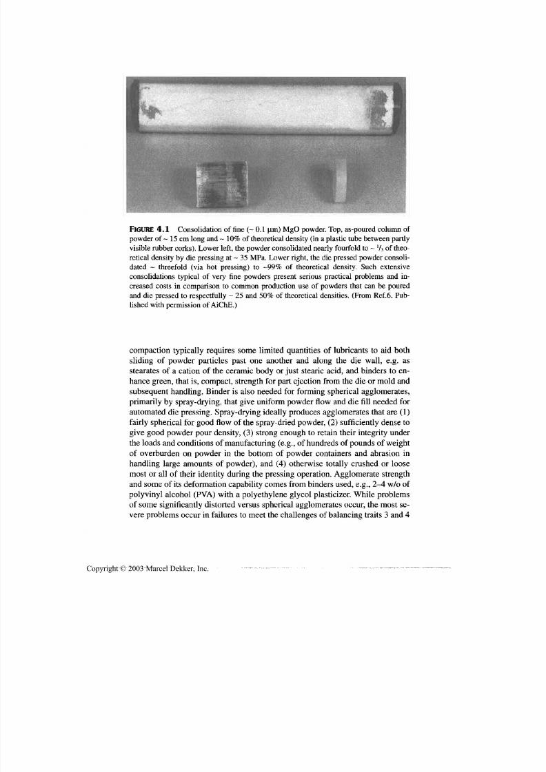
7/29/2019 29540824708539
http://slidepdf.com/reader/full/29540824708539 114/361
Forming and Pressureless Sintering 103
FIGURE 4.1 Consolidation of fine (~ 0.1 um) MgO powder. Top,as-poured column of
powder of ~ 15 cm long and ~ 10% of theoretical density (in a plastic tube between partly
visible rubber corks). Lower left, the powder consolidated nearly fourfold to ~ V 3 of theo-
retical density by die pressing at ~ 35 MPa.Lower right, the die pressed powder consoli-
dated ~ threefold (via hot pressing) to -99% of theoretical density. Such extensive
consolidations typical of very fine powders present serious practical problems and in-
creased costs in comparison to common production use of powders that can be poured
an d die pressed to respectfully ~ 25 and 50% of theoretical densities. (From Ref.6. Pub-
lished with permission of AiChE.)
compaction typically requires some limited quantities of lubricants to aid both
sliding of powder particles past one another and along the die wall, e.g. as
stearates of a cation of the ceramic body or just stearic acid, and binders to en-
hance green, that is , com pact, strength fo r part ejection from the die or mold and
subsequent handling. Binder is also needed fo r forming spherical agglomerates,
primarily by spray-drying, that give uniform powder flow and die fill needed fo rautomated die pressing. S pray-drying ideally produces agglomerates that are (1)
fairly spherical fo r good flow of the spray-dried powder, (2 ) sufficiently dense to
give good po wder pour d ensity, (3) strong enough to retain their integrity under
the loads an d conditions of m anufa cturing (e.g., of hundreds of pounds of weight
of overburden on powder in the bottom of powder containers an d abrasion in
handling large amounts of powder), and (4) otherwise totally crushed or loose
most or all of their identity during th e pressing operation. Agglomerate strength
and some of its deformation capability com es from binders used, e.g.,2 — 4 w/o of
polyvinyl alcohol (PVA ) w ith a polyethylene glycol plasticizer. W hile problems
of some significantly distorted versus spherical agglomerates occur, the most se-vere problems occur in failures to meet the c hallenges of balancing traits 3 and 4
Copyright © 2003 Marcel Dekker, Inc.
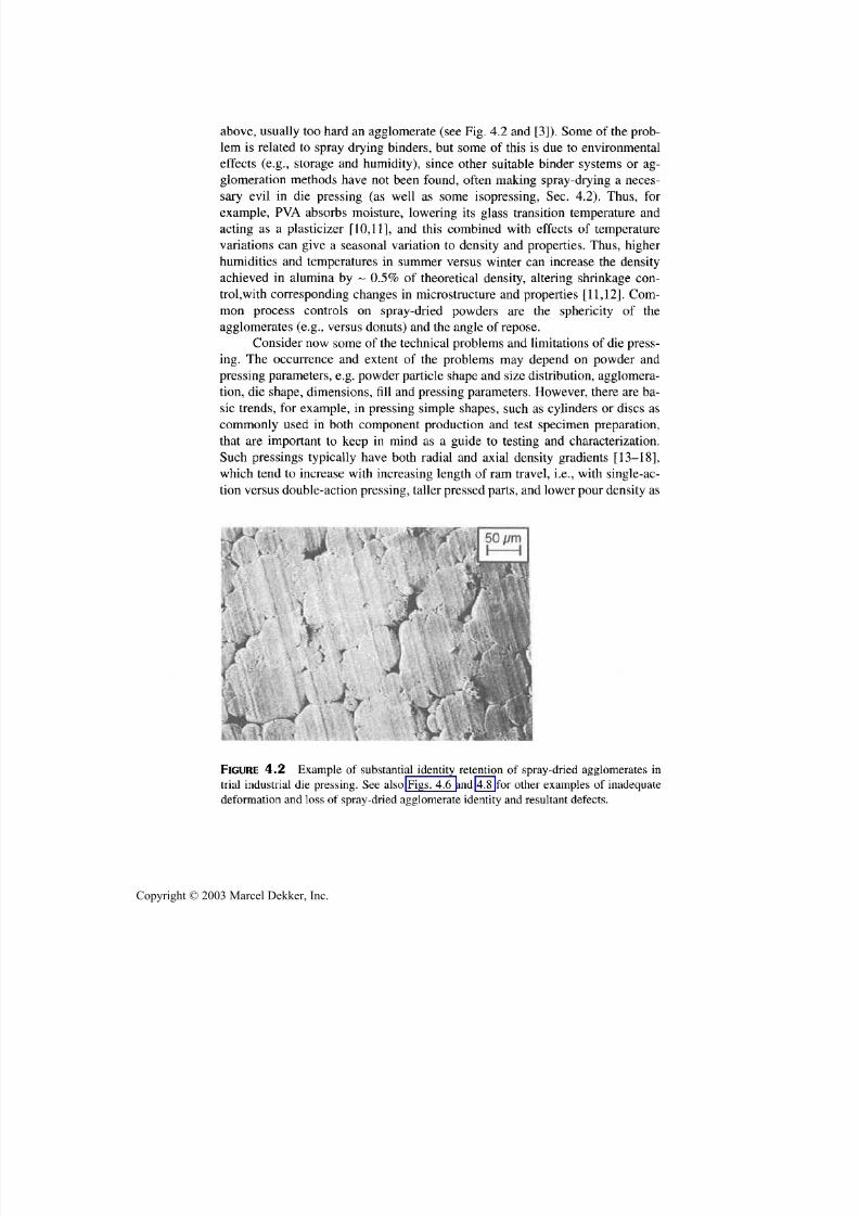
7/29/2019 29540824708539
http://slidepdf.com/reader/full/29540824708539 115/361
104 Chapter 4
above, usually to o hard an agglomerate (see Fig. 4.2 and [3]). Some of the prob-
lem is related to spray drying binders, but some of this is due to environ m ental
effects (e.g., storage and humidi ty) , since other suitable binder systems or ag-
glomeration methods have not been found, often making spray-drying a neces-
sary evil in die pressing (a s wel l as some isopressing, Sec. 4.2). Thus, fo r
example, PV A absorbs moisture, lowering its glass transit ion temperature and
acting as a plasticizer [10,11], and this combined with effects of temperature
variations can give a seasonal variation to density and properties. Thus, higher
humidities and temperatures in summer versus winter can increase the density
achieved in alu m ina by ~ 0.5% of theoretical density, altering shrinkage con-
trol, with corresponding changes in microstructure and properties [11,12]. Com-
m on process controls on spray-dried powders are the sphericity of theagglom erates (e.g., versu s do nu ts) and the angle of repose.
Consider n ow some o f the technical problems and limitations of die press-
ing. The occurrence and extent of the problems may depend on powder and
pressing parameters, e.g. powder particle shape and size distribution, agglomera-
tion, die shape, dimensions, fill and pressing parameters. H owev er, there are ba-
sic trends, for example, in pressing simple shapes, such as cylinders or discs as
commonly used in both component production and test specimen preparation,
that are important to keep in mind as a guide to testing and characterization.
Such pressings typically have both radial and axial density gradients [13-18],
which tend to increase with increasing length of ram travel, i.e., with single-ac-tion versus dou ble-ac tion press ing, taller pressed parts, and lower pour density as
FIGURE 4.2 E xam ple of substan tial identity retention of spray-dried agglomerates in
trial industrial die pressing. See also Figs. 4.6 an d 4.8 for other examples of inadequate
deformation and loss of spray-dried agglomerate identity and resul tant defects.
Copyright © 2003 Marcel Dekker, Inc.

7/29/2019 29540824708539
http://slidepdf.com/reader/full/29540824708539 116/361
Forming and Pressureless Sintering 105
commonly encountered with finer particles. The powder compacted nearest to a
moving die ram commonly reaches the highest density at the compact periphery
and decreases by a few or more percent of theoretical density with distance fromthe die wall, often approaching a nearly constant density over the central part, for
example, one-half, of the die diameter (Fig. 4.3). Progressing further from a
moving ram, the axial density values decrease, while the radial density variation
first decreases, often nearly disappearing over about the middle one-third of the
compact height for a single moving ram, but then progressively increases in
about the bottom one-third of the compact height. However, the radial density
gradient in the bottom portion of the die with only the top ram moving is typi-
cally the reverse of that in the top of the compact,that is, the lowest radial density
is at the bottom of the compact periphery, with the pressed density increasing
with radial distance in from the compact periphery. This radial density change is
commonly nearly a mirror image of that at the top,both in relative and absolute
values. Use of double-acting rams results in reduced axial density gradients be-
1.0,0.0
0.0
0.2 0.4 0.6 0.8
FRACTION OF BODY RADIUS
1.0
FIGURE 4.3 Plots of the of the cross-sectional density gradients in die-pressed cylin-
ders. (Data from Refs. 13 and 14.)
Copyright © 2003 Marcel Dekker, Inc.

7/29/2019 29540824708539
http://slidepdf.com/reader/full/29540824708539 117/361
106 Chapter 4
tween the top and bottom of pressed cylinders since the bottom half becomes ap-
proximately a mirror image of the top, which may yield more density uniformity
in the central portion, due to radial and axial gradients that may be introduced
there [14]. Basically such double-action pressing results in the density gradients
in the bottom half of the pressing being a mirror image of the top half of a press-
ing with a single-acting press, rather than the density trends in the bottom half of
a single-action pressed body. As die wall friction increases, as in pressing cylin-
drical shells of limited wall thickness, or in using finer, more voluminous pow-
der, these density gradients may be more severe, as indicated by gradients
observed in commercially die-pressed sonar transducer rings (Fig. 4.4).
Other pressing defects that often occur individually, are defects of a gen-
eral laminar character collectively, that is, nominally normal to the pressing axis.
These are often areas of limited or no bonding or contact of parts of adjacent
powder layers in a nominally vertical direction. Such laminations may be fairly
diffuse or continuous in a given layer, and may occur approximately periodically
over much of the length, especially of longer pressed parts. Springback of the
compacted powder on release of pressing pressure is a major factor in the occur-
rence and extent of such laminar defects. Near th e end(s) of pressed parts in con-
tact with moving die ram(s) less laminar defects m ay occur, consisting of partial
to complete separation of part or all of various shaped end sections, referred to
by such terms as end-capping [3,19] or ring capping [3], all from th e same un-
derlying causes. However, air entrapment can also be an important factor in theforming of some laminar defects [ 18,20] in which case they are more discrete
and produce greater vertical separation of the opposing powder layers, e.g., com-
monly forming lenticular pores (Fig. 4.5), but may be more varied [10].
The occurrence and severity of the above laminar defects are increased by
greater springback of the powder compact upon release of the pressing pressure.
Thus, they are limited or prevented by better particle flow and less die wall fric-
COLD PRESSED ISOSTATICALY PRESSED SLIP CAST
FIGURE 4.4 Schematicsof indicated density variationsin PZT sonar transducer rings
(inner dia. ~ 5, wall thickness~ 1, an d height ~2 cm) commercially producedby (A) Die
(probably double-action) pressing; (B) isopressing; and (C) slip casting. Note shaded ar-
eas are somewhat more porous (i.e., lower density) areas revealed by etching. (From Ref.
17, published with permissionof the American Ceramic Soc.)
Copyright © 2003 Marcel Dekker, Inc.

7/29/2019 29540824708539
http://slidepdf.com/reader/full/29540824708539 118/361
Forming and Pressureless Sintering 107
B
DIRECTION OF COMPRESSION
DURING MANUFACTURING
FRACTURE SURFACES
A STRENGTHS 20-40% LOWER THAN BSTRENGTHS
FIGURE 4.5 Fracture initiation from large laminar pores in a commercial die-pressed
PZT sonar transducer ring showing the orientation of lens-shaped laminar pores normal to
th e pressing direction an d resultant strength anisotropy, i.e., lower strengths of A versus B
specimens. (From Ref. 17 , published with permission of the American Ceramic Soc.)
tion. that is, better lubrication, greater green strength (e.g., stronger binders), an d
less ram travel (e.g., denser packing pow der an d lower pressing pressures as well
as lower part aspect ratios). No te that sometimes isopressing follow ing die press-
ing is used because of potential advantages of better part shape definition of die
pressing and greater and more uniform compaction of isopressing, includingpossible reduction of die pressing lamination problems. However, besides re-
quiring an added operation an d cost, more recent evaluation of such dual press-
in g indicates that while laminar and related defects from die pressing may be
reduced by subsequent isopressing, some lamination defects often remain
[21,22], and once they o ccur, they are difficult to reduce or remove.
Besides powder, die, and pressing parameters impacting the above den-
sity variations and possible laminar defects, powder agglomerates can have
considerable effect depending on their num ber and character. Agglomerates that
do not adequately lose their identity will leave a fairly uniform pattern of their
remnant effects, fo r example, larger pores in the remaining interstices between
Copyright © 2003 Marcel Dekker, Inc.
7/29/2019 29540824708539
http://slidepdf.com/reader/full/29540824708539 119/361
108 Chapter 4
th e agglomerates (e.g., Fig. 4.2). However, a limited population of spray-dried
or other hard agglomerates that undergo limited or no collapse during pressing
can result in other serious defects. One is simply a larger pore in the interstices
between parts or all of three or four contacting agglomerates that underwent
limited or no deformation (Fig. 4.6), the occurrence and character of which may
depend on differences in the extent and t im ing of the collapse of surrounding
agglomerates. Often more serious is the formation of a partial peripheral
crack/pore (Fig. 4.7), e.g., ab out halfway around an isolated hard agglomerate,
FIGURE 4.6 Pores between rem nant agglomerates near the sintered surface in sintered
comm ercial TZP.
FIGURE 4.7 E x a m ple of fracture occurring from an isolated hard agglomerate in test-ing a sintered die-pressed alum ina.
Copyright © 2003 Marcel Dekker, Inc.
7/29/2019 29540824708539
http://slidepdf.com/reader/full/29540824708539 120/361
Forming and Pressureless Sintering 109
FIGURE 4.8 SEM example of laminar cracks due to inadequate deformation of spray
dried agglomerates in die pressing test bars of commercial TZP.
due to factors such as poor bonding of surrounding powder an d differential m a-
trix-agglomerate springback on release of the pressing pressure. Use of spray-
dried agglomerates can change th e picture substantially, introducing local
laminar cracks/pores when they do not deform and lose much of their identity,
at least in some pressed part sizes and configurations. Increasing relative hu-
midity in the powder compact can substantially exacerbate green body density
gradients, which are typically accentuated on sintering.
Die pressing can also result in considerable preferred orientation of platy
or elongated particles, particularly in pressing bodies of low aspect ratio. Fur-
ther, the above differences in die pressed density reflect differences in relative
Copyright © 2003 Marcel Dekker, Inc.
7/29/2019 29540824708539
http://slidepdf.com/reader/full/29540824708539 121/361
110 Chapter 4
motion of the powder, and thus should also have some correlation with varying
orientation of platy or elongated particles during pressing. Again such preferred
orientation is often increased on sintering [23]. Also note that some of the den-sity gradients of (cold) die pressing can occur in hot pressing, unless theoretical
density is achieved, and some laminar defects may still occur in bodies hot
pressed to transluc enc y, that is, near theoretical de nsity (Sec. 8.2.1), corroborate
such hot pressing effects. Further, greater interparticle motion in hot pressing
versus (cold) die pressing enhances the opportunity for orientation of platy or
elongated particles.
Die pressing is widely used in industry, especially for smaller parts (e.g.,
a few to several cm in dimensions), mainly with lower aspect ratios (e.g., < 3).
Larger bodies, for exam ple, for refractory and w ear uses are pressed w ith larger,
especially lateral, dimensions (e.g., of tens of cm), but die pressing must com-
pete with other fabrication methods. Some pressing variations or defects such
as lamina r defects m ay be partial ly eliminated or ameliorated by sintering, but
they can be exacerbated as density gradients typically are, and w hile variations
in preferred orientation of grains crystal lographic structure can be diminished
by sintering, it is often increased, especial ly w ith grain growth [23]. The l im ita-
tions of such larger bodies of consolidated powder lies as much or more in their
sintering than in their green formation and die pressing is generally a reason-
able option for fabrication of large bodies (Table 4.1). However, powder-based
fabrication generally has increasing costs and decreasing component capabil i-
ties as component size increases. Increasing costs of larger presses, powder
loading an d green part han dling , as well as mu ch longer pressing cycles al lcon-
tr ibute to increasing pressed part costs as their size increases. However, die
pressing is used fo r m ak in g m a n y larger parts, especially those that have two or
all three sizeable dimensions.
4.2.2 Hydrostatic/Isostatic Pressing
Isostatic pressing, i.e., using hydrostatic pressure, is commonly done on both
laboratory and indu str ial scales by placing pow der in plastic, or more com mo nlyrubber or urethane, bags that are sealed (andoften evacuated), then placed in a
hydrostatic pressure (typically cylindrical) vessel with a suitable pressing fluid,
which upon closing and sealing the vessel is pressurized. This process, referred
to as wet bag isopressing, which is discussed furth er below, has considerable in -
dustrial use, especially for larger, specialty components. There is, however an
approximately hydrostatic pressing process referred to as dry bag isopressing or
dry bag pressing that is wid ely used indu str ial ly because of its practicality.
Ba sically dry bag pressing can b e envisioned as a hybrid between fully iso-
static pressing and die pressing. It essentially consists of an oversized "metal die"
as for die pressing, but with a thick rubber bladder wall in the metal "die" or hous-
Copyright © 2003 Marcel Dekker, Inc.
7/29/2019 29540824708539
http://slidepdf.com/reader/full/29540824708539 122/361
Forming and Pressureless Sintering 111
ing. The bladder and housing are designed so that upon filling the central volume
formed by the rubber bladder and sealing the bladder to the interior of the metal
housing, th e area between th e bladder and the metal housing can be pressurizedwith hydraulic fluid to provide radial (e.g., biaxial) pressing on the powder. The
top of the bladder is typically sealed by an applied axial mechanical pressure (that
does not apply pressure to the powder), while the bottom is either permanently
sealed or pressure sealed in con junction w ith sealing the top.Such pressing is lim-
ited to substantially lower pressures than m uch wet bag isopressing, e.g., to 20-60
MPa. However, such pressures encompass the range where most of the com-
paction occurs in pressing, and the radial nature of the pressure is more effective
for compaction, as is limited or no "die wall" friction. Dry bag pressing, while
having some shape limitations, also has some shaping advantages, in particular
the rubber bladder can be shaped some, to produce bodies of tapering or varying
diameter. Thus, the process has been u sed for production of spark plug insulators,
where partial shaping of the taper and shoulders reduces the amount of contour
grinding needed. (Some trade-off of better pressed body q uality with broader par-
ticle size distribution, e.g.,5-40 |im particles, was required since contour grind-
ing costs increase with larger particle sizes [24].) Other shapes produced include
both cylindrical and various shaped "spherical" alumina pieces for all but the
smaller sizes (e.g., > 1 cm) of ball-milling media (Fig. 4.9),an d tubes, fo r exam-
FlGURE 4.9 Examples of industrially produced ceramic parts, e.g.,milling media via
dry bag isopressing (central area) and rod- and bar-shaped parts via extrusion (and tubes
that are not show n). (Photo courtesy of Diamonite Products.)
Copyright © 2003 Marcel Dekker, Inc.
7/29/2019 29540824708539
http://slidepdf.com/reader/full/29540824708539 123/361
112 Chapter 4
pie, high quality ones for high -pressure, high-intensity lamps [25]. Such fabrica-
tion is practical in view of reasonable pressing cycles of minutes, substantially
less than normal isopressing, due to the small volumes of fluid to be pressurizedand the rapid m echanica l sealing. Aga in since "die" fill is automated and depends
on good and uniform powd er flow, spray-dried powder is comm only used, but it
is less likely to produce the extent of defects as often occur in die pressing due to
higher and hydrostatic pressures of isopressing. Moderate equipment cost, rea-
sonable p roduction rates, and generally more uniform , less defective bodies often
ma ke th is a suitable produc tion process.
W et bag isopressing is carried out in pressure vessels that are produced up
to a few meters in heig ht and a meter or more in diameter, but at substantial cost
fo r such larger sizes. These costs may be justif ied with sufficient volume since
larger volumes in one press save on the substantial cycle time (minutes), when
averaged over more parts in a run. Pressure capabilities commonly range from ~
100 MPa to ~ 700 MPa,with sub stantia l cost increases fo r high pressures, espe-
cially as size increases. It is used more for special fabrication, such as longer
tubes or rods where extrusion is not available or suitable, for exam ple, for tubes
or rods with flanges, simple, limited change of diameter(s) or shape (including
hemispherical sections and ogives, e.g.,fo r IR domes or radomes), or closed-end
tubes (such as for some batteries [26].) It can also produce very large pieces, fo r
example, of cross sectional areas of 0.1-0.3 m2
an d lengths to > 2.5 m [27]. An-
other important use is for prototyping components. Due to their overall good
uniformity, logs or blocks of isopressed powders are often used, fo r example, by
ceramic manufacturers, for prototyping components by green machining them
from isopressed bodies, then firing.
As noted earlier, powder (which is sometimes spray-dried for better fill) is
filled into plastic or rubber bags, which are sealed (then often evacuated) and
loaded in the press, pressed, then unloaded and unbagged. Most or all of these
steps being manual with limited or no automation and pressing cycles being of
the order of several min ute s, and shapes often being limited have constrained use
of isopressing. However, its use is aided first by higher green densities, e.g.,
commonly 55-65% of theoretical densities [28] to as high as ~ 75% [29]. Shapeversatility is another plus, and it, and especially accuracy, can be improved by
the common practice of loading bags in perforated metal or wire-mesh holders,
thicker shaped bags, and especially use of mandrels, for example, for cylinders
and other tooling designs. Thus, PZT sonar rings have been produced by iso-
pressing cylindrical tubes on a mandrel [Fig. 4.4B], with the rings then being
gang sliced from the tubes. While direct feeding of raw powder is typical fo r lab-
oratory and some production processing, use of agglomerated, especially, spray-
dried, powder is used to aid uniformity of bag fill, which is likely to be needed
for increased automation to make the process more cost-effective.
The n atu re of the pressing beha vior and results has ma ny similarities to die
Copyright © 2003 Marcel Dekker, Inc.

7/29/2019 29540824708539
http://slidepdf.com/reader/full/29540824708539 124/361
Forming and Pressureless Sintering 113
(uniaxial) pressing, but with less heterogeneity problems and frequently higher
density. Thus, compaction is most rapid at low pressures, fo r example, at < 100
MPa where alumina green density m ay reach ~ 60% of theoretical density, thenincrease more slowly, reaching ~ 65% at 700 MPa [28-30] (often with less in-
crease in fired density [28]). (Note, however, that use of cyclically applied hy-
drostatic pressure has been reported to allow achieving densities normally
obtained at higher pressures, though at some increase in cycle time [29-33].)
There is also some density inhomogeneity, e.g.,near mandrels (e.g., Fig. 4.4C),
especially their ends, and near the bag surface [30], that is, similar to, but less ex-
treme than higher density near moving die-pressing rams. O ne important differ-
ence between iso- and diepressing is that die pressing often results in varying
anisotropy due to preferred orientation of anisotropically shaped particles, for-
mation of laminar defects or pores, or both as noted earlier. On the other hand,isopressing results in little or none of this, even with fairly anisotropically
shaped powder particles [23]. However, isopressing costs are often higher an d
allowable lateral dim ensions m ore constrained than in die pressing (Table 4.1 ).
4.3 PLASTIC FORM ING
4.3.1 Extrusion
There are a variety of plastic form ing processes that are made feasible by m ixing
ceramic powder with additives that allow the resultant mix to be plastically
formed [1-4]. Originally this w as accomplished by using traditional ceramic ra w
m aterials, primarily clays that can be mad e quite plastic w ith considerable addi-
tion of water. This allowed such clay-derived bodies as pottery and bricks to be
formed by forcing a mass of a plastic mix by hand into a mold. Later, th e potter's
wheel was invented fo r more versatile pottery forming and is still used today in
much the same fashion as originally developed. Technology of the potter's wheel
has also evolved to use rotating wheels fo r highly automated plastic forming of
cookware an d china, as well as some fo r institutional an d electrical porcelain
bodies. This also includes m aking large (e.g., ~1 m diameter and > 1 m high)stoneware vessels. The first of two other important derivatives of this original
plastic forming technology are injection molding, which is discussed in the fol-
lowing section; the second is extrusion, i.e., forcing a plastic m ass through a die
to shape it . Extrusion is still used today not only fo r production of bricks, but
also for other clay-derived bodies, such as sizeable sections of ceramic pipe, as
well as other ceramics.
The focus of this section is extrusion as a fabrication method fo r technical
ceramics, which first requires use of additives (binders) to provide the plasticity
that is provided by clays in traditional ceramics, as well as selection of the type
of extruder, which ca n also impact th e selection of binders. O ne type of extruder
Copyright © 2003 Marcel Dekker, Inc.

7/29/2019 29540824708539
http://slidepdf.com/reader/full/29540824708539 125/361
114 Chapter 4
is a ram extruder, which uses a hydra ulically activated ram to force a plastic ce-
ramic mass at controlled rates down th e encompassing metal barrel and through
the product forming die at the opposite end of the barrel. Such extrusion is typi-cally done at room temp erature, usu ally with water-based binders, but other liq-
uid-based binders can be used (Table 4.1). A n important requirement is that th e
plastic ceramic mass, which is mixed elsewhere, be de-aired after being placed
in the barrel—this makes ram extrusion a batch process, though this constraint
can be reduced with a two barrel extruder where one barrel is loaded and evacu-
ated w hile the other is bein g used for extrusion . Typical binder systems consist
of a binder/flocculant (e.g. , methylcellulose or PVA), a coagulant (e.g., CaCL, or
MgC l2), and a lubricant (e.g. , stearates, silicones, oils, fine talc or graphite,
needed m ainly with high die and extrud ate surface areas) [3,34]. However, other
systems such as sol-based system s may b e feasible as noted below.
The other type of extruder is one that uses a screw or auger to force th e
plastic mass through th e product forming die. Such screw extruders typically
also h ave a m ixin g and a de-airing and e vacuation section prior to the extrusion
section, w hich in principal makes screw extruders potentially capable of con tin-
uou s operation. Screw extrud ers are generally operated at room temperature with
th e same or similar binder systems as used with ram extruders. In such cases,
while there are various difference s between this and ram extrusion , there are sub-
stantial similarities; and w hile both are used for ceramics, ram extrusion m ay be
more widely used. However, many screw extruders, which are used extensivelyfo r extrusion of thermal plastics, can be operated at elevated temperatures at
which such plastics are sufficiently plastic to be extruded. Thus, such extruders
can use ceramic mixes made plastic by use of thermoplastic binders, that is.
which extrude essentially as a hig hly f i lled plastic [35]. This is very sim ilar to in-
jection molding discussed in the next section, including binder systems mixing
and operation. While used some for ceramic extrusion, such thermoplastic
binder extrusion m ay have greater future potent ia l use with preceramic polymers
as the binder.
Choice of extruder type involves a variety of factors, such as init ial and
operating costs (e.g. , wear, especially of screws), availabili ty, operation and re-sul tant extrudate character, including size and complexity, and yield. However,
other than in some special cases discussed below, the net balance is often simi-
lar, for examp le, since die costs are sim ilar (and can be several to m an y tens of
thousands of dollars, e.g. , for extruding cellular bodies). Thus, there is often
not a large dif ference between the two; whi le ram extrusion is very common
fo r technical ceramics, screw extruders are widely used for clay-derived bod-
ie s and have been used for at least some extruded exhaust catalyst supports ,
which is a very demanding applicat ion (Fig 4.10). There is some advantage of
screw extruders for cont inuous product ion, and they may be somewhat more
scalable to larger e xtru date s izes , w hich are cur rent ly of the order of 0.1 m 2 in
Copyright © 2003 Marcel Dekker, Inc.
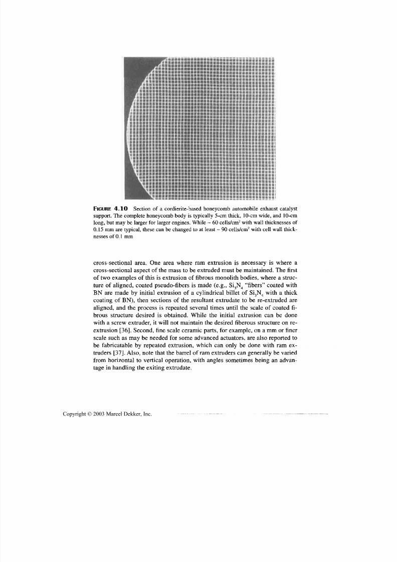
7/29/2019 29540824708539
http://slidepdf.com/reader/full/29540824708539 126/361
Forming and Pressureless Sintering 115
FIGURE 4.10 Section of a cordierite-based honeycomb automobile exhaust catalyst
support. The complete honeycomb body is typically 5-cm thick, 10-cm wide, and 10-cm
long, but may be larger fo r larger engines. While ~ 60 cells/cm2 with wall thicknesses of
0.15 mm are typical, these can be changed to at least ~ 90 cells/cm 2with cell wall thick-
nesses of 0.1 m m
cross-sectional area. One area where ram extrusion is necessary is where a
cross-sectional aspect of the m ass to be extruded m ust be m aintained. The first
of tw o examples of this is extrusion of fibrous m onolith bodies, w here a struc-
ture of aligned, coated pseudo-fibers is made (e.g., Si3N 4 "fibers" coated with
BN are made by initial extrusion of a cylindrical billet of Si3N 4 with a thickcoating of BN), then sections of the resultant extrudate to be re-extruded are
aligned, and the process is repeated several times until the scale of coated fi-
brous structure desired is obtained. While the initial extrusion can be done
with a screw extruder, it will not maintain th e desired fiberous structure on re-
extrusion [36]. Second, fine scale ceramic parts, for example, on a mm or finer
scale such as may be needed fo r some advanced actuators, are also reported to
be fabricatable by repeated extrusion, which can only be done with ram ex-
truders [37]. Also, note that the barrel of ram extruders can generally be varied
from horizontal to vertical operation, with angles sometimes being an advan-
tage in handling th e exiting ex trudate.
Copyright © 2003 Marcel Dekker, Inc.
7/29/2019 29540824708539
http://slidepdf.com/reader/full/29540824708539 127/361
116 Chapter 4
Note some factors for either type of extruder; Extrusion of many objects,
especially those with axial holes, such as for tubes and honeycom b structures, re-
quires die designs that entail the extruded material to be flowing around and cutby parts of the die, then be knitted back together, that is , healed or rebonded, be-
yond this change of flow. This requires more complex and expensive dies, but
whose engineering is well established. The presence of a considerable content of
fine, submicron, particles generally aids extrusion. Extrusion pressures are com-
monly a few to severa l, e.g., 15, MPa, w ith lower values fo r bodies with increas-
ing clay content. Extrudate formation rates can be up to ~ 1 m/sec and with large
extruded bodies can result in productio ns of up to the order of a hundred tons per
day for bodies with substantial clay content.
Typical applications of extrusion are rods and tubes, the latter ranging
from thermocouple insulators, larger insulators, lamp envelopes, and furnace
tubes, but includ ing other shapes (Fig. 4.9). One of the largest markets is cellular
ceramics fo r various uses, (see Fig. 4.10), the largest of which is for auto exhaust
catalyst supports, a market tha t is probably in excess of a hundred m illion dollars
per year and growing. However, there are a variety of other environm ental uses
of such cellular materials fo r catalytic uses and filtering, as well as for rotary
heat exchangers, some of which are likely to grow substantially with increasing
constraints on pollut ion.
Turning to the character of extruded ceramics, there are two key aspects
that, while often not given adequate attention, are important. The first is the na-
ture of the porosity. Theoretically, the axial distribution of plastic binder in the
extrudate, though being complex due to its three-dimensional connections
around the ceramic particles, shou ld also have a basically tubular character in the
axial direction, which probably varies with the range and absolute scale of the
particle size. An overall axial tub ular character o f much of the binder m ust result
from the streamline flow necessary for producing a coherent, uniform extrusion.
Thus, while th e binder acts as a lubr icant for the ceramic particles to move to ac-
commodate the deformation of the extrusion, the plastic flow of the binder itself
is also important in the extrusion and any locally higher binder content will be
elongated axially. While sintering will substa ntially reduce the am ount of theporosity left from binder burnout and reduce it s degree of connectivity, consider-
able remnants of the tubular character probably will remain. Though little study
has been made of such axial tubular character of porosity in extruded ceramics
(or metals), recent ev alua tion of the porosity dependence of extruded ceram ics is
consistent with such axial tubular character [21,22] (Table 4.1). A basic conse-
quence of such axial porosity character in extruded bodies is a substantial
anisotropy of porosity dependent properties, which , while not studied much, is
supported by limited data showing anisotropy in extruded bodies. Some of this
results from preferred orientation of the ceramic structure as discussed below,
but some most l ikely arises from some tubular pore character and its preferred
Copyright © 2003 Marcel Dekker, Inc.
7/29/2019 29540824708539
http://slidepdf.com/reader/full/29540824708539 128/361
Forming and Pressureless Sintering 117
axial orientation. The substantial anisotropy of properties that can result from
such axial tubular pore character are both a strong reason to evaluate porosity
character in extruded bodies, and can be an important tool in demonstrating anddefining it . Even less attention has been given to the possibility of radial gradi-
ents of porosity that may occur in extrusion and of the effects of knitting sections
of extrudate back together after being temporarily separated in some extrusions,
for example, in tubes and cellular structures.
The other key m icrostructural factor in extruded ceramics that has received
insufficient attention is preferred o rientation of the crystal structure of the grains
in extruded ceramics. Varying degrees of this are expected as a function of the
degree and range of anisotropy of particle/crystallite shape and its relation to the
crystal structure, particle sizes and size distributions, and extrusion lateral di-
mensions and pressures. While quantification of effects of these factors is notavailable, some dem onstration of their occurrence and their substantial impact is
shown by the following two examples. The first is substantial study of BeO by
Fryxell and Chandler [23] using both AOX an d U OX powders, which respec-
tively have equiaxed particles and considerable content of fine morphological
particles with the long axis of elongated particles being the c-axis (Sec. 2.2).
They showed that while both powders gave isotropic bodies of sintered B eO
when first consolidated by isopressing, as did the equiaxed AOX powder when
consolidated by extrusion, extrusion of the the UOX powder with some elon-
gated particles resulted in a substantial c-axis texture along the extrusion axis.
Thu s, extrusion resulted in sub stantial axial orientation of the elongated powd er
particles, and this orientation increased with increasing sintering and grain
growth (hence being an important forerunner to the substantial microstructural
seeding that has been of more recent interest). The resultant anisotropy of the
BeO from UOX powder , e.g.,up to a hundre d-fold higher x-ray intensity of pre-
ferred peaks than in a random ly oriented body, translated into anisotropy of bulk
properties. Thus, the axial thermal expansion of the UOX derived BeO bodies
decreased up to 7% below that of isotropic BeO,consistent with lower expan-
sion along the c-axis. Similarly, Y oun g's and shear m oduli we re up to 7% higher
along the extrusion axis o f U O X derived BeO,and both room- and higher tem-perature strengths of larger grain bodies were higher in the axial direction.
The second example of the occurrence an d impacts of preferred crystal ori-
entation from extrusion, which also shows other important engineering benefits
is extrusion of cordierite auto exhaust catalyst supports by Lachman and
coworkers [38,39]. They used clay as a substantial ingredient fo r forming the re-
sultant cordierite, which not only significantly lowered raw materials costs, e.g.,
possibly by as much as an order of magnitude, but also greatly aided the extrud-
ability of the body. Extrusion of the green honeycomb body resulted in signifi-
cant preferred crystal orientation of the clay particles as expected. However,
rather than being destroyed in the reaction of the clay w ith the other constituents
Copyright © 2003 Marcel Dekker, Inc.
7/29/2019 29540824708539
http://slidepdf.com/reader/full/29540824708539 129/361
118 Chapter 4
to form cordierite, the preferred orientation of the clay particles resulted in a pre-
ferred orientation of the resultant cordierite grains. This unexpected cordierite
orientation resulted in another advantage of using clay, namely a beneficialanisotropy of thermal expansion, that is, the highest cordierite expansion direc-
tion normal to the honeycom b cell wa lls, wh ich is the mo st benign, and thus ben-
eficial to thermal stress and shock performance of the catalyst support. Thus,
preferred orientation of even reactive ingredients that lose their chemical identity
en route to the final product can have an impact on the resultant extruded and
fired body in the intervening reactions if orientation of the reactive ingredient
particles carries over to the fired product (Table 4.1 ).
Now consider recent developments and future possibilities, focusing on
three promising areas, the first being binders. Chen and Cawley [40] have ex-
truded alpha alumina using a colloidal boehmite, AIO(OH), sol with 0.3 w/o
PVA as binder, and K u m ar an d coworkers [41 ] reported similar extrusion of both
a- and y-alumina. Further demonstration of this, as well as of the second an d
third areas of orientation and compo sites, is work of Bla ckb urn and Tawson [42]
forming composites of chopped, oriented alumina fibers in a mullite matrix by
extruding mixes of fine silica and the alumina fibers using a boehmite sol. An-
other example of successful alignment of anisotropically shaped particles is
Muskat and coworkers' [43] extrusion of 15% p-Si ?N 4 whiskers in a predomi-
nately a-Si3N4 (using a conventional organic-based binder system) with subse-
quent sintering to 95% of theoretical density, preserving the high degree oforientation of |3-Si3N4 whiskers. W hile this latter Si3N 4 extrusion used a conven-
tional fugitive organic binder, use of preceramic polymer binder systems should
be feasible, and though being a cost factor, m ay offer potential in both composi-
tions, densities, and qualities achievable.
4.3.2 Injection Molding
Injection molding is the other major plastic forming method besides extrusion,
of which it is basically a derivative, since it essentially consists of extruding a
spaghetti-size stream of plastic ceramic mix into a mold of the component to beformed. Typically the binder-ceramic plastic mix is heated above the glass tran-
sition temperature of the binder, for example, by 125-150°C, and the mold cav-
ity is cooled, with the mix injected into the cavity ideally becoming rigid just as
cavity filling is completed. This process, which was developed about 75 years
ago, has been attractive fo r forming modest size parts, from dimensions < 1 cm
up to a few tens of cm (Table 4.1 ), with larger bodies being fairly open, since
massive bodies present various problems, such as slow temperature changes.
The attraction of injection molding is rapid forming (cycles from ~1 min) with
considerable intricacy, for exam ple, nom ina l thicknesses of 0.5-5 m m and
(closed o r throu gh) holes > 1.5 mm diameter, with tight tolerances, < 0.1 mm.
Copyright © 2003 Marcel Dekker, Inc.

7/29/2019 29540824708539
http://slidepdf.com/reader/full/29540824708539 130/361
Forming and Pressureless Sintering 119
Injection molding became th e production process fo r spark plug insulators in the
late 1930s (but was replaced by dry bag isopressing and contour grinding as
noted in Sec. 4.2.2), has had a variety of industrial uses since then, (see Fig4.11), and has been of considerable interest fo r fabricating turbocharger and tur-
bine engine rotors and other components, such as individual vanes or complete
vane assemblies. (However, note that recent tests of pressure-cast tensile test
specimens has shown that they have much better strength and reliability than
those made by injection molding, Sec. 4.4.1).
Keys to successful injection molding are several interactive factors as
FIGURE 4.11 Examples of injection molded ceramics: (A) intermediate-sized parts
an d (B ) smaller parts. (Photos courtesy of Diamonite Products.)
Copyright © 2003 Marcel Dekker, Inc.

7/29/2019 29540824708539
http://slidepdf.com/reader/full/29540824708539 131/361
120 Chapter 4
discussed in a number of reviews of the subject [3,44-50]. These include the binder
system, mixing uniformity, particle size and distribution, mold design, and opera-
tional parameters (e.g., temperatures, pressures and material flow rates). Thermo-
plastic binders are most common, but other binders are used or being explored as
discussed below. Usually a major and minor binder constituent is used so that the
latter is burned off at lower temperatures, aiding in removal of the major binder
content, which is one of the challenges for injection molding. Particle size effects
manifest themselves m ainly via their effect on viscosity, which impacts both mixing
and actual mo lding, with finer particles substantially increasing viscosity above ~
50 v/o,but w ith some red uctions of the rates of v iscosity increases with increasing
particle size distrib ution . Finer particles also increase difficulties of binder removal.
Thus, typically used powder particles are one to several micron s in diameter. O bvi-
ously a challenge is to have the mold fill completed just before the body "freezes,"
which depends on how the extrudate is entered into the mold, the mold-material
temperature differences, and the rate of material flow into the mold.
Failure to adequately meet the above challenges results in various prob-
lems which are often interactive and com mon ly fall into four categories. The first
is inadequate molding—e.g. , pores from inadequate de-airing, incomplete filling
of the mold, and incom plete kn itting of adjac ent strands of the extrudate [51,52].
The second is inhomogeneous mixing from agglomerates of the bind er or the ce-
ramic, as well as less extreme but larger scale composition variations. Third is
residual stresses from both composition variations and, especially, "frozen in "stress from thermal gradients and frequent resultant cracking as molding is com-
pleted or during early stages of burnout . Fourth is binder burnout, which is chal-
lenging because of the volume of binder to be burned out, combined with its
expansion and plasticity durin g burnou t, hence a l lowing distortion and exacerba-
tion of molding problems [51-53]. Possible issues that have received little atten-
tion are probable tubular pore character and alignment of anisotropic particles
within extrudate strands expected (with some demostration, Ref. [54], and resul-
tant effects of probable anisotropy of properties of the strands causing sections
of them to act as pseudo large grains with anisotropic properties and hence
sources of stress concentration.A variety of changes are in varying degrees of demonstration to improve
the basic process or make it more versatile. One of broader development is use
of other binders and molding parameters to allow much lower pressure molding,
that is, by ~ 10-100-fold from those typically used in normal (high, 7-70 MPa)
pressure molding [3,55]. Other efforts include other nov el binders, such as those
based on water—e.g., use of water-soluble organic-based gelling agents in wa-
ter-based binders [55] or water as the m ain binder con stituent, with freezing of
the water via a cooled mold the method or rigidization [56]—as well as prece-
ramic polymer-based binder systems [57]. All of these significantly change one
or more aspects of injection molding, especially binder "burnout." Finally, some
Copyright © 2003 Marcel Dekker, Inc.

7/29/2019 29540824708539
http://slidepdf.com/reader/full/29540824708539 132/361
Forming and Pressureless Sintering 121
investigation of injection molding for possible advantageous forming of ceramic
composites—e.g., with possible favorable preferred orientation of the dispersed
phase—has been made. For example, Tsao and Danforth [58] showed that whileaverage lengths of SiC whiskers were approximately halved, there was consider-
able preferred alignment in injection mo lding them in a silicon nitride m atrix.
4.4 COLLOIDAL PROCESSING
4.4.1 Slip, Tape, and Pressure Casting
Forming ceramic bodies by slip castin g is a long standing process consisting of
making a slurry of the green body constituents, then casting this in a porous
mold, typically of (naturally porous) plaster, and more recently porous plastics.
As m uch of the slurry liquid at or near the mold surface is absorbed in the pores
in the mo ld, a layer of solid—the cast layer— is formed by the interlocking solid
particles in the region nea r the mold surface. As the process co ntinue s, this solid
layer increases so long as the mold pores continue to absorb slurry liquid. While
thick deposits, including solid bodies without any cavity, can be made, slip cast-
ing is particularly suited for making hollow bodies, often with thin to modest
wall thickness (Table 4.1). Such hollow bodies, w hich can be quite sizable and
versatile in shape, are made by simply pouring excess slip out of the mold. The
first of two key factors is the slurry, that is, the slip. For environmental, cost,practical, and historical reasons water is the primary liquid used, but some other
liquids are used. For reasonable shelf life and un iformity of the resultant green
body, stable slips are important, for which there is substantial background on
the colloidal chem istry necessary for such slip stability [59]. (Increasingly, such
colloidal concepts are also being used to guide development of other colloidal
systems, such as binders for injection m olding and extrusion.) A major applica-
tion and driving force for further development of slip casting has been the sani-
tary ware industry, since ceramic toilets, urinals, and washbasins would be
difficult and very costly to make by other means. They being large, hollow
shapes with modest wall thickness make them amenable to slip casting [60].These products are also a natural for the process, since clays are a major ra w
material for them , and clays are very amenable to form ing good slips and bridg-
in g over die pores (clays were thus the origin of the technology, much as they
were for extrusion). Today the process and its derivatives are used for a variety
of other, mostly nonclay derived, ceramics and diverse applications, with poten-
tial for more use.
A key step in the process follow ing the actual slip casting is drying, part of
which occurs in the mold, causing shrinkage of the part that is important for its
removal from the mold (typically made in two or more pieces to facilitate part
removal), as well as subsequent drying. Common drying shrinkages are of the
Copyright © 2003 Marcel Dekker, Inc.
7/29/2019 29540824708539
http://slidepdf.com/reader/full/29540824708539 133/361
122 Chapter 4
order of 3% or more, and can be anisotropic, the combination of which often re -
quires process adjustment to avoid crack ing. Another important step fo r produc-
tion is drying of the molds so they can be reused .Slip casting, as traditionally practiced, like an y process, has its advantages
and d isadvantages/limitations (Table 4.1). The biggest advantage is its versatility,
first in terms of shape an d second in terms of size an d ma terials applicability. It can
also accommodate a range of particle sizes, working with typical particle sizes
from a fraction of a m icron (green densities of ~ 40-50% for ~ 0.5 micron particles
[61] to several microns. It can also work fairly well w ith finer, nano scale particles,
though with challenges of particle flocks adequately bridging m old pores (mainly
in newer plastic molds which have larger pores) and lower particle volume frac-
tions and resultant green densities, for example, 32-36% for Al2O 3-ZrO 2 compos-
ites [62] while most common for oxides, it has some applicability to non-oxides,e.g., SiC [63]63]. Traditional slip casting is done with low capital cost—standard
mixing equipment, plaster molds, moderate drying facilities, and standard binder
burnout and sintering facilities. Because of these factors, it has been a handy
process to mak e a limited num ber of pieces, for example, prototypes.
However, slip casting has limitations, which , from an operational standpoint,
are primarily its slow casting rates, with thickness proportional to the square root
of casting time, an d hence increased cost of casting and of drying to avoid crack-
ing, as well as costs fo r preparing and maintaining a large mold inventory and fa-
cilities for mold storage and drying. Drying times of one to a few hours per cm of
thickness are often required [3], thou gh they may be reduced some for bodies by
impinging of slip-cast deposits from adjacent or opposing sides of a mold. There
are also some technica l issues such as segregation of larger particles and resu ltan t
gradients of particle grains and oriented/laminar arrays of porosity (Fig. 4.4C),
that, while not wid ely addressed, should be considered. However, flexure bars cut
from slip-cast sonar transduc ers norm al to the lamellar porosity had strengths com -
parable to those fo r bars from isopressed and the strong direction of die-pressed
transducer rings [17]. These limitations result in slip casting being used in areas
such as sanitary ware, since nothing else is really practical, but slipcasting being
displaced by other processes for other produc ts, such as sonar transducer rings.While slip casting is often applied to modest size components, it can be
used fo r larger bodies. Some of these are larger crucibles or other vessels where
the wall thickness is modest, e.g., <1 cm. Again, sanitary ware such as toilets,
urinals, and washbasins were made only by slip casting for years before im-
provements by pressure casting were introduced. Beyond this, large refractory
bodies have been made. Thus, large, ~ 2.5 m long alumina refractories with lat-
eral dimensions of ~ 0.3-0.4 m whose isopressing was successfully shown by
W erenberg and cow orkers [27], were typic ally made by slip casting.
The first of four developments that have significantly improved and ex-
tended the use of slip casting is the use of pressure in casting. This entails some
Copyright © 2003 Marcel Dekker, Inc.

7/29/2019 29540824708539
http://slidepdf.com/reader/full/29540824708539 134/361
Forming and Pressureless Sintering 123
form of pressure or stress to enhance ca sting rates and may often also inc lude use
of vacuum to increase fluid infiltration into the mold. O ne method of enhancing
casting has been centrifugal casting, that is , casting in a mold in a centrifuge,which though studied for the dinnerware industry [60], has been primarily, if not
exclusively, a laboratory tool. Such casting, which uses greater centrifugal stress
on the colloidal particles versus on the fluid, can increase green density, e.g., to ~
57% of theoretical density for TZP [64], as well as align reinforcing particles
[65]. However, higher green densities (e.g., 60-70% of theoretical) and shorter
casting times are an attraction [66]. Recent developments show promise for
making larger ceramic tubes, due to lower rotating speeds, and hence possible
increased safety [67].
O f much broader use is the application of pressure (e.g., from < 1 to a few
MPa) on the slip to increase the fluid flow through the deposit and the m old andthus decrease th e casting time, fo r example by three- to sixfold for a thickness of
~ 1 cm, increase green density, and reduce drying shrinkage, by two- to four-
fold. Such pressure casting is now extensively used in the sanitary ware industry,
where along with other advances, namely microwave drying of parts an d molds
an d the automation of the process, has reduced both process energy needs and
production time, fo r example, from 2-3 days to 9-10 hrs [68]. Polym eric m olds
have replaced plaster molds because of large increases in mold life, e.g. ~ 10,000
versus -100 cycles respectively fo r plastic and plaster molds (but also with
much larger pores in plastic versus plaster molds, hence added challenges fo r
slip casting fine powders).There has been considerable interest in application of
pressure casting to ceramics fo r high-performance applications such as turbine
and piston engines, since it shows promise of substantially increasing compo-
nent reliability by reducing processing defects [69]. W hile this is prom ising, is-
sues remain, in particular whether components with such improved performance
can be produced cost-effectively. Thus, fo r example, residual stresses can be a
factor in such casting, and use of higher pressures to further reduce casting times
an d increase green density can be limited not only by diminishing returns, as
well as bubble form ation by gases dissolved in the slip liquid und er pressure, be-
ing released to form bubbles upon pressure release [70], tha t is, as in the "bends"in the blood of divers (Table 4 .1).
While sanitary ware manufactured by pressure casting represents sizable
bodies m ade by the process, add itional perspective on the potential capabilities of
the process is given by earlier work (under direction of Professor Smoke, results
reported to this author by Professors McLaren and Haber, Rutgers University,
New Brunsw ick, New Jersey). The goal of making 90% alumina seal rings ~ 1 m
diameter, ~ 2.5 cm thick with a wa ll thickness of ~ 7.5 cm for a fusion Tokomac
reactor was met by pressure casting, achieving a cast density of ~ 54% of theoret-
ical. The -1% drying shrinkage, though low, represented a substantial radial
shrinkage of ~ 6 mm, which could cause cracking given th e limited green
Copyright © 2003 Marcel Dekker, Inc.
7/29/2019 29540824708539
http://slidepdf.com/reader/full/29540824708539 135/361
124 Chapter 4
strength. To accomm odate this radial shrinkag e, indiv idua l rings were placed on
an array of radially oriented pie-shaped pieces of Teflon sheet such that radial
shrinkage could be accommodated by either slippage of the rings on the Teflon
pieces or by these pieces sliding on their support. (Similar novel engineering solu-
tion to the much greater firing shrinkage of these rings is described in Sec. 4.7).
Interest in the technical capabilities of pressure casting were significantly
heightened by more recent demonstrations of tensile strengths and reliability
with silicon nitride com positions kn ow n to be capable of high room temperature
strengths with limited processing defects. Pujari and coworkers [71] showed that
pressure casting of specimens fo r true tensile testing of such compositions re -
sulted in remarka bly hig h tensile strengths (e.g. ~ 1 GPa) and high Weibull mod-
uli ( ~ 20), which are both much higher than have been obtained with injection
molding. Lyckfeldt and coworkers [69] showed in a detailed study of applying
pressure casting to making prototype silicon nitride engine rotors that many of
th e challenges of casting thicker (e.g., > 50mm) and more complex cross sec-
t ions could be adequately met, but casting times to achieve this were long, ~ 3.5
hrs. They noted that use of a parti ally floccu lated slip could reduce c asting times
by two- to three-fold, by bridging mold pore openin gs with sm aller particles, but
use of such slips required more development to avoid casting problems. Thus,
pressure casting has substantial promise, but casting issues of quality versus
faster casting (and lower costs) remain.
The fourth development that significantly extended th e use, versatility, andproductivity of slip casting is tape casting . This consists of casting a thin layer of
slip onto an impervious surface, commonly a Mylar sheet that allows it and the
cast sheet to be sub seq uen tly rolled u p for storage and han dling [72]. Casting is
typically via a doctor blade system , that is, a slip-containing reservoir that sits on
the Mylar tape and slides under the doctor blade reservoir so tape is formed by
th e Mylar sheet and the reservoir moving relative to one another, with slip flow-
ing out of the bottom of one side of the reservoir, where there is an adjustable
narrow gap between the reservoir bottom and the Mylar. Tapes of various thick-
ness, e.g., < 10 )iim to several tens of microns, are cast by adjusting the extent of
this gap to various heights above the Mylar, as a function of the gap, the Mylarspeed, and the slip character and drying shrinkage. Drying of such tapes occurs
into the air above the top side of the tape rather into the surface (M ylar) on which
it is cast. While there is increasing interest in aqueous-based slips fo r tape cast-
ing, many are nonaqueous based systems. Tapes up to a meter or more in width
are produced in very large qua ntities fo r ceramic, especially alumina, substrates
and mu lt i layer packages, as well as barium titanates fo r multilayer capacitors.
These, along with thicker colloidal pastes of metals and of other ceramics for
screen printing (horiz onta l, i.e., x-y) electrical conductors and electrical compo-
nents on the tapes, are basic to the large ceramic electronics ind ustry (Fig. 4.12).
Copyright © 2003 Marcel Dekker, Inc.
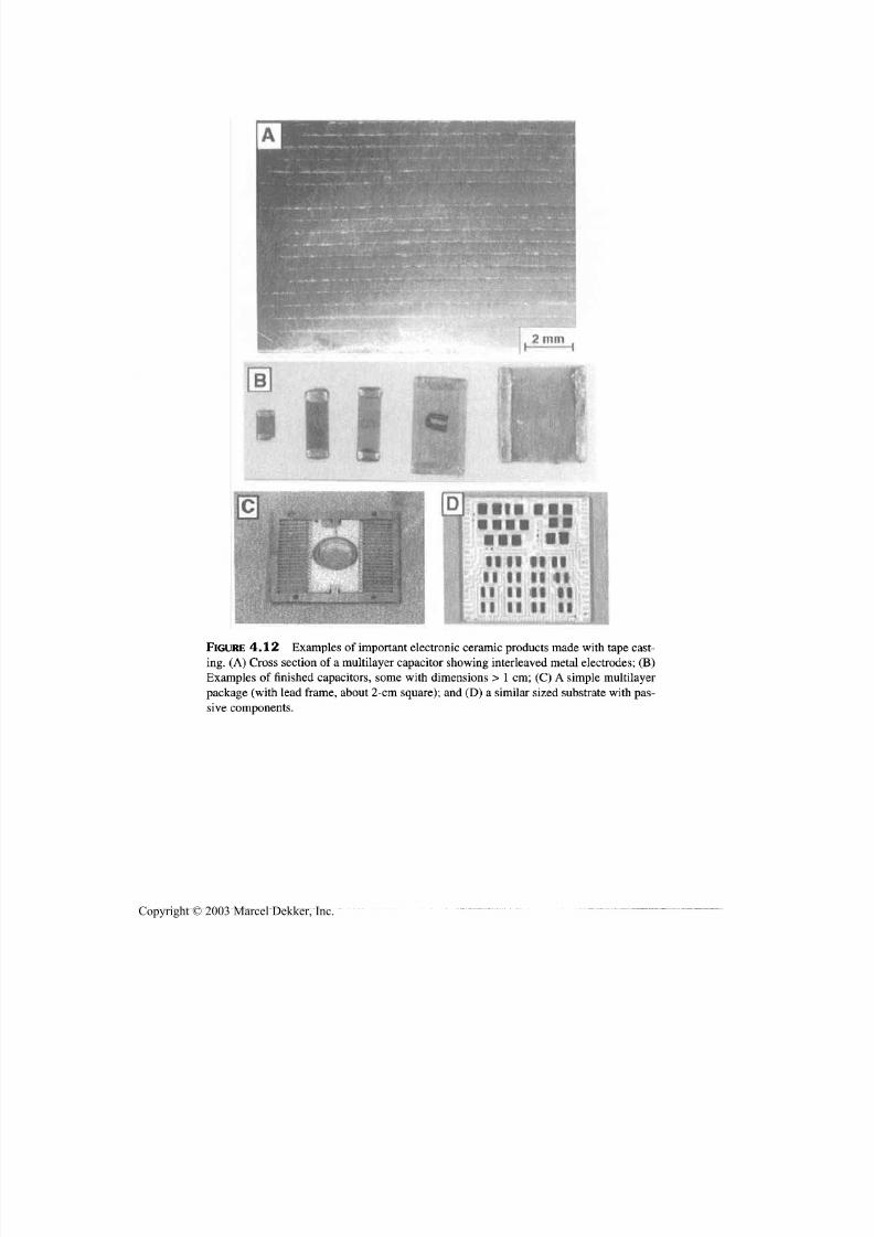
7/29/2019 29540824708539
http://slidepdf.com/reader/full/29540824708539 136/361
Forming and Pressureless Sintering 125
FIGURE 4.12 Examples of important electronic ceramic products m ade w ith tape cast-ing. (A) Cross section of a multilayer capacitor showing interleaved metal electrodes; (B)
E xamples of finished capacitors, some with dime nsions > 1 cm; (C ) A simple multilayer
package (with lead frame, about 2-cmsquare); and (D) a similar sized substrate with pas-
sive components.
Copyright © 2003 Marcel Dekker, Inc.
7/29/2019 29540824708539
http://slidepdf.com/reader/full/29540824708539 137/361
126 Chapter 4
For these (and other) applications punching of holes in the tapes (for "vias" to be
filled with metal pastes for vertical, i.e., z direction conductors) and especially
lamination of tapes carefully aligned on top of one another are important steps.However, ceramic tapes are also used fo r other applications, e.g., miniature fer-
r ite memory cores (Sec. 4.8), and are of interest fo r other possible applications
includ ing stru ctur al com posites, rapid prototyping (Sec. 7.4), and other possible
applications such as fuel cells.
Several additional factors that indicate further potential for slip and tape
casting should be noted. First, though not treated here, these processes, espe-
cially slip casting, are also important ceram ic coating tech niques for a variety of
ceramic coatings for ceramic and metal substrates. Second, substantial work
continues to expand the technical base of slip preparation (see [73,74]) and use,
fo r example, regarding possible effects of using slips above room temperaturevia heating, including microwave h eating of sl ips [75]. Third, slip and tape ca st-
ing has significant potential for fabricating ceramic composites (paniculate,
whisker, and laminar) and functionally graded materials [76-78].
4.4.2 Electrophoretic Deposition (EPD)
Another important colloidal deposition process is electrophoretic deposition
(EPD), which is most applicable to dielectric materials [79-82], but can be used
some for deposition of electrically conducting particles. Electrophoretic deposi-
tion uses electrical charges that comm only form on the surface of colloidal pow -
der particles in a liquid medium by applying an electric field between two
electrodes with th e colloidal medium between them. This typically uses electrical
charges form ing on the particle surfaces due to one of the following mechanisms:
1. Desorption of ions at the interface with the liquid, fo r example, on
clay particles
2. Chem ical reaction between the powd er particle surface and the liquid,
fo r example, of oxide powders and
3. Preferential adsorption of specific additives or impurity ions, for ex-
am ple, surfactan ts or polyelectrolytes
Thus, E PD uses an electrical field across a colloidal medium to drive th e charged
particles to the electrode where they will be neutralized and thus form a deposit
of particles, a green body. This is ana logous to electroplating except E PD uses an
electric field to deposit charged pow der particles in a fluid instead of a solution
with ions to be deposited as atoms.
Electrophoretic deposition, like processes such as extrusion and slip cast-
ing, was originally discovered and developed with clay-containing bodies using
wa ter as the liquid , but has been applied to a variety of ceramics. D ielectric par-
ticles can be used in w ater, wh ere the surface charge can be adjusted by changing
Copyright © 2003 Marcel Dekker, Inc.
7/29/2019 29540824708539
http://slidepdf.com/reader/full/29540824708539 138/361
Forming and Pressureless Sintering 127
the pH, as well as in m any organic liquids, which ca n also be used with m any ox-
ide and nonoxide powd ers. K ey factors increasing the rate of material deposition
are increases in the density and size of colloidal particles, their charge, and theelectrical field that can be applied between the electrodes. However, deposition
is limited by too high a conductivity in the liquid, which can result in electrical
breakdown, and more commonly by electrolysis in water-based systems and the
release of O 2 and H 2, which can present limitations, fo r example, due to bubbles
in the deposit, as well as possibilities, as discussed below.
There are some ways of avoiding or using effects of release of O 2 or H 2
when using water as the fluid medium as discussed below, as well as important
possibilities of using such gas generation to form prom ising novel porous bodies
(Sec. 7.3).However, a general way of avoiding such electrolysis limitations with
aqueous suspensions is to use nonaqueous suspensions fo r EPD, fo r which there
is a substantial literature [78]. EPD with nonaqueous suspensions requires
higher, but manageable voltages—e.g., a few thousand volts—versus aqueous
suspensions, where a few hundred to well less than 100 V are typical. In either
case EPD is generally best for particles of ~ 1-20 (im and suspensions that are
neither to o stable nor too unstable, and often is aided by various additives, again
for wh ich there is a fair amount of documentation.
E PD, like slip casting, is basically a coating process that can be used simply
for coating as well as for making various free-standing bodies; there are several
similarities an d differences between the two processes. Thus, while both use fe-male m olds, E PD often also uses m ale molds on which to deposit; an d while both
m ay be often done with binders, these m ay give too m uch adhesion to electrodes,
especially male ones fo r EPD. However, E PD often needs little or no binder an d
low adhesion an d burnable graphite (pencile lead) or sprayed electrodes can be
used. Though actual E PD deposition rates slow at higher deposit thicknesses, they
are theoretically linear in time as compared with a square root dependence of slip
cast thickness with time. Thus, E PD generally has very reasonable deposition rates
and times, rates of the order of a mm/min. G reen densities from EPD m ay be lower
than for slip casting, ~ 50% of theoretical density, but can be up to at least 60%.
Electrophoretic deposition is potentially ideal fo r forming both coatings ona variety of surface shapes as well as small, thin wall devices. I ts advantages as a
coating technique stem not only from th e very lo w capital needed, (basically a
modest power supply and plastic tank s) but also from th e versatility of shape that
can be coated. This versatility results from th e fact that deposition is driven by
the electrical field that is normal to the local section of the electrode, so the
geometry of the deposit generally follows the global an d local geometry of the
electrode on which the deposit is made. Further, m any parts, especially smaller
ones, can be made simu ltaneously in one deposition cell. E lectrophoretic deposi-
tion was developed as the fabrication process fo r p-alumina battery tubes [83],
but greater potential is indicated by several other developments.
Copyright © 2003 Marcel Dekker, Inc.
7/29/2019 29540824708539
http://slidepdf.com/reader/full/29540824708539 139/361
128 Chapter 4
Work to use EPD to make fiber-optic ferrules, besides being another possible
application, illustrates further potential for the process. Thus, Kerkar and Rice
[84] used a male mold consisting of a noble metal coated on a much stiffer
metal , (W) as the deposition electrode for E PD of zirconia ferrules. The purpose
of the noble metal on the deposition electrode was to absorb the hydrogen pro-
duced by electrolysis of the wa ter (and to be rechargable by therm ally remov ing
the hydrogen) .
An important development in EPD and for its future potential was the
demonstration by Aksay [79,85] of a machine (called the "Elephant") and tech-
nique of forming continuous tape or slabs from ~ 3 mm and up to ~ 15 mm thick-
ness of clay conta ining bodies fo r tile and possibly dinnerware production, but
potentially applicable to other bodies. This machine consisted of two large (1.5 m
diameter) side-by-side hollow metal rolls that counter rotated at 5 r/hr, yielding
tape or slab speeds of ~ 25 m/hr or ~ 40 cm/min. The rolls were separated at their
closest approach by the thickness of the tape or slab to be produced and were the
anodes on which the deposit was made on their outside surfaces. In the upper,
curved V -shaped area betw een the two rolls is held a m atching V -shape body that
does not contact the rolls since it is the cathode, and the space between its curved
surfaces is where the tapes begin to form on each roll. The lower portion of the V --
shaped body is a pump supplied slip reservoir and distributor, and the upper por-
tion is a collector and drain for excess slip to be recycled. The tapes formed on
each roll over their length (30 cm in this case) are laminated together by the rollsand the m oving tak eup surface since this doubles output and also results in a sym-
metrical distribution of stress gradients in the two tapes, hence limiting their ef-
fects. The outer surfa ces of the rolls are coated w ith Zn m etal to absorb the oxyg en
given off there, converting it to ZnO, which must be removed periodically (e.g.,
once a year) or c ontin uou sly by bru shing , and the consum ed Zn replenished. An-
nual consumption of Zn w as 12 mm , which was ~ 0.5 kg of Zn per ton of tape pro-
duced, along with 22 kWh of electrical power per ton of tape to operate the
mac hine. The mac hine has been produced and used com mercially.
Another development of EPD to note is making bodies of laminated or
graded structures in terms of composition and microstructure [86-88]. Whileany tape forming technique can be used for making such graded structures,
E PD allows finer gradation steps, which can be in bodies of much more diverse
configurations than can be made by conventional tape lamination. However,
making tapes by E PD for lam ination can also be adv antageo us for both the finer
gradation feasible as well as speeding th e process by making several tapes si -
multaneously, for example, in the same bath to compensate for moderate depo-
sition rates. Also note that some experimental work has apparently shown
potential of depositing more complex shapes and structure on an array of dis-
posable (carbo n) electrodes and by creating mo re com plex electr ic fields within
the deposi t ion bath .
Copyright © 2003 Marcel Dekker, Inc.

7/29/2019 29540824708539
http://slidepdf.com/reader/full/29540824708539 140/361
Forming and Pressureless Sintering 129
Thus, in summ ary, while there are constraints in using EPD for bodies with
thicker cross sections, (due to deposition rates and electrolysis), there are a vari-
ety of capabilities that make it an attractive possibility for a variety of materialan d component applications. These capabilities include considerable shape,
composition, and versatility, as well as some ways of reducing constraints on it;
thus expanding it s potential use and opportunities by taking advantage of its sim-
plicity, modest cost, versatility, and potential fo r close control. Thus, EPD has
considerable potential beyon d it s current use and investigation.
4.5 MISCELLANEOUS POWDERCONSOLIDATION TECHNOLOG IES
The first of a few less developed or used powder consolidation methods that arebriefly noted is explosive compaction. Shaped explosive technology has been
used to experimentally consolidate powder in a metal container to substantial
density, but is seriously limited by not only safety and cost issues, but also by
residual stress and cracking issues. Considerable use has been m ade of the abil-
ity to achieve high powder packing densities of powders of carefully designed,
broad particle-size distributions via vibratory compaction, usually in tubes—
e.g., fo r nuclear fuel rods and for electrical heating elements used both in home
electric ranges and industrial heating elements. Tubes are typically swaged to
high density, fo r example, to increase thermal c ondu ctivity, but in the case of nu-
clear fuel elements, to still allow escape of gases formed by nuclear fission. In
this context it should also be noted that a very high percent of theoretical densi-
ties can be achieved by placing even very fine powders in steel tubes then cold
rolling them fairly flat due to the very high local pressures between th e rolls.
Again, how ever, residual stress and cracking upon extraction, as well as cost is-
sues, greatly restrict practical possible use.
Besides vibratory compaction and tube sw aging, another less know n com-
paction process of some established practical use is direct roll forming or com-
paction of powders without metal tubes. Such direct roll compaction has
received considerable investigation for a variety of materials and applications,with some successful applications, and potential fo r considerably more. This ba-
sically consists of feeding powder between tw o counter rotating rolls that are
usually horizontal with varying types of powder feed from the top and the com-
pacted product, often tape or sheet exiting downward from the bottom of the
rolls. However, specifics of the operation vary considerably with th e material
an d application.
For ceramics, roll compaction has been mainly used to produce tapes, of-
ten thicker than typical tape casting (e.g., 0.5-1.5 mm and ~ V3 m wide), such as
for thicker electronic substrates, at substantial rates (e.g., several cm/sec [3,72].
I t requires more rigid powder preparation, usually spray-dried (with binder) and
Copyright © 2003 Marcel Dekker, Inc.
7/29/2019 29540824708539
http://slidepdf.com/reader/full/29540824708539 141/361
130 Chapter 4
screened between 80 and 325 mesh, and it is reported better for fixed high vol-
um e rather than small volume or experimental runs, and requires no drying step.
Roll compaction is also used for Pharmaceuticals, for example, to produce sim-ple compacted shapes to be used for forming denser granules for final pill press-
ing [89], where an evacuated auger feeds de-aired powder between a fixed and a
moveable rotor, which are counter-rotating at the same speed. Compaction pres-
sures of ~ 140 MPa are indicated v ia use of plant air pressures on the rolls, with
roll compaction taking only ~ V 6-'/4 the time for comparable die pressing. Other
nonmetallic applications apparently inc lude briquets (e.g., of charcoal) that are
done at high volum e and high rates.
Roll compaction has been more extensively investigated for consolidation
of metal pow ders, w here it has a long history and takes various m anifestations as
addressed in the comprehensive review by Dube [90]. Two of the most common
manifestations are to produce tape or sheet from metal powder by either of two
routes. These are by direct roll compaction of the powder w ithout any binders or
sintering, or by partial densification of powders with binders, that is, roll com-
paction of green tapes or sheets (followed by sintering and possibly cold or hot
rolling). The latter compaction of green powder metallurgy sheets or tapes is di-
rectly analogous to ceramic roll compaction and thus a good source of informa-
tion for such ceramic processing. However, even direct rolling of metal powders
to high densities has relevance to roll compaction of ceramics since compaction
of metals to ~ 91% of theoretical density is estimated to involve only about12-15% bulk deformation. Metal results show that (1 ) particle morphology and
surface roughn ess are importan t (e.g., while smooth spherical powders have good
flow, they do n ot roll compact well); (2) larger rolls are better for higher densities
and greater product thickness; and (3) there is a substan tial decrease in density
near the edges of roll compacted powders (also seen in ceramics) that must be ad-
dressed (removed or possibly reduced or elimina ted by possible mo difications of
the roll compaction equipment). Note that while metal powder costs have often
been a limitation (and binder costs for green sheet compaction a factor), there are
existing applications of roll compaction of metals, and they are expected to ex-
pand. Further, some applications are for porous, not dense, metal sheets—e.g. fo rbattery and fuel cell applications. There is some indication that roll com paction of
strip w ith different surface versus interior composition is feasible.
Another possible way of forming ceramics is to have either a liquid pre-
cursor or a liquid slurry of ceramic powder where ingredients in the solvent can
be polymerized, for example, catalytically or thermally, r igidizing the previ-
ously fluid system once poured in a mold, from wh ich the rigid body can be re-
moved. An example of this is sol-gel processing, where sols are poured in a
mold then r igidized via polymeriza tion (for alkoxide sols) or extraction of water
(for colloidal sols). Thus, for example, Becher and coworkers [91] gelled alu-
min a sols and sintered resultant bu lk gel bodies ( through various phase transfer-
Copyright © 2003 Marcel Dekker, Inc.
7/29/2019 29540824708539
http://slidepdf.com/reader/full/29540824708539 142/361
Forming and Pressureless Sintering 131
mations) to bulk alumina bodies, approaching densities achieved in commercial
sintering of alumina. However, the low alumina content of the sols and the re-
sultant large shrinkages on gelling and on sintering were judged to make suchroutes at best limited technically as well as due to cost. Som e industrial work
was later conducted on use of sols as the binder fo r processing commercial alu-
mina, but was abandoned.
Hench [92] more extensively investigated casting of SiO 2-based glasses
from silica sols, developing additives to aid in drying. This technology appar-
ently later became the basis of a comm ercial venture to produce low cost optical
lenses that could be formed and sintered directly to final optical performance
without any conventional lens machining and finishing. However, this approach
was apparently u nsuccessful due to difficulties in accurate control of the large
shrinkages involved and was apparently replaced in this venture by use of low-
melting glasses that could be molded by more conventional, but lower tempera-
ture, glass processing.
Significant interest later increased in rigidizing of liquid systems in a die
or mold via use of organic binder gelling agents, given th e name gelcasting [93].
This consisted of using acrylate monomers in organic solvents or acrylamides in
water, with gelling via polymerization in either case. Promising results were
demonstrated in casting various shapes from slurries of ~ 55 v/o alum ina. Toxic-
ity issues with these mono m ers led to development of other lo w toxicity system s
[94]. Such liquid casting systems should be advantageous to preferred orienta-tion of particles in electric or magnetic fields, with th e latter recently being
demonstrated [95]. PVA-based binders have also been reported for gelcasting
use [96], and others are likely to be found, mak ing this a possible a lternative fab-
rication route, though more study and control of drying and firing shrinkages
may be important. Such gelcasting processes, which entail gelling of organic
materials, raise th e question of whether observations of some pure polyacry-
lamide gels being greatly reduced in volume (e.g., by > 100-fold) by immersing
them in acetone-water mixtures and applying small voltages (e.g., 2-2.5 V )
across the gel [97], m ight be applicable to drying som e gelcast bodies.
4. 6 BINDER SYSTEMS, DRYING , G REENMACHINING , BINDER-BURNOUT, ANDBISQUE FIRING /MACHINING
Binder technology is such an important aspect of ceramic fabrication that it de-
serves some added attention over and above that briefly given in the preceding
sections on specific forming m ethods. This attention to consider some overall
issues, needs, and similarities and differences in binder systems fo r different
forming methods is still only a small fraction of this large and complex area.
There has been much research attention in this area in recent years, but specific
Copyright © 2003 Marcel Dekker, Inc.
7/29/2019 29540824708539
http://slidepdf.com/reader/full/29540824708539 143/361
132 Chapter 4
practical guidance, especially based on indu str ial practice is more limited since
this is typically considered proprietary information. Some books on ceramic
fabrication provide useful guidance on binders, [1,3,4,7]; some suggested litera-ture articles are [98-106], and suppliers often provide useful information. A
useful compilation of not only binders fo r various form ing operations, but also
general use of them and other organic additives in ceramic firming and process-
ing is found in [106].
Overall binder needs are to meet enough of three criteria to be useable.
The first and basic one is to provide either th e "solid" deformation of the powder
m ass, or flowability of colloidal slurries or ceramic precursors, needed to form a
consolidated powder compact suitable for the component, that is, near its shape
and dimensions, allowing for shrinkage on firing. This deformation criteria gen-
erally significantly increases from least to most in the order of dry, isopressing or
die pressing, extrusion, and injection molding, with significant increases in the
extent of plastic deformation and,hence, total binder contents being required for
th e latter tw o fabrication processes. However, inadequate deformation or de-
struction of the relic structu re of agglom erates, especially from spray-drying can
be a problem. Injection molding has typically been with higher temperature,
commonly thermoplastic based, binder systems, which have also been used for
some extrusion, which is no rm ally done w ith room temperature, water-based
binder systems.
Bin der con tents for colloidal processing, e.g., slip, tape o r pressure casting,
or EPD, after drying are sim ilar to, or less than, those for dry pressing. How ever,
the amount of solvent needed for flow of such colloidal slurries is generally sim-
ilar to or greater than that needed for ex trusion, and binder plus solvent contents
are similar to binder contents in injection molding. A critical difference, as dis-
cussed below, is removal of solvents versus other binder constituents and sinter-
ability. The true green density, that is, the true volume fraction of the actual
ceramic product in the green compact, is a key measure of the latter two issues,
with green densities of at least 50-60% of theoretical being generally desired to
necessary. Suc h densities are necessary for suitable firing, but can also be fac tors
in limiting drying shrinkages and possible cracking from drying.The second basic binder requirement is to provide sufficient strength fo r
green body handling and subsequent stressing. The first challenge is removal of
the part from the mold or die, for example, preventing cracking from spring-
back or end-capping (in die pressing). How ever, beyond this , there can be a va-
r iety of demands, an important one being green machining, that is , machining
with conventional tungsten carbide machine tools, as opposed to typical ma-
chining of fired ceramics w hich is mu ch more expensive than green mac hining.
Note that green m ach ining parts , especial ly from isopressed bodies (logs) is an
important method fo r making ceramic prototype parts (Table 4.1). Such m a-
chining may dictate the type of binder (e.g. , acrylics) and their amount [102].
Copyright © 2003 Marcel Dekker, Inc.
7/29/2019 29540824708539
http://slidepdf.com/reader/full/29540824708539 144/361
Forming and Pressureless Sintering 133
(I n some cases, parts ma y be bisque fired beyond binder burn out with some sin-
tering where they can still be machined with W C tooling due to sufficient
strength from initial sintering.) Binder needs m ay also increase significantly fo rlarger part sizes or extremes of shape due to stresses in handling such bodies
and the limits in reducing such stresses by better handling methods. Finally,
binder strengths can be a factor in limiting thermal stress cracking of green
parts during heating fo r binder removal.
Actual binder removal is the third key factor in choosing and using
binders, w ith part size, shape, and green m icrostructure being im portant factors
along with acceptable firing atm ospheres. Thu s, binder rem oval is generallyeas-
ier in oxidizing atmospheres since these allow oxidation of binder residues,
which often occur since m any binders do not completely break down to volatile
an d readily oxidized fragments as wou ld be ideal. More cha llenging is remo vingbinders from bodies that contain oxidizable constituents, such as bodies with
metallization, fo r example, in cofired electronic ceramics, nonoxide ceramics, or
com posites with non oxide co nstituents, where little or no oxidative character to
the atmosphere can be tolerated. For such cases there is a general need and desire
for binders that decompose by direct volatilization, pyrolysis, or both, and do so
over a range of moderate temperatures. While ind ividual binder co nstituents of-
ten burnout over a range of temperatures as desired, removal over a range of
temperatures is often purposely enhanced by addition of constituents that extend
th e bu rno ut temperature range. Thu s, addition of limited binder constituents that
burn out at lower temperature are often made to enhance burnout of the main
binder components by the form er's earlier bu rnou t providing more ingress of the
burnout atmosphere into the body and more egress of burnout products out of the
body. It is also often feasible to control the oxidative character of the binder
burnout atmosphere so it will oxidize th e binder constituents, but not the most
oxidizable bod y constituent, fo r example, by controlling water vapor content in
firing ceramics with m etalization.
Note that while some binder constituents may be added to aid binder
burnout as noted above, there are some binder systems in which this is inherent.
A large portion of these are binders with large solvent contents, in which case,
solvent removal by drying thus provides easier burnout of rem aining, more sta-
ble binder constituents. W hile this includes binders with organic solvents, those
with water as the solvent are particularly a dvantageous. H owever, note that such
drying as an early stage of binder burnout presents challenges of shrinkage
cracking as does binder burnout and sintering. (Note that drying has received
more recent research attention; see the review by [105].) There are, however,
other, nonaqueous, binder systems with useful aspects of binder removal, of
which binders based on polyethylene and mineral oil are a key example. This
thermoplastic binder system phase separates on cooling from temperatures
where it has suitable plasticity fo r form ing bodies, with each phase b eing totally
Copyright © 2003 Marcel Dekker, Inc.

7/29/2019 29540824708539
http://slidepdf.com/reader/full/29540824708539 145/361
134 Chapter 4
interconnected with itself. Thu s, th e mineral oil can be readily rem oved by evap-
orization or by solvent removal prior to, or separate from, subsequent pyrolysis
of the polyethylene. Note that the polyethylene is both sufficiently strong tomaintain component integrety as the sole remaining binder constituent, and that
it is one of the cleanest burn ing binder in oxidiz ing or other atm ospheres since it
readily decomposes to volatile species at reasonable temperatures (e.g., being
used for the initial development of large multilayer A1N electronic packages
[107,108].
Besides th e above key issue of actual binder removal during burnout, there
is also the key requirement to do this without disruption of the body by generat-
in g pores or cracks. S uch defects can arise due to either or both of two factors in
binder burnout, wh ich are
1. Excessive generation of gasses in the body with inadequate out-
gassing from th e body
2. Differential ceramic-binder therm al expansions, during burnout
Thus, when local or global generation of burnout gasses in a body sufficiently
exceeds th e ability of the pore structure to allow gases to move out of the body
cracks, larger pores, or both can develop. Such outgassing problems obviously
increase with the rate of generation of gases which is both a function of the
amount and type of binder and the heating rates. Thus, injection-molded bodies
that commonly have more and higher temperature binder may require severaldays to a week of more for binder burnout (in a separate furnace from that for
sintering to be cost-effective), while die-pressed bodies m ay have binder burnout
during heating for sintering. Binder burnout problems also increase as the length
and tortuosity of the pore channels for gas removal increase, which means in-
creases with both the body dimensions, particularly the smallest ones, as well as
with decreasing body particle sizes. Increasing body dimensions is also a key
factor in problems from ceramic-binder expansion differences, which result from
binder being mostly or completely removed from the outer portions of the body,
with limited removal from the innermost portions of the body. Such outer por-
tions are often weak and have the more modest thermal expansion of the ce-ramic, while the inner portions with substantial binder have higher thermal
expansion dominated by the typically much higher binder (plastic) expansions.
Thus, on continued heating the higher expanding interior puts the lower expand-
ing, more friable exterior in tension which often cracks the exterior during
binder burnout. Such cracks generally result in surface or near surface pores on
sintering and can be a frequent problem in larger alum ina wear tiles [109].
Finally, note a few other factors about binders. They are a measurable cost
factor, some because of material costs, for example, where large contents are
used, and also for the processing steps for both their use and removal. Mixing of
th e various binder-system constituents m ay require th e addition of some con-
Copyright © 2003 Marcel Dekker, Inc.

7/29/2019 29540824708539
http://slidepdf.com/reader/full/29540824708539 146/361
Forming and Pressureless Sintering 135
stituents before others; e.g., surfactants may be denied powder surface sites
needed to be effective if they are not added early, usually first. Additional addi-
tives are often needed to control side effects of other ingredients; fo r example,defoamers are commonly needed since foaming during m illing of slurries can be
a problem. Thus, interactions between various organic additives must also be
considered [110]. Also, the presence of low levels of impurities or metallic con-
stituents (e.g., from catalysts in preparing polymeric constituents) m ay have to
be addressed. Some binders such as PVA can be measurably affected by humid-
ity, an d hence show seasonal and other variations [11,12]. The issue of deforma-
tion of spray-dried agglomerates an d resultant defects in die pressing has
attracted research [111-115]. While burnout is the most common method of re-
moval, chemical removal is possible in some cases (e.g., with the oil-polyethyl-
ene binder), and removal by wicking out of the sample solvent extracted binderconstituents is also feasible. The latter can be aided by burying com ponents in
pow der that aids th e wicking, but effects on binder removal time and net costs of
the burying powder, its addition and removal must be considered. Also there
m ay be effects of electric versus gas furnace heating on the amount an d type of
binder removal since gas combustion products m ay slow binder burnout at high
furnace loadings. Controlling furnace and especially part temperatures during
binder burnout may be a challenge due to exotherms from combustion of binder
products in air firing.
4.7 SINTERING
Firing of ceramic bodies to uniformly sinter them to the desired dimen sions and
properties (andthus to a certain m icrostructural range ) is com monly the last step
in actually making a ceramic body, thoug h other steps such as machining, metal-
ization, coating, and inspection my be yet to come. As noted earlier, sintering
m ay be after a separate binder b urnou t or bisque firing stage, or as a continuation
of binder burnout. Successfully achieving this central role of sintering presents
challenges of not only meeting the desired overall temperature-time schedule,
which may vary fo r different components of the same body and with the atmos-phere, temperature uniformity during the firing cycle, and handling of shrinkage
an d other deformation issues. All of these can vary with th e size of the furnace
and of the size and shape of the components being fired.
Consider first the furnace atmosphere and temperature. Comm on oxide fir-
ings are in air at temperatures to 1600-1700°C, which allows use of efficient
tunnel kilns, as well as belt or periodic kilns of respectively decreasing cost ef -
fectiveness for volume production. Higher temperatures can be achieved with
ZrO 2 resistive elements but at great reduction in furnace size an d higher cost.
Temperatures over the same range or substantially higher can readily be
achieved in vacuu m , inert, or reducing atmospheres, though furnace sizes tend to
Copyright © 2003 Marcel Dekker, Inc.

7/29/2019 29540824708539
http://slidepdf.com/reader/full/29540824708539 147/361
136 Chapter 4
decrease and operation costs increase as temperature increases. Such furnaces,
which as noted earlier present challenges for binder removal, are typically peri-
odic, but belt furnaces to fire silicon nitride have been demonstrated. Firing of
some nonoxide bodies such as Si3N 4, SiC, or A1N requires limiting their vapor-
ization, which can be accomplished using furnaces in a pressure vessel such as a
H IP unit , or a vessel of less pressure capability (e.g., 100 atm or less), but both at
higher costs. How ever, adequa te atmosphere effects can often be obtained by fir-
in g parts in an inert or nono xidizing (N 2), atmosphere by burying th e parts in a
powder of similar composition as that of the bodies being fired. Thus, for firing
Si3N 4, Si3N 4 powders with the same or similar sintering additives are used, but
often w ith coarser particle sizes for the bur yin g pow der to lim it it sintering to the
parts , and p otential ly allowin g its reuse since such bu rying powders are typically
a measurable cost item. Some oxides also present vaporization problems, e.g.,
those such as PZT losing PbO. In such cases parts are often fired in compatible
(e.g., MgO) crucibles with lids and some excess powder of the composition or
th e most volatile species such as PZT or the volatile species, PbO .
A critical factor fo r viable production is temperature uniformity on both a
global and local scale in the furnace, particularly over the temperature range
where m easurable sintering occurs. G lobal uniformity is needed for adequately
similar density, hence shrinkage, to be achieved in parts over most, preferably
all, of the firing volume of the furnace, since successful firing of many speci-
mens at once is com m only essential to the economical viab il ity of products. Alsoof importance is the temperature unifo rm ity locally, that is, on the scale of the
parts being fired. Failure to have this will commonly result in differential sinter-
in g of some com ponent areas, w hich comm only results in various combinations
of not only variable microstructures, and hence variable local properties in a
given component , to warping an d distortion, as well as possible cracking of com-
ponents. Kiln furniture, and use of tra ys or crucibles in w hich to fire parts, some-
times with burying them in powder, can be important to adequately uniform
sintering. Such component uniformity often is also related to control of creep
and of sh rinkage of parts durin g firing as discussed b elow.
Creep of parts during sintering becomes an important firing problem asfiring temperatures, part sizes, especially in one or two dimensions, and the ex-
tent of component creep increase, th e latter typically being significan tly exacer-
bated by use of mos t densification aids (e.g., in A12O 3 and Si3N 4 with typical
additives) . To l imit creep problems in fir ing, large components must be given
substantial support to m inim ize deformation. H owever, note first that in some
cases creep during sintering or after can sometimes be used to shape compo-
nents (referred to as slum p form ing ), but generally does not produce the highest
performance components. Second, good support of larger components to mini-
mize creep deformation du r ing s intering may often exacerbate serious problems
of constrained shr inkage.
Copyright © 2003 Marcel Dekker, Inc.
7/29/2019 29540824708539
http://slidepdf.com/reader/full/29540824708539 148/361
Forming and Pressureless Sintering 137
Allowing free, unconstrained, shrinkage, which is essential to achieve th e
properties expected for the component and its processing, is often not a problem
for small components. Thus the typical 15-20% linear shrinkage of green partswith maxim um dimensions of ~ 1 cm m eans linear shrinkages of only 1.5-2 m m
(actually usua lly half of these values since parts typically shrink about their cen-
ter) against modest frictional forces from th e small mass of the component. O f-
ten placing small components on some coarser grain or in a bed of burying grain
of a compatible composition is enoug h, since fo r example th e grain allows some
movement by rolling, sliding, or otherwise shifting to accommodate the small
shrinkages of small parts. However, even parts of modest size—dimensions of a
few or more centimeters, with recesses, shoulders, or blind or through holes—
m ay present shrinkage problems due to friction on the shoulder and higher fric-
tional forces with greater mass, or constraints of grain particles in recesses or
holes, especially as their dimensions increase.
Keeping constraints on sintering shrinkage small becomes an increasing
critical problem fo r successful firing of larger components due to both th e larger
actual shrinkages and the greater com ponent mass and resultant friction between
the component and the surface supporting it. These problems and a clever engi-
neering solution fo r some cases are illustrated by the firing of 90% alumina seal
rings for a Tokomac fusion reactor that were pressure cast (Sec. 4.4.1) to ~ 54%
of theoretical density with an OD and ID of ~ 122 and 114 cm and a thickness of
~ 2.5 cm. The radialfiring
shrinkage of ~ 20% thus represented radial contrac-tion of the rings of ~ 12 cm! This large radial firing shrinkage was accommo-
dated by placing the rings on a support structure made of a combination of two
sets of flat, pie-shaped plates of SiC (similar to, but thicker than th e pie-shaped
pieces of Teflon sheet used to accommodate drying shrinkage); a large numb er of
commercially produced ruby ball bearings (~ 2 mm dia.); and typical alumina
grain used to accommodate sintering shrinkage. Larger pie-shaped SiC pieces
were oriented radially as the base of the shrinkage accomm odating support struc-
ture, with ~ 40 ruby balls placed on top of each SiC plate in this bottom array of
SiC plates. Then the smaller pie-shaped SiC plates were placed on the ruby balls,
and alumina grain w as placed on top of the smaller SiC plates. The ruby ballswere glued in place on each plate with model airplane g lue, so the balls could not
move during support assembly, placement of the seal ring on the support, and
loading the system in the firing furnace, but the glue readily burned off during
heating to allow th e support to function as follows. Most of the radial shrinkage,
hence also circumferential shrinkage, was accommodated by the ready radial
motion of the top, smaller SiC plates over the larger, bottom SiC plates via the
ruby balls between them, and the limited differential motion of the seal ring rela-
tive to each of the top SiC pieces was accommodated by the alumina grain be-
tween them and the seal ring.
The first of two important added aspects of sintering tha t are briefly noted
Copyright © 2003 Marcel Dekker, Inc.

7/29/2019 29540824708539
http://slidepdf.com/reader/full/29540824708539 149/361
138 Chapter 4
here is alternative heating methods beyond those traditionally used for firing—
i.e., gas firing, electrical resistance heating, or inductive heating. While m i-
crowave heating has received most attention, there are other newer heatingmethods that may have some future applicability, as discussed in Section 8.2.2.
However, note that the advantage of rapid heating that alternate heating methods
often offer is commonly l imited by binder burnout, outgassing of powders, and
therm al stresses. The second and larger topic is reaction sintering; that is , sinter-
ing constituents that not only are to densify, but also react during sintering to
give th e desired product composition—often a composite ceramic. Such reaction
sintering, which is potential ly important, is discussed in connection with the im-
portant broader topic of reaction processing in Section 6.5. However, note here
that reactions typically involved co mm only result in significant increases in con-
stituent densities, which thus generates substantial new porosity in the reactingbody. If such additional porosity is formed simultaneously with, rather than
mostly after sintering of the starting constitu ents there may be greater limitations
to achieving lo w porosity in the final body.
4.8 DISCUSSION ANDSUMMARY
The substan tial and grow ing diversity of powder-based fabrication options not
only allow a broad range of components to be fabricated, but also often pro-
vides different fabrication options and thus the opportunity and need to make
fabrication/processing choices. Som e choices are often clearly based on compo-
nent size, shape, or dimensional requirements. Thus, long straight cylinders or
tubes with homogeneous character and a substantial range of cross-sectional
shapes will often be mad e by extrusion. However, these might also be made by
isopressing, slip, or pressure casting, and possibly also by EPD or even tape
winding (for tubes), depending on availability of facilities and experience as
well as the numbers to be produced. Change any of the above characteristics,
and fabrication options change. Thus, short cylinders or tubes are likely to open
some oppo rtunities for die pressing and po ssibly injection molding (which often
compete for many sm aller components) . Large diameters would begin to el imi-nate extrusion and favor at least some of the above options, and graded cross
sectional character and va ryin g cross-sectional dim ension s, for exam ple, for
tubes with side openings or flared or closed focus on al ternates to extrusion.
The materials involved also can enter the evaluation—compositions with some
mineral ingredients, especially clay, that enhance plastic forming can aid form-
ing of more complex shapes, such as pipes with an additional entrance besides
their two ends [1]. Besides availabil ity of facilities and experience th e m an y
fabrication choices are driven basically by achieving the component character
(configuration, dimensions, performance) and costs needed. These are interre-
lated, often in a complex fashion as discussed in Section 1.4; character varia-
Copyright © 2003 Marcel Dekker, Inc.

7/29/2019 29540824708539
http://slidepdf.com/reader/full/29540824708539 150/361
Forming and Pressureless Sintering 139
tions increase costs to correct the deficiency or even m ore severely by rejection
of components.
Briefly consider options fo r preparation of plates fo r electronic substrates,which are generally made by tape casting. They are also sometimes made by die
pressing of thin plates, and can be made by extrusion, for example, some earlier
development of A1N substrates (andsubsequent development on multilayer A1N
packages) used A1N tapes made by extrusion with a thermoplastic (polyethylene-
mineral oil) binder. Both EPD and roll compaction may also be possibilities for
some applications.
It is also important to consider variations in development, under competi-
tion, and with; for exam ple, the important commercial dev elopment of automo-
tive ceramic catalyst support honeycombs. At least two initial competitors
pursued development via differing processes of making ceramic tapes (at least
one via extrusion) and of forming them, for example, by calendering the tapes
an d rolling them into either individual monoliths or larger rolls from which indi-
vidual mo noliths could be cut. However, successful development was via extru-
sion, which required a great deal of development (done by one of the two above
competitors), and remains the dominant method of manufacture (though appar-
ently with changes over time, between ram and screw extrusion).
Next consider the first of two examples of fabrication changes over time.
Ferrite memory (toroidal) cores have been an item of commerce for about 50
years or more, but their use and manufacture has changed over the years, mainlydriven by m inaturation. Thus, in the 1950s, co res with diameters of ~ 2 mm were
produced b y die pressing, but w ith diameters shrinking to < 0.5 mm a switch was
made to a high-speed tape casting process with cores then punched from the
tape, which ha s continued with further reductions in size, to diameters of ~ 0.15
mm. Note that such minaturation is very comm on for many electrical, an d espe-
cially electronic, components; for example, of ZrO 2 exhaust sensors in cars and
many aspects of ceramic electronic packages.
The second case is the evolution of the manufacture of PZT rings for sonar
transducers, where the rings are typically short sections of tubes ~ 1-2-cm
height, < 1 cm wall thickness, and ~ 4-10-cm diameter (Fig. 4.4). Earlier usewas made of slip casting or die pressing, but plant area and drying issues (of
time) of the former and pressing defects of the latter led to production by iso-
pressing tubes that were then gang sliced to length after sintering.
Briefly consider now the size capabilities of the various fabrication
methods. These are determined by limitations of both the fabrication process
and sintering, with the two often interacting—injection molding is limited by
both adequate die fill and binder burnout-sintering, both of which are signifi-
cantly dependent on the binder behavior. As noted earlier, sizes are generally
not limited to specific dimensional limits, but instead are limited by either in -
creasing co sts to achieve the desired larger parts, or by reductions of part capa-
Copyright © 2003 Marcel Dekker, Inc.

7/29/2019 29540824708539
http://slidepdf.com/reader/full/29540824708539 151/361
140 Chapter 4
bili t ies due to sacrifices in microstructure and hence performance of larger
components, or commonly some combination of both, all of which are gener-
ally impacted by the material , th e fabricatio n process and its parameters, and
specifics of the component size and configuration. Thus, fo r example, clever
engineer ing w as noted fo r solving shr inkage chal lenges fo r both the drying and
firing of large pressure cast alum ina rings for a Tokomak reactor. However,
this was at the expense of increased costs, and the success of these methods
would most l ikely be substan tia l ly reduced fo r other similar geometries; fo r
example, shr inkages of solid discs of the same thickness and diameter would
have been much more difficult to accommodate due to the much greater con-
tact area between th e part and its support and the greater part mass both greatly
increasing frictional resistance to the shr inkages of the parts. A s summarizedin Table 4.1, large parts of substantia l mass— a meter or more in one dimens ion
and tens of centimeters in lateral dimens ions— can be made by, in approximate
order of decreasing size capability, die pressing, isopressing, sl ip and some
pressure casting, and extrusion . Longer lengths w ith mo re moderate lateral di-
mensions can often be made by extrusion, isopressing, some casting methods,
EPD, and possibly roll compaction.
The above are guidel ines fo r selection of fabrication based on compo-
nen t geometry. Where more than one process is suitable from the geometry
and related cost perspective, selection then is made on a performance basis.
However, this is more complex since the property capabilities of the process-in g methods of this chapter are often competi t ive, and vary with a variety of
property, material , and processing factors; nevertheless there are some guide-
l ines. The promise of pressure-cast bodies over those from injection molding
noted earlier is one im po rtan t exam ple. Further, effects of the amount, loca-
tion and character of residual porosity and of grain size and orientat ion on
component performance, noted in Table 4.1, though often complex, can often
be im portant guide s . Thus, for exam ple, axial porosity in extruded bodies are
detr imental to axial electr ical breakdown , but more benign fo r axial stressing.
However , competi t ion between fabr icat ion methods of this chapter and those
of Chapter 6 will often favor some of those of Chapter 6, provided they meetgeometry and cost requirem ents .
Thus , in summary, there is a divers i ty of fabr icat ion methods and
processes from which to choose. Choices are impacted by materials and
m icros tructures to be fabr icated, as well as availabil i ty of facilities and expe-
rience, but particu larly by com pon ent character (shape, size, and properties)
and costs, with the two being interrelated. Also note (1) addi t ives often play
an important role in variou s fabr icat ion (e .g. , in colloidal technology; [73,74])
and in densif ication (Chap . 5), and (2) there are also other important fabrica-
tion methods (Chap. 6) tha t , t h ough often not given as much at tention, have
Copyright © 2003 Marcel Dekker, Inc.
7/29/2019 29540824708539
http://slidepdf.com/reader/full/29540824708539 152/361
Forming and Pressureless Sintering 141
significant potential to compete with typical powder sintering methods of
this chapter.
REFERENCES
1. F. Singer, F.F. Singer. Industrial Ceramics. London: Chapman and Hall, 1984.
2. W . Ryan. Properties of Ceramic Raw Materials. New York: Pergamon Press, 1968.
3. J.S. Reed. Introduction to the Principles of Ceramic Processing. N ew York: John
Wiley & Sons, 1988.
4. D.W. Richerson. Modern Ceramic Engineering. New York: Marcel Dekker, Inc.,
1992.
5. P.E.D. Morgan. Chemical processing for ceramics (andpolymers). In: H. Palmour
III, R.F. Davis, T.M. Hare, eds. Processing of Crystalline Ceramics, Materials Sci-ence Research, Vol. 11. New York: Plenum Press, 1978,67-77.
6. R.W. Rice. Ceramic processing: an overview. J. AiChE, 36(4):481-510, 1990.
7. M.N. Rahaman. Ceramic Processing and Sintering. New York: Marcel Dekker,
Inc., 1995.
8. C.R. Veale. Fine Powders Preparation, Properties and Uses. London: Applied Sci-
ence Publishers LTD, 1972.
9). D. Segal. Chemical Synthesis of Advanced Ceramic Materials. Cambridge: Cam-
bridge Univ. Press, 1989.
10. R.A. DiMilia, J.S. Reed. Effect of Humidity on the Pressing Characteristics of
Spray-Dried Alumina. In: J.A. Mangles, G.L. Messing, eds. Forming of Ceramics.
Adv. in Ceramics. Vol. 9. Westerville, OH: Am. Cer. Soc. 1984,pp.38 6.
11. N. Shinohara, M. Okumiya, T. Hotta, K . Nakahira, M. Naito, K . Uematsu. Effect
of seasons on density, strength of alumina. Am. Cer. Soc. Bui. 78(2):81-84, 1999.
12. D.W. Whitman, D.I. Cumbers, X.K. W u. Humidity sensitivity of dry-press binders.
Am. Cer. Soc. Bui. 74(8):76-79, 1995.
13. A.B. Van Groenou. Compaction of ceramic powders. Pwd. Tech. 28:221-228,
1981.
14. R.A. Thompson. Mechanics of powder pressing: I . Model fo r powder densifica-
tion. Am. Cer. Soc. Bui. 60(2):237-243, 1981.
15. J.J. Lannutti, T.A. Deis, C.M. Kong, D.H.Phillips. Density gradient evolutiondur-
ing dry pressing. Am. Cer. Soc. Bui. 76(l):53-58, 1997.16. T.A. Deis, J.J. Lannutti. X-ray computed tomography fo r evaluation of densitygra-
dient formation during the compaction of spray-dried granules. J. Am. Cer. Soc.
81(5):1237-1247, 1998.
17. B.K. Molnar, R.W.Rice. Strength anisotropy in lead zirconate titanate transducer
rings. Am. Cer. Soc. Bui. 52 (6):505-509, 1973.
18. H.A.M. Al-Jewaree, H.W. Chandler. Air entrapment: a source of laminations dur-
ing pressing. Br. Ceram. Trans. J. 89:207-210, 1990.
19. R.A. Thompson. Mechanics of powder pressing: II. Finite-element analysis of end-
capping in pressed green powders. Am. Cer. Soc. Bui. 60(2):244-247, 1981.
20. R.W.Rice. Processing Induced Sources of Mechanical Failure in Ceramics. In: H.
Copyright © 2003 Marcel Dekker, Inc.

7/29/2019 29540824708539
http://slidepdf.com/reader/full/29540824708539 153/361
142 Chapter 4
Palmour III, R.F. Davis, T.M. Hare eds. Processing of Crystalline Ceramics. N ew
York: Plenum Press, 1978, pp. 303-319.
21. R.W. Rice. Comparison of physical property-porosity behavior with minimumsolid area models. J. Mat. Sci. 31:1509-1528, 1996.
22. R.W. Rice. Porosity of Ceramics. New York: Marcel Dekker, Inc., 1998.
23. R.E . Fryxell, B.A . Chandler. Creep, strength, expansion, and elastic mod uli of sin-
tered BeO as a function of grain size, porosity, and grain orientation. J. Am. Cer.
Soc. 47(6):283-291, 1964.
24. D.B. Quinn, R.E. Bedford, F.L. Kennard. Dry-bag isostatic pressing and contour
grinding of technical ceramics. In: J.A. Mangles, G.L. Messing, eds. Forming of
Ceramics. Adv. in Ceramics. Vol. 9. Westerville, O H: Am. Cer. Soc. 1984, pp . 4-15.
25. G.A. Fryburg, F.B. Markar. Improved fabrication of A1 2O3 tubing for sodium vapor
lamps. In: A. Mangles, G.L. Messing, eds. Forming of Ceramics. Adv. in Ceram-
ics. Vol. 9. J. Westerville, O H: Am. Cer. Soc. 1984, pp . 32-37.
26. B.J. McE ntire. Tooling design for wet-bag isostatic pressing. In: J.A. Mangles,
G.L. Messing, eds. Forming of Ceramics. Adv. in Ceramics. Vol. 9. Westerville,
O H: Am. Cer. Soc., 1984, pp. 16-31.
27. T.M. Wehrenberg, E.R. Begley, R.F. Patrick. Isostatic pressing large refractory
blocks. Am. Cer. Soc. Bui . 47(7):642-645, 1968.
28 . G.D. Kelly. Effects of Hyd rostatic Forming. Am. Cer. Soc. Bui. 40(6):378-382, 1961.
29. T. Nis him ura, K. Jinbo, Y Matsuo , S. Kim ura. Forming of ceramic powders by
cyclic-CIP-effect of bias pressure. J. Cer. Soc. Jpn. Intl. E d. 98:133-, 1990.
30. O. Abe, S. Kanzaki , H. Tabata. S tructural hom ogeneity of CIP formed green com-
pacts (2)-influence of apply ing pressure. J. Cer. Soc. Jpn. Intl. E d. 97:30-35, 1989.31. O. Abe, S. Kan zaki, H. Tabata. Structural hom ogeneity of CIP formed green com-
pacts, (Part 3)-influence of applying pressure on mecha nical properties of sintered
silicon carbide. J. Cer. Soc. Jpn, Intl. E d. 97:423-428, 1989.
32. Y. Matsuo, T. Nish imura , K . Yasuda, S. Kimura. Development of cyclic-CIP an d
its application to powder forming. Yogo-Kyokai-Shi 95:82-85, 1987.
33. T. Nishim ura, K. Kubo, K. Jinbo, Y. Matsuo, S. Kim ura. Forming of ceramic po w -
ders by cyclic-CIP-effect of frequency. J. Cer. Soc. Jpn., Int l . Ed. 98:1380-, 1990.
34. G .A. Ackley, J.C. Reed. Body parameters affecting extrusion. In: J.A. Mangles,
G.L. Messing, eds. Forming of Ceramics. Adv. in Ceramics. Vol. 9. Westerville,
O H: Am. Cer. Soc., 1984, pp. 193-200.
35. B. C. Mu tsudd y. Hot Ceramic E xtrusion. In: J.A. Mangles, G .L. Messing, eds.Forming of Ceramics. Adv. in Ceramics. Vol. 9. Westerville, OH: Am. Cer. Soc.,
1984, pp. 212-219.
36. D. Kovar, B.H. King, R.W. Trace, J.W. Halloran, Fibrous monolithic ceramics. J.
Am. Cer. Soc. 80(10):2471-2487, 1997.
37. C.V. Hoy, A. Barda, M. Griffith, and J.W. Halloran. Microfabrication of ceramics
by co-extrusion. J. Am . Cer. Soc. 81(1):152-158, 1998.
38 . I.M. Lachman, R.D. Bradley, R.M. Lewis. Thermal expansion of extruded
cordierite ceramics. Am. Cer. Soc. Bui. 60(2):202-205, 1981.
39. R.W. Rice. Mecha nical Properties of Ceramics and Composites, Grain and Particle
Effects. N ew York: Marcel Dekker, Inc., 2000, p. 95.
Copyright © 2003 Marcel Dekker, Inc.

7/29/2019 29540824708539
http://slidepdf.com/reader/full/29540824708539 154/361
Forming and Pressureless Sintering 143
40. A.Y. Chen, J.D. Crawley. Extrusion of a-Al2O.,-boehmite mixtures. J. Am. Cer.
Soc. 75(3):575-579, 1992.
41. C.S. Kumar, U.S. Hareesh, A.D. Damodaran, K.G.K. Warner. Monohydroxy alu-minium oxide (boehmite, A1OOH) as a reactive bind er for extrusion of alumina ce-
ramics. J. Eur. Cer. Soc. 17:1167-1172, 1997.
42. S. Blackburn, T.A. Lawson. Mullite-alumina composites by extrusion. J. Am. Cer.
Soc. 75(4):953-957, 1992.
43. D. Musca t, M.D. Pugh, R.A.L. Drew, H. Pickup, D. Steele. Microstructure of an
extruded ^-silicon nitride whisker-reinforced silicon nitride composite. J. Am . Cer.
Soc. 75(10):2713-2718, 1992.
44. J.A. Man gels, W . Trela. Ceramic components by injection molding. In: J.A. Man-
gles, G.L. Messing, eds. Forming of Ceramics. Adv. in Ceramics. Vol. 9. W ester-
ville, OH:Am. Cer. Soc., 1984, pp. 220-233.
45. M.J. Edirisinghe, J.R.G. Evans. Review: fabrication of engineering ceramics by in-
jection molding. I. Materials selection. Int. J. High Tech. Cers. 2:1-31, 1986.
46. M.J. E dirisinghe, J.R.G. E vans. Review : fabrication of engineering ceramics by in-
jection molding. I. Materials selection. Int. J. High Tech. Cers. 2:249-278, 1986.
47. M.J. Edirisinghe, J.R.G. Evans. Properties of ceramic injection molding formula-
tions Part 1. Melt technology. J. Mat. Sci. 22:269-277, 1987.
48. M.J. Edirisinghe, J.R.G . E vans. Properties of Ceramic Injection Molding Formula-
tions. Part II . Integrity of Moldings. J. Mat. Sci. 22:2267-2273, 1987.
49. B.C. Mutsud dy. Study of ceramic injection molding parameters. Adv, Cer. Mats.
2(3 A) :213-218, 1987.
50. R.M. German , K.F. Hens, S.-T.P. Lin. Key issues in powd er injection molding. AmCer. Soc. Bui. 70(8): 1294-1302, 1991.
51 . J.G. Zhang, M.J. Edirisinghe, J.R.G. Evans. A catalog of ceramic injection mold-
ing defects an d their causes. Ind. Cers. 9(2):72-82, 1989.
52. J.R.G . E van s, M.J. E dirisinghe. Interfacial factors affecting the incidence of de-
fects in ceramic moldings. J. Mat. Sci. 26:2081-2088, 1991.
53. G. Bandyopadhyay, K.W. French. Injection-molded ceramics: critical aspects of
the binder removal process an d component fabrication. J. Eur, Cer. Soc. 11:23-34,
1993.
54. K. U ematsu, S. Ohsaka, N. Shinohara, M. Okumiya. Grain-oriented microstructure
of alumina ceramics through the injection molding process. J. Am. Cer. Soc.
80(5):1313-1315, 1997.55. J.A. Mangels. Low-pressure injection molding. Am . Cer, Soc. Bui. 73(5):37^41,
1994.
56. A.J. Fanelli, R.D. Silvers, W.S. Frei, J.V. Burlew , G .B. Marsh. New aqueous injec-
tion molding process for ceramic powders. J. Am. Cer. Soc. 72(10):1833-1836,
1989.
57. T. Zhang, J.R.G . Eva ns. The properties of a ceramic injection mo lding suspension
based on a preceramic polymer. J. Eur. Cer. Soc. 7:405-412, 1991.
58. I. Tsao, S.C. Danforth. Injection moldable ceramic-ceramic composites: com-
pounding behavior, whisker degradation, and orientation. Am Cer. Soc. Bui.
72(2):55-64, 1993.
Copyright © 2003 Marcel Dekker, Inc.
7/29/2019 29540824708539
http://slidepdf.com/reader/full/29540824708539 155/361
144 Chapter 4
59. R.D. Nelson, Jr. Dispersing Powders in Liquids. New York: Elsevier, 1988.
60. R.R. Ro wlan ds. A review of the slip casting process. Am. Cer. Soc. Bu i.
4591):16-19, 1966.
61. H. Taguchi, Y. Takahashi, H. Miyamoto. Slip casting of partially stabilized zirco-
nia. A m . Cer. Soc. Bui. 64(2):325, 1985.
62. Z. Zhang, L. Hu, M. Fang. Slip casting nanometer-sized powders. Am . Cer. Soc.
Bui . 75(12):71-74, 1996.
63. M. O kuyam a, G .J. G arvey, T.A. Ring, J.S. Haggerty. Dispersion of silicon carbide
powders in nonaqueous solvents. J. Am . Cer. Soc. 72(10): 1918-1924, 1989.
64. W . Huism an, T. G raule, L.J. Gauckler. Centrifugal slip casting of zirconia (TZP ). J.
Eur , Cer. Soc. 13:33-39, 1994.
65. G .A. Steinlage, R.K . Roeder, K.P. Trumble, K .J. Bo wm an. Cen trifugal slip casting
of components. Am Cer. Soc. Bui. 75(5):92-94, 1996.
66. A. Salomoni, I . Stamen kovic. Pressure casting offers possibilities for technical ce-
ramics. Am. Cer. Soc. Bui . 79(ll):49-53, 2000.
67. K.-H . Kim , S.-J. Cho, D.-J. Kim , K.-J. Yoon. Cen trifugal casting of large alumina
tubes. Am. Cer. Soc. Bui . 79(ll):54-56, 2000.
68. B.A. Freed, H. Dusseldorp, J. Klieb, B. Woods, S. Oda, Sr. Microwave drying auto-
mates slip casting process an d enhances overall economy. Ind. Heating 32-34, 1990.
69. O. Lyckfeldt, E. Liden, M. Presson, R. Carlsson, P.Apell. Progress in the fabrication
of Si?N 4 turbine rotors by pressure slip casting. J. Eur. Cer. Soc. 14:383 -95, 1994.
70. PH. Rieth, J.S. Reed, A.W. Naumann. Fabrication and flexural strength of ultra-
fine-grained yttria-stabalized ziriconia. A m . Cer. Soc. Bui. 55(8):717-, 1976.
71. V. Pujari, D.M. Tracey, M.R. Foley, N.I. Paille, P.J. Pelletier, L.C. Sales, C.A.Wilkens, R.L. Yeckley. Developm ent of improved processing and evaluation meth-
ods for high reliabil ity structural ceramics fo r advanced heat engine applications.
Phase I . No rton Co. Ad vanc ed Ceram ics final report for U .S. Dept. E nergy contract
DE-AC05-84OR21400, 1993.
72. T.P. Hyatt . Electronics: Tape casting, roll compaction. Am. Cer. Soc. Bui.
74(10):56-59, 1995.
73. R. Moreno. The role of slip additives in tape technology. Part I. Solve nts and dis-
persants. A m . Cer. Soc. Bui . 71(10):1521-1531, 1992.
74. R. Moreno. The role of slip ad ditives in tape technology. Part II . Binders an d plas-
ticizers. Am. Cer. Soc. Bui . 71(11): 1647-1657, 1992.
75. J.G .P. Binn er. The effect of rising temperature using microwaves on the slip cast-
ing of alumina-based ceramics. Br. Cer. Trans. J. 91:48-51, 1992.
76 . M.J. Hoffmann, A. Nagel, P. Greil, G . Petzow. Slip casting of SiC-whisker-rein-
forced Si_,N4. J. Am . Cer. Soc. 72(5):765-769, 1989.
77. H. Takebe, K. Mo rinaga . Fabrication and mec hanical properties of lamellar A12O3
ceramics. J. Cer. Soc. Jpn. 96:1122-1128, 1988.
78. L. Shaw, R. Ab baschian . Fabrication of SiC-whisker-reinforced MoSi2 composite
by tape casting. J. Am . Cer. Soc. 78(11):3129-3132, 1995.
79. S.N. Heavens. Electrophoretic deposition as a processing route for ceramics. In:
J.G.P. Binner, ed. Advanced Ceramic Processing and Technology. Vol. 1. Park
Ridge, N J: N o ye s Pub. , 1990, pp. 255-283.
Copyright © 2003 Marcel Dekker, Inc.
7/29/2019 29540824708539
http://slidepdf.com/reader/full/29540824708539 156/361
Forming and Pressureless Sintering 145
80. R. Moreno, B. Ferrari. Adv anced ceramics via EPD of aqueous slurries. Am . Cer.
Soc. Bui. 79(l):44-48, 2000.
81. J.B. Birks. Electrophoretic deposition of insulating materials. In: J.B. Birks, J.H.Schulman, eds. Progress in Dielectrics. Vol. 1. NY: John W iley & Sons Inc., 1959,
273-312.
82 . L.M. Apininskaya, V.V. Furman. Electrophoretic deposition of coatings (a litera-
ture review). Pwd. Met. 122(2):61-64, 1973.
83. M.A. An drew s, A.H . Collins, D.C. Cornish, J. Dracass. The forming of ceramic
bodies by electrophoretic deposition., Fabrication Science 2. Proc. Brit. Cer. Soc.
No. 12, 1969, pp. 211-229.
84 . A.V. Kerkar, R.W. Rice, R .M. Spotnitz. Manufac ture of Optical Ferrules by Elec-
trophoretic Deposition. U.S. Patent 5,194,129, 1993.
85. I. Aksay. Processing an d equipment for the production of materials by elec-
trophoresis ELEPHANT. Interceram. 27(1):3334, 1978.86. M. Nagai, K. Yamashita, T. Umegaki, Y. Takuma. Electrophoretic deposition of
ferroelectric barium titanate thick films and their dielectric properties. J. Am. Cer.
Soc. 76(l):253-55, 1993.
87 . P.S. Nicholson, P. Sarkar, S. Datta. Producing ceramic laminate composites by
EPD. Am. Cer. Soc. Bui. 75(11):48-51, 1996.
88. P.S. Nicholson, P. Sarkar, X. Ha ung. E lectrophoretic deposition and its use to syn-
thesize ZrO 2/A l2O 3 micro-laminate ceramic/ceramic composites, J. Mat. Sci.
28:6274-6278, 1993.
89. V. Shulman, A.E. Hodel. Roll compaction system cuts changeover time and in-
creases production by up to 75% . Chem Proc. 40-42, 1987.90. R.K . Dube. Metal strip via roll com paction and related powder metallurgy routes.
Intl. Mat. Revs. 35(5):253-291, 1990.
91. P.P. Becher, J.H. Sommers, B.A. Bender, B.A. MacFarland. Ceramics sintered di-
rectly from sol-gels. In: H. Palm our, III, R.F. Davis, T.M. H are, eds. Processing of
Crystalline Ceram ics. New York: Plenum Pub. Corp, 1978, 79-85.
92 . L.L. Hench. U se of drying control chemical additives (DCC As) in controlling sol-
gel processing. In: L.L. Hench, D.R. Ulrich, eds. Science of Ceramic Chemical
Processing. New York: John Wiley & Sons, 1986, 52-64.
93. O.O. Omatete, M.A. Janney, R.A. Strehlow. Gelcasting—A ne w ceramic forming
process. Am. Cer. soc. Bui. 70(10):1641-1649, 1991.
94. M.A. Janney, O.O. Om atete, C.A. W alls, S.D. Nunn. R.J. Ogle, G . W estmoreland.Development of low-toxicity gelcasting systems. J. Am . Cer. Soc. 81(3):581-591,
1998.
95 . M.H. Zimmerman, K.T. Faber, E.J. Fuller, Jr. Forming textured microstructures via
the gelcasting technique. J. Am. Cer. Soc. 80(10):2725-2729, 1997.
96. S.L. Morissette, J.A. Lew is. Chem orheology of aqueo us-based alumina-poly(vinyl
alcohol) gelcasting suspensions. J. Am . Cer. Soc. 82(3):521-528, 1999.
97. T. Tanaka, I. Nishio, S.-T. Sun, S. Ueno-Nishio. Collapse of gels in an electric
field. Science 218:467^69, 1982.
98. M. Harley. Polymers fo r ceramic an d metal powder binding applications. Chem.
Ind. 51-55, 1995.
Copyright © 2003 Marcel Dekker, Inc.

7/29/2019 29540824708539
http://slidepdf.com/reader/full/29540824708539 157/361
146 Chapter 4
99 . N.R. Gurak, PL. Josty, R.J. Thompson. Properties and uses of synthetic emulsion
polymers as binders in advanced ceramics processing. Am. Cer. Soc. Bui .
66(10): 1495-1497, 1987.100. S.L. Bassner, E.H. Klingenberg. U sing poly (viny l alcohol) as a binder. Am . Cer.
Soc. Bui . 77(6):71-75, 1998.
101. X.K . W u, D.W. W hitm an, W.L. Kaufell, W.C. Finch, D.I. Cum bers. Acrylic
binders for dry pressing ceram ics. Am. Cer. Soc. Bui . 76(l):49-52, 1997.
102. X.K . W u, W.J. McA nany. Ac rylic binders for green mac hining. Am . Cer. Soc. Bui .
74(5):61-64, 1995.
103. A.S. Barnes, J.S. Reed, E.M. Anderson. Using cobinders to improve manufactura-
bility. A m . Cer. Soc. Bui . 76(7):77-82, 1997.
104. H.M. Shaw, M.J. E dirisinghe. Rem oval of binder from ceramic bodies fabricated
using plastic forming me thods. Am. Cer. Soc. Bui . 72(9):94-99, 1993.
105. G .W Scherer. Theory of drying. J. Am. Cer. Soc. 73(1):3-14, 1990.
106. T. Morse. Handbook of Organic Add itives for U se in Ceramic Body Formulation.
Butte , Montana: Montana Energy and MHD Research and Development Inst,
1979.
107. J.H. Enloe, J.W. Lau, C.B. Lundsager, R.W. Rice. Hot Pressing Dense Ceramic
Sheets fo r Electronic Substrates and for Multilayer Electronic Substrates. U.S.
Patent 4,920,640, 1990.
108. J.H. E nloe, J.W. Lau, R.W. Rice. E lectronic Package Com prising Alum inum Ni-
tride and Al u m in u m Nitride- Borosilicate G lass Com posite. U.S. Patent 5,017,434,
1991.
109. R.W. Rice. Failure ana lysis of ceramics. In: J. Varner, G . Qu inn , eds. Fractograph yof Glasses an d Ceramics IV. Westerville, O H : A m . Cer. Soc., 2001.
110. B.R. Sundlof, C.R. Perry, W.M. Carty, E.H. Klingenberg, L.A. Schultz. Addit ive
interactions in ceramic processing. A m . Cer. Soc. Bui . 79(10):67-72, 2000.
111. W.J. Walker, Jr., J.S. Reed, S.K. Verma. Inf luence of granule character on strength
and Weibull mo dulus of sintered alumina, J . Am. Cer. Soc. 82(10):50-56, 1999.
112. H. Takahashi, N. Shinohara, K. Uematsu , T. Junichiro. Influence of granulae char-
acter and composition on the mechanical properties of sintered silicon nitride. J.
Am. Cer. Soc. 79(4):843-848, 1996.
113. J. Zheng, J.S. Reed. The different roles of forming and sintering on densification of
powder compacts. A m Cer. Soc. Bui . 71(9):1410-1416, 1992.
114. J.Y. W ong, S.E. Laurich-M clntyre, A.K . Kh aund , R.C. Bradt. Strengths of greenand fired spherical alum inosilica te aggregates. J. Am . Cer. Soc.
70(10):785-791,1987.
115. M. Takahashi, S. Suzuki. Deformation of spherical granules under uniaxial load-
ing. Am. Cer. Soc. Bui . 64(9):1257-1261, 1985.
Copyright © 2003 Marcel Dekker, Inc.
7/29/2019 29540824708539
http://slidepdf.com/reader/full/29540824708539 158/361
Use of Additives toAid Densification
5.1 INTRODUCTION
Chemical species, other than those constituting the body composition sought,
may be added purposely or occur as inadvertent or unavoidable constituents,
which may affect densification, as well as resultant properties, positively or neg-
atively. The focus here is on constituents that are intentionally added since their
presence or the nature of that presence give some advantage to the resultant
body; or more commonly, give some advantageous trade-off in properties, fabri-
cability, costs, or combinations of these. There are also some cases where inad-
vertent species, not at first identified, are subsequently identified an d studied by
intentional addition.Treatment of the densification an d property effects of such species is chal-
lenging because of the scope, extent, complexity, and incomplete understanding
of the topic. The challenges arise from various factors, such as the diversity of
additives an d impurities (that is , inadvertent species an d their frequent variabil-
ity), their interactions with one another, and the nature an d parameters of the
processing and raw materials; for example, particle size and its distribution.
However, such challenges are an integral part of the engineering tasks to make
useful bodies via trade-offs in materials, fabrication/processing, properties, an d
costs to meet a specified function. While, th e availability of finer, purer, more ag-
147
Copyright © 2003 Marcel Dekker, Inc.

7/29/2019 29540824708539
http://slidepdf.com/reader/full/29540824708539 159/361
148 Chapter 5
glomerate-free powders has substantially increased to reduce th e need fo r pro-
cessing additives, there is still extensive need for and use of them. Some of this
is historical (continued use of older processes), but much is still needed due toperformance and/or cost trade-offs.
A few overall comments on densification mechanisms are in order, since,
while often not clearly identified for a given additive, material, and process,
general trends are at least partly defined. There are three basic densification
mechanisms, namely: (1) liquid-phase sintering; (2) enhancing solid diffusion
or favorably changing the balance of surface, grain bo undary, and bulk diffu-
sion; and (3) controlling grain growth, primarily supp ressing the breakaway of
grain boundaries from pores, so they can be eliminated while still at grain
boundaries. Possibly the most widely used and most effective mechanism is
liquid-phase sintering. Though there are only three mechanisms, complexities
arise since the details of the mechanism(s) for any specific application are gen-
erally not defined, may not be only a single mechanism, and may change for
different materials, other additives or impurities, and temperature ranges (e.g. ,
due to different materials or particle sizes). Thus, a small amount of particle
solubility in an additive may be effective for fine particles, but not for larger
particles. Further, while solubility generally increases with increasing temper-
ature, which may often enhance the liquid-phase mechanism, this may not al-
ways be so, due to probable increases in reactivity an d vaporization of the
l iquid. Ad ditionally, l imited amo unts of liqu id phase m ay be more effective inpressure sintering, for example, hot pressing, than in pressureless sintering,
and enhanced diffusion may be more important in pressureless sintering and
less important in pressure sintering. Finally, note that control of grain growth
in pressureless sintering generally implies controlling grain growth at high
temperatures, which still entails increased grain sizes, and is often important
where materials with sufficient optical transparency are needed, such as for
lamp envelopes.
Though widely neglected in most t rea tments of ceramics, the use of ad-
ditives and some effects of imp uri t ies are exten sively addressed in summary
form in this chapter and Chapter 3 because of the importance of additives.The focus is on reported effects rather than mechanisms since the latter are of-
ten ill defined and inadequate for practical guidance; mechanisms are noted
where there are reasonable indicat ions that they provide some guidance.
Treatment is in the order of addi t ives for single oxide, then mixed-oxide bod-
ie s fol lowed by nonoxide bodies, then composites with f irst-oxide additives
then nonoxide , mixed, or other additives addressed for each of the material
classes. Some of the property effects are noted in presenting the additive use,
but some broader o bservat ions on addi t ive effects are summarized in a subse-
quent section.
Copyright © 2003 Marcel Dekker, Inc.

7/29/2019 29540824708539
http://slidepdf.com/reader/full/29540824708539 160/361
Use of Additives to Aid Densification 149
5.2 ADDITIVES FOR DENSIFICATION OFALUMINUM OXIDE
From both a historical and economical standpoint, liquid-phase sintering of ox-
ides, especially A12O3 via use of SiO 2-based glass phases (e.g., to produce com-
mercial bodies of. nominally, 85%, 90%, 94%, 96%, and 99% alumina), is most
important. While A12O3 can be sintered with SiO 2 (and other additives to form a
glass phase at lower tem perature) [1], industrial practice is to use n atural miner-
als, mainly clays and talcs, as the sources of the desired in situ formed glasses.
Although these glass-phase sources can present some issues, they are generally
advantageous due to very low cost, ready glass formation (and without mullite
formation, which can inhibit densification), and on balance have fewer health is-
sues, for example, the absence of SiO 2, especially quartz (J. Rubin, personalcommunication, 1999). Another source of much lower temperature (e.g.,
450-800°C) "densification" (actually bonding not sintering) of A12O3, is phos-
phate bonding using H 3PO 4 to form A1PO4, which often forms at least some
glassy phase [3].
The most ex tensively used additive fo r sintering A12O3, beyond use of sil-
ica-based glassy phases, is MgO (e.g., 0.1-0.3 w/o), which was originally devel-
oped to produce envelopes for high-pressure sodium vapor lamps. Such
applications require near-zero porosity, and thus sintering at very high tempera-
tures, which, even with grain growth control, results in grain sizes a few to sev-
eral times greater than in normal sintering, and thus generally less strength and
related properties than with much conventional processing. (Note that the grain
growth with MgO additions probably reflects, at least in part, loss of MgO by va-
porization.) The discovery of MgO as an additive resulted from study of the sin-
terability of various lots of fine, high-purity A12O3 powder to give bodies
approaching transparency fo r lamp envelope application indicated better results
as limited contents of MgO increased and SiO 2 decreased [4,5]. Subsequent
studies of purposely doped (via nitrate additions), high-purity oc-A!2O3 powder
(Linde A, particle size 0.3 |im) sintered for 3 hr at 1900°C (in H2) corroborated
that inhibition of grain growth, that is, of grain boundary mobility, was a majorfactor in achieving dense, pore-free A12O3 [6]. Thus, while firing withou t addi-
tives yielded 2.3% porosity, mostly within the large, 90 Jim, grains, firing with
MgO additions yielded 99.9% of theoretical density with only isolated pores,
mostly at or near the boundaries of grains averaging 12 (im. Tests of similar sep-
arate additions of CaO, SrO, BaO, A12O3, and ZrO 2, all with lower liquefying
temperatures than with MgO, gave densities and grain sizes similar to those ob-
tained with ou t additives [7]. Tests of combined addition of 0.1w/o each of MgO
and Y 2O 3 gave similar results as with MgO alone, thus showing that some com-
bined additives w ere su ccessful (but other tests show combination w ith SiO 2, as
Copyright © 2003 Marcel Dekker, Inc.
7/29/2019 29540824708539
http://slidepdf.com/reader/full/29540824708539 161/361
150 Chapter 5
well as by itself [4], were un successful). Hwang an d coworkers [1] also showed
that limited additions of SiO 2 (from TEOS) on forming mullite or AL,O 3-SiO 2
liquid inhibited both densification and grain growth. More recent tests with purer
A12O3 powders—for example, by Bae and Baik [8]—showed more details of the
interactions of additives and impurities. Thus, in sintering of > 99.99% pure
A1?O3 powder in sapphire tubes for 1 hr at 1900°C in argon with controlled addi-
tions of MgO, SiO 2, or CaO, they showed that sintered densities increased to a
plateau of 96% of theoretical values at 300-500 ppm MgO; SiO 9 additions gave
a max imum den sity of nea rly 94% at a level of 100 ppm; then decreased to 90%
or more at 500 ppm,while CaO additions may have resulted in a maximum of
92% of theoretical d ensity with 25 ppm CaO,and then clearly decreased to only
88% at 300 ppm CaO. They also showed that codoping with MgO and CaO
modestly but progressively reduced densities achieved, an d that w hile grain size
increased modestly from 20+ to nearly 26 |im as MgO doping levels increased
from 0 to 200 ppm,C aO gave bimodal grain sizes or exaggerated grain growth,
which required at least an equal level of MgO addition to suppress such CaO in-
duced growth.
Other subsequent studies have corroborated th e benefits an d effects of
MgO and alternative additions; e.g., Warman and. Budworth [9 ] confirmed that
NiO additions also work an d showed that MgAl7O 4 did as well, ZnO, CoO,an d
Sn O 9 additions also could work, but CaO and Cr9O 3 did not. They also confirmed
that theoretical density could be obtained by sintering in pure O 2 or H2 atmos-pheres as well as vacuum, as had other investigators, since O 2 and H ? could be
diffused out of the pores [10]. However, they also showed that there were practi-
ca l size limits, above certain specimen sizes, green densities, an d heating rates,
an d O 2 an d H, atmosphere pressures had to be reduced to avoid bloating sim ilar
to that with other gases whe n th e effective outward distances for diffusion of O 2
or H 2 from th e specimen interior had been exceeded. More recent discussions of
effects of MgO on sintering A1^O3 are found from a conference on A1^O3 and
MgO [11-13].
Consider effects of additives on sintering of A10O3 at lower temperatures
where the goal is not necessarily full den sity, but limited grain size w ith limitedporosity. This is com mo nly soug ht for a favorable balance of properties, espe-
cially mechanical ones, from their general increase with decreasing residual
porosity as sintering time an d especially temperatures increase, versus general
decreases with inc reas ing grain size from increased firing to redu ce porosity. Use
of Cr,O3, MgF,, or A1PO4 have been recommended for industrial use for this pur-
pose [14]. MgF 2 should typically form MgO, an d A1PO4 will result in phosphate
bonding (discussed above).
Use of additives in hot pressing (and hot isostatic hot pressing HIPing) has
the potential of compou nding the e nhanced d ensification and reduced grain
growth of both ad ditives and pressure sintering; thou gh, as will be shown below,
Copyright © 2003 Marcel Dekker, Inc.
7/29/2019 29540824708539
http://slidepdf.com/reader/full/29540824708539 162/361
Use of Additives to Aid Certification 151
additive effects may be different between pressureless sintering and hot pressing
or other pressure sintering. However, use of MgO additions works well in hot
pressing, as shown in earlier work, e.g., of Gazza et al. [15]. They showed thatho t pressing of a high-purity, fine y-A!2O3 in vacuum gave higher densities than
hot pressing in air, but that additions of 1.25 m/o of MgO or 1.35 m/o CoO pow-
ders aided densification, especially in vacuum hot pressing. However, more sig-
nificant was the inhibition of grain growth with the additives. Grain sizes
without additives were 1-3 |im with isolated grains of 5-10 ^im at 1400°C and
20-25 ^m at 1600°C, but 0.5-1 [im and 1 |im at 1400°C and 1600°C, respec-
tively, with MgO. The CoO was as effective at 1400°C, but was less so at
1600°C; e.g., giving isolated grains of ~ 5 Jim at 1600°C, which may reflect ef-
fects of some probable reduction of CoO in the reducing environmen t due to the
vacuum and, especially, the use of graphite dies and resultant CO formation.
Harmer and Brook [16] studied the kinetics of hot pressing of A12O3 with MgO
additions in the solid solution range, interpreting their results in terms of a diffu-
sional creep process. More recently Bateman an d coworkers [17], showed that
A1 2O3 with ~ 0.25 v/o silicate-based impurities could be vacuum hot pressed to
full density at 1600°C, but that MgO was still of value in suppressing formation
of elongated grains (e.g., aspect ratios of > 3) associated with the silicate content.
Turning to other additives, again focusing on pressureless sintering, the
use of TiO2 additions (0.2%, i.e., within its limited range of solubility in A1 2O3)
to densify A1 2O3 (at 1900°C) was noted in Ryshkewitch's original book [18] andhas received considerable study, but has little or no industrial use (apparently in
part due to its frequent limitation of strength an d presumably related mechanical
properties due to formation of Al2TiO 5). TiO2 addition b y itself or in com bination
with either MnO or CuO have both been studied. Various papers [1,19-22] fo -
cusing more on initial, intermediate, or both stages of sintering, for example, at
lower temperatures of 1100-1600°C, generally attribute enhanced sintering to
enhanced diffusion. Defect models for Ti in alumina have been presented [23].
Direct comparison of TiO 2 and MgO additions have been reported by Harmer
and coworkers [21], who noted both increased final density for short firing at
1850°C, and Ikegami and coworkers [24], who noted final densities on sinteringwith TiO 2 at 1600°C were less that fo r undoped alumina, which was itself less
than for MgO addition. Watanabe and Nakayama [25] noted that sintering with
TiO 2 (or Cr2O 3) additions in a reducing atmosphere at 1500-1600°C resulted in
reduced densities attributed to gas evolution from additive reduction. Bettinelli
and coworkers [26] also noted differences with TiO2 additions under air and hy-
drogen firing. These differences again indicate differing effects due to additive
type, amount, temperature range, heating rate, and atmosphere (e.g., TiO 2 is
fairly readily reduced to Ti2O3, which is highly soluble in A12O3, but has no va-
lence difference); similarly, note that reduction of ZrO2, e.g., as in hot pressing
in graphite dies, can increase the stability of the cubic phase. More serious ef-
Copyright © 2003 Marcel Dekker, Inc.
7/29/2019 29540824708539
http://slidepdf.com/reader/full/29540824708539 163/361
152 Chapter 5
fects of densification atmosphere are shown by Wakamatsu and coworkers ' [27]
study showing that up to 2 w/o V so lution doping of high puri ty A1 2O3 sintered at
1650°C in air formed an A1VO4 grain boun dary phase that depressed densifica-
tion, grain grow th, and strength; while firing in a reducing atmosphere, w hich re -
sulted in most V in solid solution, had little effect on densification, grain
structure, or mech anical properties.
Note that there is some industrial use o f TiO 9 additives to produce 90-92%
"black" sintered alu min a to opacify the resu ltant body for microelectronic pack-
aging applications. This is done with combined additions of MnO and Fe2O3 or
of Cr2O 3 an d M oO 3 additions with firing in a reducing (H 2 containing) atmos-
phere to produce th e desired black color. This opacification is desired to avoid
possible photoelectric effects of semiconductors in the package from occurringan d alterating th e electronic be havior of the package by preventing stray optical
radiation from re aching and stim ulating the sem iconductors. Such black alumi-
nas also avoid cosme tically undesired m etal markings that can be left on normal
white alumina from rubb ing contact with metallized areas. Strength limitation s
due to Al2TiO 5 formation are apparently not as severe as for other applications,
or are reduced by the use of the other additives l imitin g the exte nt of the t itanate
phase formation, i ts grain growth, or combinations of these. There is however
some interest in reducing or removing TiO 2 due to its high dielectric constant.
Use of Y 2O V which was noted earlier and is noted below, has also been
studied [28], and commercial high purity, for example, 99% alumina bodies arecommonly sintered with small Y 2O 3 addi t ions [2]. An important benefi t of Y 2O 3
additions is their ef fe ct iveness at very low levels and temperatures. Thus, for ex-
ample, Delaunay an d coworkers [29] reported that very small additions, 0.002
a/o, of very fine (10 nm) Y 9O 3 were very effective in enhancing sintering at
1300°C versus mu ch less benefit from 1 a/o of 100 nm Y 9O 3.
Study of ZrO 2 toughened alum ina (ZTA) composites revealed inhibition of
the growth of the fine starting grains of either phase by the other. The resultant
finer ZrO^ particle, an d especially the finer alum ina matrix grain sizes are impor-
tant factors in increased strengths of such composites, and, in fact, resulted in
considerable strength increase at low levels of ZrO 2 additions, whe re transforma-tion or microcracking toughening is not significant. Lange and Hirlinger [30]
were appa rently the first to ex plicit ly show this, but they reported that at least 2.5
m/o ZrO 2 was needed to control exaggerated grain growth (and more with less
uniform m ix ing ). Hori and coworkers [31,32] corroborated such strength bene -
fits from grain growth control, even for lower levels of fine ZrO 9 additions, de-
spite some lowering of toughness. Thus, they showed that the A12O3 grain size
dropped from 4+ to ~ 2.5 |im as the ZrO,, content went from 0 to 0.1 w/o (with a
ZrO 2 particle size of 0.2 (im or larger) an d decreased less rapidly as the ZrO 2
content was fur ther increased, reaching grain size (G) ~ 1.5 |im at 5 w/o ZrO 2
(with its particle size of ~ 0.3 |im). Composite strengths increased rapidly at
Copyright © 2003 Marcel Dekker, Inc.
7/29/2019 29540824708539
http://slidepdf.com/reader/full/29540824708539 164/361
Use of Additives to Aid Densification 153
lower additions, then more slowly; that is , starting from -310 MPa and reaching
~ 570 MPa as the matrix grain size decreased, consistent with behavior of pure
A12O3. The strength increases occurred despite the indentation fracture (IF)toughness decreasing from ~ 4.8 MPa»m
l/2 with no ZrO 2 to a minimum of ~ 3.9
MPa»mV 2 at ~ 1.1 w/o ZrO 2, then rising to ~ 4.6 MPa»mV2 at 5 w/o ZrO 2. Such
grain growth benefits are obtained in man y other composites where fine particles
of a second phase with limited solubility or reaction with the matrix are used.
This includes not only other composites with ZrO 2, e.g., in MgO, as shown by
Nisida and coworkers' study of composites with up to 10 w/o of either fine
tetragonal or cubic ZrO 2 particles [33], and 3-20 v/o of A12O3 in a cubic ZrO 2
matrix by Lange and Hirlinger [34]—but also many other matrix-particle com-
posites, such that significant fractions of composite strength increases are com-
monly due to such grain growth limitation.
Other oxide additives investigated include single oxides Cr2O 3 [35], MnO
[36], as well as Cr2O 3 and MoO3 [37], the latter two again in air and hydrogen
firing, respectively, at 1400°C. Nagaoka and coworkers [38] showed that addi-
tion of 0.5-3 w/o of CaO (from CaCO 3) to a low sodium, submicron, commer-
cial a-A!2O3 sintered at 1650°C in air for 4 hr gave ~ 1.5% porosity for 0, 0.5,
and 1% CaO, increasing to 2.7 and 7.1% porosity, respectively, at 2 and 3 w/o
CaO. The density decreases correlated with large increases in the amount of Ca
aluminate formed, b ut w hile Yo ung's modulus also decreased, flexural strength
increased from 386 to 585 MPa at 0 and 2.0 w/o CaO. A dditions of 1000 ppm ofeither Y 2O 3 or La2O 3 to a high-purity, submicrom, commercial alumina sintered
in air at 1350°C both showed substantial inhibition of grain growth as density in-
creased (to ~ 99% of theoretical), with La2O 3 limiting growth more than Y 2O 3
[39]. FeO has also been investigated, show ing that while it was not an effective
sintering aid by itself, it can aid the sintering of MgO-doped alumina [40]. Note
also the combination of MgO and Y 2O 3 additions by Rossi and Burke [6] and
more recent more detailed studies of Sato and Carry [41] on combinations of
MgO and Y 2O 3 at the 500 or 1500 ppm level to a submicron commercial a-A!2O3
sintered in air at 1700°C. The latter study showed that Y 2O 3 segregation to grain
boundaries delayed densification an d increased th e apparent activation energy,then increased densification as Y 2O 3 segregation approached saturation, then de-
creased again as Y 2O 3 precipitation occurs. Also n ote variations in low levels and
ratios of CaO to SiO2 can have significant effects on the microstructure of the re-
sultant dense alumina; fo r example, giving many platelet-shaped grains [41] an d
Tomaszewski's evaluation of effects of Cr2O 3 additions in conjunction with the
glass phase in an otherwise 96% alumina body [35].
The above use of mixed- or compound-oxide additions has increased. Suc-
cessful use of MgAl2O 4 in limited trials of sintering A12O3 to transparency by
Warman and Budworth [8] is one indication of success. For sintering at lower
temperatures, Wroblewaska [42] reported that addition of 2 m/o of Mg, Ca, Sr,
Copyright © 2003 Marcel Dekker, Inc.

7/29/2019 29540824708539
http://slidepdf.com/reader/full/29540824708539 165/361
154 Chapter 5
or Ba titanates lowered alumina firing temperatures to 1500°C, with th e latter ad -
ditive forming aluminates. He subsequently reported some, but less benefit of
somewhat smaller additions of MgNb2O fi , which was found to decompose an d
produce AlNbO 4 [43]. Wanqui an d coworkers [44] showed that separate addi-
tions of 0.15-1 w/o of Ta2O5 or MgO to high-purity A12O3, Ta2O5 was more ef-
fective in densification by sintering, while MgO was more effective in grain
growth control (e.g., indicating more solid solution of the Ta2O 5), suggesting
possible advantageous combination of the two additives. Some bene fi t of combi-
nations with more Ta2O 5 than MgO was reported for sintering at 1550-1800°C.
On the other hand, Xue and Chen [45] more recently reported that high-pu rity
A12O3 powders with combined additions of 0.9 m/o CuO + 0.9 m/o TiO 2 + 0.1
m/o B2O
3+ 0.1 m/o MgO allowed > 99% of theoretical density to be obtained in
1 hr at 1070°C.
Turning to other, mostly nonoxide, additions, considerable data exists for
composites as noted earlier, as well as from earlier studies not focused on com-
posites, with only modest levels of addition or both. Such additions typically re -
quire firing in nonoxidizing atmospheres, and thus have some flexibility and cost
limitations relative to air firing, but not relative to vacuum sintering. Substantial
strength bene fi ts were shown via addition of fine Mo [46,47] or W [48] particles
in sintered A12O3, as well as with substantial A1ON addition [49]. The strength
increases were due to finer resulting A19O3 grain size, e.g., diminishing at higher
additions (to ~ 16%) of Mo [46]. Many of the above additives for grain growthcontrol are also usable in hot pressing with similar, though possibly, reduced
benefits (due to typically less grain grow th in hot pressing), provided that the ad-
ditive is not seriously reactive with typically used graphite dies. An example of
this is hot p ressing A1 2O3 with Si3N 4 additions [50].
The lower temperatures an d applied pressures of hot pressing can also al-
low use of l iquid-phase additives, whose l iquid phase forms at lower tempera-
tures, and may not be as effective at higher temperatures. Thus, Rice [51]
showed that 2w/o LiF additions allowed fine grain a- or y-A!2O 3 (e.g., respec-
tively, Linde A or B) to be hot pressed to >98% of theoretical density at <1100°C
(Fig. 5.1), which is at least 200-300°C less than for hot pressing these (and sim-i lar powders) without additives. Resultant bodies had useful, but reduced,
strengths; for example, 250-400 MPa at 22°C, which are one-third to one-half
that at similar densities withou t the L iF addition (much of w hich remained at the
grain boundaries [52]). However, about half of this strength limitation was prob-
ably due to the formation of some exaggerated grains (-10 |im in a matrix of
grains < 1 |um), which should be suppressible with addition of MgO which is
compatible with use of LiF. That the effect of LiF is via a liquid phase is consis-
tent with its melting temperature (870°C) and expected dissolution/reaction of
A12O3 with LiF (and related fluorides, e.g., LiF and MgF 2 are the most reactive
fluorides an d hence more effective as fluxes in w elding Al m etal) [53], and the
Copyright © 2003 Marcel Dekker, Inc.
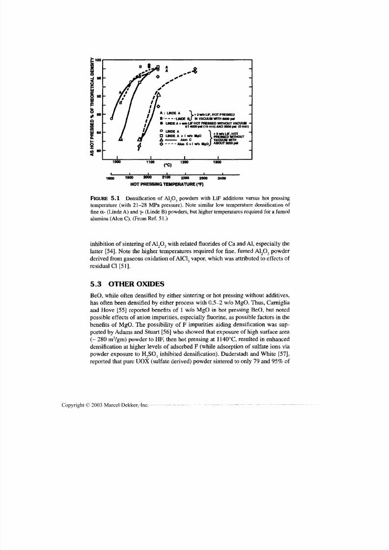
7/29/2019 29540824708539
http://slidepdf.com/reader/full/29540824708539 166/361
Use of Additives to Aid Densification 155
: i oo
O 9211 1
I"O
3UJ 84
80
A : UNDE A \+2w/o UF, HOT PRESSED
B:
LINDE Bj IN VACUUMWITH 5000p4
• LINDEA + W/OUF HOT PRESSED WITHOUT VACUUM •AT 4000pd (10 mln) AND 5000p4 (5mln)
O UNDE A > »_..,,-„„.•
D LINDE A+ I«0MgO IPRESSED WITHOUT
A Aton C f VACUUM WITH
O Aton C + 1 wfe MflOj ABOUTMOOp*
1000 1100 1200 1300
1800 1900 2000 2100 2200 2300
HOT PRESSINGTEMPERATURE (°F)
2400
FIGURE 5.1 Densification of A1 2O3 powders with LiF additions versus hot pressing
temperature (with 21-28 MPa pressure). Note similar low temperature densification of
fine a- (Linde A) and y- (Linde B) powders, but higher temperatures required for a fumed
alumina (Alon C). (From Ref. 51.)
inhibition of sintering of A1 2O3 with related fluorides of Ca and A l, especially the
latter [54]. Note th e higher temperatures required for fine, fumed A12O3 powder
derived from gaseous oxidation of A1C13 vapor, which was attributed to effects of
residual Cl [51].
5.3 OTHER OXIDESBeO, while often densified by either sintering or hot pressing without additives,
has often been densified by either process with 0.5-2 w/o MgO. Thus, Carniglia
and Hove [55] reported benefits of 1 w/o MgO in hot pressing BeO, but noted
possible effects of anion impurities, especially fluorine, as possible factors in the
benefits of MgO. The possibility of F impurities aiding densification was sup-
ported by Adams an d Stuart [56] who showed that exposure of high surface area
(~ 280 m2/gm) powder to HF, then ho t pressing at 1140°C, resulted in enhanced
densification at higher levels of adsorbed F (while adsorption of sulfate ions via
powder exposure to H2SO4 inhibited densification). Duderstadt and White [57],
reported that pure UOX (sulfate derived) powder sintered to only 79 and 95% of
Copyright © 2003 Marcel Dekker, Inc.
7/29/2019 29540824708539
http://slidepdf.com/reader/full/29540824708539 167/361
156 Chapter 5
theoretical density by itself at 1500°C in H2 for respectively 1 and 100 hr, while
addition of 0.5 w/o MgO gave respective values of 93 and 98% (and respective
values for 3 w/o ZrO, addition by themselves via respectively as a sol or as a
powder were 87 and 98% and 81 and 98%). Hill and coworkers [58] also re -
ported enhanced densification of BeO hot pressed with 2 w/o MgO by itself or
with 8 w/o SiC added for grain growth control. Later Greenspan [59] showed
substantial advantage in hot press ing BeO by addition of 3-20 (commonly 7)
w/o A1^O3; for example, near theoretical density with A12O3 at 1350°C versus at
> 1600°C without A1 2O3 addition. Besides nearly full density, use of A1 2O3 gave
fine grain size (1-2 |im) an d higher strengths in hot pressing at ~ 1350°C. MgO
typically gives larger grains, but how much of this is intrinsic, that is, at compa-
rable densities, or due to lower porosity levels is not clear. Simultaneous additionof fine SiC particles and MgO has been successful, as other combinations might
be. Commercially, most sintered BeO is produced from UOX BeO with 0.5%
magnesium trisilicate.
Brown [60] showed that additions of 1-5 m/o SrO inhibited sintering of
CaO, while Petersen and Cutler [61] showed that firing in an atmosphere with
H 2O progressively enhanced the initial rate of densification with increasing H2O
pressure above 0.01 atm. Rice [62] showed that > 99% of theoretical density
(i.e., some degree of transparency) could be achieved by hot pressing CaO with-
out additives at 1200°C, but that addition of 2 w/o LiF or NaF gave similar or
higher density at 1000°C (i.e., 200°C reduction in temperature needed) with LiFadditions judge d to be somewhat superior. Analysis showed substantial residues
from LiF remained at grain boundaries, with Li being more removable than F
with heat treatment (similar tests with NaF were not given) [52]. However, while
heat treatment at higher temperature to remove most or all of the residues of the
additive appeared to give strengths higher than for bodies tested as hot pressed,
grain size increased (e.g., from 10-20 [im to ~ 200 jam) as a result of heat treat-
me nt, giving lower strengths that could be obtained by hot pressing at lower tem-
peratures [63]. Rice [63] reported that liquid-phase densification was probably
occurring, but that densification decreased at and near the melting point of LiF
(870°C). He also noted that th e melting an d wetting of LiF could enhance release
of residual gas species that often l imit important for densification. Later Deruto
and coworkers [64] showed the LiBr-CaCO3 eutectic enhancing decomposition
of th e CaCO 3, supporting this in view of similarities expected between LiF and
LiBr (e.g., as indicate d with MgO den sification below). G upta and coworkers
[65] subsequently reported significantly improved optical transparency of CaO
vacuum ho t pressed with small (e.g., 0.2-0.6 w/o) addition of CaF0.
Baumard and coworkers [66] noted a surprising lack of investigation of ad-
ditives to aid sintering of CeO 2 and investigated effects of oxide additions of
Nb2O 5 orTiO,
on sinte ring in air at1200-1480°C.
They showed that while sinter-ing without additives gave ~ 97% of theoretical density at 1480°C (with ~ 30|0,m
Copyright © 2003 Marcel Dekker, Inc.

7/29/2019 29540824708539
http://slidepdf.com/reader/full/29540824708539 168/361
Use of Additives to Aid Densification 157
grains), higher densities were achieved at 1300-1400°C, with these increasing
with Nb2O 5 addition levels over the range studied (0.1-3 w/o) to 99.5-99.9% of
theoretical density. The same additions of TiO 2 showed similar, but more spec-tacular effects—e.g., 99.4% of theoretical density with 3 w/o addition at only
1200°C (with ~ 1 (urn grains)—with sub stantial increase in densification occur-
ring before formation of either CeTi2O6 or a liquid phase. In a subsequent
broader study of CeO 2 Chen and Chen [67] investigated a series of oxide addi-
tions at 0.1 or 1% levels in order of increasing charge/size of Mg2+
, Ca2+
, Sr2+
,
Sc3+
, Yb3+
, Y3+
, Gd3+
, La3+
, Ti4+
, Zr4*, and Nb
5+in sintering at 1270 or 1420°C.
They concluded the higher addition level suppressed grain growth via solute
drag, otherwise severely undersized dopants (Mg, Sc, Ti, and Nb) enhanced
grain growth, but was also charge dependent. Overall 0.1% Mg and 1.0% Sc in-
creased grain growth the most while 1.0% Y decreased it the most. Yoshida an d
coworkers [68] recently reported that samaria-doped ceria, of interest as a solid
electrolyte fo r solid-oxide fuel cells, requires sintering at >1600°C, but that 1%
addition of gallia allowed comparable microstructures and properties could be
obtained at ~ 150°C lower temperatures. Commercially, CeO 2 is sintered with
CaO addition, bu t selection and effects of additives are often compromised by
the presence of sodium picked up in the commercial production of CeO 2 powder
by carbonate precipitation.
Cr2O 3, which is limited in its sinterabiliy due to volatization (probably as
CrO 3) at higher temperatures, was shown by Ownby an d Jungquist [69] to besinterable to essentially theoretical density with 0.1 w/o MgO at 1600°C with 2 x
1012
atmosphere O 2 pressure, and reduced grain sizes from those in pure Cr2O 3
alone (attributed to formation of Mg-Cr spinel grain boundary particles). Use of
1% MgO resulted in densities betwee n those with 0.1% MgO and none. Roy and
coworkers [70] reviewed some data on sintering aids for Cr2O 3 an d corroborated
and extended the above results; fo r example, besides the similarity of benefits of
MgO in both A12O3 and Cr2O 3, there is also a similar benefit to use of TiO2 addi-
tions (and also marked effects on electrical properties), but with greater benefits
in Cr2O 3 as shown by Callister and coworkers [71] and Nagal and Ohbayashi
[72] (e.g., -92% dense with 1 w/o TiO 2 at 1200-1300°C with proper control ofthe O 2 partial pressure ). Com mercially, large quantities of Cr2O 3 blocks are pro-
duced by sintering w ith TiO2 additions for use as liners in tanks fo r commercial
melting of corrosive lead- an d boron-containing glasses.
Eu2O 3, of interest for a fast neutron absorber in reactors, presents serious
processing challenges due to its propensity to spontaneously microcrack as a re-
sult of its substantial thermal ex pansion anisotropy due to its noncubic (mono-
clinic) structure. At grain sizes > 12 Jim from sintering temperatures of
1800-1900°C microcracking occured [73]. Malarkey and Hunter [73] showed
that while lower levels of Ta2O5 addition resulted in a maximum in grain size of
38-55 \im at 1.0 a/o Ta, increasing addition over the range of 0.2-0.6 a/o Ta re-
Copyright © 2003 Marcel Dekker, Inc.

7/29/2019 29540824708539
http://slidepdf.com/reader/full/29540824708539 169/361
158 Chapter 5
suited in progressively finer grain size, e.g., of 6-10 [im at 0.6 a/o Ta, and thus
no microcracks.
Fe2O3 was reported by Wright [74] to show enhanced sintering with 0.5 to
2% additions of CaO (as CaCO 3), wit h acceleration of sintering on forming a liq-
uid phase. Fe2O 3 an d Fe3O4 are more sensitive to effects of atmosphere on sinter-
ing than many binary oxides, from some lower temperature study by Hayes [75]
and effects on grain size of dense sintered Fe3O4 by Yan [76]. Chlorine in the fir-
ing atmosphere can enhance grain growth [77].
Consider next densification of MgO with oxide additives, which has re-
ceived attention in part due to its important use for refractories, as has A12O3.
Ryshkewitch [18] cites FeO as one of the most effective and commonly used
mineralizers for MgO (e.g., giving 90-92% dense MgO at 1500°C), but varia-
tions can occur due to stoichiometry changes w ith variations of the firing atmos-
phere. Kriek an d coworkers [78] studied effects of CaO, Fe 2O 3, TiO 2, A12O3, an d
SiO 2 (mos tly 1-10% additions in firing dead-bu rned MgO betwe en 1250 and
1400°C. CaO was the least beneficial (actually inh ibiting sinte ring) and TiO2 th e
best, but with an optimum concentration of 1-2% or more, and the optimum
level tending to decrease as the tem perature increased. Similar trends for an opti-
mum additive level were also found for A12O3 an d SiO 0. Brown [79] reported
that 0.01% van adiu m oxide (from ammonium vanadate) aided densification on
sintering in the 1200-1450°C range, but with benefits apparently diminishing
above 1250°C whe re there was a liquid phase. Bud nikov and coworkers [80] re-ported that addition of 0-0.3 m/o HfO 0 to fine active MgO powder significantly
enhanced de nsificat ion, gene rally with modest increases in grain growth . Densi-
fication increased as the level of addition increased until 99-100% density was
achieved at 0.1% addition an d 1400°C firing, and thus no further benefit with
greater addition. These results were extended and compared with effects of
0.1-0.5 a/o additions of Fe3+ , Zr*+, Sc
3+, or Ni
2+ (whose radii are similar to that of
Mg2+
as well as Hf4+
), show ing that Hf addition was superior. Among th e latter
four, Zr and Sc were m uch less effective at lower levels of addition, but were su -
perior at higher levels [81]. The utility of TiO 2 additions (e.g., 0.2w/o) was cor-
roborated in more recent studies of sintering magnesite for refractories at1600°C by Chaudhuri an d coworkers [82], with its enhanced sintering being at -
tributed to a combination of enhanced diffusion and liquid-phase sintering (from
l iquids formed with impurities and TiO 2). Finally, note that phosphate bonding
of MgO is of interest, but the use of H3PO 4, as with some other refractories, re -
sults in too vigorous a reaction; use of Mg(H2PO 4)2»2H^O can give substantial
densification as shown by Itatani and coworkers [83]. They showed that while <
0.5 m/o addition retarded sintering, it was promoted by >1 m/o addition, espe-
cially as sintering temperatures increased—3 m/o addition showed porosity ~
2% lower than the 35% without addition at 1200°C, but a greater than threefold
porosity redu ction (from 22 to 5%) at 1400°C.
Copyright © 2003 Marcel Dekker, Inc.

7/29/2019 29540824708539
http://slidepdf.com/reader/full/29540824708539 170/361
Use of Additives to Aid Densification 159
Hamano and coworkers [84-87] conducted a series of investigations of ef-
fects of additives on MgO sintering. In earlier work, they showed that an opti-
mum level of addition of B2O 3 was 0.2 m/o at lower tem peratures and 0.5 m/o at1500°C, but was complicated by formation of 3MgO»B2O 3, which first in-
creased, then decreased, as temperature increased [84]. They later showed that
2m/o of Sm2O 3, ZnO, or NiO aided densification at 1400°C, with Sm 2O3 and
ZnO being particularly effective in earlier stage sintering, and all, especially
Sm 2O 3, limiting grain growth [85]. Subsequently, they showed that ZrO 2 was
also beneficial over the 1000-1500°C sintering range investigated, with addition
via an oxychloride [86] precursor giving somewhat higher densities than via a
sulfate precursor [87] added to Mg(OH)2 before calcining. Sintered densities
passed through modest maxima (mainly for the oxychloride precursor at inter-
med iate sintering temp eratures) or essentially plateaued at 1.5 and 1.5-3 w/o, re -
spectively. Note some of the benefits of the ZrO 2 additions were from benefits on
green density, an d hence via powder effects, with more powder effects also
shown in earlier work [88].
Turning to nonoxide additions to densify MgO, LiF has received exten-
sive attention and use, following apparently independent discovery by Rice
([89-92], with initial aid of V. Edlin) and b y C arnall and cowo rkers [93], w ith
most attention to its benefits in hot pressing, resulting in moderate to high
transparency. This discovery w as in part based on the w ork of Atlas [94] show-
ing that small (e.g., 0.5%) additions of LiF, LiCl, LiBr, or Lil, gave 3-10%porosity on sintering at 1400°C (and 13 and 18% porosity fo r Li2SO 4 and
Li2C O 3 additions, respectively) versus 38% porosity without additives. How-
ever, Atlas's results we re for sintering and LiF was only the third best (i.e., th e
next to the worst) of the four halide salts (leaving ~ 9% porosity), while hot
pressing yields transparency over a range (e.g., 0.5-2 w/o ) add ition of LiF
(which avoids deliquescence of the other Li salts) at lower temperatures
[90,92]. (Atlas also found addition of NaF had no benefi t or slightly retarded,
sintering contrary to results below, which also show other effects of process-
ing.) Thus, Rice [90,92] showed that subm icron MgO powder without LiF cold
pressed at 20-200 MPa to, respectively, 30-50% density sintered to, respec-tively, 60-90% of theoretical density, while powde rs w ith 2 w/o LiF sintered to
94-97% density at 1200°C and hot pressing with 0.5-2 w/o LiF at ~ 1000°C
yields transparent bodies. The very rapid densification in the vicinity of melt-
ing of LiF (Fig. 5.2) is vividly show n in operating a manu al hydrau lic pum p to
maintain hot pressing pressure. During the nearly vertical trend of ram travel
versus temperature, one cannot pump fast eno ugh to maintain the initial press-
ing pressure until most of the densification has occurred, that is, until final den-
sification. Rice also showed that heat treatment with very slow heating rates
can remove most or all of the residue from the LiF addition with limited or no
reduction in transparency [91, 92].
Copyright © 2003 Marcel Dekker, Inc.

7/29/2019 29540824708539
http://slidepdf.com/reader/full/29540824708539 171/361
160 Chapter 5
0.5
LU
O 0.4
LU
3CC
gi-o
oO
0.3
0.2
0.1
TEMPERATURE, °F
1000 1500 2000
200 600 80000 600 800 1000 1200
DIE TEMPERATURES, °C
FIGURE 5.2 Plot of ram travel (hence densification) versus die temperature in hot
pressing MgO+ 2 w/o LiF in graphite dies. While th e exact relation betwee n die and hot-
pressed body temperature is uncertain, it is clear that rapid densification occurs near, but
probably somewhat below, th e me lt ing point of LiF, then ceases fairly abruptly (arrow)
where final den sification begins. (Rapid d ensification somewhat below the me lting pont
of LiF may reflect it s interaction with surface hydroxide an d carbonate species.) (From
Ref. 92.)
Miles an d coworkers [95] fur ther developed th e process, showing that im -
proved m ixing and use of vacuu m hot pressing improved MgO transparency, i ts
homogeneity, or both, wi th vacuum being more important as size increases.
Smethurst an d Budworth [96] also used LiF additions, noting th e value of fine
particle size—below ~ 0.5 (im—and many others have used or studied the
process ([97-101]; for example, corroborating that densification is accelerating
well below the me lting point of LiF [97,100].
Razinger an d Fryer [102] inve stigated me chanisms of densificaion of MgO
by hot pressing MgO with LiF, Li9O, or MgF 0 additives, concluding that an im-
Copyright © 2003 Marcel Dekker, Inc.
7/29/2019 29540824708539
http://slidepdf.com/reader/full/29540824708539 172/361
Use of Additives to Aid Densification 161
portant aspect of the effect of LiF on densification was via control of the mi-
crostructure. Shimbo and coworkers [103] later reported that grain growth of
MgO treated with either A1F3 or especially MgF2 was either decreased or in-creased depending on concentration of the additive and the temperature.
The process has been extended to other sources of fluorine or of other re-
lated constituents. Thus, Rice [104] showed that other than requiring about
100°C higher temp erature, 2 w/o NaF w orked n early as well as LiF in hot press-
ing an d tends to give somewhat finer grain sizes, though often with some larger
grains—that is, a bimodal distribution. Banerjee and Budworth [105] showed
that incomplete sintering trials w ith 0.25 w/o NaF grain boundaries did not sepa-
rate from th e intergranular pores due to less grain growth than with LiF, an d thus
bodies could be sintered to transparency by first presintering in pure O 2 at 600°C
(i.e., below the liquefying temperature), then long sintering at 1600°C. Use ofvacuum and presintering at 1000°C (above the liquefying temperature) resulted
in only 97% density.
Watanabe and coworkers [88] showed that additions of 1, 4, 5, or 8 w/o
MgF2,4 w/o gave th e best results an d that while use of fine particles (< 2 ^im) ac -
celerated sintering (for 1 hr) above 1000°C to the limits of testing, 1400°C,
coarser particles (10-20 |im), though making some reduction in green density,
accelerated sintering more above ~ 1050°C. The greater benefit of larger MgF2
particles w as attributed to their slower decompo sition. They also sho wed that fir-
ing MgO compacts without particulate additions of MgF 2, but in a closed plat-
inum crucible with MgF 2 powder not in contact with the MgO resulted in
accelerated sintering nearly as high as that with the coarser MgF2 particle addi-
tion, from 1000-1300°C (the latter temperature being w here the decomposition
of MgF 2 was believed to be complete). However, benefits of MgF 2 additions
were found to occur fo r only short firing times (< 1 hr); higher densities were ob-
tained without MgF2 additions with longer sintering at 1400°C. Ikegami and
coworkers [106] showed that as little as 0.02 w/o P introduced via MgF 2 or HF
addition to M gO (with particle sizes < 0.15 (im) then calcined, at 900°C, notice-
ably increased densification so transparent MgO could be obtained by vacuum
sintering at 1600°C, with most densification complete by ~ 1250°C where mostoutgassing was completed. Similar additions of Cl~ were also beneficial, but
much less so than F~ additions, though combined F~ and Cl~additions we re quite
effective. Ikegami and coworkers [107] later extended these results showing that
Mg(OH)2 treated with HF solution, then calcined at 900°C showed accelerated
shrinkage from ~ 800 to 1200°C, with grain growth increasing at ~1100°C, then
accelerating significantly between 1200 and 1250°C, while F loss begin rapidly
at ~ 1200 and was nearly complete by ~ 1600°C. This is generally consistent
with more extensive studies of removal of additive residues by Johnson and
coworkers [52], who also showed that more F than Li or Na rem ained after hot
pressing. Leipold and Kapadia [108] showed that addition of S2
, Cl, F, or OH
Copyright © 2003 Marcel Dekker, Inc.
7/29/2019 29540824708539
http://slidepdf.com/reader/full/29540824708539 173/361
162 Chapter 5
generally at levels of 0.2-0.9 a/o, except 1.8-2.2 a/o OH, (added, respectively, as
elemental sulfur, MgCl0, MgF 2, and Mg(OH)9) all inhibited densification of
MgO , w ith the ex tent of inhib ition increasing in the order listed, in hot pressingat 850-1200°C. Hana [109] reported that treatments of MgO powder to add ~
0.15 w/o NH 4F gave translucency on hot pressing at >1500°C an d that HF treat-
me nt of the MgO powder had similar effects.
The above studies of MgO with LiF or other related additives show that
vaporization aids distribution of the additive (as well as its loss) and that, while
there m ay be som e activate d sinte ring befo re a liqu id form s, the latter is a critical
step; for example, it allows relative particle motion for consolidation in hot
pressing and liquid-phase sintering (possibly pressure enhanced in hot pressing).
LiF and NaF have been shown to be good lubricants for MgO, with LiF best at ~
900-1100°C and NaF at 1300—1500°C [145], consistent with LiF giving more
densification at lower tem peratures and NaF probably being better at higher tem-
peratures. Vacuum atmosphere can be beneficial or necessary, especially for
larger bodies, and may aid removal of additive residues, but may also be detri-
men tal , possibly due to premature removal of additive species. Liquid-phase for-
mation may be extended by interaction with impu rities and use of pressure, e.g.,
in hot pressing, as we ll as reduced by oxidation or compound formation. Though
often neglected, an d generally secondary, other factors besides th e amount of ad-
ditive are important, such as the distribution of the additive phase, and its parti-
cle size, and tha t of the MgO,which reflect not only starting parameters, but alsochanges in various stages of the process—for exam ple, on green density. Again,
direct characterization shows residual fluorine from fluoride additions in as-hot
pressed MgO [52].
One study shows CoO additions to NiO aid its sintering [110]. Varela an d
coworkers [111] showed that 2 m/o CuO addition aided sintering of SnO 9, which
is typically limited by serious vaporization. Dry air was better than dry argon
since the latter inhibited densification due to reduction of CuO and vaporization
of SnO 2 over th e 900-1250°C range investigated. Drozd, Degtyareva, an d
coworkers [112,113] also reported benefits of CuO in sintering Sn O 2 at 1550°C
as well as of V 2O 5, Bi2O 3, CoO, MnO,, ZnO, or Sb2Or Commercially Sn O 2 issintered with ZnO additions, for example, for large electrodes for electrical melt-
ing of glasses.
ThO 2, being the most refractory oxide, is clearly a candidate for using sin-
tering aids. CaO is an additive commonly used for its sintering, as noted by
Ryshkewitch [18] an d indirectly by Singer an d Singer [14] in noting use of CaF 2,
CaBr2, or CaCl2 (as well as SrF ?, N H 4I, V 9O 5,SnO,, Bi0O 3, or ZrO 2). Curtis and
Johnson [114] were an early user of CaO (or CaF2) additions, investigating
0.5-3% additions and show ing that 0.5-1% additions to powd er w ith particles <
1 }0,m gave 97% dense ThO 0 at 1800°C. Later Jorgensen and Schmidt [115]
showed that 2 m/o addition was o ptim um for sinte ring to theoretical de nsity (i.e. ,
Copyright © 2003 Marcel Dekker, Inc.

7/29/2019 29540824708539
http://slidepdf.com/reader/full/29540824708539 174/361
Use of Additives to Aid Densification 163
transparency) by the second phase inhibiting grain growth (giving grain sizes of
5-10 (am). Stuart and coworkers [116] reported that adsorbed F on ThO 2 in-
creased the rate of densification by hot pressing at tempe ratures as low as 700°C,
but that adsorption of SiO 2 with or without F inhibited densification. Halbfinger
and Kolodney [117] showed that sintering in air at 1370°C with 2 w/o NiO,
Co2O 3, ZnO, or Cu2O all gave < 6% porosity, while additions of Cr2O 3, SiO 2,
TiO 2, MgO, Ta2O 5, ZrO 2, A1 2O3, CdO, BaO, and SrO all gave > 20% porosity.
NiO was particularly effective—its effects plateaued above ~ 0.3 w/o—and pro-
duced even greater benefits when combined with limited amounts of Y2O 3,
which by itself gave limited increase of sintering. This is in contrast to results of
Greskovitch an d coworkers [118], who achieved transparency with 5-15 m/o
Y 2O 3 by sintering at 2380°C in H2, with 5 m/o being preferred since it gave th e
smallest grain size (~ 100 (im). The differences between this and the work of
Halbfinger and Kolodney reflect changes due to differing amounts of additive,
and especially atmosphere and temperature, though temperatures as low as
1850°C were used [119]. (Note that yttria-doped thoria was commercially pro-
duced for a while, and that there we re reports that ZrO2 additions could also give
transparent ThO 2.)
Chen and Wu [120] reviewed some effects of additives on sintering of
TiO 2, and also experimentally examined effects of Nb2O 5 and CaO, since such
additives are of interest fo r some electrical applications where differences in
conduction between the grain boundary region and the grain interior are critical,that is, grain boundary concentration is important. They showed that addition of
0.25 m/o Nb2O 5 alone to rutile powder modestly inhibited sintering over the tem-
perature range investigated (1100-1350°C), while additions of 0.1 or 1 m/o CaO
with the Nb2O 5 gave higher densities at 1150 and 1250°C, the latter giving the
maximum density of ~ 4 gm/cc for all rutile-based bodies studied. In contrast,
anatase powder gave densities increasing from ~ 4.15 to 4.2 gm/cc as sintering
temperatures increased from 1100 to 1350°C. All additions fell somew hat below
this trend at 1050°C, and the 0.25 m/o Nb2O 5 + 0.1 1 m/o C aO com bination gave
somewhat lower density at 1350°C, with all additions giving comparable fired
den sities as TiO 2 alone at 1150 and 1250°C. Higher de nsities (~ 98% of the oreti-cal) were reached using anatase powder, despite its giving 5-10% lower green
densities, versus use of denser rutile pow der giving densities of only ~ 90% of
theoretical. This was attributed to the onset of abnormal grain growth commenc-
ing in rutile-derived bodies before densification was completed, while in
anatase-derived bodies such growth did not commence until densification was
complete, despite their conversion to the rutile structure during sintering. Work
at Bell Labs showed that very small amounts of Cr2O3 added to TiO 2 allowed it
to be hot pressed to theoretical den sity, thou gh reduced some, i.e., being black in
color. However, full oxygen stoichiometry could be achieved throughout th e
body by subsequently annealing in an oxidizing atmosphere, while bodies hot
Copyright © 2003 Marcel Dekker, Inc.
7/29/2019 29540824708539
http://slidepdf.com/reader/full/29540824708539 175/361
164 Chapter 5
pressed without the small Cr2O 3 addition could not be returned to full oxygen
stoichiometry over m uch of the interior, which thus remained black.
The one stud y kno wn for UO 9 is that of Radfo rd and Pope [121] showingthat sintering in NH 3 (versus the normally used wet H 2) or treatment of pow-
ders with various ammonia salts increased sintered densities modestly, but
consistent ly—e.g. , from 97 to 98% of theoretical density, along with increased
grain size.
The first pressureles sintering of Y 2O 3 to full density was with the use of
10 m/o ThO2, reve rsing the roles of matrix and additive for den sifying ThO2. Jor-
gensen an d Anderson [122] reported this an d that ThO, both enhanced diffusion
and retarded grain growth due to segregation at grain boundaries. Greskovich
and Woods [123] reported further observations and process development with
ThO 2 additions. Co mm ercialization of this material was apparently pursued un-
successfully, poss ibly due to the minor radioactivity of ThO 2, which today would
be a larger imped iment. Rhodes [124,125] later reviewed sintering Y 2O 3 to full
density, including use of A19O3 or MgO, an d also demonstrated a nove l process
via addition of 8.1-12.1 m/o La2O 3 to be feasible because of a two- rather than a
single-phase field e xist ing at higher temp eratures. Thus, by sintering at 2170°C
where a second phase exists, full density could be achieved, but then obtain com-
plete solid solution (to remove the second phase and thus give good optical
transmission) by annealing at 1920-2020°C. While such phase relations are not
typical, this may provide a model for some other bodies. Subsequently,Katayama an d coworkers [126] reported that additions of 1-10 m/o CaO to Y 2O 3
gave increased densification on sintering at 1500-1700°C, with optimum results
at 1600°C with 1 m/o CaO. Lefever an d Matsko [127] reported that addition of
LiF to fine Y,O3 yielded transparen t bodies by press forging at 950°C with pres-
sures of 70-94 MPa for two days.
Volatization of ZnO makes it a good candidate for use of sintering aids,
and some have been demonstrated. Moriyoshi and coworkers [128] reported that
addition of ~ 1 a/o phosphate via t rea tment of ZnO powder in H3PO 4 yielded
quite translucent bodies on sintering at 1200°C, which may have involved some
liquid phase, and was accompanied by considerable grain growth. Of four addi-tions to ZnO, 0.5 w/o Sb^O 3 retarded densification substantially on sintering at
1180°C for 2 hr, while Li2O accelerated densification on heating to 1180°C but
gave slightly lower density after holding there 2 hr than pure ZnO [129]. On the
other hand, K 2O addition inhibited sintering on heating some, but gave slightly
higher final density than pure ZnO, an d TiO 2 addition inhibited densification on
heating somewhat less, while giving the highest density achieved after sintering
2 hr at 1180°C. Recently Luo [130] reported substantial sintering of ZnO with
Bi2O 3 additions of > 0.23 m/o, with ~ 0.58 m/o apparently being optimum . In-
creased densification occurred with increasing temperature be ginning at > 600°C
an d accelerating at ~ 700°C to the eutectic temperature (740°C), w ith th e shrink-
Copyright © 2003 Marcel Dekker, Inc.
7/29/2019 29540824708539
http://slidepdf.com/reader/full/29540824708539 176/361
Use of Additives to Aid Certification 165
age increasing inversely with heating rate; that is, much greater at 4°C/hr versus
0.5°C/min. This occurrence of sintering before a liquid forms and enhancement
with lower heating rates indicates a solid-state transport mechanism.An important application of ZnO is for varistors, which are highly nonlin-
ear resistors that have very high resistance at normal voltages, but low resistance
at excessive voltages. This highly nonlinear resistive behavior has important ap-
plications, especially for shunting voltage surges; fo r example, from lightening
strikes, to protect electronic and electrical systems from such surges. The devel-
opme nt o f ZnO varistors is a good example of both the mu ltiple and critical roles
that additives often play, as well as the frequent and important role of that
serendipity often plays in such developments. Such varistors (as well as appar-
ently some other oxide varistor materials) depend on the amount and nature of
grain boundary phase that results from the use of oxide additives used [130].
Such varistors com monly contain several additives, e.g., 97m/o ZnO with Sb 2O 3,
Bi2O 3, CoO, MnO , and Cr2O 3, to tailor properties. Originally, ZnO w as man ufac-
tured as a linear re sistor using an electrode metallization that had Bi2O 3 and other
glass-forming constituents that allowed low-temperature firing at several hun-
dred degrees centigrade. However, a firing accident at Matsushita resulting in
gross overfiring of the electrode material was found to have produced substantial
nonlinear resistance b ehavior. This behavior was found to be du e m ainly to inter-
diffusion of BL,O3 from the electrode composition into the ZnO forming a grain
boundary phase laterfound
to be the basis of the resistance nonlinearity. Notethat the Bi2O 3 dopant also plays an important role in the densification (as noted
above) as well as the electrical behavior. (Note that in contrast to the role of
grain boundary p hases ZnO [and probably other oxide] varistors has no bearing
on the other important commercial varistor material, namely SiC, where the re-
sistivity nonlinearity results directly from the contacts between the SiC parti-
cles—that is, resistive nonlinearity occurs in a bed of loose, contacting SiC
particles. The use of the glassy bond phase of SiC varistors is to provide physical
integrity of the varistor and consistency of the SiC-SiC particle contacts and
their freedom from moisture an d other possible contaminants.)
Shakelford and coworkers [131] showed that addition of SiO2 to (or the pres-ence of SiO 2 as an impurity in) ZrO 2 with CaO stabilizer enhanced sintering shrink-
age as the SiO 2 content increased steadily over the range studied from 0 to 2 w/o,
except for a more rapid increase at ~ 1% addition. Net densities approximately
plateaued from 1-2% addition due to green density decreases as SiO2 addition in-
creased and were highest fo r powder naturally containing ~ 1 w/o SiO 2. Benefits
were greatest for partial (3.5 w/o CaO) than full (> 5 w/o CaO) ZrO 2), and were
similar for MgO stabilization. Wu and Yu [132] noted earlier literature showing
benefits of small additions such as of A12O3, Bi2O 3, Fe2O3, SiO 2, or TiO 2, and inves-
tigated the addition of A12O3 or SiO 2 to ZrO 2-MgO. Mu and coworkers [11] have
shown a definite maximum of densification rate of ZrO2 with CaO stabilization at
Copyright © 2003 Marcel Dekker, Inc.

7/29/2019 29540824708539
http://slidepdf.com/reader/full/29540824708539 177/361
166 Chapter 5
12 m/o CaO. Chiou and coworkers [133] reported optimum densification of ZrO 2+
15 m/o CaO with tailored silica-based glasses as 1350°C. Lu and Bow [134] re-
ported that ZrO 2+ 3 m/o Y2O 3 with additions of up to 1 m/o MgO enhanced sinter-ing at 1350°C due to reaction of the MgO with CaO and SiO 2 impurities, bu t also
were accompanied by grain and local-phase changes; for example, bimodal grain
sizes. Also n ote that Scott and Reed [135] reported that residual Cl in oxychloride
derived ZrO 2+ Y0O 3 powders inhibited initial and intermediate stages of sintering
and sinterability was increased by laundering the powders to remove residual Cl
and by deagglomeration. An e xample of com mercial practice is the fairly recent an-
nounceme nt of sintering ZrO 2 with 3 m/o Y 2O 3 and 0.25 w/o A12O3 to produce ultra-
fine-grain fiber-optic ferrules that do not have problems on exposure to water.
5.4 M IXED OXIDES
While mixtures of oxides such as in the stabilization of ZrO 2 discussed above
could come under this heading, the focus is primarily on ternary compounds
formed by reaction between two binary-oxide compounds, e.g., MgO and A1 2O3
to form MgAl2O 4. While such mixed-oxide compo unds offer more opportunities
to enhance densification by varying stoichiometry than binary oxides, additives
are frequently used in addition to or instead of such compositional variations.
This section provides a fairly extensive summary of additive densification of im-
portant members of ternary oxide families of aluminates and silicates (structuralmaterials), and ferrites, niobates, and titanates (magnetic and electronic materi-
als), which are treated in the order listed.
5.4.1 Aluminates
Consider first magnesium aluminate, i.e., magnesia alumina spinel, MgAl2O 4,
which is of interest for both structural and especially IR window applications.
One of the earlier successes in obtaining translucen t to transparent MgAL,O4 was
work of Rhodes and coworkers [136]; they used various, mostly fine MgAl^O 4
powders or mixtures of MgO and A12OV Dense bodies were obtained by hotpressing without additives at 1300-1400°C with 70-100 MPa pressure with or
without vacuum, or by press forging at 1650-1850°C with 35 MPa pressure, but
the most transparent bodies were made by press forging with 0.8% SiO 2+ 2%
Li2O (at 1750°C and giving grain sizes of- 60 |im).
Rhodes an d coworkers also reported high densities obtained with 1 % LiF
additions ho t pressed at 1200-1300°C, which had finer grains (~ 0.2 \ J i r n ) and
lower room temperature strengths than bodies of similar grain size made without
additives, but higher strengths than bodies with large grains. After this, McDo-
nough an d Rice [137], as well as investigators at Coors [138,139], also obtained
substantial densification with LiF additions, with the latter group focusing on
Copyright © 2003 Marcel Dekker, Inc.

7/29/2019 29540824708539
http://slidepdf.com/reader/full/29540824708539 178/361
Use of Additives to Aid Densification 167
higher temperature densifications for high transparency with larger grains (and
some reduction in mechanical properties due to this and residual bou ndary phase
from the additive). Lange and Clarke [140] showed the presence of a grainbou ndary film in commercial spinel densified with LiF and interpreted the nature
of this film and its bound ary coverage to ind icate a solidified melt.
De With and coworkers [141,142] reported vacuum sintering translucent
Y3A15O 12 at 1700-1800°C with small additions of MgO or SiO 2 (respectively, ~
500 and 2000 ppm ), giving grain sizes of ~ 3 and -10 [im, respectively.
Though effects on densification were not reported, Hashiba and coworkers
[143,144] reported effects of various fluorides on enhancing formation of
ZnAl2O 4 from ZnO and A1 2O3 (and cite similar inv estigation of MgAl2O 4 forma-
tion. LiF was found most effective for forming ZnAl2O 4.
5.4.2 Silicates
Turning to silicates, consider mullite (3Al2O 3»2SiO 2), which is often difficult to
sinter unless much of the densification is achieved be fore e xtensive mullite for-
mation or unless quite fine mullite particles are used, so densification aids have
been sought. Besides adjusting the stoichiometry, some use of oxide additives
has been investigated. Thus, Baudin and Moya [145] reported that addition of
TiO 2 below the solubility limit (~ 2.9 0 0.2 w/o at 1600°C) significantly aided
sintering, while additions above the so lubility limit forme d Al2TiO 5 and inhibited
sintering. While Mitamura and coworkers [146] investigated additions of Y 2O 3,
Er2O 3, Sm 2O 3, La2O 3, and CeO 2, noting benefits of 0.5 w/o Y 2O 3 or CeO2, Mori
and coworkers [147] reported benefits of Y 2O 3 additions, as did Hwang and Fang
[148,149]. Hwang and Fang showed benefits of higher levels of Y 2O 3 additions
(2-10 w/o) and evidence for a liquid phase. Prereacted fine mu llite powde r has
apparently been ho t pressed to full density using A1F3 addition.
Modest additions of some oxides have been reported to aid sintering of zir-
con, ZrSiO4, typically in the 1450-1550°C. Thus, Hayashi and coworkers [150]
reported that TiO 2 additions resulted in formation of ZrTiO 4 on firing in O 2, in-
creased early stage densification on firing in H2, and dense bodies on sintering in
N2 (with some reduction of the TiO2). Later De A ndres and cow orkers [151] re -
ported achieving > 98% den sity with TiO2 additions, attributed to formation of a
liquid phase. Kim [152] reported increased sintering with addition of MgO,
MgO + CaO, or A1 2O3 + CaO, which apparently reacted with SiO 2 from zircon
dissociation, which did not occur with pure zircon.
5.4.3 Fcrritcs
Consider nex t magnetic materials, starting with hard ferrites. Arendt [153] inves-
tigated use of several liquid-phase sintering aids fo r BaFe 12 O ]9 an d SrFe12O 19, re -
porting that several additives in the systems M-A-S and M-A-B-S, where M=
Copyright © 2003 Marcel Dekker, Inc.

7/29/2019 29540824708539
http://slidepdf.com/reader/full/29540824708539 179/361
168 Chapter 5
Pb, Ba, or Sr oxides (with the Ba or Sr choice corresponding to the Ba or Sr fer-
rite being sintered), and A=A12O3, S= SiO 2, and B= B2O 3, were effective for den-
sification and magnetic properties—the latter especially for sintering at <
1200°C where grain growth was limited. Lucchini et al [154] showed that low-
melting silicate glasses (glazes) were effective for sintering dense hexaferrite
bodies at 1150°C (e.g., 150-200°C lower than without additions) with limited
grain growth. Fang an d coworkers [155] subsequently reported that small addi-
tions (0.3 w /o) SiO^ in sintering barium ferrite eff ective ly inhibited grain growth,
even within the solubility range of SiO0 in the ferrite. Beseniar and coworkers
[156] reported that additions of ZrO 0 can enhance sintering of Sr ferrites via a
liquid phase an d give optimum m echanical an d magne tic properties at ~ 0.3 w/o.
Turning to soft ferrites, an earlier investigation of a Li ferrite showed thatincreased addition of NiO resulted in limited decreases in density for firing at
1150°C in O 0 (and with packing powder) from 99% dense at zero addition to
98% dense at 20 m/o NiO and discontinuous grain growth [157]. Additions of
NiFe2O 4 decreased density a bit more, but suppressed discontinuous grain
growth. Both additives had mixed, but often different, effects on properties. Pe-
shev and Pecheva [158] reported that modest additions of Bi^O 3 yielded high
density Li ferrites wit h good properties at 900-1000°C due to l iquid-phase form-
ing. Kim and Im [159] reported that additions of Nb 2O 5 or V2Og to a lithium fer-
rite su bstan tially enhanced densification, especially w ith V 2O 5, attributed to both
additives increasing O diffusion an d decreased Li loss an d possible formation ofa liquid phase with V,O 5. More recently, Rezlescu an d Rezlescu [160] investi-
gated effects of CaO, NaA Sb 2O, and ZrO, additions (0.3 w /o) to a Li ferrite al l
resulted in enhanced sintering over undoped bodies, especially on firing at
>1050°C and achieving > 97% density at 1140°C, 98% with CaO with additives
versus 94% without additives. All additives limited grain growth and had vary-
ing effects on properties.
Bando an d coworkers [161] reported that simultaneo us additions of up to a
few m/o of CaO and SiO, to a Mn-Zn ferrite resulted in increasing discontinuo us
grain growth as the addition increased over th e 1100-1300°C temperature range
studied, and was associated with liquid-phase sintering. Later, however, Toole-naar [162], while showing exaggerated grain growth with SiO 2 additions,
claimed it was due to grain boundary chemistry effects, not due to liquid-phase
formation. Jain and coworkers [163] showed that addition of 0.5 w/o of MoO 3 to
a Mn-Zn ferrite aided den sification, giving ~ 94% of theoretical density at
1065°C with controlled grain growth (and the removal of the MoO 3 due to
volatilization). More recently, Drofenik [164] showed that sintering of a Mn-Zn
ferrite with Bi^O 3 additions at ~ 1350°C, while slightly increasing de nsity from
0.02 to 0.2 w/o, first decreasing density slightly to 1 w/o, an d more seriously at
higher levels, had more complex effects on grain growth and magnetic perme-
ability. Thus, at low ad ditive levels (~ 0.03 w/o) a high permeab ility and n ormal
Copyright © 2003 Marcel Dekker, Inc.

7/29/2019 29540824708539
http://slidepdf.com/reader/full/29540824708539 180/361
Use of Additives to Aid Densification 169
grain structure were obtained, while higher additive levels (> 0.05 w/o) gave
good permeability with anomalous grain growth. Higher additions (> 0.08w/o)
again gave a homogen eous microstructure along w ith intragranular porosity an dlower perme ability. They noted that addition of the Bi2O 3 increased FeO concen-
tration at grain boundaries and decreased that of Ca and Si.
Based on reports of improved performance of Co-Ni, Zn-ferrite cores with
BaO additions, Drofenik and coworkers [165] showe d that small additions (< 0.5
w/o) limited grain growth due to forming a Ba-Co hexaferrite layer on the grain
boundaries. Mahloojchi and Sale [166] showed that additions of CuO to MgO-
based soft ferrite improved sintering.
5.4.4 Electrical CeramicsTurning to electrical and electronic ceramics, Shimada and coworkers [167] re-
ported that sintering of LiNbO 3 was significantly accelerated by modest addi-
tions of C dO (e.g., 3 w/o). This was attributed to both a large increase in oxygen
diffusion as well as a reaction at 850-900°C, with the resulting second phase ap-
parently hindering ex aggerated grain grow th that occurs at 1050-1100°C in pure
LiNbO 3. Ye and coworkers [168] reported that ~ 5 w/o addition of LiF+ MgF 2 al-
lowed densification of L iTaO 3 to -97% of theoretical den sity on sintering in air
at 900°C, especially in using prereacted LiTaO3 rather than simultaneous reac-
tion and sintering. The resultant bodies showed increasing Curie temperatureswith increasing additive content, but piezoelectric and pyroelectric coefficients
were ~ 30 and 20% of single-crystal values, respectively.
Consider now various titanates for electrical applications starting with Ba-
TiO 3. A variety of additions to aid densification were evaluated by Swilam an d
Gadalla [169] an d discussed in terms of cations with higher valence substituting
for Ba2+
and cations of lower valence replacing Ti4+
, with sintering being con-
trolled by Ba diffusion. They showed additions of ZnO, CdO, PbTiO 3 and CuO
in amounts above the solubility limits at 1200°C and > 3% NiO at 1300°C
caused rapid densification due to formation of a reactive liquid phase, while ad-
ditions of MgO , NiO, CaTiO3 and Bi2O 3 in amo unts above the solubility limits at1200°C increased densification due to grain bou ndary precipitation. Row ing and
McCutcheon [170] discussed firing of PTCR compositions with Pd, and also Ca
in some cases, via a liquid phase due to 2m/o SiO 2 + 0.5 m/o TiO 2 additions.
Burn [171] reported sintering of BaTiO3 modified with Ba and Sr zirconates by
firing with liquid phase (o f CdO, Bi2O 3, B2O 3) at 1100°C. Srakar and Sharma
[172] reported sintering of BaTiO 3 with B2O 3 or PbB2O 4 glasses at 800-900°C
(instead of 1400°C for BaTiO 3 alone) significantly increased dielectric break-
down, but with equal or greater reductions in dielectric constant. A n important
application of sintered BaTiO 3 bodies is as the dielectric in multilayer capacitors
where compatibility with the sintering requirements of the electrode material is
Copyright © 2003 Marcel Dekker, Inc.
7/29/2019 29540824708539
http://slidepdf.com/reader/full/29540824708539 181/361
170 Chapter 5
critical. Thus, switches from more refractory and expensive P d- or Pt-based elec-
trodes to lower cost and lower sintering Ag-based electrodes required further
lowering of the sintering of the titanate dielectric, which is done commerciallyby combinations of ZnO, CdO, PbO, GeO9, SiO 2, B 2O 3, Bi2O 3, an d WOy
Significant benefits of densifying BaTiO3 with LiF additions were appar-
ently first reported by Walker an d coworkers [173-175]. They showed that rapid
densification via hot pressing began at lower tem peratures for the following ad-
ditives: LiF(600°C), LiF-NaF-KF eutectic (650°C), NH4F (800-900°C), and
NaF, LiCl, MgF2, or BaF, (1000-1200°C), versus ~ 1200°C for BaTiO3 alone.
Focusing on LiF as the most promising, they also showed 90-95% or more of
theoretical density could be achieved by sintering in air with 1-2 w/o LiF addi-
tion, versus ~ 1300°C withou t it (Fig. 5.3). Densities could often be first in-
creased a few percent then decreased by a similar amount with subsequent
annealing of hot-pressed (and some sintered) bodies, but annealing generally ex-
acerbated grain gro wth beyon d norm al large grain sizes (~ 50 (im) comm only re-
sulting from densification. Useful restriction of such grain growth was obtained
by also ad ding 2 w/o MgO, w hich also resulted in increased strengths over those
fo r pure BaTiO 3 of the same grain size. They concluded that th e primary mecha-
nism was liquid-phase densification, but a distin ct (transluce nt) yellow color in -
dicated some solid solution effect.
Several investigators fur ther studied and developed densification of Ba-
TiO3 with LiF. Haussonne and coworkers [176] corroborated significant bene-fits of densification with LiF: t hat an important factor was transient liquid-phase
densification, and Li is removed faster than F. They also showed that th e
process was more complicated in the details of its progress since it involved
some phase transf orm ations, could vary some with the amount of LiF and with
modest changes in the Ti/Ba ratio, and involved some subst i tu t ion of Li for Ti
an d F for O. They observed that BaLiF3 should be a desirable additive, and sub-
sequen tly showed this to be an advantageo us additive [187]. Potin and cowork-
ers [178] confirmed significant lowering of the sintering temperature (e.g., to
930°C and that some excess of Ba was a factor. They also showed the presence
of a liquid phase below the me lting point of LiF, that the Curie tem perature wasreduced from 120 to 10°C, and ques t ioned th e mechanism of forming and ef-
fects of Li2TiO 3 as suggested by others. Lin and Wu [179] f urthe r confirm ed th e
formation of a l iquid phase as well as its wet t ing of BaTiO 3, an d reported th e
formation of LiTiO, when using LiF, but not when using BaLiF3, fur ther sup-
porting its use. Guha and Anderson [180] also corroborated significant enhance-
ment of sintering BaTiO 3 with a few percent of LiF and reported that LiF first
reacts with BaTiO 3 to form a cubic solid solution and Li0TiO 3 then f orms a liq-
uid phase at 740°C, which leads to high density (e.g., at 900°C) followed by
considerable volatile loss.
Ueda [181] reported a substantial study of the effects of 11 binary oxide
Copyright © 2003 Marcel Dekker, Inc.
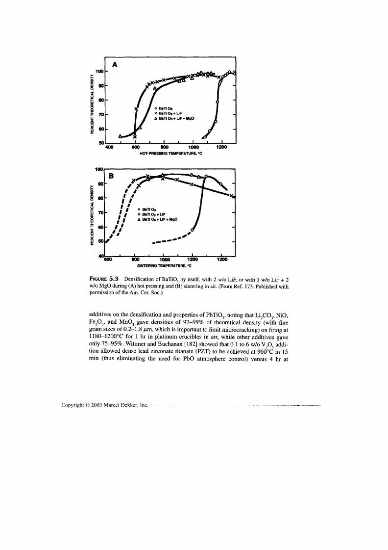
7/29/2019 29540824708539
http://slidepdf.com/reader/full/29540824708539 182/361
Use of Additives to Aid Certification 171
100
90
3E 80
SO400
o BaTI Oa
x BallOa +LIF
A BaTI Oa +UF+ MgO
600 800 1000
HOT-PRESSINGTEMPERATURE, "C
1200
100
90
80
70
60
so|/
40
B
It
I BaTi 03
x Ban 03 +LiFA Ban 03 +LiF + MgO
*600 800 1000 1200
SINTERINGTEMPERATURE, °C
1200
FIGURE 5.3 Densification of BaTiO3 by itself, with 2 w/o LiF,or with 1 w/o LiF + 2
w/o MgO during (A) hot pressing and (B) sintering in air. (From Re f. 173. Published withpermission of the Am. Cer. Soc.)
additives on the densification and properties of PbTiO3, noting that Li2CO 3, NiO,
Fe 2O3, and MnO 2 gave densities of 97-99% of theoretical density (with fine
grain sizes of 0.2-1.8 (im, which is important to limit microcracking) on firing at1180-1200°C for 1 hr in platinum crucibles in air, while other additives gave
only 75-95%. Wittmer and Buchanan [182] showed that 0.1 to 6 w/o V2O5 addi-
tion allowed dense lead zirconate titanate (PZT) to be achieved at 960°C in 15
min (thus eliminating the need for PbO atmosphere control) versus 4 hr at
Copyright © 2003 Marcel Dekker, Inc.
7/29/2019 29540824708539
http://slidepdf.com/reader/full/29540824708539 183/361
172 Chapter 5
1280°C with no additive. The optimum range of addition of 0.25 to 1 w/o gave
comparable properties as obtained without th e additive. The enhanced densifica-
tion was attribu ted to enhanced surface activity and liquid-phase sinte ring. How -
ever, the commercial sintering of PZT and PLZT remains using a PbO-rich
atmosphere provided by excess PbO.
Chen and coworkers [183] showed th at 4 w/o V 7O 5 addition aided densifi-
cation of SrTiO 3 at 1250°C bu t gave fine-grain bodies with large pores and TiO 2
precipitation. Addition of excess SrO reacted with the precipitated TiOr Cheng
and coworkers [184] reported sintering SrTiO 3 at 960°C for 2-3 hr with addition
of Li2CO 3 3 w/o, due to formation of a liquid phase. Laurent and coworkers
[185] investigated use of LiF, Li2CO 3, or LiNO 3 to densify doped SrTiO 3 while
maintaining desired prope rty levels, reporting best results with LiNO3
+ Bi2O
3.
Clarke and Hirschfeld [186] have shown that sintering of slip cast
(CaQ 6,M g0 4)Z r4(P O 4)6 powders was significantly aided by addition of ZnO, giv-
ing > 99% theoretical density with 1.5-2% addition with temperatures of
1170-1200°C for short tim es (e.g., 0.5 hr). The mechanism was interpreted to be
liquid-phase sintering, based in part separate observations of partial melting of
the phosphate. However, rapid coarsening of the microstructure an d excess grain
boundary phase occurred with marked decreases in room temperature flexure
strength (< 30 MPa) an d changes in thermal expansion—for example, negative
expansion at 1000°C with su bstan tial hysteresis. A fine microstructure with nor-
mal low expansion (~ 2 ppm/°C) and reasonable strengths of ~ 100-110 MPa orgreater were achieved by limiting exposure to the liquid phase by limiting the
amount of ZnO additive, the firing temperature, and time at temperature.
5.5 NONOXIDES
Consider nonoxides, for which additive development and use is primarily for bi-
nary borides, carbides, and n itrides, which are covered in the order listed. Within
each of these families, individual compounds are generally taken in alphabetical
order, except where some m odif ication of this order is advantageous because of
related technical or editorial factors. The focus is on additives whose key func-tion is to aid densification whether they aid or diminish some other aspects of
performance other than effects due to reduced poro sity; that is, densification ben-
efits in mak ing a composite bodies are not addressed here. Many of these materi-
als for which additives have been used to aid densification do not absolutely
require such additives, but they have been used because they offer advantages,
most commonly easier densification. Though improved powders, especially
finer, more uniform ones, and in some cases purer ones (where impurities are
detrimental rather than of some advantage) have reduced some of the driving
force for use of additives, but practicality still is important in their use. Fu rther,
there are more nonoxides of significant importance which generally cannot be
Copyright © 2003 Marcel Dekker, Inc.

7/29/2019 29540824708539
http://slidepdf.com/reader/full/29540824708539 184/361
Use of Additives to Aid Densification 173
sintered, or sinter poorly, without additives, namely diamond, SiC, A1N, BN
(hexagonal an d cubic), B 4C, and Si3N4.
Turning first to borides, LaB 6 was sintered by Shlyuko and coworkers[187] at 2000-2200°C (buried in LaB 6 powder) using Y2Oy While the Y 2O 3 ad -
dition enhanced sintering, it also reacted to form yttrium boride with the release
of gaseous B 2O 3, which above 4 w/o Y 2O 3 was progressively more detrimental
giving optimal results at 2 w/o Y 2O 3. Additions of A12O3 substantially inhibited
sintering. Hot p ressing of NbB 2 without additives at 2100°C by Mu rata and Mic-
cioli [188] yielded large grains (~ 20 |im) and a few percent of inter- and intra-
granular pores as well as considerable (mostly grain-scale, i.e., micro-) cracking.
Screening studies with 5 w/o additives of borides, carbides, or nitrides of Ti, Zr,
or W hot pressed at 2100°C showed most were ineffective in improving the
NbB2, with WC reacting to leave WB at grain boundaries and ZrN segregating at
grain boundaries. However, the Ti additives gave benefits in the o rder TiN > TiC
> TiB2, with all eliminating cracking and most or all intragranular porosity as
well as reducing grain size, i.e., ~ 4, 9, and 14 \im, respectively, with total resid-
ual porosity scaling with grain size. Optimu m results we re obtained with ~ 9 w/o
TiN which gave a minimum in grain size of ~ 2 |im. Low and McPherson [189]
reported reaction sintering of SiB 6 with either ZrO 2 or ZrSiO 4 in air at
1300-1500°C to fabricate ZrB 2-based bodies.
TiB2, which is one of the most important refractory borides, has received
considerable investigation and densification development with mainly Fe, or es-
pecially Ni, or some ceramic additions [190,191]. Champagne and Dallaire [192]
briefly reviewed use of metal additions and reported that TiB2 powder m ade using
ferrotitanium (FeTi) powder with excess Fe allowed HIPing to high density at
1300°C. Shim and coworkers [193] showed that TiB2 sintered with Fe additions
increased to a maximum of 89% of theoretical density with 0.4 w/o at 1800°C,
decreasing with higher addition levels or sintering temperature (due to vaporiza-
tion). They also showed that Ni additions gave nearly the same maximum density
at 1800°C, with higher temperatures giving poorer results due both to vaporiza-
tion and microcracking (due to larger grain size). Ferber and coworkers [194]
have shown that strengths and toughness of pure TiB2 hot pressed to >98% of the-oretical density at 1800-2000°C and bodies > 99% of theoretical density at
1425°C with 1.4 or 7.9 w/o Ni correlated in an inverse fashion with their grain
sizes, due in part to increased microcracking at larger grain sizes, with the lower
Ni addition giving the best results due to its smallest grain size, ~ 4 Jim. Einarsrud
and coworke rs [195] have show n that 1.5 w/o additions of Fe or Ni were effective
in sintering in argon or vacuum to > 94% of theoretical density at 1500-1700°C
(with no significant benefits of higher additive contents) but larger grains. They
reported similar results with similar NiB additions. Some limited work has been
conducted on use of intermetallic additives, for example, NiAl [196] in hot press-
ing at 1450°C giving limited grain growth but also an intergranular phase.
Copyright © 2003 Marcel Dekker, Inc.
7/29/2019 29540824708539
http://slidepdf.com/reader/full/29540824708539 185/361
174 Chapters
Beside the NiB addition noted above, a variety of ceramic additions have
been investigated for TiBr Watanabe [197] showed 12 w/o Ni«P additions
yielded high (and a maximum) density and strength on hot pressing in vacuum at
1300°C. Watanabe an d Kound [198] investigated effects of nine refractory
boride additions of 0-10 w/o on density, grain size, strengths, and hardness of
vacuum hot pressed TiB2+ 1 w/o CoB, showing diborides of Hf, Nb, Cr, Mo, Ta,
V, and Co gave < 1% porosity minima at 3 to 7 w/o, while additions of M nB 2 an d
M o 9B 5 reached minimum porosities of ~ 1 and 0.5%, respectively. TiB 9+ 1 w/o
CoB gave a minimum porosity of zero at 1800°C, while 5 w/o Ta2B 2 gave this
value at 1700°C and 5 w/o of W 9B 5 gave a minimum porosity of ~1 % at
1600°C. Strengths of 900-1100 MPa were achieved with several additions, in
part due to significant grain growth limitations, especially with 5 w/o TaB2 and
W 2B 5. Matsushita and coworkers [199] reported substantial improvements in
sintered densities at 1900°C with ~ 5 w/o Cr,O3. Torizuka and coworkers [200]
reported vacuum sintering TiB9 + 2.5 w/o SiC giving 96% of theoretical density
and 99% with HIPing, which was attributed to a liquid phase formed via reaction
with the ~ 1.5 w/o oxygen content in the TiB2 powder.
Thevenot [201] listed several oxides such as silicate glasses, A19O3, Fe0O3,
and M gO (added directly as Al or fluorides), as well as a variety of metals, ex-
cess carbon, and refractory ceramics or combinations of these as additives for
sintering or hot pressing of B4C, with TiB,, CrB2, W,B5, and Be2C, or SiC. SiC
was added directly or as a polycarbosilane, and some additives were combined
with carbon (e.g., Al or Si). He noted that while many improved densification,
most resulted in larger grains an d lower strengths. Most additives also left a few
percent porosity. More recently Lee and Kim [202] briefly reviewed additive sin-
tering of B4C as well as reporting further study of densification by sintering in
argon at 2150°C with A19O3 additions. A maximum of 96% of theoretical density
was achieved with 3 w/o addition (attributed to forming a liquid phase), while
exaggerated grain growth was observed with > 4 w/o addition. Kanno and
coworkers [203] showed that additions of TiB2, A1F 3, and especially Al signifi-
cantly enhanced densification, giving 95% sintered density at 2200°C in argon,
but Mg or MgF2 and especially SiC were not effective. Sigl [204]reported thataddition of 13-16 w/o TiC allowed B4C to be sintered to > ~ 98% of theoretical
density at 2150-2000°C due to formation of C and TiB 2, both of which aid den-
sification.
SiC is the most extensively studied carbide for additive effects on densifi-
cation because of its desirable properties and it by itself is very resistant tosin-
tering, for example, as shown by Nadeau's observations on limited self-bonding
with hot pressing with 20-50 kbars until temperatures of over 1500°C with
A12O3 additions [205]. The first breakthrough was successful hot pressing of ei-
ther a- or P- SiC powder with addition of ~ Im/o Al (added as A12O3 in making
SiC powder from Si and C) by Alliegro and coworkers [206]. Use of the Al addi-
Copyright © 2003 Marcel Dekker, Inc.
7/29/2019 29540824708539
http://slidepdf.com/reader/full/29540824708539 186/361
Use of Additives to Aid Certification 175
tion via hot pressing was commercialized, but has continued to be studied some,
for example, by Misra [207]. More recently a superior commercially produced
hot pressed SiC has been produced that uses only a small amount of A1N to aiddensification.
Additions of Li, Ca, Cr, and Fe also aided densification, and SiC bodies
densified with modest addition levels had good strengths, even at elevated tem-
perature [207]. Subsequently, hot pressing with A12O3 was further demonstrated
(at 1950°C), as well as successful pressureless sintering, by Lange [208] and
Mulla and Krstic [209], respectively. Extension to sintering with additions of
A12O3+ Y2O 3 [210] followed. B etter re sults were obtained with additions via sols
rather than powde rs (with tempe ratures as low as 1800°C) [211], and with other
additions (e.g., SiO 2 [212]. Liquid-phase densification is generally believed to
occur. Subsequent work has also included combined additions with at least one
of the additions b eing a rare earth oxide to yield elongated grains as has become
common in processing Si3N4. Thus, for example, Chen [213] used 6 m/o addi-
tions of A1 2O3+ Gd2O3 to pressureless sinter SiC to ~ 98% of theoretical density,
with best results at the eutectic mixture (Gd2O3/A l2O3 molar ratio of ~ 0.3) and
1950°C, which also increased room temperature toughness, attributed to in-
creased crack de flection.
The other major development with SiC was the demonstration of its pres-
sureless sintering using B+C additions in various forms (including as B4C) and
amounts, initially by Prochazka and coworkers at temperatures ~ 2100°C[214-216]. Further study indicated a liquid-phase sintering mechanism [217]
and that the amount of B needed is ~ 1 w/o when there is enough carbon to re-
move the silica coating on the SiC particles [218]. Further developments have
included other combinations of additives, for example, Al, B, and C [219-222],
other sources of more uniform distribution of B [223], as well as of carbon by it-
self [224]. Hot p ressing of SiC with substantial A1N additions indicates some ad-
vantage of A 1N in densifying SiC [225], which is consistent with small amounts
of only A1N being used to densify SiC by hot pressing (e.g., for ballistic armor
and high-temperature semiconductor processing).
Most o ther carbides, other th an WC, are normally made withou t additions,but some use of additions, especially metals, has been investigated. Thus, Kli-menko and coworkers [226] investigated use of 5-30% Ni binder with
chromium carbide for hot pressing w hich is greatly facilitated by form ation of a
liquid phase at ~ 1200°C. Small (0.1-0.2%) additions of P to the Ni further low-
ered the liquefying and densification temperatures by an additional 100-200°C,
that is, to ~ 1000°C. Cermets of TiC and various me tals, such as Fe and Ni, have
been made [227-230], as well as of metal—e.g., nickel-based alloys or Ni with
additions of Mo or Nb [230]—but such bodies are generally not as good as cer-
mets based on WC. Eyre and Bartlett [231] noted that small [ e.g. 0.1-0.2] addi-
tions to both UC and U; PuC promote sintering and can yield consistently higher
Copyright © 2003 Marcel Dekker, Inc.
7/29/2019 29540824708539
http://slidepdf.com/reader/full/29540824708539 187/361
176 Chapters
densities, an d fur ther studied details of the effects of Ni additions on UC. Math-
ers and Rice [232] conducted screening evaluations of additions of metals (Al,
B, Cr, Co, Cu, Fe, Mo, Si, Ti, Zr) and of silicides of Fe, Mo, and Nb individuallyby themselves, or with added C for signs of wetting and densification at 1900°C
with negative results.
As noted above cermets based on WC, especially with Co, have been
widely investigated and are in wide production for cutting tools and wear appli-
cations, with various compositions from a few to about 20% metal are com-
monly produced, mainly by sintering [227,233], e.g., in the 1350-1450°C
range. The presence of a liquid phase in WC-Co compositions, which has been
directly observed [234], is generally accepted, e.g., at ~ 1280°C, but can be
lowered by additives such as B and Ni [235]. Other sintering aids/bonding
agents, espe cially Ni by itself or in combination w ith other me tals have been in -
vestigated [235-238], but use of Co still predominates despite safety precau-
tions required with its use in sintering.
Carbon bodies, for example, of graphite or diamond, also do not sinter.
While graphite an d other nondiamon d carbon powders are commonly adequately
densified by use of carbon producing polymers or CVD, there has long been a
need for sintering aids for high-pressure hot pressing of diamond powders
(which themselves are made via high-pressure conversion from graphite using
additives such as Ni, Sect. 3.2). Initially small amounts (e.g., 1 m/o) of B, Si, or
Be [239] or additions of some boride, carbide, nitride, or oxide powders weredemonstrated [240], but much attention and use has been focused on Co (e.g., ~
10%) additions [241-245], similar to WC practice. However, additives in addi-
tion to Co have been investigated, for example, graphite [245] or WC, the latter
to suppress excessive grain growth that can occur [246]. Reaction sintering, that
is , conversion of graphite to diamond via hot pressing in one step using a
graphite precursor with added diamond powder with Ni as both a promoter of
graphite to d iamon d conversion and as a sintering aid/binder [247] has also been
demonstrated. While earlier temperatures and pressures of 1800-1900°C at 6-7
GPa were used, better materials (finer powders) an d technology have lowered
densification temperatures to 1400-1700°C. (Graphite apparently dissolves inliquid Ni and then precipitates as diamond.)
Turning to refractory nitrides, A1N, BN, and Si3N 4, which are all important
and unde rgo little or no sinte ring withou t additives, making additives to aid den-
sification important for them. Earlier investigations of sintering A1N focused on
use of metal additions (e.g., of Ni, Co, or Fe [248,249], but attention shifted first
to oxide (and later to some oxide producing) additives due substantially to
Komeya and Inoue [250,251], who successfully hot-pressed A1N with 5-10 w/o
Y 2O 3 additions at ~ 1800°C, which was motivated by possible uses for structural
applications, (e.g., in engines). Subsequently, increased recognition of the role of
oxygen surface species [252], and use of other or combined additives occurred
Copyright © 2003 Marcel Dekker, Inc.
7/29/2019 29540824708539
http://slidepdf.com/reader/full/29540824708539 188/361
Use of Additives to Aid Certification 177
[253-258], with much of the motivation being high thermal conductivity for
electronic applications, su ch as substrates, and processing m ore by sintering than
hot pressing. While use of either CaO or Y 2O 3 (or them combined ) is establishedfor both research and some commercial production, further work continued on
other oxide additives, mixtures or ternary compounds of them, use of small addi-
tions of carbon, and addition of desired cations with other anions such as C, and
especially F to further lower firing temperatures to < 1600°C [259-261]. The
high level of activity is reflected in the extensive and often complex literature,
especially th e patent literature in this field, but the broad consensus is that liquid-
phase sintering is generally an important, if not key, factor in densification with
additives. Some of the above results as well as several additive tests are covered
in a brief paper by Schwetz and coworkers [261]. Further work continues on ad-
ditive mixtures; for example, 0.5 w/o TiO2 +1.5 w/o Y 2O 3 + 0.4 w/o CaO ofNakahata and co workers [262], and of know n be neficial cations with other an -
ions, such as Neuman and coworkers [263] using CaF 2, CaC 2, CaH2, Ca3P2, and
CaS, with all of these except the latter converting to CaO and being beneficial.
Commercially produced A1N for the electronics industry is sintered with Y 2O 3
and A12O3 (the latter from the oxide layer on A1N pow der particles), with quality
A1N being commercially produced by hot pressing with as low as V4% Y 2O 3,
me eting specifications calling for 98.75% A1N components.
Consider next hexagonal BN, that is, the analog of graphite, which is also
not very sinterable, especially without the common oxygen/water surface conta-
mination. BN also lacks the readily available polymeric precursors for process-
ing analogous to graphite and often requires substantially lower porosities than
are obtained by preceramic polymer impregnation and pyrolysis. Thus, consider-
able attention has been focused on densification with additives, mainly by hot
pressing, which has been in commercial production for a number of years. The
focus is on use, and often extension, of the B2O 3 on the powder surface with ad -
ditional addition of B2O 3, and small (e.g., 0.2-0.3 %) additions of oxides such as
A12O3, phosph ates, alkaline earth oxides, especially CaO, or SiO 2 with formation
of a borate liquid phase an important factor [264,265]. Analysis of commercial
samples shows 2-9% residual B2O 3and
2-7% residualfine
porosity, bo th mainlyintergranular, with th e porosity an d residual B2O 3 amoun ts generally being in -
versely related. Higher pu rity BN grades with less residual B2O 3 are produced by
post densification annealing at high temperatures in vacuum to reduce B2O 3 con-
tents via volatilization. More recent studies of Hubaek and coworkers [266]
showed th at use of small additions of metallic Cu increased ho t-pressed densities
modestly (from ~ 90 to ~ 94% of theoretical density) but decreased flexural
strengths from ~ 46 to ~ 30 MPa (with ~ half of this decrease being recovered by
using up to 10 w/o Cu). However, very small Cu additions had a pronounced ef-
fect on grain structure, especially a high degree of preferred orientation, which
rapidly decreased with increased Cu additions.
Copyright © 2003 Marcel Dekker, Inc.

7/29/2019 29540824708539
http://slidepdf.com/reader/full/29540824708539 189/361
178 Chapter 5
Fabrication of cubic BN bodies from cubic BN powder (which like dia-
mond powder is made via use of catalysts, such as Mg-B-N or Ca-B-N com-
pounds, se e Sec. 3.2) is greatly assisted by use of additives as are diamondcompacts. However, as with forming th e cubic phase, densification of cubic BN
emphasizes use of different additives than for diamond. Thus, while some ce-
ramic binders have been used for diamond, the emphasis has been on metallic
additives (binders), especially Co, while th e focus of additives for desifying cu -
bic (or wurtzite) BN pow der com pacts ha ve been ceramics such as A1N
[267,268], A1B, [267], TiC [269-270], TiN [268,269], TiC-TiN solutions
[270,271], andfiB orTiB 2 [271].
Silicon nitride can be pressure sintered to high density an d reasonable
properties witho ut additives , for example, b y hot pressing with high pressures (3
GPa) at 1900°C [272]or HIPing at 1800°C with 0.17 GPa pressure [273]. While
such densification may be aided by surface oxide contents, it nonetheless, re-
flects a significant need for den sification aids, which has received substantial at-
tention, possibly more than for any other ceramic. How ever, un til den sification
aids were discovered, the focus in Si N 4 processing was via reaction sintering (or
bonding—RSSN or RBSN, respectively) by in situ nitridation of Si-powder
compacts, which is also aided by some additives—especially iron oxide, also a
common impurity in Si powders (see Sec. 3.2—as well as inhibited by other
compounds, such as AL,O3 [274]. (The focu s on reaction processing of Si3N4 was
due in part to the discovery that such processing could be carried out with thefortuitous aspect that despite the substantial [~23%] volume expansion of Si on
conversion to Si3N4, compacts can be reacted to as low as ~ 20% porosity and
reasonable properties with dimensional tolerances of ~ 0.5% between th e green
and reacted bodies, as well as done with reasonable costs.)
A significant step in densification of Si3N4 to low to zero porosities was the
study of Deeley and coworkers [275] on effects of various additions (e.g., com-
monly of 4-10%) on the hot pressing of Si3N4 powder at 1800-1850°C. They
showed that AL,O3, BeO, and MgO (as well as Mg3N 2) additions each gave < 1%
porosity, while additions of ZrO 9, CaO, Fe2O 3, ZnO, Cr2O 3, (as well as of B,
MoSi2, TiN, Cr2N) gave porosities increasing from ~ 14^4-0% in the order listed,and generally with lower porosity as the amount of additive increased over the
range evaluated. The focus in their further investigation was on MgO since it
gave somewhat lower porosity, th e second highest strength (> 100% higher than
th e A12O3 additions), while BeO presen ts a health hazard and Mg3N 2, though giv-
ing the highest strength by ~ 20%, is hydroscopic (and also probably reacts to
form MgO and MgSiN2). This focus on MgO additions was also the case in
much of the subsequent work of others, becoming the basis of the initial com-
mercialization of hot-pressed Si3N4, which is apparently still in production. The
discovery that poor high temperature strengths of hot pressed Si3N4 was due to
Ca impurities in the Si 3N 4 powder also added interest to use of MgO for densifi-
Copyright © 2003 Marcel Dekker, Inc.
7/29/2019 29540824708539
http://slidepdf.com/reader/full/29540824708539 190/361
Use of Additives to Aid Certification 179
cation since w ith powd ers with low or no C a impurities, good high tempe rature
strengths were obtained. (Note that Fe impurities also common in some Si3N4
powders can be beneficial, e.g., for nitriding Si, as noted earlier and in Sec. 3.2.)Subsequent expanding efforts lead to other ho t pressing additives to give near-
zero porosity and broader recognition of the benefit of starting with high oc-Si3N4
content and its conversion to |3-Si3N4.
The nex t step was broadening th e range of useful densification aids for hot
pressing, initially to use of Y 2O 3, apparently discovered independ ently by Gazza
[276] and Tsuge and coworkers [277], which also gave better properties, such as
increased high temperature strengths (and an oxidation problem as noted below).
Subsequ ent dev elopme nts included use of Zr-based additives [278], mainly ox-
ides, and more extension into use of rare earth and related oxide additives, such
as CeO 2 [274]. Thus, Rice and McDonough [278], reported that ZrO 2 withoutstabilizer or with Y 2O 3 stabilization, as well as with ZrSiO 4 (or ZrN or ZrC) gave
near theoretical den sity (especially with ZrSiO4 or ZrC) an d good stre ngths, with
some Si3N4 powders, and somewhat poorer results with other powders (whichwas th e probable reason why Deeley an d coworkers' [274] results with ZrO 2 ad -
ditions were intermediate in their survey). Others, fo r example, Dutta an d Buzek
[279], also reported success w ith ZrO 2-Y 2O 3 additions. Various investigators also
reported excellent densification with CeO 2 additions (e.g., Smith and Quacken-
bush [280], which was offered commercially but then withdrawn due to serious,
often catastrophic, effects of oxidation on strengths and integrity of such bodies
after intermediate temperature (at ~ 1000°C) oxidation [281]. This an d similar
oxidation p roblems with some Y2O 3 densified bodies [282] are a severe reminder
of the need fo r comprehensive characterization of new materials, not just room
and high temperature tests.
Further de velopment of densifying Si3N4 with add itives was along several
avenues, a major one being increasing attention an d success in pressureless sin-
tering with the same or similar additions used in hot pressing (or HIPing). Other
important an d often interrelated developme nts we re more use of combined addi-
tions, more attention to interaction of additives with imp urities, and the use of
this to crystallize glassy grain boundary phases to improve high temperatureproperties, and use of additives (with Y 2O 3 + other additions, such as Yb2O 3) to
enhance development of elongated (3-Si3N4 grain structures (often also aided by
seeding with fine |3-Si3N4 particles) [283]. Examples of mixed additives are
physical mixtures, fo r example, Y 2O 3 + A1 2O3 [282], and chemical mixtures, fo r
example, YA1O3 [284] and celsian (BaAl2Si2O 8) [285]. The former also includes
benefits of MgO+ Fe2O3 (the latter also stimulating Si nitriding) [286]. For more
details on part of the development of additives for Si3N4, readers are referred to
Popper's review [287].
Additives for Si3N4 have also included some non oxide additives, in combi-
nation with oxide additives or by themselves. The fo rmer includes MgO + CaF 2
Copyright © 2003 Marcel Dekker, Inc.

7/29/2019 29540824708539
http://slidepdf.com/reader/full/29540824708539 191/361
180 Chapter 5
[288] or MgF 2 [289], which further lower densification temperatures (e.g., to
1400°C), and of (Y,La),O3+ A1N [290]. Limited investigations of nonoxide addi-
tives by themselves show some failures [232] an d some successes [291-293],but many, if not all, of the latter reflect conversions to ben eficial oxide additions,
such as nitrides of Mg, Ca, and Sr.
Some general results can be seen from the substantial investigations of
densifying Si 3N 4. Oxide additives, which are almost exclusively used singly or in
combinations, usually at levels of a few percent, generally function via a liquid
phase that lowers densification temperatures by 20(M-00°C [273]. The liquid
phase becomes a solid grain bound ary phase t hat is comm only glassy, but can be
crystallized by composition control (including impurities) and heat treatment.
The liquid/grain boundary phase observations are supported by phase data, di-
rect TEM ide ntification and effects on properties. The latter include enhanced in-tergranular fracture and the occurrence of moisture driven slow crack growth,
but generally with, often significantly, improved strength and toughness at room
temperature [294-296], but decreased strengths and enhan ced slow crack growth
(from grain boundary sliding) at higher temperatures as compared with Si 3N 4
made without additives (by CV D or high pressure d ensification). These property
changes are corroborated by the one case of successful densification with a
nonoxide additive, SiBeN 9, which shows no grain boundary phase and none of
their effects [291,297]. Note that other trials of a variety of nonoxide additives
by Mathers an d Rice [232] were unsuccessful, as have been most other attempts
like those of Deeley an d coworkers above [275]. Exceptions have been where
nonoxide additives either are believed to react to form ox ides (e.g., Mg3N2, ZrC
or ZrN), or react with oxygen to form a solid solution w ith Si3N4 [291,297]. The
latter may or may not be related to the use of B, C, B 4C, or combinations with
SiC, but in either case raise th e question of why nonoxide densification aids are
not feasible or not found. Commercially, several densification routes are fol-
lowed that include reaction sintering of Si with added Y 2O 3 + A1 2O3 for subse-
quent sintering of the resultant Si 3N4 to near theoretical density and sintering of
Si 3N4 powder with additives such as Y 2O 3 + A1 2O3 + TiO 0. Commercial hot
pressing still includes either MgO or Y 2O 3 additives.TiN has been densified by high-pressure ho t pressing at 1800°C and 5 GPa
pressure [298] and at 2100-2200°C and 14 MPa pressure [299], but can be aided
by various additives, which can also aid pressureless sintering. Thus, like TiC,
Ni additions (5 w/o) have been used with reasonable success, especially in sin-
tering wit h some o ther ad ditives such as (V,Ta)C, as well as some oxygen [300].
Hot pressing with 5 or 10 w/o ad ditives of A1 2O3, Y 2O 3, or MgO, or BN, A1N, or
Si3N4, or SiC or B 4C at 1950°C with 14 MPa pressure was investigated with 10
w/o of Y 2O 3, A12O3, or B 4C giving 96-98% of theoretical den sity, with B 4C being
th e most promising based on both density an d property evaluations [301].
Kamiya and Nakano [302] report that 5 w/o Al benefits hot pressing of coarse
Copyright © 2003 Marcel Dekker, Inc.

7/29/2019 29540824708539
http://slidepdf.com/reader/full/29540824708539 192/361
Use of Additives to Aid Densification 181
(75 (im) TIN powder at 1400°C in a N2 atmosphere and fine (1.4 |im) powde r in
a vacuu m (the latter apparently required to accommodate gas evolved from the
Al-TiN interfacial reaction).Turning to MoSi2 bodies, SiO 2, which is a common impurity, ha s also been
added (for example, as up to 15% poly silicic acid, the n sinte ring in argon at
1550-1650°C giving 6% minimum porosity [303]. This gives finer grain sizes
and less strength decrease at higher temperatures than the use of ~ 8% clay in
forming heating elements. Suzuki and coworkers [304] showed that addition of
~ 5 m/o of Y 9O 3 gave maximum densification in hot pressing at 1600°C and
good high tem perature strengths, especially due to the additive and SiO 2 forming
a refractory silicate. However, they also found that while ~ 1 m/o addition of
Sc 2O 3 gave somewhat lower density it gave higher mechanical properties at ~
22°C and comparable strengths at higher tempe ratures as the Y2O 3 additions.
While ZnS is readily hot pressed to transparency at modest temperatures
(e.g., 800°C), Uematsu an d coworkers [305] report that small (0.01-1%) addi-
tions of Bi2S3, A12S3, or Li2S, though not significantly affecting densification,
limited grain sizes, especially the Bi2S3.
5.6 CERAMIC COMPOSITES
Ceramic composites present particular challenges to densification, especially by
pressureless sintering, since the presence of substantial second phase typicallyseriously inhibits sintering approx imately in proportion to the volume fraction of
dispersed phase. The difficulty of sintering composites also increases on pro-
gressing from paniculate to platelet or whisker to fiber, especially continuous,
and particularly multidirectional fiber composites, as well as the volume fraction
of nonoxide constituents increases. Thus, as discussed further in Section 6.2,
most ceramic composites are made by pressure sintering, mainly by hot pressing,
which is often aided by use of additives, especially fo r particulate composites.
As noted above, ceramic particulate composites are commonly processed,
mainly by hot pressing, with additives. Again, additives are often used to im-
prove densification since two- or multiple-phase bodies often are more difficultto densify, especially whe n at least one phase is a refractory nonox ide phase w ith
more limited densification, particularly at temperatures where oxides are typi-
cally densified. However, densification with additives also often has other bene-
fits, such as retention of finer particle and matrix grain size to increase properties
often higher at finer grain or particle sizes. While maintenance of finer particle
and matrix grain sizes is typically an important consequence of composites, es-
pecially particulate composites (and to some extent also platelet and, especially,
whisker compo sites), some add itional microstructural control is often very bene-
ficial. Composites present additional challenges to the use of additives since ad-
ditive compatibility with at least two phases are required. Data are primarily
Copyright © 2003 Marcel Dekker, Inc.
7/29/2019 29540824708539
http://slidepdf.com/reader/full/29540824708539 193/361
182 Chapter 5
available for paniculate composites since whisker, platelet, and fiber composites
provide progressively increasing challenges to sintering, an d thus are densified
unde r pressure, ge nerally re qu iring less densification aid. Also, additives may re-
sult in undesirable effects in such composites. However, on the positive side
some composite consti tuents are densification aids for the other phase, for exam-
ple, A1 2O3 for some composites with nonoxides, such as SiC. Further, an additive
for one phase may also often be effective for another phase—for example, Y^O 3
for both SiC and Si3N 4 an d with A1,O_V
Little or no data exists on additive effects in densification of composites
consisting of oxide particles dispersed in an oxide matrix, in part, due to gener-
ally easier sintering of oxide materials. (In the case of YTZP sintered with
0.25w/o A1,O3
for optical ferrules [Sec. 5.3], the A1,O3
apparently is mainly to
maintain fine grain size.) Thus, th e focus is on composites with nonoxide phases
starting with those with nonoxide particles dispersed in an oxide matrix, fol-
lowed by such p articles in nonoxide matrices—in both cases in alphabetical or-
der of the m atrix material . A gain, oxide additives are considered first , followed
by nonoxide additives.
Thus, first consider Al0O 3-TiB 2 composites, de nsificat ion of which are
briefly reviewed by Stadlbauer an d coworkers [306], who also corroborated ben-
efits of small addition (1 % MgO)—for example, giving 98 % dense A1 9O3 with-
out TiB 2 at 1800°C, and 96 and 90% density with 5 and 40 w/o TiB 2,
respectively. Cutle r an d co workers [307] showed that addition of 3 .7 w/o TiH0 toA12O3 + ~ 30w/o TiC allowed sintering to ~ 94% of theoretical density at
1860-1890°C due apparently to a transient liquid Ti-based phase, an d thus al-
lowed cladless HIPing to full density at ~ 1600°C, that is somewhat better than
by ho t pressing at 1700°C. Chae an d coworkers [308] showed that A1 2O3 + 30
w/o TiC could be sintered to a maximum of ~ 97% of theoretical density at
1700°C at an optimum Y 9O 3 addition of 0.35 w/o. They subsequently reported
that composites with 50 w/o TiC could be sintered to ~ 99% of theoretical den-
sity at 1750°C with higher (3.5 w/o) Y,O3 [309]. Sintering of both comp ositions
was attributed to a liquid phase that c rystallizes to YAG on cooling. Again, com-
posites with an alumina matrix can be "densified" via phosphate bonding, as dis-cussed by Karpinos and coworkers [310]. Finally, composites of an alumina
matrix with up to 30 w/o Ti-C-N, densified with the aid of 0-5 w /o Ni by itself or
with other metals, were sintered to 90-100% of theoretical density at 1750°C by
Ekst rom[311] .
TiB2 matrix composites with ~ 19 w/o 2YTZP were reported by Torizuka
and coworkers [312)] to be pressureless va cuu m sintered to 96.7% of theoretical
density at 1700°C with 2.5-5 w/o SiC, an d only 63.7% dense without th e SiC.
The SiC addition was also effective in limiting growth of the TiB 2 grains and of
the TZP particles. Zhang an d coworkers [313] reported that TiB2 + SiC compos-
ites could be reaction hot pressed to 99% or above theoretical density at 2000°C
Copyright © 2003 Marcel Dekker, Inc.

7/29/2019 29540824708539
http://slidepdf.com/reader/full/29540824708539 194/361
Use of Additives to Aid Densification 183
with a few percent Ni additions, but that 2 w/o addition gave maximum hardness
and flexure strength (but a minimum, though substantial, toughness). Hayashi
and coworkers [314] also reported that additions of Ni (with C) were used asdensification aids for pressureless sintering of TiB2-B 4C composites at 1600°C.
Dai and coworkers [315] reported densifying nominally 58 w/o TiB2 + 40 w/o
Ti(CN) with 2 w/o Ni at 1850°C.
Turning to SiC matrix composites, Cho and coworkers [316] reported hot
pressing of composites with 0-70 w/o of TiB2 or TiC at 1850°C via liquid-ph ase
densification from (7 w/o) A12O3 plus + (3 w/o) Y 2O 3 additions (plus SiO 2 on the
SiC surface). Cho and coworkers [317] extended this work by annealing com-
posites with TiB2 at 1950°C to obtain exaggerated growth of oc-SiC from the [3-
SiC. Lin and Iseki [318] showed that SiC with 0-40 v/o of TiC could be hot
pressed to 97.1-99.7% of theoretical densities at 1800°C with 5 w/o Al-B-C ad-dition (without which densities were only 58-66% of theoretical den sities), and
Endo and coworkers [319] used B4C and C as densification aids in hot pressing
SiC with 0-100% TiC.
SiC-AIN bodies have been ho t pressed to near theoretical density betwee n
1950-2100°C [225] an d have been similarly sintered using 2 w/o Y 2O 3 addition
by Lee and Wei [320] (while the same level of CaO or A12O3 additions gave only
~ 65% of theoretical density). Pan and coworkers [321] reported similar ho t
pressing o f such bodies w ith 0.5 w/o Y2O 3. In some co ntrast to these SiC -AIN re-
sults, Maz diyasni and coworkers [322] reported that hot pressing of A1N+ 0-30
BN at 2000°C gave 92-98% of theoretical den sities, with best d ens ification with
15 CaH 2 addition, intermediate densification without any additive, and the lower
levels of densification with 5% Y 2O 3 addition. Also note that Karpinos an d
coworkers [323] reported phosphate bonding of A1N and Si3N4 (by themselves
and with) A12O3 via H3PO 4 reaction and heating to 1250°C.
Mathers and Rice [232] tried reactive hot pressing of Al and Si with Si3N4
to produce Si3N4 with A1N and MoSi2 at 1820°C, which resulted in reaction, but
with essentially no densification, yielding only ~ 60% of theoretical density.
Hot pressing tests at 1925°C resulted in substantial Si3N4 decomposition. Si3N4
with 0-50 v/o TiC was hot pressed by Mah and coworkers [324] to near theoret-ical density at 1750°C, using 5.5 w/o CeO 2 as a hot-pressing aid. Mazdiyasni
an d Ruh [325] also ho t pressed Si3N4 with 0-50 BN and 6% CeO 2 at 1750°C.
Si3N4 matrices with 9-33 w/o A1N were sintered at 1900°C under 1 MPa N 2
with addition of La2O 3 by Zhung and coworkers [326]. While no additive gave
only ~ 68% of theoretical density with 25% A1N, add ition of La2O 3 first in-
creased densities rapidly, e.g., to 94% at 0.5 w/o, then more slowly to 97-98%
of theoretical density at 1-2 w/o La2O 3, then p lateauing or slightly decreasing at
the maximum used (7 w/o) (but with a strength maximum at 5 w/o and of
toughness at 2-5 w/o).
Investigators fabricating composites of Si3N 4 with SiC particles have fre-
Copyright © 2003 Marcel Dekker, Inc.
7/29/2019 29540824708539
http://slidepdf.com/reader/full/29540824708539 195/361
184 Chapter 5
quently done so using either A1 2O3 or Y 2O 3 (o r related compound) additions, or
combinations of these. Thus, Tanaka an d coworkers [327] showed that sintering
with 10.5 w/o A1 2O3 + 4.5 w/o Y 2O 3 gave ~ 97% theoretical density at 0% SiC,then decreasing slowly with ~ 20 SiC then more rapidly as SiC content further
increased. Kim and coworkers [328] used 6w/o Y 2O 3 + 2 w/o A1^O3 to sinter
bodies with 20 w/o SiC particles at 1750°C to 95% of theoretical density.
Cheong an d coworkers [329] used 6 w/o Y 0O 3 + 2 w/o Al^O,,, or 4 or 8% Y 2O 3 in
hot pressing at 1800°C, finding best results with 4% Y 2O 3 in densifying their
nanocomposites with 20 v/o SiC. Park an d coworkers [330] instead used 8-16
w/o Yb2O 3 additions to hot press nanocomposites with 20 v/o SiC, finding best
results with 14% Yb2O . Similar to the above, composites of reaction processed
powders of Si 3N4 + 35-40% TiN were sintered by Hillinger an d Hlavacek [331]
with a gas pressure of 2.5 MPa between 1710 an d 1740°C using 6 w/o Y^ O 3 + 4
w/oA!2O 3.
Petrovic an d coworkers [332] ho t pressed Si 3N4 + 0-50 v/o MoSi, using 1
w/o MgO at 1750°C to obtain 94-97% of theoretical density. Zhang an d cowork-
ers [333] hot pressed MoSi2 with 0.1 to 10 w/o Al metal (to react with the oxyge n
on the MoSi2 particles and form A12O3) by hot pressing at 1600°C, with the high-
est density being obtained at 5 w/o Al addition. Ting [334] ho t pressed compos-
ites of MoSi2 + 20 v/o SiC with and without 500 ppm B 2O 3 at 1600 and 1750°C
respectively, giving 97.4 and 98.1% of theoretical density, respectively, with the
B ?O 3 giving finer grain size and glassy areas and higher strength at 22°C.In some comp osites, the added dispersed phase may also aid densification.
Thus, Zakhariev and Radev [335] reported that addition of 10-30 w/o of WC to
B4C resulted in enhance d de nsif ication . Shobu and coworkers [336] reported that
substantial, e.g., 20 w/o addition of Mo 2B 5 to MoSi2, sintered to full density at
1500°C.
5.7 DISCUSSION AND CONCLUSIONS
Three aspects of using densification aids need furth er discussion, namely mecha-
nisms, effects, an d fur ther opportunities. Consider first mechanisms of actualdensification, where the interest is not in detailed mechanisms, but in those
mechanistic aspects that ind icate practical engineering guidance in selection and
developme nt of de nsification via additives. W hile it is clear that much re mains to
be understood, an overall separation into mechanisms of probable or known liq-
uid-phase den sification (which can entail liquid-phase sintering as well as inter-
particle sliding, especially in pressure densification such as hot pressing) and
other non-liquid-based me chanisms, which generally en tail enhanced diffusion.
The latter, though not as effective as the former, can be useful by themselves,
and often may accompany liquid-phase mechanisms, e.g., before the liquid
forms. Mechan isms operative in the solid state typically require some solid solu-
Copyright © 2003 Marcel Dekker, Inc.

7/29/2019 29540824708539
http://slidepdf.com/reader/full/29540824708539 196/361
Use of Additives to Aid Certification 185
tion, usually of ions of different valance than their counterparts in the material to
be densified, while liquid-phase mechanisms clearly require a second, grain
boundary, phase. While the melting point of the additive is a key factor in the
temperature of liquid-phase formation, effects of grain boundary imp urities often
play an important role in this as well as another key aspect, namely, wetting of
the grains of the material to be den sified by the liquid phase. However, other key
aspects abou t which information is incomplete are the exte nt of solubility of the
material to be de nsified by the liquid phase and precipitation of the former from
the latter.
Note that while metals are generally more easily sintered than many ce -
ramics, and hence rely less on densification aids, nonetheless some metallic den-
sification aids are used in sintering some metals, especially for refractory metals.
The common use of a few to several percent of Ni in sintering W powder is a
clear example of this. More directly pe rtinent to some ceramic processing is sig-
nificant enhancement of sintering of Si shown by Greskovich [337] in adding
small (e.g., 0.4 w/o) additions of B, which also limited grain growth (while Sn
retarded de nsification and enhanced grain growth).
Two further considerations are central to selecting and using additives as
densification aids. The first is the presence and effects of impurities, including
those on p owde r particle surfaces. As noted earlier impu rities often play an im-
portant role in den sification with additives, freq ue ntly being a route to discover-
ing additives, or an important reason fo r materials specifically added working aswell as they do. It is always better to mon itor impu rity levels that effect additive
effectiveness and adjust additive amou nts accordingly. H owever, th is is often not
done, which is a factor in varying den sification. Second is additive effects on
properties. Additives often have dual effects, one on de nsification and one on re-
sultant properties. The latter generally involve intrinsic compositional an d mi-
crostructural effects. Besides the obvious impact of reduced porosity is the
frequent control of grain growth, which is also often important. While man y sec-
ond phases at grain boundaries are effective at controlling grain size, there can
be substantial variation with temperature, impurities, and the microstructural re -
lations between the body and additive phases. Since there are frequently perfor-mance trade-offs due to effects of additives (discussed below), this is an
important factor in additive selection.
Thus, while basic additive data such as solubility, ionic sizes, melting, and
reaction be tween additive and material to be densified are important in aiding ad-
ditive selection, much still needs to be aided by actual densification results.
While this is generally true for a single compound to be densified, it is particu-
larly true for densification of composites. It is believed that the review of this
chapter is a help in this selection. It is also believed that some selection insight
can be gained from consideration of other additive uses in Chapter 3, especially
flux growth of crystals, V-L-S growth of whiskers, and stimulants or inhibitors to
Copyright © 2003 Marcel Dekker, Inc.

7/29/2019 29540824708539
http://slidepdf.com/reader/full/29540824708539 197/361
186 Chapter 5
grain growth. Also note that either or both the atmosphere provided in the densi-
fication furnace as well as that generated in the compact being densified an d their
interactions can also be important.Additives effects on properties is an important factor needing some further
comment since almost invariably their use involves some trade-off between im-
provements due to reduced porosity versus reductions due to other effects of the
additive. Additives that form a solid solution with th e material to be densified
generally have limited effects on mo st mechanical properties, but may have some
to substantial effects on electrical, thermal, magnetic, and especially some elec-
tromagnetic properties (such as color). On the other hand, grain bou ndary p hases,
which often have approximately a rule of mixtures effects on sonic, elastic, an d
magne tic properties, can have little, to substantial effects on thermal an d electrical
conductivity, and espe cially on dielectric breakdo wn and varistor behavior. A key
limitation of liquid-phase densification is high-temperature strength and deforma-
tion due to residual boundary phase near and especially above the melting point
of the remaining grain boundary phase. However, note that solid phases, espe-
cially at grain b oundaries, can present serious problems if their structure and size
result in reduced strength; for example, due to possible microcracking as densify-
ing A12O3 with TiO 2 due to formation of Al2TiO 5 [27,338] or of using V 2O 3 addi-
tives. The latter is a good example of complications of other variables since the
phase form ed is depen dent on the processing e nvironm ent, that is, lower strength
in A1 0O3 + V 2O 3 sintered in air due to formation of an A1VO4 grain boundaryphase despite some inhibition of grain grow th, but a solid solution of the V with-
out significant strength degradation on firing in a reducing atmosphere. Residual
fluoride phases, for example, from use of LiF, can lower strengths an d tough-
nesses at room tem perature as well as change electrical properties, cause bloating
or blistering from volatilization at higher tempe ratures, especially at higher heat-
ing rates and larger sizes, and greater reductions of high temperature strengths
[91,294,339] an d creep [340]. Residues of additives can also hav e other positive
or negative effects on behavior, such as oxidation, corrosion, or other environ-
mental effects and electrical properties [341].
Some of the above, as well as other effects may arise from other effects ofadditives. Thus, for example, some additives may increase green densities
achieved, as reported by Udalova an d coworkers [88,342] for LiF additions to
some oxide powders. De nsified microstructures may also be m odified by the use
of additives, fo r example, effects of small Cu additions to BN [266]. Phase trans-
formation may also be altered by the use of densification aids, as reported in
Si3N 4 (see also Sec.3.3) [343].
Three opportunities can be noted. The first is that while much yet needs to
be established, there is an increasing database and increased understanding, the
latter in part due to the availability of purer materials, and thus less confusion
due to impurity effects. Second, analytical tools have greatly increased in capa-
Copyright © 2003 Marcel Dekker, Inc.
7/29/2019 29540824708539
http://slidepdf.com/reader/full/29540824708539 198/361
Use of Additives to Aid Certification 187
bility and availability to aid in understanding and development. Third, both the
increased database and the frequent commonality of additives across various
compounds, allow reasonable selection of additives fo r densifying composites asdemonstrated above. Thus, for example, note the common use of Y2O 3 (or other
rare earth oxides) for several oxides and nonoxide s and, to a lesser exte nt, for use
of metals such as Fe, Ni, and especially Co. However, a basic question that re-
mains is Why are there so few nonoxide additives, besides metals, even for
nonoxide materials to be densified, such as SiC and Si3N4? While penetration of
oxide particle coatings is probably a factor, why B, Al, Si, or B4C are the only es-
tablished additives for SiC and BeSiN2, respe ctively, and the only one for Si3N4
is still a basic question. This is important since these additives do not re sult in an
oxide (if any) grain boundary phase, and thus do not cause slow crack growth,
e.g., due to H2O at low temperatures, or enhanced grain boundary sliding at high
temperatures in contrast to oxide additives resulting in such limitations. How-
ever, such nonoxide additives also result in normal toughness and strength,
rather than increases in these often obtained w ith oxide additives, thus again be-
ing a reminder of further needs for understanding of effects of additives on den-
sification and property trade-offs.
Finally, a few words of caution, primarily about possible significant size
effects that may occur in processing larger bodies. Most additive development,
as well as much additive usage, is done with bodies that are small—a fe w mil-
limeters—in at least one dimension, which allows fo r removal of much of the
additive or its residues. This is often important, e.g. especially for high thermal
conductivity A1N. Howe ver, fo r preparation of larger bodies significant less such
removal may occur, especially in the interior. Also in some cases some oxidation
of the additive may be important, fo r example, with nonoxide additives fo r A1N,
which may occur if there is sufficient material on the particle surfaces fo r this or
one body dimension is small enough to allow potential oxygen diffusion from
outside of the body. Where surface oxidation is limited, the re is incomplete inter-
nal oxidation, especially in larger bodies. Such size effects are also often limita-
tions on removal of gases from the interior of the body, even if the gases are
soluble in the ceramic, as shown with MgO.
REFERENCES
1. C.-S. Hwang, C.-Ti Lin, H.H. Lu . Effect of SiO 2 and TiO2 on the solubility and mi-
crostructure of alumina ceramics. J. Cer. Soc. Jap. Intl. Ed. 101:632, 1993.
2. Reference deleted.
3. S.J. Lukasiewicz, J.S. Reed. Phase development on reacting phosphoric acid with
various bayer-process aluminas. Am Cer. Soc. Bui. 66(7):1134-1138, 1987.
4. R.L. Coble. Sintering crystalline solids. II. Experimental test of diffusion models
in powder compacts. J. Appl. Phy. 32(5):793-799, 1961.
Copyright © 2003 Marcel Dekker, Inc.
7/29/2019 29540824708539
http://slidepdf.com/reader/full/29540824708539 199/361
188 Chapter 5
5. R.L. Coble. Sintering alumina: effect of atmospheres. J. Am. Cer. Soc.
45(3): 123-127, 1962.
6. G. Rossi, J.E. Burke. Influence of addi t ives on the microstructure of sinteredA12OV J. Am. Cer. Soc. 56(12):654-659, 1973.
7. I.E. Cutler, C. Bradsh aw, C.J. Christen sen , E.P. Hyatt. Sintering of alum ina at tem-
peratu res of 1400°C and below . J. Am . Cer. Soc. 40(4):134, 1957.
8. So Ik Bae, S. Baik. Critical concentration of MgO for the prevention of abnormal
grain growth in alum ina. J. Am . Cer. Soc. 77(10):2499-2504, 1994.
9. M.O. W arman, D.W. Budwor th . Criteria for the selection of additives to enable th e
sintering of alumina to proceed to theoretical density. Trans. Brit. Cer. Soc.
66(6):253-264, 1967.
10. M.O. Warman, D.W. Budworth. Effects of residual gas on the sintering of alumina
to theoretical density in vacu um . Trans. Brit . Cer. Soc. 66(6):265-271, 1967.
11 . S. Mu, E. Gilbart, R.J. Brook. Solid-state sintering: th e at tainment of high density.
In : W. D. Kingery, ed. Structure and Properties of MgO and A1 2O3 Ceramics, Advs.
Cer., 10, We sterville, OH: Am. Cer. Soc., 1984, pp. 574-582. "
12. M.P. Harmer. Use of solid-solution additives in ceramic processing. In : W.D.
Kingery, ed. Structure an d Property of MgO and Al,03 Ceramics, Advs. Cer. 10,
Westerville, OH: Am. Cer. Soc., 1984, pp. 679-696.
13 . A. Cohen, C.P. Van der Merwe, A.I. Kingon. Effect of MgO dopent dispersing
method on density an d microstructure of alumina ceramics. In : W.D. Kingery, ed.
Structure and Property of MgO and A l ^ O , Ceramics, Advs. Cer. 10, Westerville,
OH: Am. Cer. Soc., 1984, pp. 780-790. "
14 . F. Singer, S.S. Singer. Industrial Ceramics. New York: Chapman an d Hall, 1984,pp. 505,1139.
15. G.E. Gazza, J.R. Barfield, D.L. Preas. Reactive hot-pressing of alumina with addi-
tives. Am. Cer. Soc. Bui. 48(6):606-610, 1969.
16. M.P. Harmer, R.J. Brook. The effect of MgO additions on the kinetics of hot press-
ing in A1,O V J. Mat. Sci. 15:3017-3024, 1980.
17 . C.A. Bateman, SJ. Be nn ison , M.P. Harmer. Mechanism for the role of magn esia in
th e sintering of alumina containing small amounts of a liquid phase. J. Am. Cer.
Soc. 72(7): 1241-1244, 1989.
18. E. Rysh ke witch , D.W. Richerson . Oxide C eramics. Orlando, FL: Academic Press,
Inc. 1985.
19. R.D. Bagley, I.E. Cutler, D.L. Johnson . Effect of TiO, on initial sintering of AL,Or
J . A m . C e r . Soc. 53(3):136-141, 1970.
20. R.J. Brook. Effect of TiO, on the initial sintering of Al.,0.,. J. Am. Cer. Soc.
55(2): 114-115, 1972.
21. M. Harmer, E.W. Roberts, R.J. Brook. Rapid sintering of pure an d doped a-A!2Or
Trans. & J. Brit. Cer. Soc. 78( 1): 1979.
22. C.-S. Hwang, Z.-e Nakagawa, T.-H. Sung, Y. Ohya, K. Hamano. Effect of TiO 2 on
th e initial sintering of AL,O r Report of Res. Lab. of Eng. Materials, Tokyo Inst.
Tech., No. 12,95-102, 1987.
23 . F.A. Kroger. Defect models fo r sintering and densification of A1 7O3: Ti and A1 2O3:
Zr . J. Am. Cer. Soc. 67(6):390-392, 1984.
Copyright © 2003 Marcel Dekker, Inc.
7/29/2019 29540824708539
http://slidepdf.com/reader/full/29540824708539 200/361
Use of Additives to Aid Certification 189
24. T. Ikegami, K. Kotani, K. Eguchi. Some roles of MgO and TiO2 in densification of
a sinterable alumina. J. Am. Cer. Soc. 70(12):885-890, 1987.
25. T. Watanabe, C. Nak ayama . Sintering of alumina green sheet with TiO2 and Cr2O 3
in reducing atmosphere. J. Cer. Soc. Jap. Intl. Ed. 101:544, 1993.
26. A. Bet tinelli, J. Guille, J.C. Bernier. Densification of alumina at 1400°C. Cer. Intl.
14:31-34, 1988.
27. M. Wakamatsu, S. Ishida, N. Takeuchi, T. Hattori. Effect of firing atmosphere on
sintered and mechanical properties of vanadium-doped alumina. J. Am. Cer. Soc.
74(6):1308-1311, 1991.
28 . M.A. Gulgiin, V. Putlayev, M. Riihle. Effects of yttrium doping a-alumina: I, mi-
crostructure and microchemistry. J. Am. Cer. Soc. 82(7): 1849-1856, 1999.
29. D. Delaunay, A.M. Huntz, P. Lacombe. Th e influence of yttrium on the sintering of
A1 2O3. J. Less. Com. Met. 70:115-117, 1980.
30. F.F. Lange, M.M. Hirlinger. Hinderence of grain growth in A1 2O3 by ZrO 2 inclu-sions. J. Am. Cer. Soc. 67(3): 164-168, 1984.
31. S. Hori, R. Kurita, M. Yoshimura, S. Soniiya. Suppressed grain growth in final-
stage sintering of A1 2O3 with dispersed ZrO2 particles. J. Mat. Sci. Let. 4,
1067-1070, 1985.
32. S. Hori, R. Kurita, M. Yoshimura, S. Somiya. Influence of small ZrO2 additions on
the microstructure an d mechanical properties of AL,O3. In: S. Somiya, N. Ya-
mamoto, H. Hanagida, eds. Science and Technology of Zirconia III. Adv. in Ce-
ramics. Vol.24. Westerville, OH: Am. Cer. Soc., 1988, pp. 423^29.
33. A. Nisida, S. Fukuda, Y. Kohtoku, K. Terai. Grain size effect on mechanical
strengthof MgO-ZrO
2 composite ceramics.J.
Jap. Cer. Soc. Intl.Ed.
100:203-207,1992.
34. F.F. Lange, M.M. Hirlinger. Grain growth in two-p hase ceram ics: A1 2O3 inclusions
in ZrO2. J. Am. Cer. Soc. 70(11):827-830, 1987.
35. H. Tomaszewski. Effects of Cr2O 3 additions on the sintering an d mechanical prop-
erties of A12O3. Cer. Intl. 3(2):60, 1982.
36. J.R. Keski, I.E. Cutler. Effect of manganese oxide on sintering of alumina. J. Am.
Cer. Soc. 48(12):653-654, 1965.
37. S.V. Raman. Variations in sintering kinetics an d microstructure of alumina with
chromium and molybdenum additions. J. Mat. Sci. 22:3161-3166, 1987.
38. T. Nagaoka, M. Yasuoka, K. Hirao, S. Kanzaki, Y. Yamaoka. Effects of CaO addi-
tion on sintering and mechanical properties of A12O3. J, Mat. Sci. Let.15:1815-1817, 1996.
39. J. Fang, A.M. Thompson, M.P. Harmer, H.M. Chan. Effect of yttrium and lan-
thanum on the final-stage sintering behavior of ultrahigh-purity alumina. J. Am.
Cer. Soc. 80(8):2005-2012, 1997.
40. J. Zhao, M.P.Harmer. Sintering of ultra-high-purity alumina doped simultaneously
with MgO and FeO. J. Am. Cer. Soc. 70(12):860-866, 1987.
41. E. Sato, C. Carry. Yttria doping and sintering of submicrometer-grained a-A!2O3.
J. Am. Cer. Soc. 79(8):2156-2160, 1996.
42. G. Wroblewaska. Effect of Titanate Additions on Sintering temperature of A12OV
Cer. Intl. 5(3): 120, 1979.
Copyright © 2003 Marcel Dekker, Inc.
7/29/2019 29540824708539
http://slidepdf.com/reader/full/29540824708539 201/361
190 Chapter 5
43. G. W roblewask a. Sintering Kinetics of A1 9O3 doped with MgNb 2O 6. Sintering -
Theory and Practice, Mat. Sci. Mon., Elsevier Sci. Pub. Co. Amsterdam
14:165-171, 1982.44. C. Wanqiu, Z. Yujuan, Z. Y u n . Effects of Ta9O 5 and MgO additives on microstruc-
ture and mechanical properties of ultra-pure alumina ceramics. Cer. Intl. 14,
133-140, 1988.
45. L.A. Xue, I.-W. Chen. Low-temperature sintering of alumina with liquid-forming
additives. J. Am. Cer. Soc. 74(8):2011-2013, 1991.
46. C.O.McHugh, T.J. Whalen, J. Humenik, Jr. Dispersion-strengthened aluminum
oxide. J. Am. Cer. Soc. 49(9):486^91 (1966).
47. D.T. Rankin, J.J. Stiglich, D.R. Petrak, R. Ru h. Ho t-pres sing and mechanical p rop-
erties of A12O^ with an Mo-dispersed phase . J. Am. Cer. Soc. 54(6):277-281, 1971.
48. P. Hing. Spatial distribution of tungste n on the physical properties of AL,O3-W cer-
mets. Sci. of Cer. 12:87-94, 1984.
49. G. Orange , D. Turpin-Launay, P. Goeuriot, G. Fantozzi, F. Thevenot. Mechanical
behavior of a A1,O.,-A1ON composite ceramic material (aluminalon). Sci.of Cer.
12:661-666, 1984.
50. K. Takatori, H. Dori, O. Kamigaito. A preliminary stu dy of alum ina sintering by
addition of Si,N 4. J. Mat. Sci. Let. 3:987-999, 1984.
51. R.W. Rice. Fabrication and characte rization of hot pressed A1,OV U.S. Naval Re-
search Lab, Report 7111,1970.
52. W.C. Johnso n, D.F. Stein, R.W. Rice. Analysis of grain-boundary impurities and
fluoride additives in hot-presse d oxide s by auger electron sp ectroscopy. J. Am . Cer.
Soc. 57(8):342-344, 1974.53 . S.F. Belov, LA. Rozdin, V.N. Pilsko, Yu.G. Bushuev, M.S.Igumnov, and N.E.
Natanson. Reactions of aluminum oxide with fluorides of certain elements.
Izvestiya Akademii Nauk SSSR, Neorganicheskie Materialy 16(6): 1026-1028,
1980.
54 . A.A. Pirogov, M.M. Mirak'yan, E.N. Leonova, and V.V. Primachenko. Effect of
fluoride mineralizers on alumina sintering. Ogncupo ry (No. 1):37^0, 1970.
55. S.C. Carniglia, J.E. Hove. Fabrication an d properties of dense beryllium oxide. J.
Nuc . Mats. 4(2):165-176, 1961.
56. R.B. Ad ams, W.I, Stuart. Effect of adsorbed sulfate and fluoride on the density of
hot-pressed be ryllium oxide. J. Am. Cer. Soc. 50(12):685, 1967.
57 . E.G. Duderstadt , J.F. White. Sontering BeO to variable densities and grain sizes.Am. Cer. Soc. Bui. 44(11):907-911, 1965.
58. N.A . Hill, J.S. O'N eill , D.T. Livey. The properties of BeO containing up to 15 w/o
SiC and up to 2 w/o MgO. Proc. Brit. Cer. Soc. (No. 7):221-232, 1967.
59. J. Gree nspan. Develop me nt of a high-strength beryllia material. Army M aterials
and Mechanics Research Center Report AMMRC TR 72-16, 1972.
60. R.A. Brown. Sintering of calcium oxide and calcium oxide containing strontium.
Am. Cer. Soc. Bui . 44(9):693-695, 1965.
61. R.O. Petersen, I.B. Cutler. Effect of water vapor on the initial sintering of calcia. J.
Am. Cer. Soc. 51(l):21-22, 1968.
62 . R.W. Rice. CaO: I, fabrication and characterization. J. Am. Cer. Soc.
52(8):420-427, 1969.
Copyright © 2003 Marcel Dekker, Inc.
7/29/2019 29540824708539
http://slidepdf.com/reader/full/29540824708539 202/361
Use of Additives to Aid Certification 191
63 . R.W. Rice.CaO: II, Properties. J. Am. Cer. Soc. 52(8):428-436, 1969.
64. D. Deruto, G. Belleri, L. Barco, V. Longo. Inte ractions of L iBr with calcite and cal-
cium oxide p owders. Cer. Intl. 9(2):53-56, 1983.65. T.K. Gup ta, B.R. Ross ing, W.D. Straub. Fabrication of transparent polycrystalline
CaO. J. Am. Cer. Soc. 56(6):339, 1973.
66. J.F. Baumard, C. Gault, A. A rgoitia. Sintered ceria: a new dense and fine grained
ceramic material. J. Less Com . Metals. 127:124-130, 1987.
67. P.-L. Chen, I-W. Chen. Grain growth in ceria: dopant effects, defect mechanism,
and solute drag. J. Am. Cer. Soc. 79(7): 1793-1800, 1996.
68. H. Yoshida, K. Miura, J.-i. Fu jita, T. Inagaki. Effect of gallia addition on the sinter-
ing behavior of samaria-doped ceria. J. Am. Cer. Soc. 82(1):219-221, 1999.
69. P.D. Omnby, G.E. Jungquist. Final sintering of Cr2Or J. Am. Cer. Soc.
55(9):433^36, 1972.
70. S.N. Roy, S.R. Saha, S.K. Guha. Sintering kinetics of pure and doped chromiumoxide. J. Mat. Sci. 21:3673-3676, 1986.
71. W.D. Callister, M.L. Johnson , I.E. Cutler, R.W. Ure, Jr. Sintering chromium oxide
with the aid of TiO2. J. Am. Cer. Soc. 62(3-4): 208-211, 1979.
72. H. Nagai, K. Ohbatashi. Effect of TiO 2 on the sintering and the electrical conduc-
tivity of Cr2O3. J. Am. Cer. Soc. 72(3):40(MQ3, 1989.
73. C.J. Malarky, O. Hun ter, Jr. Microcracking of Eu2O3-Ta2O5 bodies. J. Am. Cer.
Soc. 61(7-8):315-317, 1978.
74. J. Wright. The effect of calcium oxide on the sintering of ferric oxide compacts.
Pwd. Tech. 30:185-194, 1981.
75. PC. Hayes. The effect of atmosphere on the sintering of Fe 3O4 and Fe 2O3 powdersat low temperatures. J. Am. Cer. Soc. 63(7-8):387-91, 1980.
76. M.F. Yan. Grain grow th in Fe3O4. J. Am. Cer. Soc. 63(7-8):443^47, 1980.
77. EC. G ennari, D.M. Pasquevich. Crystal growth of oc-Fe2O3 in chlorine atmosp here.
J. Mat. Sci. Let. 15,: 1847-1850, 1996.
78. H.J.S. Kriek, W.F. Ford, J. W hite. The effect of additions on the sintering and dead-
burning of magn esia. Trans. Brit. Cer. Soc. 99:1-34, 1959.
79 . R.A. B rown. Sintering in very pure magnesium oxide and magnesium oxide con-
taining vanadium. Am. Cer. Soc. Bui. 44(6):483-487, 1965.
80. P.P. Bud nikov, M.A . Matvee v, V.K. Yanovskii. Sintering high purity magnesia with
additions of hafnium dioxide. Refractories; 190-95, 1965.
81. P.P. Budnikov, M.A. Matveev, V.K. Yanovskii, F.Ya. Kharitonov. Sintering highpurity magnesium oxide with additives. Inorg. Mat. 3(5):749-756, 1967.
82. M.N . Chau dhuri, A. Kumar, A.K . Bhad ra, G. Banerjee , S.L. Sarkar. Microstru cture
of sintered natural magnesites with titania addition. Am. Cer. Soc., Bui.
71(3):345-348, 1992.
83. K. Itatani, T. Yamam oto, A. Kishioka, M. Kinoshita. Effect of magnesium bis(di-
hydrogen orthophosphate) dihydrate on sintering of magnesium oxide. Am. Cer.
Soc. Bui. 64(8): 1124-1128, 1985.
84. K. Hamano, Y. Akiyama. Effects of boron oxide on sintering of magnesia. Bui.
Tokyo Inst. Tech. (No. 126):59-67, 1975.
85. K. Hamano, H. Kamizono, Z. Nakagawa. Effects of minor additives on grain growth
of magnesia. Report Re s. Lab. Eng. Mats. Tokyo Inst. Tech. (No. 6):47-54, 1981.
Copyright © 2003 Marcel Dekker, Inc.
7/29/2019 29540824708539
http://slidepdf.com/reader/full/29540824708539 203/361
192 Chapter 5
86. K. Haman o, M. Miyazaki, Z. Nakagawa. Effects of addition of zirconium oxychlo-
ride on sinte ring of magnesia. Report Res. Lab. Eng.Mats. Tokyo Inst. Tech. (No.
11):73-81, 1986.87. K. Hamano, T. Yamamoto, Z. Nakagawa. Effects of zirconium sulfate addition on
sintering of magnesia. Report Res. Lab. Eng. Mats. Tokyo Inst. Tech. (No.
11):83-91, 1986.
88. H. Watanabe , Z. Nak agawa , M. Hasegawa, K. Hamano. Effects of addition of
magne sium basic carbonate, sulfate, fluoride and oxolate on sintering of m agnesia.
Report Res. Lab. Eng. Mats. Tokyo In st. Tech. (No.7):616-621, 1982.
89 . R.W. Rice. Production of transparent MgO at moderate temperatures and pres-
sures. (Ab str). Am. Cer. Soc. Bui. 41(4):271, 1962.
90. R.W.Rice. Den ser MgO has better properties. Space Aeronautics 109-112, 1963.
91. R.W. Rice. The effect of gaseous impurities on the hot pressing and behavior of
MgO, CaO, an d A1,OV Fabrication Science 2 Proc. Brit. Cer. Soc. (No.
12):99-123, 1969.
92 . R.W.Rice. Fabrication of dense MgO. U.S.Naval Res. Lab. Report 7334, 1971.
93. E. Carnall, Jr. The densification of MgO in the presence of a liquid phase. Mat.
Res. Bui. 2:1075-1086, 1967.
94 . L.M. Atlas. Effect of some lithium compounds on sintering of MgO. J. Am. Cer.
Soc. 40(6): 196-99, 1957.
95 . G.D. Miles, R.J. Sambell, J. Rutherford, G.W. Stephenson. Fabrication of fully
dense transparent po lycrystalline magnesia. Trans. Brit. Cer. Soc. 66(7):319-335,
1967.
96. E. Smethu rst, D.W. Budworth. The preparation of transparent magnesia bodies. I.By Hot Pressing. Trans. & J. Brit. Cer. Soc. 71(2):45-50, 1972.
97 . F.R. Wermuth, W.J. Knapp. Initial sintering of MgO and LiF-doped MgO. J. Am.
Cer. Soc. 55(7):401, 1973,
98 . M.W. Benecke, N.E. Olson, J.A. Pask. Effect of LiF on hot-pressing of NgO. J.
Am. Cer. Soc. 50(7):365-368, 1967.
99 . P.E.Hart, R.B. Atkin, J.A.Pask. Densification mechanisms in hot-pressing of mag-
nesia with a fugative liquid. J. Am . Cer. Soc. 53(2):83-86, 1970.
100. F.K. Volynets, L.V. Udalova, L.I. Aranovskil , V.P. Usachev. Compaction kinetics
of magnesium oxide w ith added li thium fluoride at different hot-pressing tempera-
tures. Inorg. Mat. 8:250-253, 1972.
101. F.K. Volynets, L.V. Udalova, L.I. Kleshchinskii, G.N. Vanyukhin. Nature of the"activity" of magnesium oxide doped with li thium fluoride. Inorg. Mat.
10:643-645, 1974.
102. J. Raz inge r, G.M. Fryer. Effect of the ions of lithium and fluorine on the pressure-
sintering of magnesia. Trans. & J. Brit. Cer. Soc. 71:223-230, 1972.
103. M. Shomb o, Z.-e Nakagawa, Y. Ohya, K Hamano. Effect of floride addition on
crystal growth of MgO.J. Cer. Soc. Jap. Intl. Ed. 97:844-850, 1989.
104. R.W. Rice. Hot-pressing of NgO with NaF. J. Am, Cer. Soc. 54(4):205-207, 1971.
105. M. Bane rjee, D. W. Bu dw orth . The preparation of transpare nt magnesia bodies. II.
By sintering. Trans. & J. Brit. Cer. Soc. 71(2):51-53, 1972.
106. T. Ike gam i, S.-I. Matsuda, H. Suzuki. Effect of halide dopants on fabrication of
transparent MgO.J. Am. Cer. Soc. 57(11):507, 1974.
Copyright © 2003 Marcel Dekker, Inc.
7/29/2019 29540824708539
http://slidepdf.com/reader/full/29540824708539 204/361
Use of Additives to Aid Certification 193
107. T. Ikegami, M. Kobayashi, Y. Moriyoshi, S.-I. Shirasaki. Characterization of sin-
tered MgO compacts with fluorine. J. Am. Cer. Soc. 63(ll-12):640-643, 1980.
108. M.H. Leipold, C.M. Kapadia. Effect of anions on hot-pressing of MgO. J. Am. Cer.
Soc. 56(4):200-203, 1973.
109. R. Hanna. Hot Pressing Magnesia. Am Cer. Soc. Bui. 49:548,1970.
110. S. Boskovic, M. Stevanovic. Sintering of cobalt-doped nickel. J. Mat. Sci.
10:25-31, 1975.
111. J.A. Varela, OJ. Whittemore, M.J. Ball. Structural evolution during the sintering
of Sn O 2 an d Sn O 2 -2m/o CuO. In: G. Kuczynski, Ed. Sintering 85. New York:
Plenum Press, 1987, pp. 259-268.
112. V.I. Drozd, E.V. Degtyareva, I.I. Kabakova. Effect of some oxide additives on the
sintering of Sn O 2. Proizvod. Spets. Ogneuporov (No 6):23-28, 1978.
113. E.V. Degtyareva, B.G. Alapin, V.I. Drozd. Effect of certain oxide additives on the
sintering of cassiterite refractories. Proizvod. Spets. Ogneuporov (No 10):40-45,1978.
114. C.E. Curtis, J.R. Johnson. Properties of thorium oxide ceramics. J. Am. Cer. Soc.
40(2):63-68, 1957.
115. P.J. Jorgensen, W.G.Scmidt. Final stage sintering of ThO2. J. Am. Cer. Soc.
53(l):24-27, 1970.
116. W.I. Stuart, T.L. Whately, R.B. Adams. Adsorption of fluoride on thoria and its ef-
fect on hot-pressed density. J. Aust. Cer. Soc. 8(l):6-9, 1972.
117. G.P. Halbfinger, M. Kolodney. Activated sintering of ThO 2 and ThO2-Y2O3 with
NiO. J. Am. Cer. Soc. 55(10):519-524, 1972.
118. C. Greskovich, C.R. O'Clair, M.J. Curran. Preparation of transparent Y 2O 3-doped
Th02. J. Am. Cer. Soc. 55(6):324-325, 1972.
119. M. Hartmanova, V. Saly, F. Hanic, M. Pisarcik, Ullmann. Microstructure and phys-
ical properties of transparent thoria-yttria ceramics. J. Mat. Sci. 26:4313^317,
1991.
120. C.-J. Chen, J.-M. Wu. Sintering behavior of niobium- and calcium-doped TiO2 ce-
ramics. Mats. Sci. & Eng. B5:5-15, 1989.
121. K.C. Radford, J.M. Pope. Ammonia as a sintering aid for UO 2. A m Cer. Soc. Bui.
56(2): 197-200, 1977.
122. P.J. Jorgensen, R.C. Anderson. Grain-boundary segregation and final-stage sinter-
ing of Y 2O 3. J. Am. Cer. Soc. 50(ll):553-558, 1967.
123. C. Greskovich, K.N. Woods. Fabrication of transparent ThO2-Y
2O
rAm. Cer. Soc.
Bui. 52(5):473-478, 1973.
124. W.H. Rhodes. Controlled transient solid second-phase sintering of yttria. J. Am.
Cer. Soc. 64(1):13-19, 1981.
125. W.H. Rhodes. Transparent yttria ceramics an d method fo r producing same. U.S.
Patent 4,115,134, 9/19/1978.
126. K. Katayama, H. Osawa, T. Akiba, H. Yanagida. Sintering and electrical properties
of CaO-doped Y 2O 3. J. Eur. Cer. Soc. 6:39^5, 1990.
127. R.A. Lefever, J. Matsko. Transparent yttrium oxide ceramics. Mat. Res. Bui.
2:865-869, 1967.
128. Y. Moriyoshi, M. Isobe, Y. Hasegawa, W . Komatsu. The fabrication of the translu-
cent ZnO by sintering. J. Mat. Sci, Let. 12:2347-2349.
Copyright © 2003 Marcel Dekker, Inc.
7/29/2019 29540824708539
http://slidepdf.com/reader/full/29540824708539 205/361
194 Chapter 5
129a. M. Tronteli, D. Kojar. Sintering and grain growth in doped ZnO. J. Mat. Sci.
Let.13:1832-1334, 1978.
129b. J. Luo, H. Wang , Y.-M. Chian g. Origin an d silid-state activated sintering in Bi0O 3-doped ZnO. J. Am. Cer. Soc. 82(4):916-920, 1999.
130a. L.M. Lev inso n, H.R. Philipp. The phy sics of metal oxide varistors. J. Appl. Phy.
46(3): 1332-1341, 1975.
130b. F.A. Selim, T.K. Gupta, P.L. Hower, W.G. Carlson. Low voltage varistor: device
process an d defect model . J. Appl. Phy. 51(l):765-768, 1980.
130c. G.S. Snow, S.S. Wh ite, R.A . Cooper, J.R. Armijo. C haracterization of high field
varistors in the system ZnO-CoO-PbO-Bi,Ov Am Cer, Soc. Bui. 59(6):617-622,
1980.
130d. D.R. Clarke. Varistor Ce ramics. J. Am. Cer. Soc. 82(3):485-502, 1999.
131. J.F. Shack elfo rd, P.S. Nic hols on , W.W. Sme ltzer. Influence of SiO 2 on sintering of
partially stabilized zirconia. A m. Cer. Soc. Bui. 53(12):865-868, 1974.132. F.-C. W u, S.-C. Yu. The effect of SiO, and A1 7O3 additives on the sintering of
MgO-con taining zirconia. Mat. Res. Buf. 23, 1773-1780, 1988.
133. Bi-S. Ch iou, W.-Y. Hs u, J.-G. Duh . Fabrication an d electrical behavior of liquid
phase sintered zirconia. Cer. Intl . 14:7-16, 1988.
134. H.-Y. Lu, J.-S. Bow. Effect of MgO additions on the microstructure development
of 3 mol% Y,O3-ZrO, J. Am. Cer. Soc. Bui. 72(2):228-231, 1989.
135. C.E. Scott, J.S. Re ed . Effect of launder ing an d milling on the sintering behavior of
stabilized ZrO 2 powders. A m. Cer. Soc. 58(6):587-590, 1979.
136. W.H. Rhode s, P.L. Be rneb urg, J.E. Niesse. Deve lopmen t of transparent spinel
(MgAl,O 4). AVC O Corp. Final Report AVSD-0509-70-RR for Army M aterials andMechanics Research Center Contract DAAG-46-69—C-0113, 1970.
137. W.J. McD ono ugh, R.W. Rice. Un pu blish ed results at the U. S. Naval Re search
Lab. Ca., 1975.
138. K.W. Wh ite, G.P. Kelkar. Fracture m echanism s of a coarse-grained, transparent
MgAl2O 4 at elevated temperatures. J. Am. Cer. Soc. 75(12):3440-3444, 1992.
139. D.W. Roy, J.L. Hastert. Ap plication of transparent polycrystalline body with high
ultraviolet transmittance. U.S. Patent 4,983,555, 1/18/1991.
140. F.F. Lan ge , D.R. Clarke. Morphological changes of an intergranular thin film in a
polycrystalline spinel. J. Am. Cer. Soc. 65(10):502-506, 1982.
141. C.A.M. Mulder, G. De With. Translucent Y^Al Op ceramics: electron microscopy
characterization. Solid State Ionics. 16:81-86, 1985.142. G. De With, J.E.D. Parren. Translucent Y 3A15O |2 ceramics: mechanical properties.
Solid State Ionics. 16:87-94, 1985.
143. M. Hashiba, Y. Nurishi , T. Hibino. Promotion of ZnAl7O 4 formation by A1FV J.
Mat. Sci. 23:570-576, 1988.
144. M. Hashiba, Y. Nu rishi, T. Hibino. Microstructural observation and reaction mech-
anism of ZnAl^O4 formation in the presence of various fluorides. J. Mat. Sci.
23:905-913, 1988.
145. C. Bau den , J.S. Moya. Influence of titanium dioxide on the sintering and mi-
crostructural evolut ion of mulli te. F. Am. Cer. Soc. 67(7):C-134-136, 1984.
146. T. Mitam ura, H. Kob ayashi, N, Ishibashi, T. Akiba. Effects of rare earth oxide ad-
dition on the sintering of mull i te . J. Cer. Soc. Jpn. Intl. Ed. 99:339, 1991.
Copyright © 2003 Marcel Dekker, Inc.

7/29/2019 29540824708539
http://slidepdf.com/reader/full/29540824708539 206/361
Use of Additives to Aid Densification 195
147. T. Mori, N. Kosugi, Y. Ishikawa, Y. Kubota. Microstructure and mechanical prop-
erties of mullite sintered bodies containing Y 2O 3. J. Cer. Soc. Jpn. Intl. Ed.
98:1320, 1990.148. C.-S. Hwang, D.-Y. Fang. Effects of Y 2O 3 addition on the sinterability and mi-
crostructure of mullite (Part l)-phase transformation and stability. J. Cer. Soc. Jap.
Intl. Ed. 100:1141, 1992.
149. D.-Y. Fang, C.-S. Hwang. Effects of Y 2O 3 addition on the sinterability and mi-
crostructure of mullite (Part 2)-phase transformation an d stability. J. Cer. Soc. Jap.
Intl. Ed. 101:322, 1993.
150. K. Hayashi, K. Tanaka, I. Uei. Effects of titania addition and firing atmosphere on
sintering of zircon bodies. Taikabutsu 28(219): 138-143, 1976.
151. J. De Andres, S. De Aza, J.S. Moya. Effect of TiO 2 additions on the sintering be -
havior of zircon powders. In: W. Bunk, H. Hausner, eds. Ceramic Materials an d
Components for Engines. Proc. 2nd Intl. Symp., Verlag Deutsche Keramische
Gesellschaft, Bad Honnef, Ger., 1986, pp. 299-306.
152. H. Kim. Effect of minor additives on sintering of zircon. J. Korean Cer. Soc.
15(l):3-8, 1978.
153. R.H. Arendt. Liquid-phase sintering of magnetically isotropic and anisotropic
compacts of BaFe12O19 and SrFe]2O19. J. Appl. Phy. 44(7):3300-3305, 1973.
154. E. Lucchini, S. Meriani, G. Slokar. Sintering of glass bonded ceramic barium hexa-
ferrite magnetic powders. J. Mat. Sci. 18:1331-1334, 1983.
155. T.-F. Fang, J.B. Hwang, F.S. Shiau. The role of silica in sintering barium ferrite. J.
Mat. Sci. Let. 8:1386-1388, 1989.
156. S. Besenicar, T. Kosmac, and M . Drofenik. The influence of ZrO2
additions on mag-
netic and mechanical properties of Sr ferrites. Brit Cer. Trans. & J. 86:44-46, 1987.
157. G. Bandyopadhyay, R.M. Fulrath. Effect of NiO and NiFe2O4 on the processing
and properties of lithium ferrite spinel. Am. Cer. Soc. Bui. 54(5):506-509, 1975.
158. P. Peshev, M. Pecheva. A study of sintering and magnetic parameters of spinel lithium
ferrite, H. Lithium ferrite containing Bi2Or Mat. Res.Bui. 15:1199-1205,1980.
159. H.T. Kim, H.B. Im. Sintering behavior of lithium ferrites containing Nb2O 5 an d
V2O5. J. Mat. Sci. 22:1235-1239, 1987.
160. N. Rezlescu, E. Rezlescu. Effects of addition of Na2O, Sb 2O 3, CaO, and ZrO2 on
the properties of lithium zinc ferrite. J. Am. Cer. Soc. 79(8):2105-2108, 1996.
161. Y. Bando, Y. Dceda, T. Akashi, T. Tadak. Role of CaO and SiO 2 in sintering of man-
ganese zinc ferrite. In: H. Housner, ed. Modern Developments in Powder Metal-lurgy. Vol 4. New York: Plenum Press, 1971, pp. 339 8.
162. F.J.C.M. Toolenaar. Silica-induced exaggerated grain growth in MnZn Ferrite. J.
Mat. Sci. 23:3144-3150, 1988.
163. G.C. Jain, B.K. Das, N.C. Goel. Effect of MoO3 addition on the grain growth ki-
netics of a manganese zinc ferrite. J. Am. Cer. Soc. 62:79-85, 1979.
164. M. Drofenik, A. Znidarsic, D. Makovec. Influence of the addition of Bi2O 3 on the
grain growth and magnetic permeability of MnZn ferrites. J. Am. Cer. Soc.
81(ll):2841-2848, 1998.
165. M. Drofenik, S. Besaniar, D. Kolar. Influence of BaO additions on the microstruc-
ture and magnetic properties of Co-Ni-Zn ferrites. Am Cer. Soc. Bui.
63(5):699-701, 1987.
Copyright © 2003 Marcel Dekker, Inc.

7/29/2019 29540824708539
http://slidepdf.com/reader/full/29540824708539 207/361
196 Chapter 5
166. F. Mahloojchi, F.R. Sale. Effect of CuO on the sintering of MgO-based soft fer-
rites. Cer. Intl. 15:51-64, 1989.
167. S. Shimada, K. Kodaira, T. Matsushi ta , K. Ichijo, R. Maeda. Effect of CdO addi-tive on sintering of LiNBO 3. Cer. Int l. 4(4): 167, 1978.
168. Z.-G. Ye, R. Von Der Miihll, J. Ravez, and P. Hagenmuller. Dielectric, piezoelec-
tric, and pyroelectric studies of LiTaCyderived ceramics sintered at 900°C follow-
ing the addition of (LiF + MgF 2). J. Ma t. Res. 3:112, 1988.
169. M.N . Swa lam , A.M. G adalla. Effect of additions on the sinterability of barium ti -
tanate. Trans, & J. Brit. Cer. Soc. 74(5):165-169, 1975.
170. W.-Y. Mowing, C. McCutcheon. Electrical properties of semiconducting BaTiO3
by liquid-phase sintering. Am. Cer. Soc. Bui. 62(2):231-233, 1983.
171. I. Burn. Flux-sintered B aTiO 3 Dielectrics. J. Mat. Sci. 17:1398-1408, 1982.
172. Sarkar, M. L. Sharma. Liquid phase sintering of BaTiO3 by boric oxide (B 2O 3) an d
lead borate (PbB 2O 4) glasses and its effect on dielectric streng th and dielectric con-stant. Mat. Res. Bui. 24:773-779, 1989.
173. B.E. Walker, Jr., R.W. Rice, R.C. Poh ank a, J.R. Spann. Densification and
strength of BaTiO 3 with LiF and MgO additions. Am. Cer. Soc. Bui . 55(3):
274-278, 1976.
174. B.E. Walker, Jr., J.R. Spann, R.W. Rice. High strength barium titanate ceramic
bodies. U.S. Patent 3,753,911, 8/21/1973.
175. B.E. Walker, Jr., J.R. Spann, R.W. Rice. Strengthen ed and high density BaTiO 3.
U.S. Patent 3.862,046, 1/21/1975.
176. J.M. Hauss onn e, G. Desgardin, PH. Bajolet, B. Rave au. Barium ti tanate perovskite
sintered with lithium fluoride. J. Am . Cer. Soc. 66(11):801-807, 1983.
177. G. Desgardin,, I. Mey, B. Rave au, J.M. Haussonne . BaLiF3— A new sintering
agent fo r BaTiCybased capicitors. A m. Cer. Soc. Bui. 64(4):564-570, 1985.
178. A. Portin, J. Ravez, J.P. Bonnet. Liquid-phase sintering of barium ti tanate with
lithium fluoride. J. Mat. Res. 2(4):485^88, 1987.
179. J.-N. Lin, T.-B. Wu . W etting reaction betw ee n lithium flouride and barium titanate.
J. Am. Cer. Soc. 72(9): 1709-1712, 1989.
180. J.P. Guha, H.U. Ande rson. Reaction du ring sintering of barium ti tanate with
lithium fluoride. J. Am . Cer. Soc. 69(8):C-193-194, 1986.
181. I. Ueda. Effects of additives on piezoelectric an d related properties of PbTiO 3. Jap.
J. Appl. Phy. ll(4):450-462, 1972.
182. D.E. Wittmer, R.C. Bu chann an. Low-temperature densification of lead zirconate-t i tanate w ith vanadium pentoxide additive. J. Am. Cer. Soc. 64(8):485^193, 1981.
183. J.-S. Che n, R.-J. You ng, T.-B. Wu . De nsification and microstructural development
of SrTiO3 sintered with V 2O 5. J. Am. Cer. Soc. 63(10):C-260-264, 1987.
184. S.-Y. Che ng, S.-Li Fu, C.-C. Wei. Sinte ring of SrTiO3 with Li,CO3 addition. Cer,
Intl. 15:231-236, 1989.
185. M.J. Laure nt, G. De sgardin, B. Rave au, J.M. Hou ssonne , J. Lostec. Sintering of
strontium ti tanate in the presence of li thium salts in a reducing atmosp here. J. Mat.
Sci. 23:4481-4486, 1988.
186. J.R. Clarke, D.A. Hirschfeld. The sintering effects of time, tempe rature, and ZnO
additions on CMZP ceramics. Cer. Eng. Sci. Proc. 18 (4):121-128, 1997.
Copyright © 2003 Marcel Dekker, Inc.

7/29/2019 29540824708539
http://slidepdf.com/reader/full/29540824708539 208/361
7/29/2019 29540824708539
http://slidepdf.com/reader/full/29540824708539 209/361
198 Chapter 5
207. A.K . Misra. Thermo chemical analysis of the silicon carbide-alumina reaction with
reference to liquid-phase sintering of silicon carbide. J. Am. Cer. Soc.
74(2):345-351, 1991.208. F.F. Lange . Hot-p ressing behavior of silicon carbide powd ers with additions of alu-
minum axide. J. Mat. Sci.l0:314-320, 1975.
209. M.A. Mulla, V.D. Krstic. Pressureless sintering of (3SiC with A1 2O, additions. J.
Mat. Sci. 29:934-938, 1994.
210. M.A. Mu lla, V.D. Krstic. Low -temp erature pressureless sinte ring of p-silicon car-
bide with aluminum oxide and yttrium oxide additions. Am. Cer. Soc. Bui.
70(3):439-442, 1991.
211. E. Liden, E. Carlstrom, L. Eklund, B. Nyberg, R. Carlsson. Homogeneous distribu-
tion of sinte ring additives in liquid-ph ase sintered silicon carbide. J. Am . Cer. Soc.
78(7):1761-1768, 1995.
212. J.-Y. Kim, Y.-W. Kim, M. Mitomo, G.-D. Zhan, J.-G. Lee. J. Am. Cer. Soc.
82(2) :441-444, 1999.
213. Z. Che n. Effects of gadolinia and alumina addition on the densification and tough-
ening of silicon carbide . J. Am. Cer. Soc. 79(2):530-532, 1996.
214. S. Prochazaka. Th e role of boron an d carbon in the sintering of silicon carbide. In :
P. Poppe r, ed. Special Ceramics 6, Stoke on Trent: Brit. Cer. Soc. 1974, p. 171.
215. S. Prochaz aka. Effect of boron and carbon on sintering of SiC. J. Am. Cer. Soc.
58(l-2):72, 1975.
216. S. Prochazaka, W.S. Coblenz. Silicon carbide-boron carbide sintered body. U.S.
Patent 4,081,284, 3/28/1978.
217. F.F. Lange , T.K. Gu pta. Sintering of SiC with boron compo und s. J. Am . Cer. Soc.59(ll-12):537-538, 1976.
218. J. Hojo, K. Miyachi, Y. Okabe, A. Kato. Effect of chemical composition on the sin-
terability of ultrafme SiC pow ders. J. Am . Cer. Soc. 66(7):C-114, 1983.
219. S. Shinoz aki, R.M. Williams, B.N . Jute rbock , W.T. Don lon, J. Hangas, C.R. Peters.
Microstructurrial developments in pressureless-sintered (3-SiC materials with Al,
B, and C addi t ions. A m. Cer. Soc. Bui. 64(10): 1389-1393, 1985.
220. Y. Zhou, H. Tanaka, S. Otani, Y. Ban do. Low-tem peratu re pressureless sintering of
oc-SiC with A14C 3-B 4C-C Ad dition s. J. Am . Cer. Soc. 82(8): 1959-1964, 1999.
221. H. Tanaka, Y. Inomata, K. Hara, H. Hasegawa. Normal sintering of Al-doped (3 -
SiC. J. Mat. Sci. Let. 4:315-317, 1985.
222a. B.-W. Lin, M. Imai, T. Yano, T. Iseki. Hot-pressing of (3-SiC Powder with Al-B-Cadditives. J. Am. Cer. Soc. 69(4):C-67-68, 1986.
222b. J.J. Cao, W.J. Moberly, L.C. De Jonghe, C.J. Gilbert, R.O. Ritchie. In situ tough-
ened silicon carbide w ith Al-B-C additions. J. Am. Cer. Soc. 79(2):461-469, 1996.
223. G. Passing, R. Riedel, G. Petzow. Influence of pyridine-bo rane on the sintering be-
havior and properties of a- silicon carbide . J. Am. Cer. Soc. 74(3):642-645,1991.
224. W. Van Rijwijk , D.J. Shanefield. Effects of carbon as a sintering aid in silicon car-
bide. J. Am. Cer. Soc. 73(1):148-149, 1990.
225. R. Ruh, A. Zangvil. Composition and properties of hot-pressed SiC-AIN solid so-
lutions., J. Am. Cer. Soc. 65(5):260-265, 1982.
226. V.N. Klimenko, V.A. Maslyuk , I.D. Radomysel'skii. Activated sintering of
chromium-carbide-nickel alloys. Inorg. Mat. 17: 768-771, 1978.
Copyright © 2003 Marcel Dekker, Inc.
7/29/2019 29540824708539
http://slidepdf.com/reader/full/29540824708539 210/361
Use of Additives to Aid Certification 199
227. R.K. Viswanadham, DJ. Rowcliffe, J. Gurland, eds. Science of Hard Materials.
Ne w York: Plenum Press, 1983.
228. B.S.Terry, O.S. Chinyamakobvu. Effects of cooling rate and heat treatment on themicrostructure of iron-base titanium carbide composites. J. Mat. Sci. 27,
5666-5670, 1992.
229. N.G.Zaripov, R.R.Kabirov, V.N. Bloshenko. Structural pecularities of cermets de -
sign based on titanium carbide. Part 1. Influence of chemical composition on the
ductile-brittle transition temperature, microstructure and properties of cermets. J.
Mat. Sci. 31:5227-5230, 1996.
230. M. Komac, D. Lange. The influence of MoCx and MbCx additions on microstruc-
ture and mechanical properties of TiC based ceme nted carbides. Intl. J. Pwd. Met.
&Pwd.Tech . 18(4):313, 1982.
231. B.L. Eyre, A.F. Bartlett. The effects of nickel on the structure of sintered uranium
carbide. Proc. Brit. Cer. Soc.No. 7:Nuclear and Engineering C eramics, 1967,p. 127.232. J.P Mathers, R.W. Rice. Unpublished work at the U.S. Naval Res. Lab.,
1979-1982.
233. P. Ettmayer. Hardmetals and cermets. In: R.A.Huggins, J.A. Giordmaine, and J.B.
Wachtman, Jr., eds. Annual Review of Materials Science. 19. Palo Alto: Annual
Reviews Inc., 1989,pp. 45-64.
234. L. Froschauer, R.M. Fulrath. Direct observation of liquid-phase sintering in the
system tungste n carbide-cobalt. J. Mat. Sci. 11:142-149, 1976.
235. P. Goeuriot, F. Thevenot, N. Bouaoudja, G. Fantozzi. Boron as sintering additive in
cemented WC-Co (or Ni) alloys. Cer. Intl. 13:99-103, 1987.
236. R. Cooper, S.A. Manktelow, F. Wong, L.E. Collins. The sintering characteristics
and properties of hard metal with Ni-Cr binders. Mats. Sci. & Eng. A
105/106:269-273, 1988.
237. G.S. Upadhyaya, S.K. Bhaumik. Sintering of submicron WC-10 wt. % Co hard
metals containing nickel and iron. Mats. Sci. & Eng. A 105/106:249-256, 1988.
238. E.A. Almond, B. Roebuck. Identification of optimum binder phase compositions
for improved WC hard metals. Mats. Sci. & Eng. A 105/106:237-248, 1988.
239. H.D. Stromberg, D.R. Stephens. Sintering of diamond at 1800-1900°C and 60-65
kbar. Am. Cer. Soc.Bui. 49(12): 1030-1032, 1970.
240. H.T.Hall. Sintered diamonds: a synthetic carbonado. Science 168:168-169, 8/1970.
241. H. Katzman, W.F.Libby. Sintered diamond compacts with a cobalt binder. Science
172:1132-1133, 1971.242. Y. Notsu , T. Nakajima, N. Kawai. Sintering of diamond with cobalt. Mat. Res. Bui.
12:1079-1085, 1977.
243. M. Akaishi, H. Kan ada, Y. Sato, N. Setaka, T. Ohsawa, O. Fuk unaga. Sintering be-
havior of the diamond-cobalt system at high temperature and pressure. J. Mat. Sci.
17:193-198, 1982.
244. M. Ak aishi, S. Yamoka, J. Tanaka, T. Ohsawa, O. Fu kunaga. Synthesis of sintered
diamond with high electrical resistivity and hardness. J. Am. Cer. Soc. 70(10):C-
237-239, 1987.
245. M. Akaishi, Y. Sato, N. Setaka, M. Tsutsumi, T. Ohsawa, O. Fukunaga. Effect of
additive graphite on sintering of diamond. Am. Cer. Soc. Bui. 62(6):6890-6894,
1983.
Copyright © 2003 Marcel Dekker, Inc.

7/29/2019 29540824708539
http://slidepdf.com/reader/full/29540824708539 211/361
200 Chapter 5
246. M. Akaishi, T. Ohs awa, S. Yamaoka. Synthe sis of fine-grained polycrystalline dia-
mond compact and its microstructure. J. Am. Cer. Soc. 74(1):5-10, 1991.
247. S. Tajima, H. Itoh, S. Naka. Effects of added diamond powder on the reaction sin-tering be havior of diamon d in the graphite-nickel system. J. Mat. Sci. 24:849-853,
1989.
248. M. Tronte lj, D. Kolar. Pressureless sintering of alum inum nitride to digh density. J.
Mat. Sci. 8:136-137, 1973.
249. M. Trontelj, D. Kolar. On the me chanism of reactive sinte ring of A1N. In: P. Pop-
per, ed. Special Ceramics. 6. Stoke on Trent: Brit, Cer. Soc., 1974, pp. 39-50.
250. K. Komeya, H. Inoue. Trans. & J. Brit. Cer. Soc. 70(3):107, 1971.
251. K. Komeya, H. Inoue. Role of Y 0O 3 an d SiO 2 additions in sintering of A1N. J. Am.
Cer. Soc. 57(9):411-412, 1974.
252. T. Sakai, M. Iwata. Effect of oxygen on sintering of AIM. J. Mat. Sci.
12:1659-1665, 1977.
253. S. Prochazka, C.F. Bobik. Sintering aluminum nitride. In: G. Kuczynski, ed. Mat.
Sci. Res., Vol. 13. Sintering Precesses. New York: Plenum Press, 1980, pp.
321-332.
254. N. Kuramoto, H. Taniguchi, I. Aso. Development of translucent alum inum nitride
ceramics. Am Cer. Soc. Bui. 68(4):883-887, 1989.
255. T.B. Trocz yns ki, PS. Nicholson. Effect of additives on the presureless sintering of
aluminum nitride between 1500 and 1800°C. J. Am. Cer. Soc. 72(8): 1488-1491,
1989.
256. N.S. VanD amme , S.M. Richard, S R. Winze r. Liquid-phase sintering of aluminum
nitride by euro pimum oxide additives. J. Am . Cer. Soc. 72(8): 1409-1414, 1989.257. U. Neumann, T. Reetz, C. Riissel. The influence of the anions of calcium-contain-
ing sintering aids fo r a luminum nitride. J. Eur. Cer. Soc. 12:117-122, 1993.
258. W. Miao, Y. Wu, H. Zhou. Low-temperature sintering of aluminim nitride sub-
strates with high thermal conductivity. J. Mat. Sci. Let. 16:1245-1246, 1997. (See
also: Y. Liu, H. Zhou, L. Qiao, Y. Wu. Low-temperature sintering of aluminum ni-
tride with YF3-CaF, binary additive, ibid. 703-704, 1999.
259. T. Nak amats u, F. Pom ar, K. Ishizaki. The effect of carbon coating of A1N powder
on sintering behavior an d the rmal cond uctivity. J. Mat. Sci. 34:1553-1556, 1999.
260. K. Watari, H.J. Hwa ng, M. Toriyama, S. Kanz aki. Low-te mpe rature sintering and
high thermal conductivity of YLiCvdoped A1 N ceram ics. J. Am . Cer. Soc.
79(7):1979-1981, 1996.261. K.A. Schwetz, H. Knoch, A. Lipp. Sintering of aluminum nitride with low oxide
addition. In: F.L. Riley, ed. Progress in Nitrogen Ceramics. Boston: Martinus Ni-
jhoff Pub., 1983, pp. 245-252.
262. S. Nakahata, K. Sogabe, T. Matsuura, and A. Yamakawa. One role of titanium
compound particles in aluminum nitride sintered body. J. Mat. Sci. 32:1873-1876,
1997.
263. U. Ne um ann , T. Ree tz, C. Riissel. The influence of the anions of calcium-contain-
ing sintering aids fo r aluminum nitride. J. Eur. Cer. Soc. 12:117-122, 1993.
264. E.G. Ke nd all. Interm etallic materials: carbides, borides, beryllides, nitrides, an d
silicides. In: J.E. Hove, W.C, Riley, eds. Ceramics for Advanced Technologies.
New York: John Wiley & Sons, 1965, pp. 143-183.
Copyright © 2003 Marcel Dekker, Inc.
7/29/2019 29540824708539
http://slidepdf.com/reader/full/29540824708539 212/361
Use of Additives to Aid Densification 201
265. J.H. Steele, R. Engel. Microstructural characterization of commercial hot-pressed
boron nitride. Adv. Cer. Mat. 3(5):452^56, 1988.
266. M. Habacek, M. Ueki, T. Sato. Orientation and growth of frains in copper-acti-vated hot-pressing hexagonal boron nitride. J. Am. Cer. Soc. 79(l):283-285, 1996.
267. J.C. Walmsley, A.R. Lang. A transmission electron microscope study of a cubic
boron nitride-based compact material with A1N and A1B2 binder phases. J. Mat.
Sci. 22:4093-4102, 1987.
268. K. Shintani, M. Ueki, Y. Fujimura. Microstructure and mechanical properties of
sintered cubic boron nitride. J. Mat. Sci. Let. 6:987-989, 1987.
269. B.K. Agarwala, B.P. Singh, S.K. Singhal. Synthesis and characterization of poly-
crystalline sintered compacts of cubic boron nitride. J. Mat. Sci. 21:1765-1768,
1986.
270. M.M. Bindal, R.K. Nayar, S.K. Singdhal, A . Dhar, R. Chopra. High-pressure sin-
tering of cubic boron nitride. J. Mat. Sci. 21:4347-4351, 1986.
271. B.P. Singh. Characterization of wurtzitic cubic boron nitride compacts. J. Mat. Sci.
22:495^198, 1987.
272. K. Tsukuma, M. Shimada, M. Koizumi. Thermal conductivity an d microhardness
of Si 3N 4 with and without additives. Am. Cer. Soc. Bui. 60(9):910-912, 1981.
273. I. Tanaka, G. Pezzotti, T. Okamoto, Y. Miyamoto. Dense silicon nitride without ad -
ditives: sintering and high temperature behaviors. Cer. Eng. & Sci. Proc. 10(7-
8):817-822, 198.
274. DJ. Godfrey. The effects of impurities, additions an d surface preparation on the
strength of silicon nitride. In : R.W. Davidge, ed. Mechanical Properties of Ceram-
ics (2). Proc. Brit. Soc., No 25. 1975, pp. 325-337.275. G.G. Deeley, J.M. Herbert, N.C. Moore. Dense silicon nitride. Pwd. Met.
No.8:145, 1961.
276. G.E. Gazza. Effect of yttria additions on hot-pressed Si3N4. Am. Cer. Soc. Bui.
54(9):778-781, 1975.
277. A. Tsuge, H. Kudo, K. Komeya. Reaction of Si3N 4 and Y 2O 3 in hot-pressing. J.
Am. Cer. Soc. 57(6):259-270, 1974.
278. R.W. Rice, W.J. McDonough. Hot-pressing Si3N4 with Zr-based additions. J. Am.
Cer. Soc. 58(5-6):264, 1975.
279. S. Dutta, B. Buzek. Microstructure, strength, and oxidation of a 10 wt.% zyttrite-
Si3N4 Ceramic. J. Am. Cer. Soc. 67(2):89-92, 1984.
280. J.T. Smith, C.L. Quackenbush. Phase effects in Si3N4 containing Y 2O 3 or CeO2:1,strength. Am. Cer. Soc. Bui. 59(5):529-537, 1980.
281. F.F. Lange. Ce 2O 3-Y 2O 3-SiO 2 materials: phase relations and strength. Am. Cer.
Soc. Bui. 59(2):239-249, 1980
282. A. Tsuge, K. Nishida. High strength hot-pressed Si 3N 4 with concurrent Y 2> O 3 and
A1 2O3 additions. Am. Cer. Soc. Bui. 57(4):424^27, 1978.
283. AJ. Pyzik, D.F. Carroll. Technology of self-reinforced silicon nitride. In: Annu.
Rev. Mat. Sci. 24, eds. Pala Alto: An. Revs. Inc. 1994, pp. 189-214.
284. A. Kuzukevics, K. Ishizaki. Sintering of silicon nitride with YA1O3 additive. J. Am.
Cer. Soc. 76(9):2373-2375, 1993.
285. C.J. Hwang, R.A Newman. Silicon nitride ceramics with celsian as an additive. J.
Mat. Sci. 31:150-156, 1996.
Copyright © 2003 Marcel Dekker, Inc.

7/29/2019 29540824708539
http://slidepdf.com/reader/full/29540824708539 213/361
202 Chapter 5
286. A.D. Stalios, J. Lu yte n, C.D. Hem sley, F.L. Riley. The interaction of iron during
the hot-pressing of silicon nitride. J. Eur. Cer. Soc. 7:75-81, 1991.
287. P. Popper. Sinte ring of silicon n itride, a review . In: F.L. Riley, ed. Progress in Ni-trogen Ceramics. Boston: Martinus Nijhoff Pub., 1983, pp. 187-210.
288. I.T. Ostapenko , N.F. Kartsev, R.V. Tarasov, V.P. Pod tykan . Influence of CaF2 on
compaction kinetics of Si,N4 + 10 wt. % MgO during ho t pressing. lorg. Mat.
16:587-591, 1979.
289. J.R. Osw ald, F.L. Riley, R.J. Brook. Accelerated densification of silicon nitride u s-
ing a fluoride flux. Br. Cer. Trans. & J. 86:81-84, 1987.
290. Z.-K. Hua ng, A. Rosenflanz, I.-W. Chen. Pressureless sintering of Si 3N4 ceramic
using A1N and rare-earth oxides. J. Am. Cer. Soc. 80(5): 1256-1262, 1997.
291. J.A. Palm, C.D. Greskovitch. Thermomechanical properties of hot-pressed
Si29Be f ) ,N ,8O ( )2 Ceramic. Am. Cer. Soc. Bull. 59(4):447-452, 1980.
292. N. Ucida, M. Ko izum i, M. Shamada. Fabrication of Si 3N4 ceramics with metal ni-tride additives by isostatic ho t-pressing. J. Am. Cer. Soc. 68(2):C-38-40, 1985.
293. O. Abe. Sintering of silicon nitride with alkaline-earth nitrides. Cer. Intl. 16:53-60,
1990.
294. R.W. Rice. Ce ramic fracture mode-intergranular vs. transgranular fracture. In: J.R.
Varner, V.D. Frechette, G.D. Quinn, eds. Ceramic Transactions. 64. Fractography
of Glasses an d Ceramics III. Westerville, OH: Am. Cer. Soc ., 1-53, 1996.
295. R.W. Rice . Me chanical properties of ceramics and compo sites, grain and particle
effects. New York: Marcel Dekker, Inc., 1999.
296. R.W. Rice, K.R. McKinne y, C.Cm. Wu, S.W. Freiman, W.J. McDonough. Fracture
energy of Si 3N 4. J. Mat. Sci. 20: 1392-1406, 1985.
297. C. Greskovitch, G.D. Q uinn. Thermome chanical properties of a new composition
of sintered Si 3N4. Am. Cer. Soc. B ull. 63(9): 1165-1170, 1984.
298. T. Yam ada, M. Shimada, M. Ko izumi. Fabrication and characterization of titanium
nitride by high pressure ho t pressing. Am. Cer. Soc. Bui. 59(6):611-616, 1980.
299. M. Moriyama, K. Kamata, Y. Kobayashi. Me chanical and electrical properties of
hot-pressed TiN ceramics without additives. J. Cer. Soc. Jap. Intl. Ed. 99:275,
1991.
300. M. Fukuhara, T. Mitsuda, Y. Katsumaura, A. Fukawa. Sinterability and properties
of Ti(N,_ x , O x)y-(V, Ta)C-Ni sintered alloys having a golden colour. J. Mat. Sci.
20:710-7X17, 1985.
301. M. Mo riyama, H. Aoki, Y. Kobayashi, K. K amata. The mechanical properties ofhot-pressed TiN ceramics with various additives. J. Cer. Soc. Jap. Intl. Ed.
101:271, 1993.
302. A. Kam iya, K. Nakano. Effect of alum inum addition on TiN hot-pressed sintering.
J. Mat. Sci. Let. 14:1789-1791, 1995.
303. O.V. Pshe nichnay a, P.S. Kislyi. Influence of ceramic additives on Rrecrystalliza-
tion of molybd enu m disilicide. Inorg. Mat. 15:64-66, 1979.
304. Y. Suzu ki, P.E.D. Morgan, K. Niihara. Imp rove me nt in mechan ical properties of
powder-processed MoSi2 by the addition of Sc 2O 3 and Y2O_ r J. Am. Cer. Soc.
81(12):3141-3149, 1998^
305. K. Ue mats u, K. Sawad a, Z. Kato, N. Uchida, K. Saito. Effect of additives on the
ho t pressing of zinc sulphide. J. Mat. Sci. Let. 7:473 74, 1988.
Copyright © 2003 Marcel Dekker, Inc.

7/29/2019 29540824708539
http://slidepdf.com/reader/full/29540824708539 214/361
Use of Additives to Aid Densification 203
306. W. Stadlbauer, W. Kladnig, G. Gritzner. Al2O3-TiB2 composite ceramics. J. Mat.
Sci. Let. 8:1217-1220, 1989.
307. R.A. Cutler, A.C. Hurford, A.V. Virkar. Presureless-sintered A l2O 3-TiC composites.Mats. Sci. & Eng. A105/106:183-192, 1988.
308. Ki-W. Chae, D.-Y. Kim, B.-C. Kim, K.-B. Kim. Effect of Y 2O 3 additions on the
densification of an Al2O3-TiC composite. J. Am. Cer. Soc. 76(7): 1857-1860, 1993.
309. Ki-W. Chae, D.-Y. Kim, K. Niihara. Sintering of Al2O3-TiC composite in the pres-
ence of liquid phase. J. Am. Cer. Soc. 78(l):257-259, 1995.
310. D.M. Karpinos, E.F. Mikhashchuck, R.A. Amirov, U.Sh. Shayakhmetov. Physio-
chemical processes occurring in nitride and oxide-nitride composites with phos-
phate binders during heating. Pwd Met. 21:388-391, 1982.
311. T. Ekstrom. Alumina ceramics with particle inclusions. J. Eur. Cer. Soc.
11:487-496, 1993.
312. S. Torizuka, J. Harada, H. Yamamoto, H. Nishio, A. Chino, Y. Ishibashi. Effects of
SiC addition on the mechanical properties and sinterability of TiB 2-(2 mol%Y 2O 3-
ZrO 2) composite. J. Cer. Soc. Jap. Intl. Ed. 100:685, 1992.
313. G.J. Zhang, Z.Z. Jin, X.E. Yue. Effects of Ni addition on the mechanical properties
of TiB2/SiC composites prepared by reactive hot pressing (RPH). J. Mat. Sci.
32:2093-2097, 1997.
314. S. Hayashi, Y. Kobayashi, H. Saito. TiB 2-B 4C composites presureless-sintered us-
ing Ni and C as densification aids. J. Cer. Soc. Jap. Intl. Ed. 101:149, 1993.
315. J.Y. Dai, D.X. Li, H.Q. Ye, G.J. Zhang. Study of Ni3]Si,2 intergranular phase in
Ti(CN)-TiB2-Ni ceramics. J. Mat. Sci. Let. 13:790-792, 1994.
316. K.-S. Cho, Y.-W. Kim, H.-J. Choi, J.-G. Lee. SiC-TiC and SiC-TiB2 compositesdensified by liquid-phase sintering. J. Mat. Sci. 31:6223-6228, 1996.
317. K.-S. Cho, H.-J Choi, J.-G. Lee, Y.W. Kim. In situ-toughened SiC-TiB2 compos-
ites. J. Mat. Sci. 1998.
318. B.-W. Lin, T. Iseki. Effect of thermal residual stress on mechanical properties of
SiC/TiC composites. Brit, Cer. Trans. J. 91:1-5, 1992.
319. H. Endo, M. Ueki, H. Kubo. Microstructure and mechanical properties of hot
pressed SiC-TiC composites. J. Mat. Sci. 26:3769-3774, 1991.
320. R.-R. Le, W.-C. Wei. Fabrication, microstructure, and properties of SiC-AIN ce-
ramic alloys. Cer. Eng. & Sci. Proc. 11(7-8):1094-1121, 1990.
321. Yu-B. Pan, J.-H. Qui, M. Morita, S.-H. Tan, D. Jiang. The mechanical properties and
microstructure of SiC-AIN particulate composite. J. Mat. Sci. 33:1233-1237, 1998.
322. K.S. Mazdiyasni, R. Run, E.E. Hermes. Phase characterization an d properties of
A1N-BN composites. Am. Cer. Soc. Bui. 64(8):1149-1154, 1985.
323. D.M. Karpinos, E.P. Mikhashchuk, R.A. Amirov, U.Sh. Shayakhmetov. Physico-
chemical proceses occurring in nitride and oxide-nitride composites with phos-
phate binders during heating. Sov. Pwd. Met. & Met. Cers. 21:388-391, 1982.
324. T. Mah, M.G. Mendiratta, H.A. Lipsitt. Fracture toughness and strength of Si3N4-
TiC composites. Am. Cer. Soc. Bui. 60(11):1229-1240, 1981.
325. K.S. Mazdiyasni, R. Ruh. High/low modulus Si 3N 4-B n composite fo r improved
electrical and thermal shock behavior. J. Am. Cer. Soc. 64(7):415--419, 1981.
326. H.R. Zhuang, W.L. Li, J.W Feng, Z.K. Huang, D.S. Yan. Si 3N 4-AlN Polytypoid
Composites by GPS. J. Eur. Cer. Soc. 7:329-333, 1991.
Copyright © 2003 Marcel Dekker, Inc.

7/29/2019 29540824708539
http://slidepdf.com/reader/full/29540824708539 215/361
204 Chapter 5
327. H. Tanaka, P. Greil, G. Petzow. Sinte ring and strength of silicon n itride-silicon car-
bide composite. Intl. J. High Temp. Cer. 1:107-118,1985.
328. J.-Y. Kim , T. Iseki, T. Yano. Pressureless sintering of dense Si3N 4 and Si 3N4/SiCcomposites with nitrate ad ditive s. J. Am . Cer. Soc. 79(10):2744-2746, 1996.
329. D.-S. Cheo ng, K.-T. Hw ang, C.-S. Kim . High-te mp eratu re strength an d mi-
crostructureal analysis in Si,,N 4/20-vol% -SiC nanocomposites. J. Am. Cer. Soc.
82(4):981-996, 1999.
330. H. Park, H.-W. Kim, H.-Ee Kim. Ox idation and strength reten tion of monolithic
Si 3N 4 an d nanocomposi te Si,N 4-SiC with Yb2O 3 as a sinte ring aid. J. Am . Cer. Soc.
81(8):2130-2134, 1998.
331. G. Hillinger, V. Hlavacek. Direct synthesis an d sintering of silicon nitride /titaniu m
nitride composite. J. Am. Cer. Soc. 78(2):495-496, 1995.
332. J.J. Petrov ic, M.I. Pena, H.H. Ku ng . Fabrication and microstruc tures of MoSi, re -
inforced- Si3N4 matrix composites. J. Am. Cer. Soc. 80(5): 1111-1116, 1997.
333. G.-J. Zhang , X.-M. Yue , T. Watanabe. Addition effects of aluminum and in situ for-
mation of alu mina in MoSi,. J. Mat. Sci. 34:997-1001, 1999.
334. J.-M. Ting. Sinte ring of silicon carbide/m olybd enu m disilicide composites using
boron oxide as an additive. J. Am. Cer. Soc. 77(10):2751-2752, 1994.
335. Z. Zakhariev, D. Radev. P roperties of polycrystalline boron carbide in the presence
of W 2B 5 without pressing. J. Mat. Sci. Let. 7:695-696, 1988.
336. K. Shobu , T. Watan abe, K. Tsuji. Effects of Mo,B5 addition to MoSi2 ceramics. J.
Cer. Soc. Jap. Intl Ed. 97:1309-1312, 1989.
337. C. Gre skovich. The effect of sma ll am oun ts of B and Sn on the sintering of silicon.
J .M at. Sci. 16,613-619, 1981.338. C.-S. Hw ang , Z.-e Nak agawa , K. Hamano. Microstructure and mechanical proper-
ties of TiCyadded alumina ceramics. J. Jap Cer. Soc. 94(8):761, 1986.
339. R.W. Rice. Streng th and fracture of hot-pressed MgO. Proc. Brit. Cer. Soc. No.
20:329-363, 1972.
340. J.D. Hodge , R.S. Gordo n. Grain grow th and creep in polycrystalline magnesium
oxide fabricated with and w itho ut LiF additive. Cer. Intl. 4(1): 17, 1978.
341. F.K. Volyne ts, G.N . Dronova, L.V. Ud alova. Influe nce of lithium fluoride on the
electrical conductivity of magnesium oxide doped with li thium fluoride. Inorg.
Mat. 8:343-344, 1972.
342. L.V. Uda lova, L.A. Kise leva, I.V. Kurova. General features of compaction of pow-
ders of certain lithium fluoride-doped powders. Inorg. Mat. 16:1347-1352, 1980.
343. S. Ordone z, I. Iturriza, F. Casrto. The influence of amou nt and type of additive on
a-p Si N transfo rmatio n. J. M at. Sci. 34:147-153, 1999.
Copyright © 2003 Marcel Dekker, Inc.

7/29/2019 29540824708539
http://slidepdf.com/reader/full/29540824708539 216/361
Other General Densificationand Fabrication Methods
6.1 INTRODUCTION
While powder consolidation and pressureless sintering dominate the productionof many ceramic products, there are other densification and fabrication methodsthat are important. These include several fabrication m ethods that generally havebroad applicability, or the potential for it, and those that are more specialized,
such as fabrication of fibers or designed porosity. Though the division betweenthese two areas is sometimes uncertain, those processes deemed falling more inthe latter category are addressed in the following chapter. Those generallybroader applicable processes addressed in this chapter include pressure sintering
of powders via hot pressing or hot isostatic pressing, both of which are based onpowder processing and use of compaction pressure during sintering, not just be-fore sintering, and have considerable production use—especially hot pressing.There is also press forging of powder compacts, which has had some laboratorydemonstration, and press forging of single crystals to polycrystalline bodies,which has had some production use.Another processing method that is also typ-
ically based on consolidation of powders, commonly, but not universally usedfor producing ceramic composites, is reaction processing of powder constituentswith themselves or a gaseous media, or an added, or induced, liquid phase.
Other important densification an d fabrication methods deviate signifi-
cantly from traditional powder-based processing. These include polymer pyroly-
205
Copyright © 2003 Marcel Dekker, Inc.
7/29/2019 29540824708539
http://slidepdf.com/reader/full/29540824708539 217/361
7/29/2019 29540824708539
http://slidepdf.com/reader/full/29540824708539 218/361
Other Densification and Fabrication Methods 207
pressing. In limited cases, a green body from other die pressing or alternate con-solidation has been inserted in the hot pressing die, which is one area for further
development of hot pressing as discussed further below—but for now, hot press-ing of a loose powder fill or cold-pressed powder with no organic binders is ad-dressed. Such powder is hot pressed by heating the die and its powder content tothe hot pressing temperature with the uniaxial hot pressing pressure being ap-
plied, often in a graduated fashion at the hot pressing temperature or somewhatbelow it. Details of the pressure application depend on the material and powder,and possibly the am ount of powder, driven mainly by adeq uate outgassing of thepowder, as discussed further below. The system is held at the hot pressing tem-perature an d pressure fo r periods of a few minutes to a few hours, commonly 0.5to 2 hr depending on m aterial an d powder characteristics. The uniaxial hot press-ing pressure is released at the hot pressing temperature when desired, typicallyfull, densification has been achieved (indicated by ram travel) or on initial cool-ing since maintaining pressure during cooling can cause cracking. Hot pressing
temperatures are typically inversely proportional to the hot pressing pressuresand to some extent to the time at hot pressing temperature. Hot pressing pres-sures are typically a function of pressing temperatures, allowed die materials and
sizes, but can become press limited in hot pressing large parts as discussed fur-ther below.
Die material selection and preparation is a critical factor in hot pressing,
since the material selected is a major factor in the temperature, pressure, mater-ial, and atmosphere capabilities of the hot pressing. The basic ca pabilities of thedie material are important, as are its compatibility with both the material to behot pressed and the atmosphere in which this can be suitably done, but can beextended some via effects of interface or coating materials on the die body ordie components, that is, rams and spacers (Fig. 6.1). The predominant choicefor die materials are various graphites due to basic temperature capabilities (to~ 3000°C), reasonable compatibilities with many ceramics (and extension ofthis via use of die liners and coatings), and acceptable to good properties formuch hot pressing. The large die sizes available, and their reasonable costs (due
in part to use of conventional machining) fo r many graphites are also factors intheir use. Various grades of commercial graphites provide selection from arange of performance an d cost factors, ranging from coarser microstructures(often anisotropic) to finer microstructures, isotropic (e.g., POCO) graphites.These graphites differ in thermal expansion (which must be adequately ac-counted for in die design) and in performance an d cost, with the former beingmore moderate an d latter, higher performance and cost. The bulk of hot press-ing, especially industrially, is done with lower cost graphites, which allow useat pressures of the order of 35 MPa in laboratory pressing, but is commonlyused at pressures of the order of 15 MPa industrially. Higher performance, e.g.,
isotropic, graphites can be used to pressures of 70 or more MPa. However, op-
Copyright © 2003 Marcel Dekker, Inc.
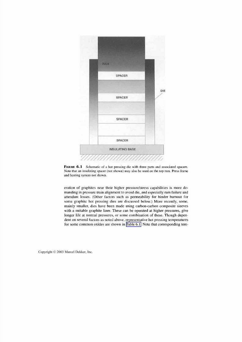
7/29/2019 29540824708539
http://slidepdf.com/reader/full/29540824708539 219/361
208 Chapter 6
FIGURE 6.1 Schematic of a hot pressing die with three parts and associated spacers.
Note that an insulating spacer (not shown) m ay also be used on the top ram. Press frame
and heating system not shown.
eration of graphites near their higher pressure/stress capabilities is more de-
manding in pressure train alignme nt to avoid die, and especially ra m failure andattendant losses. (Other factors such as permeability fo r binder burnout for
some graphite hot pressing dies are discussed below.) More recently, some,mainly smaller, dies have been made using carbon-carbon composite sleeves
with a suitable graphite liner. These can be operated at higher pressures, give
longer life at normal p ressures, or some combination of these. Though depen-
dent on several factors as noted above, representative hot pressing temperatures
for some common oxides are shown in Table 6.1. Note that corresponding tern-
Copyright © 2003 Marcel Dekker, Inc.

7/29/2019 29540824708539
http://slidepdf.com/reader/full/29540824708539 220/361
Other Dcnsification and Fabrication Methods 209
TABLE 6.1 Representative Hot Pressing Temperatures fo r Common Oxide C eramics"
Single oxide
A1203
B eOCaOCaO (+ LiF)
M gO
MgO (+LiF)TiO2
Pressingtemperature(°C)
1300-1500
1600-1800
1200
1000
1200-1400
11001200-1300
Mixed oxide
BaTiO 3
PZTPbTiO3
Mn-Zn FerriteM g Al203
MgAl2O 3 (+LiF)
Pressingtemperature(°C)
1100-1200
10001200
13501400-1600
1200-1300
"Specific temperatures will vary with the specific powder, actual pressure, and time at temperature
bu t representative temperatures are shown as an approximate guide, e.g., fo r pressures of the order of35 MPa and times of 0.5 hr for common powders.
peratures for common refractory borides, carbides, and nitrides, with typical ad-
ditives are commonly in the range to 1700-1900°C.
Other die materials used have been refractory metals such as W or Mo (or
alloys such as TZM) and some ceramics, such as A12O3 or SiC, mainly made via
hot pressing [2,3, 6,7]. These are restricted by both fabrication limitations and
costs to smaller dies, for example, to cavities of 5 -cm diameter. In using ceramic
and, especially, metal dies, cautions such as looser ram-die clearances or use of
coatings to inhibit or prevent ram-die sintering or welding are often needed. An-
other limitation is creep of the die; even small amounts of additives or impurities
that enhance creep, such as SiO2-based impurities, e.g., even at the 0.1% level
can seriously limit temperature/pressure capabilities—that is, 99% alumina may
not be adequate. SiC dies have been commercially produced (by hot pressing)
for commercial production of ferrite components in air or other atmospheres
(since hot pressing in graphite dies is not acceptable due to reduction of the fer-
rites). Various high-pressure systems, including those used for making synthetic
diamonds (which use special systems consisting of massive metal dies with
small volumes for product, internal heater, and electrical insulation), have alsobeen applied to hot pressing dense ceramics. While bodies of NiO, Cr2O3, and
A12O3 at or near theoretical density with grain sizes < lum have been obtained in
massive metal dies at temperatures of ~ 800-1200°C with pressures of <700
MPa [8], they often have strengths much below those expected for their fine
grain size. This is attributed to retention of anion species at grain boundaries
[3,9], as discussed in Section 8.2.1.
Before proceeding with more description of conventional hot pressing,
two other related processes for densifying metals, that have had some applica-
tion to ceramics, should be noted. The first is high-rate mechanical compaction
by a metal ram accelerated to high speeds by expanding gas, such as a Dynapak
Copyright © 2003 Marcel Dekker, Inc.
7/29/2019 29540824708539
http://slidepdf.com/reader/full/29540824708539 221/361
210 Chapter 6
system[l,5]. This w as applied to some ceramics, particularly UO 2-PuO 2 nuclearfuel materials, which were sealed in a metal can, evacuated while heating to
1200°C in a separate furnace, sealed off, an d rapidly loaded in the massivemetal, high-pressure die, then impacted, giving a transient high consolidationpressure, 1750M Pa (250,000 psi) . In this case th e fuel we nt from 55% to 99% of
theoretical density. Cracking from rapid cooling was not a particular problem
since th e densified body was crushed to produce dense grain for swaging in
metal tubes for fuel rods. Tests with other ceramics were generally less success-
ful due to incomplete densification, cracking, or both: for example, trials with
alumina, thoria-alum ina compo site, and thoria gave -85, 90, and 95% o f theoret-ical density, respectively, at ~ 1200°C with ~ V 2 million psi impact p ressure. The
other related process is explosive compaction [5,6], which is normally done at
room temperature, and can be done at elevated temperatures, but still generallyresults in severe cracking in most ceramics; thoug h cracking is reduced some at
higher tem peratures, it can still be a problem. The limitations of both processes
have constrained their use and development.
Graphite and metal dies are generally used in neutral or nonoxidizing condi-
tions, but are sometimes used in an atmosphere open to the air, especially graphite
dies, with some surface insulation to limit oxidation rates of the outer surfaces of
the die and ram , and hence retain reasonable die lives. G raphite dies used open to
the air maintain a reducing atmo sphere determined by the CO-CO2 balance in and
around the die as determined by operating conditions such as temperature. Suchuse of metal dies exposed to oxida tive atmospheres is often restricted by possible
detrimental internal oxidation an d bonding of dies an d rams. Again, coatings or in-
terface layers may maintain reasonable die lives an d performan ce (i.e., avoiding
oxidative bonding of die, ram, or components with one another).
Having selected the material to be pressed and the dies to be used, and
hence the allowab le temperature and pressure ranges, specific pressing tempera-
ture an d related parameters of pressure an d time are selected based on factors
such as prior experience, trial pressings, or both. Such information can be sys-
temized to give a probable pressing temperature for a specific material-powder
system by one of two methods [1,4,10]. The first, referred to as the isothermaltechnique requires several hot pressing runs in which th e t ime to reach th e target
density, e.g., 99% or more of theoretical density, at the selected pressure is plot-
ted versus the pressing temperature of each hot pressing run. This generally re-
sults in the t ime to reach th e target density with th e selected pressure decreasing
substantially and linearly with increasing pressing temperature followed bym u c h less decrease in time as temperature is further increased. The target press-
in g temp erature is that where the two linear curves intersect (Fig. 6.2A). The sec-
ond technique, referred to as the climbing temperature program, requires few er
trial pressings and is done by heating th e body, under th e selected pressure,
slowly through th e regions of densification until densification essentially ceases
Copyright © 2003 Marcel Dekker, Inc.

7/29/2019 29540824708539
http://slidepdf.com/reader/full/29540824708539 222/361
Other Densification and Fabrication Methods 211
|»
£80-
5 5 70-
60-
50-
40-
30-
20-
10-
100
|80
Ui
Q
U J __> 70
ff 60
50
B
T optimum
1350 1400 1450 1500 1550
TEMPERATURE (°C)
1600
900 1100 1300
TEMPERATURE (°C)
1500
FIGURE 6.2 Schematic of data analysis to determine target hot pressing temperatures:
(A ) isothermal and (B) rising temperature.
Copyright © 2003 Marcel Dekker, Inc.
7/29/2019 29540824708539
http://slidepdf.com/reader/full/29540824708539 223/361
212 Chapter 6
(Fig. 6.2B). A few trial runs should map out the temperature and pressure para-
meters for pressing the selected material and powder. A newer approach becom-
ing available is based on universal hot pressing curves analogous to universalsintering curves developed by Johnson [11].
An issue in much hot pressing is whether to do so under vacuum or to
evacuate an enclosed hot pressing system, then backfill with a selected, usually,
nonoxidizing atmosphere. This is most extensively done in laboratory hot press-
ing, and while used in some industrial hot pressing, is much less common since
near-zero porosity bodies generally can be achieved without vacuum hot press-
ing. This results from gas in the powder compacts being expelled, at least in
small-to medium-sized bodies, by thermal expansion as well as by mechanical
pressure, which also reduces sizes of residual gas-filled pores, whose pressure is
greatly reduced upon cooling from hot pressing. The extent to which residual gas
and related pore gradients start to occur in the interior of large hot-pressed bod-
ies appears unknown. Vacuum hot pressing may thus be more important for
larger bodies, bodies with larger initial pores, and for other reasons—for exam-
ple, to remove other sources of outgassing such as binders (discussed below).
The issue of heating for hot pressing sh ould also be noted. Most laboratory
hot presses use furn aces with resistive heatin g elements, wh ich are typically car-
bon/graphite or refractory metal elements, thus also requiring nonoxidizing at-
mospheres. On the other hand, most industrial hot presses use indu ctive heating
with coupling to a graphite suceptor or more commonly directly to the graphitedies. Such inductive heating also favors use of nonoxidizing atmospheres, but as
noted above, can often be done with some system exposure to the air atmos-
phere. The differences in rates an d uniformity of heating differ significantly be-
tween the two heating systems, with induction heating allowing faster heating
rates, hence shorter hot pressing cycles. Though not directly studied, it is likely
that ind uctiv e heating, especially via direct coup ling to the die, is more uniform.
However, it should be noted that alternative heating systems have shownprom ise for at least some ho t pressing (and som e sintering ) that deserve attention
as discussed in the next section.
Determining actual component temperatures in hot pressing is a challeng-in g problem since thermocouples often become inoperative, and where opera-
tive, typically must be some distance from the actual part(s). Optical pyrometer
temperature measurements, while improved in some ways, have similar or
greater u ncertain ties in their specific proximity to a component in the die. Thus,
hot pressing "temperatures" for one size and shape component versus another of
th e same material m ay differ substantially due to differences in thermal environ-
ments and temperature sensing in the dies, and especially from one hot press to
another. The latter differences can be 100-200°C, so operating parameters for a
specific component, an d especially a specific hot press, are typically refined by
operational trials.
Copyright © 2003 Marcel Dekker, Inc.

7/29/2019 29540824708539
http://slidepdf.com/reader/full/29540824708539 224/361
Other Densification and Fabrication Methods 213
Hot-pressed ceramics are briefly characterized in terms of three aspects:
(1 ) the materials, (2) their microstructures and properties, and (3) their numbers,
shapes, and sizes. Hot-pressed ceramics consist of an extensive and diverse array
of materials including a variety of oxide and nonoxide ceramics, many of these,
especially nonoxides, with densification additives (Chap. 5). Oxides and other
compounds that are subject to reduction or other stoichiometric changes in com-
m on hot pressing environments may require post pressing annealing or other
treatment to return them to suitable stoichiometry, but opportunities for this are
limited, especially for larger parts. While pressureless sintering of several impor-
tant refractory nonoxides has progressed substantially, there is still important im-
petus for hot pressing these and other nonoxides. The increased interest in
ceramic composites with dispersed particulate, platelet, whisker, or fiber phases
has further added to the use of hot pressing since these are more challenging to
densify by pressureless sintering, especially the latter three (Sec. 8.2.3). Thus, all
of the commercial production of composites of SiC whiskers in alumina matrices
is by hot pressing, and most fiber composites have been made by hot pressing.
Turning to microstructure, hot pressing commonly gives bodies at or near
zero porosity,:for example, frequently hot pressing gives translucent to transpar-
en t bodies fo r suitable dielectric materials, with finer, often more equiaxed, grain
structures than typically obtained from pressureless sintering th e same material
to within a few percent of the same density. The typically resultant higher trans-
parency, and mechanical, electrical, thermal, and related performance is, in fact,aprimary driving force for hot pressing. However, though dependent on material,
powder, and pressing conditions, it should also be noted that hot pressing often
results in some measurable degree of anisotropy in properties due to some crys-
talline preferred orientation, anisotropy of residual porosity, or both. Varius stud-
ies of anisotropy of hot-pressed silicon nitride bodies shows there is commonly
some anisotropy in commercial hot-pressed bodies and that this arises from ef -
fects of both grain orientation an d anisotropy of residual pores [9]. An earlier
reference for some of the more comprehensive data on the crystallographic ori-
entation aspect is the report of Iwasaki and coworkers [13], and Rice[9] has sum-
marized some more recent results.The almost universal output of hot pressing is one or a few pieces of very
basic shapes such as cylindrical or prismatic rods or plates. Where more than one
of these is produced in a given hot pressing run, it is primarily by use of spacers
to allow two to four other identical parts to be produced above or below one part
(Fig. 6.1). This requires that the die be large enough and have sufficiently uni-
form heating along its length and diameter, and that th e powder used has reason-
able pour/tap densities. On the other hand, hot pressing can produce sizable
parts—75 x 40 x >0.1 cm and 45 x 45 x 20 cm—and parts to nearly a meter in
diameter are seen as feasible. (R. Palicka, Cercom, Inc., personal communica-
tions, 2000). However, such large parts require very slow cooling to avoid crack-
Copyright © 2003 Marcel Dekker, Inc.

7/29/2019 29540824708539
http://slidepdf.com/reader/full/29540824708539 225/361
214 Chapter 6
ing, and may impose maximum dimensions—for example 2—3 m to avoid
cracking. They also present challenges in filling such large size die cavities uni-
formly and reproducibly. Hot pressing of rods has been shown to be feasible in asemicontinuous fashion by periodic addition of powder an d pressing it onto a rod
in steps[15,16], but this is probably of limited practicality fo r most purposes.
However, further development to extend th e technical capabilities and lower
costs of hot pressing are feasible as outlined below, after first considering ap -
proximate limits on the size of hot pressed parts.Another basic size limit of hot-pressed parts arises from impacts of lateral
part dimensions being ultimately limited first by capital costs (press size) and
second by o perating costs. The force needed to supply a fixed pressing pressure
increases as the square of the part area being pressed; fo r example it reaches1600 tons at a meter square part size for 14 MPa pressing pressure (-2000 psi),
that is a sizeable p ress and hy draulic system. Further, the sizes of the cross-mem -
bers (beams) of the press su stainin g such forces significantly increase with part
lateral dimensions. Though I or truss beams are likely candidates fo r crossmem-
bers, consideration of a solid rectangular beam is illustrative of increased cross
member bulk with increasing cross member length for pressing larger parts.
Thus, in order to keep the same center beam deflection and pressing pressure as
the scale of a press increases, the width of a solid beam or its thickness (or both)
must increase as the beam length is increased to press larger parts. For example,
if th e beam length is doubled, increasing its thickness to keep th e same deflec-tion an d pressing pressure results in a minimum of about a six fold increase in
beam volum e, hence m ass. Part heights are limited first by the com pactibility ofthe powder an d heights of dies and of uniform heating, as well as by die-wallfriction effects an d resultant densification gradients (see Sec. 4.2.1), which are
functions of material and part aspect ratio. Part dimensions are also ultimately
limited by heat-transfer limitations within th e part, possibly in some cases by
heating and inadequate temperature uniformity for suitably uniform densifica-
tion, but more commonly by cooling stresses, especially when they lead to
cracking, which is also material and part shape dependent. Note also that large
hot-pressed parts require powde r loading systems that can either load the pow deruniformly in the die in a practical fashion or suitably load one or more powderpreforms in the die, as well as unload th e parts. The mass of large parts becomesa factor in the engineering fo r such part handling; for example typical ceramic
parts of 1 m2
x 1 cm dimensions will weigh 200-400pounds.Consider now part shape: Some deviations from simple rods or plates is al-
ready feasible, including some pressing of parts with some simple holes or cavi-
ties. Also, hot pressing of silicon nitride turbine vanes with a two-rather than a
three-dimensional variation of shape have been shown to be feasible for net
shape pressing and at costs less than fo r injection molding and sintering of lim-
Copyright © 2003 Marcel Dekker, Inc.
7/29/2019 29540824708539
http://slidepdf.com/reader/full/29540824708539 226/361
Other Dcnsification and Fabrication Methods 215
ited numbers—for example, a few thousand per year where there is still a sub-stantial penalty for each van e for the injection m olding die costs. M ore complex
shapes, such as hemispherical domes [17] or ogive radomes, have been hotpressed with specialized tooling, an d some potential has been shown for hot
pressing more complex shapes by using a refractory pow der to apply a quasi-iso-
static pressure from the die rams and constraint of the die wall [18]. However,
such advances (discussed below) are mainly applicable to specialized, niche,
production, rather than lowcost, largescale production.
6.2 .2 Extending Practical Capabilities ofHot Pressing
Consider now increasing the number of parts hot pressed per unit time, which
can be done by reducing the pressing cycle time, by increasing the number ofparts in a given pressing, or both. Simple engineering, which of course depends
on both the part size and the die size feasible, can do quite a bit of this given the
sizes of dies feasible for pressing parts approaching a meter in diameter and at
least half a m eter in height. A horizontal hot press was built to accom modate in-
sertion and rem oval of dies into and from a horizontal chain of dies in the press-
ing train[19]. Typically there w ould be three loaded dies in the train at any onetime, one at the input side being heated for pressing, the m iddle die being in the
hot zone for actual hot pressing, and the die at the output end cooling to be re-moved when the middle die is done pressing and a new die is inserted in the in-put side of the train, moving the two remaining dies to their next station in the
press. While used some and showing potential fo r increased output, this semi-
continuous hot press presented limitations due to its horizontal n ature, requiring
the same or very similar size dies and powder loads, and presenting issues of
control of pressure on the die being heated up and its heating, as we ll as possible
problems of the part(s) in the die being cooled.
More promise in reducing the times for a pressing cycle for a given hot
press, which consist of a heating, a pressing, and a cooling stage, is seen by mov-
ing heating and die assemblies through a vertically oriented press frame suchthat the primary or only time each heating and die assembly spends in the pressframe is for actual heating and pressing portions of the hot pressing cycle. Thus,
one heating and die assembly can be being heated while one is cooling, another
is being loaded and another unloaded, with such assemblies moved in and out ofthe press frame. Such m ovem ent of heating and die assemblies has been accom-
modated by having two of them on metal wheels being moved back and forth in
and out of the press frame, or having two or more assemblies in a lazy Susan
arrangem ent. This app roach a voids the limitations of the horizontal semicontinu-
ous hot press noted above.
Copyright © 2003 Marcel Dekker, Inc.
7/29/2019 29540824708539
http://slidepdf.com/reader/full/29540824708539 227/361
216 Chapter 6
While the above use of two or more heating and die assemblies for a given
press frame can reduce costs of hot-pressed parts, the most significant cost reduc-
tions should result from using large dies and heating-pressing systems such that
substantial numbers of parts are pressed simultaneously in one die in one pressingcycle. This requires that parts not only be commonly stacked vertically (using
spacers, Fig. 6.1) but that multiple stacks arranged in horizontal arrays be used,
such as using multicavity dies. Some use of such dies has been made, but much
more extensive use requires a fundamental shift in die loading procedures, which
also has other benefits. As noted above, the standard procedure for loading powder
into dies has been to simply p our pow der into the die cavity. How ever, this is labor
intensive, and has poor reproducibility of die fill needed to obtain uniform powder
filling and consolidation in parallel stacks of powder allotments for components.Such powder loading of multicavity dies may also introduce defects, as shown by
efforts of an industrial developer of ceramic bearing components (who demon-
strated success in such multicavity die pressing, as have others). However, greater
rates of failure of silicon nitride bearing balls from mu lticavity hot pressing of in-
dividual ball blanks was found versus from balls made from blanks machined from
large silicon nitride billets. This high er ball failure rate was traced to greater inclu -
sion of graphite particles introduced in the powder filling stage for multicavity
pressing due to the large number of graphite edges from which graphite particles
could readily be abraded an d entrained by powder loading. The potential solution
to this problem, namely of usin g ball-blank preforms to be loaded into the die wasnot considered, and the hot pressing of individual ball blanks was abandoned.
However, subsequent developments in other aspects of hot pressing indicate sub-
stantial potential for hot pressin g of green-formed parts as outlined as follow s.
The first of two examp les of significant use and potential of green form ing
of parts for hot pressing, not only demonstrated green forming of sophisticated
electronic ceramic parts, but also show ed a sign ificant new op portun ity for hot
pressing. This was the conception and demonstration by Rice and coworkers[20—22] that first electronic substrates and subsequently multilayer electronic
packages made by green forming , with cofireable metalization, could be success-
fully and advantageously densified by ho t pressing (Fig. 6.3). Thus, they showedthat conventional as w ell as large m ultichip mod ule electronic p ackages could be
hot pressed to high quality—better than by sintering—with significant advan-
tages. These included higher den sities, such as transparent A1N, but m ore impor-
tantly with much greater flatness and lateral dimensional control than in
pressureless sintering. Such dimensional advantages arises since there is no lat-
eral shrinkage in hot pressing (it is all in the axial pressing direction) versus the
nearly isotropic (20% linear) shrinkage in sintering. This lack of lateral shrink-
age is a ma jor adv antag e in this packag ing (and some o ther) applications both for
customers that require a high degree of dimensional control, as well as havingth e ability to surface metallize with thin film metallization. The high density of
Copyright © 2003 Marcel Dekker, Inc.

7/29/2019 29540824708539
http://slidepdf.com/reader/full/29540824708539 228/361
Other Certification and Fabrication Methods 217
FIGURE 6.3 Multilayer A1N electronic package for multichip modules (probably the
largest ever) made by hot pressing. Package is shown with metallization in a frame fo r
populating th e package with components. (From Ref. 20, published with permission of
the American Ceramic Soc.)
the hot-pressed parts an d their flatness also lend itself well to thin film process-ing. The lack of lateral shrinkage in hot pressing also allowed formation of hy-brid electronic packages, for example, of low K dielectric with Cu metalizationto be hot pressed onto previously hot pressed A 1N or other bases.
The above technical advances were achieved by using conventional,
binder-based, green forming (tape forming), screen printing, and laminationtechniques, then burning out the binder in the hot pressing die in the heatingstage for hot pressing. Initially a binder system based on polyethylene an d min-eral oil that yielded good tape by hot extrusion was used, since this is probablyone of the cleanest burning binder systems (especially after solvent removal ofthe mineral oil, which phase separates from the polyethylene on cooling from
extrusion). Subsequently, conventional binder an d tape casting fo r other, (alu-
mina) packages were successfully adapted for hot pressing. Conventionalbinders for screen-printed metallizations were used in either case. G raphites w ithgreater permeab ility fo r enhanced binder burnou t were found to be advantageous
for die components.
Copyright © 2003 Marcel Dekker, Inc.

7/29/2019 29540824708539
http://slidepdf.com/reader/full/29540824708539 229/361
218 Chapter 6
The above development of hot pressing ceramic electronic substrates an d
multilayer packages was judged to be economically viable based in part on a sub-
stantial number of parts potentially being hot pressed simultaneously in a given
pressing (with successful demonstrations of hot pressing 3-6 sizable packages at
once). How ever, amo ng other important factors was that substrates and most mu l-
tilayer packages are, or can be made to appear as, flat plates for hot pressing,
eliminating machining costs that are a common major cost disadvantage of hot-
pressed versus pressureless sintered parts. Further, th e general cost disadvantage
of hot pressing relative to sintering can be limited by lower temperatures/shorter
densification cycles, especially for high temperature m aterials su ch as A1N (where
avoiding the need of overpressure processing atm ospheres or powders for burying
components needed in most of its sintering is also an advantage). Also, specific toth e electronics application, th e higher costs often allowable are an advantage fo r
this specific application. The econom ic viability of such hot pressing is supported
by the technology having been licensed to CEPCO (Coors Tek, Inc., Golden,
CO.), who has used it in some comm ercial prod uction.
Green forming of ceramic bodies for hot pressing has also been success-
fully used for making large bodies, e.g. 40 cm square by several cm thickness
(and some modest shapes beyond a simple plate). While use of binders with
some bodies needs further development, they have been successfully used in a
number of cases. Though some binder burnout of some medium size parts has
been done in the hot-press dies, it may often be best to have a separate binderburn out step, thoug h this can pose handling problems.
The above two uses of binder-based green forming of components have
potentially significant ramifications for the economics of hot pressing, besides
adding new product opportunities such as packages. Thus, die loading via pre-
forming can be made more efficient using existing techniques widely available
fo r sintering. It can also increase the num ber of parts for a given pressing where
higher green densities can be obtained, for example, with finer powders (whose
frequent voluminous character is often a l imitation in hot pressing ( Fig. 4.1).
However, even larger potential may exist for using green body formation for
making attached arrays of green preforms for multiple cavity hot pressing; thus,fo r example, m olding arrays of parts (such as bearing ball preforms) attached by
thin rods of green m aterial such that the array can be dropped into a m ultipart die
would eliminate th e added g raph ite contam ination noted earlier, and possibly al-
lo w automation of the hot pressing process.
B esides issues of inductive heating of a die directly and potentially more
uniformly, or by heating a die via a suceptor (giving more flexibility in die size
with a given inductive coil) or direct coupling to the die versus heating the die
via a conventional surrounding resistively heated furnace, there are other varia-
tions in heating that may have potential for special or more general application.
These c o mmo n ly entai l either or both of two options of resistive heating of the
Copyright © 2003 Marcel Dekker, Inc.
7/29/2019 29540824708539
http://slidepdf.com/reader/full/29540824708539 230/361
Other Densification and Fabrication Methods 219
graphite dies, powder compacts of conductive particles, or both. One of the ear-
lier reports of such heating is that of Glaser and Ivanick[23], who investigated
direct current resistive heating of the graphite dies and TiC powder compacts in
making small (2.5 x 1 x 0.5 cm) TiC samples with or without metal binder.
They reported reaching very near theoretical density without metal binders by
hot pressing TiC powder (2 urn particle size) at pressures of only 1-12 MPa (ap-
plied well before th e maximum temperature of 3000°C) with a maximum hold
time at temperature of 30 sec. Flexure strengths of resultant specimens of ~ 870
MPa indicate high-quality, fine-grain bodies achieved due to the short time at
high temperature. While their paper is not clear on what portion of the resis-
tance heating m ay have come from th e powder compact versus th e die, it
clearly indicated promising hot pressing cycles with such resistive heating. Oth-
ers have demonstrated successful hot pressing using resistive die heating; for
example,. Jackson and Palmer [24] report such successful hot pressing of some-
what smaller samples of eight common carbides, four common borides, and
four common oxides at modest pressure (2 1 MPa), typical temperatures, and
short times. Thus, pressing WC at 2000°C and ZrB 2 at 1900°C for 5 and 3 min,
respectively, gave dense bodies with grain sizes near th e starting particle sizes.
The Army Research Laboratory in Watertown, MA, (circa the 70s) had a sizable
hot press (apparently mainly fo r metals) using resistive heating of the die (and
presumably th e powder compact). In view of the limited resistive heating likely
in oxides (e.g., alumina), their heating probably came from th e die. This authorand colleagues attempted some hot pressing trials where the powders to be hot
pressed were conductive, but were insulated from th e graphite dies (via a B N
sleeve), so only th e powder w as resistively heated. Such trials were unsuccess-
ful since densification of the conductive powder greatly decreased as the pow-
der partially densified and increased in electrical conductivity. Use of a higher
current welding power supply instead of a conventional fixed voltage system
did not solve th e problem, supporting a focus on die heating. However, efforts
to develop hot pressing with resistive heating mainly or exclusively of the die,
despite some very promising short cycle times and properties, w as generally ne-
glected for a long period of time. Whether this was due to engineering issues ofpower leads to the dies or problems of practical handling of different die sizes
and configurations is not clear.
Recently, there has been further investigation and development of at least
laboratory systems using more sophisticated power supplies, apparently provid-
ing combinations of variable direct or alternating current and possibly pulses of
these, e.g., of higher frequency. While the details of such heating system design
an d use as well as the mechanism(s) for its success are uncertain, there have
been claims of very promising results, again associated with very short times at
maximum temperature (2-5 min), and thus promising overall hot pressing cycle
times [25-27]. Some units with at least modest (for example, mechanical pump)
Copyright © 2003 Marcel Dekker, Inc.
7/29/2019 29540824708539
http://slidepdf.com/reader/full/29540824708539 231/361
220 Chapter 6
vacuum capability have been also offered fo r sale. In some cases, retention of
fine grain sizes has been observed, while in others, substantial grain growth oc-
curred, posing some issues. However, there are other methods of grain growthcontrol, especially use of second ph ases as in composites. Possibilities of plasma
generation in the pores between particles, and resultant cleaning/activation of
particle surfaces have been suggested as a mechanism for the pressing benefits,
as also noted fo r some novel heating methods for pressureless sintering (Sec.
8.2.2). Thus, alternate heating systems m ay have important benefits, but face is -
sues such as scaling to larger sizes and flexibility— for different die sizes,
shapes, and fills, different materials and powders, and use with binders.Finally, note that an important extension of hot pressing is as an important
tool in reactive processing of ceramics, as discussed in Section6.5.
Also notethat press forging and some other deformation forming processes discussed inth e next section are extensions of hot pressing.
6.3 PRESS FORGING AND OTHERDEFORMATION FORMING PROCESSES
A natural extension of hot pressing is press forging, which basically entails
pressing a body at elevated temperatures such that it has little or no lateral con-
straint, at least initially, other than normal viscous and pressing surface resis-
tance to ve rtical and lateral flow. This is com m only done in an oversized die toprovide ram alignment as well as possible shape and size definition in the laterstate of deform ation. There are two basic manifestations of this, the first beingforging of powder-based bodies to both densify and shape them, which was dis-
covered by Spriggs and coworkers [28,29] as a result of a die failure during a
normal hot pressing run. The die failure was not observed until after th e press-
in g run, but had been accompanied by considerable densification and plastic
flow of th e ceramic powder compact. Subsequent investigation showed that not
only reasonable shaping, but also po ssible e nhanced densification w as possible,
during press forging. However, as discussed in Chapter 1, forging rates
achieved so far indicate that th e process is likely to at best be restricted to spe-cial niche applications. (Recently Kim, an coworkers [29] have reported thatstrains of 1000% h ave been achieved with a nanograin composite of ZrO 2 with
30% each of spinel and alumina in tensile elongations at higher strain rates,
e.g., 0.4 sec ' at 1650°C, which could aid practicality.) Considerable researchsubsequently followed initial observations based on demonstrated possibilities
of significant preferred grain orientation an d resultant, often beneficial, effects
on properties, such as electrical and magnetic ones [30-33]. However, green
body formation and seeding techn iques often do as good or better jo b with these
and are generally more versatile and practical techniques.The other manifestat ion of press forging, and one that has had some indus-
Copyright © 2003 Marcel Dekker, Inc.
7/29/2019 29540824708539
http://slidepdf.com/reader/full/29540824708539 232/361
Other Densification and Fabrication Methods 221
trial use, is of converting single crystals into polycrystalline bodies. This has
been commercially applied to making IR windows of halide materials, e.g., of
KC1 and CaF2, since it offers tw o advantages over the as grown single-crystal
form. Press forging of a single crystal and converting it into a polycrystalline
body provides greater strength and more isotropic properties. It also has a practi-
cal shape advantage in that most optical windows are thin discs with diameters
several times their thickness, while single-crystal growth typically produces
boules of limited diameter and greater length. There are cost and other limita-
tions on growing crystals of large diameter, so press forging which typically
compresses rods into plates while also providing some property advantages is at-
tractive. Such processing thus offers advantages that offset th e moderate cost of
forging compared with those of growth of larger diameter crystals.
The above press forging of single crystals of ceramics an d related materi-
als has various roots including those in metals forming. More specific roots are
in deformation of NaCl to recrystallize it , e.g. as in the review of Schmidt and
Boas [34], and more specifically in Stokes an d Li's studies of NaCl deformation
using extrusion of single crystals to produce high-quality polycrystalline speci-
mens fo r test [35]. Day and Stokes [36] also recrystallized M gO crystal speci-
mens by tensile straining them 60% at 1800°C then annealing at 2100°C; an d
Rice and coworkers [37] had demonstrated hot extrusion of MgO crystals and
their recrystallization to polycrystalline bodies. Rice [3,37,38] demonstrated
press forging and recrystallization of not only M gO crystals but also other cubiccrystals of CaO, spinel, and TiC (but that noncubic sapphire an d ruby deformed
very anisotropically and did not recrystallize). Height reductions of 50-60%
were readily achieved in the pressure range of 20-35 MPa in times of the order
of 0.5 hr at 1850-2000°C (Fig. 6.4), with height reductions of 70-80% seen as
feasible. Subsequently Becher an d Rice [39] demonstrated press forging of KC1and its benefits for application as high-power laser windows, which has been
used in commercial production of halide windows.
While press forging has its advantages, other hot working was also of in-
terest, particularly extrusion, which, as noted above, was demonstrated for both
NaCl [34,35] and MgO crystals [3,30,37] before press forging was demon-
strated. Hot extrusion of polycrystalline MgO, as rods with area reduction ratios
of 10, ram speeds of 5 cm/sec at temperatures of 2000°C, was also demonstrated
[37,38]. This was done in thick wall, coextrudable cans of Mo-based alloys or of
W . Extrusion of some other cubic ceramics was also demonstrated, along with
methods of starting with compacted (rather than dense) powder billets that were
simultaneously densified by pressures generated in the initial stage of extrusion.
B oth some shaping, (extrusion of round pieces versus slabs) as well as possibili-
ties of lowering extrusion temperatures and broadening the scope of extrudable
materials via high-temperature hydrostatic extrusion and "fluid to fluid extru-
sion" were demonstrated. However, unless some unusual applications were to
Copyright © 2003 Marcel Dekker, Inc.

7/29/2019 29540824708539
http://slidepdf.com/reader/full/29540824708539 233/361
222 Chapter 6
FIGURE 6.4 Press-forged M gO crystal: (A) before press forging and (B ) after partial forg-
ing. (From Refs. 30 and 38. Pub lished with permission of J. American Ceramic Society.)
arise, refractory ceramic extrusion technology remains only partially developed
and unused because of high costs and limited yields and benefits relative to other
fabrication. Coex truding glasses and metals was demonstrated by H unt [38] as a
possible method of making glass-to-metal seals, but was not successful in find-
in g practical application.
Turning to forming and hot working m ethods tha t may also entail densi-
fication, hot rolling has been considered primarily as a ceramic densification
and form ing metho d, e.g. as a method of co ntin uo us hot pressing, rather than
as a means of hot working. Ear l ie r exper iments focused on placing ceramic
Copyright © 2003 Marcel Dekker, Inc.

7/29/2019 29540824708539
http://slidepdf.com/reader/full/29540824708539 234/361
Other Densification and Fabrication Methods 223
sleeves on metal rolls to allow higher temperatures (via a furnace attached tothe rolling mill) and avoiding metal contam ination of the ceramic [38]. Trials
were unsuccessful since th e unheated rolls limited temperatures to1000-1100°C and gave unfavorable temperature gradients. Thus, substantial
glass phase had to be added to obtain sufficient flow of ceramic-glass mixtures
fo r some limited densification.
Greater, but still limited, success was achieved in hot rolling MgO with
LiF additions since this yields a more "fluid" system and at lower temperatures,
for example, 1000-1100°C [3,38,40]. This development started with a sugges-tion of Hunt to densify powders in metal tubes by swaging the powder-filled
steel tubes first at room, then at elevated temperatures. H owever, it was quickly
recognized that filling powders in steel tubes, then densifying the powder first bycold (room) temperature rolling (which readily yields very high green densities,
Sec. 4.5),then rolling the tub e and partially densified pow der at elevated temper-
atures, was more promising. Some success was achieved in limited rolling trials
in a system with alumina-sleeve-insulated metal rolls in a resistive furnace to
heat the rolls and the part to be rolled. Somewhat more success was obtained
with a prototype custom rolling m ill con sisting of larger, but less massive, lowerpressure rolls and two m etal strip heaters that were fed betw een the tube contain-
ing the powder and the bottom and top rolls (w hich were p artially thermally in -
sulated from the heaters by sheets of asbestos). MgO slabs >99% of theoretical
density a few millimeters in thickness and 2-3 cm in width an d several centime-ters long were obtained in hot rolling at 1000°C at pressures of 20 M Pa at speeds
of 2.5 cm/sec., but there w ere major problems of cracking and o utgassing. Thu s,
during hot rolling of previously cold-rolled powder, the filled tubes generallybloated back up to about their original diameters prior to cold rolling, despite be-ing evacuated at temperatures of 500°C, then sealed prior to cold rolling.
Drilling holes in the sealed, cold-rolled tubes just prior to hot rolling allowed
outgassing and prevented tube bloating within a few centimeters of the drilled
holes. Some progress on these problems was made; for example giving sometranslucent-transparent, crack-free pieces a few centimeters in lateral dimen-
sions. However, a basic problem was seen as the limited temperatures achievablein the powder to be rolled, due to having to heat the rolls substantially. This
along with costs and problems of the cans and their removal were reasons for
ceasing development.Later interest in self-propagating high-tem perature syn thesis not entailing
gaseous reactants or reaction products, where highly exothermic reactions cangenerate a reaction front that, upon ignition of the reaction, moves through a
compact of solid reactants, along a bar of the reactants, was seen as a possible
basic solution to the basic heating problem for hot rolling noted above [41].
Thus, filling a metal tube with reactant powders and cold rolling the tube and
powder, then igniting the reaction at one end of the tube so the reaction and as-
Copyright © 2003 Marcel Dekker, Inc.
7/29/2019 29540824708539
http://slidepdf.com/reader/full/29540824708539 235/361
224 Chapter 6
sociated high-temperature reaction front propagates along the length of the re-
actant powder compact in the tube was seen as a possible way of providing de-
sired heating for hot rolling to simultaneously densify the reactant products.Such heating would have the potential of heating not only primarily the material
to be consolidated, but to do so primarily in the moving reaction zone, where
consolidation would be focused, and potentially aided, by transient liquid
phases that are often generated. Further, rolling speeds might be controlled by a
feedback system to match the rolling speed to the reaction speed since this
should minimize rolling pressures, which can be sensed an d used as the feed-
back control. Trials showed some promise, a number of challenges, and some
possible requirem ents, such as that the roll diameter probably needs to be on the
scale of the size of the hot reaction zone, that is, substantially smaller than typi-
cal rolls in laboratory metal rolling mills. Such smaller rolls could also be
backed up with more massive rolls. Thus, while there are possibilities to try,
substantial challenges and uncertainty remains for hot rolling as a continuoushot pressing method.
Various approaches have been considered fo r placement of green or par-
tially sintered bodies in a pow der bed , or their encap sulation in a glass, to act as
pressure tra nsm ittin g media such that placement of the part to be densified withthe pressure trans m itting pow der or the glass encapsulation in a hot pressing die
to turn the hot press into a quasi-hot isopress [6,42-44]. While general hot iso-
pressing is discussed in the next section, some of these approaches are dis-cussed here since they use hot presses, and one [27] uses resistive heating of the
graphite die and the pow der trans mittin g media. Developm ent and possible
commercialization of these concepts for quasi-isostatic densification of ceramic
(or metal) powder preforms surrounded by a pressure transmitting carbon or
other ceramic powder in a die cavity, where th e part is pressed by applying axial
pressure to the pressure tran sm itting powder have been pursu ed. In order to cut
cycle time (and l imit heating costs) some part preforms and pressure transmit-
ting powder were heated outside of the hot press die into which they were
rapidly loaded and pressed, then unloaded from the die with only partial cool-
ing. Actual times at temperature for densification were of the order of secondsdue to the high pressures used (0.8-1 G Pa) , indicating use of massive metal diesthat limit exposure to higher temperatures and times at temperature. This ap-
proach may be more successful w ith metals because of their greater densifica-
tion by p lastic flow and co nsolid ation at lower temperatures, as well as to some
lower temperature ceramics, such as high temperature-superconductors, to
which th e process was applied. However, clear commercial success has appar-
ently not been achieved, due to temperature and pressure limitations and pres-sure variations in the powder bed.
As noted above, glasses have been considered for pressure transmitting
media for high-tem perature pressing. Thus, some have reported using glasses fo r
Copyright © 2003 Marcel Dekker, Inc.
7/29/2019 29540824708539
http://slidepdf.com/reader/full/29540824708539 236/361
Other Densification and Fabrication Methods 225
this at temperatures in the range of > 1000°C to about 1600°C [44]. A more re-
cent use of glass as a pressure transmitting media is in the rapid omnidirectional
compaction (ROC) process [45]. This entails encapsulating a ceramic, metal, or
composite powder preform in a glass such that th e preform and encapsulating
glass form a disc or cylinder "billet" that fits into the cavity in a massive metal
die. Heating the "billet" to the temperature desired and rapidly loading the hot
"billet" into the die cavity and pressing at 800 MPa for a few seconds before hot
ejection allows substantial densification of a number of materials. However, use
of metal dies, while allowing high pressures, restrict temperatures significantly,
to 600-700°C, limiting applicability; it is seen as particularly useful fo r densify-
in g ceramic-metal composites.
U se of glass as an encapsulant in some of the above methods raises two is-
sues concerning processing with glass. First is the extent to which glass is ex-
truded into th e powder compact, for example, into surface pores. While this is
typically limited if pores are small and limited in number, it can be a desired end
in some cases, mainly with more porosity. Thus, pressing parts encapsulated in
glass to extrude glass into the body to form a glass-crystalline composite may be
useful in some cases. The other issue is processing of composites of a crystalline
and a glass phase, which can have some practical ramifications. Thus, fo r exam-
ple, Clark an d Reed [46] investigated low-pressure (5 MPa) forging of glass-
bonded abrasive wheels, showing some potential fo r this. An important example
of glass-crystalline ceramic composites that are hot pressed are glass-bondedmica bodies used fo r various electrical applications [47]. A variety of shapes an d
sizes of parts are pressed, apparently in the range of 430-800°C, including irreg-
ular tubes weighing 4.5 kg and sheets to 70 x 50 x 2.5 cm. Parts can be molded
to tolerances as close as 10-15 um . These capabilities of size, shape, and toler-
ance reflect advantages that may be achievable in a number of cases of applying
glass forming techniques to glass-crystalline ceramic composites. In both of the
above cited cases of hot pressing or forging of glass-ceramic composites, anneal-
in g after pressing was needed to relieve forming-densification stresses.
6.4 HOT ISOSTATIC PRESSING (HIRING)
E xtending hot consolidation from the typical uniaxial densification of hot pressing
to triaxial ho t pressing—hot isostatic pressing—is a logical step, as is the exten-
sion of uniaxial die cold pressing to cold isopressing (CIPing), but is more costly.
Some earlier HIPing was conducted in a CIPby selecting suitable metal sheets of it
to be formed an d welded to form a larger "metal bag" (with power feed-throughs)
that contained a pressure transmitting an d electrically an d thermally insulating ce -
ramic powder [48]. A powder compact inside another sealed metal can was placed
in the center of this larger metal bag with a surrounding,but noncontacting, resis-
tive heater. Thus, the heater provided the heating fo r HIPing, while th e ceramic
Copyright © 2003 Marcel Dekker, Inc.
7/29/2019 29540824708539
http://slidepdf.com/reader/full/29540824708539 237/361
226 Chapter 6
powder in the metal bag transmitted the hydrostatic pressure from the CIP environ-
ment outside the o uter metal bag and insulated the CIP m edia and vessel from the
internal heating of the part in the inner can. There were also trials using glass as apressure "fluid" for HIPing, as discussed in the previous section [48]. While such
approaches had some success and offered some potential safety advantages over
HIP units using gases as the pressuration media, the latter were developed com-
mercially and are the basis of the HIPing industry today.
Some benefits can arise from HIPing a porous preform in a HIP with no
canning or encapsulation, since closed pores are reduced in size, numb er, or both
occurs [49], but no significant effect occurs on open pores since there is no net
pressure across them to cause them to shrink. However, HIPing is predominately
used to achieve high property levels, which typically requires achieving at, ornear zero porosity, which cannot be done without an impervious envelope
around the specimen so the HIPing pressure is applied equally to open and
closed pores in the body to be pressed. Earlier HIPing was commonly conducted
by sealing a powder compact in a refractory metal can that would apply the HIP
pressure to the encapsulated body. Su ch cans typic ally had an umb ilical cord that
allowed high-temperature evacuation in a separate furnace before being sealedoff an d moved, after cooling, to the HIP. However, such metal canning was very
cumbersome and expensive, which lead to development of two alternative ap-
proaches. Th e first was glass encapsulation of porou s compacts via use of a coat-
ing of glass pow der, such that the selected glass powd er ideally sinters to seal offthe surface of the compact after the compact is suitably outgassed (either of ad-
sorbed gas species or of gases from binder burnout) [50]. The glass, which com-
monly allows good preservation of powder preform shape, is removed after
HIPing, usually by chemical dissolution in strong acids. The second alternative
is to separately sinter the preform to closed porosity, in which case it can gener-
ally be HIPed to, or near, theoretical density without any can or encapsulent.
There are, how ever, various pros and cons to these tw o process, as discussed be-low, after briefly reviewing th e capability of HIP units today.
As HIPing has become more widely used for research and development, as
well as some production, especially of metal parts, costs of HIP units have de-creased and capabilities have increased [51,52]. Temperature capabilities to>2000°C with pressures in the range of 100 to >400 MPa are available with hot
zones of 5 to > 100 cm diam eter and len gths of 10 to >250 cm commonly avail-
able with more extreme param eters feasible. Costs increase as temperature, pres-
sure, or size (mainly diameter) increase. Most units operate with nitrogen or
argon as the pressu rizing gas, but specialty un its can be obtained that can operate
with oxygen gas (with added cost and some operational restrictions), and use of
some other gases may be feasible. Because of the interests in sinter-HIPing and
especially outgassing prior to sealing of glass encapsulation via sintering, HIP
units that can be operated with a vacuum at lower temperatures then switched
Copyright © 2003 Marcel Dekker, Inc.

7/29/2019 29540824708539
http://slidepdf.com/reader/full/29540824708539 238/361
Other Densification and Fabrication Methods 227
over to HIPing are available so the glass sealing operation does not need to be
made in a separate facility. While some HIP units can also sinter prior to HIPing,
it is generally more efficient to sinter in a separate facility.As with hot pressing, higher pressure an d longer time at temperature an d
pressure lower HIPing temperatures. Thus, typical HIPing temperatures will be be-
low those for hot pressing (Table 6.1), by 50-100°C. HIP production of metal parts
is much more advanced because of the much larger an d more diverse metal com-
ponents markets as well as the lower temperatures required, allow larger more eco-
nomical HIP units. However, some ceramic HIP production exists and more is
likely to occur. Thus, ceramic bearing components are HIPed, as are some special-
ity wear parts, an d engine components are clearly candidates. Reaction processing
(see next section) an d some other speciality processing, fo r example, of graded
bodies [52], may be practical. Component size is a serious limitation for some pos-
sible applications such as IRdomes, radomes, an d other windows. However, con-
struction of special HIP units is feasible fo r such specific components that make
one or a few parts at a time, but with little excess of gas volume, temperature, or
pressure capabilities, as indicated by Huffadine an d coworkers [53], so facility an d
operation costs may be lower than with a general purpose HIP. While such possible
custom HIP units may aid production of larger parts, HIPing is likely to limit sizes
substantially more that pressureless sintering and hot pressing.
Besides these trade-off between specialized and general purpose HIP units,
thereare
other importanttrade-offs,
especially between sinter-HIPan d
glassen -capsulated HIPing. Thus, in some cases HIPing may drive excess glass encapsu-
lent into a porous preform, which may be negligible in many cases, but may be a
problem, or an advantage in other different cases. Also, the typical glass encapsu-
lent removal by dissolution in strong acids may be deleterious to ceramic parts of
some compositions. This m ay simply require machining off some surface mater-
ial in some cases, but may present basic limitations in other cases. On the other
hand, there are also issues for sinter-HIPing, a basic one being that open pores
near the surface will generally remain open, thus, possibly requiring some surface
machining. Another issue is incompatibility between the composition being
HIPed and the HIP environment, especially the gas used; for example, HIPingcompositions sensitive to stoichiometry, such as some oxides, may be adversely
affected. Effects m ay vary from minor to major—actions varying from none to
some surface machining or annealing may be required, to more serious limita-
tions. The latter may be solved in some cases by special HIP units designed for
use with oxygen, but these are more expensive and limited in capabilities. Other
problems may arise in certain materials, such as some desintering of some Si3N4
bodies due to dissolution of nitrogen from th e grain boundary phase an d associ-
ated with use of B N crucibles [54]. These types of problems may be sporadic inlocation on a part and in time of occurrence, but can be serious. Also, outgassing
effects can occur [55], and large processing pores may not be removed, leaving
Copyright © 2003 Marcel Dekker, Inc.
7/29/2019 29540824708539
http://slidepdf.com/reader/full/29540824708539 239/361
228 Chapter 6
still serious defects [56]. More recently, Andrews and coworkers [57] reported
that commercial Si3N4 with A12O3, Y 2O 3, and Nd2O 3 gas pressure sintered at >
1600°C had a clearly visible surface reaction layer 1 m m deep in rods 11 mm di-ameter, though possibly m ore extreme in extent was similar to other observations.
This darker area had randomly distributed small black spots and larger white
snowflakelike features that were often the strength limiting flaws, giving different
strength beh avior for the surface versus interior material fo r both test specimens
an d prototype valves machined from sintered blanks. More generally, nonunifor-mities may occur in HIPing densification due to combinations of gradients of den-
sification associated with part geometry an d thermal variations of the HIP heatingsystem, as well as perturbations of this due to HIP loading an d support structurefor the components being HIPed [58]. This is directly analogous to issues of the
loading ceramic co mponents in furnaces fo r firing.
6.5 REACTION PROCESSING
Chem ical reaction is an integral part of m any ceramic processes. It is usually in -
volved in preparation of ceramic powders, especially those tailored to high pu-
rity, fine and controlled particle size, or both. The reactions of concern here arethose involving one or more particle species reacting with other such species or
with other body constituents in a fluid state, with th e reaction occurring in con-
junction with densifica tion during fabrication. Other reaction processing such aschemical vapor deposition (CVD) where all reactants are in the vapor state arediscussed in the next section. Preparation of ceramics via polymer pyrolysis[59-61] partially falls in this area, but is addressed in Section 6.6. Reactions con-
sidered in this section are generally considered in the order of increasing reactiv-
ity, as indicated by their increasing ex othermic character.
An earlier reaction process long used for making many SiC bodies is the
infiltration molten Si into a compact of fine carbon or carbon and is the infiltra-
tion of SiC grain [1,63]. This process, developed by K. Taylor of Carborundum
Co., Niagara Falls, NY (Carborundum named the product KT SiC in honor of
him) used relatively coarse raw materials, giving modest properties, room tem-perature strengths of 100-200 MPa but versatile fabrication, yielding a varietyof sizes, shapes and character of resultant bodies. Subsequently Popper and oth-
ers refined this (RB SC) process [64],especially via use of finer powders to givemu ch better properties, e.g., room temperature strengths of > 500 MPa.The re-
sultant bodies, composites of SiC and residual Si, are of moderate cost, but their
use has been limited by the excess Si, and by the later development of denseSiC via sintering or hot pressing with much smaller amounts of different more
compatible additives (Sec. 5.5).
Another older reaction processes in use is that to make reaction sintered or
bonded silicon nitride (RSSN or R B S N ) by the in situ nitriding of silicon m etal
Copyright © 2003 Marcel Dekker, Inc.
7/29/2019 29540824708539
http://slidepdf.com/reader/full/29540824708539 240/361
Other Densification and Fabrication Methods 229
powder com pacts [65,66]. This ha s been used for some time to make Si3N4 bodies
of reasonable strength at moderate cost, and was of particular interest before way s
of densifying Si3N4 powder were discovered. The reaction process yields not onlybodies of good integrity, bu t also of good dimensional control despite the large in-trinsic volume increase of Si on nitriding to form Si3N4 since much of the Si toSi3N4 conversion occurs in the vapor state w ithin the pores of the Si powder com-
pact (Sec. 3.2). Thus, Si vaporizes from sharp or other fine protrusions of the Siparticles into the pores where reaction occurs w ith the N2 (often with some H 2) or
NH 3 and deposits out Si3N4 onto the pore walls. This vapor-phase reaction in the
pores of the Si-powder compact avoids the incompatible product-precursorstresses that would occur if the reaction occurred on the surface and via diffusion
into the bulk of the Si. This also allows the Si3N4 product dimensions to be within
0.5% those of the green Si compact, making it a desirable net-shape process, repro-
ducing a variety of shapes obtainable by various powder consolidation/forming
processes. The nitriding process is aided by additives, suc h as Cr and, especially,
Fe (Sect. 3.2); but temperature control is needed to keep the reaction from becom-
ing exothermic and m elting the Si, since surface tension of the melt forms large Si
agglomerates that cannot be fully nitrided an d severely limit strengths. Despite the
above advantages of properly nitriding Si, use of the process has been limited since
additive sintering of Si3N4 yields two times the strength of RSSN due to the near-zero porosity of the latter versus the 20% porosity of good RSS N. However, it was
later discovered that sintering additives for Si3N4 could be incorporated in the Sicompact, then used to densify the resultant nitrided b ody by conventional additive-
based sintering [66]. W hile this nitriding/sintering process invo lves tw o stages of"sintering", (reaction sintering and actual sintering), it has some cost advantagesand has been used in production of some com ponents, such as some c utting tools.
Another earlier reaction p rocess is that of hot pressing some oxides directly
from uncalcined precursors, such as carbonates an d hydroxides, an d effectively
combining the decomposition of the precursor with the densification of the oxide.
Thus, Mg(OH)2 yielded dense transparent M gO wh en hot pressed at 35 M Pa and
1000°C, while hydroxides of thorium and aluminum gave theoretically dense ox-
ides at 1300 and 1500°C, respectively, and trials indicated similar effects withCa(OH)2 an d La(OH)3 [67]. Subsequent study of making MgO by this technique
showed that full densification could be achieved at lower temperatures with someincreases in pressure, but that hydroxide p recursors always left considerable con-tained water an d often considerable preferred grain orientation, w hile similar den-
sification of M gC O3 precursors did not show preferred orientation and had much
less carbonate retention [67,68]. However, later work showed that much MgO hotpressed from calcined hydroxide, carbonate, or bicarbonate precursors also re-tained some hydroxide, bicarbonate, or both which often caused clouding, blister-
ing, or gross bloating of specimens on exposure to elevated temperatures [69].
These problems—which may also vary some with storage times and conditions,
Copyright © 2003 Marcel Dekker, Inc.

7/29/2019 29540824708539
http://slidepdf.com/reader/full/29540824708539 241/361
230 Chapter 6
especially fo r calcined fine MgO powders, and should sign ificantly increase w ithhot-pressed body size—while more extreme for some powders, are a broad pro-
duction issue (Sec. 8.2.1).Turn now to a broad class of reaction processing that has been used fo r
some time and applied to a variety of compound ceramics—those containing tw o
or more metals or metalloids—widely used fo r mixed-oxide compounds, such as
MgAl2O 4 and mullite. Whenever both compounds to make the desired com-pound are sufficiently stable under han dling (storage) and processing conditions,there are two options: (1) calcine the mixed powders to form the desired com-
pound in powder form an d consolidate and sinter th e compound powder or (2)
react th e mixed and consolidated powders during th e densification process. A va-
riety of factors impact this choice, but frequently there are cases where th e sec-
ond choice is m ade, to avoid a separate pow der-calcining step, as well as achieve
as much densification before extensive reaction has occurred. The latter is often
desired fo r mixed-oxide compounds, such as mullite, that are more difficult to
densify than their con stituents. Such rea ction processing is closely related to that
often used fo r making some composites as discussed below.Consider no w some related reaction processes fo r producing ceramic-metal
composites, especially those involv ing reaction of molten Al with oxygen or nitro-
gen [70-74]. The original discovery w as that bulk alum ina bodies with several per-cent residual Al could be produced by oxidation of molten Al, especially with some
additions of Mg, Si, or both (Sec. 3.5), giving substantial alumina grow th rates attemperatures of 1100-1300°C. The process has considerable potential for produc-
ing larger and more complex shaped parts via use of molds and growth inhibitors
(to shape part boundaries). Like any process, this Lanxide process produces a rangeof compositions and microstructures that determine its properties, which along with
cost aspects determine its utility. The alumina produced had reasonable properties
consistent with its moderate to larger grain size, some toughening at low to moder-
ate temperatures due to the residual Al, and somewhat better relative strength at ele-vated temperatures, apparently due to Si-free grain b oundaries.
The above alumina-Al composite processing was further developed in sev-
eral respects. One modification was to replace the residual Al by an aluminide thatwas more corrosion-and wear-resistant (but probably reducing th e modest tough-
ening from the Al). A more significant advance was to use the process to grow a
matrix through a preform of different composition, (of ceramic particulates,platelets, or fibers) to produce a range of ceramic composites [75]. B oth the basic
composition and the range of composites were expanded by the demo nstration thatthe process could also produce AIN-based bodies [74], as well as some other com-posites, some being more metal matrix rather than ceramic matrix composites
[76,77]. Examples of the latter are composites made from molten Zr infiltration of
B 4C preforms to produce composites of Zr with ZrC grains and ZrB 2 platelets hav -
in g high strengths (450-900 MPa), toughness (11-23 MPa»m l/ 2) an d W eibull mod-
Copyright © 2003 Marcel Dekker, Inc.

7/29/2019 29540824708539
http://slidepdf.com/reader/full/29540824708539 242/361
Other Densification and Fabrication Methods 231
uli [21-68]. There has been some commercial production of products via the above
processes, but much or all of this ha s ceased, reflecting challenges to new materials
technologies. Recently, Sandhage an d coworkers [78] have shown that such ex -change reactions to produce metal-ceramic composites can often have processing
temperatures greatly reduced by limited additions of another metal. Thus, they
showed that limited additions of Cu to the Zr reactant allowed formation of a reac-
tive liquid to infiltrate at much lower temperatures (<1300°C) to react with a W Cpreform to yield in situ a dense W-ZrC-based composite of interest.
There are a variety of other composite fabrication methods, some of which
use molten metal infiltration of dense ceramic preforms, fo r example, of Al into
A12O3 [79]. Others introduce the metal as solid particulates mixed with the ceramic
particulates in various powder forming an d densifying processes, often with the
goal of achieving low or zero shrinkage on densification due to metal particle oxi-
dation eliminating much of the compact void space. Of particularly popular in this
regard has been processing of A1-A12O3 compacts, where there have been both past
industrial as well as more recent academic investigations. Industrial tests showed
that aluminum-alumina powder mixtures could be formulated an d formed by con-
ventional alumina fabrication methods that gave essentially "zero shrinkage" from
green body to fired body. While generally lower and more variable strengths ob-
tained via this zero shrinkage route versus normal commercial alumina production
could probably be improved with further development, part of the problems ap -
peared to arise from more basic dimensional effects. While the green versus firedpart dimensions were nearly or actually the same, that is , being zero shrinkage, the
intermediate stages of firing gave very different results, as shown by dilatometer
tests over the firing cycle. Thus, initial body thermal expansion rapidly increased
over that of alumina due first to substantially higher expansions of the binder an d
then that of the Al particles, with the latter extending this high expansion to higher
temperatures, then further increasing it at and beyond the melting of the Al parti-
cles, until they were consumed and the body expansion subsided to that of alu-
mina. These resultant increases then decreases in thermal expansion of the body,
and gradients of them as a function of body size, shape, and stage of the process
were seen as potential basic problems with such processing on an industrial scale.This, along with some possible storage-handling-safety issues for Al powder an d
some possible cost increases, lead to ceasing further development.
Substantial recent investigation of processing of alumina-based bodies us-
ing Al-alumina powder mixtures (named reaction bonded A12O3 designated as
RBAO), have shown refinement an d extension of the above process, particularly
by Claussen and coworkers and more recently, Messing and coworkers [80-82]
which deserve attention. Thus, use o f finer Al powders and additives to enhance
oxidation (similar to the Lanxide process above) and processing such as inten-
sive attritor milling to achieve substantial oxidation before firing (by forming hy-
droxides) and during earlier firing stages, have given strengths more competitive
Copyright © 2003 Marcel Dekker, Inc.
7/29/2019 29540824708539
http://slidepdf.com/reader/full/29540824708539 243/361
232 Chapter 6
with those of commercial aluminas: e.g. 350 MPa. Another important extension
is to use the RB AO process for fabrication of ceramic composites [83,84], as
well as combining it with molten Al infiltration to increase th e Al content whileth e body is still porous [85].
Other m etals hav e been investigated fo r oxidation to oxides; fo r example
this author showed a num ber of years ago that Ti and Zr sponge particles could
be oxidized to coherent pieces of the respective oxides with the Ti giving small
centimeter scale TiO 2 test bars with strengths >70 MPa. However, other more se-
rious an d extensive investigations have been m ade, of which those of Sandhage
and colleagues are particularly noteworthy [86-90]. They recognized that some
metals, especially heav ier alkaline earth metals such as B a, have oxides that hav e
somewhat less volum e than th e metal so there is some shrinkage of the metal onoxidation, which occurs at low temperatures, e.g., ~ 300°C. The smaller oxide
than metal volume is attributed to the size of the B a + + ion in the oxide being
substantially smaller than the B a atom in the metal. Thus, mixin g with other m et-
als that expand on oxidation and possibly some oxide product can yield a net-
zero shrinkage (though again dimensional changes with intermediate reactions
my be important) . Applications to producing various Ba containing materials
such as aluminates, ferrites, and titanates, as well as 1 -2-3 superconductors have
given encouraging results. Further, Ba i s quite ductile, such that laminates with
alternate layers of Ba with Ti particles and of Ag or Pd have been formed by
metal rolling operations, then the BaTiO 3 formed by oxidation at 300°C and an-nealing at 900°C (i.e., below th e melting point of Ag ), ind icating feasibility of
making electronic ceramic devices such as multilayer capacitors.
The above bodies made by various oxidations of metals, which have been
recently reviewed by Sandhage an d Claussen [91], are a further addition to the di-
verse methods of fabricating ceramics and composites. H owever, mu ch more eval-uation, especially of scale-up tests, is needed to better access their potential, as is
the case with an y process, an d often more so with composite fabrication, espe-
cially via reaction processes as discussed further below. Particularly pertinent to
the above processes are interactions of body size and shape and reaction exotherms
on controlling internal temperatures (e.g., as shown by melting problems in mak-ing RSSN) and of outgassing from reactive metals an d handling costs fo r them.
Consider now a large number of reactions that inherently produce ceramic
composites, prim arily particulate composites that are of interest. A good exa mp le
is th e reaction of zircon, a lumina , an d silica pow ders to yield m ullite w ith dis-
persed zirconia:
ZrSiO4 + A12O3 + SiO 2 => 3Al2O 3»2SiO 2 + ZrO 2 (6.1)
The potential advantages of this reaction is that it uses potentially lower cost raw
materials an d offers the possibility of substantially densifying the compact of the
reactants before much reaction occurs since th e formation of mullite usually re -
Copyright © 2003 Marcel Dekker, Inc.
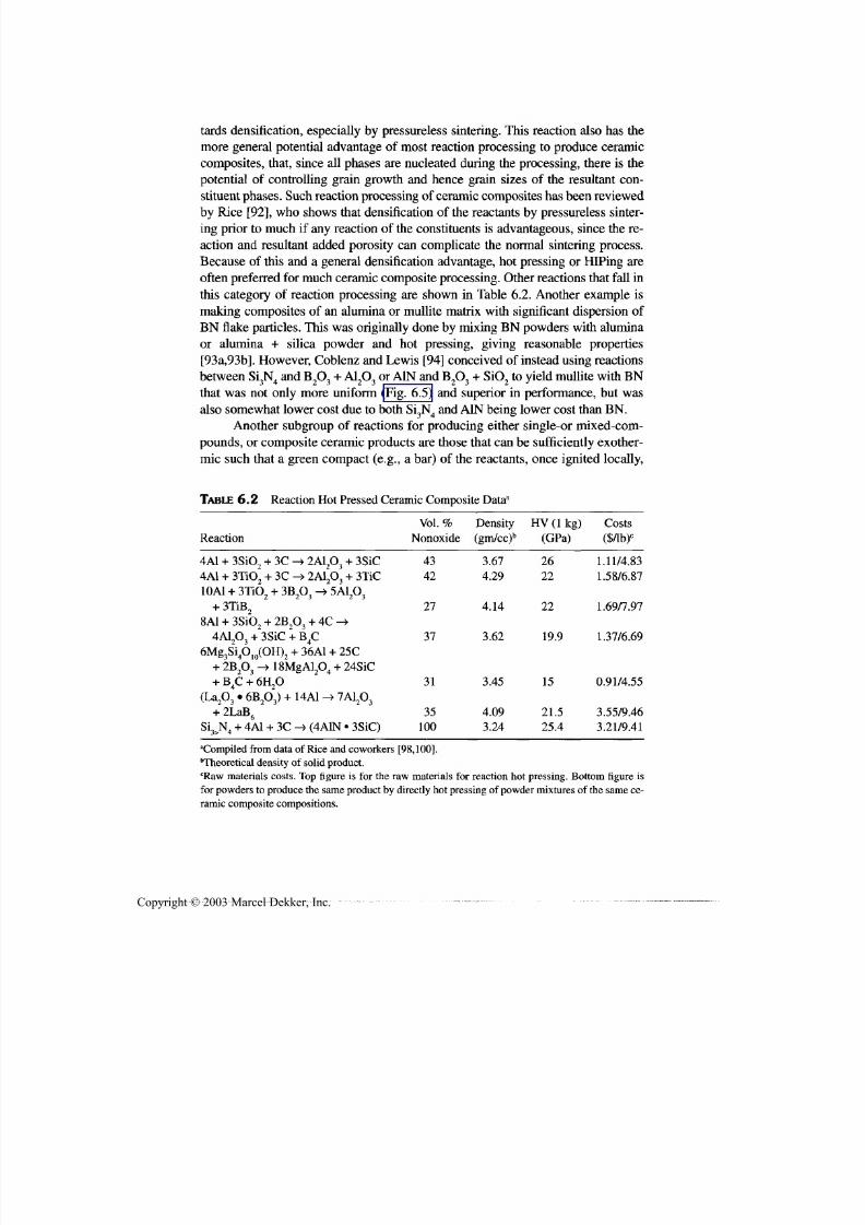
7/29/2019 29540824708539
http://slidepdf.com/reader/full/29540824708539 244/361
Other Certification and Fabrication Methods 233
tards densification, especially by pressureless sintering. This reaction also has the
more general potential advantage of most reaction processing to produce ceramic
composites, that, since all phases are nucleated during the processing, there is the
potential of controlling grain growth and hence grain sizes of the resultant con-
stituent phases. Such reaction processing of ceramic composites has been reviewed
by Rice [92], who shows that densification of the reactants by pressureless sinter-
ing prior to much if any reaction of the constituents is advantageous, since the re-
action and resultant added porosity can complicate the normal sintering process.
Because of this and a general densification advantage, hot pressing or HIPing are
often preferred for much ceramic composite processing. Other reactions that fall in
this category of reaction processing are shown in Table 6.2. Another example is
making composites of an alumina or mullite matrix with significant dispersion of
BN flake particles. This was originally done by mixing BN powders with alumina
or alumina + silica powder and hot pressing, giving reasonable properties
[93a,93b]. However, Coblenz and Lewis [94] conceived of instead using reactions
between Si3N4 and B2O3 + A1 2O3 or A1N and B2O3 + SiO2 to yield mullite with BN
that was not only more uniform (Fig. 6.5) and superior in performance, but was
also somewhat lower cost due to both Si3N4 and A1N being lower cost than BN.
Another subgroup of reactions for producing either single-or mixed-com-
pounds, or composite ceramic products are those that can be sufficiently exother-
mic such that a green compact (e.g., a bar) of the reactants, once ignited locally,
TABLE 6.2 Reaction Hot P ressed C eramic Composite Data3
Reaction
4A1+ 3SiO2 + 3C -> 2A12O3 + 3SiC
4A1+ 3TiCX + 3C -> 2ALO, + 3TiC
Vol. %
Nonoxide
43
42
Density
(gm/cc)b
3.67
4.29
H V ( l k g )(GPa)
2622
Costs($/lb)c
1.11/4.831.58/6.87
10A1 + 3TiO2 + 3B2O3 -> 5A12O3
+ 3TiB2
8A1+ 3SiO 2B2O3 + 4C
4A12O3 + 3SiC + B4C6Mg3Si4O10(OH)2 + 36A1 + 25C
18MgAl2O4 + 24SiC2B2O3
+ B4C + 6H2O
7A12O3La2O3 • 6B2O3) + 14A1
+ 2LaB6
Si3>N4 + 4A1 + 3C -> (4A1N • 3SiC)
27
37
31
35
100
4.14
3.62
3.45
4.09
3.24
22
19.9
15
21.5
25.4
1.69/7.97
1.37/6.69
0.91/4.55
3.55/9.46
3.21/9.41
"Compiled from data of Rice and coworkers [98,100].
Theoretical density of solid product.cRaw materials costs. Top figure is for the raw materials fo r reaction ho t pressing. Bottom figure is
for powders to produce the same product by directly hot pressing of powder m ixtures of the same ce-
ramic composite compositions.
Copyright © 2003 Marcel Dekker, Inc.

7/29/2019 29540824708539
http://slidepdf.com/reader/full/29540824708539 245/361
234 Chapter 6
FIGURE 6.5 A12O3-30% B N composites: (A) hot pressed from a mixture of A12O3 an d
B N ; ( B ) reaction hot pressed. Note th e more uniform microstructure in B .
(on one end), the reaction propagates along the bar to complete the reaction ofthe body without any other thermal energy other than the modest amount used
fo r reaction ignition [95]. Such reactions are referred to as self-propagating high-
temperature synthes is (SHS), high temp erature referring to the fact that the adia-
batic temperatures from the reaction can be quite high (Table 6.3) [95,96]. Such
reactions have attracted mu ch attention, due to the possibility of achieving densi-
fication with such little input of thermal energy fo r very refractory compounds.
M any of these reactions, especially some of the most vigorou s ones, are between
elemental reac tants, but there are also a substantial num ber that are reactions be-
Copyright © 2003 Marcel Dekker, Inc.
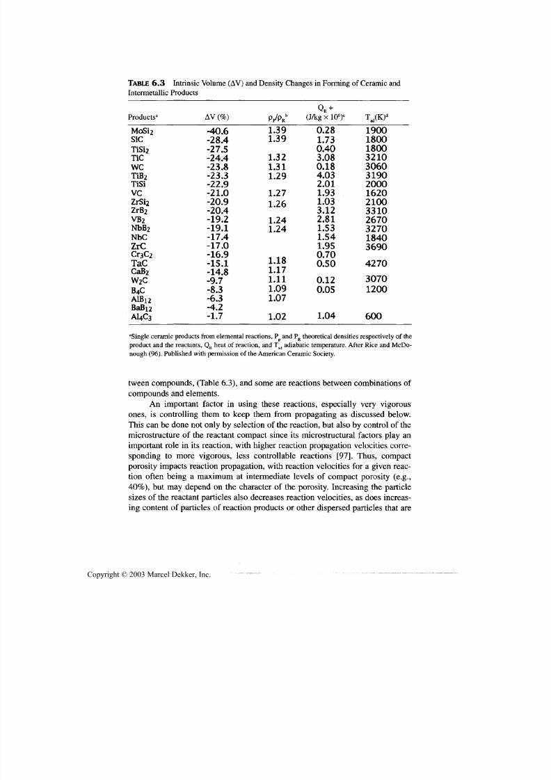
7/29/2019 29540824708539
http://slidepdf.com/reader/full/29540824708539 246/361
Other Certification and Fabrication Methods 235
TABLE 6.3 Intrinsic Volume (AV) and Density Changes in Forming of Ceramic andIntermetallic Products
Products3AV (% ) (J/kg x 106)c
T ad(K )d
MoSi2
SiCTiSi2
TiCweTiB 2TiSiVC
ZrSi2ZrB 2
VB 2
NbB 2
NbCZrCCr3C2
TaCCaB 2
W 2CB 4CAlBi2B a B i2
A14C3
-40.6-28.4-27.5-24.4-23.8-23.3-22.9-21.0
-20.9-20.4-19.2-19.1-17.4-17.0-16.9-15.1-14.8-9.7-8.3-6.3-4.2-1.7
1.391.39
1.321.311.29
1.27
1.261.241.24
1** f\
.181.171.111.091.07
1.02
0.281.730.403.080.184.032.011.93
1.033.122.811.531.541.950.700.50
0.120.05
1.04
19001800180032103060319020001620
210033102670327018403690
4270
30701200
600
aSingle ceramic products from elemental reactions, P and PR theoretical densities respectively of the
product and the reactants, QR heat of reaction, and T ad adiabatic temperature. After Rice and McDo-
nough (96). P ublished w ith permission of the Am erican Ceramic Society.
tween com poun ds, (Table 6.3), and some are reactions between com binations ofcompounds and elements.
An important factor in using these reactions, especially very vigorousones, is controlling them to keep them from propagating as discussed below.This can be done not only by selection of the reaction, but also by control of the
microstructure of the reactant compact since its microstructural factors play animportant role in its reaction, with higher reaction propagation velocities corre-sponding to more vigorous, less controllable reactions [97]. Thus, compactporosity impacts reaction propagation, with reaction velocities for a given reac-tion often being a maximum at intermediate levels of compact porosity (e.g.,
40%), but may depend on the character of the porosity. Increasing the particlesizes of the reactant particles also decreases reaction velocities, as does increas-
ing content of particles of reaction products or other dispersed particles that are
Copyright © 2003 Marcel Dekker, Inc.

7/29/2019 29540824708539
http://slidepdf.com/reader/full/29540824708539 247/361
236 Chapter 6
inert to , hence not involved in the reaction, thus diluting th e reactants. Finally,
ignition of reactions can be inhibited by contact of reactant compact surfaces
with higher thermally conducting environments, for example by contact withgraphite tooling versu s contact with a gaseous atmosphere.
Much of the earlier attention to processing u sing vigorous reactions was mo-
tivated by the possibility of obtaining dense compacts of very refractory ceramic
bodies by simply compacting the reactants then igniting the reaction, for example,
with a small coil of high temperature resistively heated wire or a torch flame or
laser beam. Further, it was proposed that this could be done w ith major cost reduc-
tions since it required so much less energy than normal ceramic processing, and
that it could often result in uniq ue compositions, microstructures, or both due to
the very transient nature of such reactions. However, these expectations were gen-
erally poorly founded due to neglecting some basic and practical factors [95,98].
Thus, extraction of many elements, especially some of those for the most vigorous
reactions to produce very refractory products such as TiB,, ZrB 2, TiC, and ZrC, is
generally expensive, mak ing many such SHS processing routes fairly to highly ex-
pensive. Further, eliminating the energy costs for densification (the gas or electric
bills for sintering or hot pressing) generally eliminates < 5% of typical ceramic
production costs, w hich, while not negligible, is not a major sav ings. Elimination,or substantial reduction, of furnaces fo r densification would be a more significant
savings, but is generally not feasible, as discussed below.
Limitations in two other basic factors of obtaining low porosity and sound ,that is uncracked, ceramic bodies by SHS were also not fully recognized [98,99].
Porosity issues are discussed here, and avoidin g cracking is discussed below. B e-
sides th e porosity of the compact of powder reactants that must be removed fo r
most applications, there are two other important sources of porosity that require
additional densification. The first is extrinsic generation of porosity due to out-
gassing of adsorbed species on compact powder surfaces, which can be very
rapid due to rapid heating to high temperatures from the reaction of compact
constituents. This generally scales with the temperatures reached in the com pact,
is a serious problem for many reactions, and can be exacerbated by the propaga-
tion of the reaction (discussed below) as well as increasing sizes of bodies beingfabricated. Such extrinsic porosity generation can in some cases result in at least
some minor explosions. The other basic source of porosity is that intrinsically
generated by the reaction itself—the exothermic nature of the reactions basically
arises from the reaction products having stronger atomic bonds, hence higher
densities, than the reactants. This increase in solid density of the reaction prod-
ucts in the reaction compact is accommodated by intrinsic generation of poros-
ity, that is typically substantial, and generally increases with the energy of the
reaction (Fig. 6.6) [96]. The combination of the three porosities that must be
eliminated to produce a dense body—the initial porosity of the compact of the
reactants and intrinsically and extrinsically generated porosity—pose challenges
Copyright © 2003 Marcel Dekker, Inc.
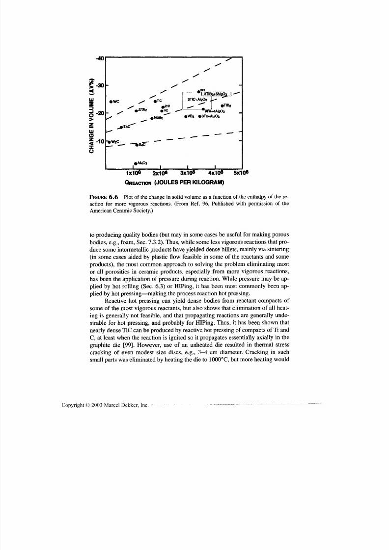
7/29/2019 29540824708539
http://slidepdf.com/reader/full/29540824708539 248/361
Other Densification and Fabrication Methods
-40
237
UJ1-z
UJo
o
•WC•T1C
kZ r 8 l 2*ZrC*
3TIC+AI203
•TIBa
•VB2 •SFe+AfeOa
«AUC3
1X10⁶ 2x10⁶ 3X10⁶ 4x10⁶ 5x10⁶
QREACDON (JOULES PER KILOGRAM)
FIGURE 6.6 Plot of the change in solid volume as a function of the enthalpy of the re-
action for more vigorous reactions. (From Ref . 96, Published with permission of the
American Ceramic Society.)
to producing quality bodies (but may in some cases be useful for making porousbodies, e.g., foam , Sec. 7.3.2). Th us, while some less vigo rou s reactions that pro-duce some interm etallic products have yielded dense billets, m ainly via sintering
(in some cases aided by plastic flow feasible in some of the reactants and someproducts), the most common approach to solving the problem eliminating mostor all porosities in ceramic products, especially from more vigorous reactions,
has been the application of pressure during reaction. W hile pressure may be ap-
plied by hot rolling (Sec. 6.3) or HIPing, it has been most commonly been ap-plied by hot pressing— making the process reaction hot pressing.
Reactive hot pressing can yield dense bodies from reactant compacts of
some of the m ost vigorous reactants, bu t also shows that elimination of all heat-ing is generally not feasible, and that propagating reactions are generally unde-sirable for hot pressing, and probably for HIPing. Thus, it has been shown that
nearly dense TiC can be produced by reactive ho t pressing of compacts of Ti andC, at least when the reaction is ignited so it propagates essentially axially in the
graphite die [99]. However, use of an unheated die resulted in thermal stresscracking of even modest size discs, e.g., 3-4 cm diameter. Cracking in such
small parts was eliminated by heating the die to 1000°C, but more heating would
Copyright © 2003 Marcel Dekker, Inc.

7/29/2019 29540824708539
http://slidepdf.com/reader/full/29540824708539 249/361
238 Chapter 6
be needed for larger parts, thus seriously restricting reductions in heating with
such SHS processing. Such restrictions are even more constrained by indicated
needs to avoid propagating reactions, at least for larger parts.As is so often the case, scaling up the size of bodies often reveals or exacer-
bates important processing issues, as was the case in scaling up reactive hot press-
ing using reactions in Table 6.2 [100,101]. While hot pressing discs 2-3 cm
diameter and < 1 cm thick gave uniform dense bodies, scaling to 5-7 cm diameter
by 2 cm thick gave discs with serious gross problems—having seriously rumpled
and sometimes cracked top surfaces and macropores or porous areas with diame-
ters of the order of half the disc diameter and thickness. Tests and evaluation re-
vealed that these areas were the result of the reactions initiating primarily from
the disc periphery and secondarily from the top and bottom of the disc with reac-
tion propagation primarily on radial and axial directions, respectively [101]. The
secondary ignition from the top and bottom surfaces densified those surfaces,sealing off much escape of gases released by the reaction exotherm, while the ra-
dial ignition sealed off the cylindrical periphery. However, radial propagation of
the reaction allowed fo r little densification since in the early stages, the bulk ofthe unreacted interior resisted consolidation of the reacting material, while in the
late stages of radial reaction propagation the densified outer peripheral area re-
sisted consolidation. C hanging th e temperature gradients (b y reducing heat lossesthrough the pressing rams) so m ost ignition of the reactions occurred in the axial
versus the radial direction, substantially reduced, but didn't eliminate, the above
gross problems. This and subseque nt tests showed the solution to achieving large,
quality hot-pressed bodies was to make the reactions nonpropagating, via use of
coarser reactant particle sizes and modest dilution of the reactants with product
particles. Thus, eliminating reaction propagation—having a normal diffusion re -action—allowed successful scaling of the reaction hot pressing to produce billets
15 cm square and 3-5 cm thick fo r ballistic testing. While it might be argued that
achieving sufficient axial reaction propagation migh t have been sufficient fo r suc-cessful scaling, this is considered doubtful, and wou ld probably hav e required hot
pressing one b ody at a time, rather than a few to several at a time (which w ould be
more economical). Thu s, use of propagating reactions for producing bulk bodiesby reactive hot pressing or closely related fabrication is seen as something to be
avoided. The advantage of using the reaction p rocessing route ca n often be that of
lower raw materials costs as illustrated in Table 6.2.Ano ther potential of reaction processing, especially with pressure consolida-
tion such as hot pressing, is obtaining a finer, possibly more homogeneous mi-
crostructure, since all grains are nucleated by the reactions, rather than simplygrowing from the starting powder particles. Thus, if there is sufficiently limited
temperature and time during de nsification, mu tual inhibition of growth of particles
of one phase by those of other phase(s), or both, finer microstructures may be at-
tained. Comparison of reaction hot pressed versus conventional hot pressing of
Copyright © 2003 Marcel Dekker, Inc.

7/29/2019 29540824708539
http://slidepdf.com/reader/full/29540824708539 250/361
Other Densification and Fabrication Methods 239
mixed oxide-nonoxide composites has shown promising results for the former ver-
sus the latter bodies despite there being more experience to guide the conventional
processing [100]. However, again requirements fo r improvement were noted, since
reaction hot-pressed composites often failed from isolated larger grains or clusters
of them. It was suggested that these resulted from heterogeneities in the reactant
compact as well as local accumulation of transient liquid phases during the reaction,
for example of Al and B 2O 3, with the two being interactive. It was also noted that lo-
cal excesses of transient liquid phases can often be inhibited by coating all particle
or those that will melt with a reactant that does not melt. Thus, promising results
have been obtained by using polyfurfural alcohol, a polymerizable liquid that can be
used as an infiltrant or part of the binder, as a moderate cost source of carbon.
There are several processes that depend on reaction in a liquid or gaseous
state that can have limited to extensive applicability to fabrication of ceramics
and ceramic composites. Starting with th e former: Electrolytic deposition ofmetal oxides or their hydroxide precursors from water solution of metal ions
[102] has some applicability, especially for electronic applications, but is limited
to thin depositions, for example, 1-10 um, such as coatings. Similarly, electrode-
position of other materials, especially nonoxide materials, from various molten
salts (Chap. 3) has some applicability since substantially greater deposition
should be feasible, but the use of molten salt baths is a serious limitation.
Much, if not all, of the use of preceramic polymers (Sec. 6.5) also falls in
this category via their preparation, polymerization, or both [59-61]. This is by farmost developed fo r carbon bodies, as illustrated in Fig. 6.7. There is again applica-
bility for thin layers, (coatings), an d bodies with small cross-sectional dimensions,
especially fibers (Sec. 7.2.1), but also some potential fo r bulk monolithic or com-
posite ceramics. Costs, large shrinkages and related issues, fo r example, of stress,
limit the use of polymeric ceramic precursors fo r producing bulk bodies. While
there are some possible means of extending fabrication of some ceramics by poly-
mer pyrolysis via some CV D processing as discussed below, much application of
such processing fo r both monolithic an d composite ceramics appears to be use of
preceramic polymers as part or all of the binder fo r green body fabrications (Sec.
4.3). The frequent requirement of spray-drying systems with organic solvents is adefinite limitation fo r such fabrication, but such spray drying is done where itscosts can be justified. In the case of composites, especially fiber composites, use of
preceramic polymers as the matrix source is promising (Sec. 8.2.3).
Turning to vapor-phase reactions, there are important uses of physically
generated vapors—by evaporation or sputtering of—metals,and reacting themetal vapor with a gas—m ethane to form carbides or nitrogen to form nitrides.
Such processing is again limited to thin layers or coatings, commonly fo r wear
applications. A good example is arc vaporization of Ti and its reaction in the va-
por state to form TiN, TiC, or combination coatings on consumer an d industrial
drill bits for wear resistance and bathroom fixtures.
Copyright © 2003 Marcel Dekker, Inc.

7/29/2019 29540824708539
http://slidepdf.com/reader/full/29540824708539 251/361

7/29/2019 29540824708539
http://slidepdf.com/reader/full/29540824708539 252/361
Other Densification and Fabrication Methods 241
FIGURE 6.8 Examples of CVD SiC bodies. Top row: thick and thin wall cylinders,
middle row;carbon mold for a simple prototype turbine rotor, the S iC rotor, and a small,
thin wall heat exchanger; and bottom row: metal prototype, carbon mold for CVD, an d
SiC CVD part. (Samples courtesy of R. Engdahl of Synterials. From Ref.61. Published
with permission of Plenum Publishing Corp.)
modest temperatures, but are readily vaporized well below CVD temperatures, by
passing a halogen gas over heated particles of the metal). Such halides are typicallythe low-cost sources for many metals and are widely used with suitable dilution and
carrier gases. While, O2 and N2 can be used to form oxides and nitrides, more often
other gases are used, e.g., H2O or CO2 for oxides and ammonia for nitrides, along
with methane for carbides, and boron halides for borides (andB and BN). Ceramics
are typically produced with such reactions at temperatures of 900-1500°C, though
these may be reduced by plasma assistance of the reactions. Other gases are also
used, especially metalorganic ones for metals and semiconductors which are exten-
sively used in the electronics industry despite their frequent toxicity and high cost
since they are used in small amounts and allow processing at much lower tempera-
tures [107,108]. Such gases can generally be reacted at temperatures of a few to
Copyright © 2003 Marcel Dekker, Inc.

7/29/2019 29540824708539
http://slidepdf.com/reader/full/29540824708539 253/361
242 Chapter 6
several hun dred degrees Centigrade. Reactions with either type of precursor are typ-
ically done at pressures substantially below one atmosphere. However, the above
noted reactants, other than most m etalorganic ones, are quite suitable for most m etaland ceramic processing, and offer low to modest cost sources for CVD. Such lower
costs, and potential diversity and quality of CVD materials that may be produced,
and the potential for near net shape fabrication give C VD substantial potential, only
a portion of which has been realized. Possibilities fo r improved products and use to
go bey ond some of the cu rrent limitations are discussed after summ arizing key as-
pects of the status of CVD.
There are substantial applications of CVD. Its largest use is for films in the
electronics industry, wh ere subs tantial process developm ent of control and repro-
ducibility has occurred, including plasma assisted CVD. There is also successful
commercial development of first, B, and later, SiC, filaments made by CVD,
which have also provided some insight on reproducibility. Som e of these process
advances can be transferred to CVD production of bulk bodies of particular inter-
est here. However, there are also important successes for CVD of bulk bodies
[104]. Earlier ones were for graphite bodies, pyrolitic graphite (PG), hence CVD
graphite. These included re-entry nose tips for intercontinental ballistic missiles
( ICBMs) (before being replaced by carbon-carbon compo sites for all-weather ca-
pability), as well as nozzles for various rockets, both demonstrating large and
complex shapes, an d m easurable thicknesses (e.g., a centimeter or more). Besides
a number of commercial technical applications for PG, it became widely used asthe liner in the bowls of tobacco pipes [104], which required substantial volume
production at modest cost (for examp le reduction in costs from a few tens of dol-
lars for similar size custom PG crucibles to of the order of a dollar or less per pipe
bow l). Ano ther comm ercial extension of the PG market w as the chemical exfolli-
ation of bulk PG and then the rolling of this material to make Grafolil®, a thick
graphite paper. Substantial CVI is used to produce some of the carbon matrix in
carbon-carbon composites, fo r example fo r high-perform ance aircraft brakes.
Technological and commercial successes are not restricted to PG . They in -
clude the comm ercial development of ZnSe and ZnS for IR w indow s, for exam-
ple, as large plates of 90 x 120 x 2.5 cm [104]. Various size IRdomes of otherceramics such as ZnS and M gO have been dem onstrated, from 8 to 20-cm-base
diameters. Another important commercial and technological development wasthat of preforms (i.e., "billets") from wh ich glass optical fibers are drawn for op-
tical comm unications [109-111]. While there are also fusion or sintering meth-
ods, there are at least three variations of CVD processing as a key step in
processing such preforms, for example of 2.2-cm dia. by 0.5 to 1-m long (giving
a few kilometers of 125-(am diameter fiber, commonly drawn at 1 m/s).
Frequently other uses of CVD for fabricating bulk bodies as opposed to
films, coatings, and filaments, thoug h considerable, face lim itations due substan-
tially to four partially interrelated factors of moderate deposition rates, mi-
Copyright © 2003 Marcel Dekker, Inc.
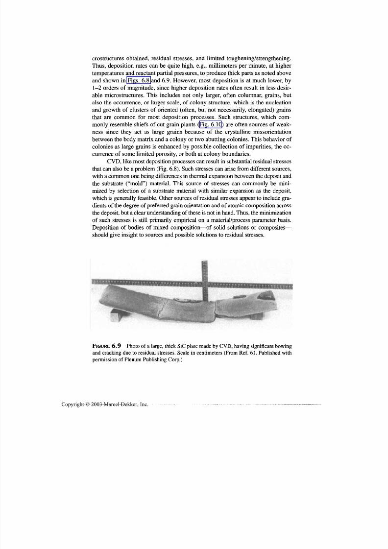
7/29/2019 29540824708539
http://slidepdf.com/reader/full/29540824708539 254/361
Other Densification and Fabrication Methods 243
crostructures obtained, residual stresses, and limited toughening/strengthening.
Thus, deposition rates can be quite high, e.g., millimeters per minute, at higher
temperatures and reactant partial pressures, to produce thick parts as noted abovean d shown in Figs. 6.8 and 6.9. However, most deposition is at much lower, by
1-2 orders of magnitude, since higher deposition rates often result in less desir-
able microstructures. This includes not only larger, often columnar, grains, but
also th e occurrence, or larger scale, of colony structure, which is the nucleation
an d growth of clusters of oriented (often, but not necessarily, elongated) grains
that are common for most deposition processes. Such structures, which com-
monly resemble shiefs of cut grain plants (Fig. 6.10) are often sources of weak-
ness since they act as large grains because of the crystalline missorientation
between th e body matrix and a colony or two abutting colonies. This behavior of
colonies as large grains is enhanced by possible collection of impurities, the oc-
currence of some limited porosity, or both at colony boundaries.
CV D , like most deposition processes ca n result in substantial residual stresses
that can also be a problem (Fig. 6.8). Such stresses ca n arise from different sources,
with a common one being differences in thermal expansion between the deposit an d
the substrate ("mold") material. This source of stresses can commonly be mini-
mized by selection of a substrate material with similar expansion as the deposit,
which is generally feasible. Other sources of residual stresses appear to include gra-
dients of the degree of preferred grain orientation and of atomic composition across
the deposit, but a clear understanding of these is not in hand. Thus, the minimizationof such stresses is still primarily empirical on a material/process parameter basis.
Deposition of bodies of mixed composition—of solid solutions or composites—
should give insight to sources an d possible solutions to residual stresses.
FIGURE 6.9 Photo of a large, thick SiC plate made by CVD, having significant bowing
an d cracking due to residual stresses. Scale in centimeters (From Ref. 61. Published with
permission of Plenum Publishing Corp.)
Copyright © 2003 Marcel Dekker, Inc.

7/29/2019 29540824708539
http://slidepdf.com/reader/full/29540824708539 255/361
244 Chapter 6
FIGURE 6.10 Examples of CVD colony structure. (A ) "Bumpy," botryoidal as-de-
posited CV D surface on Si3N4. (B.) Fracture cross section of a colony showing common,
but not universal, elongated grain structure in SiC.
A limitation of CV D, how ever, has been a focus on producing only pure, sin-
gle phase m aterials. P urity of the deposited material is often a strength of CV D; for
example, its ability to give dense bodies of materials that otherwise can only bedensified with ad ditives, wh ich may give lower temperature toughening, but seri-
ously limit high-temperature performance. However, only limited attempts have
been made to purposely make CVD bodies with two or more compounds that can
have one or more of several functions, besides possible effects on residual stresses
noted above. W here one or more additional phase is formed, the functions may be
(1 ) limiting grain sizes, (2 ) providing some composite character, particularly
toughening, and (3) compositional gradients fo r both design of materials, as well
as developing surface comp ressive stresses. Wh ere a single phase su ch as a ternary
compound is formed, it expands the ma terial possibilities of CV D , an d where solid
solutions are form ed, compositional gradients may be purposely introduced to pro-vide surface compressive stresses. Thus, instead of thinking only about pure com-
pounds and CVD as the only step in the fabrication process, consider a broaderrange of comp ositions and processing. Processing of ternary compound s and espe-
cially composites and possible additional steps in the processing are examples,
e.g., sintering of porous preforms from CVD, similar to forming optical fiber pre-forms, and heat treatment to change compositions and microstructures, which
could include transient phases, includ ing liquid ones. Thus, to expand C VD and re-
lated processing, it shou ld be viewed m ore from a materials perspective and n ot re-stricted to the chemical perspective that was essential to its development, but
appears to be restricting its further expansion an d diversification.
Copyright © 2003 Marcel Dekker, Inc.

7/29/2019 29540824708539
http://slidepdf.com/reader/full/29540824708539 256/361
Other Densification and Fabrication Methods 245
There are results that indicate the promise of addressing the substantial
task of investigating the above possibilities. First, some CVD of ternary ceramic
compounds has been made, such as Ti3SiC2 [112-116]. Second, some deposition
of tw o different cations can significantly reduce grain sizes an d improve me-
chanical properties [117,118], and similar results should occur for two different
anions. Production of ceramic particulate composites, e.g., of Si3N4 with dis-
persed (often nanometer) particles of B N(118) or TiN [118-120], some with par-
ticle-matrix epitaxial relations, an amorphous matrix, and transparency have
been reported.
The first of four other important factors fo r more study is the preferred ori-
entation that often occurs (often associated with colony structure, Fig. 6.8). Con-
trol of this could give not only more reproducible bodies, but also may allow
additional uses. Control of orientation could allow more tailoring of properties,
providing oriented grains and properties to better meet some uses. An extreme of
this is deposition of coating materials with very anisotropic thermal expansion
such that th e high crystal expansion directions are oriented parallel with th e
metal substrate surface on which the deposit is made. Thus, greater compatibility
between coating and substrate can be obtained, while giving lo w coating expan-
sion normal to the substrate (a characteristic often of interest in coatings). Ther-
mal expansion anisotropies of some ceramics that may be used fo r obtaining
more thermal expansion compatibility with metal substrates when the ceramic is
deposited with high expansion directions parallel with th e metal surface to main-tain more constant clearances of coating from other components as temperature
varies (Table 6.4). Second, gradation of composition in solid solution or com-
posite bodies can allow grading of thermal expansion and hence generation andtailoring of surface compressive stresses to give greater mechanical reliability
(until use temperatures reach fabrication temperatures) should be feasible. Third,
CVI has demonstrated important capabilities in production of carbon-carbon
composites and shows promise for a number of experimental ceramic fiber com-
posites for specialized, high value-added demanding applications (Sec. 7.5). The
demonstration that th e residual porosity typically left by CVI is amongst th e
most benign in limiting mechanical properties [121,122] further aids future pos-sible uses of CVI for ceramic composites. There are also important opportunities
for CV I processing of other specialized ceramic bodies, fo r instance fo r designed
porous structures (Sec. 7.3.2). Fourth, there have been demonstrations of modifi-
cations of CVD that results in the reacting gases forming an intermediate liquid
phase on the surface of the deposit, that decomposes to the product, fo r example,
W -C or SiC. This liquid intermediate, which is apparently related to a polymer
precursor, results in extremely fine, nanoscale, grains and very high as-deposited
strengths at room temperature [123-127]. While these results are for small sam-
ples with limited scaling, they suggest possibilities, of combining CVD and
polymer pyrolysis, that deserve further investigation.
Copyright © 2003 Marcel Dekker, Inc.
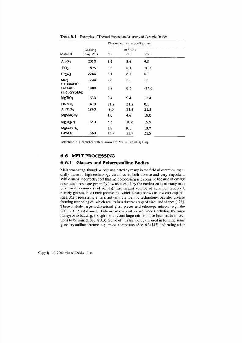
7/29/2019 29540824708539
http://slidepdf.com/reader/full/29540824708539 257/361
246 Chapter 6
TABLE 6.4 Examples of Thermal Expansion Anistropy of Ceramic Oxides
Thermal expanion coeffiencentMelting
Material temp.(°C)
A1203
Ti02
Cr203
SiO2
( a. quartz)
UAlsiO4( B > eucryptite)
MgTi03
liNbOs
Al2TiO5
MgSnB 2Oe
MgTi2Os
MgFeTaOs
CaWO4
2050
1825
2260
1720
1400
1630
1410
1860
1650
1580
oca
8.6
8.3
8.1
22
8.2
9.4
21.2
-3.0
4.6
2.3
1.9
13.7
( i o -6 o
c - ' )c c b
8.6
8.3
8.1
22
8.2
9.4
21.2
11.8
4.6
10.8
9.1
13.7
ac
9.5
10.2
6.1
12
-17.6
12.4
0.1
21.8
19.0
15.9
13.7
21.5
After Rice [61]. Published with permission of Plenum P ublishing Corp.
6.6 MELT PROCESSING
6.6.1 Glasses and Polycrystalline Bodies
M elt processing, thou gh w idely neglected by many in the field of ceramics, espe-
cially those in high technology ceramics, is both diverse and very important.
While many incorrectly feel that melt processing is expensive because of energycosts, such costs are generally low as attested by the modest costs of many melt
processed ceramics (and metals). The largest volume of ceramics produced,
nam ely glasses, is via melt processing, w hich clearly show s its low cost capabil-
ities. Melt processing entails not only th e melting technology, but also diverse
forming technologies, which results in a diverse array of sizes and shapes [128].
These include large architectural glass pieces and telescope mirrors, e.g., th e
200-in. (~ 5 m) diameter Palomar mirror cast as one piece (including the large
honeycomb backing, though more recent large mirrors have been made in sec-
tions to be joined, Sec. 8.3.3). Some of this technology is used in forming some
glass-crystalline ceramic, e.g., mica, com posites (Sec. 6.3) [47], indicating other
Copyright © 2003 Marcel Dekker, Inc.

7/29/2019 29540824708539
http://slidepdf.com/reader/full/29540824708539 258/361
Other Densification and Fabrication Methods 247
possible extensions. Another important extension is via crystallization of glasses,
commonly aided by additives (Sec. 3.5) to improve properties [9].
Much of the crystalline-based ceramic refractories produced, most of which
are composites, are made by arc skull melting, that is, melting almost all of the ma-
terial in a suitably designed water-cooled container, leaving a thin layer of un-
melted, and hence noncontaminating, material (i.e., the "skull") against the
container (which can be a few meters in diameter). A substantial volume of these
materials is solidified in the skull form, then crushed into grain for various refrac-
tory and other uses, for abrasives and for thermally conducting, electrical insulation
for encapsulated electrical heating elements (Sec. 2.4). (Note that the comminution
costs are generally more than the melting costs). The other common use of melt
forming for refractories is by tapping the melt in an arc skull melter to cast the melt
in molds (generally of graphite) to make refractory bricks and furnace parts, many
of much larger size (some weighing well over a ton, being some of the largest ce-
ramic bodies made) and more complex shapes. An important factor in such fusion
casting is controlling the microstructure, which is often done by controlling nucle-
ation and growth of grains, and often the crystalline phase in which they occur, both
of which are often impacted by the use of additives (Sec. 3.5). Another critical fac-
tor is controlling sources of both extrinsic and intrinsic porosity. A clearly extrinsic
one is outgassing of raw materials, with entrapment of much of the resultant gas in
the melt, which is an important problem not well recognized outside the field of fu-
sion derived ceramics. It is discussed some below and more extensively in Section
8.2.1. Exsolution of gasses dissolved in the melt, released on cooling to and through
solidification, can be an important problem, but is generally very material, and, to
some extent, process dependent, and hence not addressed further. A clearly intrinsic,
and very important, source of porosity in fusion processing is the intrinsic changes
in volumes of materials between the melt and solid state.
An important factor in casting any crystalline body from the melt is the
change in volume on solidification. While a few materials expand on solidification,
e.g., H2O and Si (which can result in stresses and cracking), most materials shrink
on going from the liquid to the solid state, which, if not controlled in the nature of
its occurrence, is an important source of porosity. Most cast metals have volumeshrinkages of 5-10 v/o on solidification, but the (somewhat limited, mainly oxide)
data for ceramics shows that, while some have solidification volume shrinkages
similar to metals, they frequently have shrinkages of 10-20 v/o or more—20% for
A1 2O3 [129] and 10-17% for rare earth oxides [130]. (Limited data also suggest
that some halides may have even higher solidification shrinkages, e.g., 40 v/o.).
Solidification shrinkage leads to porosity in the solidified body whenever
melt can no longer accommodate the solidification shrinkage. This occurs when-
ever melt to be solidified becomes sufficiently surrounded by solidified material, to
inhibit or prevent continued supply of melt to the solidification front (Fig. 6.11).
The volume of porosity left on final solidification in such cases is determined by
Copyright © 2003 Marcel Dekker, Inc.
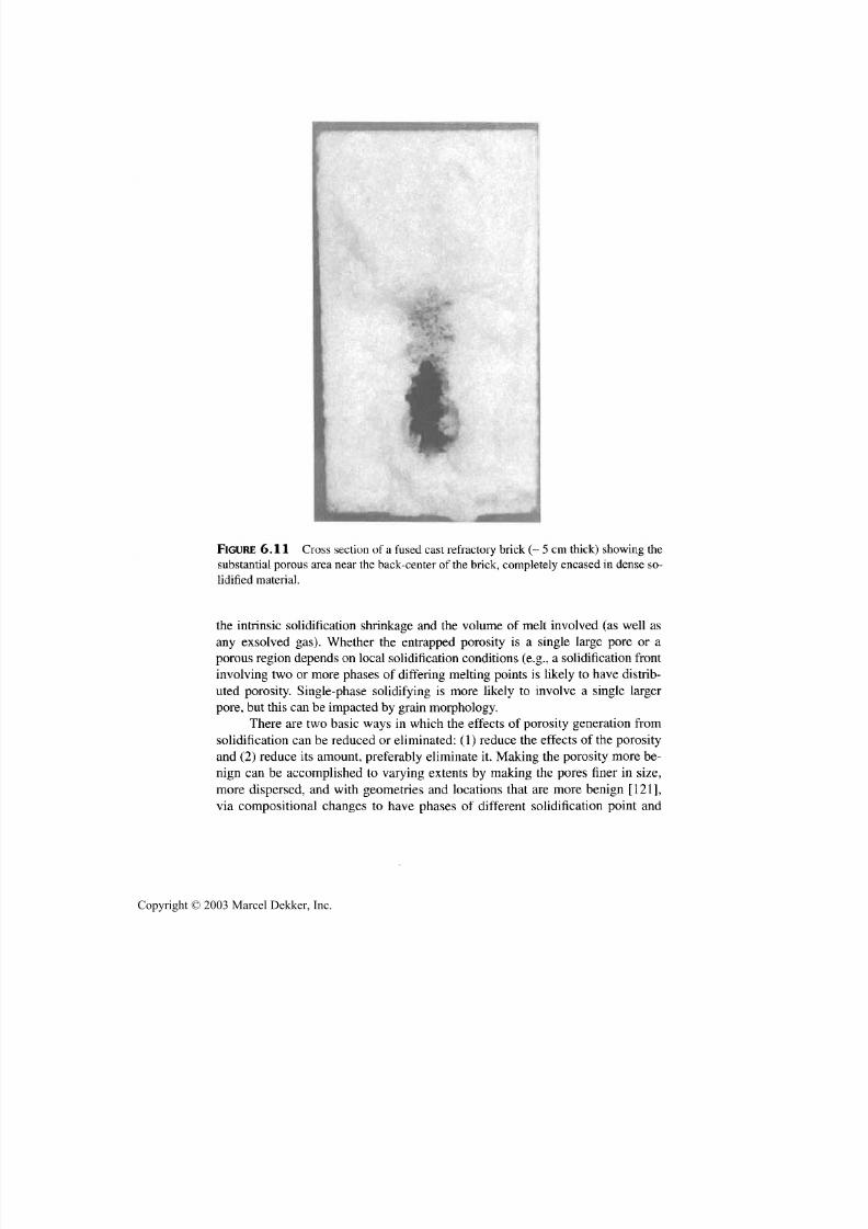
7/29/2019 29540824708539
http://slidepdf.com/reader/full/29540824708539 259/361
248 Chapter 6
FIGURE 6.11 Cross section of a fused cast refractory brick (~ 5 cm thick) showing th e
substantial porous area near the back-center of the brick, completely encased in dense so-
lidified material.
the intrinsic solidification shrinkag e and the volume of melt involved (as well as
any exsolved gas). Whether the entrapped porosity is a single large pore or aporous region depends on local solidification conditions (e.g., a solidification front
involving two or more phases of differing melting points is likely to have distrib-
uted porosity. Single-phase solidifying is more likely to involve a single largerpore, but this can be impacted by grain morphology.
There are two basic ways in which th e effects of porosity generation from
solidification can be reduced or eliminated: (1) reduce th e effects of the porosity
and (2) reduce its amoun t, preferably eliminate it. M aking the porosity more be-nign can be accomplished to varying extents by making th e pores finer in size,
more dispersed, and with geometries and locations that are more benign [121],
via compo sitional changes to have phases of different solidification point an d
Copyright © 2003 Marcel Dekker, Inc.

7/29/2019 29540824708539
http://slidepdf.com/reader/full/29540824708539 260/361
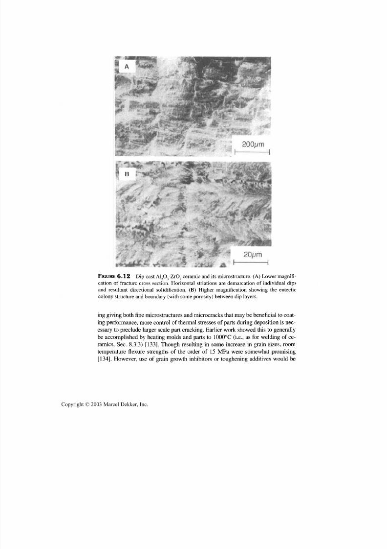
7/29/2019 29540824708539
http://slidepdf.com/reader/full/29540824708539 261/361
250 Chapter 6
FIGURE 6.12 Dip-cast Al2O 3-ZrO 2 ceramic and its microstructure. (A ) Lower magnifi-
cation of fracture cross section. Horizontal striations are demarcation of individual dips
and resultant directional solidification. (B ) Higher magnification showing th e eutectic
colony structure and boun dary (w ith some p orosity) between dip layers.
ing giving both fine microstructures and microcracks that may be beneficial to coat-
ing performance, more control of thermal stresses of parts du ring deposition is nec-
essary to preclude larger scale part cracking. Earlier work showed this to generallybe accomplished by heating molds and parts to 1000°C (i.e., as for welding of ce-
ramics, Sec. 8.3.3) [133]. Though resulting in some increase in grain sizes, roomtemperature flexure strengths of the order of 15 MPa were somewhat promising
[134]. However, use of grain grow th inhibitors or toughening additives w ould be
Copyright © 2003 Marcel Dekker, Inc.

7/29/2019 29540824708539
http://slidepdf.com/reader/full/29540824708539 262/361
Other Certification and Fabrication Methods 251
expected to give considerable strength improvement. Bodies of substantial sizes
and various shapes and materials have been demonstrated by such melt spraying. It
has also shown promise for macrocomposites (e.g., of a body with a ferrite core sur-
rounded by a ceramic dielectric [135]. Feasibility of fabricating another macrocom-
posite consisting of a ZrO2 cylindrical shell encircled by a metal shell, both
substantially thicker than normal coatings, was also shown. The motivation was to
form a lower cost ceramic cylinder liner by greatly reducing the major costs of ma-
chining such liners, which by the normal fabrication of a free standing ZrO2 sleeve,
machining both its surfaces and those of a metal sleeve into which the ZrO2 sleeve
would be shrunk fit and the metal-ZrO2 composite sleeve then presses into the
cylinder liner. Melt spraying of the metal-ZrO2 composite sleeve would eliminate
most of the most expensive machining, that of the ZrO2 since its ID surface, being
formed on a mandrel should be nearer final dimensions and finish than an as-fired
free standing ZrO2 cylindrical sleeve, and only the outer metal sleeve needs machin-
ing rather than both surfaces. While only a brief exploratory program was carried
out, potential was demonstrated by fabricating metal-ZrO2 composite sleeves (~
mm thick, ~ 6 cm in dia and ~ 12 cm in height) that showed > 700 MPa hoop tensile
strengths (R.W. Rice, unpublished work circa 1986). Some large freestanding ce-
ramic parts are apparently manufacturedby melt spraying; for example, fused silica
cylindrical shells ~ 40-50-cm diameters and heights with thicknesses of 1-3 cm for
insulators for induction heated furnaces for hot pressing and other applications.
Melt spraying toform
bulk bodies, not just coatings, also has other poten-
tials for expansion. One is in the fabrication of bodies with controlled porosity, as
demonstrated by cospraying oxide particles with carbon spheres or with selected
resin intermediates, followed by burnout to produce porous manganite coatings for
fuel cells [136]. Another approach has been to obtain denser coatings (hence also
denser bodies) by HlPing following spraying [137], or to use CVD for some infil-
tration of pores, or surface sealing, or both [138]. Finally, a potentially large area of
expansion is that of using melt spraying as a means of forming ceramic matrices in
ceramic fiber or particulate composites. There are limited reports of melt spraying
to produce ceramic composites; LaPiere and coworkers [139] sprayed alumina-
SiC particle composites with resultant strengths of ~ 100 MPa after postdeposit an-nealing. This can probably be improved significantly by spraying the body at
elevated temperatures, as for bulk alumina bodies as noted above. Again, consider-
ing other postspraying fabrication steps may be practical and significant.
6.6.2 Single Crystals
Consider next single-crystal growth, which is mainly via directional solidification
from the melt, and can be divided into techniques for growing one single crystal at a
time versus those that grow many crystals at a time, the latter typically via growing
a large ingot of large grains. Consider the latter first. This is typically done via skull
Copyright © 2003 Marcel Dekker, Inc.
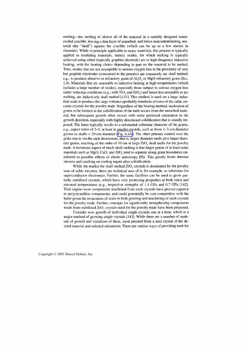
7/29/2019 29540824708539
http://slidepdf.com/reader/full/29540824708539 263/361
252 Chapter 6
melting—the melting of almost all of the material in a suitably designed water-
cooled crucible, leaving a thin layer of unmelted, and hence nonco ntaminating, ma-
terial (the "skull") against the crucible (which can be up to a few meters indiameter). While in principle applicable to many materials, this process is typically
applied to insulating materials, mainly oxides, for which melting is typically
achieved using either (typically graph ite electrode) arc or high-frequency inductive
heating, with the heating choice depending in part on the material to be melted.
Thus, oxides that are not susceptible to serious oxygen loss in the proximity of very
ho t graphite electrodes (consumed in the process) are commonly arc skull melted;
e.g., to produ ce abrasive or refractory grain of A12O3 or MgO refractory grain (Sec.
2.4). Materials that are amenable to inductive heating at high temperatures (which
includes a large number of oxides), especially those subject to serious oxygen loss
under reducing co nditions (e.g., with TiO 2 and ZrO2) and hence less amenable to arc
melting, are inductively skull melted [141]. This method is used on a large indus-
trial scale to produce the large volum es (probably hund reds of tons) of the cubic zir-
conia crystals for the jewelry trade. R egardless of the heating m ethod, nucleation of
grains to be formed in the solidification of the melt occurs from the unmelted mate-
rial, but subsequent growth often occurs with some preferred orientation in the
growth direction, especially with highly directional solidification that is usually im -
posed. The latter typically results in a substantial columnar character of the grains,
e.g., aspect ratios of 2-5, at least in smaller crystals, such as those 1-3-cm diameter
grown in skulls < 20-cm diameter (Fig. 6.4A). The other primary control over thegrain size is via the melt dimensions, that is, larger diameter melts give larger diam-
eter grains, reaching of the order of 10 cm in large ZrO 2 skull melts for the jewelrytrade. A fortuitou s aspect of m uch skull melting is that larger grains of at least some
materials such as MgO, CaO, and ZrO 2 tend to separate along grain boundaries (at-
tributed to possible effects of elastic anisotropy [9]). This greatly limits thermal
stresses and cracking on cooling ingots after solidification.
W hile the market for skull-melted ZrO 2 crystals is dominated by the jewelry
uses of cubic zirconia, there are technical uses of it, for example, as substrates fo r
superconductor electronics. Further, the same facilities can be used to grow par-
tially stabilized crystals, which have very promising properties at both room andelevated temperatures (e.g., respective strengths of 1.4 GPa and 0.7 GPa [142].
Trial engine-wear components machined from such crystals have proved superior
to polycrystalline components, and could potentially be cost competitive with the
latter given the economies of scale in both growing and mach ining of such crystalsfo r th e jewelry trade. Further, concepts fo r significantly strengthening components
made from stabilized ZrO 2 crystals used for the jewelry trade have been proposed.
Consider now growth of individual single crystals one at a time, which is a
major method of growing single crystals [143]. While there are a number of meth-
ods of growth and variations of these, most proceed from a seed crystal of the de-
sired material and selected orientation. There are various w ays of providing melt fo r
Copyright © 2003 Marcel Dekker, Inc.

7/29/2019 29540824708539
http://slidepdf.com/reader/full/29540824708539 264/361
Other Densification and Fabrication Methods 253
controlled solidification from the seed. The oldest is Verneuil growth w hich entails
feeding suitable powder particles through a torch—an oxy-acetylene, flame to de-
posit molten particles on the boule growing from a seed. S uch crystals, which gen-
erally hav e more imperfections than crystals from most other growth methods, are
still in production, especially for the jewelry trade, often with dopants for various
coloration. B oules about 2 cm in diameter and 7 cm in length are comm on products.
There are various methods of growing larger, more perfect crystals from a
molten bath. A major, long established method in laboratory and industrial use isCzochralski growth, which has melt in a crucible drawn up to a seed just contact-ing the meniscus with the melt surface, with the resultant growing seed slowly re-
tracted above the m elt. Such crystal growth by "pulling" from the melt can provide
some rough control of the size of the crystals grown via the volume and diameter
of melt bath available and speed of g rowth. Most c rystals are nominally cylindrical
boules an d usua lly limited in crystal diameters and lengths to respectively less than
the diameter an d the volume of the crucible, but also depend on the material. Thu s,sapphire is grown to diameters of about 15 cm and apparently in some cases to 20
cm with lengths a few times this, with lengths and diameters having inverse trends
with each o ther as limited by crucible vo lume. S i crystals can be even larger, to 30
cm dia. an d 100-300 kg. Crystals grow in only a few preferred growth directions
depend ent on crystal structure and composition, giving very limited co ntrol of the
boule shape other than selecting a seed crystal with a crystallographic orientation
that yields suitable growth near or along crystal directions of interest, though insome cases crystal orientations can be grown as larger slab shapes, e.g., of sap-
phire. However, w hile there are grow th constraints as outlined above, some materi-als and growth conditions yield growth of hollow and other novel crystal shapes
and morphologies [144]. While such crystal pulling is applicable to many crystals,sapphire is a major industrial product, as for other grow th methods in use.Products
such as those of Fig.6.13 are often machined from boules.
An important development in "pulling" single crystals from the melt to give
versatile shapes was the discovery and development of the edge-defined, film-fed
growth (EFG) technique [145-149]. This simple, clever method basically consists
of having a crucible of melt from which to grow desired crystals and a die, e.g., ofthe same material as the crucible so it is comp atible with the melt unde r the grow-ing conditions. The die is shaped with channels in it so that when it is held in con-
tact with the melt will be raised by capillary action to the top of the die, wherecrystal growth proceeds at or slightly above the top of the die where thermal gradi-
ents are maintained for c rystal growth as in any crystal "pulling" process. As in thelatter processes, growth is initiated using a seed crystal, whose orientation, along
with the growth conditions, determines the crystal growth axis, again like othercrystal "pulling" processes. Thus, the basic, and critical invention of the EFG®
process w as the use of a die to locally shape the liquid in the immediate vicinity of
the crystal grow th. This process was invented by Harry LaBelle, a technician on a
Copyright © 2003 Marcel Dekker, Inc.

7/29/2019 29540824708539
http://slidepdf.com/reader/full/29540824708539 265/361
254 Chapter 6
government contract project to grow sapphire filaments from the melt (he became
the president of the company, Saphikon (Milford, WA), set up in the mid- to late
sixties to commercially produce crystal products grown by this process).The EFG® process has been demonstrated with some metallic, intermetallic,
an d different ceramics (the latter apparently including some orientations of BeO
that apparently allow push ing the phase transformation back toward the m eniscus
and thus suppressing it). Com mercial production of sapphire and Si is dominant,
where a variety of two-dim ensional shapes can be m ade by grow th (mainly with a
constant horizontal cross section), and m achining (Fig. 6.13). Shapes include fila-
ments, tubes of different cross sections, and tapes (some used for wear resistant
windows for bar code readers at supermarket and other checkout stations), some of
these shapes with differing crystal orientations. Some variations are feasible—by
twisting the axis of growth with sapphire tubes of rectangular cross section, B our-
don g auge tubes can be m ade. A limitatio n of the process for some applications has
been the occurrence of limited porosity somewhat under the surface, especially at
faster product growth rates. However, some reductions of this porosity problem
have been made, and advances in machining efficiency make it more practical to
machine off the porous layer where it occurrs. Some attempts have been made tomake larger, more complex bodies such as IRdomes, but with incomplete success.
However, more recently rapid prototyping/solid freeform processing concepts
have been applied to the EFG process us ing a die that can be articulated to build up
a dome shape of sapphire in small layers [150]. Such concepts may have consider-able potential for EFG and other melt processing (Sec. 6.7.3).
The E FG process m akes a diversity of sapphire products, with significant
ones being a major source of thin sapphire plates to be laminated to glass sheets
to give wear-resistant wind ow s for supermarket checkout bar code scanners and
a variety of windows and other components fo r semiconductor an d other pro-
cessing furnaces. Though some subsurface microporosity still occurs, it can be
FIGURE 6.13 Examples of sapphire parts made by the EFG® method. (Photos courtesy
of J. Locher of Saphikon).
Copyright © 2003 Marcel Dekker, Inc.

7/29/2019 29540824708539
http://slidepdf.com/reader/full/29540824708539 266/361
Other Certification and Fabrication Methods 255
significantly reduced by slower growth rates and use of W instead of Mo dies,but costs of this are generally higher than to simply machine off the porous layer,
which is commonly done for flat parts such as for scanner window application.Pieces 30-cm square can be grown and sizes of 60-cm square are seen as feasible[151]. Added possibilities are indicated by the E FG method having been used togrow porous sapphire crystal by wicking melt into a porous W body and direc-tionally solidifying the melt then etching out the W (Sec. 7.3)
The other important method of growing individual single crystals is theheat exchanger method (HEM), which instead solidifies melt in a crucible to asingle crystal; that is, in contrast to normal crystal pulling the crucible dimen-sions and shape are typically those of the resultant crystal. This is done by m elt-ing all of the charge in a large crucible, except for a small seed situated at thebottom center (cooled) area of the crucible so that on cooling the melt in the cru-
cible, all of the melt will solidify to become part of the crystal the seed starts.
This method was developed by Fred Schmid and Dennis Viechnicki, then of theArmy Materials an d Mechanics Research Center in Watertown, MA, and hasbeen used fo r commercial production of crystals, especially sapphire, since theformation of Crystal Systems in 1969, of which Schmid is president.
Because the crystal size is directly determined by the crucible size, not
how mu ch liquid can be moved vertically across a meniscus, an d large cruciblesare feasible via welding of refractory metal sheets, the HEM allows by far the
largest crystals to be grown (Fig. 6.14). Thus, sapphire boules up to 34 cm dia.and a substantial fraction of this thick, e.g., weighing 65 kg have been grown
[152], and crystal sizes to of the order of 50 cm dia. are seen feasible. Ag ain, sap-phire is the main product, grown in four grades ranging from the highest qualitysapphire free of light scattering and lattice distortion to that with measurablelight scattering an d lattice distortion suitable fo r mechanical, structural, an d elec-tronic applications. Because the crucible dimensions perpendicular to the growthdirection determine the crystal size, they can in principle be used to som e extentto shape the crystal, but this must be balanced against growing more material ina given run and sawing a larger body into bodies of the shape desired. Further,
some possibilities of inserting refractory metal sheets into the crucible has beenshown to provide some resultant shaping, e.g., of sapphire Irdomes [153,154].Note that this method is also applicable to directional solidification of polycrys-talline ingo ts, e.g., of 66-cm square, 240-kg Si ingots [155].
Two factors should be noted about the above production of single-crystalcomponents. First, while some important shaping during growth is feasible, ma-chining still plays a large role. Improvements in machining efficiency, hencelowering o f costs, e.g., via g ang slicing and boring, co ntinue s to expand produc-tion opportunities. Second, while a primary raw material purity requirement forsingle crystal growth is for low levels of cation species, especially those of re-
fractory impurities, sources of volatile species are also an important problem.
Copyright © 2003 Marcel Dekker, Inc.

7/29/2019 29540824708539
http://slidepdf.com/reader/full/29540824708539 267/361
256 Chapter 6
FIGURE 6.14 Large sapphire boules (-34 cm dia.) grown by the Heat Exchanger Method
(HEM). (Photo courtesy of F. Sch mid , President, Crystal Systems, Salem, M A.)
Such species, e.g., from adsorbed species and anions left from calcining or pow-
der storage (Sec. 8.2.1), are also a serious problem since they often result in
trapped bubbles. In the past, much crystal growth was from previously melted
material, from single-crystal scrap from machining, Verneuil boules, as well as
purposely melted material for the sole purpose of reducing species causing bub-
bles. How ever, su itably dead burned powders hav e apparently been identified for
mu ch of the melt feed, with some remelt feed.
Tw o other factors should be noted abou t crystal growth processes in general.
First, the above melt growth processes are practical mainly for some materials,
such as those that melt congruently and lack destructive phase transformations oncooling. Thus, m aterials such as a number of nonoxides such as SiC and Si3N4 are
not amenable to such growth since they do not melt at atmospheric pressures and
BeO presents a high-temperature destructive phase transformation (which, as
noted earlier can apparently be suppressed in some growth conditions). Further,
the above crystal growth processes depending on crucibles, are limited to those
materials for which crucible materials can be found that are afforded and compati-
ble with th e material to be grown as crystals in the environments in which th e cru-
cibles can be used. These factors present lim itations for some oxide m aterials and a
variety of nonoxides. However, m any of these materials, especially many nonox-
ides are amenable to som e of these techniques such as skull melting, and some to
Copyright © 2003 Marcel Dekker, Inc.

7/29/2019 29540824708539
http://slidepdf.com/reader/full/29540824708539 268/361
Other Dcnsification and Fabrication Methods 257
other crystal growth methods, e.g., moving molten zone processes. Further, there
are other crystal growth processes. Thus, in particular vapor phase processes that
are used to grow some macro crystals, are also widely used to grow miniature sin-
gle crystals such as platelets an d especially whiskers, which are typically grown
with the aid of additives (Sec. 3.5). Further, there are some molten flux baths in
which some crystals can be grown, again often with additives, well below their
melting points, e.g., B eO to avoid its high temperature phase transformation, and
there are some possibilities of growing some nonoxide crystals via electrochemical
methods, again often with use of additives (Sec. 3.5). Finally, recent developments
of solid-state methods of crystal growth, again with an important role of additives,
shows promise (Sec. 3.5).
6.6.3 Eutectic Ceramics and DirectionalCrystallization of Glasses
Consider now primarily melt processing of eutectic materials that entails pro-
cessing of bodies of both single and polycrystalline character. Many combina-
tions of ceramic compounds and some combinations of a ceramic compound
with a refractory metal can be grown by directional solidification to produce an
array of eutectic composites. Such composites often consist of single-crystal
lamelli of rods or strips of one phase in a given crystallographic orientation in a
single-crystal matrix of the major phase with its own single-crystal orientation.Well-grown bodies of such composites often have favorable properties such as
hardness, wear resistance, and higher resistance to failure by brittle fracture and
especially creep and related high temperature deformation [9]. Typically such
properties increase as the size an d spacing of the lamelli decreases, i.e, at higher
growth rates, which have serious limitations for bulk bodies. Further, directional
solidification of such eutectic materials is limited in sizes and to very simple
shapes, mainly rod-shaped bodies, often with substantial costs. Another impor-
tant limitation is frequent breakdown of the desired lamellar crystal structure, by
not achieving it uniformly through out the body, instead a global lamellar struc-
ture is replaced by a mix of local, possibly distorted lamellar structures of somevarying orientation. The latter structure, which is termed a cell structure, i.e. con-
sisting o f cells (o r grains) of lamellar structure, has lower properties that the ho-
mogeneous and global lamellar structure of similar lamellar spacing.
There have been some indications that making bodies by consolidating eutec-
tic particles, e.g., by hot pressing ca n provide reasonable compromises in proper-
ties, while giving much more versatile size and shape processing, as well as lower
costs. Thus, Claussen [156] reported that hot pressing bodies from particles derived
from comminution of some metal-ceramic eutectics (with colony structures and
hence of compromised properties) gave bodies with the eutectic structure preserved
and having promising fracture energies, e.g., about an order of magnitude larger
Copyright © 2003 Marcel Dekker, Inc.
7/29/2019 29540824708539
http://slidepdf.com/reader/full/29540824708539 269/361
258 Chapter 6
than the ceramic matrix alone (strengths were n ot reported). Krohn and coworkers[157] obtained high toug hness, e.g., 15 MPa»m'
/2, by hot pressing eutectic particles.
Rice [92] used particles comminuted from commercially produced, approximatelyeutectic, Al2O 3-ZrO 2 abrasive particles, and, though some porosity remained, the re-tained eutectic structure gave promising toughnesses and strengths, e.g., > 500
MPa. Further comminution to reduce particle size and hence resultant porosity was
limited in effectiveness by this beginning to lose the eutectic structure. Also, proper-
ties decreased on exposure to elevated temperature oxidizing environments, due to
resultant oxidization of the partially reduced ZrO 2, thus allowing it to form mono-
clinic ZrO 2, since partial stabilization of the abrasive depends on reduction of the
ZrO 2 and not on the use of oxide stabilizers. Recently Mah and coworkers [158]
showed similar hot pressing of A12O
3-YAG eutectic particles gave reasonable
strengths of 270 M Pa. However, particularly significant are higher strengths of 700
MPa with good toughnesses of 7-8 MPa«ml/ 2 that Homeny and Nick [159] ob-
tained by hot pressing Al2O3-ZrO2 eutectic particles produced via m elt quenching
droplets using a plasma torch.
The above results for bodies made by consolidating eutectic particles sug-
gest promise for further development, as does the following possible mechanism.
As noted above, eutectic mechan ical properties tend to scale as the inverse square
root of the interlam inar eutectic spacing provid ed there is no cell structure. W hen
such structure is present it determines mechanical properties generally in inverse
relation to the square root of the colony cross-sectional dimensions, which aremuch larger than th e lamellar spacing, thus giving m uch lower m echanical prop-
erties. The approximately single-phase colony, i.e., "grain," boundaries appar-
ently provide a highly preferred path for fracture initiation. Thu s, making eutectic
particles significantly smaller than the typical colony sizes should give consider-
ably improved mechanical properties as observed. Further, densified bodies of eu-
tectic particles appear to lack nom inally single-phase grain boundaries since there
is often some joining of lamelli in abutting "grains" (Fig. 6.15). Thus, additional
strengthening may be obtained by limiting single-phase fracture paths around eu-
tectic grains, an d thus may allow strengths to be greater th an those of single-phase
polycrystalline bodies with the same grain size and similar elastic properties.Note that quenching, e.g., by splatting of eutectic melt droplets may allow finer
structure w ith highe r properties and reasonable costs.Directional solidification of both single crystals and eu tectic structures has
a much less used analog in directional crystallization of crystalizable glasses as
opposed to normal surface or bu lk random crystallization. A particularly illustra -
tive example of the potential of directional crystallization is work of Abe and
coworkers [160] in uniaxially crystalizing CaO-P 2O 5 glasses to develop fiberouscrystallites parallel with the long axis of bars parallel with the imposed thermal
gradient for cryst alliz atio n. They showed an increase in room tem perature flex-
ural strengths of sma ll bars for tension parallel with the bar axes and the fiberous
Copyright © 2003 Marcel Dekker, Inc.
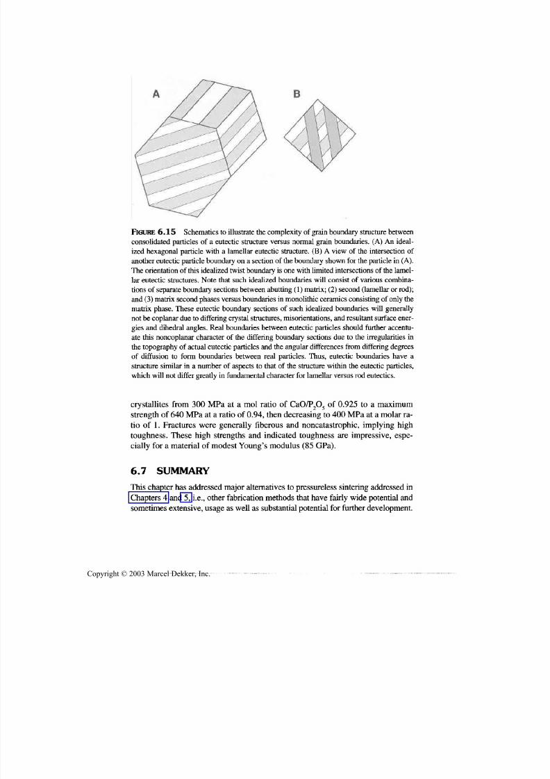
7/29/2019 29540824708539
http://slidepdf.com/reader/full/29540824708539 270/361
Other Densification and Fabrication Methods 259
FIGURE 6.15 Schematics to illustrate the complexity of grain boundary structure between
consolidated particles of a eutectic structure versus normal grain boundaries. (A) An ideal-
ized hexagonal particle with a lamellar eutectic structure. (B) A view of the intersection of
another eutectic particle boundary on a section of the boundary shown for the particle in (A).
The orientation of this idealized twist boundary is one with limited intersections of the lamel-
lar eutectic structures. Note that such idealized boundaries will consist of various combina-
tions of separate boundary sections between abutting (1) matrix; (2) second (lamellar or rod);
and (3) matrix second phases versus boundaries in monolithic ceramics consisting of only the
matrix phase. These eutectic boundary sections of such idealized boundaries will generally
not be coplanar due to differing crystal structures, misorientations, and resultant surface ener-
gies and dihedral angles. Real boundaries between eutectic particles should further accentu-
ate this noncoplanar character of the differing boundary sections due to the irregularities in
the topography of actual eutectic particles and the angular differences from differing degrees
of diffusion to form boundaries between real particles. Thus, eutectic boundaries have a
structure similar in a number of aspects to that of the structure within the eutectic particles,
which will not differ greatly in fundamental character for lamellar versus rod eutectics.
crystallites from 300 MPa at a mol ratio of CaO/P2O 5 of 0.925 to a maximumstrength of 640 M Pa at a ratio of 0.94, then decreasing to 400 M Pa at a molar ra-tio of 1. Fractures were generally fiberous and noncatastrophic, implying hightoughness. These high strengths and indicated toughness are impressive, espe-
cially for a material of modest Young's modulus (85 GPa).
6.7 SUMMARY
This chapter has addressed major alternatives to pressureless sintering addressedin
Chapters 4 an d 5, i.e., other fabrication methods that have fairly wide potential and
sometimes extensive, usage as well as sub stantial potential for further development.
Copyright © 2003 Marcel Dekker, Inc.

7/29/2019 29540824708539
http://slidepdf.com/reader/full/29540824708539 271/361
260 Chapter 6
These techniques include pressure sintering methods of hot pressing, hot isostatic
pressing (HIPing), an d press forging, then various reaction processes ranging from
those inv olving sub stantial solid, liquid, or mixed-state reactions to those dominatedby gas-phase reactions, i.e., CVD and CVI. These were followed by a variety of
melt-based processes ranging from polycrystalline an d composite bodies to glassesand single crystals.
Hot pressing is well established and has good potential fo r further growth in
general as well as in newer areas, with composites being an important factor. HIP-ing is also established, but of narrower usage scope because of size, volume, an d
cost limitations, but has reasonable g rowth poten tial. Press forging an d related ex -
tensions of hot pressing have achieved only very limited application, and are
likely to continue to be restricted to specialized applications unless some special
application or breakthrough in engineering to make them more practical occurs.Reaction processing, based mainly on liquid an d solid-state reactions, has had
some past an d continuin g successes, and much potential fo r future applications,
especially fo r composites, but realizing these probably depends substantially on
technical requirements or opportunities being meshed with further practical de-
velopment. Gas-phase reaction-based processing, i.e., CVD, which is well estab-
lished, and developing CV I, have excellent potential for further growth both fo r
monolithic as well as for composite ceramics. Much of this growth probably re-
quires using th e underlying chemically oriented technology with a much broader
materials perspective, e.g., deposition of two or multiphase bodies to control mi-
crostructure, making preforms for final densification by sintering, an d using postdeposition heat treatment to modify microstructures. Finally, melt processing of
glasses and sin gle crystals as well as both polycrystalline and composite bodies iswell established, in fact dominates some major areas of application such as
glasses and crystals. How ever, there are also reasonable opportunities fo r further
successes, including more use for higher technology applications.
The first of four other important assessments is that overall a broader per-spective on fabrication is needed, both within and between th e above fabrication
methods as well as traditional sintering-based fabrication. Thus, much reaction
processing is better done by hot pressing, and CVI has broad possibilities, notonly in composites, but also in various specialty materials (Sec. 7.3.2) and possi-
ble some other, e.g., melt sprayed, materials. Also, while some processes such asCV D have excellent capabilities for producing dense materials, they m ay alsohave other uses, e.g., as in producing porous preforms for optical fibers, and
again in making some designed pore structures.
The second po int is to note the general trends in comp onent characteristicsof size, shape versatility, properties (i.e., reflecting microstructures achieved)
an d general cost trends, as summ arized in Table 6.5. Third, note that scale-up is
again an important issue for all processes. However, fo r reaction processing
scale up can be especially important since effects of exotherms from reactions
Copyright © 2003 Marcel Dekker, Inc.

7/29/2019 29540824708539
http://slidepdf.com/reader/full/29540824708539 272/361
Other Densification and Fabrication Methods 261
TABLE 6.5 Summary of General Component Capabilities of Other Fabrication Trends3
Process
Hot pressing
Press Forging
HIP
Reaction
processing
CVD/CVI
Melt
Sintering
Size
Large
Moderate
Small to moderate
Moderate-large
Large
Very large
Small-moderate
Shape
Simple
Somewhat
versatile
Reasonably
versatility
Modest to
versatile
Fairly versatile
Simple to
moderate
Versatile
Properties
High
Often high
High
Moderate-high
Often high
Low-moderate
Moderate-high
Costs
Moderate to
high
Often high
Generally high
Often moderate
Moderate
Low-moderate
Low-moderate
"Relative to pressureless sintering.
can change with component sizes and shapes, furnace loading, and heating, and
if melting, even local and transient, occurs, it can result in coarser microstruc-
tures and phase distribution and serious component property limitations. Fourth,
while a single fabrication process is often used in making ceramics, there are in-
creasing opportunities to use two, or possibly more, as indicated by CVD of bil-let preforms for optical fibers, followed by sintering prior to fiber pulling.
REFERENCES
1. R.M.Fulrath. A critical compilation of ceramic forming methods III. H ot forming
processes. Am. Cer. Soc.Bui . 43(12):880-885, 1964.
2. T. Vasilos, R.M.Spriggs. Pressure sintering of ceramics. Progress in Ceramic Sci-
ence. Vol.4. New York: Pergamon Press, 1966, pp. 95-132.
3. R.W. Rice. Hot forming of ceramics. In : J.J. Burke, N.L.Reed, V. Weiss, eds. U l-
trafine-GrainCeramics. New York: Syracuse Univ. Press, 1970, pp. 203-250.
4. A. Ezis, J.A. Rubin. Hot pressing. In: S.J. Schnieder, ed. Engineering Materials
Handbook. Vol. 4. Ceramics and Glass. Metals Park, OH: ASM, 1991,pp. 186-193.
5. D.J. Bowers. A critical compilation of ceramic forming methods v. miscellaneous
forming methods. Am. Cer. Soc.Bui . 44(2): 145-150, 1965.
6. R.F.Davis, H. Palmour III, R.L.Porter, eds.Emergent Process Methods for High-
Technology Ceramics. Materials Science Research, Vol. 17, Plenum Press, 1984.
7. R.M.Spriggs, L.A.Brissette, M. Rosetti, T. Vasilos. Hot-pressing ceramics inalu-
mina dies. Am. Cer. Soc.B u i . 42(9):477-479, 1963.
8. R.M. Spriggs, T. Vasilos, L.A. Brissette. Grain size effects in polycrystalline ceramics.
In: W.W. Kriegel, H. Palmour HI, eds.Materials Science Research. The Role of Grain
Boundaries and Surfaces in Ceramics. 3. New York: Plenum Press, 1966,pp . 313-53.
Copyright © 2003 Marcel Dekker, Inc.

7/29/2019 29540824708539
http://slidepdf.com/reader/full/29540824708539 273/361
262 Chapter 6
9. R.W. Rice. M echanical Properties of Ceramics and Composites, G rain and Particle
Effects. New Y ork: Marcel Dekker, Inc., 2000.
10. P.H. Cra yton , J.J. Price. Prediction of effective isothermal hot-pressing tempera-ture. Am . Cer., Soc. B u i . 63(5):715-717, 1984.
11. K. An, D .L. Johnson. The pressure-assisted m aster sintering surface", to be published.
12a. H. Su, D .L. Johnso n. Master s intering surface. J. Am . Cer. Soc. 79(12):3211-3217,
1996.
12b. D.L. Jo hnson, H . Su. A practical approach to sintering. Am . Cer. Soc. B u i .
76(2):72-76, 1997.
13. H. Iwasaki, S Shikanai, T. Takahashi, A. Tsuge, H. Ohkuma, T. Ishii. Studies of
E lastically Structural Anisotropies in Hot Pressed Ceramic Materials. Toshiba Re-
search an d Development Center, Report, March 1975.
14. Reference deleted.
15. G .J. Oud eman s. Co ntinuou s hot-pressing techniqu e. Proc. B rit . Cer. Soc. No. 12,
Fabrication Science 2, 3:83-98, 1969.
16. W. Rhod es, J. Thom son, Jr. Co ntinuo us hot pressing of B a2TigO 2( ) and its evalua-
tion. A m . Cer. Soc. B u i . 55(3):308-310, 1976.
17. H. Sheinberg. Hot pressing spinel hemishells with retractable tooling. Am. Cer.
Soc. B u i . 58(7):719-721, 1979.
18. F.F. Lan ge, G .R. Terwilliger. The powder vehicle hot-pressing technique. Am . Cer.
Soc. B u i . 52(7):563-565, 1973.
19. E.H. Zehms, J.D. M cC lelland. Sem i-Con tinuous Hot Pressing. Am . Cer. Soc. B u i .
41(1):10-11, 1963.
20. R.W. Rice, J.H. Enloe, J.W. Lau, E.Y. Lu h, L.E. Dolhert. Hot-pressing-a new routeto high-performa nce ceram ic m ultilay er electronic packages. Am . Cer. Soc. B u i .
71(5):751-755, 1992.
21. J.H. Enloe, J.W. Lau, C.B. Lundsager, R.W. Rice. H ot Pressing Dense Ceramic
Sheets for Electronic Substrates and for Multilayer Electronic Substrates. U.S.
Patent 4,920,640, 5/1/1990.
22. J .H. Enloe, J .W. Lau, R.W. Rice. Electronic Package Comprising Aluminum
Nitride and Alu min um Nitride-B orosilicate G alass Com posite. U .S. Patent
5,017,434,5/21/1991.
23. F.W. Glaser, W . Ivan ick. Sintered titanium carbide. J. Metals 4:387-390, 1952.
24. J.S. Jackson, P.P. Palmer. Hot pressing refractory hard materials. In: P. Popper, ed.
Special C eramics. New York: Academic Press, 1960, pp. 305-328.25. Y. Zhou, K. Hirao, M . Toriyama, H. Tanaka. Very rapid densification of nanometer
silicon carbide powd er by pulse electric cu rrent sintering. J. Am. Cer. Soc.
83(3):654-656, 2000.
26a. Materials Modification, Inc., Fairfax, VA , www.matmod.com.
26b. W.W. Goldberger. A low cost method for pressure-assisted densification of ad-
vanced ma terials into complex shaped parts. Mats. Tech. 10(3/4):48-51, 1995.
27. J.W. Lee, Z.A. Munir , M. Shibuya, M. Ohyanagi . Synthesis of dense TiB 2-TiN
manocrystalline composites through mechanical and field activation. J . Am. Cer.
Soc. 84(6): 1209-1216, 2001.
28a. R.M . Spriggs, L. Atteraas. Densification of Single-Phase Systems Under Pressure.
Copyright © 2003 Marcel Dekker, Inc.

7/29/2019 29540824708539
http://slidepdf.com/reader/full/29540824708539 274/361
Other Densification and Fabrication Methods 263
In: R. M. Fulrath and J. A. Pask, eds. Ceramic Microstructures: Their Analysis &Production. New York: John W iley & Sons, Inc., 1968, pp . 701-727.
28b. R.M. Spriggs , R.B . B unk, L. Atteraas. Thermomechanical processing of ceramics,fabrication science. 2. Proc. B rit. Cer. Soc. No. 12, 3:65-82, 1969.29. B.-N. Kim, K. Morita, Y. Sakka. A High-Strain-Rate Superplastic Ceramic. Nature
413:288-291, 2001.30 . R.W. Rice. Deformation, recrystallization, strength, and fracture of press-forged
ceramic cry stals. J. Am . Cer. Soc. 55(2):90-97, 1972.31. M.H. Hodge. The Effect of Hot Working on the Texture and M agnetic Properties of
Th e Magnetoplumbite Ferrites. PhD Thesis, Penn. State U niv., 1973.32. J.U . Knickerbocker, D.A. Payne. Oreintation of ceramic microstructures by hot-
forming methods. Ferroelectrics 37:733-736, 1981.33. S.K. Dey, J.S. Reed. Magnetic properties of press-forged barium ferrite. Am. Cer.
Soc. Bui . 64(4):571-575, 1985.34. E . Schmid, W . B oas. Krystallplas tizitat" B erlin: Verlag von Juliu s Springer,
1935.
35 . R.J. Stokes, C.H. Li. Dislocations and the strength of polycry stalline ceramics. In:H.H. Stadelmaier, W.W. Austin, eds. Materials Science Research. Vol. 1. NewYork: Plenum Press, 1963, pp. 133-157.
36. R.B . Day, R.J. Stokes. M echanical behavior of polycrystalline magnesium oxide athigh temperatures. J. Am. Cer. Soc. 49(7):345-354, 1966.
37. R.W. Rice, J.G. Hunt, G.I. Friedman, J.L. Sliney. Identifying Optimum Parametersof Hot E xtrusions. Final B oeing Co. Report for NAS A Contract NAS-7-276, 1968.
38. R.W. Rice. Hot-wo rking of oxides. In: A. Alper, ed. High Temperature Ox ides,
New York: Academ ic P ress, 1970, pp . 235-280.
39 . P.P. Becher, R.W. Rice. Strengthening effects in press forged KC1. J. Appl. Phy.44(60):2915-2916, 1973.
40. R.W. Rice, M.W. B enecke, J.L. Sliney, G .I. Friedman. Sem i-Continu ous PressureSintering. Boeing Co. Summary Report for U.S. Navy Contract N00019-67-C-0314,1968
41 . R.W. Rice, W.J. McDonough, G.Y. Richardson, J.M. Kunetz, T. Schroeter. Hotrolling of ceramics using self-propagating high-temperature synthesis. Cer. Eng.Sci. Proc. 7(7-8):751-760, 1986.
42. S.L. W ikinson. Squeezing powders into shape. Chem Week 12:1988.
43. R.V. Ram an. Rapid consolidation of aluminides. Adv. M ats. Procs. 4/1990, pp .109-110.
44. A. Sawaoka, S. Saito. Hot Isostatic compaction using a molten glass as pressuretransmission m edia. Jpn. J. Ap pl. Phy. 13:751, 1974.
45. A.J. Pyzik, A. Pechenink. Rapid omnidirectional compaction of cerami-metal com-posites. Cer. Sci. E ng. Proc. 9(7-8):965-974, 1988.
46. T. Clark, J.S. Reed. Closed-die hot-forgin g of vitrified bonded abrasives. Am. Cer.Soc. Bui. 61(7):733-736, 1982.
47. J.J. Svec. Hot pressing glass-bonded mica. Cer. Ind. 1980, pp . 28-29.
48. H.C. Yeh, P.P. Sikora. Consolidation of Si3N4 by hot isostatic pressing. Am Cer.
Soc. Bui . 58(4):444^47, 1979.
Copyright © 2003 Marcel Dekker, Inc.

7/29/2019 29540824708539
http://slidepdf.com/reader/full/29540824708539 275/361
264 Chapter 6
49. A. Takata, K. Ishizaki. Mech anical properties of HIPed porous copper. K . Ishizaki,
L Sheppard, S. Okada, B . Hu ybrec hts, eds. Ceramic Trans. Vol. 31. Porous Materi-
als. Westerville, OH: Am, Cer. Soc., 1993, pp. 233-242.50. J. Adlerborn, M . Burs t rom, L. Hermansson, H.T. Larker. Development of high
temperature high strength silicon nitride by glass encapsulated hot isostatic press-
ing. Matls. & Design. 8(4):229-232, 1987.
51. L.M. Sheppard. Trends in HIP Equipment Capabilities. Am . Cer. Soc. B u i .
71(3):323-327, 1992.
52. L.M. Sheppard. The Evolution of HIP Continues. Am . Cer. Soc. B ui. 71(3):313-322,
1992.
53. J .B . Huffadine, A.J. Whitehead, M .J. Latimer. A simple hot isostatic pressing tech-
nique. Proc. B rit. Cer. Soc. Fabrication Science No. 12, 2:201-209, 1969.
54. S.-L. Hwang, PR Becher, H.-T. Lin. Desintering process in the gas-pressure sinter-
ing of silicon nitride. J. Am. Cer. Soc. 80(2):329-335, 1997.
55. O. Yeh eskel, Y. G efen, M. Talianker. Hot isostatic pressing of Si3N4 with Y 2O 3 ad -
ditions. J. M at. Sci. 19:745-752, 1984.
56. K.G. Ewsuk, G.L. Messing. Densification of sintered lead zirconate titanate by hot
isostatic pressing . J. Mat. Sci. 19:1530-1534, 1984.
57. W-B . Li, M.F. Ashby , K.E . E asterling. On densification and shape change during
hot isostatic pressing. Acta Metall 35(12):2831-2842, 1987.
58. M .J. An drew s, A.A. Wereszczak, T.P. Kirkland, K. Breder. Strength and Fatigue of
NT551 Silicon Nitride and NT551 Diesel Exhaust Valves. Oak Ridge National
Lab. Report ORNL/TM-1999/332, 2/2000.
59. R.W. Rice. Ceram ics from polym er pyrolysis, opportunities and needs—A materi-als perspective. A m . Cer. Soc. B u i . 62(8):889-892, 1983.
60. K.J. W ynn, R.W. Rice. Ceram ics via Polymer P yrolysis. An n. Rev. Mater. Sci.
14:297-334, 1984.
61. R.W. Rice. Advanced Ceramic M aterials and Processes. In : D.L. Cocke, A. Clearfield,
eds. Design of New Materials. Ne w York: Plenum Pub. Corp., 1987, pp . 169-194.
62. K.M . Taylor. Improved silicon carbide for high temperature parts. M aterials and
Methods 44:92-95, 1956.
63. K.M. Taylor. Dense Silicon Carbide. U.S. Patent 3,205,043, 9/7/1965.
64. G.R. Sawyer, T.F. Page. Microstructural Characterization of "REFEL" (reaction-
bonded ) silicon carbide. J. Mat. Sci. 13:885-904, 1978.
63. DJ. Godfrey. The effects of impurities, additions and surface preparation on thestrength of silicon nitride. In : R.W. Davidge, ed . Proc. B rit. Cer. Soc. No. 25. Me-
chanical Properties of Ceramics (2). 1975, pp. 325-337.
66. G. Ziegler, J. Heinrich, G . W otting. Review R elationships B etween Processing.
Microstructure and Properties of Dense and Reaction-B onded Silicon Nitride. J.
Mat. Sci. 22:3041-3086, 1987.
67. P.E.D. M organ, E. Scala. The formation of fully dense oxides by pressure calsinter-
ing of hydroxides. In: G. Kuczynski, Hooton, and Gibbon, eds. Sintering and Re-
lated Phenomena. New York: Gordon and B reach, 1967, pp. 861-892.
68. T.A. W heat, T.G. Carruthers. The hot pressing of magnesium hydroxide and mag-
nesium carbonate. In: G.H. Stewart, ed. Science of Ceramics. Vol. 4. Stoke on
Trent: B rit. Cer. Soc. 1968, pp. 33-51.
Copyright © 2003 Marcel Dekker, Inc.
7/29/2019 29540824708539
http://slidepdf.com/reader/full/29540824708539 276/361
Other Dcnsification and Fabrication Methods 265
69. R.W. Rice. The effect of gaseous impurities on the hot pressing and behavior of
MgO , CaO, and A12O3. Proc. B rit. Cer. Soc. 3:99-123, 1969.
70. M.S. Newkirk, A.W. U rquhart, H.R. Zwicker, E. B reval. Formation of Lanxide™ceramic composite materials. J. Mater. Res. 1:81-89, 1986.
71. M.K. Aghajanian, N.H. M acmillan, C.R. K ennedy , S.J. Luszcz, R. Roy. Propertiesand microstructures of Lanxide® A12O3-A1 ceramic composite materials. J. Mat.
Sci. 24:658-670, 1989.72. S. Antolin, A.S. Nagelberg, D.K . Creber. Formation of Al2O 3/metal composites by
the directed oxidation of molten aluminum-magnesium-silicon alloys: part I, mi-crostructural development. J. Am. Cer. Soc. 75(2):447-454, 1992.
73. S. An tolin, A.S. Nagelberg, D.K. Creber. Formation of Al2O 3/metal composites bythe directed oxidation of molten aluminum-magnesium-silicon alloys: part II,growth kinetics. J. Am. Cer. Soc. 75(2):455^62, 1992.
74. D.K. Creber, S.D. Poste, M .K. Agh ajanian, T.D. Claar. A1N composite growth bynitridation of aluminum alloys. Cer. Eng. Sci. Proc. 9(7-8):975-982, 1988.
75. P. B arron-A ntolin, G .H. Schiroky, C.A. Ande rsson. Properties of fiber-reinforcedalumina matrix composites. Cer. Eng. Sci. Proc. 9(7-8):759-766, 1988.
76. A.W. U rquhart. M olten metals sire M M C's, CM C's. Adv. M ats. & Proc. 7:25-29,
1991.77 . T.D. Claar, W.B. Johnson, C.A. Anderson, G.H. Schiroky. Microstructure and
properties of platelet-reinforced ceramics formed by the directed reaction of zirco-
nium with boron carbide. Cer. Eng. Sci. Proc. 10(7-8):599-609, 1989.78. M .B . Dickerson, R.L. Snyder, K.H. Sandhage. Low -temperature fabrication of
dense, near net-shaped tungsten/zirconium carbide composites with tailored phasecontents by the PRIMA -DCP process. Cer. En g. Sci. Proc. 22(4):97-107, 2001.79. W.G. Fahrenholz, D.T. Ellerby, K.G. Ewsuk, and R.E. Loehman. Forming A12O3-
Al composites with controlled compositions by reactive metal penetration of dense
aluminosilicate Preforms. J. Am. Cer. Soc. 83(5): 1293-1295, 2000.
80. N. Claussen, T. Le, S. Wu. Low-Shrinkage Reaction-B onded Alumina. J. Eur. Cer.Soc. 5:29-35, 1989.
81. S.P. G aus, P.M. Sheedy, H.S. Caram, H.M . Chan, M.P. Harmer. Controlled firing of
reaction-bonded alum inum oxide (RB AO ) ceramics: Part II, experimental results.J. Am. Cer. Soc. 82(4):909-915, 1999.
82. E. Suvaci, G . Simkovich, G.L. Messing. The reaction-bonded aluminum oxide
process: I, the effect of attrition milling on the solid-state oxidation of aluminumpowder. J. Am. Cer. Soc. 83(2):299-305, 2000.
83. S. Lathabai, D.G. Hay, F. W agner, N. Clau ssen. Reaction-bon ded mullite/zirconiacomposites. J. Am. Cer. Soc. 79(l):248-256, 1996.
84. S. W u, N. Claussen. Reaction bond ing and mechanical properties of mullite/siliconcarbide composites. J. Am. Cer. Soc. 77(11):2898-2904, 1994.
85. S. Wu, A.J. Gesing, N.A. Travitzky, N. Claussen. Fabrication and properties of Al-infiltrated RB AO-based composites. J. Eur. Cer. Soc. 7, 277-281, 1991.
86. K.H. Sandhage, S.M. Allameh, P. Ku mar, H.J. Schmutzler, D. Viers, X.-D. Zhang.Near net-shaped, alkaline-earth-bearing ceramics fo r electronic an d refractory ap -
plications via the oxidation of solid, metal-bearing precursors (the VIMOX
process). M ats. M anu . Proc. 15(1): 1-28, 2000.
Copyright © 2003 Marcel Dekker, Inc.
7/29/2019 29540824708539
http://slidepdf.com/reader/full/29540824708539 277/361
266 Chapter 6
87. M .M. Antony, K.H . Sandhage. B arium titanium/nob le metal laminates prepared by
the oxidation of solid metallic precursors. J. Mater. Res. 8(ll):2968-2977, 1993.
88. H.J. Schm utzler, M .M. Anto ny, K.H. Sandhage. A novel reaction path to BaTiO, bythe oxidation of a solid metal precursor. J . Am. Cer. Soc. 77(3): 1994.
89. R. Citak, K.A. Rodgers, K.H. Sandhage. Low-temperature synthesis of BaAl2O 4/
aluminum -bearing com posites by the oxidation of solid m etal-bearing precursors. J .
Am. Cer. Soc. 82(1):237-240, 1999.
90. K.A. Rogers, P. Kumar, R. Citak, K.H. Sandhage. Dense, shaped ceramic/metal
composites at <1000°C by the displacive compensation of porosity (DPC) method.
J. A m . Cer. Soc. 82(3):757-760, 1999.
91. K.H. Sandhage, N. Claussen. Innovative processing: reaction casting of ceramic/
metal and ceramic/intermetallic composites. In: M.N. Rahaman, ed. Vol. 1. Hand-
book of Advanced Ceramic Science and Technology. New York: Marcel Dekker, Inc.
92. R. Rice. Processing of ceramic composites. In : J.G.P. Binner , ed . Advanced CeramicProcessing and Technology. Vol. 1. Park R idge, NJ: Noyes Pubs, 1990, pp. 123-213.
93a.D. Lewis, R.P. Inge], W.J. McDonough, R.W. Rice. Microstructure and thermome-
chanical properties in alumina- and mullite-boron-nitride particulate composites.
Cer. Eng. & Sci. Proc. 2(7-8):719-727, 1981.
93b.R.W. Rice, W.J. M cD onou gh, S.W. Freiman, J.J. Mecholsky, Jr. Ablative-Resistant
Dielectric Ceramic Articles. U.S. Patent 4,304,870, 12/8/1981.
94. W.S. Coblenz, D. Lewis, III. In situ reaction of B 2O 3 with A1N and/or Si3N4 to form
B N-toughened composi tes . J . Am. Cer. Soc. 71(12): 1080-1085, 1988.
95. Z.A. Mu nir, J .B . Holt, eds. Co mb ustion and Plasme Synthe sis of High-Temperature
Materials. New York: VCH Publishers, 1990.96. R.W. Rice, W.J. McDonough. Intrinsic volume changes of self-propagating synthe-
sis. J. Am. Cer. Soc. 68(5):C-122-123, 1985.
97. R.W. Rice. Review microstructural aspects of fabricating bodies by self-propagating
synthesis. J. Mat. Sci. 26:6533-6541, 1991.
98. R.W. Rice. Assessment of the ap plication of SPS and related reaction processing to
produce dense ceramics. Cer. Eng. Sci. Proc. 11(9-10): 1226-1250, 1990.
99. G .Y. Richardson, R.W. Rice, W.J. M cDonough, J.M . Ku netz, T. Schroeter. Hot press-
ing of ceramics using self-propa gating synthesis. Cer. Eng . Sci. Proc. 7(7-8):761-770,
1986.
100. C.P. Cam eron, J.H. Enloe, L.E. Dolhert, R.W. Rice. A comparison of reaction vs con-
ventionally hot-pressed ceramic composites. Cer. Eng. Sci. Proc. 11(9-10):1190-1202,1990.
101. R.W. Rice, C.P. Cameron, P L. Berneburg. Lower Cost Ceramic Armor Materials.
In: Proceedings Second B allistics Sympo sium on Classified Topics, Johns H opkins
App lied Physics Lab. Am erican D efense Preparedness A ssn., 1992.
102. I. Zhitomirsky. New developments in electrolytic deposition of ceramic films. Am.
Cer. Soc. B u i . 57-63, 2000.
103. R.W. Haskell, J .G . B yrne. Studies in chemical vapor deposition. In: H. Herman, ed.
Treatise on Materials Science an d Technology. Vol. 1. New York: Academic
Press, 1972, pp. 293-340.
104. H.O. Pierson, ed. Ch emically V apor Deposited Coatings. Westerville, OH: Am. Cer.
Soc., 1981.
Copyright © 2003 Marcel Dekker, Inc.

7/29/2019 29540824708539
http://slidepdf.com/reader/full/29540824708539 278/361
Other Densification and Fabrication Methods 267
105. D.P. Stinton, T.M. Besmann, R.A. Lowden. Advanced ceramics by chemical vapor
deposition techniques. Am. Cer. Soc. Bui . 67(2):350-355, 1988.
106. J.S.Goela, R.L. Taylor. Monolithic material fabrication by chemical vapor deposi-tion. J. Mat. Sci. 23:4331^339, 1988.
107. P.D. Dapkus. Metalorganic chemical vapor deposition. A. Rev. Mater. Sci.
12:243-269, 1982.
108. P.A. Dowben, J.T. Spencer, G.T.Stauf. Deposition of thin metal and metal silicidefilms from the decomposition of organometallic compounds. Mats. Sci. Eng.
62:297-323,1989.
109. M.D. Rigterink. Material systems, fabrication and characteristics of glass fiber opti-cal waveguides. Am. Cer. Soc. Bui . 55(9):775-780,1976.
110. Various Authors. Glass Fibers for Optical Communications. Phy.Chem. Glasses
21(1):66, 1980.
111. L.A. Ketron. Fiber optics: the ultimate communications media. Am. Cer. Soc. Bui .66(11):1571-1578,1987.
112. C. Racault, F. Langlais, R. Naslain, Y Kihn. On the chemical vapor deposition ofTi3SiC2 from TiCl4-SiCl4-CH4-H 2 gas m ixtures. Part II An experimental approach. J.Mat. Sci.29:5041-5048,1994.
113. T. Goto, T. Hirai. Chemical vapor deposited Ti3SiC2. M at. Res. B ull. 22:1195-1201,1987.
114. M. Touanen, F. Teyssandier, M. Ducarroir, M. Maline, R. Hillel. Microcompositesand nanocomposites structures from chemical vapor deposition in the silicon-tita-
nium-carbon system. J. Am. Cer. Soc. 76(6): 1475-1481,1993.
115. M. M oriyam a, K. Kamata, I. Tanabe. M echanical properties of SiNxC ceramic films
prepared by plasma C VD. J. Mat. Sci. 26:1287-1294, 1991.116. M.I. Aivazov, T.A. Stenashkina. Synthesis of complex carbide phases in the systemsTi-B-C and Ti-Si-C bt crystallization from the gas phase. Izvestiya Akademii Nauk
SSSR, Neorganicheskie Materialy 11(7): 1223-1226,1975.
117. R.W. Rice, R. E ngdahl, unpub lished results.
118. T. Hirai. CVD of Si3N4 and its composites. In: R.F.Davis, H. Palmour III, R.L.
Porter, eds. Mat. Sci.Res. Vol.17. E mergent Process Methods for High Tech Ceram-ics. NY : Plenum Press, 1984, pp. 329-345.
119. K. Hiraga, M. Hirabayashi, S. Hayashi, T. Hirai. High-resolution electron mi-croscopy of chemically vapor-deposited |3-Si3N4-TiN composites. J. Am. Cer. Soc.
66(8):539-542, 1983.
120. T.Hirai, S. Hayashi. Density and deposition rate of chemically vapour-depositedSi3N4-TiN composites. J. Mat. Sci. 18:2401-2406,1983.
121. R.W. Rice. P orosity of Ceramics. New York: Marcel D ekker, Inc., 1998.
122. R.W. Rice. Effects of amo unt, location, and character of porosity on stiffness andstrength of ceramic fiber composites via different processing. J. Mat. Sci.
34:2769-2772,1999.
123. R. Hozl, R. Benander, R. Davis. Tungsten Alloys Containing A-15 Structure andMethod for M aking Same. U .S. Patent 4,427,445, 9/24/1984.
124. R. Hozl, J. Stiglich. Wear Performance of CM 500 Alloy as Compared to Conven-tional Hard Metals. 10th Plansee Proc, 973-980, 1981.
125. J.J.Stiglich, Jr.,D.G . B hat, R.A. Hozl. High temperature structural ceramic materi-als manufactured by the CNTD p rocess. Cer. Intl. 6(1):3-10,1980.
Copyright © 2003 Marcel Dekker, Inc.

7/29/2019 29540824708539
http://slidepdf.com/reader/full/29540824708539 279/361
268 Chapter 6
126. R.W. Rice, K.R. McKinney. Residual stresses and scaling CNTD SiC to larger sizes.
J. Mat. Sci. Let. 1:159-162, 1982
127. S. Dutta, R.W. Rice, H.C. Graham, M.C. Mendiratta. Characterization and proper-ties of controlled nu cleation thermoch emical deposition (CNT D)-silicon carbide. J.
M at. Sci. 15:2183-219 1, 1980.
128. A.R. Cooper. A critical compilation of ceramic forming methods IV. Melt forming
processes. Am. Cer. Soc. B u i . 44 (1): 1-8, 1965.
129. J.J. Rasmussen. Surface tension, density, an d volume change on melt ing of A1 2O3
Systems, Cr2O 3, Sm 2O 3. J. Am Cer. Soc. 55(6):326, 1972.
130. B . Granier, S. Heurtault. Density of l iquid rare-earth sesquioxides. J. Am. Cer. Soc.
71(11):C-466^168, 1988.
131. Newberg, J. Pappis. Fabrication of fluoride laser windows by fusion casting. In:
C.R . An drew s, C.L. Strecker, eds. Proc. Fifth Co nf. on Laser W indow M aterials, Air
Force Materials Lab., Wright-patterson Air Force Base , 1066-78, 1976.
132. R.L. Gentilman. Fusion-casting of transparent spinel. Am. Cer. Soc. B u i . 906-907,
1980.
133. J.B . Huffadine, A .G. Thomas. Flame spraying as a method of fabricating dense bod-
ies of alumina. Pwd. M etal. 7(14):290-299, 1964
134. K.T. Scott, A.G. Cross. Near-net shape fabrication by thermal spraying. In : R.W.
Davidge, ed. Novel Ceramic Fabrication Processes and Applications. Proc. B rit .
Cer. Soc. No. 38, 203-211, 12/1986.
135. R.W . B abbitt. Arc plasma fab rication of ferrite-dielectric composites. Am . Cer. Soc.
B u i . 55(6):566-571, 1976.
136. L.-W. Tai, P.A. Less ing. Plasma spra ying of porous electrodes for a planar solid ox-ide fuel cell. J . Am. Cer. Soc. 74(3):501-504, 1991.
137. Y. Ishiwata, Y. Ito, H. Kash iwaya . Densification of plasma-sprayed ceramic coatings
by HIP treatment an d their cracking behavior. J. Cer. Soc. Jpn. IntlEd., 99:665, 1991.
138. T. Mantyla . P. Vuoristo, P. Kettunen. Chemical vapor deposition of plasma-sprayed
oxide coatings. Thin Solid Films 118:437-444, 1984.
139. K . LaPierre, H. Herman, A.G. Tobin. The microstructure an d properties of plasma-
sprayed ceramic composites. Cer. Eng. Sci. Proc. 12(7-8):1201-1221, 1991.
140. V.I. Alek sandro v, VV. Osiko, A.M. Prokhorov, V.M . Tatarintsev. Synthes is and crys-
tal growth of refractory m aterials by R F m elting in a cold co ntainer. In: Current Top-
ics in Materials Science, Vol. 1. New York: North-Holland Pub. Co.,1978, p. 421.
141. K . Nassau. Cubic z irconia: an update. Lapidary J. 35(6): 1194-1200, 1210-1214,
1981.
142. R.P. Ingel, D. Lewis, B .A. B ender, R.W. Rice. Temperature dependance of strength and
fracture toughness of ZrO 2 single crystals. J. Am. C er. Soc. 65(9):C-150-152, 1982.
143. R.D . Olt, R.G . Rudne ss. Single crystals as engineering materials. Mats. Design E ng.
84-91, 1963.
144. S. Simov. Review morphology of hollow crystals of II-VI compounds. J. Mat. Sci.
11:2319-2332, 1976.
145. H.E . LaB elle, Jr., A.I. M lavsky. G rowth of controlled profile crystals from th e melt:
part 1— sapphire filaments. Mat. Res. B u i . 6:571-580, 1971.
146. H.E . LaB elle, Jr. G rowth of controlled profile crystals from the melt: part II—edge-
defined f i lm-fed growth (EFG ). M at . Res. B u i . 6:581-590, 1971.
Copyright © 2003 Marcel Dekker, Inc.

7/29/2019 29540824708539
http://slidepdf.com/reader/full/29540824708539 280/361
Other Densification and Fabrication Methods 269
147. B. Chalmers, H.E. LaBelle, Jr., A.I. M lavsky. Growth of controlled profile crystalsfrom the melt: part III—Theory. Mat. Res. Bui. 6:681-690, 1971.
148. J.T.A. Pollock. Filam entary sapphire, part 1, grow th and microstructural characteri-zation. J. Mat. Sci. 7:631-648, 1972.
149. J.T.A. Pollock. Filamentary sapphire, part 3, the growth of void-free sapphire fila-ments at rates up to 3.0 cm/min. J. Mat. Sci.7:787-92, 1972.
150. F. Theodore, T. Duffar, J.L.Santailler, J. Pesenti, M. Keller, P. Dusserre, F. Louchet,V. Kurlov. Crack generation and avoidance during the growth of sapphire domes
from an element of shape. J. Crystal Growth, 2000.151. Private communication, J. Locher. Engineering manager, Saphikon, 2000.
152. F. Schmid, C.P.Khattak, D.M. Felt. Producing large sapphire for optical applica-tions. Am. Cer. Soc. Bui. 73(2):39-44,1994.
153. C.P. Khattak, F. Schmid. Growth of near-net-shaped sapphire domes using the heatexchanger method. Mats, Let. 7(9-10):318, 1989.
154. F. Schmid, C .P. Khattak, M.B . Sm ith, D.M. F elt. Current status of sapphire for opti-cal. SPIE Proc. CR67, 1997.
155. C.P. Khattak, F. Schmid. Growth of 240 KG Multicrystalline HEM™ Silicon Ingots.Proc. 2nd
World Conf. & Exhib. of Photovoltaic Solar Energy Conversions, Vienna,Austria, 11:1870-1872,1998.
156. N. Claussen. Hot-Pressed Eutectics of Oxides and Metal Fibers. J. Am. Cer. Soc.
56(8):442, 1973.
157. U . Krohn, H. Olapinski, U . Dworak. U.S. Patent 4,595,663, 6/17/1986.158. T.-I. Mah, T.A. Parthasarathy, R.J. Kerans. Processing, microstructure, and strength
of alumina-YAG eutectic polycrystals. J. Am. Cer. Soc. 83(8):2088-2090, 2000.159. J. Homeny, J.J.Nick. Microstructure-property relations of alumina-zirconia eutectic
ceramics. Mat. Sci.Eng. A127:123-133, 1990.
160. Y. Abe, T. Kasuga, H. Hosono, K. de Groot. Preparation of high-strength calciumphosphate glass-ceramics by unidirectional crystallization. J. Am. Cer. Soc.
67(7):C-142-144,1984.
Copyright © 2003 Marcel Dekker, Inc.

7/29/2019 29540824708539
http://slidepdf.com/reader/full/29540824708539 281/361
Special Fabrication Methods
7.1 INTRODUCTION
This chapter addresses speciality fabrication methods, i.e., those yielding special
bodies or constituents for them, and thus of narrower application. Specifically,
this chapter addresses fabrication of filaments, fibers, an d related reinforce-
ments, and bodies with designed porosity, followed by rapid prototyping/solid
free form fabrication (SFF), then fab rication of ceramic fiber composites and ce-
ramic coating technology are summarized.
7.2 FABRICATION OF FILAMENTS, FIBERS, ANDRELATED ENTITIES FO R REINFORCEMENTAND OTHER APPLICATIONS
7.2.1 Introduction to Miscellaneous and Polymer-Derived Ceramic Fibers
Fabrication of filaments, ribbons, fibers, and related entities, such as whiskers
and platelets, is a major step in producing ceramic com posites, wh ether fo r their
wide usage as "reinforcement" or as toughening for structural or other applica-
tions. Other applications include the large area of low-weight thermal insulators,
as well as important use as filters, and as separators an d other applications in bat-
270
Copyright © 2003 Marcel Dekker, Inc.

7/29/2019 29540824708539
http://slidepdf.com/reader/full/29540824708539 282/361
Special Fabrication Methods 271
teries and fuel cells, and use as electrical conductive "wires," e.g.,of supercon-
ductors. Fabrication of whiskers and related (single-crystal) platelets typically
involves vapor phase processes, typically CVD , by themselves or in con junc tionwith local liquid droplets, ideally of selected composition (usually with addi-
tives), size, and placement. This is addressed in Section 3.4 and is not further ad-
dressed here.
This section addresses fabrication of filaments and fibers, which are not
explicitly defined, but are distinguished by the former typically being larger in
diameter (e.g., > 100 um, and fibers commonly having diameters of well less
than 100 um). There are also often some differences in structure; for example,
filaments may have compositional or mocrostructural gradients, which reflect
differences in fabrication processes from those for fibers, which are typically
more uniform. Another difference is that filaments are almost always produced
and used as continuous entities, that is , they are very long in length; while fibers
are often similarly produ ced and used, they may be produced directly as, or sub-
sequently by chopping to, short fibers or made into cloth or fiber structures, by
weaving, braiding , or knitting.
Fabrication methods include some miscellaneous ones, but are primarily
via extrusion/drawing, conversion of other fibers, CVD (a major source of ce-
ramic filaments), and melt-based processes, which are addressed in the order
listed, w ith most havin g various subprocesses u nder them. Each of these fabrica-
tion methods an d their major subprocesses—e.g., the increasing methods fo rfiber (filament) coatings fo r structural composites—are summarized.
Miscellaneous fiber and filament fabrication includes various methods,
some of which are briefly summarized for perspective, e.g.,growth of discontin-
uous fibers and those that may have other than structural uses. Thus, fo r exam-
ple, some very porous shorter (e.g., 1-15 cm long) fibers with high surface areas
(e.g., 500-1000 m2/gm) of nominally polygonal cross section (~ 50 um dia.)of
SiO2 [1] and of A12O3 [2] have been grown by the directional freezing of a con-
tainer of the appropriate precursor sol.The m odest strengths obtained (e.g., of ~
200 MPa)should be sufficient for many applications, such as for catalysis, be-
cause of their surface area or other attributes. Though such strengths are not suf-ficient for normal reinforcement applications, they can be increased by sintering
to reduce porosity, e.g., to 300-700 MPa. Additions of salts such as NH 4C1 can
increase the ~200-nm pore sizes and change the resultant shapes, for example
from fibers to flakes. Another process produ ces discon tinuous carbon fibers that
appear to be a hybrid of a whisker seed and a more conventional carbon fiber
(except for its CVD character) [3]. These carbon fibers, which grow like blades
of grass on carbon plates can be 1 cm or more in length, have good properties,
but are projected to cost of the order of $100/lb, tenfold higher than substantially
smaller fibers produced by the same basic process, but w ith lower properties that
may be useful as reinforcement for plastics fo r high volume, e.g.,automotive,
Copyright © 2003 Marcel Dekker, Inc.
7/29/2019 29540824708539
http://slidepdf.com/reader/full/29540824708539 283/361
272 Chapter 7
applications. There are also in situ methods of growing shorter or possibly
some longer fibers or filaments, of which eutectic systems (Sec. 6.7.3) are an
important one. Though costs and technical constraints are a factor, in somecases it may be possible to use this as a means of producing fibers or ribbons
themselves by chemically removing the eutectic matrix. For example, while
eutectic composites may have useful mechanical properties, they generally fall
far short of those of many artificial fiber composites where matrix and fiber
choices are made based on performance rather than process chemistry. How-
ever, there is some in situ development of fibers that can yield promising
toughness (Sees. 7.6 and 8.2.3).
Extrusion (often referred to as spinning) of filaments and especially fibers
is one of the most diverse and widely used method of making fibers, primarily
based on one of three types of feedstock. The first type of feedstock is an inor-
ganic glass, of w hich silicate glasses are particularly important exam ples, a key
one being the current com mercial p roduction of optical fibers from various pre-
form processing routes as discussed in Section 6.6. While fiber forming is done
by extrusion, fibers are often drawn down to finer diameters by controlling the
tensile stresses in the take-up sys tem to spool the fiber. Such extrusion/drawing
can be at substantial speeds—e.g., 125-um optical fibers produced at rates of a
meter pe r second.
The second and largest, most diverse type of fiber feedstock is that of pre-
ceramic polymers. The dominant and guiding technology here is forming thevarious experimental and com mercial carbon, m ainly graphite, contin uous fibers
that are produced [4,5]. Grow th of the carbon fiber market and the technology to
a substantial scale have lead to the availability of a diverse array of products.
These range from lower cost fibers with reasonable Young's moduli (e.g., ~ 200
GPa) and strength to high-cost fibers with high Yo ung's moduli (e.g., > 700 G Pa)
and strengths ( i.e., costs, strengths, an d elastic moduli roughly scale with one
another). However, despite the market scope and size, it still depends on other
uses of raw materials as shown by the switch from rayon (cellulose) precursors
to other precursors, mainly PAN or pitch. This occurred since rayon fiber pro-
duction greatly diminished after use of rayon fibers in tires ceased, wiping outthe major market and volume fo r rayon fibers; continued production of rayon
fibers of the quality fo r producing carbon fibers became unattractive.
The above use of polymeric precursors to yield carbon fibers (as well as
glassy carbon bodies) by forming them in the polymeric state then pyrolyzing
them to carbon served as the model for extending such processing to a variety of
compound ceramic fibers (and bodies). W hile this extension probably occurred to
various individuals, it obviously occurred to Yajima and colleagues [6] who first
demonstrated a compound ceramic, SiC-based fiber by this route (which was
commercialized as Nicalon fiber by Nippon Carbon Tokyo, Japan). It also oc-
curred to Rice [7], who anticipated such, as well as much broader, use of prece-
Copyright © 2003 Marcel Dekker, Inc.
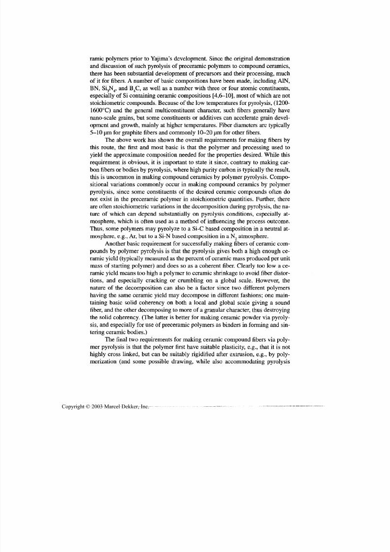
7/29/2019 29540824708539
http://slidepdf.com/reader/full/29540824708539 284/361
Special Fabrication Methods 273
ramie polymers prior to Yajima's development. Since the original demonstration
and discussion of such pyrolysis of preceramic polymers to compound ceramics,
there has been substantial development of precursors and their processing, muchof it for fibers. A number of basic com positions have been made, including A1N,
BN, SLN., and B.C, as well as a number with three or four atomic constituents,' 34' 4 ' '
especially of Si containing ceramic compositions [4,6-10], most of which are not
stoichiometric compounds. Because of the low temperatures for pyrolysis, (1200-
1600°C) and the general multiconstituent character, such fibers generally have
nano-scale grains, bu t some constituents or additives can accelerate grain devel-
opment and growth, mainly at higher temperatures. Fiber diameters are typically
5-10 um for graphite fibers and commonly 10-20 um for other fibers.
The above work has shown the overall requ irements fo r making fibers by
this route, the first and most basic is that the polymer and processing used to
yield the approximate co mposition needed for the properties desired. W hile this
requirement is obvious, it is important to state it since, contrary to making car-
bo n fibers or bodies by p yrolysis, where h igh purity carbon is typically the result,
this is uncommon in making com pound ceramics by polymer pyrolysis. Compo-
sitional variations commonly occur in making compound ceramics by polymer
pyrolysis, since some constituents of the desired ceramic compounds often do
not exist in the preceramic polymer in stoichiometric quantities. Further, there
are often stoichiometric variations in the decomposition during pyrolysis, the na-
ture of which can depend substantially on pyrolysis conditions, especially at-mosphere, which is often used as a method of influencing the process outcome.
Thus, some polymers may pyrolyze to a Si-C based composition in a neutral at-
mosph ere, e.g., Ar, but to a Si-N based composition in a N 2 atmosphere.
Another basic requirement for successfully making fibers of ceramic com-
pounds by polymer pyrolysis is that th e pyrolysis gives both a high enough ce -
ramic yield (typically measured as the percent of ceramic mass produced per unit
mass of starting polym er) an d does so as a coherent fiber. Clearly too low a ce-
ramic yield means too high a polymer to ceramic shrinkage to avoid fiber distor-
tions, and especially cracking or crumbling on a global scale. However, the
nature of the decomposition can also be a factor since two different polymershaving the same ceramic yield may decompose in different fashions; on e main-
taining basic solid coherency on both a local and global scale giving a sound
fiber, and the other decomposing to more of a granular character, thus destroying
the solid coherency. (The latter is better for mak ing ceramic pow der via pyroly-
sis, and especially for use of preceramic polymers as binders in forming and sin-
tering ceramic bodies.)
The final two requirements fo r making ceramic com pound fibers via poly-
mer pyrolysis is that the polymer first have suitable plasticity, e.g., tha t it is not
highly cross linked, but can be suitably rigidified after extrusion, e.g., by poly-
merization (and some possible drawing, while also accommodating pyrolysis
Copyright © 2003 Marcel Dekker, Inc.
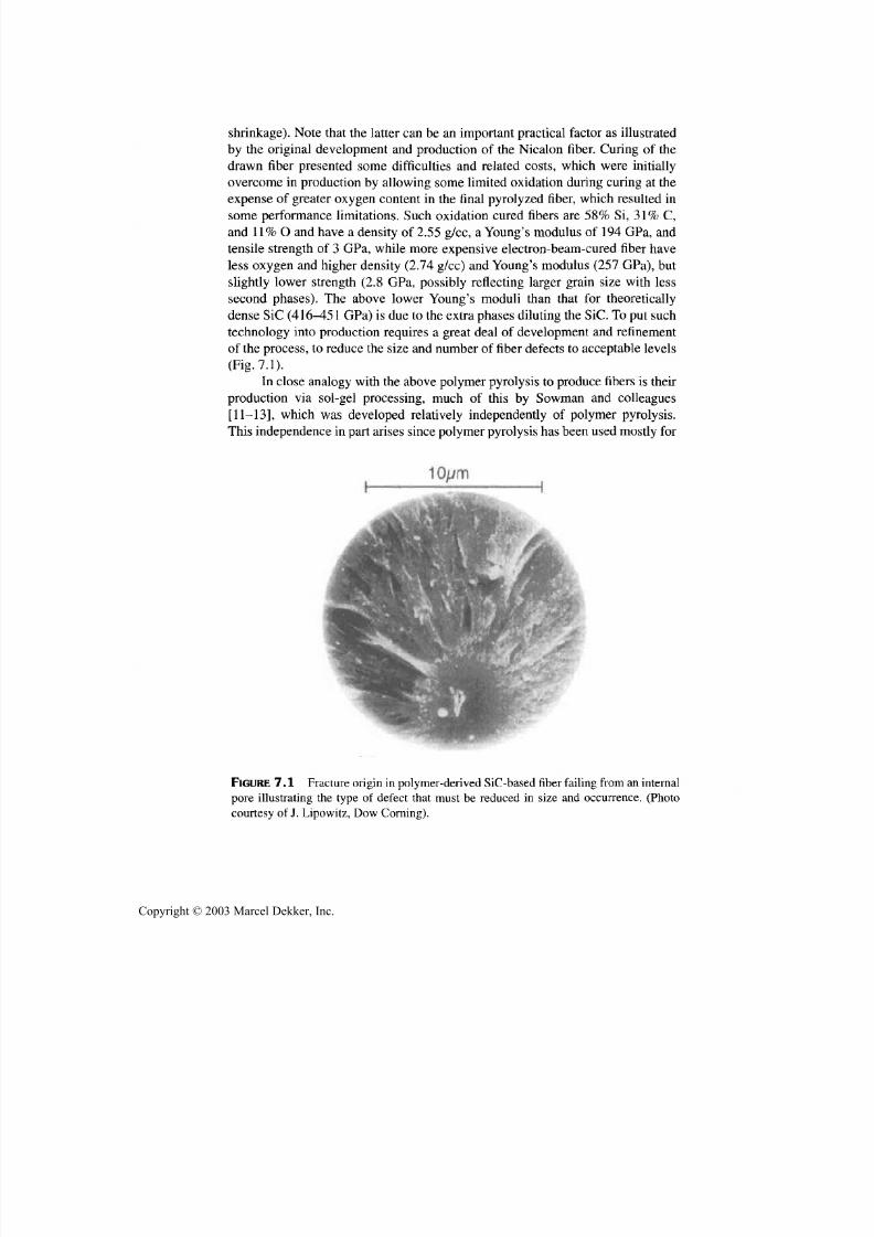
7/29/2019 29540824708539
http://slidepdf.com/reader/full/29540824708539 285/361
274 Chapter 7
shrinkage). Note that the latter can be an important practical factor as illustrated
by the original development and production of the Nicalon fiber. Curing of the
drawn fiber presented some difficulties and related costs, which were initially
overcome in production by allowing some limited oxidation during curing at the
expense of greater oxygen content in the final pyrolyzed fiber, which resulted in
some performance limitations. Such oxidation cured fibers are 58% Si, 31% C,
and 11% O and have a density of 2.55 g/cc, a Young's modulus of 194 GPa, and
tensile strength of 3 GPa, while more expensive electron-beam-cured fiber have
less oxygen and higher density (2.74 g/cc) and Young's modulus (257 GPa),bu t
slightly lower strength (2.8 GPa, possibly reflecting larger grain size with less
second phases). The above lower Young's moduli than that for theoretically
dense SiC (416^51GPa)
is due to the extra phases diluting theSiC.
To put suchtechnology into production requires a great deal of development and refinement
of the process, to reduce the size and num ber of fiber defects to acceptable levels
(Fig. 7.1).
In close analogy with the above polymer pyrolysis to produce fibers is their
production via sol-gel processing, much of this by Sowman and colleagues
[11-13], which was developed relatively independently of polymer pyrolysis.
This independence in part arises since polymer pyrolysis has been used mostly fo r
FIGURE 7.1 Fracture origin in polymer-derived SiC-based fiber failing from an internal
pore illustrating the type of defect that must be reduced in size and occurrence. (Photo
courtesy of J. Lipowitz , Dow Corning).
Copyright © 2003 Marcel Dekker, Inc.

7/29/2019 29540824708539
http://slidepdf.com/reader/full/29540824708539 286/361
Special Fabrication Methods 275
nonoxide fibers for which it is most suited and sol-gel mostly for oxide fibers for
which it is readily applicable. Most extensively developed are fibers based mainly
on alumina, with differing amounts of silica or boria to provide easier processingversus some property/performance limitations (e.g., high temperatures). Gelling
is typically an important factor in rigidizing fibers following extrusion (with lim-
ited or no drawing). Sol-derived fibers are similar to polymer-derived fibers in di-
ameter, lower firing temperatures, and fine, (nanometer), grain sizes. Different
alumina-based fiber compositions have been commercialized by a few major cor-
porations, with costs and properties reflecting the amount of alumina and its
phase (delta, gamma, or alpha) and the amount and type of second phase. Thus,
densities vary from 2.7-3.9 g/cc while Young's moduli vary from 150-373 GPa
(theoretical alpha alumina ~ 420 GPa). Tensile strengths follow a similar, but
more variable, correlation with density, with broader variations at higher density,
again possibly reflecting larger grain sizes in purer fibers.
7.2.2 Preparation of Ceramic Fibers from CeramicPowders and by Conversion of Other Fibers
The final precursor category for fibers formed by extrusion is that consisting of
the diverse array of fibers that can be produced by various means from mixes of
ceramic powd ers w ith suitable plastic binde rs. With finer ceramic particles (1 urn
or less) and suitable binders w ith a good ceramic powder loading, green ceramicfibers can be extruded at modest temperatures, with use of melting polymer
binders [14,15] or at room temperature with water-based binders [16], e.g., fol-
lowing earlier work [17-19]. Such methods have been used for both oxide and
nonoxide fibers, spun and spooled as individual fibers as with the above extru-
sion of fibers from preforms, preceramic polymers, or sols (e.g., producing green
fibers ~ 300 um dia). There is substantial literature [20-23] on development and
production of such fibers, primarily of alumina. Such fiber processing has obvi-
ous close parallels to sintering of bulk ceramics, e.g., use of ZrO 2 to limit alu-
mina grain growth an d hence obtain higher strength [21,24].
Individually handled fibers are more costly, as those above, so for lowercost fibers for less demanding application, other fiber processes have been
demonstrated, For example, Lessing [25,26], used slurries with very volatile sol-
vents such as acetone. Such slurries are placed in a rotating chamber with fine
orifices in its walls so the slurry, slung outward from the rotation, forms fibers
that are rigidified by flash evaporization of the solvent, forming green fiber mats
that may be useful fo r various applications, e.g., for batteries or fuel cells. Such
ceramic fiber forming is analogous to making cotton candy (equipment for
which has been used for making some ceramic fibers), except for the need to
subsequently fire the ceramic fibers (in mat form). Individual fibers are com-
monly 1-20 um in diameter, and have substantial aspect ratios.
Copyright © 2003 Marcel Dekker, Inc.

7/29/2019 29540824708539
http://slidepdf.com/reader/full/29540824708539 287/361
276 Chapter 7
Other manifestations of such centrifugal spinning of fibers to make fiber
mats exist, such as using sols that are spun to form fibers that are rigidified by
rapid drying, as shown for stabilized zirconia fibers(27). Such fibers can be finer
than those made using powders in binders and are commonly fired to high den-
sity and m uch finer (nm), grain size at lower temperatures.
Consider no w making ceramic fibers by converting some other fiber to a
ceramic fiber, which also has several variations depending on the nature of the
starting fiber and the conversion process. One of the largest sources of starting
fibers are organic fibers, often based on cellulose—especially rayon. Thus, H am-
ling and coworkers and others [28-30] reported making several oxide as well as
some nonoxide fibers by imp regnatin g rayon fibers with either an aqueous or or-
ganic solutionof an
inorganic salt. After impregnationof the
salt(s)in the fibersin a bath, the fibers are removed, excess surface salt removed, and the organic
fiber material slowly pyrolyzed, the salt decomposed to the oxide, and the relic
oxide sintered to replicate the starting organic fiber. There are several variations
of this versatile method, one of which is reaction processing to convert oxides
from salt decomposition to nonoxide ceramics, such as carbides or nitrides. An-
other attractive aspect of this process is that it can often be successfully per-
formed on various fiber forms, such as woven, knitted, and felted, preforms of
the organic fiber, while maintaining much of the flexibility of the original or-
ganic fiber body in the resultant ceramic fiber replica. This process is apparently
the basis of the Zircar® process for making zirconia-based felt boards for hightemperature insulation. Other natural fibers have been used in laboratory trials;
for example, jute fibers were found to be better than some other natural fibers,
with the process of ceramic rep lication of the organic structure seen as similar to
that observed in production of SiC from rice hulls [31]. Some earlier trials by
others [32] [colleagues at the Boeing Co., 1960] with cotton gauze pads gave
good fiber/gauze replication, but the resultant ceramic "pads" were brittle, appar-
ently due to sintering of many fiber contacts with one another.
The other major manifestation of fiber conversion processes is the direct
chemical conversion of a ceramic or other inorganic fiber to one of desired
chemical character, which can again follow different routes, mainly wh ether in-gredients are being removed from the starting fiber or added to it. An example of
removal of an initial fiber constituent is an approach to m ore versatile, and possi-
bly lower cost, production of silica fibers, which in pure form require extrusion
(spinning) at ~ 1800°C usin g graphite tooling [2]. A demonstrated alternative is
similar to the Vycor® process of forming a phase-separated glass from which al-
most all of the nonsilica phase can be leached out and the remaining silica read-
ily sintered to full density. In the fiber case, a glass of silica with 25 w/o Na2O
was m ade in to fibers at 1100°C, wh ich had the soda leached from it. Ano ther ex-
ample is Simpson's preparation of alpha alumina fibers by drawing of glass
fibers with 60% alum ina, then heat treating the fibers to thermally remove most
Copyright © 2003 Marcel Dekker, Inc.

7/29/2019 29540824708539
http://slidepdf.com/reader/full/29540824708539 288/361
Special Fabrication Methods 277
of the non-alumina constituents, mainly the B2O 3 and P2O 5 [33]. However, such
conversion often leaves porous areas near the fiber center and larger grains and
irregular surfaces, especially as the fiber diameters and conversion temperatures
increase (Fig. 7.2).
More common and extensive manifestation of chemical conversion of
fibers is addition of constituents by reaction of a fiber to form a chemical com-
pound different from the initial fiber composition. This is typically done by
atomic com ponents of the desired fiber comp osition being deposited on the fiber
surface and allowing them to difuse into the precursor fiber and react with it to
convert much or all of the fiber to the desired compound. The first of two key ex-
amples is the making of BN fibers by first making borea fibers by conventional
extrusion (spinning) and drawing in the glassy state, then exposing the boreafibers to N H 3 to convert them to BN fibers, usually in two stages: one at > 350°C
and the other at > 1500°C [34,35]. The other common case is conversion of car-
bo n fibers to carbides (and in come cases to mixed carbide/nitrides) by addition
of the metal to the carbon fiber surface via CVD, e.g., from halide precursors. In
principle, such fibers could often be similarly made by conversion of at least
some more refractory metal wires, to carbides or nitrides. However, this would
tend to accentuate the disadvantages of the process since the wires would often
be m ore expensive, and the y are larger (diameters of 25 um or more) thus exac-
FiGURE 7.2 Examples of fracture cross sections of alpha-alumina fibers made by draw-
ing of alumina-boria glass fibers, then thermally removing the boria to yield the alumina
fiber. Note the typical occurrence of both pores (usually at or near the center of the fiber
and of larger grains from growth during the thermal removal of most nonalumina ingredi-
ents and resultant rougher surface. (Original photos courtesy of F. Simpson, Th e Boeing
Co. From Ref. 24.)
Copyright © 2003 Marcel Dekker, Inc.

7/29/2019 29540824708539
http://slidepdf.com/reader/full/29540824708539 289/361
278 Chapter 7
erbating the porosity an d grain size issues generally common to such reaction
processing of fibers (Fig. 7.2).Such problems are very serious for making fibers
for structural applications, but may be tolerated more in other applications, such
as for superconductivity, which motivated making some of these fibers, though
their costs may be a problem.
7.2.3 CVD of Ceramic Filaments andMelt-Derived Fibers and Filaments
Consider now production of filaments by CVD, where several ceramics have
been demonstrated by such processing. The focus here is on B [67-38] and SiC
[36-40] filaments which are commercially produced by this process. Thoughthere are variations for both materials, both use a core on which the fiber mater-
ial is deposited. Originally, both apparently used W wires as cores, but the W re-
sulted in high-temperature performance limitations for SiC fibers. Generally a
25-um-diameter W wire is used for B and a 33-um pitch-derived carbon fiber
(apparently PG coated) is used for SiC. Boron halides, e.g.,BC13, are used for B
filaments, and various chlorosilanes fo r SiC,with the CVD conducted in long, >
1m , glass tubes w ith one filament being formed along the axis of each tube. T he
tubes are sealed with mercury, which also acts as the electrical contact to resis-
tively heat the W or C core on which deposition occurs, and allows feeding the
core and filament throu gh the reactor. Both filaments, comm only with diametersof 75-150 um, have high strength and Young's moduli, very fine, nanometer
grain structures, but are complex. Both have high internal stresses (e.g., that can
allow the B filaments to be longitudinally split into three equal segments). The
SiC filaments have substantial, mostly radial, grain elongation over mu ch of the
deposit giving varying preferred orientation, as well as some radial composi-
tional variations. SiC filaments, which were developed later than the B filaments,
were developed in part since costs of the B filaments could not be reduced suffi-
ciently to further expand the market fo r them, while SiC had more potential fo r
lower cost. SiC filaments are available with different surface compositions to en-
hance compatibility in different composite matrices.Preparation of ceramic fibers or filaments from the melt, while posing a
basic problem of liquid colum n instability, is a large source of ceramic fibers
with substantial further potential. The problem is that any liquid column in-
trinsically is driven by surface tension effects to break up into droplets, called
the Rayleigh instability. How fast and the extent to which a liquid column dis-
torts its surface toward breaking into droplets is a function of factors resisting
such changes in shape, with higher viscosity being an important intrinsic re-
sistance. (This instability, though an important limitation in making fibers
from a liquid column, is an important factor in making ceramic beads and bal-
loons, see Sec. 7.3.2.)
Copyright © 2003 Marcel Dekker, Inc.

7/29/2019 29540824708539
http://slidepdf.com/reader/full/29540824708539 290/361
Special Fabrication Methods 279
Glass fibers can thus generally be readily pulled (extruded/drawn) because
of their much higher viscosities combined with their excellent plasticity and its
uniformity, i.e., superplasticity. This fiber producing capability of glasses is uti-lized not only in extrusion/draw ing and spooling of individual glass fibers as dis-
cussed above, but also in large volume production of lower cost glass fibers
produced in mass, not individually [41]. Such fibers are commercially made
from various raw materials and mixes, with an important one being alumina sili-
cates (often with other limited additives), with 45-60 w/o alumina to be in prac-
tical melting and viscosity ranges. In this case, the first of two forming methods
is blowing of low-cost fibers from pouring a molten sheet of glass across a high
velocity blast of steam or compressed air such that the glass stream is blown into
droplets—many of wh ich are blown into fibers before the glass becomes too vis-
cous. The alternative m ethod is to spin fibers by pouring a mo lten stream of glass
onto a vertically oriented disk rotating at high speed, which spins off glass
droplets at high speed so they more effectively form fibers. Both processes leave
a fair amount of glass particles, called shot (e.g., 5-50 w/o), with blowing pro-
ducing more and spinning fibers less shot. Such fibers cover a range from < 1 to
> 10 (am in diameter and 1 to several centimeters long, with spun fibers being
smaller diameter and longer in length. Resulting fibers are used in large volumes
for thermal insulation, bu t also for more sophisticated applications (with pre-
forms for metal and other composites being an important growing one). Thus,
with lower shot content (e.g., by washing) these fibers are formed into papersand other preforms for making glass fiber reinforced components, such as alu-
minum engine components [42].
Crystalline ceramics (and intermetallics) often melt to low viscosity liq-
uids which, unless countered by other factors, readily results in droplet forma-
tion from a liquid (molten) stream. However, physical constraint can be effective
in preventing the distortion and breakup of liquid streams. This is demonstrated
by the earlier Taylor wire method of preparing fibers of some metals, inter-
metallics, and ceramics of moderate melting temperatures by placing them in
glass tubes in which they can be melted [43]. The tube prevents the melt from
breaking into droplets, and can subsequently be removed or used, for example asan insulator for electrically conducting fibers formed in them.
More recently, a significant extension of this type of constraint of the liq-
uid has been developed, called the invisid melt spinning (IMS) process [44-46].
This process is based on observations that rapid coating of an extruded fiber/fila-
ment of molten ceramic w ith a thin layer of compatible solid can retain the liquid
fiber/filament shape until it solidifies and thus fully stabilizes its fiber shape. A
practical low-cost m ethod of mak ing such a fiber coating is to extrude the molten
fiber into a closed chamber w ith a gas that is readily pyrolyzed or cracked on the
hot su rface of the liquid fiber to produce a solid coating on the fiber surface. U se
of propane gas to produce a carbon coating (e.g., a few hundred nanom eters in
Copyright © 2003 Marcel Dekker, Inc.
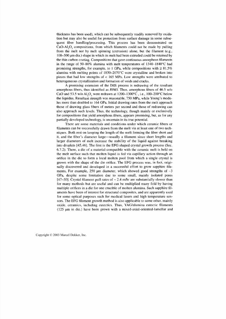
7/29/2019 29540824708539
http://slidepdf.com/reader/full/29540824708539 291/361
280 Chapter 7
thickness has been used), which can be subsequently readily removed by oxida-
tion but may also be useful fo r protection from surface damage in some subse-
quent fiber handling/processing. This process has been demonstrated onCaO-Al2O 3 compositions, from which filaments could not be made by pulling
from the melt nor by melt spinning (extrusion) alone, but the filament (e.g.,
100-500 um dia.) shape in which its melt had been extruded could be retained by
the thin carbon coating. Com positions that gave continu ous amorphous filaments
in the range of 50-80% alumina with melt temperatures of 1340-1840°C had
promising strengths, for example, to 1 GPa, w hile compositions w ith > 81.5%
alumina with melting points of 1850-2070°C were crystalline an d broken into
pieces that had low strengths of < 165 MPa. Low strengths were attributed to
heterogeneous crys tallization and formation of voids and cracks.
A promising extension of the IMS process is redrawing of the resultant
amorphous fibers, thus identified as RIMS. Thus, amorphous fibers of 46.5 w/o
CaO and 53.5 w/o A12O3 were redrawn at 1200-1300°C , i.e., 100-200°C below
the liquidus. Res ultant strength was reasonable, 750 MPa, while Youn g's modu-
lus more than doubled to 164 GPa. Initial drawing rates from the melt approach
those of drawing glass fibers of meters per second and those of redrawing can
also approach such levels. Thus, the technology, though mainly or exclusively
for compositions that yield amorphous fibers, appears promising, but, as for any
partially developed technology, is uncertain in its true po tential.
There are some materials and conditions under w hich ceramic fibers orfilaments can be successfully drawn from the melt via at least one of two tech-
niques. Both rest on keeping th e length of the melt forming the fiber short an d
it, and the fiber's diameter large—usually a filament since short lengths an d
larger diameters of melt increase the stability of the liquid against breaking
into droplets [45,46]. The first is the EFG shaped crystal growth process (Sec.
6.7.2). There, a die of a material compatible with the ceramic melt is held on
the melt surface such that molten liquid is fed via capillary action through an
orifice in the die to form a local molten pool from which a single crystal is
grown with the shape of the die orifice. The EFG process was, in fact, origi-
nally discovered and developed in a successful effort to grow sapphire fila-ments, For example, 250 urn diameter, which showed good strengths of ~3
GPa, despite some limitation due to some small, mainly isolated pores
[47-50]. Crystal filament pull rates of ~ 2.4 m/hr are substantially slower than
for many methods but are useful and can be multiplied many fold by having
multiple orifices in a die for one crucible of m olten alum ina. Such sapphire fil-
aments h ave been of interest fo r structural com posites, and are apparently used
for some optical purposes such fo r medical lasers an d high temperature sen-
sors. The EFG filament growth method is also applicable to some other, mainly
oxide, ceramics, including eutectics. Thus, YAG/alumina eutectic filaments
(125 um in dia.) have been grown with a mixed-axial-oriented-lamellar and
Copyright © 2003 Marcel Dekker, Inc.

7/29/2019 29540824708539
http://slidepdf.com/reader/full/29540824708539 292/361
Special Fabrication Methods 281
random structure and strengths of 1.9 GPa. G rowth rates were 2.5 cm/min, i.e.,
1.5 m/hr, similar to sapphire [51].
The other major, and potentially more diverse, method of growing single-crystal filaments is the floating zone process u sing laser heating . This uses laser
beams to melt a narrow, moving zone of a green or bisque-fired polycrystalline
feed rod to convert it to a single-crystal filament. This has been successfully
demonstrated with several materials and different experimental conditions.
Thus, sapphire filaments 200-250 um in dia. have been grown to give strengths
of up to 9-10 GPa at growth rates of up to 250 cm /hr [52)\], i.e., similar to EFG
sapphire. Similarly, stabilized zirconia filaments 400-600 um in dia. have been
grown at 15 cm/hr giving room temperature strengths of ~ 1 GPa and ~ 0.5 GPa
at 1400°C [53], and other materials have been grown, including ternary com-
pounds, such as , barium titanate [54]. This method in its various manifestations
has the advantage of material versatility since the melt is self-contained [55]. It
also allows different directions of filament pulling, e.g., downward, which re-
duces bubble entrapment that is still a factor for EFG. Growth rates are similar
for the two processes, but feed rod preparation is an added cost for the floating
zone method an d multiplying the number of filaments grown simultaneously is
probably more costly fo r this method than for the EFG method. H owever, it is
not necessarily an either/or choice for the two methods, since they each may
have their role to play. W hat is certain is the growing importance of single -rys-
ta l fibers and filaments [55]. For other possibilities of making single-crystalfibers and filaments, see conversion of polycrystalline to single-crystal bodies
(Sec. 3.5).
7.2.4 Fiber and Filament Behavior, Uses inComposites, and Future Directions
Since much of the above fabrication, especially of continuous fibers and fila-
ments, is for structural composites, consider their mechanical properties, espe-
cially strength an d Young's modulus, which are critical to such applications.
Young's modulus (E ) depends on the material, that is, composition (and for sin-gle-crystal fibers or filaments, their axial crystal orientation), and porosity (its
amount and character determine its reduction of E1[56]. W hile strength generally
scales w ith E, it also decreases with increasing fiber/filament diameter and ga uge
length, an d with both the amount an d size of pores present. Fiber/filament
strength also generally increases as the grain size of polycrystalline fibers/fila-
ments decreases, i.e. similar to monolithic ceramics [24], especially once pro-
cessing defects have been sufficiently reduced. However, while in monolithic
ceramics such grain size effects generally result from the size on machining
flaws relative to the grain size, in fibers/filaments the grain size dependence
arises mainly from grain size effects on surface roughness. Thus, as with mono-
Copyright © 2003 Marcel Dekker, Inc.

7/29/2019 29540824708539
http://slidepdf.com/reader/full/29540824708539 293/361
282 Chapter 7
lithic ceramics, fiber strengths have been increased by use of grain growth in-
hibitors, e.g., of zirconia in alumina [21]. Over the finer grain regime, strength
increases with decreasing grain size are attributed mainly to grain boundarygrooving w hen grosser defects such as frequent CVD colony structure and resul-
tant botryoidal (i.e., knobby) surface are minimized. At larger grain sizes, more
severe strength limitations result from more knobby, faceted surfaces (e.g., Fig.
7.2), where surface coatings such as silica on alumina fibers may limit strength
reductions [21,24]. At high temperatures creep becomes a limiting factor, wh ich
is often more limited in ternary than binary compounds, favoring the former for
high temperatures, and may also be constrained in some eutectic systems.
While fabrication of ceramic fiber composites is addressed in Section 7.6
(Sec. 8.2.3), it should be briefly noted that while handling of individual filaments
is reasonably practical, it is not practical to handle individual fibers, especially
finer ones. Instead, in most cases where it is feasible, fibers are formed into bun-
dles of hundreds to thousands of fibers called tows with an organic coating
(called sizing) fo r handling tows, that is, for keeping them from "fuzzing up".
Such handling may be for fabricating uniaxial composites or more commonly fo r
making fabrics fo r composites by weaving, braiding, knitting, etc., where fiber
diameters and Y oung 's moduli are fine enough to allow sufficient flexibility to do
so (this commonly canno t be done w ith filaments). Fabrication of ceramic fibers
by replication of organic precursors in cloth or multifiber forms such as felts,
braided forms, and so forth is thus desirable since fabrication of such fiber formsas organic rather than ceramic fibers has cost and v ersatility advantages .
Regardless of the fiber form, structural composites of ceramic matrices
with ceramic fibers generally preform best when there is very limited bonding
between the fiber and matrix. Thin ceramic coatings are often used on the fibers
to assure limiting such fiber-matrix bonding. For mainly nonoxide fiber compos-
ites for non- or limited high temperature oxidation condition use, the primary
coating is BN applied by CVD [57-59], which is available commercially. BN is
applied to individual fibers or filaments and especially to fibers in tow form (af-
ter removal of the sizing, by solvent or by burning it off in a flame) and can also
be applied to cloth form s, with bolt to bolt cloth coating becoming available [R.Engdahl, President, Synterials, Res ton, V A circa 2000). For composites of oxide
fibers in oxide matrices for use at high temperature use in oxidizing conditions,
considerable work to identify suitable bond limiting coatings is underway w ith
rare earth pho sphates the leading candidates [61].
Finally, consider briefly tw o other areas of fiber development concerning
varying fiber composition and geometry. Thus , the above summary of fiber fabri-
cation focused on the bu lk of work on fibers with the same composition through-
out the fiber. However, glass fibers made from tw o glass compositions,
apparently by fusing tw o randomly twisted fibers together, such that the axial
plane along which the two halves of the resultant fiber are joined twists ran-
Copyright © 2003 Marcel Dekker, Inc.

7/29/2019 29540824708539
http://slidepdf.com/reader/full/29540824708539 294/361
Special Fabrication Methods 283
domly [62]. Such fibers are reported to be highly flexible and resilient. Coextru-
sion of one preceramic polymer over another has also been reported [63], giving
a coating on a core fiber or a thicker surface layer, i.e., a composite core-shellfiber. Much more extensively, optical fibers are often made with various radial
gradients or steps of refractive indexes via corresponding changes in dopants.
Further compositional tailoring of such bi- or multicompositional fibers seems
feasible depending on imagination and needs.
The second area of fiber development is their shape, mainly their cross
sectional shape, especially for hollow fibers of various shapes. The simplest
manifestation is fibers in the form of a cylindrical shell, i.e., having a circular in-
ternal and external boundary of the solid forming the fiber, as developed with
glass fibers [64,65]. Such fibers of a few oxides and of Ni metal have been made
by Card [64] by the conversion method. Thus, a porous surface layer in graphite
fibers was prepared by controlled oxidation, followed by impregnation of ce-
ramic salt precursor in the pores, then pyrolyzed in air to yield the ceramic and
remove the remainder of the graphite fiber.
More versatile and extensive is the demonstration of fabricating hollow
fibers of various sizes and especially shapes (Fig. 7.3) from many materials by
various processes, e.g., as demonstrated and reviewed by Hoffman and cowork-
ers [66,67]. W hile qu artz tubes can be drawn down to 2 um ID, a variety of repli-
cation techniques are being used to prepare a diverse array of hollow fibers, with
fugitive tube processing being an important practical example, with possiblecosts of the order of 1 cent per cm. Such technology ranges from the nanometer
to the micrometer scale and from the microelectromechanical systems (MEMS)
with diverse applications from composites to catalysis, filters, miniature heat ex-
changes, and so forth.
7.3 FABRICATION OF POROUS BODIES
7.3.1 Introduction
Fabrication of porous ceramic bodies is an important and growing area of bothresearch and application, as recently reviewed, since, while porosity decreases
may properties, it can provide im portant functions that are best done w ith a vari-
ety of controlled porosity [56,68-71]. These include large and diverse applica-
tions in catalysis and thermal insulation, as well as a diversity of less extensive
applications for lightweight materials for mechanical functions, and various ex-
isting and developing filtering needs and burner applications.
The various applications require a diversity of needs for combinations of
the am ount of porosity and its character, e.g., size, shape, location, and degree of
its interconnection and orientation. Thus, substantial quantities of highly inter-
connected, very fine pores are needed to give both high surface area and its ready
Copyright © 2003 Marcel Dekker, Inc.
7/29/2019 29540824708539
http://slidepdf.com/reader/full/29540824708539 295/361
284 Chapter 7
FIGURE 7.3 Examples of microtube fabrication versatility show ing tubes with (A ) thin,
(B ) thick, and (C) porous walls; (D) with a liner, (E) a spiral tube on a straight tube, (F) a
hollow bellows of noncircular and rotating cross section, and (G) a multichannel tube.
(Photos courtesy of Dr. W. Hoffman, Air Force Philips Lab.)
Copyright © 2003 Marcel Dekker, Inc.

7/29/2019 29540824708539
http://slidepdf.com/reader/full/29540824708539 296/361
Special Fabrication Methods 285
accessibility for catalytic applications. Gradients or anisotropy of the porosity
may be needed—for example, in filters to allow good filtration in one fluid flow
direction, but limited b ack pressure fo r cleaning via reversing the flow direction.In both of these, an d many others, these porosity needs must be met while limit-
ing the compromise of other (e.g., mechanical) properties. This m ust be done in
a diversity of component sizes and shapes, for a variety of environments.
The simp lest, and most common, method of fabricating porous bodies is to
partially sinter com pacts of pow der of v arying character. The particle size and its
distribution and the method an d extent of powder consolidation along with the
extent of sintering are the key controls for the type and amount of porosity ob -
tained. The first of three key limitations of this method of fabricating porous
bodies is the am oun t porosity, e.g., to 5 0% or less; the second is the limited range
of pore character, that is, of pores between partially sintered particles; and the
third is its limitations on other properties. Th us, pores between partially sintered
particles typically give the greatest reduction in key physical, e.g., mechanical,
properties per volume fraction porosity (and give substantial constraint to fluid
flow) versus other basic types of pores.
Another simple an d widely used method of fabricating porous bodies is by
mixing ceramic powder with particles of some fugitive material, for example a
burnable material such as plastic or carbon particles of fibers (e.g., chopped),
then sintering. Other burnable materials used in industry for their low costs are
saw dust or crushed nu t shells, (used in making refractory bricks). Pore size andshape of such bodies is thus m ainly controlled by the size and shape of the fugi-
tive material, with both of these, especially shape, playing an important role in
physical properties. Shapes range from quite angular to polyhedral/spherical to
cylindrical, w ith reductions in key properties such as strength an d elastic m oduli
decreasing in the order listed, i.e., greatest decreases with sharp angular pores
(but generally less so than for pores between partially sintered grains), less re-
duction fo r polyhedral pores an d generally least fo r tubular pores (especially
when their axes are aligned parallel with the stress). Such porosity is generally
no t open un til higher porosity levels, e.g., > 50% , but can theoretically approach
a limit of 100% porosity, so there are significant opportunities for bodies withsimilar (somewhat constrained) fluid flow as with pores between partially sin-
tered grains, but better properties such as strength and elastic m oduli.
Clearly, both of the above m ethods can be com bined w ith one another, as
is often done to varying extent. Another important combination is of either or
both of the above w ith extrusion or other fabrication of bodies w ith highly ori-
ented, fine, uniform tubular cha nnels, e.g., of a honeycomb m onolith, which is
done to produce automotive exhaust, as well as various industrial, catalyst sup-
ports (Fig. 4.10). Thus, the tubu lar channels add some to the body surface area
and a great deal to its permeability, such that pores in the cell walls are highly
Copyright © 2003 Marcel Dekker, Inc.
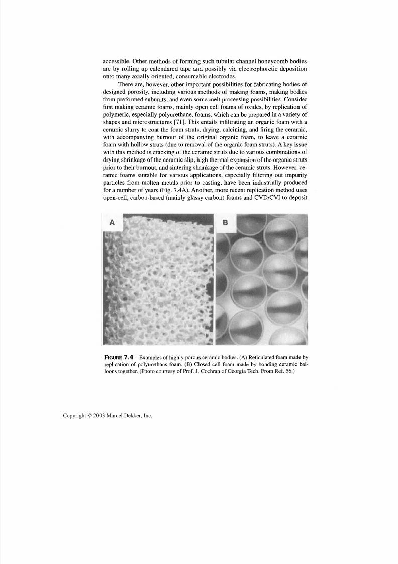
7/29/2019 29540824708539
http://slidepdf.com/reader/full/29540824708539 297/361
286 Chapter 7
accessible. Other methods of forming such tubular channel honeycomb bodies
are by rolling up calendared tape and possibly via electrophoretic deposition
onto man y axially oriented, consumable electrodes.
There are, however, other important possibilities for fabricating bodies of
designed porosity, including various methods of making foams, making bodies
from preformed sub uni ts, and even some m elt processing possibilities. C onsider
first making ceramic foams, mainly open cell foams of oxides, by replication of
polymeric, especially p olyureth ane, foams, whic h can be prepared in a variety of
shapes an d microstructures [71]. This entails infiltrating an organic foam with a
ceramic slurry to coat the foam struts, drying , calcining, and firing the ceramic,
with accompanying burnout of the original organic foam, to leave a ceramic
foam with hollow struts (due to removal of the organic foam struts). A key issuewith this method is cracking of the ceramic struts due to various combinations of
drying shrinkage of the ceramic slip, high thermal e xpansion of the organic struts
prior to their burno ut, and sintering shrink age of the ceramic struts. How ever, ce-
ramic foams suitable fo r various applications, especially filtering out impurity
particles from molten m etals prior to casting, have been ind ustrially produce d
for a num ber of years (Fig. 7.4A). Another, more recent replication m ethod uses
open-cell, carbon-based (mainly glassy carbon) foams an d CVD/CVI to deposit
FIGURE 7.4 Examples of highly porous ceramic bodies. (A ) Reticulated foam made by
replication of polyurethans foam. (B) Closed cell foam made by bonding ceramic bal-
loons together. (Photo courtesy of Prof. J. Cochran of Georgia Tech. From Ref. 56.)
Copyright © 2003 Marcel Dekker, Inc.

7/29/2019 29540824708539
http://slidepdf.com/reader/full/29540824708539 298/361
Special Fabrication Methods 287
metal, carbon, nonoxide ceramics, as well as some oxide ceramics onto the car-
bon struts to form a composite foam [72]. Both oxidative removal of the carbon
for oxide foams, and reaction between metals and the carbon as an alternative todirectly depositing carbides, should be feasible.
Direct fabrication of foams requires first a source of gas to do the "blow-
ing" and sufficient plasticity of the material to be blown to form the foam struc-
ture, which must then be rigidized. It is often necessary to follow this with
thermal treatment to obtain the final ceramic structure desired. Air or other
gasses can be beaten or otherwise mechanically introduced into very fluid ce-
ramic precursors, e.g., ceramic slips; or a material that releases suitable am ounts
of a gas due to chemical reaction, heating, or both may be used. In either case,
the liquid precursor may form a foam by themselves or with surfactant additives,
e.g., soaps, which leaves a key issue, namely rigidifing the foam. In some cases
this can be done with benign additives, e.g., using plaster of paris (calcium sul-
fate, calcined gypsum) with ceramics in which the resultant CaO is benign or
useful, as is the case with many zirconia bodies.
There are other more general methods of rigidizing foams, with polymer-
ization of an ingredient being an important one. Thus, many ceramic producing
sols can be foamed then rigidified by gelling(73), and many preceramic poly-
mers can often similarly be made into foams by frequently using their polymer-
ization for rigidizing (and their decomposition gasses as part or all of the
blowing) [74]. Commercial foaming of glassy carbon, which has been in produc-tion for years, is a good example of this, and the more recent offering of POCO®
graphite foam may be another. Binder constituents may also be another source of
rigidifyng foams, with gelcasting of foams being an important example of this
[75]. There are also variations of this, for example, very fine foam structures
have been produced using a polyethylene-mineral oil binder system, which
phase separates on cooling such that frequently most fine ceramic powder re-
mains in the po lyethylene and little in the mineral oil, which is readily solvent or
thermally removed, leaving a green ceramic foam structure [76)] as in the above
cases. A ceramic foam has also been demonstrated via sol precursors that ap-
pears to entail phase separation of the sol from some other fluid ingredients [77].Ceramic foams have also been demonstrated via infiltration of a body of partially
sintered, readily soluble, particles, e.g., of NaCl, into which a ceramic precursor
is infiltrated and rigidified, then the soluble phase is dissolved out.
There are also opportunities for foaming some ceramics via processing in
the melt state or with some melt present. The substantial commercial production
of foamed silicate glasses is a prime example, w here the key is having a "blow-ing agent," com monly CaCO3, that decomposes at high temperature where glass
foaming is feasible and limited cooling can freeze in the foam structure. Self
propagating high-temperature reactions often have transient liquid phases, e.g.,
of metal constituents, and frequently considerable gas release, e.g., of adsorbed
Copyright © 2003 Marcel Dekker, Inc.

7/29/2019 29540824708539
http://slidepdf.com/reader/full/29540824708539 299/361
288 Chapter 7
gases on the powder particles, due to the high temperatures rapidly reached.
Such reactions frequently show some foaming, but a key issue is likely to be re-
producibly controlling this process. Another process based on both melting an d
leaching is that of Saphikon (Milford, NH) to produce an open cell porous sap-
phire made by first leaching Cu from W-Cu composite used for high thermal
conductivity in electronic systems. Then the porous W body is infiltrated with
molten alumina, which is directionally solidified, with the W subsequently
leached out to leave the sapphire crystal with the W induced pore structure.
7.3.2 Porous Bodies via Ceramic Bead andBalloon and Other Fabrication Methods
A very promising, method of fabricating bodies of designed porosity, especially
of closed cell foams, is via fabrication of ceramic beads that may be dense,
porous, foamed, or hollow (balloons), fo r which there are a variety of fabrica-
tion methods [56]. Glass beads are manufactured by atomization of glass melt
streams. Glass balloons are fabricated commercially by injecting either: (1)
spray-dried agglomerates of glass frit or glass producing materials or (2) slurry
droplets of these constituents, both with suitable binder, into a vertical gas
flame. Successful balloon forming occurs when much of the outgassing of
volatile species is complete as the glass formation an d melting is about to seal
off the surface such that the remaining gas released will form balloons fromforming glass beads, wh ich are light enough to be carried up by the flame, and
captured above, with shot and other debris falling down and being collected be -
low. (Sound balloons are separated from most remaining defective ones by
putting them in water, where they are "floaters" and "sinkers, "respectively.)A
somew hat sim ilar process for some polycrystalline ceramics is by passing ap-
propriate suitable agglomerate particles through a plasma torch, as used com-
mercially to p rodu ce larger, coarser balloon s of alum ina or zirconia, primarily
used fo r thermal insulation .
There are other important processes for making glass or other ceramic
beads or balloons [56,78-80]. Basically, both require forming a droplet of a ce-ramic precursor, rigidizing it, then converting it to a ceramic. One important
commercial method is by dripping a sol precursor into a fluid that will cause
gelling of each very uniform drop before they are collected and fired. Another,
more versatile method is to make an emulsion of a ceramic precursor, e.g., a ce-
ramic slurry, sol, or preceramic p olymer, by vigoro usly m ixing it w ith an imm is-
cible liquid and surfactants, such that the spherical precursor droplets formed
become rigidified and hence can be readily sieved out of the remaining liquid,
then converted to ceramic beads. Rigidization can again be done via several
routes to polymerize the precursor, or part of the binder content for slurries,
which can be done by release, e.g., thermally, of a rigidizing agent, e.g., of HO
Copyright © 2003 Marcel Dekker, Inc.
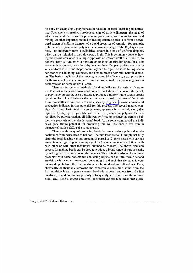
7/29/2019 29540824708539
http://slidepdf.com/reader/full/29540824708539 300/361
Special Fabrication Methods 289
for sols, by catalyzing a polymerization reaction, or basic thermal polymeriza-
tion. Such emulsion methods produce a range of particle diameters, the mean of
which can be shifted some by processing parameters, such as surfactants, an dmixing. Another important method of making ceramic beads is to form a down-
ward stream of uniform diameter of a liquid precursor of ceramic—for example,
a slurry, sol, or preceramic polymer—and take advantage of the Rayleigh insta-
bility that inherently turns a cylindrical stream into one of uniform droplets,
which can be rigidified in their downw ard flight. This is comm only done by hav-
ing the stream contained in a larger pipe with an upward draft of air (heated) to
remove slurry solvent, or with moisture or other polymerization agent fo r sols or
preceramic polymers, or to do so by heating them. Droplets, which are usually
very uniform in size an d shape, commonly can be rigidized while falling one to
tw o stories in a building, collected, and fired to beads a few millimeter in diame-
ter. The basic simplicity of the process, its potential efficiency, e.g., up to a few
ten thousands of beads pe r minute from on e nozzle, make it a promising process
demonstrated on some oxides [79,80].
There are two general methods of making balloons of a variety of ceram-
ics. The first is the above down ward oriented fluid stream of ceramic slurry, sol,
or polymeric precursor, since a nozzle to produce a hollow liquid stream b reaks
up into uniform liquid balloons that are converted to solid balloons of fairly uni-
form thin walls an d uniform size an d sphericity (Fig. 7.4B). Some commercial
production indicates further potential fo r this process. The second method con-sists of coating plastic, typically polystyrene, spheres with a ceramic slurry that
rigidizes by drying, or possibly with a sol or preceramic polymer that are
regidized by polymerization, all followed by firing to produce the ceramic bal-
loon via pyrolysis of the plastic kernel bead. Again some commercial use indi-
cates good future potential fo r producing thin wall balloons a few mm in
diameter of oxides, SiC, and a some metals.
There are also way s of producing beads that are at various points along the
continuum from dense bead to balloon. The first three are to (1) simply no t fully
sinter the bead, leaving various amounts of porosity; (2) form beads w ith various
amounts of a fugitive pore forming agent; or (3) use combinations of these witheach other or with other techniques outlined as follows. The above emulsion
process fo r making beads can be used to produce a broad range of porous beads,
by making two or more sequential emulsions. Thus, a first emulsion of a ceramic
precursor with some nonceramic containing liquids can in turn form a second
emulsion with another nonceramic containing liquid such that the ceramic con-
taining droplets from the first emulsion can be rigidized and filtered out. Then,
chemically or thermally removing the nonceramic containing liquid from the
first emulsion leaves a green ceramic bead with a pore structure from the first
emulsion, in addition to any porosity subsequently left from firing the ceramic
bead. Thus, such a double emulsion fabrication can produce beads that essen-
Copyright © 2003 Marcel Dekker, Inc.

7/29/2019 29540824708539
http://slidepdf.com/reader/full/29540824708539 301/361
290 Chapter 7
dally have an internal foam structure, which usu ally does not involve opening of
emulsion formed pores to the bead surface(Fig. 7.5A). However, some bead
compositions and fabricating methods can yield such surface opening of largerinternal pores to the bead surface by some foaming of the beads (Fig. 7.5B).
A ke y aspect of fabricating porous bodies from such beads or balloons is
forming them into desired shapes an d bonding them to form the desired body. In
any of the bead or balloon processes bulk bodies can be made from them in ei-
ther the green or fired state, each route with its advantages and issues. In either
case, large and com plex shapes can very practica lly be made us ing simple m olds
made of plastic sheets that form the part since beads or balloons only need to be
poured into the mold (possibly with some vibratory compaction, especially fo r
beads or balloons with considerable variation in diameter). Then a bonding slip,
often of the same composition as used to make the beads or balloons, is poured
into the mold, possib ly with surfactants to cause w etting primarily at bead or bal-
loon contacts, leaving pores at the interstices between the beads or balloons.
(Such pores at the interstices are very effective for reducing w eight and fairly be-
nign for other properties since fully filling the interstices between particles is the
least effective use of mass to enhance properties.) Upon drying of the slip, the
part is removed from the mold and fired. Sealing of body surfaces can also be
done via slips, either in conjunction w ith bead or balloon bonding or in a sepa-
rate operation.
Using green beads results in the same or similar shrinkage of the beads orballoons and the bonding material, which may give a stronger bond between
FIGURE 7.5 Examples of porous ceramic beads. (A ) Cross section of bead made by the
double emulsion process. (B) Ceramic beads foamed in the green state, then fired. Note
foam pores intersecting bead surfaces. From Ref. 56.)
Copyright © 2003 Marcel Dekker, Inc.

7/29/2019 29540824708539
http://slidepdf.com/reader/full/29540824708539 302/361
Special Fabrication Methods 291
them, but presents possible problems of substantial shrinkage as well as damage,
e.g., distortion, to the green and sintering beads and especially balloons. On the
other hand, using previously sintered beads or balloons to make a body results ina zero-shrinkage body, which is a large advantage, especially for making large
and complex shaped bodies. Such use of fired beads or balloons results in some
strains between them and the sintering slip bond. However, even thin bonds,
where the strain differences are small, result in good strength [56,80]. In some
cases other bonding materials/methods, e.g., glasses or cements result in good
strength, with CVI being a potentially very important one since it deposits a
strong bond with no shrinkage, but again forms generally favorable interstitial
pores, and is also potentially superior for sealing surfaces.
There are also some more specialized methods of fabricating some novel
porous bodies, in particular to prepare bodies with tubu lar pores [25,81]. Thus, it
has been shown that electrophoretic deposition from aqueous suspensions at
higher deposition rates where bubble formation at each electrode, which is nor-
mally a serious problem, can yield important pore structures (Fig. 7.6). Thus gas
bubbles from electrolysis of the water nucleate at or near the electrode surface
and grow with the deposit forming nom inally parallel chan nel pores that are nor-
mal to the electrode surface and taper to larger cross sections as deposit thick-
ness increases, i.e., with a cross section like a combination of the letters U and V.
Thus, the resultant pores are extremely anisotropic in the shape, having opening
of the order of a micron at their bottom of the U /V and orders of magn itude moreat their open end that should be very favorable for a very anisotropic filter with
very low back pressure for cleaning. Such structures are also very strong for
their porosity levels, since there is very little porosity in the ceramic walls
around the pores. Further, ceramic tubes with such U /V shaped pores can be
grown in groups to possibly form a major element of a filter module. Another,
FIGURE 7.6 Radial U/V-shaped pores made by electrophoretic deposition (EPD) of a
tube. From Ref. 24.)
Copyright © 2003 Marcel Dekker, Inc.
7/29/2019 29540824708539
http://slidepdf.com/reader/full/29540824708539 303/361
292 Chapter 7
lesser developed method is making such through pores of reasonably controlled,
adjustable sizes no rmal to a thin sheet of alumina [56].
Finally an im portan t source of mak ing an important range of porous bodiesis via use of fibers. This can be via use of shorter fibers, commonly in the form of
felts, or in bodies of continuous fibers. The latter may be used in various archi-
tectures, e.g., in various weaves and resultant cloth layup, or various filament
winding. In all of these cases various extents and ways of introducing matrices
can be used, as discussed in Section 8.2.3.
7.4 RAPID PROTOTYPING/SOLID
FREE-FORM FABRICATION (SFF)
7.4.1 Introduction and Methods
A recent area of ceramic fabrication development that has become very active
and diverse was initially focused on rapid prototyping of components as an im-
portant step in their evaluation and design [82]. Prototyping of ceramic compo-
nents has existed for a long time, e.g.,via green machining them from isopressed
logs of the desired composition, or using temporary pressing or injection mold-
ing dies, and especially slip-casting molds. However, the newer focus has not
just been on m aking prototype compo nents in shorter turnaroun d times and w ith
lower overall costs than many fabrication methods that often have expensivetooling requirements, e.g., for die pressing and especially injection molding; in-
stead the interest has widened to developing the technology to produce compo-
nents directly from a computer design, such as via a rapid prototyping machine
controlled by a computer, e.g., via CAD (computer-aided design) files. This shift
to a broader range of interests is reflected in the change of the process name or
designation from rapid prototyping to solid free-form fabrication (SFF).
Two further general extensions of this have also become of interest. The
first is "electronic warehousing", that is, not storing spare components in inven-
tory, but instead storing their design in a computer that could produce compo-
nents on demand via the developing SFF technology. The second is formanufacturing of customized components on a limited scale where such manu-
facturing could be cost-effective. It should be noted that much of the focus has
been on structural components, but there is substantial potential for electrical
an d especially electronic components, particularly mu ltilaye r ceramic electronic
packages, as discussed below. Also, besides the above overall interests in an ef-
fective way of rapidly producing parts, e.g.,prototyp e ones, there are interests in
developing some of these processes for designing microstructures on a research
or limited production basis. The more extensively developed fabrication
processes are summarized followed by some discussion of other methods that
have been considered, followed by some discussion of extension of such pro-
Copyright © 2003 Marcel Dekker, Inc.

7/29/2019 29540824708539
http://slidepdf.com/reader/full/29540824708539 304/361
Special Fabrication Methods 293
cessing to produce designed microstructures. Then the processes are compared
from several aspects, and future directions are discussed.
The concept behind the various methods is to dissect the component tobe built into various layers in a computer, which then drives the fabrication of
the part layer by layer. One of the logical early manifestation of this was to use
tape casting and automate cutting, stacking, and laminating of designed tape
sections to build up a green component to be fired, which is still in active de-
velopment [83]. This method, as some others, has considerable tape technol-
ogy on which to draw.
Another early and still expanding and developing collection of technical
approaches is based on photolithography, which was the basis of developing
stereolithography of plastics via use of photocuring. This entails building up of
polymeric components by doctor blading a layer of polymer with photoactive
additives, e.g., photoinitators, so that the pattern of that section of the component
can be photocured, i.e., polymerized, and the uncurred excess polymer removed.
The formed portion of the component, which is on an elevator system controlled
by the computer, is then lowered to allow the next layer to be formed . It has been
shown that either ceramic or metal powder particles can be mixed into the pho-
topolymer system that also acts as the binder for resultant metal or ceramic pho-
topolymer slips that can still be photocured [84-88]. This also generally requires
use of some additives to limit viscosities with suitable powder loading, and lim-
iting using too fine powders, e.g., lower limits are oftenV
2 um to keep viscositiesbelow 2000 centipoise. Also, use of metal and some ceramic powders limit the
thickness of curable layers of such slips to 50-100 um versus thicknesses of the
order of 250-500 um with other ceramics, e.g., alumina. Such procedures allow
green metal or ceramic components to be photoformed layer by layer, with suit-
able metal or ceramic powder loadings in the photopolymer system, , e.g., > 50
v/o, to obtain reasonable to good sintering of the parts.
Two variations of the photolithography approach exist. The first is using a
laser beam to photocure the photopolymer-based slip by moving the laser beam
over the layer to be patterened by com puter control of mirrors directing the laser
beam. Most commonly, photocuring uses UV wavelengths, but photopolymerscuring at other wavelengths, e.g., in the visible spectrum, are becoming more
available. Completely automated systems for such laser curing and layer by
layer development of a component have been developed. Again, these consist of
a "build platform" on an "elevator" that moves in the z direction to accurately
lower the portion of the green sample already formed so the next layer can be
formed by spreading the photopolymer-based slip, curing it, and removing un-
cured slip, then proceeding to the next layer (Fig. 7.7). The other photocuring
method uses a lamp, i.e., "flood" illumination, system with masks to determine
the areas of curing each layer. Both systems have extensive technical infrastruc-
ture, especially flood illumination, since it is the basic method by which much
Copyright © 2003 Marcel Dekker, Inc.
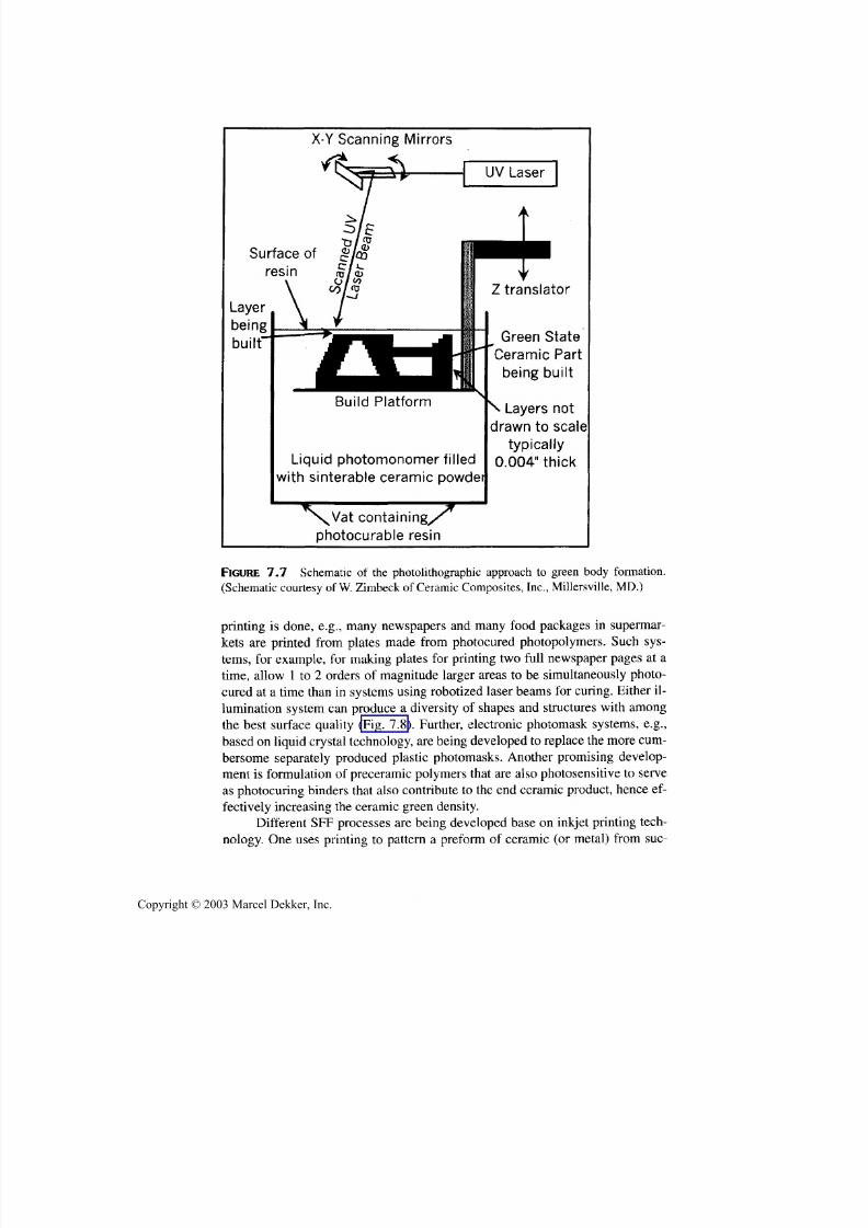
7/29/2019 29540824708539
http://slidepdf.com/reader/full/29540824708539 305/361
294 Chapter 7
X -Y Scanning Mirrors
Surface of
Layer
being
built'
resin
Build Platform
Liquid photomonomer filled
with sinterable ceramic powder
Z translator
^ Green State
Ceramic Part
being built
\Layersnot
drawn to scale
typically
0.004" thick
^s^Vat containing/'
photocurable resin
FIGURE 7.7 Schematic of the photolithographic approach to green body formation.
(Schematic courtesy of W. Zimbeck of Ceramic Composites, Inc., Millersville, MD.)
printing is done, e.g., many newspapers an d many food packages in supermar-
kets are printed from plates made from photocured photopolymers. Such sys-tems, fo r example, fo r making plates fo r printing tw o full newspaper pages at a
time, allow 1 to 2 orders of magnitude larger areas to be simultaneously photo-
cured at a time th an in systems usin g robotized laser beams fo r curing. Either il-
lumination system ca n produce a diversity of shapes an d structures with among
the best surface quality (Fig. 7.8). Further, electronic photomask systems, e.g.,
based on liquid crys tal technolog y, are being developed to replace the m ore cum-
bersome separately produced plastic photomasks. Another promising develop-
ment is form ulation of preceramic polym ers that are also photosensitive to serve
as photocuring binders that also co ntribute to the end ceramic pro duct, hence ef-
fectively increasing the ceramic green density.Different SFF processes are being developed base on inkjet printing tech-
nology. One uses printing to pattern a preform of ceramic (o r metal) from sue-
Copyright © 2003 Marcel Dekker, Inc.

7/29/2019 29540824708539
http://slidepdf.com/reader/full/29540824708539 306/361
Special Fabrication Methods 295
FIGURE 7.8 Examples of bodies fabricated by SFF using photolithography. Top figure
portion shows five alumina and one silica body, and the bottom shows the superior sur-
face finish and detail obtained via photolithography. (Figures courtesy of W. Zimbeck,
Ceramic Composites, Inc., Millersville, MD.)
Copyright © 2003 Marcel Dekker, Inc.
7/29/2019 29540824708539
http://slidepdf.com/reader/full/29540824708539 307/361
296 Chapter 7
cessive layers of powder bed (e.g., of spray-dried granules 50-100 um in dia.in
layers 180 um thick) by printing a liquid-based binder system in the pattern
needed for that layer, then another layer of powder is spread and the binder againprinted in the pattern for that layer [91]. The pattern is frozen in by evaporation
of liquid con stitue nts of the fluid binder system. A critical issue w ith this method
is the low density of the powder preform produced as discussed further below.
Binder drying time may also be a factor. Other methods print droplets of a
molten organic, e.g.,a wa x, mixed with ceramic or metal powder in the desired
pattern for each layer that is rigidified on cooling and freezing of the droplets.
Limited volume fraction of solids in such binders, e.g.,30 v/o, have been a limi-
tation, but prin ting speeds are high, e.g.,165 cm/s.
Processes are also being developed based on the use of melts. The first,
called fused deposition modeling (FDM), uses thermal polymers as binders made
into filaments, e.g., 1.8 mm in diameter, by extrusion [92]. Such filaments are the
feedstock for the process that consists of reextruding the filaments through a
heated, articulated nozzle forming an extrudate of 250 to 1300mm in diameter
depending on nozzle size selected. The pattern is formed for each planar section
of the part by articulation of the nozzle over the x-y coordinates of the build plat-
form, allowing for some expansion of the extrudate for the build, e.g. to 1.2-1.5
times the as-extruded diameter, as well as some slumping of the extrudate.
(Note: Other extrusion processes can be used to produce some finer structures,
e.g., to 10 um sizes, by multiple reextrusions that may compete with some SFFprocesses as discussed by Halloran [93].)
Another process based on melting is a process called selective laser sinter-
ing (SLS), which was originally intended to actually melt selected areas of layers
of ceramic or metal powder in order to build a part layer by layer [94]. However
it was soon found that such laser melting was not feasible in terms of amount of
energy or time to melt unless the liquefying temperatures were quite low.Some
processing using low melting constituents, e.g.,B2O 3 or phosphate precursors, to
react with other co nstituents, such as alumina, to at least partially form refractory
materials, such as aluminum borates or phosphates (often requiring posttreat-
ment to complete the reaction), was demonstrated. Thus, much of the focus ofdevelopment included using a laser beam to selectively m elt organic binder con-
stituents, e.g., of thermal polymers to form a green part. However, reasonable
success has been ach ieved in melting thin layers of metals in a pattern with much
higher power lasers, and even more melting versatility may be feasible with
electron beams as long as materials do not have high vapor pressures at high
temperatures, as for ceramics, such as SiC, BN, SiN, and to some extent MgO.
Other approaches to SFF have been tried to varying extents an d others
may be feasible. Thus, systems for SFF have been used to apply layers of a ce-
ramic slurry with a fluid binder system that can be gelled by selective addition of
a fluid gelling agent to form the desired pattern on a layer and thus build a part
Copyright © 2003 Marcel Dekker, Inc.

7/29/2019 29540824708539
http://slidepdf.com/reader/full/29540824708539 308/361
Special Fabrication Methods 297
layer by layer. While this has been demonstrated with alginate binders [95], it
should be applicable to other gelling system s [96], p ossibly including sols. A sig-
nificantly different SFF process that may be very desirable, bu t very challengingis laser stimulated CVD. Some demonstration of this has been made by using ei-
ther one or two focu sed laser beams, the latter having a common focus, with for-
mation of a solid ceramic product at the focal point, which can be controlled to
form a desired planar, as well as apparently a three-dimensional pattern [97].
There are also further possibilities for SFF based on buildup of melt layers.
While not successful using normal power lasers to melt most ceramic and
many metal powders, as noted above, some success has apparently been in SFF
of refractory metal parts by instead using an electron beam, which can provide
far more power than a laser beam. Though there are added challenges with ce-
ramics due to greater sensitivity to thermal cracking, outgassing, greater solidifi-
cation shrinkages (Sec. 6.7), and some not melting, electron beam methods
might have some useful application for some SFF of ceramics. This and further
possibilities for SFF using ceramic melts is shown by recent reporting of making
a sapphire irdome by making the EFG crystal growth-method into an SFF
process [98,99]. This was done by using the EFG method to provide a small
source of liquid alumina and the arm holding the seed crystal being robotized
such that it progressively builds the dome spherical shell form by spiraling the
seed and the arm holding it and the growing dome to progressively build up a
thin layer of melt and have it solidify to build up the dome shell in a spiral fash-ion (Fig. 7.9). The rate of bu ild, hence the parameters of the spiral (e.g., its angle,
speed, and thickness) were computer controlled to allow directional solidifica-
tion of the melt toward the liquid or free surface in a fashion to avoid thermal
stress cracking.
7.4.2 SFFApplications, Comparisons, and Trends
The primary focus of most SFF development has been on structural (e.g., en -
gine), components that have sufficient complexity so rapid prototyping is of
value to refine the component design by making test components; the highercosts of doing this are both limited and reduced by SFF. However, though not
widely recognized, it is increasingly clear that there are important applications of
SFF for nonstructural compon ents, especially electronic comp onents, and partic-
ularly ceramic multilayer packages. These reflect markets that dwarf those for
structural components an d generally have high value added as well as significant
technical needs and opportunities for SFF. Consider the primary opportunity of
ceramic electronic packages, many of which are complex and can be signifi-
cantly aided by SFF to produce prototypes for refining design, as well as possi-
ble limited production of packages customized for particular applications. Such
packages are made by casting ceramic, mainly alumina-based and some A1N,
Copyright © 2003 Marcel Dekker, Inc.
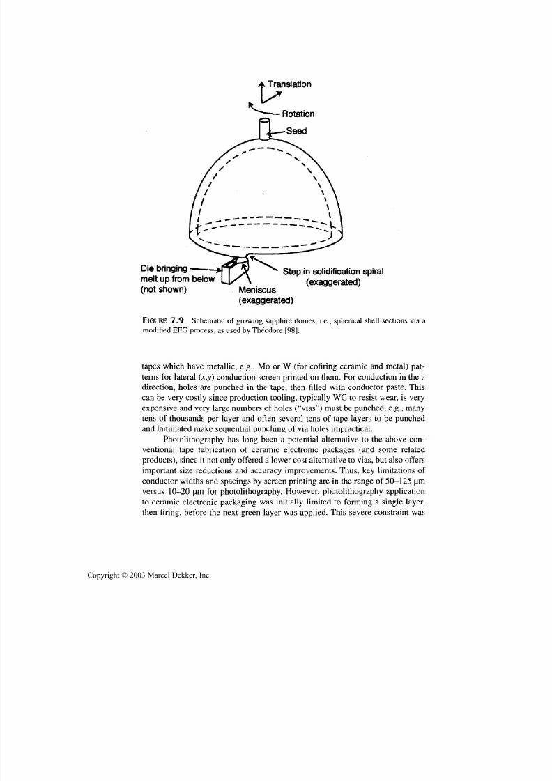
7/29/2019 29540824708539
http://slidepdf.com/reader/full/29540824708539 309/361
298 Chapter 7
Translation
Die bringing
melt up from below
(not shown)
Step in solidification spiral
(exaggerated)Meniscus
(exaggerated)
FIGURE 7.9 Schematic of growing sapphire domes, i.e., spherical shell sections via a
modified EFG process, as used by Theodore [98].
tapes which have metallic, e.g.,Mo or W (for cofiring ceramic an d metal) pat-
terns for lateral (x,y) conduction screen printed on them. Fo r conduction in the z
direction, holes are punched in the tape, then rilled with conductor paste. This
can be very costly since production tooling, typically WC to resist wear, is very
expensive an d very large numbers of holes ("vias") must be punched, e.g., manytens of thousands per layer and often several tens of tape layers to be punched
an d laminated make sequential punching of via holes impractical.
Photolithography has long been a potential alternative to the above con-
ventional tape fabrication of ceramic electronic packages (and some related
products), since it not only offered a lowe r cost alternative to vias , but also offers
important size reductions and accuracy improvements. Thus, key limitations of
conductor widths and spacings by screen printing are in the range of 50-125 | L rm
versus 10-20 jam for photolithography. How ever, photolithography application
to ceramic electronic packaging was initially limited to forming a single layer,
then firing, before the next green layer was applied. This severe constraint was
Copyright © 2003 Marcel Dekker, Inc.
7/29/2019 29540824708539
http://slidepdf.com/reader/full/29540824708539 310/361
Special Fabrication Methods 299
removed by demonstrating the technology fo r forming a multilayer stack of
green alumina layers with green cofireable metallization that could be densified
in a single firing [100]. However, solid loadings in metal and ceramic slips re-sulted in too high a viscosity, requiring too m uch solvent dilution to be practical,
a limitation that was removed in developing ceramic and metal slip com positions
that gave good solids loadings with reasonable viscosities (< 2000 centipoies)[84]. Some work is underway to develop SFF of ceramic electronic packages as
a result of these developments [W. Zimbeck, Ceramic Composites, Inc.,
Millersville, MD, personal communications, 2000-2001.]
Another development leading to added SFF investigation is the possibility
of using it to make bodies of designed microstructure, especially of porous or
composite bodies. Th us, current technologies allow pores or second ph ases to be
placed in a body with both their shape, orientation, and spacing determinedwithin the resolution of the particular process being used, which for some better
systems can be in the range of 10-50 um. Such resolution may be further in-
creased by the potential of handling ceramic p articles one at a time [102]. Thus,
as noted earlier, placing spherical pores at the center of the material filling the in-
terstices between spherical beads or balloons cuts w eight with little reduction of
most physica l properties. SFF appears to offer an alternative method of forming
such compound pore structures. Also note that Lakes has proposed that hierar-
chal pore or composite reinforcement structures should give better properties
than bodies with random pores or reinforcing particles [103]. Such hierarchal
structures are those in which the pores or reinforcing particles in one part of the
body are identical in their location, shape, and orientation, but not size, in one
area are the same as in other corresponding areas. Thus, in a foam, the cell walls
or struts wou ld have the same pores as those forming the foam, except being pro-
portionally smaller, and in turn , there could another one or two levels of smaller
hierarchal pores in the cell walls or struts.
SFF methods that have been developed have demonstrated the ability of
making test bars of ceramics, m etals, or both that have generally achieved room
temperature test bar strengths comparable with conventionally mad e sintered test
bars. As far as mechanical quality is concerned, this leaves issues such as thescaling to larger, more complex parts, and of the laminar character of parts.
There is some inherent laminar character that can often arise due to some pre-
ferred orientation of some pow der particles in extrusion or doctor blading, how -
ever, residual porosity between layers [24] is often more important. This can
have some lamellar character, which clearly leads to anisotropic properties, but
considerable anisotropy can occur due to laminar arrays of even equiaxially
shaped pores. Such arrayed pores are generally inherent in lam inating cast layers
and to some extent extruded rods due to particle gradients, e.g., from more set-
tling of larger particles in casting. Thus, interfaces between layers consist of a
surface of coarser particles being b onded to a surface of finer particles, wh ich in-
Copyright © 2003 Marcel Dekker, Inc.

7/29/2019 29540824708539
http://slidepdf.com/reader/full/29540824708539 311/361
300 Chapter 7
herently generates a change in porosity at the interface that is often as well re-
moved as porosity within the layers on sintering. Such residual laminar pore ar-
rays result in definition of the laminations on cross sections normal to thelamination, especially fractures (Fig. 7.10).
Most current strength and elastic moduli tests do not reflect anisotropy or
other limitations of such residual laminar character, but tests of 3-D printed alu-
mina test bars in various orientations showed substantial strength anisotropy
[91]. Tests of bars w ith the tensile axis norm al to the plane of the powder b ed had
only 30% the strengths of conventionally prepared sintered alumina. However,
there was also substantial anisotropy for specimens with the tensile axis in the
plane of the powder bed relative to the fast or slow axis of printing—the latter
giving 75-95% of strengths of conve ntionally prepared aluminas, and the former
only 50-60% of normal strengths. However, while this is an issue that needs
more attention, 3-D printing appears to be an extreme case, an d there are poten-
tial solutions. Th us, isopressing the 3-D printed alu m ina specimens eliminated
the anisotropy, giving slightly higher strengths with warm versus cold isopress-
ing. Though isopressing adds an extra step and may distort shapes some, espe-
cially when starting from such low den sities as the above noted 3-D printed part,
it may be an allowable operation. More generally some parts may be hot pressed
or HIPed to reduce residual porosity and any anisotropy from it as well as its re-
ductions in properties, since costs of this may often be more tolerable for SFF.
FIGURE 7.10 Fracture cross section of a stainless steel bar made by photolithography
showing diffuse, bu t definite, remnants of the laminar processing of such metal and ce-
ramic parts. (Original photo courtesy of W. Zimbeck of Ceramic Composites, Inc.,
Millersville, MD.)
Copyright © 2003 Marcel Dekker, Inc.

7/29/2019 29540824708539
http://slidepdf.com/reader/full/29540824708539 312/361
Special Fabrication Methods 301
Thus, wh ile mechanical properties achieved from various SFF processes may be
a factor in selection of specific processes, other factors as summarized below
will generally be primary ones in the choice of SFF processes.Trends in the factors impacting the selection of an SFF method are sum-
marized in Table 7.1, with observations on some possible deciding factors as fol-
lows. For forming larger compo nents or larger numbers of components at a time
(hence also high average build speed), flood illumination curing of photopoly-
mers has significant potential, while tape lamination also has good size potential
for larger components, though binder removal could be a limitation for both
methods in thicker parts. For working with two or more materials in the same
component, as needed for some composites, and many electronic components,
especially multilayer packages, photolithography is a leading candidate. Tape
lamination is also a possibility, and fused deposition mod eling (FDM ) may alsobe possible, but coarseness of structure, especially with FD M, is a limitation. For
the more specialized area of forming internal cavities (e.g., for designed pore
TABLE 7.1 Summary Evaluation of More Developed SFF Methods for Ceramics
Method
Tape lam.,
cutting
Photocure
binder
Inkprinting
E. C.a
Advantages
L-M Fast build, especially for
large parts, can do 2 or
more materials, cancover cavities
M-H Finer resolution, surface
finish, and structure, do
two or more materials
at a time, large area/
multiple parts via
flood illumination
L High build speed, low
cost system
Disadvantages
High binder content, coarser
resolution, surface finish
and structure
High binder content, covered
cavities more difficult,
limited area/number of
parts with laser beam cure
Low green density, limited
resolution/surface finish,
Laser melting M
binder (SLS)
Extruded L-M
thermalplastic
binder (FDM)
More limited binder
content, potentially
easier for covering
cavities
Good build speed, may
be able for two o r more
materials at a time
one material at a time
More materials limited, one
material at a time
High binder content, coarse
layers/surface finish/
limited resolution, some
support needed to cover
internal cavities
aE. C. = equipment costs, with low (L), medium (M), and high (H) being respectively 50-100,
200-500, and 700-1000 thousands of dollars.
Copyright © 2003 Marcel Dekker, Inc.
7/29/2019 29540824708539
http://slidepdf.com/reader/full/29540824708539 313/361
302 Chapter 7
structures), tape lamination is probably the most effective fo r caping internal
cavities, and photolithography more limited, but not without means of doing a
considerable amount. Thus, fo r example, potential internal pores can be leftfilled with uncurred photopolymer during the build phase if the uncured pho-
topolymer can be drained out later, commonly during part removal from the
build platform.
The issue of what, if any of the, SFF methods may become commercially
established for ceramics is still uncertain since much more needs to be demon-
strated, but some factors and trends are noted. M ajor factors could be (1) the im-
portance of doing larger components, larger numbers of them, or both; (2) the
importance of internal structure in components, as needed for most electronic,
some com posite, and some porous m aterials applications, and; (3) the opportuni-
ties for metal components and the applicability of their methods to fabrication of
ceramics. A factor that may bear on both metal and ceramic compo nents w ith re-
gard to electronic wa rehou sing is the extent to w hich the large numb er of materi-
als from which components are conventionally made can be narrowed dow n so a
more reasonable number of raw materials for SFF could be chosen. Another fac-
tor for components in which producing the external shape is the goal, e.g., as for
many structural componen ts, is that there is often a basic choice of SFF methods,
namely to directly produce (metal or) ceramic com ponents by SFF, or instead to
produce a temporary die, e.g., of plaster (via a rubber or plastic model) mold for
slip casting, or a composite die for die pressing, extrusion, or injection molding.This is not a feasible route for any component that has internal struc ture formed
in the SFF process, e.g., for some composite or porous bodies and for most elec-
tronic applications. However, the depth and diversity of capabilities demon-
strated and the potential fo r further developments indicate that some forms of
SFF will be established in industry and continue to grow an d evolve.
7.5 CERAMIC FIBER COMPOSITES
Ceramic fiber composite fabrication is a large, diverse, and growing topic that
could easily fill a separate volume, an d hence can only be summarized in out-line form here, mainly from other reviews [58, 104, 105]. The topic encom-
passes ceramic or glass matrices with short (e.g., ceramic whiskers, other
as-grown discontinuous, or chopped) fibers, continuous fibers (typically 5-30
microns in dia., usually in bundles, i.e., tows of hundreds to thousands of
fibers), or continuous ceramic or metallic filaments (typically 100 or more mi-
crons in dia.). The type of fibers, their chemical na ture an d that of the matrix, as
well as the size and shape and use of the composite, all impact the fabrication
route used fo r making th e component.
Whisker composites are made primarily by mixing them with the matrix
powder, e.g., alum ina, com mo nly by mil ling , then hot pressing (Sec. 6.2) or oc-
Copyright © 2003 Marcel Dekker, Inc.

7/29/2019 29540824708539
http://slidepdf.com/reader/full/29540824708539 314/361
Special Fabrication Methods 303
casionally by HIPing, for more shape versatility. Important limitations are the
health hazards posed by some whiskers in their processing, machining, or use.
Other short, e.g., chopped, fiber composites can be similarly fabricated, bu t havereceived limited attention since properties achieved (especially toughness) are
far less desirable than with most other ceramic fiber composites. Three other
possibilities that may hold promise have received little attention. The first is
making thin paper-like or thicker felt preforms of whiskers or especially short
fibers by paper- or felt-making techniques and infiltrating these with matrix pre-
cursors and laminating infiltrated layers. The second possibility for whiskers or
other, e.g., carbon [3], fibers that grow like blades of grass is to use their growth
mode to form tapes of highly aligned whiskers or short fibers. Then with the
whiskers or fibers coated with a matrix precursor before or after making tapes,
the tapes can be laminated in various orientations to give greater planar isotropy
and subsequently appropriately densified, usually by hot pressing (Sec. 6.2).
Third, alignment of whiskers or fibers with some matrix precursor may allow
forming a high density, e.g., 60 v/o, of them into pseudofilaments that are then
laid up with the same or different matrix in the pseudofilamen ts, with or without
some whiskers or fibers.
Even more versatile fabrication alternatives are available for continuous
fiber composites, where much of the versatility arises from the fiber architecture
obtained by operations such as weaving into various cloth weaves or braiding or
knitting into various shape, e.g., cylinders, by applying or adapting methodsused for polymeric matrix composites (Sec. 7.2). Thus, tows, typically after
chemical or thermal removal of organic sizing agents can be infiltrated with liq-
uid matrix precursors such as sols, preceramic polymers, or especially generally
lower cost slips (usually by drawing the tow through a bath of the liquid matrix
precursor), then laid up as tapes to be stacked in various configurations of fila-
ment wound into various shapes. (Note: Good ceramic composite toughness usu-
ally requires limited chemical bonding between the fibers and the matrix, which
often requires a fiber coating, e.g., BN for SiC and related fibers, with some
phosphate coatings showing promise for oxide fibers in oxide matrices, as dis-
cussed in Section 7.2. BN coatings can now be applied on a bolt to bolt ma nufac -turing scale [60]. Such coated fibers already have sizing removed.) Cloth sheets
may be similarly individually filled with liquid matrix precursor and stacked into
a preform, or in some cases stacked up, then infiltrated, e.g., to the extent that
slips m ay penetrate uniformly over the thicknesses required.
There are two basic routes to densifying the above preforms. The first,
most diverse in shape and size capability, but by far the most limited in terms of
densities and properties achievable, is matrix pyrolysis followed by various
numbers of further matrix precursor infiltrations and pyrolysis steps, especially
for use with preceramic polymers for the matrix. The other basic alternative
(since sintering and HIPing are generally very limited by fibers not axially
Copyright © 2003 Marcel Dekker, Inc.
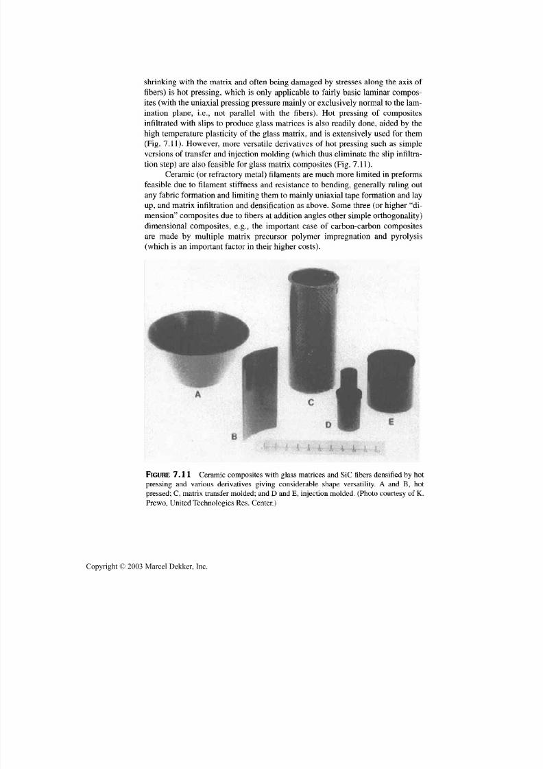
7/29/2019 29540824708539
http://slidepdf.com/reader/full/29540824708539 315/361
304 Chapter 7
shrinking with the matrix and often being damaged by stresses along the axis of
fibers) is hot pressing, which is only applicable to fairly basic laminar compos-
ites (with the uniaxial pressing pressure mainly or exclusively normal to the lam-ination plane, i.e., not parallel with the fibers). Hot pressing of composites
infiltrated with slips to produce glass matrices is also readily done, aided by the
high tem perature plasticity of the glass matrix, and is extensively used fo r them
(Fig. 7.11). However, more versatile derivatives of hot pressing such as simple
versions of transfer an d injection m olding (w hich thus eliminate the slip infiltra-
tion step) are also fea sible for glass m atrix compo sites (Fig. 7.11).
Ceramic (o r refractory metal) filaments are much more limited in preforms
feasible due to filament stiffness an d resistance to bending, generally ruling out
any fabric formation and limiting them to mainly un iaxial tape formation and lay
up , and matrix infiltration and densification as above. Some three (or higher "di-
mension" composites due to fibers at addition angles other simple orthogonality)
dimensional composites, e.g., the important case of carbon-carbon composites
are made by multiple matrix precursor polymer impregnation an d pyrolysis
(which is an imp ortant factor in their higher costs).
FIGURE 7.11 Ceramic composites with glass matrices and SiC fibers densified by hot
pressing an d various derivatives giving considerable shape versatility. A and B, hot
pressed; C, matrix transfer molded; and D and E, injection molded. (Photo courtesy of K.
Prewo, United Technologies Res. Center.)
Copyright © 2003 Marcel Dekker, Inc.

7/29/2019 29540824708539
http://slidepdf.com/reader/full/29540824708539 316/361
Special Fabrication Methods 305
Another major method of fabricating ceramic composites, including car-
bon-carbon, is chemical vapor infiltration (CVI) (Sec. 6.6). This is basically
CVD with gas flow through the preform to deposit matrix material in the inter-stices between fibers. Though there are depths of penetration of matrix deposi-
tion depending on factors such as preform character, this is a very useful method.
Low deposition temperatures, often from < 1000°C to 1200°C, reasonable
process times, sizes, times, and reasonable deposition times and chemistries
make this an important method (Fig. 7.12).
Some trials of melt forming of ceramic fiber composites have been made
with varying results. Forming SiC composites by infiltrating carbon fiber pre-
forms or pyrolyzed pieces of wood with molten Si have had some success.
Some attempts to form matrices in fiber preforms by melt spraying have not
proved successful. Eutectic composites, which are clearly a type of fiber com-posite, can clearly be made, but generally have too strong a bond between the
FIGURE 7.12 Example of large ceramic fiber composite for a flame tube made from a
braided tube of oxide fibers infiltrated with a SiC matrix by CVI. (From Ref. 58, pub-
lished with permission of Technomic Pub. Co. Inc.)
Copyright © 2003 Marcel Dekker, Inc.

7/29/2019 29540824708539
http://slidepdf.com/reader/full/29540824708539 317/361
306 Chapter 7
"fibers" (rods or lamella) and the matrix to yield th e high toughnesses, i.e., non-
catastrophic, fiberous fracture that can be achieved with composites made by
incorporating (often coated) fibers in a matrix rather than by eutectic phase sep-aration. However, directional solidification of calcium phosphate bodies has re-
sulted in considerable fiberous fracture at very respectable strength levels,
indicating promise [106].
7.6 COATINGS
Application of ceramic and some metallic surface coatings on ceramic and
metal components is briefly sum marized here. Traditional use of ceramic glass-
based coatings has been fo r decorative, surface sealing, or both purposes, such
as glaze coatings on ceramic dinnerware. Some of these coatings (and some-
times just quenching surfaces from high temperatures) also may contribute to
mechanical reliability by providing useful levels of surface compressive
stresses [107]. Use of ceramic coatings on ceramics to extend surface compres-
sive stressing is briefly discussed below. Coating of ceramics fo r electrical, di -
electric purposes, or optical purposes, are also important fo r specialized
applications. Metals are extensively coated with ceramic or intermetallic coat-
ings for friction and wear as well as corrosion protection, as well as for thermal
or electrical ins ulat ion , increased em ittance fo r better heat radiation, or combi-
nations of these. Metal coatings are also applied to some ceramics fo r conduc-tive purposes and sometimes as a step in joining ceramics with other ceramics,
and metals (Sec. 8.3.3). Major processing technologies fo r such coatings, espe-
cially ceramic, are outlined below.
Major and simple approaches to applying ceramic coatings on metals or
ceramics that are widely used in industry is application via slips or powders.
In th e latter case, a major advance was the development of electrostatic spray-
ing of dry frit powder for application of porcelain enamel coatings on metal
surfaces, e.g., fo r kitchen appliances [108-112]. This approach replaced much
application by spraying slips and has advantages over electrophoretic applica-
tion, and is widely used in industry. However, coatings of many componentsis done by dipping metal or ceramic parts in the selected slip, or spraying th e
parts, or both, then drying, followed by firing [112] Many of these ceramic
coatings contain glass constituents to limit firing temperatures, allow better
thermal expansion m atching between coating and substrate, give an imperme-
able coating, or combinat ions of these. An example of this is the coating of
electrical resistance heating elements with chromia containing glasses for re-
fractoriness and higher emittance.
Metals can also be electrophoretically coated with thin layers, as well as
via electrolytic coating of oxides or hydroxides from solutions [113], and some
nonoxide coatings may be applied electrolytically [114]. Some metal parts have
Copyright © 2003 Marcel Dekker, Inc.

7/29/2019 29540824708539
http://slidepdf.com/reader/full/29540824708539 318/361
Special Fabrication Methods 307
hard boride coatings formed on them commercially by exposing the part to B
powder, e.g., as a coating or more commonly in a powder bed, and heating to al-
low the B to diffuse into an d react with the surface an d near surface metal
[115,116]. Sol-gel coating is of increased interest and use for coating, e.g., of ce-
ramic surfaces fo r optical purposes, particularly with advances in techniques to
control shrinkage stresses and possible crazing and peeling [117,118]. Applica-
tion of coatings via other liquid precursors, e.g., preceramic polymers has also
been demonstrated an d should have good commercial potential if such polymers
become more available and at lower prices.
Thicker coatings and coatings for surface compressive effects are fre-
quently applied to the green body an d cofired with it. Such coatings may be ap-
plied to parts of very simple shapes by laminating tapes to the surface, but more
versatile methods are needed for most real components. Where conductivity is-
sues do not preclude it, electrophoretic deposition, though limited in thickness,
may be useful. While coatings can be designed fo r surface compressive stress-
ing, the coarse stepping of resultant steps, poor bonding along the interface, or
both may be serious problems. Electrophoretic deposition can give finer grading,
and CVD can be an even better method since it allows grading composition an d
expansion differences, an d does no t result in discrete interfaces at tape or other
green surface layers, as discussed below.
A large area of extensively commercialized coating of mainly, but not ex-
clusively, metal components is melt spraying (mainly plasma spraying) of ce-ramic coatings, especially fo r engine and other high temperature applications
[119-122].This basically entails passing powders of coating materials through a
plasma torch, which melts much of the particles an d accelerates them so many
splat onto the surface to be coated where they are rapidly (unidirectionally) so-
lidified. Modern systems give a variety of types of torches, their capabilities in
terms of melting and acceleration of particles, as well as protective environ-
ments for the component to be coated, including in situ surface cleaning, e.g.,
by sputtering. Metal parts are commonly first coated with a bond coat that pro-
vides some grading from the metal to the final ceramic coating, of which zirco-
nia coatings are common. While many of the parts coated are modest in size,there have been significant increases in the size of components plasma coated,
e.g., Fig. 7.13.
Consider vapor phase coating processes, which also have a fair amount of
commercialization, first addressing physical vapor deposition (PVD), that is
where all or a key ingredient are vaporized by heating, fo r example, via an arc or
electron beam [122,123]. This is often used fo r metal coatings, but is also used
for some ceramics, e.g., ZrO2-based coatings which compete with some plasma
sprayed coatings, but with different behavior reflecting basic differences in mi-
crostructure. (Note: Fabrication of ZrO2 billets for the electron beam evaporiza-
tion required specific design an d fabrication parameters to give the necessary
Copyright © 2003 Marcel Dekker, Inc.
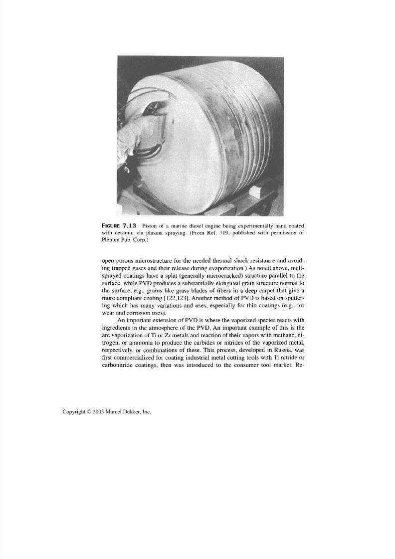
7/29/2019 29540824708539
http://slidepdf.com/reader/full/29540824708539 319/361
308 Chapter 7
FIGURE 7.13 Piston of a marine diesel engine being experimentally hand coated
with ceramic via plasma spraying. (From Ref. 119, published with permission of
Plenum Pub. Corp.)
open porous microstructure for the needed thermal shock resistance an d avoid-
ing trapped gases an d their release during evaporization.) As noted above, melt-
sprayed coatings have a splat (generally microcracked) structure parallel to the
surface, while PVD produces a substantially elongated grain structure normal to
the surface, e.g., grains like grass blades of fibers in a deep carpet that give amore compliant coating [122,123]. Another method of PVD is based on sputter-
ing which has many variations and uses, especially fo r thin coatings (e.g., fo r
wear an d corrosion uses).
An important extension of PVD is where the vaporized species reacts with
ingredients in the atmosphere of the PVD. An important example of this is the
arc vaporization of Ti or Zr metals and reaction of their vapors with methane, ni-
trogen, or am m onia to produce the carbides or nitrides of the vaporized metal,
respectively, or combinations of these. This process, developed in Russia, was
first commercialized fo r coating industrial metal cutting tools with Ti nitride or
carbonitride coatings, then was introduced to the consumer tool market. Re-
Copyright © 2003 Marcel Dekker, Inc.
7/29/2019 29540824708539
http://slidepdf.com/reader/full/29540824708539 320/361
Special Fabrication Methods 309
cently, this process has been introduced fo r consumer plumbing fixtures an d
door fixtures, to replace conventional brass-plated fixtures [124].
The other major vapor-based coating process is CVD [122,125]. Conven-
tional CVD, that which generally uses halide precursors, is used to coat ceramic
bodies and for applying debond coatings on ceramic fibers fo r ceramic compos-
ites. An important extension of materials that can be deposited by chemical va -
por routes is that of diamond and diamond-like materials [126]. These,
particularly the former, significantly extend the ranges of hardness-wear resis-
tance, as well as other properties achievable in coating materials—e.g., IR trans-
mission and band gap. For CVD coating of metals, halide precursors often
require too high a temperature and too aggressive reaction products, e.g., HC1, so
lower temperature reactants such as organometallic compounds are used, though
they often present problems of toxicity and cost.
Finally, another source of coating technology is reaction processing. While
boride coatings noted earlier are one example of this, there are many variations
of this despite frequent limitations on temperature capabilities of the substrate,
especially fo r most metals. An extension via reduction in thermal exposure is use
of SH S reactions (Sec. 6.5) which can make some coatings feasible via the very
transient heating. Similarly, application of a reactant to form a desired reaction
coating or the coating material itself as a powder then reacting it with, or bond-
ing it to, the surface via a scanned laser beam expand possibilities [127].
7.7 DISCUSSION ANDSUMMARY
Fabrication technologies used for more specialized uses, e.g., fabrication of ce-
ramic fibers (or filaments), fiber composites, bodies of designed porosity, rapid
prototyping/solid free form fabrication (SFF), an d coatings have been reviewed.
This was done since, though of narrower use than the generally broader fabrica-
tion methods addressed in Chapters 3-6, the methods of this chapter play critical
roles fo r many important an d growing applications. Further, the technologies fo r
these more specialized fabrication methods also provide insight into the broader
picture of fabrication technology. Thus note, for example, the extensions of useof not only powder-based processing to these more specialized areas, but also the
important, an d often growing, role of secondary processing methods, e.g., of
CVD and melt processing.
Overall development and use of the technologies of this chapter are ex-
pected to increase significantly. Particular examples of this are likely to be for
more versatile fiber production in terms of methods, as well as production of
more complex an d single-crystal fibers, fabrication of ceramic fiber composites,
especially with continuous fibers, and porous bodies with more designed poros-
ity. Some aspects of SFF are expected to become established, e.g., for rapid pro-
totyping, with further extensions fo r melt processes, e.g., single crystal,
Copyright © 2003 Marcel Dekker, Inc.

7/29/2019 29540824708539
http://slidepdf.com/reader/full/29540824708539 321/361
310 Chapter 7
components, and microstructural design, possibly becoming established. D evel-
opmen t and application of coating technology is expected to continue substan-
tial further development and use.
REFERENCES
1. W. Mahler, U. Chowdhry. Morphological consequences of freezing gels, L.L.
Hench, D.R. Ulrich, eds. U ltrastructure Processing of Ceramics. New York: John
Wiley, 1984, p 207.
2. T.F. Cooke. Inorgan ic fibers—a literature review. J. Am. Cer. Soc. 74(12):
2959-2978, 1991.
3a. Max L. Lake, Jyh-Ming Ting. Vapor grown carbon fiber composites. In: T.D.
Burchell, ed. Carbon Materials for Advanced Technologies. New York: Elsevier,
1999.
3b. M. Lake. Large scale production of VGCF. In: L.P. Biro et al., eds. Carbon Fila-
ments and Nanotubes: Common Origins, Differing Applications. Kluwer Acade-
mic Publishers, The Neth erlands, 2001, pp. 187-196.
3c. M. Lake. N ovel App lications of VGCF. IN: L.P. Biro et al., eds. Carbon F ilaments
and Nanotubes: Common Origins, Differing Applications. Kluwer Academic Pub-
lishers, The Netherlands, 2001, pp. 331-341.
4. P. Bracke, H. Schurman s, J. Verhoest. Inorganic Fibers and Composite Materials.
New York: Pergamon Press, 1984.
5. J.-B. Donnet, R.C. Bansal. Carbon Fibers. New York: Marcel Dekker, Inc., 1984.6. Y. Hasegaw a, M. lim ura, S. Yajima. Synthesis of continuous silicon carbide fibre,
part 2. Conversion of polycarbosilane fibre into silicon carbide fibres. J. Mat. Sci.
15:720-728, 1980.
7. R.W. Rice. Ceramics from polymer pyrolysis, opportunities an d needs—a materi-
als perspective. Am. Cer. Soc. Bui. 62(8):889-892, 1983.
8. K.J. Wynn, R.W. Rice. Ceramics via polymer pyrolysis. Ann. Rev. Mater. Sci.
14:297-334, 1984.
9. J. Lipo witz, J.A. Rabe, K.T. Ng uyen, L.D. Orr, R.R . And rol. Structure and proper-
ties of polymer-derived stoichiometric SiC fiber. Cer. Eng. Sci. Proc. 16(4):55-62,
1995.
10. J. Lipowitz, J.A. Rabe, R.M. Salinger. Ceramic fibers derived from organosiliconpolymers. In: M. Lewin, J. Preston. Handbook of Fiber Science an d Technology:
V. Ill High Technology Fibers. Part C. New York: Marcel Dekker, Inc., 1993.
11. H.G . Sow ma n. A new era in ceramic fibers via sol-gel technology. Am . Cer. Soc.
Bui. 67(12):1911-1916, 1988.
12. H.G. Sow ma n, D.D. Johnson. Ceramic ox ide fibers. Cer. Eng. Sci. Proc.
6(9): 1221-1230, 1985.
13 . T.L. Tompkins. Ceramic oxide fibers: building blocks for new applications. Cer.
Ind. pp. 45-50, 1985.
14 . G.V. Srinivasan, V. Venka teswaran. Tensile strength evaluation of polycrystalline
SiC fibers. Cer. Eng. Sci. Proc. 14(7-8):563-572, 1993.
Copyright © 2003 Marcel Dekker, Inc.

7/29/2019 29540824708539
http://slidepdf.com/reader/full/29540824708539 322/361
Special Fabrication Methods 311
15. F. Frechette, B. Dover, V. Venkateswaran, J. Kim. High temperature continuous
sintered SiC fiber for composite applications. Cer. Eng. Sci. Proc.
12(7-8):992-1006, 1991.16. S.D. Nunn, D. Popovic, S. Baskaran, J.W.Halloran, G. Subramanian, S.G. Bike.
Suspension dry spinning and rheological behavior of ceramic-powder-loaded poly-mer solutions. J. Am . Cer. Soc. 76(10):2460-2464, 1993.
17. I.E. Bailey, H.A.Barker. Ceramic fibers for the reinforcement of gas turbine
blades. In: W.W.Kriegel, H. Palmour III eds.Ceramics in Severe Environments,
Materials Science R esearch. New York: Plenum Press, 5:1971, pp. 341-359.
18. H.D. Blakelock, N.A.Hill, S.A. Lee, C. Goatcher. The production and properties
of polycrystalline alumina rods and fibers. Proc. Brit. Cer. Soc. No. 15:69-83,
1970.
19. N.D.Nazarenko, V.F.Nechitailo, N.I. Vlasko. The manufacture and properties of
oxide fibers. Soviet Pwd. Metall. 4:265-267,1969.20. J.D. Birchall. The Preparation and Properties of Polycrystalline Aluminum Oxide
Fibers. Trans. J. Br. Cer.Soc. 82:143-145, 1983.
21. A.K.Dhingra. Advances in inorganic fiber developments. In: E.J. Vandenberg, ed.
Contemporary Topics in Polymer Science, Vol. 5. New York: Plenum Press,1984,
pp. 227-260.
22. J.C. Romine. New high-temperature ceramic fiber. Cer. Eng. Sci. Proc.
8(7-8):755-765, 1987.
23. M.H.Stacey. Developm ents in continuous alumina-based fibers. Trans. J. Br. Cer.
87:168-172, 1977.
24. R.W.Rice. Mechanical properties of ceramics and composites, grain and particle
effects. New York: Marcel Dekker, Inc., 2000.
25. P. Lessing. H igh Temperature Fuel Cell Research and Development. Final Techni-
cal Status Report 4FC-DOE-F/80, Montana Energy and MH D,1980.
26. P. Lessing, M. Johnston. High Temperature Fuel Cell Research and Development.
Final Technical Status Rep ort, Montana Energy and MHD, for contract DE-AC03-
77ET 11320, Mod. A004, 1981.
27. S.S. Jada, J.F. Bauer. Discontinuous ZrO2 fiber: precursor solution chemistry-mor-
phology relations. Cer. Eng.Sci. Proc. 11(9-10):1480-1499, 1990.
28 . B.H.Hamling, A.W. Naumann, W H. Dresher. Ceramic fibers and textiles from or-
ganic precursors. Appl. Polymer Symposia. No. 9. 1969, pp. 387-394.
29 . P.A. Vityaz, I.L. Fyodorova, I.N. Yermolenko, T.M. Ulyanova. Synthesis of alu-mina and zirconia fibers. Cer.Intl. 9(2):46,1983.
30. R.J.Card, M.P.O'Toole. Solid ceramic fibers via impregnation of activated carbon
fibers. J. Am . Cer. Soc. 73(3):665-668, 1990.
31. M. Patel, B.K.Padhi. Titania fibers through jute fiber substrates. J. Mat. Sci.
Let. 12:1234-1235,1993.
32. Reference deleted.
33 . F.H. Simpson. C ontinuous Oxide Filament Synthesis (Dev itrification). Boeing Co.
Final report for contract AFML-TR-71-135, 1971.
34. J. Economy. Now tha t's an interesting way to make a fiber. Chemtech 10:240-247,
1980.
Copyright © 2003 Marcel Dekker, Inc.
7/29/2019 29540824708539
http://slidepdf.com/reader/full/29540824708539 323/361
312 Chapter 7
35. J. Economy. Present status and future for high strength fibers. SAMPE J. 1976, pp.
5-9.
36. J.-O. Carlsson. Rev iew techniq ues for the preparation of boron fibers. J. Mat. Sci.14:255-264, 1979.
37. J. Bhardw aj, A.D. Kraw itz. The structure of boron fibers. J. Mat. Sci.
18:2639-2649, 1983.
38. RE. Wawner et al. Various papers in Proc. of the 2nd and 3 rdAnnual Confs. on
Composites and Adv. Mils., American Ceramic Society, Westerville, OH, 1980.
39. R.L. Crane, V.J. Krukonis. Strength an d fracture properties of silicon carbide fila-
ment. Am. Cer. Soc. Bui. 54(2):184-188, 1975.
40. S.R. Nu tt, F.E. Wawner. Silicon carbide filaments: microstructure. J. Mat. Sci.
20:1953-1960, 1985.
41. J.J. Svec. Glass fibers produced with platinum alloys. Cer. Ind. Mag. 1978, pp.
20-21.
42. L. Caspersen, T. Bradley. Advan ced ceramic insu lating materials. Adv. Mtls. Procs.
2000, pp. 57-59.
43. I.W. Donald, B.L. Metcalfe. The preparation, properties and applications of some
glass-coated metal filaments prepared by the taylor-wire process. J. Mat. Sci.
31:1139-1149, 1996.
44. S.A. Dunn, E.G. Paquette. Redrawn inviscid melt-spun fibers-potential low cost
composite reinforcement. Adv. Cer. Mats. 12(4):804-808, 1987.
45. F.T. Wallenberger, N .E. W eston, K. Motzfeldt. Invisid melt spinning of alumin a
fibers: jet stabilization mechanism . Cer. Eng. Sci. Proc. 2(7-8):1039-1047, 1991.
46. F.T. Wallenberger, N.E. Weston, K. Motzfeldt, D.G. Swartzfager. Invisid melt spin-ning of alumina fibers: chemical je t stabilization mechanism. J. Am. Cer. Soc.
75(3):629-636, 1992.
47. S.A. New com b. Temperature and Time dependence of the Strength of C-Axis Sap-
phire from 800-1500° C. MS Thesis, Penn State Un iv., May 1992.
48. S.A. Newcomb, R.E. Tressler. Slow crack growth of sapphire at 800 to 1500° C. J.
Am. Cer. Soc. 76(10):2505-2512, 1993.
49. S.A. Newcomb, R.E. Tressler. High temperature fracture toughness of sapphire. J.
Am. Cer. Soc. 77(11):3030-3032, 1994.
50. R.W. Rice. Corroboration and extension of analysis of C-axis sapphire filament
fractures from pores. J. Mat. Sci. Let. 16:202-206, 1997.
51. J.-M. Yang, S.M. Jeng, S. Chan g. Fracture behavior of directionally solidifiedY3A15O ]2/A19O3 eutectic fiber. J. Am . Cer. Soc. 79(5): 1218-1222, 1996.
52. J.S. Haggerty, K.C. Wills, I.E. Sheehan. Growth an d properties of single crystal
oxide fibers. Cer. Eng. Sci. Proc. 12(9-10):1785-1801, 1991.
53. K.J. McClallan, H . Sayir, A.H. Heuer, A. Sayir, J.S. H aggerty, J. Sigalovsky. High-
strength, creep-resistant Y 2Cystabilized cubic ZrO 2 single crystal fibers. Cer. Eng.
Sci. Proc. 14(7-8):651-659, 1993.
54. M. Saifi, B. Dubois, E.M. Vogel. Growth of tetragonal BaTiO 3 single crystal fibers.
J. Mater. Res. 1(3):452, 1986.
55. R.S. Feigelson. Oppo rtunities for research on single-crystal cibers. Mats. Sci. Eng.
81:67-75, 1988.
Copyright © 2003 Marcel Dekker, Inc.
7/29/2019 29540824708539
http://slidepdf.com/reader/full/29540824708539 324/361
Special Fabrication Methods 313
56. R.W. Rice. Porosity of Ceramics. New York: Marcel Dekker, Inc., 1998.
57. R.W. Rice. BN Coating of Ceramic Fibers for Ceramic Fiber Composites. U.S.
Patent 4,642,271, 1987.58. R.W. Rice, D. Lewis III. Ceramic fiber composites based upon refractory polycrys-
talline ceramic matrices. In: S.M. Lee, ed. Reference Book for Composites Tech-
nology. Vol.1. Lancaster, PA: Technomic Pub. Co., Inc., 1989,pp. 117-142.
59. B. Bender, D. Shadwell, C. Bulik, L. Incorvati, D. Lewis III. Effect of fiber coat-
ings and composite processing on properties of zirconia-based matrix SiC fiber
composites. Am. Cer. Soc. Bui. 65(2):363-369, 1986.
60. Reference deleted.
61. T.A. Parthasarathy, E. Boakye, M.K. Cinibulk, M.D.Petry. Fabrication and testing
of oxide/oxide microcomposites with monazite an d hibonite as interlayers. J. Am.
Cer. Soc. 82(12):3575-3583, 1999.
62 . Announcement. Two glass fibers fused to form stronger filaments. Adv. Mats.
Processes 13:1995.
63. G. Curran. Bicomponent extrusion of ceramic fibers. Adv. Mats. Processes
25-37:1995.
64. R.J.Card. Preparation of hollow ceramic fibers. Adv, Cer. Mats. 3(l):29-31, 1988.
65. Announcement. Glass gets tough. Chem Week 1964.
66 . W.P. Hoffman, H.T.Phan, P.G.Wapner. Th e far-reaching nature of microtube tech-
nology. Mat. Res.Innovat. 2:87-96, 1998.
67 . Phillip G. Wapner, Wesley P. Hoffman. Utilization of surface tension and wettabil-
ity in the design and operation of microsensors. Sensors and Acxtuators B
71:60-67,2000.68. R.W.Rice. Evaluation and extension of physical property-porosity models based
on minimum solid area. J. Mat. Sci. 31:102-108, 1996.
69. R.W. Rice. Comparison of physical property-porosity behavior with minimum
solid area models. J. Mat. Sci. 31:1509-1528, 1996.
70 . R.W. Rice. Microstructural dependance of fracture energy and toughness of ceram-
ics and ceramic composites versus that of their tensile strengths at 22 C. J. Mat.
Sci. 31:4503-4519, 1996.
71a. J. S.-Woyansky, C.E. Scott, W.P. Minnear. Processing of porous ceramics. Am.
Cer. Soc.Bui. 71(11):1674-1882, 1992.
71b. R.W. Rice. Fabrication of ceramics with designed porosity. Cer. Eng. Sci.Proc. (in
press) 2002.72. A.J. Sherman, R.H.Tuffias, R.B.Kaplan. Refractory ceramic foams: a novel, ne w
high-temperature structure. Am. Cer. Soc. Bui. 70(6):1025-1029, 1991.
73. T. Fujiu, G.L. Messing. Analysis and modeling of sol foaming for the preparation
of low-density ceramics. J. Mats. Synthesis Proc. 1(1):33^42, 1993.
74 . T.J. Fitzgerald, V.J. Michaud, A. Mortensen. Processing of microcellular SiC
foams, part II. Ceramic foam production. J. Mat. Sci. 30:1037-1045, 1995.
75. P. Sepulveda. Gelcasting foams for porous ceramics. Am. Cer. Soc. Bui.
76(10):61-65, 1997.
76. R. Brezny, R.M.Spotnitz. Method of Making Microcellular Ceramic Bodies. U.S.
Patent No. 5,427,721, 1995.
Copyright © 2003 Marcel Dekker, Inc.
7/29/2019 29540824708539
http://slidepdf.com/reader/full/29540824708539 325/361
314 Chapter 7
77. J. Block. Inorganic Mem brane. U .S. Patent No. 4,980,062, 1990.
78. R. Brezny. Porous Ceramic Beads. U.S. Patent No. 5,322,821, 1994.
79a. Pohrong R. Chu, "A Model for Coaxial Nozzle Formation of Hollow Spheres",PhD Dissertation, Materials Science and Engineering, Georgia Institute of Tech-
nology, Atlan ta, GA , June, 1991.
79b. J.K. Cochran. Georgia Institute of Technology, Atlanta, GA, private communica-
tion 2001.
80. J.H. Chun g, J.K . Cochran, K.J. Lee. Compressive mechanical behav ior of hollow
ceramic spheres. In: D.L. Wilcox, M. Berg,T. Bernat, J.K. Cochran, D. K ellerman,
eds. Spheres and Microspheres: Synthesis and Applications. Pittsburg, PA: MRS
Proc., 372:179-186, 1995.
81 . A.V. Kerkar. Manufacture of Conical Pore Ceramics by Electrophoretic Deposi-
tion. U .S. Paten t No. 5,340,779, 1994.
82. KB. Prinz et al . Rapid P rototyping in Europe and Japan. JTEC/WTEC Panel Re-
port Pub., SME, 1997.
83. C. Griffin, J. Dau fenbach, S. McMIllin. Desktop ma nufacturing: LOM vs pressing.
Am Cer. Soc. Bui. 73(8):109-113, 1994.
84. T. Quadir, S.K. Mirle, J.S. Hallock. Three Dimensional Sintered Inorganic Struc-
tures U sing Photopolymerization. U .S. Patent N o. 5,496,682, 1996.
85. W. Zim beck, J. Jan g, W. Schulze, R.W. Rice. Autom ated fabrication of ceramic
electronic packages by stereo-photolithography. In: S.C. Danforth, D.B. Dimos F.
Prinz, eds. Proc. Solid Freeform and Additive Fabrication 2000 Symposium, Mate-
rials Research Society. Vol. 625. 2000, pp . 173-178.
86. W .R. Zimbeck, R.W . Rice. Freeform fabrication of components with designed cel-lular structure. In: D. Dimos, S.C. Danforth, M.J. Cima, eds. Proc. Solid Freeform
and Additive Fabrication Sym p. Materials Research Soc. Vol. 542. 1998.
87. W . Zimbeck, M . Pope, R. Rice. Microstructures and strengths of metals and ceram-
ics made by photopolymer-based rapid prototyping. Au stin , TX: Solid Freeform
Fabrication S ym posiu m Proceedings, 9/1996, pp. 411 118.
88. W. Zimbeck, R. Rice. Stereolithography of Ceramics and Metals. Proceedings of
the 50th Annual Con f. Soc. for Imaging Science & Technology, Cambridge, MA,
IS&T Society, 1997, pp. 649-655.
89. M. Griffith, J.W. Halloran. Freeform fabrication of ceramics via Stereolithography.
J. Am. Cer. Soc. 79(10):2601-2608, 1996.
90. J.W. Halloran, M. Griffith, T.-M. Chu. Stereolithography resin for rapid prototyp -ing of ceramics and metals. U .S. Patent 6,112,612, 2000.
91. B. Giritlioglu, M.J. Cima. Anisotropy on rectangular bars fabricated via three-di-
mensional p rinting. Cer. En g. Sci. Proc. 16(5):763-772, 1995.
92. M.K . Agarw ala, A. Bandyopadhyay, R. van W eeren, A. Safari, S.D. Da nforth, N.A.
Langrana, V.R. Jamalabad, P.J. Whalen. FDC, rapid fabrication of structural com-
ponents. Am. Cer. Soc. Bui. 75(ll):60-65, 1996.
93. C.V. Hoy, A. Barda, M. Griffith, J.W. Halloran. Microfabrication of ceramics by
coextrusion. J. Am. Cer. Soc. 81(11): 152-158, 1998.
94. D.L. Bourell, H.L. Marcus, J.W. Barlow, J.J. Seaman. Selective laser sintering of
metals an d ceramics. Intl. J. Pwd. Met. 28(4):369-381, 1992.
Copyright © 2003 Marcel Dekker, Inc.
7/29/2019 29540824708539
http://slidepdf.com/reader/full/29540824708539 326/361
Special Fabrication Methods 315
95. S. Baskaran, G.D. Maupin, G.L. Graff. Freeform fabrication of ceramics. Am Cer.
Soc. Bui. 77(7):5358, 1998.
96. A. Matsuda, Y. Matsuno, M. Tatsumisago, T. Minami. Fine patterening and charac-terization of gel films derived from methyltriethoxysilane an d tertaethoxysilane. J.
Am. Cer. Soc. 81(ll):2849-2852, 1998.
97. F.T. Wallenberger. Rapid prototyping directly from the vapor phase. Science
267(3): 1274-1275, 3/1995.
98 . F.Theodore, T. Duffar, J.L. Santailler, J. Pesenti, M. Keller, P. Dusserre, F. Louchet,
V. Kurlov. Crack generation and avoidance during the growth of sapphire domes
from an element of shape. J. Crystal Growth 204:317-324, 2000.
99 . V.N. Kurlov, F. Theodore. Growth of sapphire crystals of complicated shape.
Cryst. Res. Tech. 34(3):293-300, 1999.
100. J.W. Lau, K.E. Bennet. Imaging Process for Forming Ceramic Electronic Circuits.
U.S. Patent 4,828,961, 1989.
101. Reference deleted.
102. W.D. Teng, Z.A. Huneiti, W . Machowski, J.R.G. Evans, M.J. Edirisinghe, W. Bal-
achandran. Towards particle-by-particle deposition of ceramics using electroststic
atomization. J. Mat. Sci. Let. 16:1017-1019, 1997.
103. R. Lakes. Materials with structural hierarchy. Nature 361:511-515, 1993.
104. R. Rice. Processing of ceramic composites. In: J.G.P. Binner, ed. Advanced Ceramic
Processing and Technology. Vol. 1. Park Ridge, NJ: Noyes Pubs, 1990, pp. 123-213.
105. K.M. Prewo, J.J. Brennan. Fiber reinforced glasses and glass ceramics for high
performance applications. In: S.M. Lee, ed. Reference Book for Composites Tech-
nology. Vol. 1. Lancaster, PA: Technomic Pub. Co., Inc., 1989, pp. 97-116.
106. Y. Abe, T. Kasuga, H. Hosono, K. Groot. Preparation of high-strength calcium
phosphate glass-ceramics by unidirectional crystallization. J. Am. Cer. Soc.
67(7):C-142-144, 1984.
107. H.P. Kirchner. Strengthening of Ceramics: Treatments, Tests, and Design Applica-
tions. New York: Marcel Dekker, Inc., 1979.
108. W.D. Faust. Electrostatic enamel application theory and practice. Am. Cer. Soc.
Bui. 59(2):220-222, 1980.
109. H. Hoffmann. Theory an d practice of electrocoating porcelain enamel. Am. Cer.
Soc. Bui. 57(6):605-608, 1978.
110. G. Hein. Electrostatic deposition of powdered frit. Cer. Ind. 1973, pp. 20-21.
111. A. Lacchia. Electrostatic spraying of powdered enamels. Cer. Ind. 1977, pp.36-38.
112. S.B. Lasday. Nature of ceramic coatings and their benefits in thermal processes.
Ind. Heating 1982, pp. 49-52.
113. I. Zhitomirsky. New developments in electrolytic deposition of ceramic films",
Am. Cer. Soc. Bui. 2000. pp. 57-63.
114. D. Elwell. Electrolytic growth from high-temperature solutions. In: E. Kaldis, H.J.
Scheel, eds. Current Topics in Materials Science, 1976. Crystal Growth and Mate-
rials. 2. NewYork: North-Holland Pub. Co., 605-637, 1977.
115. J. Cataldo, F. Galligani, D. Harraden. Boride surface treatments. Adv. Mats.
Processes 2000, pp. 35-38.
Copyright © 2003 Marcel Dekker, Inc.

7/29/2019 29540824708539
http://slidepdf.com/reader/full/29540824708539 327/361
316 Chapter 7
116. K. Stewart. B oron izing protects m etals against wear. Adv. Mats. Processes 1997,
pp . 23-25.
117. H.G. Floch, J.-J. Priotton,"Colloidal sol-gel optical coatings. Am. Cer. Soc. Bui.69(7): 1141-1143, 1990.
118. H.G. Floch, P.P. Belleville, J.-J. Priotton. Colloidal sol-gel optical coatings-coat-
ings for lasers, II. Am. Cer. Soc. Bui. 74(ll):84-89, 1995.
119. R.W. Rice. Advanced Ceramic Materials an d Processes. In : D.L. Cocke, A.
Clearfield, eds. Design of New Materials. N ew York: Plenum Publishing Corp.
1987,pp.169-194.
120. G. Fisher. Ceramic coatings enhance performance engineering. Am. Cer. Soc. Bui.
65(2):283-287, 1986.
121. G. Geiger. Ceramic Coatings. Am. Cer. Soc. Bui. 71(10): 1470-1481, 1992.
122a. D.R. Biswas. Review deposition processes for films and coatings. J. Mat. Sci.
21:2217-2223, 1986.
122b. R.F. Bunshah, Handbook of Deposition Technology fo r Films an d Coatings,"
Noyes Publication, Inc., Park Ridge, N J, 1994.
123. H. Lammermann, G. Kienel. PVD coatings fo r aircraft turbine blades. Adv, Mats.
Proc. 1991, pp. 18-32.
124. T. O'brien. LifeShine non-ta rnish coating. Adv, Mats. Proc. 2000, pp. 39-40.
125a. H.O. P ierson, ed. Ch em icall y Vapor Deposited Co atings. W esterville, OH: Am.
Cer. Soc. 1981.
125b. H.O. Pierson, "Handbook of CVD" Noy es Publication, Inc., Park Ridge, NJ, 1992.
125c. F.S. Glasso, "Chemical Vapor Deposited Materials," C.R.C. Press, Inc., Boca Ra-
ton, FL , 1991.126a. C.B. C olli ns, F. Dava nloo, T.J. Lee, J.H . You, H. Park. The produ ction and use of
amorphic diamond. Bui. Am. Cer. Soc. 71(10):1535-1542, 1992.
126b. W.A. Yarbrough. Vapor-phase-deposited diamond-problems an d potential. J. Am.
Cer. Soc. 75(12):3179-3200, 1992.
127. A. Agarwal, N.B. Dahotre. Laser surface engineering of titanium diboride coat-
ings. Adv, Ma ts. Proc. 2000, pp. 43-45.
Copyright © 2003 Marcel Dekker, Inc.
7/29/2019 29540824708539
http://slidepdf.com/reader/full/29540824708539 328/361
8
Crosscutting, Manufacturing
Factors, and Fabrication
8.1 INTRODUCTIONThis chapter provides an overview of ceramic fabrication technology in three
ways. The first is by addressing three factors that can have significant impact
across several fabrication technologies, namely anion/gaseous impurities, heat-
ing methods (e.g., use of microwave and other newer methods), and fabrication
of ceramic composites. Next, three manufacturing factors are addressed, namely
surface finishing, inspection and nondestructive evaluation (NDE), and join-
ing/attachment. Finally, a summary comparison of ceramic fabrication technolo-
gies used on a substantial scale is given along with some observations on
manufacturing control.
8.2 IMPORTANT CROSSCUTTING FACTORS
8.2.1 Anion/Gaseous Impurities andOutgassing Prior to or During Certification
Adequate outgassing is a basic need for suitably densifying powder-derived
components before measurable closed porosity occurs. Adequate outgassing of
atmospheric gasses between powder particles is a basic necessity to reach, or
closely approach, theoretical density, i.e., transparency of dielectrics. It was
317
Copyright © 2003 Marcel Dekker, Inc.

7/29/2019 29540824708539
http://slidepdf.com/reader/full/29540824708539 329/361
318 Chapter 8
noted that hot pressing without a vacuum generally allows near theoretical den-
sity to be achieved (Sec. 6.2). This is consistent with theoretical evaluation
showing that < 0.5% porosity can be achieved by conventional sintering of finepowders (but substantially higher porosity ca n rema in with coarser particles and
higher sintering gas pressure) [1]. However, there are issues of retaining larger
pore clusters and p ossible reduced de nsity near the center of larger bodies due to
the central areas taking longer to get to temperature while the surface is being
sealed off by earlier densification there. There are also cases where residual
gases in pores may be a factor in some special applications. An example of the
latter is failure of small microwav e tubes due to internal cracking of the 96% alu-
mina tube housing allowing gases in the closed pores connected by cracks to
raise the tube vacuum pressures above failure level [2].
The major source of outgassing problems in densification of powders is
formation and release of gaseous species that are not constituents of the ceramic
powder nor the environment remaining in the powder. A ma jor source of these
gases is impurities themselves or their interactions with other nonconstituent,
e.g., adsorbed species discussed below. Thus, for example HF and SO x gases are
given off from firing of bodies containing clays or a broader, but still limited,
range of raw materials respectively, [3,4]. Though SO x can arise from combus-
tion of fuel in firing it also arises from impurities in the powders used, which are
the exclusive source of HF emissions. Though these outgassings may h ave some
effects on the resultant fired bodies, the basic concerns are environmental,which, as noted in Section 2.2 is also an increasing factor in preparation of high
purity ceramic raw materials, e.g., avoiding use of nitrate oxide precursors be-
cause of N O x emissions.
A major source of outgassing problems are volatile species adsorbed on
powder particle surfaces or entrapped in particles or agglomerates of them that
occur to varying extents depending on the powder material, its preparation, the
fabrication/processing conditions , as well as the end use of the component [5-7].
Adsorbed species from the atmosphe re are a problem that varies with the powder
history and external conditions, e.g., seasonal v ariations of hum idity and temper-
ature. However, a major source of such outgassing problems are species leftfrom the precurso r to the powder, especially for oxides. The problem can be seri-
ous for two reasons. The first is that complete decomposition may not occur,
some released gas may be trapped by grain growth during calcining, or adsorp-
tion of released gas species onto pow der surfaces (possibly with some rereaction
with the oxide surface), all giving strongly bonded, hard to remove species.
Again, there are interactions with impurities that may enhance retention of ad-
sorbed species. The second reason for the seriousness of the problem is that the
species, e.g., adsorbed or rereacted, are effectively in the solid state, but upon de-
composition yielded gases with of the order of 104
volume expansion that can
cause serious blis tering , bloating , or both .
Copyright © 2003 Marcel Dekker, Inc.

7/29/2019 29540824708539
http://slidepdf.com/reader/full/29540824708539 330/361
Crosscutting, Manufacturing Factors, and Fabrication 319
There are three key factors regarding the above anion impurity problem,
namely the amount of gas producing species, their nature, and that of the pow-
der they are with (which impacts both the amount of impurity as well as itscharacter and thus the ease of its decomposition/volatilization), and the oppor-
tunity fo r them to be removed before densification proceeds to inhibit an d pre-
clude their release from the body. Thus larger bodies present more problems
because of longer times required to diffuse resulting gases out of the body and
greater temperature gradients that may inhibit gas exiting the surface due to
more sintering there and lower temperature in the interior to drive gases out.
Finer particle sizes also increase the problem, both by providing finer pores
through which the gases must diffuse (often with pore dimensions being less
than the gas mean free path) as well as by lowering the sintering temperature,
which causes more sintering at lower temperatures and hence greater gas en-
trapment potential with less thermal driving force to remove the gas. This issue
of opportunity for gas removal is also very important in the method of densifi-
cation, with pressureless sintering giving greater opportunity, an d pressure sin-
tering progressively less opportunity as the pressure increases and as one goes
from hot pressing to HIPing.
Though not reported extensively (in part since publication is generally fo-
cused on successes, not on problems) there is clear evidence of a problem that is
often serious and a reasonable outline of its patterns and causes, as outlined
above and as follows. MgO derived from hydroxides, bicarbonates, or carbon-ates by calcining or direct reactive hot pressing is quite susceptible, e.g., fre-
quently yielding small hot-pressed specimens that are transparent, bu t have IR
absorption bands in their optical transmission (Fig. 8.1) showing the retention of
mainly hydroxide or carbonate impurities. Such bodies blister, become opaque,
and bloat upon subsequent high temperature exposure as the problem increases,
e.g., in larger bodies or higher pressure densification (Fig. 8.2). Thus, HIPing of
hydroxide-derived high purity, very fine MgO powder (previously CIPed at 630
MPa to give 55% of theoretical density) with 100 MPa pressure at 800°C re-
sulted in retention of 5% hydroxide (Brucite) despite prior vacuum outgassing of
the canned compact at 250°C for 4 hrs [8]. Some residual gaseous species werestill present on subsequent thermal exposure to 1750°C.
While MgO is probably more susceptible to this problem, it is a fairly gen-
eral one, e.g., occurring to varying extents in other oxides from other precursors,
e.g., in hot pressed A12O3 and MgAl2O 4 from sulphate precursors where similar,
but probably somewhat less severe effects and not occurring till higher tempera-
tures (Fig. 8.3). Similarly, use of hydroxide and other precursors for Y 2O 3 have
resulted in outgassing of powders calcined at 1000°C and green bodies presin-
tered to 1400°C and hydroxide absorption bands in transparent sintered bodies
[9,10]. Use of phosphate precursors in sintering transparent ZrO 2 has also re-
sulted in some porosity generation and clouding upon exposure to higher sinter-
Copyright © 2003 Marcel Dekker, Inc.

7/29/2019 29540824708539
http://slidepdf.com/reader/full/29540824708539 331/361
320 Chapter 8
90
OC O
l/oC O
z
OC 50
_i<
30
O
10
MgO C rystals
MMgO
(LiF)
MMgO
FMgO
2.00 3.25 4.50 5.75 7.00 8.25
WAVELENGTH IN MICRONS
9.50G563
FIGURE 8.1 IR absorption band in transpa rent hot-pressed M gO show ing retention
of measurable anion impurities, i.e., OH. (From Refs. 5 and 6. Reproduced with per-
mission of the American Inst i tu te of Chemical Engineers. Copyright© 1990 AIChE .
A ll rights reserved.)
FIGURE 8.2 Examples of clouding, blistering, and bloating due to entrapped anion
specieson post densification heating of MgO. (From Refs. 5 and 6. Reproduced with per-mission of the American Institute of Chemical Engineers. Copyright© 1990 AIChE. All
rights reserved.)
ing temperatures. Other problems can occur, e.g., reduced densification in A12O3
powder derived by CVD from oxidation of A1C13 due to residual content of Cl
(Sec. 2.4) and similar retention in similar production of TiO2 [11], apparently
due to the residual Cl enhancing grain growth in the powder compacts.
The persistence of such anion impurities and the extremes under which
they can be a problem is shown by their causing problems in melt-derived ce-
Copyright © 2003 Marcel Dekker, Inc.
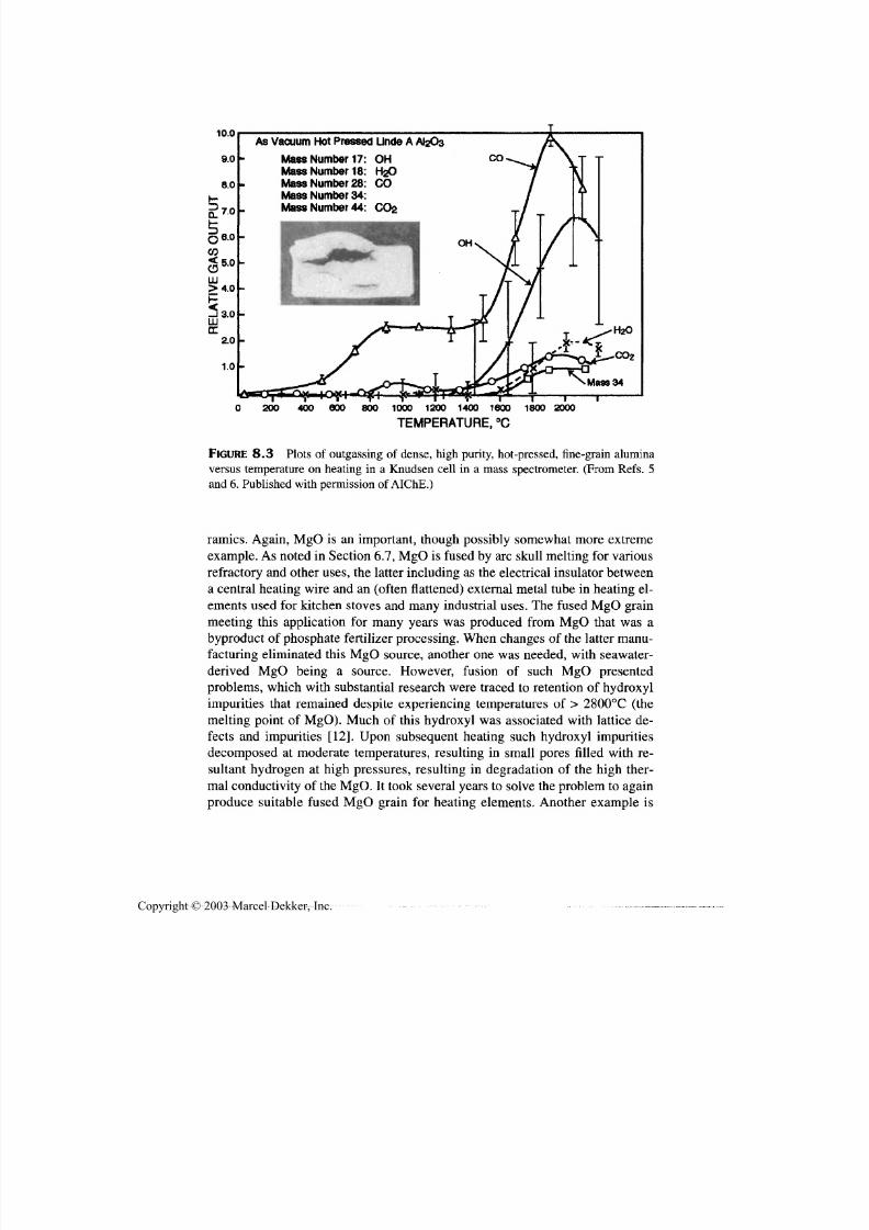
7/29/2019 29540824708539
http://slidepdf.com/reader/full/29540824708539 332/361
Crosscutting, Manufacturing Factors, and Fabrication 321
10.0As Vacuum Hot Pressed Linde A AfeOs
Mass Number 17:Mass Number 18:Mass Number 28:Mass Number 34:Mass Number 44:
200 400 600 800 1000 1200 1400 1600
TEMPERATURE, °C
1800 2000
FIGURE 8.3 Plots of outgassing of dense, high purity, hot-pressed, fine-grain alumina
versus temperature on heating in a Knudsen cell in a mass spectrometer. (From Refs. 5
and 6. Published with permission of AIChE .)
ramies. Again, MgO is an important, though possibly somewhat more extreme
example. As noted in Section 6.7, MgO is fused by arc skull melting for various
refractory and other uses, the latter including as the electrical insulator between
a central heating wire and an (often flattened) external metal tube in heating el -
ements used fo r kitchen stoves and many industrial uses. The fused M gO grain
meeting this application fo r many years was produced from MgO that was a
byproduct of phosphate fertilizer processing. When changes of the latter manu-facturing eliminated this M gO source, another one was needed, with seawater-
derived MgO being a source. However, fusion of such MgO presented
problems, which with substantial research were traced to retention of hydroxyl
impurities that remained despite experiencing temperatures of > 2800°C (the
melting point of MgO). Much of this hydroxyl was associated with lattice de -
fects and impurities [12]. Upon subsequent heating such hydroxyl impurities
decomposed at moderate temperatures, resulting in small pores filled with re-
sultant hydrogen at high pressures, resulting in degradation of the high ther-
mal conductivity of the MgO. It took several years to solve the problem to again
produce suitable fused M gO grain fo r heating elements. Another example is
Copyright © 2003 Marcel Dekker, Inc.
7/29/2019 29540824708539
http://slidepdf.com/reader/full/29540824708539 333/361
322 Chapter 8
efforts to use the MgO-BeO eutectic as a high temp erature heat storage med ia by
using its good heat of fusion for a stable heat source for temperature cycling
about the melt temperature. However, all efforts to eliminate outgassing from the
compacted powder before sealing the material in tungsten containers by electron
beam welding , resulted in failure due to resultant outgassing distorting and rup-
turing the relatively thick W container wa lls.
While MgO may again be a more extreme case, effects of anion impurities
present problems in other melting operations, especially single-crystal growth.
Thus, commercial growth of sapphire and other oxide crystals presents chal-
lenges in selecting raw materials since powders commonly retain enough ad-
sorbed species to present bubble entrapment problems in the resultant crystals
[13] (Sec. 6.7.2). One solution to this is to melt material more than once, by us-ing fused grain and recycled crystal scrap left from machining components out
of single crystals, which greatly reduces the problem, but adds to costs. Another
approach is to use coarser powders and bake them, probably und er vac uum at el-
evated temperatures, but this again adds to costs.
Much less is known of anion species and their effects in nonoxide ceram-
ics other than effects of oxygen or oxygen-containing species, in part since most
nonoxide powders are not calcined from precursors, e.g., often being made by
carbothermal reduction and reaction (Sect. 2.5). However, increasing use of de-
composable precursors, e.g., for silicon nitride, may reveal some analogous
problems to those with calcined oxide powders. However, significant hydrogenevolution has been reported in silicon nitride bodies, possibly due to reduction of
adsorbed water [14]. Clearly, reaction processing, which commonly involves
some nonoxides, can be complicated by interaction of anion species from differ-
ent constituents.
Other, nonpowder based fabrication may also present problems; for exam-
ple, there is substa ntial pos sibility of residual species that may later volatilize on
subsequent hea ting, bu t there is little or no data on this. Though limited, there is
also some data for the important area of CVD. For ceramics this is mainly the
demonstration of residual anions, usually Cl, in powders from CVD via oxida-
tion of metal halides. There is some more specific data for W from deposition ofthe reduced halides, where Cl-derived W had less grain size stability on subse-
quent high temperature exposure with resultant increased ductile-brittle transi-
tion, w hile F-derived W had m ore stable g rain size and properties [15].
8.2.2 Effects of Alternate Heating Methods
Alternate methods of heating ceramics such as various types of plasma and espe-
cially microwave heating have received substantial attention in recent years
[16-23]. There are a variety of uses of such heating, especially microwave heat-
ing, ranging from drying (long used in industry), calcining, joining, ignition of
Copyright © 2003 Marcel Dekker, Inc.

7/29/2019 29540824708539
http://slidepdf.com/reader/full/29540824708539 334/361
Crosscutting, Manufacturing Factors, and Fabrication 323
reactions (briefly noted below), and especially for heating for pressureless sinter-
ing. There is also some application to hot pressing as discussed in Section 6.2.2
and below.The following is a brief summary of this field, focusing mostly on mi-
crowave heating, which is the dominant area of investigation, starting with the
basic driving forces for such work. O ne motivation has been direct reduction of
the energy needed based on the mechanism of heating often being operative only
in the specimens to be sintered so excess energy is not expended in heating large
furnace masses as in conventional sintering using resistance or gas fired fur-
naces. While this is true, there are also costs of conversion of normal alternating
current to microwave (or plasma) energy that counters muc h or all of the benefits
of using less microwave energy. Com pared to g as firing, the disadvantage of m i-
crowave hea ting is increased by the extra costs of converting gas hea t to electric-
ity [19,20]. However, there are also possible energy and other (e.g., higher
throughput) cost savings from the very rapid heating achievable w ith microwave
or plasma heating and potentially much shorter firing cycles. Another important
motivation is the improved microstructures often obtained, e.g., finer, more uni-
form, less porous bodies. However, there are a variety of issues impacting future
possible production uses that remain to be fully resolved. These issues along
with a further outline of aspects of such heating p rocesses follow s.
O ne basic set of issues is the uniformity of heating both in the furnace it-
selfand
within individual samples, especiallyas a function of
individual compo-nent size and shape, as well as with a mixture of different components. Recall
that home microwave ovens (used for much of the initial work on microwave
sintering) commonly heat nonuniformly, which is the reason for the "lazy Su-
san" (rotating) base in them. Much better uniformity has apparently been
achieved in the larger industrial microwave furnaces that are becoming available
[22]. However, computer simulations indicate considerable effects of component
shape on thermal uniformity, which also varies with both rate of heating and mi-
crowave frequency [24]. Another important issue is the compatibility of mi-
crowav e heating and binder removal since the latter can be much more sensitive
to the nature of heating other than norm al electrical or gas heated furnaces. Thus,much microwave sintering appears to have been with parts die pressed without
binders, or with small amounts of binder, generally removed before microwave
sintering, and has been noted as an issue [18], but has apparently become a more
active area of evaluation.
The issue of both binder burnout and specimen outgassing are basic ones
for al l heating methods. Thus, conventional electric- or gas-fired furnaces heat
specimens from the outside inward, the former via radiation and convection to
the surface and the latter via thermal diffusion inward from the surface. This pre-
sents some problem of normal outgassing if the surface sinters too much before
the gasses from the interior of the specimen are adequately diffused out of the
Copyright © 2003 Marcel Dekker, Inc.
7/29/2019 29540824708539
http://slidepdf.com/reader/full/29540824708539 335/361
324 Chapter 8
specimen. Microwave heating being effectively from the inside out should thus
aid such outgassing (though the speed of heating may be a problem as noted be-
low). H owever, the opp osite is true of binder burnou t, since conv entional heatingremoves it from the outside inward, which is necessary to progressively open
pore channels to allow binder products to escape the body. The internal nature of
microwave heating presents the potential problem of binder removal from the
more central region of the sample before pore channels are open to accommo-
date this removal. Because of this, and other issues, systems that are hybrids of
conventional and m icrowa ve heating are being investigated.
Another set of possible problems arise from the potential advantage of very
fast densification rates, e.g., densification of thin rods or thin-wall tubes in sec-
onds at temperature. For example beta-alumina (apparently thin-wall) tubes iso-
pressed to 9.5 m m in dia. and bisq ue fired at 700°C to remove binder, then held at
500°C to avoid gas adsorption prior to sintering, were sintered in an rf induction
coupled plasma at feed rates of 25 m m/m in giving a transition from green precur-
sor to dense product phase in < 15 sec [23]. However, one issue is the thermal
stresses of such rapid heating and their variation with size and shape factors, and
possible resultant cracking in both unsintered material approaching the heating
zone and the sintered material receding from the heating zone. Related issues are
outgassing, w hich can be retarded by rapid sintering [25], and binder burnout; for
example, binders may give more tolerance of thermal stresses in unsintered mate-
rial from fast heating, but exacerbate binder removal issues.
Another basic issue is the broad variation in material susceptibility to mi-
crowave (or plasm a) heating . This means that "firing" schedules m ay have to be tai-
lored to the material, as well as possibly the size and shape of the components being
fired, and probably precludes cofiring of bodies which can be done to some extent
in conventional firing. Another issue is that microwave sintering is more tenuous or
precluded for materials of increasing electrical conductiv ity. W hile some m aterials
that cannot be directly heated by microwaves can be heated in dielectric, e.g., alu-
mina, crucibles [26], this may often be more cumbersome than practical. Another
issue as well as possible opportunity, is microwave sintering of ceramic composites,
where there is a significant difference in the microwave coupling to the compositeconstituents, which presents both problems and possibilities. Microwave heating
has also been shown to be useful in igniting and thus effecting propagation of self-
propagating high temperature synthesis (SHS) reactions (Sec. 6.5) [27].
Overall there are a variety of issues for these novel heating methods that
are not fully addressed. These range from basic differences with conventional
sintering, i.e., internal heating that diffuses outward versus conventional heating
progressing from the component surface inward, and their ramifications for fac-
tors such as binder removal. This leads to consideration of hybrid new-conven-
tional heatin g and how to best operate these. O ther issues include practical lim its
on the speed of heating and w orkin g with materials that microwaves do not cou-
Copyright © 2003 Marcel Dekker, Inc.

7/29/2019 29540824708539
http://slidepdf.com/reader/full/29540824708539 336/361
Crosscutting, Manufacturing Factors, and Fabrication 325
pie well with. Lacking a full evalua tion of these and related issues, a clear future
for such newer heating is not apparent, but some specialized applications seem
most likely—e.g., fast firing of small rods or tubes and possibly of fibers or fila-ments. Some specialized use for joining and with reaction processing may be
feasible, e.g., ignition of reactions, and selective heating of braze or welding m a-
terials, including use of SHS reactions for joining.
It should be noted that some of the effects of hot pressing with direct resis-
tive heating of the die (and the powder compact if it is conductive), plasma heat-
ing, or combinations, with some aspects of this being in a pulse mode, shows
some similarity to effects of microwave or plasma heating. Some possible aspects
of plasma typ e heating have in fact been cited as a possible factor in apparent en-
hanced densification (Sec. 6.2.2). More recently Oh and coworkers [28] have re-
ported improved properties from first-pulse resistive heating of nanocompositeAl2O 3-SiC and the graphite dies at lower temperature in vacuum versus conven-
tional hot pressing. S imilarly, G roza and coworkers [29] reported faster, lower
temperature densification of nano-TiN powder using plasma activated sintering
under vacuum with a graphite die (and 66 MPa pressure) and an initial electric
pulse to aid outgassing. These and other reports indicate opportunities, but again
mechanisms and practicality (e.g., repeatability, scalability) need m ore definition.
8.2.3 Fabrication of Ceramic Composites
Fabrication of ceramic composites with a ceramic matrix and a dispersed metal
or ceramic phase or with ceramic fibers, though addressed in various earlier sec-
tions on specific applicable fabrication, deserves additional attention since it re-
flects significant shifts in emphasis of fabrication methods from that for
monolithic ceramics. The shifts in commonly used or preferred fabrication meth-
ods for ceramic composites vary with the type of composite, generally increas-
ing with the type of composite, as summarized in Table 8.1 and below. Such
evaluation is supported by other reviews of ceramic composites [7,30-32].
TABLE 8.1 Use of Major Fabrication Methods for Ceramic Composites
Fabrication method"
Composite
Particulate
Platelet/whisker
Fiber
Sintering
M-H
L
—
Hot pressing
M-H
H
H
HIPing
L-M
L
—
CVD/CVI
—
—
M
aH = high, M = medium, L = low, — = none or very low. Note also some limited fabrication of par-
ticulate or platelet (e.g., crystallized glasses) and fiber (e.g., eutectic) composites, as well as some
fabrication of glass matrix fiber composites using hot glass flow injection (Fig. 7.10)
Copyright © 2003 Marcel Dekker, Inc.

7/29/2019 29540824708539
http://slidepdf.com/reader/full/29540824708539 337/361
326 Chapter 8
Paniculate composites are often fabricated by pressureless sintering of green
bodies formed by processes used for monolithic ceramics. How ever, two sets of is-
sues, one of green body formation and the other of sintering, must be considered.Both the size, shape, and density differentials of the particles of the dispersed
phase versus those of the matrix phase have impacts on the fabrication methods
used. Forming the green body by slip, tape, or pressure casting will give some dif-
ferences in spatial orientation and distrib ution of the dispersed p hase as a function
of these differences in particulate character on settling and orientation. Differential
character of matrix versus dispersed particles may also impact powder pressing re-
sults, especially in die pressing. Thus, differential local particle packing densities
may occur around larger particles, and preferred orientation of dispersed particles,
especially larger platy particles, is likely to occur on a global scale with variations
in the body as a function of compaction gradients. There are also basic issues in
densification via pressureless sintering, since isolated particles of a different phase
inhibit sintering of the surrounding m atrix particles, with such effects often being
exacerbated by local green density variations that may occur as noted abov e.
However, besides effects of both the differing characters of m atrix and dis-
persed particles, there are effects of the volum e fraction dispersed phase, and on
the mechanism(s) of sintering since liquid-phase sintering, which is common in
many ceramic particulate composites, can reduce differential densific ation prob-
lems. Further, coating of matrix material on individual dispersed particles has
been shown to frequently improve densification of ceramic particulate compos-ites as discussed in Section 2.6 (a nd should also imp rove the homogeneity of dis-
tribution of the dispersed phase). However, there are situations in which such
particle coating is not practical for technical or cost reasons. T hus, fabrication of
dual composites, i.e., of composite particles of one composition dispersed in a
matrix that is a composite of differing composition (usually of volum e fraction
of dispersed phase, but could also include a different dispersed phase) are less
amenable to sintering [7]. A ddition ally , it is important to note that reaction pro-
cessing is a substantial and promising method of fabricating many ceramic par-
ticulate composites, and that pressure sintering, especially by hot pressing, is
widely used for such fabrication (Sec. 6.5). Further, melt-derived eutectic parti-cles are typically more difficult to densify by pressureless sintering, as to a lesser
extent are composites of nonoxide constituents (Sec. 6.7.3). Thus, while pres-
sureless sintering is used for production of some c eramic p articulate comp osites,
ho t pressing is also substantial ly used, as is some HIPing. Again recall that there
are also some other methods of fabricating particulate composite such as CVD
and especially melt processing (e.g., via glass crystallization).
Turning to whisker and platelet composites, the shift to pressure sintering,
especially via hot pressing, is substantia lly greater than the shift in processing of
particulate comp osites. Problems in consolidation of green bodies of whisk er and
platelet com posites are a factor in this, but m uch of this is due to the mu ch greater
Copyright © 2003 Marcel Dekker, Inc.

7/29/2019 29540824708539
http://slidepdf.com/reader/full/29540824708539 338/361
Crosscutting, Manufacturing Factors, and Fabrication 327
inhabitation of densification in pressureless sintering. Thus, such composites are
predominately hot pressed in both laboratory preparation and in industrial pro-
duction (primarily or exclusively alumina-SiC whisker composites). Note thatHIPing of such composites, which produces a more isotropic composite, can be
more difficult. The anisotropy produced by uniaxial densification of hot pressing
aids densification, and is a factor in their use, probably a benefit for many applica-
tions, (e.g., w ear), but this requires more study. Also again note that some platelet
composites are produced by m elt processing, e.g., some crystallized glasses.
Finally, consider fiber composites, primarily those with continuous fibers
(or filaments), where there are not only significant changes in densification, but
even greater ones in fabrication of the green body. (There has been limited ef-
fort on chopped or other short fiber composites, whose fabrication generally
falls between that for whisker and continuous fiber composites.) These shiftsare summarized below, with readers referred to appropriate reviews for greater
details [30,31]. For continuous fiber (or filament) composites the challenge is to
get a reasonably homogeneous infiltration of matrix material in between fairly
closely spaced fibers, e.g., typically 30-60 v/o fibers. This is universally done
via fluid infiltration, with the fluid method depending on whether a green com-
posite body is to be formed then densified, or whether infiltration and densifica-
tion are concurrent.
Consider first the gross shifts in green body fabrication of fiber composites
versus particulate composites where liquid infiltration is used for fiber compos-
ites as opposed to powder mixing, e.g., wet or dry milling is commonly used for
particulate composites, but is generally unsuited for fiber composites. Thus, a
liquid source of the matrix is coated on fibers or filaments, commonly by infiltra-
tion into tows, cloth, or preforms. Also, depending on the specific nature of the
liquid source of the matrix, many of the methods of forming plastic composites
are available for forming green ceramic fiber composites. Thus, slurries of ma-
trix powder are a major source of matrix infiltration in fiber composites, and sols
or preceramic polymer infiltration are used, the latter being the method of mak-
ing carbon-carbon composites. Slurry infiltration is normally done filament by
filament, tow by tow, or cloth layer by cloth layer since greater masses of fibersis likely to result in the ou ter layers of fibers acting as a filter to reduce and ulti-mately prevent slurry constituents from penetrating to the center of fiber pre-
forms. Sol and preceramic polymers or their liquid precursors can be infiltrated
into fiber preforms, provided they can be suitably rigidized in the fiber preform,
which is typically done for carbon composites with carbon producing polymers.
It is also possible, in principle, to coat fibers, e.g., in their production w ith matrix
sources, with polymeric precursors probably being most practical, e.g., from an
adherence standpoint. However, this would require large volumes of coated fiber
and a significant change in relations between composite producers and their ma-
terial suppliers.
Copyright © 2003 Marcel Dekker, Inc.
7/29/2019 29540824708539
http://slidepdf.com/reader/full/29540824708539 339/361
328 Chapter 8
Once green fiber composites are made, they are densified primarily by hot
pressing. Many composites are mainly planar fiber architecture with easy con-
solidation in the direction norm al to the plane of the composite fiber architecture,and thus are a natura l choice for hot pressing normal to the plane of the compos-
ite fiber architecture. Such plainer composites limit added costs of hot pressing,
which are often not a large factor in view of other sources of composite costs,
such as those of the fibers themselves and costs of forming the composite green
body. Further, there are limited alternatives to densifying green composite bodies
with complex trade-offs of body quality and costs that make hot pressing a nat-
ural process for many composites. Neither sintering no r HIPing are generally
feasible since these both require shrinkage parallel as well as normal to the
fibers, which is generally impractical an d generally avoided in hot pressing. Hot
pressing typically yields a near or fully dense composite body and can handle
substantial size composites. For glass matrix fiber composites some added versa-
tility is feasible via injection of fluid glass for the matrix (Fig. 7.10).
An alternate densification route is to do m ultiple impregnations (often un-
der pressure) and pyrolysis of sol or especially polymeric matrix sources, bu t
this never reaches full density, and also becomes an expensive process. How-
ever, the normal process for making carbon fiber composites with three- or
higher dim ensional fiber reinforcement is such multiple impregnation and p yrol-
ysis steps since this is generally the only way to make such very expensive com-
posites. O ne other process that may be promisingwith
lower temperatureprocessing of matrices, e.g., some phosphate ones made by reaction, is autoclave
processing, but this is not low in cost and may require multiple impregnations
and autoclave reaction processing.
The remaining matrix infiltration process that entails simultaneous den-
sification is via chemical vapor deposition (CVD), typically termed chemical
vapor infiltration (CV I) for this purpose. This can, in principle, handle a wide
range of composites in terms of size, shape, and fiber architecture, as well as a
reasonable to good range of matrix materials . However, it tends to be a slow
process, can have some l imitat ions on the thicknesses handled and depths in -
filtrated. It also inherently cannot give fully dense matrices, but the pores ittends to leave appear to be intrinsically more benign in l imiting physical
properties, in contrast to other methods of forming matrices that leave some
porosity, i.e., methods involving mult iple impregnat ions and thermal decom-
position processing [33,34].
Finally, note that there are some possibilities of forming some ceramic
fiber compo sites from the m elt. D irectional solidification of eutectics is one pos-
sible method, and may be more feasible where successfully fabricated by edge-
defined film-fed grow th (E FG ) methods (Sec. 7.3). Some experiments to
introduce matrix material into fiber composites by melt spraying were unsuc-
cessful, but there may be possibilities fo r this with further development.
Copyright © 2003 Marcel Dekker, Inc.
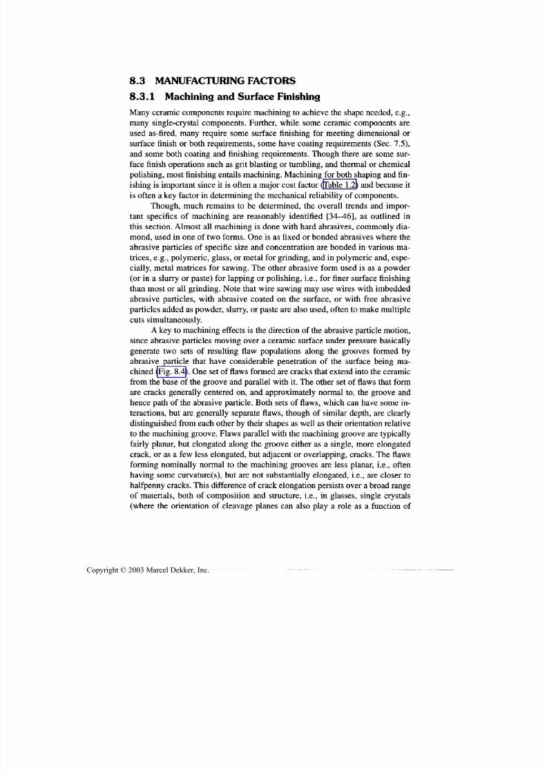
7/29/2019 29540824708539
http://slidepdf.com/reader/full/29540824708539 340/361
Cro'sscutting, Manufacturing Factors, and Fabrication 329
8.3 MANUFACTURING FACTORS
8.3.1 Machining and Surface FinishingMany ceramic components require machining to achieve the shape needed, e.g.,
many single-crystal components. Further, while some ceramic components are
used as-fired, many require some surface finishing for meeting dimensional or
surface finish or both requirements, some have coating requirements (Sec. 7.5),
and some both coating and finishing requirements. Though there are some sur-
face finish operations such as grit blasting or tumbling, and thermal or chemical
polishing, most finishing entails machining. Machining for both shaping and fin-
ishing is important since it is often a major cost factor (Table 1.2) and because it
is often a key factor in determining the mechanical reliability of components.
Though, much remains to be determined, the overall trends and impor-
tant specifics of machining are reasonably identified [34-46], as outlined in
this section. Almost all machining is done with hard abrasives, commonly dia-
mond, used in one of two forms. One is as fixed or bonded abrasives where the
abrasive particles of specific size and concentration are bonded in various m a-
trices, e.g., polymeric, glass, or metal for grinding, and in polymeric and, espe-
cially, metal matrices fo r sawing. The other abrasive form used is as a powder
(or in a slurry or paste) for lapping or polishing, i.e., for finer surface finishing
than most or all grinding. Note that wire sawing may use wires with imbedded
abrasive particles, with abrasive coated on the surface, or with free abrasiveparticles added as powder, slurry, or paste are also used, often to make multiple
cuts simultaneously.
A key to machining effects is the direction of the abrasive particle motion,
since abrasive particles moving over a ceramic surface under pressure basically
generate tw o sets of resulting flaw populations along the grooves formed by
abrasive particle that have considerable penetration of the surface being ma-
chined (Fig. 8.4). One set of flaws formed are cracks that extend into the ceramic
from the base of the groove and parallel with it. The other set of flaws that form
are cracks generally centered on, and approximately normal to, the groove and
hence path of the abrasive particle. Both sets of flaws, which can have some in-teractions, but are generally separate flaws, though of similar depth, are clearly
distinguished from each other by their shapes as well as their orientation relative
to the machining groove. Flaws parallel with the machining groove are typically
fairly planar, but elongated along the groove either as a single, more elongated
crack, or as a few less elongated, bu t adjacent or overlapping, cracks. The flaws
forming nominally normal to the machining grooves are less planar, i.e., often
having some curvature(s), but are not substantially elongated, i.e., are closer to
halfpenny cracks. This difference of crack elongation persists over a broad range
of materials, both of composition and structure, i.e., in glasses, single crystals
(where the orientation of cleavage planes can also play a role as a function of
Copyright © 2003 Marcel Dekker, Inc.

7/29/2019 29540824708539
http://slidepdf.com/reader/full/29540824708539 341/361
330 Chapter 8
FIGURE8.4
Examples of machining flaws from grinding at fracture origins as a resultof (A) grinding parallel to the tensile axis of flexure strength testing, hence failing from a
machining flaw normal with the abrasive groove and (B) grinding normal with the tensile
axis and thus failing from a machining flaw formed parallel to the abrasive groove.
Though in a softer ceramic, MgE,, they are representative of other ceramics.
crystal orientation) and many porous and dense polycrystalline materials. How-
ever, the difference in flaw shape is impacted by grain size, generally with the
shape/elongation difference disappearing when the flaws and grains are about
the same size [7,44,45] and may be reduced by porosity in some cases [34,45].
Thus, the key difference is the general elongation of the flaws parallel with
the machining grooves, which makes them more serious flaws, i.e., reducing
strength by up to 50%. Besides the above noted effect of grain size on the elonga-
tion of flaws parallel with machining grooves, there are two other effects deter-
mining the impact of this flaw elongation on tensile strengths. The first is other
sources of failure, which if present to control failure of most or all components
will obscure or preclude a strength difference due to the two m achining flaw pop-
ulations. The second is the type and orientation of the tensile stress relative to the
machining direction. In lapping and most po lishing there is no persistent direction
of the abrasive particles; the fine grooves formed and the associated parallel andperpendicular flaws are essentially random ly oriented in the component surface.
Thus, when the machining flaws are the source of failure, the most severe flaws
control failure, which in this case are the flaws parallel to the machining grooves.
This is also true where the tensile stresses causing failure are either bi- or triaxial
since the elongated flaws parallel with abrasive grooves are high stressed by such
loading. However, where the tensile stresses causing failure are uniaxial, there is
anisotropy of the tensile strength depending on the orientation of the stress versus
any persistent machining direction, as is generally the case for most grinding
(which is one of the most extensively used m achining operations), and appears to
also be so for much sawing. In such cases having the stress axis parallel with the
Copyright © 2003 Marcel Dekker, Inc.
7/29/2019 29540824708539
http://slidepdf.com/reader/full/29540824708539 342/361
Crosscutting, Manufacturing Factors, and Fabrication 331
machining direction results in higher strength and stressing normal to the machin-
ing direction and results in lower strengths, often by up to 50%.
W hile the difference in shape of the flaws parallel versus perpendicular is amajor factor in the strength of machined ceramics, there are other factors that
need to be considered. These include effects of machining parameters, materials
and microstructures being machined, and the generation of residual stresses by
ma chining. C onsider first machining parameters, where a dominant factor is the
grit size used. Except for some variations at very fine grit sizes and fine grain
sizes, strengths consistently decrease with increasing grit size, which means in-
creasing flaw sizes, depths for flaws both parallel and perpendicular to the ma-
chining direction. Similarly there is some evidence that increasing depth of cut
increases flaw depths, decreasing strengths. An important ramification of both of
these is that when a finer machining operation follows a coarser one, as is fre-quently the case, the final machining will not reflect the normal flaw population
for that machining unless the net thickness of material removed by the last ma-
chining is greater than the depth of flaws from the previous machining. Other-
wise, the strength after the final machining step will reflect larger flaw remnants
from prior machining steps.
Machining effects vary some with material and microstructure since flaw
sizes (c, measured as its depth) are
c o c (EIH)m
(FIK)m
(8.1)
where E = Young's modulus, //=hardness, and K = fracture toughness, al l being
local values controlling flaw introduction, while F = the force on abrasive parti-
cles (increasing with depth of cut and increasing g rit size) [35,38]. Thus there are
broad, but generally limited, effects of material properties and microstructures
on c via their effects on the parameters, prim arily E, H , and K . This arises since
the above dependences are not strong, and those of strength, which varies as c1/2
,
are further reduced. Further, while E and H vary widely for different materials,
there are similar trends of each for the same material so there are not large
changes of the E/H ratio between different materials. Similarly effects of poros-
ity occur via effects on E, H , an d K , but are again limited both by the low powerof the dependence of c on them, and that the porosity dependences of both E and
H are generally similar and thus app roximately cancelling. O n the other hand, H
generally decreases as grain size increases, but E is generally independent of
grain size, giving a general trend for c to decrease some with increasing hard-
ness. However, the dominant effect of grain size is via its effect in limiting elon-
gation of flaws formed parallel with the abrasive particle motion as the flaw
dimensions approach those of the grain. Clearly, there are also effects of K , but
local values controlling c appear to be much less that large crack values, espe-
cially as a function of microstructure.
To put the above in perspective, most machining flaw sizes for representative
Copyright © 2003 Marcel Dekker, Inc.

7/29/2019 29540824708539
http://slidepdf.com/reader/full/29540824708539 343/361
332 Chapter 8
strengths of typical production ceramics are in the range of 20-60 (im, often the
same range as for other flaws such as isolated pores. Finer machining flaws 5-20
|im in size have been identified for higher strength, e.g., > 600 MPa fine-grain bod-ies such as Si3N 4. A key result of flaw sizes not changing much with grain size is
that machining flaws change from being larger than the grains at fine grain sizes,
and smaller than larger grains in large-grain bodies (and also often in isolated large
grains) [7,44,45].
The situation for ceramic composites is both more complex and less studied,
being better defined for ceramic particulate composites. These generally show K
going through a m axim um as a function of the volum e fraction of dispersed partic-
ulates with c thus showing a modest minimum and strength a modest maximum
[7,38]. These trends are shifted some, but not grossly changed by dispersed parti-
cle size and ma trix grain size, i.e., finer particle size directly increases H some and
indirectly by its trend to reduce m atrix grain size some. Other composites are more
complex due to significant anisotropies of properties and of the related orientations
of the fiber-matrix interface that hav e received little or no attention.
Residual stresses are typica lly another factor in strengths of machined (and
some other) ceramics. Though not extensively studied, there are sufficient stud-
ies to outline the trends of surface compressive machining stresses. These, are
generally shallow, e.g., probably < 10 Jim with significant gradients decreasing
their levels from the surface inward. Da ta shows considerable variability in mea-
sured v alues, wh ich are comm only of the order of a few hu ndred MPa in m ainlystructural ceramics studied. Thus surface compressive stresses are commonly a
factor in, but do not appear to dominate, mechanical behavior. However, such
stresses appear to be a factor in lim iting strengths benefits of polishing over fine
grinding since there appears to be less compressive stress from polishing versus
grinding. Also, recall that polishing is typically done with random motion of the
free abrasive particles so failure is dominated by the more elongated polishing
flaws formed parallel with the local abrasive particle motion, which limits pol-
ished strengths relative to those for stressing parallel to the grinding direction of
ground samples. Thus both the machining direction and residual stress effects
combine to limit the benefits of polishing versus fine grinding on strengths(again polishing effects will also be limited if sufficient polishing is not done to
remove more serious finishing flaws from prior finishing).
Substantial progress has been made in understanding machining interac-
tions with, and effects on, various types of ceramic materials. This has been ac-
companied by su bstantial advan ces in obtaining better m achined surfaces and
some reductions in mach ining costs. Basic engineering imp rovements such as
better abrasives and especially better (and often thinner) saw blades or wires and
use of ganged blades to make multiple and thinner cuts simultaneously (thus in-
creasing product yield from a given piece) have all helped to reduce costs. Thus,
while machining costs generally remain an important factor, progress has been,
Copyright © 2003 Marcel Dekker, Inc.
7/29/2019 29540824708539
http://slidepdf.com/reader/full/29540824708539 344/361
Crosscutting, Manufacturing Factors, and Fabrication 333
and continues to be m ade, and clever engineering also can help, e.g., as shown for
some sapphire windows [46]. Optically polishing of sapphire windows ground to
dimensions is a substantial cost for many of its applications. However, it has beenshown that much or all polishing can be eliminated by applying a thin, fired glass
coating on ground sapphire surfaces normally needing substantial polishing. By
using a glass with a close (within 1%) match to the refractive index of sapphire
and a reasonable match, e.g., within 10%, of thermal expansion, both for the win-
dow orientation used, can result in suitable transparency for some applications
such as armor windows with no polishing, that is, as fired. Further, if greater
transparency quality is needed, the glass-coated surfaces can be polished to im-
prove transparency quality at lower costs than the bare sapphire. While use of
such glass coatings is not suitable for surfaces needed for some uses such as wear
or erosion resistance, it is applicable for some uses such as armor windows.
8.3.2 Component InspectionandNondestructive Evaluation (NDE)
An important step in the manufacturing of ceramic components is their inspec-
tion and evaluation to assess their suitability for meeting the needs for which
they were m anufactured. This typ ically entails tw o sets of evaluation, one to ver-
ify dimensional and surface finish requirements have been met, and one to ascer-
tain that properties needed for the function have been achieved. D imensional an dfinish verifications are generally reasonably accomplished via available technol-
og y such as optical comp aritors that are simple, fast, and are thus generally cost-
effective and have no effects on the components. Similarly, m any properties can
be checked to the extent needed with no effect on the component, e.g., its den-
sity, refractive index or dielectric constant, and optical transmission, generally
with good results at moderate costs.
The greater challenge is to inspect components for their potential reliabil-
ity in applications where failure from mechanical, thermal, or electrical stressing
of the component m ust be avoided within designed values of parameters of me-
chanical or thermal stress or of dielectric breakdown. Proof testing—stressingcomponents as used in service to stress levels that result in limited proof testing
failures while assuring no failure in the subsequently planned use— is very effec-
tive where it is applicable. U nfortunately, proof testing is very limited in its use,
primarily or exclusively to components ma inly stressed in rotation, as for grind-
ing wheels and turbine blades or rotors. Alternatively, testing to failure sets of
samples can be used (and probably was in the design/selection of the compo-
nent) to assess the probability of produced components can be done, but is
costly, time consuming, and potentially of limited accuracy.
An alternate approach that has been the focus of much effort is nonde-
structive destructive evaluation (NDE), an inspection method to ascertain the
Copyright © 2003 Marcel Dekker, Inc.
7/29/2019 29540824708539
http://slidepdf.com/reader/full/29540824708539 345/361
334 Chapter 8
capability of finished components to meet such requirements in a nondestruc-
tive fashion. There has been substantial research directed toward achieving such
a general technical goal, much of it directed toward the broad and absolute goalof determining the potential failure-caus ing flaws and the operational property
levels at which they would cause failure so components that would fail at less
than acceptable stress levels are identified and rejected. There is a substantial
and growing diversity of technologies for doing this [47]. However, there are
still serious limitations to such approaches for highly stressed components,
where resolution of fine flaws is uncertain. The first set of limitations is in the
detection of flaws present that may limit components from meeting their design
function. There is first the limiting sizes of flaws identifiable and the probabili-
ties of their detection and accuracies as a function of flaw type, location in the
comp onent, and m aterial. Sizes detectable vary with both the noted param eters
and the detection method used (e.g., ultrasonic versus radiographic versus ther-
mal methods). While the lower limits of flaw size detectability overlap with the
upper end of the sizes of flaws of concern, there is a considerable range of flaw
sizes that may cause failure that are generally not detectable. This inability of
detecting smaller flaws again varies with several key parameters noted above,
as well as the presence of different types of flaws. All of these limit both the
size of flaw detection and their prob ability of detection, w hic h is a critical issue
that has received little or no attention.
The second major problem, that has also received very little attention, is
that identifying individu al flaws of small enough size is not enough for accurate
selection of acceptable versus unaccep table comp onents. This arises for three re-
lated reasons: First, detection of a flaw is not sufficient; its size, shape, orienta-
tion, and character must be determined to estimate its severity and hence
probable failure stress. Second, many failures occur from two or more nearby
features that may be similar, such as two nearby machining flaws or a cluster of a
few pores near one another or different, such as a pore associated with a large
grain, impu rity particle, or machining flaw. Detection of such combinations and
determining the stress at which they wou ld cause failure are both still m ajor lim-
itations. Thus, failure from many individual machining flaws identified on resul-tant fracture surfaces agree with the known strength and fracture toughness
along with the observed flaw character. However, for more irregular machining
flaws, results are more variable, introducing important uncertainties, despite
such flaws identified on fracture surfaces being better characterized than by ND E
methods. Another indication of the challenge in identifying enough details of
collective flaws is to consider differences in flaws, e.g., pores, causing dielectric
breakdown versus mechanical failure. Dielectric failure is most likely from a
chain of pores parallel to the electric field in the component, while mechanical
failure is most likely from a closely spaced cluster of pores in a plane normal to
the stress direction [2]. The accuracy of disting uish ing between these two cases
Copyright © 2003 Marcel Dekker, Inc.

7/29/2019 29540824708539
http://slidepdf.com/reader/full/29540824708539 346/361
Crosscutting, Manufacturing Factors, and Fabrication 335
by NDE is very uncertain. The third complication, especially for mechanical
failure, is that there may be local stresses as well as local concentration of ap-
plied or residual stresses, both of which can be difficult to detect and quantify,making quantification of expected strengths even more uncertain.
Continued research and development will create further advances in NDE
methods. Whether these will be sufficient for much wider use of ND E in selecting
good versus bad components remains uncertain, as does the cost-effectiveness of
much NDE. Thus, note that the primary N DE methods in much of the ceramics
industry are visual examination, backed up by die penetrant tests as needed. How-
ever, current N DE techniques are useful for rejecting some components, e.g., re-
fractories, where larger, more detectable flaws are dominant sources of failure.
Further, there is growing recognition that NDE i s valuable for guiding improve-
ments in fabrication methods to make better components and may be effective as
a production control at various stages of fabrication, especially of green bodies,
rather than in addition to a final inspection (Sec. 8.4) [48]. There are also possibil-
ities of developing N D E techniques to reject finished components that are not
based on identifying specific potential failure-causing flaws, but instead depend
on correlation of behavior with use parameters (e.g., the ringing of a tea cup when
struck indicating a sound cup), which deserve more attention.
8.3.3 Attachment and Joining
Attachment or joining of ceramic components to support structures or other ce-
ramic or metal components is often needed for the ceramic component to func-
tion (some of which m ay also be aided by NDE). Thus, for example, insulating
ceramics, e.g., bricks and fiber mats, must often be joined to each other and to
furnace structures, while many structural components, e.g., turbine blades and
vanes as well as exhaust port liners or valves for internal combustion engines,
also must be attached to or incorporated into corresponding parts of the engines.
Many wear components must also be mounted to or in devices in which they are
used, as are extensive arrays of ceramic components in papermaking machines
and ceramic plungers and liners for slurry pumps. Many ceramic optical andother electromagnetic windows and all IR-domes an d radomes must be mounted
to provide seals and mechanical and aerodynamic integrity, respectively. Finally,
one of the most extensive areas of joining metals and ceramics is for electrical
and electronic applications, ranging from varistors to capacitors to ceramic sub-
strates and multilayer packages.
To meet the above extensive and diverse needs for joining and attachment
of ceramics to like or other ceramics or metals, an extensive and diverse array of
technology ha s been developed, with much of it in wide industrial use. Such
technology has been reviewed elsewhere [49-53] and is summarized here. These
technologies ca n roughly be placed in various categories ranging from mechani-
Copyright © 2003 Marcel Dekker, Inc.

7/29/2019 29540824708539
http://slidepdf.com/reader/full/29540824708539 347/361
336 Chapter 8
cal, (organic) adhesive, metal (soldering and brazing ), and glass to metal sealing
and ceramic brazing, cementatious bonding, bonding via preceramic polymers,
diffusion welding, and fusion welding. These are listed roughly in order of in-creasing p otential temperature capability. While all can be used to join ceramics
to themselves or other materials, the first three are more often used for joining
ceramics to other materials, while the latter four are often used to join ceramics
to themselves. These techniques are briefly outlined below and in Table 8.2.
Mechanical attachment covers a broad range of often simple and low-cost
techniques ranging from joining or attachment via typical mechanical fasteners
such as metal screws, nuts and bolts, clamps, and hangers. A key factor is mini-
mizing stress concentrations from holes and localized contacts as well as genera-
tion of attachment stresses due to differences of elastic or thermal strains
between the ceramic components, their attachment, and the structure to which
they are attached. A key way of limiting these problems is via use of compliant
materials, e.g., rubber, plastic, or soft metal, between the ceramic and critical
contacts with the attachment or support structure. Thus, for example, wind-
shields in aircraft and the space shuttle are held and sealed by rubber seals,
placed where the clamps and rubber seals are removed from much of the envi-
ronment the windshield may experience. The latter placement is also a common
method of raising the typically limited temperature or other environm ental range
over which such attachment can be used, e.g., placement on the back side of re-
fractory bricks or insulation bats. Another important mechanical attachment
method is shrink fitting of a m ating me tal part around a ceramic part. This entails
carefully sizing both parts so on heating the metal allows it to be slipped over the
ceramic p art on wh ich it shrinks to a tight fit on cooling. There are clear limits on
temperatures, sizes, and shapes, e.g., for cylindrical parts for placing ceramic
dies or cylinder liners in metal bodies. An extreme of this is casting metal around
a ceramic component, e.g., engine port liners, placing demands on the ceramic
thermal shock resistance.
T A B L E 8.2 Summary of Ceramic Joining Methods"
Joining
method
Adhesive
Cementitious
Mechanical
Brazing
Diffusion welding
Fusion welding
Shape
flexibility
M
M-H
L-M
M-H
L
M
Temperature/
env. cap.
L
M
L-M
M
H
H
Vac./
hermiticity
L
L
L-H
H
H
H
Strength
L
L
L-M
M-H
H
M-H
Cost
L
L
L-M
M
H
M-H
a
L= low, M= medium, and H= high.
Copyright © 2003 Marcel Dekker, Inc.
7/29/2019 29540824708539
http://slidepdf.com/reader/full/29540824708539 348/361
Crosscutting, Manufacturing Factors, and Fabrication 337
U sing organic adhesives is another basically simple and usua lly low-cost
method of joining or attaching ceramics, w here environm ental and other factors
allow. This may be used to bond ceramic com ponents to themselves or other ma-terials directly via their adhesive capabilities. Organic adhesives may also be
combined with mechanical attachment; for example, some radomes have been
attached to missile structures by bonding a layer of plastic composite to the in-
side of the dome base such that this layer could be threaded to allow the dome to
be screwed onto the m issile structure. Limitations of adhesive m ethods are envi-
ronmental and stresses. The latter can be substantial if there is considerable tem-
perature excursion of the ceramic-adhesive joint from the temperature of
bonding due to typical high-therm al expansions of organic adhesives versus ce-
ram ics, e.g., by two- to fivefold. Thus, for example bonding of PZT sonar trans-
ducer rings to one another to form elements of a sonar array using an elevated
temperature curing epoxy adhesive introduced stresses of about one-half the
PZT strength, which together with operational stresses resulted in some ceramic
ring failure [2]. With regard to environmental limitations, these, especially tem-
perature lim itations, can be relaxed some by placing the adhesive bond in an area
of limited tem perature or other exp osure.
Consider next brazing of ceramics to ceramics or m etals with metal or ce-
ramic m aterials, wh ich also includes glass-to-metal sealing (as well as soldering
at lower temperature with lower melting materials). These represent a broad ar-
ray of materials, applications and techniques based on bonding two similar or
dissimilar materials with a material that normally forms a liquid that w ets, then
bonds the p arts being joined on solidification, i.e., generally as in soldering and
brazing of metals to themselves. Low er temp erature bonding via solders is par-
ticularly needed in electronic ap plications where sem iconducting chips are pre-
sent requiring temperatures that will not damage the semiconductors. Various
solders or braz es are also used to give a hierarchy of bonding tem peratures such
that earlier form ed braze or solder joints will not be affected (undone) by subse-
quent joining operations. Some solders or brazing materials are ceramic espe-
cially silicate-based glasses. The latter, which provide a broad range of
properties and adjustment of these, are the basis of extensive industrial produc-tion of glass to metal seals used to provide electrical insulation of electrical feed
throughs that are hermetically sealed to metal housings that provide environ-
mental protection for electrical systems. There is also substantial use of the
same or similar solders and brazes used for soldering or brazing metals to ce-
ramics. Brazes are widely used for a variety of materials and applications that
include extensive use for electrical and electronic components. Some can also
be used for optical materials—e.g., promising strengths (e.g., of 200 M Pa) have
been achieved in glass brazing of large sapphire window sections (apparently
using the same or similar glass used to reduce or eliminate surface polishing
[46]; see Sec. 8.3.1). H ighest temp erature join ts by brazing are achieved with
Copyright © 2003 Marcel Dekker, Inc.

7/29/2019 29540824708539
http://slidepdf.com/reader/full/29540824708539 349/361
338 Chapter 8
noble, reactive (e.g., Ti), or refractory metal (e.g., Mo-based) brazes, which also
generally have closer thermal expansions to many ceramics. Note again limita-
tions of materials and component size and shape due to thermal stresses from
expansion differences.
An important aspect of some soldering, and especially brazing, operations
is reactions that occur between braze constituents and the ceramic being brazed.
U ndersta nding and controlling of these is leading to further advances [54]. There
ha s been increasing investigation of other reaction-based joining via reaction
processes, particularly by SHS methods (Sec. 6.5) that generate much or all of
the heating needed, and often give transient liquid phase(s). W hile precautions
are generally needed to limit effects of thermal stresses, as for fusion welding
discussed below, and im porta nt issues of outgassing (e.g., of species adsorbed or
reactant powder surfaces) during reaction, but there may be promise for some
application of such reaction bonding.
There is one large class of long stan ding use of special cements (u sual ly in-
volving some reaction) for joining ceramics and two other newer, more special-
ized, and less developed methods that generally depend on chemical reactions,
but may also in part entail some brazing or welding mechanisms. Many refrac-
tory bricks and parts are bonded with various cements, e.g., hydroxide or phos-
phate containing ones, whose decomposition or chemical change on curing aides
in developing a bond. Cem ent bonding is also extensively used to bond metal at-
tachment fixtures to ceramic electrical insulators. One of the newest develop-ments is joining via polymer pyrolysis, where two parts, most likely both
ceramic, are joined with a preceramic polymer that is subsequently converted to
a ceramic. This technique, in its early development, entails large shrinkages on
conversion to ceramic material which must be addressed, e.g., by limiting it to
small parts, use of substantial particulate filler in the preceramic polymer, or sub-
sequent densification, e.g., by sintering.
Diffusion bonding or welding ha s been extensively demonstrated for ce-
ramics. This typica lly entails join ing by placing a ceramic powder joining layer
between two ceramic com ponents and heating the components and layer so they
sinter together. This is the easiest but generally less useful approach when thetw o components are in the green state so they and the joining layer simultane-
ously sinter, and thus limit differential shrinkage between the components and
joining layer and resultant problems from such shrinkage differences. It is com-
monly more desirable to join densified parts, but this presents serious issues of
weld shrinkage versus none in the comp onents. This differential shrinkage prob-
lem can be eliminated by p ressure sin tering of the weld by m echanical loading
nominally normal to the weld plane, el im ina ting lateral shrinkage in the weld.
However, such hot-press welding or bonding is even more restricted in configu-
rations that can be reasonably joined. An other issue is joining parts of different
materials, where both differences in temperature capability of each material and
Copyright © 2003 Marcel Dekker, Inc.

7/29/2019 29540824708539
http://slidepdf.com/reader/full/29540824708539 350/361
Crosscutting, Manufacturing Factors, and Fabrication 339
of their properties, e.g., of thermal expansion, may present limitations of both
component materials and sizes and shapes to be joined. Some of these issues can
be addressed some by using a weld layer that grades its thermal expansion fromapproximately that of one material to be joined to approximately that of the other
material. Thus, while this method can often give weld capabilities approaching
those of the ceramic to be joined, there are serious constraints to this useful
method, which may be expanded by clever innovations.
Recent developments show substantial advance of diffusion bonding,
specifically for sealing the ends of alumina tubes used for sodium and more re-
cently halogen lamps [55]. The greater chemical reactivity of the hot halogen
gas precludes use of braze seals like those used with sodium vapor lamps. The
solution was to use alumina diffusion bonding to hermetically seal the dense
alumina lamp tubes with dense alumina en d plugs sintered together by either of
tw o methods. The first is sintering of a green plug in the end of a green tube
having a limited but unfilled (e.g., 50 Jim) gap between the tube and plug. The
closing of this gap between the tube and the plug is accomplished by having the
tube body having greater shrinkage, e.g., by 5-10%, due to finer powder, differ-
ent MgO addition, or lower green density, than the plug. Diffusion welding of
already fired fine-grain tubes and plugs can also be accomplished. The key to
filling the gap between the plug and the tube is keeping the thickness of the gap
to be closed between the two pieces of dense alumina to less than approxi-
mately twice the final grain size (e.g., < 50 |im) of the joined pieces, since suchgrain growth of the parts being joined is the means of closing and sealing the
initial gap between them.
The other welding technique is fusion welding, i.e., where tw o compo-
nents are joined by temporarily melting the two faces to be joined (or a filler
layer between the two faces) such that on solidification they are joined; this is
widely used for metals. This is also well established for glasses, since this is es-
sentially the mechanism of joining glass parts, e.g., in conjunction with glass
blowing. Such welding of refractory, polycrystalline (and possibly single-crys-
tal) ceramics (that exhibit normal melting behavior, as most, but not all, do) to
themselves or refractory metals ha s been clearly and fairly extensively demon-strated by using electron or laser beam or arc welding, the latter where both ma-
terials to be joined are electrical conductors. The key requirement for fusion
welding of ceramics, besides congruent melting, is to heat material surrounding
the weld to preclude thermal stress cracking during welding or on cooling of the
weld, which is also required for glass welding and has been demonstrated by
very practical means for the higher heating temperatures needed fo r refractory
ceramics, e.g., 1200°C. Resultant ceramic welds are generally very similar to
those of metals, i.e., generally dense (indicating mainly directional solidifica-
tion as desired) with larger, columnar grains (Fig. 8.5), often with strengths ap-
proaching those of some of the parent ceramics. Further, this method ca n
Copyright © 2003 Marcel Dekker, Inc.

7/29/2019 29540824708539
http://slidepdf.com/reader/full/29540824708539 351/361
340 Chapter 8
FIGURE 8.5 Micrograph of cross section of an electron beam welding of commercial
alumina. (From Ref. 56.)
probably be considerably extended for some composite ceramics or may be of
use as weld fillers, such that the weld has a eutectic or composite structure that
respectively reduces the effects of grain size on weld strength (Sec. 6.2 and
8.2.3) or limits grain growth in the weld on solidification. There is also some ap-
plicability of fusion welding to joining dissimilar materials where the size andshape of the components are within the range allowed by the thermal expansion
differences of the materials. However, despite considerable capability having
been demonstrated for a number of years, little of no use of this potentially prac-
tical method has occurred. This probably reflects such welding using technolo-
gies that, while promising, are not very familiar to many in the ceramics field
and require some to substantial investment and both considerable development
an d related uncertainty to be implemented for a specific application. This serves
as a reminder of the difficulty of introducing new technology without a clear dri-
ving force that requires it or will justify the cost of implementing it.
Finally, an important exam ple of joining is in the fabrication of large tele-
Copyright © 2003 Marcel Dekker, Inc.
7/29/2019 29540824708539
http://slidepdf.com/reader/full/29540824708539 352/361
Crosscutting, Manufacturing Factors, and Fabrication 341
scope mirrors, which no t only illustrates the extremes of diffusion bonding, bu t
also illustrates fabrication of some large glass pieces via CVD. Recall that the
large, low expansion (borosilicate) glass 5-m-dia. Mt. Palomar telescope mirrorwas cast in one piece frorr
have further increased, e.g.
melt (in 1936, Sec. 6.7.1). However, mirror sizes
by > 50%, bu t glass technology has also changed,
e.g., ultralow expansion (ULE) Ti-Si-O glass has been developed. Thus, when an
8.3-m-dia. mirror was required, Corning made it by first fabricating "boules" of
ULE glass from gaseous TiCl4 and SiCl4 via a CVD process. Thus, these gasses
were oxidized in the vapor state producing oxide particles that formed molten
droplets that deposited on a rotating table in the bottom of the furnace to produce
boule disks ~ 150 cm in dia. and ~ 14 cm thick. Selected disks were then ma-
chined and stacked tw o high to be diffusion bonded to form disks ~ 150 cm in
dia. and 28 cm thick, which were then machined into hexagonal disks (weighing
~ 1 ton). Then 44 such disks were arrayed and diffusion-bonded together (via a
thermal cycle over nine days) to form a monolithic mirror blank which was then
machined to the mirror profile [57].
8.4 FABRICATIONOVERVIEW ANDOPPORTUNITES TO IMPROVE
MANUFACTURING PROCESSES
Having surveyed the various routes and steps to fabricating ceramics, it is useful
to summarize and compare them as well as to address some opportunities to im-
prove manufacturing. Overall powder-based processing via pressureless sinter-
ing is, and will remain, the dominant fabrication route for polycrystalline
ceramics and some ceramic, mainly paniculate, composites. However, there will
be continued changes in specific steps in the fabrication, especially in green
forming, and possibly some in heating methods. Thus, die pressing remains an
important forming process because of its established cost advantages, but is lim-
ited both in terms of component shape and size as well as by the relic structure
from the spray-drying typically needed to achieve the necessary speed and relia-
bility of die fill. Injection molding is well established, very versatile in shape, bu tlimited in sizes and by binder burnout and residual processing defect structures.
Isopressing, both by w et and dry bag methods, has continuously increased in use
for some components due to combinations of green body uniformity, large com-
ponent capability (especially for wet bag pressing), and improving automation
(especially for dry bag pressing), but is limited in shape complexity. The various
slurry-colloidal processes such as tape and especially slip casting, and its deriva-
tives of pressure or centrifugal casting, have gone through various changes. Pre-
viously, slip casting was used for many components but was displaced from
some of these due to cost issues such as drying times and mold costs. However,
pressure casting has been making gains, e.g., in sanitary ware due to a variety of
Copyright © 2003 Marcel Dekker, Inc.

7/29/2019 29540824708539
http://slidepdf.com/reader/full/29540824708539 353/361
342 Chapter 8
technical improvements, and centrifugal casting may find use for large tubes.
Recent increases in automation (e.g., via robotics [58]) have aided pressure cast-
ing, as has earlier automation for sanitary ware, and is promising for other ce-
ramic forming operations where production volumes justify the investment.
Two factors may drive substantial further application of pressure casting.
The first is the substantial improvements in mechanical strengths and uniformity
due to significantly improved microstructural uniformity, e.g., over injection-
molded specimens (Sec. 4.4.1). The other major potential advantage of slip and
pressure casting and other slurry processes is that they should be amenable to
further improvements in manufacturing quality control. Thus, colloidal mecha-
nisms can limit agglom eration both by breaking agglomerates up or by filtering
them out; the latter ca n also be used to remove larger impurity particles, while
magnetic separation can also be used to remove some imp urity particles. Further,
slurry processing more readily provides opportunities for pH monitoring and
particle size measurements, including size distribution, possibly as online moni-
toring as additional and important quality control tools, complementing NDE of
fired and green bodies. Additionally, having the raw materials in slurry form
from early stages of processing throug h that of casting means tha t they are much
better protected from airborne contamination, such as dust and humidity, com-
mon problems for ceramics. Certainly some of these quality control measures
can be implemented with other processes, but slip processing such as various
casting methods, as well as tape, photolithographic, and some ink printer meth-ods for SFF, appears to be particularly advantageous for such quality control.
However, cost issues of casting methods, especially of pressure or centrifugal
casting equipment, and the times for casting components of any substantial
thicknesses, remain important issues to be addressed by further development, es -
pecially on engineering factors.
While firing for pressureless sintering is long established, it still presents
challenges and opportunities—for example, of firing larger bodies. However,
two advances should be noted: (1) Rate-controlled sintering can be an aid and is
finding broader application than just laboratory us e [59]; (2 ) newer heating
methods for both sintering and hot pressing. Though there are ma ny unknow ns,these appear to offer some important opportunities.
Pressure sintering has expanded substantially and is expected to continue
to do so, especially for higher value-added components. Hot pressing, though
having less shape versatility, is most widely used and will probably grow more
since it is simpler and cheaper and has important applications based on both
component quality, size, character, and hot pressing incurring shrinkage only
parallel with the pressing direction. Thus, ho t pressing generally provides near or
full density with finer, more homogeneous microstructure than pressureless sin-
tering, and can produce some of the larger ceramic or ceramic composite bodies
produced. Hot pressing can also be advantageous to much reaction processing,
Copyright © 2003 Marcel Dekker, Inc.

7/29/2019 29540824708539
http://slidepdf.com/reader/full/29540824708539 354/361
Crosscutting, Manufacturing Factors, and Fabrication 343
especially of composites, though homogeneous reaction is significantly pre-
ferred to propagating reactions (Sec. 6.5). While the uniaxial densification of hot
pressing can yield some anisotropy, which may be a factor of some concern insome cases, this is a major advantage in some, e.g., electronic, applications such
as large multilayer ceramic packages, where hot pressing provides much more
accurate control of dimensions, especially normal to the hot pressing direction.
Hot pressing is also important in fabrication of ceramic composites where better
densification is generally obtained in particulate composites, and even more ad-
vantages on progressively going to platelet, whisker, and especially uniaxial or
biaxial fiber composites, where uniaxial shrinkage only in the hot pressing direc-
tion is again an important factor. Further development of the use of binders and
their removal in hot pressing, which was important in application to ceramic
packages and some large structural ceramics, is expected to be of increasing im-
portance, possibly significantly so . This, for example, might entail injection
molding or casting an array of green components connected by small, disposable
struts so the array can be efficiently loaded in multicavity dies. The extension of
ho t pressing to press forging of powder compacts for densification and shaping
has progressed to where some specialized use may occur, bu t without further sig-
nificant advances to improve its economics (e.g., reduced cycle time), its future
remains uncertain. However, press forging of halide crystals to polycrystalline
IR windows has been a commercial niche use.
HIPing has also become a process of considerable advanced development
and some manufacturingof ceramics and some ceramic composites (mainly par-
ticulate, whisker, or platelet) as a result of glass canning and sinter-HIP tech-
niques along with the commercial availability of less costly HIP units. However,
costs of glass canning and its removal and issues of interactions of the glass with
the component surface, or of the high pressure, especially N 2, in the HIP atmos-
phere with the component surface in sinter-HIPing (Sec. 6.4) are issues. These
issues are in part related to the higher temperatures typically needed for ceram-
ics, especially for nonoxides versus metals, with the higher temperatures for ce-
ramics also meaning higher costs and smaller HIP units, which are a greater
constraint of ceramic versus metal HIPing. Such issues and their consequences,such as smaller size HIP units for ceramics and little or no applicability to ce-
ramic fiber composites, limit the scope of ceramic HIPing some.
Powder preparation is a basic step for the above fabrication methods based
on powder consolidation. Calcining of salts remains the dominant method for
preparation of oxide powders, carbothermic reduction for many nonoxides, and
reaction processing for many mixed oxides and particulate composites. There
can be serious problems, especially as component size increases and with pres-
sure sintering at lower temperatures, with entrapping residues of the original
compounds or of adsorbed species in the dense component. There are also vari-
ous other reaction processes for making powders, e.g., use of SHS reactions,
Copyright © 2003 Marcel Dekker, Inc.

7/29/2019 29540824708539
http://slidepdf.com/reader/full/29540824708539 355/361
344 Chapter 8
which have had some unexpected benefits of lower comminution costs. How-
ever, there are a variety of other methods of preparation, including newer meth-
ods such as sol-gel and preceramic polymer sources, as well as the equivalent of
salts for calcining nonoxide powders—though these are constrained by costs,
this could be relaxed w ith further developm ents. Further, there are trade-offs be-
tween prereacting powders for ternary compounds or composites or to carry out
the reaction as part of the sinte ring process, w ith impo rtant differences between
doing this with pressureless or pressure sintering—the latter havi ng advantages
of better elimination of porosity from the original powder and that generated by
the reactions used. There are also op portun ities for melt-derive d powders as well
as for particles for sand and related m illing.
U se of additives is comm on in m aking some pow ders, e.g., to break downsurface films on particles to be reacted or to catalyze reactions, and are even
more prevalent in sintering to aid densification, limit grain size, or both. While
improved pow der prepara tion reduces the needs for some ad ditives, they are still
in wide use because of cost advantages, e.g., of using cheaper powders or
faster/lower temp erature densification, or performance advantag es via lower
porosity, finer grain size, or both, especially at limited use temperatures. Much
remains to be understood about additive effects, but enhanced diffusion and, es-
pecially, liquid-phas e effects on densification are important, with some additives
such as LiF in MgO apparently generating a very effective liquid phase for hot
pressing, but not enough fo r similar effects in pressureless sintering. Thus, effec-tive aids fo r pressure sintering may not be effective fo r pressureless sintering ,
but not necessarily v ice versa. G rain size lim itatio ns arise from both lower tem-
perature or faster den sifica tion, or both, as well as the important m echanism of
grain growth inhibition of small insoluble second-phase particles, which is often
an important factor in many paniculate composites. Additives are also used in
other processing summarized below, e.g., to aid nucleation and growth of phases
in crystallized glasses and some fusion cast refractories, and may be effective for
similar purposes in preceramic polymer processing.
Turning to the first of three nonpowder-based fabrication processes,
namely chemical vapor deposition (CVD): this is an established commercialprocess for a number of ceramics and ceramic composites that has significant
potential for further ap plic ations . The process is well established for coatings
on comp onents and more recently for coating of ceramic fibers for comp osites.
It also is established fo r m aking bulk components such as earlier reentry ICBM
nose tips and rocket eng ine nozzles as w ell as for IR-domes and window s, and
more recently as one of the methods of producing porous preforms for making
optical fibers and telescope mirrors. These applications and the recognition
that there are substa ntial opp ortunities for CV D p rocessing based on broader
materials concepts, such as the porous preforms for fibers, broader use of
phase relations for both densification and composite processing, especially for
Copyright © 2003 Marcel Dekker, Inc.
7/29/2019 29540824708539
http://slidepdf.com/reader/full/29540824708539 356/361
Crosscutting, Manufacturing Factors, and Fabrication 345
ceramic particulate composites, show excellent opportunities for expanding
uses of CVD. These opportunities are expanded by the growing applicability
of CV I for fiber composites (Sec. 6.6), e.g., the potential for some importantcost savings and making large components w ith fairly versatile shapes, as well
as some further applications of CVI for fabrication of bodies of designed
porosity (Sec. 7.3).
The last major fabrication method of melt processing entails very diverse
applications ranging from production of glasses, refractories, refractory grain,
and glass fibers. Some of these entail very large physical and dollar volumes as
well as the largest pieces and product volume of ceramic m ade, all based on long
established processing. It also entails most single-crystal growth, which includes
increasing sizes of crystal grown (e.g., to 60-cm dimensions) as well as single-
crystal filaments and some other bulk crystal shapes (Sec. 6.7.2). Melt process-
ing also has produced a number of metal-ceramic or all ceramic eutectics as
quenched particle, filaments, or bulk bodies, and potential of SFF fabrication
from the melt using E FG growth of single crystals or eutectics. These and
broader opportunities indicated in layer by layer directional solidification of
some zirconia toughened ceramic composite compositions, extension of melt
fiber formation by IMS and RIMS indicate further diversification and growth of
melt processing. Clearly thermal stresses, entrapment of pores from frequent
large liquid to solid volume changes and bubbles from gas entrapment are chal-
lenges, clever methods of overcoming such constraints have been demonstratedand more are likely to come, e.g., as suggested by app lication to SFF. Also, again
note the use of melt processing for production of powders and finer pieces such
as sand milling media and that melt spraying is a very important coating tech-
nique, and has some application for making free standing components, which
should have significant further potential.
A few comments are in order on other aspects of fabrication in addition to
or reinforcing comments above. Thus, reaction processing of powders has
prom ising app lications, but it is genera lly best to use reactions and actual reac-
tants such that much or all of the densification of the reactants occurs prior to
the reaction wh ich generally generates additional porosity. Further, propag ationof reactions is generally undesirable, and hot pressing, as well as possibly HIP-
ing make it much easier to achieve full densification, but pressureless sintering
may be feasible in some cases. Reaction processing of ceramic fiber composite
matrices that can give higher densities/better properties under autoclave condi-
tions deserve more consideration. Reaction processing with preceramic poly-
mers is promising, especially fo r ceramic, particularly fiber, composites, but
costs have been a serious limitation. Increased ceramic yields may aid some,
but polymers that go through one or more decomposition stages where some
consolidation during these stages m ay be feasible could be an imp ortant an im-
portant technical aid.
Copyright © 2003 Marcel Dekker, Inc.
7/29/2019 29540824708539
http://slidepdf.com/reader/full/29540824708539 357/361
346 Chapter 8
Solid free-form or rapid prototyping fabrication continues to expand and
diversify, but still faces m any engineering issues of practicality, scaling, and spe-
cific, successful app lications. However, the diversity of techniques and possibleuses and progress suggests that some substantial applications will occur, but
which techniques and applications w ill survive remains to be seen. Some of the
latter m ay depend on other broader cha nges ; e.g., electronic w arehou sing of
components may depend on substantially reducing the number of materials from
which replacement components are to be m ade.
Single-crystal growth represents significant advances in melt processing of
ceramics, as attested to by the sizes and the shapes of crystals grown. G rowth of
shaped crystal pieces and the recent marriage of one-crystal growth (EFG®)
technique with SFF techniques reflect further opportunities, but so do improve-
ments in the efficiency of machining to reduce its costs. In some cases these will
compete, but both are likely to add to uses of single-crystal components. There
are also important possibilities of using some of these technique s, especially the
heat exchanger method (HEM), for directional solidification, e.g., as shown with
large Si ingots for photovoltaic devices and other demonstrations of melt casting
of CaF 2 and MgAl1O 4 for IR windows w hich, with their large (centimeter size)
grains, had mechanical properties comparable or somewhat advantageous to
those of single crystal.
Next consider surface finishing, primarily machining and ceramic coating.
The latter reflects a diversity of methods depending in part on whether the coat-
ing is made on a metal or ceramic, an area that contains m any long-standing ap-
plications and more recent ones. The former are illustrated by dip and fire
glass-based oxida tion resista nt coatings for metal heating elements, and the latter
by vapor-phase reaction processing of wear and corrosion resistant consumer
drill bits and faucet fixtures and doorknobs, as a result of needs, costs, and expe-
rience resulting from increased industrial experience.
Some limited chemical and laser methods of machining have seen very
limited use, bu t abrasive machining is the predominant method of surface fin-
ishing. It generally adds some to substantial cost (Table 1.2) and is used for di-
mensional and surface finish requirements, part of which are its ability to givesomewhat higher and more reliable strengths. Mechanism s and resultant effects
of machining are getting reasonably understood, especially the nature of flaws
and less of the residual stresses generated, showing effects of machining direc-
tion and of incomplete removal of flaws from the prior stage of machining.
Continuing improvements are occurring, driven mainly by production needs;
e.g., its impacts on use of single-crystal components and trade-offs in growth
methods or parameters.
Joining or attachment of ceramics to metals, or the same or other ceramic
is an important need for many uses of ceramics, which is probably increasing.
Methods range from mechanical, organic adhesive to various chemical bond-
Copyright © 2003 Marcel Dekker, Inc.

7/29/2019 29540824708539
http://slidepdf.com/reader/full/29540824708539 358/361
Crosscutting, Manufacturing Factors, and Fabrication 347
ing/brazing and actual welding (Table 8.1), which are generally listed in order of
increasing temperature capabilities, and to some extent cost. Fusion welding,
though demonstrated some with reasonable to good properties (with potential forfurther improvement) and potentially of moderate cost, has received little or no
use. Diffusion welding has produced the best properties, but is generally limited
in configurations to which it can be practically applied. However, fabrication of
telescope mirrors are an interesting example of use since they have no w grown
to such sizes that the huge single-piece glass mirror melt castings of the past are
no longer big enough. Thus, large mirrors are being made in pieces and being
diffusion welded together, for which it is a good application. There is a substan-
tial and growing diversity and development of various metal-based brazing tech-
niques, many based on reactive brazing.
Inspection and quality assurance is a key step, which is generally better
done for nonstructural applications, e.g., electrical and, especially, electronic
ones. It is much more challenging an d less advanced for structural applications
since proof testing is very limited in its application, e.g., to rotating components
such as grinding wheels. Substantial development of NDE methods has oc-
curred which gives an array of techniques for detecting and characterizing spe-
cific flaws to give a quantitative evaluation of the probable strength of the
component. However, these methods, while very useful for identifying many
defects and thus aiding processing improvement, are still a substantial distance
from identifying sufficiently small and diverse flaws with accuracies, reliabili-
ties, and costs needed. Industrial practice is mainly visual inspection, backed by
tests such as die penetrants, and other sampling evaluations of components.
However, N D E o f lower strength (e.g., of some refractory) components and of
green bodies as part of process monitoring or control is promising. Such green
body monitoring could fit well with monitoring of green body fabrication and of
final densification.
Finally, briefly note three important, related topics, two of industrial prac-
tice only lightly touched on in this book. The first is use of waste products as in-
gredients in making ceramic products. Examples are use of pickle liquors as
low cost sources of some ferrite powders and of wastes such as oil field sludgesto make bricks [60,61]). The second is recycling of used product to be disposed
of or materials rejected at various stages in the manufacturing process [62].
High volume ceramic products, such as refractories an d building bricks, are ex-
amples of this.
The third topic and a good one to close on is the extensive diversification of
ceramic fabrication technology, some of which was addressed above. Ceramic
fabricatioan technologies include not only more and broader methods of green
formation but also densification methods, that is, pressureless sintering and hot
pressing or HIPing. They also include broader methods of powder preparation
ranging from extending traditional salt calcining for oxides to similar preparation
Copyright © 2003 Marcel Dekker, Inc.
7/29/2019 29540824708539
http://slidepdf.com/reader/full/29540824708539 359/361
348 Chapter 8
of nonoxides to sol and preceramic polymer preparation of both types of powders
to substantial use of various CVD methods of powder preparation to even some
and growing use of melt preparation of powders. Other indications of diversifica-
tion are increasing use of melt spraying for bulk not just coating fabrication, as
well as investigation of HIP [63] or CVI [64] densification of plasma-sprayed
coatings, which may also have some applicability bulk bodies. Development of
improved single-crystal growth, SFF, new heating methods are further examples,
while shifts in emphasis on alternate fabrication methods for ceramic composites
is particularly significant. The opportunities posed by this diversification are sig-
nificant, but so are the challenges of selecting among them.
REFERENCES1. S.-J. L. Kang, K.J. Yoon. Densification of ceramics containing entrapped gases. J .
Eur. Cer. Soc. 5:135-139, 1989.
2. R.W.Rice. Failure Analysis of Ceramics.In: J. Varner, G . Quinn, eds. Fractography
of G lasses and Ceramics IV . Westerville, OH: Am. Cer. Soc.,2001.
3. D.A. Brosnan. HF emissions in manufacturing traditional ceramics. Am. Cer. Soc.
Bui. 76(1 ):59-61, 1997.
4. D.A. Brosnan. SO x emissions in firing ceramics. Am. Cer. Soc. Bui. 76(3):53-55,
1997.
5. R.W. Rice. Th e effect of gaseous impurities on the hot pressing and behavior of
MgO, CaO and Al7Or Proc. Brit. Cer. Soc. 12:99-123, 1969.6. R.W.Rice. Cerami'c processing: an overv iew. AIC hE J. 36(4):481-510, 1990.
7. R.W.Rice. Mech anical Properties of Ceram ics and Composites: G rain and Particle
Effects. New York: Marcel D ekker, 1999.
8. M.H. Leipold, T.H. Nielsen. Fabrication and characterization of isostatically hot-
pressed MgO. J . Am. Cer. Soc. 51(2):94-97, 1968.
9. W.H. Rhodes, E .A. Trickett, G.C. Mei. Processing studies for optically transparent
La2O 3-Doped Y,OV Final Report of G TE Labs. Inc., O N R Contract N00014-82-C-
0452, 1986.
10. W.H. Rhodes, E.A. Trickett, D.J. Sordelet. Key powder characteristics in sintered
optical ceramics.In: G . Messing et al., eds. Ceramic Powder Science II I Cer. Trans.
V. 12. W esterville, OH: Am. Cer. Soc., 1990, pp. 677-690.11. I.V. Antipov, L.B. K u z ' m i n , L.M. Gofman, N.L. Opolchenova, V.S. Kutsev, V.S.
Mirochnikov. Removal of chlorine-containing impurities from titanium dioxide ob-
tained by the ch lorine method. Neorganicheskie Materialy 14(5):896-899, 1978.
12. A. Briggs. The formation of hydrogen-filled cavities in MgO crystals annealed in re-
ducing atmospheres. J . Mat. Sci. 10:737-746, 1975.
13. Yu.A. Borodenko, B.L.Timan, A.M. Mel'nikova. G as inclusions in sapphire up on hor-
izontal, directional crystallization. Neorganicheskie Materialy 22(7): 1122-1126, 1986.
14 . S. Kitaoka, H. Matsubara, H. Kawamoto, H. Yanagida, M. Matsumoto, M. Kanno.
G as evolution from advanced ceramics during fracture under high vacuum. Cer.
Eng . Sci. Proc. 18(4): 1997.
Copyright © 2003 Marcel Dekker, Inc.
7/29/2019 29540824708539
http://slidepdf.com/reader/full/29540824708539 360/361
Crosscutting, Manufacturing Factors, and Fabrication 349
15. W .A. Bryant. High-temperature strength stability of three forms of chemically vapor
deposited tungsten. J. Vac. Sci. Tech. 11(4):695, 1974.
16. D.L. Johnson. Microwave and plasma sintering of ceramics. Cer. Intl. 17:295-300,1991.
17. H. Su, D.L. Johnson. Sintering of alumina in microwave-induced oxygen plasma. J.
Am. Cer. Soc. 79(12):3211-3217, 1996.
18 . W.H. Sutton. Microwave processing of ceramic materials. Am. Cer. Soc. Bui.
68(12):376-386, 1989.
19. S. Da s, T.R. Curlee. Microwave sintering of ceramics: can we save energy? Am.
Cer. Soc. Bui. 66(7): 1093-1094, 1987.
20. L.M. Shepard. Ma nufacturing ceramics with microwaves: the potential for econom-
ical production. Am. Cer. Soc. Bui. 67(10):1656-1661, 1988.
21. A.C . Metaxes, J.G .P. Binner. Microw ave processing of ceramics. In: J.G .P. Binner,
ed. Advanced Ceramic Processing and Technology. Vol. 1. Park Ridge, NJ: Noyes
Publications, 1990, 285-367.
22. J.D . Katz, R.D. Blake. Microwave sintering of multiple alumina and composite
components. Am. Cer. Soc. Bui. 67(10): 1656-1061, 1988.
23. M. Henrichsen, J. Hw ang, V.P. Dravid, D .L. Johnson. U ltrarapid phase in (i-alumina
tubes. J. Am. Cer. Soc. 83(ll):2861-2862, 2000.
24. A. Birnboim, Y. Carmel. Simulation of microwave sintering of ceramic bodies with
complex geom etry. J. Am. Cer. Soc. 70(8): 1304-1308, 1991.
25. Do-H. K im, C.H. K im. E ntrapped gas effect in the fast firing of yttria-doped z irco-
nia. J. Am. Cer. Soc. 75(3):716-718, 1992.
26. R. Rug inets, R. Fischer. Microwa ve sintering of boron carbide comp osites. Am . Cer.Soc. Bui. 74(1): 16-58, 1995.
27. R.C. Dalton, I. Ahm ad, D.E . Clark. Com bustion synthesis using microwave energy.
Cer. Eng. Sci. Proc. 11 (9-10):1729-1742, 1990.
28. S.-T. O h, K.-i., M. An do, T. Ohji. Strengthening of porous alumina by pulse electric
current sintering and nanocomposite processing. J. Am. Cer. Soc. 83(5): 1314-1316,
2000.
29. J.R. G roza, J.D. Curtis, M. Kram er. Field-assisted sintering of nanoc rystalline tita-
nium nitride. J. Am. Cer. Soc. 83(5): 1281-1283, 2000.
30. R.W. R ice, D. Lewis III. Ceramic fiber composites based upon refractory polycrys-
talline ceramic matrices.In: S.M. Lee, ed. Reference Book for Com posites Technol-
ogy. Vol. 1. Lancaster, PA:Technomic Pub. Co., Inc., 1989, pp. 117-142.31. K.M . Prewo, J.J. Bren nan. Fiber reinforced glasses and glass ceramics for high per-
formance applications", In: S.M. Lee, ed. Reference Book for Composites Tech-
noloty. Vol. 1. Lancaster, PA:Technomic Pub. Co., Inc., 1989, pp. 97-116.
32. R. Rice. Processing of ceramic composites. In: J.G .P. Binner, ed. Advanced ce-
ramic processing and technology. Vol. 1. Park Ridge, N J: No yes Pubs, 1990, pp.
123-213.
33. R.W. Rice. Effects of amo unt, location, and character of porosity on stiffness and
strength of ceramic fiber composites via different processing. J. Mat. Sci.
34:2769-2772, 1999.
34. R.W. Rice. Porosity of Ceramics. New York: Marcel Dekker, 1998.
Copyright © 2003 Marcel Dekker, Inc.

7/29/2019 29540824708539
http://slidepdf.com/reader/full/29540824708539 361/361
350 Chapter 8
35. R. W . Rice. Machining flaw model evaluation: monolithic and composite ceramic
property-microstructural effects. J. Eur. Cer. Soc. 22. 2202, 1411-1424.
36. R.W. Rice. Machining of Ceramics. In : JJ. Burke, A.E. G orum, R.N. Katz eds. Ce-ramics for High Performance Applications, Proc. of 2
nd Army Mat. Tech., Metals
and Ceramic Info. Center, Columbus, OH, 1974, pp. 287-343.
37. A.G . E van s, D.B. Marshall. W ear mech anisms in ceramics. In: D.A. Ringney, ed.
Fundamentals of Friction and Wear of Materials, 1980 ASM Materials Science
Seminar, American Soc. for Metals, Metals Park, O H, 1981, pp. 439-452
38. B. Marshall. Failure from surface flaws. In: A.G . E vans ed. Fracture in Ceramic M a-
terials-—Toughening Mechanisms, Machining Damage, Shock. New York: Noyes
Publications, 1984, pp. 190-220.
39. R.W. Rice. The effect of grinding direction on the strength of ceramics. In: S.J.
Schneider, R.W. Rice, eds. The Science of Ceramic Machining and Surface Finish-
ing, NB S Special Pub. 348. U .S. G ovt. Printing Office, Wash. D.C. 1972, pp.
365-376.
40. JJ. Mecholsky, Jr., S.W. Freiman, R.W. Rice. Effect of flaw geometry an d fracture
of glass. J. Am. Cer. Soc. 60(3-4):114-117, 1977.
41. R.W. R ice, JJ. Mecholsky, Jr. The nature of strength controlling machining flaws in
ceramics. In: B J. Hockey, R.W. Rice eds. The Science of Ceramic Machining an d
Surface Finishing II. U .S. G ovt. Printing Office, W ash. D.C., 1979, pp. 351-378.
42. R.W. Rice. Machining Flaws and the Strength-G rain Size Behavior of Ceramics. In :
BJ. Hockey, R.W. Rice, eds. The Science of Ceramic Machining and Surface Fin-
ishing II. NBS Special Pub. 562. 1979, pp. 429-454.
43. R.W. R ice, JJ . Mecholsk y, Jr., P.P. Becher. The effect of grinding direction on flawcharacter an d strength of single crystal an d polycrystalline ceramics. J . Mat. Sci.
16:853-862, 1981.
44. R.W. Rice. Effects of ceramic microstructural character on machining direc-
tion— strength anisotropy . In: S. Jaha nm ir ed. Machining of Advan ced Materials.
NIST Special Pub. 847, U .S. G ovt. Printing Office, Wash. D.C. 1993, pp.
185-204.
45a. R.W . Rice. Correlation of machining-grain-size effects on tensile strength with ten-
sile strength-grain-size behavior. J. Am. Cer. Soc. 76(4):1068-1070, 1993.
45b. RW . Rice. Porosity effects on machining direction-strength anisotropy and failure
mechanisms. J . Am. Cer. Soc. 77(8):2232-2236,1994.
46a. P. McG uire, B. Pazol, R. G entilman , J. Ask inazi, J. Locher. Large area edge-bondedflat and curved sapp hire windo ws. In: R.W. Tustison, ed. Window and Dome Tech-
nologies and Materials V II. Bellingham W A: Proc. SPIE V 4375, 2001, pp . 12-19.
46b. R. G entilman, personal comm unication, 2001.
47. L.M. Shepard. Evolution of NDE continues for ceramics. Am. Cer. Soc. Bui.
70(8):1265-1279, 1991.
48. C.H. Schilling, J.N. Gray. NDE: needs, opportunities in ceramic processing. Am.
Cer. Soc. Bui. 78(12):74-80, 1999.
49. R.W. Rice. Joining of Ceramics. In: JJ. Burke, A.E. G orum, A. Tarpinian, eds. Ad-
vances in Joining Technology. Chestnut Hill, Mass.: Brook Hill Publishing Co.,
1976, pp . 69-111.


