2935 0900 42 Air Dryers brochure 60Hz FINAL -...
8
FX1-16 Atlas Copco Refrigerant air dryers 60 Hz
-
Upload
nguyenduong -
Category
Documents
-
view
220 -
download
0
Transcript of 2935 0900 42 Air Dryers brochure 60Hz FINAL -...

FX1-16
Atlas CopcoRefrigerant air dryers
60 Hz

First in Mind—First in Choice™
Atlas Copco: Customized Quality Air Solutions through Innovation, Interaction and Commitment.
Total capability, total responsibility
Right at the heart of your business, Atlas Copco
delivers quality compressed air for superior op-
erational capacity. From compressed air gen-
eration to point of use, you can choose from our
wide range of products to create a complete
compressed air system tailored to your specific
needs. All Atlas Copco products are engineered
to integrate seamlessly, ensuring the highest lev-
el of reliability and energy efficiency. As a result,
Atlas Copco can take full responsibility for your
compressed air infrastructure with a guarantee
of best-in-class quality. With a global presence in
over 150 countries, we can provide an unrivalled
service to maintain and continually improve your
compressed air system performance.
Backed by 100 years at the forefront of com-
pressed air, Atlas Copco products offer the finest
quality and efficiency. Our goal is to be First in
Mind—First in Choice™. That is why Atlas Copco’s
pursuit of innovation never ceases, driven by the
dedication to meet and exceed your demands.
Always working with you, we are committed to
providing the customized air solution that is the
driving force behind your business.

Wherever you go in the world, whatever application you look at, you will find Atlas Copco dryers in silent operation around the clock. Industry leading companies invest in dry quality air,because they know it’s the best solution for a long term, trouble-free operation. Why shouldn’t you follow their example? No shop is too small, no air requirement too low to benefit from what FX dryers have to offer: simple and reliable operation, excellent pro-tection of your products and systems against damage or corrosion. Size doesn’t matter, results do.
Why invest in dry quality air?
Air treatment – a smart investment
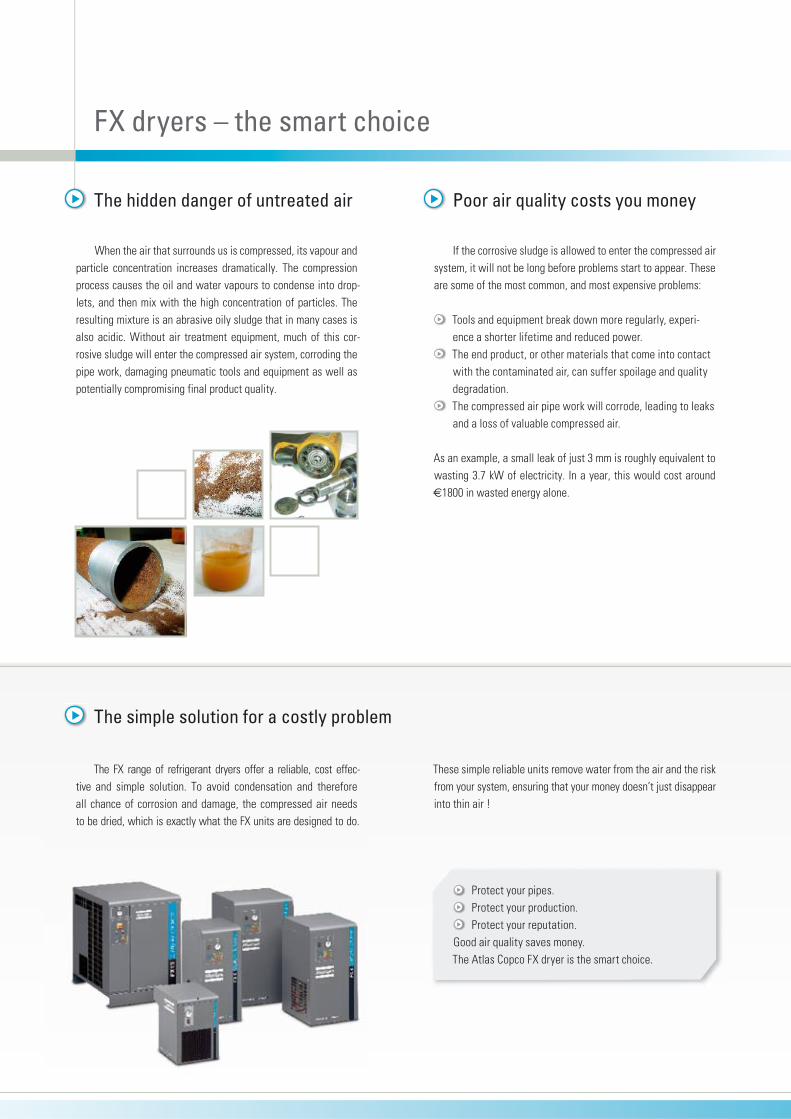
When the air that surrounds us is compressed, its vapour and particle concentration increases dramatically. The compression process causes the oil and water vapours to condense into drop-lets, and then mix with the high concentration of particles. The resulting mixture is an abrasive oily sludge that in many cases is also acidic. Without air treatment equipment, much of this cor-rosive sludge will enter the compressed air system, corroding the pipe work, damaging pneumatic tools and equipment as well as potentially compromising final product quality.
The hidden danger of untreated air
Protect your pipes. Protect your production. Protect your reputation.
Good air quality saves money.The Atlas Copco FX dryer is the smart choice.
FX dryers – the smart choice
Poor air quality costs you money
If the corrosive sludge is allowed to enter the compressed air system, it will not be long before problems start to appear. These are some of the most common, and most expensive problems:
Tools and equipment break down more regularly, experi-ence a shorter lifetime and reduced power.
The end product, or other materials that come into contact with the contaminated air, can suffer spoilage and quality degradation.
The compressed air pipe work will corrode, leading to leaks and a loss of valuable compressed air.
As an example, a small leak of just 3 mm is roughly equivalent to wasting 3.7 kW of electricity. In a year, this would cost around €1800 in wasted energy alone.
The simple solution for a costly problem
The FX range of refrigerant dryers offer a reliable, cost effec-tive and simple solution. To avoid condensation and therefore all chance of corrosion and damage, the compressed air needs to be dried, which is exactly what the FX units are designed to do.
These simple reliable units remove water from the air and the risk from your system, ensuring that your money doesn’t just disappear into thin air !
1 2
3
FX refrigerant dryers
Solid performance Steady pressure dew point No freezing of condensed moisture No chance of moisture entering the compressed air system.
Simple reliability Quality components, generously sized Simple and proven design Effective control system (hot gas bypass).
Easy installation Plug and play concept Single electrical connection All units pre-commissioned Self regulating.
Minimal maintenance Long service intervals Few component replacements Ergonomic design for fast access to key components.
Significant cost savings Increased reliability and lifetime of tools and equipment Reduced pipe work leaks, meaning reduced energy bill Fewer repairs to tools, machines and pipe work Less inconvenient breakdowns and stoppages Minimal chance of product spoilage through moisture
carryover.
The benefits add up
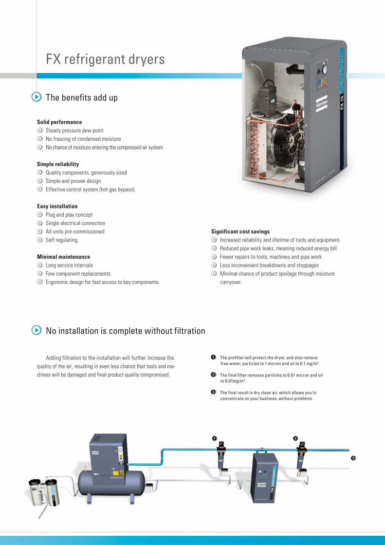
Adding filtration to the installation will further increase the quality of the air, resulting in even less chance that tools and ma-chines will be damaged and final product quality compromised.
No installation is complete without filtration
1 The prefilter will protect the dryer, and also remove free water, particles to 1 micron and oil to 0.1 mg/m3.
2 The final filter removes particles to 0.01 micron and oil to 0.01mg/m3.
3 The final result is dry clean air, which allows you to concentrate on your business, without problems.

1
2
3
4
5 6 7
8
9
1112
13
14
10
15
1 Refrigerant separator ensures that only refrigerant gas can enter the compressor,
as liquid would cause damage.
2 Refrigerant compressor brings the gaseous refrigerant to a high pressure and
a high temperature.
3 Max. pressure switch (only FX13-15)
4 Fan control pressure switch (only FX13-15)
5 Condenser fan
6 Condenser cools the refrigerant slightly so that it changes from gas to
liquid; refrigerant is more effective in the liquid state.
7 Capillary filter protects the expansion device from harmful particles.
8 Capillary tube reduces the refrigerant’s pressure, thereby lowering its
temperature and increasing its cooling capacity; the refrig-erant is now almost all liquid, with some residual gas.
9 Hot gass bypass regulates the amount of refrigerant passing through the air-
to-refrigerant heat exchanger, ensuring a stable pressure dewpoint, and eliminating the chance of the condensate freezing.
Refrigerant circuit
10 Air inlet hot saturated air enters the dryer and is cooled by the
outgoing air via the air-to-air heat exchanger. Reducing the temperature of the inlet air reduces the load on the refrigerant circuit.
11 Air-to-refrigerant heat exchanger transfers heat from the compressed air to the cold
refrigerant, forcing water vapour in the compressed air to condense. The more effective the heat transfer, the cooler the air becomes and the more water vapour condenses.
12 Air/ air heat exchanger
13 Water separator collects and drains off condensate from the cooled air flow.
The more efficient the separation, the better the pressure dewpoint, as droplets which are not collected revapourise and degrade the pressure dewpoint. The collected droplets are reliably evacuated from the separator through an electronic drain.
14 Automatic drain
15 Air outlet re-heats the outgoing air to prevent condensation on the
factory’s pipework.
Air circuit
FX 1-5 Brazed plate heat exchanger
FX 6-16 Aluminium plate heat exchanger
FX refrigerant dryersIndustrial performance – simple reliability

Notes:Refrigerant types: R134a for FX1-5 R404a for FX6-16
Technical data
FX refrigerant dryer range - 60 Hz
Model Outlet pressure dewpoint 41 °F/+5 °C
Outlet pressure dewpoint 39 °F/+4 °C
Maximumworking pressure
Electricalsupply
Dimensions Weight Compr. air
connec-tionsInlet
capacity
Pressure
drop
Inlet
capacity
Pressure
dropLenght Width Height
Type l/s cfm bar psi l/s cfm bar psi bar psi mm inch mm inch mm inch kg lb
FX1 7 14 0.20 2.88 6 13 0.15 2.18 13 189 115-230/1/60Hz 500 19.7 350 13.8 484 19.1 19 42 3/4” NPT
FX2 12 24 0.33 4.79 10 21 0.25 3.63 13 189 115-230/1/60Hz 500 19.7 350 13.8 484 19.1 19 42 3/4” NPT
FX3 16 35 0.33 4.79 14 30 0.25 3.63 13 189 115-230/1/60Hz 500 19.7 350 13.8 484 19.1 20 44 3/4” NPT
FX4 23 49 0.33 4.79 20 42 0.25 3.63 13 189 115-230/1/60Hz 500 19.7 350 13.8 484 19.1 25 55 3/4” NPT
FX5 35 74 0.40 5.75 30 64 0.30 4.35 13 189 115-230/1/60Hz 500 19.7 350 13.8 484 19.1 27 60 3/4” NPT
FX6 45 95 0.42 6.14 39 83 0.32 4.64 13 189 115-230/1/60Hz 500 19.7 370 14.6 804 31.7 51 112 1” NPT
FX7 58 122 0.50 7.29 50 106 0.38 5.51 13 189 115-230/1/60Hz 500 19.7 370 14.6 804 31.7 51 112 1” NPT
FX8 69 146 0.24 3.45 60 127 0.18 2.61 13 189 115-230/1/60Hz 560 22.0 460 18.1 829 32.6 61 135 1 1/2” NPT
FX9 79 167 0.33 4.79 68 144 0.25 3.63 13 189 115-230/1/60Hz 560 22.0 460 18.1 829 32.6 68 150 1 1/2” NPT
FX10 100 211 0.24 3.45 87 184 0.18 2.61 13 189 115-230/1/60Hz 560 22.0 460 18.1 829 32.6 73 161 1 1/2” NPT
FX11 125 264 0.26 3.84 108 229 0.20 2.90 13 189 230/1/60Hz 560 22.0 580 22.8 939 37.0 90 198 1 1/2” NPT
FX12 148 313 0.36 5.18 128 271 0.27 3.92 13 189 230/1/60Hz 560 22.0 580 22.8 939 37.0 90 198 1 1/2” NPT
FX13 192 407 0.26 3.77 167 354 0.20 2.90 16 232 460/3/60Hz 990 39.0 795 31.3 925 36.4 173 381 2” NPT
FX14 230 488 0.33 4.79 200 424 0.25 3.63 16 232 460/3/60Hz 975 38.4 795 31.3 925 36.4 178 392 2” NPT
FX15 288 611 0.46 6.67 250 530 0.35 5.08 16 232 460/3/60Hz 975 38.4 795 31.3 925 36.4 183 404 2” NPT
FX16 345 731 0.46 6.67 300 636 0.35 5.08 16 232 460/3/60Hz 975 38.4 795 31.3 925 36.4 183 404 2” NPT
Model Outlet pressure dewpoint41 °F/+5 °C
Outlet pressure dewpoint 39 °F/+4 °C
Inletcapacity
Prefilter
Afterfilter
Inletcapacity
Prefilter
Afterfilter
cfm cfm
FX1 14 DD9 DD9 13 DD9 DD9
FX2 24 DD17 DD17 21 DD17 DD17
FX3 35 DD17 DD17 30 DD17 DD17
FX4 49 DD32 DD32 42 DD32 DD32
FX5 74 DD44 DD44 64 DD32 DD32
FX6 95 DD44 DD44 83 DD44 DD44
FX7 122 DD60 DD60 106 DD60 DD60
FX8 146 DD120 DD120 127 DD60 DD60
FX9 167 DD120 DD120 144 DD120 DD120
FX10 211 DD120 DD120 184 DD120 DD120
FX11 264 DD120 DD120 229 DD120 DD120
FX12 313 DD150 DD150 271 DD150 DD150
FX13 407 DD280 DD280 354 DD175 DD175
FX14 488 DD280 DD280 424 DD175 DD175
FX15 611 DD280 DD280 530 DD280 DD280
FX16 731 DD280 DD280 636 DD280 DD280
Filter selection Capacity calculation
Ambient temperature
°F 100 104 110
K1 (corr. factor) 1 0.8 0.74
Inlet temperature
°F 100 104 113 122 131
K2 (corr. factor) 1 0.82 0.69 0.58 0.45
Inlet pressure
psi (g) 73 87 102 116 131 145 160 174 189
K3 (corr. factor) 0.9 0.96 1 1.03 1.06 1.08 1.1 1.12 1.13
Limitations:Max. ambient temp.: 110 °FMin. ambient temp.: 41 °FMax. inlet temp.: 131 °F
Reference conditions:Ambient temperature: 100 °F Inlet temperature: 100 °F Working pressure: 102 psi (g)
Example: What is the capacity of an FX6 (for a PDP of 41 °F) at the following conditions:Ambient temperature: 110 °FInlet temperature: 131 °FInlet pressure: 145 psi (g)
Correction factors from the table are: K1 = 0.74 / K2 = 0.45 / K3 = 1.08:
Qactual = K1 x K2 x K3 x Qnominal = 0.74 x 0.45 x 1.08 x 45 l/s = 16.18 l/s

In order to be First in Mind—First in Choice™ for all your
com pressed air needs, Atlas Copco delivers the products
and services that help increase your business’ efficiency
and profitability.
Atlas Copco’s pursuit of innovation never ceases, driven
by your need for reliability and efficiency. Always work-
ing with you, we are committed to providing you the cus-
tomized quality air solution that is the driving force behind
your business.
Never use compressed air as breathing air without prior purification in accordance with local legislation and standards.
2935 0
900 4
2 –
Printe
d in
Belg
ium
– S
ubje
ct to a
ltera
tion w
ithout prior
notic
e.
www.atlascopco.com