28 Volt input, 7 Amp M-Grade EMI Filter...
10
Quiet-Power ® Rev 1.9 vicorpower.com Page 1 of 10 12/2014 800 927.9474 28 Volt input, 7 Amp M-Grade EMI Filter Module Quiet-Power ® MQPI-18 M-Grade Product Description The MQPI-18 attenuates conducted common-mode (CM) and differential-mode (DM) noise for DC-DC converters including the VI Chip MIL PRM to comply with MIL-STD-461F EMI requirements for conducted noise measurements. The filter operates within the full input operating range of a 28 V MIL PRM and supports 7 A loads up to 85°C (T A ) without de-rating. Features • 50 Vin max. input • Compatible to most industry standard DC-DC converters including VI Chip MIL PRM • MIL-STD-461F compliant [a] CE101, CE102, CS101, CS106, CS114, CS115, and CS116 • 100 Vdc surge, 100 ms • 1,500 Vdc hipot hold-off to shield plane • 7 A rating • 12.9 x 25.3 x 5.0 mm, lidded SiP (System-in-Package) • 12.4 x 24.9 x 4.2 mm, open-frame • -55° to +125°C PCB temperature (see Figure 4) • Efficiency >99% • Pb solder construction Applications • Rugged Environment • Displays • Wireless Communications Assembly Process Compatibility • Designed for Pb solder SMT assembly • Compatible with typical aqueous cleaning processes (MQPI-18LP-01, open-frame only) • Compatible with most conformal coating compounds (MQPI-18LP-01, open-frame only, after reflow) PRM +IN –IN +OUT –OUT +BUS –BUS +QPI –QPI VTM +IN –IN +OUT –OUT Shield CB1 + C IN + L BUS+ BUS– Chassis/Shield CY1 CY2 CY3 CY4 Shield Plane Optional Chassis Connection LOAD Typical Application MQPI-18LP (~1/2 in 2 area) [a] When combined with MP028 PRMs and MV036 VTMs. [b] CB1 capacitor, referenced in all schematics, is a 47 uF electrolytic; United Chemi-Con EMVE101ARA470MKE0S or equivalent. CY1 to CY4, referenced in all schematics, are 4.7 nF hi-voltage safety capacitors; Vishay VY1472M63Y5UQ63V0 or equivalent. Figure 1 — Typical MQPI-18 application schematic with Vicor’s MP028 PRM and MV036 VTM modules. [b]
Transcript of 28 Volt input, 7 Amp M-Grade EMI Filter...

Quiet-Power® Rev 1.9 vicorpower.comPage 1 of 10 12/2014 800 927.9474
28 Volt input, 7 Amp M-Grade EMI Filter Module
Quiet-Power®
MQPI-18M-Grade
Product Description
The MQPI-18 attenuates conducted common-mode (CM) and differential-mode (DM) noise for DC-DC convertersincluding the VI Chip MIL PRM to comply with MIL-STD-461FEMI requirements for conducted noise measurements. The filter operates within the full input operating range of a 28 V MIL PRM and supports 7 A loads up to 85°C (TA)without de-rating.
Features
• 50 Vin max. input
• Compatible to most industry standard DC-DC converters including VI Chip MIL PRM
• MIL-STD-461F compliant[a] CE101, CE102, CS101, CS106, CS114, CS115, and CS116
• 100 Vdc surge, 100 ms
• 1,500 Vdc hipot hold-off to shield plane
• 7 A rating
• 12.9 x 25.3 x 5.0 mm, lidded SiP (System-in-Package)
• 12.4 x 24.9 x 4.2 mm, open-frame
• -55° to +125°C PCB temperature (see Figure 4)
• Efficiency >99%
• Pb solder construction
Applications
• Rugged Environment
• Displays
• Wireless Communications
Assembly Process Compatibility
• Designed for Pb solder SMT assembly
• Compatible with typical aqueous cleaning processes (MQPI-18LP-01, open-frame only)
• Compatible with most conformal coating compounds (MQPI-18LP-01, open-frame only, after reflow)
PRM
+IN
–IN
+OUT
–OUT
+BUS
–BUS
+QPI
–QPI
VTM
+IN
–IN
+OUT
–OUTShield
CB1 +
CIN
+
LBUS+
BUS–
Chassis/Shield CY1 CY2 CY3 CY4
Shield Plane
Optional Chassis Connection
LOAD
Typical Application
MQPI-18LP (~1/2 in2 area)
[a] When combined with MP028 PRMs and MV036 VTMs.[b] CB1 capacitor, referenced in all schematics, is a 47 uF electrolytic; United Chemi-Con EMVE101ARA470MKE0S or equivalent.
CY1 to CY4, referenced in all schematics, are 4.7 nF hi-voltage safety capacitors; Vishay VY1472M63Y5UQ63V0 or equivalent.
Figure 1 — Typical MQPI-18 application schematic with Vicor’s MP028 PRM and MV036 VTM modules. [b]

Quiet-Power® Rev 1.9 vicorpower.comPage 2 of 10 12/2014 800 927.9474
MQPI-18
Order Information
Part Number Description
MQPI-18LP MQPI-18 LGA package
MQPI-18LP-01 MQPI-18 LGA package, open-frame package
Also Available
MQPI-18-CB1 A MQPI-18LP mounted on a carrier board that can be paired with PRM/VTM and Cool-Power® evaluation boards available from Vicor.
Name Rating
Input voltage, BUS+ to BUS-, continuous -50 to 50 Vdc
Input voltage, BUS+ to BUS-, 100 ms transient -100 to 100 Vdc
BUS+/ BUS- to Shield pads, hipot -750 to 750 Vdc
Input to output current, continuous @ 25°C TA 7 Adc
Power dissipation, @ 85°C TA, 7 A [c] 1.85 W
Operating temperature - TA -55 to 125°C
Thermal resistance[c] - RθJ-A, using PCB layout in Figure 12 30°C/W
Thermal resistance[c] - RθJ-PCB 18°C/W
Storage temperature, JEDEC Standard J-STD-033B -55 to 125°C
Reflow temperature, 20 s exposure 245°C
ESD, Human Body Model (HBM) -2000 to 2000 V
Electrical CharacteristicsParameter limits apply over the operating temp. range, unless otherwise noted.
Absolute Maximum Ratings
Exceeding these parameters may result in permanent damage to the product.
[c] See Figure 4 for the current de-rating curve.
Parameter Symbol Conditions Min Typ Max Unit
Input range BUS+ to BUS- Measured at 7 A, 85°C ambient temperature [c] 50 Vdc
Voltage drop BUS+ to QPI+ Measured at 7 A, 85°C ambient temperature [c]) 130 mVdc
Voltage drop BUS- to QPI- Measured at 7 A, 85°C ambient temperature [c] 130 mVdc
Common-mode attenuation VBUS = 28 V, frequency = 1.0 MHz, line impedance = 50 Ω 45 dB
Differential-mode attenuation VBUS = 28 V, frequency = 1.0 MHz, line impedance = 50 Ω 75 dB
Input bias current at 50 V Input current from BUS+ to BUS- 10 uA

Quiet-Power® Rev 1.9 vicorpower.comPage 3 of 10 12/2014 800 927.9474
MQPI-18
Pin Name Name Description
8, 9 BUS+ Positive bus potential
1, 10 BUS- Negative bus potential
6, 7 QPI+ Positive input to the converter
4, 5 QPI- Negative input to the converter
2, 3 Shield Shield connects to the system chassis or to a safety ground
Pad Descriptions
BUS+
BUS+
BUS–
BUS– QPI–
QPI–
QPI+
QPI+
Shield Shield
3 4
5
6789
21
10
LGA Pattern (Top View)
MIL-STD 461F Test Results
CS101 Conducted susceptibility, power Leads Passed
CS106 Conducted susceptibility, transients, power leads Passed
CS114 Bulk cable injection, radio frequency Passed, 100% load (Figure 4)
CS114 Bulk cable injection, radio frequency Passed, 78% load (Figure 5)
CS115 Bulk cable injection, radio frequency Passed
CS116 Damped sinusoid transients Passed
CS116 Damped sinusoid transients Passed
Applications Information
The MQPI-18 was designed specifically to work with Vicor’s MIL PRM (MP028) and VTM (MV036) series of VI Chip® Factorized Power Architecture™ (FPA™)
converters to achieve compliance with the MIL-STD 461F standard.

Quiet-Power® Rev 1.9 vicorpower.comPage 4 of 10 12/2014 800 927.9474
MQPI-18
30 Hz 10 kHz
Trd CP9207-1
SGL
1MA
Unit dB A
ResBW 100 Hz
Meas T 20 ms
Det MA
Att 10 dB
INPUT 2
21.Oct 2009 16:33
100 Hz 1 kHz 10 kHz
10
20
30
40
50
60
70
80
90
100
110
0
120
CE101-42
Date: 21.OCT.2009 16:33:12
Figure 2 — CE101 EMI plots of the MP028F036M12AL and MV036F120M010, filtered with the MQPI-18LP, + (RED) and –(BLK) leads
30 Hz 10 kHz
Trd CP9207-1
SGL
1MA
Unit dB A
21.Oct 2009 16:50
ResBW 100 Hz
Meas T 20 ms
Det MA
Att 10 dB
INPUT 2
100 Hz 1 kHz 10 kHz
10
20
30
40
50
60
70
80
90
100
110
0
120
CE101-42
Date: 21.OCT.2009 16:50:50
CE101 EMI Plots: 108 Watt Load
SGL
1MA
10 kHz 10 MHz
Unit dB V
Trd CE102RED
20.Oct 2009 14:22
ResBW 10 kHz
Meas T 20 ms
Det MA
Att 10 dB
INPUT 2
100 kHz 1 MHz 10 MHz
10
20
30
40
50
60
70
80
90
100
110
0
120
CE10228
Date: 20.OCT.2009 14:22:54
Figure 3 — CE102 EMI plots of the MP028F036M12AL and MV036F120M010, filtered with the MQPI-18LP, + (RED) and –(BLK) leads
SGL
1MA
10 kHz 10 MHz
Unit dB V
Trd CE102BLK
20.Oct 2009 14:30
ResBW 10 kHz
Meas T 20 ms
Det MA
Att 10 dB
INPUT 2
100 kHz 1 MHz 10 MHz
10
20
30
40
50
60
70
80
90
100
110
0
120
CE10228
Date: 20.OCT.2009 14:30:27
CE102 EMI Plots: 108 Watt Load

Quiet-Power® Rev 1.9 vicorpower.comPage 5 of 10 12/2014 800 927.9474
MQPI-18
Lo
ad C
urr
ent
(A)
Ambient Temperature (°C)MQPI-18LP-01 MQPI-18LP
limitedby
TPCBMAX
=125°C
limitedby
TJMAX
=140°C
8.00
7.00
6.00
5.00
4.00
3.00
2.00
1.00
0.00
-40 -15 10 35 60 85 110
Figure 4 — Current de-rating over ambient temperature range
Current De-Rating
MQPI-18 Differential MQPI-18 CommonFrequency (MHz)
Att
enu
atio
n (
dB
)
90
80
70
60
50
40
30
20
10
0
0.1 1 10
Figure 5 — Attenuation curves into a 50 Ω line impedance, bias from a 48 V bus
MQPI-18 Insertion Loss Measurements

Quiet-Power® Rev 1.9 vicorpower.comPage 6 of 10 12/2014 800 927.9474
MQPI-18
BUS IN
SIGC hassis
LISN
BUS IN
SIGC hassis
LISN
Shield
BUS+ QPI+
BUS- QPI-
INA
INB
SIG50
C SIGLO A D
IPRO BE
47uF
V BUS 0
IPRO BE
Figure 6 — Test set-up to measure differential-mode EMI currents in Figure 4
MQPI Insertion Loss Test Circuits
BUS IN
SIGC hassis
LISN
BUS IN
SIGC hassis
LISN
Shield
BUS+ QPI+
BUS- QPI-INA
INB
SIG
50
C SIG
LO A DIPRO BE
IPRO BE
47uF
V BUS
0
Figure 7 — Test set-up to measure common-mode EMI currents in Figure 4

Quiet-Power® Rev 1.9 vicorpower.comPage 7 of 10 12/2014 800 927.9474
MQPI-18
Mechanical Package Drawings
0.508" [12.903 mm]
0.996" [25.298 mm] 0.196" [4.978 mm]
0.006" [0.15mm] max.0.006" [0.15mm] max.
MQPI-18LPU.S. and Foreign Patents/Patents Pending
Lot # Date Code
Pin 1 indicator
Figure 8 — Bottom view of open-frame (OF) and lidded (LID) products.
18LP-01
0.979" [24.867 mm] 0.164" [4.166 mm]
0.330 [8.382 mm]
0.006" [0.15mm] max.0.006" [0.15mm] max.0.006" [0.15mm] max.
0.489" [12.421 mm]
Figure 9 — Recommended receptor and stencil patterns.
Datum Units MQPI-18LP MQPI-18LP-01 Notes
FITS failure/billion hrs. 16 16 FITS based on the BellCore Standard TR-332
MTBF million hrs. 62.5 62.5 MTBFs based on the BellCore Standard TR-332
Weight grams 2.4 2.075
MSL 3 3
Peak Reflow Temperature °C/20 seconds 245 245 IPC/JEDEC J-STD-020D

Quiet-Power® Rev 1.9 vicorpower.comPage 8 of 10 12/2014 800 927.9474
MQPI-18
Pad and Stencil Definitions
Figure 10 — Bottom view of open-frame (OF) and lidded (LID) products. (All dimensions are in inches)
Figure 11 — Recommended receptor and stencil patterns. (All dimensions are in inches)
Stencil definition is based on a 6 mil stencil thickness, 80% of LGA pad area coverage. LGA package dimensions are for both the open-frame and liddedversions of the MQPI-18.
Quiet-Power® Rev 1.9 vicorpower.comPage 9 of 10 12/2014 800 927.9474
MQPI-18
MQPI-18 PCB Layout Recommendations
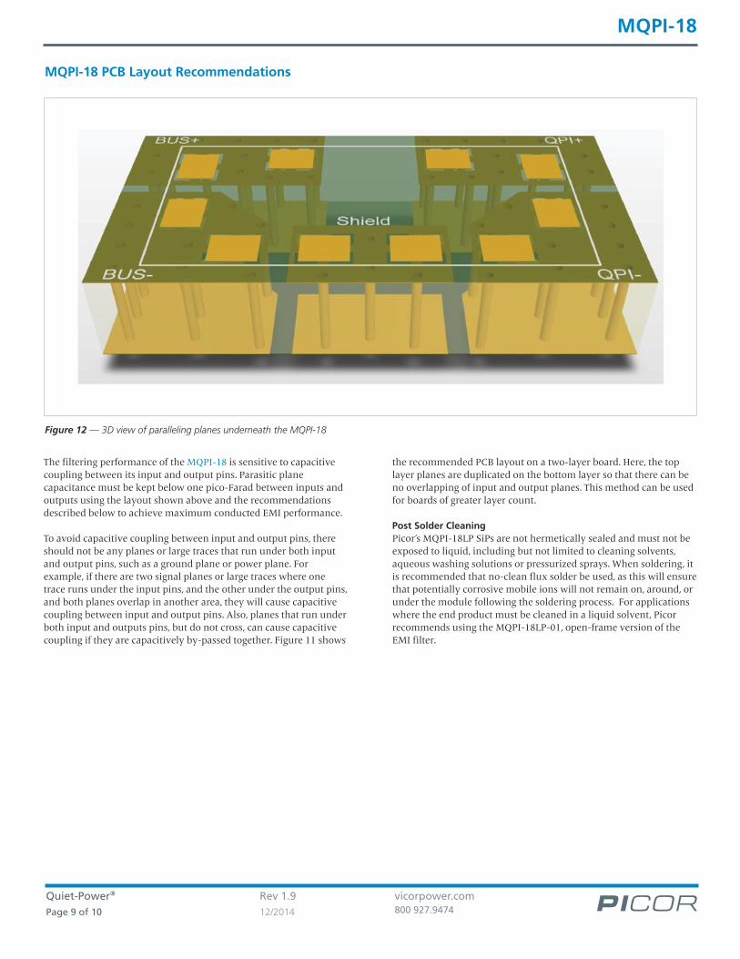
Figure 12 — 3D view of paralleling planes underneath the MQPI-18
The filtering performance of the MQPI-18 is sensitive to capacitivecoupling between its input and output pins. Parasitic planecapacitance must be kept below one pico-Farad between inputs andoutputs using the layout shown above and the recommendationsdescribed below to achieve maximum conducted EMI performance.
To avoid capacitive coupling between input and output pins, thereshould not be any planes or large traces that run under both inputand output pins, such as a ground plane or power plane. Forexample, if there are two signal planes or large traces where onetrace runs under the input pins, and the other under the output pins,and both planes overlap in another area, they will cause capacitivecoupling between input and output pins. Also, planes that run underboth input and outputs pins, but do not cross, can cause capacitivecoupling if they are capacitively by-passed together. Figure 11 shows
the recommended PCB layout on a two-layer board. Here, the toplayer planes are duplicated on the bottom layer so that there can beno overlapping of input and output planes. This method can be usedfor boards of greater layer count.
Post Solder CleaningPicor’s MQPI-18LP SiPs are not hermetically sealed and must not beexposed to liquid, including but not limited to cleaning solvents,aqueous washing solutions or pressurized sprays. When soldering, itis recommended that no-clean flux solder be used, as this will ensurethat potentially corrosive mobile ions will not remain on, around, orunder the module following the soldering process. For applicationswhere the end product must be cleaned in a liquid solvent, Picorrecommends using the MQPI-18LP-01, open-frame version of theEMI filter.

Quiet-Power® Rev 1.9 vicorpower.comPage 10 of 10 12/2014 800 927.9474
MQPI-18
Vicor’s comprehensive line of power solutions includes high density AC-DC and DC-DC modules andaccessory components, fully configurable AC-DC and DC-DC power supplies, and complete custompower systems.
Information furnished by Vicor is believed to be accurate and reliable. However, no responsibility is assumed by Vicor for its use. Vicor makes norepresentations or warranties with respect to the accuracy or completeness of the contents of this publication. Vicor reserves the right to makechanges to any products, specifications, and product descriptions at any time without notice. Information published by Vicor has been checked andis believed to be accurate at the time it was printed; however, Vicor assumes no responsibility for inaccuracies. Testing and other quality controls areused to the extent Vicor deems necessary to support Vicor’s product warranty. Except where mandated by government requirements, testing of allparameters of each product is not necessarily performed. Specifications are subject to change without notice.
Vicor’s Standard Terms and ConditionsAll sales are subject to Vicor’s Standard Terms and Conditions of Sale, which are available on Vicor’s website or upon request.
Product WarrantyIn Vicor’s standard terms and conditions of sale, Vicor warrants that its products are free from non-conformity to its Standard Specifications (the“Express Limited Warranty”). This warranty is extended only to the original Buyer for the period expiring two (2) years after the date of shipmentand is not transferable.UNLESS OTHERWISE EXPRESSLY STATED IN A WRITTEN SALES AGREEMENT SIGNED BY A DULY AUTHORIZED VICOR SIGNATORY, VICOR DISCLAIMSALL REPRESENTATIONS, LIABILITIES, AND WARRANTIES OF ANY KIND (WHETHER ARISING BY IMPLICATION OR BY OPERATION OF LAW) WITHRESPECT TO THE PRODUCTS, INCLUDING, WITHOUT LIMITATION, ANY WARRANTIES OR REPRESENTATIONS AS TO MERCHANTABILITY, FITNESS FORPARTICULAR PURPOSE, INFRINGEMENT OF ANY PATENT, COPYRIGHT, OR OTHER INTELLECTUAL PROPERTY RIGHT, OR ANY OTHER MATTER.
This warranty does not extend to products subjected to misuse, accident, or improper application, maintenance, or storage. Vicor shall not be liablefor collateral or consequential damage. Vicor disclaims any and all liability arising out of the application or use of any product or circuit and assumesno liability for applications assistance or buyer product design. Buyers are responsible for their products and applications using Vicor products andcomponents. Prior to using or distributing any products that include Vicor components, buyers should provide adequate design, testing andoperating safeguards.
Vicor will repair or replace defective products in accordance with its own best judgment. For service under this warranty, the buyer must contactVicor to obtain a Return Material Authorization (RMA) number and shipping instructions. Products returned without prior authorization will bereturned to the buyer. The buyer will pay all charges incurred in returning the product to the factory. Vicor will pay all reshipment charges if theproduct was defective within the terms of this warranty.
Life Support PolicyVICOR’S PRODUCTS ARE NOT AUTHORIZED FOR USE AS CRITICAL COMPONENTS IN LIFE SUPPORT DEVICES OR SYSTEMS WITHOUT THE EXPRESSPRIOR WRITTEN APPROVAL OF THE CHIEF EXECUTIVE OFFICER AND GENERAL COUNSEL OF VICOR CORPORATION. As used herein, life supportdevices or systems are devices which (a) are intended for surgical implant into the body, or (b) support or sustain life and whose failure to performwhen properly used in accordance with instructions for use provided in the labeling can be reasonably expected to result in a significant injury to theuser. A critical component is any component in a life support device or system whose failure to perform can be reasonably expected to cause thefailure of the life support device or system or to affect its safety or effectiveness. Per Vicor Terms and Conditions of Sale, the user of Vicor productsand components in life support applications assumes all risks of such use and indemnifies Vicor against all liability and damages.
Intellectual Property NoticeVicor and its subsidiaries own Intellectual Property (including issued U.S. and Foreign Patents and pending patent applications) relating to theproducts described in this data sheet. No license, whether express, implied, or arising by estoppel or otherwise, to any intellectual property rights isgranted by this document. Interested parties should contact Vicor's Intellectual Property Department.
Vicor Corporation25 Frontage Road
Andover, MA 01810 USA
Picor Corporation51 Industrial Drive
North Smithfield, RI 02896 USA
emailCustomer Service: [email protected]
Technical Support: [email protected]
The products described on this data sheet are protected by the following U.S. Patents Number:6,898,092